This article appeared in a journal published by Elsevier. The attached copy is furnished to the author for internal non-commercial research and education use, including for instruction at the authors institution and sharing with colleagues. Other uses, including reproduction and distribution, or selling or licensing copies, or posting to personal, institutional or third party websites are prohibited. In most cases authors are permitted to post their version of the article (e.g. in Word or Tex form) to their personal website or institutional repository. Authors requiring further information regarding Elsevier’s archiving and manuscript policies are encouraged to visit: http://www.elsevier.com/copyright

Welcome message from author
This document is posted to help you gain knowledge. Please leave a comment to let me know what you think about it! Share it to your friends and learn new things together.
Transcript

This article appeared in a journal published by Elsevier. The attachedcopy is furnished to the author for internal non-commercial researchand education use, including for instruction at the authors institution
and sharing with colleagues.
Other uses, including reproduction and distribution, or selling orlicensing copies, or posting to personal, institutional or third party
websites are prohibited.
In most cases authors are permitted to post their version of thearticle (e.g. in Word or Tex form) to their personal website orinstitutional repository. Authors requiring further information
regarding Elsevier’s archiving and manuscript policies areencouraged to visit:
http://www.elsevier.com/copyright
Author's personal copy
J O U R N A L O F T H E M E C H A N I C A L B E H AV I O R O F B I O M E D I C A L M A T E R I A L S 4 ( 2 0 1 1 ) 1 9 0 5 – 1 9 1 9
Available online at www.sciencedirect.com
journal homepage: www.elsevier.com/locate/jmbbm
Research paper
Computation of axonal elongation in head trauma finiteelement simulation
Simon Chatelina, Caroline Decka, Félix Renardb,c, Stéphane Kremerb, Christian Heinrichc,Jean-Paul Armspachb, Rémy Willingera,∗
aUniversity of Strasbourg, IMFS-CNRS, 2 rue Boussingault, 67000 Strasbourg, FrancebUniversity of Strasbourg, LINC-IPB-CNRS, 4 rue kirschleger, 67085 Strasbourg, FrancecUniversity of Strasbourg, LSIIT-CNRS, Pôle API Bd Sébastian Brant, BP 10413, 67412 Illkirch Cedex, France
A R T I C L E I N F O
Article history:
Received 6 October 2010
Received in revised form
8 June 2011
Accepted 13 June 2011
Published online 23 June 2011
Keywords:
Head FE modeling
Diffuse Axonal Injury
Diffusion tensor imaging
Head trauma simulation
A B S T R A C T
In the case of head trauma, elongation of axons is thought to result in brain damage and to
lead to Diffuse Axonal Injuries (DAI). Mechanical parameters have been previously proposed
as DAI metric. Typically, brain injury parameters are expressed in terms of pressure,
shearing stresses or invariants of the strain tensor. Addressing axonal deformation within
the brain during head impact can improve our understanding of DAI mechanisms. A
new technique based on directional measurements of water diffusion in soft tissue
using Magnetic Resonance Imaging (MRI), called Diffusion Tensor Imaging (DTI), provides
information on axonal orientation within the brain. The present study aims at coupling
axonal orientation from a 12-patient-based DTI 3D picture, called “DTI atlas”, with the
Strasbourg University Finite Element Head Model (SUFEHM). This information is then
integrated in head trauma simulation by computing axonal elongation for each finite
element of the brain model in a post-processing of classical simulation results. Axonal
elongation was selected as computation endpoint for its strong potential as a parameter
for DAI prediction and location. After detailing the coupling technique between DTI atlas
and the head FE model, two head trauma cases presenting different DAI injury levels
are reconstructed and analyzed with the developed methodology as an illustration of
axonal elongation computation. Results show that anisotropic brain structures can be
realistically implemented into an existing finite element model of the brain. The feasibility
of integrating axon fiber direction information within a dedicated post-processor is also
established in the context of the computation of axonal elongation. The accuracy obtained
when estimating level and location of the computed axonal elongation indicates that
coupling classical isotropic finite element simulation with axonal structural anisotropy is
an efficient strategy. Using this method, tensile elongation of the axons can be directly
invoked as a mechanism for Diffuse Axonal Injury.c⃝ 2011 Elsevier Ltd. All rights reserved.
∗ Corresponding author. Tel.: +33 3 68 85 29 23; fax: +33 3 68 85 29 36.E-mail address: [email protected] (R. Willinger).
1751-6161/$ - see front matter c⃝ 2011 Elsevier Ltd. All rights reserved.doi:10.1016/j.jmbbm.2011.06.007
Author's personal copy
1906 J O U R N A L O F T H E M E C H A N I C A L B E H AV I O R O F B I O M E D I C A L M A T E R I A L S 4 ( 2 0 1 1 ) 1 9 0 5 – 1 9 1 9
1. Introduction
Traumatic Brain injury (TBI) is one of the most commoncauses of death or disability and remains an importantpublic health issue. In the United States, The Center ofDisease Control and Prevention (CDC) (2010) estimates thatTBI involves annually about 1365,000 emergency departmentvisits, 275,000 hospitalizations and 52,000 deaths. Accordingto Faul et al. (2010), 1.7 million people are affected by TBIannually in the US. It contributes to 31.8% of all injury-related deaths in the US. According to the authors, motorvehicle traffic is the leading cause of TBI deaths and causes17.3% of all the related TBI between 2002 and 2006 in theUS, immediately after fall injuries (35.2%). Direct medical andindirect costs of TBI were estimated to $60 billion in the US in2000, according to Finkelstein et al. (2006).
Diffuse Axonal Injury (DAI) is one of the most frequentclosed head injuries. DAI occurs in almost half (48.2%) ofprimary intra-axial lesions of brain, according to Gentry et al.(1988a,b), and is the second cause of death by TBI, accordingto Bain and Meaney (2000). DAI results in rapid tensileelongation of the axons, and eventually in axon fibers rupture(Thibault and Gennarelli, 1990; Aldrich et al., 1992). In turn,this leads to the retraction of the cut axon into its cellularnucleus, yielding retraction balls of about 30 µm in diameter,as described by Arfanakis et al. (2002). This process is followedby axonal degeneration. According to Smith and Meaney(2000), and Smith et al. (2003), the rapid elongations of theaxons which result in head injury involve a decrease of braintissue elasticity. Even if no DAI has been diagnosed, localaxonal ruptures could appear even seventy-two hours afterTBI (Gennarelli, 1997; Pettus and Povlishock, 1996; Kelley et al.,2006). In the most severe TBI cases, DAI is the main cause oflong-time coma, with no apparent marks, increase in bloodpressure or decrease in blood flow. Associated microscopichemorrhages can only be observed in cerebral white matter.According to various epidemiological studies (Gennarelliet al., 1982; Gentry et al., 1988a,b; Ng et al., 1994; Grahamand Genarelli, 1997; Arfanakis et al., 2002), axonal injuriesare mainly concentrated in the white matter or gray/whitematter interface (corticomedullary junction). Unlike cerebralcontusions and hematomas, DAI diagnosis and locationremain difficult to determine and is sometimes not visiblewith usual medical imaging techniques. The identificationof adequate intra-cerebral mechanical parameters acting asDAI prediction metric represents an important and generallyaccepted strategy to address brain injury.
Maximal principal strain is considered in various experi-mental studies as a pertinent DAI criteria (Gennarelli et al.,1982; Thibault and Gennarelli, 1990; Bain et al., 1996; An-derson et al., 1999) with a rupture limit either around 0.10(Thibault, 2003) or between 0.18 and 0.21 (Bain and Meaney,2000).
Finite Element Human Head Models (FEHM) have beendeveloped as tools to assess head injury risk and eventuallyinjury location, essentially concerning DAI. In the lastdecades, about twenty FEHM have been reported in theliterature (Shugar, 1977; Ward et al., 1980; Hosey and Liu,1980; Ruan et al., 1991; DiMasi et al., 1991; Mendis, 1992;Bandak et al., 1994; Zhou et al., 1995; Al-Bsharat et al., 1999;
Kang et al., 1997; Zhang et al., 2001; Kleiven and Hardy, 2002;Brands, 2002; Takhounts et al., 2003; King et al., 2003; Horgan,2005; Kleiven, 2007; Iwamoto et al., 2007; Takhounts et al.,2008). Based on these models and well documented headtrauma simulations, brain shear stress and strain rate havebeen shown as pertinent parameters for DAI prediction (Kinget al., 2003; Kleiven, 2007; Marjoux et al., 2007; Deck andWillinger, 2008a,b).
For about ten years, a new imaging technique, calledDiffusion Tensor Imaging (DTI), has been developed (Basseret al., 1994; LeBihan et al., 2001; Kraus et al., 2007). By imagingthe tridimensional Brownian movement of water moleculesusing Magnetic Resonance Imaging (MRI), a tridimensionalmap of main axonal fiber orientation can be obtained. In thepresent study, it is proposed to couple structural informationfrom DTI with a classical FE head model mechanical analysisin order to compute tensile elongation of axons during TBI.Indeed, tensile elongation of the axons is thought to bethe most realistic mechanism of DAI according to manyauthors (Thibault and Gennarelli, 1990; Bain and Meaney,2000; Meythaler et al., 2001; Morrison et al., 2003; Takhountset al., 2003, 2008; Deck and Willinger, 2008a,b). Based onthe assumption of a correlation between axonal structuralanisotropy and mechanical response proposed by Tamuraet al. (2007) the purpose of this work is to develop anew method for DAI prediction and location based on theassumption of axonal elongations as the main mechanismfor tissue damage. The aim is to evaluate the influence ofmicro-scale axonal distribution on macro-scale mechanicalparameter measurements.
After a presentation of the brain finite element model andDTI data used for this study, the method of coupling thesetwo modalities as well as the axonal elongation calculationis presented. The novel axonal elongation computation tech-nique is then applied to head trauma cases as a first attemptto investigate axonal elongation based DAI mechanism. Themethodology as well as the results and limits of this studyare finally discussed.
2. Materials and method
2.1. Human head FE model and related criteria
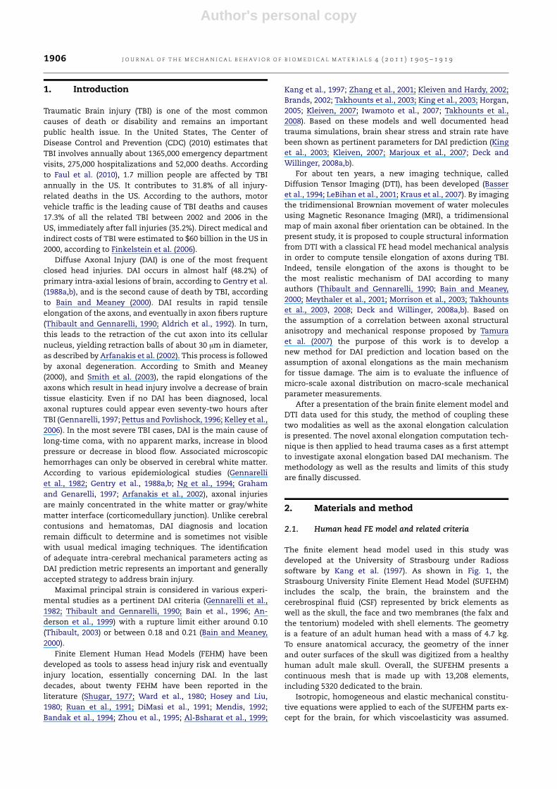
The finite element head model used in this study wasdeveloped at the University of Strasbourg under Radiosssoftware by Kang et al. (1997). As shown in Fig. 1, theStrasbourg University Finite Element Head Model (SUFEHM)includes the scalp, the brain, the brainstem and thecerebrospinal fluid (CSF) represented by brick elements aswell as the skull, the face and two membranes (the falx andthe tentorium) modeled with shell elements. The geometryis a feature of an adult human head with a mass of 4.7 kg.To ensure anatomical accuracy, the geometry of the innerand outer surfaces of the skull was digitized from a healthyhuman adult male skull. Overall, the SUFEHM presents acontinuous mesh that is made up with 13,208 elements,including 5320 dedicated to the brain.
Isotropic, homogeneous and elastic mechanical constitu-tive equations were applied to each of the SUFEHM parts ex-cept for the brain, for which viscoelasticity was assumed.
Author's personal copy
J O U R N A L O F T H E M E C H A N I C A L B E H AV I O R O F B I O M E D I C A L M A T E R I A L S 4 ( 2 0 1 1 ) 1 9 0 5 – 1 9 1 9 1907
Fig. 1 – Detailed Strasbourg university finite element head Model developed by Kang et al. (1997).
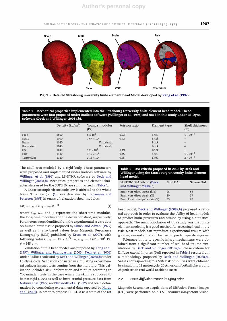
Table 1 – Mechanical properties implemented into the Strasbourg University finite element head model. Theseparameters were first proposed under Radioss software (Willinger et al., 1995) and used in this study under LS-Dynasoftware (Deck and Willinger, 2008a,b).
Density (kg/m3) Young’s modulus(Pa)
Poisson ratio Element type Shell thickness(m)
Face 2500 5 × 10⁹ 0.23 Shell 1 × 10⁻²
Scalp 1000 1.67 × 10⁷ 0.42 Brick –Brain 1040 Viscoelastic Brick –Brain stem 1040 Viscoelastic Brick –CSF 1040 1.2 × 10⁴ 0.49 Brick –Falx 1140 3.15 × 10⁷ 0.45 Shell 1 × 10⁻³
Tentorium 1140 3.15 × 10⁷ 0.45 Shell 2 × 10⁻³
The skull was modeled by a rigid body. These parameterswere proposed and implemented under Radioss software byWillinger et al. (1995) and LS-DYNA software by Deck andWillinger (2008a,b). Mechanical properties and element char-acteristics used for the SUFEHM are summarized in Table 1.
A linear isotropic viscoelastic law is affected to the wholebrain. This law (Eq. (1)) was described by Herrmann andPeterson (1968) in terms of relaxation shear modulus.
G(t) = G∞ + (G0 − G∞)e−βt (1)
where G0, G∞ and β represent the short-time modulus,the long-time modulus and the decay constant, respectively.Parameters were identified from the experimental in vitro dataon human brain tissue proposed by Shuck and Advani (1972)as well as in vivo based values from Magnetic ResonanceElastography (MRE) published by Kruse et al. (2007), withfollowing values: G0 = 49 × 103 Pa, G∞ = 1.62 × 10⁴ Pa,β = 145 s−1.
Validation of this head model was proposed by Kang et al.(1997), Willinger and Baumgartner (2003), Deck et al. (2004)under Radioss code and by Deck andWillinger (2008a,b) underLS-Dyna code. Validation consisted in simulating experimen-tal cadaver impact tests coming from the literature. This val-idation includes skull deformation and rupture according toYoganandan tests in the case where the skull is supposed tobe not rigid (1994) as well as intra-cranial pressure data fromNahum et al. (1977) and Trosseille et al. (1992) and brain defor-mation by considering experimental data reported by Hardyet al. (2001). In order to propose SUFEHM as a state of the art
Table 2 – DAI criteria proposed in 2008 by Deck andWillinger using the Strasbourg university finite elementhead model.
SUFEHM DAI criteria (Deckand Willinger, 2008a,b)
Mild DAI Severe DAI
Brain von Mises stress (kPa) 28 53Brain von Mises strain (%) 30 57Brain First principal strain (%) 33 67
head model, Deck and Willinger (2008a,b) proposed a ratio-nal approach in order to evaluate the ability of head modelsto predict brain pressures and strains by using a statisticalapproach. The main conclusion of this study was that finiteelement modeling is a good method for assessing head injuryrisk. Most models can reproduce experimental results withgood agreement and could be used to predict specific injuries.
Tolerance limits to specific injury mechanisms were ob-tained from a significant number of real head trauma sim-ulations by Deck and Willinger (2008a,b). These criteria forDiffuse Axonal Injuries (DAI) reported in Table 2 results froma methodology proposed by Deck and Willinger (2008a,b).Values corresponding to a 50% risk of injuries were obtainedby simulating 11motorcycle, 20 American football players and28 pedestrian real world accident cases.
2.2. Brain diffusion tensor imaging atlas
Magnetic Resonance acquisitions of Diffusion Tensor Images(DTI) were performed on a 1.5 T scanner (Magnetom Vision;
Author's personal copy
1908 J O U R N A L O F T H E M E C H A N I C A L B E H AV I O R O F B I O M E D I C A L M A T E R I A L S 4 ( 2 0 1 1 ) 1 9 0 5 – 1 9 1 9
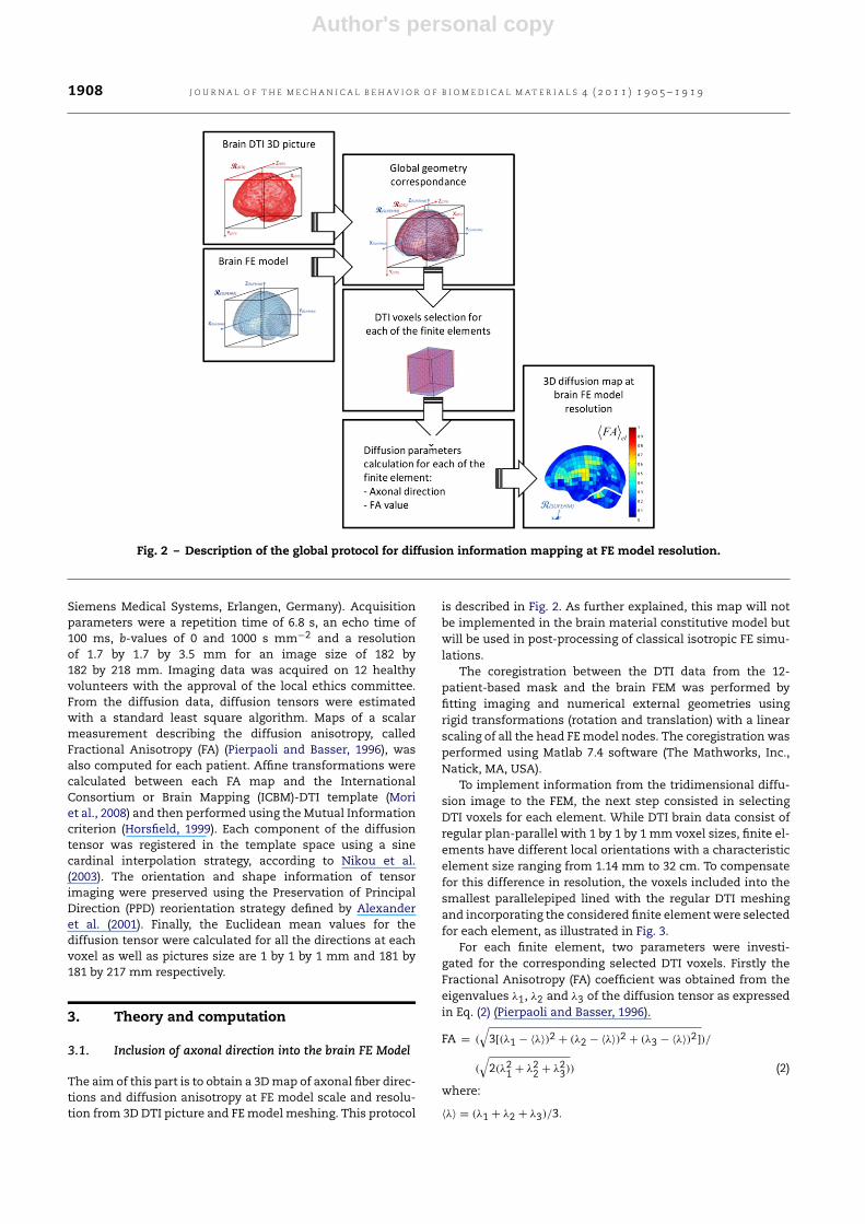
Fig. 2 – Description of the global protocol for diffusion information mapping at FE model resolution.
Siemens Medical Systems, Erlangen, Germany). Acquisitionparameters were a repetition time of 6.8 s, an echo time of100 ms, b-values of 0 and 1000 s mm−2 and a resolutionof 1.7 by 1.7 by 3.5 mm for an image size of 182 by182 by 218 mm. Imaging data was acquired on 12 healthyvolunteers with the approval of the local ethics committee.From the diffusion data, diffusion tensors were estimatedwith a standard least square algorithm. Maps of a scalarmeasurement describing the diffusion anisotropy, calledFractional Anisotropy (FA) (Pierpaoli and Basser, 1996), wasalso computed for each patient. Affine transformations werecalculated between each FA map and the InternationalConsortium or Brain Mapping (ICBM)-DTI template (Moriet al., 2008) and then performed using theMutual Informationcriterion (Horsfield, 1999). Each component of the diffusiontensor was registered in the template space using a sinecardinal interpolation strategy, according to Nikou et al.(2003). The orientation and shape information of tensorimaging were preserved using the Preservation of PrincipalDirection (PPD) reorientation strategy defined by Alexanderet al. (2001). Finally, the Euclidean mean values for thediffusion tensor were calculated for all the directions at eachvoxel as well as pictures size are 1 by 1 by 1 mm and 181 by181 by 217 mm respectively.
3. Theory and computation
3.1. Inclusion of axonal direction into the brain FE Model
The aim of this part is to obtain a 3Dmap of axonal fiber direc-tions and diffusion anisotropy at FE model scale and resolu-tion from 3D DTI picture and FEmodel meshing. This protocol
is described in Fig. 2. As further explained, this map will notbe implemented in the brain material constitutive model butwill be used in post-processing of classical isotropic FE simu-lations.
The coregistration between the DTI data from the 12-patient-based mask and the brain FEM was performed byfitting imaging and numerical external geometries usingrigid transformations (rotation and translation) with a linearscaling of all the head FEmodel nodes. The coregistration wasperformed using Matlab 7.4 software (The Mathworks, Inc.,Natick, MA, USA).
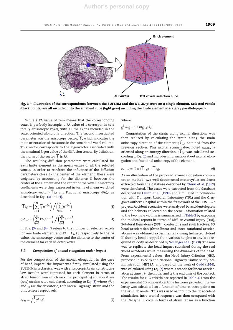
To implement information from the tridimensional diffu-sion image to the FEM, the next step consisted in selectingDTI voxels for each element. While DTI brain data consist ofregular plan-parallel with 1 by 1 by 1 mm voxel sizes, finite el-ements have different local orientations with a characteristicelement size ranging from 1.14 mm to 32 cm. To compensatefor this difference in resolution, the voxels included into thesmallest parallelepiped lined with the regular DTI meshingand incorporating the considered finite element were selectedfor each element, as illustrated in Fig. 3.
For each finite element, two parameters were investi-gated for the corresponding selected DTI voxels. Firstly theFractional Anisotropy (FA) coefficient was obtained from theeigenvalues λ1, λ2 and λ3 of the diffusion tensor as expressedin Eq. (2) (Pierpaoli and Basser, 1996).
FA = (
3[(λ1 − ⟨λ⟩)2 + (λ2 − ⟨λ⟩)2 + (λ3 − ⟨λ⟩)2])/
(
2(λ21 + λ22 + λ23)) (2)
where:
⟨λ⟩ = (λ1 + λ2 + λ3)/3.
Author's personal copy
J O U R N A L O F T H E M E C H A N I C A L B E H AV I O R O F B I O M E D I C A L M A T E R I A L S 4 ( 2 0 1 1 ) 1 9 0 5 – 1 9 1 9 1909
Fig. 3 – Illustration of the correspondence between the SUFEHM and the DTI 3D picture on a single element. Selected voxels(black points) are all included into the smallest cube (light gray) including the finite element (dark gray parallelepiped).
While a FA value of zero means that the correspondingvoxel is perfectly isotropic, a FA value of 1 corresponds to atotally anisotropic voxel, with all the axons included in thevoxel oriented along one direction. The second investigated
parameter was the anisotropy vector,−→l , which indicates the
main orientation of the axons in the considered voxel volume.This vector corresponds to the eigenvector associated withthemaximal Eigen value of the diffusion tensor. By definition,
the norm of the vector−→l is FA.
The resulting diffusion parameters were calculated foreach finite element as the mean values of all the selectedvoxels. In order to reinforce the influence of the diffusionparameters close to the center of the element, these wereweighted by accounting for the distance D between thecenter of the element and the center of the voxel. Anisotropycoefficients were thus expressed in terms of mean weighted
anisotropy vector ⟨−→l ⟩el and Fractional Anisotropy ⟨FA⟩el as
described in Eqs. (3) and (4).
⟨−→l ⟩el =
N−i=1
−→li e
−Di
N−i=1
e−Di
(3)
⟨FA⟩el =
N−i=1
FAie−Di
N−i=1
e−Di
. (4)
In Eqs. (3) and (4), N refers to the number of selected voxels
for one finite element and FAi,−→l i, Di respectively to the FA
value, the anisotropy vector and the distance to the center ofthe element for each selected voxel.
3.2. Computation of axonal elongation under impact
For the computation of the axonal elongation in the caseof head impact, the impact was firstly simulated using theSUFEHM in a classical way with an isotropic brain constitutivelaw. Results were expressed for each element in terms ofstrain tensor fromwhichmaximal principal (εI) and vonMises(εVM) strains were calculated, according to Eq. (5) where εd, ε
and I3 are the deviatoric, Left Green–Lagrange strain and theunit tensor respectively.
εVM =
32
εd : εd (5)
where:
εd = ε − (1/3)(ε.I3).I3.
Computation of the strain along axonal directions wasthen realized by calculating the strain along the main
anisotropy direction of the element ⟨−→l ⟩el obtained from the
previous section. This axonal strain value, noted εaxon, isoriented along anisotropy direction. ⟨
−→l ⟩el was calculated ac-
cording to Eq. (6) and includes information about axonal elon-gation and fractional anisotropy of the element.
εaxon = (ε × ⟨−→l ⟩el) · ⟨
−→l ⟩el. (6)
As an illustration of the proposed axonal elongation compu-tation method, two well documented motorcyclist accidentsextracted from the database described by Chinn et al. (1999)were simulated. The cases were extracted from the databasedescribed by Chinn et al. (1999) and simulated in collabora-tion with Transport Research Laboratory (TRL) and the Glas-gow Southern Hospital within the framework of the COST 327project. Accident scenarios were analyzed by accidentologistsand the helmets collected on the scene. Information relatedto the two male victims is summarized in Table 3 by exposingthe medical reports in terms of Diffuse Axonal Injury (DAI),Subdural Hematoma (SDH), contusions and skull fracture. 6Dhead acceleration (three linear and three rotational acceler-ations) was obtained experimentally using helmeted HybridIII dummy head dropped from various heights to anvils at re-quired velocity, as described byWillinger et al. (2000). The aimwas to replicate the head impact sustained during the realworld accidents while measuring the dynamics of the head.From experimental values, the Head Injury Criterion (HIC),proposed in 1972 by the National Highway Traffic Safety Ad-ministration (NHTSA) and based on the work of Gadd (1966),was calculated using Eq. (7) where a stands for linear acceler-ation at time t, t1 the initial and t2 the end time of the contact.The results for HIC criteria are reported in Table 3. From theexperimental 6D acceleration time histories provided, the ve-locity was calculated as a function of time at three points onthe skull FE model. This was used as input to the FE accidentsimulation. Intra-cranial response was then computed withthe LS-Dyna FE code in terms of strain tensor as a function
Author's personal copy
1910 J O U R N A L O F T H E M E C H A N I C A L B E H AV I O R O F B I O M E D I C A L M A T E R I A L S 4 ( 2 0 1 1 ) 1 9 0 5 – 1 9 1 9
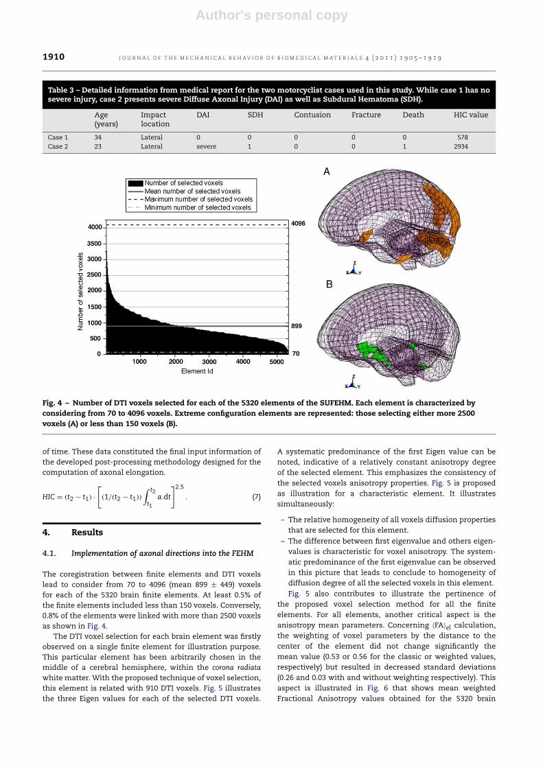
Table 3 – Detailed information from medical report for the two motorcyclist cases used in this study. While case 1 has nosevere injury, case 2 presents severe Diffuse Axonal Injury (DAI) as well as Subdural Hematoma (SDH).
Age(years)
Impactlocation
DAI SDH Contusion Fracture Death HIC value
Case 1 34 Lateral 0 0 0 0 0 578Case 2 23 Lateral severe 1 0 0 1 2934
Fig. 4 – Number of DTI voxels selected for each of the 5320 elements of the SUFEHM. Each element is characterized byconsidering from 70 to 4096 voxels. Extreme configuration elements are represented: those selecting either more 2500voxels (A) or less than 150 voxels (B).
of time. These data constituted the final input information ofthe developed post-processing methodology designed for thecomputation of axonal elongation.
HIC = (t2 − t1) ·
(1/(t2 − t1))
∫ t2
t1a.dt
2.5
. (7)
4. Results
4.1. Implementation of axonal directions into the FEHM
The coregistration between finite elements and DTI voxelslead to consider from 70 to 4096 (mean 899 ± 449) voxelsfor each of the 5320 brain finite elements. At least 0.5% ofthe finite elements included less than 150 voxels. Conversely,0.8% of the elements were linked with more than 2500 voxelsas shown in Fig. 4.
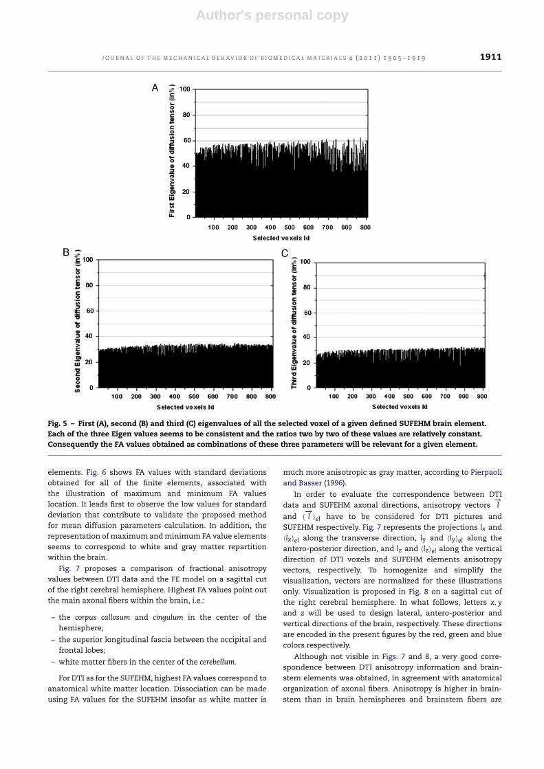
The DTI voxel selection for each brain element was firstlyobserved on a single finite element for illustration purpose.This particular element has been arbitrarily chosen in themiddle of a cerebral hemisphere, within the corona radiatawhite matter. With the proposed technique of voxel selection,this element is related with 910 DTI voxels. Fig. 5 illustratesthe three Eigen values for each of the selected DTI voxels.
A systematic predominance of the first Eigen value can benoted, indicative of a relatively constant anisotropy degreeof the selected element. This emphasizes the consistency ofthe selected voxels anisotropy properties. Fig. 5 is proposedas illustration for a characteristic element. It illustratessimultaneously:
– The relative homogeneity of all voxels diffusion propertiesthat are selected for this element.
– The difference between first eigenvalue and others eigen-values is characteristic for voxel anisotropy. The system-atic predominance of the first eigenvalue can be observedin this picture that leads to conclude to homogeneity ofdiffusion degree of all the selected voxels in this element.Fig. 5 also contributes to illustrate the pertinence of
the proposed voxel selection method for all the finiteelements. For all elements, another critical aspect is theanisotropy mean parameters. Concerning ⟨FA⟩el calculation,the weighting of voxel parameters by the distance to thecenter of the element did not change significantly themean value (0.53 or 0.56 for the classic or weighted values,respectively) but resulted in decreased standard deviations(0.26 and 0.03 with and without weighting respectively). Thisaspect is illustrated in Fig. 6 that shows mean weightedFractional Anisotropy values obtained for the 5320 brain
Author's personal copy
J O U R N A L O F T H E M E C H A N I C A L B E H AV I O R O F B I O M E D I C A L M A T E R I A L S 4 ( 2 0 1 1 ) 1 9 0 5 – 1 9 1 9 1911
Fig. 5 – First (A), second (B) and third (C) eigenvalues of all the selected voxel of a given defined SUFEHM brain element.Each of the three Eigen values seems to be consistent and the ratios two by two of these values are relatively constant.Consequently the FA values obtained as combinations of these three parameters will be relevant for a given element.
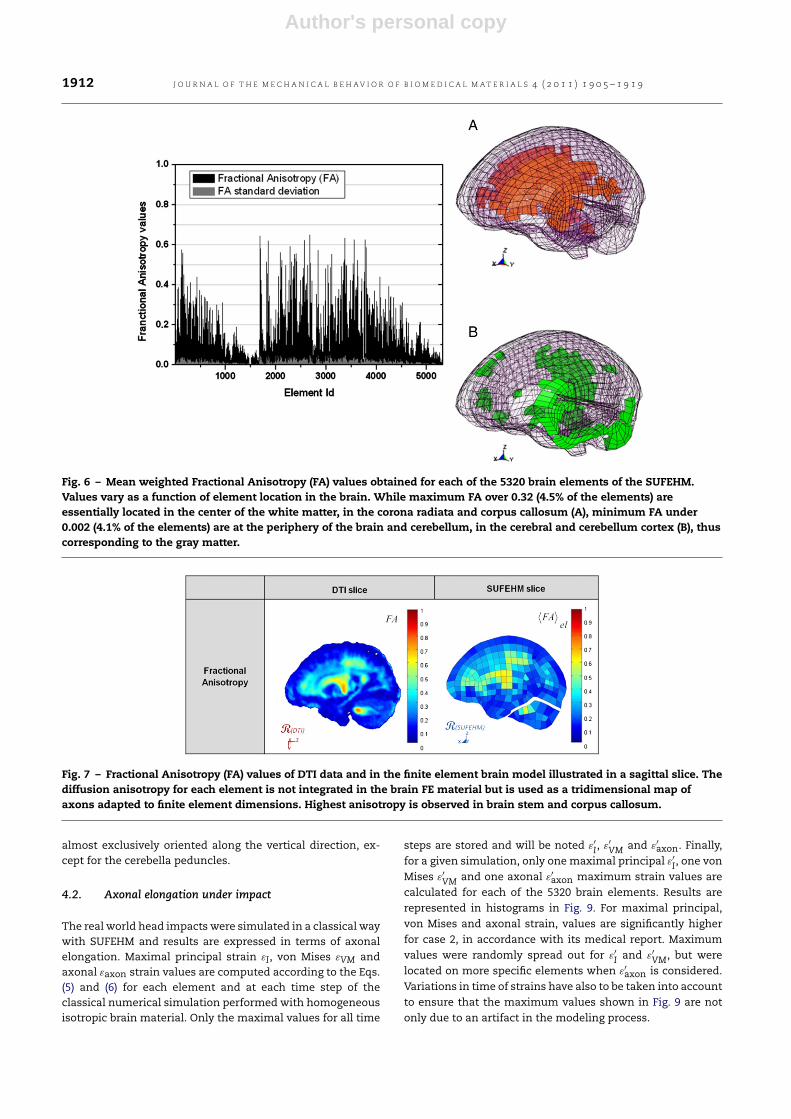
elements. Fig. 6 shows FA values with standard deviationsobtained for all of the finite elements, associated withthe illustration of maximum and minimum FA valueslocation. It leads first to observe the low values for standarddeviation that contribute to validate the proposed methodfor mean diffusion parameters calculation. In addition, therepresentation ofmaximum andminimum FA value elementsseems to correspond to white and gray matter repartitionwithin the brain.
Fig. 7 proposes a comparison of fractional anisotropyvalues between DTI data and the FE model on a sagittal cutof the right cerebral hemisphere. Highest FA values point outthe main axonal fibers within the brain, i.e.:
– the corpus callosum and cingulum in the center of thehemisphere;
– the superior longitudinal fascia between the occipital andfrontal lobes;
– white matter fibers in the center of the cerebellum.
For DTI as for the SUFEHM, highest FA values correspond toanatomical white matter location. Dissociation can be madeusing FA values for the SUFEHM insofar as white matter is
much more anisotropic as gray matter, according to Pierpaoliand Basser (1996).
In order to evaluate the correspondence between DTIdata and SUFEHM axonal directions, anisotropy vectors
−→l
and ⟨−→l ⟩el have to be considered for DTI pictures and
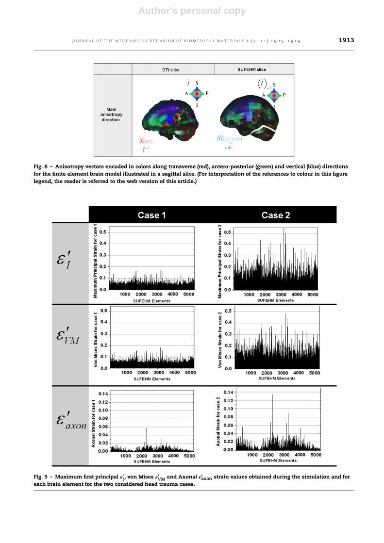
SUFEHM respectively. Fig. 7 represents the projections lx and⟨lx⟩el along the transverse direction, ly and ⟨ly⟩el along theantero-posterior direction, and lz and ⟨lz⟩el along the verticaldirection of DTI voxels and SUFEHM elements anisotropyvectors, respectively. To homogenize and simplify thevisualization, vectors are normalized for these illustrationsonly. Visualization is proposed in Fig. 8 on a sagittal cut ofthe right cerebral hemisphere. In what follows, letters x, yand z will be used to design lateral, antero-posterior andvertical directions of the brain, respectively. These directionsare encoded in the present figures by the red, green and bluecolors respectively.
Although not visible in Figs. 7 and 8, a very good corre-spondence between DTI anisotropy information and brain-stem elements was obtained, in agreement with anatomicalorganization of axonal fibers. Anisotropy is higher in brain-stem than in brain hemispheres and brainstem fibers are
Author's personal copy
1912 J O U R N A L O F T H E M E C H A N I C A L B E H AV I O R O F B I O M E D I C A L M A T E R I A L S 4 ( 2 0 1 1 ) 1 9 0 5 – 1 9 1 9
Fig. 6 – Mean weighted Fractional Anisotropy (FA) values obtained for each of the 5320 brain elements of the SUFEHM.Values vary as a function of element location in the brain. While maximum FA over 0.32 (4.5% of the elements) areessentially located in the center of the white matter, in the corona radiata and corpus callosum (A), minimum FA under0.002 (4.1% of the elements) are at the periphery of the brain and cerebellum, in the cerebral and cerebellum cortex (B), thuscorresponding to the gray matter.
Fig. 7 – Fractional Anisotropy (FA) values of DTI data and in the finite element brain model illustrated in a sagittal slice. Thediffusion anisotropy for each element is not integrated in the brain FE material but is used as a tridimensional map ofaxons adapted to finite element dimensions. Highest anisotropy is observed in brain stem and corpus callosum.
almost exclusively oriented along the vertical direction, ex-cept for the cerebella peduncles.
4.2. Axonal elongation under impact
The real world head impacts were simulated in a classical waywith SUFEHM and results are expressed in terms of axonalelongation. Maximal principal strain εI, von Mises εVM andaxonal εaxon strain values are computed according to the Eqs.(5) and (6) for each element and at each time step of theclassical numerical simulation performed with homogeneousisotropic brain material. Only the maximal values for all time
steps are stored and will be noted ε′
I, ε′
VM and ε′axon. Finally,
for a given simulation, only one maximal principal ε′
I, one vonMises ε′
VM and one axonal ε′axon maximum strain values are
calculated for each of the 5320 brain elements. Results arerepresented in histograms in Fig. 9. For maximal principal,von Mises and axonal strain, values are significantly higherfor case 2, in accordance with its medical report. Maximumvalues were randomly spread out for ε′
I and ε′
VM, but werelocated on more specific elements when ε′
axon is considered.Variations in time of strains have also to be taken into accountto ensure that the maximum values shown in Fig. 9 are notonly due to an artifact in the modeling process.
Author's personal copy
J O U R N A L O F T H E M E C H A N I C A L B E H AV I O R O F B I O M E D I C A L M A T E R I A L S 4 ( 2 0 1 1 ) 1 9 0 5 – 1 9 1 9 1913
Fig. 8 – Anisotropy vectors encoded in colors along transverse (red), antero-posterior (green) and vertical (blue) directionsfor the finite element brain model illustrated in a sagittal slice. (For interpretation of the references to colour in this figurelegend, the reader is referred to the web version of this article.)
Fig. 9 – Maximum first principal ε′I, von Mises ε′
VM and Axonal ε′axon strain values obtained during the simulation and for
each brain element for the two considered head trauma cases.
Author's personal copy
1914 J O U R N A L O F T H E M E C H A N I C A L B E H AV I O R O F B I O M E D I C A L M A T E R I A L S 4 ( 2 0 1 1 ) 1 9 0 5 – 1 9 1 9
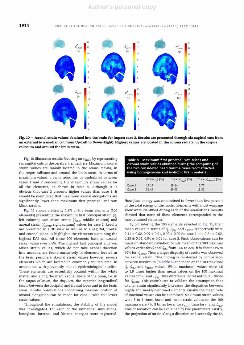
Fig. 10 – Axonal strain values obtained into the brain for impact case 2. Results are presented through six sagittal cuts froman external to a median cut (from Up-Left to Down-Right). Highest values are located in the corona radiata, in the corpuscallosum and around the brain stem.
Fig. 10 illustrates results focusing on ε′axon by representing
six sagittal cuts of the cerebral hemisphere. Maximum axonalstrain values are mainly located in the corona radiata, inthe corpus callosum and around the brain stem. In terms ofmaximum values, a same trend can be underlined betweencases 1 and 2 concerning the maximum strain values forall the elements, as shown in table 4. Although it isobvious that case 2 presents higher values than case 1, itshould be mentioned that maximum axonal elongations aresignificantly lower than maximum first principal and vonMises strains.
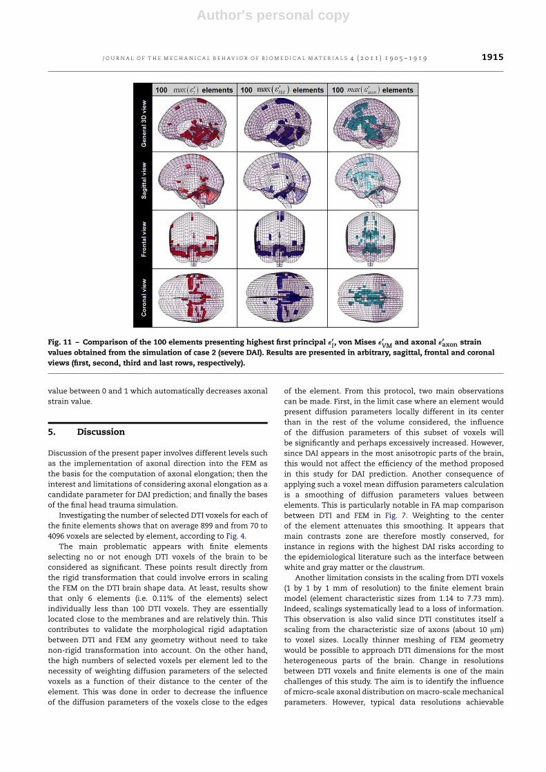
Fig. 11 shows arbitrarily 1.9% of the brain elements (100elements) presenting the maximum first principal strain (ε′
I,left column), von Mises strain (ε′
VM, middle column) andaxonal strain (ε′
axon, right column) values for case 2. Resultsare presented in a 3D view as well as in a sagittal, frontaland coronal plane. It highlights the elements sustaining thehighest DAI risk. All these 100 elements have an axonalstrain value over 2.8%. The highest first principal and vonMises strain values, which do not take axonal directioninto account, are found exclusively in elements located atthe brain periphery. Axonal strain values however, revealselements which are located in commonly injured area, inaccordance with previously related epidemiological studies.These elements are essentially located within the whitematter and along the main axonal fibers of the brain, i.e. inthe corpus callosum, the cingulum, the superior longitudinalfascia between the occipital and frontal lobes and in the brainstem. Similar observations concerning maxima location ofaxonal elongation can be made for case 1 with but lowerstrain values.
Throughout the simulations, the stability of the modelwas investigated. For each of the numerical simulations,hourglass, internal and kinetic energies were registered.
Table 4 – Maximum first principal, von Mises andAxonal strain values obtained during the computing ofthe two considered head trauma cases reconstructedusing homogeneous and isotropic brain material.
max(ε′
I) (%) max(ε′
VM) (%) max(ε′axon) (%)
Case 1 17.17 18.14 5.77Case 2 54.42 48.05 13.32
Hourglass energy was constrained to fewer than five percentof the total energy of the model. Elements with most warpageskew were identified during each of the simulations. Resultsshowed that none of these elements corresponded to themost strained elements.
By considering the 100 elements selected in Fig. 11, theirmean values in terms of ε′
I, ε′
VM and ε′axon respectively were
0.11 ± 0.02, 0.09 ± 0.01, 0.02 ± 0.00 for case 1 and 0.21 ± 0.02,0.23 ± 0.04, 0.04 ± 0.01 for case 2. First, observations can bemade on standard deviation. While mean on the 100 maximalvalues varies for ε′
I and ε′
VM from 16% to 22%, it is about 33% to40% for ε′
axon. Thus a larger disparity of results was observedfor axonal strain. This finding is reinforced by comparisonbetweenmaximum (in Table 4) andmean on the 100 maximalε′
I, ε′
VM and ε′axon values. While maximum values were 1.6
to 1.9 times higher than mean values on the 100 maximalvalues for ε′
I and ε′
VM, this difference increased to 3.8 timesfor ε′
axon. This contributes to validate the assumption thataxonal strain significantly increases the disparities betweenhighly and weakly deformed elements. Finally, themagnitudeof maximal values can be examined. Maximum strain valueswere 3 to 4 times lower and mean strain values on the 100maxima were 7 to 8 times lower for ε′
axon than for ε′
I and ε′
VM.This observation can be explained by two parameters. Firstly,the projection of strain along a direction and secondly the FA
Author's personal copy
J O U R N A L O F T H E M E C H A N I C A L B E H AV I O R O F B I O M E D I C A L M A T E R I A L S 4 ( 2 0 1 1 ) 1 9 0 5 – 1 9 1 9 1915
Fig. 11 – Comparison of the 100 elements presenting highest first principal ε′I, von Mises ε′
VM and axonal ε′axon strain
values obtained from the simulation of case 2 (severe DAI). Results are presented in arbitrary, sagittal, frontal and coronalviews (first, second, third and last rows, respectively).
value between 0 and 1 which automatically decreases axonalstrain value.
5. Discussion
Discussion of the present paper involves different levels suchas the implementation of axonal direction into the FEM asthe basis for the computation of axonal elongation; then theinterest and limitations of considering axonal elongation as acandidate parameter for DAI prediction; and finally the basesof the final head trauma simulation.
Investigating the number of selected DTI voxels for each ofthe finite elements shows that on average 899 and from 70 to4096 voxels are selected by element, according to Fig. 4.
The main problematic appears with finite elementsselecting no or not enough DTI voxels of the brain to beconsidered as significant. These points result directly fromthe rigid transformation that could involve errors in scalingthe FEM on the DTI brain shape data. At least, results showthat only 6 elements (i.e. 0.11% of the elements) selectindividually less than 100 DTI voxels. They are essentiallylocated close to the membranes and are relatively thin. Thiscontributes to validate the morphological rigid adaptationbetween DTI and FEM any geometry without need to takenon-rigid transformation into account. On the other hand,the high numbers of selected voxels per element led to thenecessity of weighting diffusion parameters of the selectedvoxels as a function of their distance to the center of theelement. This was done in order to decrease the influenceof the diffusion parameters of the voxels close to the edges
of the element. From this protocol, two main observationscan be made. First, in the limit case where an element wouldpresent diffusion parameters locally different in its centerthan in the rest of the volume considered, the influenceof the diffusion parameters of this subset of voxels willbe significantly and perhaps excessively increased. However,since DAI appears in the most anisotropic parts of the brain,this would not affect the efficiency of the method proposedin this study for DAI prediction. Another consequence ofapplying such a voxel mean diffusion parameters calculationis a smoothing of diffusion parameters values betweenelements. This is particularly notable in FA map comparisonbetween DTI and FEM in Fig. 7. Weighting to the centerof the element attenuates this smoothing. It appears thatmain contrasts zone are therefore mostly conserved, forinstance in regions with the highest DAI risks according tothe epidemiological literature such as the interface betweenwhite and gray matter or the claustrum.
Another limitation consists in the scaling from DTI voxels(1 by 1 by 1 mm of resolution) to the finite element brainmodel (element characteristic sizes from 1.14 to 7.73 mm).Indeed, scalings systematically lead to a loss of information.This observation is also valid since DTI constitutes itself ascaling from the characteristic size of axons (about 10 µm)to voxel sizes. Locally thinner meshing of FEM geometrywould be possible to approach DTI dimensions for the mostheterogeneous parts of the brain. Change in resolutionsbetween DTI voxels and finite elements is one of the mainchallenges of this study. The aim is to identify the influenceofmicro-scale axonal distribution onmacro-scalemechanicalparameters. However, typical data resolutions achievable
Author's personal copy
1916 J O U R N A L O F T H E M E C H A N I C A L B E H AV I O R O F B I O M E D I C A L M A T E R I A L S 4 ( 2 0 1 1 ) 1 9 0 5 – 1 9 1 9
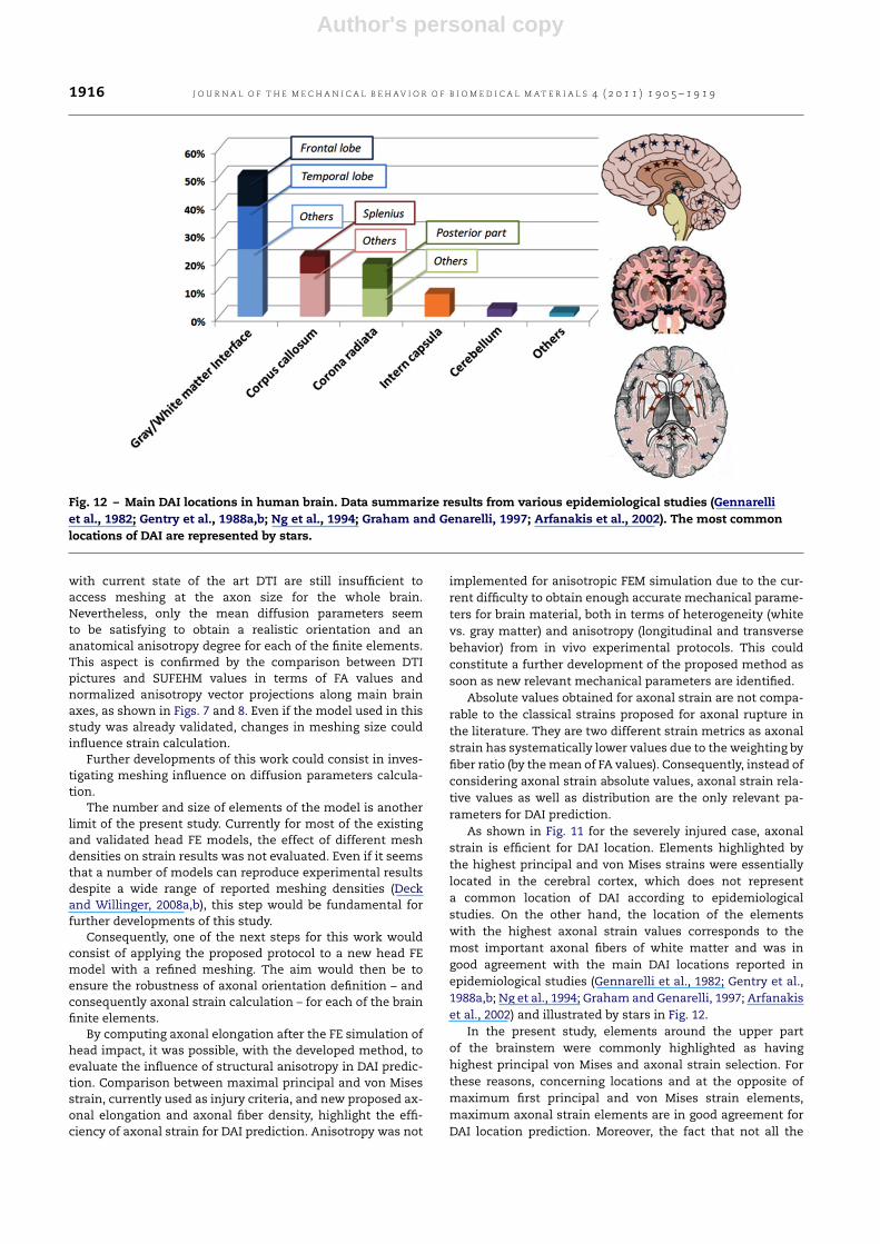
Fig. 12 – Main DAI locations in human brain. Data summarize results from various epidemiological studies (Gennarelliet al., 1982; Gentry et al., 1988a,b; Ng et al., 1994; Graham and Genarelli, 1997; Arfanakis et al., 2002). The most commonlocations of DAI are represented by stars.
with current state of the art DTI are still insufficient toaccess meshing at the axon size for the whole brain.Nevertheless, only the mean diffusion parameters seemto be satisfying to obtain a realistic orientation and ananatomical anisotropy degree for each of the finite elements.This aspect is confirmed by the comparison between DTIpictures and SUFEHM values in terms of FA values andnormalized anisotropy vector projections along main brainaxes, as shown in Figs. 7 and 8. Even if the model used in thisstudy was already validated, changes in meshing size couldinfluence strain calculation.
Further developments of this work could consist in inves-tigating meshing influence on diffusion parameters calcula-tion.
The number and size of elements of the model is anotherlimit of the present study. Currently for most of the existingand validated head FE models, the effect of different meshdensities on strain results was not evaluated. Even if it seemsthat a number of models can reproduce experimental resultsdespite a wide range of reported meshing densities (Deckand Willinger, 2008a,b), this step would be fundamental forfurther developments of this study.
Consequently, one of the next steps for this work wouldconsist of applying the proposed protocol to a new head FEmodel with a refined meshing. The aim would then be toensure the robustness of axonal orientation definition – andconsequently axonal strain calculation – for each of the brainfinite elements.
By computing axonal elongation after the FE simulation ofhead impact, it was possible, with the developed method, toevaluate the influence of structural anisotropy in DAI predic-tion. Comparison between maximal principal and von Misesstrain, currently used as injury criteria, and new proposed ax-onal elongation and axonal fiber density, highlight the effi-ciency of axonal strain for DAI prediction. Anisotropy was not
implemented for anisotropic FEM simulation due to the cur-rent difficulty to obtain enough accurate mechanical parame-ters for brain material, both in terms of heterogeneity (whitevs. gray matter) and anisotropy (longitudinal and transversebehavior) from in vivo experimental protocols. This couldconstitute a further development of the proposed method assoon as new relevant mechanical parameters are identified.
Absolute values obtained for axonal strain are not compa-rable to the classical strains proposed for axonal rupture inthe literature. They are two different strain metrics as axonalstrain has systematically lower values due to the weighting byfiber ratio (by themean of FA values). Consequently, instead ofconsidering axonal strain absolute values, axonal strain rela-tive values as well as distribution are the only relevant pa-rameters for DAI prediction.
As shown in Fig. 11 for the severely injured case, axonalstrain is efficient for DAI location. Elements highlighted bythe highest principal and von Mises strains were essentiallylocated in the cerebral cortex, which does not representa common location of DAI according to epidemiologicalstudies. On the other hand, the location of the elementswith the highest axonal strain values corresponds to themost important axonal fibers of white matter and was ingood agreement with the main DAI locations reported inepidemiological studies (Gennarelli et al., 1982; Gentry et al.,1988a,b; Ng et al., 1994; Graham and Genarelli, 1997; Arfanakiset al., 2002) and illustrated by stars in Fig. 12.
In the present study, elements around the upper partof the brainstem were commonly highlighted as havinghighest principal von Mises and axonal strain selection. Forthese reasons, concerning locations and at the opposite ofmaximum first principal and von Mises strain elements,maximum axonal strain elements are in good agreement forDAI location prediction. Moreover, the fact that not all the
Author's personal copy
J O U R N A L O F T H E M E C H A N I C A L B E H AV I O R O F B I O M E D I C A L M A T E R I A L S 4 ( 2 0 1 1 ) 1 9 0 5 – 1 9 1 9 1917
parts of the brain with high values results in high axonaldeformation leads to consider that this parameter is ableto take the axonal elongation as much as the fiber densityinto account. Axonal strain seems to be consistent with DAImechanism, in contrast to previously proposed DAI metrics.Indeed maximal principal strain and von Mises give relativelysimilar results and do not seem to correlate with DAI physicsduring brain injury.
Axonal strain seems not only to be efficient to determineDAI location, but also as DAI predictor. The two cases reportedhere are only presented as illustration. Even if this studyproposes axonal tensile elongation as a possible brain injurymetric for DAI prediction, the limiting number of casesprevented the determination of threshold values as DAIcriterion at this stage. To evaluate the capability of axonalstrain to become a DAI predictor criterion, a statistical studyshould be conducted on a significant number of real worldhead trauma simulations including a detailed descriptionof DAI location. However, this work proposes a new tool tocompute anatomical parameters with a head FEM using aspecial dedicated post-processor which takes the structuralanisotropy into account. It makes it possible to coupleclassical isotropic finite element simulation with axonalstructure anisotropy in order to address axonal elongationunder head impact. Next perspective for this study couldconsist in integrating the diffusion anisotropy map in thebrain material. Uniaxial composite laws that take fiber ratiointo account could be investigated for each finite element.Should new detailed anisotropy of in vivo brain materialbecome available, mechanical anisotropy may also be directlyintegrated in the FE model.
6. Conclusion
In this paper a methodology to compute axonal elongationin case of head impact based on head FE simulation andaxonal direction determined by a medical imaging techniqueis presented. A 12 healthy patient-based DTI database wasintegrated into an existing finite element brain model. Thebrain response in terms of stress and strain tensor was thencalculated with a classical isotropic finite element approachand used for the computation of elongation along the abovedefined “axonal direction” in each element. The approachbased on the computation of this novel injury metric hasfinally been applied to the simulation of two real worldhead trauma for demonstrative purposes. Results in termsof location and maximum axonal elongation contribute tovalidate the hypothesis of axonal elongation as main causeof DAI, since elements sustaining maximum axonal strainare located where this injury is typically observed. This studyhas demonstrated the feasibility of implementing anisotropicbrain structure information into a brain finite element model.It constitutes an easily implementable post-processing toolfor available isotropic head FEM. In a next step a number ofwell documented real world head trauma simulations willpermit the development of a threshold for this new metricof DAI. Accuracy of this new approach could be evaluatedon several existing and already validated brain FE models aswell as on a new more detailed brain meshing to determine
the reproducibility of the method. Further developmentsof this study could also examine the implementation ofanisotropic and heterogeneous brain constitutive laws forthe FEM as soon as relevant experimental parameters canbe established. Indeed this study initiates innovative andpromising possibilities to improve biofidelity of human headfinite element simulation and thus to extract more realisticinjury criteria for DAI.
Acknowledgments
The authors acknowledge research support to this work fromthe MAIF Foundation.
R E F E R E N C E S
Al-Bsharat, A., Hardy, W., Yang, K., Kahlil, T., Tashman, S., King, A.,1999. Brain/skull relative displacementmagnitude due to blunthead impact: new experimental data and model. In: Proc. 43thStapp Car Crash Conf., Society of Automotive Engineers, pp.321–332.
Aldrich, E.F., Eisenberg, H.M., Saydjari, C., Luerssen, T.G., Foulkes,M.A., Jane, J.A., Marshall, L.F., Marmarou, A., Youn, H.F., 1992.Diffuse brain swelling in severely head-injured children. J.Neurosurgery 76, 450–454.
Alexander, D.C., Pierpaoli, C., Basser, P.J., Gee, J.C., 2001.Spatial transformation of diffusion tensor magnetic resonanceimages. IEEE Trans. Med. Imaging 20, 1131–1139.
Anderson, R.W.G., Brown, C.J., Blumbergs, P.C., Scott, G., Finnie,J.W., Jones, N.R., McLean, A.J., 1999. Mechanisms of axonalinjury: an experimental and numerical study of a sheep modelof head impact. In: Proceedings of IRCOBI Conference, Sitges,Spain, pp. 107–120.
Arfanakis, K., Haughton, V.M., Carew, J.D., Rogers, B.P., Dempsey,R.J., Meyer, M.E., 2002. Diffusion tensor MR imaging in diffuseaxonal injury. Amer. J. Neuroradiol. 23, 794–802.
Bain, A.C., Billiar, K.L., Shreiber, D.I., McIntosh, T.K., Meaney,D.F., 1996. In vivo mechanical thresholds for traumatic axonaldamage. In: AGARD Specialists Meeting, Mescalero, NM.
Bain, A.C., Meaney, D.F., 2000. Tissue-level thresholds for axonaldamage in an experimental model of central nervous systemwhite matter injury. J. Biomech. Eng. 122, 615–622.
Bandak, F.A., Van Der Vorst, M.J., Stuhmiller, L.M., Mlakar,P.F., Chilton, W.E., Stuhmiller, J.H., 1994. An imaging basedcomputational and experimental study of skull fracture: finiteelement model development. In: Proc. Of the Head InjurySymposium, Washington, DC.
Basser, P.J., Mattiello, J., Le Bihan, D., 1994. Estimation of theeffective self-diffusion tensor from the NMR spin echo. J. Magn.Reson. B 103, 247–254.
Brands, D.W.A., 2002. Predicting brain mechanics during closedhead impact—Numerical and costitutive aspects. Ph.D. disser-tation, University of Eindhoven, Eindhoven, The Netherlands.
Chinn, B.P., Doyle, D., Otte, D., Schuller, E., 1999. Motorcyclistshead injuries: mechanisms identified from accident recon-struction and helmet damage replication. In: Proceedings ofIRCOBI Conference, pp. 53–72.
Deck, C., Nicolle, S., Willinger, R., 2004. Human head FE modelling:improvement of skull geometry and brain constitutive laws. In:Proc. on the IRCOBI Conference, 2004 Graz, pp. 79–92.
Deck, C., Willinger, R., 2008a. Improved head injury criteria basedon head FE model. Int. J. Crashworthiness 13 (6), 667–678.
Author's personal copy
1918 J O U R N A L O F T H E M E C H A N I C A L B E H AV I O R O F B I O M E D I C A L M A T E R I A L S 4 ( 2 0 1 1 ) 1 9 0 5 – 1 9 1 9
Deck, C., Willinger, R., 2008b. Head injury prediction tool forpredictive systems optimization. In: 7th European LS-DYNAConference.
DiMasi, F., Marcus, J., Eppinger, R., 1991. 3D anatomic brainmodel for relating cortical strains to automobile crashloading. In: Proc. of the International Technical Conference onExperimental Safety Vehicles, NHTSA, vol. 2, pp. 916–923.
Faul, M., Xu, L., Wald, M.M., Coronado, V.G., 2010. Traumatic braininjury in the United States: emergency department visits,hospitalizations and deaths 2002–2006. Centers for DiseaseControl and Prevention, National Center for Injury Preventionand Control, Atlanta, GA.
Finkelstein, E., Corso, P., Miller, T., 2006. The Incidence andEconomic Burden of Injuries in the United States. OxfordUniversity Press, New York, NY.
Gadd, C.W., 1966. Use of a weighted-impulse criterion forestimating injury hazard. In: Proc. 10th Stapp Car Crash Conf.,pp. 164–174.
Gennarelli, T.A., 1997. The pathology of traumatic brain injury.Neuroscientist 3, 73–81.
Gennarelli, T.A., Thibault, L.E., Adams, H., Graham, D.I.,Thompson, C.J., Marcincin, R.P., 1982. Diffuse axonal injuryand traumatic coma in the primate. American NeurologicalAssociation 0364-5134/82/120564-11, pp. 564–574.
Gentry, L.R., Godersky, J.C., Thompson, B., Dunn, V.D., 1988a.Prospective comparative study of intermediate-field MR andCT in the evaluation of closed head trauma. Amer. J. Radiol.150, 673–682.
Gentry, L.R., Godersky, J.C., Thompson, B., 1988b. MR imaging ofhead trauma: review of the distribution and radiopathologicfeatures of traumatic lesions. Amer. J. Radiol. 150, 663–672.
Graham, D.I., Genarelli, T.A., 1997. Trauma - blunt headinjury. In: Graham, D.I., Lantos, P.L. (Eds.), Greenfield’sNeuropathology, vol. 1. Arnold, London, Sidney, Auckland,pp. 197–262.
Hardy, W.N., Foster, C.D., Mason, M.J., Yang, K.H., King, A.I.,Tashman, S., 2001. Investigation of head injury mechanismsusing neutral density technology and high-speed biplanar X-ray. Stapp Car Crash J. 375.
Herrmann, L.R., Peterson, F.E., 1968. A numerical procedure forviscoelastic stress analysis. In: Proceedings of the 7th Meetingof ICRPG Mechanical Behavior Working Group, Orlando.
Horgan, T.J., 2005. A finite element model of the human headfor use in the study of pedestrian accidents. Department ofMechanical Engineering, University College Dublin, Doctor ofPhilosophy, National University of Ireland. pp. 138–140.
Horsfield, M.A., 1999. Mapping eddy current induced fields for thecorrection of diffusion-weighted echo planar images. Magn.Reson. Imaging 17, 1335–1345.
Hosey, R.R., Liu, Y.K., 1980. A homoemorphic finite element modelof impact head and neck injury. In: I.C.P. of Finite Elements inBiomechanics, vol. 2. pp. 379–401.
Iwamoto, M., Nakahira, Y., Tamura, A., Kimpara, H., Watanabe,I., Miki, K., 2007. Development of advanced human modelsin THUMS. In: Proc. of the 6th European LS-DYNA Users’Conference, pp. 47–56.
Kang, H.S., Willinger, R., Diaw, B.M., Chinn, B., 1997. Validation ofa 3D human head model and replication of head impact inmotorcycle accident by finite element modeling. In: Proc. 41thStapp Car Crash Conf., Society of Automotive Engineers, LakeBuena Vista, USA, pp. 329–338.
Kelley, B.J., Farkas, O., Lifshitz, J., Povlishock, J.T., 2006. Traumaticaxonal injury in the perisomatic domain triggers ultrarapidsecondary axotomie and wallerian degeneration. Exp. Neurol.198, 350–360.
King, A., Yang, K., Zhang, L., Hardy, W., 2003. Is head injury causedby linear or angular acceleration? In: IRCOBI Conference, pp.1–12.
Kleiven, S., 2007. Predictors for traumatic brain injuries evaluatedthrough accident reconstruction. In: Proc. 51th Stapp CarCrash Conf., Society of Automotive Engineers Paper 2007-22-0003, pp. 81–114.
Kleiven, S., Hardy, W.N., 2002. Correlation of an FE model of thehuman head with experiments on localized motion of thebrain-consequences for injury prediction. Stapp Car Crash J.46, 123–144.
Kraus, M.F., Susmaras, T., Caughlin, B.P., Walker, C.J., Sweeney,J.A., Little, D., 2007. White matter integrity and cognition inchronic traumatic brain injury: a diffusion tension imagingstudy. Brain 130, 2508–2519.
Kruse, S.A., Rose, G.H., Glaser, K.J., Manduca, A., Felmlee, J.P., JackJr., C.R., Ehman, R., 2007. Magnetic resonance elastography ofthe brain. NeuroImage 39, 231–237.
LeBihan, D., Mangin, J.-F., Poupon, C., Clark, C.A., Pappata,S., Molko, N., Chabriat, H., 2001. Diffusion tensor imaging:concepts and applications. J. Magn. Reson. Imaging 13,534–546.
Marjoux, D., Baumgartner, D., Deck, C., Willinger, R., 2007. Headinjury prediction capability of the HIC, HIP, SIMon and ULPcriteria. Accid. Anal. Prev. 40, 1135–1148.
Mendis, K., 1992. Finite element modelling of the brain toestablish diffuse axonal injury criteria. Ph.D. Dissert, OhioState University.
Meythaler, J.M., Peduzzi, J.D., Eleftheriou, E., Novack, T.A., 2001.Current concepts: diffuse axonal injury-asociated traumaticbrain injury. Arch. Phys. Med. Rehabil. 82, 1461–1471.
Mori, S., Oishi, K., Jiang, H., Jiang, L., Li, X., Akhter, K., Hua, K.,Faria, A.V., Mahmood, A., Woods, R., Toga, A.W., Pike, G.B.,Neto, P.R., Evans, A., Zhang, J., Huang, H., Miller, M.I., van Zijl,P., Mazziotta, J., 2008. Stereotaxic white matter atlas based ondiffusion tensor imaging in an ICBM template. NeuroImage 40,570–582.
Morrison III, B., Cater, H.L., Wang, C.C.-B., Thomas, F.C., Hung, C.T.,Ateshian, G.A., Sundstrom, L.E., 2003. A tissue level tolerancecriterion for living brain developed with an in vitro model oftraumatic mechanical loading. Stapp Car Crash J. 47, 93–105.
Nahum, A.M., Smith, R., Ward, C.C., 1977. Intracranial pressuredynamics during head impact. In: Proceed. of the 21st StappCar Crash Conf., SAE Paper 770922, pp. 339–366.
Ng, H.K., Mahaliyana, R.D., Poon, W.S., 1994. The pathologicalspectrum of diffuse axonal injury in blunt head trauma:assessment with axon and myelin strains. Clin. Neurol.Neurosurg. 96, 24–31.
Nikou, C., Heitz, F., Nehlig, A., Namer, I.J., Armspach, J.-P.,2003. A robust statistics-based global energy function for thealignment of serially acquired autoradiographic sections. J.Neurosci. Methods 124, 93–102.
Pettus, E.H., Povlishock, J.T., 1996. Characterization of a distinctset of intra-axonal ultrastructural changes associated withtraumatically induced alteration in axolemmal permeability.J. Neurotrauma 11, 507–522.
Pierpaoli, C., Basser, P.J., 1996. Toward a quantitative assessmentof diffusion anisotropy. Magn. Reson. Med. 36, 893–906.
Ruan, J.S., Kahlil, T., King, A.I., 1991. Human head dynamicresponse to side impact by finite element modeling. J.Biomech. Eng. 113, 276–283.
Shuck, L.Z., Advani, S.H., 1972. Rheological response of humanbrain tissue in shearing. ASME J. Biomech. Eng. 905–911.
Shugar, T.A., 1977. A finite element head injury model. Report NoDOT HS 289-3-550-TA, vol. 1.
Smith, D.H., Meaney, D.F., Shull, W.H., 2003. Diffuse axonal injuryin head trauma. J. Head Trauma Rehabil. 18, 307–316.
Takhounts, E.G., Eppinger, R.H., Campbell, J.Q., Tannous, R.E.,Power, E.D., Shook, S.S., 2003. On the development of theSIMon finite element head model. Stapp Car Crash J. 47,107–113.
Author's personal copy
J O U R N A L O F T H E M E C H A N I C A L B E H AV I O R O F B I O M E D I C A L M A T E R I A L S 4 ( 2 0 1 1 ) 1 9 0 5 – 1 9 1 9 1919
Takhounts, E.G., Hasija, V., Ridella, S.A., Tannous, R.E., Campbell,J.Q., Malone, D., Danelson, K., Stitzel, J., Rowson, S., Duma, S.,2008. Investigation of traumatic brain injuries using the nextgeneration of simulated injury monitor (SIMon) finite elementhead model. Stapp Car Crash J. 52, 1–32.
Tamura, A., Nagayama, K., Matsumoto, T., 2007. Variation in nervefiber strain in brain tissue subjected to uniaxiale stretch.In: Proc. 51th Stapp Car Crash Conf., Society of AutomotiveEngineers, pp. 139–154.
Thibault, L.E., 2003. Brain injury from the macro to the micro leveland back again: what have we learned to date? In: Proceedingsof IRCOBI Conference, Eindhoven, Netherlands, pp. 3–25.
Thibault, L.E., Gennarelli, T.A., 1990. Brain injury: an analysisof neural and neurovascular trauma in the nonhumanprimate. In: 34th Annual Proceedings of the Association forthe Advancement of Automotive Medicine, Des Plaines, IL,pp. 337–351.
Trosseille, X., Tarriere, C., Lavaste, F., 1992. Development of aFEM of the human head according to a specific test protocol.
In: Proceedings of the 30th Stapp Car Crash Conference,pp. 235–253.
Ward, C.C., Chan, M., Nahum, A.M., 1980. Intracranial Pressure: ABrain Injury Criterion. SAE.
Willinger, R., Baumgartner, D., 2003. Human head tolerance limitsto specific injury mechanisms. Int. J. of Crashworthiness 8 (6),605–617.
Willinger, R., Baumgartner, D., Chinn, B., Neale, M., 2000. Headtolerance limits derived from numerical replication of realworld accidents. In: Proceedings IRCOBI, Montpellier, France,pp. 209–221.
Willinger, R., Taleb, L., Pradoura, P., 1995. Head biomechanics fromthe finite elementmodel to the physicalmodel. In: ProceedingsIRCOBI, Brunnen, 1995.
Zhang, L., Yang, K., Dwarampudi, R., Omori, K., Li, T., Chang, K.,Hardy, W., Kahlil, T., King, A., 2001. Recent advances in braininjury research: a new human head model development andvalidation. Stapp Car Crash J. 45.
Zhou, C., Khalil, T.B., King, A.I., 1995. A 3D human finite elementhead for impact injury analyses. In: Symposium Proc. ofPrevention through Biomechanics, pp. 137–148.
Related Documents