International Journal of Electronics and Communication Engineering & Technology (IJECET), ISSN 0976 – 6464(Print), ISSN 0976 – 6472(Online) Volume 4, Issue 3, May – June (2013), © IAEME 270 COMPARATIVE ANALYSIS OF MULTI STAGE CORDIC USING MICRO-ROTATION TECHNIQUE Mahendra Kumar M.D 1 1 MTech student(SP AND VLSI),fourth semester, ECE Department, School of Engineering and Technology, Jain University, Jakkasandra Post, Kanakapura Taluk, Ramanagar District, Bangalore, Karnataka, India Sunil MP 2 2 Asst. Professor, ECE Department, School of Engineering and Technology, Jain University, Jakkasandra Post, Kanakapura Taluk, Ramanagar District, Bangalore, Karnataka, India Vinay Kumar S.B 3 3 Asst. Professor, ECE Department School of Engineering and Technology, Jain University, Jakkasandra Post, Kanakapura Taluk, Ramanagar District, Bangalore, Karnataka, India ABSTRACT The coordinate rotation digital computer (CORDIC) algorithm is well known iterative algorithm for performing rotations in digital signal processing applications. It has established its popularity in several important areas of application, like generation of sine and cosine functions, calculation of discrete sinusoidal transforms like fast Fourier transform (FFT), discrete sine/cosine transforms (DST/DCT), householder transform (HT), etc. CORDIC algorithm, on the other hand, offers an excellent alternative, and its best characteristic is flexibility. Its quantization accuracy is a function of word length. Hardware implementation of CORDIC results increase in Critical path delay. Pipelined architecture is used in CORDIC to increase the clock speed and to reduce the Critical path delay. In this paper a simple multi staged Pipelined CORDIC structure for generation of sine and cosine values has been implemented and verified using XILINX 14.1 tool by model sim. Besides we have proposed an generalized micro-rotation selection technique based on high speed most-significant-1- detection obviates the complex search algorithms for identifying the micro-rotations. INTERNATIONAL JOURNAL OF ELECTRONICS AND COMMUNICATION ENGINEERING & TECHNOLOGY (IJECET) ISSN 0976 – 6464(Print) ISSN 0976 – 6472(Online) Volume 4, Issue 3, May – June, 2013, pp. 270-281 © IAEME: www.iaeme.com/ijecet.asp Journal Impact Factor (2013): 5.8896 (Calculated by GISI) www.jifactor.com IJECET © I A E M E

Comparative analysis of multi stage cordic using micro rotation techniq
Apr 15, 2017
Welcome message from author
This document is posted to help you gain knowledge. Please leave a comment to let me know what you think about it! Share it to your friends and learn new things together.
Transcript
International Journal of Electronics and Communication Engineering & Technology (IJECET),
ISSN 0976 – 6464(Print), ISSN 0976 – 6472(Online) Volume 4, Issue 3, May – June (2013), © IAEME
270
COMPARATIVE ANALYSIS OF MULTI STAGE CORDIC USING
MICRO-ROTATION TECHNIQUE
Mahendra Kumar M.D1
1MTech student(SP AND VLSI),fourth semester, ECE Department,
School of Engineering and Technology, Jain University,
Jakkasandra Post, Kanakapura Taluk, Ramanagar District, Bangalore, Karnataka, India
Sunil MP2
2Asst. Professor, ECE Department,
School of Engineering and Technology, Jain University,
Jakkasandra Post, Kanakapura Taluk, Ramanagar District, Bangalore, Karnataka, India
Vinay Kumar S.B3
3Asst. Professor, ECE Department
School of Engineering and Technology, Jain University,
Jakkasandra Post, Kanakapura Taluk, Ramanagar District, Bangalore, Karnataka, India
ABSTRACT
The coordinate rotation digital computer (CORDIC) algorithm is well known iterative
algorithm for performing rotations in digital signal processing applications. It has established
its popularity in several important areas of application, like generation of sine and cosine
functions, calculation of discrete sinusoidal transforms like fast Fourier transform (FFT),
discrete sine/cosine transforms (DST/DCT), householder transform (HT), etc. CORDIC
algorithm, on the other hand, offers an excellent alternative, and its best characteristic is
flexibility. Its quantization accuracy is a function of word length. Hardware implementation
of CORDIC results increase in Critical path delay. Pipelined architecture is used in CORDIC
to increase the clock speed and to reduce the Critical path delay. In this paper a simple multi
staged Pipelined CORDIC structure for generation of sine and cosine values has been
implemented and verified using XILINX 14.1 tool by model sim. Besides we have proposed
an generalized micro-rotation selection technique based on high speed most-significant-1-
detection obviates the complex search algorithms for identifying the micro-rotations.
INTERNATIONAL JOURNAL OF ELECTRONICS AND
COMMUNICATION ENGINEERING & TECHNOLOGY (IJECET)
ISSN 0976 – 6464(Print)
ISSN 0976 – 6472(Online)
Volume 4, Issue 3, May – June, 2013, pp. 270-281
© IAEME: www.iaeme.com/ijecet.asp
Journal Impact Factor (2013): 5.8896 (Calculated by GISI)
www.jifactor.com
IJECET
© I A E M E
International Journal of Electronics and Communication Engineering & Technology (IJECET),
ISSN 0976 – 6464(Print), ISSN 0976 – 6472(Online) Volume 4, Issue 3, May – June (2013), © IAEME
271
Keywords: Co-ordinate rotation digital computer (CORDIC), cosine/sine, Fast fourier
transform (FFT), Discrete sine/cosine transforms (DST/DCT), Householder transform (HT),
Most-significant-1, Pipelined architecture.
I. INTRODUCTION
CORDIC stands for Coordinate Rotation Digital Computer is a shift and add
algorithm used to compute trigonometric, hyperbolic, linear and logarithmic functions. The
CORDIC algorithm is first introduced by Jack.E Volder in year 1959[1] and further CORDIC
algorithm has found its various applications such as pocket calculator, numerical coprocessor,
and image processing applications, direct digital synthesis and analog digital modulation.
CORDIC operates mainly in two modes for computation of different functions. These
modes are known as rotation mode and vector mode. In rotation mode, the co-ordinate
components of a vector and an angle of rotation is given and the co-ordinate component of
original vector, after rotation through given angle are computed. In vector mode, the
coordinate component of a given vector is given and the magnitude and angular argument of
original vector are computed.
The CORDIC technique uses a one bit at a time approach to make computation to an
arbitrary precision [5]-[6]. Typically, these tables only one to two entries per bit of precision.
CORDIC algorithms also use only right shifts and additions, minimizing the computation
time. It is hardware efficient algorithm because no multipliers are presenting in CORDIC, to
save gate required implementing on FPGA. If multiplier is present, then cost and number of
gates increases.
The CORDIC algorithm has become a widely used approach to elementary function
evaluation where the silicon area is a primary constraint. Pipelined CORDIC architecture is
implemented in order to reduce iterative cycle and to increase the clock speed.
II. BRIEF OVERVIEW OF CORDIC ALGORITHM
The CORDIC algorithm operates either in, rotation vectoring mode, following
linear, circular or hyperbolic coordinate trajectories. In this paper, we focus on rotation mode
CORDIC using circular trajectory.
2.1. CORDIC ALGORITHM
The basic idea of CORDIC is to rotate the vector over given angle. Each basic
rotation is realized by using shift and add operations. A vector is rotated through fixed
number of steps called as iterations. If a vector V’ having co-ordinates (x and y) is rotated
through an angle φ then obtaining a new vector with co-ordinates where x’ and y’ can be
obtained using following method[3]-[4].
X = r cosθ , Y = r sin θ (1)
V’ = = (2)
Mirco rotation φi is performed by vector at each itration I, so new vector is given by
International Journal of Electronics and Communication Engineering & Technology (IJECET),
ISSN 0976 – 6464(Print), ISSN 0976 – 6472(Online) Volume 4, Issue 3, May – June (2013), © IAEME
272
xi+1 = xi.cosφi - yi. sinφi (3)
yi+1 = yi.cosφi + xi. sinφi (4)
Factorizing cos terms vector components given as
xi+1 = xi.cosφi (xi - yi. tanφi) (5)
yi+1 = yi.cosφi (yi + xi. tanφi) (6)
As cosine is an even function,so cos(α) = cos(-α).then equation (5) and (6) becomes
xi+1 = ki.(xi - yi di 2-i) (7)
yi+1 = ki.(yi + xi di 2-i) (8)
Where I is the number of iteration required by vector to reach the required angle , k factor
is given as
K = (9)
Where ki is CORDIC gain.
Reducing original given rotation to add shift algorithm given as
xi+1 = xi - di yi 2-i
(10)
yi+1 = yi + di xi 2-i
(11)
A new variable known as accumulator is given as
zi+1 = zi – di φi (12)
di = ±1 (di is the direction of angle of rotation )
Where φi = tan-1
2-I is pre-computed and stored in table for different value of i.
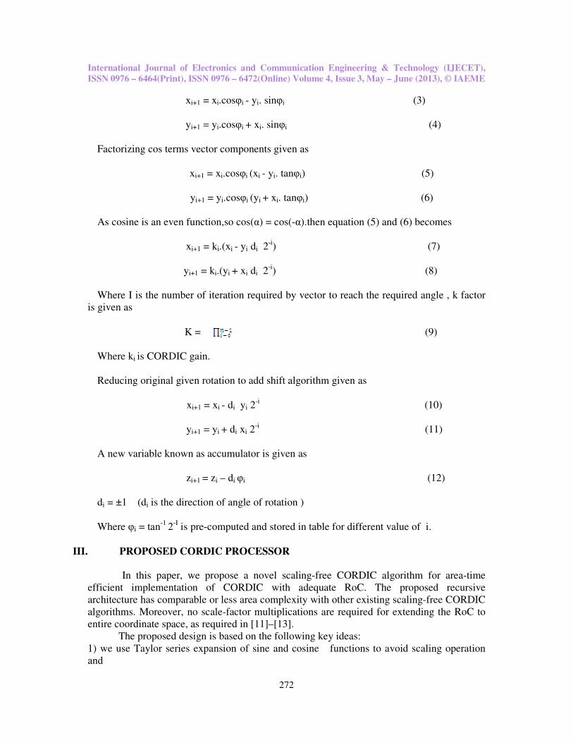
III. PROPOSED CORDIC PROCESSOR
In this paper, we propose a novel scaling-free CORDIC algorithm for area-time
efficient implementation of CORDIC with adequate RoC. The proposed recursive
architecture has comparable or less area complexity with other existing scaling-free CORDIC
algorithms. Moreover, no scale-factor multiplications are required for extending the RoC to
entire coordinate space, as required in [11]–[13].
The proposed design is based on the following key ideas:
1) we use Taylor series expansion of sine and cosine functions to avoid scaling operation
and
International Journal of Electronics and Communication Engineering & Technology (IJECET),
ISSN 0976 – 6464(Print), ISSN 0976 – 6472(Online) Volume 4, Issue 3, May – June (2013), © IAEME
273
2) Suggest a generalized sequence of micro-rotation to have adequate range of convergence
(RoC) based on the chosen order of approximation of the Taylor series.
The block diagram for the proposed CORDIC architecture is shown in Fig. below. It
makes use of the same stage for all the iterations for the coordinate calculations, as well as for
the generation of shift values.
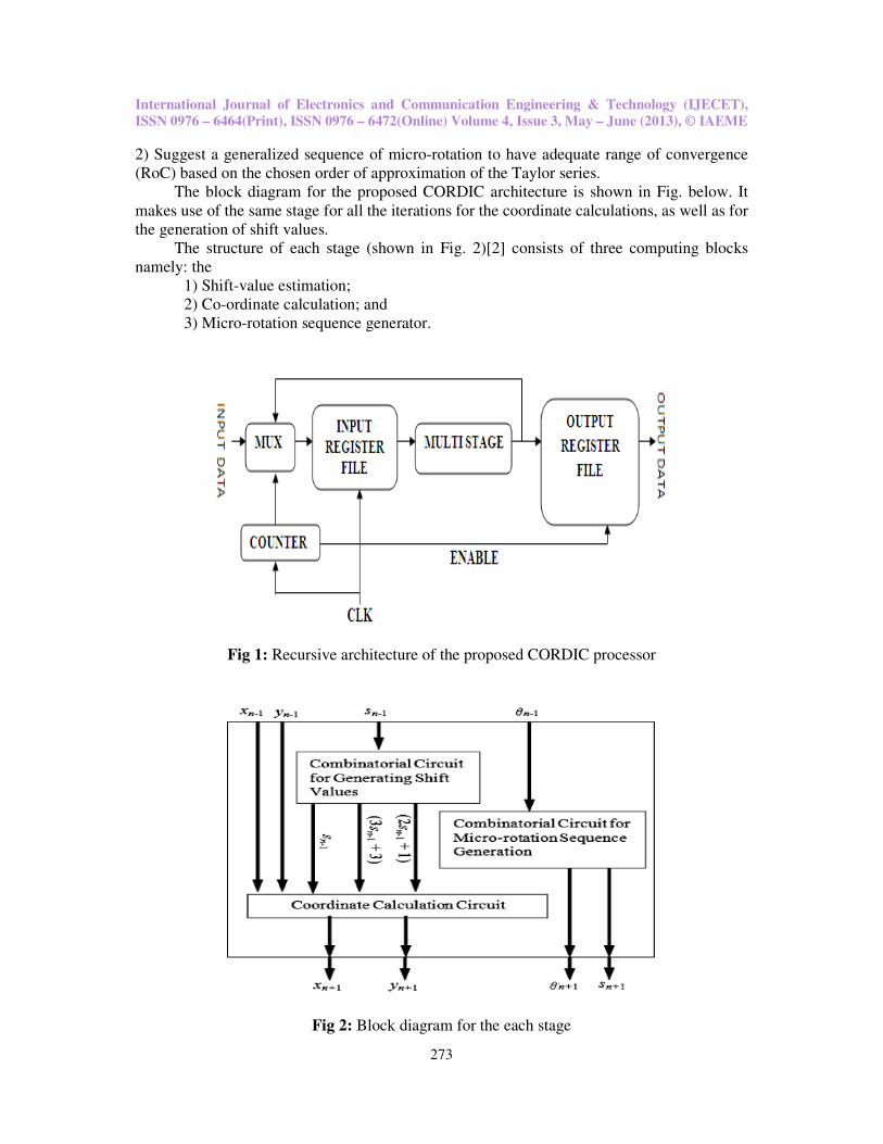
The structure of each stage (shown in Fig. 2)[2] consists of three computing blocks
namely: the
1) Shift-value estimation;
2) Co-ordinate calculation; and
3) Micro-rotation sequence generator.
Fig 1: Recursive architecture of the proposed CORDIC processor
Fig 2: Block diagram for the each stage
International Journal of Electronics and Communication Engineering & Technology (IJECET),
ISSN 0976 – 6464(Print), ISSN 0976 – 6472(Online) Volume 4, Issue 3, May – June (2013), © IAEME
274
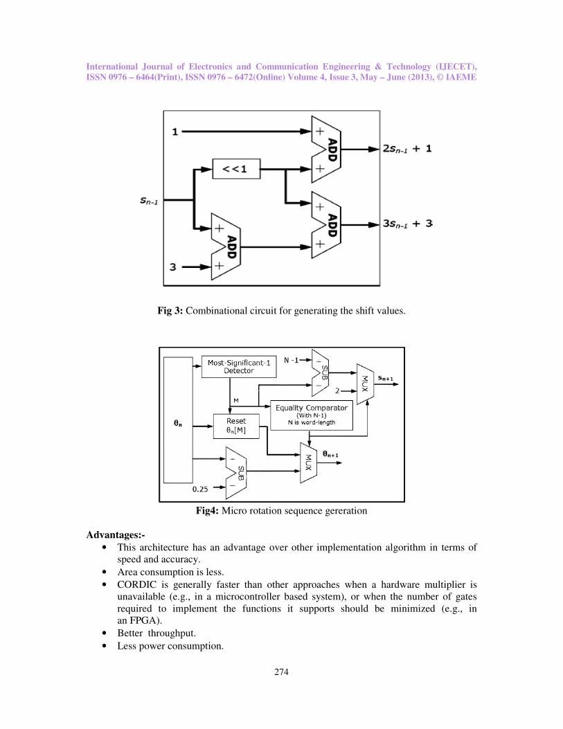
Fig 3: Combinational circuit for generating the shift values.
Fig4: Micro rotation sequence gereration
Advantages:-
• This architecture has an advantage over other implementation algorithm in terms of
speed and accuracy.
• Area consumption is less.
• CORDIC is generally faster than other approaches when a hardware multiplier is
unavailable (e.g., in a microcontroller based system), or when the number of gates
required to implement the functions it supports should be minimized (e.g., in
an FPGA).
• Better throughput.
• Less power consumption.
International Journal of Electronics and Communication Engineering & Technology (IJECET),
ISSN 0976 – 6464(Print), ISSN 0976 – 6472(Online) Volume 4, Issue 3, May – June (2013), © IAEME
275
Applications
• The algorithm was basically developed to offer digital solutions to the problems of
real-time navigation in B-58 bomber [9].
• CORDIC algorithm has also been described for the calculation of DFT,DHT [7]-[8],
Solving linear systems [11].
• Most calculators especially the ones built by Texas Instruments and Hewlett-Packard
use CORDIC algorithm for calculation of transcendental functions.
• John Walther extended the basic CORDIC theory to provide solution to and
implement a diverse range of functions [10].
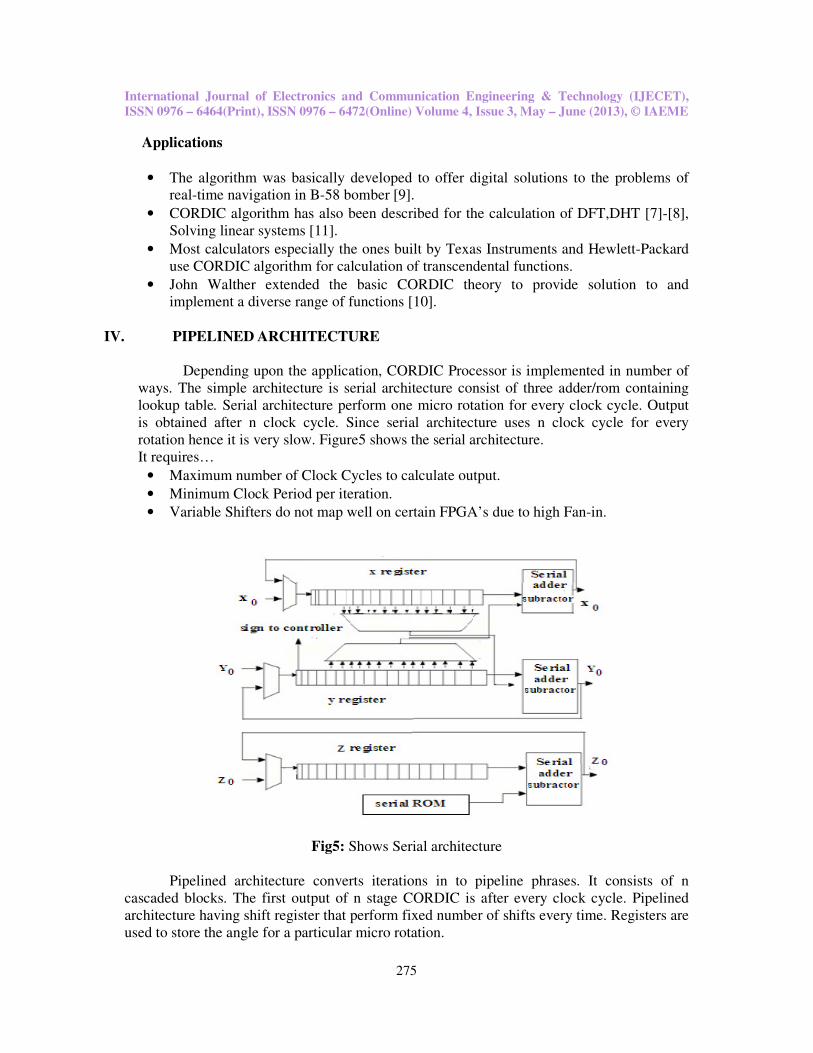
IV. PIPELINED ARCHITECTURE
Depending upon the application, CORDIC Processor is implemented in number of
ways. The simple architecture is serial architecture consist of three adder/rom containing
lookup table. Serial architecture perform one micro rotation for every clock cycle. Output
is obtained after n clock cycle. Since serial architecture uses n clock cycle for every
rotation hence it is very slow. Figure5 shows the serial architecture.
It requires…
• Maximum number of Clock Cycles to calculate output.
• Minimum Clock Period per iteration.
• Variable Shifters do not map well on certain FPGA’s due to high Fan-in.
Fig5: Shows Serial architecture
Pipelined architecture converts iterations in to pipeline phrases. It consists of n
cascaded blocks. The first output of n stage CORDIC is after every clock cycle. Pipelined
architecture having shift register that perform fixed number of shifts every time. Registers are
used to store the angle for a particular micro rotation.
International Journal of Electronics and Communication Engineering & Technology (IJECET),
ISSN 0976 – 6464(Print), ISSN 0976 – 6472(Online) Volume 4, Issue 3, May – June (2013), © IAEME
276
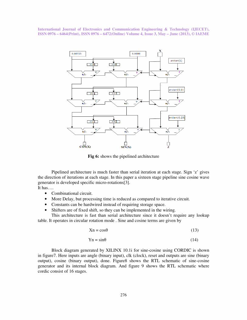
Fig 6: shows the pipelined architecture
Pipelined architecture is much faster than serial iteration at each stage. Sign ‘z’ gives
the direction of iterations at each stage. In this paper a sixteen stage pipeline sine cosine wave
generator is developed specific micro-rotations[3].
It has….
• Combinational circuit.
• More Delay, but processing time is reduced as compared to iterative circuit.
• Constants can be hardwired instead of requiring storage space.
• Shifters are of fixed shift, so they can be implemented in the wiring.
This architecture is fast than serial architecture since it doesn’t require any lookup
table. It operates in circular rotation mode . Sine and cosine terms are given by
Xn = cosθ (13)
Yn = sinθ (14)
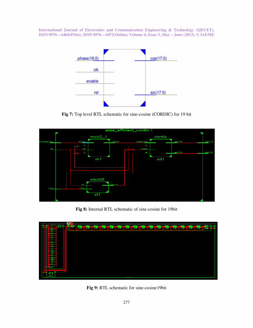
Block diagram generated by XILINX 10.1i for sine-cosine using CORDIC is shown
in figure7. Here inputs are angle (binary input), clk (clock), reset and outputs are sine (binary
output), cosine (binary output), done. Figure8 shows the RTL schematic of sine-cosine
generator and its internal block diagram. And figure 9 shows the RTL schematic where
cordic consist of 16 stages.
International Journal of Electronics and Communication Engineering & Technology (IJECET),
ISSN 0976 – 6464(Print), ISSN 0976 – 6472(Online) Volume 4, Issue 3, May – June (2013), © IAEME
277
Fig 7: Top level RTL schematic for sine-cosine (CORDIC) for 19 bit
Fig 8: Internal RTL schematic of sine-cosine for 19bit
Fig 9: RTL schematic for sine-cosine19bit
International Journal of Electronics and Communication Engineering & Technology (IJECET),
ISSN 0976 – 6464(Print), ISSN 0976 – 6472(Online) Volume 4, Issue 3, May – June (2013), © IAEME
278
V. SIMULATION AND RESULTS
The code for sine and cosine wave generator is written in Verilog and simulated using
ModelSim 10.0a The Analog wave generator to be implemented on XILINX VERTEX4
(xc4vfx12) using XILINX 14.1. Area and power reports are given for particular target device.
The power dissipation of the proposed architecture for different clock frequencies is
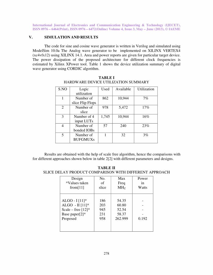
estimated by Xilinx XPower tool. Table 1 shows the device utilization summary of digital
wave generator using CORDIC algorithm.
TABLE I HARDWARE DEVICE UTILIZATION SUMMARY
Results are obtained with the help of scale free algorithm, hence the comparisons with
for different approaches shown below in table 2[2] with different parameters and designs.
TABLE II SLICE DELAY PRODUCT COMPARISON WITH DIFFERENT APPROACH
S.NO Logic
utilization
Used Available Utilization
1 Number of
slice Flip Flops
862 10,944 7%
2 Number of
slice
978 5,472 17%
3 Number of 4
input LUTs
1,745 10,944 16%
4 Number of
bonded IOBs
57 240 23%
5 Number of
BUFGMUXs
1 32 3%
Design
*Values taken
from[11]
No.
of
slice
Max
Freq
MHZ
Power
in
Watts
ALGO - I [11]*
ALGO - II [11]*
Scale – free [12]*
Base paper[2]*
Proposed
186
203
945
231
958
54.35
60.80
52.54
58.37
262.999
-
-
-
-
0.192
International Journal of Electronics and Communication Engineering & Technology (IJECET),
ISSN 0976 – 6464(Print), ISSN 0976 – 6472(Online) Volume 4, Issue 3, May – June (2013), © IAEME
279
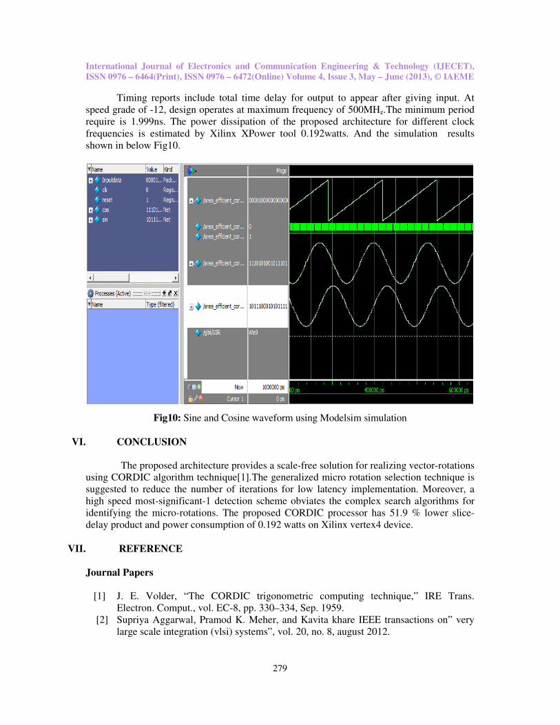
Timing reports include total time delay for output to appear after giving input. At
speed grade of -12, design operates at maximum frequency of 500MHz.The minimum period
require is 1.999ns. The power dissipation of the proposed architecture for different clock
frequencies is estimated by Xilinx XPower tool 0.192watts. And the simulation results
shown in below Fig10.
Fig10: Sine and Cosine waveform using Modelsim simulation
VI. CONCLUSION
The proposed architecture provides a scale-free solution for realizing vector-rotations
using CORDIC algorithm technique[1].The generalized micro rotation selection technique is
suggested to reduce the number of iterations for low latency implementation. Moreover, a
high speed most-significant-1 detection scheme obviates the complex search algorithms for
identifying the micro-rotations. The proposed CORDIC processor has 51.9 % lower slice-
delay product and power consumption of 0.192 watts on Xilinx vertex4 device.
VII. REFERENCE
Journal Papers
[1] J. E. Volder, “The CORDIC trigonometric computing technique,” IRE Trans.
Electron. Comput., vol. EC-8, pp. 330–334, Sep. 1959.
[2] Supriya Aggarwal, Pramod K. Meher, and Kavita khare IEEE transactions on” very
large scale integration (vlsi) systems”, vol. 20, no. 8, august 2012.
International Journal of Electronics and Communication Engineering & Technology (IJECET),
ISSN 0976 – 6464(Print), ISSN 0976 – 6472(Online) Volume 4, Issue 3, May – June (2013), © IAEME
280
[3] Rajesh Mehra, Bindiya Kamboj., ”FPGA Implementation of Pipelined CORDIC
SineCosine Digital Wave Generator” Int. J. Comp.Tech. Appl, Vol 1 (1), 54-5.
[4] K. Maharatna, A. S. Dhar, and S. Banerjee, “A VLSI array architecturefor realization
of DFT, DHT, DCT and DST,” Signal Process., vol. 81,pp. 1813–1822, 2001.
[5] P. K. Meher, J.Walls, T.-B. Juang, K. Sridharan, and K. Maharatna, “50years of
CORDIC: Algorithms, architectures and applications,” IEEETrans. Circuits Syst. I,
Reg. Papers, vol. 56, no. 9, pp. 1893–1907, Sep.2009.
[6] C. S. Wu and A. Y. Wu, “Modified vector rotational CORDIC (MVRCORDIC)
algorithm and architecture,” IEEE Trans. Circuits Syst. II,Exp. Briefs, vol. 48, no. 6,
pp. 548–561, Jun. 2001.
[7] C.-S.Wu, A.-Y.Wu, and C.-H. Lin, “A high-performance/low-latency vector
rotational CORDIC architecture based on extended elementary angle set and trellis-
based searching schemes,” IEEE Trans. Circuits Syst. II, Analog Digit. Signal
Process., vol. 50, no. 9, pp. 589–601, Sep.2003.
[8] Y. H. Hu and S. Naganathan, “An angle recoding method for CORDIC algorithm
implementation,” IEEE Trans. Comput., vol. 42, no. 1, pp.99–102, Jan. 1993.
[9] M. G. B. Sumanasena, “A scale factor correction scheme for the CORDIC algorithm,”
IEEE Trans. Comput., vol. 57, no. 8, pp.1148–1152, Aug. 2008.
[10] J. Villalba, T. Lang, and E. L. Zapata, “Parallel compensation of scale factor for the
CORDIC algorithm,” J. VLSI Signal Process. Syst., vol.19, no. 3, pp. 227–241, Aug.
1998.
[11] L. Vachhani, K. Sridharan, and P. K. Meher, “Efficient CORDIC algorithms and
architectures for low area and high throughput implementation,”IEEE Trans. Circuit
Syst. II, Exp. Briefs, vol. 56, no. 1, pp. 61–65,Jan. 2009.
[12] K. Maharatna, S. Banerjee, E. Grass, M. Krstic, and A. Troya, “Modified virtually
scaling-free adaptive CORDIC rotator algorithm and architecture,”IEEE Trans.
Circuits Syst. Video Technol., vol. 11, no. 11,pp. 1463–1474, Nov. 2005.
[13] F. J. Jaime, M. A. Sanchez, J. Hormigo, J. Villalba, and E. L. Zapata,“Enhanced
scaling-free CORDIC,” IEEE Trans. Circuits Syst. I, Reg.Papers, vol. 57, no. 7, pp.
1654–1662, Jul. .2010.
[14] Sandeep Bidwai, Saylee S. Bidwai, Prof. Dr. S.P. Patil and Sunita S. Shinde,
“Implementation & Performance Analysis of CORDIC in OFDM Based Wlan System
using VHDL”, International Journal of Electronics and Communication Engineering
& Technology (IJECET), Volume 3, Issue 3, 2012, pp. 103 - 111, ISSN Print:
0976- 6464, ISSN Online: 0976 –6472.
[15] K.Muralibabu, Dr.K.Ramanaidu, Dr.S.Padmanabhan and Dr.T.K.Shanthi, “A
Novel Papr Reduction Scheme using Discrete COSINE Transform Based on
Subcarrier Grouping in OFDM System”, International Journal of Electronics and
Communication Engineering & Technology (IJECET), Volume 3, Issue 3, 2012,
pp. 251 - 257, ISSN Print: 0976- 6464, ISSN Online: 0976 –6472.
[16] Saurabh Khandelwal, Narendra Singh, Hemdutt Joshi and Sandeep Kumar Arya,
“COSINE Modulated Filter-Bank Transmultiplexer using Kaiser Window”,
International Journal of Electronics and Communication Engineering & Technology
(IJECET), Volume 4, Issue 2, 2013, pp. 225 - 228, ISSN Print: 0976- 6464,
ISSN Online: 0976 –6472.
International Journal of Electronics and Communication Engineering & Technology (IJECET),
ISSN 0976 – 6464(Print), ISSN 0976 – 6472(Online) Volume 4, Issue 3, May – June (2013), © IAEME
281
AUTHOR INFORMATION
Mahendra kumar M.D is a student in the Department of
Electronics and Communication Engineering, School of Engineering,
Jain University, Bangalore. He obtained his Bachelor degree in
Telecommunication Engineering from AMC Engineering college,
Bangalore in 2011, Visvesvaraya Technological University, Belgaum
and He is pursuing M.tech(SP and VLSI) in Electronics and
Communication Engineering, Jain University, Bangalore. My research
interest includes VLSI, DSP, Micro-Controller.
Mr. Sunil MP, currently working as an Assistant Professor in the
department of Electronics & Communication Engineering, School of
Engineering and Technology, Jain University, Karnataka, India. He has
received B.E degree in Electronics and Communication from VTU in
2009. He has received M.Tech degree in Electronics Design and
Technology from National Institute of Technology, Calicut, Kerala in
2011. His research interests include Embedded Systems Design, Analog
and Mixed signal VLSI Design, Ultra-Thin Gate insulators for VLSI
Technologies, RF VLSI Design, Microelectronics System Packaging, Microelectronics,
Micro/Nano Sensor Technology, High-speed CMOS analog/RF-wave integrated circuits and
systems.
Vinay Kumar S.B. is an Assistant Professor in the Department of
Electronics and Communication Engineering, School of Engineering,
Jain University, Bangalore. He obtained his Bachelor degree in
Electronics and Communication Engineering from Coorg Institute of
Technology, ponnampet in 2009, Visvesvaraya Technological
University, Belgaum and Master degree (M.tech) in Signal processing
and VLSI, Jain University, Bangalore. He is pursuing Ph.D. in
Electronics and Communication Engineering, Jain University,
Bangalore. My research interest includes VLSI, Reverse logic, DSP and Embedded Systems.
He has altogether 3 international journals to his credit and also he presented 8 technical
papers in national conference.
Related Documents