Company Profile Usman Butt Electro Mechanical Service Company

Welcome message from author
This document is posted to help you gain knowledge. Please leave a comment to let me know what you think about it! Share it to your friends and learn new things together.
Transcript

Company Profile
Usman Butt Electro Mechanical Service Company

Date of Establishment: 2006
Legal Status : Sole Establishment
License No : 596991
Head Office : Al Serkal Properties, WarehouseNo.12 Dubai Investment Park (DIP-I),Dubai. P.O. Box No.22084, Dubai, U.A.E.
Branch Office : Al-Harmain Electro Mechanical Services (Prince Mutabe Street, Jeddah, Saudi Arabia)
Banks : 1. Union National Bank, Dubai2. Emirates Islamic Bank, Dubai
Experience : 7 Years (Dubai): 18 Years (Saudi Arabia)
Company Establishment
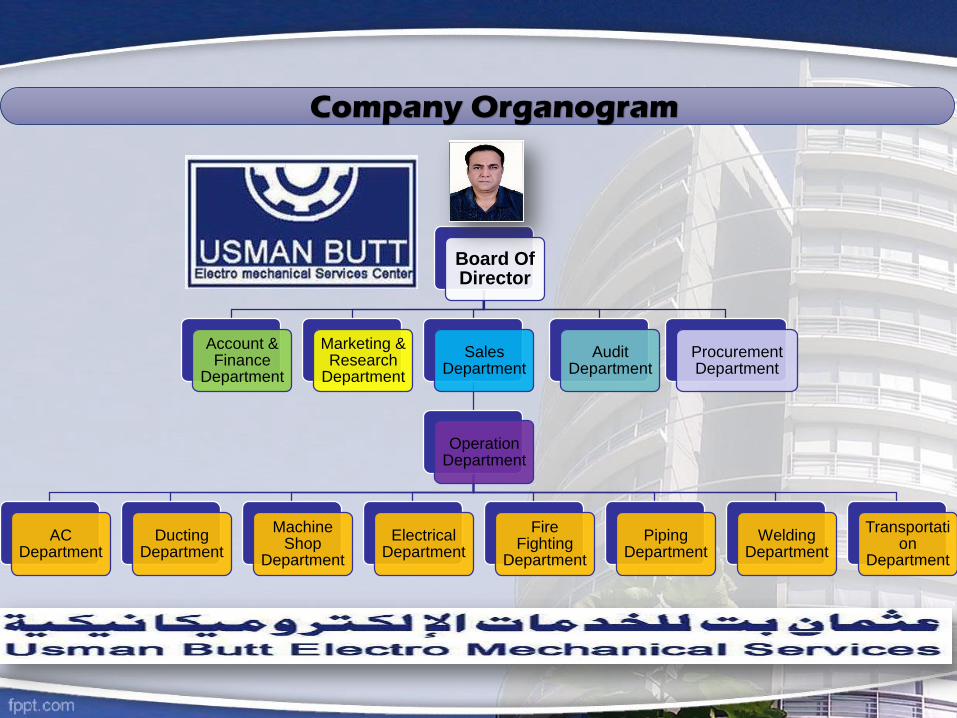
Board Of Director
Account & Finance
Department
Marketing & Research
Department
Sales Department
Operation Department
AC Department
Ducting Department
Machine Shop
Department
Electrical Department
Fire Fighting
Department
Piping Department
Welding Department
Transportation
Department
Audit Department
Procurement Department
Company Organogram
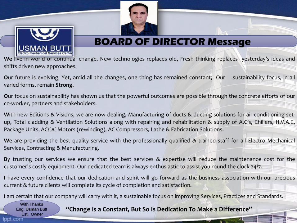
We live in world of continual change. New technologies replaces old, Fresh thinking replaces yesterday’s ideas and
shifts driven new approaches.
Our future is evolving, Yet, amid all the changes, one thing has remained constant; Our sustainability focus, in all
varied forms, remain Strong.
Our focus on sustainability has shown us that the powerful outcomes are possible through the concrete efforts of our
co-worker, partners and stakeholders.
With new Editions & Visions, we are now dealing, Manufacturing of ducts & ducting solutions for air-conditioning set-
up, Total cladding & Ventilation Solutions along with repairing and rehabilitation & supply of A.C’s, Chillers, H.V.A.C,
Package Units, AC/DC Motors (rewinding), AC Compressors, Lathe & Fabrication Solutions.
We are providing the best quality service with the professionally qualified & trained staff for all Electro Mechanical
Services, Contracting & Manufacturing.
By trusting our services we ensure that the best services & expertise will reduce the maintenance cost for the
customer’s costly equipment. Our dedicated team is always enthusiastic to assist you round the clock 24/7.
I have every confidence that our dedication and spirit will go forward as the business association with our precious
current & future clients will complete its cycle of completion and satisfaction.
I am certain that our company will carry with it, a sustainable focus on improving Services, Practices and Standards.
“Change is a Constant, But So Is Dedication To Make a Difference”
BOARD OF DIRECTOR Message
With Thanks
Eng. Usman Butt
Est. Owner

“We are committed for integrity , professional and transparency, to ensure
timely delivery of quality services”.
Company Promise

Our Vision:
To provide agile reliable technical services, support and maintenance services with quality in line with industrial demand and requirement.
Our Mission: To be focused on customer satisfaction.
Our Vision & Mission

We have a team of highly specialized professionals and experts.
Through consistent research and analysis, our team keeps itself abreast of the latest market trends and customer requirements.
Our personnel works in close coordination with our clients in order to deliver services exactly as per the client’s specifications.
Ou
r Te
am
Our Team

I. Pre-Insulated Duct Systems.II. G.I. Sheet Ducting Systems.III. Aluminum Cladding of Ducts and Pipes for HVAC Systems.1- Complete Design (Calculation of Capacities) and Installation of HVAC Systems.2- Commissioning and Rehabilitation of Chillers & Package Units.3- Fabrication of Steel Structures / All types of Fabrication related works.4- Fabrication, Insulation and Installation of Chilled Water Piping.5- Annual Maintenance Contracts of HVAC Works.6- Rewinding of all types A/C Motors, Generators & Transformers.
Manufacturing - Installations & Maintenance

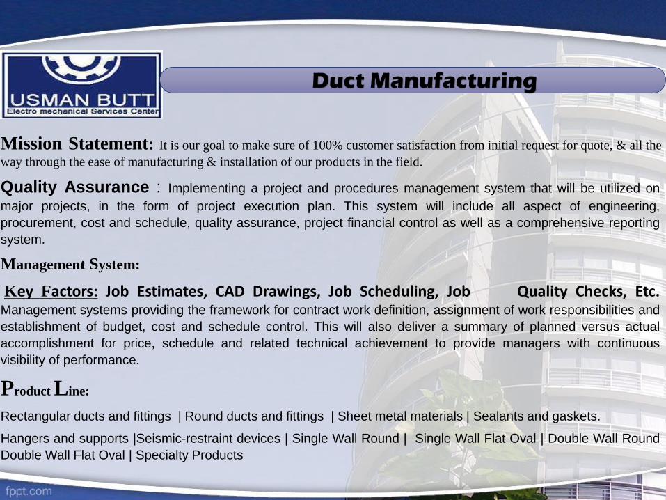
Mission Statement: It is our goal to make sure of 100% customer satisfaction from initial request for quote, & all the
way through the ease of manufacturing & installation of our products in the field.
Quality Assurance : Implementing a project and procedures management system that will be utilized on
major projects, in the form of project execution plan. This system will include all aspect of engineering,
procurement, cost and schedule, quality assurance, project financial control as well as a comprehensive reporting
system.
Management System:
Key Factors: Job Estimates, CAD Drawings, Job Scheduling, Job Quality Checks, Etc.Management systems providing the framework for contract work definition, assignment of work responsibilities and
establishment of budget, cost and schedule control. This will also deliver a summary of planned versus actual
accomplishment for price, schedule and related technical achievement to provide managers with continuous
visibility of performance.
Product Line:
Rectangular ducts and fittings | Round ducts and fittings | Sheet metal materials | Sealants and gaskets.
Hangers and supports |Seismic-restraint devices | Single Wall Round | Single Wall Flat Oval | Double Wall Round
Double Wall Flat Oval | Specialty Products
Duct Manufacturing

Rectangular
Duct & Fittings
Rectangular
FittingsRectangular
Fittings
Branch
Connection
Rectangular
StraightRectangular
Fitting
Rectangular
Fitting
Longitudinal
Seams
Rectangular
Elbows
Rectangular
Elbows
Duct Fitting - submittal

Duct Work Shop Procedure

MANUFACTURING UNITS
Pre Insulated Ducts
Pre-insulated aluminum duct is specialized in the air distribution fields and the answer to economical, technical, andconstructive question.
Many different material and system such as composite, PVC etc. had been developed as an alternative to thegalvanized sheet metal used traditionally.
Pre-insulated aluminum duct is the solution. it is a sandwich panel composed of a layer base from good fire retardantrigid polisocyanurate foam covering both sides with aluminum foil.
The aluminum guarantees sturdiness and with sand corrosion in long term use.
polyisocyanurate pre-insulated duct has been developed and spread around the world. its application has beengradually extended to all type of air distribution system such as industrial , commercial and civil.
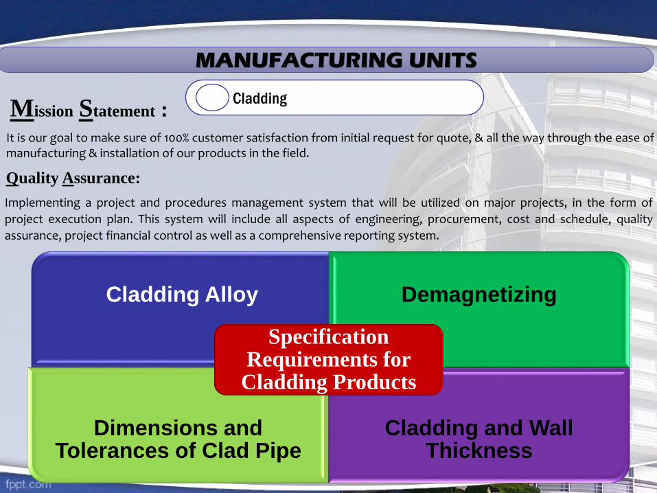
MANUFACTURING UNITS
Cladding
It is our goal to make sure of 100% customer satisfaction from initial request for quote, & all the way through the ease ofmanufacturing & installation of our products in the field.
Mission Statement :
Quality Assurance:
Implementing a project and procedures management system that will be utilized on major projects, in the form of
project execution plan. This system will include all aspects of engineering, procurement, cost and schedule, quality
assurance, project financial control as well as a comprehensive reporting system.
Cladding Alloy Demagnetizing
Dimensions and Tolerances of Clad Pipe
Cladding and Wall Thickness
Specification Requirements for
Cladding Products

Clad Pipes
Clad Plates
Clad Bends
Clad Fitting
Fabricating Clad Vessels
Longitudinally Welding of Clad Plate
Centrifugal casting
Seamless Pipe Mill Production Methods
Explosive Bonding
Product Methods
Hot Roll Bonding
Explosive Bonding
Weld overlaying
Manufacturing Of Bends From Clad Pipe
Manufacturing Of Bends From Lined Pipe
Weld Overlaying
Hot Isotactic Pressing (HIP)
Manufacturing From Clad Plate Or Pipe
Welding Clad Products

Cladding

We follow the standards of air tightness required by DW.144
We use suitable materials for the working temperature & pressure of systems within which it is installed and
shall be tear resistant.
The materials we use are always in accordance with the manufacturers technical data sheet, material safety
data sheet and application method statement.
We always take measures and proofed against Rotting, mould, fungus growth and attack by vermin.
Always consider and take adequate precautions against any hazard to health involved in the use of any
cleaner, adhesive or material in connection with the application and handling of insulation material.
Adequate consideration take in using the insulation materials and finishes that shall not produce smoke or
toxic fumes when subject to fire (as British Standards). The smoke obscuration rating of insulating materials
not greater than 5% in accordance with BS EN ISO 5659-2.
We always follow the strict execution accordance with manufacturer’s recommendations including all seals
and adhesive, take care of compatibility of such adhesives with the insulation.
Always take measures (as our quality standards & policy) to clean, dry and free from rust and other foreign
matters from all surfaces to be insulated.
Copper pipe work always thoroughly cleaned to remove all traces of surplus flux dust and debris.
Special attention given to finished appearance of all insulated areas, and remove any rough, irregular and
badly finished surfaces which shall present a neat and symmetrical appearance with all pipe lay outs.
Particular attention given to maintain the reliability and continuity of vapour barriers.
Measures always taken to ensure the close fitting to all pipe work, and the insulation shall match the outside
diameter of pipe work concerned and all joints shall be properly sealed.
Before starting insulation process we always make sure that the electrical trace heating is totally completed
and tested and surface to be insulated have been thoroughly cleaned and painted as specified or required.
Duct
Works InsulationAir-
conditionVentilation
Our Quality Standards & Scope of works

Duct
Works InsulationAir-
conditionVentilation
Our Quality Standards & Scope of works
GRILLS & DIFFUSERS
We always take care the calculation, design and manufacture the true size for reasonable throw and velocity at maximum flowconditions, but with consideration to avoid ”Dumping” at minimum flow conditions.
All Grills & diffusers are always adjusted to the face of register or grill Take care for detailing air flow registered noise level of air supplies and extract grills and plenum boxes under spigot setup and
conditions and at the operational air velocities.
As our quality policy, we always take care the insulation specification provided by the client under “Air Conditioning & Ventilation
Specifications”.
We always use insulation materials that shall not omit smoke or toxic fumes in the event of fire.
PIPE INSULATION
In our QUALITY Services we Design, Supply, Install, Test, Commission, Adjust, Balance the Chillers, Central Air Conditioning, Ventilation
systems etc. for satisfactory performance.
The purpose of the design check is to ensure the material used and the installation is in line with the design & standards intent, for the
correct functioning of the installed system(s).
All the materials which we use to install in the project, are always fully in compliance with local authority’s rules & regulations.
Full safety precautions taken during welding & cutting operations, full precautions taken to prevent fire i.e. fully charged 5kg carbon
dioxide extinguisher, protect wooden structure with fire proof blanket etc.
AIR CONDITIONING & VENTILATION

Services
HVAC
Chillers, Package
Units, Coiling Towers
Chilled Water Piping
Motor Rewinding
Fire Fighting
Welding Services
Hi Bar Motor Pumps
Fabrication & Installation
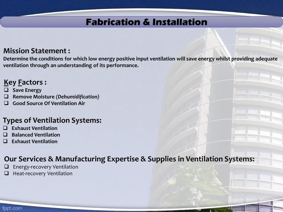
Mission Statement : Determine the conditions for which low energy positive input ventilation will save energy whilst providing adequate ventilation through an understanding of its performance.
Key Factors : Save Energy Remove Moisture (Dehumidification) Good Source Of Ventilation Air
Types of Ventilation Systems: Exhaust Ventilation Balanced Ventilation Exhaust Ventilation
Our Services & Manufacturing Expertise & Supplies in Ventilation Systems: Energy-recovery Ventilation Heat-recovery Ventilation

Our Services & Manufacturing
Expertise & Supplies in Ventilation Systems
Ducts
Ventilation
EXHAUST
VENTILATION
PORT
(Exhaust or
Supply)
Fans
Duct Work -Supply Ducts -Outside Air Ducts -Exhaust Ducts -Ventilation Ducts
Continual Ventilation -Intermittent Ventilation -Mechanical Ventilation -Continuous
Ventilation -Natural Ventilation
Multi- port Exhaust-Single Port Exhaust-Bath Exhaust - Passive Vent -Central Exhaust
Natural Ventilation - Multi-port Supply - Forced-air Supply
Local Exhaust Fan - Forced-air Fan - Ventilation Fan (Exhaust Or Supply)
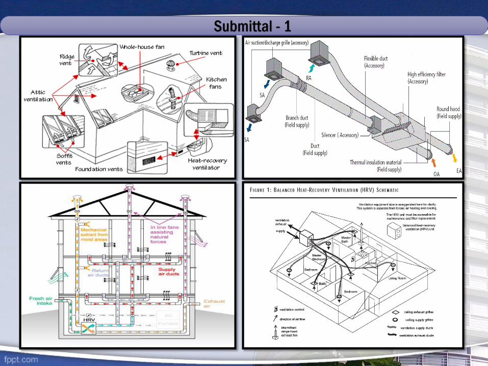
Submittal - 1
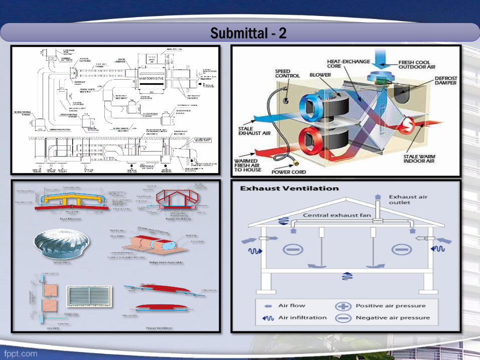
Submittal - 2

Equipment Commissioning Expertise
A.C PIPING SYSTEMS
I. A . C Copper Piping
II. M.S Chilled Water Piping Systems
Ductwork.
Variable Frequency Drives.
Packaged Roof Top Air Conditioning Units.
Split System Air Conditioning Units.
Air Handling Units.
Fan Coil Units.
Computer Room Units.
Fans.
Fire Dampers.
Indoor Air Quality.
Automatic Temperature Control System / Thermostats.
Testing, Adjusting & Balancing Work.
PLC Card Control Systems
Chiller Commissioning
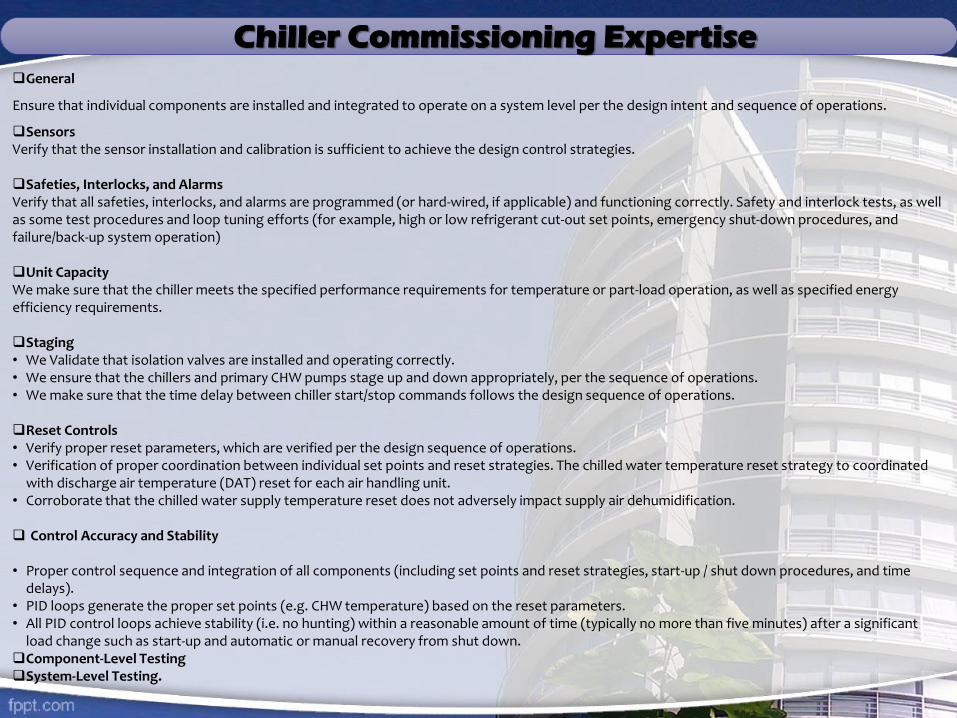
Chiller Commissioning ExpertiseGeneral
Ensure that individual components are installed and integrated to operate on a system level per the design intent and sequence of operations.
SensorsVerify that the sensor installation and calibration is sufficient to achieve the design control strategies.
Safeties, Interlocks, and AlarmsVerify that all safeties, interlocks, and alarms are programmed (or hard-wired, if applicable) and functioning correctly. Safety and interlock tests, as well as some test procedures and loop tuning efforts (for example, high or low refrigerant cut-out set points, emergency shut-down procedures, and failure/back-up system operation)
Unit CapacityWe make sure that the chiller meets the specified performance requirements for temperature or part-load operation, as well as specified energy efficiency requirements.
Staging• We Validate that isolation valves are installed and operating correctly.• We ensure that the chillers and primary CHW pumps stage up and down appropriately, per the sequence of operations. • We make sure that the time delay between chiller start/stop commands follows the design sequence of operations.
Reset Controls• Verify proper reset parameters, which are verified per the design sequence of operations.• Verification of proper coordination between individual set points and reset strategies. The chilled water temperature reset strategy to coordinated
with discharge air temperature (DAT) reset for each air handling unit. • Corroborate that the chilled water supply temperature reset does not adversely impact supply air dehumidification.
Control Accuracy and Stability
• Proper control sequence and integration of all components (including set points and reset strategies, start-up / shut down procedures, and time delays).
• PID loops generate the proper set points (e.g. CHW temperature) based on the reset parameters.• All PID control loops achieve stability (i.e. no hunting) within a reasonable amount of time (typically no more than five minutes) after a significant
load change such as start-up and automatic or manual recovery from shut down.Component-Level Testing System-Level Testing.
Key Preparations and CautionsKey Preparations and Cautions1. Successful execution of the chiller functional performance tests .2. Testing chilled water temperature reset strategy when there is minimal to no cooling load.3. Resetting the chilled water temperature to save chiller energy can result in a loss of humidity control within the building.
Necessary Instrumentation• Temperature measurement devices (hand-held devices to calibrate existing sensors)• Differential pressure measurement devices (to test installed flow meters)• Amperage and voltage measurement devices (for calculating chiller input power)• Flow measurement devices (installed or hand-held devices to measure water flows)• Data loggers (to supplement existing sensors to verify system operation)
Chiller System Pre-functional and Functional Test Procedures
• Calibration and Leak-By Test Procedures.• Chilled Water System Verification Test Procedure.• Standard Functional Tests for Chilled Water Systems.• Verification and Functional Performance Test Plan for EMS.• Chiller Pre-functional Checklist and Functional Performance Verification.• Chiller Procedures.• Packaged Air-Cooled Chiller.• Chiller System Functional Test.• Chilled Water System Sequence of Operations.• Air-Cooled Chiller Functional Tes.t• DDC Commissioning Acceptance Procedures: Standard Chilled Water System Start/Stop Control.• Component-Level Functional Test Procedures.• Chilled Water Piping Pre-functional Checklist.• Hot Water System Pump Test.• Chilled Water System Pump Test.• Condenser Water System Pump Test.
HVAC INSTALLATION PROCEDURE & STANDARDS
HVAC Systems & Components
Heat Recovery & Cooling Systems
Humidification
Air Distribution
Piping
Insulation
Meters & Gauges
BAS (Building Automation System)
Start-up, Testing & Balancing

Perimeter Outside Air Ventilation Systems.Perimeter ventilation units have self-contained DX package units or air-handling units with fan section having variable speed drive, chilledwater cooling coil, hot water heating coil, enthalpy heat recovery wheel, or desiccant wheel and supply air filtration. The perimeterventilation units provides 100-percent outside air. Reheat is hot gas bypass, a heat pipe or a run around coil. Chilled water got to begenerated by an air-cooled chiller or a 24-hour chiller. If a desiccant wheel is used for controlling the specific humidity discharge at thewheel, condenser reheat shall be used for regeneration of the desiccant, along with minimum electric backup. Supply air dew point leavingthe unit shall be maintained at 10°C (50°F) and the supply air dry bulb temperature leaving the air-handling unit shall be a minimum of 21.1°C(70° F) and not greater than 25.6°C (78° F) during occupied hours. During occupied hours, this unit shall operate to deliver conditionedventilation air and maintain positive pressure in the perimeter zone with respect to outside air pressure.
During unoccupied hours, the unit shall run at 40 percent of its capacity to provide conditioned air at 10°C (50° F) dew point and at least21.1°C (70°F) to help maintain positive pressure in the perimeter zone with respect to outside air. In both the occupied and unoccupiedmodes the system shall operate to adjust the airflow as required to maintain a differential positive pressure in the perimeter zone relative tothe prevailing pressure outside the building. When the outside air dew point drops below 2.8°C (37°F), the unit shall have the capacity tomaintain neutral pressure with respect to the outside by exhausting relief air from the return duct system. The ventilation unit shall haveself-contained microprocessor controls capable of connecting to and interoperating with a BACnet or LONWORKS direct digital control(DDC) Building Automation System. It shall also be equipped with dampers to set the design airflow through the unit, and also an analogueor digital display which measures and displays the amount of air flowing through the unit continuously.
Interior Outside Air Ventilation Systems.Interior ventilation units contained DX packaged units or air-handling units with chilled water-cooling coil, hot water heating coil, and supplyair filtration. Interior ventilation units shall incorporate enthalpy heat recovery wheel or desiccant wheel, heating coil, and a cooling coil.Heat recovery shall include use of building relief and exhaust air. Utilize condenser waste heat for desiccant regeneration. The supply airfrom the ventilation units shall be ducted to the return plenum section of the air handling unit(s) serving the interior zones. Supply air dewpoint leaving the unit shall be maintained at 10°C (50°F) and the supply air dry bulb temperature shall be a minimum of 21.1°C (70° F) and notgreater than 25.6°C (78° F). During occupied hours, this unit shall operate to provide conditioned ventilation air. The unit shall be inoperativeduring unoccupied hours. The unit shall have air-monitoring devices to indicate that the supply air is always 10 percent greater than theexhaust/relief air. The dedicated ventilation unit shall have self-contained microprocessor controls capable of connecting to andinteroperating with a BACnet or LONWORKS Direct Digital Control (DDC) Building Automation System. It shall also be equipped withdampers to set the design airflow through the unit, and also an analog or digital display which measures and displays the amount of airflowing through the unit continuously.
HVAC SYSTEM & COMPONENT
Fan Coil System:For perimeter spaces, provide four-pipe fan coil units with cooling coil, heating coil, 35 percent efficiency filters, internalcondensate drain, and overflow drain. Unit shall have self-contained microprocessor controls and shall be capable ofconnecting to and interoperating with a BACnet or LONWORKS Direct Digital Control (DDC) Building AutomationSystem. Fan coil units shall be capable of operating with unit mounted or remote mounted temperature sensor.Fin Tube Heating Systems. When fin-tube radiation is used, reheat should not be featured with perimeter airdistribution systems. Fin-tube radiation shall have individual zone thermostatic control capable of connecting to a self-contained microprocessor that can interface with a BACnet or LONWORKS Direct Digital Control (DCC) BuildingAutomation System.
Variable Volume System with Shutoff Boxes:
Variable Air Volume (VAV) systems with full shutoff VAV boxes shall be used for perimeter zone applications only. VAVshutoff boxes shall be used only with the perimeter air distribution systems in order to eliminate the need for reheat.The air-handling unit and associated VAV boxes shall have self-contained microprocessor controls capable ofconnecting to and interoperating with a Direct Digital Control (DDC) Building Automation System.
Variable Volume System with Fan-Powered Boxes:Variable air volume (VAV) systems with fan-powered VAV boxes may be used for both perimeter and interior zoneapplications. The air-handling unit and associated VAV boxes shall have self-contained microprocessor controls capableof connecting to and interoperating with a BACnet or LONWORKS Direct Digital Control (DDC) Building AutomatedSystem. Fan powered boxes shall be equipped with a ducted return, featuring a filter/filter rack assembly and coveredon all external exposed sides with two-inches of insulation. The return plenum box shall be a minimum of 61 mm (24inches) in length and shall be double wall with insulation in-between or contain at least one elbow where space allows.Fan-powered boxes may have hot water heating coils used for maintaining temperature conditions in the space underpartial load conditions. Fan powered boxes located on the perimeter zones and on the top floor of the building shallcontain hot water coils for heating.
HVAC SYSTEM & COMPONENT
HVAC SYSTEM & COMPONENT
Variable Volume System with Fan-Powered Boxes.Variable air volume (VAV) systems with fan-powered VAV boxes may be used for both perimeter and interior zone applications. The air-
handling unit and associated VAV boxes shall have self-contained microprocessor controls capable of connecting to and interoperating with aBACnet or LONWORKS Direct Digital Control (DDC) Building Automated System. Fan powered boxes shall be equipped with a ducted return,featuring a filter/filter rack assembly and covered on all external exposed sides with two-inches of insulation. The return plenum box shall be aminimum of 61 mm (24 inches) in length and shall be double wall with insulation in-between or contain at least one elbow where space allows.Fan-powered boxes may have hot water heating coils used for maintaining temperature conditions in the space under partial load conditions.Fan powered boxes located on the perimeter zones and on the top floor of the building shall contain hot water coils for heating.
Underfloor Air Distribution System. Underfloor air distribution systems incorporate variable air volume (VAV) units
designed to distribute the supply air from under the floor using variable volume boxes or variable volume dampers running out fromunderfloor, ducted, main trunk lines. Air shall be distributed into the space through floor-mounted supply registers that shall be factoryfabricated with manual volume control dampers. Supply air temperature for underfloor systems shall be between 10°C (50°F) dew point and18°C (64°F) dry bulb. For perimeter underfloor systems, provide fan coil units or fin tube radiators located beneath the floor with supply airgrilles or registers mounted in the floor. The air-handling unit, VAV boxes, and variable volume dampers shall have self-containedmicroprocessor controls capable of connecting to and interoperating with a BACnet or LONWORKS direct digital control (DDC) BuildingAutomation System. The maximum zone size of an underfloor air distribution system shall not exceed 2,360 l/s (5,000 CFM).
Underfloor Air Displacement System. Underfloor air displacement systems shall incorporate variable air volume
(VAV) units designed to distribute the supply air from under the floor using variable volume boxes or variable volume dampers running outfrom underfloor, ducted, main trunk lines. The VAV boxes or control dampers shall be hard ducted or connected directly to the main trunklines. Air shall be distributed into the occupied space through floor-mounted, low-turbulence, displacement flow, swirl diffusers and shallcontain a dust collection basket situated below the floor. Supply air temperature for underfloor systems shall be 10°C (50°F) dew point and18°C (64°F) Dry Bulb. For perimeter underfloor systems, provide fan coil units or fin tube radiators located beneath the floor with supply airgrilles or registers mounted in the floor. The air-handling unit, VAV boxes, and variable volume dampers shall have self-containedmicroprocessor controls capable of connecting to and interoperating with a BACnet or LONWORKS Direct Digital Control (DDC) BuildingAutomation System. The maximum capacity of an underfloor air distribution system shall not exceed 2,360 l/s (5,000 cfm).

HVAC SYSTEM & COMPONENTHeat Pump Systems:Console perimeter heat pump system(s) may be considered for the perimeter zone. For the interior zone either a packaged heat pumpvariable volume system or a central station air handling unit with cooling-heating coil with VAV boxes will be considered. Condenserwater loop temperatures should be maintained between 15°C (60°F) and 27°C (80°F) year round, either by injecting heat from a gasfired, modular boiler if the temperature drops below 15°C (60°F) or by rejecting the heat through a cooling tower if the temperature ofthe loop rises above 35°C (95°F) dry bulb. Outside air shall be ducted to the return plenum section of the heat pump unit. Heat pumpsshall be provided with filter/filter rack assemblies upstream of the return plenum section of the air-handling unit.
Air-handling units shall be sized to not exceed 11,800 l/s (25,000 cfm). Smaller units are encouraged to facilitate flexible zone control,particularly for spaces that involve off-hour or high-load operating conditions. To the extent possible, “plug-n-play” AHU configurationsshould be considered, facilitating easy future adaptations to space-load changes. Psychrometric analyses (complete with chart diagrams)shall be prepared for each air-handling unit application, characterizing full and part load operating conditions. Air-handling unit/coildesigns shall assure that conditioned space temperatures and humidity levels are within an acceptable range, per programmedrequirements, and ASHRAE Standards 55 and 62.Depending on sensible heat ratio characteristics, effective moisture control may require cooling coil air discharge dew pointtemperatures as low as 10°C (50°F). As required, provide face-by-pass or heat recovery features to re-heat cooling coil dischargetemperatures for acceptable space entry. Provide a direct form of re-heat and/or humidification only if space conditions require tightenvironmental control, or if recurring day-long periods of unacceptable humidity levels would otherwise result.
Supply, Return and Relief Air Fans:Centrifugal double width double-inlet forward curved and airfoil fans are preferable for VAV systems. All fans shall bear the AMCA sealand performance shall be based on tests made in accordance with AMCA Standard 210. Fans should be selected on the basis of requiredhorsepower as well as sound power level ratings at full load and at part load conditions. Fan motors shall be sized so they do not run atoverload anywhere on their operating curve. Fan operating characteristics must be checked for the entire range of flow conditions,particularly for forward curved fans. Fan drives shall be selected for a 1.5 service factor and fan shafts should be selected to operatebelow the first critical speed. Thrust arresters should be designed for horizontal discharge fans operating at high static pressure.
HVAC SYSTEM & COMPONENT
Coils:Individual finned tube coils should generally be between six and eight rows with at least 2.1 mm between fins (12 finsper inch) to ensure that the coils can be effectively and efficiently cleaned. Dehumidifying coils shall be selected for nomore than negligible water droplet carryover beyond the drain pan at design conditions. All hot water heating andchilled water cooling coils shall be copper tube and copper finned materials. Equipment and other obstructions in theair stream shall be located sufficiently downstream of the coil so that it will not come in contact with the water dropletcarryover. Cooling coils shall be selected at or below 2.5 m/s face velocity (500 fpm) to minimize moisture carryover.Heating coils shall be selected at or below 3.8 m/s face velocity (750 fpm).
Drains and Drain Pans:Drain pans shall be made of stainless steel, insulated and adequately sloped and trapped to assure drainage. Drains indraw-through configurations shall have traps with a depth and height differential between inlet and outlet equal to thedesign static pressure plus 2.54 mm (1 inch) minimum.Filter Sections: Air filtration shall be provided in every air handling system. Air-handling units shall have a disposable pre-filter and a final filter. The filter media shall be rated in accordance with ASHRAE Standard 52. Pre-filters shall be 30percent to 35 percent efficient. Final filters shall be filters with 85 percent efficiency capable of filtering down to 3.0microns per ASHRAE 52. Filter racks shall be designed to minimize the bypass of air around the filter media with amaximum bypass leakage of 0.5 percent.Filters shall be sized at 2.5 m/s (500 FPM) maximum face velocity. Filter media shall be fabricated so that fibrousshedding does not exceed levels prescribed by ASHRAE 52. The filter housing and all air-handling componentsdownstream shall not be internally lined with fibrous insulation. Double-wall construction or an externally insulatedsheet metal housing is acceptable. The filter change-out pressure drop, not the initial clean filter rating, must be used indetermining fan pressure requirements. Differential pressure gauges and sensors shall be placed across each filter bankto allow quick and accurate assessment of filter dust loading as reflected by air-pressure loss through the filter andsensors shall be connected to building automation system.

HVAC SYSTEM & COMPONENT
UVC Emitters/Lamps:
Ultraviolet light (C band) emitters/lamps shall be incorporated downstream of all cooling coils and above all drain pans to control airborneand surface microbial growth and transfer. Applied fixtures/ lamps must be specifically manufactured for this purpose. Safetyinterlocks/features shall be provided to limit hazard to operating staff.Access Doors: Access Doors shall be provided at air handling units downstream of each coil, upstream of each filter section and adjacent toeach drain pan and fan section. Access doors shall be of sufficient size to allow personnel to enter the unit to inspect and service allportions of the equipment components.Plenum Boxes: Air-handling units shall be provided with plenum boxes where relief air is discharged from the air handling unit. Plenumboxes may also be used on the return side of the unit in lieu of a mixing box. Air-flow control dampers shall be mounted on the ductworkconnecting to the plenum box.
Mixing Boxes:
Air-handling units shall be provided with mixing boxes where relief air is discharged from the air handling unit. Mixing boxes may also beused on the return side of the unit in lieu of a plenum box. Air flow control dampers shall be mounted within the mixing box or on theductwork connecting to Terminals.the mixing box.VAV terminals shall be certified under the ARI Standard 880 Certification Program and shall carry the ARI Seal. If fan-powered, the terminalsshall be designed, built, and tested as a single unit including motor and fan assembly, primary air damper assembly and any accessories. VAVterminals shall be pressure-independent type units.Units shall have BACnet or LONWORKS self-contained controls.
Fan-powered terminals:
Fan-powered terminals shall utilize speed control to allow for continuous fan speed adjustment from maximum to minimum, as a means ofsetting the fan airflow. The speed control shall incorporate a minimum voltage stop to ensure the motor cannot operate in the stall mode.All terminals shall be provided with factory-mounted direct digital controls compatible and suitable for operation with the BAS.

HVAC SYSTEM & COMPONENT
AIR DELIVERY DEVICE:Terminal ceiling diffusers or booted-plenum slots should be specifically designed for VAV air distribution. Booted plenum slots should not exceed 1.2 meters (4 feet) in length
unless more than one source of supply is provided. “Dumping” action at reduced air volume and sound power levels at maximum m3/s (cfm) delivery should be minimized. For
VAV systems, the diffuser spacing selection should not be based on the maximum or design air volumes but rather on the air volume range where the system is expected to
operate most of the time. The designer should consider the expected variation in range in the outlet air volume to ensure the air diffusion performance index (ADPI) values
remain above a specified minimum. This is achieved by low temperature variation, good air mixing, and no objectionable drafts in the occupied space, typically 150 mm (6 inch)
to 1830 mm (6 feet) above the floor. Adequate ventilation requires that the selected diffusers effectively mix the total air in the room with the supplied conditioned air, which is
assumed to contain adequate ventilation air.
TERMINALS:All motors shall have premium efficiency as per ASHRAE 90.1. 1/2 HP and larger shall be polyphase. Motors smaller than 1/2 HP shall be single phase. For motors operated with
variable speed drives, provide insulation cooling characteristics as per NEC and NFPA.
BOILERS:Boilers for hydronic hot water heating applications shall be low pressure, with a working pressure and maximum temperature limitation as previously stated, and shall be installed
in a dedicated mechanical room with all provisions made for breeching, flue stack and combustion air. For northern climates, a minimum of three equally sized units shall be
provided. Each of the three units shall have equal capacities such that the combined capacity of the three boilers shall satisfy 120 percent of the total peak load of heating and
humidification requirements. For southern climates, a minimum of two equally sized units at 67 percent of the peak capacity (each) shall be provided. The units shall be
packaged, with all components and controls factory preassembled. Controls and relief valves to limit pressure and temperature must be specified separately. Burner control shall
be return water temperature actuated and control sequences, such as modulating burner control and outside air reset, shall be utilized to maximum efficiency and performance.
Multiple closet type condensing boilers shall be utilized, if possible. Boilers shall have self-contained microprocessor controls capable of connecting to and interoperating with a
BACnet or LONWORKS Direct Digital Control (DDC) Building Automated System. Boilers shall have a minimum efficiency of 80 percent as per ASHRAE 90.1.
Individual boilers with ratings higher than 29 MW (100 million Btu/hour) or boiler plants with ratings higher than 75 MW (250 million Btu/hour) are subject to review by the
Environmental Protection Agency.
Boilers shall be piped to a common heating water header with provisions to sequence boilers on-line to match the load requirements. All units shall have adequate valving to
provide isolation of off-line units without interruption of service. All required auxiliaries for the boiler systems shall be provided with expansion tanks, heat exchangers, water
treatment and air separators, as required.
HVAC SYSTEM & COMPONENT
Gas Trains: Boiler gas trains shall be in accordance with International Risk Insurance (IRI) standards.
Automatic Valve Actuators:
Gas valve actuators shall not contain NaK (sodium-potassium) elements since these pose a danger to maintenance personnel.
Venting:
Products of combustion from fuel-fired appliances and equipment shall be delivered outside of the building through the use of breeching, vent, stack and chimney systems. Breeching connecting fuel-fired equipment to vents, stacks and chimneys shall generally be horizontal and shall comply with NFPA 54. Vents, stacks and chimneys shall generally be vertical and shall comply with NFPA 54 and 211. Breeching, vent, stack, and chimney systems may operate under negative, neutral, or positive pressure and shall be designed relative to the flue gas temperature and dew point, length and configuration of the system, and the value of the insulation techniques applied to the vent. Venting materials may be factory fabricated and assembled in the field and may be double or single wall systems depending on the distance from adjacent combustible or non-combustible materials. Material types, ratings and distances to adjacent building materials shall comply with NFPA 54 and 211.
HVAC SYSTEM & COMPONENT
Gas Trains:Boiler gas trains shall be in accordance with International Risk Insurance (IRI) standards.
Automatic Valve Actuators:Gas valve actuators shall not contain NaK (sodium-potassium) elements since these pose a danger to maintenance personnel.
Venting:Products of combustion from fuel-fired appliances and equipment shall be delivered outside of the building through the use ofbreeching, vent, stack and chimney systems. Breeching connecting fuel-fired equipment to vents, stacks and chimneys shall generally behorizontal and shall comply with NFPA 54. Vents, stacks and chimneys shall generally be vertical and shall comply with NFPA 54 and 211.Breeching, vent, stack, and chimney systems may operate under negative, neutral, or positive pressure and shall be designed relative tothe flue gas temperature and dew point, length and configuration of the system, and the value of the insulation techniques applied tothe vent. Venting materials may be factory fabricated and assembled in the field and may be double or single wall systems depending onthe distance from adjacent combustible or non-combustible materials. Material types, ratings and distances to adjacent buildingmaterials shall comply with NFPA 54 and 211.
Steam-to-water heat exchangers shall be used in situations where district steam is supplied and a hot water space heating and domestichot water heating system have been selected. Double-wall heat exchangers shall be used in domestic hot water heating applications.Plate heat exchangers shall be used for waterside economizer applications
Chillers shall be specified in accordance with the latest Air-conditioning and Refrigeration Institute (ARI) ratings procedures and latestedition of the ASHRAE Standard 90.1. As a part of the life cycle cost analysis, the use of high-efficiency chillers with COP and IPLV ratingsthat exceed 6.4 (0.55 kW/ton) should be analyzed. Likewise, the feasibility of gas-engine driven chillers, ice storage chillers, andabsorption chillers should be considered for demand shedding and thermal balancing of the total system.
BACnet or LONWORKS Microprocessor-based controls shall be used. The control panel shall have self-diagnostic capability, integralsafety control and set point display, such as run time, operating parameters, electrical low voltage and loss of phase protection, currentand demand limiting, and output/input-COP [input/output (kW/ton)] information.

HVAC SYSTEM & COMPONENT
Chilled water machines:
When the peak cooling load is 1760 kw (500 tons) or more, a minimum of three chilled water machines shall be provided. The three units shall have a combined capacity of 120 percent of the total peak cooling load with load split percentages 40-40-40 or 50-50-20. If the peak cooling load is less than 1760 kW (500 tons), a minimum of two equally sized machines at 67 percent of the peak capacity (each) shall be provided. All units shall have adequate valving to provide isolation of the off-line unit without interruption of service. Cooling systems with a capacity less than 50 tons shall use air cooled chillers.Chillers shall be piped to a common chilled water header with provisions to sequence chillers on-line to match the load requirements. All required auxiliaries for the chiller systems shall be provided with expansion tanks, heat exchangers, water treatment and air separators, as required. If multiple chillers are used, automatic shutoff valves shall be provided for each chiller.Chiller condenser bundles shall be equipped with automatic reversing brush-type tube cleaning systems.Chiller condenser piping shall be equipped with recirculation/bypass control valves to maintain incoming condenser water temperature within chiller manufacturer’s minimum. Part load efficiency must be specified in accordance with ARI Standard 550/590.The design of refrigeration machines must comply with Clean Air Act amendment Title VI: Stratospheric Ozone Protection and Code of Federal Regulations (CFR) 40, Part 82: Protection of Stratospheric Ozone.Chlorofluorocarbon (CFC) refrigerants are not permitted in new chillers. Acceptable non-CFC refrigerants are listed in EPA regulations implementing Section 612 (Significant New Alternatives Policy (SNAP) of the Clean Air Act, Title VI: Stratospheric Ozone Protection. (Note: GSA accepts these criteria in documenting certification of LEED ratings. )Refrigeration machines must be equipped with isolation valves, fittings and service apertures as appropriate for refrigerant recovery during servicing and repair, as required by Section 608 of the Clean Air Act, Title VI. Chillers must also be easily accessible for internal inspections and cleaning.

HVAC SYSTEM & COMPONENT
Cooling Water:Multiple cell towers and isolated basins are required to facilitate operations, maintenance and redundancy. The number of cells shall match the numberof chillers. Supply piping shall be connected to a manifold to allow for any combination of equipment use. Multiple towers shall have equalization pipingbetween cell basins. Equalization piping shall include isolation valves and automatic shutoff valves between each cell. Cooling towers shall have laddersand platforms for ease of inspections and replacement of components. Variable speed pumps for multiple cooling towers shall not operate below 30percent of rated capacity.Induced draft cooling towers with multiple-speed or variable-speed condenser fan controls shall be considered. Induced draft towers shall have a cleardistance equal to the height of the tower on the air intake side(s) to keep the air velocity low. Consideration shall be given to piping arrangement andstrainer or filter placement such that accumulated solids are readily removed from the system. Clean-outs for sediment removal and flushing from basinand piping shall be provided.Forced draft towers shall have inlet screens. Forced draft towers shall have directional discharge plenums where required for space or directionalconsiderations. Consideration shall be given to piping arrangement and strainer or filter placement such that accumulated solids are readily removedfrom the system. Clean-outs for sediment removal and flushing from basin and piping shall be provided. The cooling tower’s foundation, structuralelements and connections shall be designed for a 44 m/s (100 MPH) wind design load. Cooling tower basins and housing shall be constructed of stainlesssteel. If the cooling tower is located on the building structure, vibration and sound isolation must be provided. Cooling towers shall be elevated tomaintain required net positive suction head on condenser water pumps and to provide a 4-foot minimum clear space beneath the bottom of the loweststructural member, piping or sump, to allow reroofing beneath the tower.Special consideration should be given to de-icing cooling tower fills if they are to operate in sub-freezing weather, such as chilled water systemsdesigned with a water-side economizer. A manual shutdown for the fan shall be provided. If cooling towers operate intermittently during sub-freezingweather, provisions shall be made for draining all piping during periods of shutdown. For this purpose indoor drain down basins are preferred to heatedwet basins at the cooling tower. Cooling towers with waterside economizers and designed for year-round operation shall be equipped with basinheaters. Condenser water piping located above-grade and down to 3 feet below grade shall have heat tracing. Cooling towers shall be provided withBACnet LON WORKS microprocessor controls, capable of connecting to central building automation systems.
Chilled Water, Hot Water & Condenser Water PumpsPumps shall be of a centrifugal type and shall generally be selected to operate at 1750 RPM. Both partial load and full load must fall on the pump curve.The number of primary chilled water and condenser water pumps shall correspond to the number of chillers, and a separate pump shall be designed foreach condenser water circuit. Variable volume pumping systems should be considered for all secondary piping systems with pump horsepower greaterthan 10 kW (15 HP). The specified pump motors shall not overload throughout the entire range of the pump curve. Each pump system shall have astandby capability for chilled, hot water, and condenser water pumps.Each boiler cooling tower and chiller group pumps shall be arranged with piping, valves, and controls to allow each chiller-tower group to operateindependently of the other chiller and cooling tower groups.

Heating system
Steam Heating:District steam heating, if available, shall be used if determined to be economical and reliable through a life cycle cost analysis. If steam is furnished to the building, such as
under a district heating plan, it should be converted to hot water with a heat exchanger in the mechanical room near the entrance into the building. If steam heating is used,
the designer shall investigate the use of district steam condensate for pre-heating of domestic hot water. Steam heating is not permitted inside the building other than
conversion of steam-to-hot water in the mechanical room.
Also, the use of steam for HVAC applications shall be limited to the conversion of steam heat to hot water heat and for use in providing humidification. Steam shall not be
used as a heating medium for distribution throughout a building to terminal units, air handling units, perimeter heating units, coils, or any other form of heat transfer where
steam is converted to a source of heat for use in space comfort control or environmental temperature control.
Steam delivered from any source other than a clean steam generation system shall be prohibited from use in providing humidification. Steam delivered from a central plant,
a district steam system, steam boilers, or any equipment where chemicals are delivered into the medium resulting in the final product of steam shall not be used for the
purpose of providing humidification to the HVAC system or occupied spaces.
Hot Water Heating System: GSA prefers low-temperature hot-water heating systems; 205 kPa (30 psi) working pressure and maximum temperature limitation of 93.3°C (200°F). The use of electric
resistance and/or electric boilers as the primary heating source for the building is prohibited. Design and layout of hydronic heating systems shall follow the principles
outlined in the latest edition of the ASHRAE Systems and Equipment Handbook.
Temperature and Pressure Drop:Supply temperatures and the corresponding temperature drops for space heating hot water systems must be set to best suit the equipment being served. Total system
temperature drop should not exceed 22°C (72°F). The temperature drop for terminal unit heating coils shall be 11°C (52°F). Design water velocity in piping should not
exceed 2.5 meters per second (8 feet per second) or design pressure friction loss in piping systems should not exceed 0.4 kPa per meter (4 feet per 100 feet), whichever is
larger, and not less than 1.3 meters per second (4 feet per second).
Freeze Protection:Propylene glycol manufactured specifically for HVAC systems shall be used to protect hot water systems from freezing, where extensive runs of piping are exposed to
weather, where heating operations are intermittent or where coils are exposed to large volumes of outside air. Freeze protection circulation pump shall be provided along
with polypropylene glycol. Heat tracing systems are not acceptable for systems inside the building. Glycol solutions shall not be used directly in boilers, because of corrosion
caused by the chemical breakdown of the glycol. The water make-up line for glycol systems shall be provided with an in-line water meter to monitor and maintain the proper
percentage of glycol in the system. Provisions shall be made for drain down, storage and re-injection of the glycol into the system.
Radiant Heat: Radiant heating systems (hot water or gas fired) may be overhead or under floor type. They should be considered in lieu of convective or all-air heating systems in areas that
experience infiltration loads in excess of two air changes per hour at design heating conditions. Radiant heating systems may also be considered for high bay spaces and
loading docks.

Heat recovery system
Heat recovery systems are utilized in all ventilation units (100 percent outside air units) and where the temperature differentials betweensupply air and exhaust air is significant. Heat recovery should operate at a minimum of 70 percent efficiency. The heat recovery systemsmust be capable of connecting to a microprocessor controller that in turn can be connected to a direct digital control (DDC) BuildingAutomation System. Profilers shall be provided in all heat recovery systems before the heat recovery equipment.
Heat Pipe:
For sensible heat recovery a run around type heat pipe shall use refrigerant to absorb heat from the air stream at the air intake and rejectthe heat back into the air stream at the discharge of the air-handling unit. System shall have solenoid valve control to operate underpartial load conditions.
Run-around Coil:
A glycol run-around coil could be used with control valves and a pump for part load conditions. The run-around coils shall be used at theexhaust discharge from the building and at the fresh air intake into the building. The run-around coil system shall be capable of connectingto a microprocessor controller that in turn can be connected to a DDC Building Automation system.
Enthalpy Wheel:
A desiccant-impregnated enthalpy wheel with variable speed rotary wheel may be used in the supply and exhaust systems.
Sensible Heat Recovery:
For sensible heat recovery, a cross-flow, air-to-air (z-duct) heat exchanger shall recover the heat in the exhaust and supply air streams. Z-ducts shall be constructed entirely of sheet metal. Heat-wheels may also be used for sensible heat recovery. Unit shall have variable speeddrive for controlling the temperature leaving the unit.

cooling system
Chilled water systems include chillers, chilled water and condenser water pumps, cooling towers, piping and piping specialties.The chilled water systems shall have a 10°C (50°F) temperature differential in the central system, at the central plant, with a design supply watertemperature between 4°C and 7°C (40°F and 45°F). In climates with low relative humidity, an 8°C (46°F) may be used. The chilled water system shallhave a 6°C (43°F) temperature differential in the secondary systems, at the terminal points of use, such as coils with a design supply water temperaturebetween 4°C and 7°C (40°F and 45°F).District chilled water, if available, shall be used for cooling only if determined to be economical and reliable through a life cycle cost analysis.
Freeze Protection.Propylene glycol manufactured specifically for HVAC Systems is used for freeze protection, primarily in low temperature chilled water systems (less than4°C) (less than 40°F). The concentration of antifreeze should be kept to a practical minimum because of its adverse effect on heat exchange efficiencyand pump life. The water make-up line for glycol systems shall be provided with an in-line water meter to monitor and maintain the proper percentageof glycol in the system. All coils exposed to outside airflow (at some time) shall be provided with freeze protection thermostats and control cycles.Provisions shall be made for drain down, storage and re-injection of the glycol into the system.
Condenser Water.All water-cooled condensers must be connected to a recirculating heat-rejecting loop. The heat rejection loop system shall be designed for a 6°C (43°F)
temperature differential and a minimum of 4°C (40°F) wet bulb approach between the outside air temperature and the temperature of the waterleaving the heat rejection equipment. Heat tracing shall be provided for piping exposed to weather and for piping down to 3 feet below grade.
Waterside Economizer Cycle.In certain climate conditions cooling towers are capable of producing condenser water cold enough to cool the chilled water system without chilleroperation. This option shall be considered in life cycle cost comparisons of water cooled chillers. Waterside economizer cycles are particularly costeffective in the low humidity climates of the western United States. In the eastern United States, enthalpy airside economizer cycles tend to producelower operating costs. However, where used, any airside economizer shall be set so that no air with a dew point above 10°C (50°F) is allowed into thebuilding. Waterside economizer systems shall be used only in areas where the outside air temperature will be below 4.4°C (40°F) wet bulb. Watersideeconomizers shall utilize a plate heat exchanger piped in parallel arrangement with its respective chilli..
Desiccant Cooling: For high occupancy applications where moisture removal is required, solid desiccant with silica gel may be used in
combination with mechanical cooling. Heat recovery wheels may be used prior to the mechanical cooling process. Desiccant cooling units shall beequipped with airflow-setting devices for both process and reactivation air flows, and shall be equipped with gauges or digital displays to report thoseair flows continuously. The desiccant cooling system shall have self-contained microprocessor controls capable of connecting to and interoperating witha direct digital control (DDC) Building Automation system. Natural gas or condenser waste heat shall be used as fuel for reactivation of the desiccant.Lithium chloride liquid desiccants are not permitted.
Chilled Water System:
Special Cooling System

HUMIDIFICATION & WATER TREATMENT
Humidifiers and Direct Evaporative Coolers.Make-up water for direct evaporation humidifiers and direct evaporative coolers, or other water spray systems shall originate directly froma potable source that has equal or better water quality with respect to both chemical and microbial contaminants. Humidifiers shall bedesigned so that microbicide chemicals and water treatment additives are not emitted in ventilation air. All components of humidificationequipment shall be stainless steel. Air washer systems are not permitted for cooling.Humidification should be limited to building areas requiring special conditions. Courtrooms with wall coverings of wood should be providedwith humidification. General office space shall not be humidified unless severe winter conditions are likely to cause indoor relative humidityto fall below 30 percent. Where humidification is necessary, atomized hot water, clean steam or ultrasound may be used and shall begenerated by electronic or steam-to-steam generators. To avoid the potential for over saturation and condensation at low load, the totalhumidification load should be divided between multiple, independently-modulated units. Single-unit humidifiers are not acceptable. Whensteam is required during summer seasons for humidification or sterilization, a separate clean steam generator shall be provided and sizedfor the seasonal load. Humidifiers shall be cantered on the air stream to prevent stratification of the moist air. All associated equipment andpiping shall be stainless steel. Humidification system shall have microprocessor controls and the capability to connect to buildingautomation systems.
Water Treatment
The water treatment for all hydronic systems, including humidification systems, shall be designed by a qualified specialist. The designsystem shall address the three aspects of water treatment: biological growth, dissolved solids and scaling, and corrosion protection. Theperformance of the water treatment systems shall produce, as a minimum, the following characteristics; hardness: 0.00; iron content: 0.00;dissolved solids: 1,500 to 1,750 ppm; silica: 610 ppm or less; and a PH of 10.5 or above. The system shall operate with an injection pumptransferring chemicals from solution tank(s) as required to maintain the conditions described. The chemical feed system shall have self-contained microprocessor controls capable of connecting to and interoperating with a Direct Digital Control (DDC) Building AutomationSystem. The methods used to treat the systems’ make-up water shall have prior success in existing facilities on the same municipal watersupply.

AIR DISTRIBUTION SYSTEM
Variable Air Volume (VAV) Systems
The VAV supply fan shall be designed for the largest block load, not the sum of the individual peaks. The air distribution system up to theVAV boxes shall be medium pressure and shall be designed by using the static regain method. Downstream of the VAV boxes the systemshall be low and medium pressure construction and shall be designed using the equal friction method. Sound lining is not permitted. Doublewall ductwork with insulation in-between is permitted in lieu of sound lining. All VAV boxes shall be accessible for maintenance. Ductedreturn shall be utilized at all locations. VAV fan-powered box supply and return ducts shall have double wall ductwork with insulation in-between for a minimum distance of 5 feet.
Underfloor Air Distribution Systems
Provide plenum zones both for perimeter and interior in order to control the underfloor variable volume dampers or boxes with separateplenum barriers between perimeter and interior zones. The underfloor plenum shall be air tight and compartmentalized with baffles.Provisions shall be provided for cleaning the plenum space. When underfloor supply air distribution is used, the ceiling plenum shall be usedfor the distribution of the ducted return air. The perimeter and interior underfloor zones shall be clearly separated in order to maintainproper pressurization, temperature and humidity control. Zoning of the underfloor air distribution systems shall be in accordance withdescriptions presented elsewhere in this chapter. Perimeter wall below the raised flooring system shall be provided with R-30 insulation andvapour barrier below the raised floor. All VAV boxes that are part of an underfloor air distribution system for both perimeter and interiorsystems shall be located below the raised floor. The floor area used for an underfloor system shall have the slab provided with a minimumof R-10 insulation and vapour barrier from below. This shall incorporate the entire slab area used for the underfloor system.

Volume Control
Particular attention shall be given to the volume control. VAV systems depend on air volume modulation to maintain the required ventilation rates and temperature set points. Terminal air volume control devices are critical to the successful operation of the system and shall be provided. Zone loads must be calculated accurately to avoid excessive throttling of air flow due to oversized fans and terminal units. Diffusers shall be high entrainment type (3:1 minimum) to maximize air velocity at low flow rates. If ventilation air is delivered through the VAV box, the minimum volume setting of the VAV box should equal the larger of the following: 1. 30 percent of the peak supply volume; 2. 0.002 m3/s per m2 (0.4 cfm/sf) of conditioned zone area; or 3. Minimum m3/s (cfm)to satisfy Standard 62 ventilation requirements. VAV terminal units must never be shut down to zero when the system is operating. Outside air requirements shall be maintained in accordance with the Multiple Spaces Method. Airside Economizer Cycle.
Airside economizer cycleAn air-side enthalpy economizer cycle reduces cooling costs when outdoor air enthalpy is below a preset high temperature limit, usually 15 to 21°C (60°F to 70°F), depending on the humidity of the outside air. Airside economizers shall only be used when they can deliver air conditions leaving the air handling unit of a maximum of 10°C (50°F) dew point and a maximum of 70 percent relative humidity. Enthalpy economizers shall operate only when return air enthalpy is greater than the outside air enthalpy. All air distributions systems with a capacity greater than 1,416 LPS (3,000 CFM) shall have an air-side economizer.
Air distribution system
Ductwork Pressure
Following table provides pressure classification and maximum air velocities for all ductwork. Ductwork construction shall be tested forleakage prior to installation. Each section tested must have a minimum of a 20 ft. length straight-run, a minimum of two elbows and aconnection to the terminal. The stated static pressures represent the pressure exerted on the duct system and not the total static pressuredeveloped by the supply fan. The actual design air velocity should consider the recommended duct velocities in Table 5-4 when noisegeneration is a controlling factor. Primary air ductwork (fan connections, risers, main distribution ducts) shall be medium pressureclassification as a minimum. Secondary air ductwork (run outs/branches from main to terminal boxes and distribution devices) shall be lowpressure classification as a minimum.Supply, return and exhaust air ducts shall be designed and constructed to allow no more than 3 percent leakage of total airflow in systemsup to 750 Pa (3 inches WG). In systems from 751 Pa (3.1 inches WG) through 2500 Pa (10.0 inches WG) ducts shall be designed andconstructed to limit leakage to 0.5 percent of the total air flow.Pressure loss in ductwork shall be designed to comply with the criteria stated above. This can be accomplished by using smooth transitionsand elbows with a radius of at least 1.5 times the radius of the duct. Where mitered elbows have to be used, double foil sound attenuatingturning vanes shall be provided. Mitered elbows are not permitted where duct velocity exceeds 10m/s (2000 FPM).
Supply, Return and Exhaust Ductwork
DUCTWORK

Air distribution system
STATIC PRESSURE AIR VELOCITY DUCT CLASS
250 Pa (1.0 in W.G.) < 10 m/s DN < (2000 FPM DN) Low Pressure
500 Pa (2.0 in W.G) < 10 m/s DN < (2000 FPM DN) Low Pressure
750 Pa (3.0 in W.G.) < 12.5 m/s DN < (2500 FPM DN) Medium Pressure
1000 Pa (+4.0 in W.G.) < 10 m/s DN > (2000 FPM UP) Medium Pressure
1500 Pa (+6.0 in W.G.) < 10 m/s DN > (2000 FPM UP) Medium Pressure
2500 Pa (+10.0 in W.G.) < 10 m/s DN > (2000 FPM UP) High Pressure
APPLICATIONCONTROLLING FACTOR NOISE GENERATION
(MAIN DUCT VELOCITIES)
m/s (fpm)
Private Offices
Conference Rooms
Libraries
6 (1,200)
Theaters
Auditoriums
4 (800)
General Offices 7.5 (1,500)
Cafeterias 9 (1,800)

Air distribution Supply, Return and Exhaust DuctworkDUCTWORK
Sizing of Ductwork. Supply and return ductwork shall be sized using the equal friction method except for ductwork upstream of VAVboxes. Duct systems designed using the equal friction method place enough static pressure capacity in the supply and return fans tocompensate for improper field installation and changes made to the system layout in the future. In buildings with large areas of open planspace, the main duct size shall be increased for revisions in the future. Air flow diversity shall also be a sizing criterion. 80 percent diversitycan be taken at the air-handling unit and decreased the farther the ductwork is from the source until air flow diversity is reduced to zero forthe final portion of the system.Ductwork Construction. Ductwork shall be fabricated from galvanized steel, aluminium or stainless steel sheet metal depending onapplications. Flex duct may be used for low pressure ductwork downstream of the terminal box in office spaces. The length of the flex ductshall not exceed the distance between the low pressure supply air duct and the diffuser plus 20 percent to permit relocation of diffusers inthe future while minimizing replacement or modification of the hard ductwork distribution system. Generally, flex duct runs should notexceed 3 m (10 feet) nor contain more than two bends.Joint sealing tape for all connections shall be of reinforced fiberglass backed material with field applied mastic. Use of pressure sensitivetape is not permitted.Ceiling Plenum Supply.
Ceiling plenum supply does not permit adequate control of supply air and should avoid to use.Raised Floor Plenum Supply.
In computer rooms, underfloor plenum supplies are appropriate. As a general application in other areas (e.g. open offices), underfloor airdistribution/displacement systems are appropriate. Where raised floor plenums are used for supply air distribution, the plenums shall beproperly sealed to minimize leakage. R-30 insulation with vapour barrier shall be provided for perimeter of raised floor walls.Plenum and Ducted Returns.
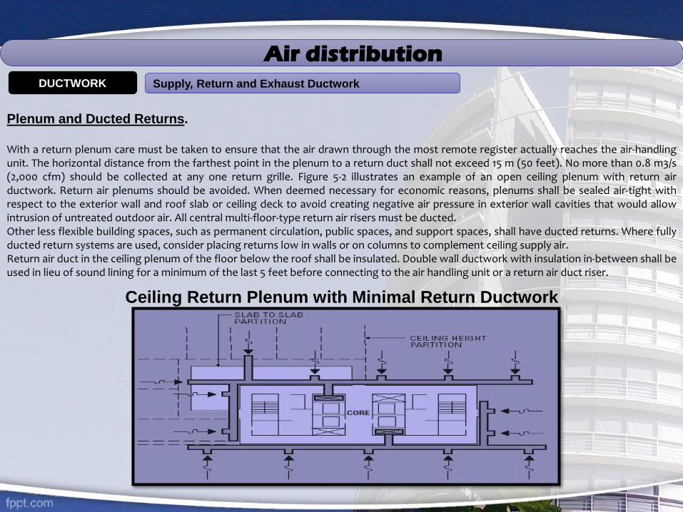
With a return plenum care must be taken to ensure that the air drawn through the most remote register actually reaches the air-handlingunit. The horizontal distance from the farthest point in the plenum to a return duct shall not exceed 15 m (50 feet). No more than 0.8 m3/s(2,000 cfm) should be collected at any one return grille. Figure 5-2 illustrates an example of an open ceiling plenum with return airductwork. Return air plenums should be avoided. When deemed necessary for economic reasons, plenums shall be sealed air-tight withrespect to the exterior wall and roof slab or ceiling deck to avoid creating negative air pressure in exterior wall cavities that would allowintrusion of untreated outdoor air. All central multi-floor-type return air risers must be ducted.Other less flexible building spaces, such as permanent circulation, public spaces, and support spaces, shall have ducted returns. Where fullyducted return systems are used, consider placing returns low in walls or on columns to complement ceiling supply air.Return air duct in the ceiling plenum of the floor below the roof shall be insulated. Double wall ductwork with insulation in-between shall beused in lieu of sound lining for a minimum of the last 5 feet before connecting to the air handling unit or a return air duct riser.
Air distribution Supply, Return and Exhaust DuctworkDUCTWORK
Plenum and Ducted Returns.
With a return plenum care must be taken to ensure that the air drawn through the most remote register actually reaches the air-handlingunit. The horizontal distance from the farthest point in the plenum to a return duct shall not exceed 15 m (50 feet). No more than 0.8 m3/s(2,000 cfm) should be collected at any one return grille. Figure 5-2 illustrates an example of an open ceiling plenum with return airductwork. Return air plenums should be avoided. When deemed necessary for economic reasons, plenums shall be sealed air-tight withrespect to the exterior wall and roof slab or ceiling deck to avoid creating negative air pressure in exterior wall cavities that would allowintrusion of untreated outdoor air. All central multi-floor-type return air risers must be ducted.Other less flexible building spaces, such as permanent circulation, public spaces, and support spaces, shall have ducted returns. Where fullyducted return systems are used, consider placing returns low in walls or on columns to complement ceiling supply air.Return air duct in the ceiling plenum of the floor below the roof shall be insulated. Double wall ductwork with insulation in-between shall beused in lieu of sound lining for a minimum of the last 5 feet before connecting to the air handling unit or a return air duct riser.
Ceiling Return Plenum with Minimal Return Ductwork

PIPING SYSTEMCHILLED WATER AND CONDENSER WATER PIPING
In general, HVAC systems shall utilize parallel piping systems with a two-pipe main distribution system arranged in a reverse return configuration. Ifapplied, series loop piping for terminal or branch circuits shall be equipped with automatic flow control valves at terminal units (all types of heattransfer units).Each terminal unit or coil shall be provided with isolation valves on both the supply and return and a flow indicating balance valve on the return line.Isolation valves shall be provided on all major branches, such as at each floor level, building wing or mechanical room.For new chilled water HVAC distribution, a pumping and piping arrangement is generally appropriate, with constant volume primary pumping andvariable volume secondary pumping. The primary and secondary circuits shall be separate, with neither having an effect on the pumping head of theother. The primary circuit serves the source equipment (chillers), while the secondary circuit serves the load. Refer also to Pumping Systems in thischapter for additional requirements.This procedure is to define the method used to ensure that the Chilled Water Pipework System comprising all pipes, tubes, valves, fittings, reducers,expanders, nipples, vents, bleed off, expansion and contraction devices, hangers, brackets, anchors, supports, sleeves, plates and all accessories andcomponents connected thereto as an integrated pipework system, installation final connections and workmanship, is correct and acceptable andconforms to the contract documents and General Specifications.
Isolation of Piping at Equipment.Isolation valves, shutoff valves, by-pass circuits, flanges and unions shall be provided as necessary for piping at equipment to facilitate equipmentrepair and replacement. Equipment requiring isolation includes boilers, chillers, pumps, coils, terminal units and heat exchangers. Valves shall also beprovided for zones off vertical risers.
Piping SupportsProvide channel supports for multiple pipes and heavy duty steel trapezes to support multiple pipes. Hanger and support schedule shall havemanufacturer’s number, type and location. Comply with MSS SP69 for pipe hanger selections. Spring hangers and supports shall be provided in all themechanical rooms.
Flexible Pipe ConnectorsFlexible pipe connectors shall be fabricated from annular close pitched corrugated and braided stainless steel. All pumps, chillers, and cooling towersshall have flexible connectors.
Piping System and Equipment IdentificationAll pipes, valves and equipment in mechanical rooms, shafts, ceilings and other spaces accessible to maintenance personnel must be identified withcolor-coded bands and permanent tags indicating the system type and direction of flow for piping systems or type and number for equipment. Theidentification system shall also tag all valves and other operable fittings. Gas piping and sprinkler lines must be identified as prescribed by relatedauthorities.

PIPING SYSTEM
Standards for Piping Material
Standard Piping Material Use Comments
ASTM Schedule 40 Chilled water up to 300 mm (12-in) dia., Condenser water up to 300 mm (12-in) dia.
Hot water
Natural gas, fuel oil
Steam (100 kPa (15 psig) to 1035 kPa (150 psi)
1035 kPa (150 psi) fittings.Standard weight pipe over 300 mm (12-in) diameter.
Test to 2100 kPa (300 psig)
Weld and test to 2100 kPa (300 psig)
ASTM Schedule 30 Chilled water over 300 mm (12 in) diaCondenser water over 300 mm (12 in) dia.
1035 kPa (150 psi) fittings.Standard weight pipe over 300 mm (12-in) diameter
ASTM Schedule 80 Steam condensate
Copper Tubing Chilled water up to 102 mm (4 in) dia,Condenser water up to 102 mm (4 in) dia.
Domestic waterRefrigeration
Cast Iron Sanitary, waste and ventStorm
Builder’s option. Use type K below groundand type L above.
Lead-free solder connections.Type ACR.

PIPING SYSTEM
EXPANSION TANK
The expansion tank should be connected on the inlet side of the circulating pump.
It is a good idea to install a service valve at the expansion tank to facilitate future maintenance. However, the valve handle should be removed to prevent the tank from being isolated from the main loop.
The tank will function properly in any position, but it must not stress the connection to the supporting pipe. Thus, the tank should
usually be mounted vertically. Do not install the expansion tank (and its service valve) in such a way that its weight is a big lever that
stresses the pipe connection or pipe.
VFD - VARIABLE FREQUENCY DRIVE
Frequency drives are also known as VFDs, variable frequency drives, VSDs, variable speed drives, and sometimes just "drives".Frequency drives are used primarily to eliminate the sudden current inrush that can cause lights to flicker when a compressor turns on. Frequency drives can also be used to convert single-phase power to 3-phase.
The chiller must have a 3-phase compressor, but the VFD can use either 1- or 3-phase input power. The control panel should matchthe ship's power, whether 1 or 3 phase. Power wiring typically goes from the control panel to the VFD, and from the VFD to the compressor. The VFD functions as the contactor/starter. The control box typically provides a dry contact for the VFD to control when the VFD turns on/off.
CHILLED WATER AND CONDENSER WATER PIPING

PIPING SYSTEM
Pump Installation
Pump Installation Procedure Before starting the pump installation process mechanical or AC engineer to study the pump
manufacturer’s written installation and alignment instructions. A layout drawing should be approved and pumps should be
installed in locations indicated making sure that there is sufficient access space for periodic maintenance, removal of motors
impellers, couplings and accessories. Set base-mounted pumps on concrete equipment bases as indicated on drawings. Suitable
lifting equipment should be used to lift and place the pumps on its location. Disconnect couplings to the half before setting. Do
not reconnect couplings until alignment operations have been completed. Install suction and discharge pipe sizes equal to or
greater than the diameter of water pump connections. Install valves of types and at locations indicated that are same size as
the piping connecting chilled water pump, bypasses, test headers and other piping systems. Install pressure gages on chilled
water pump suction and discharge in such way to be easily readable and completely isolated from vibration.
Support pumps and piping separately so that weight of piping system does not rest on pumps or its support. Install piping
accessories, hangers and supports, anchors, valves meters and gages, and equipment support as indicated for complete
installation. Electrical Wiring: Install electrical devices furnished by equipment manufacturers but not specified as factory
mounted. Furnish copy of manufacturers wiring diagram for submittal to the Consultant. Verify that electrical wiring is installed
according to manufacturer’s recommendations and installation requirements. Work to be inspected and approved by
consultant and do not proceed with equipment start up until wiring installation is acceptable.
Chilled Water Pump Alignment Align pump and driver shafts after complete unit has been leveled on foundation and after
grout has set and foundation bolts have been tightened. After alignment is correct, tighten foundation bolts evenly but not too
firmly. Fill base plate completely with non-shrink, non-metallic grout, with metal blocks and shims or wedges in place. After
grout has hardened, fully tighten foundation bolts. Check alignment and take corrective measures required to ensure perfect
alignment. Make piping connections and check alignment again, and take corrective measures if required. Connect flow-
measuring and other hydraulic system components according to manufacturer’s written installation instructions
CHILLED WATER AND CONDENSER WATER PIPING

CHILLED WATER SYSTEM

PIPING SYSTEM

CHILLED WATER SYSTEM

CHILLED WATER SYSTEM
insulation
UBEMS always uses materials which are comply with the fire and smoke hazard ratings indicated by ASTM-E84, NFPA 255 and UL 723.
Accessories such as adhesives, mastics, cements and tapes shall have the same or better fire and smoke hazard ratings.Special care take in application of insulation e.g Insulation application on all cold surface mechanical systems, such as ductwork andpiping, where condensation has the potential of forming and in accordance with Standard.
Duct Insulation:Materials used as internal insulation exposed to the air stream in ducts shall be in accordance with UL 181 or ASTM C 1071 erosion tests, andshall not promote or support the growth of fungi or bacteria, in accordance with UL 181 and ASTM G21 and G22. Ductwork with double wallconstruction having insulation in-between shall only be used for courtroom return air transfer grilles, and only if required for acousticpurposes. All exposed ductwork shall have sealed canvas jacketing. All concealed ductwork shall have foil face jacketing.All the insulations are comply with fire and smoke hazard ratings indicated by ASTM-E84, NFPA 255 and UL 723. Accessories such asadhesives, mastics, cements, tapes, etc. shall have the same or better component ratings. All supply air ducts always insulated, inaccordance with Standard 90.1.Protect Supply air duct insulation with vapour barrier jacket. The insulation cover the duct system with a continuous, unbroken vapour seal.Insulation shall have zero permeability.Return air and exhaust air distribution systems always insulated in accordance with the Standard set standards.Always evaluate insulation of return air and exhaust air distribution systems or each project and for each system to guard againstcondensation formation and heat gain/loss on a recirculating or heat recovery system. Generally, return air and exhaust air distributionsystems do not require insulation if located in a ceiling plenum or mechanical room used as a return air plenum.
Piping Insulation:All of our insulation materials are comply with the fire and smoke hazard ratings indicated by ASTM-E84, NFPA 255 and UL 723. Accessoriessuch as adhesives, mastics, cements, tapes, etc. shall have the same or better component ratings. Piping systems conveying fluids, thosehaving design temperatures less than 18°C (65°F) or greater than 40°C (105°F) shall be insulated. All piping systems with surfacetemperatures below the average dew point temperature of the indoor ambient air and where condensate drip will cause damage or createa hazard shall be insulated with a vapor barrier to prevent condensation formation regardless to whether piping is concealed or exposed.Chilled water piping systems shall be insulated with no permeable insulation (of perm rating 0.00) such as cellular glass. All exposed andconcealed piping shall have PVC jacketing.All insulation material shall comply with the fire and smoke hazard ratings indicated by ASTM-E84, NFPA 255 and UL 723. Accessories such
as adhesives, mastics, cements, tapes, etc. shall have the same or better component ratings. All equipment including air handling units,chilled and hot water pumps, and heat exchangers must be insulated in accordance with Standard 90.1. All pumps shall have jacketing.
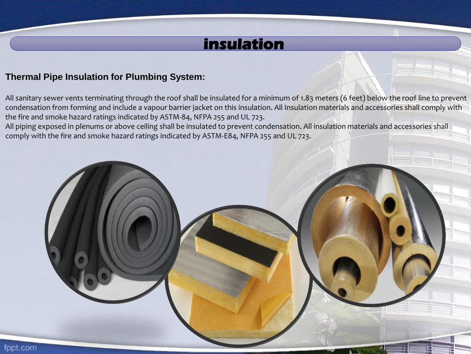
insulation
Thermal Pipe Insulation for Plumbing System:
All sanitary sewer vents terminating through the roof shall be insulated for a minimum of 1.83 meters (6 feet) below the roof line to prevent condensation from forming and include a vapour barrier jacket on this insulation. All Insulation materials and accessories shall comply with the fire and smoke hazard ratings indicated by ASTM-84, NFPA 255 and UL 723.All piping exposed in plenums or above ceiling shall be insulated to prevent condensation. All insulation materials and accessories shall comply with the fire and smoke hazard ratings indicated by ASTM-E84, NFPA 255 and UL 723.
Meter gauges & flow measuring devices
Thermometers and Gauges:
Each piece of our mechanical equipment is provided with the instrumentation or test ports to verify critical parameters, such ascapacity, pressures, temperatures, and flow rates. Following are the general instrumentation requirements:
•Thermometers and pressure gauges are used for the suction and discharge of all pumps, chillers, boilers, heat exchangers, coolingcoils, heating coils, and cooling towers. To avoid pressure gauge tolerance errors, a single pressure gauge may be installed, valved tosense both supply and return conditions. For coils with less than 10 gpm flow, provisions for use of portable instruments to checktemperatures and pressures.
•Duct static pressure gauges are used to provided for the central air-handling unit air supply fan discharge, branch take-offs ofvertical supply risers and at all duct locations at which static pressure readings are being monitored to control the operation of a VAVsystem.
•Differential static pressure gauges are always be placed across filters in air-handling units and to measure building pressure relativeto the outdoors. A temperature gauge is required at the outside air intake to each air-handling unit.
Flow Measuring Devices. Airflow measuring grids are required for all central air-handling units. Measuring grids to be provided at thesupply air duct, return air duct, and the outside air duct. Airflow measuring grids must be sized to give accurate readings at minimumflow. It may be necessary to reduce the duct size at the station to permit accurate measurement.
Water flow or energy measuring devices are required for each chilled water refrigeration machine, hot water boiler, pump, andconnections to district energy plants. Individual water flow or energy measuring devices are provided for chilled water lines servingcomputer rooms and chilled water and hot water lines to out leased spaces. Our flow measuring devices are capable ofcommunicating with the central BAS.Testing Stations. Permanent or temporary testing stations always provided for start up and testing of building systems. Connectionsshall be designed so temporary testing equipment can be installed and removed without shutting down the system.

Minimum Control and Monitoring Points for Typical HVAC Equipment
Central Air Handling Units
Start/Stop
Heating Control
Cooling Control
Humidification Control
Supply Air Reset
Static Pressure Reset
Building and Zone
Pressurization Control
Damper Position (economizer)
Supply Air Discharge Temp
Return Air Temp
Mixed Air Temp
Supply Air Flow Rate
Filter Differential Pressure
Air Flow Measuring Station
Refrigeration Equipment
Start/Stop
Leave Water Temp Reset
Demand Limiting
Isolation Valve Position
Leaving Water Temp
Entering Water Temp
kW Draw
Flow
Return Air Flow Rate
Hot Water Boilers
Start/Stop
Leaving Water Temp Reset
Reset Isolation Valve Position
Leaving Water Temp
Entering Water Temp
Flow
BTU Draw
Cooling Towers
Start/Stop
Leaving Water Temp Reset
Flow
Isolation Valve Position
Entering Water Temp
Leaving Water Temp
Terminal Boxes
Start/Stop
Discharge Temp Reset
Supply Volume Reset
Heating Control
Zone Temp Reset
Minimum Volume Reset
Zone Temp
Supply Air Reset
Zone Pressurization Control
Pumps
Start/Stop
Discharge Pressure Reset
Differential Pressure
Flow
Utilities
Natural Gas Consumption
Electricity Consumption &
Demand
Water Consumption
Fuel Oil Quantity
Minimum Control and Monitoring Points for Typical HVAC Equipment
Building Automation Systems (BAS)
Maintenance Scheduling. UBEMSC always focus to include programs for control that switch pumps and compressors from operating equipment to stand-by on a scheduled basis. Also, programs that provide maintenance schedules for equipment in every building system shall be included, complete with information on what parts and tools are needed to perform each task.
System Design Considerations: BAS’s require measurements at key points in the building system to monitorpart-load operation and adjust system set points to match system capacity to load demands. Controls cannot correctinadequate source equipment, poorly selected components, or mismatched systems. Energy efficiency requires a designthat is optimized by realistic prediction of loads, careful system selection, and full control provisions. System ability mustinclude logs of data created by user selectable features. In new buildings and major renovations, the BAS shall haveapproximately 20 percent spare capacity for future expansion. The system must provide for stand-alone operation ofsubordinate components. The primary operator workstation must have a graphical user interface. Standalone controlpanels and terminal unit controllers can have text-based user interface panels which are hand-held or fixed.
Maintenance SchedulingUBEMSC always focus to include programs for control that switch pumps and compressors from operatingequipment to stand-by on a scheduled basis. Also, programs that provide maintenance schedules for equipment inevery building system shall be included, complete with information on what parts and tools are needed to performeach task.System Design Considerations.
CHILLED WATER SYSTEM
Energy Measurement Instrumentation.BAS shall have the capability to allow building staff to measure energy consumption and monitor performancewhich is critical to the overall success of the system. Electrical values, such as V, A, kW, KVAR, KVA, PF, kWh,KVARH, Frequency and Percent THD, should be measured Electrical Engineering, Site Distribution, for separatemetering of power consumption.Energy management measurements shall be totalized and trended in both instantaneous and time-based numbersfor chillers, boilers, air-handling units and pumps. Energy monitoring data shall be automatically converted to
standard database and spreadsheet format and transmitted to a designated PC.
Energy Measurement Instrumentation. BAS shall have the capability to allow building staff to measure energy
consumption and monitor performance which is critical to the overall success of the system. Electrical values, such as V, A, kW, KVAR, KVA,PF, kWh, KVARH, Frequency and Percent THD, should be measured. See also Chapter 6: Electrical Engineering, Site Distribution, forseparate metering of power consumption.Energy management measurements shall be totalized and trended in both instantaneous and time-based numbers for chillers, boilers, air-handling units and pumps. Energy monitoring data shall be automatically converted to standard database and spreadsheet format andtransmitted to a designated PC.Require measurements at key points in the building system to monitor part-load operation and adjust system set points to match systemcapacity to load demands. Controls cannot correct inadequate source equipment, poorly selected components, or mismatched systems.Energy efficiency requires a design that is optimized by realistic prediction of loads, careful system selection, and full control provisions.System ability must include logs of data created by user selectable features. In new buildings and major renovations, the BAS shall haveapproximately 20 percent spare capacity for future expansion. The system must provide for stand-alone operation of subordinatecomponents. The primary operator workstation shall have a graphical user interface. Standalone control panels and terminal unitcontrollers can have text-based user interface panels which are hand-held or fixed.
START-UP, TESTING & BALANCING EQUIPMENT AND SYSTEMS
Start-up
We always make sure that at the time of start-up of the A/E specify that factory representatives be present for start-up of all majorequipment, such as boilers, chillers and automatic control systems.
Testing and Balancing
We always take responsibility of the A/E to adequately specify testing, adjusting and balancing resulting in not only proper operation ofindividual pieces of equipment, but also the proper operation of the overall HVAC and plumbing systems, in accordance with the designintent.
Performance Testing
A/E to specify performance testing of all equipment and systems including chillers, boilers, and other systems for part load and full loadduring summer, winter, spring and fall season as per the schedules specified by the designer.
Pressure and Leak Testing
We conduct Tests at static pressures equal to maximum design pressure of system and maximum leakage allowable less than 50% of thatallowed in HVAC Air Duct Leakage Manual.
A/E to specify IAQ testing for CO, CO2, volatile organic compounds, NO2, O3, and tobacco smoke. A/E to specify operating tests on eachair and hydronic system to measure and meet energy efficiency to specify and validate peak summer and winter energy consumption andperformance.

Go green
Air Conditioning System With CO2 as Refrigerant

Air Conditioning System With CO2 as Refrigerant
The global warming potential of Carbon dioxide (CO2) is 1.300 times over that of the refrigerant R134a. The CO2 airconditioning system is also more efficient than today´s R134a systems, consuming less fuel for the same cooling power,which reduces exhaust gas emissions. These two areas of savings combined mean that the new system has thepotential to reduce greenhouse gas emissions by 40 per cent a year compared with the global warming impact oftoday´s systems. Another benefit of the CO2 A/C system described in this short version of the article is that it can beused as a very effective auxiliary heater when operated in reverse cycle mode as a heat pump
CO2 As Refrigerant: The Trans critical Cycle
CO2 (R-744) as a refrigerant, its applications in industrial refrigeration, and a case study of a CO2 cascade system in aEuropean supermarket. (See "CO2 in Refrigeration Applications," Oct. 6, 2003; "CO2 in Industrial Refrigeration," Nov. 3,2003; and "CO2 is Keeping Supermarkets Cool," Dec. 8, 2003.) The systems presented were all subcritical - that is, therefrigeration cycles were entirely below the critical point of CO2. Now, after a brief review of CO2 characteristics,comparing subcritical and trans critical cycles, we will present a functioning trans critical system with a hermetic CO2compressor and discuss design considerations.CO2 is a component of our atmosphere that is essential to life. It has no ozone depletion potential and insignificantglobal warming potential, so CO2 has no regulatory liability, as do Huffs. There is no need to account for the amountused, and it does not need to be reclaimed. (Characteristics of CO2, compared with those of R-134a and R-404A, areshown in Table )
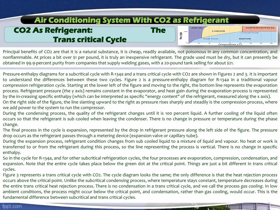
Air Conditioning System With CO2 as Refrigerant
CO2 As Refrigerant: The
Trans critical Cycle
Principal benefits of CO2 are that it is a natural substance, it is cheap, readily available, not poisonous in any common concentration, andnonflammable. At prices a bit over $1 per pound, it is truly an inexpensive refrigerant. The grade used must be dry, but it can presently beobtained in 99.9-percent purity from companies that supply welding gases, with a 20-pound tank selling for about $21.
Pressure-enthalpy diagrams for a subcritical cycle with R-134a and a trans critical cycle with CO2 are shown in Figures 2 and 3. It is importantto understand the differences between these two cycles. Figure 2 is a pressure-enthalpy diagram for R-134a in a traditional vapourcompression refrigeration cycle. Starting at the lower left of the figure and moving to the right, the bottom line represents the evaporationprocess. Refrigerant pressure (the y axis) remains constant in the evaporator, and heat gain during the evaporation process is representedby the in-creasing specific enthalpy (which can be interpreted as specific "energy content" of the refrigerant, measured along the x axis).On the right side of the figure, the line slanting upward to the right as pressure rises sharply and steadily is the compression process, wherewe add power to the system to run the compressor.During the condensing process, the quality of the refrigerant changes until it is 100 percent liquid. A further cooling of the liquid oftenoccurs so that the refrigerant is sub cooled when leaving the condenser. There is no change in pressure or temperature during the phasechange.The final process in the cycle is expansion, represented by the drop in refrigerant pressure along the left side of the figure. The pressuredrop occurs as the refrigerant passes through a metering device (expansion valve or capillary tube).During the expansion process, refrigerant condition changes from sub cooled liquid to a mixture of liquid and vapour. No heat or work istransferred to or from the refrigerant during this process, so the line representing the process is vertical. There is no change in specificenthalpy.So in the cycle for R-134a, and for other subcritical refrigeration cycles, the four processes are evaporation, compression, condensation, andexpansion. Note that the entire cycle takes place below the green dot at the critical point. Things are just a bit different in trans criticalcycles.Figure 3 represents a trans critical cycle with CO2. The cycle diagram looks the same; the only difference is that the heat rejection processoccurs above the critical point. Unlike the subcritical condensing process, where temperature stays constant, temperature decreases duringthe entire trans critical heat rejection process. There is no condensation in a trans critical cycle, and we call the process gas cooling. In lowambient conditions, the process might occur below the critical point, and condensation, rather than gas cooling, would occur. This is thefundamental difference between subcritical and trans critical cycles.
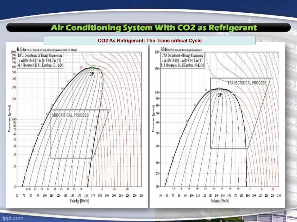
Air Conditioning System With CO2 as Refrigerant
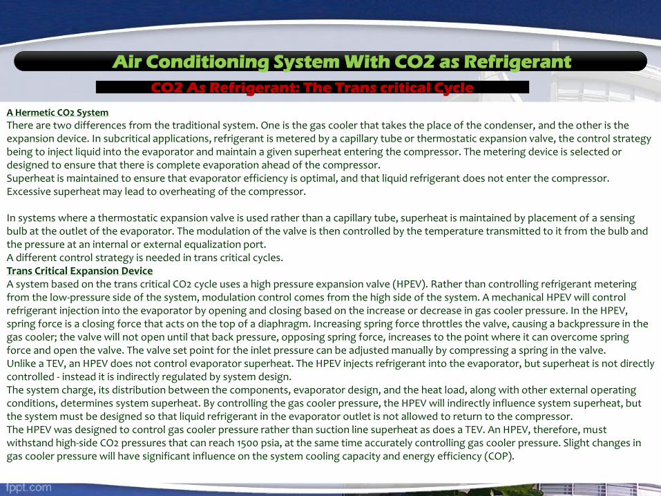
Air Conditioning System With CO2 as Refrigerant
CO2 As Refrigerant: The Trans critical Cycle
A Hermetic CO2 System
There are two differences from the traditional system. One is the gas cooler that takes the place of the condenser, and the other is the expansion device. In subcritical applications, refrigerant is metered by a capillary tube or thermostatic expansion valve, the control strategy being to inject liquid into the evaporator and maintain a given superheat entering the compressor. The metering device is selected or designed to ensure that there is complete evaporation ahead of the compressor.Superheat is maintained to ensure that evaporator efficiency is optimal, and that liquid refrigerant does not enter the compressor. Excessive superheat may lead to overheating of the compressor.
In systems where a thermostatic expansion valve is used rather than a capillary tube, superheat is maintained by placement of a sensing bulb at the outlet of the evaporator. The modulation of the valve is then controlled by the temperature transmitted to it from the bulb and the pressure at an internal or external equalization port.A different control strategy is needed in trans critical cycles.Trans Critical Expansion DeviceA system based on the trans critical CO2 cycle uses a high pressure expansion valve (HPEV). Rather than controlling refrigerant metering from the low-pressure side of the system, modulation control comes from the high side of the system. A mechanical HPEV will control refrigerant injection into the evaporator by opening and closing based on the increase or decrease in gas cooler pressure. In the HPEV, spring force is a closing force that acts on the top of a diaphragm. Increasing spring force throttles the valve, causing a backpressure in the gas cooler; the valve will not open until that back pressure, opposing spring force, increases to the point where it can overcome spring force and open the valve. The valve set point for the inlet pressure can be adjusted manually by compressing a spring in the valve.Unlike a TEV, an HPEV does not control evaporator superheat. The HPEV injects refrigerant into the evaporator, but superheat is not directly controlled - instead it is indirectly regulated by system design.The system charge, its distribution between the components, evaporator design, and the heat load, along with other external operating conditions, determines system superheat. By controlling the gas cooler pressure, the HPEV will indirectly influence system superheat, but the system must be designed so that liquid refrigerant in the evaporator outlet is not allowed to return to the compressor.The HPEV was designed to control gas cooler pressure rather than suction line superheat as does a TEV. An HPEV, therefore, must withstand high-side CO2 pressures that can reach 1500 psia, at the same time accurately controlling gas cooler pressure. Slight changes in gas cooler pressure will have significant influence on the system cooling capacity and energy efficiency (COP).
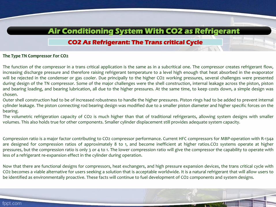
Air Conditioning System With CO2 as Refrigerant
CO2 As Refrigerant: The Trans critical Cycle
The Type TN Compressor For CO2
The function of the compressor in a trans critical application is the same as in a subcritical one. The compressor creates refrigerant flow,increasing discharge pressure and therefore raising refrigerant temperature to a level high enough that heat absorbed in the evaporatorwill be rejected in the condenser or gas cooler. Due principally to the higher CO2 working pressures, several challenges were presentedduring design of the TN compressor. Some of the major challenges were the shell construction, internal leakage across the piston, pistonand bearing loading, and bearing lubrication, all due to the higher pressures. At the same time, to keep costs down, a simple design waschosen.Outer shell construction had to be of increased robustness to handle the higher pressures. Piston rings had to be added to prevent internalcylinder leakage. The piston connecting rod bearing design was modified due to a smaller piston diameter and higher specific forces on thebearing.The volumetric refrigeration capacity of CO2 is much higher than that of traditional refrigerants, allowing system designs with smallervolumes. This also holds true for other components. Smaller cylinder displacement still provides adequate system capacity.
Compression ratio is a major factor contributing to CO2 compressor performance. Current HFC compressors for MBP-operation with R-134aare designed for compression ratios of approximately 8 to 1, and become inefficient at higher ratios.CO2 systems operate at higherpressures, but the compression ratio is only 3 or 4 to 1. The lower compression ratio will give the compressor the capability to operate withless of a refrigerant re-expansion effect in the cylinder during operation.
Now that there are functional designs for compressors, heat exchangers, and high pressure expansion devices, the trans critical cycle withCO2 becomes a viable alternative for users seeking a solution that is acceptable worldwide. It is a natural refrigerant that will allow users tobe identified as environmentally proactive. These facts will continue to fuel development of CO2 components and system designs.


PROJECTS
Gov. Hospital Mirdiff
Al Sekral Group
Imdaad L.L.C
Courtyard Marriot
Hotel
Dream Land
Tower
Carlton hotel.
Resorts. Suites
Lycée Français
International Georg
es Pompidou
Al Ghadeer
Development
Phase 1

Current projects

Electrical department
Walk-in Baking Oven
Coil Winding Machine
Automatic Coil Winding
Machine
Mega Under Coating of
Compotator
Core Loss Tester
Hi Pot & SURGE
Compression Tester
DH Type

Lathe & Fabrication
Advance Gear Mode Lathe Machine
Advance Gear Mode
Lathe Machine
Shaper
Milling MachineMilling Machine Hydraulic Press
Vertical Grinding Machine
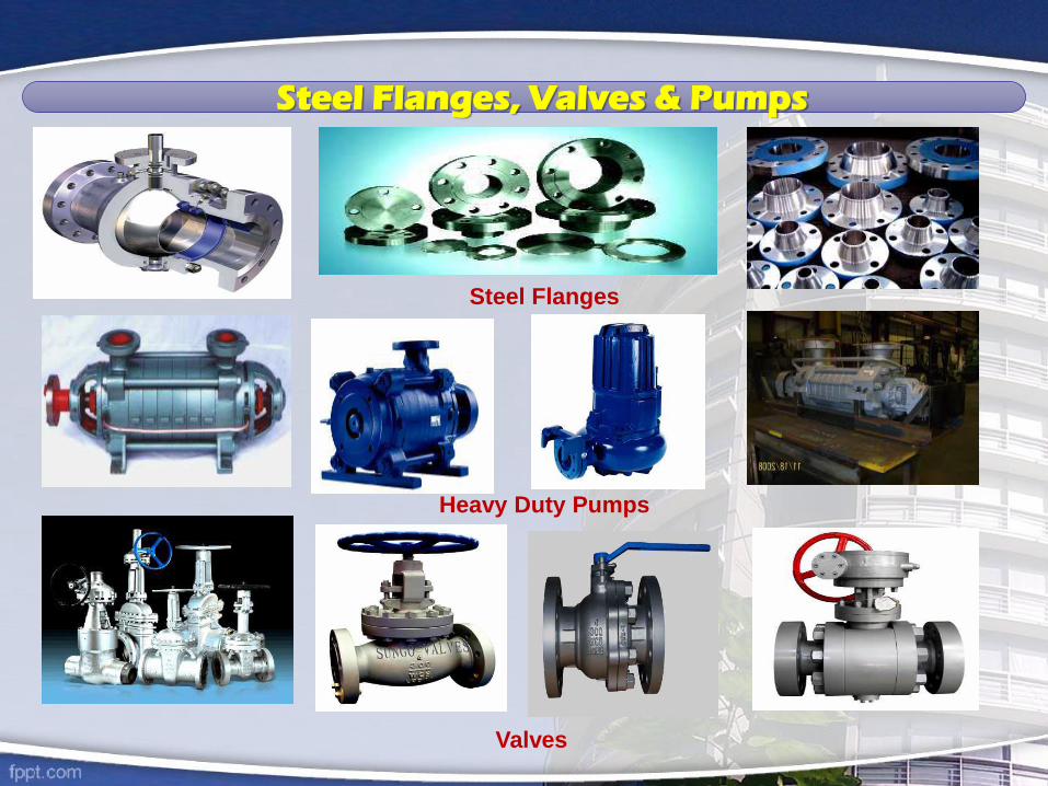
Steel Flanges, Valves & Pumps
Heavy Duty Pumps
Valves
Steel Flanges

Chillers, Package Units & Compressors
Absorption chiller

Ducting, Fire Fighting & Welding Systems
Sprinklers Smoke Detectors
Fire AlarmsWelding Plants

We are certified

We are certified
UBEMS firmly believes that our systemic procedures and processes, professionally followed by ourenthusiastic staff, clearly indicates our accomplished care and continuance in providing high levels ofour quality works, customer service and customer satisfaction.
UBEMS strives to consistently providing quality services with the most reliable and efficientmaintenance & manufacturing services, subject to total compliance on all its requirements, and wherepossible exceeds the expectations of our customers.
UBEMS focuses on training and development of its personnel through their flexibility and adaptabilityto service rough the overwhelmingly transforming business environment, by innovative workingtechniques and continuously improve the efficacy of our design and building management systems.
We will ensure that all our staff having good knowledge and understanding of our quality objectives,working towards meeting the system requirements, and committed to developing processes andpromoting new ideas.
Usman Butt Electro Mechanical Service Company

UBEMS firmly believes in the significance of health and safe working practices of ouremployees, as it forms the fundamental part of the effectiveness and efficiency of ourmanagement. Furthermore, as an organization and the employer, we do acknowledgeour commitment, so far as is reasonably practicable, in ensuring for the health and safetyof our employees, public health and not to endanger our environment.
We also consider that every employee in our organization has an individual responsibilityensuring strict adherence to company's and all legislative safety requirements and it istheir obligation working with the management in maintaining good standards of Health& Safety.
Health Policy

We are Situated Here !
JEBAL ALI FREE ZONE ROAD GATE # 07
1st Traffic signal
DUBAI INVESMENT PARK # 01
2nd Traffic signal
ROUND
ABOUT
TOWARDS GREEN COMMUNITY ROUND
ABOUT
ROUND
ABOUT
HOT PACK
ROUND
ABOUT
CAPITAL ENVELOPES
NORDIC
AGILITY
ROUND
ABOUT
ABU DHABI
PIPE
FACTORY
ROUND
ABOUT
JEBAL ALI INDUSTRIAL
AREA 1, 2, 3
ROUND
ABOUT LEHBAB ROAD
ROUND
ABOUT
GOVERNMENT
HEALTH & FIRE
EMERGENCY CENTER
LEHBAB ROAD
Maintenance Audit
6
7
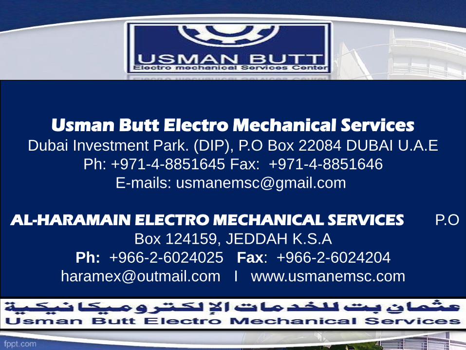
Usman Butt Electro Mechanical Services Dubai Investment Park. (DIP), P.O Box 22084 DUBAI U.A.E
Ph: +971-4-8851645 Fax: +971-4-8851646
E-mails: [email protected]
AL-HARAMAIN ELECTRO MECHANICAL SERVICES P.O
Box 124159, JEDDAH K.S.A
Ph: +966-2-6024025 Fax: +966-2-6024204
[email protected] I www.usmanemsc.com
Related Documents