instructables Common IC Breadboard Clock by Frugha Step 1: Prepare the Breadboard In this Instructables I will explain how to make this Breadboard Clock using Common IC's. Supplies: Common Cathode 7 Segment Display x6 CD4026 IC x6 CD4060 IC x1 SN7476 IC x1 SN7411 IC x1 Push Button x2 220Ω Resistors x42 10kΩ Resistors x2 2.2kΩ Resistors x1 1MΩ Resistors x1 1N4007 Diode x2 100nF Ceramic Capacitor x1 33pF Ceramic Capacitor x1 5-45pF Trimmer Capacitor x1 32.768 KHz Crystal x1 Breadboard x3 22AWG Solid Core Wire Common IC Breadboard Clock: Page 1

Welcome message from author
This document is posted to help you gain knowledge. Please leave a comment to let me know what you think about it! Share it to your friends and learn new things together.
Transcript
instructables
Common IC Breadboard Clock
by Frugha
Step 1: Prepare the Breadboard
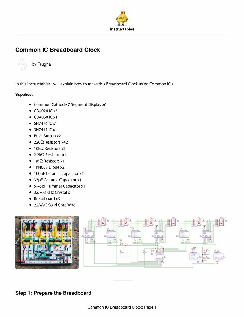
In this Instructables I will explain how to make this Breadboard Clock using Common IC's.
Supplies:
Common Cathode 7 Segment Display x6CD4026 IC x6CD4060 IC x1SN7476 IC x1SN7411 IC x1Push Button x2220Ω Resistors x4210kΩ Resistors x22.2kΩ Resistors x11MΩ Resistors x11N4007 Diode x2100nF Ceramic Capacitor x133pF Ceramic Capacitor x15-45pF Trimmer Capacitor x132.768 KHz Crystal x1Breadboard x322AWG Solid Core Wire
Common IC Breadboard Clock: Page 1
Step 2: Add the 7 Segment Displays and Resistors
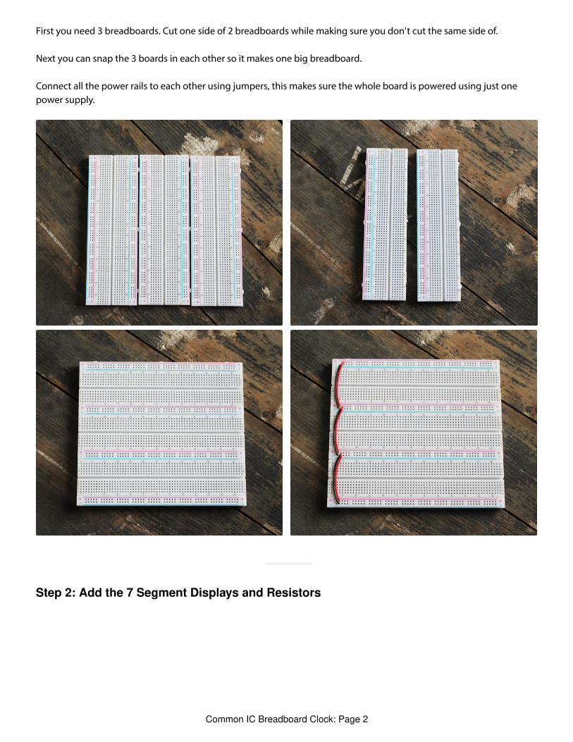
First you need 3 breadboards. Cut one side of 2 breadboards while making sure you don't cut the same side of.
Next you can snap the 3 boards in each other so it makes one big breadboard.
Connect all the power rails to each other using jumpers, this makes sure the whole board is powered using just onepower supply.
Common IC Breadboard Clock: Page 2
Step 3: Add the CD4026B IC's
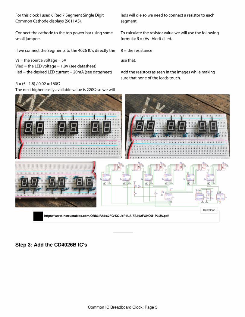
For this clock I used 6 Red 7 Segment Single DigitCommon Cathode displays (5611AS).
Connect the cathode to the top power bar using somesmall jumpers.
If we connect the Segments to the 4026 IC's directly the
leds will die so we need to connect a resistor to eachsegment.
To calculate the resistor value we will use the followingformula: R = (Vs - Vled) / Iled.
R = the resistance
Vs = the source voltage = 5VVled = the LED voltage = 1.8V (see datasheet)Iled = the desired LED current = 20mA (see datasheet)
R = (5 - 1.8) / 0.02 = 160ΩThe next higher easily available value is 220Ω so we will
use that.
Add the resistors as seen in the images while makingsure that none of the leads touch.
https://www.instructables.com/ORIG/FA8/62FG/KOU1P3UA/FA862FGKOU1P3UA.pdf
Download
Common IC Breadboard Clock: Page 3
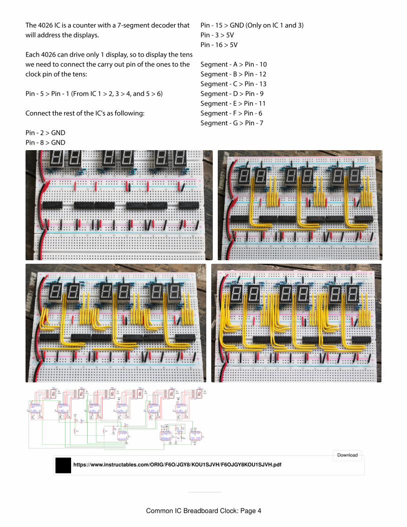
The 4026 IC is a counter with a 7-segment decoder thatwill address the displays.
Each 4026 can drive only 1 display, so to display the tenswe need to connect the carry out pin of the ones to theclock pin of the tens:
Pin - 5 > Pin - 1 (From IC 1 > 2, 3 > 4, and 5 > 6)
Connect the rest of the IC's as following:
Pin - 2 > GNDPin - 8 > GND
Pin - 15 > GND (Only on IC 1 and 3)Pin - 3 > 5VPin - 16 > 5V
Segment - A > Pin - 10Segment - B > Pin - 12Segment - C > Pin - 13Segment - D > Pin - 9Segment - E > Pin - 11Segment - F > Pin - 6Segment - G > Pin - 7
https://www.instructables.com/ORIG/F6O/JGY8/KOU1SJVH/F6OJGY8KOU1SJVH.pdf
Download
Common IC Breadboard Clock: Page 4
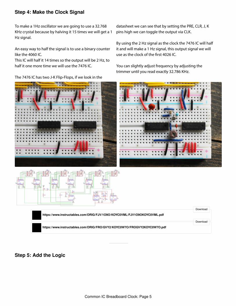
Step 4: Make the Clock Signal
Step 5: Add the Logic
To make a 1Hz oscillator we are going to use a 32.768KHz crystal because by halving it 15 times we will get a 1Hz signal.
An easy way to half the signal is to use a binary counterlike the 4060 IC.This IC will half it 14 times so the output will be 2 Hz, tohalf it one more time we will use the 7476 IC.
The 7476 IC has two J-K Flip-Flops, if we look in the
datasheet we can see that by setting the PRE, CLR, J, Kpins high we can toggle the output via CLK.
By using the 2 Hz signal as the clock the 7476 IC will halfit and will make a 1 Hz signal, this output signal we willuse as the clock of the rst 4026 IC.
You can slightly adjust frequency by adjusting thetrimmer until you read exactly 32.786 KHz.
https://www.instructables.com/ORIG/FJV/1O9O/KOYC0VML/FJV1O9OKOYC0VML.pdf
Download
https://www.instructables.com/ORIG/FRO/GVY2/KOYC0W7O/FROGVY2KOYC0W7O.pdf
Download
Common IC Breadboard Clock: Page 5
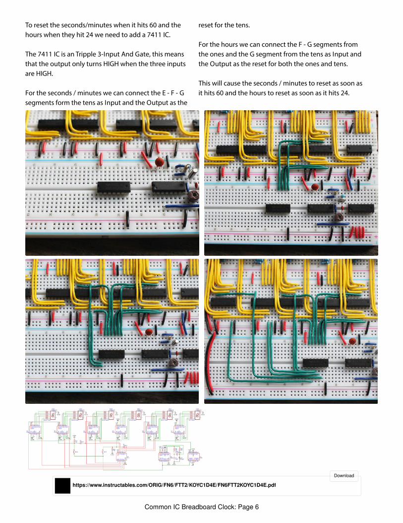
To reset the seconds/minutes when it hits 60 and thehours when they hit 24 we need to add a 7411 IC.
The 7411 IC is an Tripple 3-Input And Gate, this meansthat the output only turns HIGH when the three inputsare HIGH.
For the seconds / minutes we can connect the E - F - Gsegments form the tens as Input and the Output as the
reset for the tens.
For the hours we can connect the F - G segments fromthe ones and the G segment from the tens as Input andthe Output as the reset for both the ones and tens.
This will cause the seconds / minutes to reset as soon asit hits 60 and the hours to reset as soon as it hits 24.
https://www.instructables.com/ORIG/FN6/FTT2/KOYC1D4E/FN6FTT2KOYC1D4E.pdf
Download
Common IC Breadboard Clock: Page 6
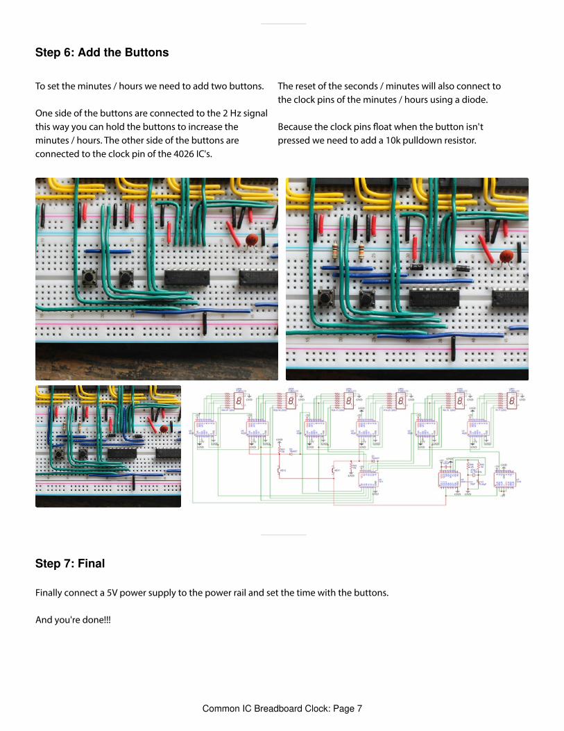
Step 6: Add the Buttons
Step 7: Final
To set the minutes / hours we need to add two buttons.
One side of the buttons are connected to the 2 Hz signalthis way you can hold the buttons to increase theminutes / hours. The other side of the buttons areconnected to the clock pin of the 4026 IC's.
The reset of the seconds / minutes will also connect tothe clock pins of the minutes / hours using a diode.
Because the clock pins oat when the button isn'tpressed we need to add a 10k pulldown resistor.
Finally connect a 5V power supply to the power rail and set the time with the buttons.
And you're done!!!
Common IC Breadboard Clock: Page 7
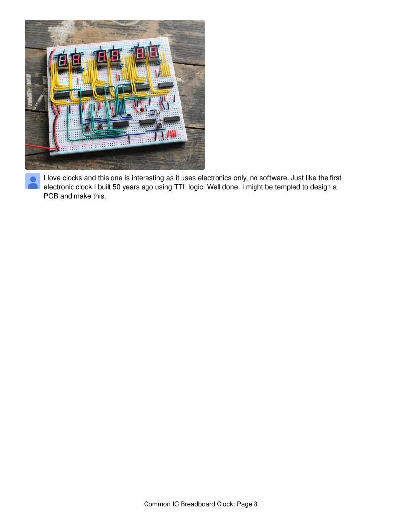
I love clocks and this one is interesting as it uses electronics only, no software. Just like the firstelectronic clock I built 50 years ago using TTL logic. Well done. I might be tempted to design aPCB and make this.
Common IC Breadboard Clock: Page 8
Related Documents