(Commonwvealth Edison Company Braidwood Generating Station Route #1, Box 84 Braceville 11 604(7-9619 Tel 81 5-458-2801 ComEd April 13, 2000 BW000040 U. S. Nuclear Regulatory Commission ATTN: Document Control Desk Washington, D.C. 20555-0001 Braidwood Station, Unit 2 Facility Operating License No. NPF-77 NRC Docket No. STN 50-457 Subject: Commonwealth Edison (ComEd) Braidwood Unit 2 Cycle 7 Steam Generator Eddy Current Examination 12 Month Summary Report In accordance with Technical Specification 5.6.9, "Steam Generator (SG) Tube Inspection Reports," item b requires the complete results of the SG tube inservice inspection to be submitted to the NRC within 12 months following completion of the inspection. The attached report includes the number and extent of tubes inspected, location and percentage of wall thickness penetration for each indication of an imperfection, and identification of tubes plugged or repaired. During the Braidwood Station, Unit 2, refueling outage (i.e., A2R07) Steam Generator inspections and repairs were completed on May 5, 1999. Please direct any questions regarding this submittal to T.W. Simpkin, Braidwood Regulatory Assurance Manager, (815) 458-2801 ext.2980. Sincerely, Tihy J. Tulon Size Vice President Braidwood Station Attachments cc: Regional Administrator - NRC Region IlIl NRC Senior Resident Inspector - Braidwood Station Office of Nuclear Facility Safety - Illinois Department of Nuclear Safety A4c(I A Unicom Company

Welcome message from author
This document is posted to help you gain knowledge. Please leave a comment to let me know what you think about it! Share it to your friends and learn new things together.
Transcript

(Commonwvealth Edison Company
Braidwood Generating Station
Route #1, Box 84
Braceville 11 604(7-9619
Tel 81 5-458-2801
ComEdApril 13, 2000BW000040
U. S. Nuclear Regulatory CommissionATTN: Document Control DeskWashington, D.C. 20555-0001
Braidwood Station, Unit 2Facility Operating License No. NPF-77NRC Docket No. STN 50-457
Subject: Commonwealth Edison (ComEd) Braidwood Unit 2 Cycle 7 Steam GeneratorEddy Current Examination 12 Month Summary Report
In accordance with Technical Specification 5.6.9, "Steam Generator (SG) Tube InspectionReports," item b requires the complete results of the SG tube inservice inspection to besubmitted to the NRC within 12 months following completion of the inspection. Theattached report includes the number and extent of tubes inspected, location andpercentage of wall thickness penetration for each indication of an imperfection, andidentification of tubes plugged or repaired. During the Braidwood Station, Unit 2, refuelingoutage (i.e., A2R07) Steam Generator inspections and repairs were completed on May 5,1999.
Please direct any questions regarding this submittal to T.W. Simpkin, BraidwoodRegulatory Assurance Manager, (815) 458-2801 ext.2980.
Sincerely,
Tihy J. TulonSize Vice PresidentBraidwood Station
Attachments
cc: Regional Administrator - NRC Region IlIlNRC Senior Resident Inspector - Braidwood StationOffice of Nuclear Facility Safety - Illinois Department of Nuclear Safety
A4c(IA Unicom Company
COMED
BRAIDWOOD STATION UNIT 2
STEAM GENERATOR EDDY CURRENT INSPECTION REPORT
CYCLE 7 REFUELING OUTAGE (A2R07)
May 1999
TABLE OF CONTENTS
1.0 INTRODUCTION
2.0 SUMMARY
3.0 CERTIFICATIONS
3.1 Procedures/Examinations/Equipment
3.2 Personnel
4.0 EXAMINATION TECHNIQUE AND EXAMINATION SCOPE
4.1 Examination Techniques
4.2 Recording of Examination Data
4.3 Witness and Verification of Examination
5.0 EXAMINATION RESULTS
5.1 Indications Found
5.2 Other Inspection Results
6.0 REPAIR SUMMARY
7.0 TUBE INTEGRITY ASSESSMENT SUMMARY
7.1 Degradation Assessment
7.2 Condition Monitoring/Operational Assessment
8.0 DOCUMENTATION
9.0 FIGURES/TABLES/ATTACHMENTS
1.0 INTRODUCTION
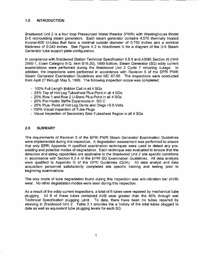
Braidwood Unit 2 is a four loop Pressurized Water Reactor (PWR) with Westinghouse ModelD-5 recirculating steam generators. Each steam generator contains 4,570 thermally treatedInconel-600 U-tubes that have a nominal outside diameter of 0.750 inches and a nominalthickness of 0.043 inches. See Figure A.2 in Attachment A for a diagram of the D-5 SteamGenerator tube support plate configuration.
In compliance with Braidwood Station Technical Specification 5.5.9 and ASME Section XI (IWB2500-1, Exam Category B-Q, item B16.20), 1989 Edition, Steam Generator (SG) eddy currentexaminations were performed during the Braidwood Unit 2 Cycle 7 refueling outage. Inaddition, the inspections were performed in accordance with Revision 5 of the EPRI PWRSteam Generator Examination Guidelines and NEI 97-06. The inspections were conductedfrom April 27 through May 5, 1999. The following inspection scope was completed:
- 100% Full Length Bobbin Coil in all 4 SGs- 25% Top of Hot Leg Tubesheet Plus-Point in all 4 SGs- 25% Row 1 and Row 2 U-Bend Plus-Point in all 4 SGs- 20% Pre-Heater Baffle Expansions in SG C- 25% Plus- Point of Hot Leg Dents and Dings >5.0 Volts- 100% Visual Inspection of Tube Plugs- Visual Inspection of Secondary Side Tubesheet Region in all 4 SGs
2.0 SUMMARY
The requirements of Revision 5 of the EPRI PWR Steam Generator Examination Guidelineswere implemented during this inspection. A degradation assessment was performed to ensurethat only EPRI Appendix H qualified examination techniques were used to detect any pre-existing and potential modes of degradation. Each technique was evaluated to ensure that thedetection and sizing capabilities are applicable to the Braidwood Unit 2 site specific conditionsin accordance with Section 6.2.4 of the EPRI SG Examination Guidelines. All data analystswere qualified to Appendix G of the EPRI Guidelines (QDA). All data analyst and dataacquisition personnel satisfactorily completed site specific training and testing prior tobeginning examinations.
The only mode of tube degradation found during this inspection was anti-vibration bar (AVB)wear. No other degradation modes were seen during this inspection.
As a result of the eddy current inspections, a total of 6 tubes were repaired by mechanical tubeplugging. All 6 of these tubes contained AVB wear greater than the 40% through wallTechnical Specification plugging Limit. To date, there have been no tubes repaired bysleeving in Braidwood Unit 2. Table 2.1 provides the a history of the total tubes plugged todate as well as equivalent tube plugging levels for each SG.
1
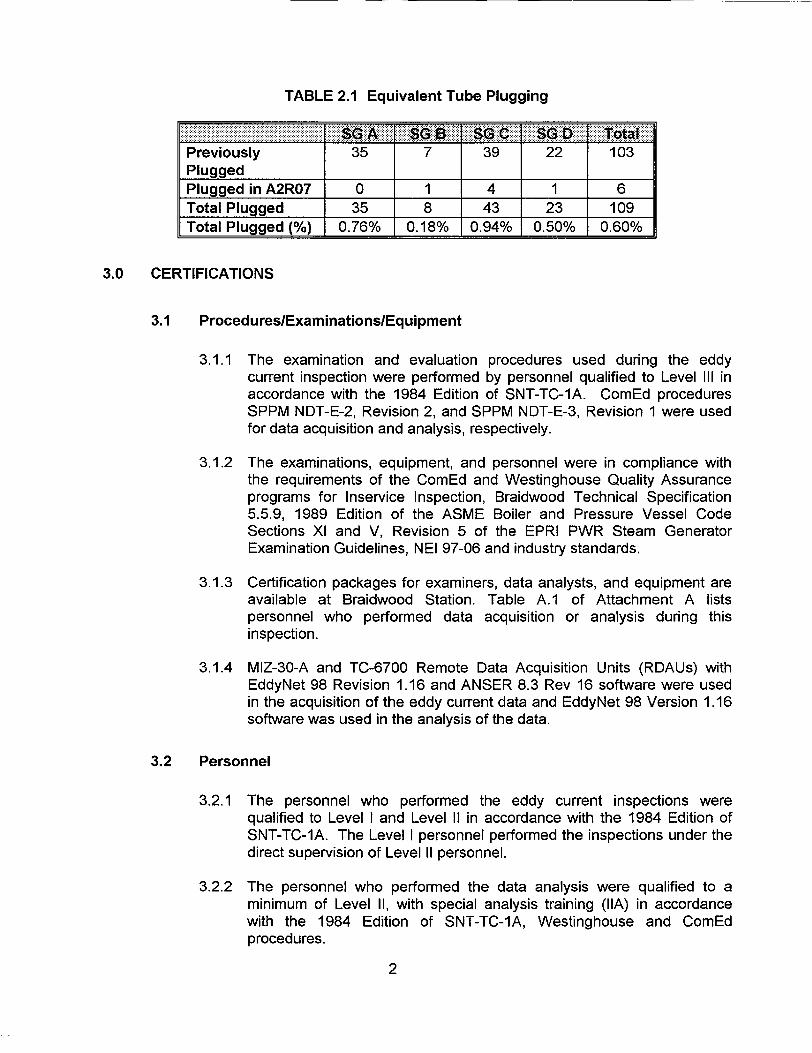
TABLE 2.1 Equivalent Tube Plugging
Previously 35 7 39 22 103Plugged l
Plugged in A2R07 0 1 4 1 6Total Plugged 35 8 43 23 109Total Plugged (%) 0.76% 0.18% 0.94% 0.50% 0.60%
3.0 CERTIFICATIONS
3.1 Procedures/Examinations/Equipment
3.1.1 The examination and evaluation procedures used during the eddycurrent inspection were performed by personnel qualified to Level IlIl inaccordance with the 1984 Edition of SNT-TC-1A. ComEd proceduresSPPM NDT-E-2, Revision 2, and SPPM NDT-E-3, Revision 1 were usedfor data acquisition and analysis, respectively.
3.1.2 The examinations, equipment, and personnel were in compliance withthe requirements of the ComEd and Westinghouse Quality Assuranceprograms for Inservice Inspection, Braidwood Technical Specification5.5.9, 1989 Edition of the ASME Boiler and Pressure Vessel CodeSections Xl and V, Revision 5 of the EPRI PWR Steam GeneratorExamination Guidelines, NEI 97-06 and industry standards.
3.1.3 Certification packages for examiners, data analysts, and equipment areavailable at Braidwood Station. Table A.1 of Attachment A listspersonnel who performed data acquisition or analysis during thisinspection.
3.1.4 MIZ-30-A and TC-6700 Remote Data Acquisition Units (RDAUs) withEddyNet 98 Revision 1.16 and ANSER 8.3 Rev 16 software were usedin the acquisition of the eddy current data and EddyNet 98 Version 1.16software was used in the analysis of the data.
3.2 Personnel
3.2.1 The personnel who performed the eddy current inspections werequalified to Level I and Level II in accordance with the 1984 Edition ofSNT-TC-1A. The Level I personnel performed the inspections under thedirect supervision of Level II personnel.
3.2.2 The personnel who performed the data analysis were qualified to aminimum of Level II, with special analysis training (IIA) in accordancewith the 1984 Edition of SNT-TC-1A, Westinghouse and ComEdprocedures.
2
3.2.3 All eddy current data analysts analyzing data were qualified inaccordance with EPRI Appendix G for Qualified Data Analysts (QDA).
3.2.4 All eddy current data analysts were trained and tested in accordancewith a site specific performance demonstration program in both bobbineddy current data and Plus Point data. Resolution analysts were alsotrained and tested specifically in the performance of data resolution. Allanalysts were required to achieve a score of 80% on both the writtenand practical examinations prior to analyzing data.
3.2.5 All eddy current data acquisition operators were trained and tested to asite specific acquisition training program. The data acquisition operatorswere required to achieve a test score of 80% or greater.
3.2.6 The eddy current analysis was subject to two independent analyses. ThePrimary Analysis was performed by Westinghouse and the SecondaryAnalysis was performed by ANATEC. The following subcontractors wereused to support data analysis at either primary or secondary analysissites; Corestar, KPS, More-Tech, Verner & James, Quantum, Wiltec andZetec. Discrepancies between primary and secondary analysis requiredLevel Ill concurrence between both parties for the final resolution.
3.2.7 An experienced eddy current Level Ill QDA was employed to serve as aProcess Control Reviewer to randomly sample the data to ensure theresolution process was properly performed and that the field calls wereproperly reported. The process control reviewer also provided dataacquisition oversight to ensure that the data collection process was incompliance with appropriate procedures. This is in accordance with theEPRI Guidelines Section 6.3.3.4.
4.0 EXAMINATION TECHNIQUE AND EXAMINATION SCOPE
All eddy current examination techniques used are qualified in accordance withAppendix H of the EPRI Steam Generator Examination Guidelines. Each examinationtechnique was evaluated to be applicable to the tubing and conditions of the BraidwoodUnit 2 steam generators.
3
4.1 Examination Techniques
4.1.1 All inservice tubes in each SG were inspected full length utilizing a 0.610inch diameter LLMC bobbin coil eddy current probe. For U-Bend regionsand cold leg tubing in rows 1 through 3, a 0.590 inch diameter LLMCspring flex bobbin probe was utilized to achieve the complete full tubeinspection. Nominal probe inspection speed was 40 inches per secondfor rows 4 through 49 and 24 inches per second for rows 1 through 3.Sufficient sampling rates were used to maintain a minimum of 30samples per inch. The bobbin coil probes were operated at frequenciesof 550 kHz, 300 kHz, 130 kHz, and 20 kHz operating in the differentialand absolute test modes. In addition, suppression mixes were used toenhance the inspection. These mixes were as follows: 550/130 kHzdifferential mix, 300/130 kHz absolute mix and a 550/300/130 kHzdifferential mix.
4.1.2 25% of the inservice tubes in each SG were inspected at the hot leg topof tubesheet expansion transition region with a 0.610 inch diameter threecoil plus-point eddy current probe. The examinations were performed 2"above to 2" below the secondary tubesheet interface. The probecontained a mid-range plus-point coil, a 0.115 inch diameter pancakecoil and a 0.080 inch diameter mid-range or standard pancake coil.Nominal probe speed was 0.5 inches per second with a sampling rate tomaintain a minimum of 30 samples per inch. The probe was operated atfrequencies of 300 kHz, 200 kHz, 100 kHz and 20 kHz operating in theabsolute test mode. Three process channels were created to displayaxial indications in a positive trace.
4.1.3 20% preheater baffle expansions in the C SG were inspected utilizing a3 coil plus-point probe described in Section 4.1.2.
4.1.4 25% of the inservice U-Bend regions of tubes in rows 1 and 2 in eachsteam generator were inspected utilizing a 0.580 inch diametermagnetically biased U-Bend Plus-Point probe. Nominal probe speedwas 0.15 inches per second with a sampling rate to maintain a minimumof 30 samples per inch. The probe was operated at frequencies of 400kHz, 300 kHz, 150 kHz and 20 kHz in the absolute test mode. Threeprocess channels were created to display axial indications in a positivetrace.
4.1.5 Tubes containing dents at Hot Leg tube support plates and Hot Legfreespan dings that were sized greater than 5.0 volts and non-quantifiable indications identified by an "I-Code" were examined with arotating plus-point probe described in Section 4.1.2. The nominal probespeed for inspection of dents was reduced to 0.15 inches per secondwhile maintaining a minimum sampling rate of 30 samples per inch.
4
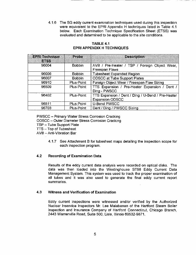
4.1.6 The SG eddy current examination techniques used during this inspectionwere equivalent to the EPRI Appendix H techniques listed in Table 4.1below. Each Examination Technique Specification Sheet (ETSS) wasevaluated and determined to be applicable to the site conditions.
TABLE 4.1EPRI APPENDIX H TECHNIQUES
04 Bobbin AVB / Pre-Heater / TSP I Foreign Object Wear,Freespan Flaws
960
96006 Bobbin Tubesheet Expanded Region96007 Bobbin ODSCC at Tube Support Plates96910 Plus-Point Foreign Object Wear / Freespan Flaw Sizing96509 Plus-Point TTS Expansion / Pre-Heater Expansion / Dent I
Ding- PWSCC96402 Plus-Point TTS Expansion / Dent / Ding / U-Bend / Pre-Heater
Expansion ODSCC96511 Plus-Point U-Bend PWSCC96703 Plus-Point Dent / Ding / PWSCC Sizing
PWSCC - Primary Water Stress Corrosion CrackingODSCC - Outer Diameter Stress Corrosion CrackingTSP - Tube Support PlateTTS - Top of TubesheetAVB - Anti-Vibration Bar
4.1.7 See Attachment B for tubesheet maps detailing the inspection scope foreach inspection program.
4.2 Recording of Examination Data
Results of the eddy current data analysis were recorded on optical disks. Thedata was then loaded into the Westinghouse ST98 Eddy Current DataManagement System. This system was used to track the proper examination ofall tubes and it was also used to generate the final eddy current reportsummaries.
4.3 Witness and Verification of Examination
Eddy current inspections were witnessed and/or verified by the AuthorizedNuclear Inservice Inspectors Mr. Lee Malabanan of the Hartford Steam BoilerInspection and Insurance Company of Hartford Connecticut, Chicago Branch,2443 Warrenville Road, Suite 500, Lisle, Illinois 60532-9871.
5

5.0 EXAMINATION RESULTS
5.1 Indications Found
5.1.1 Anti-Vibration Bar (AVB) Wear - Tube degradation was found by the100% bobbin coil examination in the U-bend region due to fretting of theAnti-Vibration Bars on the tube. A total of 656 tubes contained 795indications of AVB wear. The bobbin coil examination technique utilizedin this inspection was EPRI Appendix H qualified for the depth sizing ofAVB wear. Six tubes were removed from service as a result of AVBwear exceeding the 40% through wall (TW) repair limit. The largest ofthese indications was 44% TW. Table 5.1.1 below provides a summaryof AVB Wear degradation.
<20% T20-39%TW
146 1 153169 1 180
365239 90 158 57 62 355 452
>= 40% ° ° 1 1 414 1 1 6 6TW _ 3__ 1 _ _
TOTAL * 315 13331 67 89 162 12471 112 126 656 79* Tubes may contain indications in more than one category.
5.2 Other Inspection
5.2.1 Hot Leg Top of Tubesheet Region - 25% of the hot leg top of tubesheetregion in each steam generator was inspected using the plus pointprobe. No tube degradation was found.
5.2.2 Low Row U-Bend Plus-Point Inspection - 25% of the row 1 row 2 U-bend regions were inspected in each steam generator with a plus-pointprobe. No tube degradation was found
5.2.3 Pre-heater Expansion Plus-Point Inspection - A sample of 20% of thepre-heater baffle expansions in SG C were inspected with the plus-pointprobe. No degradation was found.
5.2.3 Hot Leg Dents and Dings > 5.0 Volts Plus-Point Inspection - 25% of thehot leg dents (at tube support plates) and dings (at freespan section oftubes), that were greater than 5.0 volts (41 dents), as measured by thebobbin coil were inspected with a plus-point probe. No degradation wasfound.
6

5.2.4 Visual Inspection of Secondary Side - Secondary side visual inspectionswere performed in the upper tube bundle of SG C. Access was gainedthrough inspection ports at the 8th support plate. A video probe wasused to inspect accessible portions of the divider lane, tube peripherylane and inner tube bundle. In addition, the top of the tubesheet regionwas inspected after sludge lancing in all four steam generators. Nodegradation was found. A foreign object, which could not be retrieved,was identified on the top of tubesheet region in the "D" steam generator.The object is wedged between R-6 C-2 and R-7 C-2. The object wasoriginally identified during A2R06 (Sept '97), at which time a 10CFR50.59 Safety Evaluation was performed allowing the tubes to remain inservice since there was no degradation. The tubes in contact with theforeign object showed no signs of wear dating back to A2R03 (March'93). Based on reinspection of these tubes during A2R07, nodegradation had occurred. During A2R07 a 10CFR 50.59 SafetyEvaluation validation was performed which allows the tubes to remain inservice provided they are inspected for degradation each refuelingoutage.
5.2.5 Visual Inspection of Previously Install Plugs - All previously installedplugs on the hot leg and cold leg tube ends were visually inspected forsigns of degradation and leakage. A total of 206 tube plugs werevisually inspected. In addition, all plugs installed during this outage werealso visually inspected. No degradation or abnormal leakage was found.
6.0 REPAIR SUMMARY
Repairs were conducted in accordance with ASME Section Xl, 1989 Edition. All repairs wereperformed using Inconel-690 mechanical tube plugs. All repairs were performed in accordancewith Westinghouse approved procedures.
7.0 TUBE INTEGRITY ASSESSMENT SUMMARYTube integrity assessments were performed to demonstrate that SG performance for eachmode of degradation met the required structural integrity requirements for the previousoperating period, Cycle 7, and for the next operating period Cycle 8. The assessment for theprevious cycle is referred to as a condition monitoring assessment and the assessment for thenext cycle is referred to as the operational assessment. The condition monitoring andoperational assessments were performed in accordance with Revision 5 of the EPRI PWRSteam Generator Examination Guidelines and the EPRI Steam Generator IntegrityAssessment Guidelines. There was no primary to secondary leakage detected during Cycle 7or upon shutdown for A2R07.
7
7.1 Degradation Assessment
In order to ensure that appropriate inspections are performed during A2R07, adegradation assessment was performed prior to the outage to identify activeand potential degradation mechanisms. For each active and potentialdegradation mechanism, an appropriate inspection sample and EPRI AppendixH inspection technique was determined. The inspection scope and techniquesused are discussed in Section 4.1 of this report. The degradation assessmentwas performed in accordance with Section 5.2 of the EPRI PWR ExaminationGuidelines, Revision 5.
7.2 Condition Monitoring / Operational Assessment
7.1.1 Anti-Vibration Bar (AVB) Wear (Condition Monitoring)
The only damage mechanism seen during A2R07 was AVB wear. Thestructural limit for AVB wear is 74% through-wall (TW) and the TechnicalSpecification repair limit is 40% TW. The deepest AVB wear indicationfound during A2R07 was 44% TW which is well below the structural limiteven when NDE uncertainty of 8% is added. An indication of this sizewould not be expected to leak during accident conditions. This tube wasremoved from service along with five other tubes having AVB weargreater than or equal to the 40% TW repair limit. Since this was the onlymode of degradation seen during the A2R07, all condition monitoringcriteria were met for Cycle 7.
7.1.2 Anti-Vibration Bar (AVB) Wear (Operational Assessment)
The only damage mechanism seen during A2R07 was AVB wear. Anoperational assessment was performed to compare the largest predictedAVB wear flaw at the end of cycle 8 (1.425 Effective Full Power Years)to the structural limit. This was performed by combing the largest flawleft inservice with NDE uncertainty and an allowance for growth using thelargest growth rate from previous inspection results over the expectedcycle length. The largest flaw predicted at the end of Cycle 8 is 61.25%TW, which is well below the structural limit of 74% for AVB wear. Thisresults in an acceptable operational assessment and supports full cycleoperation.
7.1.3 Secondary Side Internal Integrity
Inspection results found the condition of the steam generator secondaryside internals to be acceptable with no observations impacting tubeintegrity. No problems were encountered with inserting sludge lanceequipment through the access ports, thus indicating that the wrapperremains in place. Eddy current analysis did not identify any missing ordistorted support plate signals. No tube wear was found that could beattributable to loose parts from the pre-heater water components.
8
8.0 DOCUMENTATION
All original optical disks have been provided to ComEd and are maintained at BraidwoodStation. The final data sheets and pertinent tube sheet plots are contained in theWestinghouse Outage Report for Braidwood Unit 2, A2R07, and are also maintained atBraidwood Station.
9.0 FIGURES/TABLES/ATTACHMENTS
ATTACHMENT A CONTENTS
Table A.1 Data Acquisition and Analysis Personnel Certification List
Figure A.2 Westinghouse Model D-5 Tube Support Configuration
ATTACHMENT B CONTENTS
Steam Generator A Inspection MapsSteam Generator B Inspection MapsSteam Generator C Inspection MapsSteam Generator D Inspection Maps
ATTACHMENT C CONTENTS
Steam Generator A Anti-Vibration Bar Wear IndicationsSteam Generator B Anti-Vibration Bar Wear IndicationsSteam Generator C Anti-Vibration Bar Wear IndicationsSteam Generator D Anti-Vibration Bar Wear Indications
ATTACHMENT D CONTENTS
Table D.1 Tubes Repaired During AlR08Steam Generator B Tubes Repaired During A2R07Steam Generator C Tubes Repaired During A2R07Steam Generator D Tubes Repaired During A2R07Note: There Were No Tubes Repaired in Steam Generator A During A2R07
9

ATTACHMENT A
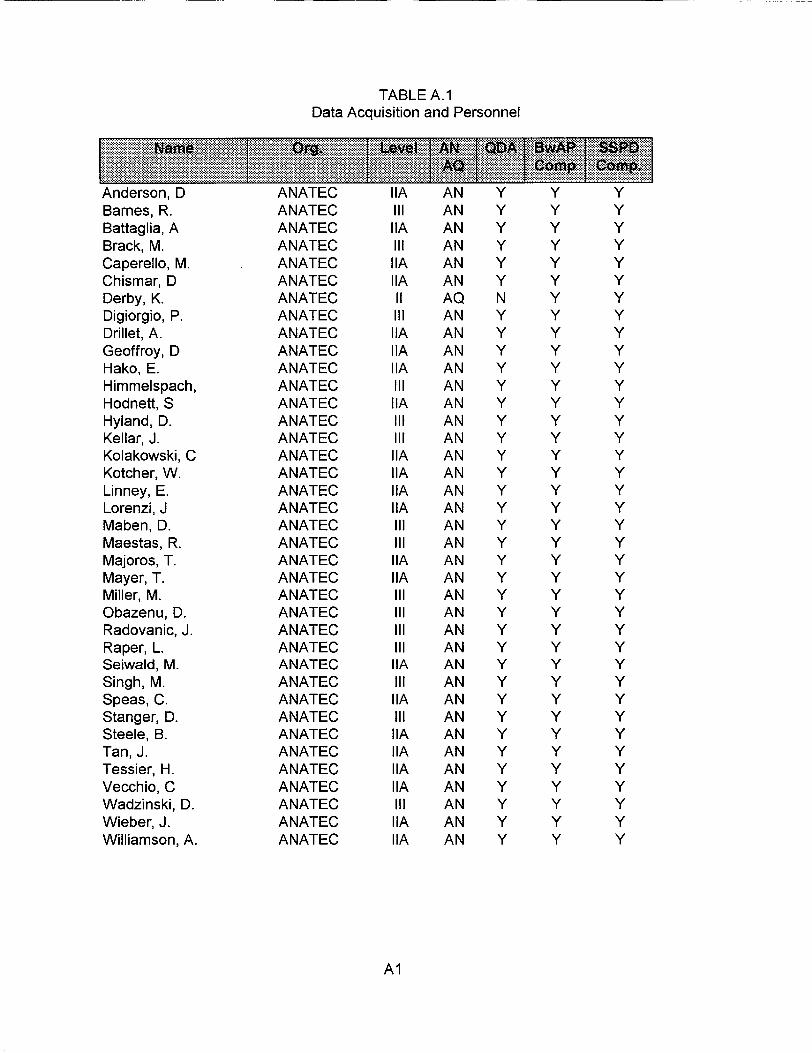
TABLE A. 1Data Acquisition and Personnel
Anderson, D ANATEC IIA AN Y Y YBarnes, R. ANATEC IlIl AN Y Y YBattaglia, A ANATEC IIA AN Y Y YBrack, M. ANATEC IlIl AN Y Y YCaperello, M. ANATEC IIA AN Y Y YChismar, D ANATEC IIA AN Y Y YDerby, K. ANATEC II AQ N Y YDigiorgio, P. ANATEC IlIl AN Y Y YDrillet, A. ANATEC IIA AN Y Y YGeoffroy, D ANATEC IIA AN Y Y YHako, E. ANATEC IIA AN Y Y YHimmelspach, ANATEC III AN Y Y YHodnett, S ANATEC IIA AN Y Y YHyland, D. ANATEC III AN Y Y YKellar, J. ANATEC III AN Y Y YKolakowski, C ANATEC IIA AN Y Y YKotcher, W. ANATEC IIA AN Y Y YLinney, E. ANATEC IIA AN Y Y YLorenzi, J ANATEC IIA AN Y Y YMaben, D. ANATEC III AN Y Y YMaestas, R. ANATEC IlIl AN Y Y YMajoros, T. ANATEC IIA AN Y Y YMayer, T. ANATEC IIA AN Y Y YMiller, M. ANATEC IlIl AN Y Y YObazenu, D. ANATEC III AN Y Y YRadovanic, J. ANATEC IlIl AN Y Y YRaper, L. ANATEC IlIl AN Y Y YSeiwald, M. ANATEC IIA AN Y Y YSingh, M. ANATEC IlIl AN Y Y YSpeas, C. ANATEC IIA AN Y Y YStanger, D. ANATEC IlIl AN Y Y YSteele, B. ANATEC IIA AN Y Y YTan, J. ANATEC IIA AN Y Y YTessier, H. ANATEC IIA AN Y Y YVecchio, C ANATEC IIA AN Y Y YWadzinski, D. ANATEC IlIl AN Y Y YWieber, J. ANATEC IIA AN Y Y YWilliamson, A. ANATEC IIA AN Y Y Y
Al
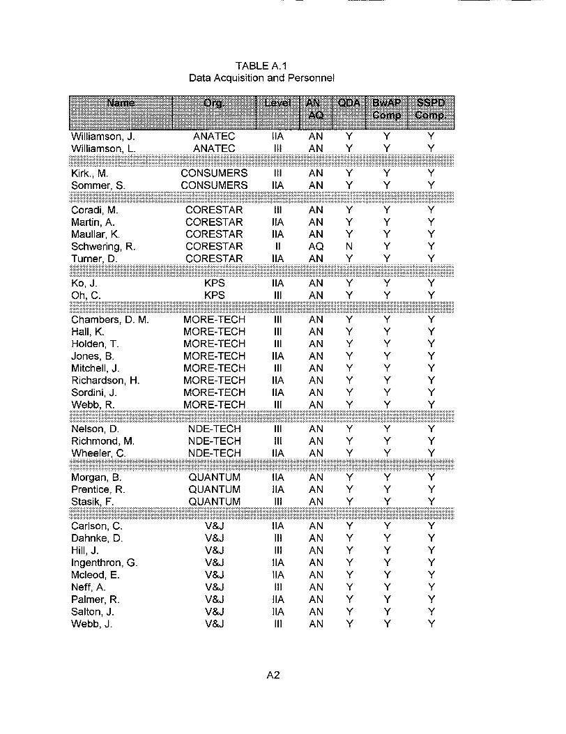
TABLE A.1Data Acquisition and Personnel
Williamson, J. ANATEC IIA AN Y Y YWilliamson, L. ANATEC III AN Y Y Y
Kirk., M. CONSUMERS lil AN Y Y YSommer, S. CONSUMERS IIA AN Y Y Y
Coradi, M. CORESTAR lil AN Y Y YMartin,A. CORESTAR IIA AN Y Y YMaullar, K. CORESTAR IIA AN Y Y YSchwering, R. CORESTAR II AQ N Y YTurner, D. CORESTAR IIA AN Y Y Y
I.. .. 1 . -..... .... ...........- ,............... ...... w................ ................... -............... ............ ...................
Ko, J. KPS IIA AN Y Y YOh, C. KPS lil AN Y Y Y
.. ............ . ..- ......... ........
Chambers, D. M. MORE-TECH III AN Y Y YHall, K. MORE-TECH Ill AN Y Y YHolden, T. MORE-TECH Ill AN Y Y YJones, B. MORE-TECH IIA AN Y Y YMitchell, J. MORE-TECH Ill AN Y Y YRichardson, H. MORE-TECH IIA AN Y Y YSordini, J. MORE-TECH IIA AN Y Y YWebb, R. MORE-TECH Ill AN Y Y Y
*;-. -.. ..-. .. -. .. . .... . .. . .
Nelson, D. NDE-TECH Ill AN Y Y YRichmond, M. NDE-TECH Ill AN Y Y YWheeler, C. NDE-TECH IIA AN Y Y Y
--~~~~~. ... . .. . .. . ...................... -.:. - -.... . ;:-... . :::. . ::. :.* . - : : : , . ...... . ,,. .... .... ....
Morgan, B. QUANTUM IIA AN Y Y YPrentice, R. QUANTUM IIA AN Y Y YStasik, F. QUANTUM lil AN Y Y Y
Carison, C. V&J IIA AN Y Y YDahnke, D. V&J lil AN Y Y YHill, J. V&J lil AN Y Y YIngenthron, G. V&J IIA AN Y Y YMcleod, E. V&J IIA AN Y Y YNeffa, . V&J IlIl AN Y Y YPalmer, R. V&J IIA AN Y Y YSalton, J. V&J IIA AN Y Y YWebb, J. V&J IIl AN Y Y Y
A2
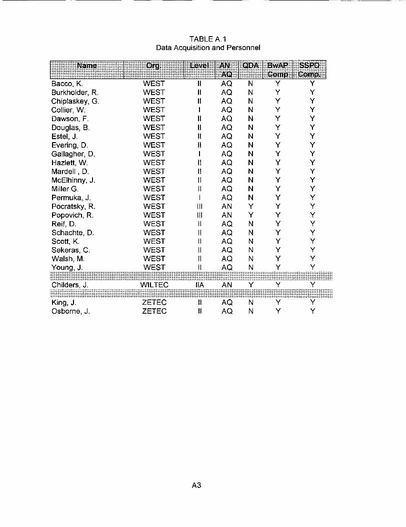
TABLE A.1Data Acquisition and Personnel
Bacco, K. WEST II AQ N Y YBurkholder, R. WEST II AQ N Y YChiplaskey, G. WEST II AQ N Y YCollier, W. WEST I AQ N Y YDawson, F. WEST II AQ N Y YDouglas, B. WEST II AQ N Y YEstel, J. WEST II AQ N Y YEvering, D. WEST II AQ N Y YGallagher, D. WEST I AQ N Y YHazlett, W. WEST II AQ N Y YMardell, D. WEST II AQ N Y YMcElhinny, J. WEST il AQ N Y YMillerG. WEST II AQ N Y YPermuka, J. WEST I AQ N Y YPocratsky, R. WEST ll AN Y Y YPopovich, R. WEST ll AN Y Y YReif,D. WEST II AQ N Y YSchachte, D. WEST II AQ N Y YScott, K. WEST II AQ N Y YSekeras, C. WEST II AQ N Y YWalsh, M. WEST II AQ N Y Y
Young, J. WEST II A
..................................................
Childers, J. WILTEC IIA AN Y Y Y
.............................................................................. .............................. ...........
King, J. ZETEC II AQ N Y YOsborne, J. ZETEC II AQ N Y Y
A3
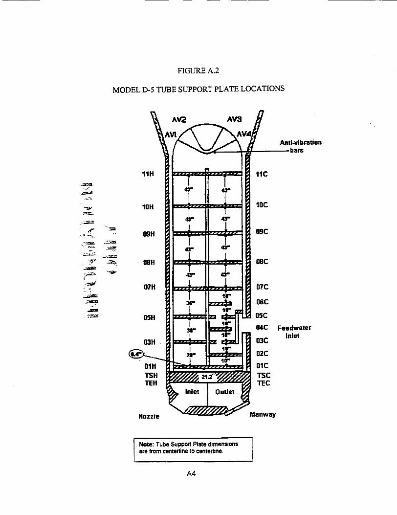
FIGURE A.2
MODEL D-5 TUBE SUPPORT PLATE LOCATIONS
Anti-vibration-bars
. .,14
-7t
.00
-.. C=
._z
.:B
FeedwaterInlet
Note: Tube Support Plate dimensionsI are from centerline to centerline. I
,
A4
ATTACHMENT B
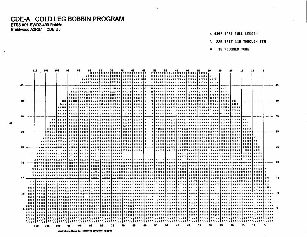
CDE-A COLD LEG BOBBIN PROGRAMETSS #01 -6WD2-499-BobbinBraidwood AMUO CDE D5
x 4367 TEST FULL LENGTH
\228 TEST 1111 TIIROUGH TEN
a 35 PLUGGED TUBE
116 165 16 95 96 85 66 76a I a aX XX XX XX XMMX X X
M I
MX XXi
MX X XI
MMMXMMMXMXX X
MMMXMMMX
MX X
t X X XIMXX X XIMX X X
76 65 66 55 5IXMXXx MMXV X M fXXXXMX XX * X XXX X X *X XMMX XX X$ X XMXa X $XMXX$MX XX MMM X M X $XX X X
XXMX$ XXX * a XXX
6 4X X XXI
45 -
46
L -t--uu--mn--ntau-u-t-u--s
35
36
25 --
26
XMX
X X
MXX XMX XMMMX
--- NX
XXaX X XMMD*-
IMX X XXINXNXX-N
I X X X X
I X XX XI
MMX*--XIXXX I
i X N-XNXN-
X X XIX X X M I
-asCIaDX X
MMCD:MX XX IMX X X
N-N-N-N*
MX XX'
MX X X
MX X X
MX X X
N-N-N *MX X
MXX X
MX X
MXXX,*
-MN-N-NMX X X
MX X XMX X X-M-X-X
MXxx x
MXX XMX X XS N-UUXIMXX XDX X X
XX XX
MX XXXI 4 *4 -N
IMX X X
MXX Xi
1MM XXI
MM X X I
X X XI
MMDXIa
MXX XMXCXX
11*4-NI
MX X XMX XMMMX
MX X XN-N-N-NMX X XMX X X
MX9X XMMMXN*4-NMX X X
MX X XMXX XMXX X
MX X
'XXX XI
MXXX 2IX XXX I
MXXX I
IX X XX i
X X X X
N-N-N-N
MX X
MX X X
MX X XMX X X
* N-N-N-
X X XXMX X XMX X
MXXX
MXXX
MXX X
MXX X
MXXMXX XMXXX
MXX XX
MXX XX
'XXXIX XXI
MXXXX
i XX X X'
MXX X
MXXX I
X X X X'
MXXX
MXXX I
MXXX XI
X XX XI!
X X XX i
XX XXI
X XX X I
XMXXIX
MXXX:X
MXXX'X
MX XX -
MX XMX X X
X X X X
XX X
-N N-N
MX X X
MMMX
MX X X
MX X X
N-N* N-N
MXX X
MX XX
MX X
MX X
F- N-N-N-X
M X X X
I MDXX
X XX XI
MX XIX
MX XXI
1*4-N-N -
XMX X
MX XX
X XX X
X XX X
XCXXX X:
X X'MX XM X I
I XMI
! X ofi
I X XI
X XI
I X XI1
IX XI:
I X I!
I X X i
I X XI:
I ~I
MX X X
MX X X
MX X X
IIN-N-N-
MX X X
MMX
MX XX
MX aX
N-N-N-N
XMX X
MX X X
MX X
MDXX*-*
N- **X
XX I.,
MM X XII
IXXXMI'l
IXX -XI:XXXX
IXXXI
XMXXI
MXXXX
MXXXI
MXXMXX X
MX X V
MX X
MX XX
MX X
MXXMXX X
MXX XMXXX
MXX
MXX X
MXX X
S 46 35MMM XMMX XX XX X
MMMX MMXX XXX
MXXX MMMX XXX
MMMX MMXX XXX
-N--N-*-N- -N*N-- -N-N-
MXXxX MMX XXX
MX XX XMX XX XX X
MX X XXX XMMX XX X
MX XXX XMMXX X XM
MM XXX XMMX X XX
XXXX MMMX XXI
MX XX XMX XX X XX
MX XX XMX XX X XX
MN-N- N-N-N- N--
MX XXXX XMX X X XX
MM XX XMX XX X XX
MM XXX XMMX X XX
MM XXX XMMX X XX
N-N-N-N -N-N-N-N *4N
MM XXX XMMXX X XX
MM XX XMX XX X XX
MX XXX XMMXX X XX
MX XXX XMMXX XX X
'MXXX MXXX XXX
MXXXX MXXX XXX
MMXX XXMX XMX
IMMXXX XMX XX X X
MMXXX XMMM XX)
MXXXX MXXX XXX
MXXxXMXXX XXX
MXXX MXXX XXX
MX XXXX XMMX XMX)
MMM XMMX XX X X
MX XXXX XMMX X X
MX X XMX XX X X
MM XX XMX XX X XI
MMM XMMX XX X XI
MX XX XMX XX X XI
MM XXX XMMXX X XI
XM
M
-NX
XXXI~
XI
X I
X I
X I
'XI
C-N-I
XI
HI* I
I X
tXI
I X
I X
IN-
t MI M
I X
I X
I-NC XC X
I X
C X
I X( X
IX-
( X
I XIX\
M
XX
:X:X
MXXX
M XXX
MM XXXD XXX* N-N-N
MXXXX
MXXXi
M XXX
XN-NX N
MMMX
MXXMXXXX
MXXXX
'XXXX
IX XXXI
IX X X X
X X
X MX aX X
MX XXN-N-N--N
MXX XXMXX XXMX XXXMXX XX
N-N-N-N-
MX XXX
MMXXXX
MX XMX X
MXXXMXX XX
XMX: XM I
XX MX I
N--N-N-NX
MX XX
XMXXX
MXXX~iMXXX 1MMXXX
36 25 26 15 16 S
MXX XX
MXX XX
X X XKM
I XXX X
I MX XXX
X XX XI
MXXIX
MX MX X
MXXXX
X X MX
----I---45
- - - - - - ---------------------------- ---- - ---'-t-rn- ---- --N--- --- tN -NW -t t4N- -S- - -rw-- - -W--tn-- -y --- n- y- N- ----- 4
XX
X
MXX XXMX XXXMXX XXMXX XX
XMXMX XiX X XM XIMMMXXXXMXMX X
MXX XXX XMXMMMXMXXXMMX XXX
XMX X XIX XX'X
MX X'XX XX'X
MXX XXI XMXMX
M XX XXIMXX XX
1s - - - - - - - - - -
XX i
16 -=1NNX XXX X XXXMX
MX XXX
MXXXIM XXXX I
IXX X I
M X XX I!X XXIX
-- M-M-X-MXX XXXMMXXXXMMXXXNXMXEXN-
MXX XXMX XXXXMMXXXMX XXX
t XM XX I
IX X XX I
iX X X XI
X X X XI
MXX XXi
X X X X
XMMXXXMXX XXMXX XXMXX XX
N-N-N-N
MXX XXXMMXXXMXX XX-M-M-X
MXMXIXX
X XIMXX XX
MX XXXXMMX'X
XMMXXXMXX XXXMMXXXMXX XX
X X X X
MXX XXMX XXX
IX XX X
M XX XXMMXMXXX
X X X X IIX XX X
X XXIX
XMX XX
MX XXXXMXMXMX XMMMMXX*-*XNX X
MXX XXXMMXXXX XX X-M-M-X
XMMXXX
MMX X XX
IMX X XX
XM X XX
XM X XX
MMX XX IIMMXXX IIMX X XX
I X XM XXI N-N-N-
X XXIXXMMX'XMMXXXXMXX XX
I -N NC-N'MXXXX
MX XXX'MXXXXXM X XX
XMMX4XX XXMXMXMXXXMMX X
I MXXX*
N-XfXl I
MM XX XI
IMXX XXi
MMMXIXX
MXX XXMXX XXMXX XXMXX XX
N-N-NXN-
MX X
X XM
MXX XXMXMXXMX.MM
I X XX XI
MM XXXI X XX XI
M XX XXII- N-N-N-
;X XXX i
XXXXI
XXXXI
XXXXI
MMXXX
XXXX'MMXXXXXXXN-14N-N N
XMMXXXMXX XX
'N 'I'
X X
-* MN-N-
X XX
MXX1X
MXXXMXXX
MXXX
IXXMXX
MXXXX
MXXXXi
MXXXXI
XX X X i
MXXXIX
X X
I X XX
MX XX X
N N-N-NX
XXXX-*
XMMXXX
MXX XX
MXX XX
N- NN-
MMM *X
MXX XX
MXX XX
MXX XX
XM N-N-N
N N -N-
MXX XX
X XX X
' '''
-- - 46
35
36
25
26
X
I X
I X
CI-N- 15
iXXX
XX X
XX X
XX X
MXX XX6 ---------------------- - - - - - - - - - - - -N--Nf ---Nfr4 -- NN NNN-r n-- -N -N--N-! -N--- -- s- nn--iw----
MXX
MMXMXIXX
I X X XX I
C''''\ I
''''IV \
MXX XXMXX XX
MX X:XMX X:X
''I
MX XXX'MMXMXX
MMXXXXMXX XX
XX XX IMM XXX I
MXX XXMMXXXX
XX XX IMX XXX
MXX XXMXX XX
X XX X IXMMXIXX
MXX XXMX XXX
116 166 1" 95 96 86 86 75 76 65 66 6s 56 45 46 35 36 25 26 15 16
W.UimXQXXuS ftt Co. -NSCISIN05041g6 10,2528
S

CDE - A HOT LEG BOBBIN PROGRAMETSS #01-BWD2499-BobbinBraidwood A2R07 CDE D5
X 171 TEST llC THROUGH TEH
n 57 IFSI 1111 1gIRo1IG11 TF11
a 35 PLUGGED TUBE
110 16 1to 95 99
C
oo0oo . .
85 8e 751000090.00.010.0.00.
I o... .... ....4.... .... ....
45
4.
35
0000.
00..0. ..
. . . .
.... a
_+++.
a.....a.. ..
.4 . .
a. .. . .
76 es 600000 0000 0.... .... 0.4.... .... a
0.... ....4_..- -- 9.... .... a.... .... 04..... .... 04... .... 0* - *+-. -9
.... .... 0
0... .... 00.. .... 0
5S 66 45 46 35o oooo oooo oooo oooo 1oooo
Of .... .. . 44...
o .... .... .... .. ....o. . .... .... .... ....
.... .... .... .. .
.... ... .... .... ....O .... .... *.-. .... ....O .... .... .... .... ... a
I
1:I -u I * *+ --.-- -- +
30 25 26 15 16 5
Do0-ooaU0.. .10o . .
U *00'
.. 00
. .o0
a ....... 0. ....... 9
4.. 0
. . 0.
-94
04,0'.
0'~0'1
_ _...
. .0..
. .. .
. .. .
*400
. . 0oa. .o
0 . . .
o A .-------- I4-4--- I 4 4- - I -+ 4 . I - 1 4 A s.+_ o @+++r _ __
0000 .0o.t
00. .
. . .0 loo. .
.... 0
. .. .*-. .
4- N 9-4-.-. 4.-.-.-. 4-4-4-*-4 -9 4-4-*-4-9 4-4-4-4- I 4-*-*--*-4 4-4-*-*-9 4-.-*-.
25
26
0(0'
0000.
-I 9-.0 .. t
1°° . t00. 4
I O. . .
0 . . .
4 . . .
..... .I
. . .0(
I. . ...
) ... .It - .I
,. .o
.-00<
,. .oo
, . ...
,. . .
I . ...
+. . .
. .. .II. . 4..
. .. .
. .. .
. .. .
. .. .
. 0
* 00 00. 66
0 ... . .
. ... 00
* ., I
... 0<
. 0.* 0
* 0 60 ..
,9-.-.-
I0 4'. . .
. ..
*-.
* 0 0.4 .
I 44444I..*.I....
>-000-0 0-0010
'0 0'
'0 0lo O
0 00 9
0 00 00 00 0e--. 01
00004
00o0
. . . ._. ..
*-. .
....
.... 0
.... (
. . .
oooo0
oooo.
+++.
- - - - -
. .. .
. .. .
_
. . .
.....I.O....... 0. .. .
. . ..
. ... I
+ .+.
*.. ..
0'16 -94
0 .0 .
00.0. *
4* -
4 . .
oooo(
. . .
. . ..
. .. .
. ...
. . .
. .. .
.0 .
oooo .
_ +..
. .. .I. ...
....
....
0 . #. .
........ 0.... I
i....4 .
a. m. .
.... i
.... X X
-
o...............
.....*............ . . _****............._-F.*...*¢¢4.+s........................ *+ 4* * * ***e**s^^.+.^*.*..xxxqxxxe
o+ . ..
*..
- +-.-+
**.** .a....¢¢+OX -@*****+e***
+*¢**v
v@****.... -- 44...* * *0.. 44.. *..F....*F*......._.+.*--*...........
00014 4 00
.4..
44444
*-'--t.
0.+
000 .
.. XXX4., XX
100.00
I-oo I* *o00
* 4 4 00 09.0o. .t
0044 -r
XXX'a11xxx*1
.4. 0o* . 0o
4 . 4 4o
4.+ + '
XX@'XtXX'sXt
00400
4.00
00.4
* . .001
§§* 4.0
XqXX
X+ ....
'0000
.0.99''
*e0
4 4 f 0
)O...°1
4 44
10 . *
0 * 4 4 4
I. . . .
. * + 4
XX''
C'XXX'
P'-+e
_ I _I-- 4.
* . .* ... ..o-* .
36
___ 45
_ i 35
**.. ...
. .. .*....
-25
26
000
9-- 152
. 04 0. noe- - Is
*o0
-.- 9*- 10
. 0
-. 005
4 4 4 0. . 4 0
XX XX
'XXX'
-4-4a- . -.
S
. I --4 9-4---444- -4--- -- *-4--~ I---- --- -4-....1~*** . o+
0..0..
0..00 4 4 . . .0.
....
*--
*....
*-....
.0 4
4 0004*o.0o-..
. f . a
. . . .
. .. .
. . ..
. . ..
*.. ..**....
XXX mXXX P
0 o00000
I....
44444'*ouX.
*. ... ..._ 4__
*....#....
~XvXX~X 0XX
XXE'
. 403
'4444<
.... (
X IXXIX " XX0 ...
'XXXXXXXX
I----. . .X
XXXXI
XXMX
* 0 0 .
lXXI.XXX.
. . . h
XXGXXXmX
*..4. XXI
.... ....I ::4.4I::* 1
.... 44.4...4.4.4...
~:UXXXl$XXXU XXUXlxuxx uXXXjXXX 4xxxm Ixx X X"X Ix M OX
116 165 10 95 96 65 8a 75 76 65 60 55 59 45 46 35 30 25 26 15 1
W~khqhomu Dect Co 9490 S18 M C&MN 10 3358
5

CDE-A HOT LEG TOP OF TUBESHEET +POINT PROGRAMETSS #02-BWD2-499-+PT. Tube Sheet/Special InterestBraidwood A21R07 CDE D5
X 1134 TEST TOP OF TURESI4EET -/+ 3I NCHIES
a 35 PLUGGED TUBE
l16 105 IGO 95 of
00)00.)
a5 8e 75 70 Ss 9.0oXX 50000 qOXO0 C0O ON Xoo 5
C*0.xx $99.9 IX..I ... X x* x. Xc* *.xx . ... I X.. ..*X *X.. a.
55 5o 45 46 35 36oQxOOOQlOOxxQOOOOxxxOoQOOOx I
25 26
04.0 '0'
XX .*0X **0
*. X X* a X X.90 X X
. 0 0 0
0 0 0 0
. 0 * .
xx..0xxO .xx. .
* . . X C
' * X
00000* 9 00
is le
46
4.
35
36
26
26
- - - - ----- 94-494-9--4- -I -4- -s U- A -A
00-00.
00. 90. a9.
. ..X
* 9 9 *
.. xx.:xx:* .XX :
* . X X
. . . . .: * 0 0 0 -
. . . .
* a *.X.ox. ..X.
. . . X I
. . . X ]
. . . X ]
. . . X ]
x.X* X* *.X.
aXXX
a,a00
XXXX
___ - 1 U .E -mmb00- --- 4U49- - -4-14-*9-4 - -4- A1 - - - I--~ II ~-A -
* . X X* . X X
. X X
. . Xx
0. 9...
0 9 9.
x..xx. .xxo..xx. *
xxo .
* . .X* * *x
aI.
99994I
X0x 00x 900X. *0(N -.- 4
X ...:xoa.
0 ..ixo. .
no.0ona0 ...
:o. .
* . 00.
.9 001, * . .X
. . X X
. 0 X X0 0 XX. . XX
a.... X.x.. X.
x 904.X 0o
o. . Xa ..X:
:.x. XXXX
0000
X . . .XXX
39-
990099 900
.9 01
I I -- 1mX--IX 90* 9&~41* - -iAm--- - 6~q too;
oo.:o 4a:
9999 0
.9. ..
. . . X I
, . ex:
X :. . $X:"o
. . X X: .XX: axx
. # * 0
e 0 0 0
0 a 4 0
. . . .
X 0X. .X .X .
oo. X:.X.XXXX
0000
X * xx'.. xx.. xx.. X X
0 .. *C
9.9.'4
Axx:xx. O:xx..
Me #
. . . X
. . . X0 . . X# * 0 X
9.. .,0
. .. :
: X...X ...
. * 0 .
. * . 0
. 0 . .
0 0 . 0 * X X.------X - - --- 9U..UF- --- 9-4S- .9-F * -- -4--44- 4--4- 4 9-4~-# "-* F-- I - -4
OC00'0.'
I. . . .
�. . 0 0
0 0 . .
. 0 4 0
. . . .
. . . .
- - - i:: : : X:. 0 . X0 0 0 X
,.i. .:X X* X X . X .
4 - - i. . . X. . . X. . . X
i.i- .'I[ X . .C
xX
0000
XXX...X
*. X X. . X X. . X X
. . 0 .
. . 0 .
- 'o -
� . 0. .
. . . .
I * .0 0
1 0 04 0
___ na--I.-- --.- .--- .-- --. --- ... 9---- - - 44419-4-9- I l-- -- * f-9-A *
x.i
xx. .xx *X X. .
X:::X,-I. 6 0 X. . . X �
(. . . X. . a X(
: : : XX "
404-9 9-
0 9..
40 9 9 9
0..
Xo..~x ..
.0O9 9 00 . . . .
0. . .
0 . 0 .
* * . X
o .xx..O X I. *xxI.. XX I
. . . .
. . . 0
. f # 0
� . 0 0 0
.X .. (
.X. . (
.X$ox 0. 4000 N
O0x00 Xooot OOX Xc
XXXXXXX
x
0 . . .
0 0 . .
. 0 0 -
0 . . .
. . . .I
. . . .
. . . .
4 .0 *
. .# 0
. .* 0
. . . .
oX XOlN N N X oo40 tOX N9 .xx
-- X
* 4� 1 � m � o O O - - 1 X I o � A � 1 m X m I 1 --- *IK � 1 X K X � 1 *- +--**f -�J-* it - j
000
X 999
X ..XNX 999
. . . .
. . 0 4
. 0 0 .
. . . .
. . 6 X
. . . X
. . . X
. . 0 X
.-xx:.X.
X.x.X 0.
. X. .
99 . N.X. .:.X.
:xxx.-xxx.
Cxxx.1xxx.
N...4N *. .X . .*X . .
.9 X X9 . X X9. X X9. XX
xx. .X X. .xx.xx. .
9 . . X
is
is
K
- ~ I L . - 4 9 . . . - - . . 4 -z. - - I - - - - 9 - 4 - - -- 49 4 - - 4 - I .-F .-- 4. 9 - 4 1 * 1 - -
...0
:. ..O
[....
0 9. .
0-..
0000.
-45
__ __ 35
36
--- 25
.- - 2 6
00
0oe- is
.0
.0. no*. 0.- -q- - 169. 0*9.0.9.0* 9 00
* 949 0
. 9. 09 9 00000
0 .0 .
00.0. .
N 999
N 999
X 999
N .0'
99 *9C. 9999 ...~X *. X Xj:9... ...ex O x .
.N .-.X..X.. X. .
.9 . Ni
.9 . NX.X .~ x X *..X.
--x x- -.X XX.OX XX.aX XXo4
.... t.OOXl..!H# ...- 0 - . . U U - . -- 0 0 -4 - - 9 4 9 - 9 - - 4 4 .- 9 - - - 9 4 - - 6 - - - I - 4 - -f t -9 -- 9 -- A- 4
- -f-t - - - R-
0. 9:
00. .:
.x.0:X ..4x X .
4x X *
0.9.: C . .. .0
**. N :
.9 .X X
4. oxx
. . . .
. . . 0
. . . 0
.X..[90 9
a 0 . X:# 0 # X�. . 6 X. . . X
.X.C X. .
XXXX
0xxoXx.
xx.
N -. Xx .... NN.* ...XX -.. ..N .... NN-- --- X
N. .. *.N N *..o xx .. *...X
NX... .. NN .... xx.. ... X
X.., 9XX ... xx.o .N
NX... .. 'N .. #* NN.. ... XX... ooXX .... xxoo ooox
S5 S. 45 46 35
000. N999
909 X. .9.
01000 XOO3 X2
. . . . I
. . . . I
, 4 . . 4
I 0 O . . ,
. . 0 .
. 0 . .
. . . .
. . . .
4-4-o-
. . f .
. . 6 .
. . . .
0000
I
* 9. * X
* 9. N.X, 9 N.X
NC- X-.-.. Ni
0 0 N X
~ 4 - - . I U - -~ - 4 9 - - 4 F - 4 4 - - 1 - 4 4 - 4 4 4 - - 4 4- * - " l f a44 9 - 4 9 9 4 - - - LI t - r -
O... ZX*.. so... .... I::
oooo* x000 00oo $0000440000
lie 165 I6N 95
: : : XXI . . . X
* . NX NXC
loo'xxC .0000
.X.
.NX.I.X . .I x cc
I... Xl
t, NX
76
C :X: 5 xxx.*X. * xxx..X.. : xxxO
Ioxox xxxois 66
'000 Nt6 is to S90 as o6 75
w ..1n99,9. 19 C11C o . N90 Flu 06m4116 I0 22
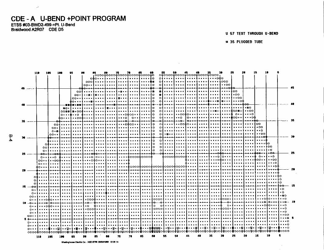
CDE - A U-BEND +POINT PROGRAMETSS #03^BWD2499-+Pt. U-BendBraidwood A2R07 CDE D5
U 57 TEST tHROUGH U-BEND
o 35 PLUGGED TUBE
113 1s S B 95 go 8S BSo 75 79 $ 65 Ss 6S 45 4U 36 39 25 2B iS is
0 o . .... ??O.O ?0..0 *** O? o *e*e**.. ^ooo ... e.... .... ae 0 o:: *e*X *X+ : **@ : :::O 0 o
_ 10 * ... . * *...:: *: *: :... *6 * * *. o *O* .. # . .. 0 ... . . * .. * 00 _
6
36
oo .. o 00 .... ... ... ... o a ... ... ... ... .. . .... .o
oo0 . * ... ... ... a . .... .. o o... . . .. . ... ... ..... .oo.. ... ... ... ......... ... .o..... .... ... *J o ..
)o. ... ... ... ..... ... is. o o ... ... ... ... ... ... ... * oo
oo o . oo ... ... ... ... ... ... o o..... ..... .. .is. oo * .. oo
o1..-.o ..01..* ... ... 0 .. ... o . .... o o ... . o.. ... ... ... oo. ...9 1 9 oM
oo .... go... .... ... 6... . ottooe .. .... o o .... .. oo o *.. .... .... .... .... ... o
oo0 . ... .... .... too. .... Goof 0... .... o o .... .... .... .... .... too. .... .... . oo
o.ff .... .... .... .... .... .. .... .... o o .... .... ... .... .... fees sees .... .. o
oo * .... .... too. .... .... ....... .... o o .0* q ... .... . .* .... e..... .. ... *00 . oo
0o) ... _ .... , .. .0 __ . _ _o o, .. .... .... 0_ _0 _e
oo too. ..... . .0 ... .... .... .... ... o .... 0 .... .... ... ..... .... .. . .4... oo
o...... .. .. .. .... ..... .. * ... o o s ..... ...... .... ... .. .. ... *4e_~~~~~ . . . . - - - - - - - _ _ ,. __ ,,.. .. ._o - - - -
45
36
2526
26
0. 0
000 *
0 0 0 0
�00 * 6
'*.O
*I.I... ..** .
0 0 0 0
... 0
. * 0 0
o *..
o * * 0
...* 0 0 *
*. O.* 4. ..... I
* . . I
I 0000(
)0000(
,0000, )0000 ,0000(
~00001
* . 0.*. ...* . 0..I . -
*. ..*.. ..*. ...*.. ..
* s10000 0000T0000
.- - - - _- - ___- - - - - - - --__ - - - - - - - __--
...* **01. ...*. ...
* * x
* @0* ..0 00
O...,@
O .....* ..
_o- __-
....* +.*. 4.
t.v
* . . .
. ...
* *0* ¢ #*. .
0(00
. . .0. . .
*.. .* . . .
* 0 f a*-* ** . .
*...
. .0*.. ..
. ..* 4 . .
0 . . 0
# 0 0 0
0 0 . .
*. .0 .0* 0
*.. ..
*-. .I.. ..I..I. .
* 4 0 0
. . 0 .
. * 0 0
69 - - -1-t n �_s
0 .0 .
00#0 . 0
Is --O--�0 0 00. .
0 . 000. #
a.--.*. . .*... . . o 0
_+e-. .*o
**....* *a*@...
**s.* ..*..^
o0..-.o...~ -o . . .*. ...*. ..... *
_ . .
a . 0
*. ..00 .** ,*0004
@..
* . . .
*-.- .**...I* . .. . ..
* ... 0
. . a :
.1:::. I-1
. .0
. . .
. .. .
. . 0
* . .* . .
0 .0
* 0. .. ..
. . .
0000
....
. ..._- .
.... 0
_-. .
. ..
)OUOO
*v¢
*4X
*¢¢***¢oooo
*4¢
* . . ***.**¢
*-¢*...**§***
*s
*...... e*...@§§
_+ +__-
*...... *....**@*o.v.¢§* . . .*U sUeUooo
........* . .
I.. U*s*0u
6 0 0. . .* *.. .0
0 40* e 0. . .
* 0X_+4 + ++
b . ....IS -+.4
++ ...
.. U.* *U-~
#* 0 ..0 #1 ..
I .. ..
OU04+
- - --
1000 *
~-4-
. ...*. ...U...)Un* *
. __
-- *-'@ ,
.... 0. .. .. ...
. *...
. 0 _
* ... U*...,
. . . .
. . . .
. .x .-
:....I
..4x0uu*
oo * -
.... .
.... G. ._ 0
. . .o.
.U. .
OU 0
. . . .+s- 4 0
.... e0
*0001
i--- 26
0
40 IS.*o.o
. . .o
.* *49-- 10I. .o
* *o
. . . .4D
... .o
.. * *oooo0
o *..
o.. 6
o. .
0000
. .... 0
f a a a. * *
,00001
te * a 0, # o & 0
.*us
i0ooo
i 0.. ..
q;UIf lo~oo. .. t .0 tl 4, ,.... .&. .. .4. .. ..
. ... 0 {...*4| . . . .|''''t''''|''''t'-|- .... di * * U * 4IsvsUl*UvloUlUve{U { ltU ...I... U1000uI wuuuo~000ult00u000u00(pu000
IN@ 195 in 95 of 85 80 7S 7 eSS go 55 59 46 40 35 36 25 20 is to
Wmshmm Mwb Co. . NMSM WAMM osz0el 20 14
5

CDE - A HOT LEG SPECIAL INTEREST +POINT PROGRAMETSS #02-BWD2499-+Pt. Tube Sheel/Special Interest Revision IBraldwood A21107 CDE D5
1 7 TEST IN -/+ 2'
0 3 TEST 1011 THROUGH IIH
7 3 TEST 0711 -/, 2'
A I TEST 0511 -9" T11ROUGH 0511
a 35 PLUGGED TUBE
its 165 iff 95 es so 76 70 es0000 0000 0000 0000 0000 0
0 0... ... a fees 0000 to.* 0000 o.. .. 06 .. ** -*As *es* a
OO.. .. *. .6.0 6*00 .000 *fee 0- ---- ---- ---- ---- ---- ---- -
55 56 4S 46 350 0000410000 OOOO(OOOO(IOOOO0 too . .... . 0.0 q.. ... 00 .000 .00. .. *. .. *. -- O$0 .... .... . 00 . .... to to
-0 *_ _#-w_. -_ .- ____a 000. .000 .... .0 to ....13 .. ** 0 ... 00#0 Ott. #to-0 .... ... .0.0 .610 to-*
0 .. a. 00 .. ... 0 .600 -fee
39 25 29 is is
01000 I I I I
5
I.-OO45
40
35
-_ 45
0000*
00 0.
)O 0 . 9
0 0 0 .
. . a 0
. . 0 a
. . . 0
0 0 . . ,
I a f 0 0 ,
I . . 0 .
� . * 0 .
*Get
4 . . 0 �no 0 0# # 0 0
0 . 0 .
. . I .4 0 0 04 0 . 0
- - - -. 1
0 . # *
. . . .
4 0 . .
. . . .
a0
0
0
. . . .
9 . . 0
4 0 0 0
a 0 0 0
- - - . f__
00
-00
0.000 . .0(
- - - a- .4 - - - - - - - - - - - -I-
a 0 0 0 0 0
0000 0000J)" oo off* O�foff.o 'O.' .00. 0 0 *at* feet 0$" 4" 0 . .... ()000' .000
0.0#1 too () .... .... . 0.0 400000000 .. o. 0 0 -. 0. .. 00()Otoo #O.. go#. 0 ... 4) Ott ... O
WO6.0 0*001) .... 0.4. O.* 6000 of. See. 0 0 too. .. O Otto too age* 4000110000 ... 04)
0 - I a � - 9 0 m m - -9 0 - -49- -G� � -.----- 4) 0
00 6 O 0 0 004�00. 0 . . . . 0 0 6 O . 004)O 0 a 6 0 0 . 0 04 0 0 0 0 0 0 $ . '00
000 .... .... :::: : 0
Oon Ott. f.. ::: :::: :::: :::: :::: 00 00 :::;,:Oo
0066 .*.* 0004 f.. too. O.* ***a **O* 0.00 0 0 .0.0 o.. .406 0040 0040 00.0 9.0. e.. 6400
.to 0*00 too. ... Otto too. so. O..*()
01 : 0 0 : : : : : : : : : : : : : : : : : : : : : : : : 00 00 : : : : : : : ()O
00 0::: :::: ::.. 0 ... .... .... 000 . .... to 00 40 .9.. .::: :::: :::: :::: :::: 00
0. 640* 0.00 .*S. 0 ... O... too so.. .40. too. 00 00 to .... .... .0
9�., 8 m go' ��- - - �- - - - - 4 a a . . .0";: '..O 46 0.4 04G, 00 �6 04 go-
000 000 4)..*. .0 00 49-.00000000000 0000 0000 0 ... .... ... 0 0 ... .... 0.00 O.. .. O
006.,# .00 .... ::*O()O.:. to..() 0 0 ... *$.. 0004 too
.0
0::: .. .... .... .... .... 1000000000( .. *6 **O* .0.00 )OO00
40
35
39
2526
26I
0100
- - - -. 0 . * �
. . . 0
0 0 . 0
. 0 . 0
. . . a �
. . . .
. . . .
. . . .
I. . . . I
I. . . * �
. . . 6
0 0 . 0
. 0 . .
6 . 0 0 ,
0 4 . 6 -
. . . .
0 . 0 .
. . . .
0 0 . 0
0 . . 9
. . . .
0. . .
. . 0 4
. . . 0
. . 0 . ,
. 4 . .
# . . 4
a a 0 *
. . 0 .
4. . .0 . * 0
. . . .
is
is
5
- - - -T- .-- - - - - - - - - - - - - - - - ---- r-- T - - --
0.
0.
00.0. .
. 0 4 .
. . . .
f a . 01
. . . . I
. 0 6 . I
, . . e . .
)O. 0 . ,
0 . * .
. . . .
0. . .
. . . .
. . 6 #
. . . .
-000
* 0 . 0
. 0 0 . I
. . . .
0 . . .
0 . 0 0
1 . 6 0 .
# 0 . .
9. . .
4. . .
. . . .
. . . .
. . . .
. . . .
. . . .
. . .* �
0 . . .
0000
a 0 * .
. . 0 .
. 0 . #
. . . .
0 0 0 0
4 . . 4
. . 0 .
. . . .
. a 0 .
. . . .
. 0 . .
. . . .
- - - - - - - -- - - - - - - - - -- - I
. . . .
. 0 . .
# 0 . 4
. . . 0
. . . 0
. . . .
, . . a *
* . . .
. . . .
. . . .
. . . .
. . . .
. . 4 .
. . 0 .
. . . .
. . . 0 �
I . . # .
1. . . .
. . . . I
- 4
. . . . 4
. 0 0 0 (
. 0 0 0
0 * . .
. . . *
. . . 0
)OOO.
G.
) 0 .
)O00-
4 0 4 .
I....- - - -
. . 4 .
. . . .
. . . .
. . 0 0
0 . . .
. 0 0 # I
4 0 . 0 1
. . 0 0 -
. . . .
; . . O .
. . . .
� :. . .
. . .
. .0 .
0 .0 .
. .0 .
. .0 0
- .4D
. .. 0
. . . .0. .
0. .
0. .
00. .
... 01
. . 0 #
. . 0 .
. 0 . 0
00 0 a
. 0 . 0
0 . 0 0
. . . .
. 0 4 4
. . . .
. . 4 0
.0 (
* 000(
, . . 0 . �
1 . 0 . .,
I 0 . . 0
1. . . .
0 . . .
0 . 0 0
0 . 4 . ,
. 0 . .
. . 0 -
. . 0 .
4. . .
0 . . .
0. . .
. 0 4 .
. . . . I
. . 0 O �
0 # 0 0
0 0
0000
0 0 0 4
. ...
0 0 4 0
. . . .
. . 0 .
. . . .
. . . .I
. . . .
. . . .
0...
4a--
0. . .
00 a .
.0. .
0. 4 .
. . . .
. . . .
�0000
I
0
0
0
go- 16.0
. 0
- CIO. . 0
-... 4D- is
. . I
. . 0
0 .0
. .00
-00 54 0 .0
0: : : 0
�0000
- - - - - - - - - - - - - - - - -0. . .,0 ...0 a . .
0000(
- - - -. 6 a .
* f 0 .
6 . 0 .
)0000
0 . 0 0
. 0 4 0
0 . 0 0
00004
. . . .
. . 0 0
0. . .
)OOOO
. . 0 0
. 0 * .
*. . .
0000,
0 0 0 . �
0 . 0 - ,
0. . .
0000(
0 . . .
0 . 0 .
4 . 0 0
)OOOO
. 0 0 .
. . . .
. 0 . .
00001
. 0 0 *
a . . *
. . 0 .
)OO00
. a . 0
4 . 0 0
. 0 0 *
,00001
0 . a 0
. . . .
0 . . 0
)OOOO
. . . .0 . . .
7 . . .�0070
i. . . .
�00001 0 : . 0 : . . . . . . . ::::I::::. . . . . . . .
. . . .
. . . .
0 . a .
0000i
I 0 . f 6
, # * 0 0
! # * . 0
)OOOO)0000 �00004 �0000$0000, �0000( )OOOO
lie its 1" go fis , " 75 79 65 so 55 59 45 49 35 so 25 20 is I*
wee"hmmmoo co NSDSM momm 103305
S

CDE-B COLD LEG BOBBIN PROGRAMETSS #01-BWD2-499-BobbinBraidwood A2R07 CDE D5
x 4335 lEST lULl IEGNTH
\ 228 TEST 11H THROUGH TEH
a 7 PLUGGED TUBE
11 165 ISO 95 96
I I I I 1
652121 X11
ofI 2121212
2121212121212121
21212121
722 22882121212*2121212
76I 212121212121421212121
21212121
65 6o2(212121 21
8211211*2d 21212121 xc9 1(21212111
21
212121
55 s6 45 46 36 30 25 26 16s 1x 21 i x 21 2 1 A A I 21 21 A 2 21 21 21 2 2 21 21 2
- x A 2 2121 2121212 .2 1 2 21 1 2 2 21 1 2 2 a12
,212212 21211212121121-21221211211212212
xx I 21212121.2 A 2121 Xxi 212222.2222 21122 21221211 X 2112 AI 12211 21122 22121121-11212212:::x1
6
- | 4545 is--- - - I. . .. . .. -_7
l l- l l leoowI 1- , '' T T T T Ad ''TV ' - T
4, 1 - 4-212121
0212121
21212121
21212121
2121
2(21221212121..22112
IW44114121212121
212121212112 I
212212
212212
212212
2121212
N N-N *42121212
212212
212212
2121212
22x x 1x
212121211I
1212121211
x2 X X 2
21212121
21212121
21212121
21212121
4-44-21-2
21212121
21212121
.2 2121 2121212121x
x12121211
N-**41212121211
21212121
21212121
21212121
2121212121212121
2121212121212121
41-44-N-2121212121212121x.212212
2121212121212121
21212121
21212121
44-44-214
21212121
21212121
21212121
21212121
;x xIx xIx a
Ix x
x xx x
xx
1x 21
-1-i
t
21212121
.21212121
.2 212121xI21212121
x x x
21212121II21212121
121212121
I 1212121
- - - - - - 1 - - - --- I 2x2x2x1xx2x1x2x
x2x1x2x
212121211
212121212121212121212121
:21212121
Ix x x x
I2x1x2x1x
x x x x
x2x1xx2x1xx
x x xx2x2x1x
x2x2x1xx2x1x2x22212121 l 2xxxxIxxxx
3536
3.
25
26
15
16
6
___ - -- 21 2*14 12-4-1 -12-2 214-NN- 1-11421 442-1 -1-21-21 *--14 21-* *-2141*4 442-1 21-21-21-21 N N 2-1-12-4-- 2--1*4-4-214 4-41-2-24-
212 21122121122 21212121X 212212 212212 212212 212212 212212 21 2112112 212212 212212 22212 212212 21122121122 212212 212
2112 21212121 XXX XXXX xxx 2121121212212 211211 221211 221221 121121212212 21 21 21212121 21212121x x 21112 1222122111 1122 21122 21212121 21212
21212 21122121122 21212121x 21122121122 21212121 212212 21221 21 2112112 212212 212212 212212 212212 212212 212212 212212 XXX
of 14441 414-42 42-42 4-2-12 1*12 12-1-1 4-12-1 2-12- 21-41-4-41 * -2 214421N- 414424 21-2*21 *4-21-2 4-2-41-21 -41-21-- 4-4442-2 212-I2t214-12
21212121 XXX xxxx xxx 212212 211211 221221 12212 211211 221221 12112 21212121 21 21 21212121 21212121x x 21122 22211 1122 22111 1122 21122 21212121
21 21212121 xx xX 21112 1222 AX XX 212212 21212121 xxxx xxxx xx 212121212121212 2121211 21 21 12121212121212 212211 12211 12212 22112 22112 21112 1222 21X
2121 xxxxxx xxxxxx 212212 221221 12212 211221 12112 211211 12112 21212121 21212121 21 21 21212121xx x x 21122 22211 1122 22211 XX 1122 21112 1222 2121x
XX 21212121 2121221 21212121 2121121 21212121 2121121 21212121 2122121 21212121 21 21 21212121 21212K 21212121 2121221 21212121 2121221 21212121 2121121 21212121 212
-44*4 21-*--N -42144- 44-4-2-2 44-4-21 41-4-4-4 41-4-4-2 21-4-N- 44-4-2-2 -4-4-4-1. 44 41 4-2-1-1 -44--N- 41-1-2-2 21-4-2-N 41-1--2 44 4-4 2-NN-N 44-44-4 21-121 4 44
21221XXX 2222 11112222 21212121xxxxx xx 212212 212212 211112211122211222212222 212212 212212 212212 212212 212212 21212 21212
212212 212212 212212 212212 212212 212212 212212 212212 212212 212212 212212 212212 212212 212212 212212 212212
21212121X 21212121 X21212121 X 21212121XX21212121 X21212121X21212121X 21212121XX21212121X 21212121 21212121 X21212121 21212121X 21212121 21212121 21212121
21212121 2121212 21122 21122 21212121 211112222 21122 2121212 212-* 1211211 1212 21122 21221122112 21122 21112 1122 1222 21212121 21212121
41N-4N- 4-4-4-21 2 21-4-2 -1-4-4421 44-4-4-2 444144N- 41442121 N-4-4 41-44-44-41 44-21-44-2 -442144 *144141 1-4-4-2 411-4-4 N-N-4-2 21-1-4-N 14-4-44 *44-4-4 211-4-2 44*4-4 2 4N--
21212121 xxxx xxxx xxxx 2121121212212 211211 221211 221221 121121212212 21212121 21212121 21212121 21212121x x 212211 12211 12212 22112 22112 21112 1222 21122 21212121
21 212212 212212 212212 212212 212212 212212 212212 212212 212212 212212 212212 212212 212212 212212 212212 212212 212212 212212 212212 212212 212212 2
-- 2 4242 -4*144- -- 4N--4--* N--42214*2-4144 441-4444 21-44414 44-21* 41414421 - 44212121 214-24 *21-14 *444421 -N-N-* *21212 *21* -41412141* 212444 212---
212 21122121122 21122121122 212212 212212 212212 212212 212212 212212 212212 212212 212212 212212 212212 212212 212212 212212 212212 212212 212212 212
212 21212121X X xxx xxx 2121121212212 211211 221211 221221 121121212212 21212121 21212121 21212121 21212121x x 212212 211211 221221x121121212212 21142 x22X 1122 21122 2121
21212 212212 212212 212212 212212 212212 212212 212212 212212 212212 212212 212212 212212 212212 212212 212212 212212 212212 212212 212212 212212 212212 21212
212121 xx x xxxxx xxxx 2121121212212 211211 221211 221221 121121212212 21212121 21212121 21212121 21212121x x 2121221 221212 2122121 121221 211212 21112 1222122111 1122 21122 212121
-4-4-4 41-1--4 41-4-4-N -21*1-2 41-4-2-4 414- 14-44 1-42-- 1-11-1 212-42 *44 144 2-1NI- 4-1NN 42-4N 4-- 4-42-1 - - 1-- 4-44-1 4-44-1 44-42 11
XX 1111221112222 2222 11 211112222 21212121xxx 21122121122 21 21 212212 212212 212212 212212 212212 2121 21111211112211122211222XXX 21111211112211122211222212222 21122 2221121112 2221121112 1222121112 1222122111 1222122111 1122 21122 2111122111222
21221212211 22112 21112 1122 1222 212212 21122 2121212 212212 212212 212212 212212 212212 212212 212212 21222 212212 212212 211112222 1111222
1112 1122 1222 212212 2121212 211112222 11112222 11112222 2222 11112222 11112222 1111 11112222 11112222 11112222
21-4-2-N 41-1-4-4- *1-4-4 21-1-4-2 -1-1-4-2 21-1-2-2 -2-1-4-N *44-4-2 21-4-2-4 41-4-4-4 -44-14-44-2 41-4-1-4 2-444444 -2-H42 4-4-44 21*4-4 41-1-4-4 21444-2IN-1I4 *14-21-41x 214444 4-4-42 21-21111:2222 12222 21122 .212121 212N-*-* 212212 21212121 !! !I -222252424 -44444 - A - 4--4M--
3.
25
26
is
is
5
x2x1x2xx2x2x2x'''V
1x xxx i1x2x1x2x12
\'I %\'I %
x2x1x2xx2x2x1x
% x x
x2x2x2xx2x1x2x
\\\\\\\\%
11x x x x212 2121x
Ix % %I x %
2121212121212121
21x2x1x2x21x2x1x2x
'I I
2121212121212121
2x x2x11
X2X1X21
% % %
:21212121:
A ' ' ' %
121212121
AM'
22xx2x1 x1Ixxxx\ %% %%
x2x2x1xx xx x 2121121I I x x
% % yx
x2x1x2xx xx x
\\\\ x
XXXXXXyXxxIAxR
21122121122121122'2 XIx21 I,1
A'''I''''
A212 21X. . x 2222x xx x
% N I
116 165 166 95 96 85 8 75 7 6 6 6 55 66 45 40 35 36 25 26 16 1t 6
We**~ El. Co . N4S4 1 05MWM 1Yo.01J

CDE-B HOT LEG BOBBIN PROGRAMETSS #01-BWD2-499-BobbinBraidwood A2RO7 CDE D5
X 171 TEST 11C THROUGH TEH
X 57 TEST 11H THROUGH TE"
a 7 PLUGGED TUBE
lie les lee 95 96
c00C
00. .
as so 75 76 Ss 6S 66 so 46 44 36 so 25 200000 0000 0000 0000 0000 0 0 0000 0000 0000 0000TOO00
: 0.* . .... .... .66. O.O. 0 0 40.0 0 .. 00 0 *fee *O.. *90:: ::
... 0 :: :::. 000
:::: :::: :::: :::: : ... 0 0 .00. o.. .0.. q..6 *..* *000
is to 5
45 45---- ----------- - - .- I ------ ---
49 ---- GG4
00-
13O..0...0...
....
. . . .
0000-
00. .
�0. ..
. . . .
. .00
. . 0
. .00
. . . .
. . . .
*. . .
. . . .
.0 . .
. . . .
. . . .
. . . .
. . . .
. . . .
. . . .
. . . .
. . . .
* 6 0 0
. . 6 .
. . . . I
. . . .
. . . . I
. . 0 0 -
I. . . a,
I 6 * . .
i. . . .
� a a 0 0
. . 0 6
. . . .
. . . .
. . . 0
. . 0 .
0 0 0 .
. . 0 0
. . . .
. . . .
. . . .
. . . .
. 0 * .
# 0 00
6 . 0a
. . 0.
. 0 ..
. 6 4*
. . . .
6 0 00
. . . 0
400 0
a04 .
. . . .
*00 4
-0-
.00 #
. . . .
'00 . 0
0 0 0
O O �O O �0 a I0 0 ,
.0 9
0 0 ,
0 0 ,
0 0 ,
0 0 -
. . . 0
. . 0 0
0 * . 4
. . . .
. . . .
. . . .
. . . 0
. . . .
. . . .I
9 0 ..-
0 0 00-
I . . . .
j . . . .
: :O"' I. 0 0
. . . .
. . . .
0 0 0 .
. . . .
. . . .
6 * . .
10 . . 0
0. . 0
. 0 . .
. 4 . .
0 0 0 .
* 0 . .
. . . .
. * 0 .
0 0 * 0
0 0 0 .
:::: i00 . 0
. . . . i
. . . . I6 e a 0 ,
, * 0 4 0 ,
I . 0 . 0 �
. . . .
. 0 0 0
0 0 0 9
. . . .
. . . 0
. . . *
. . . 0
00
-00
. .00
... 0(. - -4
00. 0
O..
000.
")�Q-6004900a 0 00. . 6 0
36 iI
900
00-
- - - - - - - - - - - -- - - - - - - - - --- - - , - - - - - - - 35... 0(. . 6 # -
. . . .
4 . . .
100 0 6
. 0 0 a
* ...
0 ...
0
0
'O
lo
0
0
0
0
. 0 00(
* 6 a 0
. . . .
)O ...
. a # .
4 0 0 0
, . 0 0 .
00
0 00
.. O
0 0 0000o::I::#.:I::::36
25
20
is
is
5
- - - - - - - - - - - - - - - - - - - - - - - - - - - - - - - - - -. . . . . . . . . . . . . . . . . . . . . . 0 0
0 ()o 6 0 4 4 . . . . . . . . . . . . . . . . . . . . . . . 0 0 0 . 6 S 0 10
0 0 6 6 0 * 0 . 0 . . . . . . . . . . . . . . . . . . . . . . 0 0 0 0
0. . . . . . . . . . . . . . . . . . . . . . . . . . 0 0 a 0
00 go e ?9 a G e -- 4D49--0 - -0 0 0 0 0. . . . . . 9. . .()0000()Ooooq Moooomooooo. 0 . . 0 6 a 0 0 0 0 a 0 0 0 9 0 9 0 0 .0
oo.. .. 00 .... *#*O 0... .... so.. .. *. *.et .4.0 0000 6000 99- 0000 .*000... .... 004. 0.04 ... .... .... #.so **to 000. feet .
et ... .... .... :: :::O()O... 0000moooo 0000()0000 0000M.... of.* to.* et 0
- - - - - - - - - - - - - - - - - - - - -- - - - - - - - - - - - - - - - - - - - - - -
. . . . . . . . . . . . . . . . . . . . . . . . . . 0 . . . . 0 . 0 . . * 0 0 0 *, . 0 . . . 0 . . . . . .0() .... .... .... .... . O$** go.. .... .... .... .... .... * ... #*#. ***O V... .. *.(O0 ..... .... .... .... 40*0 .... .... .... O.*. .. O. *... .... .... #000 ... 0 .. O. 00 .... .... .... .... .... .... .... .... .... .... .... ... *fee O... .. o. 0
- -- t- -4-. �4-t- 4D491-0 . .... .... .... $*to 00. 0004 0... .... .... .... ::04,6 :0
00. .... 040 . .... .... .... .... .... .... .... .... . see 0.00 .00 . .... .... .... *et. *000 of.. *00O.. .. so 0... .... .... . 000 .... .... .. 0... 0000 .... .... .... .... .. 4*1)000* .... 0000 ... 0 00.0 .. O
-- e- 4-G- -9�*- - - - . a0 a - I e - - 0 -- -- t-t - -i i 8 -
O.. ... oi)o ... so*. 0000 .0 W .... .... .. 00 0.00 0 0 **to **of .00. 0900 44.9 0. $see *6*000040 0000 . . .*.. .. O. .*to #off 0 0001 1. . . . . : 000 00.4 .... O.*. .... *of* :: :::: :::: �O.O.O. *to: ::O
00.0 O$ .. .... .... 06*0 ... .... .... .... .... et** see$ Sete O*$ 00.0 *fee 0000 0*00 6660 *600 4000
25
29
15
to
50. 0 .
0. . 0
xxxx
xxxx
- - -I * 0 # 0 11 * 0 0 0 1
1XXXXI
1XXXXI
0 . 0 0
. 4 . 0
AM1xxx
0 0 9 0 10 . * . �
xxxx:xxxx:
:::: I:::: I:::: I:::: I:::: * 0 4 00. . .
xxxx
�xxxx
I 0 . 0 0
1 . . 4 .
1xxxx:txxxC
0 . 0 0
. . . 0
:xxxx:xxxx
0 0 . .
* . 0 0
xxxx:xxxx:
0 . 6 .
a 0 * .
:xxxx!XXXX
a . 0 0
. 0 0 0
xxxx
xxxx
, f 0 0 6 .
! 4 0 0 0 -
AM]
1XXXXI
# * . f
a 6 . e
AM
AM
. # 0 0
0 0 0 0
xxxx
xxxx:
0 0 0 -I 0 4 0 -[XXXX[xXxx
. 0 * 0
* 0 0 6
xxxx��xxxx
.... I
. a 0 0 �
1XXXXI
lxxxxi
. 0.0
... 0
:xxxxAM
xxxxxxxx
:xxxx xxxxlxxxxlxxxxlxxxx:xxxxlxxxx xxxx xxxx xxxx
lie 105 IN 95 96 85 75 70 65 of 55 50 45 49 35 39 25 20 Is to 6
Woodnomume EWcft Co - NSD ST" 05WM W02 53

CDE-B HOT LEG TOP OF TUBESHEET +POINT PROGRAMETSS #02-BWD2499-+Pt. Tube Sheet/Special InterestBraidwood A2R07 CDE D5
X 1141 TEST TOP OF TUBESHEET -/+ 3INCHES
a 7 PLUGGED TUBE
11l 106 16 95 96
45 --00
XO.ox . .,ox . ..OX..
* XOO,*XOo
* ool
C
XxcOXX9
,.XX .
I IxxI. XXoX X .
X X.
as Be 75XXOO XXcoO 0000
0(X X oo X X.° . ..I XX** XX* *....
XX.. XX *. ... XX * .* X**. .N ..XX.. XX .. ..XX.. XX 9...
XX'. XX- * ...XX.. XX *...
XX.. XX *. .*XX.. XX * ....XX.. XX *..CXX*. XX *..o.
76 65 66°OXXO XOXX 0 X
, .XX. X.XX 0 X,XX- X-XX 0 X,XX X.XX 0 X
*XX- X-XX 0 X.XX X.XX 0 X
X XX- X-XX X0 aX XXX X XX 0 X
X X X X Xv X*1. XX. X*XX 0 X.XX. X.XX 0 XOXXX X-XX 0 XXX. X X X X0 X
66 56 45 40 35 36oXX 0000o QOOX 00XX 0000
.XXe *... *..X *.X .9..0 a
.XX *... *.x *Oxx *...* 0
.XX. .... . O*X .XX ....
* X #- * ..- -. _-.N .-.*N- -- #.- .*
.XX. *... ... X *qXX *:**
XX X X X XX . . . . .*XX .... as A*XX *....
e.XX. ... MINX *XX *....
e- *_ . --- * A*.eXX. *... d OX *XX se. .*XX. g.o. .. X q.XX ....eXX* 9.00 0..X *.XX **.* .*XX. .9O 0 X *.XX .. ...
00*00
* 941we.. ...
. ...
. ...
* . . I
_v . .
* . 0 1
-9 ---~oxOX0* -XOO
*x N
ox . .,
X.-ox X .
25 26 16 1t 6
45
XO9,
>XX. 9
.XX*XXO
OXX0
4.
35
36
25
20
16
16
6
- -X- 9 N -XI- --. *- -_ - - -- - --
f--r -- -
00 _. He X.. XX. X.. XX- .9 90 oxx. X.xx 0 X *XX 9.00( ..X .X .. . *X.. *XX* 0000. xx*. X.. xx xx* xx. *.* *Xx X.xx 0 X *XX. ***oo $*lx foxx *.*. **** *x** *Xo .00
0.. XX.* *Xe * XX* xx.. XX ** .... . xx. xx 0 X *X X. **. ***x *.xx *.** *g*o* *X* *XX* *.OO999 xx.. *X** *xxf Xxo. XX.. .... OXXO x.xx 0 X *XXO **** *..X **XX *... *.** *xog *qxx *..
-. .- -X * f* -mXXm-,X-*- -X X m m - - Xe * ~-*- - - � X--** I , 4 X 4o s**F -.*... xx.. *X** *XXO XX#4 XXq. .** XX. X-xX 0 X *XX *-* o..x *.Xx G*e* *fee *Xoo *XXf ....
0 .... xX- *X*. *xx* xx** XX.4 *. * *xxf xoXx 0 X *xx *.*. .*.X *.XX **** *..O *X** .XX. ... 0O0. .... Xx.* *xo. .xx. xx.. Xx.f O.:. O XX Xx 0 X *xX *... .. x *.xx *** **.** *X*$ *XXO 9999 .00 ... .0 XX. .X.. .XXO xx.. XX. OXX . X.. OxXOXx 0 X *. X *xXx ...0 X** XX 0.. .e
00.. .00 (XXO. *X..*XO XoXx. XX.o .. (0x(xX4 X000(*# ex40 00X9i*_0.. ..-. XX.. _*X -XX. xx XX.. I .*.X °.XX .9.0 0... .xq .xx4 0099 9-000... * .* XX *... . . ... XXtO OOX 000 oNo o 00 00 ... X X.XX .. ease *o *xxq .. 0. *.*oo . *.. .X. X * ... Ox .XX . .... Xs. *XXO *fee. 0..0
o - XX .X. . .XX XX.. XX. ... .XX *X.X .. X x *XX 999 .. Xx ..x o~ Xx X * x*x .*e* *9~ *X*~ .XX 999 99 990 ._ XX* . .XX XX_ XX * .... X X- X . * * ,XX ., * X 9 9 00 ... XX*. *X.. XXo XX.. XXo. 0... *XXO xo.x *.x .XX. .... ... X *Xxx 9 O... X** .XX. too. O*.0
0 .... XX.. X.. .Xo xx.. XX.* .. oeX.x *...X *XX. .* *. ... X vs X*. .XXf 999 ... 0 :0 ... X. .... xx.. X.. xx x xxxo XX. .. 4 xX# XO* $. Ox xf .... * o x #.xx *... .... .@ X.. OXX set * .* . 0
0 .... .... XX.9 .X* .XX XX.. XXOO .... OXX X.X .. X XX- .... ... X ..XX . ... *Xs. XX. .... .... .o0. .... .... XX.* X.. XXo XX. XX .... KXX. X.*X ... X *XX .... ... X .. XX .... .. *. *X. *XX. ... .... . 0
00. o... .... XX.. .X.. XX XX.. XX. . .K X. X.X .*.x * XX* .... ... X * XX .... .... *X *XX. 9.. ... .00. 0 0... 9... XX.- X.. XX° XKx. XX.. ... * x x.4X $.Ox o .... ... X o.XX 99* 000. .X.. XX. ..-- o0.. .00
- e.. *.- 9_-. N-Ne . -X._ _*- *N N->*.-. N*-N. *.--. *N-. #..N *- *N1t o- **.-.. _ -.- N .-- N -.-.-. -.N-.- -NN- -.. 9-.-.-. .
o.. o..0 0... XX.. X.. * XX. XX.. ... *XXs .Xo X..x 0K*XX .. .*.X *.XX .... 0. X*. *XX9 ... o o... .. o-o. *... * .. eX * XX x* XX** ... *X -_-oOXX ... X.. 9 X** x -XX ... oo.* 1 hX.. ..
o.. . .... XX.. .X. *XXX XX*. XX .. * * X * *XX .... s ....... ... x X... .... #* *Xoo x 9999 999 .. o
0. . .... .... XXX . X. *XX XX . XX9 . . . . XX9 X* X **X XX. .... * IX . XX .... .... 0 X * 9 9.9. 99.. 900io .... 6.* YY# fxf xHW xxs xx. O. . o x $ . Xx f *#o so x $ g lo e o . x o s e *
w~~~~~~ - _ww 6_*6G*_!
$
35
36
26
26
16
is
is
0 9. 9
0 . 9 a
00004)0000( 40000'
ArkXxK* *
XX ..XXOO(
*X. *
40000
HXX: XX.. xx.'OX xo
Hx e!xx * *'XX..(
XX.XX..:X X .~Xxoo
HX.
oxxo
lox xo
X..X
X0004
99 K
o0 o0X
' XX..KK'* XX .OXXo
' . 9 . .e
4 9 9 9 90
99 9
4 ' 0X
100Ax,
9. XX.90 X X
.90 X X00XX( 40000
a 00 v 0 0
* 000000,
O X O O
OXxvv OXXO)xxo
'0000,
.9..
40000
#9900
9 996 09 9. 0
:00000O0Oc
116 165 Il 95 x Too * * Ax* * Axxooo e 'XXX 'XXOOXXooo xof 86 U 76 7@ 66 6@ 66 6 46 41 35 3@ 26 2@ 16 1 6
W96*Qgb..EIecb IcO -NSO SIUB 05MNS0 100337

CDE-B U-BEND +POINT PROGRAMETSS #03-BWD2499-+Pt. U-BendBraidwood A2R07 CDE D5
U 57 TEST THROUGH U-BEND
a 7 PLUGGED TUBE
116 165 166 95 96
C00c
00. .45
95 86 75 76 650000 Q0000 0000 Q0000 1100000 . . .. .*e*s*4 s
I .... f.... f... t .44$...
. . . ... .... .* *0*
I *.-. - .... *** *..... .. .... #*-.. *.* 4... .... ....
6690
55 56 45 46 35 36 25 26 15 1i0q1ooooo0000qoo 000o0oooo0o0o I a I I
-- f--I I I- U-.00
00400..0 4 4
o o0 00 0
0 0-
0 0-
0 a0 0
5
* . 0
* 0 0 *
46
.:.. 4.... 4 t*4 40000
00.00'.900... .0
4. - t I- * -- 6 4---4-* 4 4-4-4-4.- F 4-4-4-4- 4- �-*-4--*- I 4-4--*-4- 4.00.
n*0 .0...O0 ...
* *004.40 0* .001
14...,
. .. .I
). .. . * 4 000 44
0..
0000
0
000
*.001* . 0
04 *0. . .
400..I 044'00 *4
40004.0 00* 4 * 0* * 4 0
35
25
26
15
16
S
00. .4. 44 )O. 4. 0 0 . .... .000. . .. 4.. ... 4. . 000.0 . . .... . . . . . .... 0 0 .... 44 .0
0 0.... .. 4*4 4q400 00 4.4 4. . . . . ... ,* ** .. . ... 0 0- -9.-0- 4-44 --4-4-- 44----444- ---- 4--4 9- -444 -4 44.- 4-4449 4--- --- -444 ---
*4 ... ... .. . .. ... .... .. ... .44. 4.4.*4 ..44 0 0. .. .. . . .4. . .... 4...
00. . . .. ......... . *. . .0 0 .4...... ..... 4.... . ...... . 4 4 00
0. 0 . . . . 40000( 0000( M0000 0000 ** 0 ~ *. .. 4**4 400. .. 0 . . . 4 04444 .. O.. 0 O...0 f000 .000
0... 4 .44 *4 00001 0000 )0000 )0000 )0000 ( *4 44 4) :444 44 4400
.... . .... .. ...4~ 4q4 4444 of 4 .4 .... 4.. . 4. 4.40 to.. o... 4..0. .44 4444. .... .. ~0( .O .44 .44 . 44 444 ** .... 4 .** ... ** .. ..
O'*.* .0 *0
0-*400 4444 44 .. 44 4q44 .444 444 ... 44 . .. . ..... ~ 00 444 4444 4444 too4 O.O 4444 .. O. .*g . 04~ 0
00 0...0 .44444 44 4w 4.44 444 .. .. .... .. ... *o 0.. . . . ..4q4 .44 4444444 4 . ...... 000. .. ... 0 . . . 00 .... .444 $444 .444 4444 0000 4.. . . 4 .. O 444 ... 0004 4444 4444 4440 0tt .0O
0 .. 4.40 0 *4404444 0 *~ ** ~ 44 a .0 0.. .~4 .44 . 44 444 0 .4 44 400. 40.... . *:4: 444w 0.00 444 44 44 44 44 0000 4444 40of# 44. to44 too. *p444 000. 4444 444 4444 4444 .4
0 .. .. .444 sees 4 ... 444o o * 444 44 4444*#.. 444 44 44..4444 444 4444 4 4 * * 4444 4444 4444 4444 4444 .0*00.0 .. o.~ .. O. 4 4444too. ... O 4444 4444 444 4444 44 4444 444 444* *444 4444 4 w o w 4444 4444 444 4000
0---4 --44 -444 4---4 -- 44 44--- 4---- -- 44 -444 4---- -- 4--4---- --- 4444- ----- --- 4 444- -- 444*-- 44n 44- -444 4---
35
36
26
iS
0 4 .0 . .
Out e
00001
Iu. .u.110000
0 0uto0ouo
4 U. 4aU ool0u00
U a a*IU00O
.4 0.0IoooU'.
� 0 0 0 0 ,! . . . 0 ,
� 04404 � 4 U . 4
0000'U.0 * .I00004
* *. .*10000'
00 0 00
4.44
e000
.4..
U. '.100001
I . .010000
* 4 4
'0000. U . *I out**e.(~U.o
* . 0
0000' )o0U0
* 0 . a
'0U000 u000
0 4 .0I0000u
e 4. 0
* 4 000o0000 Tou
Of0
116 165 166 e5 t6 65 as 75 76 66 o6 65 56 45 40 36 so 26 26 is i6
Wasbqhouw Elecile Co -N30 611 065MIM106 004 4
a

CDE-C COLD LEG BOBBIN PROGRAMETSS #01 -BWD2-499-BobbinBraidwood A2R07 CDE D5
x 4303 1181 FU~ll LENGTH
\228 TEST 11C THROUGH TEC
a 39 PLUGGED TUBE
116 165 166 95 96 aI i I I I I
5 Iis 75 70 6 66 so 6]RN X RE XEAAA9#kXXX X
45
4. --
35 - ---- A
XNAEKE
KENX
--- - t-A
EKE.X
PA NAX
ANNEX
.AEANX
F---f -
INANE.X
KEEN XX
I AREAX
A XA X XI
K* -*44I
RAKE]X
.NAEECX
REN X
-ENX I
-4XA E
RAE0X
RANKXKEKEW-N- ft t-
KEENXKEENX
KENX
KANEX
-44*-NA-
KEENX
KEENX
EKANX
KNEEX
*14*ftX
ENKEX
X AXX
I ARN,
IANNEX
I *-N -flANNEXX
I ANE.X
CANER X
ICRANE-
A N-N-N
CAERE]X
X NNE
ANNA]
KEEN]
I N*N-*-
KNEE]
ANNE]
KERRANNEX
ANNNNXAXE
fl-N-X.
KNEEX
XX AR
RAKE
XXKXX
N-A- N1
KNEEX
XXENX
KNEE
EXXXXXXX-f
KEEN
ANNAX
AXX
XXNNE,
IXXXX-
KEEN]X
XCXEEKXCRXANEX]
I X X--A-NX
EKXE X
KNE X
XAXNXA
KNE X-
N EKE
A EKE
NEAR
ERXX
fl-ft-X
XEXXE
N KXEK
KNEE
A AX N
A-A **
KEEN
EN AN
XEXXX
X EXX
N-A-ft X
KEENX
KEENX
REEKX
KEENX
-Nf -NXA
*1N"
NE XX X
XE XXXXXNK
EN XE I
*X4XA-XX
KAXNX
XKXNX
KNEEX
a)L~ 36C
--- I -4-,--
X XE N X
KNEEX X
C EN NX
IX A-XN-
K XKXK
N-fti **
XaN X
K NUNKNEEX
XNXXN
X X-X
X XEX
KEENX
XNENX
XNXNK
XX- XX-44
EENN-KKNEEX
KANEX
XNXNXE
XK-X-XX-
ANKA**.
XNEARX--N
XAKEK
ANXNXA
KKRA
RAK
XRa X
KAX
A XU
-f- A-ftX
KEENX
XANNA
XANNE
XXN
IX4-A Xi
I- t- -A-A-
XCXNXEC
CEKEECXCAERE]X
XXX X
XXX XA-KNEEX
N1 &AA XXXAl-
U EK U
X a
X UX K.
X K
A A
X A
N A
A X
N K-AX K
X4
XNNA]
XX X XA-
A]~
XEC
AN:
KEENX
XKXNXE
XNXNXK
X X X
Cs 56 45 4
A* *44-N- 444--N N-A-A-ft
IA RA ARE KEEN XX
CRN A RAN X X AXXNAXX
CREEK KAN KEXXNAX
AREA*- EK KANEXEXKXE XN KNEE X
4-A -A-ft -Aft-- N-N-N-f
NEARX NEX KEEN XX
RAKEX XRN KANE XX
XEXEN KNE KANE XX
RAN AAXR XEXKX
-K A-K-A -A-b-As 54-N-A
KEENX NEE X AXX AN]X
XRXNA KXN X KEKECXX
EXEXXN EXE X KXX KKXX
XKXKXE KAX X AUNKI0X
N-NK-N 44--A- K-N-f
ANKA KEAK ENKEC
KEAN EAKE EKENI
ANAK KANE KNEE]
KEENKEEN XNAXK-A-N- 44-N-K- N-A-N
XA NANNEX
I XNXX
X-A-X XKEENXKANEXNA N
ANNA-ARXAXNXXXAXXNXKX
XEXENKEENX
F-A--XXA-fKEEN X
X XK XNX NA AEK XNXCX X X X4-
KEEN]KNEE]KANEX]
N-A-N AANNE9XKXNXEEaNXX
EK NiXA-A-N -NE NUNKANEXXN NXKXAXK
ANNAXIKXAXK
KEENX
-A-N-N-N
XNXAXN
KNEEXXNXANEAAN -A-KXAXA-
ANNAX
XNXAXKXKXEXK
XENKEX-A-A-A XANNAX
KANEX
KEENX
KANE XXAXMXSXK
KNEE X
ANNAX
KNEE XI XEKXE
F X-NX-NX
XX KEN
ANNXE-
XN KE XIKNEE:X
AXA-K-XtXXNXKXKANNAXXEXE
CAX
CA AU
CNN EUHE-U-NAI KNEEXA KEN X
CA AN X
IE AN XX
I-- AN-
ANNAX
KEENX
XKXEN
XEXEXE
N-f fi XXNXNXK
KEENXXNXKX
XNXNXE
X -N-A-NXNX
KEENXKEENXKNEEXA-A-
XNXNXE
XNXNXKXNXEKXEKEEN X
4-A-N-A IA EK C
KEEN]XKX AN CKEEN]X
X-- XENXNANX
ANNEX
ANNA
XA- X -K
XXN AK
KANKENX
-KEEN
KANKXCNN ANi
CNN ANXXIXNX ANX X-N-A-ACXXN
EN ANXEN XEXKNEE]X XN- XEX
EN XEXANXXE-XXE
XXNAK
-AN- ftXANNE
XENXKNEEX
25 -
26 -- X
15 -A-A-
ENXXAN
XXEXC
EKE]!
-K-N--A- I A fl-At K-ft-N-KU 44-N-K-N 4 44-N-K-K S N-A-N-A IA-fl A
45
4.
XEXKKEEN
ANNEKEENXit-N-fANNAXNEARX
XXNXEKNEE
-XXAfX-NXXEXKXXXEXXXXKX
NXNXXAXNXX]
XXNXK
XNXEAXK
-A-* -fIXX X-EXAX
IXKENXICXX XIE
X XN--X--
XNNEEKAN.XXXNXN
* 35 36 25 26 16 16X XN XX XI I I
a
KNEEX
KANEX
XAXNXA
NAXNXE
ft XfXA
XKXKXE
XKXNE
KEENX
KEEN X
-N-X-ftXK-
.KXNNXAIRENEX
E N XXCX
CNX EN C
CAX XX X
IN ANN-XXNXNXE
XENNEANNEXXEANXK
XENEXE
XEXNAXAANN
ANN
NEXEN
AX-AX-A-A"X
XXXXAXENX
EXXXN
AXNNEI
F A-N-N-N-
NXXX
iXEAN]
]ENKNC
N AN X-
EAXNXI
XEXEX.
NNXNXN
N---ftN-X
N XXN
ANNEX
ANNEX
ANNEX
X-A-XXA
KEENX
K ANN
XNXXX
XNXXX
KNEE C
N XNXX
X -MXNtX
A NKNXI
A KENXX
IN ENXX
CRANEXX
4-AX-X-fX-X--
INENAxx
RNEXXNXRXE
X X---X
NXaNXA ASK
A- N-A-N
ANNEXANNEXXNANA
N-N-A*-*-I
IKAKAXKEEN XKANEXXEXEXK
X- X A-XKEENXINANEIN NAX
KNEEXX-- X4-A-
X NE XEXXA EN]
I1X1C Naa
AN~x X
XNXEC
KEEN
XEXKXC
XEXEXE
XNXAX
KENXKNEEXXKXNXE
KEENXft XK*
XNXKXEANNAX
XKXKNXEXAXK-N-AXA-XAXKXK
KANE*KNEEX
ANNE:-f K-N
___1---- 35
KXAKX
AN.Xit K-A---XKNXXAKANE *
XA EKEX
CE X AX X X-X-I
X XA XCA NA A*F
ANNA]X XA XN XI
N-N-N--ANN-E
KEEN
IEXKXA
KEENX
25
ANNEX
XAXAN
ANNEX
ANNE X
A-NXiAX
F Nof-
IAXN
ENXKENX
CAKEX
A --A *-
IEEEXIENXAIAXXNCE ANNX
16
S
am
-- 4-- N4N--K+fi-- - -- ANA -NN-AN f-A- I4-NN- t -- AN-I4---A* -- AAI 4---N -- N
is
16
S
XAX X
XNXKX
XEXKKEENX
N AX N EX- K E E NXIX AN XN
A NX N AX
XEXEXNKNEEX
XNXKXEXNXKXN
XK E N AX CK E E N ]XXKX N EX]X XN X]
XEXNXA
XKXAXNKNEEXN EX N X
XK IXN XAXKXNX'XAXNXA
E NX A KXI N A N EX
IE XANXN
CA XA A
XKXEXNN ANN
XNXKXAXEXEX
-EX A NX EIN XNXXE
CA XK NK N E E X
ANNEXANNEX
ANNAXX X X
N EX N KXA N N A X
ICX K KX K
C EN X XK
N KKANEX
ANNAXKNXEXK
KNEE-E EX K KXNX E NX KK N E E X
KNEE-XEXAXKXNXAXKKAXNE
XEXC
XE N E NX ]K N E E ]XA N N A ]X
ANNE-
KNEEXKNEEXNEXAXK
N -A -N -N -l 4 4 A N N - M E S A f -- 1 4 A N A N- * N K l M E - -N t -N -e M - lK I 4 N -K -A a-N-N-s I -a-a-a-a * A-A-N-K - - - - - - - - - - - - - - - - -
XNXNXK
XKANE
C E X A N N ]X
NA EN C
'' ' I I
ANNEXXNENXK
KEXNXKXXEX A NX]
XEXKXA' K A N EX
KEENXXKNEE
I X ANXXNE AX X N KX
I % %%'
F ' ' ' ' ' X
XENNXNXNXNXA
INX A NX K
IK XAXXK
F'''
A'''
AKAK 4 KEE 4 EKAK A N Ex i x -* K N E -xl A N A K
C XEXN E XNC E K X K
I % %% %1I''',
XEXEXEXEXAXN
KEEN]K N E E ]X
E N E NX XK N E E X
KEENXXEXEXK
K N E E X XC X A N
'''' %I
KANA
ANXEXENEKA.XA
110 105 166 9 6 SO I Of 75 76 6 66 66 66 45 45 35 36 25 26 16 16
W-.avhoca Fins Cc. NW -M EWiN 0932820
a
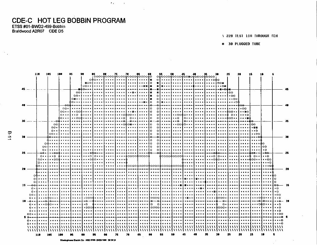
CDE-C HOT LEG BOBBIN PROGRAMETSS #01 -BWD2A99-BobbinBraidwood A2R07 CDE D5
\ 228 I ES I 1111 t IIROUGH MlE
a 39 PLUGGED TUBE
456-
4 --
11 @ 1 5A 9 as so 75
o(0 .. f .... . .000 .$.. .# ....
ooze O .... .... 4.ee.4__, _ _ beg -. ._* -4-+ +
oo . .... .. X.. .. X.. ....On .. .... .... .... . ...0... .... .... .... . .
70 65 690000ooooooo
35
36 --
25 ---
20
15 G
00-
Is -G.
o0-o0 e
on
c
we.
00o* .
0. 0 .
>0 ..
0
- Too
0--
.e...*e. .*. 0.*0 0* -- S
. . .
0-
. ...0 ...
....
. ..
. ...*-..*-..0 0.
*---.. 00. 0*e***.
....
....A..*... 0...4 00
* ... #* v0* ..
. -...
. ..- .4*~...
v-+. O
.. . . .
*. .... .. .
I*.. ..
. . .
0 ---0 *4 .
''''1.
-. . . .
. ...
. ..
. ..
.. s T
. 0 . on
* 9 T
. ..
an....
4 *+
. . 0
.a.e
Too *0. 4
a m
of0 . .
. ..@. ... ..
I. . .
I. -...
i....
I. .11.
. .,..
*--.**....*--.
* ... .. .
. ...
. .. .
a 0To aa a
a aa 0a 0o 0
-9--0 o0 00 o0 o
0 o0 o0 o
66 69 45 44 35000) oooo00a00(0 0000 0000
) ... .... .... .§ .
. .. . .. . .. . . . .X . .. ..
) . ... . . .. . . .. . . .. . e...
I
I
I
I
I
I
I
. . . .
v . . .
.***v..
. ..
. 0.
. * Too
.0 T
D On
39 26 28 is to
.. . .
en..0 ...
.9.
...
- - - d -- _ 45
. . . .
*| .* a.* 0. I* ..
,00
- -4
0 0.00. 0 @
of 0loo 0 0
0 0.0 ..e. 0.. . . .
. .0 (
....-
* .oo....* ..
00o
-00
0 *o
* * To
Io" "#0* * 0D
6
s..s .. o .. . .0. .0. 0*. 0* * **
.... oooooooom oooomoooo ... ... ... o... .... .... o.. .. o
.... 0000 . ... ... .. . .... . ... ... .....
*.*...-. .. I
* *
35
.....
....* * *o
!0 * * *
0 ...
0. -
4 .
0 . .
...
e***.A.*...
. ...I .. ..I ..i .. ..
+ . ** 0...*.*.*
*...* . .
* ".', m9 I*0* 00o* e0
. . .
.
. ...
. .. .
* P0. .4
. ..I* 0
. .
)*0.. ...a. .
O-- .
. ..* 0¢
. 0a
. .*
. 00. 04
A..*.
. . .* ..
*-*04_..
. . .60 .. s. ..
* -4 ,
I0.
.
. 00
. ..... *0. ... .4
. .- ..
. ae
. ..
... 4
*0
0o 0
0000
. .+.*0 f a
. . . .I
* v
- **@X..00
* ¢ 0so . .
. 0.
. .*.@* 0
. .e
4 *.*a* *04 .0. ...* a .
* . .* 6
. 0 .*.@ *
a . . .
6....
. . . .
a
. .. .
.... 4
at* 0 .. . . .t0. 0
. . St .
0 0a0 *@*. 0.
+ * 0 40
0 0** 00
. 0 06 ¢**0
* ..0 e-.*
* 0. 0-
0 . 0
* 00
. a . a
* *0
* 0.4
0 0 .a **
*.. ..I. ...
I001..~ 0
0 00
O*-
0 -
000 O
. 0.a 66
*.. ..* X0. ..A.*9.
4-++~
0 ...* a
* . .* *0
. 0 v
* 0a . 0
4 a0
0 # .. ... e.
* . * *
0 0+ #
0 9 .
***X6***Xf0 e0
* .@e ..*.. .*. ..
A....
# 0
6*0* * a 0
* a**a@
0.* .*-Z.00. +-
'O.
ev@'O**0 00
)O'Olo
. o
. o
.. O
-s .
26
is
6I**.*¢ § I I I I I ' ' ' s ' ' ' ' § ' ' ' ' § ' ' ' ' § ' ' ' ' § ' ' ' ' § ' ' ' ' § ' ' ' ' § ' ' ' " ' ' @ @ ?. | @ | § @ X * * § * * * @ t ' ' ' @ t ' @ ' °¢¢0. * *,
0. * * *
\ \ \ V
. X**.90
0 000 aea 0
0 0ss0 *0
0 00I . I ,H e.
* 0 v v
\ \ \ \
0 4e0. .0
. 00e0 00
I\ \ \\I\ \ \ \
.00.00
0 00***00
i\ \\ \i\ \\ \
* * ****0
X * .o* *#O
IN@ 1e5 1 9 9 8 85 T 76 7.6 so Ss so 45 40 36 30 26 2 is it
W_"aElmb Co -NWSDYtltlXtS 09,2024
6

CDE-C U-BEND BOBBIN PROGRAMETSS #01-BWD2499-BobbinBraidwood A2R07 CDE D5
X 171 TEST liC THROUGH 19H
a 39 PLUGGED TUBE
11 106 10 95 9s Ss so 75 70l I I I 1 000090000q0ooo090000
65 66T0000TO
65 5s 45 U 35 300o000090000o000a0000Q0000l
25 20 15 10 S
'O00 .... .... .... .... I0 . . 1.. ~ ... . **t*.
La .... X .... .... .. * ..oa45
4.
35
w3-~ 30
r'3
25
20
15
_ __ _ 4-\04 4- 4 -, * 4----- -- -- 4- -- s.- -_F-._ - 4.-. *- * - ,.
00 t... se. se. ss .e .* a .... .... . .. . ... .. e.. .... 00
00. .. 0. ... .... .... .... .... a o .... ....* ... .... .*.. .... .o00oe- . .... .... .... .... .... .... a o .... .... .... ...a. .... .... .. oo0
0 o0 ... O..* .. .. .... .... .. e. 0 0 a... .... .... .... .4.. .... ... o(
00 . .... .... .... .... ... .. .... 0 0 .... .... 0... .... '*4. ... * 0-*00
0o... ...00. ... .... .e.4 .... .0 ..... 0 0 ... ..0 .... .... .... .... 00...u0
o... .. o .... .... ........ .... .. o ... .... ... ** ... 0 * .... 0o
0 .0 *... .. #. .... 0... ..... 4 . 0.. ..00. 0 .... .. 0 .... .... ... 0 0... .... .4..a 0.
00 .....4 . . ....0 0 . . ............... .. *. 0 *...... o00 ooo
0 oo. .... ... ... .... ... ... .... .... .... 0 0 .... .... .... .... . ... .... . .eeoM. ... . . .. . . .. . . .. . . .. . . .. . . .. . . .. . . . . o ... . g.., . ... .... ..... . .. .... 6 . .o.4
oo .... .... ......... .... .... .... .... .... o o .... as... .... 0... go.. .... .... .... ... oo
O . . .. . . .. . . .. .. .. . . .. . . .. . . .. .... .... O O .. 0... .. @@ @ .§§ .
-- 4-4-4-- 0-44? 8-4 - 4---- 444 44 -- ... ---- 4 - 4- 44--5 *-4.. -44- 44--4 -4*- **-- -- * 4- - *-.-4. 9
0 0 . **... . ... .... .. ... 4* . .... .... .... .... O* O .... . . *4** 04. .4 a a . . Iv * ... 00 .O' . 4... .... .... * ..... .... 0.00- .- 4-...- O4-4 O-- -§ O 4-. 4.4.4. -0 4 90o .... .. o. .... . . .0 ... o o... 9... .. ooo ooo ooo oo....0 .0 6*... ... o.. .. .. ... o.. 0..o
o.... ... .... .... ... #. .... .... ........... . . ... .... .... .... ... ... ...o(.... .... .... .... .... .... .... .... oo oooo oooo .... .... .... .. .... ........ .... .... . .. o :: ::
,.. . .*. ........ ... .... *. . *.. .. . .. .. . ..... . .. .. . *.. .. . .. .. . .. a. *. .a . .. . o . .. 4. . ... *..* 9.. .... *.0 .. . .. . . .. .. .. . . .. . . .. . .. .. . .. .. o... .. ... .. 0.... .* ...... ... . . . .. . ... ... . .. ... *... .. . .* . . ¢. .. .0o ... ... .... ... M-. ...... ... ... ... ... .....-.. e .... .... .... .... go
o. .... .... .... .... .... .... .... .... .... .... .... .... .... .... .... .... .... 0... .... .... .... o0
o. ... .... .. . ... ... . ... ... . ... ..... .. .... .. .. ... ... .... . ... ... ..... ...
o . a.... .... .... ....... ... ... ... ... f000 0... ... ... ... ... ... ... .... ... ... ... ... .o4~ 000
oo ... .. ... ..... ... .... . . .. . . .. . . .. . . .. . . .. . . .. . . .. . . .. . . .. . . .. . . .. . . .. . . .. . . .. .oo0o. ... o.. ... .... o .. . . .. . . .. . . .. . ... ooo ..... e... .. oo .... .oo. .
60 . .
0 . .OX.-
xxxOlxx *XExxoxi
x .xx-xoxx
* X:I:::: eso of* *40*xxxl4xxx.Ix:0f * xqxxf*.xxx0XXX xxxo *Xo * xoX x 0XXX
HMxxx. xx*x
:xxox
Xsx~xxxoXX:
=xxxx=xxxx
xxx .,xxxo
.4...
:. .:xoxx:Xo~x
e * * 4
.xxx
oXxxi
4...
xxx.PXXXO
..*Xxxoxx Xo x
X . * 1
X-XX1
xoxoxxx
:o~xx xxx0~
4...0
* Ox0xXxoxx
* . .0.40x.X01.Xox
11 its 10M 5 to $S 75 70 65 so 55 569 45 U 35 30 25 29 11 1
W.ev&V ..t 4 "C P0811 05W M 121106
6

CDE-C HOT LEG TOP OF TUBESHEET +POINT PROGRAMETSS #02-B WD2-499-+Pt. Tube Sheet/Special InterestBraidwood A2R07 CDE D5
X 1133 TEST TOP OF TUBESHEETINCHES
- /+ 3
a 39 PLUGGED TUBE
0
116 105 lee 95 go
45 -
40 -- 4- -- A
35 -I-
36 --- I
25 - -
20 ____
Xcx
15 --- 9*oxox
XOXX . X
is - -N-N
X.- XxXX . X
OX *X
ox.-O-N-I
oo X. I
0 * X *
* . X c
- * xo:-c-. Ne"O* C X.:
* cc0X.0* cc0X.0
xOX.
X X.X.X.X.X X.X X
.XO
*XOX(X x.XX.x.XX N c-XX.x.XX. XxX. Xx-* x.x
OX * X
ox X X
CX.X
CX XeX X
:OX(10 *X
0 X0.*X
ccX
#X. c
*..Xx
*..X
ic-c-N.**Xi
-***Xi
:XX.
* X
*..X
ccXccX
-- x0OX
X* .X
X.*OX(
X# X
X * OX
-Xex
X. cXX: :X
X X--
X. *X
X. XX. X
X. cx
X. cX,
X ..X,
X c. X,'X ~XX. cX
0C
lxOC
Xc..
X ..
Xc.c
)Xc.
X .
Xc..
Xc..
Xc.
Xc.
Xc...
Xc.
Xc.
Xc..X -- c--X .X ...
X00
XOOC
Xc.Xc
as as 75 76 4DOOC- OOOX xoox X000(0(O... cc.X X*.X Xc.-cc.0. cc.Xx XcX Xc..*.. c. .c.. XccqX Xscci
* c-c- .c-c-c- N.-. X . *. -i
ccc0. cccx XccX Xc0.c
... . .X X..X Xc-...
.x. . X .cX X*...
... . .X X.*X Xc...
ccc .. X x..x Xc..~cc.. c...X cx.. Xc00
* .* ccX Xccx X0cc
cccx XccX XC..
ccc. cccx X**X X#cc'
ccc6 .. cx X-.X Xc...,
.. . x. X .. x X...,
c... ... x X ccX Xc.0c. C .. X xccX X..$..... X X.cX X..c
c...... cX X.-X Xc.C(
)(0)O~ c X X.X X() 0I 0c.c.X Xcc .X(
#~c.c.X XccXX.
Cc...cX X.cX X...cccc .cc. Xcc.X X........ X X..X Xc..c
...c. ...cX X.cX X...
...... X XC*X X...I cc...... X X-*X Xcccp( . . . cc. X X . c X .cc
. ... cccX X44X Xccc
.. cc ... x Xcc0X X.**) c.cc 00cX X**X Xcc.
so.c* Cccx X4cX X#*c
...cc ... X XccX cc....c.. ccX XccX c.c0
0000 OOOX XOOX 0000'
is Go6OCCOO 0 01
.c. 0 C
c... 0 0
ccc0 0
cc.0 0C~c 0 0ccc 0 0
cc. 0 0ccc 0 0..c 0 0... 0 0
cc.0 0ccc 0 0cc.0 0
0C00
550000
C. c .
* . . .
so 45 46 35oxoo X000 0000 xoxo.X.. XcXc cc X*XO(.X.. XcX. cccXcXc
.XcXcXc cc.. XcX*c
cXc. XcX .c... XcXc,.X.. XcX. cCtc XcXc,
.X.* XOX. cccc XcXs.*N .- * N c--N. -~.----- N*-N-c-.X.. X.x .... X..X.. XcXc c. X.Xc-.XOO X.X* c. XcXc
cXO X.X. cc XcXc.
K-- N* *---c N-cc-cXOomXcX. Cccc
.X.. X.Xc cccc. XcX.
.X.. XcXc O... XcX*cXc. X*X# ccc c X.Xc
c XOD-. X-c-Nc X .X
cx. *_X
.X V.X. X~
.X.X~
c X .Xc Xc0XcX*X'cX. X,
-u _00.00
. .OX(
'00 * X
00c(
'00. X
ccc 0X
...cX
X00X * CIOX~ cOX c. aI X ~.Xc09..
- Xc ccXc..
Xc ccI
oxc XO
-6 c 00
is 25 26 is 16 S
)OCOO(
.... I
.... II....I....
. . . .
a 0 * #. . . .
,0000
0000.
0 0
0000
0000;
cccc:
cxc.
OX 00
cx X
. Xccx c* X..-c-Nc-U0
cxc.Xcx Ci 0.c .X ..c 4X .ci
c0X . cc 0Xc0.
C cXcciIc.Xcci.
Xcic
X . Xc -
N-c-KX cX cXc0 Xc0Xc. X .Xc4X c
N-c--Nc-
a3+-N.-X . X cX cX cXc4 Xc.x0x CN-c-N-X .X.X 0 X .X *X.#X cX *
c. .C.
I. . . .
ici.X cXc.X *X cxX .XX-K-c-NXc XOXc XOIXc0X #Xc0Xc0
Xc.Xc.X CX c
Xc0Xc*IXc0 Xc4-N4-c-NX *X .Xc XCXc.Xc.Xc0Xc0
Xc0Xc.Xc0Xc0X X .XX aXc0
.Xcii
.X.cX,
O -X X'
cX.Xc-*4
# X cXc Xc0XcXc6X*Xc.X
OXOXG*ox
oxoxc Xc.X* Xc0X
ccX
ccXccX
ccX
ccXi
ccXi
*Xi
cC
Xc c-N-c-c--c-IX� c
Xc cc;
Xc * cXc cc'Xc..Xc cc-c-.-c
Xc ccX cccX c cXc cc-N.--.-. -X c c cXc ccX c .C
Xc. c
--1 35
:X.
Xc
~ox. .
cXcX XX cXN X i
c Xx.X X.,
X XX c
CXX.,XX .'
45
46
0
XO
. XOXc Xc.X*X* Xc*-Nc-C X ccXc x* X .X# Xc#X
c X cXc Xc.Xc X cX'OX* X
1OXcXc Xc.X.xcX X* Xc*X
36
- -25
-26
XXXNo-X0X0XOXX cXN c-*-NX cXX cXX .XxXOX
15
is
U 5OX. XOX cxOX cxOXOXI
c .. X.
~ooX.::cicX
'.:Xc:Xo -Xo-X
cccxi.. cX
ccc .X'000X
x.-ciX~ c :XX c c .Xi
iXOoX(
xc..Xc..:Xc. c
'XOO(
.... .... cI ----. . 0 9
4 * . *
. . 0 0
�0000
cic -cx Xci:I c.X
lox OOc
XcicX .Xc:Xc Xc
iXOXO' 00001
XcX.Xc:Xc:XcX.
)XOXO
.xXxc Xc.X
'OX OXI
c c c xi0O -;cc. cX
ic c -X~OOOXc
Xc --Xc..:Xc cc.IXOOO
X . c
OX 001
c Xc:Xc X cXcOXcX
iCX0X: X00
XOXOOCOO$ioooo
116 1 65 166 95 go as as 75 76 65 66 65 St 46 46 36 36 26 26 Is to S
Wcc"chocc. SOcIM. Co. - NSDOS 8105O&MIIM 30:47

CDE-C U-BEND +POINT PROGRAMETSS #03-BWD2499-+Pt. U-BendBraidwood A2R07 CDE D5
U 57 TEST THROUGH U-BEND
a 39 PLUGGED TUBE
116 106 16 9s 96 e6 so 75, 0000000090000
OC
000..00*o
45
46 - __I-
35 400
0040...
00. 4
* 4 .-
* -- -949-004
00. .
o. . .>4*-G*
G . .
G G G
G.G.G.G.G.G.GG. ..
0000.oo..
oa . .0 . . .
* * 00'.* 4G . oo
. . .oo
...
....G_ G
G G GG G. .G G GG...
~o...G. . G* .G
G ..... .. G.G G .G. .. G
. .. G.__*0
G 0 .G. .. G
G. G G
G . G. I
I.G.
G G..G. G ..... GG G G
G
G....G.G.G.G.....
G G G.G.G.G.
*... 0... 0
.--- 4 .- 4.-. $.. Ga
G . G
...
0.-.
G. . .
.. O.
G . G
_ G.
GG. ..GG. ..
a aa 0a o0 0e-4e0 00 00 00 0
G . : . 1-:::76 65
,.... ....I 66 55 56 4s 46 35 36 25 26 16 16,Io 0 0ooo 0oooo ooo oooo oooo
a 0 .... .... .... .... ... o o. a fees G.... .... .... .... 0 ooa
I a ae.. es# _ * ss. .... ..... ... .... .. ¢*O, .. ___ __ - - - - - - - - - - - - _- - - - - -
G+ .
1.-..G
4.0.
G. . oo
. . o
G0 . G
0 . 4*
** 0
* s 0*.. 6. .. G..... G
G....GG. ..*...G**....
0 * * 4,
G ..GG...
G G..
G*G.G.
* G. . 4
00.00* .00* * .0
GOO * GC 0..COO- G
*9.*. 00
... D-...
* G 0 .
G . . 0
4-4-4.
5
*v*§ *..*§*+
- - -
*¢¢¢
-++
... - - - - - - - - -- --- -
4s
* ..- -- - - - -- - - -... ,- .- - __ - ._. -- - _._ _
GG....a G .G*...GGG. ..
... .o
G*G.G.G.....G.. .
On$ GGG. G**--G* G*
G . G .
* . G .
* G G G
* . G G
0000
0000
* 0 4 0
1 . G 0 .
i 0 G 0 .; 0 0 6 *
. . oo*. .v.... 4.... *
of . .
.... 0
.... Ga....
oo00.oa. .0. . 00
I I- 35
W 3-
I0'
000.
_-, -- -*44-4-4-4 - -4__- 44- .4-4_ -4 .4_+-+- 1_
G . .
* 0 0 G
GG* -* 040 G.
_ G G G_
0000
0000
* XGI. GIG. GGi..GG.
* . G* Xa* XG* *0
'000* 0
26
26
050~
15 -ea
uu 't ' '4'''-'-'' t ' 4 ' ~ ' I ' - - - ' t G t -4- I o- 1 . - - -* - - U |- I t ' ' ' '- I - '-' . oI
36
25
26
0..00..o . . .
oC. . 4.
4 ............G G G
G ..o
. G. oo
GG....G.....
C....C....)G .....
4G..._- G0
.... GG
IG...G....G
G,. ..
G ....G . ..G.G..
G . . 0. G ..o.... G....
....
....
o. . .G
. .. G.GG....G
G.G.G.
GG. ..GG....
G.G.G.. .. G.
ooooC
ooooC
Coooo( oooo0oooo
o0000
.... 0I.G..G.I....*. G...
4 . 0.* . 4 0a.a...... G
o . . .
o...' ....... 4
.... 0
... GIG.G... G...
0..G00.G. ....... 4
4.0.4*004..4 0
4 . 0)OOOO0jOOOO0O00004_ -4--_- 4..-- 144441+~ -...
.... G
.... GG....
.... 0
.---- --._.. . . . .. .-- 4 -.--..
0.
0o.
00.
0..
0. .0..0. .
00.
. G . .o
4- .. .o
....
0. G .
0. . 4
.O...
.... G
.... G
GG........ 4.... GG.G.G.
._GG
G G..
G. ...G.....
.... 0G.G.G.G.G.G.G. .. G
G....*. ....... 0* . ..
. .oGo
.0004
.- o.0 4
.0004G. .oo
I....IG. ....... GGG. .. G.
.
.... 0a........ 0
G........ GG....G.G.G.. G ._
. ..G0 0 00 00
0000
90 0'O 0,00
, 0 0
¢ s0
* 0 .G G. .G. G 0G .G
*- G G
G G0. .
G0 0*
. GG4 4G. . G
0 0.
G .G
0..G
G G.G .0
G. GG 6.. G GG
G G. G
¶ � I � t I 4�44 4 44-4* 4-44-4 * 4-4-4-4 1 4-4 4-4- 4 4-44S
G 0G. G 0a ..
.
a.- -
. 040 G0G GGvo a
+s G .-
0 4 a*G .G6 .4
G * 0 .
e .. .. .G .
4 4 a .
*...
.*.4
.*... ** G
****
. . G.a
44 . (G.4. G (44444____ 0
* . . (0 . .9. . .
. . 0 G
* 0 G_.
~000 G
O'0O 0
1000 '9 9.. .. .
. G._
. G G
. G...G.G.G.....
_
* ..G G0G G 4
0 G00 G0a..G
**
#* G. . GG G
. G G G
* a G GC
4.. 0'
.4...
4444
4__ G
* .. G. .. .. .. .
G . . +
GG . C
00 *..s
.... I4*
0G G G
G G .0
O * * * 14_* .
'O00
409. 0* 0*00
.O
400.00
15
16
0 - -4-----4-4- -4- a~~~~~~~~~~~~- ... - I - ._- - - -_ _*
oo . G.U 4. .U0OOUl
1 *. . .
' .4'U
)OOUo(
.*.4
4 U 4.
'OUOOU. .41Uooo0
G .. .UI# # U C4U
' a U *10U0,
* U 4OUOO( 'U000
.. $UoooUc
* * U'o.Go.. U.
)00U0.U. GOUOO' =000
. ..0 00
I... u100ou
4. U 4
OOUOC
4 a 440
COU00
UG. G.*UOOOU G0
u0001* * 0 0
I. UIOOOU(
4. U.1o0Uo
.U..oUoo'
U. 44*G GGU*.)U000 . GI o oU'
* 4 4 0. G 4 0
quou'oUoU
116 165 166 95 96 a6 Be 76 76 65 66 55 66 45 48 36 36 26 26 1i 16
W ~d~g4m" ElWc Ce - NSD 18 05MISO 00U3i 47
6

CDE-C EXPANDED BAFFLE +POINT PROGRAMETSS #02-B3WD2499-+Pt. Tube Sheet/Special InterestBraidwood A21R07 CDE D5
B 32 TEST *2C AND 03C -/+ 2 INCHES
a 39 PLUGGED TUIBE
II$ 1*5 1 96 9b as as t6I 1 I 1 I I BooolOSBOB~ooo
45 -
40
BB-
~o...
eo
oo * 0
e* . .*. ...
o . . .
-. _...
35 900
0000. .
00. .
oo . .o . . .
o . . .
.... 0.....
. .00
. . 0
0 4 00
4 a . 0
. 0 * .
4 . 0 0
. . . .
. . . .
* . .* ..
Tn 30Ln
25-
29
o.,.
o.-
o.
00.
o . .
oo . .o . . .
o...
.,..,
*). ..
. .o
. . oo*...0# * 0
*. ... .. .. .. .. .0..1. .--
I... .I. .. .. .* ..
*. ..*.. . I. .. ..0. .I_ ..
I.0. .I. .... ..
. #0
. ._.
.... 0.... 0
. . .o.
. . .o
_ + 0
* + .*. 64. .. .
. .. .
_
*.. ..
, 0 .:: I.:
0 .. .
1 .
. . .*0
+ .. .0(
+....I
0 . .
{....
t-..1. . . .
. . ...
. . ...
4....
{....
....
1....
Fe
OOOC
. . . .
4~.
. . . .
. .e. .oo. .a,
o. .
oe . ..
.. .
.... 0
. . ..
i . . . .
. . ...
i . . .
. .... .
IB o00o o0o o0o o49----0 o0
0 o i
0o 0
to 0
t° 9 G.to o0 0
o o
0 0 ,to 9(
q
1 . .1 ..1-.-.1-.-.
. . . .
i.. . .
. . ...
1--00
i . ... II . . . I
. . . .o
# . # .
-F....-
1
Fo . . .
F-. .
'O . . .
^....
0. ..... . .... . ...
0 . 0 .
* e 0 *
0 . . .
. 0 . .
. . 0 0
. . 0 0
0 0 . .
0 0 0 0
.. 66
666*
0a.0
0*.0
.. 00
.. 0.
0000
0a40
65 64 65 50 45 4 3
D9OOOO0 0 0 000B BOBO 00OB OOO81
iBe#* a tB*fB t0t+ *** t***
*t*00t a a O.*...t..*t---*te .°-*.---555.
1 * a *.S to. °ff °00 1_
Is0 0.�0.0 ,0 0 0 01 . 0 . 0
I . . .
I . . .
1 * .1 X -0 . * #
) o..~
i.o . . .1
t* 4 - * -
I . ...
1... .
00
-00
.. 00
.. 00
.... .... _§_e4P ........... 1 1 -
I . So,
I. . .o
I. . . ez
0 .... 0
* . .
30 25 2 is to
N01
I. . oe
,,,,,I, ...... I~~~ -. -I -F -........... I- 36
- 45
* 11* 0 .. . .
1 . .
6
00
*00. . 0
0 0 00
- 35
# .....
. . .
. . . .s
IA . . .
4 0 0 0 (
. 0 a 0 (
0 f 0 0
0 . f 0
1°o
26
)ooodoqOOo- - 1
0000oqq
p . .Op. ...
t.- .).. ..
I. . .o
O. .
)O ....
4.0..
)OOOOTOOOOTOOOOTOOOOTOOOOI
. . ..
.... 0
....
. . .0
* 6 . 0
. .. .
I. ...
-. -
... v.... f. aa# _+
.... :
....
. .. .
....
....
.... I
.... ,
.4.+.:
. . .
. .. .
. ...
.... 0
. 0. ._
* e.
.... 0
.... 0. .. .I* 0. ,
. ooo
.o0
. ooo
. ...
.... 0* . .*........ 0
. ...* . .. .. .$ . ..
)....*). ....... 0. .. .
0 0 9 9I..0
1. . 6.
* . . .
* .0
. ..* .
0 * 0
I. . ..
. ..
I...;0 0sI4*.
. ...*-o- ,
0 4.
. ... ..
. .... ..
. 0.. 00
. . .
;;;;.0 00
* I+. .0 .
I. ...
- -. ... ..0 .0. . .
~* 0
e a
* * * 0
- -. ... .0
. . .*
. . .
I. .i. .**¢ ¢ .
I. ...
,a . 0 .
I. .
. . ..
.+ 0
*@.0 00
*.**. .0
0 # 4 0
0 0.
. 9 a
0 0 4 0
0 0.. ..
0 ..0+ e
. . .0 . 0
- - - -
0 0.0 . . .
0 00. ..
* . *I
I0 . . . .
,0 0 0 #
'-� o.' ,
�� 00 :
000:
9 . . .
0 . . 0
0 0 0 4
0 4 . 0
4 0 0 .
0 0 . 0
0 0 . 0
. . . .
. . 0 .
. 0 6 .
. 0 . 0
0 * 0 0
* f* C* 00* .0.
i ..
4 000 ... ..0
.
o--4
. ..
6 .a* @ .
I 0 0
00. .
. ..
.
. ..
v I...* * *
I . 0
* 6..
1 . .! ..i . .
0 00
6 000
0*40... O(
0 *..�
....
....
....
....
....
....
.04. *
Q� �.
�Oe. 6
0 0 0 0
0 0 0 0
4 0 . 0
i
�O
0
0
00. 0
, . 0
-00. . 0
� -. 49-
, . 6 0
, . f 0
'4 0 0
� . .00
29
--------------- I0 I _ _ _ _ 1 _ _ _ _ 1 . _ .1 - - - - a - - - - - - -o | @ | X @ @ | | 0 0 X | e s * @ | | l @ @ @ | s @ @ @ @ l+ - - @ | @ | - -
o ... |
o .. 1o ... h
:::: :::: :::: :::: :::: :::: :: 0: i 4 4 0 .
�0000I. .
1. .I. .
oo000
a * .a ..
* . .
0O000
. . .. 0.. ..
0000,
. .6
., 0 .
0000O
a ..0 604 a .
~0000
a* *I0.
>0000( ~0000
* * .
00004
t¢ 0 a
6 f f
* 0f0 000 00
,0000
_ . . I
0000(
9 .0|* - 0
.... 0
tOOo00
0 . _
.. 0
+00000000$0000$0000�0000�0000�0000�0000�0000 ~0000,lie 145 lee 95 go as so 75 70 65 Go 55 so 45 40 36 30 2S 2 is is
WEIhu" 8cfto NSD SlT0 05MIM1 12 2812
6

CDE-C HOT LEG SPECIAL INTEREST +POINT PROW3RAMETSS #02-BWD2499-+Pt. Tube Sheet/Special Interest Revision IBraidwood A2R07 CDE D5
0 1 TEST lOH THROUGH 11H
5 5 TEST 05H -1+ 2 INCHES
Z I TEST 05H THROUGH 07H
1 1 TEST O1H THROUGH 03H
a 39 PLUGGED TUBEli 1ss is 95 9o
045 -- -.-- - - 8.-11 00 .
030 o.$.On0. . .f
s85 8 75 75 65ooCo0000 0000 oooo ocoo
o o... .... . .... ...aoo.* . ... .... . .. ....zo.. .... .... ... 6. .... .. an0-5.. 4. .._ 4 4 .'..f ...a
IS. .... . . .- ...
.. .... .... .... .. .. ........ O#-.. . .... ... ... ....
:::. .:: :: . .:: .1 0 o .,
goa0aa--aaa0
55 56 45 45 350o000 00000o000o0000 ooooC
o .... 4......*... .o
........ --... .. ....
a ... .... .... ....9 ... .... ....9 . .. ...*-. ... 99.9... *.. ...9
O .... ... ... .... to$*...
35 25 26 15 to 6
>00
. .oa
...
....
. 0...II. ...
00.00. .00. . .0
- _---- 45
4. -
36
11 300)
25
26_0' -
0,0
0 .0 .
00.0.9.
9"
, -, -- F_ . _...
00. .... .... ....00.. .. oo .... ....I ... *. .... ....o... .. o .... . ...
_ _ _ .+ .. 9*9 _ . . . 0 0 . _ 9 99 99 o 900
.... .... .... .... 0 0 o ... .... .... ... 9. 9.. ... 009.. .o.0
. 000 . . .... 0 0 . .900. 0... .... 9999 .... oo.. .. 09999 ... o o.. .... 0 0 .... .. o0 0o.. .... 9... .... 0o.0. ..
... ... o o ... o o ... .o o.. ... .... ... oo. M
.... ...... .... o o ..0 0 .... .... .... ** .9 so.. .... .... 9909.99 99.. .... .... 0 0 .... .... of.9.. .... .. .... .... .. 0
.... .... .... .4. .o ............ .... .... .... .... .. .. o0
35
35
0000.0..
00. .
I....I. ...
. .. .
. 0...
. ._.
. ...
. ...C0o
00'0.,
Io -66.- .oo6' 3...-.- -9994
. ...
.... 0
. .. .
. .. .
_
, . .o0* e0. . .o0
. .. .
.. a..
. .. .
. .. .. ...
* ....* . ..... 0. . ..
o-_+_
o. . . 6
o . . .
.... ....04
.... 0
. .. .
.... 0
. .. .
0..00. .0o . .o ...
>0 ...
....
... 0
. .o0
. .oo.... i
*....
0. ._.
. .. .
. .. .
. ...
*- - -
4 * +
* . . .
*...
....
* . . .
*....
0*
----
...
. .6
0 00. 0.a 0O. 00
. . . .
0. .. 0.0 .0
0000
0000
0 00. ..
0 4.. . .
#4 0. ... 0 0. .0
9999'
.9.,
0 .09 00
.0 00. . .. .0
4- 4-*-*- .i-�-----� 34-4-4-9. 4 4-4-4-9- 4-4-4 1 4-*-4-9- 4 4-4-9-�4 9-9-4-4 1 *--4-4 9 ** 3 �d'4-4 I 9-Wd- I'0000'
'0000
OCOO '0000' 0000>
0000>
I9.99
>9999
>9. 9
>9.9.
9 9 0O99.0O*. * *...! ..
. 9 . 9
....4 0 . 9ss00. ..
9999<*999 0.>
0... ... ..0 .0
0..'00* .. ... . . .
zs
o000. 0
.. o'9. 00
. . 09.0..oocoo OOOO ,oooo
....-
.... 0
.... 0
....-
. . ..
. .. .
. .. .
. ..
oa....... 0
99..
a . ..a....o...9
-
. .. .
.... 0
.... 4
.... 0
.9.99
9999>
*. .0*. .
)00
0
am
i5
.0** 000<
909* 0004* *.* .06.
. .. .
. . .*...0I 4 0
). .~*....*.. ..* * .
*. ..*. ...
* X00000
I9999'. **. *.
. . . .
* . . .
* 0 0 .
*. ..*. 0.* 4..*B a
0. . .* . 3 .
*9999
*9999
4 . I* . . .
* . 0
. .a..I*....
* 0...
ooo0-h ..
I .....
I ....
I .. . .
*.* + 0* a.
'O . . .
9--94*444 --- 4. 94-4 - 4.----- 1.-.-.- .-. 4 .... 4-44.. 4---.3-4944-44-994 -4-4-4 4- - - - 9-9-
' 0
'.0.00
,.o0
26
150..'0..'09.'0
009 9
9 9 9 0
0 9 9 90 00000*# . a
.9...
9...'
. .a..
. .. .
.. 0..
*. . 0
* . . .
*.. f* 0...... 0a a a
9§.9
.9.9
o09
000..9..
.... 0
.... 4
.... 6a....
, 0 . . 0
. 0 0 0
0 0 $ 0
0 * 0 0
'0 .9..9. 0.
9...4
.0O* *0*9*0
*9*00
a-.-.-.-* .-.- 4--. 4.- . 4 *. - 1 . 4 , - 44- 4 4|* --* 4 - --- ---.-9-9-------6--4 ... , .... , . . ... *.
0 . ..0. 9 9
0.. *0000>
. . . .
. . . .
. . . .
)00001
i- * .
6 ...
t0000,
99994..
i oooS.
* a#* * 0.... a
0000
.... 0. ..
.... 0
OOOG0
.... ,
... s
.....
,0000'
i. . . .
0 O C .
F. . .
t0000,
1 . ... I
1 . .. a.
I. . ...
=00(O
95.9>0006'
9...'
0000> *.99
>0000
0.9.
.9.9
*0000 >0000
6 6a0 00* 04o0000 0000>
, 6 ..* 0 0. . a
)0000(
* # *1'. 9 '0 00
'0000, 0000< 40000'
. * * o.* 0*.. 0
000040000'
115 1i5 105 95 0 85 75 75 65 so 66 6s 45 4U 36 35 25 26 is 1i
Wn Ebmm gosef Co . NSD snM oWf9WO W 65 6
6

CDE-D COLD LEG BOBBIN PROGRAiwETSS #01 -BWD2499-BobbinBraidwood A2R07 CDE D5
x 4321 I 1SI F UI t I ING III
\ 227 TEST 11H THROUGH TEN
a 22 PLUGGED TUBE
1e 165 16 95 96 85 66 75A X X A A XX
X X X K I XX X
A .X XX I .X X : . X.XXX XXX
45
40 --- _
A XX'
AAMMX
X MMM
X XX M
*rnXMX X
MXxX X
XX
* X X M
1.X x IMX XXI
X XX XI
M X X xX C
-A-N N-h-
AMX X
MX X
MX X X
MXXX-
N-N-N--N
MX X X
MX X X
MX X X
X X X
N-N-N-N
MXX X
M XX X
I**** ,
XMXXX.
CXXXX
XXX XI
XMXXX:
CXXXX
CXXXX:
CXXXX
xxxxxxxx
Mxx:x
IXx xxx
*W*N-A
CX XX X
X XX X
MX X
X XMX
N-N-Il-N
MMMX
xxXMX X
-A
XXX
X
XX
X
76 65ItXX XMAXXX Mt
XXX M xX XX X
X XX X X XX AX XX X XXX M
X XX MMX X
flox MxxxXM
X XX XMX XX
X X XMXX X
X X xX X XM X
X X X X XX X
X X
X X
X X
X x
X X
X X
X X
MX
66 65 56 45 46 35 36 25A AM % X A X.X A MX MX XX MX XX XX X X
XU A MX XXXX XMMMX XXX MX XX XMX XX X
X M X XX XM X X X xX XX X XX XMX XX XX X
* XX x X XXX XMX X XMXXX X X X X X X X MXX X
*--N-N N-* -IAI-NN N**--N -N N--I- 'NN--- -NNI -*
M x XMM MM XXX XMXXX XMXxX XMX X XMX XX N
M C MX XXxX XXXXX X XXXX XXX X XX X X xXMX X
XU ) x MMX x XXXX XXMX MXX X X xXXN MXX X X
X C X XXX X X XMMXX XXXC xx XX X X MXX XxN N--ft * N-N--N- -N-N-N N N-N-N N- N-N-N N-N-N N*-N-- N
XX X MX XX XMMXX MX X XMXxX X MMX X M X XX X
K M X MM XXX XMX X XMX X XMMXX M XX X X XXM X
M XX )k MXXX MX X XXX XXMM MX XX MX X X MX X X
X M MX xXXX X XX XMXX MX X XMxX XX XMX XX I
26
X
MX
X XX X
X XX X
16 16
6
AN--
X XXX XXX X
45
-__----_--- 46
35 I
X X
A X X
*N-* F I--N-N * N-- - I -x I-MX X X
MMMXCXX
MX X :x
MMMX:
MXxX X
MMMX
MX X X
MX X X
M XX X
MX X X
MX X X
MX X
IX
CXX
X
xx
MMMX
MX X
MMM xX
MX XX
MXX X.MX XxX
M X XX
MMMX
MX X XMX XX
'MX X XM XxX X
MX XMX X XMX X XMX X X
MX XX CMMMXCXX
MMMXCXXX X X
MX X XMXxX XMX X
'MxXX X
MMMX.XMX X'XMX X XMX X
M XxX XX X X
MxX X XMMX X
a xXX XX XXM XX X
35
36oJL 393-'4
25--
26
X I
X I
15 -* *
X X
X XXx x
x x16 -AlItN-
XXXxxxxxx
xxxxN-N_-_-_-
w - s w b _ X i g W w_ _ _ s _ s _ _ _ _ z _ _ _ @s S _ s _ _ _ _ & _. L _ _ _ & I-HHHH *+F*OH F*4HHF X X X X SHF** * * *F*F*F H *+* H***+X X IX X F*5 X X 5 X X X X+HHHFHHHH X X X X d | --N N - t N N N N -N N- N N t IN . -
x X
XXx
MXX X
MX X X
M XX X
X XXfl
XX X C
M M M X X CX
M M M X X CX
C MMMXC
M XX X
M9X X
MMXX
M XX X
N -- - N -
M XX X
MMXX
MMX X
MMXX
C X X X:
C MMMXC
CMxX X X
X X N m X:
- X X X
MxX XX
-MMMX
MX X X
MX X X
MMX X
MMM xX
N-N-N-N
X XX X
MX X X
MXxX X
X XXMX
MXxX X
MMM X
MMM X
Al-N--N-N
MXxX X
MX X X
M XxXX
M M M X X CX
M M M X CX
'MMMXCX
M M M X CX
N-MN-N-*
M MMX X CX
MX X X:
MX X X
CX XX.X
Mx xXx
MMM X
MMM XC
MMM XC
.X XX X
: x x x x I
tXXXX
IX X * I
Cx X X I
M XX X
MMX X
MMX X
MX X X
N-I N-N-
CMx X .
CMX X
I X X'
I X M
MXxX X
MX X X
M M MX
M M MX
CMX X X
MX X X
MMM X
MMM X
MX X X
N-N-N-N-
AMMMXX
t x X XX
C M X I
i x x x x1
CXXXXI
MX X XMX XXMX X XMX X
N-Al-N-NMX XMMM XM M M X
MMXXIX XXX IMM XIXXX XIMMMMI I
MX X .M M MXMX X X
N-N-N-NM M MXM M MX IMXXxXI
MXXXI
1X XX:iI X X X X :
X XXI
XXxXX
M M MXMX X XM XxX X
C MM X X
C M X X
M M MXMX X X
X XX X'N-MN-ft
XXX
M M M X
M M M X
CMX X XA X X X X X X X i A A X
I -N- N-N- - - N -N -N--Il- t * **-N-- -- I -N--I t- I N-N- - - - -t-I- - - N - I - N -N - N - N -t I N - - - U N - XIt I t X - N N - N -I t - N -N f Fll*r rr7MMX X
MMM XMX X X
M XX X
N-N--Al-I
MX X X
MMX X
M xX X
M X X X
N-N-N-ftXM X X XM M M x X
MXX X :
MXX X
MXX X
MXX X
MMX X
X X X
N-N-N-N-
MMX XMX X XMMM X
M X XXMMX X
M X XX
M M MXN AN-N
MX X I
: XX X X
MMMXC
M M MXCX KN--It-N-N
X X X X
MX X X
MMX XMMxX XMXx xx
N- N-N-N-
MMM X
M XX X
MX X X
XMX X
N-fiN-x
MMX XM M M x X
X XxX I
M M M X I
MX X X I
M MMX X Cx
IN-N---N-CMx x XX:
XXMMX X
IX X X
CX X X
MMM X
MX X X
MXX X
MXX X
MXX X
MMMX
im"-Nfl
MX X X
I X X X
t X XX X
X X X X
CXX MX
M1XX X
M xXXX
MXX X
MX X
N-N-N-N-
X X X
M MX
M X:XX
CMX X X
M X X X
CMX X X
I X MMX
1-N.*-* *
CMX X X
I X MMx
I MX X X
X X MXx
I -N-f
MX X X.X XMX
M XX XM X XX
)I XX XM
MXXX
MXXX
MXXXN-Nl-NN
MMX X
CC XXCX X
MXXXI
MxXX
MXXXX
MX XXIX
IX MX XI
I:X MX XI
M XX X
M XX X
M XX X
N N - -I
M M X X
X XMX xXX
MMM XCX
MMM XCx
MMM X
XMXM'
-N N-f N'
MMM X
MX X X
MMM X'
MMM xX
N-It--It-
MMM X'MX X XMMX X'
MM xXX
MMX X
M XXX X
CMX XxXX
I X MMx
MX X XMX X X
MMM X
MMX X
It--f ItX
MXX X I
MX XXI
M XX X
MXXXN-N-Il-f
X XMMMMM XMMM X
C X XX MC;
C X XX MCi
CMXXX:
I X X X X II*XXX*
CMXXX:
i X xM X C
ixXxX XCF XXXI
MMX XMXxX XMX X XMMX X
N N-A It'MX X XMX X XM M MX
M M MXN-NflMX X XMMX X
MMM XMMxX XMX X XMMX X
MXXX
MX XMMM X
xxxx
tMX xx
CXX XX
X XMXX
I-MN I Ix
I X X X X
CMXXXX XMXXCXXXX
FI*-*N*CxX XM
MX X MX
IXX XXIXX MX
MMX XMXxX X
M X X XMMxX X
M xX X*11*-ItMX X XMMM X
. . . .
X XX MCI
X XX XC~
"XXX: M
MM X X I
MX :XX i
ICX
F * It-N--
XxXXMMX XMX X XMMX X
N-N-N-N-
N N'ftNMMM xXMXX XMMM X
X XX X
N-N-AlNMMM XMMM XMMM X-M-X-X
-- 25
F -_ 20
X
X1
Xx
XXXX-
XXX
N-N N---
15
0 FHI -It-- It-N-I- --N-It-N-N-It-It-N It-Ht-- N-N j It- N-It-Il-XNX-X X t xNx-It-N - N N -N-N-N- N-N-t-Il 9 -N-N- I- N -t-It-N-XXXX--------- ,^
MX X XM xX X
X X X XIXXXXIIM X X X I
I\\\\%%
\\\\ %%
MX X XM MX
MMM XC
M M M X CX
N % N
'M Mx xXXM xX X
MX X XMX X X IX X X X
I\\\\N%
MX xXM M MX
MX X X
MX X XMMXXXXMMXXX
X \ \ s
ICXXX X C
IXXX XI
[\\\\' %i % % %
M MXMMX X
X X XMX X X
AMMtxxxx
MX XXMX X
X X X C
XX X XCMX X XMXXX
M MXMMMX
Ixxx xi
I'''''I \ \\ x
i % %% %
xxxxMMXXX
I \ x
XX x xxiXX MCxx
" ' C% ,
'MMXXX'MXXXXI x x! x x
M M MXMXXX
116 165 166 9g gg 85 s6 75 76 6S '6 55 66 45 46 35 36 2s 26 15 16
Weec.. VEa Co - NlM SO N 5-own U o W4
a

CDE-D HOT LEG BOBBIN PROGRAMETSS #01-BWD2499-BobbinBraidwood A2R07 CDE D5
X 170 TEST 11C THROUGH TEH
X b7 TEST 11H THROUGH TEll
a 22 PLUGGED TUBE
lie 105 Ieg 95 90 85 8G 751|ooooqoooo9ooo
45 i i i -
46 -- I 4 -- 0GE00-
00. .0 . . .
0..
G!
00
.0. *
* . ..
* .004
. . 004
04
000'100 9 .
;. .9..
). . .
4....
10 * 0
. ...
. . .
* §0* . .
* ..* ..
*.0 A. . .
76 65 Go
11.0..0 .90.9..10
::: :::: aoog
55 59 45 46 35 30 25oQooooQooooQOOOOOOO000001
26 is is 5
-- ts-t+a a n e*--d--+--I * d-.- 4 - 4 -9-9-e *9-01 - 1 ------ 4-
0
0
0
A. 0
* . .* v.. ..
9 on.
. . . 0. # e.
. . * o
0 0 0 *
0 00
. ..
4 0.. ..
00.**@.
0 . . 0 -
0 . 0 0 -
. * . 0 -
,. 0 . 0 �
0 6 4 . �
,. . . . I
0 0o a
a 0a 0
0 00 00 0
40 0
0 0*0 0 0.0.4
* - X *
0 004. .e . . .
0
-- 4-H e.
, 0
, . 0
9 . 9 a
*0 .96.
0 .9..
* 0 . .
00. 00. .009.. 0
:. .. *. 4. .... * .... v .... .o0*e.. *.^.*.. 4 4 .... * 4..^ oo
46
4.
. .9.4
a .*..****X00 00
>00.a.
)00 9.
.00
. . 00
. 9 9 0O9 0 oi
35
36
25
26
15
i6
6
- - - -
00 ..99 ~999 9999 ~ .... 00 00.0 9. 0 0 O $ .00 09 .0 * o 9999 4*09 90
0 0 .. .... .... .p99 90 999 99 9*9 . f * 0 9 0 f 9 099 a 99990 **0 999 99 '99w 999 0 0
0.9 9.990. 0 .* 999 a .99 . .9 .9~ . . . 0 0 . . . 99 0 999 99a'9 .. **9 9 0 0 9 99990 0
0 0.. . .. ............... . . .9. .......... 0 0 . .9~ . . .999*~999 .. .0 0
1). 99... .9.. ..................... .9. .. 0 0 99 99.. 9999 9999
0 0 . . . . .99 .99 . 9 . . .*~ 99 0 0 .'~ ~ ~ 99 .. ~ ~ ~ . . . .. 0
0 . 999 9 .9999 099 999 99. 9 99 0 0 0 9.9 99 99 99 99 99 99 *9 999 . 0
0.. 0T .90 999 999 .9.0 0 0... 0 a99 O(0000 10000) 00000 10000m 9.... 0 0.. . a.. 9 O .. *000099 .9$004 999 9999 99900 OO 0... .0* 0~* 09 999 990(099 . 9 99 00.. .9000- ..99 9999 * O9 9 9 9 99I99 99 99 .9.00... 9999 9999 999 999 99 9999 999 0000 oo 0000 )0000 000000 000o) . . .. . . dodo 9999 9999 999 9999.999.99O 990
.. ' Uto F-v . .. |.. .. ,, O#$ #*O 000 4 U U * -- .. ... .. ++. *. ... .. + ... ... .... +_
0~~o ... .0 0. .... .... .... .... ... o *oo. .... o o* .... .. oo o.... .. .... .... . ... .. .. ....o o
oo ....$* 0* ..... dd .... .... .... .... .... ....oo .... .... .... ... .... .... .... ...;. *o
o. ... ... ... ... ..... .... .. . . .. . .. 0. . . .. . . .. . . .. ... .... . .o...
oo -- .... ... ... ... .......... oo..... ... ... ... ........ .. oog
0 ...... .... .... o .... .... ... ... .... .... . o. .... .... .... . ... .... .... 4... of.. .. 0. ...
o .. .... .... .... .... .... .... .... .... .... .of o..... .... .... .... .... .... .... ... ... o
0 o.. .... .... 0 .... .... .... 0... . ... .... 0... .0 o o$... .... .... .... .... .... ......... $oo 0
O. . ... ,... .... ... 0. .... .... .... . ... .... .... o00 o 4 .... ... e... .... .... )0 ... .... ... 4. .... )00 .o 0
o .. .. o ..... .. o o .. ... ... ooo ooo ooo ooo.... .. oo.. .... ... . .. . a o
oo ...... aa 0 ..o ... ... ... o .. ... ..... ... ... o.. ... ... oo.. .. oo
0o. .... .... .... .... Good . ... .... .... 9* ... 9 .9.. .... .. 00 9999 9999 99.9 9999 999. .... .... .... .... .... .... .... .9.9 .... 99.9 9999 .... .9.9.. .... .... ..
0... .... .. I.. .... .... .... .... .... .0... .. . .. 9.999 9999 mood . .... . .... .... .. .0
0o. ... 0 0... .... ... ... ... ... .... .... 0.. 0.. ... ... ... .... ... 0.. 9999 ..999 ... 0 0... .o0
0o. .... .... .... .... .000 .... .... .... .... 99.. 0000 ... .... .... ... .... 000. .99. .... 9..9 .... 99009.. .. 9 999 o99 99o 9999 9999 9999 999 5999 ... 9 9999 9999 9999 9999 9o99 9999 9999 9999 9999 .. 99 ooo . .. .. .. oo.. .0
00.. . . o @_ .. + - . ._* ++9 _ _ - e + . + . _ ... .* ,* .. 9. 999 999 . ~ ., ... 900_.
36
3.
25
26
15
50 9 *Of 9 a
xxxxxxxx
xxix xixxj:x~xxx: :xxix
xxxi:xxix:
cxxxx~~xxxx, :xxxx Ixxix: :xxxi
:xx xxixxxx:ixxix:
:xxixXxxix
xxix:xxxi: lcxxix :xxxi
:xxxicxxxx0 .cxx xx 'xxix
1xxixxxxx:xxxt
p99994 0
LiI R.04,1xiixI :xxii xxxi:
xxix cXxxx.
9.99,
9 . ..
xxxi:xxix:
9. *O9 0 **
cxxx1xxxx
116 1i5 1" 95 of 85 Go 76 is 65 6s 55 56 45 46 35 30 26 26 16 1t 6
Webqhomm Eb.bk Co. -NSD ST OSO W 00 81 -43
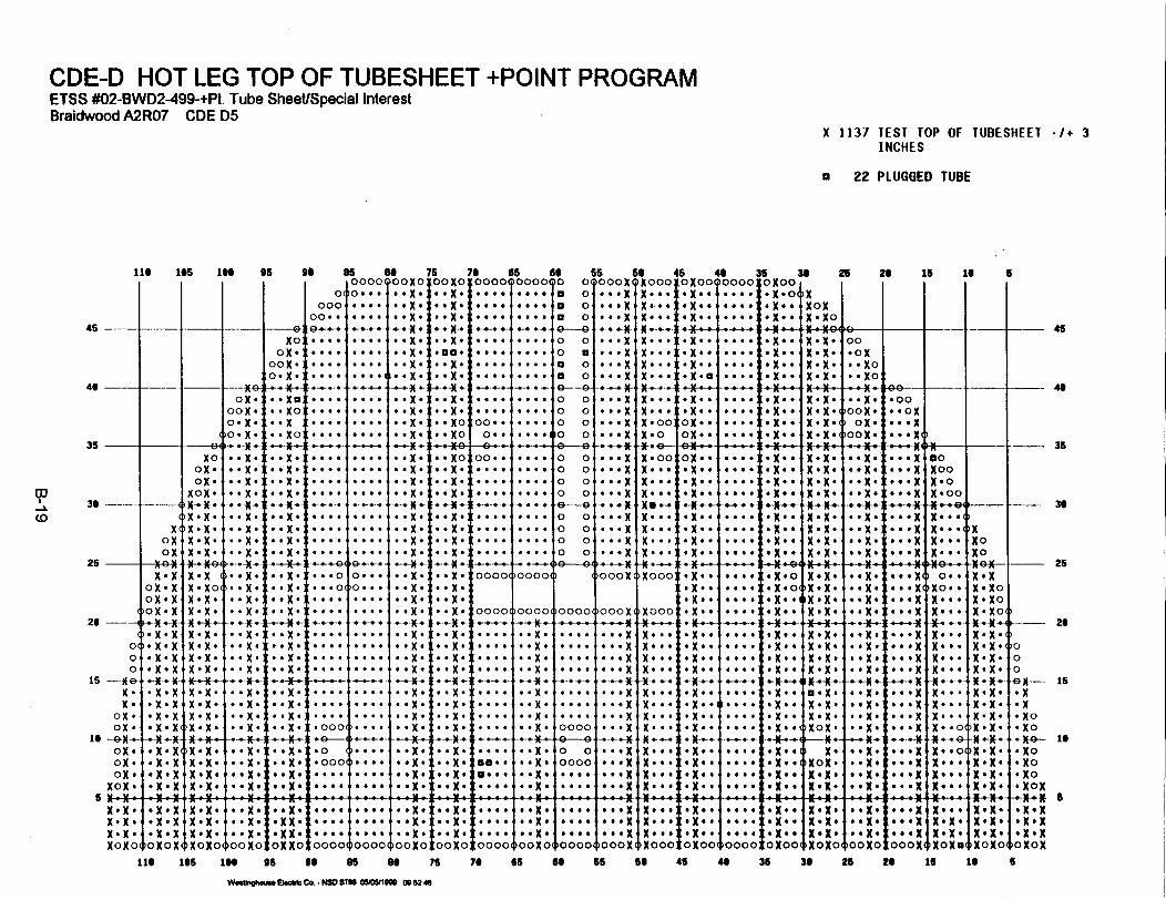
CDE-D HOT LEG TOP OF TUBESHEET +POINT PROGRMMETSS #02-BWD2A499-+Pt. Tube Sheet/Special InterestBraidwood A21R07 CDE D5
X 1137 TEST TOP OF TUBESHIEET -/+ 3INCHES
a 22 PLUGGED TUBE
116 105 16 95
C00c
00.45 -
46 -- l -- -4
35-
36 -
25
20 --
000s--
15--1(N .A
OX.
OX.ox.
OX.
OX.X.
X..4,N .N.
N oN o
--- 4
XcoNox
Kx.XOX * X
OX *X
)oxX*N
.X.X
* N . N
-* N. N*X.X
-* t.-K-
* N . N. X. X.x .N
Noxox.xox.
* X .
N.N.NX .
xX.X
,* .- *
X .X .X . x.4N.NX.
X N.X.X I g
ox.:
X0.:0. N
XO*
* X .N
*.Xe
.X.
. XC* -
.XN
..X
X .N
**Xe
*.X*
X*4*
X0OX.
0X.0.X
*.Xe
.. Xo
*Xe
X.Xe
I. XN
,O X~
.eX e,X N
X- K~
* .
X
.0* OW
65 as 750000 0OX0 OOXO0( ... .. X. .. X.
-' .-.-. .-.-t #oxX. . ..XCOX.
.. X. .e#eXD.
0~.eX. .X
X ~e ... *X
.... ..eX. .. XO
76 65 66I0000 0000 0
.9.. .e.. *
,-4 --. -4-4 ..-
e 0
... e ::. 0
* o:::: 00. .
56 56o cooXIXo000
o *..x Xe..0 #*.X X*...0 *#*X X*..
a ... X N ...0 ... X X...0 ... X X...
.4-.- ft-ce...0 ... X N ...0 ...X X ...0 ... X X.000 ... X X.0
* X . *
O X. .O. X.oN. .
C. . .. ,
'e.e. .
. X* .
. Xe6.
: * X
X.X.X-X:X .X .
X * XNec
45 40 36I xoo00cj0oo OXoOX.4 4..#. .X.0,
.X.. I.... *X..XOXoN * o
00.oN
*. No*. No
,*.CX.
>OOX.ox.
oox
.00
* *.X N
36 25 26 is 1s 5
45
IIII
II
11-11:
........
. . . .I
1 .- ,
#0 40-. . . .
. . . .
. . . .
Q� � "0...0.... . . .
'I". . . .
. . . .
. . . .
. . . .
. . . 0
. 6 . .
. . . .
0. . .
* Xe
.X.X.
Xt.X N
*.X I
.X I
.X.
X.X.
. Xe
X.
* X.:
X e.:
. . XO
* . X *
* . X *
00. .
. . 0 .
. . . .
. . . 0
0 * 0 0
. . . .
. . . .
. . . .
. . . .
. . . .
. . . .
. . . 0
- . . 4 I
0 4 0 .
. . . .
. . . .
. . . .
0 00 00 00 0
-0 00 00 00 0
. . . X
. . . X
. . 0 X* . 0 X
0**. . . X. . . X
. . . X
. . . X
XX . *. ~XN. *. .Xe 0 @0
X . . .
X.: .: :Xe. e.:
Oie.
0.X::
- - - - I0. . . :0 0 . . �0 0 . . :0 0 # 0 :
*. . .
0. . .
. . . .
0 . . #
F -N---
;CX...
X .X eX .X.
X .X.0
X .X.6X4 N.XNX .XNX .X
. . X e,
-* .Xej
* .X .
--- e- .-.- X
* CX
.. CN-
*0X00XCOX .00
X .* . t
X * .
NO
)X
-- I - 48
* . N* . X *
H- .KX.
:. . X#
:. .X.:. .X.
oooo0$oo0o$ 100ox X000:
:000:e. ..
.....I. . C
'00001
.. X.
* C X C
* .X .
* .X .
..X .
)0000(
0 0
0000
)Ooox
. # . X I* .. X,0 0 . X �. . . X ,
. . X,. . . X �
. OX,. . . X �
, . . . X �, . . . X �
, . 0 . X,, . $OX,
XOO
X . *
-K-.. 4-
N * *
X . ..
Xe. ..N 0e.Xe ..
.X.:0X.
.XC
CXO
OX.
*Xe*Xe..
XN.
. . 9 .
0 . 0 0
0 0 0 0
0 . . *
0 0 0 0
0 0 . 0
. 0 0 .
4 . . 0
. . . .
Io. . .
. 0 . .
. 6 . .
. . . .
. . . 0
. . . .
0 0 9 .
.X.0
O Xe .
X . e
. N e .
eNX. cc. X. ccX . e
.X. o,
NeX.X
NX .X
aoN. X
N XN. X
N.
NXN. X
# . ie:eo. X :
e. NXeeON.X
*o.X o
O * Xe0
-4 .fX .
CoN.Xoc.X.0eC. Xe.eON.X
*.. i~
oeo 4 X
I !-,.ti.t.X
I 0 ..
IXOONe$ oXNo. .
X*.4-*-
N.e e
XN0e e
N ..*
X .. 0
N . . 0No 0..N ...NX o
N . XNo
ft .X-.-
eX.X *X *X *X .X N.XK . X
-_ __ 35
-- -36
I-- 26
00,G --- 15
* No* NO
O NoO NOG- INON
UXNX N t e e.XI O N
N o o o x e ~ . . NXe N X
- ---C-I4 --4C- 4 -- 44--14 -44--1-44- 444--- 1-4I-4---I-C4--44--4 I4--4U-I -44- 1-14-- -44-144--41--1I- 441-144--1 *-4444--4I 0 -4U 0
e Xox,
cO XN CX O X 04
I. 0 N eX t
006X.:
;.e.X
CXX.oN0 X:oxxo 00004 40000 ooXo:
~.e.XeC . NO
0 0 N O. X00004
cOO 0X
'00004
O o X.. X :~~O00Nc
NX eXe*. eN * e
cNooo
eN..o0 C
aoX *.ONO01 40000
eN *...XO eC X f
ONOO4
X .Xe 4
NoXeNX..XNXo~o
e. X *e o XeCC0XC*
coo NO
cooN0
CCC .XOooN-
No o eXNe Xo
-Xe XNXON.
eX.NON.NON 0
I oX .Ne N O N0I - e X
~oNoN116 Oss 16 95 so 85 of 76 7ye es 8 6 56 46 40 35 30 25 26 1 16t S
Wookqehm"s ElooIc Co. -NSC STOG O6WMIM 0B 52 46
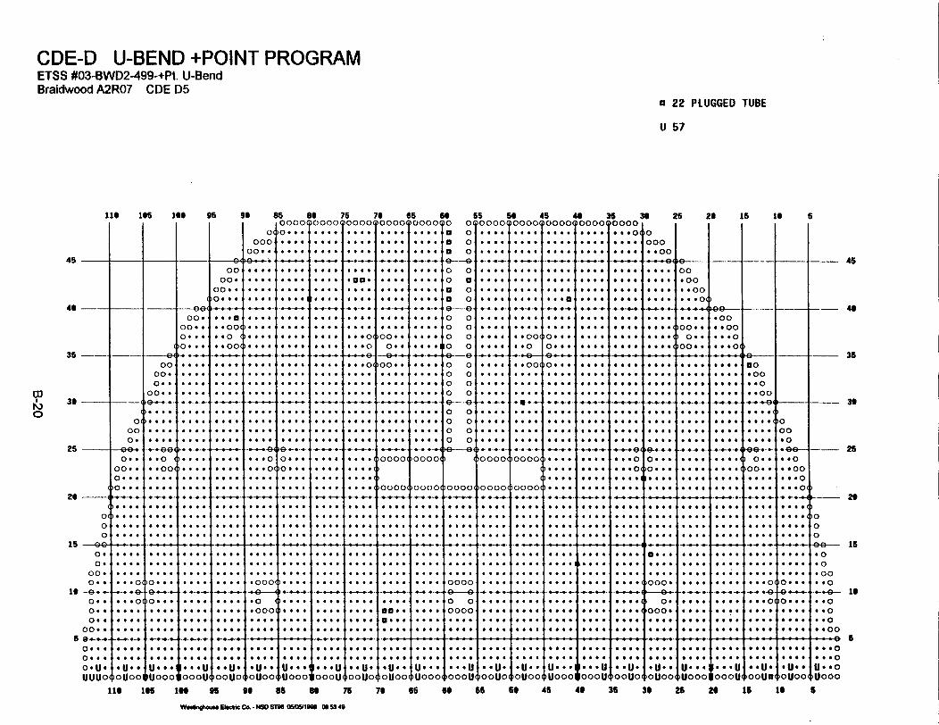
CDE-D U-BEND +POINT PROGRAMETSS #03-BWD2A99-+Pt. U-BendBraidwood A2RO7 CDE D5
a 22 PLUGGED TUBE
U 67
III 105 Is* 95 go as of 76 70 65 60i I I I I 100000000000000000000000000
65 50 45 35 39 25 24 is is00000000000000000000000000. I
5
Oo010.:*:1::#T*:*1:::T:::0040 **:O Os:. 0:0: 600. of*.
45
40 --- A-
35 ei
00
Do-
0. O
00 0 O
9 e m -
O O O O
0 0 0 0
-- O&00-
00. 00. 0 0
)O ...�4
O O O 0
O . . O
O O O O
O O . O
4 O 0 O
0 4 * 4
CD
r�)030 -
26 -
26
04
00
IS 949-0 O0 O
00.0. O
If -O- -0. .0. O0. 4
00. .
59 � � �0 0 O 900 . .0OUSUUUO
-O0 O0. �0 O O
00. O �0. . O,
>O. . O,
). O O O,) 0 0 4 O �IO6O O
I000 O
O O O:.... O O .
O: : 409,
. O O01
O . O O
. O O O
O O O O
:::: I::::-O' "4"1
000
O :0
. . O
O O O .
. O O O �
O O O . I
10
� E�, --
) 0I.::: �
�. +-O-�->. O O . -� O O O O -
O O O OO O O O
O O O O
6 . 4 0
O O O O
O O O O
O . * .
O . . .
00
00.00 0 004 . O
O .00
0 0.00
O0 O 0
. O
O O
O O
O
O 4 4 O
O0
OO
O0OO
O O
O0OI
6O6O
O004
O O
. O
O .
O O
O
0O O .
0O O .
0 . 0 .
O
O O I
O O
O O O
O O
O O
0 0 O 4
0O O
O O I
I O O O O I
O .O O
. O
O O
O O
O O
-- 04
0
O(
O O a 4
-000
0:OOO
OO a 0
O 0 4 O
O OOO OO O; OOO OO0
00 OO OO OO 0
O O a O
. O O O
. O O O
0. . .
. 0 0 0
. O . .
# 0 0 .
O O 0 .
0 O . .
O O O O
O O O O
O O O O
O O O .
O 0 O O
O O O O
4 . O O
O 0 * 4
O O O O
O O O O
O O O O
O O O .
.00.
0 0 . 0
0 O O O
�4- O
0 4 4 O
O . O 0
0 0 0 0
4 0 . 0
�-q
0 0 . 0
O O O O
O O O O
O O O O
O . O O
O O 0 O
O . O .
0 0 0 .
1. O-
, 0 4 0 .
O O O O
O O . .
O O . O
O O O O
O O O O
0 0 * 4
O 0 . 0
O O * *
0. . .
00. *
0 0 0
-
00 0 0
. O O .
. . O O
. O O O
O O . .
. 0 O .
O O O O
0 0 0 O
0000,
O O O .
I* O -
. . * 0 �O O O O I
O O O O 1
O O O O .
O O . O I
O . . .
O . O O I
� : : :-,4,
>0000(
a 0
a 0
a 0
0-G
0 0
0 a
a 0
0 0
0 00 00 00 0
-0-90 00 00 00 0
0 00 00 00 0
�e ---- G.I
I :O O .I . : O O I : : O O I . : . :
I . . O . O . . . . O : : : ?
I O . . O O O O . . O O . . . . .I O O . .
.. O-
IO . O O
. . O O
,4O0 6
.0* 4
,4�O**-
OO6 O
....O00 0
1O#O O- .4� �
O O O .
OO 0 O
.O -
OO 4 O
O. 0 0
. O . -
0000,
O O O OO O O O0 0 O 4
0 O 0 .
* 4�-*
0 04 0
. 9O O
0 0 00
a O 0
-0- E)0 0 00O O O O. . O OO O O O
-11-O O . O0 O0 0. O O O0 00 0
� 4 0 . O-
)0000
O 00 0
O O
0
0
49-O-�
O0
O
O O
O O O
4 f O O
O 4 4 O
1O
O O
O 6 4
O O
4 O 4 O I
O O
O
O
O O O O
6 O O O
4 O O O
O O.
0 0 O
0 0 O
O O0O
0 O..
0 .. O
O OOO
O 0 O
O O
O 0 0 0
6 6O a
9 O0
6 O
O
O
-1
. O
O O
O 0 O
O I
0 O O 4
0 0 0 O
0
000
.00
0O O
0OO
O O
0O
0OI
O
O00
OO0O
9a&4
0*OO
�o O O .
O0
4O0O
a00*
OO
O
I--
,00 OO
O O
0 0 0O
)OOO.
0.
)OOO.
a . 0 .
a O 0 0
00.00,9--".. O
I10IO..)Ooe.
-1O O I
O O O O
O 0 0
O O
O 4 0
O
O O
O O
4 O O .
-00
00
00
0OOO4
0O
O
O 0 O O
O 9 O 0
OO 0 aI
O O
O0 0
OO
O O
O0 O
O 0 !
1OOOO(b 000 Odbo 000 (bo 000(boooo(
9no0 000 O 00 0 00
O 0 O
0.
'00. O
O O
O O 0 O
0 0 4 O
O 6 O .
O 0 O
0 O O
O
0
.- G.0
O a O 0
--- i 1 - 40
-. L---4--- - -1 4-- 45
--- +-.-4 .
- - -t-- 35
O O : O
O 0 O O
O O O 6
O O O O i
O O O O
O . O .
O . O O I
. O O O I
O O O O ,IO O # 0 1
O O O .
0 00 #
O 6. O
# 0O 0
O . O O
O O O O
O O O O
O O O O
O O . .
O O O .
. . . .
4 0O O
. 00 4
. O O .I
O . O OO O O OI
O O O O
. O . OI
,an*.,
�0. : : : �
O O O O
0 O 4 0
4 O 4 .
O . 0 O
O O O .
O O O O
O O O O
O O . O
O O O .
. . O O
O O . O
O 6 6 O
. O0 0 1
0 00 0 �
O OO O
0 00 0
I O OO 0
1 O O O .
O O O O
0000
0 a.
0 0
0000
. O O O
. 6 a .
.O 0 O
0O O O
a. O O
OO O O
..
O O O O
O O O O
O . O O
. O O O
-O...
O O O O
*6. O
OO0 O
O0O 0
0 0 . O
0 O 0 0
O O O O
0 a 6 O
O O O O
O O O O
O O O O
O . O O
I
1000O0
0::oO0 0 .0
I O O 0 0 (10 * 00 (
O .O ,:...O0.O
O O . O
O O O O
0...
-- 30
-- 25
1,--- 261100099 15* 0O 0-00O O 0
--- O- laO . 0O 0 0. . 00 6 00- - - - K- - - - - - --------------------- - - - - - - ---------------------------------------------- ---------------------- --------------------------------------------------- - - - - - - ---
0 0 0 .4 O 0 0
0 U 0 0
IOU00
I O O 0 Oi . O 9 4
I U 0 * O I
OU0001
0 O 4 0
0 O O 9
I 0 0 0 U
100ou
0 0 0 0
0 0 O O
**U*
0OU01
0 O O O
. 0 . O
,.U.*
)OUOO
. . O 6
0 O 0 0
U 9 6 . IU0001
O 9 O O
* 0 O .
0 0 U.
�oouo,
. O . 0 �
. . O 0 �
*U.*
OU00(
. . . .
. O . .
U 0 O 0
�Uooo
0 0 . .
0 0 . O
O O 0 U
o0ou,
. 0 O O I
. O O . I
O U.,
)OOU0(
O 0 O O
O 6 O O
*U. O
10UOO,
. * 0 O I
. . 0 * . ,
U. .. I
�Uoooj
* O . .
a 4 6 .
1. O. U
100OU
O O 9 0
0 O O 0
a U.
0OU01
0 O 0 O
O O . .
U. 0.
1uOOO
* . 6 .
0 0 * 0
O O 0 U
00OW
0O . O
a O 0 0
0 * U O
)Ooua
* 0 a 4* 0 0 #a U 6 fOU004
f 0.04 0 a 0U * 0 0
)uOOO
lie 165 IN 95 99 as of 75 76 66 69 65 so 45 49 35 36 25 20 is to
W"*Vtm" El I I - CO. - NW ST96 OMWIM 00 53 49
5
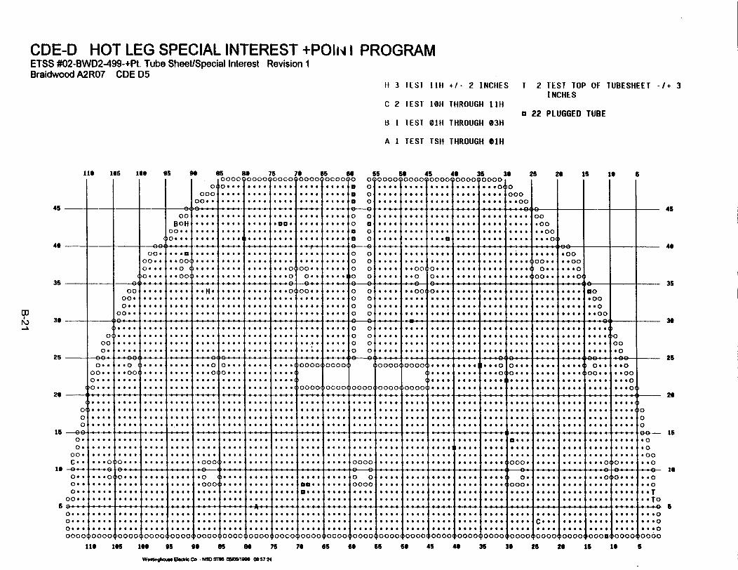
CDE-D HOT LEG SPECIAL INTEREST +POII- I PROGRAMETSS #02-BWD2499-+Pt. Tube Sheet/Special Interest Revision 1Braidwood A2R07 CDE D5
11 3 IESI 11H +/- 2 INCHES T 2 TEST TOP OF TUBESHEET -/ * 3INCHES
C 2 IEST A0H THROUGH liii
H I 'EST 01H THROUGH 03Ha 22 PLUGGED TUBE
A 1 TEST TSH THROUGH *1H
45
46
36
36
25
26
16
i6
6
116 166 166 95 9 a 5 8 76 76 65 66 65 s6 45 46 36 36 26 26 i6 1i 60000 00000000 o00001 oco00o 0 0 0000 000000 000 00 00000
.o .. .... .... .... *... a 0 *.. *e.. @.*. .. *..0o 0000 . ... . .. .... * ... *. *... ... X ... a. * X X** . 00000 .... ... .*.. .. 0 .... ... a * .... * ** **** .*00
-oH . . .-. . ..-. ... . .tlO. ....... ... o e.. .... .... .... .... .... .oo
oo 0 I .... .... .. .. I.. .... .... o. .. *... s.. .... too. . 1o_~00 __ O ........... .oo__.-* _## ......... ... 0 . u ++ .|@.@|@e|. + l||e- ^-+s-+
00.. ........ . .... .... 0 0 sofes.... . ... * ** * .. *. . . .oo0...* : *0 o ....*......... .... 00.. .... 0 0 . ... .... *..... .* 0.. .0*
0... '.00 .... .... ... ... 0. 0.. *.... 0 0 .... *.0 0o... .... .... .... 0.. .... o
0.0 ... ... .... too. ... .... 00.00 0000 000 0M00.. see 090 .0... *..o o O .0.o* .. . . .... .. .... 0000 0000 0000 0000 00 . .... .... .... .... .... .... ... . oo
__.__.._ ._ .. + . 4- . . . . .. . . . . . 4 - . * * _ .-. _..+ -+ 9.... .... .... . . * * ** .... **. . . .** too. *4 .. ** *... .... ....
O.. ...... ...... .... * -. *@ Oo*.. .... .... .... .... .... .... .... ..4.s.. fetO0~4*se o 400 ... ... ..... ** .... .... .**., ... OO *. .... .... .... .... ....* .. $f#00 *O o. too. .... 4...00)
-O .... .. .... .... .... .... .... .... .... 4.-. ... 4 - .-.. .. to . .... .... .... .4- f.. .... .... *0e- - F a - H- - s. .*e
O.. .. O .... .... ... 0 O---. ... .... 0000 )OCOO 0000 0000 too. ... **0 e oo 04 too. .... 1 O0 ego0 to * 00 .... * 0 .... 0... ... .... * s 0 Ott too... 0 60,0 0 * *00Ox* ... * . * **. *.* .... .... :::O.. ... to .... . .... .) . .. . . : .... 00 . .... .* *'O
(O . . .* . * .... .... .... . .. . . . . . OO 4)0 o 0C00 O1o 0000 0000( 0000( . 0 . 0 O O o * .1. * O
(...to .... .... *... .... .... *. .. O.... ..X. .... .... .... .... s... too. .... too. too. 0... .... .... (0 X X. .. .... to. tos .... .... .... .... 000O* 000 ... ....s t .... .... .... 6.... .... .... .... .... . .. ()O
0 *4.. 0*0* *.* ... .. .. 4. .... ... .... ... 6to. .... .... .... .... .... * *... .... .... . .... too . .. .. 000
o. .... .... .... .... .... .... .... .... .... .... . ... .... .... .... .... ... too.. ... . .... .... ....
oo .... .... .. .... .... .. .... ....... .... .... O.... .... .ooC- . ... ... .... .... .oo .... . .. . .... ... 000 .. .... oooo .... ... . .... . ... . .. oo. ... . .... ... ... .. o0
Co.. ... o o... .... .... .o00 .... .... ... .... .... . ... 00 ........ .. .to . .... .... ... o 000* .. oo
o..o .... 0).... .... see. .oooI .... ... ...o. ao.. .... oooo .... .... #... .... too. oo. .... .... .... 1.... .. oo.. .... .... ... .. o.. .... 0 .... . ... .... o.e .... .... 0 .... .... .... .... .... .... too. too. .... .... *to
o o. .... .... t .... too. .... .... .... .... 0... .... .... to. so . .... .... ... ... .... ... 0 ... o ... o* OT0 + . . .. ._ . . . _. . . . . . .+ . . . .. . . . . . . . . . .. .
46
4.
35
36
26
16
-6
0. 4. .... 4.... 4... e . ..J ***.
~ 0 0 c.
. . . . v ...
.... I ..
... 4.. ....O.C.O-
. .. . .. . .
.... I..
.... 4...I 0 . 4
1. ..I. .
=00o =0000'. . 0 0 . * . 0 0 4 . . . 0 . . v...v0000
0 .00 ... ..
)0000
t . .0... 0. .. 0
oooooooo0oooo0ooooloooo0boooo0oooo ~0000$00C00140000, oooo0loooo ~0000, oooo0oooo0oooo0oooo
i16 166 16 es 90 65 8 76 76 66 66 66 6 45 U 36 36 26 2* 1s 16
Woftmgm S1 Cc N 506COSM 00611906 095724
5

ATTACHMENT C
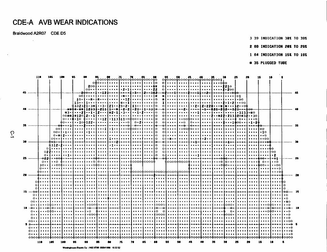
CDE-A AVB WEAR INDICATIONSBraidwood A2R07 CDE D5
3 39 INDICATION 30x TO 39s
2 68 INDICATION 206 TO 29X
1 64 INDICATION 15X TO 19S
a 36 PLUGGED TUBE
110 105 100 96 90 65 as 75 70 65 GOIOoooTooooTooootooooTooooTo
0
2000o..
I� 1
4
0 . . .
4 **9*2 1# $ *99 I....40
5S So 45 40
04.... 4.... 4 .... ...c4 .... 4.... 4.9.....oj... ... ... ...
35 30 25 20 16 1000O1~T .. *210
.. ,.2001
5
45 I- I 4<b 4 9-*--4 49--9 - 9-4-- --- - ---- I49-- 9-- -+ -- 9U- 4---. - 9- -9-9 -4 -
40 I t
35 i
II
30
25 -
20
01 -
O-
00
15 -9G.09.0o.
00.0..
IS -9-..-0.0. .0. .
00. .a ,
020.
0..
0...
0 . . .
0. .9
I. . .
. . .01
9 .01
.... 0
00,00.-0.5
00. .
312.
0 4-99
. .o..0
.9:00
. .o.
0....9..-.-
0 -.
.... 0
0 _ .
---m.3.
0055
0 99
00
10.>3323* * 2.12.1*0
.1
....
. .01
-000
9-9-
.0
.000
.....
9.3.
2-
.*12
0.....0...
*-.-.-.
9.9.1
21 *-I-*+c2-1t
... I
... 13
1. . . .I . ..12!....
.....
.....
. .
.4. ..
. ..... .....0....
9 a . .-.12
3* 2.!3-2-.2.2
..3. .
i11 90.99 9 0
I . . .
* * *o.0 .....
4....
,9999
t _ *
1. . . <
13..-12-a-
00...
00. .. 0 .0poo. . I
I .... .1§ 0 0 #F. 0 1I +.__..
0000..
t + -3,3
. . . .
. .Iv*
t .
. . . .+++ 1
. . . o-
. . . o -
4 o o o
a a0 a0 10 0
0 00 00 00 0
9-90 00 00 00 09 -90 00 00 00 0
.. 0..
. .. .o .o
* ...... 0
* v0
. . .
. . . ..
oooo,
. * 2 .
__.s _. . _, : * x o +sK a | * . L n n _ . __ _ _ . _^ . ^
9- .00*.90
9 00
* * 00(..... 0...I.... a
-4-.
~0000(
* *10. 9. I
O * 0
'O * * 00. 9 9
.+-4-..... 9..
* . . I
I.-..19999
9999.9.9.
.9.9.9
* * . *
9..., 0
9... 0
~..e.2
.4--
'p9 0
!* 9 02
0999 '
.... 0
.... 0
.. 0.I
~. .
. . .a o
.213
-.-..-.
004 1
oa...
0 . .
.0..
r..
.... 0
'.313 .3o2003 9301
9...
2.22
o .e.
O....
.... 4
.... 9
. ...
.a...
. .. .
. - s
* ...... 4.... 0* ..
... Oel-2,
._f0.... 9.... 4....aa....6 +_.... *. . ...... 0.... 0a 0 .. 0...
9-009 10
. .o
. .oo
9.0.
l....
9.00
oo . ..
.9...
0...
.9...
I. . .
1 35
.1a2a..
01.00. . 00
2.o0
)O00
L-.9 -
.900
I 990 0
9 9 90 4
45
I U4
'00 001210000111000 10000 1100004
-_ 30
- 25
~-- 29
00,099 15. 0.0500
4-4--* -.. 4-4-. 94494 -44- 54-99 49-..-. 9--.- I -9-.-.4 49-.. 4 9--.-- 5-9-49-94 44-99 4-9--4- 4 -9--.-4- -949-
****1* . . .4
4--
. . .. I
* . . .I . .
. . .
1k -1.1k 0 1
1[* . .
. . .
. . . .
.- .-. 11 . . -'. . .
# . . .
:.:. I
.:, 4
� .- � 4 �
,; : O' : :
. .- .
0 . . .
. . . .
. .. ..
I . ...
99994. . ... I
. . ...
0 .. 0.
0 .. 0.I. . ...
to oto o
4 .... 0
. . ._
. .. ..
a . 6
.... 0
.... 0* ........ 0
. .. .. ...... .. .*. ...
. .. .
.... 0.......
* 0...
. 0. .* *0# 660 .a
I.+ .e
I. .I.4*
I.. .IO #
* . .
*....*....*.. ..
0 0.0 0#
0 a... 00
.94..
9...*
0 . 0. ..a a 0
. ..
. . .
4 0 # #
4000. 4
4 ...
. . . .
*OO. -I.. .
9. 00**....* * .
# . .
*-..... . ..
*. ...
* . .* e.* . 4
I 900 00
0 0 .a * 0
* *4*....*. .
* ..6
. . . .
*. [email protected] 0.* G'¢
.* . . .
* ..* s0
. .s .
9 * 0
999.1
O * a .0 9 9
0*.*
* s0* 0 .
* .0*.
. *0* *0a .0* * 00
10
Sd- . . 49-4-9-." 4-4-4-4-9-I �--�- + 9-4-9-4-S 4-9--4-444-4-9-4-4-4--4-9-4-l4-4-9-4-4-9-9-4-4-I 4-9-4-949-4-4-4-6-9-9-4-444-4-9-9-4" 9-4-4-944-4-4-' 44-4-4-4-I -9-4-4-4-I 4-4-4-4 9-4-4-9-6-4-4-9-949-4-4-4-4-4-4-4-9
0 . .
O s .
0 9 9 9
0000
* . 6 .
* s0* .4
0000,
i.999. 4 f : : X* s.* X6* 04*.
0O000
999990 9 9999 .0
400004
iI
9.... .... 9....9....,.9.4.9.94 .... 4....'§§9.9.4.9.4 ..... 4....4....
::9:I::::
.... .... .....0000........
.0000
....
.9...
0000.
.... 9*...0* e0
oooo
9...
'0000
990
. .0
. .. ooooo1.ooooqoooo '0000' o00001 .oooo0ooooq0ooooqoooo' o0000 o0000
110 105 100 95 a s6 of 76 79 65 65 U 45 4 35 30 25 2t 16 1t
Woolfthmu. Floc Co - NSM CM 011000 163252
6

CM6 - A All AVS War 1,udfeetts
graidwed 2 ARM0 COE 169006601 951SUSSO 16s2716U
INVCOL VOLTS 16Im PN O LOON I I4 INCH BSlT EMT POIA PTYK CAL COMENTS
-121 ------ .04 iPO s1 P2 AV4 .60 T9N TIC .010 MSAL 251
126 0 .77 S POT 1s P2 AVI .60 TEN TEC Si1SENALI. 251126 a 1.34 S POT 22 P2 AWA .00 TIN TEC Il1ESAIL 261I
33 13 .66 POT l P2 AV3 .00 TEN TIC .510 NSALL 161I
I36 10 1.64 6 PO 24 P2 AV2 .60 TEN TIC .615 SAL 161136 16 .65 SPOT 15 P2 AV3 .SO TIEN TIC .510 ALL 161
I38 17 1.62 0 POT 17 FE AVl TE 19 TIC .610 HSALL 161 II36 17 2.77 5 POT 31 P2 AV2 .SO TEN TIC .610 OSIALL 161II30 17 2.12 * POT 30 PE AVl .SO TEN TIC .610 UMALL 161I36 17 3.46 4 POT 31 P2 AV4 .SO 19N TIC .610 USALL 161I
136 is 1.13 S POT 17 P2 AV2 .SO TIEN TIC OXS1ESAL 141II36 16 1.27 0 POT 16 P2 AV3 .6 TEN TIC .016 MSALL 141
I30 20 1. 20 6 pOT 2 PE AVI .66 194 TIC .018 HSALL 161I30 20 2.20 6 POT Zs PE AV2 .6SO TIM TIC .616 ISAL 161I13020 2.34 POT 29 pi "Al .60 TIN TIC IISE SALL 161II30 20 1.60 0 POT 27 P2 AW4 .60 TEN TIC .616 NSALL 161I
139 20 1.15 SPOT 18 P2 AVI 600 TIM TIC Gl1OESALL 1611 39 20 1.60 6 POT 1s P2 AV2 640 TEN TIC .610 MSALL 161I1 39 20 2.11 6 POT 30 P2 AV3 600 TIM TIC .616 I1SALL 1611 39 26 .97 SPOT 16 P2 AV4 60TIM TIC .SlOESAIL 161 I
I40 2 3.31 6 POT 34 P2 AV2 .66 TEN TIC .616 HSALL 141II40 20 1.60 0 POT 24 P2 AV3 .60 TIN TIC .610 NSALI. 141
I30 21 1.11 0 POT 16 P2 AVI. .00 TEN TIC .616 NSALL 121I30 21 3.20 6 POT 34 P2 AV2 .60 TIN TIC .616 MUAL 121I
I 30 21 1.67 0 POT 22 P2 AV3 .00 TIN TIC .610 ESAIL 121
1 39 21 .97 S POT 17 92 AVI .60 TIM TIC .610 01SALL 1611 39 21 2.57 S POT 31 P2 AW2 .60 TIM TIC .IlSUALL 1011 39 21 1.22 S POT 20 P2 AV3 600 TIN TIC SlOESNALL 101I1 39 21 .94 S POT 17 P2 AV4 600 TIN TIC .616 MSALL 101I
I 39 22 1.23 0 POT 1a P2 AVI .60 TEN TIC .610 MBALL 121 I1 39 22 1.32 S POT 19 P2 AV2 .60 TIM TIC elf NBALL 121 I
1 39 23 3.786 SPOT 36 P2 AV2 .60 TIN TIC S10 MALL 61
I 39 23 2.19 SPOT 29 P2 AVl .90 TEN TIC S10 MALL 61
I ~23 1.69 S PCT 16 P2 AVI .60 TIN TIC .610ISA L 21
I30 24 .96 0 PCT 15 P2 AVI .60 TIN TIC .610 SBALL 21I30 24 1.65 0 POCT 22 P2 AV2 .60 TIN TIC .610 SEALL 21I138 24 1.96 O PCT 25 P2 AV3 .00 TIN TIC .610 MBALL. 2 1
I 36 24 1.63 0 PCI 16 P2 AV4 .60 TEN TI .610 MSALL. 21
140 24 2.67 S POT 32 P2 AW2 .60 TIN TIC .I1ESALL 41140 24 1.11 S POT 18 P2 AV4 .60 TEN TIC GI10 "AL. 41
1 41 24 1.51 6 PCT 21 P2 AV2 .0TEN TI .616 OWSALL 211 41 24 1.90 6 POT 23 P2 AV3 .60 TEN TIC .616 NSALL 21
1 38 25 1.20 S POT 21 P2 AVI .60 TEN TIC .O10 NALL 41 I1 38 25 4.12 a6PCT 38 P2 AWZ .6 TEN TIC .616 MBALL 411 30 25 4.24 S POT 30 P2 AV3 .60 TEN TIC GI10 AML 411 38 25 1.71 S PCT 26 P2 AV4 .60 TEN TIC .l1ESALL 41
140 25 1.25 S POT 18 P2 AVI .60 TIN TIC .616ESBALL 21 II 40 25 1.66 6 POT 22 P2 AW2 .04 TIN TIC .616 ESALL 2114 25 2.67 O PCT 26 P2 AV3 .60t TIN TIC .S1SESALL 2114 25 .99 S POT 15 P2 AV4 .60 TIN TEC .616EMALL 21
41 25 1.49 S PCT 21 P2 AVl 690 TIM TEC .516 WALL 211 41 25 2.40 SPCT 29 P2 AV2 060 TIM TEC .616ESALL 211 41 25 3.64 6 PCT 36 P2 AV3 .60 TIM TIC .616ESA1L 21
1 36 26 1.60 0 PCT 17 P2 AV2 .0TIN TIC .616 ESAL 41
1 38 26 1.43 O PCT 26 P2 AV1 .60 TEN TIC OX1SEMALL 211 38 26 3.87 6 PCT 32 P2 AV3 .90 TIM TIC .516 MSALL 21
1 40 26 .66 ISPCT 15 P2 AW1 600 TIM TIC .61X6ESALL 4 1I 0 26 3.26 6 PCI 34 P2 AV3 60 TIN TIC .616 MBALL 41
I42 26 1.73 5 PCI 23 P2 AV3 .Be TIM TIC .616 MSALL 21
1 38 27 1.29 6 POT 18 P2 AV2 .66 TIN TIC .616 NBALL 211 38 27 1.33 6 PCT 19 P12 AV3 .Of TIN TIC .610 Mal. 21
1 36 26 1.63 6 PCT 16 P2 AW3 .66 TIN TIC .610 ESALL 2;
138 26 1.51 S POT 21 P2 AV3 .60 TIN TIC SlOESALL 21
142 28 1.01 S POT 15 P2 AV2 .SO TIM TIC .616 HSALI. 21142 28 1.27 S PCT 18 P2 AV3 .610 TEN TIC .I10 "ML 21I
I 4 28 2.43 6 POT 28 P2 AV2 .SO TIN TIC .616 ISBALL 21I" 46 s2 2.47 6 PCT 29 P2 AV3 .6 TIN TIC .616 HSALL 21I
14626 1.6 SPOT 23 P2 AV4 .60 TEN TIC SISESBALL 21
i 47 26 1.34 S POT 19 P2 AVI .66 TIN TIC .616ESA1L 21
I 40 29 1.66 6 POT 24 P2 AV2 .460 TIN TIC .610 MBALL 211 40 29 2.55 0 POT 25 P2 AV3 .60 TEN TIC .610 *BALL 21I14029 .96 S POT 15 P2 AV4 .66 TEN TIC .616ES"ML 21
1 47 29 2.17 S POT 26 P2 AV2 .60 TIN TIC .61I6PALL 211 47 29 2 .65 S POT 25 P2 AW3 .66 TIN TIC .610 NBALL. 21
1 36 36 1.94 S POT 25 P2 AVI .66 TEN TIC .61SESBALL 21
ROMt COL VOLTS DEG IND PER COS LOCH INCHI INCN BE0T EN9T POIA PTYPE CAL COISENiSI
C-2

CUE A All AVE fter Indleatlems
S*ra4wed 2 AM7 UI 1986666041 60,1411204 16.22.6
I RNO 604. VOLTS KGS IND PER GM LOCU 16041 INCW BEST EMUI PDIA PrfPf CAL. 6046661
I36 30 1.092 a POT 15 P2 AV2 .TEN3) TIC .610 IMALL 2 1I38 30 1.64 a PCI 21 P2 AV3 .0TEN TIC .610 NZALL 2 1
138 3S0 1.11 S POT 16 P2 AV4 .TIM3 TIC .610 WALL 24
3a 30 1.66 0 PCT 25 P2 LV2 TEN111 TIC .610 MMAL 4l
I a38 2 .0" a PVT 27 PE AW3 TEN111 TtC .610 MALL 4 1
I46 36 3.16 a PCT 33 P2 LW2 .T013 TIC .610 WSALL 24AS 30 3.38 6 PCT 34 P2 AV3 TEN1) TIC .610 SA~LL 21
I42 30 1.49 6 PCT 22 P2 AV3 .0o TEN TIC .610 'SAIL A4 I
AS4 38 2.11 0 PCI 27 P2 AV2 .01 TIN TIC .610 UMAL 4 1
I47 30 1.67 a Par 22 P2 LW .041 TEN TIC .610 1'1ALL 24I47 38 1.11 6 POT 16 P2 LV3 .0o TEl TIC .610 1111ALL 21
I38 31 1.6" 0 Par 10 P2 LVI .0611) TIC .610 'SALL 21I38 31 1.44 0 Per 20 PE LW2 .00 TIN TIC .610 'SMALL 2 1438 31 2.55 S POT 20 P2 AV) .04 TEN TIC .616'SAIL 21I
I38 31 1.21 0 PCT 17 P2 AV4 .of TIN TIC .618 141ALL 21
AG4 31 1.20 0 PCT 26 PE AVl .0 TIN TIC .010 'S11ALL 41I46 31 1.43 0 PCT 21 P2 L2 .So TIN TIC .610 NIALL 41
AS4 31 1.14 * PCT L8 P2 AV3 .of TIN TIC a61l "MAL 41
AS6 31 1.30 O PCT 20 P2 AV4 .SS TIN TIC .610'SA L 4 1I
149 31 1.31 S PCT 1s P2 AVI .TE11) TIC .610 SAIL 21I
I 4 33 1.01 0 PC Is1 P2 AV3 .TEN3) TIC .616 NIALL 221
AS834 1.68 0 PCT 20 P2 W2 So0 T1EN TIC .O0lO1ALL 264
429 35 1."0 SPOT 15 P2 AV4 .0TIC TEN4 .610'SAL 591
I3B 35 1.77 6 PCI 23 P2 VI .of 1114 TIC .610 MALL NI I
1 41 36 .91 0 PCI i5 P2 AV2 .0 TIN TIC .610 MMALL 261I41 38 2.16 a PCI 27 P2 A3 .GS 11E4 TIC .610 MMAL 261I
I41 37 1.37 0 PCT 24 P2 LW2 .TEN1 TIC .610 IU1ALL 321I
445 37 2.64 0 PCT 26 P2 AV3 TEN13) TIC .610 MSAIL XI I
1 31 38 1.38 6 PCI 24 P2 AV3 .TE13) TIC .610 "MAL 321
1 48 38 .91 a PCT 15 P2 AVI .GS TEN TIC .616 '1BAIL 301I
1 AS 38 1.11 0 PCT 17 P2 LVI .0 TENl TIC .610 'S1AIL 301
1 41 39 1.02 0 PCI 20 P2 AV4 .o0 TEN4 TIC .610 NSAL 321
1 45 48 .95 O PCT 15 P 2 AV2 .0TENl TIC . 610MALL 301
1 2641l 1.Is6 OPCT lB P2 LV3 0 TEN TIC .61S'SAIL 311
1 39 41 .93 O PCT 15 P2 AV2 .TEN14 TIC .61S'MALL 304
145 41 .780 SPOT 17 P2 AV2 .41 TIN TIC .616'1SALL 321I
130 42 .68 S PCT 15 P2 AVS .SS TEN TEC .56 1111ALL 321
I41 42 1.6 so 6 PCT 23 P2 AV3 .0TIN TIC .816 MSALL 3041
145 45 G .65 PCT 15 P2 AVI .TEN11 TIC .610'SAIL 364
445 45 1.14 I PCI 22 P2 AV2 .00 TEN TIC .610 1111ALL 361
I48 47 1.64 6 PCT 24 P2 AV2 .of TEN TIC .610 'SALL 364
445 S1 1.06 6 PCT 17 P2 AV3 .00 TIC TEN .610 MSALL 471
4 s 4 SS 1.27 6 PCT 20 P2 AV2 .0TIC TIN .610 'SAL 474445 55 1.68 6 PCT 24 P2 AV3 0 TIC TEN4 610 'SALL 4741
142 56 1.1 is OPCT 16 P2 AV2 .00 TIC TEN4 .I10'SALL 471
1 45 59 .92 O PCT 1 5 P2 AV2 .o0 TIC TIN .61'MALL 474
1 45 59 1.44 0 PCI 20 P2 LV3 .GS TIC TIN .61 'SAIL 471
4 48 59 2.27 0 PCI 29 P2 AV2 .SO TIC TEN4 .610 'SALL 471I
14450S .99 O PCT 15 P2 LV3 .00 TIC TIN .610 14BLL 4711485 9 .49 O PVT IS P2 AV4. .GS TIC TIN .610'SBALL 471I
I26 6 1.58 6 PCI 24 P2 ALVI .011 TIM EC .616 "MAL 56olI26 60 .79 0 PCI 15 P2 LV4 .0TEN TIC .610 'SALL 504l
4 4 Go0 1.25 0 PCI 19 P2 AW1 .0 TIC 1314 .810 'SAL 491I46 66 2.28 0 PCI 26 P2 AV2 .00 TIC 1314 .610 'SALL 494
AS 61 2.62 0 PCI 31 P2 AV2 .GS TIC 1114 .616 'SAIL 4741
AS4 61 1.36 0 PCI 21 P2 LV3 00 TIC TE)4 .610 ISAL 474
445 61 3.11 0 PCI 33 P2 LV3 00TIC TIN .610 MSALL 471445 61 1.05 0 PCT 15 P2 AV4 00TIC 1114 .616 'SAIL 471
44 662 3.97 O PCT 37 P2 LVZ 0 TIC TIN .810'SLIL 491
4 46 62 1.64 0 PCI 23 P2 LV3 .SS TIC 11)4 .610 'SAIL 491
4 4 64 1.00 6 PCTIs1 P2 AV3 .SS TIC TE)4 610 'SALL 491
1 45 64 1. 12 6 PCI 16 P2 LVI .SS TIC TEN .610 'SLP 514445 6 2.13 a PM 26 P2 AV2 .00 TIC TE14 .610 NMARP 514445 64 I.90 0 PCT 24 P2 AV3 .of TIC TEN .610 'SMP 514
439 65 1.04 0 PC IS1 P2 AV2 .0TIC TE94 .610 'SLMP 511I
439 65 1.71 0 PCI 23 P2 LV3 0 TIC TE94 .610 "MAP 514
436 68 1.62 0 PC 28 P2 AV3 0 TIN TIC .510 'SAIL 484
IROW CCI. VOLTS DEG IND PER CNN LOCN INCHI INCN2 SEOT CNUT PDIL PTYPE CAL COSNTSI
C-3
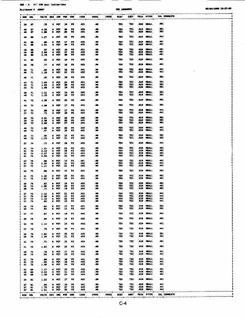
OK - A Al) AU5 Mieldlete
g6aeav" 2 6217 CK 1208050l1 ,O.,Im Mo~tu
I ROM .O VOLTS KG6 la Po6 LOON 1CN41 I6Cff 616T EMT POIA P.23V CAL COMMENTS
I36 67 .76 a PCI 16 Al AVI .TER11 TEC .613 MALL 461
46697 4.36 a PCT ISPFt AV2 .66 1TE4 T10 .610 WALL 36140 67 1."6 a 6 PCI I P LV3 .96 TEN TIC .610 MALL 361
I46 66 1.27 0 MTi 23 Pt AVZ .60 194 'MC .616 MNALL "I1
I41 66 .06 6 pay 17 Pt AV2 .96 T1EN 11C .616 MALL "6I41 So 1.61 6 MCI 36. P2 AV3 .60 1mm 110 U6 MALL 461
146 N .67 6 PCI 1 Pt AVI .04, TEN T10 .6 13MALL 46414466a 3.66 6 PCT 37 Pt AV2 .60, TEN 110.6141 MALL 461I46 66 3.76 6 PCT 36 P2 LV3 .40 TEN TIC .6146 MAL4L "I4
14163 .04 a Per is Pt LVI 00TN E .66 9 10 SlMA L 464
46 76 .77 0 par is P2 AV3 .66 TE4 TC .110 .6 B ALL 461I
14671 .64 6 P0713e Pt AVI .66 TEN TEC .613 MALL 461II46 71 1.1 is 6 POT 22 Pt AV2 .66 TEN 110 .161 MALL 44
1 42 71 .62 a Per 16 P AV3 .So 19N TIC n61 WALL 361
1 43 71 1.64 6 POT 24 Pt AVl .66 TEN T10 .613 WALL 36411 43 71. 1.63 6 PCT 26 Pt AV2 .TEN9 TI0 .616 WALL 361 I1 43 71 1.69 6 PCI 13 Pt AV3 So6 TE4 TEC .620 WALL 361I
I4671 1. 21 6 Per 19 Pt AV2 .So TE4 T11 .616 "MLL 3611 46 71 1.1 is 6 PCT 16 P2 AV4 .So 11EN TEC .610 WALL 361I
1 41 72 1.35 6 PC? 23 Pt AV3 .So TEN TIC .6316 MALL 461I
1 4372 I.66 6 PCI 17 P2 AVl .So 194 110 .613 WALL 361
1 37 73 .66 6 PCT 17 Pt AVI .66 11EN 110 .610 WALL 41137 73 .73 aSPOT 16 Pt AV3 .66 UK1 110 .46ISMALL 441
31 73 2.61 6 PCT 33 Pt AV2 .66 TE14 110 .613 MALL 361I13373 2.36 6 PCI' 23 Pt AVI .66oTE 194 10.61 MALL 361I39 73 2.66 0 PCT 27 Pt A"4 .66 111 110 .623 MALL 3641
I46 73 1.66 6 pCI 26 Pt AV2 .66 194 T10 .613 MALL 44I 4 73 .67 6 PCT 16 P LV3 .So 1114 110 .616 MALL 44
I 4 73 .85 6 PCT 15 P2 AI .So 1114 TE0 .6510 MALL 361II46 73 1.33 6 PCT 21 P2 AV2 .TE111 TC .61, MMALL 361I
37 74 .73 6 POT 16 P2 Al .TER11 TE0 .610 M6ALL 4I
141 74 1.21 6 POT 22 P2 AVI .as 1I44 TIC .610 M0ALL 461I1 41 74 2.19 o POT 36 P2 LV2 .66111 TEC .610, 6MAL 461 41 74 3.47 S POT 37 P2 LVI TEN TEC4 110 SI MLL 461 41 74 2.69 6 PC? 33 P2 AV4 .66 TE4 T10 .610 1MAL 46
I37 76 .66 0 PCT is P2 AVl .66111 T10 .516 OMALL 44I37 76 2.36 0 POT 31 P2 LWZ .So TEN TEC .616 MNALL 44I37 75 1.11 0 POT 21 P2 LVI .So 1114 E0 .10 NMAL 44"
I39 75 .66 0 POT 1s P2 LVI .So 1114 11 610 "MAL 381
1 41 75 1.43 0 PCT 25 P2 l .66 1114 TEC .616 MALL 46I41 76 1.62 6 POT 26 P2 VI .66 7114 TEC .610 MALL 46
I36 76 .93 0 POT 13 P2 AV2 .66 1114 T1 .610 1MLL 481so3 76 1.66 6 PCT 26 P2 AV3 .66 11E4 1E 10 66MALL 46
13076 .73 O POT 16 P2 AV4 .66 T14 TIC Ile $MALL 46
I37 76 1.12 6 POT 21 P2 AVl .66 11E4 TC .610 MALL 44I37 76 2.46 0 PCT 32 P2 A2 .So 11EN 110 .616 HMAL 44I37 76 1.16a 0 POT 22 P2 LVI 60 1144 T10 .616 MNALL 44I37 76 .66 6 POT 16 P2 AV4 So TEN4 T10 .610 MALL 44"
I39 76 .4 0 PCT 16 P2 AVI .66 T114 T10 610 MALL 361II39 76 .65 6 POT 1s P2 AV3 .66 1144 TC .610 MALL 361I
137 77 .67 S POT 18 P2 LVZ S66 TEN4 TE0 SlOMALL 41I
I29 76 .96 0 POT 19 P2 AVl .66 114 110 .610 MALL 461I
I34 76 1.13 6 POT 16 P2 LV2. .So T144 T0 .610 MNALL 421I
137 76 .76 6 POT 16 P2 AVl .66 11E TEC .610 MALL "4I
I39 76 1.82 0 PO 26 P.2 V2 .Go 1144 TEC .616 NMAL 361II39 78 1.33 0 POT 21 P2 LV3 .So TEN4 TE .610 "MAL 361I
I41 76 .73 0 PCT 1s P2 LV .So 1144 110 .616 MALL 464
131 79 1.02 S POT 16 P2 LV3 S.6TEN1144 1 10 .6I ML L 461I
I 6 79 .76 6 POT 17 P2 AV2 .Go TEN TIC .616 MALL " I1 46 79 .96 0 PCT 19 P2 LVI .TEN14 TIC .616 MALL 44
41 79 .66 0 POT 16 P2 AVI .So TE44 110 .616 1MAL "41 41 79 .86 6 POT 1s P2 LV2 .So 1144 TE .616B MMALL 44
I41 79 1.46 0 POT 24 P2 LVI .So 1144 T1 .616 MALL 44
I45 66 1.37 6 POT 21 P2 LV2 .TEN14 TEC .616 MBALL 46I46 of 2.33 0 POT 31 P2 LVI .TE114 TIC .616 DMAL 461
1 46 66 1.46 6 POT 24 P2 LV4 .So 1144 T0 .616 1MALL 6
13.461 1.32 6 PC0717 P2 LV2 .66 1144 110.616 MALL 421I
37 61 .93 6 POT 19 P2 LVI .66 1144 TIC .616 MALL 44I37 61 1. 76 6 POT 27 P2 LVI .So 1144 11 .616 MALL 44I37 61 1.61 6 POT 25 P2 LVI .TE111 110 .62913 MAL MI
I ROW COL VOLTS 016 LUD PER CN4N LOON 16041 INC42 BEST EMT POLL PTYPE CAL. COSNT I
C-4

CE - A All AV9 Usr LoslaatIes
freAdwd 2 AN? OK 1iogui 014/11800, 13,291
I ROW COL voLTS DEG 1 PER CNN LOC INCI INCH2 3EC6 T POIA PrTPE CAL CWU6E1 T
40 .72 a PCT 16 Pt AVn .40 TEN TEC .10 MLL 41
1 46 81 1.9# 0 PCT go P2 AV2 . TEN TEC .610 ULL 401
1 37 62 .f6 0 PeC 1S P2 AWL .0 TEN TEC .61S MALL 44! 1
37 *2 .71 0 PCT 16 P2 AVI .a TEN TEC .61S MALL 441 -
4 .53 * PCT 15 P2 An .80 TEH TEC 61S ALL 4414 *2 .6 0 PCT 13 P2 AV3 .0 TIE1 TEC .61 MIALL 44"
I 41 02 .77 6 PCT 16 P2 AY1 .S TE1 TEC .610 MALL 441 1
1 41 *2 2.42 S PC? 32 P2 Anl .O TEN TEC .81S MALL 441 11 41 02 1.19 0 PCT 22 P2 AV3 .SO TE TEC .610 MALL 44" I
41 02 1.13 0 PeC 21 P2 AV4 .O TE TEC .613 MALL 44I
1 45 2 .79 0 PCT 16 P2 AV2 .08 TEN TEC .819 MALL 40! 1
1 40 3 1.37 W PCT 24 P2 AWL OR TEN TEC .013 MALL 44" Ii 48 *3 1.00 0 PCT 0 P2 An . TE TEC .618 MALL 44"I40 33 .00 6 PC? 23 P2 AV3 .00 1114 TIC .616 MIALL "I!
40 83 .74 0 PaC 16 P2 AW .0S TEN TEC .016 MALL 44!
39 34 1.35 0 PCT 21 P2 An .S8 TEN TEC .61S MALL 421
39 #1.0 PCT 16 P2 AV2 .E1 TEC 61S MALL 421 1
39 as .92 0 PCT 16 P2 AU .SO 1114 TIC .613 MALL 42!1
40 s .91 0 PCT 1S P2 AWl GO TEH TEC 61U MALL 44!
4 5 1.99 PCT? 23 P2 AU .O TEN TEC .618 MALL 44! !I as 3.73 0 PCT 13 P2 A .S TE TEC .610 MALL 44! 1
I 41 S .82 0 PCT 17 P2 AU . TE1 TEC .619 MAL 44141 s .018 0 PCT 17 P2 AY1 .0 TE1 TEC .61S 1MLL A !
1 46 66 a63 0 PCT 17 P2 AW . TE TEC .61S MALL 381 1145006 1.63 O PC? 17 P2 AU2 R0 11EN TIC .G1SMALL 38!
I 38 SO 1.17 0 PCT 19 P2 AU .00 TEN TEC .618 MALL 421 1
40 86 2.23 Z PCT 31 P2 AWl .0 TE TIC .619 MALL 44!40 *6 2.34 S PCT 31 P2 AV2 . TE1 TEC .616 M6ALL 44!1 6S 1.33 S PCT 24 P2 AU .88 TE1 TEC .61 MALL 44! 140 00 86 6 PCT 18 P2 AV4 .O TEN TEC .610 MALL 44
I 36 87 1.13 S PCT 22 P2 An .ss TE1 TEC .610 MALL 44!
1 39 87 1.05 0 PCS 17 P2 AV2 .0 TS" TEC .610 MALL 421
8 67 .76 0 PCT 16 P2 AVl .I TEH TEC . 616 MMALL 44!1 49 87 2.37 S PCT 32 P2 AV2 SS TEN TEC .616 MALL 44
8 4S 07 .69 0 PC 15 P2 AV3 . TEN TEC .610 MALL 44I 40 87 .76 9 P7C 16 P2 AV4 8 TEN TEC .610 MALL 441
1 41 67 1.63 0 PC 26 P2 AY2 .f TE1 TEC .619 MALL 44!1 41 67 2.24 0 PCT 31 P2 An .OR 96E TIC .610 MBALL 44!
I 33 6 .67 S PCT 16 P2 AV2 GO TEN TEC .610 MALL 44! 1
136 6 .76 0 PCT 16 P2 AV2 .O TEH TEC .619 MIALL 441
1 36 86 1.21 0 PCT 22 P2 AV3 .60 TE1 TEC .610 MALL 441
I 4 a s8 2.S1 0 PCT 29 P2 AU2 .W TE TEC 610 M1ALL 44!1 4 a 88 1.31 0 PCT 23 P2 AU .Of TE7 TEC 610 MMALL 4411 4 a s8 W PCT 29 P2 AV4 .R TEH TEC 610 MALL 44!
1 47 88 1.18 9 PCT 21 P2 AU .O TIH TIC 610 MALL 4011 47 88 .87 6 PCT 17 P2 AV4 .6 11 TIC .610 MALL 411
I 36 89 .79 a PCT 17 P2 AV2 .O 11 TEC .610 MALL 44!36 89 .89 a PCT 17 P2 AU .SO 7H TIC .610 MALL 44!
38 69 1.40 I PCT 21 P2 AV2 .OR TE1 TEC 616 ALL 421
14 89 85 S P7T 13 P2 AU .00 TEH TEC .610 MALL 44!1 4 89 .72 * PCT 16 P2 AV3 96 TE7 TIC 610 MALL 44!
41 89 .90 6 PCT 18 P2 An .OR TEN TEC 610 MBALL 44!
I 42 89 .91 S PCT 15 P2 AU .GO TEN TEC .610 MALL 381 11 42 89 .87 S PCT 15 P2 AV3 .SO TEN Tc .610 MALL 381
35 90 1.99 6 PCT 26 P2 AU .Of TE7 TC 616 MALL 421
1 38 96 .94 6 PCT 16 P2 AV3 SO TEN TEC .610 MBALL 421
39 0 1. 5 * PCT 23 P2 AU2 .0 TE1 TEC .616 MALL 4211 39 W0 2.52 0 PCT 39 P2 AU .Of TEN TEC .610 NMALL 42!
I 41 W 1.00 0 PCT 21 P2 AU .SO TE1 TEC .610 MALL 44!
39 91 2.42 0 PCT 29 P2 AV2 .Of TE1 TEC .610 MALL 42!
I 41 91 .67 0 PCT 15 P2 AV1 TE. TEC .610 MALL 44!
141 91 2.62 S PCT 33 P2 AV2 .S TEH TIC .616 l ALL 44!
141 91 .O S PCT 17 P2 AU .Of TEH TEC .616 HMALL 44!
145 91 1.11 * PCT 21 P2 AV1 .Of TEH TEC .616 HMALL .40!
36 92 .85 S PCT 18 P2 AU .Of TEH TEC .619 MHALL 44!
I 38 92 1.61 0 PCT 23 P2 AV2 .O 71H TEC .616 MBALL 4211 38 92 1.38 S PCT 20 P2 AU .W TEH TEC .616 MALL 421
141 92 1.65 0 PCT 18 P2 AV2 .Of 71H TEC .61S MALL 381
1 41 92 2.33 0 PCT 29 P2 AV3 .W TE7 TIC .616 MHALL 381
ROW COL VOLTS DEG IND PER CNN LOCN INCHI IHCH2 SEIT ENDT POIA PTYPE CAL CUHTS I
C-5
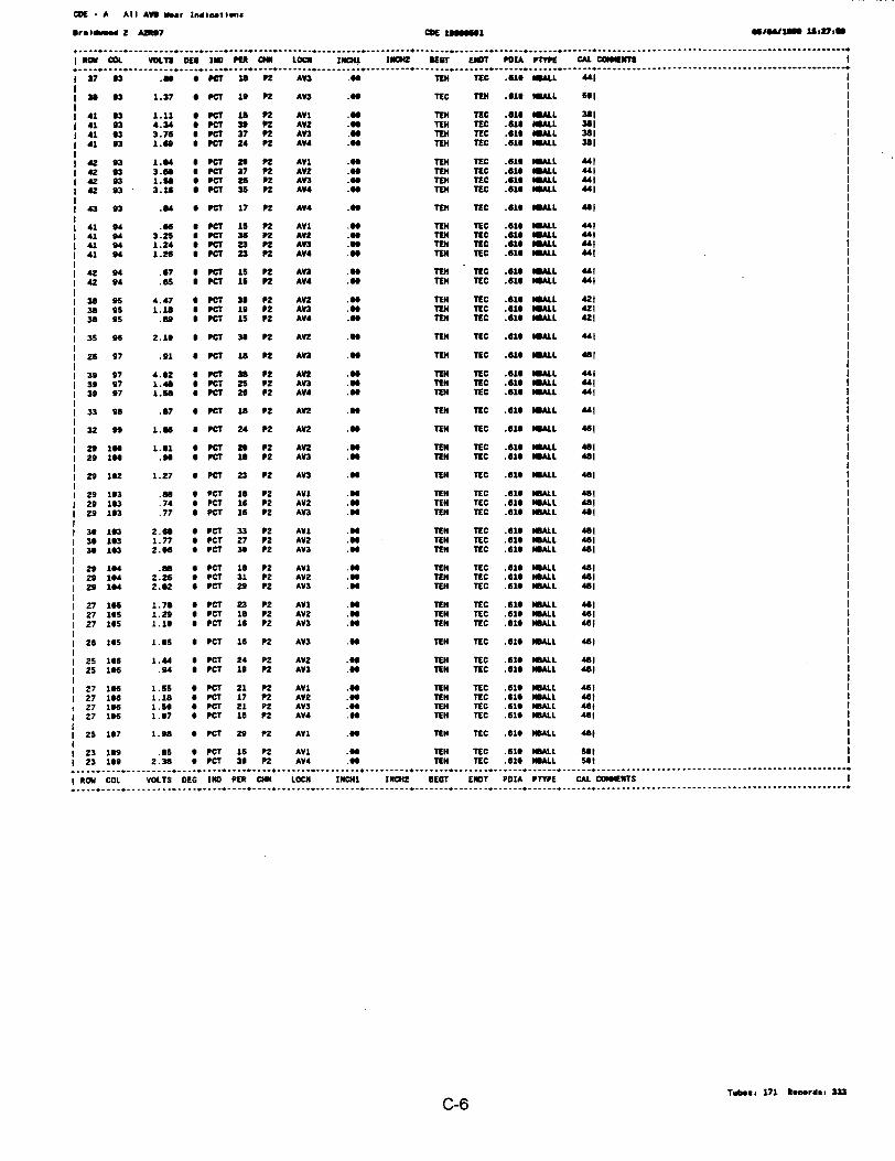
CDE - A All AU Moar Indicaltens
,ealwd 2 A17 CDE 1 _666 41 ,641m 18Db
I RON COL VOLT8 DEG IND P CM LOU 16041 IMCH BE9T EHDT PIA P1W! CAL CIOPMN. ......... .............. ... __........ ............ .. .___. *.......... ................ _..... .. .____. .......... .. ........ ..........--. .... - -. ..............-
1 37 93 .86 6 PCT 18 P2 AV3 .96 YEM TIEC .616 UALL 441
I 38 93 1.37 6 PCT 19 PZ AVn .66 TEC TEN .616 ALL 5S0
141 93 1.11 PCT i nP AV1 .40 TEN TEC .619 IALL 381
1 41 93 4.34 6 PCT 39 P2 AV2 .66 TEN TEC .619 GALL 381141 93 3.76 6 PCT 37 P2 AV3 .41 TEN TEC .61 ALL 381
1 41 63 1.89 6 PCT 24 P2 AV4 .M TEN TEC .619 I8ALL 381
| 42 93 1.04 a PCT to Pn AV1 .66 TEN TEC .619 IMLL 4411 42 93 3.64 6 PCT 37 P2 AV2 .66 TEN TEC .610 MLL 44"
1 42 93 1.B8 9 PCT 26 P2 AV3 .94 TEN TEC .616 WALL 44"
1 42 93 3.16 6 PCT 35 P2 AW .66 TEN TEC .61 MALL 441
I 43 93 .84 6 PCT 17 P2 AV4 .99 TEN TEC .619 SALL 481
I 41 94 .6t a PCT 1S P2 AVI .90 TIEN TEC .61U 11ALL 441
1 41 04 3.25 * PCT 36 P2 AV2 .66 TEN TEC .616 IMALL 44"1 41 4 1.24 9 PCT 23 P2 AV3 .99 TEN TEC .610 mALL 44"
1 41 94 1.26 6 PCT 23 Pn AV4 .99 TEN TEC .619 SUALL 441
42 94 .67 6 PCT 15 P2 AV3 .60 TIN TIC .619 LL 441
1 42 94 .65 6 PCT 15 P2 AV4 .6 TEN TEC .616 MALL 441
38 96 4.47 9 PCT 39 P2 AV2 .6 TEN TEC .619 ALL 421
1 38 95 1.18 9 PCT 19 P2 An3 .66 TEN TEC .610 IALL 421
1 38 95 .69 6 PCT 15 P2 AV4 .66 TEN TEC .619 MLL 421
I 35 96 2.16 9 PCT 30 P2 AV2 .66 TEN TEC .616 MALL 441
1 26 97 .91 a PCT 1U P2 An3 .66 TIEN TEC .619 UALL 481
1 39 97 4.62 a PCT 38 P2 AV TEN TEC .610 MALL 441
1 39 97 1.48 a PCT 25 P2 AV3 .06 TEN TEC .61 WALL 441I 39 97 1.50 6 PCT 26 P2 AV4 .99 TEN TEC .610 IIALL 441
| 33 98 .87 6 PCT iB P2 AVn .66 TEN TEC .619 SALL 441
13299 1.66 a PCT 24 P2 AVZ .91 TEN TEC .61 MALL 461
I 29 196 1.61 6 PCT 26 P2 AVZ .99 TEN TEC .61U SALL 481
I 29 194 .9S 0 PCT 18 P2 AV3 .96 TEN TEC .610 HSALL 481
I 29 162 1.27 0 PCT 23 P2 AV3 .6 TEN TEC .619 SALL 41!
I 29 163 .88 9 PCT 18 P2 AV1 .99 TEI TEC .610 SMALL 481
129 163 .74 * PCT 16 P2 AV2 .6 TEN TEC .619 HALL 481
I 29 163 .77 6 PCT 16 P2 AV3 .66 TEN TEC .610 HmALL 481
I 30 193 2.68 6 PCT 33 P2 AV1 .49 TEN TEC .610 MBALL 4811 30 163 1.77 6 PCT 27 P2 AV2 .66 TEN TEC .610 WALL 4911 36 193 2.66 6 PCT 39 P2 AV3 .96 TEN TEC .610 MALL 481
1 29 194 .08 4 PCT 18 P2 AVI .66 TEN TEC .619 UALL 4811 29 194 2.26 9 PCT 31 P2 AV2 .*9 TEN TEC .616 HSALL 481
1 29 194 2.62 6 PCT 20 P2 AV3 .99 TEN TEC .616 HSALL 481
I 27 196 1.78 6 PCT 23 P2 AV1 .66 TEN TEC .616 SMALL 4"I1 27 195 1.29 9 PCT 16 P2 AVZ .96 TEN TEC .610 WALL 461I 27 195 1.16 6 PCT 16 P2 AV3 .6 TEN TEC .616 HMALL 461
28 165 1.65 9 PCT 16 P2 AV3 .96 TEN TEC .619IOIALL 4"1
1 25 166 1.44 9 PCT 24 PZ AVZ .66 TEI TEC .619 ISALL 481
1 25 166 .94 * PCT 19 P2 AV3 .66 TEN TEC .616 HIALL 481
1 27 166 1.55 6 PCT 21 P2 AV1 .66 TEI TEC .616 WALL 4611 27 19e 1.16 6 PCT 17 P2 AVZ .66 TEI TEC .616 IALL 461i 27 166 1.56 6 PCT 21 P2 AV3 .66 TEN TEC .616 ISALL 4681 27 166 1.67 9 PCT 16 P2 AV4 . TEN TEC .619 HSALL 461
I 25 167 1.08 6 PCT 29 P2 AVI .*6 TEN TEC .616 1SALL 481
123 199 .5 * PCT 16 P2 AV1 .66 TEN TEC .610I LL 561123 199 2.38 * PCT 36 P2 AW4 .99 TEI TEC .6169UALL Set, ... , - -- ................. , ,,.... _ ,.............................................. ...........................................................................................
I ROW COL VOLTS DEG IND PER CNN LOCK IHCH11 1N=2 SEGT EHT PDIA PTYPE CAL COEHTS
Tboso. 171 Recordi 333
C-6
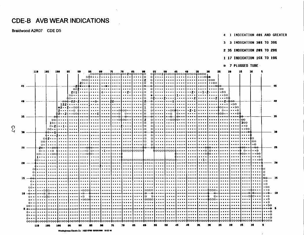
CDE-B AVB WEAR INDICATIONSBraidwood A2R07 CDE D5
4 1 INDICATION 40X AND GREATER
3 3 INDICATION 30X TO 39X
2 35 INDICATION 20X TO 29X
1 17 INDICATION 15X TO 19X
a 7 PLUGGED TUBE-
lie 195 IS 95 go es as 75 70 6S es S5 66 4S 44 35 30 26 2 6 is i 6
.0 oooo see- o oo o ... oo o 2o oool oooo see- oooo soooo0o0 o... ... . .... .... .... o o .... .... .... ... ... o ----
45 I_ _- ** --- _ - _ - .- -2- 9° - -- --
45
49 i --
122n2 . .
1- -2
. . 0.*...* *1* . .
* .0 oo0
. .o0
. .oo_ _ #
. .. .
. 0 _*........ 4. .. .
. . .
_+ 0 _
*....
. ...
. . . .
� .-- j
0 0 . . �
. 0 0 *
. . .o
. . .o.
. . .o... ..
.... 4
oo0. .
>oo. .,
....
. . .
. . ..
*--0
* ..
. .. .
_+_ +
o o1 0o oo o
*.. .. . .
... 0
... - - --------. .. .. .. .-. 0.0o
. .o
. .. .
. ... a
o0.. .
o . . .
. ...
.... a
2 -.... 0
.... .... o.. ... #0, ... .*... ooj.. ...
35 6oo
100
O° 2oo.
35
2ooo
0000
. .. .I. .0..I
. . .. 0
.... 00
.. 001
.0 0 0
. . 0 0
4 * * #0
-i 36
o. . .
. . 6
. .0..
. .. .
. 0...
_ - .__ -_ .*._4. oo 4-9 4-4-
o.
.... 0
2. .*. a.... .. .
. .. .*. ..
. 0...
. .. .
. . ..
. .. .
. .. .
. . ..
o
o
o
o
0
o
0
0
0000
0409
a*6*
4000
0000
a*00
*004
0006
*006I
0000,
0**0,
4000
a#a0
! .. . 0� 00 . 0
.00*
0000
*0*0
40**
000#
0a00
.0.0
I0000,
j4t00
0006
0000
0000
04a0
&600
a.00
oo
300
* . o
,* .o0
i 36. 0...
. .. .
. ...
.... 0
oo
.o
_26 26e_|. oo ._ ... - - -_ __. e_ -__.,. _..oK . . '0_-
20
o. .oo. .
I...'.....
. -..I. ...
.. O .o
. .oo
....
...
....
....
....
. ...
o... .. .. .
. . .. I* ..
I. ...
I- - -
. . .o.
. . . o
*....
*....
o.--**. ..
.. ...
* . .
* * 0
* * 0
. ..
. .. .
oooo4
*...
oooo oooo00 fooo ooot
oooo0
oooo0
0 -_
*. ...
I.. .. I
. ...... 0
.... 0
I....
_
*.. ..
. .0..
0 *04 00
0 00
@ @4
4 00
*... O*.....
0 I
. . . .
. ..
. .
. ..
0 .40 0 0 0. 000 00
*-0 .
* .. .. ...*.. ..**....
0 * * 0
. . 0
**.*. . .* ..
*....
@* .
.. X0
* a 0
.*..
J....* 4 .* # .
0(
0 �
0�
.*....*.. ..* . .
'O0
0
15
oo .... X ... - X - - - - �.- 4- -
o .o .
oo.o. .
. . . .I
. . ...
I . ...
. . . . I . ooo#
. ..4 000 00
I . ...I . . .
. .. .
. .. .*.. ..
oooo I .... .
* . . .
. .0..
. 0...
ooo .
. .6..
. . .* *.. .. a.
.... 0
. . S.
. . ..
.... 0
0 0 0 .
0 0 0 0
a . . 0
0 0 . 01
9 . 0 0
0 0 0 0
0 4 0 0
)O . 0 .
.o0
.o0
.oo0
. .o
is
+ I T - - -0 0 *
0*0
0. .
00. 0
0 . .0(
� 0 0 0 0
�0* 4 0
6 . 0 0
0 0 a 0
0 0 0 0
i- . l. 11 + 0I 0 0 04
.o
... .
I . ...
.* . .
'o o
oooo0 0 0.... 0
11 * - 11 * v 1
.... 0
.... 6
.... 0
.... 0
, 0 0 * s (
i 0 * 0 6 ( o00.oo .
.... *
.... *. ..
.... 6
6 6 . 01
0 0 0 0
6 0 0 f
0 0 0 0
)O_ 0
o . . ..... 00I....00
0 00
. 0 0
0 0 0
0 0 00
-- --- -- - - -o:: . :: .:: . §... l.o...~ .... .... ....
Ile ....... ISO.4 6 6 4 0 0 . 0 4 0 0 0
I 0 00 .
)0000(
.. 0 .. ... ... ....*a 000f
0 0 * 0
1 0 !1 @ @,0000o
,....
, 0....
t .toooo0
.... 0
.... 0
.... 0
oooo0
.... *
a........ 0
oooo(
.... 0
.... 0
.... 0
)0000
.... *.... *.... 0
oooo0
.... 00
.... 0*
.... 00oooo0
.... 4
.... 0
.... 0PoooO
6 * 0 0
0 0 0 0
0 0 0 *
00001
. . .
. . . o
. . . o
)oooo00004000000oooo' 100000000o0000(toooo oooo95 99 8S i s 70 65 es 56 Ss 45 42 35 30 25 20 is to S
W _oAu Pid Co - N80 FM eaM 1012 4

CM* - Altl AW Usr w leette
OraGde0 2 A 7 cot 166661 *"mom 283 4 0#1
. ................................................ ........................................................................................ _.... .... ,,,... .. ,__... .... .... ___
I now CIL VOLT$ DE la PE " LOCO m 1I11 NET EMT PUA P1W CAL CO613I
33 14 2.67 0 C 31 P2 AVE .60 IU TiC .6u4 MULL GI
1 33 14 1.61U PC? 24 P2 AV3 .10 in TIC .u1 ALL Il
a 35 i 2.15 * PCn 7 P2 AV2 .60 TIN TIC as .N LL el
135 1 4.60 0 Mr 39 P2 An .60 in TIC .610 NALL Il
I 35 15 2.16 6 PC? 27 P2 AM4 .06 TN TIC .616 Al. Il
14 22 1.34 0 CT U 21 P2 AV2 .60 TN TEC .U4 NILL GI
4 22 1.66 0 PC 17 P2 AU .60 TN TIC .61u NLL eI
0 41 26 1.74 6 PCT 23 P2 AVl .60 UN mc .610 NuLL 41 1
43 30 1.64 0 PC? 22 P2 AVE .0 TEN TEC .u16 MLL 41
21 32 1.0 0 PC? 17 F2 AV1 .60 UN TEC .610 "L" g61e
143 32 .7 0 PM7T 15 P2 AV1 .66 UN mC .61 ALL 221 I
I 37 36 .03 6 PC? 1i P2 AVl .16 Tel I£C .US ALL 261 11 37 36 .01 0 PC? 16 P2 AM .0 UEN n c .i@ mALL 261 I
37 36 .67 6 MT 17 P2 AU .1 UEN TIC .610 MALL 261 II 37 36 .60 0 PCT 15 P2 AW4 .90 UN TIC .U MLL 261
41 36 1.48 6 PC 23 PZ AVW .64 UN TIC .gig ML 261
43 37 1.91 73 PCT 25 P2 AV .60 TN . c gis 1 .LL 26143 37 2.26 117 PCT 27 P2 AU .60 UN TEC .616 1LL 21 I
1 37 38 1.86 a PC? 26 P2 AV2 .60 UN TIC .610 NILL 261
I 37 36 2.25 a PCT 23 P2 AU .60 UN TIC .616 NuL 261
42 44 1.65 9 PCT 16 PE AV .99 TEN TIC .616 MLL 321 1
1 42 44 1.06 PCT 15 P2 AU .0 TEN TIC .619 mALL 321
141 46 1.15 9 Par 3 P2 AVU SO TEN TEC .610 ALL . 1 1
40 46 1.3* S PCT is P2 AU .SS TEN TEC .616 MALL 3Y j
1 41 50 1.47 PCT 21 P2 AU .H TEN TEC .C19 IIALL 361 I
| 49 51 .9C 9 PCT 15 P2 AV4 .0 TUN TIC .616 NLL 321
1 41 55 1.92 * PCT 26 P2 AV2 .66 TU TEC .616 m4P W1 I1 41 55 1.67 6 PCT 24 Pn AU .66 TIN TEC .510 9 6P 961 I
1 41 55 .95 9 PCT 16 P2 AV4 .0 TUN TEC .610 UAP 9661
1 34 59 1.52 115 PCT 29 P2 AV3. .H6 TEN TEC .66 MAL 351 I
1 3659 .0 9 0 CT 15 P2 An .H TEN TEC .610 lAP 961 I
1 45 59 1.14 5 PCT 19 P2 AY1 .99 TEN TEC .610 lAAP 1
1 40 59 1.34 9 PCT 21 P2 AV2 .6 TEN TEC .610 "MP g6e l1 49 59 2.14 6 PCT 25 P2 AV3 .4 TEN TEC .610 "MP 9611 44 59 89 5 PCT 15 P2 AV4 .66 TEN TEC .619 "MP "I
1 47 59 1.24 a PCT 26 P2 AVI .H TUN TEC .610 7MP 961
43 67 3. 6 PCT 33 P2 AV2 .H UN TEC .610 ALL 341
1 43 67 2.09 6 PC? 27 P2 An .HS TEN TEC .610 MALL 341 1
1 43 67 .97 0 PCT 16 P2 A94 .6 TEN TEC .610 PMALL 341
1 49 67 1.65 9 PCT 23 P2 AV4 . TEN TEC .U6 NLL 341 I
1 32 70 .94 9 PCT 15 P2 AV1 .90 TEN TEC .619 UALL 341 t
1 32 76 .Z5 9 PCT 1S P2 An .TE UN TEC .619 IALL 341 1
1 32 7H 2.27 6 PCT 29 P2 AV .9 TEN TEC .616 MIALL 341 I
1 40 74 1.44 6 PCT 20 P2 AVU .S TEN TEC .610 MALL 4211 49 74 1.C 9 PCT 24 P2 AU .HTEN TEC .616 UALL 421
1 46 75 1.55 * PCT 22 P2 AVU .S TUN TEC .616 NBALL 461
1 24 78 1.11 9 PCT 17 P2 AV4 SO TEN TEC .61U LL 461
1 43 79 5.2 9 PCT 41 P2 AV2 .9TEN TEC .619 ISALL 461 I1 43 79 3.56 6 PCT 36 P2 AV3 .6TEN TEC .5619 MALL 451 I1 43 79 1.9S 6 PCT 26 P2 AV4 .0 TEN TEC .619 MIALL 461
i1 6 1.43 6 PCT 26 P2 AV2 .ff TEN TEC .616 MIALL 481 I
I 36 S1 1.66 6 PCT 16 P2 AV2- .f TEN TEC .616 ISALL 461 1
44 Q2 2.76 0 PC 36 P2 An .sTEN TEC .610 MALL 501 i
39 aS .92 PCT 15 P2 AV2 .ff TEN TEC .61ISALL Sol I
1 39 95 1.13 6 PC 17 P2 AV3 .6 TEN TEC 61S MALL ol I
| 46 59 2.29 * PCT 28 P2 AV4 .6 TEN TEC .61 MALL 561 I
1 46 S5 1.76 9 PCT 23 P2 AU .99 TEN TEC .616 IMALL 541
I 44 S0 2.66 9 PCT 26 P2 AV2 .6 TEN TEC .619 N1LL 551 I1 44 6 1.81 9 PCT 24 P2 AU .96 TEN TEC .616 SMALL 561 I1 44 SS 1.62 6 PCT 16 P2 AV4 .99 TEN TEC .610 MALI. 561
1 43 91 1.24 0 PCT 16 P2 AV3 .UTEN TEC .619 NALL 561 I
1 45 91 2.51 a PCT 36 P2 AVU .6 TEN TEC .1 BALL 541 1
1 45 91 1.33 6 PCT 20 P2 AV3 .9 TEN TEC .616 MBALL 541 I
1 40 92 1.33 9 PCT 26 P2 AV3 .95 TEN TEC .619 IMALL 541
1 46 93 1.46 a PCT 22 P2 AV3 . TEN TEC .619 LL 541 j
43 93 2.27 9 PCT 27 P2 AV .6 TEN TEC .616 NSALL 56 a
| 36 65 1.66 9 PCT 23 P2 AV2 .6 TEN TEC .610 NULL 51 I
I ROW COL VOLTS DEG SW PER CNH LOON 14 lNZI UCT EHDT PSIA PTWE CAL 00E0 7 I
C-8

CKi - I All AV Wage Indoeatsaa
BrolIowd 2 AM7 cm 18999681 SO/Ollism 03248s46a
IRMM OD. VOLTS KGl DO PER am LOW flCRI Ina to 6? EWT POlL PT1WE CaI USOSOTSI
36
3839
32
39
38
38
38
39
38
37
2829
38
32
3333
GO
96#o
97
979797
8
95
GO
99
1in1i
11
101
183103
1.27
.n01.35
.96
1.911.03.90
1.151.07
1.94
2.07
1.40
1.35
.84
.97
1.03
.96S92
J PaC
a PCTS PCT
0 PCT
J PCT* Pay0 PCT
* PCT0 PCa
* PCT
0 Pc?
0 PCT
0 PCT* Pcr
9 PCT
* PCT
* PCT
21
18
28
17
172515
17
27
92
2115
16
25
1515
Pn
P2
PE
PE
P2P2P2
P2PE
P2
P2
PE
PEPE
P2
Pt
P2p2
AVl
AVI
AVIAV3AV4
AV3AVA
AV4
LVE
LYS
AV3
LV3
LELV4
.96
.90
.86
.86
.96
.86
.86
.00
.00
.86
.00
.00
.86
.86
.86
.86
.09
.8
TEN
TENTEN
TEN
nNTENTEN
TENTEN
TEN
TEN
TIEN
TENTEH
TEN
TEN
TJNTaN
TIC
TECTEC
TEC
TECTECTEC
TECnc
TEC
TEC
TIC
TECTEC
TEC
TEC
TECTECWEC
.S10 VIALL
.610 ALL
.61J ISALL
.618 MML1
.619 "MAL.619 IALL
.910 MRAL1
.610 IBALL
.610 NALL
.61J WALL
.610 IALL
.610 WALL
.610 MMALL
.610 UALL
.619 HMALL
.610 NALL
.615 HALL*1 w
"I
Sol581
set
SolSol501
"0I
Sol
"I1
Sol
SolSol
Sol
6"1
"I1641S41
I tl J 11~ 1. 1U rz A ._ .- ... _ , _I 33 103 1.23 S PCT 20 Pn AV4 . TEN TIC J1C I P *41
I 28 104 1.39 a PCT 21 Pn aL . TEN TEC .619 WALL 521 I
25 le 1.9 a PCT 24 P2 AWL .J5 TEN TEC .610 1ALL 621 11 2518, 1.33 a PC1 21 Pn AV4 .86 TEN TEC .610 UALI 6521 1
N2 1 1.86 9 17 n LV . TEN TEC .61S WALL 621._
I aIU COL. VaLl OEC 15 pu CNI LOCI 1ll041 lNCH2 916 19? PbIL P1W! CAL COISST
..... ..... ,,... ... ,,,,,,,,,,,,,..................... ..................................... _ _.. _,....................................
Tube: 56 Record,; S1
C-9

CDE-C AVB WEAR INDICATIONSBraidwood A2R07 CDE D5
4 4 INDICAIION 40X AND GREATER
3 29 INDICATION 30X TO 39X
2 58 INDICATION 20X TO 29X
1 35 INDICATION 15X TO 192
O 39 PLUGGED TUBE
116 165 if
45
40 -- +_
35 s
90
25
26 --- --
00
015 -9
0.
0.
00.
Is - 9-.
0. .
00..
oo00
0o.0. .00. .0 . .
)o. . .
* . .0*
... 0
....
. . .o.
02
00.oo ...
I. . ..
....
....11+.e.-
. .0
. .00
.ti-
. .. .
...
.... _
...
0 95 9S 85 as 76 7 65 6 60000 oooo oooo 0000 0000o 0 0
oo ..... ... .... .... 2a00o .... .... *..I .... 2 a
oo#. .... .... .... .... .. au a a.. . 0.. .... .. .. .... ... .*--2 U a
00 .... .... 4.... .... ... .... a aoo. .... 24-- .1.. .... ....0 .... 0 21a.- ... *223 .... .... .... .... a 21.2- .... *12- .... *-32 .... ..a. 0 0
29 .2-32 *2--- 18-3 4-.--. 2-- . 2.-.----. -4 .- -94- -O0 0 .. .. .... .... ... . . 0 0
00o. .. oo .... 1* .... * 22 .-a3 .... o 2o.0. .. -2 .. ..... ... o oo.. .... o 03041 .100 1.2 .2- .. 0 o.. .... 0 1__..- .. _ -.. __._e--. 4. e--2
.... .. ... .... .... ... 0 O.. .... 0 1
.... .... .... 0 0.... .0 0*.... ... _ .* .. *.. .*.. .... * *44.* *4.. 9-..
..... .... .... .... .... .... 0.... .... .... ..... .... *0 .. .... .... 0 0.... .... .... .... ... ... .... .... o 0.... .... .... .... .... .... .... .... o o
... _- D(o-.-. . ...e e^ *_. . ... ... . ... G- > a.... . ... o... .... .... 0o000 0000oo
....... .... ....
.... ......... .... ....
.... .... ... .... ...... oooooooo
. 00 ... .. + . .. 0000
-*-9---- -... 4 -.... -4 .... 4- .... 4 ... *. *... . ... .... .... . ... .... ....
.... .... ..000 ... .... .... .... .... 0000._. .4 -- _. -_ _*. 4 ..... ...... ...
.... .... .... .... .
.... .... .o 4: .. . .... .... .... ....
0000 0000 0000 0000 0000 0000 0000 0000 0000
i5 66 46 40 35)0000 0000o00o1 0000 000C
0- ..... .. 42- 2...~.1 . . . .. . . . . . . . . . . ....
.... .... .... .... ....
..2- ... . .. 4.2,35§ I000...0 004... 2.3.. 44-
..... ... 0 O -- tote 2 -F ..4.
000.... . 0
~.. .. . . . .o . . .*
. 0. . 9 . . . 0 104*~i
. . . . . . . . . .* 4 0 * 0 4 * t *... 4 4 4,+ 4.4 .4..
,,2 *Xt-t* t*,so let
0..,. 00 ... .t. o f.$ 0-- 0+-
30 26 26 i6 1i
ooa
t* .3I....I
. 2 . .
4...
F . 1,
. . .1 I
03.00lo2301..2°. . 20_
400 *1
4 1-.400 * I
+++ _s_+_@0 -4--Tr --s Tr --s
5
.I
Ii
3
q
o 000040000
t_ . .
.. . dI..
I- j
* 0 0 1
. . .
F. ._0.
.. . . .
. . . .
.. ..
0 ...
9 . .
:::::I4....s
a . . .
a--
a . ..
1 * 4
ts . .
. . * v
a #. v
f .... #
t ...
. . ...
. . ...
. . ...
0 . ...
. . . a
t .. ..
. .....
. .. ..
t . ...
t . * @ *
.4...
40.
~0.
00...iIo. . .0
to . . .
1... :t --0
O:*.t 00
1I
'99-
400. . 0o
. . . 0
333a,
-- -- _ -- j _ 40
45
4...
4- ...1
: t
!04 .- W..
0. . ..0 .... i
1 . .. #t+ 0 l
00200. .0. .00
-G43I* 3 * q4
I9....
1Z1p 0..
400- oo. .0
* . . 0
V--7
4I
23.0
.0. .00
t... "4. . .0. . .0.
1....q.-... 4
4....
0 . ..
.0 . . .
1000
-94. 4
.4I'
--- 2
a -- 16
.0
*0.0.0.00
+_e 6
T -T--- 35
-. -- 36
---- 25
a _ I .--- - 4- - - - - .-.-. 4 4*.- 4 * 4 -4- * 4-9 -*- - 4+ .+._.,._0 . ..o. . .0. .
l. . . t 4 4 4 .0
..... ...... ..
oooo0
t * 0 0 .
I. .I. .
pOOOO0 0000, 400004
. .0
* 0
* . . .
pOOOO
. 4... t . .4.. .. ... 4 .... I'.... . .. . .
.... 4....
. . * 0
. . . 0
0000
6oooo oooo oooo 000000 0000 004 p00004 40000
110 165 16 96 96 8s a6 75 76 65 60 56 5s 45 U 35 36 25 26 15 1i
W4,164mke E4.c C* - NSO ST" MMIM 135516

Ct - C All All, r ladiltlas
Braoldwd 2 AS7 CO 1_666601 "1, i 11260467
*.--- - ---.- . - ........................ -. -... . .. ...... . .. . . .. ... .... .. . .
R VOL VT3 O tM P1u C LOCN INCHi INO@ 66 tHMT P. .P.. . .CAL et .
~~~~~~. . . ... . ....... . ........ .......... .... .....- *-.... ... ... .-..--........... *.....
127 a .6 6 PCT 17 Pn An. .ff TU. TtC .6I.ALL *1
27 a 2.70 6 PCT 31 Pn AWn .9 TCE TIC .U ISALL 61
1 27 8 4.67 6 PCT 39 Pt AV .00 TEN TeC .6U1 MALL 61
1 27 9 1.43 S PCT 23 Pn AV1 .S9 TE rtc .8U EmALL 1l
1 27 9 .79 6 PCT 1S Pn A .69 TE TIC .616 MALL 1U1
1 27 9 1.49 6 PCT 23 P AV4 .66 TEN TtC .61U MSALL Ul I
1 36 13 .965 PCT 15 P2 AWL .6 TEN TIC .610 ALL Lai
I 33 14 .97 6 PCa 15 P2 Anl .69 TCH TIC .66 ALL 121 1
1 33 14 1.27 6 C 22 ATE TC .610 MALL 121 1
1 33 14 1.83 * PCT 24 PZ AV4 .Be TEH TEC .616 MALL 121 1
1 32 16 B9 * PCT U P2 AV1 .66 TEN TIC .61 MALL 1U1
132 16 1.63 O PCT 16 P2 A2 .Be TEX TIC .6 MALL 1S1 l
1 34 16 1.66 6 PCT 1t Pn AV3 .Be T TIC .81 MALL 161 1
I 34 17 1.16 * PCT 19 P2 AV1 .66 TE TIC .61 MALL 161
1 34 17 1.43 6 PCT 22 P2 A3 .66 TEN TtC .61 MALL 11 1
I 36 17 Z.66 6 PCT 31 2 AV2 .B6 TEN TIC .61 MIALL 11e
1 36 17 1.48 6 PCT 23 P2 An3 .S TEN TIC .6U1 MALL 101
36 18 .65 I PCT 17 72 AV1 .06 TIN TIC .61 MALL 121
1 36 16 2.27 9 PCT 30 P2 An2 .6 TEH TIC .616 ALL 121
1 36 16 2.71 9 PCT 34 Pz AV3 .Be TIN TIC .616 MALL 121
I 36 19 2.19 6 PCT 32 Pn An2 .B TIN TIC .61U MALL 121 1
1 36 19 2.75 6 PCT 34 Pn V3 .Be TtE TIC .16U MALL 121
I 35 25 Be 6 PCT 1S Pn AWL .B TEN TIC .616 MALL l6 I
36 26 .* a PCT 1S Pn AV2 .S TIN TIC .6 UMALL 161
1 36 25 .97 0 PCT 17 P2 AV3 .St TtE TIC .610 MMALL 161 1
1 36 26 .69 0 PCT 16 P7 AV4 .65 TEN TIC .61 MALL li I
| 36 26 2.67 9 7CT 31 PZ AV2 .B TtE TIC .618 ALL 1l6
1 38 26 2.66 0 PCT 32 P2 An3 .66 TUE TIC .616 MALL 11e
1 36 21 1.91 * PCT 16 P2 A3 .f0 TEN TEC .8U ALL 161
I 38 21 1.66 6 PCT 18 P2 AV2 .00 TtE TEC .616 MALL UlI
1 38 21 1.66 0 PCT 18 P2 AV3 .ff TIN TEC .61U MALL Ill
1 41 22 Z.66 6 PCT 26 P2 AV3 .69 TEN TIC .61 MALL 121
1 41 22 1.53 6 PCT 21 P2 AV4 .69 TEN TIC .61 MALL 121
42 22 2.69 0 PCT 36 P2 AV3 .6 TEN TEC .616 MALL 121 1
I 42 22 2.14 0 PCT 27 P2 AV4 .06 TIN TEC .61U MALL 121
1 37 23 1.62 * PCT 16 P2 AV2 .S6 TEN TEC .51 MALL 121
42 23 1.11 0 PCT 21 P2 An3 .96 TEN TIC .61 MMALL 121 I
1 44 23 1.99 6 PCT 36 P2 AV2 .00 TEN TIC .61 MALL 121 I
I 44 23 4.66 6 PCT 38 P2 An .66 TIN TIC .61, MALL 121
1 42 25 2.S * PCT 32 P2 AV2 .S6 TEN TIC 6 I MALL 11e
1 42 25 2.13 O PCT 28 P2 AV3 .9S TEN TIC .616 lMALL 11o
1 42 25 1.33 9 PCT 22 P2 AV4 .9S TEN TIC .6U MALL 161
I 45 25 2.23 6 PCT 29 P2 An2 .66 TEN TEC .616 MALL 161
1 45 25 3.16 9 PCT 34 P2 AV3 .96 TEN TIC .619MALL 161
1 45 25 1.41 PC? 22 P2 AV4 .99 TI TEC .616 MALL 191
I 36 26 .65 6 C? 16 P2 A8n .6 TIN TIC .610 MALL Si1
1 45 26 .97 9 PCT 15 P2 AV2 . 9f T IN T IC .61 6 MALL SI
I 5 2 6 2 .S 6E9P C ? 2 9 P2 A n . n T I N T IC . 1 9 MA L L a I
1 4 5 26 .9 2 PC T 15 P2 AV 4 . Be TEN T IC .619 MA IL SI
538 27 1 .94 * PC ? 25 P2 AV2 .69 T I TEC .61 MALL eI
138 27 1.3 9 PCT 16 P2 AV3 .96 TEN TIC .16M IALL I1
1 4627 3.46 9 PCT 34 P2 893 .60 TIN TIC .6U16MALL 8I1
1 44 26 1.17 6 PCT 19 P2 AV2 .9 TEN TIC .619 ALL 61
I 44 28 1.29 6 PCT 21 P2 AV3 .96 TIN TIC .610 MALL 61 1
144 26 .87 7 PC? 15 P2 8V4 .6 TIN TEC .616 MALL 61
1 48 29 .90 PCT 17 P2 AV4 .66 TEN TIC .616 MALL 61
13 736 1.6 * PCT 16 P2 AV1 .n6 TEN TIC .61 MALL eI
1 38 36 1.54 a PCT 22 P2 AV2 .*9 TEN TEC .616 MALL 61 1
1 38 39 1.66 6 PCT 23 P2 AV3 .66 TEN TEC .616 MALL *1
141 36 1.95 PCT 25 P2 AVZ Be TIN TEC .610 MALL 61 1
1 41 39 1.8 0 PCT 22 P2 An4 .8s TIN TEC .616 MALL *1
j145 36 2.19 * PCT 27 P2 892 .ff TIN TIC .618IMALL 611
1 45 36 3.37 6 PCT 34 P2 8V3 .66 TIN TIC .618 MALL 81I
1 45 3 S 1.39 6PCT 26 P2 AV4 .U TEN TEC .61 HMALL SI
j 48 3 6 .64 6 PCT 16 P2 AV4 .6S TEN TEC .610 NMALL *
j41 31 2.46 I PCT 36 P2 AV1 .H TIN TIC .6U MALL 41
1 41 31 2.48 *ECT 3 6 P2 AV2 .66 T IN T IC .616 ALL 41
1 41 3 1 2.25 * PCT 25 P2 AV3 .9 TIN TEC .616 ALL 41 i
1 38 33 .94 6 PCT 22 P2 AV1 .B TEN TIC .616 MBALL 21 1
138 33 2.19 * PCT 31 P2 AV2 Be TIN TIC .618 ALL 21 I
38 33 2.66 S PCT 33 P2 AV3 .*6 TEN TIC .616 MALL 21
35 33 1.66 6 PCT 21 P2 AV4 .90 TEN TIC .610 MALL 21
I 43 33 S.7 0 PCT 17 P2 A82 .09 TIN TEC .616 MALL 21
I RU E C O L V O L T S D E6 1 H D P1 C N L OCH D 1 I HC H 2 SED T E H D T PD IA P Tr P E C A L C 6 T43 33 .9 . .17 .AV . 4 TE .E .61 .B
L .21 .......
C-1 1

- C All AMU r lIdleations
9r _ 2 AW COE 1mMl a m 2616487
......................... ........................................... ,,,,,... , ,,........ ,,,...................................... _ .................
I m1 COL VLT8 666 INm PER 0a LOcU 1N101 1 42 6 neT W POIA P1W! CAL ..w.. _.............................. ,,_................................................................................................................................
... .......
Ix 34 1.67 a PCT ? P2 An3 .06 TIN TIC .69 ALL 1ei
41 34 1.66 6 PCT 22 Pn AVn .66 TEN TEC .610 WALL i641 34 1.4 6 PeT 26 Pn AV3 .66 TEN TIC .616 WALL 1le
A 46 34 1. n 6 PCT 20 Pn AV2 .40 TIN TIC .61c ALL 11e
146 34 1.44 * PCT 26 P2 ATE .66 TIN TIC .610 MALL 161 I
1 46 N .6 S PCT 21 P2 AV4 .40 TI TIC .610 WAL 16U
I 41 36 1.36 6 PaT 26 Pt AVn .00 TDI TIC .616 UALL 141I 41 36 1.57 6 PCT 23 Pn AnE .06 TIN TIC .616 WAL 141
I 41 36 1.09 6 POT 17 Pn AV4 .06 TIN TIC .616 AL 141
42 36 .8 I POT 15 Pn AVn .06 TIN TIC .616 WAL 141
42 36 2.71 SPOT 31 P2 ATE .06 TI" TIC .610 I ML 141
I 42 36 1.13 a POT 23 Pn AV4 .06 TN TIC .616 WALL 141
30 37 .51 6 PCU 16 P2 AVL .06 TN TIC .616 WALL I 81
36 37 1.63 POT 25 Pn AV2 .0G TEN TEC .C1 MII AL. 1 I36 37 Z.76 S PCT 31 Pn ATE .0 TI TIC .61c WALL le3 3 37 1.31 * POT 26 Pn AV4 .0H UIN TIC .16 WLL lo t
| 41 30 3.36 6 PCT *5 P2 AZ .H6 TE TIC U9 WALL 51 1
I 41 38 1.32 a PCT 22 P2 AnI .06 TEN TEC .810 ALL 29 1
1 36 32 .6 PCT 15 P2 ATE .0U TEN TEC .61U ALL 269
I 38 39 1.42 6 PCT 21 P2 ATE .80 TEN TEC .616 WALL 261
42 3S 1.3S 6 PCT 21 P ATE .96 TEN TEC 616 WALL 291 1
I 42 39 1.62 6 PCT 23 P2 An .G6 TEN TEC .61 WALL
46 39 1.16 U PT 16 P2 AE .GO TEH TIC .61S WALL 21 1
146 39 2.37 9 PCT 29 Pn ATE .90 TEN TIC .616 WALL 261
33 46 3.63 6 PCT 33 P2 AY1 .90 TIN TEC .616 MALL Li
I 43 41 2.23 9 PCT 28 P2 ATE .0H TIN TEC .618 WALL LeI i143 41 1.63 S CT 25 P2 ATE .G TEN TEC 8616 WALL 1l
4 46 41 3.43 6 PCT 35 Pn AV1 .0H TIH TIC 861 1ALL 1l I
1 46 41 4.49 S PCT 39 P2 AV . TEN TEC .610 WALL 1l i1 46 41 6.91 9 PCT 44 P2 A3 .GO TEN TEC .610 aLL 109
1 45 41 2.69 S PCT 31 P2 AY GO TEN TIC .610 WALL 10 i
I 4 41 .4 9 PCT 15 PZ AY1 GO TEI TEC .610 WALL li
1 28 42 1.13 9 PCT 26 Pt ATE .0H TEN TEC .616 ALL 291
30 42 .6 9 PT 16 P2 An .66 TEN TEC .616 WALL 261 I
I 47 I4 1.6 * PCT 1 P2 A .0 TEN TIC .619 6 ALL I
I 41 49 1.41 * PCT 26 P2 AVI .04 TEI TEC .618 WALL 221
141 59 1.14 PCT 16 P2 A"I .4 1TN TEC .619 ALL 241 I94106 1.2 SaPOT 21 P2 AV2 . TEN TEC .616 ALL 241 I
I41 S 2.63 9POT S2 P2 ATE .06 TIN TEC .616 WALL 241 I
S44 o5 1.19 9 PCT 16 P2 AV1 .O TEN TEC .619 SALL 241
1445o 1.24 PCT 18 P2 AV2 .O TIN TEC U91 ALL 241
S 46 51 3.71 9 PCT 36 P2 AT3 .H6 TEN TEC .61U WALL 269
1 46 51 3.62 9 PCT 36 P2 AV4 .O TEN TC .616 MALL 269
1 45 52 1.41 6 PCT 22 P2 AVI .06 TEN TC .619 WALL 221
I 45 52 1.Sl 6 PCT 23 P2 ATE .69 TEN TEC .616 WLL 221
I 46 53 .9H 9 PCT 1S P2 AV TEN TIC .616 WALL 21
I 43 54 1.72 9 PT 26 P2 AT .66 TEN TIC .61S WALL 261 I
I 42 SS 1.69 S PCT 25 P2 AV2 GO TIH TEC 616 WALL 26U
42 SS 3.57 PCT 36 P2 AV3 GO TEN TEC .619 ALL 261 I1 42 SS 1.54 U PCT 24 P2 AV4 .0 TEN TEC .616 WALL 26 I
I 45 55 1.10 6 PCT 19 P2 AV1 .H6 TEN TEC .61S WALL 29 I
145 55 1.26 9 PCT 19 P2 AVZ .O TEN TEC .61H SLL 209 11 45 SS 1.45 9 PCT 21 P2 AV3 .e TEN TIC .610 WALL 26I
1 34 ss 1.66 9 PCT 17 P2 AY1 .e TEN TEC .610 WALL 281 I
I 35 56 1.46 a PCT 21 P2 An .GO TEN TIC .610 WALL 29 I1
I 36 56 1.16 9 PCT 18 P2 An .GO TEN TEC .616 WLL 281 I
9 38 56 1.77 6 POT 24 Pn ATE .04 TEN TEC .619 IALL 2Z9
I 42 56 2.92 6 PCT 26 P2 AY1 .06 TEN TEC .61I WALL 2 l
| 43 56 1.57 6 PCT 25 P2 AV .0 TEN TIC .619 WLL 26I
1 43 56 2.24 6 PCT 28 P2 AV4 .0 TEN TEC .61V MALL U1l
47 SO 1.45 a PCT 22 P2 AV2 .H4 TEN TEC .619 ALL 261
9 30 66 2.31 9 PCT 28 P2 AV1 .90 TIN TIC .616 WALL 301
I 31 66 1.74 9 PCT 24 P2 ATE .H0 TEN TIC .616 WLL 391 1
1 39 06 1.52 9 PCT 22 P2 ATE .04 TEN TEC .619 WALL 301
38 Go 1.43 6 PCT 21 P2 AV1 .09 TN TEC .616 WALL 301 11 38 66 2.26 POT 20 P2 AV2 .6 TIN TIC .616 WALL 391
1 38 " 1.86 * PCT 25 P2 ATE .G TEN TIC .610 WALL 361 1
1 38 " 1.66 9 PT 17 P2 A4 . TEN TEC .819 WALL 391
141 6 1.75 * CT 26 P2 AV2 .9H TEN TEC S1W ALL 269 I
I 41 GO 4.25 9 PCT 38 P2 AV3 .0 TEN TEC .610 WALL 269
14.9 a PCT 21 P2 .V2 H TEH TC 61 .L.ZCI.I
....................................................................................................... .. ........ .. ........................
C-12

CK - C All AVS M" r laIestISM U
*,.ge 2 ASM7 CII 6 esg _ 106467
i EST vMLiP oa 1 a LCt jua 1Y 61 uEr P CAL CO VIM
1 4 *S 1.;L2 6 PC n.u lH if Awu l 5
45 *U 1.48 6 PC? 24 P2 AV2 .6 TM TIC .616 MLL 2@1l
146 6 2.6 6 PC 25 P2 AU .6 19 TC .56 MLL 2 1
t 46 U 2.63 6 PC? 32 Pn A2 .45 TDI TEC .US MLL 2611
1 4C C 7.6J 0 PCI 44 Pn An .56 ra TIC .616 MAuL 261
1 465 C 2.56 6 PC? 32 Pn AV4 .55 TIH TIC .61 MALL 261 1
s 4S 61 1.1 6PCT 17 .2 AV2 .51 TEN TEC .616 MAL 2a1
1 4S 61 71 6*PC 24 P2 AVI .s6 113 TEC .61s MALL 261
45 1 4 PCT 16 P2 AV4 .56 TEI TIC .616 MALL 261
0 36 2.6 6 PC? 32 P2 AV2 .66 TEN TIC .616 WALL 321
1 3 s 6 1.6 a PCT 1 n AW So 1EN TIC .61s MALL 2.1
47 66 1.64 PCT 32 Pn AvW .56 TEN TIC .616 NMALL 321
46 71 1.4 a PCT 16 P2 AV2 .66 TEN TIC .61 IMLL 341
43 71 214 a Pe 2 P2 A .TE T TEC .1 a ALL 341
| 41 71 .7 a PC? 26 P2 A2 in TIC .610 UALL 34
33 2 1.43 6 PCT 23 P2 AV .so TEN TEC .6s1 mALL 341
38 72 1.21 5 PCT 1 P2 An .ss TEN TIC .616 MALL 341
41 72 2.47 PCT 31 P2 AV2 .56 T13 TIC .616 MALL 341
1 417 4.16 6 Pe 3s P2 An .so TEN TIC .u16 ML 341
I 41 72 1.2 PCT 1 P2 AV . TEN TIC .616 MLL 341
41 73 1.7 PC? 26 P2 A* . TIC TIE .61 MLL 461
36 72 1.33 S PC 21 P2 AVn .I TIC .61 MALL 461 1
43 7 8 .63 6 CT C 1 P2 A Un .56 TE9 T IC .61U M LL 4 1
T 4N 73 2.66 6 PC? 26 2 Avl .6 TIM TEC .616 MLL 311
4 7 3.76 6PC 37 P2 Al .Go TIE TEC .616 "LL 361
1 46 72 6.6 6 pC? 4 P2 AU .6 TEII TEC .61 ULL 361
1 46 7S 1.4S 6 PCT 23 P2 AV4 .6S TIM TEC .616 MLL 341
4 2 8 1.76 * PCT 25 P2 AV2 .56 TEN TIC .6S MALL 361
4 43 78 .36 S PCT 17 P2 AWn .s6 TEI TIC .616 WALL 361
I4 56 1.S7 6 19 P2 AW4 .ff 4 TIC .616 IALL 381
1 46 71 1.61 6 PCT 17 P2 AV1 .So TE TIC 66SALL 464
1 4 81 2.76 6 PCT 32 P2 AV2 .J TIH TIC .61 MLL 481
7 4 1 .66 6 PCT 1 P2 AU .ss TIN TEC .616 LL 4 t
1 42 61 1.15 6 PC? 13 P2 AVl .SS TEI TEC .616 "ML 484 1
1 42 1 2."6 4 PCT 32 Pn AV2 .ff tIM TIC .61S MALL 484
1 42 1 2.26 6 PCT 25 P2 An .S6 TE1 TEC .61S MALL 438
1 42 1 1.64 6 PCT 17 P2 AV4 .Go TEN TEC .61S MALL 484 1
I 41 62 1.27 S PCT 1 P2 AU4 .S6 TEN TIC .616 MALL 481
14282 2.67 9PCT 27 P2 A2 .66 TEI TEC .6UI0ALL 4"I
1 42 62 1.U1 * PCT 19 P2 AI .GM TIM TIC .616 MALL 481
4 4 e l3 1.13 S P 2 P2 AWV .5 TI TC 61 MLL 384
4 46 63 3.48 a PCT 36 P2 AV2 .69 TEI TEC .61U MALL 31
42 *3 3.31 S PC? 3 P2 AU .S6o TE TEC .61S MLL 31
4 41 63 1. S PC? 19 P2 AVE .Go TEI TEC .61S MLL 3641
I 41 3 1.62 6 PCT 1 P2 AU .6 TEI TEC .61U MLL 364
42 63 1.3S PCT 23 P2 AU .56 TEN TEC .616 MALL 3641
43 63 1.47 4 PCT 17 P2 AV1 .5 194 TIC .616 ML 311
I 43 63 7.6f 6 PC? 44 P2 An .S6 1EH TIC .616 MLL 364
1 43 63 2.21 6 PCT 2S P2 AU .6S TEH TEC .616 MALL 361 1
143 63 1.63 6 PC? 19 P2 A4 .6S TEI TEC .616 WALL 351
4 38 64 2.8 S PCT 15 P2 AV2 .U TIN TIC .610 SIALL 361
4S 864 .S * PCT 17 P2 AV3 .5 TIH TIC .6o MALL 384 0
4 43 8B4 .78 * PC? 1S P2 AV2 .ff TIH TIC .616 MLL 384
1 43 84 2.13 6 PCT 21 P2 AU .56 TEI TIC .61S MALL 381
8 46 85 1.15 * PC? 16 P2 AV2 .5 TIM TEC .616 MALL 481
4 4 85 1.1 S aPCT 1S P2 AV3 .56 TEI TEC .616 MIALL 441
T 45 85 1.66 S PcT 23 P2 AU .JS TEH TIC .61 MALL 438 1
36 63 1.21 a PCT 19 P2 AV2 .tS TIH TEC .61t MALL 461
1 36 6 1.65 6 PCT 24 P2 AVU . TIH TIC .61S ALL 461
4 36 66 1.46 * PCT 22 P2 AV3 .SS TEI TEC .616 MRALL 481
437 87 .78 SPCT 19 P2 AV1 .59 TEI TEC .616ISA 4211
4 37 7 1.48 * PCT 22 P2 AV2 .9S TEI TEC .616 MSALL 421T
37 87 .7 6 PCT 17 P2 AU .5 TEI TEC .61 MIWALL 421
| 43 8 1.44 4 PCT 22 P2 AU .ff TEI TEC .61 MALL 561 1
48 4 8 1.77 6 PC? 25 P2 AU .U6 TEI TEC .610 MALL Ul4
4 36 89 1.23 * PCT 19 P2 AV3 Go TEI TEC .616 IMALL 441
436 5 1.92 aPCT 25 P2 AV2 * TEI TEC .610 MALL 521
4 36 SS 2.76 6 PCT 31 P2 AV3 .f TEI TEC .616 MALL 521
1 36 S6 1.56 6 PCT 17 P2 AV4 .6 1TEH TEC .61S mALL 5241
4 42 aS 2.67 6 PCT 31 P2 AV2 .f TEN TEC 610 WMALL 441
1 42 6 2.16 6 PCT 27 P2 AU .S6 TEN TEC .61 ALL 444
I ROH COL VOLTS DE6 IHD PER CH L 100T1 IHCH2 6E6? ET PIA PTYPE CAL CtHTS I
C-13
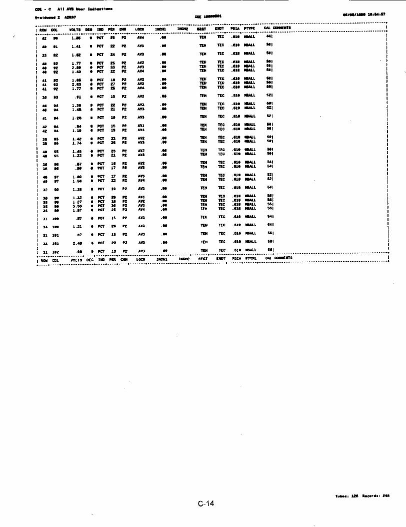
CD -C All AVS Wet Ismilestl
ersiwed 2 AM2t cog Isomm1 fflo8U 16 41S7
O Ke. VOLT IOEND OER LaCM C 1 1NCI N KUT EHDT PORA PWE CAL CO6UEN T
o 4Z 99 0 PC6 2T P2 AU .Te TE . MALL "I
41 01 1.41 4 PC8 22 P2 A n 66 TEH TEC .616 ALL 01t
1 33 92 1.62 I PCT 24 P2 AU .0 TEN TEC .618 ALL S6l
48 92 1.77 6 PCT 25 n n AV2 TEN TEC .616 MALL "I
40 42 2.00 Z PCT 33 P2 A n. TEN TIC .61T USALL SoI
4 S2 1.49 * C 22 AV4 .Z2 TEN T4C .610 TC UALL So1
I 41 42 1.6Z 0 PC8 LO P2 AVZ .96 TIN TEC .610 mALL Sol I
I 41 92 2.63 0 PCT 27 P2 AU .88 TN TEC .U19 MALL "I I
I 41 92 1.77 0 PCT 25 Pn AV4 .0 TEN TEC .610 IALL 661 0
36 93 .1 * PCT 15 P2 AV2 .90 TEN TEC U8 ALL 621 i
1 S 1.30 0 PCT 22 n A n .T T£ C .61E 8MALL 591
I 4* S4 1.46 0 PCT 21 P2 A n .8 TUN 'C .610 WALL 521
| 41 94 1. 28 S PCT 1S P2 AU T6 EN TEC .616 NALL 521
1 42 04 . PC* i1 P2 AVI . N TEC .418 MALL O1 I
1 42 94 1.19 0 PCT 19 n A4 .6 TEN TEC .U18 1MIL o1l
I 38 ff 1.42 0 PCT 23 P2 A2 . EH TEC .610 MLL ol I
1 38 0f 1.74 8 C 26 P2 AU .An UEN TEC .618 8SALL Sol I
1 95 1 .45 0 PC 23 P2 AV2 U TEN TEC I .610 ALL So l
148 5 1.22 0 PCT 21 P2 An .TE UN TEC 518 ILL 611
13o56 .87 9PC 16 P2 A18 .6 U TUC T6H T 8ALL 541
I 36 6 .n 0 PCT 17 n Af .EN TEC .610 UML 641
46 97 1.9 0 PCT 17 7P2 AU .8 TN TEC .610 IALL 521
I4 07 1.66 0 PaC 22 P2 AV4 . 8 TEN TEC .610 MALL 521
32 99 1.16 a PCT 10 P2 AU .UN TEC .610 UML U41
I36 to 1.32 6 PCT 20 P2 Awl .66 TU TEC .016 MALL So1
13 99 1 .27 6 PCT 1 P2 A2 . 8 TEN TEC .61 MALL Sol
I 36 99 3.68 * PCT 35 PZ AU .S6 TEN TEC .616 PALL 581
1 36 00 1.87 0 PCT 25 P2 AU .66 TEN TEC .6156 MALL S6l
31 16 .87 0 PCT 1S P2 AU .u TEN TEC .619 OWALL 41 I
34 1n 1.21 6 PCT 20 P2 AU .66 TEN TEC .610 61ALL 541
I 31 161 .S7 6 PCT 15 P2 AU .6 TIN TEC .610 MALL 561
I 34 101 2.48 0 PCT 29 P2 AU .6 TEN TEC .610 ALL 561
31 162 .98 0 PCT 16 P2 A3 .9 TEN TEC .610 MALL 561
I RON CO; VOLTS DES IND PER CH LOC; INCHI. IN2 DEST END? POIA PE CAL COMENTS I
Tubes: 126 Recot 2z4
C-14
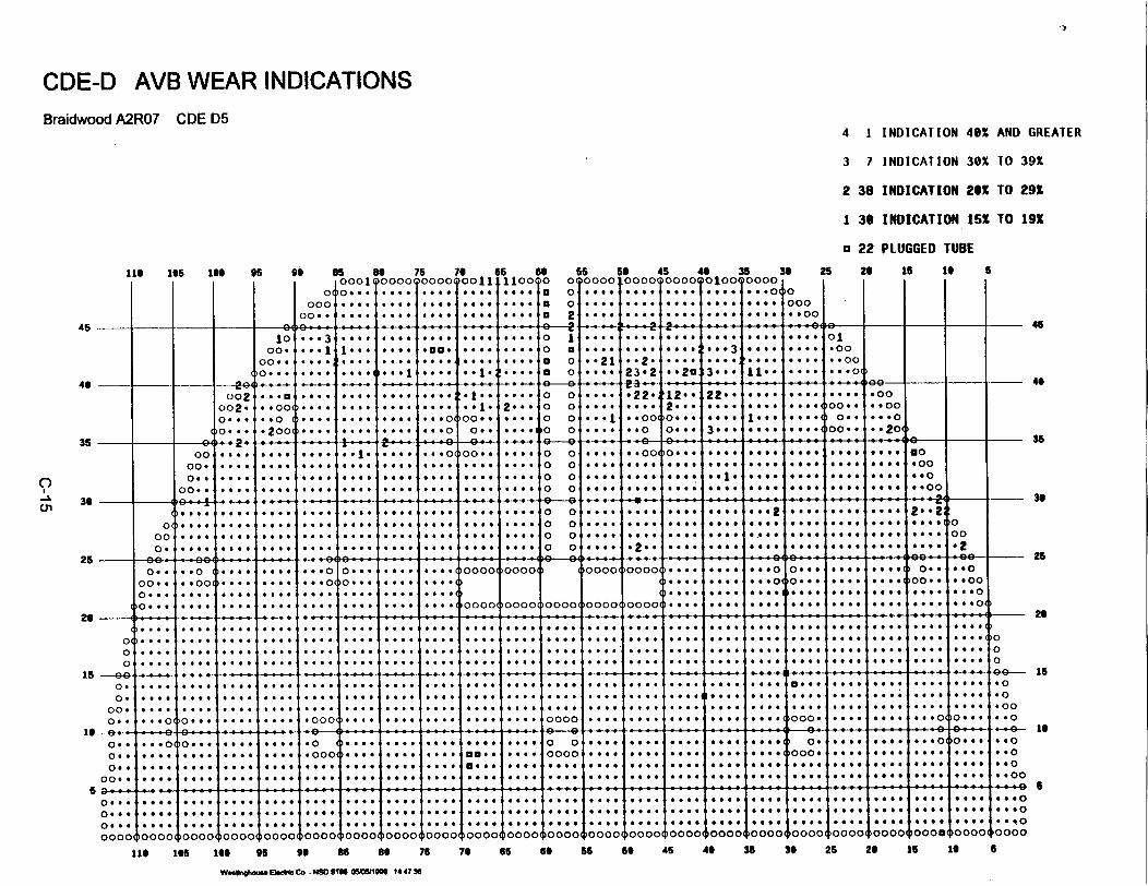
CDE-D AVB WEAR INDICATIONSBraidwood A2R07 CDE D5
4 1 INDICATION 40X AND GREATER
3 7 INDICATION 30X lO 391
2 38 INDICATION 201 TO 29X
1 30 INDICATION 15X TO 191
a 22 PLUGGED TUBE
11 105 10 95 9i
I I I I o0
c00c0. .
85 8a 750001 0000000
J.... 4.... 4...
76 65 6I0011 o1100 0
, .... .... a
66 560 oooo 10000 .... ....o *@... 0 ...2 .... *....
45 4 35 36 25 20 16 1t, *00 .10 000*.v 0
0 .* * ooOOQlOOQ4.... O..I4 .. oIoI
5
45
4.
35
0
cn3.
25
26
15
16
I0.. ...3 ... .....
10. * 3*... .... .... .... .... ° 0 .... .... .... 3... .,1.. .... ol.02 . .* 1 I.. . *.. *000 .... .... 0 a .... .... 2... 23 .... .... .oo
0 o.. .... ... .. .. .... .... 0a 0 2 .... .... 2... 4.... 4 .... .. oo.. ..0 .4.. .... .... aO.... *00.4 .... 0 0o . .. 0 04.. 2 a3 1. .... 0.. ...o
002 ... a .... .... 00- !- 1.. .... o o .... 6220!12*o 22-9 .... .... .... .*oo°°02- -*° -et --.. .... .... *e1- 2e oo.... .... oo 2** Otto too. ....w0O. ..oo0... .. 0 .... .... .... ... o 0o.. .... 0 0 ... I .. 0o 0... ... ..**. .... o.. ... o
00''' 2°°o ::** 4 O 00'' .... 0 0 oo..00 0... 4 4 *:;O
00o .... Otte Oto 1 . ... o o .. .. .... 0. 0 .... .4.. .... 4444 4444 4444 4444 Otto 000.. .... .... .... .... .... .... .... o 0o0 .... ... ..4. .... .... .*** .... .... *0o
00. .... ... 4. .... .... .... * .... .... .. 0. 0 o.... .... ease Otto of. .. 4. .... Oo *.00
0o.. .... .... .... Oa .. .... .... et 4o4 0 0.. 9..4 .. a 444w *404 4444 Otto Ottoo444
00 , -4_. p44. . . 4 _ ,. .444 e e *. -0 - -- 4. - -,4 - 44 .- 4--00
0 o. * 0. #* 000 .... 4 ... 0 0 0 0 0 4 . ... .... .... 0.. 4..oo .... 0.0 .... .. .. .... . .... ... .. too. .... .s .... ... 0 .... .:: .... . .... ** ........o
00 . ... .. .... .... .... .. o4o4.. 44 4 .... p4 .... 0.. .... s e . ... 0. . .O 020 o o 4 4444 . . . 4 . . . . . . . .4 . . . . . oa4 a 4 44.a . 4 4 4 .4 .
o.. .. oo .... .... ... o O... O4 4 00 0000 0000 0000 0000 t4oo. 44.. 44.. 4444 .... .... 4o.. .. o
o.. ... 0 .... . . ..aa .... .... ... ..... ... ... ... ... 0.. ... ... oa 0 Soto .. ... . ... ... .... .... . .. . . ... :: ooo oo ooo ooo ooo (...... .... 4 ....I ... ... ... .. oa000
4444. . .* 44 4 .. 4 4. .4 4. .4 .44 4444 4444 444 100 4* 4444 4444 *4 444a 4444 444 4 444 .O . . . . .* . e . ¢ O a .. .. O .. . . . ..... . . *.e *** a * *v .a. *.. . . .** ** .v .** .* .
01... . . . O O .X . 0 . . . . . ...... ..e .OO. ... . .. .. a~s a ¢¢ a* a*¢ 0* *.. **@ **4 *X a 0 . ** .0 . 44. ** 444 4.444 4.444.* **e@ * 4 444 4444 4444 4444 4444 4444 444 444 444 4444 444 0
0 . ... 4 4 .... _.. .. , ,._.. .4,, 4 ._ 4... 4444 4 . 44., _._ 44+ 0 0
0 .... 4 444 4. . 44* 4444 4444 4444 4444 44 ... 4.4 4444 *4 *4O 4444 s444 4444 a#O 40
00 .. 4 go4 44 .. .. 44 4444 444 ... 4 444 4**4 p444 444 4q44 4**4 44 40
004 - 0 0.. *...* ** *44 444 * .. 0 . * * . .. .. .. *4 **@ ..4 0 0 444 444 444 .4. 4.. 0. 4.. .4 .. ... 0 0... .0* 0
0. 4 * 4 4 44 O* 444 4** 444* *000 * 4 44X 44 44 e + * B4 v4 4444 0000 X X 444 4 4* * * * 4 444++ 0004 444 444 444 4444** v v 440O
044 444 444 4.. _44 44 444 44 4 4 4 ... 444 4o, 4444 444 44 4 4 4 4 . o 4 4 4 4 4 4 4 4 4 4
o* ... O... .... . .. O... .oo .. .. . ... O . :. .. 0. 0 11.. ... .oooo ... . . . .. . ... .... ... ooo .... ... ... . .. .. o0a0 0
o.: .... .... # .... .... .... .... .... .. .. .... .... ....... .... .... .... ... ... .... Oa.. .... 0... ..o
oo. .... ... . ... ... ... .... . ... ... ....... ... .... ... ... ... ... ... ... ... ... .. oo.0 00100O
sO:a.,, a., . .... * f _ _ .,, ... -O...ones o. _'' _*6 _ . ... .. ol0 . . s . . . * * . * . 0 **** ... 0 0 60 f*0 0 0 . . .. . a a4 * 9 0 0 0 # a6 00 000
45
4.
36
26
26
is
to
Sa
0 ..
0. a .0 a . a
I- - - - l - - l
6 a00 .0a 0 e *
4 4 4 40 .. ..4 ... 4 .0 0 4 4 $ ....0
,0000( 10000'
::::I::::
444444.44
~00001*...)000 .4..0000
~00 00( 10000
4. 4. # . 4 4 4 4 4 4a 4 4a
000 0(
4 44 00
0 . q O10000
ooooqoooo o0000 oooo0oooo00ooootooool 10 00. 0'0~(, 0000 10000 00000000oo~oooa
116 165 166 96 a 86 8 76 76 65 66 66 6 45 46 35 36 26 26 16 16
W eS*Vh... Elm1 Co - NM0 s66 O66IM i4 47 so
6
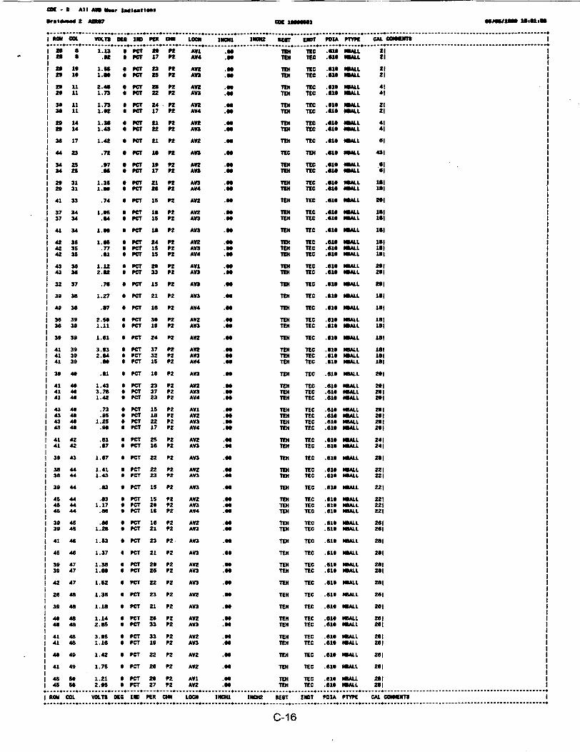
O - All AND Nmr Inrlet1o6ns
Proldimd 2 AMS? CK196666 466fl11S, Issue"
L VOLTI aS n IND Put U LOCII mICNI 11 1 11m? ET POKA P CAL COIMENTS
I Zs 1.1.3 a PCa " 2 Afw .06 TE TIC .616 Ul. 21 1S2 * .62 OPCT 17 Pt AV4 .6 Tam TIC .S16WALL 21
I so 16 1.66 6 PC? 23 PS AV2 . s TEn TC .615 WALL 21 12 0 1.80 6 PCr 25 P2 AU .00 TE TIC 610 WIALL 21 1
1 29 11 2.40 6 PC? 23 P2 AV2 .00 Tm TIC .616 WAL II 29 11 1.73 6 PCT 22 P2 AU .40 Tm TIC .610 WALL 41
3 611 1.73 u PC? 24- P2 A .9 TmN TIC .610 WAL 21I 36 1 1.02 * PCT 17 P2 A4 .Tm TIC .160 1ALL 21 I
1 29 14 1.36 6 PC? 21 P2 AU .6Tm TIC .uc1 ALL 41 I1 29 14 1.43 * PC? 22 Pn AU .a Tm TIC .610 1ALL 41 1
1 36 17 1.42 * PC? 21 P2 AV2 .a TIN TIC .616 WALL 6I 1
I .72 PC? la 18 2 AU . TIC TIN .419 WLL 431
1 34 25 .97 PCT 6 P2 AU .6 1EN TIC .51 A 151 34 25 a66 0 PfC 17 P2 AV& .s6 TIN TIC .61s WALL 6
26 31 1.35 0 PCT 21 P2 AU .E N TIC .616 ALL 181I 29 31 1.S6 a PCT 26 Pt2 AV4 . TIC .616 WALL 1*1 t
1 41 33 .74 6 PCT 16 P2 AU .E N TIC .616 WLL 201
37 34 1.65 6 PCT 1 I P AU2 .GO Tm TIC .616 WALL 18137 34 44 a PCT 15 P2 A . TEN TIC .U1 WALL 18
I 41 34 1.6 a PCT 1s P2 AU .a6 TEN TIC .1 WLL lei
1 42 35 1.66 6 PCT 24 Pn AU .60 TEN TEC .1 AML Sa1142 35 .77 a PCT 15 Pn AU .E T TIC .616 WALL le8 I
42 35 .61 PCT 1S Pt AV4 6 TmN TIC USI IALL 181 I
1 43 32 1.12 6 PCT 29 P2 AV . Tm TIC .616 WALL 291 143 38 2.6a * PCT 33 P2 AU .SO Tm TIC .61 WALL 2n1 I
i 32 37 .76 CT P s5 P2 AU .E T TIC .616 a ALL 291
I 39 32 1.27 * PCT 21 P2 AU .E T TEC .610 WALL Lai
I 4 36 .87 6 PC? 16 P2 AV4 . TmEN TIC .610 ALL 1S1
1 36 39 2.56 6 PCT 32 P2 AV2 .66 Tm TIC .610 WALL 181 II 36 39 1.11 6 PCT 19 P2 AV3 .0 Tm TEC .616 WALL 1L1 i
I 39 39 1.61 0 PC* 24 P2 AU .66 Tm TIC .610 LL 11 1
1 41 39 3.93 6 PCT 37 P2 AU .96 TE TIC .616 WALL La i1 41 39 2.64 * PCT 32 P2 AV3 .6 Tm TIC .619 WALL 161 1141 39 .66 * PCT 15 P2 AV4 .89 TmE TIC .616 WLL 181 I
39 46 .61 SPCT 16 P2 AU .66 TEm TIC GI1WALL 261 !1 41 4 1.43 9 PCT 23 P2 AU .96 TEN TIC .610 WALL 2011 41 4 3.78 6 PC? 37 P2 AU .66 TN TIC .616 WALL M11I 41 4 1.42 6 PCT 23 P2 AV4 .66 TE TEC .616 WALL 201
43 4 .73 6 PCT 15 P2 AWL .00 TEN TIC .610 WALL 29143 46 .95 * PCe 1s P2 AU .66 TIN TIC .616 WALL 261 1
i 43 4 1.25 0 PCT 22 P2 AU .0 TEm TEC .610 WALL 291143 49 .90 PCT 17 P2 AV4 .6 TmN TEC .610 WLL 291 1
41 42 .U1 PCT 25 P2 AV2 .66 Tm TIC .61 IALL 241 11 41 42 .87 9 PCT 16 P2 AU .66 TEN TEC .61U WLL 241
| 39 43 1.67 * PCT 22 P2 AV3 .6 TE TIC .610 WALL 281 I
1 38 44 1.41 9 PCT 22 P2 AV2 . TEN TEC .610 WALL 221 11 36 44 1.43 3 PCT 23 P2 AV3 .0 TEm TIC 610 WALL 221 I
1 39 44 .3 PCT 1S P2 AU .66 TEm TEC .616 ALL 221 1
1 45 44 .83 6 PCT 1S P2 AV2 .89 TEm TEC .610 ALL 221 11 45 44 1.17 6 PCT 26 P2 AV3 . TEm TEC .16 WALL 221 11 45 44 .86 6 PCT 16 P2 AV4 .98 TEm TIC .610 ALL 221 1
1 39 45 .86 6 PCT 16 P2 AU .86 Tm TEC .61U WALL 2611 39 45 1.28 6 PCT 21 P2 AV3 .6 TEm TIC .619 WLL 261
1 41 46 1.53 6 PCT 23 P2. AU .66 TEm TEC .61 WALL 281 I
1 4546 1.37 8 PCT 21 P2 AU .66 TEN TEC 619 ItALL 281 I
1 39 47 1.38 6 PCT 29 P2 AU .96 TEm TEC .618 ALL 281 11 39 47 1.69 6 PCT 25 P2 AU .96 TER TIC .616 WALL 281
1 42 47 1.52 6 PCT 22 P2 AU .66 TEN TEC .619 WALL 261 1
1 26 48 1.36 6 PC? 23 P2 AV2 . TEN TIC .619 WALL 261
I 39 48 1.18 6 PCT 21 P2 AU .89 TEN TEC .616 WALL 261 1
1 49 48 1.14 6 PCT 20 P2 AV .66 TEN TEC .616 WALL 251 11 49 48 2.65 PCT 33 P2 AU .66 TEN TIC .616 WALL 291 I
1 41 48 3.65 6 PCT 33 P2 AV2 .99 TEm TEC .610 WLL 261 I141 48 1.16 I PCT 19 P2 AV3 .9 TEm TEC .616 W9ALL 261 1
I 4 49 1.42 6 PCT 22 P2 AV2 .66 TEm TEC .610 WSALL 261 !1 41 49 1.75 9 PCT 26 P2 AU .9 TEN TEC .610 MIALL 261 I
| 45 50 1.21 6 PCT 29 P2 AV1 .9 TEm TEC .610 WALL 261 11 45 50 2.05 0 PCT 27 P2 AU .66 TEm TEC .610 ALL 281 I
.-,-,_--I ROM COL VOLTS DEC 1 PE CNN LOCN INCNI INCN2 5EST ENST POIA PTYPE CAL CCOE1TS I
* *-----6.............................................................................................
C-16

COE - D Al) AWS War indications
brold"1 2 A7 CE _66Uif osfs0im1 161 6s 5
............... ...............-------.. .........................................................------.... I------.....----------------------------------------------------------.........................
*W CD L VOLTS D C 1o PU M LOCO I11111 1baH BEST 1301 P01A PlIZW CAL CISWW.... .. . . . ...........................-- ----- --- --- --- -- ....... ------------- ------ *----------------------------------_-,-,-,-,-,-,-,-,-_
46 .64 PC* 1i ft AT .N ' 134 TC .61S ALL U!
49 1.15 6 SW 13 ft A Y . TIN TIE .610 mA14LL 29i
I 37 61 1.57 6 PCT 17 ft AV .5 3in TEC .110 ALL 25I
42 51 1.66 9 PC9 18 ft AYl .9 1T4 TEC .619 ALL 21I
1 42 51 1.15 6 Kr 19 ft AVl .96 TIN TIC .610 ALL 261
42 52 1.23 6 Per 21 PE AVE .65 TIN TIC .619 NLCL 26!
I 42 52 . 6 CT 17 D AV .65 1EN TIC .61 MLL 261
" 44 1.11 6 PC? i1 ft AW2 .65 TIN TEC .616 ALL 261
1 44 U .6 6 PC 16 ft An .65 TEN TEC .81 mAIL 261
45 66 1.22 6 PCT 26 ft AU .TIN TIC .616 mLL 261
1456 2.22 S PCT 29 ft AV3 .66 TIN TIC .610 1 261
4 so .70 6 PCT 17 nt AU .91 TEN TIC .610 $.L 21!
I 4 s o6 1.71 6 PCT 25 n AW . 1N TIC .616 13L. 21!
49 63 .76 6 PCT 15 ft AVl .11 13 TIC .610 mA 36!
1 49 63 4 PT 16 ft AV4 .99 TEN TIC .619 mAL 361
38 4 1.33 6 PCT 22 P2 AU .64 TIN TCE .616 SMAL 381
I 3 64 16 6 PCIT 27 nS AV3 .n5 TIN TIC .616 NmL 381
1 49 64 .D9 * PCT 17 ft AY1 .69 laI TIC .616 ALL 31!
41 6S 1.65 6 PCT i5 P2 AWV .65 1T3 TIC .616 1IL 341
49 aS .6 6 PCSW 16 F AYL .99 Tat TIC .616 mALL 341
4S GS .67 6 PCT 1S ft AI .*9 TIN TIC .616 30ALL 341
| 3 67 1.65 6 PeC 18 ft AY3 .65 TIN TIC .61, 30LL 3 361
141 67 .79 a PC 17 2 AU .6 TIEN TEC .16 mALL 361
141 67 .78 s CPT lS AU .94 TNN TIC .61S SLL 3 1
i 48 67 .74 S PCT 15 ft AY4 .9 TIN TIC .61T mALL 36!
39 68 .915 6 PCT 1S P2 An2 .96 134 TEC .16 mALL 38!
39 78 .6 6 PCT 1S P2 An .91 TIN T3C .610 ALL 4! "
1 39 7S 1.3 6 PCT 26 P2 An .96 TEN TEC .616 WALL 41!
1 42 78 1.Z2 6 PCT 25 n AWL .*14 TEN TEC .610 HBALL 4"!
1 42 7 5. 13 6 PCT 46 P2 An .SS TEN TEC .61 SMALL 48 !1 42 76 1.99 6 PCT 1S P2 An 9 TEN TEC .610 mALL 491
j35 75 .92 * PCT 1S n AWL .6 TEN TEC .61 ALL 421
I 35 75 1. 19 6 PC 1S n AU .99 TEN TEC .610 30L 421
1 41 78 .NS 6 PCT 1S P2 AU .45 TEN TEC .616 SAMI 421
1 35 79 1.56 S PCT 22 n AU 9 TEN TEC .61 mALL 421
1 35 79 1.61 * PCT 23 P2 AY3 .V TEN TEC .619 UALL 421
1 35 79 1.56 9 P7C 18s n AY4 . TEN TEC .61 MLL 42!
49 81 .82 6 PCT 1S P2 AW1 .6 TEN TEC 616 LLI 44
1 34 82 1.6 6 PCT 17 P2 AW2 . TEN TEC .61 MALL 461
1 35 G4 .92 42 PCT 16 PE AV4 .SS TEN TEC .616 MLL 461
43 I4 1.95 9 PCT 17 n AU .U TEN TEC .616 MALL 48!
42 86 1.65 6 PCT 18 P2 AU 99 TEN TEC .616 SMALL ol!
1 42 85 1.57 * PCT 23 P2 AU So TEN TEC .616 SMALL ol!
1 43 86 1.96 S PCT 18 P2 AU .s6 TEN TEC .616 SmALL l5I
44 as 2.4 SS PCT 30 P2 AU .S TEN TEC .616 MALL So
| 44 92 .65 6 PCT 1S P2 AV4 .16 TEI TEC .616 SMALL 541
36 93 .D4 S PCT 15 P2 An . TEN TEC .616 SMALL 541
1 35 93 1.22 6 PCT 29 P2 AVU .6 TEN TEC .616 SmALL 541
39 96 1.36 a PCT Z2 n AV2- NSS TEN TEC .618 ALL 521
38 9 .77 0 PCT 1S P2 AVU .s TEN TEC .616 ALL 521
1 35 97 1.21 6 PCT 26 P2 AV2 .9 TEN TEC .610 mALL 541
1 38 97 1.46 6 PCT 21 P2 AV1 .S9 TEN TIC .616 SMALL 54!
1 3 9 S7 1.22 a PCT 1S n AW2 .66 TIN TEC .616 SMALL S4!
1 38 97 1.25 * PCT 26 P2 AV3 so TIN TEC .616 SMALL s5!
|4 97 .2 S PCr 15 P2 AU . TEN TEC .616 SMALL 641
1 4S 97 1.41 S PCr 21 P2 AU .S TEN TEC .616 SMALL 541
130 11 1.11 S 7CT 18 0 2 AV2 .99 TEI TEC .61 ALL So!
1 36 191 .85 * PCT 1S P2 AU .61 TIN TEC .610 mALL 58
ROM CDL VOLTS DEG 1ND PER CNN LOCH INCHI INCH2 SCT END? PDZA PTYPE CAL COS E T3
C-17 Iw.Tso 76 Records, 126
ATTACHMENT D

TABLE D.1:SG TUBES REPAIRED DURING A2R07
I A 0 Y4 f u1 U.ZY Z lZZ I Om-U.Uo
2 A 19 40 SCI 0.39 2 19 TSH-0.333 A 24 38 SCI 0.13 2 92 TSH-0.094 A 24 78 SC0 0.22 2 106 TSH-0.105 A 31 38 SCI 0.14 2 105 TSH-0.056 A 44 67 SVI 0.70 1 74 02C+0.987 A 36 16 43% 6.37 P2 85 AV2+0.008 B 2 57 TBP 1.30 1 21 11H+8.009 B 6 12 SCI 0.56 2 19 TSH-0.03
10 B 15 25 SCI 0.35 2 30 TSH-0.0511 B 17 36 SCI 0.16 2 84 TSH-0.0912 B 18 11 SCI 0.27 2 39 TSH-0.0713 B 20 6 SCI 0.33 2 50 TSH-0.0314 B 20 7 SCI 0.35 2 50 TSH-0.0415 B 21 55 SVI 1.12 1 50 02C+0.3416 B 27 32 SCI 0.23 2 53 TSH-0.0917 B 28 25 SVI 0.92 1 72 01H+0.4518 B 28 41 SCI 0.15 2 134 TSH-0.0519 B 33 20 SCI 0.24 2 160 TSH-0.0620 B 34 96 SCI 0.19 2 74 TSH-0.0221 B 35 33 SCI 1.29 2 11 TSH-0.0022 B 37 78 SCI 0.10 2 92 TSH-0.0823 B 37 89 SCI 0.26 2 50 TSH-0.0724 B 38 88 SCI 0.17 2 101 TSH-0.0525 B 40 88 SCI 0.39 2 32 TSH-0.0426 B 41 89 SCI 1.38 2 17 TSH-0.0327 B 42 31 SCI 0.19 2 23 TSH-0.0428 B 43 28 SCI 0.31 2 37 TSH-0.0029 B 43 55 SCI 0.13 2 111 TSH-0.0230 B 46 28 SCI 0.17 2 131 TSH-0.0931 B 46 45 SCI 0.18 2 63 TSH-0.0832 B 47 31 SCI 0.29 2 38 TSH-0.0633 B 48 80 SCI 0.43 2 10 TSH-0.1034 C 18 25 SVI 0.75 1 66 01H+0.5135 C 19 27 SVI 0.35 1 102 01H+0.4736 C 34 66 SVI 1.52 1 77 08H+0.7037 C 35 59 MCI 0.24 2 86 TSH+0.0338 C 49 53 SVI 1.93 1 121 08H+0.64
D1
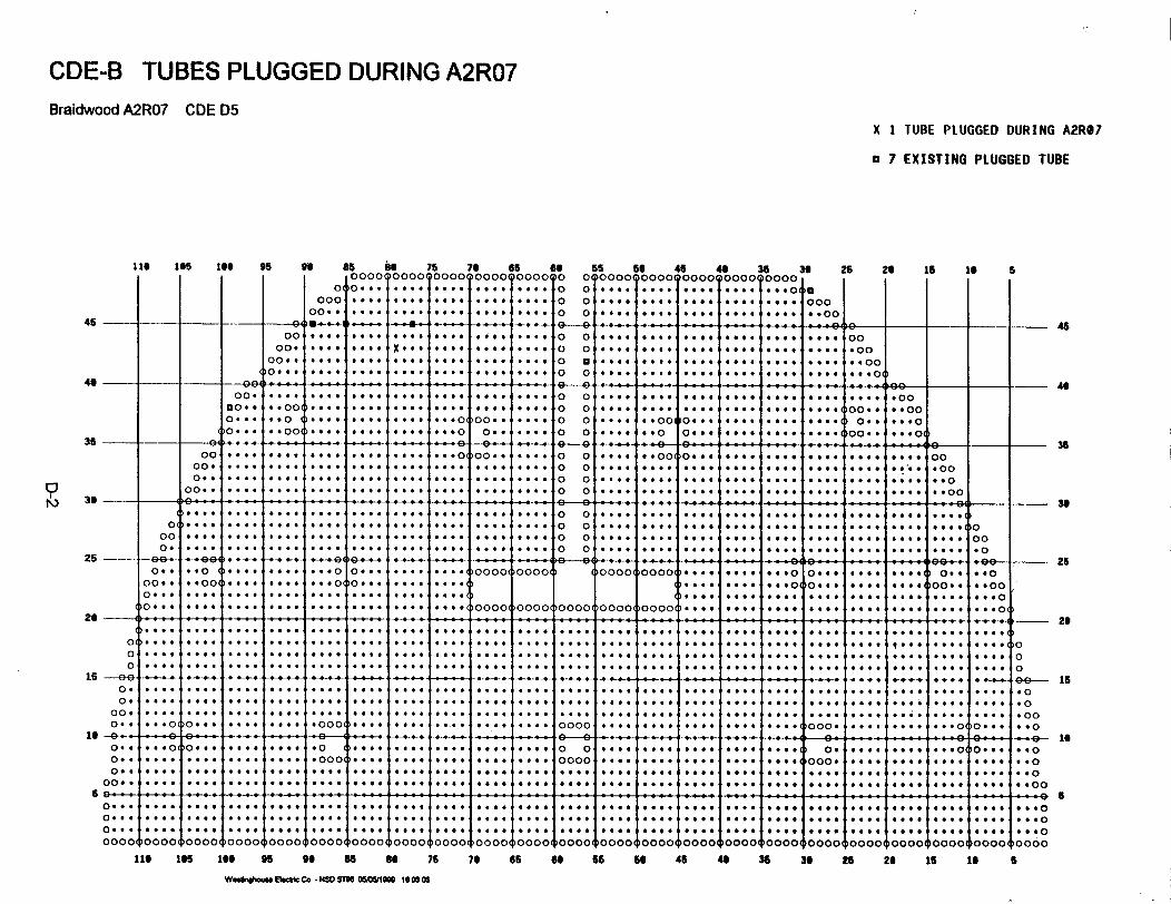
CDE-B TUBES PLUGGED DURING A2R07Braidwood A2R07 CDE D5
X 1 TUBE PLUGGED DURING A2R97
a 7 EXISTING PLUGGED TUBE
11 165 i* 9S5 96 85 66 75 70 65 69 55 56 4510000 0000 0000900 0000 000 0 0000 0000 0000
0 0... 4.... *... *... see. 0 04.... .... ....*o00 ...... .... ..... 4.... .... 0 0 .... 4.... 4....000.. O.. I.*to *#** 4...* 4*64. fo of...f j.... 00
46 35 36 25 26 15 1i,0000000000 ,
S
10I* 4444 4000
45
46
35
3.
25
26
15
16
6
___ - 4-- 4-4-4 4-4- 4-4-4 4---- 4- -4 9-9 *-*--*P . v- o.--.-.- -.... . +-.-+- ---.-- .-.--.-9bo .- - - - - -
00. .. . .44 . 4 . .4 * 0 0 * 4 4 4* 44* s 44 40
00.. ... .... 44 .40 U ..... 4. .... .. 444 40.0
00 4 4 * . 4 4 * 4 4 ~ 4 ~ 4 40 0 0 . . ~ 4 4 ~ ~ 4 4 4 ~0... ... *... .... .... .... .. 0. .*
0.4. -.00 .... s_.. .... ... 0 .. so .*.. 0 0 4 ... e 0... .. . .... 0.. ..+.
- 0 ... 4-4- O-- .... 4 4 -.-. .-. -. O.-.0 -0-.-. .- 4.- 0 -0 -...-. .-.-0- O.-.-. .-44-4 *e.-.. so.-. 4--.-. ---.-. 0 - __00O 4 .. 0 4..*. *...O 00.. .... 0 0 .4.. .0 040* *oo *s .. . *. * .00
.* .... ... . 4. * . . . 0 0 *44 O4 4* * *044* .44: 44 4 O*.. 44*0 O. . . * 4444 46 .444 . .. . .... 0 0 .. 444 0444 4 444 4* 444 .o. $O 4 40
0 0 o .... . O.. + , .... .. .. .... 4 44 4_0 0 . . . 4444 .4 4 44 4 ...44 w. .. 44 4o4 .. O4 4 000. .. .... .4... 4... .... ... 0 0 .. ... 44 4444 4... ... 4 .... .. .... 4 .0
0 .. .. .. ... 4. .4.4.4 . .... .. . . .... .000 0 000 0000 ... .... . . .0 0.... .... .. .. .. 0oo. . ..... . . . .... .. . ... ... ... ... o ..... :.... .... .... .. *.oo
00.. 4.00 4444 .... .0 . .... .... ... o. .4 . ...0 .... ... O... .... 400o ... ... ... ..... . . .. . . .. . . .. .. .. o o .... . . . .... .. . ... ... ... . ... .... o
0.... .... .. 4. . 4 . .. .... .... 00000 0000 .0000 0000. .... .. .. 4 .... . ... .444 *.o0 _-.. .. . 0 4 . _. o | . . ,o 4 4 . + 4 .... 0o ... .... .... .... .... o .. . .... . ... 00 oooo oooo oooo oooo00( .... 0 .... .. *. oo... .... ... o.. .. 00o
oo.1. .. o .. . . .. .o o.............. ... .. ..... ... ... ... o.. ... ... oo. . .o :
0 .... .. 4 .... .... .... .... o ... 4444 .... .... .... .... 444 . .... ... 4..o4 0
o .... .... .... .... .... .. O.. 0.. 06.. .... oo oooo oooo .... .... .... 0 of O.* .6 ... .... . . .0.. .... ... o
0 .. . ... . .. .... . ..... . . .. .... .... .... ... 0O .X.. .... .... .... .... .... .... ...... .... ... ... .... ... o0
0 ... .... .... .... .... 4444 4444 .. ... .... .4.. 44.. 4.. 44 4. .. 4. .. .. 4. .. *0oo .: . .... 04 ..... .... .... .... . .0....6 .... 0 .... 11 .... o ..... ... .... .... 0 0.....o
00 4 4 4 4 4 4 4 4 4 * 4 4 4 4 44 4 4 4 4 4 4 4 4 4 4 444 44 4 4 4 44 4 4 4 4 4444 ease 40o...... ..... .... ....... .... .... ... .... .... .... ... ........ . ... ... .. O 0... .. oo. 0.. .... .... .... .... 4... .... 0000.. .... .... ... 4 444. .... .... .. ..0004 .... .... ..o0
o. .. oo.. .... .... .o ... .... .... .... .... o.o.... .. O...-. .... .... o. . ... .. ... o... *..o
0 .. .... 0 + .4.444..44 .0 4... + +4 I 04.+ 0* _+ 4+ 0 0+ ..00., 4 00
0o . 4
0 .4
0. 4 4
0000
.4..
'0000=000(
0 ... .. .. ...
)0000 0000()0000('00004 00001
0 4 # .
. .00 40
10000 100001
4...
400000000(
.4..
l000'00001
'.e4.4
. , *@*
.4..'
000(
4...0000
0000w100001
6 0 6* X.a 00
00000
0 0 0 0
00e04...1000
0 #vs. 00* .@
00004
4 44f 0
. 44 0
4.40
10000
116 105 166 95 96 85 as 75 76 65 66 66 5O 45 46 36 36 25 26 15 1i
WeOh...4 Ic Co - NM SM 05WW 16 05
6
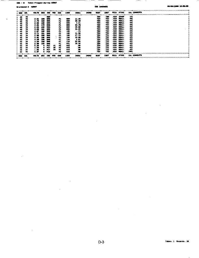
Cog - 5 T_*.. P*uge Dor lsey A?7
lr.4id 2 0 CIl J_ c lomso estm11m "IBM"
. . .................. _. ,... ,...,,__. .. ............................. .... ...... . ... .. ... . . .. ... .. .. ......
GIa s n Es cm LOCIS zlow Ilcll KU iT POIA ,tW CAL CWJItI,_,.__.. ... ,... ,... +,...... ._. _....... _ ._.,. .. . . .. .. . .. ... .. . . .. . . - - - - - -- - - -- - -- --- - - - - - - - - - - - -
43 7" nOD" 1H .11 zP 11 1.1 43 n 2.U 1n o1 P1 gm 11.45 Tel TIC .610 ALL "5I1 43 As Z." zn m P1 i 30.40 TM TEC .610 ImAl 461
43 7 Z." 1i O1m Pi 034 5.21 184 TEC .510 NML 461I 43 70 2.03 17 m pi -O 23.73 1T TIC .010 I1LL 4"11 43 7 2." 1in Omil P 1 SON 29.00 DI TIC .610 ALL 4611 43 79 2.6 141 l5 71 63 35.03 TEN TEC .010 AILL 4"11 43 n 2.07 IS sily P1 1W -. 73 1T4 TIC .61 MIL 4411 43 79 2.71Z 141 D P1 14 11." TIN TIIC .610 LL 401
1 43 79 2.6 no o1n P1 134 17.72 TIN TEC .515 mALL 461
1 43 79 2.41 180 G4O1 Pi 13" 35.6 18t TEC .010 "LL 461
1 43 79 4.40 186 ON pi 1114 S.07 14 TIC .510 ALL 45 11 43 7 3.2 1 N 11 P1 11I 22.50 18E TIC .515 ALL 4511 43 " 2.55 Ism 510 P1 AV1 10.3# 1I8 TC .010 "MLL 4611 43 70 5.20 0 PCT 41 t AV .00 T1 TEC .U10 ULL 4611 43 70 3.11 0 PCT 35 Pt AV3 .55 TEN TEC .510 1SALL 4 I1 43 79 1.30 S PC5 26 Pt AV4 .00 TEN TEC .015 "AL 4611 43 n 4.67 0 P1D Pn AV2 .05 TEN TIC .310 OMALL 1551,........................................I *a COL VOLT DE to PER am LOCM 1114ll 114C42 lECT EN1T POIA PTY9E CAL COOEOTS
D-3 Toses. 1 Recrds 10
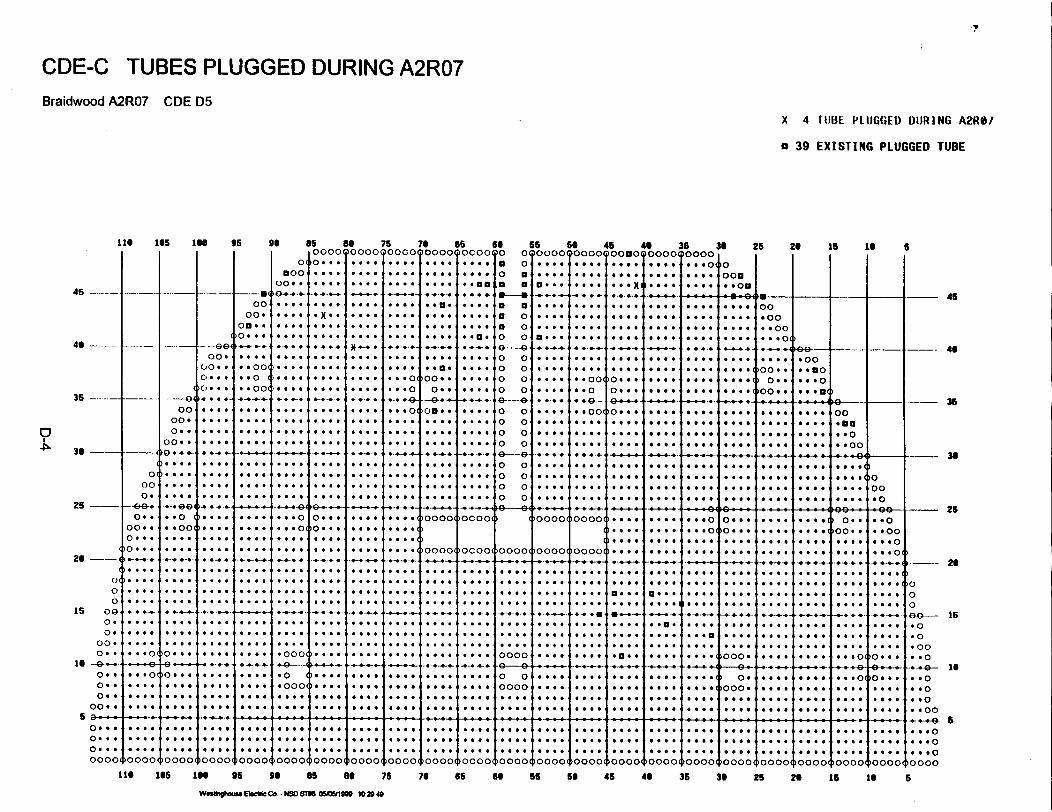
.44
CDE-C TUBES PLUGGED DURING A2R07Braidwood A2R07 CDE D5
X 4 IOBE PLUGGED DURING A2RM/
a 39 EXISTING PLUGGED TUBE
116 165 160 95 go es es 75 78I I I I I i OOO>i0000000000000
45 ---
4*
35
0 36--
25 --
26-
00
15 -- 090.0.
00.0. .
16 --.-0. .0 .0 4
00 * 4
00040
o.00. .0 . . .o...
* . .0.4-. . .
...0
.4..
. . . .
.... 0
. ... ,
* . o0 6 *o.
'0000.o..
00'4
....
. .0.00
>0 4
9.-.-.-
*0 .
-- -ee00.
C00..
C, . . .
C>...
0oo00.
o0..
- -00(
... .
* * 00
coo
0'
00e004
'0-4-4-.
4....
* *0
.004-9-
*.000
0 4 4
* x. *,
94-4--.
0 4 4 4
0 4 4 4
44444
4 4 40>* 4 4 0
* 4. 0>
4444>
4444>
4444>
4444>
t ----0.
0 ....
0 .. 00
. . ...
. . a
o..
)G ...
0 . .,.
. 0 . .
0 .....
. . ...
{ ....I
.... S
.....***.4e *o*,* . | . i
*|***.-.*-44<< .i
_ . - +,
.....
.. @.l
.....*e.'+-. .-. ,
....*e.'
es.4.4*.
____ i
ocoo
ocoo<^
*.**sv***.*s... s*.. ,,
....
....
.. *s
....- . | +.
....
.*
... e. * * .
>+H+_- - -__-_4+,.,I s-
66 66 55 56 45 46 35 39 25 26 15 164 OCOO 0 0 0000 0000b00*000000 0000 0 s I I I
ao a 4* * UO... .... .. OX tooI ..... II
1a 4
a 04*9 0i4
'0 0'
0 0,'0 0'0 0
0 04
,t9---el
'0 0''0 04'0 0
'0 0'
'0 0''0 0'
O O
)0000>
0000t
| ....
1**-*1 *1n * . .e.. ._
| ....
+*vv4*@
@@| . F.
1 s1ss|....
I....
i 5
I ....
....
* x Z *
l**es
poooo,
foooo,
b....I ....
I ....
I ....
I ....
f ...
f ....
f ....
§ ....
§ ....
-- - --
. . . .
4 ... ,
4 . .o
I* * 00(
O ...
.- 1
. ., . .
a .... .
I0 . ..
. . ., .
po . . .
IO....
0 .O.
. .0 .
. . ...
1 . 'ls'a'4;.. . .0 0.
0 . . .. 0.* .00 00
0 *
. ..0 00
0 * 0
. ..
0 . * | .
1 * .
. .... i
t -1i 0 1.
. . . .
1. a .
6
. ._ ..
I .... ,
* . ..
a 0...
1. . *
. . ...
00.00.400
* 4 0>. .o
* . . .4
00 4.
O..~-00. .
I... I
poo. . I
b-0.00.. n0* 4 4 09 .oo
a . .oo
. . . .
{....
{....
{....
..... 0
0 .... *
{. . .
----. 4 4---- 46
4.4-4-4- 4-4-4-4-14-U-4-40UE--------I-4---I 4-
I .o
I. .mo0 -4 .0I...00-*- *- -G4
4444'
a4444>
o00, . o
.-- 35
.-- 36
___ 25
26
I --- 24
00GO Is
45
ppoooo
. . ...
. . ...
I . .. .
. . ...
I . .. .
. . ...
,....
I . .. .
I .... .
1. ...
I .... .
0 .... .
0 . .. . .
'. 444
)- 0 ..- 't 0-...r
il . 0...
0 ao .0
. . .
. . ...
0 . . .
. .o ..
. .....
i... .. ..
0 ... Oa 4 0(
440>i...o
* 4 . 54 ... .
Ie .. ia
. . . ..
i . ... I
)o... l
t6'-
0 . * .
.. .
>0.4.0
44444
>000. 4
. . .. .4 . 4 . . .
I .. ..
. . .
- - - I .- -0 .- 4J- rO-. . .
I . . . .I
i .l . _
, . . .
. ._ . .
I . ...
. . ...
. . ...
. . . .o
4 4 009 .*oo
I a a 0lI. . 0.o
4 .. 0>
I . ...4 .... .
I .... .
0 . . .
.0.o0
. .o0e e+.4 4 - 4- -- 1 -- -° .- -. 4--o .4 1- .---
0 00000.... l
I °°°°.
a a* .
I * 6
I 0* .
I .4 44
I 0.>000.
4. .0,
a.a..
. . ..
*....
>0 * . .i0... .I.4..,
.. O
.. O
4 4 00
60 -,-,-,- - - --4,, - m -. .-.- .- -- - -I------
0000 '00004
. .... .. .. 0...
oooo0
444444444 *
I
I
. ..*. . 0... . . .. ... .0000,..... 4... 1....44..1.4......4..4..4..4...... .......
0000>
. ...
...... .. .
oooo0
. . . . . 4 . . . . . . . ...*. 0.. . ..
0000o
...... ....... *
)OOoo
.... .... : . . :..... .0O
. .. 0
0000> :00 0> 00004 oooo oo0ooooo ocoo oooo oooo0oooo.... .... 4.9...... . ..0
'0000 oooo0 0oooooooo oooo
16 16 in 95 96 85 8a 75 76 65 66 55 56 45 46 36 36 25 26 15 16
W.40hl.w 8 '' Co - NSDS16 05MI e 120 40
6
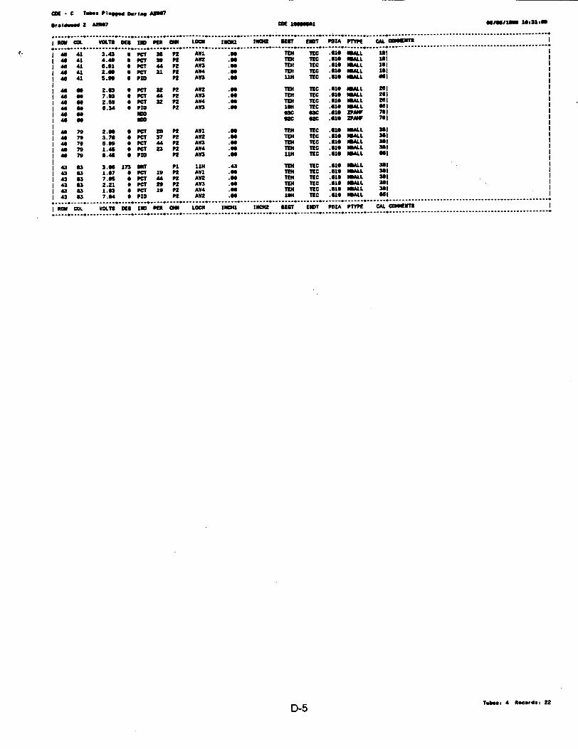
Ct . C lWSs P18ugs Dun, A507
aSteIwse 2 4207 Cm usessan "es~llon Mile00
I - CO VOLTM O66 -u PU cm tOWN CIP1 I90 NWC LST IPZAL ""Of CAL. @0ff2 I
I l 41 3.43 * PCi 3s P12 AVl .00 TINl NC .410 flIALL lei
461 4.40 aspot so P2 AVl .66 1334 NC .610 ALLt 1*1II 6 41 6.91 6 PCT 44 P2 AV3 .me TEN tic .610 aaa lei
46 41 2.41 0 PCr 31 PR AM .66 1134 NC .010 NMLt JAII40 41 S.0" 6 PUD P2 LW) .96 11I4 NEC .610 WALLt "I
I a of 2.61 0 PC? 32 P2 AV2 .66 TEN TEC .616 WALL 261I S 6 7.13 6 PC? 44 P2 AV3 .60 TEN NEC .616 OSALL ill
46 as 2.69 6 PC? 32 P2 LW4 .6 1334 NIC .616 ALLt 26146 60 6.34 6 Pro P2 LV3 .is6m NEC .616 MSALL " I I
14 60 IM sac sac .610 2PM 7ul114 so 20D 92C ox .616 2PMU tea
1 4679 2.90 SPONT Ra p2 LVI a5 1TE4 NC .i1 It Lt 261a46 79 3.76 0 PCT 37 P2 AV2 .50 TEN NIC .610 ISALt 361a
I 46 79 6.90 0 PC? 44 P2 LV) .Of 7334 NC .610 IALt 38!1I 4 79 1.46 6 PC? 23 P2 AV4 a5 1334 TC .610 WISA. 381I
467" 6."48 SPU P2 LV3 a5 1134 NoC.610 MAtt a6
143 83 3.66 In3 ONY P1 1114 .43 1To 'MC .610 SALt 3811 43 63 1.67 0 PCT 19 P2 AVl .6 TNH TIC .610 NALt 381
143 83 7.66 6 POT 44 P2 AVl .66133 TIEC .610 SNALt 361I143 63 2.21 0 PCI 29 P2 LV) .60 TOO tic .gig MALL 361143 83 1.03 0 PC? 19 P2 AW4 .66 T133 NC .616 atLt 381
1 43 03 7.04 0 PlC PR LV2 .6 16s" tic .610 MAtL t SII
I ROM COL VOLTS KG6 15 PER CMO LOCH INCH1 134042 SECT EIT POAM PTVPE CAL CUOMENTS
D-5 Tube: 4 Records: 22
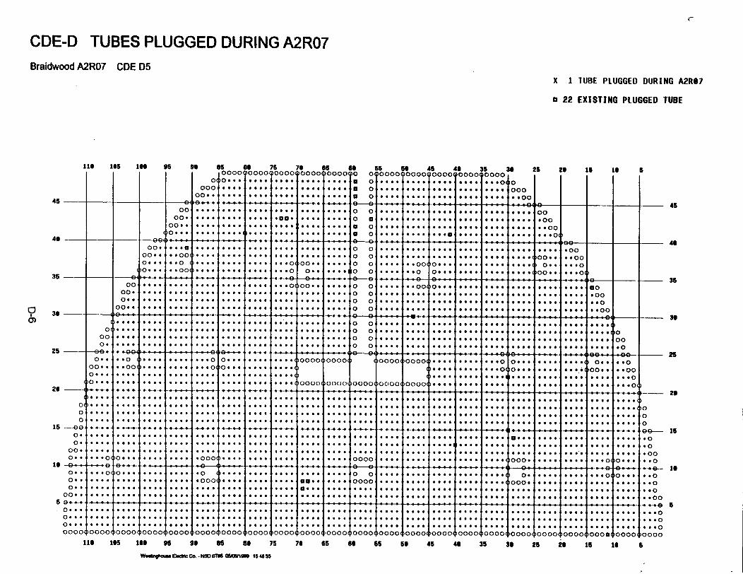
C
CDE-D TUBES PLUGGED DURING A2R07Braidwood A2R07 CDE D5
X 1 TUBE PLUGGED DURING A2R87
a 22 EXISTING PLUGGED TUBE
116 5 65 1 95 96 86 of 75 76 65 66 56 o 45 4 5 36 25 26 15 16l oooooo0090oo09oo0o 0o 0cD0000Qo000Qoooo0oooo0oooO, , , . S
0001.. 4 *44*4 4444
45 -I -0'00*
0040040.00 . 4*
.G-* . .* *0S 0GS S S G
* G
.ee0
.... 4G. .. G
*.4.
G**..G
G 0. GG 0 0
S 0 0.
0 . 00 00
G 0.-4e
9 0GSS*G@G *S.*S .G
* 0a 0a 00 90 00 aa 0a 0
*** * G G.
0000G GOO
.im~ H j064 i i * e L 450 G06 **e.00
a a e a
* 44.
4.4.
G S40 .S
00.00.0 00... 046
35
'?360)
26
26
15
le
5
00.. . .00 .... . 4 4.. . 04 .. 0 0 4...44 * o 00 . .. 4 00
0 ... 4.00 GG . G G. 4. . G . 4S.G.0 0 00G . 4 . .. .G 0 0 S Sa. .0 SaG S a0 0.4G44 4 *44 0 0 W 0 .. 44 0 00... .. 00 4 ... .... ... 4 .40 006 (0 . .4.. 0 0 G... *.0 0 ..* . Go-* O*4w 4..*.( 0 .0. ...
0 0 4 4 . .. 4 . 4G 4 4 4 4 . 4 0 0 0~ . .. 0 0 . . 0 0 . 4 4 .* * * **0_ o _ S S .. SG....4... 4.44 .... , . .. 0 0 G G . G _. 4... 4.4. .a...... a G.000.o... . .... .... 4 ... .... .... .... 0 0 .... .... .... 4.* ... .... .... ...o
oo. .. .... .... .... .... ... .S... .... 0 0 .... .... .... .... .... ....44 4444 4...0 o... .. ow 44 >.44 4.... ... ... o oo..4 ... 0 0 .... 4.oo o4.. .... .... .4... ) .. 4 ... o 444
00 .. ... .... 4. . .... .... . .. o o.. .... 0 .0 .. * . o. . ..0 .. .... .444 4Sot fees *. . o0 0__ _ H S . *- . . ., ., G . G G G G G, _ 0 066. Se . . o _. . G. G . so0G .- 00 G00000S 00GG 000a aGS S1
0. SGG .... .... .... GGGG .... .... ... o .o.. .... 0 0 .... ..O .... SS.... .... .. ... .a e 0
0.. 4.0 4 .. . 4.0 0 G... .... .... 0000 0000 0000 0000 .... .. .G... 0.... .... .... 0..o S0. .. .... 4...... .... .... ..... .. o4 .... .. .... .. .... .
oo. .. ......... .. .. ...... o .......... .... .... .... ... .... 4*4 oo *
0. . 0 . .... S . .. 4444 4444 0000 00000 000 0000 00000 0 00 Goo* p444 444 4 400 4444 **44 444~000 0 G.... .... .4.. .... .... 4...44. ... S S4. G. .... o4a o .... ... 44 .... 4 ... .... .... ....
0OG... 4.. . SGS. ... G .. 4.. .... .... .4.. .... .... o o .... .... .... .... .... .... .... .... .... o00 o..... .... *~.... .... .... .... .... .... o o .... .... .... .... ... ... ... .... .... 0o0 . ......... .... .... 4... 4444... .... o o .... ... .... .... ........ .... .... .... 0o
-- -0 . -- ,_ .. .. . 4 4 - ~ - - 4 - 4- 4-- 4- -4- 4 -4-4- _ e e - .o _. 4-4-a e a .- 4 ..- 4- a.4. -* _ _ - -0 so .. .. o4 .. .. 44 * * .oo4 4o44 .... .... 44oo 444O oooo ... 4 4444 444 .4 444 ... o o4 ... ** 4 **o. 4..o 40
0. ..4 ..4 o ... .... ..4 4o... .... 4. ..4 .... .... 4444 4..4 44f Go.* o ... .... ... * * . .* 00 ... 0... . ... .... .... 0 0.....44 .... .... S t oo G..$ .4.. G44* .... ..00 .... 4 0 .. 0. ... * 40
-_- . 4-4-4-0 3--4 .-.-. .-. - & * G , _.+, .-.-.. --.- - 4 -_-_4 .- - 4-4-_ 4. . -. g.- ... -
0. 00. 4. * .. .. .. .0. . .... .... .... . . .... ...0 .... 4444 .... .4.4 0. * 4 4444... *. 0 0... .. 0
0.. .... 444 .... .... .... .... .... 4 * .... .... 44 . 000 4... .... .... . . .... g s 00.0 .... ... . .4 4 g s 4.0.0 o. .... 0. S G G G 4444. .... 4 .4444 ... . . . . . )O . . . o0
0 4 4 4 4 444 4 4 44 4 44 44 4 4 4 4444 - -4 4 .0
o. S.SG G0 GG..S .... 0 00a ... ... ... ... ... ... ... ... ... ... ... ... ... ... .. e.. ... S .... ... ... S.OG
o. S ... ... ... ... S....40 .... . G...S .... ... ... ... 10GS0G0 0a00SG. .... 00 ... ... ... ... ... ... ... G. ..... .ooo. SSSS0SaafG .... a 006 ... ... ... ... ... ... ... ... ... ... ... ... S. ... ... ... ... ... ... ... ... .oo .. 0 0 S S G G .G ...G. ... .Oo O... .... ... ... ... ooo ... S...0S00 . ... . ... ... oo G ... ... .. o o .. .. o
-. - o.. ... ... .o ... ... ... ... ... - -... ... ... .....-..... .oo..
35
36
22
26
is
is
S0 ...
0. 4 G
0000'
*.G..G*G G* GX
0000,
*.G..GI G *. GI
I G . 0G
)0000
lo
40000'
a G 4 4 4 G4 4 . 4 4 G 4 4 . .4..*** 1@ 4 . . 4. .. B..e
I
I
IG 44G ... S a*4 .X 4 4 4 4 ....44 4 .4.444.4. 44444.4
I
I
I
::::I. S S .
,00**1
)0000
. GS... 4 . 4 4 4.0
00004 'oo,000000oooo00 >0000( 10000$00004 40000( 0oooo0ooooloooo4oooo 40000 '00004 0ooo0 0000$oooo116 165 1SO 96 9g 85 86 75 76 65 66 66 56 45 46 35 36 25 29 15 16
W emm Oocbf Co. N SD S 0818 15 41 55
S
CS - D Taboo PONN" lrta A£U
. . .. v. . -se ... e .. 1. .49 7 _m mTS Tom .U am 1l3I
I 4t 7 1.1 a PCT A Pt AVl .6 I3 N IC . L dli 114 76 t.1D 0 PCa 40 72 AV2 .00 Tt TIC .610 NIA 461
41 4 1.6 * PCT isDt An .00 13 TItC .610 BEL 4d11 42 7 .41 0 l Pt An . N TtC .U6 mLL 41
4 1 t.63 PID nt AV2 .6 TtIC TIE USI NL 471.,. .. ,; .... . . . . .. . .. .. .................... , -- -- - . ... . . . . .. . . .. . . . . . .-.. . . . . .. . . . . . . . . . . . . . . . . . .
i Raw VOLTS On ine 0 LOC* IDOM INOM K ET D PTOU Pl CAL ChnUIT
... . . .. . . . .. . . . .. . . . . .. . .. . .. . . . . . ... . . .. ... . .w. -. .................... . ... ,, . -..... . ... . . . . . . . . . . . . . .. . . .
DlTubets I Rrds: 6D-7
Related Documents