&ASRAO SCIETWI NNYVhU SY5VIMk GOUP 81qoj0s 8 V3 NEQ NUCLEAR ENVIRONMENTAL QUALIFICATION 9903240044 890313 PDR ADOCK 0500327 p PDR- 003

Welcome message from author
This document is posted to help you gain knowledge. Please leave a comment to let me know what you think about it! Share it to your friends and learn new things together.
Transcript
&ASRAO SCIETWI NNYVhU SY5VIMk GOUP
81qoj0s8 V3
NEQ NUCLEAR ENVIRONMENTAL QUALIFICATION
9903240044 890313 PDR ADOCK 0500327 p PDR-
003
I. I U
QUALIFICATION TEST PROGRAM FOR
SILICONE RUUBER INSULATED CABLES FOR USE IN
TENNESSEE VALLEY AUTHORITY'S SEQUOYAH AND WATTS BAR
NUCLEAR PLANTS
For
Tennessee Valley Authority 400 West Somali Hill Drive Knoxville, Tern...., 37902
I NEQ Test Report
3REPORT NO. 18056-1
WyLE jOB3 No. 18056 3 ~ ~~CUSTOMER TV74A P. 6. No. ___ __ ___ __ ___ __ __
3VAPAGE ± OF 291 PAGE REPORT
DATE January 27, 1989
3 SPECIFICATION (S) See References
in Paragraph 5.0 of this
Summary Section
LOU CUSTOMER Tennessee Valley Authority (TVA)
ADDRESS 400 West Summit Hill Drive. Knoxville. Tennessee 37902
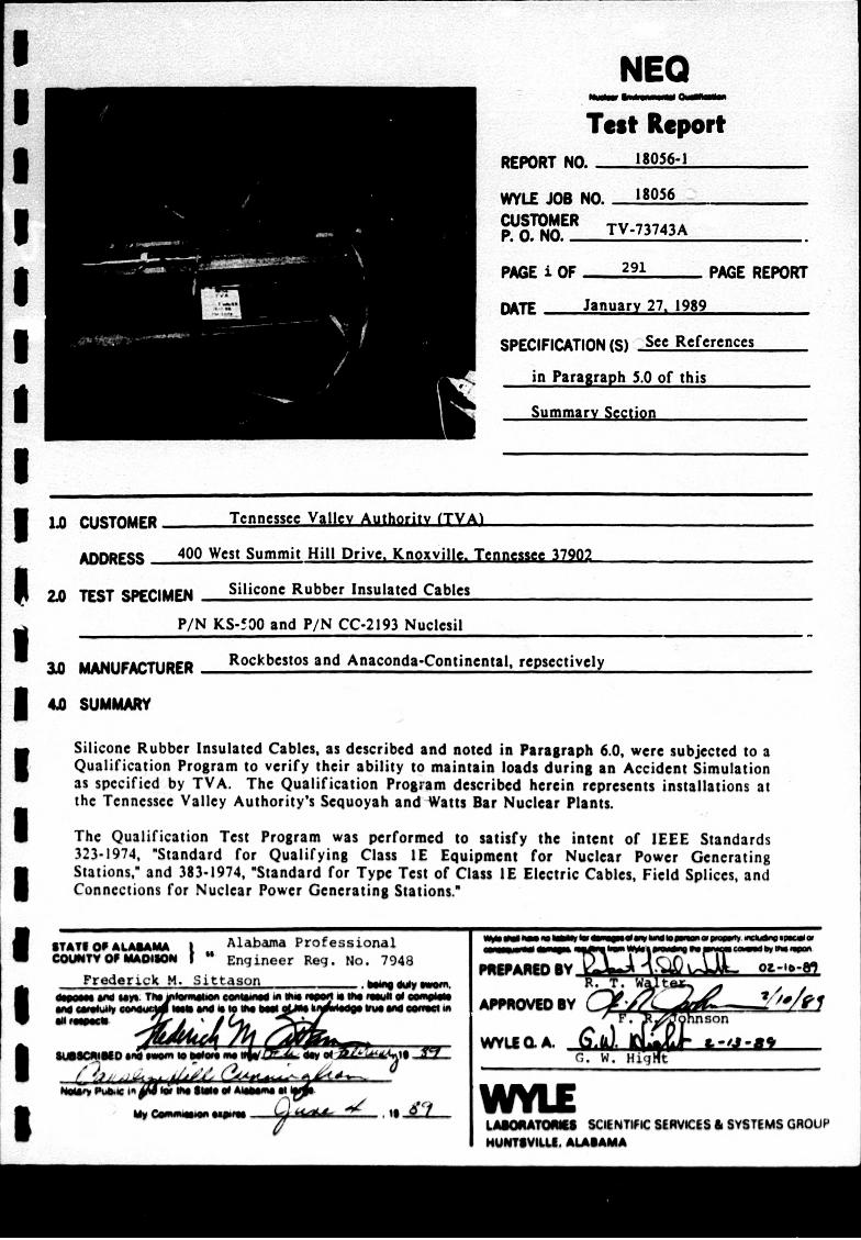
2.0 TEST SPECIMEN Silicone Rubber Insulated Cables
P/N KS-530 and P/N CC-2193 Nuclesil
U MANUFACTURER Rockbestos and Anaconda-Continental, repsectively
4,0 SUMMARY
Silicone Rubber Insulated Cables, as described and noted in Paragraph 6.0, were subjected to a I Qualification Program to verify their ability to maintain loads during an Accident Simulation as specified by TVA. The Qualification Program described herein represents installations at the Tennessee Valley Authority's Sequoyah and -Watts Bar Nuclear Plants.
I The Qualification Test Program was performed to satisfy the intent of IEEE Standards 323-1974, "Standard for Qualifying Class IE Equipment for Nuclear Power Generating I Stations,* and 383-1974, 'Standard for Type Test of Class IE Electric Cables, Field Splices, and Connections for Nuclear Power Generating Stations.'
$TAT@ OPUALAWAM Alabama Professionalmab"wm ow0AIsom CUTY@UMOf UO VA4 Engineer Reg. No. 7948By A
Frederick M. Sittason"*R.T aspsi vW sip. Tft ius eIsji 60ta ini 06 ~ j S eg
go emw T Is"T"i ( .~7 u 4_1 - I. a, APROU .BYR~n
#Wy LMOATOASSC*NTIFC SIRVIES 6 SYSTEMS GROUP
WWFVU. MAMAMA
Page No. HI Test Report No. 18056-1
SUMMARY (Continued) The Qualification Program was performed on two independent manufacturer's types of silicone rubber insulated cables. A description of the test specimens ispresented in Paragraph sections:
e Section I
e Section HI
0 Section III
e Section IV
a Section V
e Section VI
e Section VII
6.0 of this Section. This report contains the following
- Specimen Identification- Preparation, and Baseline Functional Test
- Normal Radiation Exposure and PostRadiation Functional Test
* Thermal Aging and Post-Thermal Aging Functional Test
- Accident Radiation Exposure and Radiation Functional Test
Post-
- Accident Simulation and Post-Test Functional Test
* Voltage Withstand Test and Post-Test Inspection
* Wyle Laboratories' Qualification Plan No. 18057-00, Revision A
The test Program was conducted in the sequence indicated by Section I through VI above and in accordance with Wyle Laboratories- Qualification Plan 18057-00, Revision A. which is contained in Section VII.
Four anomalies occurred during the test included in the appropriate sections of below.
Notice of AumonlyNe
Date of
11-03-88
program. Details of the anomalies are this report and are briefly described
Doesrintlom
III Cable Trays A, C, and E were exposed to an over-temperature condition in the initial thermal aging period. During the thermal aging chamber temperature startup, the chamber temperature was inadvertently allowed to increase in excess of the temperature tolerance acceptance criteria. The out-of-specif ication temperature was determined to have been approximately 5.6 dog C above the required temperature of 112*C, for a period of less than 5 minutes. The short period of specimen exposure to the out-of-specification temperature was considered to have no effect upon the qualification program for the silicone rubber Insulated cables..
WYLUm NI WIIHS peeity
4.0
Page No. Ill Test Report No. 18056-1
4.0 SUMMARY (Continued)
Notice of Date of AsmlyN. Anomaly Seto Descrintion
32 12-03-88 V Low resistance values recorded for Cable Tray C were documented during the pre-test wet insulation resistance mea4surements. The test chsimber was drained of water and insulation resistance measurements were repeated at certain intervals. At the Customer's .1 request. Cable Tray C was removed from the Accident Chamber and discontinued from the test program. .1 The pre-test wet insulation resistance measurements were repeated on the test specimens of Cable Trays A and E, and testing was continued.
3 12-28-88 V Power supply line voltage fluctuations and power losses resulted in test I specimen out-of-specification conditions. A conservative estimate of 5 hours '0 minutes was added to the test Iprof i i the post-DDE aging temperature of , i50F (+9, -0 deg F). The test specimens remained powered during I the additional test period.
4 12-09-88 V Out-of-specification PH levels existed for the chemical spray solution during I the Accident Simulation. The high PH level (0.15 above tolerance) occurred for approximately the last 2 hours of I the required chemical spray test. The short period of chemical spray at the high PH level was considered not to have a detrimental effect upon the test specimens' performance.
The test specimens were subjected to normal radiation exposure, thermal aging, Iand accident radiation exposure. The 40-year test specimens specified for Sequoyah Nuclear Plant demonstrated the capability to maintain specified voltage and current during the specified Design Basis Event (LOCA Simulation). I It is therefore judged that the Sequcyab Nuclear Plant 40-year silicone rubber insulated cables, described and noted in Paragraph 6.0 of this section, met the acceptance criteria requirements of Wyle Laboratories' Qualification Plan a (WLQP) 18057-00, Revision A.
vYim V0
Page No. I, Test Report No. 18056-1
5.0
5.3
5.4
5.5
5.6
5.7
6.0
SpecimenNo Mmasofctrt
RWC-S-A.40 RWC-S-B.40 RWC-S-C.40 RWC-S-D.40 RWC-S-E.40
RWC-S-A. 15 RWC-S-D. 15 RWC-S-C. 15 RWC-S-D. 15 RWC-S-E. I5
RWC-W-A.40 RWC-W-D.40 RWC-W-C.40 RWC-W-D.40 RWC-W-E.40
RWC-W-A. IS RWC-W-D.15 RWC-W-C. 15 RWC-W-D. 15 RWC-W-E.15
Rockbestos Rockbestos Rockbestos Rockbestos Rockbestos
Rockbestos Rockbestos Rockbestos Rockbestos Rockbestos
Rockbestos Rockbestos Rockbestos Rockbestos Rockbestos
Rockbestos Rockbestos Rockbestos Rock bestos Rockbestos
KS-500 KS-500 KS-500 KS-500 KS-500
KS-500 KS-500 KS-500 KS-500 KS-S00
KS-500 KS-S00 KS-500 KS-S00 KS-500
KS-500 KS-500 KS-500 KS-500 KS-500
Cable No.
I -3V-62-"S0A/CDBN 1-3V-43-9841 D/SSVN 1-3 V-67.31 lIDI 1-3 V-67-3091 A/9DO 1-3V-62-281 I1D/6D1I
I -3V-62-4450A/CDD3 1-3V-43.984 IB/5SVG 1-3V-67-31 I IDB/9DR 1-3 V-67.309 IA/9DR 1-3V-62-281 I1B/6DG
I -3V.62-44S0A/CDB8 1-3V-43-9841 I /5SVR 1-3V-.67-31 I IDB/9DX 1-3V-67.3091 A/9DX 1-3V-62-281 I D/6DR
I .3V-62-4450A/CDB9 I .3V-43-984 IB/SVISS 1-3 V-67-311II BO9DY I .3V-67.3091IA/9DY 1-.3V-62-28 1 ID/6DC I
Cale Siz
14 AWG 14 AWG 14 AWG 14 AWG 14 AWG
14 AWG 14 AWG 14 AWO 14 AWG 14 AWG
Cable Tra
AWG AWO AWO AWO AWG
AWO AWG AWG AWG AWG
wn UMm Nuftn WepWutuy
REFERENCES
IEEE Standard 323-1974, *Standard for Qualifying Class IE Equipment for Nuclear Power Generating Stations."
IEEE Standard 383-1974, "Standard for Type Test of Class IE Electric Cables, Field Splices, and Connections for Nuclear Power Generating Stations."
10 CFR 50, Appendix B, "Quality Assurance Criteria for Nuclear Power Plants and Fuel Reprocessing Plants,w U. S. Nuclear Regulatory Commission, 1973.
10 CFR 50.49, "Environmental Qualification of Electrical Equipment Important to Safety for Nuclear Power Plants,* U. S. Nuclear Regulatory Commission, January 21, 1983.
TVA Contract No. TV-73743A.
Wyle Laboratories' (Eastern Operations) Quality Assurance Program Mianual, dated June, 1988.
Wyle Laboratories' Qualification Plan No. 18057-00, Revision A.
TEST SPECIMEN DESCRIPTION
Descriptions of the cable specimens are as follows:
Page No. v Test Report No. 18056-1
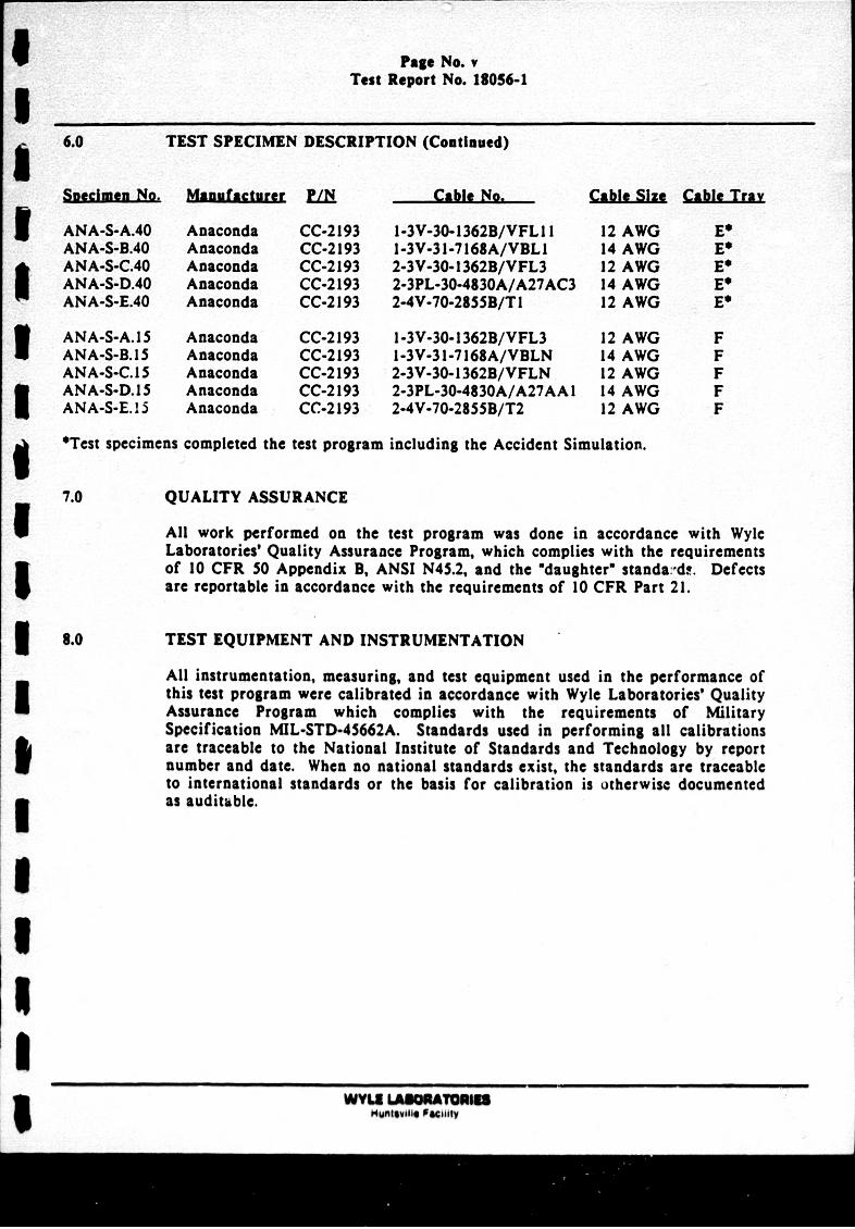
6.0 TEST SPECIMEN DESCRIPTION (Continued)
anamuienNo
ANA-S-A.40 ANA-S-B3.40 ANA-S-C.40 ANA-S-D.40 ANA-S-E.40
ANA-S-A.15 ANA-S-B3. I AN A-S-C. 15 ANA-S-D. 15 ANA-S-E. 15
Manufacure FM~
Anaconda Anaconda Anaconda Anaconda Anaconda
Anaconda Anaconda Anaconda Anaconda Anaconda
CC-2193 CC-2193 CC-2193 CC-2193 CC-2193
CC-2193 CC-2 193 CC-2 193 CC-2 193 CC-2193
Cable No.
I -3V-30- 1362D/ VFL 11I 1-3V-3 1-7 168A/ VEL1 2-3V-30- 1362B/VFL3 2-3PL-30-4830A/A27AC3 2-4V-70-2855B/T1
1 -3V-30- 1362B/VFL3 I -3V-3 1-7 168A/VBLN 2-3V-30- 1362B/VFLN 2-3PL-30-4830A/A27AA I 2-4V-70-2855B/T2
CableM Si able Tr
AWG AWG AWG AWO AWG
12 AWO 14 AWO 12 AWG 14 AWG 12 AWG
sTest specimens completed the test program including the Accident Simulation.
QUALITY ASSURANCE
All work performed on the test program was done in accordance with Wyle Laboratories' Quality Assurance Program, which complies with the requirements of 10 CFR. S0 Appendix B, ANSI N45.2, and the *daughter" standavd!. Defects are reportable in accordance with the requirements of 10 CFR Part 21.
TEST EQUIPMENT AND INSTRUMENTATION
All instrumentation, measuring, and test equipment used in the performance of this test program were calibrated in accordance with Wyle Laboratories' Quality Assurance Program which complies with the requirements of Mfilitary Specification MIL-STD-45662A. Standards used in performing all calibrations are traceable to the National Institute of Standards and Technology by report number and date. When no national standards exist, the standards are traceable to international standards or the basis for calibration is otherwise documented as auditable.
WYLE AGMO HuntsillUe Faciitgy
ap
'U a
SPECIMEN IDENTIFICATION, PREPARATION, AND BASELINE
FUNCTIONAL TEST
Page No. 1-1 Test Report No. 18056-1
SECTION I
SPECIMEN IDENTIFICATION, PREPARATION, AND BASELINE FUNCTIONAL TEST
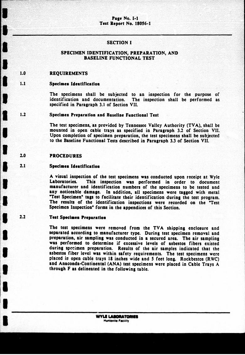
1.0 REQUIREMENTS
1.1 Specimen Identification
The specimens shall be subjected to an inspection for the purpose of identification and documentation. The inspection shall be performed as specified in Paragraph 3.1 of Section VII.
1.2 Specimen Preparation and Baseline Functional Test
The test specimens, as provided by Tennessee Valley Authority (TVA), shall be mounted in open cable trays as specified in Paragraph 3.2 of Section VII. Upon completion of specimen preparation, the test specimens shall be subjected to the Baseline Functional Tests described in Paragraph 3.3 of Section VII.
2.0 PROCEDURES
2.1 Specimen Identification
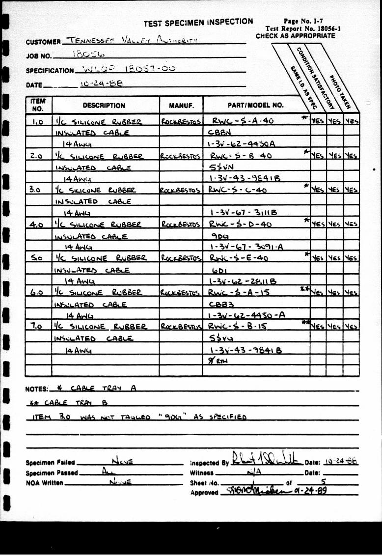
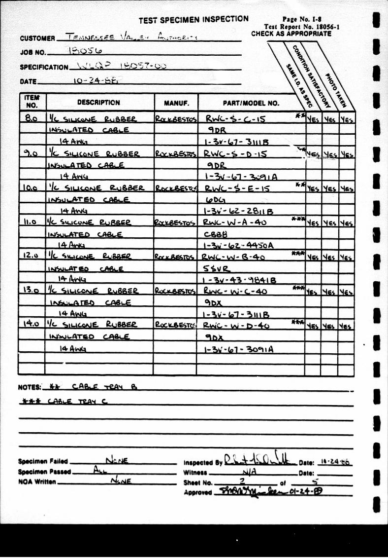
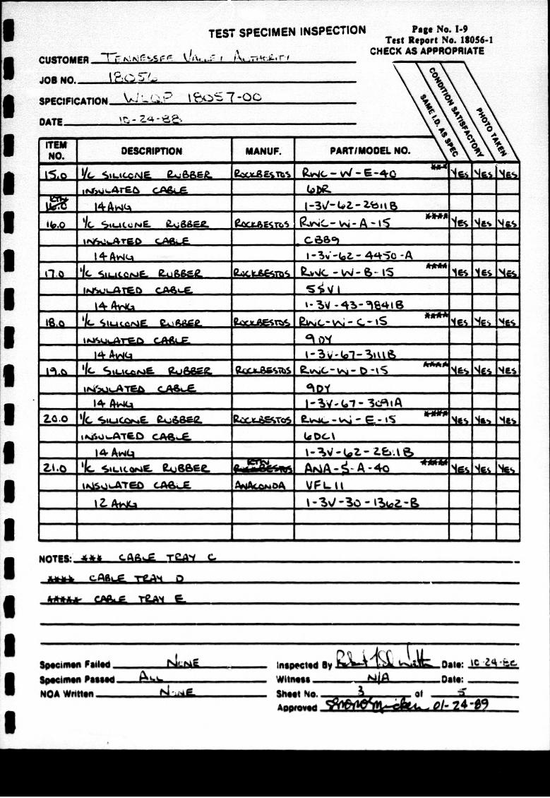
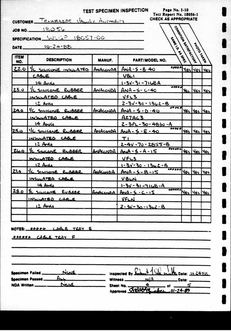
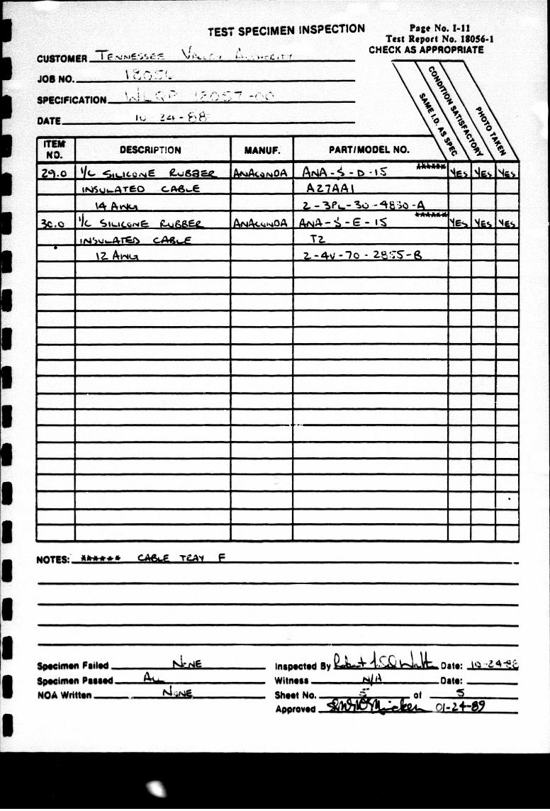
A visual inspection of the test specimens was conducted upon receipt at Wyle Laboratories. This inspection was performed in order to document manufacturer and identification numbers of the specimens to be tested and any noticeable damage. In addition, all specimens were tagged with metal OTest Specimen" tags to facilitate their identification during the test program. The results of the identification inspections were recorded on the 'Test Specimen Inspection* forms in the appendices of this Section.
2.2 Test Specimen Preparation
The test specimens were removed from the TVA shipping enclosure and separated according to manufacturer type. During test specimen removal and preparation, air sampling was conducted in a secured area. The air sampling was performed to determine if excessive levels of asbestos fibers existed during specimen preparation. Results of the air samples indicated that the asbestos fiber level was within safety requirements. The test specimens were placed in open cable trays 18 inches wide and 5 feet long. Rockbestos (RWC) and Anaconda-Continental (ANA) test specimens were placed in Cable Trays A through F as delineated in the following table.
VWYlEL UThE "WHnIP"i PatWt
Page. No. 1-2 Test Report No. 18056-1
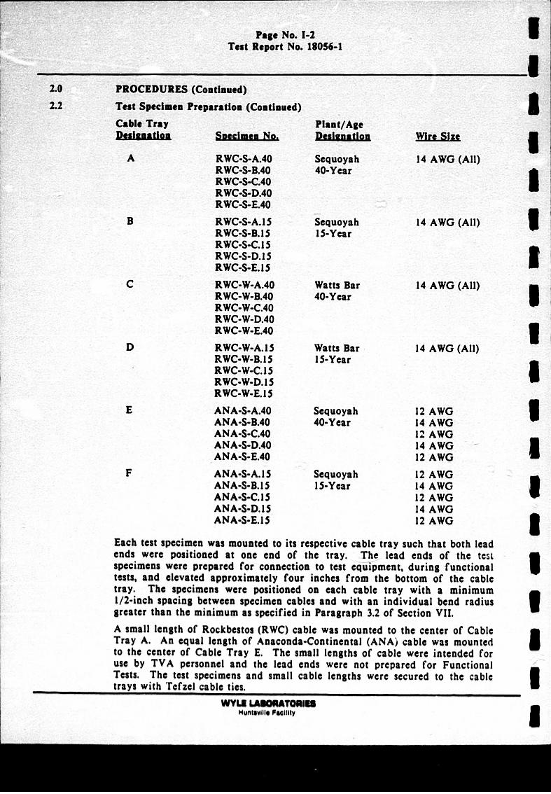
2.0 PROCEDURES (Continued)
2.2 Test Specimen Preparation (Continued)Cable Tray
Spec~ime o
RWC-S-A.40 RWC-S-D.40 RWC-S-C.40 RWC-S-D.40 RWC-S-E.40
RWC-S-A.1 S RWC-S-B.1 S RWC-S-C.l 5 RWC-S-D.l S RWC-S-E. IS
RWC-W-A.40 RWC-W-B.40 RWC-W-C.40 RWC-W-D.40 RWC-W-E.40
RWC-W-A. IS RWC-W-D.15 RWC-W-C. 15 RWC-W-D. 15 RWC-W-E.1 S ANA-S-A.40 ANA-S-D.40 ANA-S-C.40 ANA-S-D.40 ANA-S-E.40
ANA-S-A.l 5 ANA-S-D. 15 ANA-S-C.15 ANA-S-D. IS ANA-S-E.l S
Plaint/Age PsituatioSequoyah 40-Year
Sequoyah IS-Year
Watts Bar 40-Year
Watts Bar I15-Year
Sequoyah 40-Year
Sequoyah 15-Year
14 AWG (All)
14 AWG (All)
14 AWG (All)
14 AWG (All)
12 AWO 14 AWG 12 AWO 14 AWO 12 AWG
12 AWG 14 AWO 12 AWO 14 AWG 12 AWG
Each test specimen was mounted to its respective cable tray such that both lead ends were positioned at one end of the tray. The lead ends of the test specimens were prepared for connection to test equilpment, during functional tests, and elevated approximately four inches from the bottom of the cable tray. The specimens were positioned on each cable tray with a minimum 1/2-inch spacing between specimen cables and with an individual bend radius greater than the minimum as specified in Paragraph 3.2 of Section VII. A small length of Rockbestos (RWC) cable was mounted to the center of Cable Tray A. An equal length of Anaconda-Continental (ANA) cable was mounted to the center of Cable Tray E. The small lengths of cable were intended for use by TVA personnel and the lead ends were not prepared for Functional Tests. The test specimens and small cable lengths were secured to the cable trays with Tcfzel cable ties.
WYLE LABOUATMOR Huntsville Faciity
Page No. 1-3 Test Report No. 18056-1
S 2.0 PROCEDURES (Continued)
.2.2 Test Specimen Preparation (Coutionued)
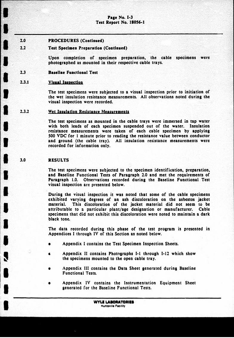
:5 Upon completion of specimen preparation, the cable specimens were photographed as mounted in their respective cable trays.
I 2.3 Baseline Functional Test
2.3.1 Visual Insisection
The test specimens were subjected to a visual inspection prior to initiation of the wet insulation resistance measurements. All observations noted during the visual inspection were recorded.
U 2.3.2 Wet Insulation Resistance Measurements
The test specimens as mounted in the cable trays were immersed in tap water with both leads of each specimen suspended out of the water. Insulation resistance measurements were taken of each cable specimen by applying 500 VDC for I minute prior to reading the resistance value between conductor and ground (the cable tray). All insulation resistance measurements were
recorded for information only.
I 3.0 RESULTS
The test specimens were subjected to the specimen identification, preparation, and Baseline Functional Tests of Paragraph 2.0 and met the requirements of Paragraph 1.0. Observations recorded during the Baseline Functional Test visual inspection are presented below.
I During the visual inspection it was noted that some of the cable specimens exhibited varying degrees of an ash discoloration on the asbestos jacket material. This discoloration of the jacket material did not seem to be Iattributable to a particular plant/age designation or manufacturer. Cable specimens that did not exhibit this discoloration were noted to maintain a dark black tone.
I The data recorded during this phase of the test program is presented in Appendices I through IV of this Section as noted below.
0 Appendix I contains the Test Specimen Inspection Sheets.
a Appendix II contains Photographs 1-1 through 1-12 which show I the specimens mounted to the open cable tray.
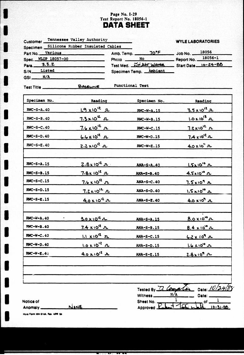
0 Appendix III contains the Data Sheet generated during Baseline U Functional Tests.
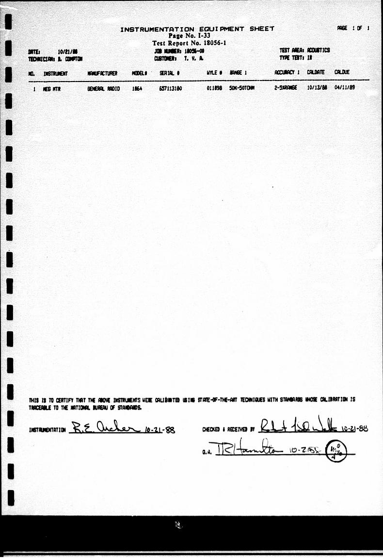
e Appendix IV contains the Instrumentation Equipment Sheet 3 generated for the Baseline Functional Tests.
WYLI LAUOMATONIU B IHuntsville Facility
THIS PAGE INTENTIONALLY LEFT BLANK
WYLI AAO H~untsville Paeclilty
U
3 I
Page No. 1-4 Test Report No. 18056-1
Page No. 1-5 Test Report No. 18056-1
APPENDIX I
TEST SPECIMEN INSPECTION SHEETS
WYL AWu ofunhaville Poe IV
THIS PAGE INTENTIONALLY LEFT BLANK
wyw wumpww FUahhV
U I
Pago No. 1-6 Test Report No. 18056-1
TEST SPECIMEN INSPECTION
CUSTOMER ~EN~~'A~
Joe NO. SPECIFICATION vJ-('lCY -
DATE-- Q.-7, lbe
DESCRIPTION MANUF. PARTIN(
Pago No. 1-7 Test Report No. 11056.1
CHECK AS APPROPRIATE
DOEL NO.
-. tic-A~t so ckr L _______ 9a i caj -- --- 4
-- 34 -4- - -S 1
- 1,4S%.l.AT~lD c.&__ _ _ _ _ _ _ _ _ _ _ _ _ __ -
- -lo - vi--29i
114 Avo __mila
-. lk S~iuco#AT EA CuRIWL ______x&%A _____________VC
NOTUW 4 C-AA T2.A- A
A,* "AL YRAE 16
SedIwe FOR"~ Spoime Passed NOA Written-
WIIM4 -Date:
ShotAe. of
rw un
jAt lawAman
TEST SPECIMEN INSPECTON - IA
JOB No. ~ i~
DATE i a- 2.4 - ;i
DESCRIPMiN UANUF. PARTIM4
Page No. 1-8 Test Report No. 180%-1
CMECK AS APPROPRIATE
DOEL NO. 9 '
YL J~J Q.&&*L Aa "a:iii%1& 2 - Bw~u%-ATE~b CA&GE DR_
- 14 A1v*a _ _ I 'Slit- 3 in
SI4 .LACAiNJ Q..ueC&&-P Lau w pL~, -0 is
-14 A-4a __ _ ~I(~- %..FI -6- -&-
10- S'I imAL Suglfl. &6 L bCLjChj 9Qwt,4L: F is All. Iift - muui..M0 c*A*&.& s4--
-~ ~~~~~~r= -4ed. ,____ -T
.92j. - A"aw~E 9.uB6Se w - a -40 - I.J~~J~ 0 A ~Ao 9 CA & .__ _ _ __ _ _ _ _ _ _ _ _ _
%-0 4J SiLA j"__ __________________I-L 40 IL14
NO ~th&~ .AL.b CaA% 6 -
14. LA4Wt 15~ 111
spni.~ pa"e~ - Paned,
NOA Whiltg-
WApG~td IV ý- - Dg*e K-'Ut Wilwime kiA oe So"t No. Go AOPoNW 51&ed ew-,mL
I I I U I U I
.3 I U
eWeNe Kl-- A
ALL-
TEST SPECIMEN INSPECTION
CUSTOER ? r
ion No.
SPECIFICATION ,(~P7-c DATE
OISCNPT1N UMAUF.
Page No. I.9 Test Report No. 13056.
CHECK AS APPROPRIATE
PARTIM4
VG stcom. a.aszL RV - a *-0 . ý
- -- - -4a.
I +Aw ____ i-U-(.Z.- 4445c -A
r.ck± 14 laijco&w. MuggSle eoLE-u R.wJcX - W - ep- IS I*.uMJAT. 6A& 1__ _ S qI__
- --A
- 4 I4w" ___1_i._A
ZG- C 3Su~o& ( 9*41S ý Mas AL".- %ft - 4-s %OakI
tw&QA'rG CAG.&A __&"AVF
NiM.A LA ,9& _A& _ _ _ _ _ _ _
$""Waied
IJMtAepewedl 9124
U"m
TEST SPECMEN INSPECTION
~UItflM**
Pae. No. 1-10 Tect Report No. 18054-1
CHECK AS APPROPRIATE
JoeNO. I
DATE
ffw DESCRIPTION MANUF. PART/WM
U. k TLAeo AMM~w~A. A#A-Aý -6-44z A, As
- c.Q Pk. _______ eV&.eAA40.AA --- -4 AL
- 2 -- -'sV
- .r.qQ ri -4aa A&______SAL___
MA.. --. .. SE A.JAc.-&-b-oli1~
14 44( ____ -5,L-'50-40rS -A t,.c5j eu14* Ap Laab& Q - I- - 4,o J4
____Z.-4t/ -la - ZS
Z6,41~ q.aca 'q%&A &&-gA.~ ~eAm - A
~2A~ i-:W-'1
'I( &WA-A AN-j -- "lsl
jij ~IA~tAIE. ~ AUL. t.&.aAi Ar4A- -c..- is -~i
V~i-9
MOZ- 4- -mWL
h~h'6L ~A&i £
"*A W~#.~eLLr
40ewe~d oI-z4.
Mifffmas
,&" Aý -W %d =
TEST SPECIMEN INSPECTION
CUSTOM"RT h~ ,,. b~
Jos NO.
DATE .
ITEM AM~ DESCRIPTION MANUF.
Past No. 1-11 Test Report No. 18054-1
CHECK AS APPROPRIATE
.0 L-oF Rw~g A~at ALA- - b - :: km W
-Cf -uicm -&ee -rkNA AA '
-2 -rm 2- 4V-- S
-OIR. - -~ F
IPeeWeN Psed 8pow Fieed.
NOA Wdftme -
Au-~WIIrm. Da1te: Sheet No. of ... 1.......
-WV oQ- .+
PARTiM4
Pago No.1.12Tut 303ff t No. 1805.1
THINS PAGE INTENTIONALLY LIFT BLANK
wyw
Page No. 1-13 Test Report No. 18056-1
APPENDIX 11
PHOTOGRAPHS
WYLw rnMT I"vntvIIl FuWiBIy
Test
THIS PAGE
Page No. 1-14 Report No. 16056-1
INTETIONLLY EFT LAN
VJVL LAM I 0I Huntvill Faclit
13
I U I I I I
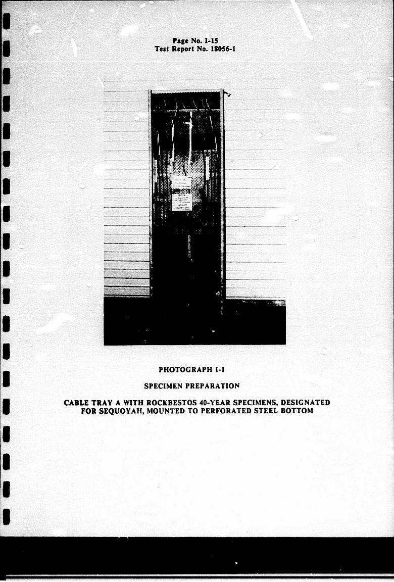
Page No. 1-15 Test Report No. 18056-1
PHOTOGRAPH 1-1
SPECIMEN PREPARATION
CABLE TRAY A WITH ROCKDESTOS 40-YEAR SPECIMENS, DESIGNATED FOR SEQUOYAH, MOUNTED TO PERFORATED STEEL BOTTOM
~.. ~.
K
K
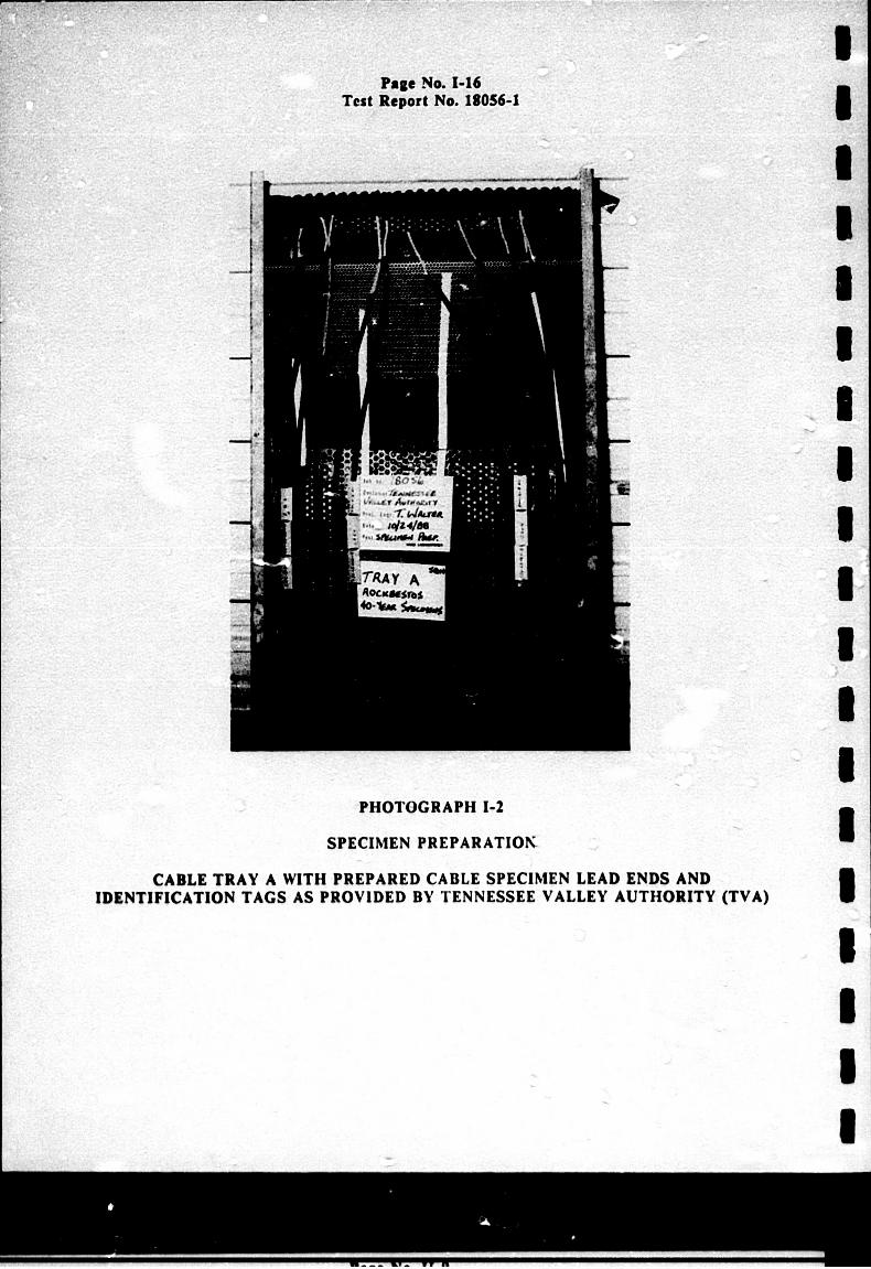
PHOTOGRAPH 1-2
SPECIMEN PREPARATIOK
CABLE TRAY A WITH PREPARED CABLE SPECIMEN LEAD ENDS AND IDENTIFICATION TAGS AS PROVIDED BY TENNESSEE VALLEY AUTHORITY (TVA)
Page No. 1-16 Test Report No. 18056-1
r3, I I I I U
.1 I U I.
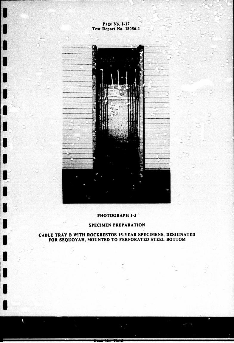
Page No. 1-17 Test Report No. 18056-1
PHOTOGRAPH 1-3
SPECIMEN PREPARATION
CABLE TRAY B WITH ROCKBESTOS 15-YEAR SPECIMENS, DESIGNATED FOR SEQUOYAH, MOUNTED TO PERFORATED STEEL BOTTOM
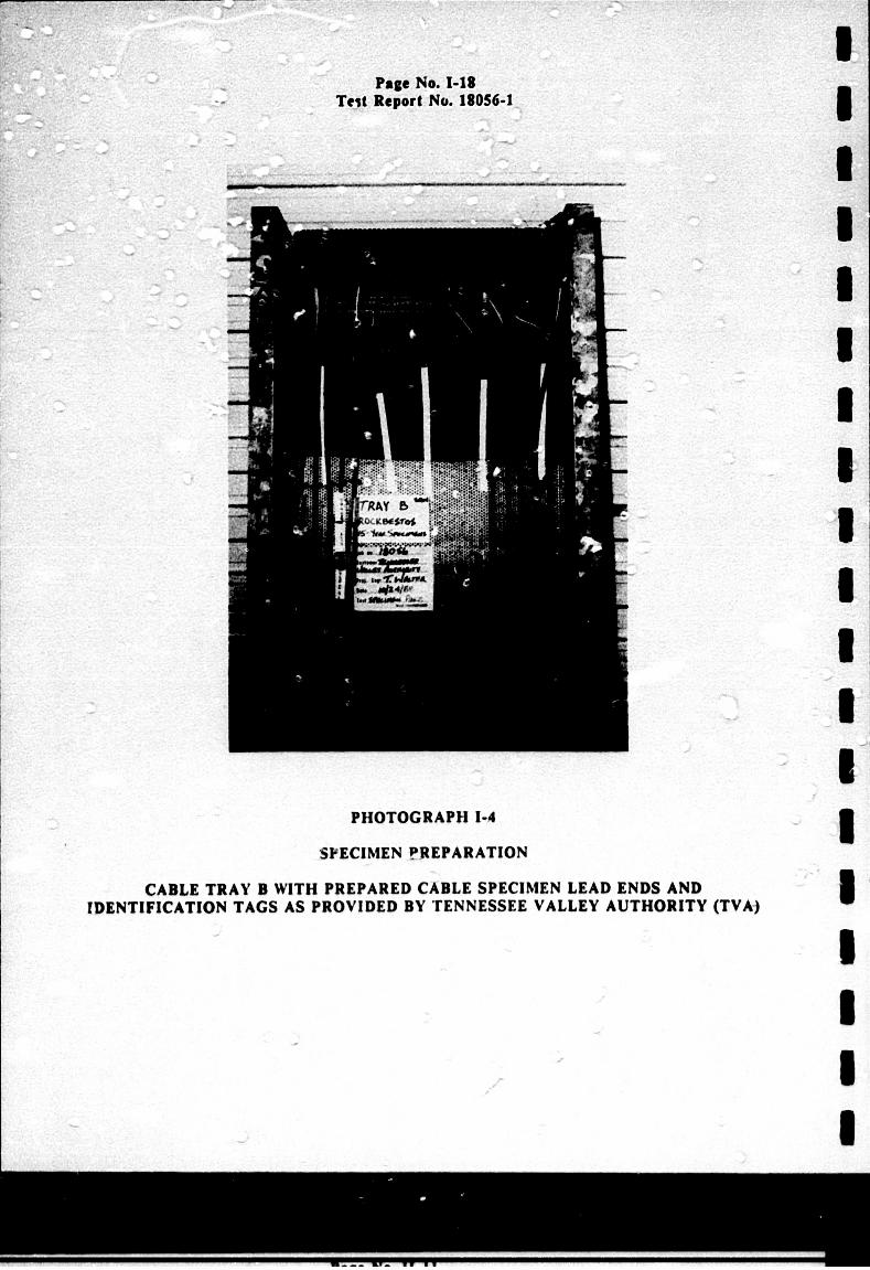
PHOTOGRAPH I-A
SPECIMEN PREPARATION
CABLE TRAY 3 WITH PREPARED CABLE SPECIMEN LEAD ENDS AND IDENTIFICATION TAGS AS PROVIDED DY TENNESSEE VALLEY AUTHORITY (TVAJ
77-
I I U I I U I 3 I I
Page No. 1-18 Telt Report No. 18056-1
I *1 *1 I I I I
I I
I I I I I I I
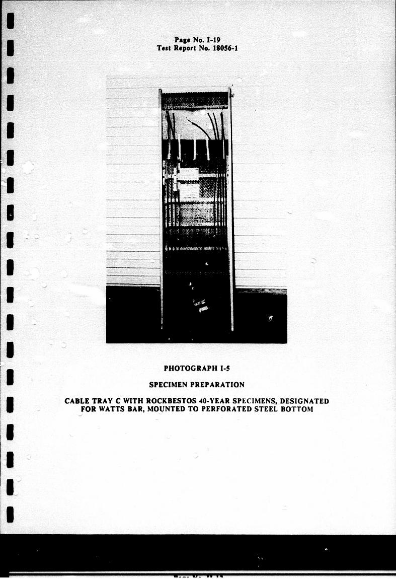
PHOTOGRAPH I-5
SPECIMEN PREPARATION
CABLE TRAY C WITH ROCKBESTOS 40-YEAR SPECIMENS, DESIGNATED FOR WATTS BAR, MOUNTED TO PERFORATED STEEL BOTTOM
Page No. 1-19 Test Report No. 18056-1
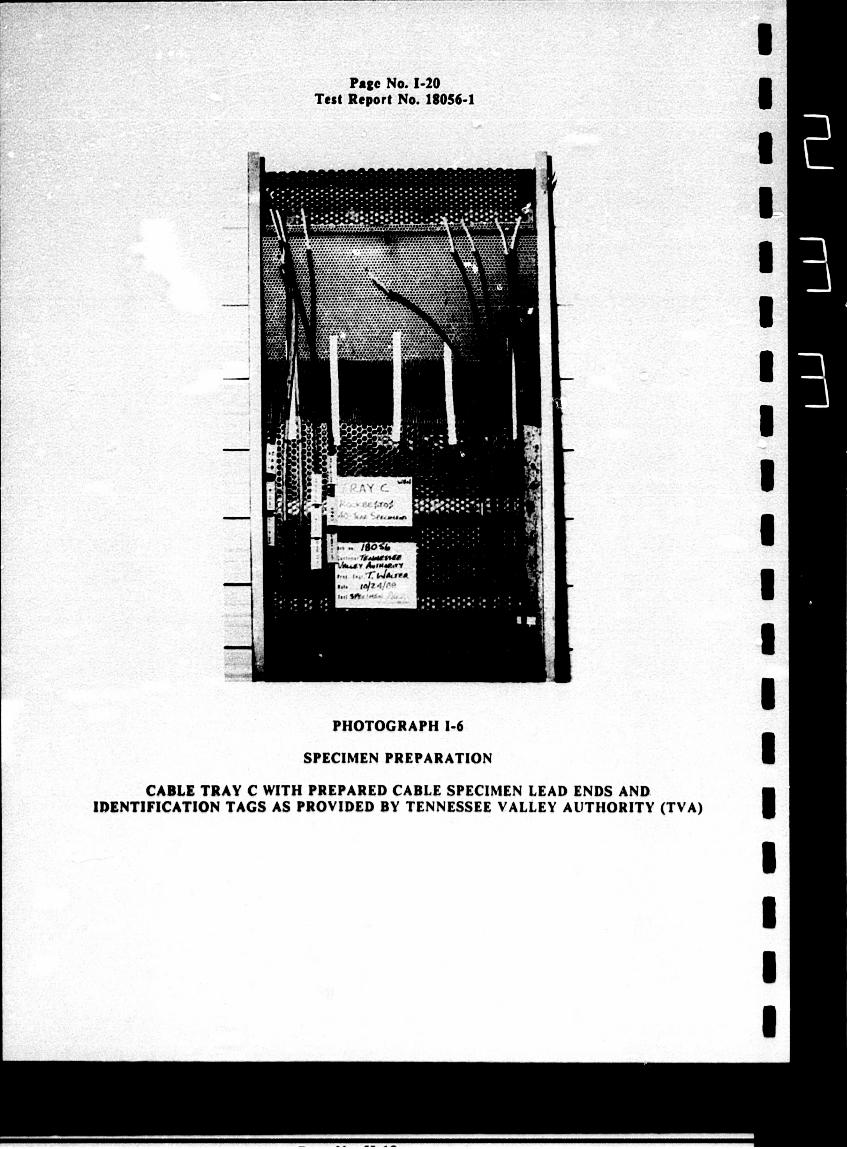
PHOTOGRAPH 1-6
SPECIMEN PREPARATION
CABLE TRAY C WITH PREPARED CABLE SPECIMEN LEAD ENDS AND IDENTIFICATION TAGS AS PROVIDED BY TENNESSEE VALLEY AUTHORITY (TVA)
Page No. 1-20 Test Report No. 18056-1
A.'
:3 I I
I U I I U I U I I I I I U U I
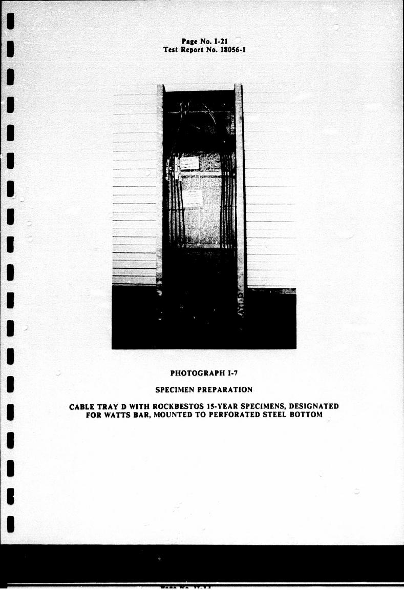
PHOTOGRAPH 1-7
SPECIMEN PREPARATION
CABLE TRAY D WITH ROCKBESTOS 15-YEAR SPECIMENS, DESIGNATED FOR WATTS BAR, MOUNTED TO PERFORATED STEEL BOTTOM
Page No. 1-21 Test Report No. 13056-1
Page No. 1-22 Test Report No. 18056-1
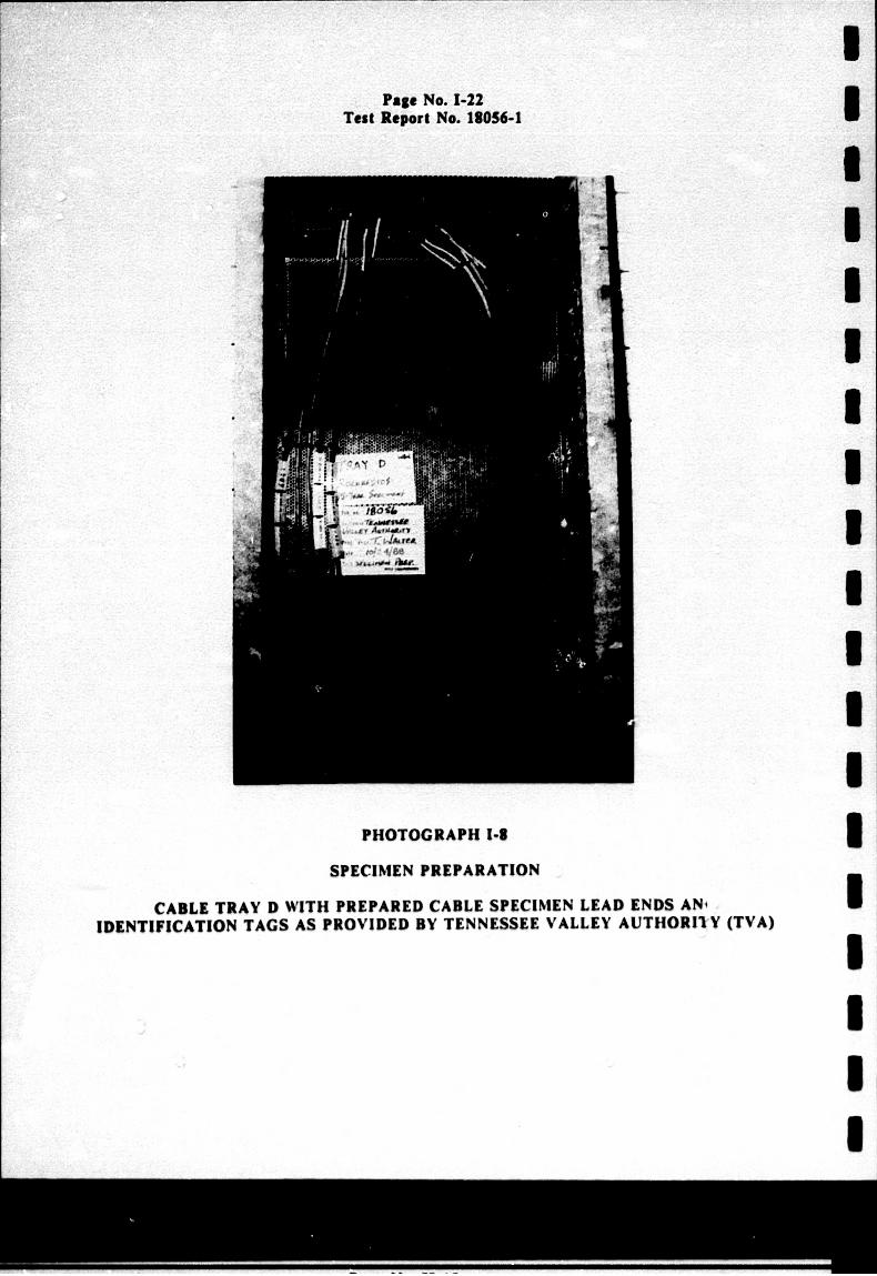
PHOTOGRAPH 1-1
SPECIMEN PREPARATION
CABLE TRAY D WITH PREPARED CABLE SPECIMEN LEAD ENDS ANi IDENTIFICATION TAGS AS PROVIDED BY TENNESSEE VALLEY AUTHORITYV (TVA)
I I I I I U U U U I U I I I U U I I I
I
S U I I I I I I I I I I I I I U I
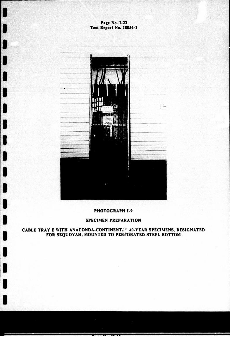
PHOTOGRAPH 1.9
SPECIMEN PREPARATION
CABLE TRAY I WITH ANACONDA-CONTINENT;, 40-YEAR SPECIMENS, DESIGNATED FOR SEQUOYAH, MOUNTED TO PERFORATED STEEL BOTTOM
Page No. 1-23 Test Report No. 11056-1
Page No. 1-24 Test Report No. 18056-1
I
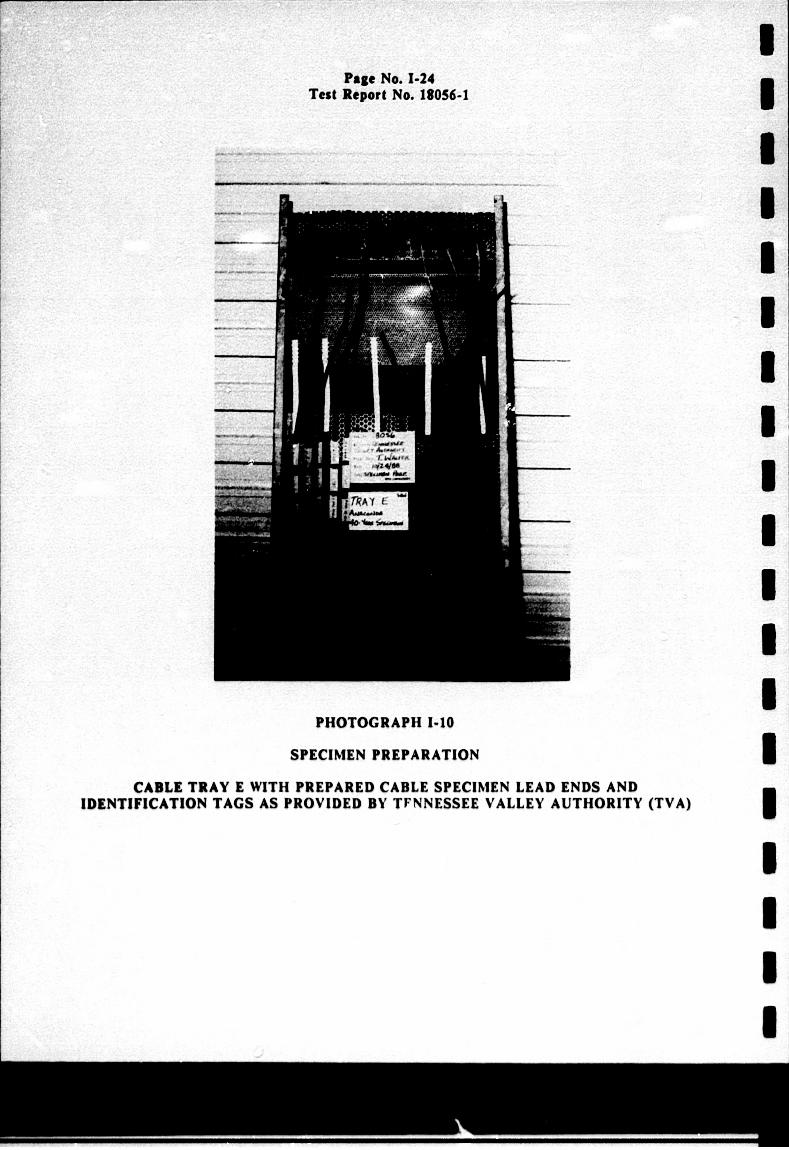
PHOTOGRAPHI1-10
SPECIMEN PREPARATION
CABLE TRAY E WITH PREPARED CABLE SPECIMEN LEAD ENDS AND IDENTIFICATION TAGS AS PROVIDED BY TFNNESSEE VALLEY AUTHORITY (TVA)
Page No. 1-25 Test Report No. 18056-1
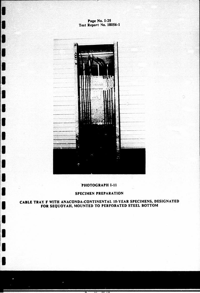
.PHOTOGRAPH I-11
SPECIMEN PREPARATION
CABLE TRAY F WITH ANACONDA-CONTINENTAL 15-YEAR SPECIMENS, DESIGNATED FOR SEQUOYAH, MOUNTED TO PERFORATED STEEL BOTTOM
Page No. 1-26 Test Report No. 18056-1
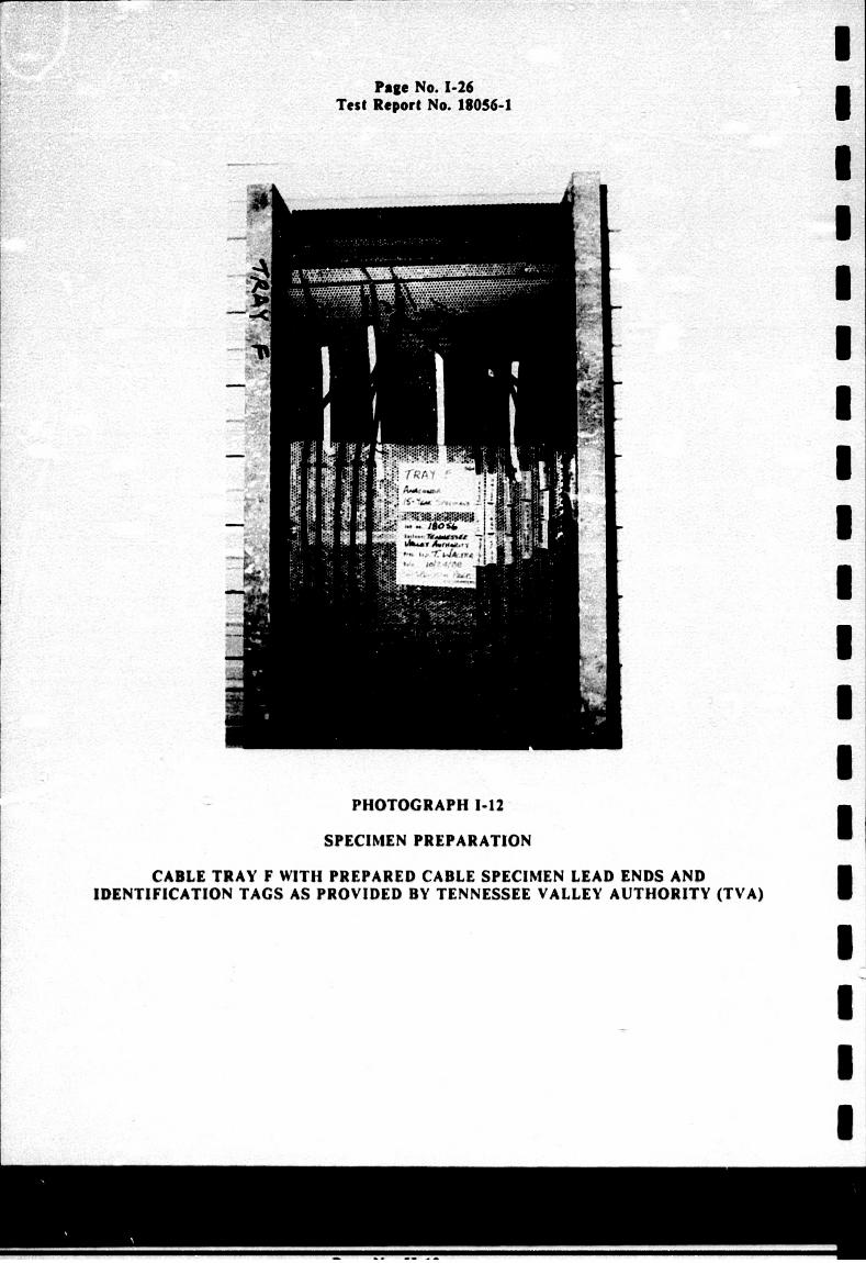
PHOTOGRAPHI1-12
SPECIMEN PREPARATION
CABLE TRAY F WITH PREPARED CABLE SPECIMEN LEAD ENDS AND IDENTIFICATION TAGS AS PROVIDED BY TENNESSEE VALLEY AUTHORITY (TVA)
[I I I I
APPENDIX III
DATA SHEET
WHw . m meum IN Pg4Ufy
'Page No. 1-27 Test Report No. 18056.1
Page No. 1-21 Test Roport No. 18056-1
THIS PAGI INTENTIONALLY LEFT BLANK
WYLiMwift"W PM Aty
Page No. 1-29 Test Report No. 18056-1
DATA SHEET
customer Tennessee Specimen Silicone Part No. Various Qns WL40P 18057-00Pars. 3.. SIN Listed GSI N/A
valley Authority
Rubber Insulated CablesWYLE LABORATORIES
Amb. Temp. 70oF Job No. 18056 Photo No Report No. 18056-1 Test Med. Zý A~a WATOOL Start Date 10~-Pq-186 Specimen Temp. _.Ajoignt...
SAK~w"IE Functional Test
Notice of Anomaly *y6 POW *a O41L a" me -
Tested By Date: Witness _________ Date: Shoet No. 1.Of 1 Approved V-L.L. LMJk 41tKI &A4L
Test Title
SPeciMen No. Reading Specmen No. Reading
RNC-SA. 40 1.9 X0` ISL RWC-W-A. 15 3S.5SY %17~ .ZL
NWC-S-D. 40 (i.-(. Y. *t .elNfRWC-W-D. 15 -1A V. to.J
F&C-S-E. 40 2.Z-tiAO' .nL. RWC-W-E. 15 4.0LC A.Id L
RN6C-S-A.15 V.~. 10.L ft. ANA-S-A,40 I.SxL1O toL.
RVC-S-D.15 1 I Ax. AN&-S-D.40 4.jAtoe.%
NfC"S.E.15 4.0 Y. %0L.n J&N-S-E. 40 4.6 OY.it
R1C-W-A. 40 S. ,I OltO11 j%- ANA-S-A,15 9.0YtoKI$a .TL
NC-W-13. 40 7.4 xI -) MANS-3. 15XI&jo
RUC-W-D. 40 tA x 10 It A. ANA-S-D. 15 Y 0 t
UWC-W-Z. 40 4.o %.e A aN-S-E.S isId J,-
Page No. 1-30 Test Report No. 18056-1
THIS PAGE INTENTIONALLY LEFT BLANK
WVLE LAUMMTO01 H4untsille Facility
I
I I I I
I I I I I I I I I I I I I
APPENDIX IV
INSTRUMENTATION EQUIPMENT SHEET
WJYLE ADTU H~untsville Facii~ty
Page No. 1-31 Test Report No. 18056-1
Page No. 1-32 Test Report No. 18056-1
THIS PAGE INTENTIONALLY LEFT BLANK
WYLE I rm
~i. I mm
I
I U I I I I I I I I I I
~TI
I I I
10/91/8 icmu &. mIM
-ifm
MNo m
WWmIne
amm MID
INSTRUMENTATION EGU11 MENT SHEEI Page No. 1-33
Test Report No. 18056-1 in mamfd low-0 0umsD 1. V. IL
1864 057113180 0ox1% U50K-SO"
TOT? Aflf 11W lTs XIiS
~La1
"OI3J04/11/89
13 TO UNTIFY TOT? TM OWA DOWlUES MElE CAUbUT9 eta ITE4F-TW6WI lJuECSa wITh SIAIU "a0 Ca3UTIDi 18 METO YE WTINX UIM OF STAIL
manm~: ~. hL .. 1641 -im 050DW I HMIVIO P1 WbL ii0.4
PAKIEOF I
-86
THIS PAGE INTENTIONALLY LEFT BLANK
wnI ui wo"Wgpw " u1~
Page No. 1-34 Test Report No. 18056-1
NORMAL RADIATION EXPOSURE AND POSTaRADIATION
FUNCTIONAL TEST
Page No. Il-I Test Report No. ISIS-I
SECTION 11
NORMAL RADIATION WIXPOSURE AND POST-RADIATION VUACT1IONAL TEST
REQUIRENMNT
Normal Radiation Expeoure
The test specimens shall be subjected to the normal radiation exposure as specified in Paragraph 3.4 of Section VII.
Post-Radiation Vunutcena Tast
The test specimens shall be subjected to a Functional Test upon completion of radiation exposure. The Functional Tast shall be performed as specified in Paragraph 3.5 of Section VIL
PROCEDURES
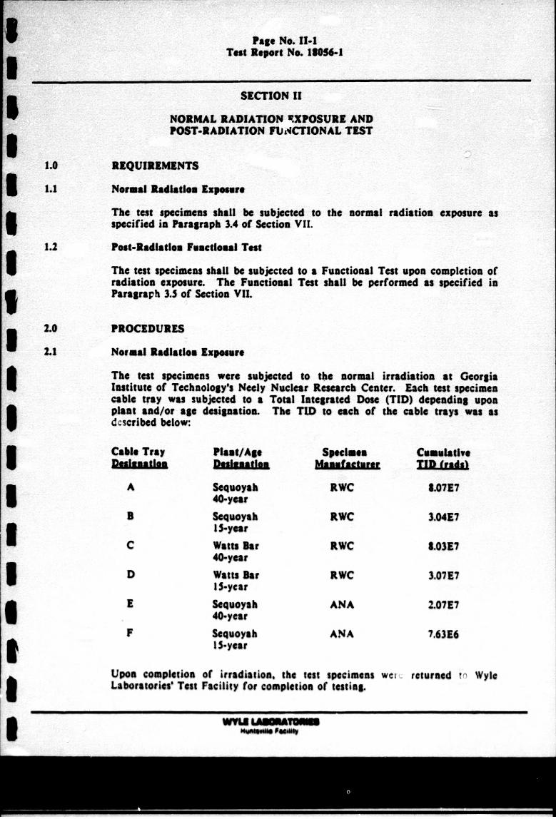
Nevmal Radiation Exposure
The test specimens were subjected to thme normal irradiation at Georgia Institute of Technology's Neely Nuclear Research Centar. Each test specimen cable tray was subjected to a Total Integrated Doss MTD) depending upan plant and/or age desigaatios. The TID to each of the cable trays was as described below:
Cable Tray rn-p--al -t
A
3
C
D
F
Plant/Ago
&nqumb 40-year Seuoyah 1 S-year Watts hr 40-year Watts Bar I $-year Soquoyah 40-year Weqomb IS-year
Spoe"lo
RWC
RWC
RWC
1WC
ANA
ANA
Cumulative
8.071E7
3.0417
L0317
3.0717
2.07E7
7.6316
upon completos of irradiatio. the tats specimens werý returned to Wyle Laboratoris' Tats facility for compkleuos of taist&n
WY. Po p"
Faew No. 11-2I Teot Repert N&. 186061
2.0 PROCEDURES (Cueosslue)
2.2 PeetRodisdoei Functional TestI
UPo" 00ompe101on Of irradiation. the tast specimens were subjected to a Post. Radiation Functional Teom The Functional Test was performed as described in Paragraph 2.3, Section 1. of this report.
&s0 RESULTSI
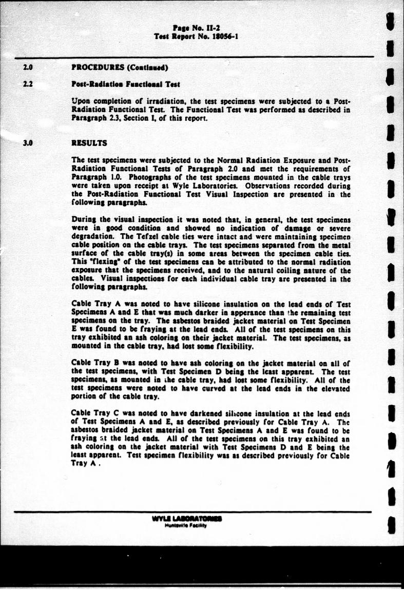
Th seast specimens were subjee to the Normal Radiation Exposure and PostRaduation Functional Test of Paragraph 2.0 sad met the requirements of Paragraph. 1.0. Photograpwhs of the seat specimens mounted in the cable trays were takren upon receipt as Wyle Laboratories. Observations recorded during the Poss-Radiasift Functional Teast Visual Inspection are presented in the3 following paragraphs.
During the visual inspection it was note that. in general, the teat specimens9 were in good condition and showed so indication of damap or severe degradation. The Tefze cable ties were iatact sand were maintaining specimen cable position on the cable trays. The test speimen separated from the metlW asurac of the cable tray(s) in some areas between the specimen cable ties. This ¶lexls of the lset specimens can be attributed to the normal radiation exposue that the specimens received, and to the natural coiling assure of the cables Visual inspectioes for each individual cable tray are presented In the3
Cable Tray A was n01ed to have Silicone insulation on the lead ends of Teat Specimens A and I that was much darker in apperance than the remaining teat Wspcimens on the tray. The asbestos braided Jacket material on Test Specimen E was found to be fraying; at the lead ends. All of the test specimens on this tray exhilbited as ask coloring on their Jacket material. The test specimens, as mounted In she cable tray, bad lestome flexibility.
Cable Tray 3 was noted to have ash coloring on the Jacket material on all ofI the test specimens, with Test Specimen D being the least apparent. The test speimes,% as mounted in hbe cable tray. had lost some flexibility. All of the teat specimens wen *NWe to bae" curved at the lead ends Is the elevated3 portion of the cable teay.
Cable Tray C was note to hae" darkened hosicoe Insulation at the lead ends3 Of Tess Specimens A sad 9. as described previously for Cable Tray A. The asbestos braided Jacket material on Test Specimens A sand a was found to be fraying 2t the lead enak All 0f Sim test speimens on this tray exhibited an ash 40oloring on the Jacket material with Test Specimens D and I being theS Neas apparent. Test specime flexibility was as described previously for Cable Tray A.
welft -
I Pagp No. 11-3 Test Report No. 13054-1
3.0 RESULTS (Continued)
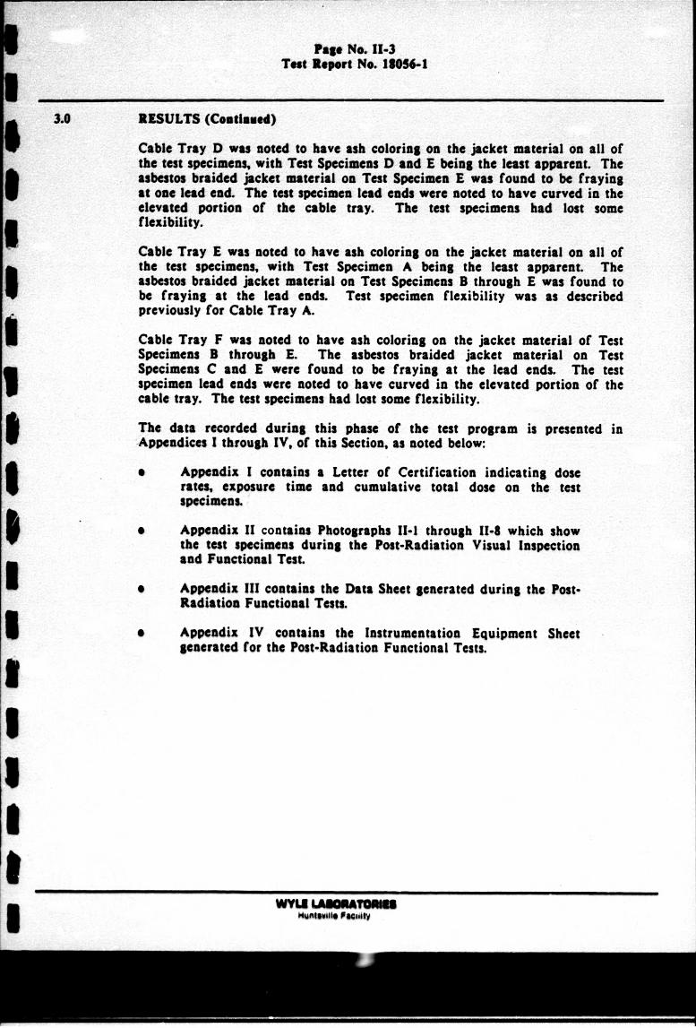
Cable Tray D was noted to have ash coloring on the jacket material on all of the test specimens, with Test Specimens D and E being the least apparent. The asbestos braided jacket material on Test Specimen E was found to be fraying I ~at oue lead end. The test specimen lead ends were noted to have curved in the elevated portion of the cable tray. The test specimens had lost some p flexibility.
Cable Tray E was noted to have ash coloring on the jacket material on all of the test specimens, with Test Specimen A being the least apparent. The asbestos braided jacket material on Test Specimens B through E was found to be f raying at the lead ends. Test specimen flexibility was as described previously for Cable Tray A.
Cable Tray F was noted to have ash coloring on the jacket material of Test Specimens B through E. The asbestos braided jacket material on Test Specimens C and E were found to be fraying at the lead ends. The test I specimen lead ends were noted to have curved in the elevated portion of the cable tray. The test specimens had lost some flexibility.
The data recorded during this phase of the test program is presented in Appendices I through IV. of this Section, as noted below:
0 Appendix I contains a Letter of Certification indicating dose rates, exposure time and cumulative total dose on the test
Appndi 11contains Photographs 11-1 through 11-8 which show I the test specimens during the Post-Radiation Visual Inspection and Functional Test. I Appendix III contains the Data Sheet generated during the PostRadiation Functional Tests.
I Appendix IV contains the Instrumentation Equipment Sheet generated (fo the Post-Radiation Functional Tests.
WfLAUAT bgjvgusfe PUM6V
Page No. 11-4 Tast R@pit No. 13056-
THIS PAGE INTENTIONALLY LEFT BLANK
WYULm
Page No. 11-5 Test Report No. 18056-1
APPENDIX I
LETTER OF CERTIFICATION FOR THE IRRADIATION EXPOSURE
WWYLE Wit Sl Fee"i
Page No. 11-6 Test Report No. 18056-1
SI
S
t.THIS PAGE INTENTIONALLY LEFT BLANK
-3 £
WYLI IAAOU mutwuitlvII Feolltv
Related Documents