Instruction Manual C-453EM GROUND FAULT RELAY / RESISTOR MONITOR SIGMA SIGMA MONITOR RELAY the power to protect www . ElectricalPartManuals . com

Welcome message from author
This document is posted to help you gain knowledge. Please leave a comment to let me know what you think about it! Share it to your friends and learn new things together.
Transcript
Instruction Manual C-453EM
GROUND FaUlt RElaY / REsIstOR MONItOR
sigm
a
sIGMa MONItOR RElaY
the power to protect
www . El
ectric
alPar
tMan
uals
. com
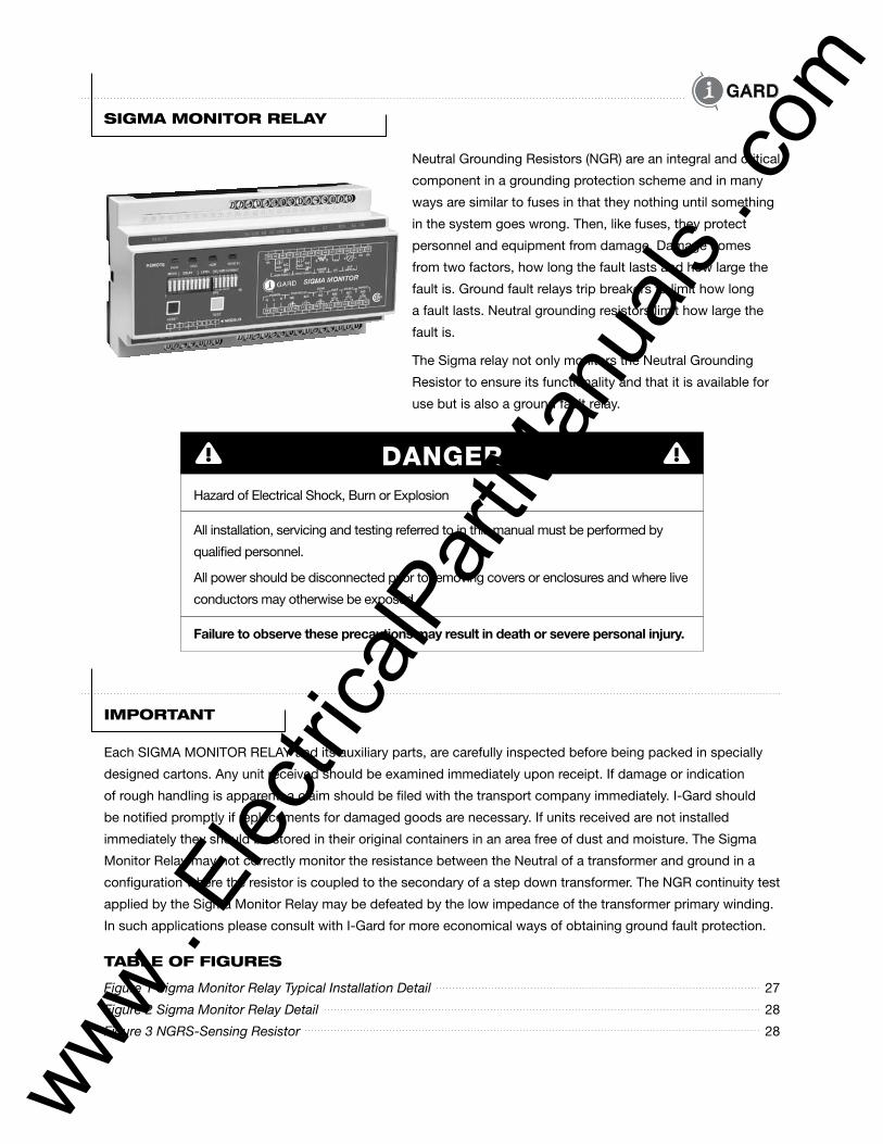
TABLE OF FIGURES
Figure 1 Sigma Monitor Relay Typical Installation Detail 27
Figure 2 Sigma Monitor Relay Detail 28
Figure 3 NGRS-Sensing Resistor 28
SIGmA mOnITOR RELAy
Neutral Grounding Resistors (NGR) are an integral and critical
component in a grounding protection scheme and in many
ways are similar to fuses in that they nothing until something
in the system goes wrong. Then, like fuses, they protect
personnel and equipment from damage. Damage comes
from two factors, how long the fault lasts and how large the
fault is. Ground fault relays trip breakers to limit how long
a fault lasts. Neutral grounding resistors limit how large the
fault is.
The Sigma relay not only monitors the Neutral Grounding
Resistor to ensure its functionality and that it is available for
use but is also a ground fault relay.
DANGERHazard of Electrical Shock, Burn or Explosion
All installation, servicing and testing referred to in this manual must be performed by
qualified personnel.
All power should be disconnected prior to removing covers or enclosures and where live
conductors may otherwise be exposed.
Failure to observe these precautions may result in death or severe personal injury.
ImPORTAnT
Each SIGMA MONITOR RELAY and its auxiliary parts, are carefully inspected before being packed in specially
designed cartons. Any unit received should be examined immediately upon receipt. If damage or indication
of rough handling is apparent, a claim should be filed with the transport company immediately. I-Gard should
be notified promptly if replacements for damaged goods are necessary. If units received are not installed
immediately they should be stored in their original containers in an area free of dust and moisture. The Sigma
Monitor Relay may not correctly monitor the resistance between the Neutral of a transformer and ground in a
configuration where the resistor is coupled to the secondary of a step down transformer. The NGR continuity test
applied by the Sigma Monitor Relay may be defeated by the low impedance of the transformer primary winding.
In such applications please consult with I-Gard for more economical ways of obtaining ground fault protection.
www . El
ectric
alPar
tMan
uals
. com
TABLE OF COnTEnTS
1. Introduction 2
2. Description 2
3. Method of Operation 3
3.1 Components of the System 3
3.2 Neutral Grounding Resistor (NGR) Monitoring 3
3.3 Ground Fault Detection 4
4. Installation Instructions 5
4.1 The Sigma Monitor Relay 5
4.2 Zero Sequence Current Sensor (ZSCS) 6
4.3 NGRS-XX Sensing Resistor 7
4.4 Configuration of Sigma Monitor Relay and NGR 7
5. trip Relay and auxiliary Fault Relays 8
6. lED Indicators and Diagnostics 10
6.1 Start-up and Reset Indicators 10
6.2 Power On LED (Green), 6.3 GND Fault LED (Red) 10
6.4 NGR Fault LED (Red), 6.5 Zone GR. LED (Red) 11
7. self-test 11
8. Relay settings 12
8.1 Trip Relay Operating Modes 12
8.2 Trip Memory Setting 14
8.3 Ground Fault Trip Time Delay, 8.4 Ground Fault Trip Current Level 14
8.5 NGR Set Let-through Current 15
9. sigma Monitor Relay Configuration switches 15
10. ModBus Communications 19
11. technical specifications 23
12. Catalogue Numbers 25
appendix a High-pot and Dielectric testing 26
appendix B CaN/Csa M421-00 Use of Electricity in Mines (Excerpts) 26
TABLES
Table 9.1 Trip Relay Operating Mode Setting Dip Switch #1 16
Table 9.2 Trip Memory Selection Dip Switch #2 16
Table 9.3 Ground Fault Trip Time Delay Settings Dip Switches #3 - #4 - #5 - #6 - #7 17
Table 9.4 Ground Fault Trip Current Level Settings Dip Switches #8 - #9 - #10 18
Table 9.5 System Frequency Selection Dip Switches #11 18
Table 9.6 NGR Let-through Current Settings Dip Switches #12 - #13 - #14 - #15 - #16 18
Table 10.1 Modbus RTU Standard 8 Byte Holding Register Read Function (03) 20
Table 10.2 Returned Information Structure For Holding Register Request 20
Table 10.3 Sigma Relay Register Definitions 21
Table 10.4 System Function Registers 22
Table 10.5 Modbus Register Format Conventions 23
Sigma Instruction Manual I-GARD1www . El
ectric
alPar
tMan
uals
. com
I-GARD Sigma Instruction Manual2
1 InTROdUCTIOn
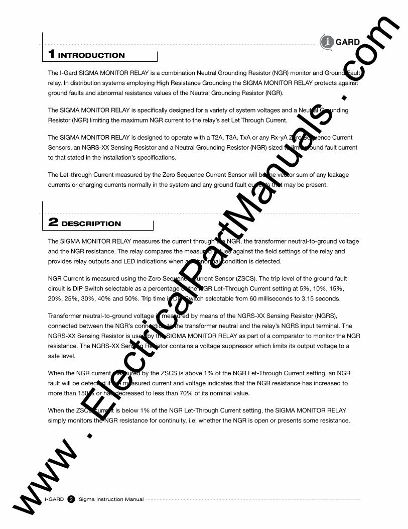
The I-Gard SIGMA MONITOR RELAY is a combination Neutral Grounding Resistor (NGR) monitor and Ground Fault
relay. In distribution systems employing High Resistance Grounding the SIGMA MONITOR RELAY protects against
ground faults and abnormal resistance values of the Neutral Grounding Resistor (NGR).
The SIGMA MONITOR RELAY is specifically designed for a variety of system voltages and a Neutral Grounding
Resistor (NGR) limiting the maximum NGR current to the relay’s set Let Through Current.
The SIGMA MONITOR RELAY is designed to operate with a T2A, T3A, TxA or any Rx-yA Zero Sequence Current
Sensors, an NGRS-XX Sensing Resistor and a Neutral Grounding Resistor (NGR) sized to limit ground fault current
to that stated in the installation’s specifications.
The Let-through Current measured by the Zero Sequence Current Sensor will be the vector sum of any leakage
currents or charging currents normally in the system and any ground fault currents that may be present.
2 dESCRIPTIOn
The SIGMA MONITOR RELAY measures the current through the NGR, the transformer neutral-to-ground voltage
and the NGR resistance. The relay compares the measured values against the field settings of the relay and
provides relay outputs and LED indications when an abnormal condition is detected.
NGR Current is measured using the Zero Sequence Current Sensor (ZSCS). The trip level of the ground fault
circuit is DIP Switch selectable as a percentage of the NGR Let-Through Current setting at 5%, 10%, 15%,
20%, 25%, 30%, 40% and 50%. Trip time is DIP Switch selectable from 60 milliseconds to 3.15 seconds.
Transformer neutral-to-ground voltage is measured by means of the NGRS-XX Sensing Resistor (NGRS),
connected between the NGR’s connection to the transformer neutral and the relay’s NGRS input terminal. The
NGRS-XX Sensing Resistor is used by the SIGMA MONITOR RELAY as part of a comparator to monitor the NGR
resistance. The NGRS-XX Sensing Resistor contains a voltage suppressor which limits its output voltage to a
safe level.
When the NGR current measured by the ZSCS is above 1% of the NGR Let-Through Current setting, an NGR
fault will be detected if the measured current and voltage indicates that the NGR resistance has increased to
more than 150% or has decreased to less than 70% of its nominal value.
When the ZSCS current is below 1% of the NGR Let-Through Current setting, the SIGMA MONITOR RELAY
simply monitors the NGR resistance for continuity, i.e. whether the NGR is open or presents some resistance.
www . El
ectric
alPar
tMan
uals
. com
Sigma Instruction Manual I-GARD3
The SIGMA MONITOR RELAY has three output relays:
•TheTripRelaycanbeprogrammedforshuntoperation(notfailsafe)orundervoltageoperation(failsafe)
in a main breaker trip circuit. The Trip Relay will energize on either an NGR Fault or a Ground Fault.
•TheNGRFaultAuxiliaryTripRelaycanbeusedtogiveadoor/panelmountedorremoteindicationofan
NGR Fault.
•TheGroundFaultAuxiliaryTripRelaycanbeusedtogiveadoor/panelmountedorremoteindicationof
a Ground Fault.
The SIGMA MONITOR RELAY provides a current source output for connection to a 1mA full scale ammeter
(either analog or digital). The output signal is proportional to the measured current and is expressed as a
percentage of the NGR Let-Through Current.
3 mETHOd OF OPERATIOn
3.1 Components of the system
The Zero Sequence Current Sensor (ZSCS) is an I-Gard type T2A, T3A, TxA or any Rx-yA Zero Sequence
Current Sensors.
The NGRS-XX Sensing Resistor is selected to match the line-to-line voltage of the system in which the
SIGMA MONITOR RELAY will be used.
The NGR will be sized for a Let-through Current according to the specifications of the system in which it
will be installed.
A DIP Switch array on the SIGMA MONITOR RELAY permits selection of Trip Relay Operational Mode, Trip
Memory, Ground Fault Trip Time Delay, Ground Fault Trip Current Level and the NGR Let-Through Current.
3.2 NGR MONItORING
The SIGMA MONITOR RELAY is designed to be used with an I-GARD type “A” (TxA Rx-yA) Zero Sequence
Current Sensor, an NGRS-XX Sensing Resistor and an NGR sized for a Let-Through Current according to
the specifications of the system in which it will be installed.
DIP Switches on the SIGMA MONITOR RELAY are used to set the NGR Let-Through Current to one of thirty
two settings as shown in TABLE 5.
Refer to TABLE 9.6 for DIP Switch settings for the NGR Let-Through Current.
www . El
ectric
alPar
tMan
uals
. com
I-GARD Sigma Instruction Manual4
The SIGMA MONITOR RELAY monitors the NGR using one of two methods, a Measurement mode of
operation where the NGR resistance is measured using the leakage current through the NGR and a
Continuity mode of operation where the continuity of the NGR is checked, which is used when the leakage
current is too low for the measurement mode to accurately gauge the resistance of the NGR.
The Measurement mode of operation is used when the combination of current through the ZSCS and
neutral-to-ground voltage indicates that the resistance of the NGR has increased to more than 150% of
its nominal value or has decreased to less than 70% of is nominal value. If these limits are exceeded,
the SIGMA MONITOR RELAY will indicate an NGR failure and trip within 3.5 seconds. A fast response is
necessary as failure of the NGR implies that there is limited ground fault protection on the system. It also
ensures fast tripping when a transformer is energized and the resistor is faulty.
By measuring the leakage values of current and voltage the SIGMA MONITOR RELAY recognizes when the
resistance of the NGR cannot be measured accurately. If the NGR current is than 1% of the Let-Through
Current the NGR integrity monitor detects whether the NGR resistance is present or the NGR has failed
such that it presents an open circuit.
In the event that the NGR opens completely when the SIGMA MONITOR RELAY is in the Measurement
mode described above, the appearance of the open circuit will cause the SIGMA MONITOR RELAY to
switch from the Measurement mode to the Continuity mode described above. The Continuity mode will
recognize that the NGR circuit is open and indicate an NGR failure within 3.5 to 10 seconds.
3.3 Ground Fault Detection
The SIGMA MONITOR RELAY measures Ground faults by measuring the current through the NGR. The
relay compares the measured values against the field settings of the relay and provides relay outputs and
LED indications when an abnormal condition is detected.
NGR Current is measured using the Zero Sequence Current Sensor (ZSCS). The trip level of the Ground
fault circuit is DIP Switch selectable as a percentage of the set NGR Let-Through Current with Ground fault
trip settings of: 5%, 10%, 15%, 20%, 25%, 30%, 40% and 50%.
The Ground Fault Trip Time setting defines the length of time a Ground fault must persist before a fault
is qualified and reported by the relay by operating the Ground Fault output relay and the Main Trip relay.
This setting can also be used to delay the indication by the SIGMA MONITOR RELAY of a Ground Fault.
The Ground Fault Trip time is DIP Switch selectable from its minimum setting of 60 milliseconds to 3.15
seconds.
DIP Switches on the SIGMA MONITOR RELAY must be set for the required Ground Fault Time Delay and
Ground Fault Trip Current Level.
Refer to TABLE 9.3 for DIP Switch settings for the GROUND FAULT TRIP TIME DELAY.
Refer to TABLE 9.4 for DIP Switch settings for GROUND FAULT CURRENT LEVEL.
www . El
ectric
alPar
tMan
uals
. com
Sigma Instruction Manual I-GARD5
4 InSTALLATIOn InSTRUCTIOnS
CAUTIONThe G terminal of the SIGMA MONITOR RELAY should be connected to
Ground as described BEFORE connecting the R terminal of the NGRS-XX
Sensing Resistor to the appropriate terminal on the SIGMA MONITOR RELAY.
Similarly, when disconnecting the NGRS Sensing Resistor from the SIGMA
MONITOR RELAY, the R terminal of the NGRS Sensing Resistor should
be disconnected BEFORE the Ground connection is removed from the G
terminal of the SIGMA MONITOR RELAY.
The procedure described above provides a discharge path for static
electricity which could damage the SIGMA MONITOR RELAY.
4.1 the sigma Monitor Relay
4.1.1 Location
The SIGMA MONITOR RELAY should be located as close as possible to the system’s isolating device,
circuit breaker or contactor.
4.1.2 Mounting
Mount the SIGMA MONITOR RELAY horizontally using 35 mm DIN rail bolted or firmly fixed to flat
surface. Allow at least 20 mm of rail to extend beyond each end of the relay. Secure the relay to the DIN
rail ensuring the release latches at the bottom of the relay engage the rail. If the relay is to be mounted
in any other position take appropriate steps to prevent the relay from disengaging from the DIN rail.
4.1.3 Connections
Refer to Figure 1 for electrical connections to the SIGMA MONITOR RELAY. Terminals on the relay will
accept up to #14 AWG wire.
Connect the G terminal on the SIGMA MONITOR RELAY to a suitable grounding point. Connect control
power to terminals L and N. An isolation transformer is recommended as the source of supply to
prevent excessive voltage being applied to the relay’s internal power supply.
This grounding point should be electrically common to the grounding point of the NGR.
The SIGMA MONITOR RELAY must be grounded as described above. As the relay’s housing is non
metallic, no chassis bond is required.
www . El
ectric
alPar
tMan
uals
. com
I-GARD Sigma Instruction Manual6
Connect the Sensing Resistor input terminals on the SIGMA MONITOR RELAY to the R terminal of the
NGRS-XX Sensing Resistor as shown in Figure 2.
Connect terminals 47 & 48 on the SIGMA MONITOR RELAY to the X1 and X2 terminals of the Zero
Sequence Current Sensor as shown in Figure 2.
Refer to the description of the Trip Relay Operating Mode settings for an explanation of the Shunt (not
failsafe) and Undervoltage (failsafe) Operating Modes and the relay contact states for each of these
operating modes. The connection of field devices to the terminals of the SIGMA MONITOR RELAY must
be as specified in the installation specifications. These include the Trip Relay terminals, the Auxiliary
FaultRelayterminals,theexternalReset,TestandtheG/FMeterterminals.
Ifdoor/panelmountedorremoteTestand/orResetcontrolsarerequired,connectmomentarysingle
pole single throw (SPST) normally open contact pushbuttons to the appropriate terminals on the SIGMA
MONITOR RELAY. Refer to Figure 2. These contacts are to be voltage free.
Ifapanel/doormountedorremotegroundfaultmeterisrequired,anI-GardGM-AM1typemeteror
a meter conforming to specifications given in this document can be connected to the appropriate
terminals on the SIGMA MONITOR RELAY. Refer to Figure 2. The I-Gard percentage ammeter is
designed for use in this application. If a meter other than the I-Gard GM-AM1 is used, observe the
polarity shown on the front panel and in Figure 2.
4.2 Zero sequence Current sensor (ZsCs)
4.2.1 Location
The Zero Sequence Current Sensor (ZSCS) should be mounted near the system transformer neutral
(whether a Transformer or a Generator) along with the NGRS-XX Sensing Resistor and NGR.
4.2.2 Mounting
The overall dimensions of the T2A ZSCS are 104 mm x 104 mm x 44 mm. If another size Zero Sequence
Current Sensor is used please refer to Document C-700EM Sensors.
4.2.3 Connections
The neutral point of the system is to be connected to the ungrounded end of the Neutral Grounding
Resistor (NGR) such that this conductor passes through the window of the Zero Sequence Current
Sensor.
The secondary terminals, X1 and X2, must be connected to the appropriate terminals on the SIGMA
MONITOR RELAY as shown in Figure 2.
www . El
ectric
alPar
tMan
uals
. com
Sigma Instruction Manual I-GARD7
4.3 NGRs-XX sENsING REsIstOR
The NGRS-XX Sensing Resistor must be selected from those available from I-Gard and must be one
that is designed for use in a system with a system voltage in which it will be installed.
4.3.1 Location
The NGRS-XX Sensing Resistor should be mounted in near the system transformer, along with the
ZSCS and the NGR.
4.3.2 Mounting
The overall dimensions of NGRS-1 to NGRS-7 (from 140 to 700 volts) Sensing Resistor are 89 mm x
65 mm x 71 mm. A metal mounting bracket extends from one side of the housing. The bracket has two
6 mm mounting holes in it through which bolts or self threading screws can be used to mount the 1 to
NGRS-7 Sensing Resistor to a flat surface. Refer to Figure 4.
Dimensions for other NGRS-XX are available upon request or may be updated regularly at
www.i-gard.com.
4.3.3 Connections
The Neutral terminal of the NGRS-XX Sensing Resistor must be connected to the ungrounded end of
the NGR. This is the same connection point as it is connected to the system neutral. Refer to Figure 2.
The R terminal of the NGRS-XX Sensing Resistor must be connected to the appropriate terminal of
the SIGMA MONITOR RELAY as shown in Figure 2. The G terminal of the NGRS-XX Sensing Resistor
should be connected to a suitable ground point. This grounding point should be separate from the
ground path from the NGR so that the ground path from the NGR is monitored as well as the NGR itself.
4.4 Configuration of sigma Monitor Relay and NGR
The SIGMA MONITOR RELAY has settings for the Let-through Current (Neutral Grounding Resistor
rated current), Ground Fault Trip Current Level and Ground Fault Time Delay. These settings may
be specified in the installation requirements. However, the Let-through Current and Ground Fault
Trip Current Level are, in part, dependent on conditions that can only be determined at the time of
installation or if and when there are changes to the operating environment.
One of the operating conditions that impact on relay settings is the amount of leakage or charging
current in the system. This may vary from one installation to another or, as noted above, when there are
changes to the operating environment.
As the Let-through Current measured by the Current Transformer will be the vector sum of any leakage
currents or charging currents normally in the system and any ground fault currents that may be present, it is
important that the leakage currents or charging currents normally in the system be taken into consideration
when setting the relay’s ground fault trip points. Failure to take the leakage currents or charging currents
into consideration may result in nuissance tripping due to the low Let-through Current settings.
www . El
ectric
alPar
tMan
uals
. com
I-GARD Sigma Instruction Manual8
The Ground Fault Trip Current Level is set as a percentage of the Let-through Current through the
NGR. The Ground Fault Trip Current Level settings available are: 50%, 40%, 30%, 25%, 20%, 15%,
10% and 5%.
The SIGMA MONITOR RELAY has thirty two settings for the Let through Current setting ranging from
1 A to 400 A with a TxA or Rx-yA ZSCS. For higher rated currents a special 10,000:1 core balanced
sensor is required.
Zone Grading is supported on the SIGMA MONITOR RELAY. If voltage free, normally open (NO)
contactsconnectedtotheZONEI/Linputterminalsareclosed,therelay’sGroundFaultTripTimeDelay
is extended by 750 mSec. This allows a downstream or another protective device to selectively clear
the ground fault.
The SIGMA MONITOR RELAY has a Trip Inhibit input. If voltage free, normally open (NO) contacts
connected to the INHIBIT input terminals are closed, the relay’s Ground Fault Trip and NGR Fault Trip
functions are inhibited.
WARNINGOperation of the Trip Inhibit circuit will prevent the SIGMA MONITOR RELAY
from tripping on either an NGR Fault or a Ground Fault. Care must be taken to
ensure that the Trip Inhibit circuit is operated only for a short time to prevent injury
or damage to the system’s transformer or circuits connected to the system’s
transformer secondary.
5 TRIP RELAy And AUXILIARy FAULT RELAyS
The SIGMA MONITOR RELAY has three output relays:
•TheTripRelaycanbeprogrammedforshunt(notfailsafe)orundervoltage(failsafe)operation.TheTrip
Relay will trip on either an NGR Fault or a Ground Fault.
•TheNGRFaultAuxiliaryRelaycanbeusedtogivelocal(door/panel)orremoteindicationofan
NGR Fault.
•TheGroundFaultAuxiliaryRelaycanbeusedtogivelocal(door/panel)orremoteindicationofa
Ground Fault.
www . El
ectric
alPar
tMan
uals
. com
Sigma Instruction Manual I-GARD9
All relays are electrically held, i.e. when power is off, the relays are always in the de-energized state. The de-
energized state of the relay contacts is shown on the front panel of the SIGMA MONTOR RELAY. Note that this is
irrespective of the Trip Relay Operating Mode.
All relays can be in one of two states, Idle or Tripped. Whether the Trip Relay is energized or de-energized when
in one of these states depends on the Trip Relay Operating Mode.
When the Trip Relay Operating Mode of the SIGMA MONITOR RELAY is set for the Shunt (Non-Failsafe) Mode
and no fault condition is present, the Trip Relay is Idle or de-energized. If a fault condition is detected and
qualified, the Trip Relay is Tripped or energized.
When the Trip Relay Operating Mode of SIGMA MONITOR RELAY is set for the Undervoltage (Failsafe) Mode
and no fault condition is present, the Trip Relay is normally Idle or energized. The Trip Relay is Tripped or de-
energized if a fault condition is detected on the system. The Failsafe Mode of operation allows the SIGMA
MONITOR RELAY to be configured such that the Trip Relay is de-energized and put into its Tripped state when
control power is off.
Refer to TABLE 1, TRIP RELAY OPERATING MODE SETTING, for description of relay states when SIGMA
MONITORRELAYisIdle/Not-TrippedfortheFailsafeandNon-FailsafeOperatingModes.
The Auxiliary Fault Relays operate exclusively in the Shunt (Non-Failsafe) Mode. When the SIGMA MONITOR
RELAY is operating and no fault condition is present, the Auxiliary Fault Relays are Idle or de-energized. If a fault
condition is detected and qualified, the appropriate Auxiliary Fault Relay is Tripped or energized.
The SIGMA MONITOR RELAY uses non-volatile memory to store the states of the Trip and Auxiliary Fault relays
in case of a loss of control power.
If the Trip Memory option is ON and the SIGMA MONITOR RELAY is powered down while indicating a fault
condition, the Trip, NGR and GND Auxiliary Fault relays are restored to the states these relays were in at the time
of the power loss when control power is restored. If an NGR Fault was indicated at the time of the loss of control
power, the NGR Fault Relay will be restored to a Tripped state when control power is restored. Similarly, if a GND
Fault was indicated at the time of the loss of control power, the GND Fault Relay will be restored to a Tripped
state when control power is restored. The Main Trip relay will be set to a Trip State if either of the NGR or GND
Auxiliary Fault relays is restored to a Trip State.
If the Trip Memory option is ON and, when control power is restored, if the NGR or GND Fault relays are
restored to a Trip State, the LED associated with the fault relay, i.e. NGR Fault or GND Fault LED is set to
intermittently flash. The Trip Relay, Auxiliary Fault relays and associated LED and will remain in such condition
indefinitely regardless of whether a fault is present on the system and until the conditions which caused the
SIGMA relay to trip are cleared and the relay is manually reset.
When SIGMA MONITOR RELAY is manually reset, the states of the Trip Relay and Auxiliary Fault relays are set to
their respective Idle states in the relay’s operating memory and are then stored in the non-volatile memory.
www . El
ectric
alPar
tMan
uals
. com
I-GARD Sigma Instruction Manual10
6 LEd IndICATORS And dIAGnOSTICS
The SIGMA MONITOR RELAY has four Light Emitting Diodes (LEDs) located on its front panel. These LEDs are
the Green PWR (Power) LED; the Red GND (Ground) FAULT and NGR FAULT LEDs; and the ZONE GR. (Zone
Grading) LED.
6.1 start-up and Reset Indications
The SIGMA MONITOR RELAY has a start-up sequence where the Red GND FAULT, NGR FAULT and ZONE
GR. LEDS flash ON and OFF twice before being turned OFF. The Green PWR (Power) LED may also flash
before it is turned ON. These indications will be the same whether the start up is a result of a manual reset
or the application of control power.
During a manual reset the Red GND FAULT, NGR FAULT and ZONE GR. LEDs are turned ON for two
seconds as an indication that a reset sequence is taking place. During this time the Green PWR (Power)
LED will intermittently flash. After these indications the SIGMA MONITOR RELAY resets giving the start-up
indications described above.
After The SIGMA MONITOR RELAY has gone through the start-up sequence and is operating normally
the Green PWR (Power) LED will turn ON and the Red GND FAULT, NGR FAULT and ZONE GR. LEDS will
turn OFF.
6.2 Power on lED (Green)
The Green PWR (Power) LED will turn ON when control power is applied to the SIGMA MONITOR RELAY
and the relay is operating normally.
The Green PWR (Power) LED will intermittently flash if control power is applied to the SIGMA MONITOR
RELAY but the relay is not operating correctly due to a malfunction in the microprocessor circuit. Control
power must be turned off and then restored to reset the SIGMA MONITOR RELAY to clear this indication.
The Green PWR (Power) LED will intermittently flash during a manual reset or power on reset as
described above.
6.3 GND Fault lED (Red)
The Red GND FAULT LED will turn OFF when the SIGMA MONITOR RELAY is operating normally and no
Ground Fault has been detected and qualified.
The Red GND FAULT LED will turn ON when the SIGMA MONITOR RELAY has detected and qualified a
Ground Fault. The RED GND FAULT LED will remain ON until the SIGMA MONITOR RELAY is manually
reset even if the NGR fault condition has been corrected.
The Red GND FAULT LED will intermittently flash when the SIGMA MONITOR RELAY is powered up
after having been powered down while indicating a Ground Fault. The SIGMA MONITOR RELAY must be
manually reset to clear this condition.
The Red GND FAULT LED will turn ON during a manual reset as described above.
www . El
ectric
alPar
tMan
uals
. com
Sigma Instruction Manual I-GARD11
6.4 NGR Fault lED (Red)
The Red NGR FAULT LED will turn OFF when the SIGMA MONITOR RELAY is operating normally and no
NGR Fault has been detected and qualified.
The Red NGR FAULT LED will turn ON when the SIGMA MONITOR RELAY has detected and qualified an
NGR Fault. The RED NGR FAULT LED will remain ON until the SIGMA MONITOR RELAY is manually reset
even if the NGR fault condition has been corrected.
The Red NGR FAULT LED will intermittently flash when the relay is powered up after having been powered
down while indicating an NGR Fault. The SIGMA MONITOR RELAY must be manually reset to clear this
condition.
The Red NGR FAULT LED will turn ON during a manual reset as described above.
6.5 Zone Gr. lED (Red)
The Red ZONE GR. LED will turn OFF when the SIGMA MONITOR RELAY is operating normally.
TheRedZONEGR.LEDwillturnONwhentheZONEI/Linputcircuitisactive,i.e.NormallyOpen(NO)
contacts connected to these inputs are closed.
The Red ZONE GR. LED will intermittently flash when the relay’s Self-Test circuit is enabled through the
operation of the TEST pushbutton on the front panel.
The Red ZONE GR. LED will turn ON while the installer is adjusting the operational settings on the SIGMA
MONITOR RELAY by way of the DIP Switches. When the relay detects that the installer has stopped
making adjustments to these settings the Red ZONE GR. LED will turn OFF.
The Red ZONE GR. LED will turn ON during a manual reset as described above.
7 SELF-TEST
The SIGMA MONITOR RELAY has a built-in Self-Test feature.
WARNINGOperation of the Self Test circuit will cause the NGR Fault and the Trip Relays to
signal a fault and trip the circuit breaker or contactor disconnecting the circuits
connected to the system’s transformer secondary.
www . El
ectric
alPar
tMan
uals
. com
I-GARD Sigma Instruction Manual12
The Self-Test feature in the SIGMA MONITOR RELAY requires that all equipment i.e. the SIGMA MONITOR
RELAY, the NGRS-XX Sensing Resistor, the ZSCS and the NGR be connected as described in this manual.
The ideal test condition is with control power applied to the SIGMA MONITOR RELAY and no voltage applied to
system transformer’s primary winding. Alternatively, the system transformer’s primary winding may be powered
with the system transformer secondary isolated from the load.
The Self-Test feature is activated pressing the TEST pushbutton on the front panel of the SIGMA MONITOR
RELAY. When Self-Test feature is activated the Red ZONE GR. LED will intermittently flash, at the same time a
voltage is internally applied at the NGRS Sensing Resistor input. This creates an out-of-range condition on the
NGRS input causing the SIGMA MONITOR RELAY to detect an NGR Fault and Trip. This verifies that the NGR
monitoring circuitry within the SIGMA MONITOR RELAY and related microprocessor software is functioning
correctly.
The SIGMA MONITOR RELAY must be manually reset or control power must be turned off and then restored to
reset the relay once the Self-Test feature is enabled.
The Test and Reset functions can be operated by means of the TEST and RESET pushbuttons mounted on the
frontpaneland/orexternallyconnectedremoteswitches.
No additional test equipment is required.
8 RELAy SETTInGS
All settings on the SIGMA MONITOR RELAY are defined by means of a DIP Switch array located on the front
panel of the relay.
Refer to:
•TABLE9.1forTripRelayOperatingMode.
•TABLE9.2forTripMemoryON/OFF.
•TABLE9.3forGroundFaultTripTimeDelay.
•TABLE9.4forGroundFaultTripCurrentLevel.
•TABLE9.5SystemFrequencySelection
•TABLE9.6forNeutralGroundingResistorLet-ThroughCurrent.
In these tables, DIP Switch settings are either Up or Down designated U and D respectively.
8.1 tRIP RElaY OPERatING MODEs
The SIGMA MONITOR RELAY can be set for a Shunt Trip Operating Mode (Not Failsafe) or an Undervoltage
Trip Operating Mode (Failsafe) operation with the Trip Relay Operating Mode Dip Switch.
Refer to TABLE 9.1 TRIP RELAY OPERATING MODE SETTING.
www . El
ectric
alPar
tMan
uals
. com
Sigma Instruction Manual I-GARD13
The Trip Relay is electrically held, i.e. when control power is off, the relay is de-energized.
Note that this is irrespective of the Trip Relay Operating Mode setting.
8.1.1 SHUNT TRIP MODE (NOT FAILSAFE)
In the Shunt Trip Mode (Not Failsafe), the Trip Relay remains de-energized (no trip) when control voltage
is applied to the SIGMA MONITOR RELAY and the system is operating normally. The Trip Relay is
energized (trip) when the measured values of the Ground Fault current or NGR Resistance exceed the
threshold settings for the time specified.
The Trip Relay will energize (trip) after a fault is qualified and will remain energized (tripped) until the
SIGMA MONITOR RELAY is reset whether or not the fault that caused the trip remains present on the
system. The Trip Relay will be de-energized (no-trip) if the control voltage is removed.
When control voltage is applied the Trip Relay will at first be de-energized (no-trip) and the SIGMA
MONITOR RELAY will start operating normally. If the Trip Memory option is OFF the Trip Relay will
remain de-energized (no-trip). However, if the Trip Memory option is ON and a Trip state is stored in the
non-volatile memory, the Trip Relay will energize (trip) approximately 1 second after control voltage is
applied and will remain energized (tripped), regardless of whether a fault is present on the system.
The Trip Relay will de-energize (no-trip) if the SIGMA MONITOR RELAY is reset through a local or
remote reset. When reset, the SIGMA MONITOR RELAY will resume monitoring of the system and, if a
fault remains on the system, will detect the fault and will re-trip, energizing the Trip Relay.
8.1.2 UNDERVOLTAGE TRIP (FAILSAFE) MODE
When programmed for the UNDERVOLTAGE TRIP MODE and the SIGMA MONITOR RELAY is operating
normally, the Trip Relay energizes approximately 1 second after control voltage is applied. The Trip
Relay de-energizes (trips) under any of the following conditions:
•ThemeasuredvaluesoftheGroundFaultcurrentorNGRResistanceexceedthethresholdsettings
for the time specified.
•TheSIGMAMONITORRELAYisreset.
•Controlvoltageisremoved.
The Trip Relay remains energized after a trip, providing control voltage is present, until the SIGMA
MONITOR RELAY is reset whether or not the fault that caused the trip remains present on the system.
When control voltage is applied the Trip Relay will at first be energized (no-trip) and the SIGMA MONITOR
RELAY will start operating normally. If the Trip Memory option is OFF the Trip Relay will remain energized
(no-trip). However, if the Trip Memory option is ON and a Trip State is stored in the non-volatile memory, the
Trip relay will de-energize (trip) approximately 1 second after control voltage is applied to the relay and will
remain de-energized (tripped), regardless of whether a fault is present on the system.
www . El
ectric
alPar
tMan
uals
. com
I-GARD Sigma Instruction Manual14
The Trip Relay will energize (no-trip) if the SIGMA MONITOR RELAY is reset through a local or remote reset.
When reset, the SIGMA MONITOR RELAY will resume monitoring of the system and, if a fault remains on
the system, will detect the fault and will re-trip, de-energizing the Trip Relay.
8.2 tRIP MEMORY sEttING
The SIGMA MONITOR RELAY stores the states of the Trip Relay and Auxiliary Fault Relays in non-volatile
memory and can, if programmed to do so by means of the TRIP MEMORY Setting, restore the state of the
Trip Relay when control power is applied.
The SIGMA MONITOR RELAY can be set for Trip Memory ON (DIP switch #2 UP) or Trip Memory OFF
(DIP switch #2 DOWN).
Refer to TABLE 9.2 TRIP MEMORY SETTING.
When the Trip Memory option is OFF the Trip Relay and Auxiliary Fault Relays are returned to their Idle
operating states when control power is applied.
When the Trip Memory is ON the Trip Relay and Auxiliary Fault Relays are restored to the state these relays
had prior to the loss of control power. If the SIGMA MONITOR RELAY was indicating a fault condition when
control power was lost, the states of the Trip Relay and Auxiliary Fault Relays will be maintained until the
relay is manually reset.
The SIGMA MONITOR RELAY retains the states of the Trip Relay and Auxiliary Fault Relays stored in non-
volatile memory indefinitely.
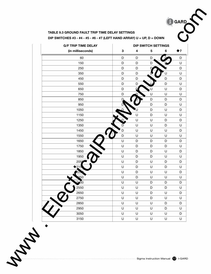
8.3 GROUND FaUlt tRIP tIME DElaY
The SIGMA MONITOR RELAY can be programmed for Ground Fault Trip Delays ranging from
60 milliseconds to 3.15 seconds.
Refer to TABLE 9.3 GROUND FAULT TRIP TIME DELAY SETTINGS to determine the DIP Switch settings for
the application.
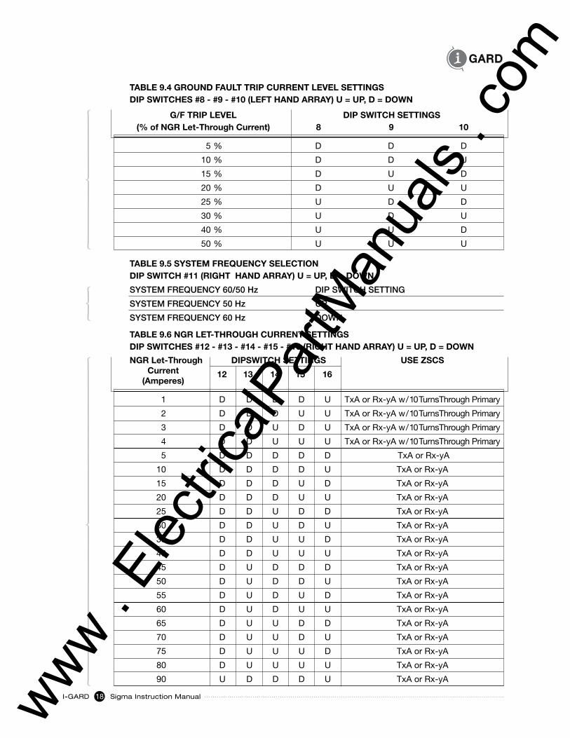
8.4 GROUND FaUlt tRIP CURRENt lEVEl
The SIGMA MONITOR RELAY can be programmed for a number of Ground Fault Trip Levels expressed as
a percentage of the NGR Let-Through Current setting. Eight Ground Fault Trip Level settings are available
and are: 5%; 10%; 15%; 20%; 25%; 30%; 40%; 50%.
I-Gard recommends that the Ground Fault Trip Level setting be set as low as possible to provide maximum
operating personnel and equipment protection without having the SIGMA MONITOR RELAY report Ground
Faults falsely.
www . El
ectric
alPar
tMan
uals
. com
Sigma Instruction Manual I-GARD15
Refer to TABLE 9.4 GROUND FAULT TRIP CURRENT LEVEL SETTINGS to determine the DIP Switch
settings for the application.
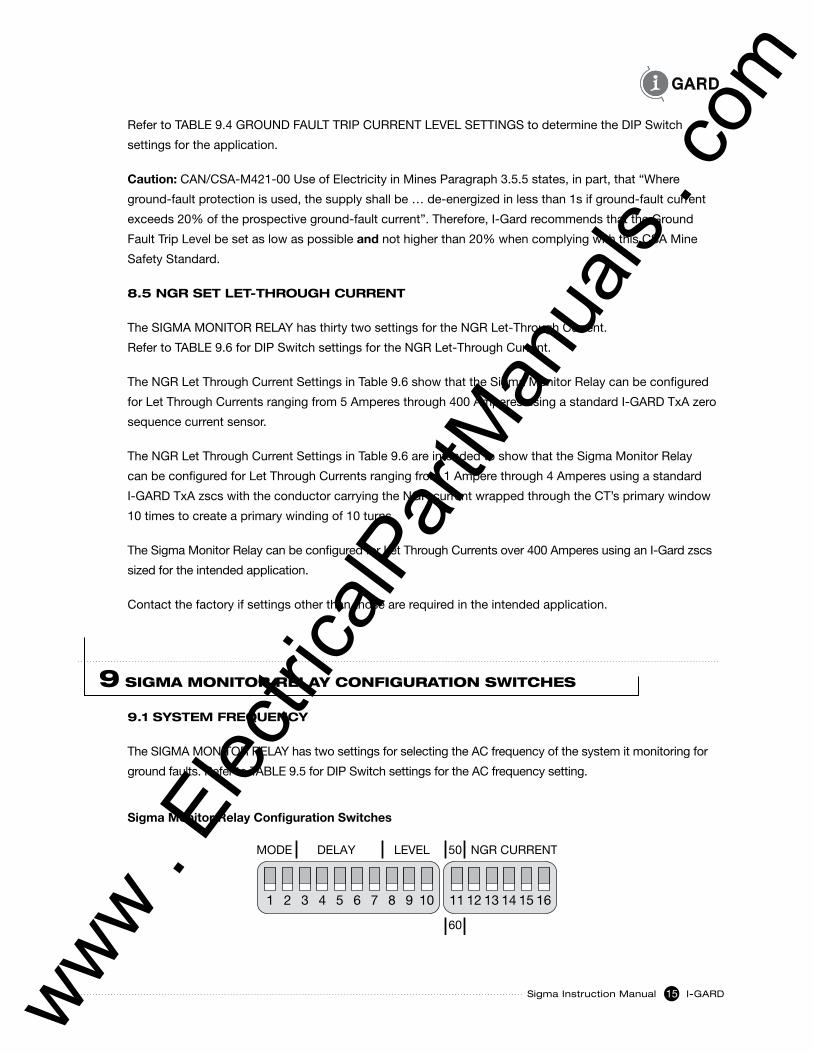
Caution:CAN/CSA-M421-00UseofElectricityinMinesParagraph3.5.5states,inpart,that“Where
ground-fault protection is used, the supply shall be … de-energized in less than 1s if ground-fault current
exceeds 20% of the prospective ground-fault current”. Therefore, I-Gard recommends that the Ground
Fault Trip Level be set as low as possible and not higher than 20% when complying with this CSA Mine
Safety Standard.
8.5 NGR sEt lEt-tHROUGH CURRENt
The SIGMA MONITOR RELAY has thirty two settings for the NGR Let-Through Current.
Refer to TABLE 9.6 for DIP Switch settings for the NGR Let-Through Current.
The NGR Let Through Current Settings in Table 9.6 show that the Sigma Monitor Relay can be configured
for Let Through Currents ranging from 5 Amperes through 400 Amperes using a standard I-GARD TxA zero
sequence current sensor.
The NGR Let Through Current Settings in Table 9.6 are intended to show that the Sigma Monitor Relay
can be configured for Let Through Currents ranging from 1 Ampere through 4 Amperes using a standard
I-GARD TxA zscs with the conductor carrying the NGR current wrapped through the CT’s primary window
10 times to create a primary winding of 10 turns.
The Sigma Monitor Relay can be configured for Let Through Currents over 400 Amperes using an I-Gard zscs
sized for the intended application.
Contact the factory if settings other than those are required in the intended application.
9 SIGmA mOnITOR RELAy COnFIGURATIOn SWITCHES
9.1 sYstEM FREQUENCY
The SIGMA MONITOR RELAY has two settings for selecting the AC frequency of the system it monitoring for
ground faults. Refer to TABLE 9.5 for DIP Switch settings for the AC frequency setting.
Sigma Monitor Relay Configuration Switches
MODE DELAY LEVEL NGR CURRENT50
60
1 2 3 4 5 6 7 8 9 10 11 12 13 14 15 16
www . El
ectric
alPar
tMan
uals
. com
I-GARD Sigma Instruction Manual16
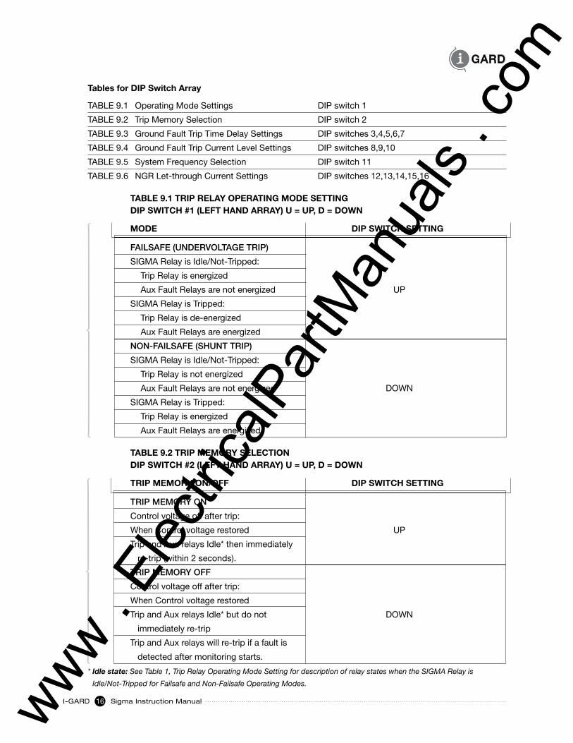
Tables for DIP Switch Array
TABLE 9.1 Operating Mode Settings DIP switch 1
TABLE 9.2 Trip Memory Selection DIP switch 2
TABLE 9.3 Ground Fault Trip Time Delay Settings DIP switches 3,4,5,6,7
TABLE 9.4 Ground Fault Trip Current Level Settings DIP switches 8,9,10
TABLE 9.5 System Frequency Selection DIP switch 11
TABLE 9.6 NGR Let-through Current Settings DIP switches 12,13,14,15,16
TABLE 9.1 TRIP RELAY OPERATING MODE SETTING DIP SwITCh #1 (LEFT hAND ARRAY) U = UP, D = DOwN
MODE DIP SwITCh SETTING
FAILSAFE (UNDERVOLTAGE TRIP)
SIGMARelayisIdle/Not-Tripped:
Trip Relay is energized
Aux Fault Relays are not energized UP
SIGMA Relay is Tripped:
Trip Relay is de-energized
Aux Fault Relays are energized
NON-FAILSAFE (SHUNT TRIP)
SIGMARelayisIdle/Not-Tripped:
Trip Relay is not energized
Aux Fault Relays are not energized DOWN
SIGMA Relay is Tripped:
Trip Relay is energized
Aux Fault Relays are energized
TABLE 9.2 TRIP MEMORY SELECTION DIP SwITCh #2 (LEFT hAND ARRAY) U = UP, D = DOwN
TRIP MEMORY ON/OFF DIP SwITCh SETTING
TRIP MEMORY ON
Control voltage off after trip:
When Control voltage restored UP
Trip and Aux relays Idle* then immediately
re-trip (within 2 seconds).
TRIP MEMORY OFF
Control voltage off after trip:
When Control voltage restored
Trip and Aux relays Idle* but do not DOWN
immediately re-trip
Trip and Aux relays will re-trip if a fault is
detected after monitoring starts.
* Idle state: See Table 1, Trip Relay Operating Mode Setting for description of relay states when the SIGMA Relay is
Idle/Not-Tripped for Failsafe and Non-Failsafe Operating Modes.
www . El
ectric
alPar
tMan
uals
. com
Sigma Instruction Manual I-GARD17
TABLE 9.3 GROUND FAULT TRIP TIME DELAY SETTINGS
DIP SwITChES #3 - #4 - #5 - #6 - #7 (LEFT hAND ARRAY) U = UP, D = DOwN
G/F TRIP TIME DELAY DIP SwITCh SETTINGS
(in milliseconds) 3 4 5 6 7
60 D D D D D
150 D D D D U
250 D D D U D
350 D D D U U
450 D D U D D
550 D D U D U
650 D D U U D
750 D D U U U
850 D U D D D
950 D U D D U
1050 D U D U D
1150 D U D U U
1250 D U U D D
1350 D U U D U
1450 D U U U D
1550 D U U U U
1650 U D D D D
1750 U D D D U
1850 U D D U D
1950 U D D U U
2050 U D U D D
2150 U D U D U
2250 U D U U D
2350 U D U U U
2450 U U D D D
2550 U U D D U
2650 U U D U D
2750 U U D U U
2850 U U U D D
2950 U U U D U
3050 U U U U D
3150 U U U U U
www . El
ectric
alPar
tMan
uals
. com
I-GARD Sigma Instruction Manual18
TABLE 9.4 GROUND FAULT TRIP CURRENT LEVEL SETTINGS DIP SwITChES #8 - #9 - #10 (LEFT hAND ARRAY) U = UP, D = DOwN
G/F TRIP LEVEL DIP SwITCh SETTINGS (% of NGR Let-Through Current) 8 9 10
5 % D D D
10 % D D U
15 % D U D
20 % D U U
25 % U D D
30 % U D U
40 % U U D
50 % U U U
TABLE 9.5 SYSTEM FREqUENCY SELECTION DIP SwITCh #11 (RIGhT hAND ARRAY) U = UP, D = DOwN
SYSTEM FREQUENCY 60/50 Hz DIP SWITCH SETTING
SYSTEM FREQUENCY 50 Hz UP
SYSTEM FREQUENCY 60 Hz DOWN
TABLE 9.6 NGR LET-ThROUGh CURRENT SETTINGS DIP SwITChES #12 - #13 - #14 - #15 - #16 (RIGhT hAND ARRAY) U = UP, D = DOwN
NGR Let-Through DIPSwITCh SETTINGS USE ZSCS Current (Amperes)
1 D D D D U TxAorRx-yAw/10TurnsThroughPrimary
2 D D D U U TxAorRx-yAw/10TurnsThroughPrimary
3 D D U D U TxAorRx-yAw/10TurnsThroughPrimary
4 D D U U U TxAorRx-yAw/10TurnsThroughPrimary
5 D D D D D TxA or Rx-yA
10 D D D D U TxA or Rx-yA
15 D D D U D TxA or Rx-yA
20 D D D U U TxA or Rx-yA
25 D D U D D TxA or Rx-yA
30 D D U D U TxA or Rx-yA
35 D D U U D TxA or Rx-yA
40 D D U U U TxA or Rx-yA
45 D U D D D TxA or Rx-yA
50 D U D D U TxA or Rx-yA
55 D U D U D TxA or Rx-yA
60 D U D U U TxA or Rx-yA
65 D U U D D TxA or Rx-yA
70 D U U D U TxA or Rx-yA
75 D U U U D TxA or Rx-yA
80 D U U U U TxA or Rx-yA
90 U D D D U TxA or Rx-yA
12 13 14 15 16
www . El
ectric
alPar
tMan
uals
. com
Sigma Instruction Manual I-GARD19
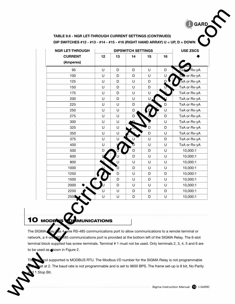
TABLE 9.6 - NGR LET-ThROUGh CURRENT SETTINGS (CONTINUED)
DIP SwITChES #12 - #13 - #14 - #15 - #16 (RIGhT hAND ARRAY) U = UP, D = DOwN
NGR LET-ThROUGh DIPSwITCh SETTINGS USE ZSCS
CURRENT 12 13 14 15 16
(Amperes)
95 U D D U D TxA or Rx-yA
100 U D D U U TxA or Rx-yA
125 U D U D D TxA or Rx-yA
150 U D U D U TxA or Rx-yA
175 U D U U D TxA or Rx-yA
200 U D U U U TxA or Rx-yA
225 U U D D D TxA or Rx-yA
250 U U D D U TxA or Rx-yA
275 U U D U D TxA or Rx-yA
300 U U D U U TxA or Rx-yA
325 U U U D D TxA or Rx-yA
350 U U U D U TxA or Rx-yA
375 U U U U D TxA or Rx-yA
400 U U U U U TxA or Rx-yA
500 D U D D U 10,000:1
600 D U D U U 10,000:1
800 D U U U U 10,000:1
1000 U D D U U 10,000:1
1250 U D U D D 10,000:1
1500 U D U D U 10,000:1
2000 U D U U U 10,000:1
2250 U U D D D 10,000:1
2500 U U D D U 10,000:1
10 mOdBUS COmmUnICATIOnS
The SIGMA relay has 4-wire RS-485 communications port to allow communications to a remote terminal or
network, a 4-wire RS-485 communications port is provided at the bottom left of the SIGMA Relay. The 6-slot
terminal block supplied has screw terminals. Terminal # 1 must not be used. Only terminals 2, 3, 4, 5 and 6 are
to be used as shown in Figure 2.
TheprotocolsupportedisMODBUSRTU.TheModbusI/DnumberfortheSIGMARelayisnotprogrammable
and is set at 2. The baud rate is not programmable and is set to 9600 BPS. The frame set-up is 8 bit, No Parity
and 1 Stop Bit.
www . El
ectric
alPar
tMan
uals
. com
I-GARD Sigma Instruction Manual20
The communications cable should ideally be standard 4-wire with two twisted-pairs, and a grounding shield
to prevent electro magnetic interference. The shield of the cable between nodes should not be continuously
grounded but should be grounded at one end. The cable may be grounded at the Sigma Relay using the ground
connection provided on terminal # 6.
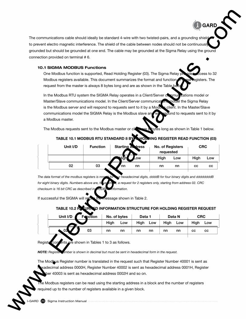
10.1 sIGMa MODBUs Functions
One Modbus function is supported, Read Holding Register (03). The Sigma Relay provides access to 32
Modbus registers available. This document summarizes the format and function of these registers. The
request from the master is always 8 bytes long and are as shown in the Table below.
IntheModbusRTUsystemtheSIGMARelayoperatesinaClient/Servercommunicationsmodelor
Master/Slavecommunicationsmodel.IntheClient/ServercommunicationsmodeltheSigmaRelay
istheModbusserverandwillrespondtorequestssenttoitbyaModbusclient.IntheMaster/Slave
communications model the SIGMA Relay is the Modbus slave and will respond to requests sent to it by
a Modbus master.
The Modbus requests sent to the Modbus master or client are 8 bytes long as shown in Table 1 below.
TABLE 10.1 MODBUS RTU STANDARD 8 BYTE hOLDING REGISTER READ FUNCTION (03)
Unit I/D Function Starting Address No. of Registers CRC requested
High Low High Low High Low
02 03 nn nn nn nn cc cc
TABLE 10.2 RETURNED INFORMATION STRUCTURE FOR hOLDING REGISTER REqUEST
Unit I/D Function No. of bytes Data 1 Data N CRC
High Low High Low High Low High Low
02 03 nn nn nn nn nn nn cc cc
The data format of the modbus registers is nnnnH for four hexadecimal digits, ddddB for four binary digits and ddddddddB
for eight binary digits. Numbers above are, for example, a request for 2 registers only, starting from address 02. CRC
checksum is 16 bit CRC as described in MODBUS information.
If successful the SIGMA will return the message shown in Table 2.
Register contents are shown in Tables 1 to 3 as follows.
NOTE: Register number is shown in decimal but must be sent in hexadecimal form in the request.
The Modbus Register number is translated in the request such that Register Number 40001 is sent as
hexadecimal address 0000H, Register Number 40002 is sent as hexadecimal address 0001H, Register
Number 40003 is sent as hexadecimal address 0002H and so on.
The Modbus registers can be read using the starting address in a block and the number of registers
required up to the number of registers available in a given block.
www . El
ectric
alPar
tMan
uals
. com
Sigma Instruction Manual I-GARD21
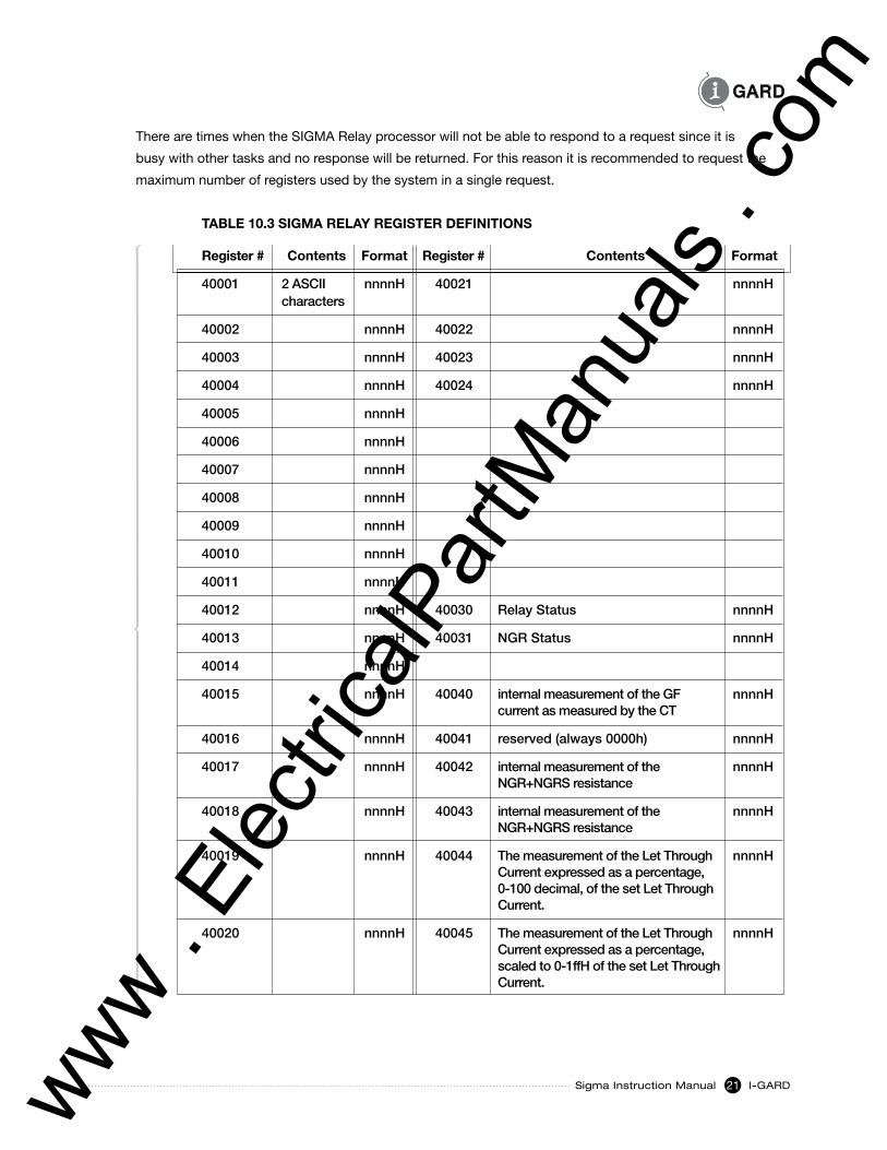
There are times when the SIGMA Relay processor will not be able to respond to a request since it is
busy with other tasks and no response will be returned. For this reason it is recommended to request the
maximum number of registers used by the system in a single request.
TABLE 10.3 SIGMA RELAY REGISTER DEFINITIONS
Register # Contents Format Register # Contents Format
40001 2 ASCII nnnnH 40021 nnnnH characters
40002 nnnnH 40022 nnnnH
40003 nnnnH 40023 nnnnH
40004 nnnnH 40024 nnnnH
40005 nnnnH
40006 nnnnH
40007 nnnnH
40008 nnnnH
40009 nnnnH
40010 nnnnH
40011 nnnnH
40012 nnnnH 40030 Relay Status nnnnH
40013 nnnnH 40031 NGR Status nnnnH
40014 nnnnH
40015 nnnnH 40040 internal measurement of the GF nnnnH current as measured by the CT
40016 nnnnH 40041 reserved (always 0000h) nnnnH
40017 nnnnH 40042 internal measurement of the nnnnH NGR+NGRS resistance
40018 nnnnH 40043 internal measurement of the nnnnH NGR+NGRS resistance
40019 nnnnH 40044 The measurement of the Let Through nnnnH Current expressed as a percentage, 0-100 decimal, of the set Let Through Current.
40020 nnnnH 40045 The measurement of the Let Through nnnnH Current expressed as a percentage, scaled to 0-1ffH of the set Let Through Current.
www . El
ectric
alPar
tMan
uals
. com
I-GARD Sigma Instruction Manual22
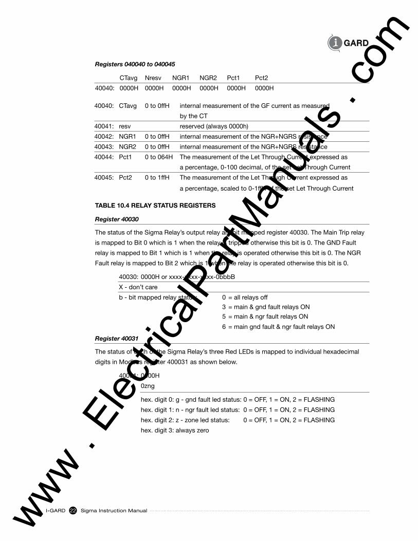
Registers 040040 to 040045
CTavg Nresv NGR1 NGR2 Pct1 Pct2
40040: 0000H 0000H 0000H 0000H 0000H 0000H
40040: CTavg 0 to 0ffH internal measurement of the GF current as measured
by the CT
40041: resv reserved (always 0000h)
40042: NGR1 0 to 0ffH internal measurement of the NGR+NGRS resistance
40043: NGR2 0 to 0ffH internal measurement of the NGR+NGRS resistance
40044: Pct1 0 to 064H The measurement of the Let Through Current expressed as
a percentage, 0-100 decimal, of the set Let Through Current
40045: Pct2 0 to 1ffH The measurement of the Let Through Current expressed as
a percentage, scaled to 0-1ffH of the set Let Through Current
TABLE 10.4 RELAY STATUS REGISTERS
Register 40030
The status of the Sigma Relay’s output relay are bit mapped register 40030. The Main Trip relay
is mapped to Bit 0 which is 1 when the relay is tripped otherwise this bit is 0. The GND Fault
relay is mapped to Bit 1 which is 1 when the relay is operated otherwise this bit is 0. The NGR
Fault relay is mapped to Bit 2 which is 1 when the relay is operated otherwise this bit is 0.
40030: 0000H or xxxx-xxxx-xxxx-0bbbB
X - don’t care
b - bit mapped relay status: 0 = all relays off
3 = main & gnd fault relays ON
5 = main & ngr fault relays ON
6 = main gnd fault & ngr fault relays ON
Register 40031
The status of each of the Sigma Relay’s three Red LEDs is mapped to individual hexadecimal
digits in Modbus register 400031 as shown below.
40031: 0000H
0zng
hex. digit 0: g - gnd fault led status: 0 = OFF, 1 = ON, 2 = FLASHING
hex. digit 1: n - ngr fault led status: 0 = OFF, 1 = ON, 2 = FLASHING
hex. digit 2: z - zone led status: 0 = OFF, 1 = ON, 2 = FLASHING
hex. digit 3: always zero
www . El
ectric
alPar
tMan
uals
. com
Sigma Instruction Manual I-GARD23
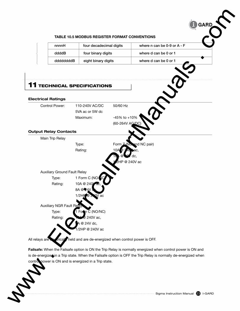
11 TECHnICAL SPECIFICATIOnS
Electrical Ratings
ControlPower: 110-240VAC/DC 50/60Hz
5VA ac or 5W dc
Maximum: -45% to +10%
(60-264VAC/DC)
Output Relay Contacts
Main Trip Relay
Type: Form Z (NO and NC pair)
Rating: 10A @ 240V ac,
10A @ 30V dc,
1/2HP@240Vac
Auxiliary Ground Fault Relay
Type: 1FormC(NO/NC)
Rating: 10A @ 240V ac,
8A @ 24V dc,
1/2HP@240Vac
Auxiliary NGR Fault Relay:
Type: 1FormC(NO/NC)
Rating: 10A @ 240V ac,
8A @ 24V dc,
1/2HP@240Vac
All relays are electrically held and are de-energized when control power is OFF.
Failsafe: When the Failsafe option is ON the Trip Relay is normally energized when control power is ON and
is de-energized in a Trip state. When the Failsafe option is OFF the Trip Relay is normally de-energized when
control power is ON and is energized in a Trip state.
TABLE 10.5 MODBUS REGISTER FORMAT CONVENTIONS
nnnnH four decadecimal digits where n can be 0-9 or A - F
ddddB four binary digits where d can be 0 or 1
ddddddddB eight binary digits where d can be 0 or 1
www . El
ectric
alPar
tMan
uals
. com
I-GARD Sigma Instruction Manual24
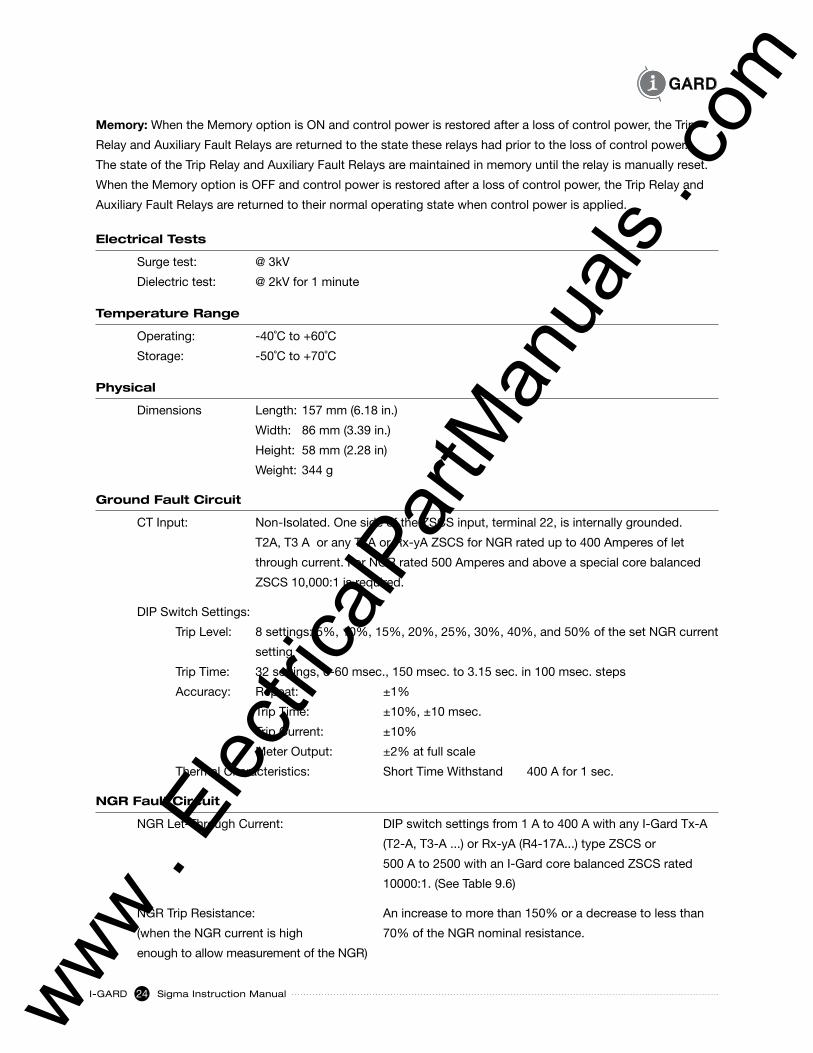
Memory: When the Memory option is ON and control power is restored after a loss of control power, the Trip
Relay and Auxiliary Fault Relays are returned to the state these relays had prior to the loss of control power.
The state of the Trip Relay and Auxiliary Fault Relays are maintained in memory until the relay is manually reset.
When the Memory option is OFF and control power is restored after a loss of control power, the Trip Relay and
Auxiliary Fault Relays are returned to their normal operating state when control power is applied.
Electrical tests
Surge test: @ 3kV
Dielectric test: @ 2kV for 1 minute
temperature Range
Operating: -40˚C to +60˚C
Storage: -50˚C to +70˚C
Physical
Dimensions Length: 157 mm (6.18 in.)
Width: 86 mm (3.39 in.)
Height: 58 mm (2.28 in)
Weight: 344 g
Ground Fault Circuit
CT Input: Non-Isolated. One side of the ZSCS input, terminal 22, is internally grounded.
T2A, T3 A or any TxA or Rx-yA ZSCS for NGR rated up to 400 Amperes of let
through current. For NGR rated 500 Amperes and above a special core balanced
ZSCS 10,000:1 is required.
DIP Switch Settings:
Trip Level: 8 settings: 5%, 10%, 15%, 20%, 25%, 30%, 40%, and 50% of the set NGR current
setting
Trip Time: 32 settings, 0-60 msec., 150 msec. to 3.15 sec. in 100 msec. steps
Accuracy: Repeat: ±1%
Trip Time: ±10%, ±10 msec.
Trip Current: ±10%
Meter Output: ±2% at full scale
Thermal Characteristics: Short Time Withstand 400 A for 1 sec.
NGR Fault Circuit
NGR Let-Through Current: DIP switch settings from 1 A to 400 A with any I-Gard Tx-A
(T2-A, T3-A ...) or Rx-yA (R4-17A...) type ZSCS or
500 A to 2500 with an I-Gard core balanced ZSCS rated
10000:1. (See Table 9.6)
NGR Trip Resistance: An increase to more than 150% or a decrease to less than
(when the NGR current is high 70% of the NGR nominal resistance.
enough to allow measurement of the NGR)
www . El
ectric
alPar
tMan
uals
. com
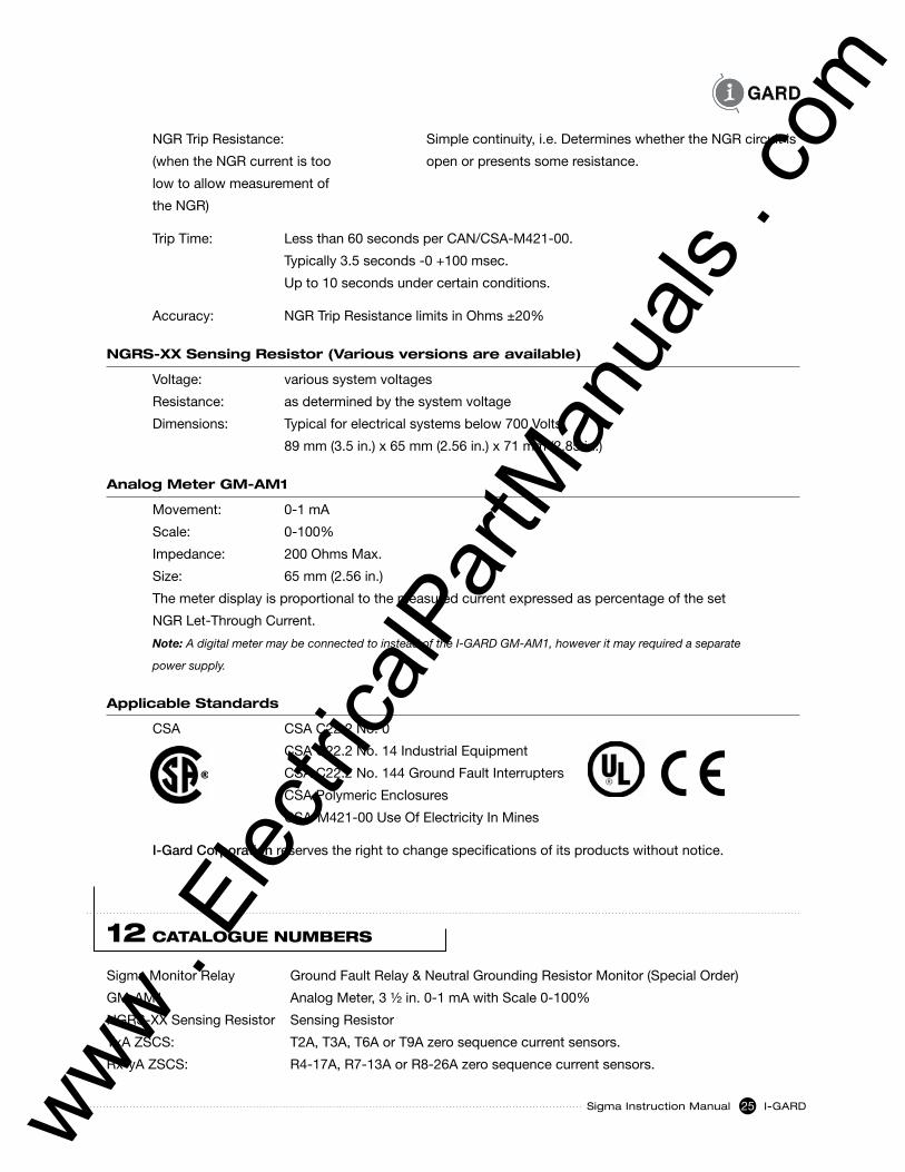
Sigma Instruction Manual I-GARD25
NGR Trip Resistance: Simple continuity, i.e. Determines whether the NGR circuit is
(when the NGR current is too open or presents some resistance.
low to allow measurement of
the NGR)
TripTime: Lessthan60secondsperCAN/CSA-M421-00.
Typically 3.5 seconds -0 +100 msec.
Up to 10 seconds under certain conditions.
Accuracy: NGR Trip Resistance limits in Ohms ±20%
NGRs-XX sensing Resistor (Various versions are available)
Voltage: various system voltages
Resistance: as determined by the system voltage
Dimensions: Typical for electrical systems below 700 Volts:
89 mm (3.5 in.) x 65 mm (2.56 in.) x 71 mm (2.85 in.)
analog Meter GM-aM1
Movement: 0-1 mA
Scale: 0-100%
Impedance: 200 Ohms Max.
Size: 65 mm (2.56 in.)
The meter display is proportional to the measured current expressed as percentage of the set
NGR Let-Through Current.
Note: A digital meter may be connected to instead of the I-GARD GM-AM1, however it may required a separate
power supply.
applicable standards
CSA CSA C22.2 No. 0
CSA C22.2 No. 14 Industrial Equipment
CSA C22.2 No. 144 Ground Fault Interrupters
CSA Polymeric Enclosures
CSA-M421-00 Use Of Electricity In Mines
I-Gard Corporation reserves the right to change specifications of its products without notice.
12 CATALOGUE nUmBERS
Sigma Monitor Relay Ground Fault Relay & Neutral Grounding Resistor Monitor (Special Order)
GM-AM1 Analog Meter, 3 ½ in. 0-1 mA with Scale 0-100%
NGRS-XX Sensing Resistor Sensing Resistor
TxA ZSCS: T2A, T3A, T6A or T9A zero sequence current sensors.
Rx-yA ZSCS: R4-17A, R7-13A or R8-26A zero sequence current sensors.
www . El
ectric
alPar
tMan
uals
. com
I-GARD Sigma Instruction Manual26
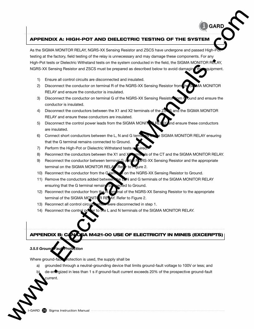
APPEndIX A: HIGH-POT And dIELECTRIC TESTInG OF THE SySTEm
As the SIGMA MONITOR RELAY, NGRS-XX Sensing Resistor and ZSCS have undergone and passed High-Pot
testing at the factory, field testing of the relay is unnecessary and may damage these components. For any
High-Pot tests or Dielectric Withstand tests on the system conducted in the field, the SIGMA MONITOR RELAY,
NGRS-XX Sensing Resistor and ZSCS must be prepared as described below to avoid damaging this equipment.
1) Ensure all control circuits are disconnected and insulated.
2) Disconnect the conductor on terminal R of the NGRS-XX Sensing Resistor from the SIGMA MONITOR
RELAY and ensure the conductor is insulated.
3) Disconnect the conductor on terminal G of the NGRS-XX Sensing Resistor from Ground and ensure the
conductor is insulated.
4) Disconnect the conductors between the X1 and X2 terminals of the ZSCS and the SIGMA MONITOR
RELAY and ensure these conductors are insulated.
5) Disconnect the control power leads from the SIGMA MONITOR RELAY and ensure these conductors
are insulated.
6) Connect short conductors between the L, N and G terminals of the SIGMA MONITOR RELAY ensuring
that the G terminal remains connected to Ground.
7) Perform the High-Pot or Dielectric Withstand tests required.
8) Reconnect the conductors between the X1 and X2 terminals of the CT and the SIGMA MONITOR RELAY.
9) Reconnect the conductor between terminal G of the NGRS-XX Sensing Resistor and the appropriate
terminal on the SIGMA MONITOR RELAY. Refer to Figure 2.
10) Reconnect the conductor from the G terminal on the NGRS-XX Sensing Resistor to Ground.
11) Remove the conductors added between the L, N and G terminals of the SIGMA MONITOR RELAY
ensuring that the G terminal remains connected to Ground.
12) Reconnect the conductor from the R terminal of the NGRS-XX Sensing Resistor to the appropriate
terminal of the SIGMA MONITOR RELAY. Refer to Figure 2.
13) Reconnect all control circuits which were disconnected in step 1.
14) Reconnect the control power to the L and N terminals of the SIGMA MONITOR RELAY.
APPEndIX B: CAn/CSA m421-00 USE OF ELECTRICITy In mInES (EXCERPTS)
3.5.5 Ground-Fault Protection
Where ground-fault protection is used, the supply shall be
a) grounded through a neutral-grounding device that limits ground-fault voltage to 100V or less; and
b) de-energized in less than 1 s if ground-fault current exceeds 20% of the prospective ground-fault
current.
www . El
ectric
alPar
tMan
uals
. com
Sigma Instruction Manual I-GARD27
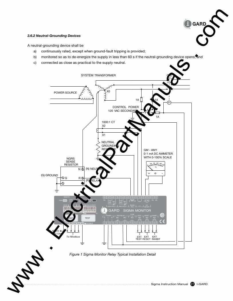
3.6.2 Neutral-Grounding Devices
A neutral-grounding device shall be
a) continuously rated, except when ground-fault tripping is provided;
b) monitored so as to de-energize the supply in less than 60 s if the neutral-grounding device opens; and
c) connected as close as practical to the supply neutral.
POWER SOURCE
ST
NEUTRALGROUNDINGRESISTOR
%100
806040200
-+
EXTTEST
EXTRESET
(R) RELAY
(N) NEUTRAL
(G) GROUND
NGRSSENSE
RESISTOR
X1
X2
X0
CONTROL POWER120 VAC SECONDARY
1000:1 CT
1A
EXTINHIBIT
1A 1A
GM - AM10-1 mA DC AMMETERWITH 0-100% SCALE
C.B.TRANSFORMERSYSTEM
To Modbus
#1 Do Not Use
GARDZONE
FLTNGR
GR
RESET
5251
NA NANA
50494847464544434241403938
NANA
161
DELAYMODETEST
G
NGR CURRENT
-+
GFR-RM MONITOR
G/FRES.
PWR GNDFLT
METERSENSE
I/LTRIP RELAYPOWERLEVEL
G/FCTGSNCNONO NC
NONONONONCN
GND FAULTNGR FAULT
LRESET
ZONE
TEST
NONC NC
NOS
CTG/F
METERSENSERES.GND FAULTNGR FAULT
G
SIGMA MONITOR
MODE
PWR GNDFLT
NGRFLT
ZONEGR
1 16
DELAY LEVEL NGR CURRENT
12 13 14 15 16 17 18 19 20 21 22 23 24 25 26
ZONEI/L TEST RESETTRIP RELAYPOWER
NONONONCNLG NO
NANA NA
525150494847464544434241403938
2 3 4 5 61
RESET TEST
MODBUS
REMOTE
INHIBIT
NO
50
60
1 2 3 4 5 6 7 8 9 10 11 12 13 14 15 16
N
G R
Figure 1 Sigma Monitor Relay Typical Installation Detail
www . El
ectric
alPar
tMan
uals
. com
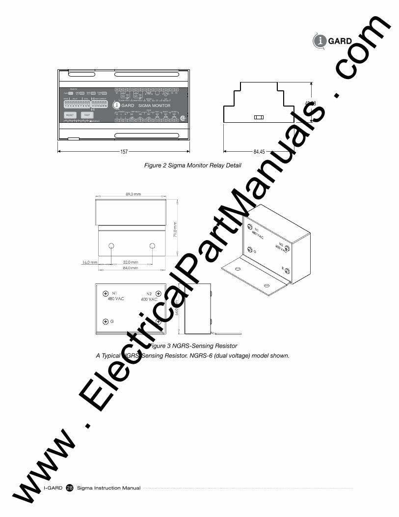
I-GARD Sigma Instruction Manual28
Figure 3 NGRS-Sensing Resistor
A Typical NGRS-Sensing Resistor. NGRS-6 (dual voltage) model shown.
NONC NC
NOS
CTG/F
METERSENSERES.GND FAULTNGR FAULT
G
SIGMA MONITOR
PWR GNDFLT
NGRFLT
ZONEGR
12 13 14 15 16 17 18 19 20 21 22 23 24 25 26
ZONEI/L TEST RESETTRIP RELAYPOWER
NONONONCNLG NO
NANA NA
525150494847464544434241403938
2 3 4 5 61
RESET TEST
MODBUS
REMOTE
INHIBIT
NO
MODE DELAY LEVEL NGR CURRENT50
60
1 2 3 4 5 6 7 8 9 10 11 12 13 14 15 16
157 84.45
48.23
Figure 2 Sigma Monitor Relay Detail
www . El
ectric
alPar
tMan
uals
. com

InSTRUCTIOn mAnUALS
C-407 GCHK-100 Mining Relay Ground Fault Protection System Manual
C-408 Sleuth High Resistance Grounding System Manual
C-322 MGFR Ground Fault Relay Manual
C-409 DSP Ohmni High Resistance Grounding System Manual
C-102 Gemini High Resistance Grounding System Manual
C-101 StopLight High Resistance Grounding System Manual
C-105 Fusion Ground Fault Protection System Manual
C-403 GFR-RM Sigma Resistor Monitoring and Ground Fault Relay
C-107 Sentinel High Resistance Grounding System
www . El
ectric
alPar
tMan
uals
. com
7615 Kimbel St., Unit 1
Mississauga, Ontario
Canada L5S 1A8
Phone 905-673-1553
Toll Free 1-800-737-4787
Fax 905-673-8472
e-mail: [email protected]
www.i-gard.comthe
pow
er to
pro
tect
www . El
ectric
alPar
tMan
uals
. com
Related Documents