Maintenance Manual • r Circuit GEK-7310C (Includes Supplement GEI-86134) B Tes -3/3A-50 and RU-3/3A-50 GENERAL ELECTRIC www . ElectricalPartManuals . com www . ElectricalPartManuals . com

Welcome message from author
This document is posted to help you gain knowledge. Please leave a comment to let me know what you think about it! Share it to your friends and learn new things together.
Transcript
Maintenance Manual • Power
Circuit
GEK-7310C (Includes Supplement GEI-86134)
Breakers Types AKR-3/3A-50 and AKRU-3/3A-50
GENERAL fj ELECTRIC www . El
ectric
alPar
tMan
uals
. com
www . El
ectric
alPar
tMan
uals
. com
CONTENTS Page GENERAL DESCRIPTION . . . . . . . . . • . . . . . . . . . . • . . . . . . • . . • . . . . . • • . . • . . . • . . . . . 3
General . • . • . . . • . . • . • • . . • . • • . . . • . • . . . • • . . . • . • . • • . . . . . . . . . . . . . • . • • . . • 3 Breaker Types . . . . . . . . . . • • . . . • • . • . • • . . • . . . . • . . • . • • • • • . • . . • • . . . • • . . • . . 3
Mounting . . . • . . . .. . • • . . • . . . . • . . . . . . . . . . . • . • • . . • • . . . . • . . . • . . • • . . . . . • 4 Fused Breakers. . . . . . . . • . . • . • • • . . • • . . . . . . . . . . . . . . . . . . . . . . • . . . . • . • • . • 4
Breaker Ratings . . . • • . . . . . . • . . . • . . . • . . . • . . . . . . . . . . . . • . . . . . . . • . . • . . . . . . 4 Breaker Description • • . . . • . • • . . . . • . . • . . . . . . . . . . . . . . • . • . . • . . • . . . . . . • . . . . 4
RECEIVING, HANDLING, AND STORAGE . . . . . • . . • . . . . . . . . . . . • . . . . . . . . . . . . . . . . . . 5 Receiving and Handling . . • . . . . . • . . . . . . . . . . . . . • . . • . . . . . • . . . . . . . . . . . . . . . . . 5 Storage . . . • • • . . • . . . . • . . . • . . . • . . . . • • . • . . . . . . . . . . . . . • . . . . . • . . . . • • . . . . 5
BREAKER OPERATION . • • • . . . . . . • . . • . . . . • • . . . . . • . . . . . . • . . . . • . • . . • . • . • . . • . 5 Putting the Breaker in Service • . . • . • . . • • . . . • . . . . . . . . • • . . • . . . . . • . . . . . . • . • . . 5
Drawout Breakers • • . . • . • • . • . . • . . • . . • • . . . . . . . . • . • • . . • . . . . . . . . • • . . . . . . 5 Breaker Insertion (Fig . 3). • • . . • . . . • . • . . . . • . . • • . . . . . • . . • . • • . . • . . • • . • • . • • 5 Breaker Withdrawal . • . . • . . . . . . . . • . • • • . . . . • . . • . . • . • . . . . . . • • • . . . . . • . . • • 7 Stationary Breakers • • . . • . . . • • . • . . . . . . . . • . . . . . . • • • • . • • • • . • • . • • . . • . . . . . 7 Pre-service Check . • . . • . . • • • . . • • . . • . . . . . . . . . . • . . • . • • . • • • . • . . • • . • . . • . 8
Operating the Breaker . . • . . • • • • . . • • • . . • • • • . . . . . • • . • . • • . . • • . . . . • . • • • • • • . . 8 Manual Closing • • • • • . • • . • . . . • . • • • • . • • • • . . . • . . . • . • . . . . • • • • . • . • . • • . • • . 8 Electrical Closing . • • . . . • • • • • . . • • • • • • . • • . . • • • • • • • • • • • . . • . • • . . . . • • . . • . 10
Opening the Breaker. • • . . • . • • • . • • . • • . • . • • . . . . • . . • • . . • . • . • • • • • • • • • . • • . • • . 10 Interlocks • . . • • • . • • • • • . • • • • • • • • • . • • • . . . . • • • . . • • • • • • • . • • • • . . . . • • . • • • . • 10
Closing Spring Interlock (Figs. 6A and 6B) • . . • . • . • • • • • • • • • • • • • . • . . • • • . . . . • • • . 10 Racking Mechanism Interlocks (Fig. 8) • • • . • • . . . • . . • . . • . • • • • • . • • • . . . • • • . . . • . 11 Optional Interlocks • • • . • . • • • • . • • • . . • • . • . . . • . . • • • • • . • • • • . • . • • . • . • • • • . . 11
Accessories • • • • • • • • • • • • • • . . • • • • . • • • • . • • • . . . . • • • . • . • • . • . • . . . • . • . • . • • • 12 Shunt Trip • . . • • • . . • . • • • • . • • . • • • • • • . • . . . • . . . . • . . . . . • • . • . • • . • • . . • • • • 12 Undervoltage Device . • . . . • . . • • • • • • • • • • • • • • • . • • • • . . • • • . • . • • . . . • . . . . . . • . 13 Static Time-delay Undervoltage • • • • • . . • . • • • • . • • • • • • . . • • . . • • • • • • • • . • . . • . • . 13 Electric Lockout Device . . • • . • • • . • • • . • • • . • . . . . . . • • . . • . • . • • . . • . . . • • • . • • • 13 Auxiliary Switch • • • • . . . • • • • • • • • . • • . . • . • . . . . . . • • • . . • • • • . . . • • . • . . • • • . . 14 Bell Alarm . . . • • • . • . • • • . . • . , • • • • . . • • . • . • • . . • • • • • . • . • • . • • . • . • • • . • . . • 14
BREAKER MAINTENANCE • • • • . . . . • • . • • . • . • • . • . . . • . . . . • • • • . . . . • . . . . • . . . • . . . 15 Safety Precautions • . • . . . • . . • • . . . . • . • . • . . . • • . • . . • • . . • . • • • • • . • . • . . . • . . . • . 15 General . • . . . • . . • . . • . • • . . • . . • . • . • • . . . • . . • . . . • . • • . . • • . . . • . . . . • . • . • • . . 15 Arranging the Breaker for Slow Closing . . • • • . • . . . . . • • . . . • . • • . • • . • • . • • . • . • . • . . • 15 Lubrication . . . . . . . . . . • . . . . . • . . . . . • . ·· . • . . . . . . . . . . . . . . . . . . . . . . . . . . . . • . . . 16 Replacement and Adjustment of Components and Accessories . . . . . . . • . . . . • . • . . . . . • • . • 16
Mechanism (Figs. 12, 13, and 14) . • . . . . . . . . . • . . • • . • • . • • • • • • . • . . . • • . . . • . . . 16 Mechanism Replacement (Figs. 15 and 16) . • . . • . . . . . . . . • . . • . • • • • . . • • . • . . . • . . . 18 Latch Adjustment • • • • • • • • . • • • • • • • • • • . . • . . . • • . • . . . . • . • . . . • . . • . • . • • • • . 19 Manual Handle Adjustment • • • . . . • • . . • . • . . • • . . . . . • • • . . . • • • • • • • • • . • . • • . • • • 19
Contact Maintenance . • • . • . • • . • • . • . • • . . • • . • . . . • . . • . • • • • . . • . • • • • . • • . • • . • • . 19 Contact Replacement (Fig. 17) • • • • • • • • . • . • . • . • • • • . • . • • • • • • . . • • . • • • • • . • • . . 19 Contact Adjustment • • • • • • • . • . . • • • • • . • • • • • • • . • . • • • • • • • . . • • . • . • • • . • • . • . . 20
Components and Accessories • • • • . • • • • • • . • • . • • • • • . • • • • • • • • • • • • • . • . . • • • • . • . . 21 Auxiliary Switch (Fig . 18) • • • • • • . • • • • • • . • • • • • • . • • . • • • . • • • • • • • • . • • • • . • • • • 21 Shunt Trip and Undervoltage Device (Figs. 19 and 20) • • . • • • • • • . • • • . • • • • • • • • . • • . • • 22 Maintenance of Static Delay Device for Undervoltage (Figs . 21 and 22) . • • . • • . • • . • • • • • . 24 Electrical Control Components • • . • • • • • • • • • • • . : • • • • . • • • • • • • • • . . • • • • • • • • • • • 2 5 Bell Alarm/Lockout (Fig. 26) • • . • • . • . • • . • • . • • • • • • • • • • • • • • • • • • • . • • • • • • • • • • 27 Drawout Mechanism and Interlocks • • . • • . • • . • • • • • • . . • • • • • • • • • • • • • • • • • • • • • . • 28
AKRU-50 Fused Breaker • • . • • • • • • • • • • • • • • • • . • • • . . • • • • • • • • • • • . • • • • . . . • • • • • 29 Fuse Replacement • • . • • • . • . • • • • • • • • • • • • • . • • • • . . • • • • • . . • • • • • • • • • • . • • • • 2 9 Open Fuse Lockout Device (Fig. 32) . • • • . • • • . . • . . • • • . • • • • • . • • • • • • • . • . . • • • • . 31
Power Sensor Overcurrent Trip Device . . . . . . . . . . . . . . . . . • . . . . • . . • . . . . . . • • . • . . . 3 1 False Tripping Caused by Faulty Ground Fault Operation • . . . . . . • • . . . . • . • . • . . • • • • 34 Testing Current Sensors . . . . . . . . . . . . • • . • . . . . . . . . . • • . • • . • . . . . . • • • . • • . • • 34 Replacement . • . . . . . . . . . . . . . . . . • . . . • . . . . • . . • . . . . . . . . . • • . . . . . . • • . • . • 34 Magnetic Trip Device (Figs. 33 and 38) • . . . . . . . . . . . . • . . . . . . . . . . . . . . . . . . . . • . 36 Selective Tripping . . . . . . . . • . . . . . . . . . . . . . . . . . . . . . . . . . • . . . . . • . . . . . . . • . 3 6
Time-current Curves . . . . . . . . . . . . . • . • . . . . . . . . . . . . . . . • . . • . . • • • . • . . . . • . . . 3 7, 3 8 www . El
ectric
alPar
tMan
uals
. com
www . El
ectric
alPar
tMan
uals
. com
LOW-VOLTAGE POWER CIRCUIT BREAKERS TYPES AKR-3/3A-50 AND AKRU-3/3A-50
GENERAL DESCRIPTION
GENERAL Low-voltage power circuit breakers are used for
controlling and protecting power circuits in the lowvoltage range (usually up to 600 volts). In serving this function, they are a means of safely switching loads and automatically clearing circuits when abnormal conditions occur. Among these conditions, the more common are short c ircuits and sustained overloads and undervoltages.
The proper use, care, and maintenance of these breakers is a prime safety consideration for the protection of personnel, as well as a means of minimizing equipment damage when faults occur. Persons who apply, use, and service these breakers will acquire the knowledge they need by gaining the information contained in these instructions.
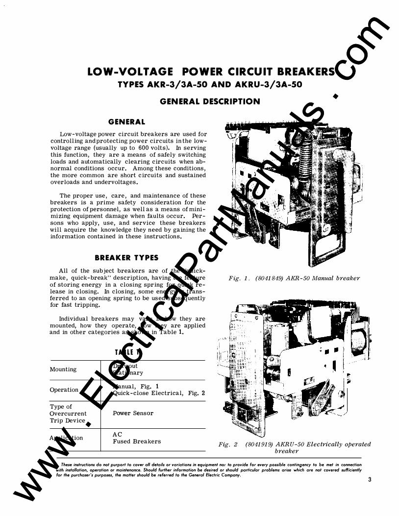
BREAKER TYPES All of the subject breakers are of the "quick
make, quick-break" description, having the feature of storing energy in a closing spring for quick release in closing. In closing, some energy is transferred to an opening spring to be used subsequently for fast tripping.
Individual breakers may vary in how they are mounted, how they operate, how they are applied and in other categories as shown in Table 1.
Mounting
Operation
Type of Overcurrent Trip Device
Application
TABLE 1 Drawout Stationary
Manual, Fig. 1 Quick-close Electrical, Fig. 2
Power Sensor
AC
Fig. 1 . (8041849) AKR- 50 Manual breaker
Fused Breakers Fig. 2 (8041919) AKRU - 50 Electrically operated breaker
These instructions do not purport to cover all details or variations in equipment nor to provide for every possible contingency to be met in connection with installation, operation or maintenance. Should further information be desired or should particular problems arise which are not covered sufficiently for the purchaser's purposes, the matter should be referred to the General Electric Company.
3 www . El
ectric
alPar
tMan
uals
. com
www . El
ectric
alPar
tMan
uals
. com
GEK-7310, Power Circuit Breakers
M O U NT I N G
Most breakers produced are of the "drawout" type. These breakers are equipped with features which make them easy to install in or withdraw from their associated switchgear equipment. These features are a racking mechanism (which facilitates inserting and withdrawing the breaker unit) and primary and control power disconnects which connect and part automatically. Interlocking devices are included. Drawout br eakers of the same rating and type are interchangeable in their various locations in the equipment. This helps breaker maintenance in that spare breakers can be "plugged in" while breakers are being inspected or serviced.
The "stationary" breakers are designed to be mounted on a framework or panel, with mechanical fasteners being used to secure the breaker frame and make power connections. If control power connections are needed, a suitable terminal board is supplied.
F U S E D BREAKERS
Fused breakers are given the extra letter "U" in their model identification number. Type AKRU breakers are not interchangeable with standard general-purpose drawout breakers since their enclos'ures must be modified to provide the extra space required for the fuses.
All fused breakers are equipped with an opened fuse lockout device (O FLO device). This automatically trips the breaker open when any of the three fuses open. It also latches the breaker in the opened position until a resetting device is manually operated. This should not be done until the expended fuse is replaced. This arrangement eliminates the possibility of allowing the circuit to have only one phase energized.
BREAKER RATINGS Type AKR- 50 breakers are 1600-ampere frame
size breakers. This represents the maximum continuous current they may carry . This current value is modified by the rating of the overcurrent trip device with which the breaker is equipped. The lowest available rating of the Power Sensor trip device is 200 amperes.
A s to voltage ratings, the breakers may be applied up to 600 volts, ac.
4
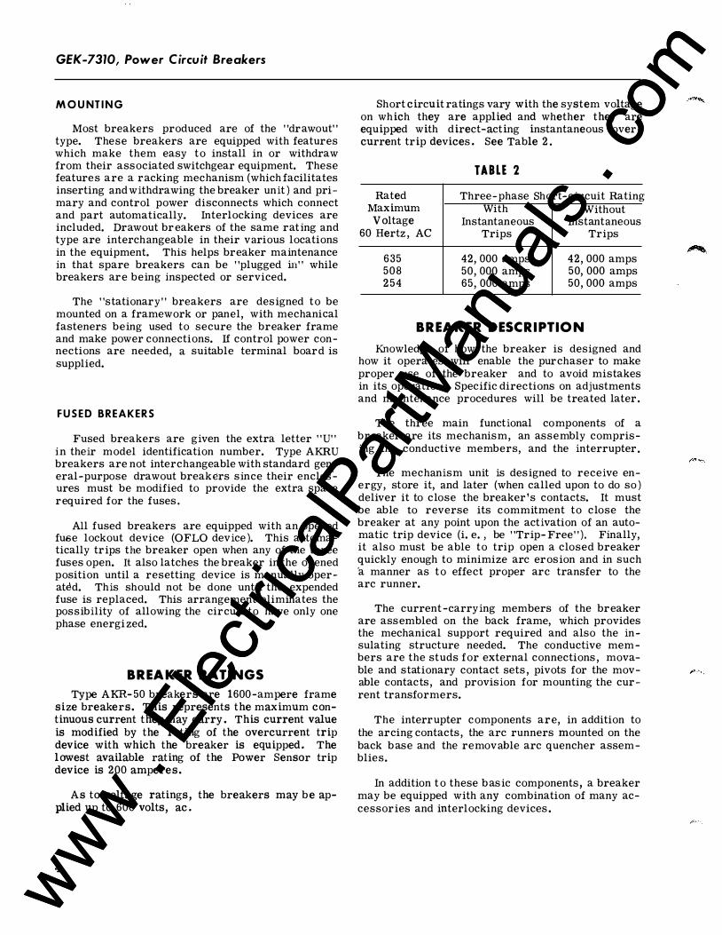
Short circuit ratings vary with the system voltage on which they are applied and whether they are equipped with direct-acting instantaneous overcurrent trip devices. See Table 2 .
Rated Maximum Voltage
60 Hertz , AC
635 508 254
TABLE 2 Three-phase Short-circuit Rating
With Without Instantaneous
Trips
42, 000 amps 50, 000 amps 65, 000 amps
Instantaneous Trips
42, 000 amps 50, 000 amps 50, 000 amps
BREAKER DESCRIPTION Knowledge of how the breaker is designed and
how it operates will enable the purchaser to make proper use of the breaker and to avoid mistakes in its operation. Specific directions on adjustments and maintenance procedures will be treated later.
The three main functional components of a breaker are its mechanism, an assembly comprising the conductive members, and the interrupter.
The mechanism unit is designed to receive energy, store it, and later (when called upon to do so) deliver it to close the breaker's contacts. It must be able to reverse its commitment to close the breaker at any point upon the activation of an automatic trip device (i. e. , be "Tr.ip- Free"). Finally, it also must be able to trip open a closed breaker quickly enough to minimize arc erosion and in such ·a manner as to effect proper arc transfer to the arc runner.
The current-carrying members of the breaker are assembled on the back frame, which provides the mechanical support required and also the insulating structure needed. The conductive members are the studs for external connections , movable and stationary contact sets , pivots for the movable contacts , and provision for mounting the current transformers.
The interrupter components are, in addition to the arcing contacts , the arc runners mounted on the back base and the removable arc quencher assemblies.
In addition to these basic components, a breaker may be equipped with any combination of many accessories and interlocking devices.
www . El
ectric
alPar
tMan
uals
. com
www . El
ectric
alPar
tMan
uals
. com
Power Circuit Breakers, GEK-7310
RECEIVING, HANDLING, AND STORAGE RECEIVING AND HANDLING
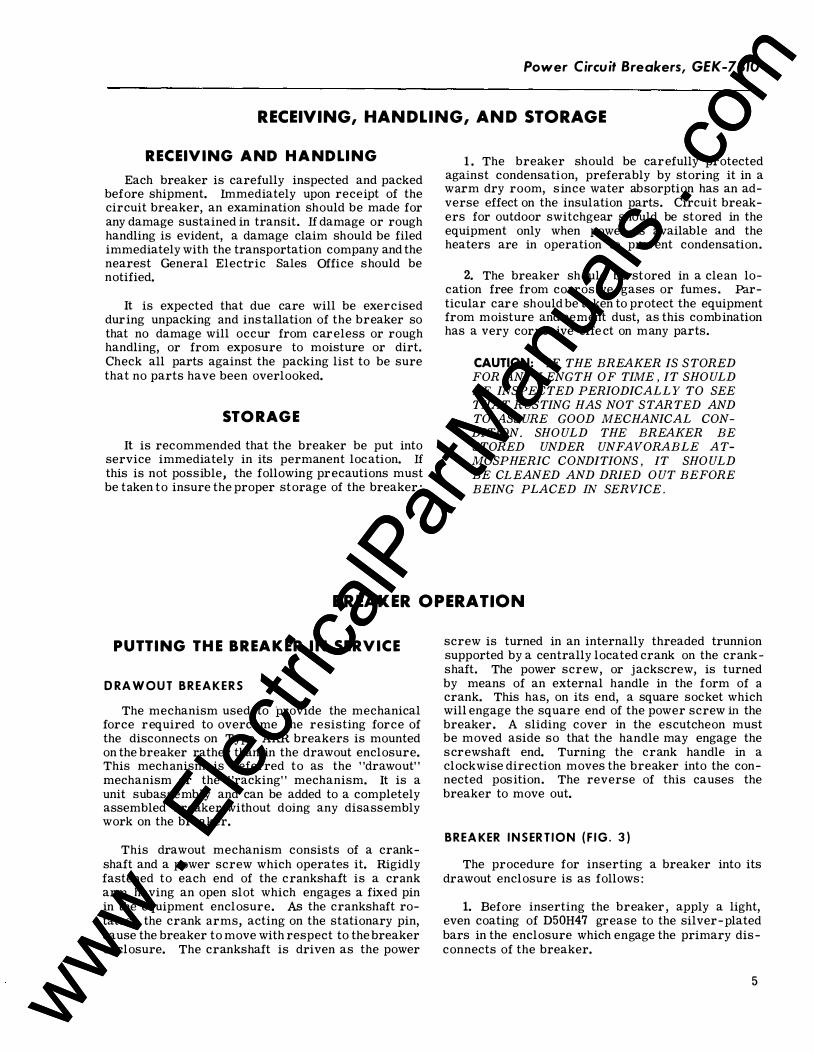
Each breaker is carefully inspected and packed before shipment. Immediately upon receipt of the circuit breaker, an examination should be made for any damage sustained in transit. lf damage or rough handling is evident, a damage claim should be filed immediately with the transportation company and the nearest General Electric Sales Office should be notified.
It is expected that due care will be exercised during unpacking and installation of the breaker so that no damage will occur from careless or rough handling, or from exposure to moisture or dirt. Check all parts against the packing list to be sure that no parts have been overlooked.
STORAGE It is recommended that the breaker be put into
service immediately in its permanent location. lf this is not possible, the following precautions must be taken to insure the proper storage of the breaker:
1 . The breaker should be carefully protected against condensation, preferably by storing it in a warm dry room, s ince water absorption has an adverse effect on the insulation parts. Circuit breakers for outdoor switchgear should be stored in the equipment only when power is available and the heaters are in operation to prevent condensation.
2. The breaker should be stored in a clean location free from corrosive gases or fumes. Particular care should be taken to protect the equipment from moisture and cement dust, as this combination has a very corrosive effe ct on many parts.
CAUTION: IF THE BREAKER IS STORED FOR ANY LENGTH OF TIME, IT SHOULD BE INSPECTED PERIODICALLY TO SEE THAT RUSTING HAS NOT STARTED AND TO ASSURE GOOD MECHANICAL CONDITION. SHOULD THE BREAKER BE STORED UNDER UNFAVORABLE ATMOSPHERIC CONDITIONS, IT SHOULD BE CLEANED AND DRIED OUT BEFORE BEING PLACED IN SERVICE.
BREAKER OPERATION
PUTTING THE BREAKER IN SERVICE
ORA W O U T BREAKERS
The mechanism used to provide the mechanical force required to overcome the resisting force of the disconnects on Type AKR breakers is mounted on the breaker rather than in the drawout enclosure. This mechanism is referred to as the "drawout" mechanism or the "racking" mechanism. It is a unit subassembly and can be added to a completely assembled breaker without doing any disassembly work on the breaker.
This drawout mechanism consists of a crankshaft and a power screw which operates it. Rigidly fastened to each end of the crankshaft is a crank arm having an open slot which engages a fixed pin in the equipment enclosure. As the crankshaft rotates, the crank arms, acting on the stationary pin, cause the breaker to move with respect to the breaker enclosure. The crankshaft is driven as the power
screw is turned in an internally threaded trunnion supported by a centrally located crank on the crankshaft. The power screw, or jackscrew, is turned by means of an external handle in the form of a crank. This has, on its end, a square socket which will engage the square end of the power screw in the breaker. A sliding cover in the escutcheon must be moved aside so that the handle may engage the screwshaft end. Turning the crank handle in a clockwise direction moves the breaker into the connected position. The reverse of this causes the breaker to move out.
BREAKER I N S ERT ION ( F I G . 3 )
The procedure for inserting a breaker into its drawout enclosure is as follows:
1. Before inserting the breaker , apply a light, even coating of D50H47 grease to the silver-plated bars in the enclosure which engage the primary disconnects of the breaker.
5 www . El
ectric
alPar
tMan
uals
. com
www . El
ectric
alPar
tMan
uals
. com
GEK-7310, Power Circuit Breakers
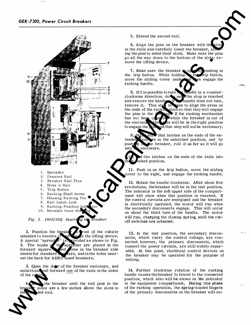
1 . S pr ea der 2. Dra wo ut R ai l 3. Br ea ker R ai l Pin s 4 . S lots in Rai l 5 . Tr i p B utton 6. Rac ki ng Shaft Arms 7. Hou sing R a c king Pin 8. R ai l Latc h Lin k 9. R a c king Po sition In dicator
1 0. Movab le Inn er Hou sing
Fig. 3. (8041582) Inserting the breaker
2. Position the breaker in front of the cubicle intended to receive it and engage the lifting device . A special "spreader" is provided as shown in Fig. 3. The hooks of the spreader are placed in the forward square-shaped holes in the breaker s ide sheets for standard breakers, and in the holes nearest the back for AKRU fused breakers.
3. Open the door of the breaker enclosure, and unlatch and pull forward one of the rails in the sides of the cubicle.
-
4. Raise the breaker until the rail pins in the breaker sides are a few inches above the slots in the extended rail.
6
5. Extend the second rail.
6. Align the pins on the breaker with the slots in the rails and carefully lower the breaker, allowing the pins to enter their slots. Make sure the pins go all the way down to the bottom of the slots; remove the lifting device.
7. Make sure the breaker is open by pushing in the trip button. While holding in the trip button, move the sliding cover aside and then engage the racking handle.
8. If it is possible to turn the handle in a counterclockwise direction, do so until the stop is reached and remove the handle. If the handle does not turn, remove it. This step is taken to align the arms on the ends of the racking shaft so that they will engage the pins in the housing. If the racking mechanism has no� been operated while the breaker is out of the enclosure, the arms will be in the right position to engage the pins and this step will not be necessary.
9. Make sure that latches on the ends of the extended rails are in the unlatched position, and by pushing on the breaker, roll it as far as it will go into the enclosure.
1 0. Put the latches on the ends of the rails into their locked position.
11 . Push in on the trip button, move the sliding cover to the right, and engage the racking handle.
12. Rotate the handle clockwise. After about five revolutions, the breaker will be in the test position. The indicator in the left upper s ide of the compartment will show when this position is reached. If the control circuits are energized and the breaker is electrically operated, the motor will run when the secondary disconnects engage. This will occur on about the third turn of the handle. The motor will run, charging the closing spring, until the cutoff switches are actuated.
13. In the test position, the secondary disconnects, which carry the control voltage, are connected; however, the primary disconnects, which connect the power circuits, are still widely separated. At this point, electrical control devices on the breaker may be operated for the purpose of testing.
14. Further clockwise rotation of the racking handle causes the breaker to travel to the connected position, which also will be shown on the indicator in the equipment compartment. During this phase of the racking operation, the spring-loaded fingers of the primary disconnects on the breaker will en-
www . El
ectric
alPar
tMan
uals
. com
www . El
ectric
alPar
tMan
uals
. com
gage the stationary bar in the equipment enclosure . The opening of these fingers against the force of the springs will cause a noticeably higher load requirement in the racking effort. This will very quickly fall off to a lesser force requirement to the end of travel, at which point a stop will be encountered. About three handle turns will be required between the peak force requirement and reaching the stop which ends the movement. Upon reaching the stop, the handle should be removed without any reversal of the handle motion. Approximately 24 turns on the handle are required for the complete racking cycle.
1 5. The first time the breaker is introduced into the enclosure, it should be completely withdrawn and the marks of the disconnect fingers on the grease on the stationary bars examined. These tracks marks should indicate no less than 1 /4- inch engagement. The maximum amount that can be attained is 9 /16- inch.
B R EAKER WITH ORA W AL
1. Trip the breaker open, hold in the trip button, and move the sliding cover in the escutcheon aside to the right.
2. Engage the racking handle and crank in a counterclockwise direction.
3. Approximately 24 turns of the handle will complete the racking-out operation and bring the breaker to the disconnected position. This will be shown on the indicator in the compartment and will be evident to the person operating the mechanism because a stop will be encountered beyond which no further movement can be made. Towards the end of the racking cycle, the "closing spring interlock" will be activated. This will cause the closing spring to discharge, but will not close the breaker.
4. To withdraw the breaker completely, open the latches on the ends of the rails, and pull the breaker out of the compartment. The breaker may now be lifted off the rails by the lifting device.
STATI O N ARY B R E A K ERS
Stationary breakers are intended for separate mounting on a framework or switchboard panel, or in an enclosure of the customer's own design and construction. They are the same breaker unit as the drawout type; however, they do not have the drawout features, namely, the racking mechanism and automatic disconnects and interlocks.
Careful consideration should be given to the selection of a location for mounting stationary break-
Power Circuit Breakers, GEK-7310
ers. They should be situated so that they can be easily reached for operation and maintenance, with enough surrounding free space so that working in the area is not troublesome. If it is possible, the location chosen should be dry and clean and not subject to extreme variations of temperature.
Mounting the breaker involves bolting the frame of the breaker to its supporting structure within the switchboard or enclosure, making power connections to the breaker studs, and making control power connections to the breaker terminal board and auxiliary switch terminals, if these are required. Four mounting holes are required for the hardware which fastens the frame to its support.
These mounting holes must all be in the same vertical plane. If they are not, strain may be imposed on the breaker structure which could adversely affect the operation of the breaker. The outline drawing which is furnished with the breaker gives information on preparing a mounting structure and a cover or door suitable for preventing access to live parts of the breaker.
Another requirement of the supporting structure for the breaker is that it be rigid enough to withstand the forces that result from high momentary and short-circuit currents to which the breaker may be subjected. Connectingbus or cable must also be supported adequately to resist these forces. Points of support for buswork or cable must be close enough to the breaker so that no appreciable strain is imposed on the breaker's studs.
Manual breakers must be located so that clearance is provided for the sweep of the handle when it is operated. This requirement will be 11 inches to the right from the center line of the breaker, or 2-1/2 inches beyond the right edge of the breaker frame.
Since each upper stud of the breaker is composed of two separate members, the connections to the stud must provide a solid connection across the two parallel stud members, as well as an external connection. All stationary breakers will be shipped with connector bars already fastened to both upper and lower studs. These bars will accommodate cable connectors or busbars. If an external bar connects across both halves of the upper studs, the connector bars may be dispensed with. In this case, the end of the connecting bus should extend in towards the breaker base no more than 5 /8-inch beyond the centerline of the fastener hole.
Control connections on stationary breakers are made to a terminal board located in the upper left front area of the breaker (front view). The terminal board may have 6, 10 or 14 points. This will be governed by the requirements of the control scheme.
7 www . El
ectric
alPar
tMan
uals
. com
www . El
ectric
alPar
tMan
uals
. com
GEK-7310, Power Circuit Breakers
If the breaker has an auxiliary switch, external connections may be made directly to the terminals of the switch.
PRE-SERVICE CH ECK
Before putting the breaker into service for the first time, it would be well to make a cursory examination and a preliminary check of the operation of the breaker. This may be carried out with the breaker on a workbench or on the extended rails of an equipment drawout compartment. The check should consist of the following:
1. Attach the drawout racking handle to the shaft on the breaker after pushing the trip button and sliding the cover aside. Turn the handle clockwise until it stops. This will deactivate the various interlocks which otherwise would keep the breaker from closing.
NOTE: Remember, later, that this mechanism must be set back to its original position before the breaker can be inserted in the equipment.
2 . Remove the arc quencher from each pole and examine it for the possibility of broken or missil;lg parts. Do not replace the arc quenchers until after the preliminary examination is completed.
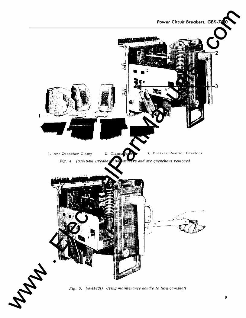
3. Charge the closing spring. If the breaker is manually operated, turn the handle counterclockwise a� far as it will go (140 degrees), then reverse the motion and return it to the vertical position. If the breaker is electrically operated, use the maintena_;nce handle, Fig. 5, to turn the camshaft which charges the closing spring.
NOTE: It probably will be necessary to align the triangular socket in the handle to make it go on the end of the shaft.
4. Close the breaker. The manual breaker is closed by pushing the CLOSE button in the escutcheon. The "quick-close" electrical breaker may be closed by pulling forward on the armature of the closing solenoid which is located beneath the mechanism and may be reached through the large rectangular opening in the lower end of the escutcheon. This may be done safely since none of the parts that move in closing are in this area. (See Fig. 6A.)
Observe the difference between the position of the stationary contacts when the breaker is opened and when it is closed. The main contacts should
8
move in ("wipe") at least 1 /16 inch. If they do not seem to do so, and careful measurement confirms this, refer to the section of these instructions entitled ''CONTACT MAINTENANCE.''
5. Make sure that all the devices used for tripping the breaker open are operable. Manually activate these with the breaker closed to establish this. Devices in this category are the manual trip, the overload devices, the shunt trip, and the undervoltage device.
6. If the breaker is a drawout breaker, check the operation of the interlock devices. Make sure that lifting interlock pin (3), Fig. 4, will trip the breaker and that the sliding cover (1 ), Fig. 8 cannot be opened if the breaker is closed. Check that the closing spring will discharge automatically if it is charged, and the drawout racking handle is cranked as far as it will go in the counterclockwise direction.
7. Replace the arc quenchers, clamping them securely.
8. The electrical operation of electrical breakers should be checked when control power is available, with the breaker in the "test" position in the drawout equipment compartment.
OPERATING THE BREAKER A breaker may be equipped to operate either
manually or electrically. Both types of operation result in the same fast- closing movement as far as the contact action is concerned. The variation is in the way energy is stored in the closing spring, and how it is released.
M A N U AL CLOSI N G
Manually operated AKR breakers are constructed with front-mounted handles. Handle operation resets the mechanism and fully charges the closing spring. A complete charge is accomplished in either cranking the handle through one cycle (135-degree swing) or three cycles (50-degree swing). The CLOSE button, mounted on the escutcheon, is used to close the breaker contacts and the TRIP button to open them.
If equipped with a closing solenoid, a manual breaker may be closed remotely by a control switch or relay . Before this can be done , however, the
www . El
ectric
alPar
tMan
uals
. com
www . El
ectric
alPar
tMan
uals
. com
Power Circuit Breakers, GEK-7310
l. Ar c Qu en ch er C lam p 2. C lam p Scr ew 3, Br ea ker P o s ition Int er lo ck
Fig. 4. (8041 848) Breaker with barriers and arc quenchers rem oved
Fig. 5. (80418 31 ) Using m aintenance handle to turn camshaft
9 www . El
ectric
alPar
tMan
uals
. com
www . El
ectric
alPar
tMan
uals
. com
GEK-7310, Power Circuit Breakers
closing spring has to be charged by hand. The closing solenoid is an optional accessory and is not supplied unless specified in the breaker order. 7----------::-:�::
ELECTR ICAL CLOSI N G
Applying control power immediately energizes the closing motor on electrical breakers. Cutoff of the motor circuit does not occur until after the spring is completely charged and over center. The spring is mechanically held from discharging until the closing circuit activates a solenoid which releases the holding latch.
A push-button closing switch may be provided on electrical breakers. This feature, however, is provided only if specified in the breaker order. If supplied, it is located in the right side of the escutcheon.
When in service, all electrical breakers are closed either by energizing the closing circuit remotely, or at the breaker location by operation of the push button switch in the escutcheon (if the breaker is so equipped) .
OPENING THE BREAKER
A closed breaker will open (trip) whenever the trip latch (1 1), Fig. 12, is moved off the roller on the secondary latch (14). A number of trip paddles are mounted on the trip shaft, one for each tripping device.
INTERLOCKS Some interlock devices are required by Industry
Standards and Certi�ying Authorities; others are optional and intended only for special applications. The standard interlock devices described in the following paragraphs are used only on drawout breakers. Stationary breakers have no required interlocks .
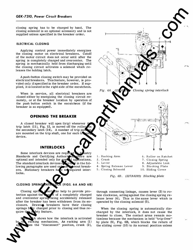
CLOS I N G SPR ING I NT E R LOCK ( F I G S. 6 A A N D 68)
Closing spring interlocks help to provide protection against the hazard of a completely charged and overcenter spring being accidentally released after the breaker has been withdrawn from its enclosure. Drawout breakers have their closing springs fully charged prior to closing and thus require this safety feature.
Figure 6A shows how the interlock is activated by the racking mechanism. As racking arm (1) approaches the "disconnect" position, crank (2),
10
8 3 4 5
Fig. 6A . (227A8290) Closing spring interlock
1 . Rac king Arm 2. C ran k 3 . Le··.rer 4. S pr ing R elea s e Lev er 5 . C lo sing So lenoi d
6 . R o ller on R a tc h et 7. C lo si ng Spring 8. A djus tab le Lin k 9. B lo c king P la te
1 0. S li di ng Cov er
Fig. 6B. (227A8289) Blocking Plate
through connecting linkage, causes lever (3) to rotate clockwise, acting against the closing spring release lever (4). This is the same lever which is operated by the closing solenoid (5 ).
When the closing spring is automatically discharged by the interlock, it does not cause the breaker to close. The contact arms remain motionless because the mechanism is held "trip-free" by plate (9 ), Fig. 6B, which blocks the return of the sliding cover (10) to its normal position unless
www . El
ectric
alPar
tMan
uals
. com
www . El
ectric
alPar
tMan
uals
. com
the breaker is in the "test" position or the "connected" position. This limits motion to those parts within the mechanism frame, which are relatively inaccessible, and minimizes the possibility of an accident.
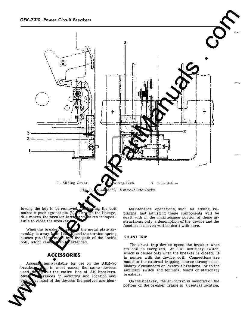
RACK I N G M ECHA NIS M INTER LOCKS
( FIG . 8 )
A drawout breaker connected to a power circuit must not be allowed to move unless the breaker's contacts are open. This requirement is met by automatically locking closed the sliding cover in the escutcheon when the breaker is closed.
Unless this cover is moved, the drawout racking handle cannot be used. Locking is accomplished by link (2 ) , Fig. 8 which moves down into a notch in the cover in response to the main shaft being in the closed position.
Another aspect of the interlock arrangement is that the opening movement of the sliding cover cams the manual trip button into the tripped position, keeping the breaker "trip-free", so a closing cycle of the mechanism will not cause any closing movement of the contacts. This condition will prevail as long as the drawout handle is engaged.
Another interlock feature is the breaker position inter lock. This makes the breaker "trip-free" while
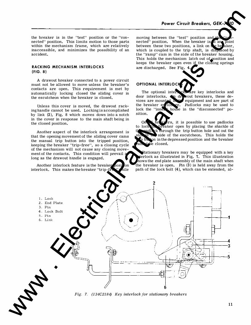
l . Lo c k 2. En d P lat e 3 . Pin 4. Lo ck Bo lt 50 Pin 6. Link
Power Circuit Breakers, GEK-7310
moving between the "test" position and the "connected" position. When the breaker is at any point between these two positions, a link on the breaker , which is coupled to the trip shaft, is displaced by the "ramp" cam in the side of the breaker housing. This holds the mechanism latch out of position and keeps the breaker open even if the closing springs are discharged. See Fig. 4.
OPTIONAL I NTERLOCKS
The optional interlocks are key interlocks and door interlocks. On drawout breakers, these devices are mounted in the equipment and are part of the breaker enclosure. Padlocks may be used to lock the "inner " house in the "disconnected" position.
On all breakers, it is possible to use padlocks to lock the breaker open by placing the shackle of the padlock through the trip button hole and out the slot in the side of the escutcheon. This holds the trip button in the depressed position and the breaker cannot be closed.
Stationary breakers may be equipped with a key interlock as illustrated in Fig. 7. This illustration shows the end plate assembly of the main shaft when the breaker is open. Pin (3) is held away from the path of the lock bolt (4), which can be extended, al-
6
Fig. 7. {1 34C21 84) Key interlock for stationary breakers
1 1 www . El
ectric
alPar
tMan
uals
. com
www . El
ectric
alPar
tMan
uals
. com
GEK-7310, Power Circuit Breakers
! '
('''-- __ 1y\\l \ �; ---+t' . :
�(�� r-·· ' '
3
rt----1---f-- -
iL: - :,,......__::���.:.:U-.-t.flt=::=-:..::
!i-r--1 ! ' i! :
' I ����d�����-----2 _..op.,,.. 3------------���1 2 ----------------��
- -·
1 . S liding Cov e r 2 . Lo c ki ng Lin k 3 . Tr ip Bu tton
Fig. 8. (1 34C2179) Dr;awout interlocks
lowing the key to be removed. Extending the bolt makes it push against pin (5 ). Through the linkage, this moves the breaker latch, and makes it impossible to close the breaker.
When the breaker is closed, the metal plate assembly is away from link (6) and the torsion spring causes pin (3) to move into the path of the lock's bolt, which cannot then be extended.
ACCESSORIES Accessories available for use on the AKR-50
breakers are, in most cases, the same devices used throughout the entire line of AK breakers. Minor differences in mounting and location may exist, but most of the devices themselves are identical.
12
Maintenance operations, such as adding, replacing, and adjusting these components will be dealt with in the maintenance portion of these instructions; only a description of the device and the function it serves will be dealt with here.
S H U NT T R I P
The shunt trip device opens the breaker when its coil is energized. An "A" auxiliary switch, which is closed only when the breaker is closed, is in series with the device coil. Connections are made to the external tripping source through secondary disconnects on drawout breakers, or to the auxiliary switch and terminal board on stationary breakers.
On the breaker , the shunt trip is mounted on the bottom of the breaker frame in a central location.
www . El
ectric
alPar
tMan
uals
. com
www . El
ectric
alPar
tMan
uals
. com
U N D ERVOLTAGE D EVICE
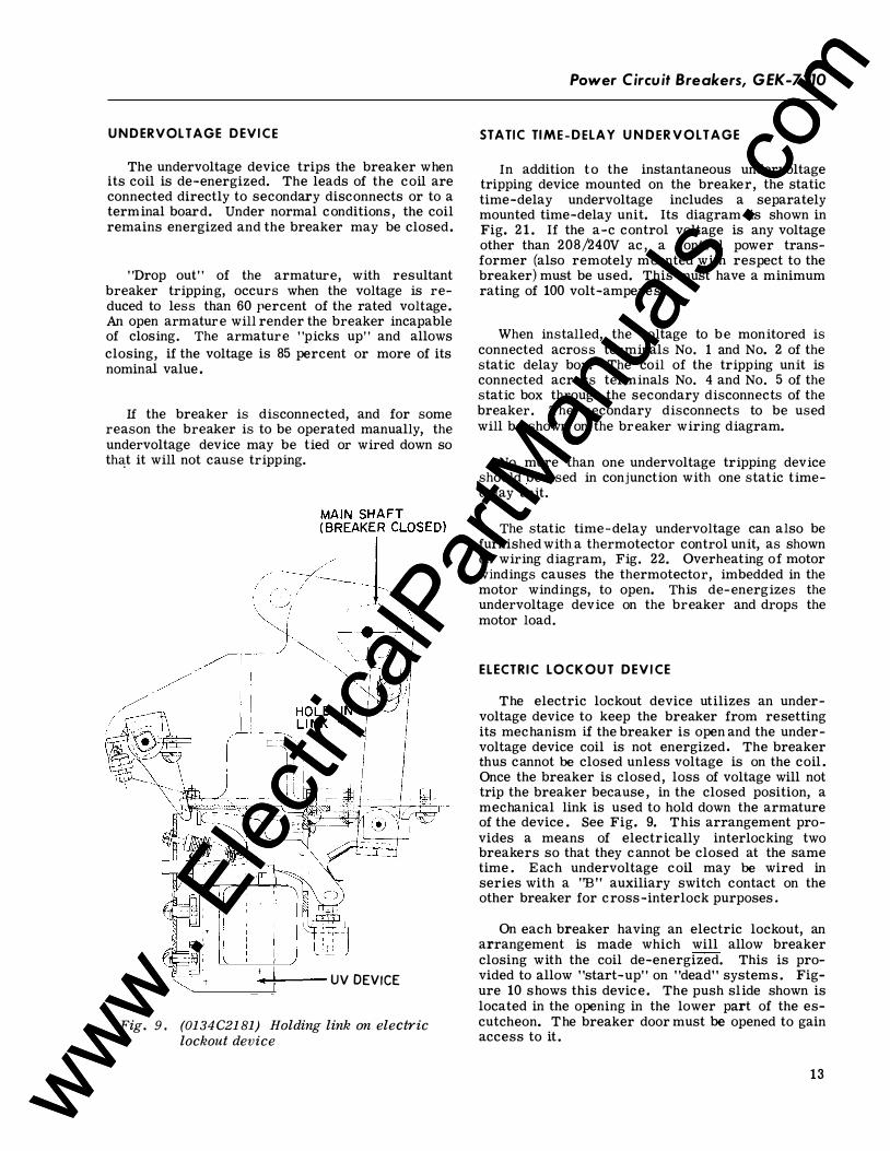
The undervoltage device trips the breaker when its coil is de-energized. The leads of the coil are connected directly to secondary disconnects or to a terminal board. Under normal conditions , the coil remains energized and the breaker may be closed.
"Drop out" of the armature, with resultant breaker tripping, occurs when the voltage is reduced to less than 60 percent of the rated voltage. An open armature will render the breaker incapable of closing. The armature "picks up" and allows closing, if the voltage is 85 percent or more of its nominal value .
If the breaker is disconnected, and for some reason the breaker is to be operated manually, the undervoltage device may be tied or wired down so th<�:t it will not cause tripping.
.-.JL...--- UV DEVICE
Fig. 9. (0134C2181) Holding link on electric lockout device
Power Circuit Breakers, GEK-7310
STATIC TI ME-DELAY U N DER V O LTAGE
In addition to the instantaneous undervoltage tripping device mounted on the breaker, the static time-delay undervoltage includes a separately mounted time-delay unit. Its diagram is shown in Fig. 2 1 . If the a-c control voltage is any voltage other than 208/240V ac , a control power transformer (also remotely mounted with respect to the breaker) must be used. This must have a minimum rating of 100 volt-amperes.
When installed, the voltage to be monitored is connected across terminals No. 1 and No. 2 of the static delay box. The coil of the tripping unit is connected across terminals No. 4 and No. 5 of the static box through the secondary disconnects of the breaker. The secondary disconnects to be used will be shown on the breaker wiring diagram.
No more than one undervoltage tripping device should be used in conjunction with one static timedelay unit.
The static time-delay undervoltage can also be furnished with a thermotector control unit, as shown on wiring diagram, Fig. 22. Overheating of motor windings causes the thermotector, imbedded in the motor windings, to open. This de-energizes the undervoltage device on the breaker and drops the motor load.
ELECTRIC LOCK OUT D EVICE
The electric lockout device utilizes an undervoltage device to keep the breaker from resetting its mechanism if the breaker is open and the undervoltage device coil is not energized. The breaker thus cannot be closed unless voltage is on the coil . Once the breaker is closed, loss of voltage will not trip the breaker because , in the closed position, a mechanical link is used to hold down the armature of the device . See Fig. 9. This arrangement provides a means of electrically interlocking two breakers so that they cannot be closed at the same time . Each undervoltage coil may be wired in series with a "B" auxiliary switch contact on the other breaker for cross-interlock purposes.
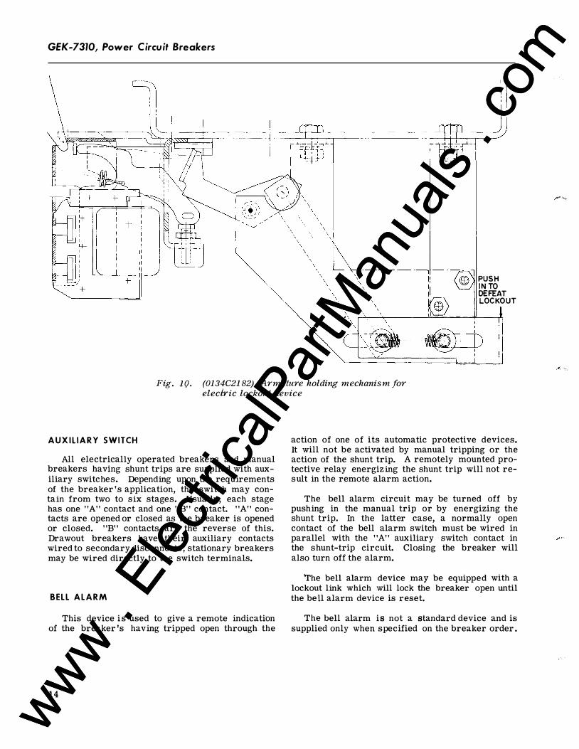
On each breaker having an electric lockout, an arrangement is made which will allow breaker closing with the coil de-energized. This is provided to allow "start-up" on "dead" systems . Figure 10 shows this device. The push slide shown is located in the opening in the lower part of the escutcheon. The breaker door must be opened to gain access to it .
13 www . El
ectric
alPar
tMan
uals
. com
www . El
ectric
alPar
tMan
uals
. com
GEK-7310, Power Circuit Breakers
---- -i I
___ j
PUSH INTO DEFEAT LOCKOUT
Fig. lQ. (0134C2182) Ar mature holding mechanism for electric lockout device
A U X I L I A R Y SWITCH
All electrically operated breakers and manual breakers having shunt trips are supplied with auxiliary switches. Depending upon the requirements of the breaker's application, the switch may contain from two to six stages. Usually, each stage has one "A" contact and one "B" contact. "A" contacts are opened or closed as the breaker is opened or closed. "B" contacts are the reverse of this. Drawout breakers have their auxiliary contacts wired to secondary disconnects; stationary breakers may be wired directly to the switch terminals.
BELL A L A R M
This device is used to give a remote indication of the breaker's having tripped open through the
14
action of one of its automatic protective devices. It will not be activated by manual tripping or the action of the shunt trip. A remotely mounted protective relay energizing the shunt trip will not result in the remote alarm action.
The bell alarm circuit may be turned off by pushing in the manual trip or by energizing the shunt trip. In the latter case, a normally open contact of the bell alarm switch must be wired in parallel with the "A" auxiliary switch contact in the shunt-trip circuit. Closing the breaker will also turn off the alarm.
The bell alarm device may be equipped with a lockout link which will lock the breaker open until the bell alarm device is reset.
The bell alarm is not a standard device and is supplied only when specified on the breaker order.
www . El
ectric
alPar
tMan
uals
. com
www . El
ectric
alPar
tMan
uals
. com
Power Circuit Breakers, GEK-7310
BREAKER MAINTENANCE
SAFETY PRECAUTIONS WARNING: BEFORE INSPECTING OR BEGINNING ANY MAINTENANCE WORK ON THE BREAKER, IT MUST BE DISCONNECTED FROM ALL VOLTAGE SOURCES,BOTH POWER AND CONTROL, AND THE BREAKER MUST BE IN THE "OPEN" POSITION. ALSO, BEFORE WORK IS DONE ON THE BREAKER, THE CLOSING SPRING IS TO BE MECHANICALLY DISCONNECTED FROM THE CAMSHAFT OF THE MECHANISM. WITH THE SPRING DISCONNECTED, THE BREAKER MAY BE CLOSED SLOWLY, USING THE MAINTENANCE HANDLE AS SHOWN IN FIG. 5.
GENERAL
Breakers should be cared for through the implementation of a systematic maintenance program. A periodic inspection routine is recommended. How frequently an inspection is made of an individual breaker will depend on the circumstances of its use. It would be well to inspect any breaker at least once a year. If it is frequently operated, or installed in an area of high humidity or a dusty, dirty atmosphere, the frequency of maintenance inspections should be increased. Under extremely bad conditions, inspections might be monthly.
A maintenance inspection should include an overall visual check and the observation of a few closing and opening operations. If the breaker is electrically operated, at least one electrical operating cycle should be observed. A close inspection should be made of contacts and the inner surfaces of the arc quencher side plates and inner components. Contact wipe should be checked as described in the maintenance section dealing with contacts.
If dirt, grease, or any other foreign material is found on any parts of the breaker, it should be removed by a thorough and careful cleaning. Insulating surfaces should be checked for any conditions that could cause a loss of insulating properties.
If a breaker has interrupted a short circuit, its contacts should be inspected.
It is good policy, if a number of breakers are included in an installation, to have one or more spare breakers to install in the place of breakers requiring maintenance work. In such cases, a rotating program, providing for a periodic withdrawal from
service of each breaker in turn for inspection and maintenance, is an excellent means of establishing a high level of service reliability. Maintaining a reasonable stock of recommended spare parts will be a good means of ensuring that maintenance work will be done quickly.
Maintenance work will, in most cases, consist of cleaning and replacement of worn or damaged breaker components. Most of the following instructions will comprise descriptions of replacement operations and any adjustments that may be required after new parts are installed. They will be equally useful for adding accessories to breakers not originally equipped with them.
NOTE: Breakers withdrawn from equipment must have their drawout mechanism cranked to the "connected" position to operate normally. See Step 1 of "PreService Check" instructions.
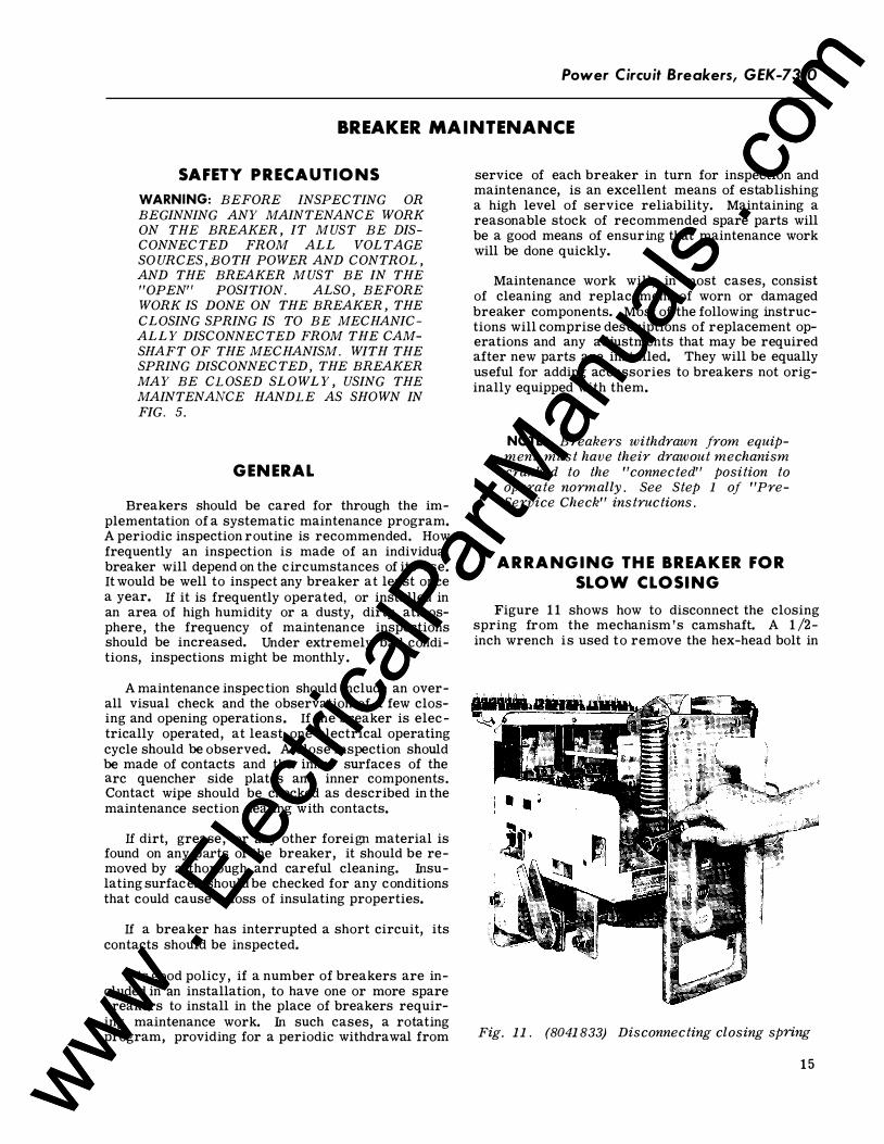
ARRANGING THE BREAKER FOR SLOW CLOSING
Figure 11 shows how to disconnect the closing spring from the mechanism's camshaft. A 1/2-inch wrench is used to remove the hex-head bolt in
Fig. 11. (8041833) Disconnecting closing spring
1 5 www . El
ectric
alPar
tMan
uals
. com
www . El
ectric
alPar
tMan
uals
. com
GEK-7310, Power Circuit Breakers
the bottom of the spring assembly. This part of the operation must be done only when the closing spring has been discharged and is at its shortest condition of extension. After the bolt has been removed, the ratcheting maintenance handle may be used to turn the camshaft, closing the breaker slowly. The breaker should be operated only to the point where the roller on the ratchet stops against the prop link. (See Fig. 6A. ) At this point, the manual close button must be pushed, or the armature of the closing solenoid, must be pulled, to move the prop away. When this is done, the slow closing action may be continued.
Closing the breaker slowly, while observing the action of the mechanism and contacts, is a good way of judging the correctness of mechanical and contact relationships. Some of the maintenance procedures described later will involve operating the breaker in this manner .
LUBRICATION In general, the circuit breaker requires mod
erate lubrication. Mechanical bearing points and sliding surfaces should be lubricated at the regular:, inspection periods with a thin film of GE lubricant D50H15. Sliding silver-plated contact surfaces should be lubricated with GE lubricant D50H47 .
4 5 6 7
Hardened grease and dirt should be removed from latch and bearing surfaces by using kerosene.
CAUTION: ALL EXCESS LUBRICANT SHOULD BE REMOVED TO AVOID ANY ACCUMULATION OF DIRT OR DUST.
NOTE: The use of cotton waste to wipe bearing surfaces should be avoided, as the cotton rave lings may become entangled under the bearing surfaces and destroy the surface of the bearing.
On drawout breakers, the contact surface of the disconnect studs should be greased with GE Grease Specification D50H47.
REPLACEMENT AND ADJUSTMENT OF COMPONENTS AND ACCESSORIES
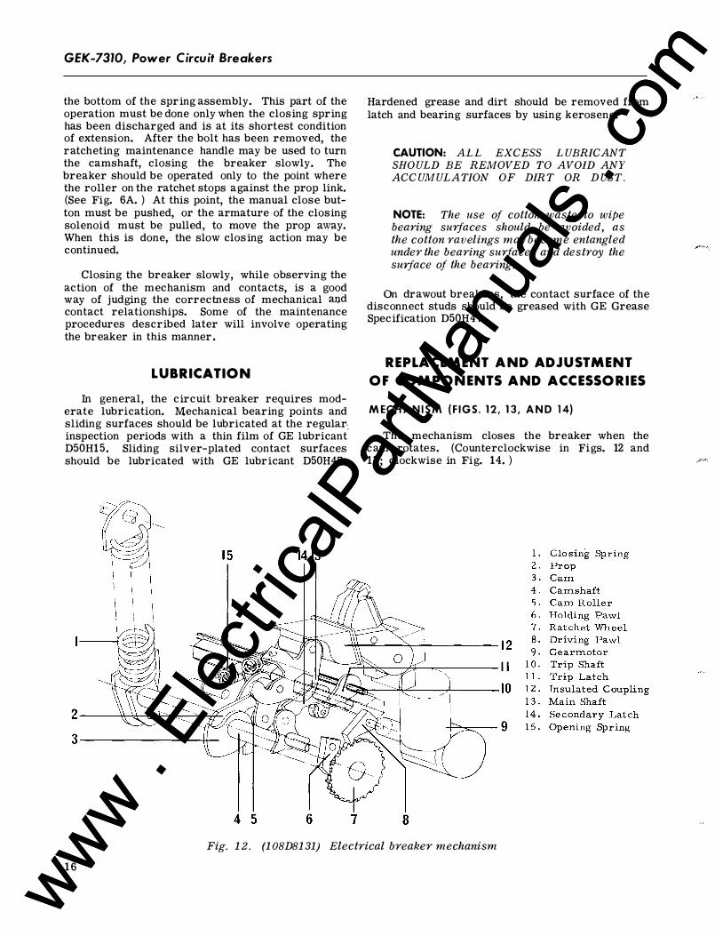
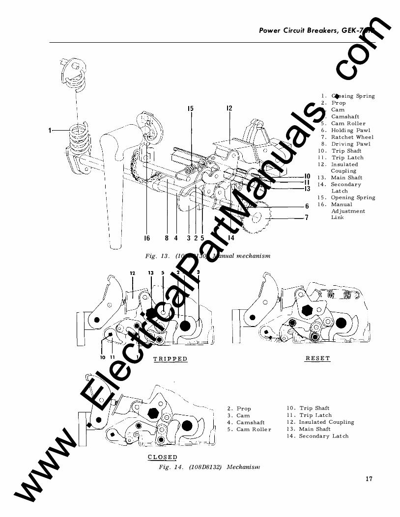
M ECH A N I S M (F IGS. 1 2, 1 3, A N D 14)
The mechanism closes the breaker when the cam rotates. (Counterclockwise in Figs. 12 and 13; clockwise in Fig. 14. )
8 Fig. 12. (108D8131) Electrical breaker mechanism
16
www . El
ectric
alPar
tMan
uals
. com
www . El
ectric
alPar
tMan
uals
. com
Power Circuit Breakers, GEK-7310
~ I l. C lo s ing S pr ing
2 . Pr o p 12 3 . Cam
4. Camshaf t 5 . Cam R o ller
1 6 . Ho lding Paw l 7. Ra tch et Wh eel 8. Dr iving Paw l
l 0 . Tri p Shaf t l l. Tri p La tch 1 2 . In su la ted
10 C ou pli ng
1 3 . Main Shaf t II 14. S econ dar y 13 La tch 1 5 . Opening S pring
6 16 . Manua l Adjus tm en t
7 Lin k
16 8 4 3 2 5 14
Fig. 13. {108D8130) Manual mechanism
""---=· " �" n\ \
10 11 14 TRIPPED RESET
2 . Pro p l 0 . Tri p Shaf t
3 . Cam l l. Tri p La tch
4 . Camshaf t 1 2 . Insu la ted C ou pling
5 . Cam R o ller 1 3 . Main Shaf t 14 . S ec on dar y La tch
CLOSED Fig. 14. (108D8132) Mechanism
17
www . El
ectric
alPar
tMan
uals
. com
www . El
ectric
alPar
tMan
uals
. com
GEK-7310, Power Circuit Breakers
Fixed centers are shown shaded in Fig. 14.
The prop is free to rotate on the cam shaft. It holds the cam roller in place after the cam roller has been raised by the cam. A light tension spring holds the prop in the position shown, but allows it to move out of the way of the cam roller.
On electrical breakers, the eccentric output shaft of the gearmotor turns the camshaft by causing the driving pawl to reciprocate, advancing the ratchet wheel.
Fast cam action occurs when the closing spring goes over center, unless it is held by a prop link (not shown) acting against a stop on the ratchet wheel. Figures 12 and 13 show the closing spring in a position just over center.
When the manual breaker handle is raised counterclockwise, a strong torsion spring rotates the
driving pawl assembly until it engages a notch on the camshaft. Returning the handle to its normal position pulls the chain on the sprocket segment, rotating the camshaft.
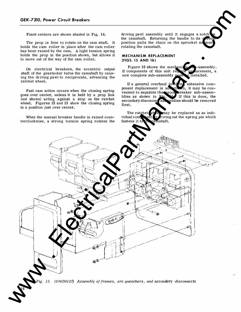
M ECH A N I S M R E P L ACE M EN T (F IGS. 15 A N D 1 6 )
Figure 16 shows the mechanism sub-assembly . If components of this unit require replacement, a new complete sub-assembly must be installed.
If a general overhaul involving extensive component replacement is undertaken, it may be convenient to separate the major breaker sub-assemblies as shown in Fig. 15 . If this is done, the secondary disconnect assemblies should be removed first .
The ratchet wheel may be replaced as an individual component by driving out the spring pin which fastens it to the camshaft.
Fig. 15. (1 08D8127) Assembly of frames, arc quenchers, and secondary disconnects
18
www . El
ectric
alPar
tMan
uals
. com
www . El
ectric
alPar
tMan
uals
. com
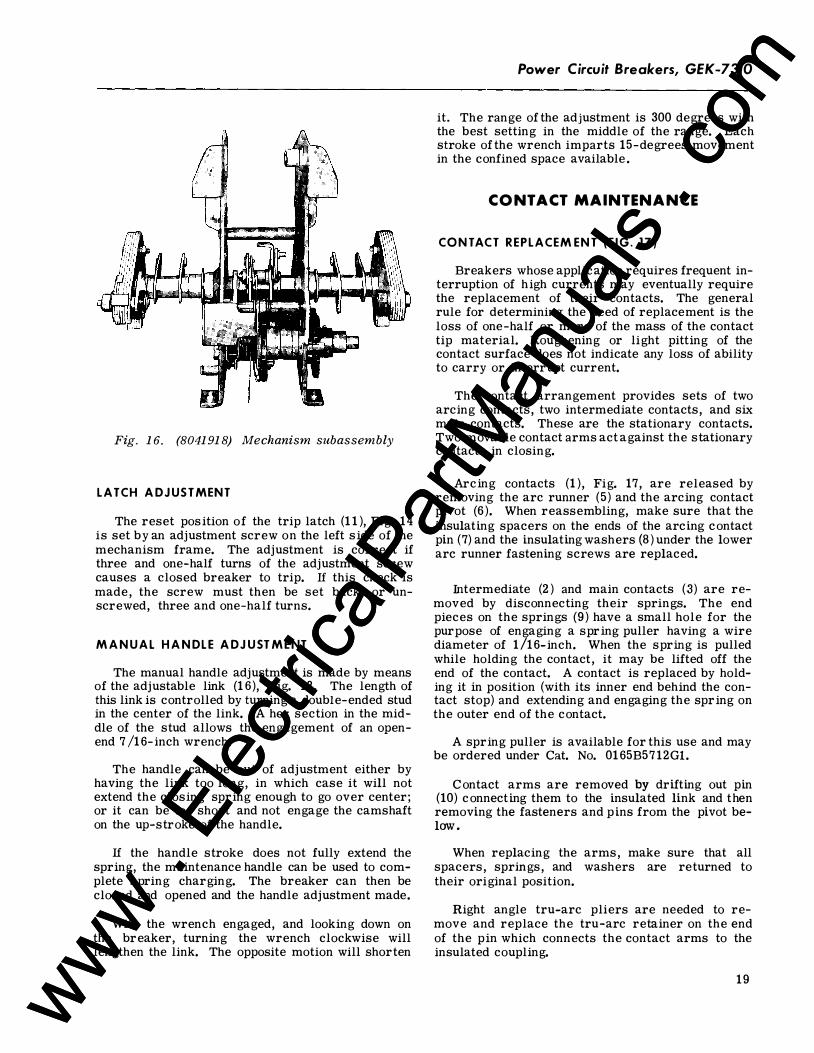
Fig. 16. (8041918) Mechanism subassembly
L ATCH A DJUSTMENT
The reset position of the trip latch (1 1 ), Fig. 14 is set by an adjustment screw on the left side of the mechanism frame. The adjustment is correct if three and one-half turns of the adjustment screw causes a closed breaker to trip. lf this check is made, the screw must then be set back, or unscrewed, three and one-half turns.
M A N U A L H A N DL E A DJUST M E NT
The manual handle adjustment is made by means of the adjustable link {16), Fig. 13. The length of this link is controlled by turning a double-ended stud in the center of the link. A hex section in the middle of the stud allows the engagement of an openend 7 /16- inch wrench.
The handle can be out of adjustment either by having the link too long, in which case it will not extend the closing spring enough to go over center; or it can be too short and not engage the camshaft on the up-stroke of the handle.
lf the handle stroke does not fully extend the spring, the maintenance handle can be used to complete spring charging. The breaker can then be closed and opened and the handle adjustment made.
With the wrench engaged, and looking down on the breaker, turning the wrench clockwise will lengthen the link. The opposite motion will shorten
Power Circuit Breakers, GEK-7310
it. The range of the adjustment is 300 degrees with the best setting in the middle of the range. Each stroke of the wrench imparts 15-degrees movement in the confined space available .
CONTACT MAINTENANCE
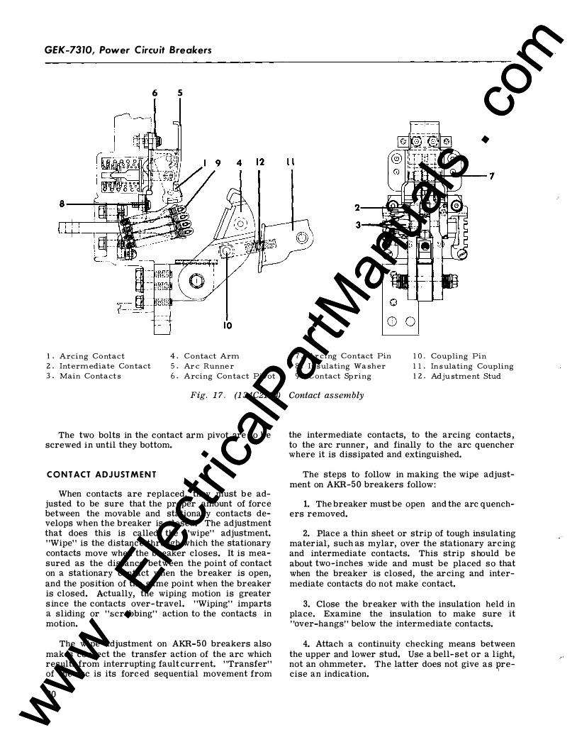
CO NTACT REPLACEM ENT ( F I G . 17)
Breakers whose application requires frequent interruption of high currents may eventually require the replacement of their contacts. The general rule for determining the need of replacement is the loss of one-half or more of the mass of the contact tip material. Roughening or light pitting of the contact surface does not indicate any loss of ability to carry or interrupt current.
The contact arrangement provides sets of two arcing contacts, two intermediate contacts, and six main contacts. These are the stationary contacts. Two movable contact arms act against the stationary contacts in closing.
Arcing contacts (1 ), Fig. 17, are released by removing the arc runner (5) and the arcing contact pivot {6 ). When reassembling, make sure that the insulating spacers on the ends of the arcing contact pin (7) and the insulating washers (8) under the lower arc runner fastening screws are replaced.
Intermediate (2 ) and main contacts (3) are removed by disconnecting their springs. The end pieces on the springs {9 ) have a small hole for the purpose of engaging a spring puller having a wire diameter of 1/16-inch. When the spring is pulled while holding the contact, it may be lifted off the end of the contact. A contact is replaced by holding it in position (with its inner end behind the contact stop) and extending and engaging the spring on the outer end of the contact.
A spring puller is available for this use and may be ordered under Cat. No. 0165B57 12Gl.
Contact arms are removed by drifting out pin (10) connecting them to the insulated link and then removing the fasteners and pins from the pivot below.
When replacing the arms, make sure that all spacers, springs, and washers are returned to their original position.
Right angle tru-arc pliers are needed to remove and replace the tru-arc retainer on the end of the pin which connects the contact arms to the insulated coupling.
19 www . El
ectric
alPar
tMan
uals
. com
www . El
ectric
alPar
tMan
uals
. com
GEK-7310, Power Circuit Breakers
1 . Arcing Contact 2 . Int erm ediat e Contact 3 . Main Contact s
6 s
4 . 5 . 6 .
C ontact Arm Ar c Runn er Arcing Contact Pivot
Fig. 17. (134C2174)
The two bolts in the contact arm pivot are to be screwed in until they bottom.
C O N T ACT ADJUST M E N T
When contacts are replaced, they must b e adjusted to be sure that the proper amount of force between the movable and stationary contacts develops when the breaker is closed. The adjustment that does this is called the "wipe" adjustment. "Wipe" is the distance through which the stationary contacts move when the breaker closes. It is measured as the distance between the point of contact on a stationary contact when the breaker is open, and the position of the same point when the breaker is closed. Actually, the wiping motion is greater since the contacts over-travel. "Wiping" imparts a sliding or "scrubbing" action to the contacts in motion.
The wipe adjustment on AKR-50 breakers also makes correct the transfer action of the arc which results from interrupting fault current. "Transfer" of the arc is its forced sequential movement from
20
7 . Ar cing C ontact Pin 1 0. Cou pling Pin 8 . Insulating Wa sh er 1 1 . In s u lating Cou pling 9 . C ontact S pring 1 2 . Adju stm ent Stud
Contact assembly
the intermediate contacts, to the arcing contacts , to the arc runner , and finally to the arc quencher where it is dissipated and extinguished.
The steps to follow in making the wipe adjustment on AKR-50 breakers follow:
1. The breaker must be open and the arc quenchers removed.
2. Place a thin sheet or strip of tough insulating material, such as mylar, over the stationary arcing and intermediate contacts. This strip should be about two-inches .wide and must be placed so that when the breaker is closed, the arcing and intermediate contacts do not make contact.
3. Close the breaker with the insulation held in place. Examine the insulation to make sure it "over-hangs" below the intermediate contacts.
4. Attach a continuity checking means between the upper and lower stud. Use a bell-set or a light, not an ohmmeter. The latter does not give as J?recise an indication.
www . El
ectric
alPar
tMan
uals
. com
www . El
ectric
alPar
tMan
uals
. com
' I
5. Facing the breaker, turn the wipe adjustment stud clockwise until it is indicated that the main contacts have �arted. A 7 /1 6-inch end wrench fits the hex section on the stud.
6. Slowly turn the stud counterclockwise until the main contacts just touch.
7. Turn the stud counterclockwise from this point 270 degrees. This will be 4 - 1 /2 times the distance from flat to flat or from point to point on the hex section of the stud.
8. Trip the breaker to avoid accidental tripping, and remove the insulating strips.
It is recommended that this adjustment be c hecked in the course of routine maintenance inspections .
COMPONENTS AND ACCESSORIES
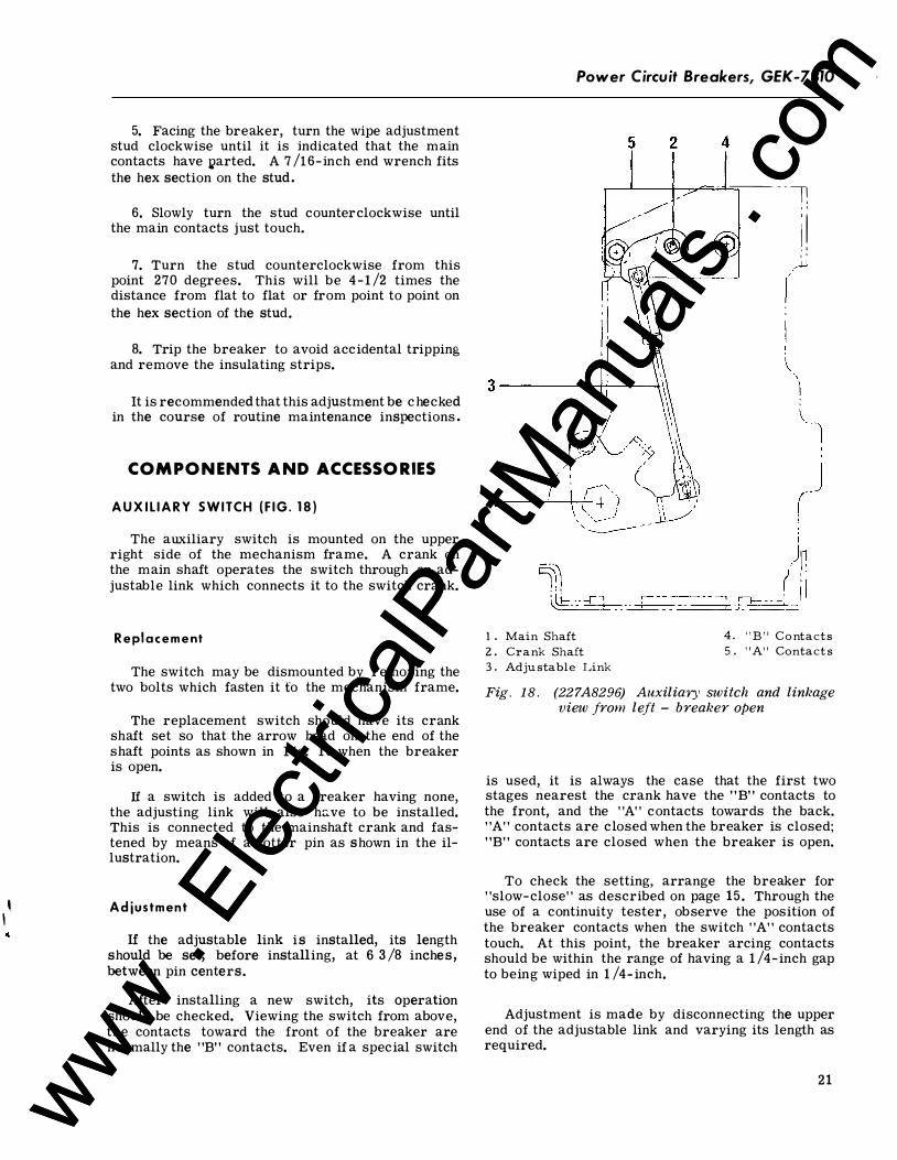
A U X I L I A R Y SWITCH ( F I G . 1 8 )
The auxiliary switch is mounted on the upper right side of the mechanism frame. A crank on the main shaft operates the switch through an adjustable link which connects it to the switch crank.
R e placement
The switch may be dismounted by removing the two bolts which fasten it to the mechanism frame.
The replacement switch should have its crank shaft set so that the arrow head on the end of the shaft points as shown in Fig. 1 8 when the breaker is open.
If a switch is added to a breaker having none, the adjusting link will also h�ve to be installed. This is connected to the mainshaft crank and fastened by means of a cotter pin as shown in the illustration.
Ad justment
If the adjustable link is installed, its length should be set, before installing, at 6 3 /8 inches , between pin centers.
After installing a new switch, its operation should be checked. Viewing the switch from above, the contacts toward the front of the breaker are normally the "B" contacts. Even if a special switch
Power Circuit Breakers, GEK-7310
5 2
1 . Main Shaf t 2 . Cran k Shaf t 3 . A dju s tab le Lin k
4
� - � � � ' '
i l · ' ' '
.....w
4. " B " C o n ta cts 5 . " A" Con ta cts
Fig . 1 8. (227A8296) Auxiliary switch and linkage view from left - breaker open
is used, it is always the case that the first two stages nearest the crank have the "B" contacts to the front, and the "A" contacts towards the back. "A" contacts are closed when the breaker is closed; "B" contacts are closed when the breaker is open.
To check the setting, arrange the breaker for "slow-close" as described on page 15 . Through the use of a continuity tester, observe the position of the breaker contacts when the switch "A" contacts touch. At this point, the breaker arcing contacts should be within the range of having a 1 /4-inch gap to being wiped in 1 /4- inch.
Adjustment is made by disconnecting the upper end of the adjustable link and varying its length as required.
21 www . El
ectric
alPar
tMan
uals
. com
www . El
ectric
alPar
tMan
uals
. com
GEK-7310, Power Circuit Breakers
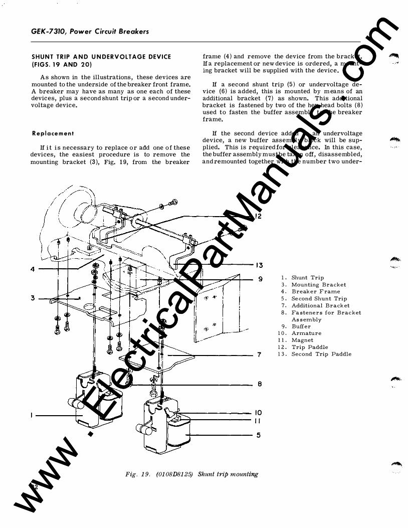
S H U N T T R I P A N D U N D E R V O LTAGE DEVICE (F IGS . 19 AND 20)
As shown in the illustrations, these devices are mounted to the underside of the breaker front frame. A breaker may have as many as one each of these devices, plus a second shunt trip or a second undervoltage device.
R e p l a ce m e n t
If i t i s necessary to replace o r add one o f these devices, the easiest procedure is to remove the mounting bracket (3 ), Fig. 1 9, from the breaker
frame (4 ) and remove the device from the bracket. If a replacement or new device is ordered, a mounting bracket will be supplied with the device .
If a second shunt trip (5 ) or undervoltage device (6) is added, this is mounted by m eans of an additional bracket (7) as shown. This additional bracket is fastened by two of the hex head bolts (8) used to fasten the buffer assembly to the breaker frame.
If the second device added is an undervoltage device, a new buffer assembly block will be supplied. This is required for clearance. In this case, the buffer assembly must be taken off, disassembled, and remounted together with the number two under-
�-------------- 1 2
3
22
----�
7
8
1 0 I I
�------------ 5
Fig. 19. (0108D8125) Shunt trip mounting
l . Shunt Trip 3 . Mounting Bracket 4. Break e r F rame 5 . Se cond Shunt Trip 7. Additional Brack et 8 . Fa stene r s for Bracket
As s embly 9. Buffer
1 0 . Armature 1 1 . Magnet 1 2 . Trip Paddle 1 3 . Second Trip Paddle
www . El
ectric
alPar
tMan
uals
. com
www . El
ectric
alPar
tMan
uals
. com
1 2 1 3 9
Power Circuit Breakers, GEK-7310
6
8 2
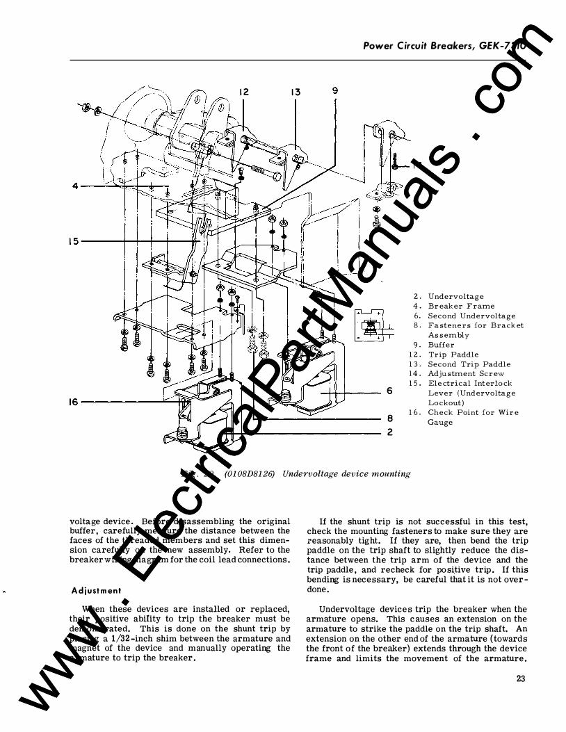
2 . Un dervo ltage 4 . Br ea ker Frame 6. Secon d Un dervo ltage 8 . Fa s tene r s for Brac ke t
As s embly 9. Buffer
1 2 . Tri p Pa ddle 1 3 . Secon d Tri p Pa ddle 14 . A dj us tmen t Scr e w 1 5 . E le c trica l In terlo c k
Lever ( Un dervo lta g e Lo c kou t)
1 6 . Che c k Poin t for Wir e Gauge
Fig. 20. (01 08D81 26) Undervoltage device mounting
voltage device . Before disassembling the original buffer, carefully measure the distance between the faces of the threaded members and set this dimension carefully on the new assembly. Refer to the breaker wiring diagram for the coil lead connections .
A d j u st m ent
When these devices are installed or replaced, their positive ability to trip the breaker must be demonstrated. This is done on the shunt trip by placing a 1/32 -inch shim between the armature and magnet of the device and manually operating the armature to trip the breaker .
If the shunt trip is not successful in this test, check the mounting fasteners to make sure they are reasonably tight. If they are, then bend the trip paddle on the trip shaft to slightly reduce the distance between the trip arm of the device and the trip paddle , and recheck for positive trip . If this bending is necessary, be careful that it is not overdone.
Undervoltage devices trip the breaker when the armature opens. This causes an extension on the armature to strike the paddle on the trip shaft. An extension on the other end of the armature (towards the front of the breaker) extends through the device frame and limits the movement of the armature .
23 www . El
ectric
alPar
tMan
uals
. com
www . El
ectric
alPar
tMan
uals
. com
GEK-7310, Power Circuit Breakers
When the armature is released, this extension stops against the top of the slot through which it protrudes. To check positive trip, the armature should be held down, the end of a 1/32-inch diameter wire should be inserted against the top of the slot, and the armature released. If this trips the breaker, the setting is correct. The place to insert the wire is shown at ( 1 6) , Fig. 20. Note that only the tip of the wire is to be inside the slot.
If the undervoltage device does not have positive tripping ability, the adjustment screw of the trip paddle assembly may be turned in increments of half turns until the check is successful.
When the undervoltage device is closed and tl1e breaker mechanism is reset, there must be clearance between the trip paddle and the device armature-.
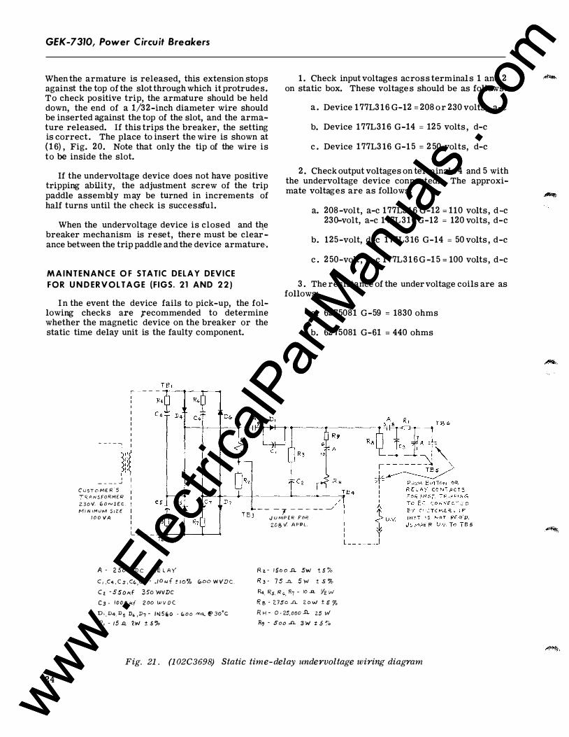
M A I N T E N A N C E O F STATIC DELAY DEVICE
FOR U N D ER V O L T A G E (F IGS. 21 AND 2 2 )
I n the event the device fails to pick-up, the following checks are ,recommended to determine whether the magnetic device on the breaker or the static time delay unit is the faulty component.
- - - - -,
�i/ I ' � _ _ _ _ j I
D,
1 . Check input voltages across terminals 1 and 2 on static box. These voltages should be as follows :
a . Device 1 77L3 16 G-12 = 208 or 230 volts, a-c
b. Device 1 77L316 G-14 = 12 5 volts , d-e
c . Device 1 77L3 16 G-1 5 = 2 50 volts, d-e
2 . Check output voltages on terminals 4 and 5 with the undervoltage device connected. The approximate voltages are as follows :
a. 208-volt, a-c 177L3 16 G-12 = 110 volts , d-e 230-volt, a-c 177L316 G-12 = 120 volts, d-e
b. 125-volt, d-e 177L316 G-14 = 50 volts , d-e
c . 2 50-volt , d-c 177L3 1 6 G -1 5 = 100 volts , d-e
3 . The resistance of the under voltage coils are as follows:
a. 6275081 G-59 = 1830 ohms
b. 62 75081 G-61 = 440 ohms
/ /
C u s T D ME R . S T O A N S FORMU< 2. 3 o v'. 1D a � s £ c . fVI J N I M LJ M S I Z E - - - -, - - - - - ._/ T B J J U MP E R FDf'.
2D 8 V: APPL .
24
1 0 0 VA R5
I L - - - - -+--+----�----4
TB 2
A - 2 50V D.c R E L A Y C , ,C4 , C 5 , C'-,C1 - .I D 1-1 f t i O'l. V,OO W VDC . C a - 55o�<F 3 5o WVDC
C3 - 1000 u.f 2 00 W V D C
D . , D4. D 5 D. ,D, - i i>J S a O - ,;, o o m«. @ 3o'c R. - 15 .ll. 2W ! S �b
R � - 1 5o o .Il.. SW t S 'o R 3 - 7 5 ..n.. S W t 5 7o R4, Rs. R o, R7 - 10 ..n. Yz W
R s - 2.7so ..n.. z o w ± s r, R H - 0 - 25,ooo .Il.. 25 \N R� · 5oo ..n.. 3 W t 5 %
Fig. 21. (102C 3698) Static time-delay undervoltage wiring diagram
www . El
ectric
alPar
tMan
uals
. com
www . El
ectric
alPar
tMan
uals
. com
A- 25J voc RELAY C,,C4,�C� C�,c7 - IO#f il"%
�00 WVDC Cr 55J -<d 350 WVPC C3 - IQOO-'If 200 WVl>C O,, D�Ds,D,,Dr !N5�0
Goo ma. (fJ 3o°C R, - ;5 .n. 'JW ! 5fo, Rz - ;soon sw t 5% R3 - 75 .n SW t 5"!. R4,Rs,R,,R7- !0""- 'kW.
R8 - 275o.s.l. 2CJW t 5 % Ril- o -25K 25W R9 - 300 ..n 3 w "t 5 7D R/(), R;I - 50 -"- <SW F- I Anp /3U55 ru�E TrP£ A&c T- lHEI\Nt> TECTOR X- 7RAN>F fl5j?30 Vf'RI - 24 V 5Ec 1!- /2 V A.c RELAY
Power Circuit Breakers, GEK-7310
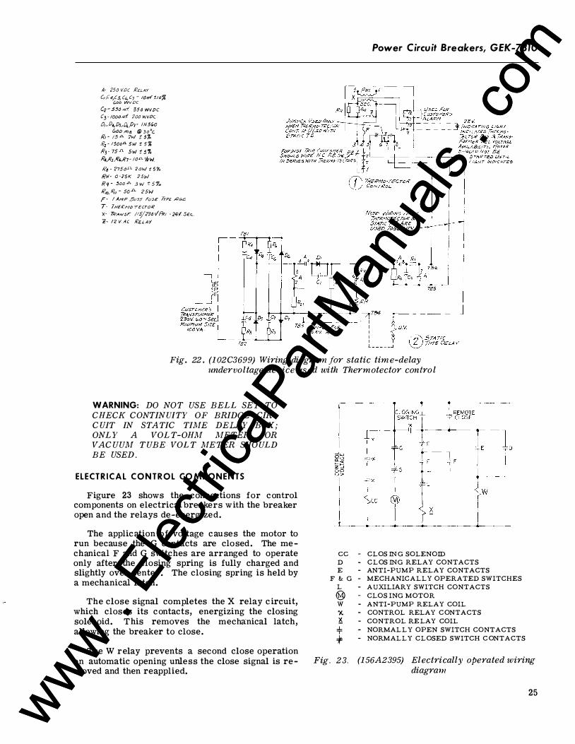
Fig. 22. (102C3699) Wiring diagram for static time-delay undervoltage device used with Thermotector contro l
WARNING: DO NOT USE BELL SET TO CHECK CONTIN UITY OF BRIDGE CIRC UIT IN STATIC TIME DELAY BOX ; ONLY A VOLT-OHM METER OR VACUUM TUBE VOLT METER SHOULD BE USED.
ELECTR ICAL C O N T R O L CO MPONENTS
Figure 23 shows the connections for control components on electrical breakers with the breaker open and the relays de-energized.
The application of voltage causes the motor to run because the G contacts are closed. The mechanical F and G switches are arranged to operate only after the closing spring is fully charged and slightly over center . The closing spring is held by a mechanical latch.
The close signal completes the X relay c ircuit, which closes its contacts, energizing the closing solenoid. This removes the mechanical latch, allowing the breaker to close.
The W relay prevents a second close operation on automatic opening unless the close signal is removed and then reapplied.
cc D E
F & G L @ w ')(. lS.
..!.. T
+ Fig . 23.
- CLOS IN G SOLENOID - CLOS ING RELAY CONTACTS - ANTI-PUMP RELAY CONTACTS - MECHANICALLY OPERATED SWITCHES - AUXILIARY SWITCH CONTACTS - CLOS ING MOTOR - ANTI-PUMP RELAY COIL - CONTROL RELAY CONTACTS - CONTROL RE LAY COIL - NORMALLY OPEN SWITCH CONTACTS - NORMALLY CLOSED SWITCH C ONTACTS
(156A2395) Electrically operated wiring diagram
25 www . El
ectric
alPar
tMan
uals
. com
www . El
ectric
alPar
tMan
uals
. com
GEK-7310, Power Circuit Breakers
R e p l a c e m e n t
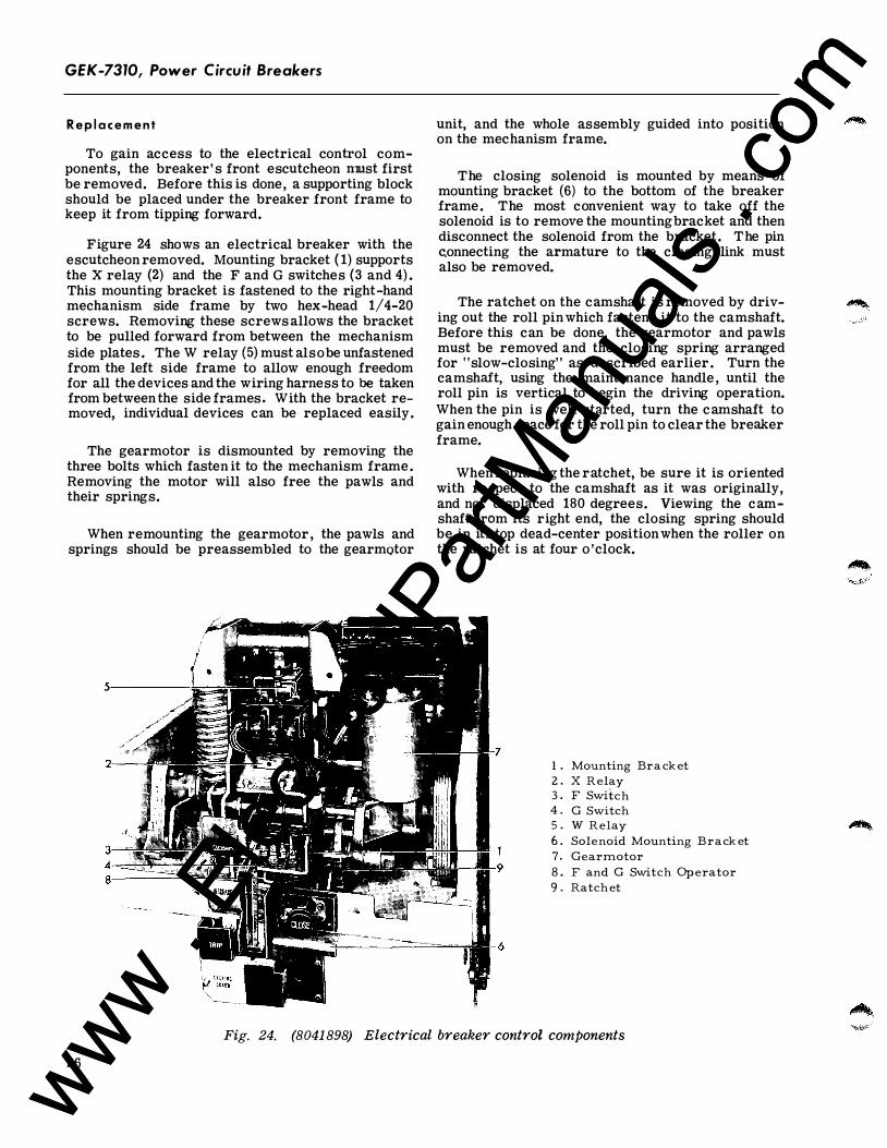
To gain access to the electrical control components, the breaker' s front escutcheon nrust first be removed. Before this is done, a supporting block should be placed under the breaker front frame to keep it from tipping forward.
Figure 24 shows an electrical breaker with the escutcheon removed. Mounting bracket ( 1) supports the X relay (2) and the F and G switches (3 and 4) . This mounting bracket is fastened to the right-hand mechanism side frame by two hex-head 1/4-20 screws. Removing these screws allows the bracket to be pulled forward from between the mechanism side plates . The W relay (5) must alsobe unfastened from the left side frame to allow enough freedom for all the devices and the wiring harness to be taken from between the side frames. With the bracket removed, individual devices can be replaced easily.
The gearmotor is dismounted by removing the three bolts which fasten it to the mechanism frame . Removing the motor will also free the pawls and their springs.
When remounting the gearmotor , the pawls and springs should be preassembled to the gearmotor
unit, and the whole assembly guided into position on the mechanism frame.
The closing solenoid is mounted by means of mounting bracket (6) to the bottom of the breaker frame. The most convenient way to take off the solenoid is to remove the mounting bracket and then disconnect the solenoid from the bracket. The pin c.onnecting the armature to the closing link must also be removed.
The ratchet on the camshaft is removed by driving out the roll pin which fastens it to the camshaft. Before this can be done, the gearmotor and pawls must be removed and the closing spring arranged for "slow-closing" as described earlier . Turn the camshaft, using the maintenance handle , until the roll pin is vertical to begin the driving operation. When the pin is well started, turn the camshaft to gain enough space for the roll pin to clear the breaker frame.
When replacing the ratchet, be sure it is oriented with re spect to the camshaft as it was originally, and not displaced 180 degrees. Viewing the camshaft from its right end, the closing spring should be in its top dead-center position when the roller on the ratchet is at four o 'clock.
1 . Mounting Bra ck et 2 . X R elay 3 . F Switch 4 . G Switch 5 . W R elay 6 . Sol enoid Mounting Brack et 7. G earmotor 8 . F and G Switch Op erator 9 . Ratch et
Fig. 24. (8041 898) Electrical breaker control components
26
www . El
ectric
alPar
tMan
uals
. com
www . El
ectric
alPar
tMan
uals
. com
A d j u s t m e n t ( F i g . 25 )
For proper electrical operation, the F and G mechanically operated switches musLoperate at the proper point in the closing cyCle . If these switches are to be replaced, measure the distance between the tip of the switch button and the bracket on which they are mounted. When the new switch is mounted, duplicate the measured dimension, then check for proper operation.
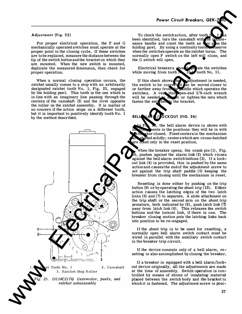
When a normal closing operation occurs, the ratchet usually comes to a stop with an arbitrarily designated ratchet tooth No. 1 , Fig. 25, engaged by the holding pawl. This tooth is the one which is in line with an imaginary line passing through the centers of the camshaft (2) and the rivet opposite the roller on the ratchet assembly. It is matter of no concern if the action stops on a different tooth, but it is important to positively identify tooth No. 1 by the method described.
11---+-��,-'F' 2:---�----���T+-
3
l . Ratchet Tooth No . l 2 . Camshaft 3 . Ratchet Stop R oller
Fig. 25 . (01 34C21 76) Gearmotor, pawls , and ratchet subassembly
Power Circuit Breakers, GEK-7310
To check the switch action, after tooth No . 1 has been identified, turn the camshaft with the maintenance handle and count the teeth as they pass the holding pawl. By using a continuity tester, observe when the switches operate as the ratchet turns. The normally open F switch on the left will close, and the G switch will open.
Electrical breakers should operate the switches while moving from tooth No . 10 to tooth No. 1 1 .
If this check shows that an adjustment is needed, the switch to be corrected can be moved closer to or farther away from the paddle which operates the switches. A very thin open-end 5/8-inch wrench will be needed to loosen or tighten the nuts which fasten the switches to the bracket.
BELL ALAR M / L O C K O UT ( F IG . 26)
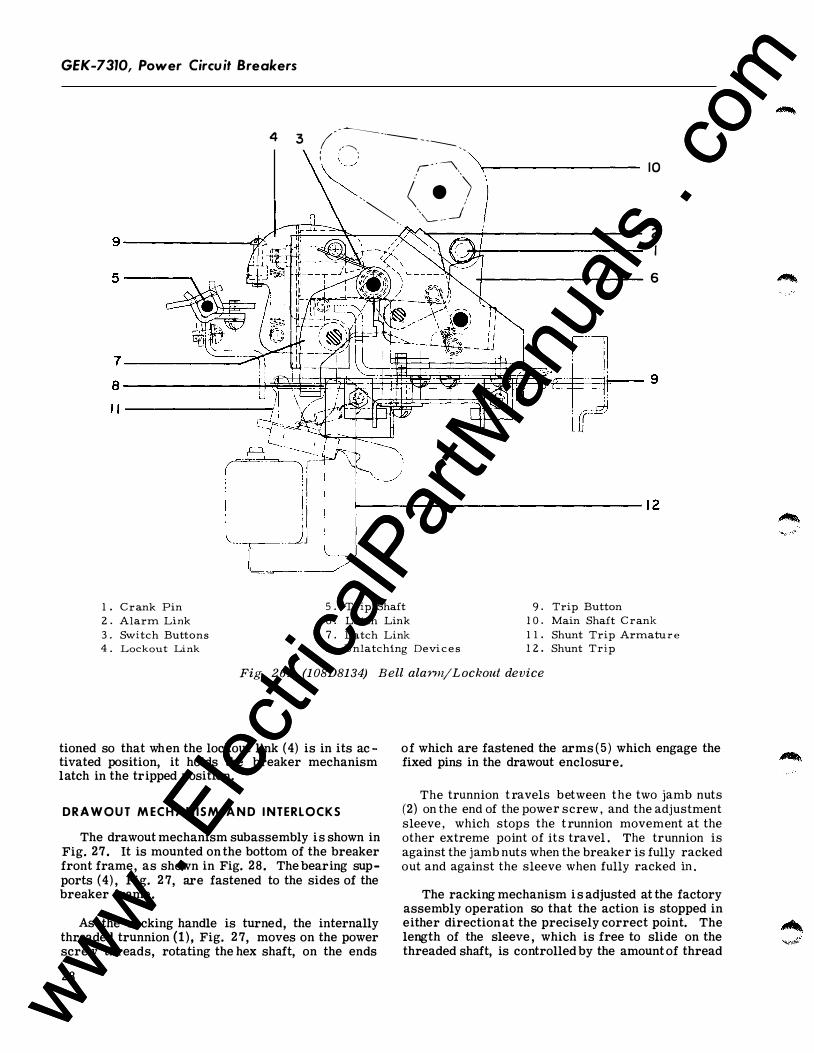
In Fig. 26 , the bell alarm device is shown with its components in the positions they will be in with the breaker closed. Fixed centers in the mechanism are shaded solidly ; centers which are cross-hatched are fixed only in the reset position.
When the breaker opens, the crank pin ( 1) , Fig. 26 , pushes against the alarm link (2) which closes against the bell alarm switch buttons (3) . If a lockout link ( 4) is provided, this is pushed by the same action and causes the end of the adjustment screw to act against the trip shaft paddle ( 5) keeping the breaker from closing until the mechanism is reset.
Resetting is done either by pushing on the trip button (9) or byoperating the shunt trip ( 12) . Either action causes the latching edges of the two latch links (6) and ( 7) to separate. A slide attachment on the trip shaft or the second arm on the shunt trip armature, both indicated by (8) , push latch link ( 7) away from latch link (6) . This releases the switch buttons and the lockout link, if there is one. The breaker closing motion puts the latching links back into position to be re-engaged.
If the shunt trip is to be used for resetting, a normally open bell alarm switch contact must be wired in parallel with the auxiliary switch contact in the -breaker trip circuit.
If the device consists only of a bell alarm, re setting is also accomplished by closing the breaker.
If a breaker is equipped with a bell alarm/lockout device originally, all the adjustments are made at the time of assembly. Switch operation is controlled by means of shims of insulating material placed between the switch body and the bracket to which it is fastened. The adjustment screw is posi-
27 www . El
ectric
alPar
tMan
uals
. com
www . El
ectric
alPar
tMan
uals
. com
GEK-7310, Power Circuit Breakers
( , -------- --- - ------------.- ------ - -4 3
: \ :
� .. (.') �-- -,\_ __ _}
10
2 I
�------------------- 6
1 . C rank Pin 2 . Alarm Link
5 . Trip Shaft 9. Trip Button 6 . Latch Link 1 0 . Main Shaft C rank
3 . Switch Buttons 7. Latch Link 1 1 . Shunt Trip Armatu r e 4 . Lockout Link 8 . Unlatching Devi c e s 1 2 . Shunt Trip
Fig_ 2 6. (108D8134) Bell alarm/Lockout device
tioned so that when the lockout link ( 4) is in its ac tivated position, it holds the breaker mechanism latch in the tripped position.
DRAWOUT M ECH A N ISM A N D I NTERLOCKS
The drawout mechanism subassembly is shown in Fig. 27. It is mounted on the bottom of the breaker front frame, as shown in Fig. 28 . The bearing supports (4) , Fig. 2 7, are fastened to the sides of the breaker frame.
As the racking handle is turned, the internally threaded trunnion (1) , Fig. 2 7, moves on the power screw threads, rotating the hex shaft, on the ends
28
of which are fastened the arms ( 5) which engage the fixed pins in the drawout enclosure.
The trunnion travels between the two jamb nuts (2) on the end of the power screw, and the adjustment sleeve, which stops the trunnion movement at the other extreme point of its travel. The trunnion is against the jamb nuts when the breaker is fully racked out and against the sleeve when fully racked in .
The racking mechanism is adjusted at the factory assembly operation so that the action is stopped in either direction at the precisely correct point. The length of the sleeve , which is free to slide on the threaded shaft, is controlled by the amount of thread
www . El
ectric
alPar
tMan
uals
. com
www . El
ectric
alPar
tMan
uals
. com
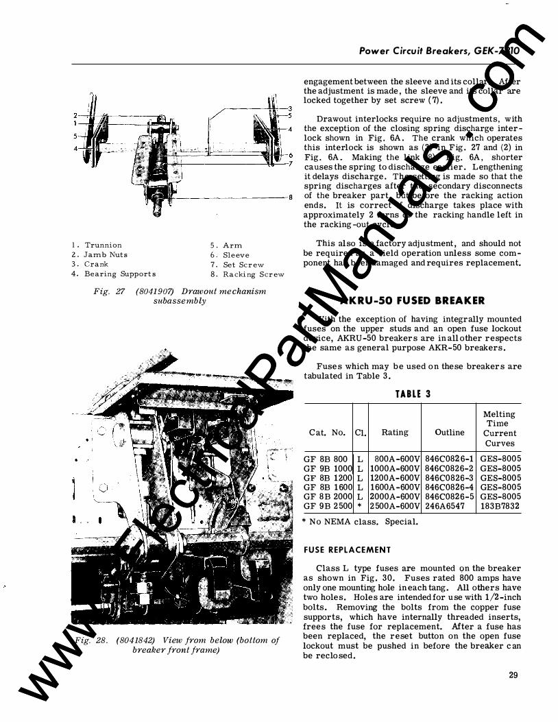
1 . Trunn ion 5 . Arm 2. Jamb Nu ts 6 . Sl eev e 3 . Cran k 7. S et S cr ew 4. B earing Su ppor ts 8 . Ra cki ng S cr ew
Fig. 27 (8041 907) Drawout mechanism subassembly
Fig. 28. (8041842) View from below (bottom of breaker front frame)
Power Circuit Breakers, GEK-7310
engagement between the sleeve and its collar. Mter the adjustment is made , the sleeve and its collar are locked together by set screw ( 7) .
Drawout interlocks require no adjustments, with the exception of the closing spring discharge interlock shown in Fig . 6A . The crank which operates this interlock is shown as (3) in Fig . 27 and (2) in Fig . 6A . Making the link (8) , Fig. 6A , shorter causes the spring to discharge earlier . Lengthening it delays discharge . The setting is made so that the spring discharges after the secondary disconnects of the breaker part, but before the racking action ends. It is correct if discharge takes place with approximately 2 turns of the racking handle left in the racking -out cycle.
This also is a factory adjustment , and should not be required as a field operation unless some component has been damaged and requires replacement.
AKRU-50 FUSED BREAKER With the exception of having integrally mounted
fuses on the upper studs and an open fuse lockout device, AKRU-50 breakers are in all other respects the same as general purpose AKR-50 breakers .
Fuses which may be used on these breakers are tabulated in Table 3 .
TABLE 3 Melting Time
Cat. No. Cl. Rating Outline Current Curves
GF 8B 800 L 800A-600V 846C082.6-1 GES-8005 GF 9B 1000 L 1000A-600V 846C0826-2 GES-8005 GF 8B 1200 L 1200A-600V 846C0826-3 GES-8005 GF 8B 1600 L 1600A-600V 846C0826-4 GES-8005 GF 8B 2000 L 2000A-600V 846C0826-5 GES-8005 GF 9B 2 500 * 2 500A-600V 246A6547 183B7832
* No NEMA class. Special.
FUSE REPLACEMENT
Class L type fuses are mounted <;>n the breaker as shown in Fig. 30. Fuses rated 800 amps have only one mounting hole in each tang. All others have two holes. Holes are intended for use with 1/2-inch bolts. Removing the bolts from the copper fuse supports, which have internally threaded inserts, frees the fuse for replacement. Mter a fuse has been replaced, the reset button on the open fuse lockout must be pushed in before the breaker c an be reclosed.
29 www . El
ectric
alPar
tMan
uals
. com
www . El
ectric
alPar
tMan
uals
. com
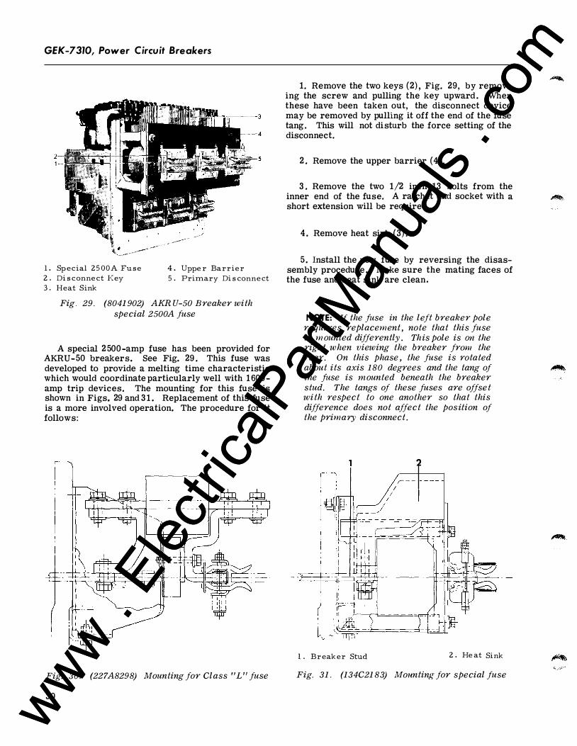
GEK-7310, Power Circuit Breakers
l. S pecia l 2 5 0 0 A Fu s e 4. U pper Barri er 2 . Di s conn ec t K ey 5 . Primar y Di s conn ec t 3 . Hea t Sin k
Fig . 29. (8041902) AKRU-50 Breaker with special 2500A fuse
A special 2 500-amp fuse has been provided for AKRU-50 breakers. See Fig. 29 . This fuse was developed to provide a melting time characteristic which would coordinate particularly well with 1600-amp trip devices. The mounting for this fuse is shown in Figs. 29 and 3 1 . Replacement of this fuse is a more involved operation. The procedure for it follows:
Fig. 30. (227A8298) Mounting for Class "L" fuse
30
1. Remove the two keys (2) , Fig. 29, by removing the screw and pulling the key upward . When these have been taken out, the disconnect device may be removed by pulling it off the end of the fuse tang. This will not disturb the force setting of the disconnect.
2 . Remove the upper barrier (4) .
3 . Remove the two 1/2 inch-13 bolts from the inner end of the fuse. A ratchet and socket with a short extension will be required.
4 . Remove heat sink (3) .
5 . Install the new fuse by reversing the disassembly procedure . Make sure the mating faces of the fuse and heat sink are clean.
NOTE: If the fuse in the left breaker pole requires replacement, note that this fuse is m ounted differently . This pole is on the right when viewing the breaker franz the rear. On this phase, the fuse is rotated about its axis 1 80 degrees and the tang of the fuse is mounted beneath the breaker stud. The tangs of these fuses are offset with respect to one another so that this difference does not affect the position of the primary disconnect.
I I J
l . Br ea ker S tu d
I ;- -
/
2
2 . Hea t Sin k
Fig. 31. (134C2183) Mounting for special fuse
www . El
ectric
alPar
tMan
uals
. com
www . El
ectric
alPar
tMan
uals
. com
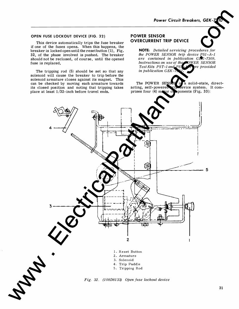
Power Circuit Breakers, GEK-7310
OPEN FUSE LOCKOUT DEVICE ( F I G . 3 2 )
This device automatically trips the fuse breaker if one of the fuses opens. When this happens, the breaker is locked open until the reset button ( 1), Fig. 32 , of the phase involved is pushed. The breaker should not be reclosed, of course , until the opened fuse is replaced.
POWER SENSOR OVERCURRENT TRIP DEVI C E
NOTE: Detailed servicing procedures for the POWER SENSOR trip device PS1 -A-1 are contained in publication GEK - 7309. Instructions on use of the POWER SENSOR Test Kits PST-1 and PST-1 -1 are provided in publication GEK - 7301. The tripping rod (5) should be set so that any
solenoid will cause the breaker to trip before the solenoid armature closes against its magnet. This can be checked by moving each armature towards its closed position and noting that tripping takes place at least 1 /32- inch before travel ends.
The POWER SENSOR is a solid-state, directacting, self-powered trip device system. It comprises four (4) major components (Fig. 33 ) :
2
1 . R e s et Button 2 . Armatur e 3 . Solenoid 4. Trip Paddle 5 . Tripping Rod
Fig. 32 . (1 08D81 33) Open fuse lockout device
l l I : : I _ _ __),. --=r
I
I 5
31 www . El
ectric
alPar
tMan
uals
. com
www . El
ectric
alPar
tMan
uals
. com
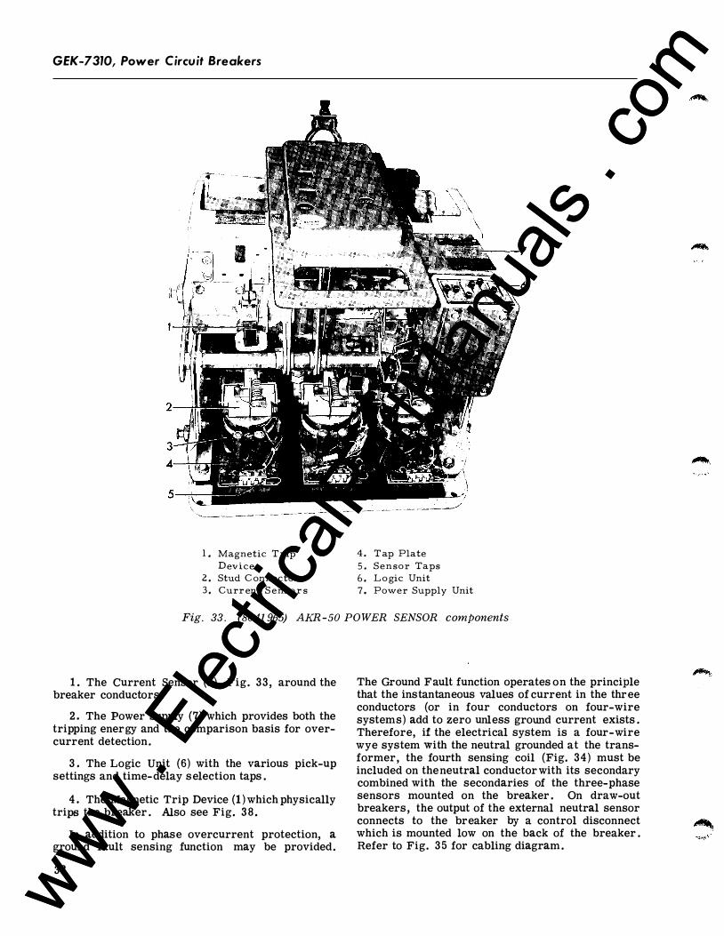
GEK-7310, Power Circuit Breakers
1 . Magnetic T rip 4. T ap Plate Device 5 . Sensor Taps
z . Stud C onnector 6. L o gic Unit 3 . Curr ent S ens o r s 7. Power Supply Unit
Fig. 33 . (8041965) AKR-50 POWER SENSOR components
1 . The Current Sensor (3 ) , Fig. 33 , around the breaker conductors .
2 . The Power Supply (7) which provides both the tripping energy and the comparison basis for overcurrent detection.
3 . The Logic Unit (6) with the various pick-up settings and time-delay selection taps .
4 . The Magnetic Trip Device (l ) which physically trips the breaker . Also see Fig. 3 8 .
In addition to phase overcurrent protection, a ground fault sensing function may be provided.
32
The Ground Fault function operates on the principle that the instantaneous values of current in the three conductors (or in four conductors on four-wire systems) add to zero unless ground current exists . Therefore, if the electrical system is a four-wire wye system with the neutral grounded at the transformer, the fourth sensing coil (Fig. 34) must be included on the neutral conductor with its secondary combined with the secondaries of the three-phase sensors mounted on the breaker . On draw-out breakers, the output of the external neutral sensor connects to the breaker by a control disconnect which is mounted low on the back of the breaker . Refer to Fig. 35 for cabling diagram.
www . El
ectric
alPar
tMan
uals
. com
www . El
ectric
alPar
tMan
uals
. com
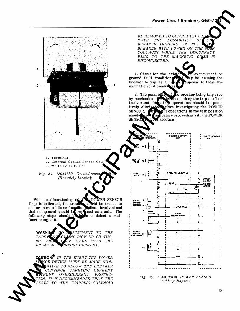
2
1 . Terminal 2. External Gr ound Sensor Coil 3 . White Polarity Dot
Fig. 34. (8039650) Ground sensor coil (Remotely located)
When malfunctioning of the POWER SENSOR Trip is indicated, the trouble should be traced to one or more of these four components involved and that component should be replaced as a unit. The following steps should be taken to detect a malfunctioning unit:
WARNING: NO ADJUSTMENT TO THE TAPS CONTROLLING PICK-UP OR TIMING SHOULD BE MADE WITH THE BREAKER CARRYING CURRENT.
CAUTION: IN THE EVENT THE POWER SENSOR DEVICE MUST BE MADE NONOPERATIVE TO ALLOW THE BREAKER TO CONTINUE CARRYING CURRENT WITHOUT OVERCURRENT PROTECTION , IT IS RECOMMENDED THAT THE LEADS TO THE TRIPPING SOLENOID
Power Circuit Breakers, GEK-7310
BE REMOVED TO COMPLETELY ELIMINATE THE POSSIBILITY OF THE BREAKER TRIPPING. DO NOT CLOSE BREAKER WITH POWER ON THE MAIN CONTACTS WHILE THE DISCONNECT PLUG TO THE MAGNETIC COILS IS DISCONNECTED.
1 . Check for the existence of overcurrent or ground fault conditions that may be causing the breaker to trip as a proper response to these abnormal circuit conditions.
2, The possibility of the breaker being trip free by mechanical interferences along the trip shaft or inadvertent shunt trip operations should be positively eliminated before investigating the POWER SENSOR. Successful operations in the test position should be obtained before proceeding with the POWER SENSOR trouble shooting.
r - - - - - - - - - - - - - - , ,- - - - - - - - - - ..., I BACK FRAME ' , POWER SUPPLY
r - - - - - - - - - ,
MAGNETIC SENSORS I ' UN I T I J I
POWER SENSOR 1 UNIT
(-----..+-1 I I I �� I ' II I +-------r-1 I I I 1!.----.L I R : : � I
R,lg�l lc 1 r..._,':,_L _-TI_.C.:::OM=Mc..:Oc:..:N-;:N:::.EG:::.A:.:.To.:IV.:;.E -t--�:t-' ---
�20V.I+l l w
I 1 D.C. REF. I �--t---'-=-'---t--..,.-+1 --..;<Nt- TO SCR 1 N M, I ANODE � I I I
1 A ('; A : S WIRE IA j li�, c ' : ct IIIOUIID :��----+-! .;._: --+---<·..-SENSOR Ia ' ; 1 y ; ; R 1 1 r 1 ,-;:: .... _....._ __ �.HIELD < lc l L=J : �
1 SURGE 1
lA I [Q� SUPP$SORS �t
1 I I
: POWER I �· �D --t---Q--r----'----<0;._.
I SENSOR IB I 1(0V£RCURRENT) I H H b I l I I i lc I �� � cp �t
I ' : ,_x_�-�TE�S�T--7--���� I : I U TEST PI 1 I 1 <--�--��-�.-��. --� I
'--- - - - - - - - - - _j L - - - - - - - - - - � L - - - - - - - - j
Fig. 35. (133C9018) POWER SENSOR cabling diagram
33 www . El
ectric
alPar
tMan
uals
. com
www . El
ectric
alPar
tMan
uals
. com
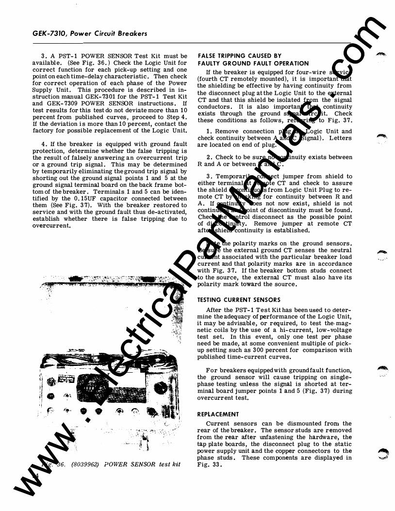
GEK-7310, Power Circuit Breakers
3 . A PST- 1 POWER SENSOR Test Kit must be available. (See Fig. 36 . ) Check the Logic Unit for correct function for each pick-up setting and one point on each time-delay characteristic . Then check for correct operation of each phase of the Power Supply Unit . This procedure is described in instruction manual GEK- 73 01 for the PST- 1 Test Kit and GEK- 7309 POWER SENSOR instructions . If test results for this test do not deviate more than 10 percent from published curves , proceed to Step 4 . If the deviation i s more than 10 percent, contact the factory for possible replacement of the Logic Unit.
4 . If the breaker is equipped with ground fault protection, determine whether the false tripping is the result of falsely answering an overcurrent trip or a ground trip signal . This may be determined by temporarily eliminating the ground trip signal by shorting out the ground signal points 1 and 5 at the ground signal terminal board on the back frame bottom of the breaker . Terminals . ! and 5 can be identified by the 0 . 15UF capacitor connected between them (See Fig. 3 7) . With the breaker restored to service and with the ground fault thus de-activated, establish whether there is false tripping due to overcurrent.
Fig. 36. (8039962) POWER SENSOR test kit
34
FALSE TR IPPING CAUSED BY
FAULTY GROUND FAULT OPERATION
If the breaker is equipped for four-wire service (fourth CT remotely mounted), it is important that the shielding be effective by having continuity from the disconnect plug at the Logic Unit to the external CT and that this shield be isolated from the signal conductors . It is also important that continuity exists through the ground signal circuit. Check these conditions as follows, referring to Fig. 37 .
1 . Remove connection plug at Logic Unit and check continuity between A and C (Signal) . Letters are located on end of plug.
2 . Check to be sure no continuity exists between R and A or between R and C .
3 . Temporarily connect jumper from shield to either terminal at remote CT and check to assure the shield is continuous from Logic Unit Plug to remote CT by checking for continuity between R and A . If continuity does not now exist, shield is not continuous and point of discontinuity must be found. Check the control disconnect as the possible point of discontinuity. Remove jumper at remote CT after shield continuity is established.
Note the polarity marks on the ground sensors . Be sure the external ground CT senses the neutral current associated with the particular breaker load current and that polarity marks are in accordance with Fig. 3 7. If the breaker bottom studs connect to the source, the external CT must also have its polarity mark toward the source .
TESTING CURRENT SENSORS
After the PST- 1 Test Kit has been used to determine the adequacy of performance of the Logic Unit, it may be advisable, or required, to test the- magnetic coils by the use of a hi-current, low-voltage test set. In this event, only one test per phase need be made, at some convenient multiple of pickup setting such as 300 percent for comparison with published time- current curves.
For breakers equipped with groundfault function, the ground sensor will cause tripping on singlephase testing unless the signal is shorted at terminal board jumper points 1 and 5 (Fig. 3 7) during overcurrent test.
R EPLACEMENT
Current sensors can be dismounted from the rear of the breaker . The sensor studs are removed from the rear after unfastening the hardware, the tap plate boards, the disconnect plug to the static power supply unit and the copper connectors to the phase studs . These components are displayed in Fig. 33 .
www . El
ectric
alPar
tMan
uals
. com
www . El
ectric
alPar
tMan
uals
. com
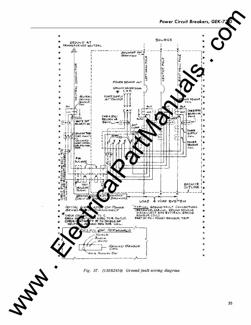
Power Circuit Breakers, GEK-7310
11 11
a 50 u R C E a G;RO\Jt-.� D .ti,T • TRANS!"OR.MEI! ).IEIJ T ii! Ft L 1 : : a - -- ------- - ------ '" ---- ..., ----"' - - - - ----II
•
11 11 11 11
11
21
21
II
II •
QC g u J 0 z
8
1 ;t5R.£//Kc-<' 'n,P : II I TE/f!M.WALS Uf IJ) 1
: � � � : : ==> 11. '; I
POWF!R SE:N50R '-'N'T
% � 4 1 w :t 1- 1- l-
It 2 � -' � i'i
' ) ) 1 21 . Ro<>NO SEi'!So� 1
t:. o u.. l iS 6L.l( CAII.l47i>ll 21
�I.I:Kf-1 0� ll e<¥U•"· I
- --.) 1 11
P , - - j II I POI!IC!t 1 • !>UPPL'(
�::1• 1.. ! 11 Po""U ' • ��loiSoR. I C.o>L j 41
1 41 I . I l u I • I ll I
f!';RE.At<: E� 1 11 OUTLINE I a
_ _ _/ _ _ _ _ j II
•
11 11!/n·I,<IL lvsr,q<.Lt4T7"N OF PoW'6i� TY!"I CA l.. "'�0\JtJD F A U LT Co >J >.: E:C'!'iON<;; (e>REAKE:R1 c: ... e\.IN�11 GjE'OIJ>.iO SENSO� D I S CO ti T'J E: C i A NC li,l(T Eit NAL G\ R.OVN0 GE.NSOR C O l L.)
11
a ,:;EIVt/!>0� t#VI'r 'V.<5 CONNcC7" • *CHECK CONTINUITY A TO C
GWE't<: tul CONIINVIT'< A OR.C. TO R (S�IF.l.C) 11 CHEG� CONTINVITY R TO !>HIEi.P Gi' HE'UT�AL <SRO�O SEN SO� COI L . •
n
n
IS
II
II
P,l.R\ 0!= PS· I POWER SENSOR. TRIP
Fig. 37. (1 38B2454) Ground fault wiring diagram
a
•
II
•
11 n
II
n
II
35 www . El
ectric
alPar
tMan
uals
. com
www . El
ectric
alPar
tMan
uals
. com
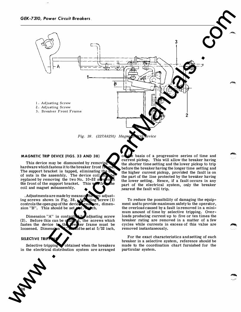
GEK-7310, Power Circuit Breakers .
3 c::�� I ; '
1 . Adjusting Screw 2 . Adju sting Screw 3 . Br eak er Front Frame
2
Fig. 38. (227A8291) Magnetic trip device
MAGNETIC TRIP DEVICE (FIGS. 3 3 AND 3 8 )
This device may be dismounted by removing the hardware which fastens it to the breaker front frame. The support bracket is tapped, eliminating the use of nuts in the assembly. The device coil may be replaced by removing the two No. 10-32 screws in tlie front of the support bracket. This will free the coil and magnet subassembly.
, Adjustments are made by means of the two adjusting screws shown in Fig. 38 . Adjusting screw ( 1) controls the open gap of the device armature , dimension "B". This should be set at 1/4 inch.
Dimension "A" is controlled by adjusting screw (2) . Before this can be changed, the screws which fasten the device to the breaker frame must be loosened. Dimension "A" should be set at 5/32 inch.
SELECTIVE TRIPPIN G
Selective tripping is obtained when the breakers in the electrical distribution system are arranged
36
on the basis of a progressive series of time and current pickup. This will allow the breaker having the shorter time setting and the lower pickup to trip before the breaker having the longer time setting and the higher current pickup, provided the fault is on the part of the line protected by the breaker having the lower setting. Hence, if a fault occurs in any part of the electrical system, only the breaker .nearest the fault will trip.
To reduce the possibility of damaging the equipment and to provide maximum safety to the operator, the overload caused by a fault is removed in a minimum amount of time by selective tripping. Overloads producing current up to five or ten times the breaker rating are removed in a matter of a few cycles while currents in excess of this value are removed instantaneously.
For the exact characteristics and setting of each breaker in a selective system, reference should be made to the coordination chart furnished for the particular system.
www . El
ectric
alPar
tMan
uals
. com
www . El
ectric
alPar
tMan
uals
. com
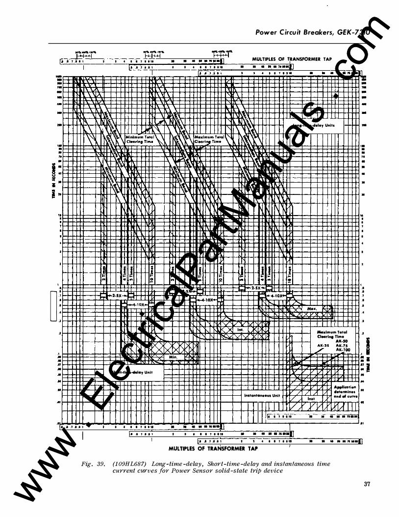
Power Circuit Breakers, GEK-7310
.,.. ..,.. ,., .. � 1.1 .I .1 .I .I I I I <I l l l l t tt II II 41 It 10 11 1111111 MULTIPLES OF TRANSFORMER TAP 1.1 .I .1 .I .I I I 4 I I l I t tl • • .. . . .. ... 1
Long-tlmo-dolay Unltl
' \
� ���4---�+*�-+��LH-+��--+-�++-+��YH-+��--�+L++-+��YH���--�-+-+-+4-����H 1-H-t-tt----i-ilj r j J J -r J - J j .I
� .I
·' .I
.I
..
..
..
.I ..
...
.17 .. .. ... ...
...
.I
" • � 0 " • �
1-1�+-1-+---+-i:""L·--.. 2-SX � �l.-4-lOX�
Short-tlmo-tlolay Unit
....
' '
Min.
-r J -�
'\.X Int. r\
. ... ! l--t-t-+-t-�+-+-l4-H !
Max . "Q.. .A X X
I Mooiolmum Tatal Clearing Time
AK-50
/25 ��:��
v /
t��t���:::�::t:t:t������=t���::::t::t:t:t:t�����:tt:t:t::::t::t:1:t:1jtttj�t:t���:2/��Z����2!�;4 A..,.llcation r / / / tloto,..inol H-++t+--+--+--t-++IH-H-t-+t+-+--+--t++IH-H-++t+--+--i ln1tantanoau1 Unit ,_.�r'-t-'..,..._.u...+t71 end al curve ,/ lnot
I I 1 7 1 1 11 • • .. .. . " · ·
, .. .I .1 .1 .1 1 • I • I I 7 I 1 11 • • . .. . ... • ! I I l.t ..1 l .1 .I 1 I I • I I 1 I I ll • • • . . ..... 1
-
Ill .. .. ,. • •
.. •
•
.. I
I
' I
I
•
I
•
I .I
.I
·' .I
.I
..
.I
..
.I I .. I ..
.17 I . ..
. ..
. ..
.II
.II
.II
I I , .. .I .l .I .I 1 I I • I I 1 I I II • • .. . . .. ... I MULTIPLES OF TRANSFORMER TAP I
Fig . 39. (109HL687) Long -time -delay, Short-time -delay and instantaneous time current curves for Power Sensor solid -state trip device
37 www . El
ectric
alPar
tMan
uals
. com
www . El
ectric
alPar
tMan
uals
. com
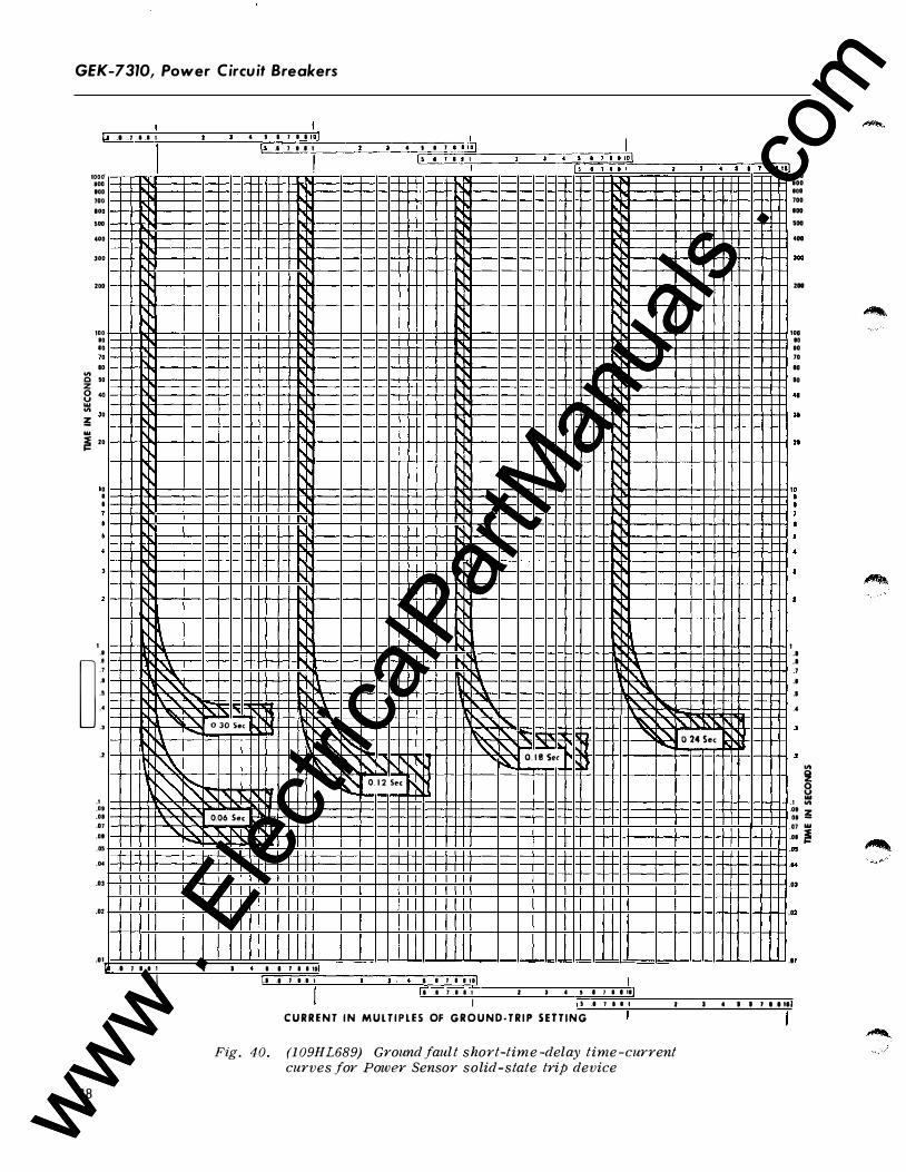
GEK-7310, Power Circuit Breakers
Ll .I . 7 .I .I 1
IOO(f ...
...
100
...
...
...
•••
200
0
D
100 • • D
.. "' c • D z 8 .. ... "' D � � 2 D
D I I
3
1 ..
� .. .1 .. ..
..
·'
38
..
.1
.08
...
.01
...
...
...
.03
.02
.. 1
� . . I
l .'-.\ '"' !\.."' � � "' � \ � � � " ......
7 1 .1 1
I
..... '"
� "
''-
I
0 30 Sec
' 0.06 Sec
1'\.
I
t I I J I I 11/ \.J .I 1 1 .1 1
"' .l l't ""' u ''-
'"'\: '"' '" �" L\:
� �
• I I 7 I I ID .I I 7 1 .1 I
I
4 I I J __ tlJ!)
' ,r-, "r-. 0. 1 2 Sec 1'-
I I . •
��-S�I�l �l�l�l,-----�--��·-i·�I�J �I�I�I
D�'----�,-����· I f5 I J i l l 4 I �
" " " ""
1\ "
1'-1 " �l ' ll �\_ .\ !'..'-
� '\. " " '" " ' � """ !" "ii:: '"' i'\. l � 0. 1 8 Sec .}
I I 7 I l iD I .I .I 7 I I t ' • • • I 1 I I II
I 5 .I 7 I I I
'" ·"'
'"
'
0 24 Sec
• •
1'1 'L
1
1
DOD 100
IDO 700
...
. ..
. ..
. ..
200
..
..
10
70
..
10
..
H
21
1
1 .. .. .1 .. ..
..
..
..
.1
"' � � "'
�: � OJ OU oo ! o• ..
.0
.0
.I
I I 7 I I II
C U R R E N T I N M U L T I P L E S OF G R O U N D - T R I P S E T T I N G
Fig. 40. (1 09HL689) Ground fault s hort-time -delay time-current curves for Power Sensor solid-state trip device
www . El
ectric
alPar
tMan
uals
. com
www . El
ectric
alPar
tMan
uals
. com

www . El
ectric
alPar
tMan
uals
. com
www . El
ectric
alPar
tMan
uals
. com
G E K-7310C 3-81 ( 10M)
For further information call or write your local General Electric Sales Office or . . .
Distribution Equipment Division 41 Woodford Avenue Plainville, CT 06062
GENERAL fl ELECTRIC
' www .
Elec
tricalP
artM
anua
ls . c
om
www . El
ectric
alPar
tMan
uals
. com
Related Documents


![WWW Piramide - IntroducciónPD] Publicaciones... · WWW। Piramide ।।।।।।।.com WWW। ।।।।।।। ।।।।।।।।।।। ।।।।।।।.com](https://static.cupdf.com/doc/110x72/5e0b08b231a4536209097ef2/www-piramide-introduccin-pd-publicaciones-wwwa-piramide-aaaaaaacom.jpg)