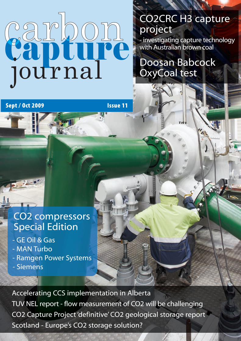
Sept / Oct 2009 Issue 11 Accelerating CCS implementation in Alberta TUV NEL report - flow measurement of CO2 will be challenging CO2 Capture Project ‘definitive’ CO2 geological storage report Scotland - Europe’s CO2 storage solution? CO2CRC H3 capture project - investigating capture technology with Australian brown coal Doosan Babcock OxyCoal test CO2 compressors Special Edition - GE Oil & Gas - MAN Turbo - Ramgen Power Systems - Siemens

Welcome message from author
This document is posted to help you gain knowledge. Please leave a comment to let me know what you think about it! Share it to your friends and learn new things together.
Transcript
Sept / Oct 2009 Issue 11
Accelerating CCS implementation in Alberta
TUV NEL report - flow measurement of CO2 will be challenging
CO2 Capture Project ‘definitive’ CO2 geological storage report
Scotland - Europe’s CO2 storage solution?
CO2CRC H3 captureproject- investigating capture technologywith Australian brown coal
Doosan BabcockOxyCoal test
CO2 compressorsSpecial Edition - GE Oil & Gas- MAN Turbo- Ramgen Power Systems- Siemens
CCJ11a:Layout 1 15/09/2009 09:57 Page 1

www.senergyworld.com
Your answer to carbon storage
is here
Over 400 leading geological, geophysical, reservoir engineering and well engineering consultants across more than 15 international locations, engineering the smart solutions to your carbon storage challenges.
Senergy - results driven by Brainergy®
Site selection, injectivity, storage capacity, reservoir integrity, flow/phase studies, storage simulation, enhanced hydrocarbon recovery, monitoring, facilities requirements, commercial services.
United Kingdom Ireland Norway United Arab Emirates Malaysia Australia New Zealand
Oil & Gas Survey & GeoEngineering Alternative Energy Technology Training Investments
CCJ11a:Layout 1 15/09/2009 09:57 Page 2
Contents
Doosan Babcock OxyCoalTM test facilityJoan Ruddock MP, UK Minister of State for the Department of Energy & ClimateChange, has opened a major project to demonstrate Doosan Babcock’s OxyCoal™Clean Combustion technology in Renfrew, Scotland
BASF, Linde, RWE pilot CO2 scrubbing plant opensThe Coal Innovation Centre of RWE Power in Niederaussem aims to testtechnology for CO2 flue gas scrubbing
Sept/Oct 2009 Issue 11
TUV NEL report - flow measurement of CO2TUV NEL reports that flow measurement of CO2 will present major challenges. Thestudy was undertaken by TUV NEL to investigate the flow measurement of carbondioxide in Carbon Capture and Storage applications as part of a flow metrologyproject under the Engineering and Flow Programme
CO2 Capture Project CO2 geological storage reportThe recent report from the CO2 Capture Project, “A Technical Basis for CarbonDioxide Storage”, offers the most definitive guide to technical issues surroundingCO2 storage to date, says Iain Wright, CO2 Capture Project
Scotland - Europe’s CO2 storage solution?CO2 storage in the North Sea offshore Scotland could trap European CO2 emissionsfor decades and provide the UK with a natural resource worth as much asGBP10bn a year, says Prof. Stuart Hazeldine, University of Edinburgh
Carbon Capture Journal213 Marsh Wall, London, E14 9FJ, UKwww.carboncapturejournal.comTel +44 (0)207 510 4935Fax +44 (0)207 510 2344
EditorKeith [email protected]
PublisherKarl [email protected]
Advertising salesAlec EganTel +44 (0)203 051 [email protected]
25
Four post-combustion CO2 compression strategies comparedBy Simone Bertolo, Global Market Development Manager, GE Oil & Gas
Innovative and proven CO2 compression technology for CCS and EORDr. Rolf Habel and Christian Wacker, MAN Turbo AG, give an overview of existing andinnovative technologies for CO2 compression, including reciprocating andcentrifugal compression - with focus on innovative gear type designs - and acomparison to other technologies
Low-cost, high-efficiency CO2 compressorsRamgen Power Systems is developing a unique shockwave compression technologyfor use on high molecular weight gases like CO2. The primary goal is a low-cost,high-efficiency CO2 compressor that will significantly reduce the overall capital andoperating costs of CCS. By Peter Baldwin, President, Ramgen Power Systems
The right solution for CO2 compression – integrally geared compressorsfrom SiemensSiemens has investigated the most important market requirements to identify thebest solution from the existing portfolio of turbomachinery and has concluded thatintegrally geared turbocompressors incorporate the optimum design concept foreconomic CO2 compression. By Thomas Winter, Sales Manager for compressors,Siemens
10
8
19
16
2
CO2CRC H3 Capture ProjectThe CO2CRC H3 Capture Project was recently opened at International Power’sHazelwood Power Station. Its purpose is to better understand the performance ofvarious CO2 capture technologies with Australian brown coal flue gases and toevaluate the performance of three technologies for larger scale capture
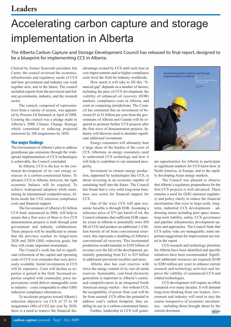
Accelerating carbon capture and storage implementation in AlbertaThe Alberta Carbon Capture and Storage Development Council has released its finalreport, designed to be a blueprint for implementing CCS in Alberta
Projects and policy
Special section - CO2 compressor technology
Leaders
Carbon capture journal (Print) ISSN 1757-1995Carbon capture journal (Online) ISSN 1757-2509
1Sept - Oct 2009 - carbon capture journal
Carbon Capture Journal is your one stopinformation source for new technicaldevelopments, opinion, regulatory andresearch activity with carbon capture,transport and storage.
Carbon Capture Journal print magazine ismailed to over 2,000 power companyexecutives, government policy makers,investors and researchers, with a further500-1000 copies distributed at tradeshows, as well as being downloadedapprox. 2,000 times as a pdf.
Subscriptions: £195 a year for 6 issues. Tosubscribe, please contact Karl Jeffery [email protected] you can subscribe online at www.d-e-j.com/store
Front cover:
Siemens integrally geared turbocompressorfor CO2
28
6
Transport and storage
22
26
14
CCJ11a:Layout 1 15/09/2009 09:58 Page 1
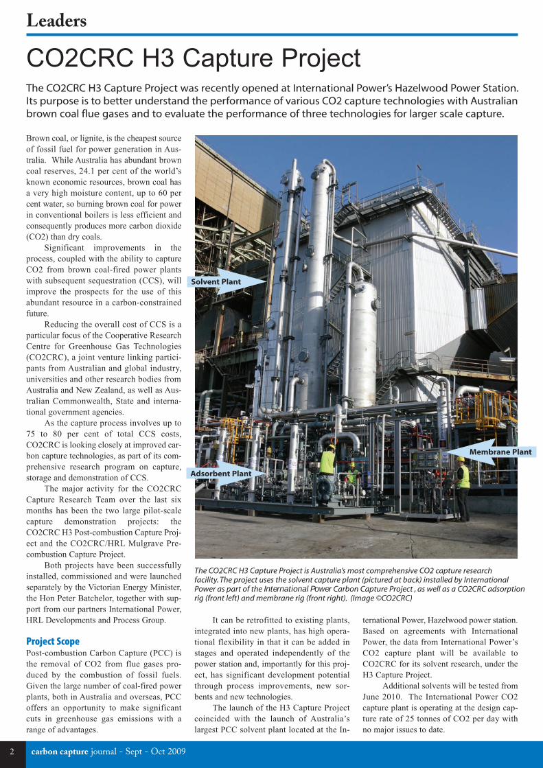
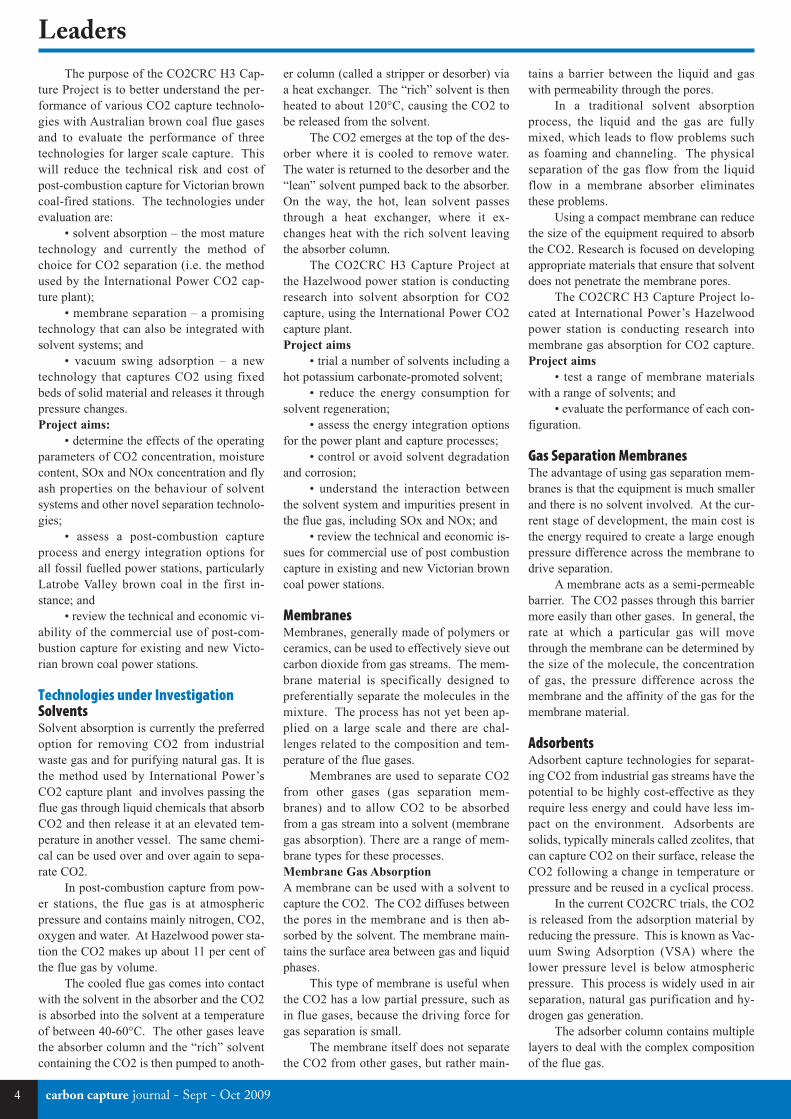
CO2CRC H3 Capture ProjectThe CO2CRC H3 Capture Project was recently opened at International Power’s Hazelwood Power Station.Its purpose is to better understand the performance of various CO2 capture technologies with Australianbrown coal flue gases and to evaluate the performance of three technologies for larger scale capture.
Brown coal, or lignite, is the cheapest sourceof fossil fuel for power generation in Aus-tralia. While Australia has abundant browncoal reserves, 24.1 per cent of the world’sknown economic resources, brown coal hasa very high moisture content, up to 60 percent water, so burning brown coal for powerin conventional boilers is less efficient andconsequently produces more carbon dioxide(CO2) than dry coals.
Significant improvements in theprocess, coupled with the ability to captureCO2 from brown coal-fired power plantswith subsequent sequestration (CCS), willimprove the prospects for the use of thisabundant resource in a carbon-constrainedfuture.
Reducing the overall cost of CCS is aparticular focus of the Cooperative ResearchCentre for Greenhouse Gas Technologies(CO2CRC), a joint venture linking partici-pants from Australian and global industry,universities and other research bodies fromAustralia and New Zealand, as well as Aus-tralian Commonwealth, State and interna-tional government agencies.
As the capture process involves up to75 to 80 per cent of total CCS costs,CO2CRC is looking closely at improved car-bon capture technologies, as part of its com-prehensive research program on capture,storage and demonstration of CCS.
The major activity for the CO2CRCCapture Research Team over the last sixmonths has been the two large pilot-scalecapture demonstration projects: theCO2CRC H3 Post-combustion Capture Proj-ect and the CO2CRC/HRL Mulgrave Pre-combustion Capture Project.
Both projects have been successfullyinstalled, commissioned and were launchedseparately by the Victorian Energy Minister,the Hon Peter Batchelor, together with sup-port from our partners International Power,HRL Developments and Process Group.
Project ScopePost-combustion Carbon Capture (PCC) isthe removal of CO2 from flue gases pro-duced by the combustion of fossil fuels.Given the large number of coal-fired powerplants, both in Australia and overseas, PCCoffers an opportunity to make significantcuts in greenhouse gas emissions with arange of advantages.
It can be retrofitted to existing plants,integrated into new plants, has high opera-tional flexibility in that it can be added instages and operated independently of thepower station and, importantly for this proj-ect, has significant development potentialthrough process improvements, new sor-bents and new technologies.
The launch of the H3 Capture Projectcoincided with the launch of Australia’slargest PCC solvent plant located at the In-
ternational Power, Hazelwood power station.Based on agreements with InternationalPower, the data from International Power’sCO2 capture plant will be available toCO2CRC for its solvent research, under theH3 Capture Project.
Additional solvents will be tested fromJune 2010. The International Power CO2capture plant is operating at the design cap-ture rate of 25 tonnes of CO2 per day withno major issues to date.
The CO2CRC H3 Capture Project is Australia’s most comprehensive CO2 capture researchfacility. The project uses the solvent capture plant (pictured at back) installed by InternationalPower as part of the International Power Carbon Capture Project , as well as a CO2CRC adsorption rig (front left) and membrane rig (front right). (Image ©CO2CRC)
Solvent Plant
Adsorbent Plant
Membrane Plant
Leaders
2 carbon capture journal - Sept - Oct 2009
CCJ11a:Layout 1 15/09/2009 09:59 Page 2
Compression solutions for the Oil & Gas industry.
Nautilus pompilius has a life span of about 20 years and gets by
on one meal a month. Its design is about 60 million years old and
has not changed much since. One could say that it has stood the
test of time. While nature still does create the most impressive
and enduring technology, we have been engineer ing tomorrow’s
industrial solutions for over two centuries.
We offer a comprehensive range of compression products for
up-, mid-, and downstream applications. These are innovative
solutions that address the challenges of today’s economic
reality, and will serve you reliably and economically in the long
run. Innovation that stands the test of time.
Compressors Turbines Expanders Reactor Systems PrimeServ www.manturbo.com
MAN TurboEngineering the Future – since 1758.
Innovation that stands the test of time.
CCJ11a:Layout 1 15/09/2009 09:59 Page 3
carbon capture journal - Sept - Oct 20094
Leaders
er column (called a stripper or desorber) viaa heat exchanger. The “rich” solvent is thenheated to about 120°C, causing the CO2 tobe released from the solvent.
The CO2 emerges at the top of the des-orber where it is cooled to remove water.The water is returned to the desorber and the“lean” solvent pumped back to the absorber.On the way, the hot, lean solvent passesthrough a heat exchanger, where it ex-changes heat with the rich solvent leavingthe absorber column.
The CO2CRC H3 Capture Project atthe Hazelwood power station is conductingresearch into solvent absorption for CO2capture, using the International Power CO2capture plant.Project aims
• trial a number of solvents including ahot potassium carbonate-promoted solvent;
• reduce the energy consumption forsolvent regeneration;
• assess the energy integration optionsfor the power plant and capture processes;
• control or avoid solvent degradationand corrosion;
• understand the interaction betweenthe solvent system and impurities present inthe flue gas, including SOx and NOx; and
• review the technical and economic is-sues for commercial use of post combustioncapture in existing and new Victorian browncoal power stations.
MembranesMembranes, generally made of polymers orceramics, can be used to effectively sieve outcarbon dioxide from gas streams. The mem-brane material is specifically designed topreferentially separate the molecules in themixture. The process has not yet been ap-plied on a large scale and there are chal-lenges related to the composition and tem-perature of the flue gases.
Membranes are used to separate CO2from other gases (gas separation mem-branes) and to allow CO2 to be absorbedfrom a gas stream into a solvent (membranegas absorption). There are a range of mem-brane types for these processes.Membrane Gas Absorption
A membrane can be used with a solvent tocapture the CO2. The CO2 diffuses betweenthe pores in the membrane and is then ab-sorbed by the solvent. The membrane main-tains the surface area between gas and liquidphases.
This type of membrane is useful whenthe CO2 has a low partial pressure, such asin flue gases, because the driving force forgas separation is small.
The membrane itself does not separatethe CO2 from other gases, but rather main-
The purpose of the CO2CRC H3 Cap-ture Project is to better understand the per-formance of various CO2 capture technolo-gies with Australian brown coal flue gasesand to evaluate the performance of threetechnologies for larger scale capture. Thiswill reduce the technical risk and cost ofpost-combustion capture for Victorian browncoal-fired stations. The technologies underevaluation are:
• solvent absorption – the most maturetechnology and currently the method ofchoice for CO2 separation (i.e. the methodused by the International Power CO2 cap-ture plant);
• membrane separation – a promisingtechnology that can also be integrated withsolvent systems; and
• vacuum swing adsorption – a newtechnology that captures CO2 using fixedbeds of solid material and releases it throughpressure changes.Project aims:
• determine the effects of the operatingparameters of CO2 concentration, moisturecontent, SOx and NOx concentration and flyash properties on the behaviour of solventsystems and other novel separation technolo-gies;
• assess a post-combustion captureprocess and energy integration options forall fossil fuelled power stations, particularlyLatrobe Valley brown coal in the first in-stance; and
• review the technical and economic vi-ability of the commercial use of post-com-bustion capture for existing and new Victo-rian brown coal power stations.
Technologies under InvestigationSolventsSolvent absorption is currently the preferredoption for removing CO2 from industrialwaste gas and for purifying natural gas. It isthe method used by International Power’sCO2 capture plant and involves passing theflue gas through liquid chemicals that absorbCO2 and then release it at an elevated tem-perature in another vessel. The same chemi-cal can be used over and over again to sepa-rate CO2.
In post-combustion capture from pow-er stations, the flue gas is at atmosphericpressure and contains mainly nitrogen, CO2,oxygen and water. At Hazelwood power sta-tion the CO2 makes up about 11 per cent ofthe flue gas by volume.
The cooled flue gas comes into contactwith the solvent in the absorber and the CO2is absorbed into the solvent at a temperatureof between 40-60°C. The other gases leavethe absorber column and the “rich” solventcontaining the CO2 is then pumped to anoth-
tains a barrier between the liquid and gaswith permeability through the pores.
In a traditional solvent absorptionprocess, the liquid and the gas are fullymixed, which leads to flow problems suchas foaming and channeling. The physicalseparation of the gas flow from the liquidflow in a membrane absorber eliminatesthese problems.
Using a compact membrane can reducethe size of the equipment required to absorbthe CO2. Research is focused on developingappropriate materials that ensure that solventdoes not penetrate the membrane pores.
The CO2CRC H3 Capture Project lo-cated at International Power’s Hazelwoodpower station is conducting research intomembrane gas absorption for CO2 capture.Project aims
• test a range of membrane materialswith a range of solvents; and
• evaluate the performance of each con-figuration.
Gas Separation MembranesThe advantage of using gas separation mem-branes is that the equipment is much smallerand there is no solvent involved. At the cur-rent stage of development, the main cost isthe energy required to create a large enoughpressure difference across the membrane todrive separation.
A membrane acts as a semi-permeablebarrier. The CO2 passes through this barriermore easily than other gases. In general, therate at which a particular gas will movethrough the membrane can be determined bythe size of the molecule, the concentrationof gas, the pressure difference across themembrane and the affinity of the gas for themembrane material.
AdsorbentsAdsorbent capture technologies for separat-ing CO2 from industrial gas streams have thepotential to be highly cost-effective as theyrequire less energy and could have less im-pact on the environment. Adsorbents aresolids, typically minerals called zeolites, thatcan capture CO2 on their surface, release theCO2 following a change in temperature orpressure and be reused in a cyclical process.
In the current CO2CRC trials, the CO2is released from the adsorption material byreducing the pressure. This is known as Vac-uum Swing Adsorption (VSA) where thelower pressure level is below atmosphericpressure. This process is widely used in airseparation, natural gas purification and hy-drogen gas generation.
The adsorber column contains multiplelayers to deal with the complex compositionof the flue gas.
CCJ11a:Layout 1 15/09/2009 09:59 Page 4
Leaders
ConclusionsEvaluation of all initial test results are un-derway, the results of which will appear indue course. The ultimate focus will be onthe development of engineering solutions toimplement capture on a larger scale, theidentification of prospective technique(s) forpost-combustion power plant trial (includingprovision of supporting data) and identify-ing and resolving any further engineering is-sues.
CO2CRC plans to run all three capturerigs under continuous industrial conditions,using post-combustion flue gas from the In-ternational Power Hazelwood power station,collecting data and evaluating it in accor-dance with the aim of the project. The rigsare instrumented to provide the necessarydata acquisition on a continuous basis. Aswell as the plant-based tests there will be on-going laboratory work feeding into the pro-gram along with extensive evaluation of testwork and reformulation of tests as the pro-gram progresses.
It is important to evaluate the merit ofeach of the alternative techniques for CO2capture from post-combustion flue gas, andselect the best prospective technology(ies)for a scaled up power plant trial. Engineer-
ing studies, including heat/process integra-tion and techno-economic evaluations, willcontinue throughout the program and willmake an invaluable contribution to the finaldecision on the technology that will bescaled up in the future.
Process GroupProcess Group has been responsible for thedesign, fabrication, installation and commis-sioning of the pilot capture plant at Hazel-wood, the biggest of its kind in Australia andone of the biggest carbon capture trials in theworld.
Fitted to one of the power station’seight generating units, the plant is designedto capture up to 50 tonnes of CO2 a day. Inthe first phase of operation it is collecting 25tonnes a day.
The carbon capture plant was designedand manufactured at Process Group’sRowville headquarters and transported inmodules to the Hazelwood site, where it wasconnected to the number eight generatingunit.
Mr Dugan, Managing Director, ProcessGroup, said the modular production ap-proach was likely to be attractive to other po-tential users of Process Group’s carbon cap-
ture technology.“By completing virtually all the com-
plex construction and assembly work off-site, we can achieve significant time and costsavings,” he said.
Mr Dugan said Process Group was indiscussions with a number of organisationsinterested in trialling carbon capture technol-ogy.
More informationFor images and information about the H3project and other demonstrations in Aus-tralia see:www.co2crc.com.au
Process Group
Process Group is a leading supplier ofpackaged process systems (including car-bon capture and associated processes) toa range of industries, including oil andgas, petrochemical and power generation.The company is based in Melbourne witha large facility in the United Arab Emi-rates.www.processgroup.com.au
CO2 Recapture CO2 EOR
CO2 Sequestration CO2 Dehydration
CO2 Pipelines CO2 Injection Facilities
Specialists in:
Experienced Responsible
www.mustangeng.com Houston • London • Perth • Mumbai • Abu Dhabi • Kuala Lumpur
ExpeespR
eeriencponsib
edble
espR ponsib ble
angeng.com.mustwwww.
m Houston • London • erthP • M
umbai • Abu Dhabi • uala LumpurK
CCJ11a:Layout 1 15/09/2009 10:00 Page 5
Chaired by former Syncrude president JimCarter, the council reviewed the economic,infrastructure and regulatory needs of CCSand how government and industry can worktogether now, and in the future. The councilincluded experts from the provincial and fed-eral governments, industry, and the researchsector.
The council, composed of representa-tives from a variety of sectors, was appoint-ed by Premier Ed Stelmach in April of 2008.Creating the council was a pledge made inAlberta’s 2008 Climate Change Strategywhich committed to reducing projectedemissions by 200 megatonnes by 2050.
The major findingsThe Government of Alberta’s plan to addressgreenhouse gas emissions through the wide-spread implementation of CCS technologiesis achievable, the Council concluded.
In Alberta, CCS is the key to the con-tinued development of its vast energy re-sources in a carbon-constrained future. Toadvance CCS in Alberta, however, the righteconomic balance will be required. Toachieve widespread adoption while main-taining its international competitiveness, Al-berta needs fair CO2 emission compliancecosts and financial support.
The Government of Alberta’s $2-billionCCS fund, announced in 2008, will help toensure that a first wave of three to five CCSdemonstration projects is built through jointgovernment and industry collaboration.These projects will be insufficient to ensurethat the province reaches its longer-term2020 and 2050 GHG reduction goals, butthey will create important momentum.
The Council’s work has led to signifi-cant refinement of the capital and operatingcosts of CCS over estimates that were previ-ously available. Initial investments in CCSwill be expensive. Costs will decline as ex-pertise is gained in the field. Increased ex-pertise coupled with commodity price im-provements could deliver manageable coststo industry – costs comparable to other GHGreduction compliance alternatives.
To accelerate progress toward Alberta’sreduction objective via CCS of 25 to 30megatonnes (Mt) of CO2 per year by 2020,there is a need to remove the financial dis-
advantage created by CCS until such time ascost improvements and/or higher compliancecosts level the field for industry worldwide.
How much it will take to fill this “fi-nancial gap” depends on a number of factors,including the pace of CCS development, theviability of enhanced oil recovery (EOR)markets, compliance costs in Alberta, andcosts in competing jurisdictions. The Coun-cil has estimated that an investment of be-tween $1 to $3 billion per year from the gov-ernments of Alberta and Canada will be re-quired to promote further CCS projects afterthe first wave of demonstration projects. In-dustry will likewise need to shoulder signifi-cant additional investment.
Energy consumers will ultimately beara large share of the burden of the costs ofCCS. Albertans, as energy consumers, needto understand CCS technology and how itwill help to contribute to our sustained pros-perity.
Investment in cleaner energy produc-tion, supported by technologies like CCS, isabout investing in an economy capable ofsustaining itself into the future. The Councilhas found that a very solid long-term busi-ness case exists for financial support forCCS.
One of the ways CCS will spur eco-nomic benefits is through EOR. Assuming areference price of $75 per barrel of oil, theCouncil estimates that sufficient EOR capac-ity exists in Alberta to potentially store 450Mt of CO2 and produce an additional 1.4 bil-lion barrels of oil from conventional reser-voirs; this represents a doubling of Alberta’sconventional oil recovery. This incrementalproduction would translate to $105 billion ofrevenue over the life of the development, po-tentially generating from $11 to $25 billionin additional provincial royalties and taxes.
Alberta also has coal reserves withtwice the energy content of its vast oil sandsreserves. Sustainable, coal-fired electricitygeneration is important to Alberta’s contin-ued competitiveness in an integrated NorthAmerican energy market – but without CCS,the acceptability of power from coal will befar from assured. CCS offers the potential toaddress coal’s carbon footprint, thus en-abling its use in a carbon-constrained future.
Further, leadership in CCS will gener-
ate opportunities for Alberta to participatein significant markets for CCS know-how inNorth America, in Europe, and in the rapid-ly developing Asian energy markets.
The Council was pleased to observethat Alberta’s regulatory preparedness for thefirst CCS projects is well advanced. Thereremains a need for GHG emission regulato-ry and policy clarity to reduce the financialuncertainties that exist in large-scale, long-term, industrial CCS developments – ad-dressing issues including pore space tenure,long-term liability, safety, CCS governanceand pipeline infrastructure development op-tions and approaches. The Council finds thatCCS safety risks are manageable; some im-portant suggestions for improvement are not-ed in the report.
CCS research and technology prioritiesfor Alberta have been identified and specificinitiatives have been recommended. Signifi-cant additional resources are required ($100to $200 million per year) to enhance currentresearch and technology activities and im-prove the viability of commercial CCS andrelated technologies.
CCS development will require an effortsustained over many decades. It will demandlong-term thinking from our leaders. Gov-ernment and industry will need to stay thecourse irrespective of economic uncertain-ties – including those brought about by thecurrent downturn.
Accelerating Carbon Capture and Storage Implementation in Alberta
Alberta Carbon Capture and Storage Development Council
Final ReportMarch 2009
Accelerating carbon capture and storage
implementation in AlbertaThe Alberta Carbon Capture and Storage Development Council has released its final report, designed tobe a blueprint for implementing CCS in Alberta.
Leaders
6 carbon capture journal - Sept - Oct 2009
CCJ11a:Layout 1 15/09/2009 10:00 Page 6

In 2009, companies have benefit to: Implement Risk management frameworks Optimize CO2 EOR solutions Perform Well integrity risk assessments (P&RTM) Share our knowledge through training sessions on demand
Oxand : Over 50 leading risk management consultants and experts in geology, geophysics, material durability, and long term structural integrity, working from 5 locations worldwide and applying the same rigor as for their nuclear projects.
What about your projects ? Take advantage of our unique experience and know-how.
www.oxand.com [email protected]
Your solution for secure gas storage
CCJ11a:Layout 1 15/09/2009 10:00 Page 7
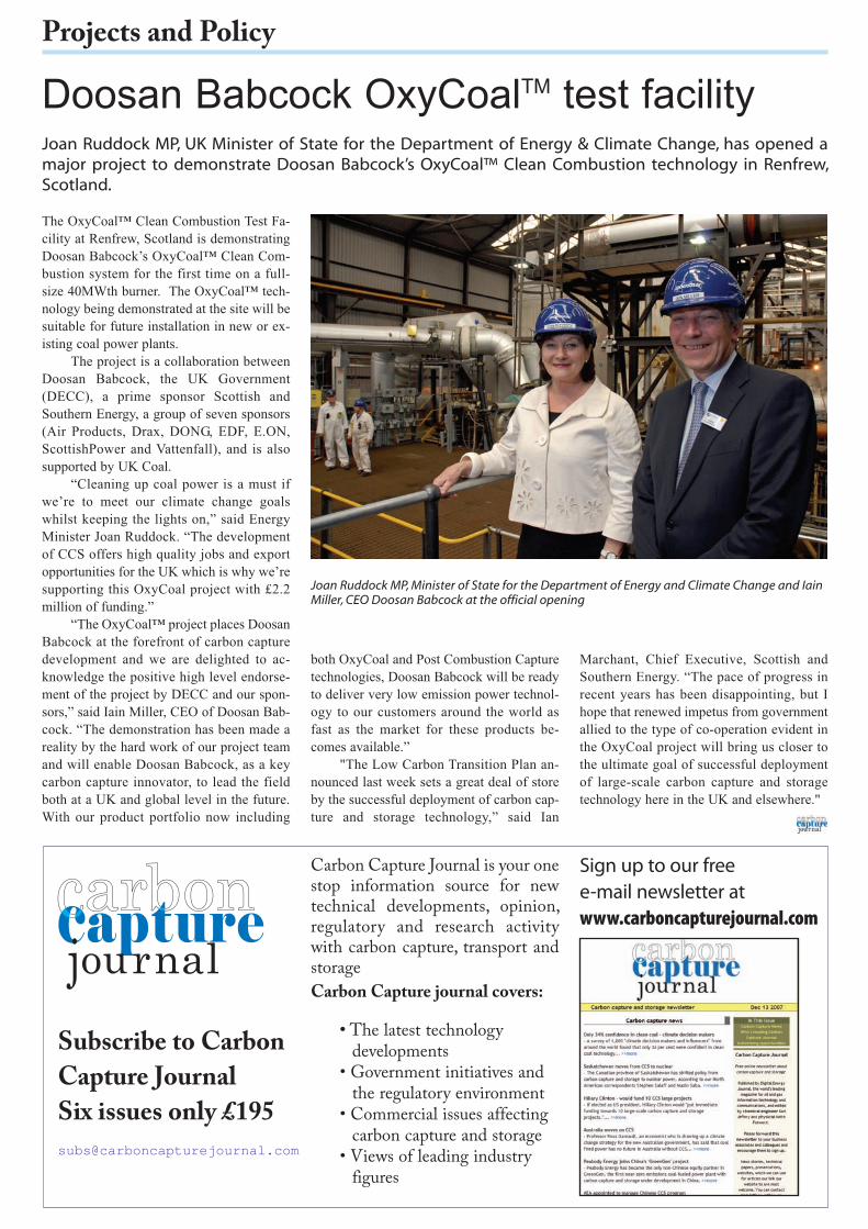
Doosan Babcock OxyCoalTM test facilityJoan Ruddock MP, UK Minister of State for the Department of Energy & Climate Change, has opened amajor project to demonstrate Doosan Babcock’s OxyCoal™ Clean Combustion technology in Renfrew,Scotland.
The OxyCoal™ Clean Combustion Test Fa-cility at Renfrew, Scotland is demonstratingDoosan Babcock’s OxyCoal™ Clean Com-bustion system for the first time on a full-size 40MWth burner. The OxyCoal™ tech-nology being demonstrated at the site will besuitable for future installation in new or ex-isting coal power plants.
The project is a collaboration betweenDoosan Babcock, the UK Government(DECC), a prime sponsor Scottish andSouthern Energy, a group of seven sponsors(Air Products, Drax, DONG, EDF, E.ON,ScottishPower and Vattenfall), and is alsosupported by UK Coal.
“Cleaning up coal power is a must ifwe’re to meet our climate change goalswhilst keeping the lights on,” said EnergyMinister Joan Ruddock. “The developmentof CCS offers high quality jobs and exportopportunities for the UK which is why we’resupporting this OxyCoal project with £2.2million of funding.”
“The OxyCoal™ project places DoosanBabcock at the forefront of carbon capturedevelopment and we are delighted to ac-knowledge the positive high level endorse-ment of the project by DECC and our spon-sors,” said Iain Miller, CEO of Doosan Bab-cock. “The demonstration has been made areality by the hard work of our project teamand will enable Doosan Babcock, as a keycarbon capture innovator, to lead the fieldboth at a UK and global level in the future.With our product portfolio now including
both OxyCoal and Post Combustion Capturetechnologies, Doosan Babcock will be readyto deliver very low emission power technol-ogy to our customers around the world asfast as the market for these products be-comes available.”
"The Low Carbon Transition Plan an-nounced last week sets a great deal of storeby the successful deployment of carbon cap-ture and storage technology,” said Ian
Marchant, Chief Executive, Scottish andSouthern Energy. “The pace of progress inrecent years has been disappointing, but Ihope that renewed impetus from governmentallied to the type of co-operation evident inthe OxyCoal project will bring us closer tothe ultimate goal of successful deploymentof large-scale carbon capture and storagetechnology here in the UK and elsewhere."
Joan Ruddock MP, Minister of State for the Department of Energy and Climate Change and IainMiller, CEO Doosan Babcock at the official opening
Projects and Policy
Subscribe to Carbon
Capture Journal
Six issues only £195
Sign up to our free e-mail newsletter atwww.carboncapturejournal.com
Carbon Capture Journal is your onestop information source for newtechnical developments, opinion,regulatory and research activitywith carbon capture, transport andstorage
Carbon Capture journal covers:
• The latest technologydevelopments
• Government initiatives andthe regulatory environment
• Commercial issues affectingcarbon capture and storage
• Views of leading industryfigures
CCJ11a:Layout 1 15/09/2009 10:00 Page 8
28-29 October 2009 Institution of Mechanical Engineers, LondonBook now:www.imeche.org/events/s1439
ATTENDING THIS EVENT WILL HELP YOU: �Understand the policy and regulatory issues surrounding Carbon Capture and Storage (CCS)�Appreciate the importance of CCS to achieving carbon emission reductions �Discover the latest technological developments in CCS, both in the UK and internationally�Identify the options and health and safety issues for transportation and storage
PROCESS INDUSTRIES DIVISIONPOWER INDUSTRIES DIVISIONENERGY, ENVIRONMENT & SUSTAINABILITY GROUP
CARBON CAPTURE AND STORAGEMAKING IT HAPPEN
Improving the world through engineering
Great Plains Synfuels Plant
By permission of Basin Electric Power Cooperative
�
�
�
�
�
�
�
�
�
�
�
�
�
�
�
�
�
�
�
�
�
�
�
�
�
�
�
�
�
�
�
�
�
�
�
�
�
�
�
�
�
�
�
�
�
�
�
�
�
�
�
�
�
�
�
�
�
�
�
�
�
�
�
�
�
�
�
�
�
�
�
�
�
�
�
�
�
�
�
�
�
�
�
�
�
�
�
�
�
�
�
�
�
�
�
�
�
�
�
�
�
�
�
�
�
�
�
�
�
�
�
�
�
�
�
�
�
�
�
�
�
�
�
�
�
�
�
�
�
�
�
�
�
�
�
�
CCJ11a:Layout 1 15/09/2009 10:01 Page 9
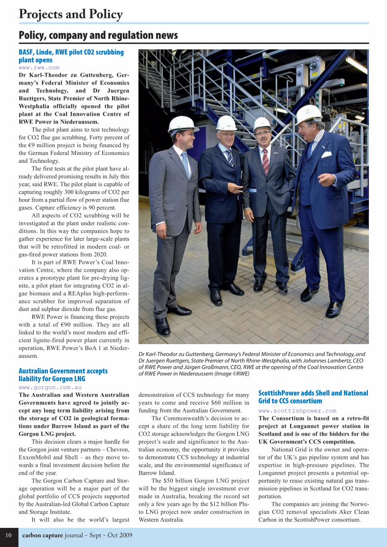
BASF, Linde, RWE pilot CO2 scrubbingplant openswww.rwe.comDr Karl-Theodor zu Guttenberg, Ger-
many’s Federal Minister of Economics
and Technology, and Dr Juergen
Ruettgers, State Premier of North Rhine-
Westphalia officially opened the pilot
plant at the Coal Innovation Centre of
RWE Power in Niederaussem.
The pilot plant aims to test technologyfor CO2 flue gas scrubbing. Forty percent ofthe €9 million project is being financed bythe German Federal Ministry of Economicsand Technology.
The first tests at the pilot plant have al-ready delivered promising results in July thisyear, said RWE. The pilot plant is capable ofcapturing roughly 300 kilograms of CO2 perhour from a partial flow of power station fluegases. Capture efficiency is 90 percent.
All aspects of CO2 scrubbing will beinvestigated at the plant under realistic con-ditions. In this way the companies hope togather experience for later large-scale plantsthat will be retrofitted in modern coal- orgas-fired power stations from 2020.
It is part of RWE Power’s Coal Inno-vation Centre, where the company also op-erates a prototype plant for pre-drying lig-nite, a pilot plant for integrating CO2 in al-gae biomass and a REAplus high-perform-ance scrubber for improved separation ofdust and sulphur dioxide from flue gas.
RWE Power is financing these projectswith a total of €90 million. They are alllinked to the world’s most modern and effi-cient lignite-fired power plant currently inoperation, RWE Power’s BoA 1 at Nieder-aussem.
Australian Government acceptsliability for Gorgon LNGwww.gorgon.com.auThe Australian and Western Australian
Governments have agreed to jointly ac-
cept any long term liability arising from
the storage of CO2 in geological forma-
tions under Barrow Island as part of the
Gorgon LNG project.
This decision clears a major hurdle forthe Gorgon joint venture partners – Chevron,ExxonMobil and Shell – as they move to-wards a final investment decision before theend of the year.
The Gorgon Carbon Capture and Stor-age operation will be a major part of theglobal portfolio of CCS projects supportedby the Australian-led Global Carbon Captureand Storage Institute.
It will also be the world’s largest
demonstration of CCS technology for manyyears to come and receive $60 million infunding from the Australian Government.
The Commonwealth’s decision to ac-cept a share of the long term liability forCO2 storage acknowledges the Gorgon LNGproject’s scale and significance to the Aus-tralian economy, the opportunity it providesto demonstrate CCS technology at industrialscale, and the environmental significance ofBarrow Island.
The $50 billion Gorgon LNG projectwill be the biggest single investment evermade in Australia, breaking the record setonly a few years ago by the $12 billion Plu-to LNG project now under construction inWestern Australia.
ScottishPower adds Shell and NationalGrid to CCS consortiumwww.scottishpower.comThe Consortium is based on a retro-fit
project at Longannet power station in
Scotland and is one of the bidders for the
UK Government’s CCS competition.
National Grid is the owner and opera-tor of the UK’s gas pipeline system and hasexpertise in high-pressure pipelines. TheLongannet project presents a potential op-portunity to reuse existing natural gas trans-mission pipelines in Scotland for CO2 trans-portation.
The companies are joining the Norwe-gian CO2 removal specialists Aker CleanCarbon in the ScottishPower consortium.
Policy, company and regulation news
Dr Karl-Theodor zu Guttenberg, Germany’s Federal Minister of Economics and Technology, andDr Juergen Ruettgers, State Premier of North Rhine-Westphalia, with Johannes Lambertz, CEOof RWE Power and Jürgen Großmann, CEO, RWE at the opening of the Coal Innovation Centreof RWE Power in Niederaussem (Image ©RWE)
Projects and Policy
10 carbon capture journal - Sept - Oct 2009
CCJ11a:Layout 1 15/09/2009 10:01 Page 10
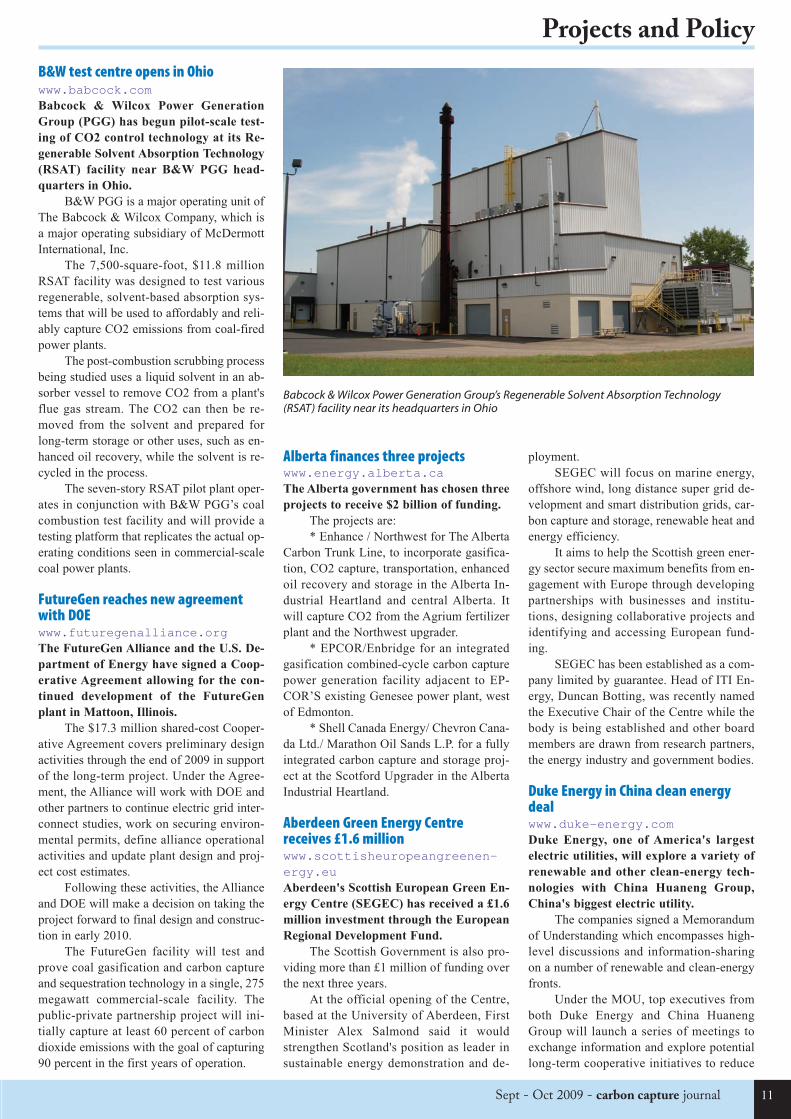
B&W test centre opens in Ohiowww.babcock.comBabcock & Wilcox Power Generation
Group (PGG) has begun pilot-scale test-
ing of CO2 control technology at its Re-
generable Solvent Absorption Technology
(RSAT) facility near B&W PGG head-
quarters in Ohio.
B&W PGG is a major operating unit ofThe Babcock & Wilcox Company, which isa major operating subsidiary of McDermottInternational, Inc.
The 7,500-square-foot, $11.8 millionRSAT facility was designed to test variousregenerable, solvent-based absorption sys-tems that will be used to affordably and reli-ably capture CO2 emissions from coal-firedpower plants.
The post-combustion scrubbing processbeing studied uses a liquid solvent in an ab-sorber vessel to remove CO2 from a plant'sflue gas stream. The CO2 can then be re-moved from the solvent and prepared forlong-term storage or other uses, such as en-hanced oil recovery, while the solvent is re-cycled in the process.
The seven-story RSAT pilot plant oper-ates in conjunction with B&W PGG’s coalcombustion test facility and will provide atesting platform that replicates the actual op-erating conditions seen in commercial-scalecoal power plants.
FutureGen reaches new agreementwith DOEwww.futuregenalliance.orgThe FutureGen Alliance and the U.S. De-
partment of Energy have signed a Coop-
erative Agreement allowing for the con-
tinued development of the FutureGen
plant in Mattoon, Illinois.
The $17.3 million shared-cost Cooper-ative Agreement covers preliminary designactivities through the end of 2009 in supportof the long-term project. Under the Agree-ment, the Alliance will work with DOE andother partners to continue electric grid inter-connect studies, work on securing environ-mental permits, define alliance operationalactivities and update plant design and proj-ect cost estimates.
Following these activities, the Allianceand DOE will make a decision on taking theproject forward to final design and construc-tion in early 2010.
The FutureGen facility will test andprove coal gasification and carbon captureand sequestration technology in a single, 275megawatt commercial-scale facility. Thepublic-private partnership project will ini-tially capture at least 60 percent of carbondioxide emissions with the goal of capturing90 percent in the first years of operation.
Alberta finances three projectswww.energy.alberta.ca The Alberta government has chosen three
projects to receive $2 billion of funding.
The projects are:* Enhance / Northwest for The Alberta
Carbon Trunk Line, to incorporate gasifica-tion, CO2 capture, transportation, enhancedoil recovery and storage in the Alberta In-dustrial Heartland and central Alberta. Itwill capture CO2 from the Agrium fertilizerplant and the Northwest upgrader.
* EPCOR/Enbridge for an integratedgasification combined-cycle carbon capturepower generation facility adjacent to EP-COR’S existing Genesee power plant, westof Edmonton.
* Shell Canada Energy/ Chevron Cana-da Ltd./ Marathon Oil Sands L.P. for a fullyintegrated carbon capture and storage proj-ect at the Scotford Upgrader in the AlbertaIndustrial Heartland.
Aberdeen Green Energy Centrereceives £1.6 millionwww.scottisheuropeangreenen-ergy.euAberdeen's Scottish European Green En-
ergy Centre (SEGEC) has received a £1.6
million investment through the European
Regional Development Fund.
The Scottish Government is also pro-viding more than £1 million of funding overthe next three years.
At the official opening of the Centre,based at the University of Aberdeen, FirstMinister Alex Salmond said it wouldstrengthen Scotland's position as leader insustainable energy demonstration and de-
ployment.SEGEC will focus on marine energy,
offshore wind, long distance super grid de-velopment and smart distribution grids, car-bon capture and storage, renewable heat andenergy efficiency.
It aims to help the Scottish green ener-gy sector secure maximum benefits from en-gagement with Europe through developingpartnerships with businesses and institu-tions, designing collaborative projects andidentifying and accessing European fund-ing.
SEGEC has been established as a com-pany limited by guarantee. Head of ITI En-ergy, Duncan Botting, was recently namedthe Executive Chair of the Centre while thebody is being established and other boardmembers are drawn from research partners,the energy industry and government bodies.
Duke Energy in China clean energydealwww.duke-energy.comDuke Energy, one of America's largest
electric utilities, will explore a variety of
renewable and other clean-energy tech-
nologies with China Huaneng Group,
China's biggest electric utility.
The companies signed a Memorandumof Understanding which encompasses high-level discussions and information-sharingon a number of renewable and clean-energyfronts.
Under the MOU, top executives fromboth Duke Energy and China HuanengGroup will launch a series of meetings toexchange information and explore potentiallong-term cooperative initiatives to reduce
Babcock & Wilcox Power Generation Group’s Regenerable Solvent Absorption Technology(RSAT) facility near its headquarters in Ohio
Projects and Policy
11Sept - Oct 2009 - carbon capture journal
CCJ11a:Layout 1 15/09/2009 10:01 Page 11
carbon capture journal - Sept - Oct 200912
Projects and Policy
coal plant emissions and develop other re-newable sources of electricity generation.
One key focal point will be emergingcleaner-coal technologies including carboncapture and sequestration and coal gasifica-tion.
Duke Energy is building one of thecleanest, largest and most advanced coalgasification power plants in the world – a630-megawatt facility in Edwardsport, Ind.,which is scheduled to go online in 2012. Inaddition, Duke Energy is spending $17 mil-lion to study carbon capture at the site andproposing to spend $121 million to study thepotential capture and permanent under-ground storage of up to 60 percent of theplant's carbon dioxide emissions.
China Huaneng Group has successful-ly built China's first CO2 capturing demon-stration facility in Huaneng Beijing Cogen-eration Power Plant. Also, a larger scaleCO2 capturing facility in one of Huaneng'scoal-fired power plants in Shanghai is un-der construction, and is scheduled to be putinto operation by the end of 2009.
Huaneng is also building its GreenGenproject – a 250-megawatt IGCC demonstra-tion power plant in Tianjin. It will be Chi-na's cleanest and most environmentallyfriendly coal-fired power plant when it isput into operation in 2011.
CCS Summer School begins in Australiawww.co2crc.com.auOver fifty post-graduate students from
around the world have begun a CCS
course at the 2009 IEA Greenhouse Gas
R&D programme (IEA GHG) CCS Sum-
mer School in Lorne, Victoria, Australia.
The week-long School will allow stu-dents from diverse backgrounds such as en-gineering, chemistry, geology and econom-ics to learn from local and international ex-perts in CCS.
In addition to discussions and presen-tations, the students will undertake focusedresearch projects on important issues inCCS, with a presentation to their peers at theend of the week. Students will gain a broadoverview of the issues surrounding technol-ogy development and implementation ofCCS.
The Global CCS Institute is a majorsupporter of the School and a member oftheir staff will be attending as a mentor.
The Victorian Government, which hasprovided significant support for CCS proj-ects in the state, is a major local sponsor.Four of the students (two from China andtwo from India) have received funding fromthe Australian Government through AusAIDto attend.
The School’s excursion to the
CO2CRC Otway Project has been madepossible through the generous support ofWoodside Energy Ltd. Event sponsorshiphas also been provided by Chevron Aus-tralia. Sponsorship of the IEA GHG Sum-mer School series is provided by BP, Al-stom, Schlumberger, E.On, StatoilHydro,Shell, Gassnova and RWE.
GE Energy proposes Australian IGCCplantwww.ge.com/energyGE has submitted a full project proposal
to the Queensland and Australian federal
governments for a 400MW (pre-carbon
capture) plant capable of capturing 90%
of the CO2 in the fuel stream.
If the development phase moves for-ward this year, the plant is expected to beready for commercial operation in late 2015or early 2016.
The proposed Wandoan Power Projectwould be based on GE’s commerciallyavailable IGCC technologies that have beenoperating for decades around the world andare being used at the 630-MW commercialplant under construction for Duke Energy atEdwardsport, Ind. in the United States.
GE is working with Stanwell and Xs-trata Coal to develop the project. Coal sup-ply and a long term CO2 storage solutionare critical aspects of the project, and Xstra-ta is working co-operatively with the con-sortium to identify and secure long term so-lutions that will serve this project.
CCSA and CSLF meet UK industrywww.ccsassociation.org.ukwww.cslforum.orgThe Carbon Capture and Storage Associ-
ation (CCSA) is co-hosting a Stakehold-
ers meeting on 3 September 2009, in
preparation for the Carbon Sequestration
Leadership Forum (CSLF) Ministerial
Meeting in London on 12-14 October.
The purpose of this preliminary meet-ing will be to ensure that a community ofstakeholders including industry and NGOsare aligned behind the a united set of policyobjectives ahead of the crucial CSLF Min-isterial Meeting, which will itself shape theglobal CCS community’s input for Decem-ber’s landmark UNFCCC summit in Copen-hagen.
Commenting ahead of the meeting on3 September, CCSA Chief Executive JeffChapman said:
“The CSLF Ministerial Meeting on 12-14 October 2009 represents the most impor-tant milestone for the global CCS commu-nity ahead of December’s critical UNFCCCcongress in Copenhagen.”
“In order to ensure that CCS plays its
rightful role in the UNFCCC’s recommen-dations, it is essential that the global com-munity is aligned behind a coherent set ofgoals.”
“The aim of the CSLF MinisterialMeeting is to enable the CCS community toagree on these proposed recommendationsand, by its involvement in this preliminarymember meeting, the CCSA is delighted tobe playing a leading role in driving dialogueahead of what will be a critical phase forCCS.”
Dr Jeff Chapman will also be chairingthe Stakeholder Forum at the CSLF Minis-terial Meeting itself, underlining the centralrole the CCSA is expecting to play in ad-vance of the UNFCCC congress in Copen-hagen.
University of Wyoming receives $2Mgrantwww.uwyo.eduThe University of Wyoming has received
nearly $2 million in federal funding to
support its efforts to enhance carbon se-
questration research and technology.
UW was one of just three schools to re-ceive multiple approvals; the University ofTexas at Austin and the New Mexico Insti-tute of Mining and Technology in Socorro,N.M., were the others.
James D. Myers, a professor in the UWDepartment of Geology and Geophysics, re-ceived $994,910 over three years to developthe Wyoming CCS Technology Center(WCTI), which would be based in Laramiebut facilitate training and technology trans-fer throughout the region. His award will bematched by $990,000 in AML funds allocat-ed by the Wyoming State Legislature forcarbon sequestration research.
The WCTI will use an industry-widemodel to train a professional workforce,provide pathways for graduates and profes-sionals from allied fields and create a vehi-cle for communicating regional carbon cap-ture and storage knowledge and technology.
The second approved UW proposal,submitted by Subhashis Mallick, a profes-sor in the Department of Geology and Geo-physics and a faculty member in the Schoolof Energy Resources, and Vladimir Alvara-do, a professor in the Department of Chem-ical and Petroleum Engineering, is worth$1,046,917 over three years.
Their goal is to combine multiphaseflow simulations with multi-componentseismic waveform modeling and inversionto determine if seismic waveform inversioncan accurately predict carbon dioxide plumemovements within storage reservoirs inpost-injection scenarios.
CCJ11a:Layout 1 15/09/2009 10:01 Page 12
Book Now – Call +44 20 7099 0600 or Online at:www.greenpowerconferences.com/carboncapture
Organised By:
Making the transition from theory to commercialisation
20-21 October 2009 • Grand Hyatt Doha, Qatar
SPECIAL OFFER!
15%discount, use discount
codeCCJ15whenbooking!
Insight and Analysis from CCS Experts Including:
� Dr. HishamAl-Khatib, Honorary Vice Chairman,World Energy Council, Jordan� Dr. Mohammed Jassim Al-Maslamani, Member, Supreme Council for Environment and Natural Reserves, Qatar� John Gale, General Manager, IEA Greenhouse Gas R&D Programme, UK� Prof. Stuart Haszeldine, Director, Scottish Centre for Carbon Storage, UK� Prof. GeoffMaitland, Professor of Energy Engineering, Imperial College London, UK andProgrammeDirector,Qatar Carbonates and Carbon Storage Research Centre, Qatar
� Dr. Felix Matthes, Energy & Climate Division, Institute for Applied Ecology, Germany� Kai Tullius, Policy Officer, European Commission
Plus Case Studies, Practical Lessons and Best Practice Advice from:
� Stephen Adamson, CCS Commercial Manager, Scottish Power, UK� Paul Bryant, Regional Director, Eastern Hemisphere,Hydrogen Energy, UAE� Desmond deVries, CCS Project Manager,Groningen Province, The Netherlands� Nigel Jenvey, Technical Director Carbon & Climate,Maersk Oil, Denmark� Luc deMarliave, Coordinator, Climate Change, Sustainable Development & Environment,Total, France� Anders Bradt Schulze, Head of CO2 Projects,Maersk Tankers, Denmark� Mahmut Sengul, Vice President Middle East and Asia, Schlumberger Carbon Services, UAE� Dr. Thomas Thielmann, Head of Coal Group, RWE, Germany� Senior Representative, StatoilHydro, Norway
Gain an indepth understanding of the opportunitiesand threats for CCS in theMiddle East and beyond:
� A timely update on the status and lessons from CCS projects worldwide� Understand the progress and potential of available CCS technologies� Listen to experts share their predictions on future market growth� Identify investment opportunities in the region� Hear expert analysis and assessment of the regulatory and legal frameworks defining the CO2 value chain� Participate in a series of interactive panel discussions and help shape this fast moving market� Benefit from first class networking opportunities through our online networking tool prior to, during and after the event
2nd Annual Event
Book Now to receive your 15% discount.Use discount code CCJ15 when booking
CCJ11a:Layout 1 15/09/2009 10:01 Page 13
carbon capture journal - Sept - Oct 200914
Special section - CO2 compressor technology
quired. No pump is needed since neither aliquid nor a dense supercritical phase is pres-ent at any point during the compressionprocess.
Due to the compressible character of thegas, its final temperature is very high, in thiscase about 130°C. A final cooling step to20°C was performed, under the assumption adenser state is desirable for the transportationprocess. Depending on the characteristics ofthe latter, however, more moderate coolingmay be sufficient. This compression onlycase A is assumed as baseline.
B) Compression/Pumping with Su-
percritical Liquefaction: For this case, theCO2 stream is brought to a pressure justabove the critical pressure through six com-pression sections intercooled with water atambient conditions. Subsequent cooling re-sulted in CO2 liquefaction at a compressoroutlet pressure of 80 bar. A pump then is usedto bring the dense fluid to final pressure. Theliquefaction pressure in this solution is abovethe minimum dictated by the cooling medi-um temperature.
C) Compression/Pumping with Sub-
critical Liquefaction: In view of the possi-bility of liquefying CO2 at a lower pressurethan above for the cooling medium used, thisstrategy uses six compression stages to bringthe CO2 to a subcritical pressure of 60 bar.This is the minimum pressure required forliquefaction at 20°C with water at ambientconditions. After liquefaction at these condi-
With CCS, the carbon content of a powerplant’s fuel (if pre-combustion or oxy-fuel)or exhaust stream (post-combustion) is sepa-rated and then stored or re-injected under-ground.
Because CCS is the only emissions re-duction method that enables a continued useof fossil fuels, it is strategically important asa bridge technology leading toward the daywhen an increased share of renewablesources has become part and parcel of theworld energy supply.
However, the energy requirements andhence the overall generating-system ineffi-ciencies CCS carries with it can be signifi-cant. Depending on the type of power plant,fuel, and separation method used, the net in-efficiencies CCS adds can range from aboutsix to 12 percent.
To date, much of the CCS-related re-search in the power sector has been focusedon finding optimum ways to separate carbonfrom either the fuel or post-combustion ex-haust streams. This is critical because sepa-ration of CO2 from the usually dilute exhaustgas or fuel stream is the most energy-inten-sive process step in CCS. It is heavily ener-gy-intensive because of the typically veryhigh volume flows and high pressure ratios,as well as the unique characteristics of ex-haust gas.
But as important as separation is, it is-n’t the only area where significant progresscan be made. It turns out that CO2 compres-sion processes contribute significantly tooverall power plant efficiency penalties, aswell as capital costs.
The compression process has been con-sidered a secondary issue, and attainable withcommercial technology. While that is true, acloser examination shows that CO2 compres-sion itself can account for overall power plantefficiency losses of up to five percent, de-pending on the power plant and the compres-sion chain characteristics. Since the CO2compression process is a parasitic energyconsumer, any measure leading to a reducedCO2 compression workload directly trans-lates into a net plant performance improve-ment.
Thus, there is an opportunity to consid-erably improve the overall economic picturefor CO2-lean fossil-fueled power plants byoptimizing CO2 compression processes.
In a state-of-the-art post-combustion
capture process based on chemical absorp-tion, CO2 is separated from the exhaust gasstream of the power plant at close-to-ambi-ent conditions. Although the exhaust gas ofnatural gas-fired power plants contains lowCO2 concentrations (typically about four per-cent by volume), the exhaust gas flows arequite large. Thus, the volume flows of sepa-rated CO2 to be compressed are also large.
These high volumes, depending on thepower plant size, may exceed those typicallyencountered in other CO2 compression ap-plications. Moreover, the final CO2 pressurerequired for transportation of this gas de-pends on the characteristics of both the finalstorage or reinjection site, as well as thetransportation process itself.
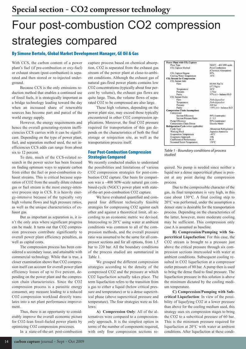
Four Post-Combustion CompressionStrategies ComparedWe recently conducted studies to understandthe possibilities and limitations of variousCO2 compression strategies for post-com-bustion CO2 capture. Our basis for compari-son was a ~400 MW-scale natural gas com-bined-cycle (NGCC) power plant with state-of-the-art post-combustion CO2 capture.
We have evaluated quantified and com-pared four different technically feasiblestrategies for compressing CO2 against eachother and against a theoretical limit, all ac-cording to an economic metric we devised.Intercooling to 20°C using water at ambientconditions was common to all of the com-pression methods, and the overall pressureratio was assumed to be the same for all com-pressor sections and for all options, from 1,5bar to 220 bar. All the boundary conditionsof the process studied are summarized inTable 1.
We grouped the different compressionstrategies according to the density of thecompressed CO2 and the pressure at whichCO2 liquefaction actually takes place. Theterm liquefaction refers to the transition froma gas to either a liquid (below critical pres-sure and temperature) or to a dense supercrit-ical phase (above supercritical pressure andtemperature). The four strategies were as fol-lows:
A) Compression Only: All of the al-ternatives were compared to a compression-only approach. It is the simplest option interms of the number of components required,with only four compression sections re-
Four post-combustion CO2 compression
strategies comparedBy Simone Bertolo, Global Market Development Manager, GE Oil & Gas
Table 1 - Boundary conditions of processstudied
CCJ11a:Layout 1 15/09/2009 10:01 Page 14
Sept - Oct 2009 - carbon capture journal 15
Special section - CO2 compressor technology
tions, the liquid CO2 is pumped to final pres-sure.
D) Refrigerated Compression/Pump-
ing: CO2 liquefaction using water at ambientconditions as a cooling medium is inherentlylimited by the characteristics of the surround-ing ambient. However, absorption refrigera-tion cycles can be economic in cases whereheat energy is available at temperatures be-tween about 100 and 200°C. Such is the casefor a combined-cycle power plant with steamas its working fluid in the bottoming cycle.
Therefore, an absorption refrigerationcycle was introduced to evaluate the poten-tial of CO2 liquefaction at a temperature be-low the minimum achievable with watercooling, and at a pressure below the mini-mum of 60 bar from above. Intercooling isstill carried out to 20°C with water for pres-sures below the cryogenic liquefaction pres-sure. In this configuration, the CO2 is cooledto a temperature below ambient during lique-faction by using heat from the CO2 exhauststream as a heat source to evaporate theworking fluid of a refrigeration cycle.
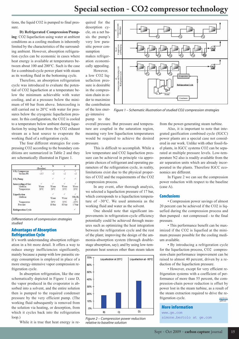
The four different strategies for com-pressing CO2 according to the boundary con-ditions are summarized in Table 2 and theyare schematically illustrated in Figure 1.
Advantages of AbsorptionRefrigeration CycleIt’s worth understanding absorption refriger-ation in a bit more detail. It offers a way toreduce energy inefficiencies significantly,mainly because a pump with low parasitic en-ergy consumption is employed in place of amore energy-intensive vapor compression re-frigeration cycle.
In absorption refrigeration, like the oneschematically depicted in Figure 1 case D,the vapor produced in the evaporator is ab-sorbed into a solvent, and the entire solutionthen is pumped to the required condenserpressure by the very efficient pump. (Theworking fluid subsequently is removed fromthe solution via heating, or desorption, fromwhich it cycles back into the refrigerationloop.)
While it is true that heat energy is re-
from the power-generating steam turbine.Also, it is important to note that inte-
grated gasification combined cycle (IGCC)power plants are a special case not consid-ered in our work. Unlike with other fossil-fu-el plants, in IGCC systems CO2 can be sepa-rated at multiple pressure levels. Low-tem-perature N2 also is readily available from theair separation units which are already incor-porated in the plants. Therefore IGCC eco-nomics are different.
In Figure 2 we can see the compressionpower reduction with respect to the baseline(case A).
Conclusions• Compression power savings of almost
20 percent can be achieved if the CO2 is liq-uefied during the compression process andthen pumped - not compressed - to the finalpressure.
• This performance benefit can be max-imized if the CO2 is liquefied at the mini-mum pressure possible for the cooling medi-um available.
• By introducing a refrigeration cyclefor the liquefaction process, CO2 compres-sion-chain performance improvement can beraised to almost 40 percent, driven by a re-duction of the liquefaction pressure.
• However, except for very efficient re-frigeration systems with a coefficient of per-formance of more than 55 percent, the com-pression-chain power reduction is offset bypower lost in the steam turbine, as a result ofthe steam extraction required to drive the re-frigeration cycle.
quired for thedesorption cy-cle, on a net ba-sis the pump’svery low para-sitic power con-sumptionmakes refriger-ation economi-cally appealing.
However,a low CO2 liq-uefaction pres-sure is desirablein the compres-sion chain in or-der to maximizethe contributionof the less ener-gy-intensivepump to theoverall pressure. But pressure and tempera-ture are coupled in the saturation region,meaning very low liquefaction temperatureswould be required to achieve the desiredpressure.
This is difficult to accomplish. While alow temperature and CO2 liquefaction pres-sure can be achieved in principle via appro-priate choices of refrigerant and operating pa-rameters of the refrigeration cycle, in reality,limitations exist due to the physical proper-ties of CO2 and the requirements of the CO2compression process.
In any event, after thorough analysis,we selected a liquefaction pressure of 17 bar,which corresponds to a liquefaction tempera-ture of –30°C. We used ammonia as theworking fluid and water as the solvent.
One should note that significant im-provements in refrigeration-cycle efficiencypotentially could be achieved through meas-ures such as optimizing the heat integrationbetween the refrigeration cycle and the restof the plant; improving the design of the am-monia-absorption system (through double-stage absorption, say); and by using low-tem-perature heat sources other than steam taken
Differentiators of compression strategiesstudied
Figure 1 – Schematic illustration of studied CO2 compression strategies
Figure 2 – Compression power reductionrelative to baseline solution
More informationwww.ge.comsimone.bertolo at ge.com
CCJ11a:Layout 1 15/09/2009 10:01 Page 15
carbon capture journal - Sept - Oct 200916
Special section - CO2 compressor technology
Innovative and proven CO2 compression
technology for CCS and EOR
CO2 has been used for a very long time, forinstance in refinery and food industry, andmost applications have required it to be com-pressed
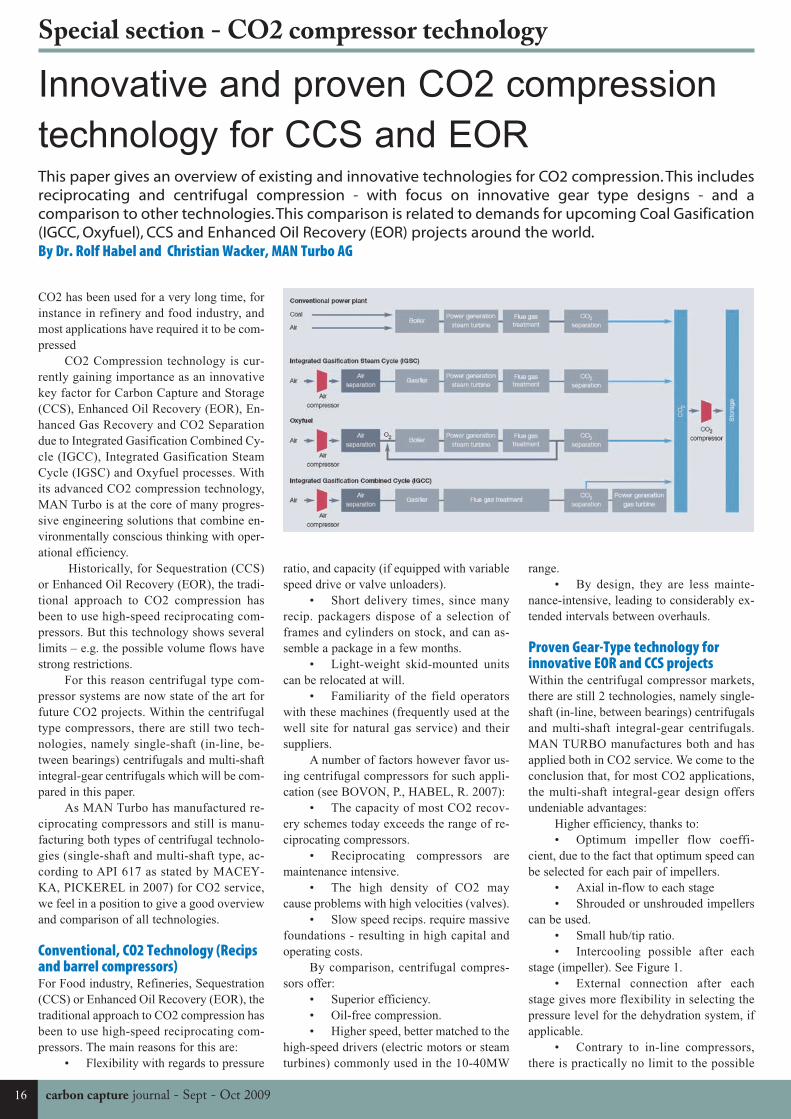
CO2 Compression technology is cur-rently gaining importance as an innovativekey factor for Carbon Capture and Storage(CCS), Enhanced Oil Recovery (EOR), En-hanced Gas Recovery and CO2 Separationdue to Integrated Gasification Combined Cy-cle (IGCC), Integrated Gasification SteamCycle (IGSC) and Oxyfuel processes. Withits advanced CO2 compression technology,MAN Turbo is at the core of many progres-sive engineering solutions that combine en-vironmentally conscious thinking with oper-ational efficiency.
Historically, for Sequestration (CCS)or Enhanced Oil Recovery (EOR), the tradi-tional approach to CO2 compression hasbeen to use high-speed reciprocating com-pressors. But this technology shows severallimits – e.g. the possible volume flows havestrong restrictions.
For this reason centrifugal type com-pressor systems are now state of the art forfuture CO2 projects. Within the centrifugaltype compressors, there are still two tech-nologies, namely single-shaft (in-line, be-tween bearings) centrifugals and multi-shaftintegral-gear centrifugals which will be com-pared in this paper.
As MAN Turbo has manufactured re-ciprocating compressors and still is manu-facturing both types of centrifugal technolo-gies (single-shaft and multi-shaft type, ac-cording to API 617 as stated by MACEY-KA, PICKEREL in 2007) for CO2 service,we feel in a position to give a good overviewand comparison of all technologies.
Conventional, CO2 Technology (Recipsand barrel compressors)For Food industry, Refineries, Sequestration(CCS) or Enhanced Oil Recovery (EOR), thetraditional approach to CO2 compression hasbeen to use high-speed reciprocating com-pressors. The main reasons for this are:
• Flexibility with regards to pressure
ratio, and capacity (if equipped with variablespeed drive or valve unloaders).
• Short delivery times, since manyrecip. packagers dispose of a selection offrames and cylinders on stock, and can as-semble a package in a few months.
• Light-weight skid-mounted unitscan be relocated at will.
• Familiarity of the field operatorswith these machines (frequently used at thewell site for natural gas service) and theirsuppliers.
A number of factors however favor us-ing centrifugal compressors for such appli-cation (see BOVON, P., HABEL, R. 2007):
• The capacity of most CO2 recov-ery schemes today exceeds the range of re-ciprocating compressors.
• Reciprocating compressors aremaintenance intensive.
• The high density of CO2 maycause problems with high velocities (valves).
• Slow speed recips. require massivefoundations - resulting in high capital andoperating costs.
By comparison, centrifugal compres-sors offer:
• Superior efficiency.• Oil-free compression.• Higher speed, better matched to the
high-speed drivers (electric motors or steamturbines) commonly used in the 10-40MW
range.• By design, they are less mainte-
nance-intensive, leading to considerably ex-tended intervals between overhauls.
Proven Gear-Type technology forinnovative EOR and CCS projectsWithin the centrifugal compressor markets,there are still 2 technologies, namely single-shaft (in-line, between bearings) centrifugalsand multi-shaft integral-gear centrifugals.MAN TURBO manufactures both and hasapplied both in CO2 service. We come to theconclusion that, for most CO2 applications,the multi-shaft integral-gear design offersundeniable advantages:
Higher efficiency, thanks to:• Optimum impeller flow coeffi-
cient, due to the fact that optimum speed canbe selected for each pair of impellers.
• Axial in-flow to each stage• Shrouded or unshrouded impellers
can be used.• Small hub/tip ratio.• Intercooling possible after each
stage (impeller). See Figure 1.• External connection after each
stage gives more flexibility in selecting thepressure level for the dehydration system, ifapplicable.
• Contrary to in-line compressors,there is practically no limit to the possible
This paper gives an overview of existing and innovative technologies for CO2 compression. This includesreciprocating and centrifugal compression - with focus on innovative gear type designs - and acomparison to other technologies. This comparison is related to demands for upcoming Coal Gasification(IGCC, Oxyfuel), CCS and Enhanced Oil Recovery (EOR) projects around the world. By Dr. Rolf Habel and Christian Wacker, MAN Turbo AG
CCJ11a:Layout 1 15/09/2009 10:01 Page 16
Sept - Oct 2009 - carbon capture journal 17
Special section - CO2 compressor technology
number of stages in one machine (pressureratio of 200 is possible on a single frame).
• Integral-gear compressors can bedirect-driven by a 4-pole electric motor onthe bull-gear, or a steam turbine on one ofthe pinions.
All the features of these machines arewell-proven and many references exist invarious services and frame sizes:
• Design is existing for 30 years andmore.
• Engineered units can be built up to10 stages (5 pinions).Unit power range up to30 MW is commonly used, for instance inair separation plants.
• Can be equipped with all the cur-rent range of sealing systems.
• Integral-gear compressors now rec-ognized by API 617.
• Reliability and interval betweenoverhaul considered comparable to in-linedesign.
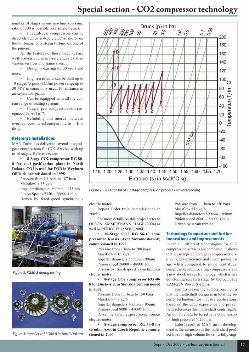
Reference installationsMAN Turbo has delivered several integral-gear compressors for CO2-Service with upto 10 stages. References are:
• 8-Stage CO2 compressor RG 80-
8 for coal gasification plant in North
Dakota, CO2 is used for EOR in Weyburn
Oilfields commissioned in 1998
Pressure from 1.1 bara to 187 baraMassflow ≈ 35 kg/sImpeller diameters 800mm – 115mmPinion Speeds 7350 – 26600 1/minDriven by fixed-speed synchronous
electric motorRepeat Order train commissioned in
2005For more details on this project refer to
OLSON, AMMERMANN, HAGE (2004) aswell as PERRY, ELIASON (2004).
• 10-Stage CO2 RG 56-10 com-
pressor in Russia (Azot Nowomoskowsk)
commissioned in 1992
Pressure from 1 bara to 200 bara: Massflow ≈ 13 kg/sImpeller diameters 550mm – 90mmPinion speed 26000 – 48000 1/minDriven by fixed-speed asynchronous
electric motor• 8-stage CO2 compressor RG 40-
8 for Duslo A.S. in Slovakia commissioned
in 2002
Pressure from 1.1 bara to 150 baraMassflow ≈ 8 kg/hImpeller diameters 400mm – 95mmPinion speed 8000 – 41000 1/minDriven by variable speed asynchronous
electric motor• 8-stage compressor RG 56-8 for
Grodno Azot in Czech Republic commis-
sioned in 2006
Pressure from 1.1 bara to 150 baraMassflow ≈16 kg/hImpeller diameters 500mm – 95mmPinion speed 8000 – 36000 1/minDriven by steam turbine
Technology Comparison and furtherInnovations and ImprovementsIn table 1 different technologies for CO2compression services are compared. It showsthat Gear type centrifugal compressors dis-play better efficiency and lower power us-age when compared to inline centrifugalcompressor, reciprocating compressors anda new shock waves technology, which is in adeveloping/research stage by the companyRAMGEN Power Systems.
For this reason the authors` opinion isthat the multi-shaft design is in total the su-perior technology for industry applications,based on the good experience and provenfield references for multi-shaft centrifugals.An option could be barrel type compressorsfor high pressures > 250 bar.
Latest result of MAN turbo develop-ment is the extension of the multi-shaft prod-uct line for high volume flows - a fully engi-
Figure 1: T-s Diagram of 10 stage compression process with intercooling
Figure 3: Impellers of RG80-8 in North Dakota
Figure 2: RG80-8 during testing
CCJ11a:Layout 1 15/09/2009 10:01 Page 17
neered RG 100. For this reason MAN Turbocan now offer the following flows with theirexisting gear type product line according totable 2.
ConclusionIn conclusion, and based on our experience,integral-gear compressors have definite ad-vantages over reciprocating or supersonictechnologies and in-line centrifugals in mostCO2 service:
• Gear type compression is more ef-ficient than supersonic or reciprocating tech-nology (see figure 1)
• In-line compressors require ap-prox. twice the number of stages than do in-tegral-gear compressors, leading to one ortwo additional casings.
• Integral-gear compressors showhigher efficiency.
• Integral-gear compressors have
comparable maintenance requirements as in-line compressors.
The integral-gear compressor is a
proven, reliable, and cost effective solutionfor CO2 service.
ReferencesBOVON, P.; Habel, R.: CO2 CompressionChallengesASME Turbo Exp, CO2 Com-pression Panel, May 2007, Montreal, Cana-daMACEYKA, T.; PICKEREL, G.; IntegrallyGeared Compressors - API Specs ExtendTheir Service To Offshore Services, Turbo-machinery International sept/oct 2007OLSON, B.; AMMERMANN, D.; HAGE;H.: CO2 Compression Using an Eight Stage,Integrally Geared, Centrifugal Compressor,Proceedings of IPC 2004, Calgary AlbertaCanadaPERRY, M.; ELIASON, D.: CO2 Recoveryand Sequestration at Dakota GasificationCompany, October 2004
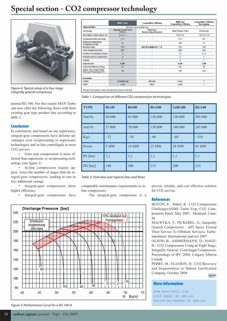
Table 1: Comparison of different CO2 compression technologies
TYPE RG45 RG80 RG100 2xRG80 RG140
Nm3/h 20.000 65.000 120.000 130.000 205.000
Am3/h 27.000 70.000 130.000 140.000 245.000
Kg/s ~12 ~34 ~66 ~68 ~110
Power 5 MW 14 MW 25 MW 28 MW 45 MW
PS [bar] 1,1 1,1 1,1 1,1 1,1
PD [bar] 140 200 215 200 215
Table 2: Overview over typical sizes and flows
Figure 4: Typical setup of a four stageintegrally geared compressor
Figure 5: Performance Curve for a RG 100-8
More information
www.manturbo.comrolf.habel at man.eu christian.wacker at man.eu
Special section - CO2 compressor technology
18 carbon capture journal - Sept - Oct 2009
CCJ11a:Layout 1 15/09/2009 10:01 Page 18
porting cooling towers or fin-fan radiators,themselves a significant capital and installa-tion expense.
The actual intercooler selection is madeeven more difficult by the need for low-pres-sure drop designs and the requirement to uselow heat transfer effectiveness corrosion-re-sistant stainless steel construction. Air-cooled heat exchangers, often required incold or arid climates, exacerbate the prob-lem with their generally lower approach tem-peratures and require substantial fan horse-power, often overlooked in the “compressor”power evaluation.
The Ramgen concept offers matchedsets of independent-drive, single-stage com-pressors instead of a conventional integralgear compressor configuration with a com-mon bull gear drive. Each of the stages canachieve a 10+:1 pressure ratio. An intercool-er is used between the LP and HP Stages andan aftercooler is used after the HP Stage. Thehigh-pressure stage is shown in Fig. 3 alongwith a typical T-s diagram for a two-stageconfiguration.
These stage discharge coolers can bethe CCS process itself. Cost effective heatintegration, enabled by the high quality heatof compression associated with the 10:1compression ratio, can substantially improvethe economics of CCS. The Ramgen LP andHP Stages can provide approximately 270Btu/lbm- CO2 for a variety of heat integra-tion options.
At a minimum, this independent-driveapproach allows better matching of eachstage to its specific process flow, includingside-streams. In addition, this drive config-
CO2 compressors represent approximately1/3 of the significant capital and operatingcost of a post-combustion, amine-based CCSsystem. The CO2 compressor power re-quired for a pulverized coal power plant is8-12% of the plant rating, depending largelyon the suction pressure.
A 1,000 MW PC plant would require100 MW, or 134,000 hp for CO2 compres-sion at an estimated $150 million equipmentcost for today’s 3 x 50% configuration. In-stallation costs at $75-100 million would bein addition.
Ramgen TechnologyRamgen’s shock compression technology isexpected to represent a significant advance-ment in the state of the art for many com-pressor applications, and specifically forCO2 compression.
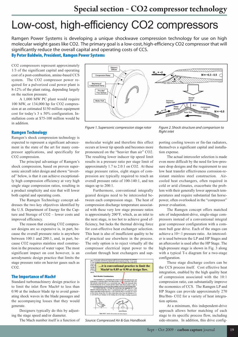
The principal advantage of Ramgen’sshock compression, based on proven super-sonic aircraft inlet design and shown “invert-ed” below, is that it can achieve exceptional-ly high compression efficiency at very highsingle stage compression ratios, resulting ina product simplicity and size that will lowerboth capital and operating costs.
The Ramgen Technology concept ad-dresses the two key objectives identified bythe U.S. Department of Energy for the Cap-ture and Storage of CO2 – lower costs andimproved efficiency.
The reason that existing CO2 compres-sor designs are so expensive is, in part, be-cause the overall pressure ratio is anywherebetween 100:1 and 200:1, and, in part, be-cause CO2 requires stainless steel construc-tion in the presence of water vapor. The mostsignificant impact on cost however, is anaerodynamic design practice that limits thestage pressure ratio on heavier gases such asCO2.
The Importance of Mach#Standard turbomachinery design practice isto limit the inlet flow Mach# to less than0.90 at the inducer blade tip to avoid gener-ating shock waves in the blade passages andthe accompanying losses that they wouldgenerate.
Designers typically do this by adjust-ing the stage speed and/or diameter.
The Mach number itself is a function of
molecular weight and therefore this effectoccurs at lower tip speeds and becomes morepronounced on the “heavier than air” CO2.The resulting lower inducer tip speed limitresults in a pressure ratio per stage limit ofapproximately 1.7 to 2.0:1 on CO2. At thesestage pressure ratios, eight stages of com-pression are typically required to reach anoverall pressure ratio of 100-140:1, and tenstages up to 200:1.
Furthermore, conventional integrallygeared designs need to be intercooled be-tween each compression stage. The heat ofcompression discharge temperature associat-ed with these very low stage pressure ratiosis approximately 200°F, which, as an inlet tothe next stage, is too hot to achieve good ef-ficiency, but lacks the thermal driving forcefor cost-effective heat exchanger selection.This heat is also of insufficient quality to beof practical use elsewhere in the process.The only option is to reject virtually all thecompressor electrical input power to thecoolant through heat exchangers and sup-
Low-cost, high-efficiency CO2 compressorsRamgen Power Systems is developing a unique shockwave compression technology for use on highmolecular weight gases like CO2. The primary goal is a low-cost, high-efficiency CO2 compressor that willsignificantly reduce the overall capital and operating costs of CCS.By Peter Baldwin, President, Ramgen Power Systems
Figure 1. Supersonic compression stage rotor Figure 2. Shock structure and comparison toflight inlet
Source: Compressed Air & Gas Handbook
Special section - CO2 compressor technology
19Sept - Oct 2009 - carbon capture journal
CCJ11a:Layout 1 16/10/2009 11:46 Page 19

uration approach lends itself to a variablespeed capability that can provide desirableoperational flexibility.
The Ramgen baseline drive utilizes aconventional low-speed motor and simple,single-step external speed-increasing gear-box, with other variations available to suitcustomer and contract requirements. High-speed permanent magnet motor drives orsteam turbines are both feasible drive alter-natives.
CO2 Properties & Application IssuesCarbon dioxide has both unique chemicaland thermodynamic properties that requirecare in selecting and applying compressorson CO2 service.
CO2 forms carbonic acid in the pres-ence of water and the CO2 is normally de-hydrated at some point during the compres-sion process, usually at some convenient in-terstage pressure. The amount of water con-sidered acceptable is subject to some debate,but current system guidelines issued by theU.S. Department of Energy call for -40°Fdew point. Stainless steel construction istypically required in the presence of water.
CO2 can also infiltrate elastomers,which then suffer decompression damagefrom incomplete out gassing analogous todivers getting “the bends”. Suitable seal,gasket and o-ring materials are available andhave been applied successfully.
Intercooler selection and operation re-quire great care. Good design practice main-tains a minimum 20°F superheat at the inletof each compression stage to avoid the CO2two-phase region, or that of the impuritieswithin it. In practice, experienced operatorsmaintain stage inlet temperatures between95°F and 100°F, and 1600 psia is consideredto be the minimum discharge pressures to in-sure that all impurities are above their criti-cal pressure.
Eight or ten-stage designs are particu-larly sensitive to this two-phasing effect be-cause the margin between the compressor-stage discharge pressure and the two-phaseregion in and around the critical point,shown in red, is both small and somewhatunpredictable, depending on impurities.
The proximity of the line of constant100°F temperature to the CO2 vapor domein the pressure-enthalpy diagram show ingreen (Fig. 4) illustrates the challenge of ful-ly intercooling the later stages of multi-stagedesigns. Ramgen, on the other hand andshown in blue, operates in regions very muchremoved from the critical point.
At the same time, the enthalpy associ-ated with these CO2 state points does offer asignificant opportunity for heat recovery onboth the Ramgen LP and HP stages. Ram-
gen offers the user approximately 270Btu/lbm-CO2 compressed, with high quality490-510°F heat of compression heat integra-tion.
Compressor Performance Issues &AssumptionsCompressor performance calculations arerelatively straightforward. The assumptionsbehind them are not.
The specification generally providesthe basic input of mass flow, gas composi-tion, inlet pressure and temperature, and dis-charge pressure, but invariably overlookedare the cooling medium available and itstemperature. The CCS process itself onlycontrols the first stage suction conditions;the cooling medium controls the others.
A good assumption for pressure drop isΔP = P2
0.7 / 10, but not to exceed 5 psi.Coolant temperature is only relevant to de-
termining subsequent stage inlet tempera-tures and coolant flow rates. In the case ofCO2, experienced operators generally as-sume interstage temperatures of 100°F toavoid the two-phase regions and control it atthat level.
Configuration assumptions are requiredbeyond these generic values and includesparing philosophy, or stated differently,how many units are required to meet themass flow specified.
Ramgen will develop a series of LP andHP frame sizes to support both amine-basedand the ammonia-based capture technolo-gies, as well as any capture technologies thatmight emerge. The planned LP and HP sizeswould be able to support the full capacity800MW unit in a single set of units.
Ramgen’s Competitive AdvantageRamgen’s technology has both capital andoperating cost advantages.
• Ramgen expects to be 50-60% of theconventional integrally-geared centrifugalcompressor on an installed cost basis.
• The Ramgen two-stage configuration
Figure 3. Ramgen Independent-Drive HP Stage
Figure 4. Pressure-enthalpy diagram
Special section - CO2 compressor technology
20 carbon capture journal - Sept - Oct 2009
CCJ11a:Layout 1 16/10/2009 11:46 Page 20
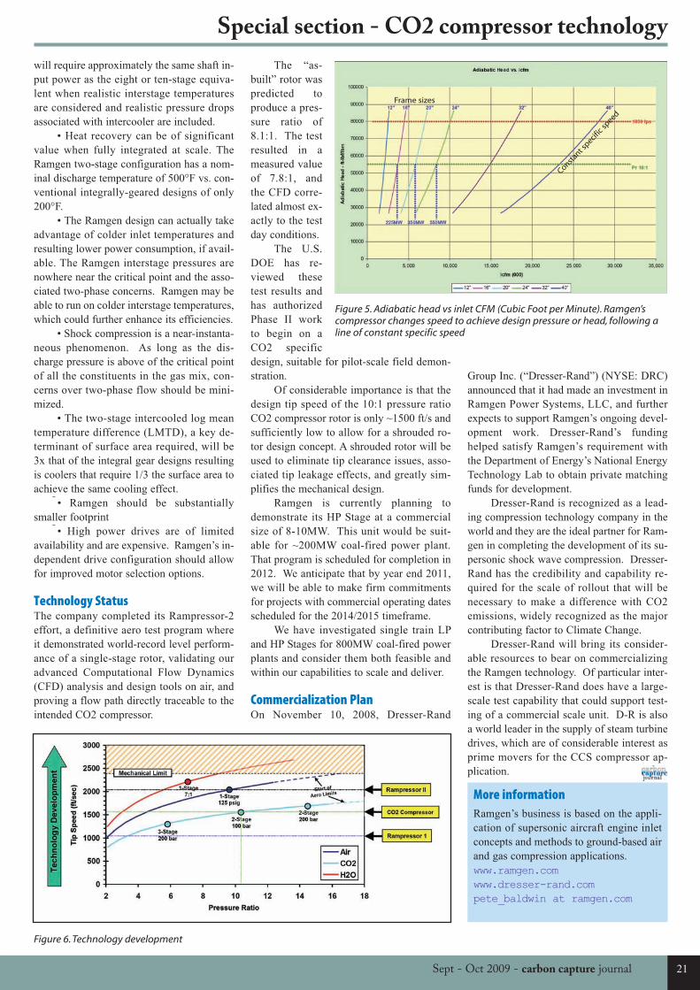
will require approximately the same shaft in-put power as the eight or ten-stage equiva-lent when realistic interstage temperaturesare considered and realistic pressure dropsassociated with intercooler are included.
• Heat recovery can be of significantvalue when fully integrated at scale. TheRamgen two-stage configuration has a nom-inal discharge temperature of 500°F vs. con-ventional integrally-geared designs of only200°F.
• The Ramgen design can actually takeadvantage of colder inlet temperatures andresulting lower power consumption, if avail-able. The Ramgen interstage pressures arenowhere near the critical point and the asso-ciated two-phase concerns. Ramgen may beable to run on colder interstage temperatures,which could further enhance its efficiencies.
• Shock compression is a near-instanta-neous phenomenon. As long as the dis-charge pressure is above of the critical pointof all the constituents in the gas mix, con-cerns over two-phase flow should be mini-mized.
• The two-stage intercooled log meantemperature difference (LMTD), a key de-terminant of surface area required, will be3x that of the integral gear designs resultingis coolers that require 1/3 the surface area toachieve the same cooling effect.
• Ramgen should be substantiallysmaller footprint
• High power drives are of limitedavailability and are expensive. Ramgen’s in-dependent drive configuration should allowfor improved motor selection options.
Technology StatusThe company completed its Rampressor-2effort, a definitive aero test program whereit demonstrated world-record level perform-ance of a single-stage rotor, validating ouradvanced Computational Flow Dynamics(CFD) analysis and design tools on air, andproving a flow path directly traceable to theintended CO2 compressor.
The “as-built” rotor waspredicted toproduce a pres-sure ratio of8.1:1. The testresulted in ameasured valueof 7.8:1, andthe CFD corre-lated almost ex-actly to the testday conditions.
The U.S.DOE has re-viewed thesetest results andhas authorizedPhase II workto begin on aCO2 specificdesign, suitable for pilot-scale field demon-stration.
Of considerable importance is that thedesign tip speed of the 10:1 pressure ratioCO2 compressor rotor is only ~1500 ft/s andsufficiently low to allow for a shrouded ro-tor design concept. A shrouded rotor will beused to eliminate tip clearance issues, asso-ciated tip leakage effects, and greatly sim-plifies the mechanical design.
Ramgen is currently planning todemonstrate its HP Stage at a commercialsize of 8-10MW. This unit would be suit-able for ~200MW coal-fired power plant.That program is scheduled for completion in2012. We anticipate that by year end 2011,we will be able to make firm commitmentsfor projects with commercial operating datesscheduled for the 2014/2015 timeframe.
We have investigated single train LPand HP Stages for 800MW coal-fired powerplants and consider them both feasible andwithin our capabilities to scale and deliver.
Commercialization PlanOn November 10, 2008, Dresser-Rand
Group Inc. (“Dresser-Rand”) (NYSE: DRC)announced that it had made an investment inRamgen Power Systems, LLC, and furtherexpects to support Ramgen’s ongoing devel-opment work. Dresser-Rand’s fundinghelped satisfy Ramgen’s requirement withthe Department of Energy’s National EnergyTechnology Lab to obtain private matchingfunds for development.
Dresser-Rand is recognized as a lead-ing compression technology company in theworld and they are the ideal partner for Ram-gen in completing the development of its su-personic shock wave compression. Dresser-Rand has the credibility and capability re-quired for the scale of rollout that will benecessary to make a difference with CO2emissions, widely recognized as the majorcontributing factor to Climate Change.
Dresser-Rand will bring its consider-able resources to bear on commercializingthe Ramgen technology. Of particular inter-est is that Dresser-Rand does have a large-scale test capability that could support test-ing of a commercial scale unit. D-R is alsoa world leader in the supply of steam turbinedrives, which are of considerable interest asprime movers for the CCS compressor ap-plication.
Figure 6. Technology development
Figure 5. Adiabatic head vs inlet CFM (Cubic Foot per Minute). Ramgen’scompressor changes speed to achieve design pressure or head, following aline of constant specific speed
More informationRamgen’s business is based on the appli-cation of supersonic aircraft engine inletconcepts and methods to ground-based airand gas compression applications.www.ramgen.comwww.dresser-rand.compete_baldwin at ramgen.com
Special section - CO2 compressor technology
21Sept - Oct 2009 - carbon capture journal
Constant sp
ecific
speed
Frame sizes
CCJ11a:Layout 1 16/10/2009 11:46 Page 21
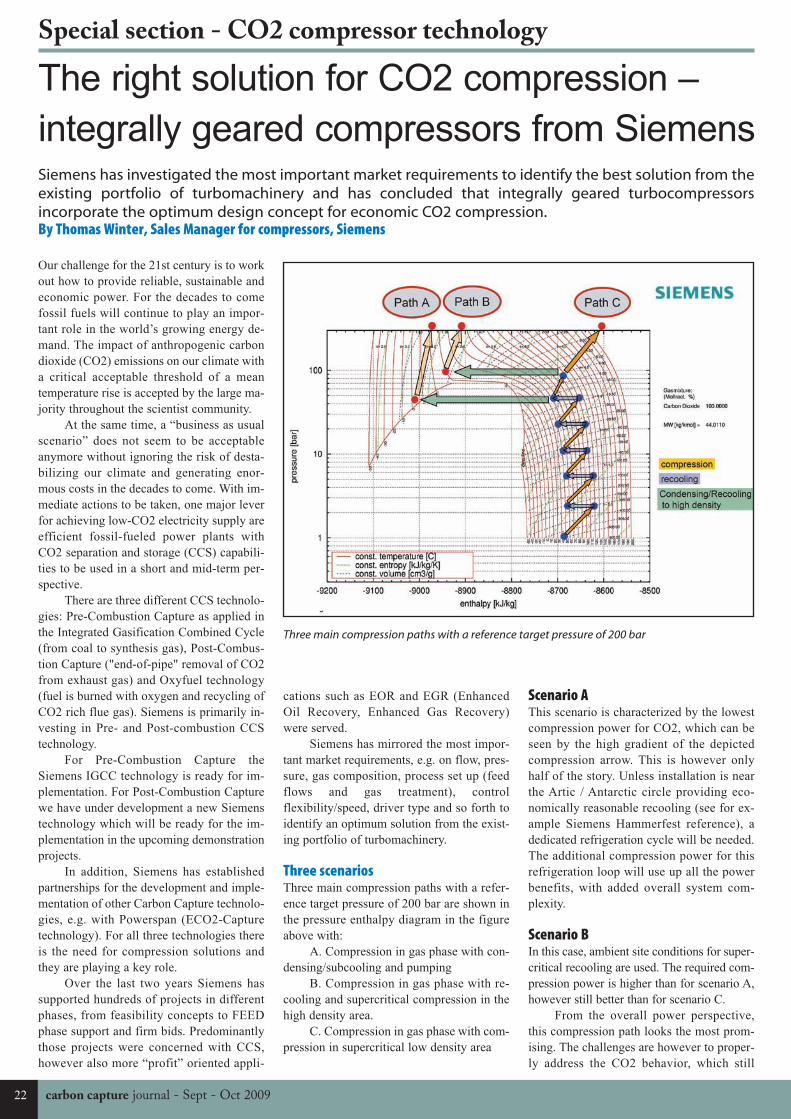
The right solution for CO2 compression –
integrally geared compressors from SiemensSiemens has investigated the most important market requirements to identify the best solution from theexisting portfolio of turbomachinery and has concluded that integrally geared turbocompressorsincorporate the optimum design concept for economic CO2 compression.By Thomas Winter, Sales Manager for compressors, Siemens
Our challenge for the 21st century is to workout how to provide reliable, sustainable andeconomic power. For the decades to comefossil fuels will continue to play an impor-tant role in the world’s growing energy de-mand. The impact of anthropogenic carbondioxide (CO2) emissions on our climate witha critical acceptable threshold of a meantemperature rise is accepted by the large ma-jority throughout the scientist community.
At the same time, a “business as usualscenario” does not seem to be acceptableanymore without ignoring the risk of desta-bilizing our climate and generating enor-mous costs in the decades to come. With im-mediate actions to be taken, one major leverfor achieving low-CO2 electricity supply areefficient fossil-fueled power plants withCO2 separation and storage (CCS) capabili-ties to be used in a short and mid-term per-spective.
There are three different CCS technolo-gies: Pre-Combustion Capture as applied inthe Integrated Gasification Combined Cycle(from coal to synthesis gas), Post-Combus-tion Capture ("end-of-pipe" removal of CO2from exhaust gas) and Oxyfuel technology(fuel is burned with oxygen and recycling ofCO2 rich flue gas). Siemens is primarily in-vesting in Pre- and Post-combustion CCStechnology.
For Pre-Combustion Capture theSiemens IGCC technology is ready for im-plementation. For Post-Combustion Capturewe have under development a new Siemenstechnology which will be ready for the im-plementation in the upcoming demonstrationprojects.
In addition, Siemens has establishedpartnerships for the development and imple-mentation of other Carbon Capture technolo-gies, e.g. with Powerspan (ECO2-Capturetechnology). For all three technologies thereis the need for compression solutions andthey are playing a key role.
Over the last two years Siemens hassupported hundreds of projects in differentphases, from feasibility concepts to FEEDphase support and firm bids. Predominantlythose projects were concerned with CCS,however also more “profit” oriented appli-
cations such as EOR and EGR (EnhancedOil Recovery, Enhanced Gas Recovery)were served.
Siemens has mirrored the most impor-tant market requirements, e.g. on flow, pres-sure, gas composition, process set up (feedflows and gas treatment), controlflexibility/speed, driver type and so forth toidentify an optimum solution from the exist-ing portfolio of turbomachinery.
Three scenariosThree main compression paths with a refer-ence target pressure of 200 bar are shown inthe pressure enthalpy diagram in the figureabove with:
A. Compression in gas phase with con-densing/subcooling and pumping
B. Compression in gas phase with re-cooling and supercritical compression in thehigh density area.
C. Compression in gas phase with com-pression in supercritical low density area
Scenario AThis scenario is characterized by the lowestcompression power for CO2, which can beseen by the high gradient of the depictedcompression arrow. This is however onlyhalf of the story. Unless installation is nearthe Artic / Antarctic circle providing eco-nomically reasonable recooling (see for ex-ample Siemens Hammerfest reference), adedicated refrigeration cycle will be needed.The additional compression power for thisrefrigeration loop will use up all the powerbenefits, with added overall system com-plexity.
Scenario BIn this case, ambient site conditions for super-critical recooling are used. The required com-pression power is higher than for scenario A,however still better than for scenario C.
From the overall power perspective,this compression path looks the most prom-ising. The challenges are however to proper-ly address the CO2 behavior, which still
Three main compression paths with a reference target pressure of 200 bar
Special section - CO2 compressor technology
22 carbon capture journal - Sept - Oct 2009
CCJ11a:Layout 1 15/09/2009 10:01 Page 22
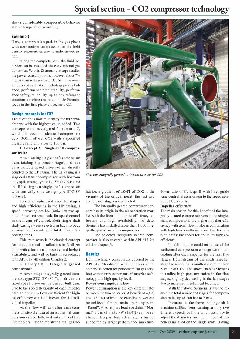
shows considerable compressible behaviorat high temperature sensitivity.
Scenario CHere, a compression path in the gas phasewith consecutive compression in the lightdensity supercritical area is under investiga-tion.
Along the complete path, the fluid be-havior can be modeled via conventional gasdynamics. Within Siemens concept studiesthe power consumption is however about 7%higher than with scenario B.). Still, the over-all concept evaluation including power bal-ance, performance predictability, perform-ance safety, reliability, up-to-day referencesituation, timeline and so on made Siemensfocus in the first phase on scenario C.).
Design concepts for CO2The question is now to identify the turboma-chinery with the highest value added. Twoconcepts were investigated for scenario C,which addressed an identical compressionduty: 300t/h of wet CO2 with a specifiedpressure ratio of 1.9 bar to 160 bar.
1. Concept A – Single-shaft compres-
sor train:
A two-casing single-shaft compressortrain, totaling four process stages, is drivenby a variable-speed drive system directlycoupled to the LP casing. The LP casing is asingle-shaft turbocompressor with horizon-tally spilt casing, type STC-SH (17-6-B) andthe HP-casing is a single shaft compressorwith vertically split casing, type STC-SV(10-6-B).
To obtain optimized impeller shapesand high efficiencies in the HP casing, aspeed-increasing gea box (ratio 1.9) was ap-plied. Provision was made for speed controlas the means of control. Both single-shaftshaft casings were selected in back to backarrangement providing in total three inter-cooling steps.
This train setup is the classical conceptfor petrochemical installations in fertilizerunits with a focus on robustness and highestavailability, and will be built in accordancewith API 617 7th edition Chapter 2.
2. Concept B – Integrally geared
compressor:
A seven-stage integrally geared com-pressor, type STC-GV (80-7), is driven viafixed-speed drive on the central bull gear.Due to the speed flexibility of each impellerpair, an optimum flow coefficient for high-est efficiency can be achieved for the indi-vidual impeller.
As the flow will exit after each com-pression step the idea of an isothermal com-pression can be followed with in total fiveintercoolers. Due to the strong real gas be-
havior, a gradient of dZ/dT of CO2 in thevicinity of the critical point, the last twocompressor stages are uncooled.
The integrally geared compressor con-cept has its origin in the air separation mar-ket with the focus on highest efficiency so-lutions and high availability. To date,Siemens has installed more than 1,000 inte-grally geared air turbocompressors.
The selected integrally geared com-pressor is also covered within API 617 7thedition chapter 3.
ResultsBoth machinery concepts are covered by theAPI 617 7th edition, which addresses ma-chinery selection for petrochemical gas serv-ices with their requirements of superior tech-nology at a high quality level.Power consumption is key
Power consumption is the key differentiatorbetween the two concepts. A benefit of 4,890kW (13.9%) of installed coupling power canbe achieved for the main operating point“Rated”. Also at part load condition “Nor-mal” a gap of 3,937 kW (13.4%) can be re-alized. This part load advantage is furthersupported by larger performance map turn-
down ratio of Concept B with Inlet guidevane control in comparison to the speed con-trol of Concept A. Impeller efficiency
The main reason for this benefit of the inte-grally geared compressor versus the single-shaft compressor is the higher impeller effi-ciency with axial flow intake in combinationwith high head coefficients and the flexibili-ty to adjust the speed for optimum flow co-efficients.
In addition, one could make use of theisothermal compression concept with inter-cooling after each impeller for the first fivestages. Downstream of the sixth impellerstage the recooling is omitted due to the lowZ-value of CO2. The above enables Siemensto realize high pressure ratios in the firststages, slightly decreasing in the last stagesdue to increased mechanical loadings.
With the above Siemens is able to re-duce the total number of stages for compres-sion ratios up to 200 bar to 7 or 8.
In contrast to the above, the single-shaftmachine suffers from running at only twodifferent speeds with the only possibility toadjust the diameter and the number of im-pellers installed on the single shaft. Having
Siemens integrally geared turbocompressor for CO2
Special section - CO2 compressor technology
23Sept - Oct 2009 - carbon capture journal
CCJ11a:Layout 1 15/09/2009 10:01 Page 23
a polytropic efficiency for the first processstage (made up of 3 impellers) above 82%, astrong decrease to only 70% for the lastprocess stage is encountered.
This is mainly due to the strong volumedecrease throughout the compression chain,resulting in 2D vane configuration on the laststages and poor impeller performance.
In addition, the overall number of im-pellers is twelve compared to seven on theintegrally geared compressors, which is alsodue to the reduced head coefficients for sin-gle-shaft impellers.Energy savings due to compact design
To sum up, even with a relatively low ener-gy cost of 2.5 €/W value added amountingto €12.225 million can be realized by optingfor the integrally geared compressor solu-tion. In addition to the OPEX benefits, theinvestment cost for an integrally gearedcompressor is lower than for a single-shaftcompressor train.
This is the result of a compact designwith fewer impellers and smaller impeller di-ameters. Both compressor concepts are suit-able for wet CO2 conditions even underNACE sour gas conditions.
Overall, there is a striking life-cyclecost advantage for the integrally geared com-pressor.
Due to the compact design, the instal-lation weight is considerably lower and thespace required as well. This cuts cost on theexpenses for ground, concrete work and civ-il engineering.
Furthermore, complete packaged unitscan be realized with coolers installed in steelframes and completely assembled piping in-cluding necessary anti-surge loops. This en-ables single lift units with reduced site in-stallation time and reduces the piping inter-faces to a minimum.
As far as machine robustness is con-cerned, permissable nozzle loads on singleshaft compressors with several times NEMAare higher than on integrally geared com-pressors.
On integrally geared compressors theallowable forces and moments require acloser look and will be calculated case wisefor each single compressor. If necessary,compensators will be installed on the inter-faces to the suction and discharge piping toaccommodate for excessive loading.
Furthermore, the integrally gearedcompressor with overhung bearing design ismore sensitive in applications with a highpotential of fouling or particle loading in thegas phase. This is however not the case inCO2 compression duties.Flexibility
A major advantage of the integrally gearedcompressor is its flexibility for intermediate
control of pressure/temperature or flow. Thisenables distinct conditions to be controlledthroughout the compression chain within onesingle compressor. This can be of benefitwhen controlling pressures for feed or ex-traction flow or pressures on process gastreatments like dehydration. A single-shaftcompressor is usually speed controlled andhas only one degree of freedom.
The availability of both compressorconcepts are in the 99% range, with both be-ing applied in critical compression services.This underlines the high quality and expert-ise as well as the clients trust in this technol-ogy.
SummarySiemens established that the preferred andmost efficient solution for CO2 compressionis the integrally geared compressor. It willgive the most value added especially in ap-plications where its compression power is“parasitic”.
Siemens has more than 60 years of ex-perience in the manufacturing of integrallygeared compressors. Continuous enhance-ment of this product has ensured its out-standing reputation in the process compres-sion market. Nevertheless, high-pressureCO2 compression will again be the driver forfurther product enhancement tailored to thespecifics of CO2 gas behavior.
Siemens has the necessary expertise tosuccessfully design, build and test integrallygeared compressors. These include:
- Correct prediction of gas data
throughout the pressure/temperature
range.
Benchmarking of the Siemens gas pro-gram using proprietary BWRS equation wasperformed versus commercially availabletools and IUPAC tabulation data. This en-sures a proper prediction of CO2 gas datawhile considering the strong gradient of thecompressibility versus temperature.
- Verification of sensitivity to temper-
ature, pressure or net frequency varia-
tions.
Those checks are performed for eachselection to ensure sufficient safety marginswithin the performance map. Where neces-sary, provision has to be made for suitablemitigation measures such as temperaturecontrol, frequency conversion and so on.
- Appropriate material selection for
corrosion due to wet CO2.
Throughout the compressor saturatedconditions might be present in combinationwith CO2. Above a certain level of relativehumidity it is seen to be mandatory to usestainless steel. Special consideration shouldbe given at standstill conditions with theneed for additional inert gas purging. In ad-
dition, further corrosive conditions such assour gas conditions acc. to NACE will beconsidered.
- Correct prediction of dynamic seal
forces
This is essential for the last stageswhere low rotor weight is combined withhigh density and excitation forces. WithSiemens internal test rig measurement ofstiffness, damping and inertia of non-con-tacting seals has been performed. Thosewere conducted under simulation of originaloperating conditions to allow a correct pre-diction of dynamic seal forces.
- Sufficient control flexibility and
speed.
The control speed of Siemens compres-sors lies in the range of 1.25%/s related tothe rated point. This easily allows fulfillmentof the flexibility requirements of powerplants being in the range of %/min.
- Consideration of Joule Thompson
effect.
The complete compressor and its auxil-iary system will be checked to set appropri-ate pressure reference points or temperaturelevels, e.g. AS valve, carbon seal rings.Siemens can thus prevent precipitation ofwater/ice, expansion into the 2-phase regionof CO2 and the necessity to use materials forcold temperatures.
ConclusionFossil energy will remain the cornerstone ofpower generation for the foreseeable future.The task is to meet increasing energy de-mand while simultaneously protecting ourenvironment. Therefore CO2 emissions needto be reduced to combat climate change.
To ensure a balance between sustain-ability and economically reasonable condi-tions, CCS needs efficient concepts and tur-bomachinery. Considering CAPEX andOPEX, and following the intense researchand development in accordance with currentand upcoming CO2 project requirements, in-tegrally geared turbocompressors incorpo-rate the optimum design concept for eco-nomic CO2 compression.
More informationSiemens Energy Sector is the world’sleading supplier of a complete spectrumof products, services and solutions for thegeneration, transmission and distributionof power and for the extraction, conver-sion and transport of oil and gas. For moreinformation visit:www.siemens.com/energy
Special section - CO2 compressor technology
24 carbon capture journal - Sept - Oct 2009
CCJ11a:Layout 1 15/09/2009 10:01 Page 24
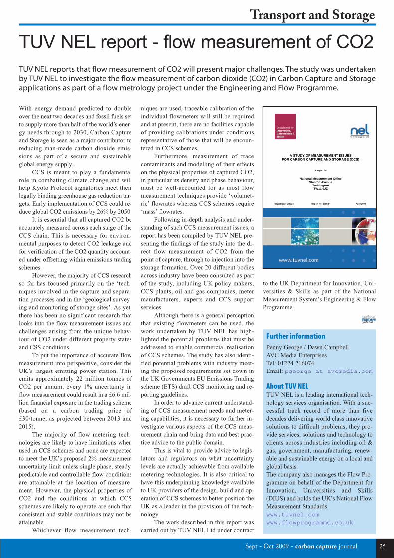
Sept - Oct 2009 - carbon capture journal 25
Transport and Storage
TUV NEL report - flow measurement of CO2
With energy demand predicted to doubleover the next two decades and fossil fuels setto supply more than half of the world’s ener-gy needs through to 2030, Carbon Captureand Storage is seen as a major contributor toreducing man-made carbon dioxide emis-sions as part of a secure and sustainableglobal energy supply.
CCS is meant to play a fundamentalrole in combating climate change and willhelp Kyoto Protocol signatories meet theirlegally binding greenhouse gas reduction tar-gets. Early implementation of CCS could re-duce global CO2 emissions by 26% by 2050.
It is essential that all captured CO2 beaccurately measured across each stage of theCCS chain. This is necessary for environ-mental purposes to detect CO2 leakage andfor verification of the CO2 quantity account-ed under offsetting within emissions tradingschemes.
However, the majority of CCS researchso far has focused primarily on the ‘tech-niques involved in the capture and separa-tion processes and in the ‘geological survey-ing and monitoring of storage sites’. As yet,there has been no significant research thatlooks into the flow measurement issues andchallenges arising from the unique behav-iour of CO2 under different property statesand CSS conditions.
To put the importance of accurate flowmeasurement into perspective, consider theUK’s largest emitting power station. Thisemits approximately 22 million tonnes ofCO2 per annum; every 1% uncertainty inflow measurement could result in a £6.6 mil-lion financial exposure in the trading scheme(based on a carbon trading price of£30/tonne, as projected between 2013 and2015).
The majority of flow metering tech-nologies are likely to have limitations whenused in CCS schemes and none are expectedto meet the UK’s proposed 2% measurementuncertainty limit unless single phase, steady,predictable and controllable flow conditionsare attainable at the location of measure-ment. However, the physical properties ofCO2 and the conditions at which CCSschemes are likely to operate are such thatconsistent and stable conditions may not beattainable.
Whichever flow measurement tech-
niques are used, traceable calibration of theindividual flowmeters will still be requiredand at present, there are no facilities capableof providing calibrations under conditionsrepresentative of those that will be encoun-tered in CCS schemes.
Furthermore, measurement of tracecontaminants and modelling of their effectson the physical properties of captured CO2,in particular its density and phase behaviour,must be well-accounted for as most flowmeasurement techniques provide ‘volumet-ric’ flowrates whereas CCS schemes require‘mass’ flowrates.
Following in-depth analysis and under-standing of such CCS measurement issues, areport has been compiled by TUV NEL pre-senting the findings of the study into the di-rect flow measurement of CO2 from thepoint of capture, through to injection into thestorage formation. Over 20 different bodiesacross industry have been consulted as partof the study, including UK policy makers,CCS plants, oil and gas companies, metermanufacturers, experts and CCS supportservices.
Although there is a general perceptionthat existing flowmeters can be used, thework undertaken by TUV NEL has high-lighted the potential problems that must beaddressed to enable commercial realisationof CCS schemes. The study has also identi-fied potential problems with industry meet-ing the proposed requirements set down inthe UK Governments EU Emissions Tradingscheme (ETS) draft CCS monitoring and re-porting guidelines.
In order to advance current understand-ing of CCS measurement needs and meter-ing capabilities, it is necessary to further in-vestigate various aspects of the CCS meas-urement chain and bring data and best prac-tice advice to the public domain.
This is vital to provide advice to legis-lators and regulators on what uncertaintylevels are actually achievable from availablemetering technologies. It is also critical tohave this underpinning knowledge availableto UK providers of the design, build and op-eration of CCS schemes to better position theUK as a leader in the provision of the tech-nology.
The work described in this report wascarried out by TUV NEL Ltd under contract
to the UK Department for Innovation, Uni-versities & Skills as part of the NationalMeasurement System’s Engineering & FlowProgramme.
TUV NEL reports that flow measurement of CO2 will present major challenges. The study was undertakenby TUV NEL to investigate the flow measurement of carbon dioxide (CO2) in Carbon Capture and Storageapplications as part of a flow metrology project under the Engineering and Flow Programme.
A STUDY OF MEASUREMENT ISSUES
FOR CARBON CAPTURE AND STORAGE (CCS)
A Report for
National Measurement Office Stanton Avenue
Teddington TW11 0JZ
Project No: FGRE24 Report No: 2009/54 April 2009
Further informationPenny George / Dawn CampbellAVC Media EnterprisesTel: 01224 216074Email: pgeorge at avcmedia.com
About TUV NELTUV NEL is a leading international tech-nology services organisation. With a suc-cessful track record of more than fivedecades delivering world class innovativesolutions to difficult problems, they pro-vide services, solutions and technology toclients across industries including oil &gas, government, manufacturing, renew-able and sustainable energy on a local andglobal basis.The company also manages the Flow Pro-gramme on behalf of the Department forInnovation, Universities and Skills(DIUS) and holds the UK’s National FlowMeasurement Standards.www.tuvnel.comwww.flowprogramme.co.uk
CCJ11a:Layout 1 15/09/2009 10:01 Page 25
26 carbon capture journal - Sept - Oct 2009
Transport and Storage
CCP CO2 geological storage report
www.cplccp.netThe world is more interested in CCS than everbefore. CCS has the potential to act as a bridge- reducing CO2 emissions now as the worldmoves to renewable sources of energy. Yetquestions over the security of CO2 storage andthe cost of large scale deployment remain. Inresponse the CCP has published ‘A TechnicalBasis for Carbon Dixoide Storage’. Based onfive years of research it provides evidence thatCO2 geological storage works at scale now andis safe, permanent and cost-effective.
The report contains the combined knowl-edge from the oil and gas industry, gained fromdecades of subsurface experience. The CCP hasundertaken more than 150 projects to increaseunderstanding of the science, engineering appli-cation and economics of CCS – collaboratingwith government, leading research institutions,universities and commercial organisations.
The findings of the report offer significantprogress in the rapid deployment of CCS at in-dustrial scale – enabling decision makers tolearn from decades of subsurface expertise fromthe oil and gas industry. It looks at the key tech-nical issues which arise in mass CO2 storage,including the location and characterization ofpossible storage sites, well integrity, monitor-ing arrangements, field operations and decom-missioning.
The CCP, established in 2000, is a part-nership between ConocoPhillips, Chevron, Eni,BP, BR Petrobras, StatoilHydro, Shell, SuncorEnergy. The CCP works closely with the USDepartment of Energy, the Norwegian Re-search Council and the European Union. Themission of the organisation is to help developthe technologies, through research and demon-strations, to make carbon capture and geologi-cal storage a practical reality for atmosphericcarbon mitigation.
At a time when governments need to bal-ance the need to reduce carbon emissions withthe realities of securing dependable energy sup-plies for the near term, CCP’s new report is amajor step forward in helping decision makersto understand the main technical issues aroundstorage and to demonstrate increased under-standing of the safety, cost effectiveness andpermanence of CO2 geological storage at scale.
Overview of FindingsSite locationThe CCP report finds that the most effectivefactors in minimizing leakage and ensure safe-ty of geological CO2 storage is site selection.
Subsurface characterization is a fundamentalstep in identifying potential geological units forCO2 storage. While some degree of uncertain-ty is inevitable when characterizing the subsur-face because of inherent natural variability,three elements are essential for geological stor-age to be technically feasible.
The potential storage unit must have suf-ficient pore volume to store all the injected ma-terial (‘capacity’); the formation characteristicsmust allow near well bore injectivity (‘injectiv-ity’); and an overlying sealing package mustensure the containment of appropriate fluids(‘containment’). In general it is best if the siteallows for CO2 to be stored at depths below800-1000 metres where CO2 is compressed toa super dense phase which enhances both thestorage capacity and the containment ability.Well designStringent analysis and integrity in well designand construction is of key importance in elimi-nating leaks from geological CO2 storagewells. Clearly wells designed for an environ-ment exposed to CO2 require understanding ofthe conditions of the well’s service life, its aban-donment, the physical features of the well it-self, as well as geological; and chemical char-acteristics such as the pressure, temperature andproduction / injection chemistry when the wellis operating.
The CCP study which evaluated the bar-rier conditions of a well bore exposed to CO2,found that Portland-based cement and carbonsteel provided an effective barrier to CO2 andthat cement placement was more significant inresisting CO2 migration along the barrier sys-tem than the choice of cement itself.MonitoringDirect monitoring tools and techniques can beused to measure concentrations of CO2, nearwell bores in the subsurface or by taking sur-face measurements. However, most monitor-ing will be undertaken by indirect measurementmethods such as seismic, gravity or electromag-netic surveys.
A range of tools already exist to carry outmonitoring activities, and careful selectionneeds to be made to ensure the right tools areused for the right task, taking into account thesite-specific conditions. In most cases, com-plex 3-D computer models are built that serveas proxies for visualization and quantificationof the subsurface environment. Informationfrom monitoring helps refine and improve thesemodels. Gravity measurements, which revealchanges in density for a theoretical vertical col-
umn of rock, are another indirect measurementtool likely to be applied at CO2 sites. Satellite-based applications are also being used to detectalterations in ground elevations – capable of de-tecting changes in vertical elevations of onemillimetre – ground uplift or subsidence thatthat can be attributed to changes taking place inthe subsurface.Development, operation and decommis-sioningField planning and development involves usingthe earth and dynamic models developed duringsite assessment to determine the well count, welltype, injection strategies and operational param-eters (especially pressure). Advanced well de-signs, such as horizontal and multilateral wells,may be used in CO2 storage to improve indi-vidual well rates, reduce near well bore pressureimpacts and control distribution of CO2.
Reservoir characteristics will have an im-pact on the well count and density and will alsoaffect the injection strategy. Arguably the mostimportant parameter for CO2 storage projectsis the maximum bottom hole injection pressure,where the goal is to maximize the injection ratewithout compromising the integrity of the con-tainment system.
In monitoring well integrity, cement eval-uation logs can be used to assess the integrityof the well’s sheath of cement in the annularspace between the casing and the formation.Sonic and ultrasonic evaluation tools can alsobe used. The information they provide will beone important source of data, in addition todrilling reports, drilling fluid reports, open holelog information, and cement placement infor-mation.
During the well operations phase, vari-ous techniques can be employed for monitor-ing well integrity. Mechanical integrity testscan be used to ensure the seal is intact. Pres-sure/temperature logs, noise logs, thermal de-cay time logs and cement evaluation logs canalso be used. Where necessary, remediation andrepair can be carried out, and on occasion wellsmay need to be completely decommissioned.
During the closure phase, the focus is onlong-term containment and isolation of the in-jectant with the natural and engineered systems.Consideration should be given to the potentialdeterioration of materials due to long-term CO2exposure, which has an impact on the materialsselected for use in decommissioning. If materi-al performance can impact long term contain-ment, this can be mitigated by material choice.
The recent report from the CO2 Capture Project (CCP), “A Technical Basis for Carbon Dioxide Storage”,offers the most definitive guide to technical issues surrounding CO2 storage to date. By Iain Wright, CO2 Capture Project (CCP)
CCJ11a:Layout 1 15/09/2009 10:01 Page 26
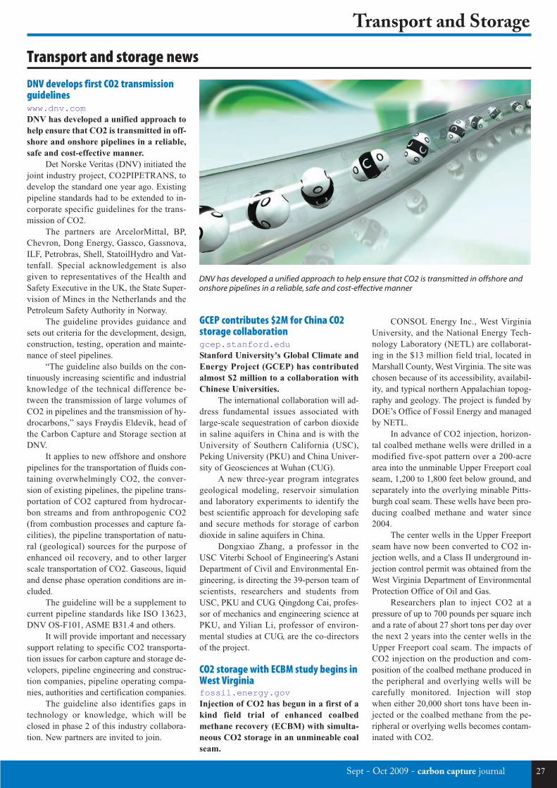
Sept - Oct 2009 - carbon capture journal 27
Transport and Storage
Transport and storage news
DNV develops first CO2 transmissionguidelineswww.dnv.comDNV has developed a unified approach to
help ensure that CO2 is transmitted in off-
shore and onshore pipelines in a reliable,
safe and cost-effective manner.
Det Norske Veritas (DNV) initiated thejoint industry project, CO2PIPETRANS, todevelop the standard one year ago. Existingpipeline standards had to be extended to in-corporate specific guidelines for the trans-mission of CO2.
The partners are ArcelorMittal, BP,Chevron, Dong Energy, Gassco, Gassnova,ILF, Petrobras, Shell, StatoilHydro and Vat-tenfall. Special acknowledgement is alsogiven to representatives of the Health andSafety Executive in the UK, the State Super-vision of Mines in the Netherlands and thePetroleum Safety Authority in Norway.
The guideline provides guidance andsets out criteria for the development, design,construction, testing, operation and mainte-nance of steel pipelines.
“The guideline also builds on the con-tinuously increasing scientific and industrialknowledge of the technical difference be-tween the transmission of large volumes ofCO2 in pipelines and the transmission of hy-drocarbons,” says Frøydis Eldevik, head ofthe Carbon Capture and Storage section atDNV.
It applies to new offshore and onshorepipelines for the transportation of fluids con-taining overwhelmingly CO2, the conver-sion of existing pipelines, the pipeline trans-portation of CO2 captured from hydrocar-bon streams and from anthropogenic CO2(from combustion processes and capture fa-cilities), the pipeline transportation of natu-ral (geological) sources for the purpose ofenhanced oil recovery, and to other largerscale transportation of CO2. Gaseous, liquidand dense phase operation conditions are in-cluded.
The guideline will be a supplement tocurrent pipeline standards like ISO 13623,DNV OS-F101, ASME B31.4 and others.
It will provide important and necessarysupport relating to specific CO2 transporta-tion issues for carbon capture and storage de-velopers, pipeline engineering and construc-tion companies, pipeline operating compa-nies, authorities and certification companies.
The guideline also identifies gaps intechnology or knowledge, which will beclosed in phase 2 of this industry collabora-tion. New partners are invited to join.
CONSOL Energy Inc., West VirginiaUniversity, and the National Energy Tech-nology Laboratory (NETL) are collaborat-ing in the $13 million field trial, located inMarshall County, West Virginia. The site waschosen because of its accessibility, availabil-ity, and typical northern Appalachian topog-raphy and geology. The project is funded byDOE’s Office of Fossil Energy and managedby NETL.
In advance of CO2 injection, horizon-tal coalbed methane wells were drilled in amodified five-spot pattern over a 200-acrearea into the unminable Upper Freeport coalseam, 1,200 to 1,800 feet below ground, andseparately into the overlying minable Pitts-burgh coal seam. These wells have been pro-ducing coalbed methane and water since2004.
The center wells in the Upper Freeportseam have now been converted to CO2 in-jection wells, and a Class II underground in-jection control permit was obtained from theWest Virginia Department of EnvironmentalProtection Office of Oil and Gas.
Researchers plan to inject CO2 at apressure of up to 700 pounds per square inchand a rate of about 27 short tons per day overthe next 2 years into the center wells in theUpper Freeport coal seam. The impacts ofCO2 injection on the production and com-position of the coalbed methane produced inthe peripheral and overlying wells will becarefully monitored. Injection will stopwhen either 20,000 short tons have been in-jected or the coalbed methane from the pe-ripheral or overlying wells becomes contam-inated with CO2.
GCEP contributes $2M for China CO2storage collaborationgcep.stanford.eduStanford University's Global Climate and
Energy Project (GCEP) has contributed
almost $2 million to a collaboration with
Chinese Universities.
The international collaboration will ad-dress fundamental issues associated withlarge-scale sequestration of carbon dioxidein saline aquifers in China and is with theUniversity of Southern California (USC),Peking University (PKU) and China Univer-sity of Geosciences at Wuhan (CUG).
A new three-year program integratesgeological modeling, reservoir simulationand laboratory experiments to identify thebest scientific approach for developing safeand secure methods for storage of carbondioxide in saline aquifers in China.
Dongxiao Zhang, a professor in theUSC Viterbi School of Engineering's AstaniDepartment of Civil and Environmental En-gineering, is directing the 39-person team ofscientists, researchers and students fromUSC, PKU and CUG. Qingdong Cai, profes-sor of mechanics and engineering science atPKU, and Yilian Li, professor of environ-mental studies at CUG, are the co-directorsof the project.
CO2 storage with ECBM study begins inWest Virginiafossil.energy.govInjection of CO2 has begun in a first of a
kind field trial of enhanced coalbed
methane recovery (ECBM) with simulta-
neous CO2 storage in an unmineable coal
seam.
DNV has developed a unified approach to help ensure that CO2 is transmitted in offshore andonshore pipelines in a reliable, safe and cost-effective manner
CCJ11a:Layout 1 15/09/2009 10:01 Page 27
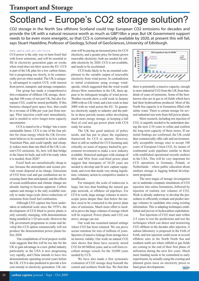
28
Transport and Storage
zens will be paying an increased price for CCSelectricity, and a greater price for home-grownrenewable electricity; both are needed for reli-able electricity by 2020. CCS is not available,and needs to be accelerated.
CCS looks likely to be an essential com-pliment to the variable output of renewableelectricity from wind power. In contradictionto initial evaluations using average wind-speeds, which suggested that the wind wouldalways blow somewhere in the UK, there ap-pear to be infrequent troughs of wind power.Weather records show a cold week in January2000 with no UK wind, and a hot week in June2009 with no wind across the EU. To guaran-tee electricity supply to industry and the pub-lic in these periods means either developingmuch more energy storage, or keeping a fullfleet of coal and gas power plant with CCSready for action.
The UK has good analysis of policyneeds, and has put in place the regulatoryframework for CCS to operate. However,there is still no method for CCS licensing and,critically, no sense of urgency backed by gov-ernment investment to make a new industryavailable. Historical analogies with cleanup ofSOx and NOx from coal-fired power plantsuggest that timespans of 10-20 years areneeded to develop and fit new capture equip-ment, and even that needs very strong legisla-tion; voluntary action in competitive market isinsufficient.
For transport, the scale of endeavour islarge, but less than building the natural gaspipe network, or offshore oil pipelines. ForCCS to work, large storage volumes in micro-scopic pores deeper than 1km below the sur-face need to be connected to the power plantsites of emissions. Much more effort is need-ed to prove the large volumes of storage whichwill be required. Power plants and CO2 canmove; storage can not.
Our work has examined natural settingswhere CO2 has been retained. We can provesecure retention for tens of millions of years.Spectres of massive leakage from storage haveno known validity. Our work on natural CO2sites shows that these have securely storedCO2 for 60 Million years, and so will form ex-cellent storage vessels for the 10,000 yearsneeded by CCS.
We have also made a first systematicevaluation of CO2 storage deep beneath thecentral and northern North Sea. We find that
www.geos.ed.ac.uk/sccsCCS power is the only way to burn fossil fuelwith lower emissions, and will be essential tofill in electricity generation gaps on weekswhen wind does not blow across the EU. CCSis part of the UK plan for a low carbon future,but is progressing too slowly, to be commer-cially proven when needed. The UK is unique-ly advantaged to exploit CCS, with interestfrom power, transport, and storage companies.
Our group has made a comprehensivefirst evaluation of offshore UK storage, show-ing that 100 years of not just UK, but also Eu-ropean CO2, could be stored profitably. If thisbusiness charged pore space fees, that couldbe a revenue of £5Bn per year just from stor-age. Pilot injection could start immediately,and is needed to solve longer-term capacityuncertainties.
CCS is stated to be a ‘bridge’ into a moresustainable future. CCS is one of the four pil-lars for clean energy which the UK Govern-ment believes to be essential in its low carbonTransition Plan, and could rapidly and cheap-ly reduce more than one third of the UK’s cur-rent CO2 emissions. So, how will that bridgeto the future be built, and will it be ready whenit is needed, from 2020?
Fossil fuels are unrealistically cheap touse, because the atmosphere and oceans pro-vide waste disposal at no charge. Emissionsof CO2 from coal and gas combustion are in-creasing faster than anticipated, and the effectsof ocean acidification and climate change arealready starting to become apparent. Carboncapture and storage is the only available rem-edy to make large-scale direct reductions ofemissions from fossil fuel combustion.
Although CO2 capture has been under-taken at industrial scale since the 1970’s, thedevelopment of CCS fitted to power plants isonly currently emerging, with demonstrationsbeing installed at 1/10 size-scale. However theUK government programme to create and de-velop this CCS option commercially will notproduce the demonstration power plants be-fore 2020.
Our compilations of rival projects world-wide suggests that this will be too late for theUK to gain advantage in a new global industryparticularly as the USA is now progressingvery rapidly, and China intends to have twodemonstrations operating several years beforethe UK. CCS is also predicted to provide a lowcost remedy to electricity generation: UK citi-
there is potentially a massive capacity, enoughto store industrial CO2 from the UK from hun-dreds of years of emissions. Some of the best-known sites are in gas or oil fields which havehad their hydrocarbons produced. Most of theNorth Sea capacity is in formations filled withsaline water. There is certain storage for sev-eral industrial size tests from full power plants.
More research, including test injection ofCO2, is urgently needed to be undertaken dur-ing the next 2-10 years to refine and confirmthe long-term capacity of these stores. If ourinitial findings are confirmed, the UK couldthen commercially offer safe and environmen-tally acceptable storage sites to accept 100years of European Union CO2, by means ofcontinental scale pipelines similar to thosewith established operational records onshorein the USA. This will be very important forCCS operations in Germany, Poland, orNetherlands – where public education aboutonshore storage is lagging behind develop-ment proposals.
The next stages of storage investigationare to undertake computer simulations of CO2injection into saline formations, followed byinjection of realistic test volumes of CO2.Work is already underway to develop the pro-cedures to efficiently evaluate and predict stor-age volumes in candidate sites using existinginformation. This is adapting techniques estab-lished and proven in hydrocarbon exploitation.
Test injections of CO2 must start within2-5 years to test the predictions and test thetechniques which can detect and monitoringCO2 offshore in the decades after injection. Asubsea laboratory is proposed in the Firth ofForth, and test injection could occur at severaloffshore sites in the North North Sea andsouthern north sea where oilfield or gas fieldsare coming to the end of their first phase ofutilization during the next few years. Muchmore funding needs to be committed to earlyexperiments, by actually using the existing andplanned green taxes on electricity prices tofund green developments.
carbon capture journal - Sept - Oct 2009
Scotland - Europe’s CO2 storage solution?CO2 storage in the North Sea offshore Scotland could trap European CO2 emissions for decades andprovide the UK with a natural resource worth as much as GBP10bn a year. But UK Government supportneeds to be even more energetic, so that CCS is commercially available by 2020, at present this will fail,says Stuart Hazeldine, Professor of Geology, School of GeoSciences, University of Edinburgh.
CCJ11a:Layout 1 15/09/2009 10:01 Page 28

Engineering EnergyFor Life...
Can you help us solve the power generation challenges of the 21st Century?
We are currently expanding our UK and worldwide operations and have a variety ofexciting engineering and research opportunties.
View and apply for all of our positions online at: www.doosanbabcock.com/careers
Doosan Babcock designs, supplies and constructs advanced steam generation technology for the power industry.We develop some of the cleanest, most efficient coal-powered plant in the world. Doosan Babcock is also aleading energy services company operating in the thermal power, nuclear, oil & gas and petrochemical industries.Through our innovation we support and enhance the service life of energy assets across the world. With globalheadquarters in the UK, Doosan Babcock employs around 5,000 personnel.
Exciting opportunities for engineers of all disciplines
Career development
CO2 Storage - Geology for Engineers (ref:K1732)Thursday 4th March 2010This short course is designed for Engineers and Managers with limited or no previous geological knowledge. The aim is to provide an up-to-date introduction of the geological and geophysical aspects of CO2 Storage.
Risk & Uncertainty in the Geological Storage of CO2 (ref:K1733)Friday 5th March 2010This course introduces risk management techniques and explores uncertainties associated with the geological storage of CO2. It builds upon the previous course, Geology for Engineers, by examining the behaviour of CO2 in the subsurface and how this information is used to estimate properties of the storage site such as capacity.
One Day Short Courses Thursday 4th and Friday 5th March 2010
Scottish Centre for Carbon Storage
www.erp.ac.uk/sccs
Location: Raeburn Room, Old College, EdinburghMap: http://tinyurl.com/Raeburn-RoomFor further information visit: www.erp.ac.uk/sccs/cpd/
CCJ11a:Layout 1 15/09/2009 10:01 Page 29

Contact: T: +44 (0) 1491 415 400 Email: [email protected]
Our energy and environmental experience is unique in being able to offer clients the immense breadth of support required to develop their CCS projects at each stage of the lifecycle.
Just some of our areas of expertise:
Integrated Carbon Management ServicesTechnical and commercial counsel from source to sinkGuidance in legislative and market developmentsPlanning and consenting adviceEnvironmental and monitoring assistance
RPS are global specialists in managing major, complex, multi-disciplinary projects.
CCJ11a:Layout 1 15/09/2009 10:01 Page 30
Related Documents