0 IFB SYSTEM * ~~~~~~~~~MA-4 AX-4 PIC-4000B INSTRUCTION and SERVICE MANUAL * EIlk Clear-sConm 11 intercom Systems 0 4065 Hollis St., Emeryville, CA 94608 (510) 496-6666 C Clear-Com Intercom Systems 810048 8/15/88 REV. A

Welcome message from author
This document is posted to help you gain knowledge. Please leave a comment to let me know what you think about it! Share it to your friends and learn new things together.
Transcript

0
IFB SYSTEM* ~~~~~~~~~MA-4 AX-4
PIC-4000B
INSTRUCTIONand
SERVICE MANUAL
* EIlk Clear-sConm11 intercom Systems
0 4065 Hollis St., Emeryville, CA 94608 (510) 496-6666
C Clear-Com Intercom Systems 810048 8/15/88 REV. A

** IFB SYSTEM MANUAL **b ** DOCUMENTATION ADDENDUM
0@ ** MA-4 & AX-4 **** REV.B **** December 22, 1987 **** **
MIC TO LINE GAIN LEVEL INCREASE
In effecting a 4dB Mic to Line increase in gain level, thefollowing changes have been made:
Change: At: To:
15K OHM R27, 28, 6.8K OHM29, 30

as CLEAR-COM S** DOCUMENTATION ADDENDUM t* t* PIC-4000B/IFB SYSTEM *1' w ** DATE: JUNE 25. 1987
* *****|*****tts*ttst**ts*st ts***$**t*
* PIC-4000B - STEREO/SPLIT FEED IFB OUTPUTS.* PIC-4000B - CONNECTION TO MS-808 MAIN STATION.
0 1. PIC-4000B:
1.1 Stereo/Split Feed outputs:
1.1.1 The Model PIC-4000 IFB central Electronics has been upgradedto the Model PIC-40005. The upgrage consists of a circuitdesign change that permits all of the four IFB outputs tofeed two discrete audio channels ("Interrupt" & "Non-Interrupt") to the new Model TR-532 Stereo/Split Feed TalentReceivers. The two discrete signals, plus the DC operationpower, are sent to the TR-532 via 3-pin XL type connectorsand two conductor shielded cable (standard microphone
0 cable).
1.1.2 This upgrade in no way effects the PIC-4000B's operationwith TR-50 Single Channel Talent Receivers, which receiveonly the "Interrupt" signal.
a 1.1.3 TR-50s and TR-532s should not be combined on the same IF1W _ output. However, if they are accidently connected to the
same output, no damage will result to the units or to thesystem.
1.1.4 Each of the four IFB outputs can operate a maximum of fourTR 50U ing1e Channel Talvnt Receivers or two TR-532Stereo/Split Feed Talent Receivers.
1.1.5 This upgrade eliminates the -SPC" Sportscaster/Two Channeloutput" option, which provided the "Interrupt/Non-Interrupt"outputs to two channel Talent Receivers via a 6-pin cable.
1.2 Connection between a PIC-4000B and a MS-808 Main station:
1.2.1 The new PIC-4000B now replaces the Model PIC-4 IFS CentralElectronics. The PIC-4 was originally designed as the IF1Central Electronics for MS-808 Main Stations. The PIC-4 was
@ controlled by one or more Model IFB-4 IFS Control Modulesinstalled in an MS-808 Main Station.
1.2.2 An MS-808 connects to the PIC-4000B via 6-pin connectors inthe same manner as an MA-4 or AX-4 IFB Control Pane!connection. (The MS-808 originally connected to the PIC-4via a 12 pair cable terminating in a 30-pin "Tuchell"connector. MS-808s are now equipped with 6-pin male XL typeconnectors for connection to the PIC-4000B.)
1.2.3 An IFB system can contain a combination of MA-4/AX-4 "stanJ-alone" Control Panels and MS-808 Main stations equipped with7IF-4 Control Modules to control one or more PIC-4000Bs.

IFB System Installation and Operation Manual
CONTENTS
* I. INTRODUCTIONA. IFB System Concept ....... 1B. Unit Descriptions ........ 2
II. INSTALLATIONA. System Capacity .......... 4
* B. System Architecture ..... 4System Diagrams .......... 5
C. Interconnect Cabling ..... 6D. System Connection ........ 7
System Wiring Example ....8E. Unit Mounting ............ 9
S. wF. Setup and System Check..10
III. OPERATION .................. 10
IV. TECHNICAL INFORMATIONA. Maintenance & Warranty. .11
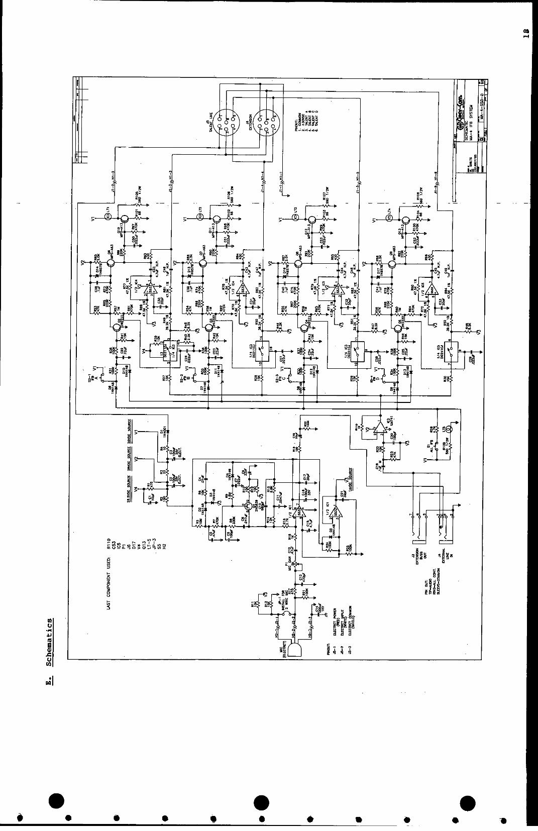
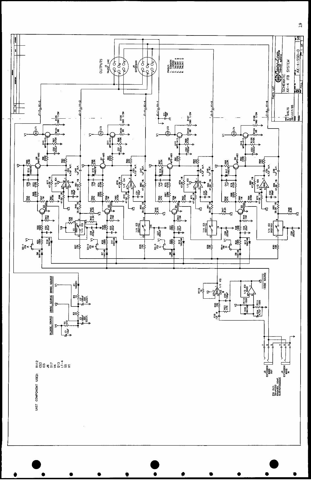
* - B. Troubleshooting ......... 11C. Parts Lists ............. 13D. Specifications .17E. Schematics .18F. Component Locations . 21
0
While Clear-Com makes every attempt to maintain the accuracy of theInformation contained in its product manuals, the Information Is subject to
* change Nithout notice:'

* I. INTRODUCTION
A. IFB System
During production of a program for transmission or recording, adirector or producer frequently needs to cue the performingtalent. This is done using Interrupt FoldBack, a type of closed-circuit intercom for sending program and cue audio on "IFB" linesfor the talent to monitor. The IFs line carries three signals:program audio, cue audio, and the dip or mute control. See thesignal flow diagram below. Electronic control allows thedirector to interrupt the program signal when addressing thetalent. IFB communications are one-way only -- from an accesslocation to the selected talent position.
, ,_.w ONIRC
v ._ .... CUE AUDIO A TANT NWMCAL
MA/AX-4 MA/A-4 A/A-4
Clear-Com's new stand-alone IFB components provide highperformance, cost- effective answers for applications whereregular intercom functions are not also required, or where spaceconstraints require compact, versatile packaging. The simpleststand-alone system consists of a PIC-4000, an MA-4, a PS-20 forpower and one to four TR-50 talent receivers. This system willpermit cuing of one to four talent positions from only one accesslocation.
NOTE: Throughout this manual, access location refers to thephysical place someone needs to cue the talent from. Talentposition refers to the individual "talent" cue channels.

B. Unit Descriptions
Clear-Com's stand-alone series of IFB components offers two typesof talent access station. The MA-4 has a built-in electretgooseneck microphone and a pre-amplifier with line-level output.It provides access to four talent positions. Each AX-4 allowsaccess, from the same location, to an additional group of fourtalent positions; it requires an external line-level signal forits cue audio source. The MA-4's cue audio and ALL controlsignals will feed up to twenty-three AX-4's, so that only one MA-4 is reqired at each access location. Each talent position maybe accessed independently, or simultaneously with any other(s).The ALL button on the MA-4 simultaneuosly accesses all talentpositions of the MA-4 and each AX-4 extension unit fed from thatMA-4.
_~~~~~~~~~~~~~~
c=iz r ___...,.................
o -_0 0
o 0 L1-4 0
0 j~.e .00 0
THE MA-4 THE AX-4

* *A PIC-4000 unit is required for every four talent positions, orfraction thereof. For example, a system with five to eighttalent positions will require two PIC-4000s. The same IFB systemwith three access locations will require three MA-4's and threeAX-4's, but will still need only two PIC-4000's. The PIC-400performs the program feed and interrupt functions for each talentposition, and also terminates the IFB lines.
2
3
4
* _ : ~~~Sad sG ;Nw 00 FeC O Wff 0 O er 5S
5 6 7 8 9
10~~~~~~ RE 0 aE 0 0E EiE !
THE PIC-4000
The connectors on the MA-4, AX-4, and PIC-4000 are arranged forconvenient interconnection as a stand-alone system. However, allunits' electrical characteristics are identical to those of theintegrated IFB systems on our standard broadcast intercom line.So with suitable connector adaptors, both types of units may bemixed in a system.
II. INSTALLATION 0A. System Capacity
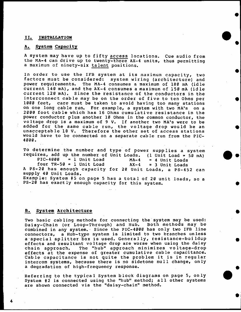
A system may have up to fifty access locations. Cue audio fromthe MA-4 can drive up to twenty-three AX-4 units, thus permittinga maximum of ninety-six talent positions.
In order to use the IFB system at its maximum capacity, twofactors must be considered: system wiring (architecture) andpower requirements. The MA-4 consumes a maximum of 180 mA (idlecurrent 140 mA), and the AX-4 consumes a maximum of 150 mA (idlecurrent 120 mA). Since the resistance of the conductors in theinterconnect cable may be on the order of five to ten Ohms per1000 feet, care must be taken to avoid having too many stationson one long cable run. For example, a system with two MA's on a2000 foot cable which has 16 Ohms cumulative resistance in thepower conductor plus another 10 Ohms in the common conductor, thevoltage drop is a maximum of 9 V. If another two MA's were to beadded for the same cable run, the voltage drop would be anunacceptable 18 V. Therefore the other set of access stationswould have to be connected on a separate cable run from the PIC-4000.
To determine the number and type of power supplies a systemrequires, add up the number of Unit Loads. (1 Unit Load = 50 mA)
PIC-4000 = 1 Unit Load MA-4 = 4 Unit Loadsfour TR-50 = 1 Unit Load AX-4 = 3 Unit Loads
A PS-20 has enough capacity for 20 Unit Loads, a PS-452 cansupply 40 Unit Loads.Example: System #5 on page 5 has a total of 20 unit loads, so aPS-20 has exactly enough capacity for this system.
B. System Architecture
Two basic cabling methods for connecting the system may be used:Daisy-Chain (or Loop-Through) and Hub. Both methods may becombined in any system. Since the PIC-4000 has only two IFB lineconnectors, a Hub-type system is limited to two branches unlessa special splitter box is used. Generally, resistance-buildupeffects and resultant voltage drop are worse when using the daisychain approach. The "hub" approach minimizes voltage-dropeffects at the expense of greater cumulative cable capacitance.Cable capacitance is not quite the problem it is in regularintercom systems, because there is no sidetone null change, onlya degradation of high-frequency response.
Referring to the typical System block diagrams on page 5, onlySystem #2 is connected using the "hub" method; all other systemsare shown connected via the "daisy-chain" method.
4.
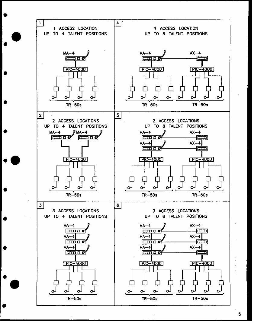
1 41 ACCESS LOCATION 1 ACCESS LOCATION0 UP TO 4 TALENT POSITIONS UP TO 8 TALENT POSITIONS
MA-4 AX-4
PIC-4000 1 PIC-4000 1 PIC-40001
TR-50s TR-50s TR-50s
2 52 ACCESS LOCATIONS 2 ACCESS LOCATIONS
UP TO 4 TALENT POSITIONS UP TO 8 TALENT POSITIONSMA-4 ,MA-4 ,MA-4 AX-4
TAI4MA-4| AX-4
MA- r A4
.0| PIC-4000 1 X PIC-4000 1 | PIC-4000
TR-50s TR-50s TR-50s
3 63 ACCESS LOCATIONS 3 ACCESS LOCATIONS
UP TO 4 TALENT POSITIONS UP TO 8 TALENT POSITIONS
MA- 4 2M- A-
MA- 4T A4 X4
* ~MA-41 A4 X4
PIC-4000 1 PIC-4000 P I C-40001
TR-50s TR-50s TR-50s
5

C. Interconnect Cabling 0Use one multi-pair cable for each group of four channels whenconnecting the IFB lines between the access stations and theirassociated component (other MA's or AX's and the PIC-4000).This cable MUST have (four) SEPARATELY shielded conductors orpairs of conductors to prevent crosstalk. Suitable cable typesare: Alpha #6054, Belden I's 8725 or 9330, and Mogami #2602. Asnoted in Section B, the resistance buildup in both the power and
common (or ground) conductors must be kept at a minimum forproper operation. Resistance buildup in the common conductorwill also increase crosstalk. Follow the diagram below for bestresults in connecting the cable to the XLR connectors. Noticethat all four of the spare conductors in each pair are tiedtogether to pin 2 (DC power), and all shields are tied togetherto pin 1 (common). This arrangement minimizes resistance buildupeffects in long cable runs.
Clear-Com has ready-made cable in 25, 50, and 100 foot lengths tofit your cabling and system architecture needs. The model numberis ICxx/6.
6 PINXLR CONNECTOR
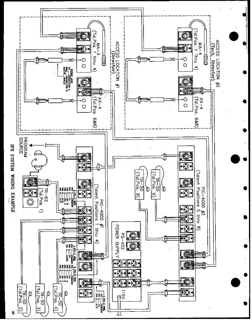
In a system with more than four talent positions (one group), thecue audio from the MA's mic preamp and the ALL control signalmust be bussed from the MA to each AX unit. A two-conductorshielded mic cable with 1/4" TRS 'phone plugs at each end is usedfor this purpose. Refer to the diagram on page 8, system wiring,for pin-out details.Note: the diagram shows the access stations for talent positions5-8 connected in a "hub" from the second PIC-4000 while thestations for the first group of talent positions (1-4) are shownconnected in the "daisy-chain" method. In practice, stations forboth groups of talents would be interconnected in the same manner.
6

Connect single channel talent receivers to the PIC-4000 usingstandard two-conductor mic cable. For a split-feed receiver, ourstandard 2/4 channel interconnect cable (ICxx/6 can be used. Ifcustom cabling is made, refer to the diagram on page 8 forpinouts. Notice that pins 5 and 6 are not used, and be sure tokeep the conductors for pins 3 and 4 in separate shields. Onlytwo conductors are necessary for the cabling between the powersupply and the PIC-4000(s). If any section of this cable is morethan a few feet long, be sure that heavy-gauge wire is used.
D. System Connection
1) Determine the architecture for your IFB system.
2) Decide upon a location for the PIC-4000(s). Then:
3) Connect the PIC-4000(s) to Clear-Com power supply(s) suchas the PS-452 or PS-20. (#9)
4) Connect the program source(s) to the PIC-4000(s) asrequired. (#5,6) A balanced program source is connected topins 2 and 3 of the program input. The common pin can beconnected to the commmon or ground point of the source, ifnecessary to eliminate any residual hum. If a single-endedsource is used, either pin 2 or 3 must be connected to thecommon point of the source. The "high" side is connectedto the other pin (2 or 3).
5) Use standard multi-pair shielded cables and two-conductorshielded mic cables to interconnect the access stations asdescribed in the preceding section.
6) Route all cables from the access locations and the talentreceivers to the PIC-4000's using either or both of themethods discussed in Section B above. Pin assignments forthe rear panel IFB XLR connectors are: Pin 1, COMMON; Pin2, POWER; Pins 3-6, TALENT CHANNELS 1-4 respectively. (#7)
7) Route cables away from heavy AC power sources such aslighting panels or electric motors.
8) In permanent installations, cables should be installed inaccordance with approved local building codes.
(The numbers in () refer to the diagram on page 3.)
------- ---------------~---n r -----~ -------------------
* 3 oe 1C~~~ U > Me0 0 Hz
.* .
oX~~~~~~ .C~~~xS 4~ ~~
3~ ~ ~~~N TI I3@ 0-i I
2 tL =X~~n0 s t t I Id noO
= mS X~~~o I I 11
I | || | m w _A I I
t3J 0;_ 0Q-4~ ~~~~~-
I 11 11111 11] m j 1 jW W~~~~~~~~~~Lu C
0 0~~~~~~
|; 0 n Mn Ajnwo 9 R 1> t1 II T I E } | z. en L -v
0 ~~00
1-e~~~s 1-1 1<1 0 i11,I
, I 10 21 % 2 % > ; | I I I~~~0 c
M -u~~~~~~~
M~~~~~~~~~
Ln~~~~~~~~
OR~~~~~~~~~~~~

E. Physical Mounting
0 The PIC-4000 is designed for mounting in a standard 19" rack. Itrequires only one 1.75" rackspace, and is 6.5" deep.
The MA-4 and AX-4 may be mounted in a console or desk, or in astandard 19" rack using the optional rack kit (CC# 820022).Refer to the diagrams below for mounting dimensions wheninstalling in a desk or console. There are no specialconstraints on relative positioning of MA's and AX's, though itis expected that the extension bus cable (the one with phoneplugs) will be no more than 10 feet (normally 18 inches long).Be sure to make allowance for the XLR connectors to be pluggedinto the back of each access station.
6.115 1.175
4.715 1.1756.500 6.625 I C
6.300 -41.750 -5.550 6.500 6.625
.5 < / .~~~~140 DA
MOUNTING DIMENSIONS OF MA-4.,
4 1500 T 1.750;
-o o .140 DIA.
t 1.5t25 _ O 8 1
0N
MOUNTING DIMENSIONS OF AX-4

F. Set-Up and System Check
After Program Sources are connected, assign them at the PIC-4000to the talent channels with the Program (Source) select switchesfor each channel's interrupt (#3) and non-interrupt (#2) talentfeeds. Set the toggle handle up to select source #1, or down toselect source #2.
Set the attenuation or dip of the program feed during cuing withthe dip adjust trims (#4). They can be set from no attenuation(fully CW) to greater than 50dB (fully CCW).
Before adjusting the Program Level trims at the PIC-4000, thevolume at the Talent Receivers must be adjusted (via the controlon the Receiver) for a comfortable cue audio level in theearpiece or headset while someone is cuing that talent positionfrom one of the access locations.
The PROGRAM INPUT LEVEL trims (#l) permit use of program levelsranging from -20dBv to OdBv. At full clockwise rotation, thegain from program input to the IFB line is approximately unity.So at maximum gain setting, a program level of -2OdBv will beroughly the same volume on the IFB line as the cue audio. If theprogram source level is around OdBv, the trims will have to beset near full counter-clockwise rotation to match the cue audiolevel on the IFB lines.
(NOTE: The numbers in () refer to the diagram on page 3.)
The only adjustment possible at the MA-4 is a trim (+/- 5dB) ofthe mic gain. Adjusting this gain should be necessary only inunusual circumstances, because of the mic preamp's limiter.
III. OPERATION
The system is operated by engaging the desired cue buttons on theaccess stations. A control voltage on the IFB line causes thePIC-4000 to dip the program feed to that channel so that thecues given are understandable. (At an optional split-feedreceiver, the program is dipped only in the cue side; the otherside has continuous program with no cue.)
A. Press the IFB button on the access station corresponding tothe talent position(s) you wish to cue, then speak intothe MA-4's microphone.
B. Press the MA-4's ALL button, and you simultaneously activateevery IFB line, including those on any accompanying AX-4units.
The control voltage also causes the corresponding buttons at allother access locations to be brightly lit, indicating whichchannels are in use.
10

IL. iTCNxCAL INFORMATlON
Trk i lbn Shooting
The table of troubles on the next page, which generally involves systemwiring, covers only the most likely problems. In any trouble-shootingeffort, keep these points in mind:
1) The power for all units in the system is routed from the powersupplies through the PIC-4000.
2) All access stations (MA's and AX's) and the talent receivers areconnected across the IFB lines in a bridging configuration (high-impedence)
3) Each IFB line is terminated by its associated PIC-4000. Thetermination is about 220 ohms A.C., and approximately 5000 Ohms
D.C.4) Three different types of signals are present on the IFB line:
a. Cue audio, which originates from an access station's micb. Program audio, from the associated PIC-4000, andc. Interrupt control signal, a D.C. voltage which alsoorignates at an access station.
5) The audio levels are approximately -15 dBv ref.O-.775VRMS),and the D.C. control voltage is about +13 Volts.
6) The cue audio and ALL control signal for operation of the AX-4stations at any given location are supplied by the MA-4 stationat that location.

TROUBLE SHOOTING
SYMPTOM CAUSE REMEDY
Ch anne l access A No power A Check that power
buttons not lit or supply is operat-
too dim. ing & connectedto the PIC-4000.
B Insufficent power B Increase power cap-acity or connectfewer stationson each cablerun.
Access button won't A Excessive DC load A Isolate & replacelight brightly when on affected IFB faulty module on
engaged at any line affected line.station.
B IFB line shorted B Isolate & repairin cabling cable.
Access button remains I F B 1 i n e n o t Insure that station
brightly lit after terminated connections to PIC-
being released. 4000 are intact.
No cue from an AX-4 A Associated MA-4 A Insure that MA-4
station. not operating is connected toa PIC-4000.
B Faulty or missing B Verify connectionconnection to MA- of extension busor AX- unit. to affected AX-
unit.
Hum or buzz from Mis-connection of Program inputs are
program. (pgm. trim program source to balanced. If single-
affects loudness) input. ended source is used,one of inputs must bereferenced to Common.
12
12

ASSEMBLY 710161 ASY PC MODULE FOR MA-4
P/N DESCRIPTION OTY REF DESIG
150001 CAD 22 PF 20% soY ZSU .2LS .ISTHK 4 C30 C33 C32 C31150002 AAA CAE IUF N.P. ELECTROLYTIC SOV R.L. 4 C46 C4A C4A C47150006 CAD IOOPF DISC IOX 2 C6 C20150010 CAE 22UF ELECTROLYTIC 16V R.L. 2 CIs CY150011 CAE IOOUF ELECTROLYTIC 35v R.L. 3 C16 C3 C2150014 CAD 47OPF CERAMIC DISC IOX SOv 1 C13150026 CAD 39PF DISC 5x 2 C21 C17150030 CAT 4.7UF TANTALUM 16V 1 CIS150034 CAN .22UF MONOLYTHIC SOJ 4 C25 C24 C23 C22150035 AAA CAN .1 MONOLYTHIC 104ZU soy 4 C3J C41 C40 C39150043 CAN .47UF MONOLYTHIC SOV 2 Cs C12150059 CAD .0039 UF AT IKW I C14150064 CAE jOUF soy R.L. ELECTROLYTIC 1 Cl150068 CAM .0047UF MYLAR sov 10% 1 Cli150076 CAM .01 MONOLYTHIC 1ox SOV 1 C4150078 CAM .047 MONOLYTHIC 10% SOV I CB150082 CAM .022 UF MONO CK0S IOX SOv 9 C7 C52 C51 CS0 C29 c29
C27 C26 C53150085 CAM .IUF MONO CK0S IOOV 10% 1 C19150087 CAE 4.7UF/SOV NP ELECTROLYTIC R.L. 4 C43 C42 c45 C44150094 CAD 6aOPF 5x DISC OR MONO SOY .2SLS I C10170089 PCB HA-4 PC BOARD 1210112 TER HEADER MULTI PIN HEADER(MIN 18 PIN) 10 X X X J2(4) X X
* ~~~~~~~~~~~~~~~JI X X X210134 swc PC MOUNT 1/4 IN JACK DOUBLE OPEN CIRCUIT I J3210135 SwC R/A PC MOUNT 1/4 IN STEREO JACK TIP SWITCHED I J4410002 RES CF 1/4W sx 10 OHMS 1 R4410004 RES CF 1/4W 5% 22 OHMS I R3410010 RES CF 1/4W 5s IK OHMS 2 R10 RAl410011 RES CF 1/4W 5% 2.2K OHMS I R40410013 RES CF 1/4W 5% 4.7K OHMS 1 R26410014 RES CF 1/4W 5% 2K OHMS 4 R86 RAS RB7 RBa410016 RES CF 1/4W 5% 10K OHMS 4 R13 R6 R39 R20410017 RES CF 1/4W 5% 15K OHMS 9 RAl R30 R29 A28 R27 RAA
R43 RA2 R41410021 RES CF 1/4W 5s 47K OHMS 5 RS4 R53 R23 R56 RSS410024 RES CF 1/4W 5% lOOK OHMS 10 R22 R21 R37 R36 R35 R34
R33 R32 R31 R38410028 RES CF 1/4W 5% 220K OHMS 10 R90 R25 R24 R89 R68 R67
R66 R6s R92 R9I410030 RES CF 1/4W 5% 470K OHMS 13 R7 R61 R100 R99 R98 R97
R76 R75 R74 R73 R64 R63R62
410031 RES CF 1/4W 5% 12K OHMS I R14410033 RES CF 1/4W 5s 330K OHMS I RB410036 RES CF 1/4W 5s 6.SK OHMS I RIS410037 RES CF 1/4W 5% 6.2K OHMS 4 R47 R45 R48 R46410040 RES CF 1/4W 52 2.7K OHMS I R16410042 RES CF 1/4W 5% 470 OHMS 2 R17 Ri
410057 RES CF 1/4W 5% 68 OHMS 4 R104 R103 R102 RIOl410059 RES CF 1/4W 5% 1 MEGAOHM 4 R60 R59 R58 R57410059 RES CF 1/4W 5% 10 MEGAOHM I RS410067 RES CF 1/4W 5% 1.8 MEGAOHMS I RA410071 RES CF 1/4W 5x 100 OHMS 4 R19 R12 RIO R2
410099 RES CF 1/2W 5% 560 OHMS s RIO? RIOS RIO? A10 R105410105 RES CF 1/SW 1% 47.5K OHMS 12 R72 A71 R70 R69 RA4 R83
R82 R61 R80 R79 R78 R77410106 RES CF 1/4W 5% 430 OHMS 4 R95 R94 R93 R96410111 RES MF 1/8W 1% 39.2K OHMS 4 R551 50 R49 552470046 REV 5K TRIMPOT H MTG BECKMANN $91A5K 1 Pi480000 DIG 1N414a SIGNAL DIODE 12 D7 D6 Ds D9 D10 DlI
D12 D13 D3 D4 DS D2480001 D10 1N4001 RECTIFIER DIODE I Di480004 TRA MPS-A13 TRANSISTOR 4 010 013 012 O01480006 TRA 2N2222 TRANSISTOR 4 02 05 04 03490008 TRA MPS-A63 TRANSISTOR 4 06 09 08 07480018 ICS LM741 IC OP AMP 9-PIN DIP 1 IC2480026 DIG lN957B ZENER DIODE 6.8V 5% .4W 4 D14 D15 D16 D17480069 TRN 2N5639 N CHANNEL JFET 1 0l480070 AAA ICS NE5532 DUAL LO NOISE OP AtP 3 ICI IC4 ICS480092 ICS QUAD CMOS ANALOG SWITCH DG211CJ I IC3510050 SWT SCH#F-N-00-4U-EE-N-21-01-16-01-B-AG-3-03 I Si510070 SWT NON-LOCK MOM *FI750044UOATI21I116O1DAG3O3 1
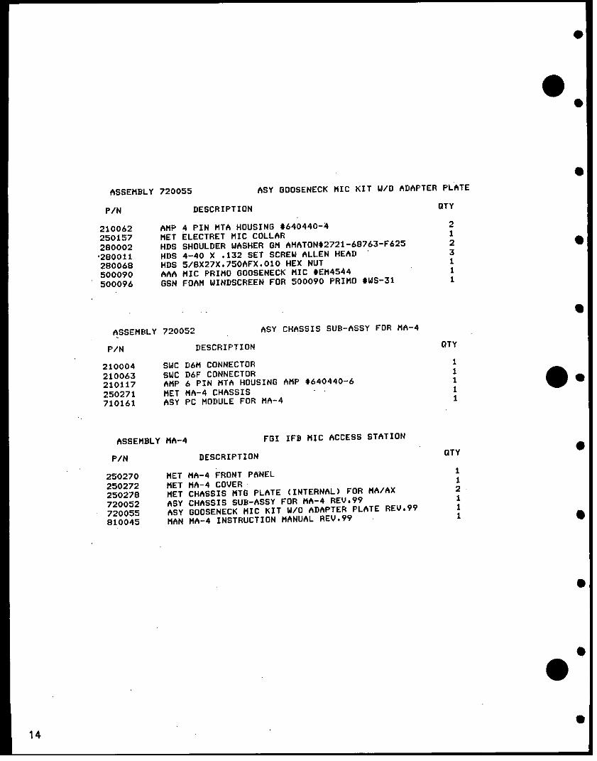
ASSEMBLY 720055 ASY GOOSENECK MIC KIT W/O ADAPTER PLATE
P/N DESCRIPTION OTY
210062 AMP 4 PIN MTA HOUSING t640440-4 2
250157 MET ELECTRET MIC COLLAR 1
280002 HDS SHOULDER WASHER GM AMATON*2721-68763-F625 2
'280011 HDS 4-40 X .132 SET SCREW ALLEN HEAD 3
280068 HDS 5/8X27X.750AFX.010 HEX NUT 1
500090 AAA MIC PRIMO GOOSENECK MIC *EM4544 1
500096 GSN FOAM WINDSCREEN FOR 500090 PRIMO *WS-31 1
ASSEMBLY 720052 ASY CHASSIS SUB-ASSY FOR MA-4
P/N DESCRIPTION OTY
210004 SWC D6M CONNECTOR 1
210063 SWC D6F CONNECTOR 1
210117 AMP 6 PIN MTA HOUSING AMP *640440-6 1
250271 MET MA-4 CHASSIS - 1
710161 ASY PC MODULE FOR MA-4 1
ASSEMBLY MA-4 FGI IFB MIC ACCESS STATION
P/N DESCRIPTION OTY
250270 MET MA-4 FRONT PANEL 1
250272 MET MA-4 COVER 1
250278 MET CHASSIS MTG PLATE (INTERNAL) FOR MA/AX 2
720052 ASY CHASSIS SUB-ASSY FOR MA-4 REV.99 1
720055 ASY GOOSENECK MIC KIT W/O ADAPTER PLATE REV.99 1
810045 MAN MA-4 INSTRUCTION MANUAL REV.99 1
14
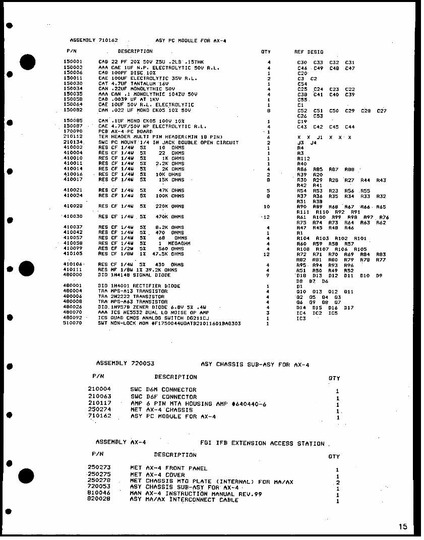
ASSEMBLY 710162 ASY PC MODULE FOR AX-4
P/N DESCRIPTION OTY REF DESIG
150001 CAD 22 PF 20% 50V ZsU *2LS .ISTHK 4 C30 C33 C32 C31150002 AAA CAE IUF N.P. ELECTROLYTIC soY R.L. 4 C46 c C49 CAB C47150006 CAD IOOPF DISC.10% 1 C20150011 CAE IOOUF ELECTROLYTIC 35V R.L. 2 C3 C2150030 CAT 4.7UF TANTALUM 16V I CS4150034 CAN .22UF MONOLYTHIC sov 4 C25 C24 C23 C22150035 AAA CAN .1 MONOLYTHIC 104ZU soy 4 C38 C41 C40 C39150058 CAD .0039 UF AT IKV I C55.150064 CAE IOUF SOy R.L. ELECTROLYTIC 1 Cl150082 CAM .022 UF MONO CKOS iox soy 8 C52 CSI C50 C29 C28 C27
C26 C53150085 CAM .IUF MONO CKOS lOOV 10% 1 C19150087 CAE 4.7UF/SOV NP ELECTROLYTIC R.L. 4 C43 C42 C4s C44170090 PCB AX-4 PC BOARD 1210112 TER HEADER MULTI PIN HEADER(MIN 18 PIN) 6 X X Ji X X X210134 SwC PC MOUNT 1/4 IN JACK DOUBLE OPEN CIRCUIT 2 J3 J4410002 RES CF 1/4W 5% 10 OHMS I R4410004 RES CF 1/4W 5% 22 OHMS I R3410010 RES CF 1/4W 5% 1K OHMS 1 R112410011 RES CF 1/4W 5x 2.2K OHMS I R40410014 RES CF 1/4W 5% 2K OHMS 4 RB6 R85 R87 RAS410016 RES CF 1/4W 5x 10K OHMS 2 R39 R20410017 RES CF 1/4W 5% 15K OHMS s R30 R29 R28 R27 R44 R43
R42 R41410021 RES CF 1/4W 5% 47K OHMS s R54 R53 R23 R56 RSS410024 RES CF 1/4W 5% IOOK OHMS B R37 R36 R35 R34 R33 R32
R31 R3B410028 RES CF 1/4W 5% 220K OHMS 10 R90 R89 R68 R67 866 R65
R111 R10 R92 R91410030 RES CF 1/4W s5 470K OHMS -12 R61 R100 R99 R98 R97 R76
R75 R74 R73 R64 R63 R62410037 RES CF 1/4W 5% 6.2K OHMS 4 R47 R45 R48 R46410042 RES CF 1/4W 5s 470 OHMS I RI410057 RES CF 1/4W 5% 68 OHMS 4 R104 R103 8102 R101410058 RES CF 1/4W 5s 1 MEGAOHM 4 R60 R59 RS9 R57410099 RES CF 1/2W 5% 560 OHMS 4 RIGS R107 R106 R105410105 RES CF 1/BW 1% 47.sK OHMS 12 R72 R71 R70 R69 R84 R83
- . Rs2 RBI R8O R79 R76 R77410106 RES CF 1/4W 5% 430 OHMS 4 R895 R94 R93 R96410111 RES MF 1/8W 1% 39.2K OHMS 4 R51 R50 R49 R52480000 DID 1N4148 SIGNAL DIODE 9 D18 D13 D12 Dll D10 D9
Dn D7 D6480001 DIO 1N4001 RECTIFIER DIODE I Di480004 TR MPS-A13 TRANSISTOR 4 010 013 012 011490006 TRA 2N2222 TRANSISTOR 4 02 05 04 03480008 TRA MPS-A63 TRANSISTOR 4 06 09 08 07480026 DIO.INVS7D ZENER DIODE 6.BV 5% .4W 4 D14 DIS D16 D17480070 AAA ICS NE5532 DUAL LO NOISE OP AMP 3 IC4 IC2 ICS480092 ICS QUAD CMOS ANALOG SWITCH OG211CJ I IC3510070 SWT NON-LOCK MOM $F1750044UOATB21011601BA8303 I
ASSEMBLY 720053 ASSY CHASSIS SUB-ASY FOR AX-4
P/N DESCRIPTION STY
210004 SWC D6M CONNECTOR 1210063 SWC D6F CONNECTOR 1210117 AMP 6 PIN MTA HOUSING AMP t640440-6 1250274 MET AX-4 CHASSIS 1.710162 ASY PC MODULE FOR AX-4 I
ASSEMBLY AX-4 FGI IFB EXTENSION ACCESS STATION
P/N DESCRIPTION STY
250273 MET AX-4 FRONT PANEL 1250275 MET AX-4 COVER I250278 MET CHASSIS MTG PLATE (INTERNAL) FOR MA/AX .2720053 ASSY CHASSIS SUB-ASY FOR AX-4- 1810046 MAN AX-4 INSTRUCTION MANUAL REV.99 1820028 ASY MA/AX INTERCONNECT CABLE 1

ASSEMBLY 710141 ASY PIC-4 MODULE
PIN DESCRIPTION OTY REF DESIG
150007 CAD 200PF DISC 1O0 a C42 C45 C32 C29 C17 C16C6 CS
1500I B CAM .022UF MYLAR POLY ONE 1OX (150046 EQUIY) 4 C44 C43 C31 C30
150009 AAA CAT IUF TANTALUM 35V A.L. I Cll
150021 CAE 220UF ELECTROLYTIC 35V R.L. 1 C37
150026 CAD 39PF DISC 5% 5 C22 C38 C50 C49 C23
150027 CAE IOUF ELECTROLYTIC 16Y R.L. a C26 C20 C13 C9 C2 C48C39 C35
150035 AAA CAN .1 MONOLYTHIC 104ZU 50V 4 C24 C52 CSI C25
150043 CAN .47UF MONOLYTHIC 50 8 C4 C46 C41 C33 C28 C19Cis Ca
150044 CAT 4.7 UF TANTALUM 35V R.L. I C36
150065 CAE 2.2UF N.P. ELECTROLYTIC SOy s C47 C40 C34 C27 CIS C14C7 C3
170072 PCB PIC-4 CIRCUIT BOARD REY.A 1
210075 TER DIP 16 PIN DIP SOCKET I
210101 SOC A PIN DIP SOCKET S210106 TER MOLEX 8624-NC 10-69-1203 HEADER I H2
210109 SOC SINGLE PIN SOCKET FOR DLC OPTION JUMPS B
210112 TER HEADER MULTI PIN HEADER(MIN IS PIN) 32
410011 RES CF 1/4W 5 2.2K OHMS 4 R45 R43 R32 RS6
410013 RES CF 1/4W 5X 4.7K OHMS s R2 R89 R78 R75 R64 R23
410016 RES CF 1/4W 5% 10K OHMS a Rs RB7 RAO R73 R66 R20R17 RB
410019 RES CF 1/4W 5% 22K OHMS 4 RA3 R70 R69 R94
410022 RES CF 1/4W 52 27K OHMS 16 R28 R19 RIB R7 R6 RB6RBI R72 R67 R62 R63 AllR30 R61 R60 R29
410024 RES CF 1/4W 5% lOOK OHMS 16 892 R93 R9I R90 R24 R13R12 Rl R35 RSS R46 R42R33 R53 R48 R40
410028 RES CF 1/4W 5% 220K OHMS 2 R76 R77
410030 RES CF 1/4W sx 470K OHMS 4 R71 R68 R85 R82
410031 RES CF 1/4W 5X 12K OHMS 6 R25 R52 R49 R39 R36 R57
410041 RES CF 1/4W 5% 1.2K OHMS S R4 RAs R79 R74 R65 R21R16 R9
410049 RES CF 1/4W 5% 91K OHMS 4 R26 RS9 R27 R5A
410058 RES CF 1/4W 5% I MEGAOHM 4 R37 R51 RSO R38
410060 RES CF 1/4W 5% 240 OHMS 8 R3 R54 R47 R41 R34 R22RIS RIO 0
410065 RES CF 1/2W 5% 22 OHMS I R44
470035 REV 50K TRIMPOT PIHER*PT15NB-5OK 6 PS P4 P3 P2 P1 P6
480000 DIO IN4148 SIGNAL DIODE 9 D2 010 09 DS D7 D605 D4 D3
480001 DID IN4001 RECTIFIER DIODE I Dl
480004 TRA MPS-A13 TRANSISTOR 4 08 07 04 03
480021 AAA ICS NES534N OP AMP LOW NOISE 1 IC5
480056 ICS RC4559NB DUAL OP AMP B-PIN DIP 6 IC7 IC6 IC4 IC3 IC2 ICI
480079 TRA J174 P-CHANNEL JFET 4 06 05 02 01
510071. SWT SPOT MINI TOG PC B S7 5B S6 85 S4 6352 Sl
ASSEMBLY 720054 ASY PIC-4000 REAR PANEL ASSY
P/N DESCRIPTION OTr
150029 CAD .OIUF DISC I.4KVDC ISOVAC UL APPROVED I
210002 AAA SWC D3F CONNECTOR 3
210003 AAA SWC D3M CONNECTOR 7
210063 SWC D6F CONNECTOR 2
250281 MET PIC-4000 REAR PANEL I
ASSEMBLY PIC-4000 FGI PGM. INTERR. CONT. (STAND ALONE)
P/N DESCRIPTION OTY
210115 AMP 16 PIN MTA HOUSING *1-640440-6 2
240025 KNB PIHER KNOB CODE I RED 4
240033 KNB SHORT BROWN PIHER KNOB CODE 1 2
250073 AAA MET MODULAR CHASSIS MAIN FRAME 113/4 INCH I
250152 AAA MET COVER FOR 1 3/4 INCH RACK I
250282 MET PIC-4000 FRONT PANEL I
260103 HDS PCB SUPPORT RICHCO0LCBSB-4-NA 2
710141 ASY PIC-4 MODULE REV.D I720054 ASY PIC-4000 REAR PANEL ASSY 1735011 ASY PIC-4000 HARNESS I
810047 MAN PIC-4000 INSTRUCTION MANUAL I ;
16

D. Specifications
Circuit Design: IC amps, solid state audio switchingPower Required: 24-32 V.D.C. 60 mA max. (PIC-4000)
180 mA max, 140 mA idle (MA-4)150 mA max, 120 mA idle (AX-4)
* Frequency response: 200 HZ to 18 kHZ.Signal to noise ratio: better than -60 dB (mic input)
better than -65 dB (pgm input)Distortion: < 0.1% T.H.D. @ lkHZNominal IFB Line Level: -18dBv *Gains:
* (PIC-4000) Pgm to IFB line: unity (trims full clockwise)(MA-4) Mic to IFB line: +40 dB (trim at mid position)(AX-4) Extension bus
to IFB line: -14 dbMaximum number ofaccess locations: 50
* Maximum number oftalent positions: 96 (24 4-channel access stations)IFS Line Connectors: 6-pin XLRDimensions (HxWxD): (PIC-4000) 1.75" x 19" x 6.5"
(MA-4) 1.75" x 6.3" x 6.3"(AX-4) 1.75" x 4.9" x 6.5"
*0 wWeight: (PIC-4000) 3.2 lbs. (1.5 kg.)(MA-4) 1 lb. 7.68 oz (.67 kg)(AX-4) .96. lb (.43 kg)
* 0 dBv is referred to 0.775 V.RMSSpecifications subject to change without notice.
0
017
W ,1:1t1 ! X, -~~~~~~~~~~~~~~
j to J. - - A < -- 3 _ X~~~~~~~~~~~~~~~~~~~~~~~~~~~~~-
'I 10
I> Ct
E~~ffit mE8'33 2a: X ; 'X< @ffit 3E~~~~~~~~~~~~~~~
d t M 5 8 3 n23 Ai l L AX Ram~~~~~~4S0 0
01l) nz84 U l < A y a
|1~~~~~~~~~~~~~~~~~~~~~~~~~~~~~~~~~~~~~~~~~~~~~~~~~~~~~~~~~~.
Q -SX: EX ( ffi |~~tg
.~ ~ ~ - 2i -, 0
_ Z
0~~~~~~~~~~~~~~~~~~~~~~~~~~~~~~~~~~~~0
in<
C Ht Us U., = Ss U., _ s oz_ _~~~~~~~~~( w o U
ffi-f| K, l _ W >f 4 - f____t -- f| t
+ Lg N sw 5 O~~~~~m eg 0.g t g N t $ gZ >
S C; i a~~N Z MR X
g | | 1 1 1 - r | X~~~~~~~~~~~~~- I
g1 . 0! H .
_ OIntO_ W MO _;
11: C; g n C > O J V) I o(o
2T T~~~~
°- 5F z h

MI ~~~ VAo E
" m~~~~~~~~~~~~~~~~-. _1h i R , ' g ,
>oue~~~~~~~~~~~~~~~~~~~~~~- - .T- - - - -
.~~~~~~~~~~~~~~~~~~~~~~~~~~~~~~~~~~~~~g ... o ^
^igw
> ib b m! I § g 1"°> lo° I l -° = =° 1=°* H! y VIA

0 P. Component Locations
~~~R . E mair LLL eM R2 °0 R 2 CS1 R *C * C@
C25@ C27 2 R C9 W 2-2-3 52- 52-1R O* ~ R832+ s R5S I40 R5@@R ICS R @
~~~~~: * @ s >$R65 @ N
] 2 @9 IC38 'C'' CC2LOHs DDE 2G C JC
LCHANDE A LcHANC.DJLC EHAN D
*~~~~~~~~~E DE G GrW C. . G0:DCI8 I I S24S- 22S-3 ~~~~~~~~~~~~~~~~~~~~3 J
0 00s 0
MA-40
0~~'et RC7 S
0 211

0
-~~~~~~~~~ C.2 . C
C27 .42 * . CS1*C 84 R4 C* C5
4G~ a 8 S R6 _8
C. D. ( 9 c-C. * 112.® 6JJJX 52R4 S 52-3 S2-2 S2-1
* * S wS c4 S * iS 6E3 G 5w J <3 SL]3110 M @1@ @ 1~~~~~~J tj
* ~~~~~~~~~~~~~~~~Oo 0
S9 R30 2 C27@IR4 19(WC24d 0@ R~~27 j
96 WI] ( S 4 (
A~~~~~~~~
2 Da9 IR4I lS S 1 5
4~~~~~~~X
*~~~~~~ 84 ASSY 710162 c43 47C44 Co48C45c4
22
Related Documents