City of Winter Springs Water Treatment Plant No 2 Electrical Improvements ITB 02-21 DS Proposal Due Date: May 21, 2021 @ 10AM Addendum No. 1 – April 22, 2021 To Prospective Bidders and Other Concerned: MANDATORY pre-bid webinar to review the bid documents, call in details below. ITB 02-21 DS WTP No 2 Electrical Upgrades – Pre-bid Tue, Apr 27, 2021 2:00 PM - 3:00 PM (EDT) Please join my meeting from your computer, tablet or smartphone. https://global.gotomeeting.com/join/842284381 You can also dial in using your phone. United States: +1 (786) 535-3211 Access Code: 842-284-381 New to GoToMeeting? Get the app now and be ready when your first meeting starts: https://global.gotomeeting.com/install/842284381 During the pre-bid webinar, we will schedule time slots based on the number of Respondents for a MANDATORY field trip to be conducted by appointment only to the Water Treatment Plant No. 2 on April 28, 2021. Each Respondent is limited to two (2) participants per tour. All attendees shall be required to sign-in and provide their own transportation to/from the facility and provide their own safety equipment appropriate for touring the facility.

Welcome message from author
This document is posted to help you gain knowledge. Please leave a comment to let me know what you think about it! Share it to your friends and learn new things together.
Transcript
City of Winter Springs Water Treatment Plant No 2 Electrical
Improvements ITB 02-21 DS
Proposal Due Date: May 21, 2021 @ 10AM
Addendum No. 1 – April 22, 2021
To Prospective Bidders and Other Concerned: MANDATORY pre-bid webinar to review the bid documents, call in details below. ITB 02-21 DS WTP No 2 Electrical Upgrades – Pre-bid Tue, Apr 27, 2021 2:00 PM - 3:00 PM (EDT) Please join my meeting from your computer, tablet or smartphone. https://global.gotomeeting.com/join/842284381 You can also dial in using your phone. United States: +1 (786) 535-3211 Access Code: 842-284-381 New to GoToMeeting? Get the app now and be ready when your first meeting starts: https://global.gotomeeting.com/install/842284381 During the pre-bid webinar, we will schedule time slots based on the number of Respondents for a MANDATORY field trip to be conducted by appointment only to the Water Treatment Plant No. 2 on April 28, 2021. Each Respondent is limited to two (2) participants per tour. All attendees shall be required to sign-in and provide their own transportation to/from the facility
and provide their own safety equipment appropriate for touring the facility.
P a g e | 2 Bidders on the above-named project are hereby notified that the Bidding Documents are modified as indicated below. Bidders are required to acknowledge receipt of this Addendum in the space provided on the Bid Form.
This Addendum shall become part of the Contract and provisions of the Contract apply.
CLARIFICATIONS
The summary below is a highlight of the clarifications which were made to the Contract as part of Addendum #1:
a. Mandatory pre-bid webinar join details.
b. Mandatory field trip to Water Treatment Plant #2 details.
c. Appendix B
1) Appendix B is the approved generator shop drawing and is added to the contract.

P a g e | 3
APPENDIX B
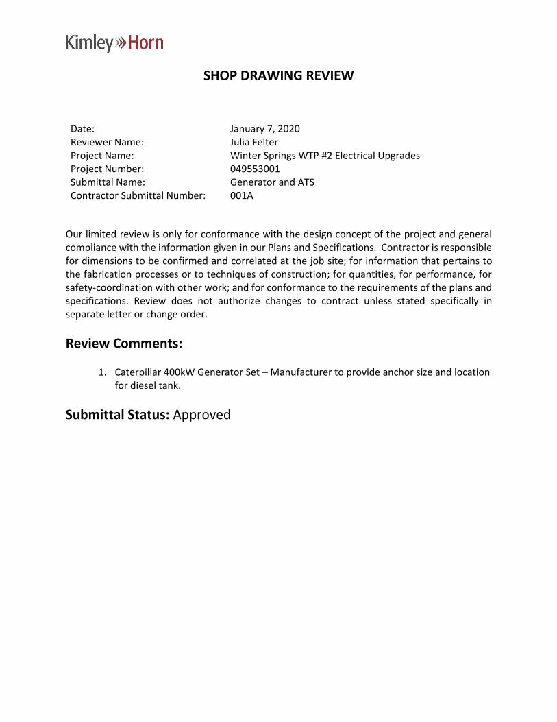
SHOP DRAWING REVIEW
Date: January 7, 2020 Reviewer Name: Julia Felter Project Name: Winter Springs WTP #2 Electrical Upgrades Project Number: 049553001 Submittal Name: Generator and ATS Contractor Submittal Number: 001A
Our limited review is only for conformance with the design concept of the project and general compliance with the information given in our Plans and Specifications. Contractor is responsible for dimensions to be confirmed and correlated at the job site; for information that pertains to the fabrication processes or to techniques of construction; for quantities, for performance, for safety-coordination with other work; and for conformance to the requirements of the plans and specifications. Review does not authorize changes to contract unless stated specifically in separate letter or change order.
Review Comments:
1. Caterpillar 400kW Generator Set – Manufacturer to provide anchor size and location for diesel tank.
Submittal Status: Approved
16216-001A Generator-ATS Resubmittal SD010721.doc Stephen E. Bailey, P.E.
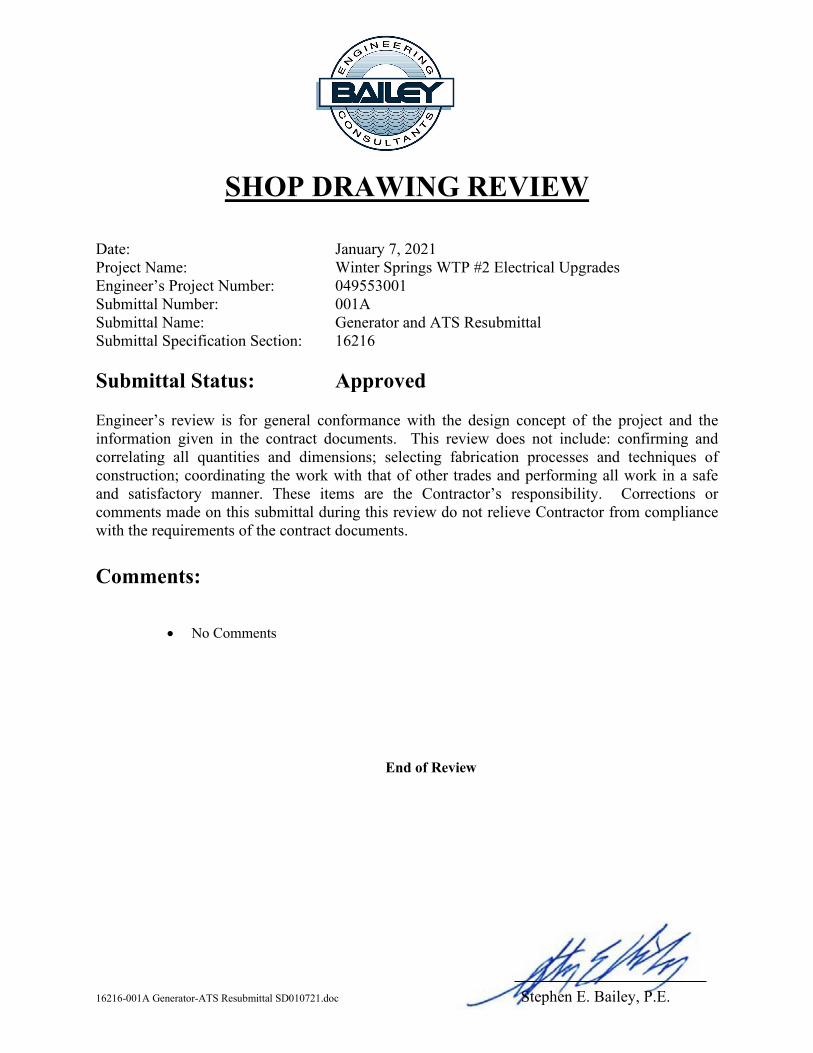
SHOP DRAWING REVIEW Date: January 7, 2021 Project Name: Winter Springs WTP #2 Electrical Upgrades Engineer’s Project Number: 049553001 Submittal Number: 001A Submittal Name: Generator and ATS Resubmittal Submittal Specification Section: 16216 Submittal Status: Approved Engineer’s review is for general conformance with the design concept of the project and the information given in the contract documents. This review does not include: confirming and correlating all quantities and dimensions; selecting fabrication processes and techniques of construction; coordinating the work with that of other trades and performing all work in a safe and satisfactory manner. These items are the Contractor’s responsibility. Corrections or comments made on this submittal during this review do not relieve Contractor from compliance with the requirements of the contract documents. Comments:
• No Comments
End of Review
Ring Power Corp 500 World Commerce Parkway St. Augustine, Florida 32092 904-737-7730
Project: City of Winter Springs
Ring Power Job Number: 200617 Submittal Review Comments Engine-Generator: Submittal Comment Response
1. Confirm fuel level and leak detection monitoring equipment to be provided per specification section 16216, 2.04. -Confirmed.
2. Confirm enclosure meets requirements per specification section 16216, 2.06, B. -Confirmed. See page 60 of submittal for CAT certification for wind load compliance.
3. Confirm remote I/O signals for the generator control panel to be provided per
specification section 16216, 2.11, A, 8, d. -Confirmed.
4. Confirm remote I/O signals for the ATS to be provided per specification section 16216,
2.12, E, 17. - Confirmed. Auxiliary Contacts Source Available: Dry contacts consisting of two
normally open and two normally closed contacts shall be provided to indicate the following
a. ATS in Normal – (2) Sets, of Acc.14 NO/NC Dry contacts provided for Source Connected Contacts b. ATS in Emergency – (2) Sets, of Acc.14 NO/NC Dry contacts provided for Source Connected Contacts c. ATS Fail – Dry Contacts 18RX OP Relay can be used for N/E Source Failure
George Soha George Soha Project management Power Systems Division Ring Power Direct (407) 472-6272 Cell (407) 793-5482 [email protected]
500 World Commerce Parkway St. Augustine, Florida 32092 www.ringpower.com (904) 737-7730
Submittal Data
Prepared For: City of Winter Springs
City of Winter Springs WTP
Caterpillar C13 400kW Generator Set
Ring Power Project Number: 200617 Project Manager: George Soha Salesman: Mark Barbarulo
Your North and Central Florida Caterpillar® Dealer
Ring Power Corp 500 World Commerce Parkway St. Augustine, Florida 32092 904-737-7730
Dear Customer:
The submittal information contained in the following pages contains technical data on your project including product specifications, drawings and start-up requirements. Your project is currently “Hold for Approval”. This document requires your immediate review and concurrence before we can proceed with an equipment order. Please return either the corrected copy with the Letter of Submittal Return or the Letter of Submittal Approval to your Project Manager, George Soha, at your earliest convenience.
If you have any general or technical questions please contact them at:
Office: (407) 472-6272 Fax: (407) 438-0922 Email: [email protected]
If you need pricing assistance with future projects, please contact your sales representative, Mark Barbarulo, at:
Office: (407) 472-6231 Mobile: (407) 383-5840 Email: [email protected]
Thank you,
Jonathan Long Manager - Project Management Office Power Systems Division Ring Power Corporation (904) 494-1290 [email protected]
Ring Power Corp 500 World Commerce Parkway St. Augustine, Florida 32092 904-737-7730
Letter of Submittal Approval Project # 200617
Project Name: City of Winter Springs WTP
I have reviewed the information contained in the Engineering Submittal and agree that the products, specifications and content meet the technical requirements of this project. I thereby approve this Engineering Submittal as provided.
_______________________ _______________________ Customer Signature Date
_______________________ _______________________ Ring Power Project Manager Date Received
_ _ _ _ _ _ _ _ _ _ _ _ _ _ _ _ _ _ _ _ _ _ _ _ _ _ _ _ _ _ _ _ _ _ _ _ _ _ _ _ _ _ _ _ _ _ _
Letter of Submittal Return Project # 200617
Project Name: City of Winter Springs WTP
I have reviewed the information contained in the Engineering Submittal, made the applicable changes and returned the original copy for your review and correction.
_______________________ _______________________ Customer Signature Date
_______________________ _______________________ Ring Power Project Manager Date Received
Ring Power Job Number: 200617
SUBMITTAL TITLE PAGE
Standby Generator Caterpillar C13 Generator Set
City of Winter Springs WTP
Caterpillar Generator Dealer
(904) 737-7730
Enclosure & Sub-Base Fuel Tank Manufacturer Fidelity Manufacturing
1900 NE 25th AveOcala, FL 34470(352) 414-4700
Email: [email protected]
Salesperson: Mark Barbarulo
Project Manager: George Soha
Ring Power Generator Contacts
Ring Power Systems
500 World Commerce Parkway
St. Augustine, FL 32092
Phone: (407) 472-6272
Submittal Table of Contents City of Winter Springs WTP Page 1 of 2
TABLE OF CONTENTS
PROJECT NAME: City of Winter Springs WTP PROJECT NUMBER: 200617
1. GENERATOR SET
Generator Set Specification Sheet Generator Technical Data Generator Set Package Performance Data Package Data Systems Data Permanent Magnet Excitation Module Engine Controller Voltage Regulator Generator Set Controller
2. ACCESSORIES
Generator Circuit Breaker Battery Charger Batteries Jacket Water Heater Enclosure & Accessories
3. DRAWINGS
Cable Connections / Sizing Fidelity Fuel Tank Drawings Generator Set Pad Outline Generator Set – Mechanical Generator Set – Electrical
4. GENERAL INFORMATION
Fuel Tank Registration Information Division of Responsibilities Pre Start-Up Checklist Caterpillar Limited Warranty Statement Extended Service Coverage Equipment Lifting Diagram UL 2200 Listing Generator Set Prototype Testing Statement

Submittal Table of Contents City of Winter Springs WTP Page 2 of 2
5. ATS / SWITCHGEAR
Drawings Outline & Mounting Diagram Wiring Diagram Equipment Brochure
Warranty Statement
(*) INDICATES ITEMS SHIPPED LOOSE. INSTALLATION / ASSEMBLY IS THE RESPONSIBILITY OF THE CUSTOMER / CONTRACTOR.

Justin Welty
Justin Welty
GENERATOR SET
Justin Welty
Justin Welty
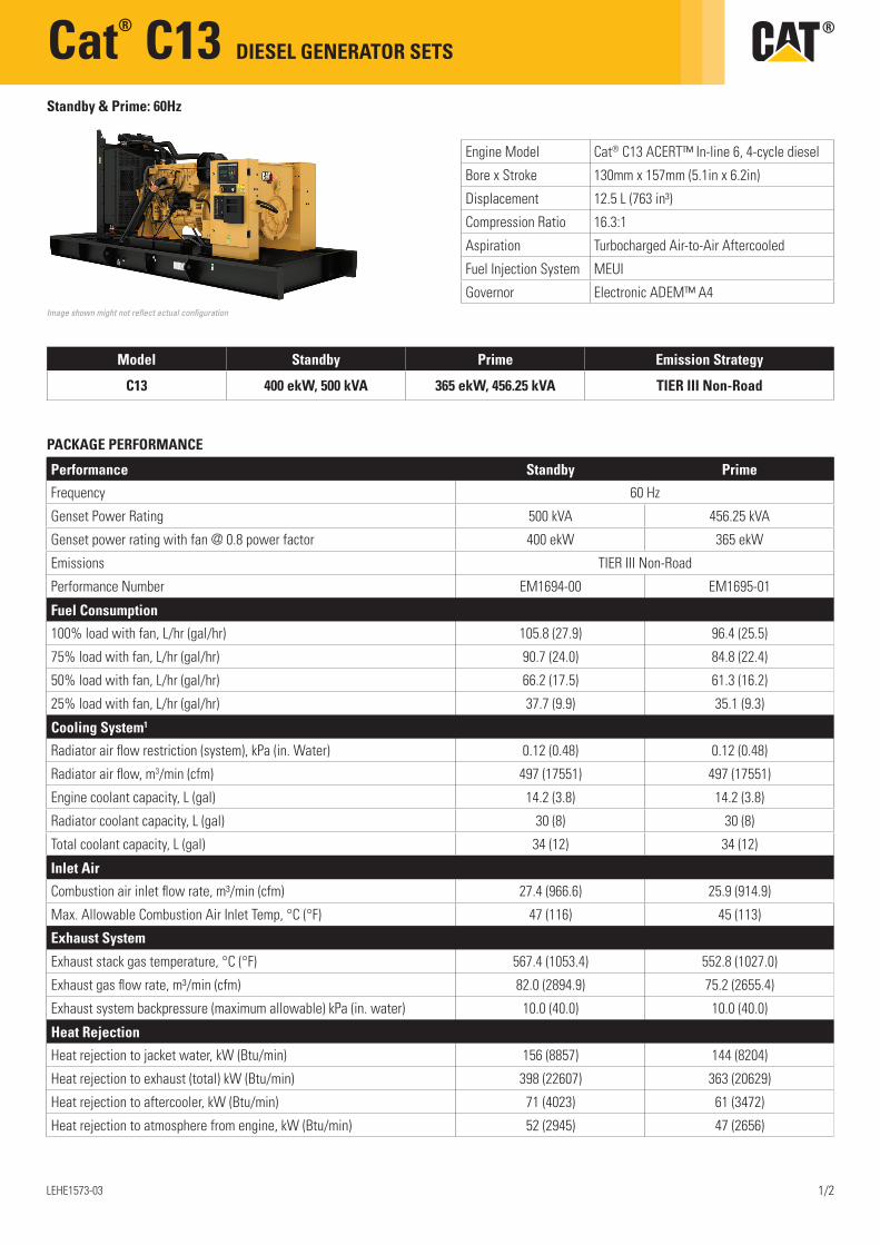
Cat® C13 DIESEL GENERATOR SETS
LEHE1573-03 1/2
Standby & Prime: 60Hz
PACKAGE PERFORMANCE
Image shown might not reflect actual configuration
Engine Model Cat® C13 ACERT™ In-line 6, 4-cycle diesel
Bore x Stroke 130mm x 157mm (5.1in x 6.2in)
Displacement 12.5 L (763 in³)
Compression Ratio 16.3:1
Aspiration Turbocharged Air-to-Air Aftercooled
Fuel Injection System MEUI
Governor Electronic ADEM™ A4
Model Standby Prime Emission Strategy
C13 400 ekW, 500 kVA 365 ekW, 456.25 kVA TIER III Non-Road
Performance Standby Prime
Frequency 60 Hz
Genset Power Rating 500 kVA 456.25 kVA
Genset power rating with fan @ 0.8 power factor 400 ekW 365 ekW
Emissions TIER III Non-Road
Performance Number EM1694-00 EM1695-01
Fuel Consumption
100% load with fan, L/hr (gal/hr) 105.8 (27.9) 96.4 (25.5)
75% load with fan, L/hr (gal/hr) 90.7 (24.0) 84.8 (22.4)
50% load with fan, L/hr (gal/hr) 66.2 (17.5) 61.3 (16.2)
25% load with fan, L/hr (gal/hr) 37.7 (9.9) 35.1 (9.3)
Cooling System1
Radiator air flow restriction (system), kPa (in. Water) 0.12 (0.48) 0.12 (0.48)
Radiator air flow, m3/min (cfm) 497 (17551) 497 (17551)
Engine coolant capacity, L (gal) 14.2 (3.8) 14.2 (3.8)
Radiator coolant capacity, L (gal) 30 (8) 30 (8)
Total coolant capacity, L (gal) 34 (12) 34 (12)
Inlet Air
Combustion air inlet flow rate, m³/min (cfm) 27.4 (966.6) 25.9 (914.9)
Max. Allowable Combustion Air Inlet Temp, °C (°F) 47 (116) 45 (113)
Exhaust System
Exhaust stack gas temperature, °C (°F) 567.4 (1053.4) 552.8 (1027.0)
Exhaust gas flow rate, m³/min (cfm) 82.0 (2894.9) 75.2 (2655.4)
Exhaust system backpressure (maximum allowable) kPa (in. water) 10.0 (40.0) 10.0 (40.0)
Heat Rejection
Heat rejection to jacket water, kW (Btu/min) 156 (8857) 144 (8204)
Heat rejection to exhaust (total) kW (Btu/min) 398 (22607) 363 (20629)
Heat rejection to aftercooler, kW (Btu/min) 71 (4023) 61 (3472)
Heat rejection to atmosphere from engine, kW (Btu/min) 52 (2945) 47 (2656)
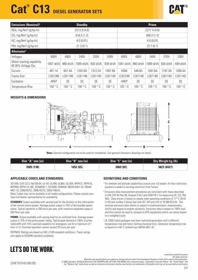
Cat® C13 DIESEL GENERATOR SETS
Emissions (Nominal)2 Standby Prime
NOx, mg/Nm³ (g/hp-hr) 2313.9 (4.6) 2277.4 (4.6)
CO, mg/Nm³ (g/hp-hr) 616.5 (1.2) 608.3 (1.2)
HC, mg/Nm³ (g/hp-hr) 4.0 (0.01) 4.9 (0.01)
PM, mg/Nm³ (g/hp-hr) 21.3 (0.1) 22.7 (0.1)
Alternator3
Voltages 600V 480V 240V 220V 208V 600V 480V 240V 220V 208V
Motor starting capability @ 30% Voltage Dip 1057 skVA 880 skVA 1089 skVA 930 skVA 839 skVA 1057 skVA 880 skVA 1089 skVA 930 skVA 839 skVA
Current 481.1A 601.4A 1202.8A 1312.2A 1387.9A 439A 548.8A 1097.6A 1197.3A 1266.4A
Frame Size LC6124B LC6114B LC6114B LC6114D LC6114D LC6124B LC6114B LC6114B LC6114D LC6114D
Excitation AREP SE SE SE SE AREP SE SE SE SE
Temperature Rise 150 ° C 150 ° C 150 ° C 105 ° C 130 ° C 125 ° C 105 ° C 105 ° C 105 ° C 105 ° C
WEIGHTS & DIMENSIONS
APPLICABLE CODES AND STANDARDS:AS1359, CSA C22.2 No100-04, UL142, UL489, UL869, UL2200, NFPA37, NFPA70, NFPA99, NFPA110, IBC, IEC60034-1, ISO3046, ISO8528, NEMA MG1-22, NEMA MG1-33, 2006/95/EC, 2006/42/EC, 2004/108/EC. Note: Codes may not be available in all model configurations. Please consult your local Cat Dealer representative for availability.
STANDBY: Output available with varying load for the duration of the interruption of the normal source power. Average power output is 70% of the standby power rating. Typical operation is 200 hours per year, with maximum expected usage of 500 hours per year.
PRIME: Output available with varying load for an unlimited time. Average power output is 70% of the prime power rating. Typical peak demand is 100% of prime rated ekW with 10% overload capability for emergency use for a maximum of 1 hour in 12. Overload operation cannot exceed 25 hours per year
RATINGS: Ratings are based on SAE J1349 standard conditions. These ratings also apply at ISO3046 standard conditions.
DEFINITIONS AND CONDITIONS1 For ambient and altitude capabilities consult your Cat dealer. Air flow restriction
(system) is added to existing restriction from factory.2 Emissions data measurement procedures are consistent with those described
in EPA CFR 40 Part 89, Subpart D & E and ISO8178-1 for measuring HC, CO, PM, NOx. Data shown is based on steady state operating conditions of 77° F, 28.42 in HG and number 2 diesel fuel with 35° API and LHV of 18,390 BTU/lb. The nominal emissions data shown is subject to instrumentation, measurement, facility and engine to engine variations. Emissions data is based on 100% load and thus cannot be used to compare to EPA regulations which use values based on a weighted cycle.
3 UL 2200 Listed packages may have oversized generators with a different temperature rise and motor starting characteristics. Generator temperature rise is based on a 40° C ambient per NEMA MG1-32.
LEHE1573-03 (05/20)
www.Cat.com/electricpowerAll rights reserved.
Materials and specifications are subject to change without notice.The International System of Units (SI) is used in this publication.© 2020 Caterpillar. All Rights Reserved. CAT, CATERPILLAR, LET’S DO THE WORK, their respective logos, “Caterpillar Corporate Yellow”, the “Power Edge” and
Cat “Modern Hex” trade dress as well as corporate and product identity used herein, are trademarks of Caterpillar and may not be used without permission
Dim “A” mm (in) Dim “B” mm (in) Dim “C” mm (in) Dry Weight kg (lb)
3505 (138) 1652 (65) 2069 (82) 3823 (8427)
C
BA
2/2
Note: General configuration not to be used for installation. See general dimension drawings for detail.
11/30/2020 Caterpillar Generator Data
https://tmiwebclassic.cat.com/tmi/servlet/TMIDirector?Action=openwindow&log=genXmlData&type=RNGenDataRefNum&refno=&selection=&unitType… 1/9
G�������� D���(AT400240)-E����� (BAA126422A)-CEM
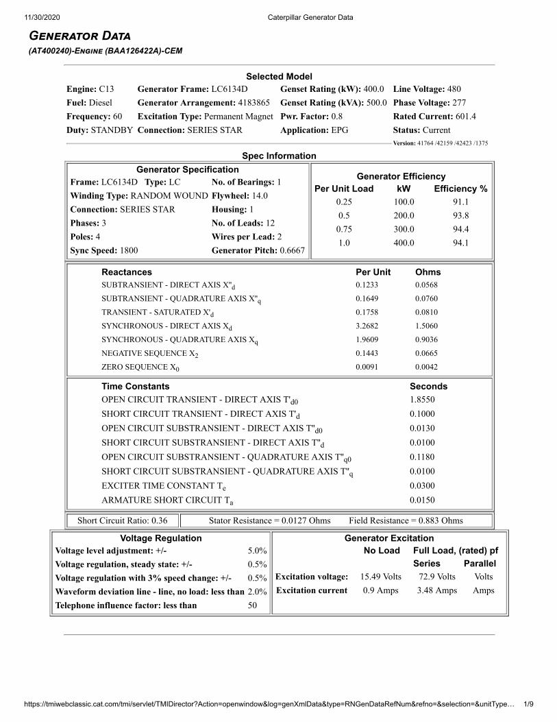
Selected ModelEngine: C13 Generator Frame: LC6134D Genset Rating (kW): 400.0 Line Voltage: 480Fuel: Diesel Generator Arrangement: 4183865 Genset Rating (kVA): 500.0 Phase Voltage: 277Frequency: 60 Excitation Type: Permanent Magnet Pwr. Factor: 0.8 Rated Current: 601.4Duty: STANDBY Connection: SERIES STAR Application: EPG Status: Current
Version: 41764 /42159 /42423 /1375
Spec InformationGenerator Specification
Frame: LC6134D Type: LC No. of Bearings: 1Winding Type: RANDOM WOUND Flywheel: 14.0Connection: SERIES STAR Housing: 1Phases: 3 No. of Leads: 12Poles: 4 Wires per Lead: 2Sync Speed: 1800 Generator Pitch: 0.6667
Generator EfficiencyPer Unit Load kW Efficiency %
0.25 100.0 91.10.5 200.0 93.80.75 300.0 94.41.0 400.0 94.1
Reactances Per Unit OhmsSUBTRANSIENT - DIRECT AXIS X''d 0.1233 0.0568
SUBTRANSIENT - QUADRATURE AXIS X''q 0.1649 0.0760
TRANSIENT - SATURATED X'd 0.1758 0.0810
SYNCHRONOUS - DIRECT AXIS Xd 3.2682 1.5060
SYNCHRONOUS - QUADRATURE AXIS Xq 1.9609 0.9036
NEGATIVE SEQUENCE X2 0.1443 0.0665
ZERO SEQUENCE X0 0.0091 0.0042
Time Constants SecondsOPEN CIRCUIT TRANSIENT - DIRECT AXIS T'd0 1.8550SHORT CIRCUIT TRANSIENT - DIRECT AXIS T'd 0.1000OPEN CIRCUIT SUBSTRANSIENT - DIRECT AXIS T''d0 0.0130SHORT CIRCUIT SUBSTRANSIENT - DIRECT AXIS T''d 0.0100OPEN CIRCUIT SUBSTRANSIENT - QUADRATURE AXIS T''q0 0.1180SHORT CIRCUIT SUBSTRANSIENT - QUADRATURE AXIS T''q 0.0100EXCITER TIME CONSTANT Te 0.0300ARMATURE SHORT CIRCUIT Ta 0.0150
Short Circuit Ratio: 0.36 Stator Resistance = 0.0127 Ohms Field Resistance = 0.883 Ohms
Voltage RegulationVoltage level adjustment: +/- 5.0%Voltage regulation, steady state: +/- 0.5%Voltage regulation with 3% speed change: +/- 0.5%Waveform deviation line - line, no load: less than 2.0%Telephone influence factor: less than 50
Generator Excitation No Load Full Load, (rated) pf
Series ParallelExcitation voltage: 15.49 Volts 72.9 Volts VoltsExcitation current 0.9 Amps 3.48 Amps Amps
11/30/2020 Caterpillar Generator Data
https://tmiwebclassic.cat.com/tmi/servlet/TMIDirector?Action=openwindow&log=genXmlData&type=RNGenDataRefNum&refno=&selection=&unitType… 2/9
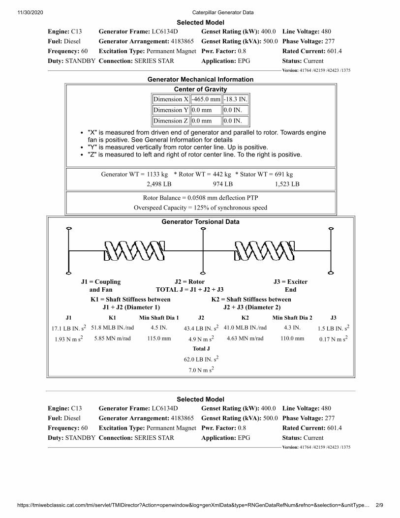
Selected ModelEngine: C13 Generator Frame: LC6134D Genset Rating (kW): 400.0 Line Voltage: 480Fuel: Diesel Generator Arrangement: 4183865 Genset Rating (kVA): 500.0 Phase Voltage: 277Frequency: 60 Excitation Type: Permanent Magnet Pwr. Factor: 0.8 Rated Current: 601.4Duty: STANDBY Connection: SERIES STAR Application: EPG Status: Current
Version: 41764 /42159 /42423 /1375
Generator Mechanical InformationCenter of Gravity
Dimension X -465.0 mm -18.3 IN.Dimension Y 0.0 mm 0.0 IN.Dimension Z 0.0 mm 0.0 IN.
"X" is measured from driven end of generator and parallel to rotor. Towards enginefan is positive. See General Information for details"Y" is measured vertically from rotor center line. Up is positive."Z" is measured to left and right of rotor center line. To the right is positive.
Generator WT = 1133 kg * Rotor WT = 442 kg * Stator WT = 691 kg 2,498 LB 974 LB 1,523 LB
Rotor Balance = 0.0508 mm deflection PTPOverspeed Capacity = 125% of synchronous speed
Generator Torsional Data
J1 = Couplingand Fan
J2 = RotorTOTAL J = J1 + J2 + J3
J3 = ExciterEnd
K1 = Shaft Stiffness between J1 + J2 (Diameter 1)
K2 = Shaft Stiffness between J2 + J3 (Diameter 2)
J1 K1 Min Shaft Dia 1 J2 K2 Min Shaft Dia 2 J3
17.1 LB IN. s2 51.8 MLB IN./rad 4.5 IN. 43.4 LB IN. s2 41.0 MLB IN./rad 4.3 IN. 1.5 LB IN. s2
1.93 N m s2 5.85 MN m/rad 115.0 mm 4.9 N m s2 4.63 MN m/rad 110.0 mm 0.17 N m s2
Total J
62.0 LB IN. s2
7.0 N m s2
Selected ModelEngine: C13 Generator Frame: LC6134D Genset Rating (kW): 400.0 Line Voltage: 480Fuel: Diesel Generator Arrangement: 4183865 Genset Rating (kVA): 500.0 Phase Voltage: 277Frequency: 60 Excitation Type: Permanent Magnet Pwr. Factor: 0.8 Rated Current: 601.4Duty: STANDBY Connection: SERIES STAR Application: EPG Status: Current
Version: 41764 /42159 /42423 /1375
11/30/2020 Caterpillar Generator Data
https://tmiwebclassic.cat.com/tmi/servlet/TMIDirector?Action=openwindow&log=genXmlData&type=RNGenDataRefNum&refno=&selection=&unitType… 3/9
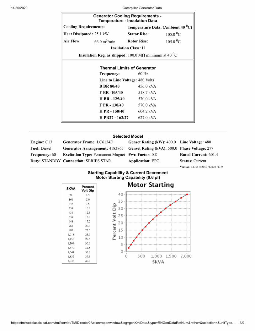
Generator Cooling Requirements - Temperature - Insulation Data
Cooling Requirements: Temperature Data: (Ambient 40 0C)Heat Dissipated: 25.1 kW Stator Rise: 105.0 0CAir Flow: 66.0 m3/min Rotor Rise: 105.0 0C
Insulation Class: H
Insulation Reg. as shipped: 100.0 MΩ minimum at 40 0C
Thermal Limits of GeneratorFrequency: 60 HzLine to Line Voltage: 480 VoltsB BR 80/40 456.0 kVAF BR -105/40 518.7 kVAH BR - 125/40 570.0 kVAF PR - 130/40 570.0 kVAH PR - 150/40 604.2 kVAH PR27 - 163/27 627.0 kVA
Selected ModelEngine: C13 Generator Frame: LC6134D Genset Rating (kW): 400.0 Line Voltage: 480Fuel: Diesel Generator Arrangement: 4183865 Genset Rating (kVA): 500.0 Phase Voltage: 277Frequency: 60 Excitation Type: Permanent Magnet Pwr. Factor: 0.8 Rated Current: 601.4Duty: STANDBY Connection: SERIES STAR Application: EPG Status: Current
Version: 41764 /42159 /42423 /1375
Starting Capability & Current DecrementMotor Starting Capability (0.6 pf)
SKVA PercentVolt Dip
78 2.5161 5.0248 7.5339 10.0436 12.5539 15.0648 17.5763 20.0887 22.5
1,018 25.01,158 27.51,309 30.01,470 32.51,644 35.01,832 37.52,036 40.0
11/30/2020 Caterpillar Generator Data
https://tmiwebclassic.cat.com/tmi/servlet/TMIDirector?Action=openwindow&log=genXmlData&type=RNGenDataRefNum&refno=&selection=&unitType… 4/9
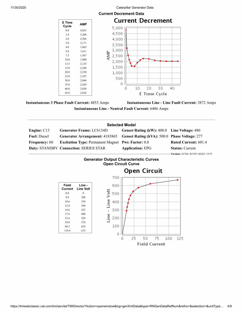
Current Decrement Data
E TimeCycle AMP
0.0 4,8531.0 3,2062.0 2,5663.0 2,1714.0 1,8655.0 1,6117.5 1,56710.0 1,90812.5 2,12515.0 2,26020.0 2,23025.0 2,10730.0 2,04635.0 2,02940.0 2,03045.0 2,036
Instantaneous 3 Phase Fault Current: 4853 Amps Instantaneous Line - Line Fault Current: 3872 AmpsInstantaneous Line - Neutral Fault Current: 6486 Amps
Selected ModelEngine: C13 Generator Frame: LC6134D Genset Rating (kW): 400.0 Line Voltage: 480Fuel: Diesel Generator Arrangement: 4183865 Genset Rating (kVA): 500.0 Phase Voltage: 277Frequency: 60 Excitation Type: Permanent Magnet Pwr. Factor: 0.8 Rated Current: 601.4Duty: STANDBY Connection: SERIES STAR Application: EPG Status: Current
Version: 41764 /42159 /42423 /1375
Generator Output Characteristic CurvesOpen Circuit Curve
FieldCurrent
Line -Line Volt
0.0 09.0 28810.6 33612.4 38414.6 43217.8 48023.4 52834.8 57660.2 624119.4 672
11/30/2020 Caterpillar Generator Data
https://tmiwebclassic.cat.com/tmi/servlet/TMIDirector?Action=openwindow&log=genXmlData&type=RNGenDataRefNum&refno=&selection=&unitType… 5/9
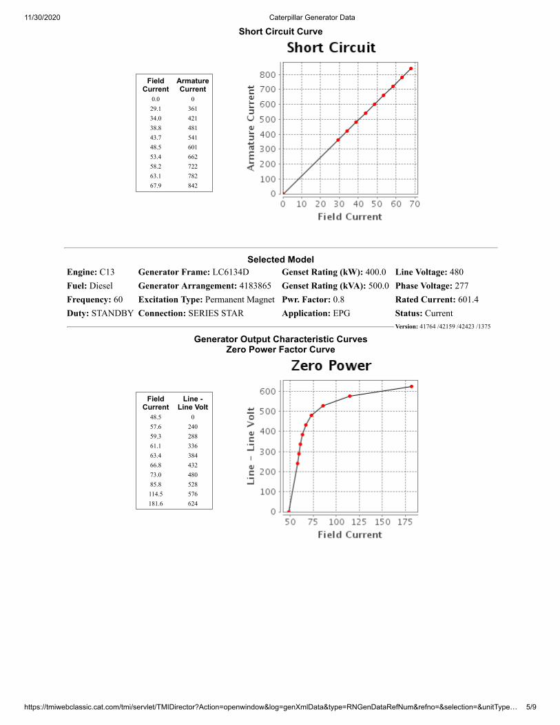
Short Circuit Curve
FieldCurrent
ArmatureCurrent
0.0 029.1 36134.0 42138.8 48143.7 54148.5 60153.4 66258.2 72263.1 78267.9 842
Selected ModelEngine: C13 Generator Frame: LC6134D Genset Rating (kW): 400.0 Line Voltage: 480Fuel: Diesel Generator Arrangement: 4183865 Genset Rating (kVA): 500.0 Phase Voltage: 277Frequency: 60 Excitation Type: Permanent Magnet Pwr. Factor: 0.8 Rated Current: 601.4Duty: STANDBY Connection: SERIES STAR Application: EPG Status: Current
Version: 41764 /42159 /42423 /1375
Generator Output Characteristic CurvesZero Power Factor Curve
FieldCurrent
Line -Line Volt
48.5 057.6 24059.3 28861.1 33663.4 38466.8 43273.0 48085.8 528114.5 576181.6 624
11/30/2020 Caterpillar Generator Data
https://tmiwebclassic.cat.com/tmi/servlet/TMIDirector?Action=openwindow&log=genXmlData&type=RNGenDataRefNum&refno=&selection=&unitType… 6/9
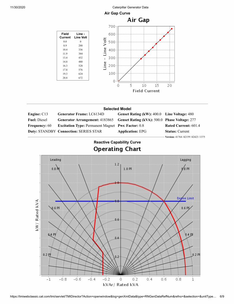
Air Gap Curve
FieldCurrent
Line -Line Volt
0.0 08.9 28810.4 33611.9 38413.4 43214.8 48016.3 52817.8 57619.3 62420.8 672
Selected ModelEngine: C13 Generator Frame: LC6134D Genset Rating (kW): 400.0 Line Voltage: 480Fuel: Diesel Generator Arrangement: 4183865 Genset Rating (kVA): 500.0 Phase Voltage: 277Frequency: 60 Excitation Type: Permanent Magnet Pwr. Factor: 0.8 Rated Current: 601.4Duty: STANDBY Connection: SERIES STAR Application: EPG Status: Current
Version: 41764 /42159 /42423 /1375
Reactive Capability Curve
11/30/2020 Caterpillar Generator Data
https://tmiwebclassic.cat.com/tmi/servlet/TMIDirector?Action=openwindow&log=genXmlData&type=RNGenDataRefNum&refno=&selection=&unitType… 7/9
Selected ModelEngine: C13 Generator Frame: LC6134D Genset Rating (kW): 400.0 Line Voltage: 480Fuel: Diesel Generator Arrangement: 4183865 Genset Rating (kVA): 500.0 Phase Voltage: 277Frequency: 60 Excitation Type: Permanent Magnet Pwr. Factor: 0.8 Rated Current: 601.4Duty: STANDBY Connection: SERIES STAR Application: EPG Status: Current
Version: 41764 /42159 /42423 /1375
11/30/2020 Caterpillar Generator Data
https://tmiwebclassic.cat.com/tmi/servlet/TMIDirector?Action=openwindow&log=genXmlData&type=RNGenDataRefNum&refno=&selection=&unitType… 8/9
Caterpillar Confidential: GreenContent Owner: Commercial Processes Division
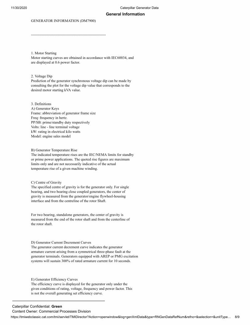
General InformationGENERATOR INFORMATION (DM7900) ------------------------------------------------------------- 1. Motor Starting Motor starting curves are obtained in accordance with IEC60034, and are displayed at 0.6 power factor. 2. Voltage Dip Prediction of the generator synchronous voltage dip can be made by consulting the plot for the voltage dip value that corresponds to the desired motor starting kVA value. 3. Definitions A) Generator Keys Frame: abbreviation of generator frame size Freq: frequency in hertz. PP/SB: prime/standby duty respectively Volts: line - line terminal voltage kW: rating in electrical kilo watts Model: engine sales model B) Generator Temperature Rise The indicated temperature rises are the IEC/NEMA limits for standby or prime power applications. The quoted rise figures are maximum limits only and are not necessarily indicative of the actual temperature rise of a given machine winding. C) Centre of Gravity The specified centre of gravity is for the generator only. For single bearing, and two bearing close coupled generators, the center of gravity is measured from the generator/engine flywheel-housing interface and from the centreline of the rotor Shaft. For two bearing, standalone generators, the center of gravity is measured from the end of the rotor shaft and from the centerline of the rotor shaft. D) Generator Current Decrement Curves The generator current decrement curve indicates the generator armature current arising from a symmetrical three-phase fault at the generator terminals. Generators equipped with AREP or PMG excitation systems will sustain 300% of rated armature current for 10 seconds. E) Generator Efficiency Curves The efficiency curve is displayed for the generator only under the given conditions of rating, voltage, frequency and power factor. This is not the overall generating set efficiency curve.
11/30/2020 MAX Performance Data Display
1/5
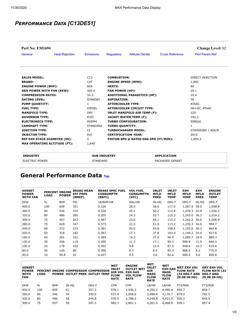
P���������� D��� [C13DE51]
Perf No: EM1694 Change Level: 02General Heat Rejection Emissions Regulatory Altitude Derate Cross Reference Perf Param Ref
SALES MODEL: C13 COMBUSTION: DIRECT INJECTIONBRAND: CAT ENGINE SPEED (RPM): 1,800ENGINE POWER (BHP): 609 HERTZ: 60GEN POWER WITH FAN (EKW): 400.0 FAN POWER (HP): 20.1COMPRESSION RATIO: 16.3 ADDITIONAL PARASITICS (HP): 10.4RATING LEVEL: STANDBY ASPIRATION: TAPUMP QUANTITY: 1 AFTERCOOLER TYPE: ATAACFUEL TYPE: DIESEL AFTERCOOLER CIRCUIT TYPE: JW+OC, ATAACMANIFOLD TYPE: DRY INLET MANIFOLD AIR TEMP (F): 120GOVERNOR TYPE: ELEC JACKET WATER TEMP (F): 192.2ELECTRONICS TYPE: ADEM4 TURBO CONFIGURATION: SINGLECAMSHAFT TYPE: STANDARD TURBO QUANTITY: 1IGNITION TYPE: CI TURBOCHARGER MODEL: GTA5002BS 1.60A/RINJECTOR TYPE: EUI CERTIFICATION YEAR: 2015REF EXH STACK DIAMETER (IN): 5 PISTON SPD @ RATED ENG SPD (FT/MIN): 1,854.3MAX OPERATING ALTITUDE (FT): 1,640
INDUSTRY SUB INDUSTRY APPLICATION
ELECTRIC POWER STANDARD PACKAGED GENSET
General Performance Data Top
GENSETPOWERWITH FAN
PERCENTLOAD
ENGINEPOWER
BRAKE MEANEFF PRES(BMEP)
BRAKE SPEC FUELCONSUMPTN(BSFC)
VOL FUELCONSUMPTN(VFC)
INLETMFLDPRES
INLETMFLDTEMP
EXHMFLDTEMP
EXHMFLDPRES
ENGINEOUTLETTEMP
EKW % BHP PSI LB/BHP-HR GAL/HR IN-HG DEG F DEG F IN-HG DEG F400.0 100 609 351 0.326 28.0 56.6 117.0 1,287.5 38.0 1,058.8360.0 90 546 315 0.326 25.1 50.2 112.8 1,239.3 32.8 1,026.2320.0 80 486 280 0.355 24.3 53.7 115.3 1,243.0 36.2 1,014.2300.0 75 457 263 0.367 23.6 54.1 115.3 1,242.2 36.6 1,006.9280.0 70 428 247 0.373 22.5 51.8 113.2 1,230.3 34.6 994.7240.0 60 372 214 0.381 20.0 45.8 108.4 1,193.6 30.2 964.8200.0 50 316 182 0.387 17.3 37.8 103.0 1,140.2 25.0 927.6160.0 40 261 151 0.389 14.3 27.4 96.5 1,080.7 18.9 889.3120.0 30 206 119 0.390 11.3 17.1 90.3 998.9 12.9 840.0100.0 25 178 102 0.392 9.8 12.4 87.5 948.6 10.3 810.680.0 20 149 86 0.396 8.3 8.5 85.3 886.6 8.2 770.940.0 10 90.8 52 0.427 5.5 3.6 82.6 689.5 5.6 609.6
GENSETPOWERWITHFAN
PERCENTLOAD
ENGINEPOWER
COMPRESSOROUTLET PRES
COMPRESSOROUTLET TEMP
WETINLETAIR VOLFLOWRATE
ENGINEOUTLET WETEXH GASVOL FLOWRATE
WETINLETAIRMASSFLOWRATE
WETEXH GASMASSFLOWRATE
WET EXH VOLFLOW RATE(32 DEG F AND29.98 IN HG)
DRY EXH VOLFLOW RATE (32DEG F AND29.98 IN HG)
EKW % BHP IN-HG DEG F CFM CFM LB/HR LB/HR FT3/MIN FT3/MIN400.0 100 609 61 357.2 978.1 2,936.2 4,292.2 4,490.4 950.7 854.7360.0 90 546 54 330.0 915.9 2,656.6 3,998.8 4,176.7 879.0 792.5320.0 80 486 58 344.8 970.5 2,788.5 4,248.8 4,421.0 930.2 846.5300.0 75 457 59 347.3 982.7 2,801.1 4,301.0 4,468.6 939.1 857.4
11/30/2020 MAX Performance Data Display
2/5
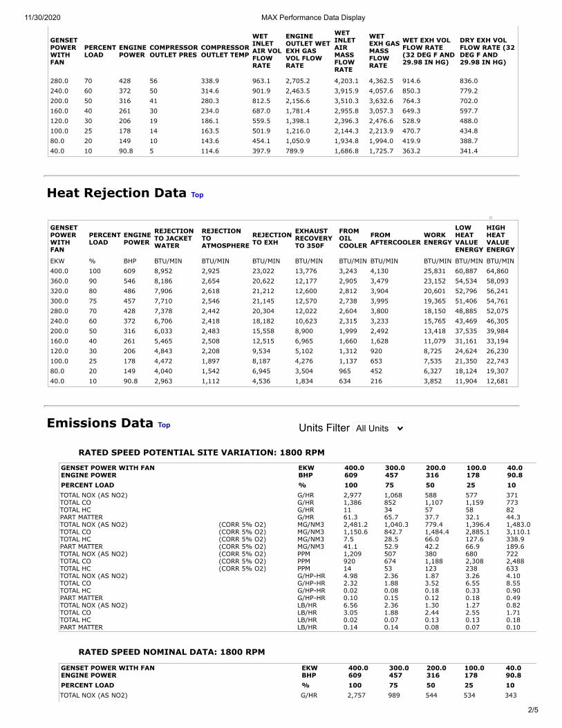
GENSETPOWERWITHFAN
PERCENTLOAD
ENGINEPOWER
COMPRESSOROUTLET PRES
COMPRESSOROUTLET TEMP
WETINLETAIR VOLFLOWRATE
ENGINEOUTLET WETEXH GASVOL FLOWRATE
WETINLETAIRMASSFLOWRATE
WETEXH GASMASSFLOWRATE
WET EXH VOLFLOW RATE(32 DEG F AND29.98 IN HG)
DRY EXH VOLFLOW RATE (32DEG F AND29.98 IN HG)
280.0 70 428 56 338.9 963.1 2,705.2 4,203.1 4,362.5 914.6 836.0240.0 60 372 50 314.6 901.9 2,463.5 3,915.9 4,057.6 850.3 779.2200.0 50 316 41 280.3 812.5 2,156.6 3,510.3 3,632.6 764.3 702.0160.0 40 261 30 234.0 687.0 1,781.4 2,955.8 3,057.3 649.3 597.7120.0 30 206 19 186.1 559.5 1,398.1 2,396.3 2,476.6 528.9 488.0100.0 25 178 14 163.5 501.9 1,216.0 2,144.3 2,213.9 470.7 434.880.0 20 149 10 143.6 454.1 1,050.9 1,934.8 1,994.0 419.9 388.740.0 10 90.8 5 114.6 397.9 789.9 1,686.8 1,725.7 363.2 341.4
Heat Rejection Data Top
GENSETPOWERWITHFAN
PERCENTLOAD
ENGINEPOWER
REJECTIONTO JACKETWATER
REJECTIONTOATMOSPHERE
REJECTIONTO EXH
EXHAUSTRECOVERYTO 350F
FROMOILCOOLER
FROMAFTERCOOLER
WORKENERGY
LOWHEATVALUEENERGY
HIGHHEATVALUEENERGY
EKW % BHP BTU/MIN BTU/MIN BTU/MIN BTU/MIN BTU/MIN BTU/MIN BTU/MIN BTU/MIN BTU/MIN400.0 100 609 8,952 2,925 23,022 13,776 3,243 4,130 25,831 60,887 64,860360.0 90 546 8,186 2,654 20,622 12,177 2,905 3,479 23,152 54,534 58,093320.0 80 486 7,906 2,618 21,212 12,600 2,812 3,904 20,601 52,796 56,241300.0 75 457 7,710 2,546 21,145 12,570 2,738 3,995 19,365 51,406 54,761280.0 70 428 7,378 2,442 20,304 12,022 2,604 3,800 18,150 48,885 52,075240.0 60 372 6,706 2,418 18,182 10,623 2,315 3,233 15,765 43,469 46,305200.0 50 316 6,033 2,483 15,558 8,900 1,999 2,492 13,418 37,535 39,984160.0 40 261 5,465 2,508 12,515 6,965 1,660 1,628 11,079 31,161 33,194120.0 30 206 4,843 2,208 9,534 5,102 1,312 920 8,725 24,624 26,230100.0 25 178 4,472 1,897 8,187 4,276 1,137 653 7,535 21,350 22,74380.0 20 149 4,040 1,542 6,945 3,504 965 452 6,327 18,124 19,30740.0 10 90.8 2,963 1,112 4,536 1,834 634 216 3,852 11,904 12,681
Emissions Data Top Units Filter All Units
RATED SPEED POTENTIAL SITE VARIATION: 1800 RPM
TOTAL NOX (AS NO2) G/HR 2,977 1,068 588 577 371TOTAL CO G/HR 1,386 852 1,107 1,159 773TOTAL HC G/HR 11 34 57 58 82PART MATTER G/HR 61.3 65.7 37.7 32.1 44.3TOTAL NOX (AS NO2) (CORR 5% O2) MG/NM3 2,481.2 1,040.3 779.4 1,396.4 1,483.0TOTAL CO (CORR 5% O2) MG/NM3 1,150.6 842.7 1,484.4 2,885.1 3,110.1TOTAL HC (CORR 5% O2) MG/NM3 7.5 28.5 66.0 127.6 338.9PART MATTER (CORR 5% O2) MG/NM3 41.1 52.9 42.2 66.9 189.6TOTAL NOX (AS NO2) (CORR 5% O2) PPM 1,209 507 380 680 722TOTAL CO (CORR 5% O2) PPM 920 674 1,188 2,308 2,488TOTAL HC (CORR 5% O2) PPM 14 53 123 238 633TOTAL NOX (AS NO2) G/HP-HR 4.98 2.36 1.87 3.26 4.10TOTAL CO G/HP-HR 2.32 1.88 3.52 6.55 8.55TOTAL HC G/HP-HR 0.02 0.08 0.18 0.33 0.90PART MATTER G/HP-HR 0.10 0.15 0.12 0.18 0.49TOTAL NOX (AS NO2) LB/HR 6.56 2.36 1.30 1.27 0.82TOTAL CO LB/HR 3.05 1.88 2.44 2.55 1.71TOTAL HC LB/HR 0.02 0.07 0.13 0.13 0.18PART MATTER LB/HR 0.14 0.14 0.08 0.07 0.10
GENSET POWER WITH FAN EKW 400.0 300.0 200.0 100.0 40.0ENGINE POWER BHP 609 457 316 178 90.8PERCENT LOAD % 100 75 50 25 10
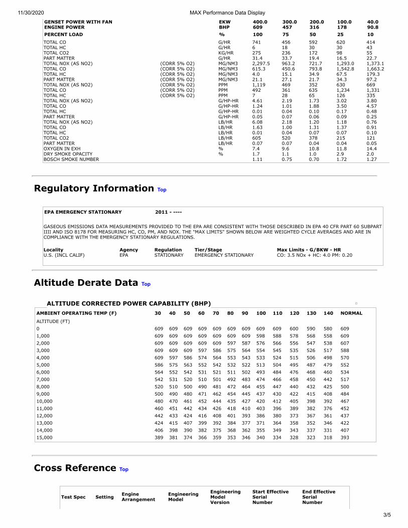
RATED SPEED NOMINAL DATA: 1800 RPM
TOTAL NOX (AS NO2) G/HR 2,757 989 544 534 343
GENSET POWER WITH FAN EKW 400.0 300.0 200.0 100.0 40.0ENGINE POWER BHP 609 457 316 178 90.8PERCENT LOAD % 100 75 50 25 10
11/30/2020 MAX Performance Data Display
3/5
TOTAL CO G/HR 741 456 592 620 414TOTAL HC G/HR 6 18 30 30 43TOTAL CO2 KG/HR 275 236 172 98 55PART MATTER G/HR 31.4 33.7 19.4 16.5 22.7TOTAL NOX (AS NO2) (CORR 5% O2) MG/NM3 2,297.5 963.2 721.7 1,293.0 1,373.1TOTAL CO (CORR 5% O2) MG/NM3 615.3 450.6 793.8 1,542.8 1,663.2TOTAL HC (CORR 5% O2) MG/NM3 4.0 15.1 34.9 67.5 179.3PART MATTER (CORR 5% O2) MG/NM3 21.1 27.1 21.7 34.3 97.2TOTAL NOX (AS NO2) (CORR 5% O2) PPM 1,119 469 352 630 669TOTAL CO (CORR 5% O2) PPM 492 361 635 1,234 1,331TOTAL HC (CORR 5% O2) PPM 7 28 65 126 335TOTAL NOX (AS NO2) G/HP-HR 4.61 2.19 1.73 3.02 3.80TOTAL CO G/HP-HR 1.24 1.01 1.88 3.50 4.57TOTAL HC G/HP-HR 0.01 0.04 0.10 0.17 0.48PART MATTER G/HP-HR 0.05 0.07 0.06 0.09 0.25TOTAL NOX (AS NO2) LB/HR 6.08 2.18 1.20 1.18 0.76TOTAL CO LB/HR 1.63 1.00 1.31 1.37 0.91TOTAL HC LB/HR 0.01 0.04 0.07 0.07 0.10TOTAL CO2 LB/HR 605 520 378 215 121PART MATTER LB/HR 0.07 0.07 0.04 0.04 0.05OXYGEN IN EXH % 7.4 9.6 10.8 11.8 14.4DRY SMOKE OPACITY % 1.7 1.1 1.0 2.9 2.0BOSCH SMOKE NUMBER 1.11 0.75 0.70 1.72 1.27
GENSET POWER WITH FAN EKW 400.0 300.0 200.0 100.0 40.0ENGINE POWER BHP 609 457 316 178 90.8PERCENT LOAD % 100 75 50 25 10
Regulatory Information Top
EPA EMERGENCY STATIONARY 2011 - ----
GASEOUS EMISSIONS DATA MEASUREMENTS PROVIDED TO THE EPA ARE CONSISTENT WITH THOSE DESCRIBED IN EPA 40 CFR PART 60 SUBPARTIIII AND ISO 8178 FOR MEASURING HC, CO, PM, AND NOX. THE "MAX LIMITS" SHOWN BELOW ARE WEIGHTED CYCLE AVERAGES AND ARE INCOMPLIANCE WITH THE EMERGENCY STATIONARY REGULATIONS. Locality Agency Regulation Tier/Stage Max Limits - G/BKW - HRU.S. (INCL CALIF) EPA STATIONARY EMERGENCY STATIONARY CO: 3.5 NOx + HC: 4.0 PM: 0.20
Altitude Derate Data Top
ALTITUDE CORRECTED POWER CAPABILITY (BHP)AMBIENT OPERATING TEMP (F) 30 40 50 60 70 80 90 100 110 120 130 140 NORMAL
ALTITUDE (FT) 0 609 609 609 609 609 609 609 609 609 600 590 580 6091,000 609 609 609 609 609 609 609 598 588 578 568 558 6092,000 609 609 609 609 609 597 587 576 566 556 547 538 6073,000 609 609 609 597 586 575 564 554 545 535 526 517 5884,000 609 597 586 574 564 553 543 533 524 515 506 498 5705,000 586 575 563 552 542 532 522 513 504 495 487 479 5526,000 564 552 542 531 521 511 502 493 484 476 468 460 5347,000 542 531 520 510 501 492 483 474 466 458 450 442 5178,000 520 510 500 490 481 472 464 455 447 440 432 425 5009,000 500 490 480 471 462 454 445 437 430 422 415 408 48410,000 480 470 461 452 444 435 427 420 412 405 398 392 46711,000 460 451 442 434 426 418 410 403 396 389 382 376 45212,000 442 433 424 416 408 401 393 386 380 373 367 361 43713,000 424 415 407 399 392 384 377 371 364 358 352 346 42214,000 406 398 390 382 375 368 362 355 349 343 337 331 40715,000 389 381 374 366 359 353 346 340 334 328 323 318 393
Cross Reference Top
Test Spec Setting Engine Arrangement
Engineering Model
Engineering Model
Version
Start Effective Serial
Number
End Effective Serial
Number
11/30/2020 MAX Performance Data Display
4/5
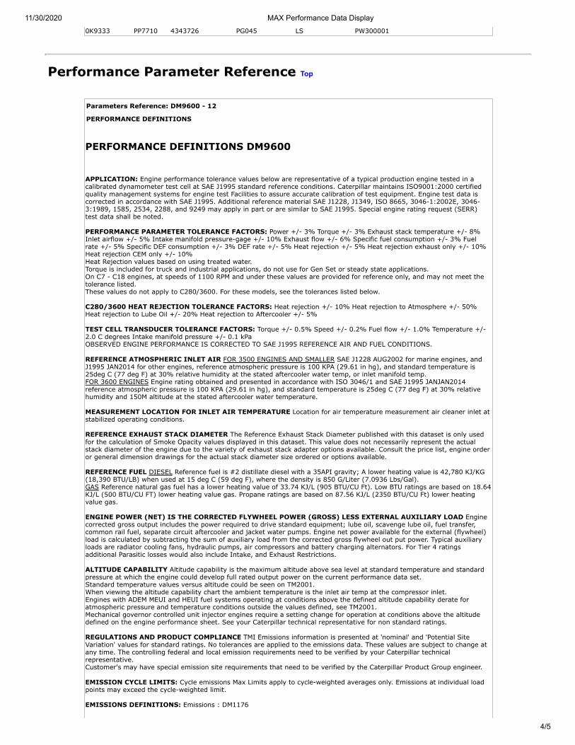
0K9333 PP7710 4343726 PG045 LS PW300001
Performance Parameter Reference Top
Parameters Reference: DM9600 - 12
PERFORMANCE DEFINITIONS
PERFORMANCE DEFINITIONS DM9600
APPLICATION: Engine performance tolerance values below are representative of a typical production engine tested in acalibrated dynamometer test cell at SAE J1995 standard reference conditions. Caterpillar maintains ISO9001:2000 certifiedquality management systems for engine test Facilities to assure accurate calibration of test equipment. Engine test data iscorrected in accordance with SAE J1995. Additional reference material SAE J1228, J1349, ISO 8665, 3046-1:2002E, 3046-3:1989, 1585, 2534, 2288, and 9249 may apply in part or are similar to SAE J1995. Special engine rating request (SERR)test data shall be noted.
PERFORMANCE PARAMETER TOLERANCE FACTORS: Power +/- 3% Torque +/- 3% Exhaust stack temperature +/- 8%Inlet airflow +/- 5% Intake manifold pressure-gage +/- 10% Exhaust flow +/- 6% Specific fuel consumption +/- 3% Fuelrate +/- 5% Specific DEF consumption +/- 3% DEF rate +/- 5% Heat rejection +/- 5% Heat rejection exhaust only +/- 10%Heat rejection CEM only +/- 10% Heat Rejection values based on using treated water. Torque is included for truck and industrial applications, do not use for Gen Set or steady state applications. On C7 - C18 engines, at speeds of 1100 RPM and under these values are provided for reference only, and may not meet thetolerance listed. These values do not apply to C280/3600. For these models, see the tolerances listed below.
C280/3600 HEAT REJECTION TOLERANCE FACTORS: Heat rejection +/- 10% Heat rejection to Atmosphere +/- 50%Heat rejection to Lube Oil +/- 20% Heat rejection to Aftercooler +/- 5%
TEST CELL TRANSDUCER TOLERANCE FACTORS: Torque +/- 0.5% Speed +/- 0.2% Fuel flow +/- 1.0% Temperature +/-2.0 C degrees Intake manifold pressure +/- 0.1 kPa OBSERVED ENGINE PERFORMANCE IS CORRECTED TO SAE J1995 REFERENCE AIR AND FUEL CONDITIONS.
REFERENCE ATMOSPHERIC INLET AIR FOR 3500 ENGINES AND SMALLER SAE J1228 AUG2002 for marine engines, andJ1995 JAN2014 for other engines, reference atmospheric pressure is 100 KPA (29.61 in hg), and standard temperature is25deg C (77 deg F) at 30% relative humidity at the stated aftercooler water temp, or inlet manifold temp. FOR 3600 ENGINES Engine rating obtained and presented in accordance with ISO 3046/1 and SAE J1995 JANJAN2014reference atmospheric pressure is 100 KPA (29.61 in hg), and standard temperature is 25deg C (77 deg F) at 30% relativehumidity and 150M altitude at the stated aftercooler water temperature.
MEASUREMENT LOCATION FOR INLET AIR TEMPERATURE Location for air temperature measurement air cleaner inlet atstabilized operating conditions.
REFERENCE EXHAUST STACK DIAMETER The Reference Exhaust Stack Diameter published with this dataset is only usedfor the calculation of Smoke Opacity values displayed in this dataset. This value does not necessarily represent the actualstack diameter of the engine due to the variety of exhaust stack adapter options available. Consult the price list, engine orderor general dimension drawings for the actual stack diameter size ordered or options available.
REFERENCE FUEL DIESEL Reference fuel is #2 distillate diesel with a 35API gravity; A lower heating value is 42,780 KJ/KG(18,390 BTU/LB) when used at 15 deg C (59 deg F), where the density is 850 G/Liter (7.0936 Lbs/Gal). GAS Reference natural gas fuel has a lower heating value of 33.74 KJ/L (905 BTU/CU Ft). Low BTU ratings are based on 18.64KJ/L (500 BTU/CU FT) lower heating value gas. Propane ratings are based on 87.56 KJ/L (2350 BTU/CU Ft) lower heatingvalue gas.
ENGINE POWER (NET) IS THE CORRECTED FLYWHEEL POWER (GROSS) LESS EXTERNAL AUXILIARY LOAD Enginecorrected gross output includes the power required to drive standard equipment; lube oil, scavenge lube oil, fuel transfer,common rail fuel, separate circuit aftercooler and jacket water pumps. Engine net power available for the external (flywheel)load is calculated by subtracting the sum of auxiliary load from the corrected gross flywheel out put power. Typical auxiliaryloads are radiator cooling fans, hydraulic pumps, air compressors and battery charging alternators. For Tier 4 ratingsadditional Parasitic losses would also include Intake, and Exhaust Restrictions.
ALTITUDE CAPABILITY Altitude capability is the maximum altitude above sea level at standard temperature and standardpressure at which the engine could develop full rated output power on the current performance data set. Standard temperature values versus altitude could be seen on TM2001. When viewing the altitude capability chart the ambient temperature is the inlet air temp at the compressor inlet. Engines with ADEM MEUI and HEUI fuel systems operating at conditions above the defined altitude capability derate foratmospheric pressure and temperature conditions outside the values defined, see TM2001. Mechanical governor controlled unit injector engines require a setting change for operation at conditions above the altitudedefined on the engine performance sheet. See your Caterpillar technical representative for non standard ratings.
REGULATIONS AND PRODUCT COMPLIANCE TMI Emissions information is presented at 'nominal' and 'Potential SiteVariation' values for standard ratings. No tolerances are applied to the emissions data. These values are subject to change atany time. The controlling federal and local emission requirements need to be verified by your Caterpillar technicalrepresentative. Customer's may have special emission site requirements that need to be verified by the Caterpillar Product Group engineer.
EMISSION CYCLE LIMITS: Cycle emissions Max Limits apply to cycle-weighted averages only. Emissions at individual loadpoints may exceed the cycle-weighted limit.
EMISSIONS DEFINITIONS: Emissions : DM1176
11/30/2020 MAX Performance Data Display
5/5
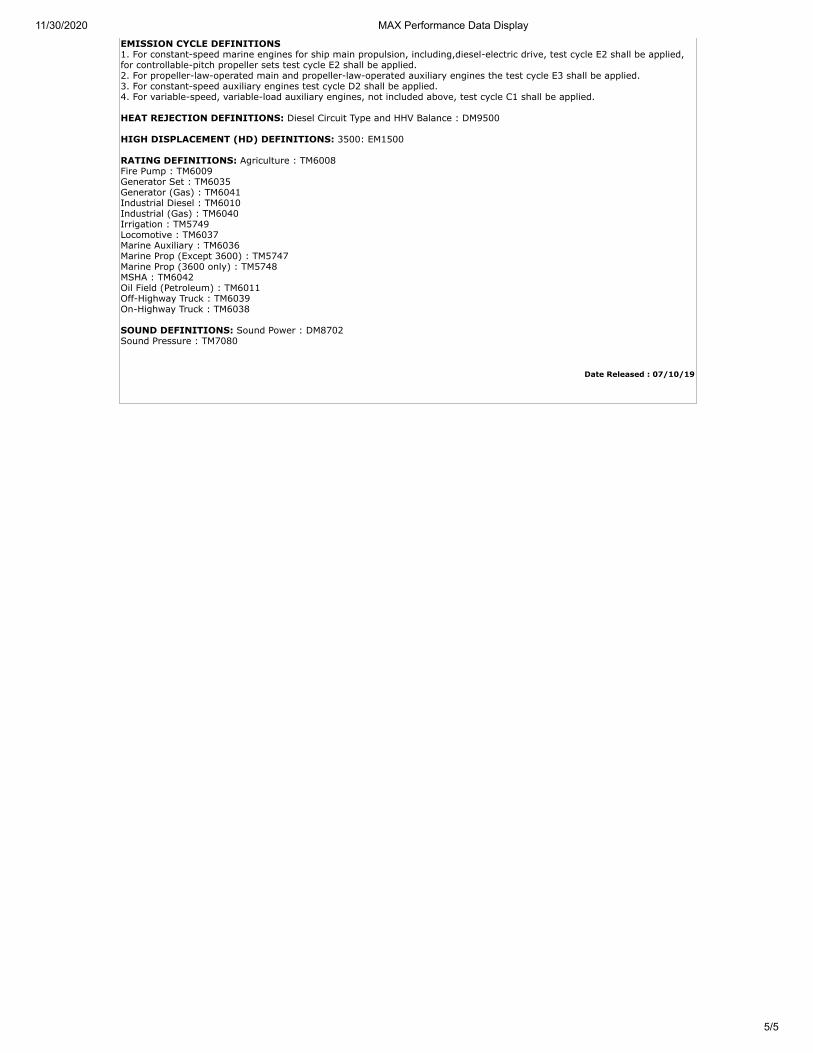
EMISSION CYCLE DEFINITIONS 1. For constant-speed marine engines for ship main propulsion, including,diesel-electric drive, test cycle E2 shall be applied,for controllable-pitch propeller sets test cycle E2 shall be applied. 2. For propeller-law-operated main and propeller-law-operated auxiliary engines the test cycle E3 shall be applied. 3. For constant-speed auxiliary engines test cycle D2 shall be applied. 4. For variable-speed, variable-load auxiliary engines, not included above, test cycle C1 shall be applied.
HEAT REJECTION DEFINITIONS: Diesel Circuit Type and HHV Balance : DM9500
HIGH DISPLACEMENT (HD) DEFINITIONS: 3500: EM1500
RATING DEFINITIONS: Agriculture : TM6008 Fire Pump : TM6009 Generator Set : TM6035 Generator (Gas) : TM6041 Industrial Diesel : TM6010 Industrial (Gas) : TM6040 Irrigation : TM5749 Locomotive : TM6037 Marine Auxiliary : TM6036 Marine Prop (Except 3600) : TM5747 Marine Prop (3600 only) : TM5748 MSHA : TM6042 Oil Field (Petroleum) : TM6011 Off-Highway Truck : TM6039 On-Highway Truck : TM6038
SOUND DEFINITIONS: Sound Power : DM8702 Sound Pressure : TM7080
Date Released : 07/10/19
11/30/2020 Package Data Display
1/3
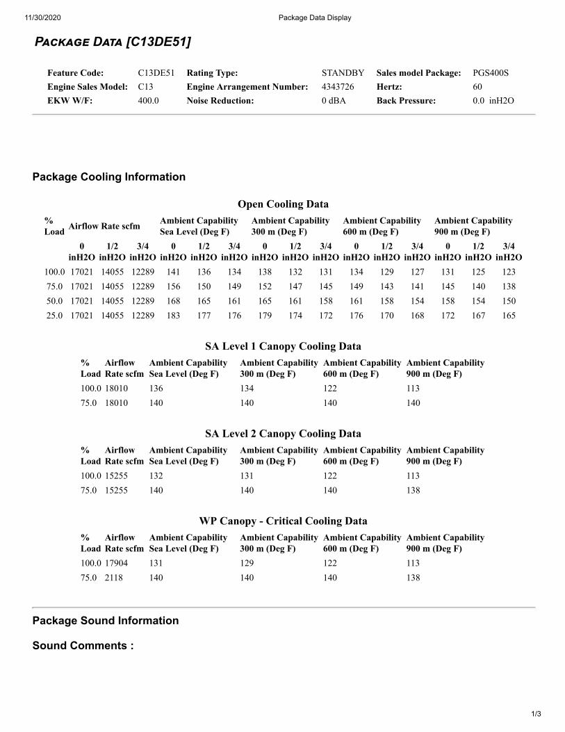
P������ D��� [C13DE51]
Feature Code: C13DE51 Rating Type: STANDBY Sales model Package: PGS400SEngine Sales Model: C13 Engine Arrangement Number: 4343726 Hertz: 60EKW W/F: 400.0 Noise Reduction: 0 dBA Back Pressure: 0.0 inH2O
Package Cooling Information
Open Cooling Data%Load Airflow Rate scfm Ambient Capability
Sea Level (Deg F)Ambient Capability300 m (Deg F)
Ambient Capability600 m (Deg F)
Ambient Capability900 m (Deg F)
0inH2O
1/2inH2O
3/4inH2O
0inH2O
1/2inH2O
3/4inH2O
0inH2O
1/2inH2O
3/4inH2O
0inH2O
1/2inH2O
3/4inH2O
0inH2O
1/2inH2O
3/4inH2O
100.0 17021 14055 12289 141 136 134 138 132 131 134 129 127 131 125 12375.0 17021 14055 12289 156 150 149 152 147 145 149 143 141 145 140 13850.0 17021 14055 12289 168 165 161 165 161 158 161 158 154 158 154 15025.0 17021 14055 12289 183 177 176 179 174 172 176 170 168 172 167 165
SA Level 1 Canopy Cooling Data%Load
AirflowRate scfm
Ambient CapabilitySea Level (Deg F)
Ambient Capability300 m (Deg F)
Ambient Capability600 m (Deg F)
Ambient Capability900 m (Deg F)
100.0 18010 136 134 122 11375.0 18010 140 140 140 140
SA Level 2 Canopy Cooling Data%Load
AirflowRate scfm
Ambient CapabilitySea Level (Deg F)
Ambient Capability300 m (Deg F)
Ambient Capability600 m (Deg F)
Ambient Capability900 m (Deg F)
100.0 15255 132 131 122 11375.0 15255 140 140 140 138
WP Canopy - Critical Cooling Data%Load
AirflowRate scfm
Ambient CapabilitySea Level (Deg F)
Ambient Capability300 m (Deg F)
Ambient Capability600 m (Deg F)
Ambient Capability900 m (Deg F)
100.0 17904 131 129 122 11375.0 2118 140 140 140 138
Package Sound Information
Sound Comments :
11/30/2020 Package Data Display
2/3
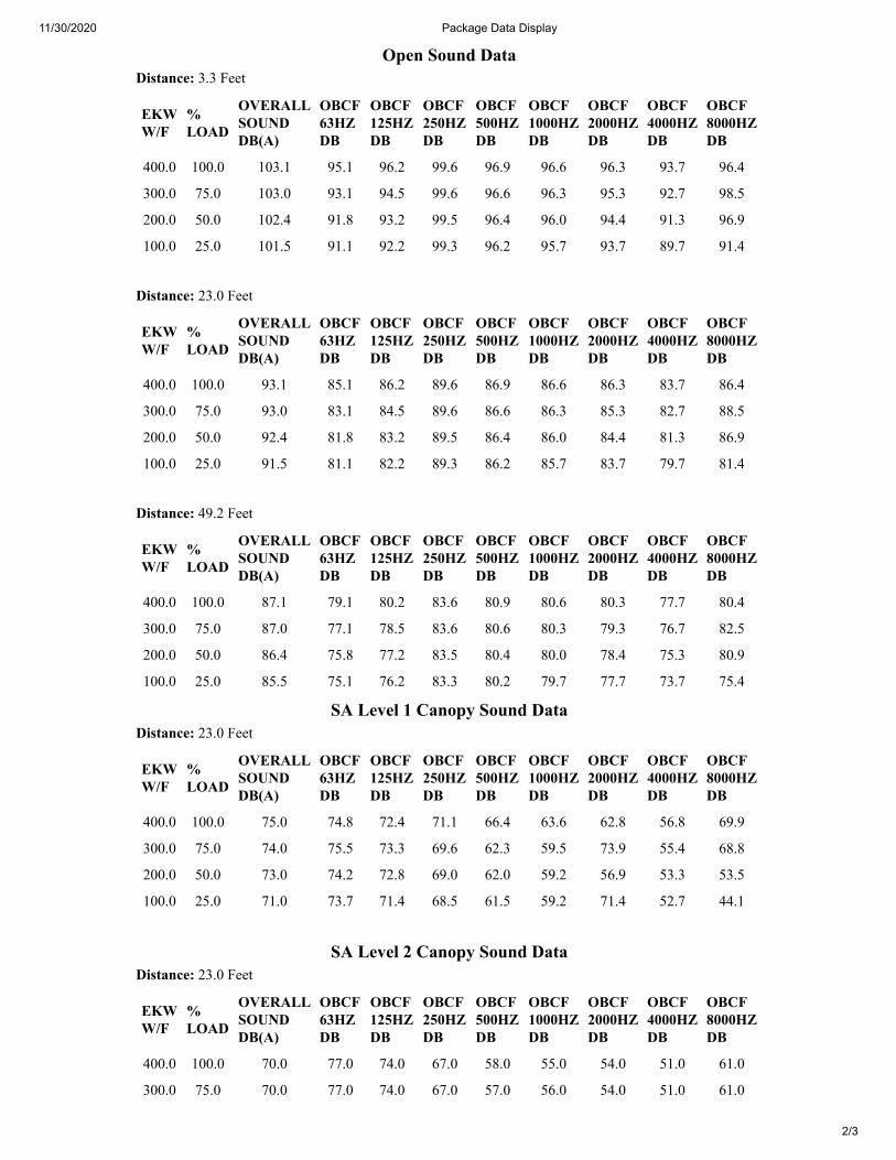
Open Sound DataDistance: 3.3 Feet
EKWW/F
%LOAD
OVERALLSOUNDDB(A)
OBCF63HZDB
OBCF125HZDB
OBCF250HZDB
OBCF500HZDB
OBCF1000HZDB
OBCF2000HZDB
OBCF4000HZDB
OBCF8000HZDB
400.0 100.0 103.1 95.1 96.2 99.6 96.9 96.6 96.3 93.7 96.4
300.0 75.0 103.0 93.1 94.5 99.6 96.6 96.3 95.3 92.7 98.5
200.0 50.0 102.4 91.8 93.2 99.5 96.4 96.0 94.4 91.3 96.9
100.0 25.0 101.5 91.1 92.2 99.3 96.2 95.7 93.7 89.7 91.4
Distance: 23.0 Feet
EKWW/F
%LOAD
OVERALLSOUNDDB(A)
OBCF63HZDB
OBCF125HZDB
OBCF250HZDB
OBCF500HZDB
OBCF1000HZDB
OBCF2000HZDB
OBCF4000HZDB
OBCF8000HZDB
400.0 100.0 93.1 85.1 86.2 89.6 86.9 86.6 86.3 83.7 86.4
300.0 75.0 93.0 83.1 84.5 89.6 86.6 86.3 85.3 82.7 88.5
200.0 50.0 92.4 81.8 83.2 89.5 86.4 86.0 84.4 81.3 86.9
100.0 25.0 91.5 81.1 82.2 89.3 86.2 85.7 83.7 79.7 81.4
Distance: 49.2 Feet
EKWW/F
%LOAD
OVERALLSOUNDDB(A)
OBCF63HZDB
OBCF125HZDB
OBCF250HZDB
OBCF500HZDB
OBCF1000HZDB
OBCF2000HZDB
OBCF4000HZDB
OBCF8000HZDB
400.0 100.0 87.1 79.1 80.2 83.6 80.9 80.6 80.3 77.7 80.4
300.0 75.0 87.0 77.1 78.5 83.6 80.6 80.3 79.3 76.7 82.5
200.0 50.0 86.4 75.8 77.2 83.5 80.4 80.0 78.4 75.3 80.9
100.0 25.0 85.5 75.1 76.2 83.3 80.2 79.7 77.7 73.7 75.4
SA Level 1 Canopy Sound DataDistance: 23.0 Feet
EKWW/F
%LOAD
OVERALLSOUNDDB(A)
OBCF63HZDB
OBCF125HZDB
OBCF250HZDB
OBCF500HZDB
OBCF1000HZDB
OBCF2000HZDB
OBCF4000HZDB
OBCF8000HZDB
400.0 100.0 75.0 74.8 72.4 71.1 66.4 63.6 62.8 56.8 69.9
300.0 75.0 74.0 75.5 73.3 69.6 62.3 59.5 73.9 55.4 68.8
200.0 50.0 73.0 74.2 72.8 69.0 62.0 59.2 56.9 53.3 53.5
100.0 25.0 71.0 73.7 71.4 68.5 61.5 59.2 71.4 52.7 44.1
SA Level 2 Canopy Sound Data
Distance: 23.0 Feet
EKWW/F
%LOAD
OVERALLSOUNDDB(A)
OBCF63HZDB
OBCF125HZDB
OBCF250HZDB
OBCF500HZDB
OBCF1000HZDB
OBCF2000HZDB
OBCF4000HZDB
OBCF8000HZDB
400.0 100.0 70.0 77.0 74.0 67.0 58.0 55.0 54.0 51.0 61.0
300.0 75.0 70.0 77.0 74.0 67.0 57.0 56.0 54.0 51.0 61.0
11/30/2020 Package Data Display
3/3
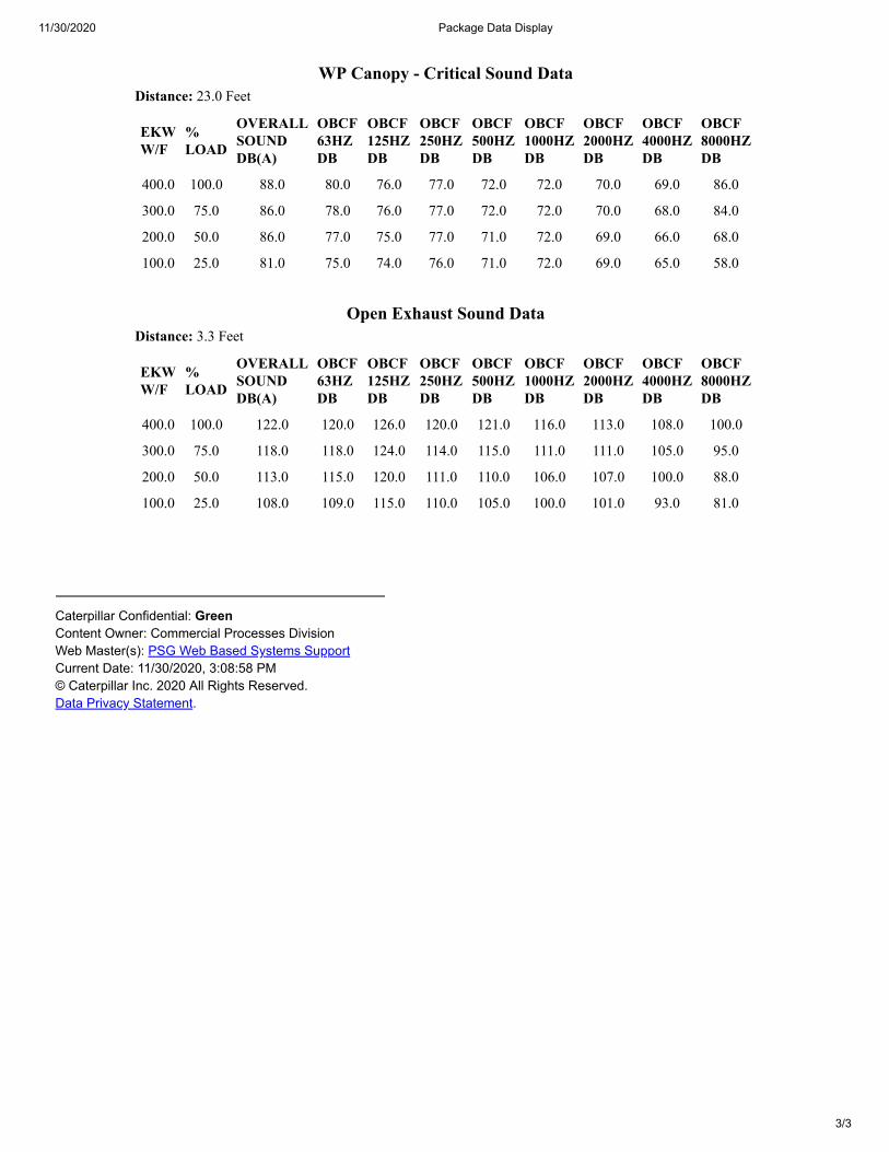
Caterpillar Confidential: GreenContent Owner: Commercial Processes DivisionWeb Master(s): PSG Web Based Systems SupportCurrent Date: 11/30/2020, 3:08:58 PM© Caterpillar Inc. 2020 All Rights Reserved.Data Privacy Statement.
WP Canopy - Critical Sound Data
Distance: 23.0 Feet
EKWW/F
%LOAD
OVERALLSOUNDDB(A)
OBCF63HZDB
OBCF125HZDB
OBCF250HZDB
OBCF500HZDB
OBCF1000HZDB
OBCF2000HZDB
OBCF4000HZDB
OBCF8000HZDB
400.0 100.0 88.0 80.0 76.0 77.0 72.0 72.0 70.0 69.0 86.0
300.0 75.0 86.0 78.0 76.0 77.0 72.0 72.0 70.0 68.0 84.0
200.0 50.0 86.0 77.0 75.0 77.0 71.0 72.0 69.0 66.0 68.0
100.0 25.0 81.0 75.0 74.0 76.0 71.0 72.0 69.0 65.0 58.0
Open Exhaust Sound Data
Distance: 3.3 Feet
EKWW/F
%LOAD
OVERALLSOUNDDB(A)
OBCF63HZDB
OBCF125HZDB
OBCF250HZDB
OBCF500HZDB
OBCF1000HZDB
OBCF2000HZDB
OBCF4000HZDB
OBCF8000HZDB
400.0 100.0 122.0 120.0 126.0 120.0 121.0 116.0 113.0 108.0 100.0
300.0 75.0 118.0 118.0 124.0 114.0 115.0 111.0 111.0 105.0 95.0
200.0 50.0 113.0 115.0 120.0 111.0 110.0 106.0 107.0 100.0 88.0
100.0 25.0 108.0 109.0 115.0 110.0 105.0 100.0 101.0 93.0 81.0
11/30/2020 Systems Data
1/2
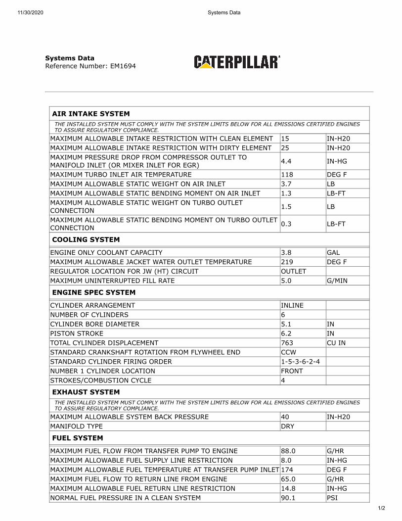
Systems DataReference Number: EM1694
AIR INTAKE SYSTEMTHE INSTALLED SYSTEM MUST COMPLY WITH THE SYSTEM LIMITS BELOW FOR ALL EMISSIONS CERTIFIED ENGINESTO ASSURE REGULATORY COMPLIANCE.
MAXIMUM ALLOWABLE INTAKE RESTRICTION WITH CLEAN ELEMENT 15 IN-H20MAXIMUM ALLOWABLE INTAKE RESTRICTION WITH DIRTY ELEMENT 25 IN-H20MAXIMUM PRESSURE DROP FROM COMPRESSOR OUTLET TOMANIFOLD INLET (OR MIXER INLET FOR EGR) 4.4 IN-HG
MAXIMUM TURBO INLET AIR TEMPERATURE 118 DEG FMAXIMUM ALLOWABLE STATIC WEIGHT ON AIR INLET 3.7 LBMAXIMUM ALLOWABLE STATIC BENDING MOMENT ON AIR INLET 1.3 LB-FTMAXIMUM ALLOWABLE STATIC WEIGHT ON TURBO OUTLETCONNECTION 1.5 LB
MAXIMUM ALLOWABLE STATIC BENDING MOMENT ON TURBO OUTLETCONNECTION 0.3 LB-FT
COOLING SYSTEM
ENGINE ONLY COOLANT CAPACITY 3.8 GALMAXIMUM ALLOWABLE JACKET WATER OUTLET TEMPERATURE 219 DEG FREGULATOR LOCATION FOR JW (HT) CIRCUIT OUTLETMAXIMUM UNINTERRUPTED FILL RATE 5.0 G/MIN
ENGINE SPEC SYSTEM
CYLINDER ARRANGEMENT INLINENUMBER OF CYLINDERS 6CYLINDER BORE DIAMETER 5.1 INPISTON STROKE 6.2 INTOTAL CYLINDER DISPLACEMENT 763 CU INSTANDARD CRANKSHAFT ROTATION FROM FLYWHEEL END CCWSTANDARD CYLINDER FIRING ORDER 1-5-3-6-2-4NUMBER 1 CYLINDER LOCATION FRONTSTROKES/COMBUSTION CYCLE 4
EXHAUST SYSTEMTHE INSTALLED SYSTEM MUST COMPLY WITH THE SYSTEM LIMITS BELOW FOR ALL EMISSIONS CERTIFIED ENGINESTO ASSURE REGULATORY COMPLIANCE.
MAXIMUM ALLOWABLE SYSTEM BACK PRESSURE 40 IN-H20MANIFOLD TYPE DRY
FUEL SYSTEM
MAXIMUM FUEL FLOW FROM TRANSFER PUMP TO ENGINE 88.0 G/HRMAXIMUM ALLOWABLE FUEL SUPPLY LINE RESTRICTION 8.0 IN-HGMAXIMUM ALLOWABLE FUEL TEMPERATURE AT TRANSFER PUMP INLET 174 DEG FMAXIMUM FUEL FLOW TO RETURN LINE FROM ENGINE 65.0 G/HRMAXIMUM ALLOWABLE FUEL RETURN LINE RESTRICTION 14.8 IN-HGNORMAL FUEL PRESSURE IN A CLEAN SYSTEM 90.1 PSI
11/30/2020 Systems Data
2/2
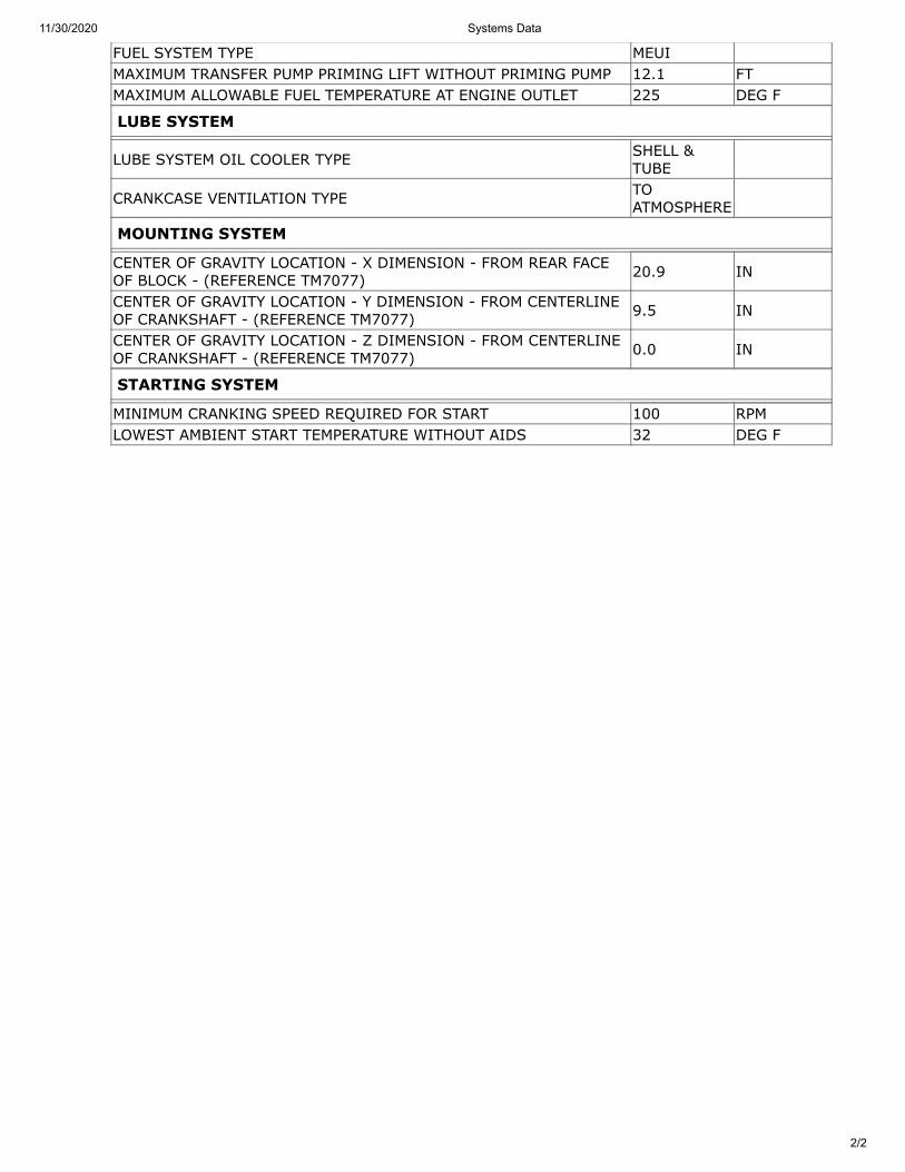
FUEL SYSTEM TYPE MEUIMAXIMUM TRANSFER PUMP PRIMING LIFT WITHOUT PRIMING PUMP 12.1 FTMAXIMUM ALLOWABLE FUEL TEMPERATURE AT ENGINE OUTLET 225 DEG F
LUBE SYSTEM
LUBE SYSTEM OIL COOLER TYPE SHELL &TUBE
CRANKCASE VENTILATION TYPE TOATMOSPHERE
MOUNTING SYSTEM
CENTER OF GRAVITY LOCATION - X DIMENSION - FROM REAR FACEOF BLOCK - (REFERENCE TM7077) 20.9 IN
CENTER OF GRAVITY LOCATION - Y DIMENSION - FROM CENTERLINEOF CRANKSHAFT - (REFERENCE TM7077) 9.5 IN
CENTER OF GRAVITY LOCATION - Z DIMENSION - FROM CENTERLINEOF CRANKSHAFT - (REFERENCE TM7077) 0.0 IN
STARTING SYSTEM
MINIMUM CRANKING SPEED REQUIRED FOR START 100 RPMLOWEST AMBIENT START TEMPERATURE WITHOUT AIDS 32 DEG F
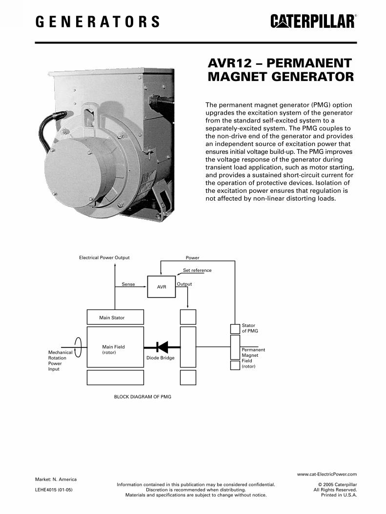
G E N E R A T O R S
AVR12 – PERMANENTMAGNET GENERATOR
The permanent magnet generator (PMG) optionupgrades the excitation system of the generatorfrom the standard self-excited system to aseparately-excited system. The PMG couples tothe non-drive end of the generator and providesan independent source of excitation power thatensures initial voltage build-up. The PMG improvesthe voltage response of the generator duringtransient load application, such as motor starting,and provides a sustained short-circuit current forthe operation of protective devices. Isolation ofthe excitation power ensures that regulation isnot affected by non-linear distorting loads.
www.cat-ElectricPower.comMarket: N. America
Information contained in this publication may be considered confidential. © 2005 Caterpillar LEHE4015 (01-05) Discretion is recommended when distributing. All Rights Reserved.
Materials and specifications are subject to change without notice. Printed in U.S.A.
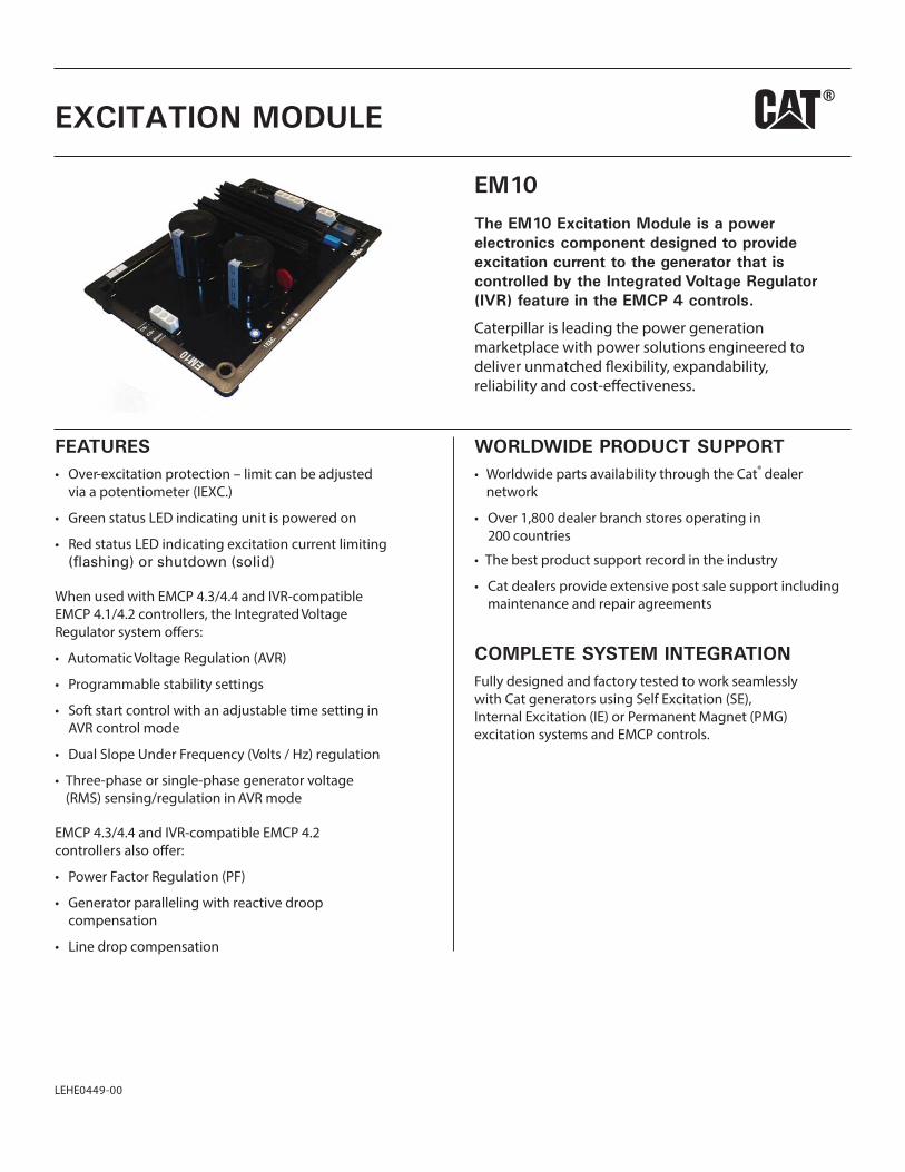
FEATURESOver
R r
rR r
R A
t
Sof r tA
F
vA
r
F R
i
WORLDWIDE PRODUCT SUPPORTW r ®
0 c00
r
COMPLETE SYSTEM INTEGRATIONF
r S
EM10
The EM10 Excitation Module is a power electronics component designed to provide excitation current to the generator that is controlled by the Integrated Voltage Regulator (IVR) feature in the EMCP 4 controls.
i ci
EXCITATION MODULE
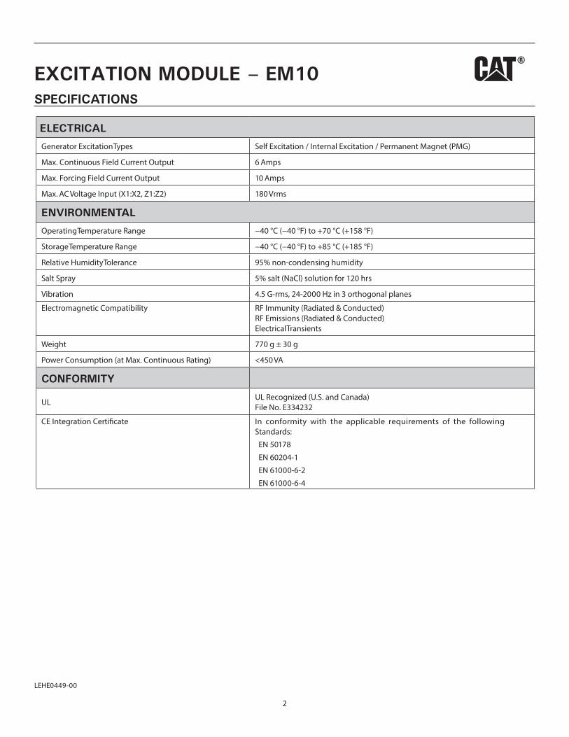
SPECIFICATIONS
2
ELECTRICAL
Generator Excitation Types Self Excitation / Internal Excitation / Permanent Magnet (PMG)
Max. Continuous Field Current Output 6 Amps
Max. Forcing Field Current Output 10 Amps
Max. AC Voltage Input (X1:X2, Z1:Z2) 180 Vrms
ENVIRONMENTAL
Operating Temperature Range −40 °C (−40 °F) to +70 °C (+158 °F)
Storage Temperature Range −40 °C (−40 °F) to +85 °C (+185 °F)
Relative Humidity Tolerance 95% non-condensing humidity
Salt Spray 5% salt (NaCl) solution for 120 hrs
Vibration 4.5 G-rms, 24-2000 Hz in 3 orthogonal planes
Electromagnetic Compatibility RF Immunity (Radiated & Conducted) RF Emissions (Radiated & Conducted) Electrical Transients
Weight 770 g ± 30 g
Power Consumption (at Max. Continuous Rating) <450 VA
CONFORMITY
ULUL Recognized (U.S. and Canada) File No. E334232
CE Integration Cer In conformity with the applicable requirements of the following Standards:
EN 50178
EN 60204-1
EN 61000-6-2
EN 61000-6-4
EXCITATION MODULE – EM10
LEHE0449-00
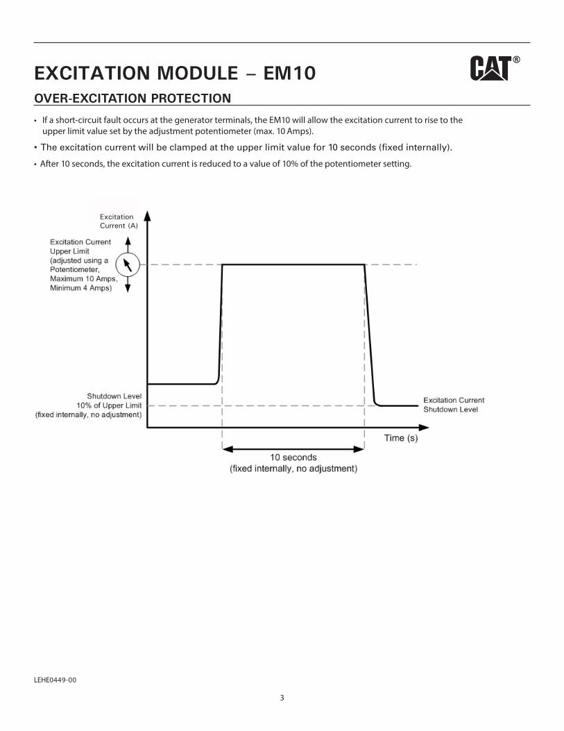
OVER-EXCITATION PROTECTION
r r 1 r10
Af 1 r 1 t
3
ExcitationCurrent (A)
EXCITATION MODULE – EM10
0449-00
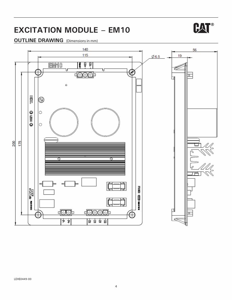
OUTLINE DRAWING (Dimensions in mm)
4
EXCITATION MODULE – EM10
LEHE0449-00
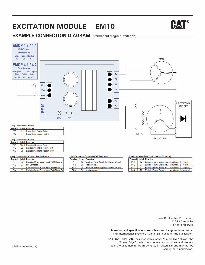
EXAMPLE CONNECTION DIAGRAM (Permanent Magnet Excitation)
www.Cat-Electric Power.com©2013 Caterpillar
All rights reserved
Materials and specifications are subject to change without notice.The International System of Units (SI) is used in this publication.
CAT, CATERPILLAR, their respective logos, “Caterpillar Yellow”, the“Power Edge” trade dress, as well as corporate and product
identity used herein, are trademarks of Caterpillar and may not beused without permission.
EXCITATION MODULE – EM10
LEHE0449-00 (08/13)
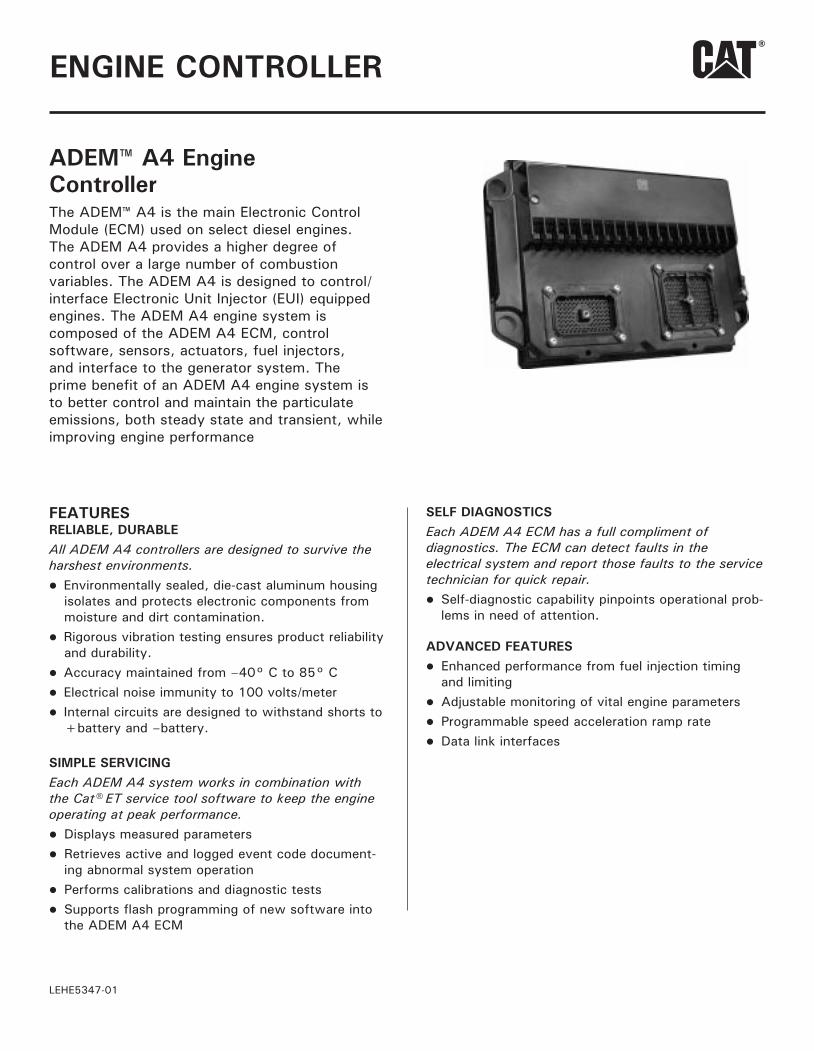
ADEM™ A4 EngineController The ADEM™ A4 is the main Electronic ControlModule (ECM) used on select diesel engines.The ADEM A4 provides a higher degree of control over a large number of combustion variables. The ADEM A4 is designed to control/interface Electronic Unit Injector (EUI) equipped engines. The ADEM A4 engine system is composed of the ADEM A4 ECM, control software, sensors, actuators, fuel injectors, and interface to the generator system. The prime benefit of an ADEM A4 engine system is to better control and maintain the particulate emissions, both steady state and transient, while improving engine performance
ENGINE CONTROLLER
FEATURESRELIABLE, DURABLEAll ADEM A4 controllers are designed to survive the harshest environments.l Environmentally sealed, die-cast aluminum housing
isolates and protects electronic components from moisture and dirt contamination.
l Rigorous vibration testing ensures product reliability and durability.
l Accuracy maintained from –40° C to 85° Cl Electrical noise immunity to 100 volts/meterl Internal circuits are designed to withstand shorts to
+battery and –battery.
SIMPLE SERVICINGEach ADEM A4 system works in combination with the Cat® ET service tool software to keep the engine operating at peak performance.l Displays measured parametersl Retrieves active and logged event code document-
ing abnormal system operationl Performs calibrations and diagnostic testsl Supports flash programming of new software into
the ADEM A4 ECM
SELF DIAGNOSTICSEach ADEM A4 ECM has a full compliment of diagnostics. The ECM can detect faults in the electrical system and report those faults to the service technician for quick repair.l Self-diagnostic capability pinpoints operational prob-
lems in need of attention.
ADVANCED FEATURESl Enhanced performance from fuel injection timing
and limitingl Adjustable monitoring of vital engine parametersl Programmable speed acceleration ramp ratel Data link interfaces
LEHE5347-01
DESCRIPTIONThe ECM is housed in an environmentally sealed cast-ing. All wiring connections to the ECM are made using two sealed connectors: a single seventy-pin connector and a single one hundred twenty-pin connector.
ENGINE SPEED GOVERNINGDesired engine speed is calculated by the ECM and held within ±0.2 Hz for isochronous and droop mode. The ECM accounts for droop that is requested. The proper amount of fuel is sent to the injectors due to these calculations. The ECM also employs cooldown/shutdown strategies, acceleration delays on startup, acceleration ramp times and speed reference.
FUEL LIMITINGWarm and cold fuel-air ratio control limits are con-trolled by the ECM. Electronic monitoring system derates, torque limit, and cranking limit, programma-ble torque scaling, and cold cylinder cutout mode are standard features.
FUEL INJECTION TIMINGMaster timing for injection is controlled by the ECM control. Temperature dependencies are accounted for in the fuel injection calculations.
ELECTRONIC MONITORINGElectronic monitoring of vital engine parameters can be programmed. Warning, derate, and shutdown event conditions may be customized by the user.
INFORMATION MANAGEMENTThe ECM stores information to assist with electronic troubleshooting. Active and logged diagnostic codes, active events, logged events, fuel consumption, engine hours, and instantaneous totals aid service technicians when diagnosing electronic faults and scheduling preventive maintenance.
CALIBRATIONSEngine performance is optimized through injection timing. Auto/manual sensor calibrations are standard features.
ON-BOARD SYSTEM TESTSSystem tests are available to assist in electronic trou-bleshooting. These tests include: injector activation, injector cutout, and override of control outputs.
DATA LINK INTERFACESThe ADEM A4 communicates with the EMCP via a dedicated communication network.
ELECTRONIC SENSINGThe following sensing is available on the ADEM A4: oil pressure, fuel pressure, fuel temperature, atmospheric pressure, air inlet temperature, turbo outlet pressure, engine coolant temperature, engine speed, throttle, position, exhaust temperature, oil filter pressure differential, fuel filter pressure differential, air filter pressure differential and crankcase pressure.
2LEHE5347-01
ENGINE CONTROLLER
SPECIFICATIONS Impervious to:
salt spray, fuel, oil and oil additives, coolant,spray cleaners, chlorinated solvents, hydrogensulfide and methane gas, and dust
Input and output protectionall inputs and outputs are protected againstshort circuits to +battery and –battery
Input voltage range (24 VDC nominal)18 to 32 VDC
Mountingengine mounted
Reverse polarity protected
Shock, withstands 20 g
Temperature rangeOperating: –40° C to 85° C (–40° F to 185° F)Storage: –50° C to 120° C (–58° F to 248° F)
Vibrationwithstands 8.0 g @ 24 to 2 kHz
3LEHE5347-01
ENGINE CONTROLLER
INTEGRATED VOLTAGEREGULATOR
LEHE0448-00
FEATURESWhen used with an Excitation Module, EMCP 4.3/4.4 and IVR-compatible EMCP 4.1/4.2 controllers o
Automatic Voltage Regulation (AVR)
Programmable stability settings
Soft start control with an adjustable time setting in AVR control mode
Hz) regulation
Three-phase or single-phase generator voltage (RMS) sensing/regulation in AVR mode
Setpoint adjustment from the EMCP display or Cat® ET Service Tool
IVR Operating Status and Voltage Bias Overview screens to provide an enhanced level of user interface
Integrated Voltage Regulator event monitoring
EMCP 4.3/4.4 and IVR-compatible EMCP 4.2 controllers also o
Power Factor Regulation (PF)
Reactive Droop compensation
Line drop compensation
COMPLETE SYSTEM INTEGRATIONFully designed and factory tested to work seamlessly with Cat generators using Self Excitation (SE), Internal Excitation (IE) or Permanent Magnet (PMG) excitation systems and EMCP controls.
INTEGRATED VOLTAGE REGULATOR
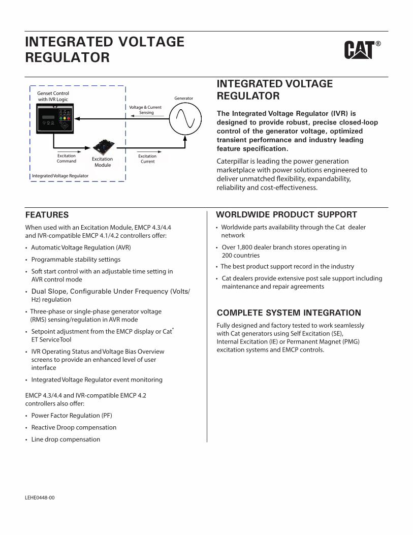
The Integrated Voltage Regulator (IVR) is designed to provide robust, precise closed-loop control of the generator voltage, optimized transient performance and industry leading feature specification.
Caterpillar is leading the power generation marketplace with power solutions engineered to deliver unmatc y, expandability, reliability and cost-e iveness.
Generator
Voltage & CurrentSensing
ExcitationCurrent
ExcitationCommand
Genset Controlwith IVR Logic
ExcitationModule
Integrated Voltage Regulator
WORLDWIDE PRODUCT SUPPORT Worldwide parts availability through the Cat dealer network
Over 1,800 dealer branch stores operating in 200 countries
The best product support record in the industry
Cat dealers provide extensive post sale support includingmaintenance and repair agreements
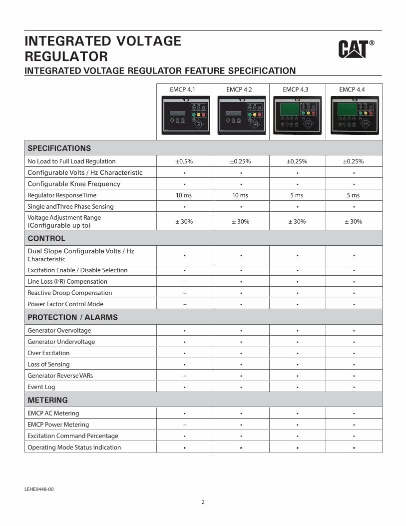
EMCP 4.1 EMCP 4.2 EMCP 4.3 EMCP 4.4
SPECIFICATIONS
No Load to Full Load Regulation ±0.5% ±0.25% ±0.25% ±0.25%
Regulator Response Time 10 ms 10 ms 5 ms 5 ms
Single and Three Phase Sensing
Voltage Adjustment Range ± 30% ± 30% ± 30% ± 30%
CONTROL
Characteristic
Excitation Enable / Disable Selection
Line Loss (I2R) Compensation –
Reactive Droop Compensation –
Power Factor Control Mode –
PROTECTION / ALARMS
Generator Overvoltage
Generator Undervoltage
Over Excitation
Loss of Sensing
Generator Reverse VARs –
Event Log
METERING
EMCP AC Metering
EMCP Power Metering –
Excitation Command Percentage
Operating Mode Status Indication
INTEGRATED VOLTAGE REGULATOR FEATURE SPECIFICATION
2
INTEGRATED VOLTAGEREGULATOR
LEHE0448-00
George Soha
Rectangle
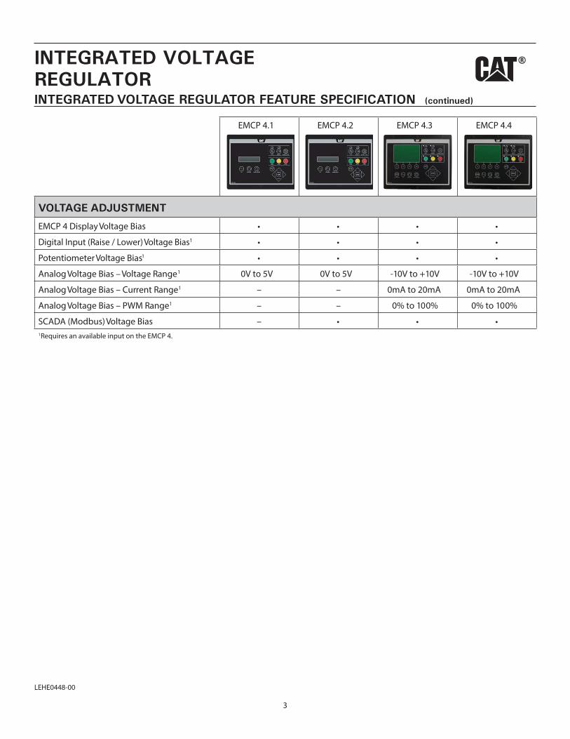
EMCP 4.1 EMCP 4.2 EMCP 4.3 EMCP 4.4
VOLTAGE ADJUSTMENT
EMCP 4 Display Voltage Bias
Digital Input (Raise / Lower) Voltage Bias1
Potentiometer Voltage Bias1
Analog Voltage Bias – Voltage Range1 0V to 5V 0V to 5V -10V to +10V -10V to +10V
Analog Voltage Bias – Current Range1 – – 0mA to 20mA 0mA to 20mA
Analog Voltage Bias – PWM Range1 – – 0% to 100% 0% to 100%
SCADA (Modbus) Voltage Bias –1Requires an available input on the EMCP 4.
INTEGRATED VOLTAGE REGULATOR FEATURE SPECIFICATION (continued)
3
INTEGRATED VOLTAGEREGULATOR
LEHE0448-00
George Soha
Rectangle
INTEGRATED VOLTAGEREGULATOR
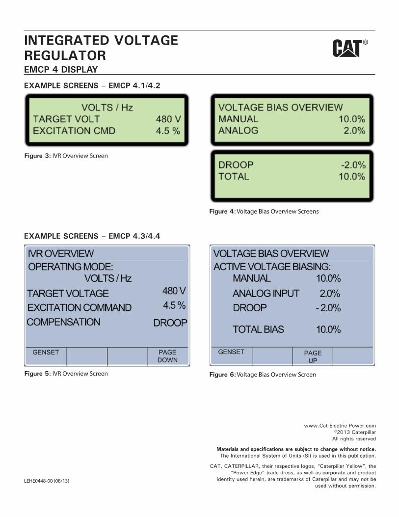
Figure 3: IVR Overview Screen
Figure 4: Voltage Bias Overview Screens
Figure 5: IVR Overview Screen Figure 6: Voltage Bias Overview Screen
EMCP 4 DISPLAY
EXAMPLE SCREENS – EMCP 4.1/4.2
EXAMPLE SCREENS – EMCP 4.3/4.4
www.Cat-Electric Power.com©2013 Caterpillar
All rights reserved
Materials and specifications are subject to change without notice.The International System of Units (SI) is used in this publication.
CAT, CATERPILLAR, their respective logos, “Caterpillar Yellow”, the“Power Edge” trade dress, as well as corporate and product
identity used herein, are trademarks of Caterpillar and may not beused without permission.
LEHE0448-00 (08/13)
1
Attachment
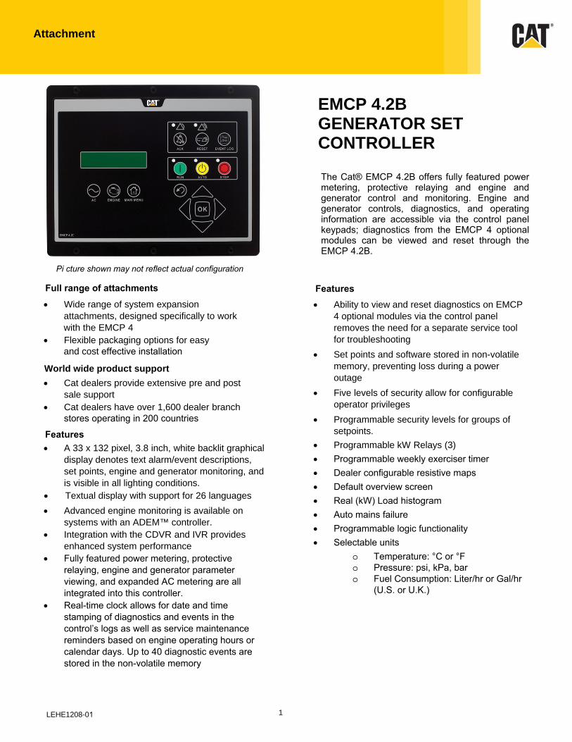
EMCP 4.2B GENERATOR SET CONTROLLER
The Cat® EMCP 4.2B offers fully featured power metering, protective relaying and engine and generator control and monitoring. Engine and generator controls, diagnostics, and operating information are accessible via the control panel keypads; diagnostics from the EMCP 4 optional modules can be viewed and reset through the EMCP 4.2B.
• Wide range of system expansion attachments, designed specifically to work with the EMCP 4
• Flexible packaging options for easy
and cost effective installation
World wide product support
• Cat dealers provide extensive pre and post sale support
• Cat dealers have over 1,600 dealer branch stores operating in 200 countries
• A 33 x 132 pixel, 3.8 inch, white backlit graphical
display denotes text alarm/event descriptions,
set points, engine and generator monitoring, and
is visible in all lighting conditions.
• Textual display with support for 26 languages
• Advanced engine monitoring is available on systems with an ADEM™ controller.
• Integration with the CDVR and IVR provides enhanced system performance
• Fully featured power metering, protective relaying, engine and generator parameter viewing, and expanded AC metering are all integrated into this controller.
• Real-time clock allows for date and time stamping of diagnostics and events in the control’s logs as well as service maintenance reminders based on engine operating hours or calendar days. Up to 40 diagnostic events are stored in the non-volatile memory
LEHE1208-01
Features
• Ability to view and reset diagnostics on EMCP
4 optional modules via the control panel
removes the need for a separate service tool
for troubleshooting
• Set points and software stored in non-volatile
memory, preventing loss during a power
outage
• Five levels of security allow for configurable
operator privileges
• Programmable security levels for groups of
setpoints.
• Programmable kW Relays (3)
• Programmable weekly exerciser timer• Dealer configurable resistive maps• Default overview screen• Real (kW) Load histogram• Auto mains failure• Programmable logic functionality• Selectable units
o Temperature: °C or °Fo Pressure: psi, kPa, baro Fuel Consumption: Liter/hr or Gal/hr
(U.S. or U.K.)
Full range of attachments Features
Pi cture shown may not reflect actual configuration
2
Attachment
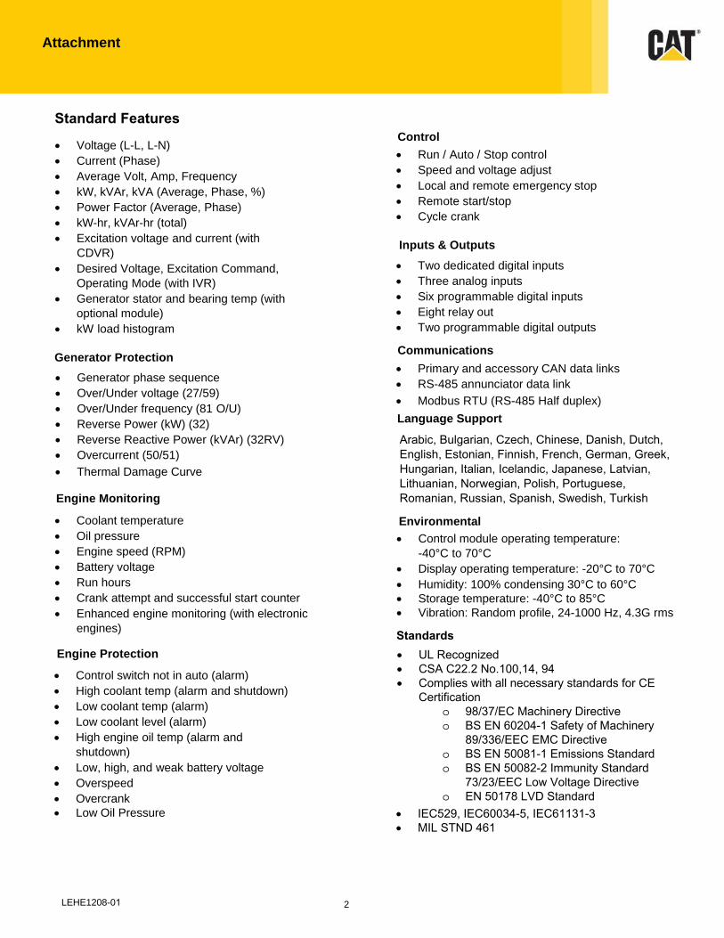
Standard Features
• Voltage (L-L, L-N)
• Current (Phase)
• Average Volt, Amp, Frequency
• kW, kVAr, kVA (Average, Phase, %)
• Power Factor (Average, Phase)
• kW-hr, kVAr-hr (total)
• Excitation voltage and current (with
CDVR)
• Desired Voltage, Excitation Command, Operating Mode (with IVR)
• Generator stator and bearing temp (with optional module)
• kW load histogram
Generator Protection
• Generator phase sequence
• Over/Under voltage (27/59)
• Over/Under frequency (81 O/U)
• Reverse Power (kW) (32)
• Reverse Reactive Power (kVAr) (32RV)
• Overcurrent (50/51)
• Thermal Damage Curve
Engine Monitoring
• Coolant temperature
• Oil pressure
• Engine speed (RPM)
• Battery voltage
• Run hours
• Crank attempt and successful start counter
• Enhanced engine monitoring (with electronic engines)
Engine Protection
• Control switch not in auto (alarm)
• High coolant temp (alarm and shutdown)
• Low coolant temp (alarm)
• Low coolant level (alarm)
• High engine oil temp (alarm and shutdown)
• Low, high, and weak battery voltage
• Overspeed
• Overcrank
• Low Oil Pressure
Control
• Run / Auto / Stop control
• Speed and voltage adjust
• Local and remote emergency stop
• Remote start/stop
• Cycle crank
Inputs & Outputs
• Two dedicated digital inputs
• Three analog inputs
• Six programmable digital inputs
• Eight relay out
• Two programmable digital outputs
Communications
• Primary and accessory CAN data links
• RS-485 annunciator data link
• Modbus RTU (RS-485 Half duplex)
Language Support
Environmental
LEHE1208-01
Arabic, Bulgarian, Czech, Chinese, Danish, Dutch, English, Estonian, Finnish, French, German, Greek, Hungarian, Italian, Icelandic, Japanese, Latvian, Lithuanian, Norwegian, Polish, Portuguese, Romanian, Russian, Spanish, Swedish, Turkish
• Control module operating temperature:
-40°C to 70°C
• Display operating temperature: -20°C to 70°C
• Humidity: 100% condensing 30°C to 60°C
• Storage temperature: -40°C to 85°C
• Vibration: Random profile, 24-1000 Hz, 4.3G rms
Standards• UL Recognized• CSA C22.2 No.100,14, 94• Complies with all necessary standards for CE
Certificationo 98/37/EC Machinery Directiveo BS EN 60204-1 Safety of Machinery
89/336/EEC EMC Directiveo BS EN 50081-1 Emissions Standardo BS EN 50082-2 Immunity Standard
73/23/EEC Low Voltage Directiveo EN 50178 LVD Standard
• IEC529, IEC60034-5, IEC61131-3• MIL STND 461
3
Attachment
Optional Modules
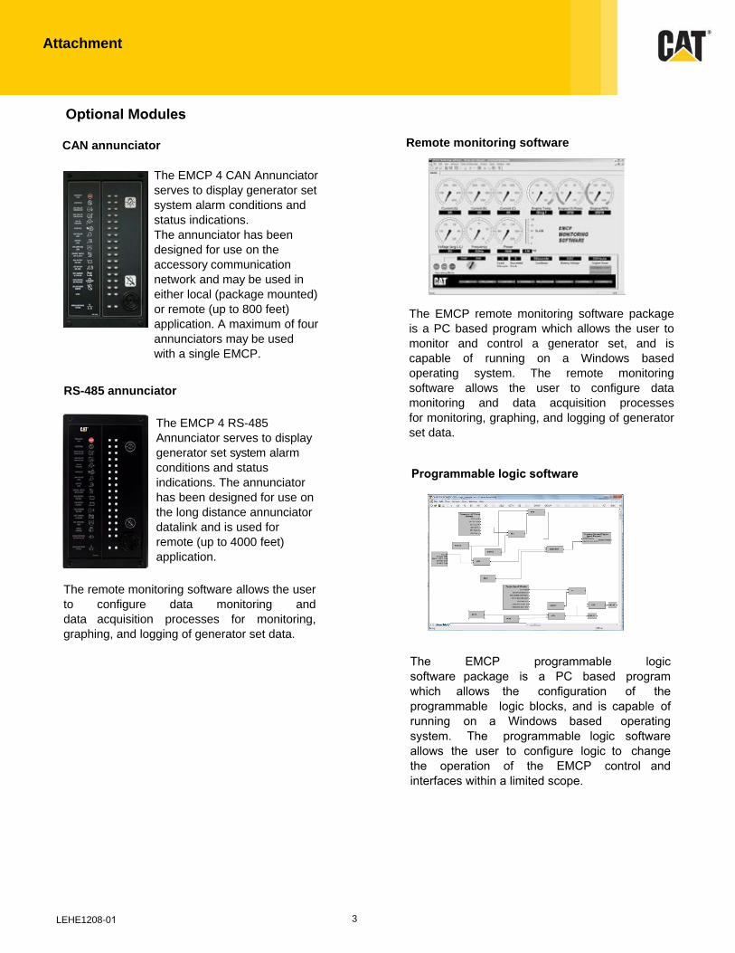
CAN annunciator
The EMCP 4 CAN Annunciator
serves to display generator set
system alarm conditions and
status indications.
The annunciator has been
designed for use on the
accessory communication
network and may be used in
either local (package mounted)
or remote (up to 800 feet)
application. A maximum of four
annunciators may be used
with a single EMCP.
RS-485 annunciator
The EMCP 4 RS-485
Annunciator serves to display
generator set system alarm
conditions and status
indications. The annunciator
has been designed for use on
the long distance annunciator
datalink and is used for
remote (up to 4000 feet)
application.
The remote monitoring software allows the user
to configure data monitoring and
data acquisition processes for monitoring,
graphing, and logging of generator set data.
Remote monitoring software
LEHE1208-01
The EMCP remote monitoring software package
is a PC based program which allows the user to
monitor and control a generator set, and is
capable of running on a Windows based
operating system. The remote monitoring
software allows the user to configure data
monitoring and data acquisition processes
for monitoring, graphing, and logging of generator
set data.
The EMCP programmable logic software package is a PC based program which allows the configuration of the programmable logic blocks, and is capable of running on a Windows based operating system. The programmable logic software allows the user to configure logic to change the operation of the EMCP control and interfaces within a limited scope.
Programmable logic software
Attachment
Optional Modules (Continued)
Materials and specifications are subject to change without notice.CAT, CATERPILLAR, their respective logos, “Caterpillar Yellow,” the “Power Edge” trade dress as well as corporate and
product identity used herein, are trademarks of Caterpillar and may not be used without permission.
cat.com/powergeneration ©2018 Caterpillar
All rights reserved. LEHE 1208-01 (08/18)
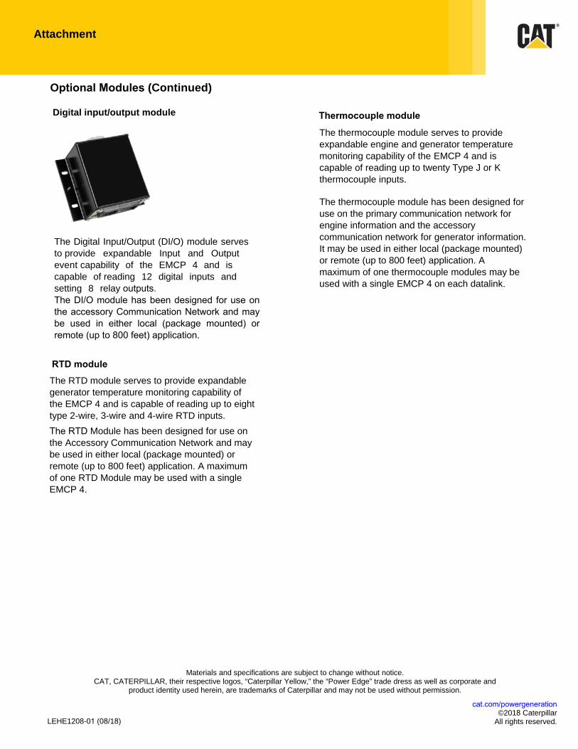
Thermocouple module
The thermocouple module serves to provide
expandable engine and generator temperature
monitoring capability of the EMCP 4 and is
capable of reading up to twenty Type J or K
thermocouple inputs.
The thermocouple module has been designed for
use on the primary communication network for
engine information and the accessory
communication network for generator information.
It may be used in either local (package mounted)
or remote (up to 800 feet) application. A
maximum of one thermocouple modules may be
used with a single EMCP 4 on each datalink.
RTD module The RTD module serves to provide expandable
generator temperature monitoring capability of
the EMCP 4 and is capable of reading up to eight
type 2-wire, 3-wire and 4-wire RTD inputs.
The RTD Module has been designed for use on
the Accessory Communication Network and may
be used in either local (package mounted) or
remote (up to 800 feet) application. A maximum
of one RTD Module may be used with a single
EMCP 4.
Digital input/output module
The Digital Input/Output (DI/O) module serves
to provide expandable Input and Output
event capability of the EMCP 4 and is
capable of reading 12 digital inputs and
setting 8 relay outputs. The DI/O module has been designed for use on the accessory Communication Network and may be used in either local (package mounted) or remote (up to 800 feet) application.

Justin Welty
Justin Welty
ACCESSORIES
Justin Welty
Justin Welty
Circuit Breakers
LEHE0942-06 1/18
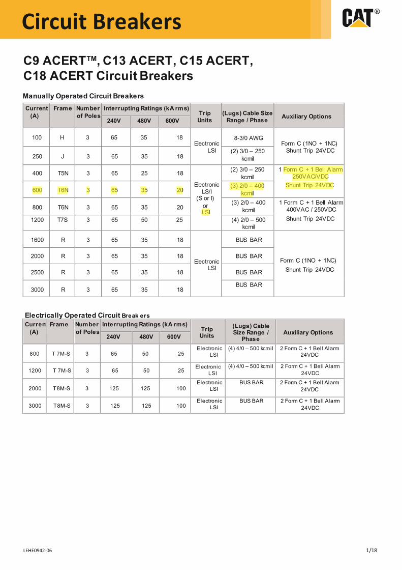
C9 ACERTTM, C13 ACERT, C15 ACERT, C18 ACERT Circuit Breakers Manually Operated Circuit Breakers Current
(A) Frame Number
of Poles Interrupting Ratings (kA rms)
Trip Units
(Lugs) Cable Size Range / Phase Auxiliary Options
240V 480V 600V
100 H 3 65 35 18 Electronic
LSI
8-3/0 AWGForm C (1NO + 1NC)
Shunt Trip 24VDC 250 J 3 65 35 18
400 T5N 3 65 25 18
Electronic LS/I
(S or I) or LSI
(2) 3/0 – 250kcmil
1 Form C + 1 Bell Alarm 250VAC/VDC
Shunt Trip 24VDC 600 T6N 3 65 35 20
(3) 2/0 – 400kcmil
800 T6N 3 65 35 20 (3) 2/0 – 400
kcmil1 Form C + 1 Bell Alarm
400VAC / 250VDC Shunt Trip 24VDC 1200 T7S 3 65 50 25 (4) 2/0 – 500
kcmil
1600 R 3 65 35 18
Electronic LSI
BUS BAR
Form C (1NO + 1NC) Shunt Trip 24VDC
2000 R 3 65 35 18 BUS BAR
2500 R 3 65 35 18 BUS BAR
3000 R 3 65 35 18 BUS BAR
Electrically Operated Circuit Break ers Current
(A) Frame Number
of Poles Interrupting Ratings (kA rms)
Trip Units
(Lugs) Cable Size Range /
Phase Auxiliary Options
240V 480V 600V
800 T 7M-S 3 65 50 25 Electronic
LSI (4) 4/0 – 500 kcmil 2 Form C + 1 Bell Alarm
24VDC
1200 T 7M-S 3 65 50 25 (4) 4/0 – 500 kcmil 2 Form C + 1 Bell Alarm
24VDC
2000 T8M-S 3 125 125 100 Electronic
LSI BUS BAR 2 Form C + 1 Bell Alarm
24VDC
3000 T8M-S 3 125 125 100 Electronic
LSI BUS BAR 2 Form C + 1 Bell Alarm
24VDC
Electronic LSI
(2) 3/0 – 250kcmil
George Soha
Highlight
George Soha
Highlight
George Soha
Highlight
George Soha
Highlight
George Soha
Highlight
Circuit Breakers
LEHE0942-06 12/18
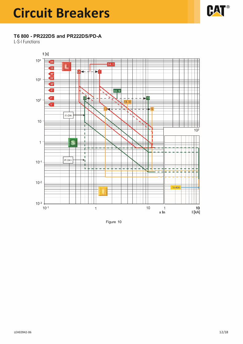
T6 800 - PR222DS and PR222DS/PD-A
Figure 10
BATTERY CHARGER
LEHE0141-02
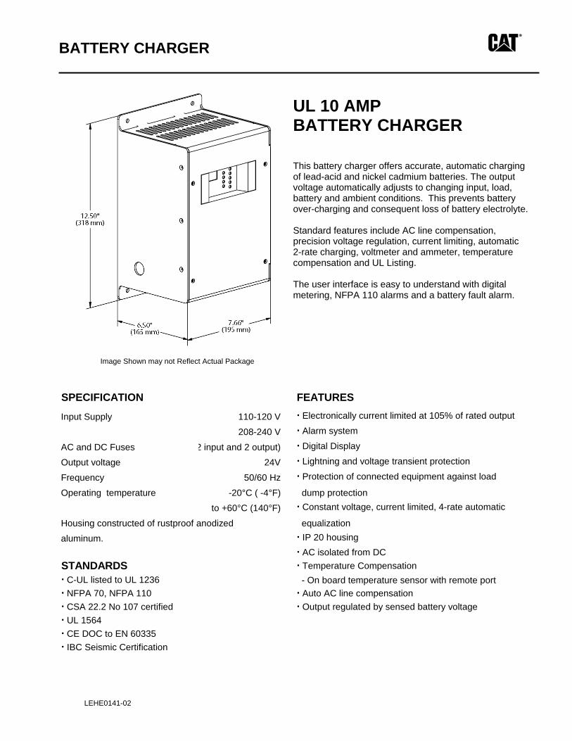
UL 10 AMP BATTERY CHARGER This battery charger offers accurate, automatic charging of lead-acid and nickel cadmium batteries. The output voltage automatically adjusts to changing input, load, battery and ambient conditions. This prevents battery over-charging and consequent loss of battery electrolyte. Standard features include AC line compensation, precision voltage regulation, current limiting, automatic 2-rate charging, voltmeter and ammeter, temperature compensation and UL Listing. The user interface is easy to understand with digital metering, NFPA 110 alarms and a battery fault alarm.
Image Shown may not Reflect Actual Package
SPECIFICATION FEATURES
Input Supply 110-120 V · Electronically current limited at 105% of rated output
208-240 V · Alarm system
AC and DC Fuses 2 input and 2 output) · Digital Display
Output voltage 24V · Lightning and voltage transient protection
Frequency 50/60 Hz · Protection of connected equipment against load
Operating temperature -20°C ( -4°F) dump protectionto +60°C (140°F) · Constant voltage, current limited, 4-rate automatic
Housing constructed of rustproof anodized equalizationaluminum. · IP 20 housing
· AC isolated from DC STANDARDS · Temperature Compensation · C-UL listed to UL 1236 - On board temperature sensor with remote port· NFPA 70, NFPA 110 · Auto AC line compensation · CSA 22.2 No 107 certified · Output regulated by sensed battery voltage· UL 1564· CE DOC to EN 60335· IBC Seismic Certification
BATTERY CHARGER
2
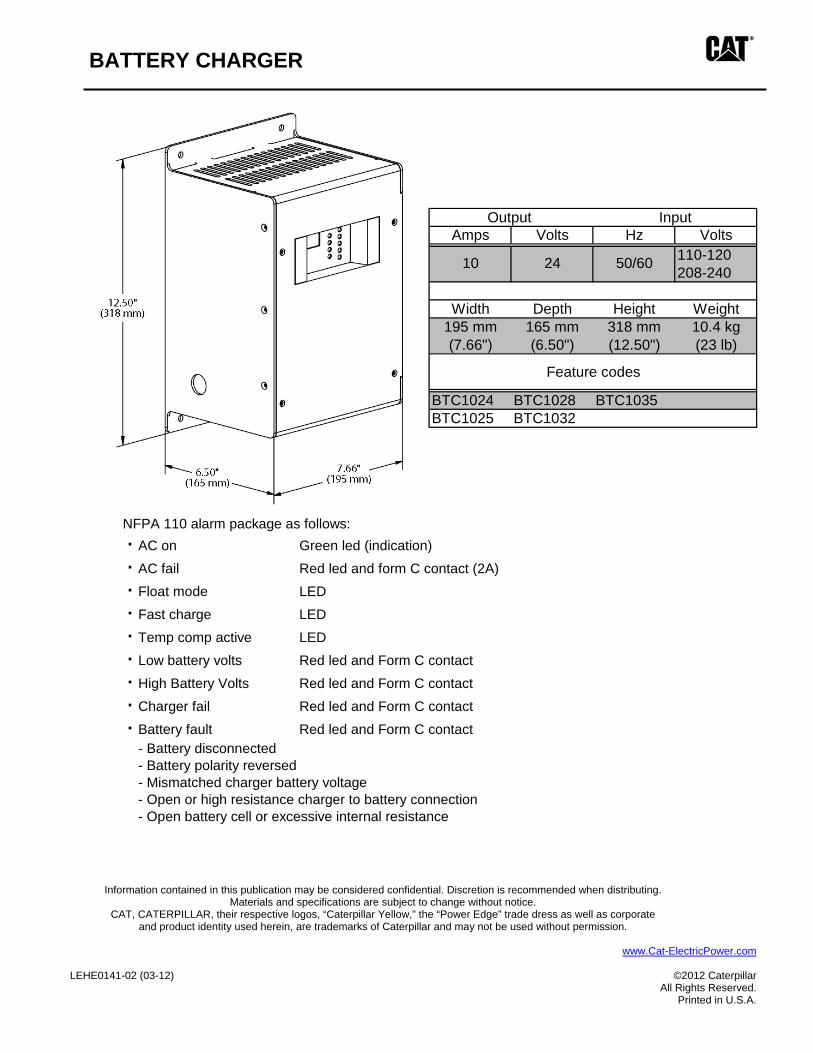
OPTIONS NFPA 110 alarm package as follows:· AC on Green led (indication)
· AC fail Red led and form C contact (2A)
· Float mode LED
· Fast charge LED
· Temp comp active LED
· Low battery volts Red led and Form C contact
· High Battery Volts Red led and Form C contact
· Charger fail Red led and Form C contact
· Battery fault Red led and Form C contact - Battery disconnected- Battery polarity reversed- Mismatched charger battery voltage- Open or high resistance charger to battery connection- Open battery cell or excessive internal resistance
Information contained in this publication may be considered confidential. Discretion is recommended when distributing. Materials and specifications are subject to change without notice.
CAT, CATERPILLAR, their respective logos, “Caterpillar Yellow,” the “Power Edge” trade dress as well as corporate and product identity used herein, are trademarks of Caterpillar and may not be used without permission.
www.Cat-ElectricPower.com
LEHE0141-02 (03-12) ©2012 Caterpillar
All Rights Reserved. Printed in U.S.A.
Amps Volts Hz Volts110-120208-240
Width Depth Height Weight195 mm 165 mm 318 mm 10.4 kg(7.66") (6.50") (12.50") (23 lb)
BTC1024 BTC1028 BTC1035BTC1025 BTC1032
Output Input
10 24 50/60
Feature codes
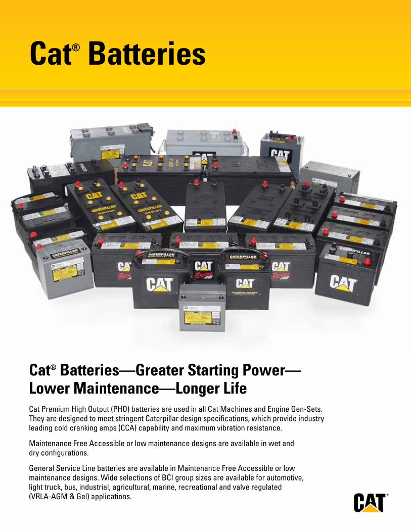
Cat® Batteries
Cat® Batteries—Greater Starting Power—Lower Maintenance—Longer LifeCat Premium High Output (PHO) batteries are used in all Cat Machines and Engine Gen-Sets. They are designed to meet stringent Caterpillar design specifications, which provide industry leading cold cranking amps (CCA) capability and maximum vibration resistance.
Maintenance Free Accessible or low maintenance designs are available in wet and dry configurations.
General Service Line batteries are available in Maintenance Free Accessible or low maintenance designs. Wide selections of BCI group sizes are available for automotive, light truck, bus, industrial, agricultural, marine, recreational and valve regulated (VRLA-AGM & Gel) applications.
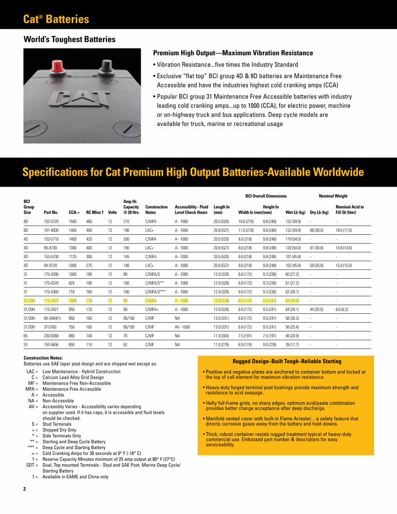
Cat® Batteries
World’s Toughest Batteries
2
Premium High Output —Maximum Vibration Resistance
• Vibration Resistance...five times the Industry Standard
• Exclusive “flat top” BCI group 4D & 8D batteries are Maintenance Free Accessible and have the industries highest cold cranking amps (CCA)
• Popular BCI group 31 Maintenance Free Accessible batteries with industry leading cold cranking amps...up to 1000 (CCA), for electric power, machine or on-highway truck and bus applications. Deep cycle models are available for truck, marine or recreational usage
Construction Notes:Batteries use SAE taper post design and are shipped wet except as:
LAC = Low Maintenance - Hybrid Construction C = Calcium Lead Alloy Grid Design MF = Maintenance Free Non-Accessible MFA = Maintenance Free Accessible A = Accessible NA = Non-Accessible AV = Accessibly Varies - Accessibility varies depending on supplier used. If it has caps, it is accessible and fluid levels should be checked. S = Stud Terminals + = Shipped Dry Only * = Side Terminals Only ** = Starting and Deep Cycle Battery *** = Deep Cycle and Starting Battery ≈ = Cold Cranking Amps for 30 seconds at 0° F (-18° C) † = Reserve Capacity Minutes minimum of 25 amp output at 80° F (27°C) SDT = Dual, Top mounted Terminals - Stud and SAE Post. Marine Deep Cycle/ Starting Battery 1 = Available in EAME and China only
Rugged Design–Built Tough–Reliable Starting
• Positive and negative plates are anchored to container bottom and locked at the top of cell element for maximum vibration resistance.
• Heavy-duty forged terminal post bushings provide maximum strength and resistance to acid seepage.
• Hefty full-frame grids, no sharp edges, optimum acid/paste combination provides better charge acceptance after deep discharge.
• Manifold vented cover with built-in Flame Arrestor…a safety feature that directs corrosive gases away from the battery and hold-downs.
• Thick, robust container resists rugged treatment typical of heavy-duty commercial use. Embossed part number & descriptors for easy serviceability.
Specifications for Cat Premium High Output Batteries-Available Worldwide
BCI Group Size Part No. CCA ≈ RC Mins † Volts
Amp Hr. Capacity @ 20 Hrs.
Construction Notes
Accessiblity - Fluid Level Check Hours
Length In (mm) Width In (mm)
Height In (mm) Wet Lb (kg) Dry Lb (kg)
Nominal Acid to Fill Qt (liter)
8D 153-5720 1500 465 12 210 C/MFA A - 1000 20.5 (520) 10.8 (275) 9.8 (248) 132 (59.9) - -
8D 101-4000 1400 400 12 190 LAC+ A - 1000 20.8 (527) 11.0 (278) 9.8 (248) 132 (59.9) 86 (39.0) 18.0 (17.0)
4D 153-5710 1400 425 12 200 C/MFA A - 1000 20.5 (520) 8.6 (218) 9.8 (248) 119 (54.0) - -
4D 9X-9730 1300 400 12 190 LAC+ A - 1000 20.8 (527) 8.6 (218) 9.8 (248) 120 (54.0) 81 (36.8) 14.8 (14.0)
4D 153-5700 1125 305 12 145 C/MFA A - 1000 20.5 (520) 8.6 (218) 9.8 (248) 101 (45.8) - -
4D 9X-9720 1000 275 12 140 LAC+ A - 1000 20.8 (527) 8.6 (218) 9.8 (248) 102 (45.8) 59 (26.8) 15.9 (15.0)
31 175-4390 1000 180 12 90 C/MFA/S A - 1000 12.9 (329) 6.8 (172) 9.3 (236) 60 (27.2) - -
31 175-4370 825 190 12 100 C/MFA/S** A - 1000 12.9 (329) 6.8 (172) 9.3 (236) 61 (27.2) - -
31 175-4360 710 185 12 100 C/MFA/S*** A - 1000 12.9 (329) 6.8 (172) 9.3 (236) 62 (28.1) - -
31/30H 115-2422 1000 170 12 90 C/MFA A - 1000 12.9 (329) 6.8 (172) 9.5 (241) 63 (28.6) - -
31/30H 115-2421 950 170 12 90 C/MFA+ A - 1000 12.9 (329) 6.8 (172) 9.5 (241) 64 (29.1) 44 (20.0) 6.6 (6.2)
31/30H 9X-3404(1) 950 165 12 95/100 C/MF NA 13.0 (331) 6.8 (172) 9.5 (241) 58 (26.3) - -
31/30H 3T-5760 750 165 12 95/100 C/MF AV - 1000 13.0 (331) 6.8 (172) 9.5 (241) 56 (25.4) - -
65 230-6368 880 140 12 70 C/MF NA 11.9 (304) 7.5 (191) 7.5 (191) 46 (20.9) - -
24 153-5656 650 110 12 52 C/MF NA 11.0 (279) 6.9 (174) 9.0 (229) 39 (17.7) - -
BCI Overall Dimensions Nominal Weight
George Soha
Highlight
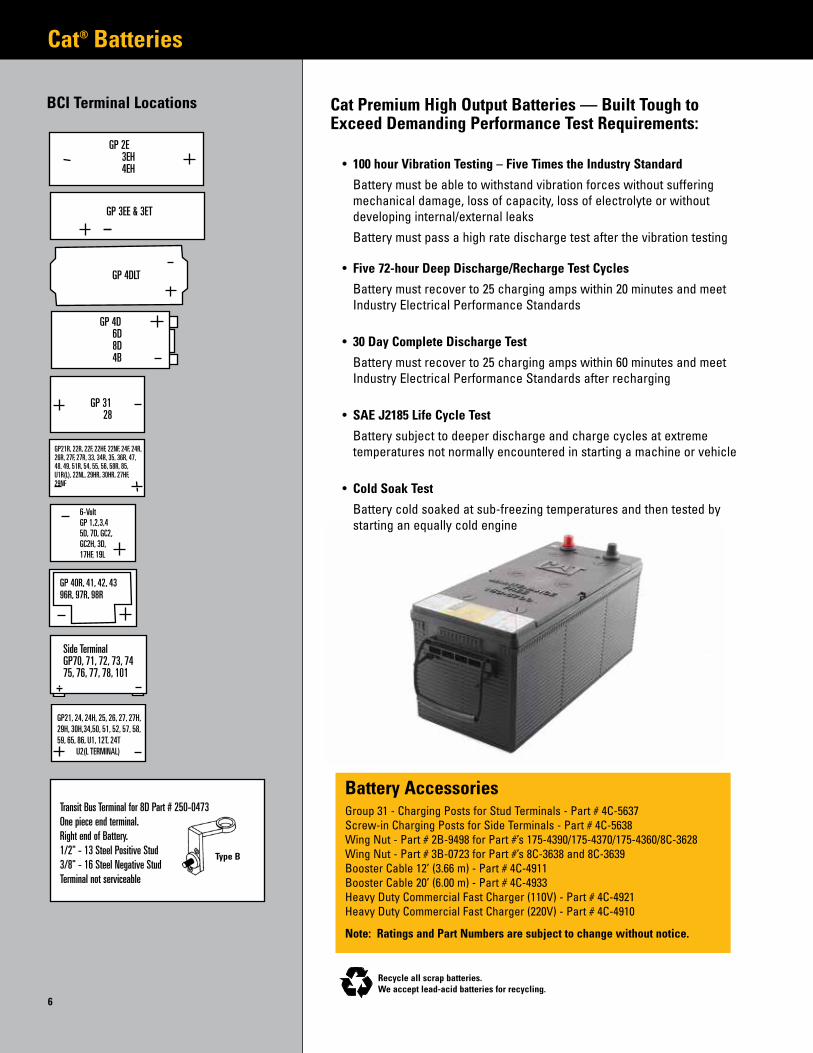
Cat® Batteries
6
Battery AccessoriesGroup 31 - Charging Posts for Stud Terminals - Part # 4C-5637Screw-in Charging Posts for Side Terminals - Part # 4C-5638Wing Nut - Part # 2B-9498 for Part #’s 175-4390/175-4370/175-4360/8C-3628Wing Nut - Part # 3B-0723 for Part #’s 8C-3638 and 8C-3639Booster Cable 12’ (3.66 m) - Part # 4C-4911Booster Cable 20’ (6.00 m) - Part # 4C-4933Heavy Duty Commercial Fast Charger (110V) - Part # 4C-4921Heavy Duty Commercial Fast Charger (220V) - Part # 4C-4910
Note: Ratings and Part Numbers are subject to change without notice.
Cat Premium High Output Batteries — Built Tough to Exceed Demanding Performance Test Requirements:
• 100 hour Vibration Testing – Five Times the Industry Standard
Battery must be able to withstand vibration forces without suffering mechanical damage, loss of capacity, loss of electrolyte or without developing internal/external leaks
Battery must pass a high rate discharge test after the vibration testing
• Five 72-hour Deep Discharge/Recharge Test Cycles
Battery must recover to 25 charging amps within 20 minutes and meet Industry Electrical Performance Standards
• 30 Day Complete Discharge Test
Battery must recover to 25 charging amps within 60 minutes and meet Industry Electrical Performance Standards after recharging
• SAE J2185 Life Cycle Test
Battery subject to deeper discharge and charge cycles at extreme temperatures not normally encountered in starting a machine or vehicle
• Cold Soak Test
Battery cold soaked at sub-freezing temperatures and then tested by starting an equally cold engine
Recycle all scrap batteries.We accept lead-acid batteries for recycling.
BCI Terminal Locations
GP 2E 3EH 4EH
GP 3EE & 3ET
GP 4DLT
GP 4D 6D 8D 4B
GP 31 28
GP21R, 22R, 22F, 22HF, 22NF, 24F, 24R, 26R, 27F, 27R, 33, 34R, 35, 36R, 47, 48, 49, 51R, 54, 55, 56, 58R, 85, U1R(L), 22NL, 29HR, 30HR, 27HF, 29NF
6-VoltGP 1,2,3,45D, 7D, GC2,GC2H, 3D,17HF, 19L
GP 40R, 41, 42, 4396R, 97R, 98R
Side TerminalGP70, 71, 72, 73, 7475, 76, 77, 78, 101
GP21, 24, 24H, 25, 26, 27, 27H, 29H, 30H,34,50, 51, 52, 57, 58, 59, 65, 86, U1, 12T, 24T U2(L TERMINAL)
Transit Bus Terminal for 8D Part # 250-0473One piece end terminal.Right end of Battery.1/2" - 13 Steel Positive Stud3/8" - 16 Steel Negative StudTerminal not serviceable
Type B
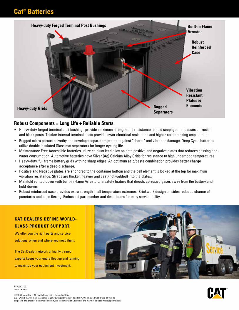
Cat® Batteries
Robust Components = Long Life + Reliable Starts• Heavy-duty forged terminal post bushings provide maximum strength and resistance to acid seepage that causes corrosion
and black posts. Thicker internal terminal posts provide lower electrical resistance and higher cold cranking amp output.• Rugged micro porous polyethylene envelope separators protect against “shorts” and vibration damage. Deep Cycle batteries
utilize double insulated Glass mat separators for longer cycling life.• Maintenance Free Accessible batteries utilize calcium lead alloy on both positive and negative plates that reduces gassing and
water consumption. Automotive batteries have Silver (Ag) Calcium Alloy Grids for resistance to high underhood temperatures.• Heavy-duty, full frame battery grids with no sharp edges. An optimum acid/paste combination provides better charge
acceptance after a deep discharge. • Positive and Negative plates are anchored to the container bottom and the cell element is locked at the top for maximum
vibration resistance. Straps are thicker, heavier and cast (not welded) into the plates.• Manifold vented cover with built-in Flame Arrestor…a safety feature that directs corrosive gases away from the battery and
hold-downs.• Robust reinforced case provides extra strength in all temperature extremes. Brickwork design on sides reduces chance of
punctures and case flexing. Embossed part number and descriptors for easy serviceability.
PEHJ0073-03www.cat.com
© 2014 Caterpillar • All Rights Reserved • Printed in USACAT, CATERPILLAR, their respective logos, “Caterpillar Yellow” and the POWER EDGE trade dress, as well as corporate and product identity used herein, are trademarks of Caterpillar and may not be used without permission.
Built-in Flame Arrestor
Robust ReinforcedCase
Vibration Resistant Plates & Elements
Heavy-duty Grids Rugged Separators
Heavy-duty Forged Terminal Post Bushings
CAT® DEALERS DEFINE WORLD-
CLASS PRODUCT SUPPORT.
We offer you the right parts and service
solutions, when and where you need them.
The Cat Dealer network of highly trained
experts can help you maximize your equipment
investment.
CAT DEALERS DEFINE WORLD-
CLASS PRODUCT SUPPORT.
We offer you the right parts and service
solutions, when and where you need them.
The Cat Dealer network of highly trained
experts keeps your entire fleet up and running
to maximize your equipment investment.
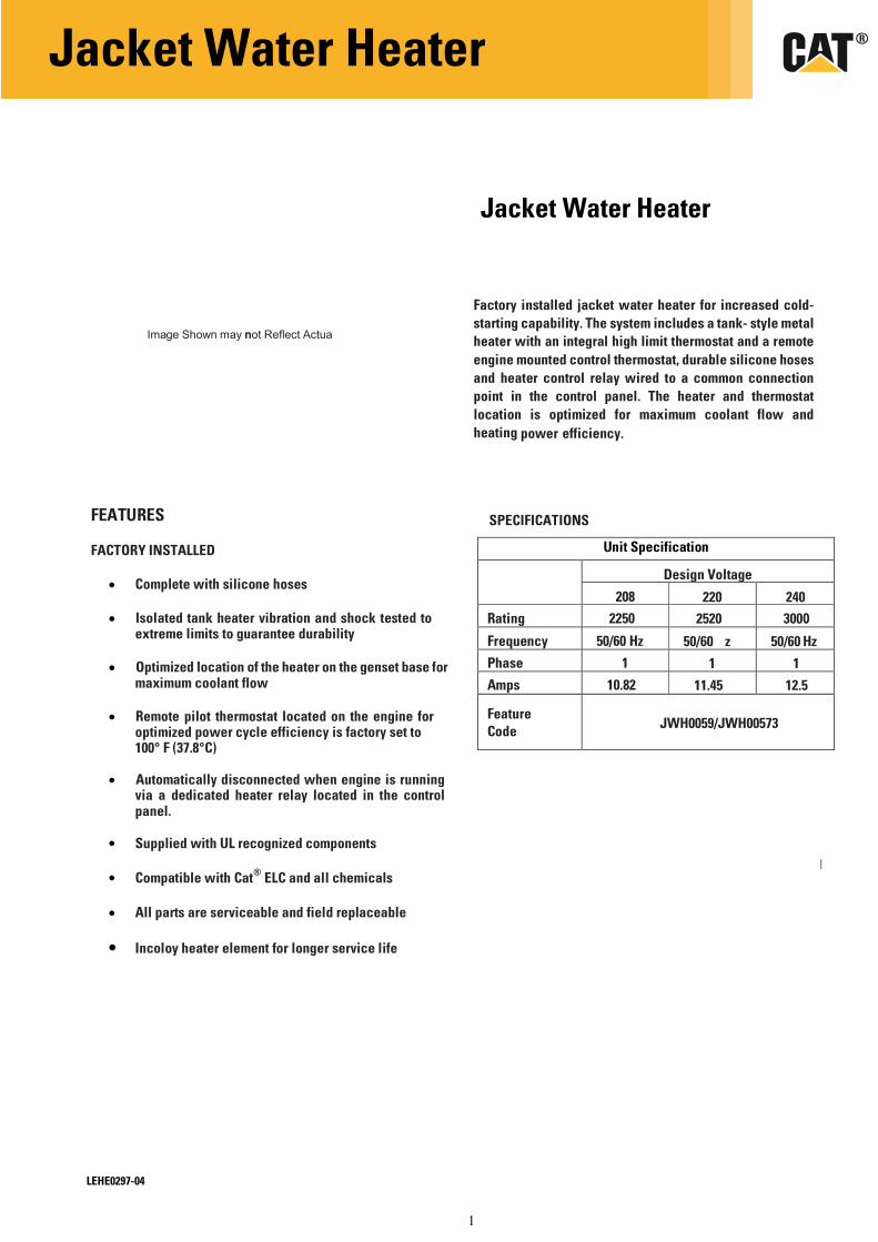
1
Ima ge Shown may n not Reflect Actua
Facto starti meta remo silico comm heat maxi
ory installed j ing capability l heater with
ote engine mo one hoses an mon connecti er and thermo mum coolant
acket water h . The system an integral h
ounted contro d heater cont ion point in th ostat location flow and hea
eater for incr includes a ta igh limit ther
ol thermostat, rol relay wire
he control pan is optimized
ating power e
H
eased cold- ank-style mostat and a
durable d to a
nel. The for fficiency.
Jacket Water Heater
Factory installed jacket water heater for increased cold-
starting capability. The system includes a tank- style metal
heater with an integral high limit thermostat and a remote
engine mounted control thermostat, durable silicone hoses
and heater control relay wired to a common connection
point in the control panel. The heater and thermostat
location is optimized for maximum coolant flow and
heating power efficiency.
FEATURES
FACTORY INSTALLED
SPECIFICATIONS
Complete with silicone hoses
Isolated tank heater vibration and shock tested toextreme limits to guarantee durability
Optimized location of the heater on the genset base formaximum coolant flow
Remote pilot thermostat located on the engine foroptimized power cycle efficiency is factory set to100° F (37.8°C)
Automatically disconnected when engine is runningvia a dedicated heater relay located in the controlpanel.
Supplied with UL recognized components
Compatible with Cat® ELC and all chemicals
All parts are serviceable and field replaceable
Incoloy heater element for longer service life
Unit Specification
Design Voltage
208 220 240
Feature
Code JWH0059/JWH00573
Jacket Water Heater
LEHE0297-04
Rating 2250 2520 3000
Frequency 50/60 Hz 50/60 z 50/60 Hz
Phase 1 1 1
Amps 10.82 11.45 12.5
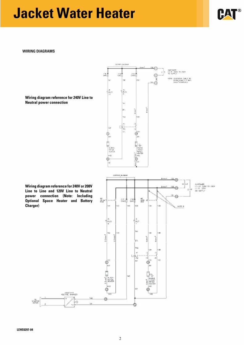
2
WIRING DIAGRAMS
Jacket Water Heater
LEHE0297-04
Wiring diagram reference for 240V or 208V Line to Line and 120V Line to Neutral
power connection (Note: Including
Optional Space Heater and Battery
Charger)
Wiring diagram reference for 240V Line to
Neutral power connection
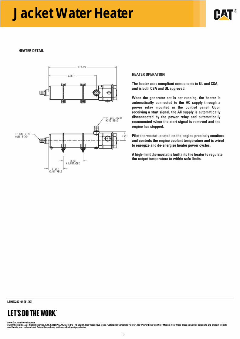
3
HEATER DETAIL
HEATER OPERATION
The heater uses compliant components to UL and CSA,
and is both CSA and UL approved.
When the generator set is not running, the heater is automatically connected to the AC supply through a
power relay mounted in the control panel. Upon
receiving a start signal, the AC supply is automatically
disconnected by the power relay and automatically reconnected when the start signal is removed and the
engine has stopped.
Pilot thermostat located on the engine precisely monitors
and controls the engine coolant temperature and is wired
to energize and de-energize heater power cycles.
A high-limit thermostat is built into the heater to regulate the output temperature to within safe limits.
www.Cat.com/electricpower© 2020 Caterpillar. All Rights Reserved. CAT, CATERPILLAR, LET’S DO THE WORK, their respective logos, "Caterpillar Corporate Yellow", the "Power Edge" and Cat “Modern Hex” trade dress as well as corporate and product identity used herein, are trademarks of Caterpillar and may not be used without permission
LEHE0 297-04 (11/20)
Jacket Water Heater
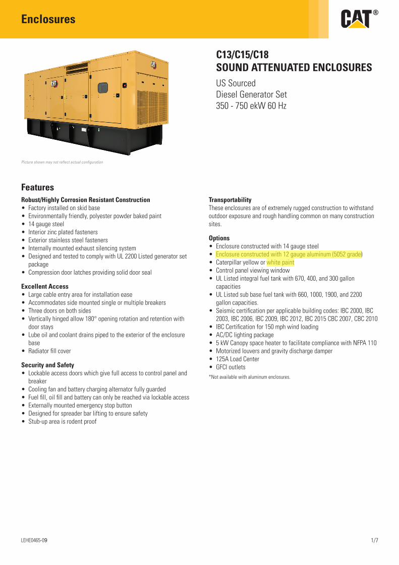
Enclosures
LEHE0465-09 1/7
C13/C15/C18 SOUND ATTENUATED ENCLOSURESUS Sourced Diesel Generator Set 350 - 750 ekW 60 Hz
FeaturesRobust/Highly Corrosion Resistant Construction• Factory installed on skid base• Environmentally friendly, polyester powder baked paint• 14 gauge steel• Interior zinc plated fasteners• Exterior stainless steel fasteners• Internally mounted exhaust silencing system• Designed and tested to comply with UL 2200 Listed generator set
package• Compression door latches providing solid door seal
Excellent Access• Large cable entry area for installation ease• Accommodates side mounted single or multiple breakers• Three doors on both sides• Vertically hinged allow 180° opening rotation and retention with
door stays• Lube oil and coolant drains piped to the exterior of the enclosure
base• Radiator fill cover
Security and Safety• Lockable access doors which give full access to control panel and
breaker• Cooling fan and battery charging alternator fully guarded• Fuel fill, oil fill and battery can only be reached via lockable access• Externally mounted emergency stop button• Designed for spreader bar lifting to ensure safety• Stub-up area is rodent proof
TransportabilityThese enclosures are of extremely rugged construction to withstand outdoor exposure and rough handling common on many construction sites.
Options• Enclosure constructed with 14 gauge steel• Enclosure constructed with 12 gauge aluminum (5052 grade)• Caterpillar yellow or white paint• Control panel viewing window• UL Listed integral fuel tank with 670, 400, and 300 gallon
capacities• UL Listed sub base fuel tank with 660, 1000, 1900, and 2200
gallon capacities.• Seismic certification per applicable building codes: IBC 2000, IBC
2003, IBC 2006, IBC 2009, IBC 2012, IBC 2015 CBC 2007, CBC 2010• IBC Certification for 150 mph wind loading• AC/DC lighting package• 5 kW Canopy space heater to facilitate compliance with NFPA 110• Motorized louvers and gravity discharge damper• 125A Load Center• GFCI outlets*Not available with aluminum enclosures.
Picture shown may not reflect actual configuration
George Soha
Highlight
George Soha
Highlight
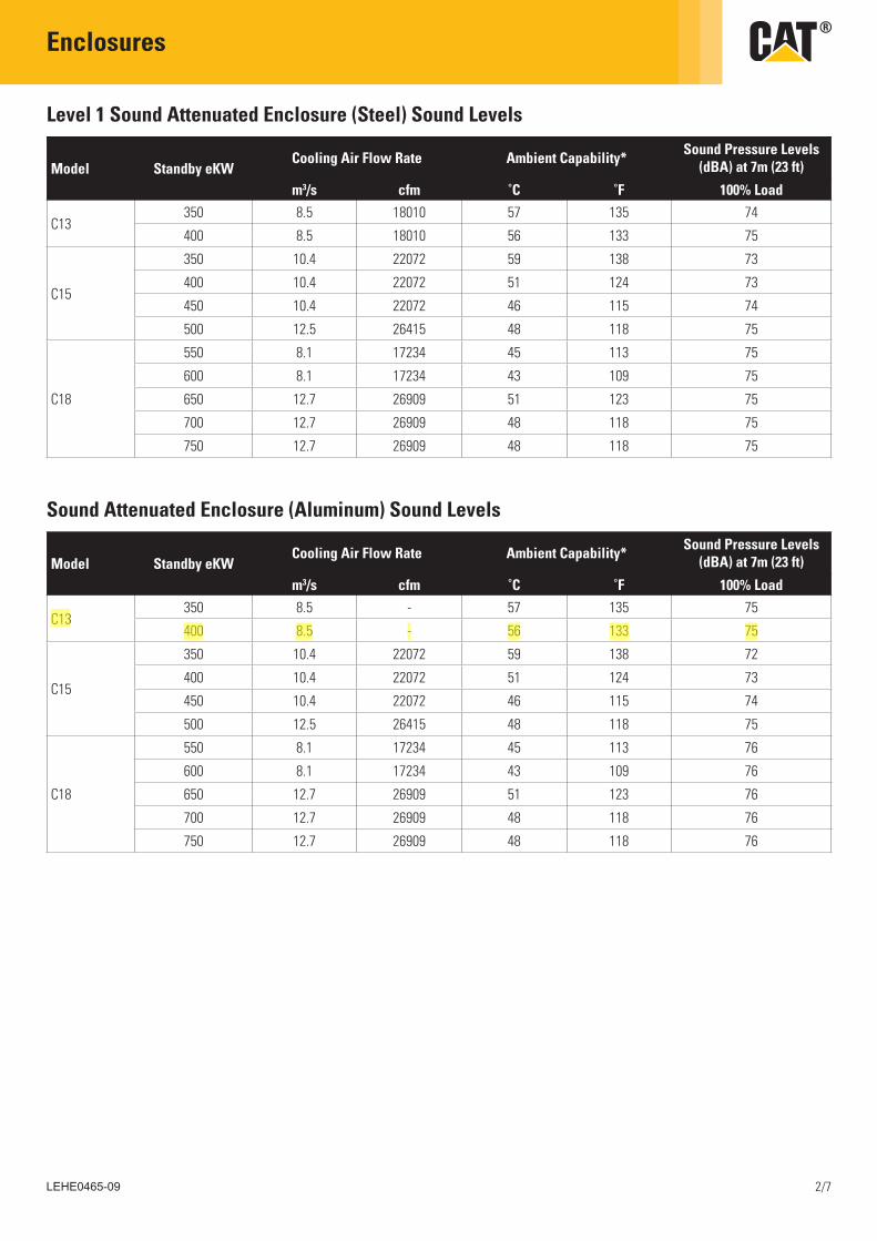
Enclosures
LEHE0465-09 2/7
Level 1 Sound Attenuated Enclosure (Steel) Sound Levels
Sound Attenuated Enclosure (Aluminum) Sound Levels
Model Standby eKWCooling Air Flow Rate Ambient Capability* Sound Pressure Levels
(dBA) at 7m (23 ft)
m3/s cfm ˚C ˚F 100% Load
C13350 8.5 18010 57 135 74
400 8.5 18010 56 133 75
C15
350 10.4 22072 59 138 73
400 10.4 22072 51 124 73
450 10.4 22072 46 115 74
500 12.5 26415 48 118 75
C18
550 8.1 17234 45 113 75
600 8.1 17234 43 109 75
650 12.7 26909 51 123 75
700 12.7 26909 48 118 75
750 12.7 26909 48 118 75
Model Standby eKWCooling Air Flow Rate Ambient Capability* Sound Pressure Levels
(dBA) at 7m (23 ft)
m3/s cfm ˚C ˚F 100% Load
C13350 8.5 - 57 135 75
400 8.5 - 56 133 75
C15
350 10.4 22072 59 138 72
400 10.4 22072 51 124 73
450 10.4 22072 46 115 74
500 12.5 26415 48 118 75
C18
550 8.1 17234 45 113 76
600 8.1 17234 43 109 76
650 12.7 26909 51 123 76
700 12.7 26909 48 118 76
750 12.7 26909 48 118 76
George Soha
Highlight
George Soha
Highlight
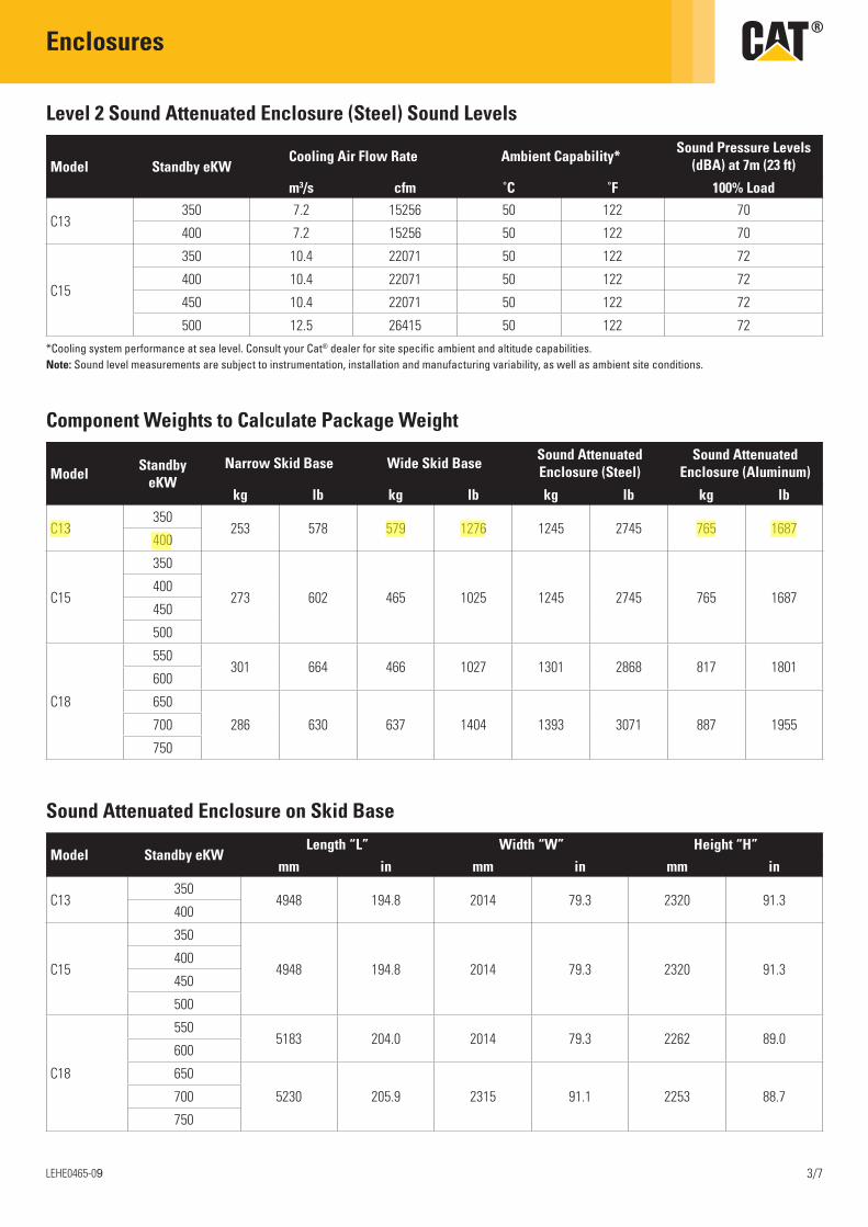
Enclosures
LEHE0465-09 3/7
Level 2 Sound Attenuated Enclosure (Steel) Sound Levels
Component Weights to Calculate Package Weight
Sound Attenuated Enclosure on Skid Base
Model Standby eKWCooling Air Flow Rate Ambient Capability* Sound Pressure Levels
(dBA) at 7m (23 ft)
m3/s cfm ˚C ˚F 100% Load
C13350 7.2 15256 50 122 70
400 7.2 15256 50 122 70
C15
350 10.4 22071 50 122 72
400 10.4 22071 50 122 72
450 10.4 22071 50 122 72
500 12.5 26415 50 122 72
Model Standby eKW
Narrow Skid Base Wide Skid Base Sound Attenuated Enclosure (Steel)
Sound Attenuated Enclosure (Aluminum)
kg lb kg lb kg lb kg lb
C13350
253 578 579 1276 1245 2745 765 1687400
C15
350
273 602 465 1025 1245 2745 765 1687400
450
500
C18
550301 664 466 1027 1301 2868 817 1801
600
650
286 630 637 1404 1393 3071 887 1955700
750
Model Standby eKWLength “L” Width “W” Height “H”
mm in mm in mm in
C13350
4948 194.8 2014 79.3 2320 91.3400
C15
350
4948 194.8 2014 79.3 2320 91.3400
450
500
C18
5505183 204.0 2014 79.3 2262 89.0
600
650
5230 205.9 2315 91.1 2253 88.7700
750
*Cooling system performance at sea level. Consult your Cat® dealer for site specific ambient and altitude capabilities.Note: Sound level measurements are subject to instrumentation, installation and manufacturing variability, as well as ambient site conditions.
George Soha
Highlight
George Soha
Highlight
George Soha
Highlight
George Soha
Highlight
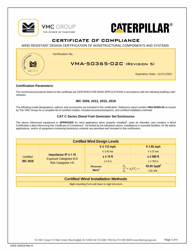
CERTIFICATE OF COMPLIANCE
WIND RESISTANT DESIGN CERTIFICATION OF NONSTRUCTURAL COMPONENTS AND SYSTEMS
Page 1 of 4
102S-104318 Rev 9
Certification No.
VMA-50365-02C (Revision 5)
Expiration Date: 12/31/2021
Certification Parameters: The nonstructural products listed on this certificate are CERTIFIED FOR WIND APPLICATIONS in accordance with the following building code1 releases.
IBC 2009, 2012, 2015, 2018 The following model designations, options, and accessories are included in this certification. Reference report number VMA-50365-02 as issued by The VMC Group for a complete list of certified models, included accessories/options, and certified installation methods.
CAT C Series Diesel Fuel Generator Set Enclosures The above referenced equipment is APPROVED for wind application when properly installed2, used as intended, and contains a Wind Certification Label referencing this Certificate of Compliance3. As limited by the tabulated values, installations in essential facilities, for life safety applications, and/or of equipment containing hazardous contents are permitted and included in this certification.
53.03 lbs/ft2
2.65 kPa
Certified Wind Design LevelsV ≤ 112 mph V ≤ 82 mph
PressureBasis4
Importance IP ≤ 1.15
Exposure Categories B-DRisk Categories I-IVIBC 2018
Certified
V ≤ 50 m/s V ≤ 37 m/s
z ≤ 15 ft z ≤ 500 ft
z ≤ 5 m z ≤ 152 m
Certified Wind Installation MethodsRigid mounting from unit base to rigid structure
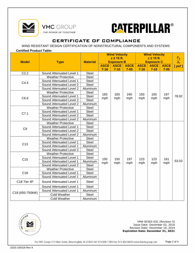
CERTIFICATE OF COMPLIANCE
WIND RESISTANT DESIGN CERTIFICATION OF NONSTRUCTURAL COMPONENTS AND SYSTEMS
Page 2 of 4
102S-104318 Rev 9
Certified Product Table:
Model Type Material
Wind Velocity z ≤ 15 ft.
Exposure B
Wind Velocity z ≤ 15 ft.
Exposure C 𝑭𝒉𝑨𝒇
[ psf ] ASCE 7-16
ASCE 7-10
ASCE 7-05
ASCE 7-16
ASCE 7-10
ASCE 7-05
C2.2 Sound Attenuated Level 1 Steel
183 mph
183 mph
240 mph
150 mph
150 mph
197 mph 78.92
C4.4
Weather Protective Steel Sound Attenuated Level 1 Steel Sound Attenuated Level 2 Steel Sound Attenuated Level 2 Aluminum
C6.6
Weather Protective Steel Sound Attenuated Level 1 Steel Sound Attenuated Level 2 Steel Sound Attenuated Level 2 Aluminum
C7.1
Weather Protective Steel Sound Attenuated Level 1 Steel Sound Attenuated Level 2 Steel Sound Attenuated Level 2 Aluminum
C9
Weather Protective Steel
150 mph
150 mph
197 mph
123 mph
123 mph
161 mph 53.03
Sound Attenuated Level 1 Steel Sound Attenuated Level 2 Steel Sound Attenuated Level 2 Aluminum
C13
Weather Protective Steel Sound Attenuated Level 1 Steel Sound Attenuated Level 1 Aluminum Sound Attenuated Level 2 Steel
C15
Weather Protective Steel Sound Attenuated Level 1 Steel Sound Attenuated Level 1 Aluminum Sound Attenuated Level 2 Steel
C18 Weather Protective Steel
Sound Attenuated Level 1 Steel Sound Attenuated Level 1 Aluminum
C18 Tier 4F Sound Attenuated Level 1 Steel
C18 (650-750kW)
Sound Attenuated Level 1 Steel Sound Attenuated Level 1 Aluminum
Cold Weather Steel Cold Weather Aluminum
VMA-50365-02C (Revision 5) Issue Date: December 02, 2016
Revision Date: December 10, 2019 Expiration Date: December 31, 2021
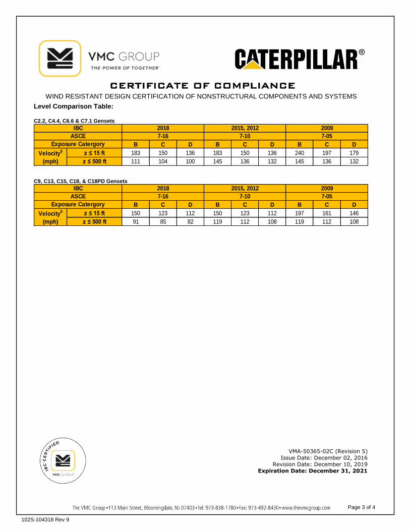
CERTIFICATE OF COMPLIANCE
WIND RESISTANT DESIGN CERTIFICATION OF NONSTRUCTURAL COMPONENTS AND SYSTEMS
Page 3 of 4
102S-104318 Rev 9
Level Comparison Table: C2.2, C4.4, C6.6 & C7.1 Gensets
B C D B C D B C Dz ≤ 15 ft 183 150 136 183 150 136 240 197 179z ≤ 500 ft 111 104 100 145 136 132 145 136 132
20097-05
IBCASCE
Exposure CatergoryVelocity5
(mph)
20187-16
2015, 20127-10
C9, C13, C15, C18, & C18PD Gensets
B C D B C D B C Dz ≤ 15 ft 150 123 112 150 123 112 197 161 146z ≤ 500 ft 91 85 82 119 112 108 119 112 108
20097-05
IBCASCE
Exposure CatergoryVelocity5
(mph)
20187-16
2015, 20127-10
VMA-50365-02C (Revision 5) Issue Date: December 02, 2016
Revision Date: December 10, 2019 Expiration Date: December 31, 2021
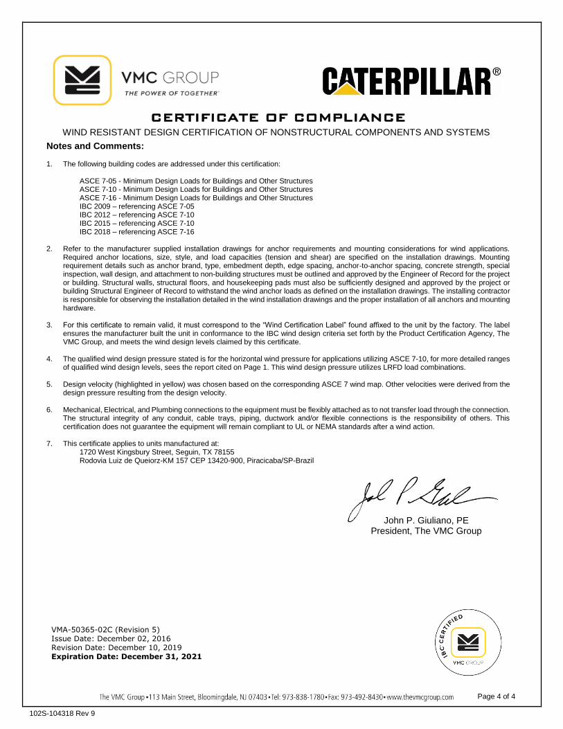
CERTIFICATE OF COMPLIANCE
WIND RESISTANT DESIGN CERTIFICATION OF NONSTRUCTURAL COMPONENTS AND SYSTEMS
Page 4 of 4
102S-104318 Rev 9
Notes and Comments: 1. The following building codes are addressed under this certification:
ASCE 7-05 - Minimum Design Loads for Buildings and Other Structures ASCE 7-10 - Minimum Design Loads for Buildings and Other Structures ASCE 7-16 - Minimum Design Loads for Buildings and Other Structures IBC 2009 – referencing ASCE 7-05 IBC 2012 – referencing ASCE 7-10 IBC 2015 – referencing ASCE 7-10 IBC 2018 – referencing ASCE 7-16
2. Refer to the manufacturer supplied installation drawings for anchor requirements and mounting considerations for wind applications. Required anchor locations, size, style, and load capacities (tension and shear) are specified on the installation drawings. Mounting requirement details such as anchor brand, type, embedment depth, edge spacing, anchor-to-anchor spacing, concrete strength, special inspection, wall design, and attachment to non-building structures must be outlined and approved by the Engineer of Record for the project or building. Structural walls, structural floors, and housekeeping pads must also be sufficiently designed and approved by the project or building Structural Engineer of Record to withstand the wind anchor loads as defined on the installation drawings. The installing contractor is responsible for observing the installation detailed in the wind installation drawings and the proper installation of all anchors and mounting hardware.
3. For this certificate to remain valid, it must correspond to the “Wind Certification Label” found affixed to the unit by the factory. The label ensures the manufacturer built the unit in conformance to the IBC wind design criteria set forth by the Product Certification Agency, The VMC Group, and meets the wind design levels claimed by this certificate.
4. The qualified wind design pressure stated is for the horizontal wind pressure for applications utilizing ASCE 7-10, for more detailed ranges
of qualified wind design levels, sees the report cited on Page 1. This wind design pressure utilizes LRFD load combinations.
5. Design velocity (highlighted in yellow) was chosen based on the corresponding ASCE 7 wind map. Other velocities were derived from the design pressure resulting from the design velocity.
6. Mechanical, Electrical, and Plumbing connections to the equipment must be flexibly attached as to not transfer load through the connection.
The structural integrity of any conduit, cable trays, piping, ductwork and/or flexible connections is the responsibility of others. This certification does not guarantee the equipment will remain compliant to UL or NEMA standards after a wind action.
7. This certificate applies to units manufactured at:
1720 West Kingsbury Street, Seguin, TX 78155 Rodovia Luiz de Queiorz-KM 157 CEP 13420-900, Piracicaba/SP-Brazil
VMA-50365-02C (Revision 5) Issue Date: December 02, 2016 Revision Date: December 10, 2019 Expiration Date: December 31, 2021
John P. Giuliano, PE President, The VMC Group

Justin Welty
Justin Welty
DRAWINGS
Justin Welty
Justin Welty
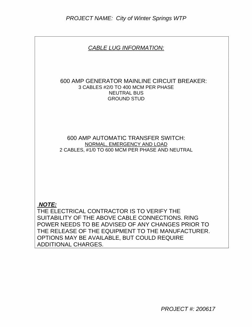
PROJECT NAME: City of Winter Springs WTP
PROJECT #: 200617
CABLE LUG INFORMATION:
600 AMP GENERATOR MAINLINE CIRCUIT BREAKER: 3 CABLES #2/0 TO 400 MCM PER PHASE
NEUTRAL BUS GROUND STUD
600 AMP AUTOMATIC TRANSFER SWITCH: NORMAL, EMERGENCY AND LOAD
2 CABLES, #1/0 TO 600 MCM PER PHASE AND NEUTRAL
NOTE: THE ELECTRICAL CONTRACTOR IS TO VERIFY THE SUITABILITY OF THE ABOVE CABLE CONNECTIONS. RING POWER NEEDS TO BE ADVISED OF ANY CHANGES PRIOR TO THE RELEASE OF THE EQUIPMENT TO THE MANUFACTURER. OPTIONS MAY BE AVAILABLE, BUT COULD REQUIRE ADDITIONAL CHARGES.
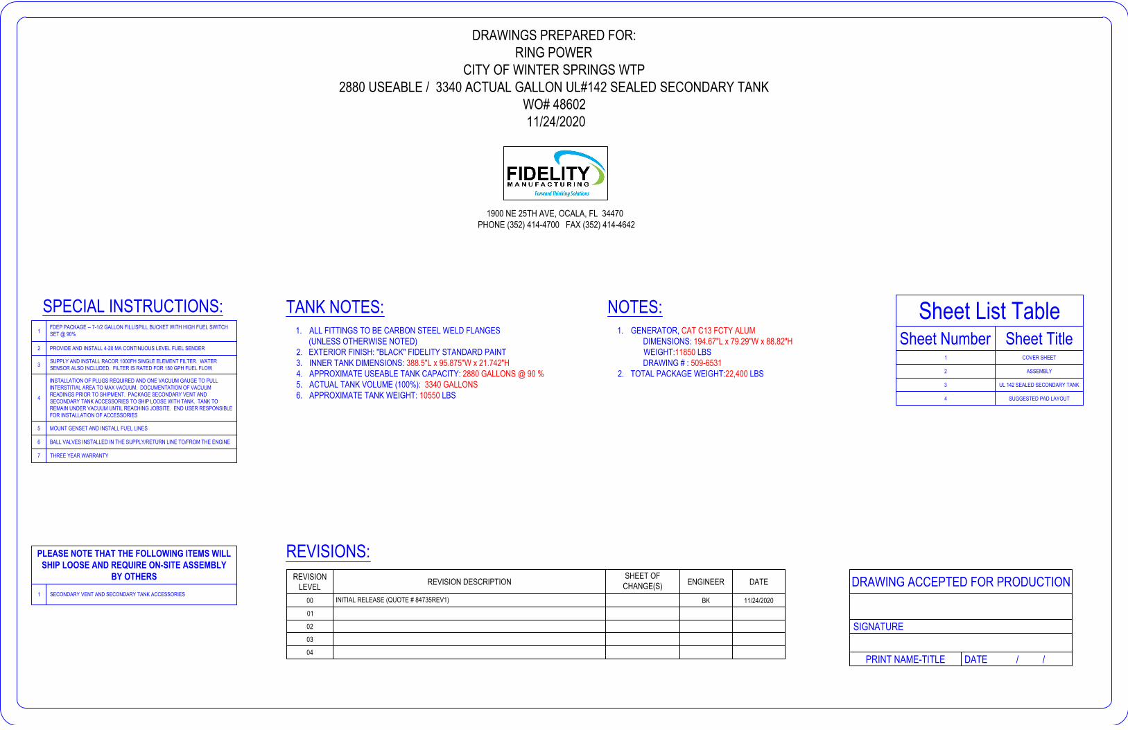
NOTES:1. GENERATOR, CAT C13 FCTY ALUM
DIMENSIONS: 194.67"L x 79.29"W x 88.82"HWEIGHT:11850 LBSDRAWING # : 509-6531
2. TOTAL PACKAGE WEIGHT:22,400 LBS
DRAWINGS PREPARED FOR:RING POWER
CITY OF WINTER SPRINGS WTP2880 USEABLE / 3340 ACTUAL GALLON UL#142 SEALED SECONDARY TANK
WO# 48602 11/24/2020
TANK NOTES:1. ALL FITTINGS TO BE CARBON STEEL WELD FLANGES (UNLESS OTHERWISE NOTED)2. EXTERIOR FINISH: "BLACK" FIDELITY STANDARD PAINT3. INNER TANK DIMENSIONS: 388.5"L x 95.875"W x 21.742"H4. APPROXIMATE USEABLE TANK CAPACITY: 2880 GALLONS @ 90 %5. ACTUAL TANK VOLUME (100%): 3340 GALLONS6. APPROXIMATE TANK WEIGHT: 10550 LBS
SPECIAL INSTRUCTIONS:1
FDEP PACKAGE -- 7-1/2 GALLON FILL/SPILL BUCKET WITH HIGH FUEL SWITCHSET @ 90%
2 PROVIDE AND INSTALL 4-20 MA CONTINUOUS LEVEL FUEL SENDER
3 SUPPLY AND INSTALL RACOR 1000FH SINGLE ELEMENT FILTER. WATERSENSOR ALSO INCLUDED. FILTER IS RATED FOR 180 GPH FUEL FLOW
4
INSTALLATION OF PLUGS REQUIRED AND ONE VACUUM GAUGE TO PULLINTERSTITIAL AREA TO MAX VACUUM. DOCUMENTATION OF VACUUMREADINGS PRIOR TO SHIPMENT. PACKAGE SECONDARY VENT ANDSECONDARY TANK ACCESSORIES TO SHIP LOOSE WITH TANK. TANK TOREMAIN UNDER VACUUM UNTIL REACHING JOBSITE. END USER RESPONSIBLEFOR INSTALLATION OF ACCESSORIES
5 MOUNT GENSET AND INSTALL FUEL LINES
6 BALL VALVES INSTALLED IN THE SUPPLY/RETURN LINE TO/FROM THE ENGINE
7 THREE YEAR WARRANTY
REVISIONLEVEL REVISION DESCRIPTION
SHEET OFCHANGE(S) ENGINEER DATE
00 INITIAL RELEASE (QUOTE # 84735REV1) BK 11/24/2020
01
02
03
04
REVISIONS:PLEASE NOTE THAT THE FOLLOWING ITEMS WILLSHIP LOOSE AND REQUIRE ON-SITE ASSEMBLY
BY OTHERS1 SECONDARY VENT AND SECONDARY TANK ACCESSORIES
PRINT NAME-TITLE DATE / /
DRAWING ACCEPTED FOR PRODUCTION
SIGNATURE
1900 NE 25TH AVE, OCALA, FL 34470 PHONE (352) 414-4700 FAX (352) 414-4642
Sheet List TableSheet Number Sheet Title
1 COVER SHEET
2 ASSEMBLY
3 UL 142 SEALED SECONDARY TANK
4 SUGGESTED PAD LAYOUT
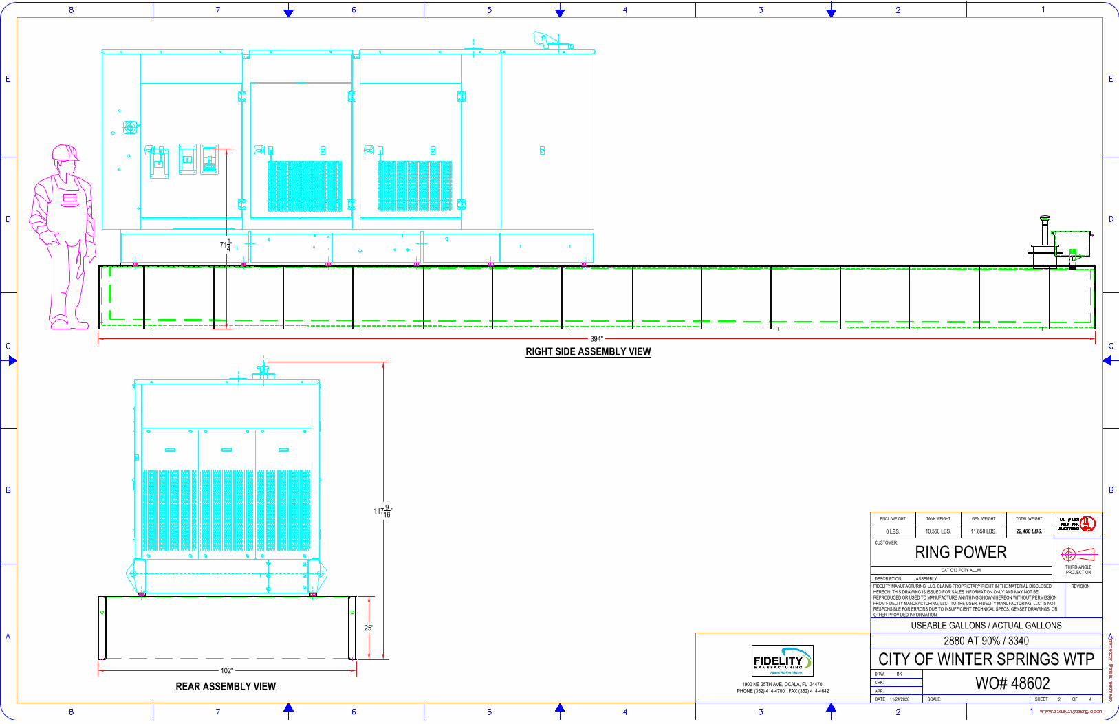
RIGHT SIDE ASSEMBLY VIEW
REAR ASSEMBLY VIEW102"
25"
394"
117 916"
7114"
SHEET
DRW.
CHK.
APP.
REVISION
DATE
CUSTOMER:
SCALE:
PROJECTIONTHIRD-ANGLE
OF
DESCRIPTION
USEABLE GALLONS / ACTUAL GALLONS
ASSEMBLYFIDELITY MANUFACTURING, LLC. CLAIMS PROPRIETARY RIGHT IN THE MATERIAL DISCLOSEDHEREON. THIS DRAWING IS ISSUED FOR SALES INFORMATION ONLY AND MAY NOT BEREPRODUCED OR USED TO MANUFACTURE ANYTHING SHOWN HEREON WITHOUT PERMISSIONFROM FIDELITY MANUFACTURING, LLC. TO THE USER. FIDELITY MANUFACTURING, LLC. IS NOTRESPONSIBLE FOR ERRORS DUE TO INSUFFICIENT TECHNICAL SPECS, GENSET DRAWINGS, OROTHER PROVIDED INFORMATION.
1900 NE 25TH AVE, OCALA, FL 34470 PHONE (352) 414-4700 FAX (352) 414-4642
42
CAT C13 FCTY ALUM
2880 AT 90% / 3340
CITY OF WINTER SPRINGS WTPWO# 48602
BK
11/24/2020
RING POWER
ENCL. WEIGHT TANK WEIGHT GEN. WEIGHT TOTAL WEIGHT
0 LBS. 10,550 LBS. 11,850 LBS. 22,400 LBS.
AutoCAD SHX Text
UL #142
AutoCAD SHX Text
File No.
AutoCAD SHX Text
MH27650
AutoCAD SHX Text
UL #142
AutoCAD SHX Text
File No.
AutoCAD SHX Text
MH27650
AutoCAD SHX Text
A
AutoCAD SHX Text
B
AutoCAD SHX Text
C
AutoCAD SHX Text
D
AutoCAD SHX Text
E
AutoCAD SHX Text
1
AutoCAD SHX Text
2
AutoCAD SHX Text
3
AutoCAD SHX Text
4
AutoCAD SHX Text
5
AutoCAD SHX Text
6
AutoCAD SHX Text
7
AutoCAD SHX Text
8
AutoCAD SHX Text
E
AutoCAD SHX Text
D
AutoCAD SHX Text
C
AutoCAD SHX Text
B
AutoCAD SHX Text
A
AutoCAD SHX Text
8
AutoCAD SHX Text
7
AutoCAD SHX Text
6
AutoCAD SHX Text
5
AutoCAD SHX Text
4
AutoCAD SHX Text
3
AutoCAD SHX Text
2
AutoCAD SHX Text
1
AutoCAD SHX Text
created using AutoCAD
AutoCAD SHX Text
www.fidelitymfg.com
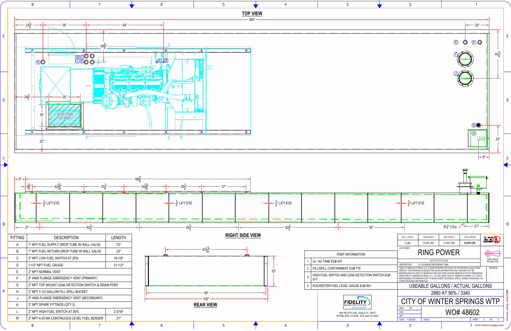
TOP VIEW
RIGHT SIDE VIEW
REAR VIEW
394"
99"102"
25"
Ø 78" (12x) 21"21"
F
E
J
K2 I N N P T F I T T IN G 2 I N
N P T F IT T IN G
M
D
H
CG
ELEC STUBUP AREA
26"
18"
2812"
22"
2 IN
N P T F I T T I NG
2 IN N P T F I T T ING2 IN
N P T F I T T IN G
A B
8212"
1-1 /
2 I N N P T F I T T ING
8212" 821
2" 55"
12" LIFT EYE 1
2" LIFT EYE 12" LIFT EYE 1
2" LIFT EYE
2 I N N P T F I T T INGL2 IN
N P T F I T T I NGK
558" 4215
16" 3314" 3413
16" 2912" 37"
9" 18678"
671116"
20"
4014"
9"
23"
2312" 36" 64"
2634"
USEABLE GALLONS / ACTUAL GALLONS
SHEET
DRW.
CHK.
APP.
REVISION
DATE
CUSTOMER:
SCALE:
PROJECTIONTHIRD-ANGLE
OF
DESCRIPTION UL 142 SEALED SECONDARY TANKFIDELITY MANUFACTURING, LLC. CLAIMS PROPRIETARY RIGHT IN THE MATERIAL DISCLOSEDHEREON. THIS DRAWING IS ISSUED FOR SALES INFORMATION ONLY AND MAY NOT BEREPRODUCED OR USED TO MANUFACTURE ANYTHING SHOWN HEREON WITHOUT PERMISSIONFROM FIDELITY MANUFACTURING, LLC. TO THE USER. FIDELITY MANUFACTURING, LLC. IS NOTRESPONSIBLE FOR ERRORS DUE TO INSUFFICIENT TECHNICAL SPECS, GENSET DRAWINGS, OROTHER PROVIDED INFORMATION.
1900 NE 25TH AVE, OCALA, FL 34470 PHONE (352) 414-4700 FAX (352) 414-4642
3 4
2880 AT 90% / 3340
RING POWER
11/24/2020
BK
WO# 48602CITY OF WINTER SPRINGS WTP
CAT C13 FCTY ALUM
FITTING DESCRIPTION LENGTHA 1" NPT FUEL SUPPLY DROP TUBE W/ BALL VALVE 23"
B 1" NPT FUEL RETURN DROP TUBE W/ BALL VALVE 23"
C 2" NPT LOW FUEL SWITCH AT 25% 16-1/8"
D 1-1/2" NPT FUEL GAUGE 21-1/2"
E 2" NPT NORMAL VENT
F 8" ANSI FLANGE EMERGENCY VENT (PRIMARY)
G 2" NPT TOP MOUNT LEAK DETECTION SWITCH & DRAIN PORT
H 2" NPT 7-1/2 GALLON FILL SPILL BUCKET
J 8" ANSI FLANGE EMERGENCY VENT (SECONDARY)
K 2" NPT SPARE FITTINGS (QTY 2)
L 2" NPT HIGH FUEL SWITCH AT 90% 2-3/16"
M 2" NPT 4-20 MA CONTINUOUS LEVEL FUEL SENDER 21"
FDEP INFORMATION
1 UL 142 TANK EQ# 497
2 FILL/SPILL CONTAINMENT EQ# 778
3 HIGH FUEL SWITCH AND LEAK DETECTION SWITCH EQ#817
4 ROCHESTER FUEL LEVEL GAUGE EQ# 901
ENCL. WEIGHT TANK WEIGHT GEN. WEIGHT TOTAL WEIGHT
0 LBS. 10,550 LBS. 11,850 LBS. 22,400 LBS.
AutoCAD SHX Text
UL #142
AutoCAD SHX Text
File No.
AutoCAD SHX Text
MH27650
AutoCAD SHX Text
A
AutoCAD SHX Text
B
AutoCAD SHX Text
C
AutoCAD SHX Text
D
AutoCAD SHX Text
E
AutoCAD SHX Text
1
AutoCAD SHX Text
2
AutoCAD SHX Text
3
AutoCAD SHX Text
4
AutoCAD SHX Text
5
AutoCAD SHX Text
6
AutoCAD SHX Text
7
AutoCAD SHX Text
8
AutoCAD SHX Text
E
AutoCAD SHX Text
D
AutoCAD SHX Text
C
AutoCAD SHX Text
B
AutoCAD SHX Text
A
AutoCAD SHX Text
8
AutoCAD SHX Text
7
AutoCAD SHX Text
6
AutoCAD SHX Text
5
AutoCAD SHX Text
4
AutoCAD SHX Text
3
AutoCAD SHX Text
2
AutoCAD SHX Text
1
AutoCAD SHX Text
created using AutoCAD
AutoCAD SHX Text
www.fidelitymfg.com
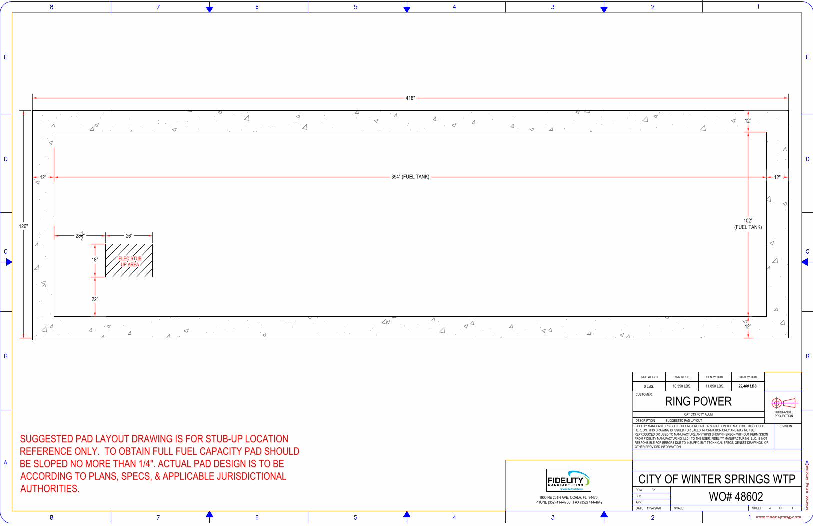
102"(FUEL TANK)
394" (FUEL TANK)
126"
12"
418"
12"
12"
12"
ELEC STUBUP AREA
26"
18"
2812"
22"
SHEET
DRW.
CHK.
APP.
REVISION
DATE
CUSTOMER:
SCALE:
PROJECTIONTHIRD-ANGLE
OF
DESCRIPTION SUGGESTED PAD LAYOUTFIDELITY MANUFACTURING, LLC. CLAIMS PROPRIETARY RIGHT IN THE MATERIAL DISCLOSEDHEREON. THIS DRAWING IS ISSUED FOR SALES INFORMATION ONLY AND MAY NOT BEREPRODUCED OR USED TO MANUFACTURE ANYTHING SHOWN HEREON WITHOUT PERMISSIONFROM FIDELITY MANUFACTURING, LLC. TO THE USER. FIDELITY MANUFACTURING, LLC. IS NOTRESPONSIBLE FOR ERRORS DUE TO INSUFFICIENT TECHNICAL SPECS, GENSET DRAWINGS, OROTHER PROVIDED INFORMATION.
1900 NE 25TH AVE, OCALA, FL 34470 PHONE (352) 414-4700 FAX (352) 414-4642
4 4
RING POWER
11/24/2020
BK
WO# 48602CITY OF WINTER SPRINGS WTP
CAT C13 FCTY ALUM
SUGGESTED PAD LAYOUT DRAWING IS FOR STUB-UP LOCATIONREFERENCE ONLY. TO OBTAIN FULL FUEL CAPACITY PAD SHOULDBE SLOPED NO MORE THAN 1/4". ACTUAL PAD DESIGN IS TO BEACCORDING TO PLANS, SPECS, & APPLICABLE JURISDICTIONALAUTHORITIES.
ENCL. WEIGHT TANK WEIGHT GEN. WEIGHT TOTAL WEIGHT
0 LBS. 10,550 LBS. 11,850 LBS. 22,400 LBS.
AutoCAD SHX Text
A
AutoCAD SHX Text
B
AutoCAD SHX Text
C
AutoCAD SHX Text
D
AutoCAD SHX Text
E
AutoCAD SHX Text
1
AutoCAD SHX Text
2
AutoCAD SHX Text
3
AutoCAD SHX Text
4
AutoCAD SHX Text
5
AutoCAD SHX Text
6
AutoCAD SHX Text
7
AutoCAD SHX Text
8
AutoCAD SHX Text
E
AutoCAD SHX Text
D
AutoCAD SHX Text
C
AutoCAD SHX Text
B
AutoCAD SHX Text
A
AutoCAD SHX Text
8
AutoCAD SHX Text
7
AutoCAD SHX Text
6
AutoCAD SHX Text
5
AutoCAD SHX Text
4
AutoCAD SHX Text
3
AutoCAD SHX Text
2
AutoCAD SHX Text
1
AutoCAD SHX Text
created using AutoCAD
AutoCAD SHX Text
www.fidelitymfg.com
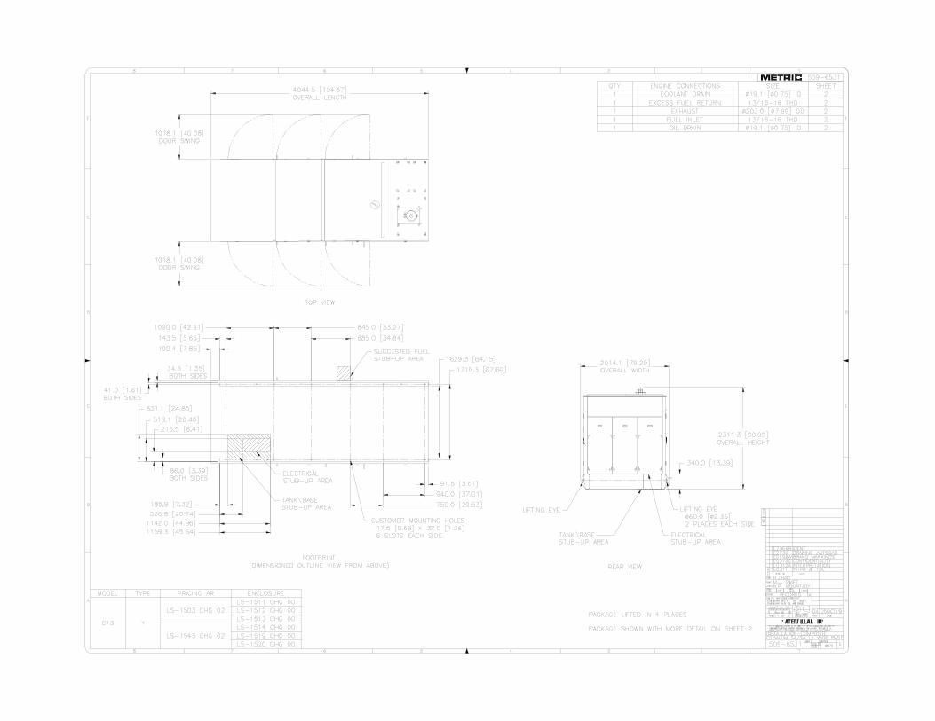
AutoCAD SHX Text
1
AutoCAD SHX Text
F
AutoCAD SHX Text
E
AutoCAD SHX Text
D
AutoCAD SHX Text
2
AutoCAD SHX Text
3
AutoCAD SHX Text
4
AutoCAD SHX Text
C
AutoCAD SHX Text
B
AutoCAD SHX Text
M
AutoCAD SHX Text
L
AutoCAD SHX Text
HT
AutoCAD SHX Text
TR
AutoCAD SHX Text
A
AutoCAD SHX Text
T
AutoCAD SHX Text
A
AutoCAD SHX Text
DATE
AutoCAD SHX Text
CONTROL
AutoCAD SHX Text
PROD.
AutoCAD SHX Text
PROD.
AutoCAD SHX Text
PRE
AutoCAD SHX Text
NAME
AutoCAD SHX Text
O
AutoCAD SHX Text
N
AutoCAD SHX Text
EXP
AutoCAD SHX Text
APPD
AutoCAD SHX Text
CEPT
AutoCAD SHX Text
CON-
AutoCAD SHX Text
CHK
AutoCAD SHX Text
DRN
AutoCAD SHX Text
E
AutoCAD SHX Text
T
AutoCAD SHX Text
SPEC NO.
AutoCAD SHX Text
30
AutoCAD SHX Text
THIRD ANGLE
AutoCAD SHX Text
PROJECTION
AutoCAD SHX Text
VER
AutoCAD SHX Text
0
AutoCAD SHX Text
20
AutoCAD SHX Text
10mm
AutoCAD SHX Text
UNLESS OTHERWISE SPECIFIED
AutoCAD SHX Text
DIMENSIONS ARE IN MM [INCH]
AutoCAD SHX Text
SCALE
AutoCAD SHX Text
SHEET
AutoCAD SHX Text
DIMENSIONS W/O TOL ARE BASIC
AutoCAD SHX Text
THE INFORMATION HEREON IS THE PROPERTY OF CATERPILLAR INC. AND/OR ITS
AutoCAD SHX Text
SUBSIDIARIES. WITHOUT WRITTEN PERMISSION, ANY COPYING, TRANSMITTAL TO
AutoCAD SHX Text
OTHERS, AND ANY USE EXCEPT THAT FOR WHICH IT IS LOANED IS PROHIBITED.
AutoCAD SHX Text
CHG
AutoCAD SHX Text
E
AutoCAD SHX Text
1
AutoCAD SHX Text
SUB
AutoCAD SHX Text
DES
AutoCAD SHX Text
2
AutoCAD SHX Text
3
AutoCAD SHX Text
4
AutoCAD SHX Text
5
AutoCAD SHX Text
6
AutoCAD SHX Text
8
AutoCAD SHX Text
F
AutoCAD SHX Text
E
AutoCAD SHX Text
D
AutoCAD SHX Text
7
AutoCAD SHX Text
5
AutoCAD SHX Text
6
AutoCAD SHX Text
C
AutoCAD SHX Text
B
AutoCAD SHX Text
8
AutoCAD SHX Text
A
AutoCAD SHX Text
7
AutoCAD SHX Text
509-6531
AutoCAD SHX Text
509-6531
AutoCAD SHX Text
04
AutoCAD SHX Text
C13ALUM SA/SA L1 WIDE BASE
AutoCAD SHX Text
W973
AutoCAD SHX Text
INSTALLATION-COMPOSITE
AutoCAD SHX Text
1 OF 3
AutoCAD SHX Text
H.ZHAO
AutoCAD SHX Text
M.J. SWIFT
AutoCAD SHX Text
N.P. MOUNTJOY
AutoCAD SHX Text
25OCT19
AutoCAD SHX Text
1E2966B
AutoCAD SHX Text
IDENT
AutoCAD SHX Text
X
AutoCAD SHX Text
RECORDS
AutoCAD SHX Text
1E2733
AutoCAD SHX Text
1E0198W
AutoCAD SHX Text
1E0013G
AutoCAD SHX Text
1E0012A
AutoCAD SHX Text
1E0011
AutoCAD SHX Text
DRAWING-AUTOCAD
AutoCAD SHX Text
BRAND MARKINGS
AutoCAD SHX Text
CONFIDENTIALITY
AutoCAD SHX Text
INTERPRETATION
AutoCAD SHX Text
INTPR & TOL
AutoCAD SHX Text
OTHER
AutoCAD SHX Text
-
AutoCAD SHX Text
1 = 16
AutoCAD SHX Text
MODEL
AutoCAD SHX Text
TYPE
AutoCAD SHX Text
PRICING AR
AutoCAD SHX Text
C13
AutoCAD SHX Text
Y
AutoCAD SHX Text
LS-1503 CHG 02
AutoCAD SHX Text
ENCLOSURE
AutoCAD SHX Text
LS-1511 CHG 00
AutoCAD SHX Text
LS-1513 CHG 00
AutoCAD SHX Text
LS-1519 CHG 00
AutoCAD SHX Text
LS-1512 CHG 00
AutoCAD SHX Text
LS-1514 CHG 00
AutoCAD SHX Text
LS-1520 CHG 00
AutoCAD SHX Text
LS-1543 CHG 02
AutoCAD SHX Text
QTY
AutoCAD SHX Text
ENGINE CONNECTIONS
AutoCAD SHX Text
SHEET
AutoCAD SHX Text
2
AutoCAD SHX Text
2
AutoCAD SHX Text
2
AutoCAD SHX Text
SIZE
AutoCAD SHX Text
1
AutoCAD SHX Text
1
AutoCAD SHX Text
1
AutoCAD SHX Text
2
AutoCAD SHX Text
1
AutoCAD SHX Text
2
AutoCAD SHX Text
1
AutoCAD SHX Text
COOLANT DRAIN
AutoCAD SHX Text
%%C19.1 [%%C0.75] ID
AutoCAD SHX Text
EXCESS FUEL RETURN
AutoCAD SHX Text
13/16-16 THD
AutoCAD SHX Text
EXHAUST
AutoCAD SHX Text
%%C203.0 [%%C7.99] OD
AutoCAD SHX Text
FUEL INLET
AutoCAD SHX Text
13/16-16 THD
AutoCAD SHX Text
OIL DRAIN
AutoCAD SHX Text
%%C19.1 [%%C0.75] ID
AutoCAD SHX Text
PACKAGE LIFTED IN 4 PLACES PACKAGE SHOWN WITH MORE DETAIL ON SHEET 2
AutoCAD SHX Text
REAR VIEW
AutoCAD SHX Text
TOP VIEW
AutoCAD SHX Text
LIFTING EYE 60.0 [ 2.36] 2 PLACES EACH SIDE
AutoCAD SHX Text
FOOTPRINT (DIMENSIONED OUTLINE VIEW FROM ABOVE)
AutoCAD SHX Text
ELECTRICAL STUB-UP AREA
AutoCAD SHX Text
CUSTOMER MOUNTING HOLES 17.5 [0.69] X 32.0 [1.26] 6 SLOTS EACH SIDE
AutoCAD SHX Text
LIFTING EYE
AutoCAD SHX Text
ELECTRICAL STUB-UP AREA
AutoCAD SHX Text
TANK\BASE STUB-UP AREA
AutoCAD SHX Text
TANK\BASE STUB-UP AREA
AutoCAD SHX Text
SUGGESTED FUEL STUB-UP AREA
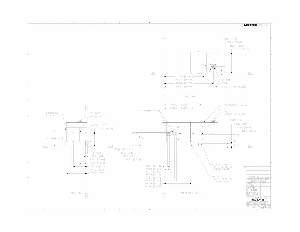
AutoCAD SHX Text
1
AutoCAD SHX Text
F
AutoCAD SHX Text
E
AutoCAD SHX Text
D
AutoCAD SHX Text
2
AutoCAD SHX Text
3
AutoCAD SHX Text
4
AutoCAD SHX Text
C
AutoCAD SHX Text
B
AutoCAD SHX Text
M
AutoCAD SHX Text
L
AutoCAD SHX Text
HT
AutoCAD SHX Text
TR
AutoCAD SHX Text
A
AutoCAD SHX Text
T
AutoCAD SHX Text
A
AutoCAD SHX Text
DATE
AutoCAD SHX Text
CONTROL
AutoCAD SHX Text
PROD.
AutoCAD SHX Text
PROD.
AutoCAD SHX Text
PRE
AutoCAD SHX Text
NAME
AutoCAD SHX Text
O
AutoCAD SHX Text
N
AutoCAD SHX Text
EXP
AutoCAD SHX Text
APPD
AutoCAD SHX Text
CEPT
AutoCAD SHX Text
CON-
AutoCAD SHX Text
CHK
AutoCAD SHX Text
DRN
AutoCAD SHX Text
E
AutoCAD SHX Text
T
AutoCAD SHX Text
SPEC NO.
AutoCAD SHX Text
30
AutoCAD SHX Text
THIRD ANGLE
AutoCAD SHX Text
PROJECTION
AutoCAD SHX Text
VER
AutoCAD SHX Text
0
AutoCAD SHX Text
20
AutoCAD SHX Text
10mm
AutoCAD SHX Text
UNLESS OTHERWISE SPECIFIED
AutoCAD SHX Text
DIMENSIONS ARE IN MM [INCH]
AutoCAD SHX Text
SCALE
AutoCAD SHX Text
SHEET
AutoCAD SHX Text
DIMENSIONS W/O TOL ARE BASIC
AutoCAD SHX Text
THE INFORMATION HEREON IS THE PROPERTY OF CATERPILLAR INC. AND/OR ITS
AutoCAD SHX Text
SUBSIDIARIES. WITHOUT WRITTEN PERMISSION, ANY COPYING, TRANSMITTAL TO
AutoCAD SHX Text
OTHERS, AND ANY USE EXCEPT THAT FOR WHICH IT IS LOANED IS PROHIBITED.
AutoCAD SHX Text
CHG
AutoCAD SHX Text
E
AutoCAD SHX Text
1
AutoCAD SHX Text
SUB
AutoCAD SHX Text
DES
AutoCAD SHX Text
2
AutoCAD SHX Text
3
AutoCAD SHX Text
4
AutoCAD SHX Text
5
AutoCAD SHX Text
6
AutoCAD SHX Text
8
AutoCAD SHX Text
F
AutoCAD SHX Text
E
AutoCAD SHX Text
D
AutoCAD SHX Text
7
AutoCAD SHX Text
5
AutoCAD SHX Text
6
AutoCAD SHX Text
C
AutoCAD SHX Text
B
AutoCAD SHX Text
8
AutoCAD SHX Text
A
AutoCAD SHX Text
7
AutoCAD SHX Text
509-6531
AutoCAD SHX Text
509-6531
AutoCAD SHX Text
04
AutoCAD SHX Text
C13ALUM SA/SA L1 WIDE BASE
AutoCAD SHX Text
W973
AutoCAD SHX Text
INSTALLATION-COMPOSITE
AutoCAD SHX Text
2 OF 3
AutoCAD SHX Text
H.ZHAO
AutoCAD SHX Text
M.J. SWIFT
AutoCAD SHX Text
N.P. MOUNTJOY
AutoCAD SHX Text
25OCT19
AutoCAD SHX Text
1E2966B
AutoCAD SHX Text
IDENT
AutoCAD SHX Text
X
AutoCAD SHX Text
RECORDS
AutoCAD SHX Text
1E2733
AutoCAD SHX Text
1E0198W
AutoCAD SHX Text
1E0013G
AutoCAD SHX Text
1E0012A
AutoCAD SHX Text
1E0011
AutoCAD SHX Text
DRAWING-AUTOCAD
AutoCAD SHX Text
BRAND MARKINGS
AutoCAD SHX Text
CONFIDENTIALITY
AutoCAD SHX Text
INTERPRETATION
AutoCAD SHX Text
INTPR & TOL
AutoCAD SHX Text
OTHER
AutoCAD SHX Text
-
AutoCAD SHX Text
1 = 20
AutoCAD SHX Text
RIGHT SIDE VIEW
AutoCAD SHX Text
REAR VIEW
AutoCAD SHX Text
TOP VIEW
AutoCAD SHX Text
EXHAUST
AutoCAD SHX Text
PANEL VENT
AutoCAD SHX Text
EXHAUST
AutoCAD SHX Text
VENT
AutoCAD SHX Text
RADIATOR CAP ACCESS
AutoCAD SHX Text
COOLANT DRAIN 19.1 [ 0.75] ID FLEXIBLE HOSE
AutoCAD SHX Text
OIL DRAIN 19.1 [ 0.75] ID FLEXIBLE HOSE
AutoCAD SHX Text
EXHAUST 203.0 [ 7.99] OD
AutoCAD SHX Text
RADIATOR CAP ACCESS
AutoCAD SHX Text
CIRCUIT BREAKERS
AutoCAD SHX Text
EMERGENCY STOP BUTTON
AutoCAD SHX Text
VENT
AutoCAD SHX Text
A
AutoCAD SHX Text
C
AutoCAD SHX Text
A
AutoCAD SHX Text
C
AutoCAD SHX Text
A
AutoCAD SHX Text
C
AutoCAD SHX Text
B
AutoCAD SHX Text
B
AutoCAD SHX Text
B
AutoCAD SHX Text
B
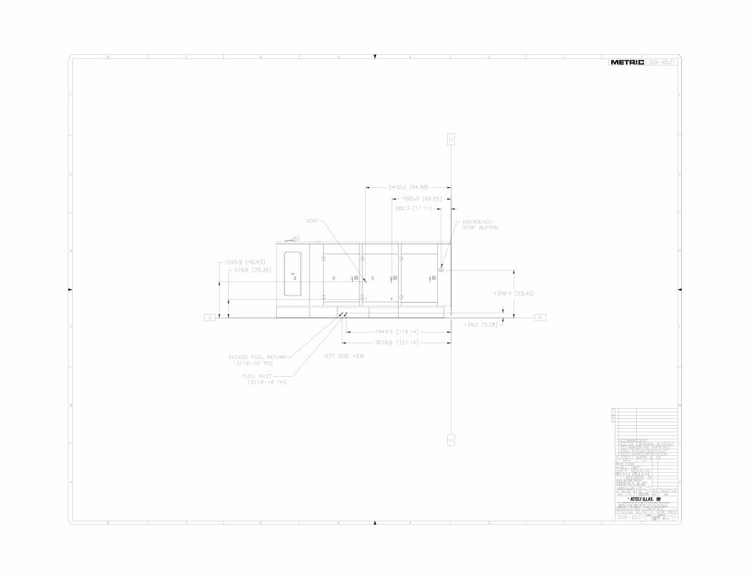
AutoCAD SHX Text
INTPR & TOL
AutoCAD SHX Text
1E0011
AutoCAD SHX Text
1
AutoCAD SHX Text
F
AutoCAD SHX Text
E
AutoCAD SHX Text
D
AutoCAD SHX Text
2
AutoCAD SHX Text
3
AutoCAD SHX Text
4
AutoCAD SHX Text
C
AutoCAD SHX Text
B
AutoCAD SHX Text
M
AutoCAD SHX Text
L
AutoCAD SHX Text
HT
AutoCAD SHX Text
TR
AutoCAD SHX Text
A
AutoCAD SHX Text
T
AutoCAD SHX Text
A
AutoCAD SHX Text
DATE
AutoCAD SHX Text
CONTROL
AutoCAD SHX Text
PROD.
AutoCAD SHX Text
PROD.
AutoCAD SHX Text
PRE
AutoCAD SHX Text
NAME
AutoCAD SHX Text
O
AutoCAD SHX Text
N
AutoCAD SHX Text
EXP
AutoCAD SHX Text
APPD
AutoCAD SHX Text
CEPT
AutoCAD SHX Text
CON-
AutoCAD SHX Text
CHK
AutoCAD SHX Text
DRN
AutoCAD SHX Text
E
AutoCAD SHX Text
T
AutoCAD SHX Text
SPEC NO.
AutoCAD SHX Text
30
AutoCAD SHX Text
THIRD ANGLE
AutoCAD SHX Text
PROJECTION
AutoCAD SHX Text
VER
AutoCAD SHX Text
0
AutoCAD SHX Text
20
AutoCAD SHX Text
10mm
AutoCAD SHX Text
UNLESS OTHERWISE SPECIFIED
AutoCAD SHX Text
DIMENSIONS ARE IN MM [INCH]
AutoCAD SHX Text
SCALE
AutoCAD SHX Text
SHEET
AutoCAD SHX Text
DIMENSIONS W/O TOL ARE BASIC
AutoCAD SHX Text
THE INFORMATION HEREON IS THE PROPERTY OF CATERPILLAR INC. AND/OR ITS
AutoCAD SHX Text
SUBSIDIARIES. WITHOUT WRITTEN PERMISSION, ANY COPYING, TRANSMITTAL TO
AutoCAD SHX Text
OTHERS, AND ANY USE EXCEPT THAT FOR WHICH IT IS LOANED IS PROHIBITED.
AutoCAD SHX Text
CHG
AutoCAD SHX Text
E
AutoCAD SHX Text
1
AutoCAD SHX Text
SUB
AutoCAD SHX Text
DES
AutoCAD SHX Text
2
AutoCAD SHX Text
3
AutoCAD SHX Text
4
AutoCAD SHX Text
5
AutoCAD SHX Text
6
AutoCAD SHX Text
8
AutoCAD SHX Text
F
AutoCAD SHX Text
E
AutoCAD SHX Text
D
AutoCAD SHX Text
7
AutoCAD SHX Text
5
AutoCAD SHX Text
6
AutoCAD SHX Text
C
AutoCAD SHX Text
B
AutoCAD SHX Text
8
AutoCAD SHX Text
A
AutoCAD SHX Text
7
AutoCAD SHX Text
509-6531
AutoCAD SHX Text
509-6531
AutoCAD SHX Text
04
AutoCAD SHX Text
C13ALUM SA/SA L1 WIDE BASE
AutoCAD SHX Text
W973
AutoCAD SHX Text
INSTALLATION-COMPOSITE
AutoCAD SHX Text
3 OF 3
AutoCAD SHX Text
H.ZHAO
AutoCAD SHX Text
M.J. SWIFT
AutoCAD SHX Text
N.P. MOUNTJOY
AutoCAD SHX Text
25OCT19
AutoCAD SHX Text
DRAWING-AUTOCAD
AutoCAD SHX Text
1E2733
AutoCAD SHX Text
1E0198W
AutoCAD SHX Text
BRAND MARKINGS
AutoCAD SHX Text
INTERPRETATION
AutoCAD SHX Text
1E0012A
AutoCAD SHX Text
CONFIDENTIALITY
AutoCAD SHX Text
1E0013G
AutoCAD SHX Text
IDENT
AutoCAD SHX Text
1E2966B
AutoCAD SHX Text
X
AutoCAD SHX Text
RECORDS
AutoCAD SHX Text
-
AutoCAD SHX Text
1 = 16
AutoCAD SHX Text
LEFT SIDE VIEW
AutoCAD SHX Text
EXCESS FUEL RETURN 13/16-16 THD
AutoCAD SHX Text
FUEL INLET 13/16-16 THD
AutoCAD SHX Text
EMERGENCY STOP BUTTON
AutoCAD SHX Text
VENT
AutoCAD SHX Text
C
AutoCAD SHX Text
A
AutoCAD SHX Text
C
AutoCAD SHX Text
A
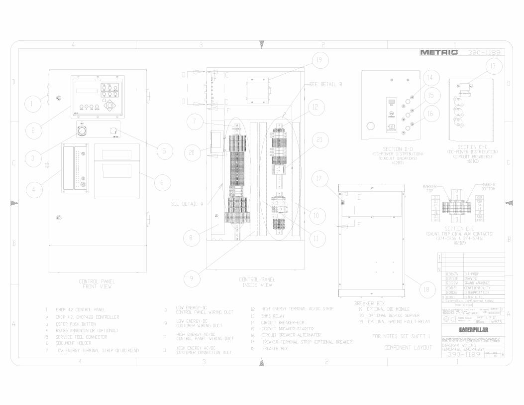
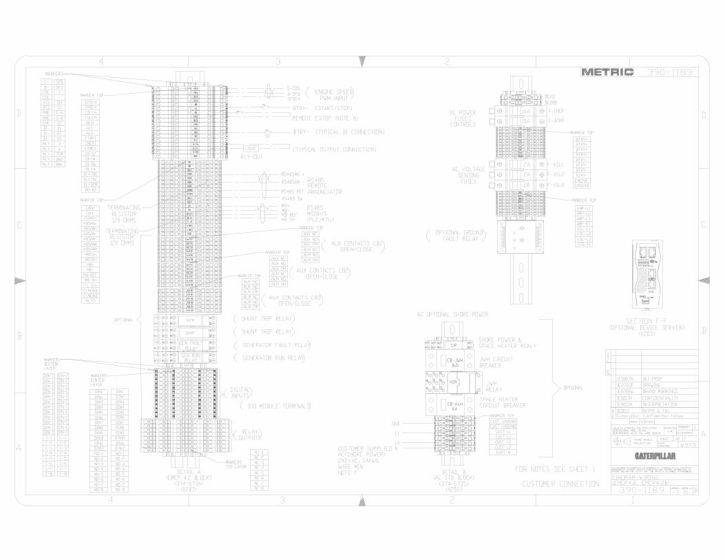
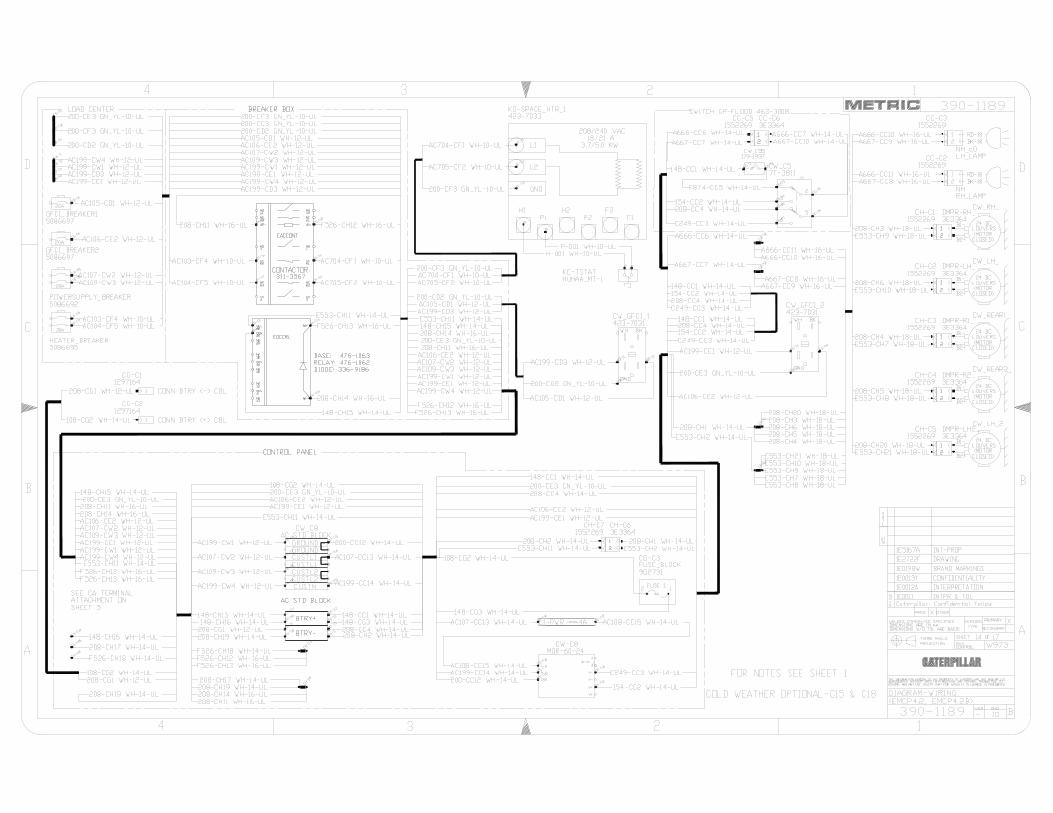

Justin Welty
Justin Welty
GENERAL INFORMATION
Justin Welty
Justin Welty

DEP Form: 62-761.900(2)
Form Title: Storage Tank Facility Registration
Form
Effective Date: January 2017
Incorporated in Rule 62-761.400, F.A.C.
Department of Environmental Protection
2600 Blair Stone Road♦Tallahassee, Florida 32399-2400
Storage Tank Facility Registration Form Review Registration Instructions Before Completing this Form
Submit this completed form for the facility when registration of storage tanks or compression vessels is required by Chapter 376.303, Florida Statutes Please check all that apply: New Registration New Owner
Existing Facility Info Update/Correction Existing Owner Info Update/Correction New Tanks Existing Tank Info Update/Correction
A. FACILITY INFORMATION County: DEP Facility ID: Facility Name: ______________________________________________________ Facility Address: ___ Facility Contact: ___ Facility Type(s):
City: Zip: Business Phone:
Financial Responsibility Mechanism (choose): Insurance Other 24 Hour Emergency Contact: Emergency Phone:
B. TANK OWNER INFORMATION: Identify individual(s) or Business(es) responsible for payment of Registration Fees at the facility location named above
Company/Individual Name: Ownership Effective Date: _________________ Mail Address: STCM Account Number (if known): ___________ City, State, Zip: ______________________________________________________________________________________________ Contact Person: ______________________________________________________________________________________________ Telephone: ________________________ Email Address: ____________________________________________________________
C. PROPERTY OWNER INFORMATION: Identify individual(s) or entity that if vested with ownership, dominion or legal or rightful title to the real property
Company/Individual Name: ____________________________________________ Ownership Effective Date: ___________________Mail Address: _______________________________________________________________________________________________City, State, Zip: ______________________________________________________________________________________________Contact Person:_____________________________________________________________________________________________Telephone: ________________________ Email Address: ____________________________________________________________
D. TANK/VESSEL INFORMATION: Complete one row for each storage tank or compression vessel system located at this facility (see Registration Instructions for codes)
Tank ID T or V A or U Capacity Installation Date Content Code Status Effective Date Construction Piping Monitoring
1
2
3
4
5
6
7
8
Certified Contractor (performing UST installation or removal): ___________________________________ DBPR License No.: _____________________
Facility Registration Certification: To the best of my knowledge and belief, all information submitted on this form is true, accurate and complete.
Signature Date
Printed Name _______________________________________________________
Title
Submit this form to [email protected]
(January 2017)
Florida Department of Environmental Protection Bob Martinez Center • 2600 Blair Stone Road • Tallahassee, Florida 32399-2400
Division of Waste Management - Storage Tank Facility Registration Form Registration Instructions and Codes List
Storage tank registration is available online through the DEP Business Portal in lieu of the paper form: • DEP Business Portal can be found: http://www.fldepportal.com/go/submit-registration• Instructions on how to navigate the DEP Business Portal can be found on the DEP Registration web page:
http://www.dep.state.fl.us/waste/categories/tanks/pages/registration.htm
Storage Tank Facility Registration Form In the first outlined section block, identify the types of information being submitted on the registration form. [Forms 62-761.900(2) for USTs and 62-762.901(2) for ASTs. For facilities with both types of tanks, one form may be used].Check New Registration when the location is being registered for the first time and no Facility Identification number exists. If submitting a revised Registration form, check all other boxes that apply to designate the type(s) of revisions being submitted.
A. Facility Information
County List the county where the storage tank facility is located.
Facility ID Include the DEP Facility Identification number whenever possible. Write in “Pending” when submitting a new registration for the first time. Remember: the facility ID number identifies the location, and it does not change even when a facility is transferred to a new owner upon sale of the facility.
Facility Name Provide the current name of the business establishment operating at the facility location. When registering an abandoned facility, where tanks exist but there is no operational business, identify the location with the property owner’s name, as in “Smith Property”, if no other facility name is being used.
Facility Address Include the street number and name. In a rural area with no street number associated with it, provide the parcel ID number along with directions (e.g., ‘x’ miles N of intersection...). Provide the name and telephone number of a contact person or manager on location, where possible.
Facility Type This information is an explanation or term that most closely describes the operational use of the facility. Select the code(s) that provides the best or most appropriate description of the facility.
1. If the facility is owned by a government entity, select the appropriate type from the following:F. Federal Government H. Local or City Government N. Native Tribal LandsG. State Government I. County Government
2. If the facility meets the definition of “bulk product facility” - a waterfront location with at least one aboveground tankwith a capacity greater than 30,000 gallons which is used for the storage of pollutants (“Pollutants” includes oil of anykind and in any form, gasoline, pesticides, ammonia, chlorine, and derivatives thereof, excluding liquefied petroleumgas”); select the type from:T. Coastal bulk product facility - facility, as defined above and located on the Florida coast, may have storage tank
systems that store hazardous substances in addition to pollutants. (“Coastline means the line of mean low wateralong the portion of the coast that is in direct contact with the open sea and the line marking the seaward limit ofinland waters, as determined under the Convention on Territorial Seas and the Contiguous Zone, 15 U.S.T. (Pt. 2)1606.”).
S. Inland waterfront bulk product facility – a facility, as defined above and located on “inland waterways” (lakes,rivers), may have storage tank systems that store hazardous substances in addition to pollutants.
3. When the facility is a “waterfront location”, but not a bulk product facility as defined above, select the mostappropriate type from:V. Marine fueling facility - a commercial, recreational, or retail coastal facility that provides fuel to vessels and may
store other pollutants and/or hazardous substances on site.
(January 2017)
Facility Type continued
W. Waterfront fueling facility - a commercial, recreational, or retail facility located on a non-coastal waterway that provides fuel to vessels and may store other pollutants and/or hazardous substances on site.
4. When the facility is not described as previously stated, select the most appropriate type from:
A. Retail Station - primarily supplies vehicular fuel to automotive customers; may store other regulated substances.
C. Fuel User, Non-retail - primarily stores motor fuel and/or other pollutants or hazardous substances for consumption by facility/owner/operator.
D. Inland Bulk Petroleum Storage - inland facility with no waterfront access, that has multiple active UST and/or AST storage systems used primarily for storage of pollutants intended for distribution. May also store hazardous substances on-site for facility consumption and/or distribution purposes.
E. Industrial Plant - inland facility with no waterfront access; may include power plants and facilities designed for manufacturing and/or chemical processing; may have multiple active UST and/or AST storage systems used for storage of pollutants and/or hazardous substances intended for facility consumption.
J. Collection Station - maintenance or other related facility that acquires and temporarily stores used and/or waste oil prior to recycling and/or disposal.
K. Inland Bulk Chemical Storage - inland facility with no waterfront access, that has multiple active UST and/or AST storage systems and/or compression vessels used for storage of hazardous substances intended for distribution. May also store pollutants on site for facility consumption and/or distribution purposes.
L. Chemical User - facility primarily uses regulated hazardous substance tanks on site; may also store pollutants.
M. Agricultural - facility actively used in production of crops, plants, or livestock.
P. UST Residential (>1100 gallons) - residence with USTs regulated by Federal Environmental Protection Agency.
Z. Other - Identify the type of establishment that you are registering.
Financial Responsibility – The demonstration of financial responsibility shall be made by the owner or operator in accordance with 40 CFR 280, Subpart H. Check box for Insurance or Other (includes all other financial responsibility methods).
24 Hour Emergency Contact - Provide the name and telephone number of the Emergency Contact for this facility.
B. Tank Owner Information
1. Provide the name, address, contact name, telephone number, and email address of the individual(s) and/or business(es) that are responsible for the operation of the storage tanks and for the payment of DEP annual Storage Tank Registration fees. The tank owner will also be associated with the role of Account Owner and will be given a STCM Account Number. The Account Owner is responsible for payment of the annual storage tank registration fees, and will receive the annual storage tank registration placard(s) upon payment.
2. When submitting revisions to owner name or address information, please include their STCM Account Number, when available.
3. Submit a registration form when the tank ownership changes, complete with the date and new account owner's signature.
C. Property Owner Information
1. Provide the name, address, contact name, telephone number, and email address of the individual(s) and/or business(es) that are vested with ownership, dominion or legal or rightful title to the real property.
2. Submit a registration form when the property ownership changes, complete with the date.
(January 2017)
D. Tank/Compression Vessel Information - Complete one row in Section D for each storage tank and/or compression vessel system located at the facility. Use the following system description codes where appropriate.
1. Tank ID – number the systems sequentially, or provide a unique ID number; do not use symbols (#, %, -, etc.).
2. Tank or Vessel Indicator – choose T or V to describe the system type.
3. Tank Placement – choose A or U to designate aboveground or underground placement of the system.
4. Tank Capacity – enter the storage tank capacity in gallons.
5. Installation Date – record the date of installation in ‘MM/YY’ format; provide a best estimate if unknown.
6. Tank Content – record the current content (or last content, if system is closed or out-of-service) from the list below:
A Leaded Gasoline K Kerosene U Mineral Acid* B Unleaded Gasoline (No Ethanol) L Waste Oil V Grades 5 & 6 bunker “C” residual oils D Vehicular Diesel M Fuel Oil: on-site heating only; USTs or ASTs < 30K gals^ W Petroleum-based additive product E Aviation Gasoline N Fuel Oil: distribution; or on-site heating - ASTs > 30K gals¥ X Miscellaneous petroleum-based product F Jet Fuel O New and Lube Oil Y Unknown Substance G Diesel Fuel-Emergency Generator Q Pesticide Z Other Substance (please identify) H Diesel Fuel-Generator or Pump R Ammonia Compound 7 Biodiesel (B20) I Diesel Fuel-Ultra Low Sulfur S Chlorine Compound 8 E10 – blend of 10% ethanol/90% gasoline J Used Oil T Hazardous Substance (CERCLA) 9 E85 – blend of 85% ethanol/15% gasoline * Mineral Acid = Hydrobromic acid, Hydrochloric acid, Hydrofluoric acid, Phosphoric acid and Sulfuric acid. ^ M = fuel is used solely to heat the facility premises and must be stored in a tank with capacity < 30,000 gallons; exempt from regulation. ¥ N = fuel is distributed as heating fuel, or fuel is used solely to heat the facility premises, but the storage tank capacity exceeds 30,000 gallons. ** Compartmented tanks – register as a single tank; itemize the size and contents of each compartment. See construction miscellaneous attributes. ** Manifold tanks – register as individual storage tanks; with individual size and content – even though they are “connected”.
7. Status – record the current status of the system, and the status effective date (or best estimate) in ‘MM/YY’ format.
Update the tank status timely, as necessary for tanks moving between “in service” and “out of service” status. A. Properly closed in-place UST filled with sand, concrete or other inert material; AST rendered unusable.
B. Removed from the site.
D. Deleted – Data Error – Added to STCM in error; may be a duplicate tank (and/or facility), or tank was registered prior to installation and decided not to have tank installed.
E. Construction modified – AST constructed as a “mobile tank” or enclosed in a building; no longer retains a “regulated” status.
M. Moved to New Site – Designation that identifies a tank as removed from a particular facility and reinstalled at a second facility.
T. Out-of-service tank – Tank system that is designated as out-of-service by the owner or operator.
U. In-service – Tank system that is NOT designated as out-of-service by the owner or operator.
V. Temporary out-of-service – Field erected storage tank system that is designated as temporary out-of-service by the owner or operator.
W. Non-regulated use/process – Exempt from regulation due to how the tank or substance is used; i.e. tank stores diesel used in FLOWTHROUGH process.
Z. Non-regulated product – Stored in tank; provide status effective date when status relates to a ‘change in product’ from a regulated substance to a non-regulated substance for a particular storage tank.
8. Construction, Piping, and Monitoring Attributes – Select from the lists below, the codes that best describe the attributes of each storage tank system.
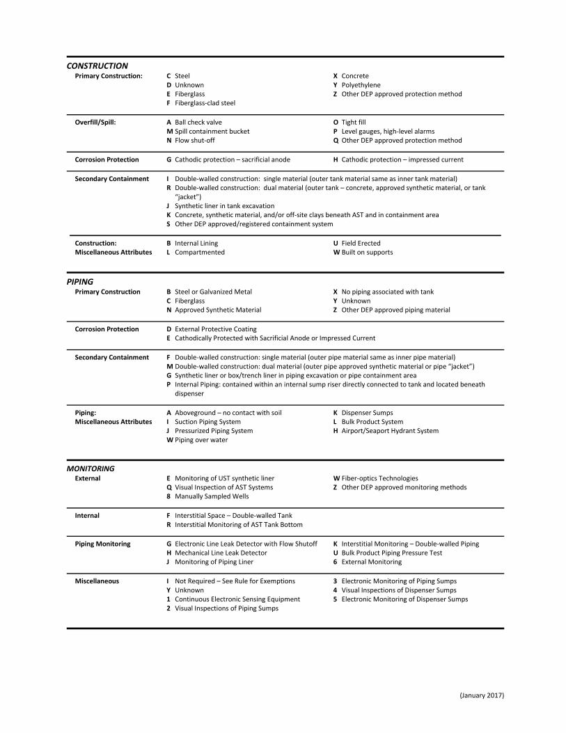
(January 2017)
CONSTRUCTION Primary Construction: C Steel X Concrete D Unknown Y Polyethylene E Fiberglass Z Other DEP approved protection method F Fiberglass-clad steel
Overfill/Spill: A Ball check valve O Tight fill M Spill containment bucket P Level gauges, high-level alarms N Flow shut-off Q Other DEP approved protection method
Corrosion Protection G Cathodic protection – sacrificial anode H Cathodic protection – impressed current
Secondary Containment I Double-walled construction: single material (outer tank material same as inner tank material) R Double-walled construction: dual material (outer tank – concrete, approved synthetic material, or tank
“jacket”) J Synthetic liner in tank excavation K Concrete, synthetic material, and/or off-site clays beneath AST and in containment area S Other DEP approved/registered containment system
Construction: B Internal Lining U Field Erected Miscellaneous Attributes L Compartmented W Built on supports
PIPING Primary Construction B Steel or Galvanized Metal X No piping associated with tank C Fiberglass Y Unknown N Approved Synthetic Material Z Other DEP approved piping material
Corrosion Protection D External Protective Coating E Cathodically Protected with Sacrificial Anode or Impressed Current
Secondary Containment F Double-walled construction: single material (outer pipe material same as inner pipe material) M Double-walled construction: dual material (outer pipe approved synthetic material or pipe “jacket”) G Synthetic liner or box/trench liner in piping excavation or pipe containment area P Internal Piping: contained within an internal sump riser directly connected to tank and located beneath
dispenser
Piping: A Aboveground – no contact with soil K Dispenser Sumps Miscellaneous Attributes I Suction Piping System L Bulk Product System J Pressurized Piping System H Airport/Seaport Hydrant System W Piping over water
MONITORING External E Monitoring of UST synthetic liner W Fiber-optics Technologies Q Visual Inspection of AST Systems Z Other DEP approved monitoring methods 8 Manually Sampled Wells
Internal F Interstitial Space – Double-walled Tank R Interstitial Monitoring of AST Tank Bottom
Piping Monitoring G Electronic Line Leak Detector with Flow Shutoff K Interstitial Monitoring – Double-walled Piping H Mechanical Line Leak Detector U Bulk Product Piping Pressure Test J Monitoring of Piping Liner 6 External Monitoring
Miscellaneous I Not Required – See Rule for Exemptions 3 Electronic Monitoring of Piping Sumps Y Unknown 4 Visual Inspections of Dispenser Sumps 1 Continuous Electronic Sensing Equipment 5 Electronic Monitoring of Dispenser Sumps 2 Visual Inspections of Piping Sumps

(January 2017)
E. Certified Contractor and Certification
Record the name and the Department of Business and Professional Regulation License Number for the Certified Contractor whenever an underground storage tank has been installed or removed. Do not rely on the contractor to file this form. Storage Tank Registration Forms are required to be submitted by the storage tank system owner.
Please Remember - The Registration Form cannot be processed without the name and signature of the storage tank system owner and the date of the form submittal. Please print the name legibly in case a representative of the storage tank program should need to contact you.
Submit form to [email protected]
If you have questions, please call a storage tank registration representative at (850) 245-8839 or email [email protected] for assistance. Thank you for your cooperation.
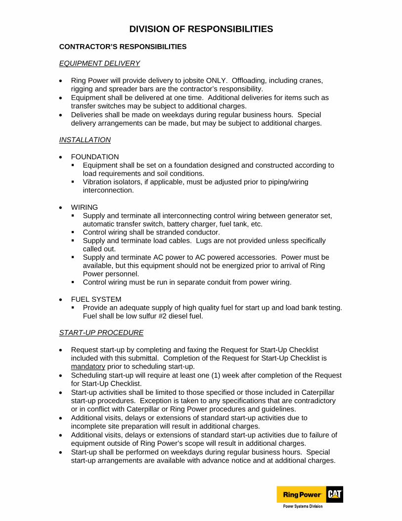
DIVISION OF RESPONSIBILITIES CONTRACTOR’S RESPONSIBILITIES EQUIPMENT DELIVERY
• Ring Power will provide delivery to jobsite ONLY. Offloading, including cranes, rigging and spreader bars are the contractor’s responsibility.
• Equipment shall be delivered at one time. Additional deliveries for items such as transfer switches may be subject to additional charges.
• Deliveries shall be made on weekdays during regular business hours. Special delivery arrangements can be made, but may be subject to additional charges.
INSTALLATION
• FOUNDATION Equipment shall be set on a foundation designed and constructed according to
load requirements and soil conditions. Vibration isolators, if applicable, must be adjusted prior to piping/wiring
interconnection.
• WIRING Supply and terminate all interconnecting control wiring between generator set,
automatic transfer switch, battery charger, fuel tank, etc. Control wiring shall be stranded conductor. Supply and terminate load cables. Lugs are not provided unless specifically
called out. Supply and terminate AC power to AC powered accessories. Power must be
available, but this equipment should not be energized prior to arrival of Ring Power personnel.
Control wiring must be run in separate conduit from power wiring.
• FUEL SYSTEM Provide an adequate supply of high quality fuel for start up and load bank testing.
Fuel shall be low sulfur #2 diesel fuel. START-UP PROCEDURE
• Request start-up by completing and faxing the Request for Start-Up Checklist included with this submittal. Completion of the Request for Start-Up Checklist is mandatory prior to scheduling start-up.
• Scheduling start-up will require at least one (1) week after completion of the Request for Start-Up Checklist.
• Start-up activities shall be limited to those specified or those included in Caterpillar start-up procedures. Exception is taken to any specifications that are contradictory or in conflict with Caterpillar or Ring Power procedures and guidelines.
• Additional visits, delays or extensions of standard start-up activities due to incomplete site preparation will result in additional charges.
• Additional visits, delays or extensions of standard start-up activities due to failure of equipment outside of Ring Power’s scope will result in additional charges.
• Start-up shall be performed on weekdays during regular business hours. Special start-up arrangements are available with advance notice and at additional charges.
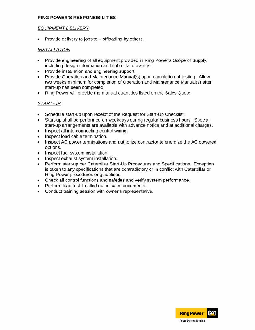
RING POWER’S RESPONSIBILITIES EQUIPMENT DELIVERY
• Provide delivery to jobsite – offloading by others. INSTALLATION
• Provide engineering of all equipment provided in Ring Power’s Scope of Supply, including design information and submittal drawings.
• Provide installation and engineering support.
• Provide Operation and Maintenance Manual(s) upon completion of testing. Allow two weeks minimum for completion of Operation and Maintenance Manual(s) after start-up has been completed.
• Ring Power will provide the manual quantities listed on the Sales Quote. START-UP
• Schedule start-up upon receipt of the Request for Start-Up Checklist.
• Start-up shall be performed on weekdays during regular business hours. Special start-up arrangements are available with advance notice and at additional charges.
• Inspect all interconnecting control wiring.
• Inspect load cable termination.
• Inspect AC power terminations and authorize contractor to energize the AC powered options.
• Inspect fuel system installation.
• Inspect exhaust system installation.
• Perform start-up per Caterpillar Start-Up Procedures and Specifications. Exception is taken to any specifications that are contradictory or in conflict with Caterpillar or Ring Power procedures or guidelines.
• Check all control functions and safeties and verify system performance.
• Perform load test if called out in sales documents.
• Conduct training session with owner’s representative.
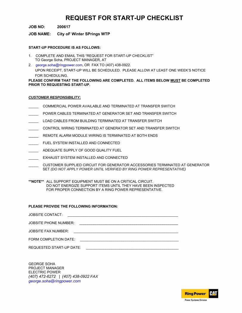
REQUEST FOR START-UP CHECKLIST JOB NO: 200617
JOB NAME: City oF Winter SPrings WTP
START-UP PROCEDURE IS AS FOLLOWS:
1. COMPLETE AND EMAIL THIS “REQUEST FOR START-UP CHECKLIST”TO George Soha, PROJECT MANAGER, AT
2. [email protected], OR FAX TO (407) 438-0922.
UPON RECEIPT, START-UP WILL BE SCHEDULED. PLEASE ALLOW AT LEAST ONE WEEK’S NOTICE
FOR SCHEDULING.PLEASE CONFIRM THAT THE FOLLOWING ARE COMPLETED. ALL ITEMS BELOW MUST BE COMPLETED PRIOR TO REQUESTING START-UP.
CUSTOMER RESPONSIBILITY:
_____ COMMERCIAL POWER AVAILABLE AND TERMINATED AT TRANSFER SWITCH
_____ POWER CABLES TERMINATED AT GENERATOR SET AND TRANSFER SWITCH
_____ LOAD CABLES FROM BUILDING TERMINATED AT TRANSFER SWITCH
_____ CONTROL WIRING TERMINATED AT GENERATOR SET AND TRANSFER SWITCH
_____ REMOTE ALARM MODULE WIRING IS TERMINATED AT BOTH ENDS
_____ FUEL SYSTEM INSTALLED AND CONNECTED
_____ ADEQUATE SUPPLY OF GOOD QUALITY FUEL
_____ EXHAUST SYSTEM INSTALLED AND CONNECTED
_____ CUSTOMER SUPPLIED CIRCUIT FOR GENERATOR ACCESSORIES TERMINATED AT GENERATOR SET (DO NOT APPLY POWER UNTIL VERIFIED BY RING POWER REPRESENTATIVE)
**NOTE** ALL SUPPORT EQUIPMENT MUST BE ON A CRITICAL CIRCUIT. DO NOT ENERGIZE SUPPORT ITEMS UNTIL THEY HAVE BEEN INSPECTED FOR PROPER CONNECTION BY A RING POWER REPRESENTATIVE.
PLEASE PROVIDE THE FOLLOWING INFORMATION:
JOBSITE CONTACT: ________________________________________________________
JOBSITE PHONE NUMBER: __________________________________________________
JOBSITE FAX NUMBER: _____________________________________________________
FORM COMPLETION DATE: __________________________________________________
REQUESTED START-UP DATE: _______________________________________________
GEORGE SOHA PROJECT MANAGER ELECTRIC POWER (407) 472-6272 | (407) 438-0922 [email protected]

SELF5709
Effective with sales to the first user on or after August 1, 2016
CATERPILLAR LIMITED WARRANTYIndustrial, Petroleum, Locomotive, and Agriculture Engine Products and Electric Power
Generation ProductsWorldwide
Caterpillar Inc. or any of its subsidiaries (“Caterpillar”) warrants new and
remanufactured engines and new and rebuild electric power generation
products sold by it (including any products of other manufacturers
packaged and sold by Caterpillar), to be free from defects in material
and workmanship.
This warranty does not apply engines sold for use in on-highway vehicle or
marine applications; engines in machines manufactured by or for Caterpillar;
C175, 3500 and 3600 series engines used in locomotive applications; 3000
Family engines, C0.5 through C4.4 and ACERT™ (C6.6, C7, C7.1, C9,
C9.3, C11, C13, C15, C18, C27, and C32) engines used in industrial, mobile
agriculture and locomotive applications; or Cat®
batteries; or Electric Power
Generation Products manufactured or assembled in India. These products
are covered by other Caterpillar warranties.
This warranty is subject to the following:
Warranty Period
• For industrial engines, engines in a petroleum applications
or Petroleum Power Systems (excluding petroleum fire
pump application), or engines in a Locomotive application, or
Uninterruptible Power Supply (UPS) systems, the warranty period
is 12 months after date of delivery to the first user.
• For engines used in petroleum fire pump and mobile agriculture
applications the warranty period is 24 months after date of delivery
to the first user.
• For controls only (EPIC), configurable and custom switchgear
products, and automatic transfer switch products, the warranty
period is 24 months after date of delivery to the first user.
• For new CG132, CG170 and CG260 series power generation
products the warranty period is 24 months/16,000 hours, whichever
comes first, after date of delivery to first user.
• For electric power generation products other than CG132, CG170
and CG260 series in prime or continuous applications the warranty
period is 12 months. For standby applications the warranty period
is 24 months/1000 hours. For emergency standby applications the
warranty period is 24 months/400 hours. All terms begin after date
of delivery to the first user.
• For Caterpillar rebuild electric power generation products the
warranty period is 12 months, but not to exceed 24 months
from shipment of rebuilt electric power generation product from
Caterpillar.
• For all other applications the warranty period is 12 months after
date of delivery to the first user.
Caterpillar Responsibilities
If a defect in material or workmanship is found during the warranty
period, Caterpillar will, during normal working hours and at a place of
business of a Cat dealer or other source approved by Caterpillar:
• Provide (at Caterpillar’s choice) new, Remanufactured, or
Caterpillar approved repaired parts or assembled components
needed to correct the defect.
Note: New, remanufactured, or Caterpillar approved repaired parts or
assembled components provided under the terms of this warranty
are warranted for the remainder of the warranty period applicable
to the product in which installed as if such parts were original
components of that product. Items replaced under this warranty
become the property of Caterpillar.
• Replace lubricating oil, filters, coolant, and other service items
made unusable by the defect.
• Provide reasonable and customary labor needed to correct
the defect, including labor to disconnect the product from and
reconnect the product to its attached equipment, mounting, and
support systems, if required.
For new 3114, 3116, and 3126 engines and, new and Caterpillar rebuild
electric power generation products (which includes the following: any
new products of other manufacturers packaged and sold by Caterpillar)
• Provide travel labor, up to four hours round trip, if in the opinion
of Caterpillar, the product cannot reasonably be transported to
a place of business of a Cat dealer or other source approved by
Caterpillar (travel labor in excess of four hours round trip, and any
meals, mileage, lodging, etc. is the user’s responsibility).
For all other products:
• Provide reasonable travel expenses for authorized mechanics,
including meals, mileage, and lodging, when Caterpillar chooses
to make the repair on-site.
User Responsibilities
The user is responsible for:
• Providing proof of the delivery date to the first user.
• Labor costs, except as stated under “Caterpillar Responsibilities,”
including costs beyond those required to disconnect the product
from and reconnect the product to its attached equipment,
mounting, and support systems.
• Travel or transporting costs, except as stated under “Caterpillar
Responsibilities.”
• Premium or overtime labor costs.
• Parts shipping charges in excess of those that are usual and
customary.
• Local taxes, if applicable.
• Costs to investigate complaints, unless the problem is caused by a
defect in Caterpillar material or workmanship.
• Giving timely notice of a warrantable failure and promptly making
the product available for repair.
• Performance of the required maintenance (including use of proper
fuel, oil, lubricants, and coolant) and items replaced due to normal
wear and tear.
• Allowing Caterpillar access to all electronically stored data.
Limitations
Caterpillar is not responsible for:
• Failures resulting from any use or installation that Caterpillar
judges improper.
• Failures resulting from attachments, accessory items, and parts
not sold or approved by Caterpillar.
• Failures resulting from abuse, neglect, and/or improper repair.
• Failures resulting from user’s delay in making the product available
after being notified of a potential product problem.
• Failures resulting from unauthorized repairs or adjustments, and
unauthorized fuel setting changes.
• Damage to parts, fixtures, housings, attachments, and accessory
items that are not part of the engine, Cat Selective Catalytic
Reduction System or electric power generation product (including
any products of other manufacturers packaged and sold by
Caterpillar).
• Repair of components sold by Caterpillar that is warranted directly
to the user by their respective manufacturer. Depending on type of
application, certain exclusions may apply. Consult your Cat dealer
for more information.
(Continued on reverse side…)
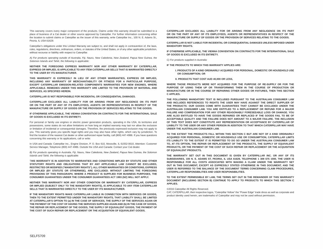
SELF5709
This warranty covers every major component of the products. Claims under this warranty should be submitted to a
place of business of a Cat dealer or other source approved by Caterpillar. For further information concerning either
the location to submit claims or Caterpillar as the issuer of this warranty, write Caterpillar Inc., 100 N. E. Adams St.,
Peoria, IL USA 61629.
Caterpillar’s obligations under this Limited Warranty are subject to, and shall not apply in contravention of, the laws,
rules, regulations, directives, ordinances, orders, or statutes of the United States, or of any other applicable jurisdiction,
without recourse or liability with respect to Caterpillar.
A) For products operating outside of Australia, Fiji, Nauru, New Caledonia, New Zealand, Papua New Guinea, the Solomon Islands and Tahiti, the following is applicable:
NEITHER THE FOREGOING EXPRESS WARRANTY NOR ANY OTHER WARRANTY BY CATERPILLAR,
EXPRESS OR IMPLIED, IS APPLICABLE TO ANY ITEM CATERPILLAR SELLS THAT IS WARRANTED DIRECTLY
TO THE USER BY ITS MANUFACTURER.
THIS WARRANTY IS EXPRESSLY IN LIEU OF ANY OTHER WARRANTIES, EXPRESS OR IMPLIED,
INCLUDING ANY WARRANTY OF MERCHANTABILITY OR FITNESS FOR A PARTICULAR PURPOSE,
EXCEPT CATERPILLAR EMISSION-RELATED COMPONENTS WARRANTIES FOR NEW ENGINES, WHERE
APPLICABLE. REMEDIES UNDER THIS WARRANTY ARE LIMITED TO THE PROVISION OF MATERIAL AND
SERVICES, AS SPECIFIED HEREIN.
CATERPILLAR IS NOT RESPONSIBLE FOR INCIDENTAL OR CONSEQUENTIAL DAMAGES.
CATERPILLAR EXCLUDES ALL LIABILITY FOR OR ARISING FROM ANY NEGLIGENCE ON ITS PART
OR ON THE PART OF ANY OF ITS EMPLOYEES, AGENTS OR REPRESENTATIVES IN RESPECT OF THE
MANUFACTURE OR SUPPLY OF GOODS OR THE PROVISION OF SERVICES RELATING TO THE GOODS.
IF OTHERWISE APPLICABLE, THE VIENNA CONVENTION ON CONTRACTS FOR THE INTERNATIONAL SALE
OF GOODS IS EXCLUDED IN ITS ENTIRETY.
For personal or family use engines or electric power generation products, operating in the USA, its territories and
possessions, some states do not allow limitations on how long an implied warranty may last nor allow the exclusion
or limitation of incidental or consequential damages. Therefore, the previously expressed exclusion may not apply to
you. This warranty gives you specific legal rights and you may also have other rights, which vary by jurisdiction. To
find the location of the nearest Cat dealer or other authorized repair facility, call (800) 447-4986. If you have questions
concerning this warranty or its applications, call or write:
In USA and Canada: Caterpillar Inc., Engine Division, P. O. Box 610, Mossville, IL 61552-0610, Attention: Customer
Service Manager, Telephone (800) 447-4986. Outside the USA and Canada: Contact your Cat dealer.
B) For products operating in Australia, Fiji, Nauru, New Caledonia, New Zealand, Papua New Guinea, the Solomon Islands and Tahiti, the following is applicable:
THIS WARRANTY IS IN ADDITION TO WARRANTIES AND CONDITIONS IMPLIED BY STATUTE AND OTHER
STATUTORY RIGHTS AND OBLIGATIONS THAT BY ANY APPLICABLE LAW CANNOT BE EXCLUDED,
RESTRICTED OR MODIFIED (“MANDATORY RIGHTS”). ALL OTHER WARRANTIES OR CONDITIONS, EXPRESS
OR IMPLIED (BY STATUTE OR OTHERWISE), ARE EXCLUDED. WITHOUT LIMITING THE FOREGOING
PROVISIONS OF THIS PARAGRAPH, WHERE A PRODUCT IS SUPPLIED FOR BUSINESS PURPOSES, THE
CONSUMER GUARANTEES UNDER THE CONSUMER GUARANTEES ACT 1993 (NZ) WILL NOT APPLY.
NEITHER THIS WARRANTY NOR ANY OTHER CONDITION OR WARRANTY BY CATERPILLAR, EXPRESS
OR IMPLIED (SUBJECT ONLY TO THE MANDATORY RIGHTS), IS APPLICABLE TO ANY ITEM CATERPILLAR
SELLS THAT IS WARRANTED DIRECTLY TO THE USER BY ITS MANUFACTURER.
IF THE MANDATORY RIGHTS MAKE CATERPILLAR LIABLE IN CONNECTION WITH SERVICES OR GOODS,
THEN TO THE EXTENT PERMITTED UNDER THE MANDATORY RIGHTS, THAT LIABILITY SHALL BE LIMITED
AT CATERPILLAR’S OPTION TO (a) IN THE CASE OF SERVICES, THE SUPPLY OF THE SERVICES AGAIN OR
THE PAYMENT OF THE COST OF HAVING THE SERVICES SUPPLIED AGAIN AND (b) IN THE CASE OF GOODS,
THE REPAIR OR REPLACEMENT OF THE GOODS, THE SUPPLY OF EQUIVALENT GOODS, THE PAYMENT OF
THE COST OF SUCH REPAIR OR REPLACEMENT OR THE ACQUISITION OF EQUIVALENT GOODS.
CATERPILLAR EXCLUDES ALL LIABILITY FOR OR ARISING FROM ANY NEGLIGENCE ON ITS PART
OR ON THE PART OF ANY OF ITS EMPLOYEES, AGENTS OR REPRESENTATIVES IN RESPECT OF THE
MANUFACTURE OR SUPPLY OF GOODS OR THE PROVISION OF SERVICES RELATING TO THE GOODS.
CATERPILLAR IS NOT LIABLE FOR INCIDENTAL OR CONSEQUENTIAL DAMAGES UNLESS IMPOSED UNDER
MANDATORY RIGHTS.
IF OTHERWISE APPLICABLE, THE VIENNA CONVENTION ON CONTRACTS FOR THE INTERNATIONAL SALE
OF GOODS IS EXCLUDED IN ITS ENTIRETY.
C) For products supplied in Australia:
IF THE PRODUCTS TO WHICH THIS WARRANTY APPLIES ARE:
I. PRODUCTS OF A KIND ORDINARILY ACQUIRED FOR PERSONAL, DOMESTIC OR HOUSEHOLD USE
OR CONSUMPTION; OR
II. PRODUCTS THAT COST AUD 40,000 OR LESS,
WHERE THOSE PRODUCTS WERE NOT ACQUIRED FOR THE PURPOSE OF RE-SUPPLY OR FOR THE
PURPOSE OF USING THEM UP OR TRANSFORMING THEM IN THE COURSE OF PRODUCTION OR
MANUFACTURE OR IN THE COURSE OF REPAIRING OTHER GOODS OR FIXTURES, THEN THIS SECTION
C APPLIES.
THE FOLLOWING MANDATORY TEXT IS INCLUDED PURSUANT TO THE AUSTRALIAN CONSUMER LAW
AND INCLUDES REFERENCES TO RIGHTS THE USER MAY HAVE AGAINST THE DIRECT SUPPLIER OF
THE PRODUCTS: OUR GOODS COME WITH GUARANTEES THAT CANNOT BE EXCLUDED UNDER THE
AUSTRALIAN CONSUMER LAW. YOU ARE ENTITLED TO A REPLACEMENT OR REFUND FOR A MAJOR
FAILURE AND COMPENSATION FOR ANY OTHER REASONABLY FORESEEABLE LOSS OR DAMAGE. YOU
ARE ALSO ENTITLED TO HAVE THE GOODS REPAIRED OR REPLACED IF THE GOODS FAIL TO BE OF
ACCEPTABLE QUALITY AND THE FAILURE DOES NOT AMOUNT TO A MAJOR FAILURE. THE INCLUSION
OF THIS TEXT DOES NOT CONSTITUTE ANY REPRESENTATION OR ACCEPTANCE BY CATERPILLAR OF
LIABILITY TO THE USER OR ANY OTHER PERSON IN ADDITION TO THAT WHICH CATERPILLAR MAY HAVE
UNDER THE AUSTRALIAN CONSUMER LAW.
TO THE EXTENT THE PRODUCTS FALL WITHIN THIS SECTION C BUT ARE NOT OF A KIND ORDINARILY
ACQUIRED FOR PERSONAL, DOMESTIC OR HOUSEHOLD USE OR CONSUMPTION, CATERPILLAR LIMITS
ITS LIABILITY TO THE EXTENT IT IS PERMITTED TO DO SO UNDER THE AUSTRALIAN CONSUMER LAW
TO, AT ITS OPTION, THE REPAIR OR REPLACEMENT OF THE PRODUCTS, THE SUPPLY OF EQUIVALENT
PRODUCTS, OR THE PAYMENT OF THE COST OF SUCH REPAIR OR REPLACEMENT OR THE ACQUISITION
OF EQUIVALENT PRODUCTS.
THE WARRANTY SET OUT IN THIS DOCUMENT IS GIVEN BY CATERPILLAR INC. OR ANY OF ITS
SUBSIDIARIES, 100 N. E. ADAMS ST, PEORIA, IL USA 61629, TELEPHONE 1 309 675 1000, THE USER IS
RESPONSIBLE FOR ALL COSTS ASSOCIATED WITH MAKING A CLAIM UNDER THE WARRANTY SET
OUT IN THIS DOCUMENT, EXCEPT AS EXPRESSLY STATED OTHERWISE IN THIS DOCUMENT, AND THE
USER IS REFERRED TO THE BALANCE OF THE DOCUMENT TERMS CONCERNING CLAIM PROCEDURES,
CATERPILLAR RESPONSIBILITIES AND USER RESPONSIBILITIES.
TO THE EXTENT PERMISSIBLE BY LAW, THE TERMS SET OUT IN THE REMAINDER OF THIS WARRANTY
DOCUMENT (INCLUDING SECTION B) CONTINUE TO APPLY TO PRODUCTS TO WHICH THIS SECTION C
APPLIES.
©2016 Caterpillar All Rights Reserved.
CAT, CATERPILLAR, their respective logos, "Caterpillar Yellow" the "Power Edge" trade dress as well as corporate and
product identity used herein, are trademarks of Caterpillar and may not be used without permission.
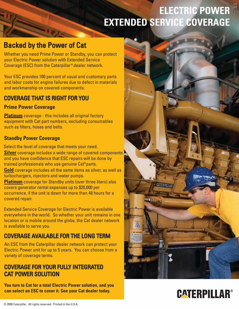
®
Backed by the Power of CatBacked by the Power of CatWhether you need Prime Power or Standby, you can protect your Electric Power solution with Extended Service Coverage (ESC) from the Caterpillar dealer network.
Your ESC provides 100 percent of usual and customary parts and labor costs for engine failures due to defect in materials and workmanship on covered components.
COVERAGE THAT IS RIGHT FOR YOUCOVERAGE THAT IS RIGHT FOR YOUPrime Power Coverage
Platinum coverage - this includes all original factory equipment with Cat part numbers, excluding consumables such as filters, hoses and belts.
Standby Power CoverageSelect the level of coverage that meets your need.Silver coverage includes a wide range of covered components and you have confidence that ESC repairs will be done by trained professionals who use genuine Cat parts. Gold coverage includes all the same items as silver, as well as turbochargers, injectors and water pumps.Platinum coverage for Standby units (over three liters) alsocovers generator rental expenses up to $20,000 peroccurrence, if the unit is down for more than 48 hours for acovered repair.
Extended Service Coverage for Electric Power is available everywhere in the world. So whether your unit remains in one location or is mobile around the globe, the Cat dealer network is available to serve you.
COVERAGE FOR YOUR FULLY INTEGRATED COVERAGE FOR YOUR FULLY INTEGRATED CAT POWER SOLUTIONCAT POWER SOLUTION
You turn to Cat for a total Electric Power solution, and you can select an ESC to cover it. See your Cat dealer today.
COVERAGE AVAILABLE FOR THE LONG TERMCOVERAGE AVAILABLE FOR THE LONG TERMAn ESC from the Caterpillar dealer network can protect your Electric Power unit for up to 5 years. You can choose from a variety of coverage terms.
®
© 2009 Caterpillar. All rights reserved. Printed in the U.S.A.
ELECTRIC POWEREXTENDED SERVICE COVERAGE
jim henry
Line
Jim Drackley
Typewritten Text
Jim Drackley
Typewritten Text
Jim Drackley
Typewritten Text
Jim Drackley
Typewritten Text
Jim Drackley
Typewritten Text
Tony Anderson
Rectangle
Tony Anderson
Rectangle
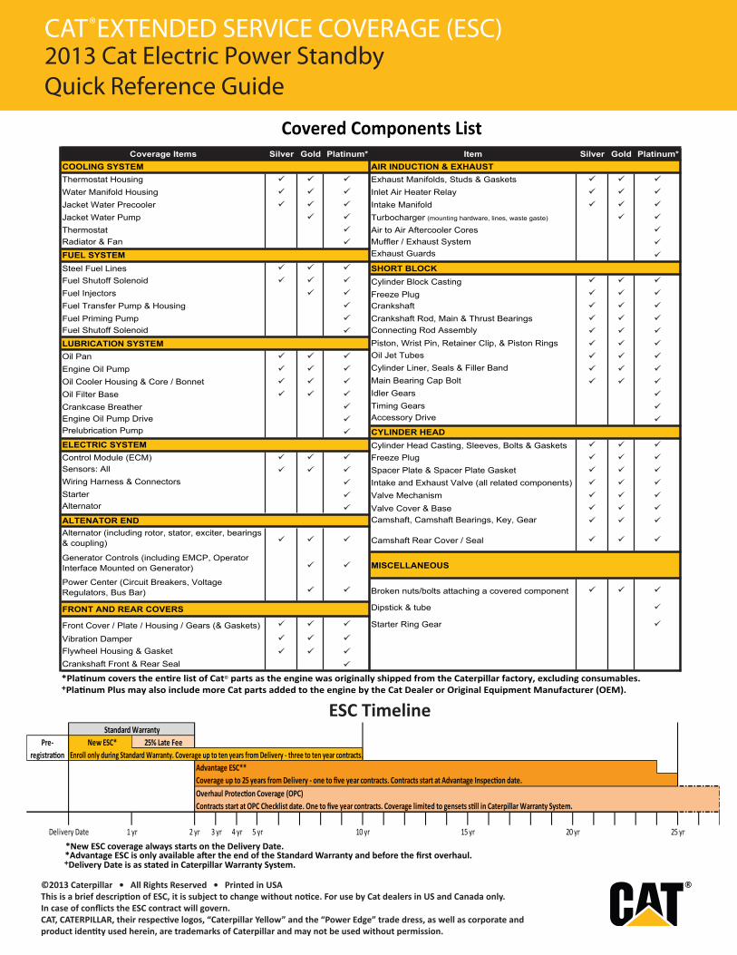
CAT®
m*unitalPdloGrevliSmetIm*unitalPdloGrevliSsmetI egarevoCTSUAHXE & NOITCUDNI RIAMETSYS GNILOOC
Thermostat Housing Exhaust Manifolds, Studs & GasketsWater Manifold Housing Inlet Air Heater RelayJacket Water Precooler Intake ManifoldJacket Water Pump Turbocharger (mounting hardware, lines, waste gaste)
Thermostat Air to Air Aftercooler CoresRadiator & Fan Muffler / Exhaust System
FUEL SYSTEM Exhaust Guards
Steel Fuel Lines SHORT BLOCKFuel Shutoff Solenoid Cylinder Block CastingFuel Injectors Freeze PlugFuel Transfer Pump & Housing CrankshaftFuel Priming Pump Crankshaft Rod, Main & Thrust BearingsFuel Shutoff Solenoid Connecting Rod Assembly
LUBRICATION SYSTEM Piston, Wrist Pin, Retainer Clip, & Piston RingsOil Pan Oil Jet Tubes
Engine Oil Pump Cylinder Liner, Seals & Filler Band
Oil Cooler Housing & Core / Bonnet Main Bearing Cap Bolt
Oil Filter Base Idler Gears
Crankcase Breather Timing GearsEngine Oil Pump Drive Accessory DrivePrelubrication Pump CYLINDER HEADELECTRIC SYSTEM Cylinder Head Casting, Sleeves, Bolts & GasketsControl Module (ECM) Freeze PlugSensors: All Spacer Plate & Spacer Plate GasketWiring Harness & Connectors Intake and Exhaust Valve (all related components)Starter Valve MechanismAlternator Valve Cover & BaseALTENATOR END Camshaft, Camshaft Bearings, Key, GearAlternator (including rotor, stator, exciter, bearings & coupling) Camshaft Rear Cover / Seal
Generator Controls (including EMCP, OperatorInterface Mounted on Generator) MISCELLANEOUS
Power Center (Circuit Breakers, Voltage Regulators, Bus Bar) Broken nuts/bolts attaching a covered component
FRONT AND REAR COVERS Dipstick & tube
Front Cover / Plate / Housing / Gears (& Gaskets) Starter Ring Gear
Vibration DamperFlywheel Housing & GasketCrankshaft Front & Rear Seal
Covered Components List
*Platinum covers the entire list of Cat© parts as the engine was originally shipped from the Caterpillar factory, excluding consumables.+Platinum Plus may also include more Cat parts added to the engine by the Cat Dealer or Original Equipment Manufacturer (OEM).
*New ESC coverage always starts on the Delivery Date.
ESC Timeline
Enroll only during Standard Warranty. Coverage up to ten years from Delivery - three to ten year contracts.Advantage ESC** Coverage up to 25 years from Delivery - one to five year contracts. Contracts start at Advantage Inspection date. Overhaul Protection Coverage (OPC)Contracts start at OPC Checklist date. One to five year contracts. Coverage limited to gensets still in Caterpillar Warranty System.
Delivery Date
Pre- registration
1 yr
Standard WarrantyNew ESC* 25% Late Fee
2 yr 3 yr 4 yr 5 yr 10 yr 15 yr 20 yr 25 yr
+Delivery Date is as stated in Caterpillar Warranty System.
©2013 Caterpillar • All Rights Reserved • Printed in USAThis is a brief description of ESC, it is subject to change without notice. For use by Cat dealers in US and Canada only. In case of conflicts the ESC contract will govern.CAT, CATERPILLAR, their respective logos, “Caterpillar Yellow” and the “Power Edge” trade dress, as well as corporate and product identity used herein, are trademarks of Caterpillar and may not be used without permission.
EXTENDED SERVICE COVERAGE (ESC)2013 Cat Electric Power StandbyQuick Reference Guide
CAT®
*Advantage ESC is only available after the end of the Standard Warranty and before the first overhaul.
Tracy Stenberg
Rectangle
Tracy Stenberg
Rectangle
Tracy Stenberg
Rectangle
Tracy Stenberg
Rectangle
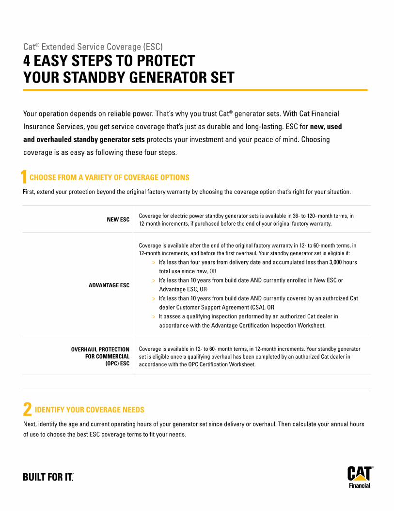
Cat® Extended Service Coverage (ESC)
4 EASY STEPS TO PROTECT YOUR STANDBY GENERATOR SET
Your operation depends on reliable power. That’s why you trust Cat® generator sets. With Cat Financial
Insurance Services, you get service coverage that’s just as durable and long-lasting. ESC for new, used
and overhauled standby generator sets protects your investment and your peace of mind. Choosing
coverage is as easy as following these four steps.
IDENTIFY YOUR COVERAGE NEEDS
Next, identify the age and current operating hours of your generator set since delivery or overhaul. Then calculate your annual hours
of use to choose the best ESC coverage terms to fit your needs.
2
CHOOSE FROM A VARIETY OF COVERAGE OPTIONS
First, extend your protection beyond the original factory warranty by choosing the coverage option that’s right for your situation.
NEW ESCCoverage for electric power standby generator sets is available in 36- to 120- month terms, in 12-month increments, if purchased before the end of your original factory warranty.
ADVANTAGE ESC
Coverage is available after the end of the original factory warranty in 12- to 60-month terms, in 12-month increments, and before the first overhaul. Your standby generator set is eligible if:
> It’s less than four years from delivery date and accumulated less than 3,000 hours total use since new, OR
> It’s less than 10 years from build date AND currently enrolled in New ESC or Advantage ESC, OR
> It’s less than 10 years from build date AND currently covered by an authroized Cat dealer Customer Support Agreement (CSA), OR
> It passes a qualifying inspection performed by an authorized Cat dealer in accordance with the Advantage Certification Inspection Worksheet.
OVERHAUL PROTECTION FOR COMMERCIAL
(OPC) ESC
Coverage is available in 12- to 60- month terms, in 12-month increments. Your standby generator set is eligible once a qualifying overhaul has been completed by an authorized Cat dealer in accordance with the OPC Certification Worksheet.
1
Tracy Kilby
Rectangle
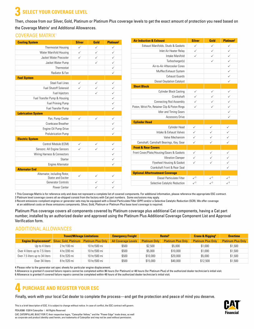
Alternator EndAlternator, including Rotor,
Stator and Exciterz z z
Generator Controls z z
Power Center z z
Electric System
Control Module (ECM) z z z
Sensors: All Engine Sensors z z z
Wiring Harness & Connectors z
Starter z
Engine Alternator z
Lubrication System
Pan, Pump Cooler z z z
Crankcase Breather z
Engine Oil Pump Drive z
Prelubrication Pump z
Fuel System
Steel Fuel Lines z z z
Fuel Shutoff Solenoid z z z
Fuel Injectors z z
Fuel Transfer Pump & Housing z
Fuel Priming Pump z
Fuel Transfer Pump z
Cooling System Silver Gold Platinum2
Thermostat Housing z z z
Water Manifold Housing z z z
Jacket Water Precooler z z z
Jacket Water Pump z z
Thermostat z
Radiator & Fan z
PURCHASE AND REGISTER YOUR ESC
Finally, work with your local Cat dealer to complete the process—and get the protection and peace of mind you deserve.4
Then, choose from our Silver, Gold, Platinum or Platinum Plus coverage levels to get the exact amount of protection you need based on
the Coverage Matrix1 and Additional Allowances.
SELECT YOUR COVERAGE LEVEL
Travel/Mileage Limitations Emergency Freight Rental5 Crane & Rigging6 Overtime
Engine Displacement4 Silver, Gold, Platinum Platinum Plus Only All Coverage Levels Platinum Only Platinum Plus Only Platinum Plus Only Platinum Plus Only
Up to 4 liters 2 hr/100 mi 10 hr/500 mi $500 $2,500 $5,000 $1,000 $1,500
Over 4 liters up to 7.5 liters 4 hr/200 mi 10 hr/500 mi $500 $5,000 $10,000 $1,000 $1,500
Over 7.5 liters up to 34 liters 8 hr/320 mi 10 hr/500 mi $500 $10,000 $20,000 $5,000 $1,500
Over 34 liters 8 hr/320 mi 10 hr/500 mi $500 $15,000 $40,000 $12,500 $1,500
3
Optional Aftertreatment Coverage
Diesel Particulate Filter z3 z3 z3
Selective Catalytic Reduction z3 z3 z3
Front & Rear Covers
Front Cover/Plate/Housing/Gears & Gaskets z z z
Vibration Damper z z z
Flywheel Housing & Gasket z z z
Crankshaft Front & Rear Seal z
Cylinder Head
Cylinder Head z z z
Intake & Exhaust Valves z z z
Valve Mechanism z z z
Camshaft, Camshaft Bearings, Key, Gear z z z
Short Block
Cylinder Block Casting z z z
Crankshaft z z z
Connecting Rod Assembly z z z
Piston, Wrist Pin, Retainer Clip & Piston Rings z z z
Idler and Timing Gears z
Accessory Drive z
Air Induction & Exhaust Silver Gold Platinum2
Exhaust Manifolds, Studs & Gaskets z z z
Inlet Air Heater Relay z z z
Intake Manifold z z z
Turbocharger(s) z z
Air-to-Air Aftercooler Cores z
Muffler/Exhaust System z
Exhaust Guards z
Diesel Oxydation Catalyst z
This is a brief description of ESC. It is subject to change without notice. In case of conflict, the ESC contract will govern.
PEHJ0380 ©2014 Caterpillar | All Rights Reserved
CAT, CATERPILLAR, BUILT FOR IT, their respective logos, “Caterpillar Yellow,” and the “Power Edge” trade dress, as well as corporate and product identity used herein, are trademarks of Caterpillar and may not be used without permission.
COVERAGE MATRIX1
1 This Coverage Matrix is for reference only and does not represent a complete list of covered components. For additional information, please reference the appropriate ESC contract.2 Platinum level coverage covers all as-shipped consist from the factory with Cat part numbers. Some exclusions may apply.3 Recent emissions-compliant engines or generator sets may be equipped with a Diesel Particulate Filter (DPF) and/or a Selective Catalytic Reduction (SCR). We offer coverage
at an additional costs on these emissions components. Silver, Gold, Platinum or Platinum Plus base level coverage is required.
Platinum Plus coverage covers all components covered by Platinum coverage plus additional Cat components, having a Cat part number, installed by an authorized dealer and approved using the Platinum Plus Additional Coverage Component List and Approval Verification form.
ADDITIONAL ALLOWANCES
4 Please refer to the generator set spec sheets for particular engine displacement.5 Allowance is granted if covered failure repairs cannot be completed within 96 hours (for Platinum) or 48 hours (for Platinum Plus) of the authorized dealer technician’s initial visit.6 Allowance is granted if covered failure repairs cannot be completed within 48 hours of the authorized dealer technician’s initial visit.
Tracy Kilby
Rectangle
Tracy Kilby
Rectangle
Tony Anderson
Rectangle
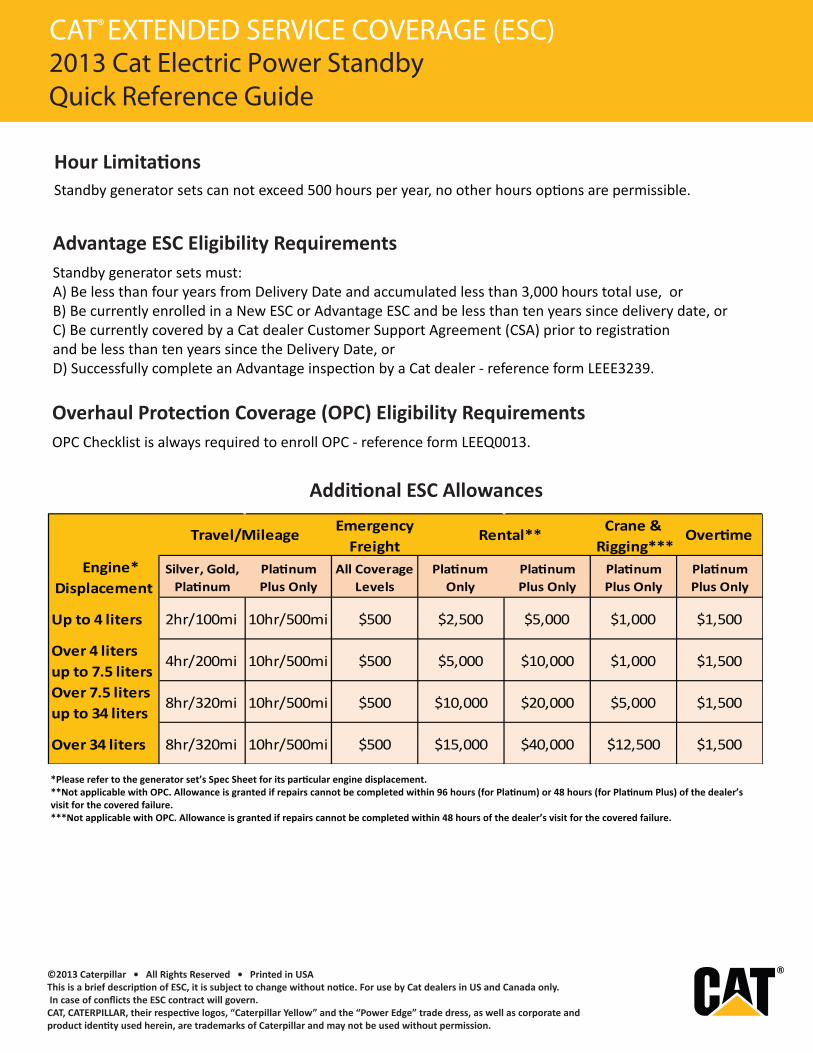
*Please refer to the generator set’s Spec Sheet for its particular engine displacement.**Not applicable with OPC. Allowance is granted if repairs cannot be completed within 96 hours (for Platinum) or 48 hours (for Platinum Plus) of the dealer’s visit for the covered failure.***Not applicable with OPC. Allowance is granted if repairs cannot be completed within 48 hours of the dealer’s visit for the covered failure.
Additional ESC Allowances
Emergency Freight
Crane & Rigging***
Overtime
Engine* Displacement
Silver, Gold, Platinum
Platinum Plus Only
All Coverage Levels
Platinum Only
Platinum Plus Only
Platinum Plus Only
Platinum Plus Only
Up to 4 liters 2hr/100mi 10hr/500mi $500 $2,500 $5,000 $1,000 $1,500
Over 4 liters up to 7.5 liters
4hr/200mi 10hr/500mi $500 $5,000 $10,000 $1,000 $1,500
Over 7.5 liters up to 34 liters
8hr/320mi 10hr/500mi $500 $10,000 $20,000 $5,000 $1,500
Over 34 liters 8hr/320mi 10hr/500mi $500 $15,000 $40,000 $12,500 $1,500
Travel/Mileage Rental**
©2013 Caterpillar • All Rights Reserved • Printed in USAThis is a brief description of ESC, it is subject to change without notice. For use by Cat dealers in US and Canada only. In case of conflicts the ESC contract will govern.CAT, CATERPILLAR, their respective logos, “Caterpillar Yellow” and the “Power Edge” trade dress, as well as corporate and product identity used herein, are trademarks of Caterpillar and may not be used without permission.
Standby generator sets can not exceed 500 hours per year, no other hours options are permissible.
Standby generator sets must: A) Be less than four years from Delivery Date and accumulated less than 3,000 hours total use, orB) Be currently enrolled in a New ESC or Advantage ESC and be less than ten years since delivery date, or C) Be currently covered by a Cat dealer Customer Support Agreement (CSA) prior to registration and be less than ten years since the Delivery Date, or D) Successfully complete an Advantage inspection by a Cat dealer - reference form LEEE3239.
Hour Limitations
Advantage ESC Eligibility Requirements
EXTENDED SERVICE COVERAGE (ESC)2013 Cat Electric Power StandbyQuick Reference Guide
Overhaul Protection Coverage (OPC) Eligibility RequirementsOPC Checklist is always required to enroll OPC - reference form LEEQ0013.
CAT®
Tracy Stenberg
Rectangle
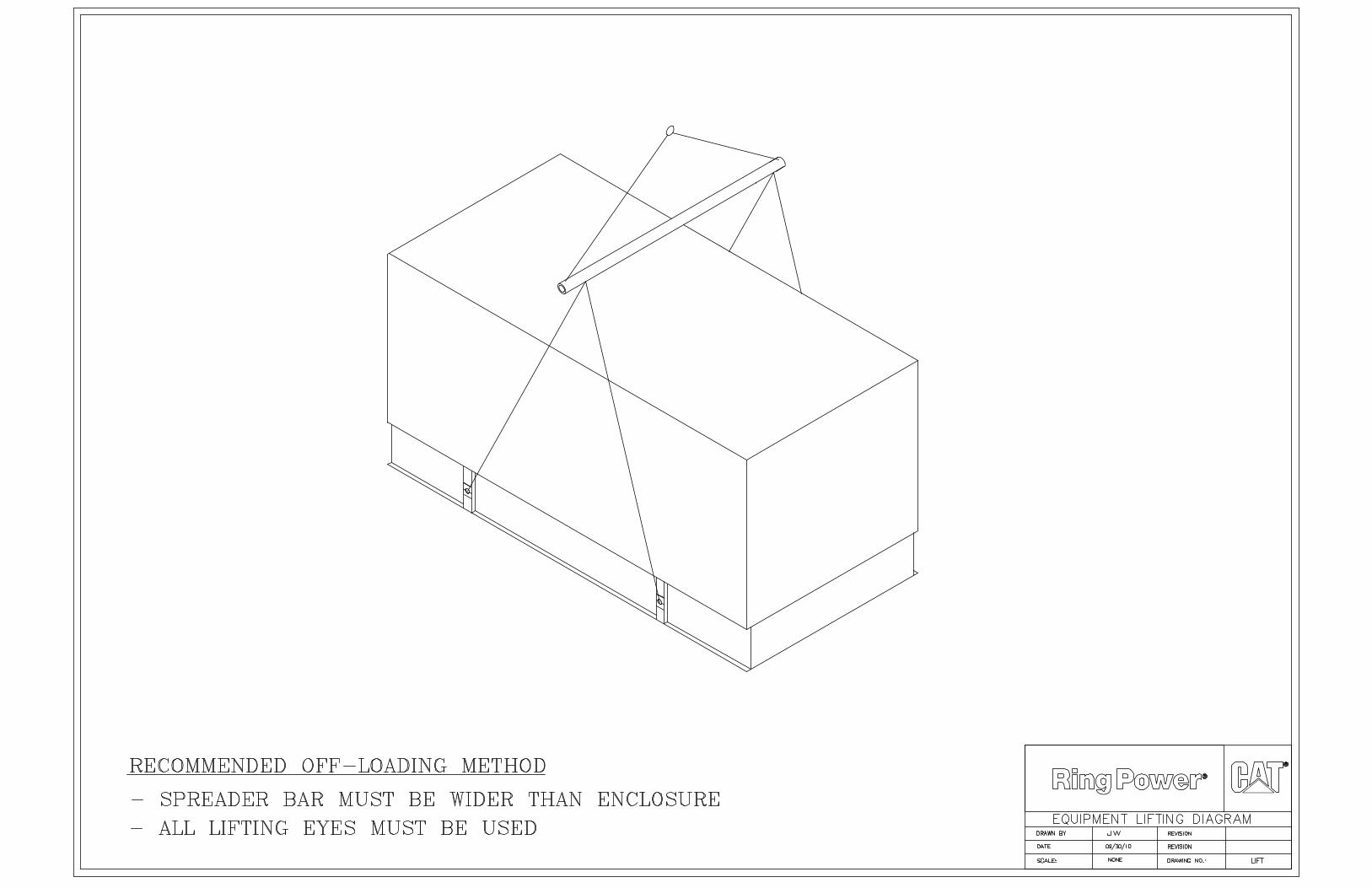
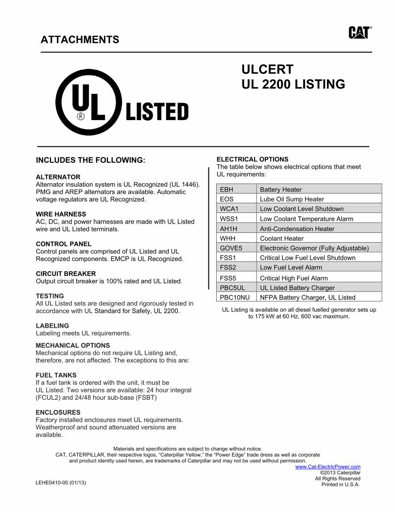
ATTACHMENTS
ULCERT UL 2200 LISTING
ELECTRICAL OPTIONS The table below shows electrical options that meet UL requirements:
MECHANICAL OPTIONS Mechanical options do not require UL Listing and, therefore, are not affected. The exceptions to this are:
FUEL TANKS If a fuel tank is ordered with the unit, it must be UL Listed. Two versions are available: 24 hour integral (FCUL2) and 24/48 hour sub-base (FSBT)
ENCLOSURESFactory installed enclosures meet UL requirements. Weatherproof and sound attenuated versions are available.
Materials and specifications are subject to change without notice. CAT, CATERPILLAR, their respective logos, “Caterpillar Yellow,” the “Power Edge” trade dress as well as corporate
and product identity used herein, are trademarks of Caterpillar and may not be used without permission. www.Cat-ElectricPower.com
©2013 Caterpillar All Rights Reserved
LEHEXXXXXX (01/13) Printed in U.S.A.
INCLUDES THE FOLLOWING:
ALTERNATOR Alternator insulation system is UL Recognized (UL 1446). PMG and AREP alternators are available. Automatic voltage regulators are UL Recognized.
WIRE HARNESS AC, DC, and power harnesses are made with UL Listed wire and UL Listed terminals.
CONTROL PANEL Control panels are comprised of UL Listed and UL Recognized components. EMCP is UL Recognized.
CIRCUIT BREAKER Output circuit breaker is 100% rated and UL Listed.
TESTINGAll UL Listed sets are designed and rigorously tested in accordance with UL Standard for Safety, UL 2200.
LABELING Labeling meets UL requirements.
EBH Battery HeaterEOS Lube Oil Sump Heater WCA1 Low Coolant Level Shutdown WSS1 Low Coolant Temperature Alarm AH1H Anti-Condensation Heater WHH Coolant Heater GOVE5 Electronic Governor (Fully Adjustable) FSS1 Critical Low Fuel Level Shutdown FSS2 Low Fuel Level Alarm
FSS5 Critical High Fuel Alarm PBC5UL UL Listed Battery Charger PBC10NU NFPA Battery Charger, UL Listed
UL Listing is available on all diesel fuelled generator sets up to 175 kW at 60 Hz, 600 vac maximum.
LEHE0410-00 (01/13)

Justin Welty
Justin Welty
Justin Welty
TRANSFER SWITCH
Todd Priolo ASCO Power Technologies
155 E Wildmere Ave Ste 1001
Longwood, FL 32750 United States
Nov 25, 2020
www.ascopower.com | [email protected] 800.800.ASCO | 160 Park Avenue, Florham Park NJ 07932
City of Winter Springs WTP2
TRANSFER SWITCH
SUBMITTAL REVISION 00
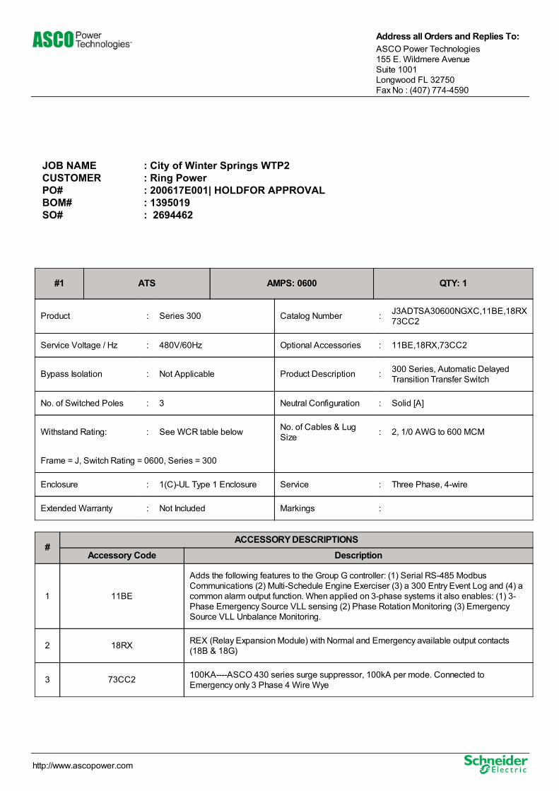
#1 ATS AMPS: 0600 QTY: 1
Product : Series 300 Catalog Number : J3ADTSA30600NGXC,11BE,18RX73CC2
Service Voltage / Hz : 480V/60Hz Optional Accessories : 11BE,18RX,73CC2
Bypass Isolation : Not Applicable Product Description : 300 Series, Automatic DelayedTransition Transfer Switch
No. of Switched Poles : 3 Neutral Configuration : Solid [A]
Withstand Rating: : See WCR table below No. of Cables & LugSize : 2, 1/0 AWG to 600 MCM
Frame = J, Switch Rating = 0600, Series = 300
Enclosure : 1(C)-UL Type 1 Enclosure Service : Three Phase, 4-wire
Extended Warranty : Not Included Markings :
#ACCESSORY DESCRIPTIONS
Accessory Code Description
1 11BE
Adds the following features to the Group G controller: (1) Serial RS-485 ModbusCommunications (2) Multi-Schedule Engine Exerciser (3) a 300 Entry Event Log and (4) acommon alarm output function. When applied on 3-phase systems it also enables: (1) 3-Phase Emergency Source VLL sensing (2) Phase Rotation Monitoring (3) EmergencySource VLL Unbalance Monitoring.
2 18RX REX (Relay Expansion Module) with Normal and Emergency available output contacts(18B & 18G)
3 73CC2 100KA----ASCO 430 series surge suppressor, 100kA per mode. Connected toEmergency only 3 Phase 4 Wire Wye
JOB NAME : City of Winter Springs WTP2CUSTOMER : Ring PowerPO# : 200617E001| HOLDFOR APPROVALBOM# : 1395019 SO# : 2694462
Address all Orders and Replies To:ASCO Power Technologies 155 E. Wildmere Avenue Suite 1001 Longwood FL 32750 Fax No : (407) 774-4590
http://www.ascopower.com
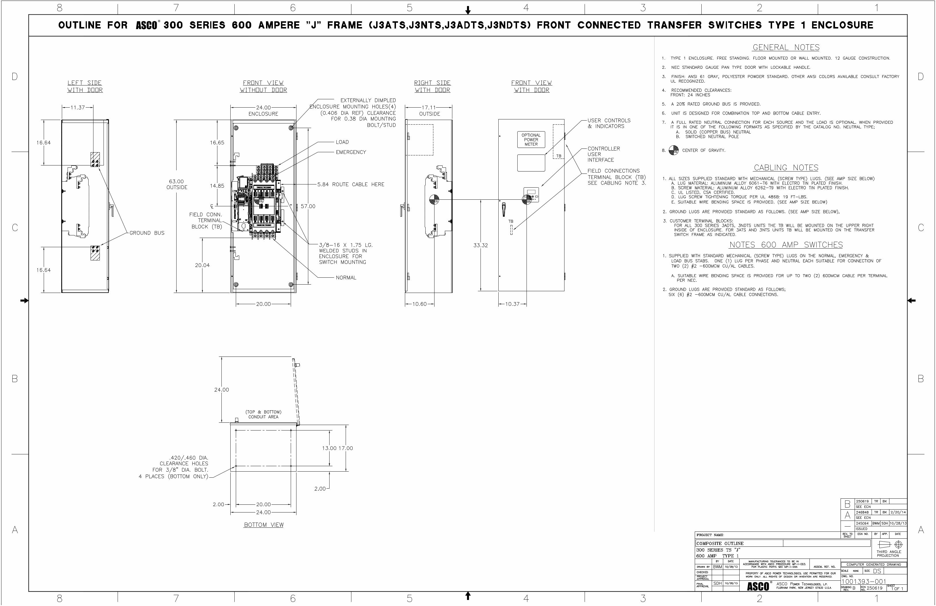
ASCO®
ASCO®
SESA478692
Text Box
J3ADTSA30600NGXC,11BE,18RX 73CC2
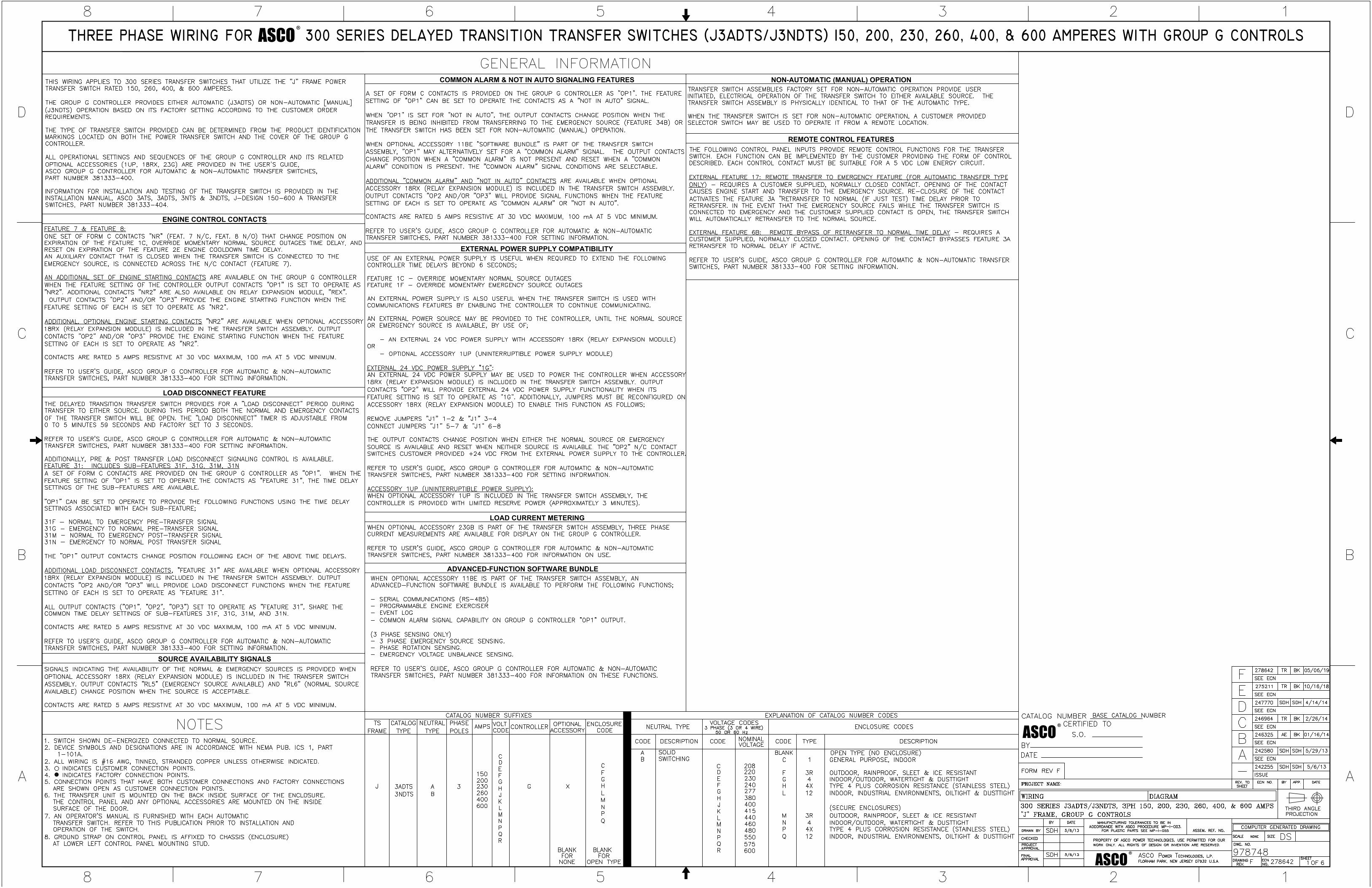
ASCO®
ASCO®
ASCO®
ENGINE CONTROL CONTACTS
LOAD DISCONNECT FEATURE
COMMON ALARM & NOT IN AUTO SIGNALING FEATURES
SOURCE AVAILABILITY SIGNALS
EXTERNAL POWER SUPPLY COMPATIBILITY
LOAD CURRENT METERING
NON-AUTOMATIC (MANUAL) OPERATION
REMOTE CONTROL FEATURES
ADVANCED-FUNCTION SOFTWARE BUNDLE
SESA478692
Text Box
J3ADTSA30600NGXC,11BE,18RX 73CC2
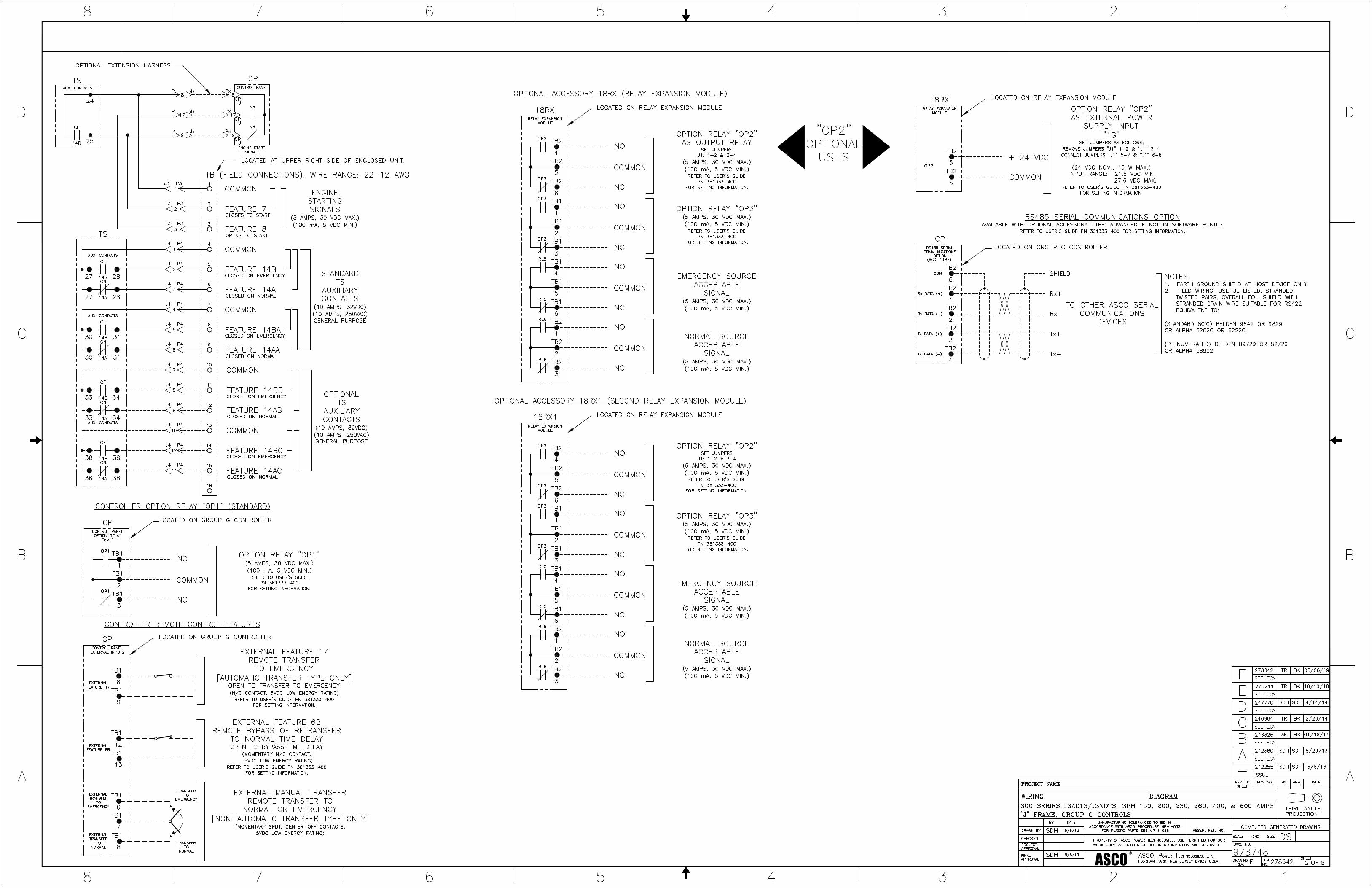
ASCO®
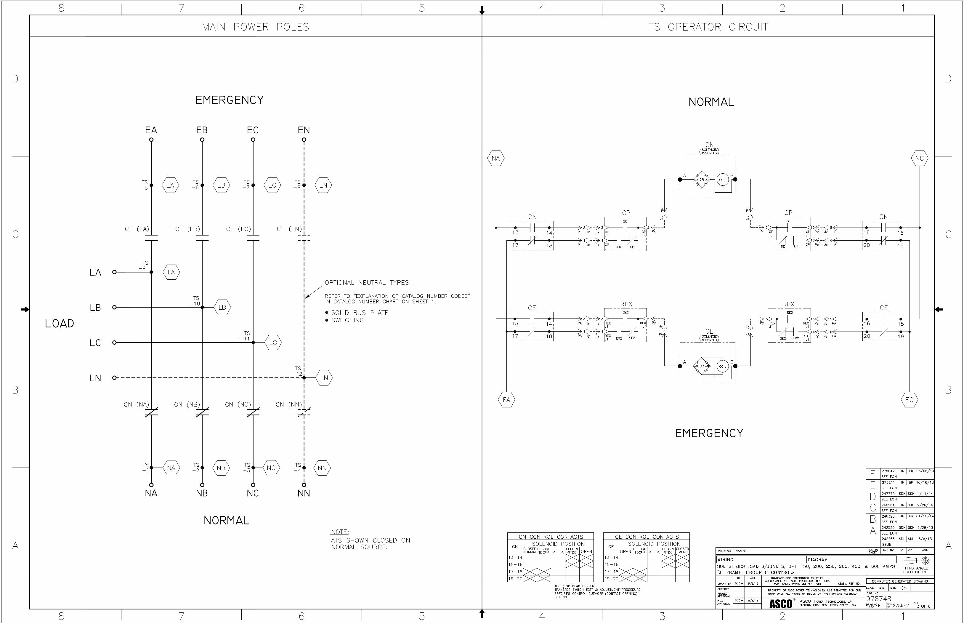
ASCO®
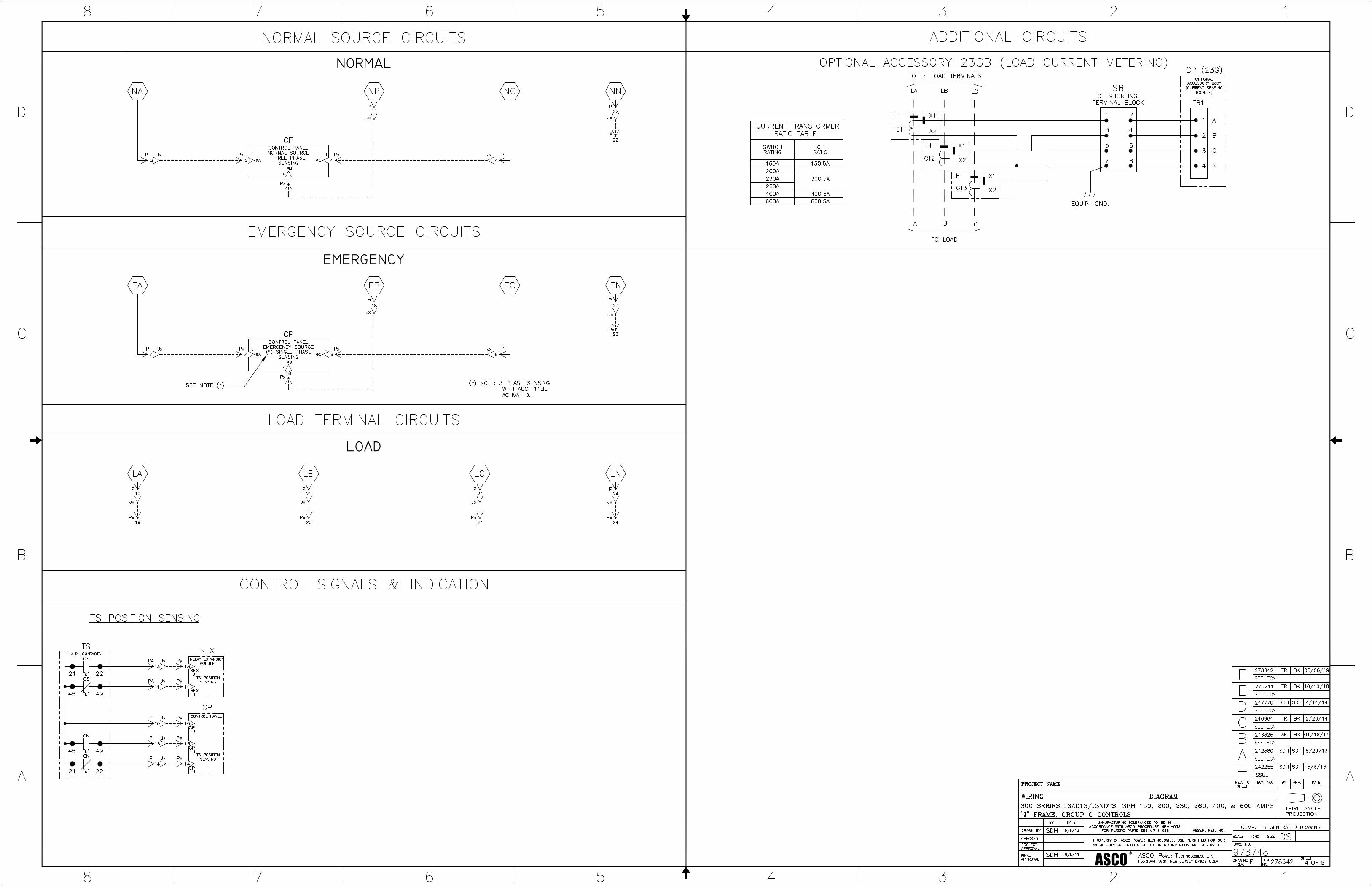
ASCO®
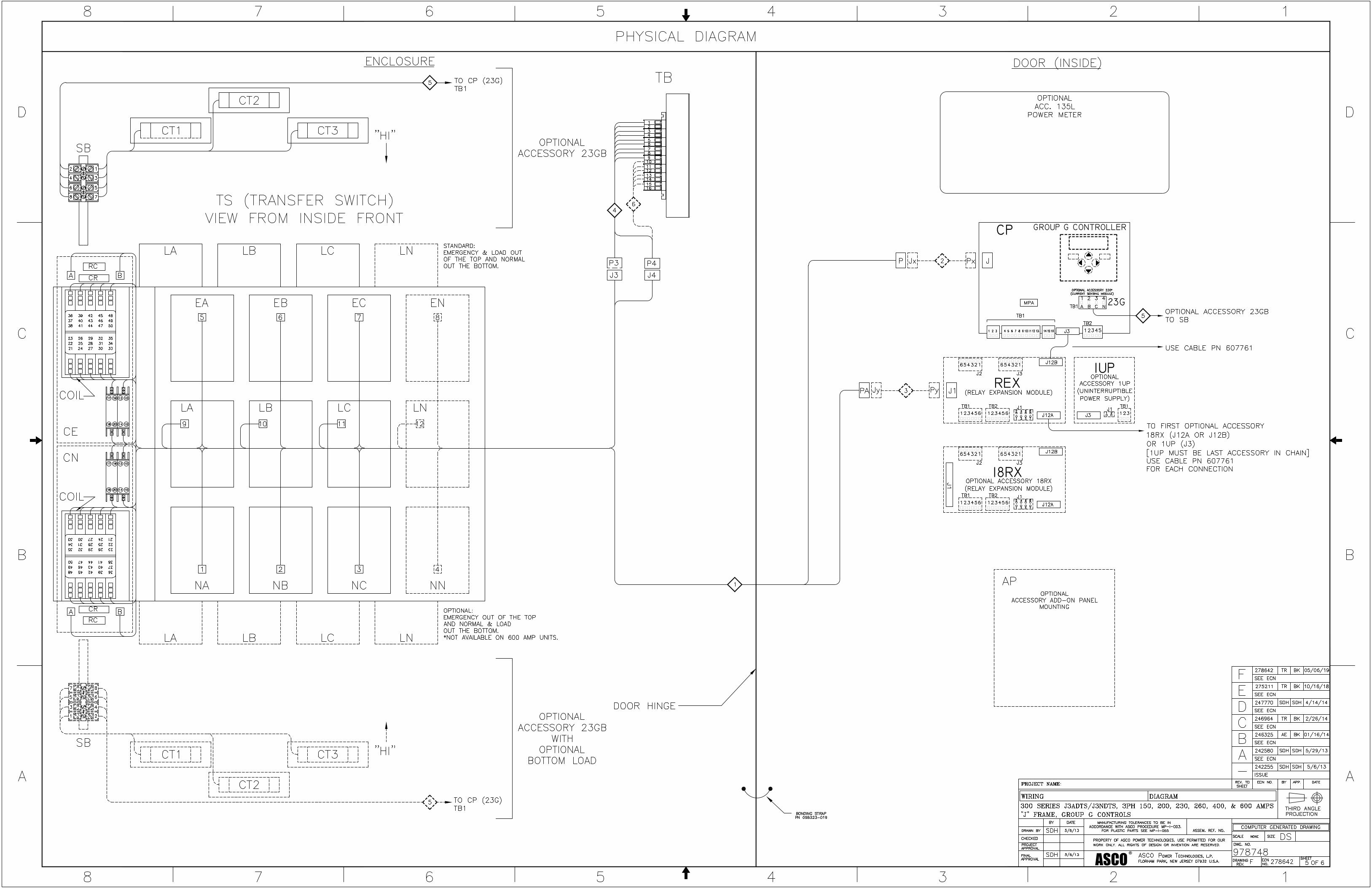
ASCO®
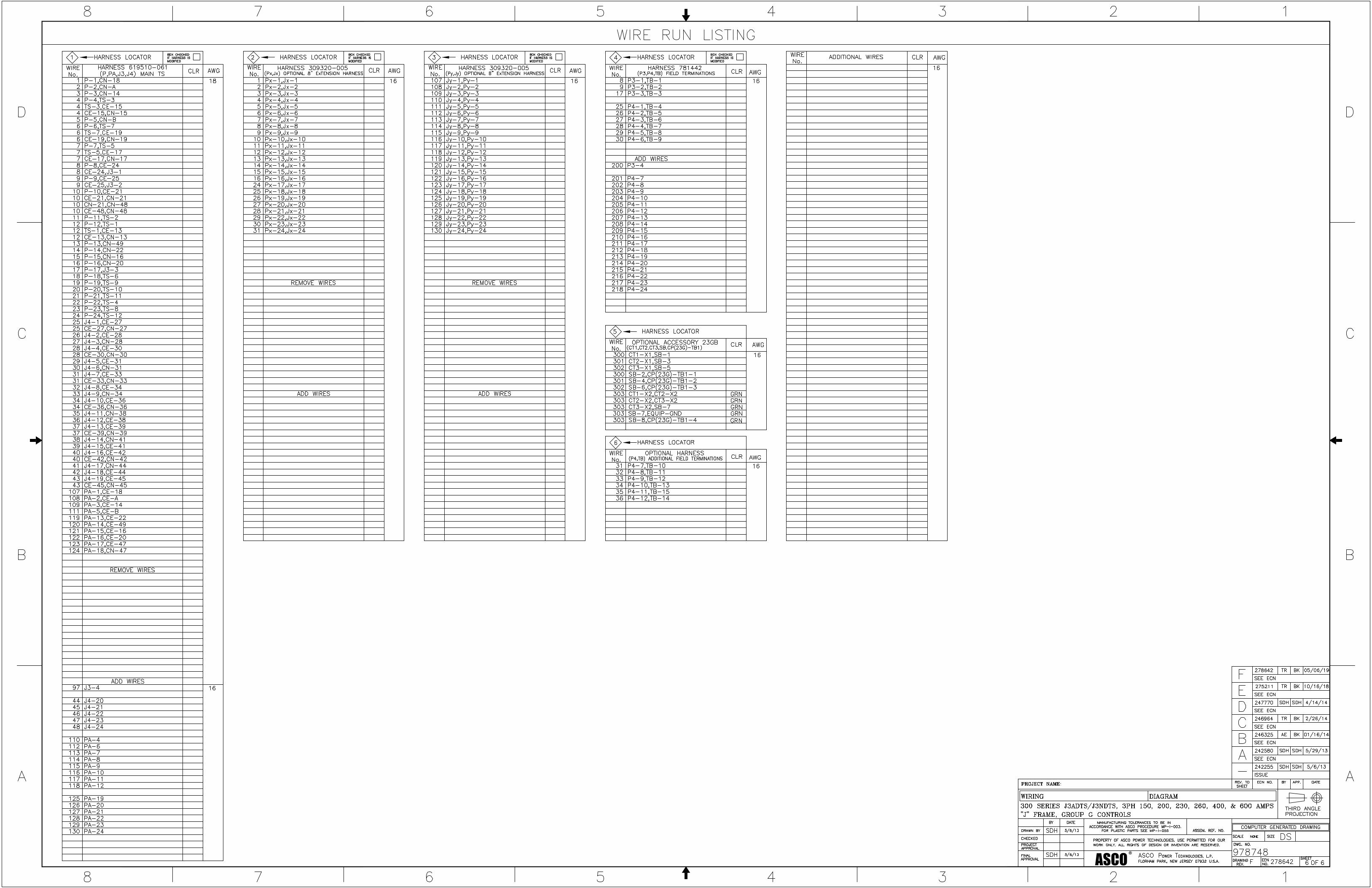
ASCO®
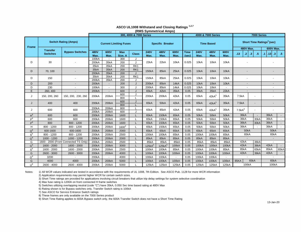
480V
Max.
600V
Max.
Max
Size, AClass
240V
Max.
480V
Max.
600V
Max.
Time
(sec)
240V
Max.
480V
Max.
600V
Max..13 .2 .3 .5 .1 .13 .3 .5
100kA - 300 J
200kA 35kA 200 J
35kA 35kA 200 RK1
35kA 35kA 200 RK1
200kA 35kA 200 J
35kA 35kA 200 RK1
200kA 35kA 200 J
D 200 - 200kA - 200 J 200kA 85kA 14kA 0.025 10kA 10kA 10kA
D 230 - 100kA - 300 J 200kA 85kA 14kA 0.025 10kA 10kA -
E 260, 400 - 200kA - 600 J 65kA 42kA 35kA 0.05 35kA 35kA 22kA
600 J
800 L
600 J
800 L
200kA 200kA 800 L
200kA 200kA 600 J
H8 600 600 200kA 200kA 1600 L 65kA 150kA 65kA 0.05 50kA 50kA 50kA - -
P8 600 600 200kA 200kA 1600 L 65kA 150kA 65kA 0.05 50kA 50kA 50kA 30kA -
P8 800 800 - 1200 200kA 200kA 1600 L 65kA 150kA 65kA 0.05 50kA 50kA 50kA 30kA -
H 800 - 1200 800 - 1200 200kA 200kA 16004 L 65kA 150kA 65kA 0.05 50kA 50kA 50kA - -
Q8 600-1600 600-1600 200kA 200kA 2000 L 65kA 65kA 65kA 0.05 65kA 65kA 65kA
S8 800 - 1200 800 - 1200 200kA 200kA 2500 L 100kA 100kA 65kA 0.05 100kA 100kA 65kA
G8 1000 - 1200 1000 - 1200 200kA 200kA 2000 L 85kA 85kA 85kA 0.05 85kA 85kA 85kA
G 200kA 200kA 2500 L 85kA 85kA 85kA 0.05 85kA 85kA 85kA 36kA
G8 1600 - 2000 1600 - 2000 200kA 200kA 3000 L 125kA
6125kA
6 100kA 0.05 100kA 100kA 100kA 36kA -
S8 1600 - 2000 1600 - 2000 200kA 200kA 2500 L 100kA 100kA 85kA 0.05 100kA 100kA 85kA 65kA 65kA
G 2600 - 3000 2600 - 3000 200kA 200kA 4000 L 100kA 100kA 100kA 0.05 100kA 100kA 100kA 36kA -
G8 3200 - 200kA - 4000 L 100kA 100kA - 0.05 100kA 100kA -
G 4000 4000 200kA 200kA 5000 L 100kA 100kA 100kA 0.05 100kA 100kA 100kA 85KA
U8 2600 - 4000 2600 - 4000 200kA 200kA 5000 L 125kA 125kA 125kA 0.05 125kA 125kA 125kA
Notes: 1) All WCR values indicated are tested in accordance with the requirements of UL 1008, 7th Edition. See ASCO Pub. 1128 for more WCR information
2) Application requirements may permit higher WCR for certain switch sizes.
3) Short Time ratings are provided for applications involving circuit breakers that utilize trip delay settings for system selective coordination
4) Max fuse rating is 1200A on front connected H frame switches
5) Switches utilizing overlapping neutral (code "C") have 35kA, 0.050 Sec time based rating at 480V Max
6) Rating shown is for Bypass switches only, Transfer Switch rating is 100kA
7) See ASCO for Service Entrance Switch ratings
8) These frames are only available on the 7000 Series product
9) Short Time Rating applies to 600A Bypass switch only, the 600A Transfer Switch does not have a Short Time Rating
J 150, 200, 260 150, 200, 230, 260 200kA 200kA 200kA 200kA 42kA 0.05
1600 - 2000 (Front Connected TS Only)
J 600 600
0.05 65kA 42kA5 35kA200kA 200kA 65kA
65kA 85kA 42kA 0.05 65kA 42kA5 35kA
J 400 400
-
50kA 42kA
10kA 10kA - -
-10kA
-
7.5kA9
7.5kA -
-
65kA 42kA5 35kA 7.5kA - -
D 30 - 22kA 22kA 10kA 0.025 10kA
85kA 25kA 10kA
300, 4000 & 7000 Series 4000 & 7000 Series
13-Jan-20
(RMS Symmetrical Amps)
Short Time Ratings3 (sec)
Transfer
SwitchesBypass Switches
480V Max. 600V Max.Frame
Switch Rating (Amps)Current Limiting Fuses Specific Breaker
7000 Series
D 70, 100 10kA
D 150 - 150kA 85kA
- 150kA
ASCO UL1008 Withstand and Closing Ratings 1,2,7
42kA 42kA
36kA 36kA
36kA 36kA
- -
- -
25kA 10kA 10kA 10kA
65kA
Time Based
0.025
0.025 -
- -
-
-
42kA 42kA
-
100kA 100kA
36kA 36kA
36kA 36kA
-
85kA
65kA
-
65kA
-
85kA
-
50kA 50kA
65kA
42kA
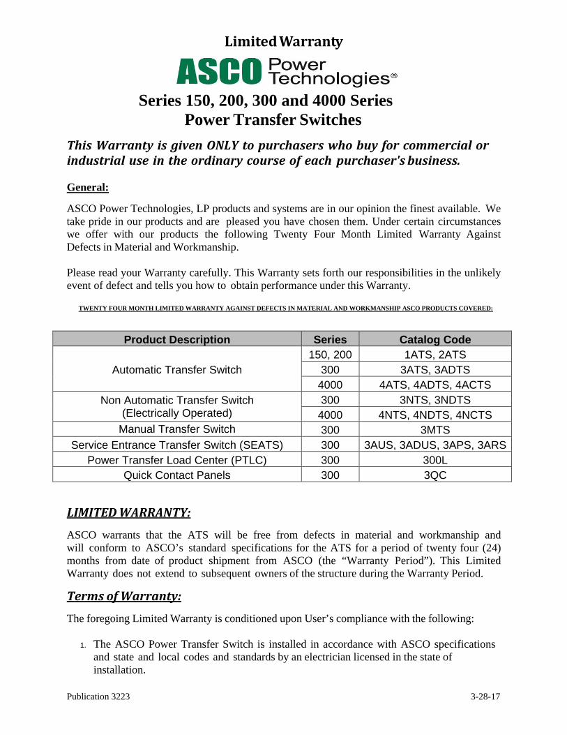
Publication 3223 3-28-17
Limited Warranty
Series 150, 200, 300 and 4000 Series Power Transfer Switches
This Warranty is given ONLY to purchasers who buy for commercial or industrial use in the ordinary course of each purchaser's business.
General:
ASCO Power Technologies, LP products and systems are in our opinion the finest available. We take pride in our products and are pleased you have chosen them. Under certain circumstances we offer with our products the following Twenty Four Month Limited Warranty Against Defects in Material and Workmanship.
Please read your Warranty carefully. This Warranty sets forth our responsibilities in the unlikely event of defect and tells you how to obtain performance under this Warranty.
TWENTY FOUR MONTH LIMITED WARRANTY AGAINST DEFECTS IN MATERIAL AND WORKMANSHIP ASCO PRODUCTS COVERED:
Product Description Series Catalog Code
150, 200 1ATS, 2ATS
Automatic Transfer Switch 300 3ATS, 3ADTS
4000 4ATS, 4ADTS, 4ACTS
Non Automatic Transfer Switch (Electrically Operated)
300 3NTS, 3NDTS
4000 4NTS, 4NDTS, 4NCTS
Manual Transfer Switch 300 3MTS
Service Entrance Transfer Switch (SEATS) 300 3AUS, 3ADUS, 3APS, 3ARS
Power Transfer Load Center (PTLC) 300 300L
Quick Contact Panels 300 3QC
LIMITED WARRANTY:
ASCO warrants that the ATS will be free from defects in material and workmanship and will conform to ASCO’s standard specifications for the ATS for a period of twenty four (24) months from date of product shipment from ASCO (the “Warranty Period”). This Limited Warranty does not extend to subsequent owners of the structure during the Warranty Period.
Terms of Warranty:
The foregoing Limited Warranty is conditioned upon User’s compliance with the following:
1. The ASCO Power Transfer Switch is installed in accordance with ASCO specificationsand state and local codes and standards by an electrician licensed in the state ofinstallation.
Publication 3223 3-28-17
2. The ASCO Power Transfer Switch is maintained in accordance with ASCO instructions and used under normal conditions for the purposes intended by ASCO.
All warranty field-related repairs, replacements or adjustments must be made by ASCO Services Inc. or its duly authorized representative.
Optional Available Extended Warranty
Optional extended warranty coverage may be purchased from ASCO for a specified fee at the time of the original sale. If purchased, warranty period shall be extended up to an additional thirty - six (36) months beyond the standard twenty - four (24) months to provide up to five (5) year coverage applicable to the above referenced products, except for 3AUS, 3APS, and 3ARS products where the warranty period for the circuit breaker shall be limited to 24 months from date of shipment from ASCO. The length of optional extended coverage shall be reflected on the ASCO invoice and/or order acknowledgement document.
Warranty Extends to First Purchaser for Use, Non-transferable:
This Warranty is extended to the first person, firm, association or corporation for whom the ASCO product specified herein is originally installed for use (the "User") in the fifty United States or Canada. This Warranty is not transferable or assignable without the prior written permission of ASCO.
Assignment of Warranties: ASCO assigns to User any warranties which are made by manufacturers and suppliers of components of, or accessories to, the ASCO product and which are assignable, but ASCO makes NO REPRESENTATIONS as to the effectiveness or extent of such warranties, assumes NO RESPONSIBILITY for any matters which may be warranted by such manufacturers or suppliers and extends no coverage under this Warranty to such components or accessories.
Drawings, Descriptions:
ASCO warrants for the period and on the terms of the Warranty set forth herein that the ASCO product will conform to the descriptions contained in the certified drawings, if any, applicable thereto, to ASCO's final invoices, and to applicable ASCO product brochures and manuals current as of the date of product shipment (“Descriptions”). ASCO does not control the use of any ASCO product. Accordingly, it is understood that the Descriptions are NOT WARRANTIES OF PERFORMANCE and NOT WARRANTIES OF FITNESS FOR A PARTICULAR PURPOSE.
Warranty Claims Procedure:
Within a reasonable time, but in no case to exceed thirty (30) days, after User's discovery of a defect, User shall contact [email protected]. Subject to the limitations specified herein, an ASCO Services field service representative will repair the non-conforming ASCO product warranted hereunder, without charge for parts, labor, or travel expenses. Warranty coverage will apply only after ASCO's inspection discloses the claimed defect and shows no signs of treatment or use that would void the coverage of this Warranty . All defective products and component parts replaced under this warranty become the property of
Publication 3223 3-28-17
ASCO.
Warranty Performance of Component Manufacturers: It is ASCO's practice, consistent with its desire to remedy Warranty defects in the most prompt and effective manner possible, to cooperate with and utilize the services of component manufacturers and their authorized representatives in the performance of work to correct defects in the product components. Accordingly, ASCO may utilize third parties in the performance of Warranty work, including repair or replacement hereunder, where, in ASCO's opinion, such work can be performed in less time, with less expense, or in closer proximity to the ASCO product.
Items Not Covered By Warranty:
THIS WARRANTY DOES NOT COVER DAMAGE OR DEFECT CAUSED BY misuse, improper application, wrong or inadequate electrical current or connection, negligence, inappropriate on site operating conditions, repair by non-ASCO designated personnel, accident in transit, tampering, alterations, a change in location or operating use, exposure to the elements, water, or other corrosive liquids or gases, Acts of God, theft or installation contrary to ASCO's recommendations or specifications, or in any event if the ASCO serial number has been altered, defaced, or removed.
THIS WARRANTY DOES NOT COVER shipping costs, installation costs, external circuit breaker resetting or maintenance or service items and further, except as may be provided herein, does NOT include labor costs or transportation charges arising from the replacement of the ASCO product or any part thereof or charges to remove or reinstall same at any premises of User.
REPAIR OR REPLACEMENT OF A DEFECTIVE PRODUCT OR PART THEREOF DOES NOT EXTEND THE ORIGINAL WARRANTY PERIOD.
THE PRODUCTS LISTED IN THIS WARRANTY ARE NOT FOR USE IN THE CONTROL AREA OR ANY REACTOR CONNECTED OR SAFETY APPLICATIONS OR WITHIN THE CONTAINMENT AREA OF A NUCLEAR FACILITY OR FOR INTEGRATION INTO MEDICAL DEVICES.
Limitations:
THIS WARRANTY IS IN LIEU OF AND EXCLUDES ALL OTHER WARRANTIES, EXPRESS OR IMPLIED, INCLUDING MERCHANTABILITY AND FITNESS FOR A PARTICULAR PURPOSE.
USER'S SOLE AND EXCLUSIVE REMEDY IS REPAIR OR REPLACEMENT OF THE ASCO PRODUCT AS SET FORTH HEREIN.
IF USER'S REMEDY IS DEEMED TO FAIL OF ITS ESSENTIAL PURPOSE BY A COURT OF COMPETENT JURISDICTION, ASCO'S RESPONSIBILITY FOR PROPERTY LOSS OR DAMAGE SHALL NOT EXCEED THE NET PRODUCT PURCHASE PRICE.
IN NO EVENT SHALL ASCO ASSUME ANY LIABILITY FOR INDIRECT, SPECIAL, INCIDENTAL, CONSEQUENTIAL OR EXEMPLARY DAMAGES OF ANY KIND WHATSOEVER, INCLUDING WITHOUT LIMITATION LOST PROFITS, BUSINESS INTERRUPTION OR LOSS OF DATA, WHETHER ANY CLAIM IS BASED UPON
Publication 3223 3-28-17
THEORIES OF CONTRACT, NEGLIGENCE, STRICT LIABILITY, TORT, OR OTHERWISE.
Miscellaneous:
NO SALESPERSON, EMPLOYEE OR AGENT OF ASCO IS AUTHORIZED TO ADD TO OR VARY THE TERMS OF THIS WARRANTY. Warranty terms may be modified, if at all, only in writing signed by an ASCO officer.
ASCO obligations under this Warranty are conditioned upon ASCO timely receipt of full payment of the product purchase price and any other amounts due. ASCO reserves the right to supplement or change the terms of this Warranty in any subsequent warranty offering to User or others. In the event that any provision of this Warranty should be or becomes invalid and/or unenforceable during the warranty period, the remaining terms and provisions shall continue in full force and effect.
This Warranty shall be governed by, and construed under, the laws of the State of New Jersey, without reference to the conflict of laws principles thereof.
This Warranty represents the entire agreement between ASCO and User with respect to the subject matter herein and supersedes all prior or contemporaneous oral or written communications, representations, understandings or agreements relating to this subject.
ASCO SERIES 300Power Transfer Switches
ascopower.com
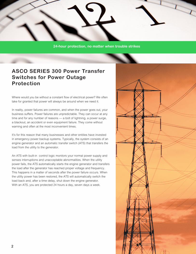
2
Where would you be without a constant flow of electrical power? We often take for granted that power will always be around when we need it. In reality, power failures are common, and when the power goes out, your business suffers. Power failures are unpredictable. They can occur at any time and for any number of reasons — a bolt of lightning, a power surge, a blackout, an accident or even equipment failure. They come without warning and often at the most inconvenient times. It’s for this reason that many businesses and other entities have invested in emergency power backup systems. Typically, the system consists of an engine generator and an automatic transfer switch (ATS) that transfers the load from the utility to the generator.
An ATS with built-in control logic monitors your normal power supply and senses interruptions and unacceptable abnormalities. When the utility power fails, the ATS automatically starts the engine generator and transfers the load after the generator has reached proper voltage and frequency. This happens in a matter of seconds after the power failure occurs. When the utility power has been restored, the ATS will automatically switch the load back and, after a time delay, shut down the engine generator. With an ATS, you are protected 24 hours a day, seven days a week.
ASCO SERIES 300 Power Transfer Switches for Power Outage Protection
24-hour protection, no matter when trouble strikes
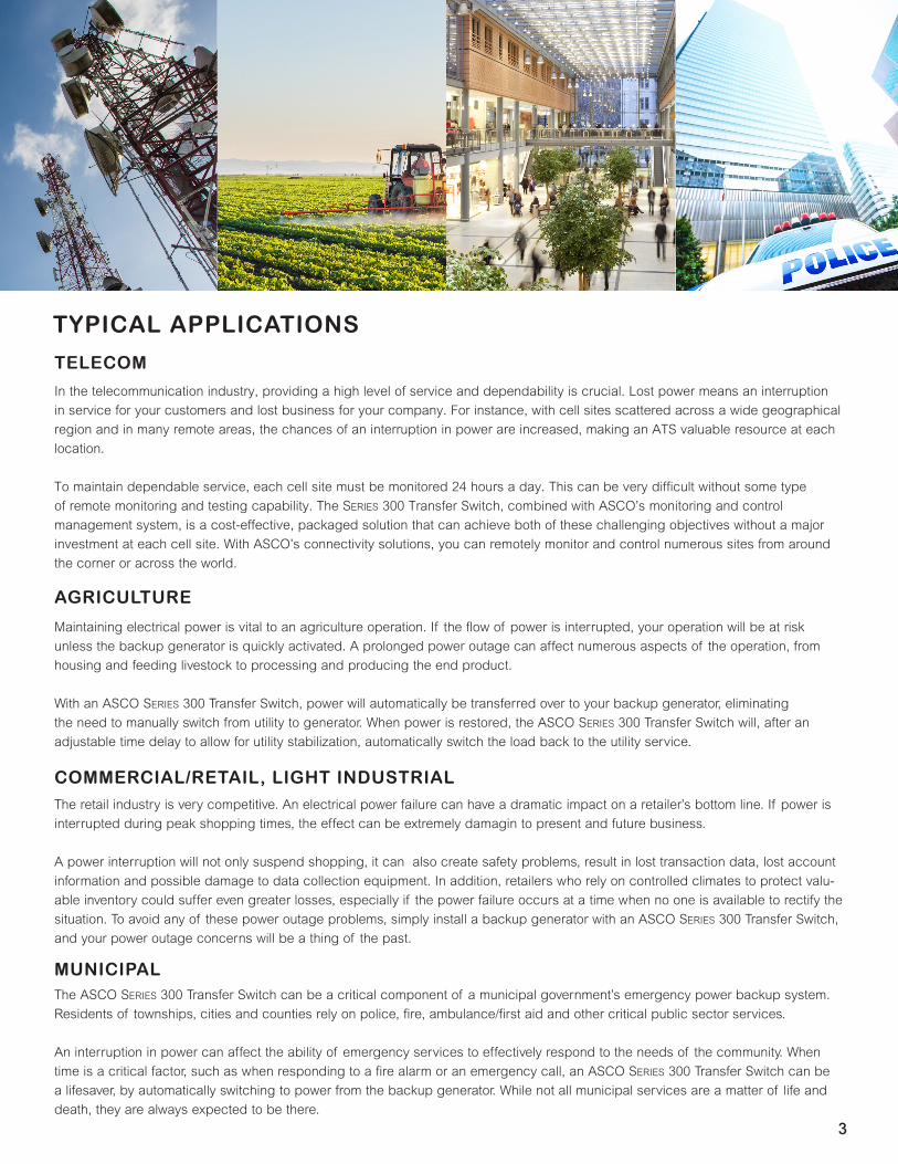
33
In the telecommunication industry, providing a high level of service and dependability is crucial. Lost power means an interruption in service for your customers and lost business for your company. For instance, with cell sites scattered across a wide geographical region and in many remote areas, the chances of an interruption in power are increased, making an ATS valuable resource at each location. To maintain dependable service, each cell site must be monitored 24 hours a day. This can be very difficult without some type of remote monitoring and testing capability. The SerieS 300 Transfer Switch, combined with ASCO’s monitoring and control management system, is a cost-effective, packaged solution that can achieve both of these challenging objectives without a major investment at each cell site. With ASCO’s connectivity solutions, you can remotely monitor and control numerous sites from around the corner or across the world.
Maintaining electrical power is vital to an agriculture operation. If the flow of power is interrupted, your operation will be at risk unless the backup generator is quickly activated. A prolonged power outage can affect numerous aspects of the operation, from housing and feeding livestock to processing and producing the end product. With an ASCO SerieS 300 Transfer Switch, power will automatically be transferred over to your backup generator, eliminating the need to manually switch from utility to generator. When power is restored, the ASCO SerieS 300 Transfer Switch will, after an adjustable time delay to allow for utility stabilization, automatically switch the load back to the utility service.
The retail industry is very competitive. An electrical power failure can have a dramatic impact on a retailer’s bottom line. If power is interrupted during peak shopping times, the effect can be extremely damagin to present and future business. A power interruption will not only suspend shopping, it can also create safety problems, result in lost transaction data, lost account information and possible damage to data collection equipment. In addition, retailers who rely on controlled climates to protect valu-able inventory could suffer even greater losses, especially if the power failure occurs at a time when no one is available to rectify the situation. To avoid any of these power outage problems, simply install a backup generator with an ASCO SerieS 300 Transfer Switch, and your power outage concerns will be a thing of the past.
The ASCO SerieS 300 Transfer Switch can be a critical component of a municipal government’s emergency power backup system. Residents of townships, cities and counties rely on police, fire, ambulance/first aid and other critical public sector services. An interruption in power can affect the ability of emergency services to effectively respond to the needs of the community. When time is a critical factor, such as when responding to a fire alarm or an emergency call, an ASCO SerieS 300 Transfer Switch can be a lifesaver, by automatically switching to power from the backup generator. While not all municipal services are a matter of life and death, they are always expected to be there.
TELECOM
TYPICAL APPLICATIONS
AGRICULTURE
COMMERCIAL/RETAIL, LIGHT INDUSTRIAL
MUNICIPAL
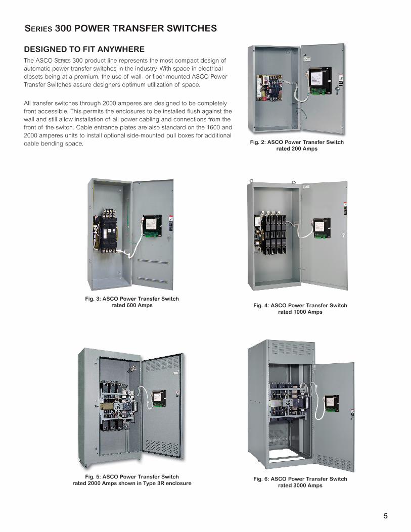
5
DESIGNED TO FIT ANYWHEREThe ASCO SerieS 300 product line represents the most compact design of automatic power transfer switches in the industry. With space in electrical closets being at a premium, the use of wall- or floor-mounted ASCO Power Transfer Switches assure designers optimum utilization of space.
All transfer switches through 2000 amperes are designed to be completely front accessible. This permits the enclosures to be installed flush against the wall and still allow installation of all power cabling and connections from the front of the switch. Cable entrance plates are also standard on the 1600 and 2000 amperes units to install optional side-mounted pull boxes for additional cable bending space. Fig. 2: ASCO Power Transfer Switch
rated 200 Amps
Fig. 4: ASCO Power Transfer Switch rated 1000 Amps
Fig. 5: ASCO Power Transfer Switch rated 2000 Amps shown in Type 3R enclosure
Fig. 6: ASCO Power Transfer Switch rated 3000 Amps
Fig. 3: ASCO Power Transfer Switch rated 600 Amps
Series 300 POWER TRANSFER SWITCHES
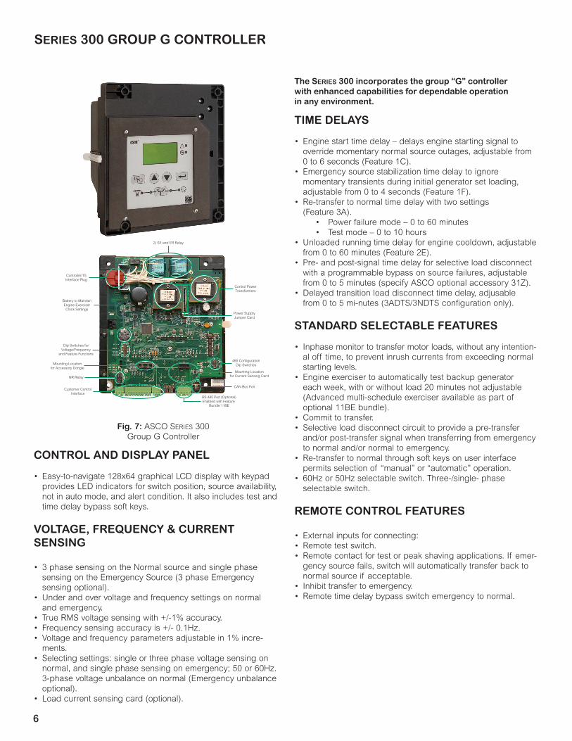
6
Fig. 7: ASCO SerieS 300 Group G Controller
The Series 300 incorporates the group “G” controller with enhanced capabilities for dependable operation in any environment.
Controller/TSInterface Plug
2) SE and ER Relay
Control PowerTransformers
Power SupplyJumper Card
485 ConfigurationDip Switches
Mounting Locationfor Current Sensing Card
Battery to MaintainEngine Exerciser
Clock Settings
Dip Switches forVoltage/Frequency
and Feature Functions
Mounting Locationfor Accessory Dongle
NR Relay
Customer ControlInterface
RS 485 Port (Optional)Enabled with Feature
Bundle 11BE
CAN Bus Port
SERIES 300 GROUP G CONTROLLER
TIME DELAYS
• Engine start time delay – delays engine starting signal to override momentary normal source outages, adjustable from 0 to 6 seconds (Feature 1C).
• Emergency source stabilization time delay to ignore momentary transients during initial generator set loading, adjustable from 0 to 4 seconds (Feature 1F).
• Re-transfer to normal time delay with two settings (Feature 3A).
• Power failure mode – 0 to 60 minutes• Test mode – 0 to 10 hours
• Unloaded running time delay for engine cooldown, adjustable from 0 to 60 minutes (Feature 2E).
• Pre- and post-signal time delay for selective load disconnect with a programmable bypass on source failures, adjustable from 0 to 5 minutes (specify ASCO optional accessory 31Z).
• Delayed transition load disconnect time delay, adjusable from 0 to 5 mi-nutes (3ADTS/3NDTS configuration only).
STANDARD SELECTABLE FEATURES
• Inphase monitor to transfer motor loads, without any intention-al off time, to prevent inrush currents from exceeding normal starting levels.
• Engine exerciser to automatically test backup generator each week, with or without load 20 minutes not adjustable (Advanced multi-schedule exerciser available as part of optional 11BE bundle).
• Commit to transfer.• Selective load disconnect circuit to provide a pre-transfer
and/or post-transfer signal when transferring from emergency to normal and/or normal to emergency.
• Re-transfer to normal through soft keys on user interface permits selection of “manual” or “automatic” operation.
• 60Hz or 50Hz selectable switch. Three-/single- phase selectable switch.
REMOTE CONTROL FEATURES
• External inputs for connecting:• Remote test switch.• Remote contact for test or peak shaving applications. If emer-
gency source fails, switch will automatically transfer back to normal source if acceptable.
• Inhibit transfer to emergency.• Remote time delay bypass switch emergency to normal.
CONTROL AND DISPLAY PANEL
• Easy-to-navigate 128x64 graphical LCD display with keypad provides LED indicators for switch position, source availability, not in auto mode, and alert condition. It also includes test and time delay bypass soft keys.
VOLTAGE, FREQUENCY & CURRENT SENSING
• 3 phase sensing on the Normal source and single phase sensing on the Emergency Source (3 phase Emergency sensing optional).
• Under and over voltage and frequency settings on normal and emergency.
• True RMS voltage sensing with +/-1% accuracy.• Frequency sensing accuracy is +/- 0.1Hz.• Voltage and frequency parameters adjustable in 1% incre-
ments.• Selecting settings: single or three phase voltage sensing on
normal, and single phase sensing on emergency; 50 or 60Hz. 3-phase voltage unbalance on normal (Emergency unbalance optional).
• Load current sensing card (optional).
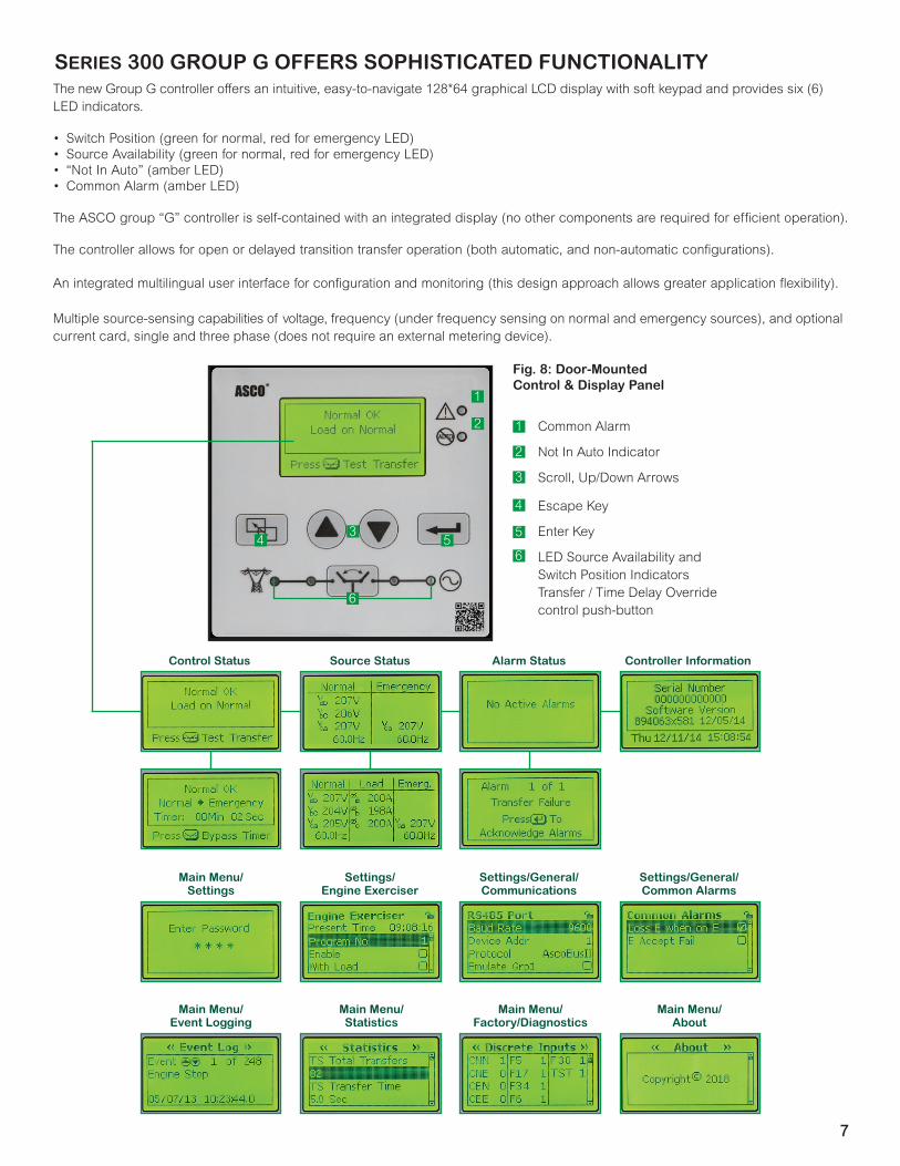
7
6
543
2
1
Fig. 8: Door-Mounted Control & Display Panel
1
LED Source Availability and Switch Position IndicatorsTransfer / Time Delay Override control push-button
2
Escape Key
3
4
5 Enter Key
Scroll, Up/Down Arrows
Common Alarm
6
Not In Auto Indicator
Main Menu/ Settings
Settings/ Engine Exerciser
Settings/General/Communications
Settings/General/Common Alarms
Control Status Source Status Alarm Status Controller Information
Main Menu/ Event Logging
Main Menu/ Statistics
Main Menu/ Factory/Diagnostics
Main Menu/ About
SERIES 300 GROUP G OFFERS SOPHISTICATED FUNCTIONALITYThe new Group G controller offers an intuitive, easy-to-navigate 128*64 graphical LCD display with soft keypad and provides six (6) LED indicators.
• Switch Position (green for normal, red for emergency LED)• Source Availability (green for normal, red for emergency LED)• “Not In Auto” (amber LED)• Common Alarm (amber LED)
The ASCO group “G” controller is self-contained with an integrated display (no other components are required for efficient operation).
The controller allows for open or delayed transition transfer operation (both automatic, and non-automatic configurations).
An integrated multilingual user interface for configuration and monitoring (this design approach allows greater application flexibility).
Multiple source-sensing capabilities of voltage, frequency (under frequency sensing on normal and emergency sources), and optional current card, single and three phase (does not require an external metering device).

16
ASCO Power Technologies - Global Headquarters160 Park AvenueFlorham Park, NJ 07932Tel: 800 800 ASCO
© 2019 ASCO Power Technologies. All Rights Reserved. Life Is On Schneider Electric is a trademark and the property of Schneider Electric SE, its subsidiaries and affiliated companies. Publication 1195 R3. Printed in the U.S.A.
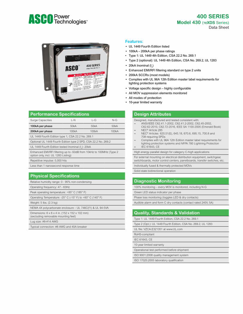
Features: • UL 1449 Fourth Edition listed • 100kA – 200kA per phase ratings
• Type 1: UL 1449 4th Edition, CSA 22.2 No. 269.1 • Type 2 (optional): UL 1449 4th Edition, CSA No. 269.2, UL 1283
• 20kA Inominal (In) • Enhanced EMI/RFI filtering standard on type 2 units • 200kA SCCRs (most models) • Complies with UL 96A 12th Edition master label requirements for
lighting protection systems
• Voltage specific design – highly configurable • All MOV suppression elements monitored • All modes of protection • 10-year limited warranty
Performance SpecificationsSurge Capacities L-N L-G N-G
100kA per phase 50kA 50kA 50kA
200kA per phase 100kA 100kA 100kA
UL 1449 Fourth Edition type 1, CSA 22.2 No. 269.1
Optional UL 1449 Fourth Edition type 2 SPD, CSA 22.2 No. 269.2
UL 1449 Fourth Edition tested Inominal (In): 20kA
Enhanced EMI/RFI filtering up to -50dB from 10kHz to 100MHz (Type 2 option only, incl. UL 1283 Listing)
Repetitive impulse: 5,000 hits
Less than 1 nanosecond response time
Physical SpecificationsRelative humidity range: 0 - 95% non-condensing
Operating frequency: 47 - 63Hz
Peak operating temperature: +85° C (185° F)
Operating Temperature: -25° C (-15° F) to +60° C (140° F)
Weight: 5 lbs. (2.3 kg)
NEMA 4X polycarbonate enclosure – UL 746C(f1) & UL 94-5VA
Dimensions: 6 x 6 x 4 in. (152 x 152 x 102 mm) (excluding removable mounting feet)
Lug size: #8-#14 AWG
Typical connection: #8 AWG and 40A breaker
Design AttributesDesigned, manufactured and tested consistent with: – ANSI/IEEE C62.41.1-2002, C62.41.2-2002, C62.45-2002,
C62.62-2010, C62.72-2016, IEEE SA 1100-2005 (Emerald Book) – NEC® Article 285 – NEC® Articles 620.51(E), 645.18, 670.6, 695.15, 700.8 and
708 requiring SPDs – Complies with UL 96A 12th Edition master label requirements for
lighting protection systems and NFPA 780 Lightning Protection – IEC 61643, CE
High energy parallel design for category C-high applications
For external mounting on electrical distribution equipment, switchgear, switchboards, motor control centers, panelboards, transfer switches, etc.
Individually fused & thermally protected MOVs
Solid state bidirectional operation
Quality, Standards & ValidationType 1: UL 1449 Fourth Edition, CSA 22.2 No. 269.1
Type 2 (Opt.): UL 1449 Fourth Edition, CSA No. 269.2, UL 1283
UL file: VZCA.E321351 at www.UL.com
RoHS-compliant
IEC 61643, CE
10-year limited warranty
Operational test performed before shipment
ISO 9001:2008 quality management system
ISO 17025:2005 laboratory qualification
Diagnostic Monitoring100% monitoring – every MOV is monitored, including N-G
Green LED status indicator per phase
Phase loss monitoring (toggles LED & dry contacts)
Audible alarm and form C dry contacts (contact rated 240V, 5A)
400 SERIESModel 430 (TEXDS Series)
Data Sheet
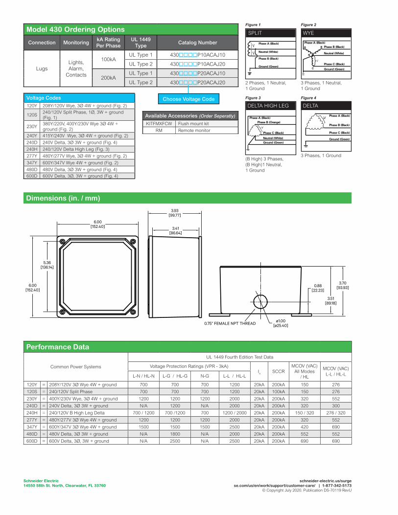
Performance Data
Common Power Systems
UL 1449 Fourth Edition Test Data
Voltage Protection Ratings (VPR - 3kA)In SCCR
MCOV (VAC)All Modes
/ HL
MCOV (VAC)L-L / HL-LL-N / HL-N L-G / HL-G N-G L-L / HL-L
120Y = 208Y/120V 3Ø Wye 4W + ground 700 700 700 1200 20kA 200kA 150 276120S = 240/120V Split Phase 700 700 700 1200 20kA 100kA 150 276230Y = 400Y/230V Wye, 3Ø 4W + ground 1200 1200 1200 2000 20kA 200kA 320 552240D = 240V Delta, 3Ø 3W + ground N/A 1200 N/A 2000 20kA 200kA 320 300240H = 240/120V B High Leg Delta 700 / 1200 700 /1200 700 1200 / 2000 20kA 200kA 150 / 320 276 / 320277Y = 480Y/277V 3Ø Wye 4W + ground 1200 1200 1200 2000 20kA 200kA 320 552347Y = 600Y/347V 3Ø Wye 4W + ground 1500 1500 1500 2500 20kA 200kA 420 690480D = 480V Delta, 3Ø 3W + ground N/A 1800 N/A 2000 20kA 200kA 552 552600D = 600V Delta, 3Ø, 3W + ground N/A 2500 N/A 2500 20kA 200kA 690 690
5.36[136.14]
6.00[152.40]
6.00[152.40]
3.93[99.77]
3.41[86.64]
3.70[93.93]
3.51[89.18]
0.88[22.23]
ø1.00[ø25.40]0.75” FEMALE NPT THREAD
SPLIT
2 Phases, 1 Neutral, 1 Ground
Phase B (Black)
Phase A (Black)
Neutral (White)V
V
}}
Ground (Green)
WYE
3 Phases, 1 Neutral, 1 Ground
}
Phase A (Black)Phase B (Black)
Neutral (White)
Phase C (Black)
Ground (Green)
A
C
N
V
B
DELTA HIGH LEG
(B High) 3 Phases, (B High)1 Neutral, 1 Ground
Phase A (Black)Phase B (Orange)
Neutral (White)
Phase C (Black)
Ground (Green)
}V
DELTA
3 Phases, 1 Ground
Phase A (Black)
Phase C (Black)
Phase B (Black)
Ground (Green)
}V
Model 430 Ordering Options
Connection Monitoring kA Rating Per Phase
UL 1449 Type Catalog Number
LugsLights, Alarm,
Contacts
100kA UL Type 1 430P10ACAJ10
UL Type 2 430P10ACAJ20
200kAUL Type 1 430P20ACAJ10
UL Type 2 430P20ACAJ20
Dimensions (in. / mm)
Choose Voltage CodeVoltage Codes120Y 208Y/120V Wye, 3Ø 4W + ground (Fig. 2)
120S 240/120V Split Phase, 1Ø, 3W + ground (Fig. 1)
230Y 380Y/220V, 400Y/230V Wye 3Ø 4W + ground (Fig. 2)
240Y 415Y/240V Wye, 3Ø 4W + ground (Fig. 2)240D 240V Delta, 3Ø 3W + ground (Fig. 4)240H 240/120V Delta High Leg (Fig. 3)277Y 480Y/277V Wye, 3Ø 4W + ground (Fig. 2)347Y 600Y/347V Wye 4W + ground (Fig. 2)480D 480V Delta, 3Ø 3W + ground (Fig. 4)600D 600V Delta, 3Ø, 3W + ground (Fig. 4)
Available Accessories (Order Seperatly)
KITFMXFCW Flush mount kitRM Remote monitor
schneider-electric.us/surgese.com/us/en/work/support/customer-care/ | 1-877-342-5173
© Copyright July 2020. Publication DS-70119 RevU
Schneider Electric14550 58th St. North, Clearwater, FL 33760
Figure 1
Figure 3
Figure 2
Figure 4
Related Documents