Welcome message from author
This document is posted to help you gain knowledge. Please leave a comment to let me know what you think about it! Share it to your friends and learn new things together.
Transcript

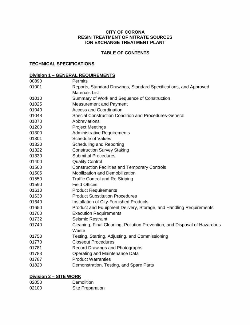
CITY OF CORONA RESIN TREATMENT OF NITRATE SOURCES
ION EXCHANGE TREATMENT PLANT
TABLE OF CONTENTS
TECHNICAL SPECIFICATIONS
Division 1 – GENERAL REQUIREMENTS
00890 Permits
01001 Reports, Standard Drawings, Standard Specifications, and Approved
Materials List
01010 Summary of Work and Sequence of Construction
01025 Measurement and Payment
01040 Access and Coordination
01048 Special Construction Condition and Procedures-General
01070 Abbreviations
01200 Project Meetings
01300 Administrative Requirements
01301 Schedule of Values
01320 Scheduling and Reporting
01322 Construction Survey Staking
01330 Submittal Procedures
01400 Quality Control
01500 Construction Facilities and Temporary Controls
01505 Mobilization and Demobilization
01550 Traffic Control and Re-Striping
01590 Field Offices
01610 Product Requirements
01630 Product Substitution Procedures
01640 Installation of City-Furnished Products
01650 Product and Equipment Delivery, Storage, and Handling Requirements
01700 Execution Requirements
01732 Seismic Restraint
01740 Cleaning, Final Cleaning, Pollution Prevention, and Disposal of Hazardous
Waste
01750 Testing, Starting, Adjusting, and Commissioning
01770 Closeout Procedures
01781 Record Drawings and Photographs
01783 Operating and Maintenance Data
01787 Product Warranties
01820 Demonstration, Testing, and Spare Parts
Division 2 – SITE WORK
02050 Demolition
02100 Site Preparation
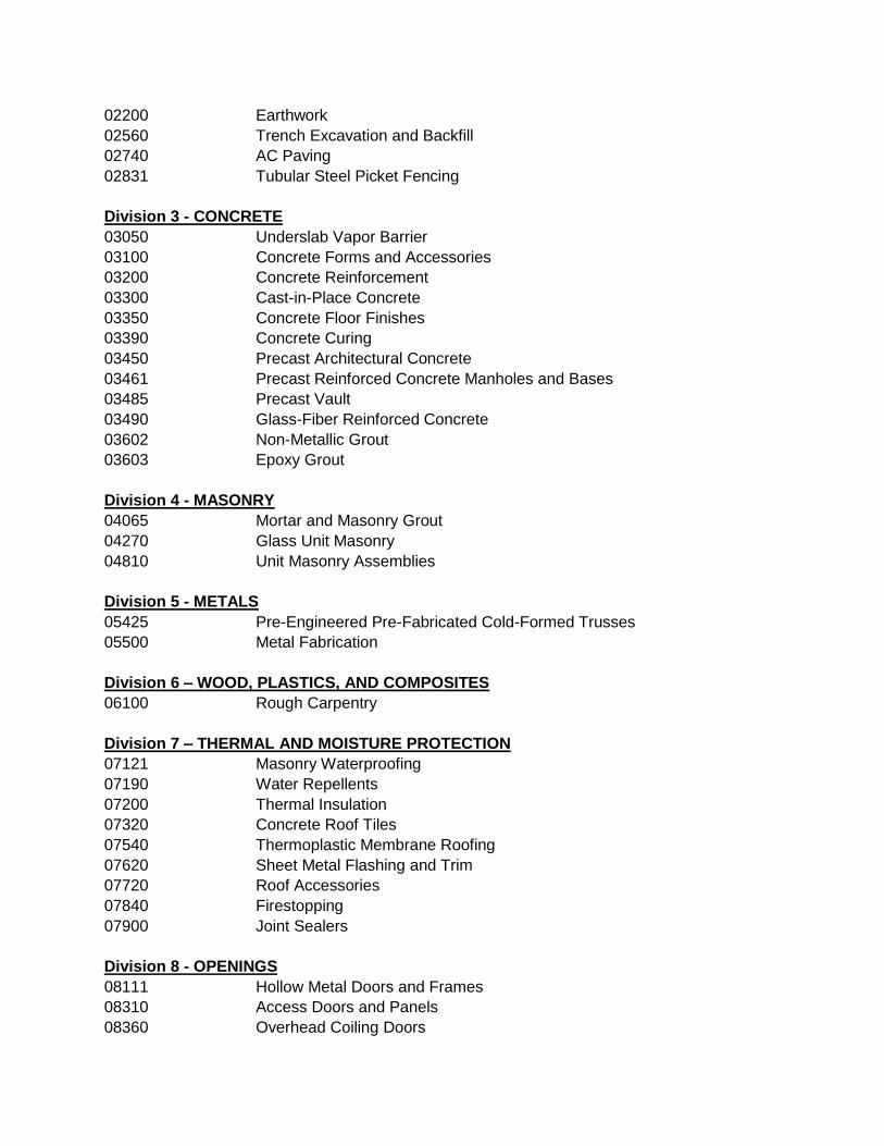
02200 Earthwork
02560 Trench Excavation and Backfill
02740 AC Paving
02831 Tubular Steel Picket Fencing
Division 3 - CONCRETE
03050 Underslab Vapor Barrier
03100 Concrete Forms and Accessories
03200 Concrete Reinforcement
03300 Cast-in-Place Concrete
03350 Concrete Floor Finishes
03390 Concrete Curing
03450 Precast Architectural Concrete
03461 Precast Reinforced Concrete Manholes and Bases
03485 Precast Vault
03490 Glass-Fiber Reinforced Concrete
03602 Non-Metallic Grout
03603 Epoxy Grout
Division 4 - MASONRY
04065 Mortar and Masonry Grout
04270 Glass Unit Masonry
04810 Unit Masonry Assemblies
Division 5 - METALS
05425 Pre-Engineered Pre-Fabricated Cold-Formed Trusses
05500 Metal Fabrication
Division 6 – WOOD, PLASTICS, AND COMPOSITES
06100 Rough Carpentry
Division 7 – THERMAL AND MOISTURE PROTECTION
07121 Masonry Waterproofing
07190 Water Repellents
07200 Thermal Insulation
07320 Concrete Roof Tiles
07540 Thermoplastic Membrane Roofing
07620 Sheet Metal Flashing and Trim
07720 Roof Accessories
07840 Firestopping
07900 Joint Sealers
Division 8 - OPENINGS
08111 Hollow Metal Doors and Frames
08310 Access Doors and Panels
08360 Overhead Coiling Doors
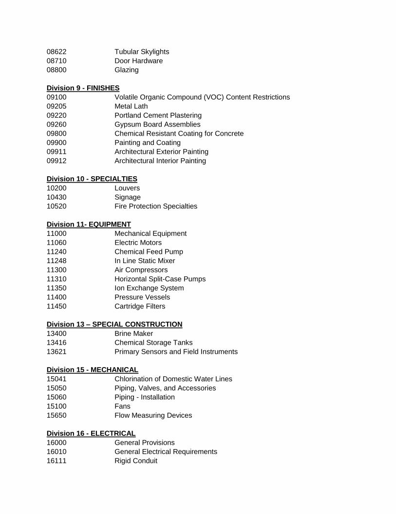
08622 Tubular Skylights
08710 Door Hardware
08800 Glazing
Division 9 - FINISHES
09100 Volatile Organic Compound (VOC) Content Restrictions
09205 Metal Lath
09220 Portland Cement Plastering
09260 Gypsum Board Assemblies
09800 Chemical Resistant Coating for Concrete
09900 Painting and Coating
09911 Architectural Exterior Painting
09912 Architectural Interior Painting
Division 10 - SPECIALTIES
10200 Louvers
10430 Signage
10520 Fire Protection Specialties
Division 11- EQUIPMENT
11000 Mechanical Equipment
11060 Electric Motors
11240 Chemical Feed Pump
11248 In Line Static Mixer
11300 Air Compressors
11310 Horizontal Split-Case Pumps
11350 Ion Exchange System
11400 Pressure Vessels
11450 Cartridge Filters
Division 13 – SPECIAL CONSTRUCTION
13400 Brine Maker
13416 Chemical Storage Tanks
13621 Primary Sensors and Field Instruments
Division 15 - MECHANICAL
15041 Chlorination of Domestic Water Lines
15050 Piping, Valves, and Accessories
15060 Piping - Installation
15100 Fans
15650 Flow Measuring Devices
Division 16 - ELECTRICAL
16000 General Provisions
16010 General Electrical Requirements
16111 Rigid Conduit
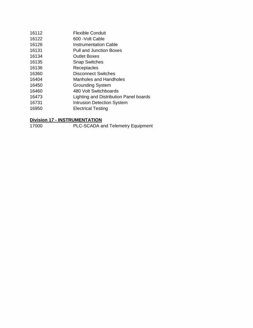
16112 Flexible Conduit
16122 600 -Volt Cable
16126 Instrumentation Cable
16131 Pull and Junction Boxes
16134 Outlet Boxes
16135 Snap Switches
16136 Receptacles
16360 Disconnect Switches
16404 Manholes and Handholes
16450 Grounding System
16460 480 Volt Switchboards
16473 Lighting and Distribution Panel boards
16731 Intrusion Detection System
16950 Electrical Testing
Division 17 - INSTRUMENTATION
17000 PLC-SCADA and Telemetry Equipment
00890- Permits - 1 of 4
7-15-vw
SECTION 00890 PERMITS
PART 1 - GENERAL 1.1 Work Included
A. Obtain and/or comply with encroachment permits, license permits, and agreements from the following agencies.
Regional Water Quality Control Board, Santa Ana Region (RWQCB)
City of Corona Business License
Santa Ana Project Watershed Authority (SAWPA)
Obtain permits and licenses prior to starting construction. 1.2 Related Work
A. General Conditions Article 14: Permits and Licenses 1.4 Submittals
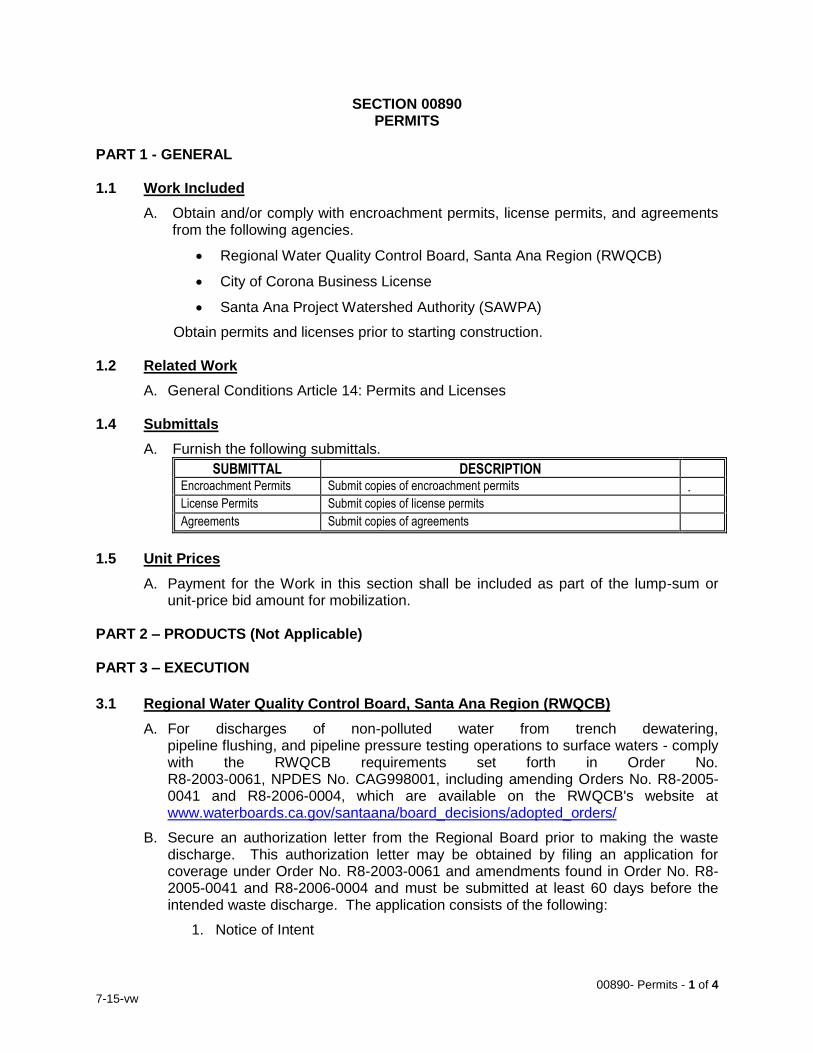
A. Furnish the following submittals.
SUBMITTAL DESCRIPTION Encroachment Permits Submit copies of encroachment permits . License Permits Submit copies of license permits Agreements Submit copies of agreements
1.5 Unit Prices
A. Payment for the Work in this section shall be included as part of the lump-sum or unit-price bid amount for mobilization.
PART 2 – PRODUCTS (Not Applicable) PART 3 – EXECUTION
3.1 Regional Water Quality Control Board, Santa Ana Region (RWQCB)
A. For discharges of non-polluted water from trench dewatering, pipeline flushing, and pipeline pressure testing operations to surface waters - comply with the RWQCB requirements set forth in Order No. R8-2003-0061, NPDES No. CAG998001, including amending Orders No. R8-2005-0041 and R8-2006-0004, which are available on the RWQCB's website at www.waterboards.ca.gov/santaana/board_decisions/adopted_orders/
B. Secure an authorization letter from the Regional Board prior to making the waste discharge. This authorization letter may be obtained by filing an application for coverage under Order No. R8-2003-0061 and amendments found in Order No. R8-2005-0041 and R8-2006-0004 and must be submitted at least 60 days before the intended waste discharge. The application consists of the following:
1. Notice of Intent
00890- Permits - 2 of 4
7-15-vw
2. For projects involving well development, well purging, groundwater extraction (which includes trench dewatering), a site characterization study report defining the proximity of the extraction well(s) to known contaminated sites, the presence of contaminated groundwater onsite, contaminants and their properties, and a three dimensional assessment of the extent and concentration of contaminants in the subsurface is required. The study report shall include a description of the geologic and hydrologic factors that control the migration of the contaminants. It shall also include a list of known or suspected leaking underground tanks and other facilities or operations which have or may have impacted the quality of the underlying groundwater within 200 feet of the site.
3. A report which includes:
a. Characterization of the proposed waste discharge (for projects involving well development, well purging and groundwater extraction, a representative groundwater sample shall be analyzed for all 126-priority pollutants listed in Attachment B of R8-2003-0061;
b. the name of the receiving water;
c. the estimated average and maximum daily flow rates;
d. the frequency and duration of the discharge;
e. a description of the proposed treatment system (if appropriate); and
f. a map showing the path from the point of initial discharge to the ultimate location of discharge.
4. Any other information deemed necessary by the Santa Ana Regional Board Executive Officer.
5. If the non-polluted waste discharge is applied to land without entering into a municipal storm drainage conveyance system or natural drainage course, then the discharge is exempt from the requirements of Order No. R8-2003-0061 and subsequent amendments.
6. If the non-polluted waste discharge enters into a municipal storm drainage conveyance system or dry/seasonal drainage course such that the entire discharge will percolate completely prior to reaching any surface water downstream, then the discharge is exempt from the requirements of Order No. R8-2003-0061 and subsequent amendments.
C. Other Wastewater Discharges.
Comply with all applicable requirements of the Regional Board for all other waste discharges, including discharges of potentially polluted or contaminated water. If required by the Regional Board, Contractor shall, at his sole expense, obtain a wastewater discharge permit from the Regional Board. Provide a copy of said wastewater discharge permit to the City. Comply with the conditions therein, and perform the monitoring required.
D. General Discharge Requirements.
Contractor shall not allow any discharges from the construction site which may have an adverse effect on receiving waters of the United States. Waste discharges shall not contain a concentration of total residual chlorine of more than 0.1 mg/l. Waste discharges shall not contain oils, greases, waxes, or other materials in concentrations which result in a visible film or coating on the surface of receiving
00890- Permits - 3 of 4
7-15-vw
waters. Waste discharges shall not cause erosion or sedimentation in the receiving waters.
E. Notification of Wastewater Discharge.
Provide written notification to the City and the Regional Board five (5) days prior to the start of any waste discharge; and provide written notification to the agency/municipality that owns, operates, and maintains the municipal storm drainage conveyance system a minimum of one (1) week prior to the start of any discharge into a municipal storm drainage conveyance system.
3.2 Regional Water Quality Control Board, Santa Ana Region (RWQCB) – Stormwater
Pollution Prevention Plans
A. Comply with current California State Water Control Board (SWRCB) General Construction Activity NPDES Stormwater Permit (General Construction Permit) requirements where Stormwater Pollution Prevention Plans (SWPPP) are required. Refer to Specifications Section 01740 – Cleaning, Final Cleaning, Pollution Prevention and Disposal of Hazardous Waste for additional information.
3.3 City of Corona Business License Certificate
A. A City of Corona business license certificate will be required for work in the City of Corona.
B. City business license certificate forms are available at the Business License Division, 400 South Vicentia Avenue, first floor public counter, Corona, CA 92882, or by calling (951) 736-2275.
END OF SECTION
00890- Permits - 4 of 4
7-15-vw
THIS PAGE INTENTIONALLY BLANK
01001 – Reports, Standard Drawings, Standard Specifications, and Approved Materials List - 1 of 2
7-15-vw
SECTION 01001 REPORTS, STANDARD DRAWINGS, STANDARD SPECIFICATIONS
AND APPROVED MATERIALS LIST
PART 1 - GENERAL 1.1 Standard Specifications, Standard Drawings and Equal Opportunity Program
Requirements
A. Standard Specifications, Standard Drawings and Equal Opportunity Program Requirements shall be as described in the Contract Documents.
1.2 Reports
A. A geotechnical study report titled, “Geotechnical Exploration City of Corona Department of Water and Power Resin Treatment of Nitrate Sources Facility Southwest Corner of Quarry Street and Rimpau Avenue”, dated November 5, 2013 is provided as an appendix to these Contract Documents.
Information about existing geotechnical conditions provided in the geotechnical report is made available to the Contractor for such use as he may choose to make of it in the preparation of his bid, but City gives no guarantee, either expressed or implied, that it represents a true or complete cross section of all of the material to be encountered in performing the excavation and earthwork on this Project.
B. A preliminary design report titled, “City of Corona Resin Treatment of Nitrate Sources Project Preliminary Design Report”, dated September 27, 2013 is provided as an appendix to these Contract Documents.
1.3 Reference Standards
A. Standards listed as "Reference Standards" in the various sections of these Contract Documents are hereby incorporated into this specification by reference.
B. Referenced documents shall include all revisions, amendments, supplements or addenda issued on or before the date of Issuance of Notice Inviting Bids.
C. The City of Corona DWP Modifications to Standard Specifications for Public Works Construction are incorporated into this Contract by reference and will be enforced unless superseded by the Contract Documents as described in General Conditions Article 2 - Contract Documents.
D. The City of Corona Standard Plans are incorporated into this Contract by reference and will be enforced unless superseded by the Contract Documents as described in General Conditions Article 2 – Contract Documents.
1.4 Approved Materials List
A. All the material used on this Project, including pipe, valves, couplings etc., shall be in accordance with items listed in the City’s current Approved List of Materials for Water and Sewer Facilities, latest edition, available on the City’s website and included as an Appendix to these Contract Documents.
B. Materials not listed in the approved materials list or in these specifications must be submitted for the City’s approval and accepted for use on this contract prior to
01001 – Reports, Standard Drawings, Standard Specifications, and Approved Materials List - 2 of 2
7-15-vw
contract award in accordance with Article 7 – Substitutions in the General Conditions and Section 01630 Product Substitution Procedures.
PART 2 - PRODUCTS (Not applicable) PART 3 - EXECUTION (Not applicable)
END OF SECTION

01010 – Summary of Work and Sequence of Construction - Page 1 of 4
7-15-vw
SECTION 01010 SUMMARY OF WORK AND SEQUENCE OF CONSTRUCTION
PART 1 - GENERAL 1.1 Description
This section provides a summary of the work, the location, work sequence, closeout, contractor use of premises, and activities by others at the Project site.
1.2 Work Covered by Contract Documents
A. It is the intent of the Contract Documents to provide the City of Corona with a fully operational municipal water treatment facility to remove nitrates and perchlorates from local groundwater, as specified. The design capacity of the resin treatment system is initially sized for 1,600 gallons per minute (gpm) with the ability to expand to 6,000 gpm in the future.
B. The Work includes furnishing products, labor, tools, transportation, and services to construct the following:
1. Site work including removal of existing trees, park benches, landscaping, sports facilities, etc. from the construction area and construction of site fencing, gates, yard piping, AC pavement, concrete pavement and walkways.
2. Construction of water treatment plant building with architectural features.
3. Construction of ion exchange vessels with resins, process piping, filters, valves, fittings, flow meters, salt storage, briner, and associated mechanical equipment and improvements.
4. Construction of process piping.
5. Construction of chemical storage and delivery system, including containment area, chemical storage tanks, metering pumps, chemical piping, and all supporting equipment and improvements.
6. Construction of electrical, lighting, and instrumentation system.
The Work is included in a single contract. The major components of the Work include all items shown on the drawings and specifications, to make the facility complete and operational.
1.3 Project Location
A. The Project is located at 410 Rimpau Avenue , Corona, California.
B. Conditions at the Project site are as follows:
Ground Elevation: 642 feet MSL Typical Temperature Range: 31°F - 110° F Relative Humidity: 10% to 90%
All mechanical and electrical equipment shall be designated to operate at the project site. Derating and necessary oversizing to achieve performance shall be incorporated in equipment design. Cooling of equipment will be by circulation of
01010 – Summary of Work and Sequence of Construction - Page 2 of 4
7-15-vw
outside air which often contains dust. Equipment shall be designed to prevent damage which could be caused by high or low ambient temperature within the specified range, freezing, dust in the air, winds of up to 70 mph, and wet weather conditions. Equipment shall be specifically designed to function satisfactorily under said conditions. All electrical and mechanical equipment shall be suitably sealed.
PART 2 - PRODUCTS (Not Applicable) PART 3 - EXECUTION 3.1 Work Sequence
A. The general sequence of Work shall be as follows:
Preparation
1. Before beginning Work, coordinate with servicing electrical utility regarding electric service to site. Obtain required permits, licenses and construction easements. Call Underground Service Alert and utilities to obtain staking and marking of buried utilities. Submit proposed schedule of Work, insurance and bonds. Pothole as needed to supplement staking and marking. Take preconstruction photographs.
2. Verify utility locations, field dimensions, pipe sizes and types, and voltage and phase of on-site electrical services. If discrepancies or conflicts are found, bring these to attention of City’s Representative.
3. Submit shop drawings and other submittals.
4. Begin manufacturing and shipping materials and equipment after receiving accepted submittals.
Execution
5. Site demolition.
6. Construct onsite underground utilities.
7. Construct building.
8. Install new equipment.
9. Install electrical, lighting, and communications improvements.
10. Construct offsite utilities and connections.
11. Perform equipment testing and startup.
12. Perform SCADA programming and system integration by City.
13. Demonstrate satisfactory installation and operation of installed work, including performing vendor and system functional tests.
Closeout
14. Provide operator training, including O&M manuals containing the engineering cut-sheets on all equipment.
15. Provide schedule of equipment and materials costs.
16. Provide record drawings.
17. Clean up and restore construction areas.
18. Provide warranty as specified.
01010 – Summary of Work and Sequence of Construction - Page 3 of 4
7-15-vw
3.2 Contractor Use of Premises
A. The following facilities shall remain operational during construction of this Project:
1. Do not shut off pipelines or power, or take action which might adversely affect City’s use or operation of City’s facilities or premises without prior written authorization from City.
2. Install approved signs, barricades and lights necessary to ensure public safety and safety of City’s operators and personnel. Provide steel plates across ditches to enable safe access of City’s personnel to facilities.
3.3 Activities by Others
A. The City, utilities, and others may perform activities within the Project area while the Work is in progress. Schedule the Work with the City, utilities, and others to minimize mutual interference and delays. Activities performed by others may include the following construction projects or maintenance activities:
1. SCADA programming and system integration by City
2. SCE electrical service installation
3. Routine inspection, maintenance, and repair of existing nearby water production facilities
4. Construction of hazardous waste facility on Rimpau Avenue across the street from Ion Exchange Treatment Plant site
5. There are no known concurrent construction projects at this location
B. When cooperation fails, submit recommendations and perform Work in coordination with work of others as directed.
C. When the Work depends, for proper execution or results, upon work performed by others, inspect and promptly report apparent discrepancies or defects in work performed by others.
3.4 Occupancy
A. Pre-startup checkout and functional testing shall precede City’s use of completed Work.
END OF SECTION

01010 – Summary of Work and Sequence of Construction - Page 4 of 4
7-15-vw
THIS PAGE INTENTIONALLY BLANK
01025 – Measurement and Payment Page 1 of 10
7-15-vw
SECTION 01025 MEASUREMENT AND PAYMENT
PART 1 - GENERAL 1.01 Description
A. Measurement and payment for bid items listed in the proposal shall be based upon use of a lump sum or unit price method. Extra work or changes in the Work shall be accomplished as provided in the General Conditions.
1.02 Related Work
A. The Work of the following Sections apply to Work of this Section. Other Sections of
the Specifications, not referenced below, shall also apply to the extent required for
proper performance of the Work.
1. Bid Proposal Form
2. Section 01010 – Summary of Work and Sequence of Construction
3. Section 01301 – Schedule of Values
4. Article 44 – General Conditions 1.03 Submittals
A. Partial Payment Requests
B. Final Payment Request
1.04 Submittal Format
A. Submit typewritten Payment Requests on 8-1/2” x 11” paper AIA format approved by City
1.05 Measurement
A. General
Measurement for unit price quantities shall be based upon the appropriate bid item in the Bid Schedule. The actual quantity of measurement shall be as constructed by Contractor in place in conformance with the Plans and Specifications.
B. Unit Measurements
Measurement for bid items involving units of the item shall be based upon the number of units counted as indicated in the bid item.
C. Lump Sum Measurement
Measurement for a lump sum bid item shall be considered as a complete project or a portion of a project constituting a unit. The items to be included in the lump sum bid shall be as specified in the proposal bid item and/or as indicated on the accepted Schedule of Values.
01025 – Measurement and Payment Page 2 of 10
7-15-vw
1.06 Payment
A. General
1. Payment shall be based on the approved schedule of values.
2. The unit and lump sum prices to be paid shall be full compensation for the items of work and all appurtenant work, including furnishing all materials, labor, equipment, tools, and incidentals.
3. Payment will not be made for materials wasted or disposed of in a manner not called for under the Contract. This includes rejected material not unloaded from vehicles, material rejected after it has been placed, and material placed outside of the Plan lines. No compensation will be allowed for disposing of rejected or excess material.
4. Whenever any portion of the Work is performed by the City at the Contractor's request, the cost thereof shall be charged against the Contractor, and may be deducted from any amount due or becoming due from the City.
5. Whenever immediate action is required to prevent injury, death, or property damage, and precautions which are the Contractor's responsibility have not been taken and are not reasonably expected to be taken, the City may, after reasonable attempt to notify the Contractor, cause such precautions to be taken and shall charge the cost thereof against the Contractor, or may deduct such cost from any amount due or becoming due from the City. City action or inaction under such circumstances shall not be construed as relieving the Contractor or its Surety from liability.
6. Payment shall not relieve the Contractor from its obligations under the Contract; nor shall such payment be construed to be acceptance of any of the Work. Payment shall not be construed as the transfer of ownership of any equipment or material to the City. Responsibility of ownership shall remain with the Contractor who shall be obligated to store any fully or partially completed work or structure for which payment has been made; or replace any materials or equipment required to be provided under the Contract which may be damaged, lost, stolen or otherwise degraded in any way prior to acceptance of the Work.
7. Guarantee periods shall not be affected by any payment.
8. If, within the time fixed by law, a properly executed notice to stop payment is filed with the City, due to the Contractor's failure to pay for labor or materials used in the Work, all money due for such labor or materials will be withheld from payment to the Contractor in accordance with applicable laws.
9. Partial payments made after the contract completion date will reflect the amount withheld for Liquidated Damages. Any such partial payments made to the Contractor, or its Sureties, will not constitute a waiver of the City's Liquidated Damages.
10. If requested by the City's Representative, provide such additional data as may be reasonably required to support the submitted Invoice. Such data may include but is not limited to satisfactory evidence of payment for equipment, materials and labor including payments to Subcontractors and suppliers. Request for payment for delivered equipment and material shall be
01025 – Measurement and Payment Page 3 of 10
7-15-vw
accompanied by certified paid invoices from the supplier. Such equipment and material shall be suitably and safely stored at the site of the Work.
B. Payment for Unit Price Items
Payment for a unit price bid item shall be based upon the amount shown in the bid schedule multiplied by the total quantity measurement of the item and shall be full compensation for furnishing all supervision, planning, design, design engineering fees, labor and services, operations, transportation, materials, equipment, tools, supplies, incidentals and appurtenances required for construction of the item complete in place in accordance with the Plans and Specifications, including all costs of permits and cost of compliance with the regulations of public agencies having jurisdiction.
C. Payment for Lump Sum Items
Payment for lump sum bid items shall be based upon the amount shown in the Bid Schedule and shall be full compensation for furnishing all supervision, planning, design, design engineering fees, labor and services, operations, transportation, materials, equipment, tools, supplies, incidentals and appurtenances required for construction of the unit of work complete in place in accordance with the Plans and Specifications, including all costs of permits and cost of compliance with the regulations of public agencies having jurisdiction.
D. Payment for Installation of Pre-Purchase Materials and Equipment
The City has selectively pre-purchased specific critical and long lead time items for use on this Project. Payment for installation of City-furnished materials and equipment shall be full compensation for furnishing all supervision, planning, design, design engineering fees, labor and services, operations, transportation, tools, supplies, incidentals and appurtenances required for construction of the unit of work complete in place in accordance with the Plans and Specifications, including all costs of permits and cost of compliance with the regulations of public agencies having jurisdiction. Include Contractor’s cost for coordinating delivery, storage, and installation in the appropriate bid item or items within the Bid Schedule.
E. Work Not Listed in the Bid Schedule
Costs for related work and appurtenances which are required and/or implied by the General Conditions, Technical Specifications, Plans, and Permits and are not listed as a separate bid item, but are necessary to complete the project shall be included in the appropriate bid item or items within the Bid Schedule of Contractor’s Bid Amount.
F. Payment for Testing
1. Party responsible for payment for testing is identified in individual sections of Contract Documents under tests required. Where specifications are silent regarding responsible party paying for tests, costs of first tests will be paid by City.
2. If testing or inspection indicates failure of a material or procedure to meet Contract Document requirements, City will backcharge Contractor for retesting and reinspection costs incurred by testing or inspection agency of City’s choice. Such costs will be deducted from the progress payments to the Contractor.
3. Additional tests and inspections not specified herein, but requested by City
01025 – Measurement and Payment Page 4 of 10
7-15-vw
will be paid for by City, unless result of such tests and inspections are found to not comply with Contract Documents, in which case City will pay all costs for initial testing as well as retesting and reinspection and backcharge Contractor for retesting and reinspection.
4. Costs for additional tests or inspections required because of change in materials being provided or change of source or supply shall be paid by City direct to testing laboratory.
5. Cost of testing which is required solely for convenience of Contractor in his scheduling and performance of Work shall be borne by Contractor.
6. Contractor shall pay all costs for correcting deficiencies.
PART 2 – PRODUCTS
2.01 SCHEDULE OF COMPLETED VALUES
A. The Schedule of Completed Values shall be a tabular listing of the Items of Work from the approved Schedule of Values.
B. The Schedule of Completed Values shall show for each Item of Work the Item Number; Description; Item Value; Percent and Value Complete for the previous period; Percent and Value complete for the current period; Value of Stored Materials (if any); and the Total Billing Value.
C. List each issued Field Order and Change Order on the Schedule of Completed Values as a separate Item.
D. Attach a Schedule of Completed Values to each Invoice presented for payment.
2.02 INVOICES
A. Invoices shall be prepared on Contractor letterhead, dated and addressed to:
Finance Department City of Corona, Department of Water and Power 755 Corporation Yard Way Corona, CA 92880
B. Invoices shall have the following subject block:
Project Title: {Resin Treatment of Nitrate Sources Project CIP P.O. No.: {CIP PURCHASE ORDER NUMBER} Invoice Number: {CONTRACTOR'S INVOICE NUMBER} Invoice Period: {INVOICE PERIOD ENDING DATE}
C. Consecutively number invoices and show the Amount of Original Contract; Value of Approved Changes; Current Contract Amount; Total Billing Value from the Schedule of Completed Values; Percentage and Value of Retention (if any); Value of Previous Invoices; and Payment Amount Due.
D. Each invoice shall bear the Contractor's signature and the signature of the City’s Representative. Submit an electronic copy/scan of each invoice via email to the Engineer and the City's Representative. The email subject line shall be "City of

01025 – Measurement and Payment Page 5 of 10
7-15-vw
Corona, DWP, Resin Treatment of Nitrate Sources Project Invoice #" followed by the invoice number.
PART 3 - EXECUTION 3.01 Scope
A. This section defines the bid items listed in the bid schedule and describes measurement and payment provisions for each of the bid items.
3.02 Bid Item 1 – Mobilization/Demobilization
A. The amount bid for Mobilization/Demobilization shall not exceed 5.0% of Contractor’s bid total for either schedule. Contactor will be paid half of the Contractors bid amount upon successful completion of mobilization work and the remaining half of the Contractors bid amount upon successful completion of demobilization work. Any amount bid in excess of the stipulated 5.0% cap will not be paid until project completion.
B. Payment for this item will be made at the lump sum price named in the Bid Schedule under Item Number 1, which price shall constitute full compensation for all work and expenditures required to mobilize, as described in General Conditions Article 45 – Mobilization and herein, including provide bonds and insurance; obtain required permits; provide preconstruction photos and videos; prepare project schedule; provide project sign; construct and remove temporary bypass facilities; construct and remove temporary traffic control facilities; locate existing utilities; construct and remove temporary utilities; construct and remove temporary facilities; install and remove temporary fence; install and remove temporary noise attenuation facilities; perform required surveys, testing, site maintenance and cleanup; remove and reinstall existing site facilities as required; implement stormwater pollution control best management practices; comply with all General and Special conditions; demobilize; provide record drawings, operation and maintenance manuals, warranties, and well completion report; startup and testing, training, and provide surface restoration and cleanup of construction site complete in place, as required by the Contract Documents with sole exclusion of payments to be made as defined herein for other items in the Bid Schedule.
C. Work to be paid for under this item shall also include furnishing, setting up, and removing Contractor’s operations at Project site including temporary offices, utilities, staging areas, security, etc. The Work shall also include furnishing any temporary construction facilities and trailers required by the Contract Documents.
D. Work to be paid for under this item shall also include protecting existing survey monuments in place and, if Contractor’s operations disturb any such monuments, hiring a registered land surveyor to reestablish and reset the disturbed monuments.
E. Upon completion of mobilization, 50 percent of the amount bid for this item (or 50 percent of the stipulated 5.0% cap, whichever is less, will be paid to Contractor. The remainder will be paid as part of final contract payment upon successful demobilization and project completion.
01025 – Measurement and Payment Page 6 of 10
7-15-vw
3.03 Bid Item 2 – Trench Safety Measures, Sheeting, Shoring and Bracing A. No measurement will be made for this item.
B. Work to be paid for under this item shall include all labor, materials and equipment for temporary sheeting, shoring and bracing required for trench safety including all planning, design, engineering fees, rental fees, furnishing and constructing, and removal and disposal of such temporary sheeting, shoring and bracing, complete, as required under the provisions of any permits, these Contract Documents, and in accordance with the requirements of OSHA and the Construction Safety Orders of the State of California, pursuant to the provisions of Section 6705 of the California Labor Code.
3.04 Bid Item 3 – Site Civil
A. No measurement will be made for this item.
B. Work to be paid for under this item shall include all labor, materials and equipment for all civil, demolition, grading, earthwork, import or export of soil materials, stockpiling, paving, concrete flatwork, fencing, gates, site work, and miscellaneous sitework.
C. The lump sum price bid for this item shall include potholing all utilities shown on the plans. Contractor will be entitled to fair compensation for any additional potholing of utilities:
1. Which are not shown on the plans at time of bid and are subsequently identified in the field by Underground Service Alert, surface features or walking the alignment with a reliable electronic pipe finder, or;
2. Which are not shown on the plans in their proper location such that multiple potholes are necessary to find them.
D. Work to be paid for under this item shall include furnishing all labor, materials, and equipment for site demolition and soil preparation including removal of existing fencing, piping, asphalt and trees where shown, localized pavement or concrete flatwork saw-cutting, removal and replacement where shown, abandoning utilities in place including disconnection from existing work and backfilling existing pipe with 2 sack cement slurry, removal and salvage of existing valves, scarifying, and sterilizing existing soil beneath concrete pads and asphalt paving, preparation and compaction of subgrade beneath new improvements in accordance with geotechnical report requirements, disposal of excess excavated material, and any appurtenant work as required by the Contract Documents.
E. Work to be paid for under this item shall include all labor, materials and equipment for grading and structural excavation including excavation, blasting, stockpiling, hauloff and disposal of excavated material, placement of suitable fill. backfill, compaction, preparation and compaction of subgrade beneath new improvements in accordance with geotechnical report requirements, scarifying and sterilizing existing soil where shown, and any appurtenant work as required by the Contract Documents.
F. Work to be paid for under this item shall include all labor, materials and equipment to construct reinforced concrete paving on aggregate base where shown including subgrade preparation, aggregate base, compaction, concrete, reinforcing, curing,
01025 – Measurement and Payment Page 7 of 10
7-15-vw
and any appurtenant work as required by the Contract Documents.
G. Work to be paid for under this item shall include all asphalt and concrete paving, concrete flatwork and retaining walls, including excavation, subgrade preparation and compaction, bender boards, subdrainage, subbase, base, concrete formwork, concrete reinforcement, concrete slabs, sidewalks, gutters, ribbon drains, swales, paving, steps, ramps, retaining walls, and flatwork, asphalt paving, manhole and valve rings, slurry seal, striping, and all appurtenant work in accordance with the Contract Documents.
H. Work to be paid for under this item shall include all labor, materials and equipment to construct new piping of size, class and type shown on the plans, including protection of existing utilities, trench excavation, bedding, piping, manifolds, fittings, spools, joints, couplings, dismantling joints, welds, bolts, flanges, gaskets, hangers, supports, brackets, saddles, wall penetrations and spools, thrust restraint, concrete collars and encasement, coatings, linings, warning and detection tape, locating wire, incidental valves, gauges and appurtenances, backfill, compaction, surface restoration, testing and disinfection, flange insulating kits, cathodic protection test stations, cleanup and any appurtenant work as required by the Contract Documents.
I. Work to be paid for under this item shall include all labor, materials and equipment to construct asphalt concrete paving on aggregate base of thicknesses shown and at locations shown on plans, including subgrade preparation, aggregate base, compaction, asphalt, rolling, sealing and any appurtenant work as required by Contract Documents.
3.05 Bid Item 4 Structural
A. No measurement will be made for this item.
B. Work to be paid for under this item shall include all labor, materials, and equipment to construct the reinforced unit masonry building where shown and to dimensions shown including structural excavation, backfill, subgrade preparation, concrete encasement of piping beneath slabs and footings, concrete foundation, concrete flooring, masonry block walls, roof framing, roofing, doors, louvers, vents, fans, plumbing, finishes, building wiring and lighting, architectural features, and all other appurtenant work as required by the Contract Documents.
3.06 Bid Item 5 – Mechanical
A. No measurement will be made for this item.
B. Work to be paid for under this item shall include all mechanical system work.
C. Before ordering manufacture of equipment or structures described in submittals, Contractor shall verify the following under this pay item:
1. That submitted item(s) can be delivered to the point of installation and will fit
through applicable doors, hatches, gates and/or openings both during construction and following completion of construction.
2. That flanges or ends of pumps, tanks, valves, and piping equipment are of compatible sizes, offsets, configurations and pressure classes to mate with adjacent piping.
01025 – Measurement and Payment Page 8 of 10
7-15-vw
3. That dimensions of vertical turbine pumps and motors replacing existing pumps are either more compact than the pumps they replace, or will fit through existing doors, hatches, and openings and can be installed for the bid amount within the existing pump cans or wells without violating applicable NEC or other code clearances or rendering piping, service hatches, ports or panels inoperable or inaccessible for service.
4. That dimensions of centrifugal pump and motor assemblies replacing existing pumps and motors are either more compact than pump assemblies they replace, or will fit through existing doors, hatches, and openings and can be installed for the bid amount within the existing mounting pad geometry and working area without violating applicable NEC or other code clearances or rendering piping, service hatches, ports or panels inoperable or inaccessible for service.
5. That dimensions of tanks replacing existing tanks are either more compact than the tanks they replace, or will fit through existing doors, hatches, and openings and can be installed for the bid amount, within the existing tank footprints and overhead clearances without violating applicable NEC or other code clearances or rendering piping, service hatches, ports or panels inoperable or inaccessible for service.
6. That dimensions of equipment replacing existing equipment are either more compact than the equipment they replace, or will fit through existing doors, hatches and openings and can be installed for the bid amount within the existing equipment footprints and overhead clearances without violating applicable NEC or other code clearances or rendering service hatches, ports or panels inoperable or inaccessible for service.
7. That weights of valves and equipment are within the lifting capacity of on-site overhead crane systems planned for use for their installation and future removal.
8. That power requirements, including voltage, phase and full-load amperage of electrical equipment and motors are consistent with power available on site.
D. In the event discrepancies are discovered between field conditions and dimensions
shown on submittals and the Contract Documents, City’s Representative will work with Contractor to prepare such modifications to the Contract Documents as required to address the issues brought up.
E. In the event discrepancies are discovered between field conditions and dimensions shown on submittals and the Contract Documents, but said discrepancies are not brought to the attention of City’s Representative by Contractor in a clear and timely manner, City’s liability shall be limited to the difference in cost between Work shown in the Contract Documents and Work that would be necessary had Contractor notified City of said discrepancy at time submittals were delivered.
3.07 Bid Item 6 – Electrical
A. No measurement will be made for this item.
B. Work to be paid for under this item shall include all labor, materials and equipment to construct complete electrical and lighting system per NEC requirements as required to drive motors, loads and equipment shown including incidental servicing utility fees, transformer and electrical equipment pads, transformers, conduit, connections, wiring, grounding, overcurrent protection, motor control center, starters, panels,
01025 – Measurement and Payment Page 9 of 10
7-15-vw
disconnects, utility outlets, lighting and any appurtenant work as required by the Contract Documents.
C. Price shall constitute full compensation for all work performed including, but not limited to all labor, supervision, materials, equipment, transportation, etc. procurement, delivery, logistics of materials and all labor, supervision, and equipment necessary for complete installation of the electrical systems including, but not limited to, coordination with utility service provider, trenching, excavation, backfill, compaction, placement of slurry mixes, furnishing and installing duct banks, conduit, pullboxes, grounding equipment, wires, wiring, switches, transformers, interface connections, motor control center, integrated power center, electrical equipment and components, installation of control panels and materials, and appurtenances necessary to electrically connect, test, and start-up the electrical system as specified in the Contract Documents. Include in this bid line item Contractor’s cost for electrical equipment installation, including procurement administration, overhead, logistics, supervision, and incidentals associated with the City Furnished, Contractor Installed Motor Control Center. This line item shall include electrical testing.
3.08 Bid Item 7 – Instrumentation
A. No measurement will be made for this item.
B. Work to be paid for under this item shall include all labor, materials, and equipment to construct all new instrumentation and telemetry as shown and as required to provide a complete operating integrated system including pressure, flow, level, intrusion, position and temperature instruments and switches, connections, wiring, cables, grounding, interconnection with motor control center, tie-in with District SCADA system, and any appurtenant work as required by the Contract Documents.
3.09 Bid Item 8 – Miscellaneous
A. No measurement will be made for this item.
B. Work to be paid for under this item shall include all miscellaneous other work to construct a complete and operable project, but not specifically defined in other bid line items.
END OF SECTION
01025 – Measurement and Payment Page 10 of 10
7-15-vw
THIS PAGE INTENTIONALLY BLANK
01040 – Access and Coordination Page 1 of 8
7-15-vw
SECTION 01040 ACCESS AND COORDINATION
PART 1 - GENERAL 1.1 Work Included
A. Site access, licenses, permits, sales taxes, coordination with City, Federal, State and Local authorities, utilities, neighboring property owners, special events, design engineer, and other contractors.
1.2 Related Work
A. Section 00890: Permits B. Section 01025: Measurement and Payment C. Section 01500: Construction Facilities and Temporary Controls D. Section 02225: Protecting Existing Utilities
1.3 Right-of-Way
A. The right-of-way for the facility to be constructed will be provided by the City as shown on the Contract Documents. Make arrangements and pay all expenses for additional area required by the Contractor outside the limits of the right-of-way unless otherwise specified in the Contract Documents.
B. Where rights-of-way are on public property, they shall be subject to the work permits to be issued by the proper public agencies as described in the Permits section of this specification.
C. Confine work, including construction activities, access to site, parking, and storage within street rights-of-way and the project easements as shown on the Drawings.
D. In case of serious interference to the Work due to City delay in furnishing rights-of-way or easements necessary for the construction, the Contractor will be allowed an extension of time to complete the Contract which is equal to the time lost by City delay. City shall not be liable for any damages, including but not limited to damage for expenses, overhead or extended overhead, resulting from such delay.
E. If Contractor performs work outside the limits of said work area, stop all work immediately and restore all areas to their pre-construction condition to the satisfaction of the City and the property owners. Provide an indemnification letter to the City regarding any unauthorized work outside said rights-of-way or easements.
1.4 Access
A. During the construction period, the Contractor will have use of the premises as directed by the City’s Representative. The City reserves the right and may undertake or award other contracts for additional Work on or near the Worksite. The Contractor shall not have exclusive access to or use of work areas or the worksite. City may require Contractor to use certain facilities and areas concurrently with others.
B. Where Contractor’s Work depends on access to any premises or rights-of-way that are (a) outside the construction areas for the Project, or (b) otherwise in use by other contractor or workers employed by other agencies, provide written notice to City of
01040 – Access and Coordination Page 2 of 8
7-15-vw
its need for such access, the date when such access is needed and the expected duration of access needed to prosecute its Work. Provide such written notice to City no later than thirty (30) days prior to Contractor’s expected access date.
1.5 General Coordination
A. The Contractor warrants that it has carefully reviewed the Contract Documents and all other pertinent information made available by the City relating to the nature and scheduling of other contracts that may be awarded and to constraints related to City operations, and in submitting its bid and executing this Contract has taken into account the need to coordinate its Work with that of other Contractors and/or City Operations. It is the express obligation and duty of the Contractor under the Contract to coordinate its Work with the work of others.
B. City will endeavor to advise the Contractor of the known other work at or near the site, including City Operations.
C. If any part of the Contractor’s Work depends on the work of any other contractor or City for proper execution or results, prior to proceeding with its own Work, Contractor shall promptly inspect and immediately, and in no event later than forty-eight (48) hours from when such work was made available to Contractor, notify the City’s Representative of any discrepancies, or defects or failures to perform or complete said other work that would preclude or hinder the proper execution or achievement of the Contractor’s Work. Failure to inspect and report such defects shall constitute an acceptance of the other contractor’s work as fit and proper for the reception of the work, except as to latent defects in the other contractor’s work. Further, any delays by then Contractor in inspecting and/or reporting any defects in such work that results in delays to the Contractor’s Work shall be the sole responsibility of the Contractor and the City will not be liable for any resulting delays and/or damages.
D. The Contractor shall be responsible for coordinating any work carried on in the construction worksite by other parties or by the City simultaneously with the construction work for this Project. The Contractor shall include as part of its Bid any costs that might be incurred as a result of coordinating the Work for this Project with such other work. In no case shall the Contractor be entitled to additional compensation from the City for damages suffered as a result of work being carried on in the construction worksite by other parties or by the City simultaneously with the construction Work for this Project. However, if such work results in a delay to the Contractor‘s work, the Contractor may be entitled to an extension of time as specified in the General Conditions, Article 43 – Time for Completion and Liquidated Damages.
1.6 Permits
A. Obtain, pay for, and comply with required permits, licenses, work permits and authorizations from appropriate agencies, including the following:
1. Licenses
a. Before submitting bids, Contractors shall be licensed in accordance with provisions of Chapter 9, Division 3, of the Business and professions Code of the State of California.
01040 – Access and Coordination Page 3 of 8
7-15-vw
2. State, Federal and Railroad permits for which City has initiated permit acquisition
a. NPDES Discharge Permit
b. Division of Occupational Safety and Health Administration Mining and Tunneling Unit underground classification
3. Local permits for which City has initiated permit acquisition
a. None
4. Contractor shall obtain the following permits:
a. General Construction Activity NPDES Stormwater Permit
b. Excavation and Dirt Moving Permit from Cal OSHA
c. Safety Permit from California Division of Industrial Safety
B. Obtain permits before starting construction.
1.7 Coordination with City of Corona
A. Contact City of Corona Department of Water and Power at the following location 72 hours before start of construction:
CITY OF CORONA Department of Water and Power 755 Corporation Yard Way Corona, CA 92880
(951) 279-3660 Tom Moody (Operations Manager)
B. Submit written details and reasons for proposed deviations from the Contract
Documents. Do not deviate from Contract Documents until written authorization is received.
C. If Contractor fails to comply with a request of City, or is unable to comply with a request, and it is necessary for City's forces to do Work that is Contractor's responsibility, City will bill Contractor. Each incident requiring work by City's forces will be covered by a separate billing.
D. Do not begin Work until Contractor's schedule, traffic control plans, haul routes, and permits have been reviewed and approved by City in writing.
E. Notify Department of Water and Power in writing at least 14 calendar days before any proposed shutdown of, startup of, or connection to water, sewer or drainage facilities not in a plant. Plant shutdown requirements are described in Specifications Section 01014. Do not assume water or sewer lines can be shut down. Do not shut down utilities without prior written authorization. Do not operate City valves without written authorization or direct supervision by the City.
F. Notify Department of Water and Power in writing at least 72 hours before draining and filling of water lines, and operation of existing valves. Contractor shall not operate any main line water valve.
01040 – Access and Coordination Page 4 of 8
7-15-vw
G. Coordinate with Department of Water and Power regarding time of day for system tie-in work.
1.8 Requests for Information (RFI’s)
A. Immediately upon discovery of need for additional information or interpretation of Contract Documents, prepare and submit an RFI in format specified.
1. City’s Representative will only respond to RFI’s submitted by Contractor. RFI’s submitted by other entities will be returned with no response.
B. Coordinate and submit RFIs in prompt manner to avoid delays in Contractor's Work or Work of subcontractors.
C. RFI’s shall include detailed, legible description of item needing information or interpretation and the following:
1. Project name.
2. Project number.
3. Date.
4. Name of Contractor.
5. Name of Engineer of Record.
6. Name of City’s Representative.
7. RFI number, numbered sequentially.
8. RFI subject.
9. Specification Section number and title and related paragraphs, as appropriate.
10. Drawing number and detail references, as appropriate.
11. Field dimensions and conditions, as appropriate.
12. Contractor's suggested resolution. If Contractor's suggested resolution impacts Contract Time or Contract Sum, Contractor shall state impact in RFI.
13. Contractor's signature.
14. Attachments, including sketches, descriptions, measurements, photos, catalog data, shop drawings, coordination drawings, and other information necessary to fully describe items needing interpretation. Include dimensions, thicknesses, structural grid references, and details of affected materials, assemblies, and attachments on attached sketches.
D. RFI Forms shall be software-generated forms with content shown above, acceptable to City’s Representative.
E. Attachments shall be electronic files in Adobe Acrobat PDF format.
F. City’s Representative will review each RFI, determine action required, and respond. Allow 7 working days for City’s response for each RFI. RFIs received by City’s Representative after 1:00 p.m. will be considered as received the following working day.
G. The following Contractor-generated RFIs will be returned without action:
1. Requests for acceptance of submittals.
2. Requests for acceptance of substitutions where no monetary rebate is included.
01040 – Access and Coordination Page 5 of 8
7-15-vw
3. Requests for acceptance of Contractor's means and methods.
4. Requests for coordination information already indicated in Contract Documents.
5. Requests for adjustments in Contract Time or Contract Sum.
6. Requests for interpretation of actions of City’s Representative on submittals.
7. Incomplete RFIs or inaccurately prepared RFIs.
H. City’s Representative’s action may include request for additional information, in which case City’s Representative’s time for response will date from time of receipt of additional information.
I. City’s Representative’s action on RFIs that may result in changes to Contract Time or Contract Sum may be eligible for Contractor to submit Change Order requests.
J. If Contractor believes RFI response warrants change in Contract Time or Contract Sum, notify City’s Representative in writing within 10 days of receipt of RFI response.
K. Prepare, maintain, and submit tabular log of RFIs organized by RFI number. Submit log weekly. Include the following:
1. Project name.
2. Name and address of Contractor.
3. Name and address of City’s Representative.
4. RFI number including RFIs returned without action or withdrawn.
5. RFI description.
6. Date RFI was submitted.
7. Date City’s Representative's response was received.
L. On receipt of City’s Representative's action, update RFI log and immediately distribute RFI response to affected parties. Review response and notify City’s Representative within 7 days if Contractor disagrees with response.
1.9 Coordination with City, County or State Traffic Engineer
A. Coordinate with City, County or State Traffic Engineer as required, to perform all portions of the Work.
1.10 Coordination with Property Owners
A. Coordinate construction with property owners neighboring project limits.
B. Notify designated sensitive receptors concerning the Project timing and construction schedule. Post informational signs at the Project site at least 72-hours in advance of construction. The informational signs shall include information regarding the project and the name and phone number of a contact person to call for questions or complaints.
1.11 Coordination with Utilities
A. Obtain service requirements from public utilities for water, sewer, gas, power, telephone, telemetering and other utility requirements. Work needed to connect to public utilities shall comply with utility service requirements. Pay service charges of utilities, including charges for trenching, piping, conduit, cables, boxes, metering, grounding and backfill.
01040 – Access and Coordination Page 6 of 8
7-15-vw
B. Protect existing underground utilities.
C. Determine and notify those agencies requiring advance notification for inspection or other purposes before beginning construction in any jurisdictional area of an agency. Provide a minimum of two weeks advance notice to the various agencies before beginning construction in the area unless specific advance times and requirements are stated in these Specifications or in permit conditions.
D. Electrical utility companies may maintain energized aerial electrical power lines in immediate vicinity of Work. Do not consider these lines to be insulated. Construction personnel working near these lines are exposed to an extreme hazard from electrical shock. Contractors, their employees and construction personnel working on this project must be warned of the danger and instructed to take adequate protective measures, including maintaining a minimum of 10 feet clearance between lines and construction equipment and personnel. (See OSHA Std. 1926.550(A)15). As an additional safety precaution, call electrical utility company to arrange, if possible, to have these lines de-energized or relocated when Work reaches their immediate vicinity. Cost of such temporary arrangements shall be borne by Contractor.
1.12 Coordination with Other Contractors
A. When two or more contractors are employed in related or adjacent work, each shall conduct work operation in such a manner as not to cause any delay or hindrance to the other. City will not be responsible for damage caused by such delays, but where such a delay, in the opinion of the City’s Representative, is of such a nature that it could not have been prevented by a reasonable amount of cooperation on the part of the Contractor, then the Contractor may be entitled to an extension of time for completion of the Work as specified in the General Conditions, Article 43 – Time for Completion and Liquidated Damages. The Contractor shall afford other contractors reasonable opportunity for the introduction and storage of their materials and the execution of their work, and shall properly coordinate its work with theirs.
B. Cooperate and communicate with any other contractor performing work that may connect, complement, and/or interfere with the Contractor’s Work and resolve any disputes or coordination problems with such contractor.
C. Coordinate with other contractors working onsite to avoid impacting their operations, and to insure that facility interfaces are properly joined. Where proper execution of the Work is dependent on work by others, inspect and promptly report discrepancies and defects to the City’s Representative.
D. Nothing in this section shall be construed as relieving the Contractor of the full responsibility for completing the Work in its entirety, for making good defective work and materials, for protecting the work from damage, for being responsible for damage, or for the Project as set forth in the General Conditions and General Requirements and other Contract Documents. No action undertaken by City under this section shall be deemed complete and acceptable, and such action shall not relieve the Contractor, sureties, or insurers of the provisions of the Contract Documents relating to Contractor’s insurance, indemnity, or guarantees.
1.13 Coordination with Design Engineer
A. Engineering firm responsible for preparation of Plans and Specifications is:
01040 – Access and Coordination Page 7 of 8
7-15-vw
AKM Consulting Engineers 553 Wald Irvine, CA 92618 (949) 753-7333 Contact: Gary Hobson, PE
1.14 Lines of Communication
A. Lines of communication between Contractor, City, and other parties shall be defined at Preconstruction Conference. Contractor shall adhere to direction regarding this matter given to them at that time.
1.15 Schedule, Submittals, Sequence of Work
A. Coordinate scheduling, submittals, and work of the various sections of the Specifications to assure an efficient and orderly sequence of installation of interdependent construction elements.
B. Submit Supplementary progress schedules after Work is in progress with each Partial Payment Request, and when requested by the City’s Representative. Do not put schedule changes requiring an increase in City's personnel on Project into effect until City has made arrangements for additional personnel.
C. Verify the utility requirements and characteristics of operating equipment are compatible with building utilities. Coordinate work of various sections having interdependent responsibilities for installing, connecting to, and placing in service, such equipment.
D. Coordinate space requirements and installation of mechanical and electrical work indicated diagrammatically on the drawings. Follow routing shown for pipes, ducts, and conduit, as closely as practicable, place runs parallel with line of building and structures. Use spaces efficiently to maximize accessibility for other installations, for maintenance and for repairs.
E. Coordinate completion and cleanup of work of separate sections in preparation for Substantial Completion and for portions of work designated for City’s partial utilization.
F. After City occupancy of premises, coordinate access to site for correction of defective work and work not in accordance with Contract Documents, to minimize disruption of the City’s activities.
1.16 Unit Prices
A. Payment for obtaining and complying with permits during construction, including NPDES permits, building permits, encroachment permits, excavation permits, disposal permits, temporary easements, licenses, inspection fees, and Federal, State and local taxes will be included in prices bid for Work for which such costs are appurtenant.
B. Payment for coordinating with agencies, events and persons described will be included in prices bid for Work to which coordination is appurtenant.
01040 – Access and Coordination Page 8 of 8
7-15-vw
PART 2 - PRODUCTS (Not Applicable) PART 3 - EXECUTION (Not Applicable)
END OF SECTION
01048 – Special Construction Conditions and Procedures – General Page 1 of 4
7-15-vw
SECTION 01048 SPECIAL CONSTRUCTION CONDITIONS AND PROCEDURES - GENERAL
PART 1 - GENERAL 1.1 Scope
A. This section covers special construction conditions and procedures associated with this construction contract.
1.2 Requirements Covered in Other Specification Sections
A. Section 01010: Summary of Work and Sequence of Construction B. Section 01025: Measurement and Payment C. Section 01040: Access and Coordination D. Section 01500: Construction Facilities and Temporary Controls E. Section 01750: Starting, Starting, Adjusting and Commissioning F. Section 01820: Demonstration, Training and Spare Parts
1.3 Normal Work Schedule
A. Conduct all Work within the following City-approved schedule:
1. Normal Work Hours: 7:00 AM to 5:00 PM
2. Normal Work Days: Monday through Friday
B. Exceptions to this Work schedule are described in Paragraph 1.4 below. 1.4 Saturday, Sunday, Holiday and Night Work
A. No work shall be done between the hours of 5:00 p.m. and 7:00 a.m., nor on Saturdays, Sundays or legal holidays, except such work as is necessary for the proper care and protection of the Work already performed, or except in case of emergency, and in any case only with the written approval of City.
B. It is understood, however, that night work may be established as a regular procedure by Contractor if he first obtains the written approval of City, and that such notice may be revoked at any time by City if Contractor fails to maintain at night adequate force and equipment for reasonable prosecution and to justify inspection of the Work.
1.5 Cooperation with Other Contractors
A. City may have additional work performed in this area by other contractors. The Contract requires cooperation with those contractors in the area. Any difference or conflict which may arise between the Contractor and other contractors shall be adjusted and determined by the City. Contractor shall conduct his operations as to interfere to the least possible extent with the work being done by other contractors. Promptly make good, any injury or damage to other contractor's work caused at his hands and at his own expense, with no additional allowance made therefor.
1.6 Site Clearance
A. Restrict the area of activity to avoid damage of trees and shrubs and do not remove trees unless specifically directed by the contract Plans and Specifications or at the
01048 – Special Construction Conditions and Procedures – General Page 2 of 4
7-15-vw
City's direction. Contractor is responsible for the disposal of all material to be removed.
B. All fences, walls, shrubs, sprinkler systems, substructures or any other improvement removed or disturbed by Contractor during construction shall be replaced and/or repaired within 48 hours at the Contractor's expense to the satisfaction of the City and/or property owner.
1.7 Standardization and Uniformity of Equipment and Certain Materials
A. To ensure standardization and uniformity in all parts of the Work under this Contract, like items of new (i.e., non-salvaged) equipment shall be the products of one manufacturer. Like items of certain materials shall be the products of one manufacturer. Materials, equipment, and appliances shall be current models now in production.
B. Uniformity in like equipment items is required in order to provide the City with inter-changeability capabilities, simplified spare parts inventory, and standardized maintenance programs and manufacturers' services.
C. Standardization requirements shall be as specified in the various technical sections.
D. Generally, material items exempt from standardization include structural steel, reinforcing steel, building insulation, roofing materials, sheet metal, materials specified only by reference to a recognized standard, and items hidden from view where inter-changeability, color, and texture is not a significant factor for standardization.
E. Inform suppliers and subcontractors of these requirements, and provide the necessary coordination to accomplish the standardization specified.
1.8 Field Tests, Adjustments and Operation
A. Operate and test all mechanical and electrical equipment installed by the Contractor to the satisfaction of the City. Perform tests to determine whether the equipment has been properly assembled, aligned, adjusted, wired and connected. Any changes, adjustments or replacements of equipment which are due to errors or omissions on the part of the Contractor shall be done at his own expense.
B. Test equipment at rated speeds for required performance, instrumentation control and automatic operation.
C. The use of water during these tests shall be in conformance with Specification Section 01500, Construction Facilities and Temporary Controls.
D. During the testing of equipment, arrange for the presence, as necessary, of representatives of the manufacturers of all the various pieces of equipment furnished, to provide instruction for City personnel appointed by the City in the operation and care thereof. The cost of providing qualified instruction personnel shall be borne by the Contractor.
1.10 Lubricants
A. Properly lubricated and furnished with a one (1) year supply of all necessary lubricants.
01048 – Special Construction Conditions and Procedures – General Page 3 of 4
7-15-vw
1.11 Services of Manufacturer's Representative
A. Provide the services of factory-trained and authorized manufacturer's representative familiar with all equipment to supervise installation of equipment furnished and its start-up. Cost for this service shall be included in prices bid for the Work.
B. Check all equipment for lubrication, alignment, rotation, vibration, and notify the Contractor and the City of anything in the installation which might render the manufacturer's guarantee null and void.
C. The Equipment Supplier's representative shall also provide instruction to the operating personnel as to the proper method of operation and recommend lubrication (products and schedule).
D. Minimum on-site services of manufacturer's representatives shall be as specified elsewhere herein (reference specific specification sections for the various equipment), or if not specified, shall be as necessary for proper installation by Contractor and proper instruction of City in the use and maintenance of the Work.
1.12 Responsibility for Job Site Conditions
A. Contractor agrees he shall assume sole and complete responsibility for job site conditions during the course of construction of this project, including safety of all persons and property; this requirement shall apply continuously and not be limited to normal working hours; and the Contractor shall defend, indemnify and hold the City and the design consultant harmless from any and all liability except for that arising from the sole negligence of the City.
B. It is the Contractor's sole responsibility to protect the safety of employees from construction-related conditions or activities.
PART 2 - PRODUCTS (Not Applicable) PART 3 - EXECUTION (Not Applicable) END OF SECTION
01048 – Special Construction Conditions and Procedures – General Page 4 of 4
7-15-vw
THIS PAGE INTENTIONALLY BLANK
01070 – Abbreviations - Page 1 of 14
7-15-vw
SECTION 01070 ABBREVIATIONS
PART 1 - GENERAL 1.1 Work Included
A. This section lists abbreviations and defines them for use in these Contract Documents.
1.2 References
A. The Plans and Specifications contain references to various standards, standard specifications, codes, practices and requirements for products, execution, tests, and inspections. These reference standards are published and issued by the agencies, associations, organizations and societies listed in this section or identified in individual product specification sections. Such references are incorporated into and made a part of the Plans and Specifications to the extent applicable. Reference shall be made to the latest edition of said standards at time of bid.
B. Obtain and maintain at the worksite copies of reference standards identified on the Plans and in the Specifications necessary to properly execute the Work.
C. At a minimum, the following shall be readily available at the site, as applicable to the Work:
1. Local and state building codes.
2. Safety Codes: State of California Industrial Safety Codes and regulations and Occupational Safety and Health Act (OSHA) regulations, to extent applicable to the Work.
3. “Greenbook” – SSPWC - Standard Specifications for Public Works Construction, current edition.
D. Publications listed below form part of this specification to extent referenced and are referred to in text by the basic designation only.
1. CSI TD-2-4 - Construction Specifications Institute Abbreviations.
2. SSPWC - Standard Specifications for Public Works Construction "Greenbook".
1.3 Application
A. When references are made in these specifications to standards, specifications, or other published data of various international, national, regional, or local organizations, such organizations may be referred to by their acronym or abbreviation only.
B. If an abbreviation is not listed below refer to CSI TD-2-4.
C. Where use of Standard Specifications for Public Works Construction "Greenbook" is made, refer to SSPWC for use and description of abbreviations.
D. Interpretation of abbreviations shall consider context or discipline in which they are used. For example:
1. FF means "finish floor" when referring to a floor slab.
01070 – Abbreviations - Page 2 of 14
7-15-vw
2. FF means "flat face" when referring to a pipe flange.
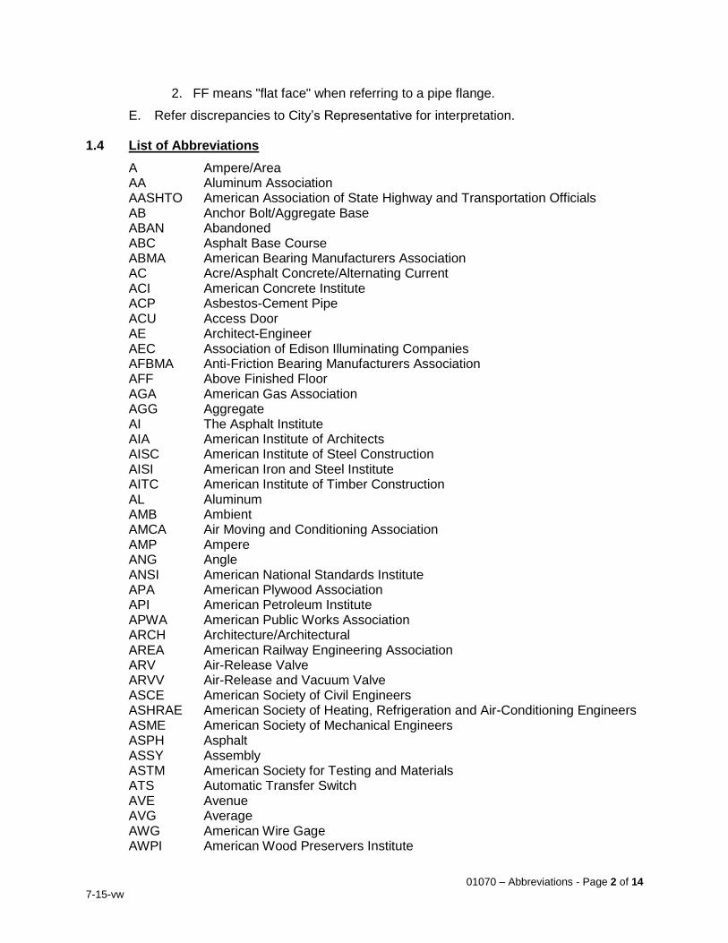
E. Refer discrepancies to City’s Representative for interpretation. 1.4 List of Abbreviations
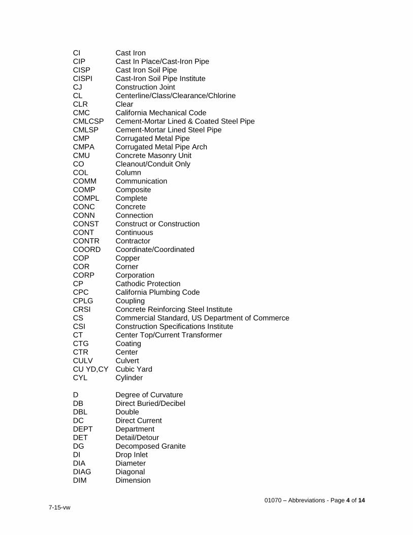
A Ampere/Area AA Aluminum Association AASHTO American Association of State Highway and Transportation Officials AB Anchor Bolt/Aggregate Base ABAN Abandoned ABC Asphalt Base Course ABMA American Bearing Manufacturers Association AC Acre/Asphalt Concrete/Alternating Current ACI American Concrete Institute ACP Asbestos-Cement Pipe ACU Access Door AE Architect-Engineer AEC Association of Edison Illuminating Companies AFBMA Anti-Friction Bearing Manufacturers Association AFF Above Finished Floor AGA American Gas Association AGG Aggregate AI The Asphalt Institute AIA American Institute of Architects AISC American Institute of Steel Construction AISI American Iron and Steel Institute AITC American Institute of Timber Construction AL Aluminum AMB Ambient AMCA Air Moving and Conditioning Association AMP Ampere ANG Angle ANSI American National Standards Institute APA American Plywood Association API American Petroleum Institute APWA American Public Works Association ARCH Architecture/Architectural AREA American Railway Engineering Association ARV Air-Release Valve ARVV Air-Release and Vacuum Valve ASCE American Society of Civil Engineers ASHRAE American Society of Heating, Refrigeration and Air-Conditioning Engineers ASME American Society of Mechanical Engineers ASPH Asphalt ASSY Assembly ASTM American Society for Testing and Materials ATS Automatic Transfer Switch AVE Avenue AVG Average AWG American Wire Gage AWPI American Wood Preservers Institute
01070 – Abbreviations - Page 3 of 14
7-15-vw
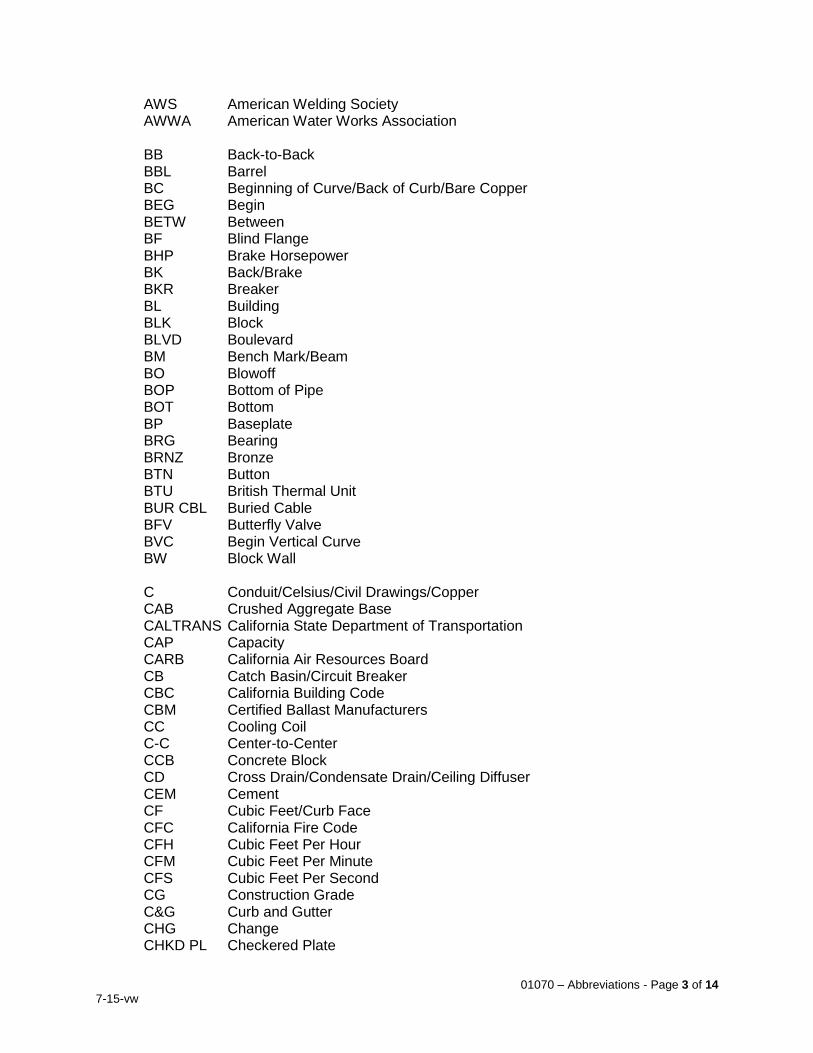
AWS American Welding Society AWWA American Water Works Association BB Back-to-Back BBL Barrel BC Beginning of Curve/Back of Curb/Bare Copper BEG Begin BETW Between BF Blind Flange BHP Brake Horsepower BK Back/Brake BKR Breaker BL Building BLK Block BLVD Boulevard BM Bench Mark/Beam BO Blowoff BOP Bottom of Pipe BOT Bottom BP Baseplate BRG Bearing BRNZ Bronze BTN Button BTU British Thermal Unit BUR CBL Buried Cable BFV Butterfly Valve BVC Begin Vertical Curve BW Block Wall C Conduit/Celsius/Civil Drawings/Copper CAB Crushed Aggregate Base CALTRANS California State Department of Transportation CAP Capacity CARB California Air Resources Board CB Catch Basin/Circuit Breaker CBC California Building Code CBM Certified Ballast Manufacturers CC Cooling Coil C-C Center-to-Center CCB Concrete Block CD Cross Drain/Condensate Drain/Ceiling Diffuser CEM Cement CF Cubic Feet/Curb Face CFC California Fire Code CFH Cubic Feet Per Hour CFM Cubic Feet Per Minute CFS Cubic Feet Per Second CG Construction Grade C&G Curb and Gutter CHG Change CHKD PL Checkered Plate
01070 – Abbreviations - Page 4 of 14
7-15-vw
CI Cast Iron CIP Cast In Place/Cast-Iron Pipe CISP Cast Iron Soil Pipe CISPI Cast-Iron Soil Pipe Institute CJ Construction Joint CL Centerline/Class/Clearance/Chlorine CLR Clear CMC California Mechanical Code CMLCSP Cement-Mortar Lined & Coated Steel Pipe CMLSP Cement-Mortar Lined Steel Pipe CMP Corrugated Metal Pipe CMPA Corrugated Metal Pipe Arch CMU Concrete Masonry Unit CO Cleanout/Conduit Only COL Column COMM Communication COMP Composite COMPL Complete CONC Concrete CONN Connection CONST Construct or Construction CONT Continuous CONTR Contractor COORD Coordinate/Coordinated COP Copper COR Corner CORP Corporation CP Cathodic Protection CPC California Plumbing Code CPLG Coupling CRSI Concrete Reinforcing Steel Institute CS Commercial Standard, US Department of Commerce CSI Construction Specifications Institute CT Center Top/Current Transformer CTG Coating CTR Center CULV Culvert CU YD,CY Cubic Yard CYL Cylinder D Degree of Curvature DB Direct Buried/Decibel DBL Double DC Direct Current DEPT Department DET Detail/Detour DG Decomposed Granite DI Drop Inlet DIA Diameter DIAG Diagonal DIM Dimension
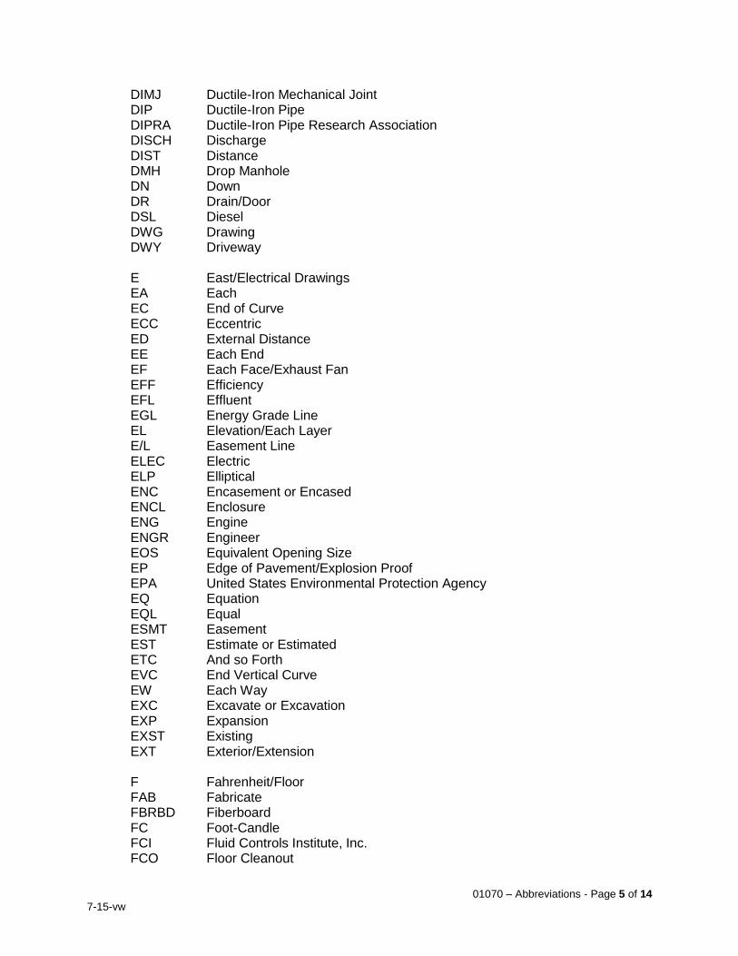
01070 – Abbreviations - Page 5 of 14
7-15-vw
DIMJ Ductile-Iron Mechanical Joint DIP Ductile-Iron Pipe DIPRA Ductile-Iron Pipe Research Association DISCH Discharge DIST Distance DMH Drop Manhole DN Down DR Drain/Door DSL Diesel DWG Drawing DWY Driveway E East/Electrical Drawings EA Each EC End of Curve ECC Eccentric ED External Distance EE Each End EF Each Face/Exhaust Fan EFF Efficiency EFL Effluent EGL Energy Grade Line EL Elevation/Each Layer E/L Easement Line ELEC Electric ELP Elliptical ENC Encasement or Encased ENCL Enclosure ENG Engine ENGR Engineer EOS Equivalent Opening Size EP Edge of Pavement/Explosion Proof EPA United States Environmental Protection Agency EQ Equation EQL Equal ESMT Easement EST Estimate or Estimated ETC And so Forth EVC End Vertical Curve EW Each Way EXC Excavate or Excavation EXP Expansion EXST Existing EXT Exterior/Extension F Fahrenheit/Floor FAB Fabricate FBRBD Fiberboard FC Foot-Candle FCI Fluid Controls Institute, Inc. FCO Floor Cleanout
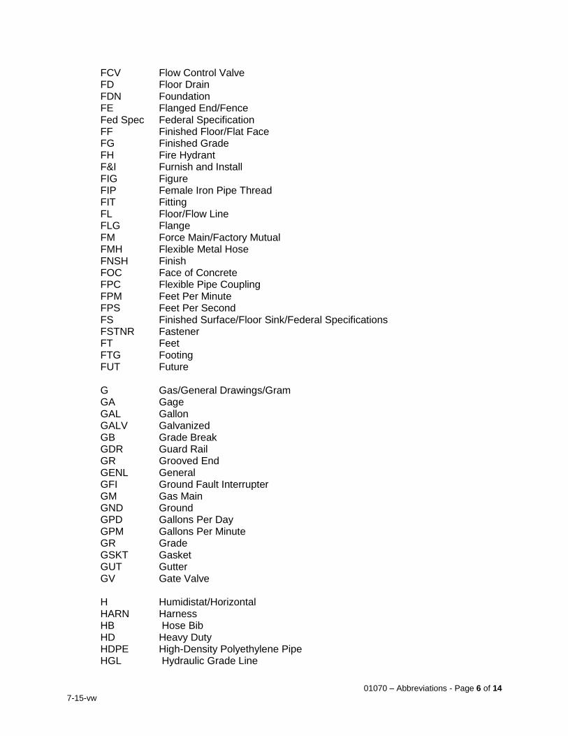
01070 – Abbreviations - Page 6 of 14
7-15-vw
FCV Flow Control Valve FD Floor Drain FDN Foundation FE Flanged End/Fence Fed Spec Federal Specification FF Finished Floor/Flat Face FG Finished Grade FH Fire Hydrant F&I Furnish and Install FIG Figure FIP Female Iron Pipe Thread FIT Fitting FL Floor/Flow Line FLG Flange FM Force Main/Factory Mutual FMH Flexible Metal Hose FNSH Finish FOC Face of Concrete FPC Flexible Pipe Coupling FPM Feet Per Minute FPS Feet Per Second FS Finished Surface/Floor Sink/Federal Specifications FSTNR Fastener FT Feet FTG Footing FUT Future G Gas/General Drawings/Gram GA Gage GAL Gallon GALV Galvanized GB Grade Break GDR Guard Rail GR Grooved End GENL General GFI Ground Fault Interrupter GM Gas Main GND Ground GPD Gallons Per Day GPM Gallons Per Minute GR Grade GSKT Gasket GUT Gutter GV Gate Valve H Humidistat/Horizontal HARN Harness HB Hose Bib HD Heavy Duty HDPE High-Density Polyethylene Pipe HGL Hydraulic Grade Line
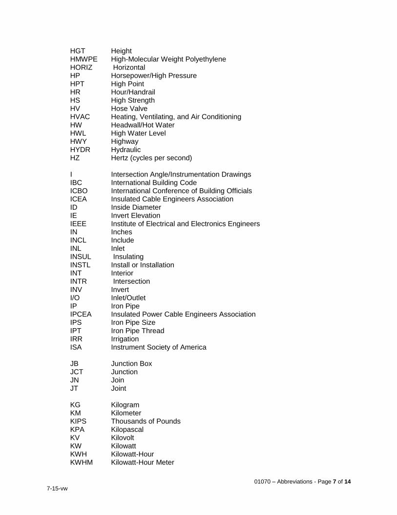
01070 – Abbreviations - Page 7 of 14
7-15-vw
HGT Height HMWPE High-Molecular Weight Polyethylene HORIZ Horizontal HP Horsepower/High Pressure HPT High Point HR Hour/Handrail HS High Strength HV Hose Valve HVAC Heating, Ventilating, and Air Conditioning HW Headwall/Hot Water HWL High Water Level HWY Highway HYDR Hydraulic HZ Hertz (cycles per second) I Intersection Angle/Instrumentation Drawings IBC International Building Code ICBO International Conference of Building Officials ICEA Insulated Cable Engineers Association ID Inside Diameter IE Invert Elevation IEEE Institute of Electrical and Electronics Engineers IN Inches INCL Include INL Inlet INSUL Insulating INSTL Install or Installation INT Interior INTR Intersection INV Invert I/O Inlet/Outlet IP Iron Pipe IPCEA Insulated Power Cable Engineers Association IPS Iron Pipe Size IPT Iron Pipe Thread IRR Irrigation ISA Instrument Society of America JB Junction Box JCT Junction JN Join JT Joint KG Kilogram KM Kilometer KIPS Thousands of Pounds KPA Kilopascal KV Kilovolt KW Kilowatt KWH Kilowatt-Hour KWHM Kilowatt-Hour Meter
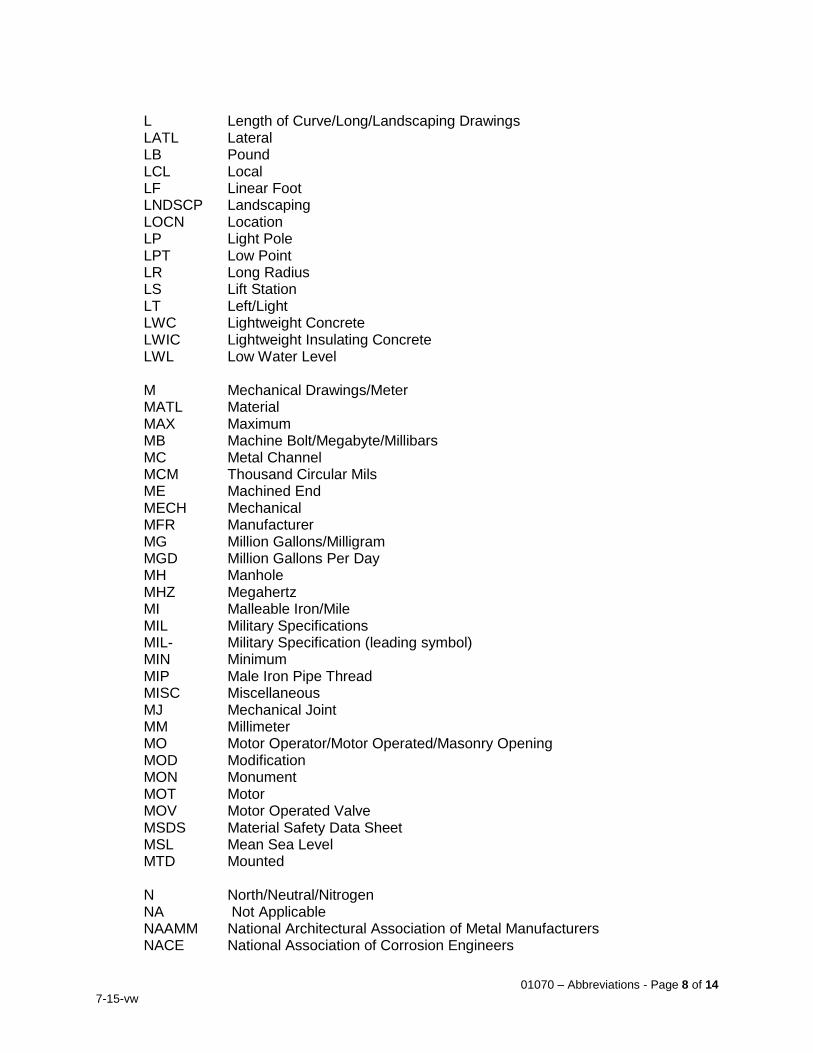
01070 – Abbreviations - Page 8 of 14
7-15-vw
L Length of Curve/Long/Landscaping Drawings LATL Lateral LB Pound LCL Local LF Linear Foot LNDSCP Landscaping LOCN Location LP Light Pole LPT Low Point LR Long Radius LS Lift Station LT Left/Light LWC Lightweight Concrete LWIC Lightweight Insulating Concrete LWL Low Water Level M Mechanical Drawings/Meter MATL Material MAX Maximum MB Machine Bolt/Megabyte/Millibars MC Metal Channel MCM Thousand Circular Mils ME Machined End MECH Mechanical MFR Manufacturer MG Million Gallons/Milligram MGD Million Gallons Per Day MH Manhole MHZ Megahertz MI Malleable Iron/Mile MIL Military Specifications MIL- Military Specification (leading symbol) MIN Minimum MIP Male Iron Pipe Thread MISC Miscellaneous MJ Mechanical Joint MM Millimeter MO Motor Operator/Motor Operated/Masonry Opening MOD Modification MON Monument MOT Motor MOV Motor Operated Valve MSDS Material Safety Data Sheet MSL Mean Sea Level MTD Mounted N North/Neutral/Nitrogen NA Not Applicable NAAMM National Architectural Association of Metal Manufacturers NACE National Association of Corrosion Engineers
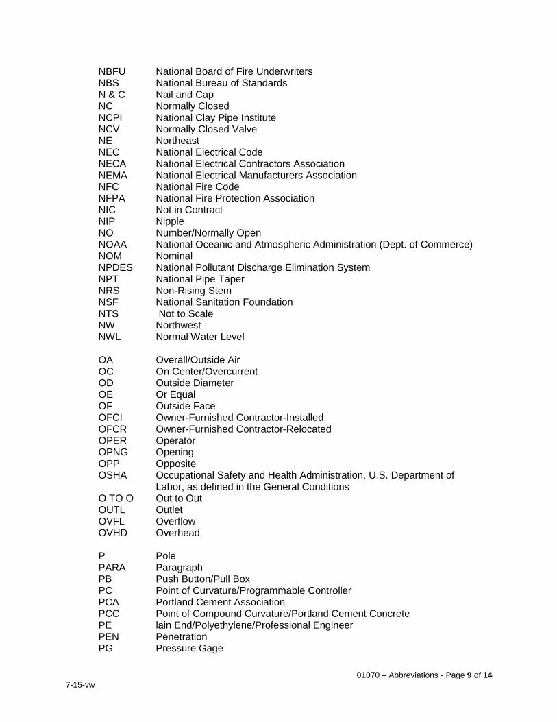
01070 – Abbreviations - Page 9 of 14
7-15-vw
NBFU National Board of Fire Underwriters NBS National Bureau of Standards N & C Nail and Cap NC Normally Closed NCPI National Clay Pipe Institute NCV Normally Closed Valve NE Northeast NEC National Electrical Code NECA National Electrical Contractors Association NEMA National Electrical Manufacturers Association NFC National Fire Code NFPA National Fire Protection Association NIC Not in Contract NIP Nipple NO Number/Normally Open NOAA National Oceanic and Atmospheric Administration (Dept. of Commerce) NOM Nominal NPDES National Pollutant Discharge Elimination System NPT National Pipe Taper NRS Non-Rising Stem NSF National Sanitation Foundation NTS Not to Scale NW Northwest NWL Normal Water Level OA Overall/Outside Air OC On Center/Overcurrent OD Outside Diameter OE Or Equal OF Outside Face OFCI Owner-Furnished Contractor-Installed OFCR Owner-Furnished Contractor-Relocated OPER Operator OPNG Opening OPP Opposite OSHA Occupational Safety and Health Administration, U.S. Department of
Labor, as defined in the General Conditions O TO O Out to Out OUTL Outlet OVFL Overflow OVHD Overhead P Pole PARA Paragraph PB Push Button/Pull Box PC Point of Curvature/Programmable Controller PCA Portland Cement Association PCC Point of Compound Curvature/Portland Cement Concrete PE lain End/Polyethylene/Professional Engineer PEN Penetration PG Pressure Gage
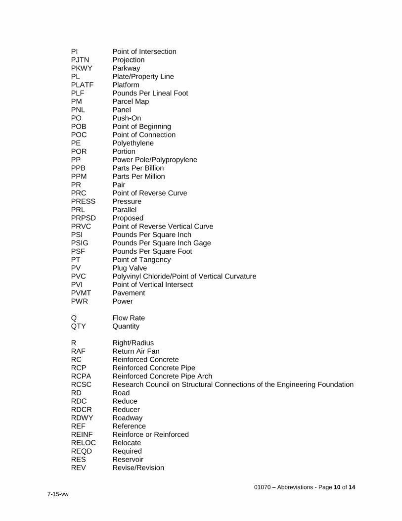
01070 – Abbreviations - Page 10 of 14
7-15-vw
PI Point of Intersection PJTN Projection PKWY Parkway PL Plate/Property Line PLATF Platform PLF Pounds Per Lineal Foot PM Parcel Map PNL Panel PO Push-On POB Point of Beginning POC Point of Connection PE Polyethylene POR Portion PP Power Pole/Polypropylene PPB Parts Per Billion PPM Parts Per Million PR Pair PRC Point of Reverse Curve PRESS Pressure PRL Parallel PRPSD Proposed PRVC Point of Reverse Vertical Curve PSI Pounds Per Square Inch PSIG Pounds Per Square Inch Gage PSF Pounds Per Square Foot PT Point of Tangency PV Plug Valve PVC Polyvinyl Chloride/Point of Vertical Curvature PVI Point of Vertical Intersect PVMT Pavement PWR Power Q Flow Rate QTY Quantity R Right/Radius RAF Return Air Fan RC Reinforced Concrete RCP Reinforced Concrete Pipe RCPA Reinforced Concrete Pipe Arch RCSC Research Council on Structural Connections of the Engineering Foundation RD Road RDC Reduce RDCR Reducer RDWY Roadway REF Reference REINF Reinforce or Reinforced RELOC Relocate REQD Required RES Reservoir REV Revise/Revision
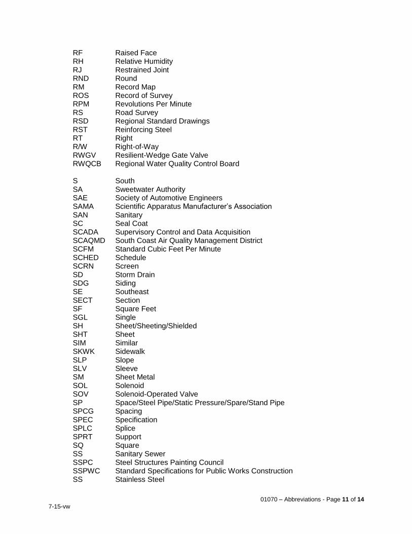
01070 – Abbreviations - Page 11 of 14
7-15-vw
RF Raised Face RH Relative Humidity RJ Restrained Joint RND Round RM Record Map ROS Record of Survey RPM Revolutions Per Minute RS Road Survey RSD Regional Standard Drawings RST Reinforcing Steel RT Right R/W Right-of-Way RWGV Resilient-Wedge Gate Valve RWQCB Regional Water Quality Control Board S South SA Sweetwater Authority SAE Society of Automotive Engineers SAMA Scientific Apparatus Manufacturer’s Association SAN Sanitary SC Seal Coat SCADA Supervisory Control and Data Acquisition SCAQMD South Coast Air Quality Management District SCFM Standard Cubic Feet Per Minute SCHED Schedule SCRN Screen SD Storm Drain SDG Siding SE Southeast SECT Section SF Square Feet SGL Single SH Sheet/Sheeting/Shielded SHT Sheet SIM Similar SKWK Sidewalk SLP Slope SLV Sleeve SM Sheet Metal SOL Solenoid SOV Solenoid-Operated Valve SP Space/Steel Pipe/Static Pressure/Spare/Stand Pipe SPCG Spacing SPEC Specification SPLC Splice SPRT Support SQ Square SS Sanitary Sewer SSPC Steel Structures Painting Council SSPWC Standard Specifications for Public Works Construction SS Stainless Steel
01070 – Abbreviations - Page 12 of 14
7-15-vw
ST Street STA Station STBY Standby STD Standard STK Stake STL Steel STR Straight STRL Structural STRUCT Structure STS Storm Sewer SURF Surface SW Southwest SWG Swing SWRCB State Water Resources Control Board SYMM Symmetrical SYS System T Ton/Tangent Length of Curve TAN Tangent T/B Top of Beam TB Top of Bank/Terminal Board T&B Top and Bottom TBG Tubing TBM Temporary Bench Mark TC Top of Curb TDH Total Dynamic Head TDS Total Dissolved Solids TEL Telephone TEMP Temperature/Temporary THB Thrust Block THD Thread or Threaded THH Thrust Harness THK Thick TO Turnout T/O Top of TOC Top of Concrete/Top of Curb TOP Top of Pipe TOS Top of Slab TOT Total TP Telephone Pole TRD Thread TRA Tie Rod Assembly TS Tube Sheet TYP Typical UBC Uniform Building Code UD Underdrain UG Underground UL Underwriters Laboratories, Inc. ULT Ultimate UON Unless Otherwise Noted UPC Uniform Plumbing Code
01070 – Abbreviations - Page 13 of 14
7-15-vw
USA Underground Service Alert USDC United States Department of Commerce USGS United States Geologic Survey UTC Underground Telephone Cable UTIL Utilities V Vent/Valve/Volt/Vertical VAC Vacuum/Volts, Alternating Current VC Vertical Curve VEL Velocity VERT Vertical VFD Variable Frequency Drive VOL Volume VPC Vertical Point of Curve VPI Vertical Point of Intersection VPT Vertical Point of Tangency W West/Watt/Wide/Water/Wire W/ With WADG Water Agencies’ Design Guide WAS Water Agencies’ Standards WASC Water Agencies’ Standards Committee WATCH Work Area Traffic Control Handbook WCLIB West Coast Lumber Inspection Bureau WCRSI Western Concrete Reinforcing Steel Institute WE Weld End WG Water Gage WL Waterline WLD Welded WM Water Meter W/O Without WP Waterproof/Working Point WRI Wire Reinforcement Institute WSE Water Surface Elevation WSP Water Stop WT Weight WTR Water WWF Welded Wire Fabric WWM Woven Wire Mesh WWPA Western Wood Products Association WWR Welded Wire Reinforcement YCO Yard Cleanout YD Yard YP Yield Point YR Year YS Yield Strength
PART 2 - PRODUCTS (Not Applicable) PART 3 - EXECUTION (Not Applicable)
END OF SECTION

01070 – Abbreviations - Page 14 of 14
7-15-vw
THIS PAGE INTENTIONALLY BLANK
01200 – Project Meetings - Page 1 of 6
7-15-vw
SECTION 01200 PROJECT MEETINGS
PART 1 - GENERAL 1.1 Scope
A. This section addresses requirements for preconstruction meeting, progress meetings, specially called meetings and post-construction meeting.
B. The City will prepare agenda, preside at meetings, and record and distribute minutes to all parties.
C. The Contractor shall provide data required and be prepared to discuss all items on the agenda.
1.2 Contractor’s Responsibilities
A. Inform participants and others involved, and individuals whose presence is required, of date and time of each meeting.
B. For all meetings other than those required by Contract Documents or Owner’s Representative, Contractor shall record minutes, including significant proceedings and decisions for each meeting. Reproduce and distribute copies of minutes within 5 days after each meeting. Provide copies to Owner’s Representative, all other participants in meeting, and all other parties affected by decisions made at meeting.
1.3 Preconstruction Meeting
A. General
After execution of the contract and before construction begins, a preconstruction meeting to confirm chain of communication, define administrative processes, and discuss specific construction requirements will be held at a time and location designated by the City’s Representative. Preconstruction meeting will be held at the City’s field office, or a mutually agreed upon location.
B. Attendance
Meeting shall be attended by:
1. City’s Representative.
2. City’s Project Manager.
3. City staff, as required.
4. Design Engineer.
5. Engineer’s design subconsultants, as required.
6. Contractor and his superintendent, major subcontractors – representatives present for each party shall be authorized to act on their behalf.
7. Representatives of government agencies, utilities, and private parties having a relevant degree of control or responsibility.
8. Other persons designated by the City.
C. Agenda
The agenda for the meeting shall include the following items as a minimum.
01200 – Project Meetings - Page 2 of 6
7-15-vw
1. Scheduling Items
a. Distribution and discussion of the construction schedule including critical construction sequencing.
b. Phasing
c. Critical work sequencing and long-lead items
d. Procedures for schedule revisions
e. Establishment of a schedule for progress meetings
2. Designation of key personnel and their duties
a. Designation of persons authorized to represent and sign documents for the City and Contractor, with examples of official signature of each
b. List of names, addresses and telephone numbers of those persons authorized to act for the Contractor in emergencies
c. Safety and first aid procedures including designation of Contractor's safety officer
3. Lines of communications
a. Procedures and forms for processing field decisions and Change Orders
b. Request for Information (RFI) forms and procedures
c. Submittal forms, procedures and review process
d. Proposal requests
e. Testing laboratory or agency and testing procedures
f. Payment application and processing procedures
g. Change order procedures
4. Distribution of Contract Documents
5. Use of premises
a. Parking availability
b. Field office, work, and storage areas
c. Equipment deliveries and priorities
d. Work restrictions
e. Working hours
f. City’s occupancy requirements
g. Responsibility for temporary facilities and controls including barricades, utilities, sanitary facilities, signs and other facilities required
h. Procedures for moisture and mold control
i. Procedures for disruptions and shutdowns
j. Construction waste management and recycling
6. First Aid
7. Security
8. Progress cleaning and housekeeping
9. Construction permit requirements, procedures and posting
10. Identification of sub-contractor responsibilities
11. Schedule of Values
12. Procedures for maintaining record documents
01200 – Project Meetings - Page 3 of 6
7-15-vw
13. Coordination with other contractors and activities
14. Other project related and administrative items as appropriate 1.4 Progress Meetings
A. General
Progress meetings to review progress, schedule, and administrative processes with City and Contractor shall be held weekly, or as designated by the City, at times scheduled at the preconstruction meeting unless changes are agreed to by all parties and appropriate notification of such changes has been given. Adjust work schedule to accommodate progress meetings. Avoid performing work requiring inspection when inspector or City’s Representative is unavailable to observe work. Progress meetings will be held at the City’s field office, or mutually agreed upon location.
B. Attendance
1. City’s Representative (Construction Manager).
2. City staff, as required.
3. Design Engineer, as required.
4. Engineer’s design sub-consultants, as required.
5. Contractor, Project Superintendent required.
6. Subcontractors and suppliers, as required. Representatives present for each party shall be authorized to act on their behalf.
C. Agenda
The agenda for these meetings shall include the following items:
1. Minutes of previous meeting (City).
2. Review progress of construction since the previous meeting (Contractor).
3. Discuss problems, conflicts, and field observations (City / Engineer / Contractor).
4. Identify problems which impede planned progress and develop corrective measures as required to regain the projected schedule. Revise the construction schedule if necessary. (Contractor).
5. Coordinate the progress of subcontractors (Contractor).
6. Review changes proposed by the City for their effect on the construction schedule and completion time (Contractor).
7. Schedules, including off-site fabrication and delivery schedules (Contractor).
8. At the third progress meeting of each month, review and update the CPM schedule, as required by Section 01320 Scheduling and Reporting. Identify schedule deficiencies and corrective action, if any, and review contract time adjustments for pending change orders.
9. Plan progress during the next construction period; 3-week look ahead minimum (Contractor).
10. Status of change orders (City / Engineer).
11. Submittal review status (City / Engineer).
12. Review of Contractor’s record drawings (City / Contractor).
13. Quality standards and control (City / Engineer).
01200 – Project Meetings - Page 4 of 6
7-15-vw
14. Corrective measures required (City / Engineer / Contractor).
15. Applications for payment status (City).
16. Coordination between all parties (All Parties).
17. Other business (All Parties). 1.5 Instrumentation and Control System Pre-Submittal Conference
A. General
Conference to review and approve the manner in which the Contractor intends to respond to the Division 17 Contract requirements before any instrumentation or control system submittals are prepared. Refer to Division 17 specifications for further requirements. Contractor shall arrange for a conference to be held not more than 45 calendar days following receipt of Notice to Proceed. Provide minimum 14 calendar days’ notice to the City. Conference will be held at City's field office, or mutually agreed upon location.
B. Attendance
1. Contractor, I&C sub-contractor, and electrical sub-contractor
2. Major control system suppliers (i.e. control panel fabricators, equipment suppliers)
3. City’s Representative
4. City’s control system integrator
5. Design Engineer
6. Engineer’s electrical design sub-consultant
C. Agenda
The agenda for this meeting shall include the following items:
1. Designation of responsible personnel
2. Contractor shall present a list of:
a. Equipment and materials required
b. Manufacturer / model number proposed by the Contractor for each item
c. Name of the company that will install each item
3. Contractor shall present a list of any exceptions to the Plans and Specifications along with a brief explanation of each. Approval will be subject to formal submittal.
4. Contractor shall present a sample of each type of submittal specified in the Construction Documents.
5. Contractor shall present a flow chart showing the steps to be taken in preparing and coordinating each system.
6. Contractor shall present a bar chart CPM schedule for all control system related activities from the pre-submittal conference through start-up, testing, and training. Schedule shall indicate dates relative to:
a. Submittals
b. Design
c. Fabrication
01200 – Project Meetings - Page 5 of 6
7-15-vw
d. Factory acceptance testing
e. Deliveries
f. Installation
g. Field testing
h. Key milestone dates identified in the Contract Documents
7. Contractor shall present the method and procedures for meeting the coordination requirements of the Specifications. Contractor shall present the method and procedures for system check out, including general outline of factory tests.
8. Contractor shall present the method and procedure for commissioning.
9. Contractor shall present the proposed wiring numbering system. The proposed wiring numbering system shall include numbering provisions for the major systems suppliers so work can be fully coordinated with the I&C Sub-contractor and control system integrator.
1.6 Special Meetings
A. Upon appropriate notice to other parties, special meetings may be called by the City’s Representative or Contractor, at times agreed to by all parties involved.
1.7 Post-construction Conference
A. General
A post-construction conference will be held before final inspection of the Work to discuss and resolve all unsettled matters. Bonds and insurance to remain in force, and other documents required to be submitted by the Contractor will be reviewed and all deficiencies determined. Schedules and procedures for the final inspection process and for the correction of defects and deficiencies shall be discussed and agreed. Contractor shall request conference when final punchlist items are complete. Conference will be held at City's field office, or mutually agreed upon location.
B. Attendance
1. City’s Representative.
2. City staff, as required.
3. City’s control system integrator
4. Design Engineer, as required.
5. Engineer’s design sub-consultants, as required.
6. Contractor, Project Superintendent, required.
7. Subcontractors and suppliers, as required.
C. Agenda
1. Review of documents required to be submitted by Contractor.
a. As-Built Drawings
b. Detailed Schedule of Equipment and Materials Costs
c. Procedures required prior to inspection for Substantial Completion and for final inspection for acceptance
d. Written warranties
01200 – Project Meetings - Page 6 of 6
7-15-vw
e. O&M Manuals
f. Demonstration training
g. Well Driller’s Log
2. Identification of deficiencies – punch list
3. Review schedule and procedure for final inspection process
4. Confirm schedule for correction of defects and deficiencies
5. Procedures for processing Applications for Payment at Substantial Completion and for final payment
6. Coordination with other contractors on site
7. City’s partial occupancy requirements
8. Responsibility for removing temporary facilities and controls
9. Notice of Completion
PART 2 - PRODUCTS (Not Applicable) PART 3 - EXECUTION (Not Applicable)
END OF SECTION
01301 – Schedule of Values - Page 1 of 4
7-15-vw
SECTION 01301 SCHEDULE OF VALUES
PART 1 – GENERAL 1.1 Work Included
A. This section includes preparation of the Schedule of Values providing a breakdown of labor, materials, equipment and other costs for measurement and payment purposes. The schedule shall also show the division of work between the Contractor and each of the Subcontractors. The Schedule of Values shall be broken down according to each Specification Division within each project area or structure on the site.
B. Include an item in the Schedule for County and State taxes. The Contractor may also include cost items for bond, insurance, temporary facilities and mobilization. Provide supporting data as requested by the City’s Representative for any Schedule item. Schedule shall also include items for the purchase/delivery costs for each item and material which the Contractor will request payment prior to installation. Each item shall include overhead and profit directly proportional to the direct cost of that item over the total Contract cost.
C. Assign prices to Bid Items which aggregate the Contract Price. Base prices on costs associated with scheduled activities for each Bid Item of Work.
D. The finalized Schedule of Values shall not be approved until the Contractor has responded to all review comments of the City. Provide supporting data, including certified payrolls, as requested by the City’s Representative for any Schedule item.
E. Prepare a Schedule of Materials and Equipment Costs providing information necessary for the City to document asset valuations for the City’s Enterprise Asset Management program.
1.2 Unit Prices
A. Payment for the Work in this Section shall be included as part of the lump-sum or unit-price bid amount for which such Work is appurtenant thereto, including all Work and materials specified herein and as may be required to complete this portion of the Work.
PART 2 – MATERIALS (Not Applicable) PART 3 – EXECUTION 3.1 Submittals
A. Submit Schedule of Values and Schedule of Equipment and Materials Costs deliverables as described herein and in accordance with the following timeline:
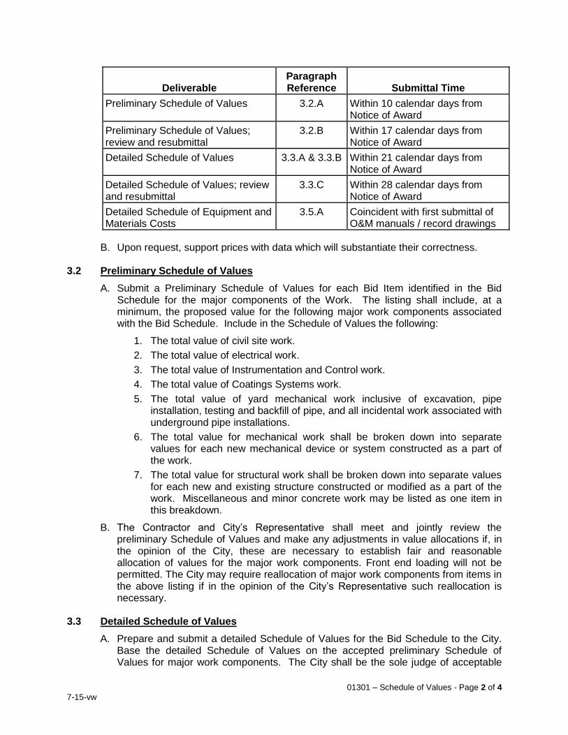
01301 – Schedule of Values - Page 2 of 4
7-15-vw
Deliverable Paragraph Reference Submittal Time
Preliminary Schedule of Values 3.2.A Within 10 calendar days from Notice of Award
Preliminary Schedule of Values; review and resubmittal
3.2.B Within 17 calendar days from Notice of Award
Detailed Schedule of Values 3.3.A & 3.3.B Within 21 calendar days from Notice of Award
Detailed Schedule of Values; review and resubmittal
3.3.C Within 28 calendar days from Notice of Award
Detailed Schedule of Equipment and Materials Costs
3.5.A Coincident with first submittal of O&M manuals / record drawings
B. Upon request, support prices with data which will substantiate their correctness. 3.2 Preliminary Schedule of Values
A. Submit a Preliminary Schedule of Values for each Bid Item identified in the Bid Schedule for the major components of the Work. The listing shall include, at a minimum, the proposed value for the following major work components associated with the Bid Schedule. Include in the Schedule of Values the following:
1. The total value of civil site work.
2. The total value of electrical work.
3. The total value of Instrumentation and Control work.
4. The total value of Coatings Systems work.
5. The total value of yard mechanical work inclusive of excavation, pipe installation, testing and backfill of pipe, and all incidental work associated with underground pipe installations.
6. The total value for mechanical work shall be broken down into separate values for each new mechanical device or system constructed as a part of the work.
7. The total value for structural work shall be broken down into separate values for each new and existing structure constructed or modified as a part of the work. Miscellaneous and minor concrete work may be listed as one item in this breakdown.
B. The Contractor and City’s Representative shall meet and jointly review the preliminary Schedule of Values and make any adjustments in value allocations if, in the opinion of the City, these are necessary to establish fair and reasonable allocation of values for the major work components. Front end loading will not be permitted. The City may require reallocation of major work components from items in the above listing if in the opinion of the City’s Representative such reallocation is necessary.
3.3 Detailed Schedule of Values
A. Prepare and submit a detailed Schedule of Values for the Bid Schedule to the City. Base the detailed Schedule of Values on the accepted preliminary Schedule of Values for major work components. The City shall be the sole judge of acceptable
01301 – Schedule of Values - Page 3 of 4
7-15-vw
numbers, details and description of values established. If, in the opinion of the City’s Representative, a greater number of Schedule of Values items than proposed by the Contractor is necessary, the Contractor shall add the additional items so identified by the City’s Representative.
B. The minimum detail of breakdown of the major work components is indicated below. Provide greater detail as directed by the City’s Representative.
1. Section 01320, "Scheduling and Reporting," broken down by submittal.
2. Separate the Civil site work into individual drainage piping, drainage structures, site concrete, paving, excavation cut and fill, soil import or export, removal of existing pipe, clearing and grubbing and any other items determined to be necessary for the establishment of Pay and Schedule Activity items.
3. Separate the electrical work by structure and yard facilities. Separate structures, electrical work into conduit and raceway installation, cable and wire installation, and electrical equipment installation, terminations and lighting. Separate yard facilities by duct bank designation and substations.
4. Separate instrumentation and Control work by structure.
5. Separate painting and Coating work by structure and yard area. Where specific coating work at structures or yard areas may be critical to performing the work to meet milestone and Contract dates, such work shall be included as individual pay and Schedule activity items.
6. Separate yard piping work into individual pipelines running from and to termination points at the various structures. Make each pipeline an individual pay item unless otherwise allowed by the City.
7. Separate mechanical work within each structure to identify individual piping systems, equipment installation by equipment name and number, and equipment testing and checkout.
8. Separate concrete structures, steel, and masonry into excavation, subgrade preparation, and appurtenant pre-foundation work, structural steel, masonry, concrete foundation construction, slabs on grade, walls/columns, suspended slabs, stairs, etc. (sufficient breakdown shall be provided to accommodate necessary Schedule detail), hydrostatic structure testing where required and backfill.
9. Equipment testing and plant startup broken down for completion milestones for each.
10. All other work not specifically included in the above items shall be broken down as necessary for establishment of pay and Schedule activity items.
C. The Contractor and City’s Representative shall meet and jointly review the detailed Schedule of Values. The value allocations and extent of detail shall be reviewed to determine any necessary adjustments to the values. Make any adjustments deemed necessary to the value allocation or level of detail and submit a revised detailed Schedule of Values to the City for record.
3.4 Changes to Schedule of Values
A. Changes to the CPM Schedule to add activities not included in the original schedule, but included in the original work (schedule omissions) shall have values assigned as
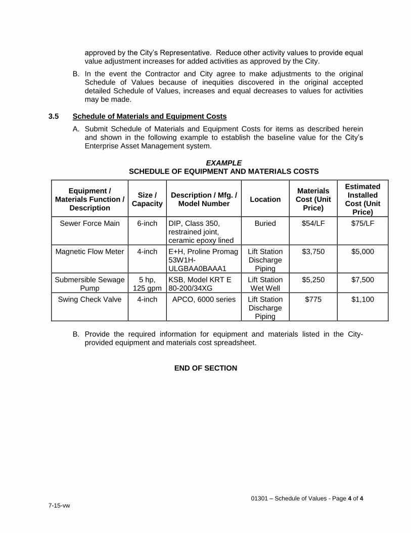
01301 – Schedule of Values - Page 4 of 4
7-15-vw
approved by the City’s Representative. Reduce other activity values to provide equal value adjustment increases for added activities as approved by the City.
B. In the event the Contractor and City agree to make adjustments to the original Schedule of Values because of inequities discovered in the original accepted detailed Schedule of Values, increases and equal decreases to values for activities may be made.
3.5 Schedule of Materials and Equipment Costs
A. Submit Schedule of Materials and Equipment Costs for items as described herein and shown in the following example to establish the baseline value for the City’s Enterprise Asset Management system.
EXAMPLE SCHEDULE OF EQUIPMENT AND MATERIALS COSTS
Equipment / Materials Function /
Description
Size / Capacity
Description / Mfg. / Model Number
Location Materials Cost (Unit
Price)
Estimated Installed
Cost (Unit Price)
Sewer Force Main 6-inch DIP, Class 350, restrained joint, ceramic epoxy lined
Buried $54/LF $75/LF
Magnetic Flow Meter 4-inch E+H, Proline Promag 53W1H-ULGBAA0BAAA1
Lift Station Discharge
Piping
$3,750 $5,000
Submersible Sewage Pump
5 hp, 125 gpm
KSB, Model KRT E 80-200/34XG
Lift Station Wet Well
$5,250 $7,500
Swing Check Valve 4-inch APCO, 6000 series Lift Station Discharge
Piping
$775 $1,100
B. Provide the required information for equipment and materials listed in the City-
provided equipment and materials cost spreadsheet.
END OF SECTION
01320 – Scheduling and Reporting - Page 1 of 10
7-15-vw
SECTION 01320
SCHEDULING AND REPORTING PART 1 – GENERAL 1.1 Work Included
A. This section specifies the scheduling of the work performed by the Contractor. The Contractor shall employ computerized Critical Path Method (CPM) scheduling in the development of the schedule and project status reporting requirements of the Contract.
B. Prepare the CPM schedule and all reports with "Primavera 6" software or equal. This will be referred to as the Scheduling System. The system shall be capable of handling, processing, printing and plotting data to satisfy all requirements of this Section.
C. All times and durations specified and schedules prepared by Contractor shall be in working days.
1.2 Unit Prices
A. Payment for the Work in this Section shall be included as part of the lump-sum or unit-price bid amount for which such Work is appurtenant thereto, including all Work and materials specified herein and as may be required to complete this portion of the Work.
PART 2 – MATERIALS (Not Applicable) PART 3 – EXECUTION
3.1 Progress of Work
A. It is expressly understood and agreed the time of beginning, the rate of progress, and the time of completion of the work are of the essence of this Contract. Execute the work with such progress as required to prevent any delay to the general completion of the Contract, the Contract milestones, and to other contractors working on other contracts at the site.
B. Prepare and submit a Construction Schedule in accordance with the requirements of this Section. By preparing and submitting the Construction Schedule, the Contractor represents it can and intends to execute the contracted Work and all portions thereof, including all activities of subcontractors, equipment vendors and suppliers, submittals and resubmittals within the specified times and constraints and the bid covers all costs associated with the execution of the Work in accordance with the Construction Schedule.
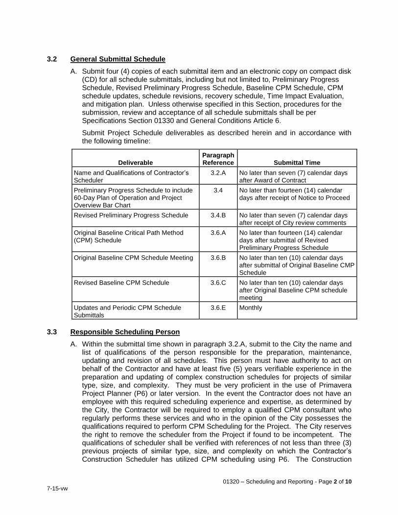
01320 – Scheduling and Reporting - Page 2 of 10
7-15-vw
3.2 General Submittal Schedule
A. Submit four (4) copies of each submittal item and an electronic copy on compact disk (CD) for all schedule submittals, including but not limited to, Preliminary Progress Schedule, Revised Preliminary Progress Schedule, Baseline CPM Schedule, CPM schedule updates, schedule revisions, recovery schedule, Time Impact Evaluation, and mitigation plan. Unless otherwise specified in this Section, procedures for the submission, review and acceptance of all schedule submittals shall be per Specifications Section 01330 and General Conditions Article 6.
Submit Project Schedule deliverables as described herein and in accordance with the following timeline:
Deliverable Paragraph Reference Submittal Time
Name and Qualifications of Contractor’s Scheduler
3.2.A No later than seven (7) calendar days after Award of Contract
Preliminary Progress Schedule to include 60-Day Plan of Operation and Project Overview Bar Chart
3.4 No later than fourteen (14) calendar days after receipt of Notice to Proceed
Revised Preliminary Progress Schedule 3.4.B No later than seven (7) calendar days after receipt of City review comments
Original Baseline Critical Path Method (CPM) Schedule
3.6.A No later than fourteen (14) calendar days after submittal of Revised Preliminary Progress Schedule
Original Baseline CPM Schedule Meeting 3.6.B No later than ten (10) calendar days after submittal of Original Baseline CMP Schedule
Revised Baseline CPM Schedule 3.6.C No later than ten (10) calendar days after Original Baseline CPM schedule meeting
Updates and Periodic CPM Schedule Submittals
3.6.E Monthly
3.3 Responsible Scheduling Person
A. Within the submittal time shown in paragraph 3.2.A, submit to the City the name and list of qualifications of the person responsible for the preparation, maintenance, updating and revision of all schedules. This person must have authority to act on behalf of the Contractor and have at least five (5) years verifiable experience in the preparation and updating of complex construction schedules for projects of similar type, size, and complexity. They must be very proficient in the use of Primavera Project Planner (P6) or later version. In the event the Contractor does not have an employee with this required scheduling experience and expertise, as determined by the City, the Contractor will be required to employ a qualified CPM consultant who regularly performs these services and who in the opinion of the City possesses the qualifications required to perform CPM Scheduling for the Project. The City reserves the right to remove the scheduler from the Project if found to be incompetent. The qualifications of scheduler shall be verified with references of not less than three (3) previous projects of similar type, size, and complexity on which the Contractor’s Construction Scheduler has utilized CPM scheduling using P6. The Construction
01320 – Scheduling and Reporting - Page 3 of 10
7-15-vw
Scheduler is required to attend all meetings pertaining to scheduling and progress of the Work.
B. Provide one licensed copy of scheduling software to the City registered in the City’s name. The software copy shall become the property of the City. City’s approval of the Contractor’s CPM scheduling person is a prerequisite to the issuance of the Notice to Proceed.
3.4 Preliminary Progress Schedule Submittal
A. Within the submittal time shown in paragraph 3.2.A, submit four (4) hardcopies and one (1) electronic copy of a cost loaded Preliminary Progress Schedule package which shall serve as the Contractor's Plan of Operation for the initial 60 working day period of the Contract Time and to identify the manner in which the Contractor intends to complete all work within the Contract Time. Submit (1) a 60-day Plan of Operation bar chart, and (2) a project overview bar chart type plan for all work as indicated below.
1. 60-Day Plan of Operation: During the initial 60 working days of the Contract Time, conduct Contract operations in accordance with the 60-day bar chart Plan of Operation. The bar chart so prepared and submitted shall show the dates for accomplishment of the Contractor's early activities including:
a. mobilization,
b. permits,
c. submittals necessary for early material and equipment procurement – including the maximum allowable review period, as specified,
d. submittals necessary for long lead equipment procurement – including the maximum allowable review period, as specified,
e. CPM submittals,
f. initial site work, and
g. other submittals and all other activities required and planned for execution in the first 60 working days.
The information shall provide sufficient durations for administration, fabrication, and transportation to produce realistic delivery dates for the procurement items.
2. Project Overview Bar Chart: The overview bar chart shall indicate the major components of the project work and the sequence relations between major components and subdivisions of major components. The overview bar chart shall indicate the relationships and time frames in which the various components of the work will be made substantially complete and placed into service to meet the project milestones. Include sufficient detail for the identification of subdivisions of major components into such activities as
a. excavation,
b. foundation subgrade preparation,
c. foundation concrete,
d. completion of all structural concrete,
e. utilities work,
f. major mechanical work,
01320 – Scheduling and Reporting - Page 4 of 10
7-15-vw
g. major electrical work,
h. instrumentation and control work, and
i. other important work for each major facility within the overall project scope.
Indicate approximate planned durations and start dates for each work item subdivision representing the Contractor’s best estimate for the Work the summary activity represents. The total duration of the summary activities shall equal the Contract Time. Accurately plot each major component and subdivision component on time scale sheets not to exceed 24-inches by 36-inches in size. Use not more than four sheets to represent this overview information.
B. The City will review the Preliminary Progress Schedule and provide any comments at
a meeting with the Contractor within ten (10) calendar days after submittal to the City. The City's review and comment on the schedules shall be limited to Contract conformance with the sequencing and milestone requirements as stated in other sections of the Specifications. Make corrections to the schedules necessary to comply with the Contract requirements and adjust the schedules to incorporate any missing information requested by the City. Any revisions necessary as a result of the City review and meeting with the Contractor shall be resubmitted for review to the City within the submittal time shown in paragraph 3.2.A.
C. The Preliminary Progress Schedule will be used temporarily to record and monitor the progress of the Work until the Baseline Schedule, specified hereinafter, has been completely developed and favorably reviewed. Incorporate recorded data on the Preliminary Progress Schedule into the Baseline Schedule during the first schedule update.
3.5 Schedule Methodology
A. The scheduling method to be used shall be CPM in the form of an activity on node Precedence Diagram Network (PDN) with capabilities of identifying the critical path.
B. Work Breakdown Structure:
1. Submit to the City for approval the following:
a. work breakdown structure,
b. the associated alphanumeric coding structure to implement the work breakdown structure, and
c. the activity identification system for labeling all work activities.
C. Designate code fields as follows:
1. The first code field shall designate the bid item.
2. The second code field shall identify the type of activity and shall be defined as:
a. submittal,
b. review/approval,
c. procurement/fabrication,
d. delivery,

01320 – Scheduling and Reporting - Page 5 of 10
7-15-vw
e. construction/installation,
f. start-up, or
g. change order
3. The third field shall identify the specification section under which the activity will be paid.
4. The fourth code field shall identify who is responsible to perform the activity (i.e., the Contractor, subcontractor(s), supplier, etc.).
5. The fifth code field shall identify the area being worked in or the facility, if appropriate.
6. The sixth code field shall identify the construction phase or project element (if phasing of work or project elements are identified in the Contract).
7. Include all Change Orders and Notices of Non-Compliance as separate code fields.
3.6 CPM Schedule Submittals
A. Original Baseline CPM Schedule Submittal: Within the submittal time shown in paragraph 3.2.A, submit for review by the City a hard copy of the Original Baseline CPM Network Schedule and the Computerized Schedule Report tabulations. Also submit a CD (compact disk) containing all of the schedule submittal information and data. Submit a new disk with updated information with each change or submission of the CPM schedule. The disk shall contain data compatible with Primavera 6 to generate network diagrams and schedule reports identical to the hard copies submitted. This submittal shall have already been reviewed and approved by the Contractor's Project Manager, Project Superintendent, and the Project Estimator prior to submission. The CPM Schedule shall be a time-scaled network diagram of the "I-j" activity-on-arrow or precedence type. The Network Diagram shall describe the activities to be accomplished and their logical relationships and show the Critical Path.
The Computerized Schedule Report tabulations shall include the following:
1. Report of activities sorted by Activity Number
2. Report of activities sorted by Early Start date
3. Report of activities sorted by Total Float.
4. Report of activities sorted by Responsibility Code. Responsibility Codes shall be established for the Contractor, City, subcontractors, suppliers, etc. Identify these codes in the Network Diagram.
5. A successor-predecessor report which shall identify the successor and predecessor activities for each activity and ties between schedule activities
B. Original Baseline CPM Schedule Review Meeting: Within the time stipulated above, meet with the City to review the Original Baseline CPM Schedule submittal. The Contractor’s Project Manager, Project Superintendent, and Project Scheduler shall be in attendance. The City's review will be limited to the submittal's conformance to the Contract requirements. However, the review may also include:
1. Clarifications of the design intent, process, and startup requirements.
2. Directions to include activities and information missing from the submittal.
01320 – Scheduling and Reporting - Page 6 of 10
7-15-vw
3. Requests to the Contractor to clarify the schedule.
C. Revisions to the Original Baseline CPM Schedule: Within the submittal time shown in paragraph 3.2.A, revise the Original Baseline CPM Schedule submittal to address all review comments from the Original Baseline CPM Schedule Meeting and resubmit the network diagrams and reports for the City's review. The City, within fourteen (14) days from receipt of the Revised Baseline CPM Schedule will either (1) accept the schedule as submitted, or (2) advise the Contractor in writing to review any part or parts of the schedule which either do not meet the Contract requirements or are unsatisfactory for the City to monitor the project's progress and status or evaluate monthly payment requests by the Contractor. The City may accept the schedule with conditions that the first monthly CPM schedule update be revised to correct deficiencies identified. When the schedule is accepted, it shall be considered as the "Original Baseline CPM Construction Schedule" until an updated schedule has been submitted. The City reserves the right to require the Contractor to adjust, add to, or clarify any portion of the schedule which may later be discovered to be insufficient for the monitoring of the Work. No additional compensation will be provided for such adjustments, additions or clarifications.
D. Acceptance: The acceptance of the Contractor's schedule by the City will be based solely upon the schedule's compliance with the Contract requirements. By way of the Contractor assigning activity durations and proposing the sequence of the Work, the Contractor agrees to utilize sufficient and necessary management and other resources to perform the work in accordance with the schedule. Upon submittal of a schedule update, the updated schedule shall be considered the "current" project schedule.
Submission of the Contractor's progress schedule to the City shall not relieve the Contractor of the Contractor's total responsibility for scheduling, sequencing, and pursuing the Work to comply with the requirements of the Contract Documents, including adverse effects such as delays resulting from ill-timed work.
E. Monthly Updates and Periodic CPM Schedule Submittals: Following the acceptance of the Contractor's Original Baseline CPM Schedule, monitor the progress of the Work and adjust the schedule continuously to reflect actual progress and any changes in planned future activities. Submit complete schedule updates in accordance with General Conditions Article 6, including all information requested in the original schedule submittal and as specified herein. Each update shall continue to show all work activities including those already completed. These completed activities shall accurately reflect the "as built" information by indicating when the work was actually started and completed.
Neither the submission nor the updating of the Contractor's original schedule submittal nor the submission, updating, change or revision of any other report, curve, schedule or narrative submitted to the City by the Contractor under this Contract, nor the City's review or acceptance of any such report, curve, schedule or narrative shall have the effect of amending or modifying, in any way, the Contract completion date or milestone dates or of modifying or limiting, in any way, the Contractor's obligations under this Contract. Only a signed, fully executed change order can modify these contractual obligations.
The monthly schedule update submittal will be reviewed with the Contractor during a monthly construction schedule review meeting held on the twentieth (20th) work day of each month. The goal of these meetings is to enable the Contractor and the City
01320 – Scheduling and Reporting - Page 7 of 10
7-15-vw
to initiate appropriate remedial actions to minimize any known or foreseen delay in completion of the Work and to determine the amount of Work completed since the last month's schedule update. The status of the Work will be determined by the percent complete of each activity shown in the Network Diagram. These meetings are considered a critical component of the overall monthly schedule update submittal and the Contractor shall have appropriate personnel attend. As a minimum, the Contractor's Project Manager and General Superintendent shall attend these meetings. Submit within seven (7) working days after the monthly progress meeting the revised CPM Network Diagram, the revised CPM computerized tabulations as noted in this Section, the revised successor/predecessor report, the Project Status Reports as defined in Paragraph 3.10 and the Contractor's Application for Payment. Within five (5) working days of receipt of the above noted revised submittals, the City will either accept or reject the monthly schedule update submittal. If accepted, the percent complete shown in the monthly update will be the basis for the Application for Payment to be submitted by the Contractor. If rejected, correct and resubmitt the update before the Application for Payment for the update period can be processed.
F. Schedule Revisions: Highlight or otherwise identify all changes to the Network Diagram Schedule Logic or activity durations made from the previous schedule. Modify any portions of the CPM schedule which become infeasible because of activities behind schedule or for any other valid reason.
3.7 Change Orders
A. Upon approval of a change order, or upon receipt by the Contractor of authorization to proceed with additional work, the change shall be reflected in the next submittal of the CPM schedule by the Contractor. Utilize a sub-network in the schedule depicting the changed work and its effect on other activities. This sub-network shall be tied to the main network with the appropriate logic, so a true analysis of the Critical Path can be made.
3.8 CPM Standards
A. Definitions: CPM, as required by this Section, shall be interpreted to be generally as outlined in the Association of General Contractors (AGC) publication, "The Use of CPM in Construction" except that either "I-j" arrow diagrams or precedence diagramming format may be utilized. In the case of conflicts between this specification and the AGC Document, this specification shall govern.
B. Construction Schedules: Include in the construction schedules a graphic network diagram and computerized construction schedule reports as described in Paragraph 3.6.
C. Networks: The CPM network shall be in a form of a pure logic diagram or, if directed or approved by the City, a time scaled "I-j" activity-on-arrow or precedence type diagram and may be divided into a number of separate sheets with suitable match lines relating the interface points among the sheets. Individual sheets shall not exceed 36-inch by 60-inch (maximum 2 sheets).
D. Except for a pure logic diagram, all construction activities and procurement shall be indicated in a time-scaled format and a calendar time line shall be shown along the entire sheet length. Plot each activity arrow or node to accurately represent beginning and completion dates of each activity along the calendar time line. Show
01320 – Scheduling and Reporting - Page 8 of 10
7-15-vw
all activities using the symbols that clearly distinguish between critical path activities, non-critical activities and free float for each non-critical activity. Identify all activity items by their respective Activity Number, Responsibility Code, Work Duration, and their Dollar Value. All non-critical path activities shall show their total float time in scale form by utilizing a dotted line or some other graphical means.
E. Duration Estimates: Compute the duration estimate for each activity in working days to represent the single best estimate considering the scope of the activity work and resources planned for the activity. Except for certain non-labor activities, such as curing of concrete or delivery of materials, activity duration shall not exceed 10 working days nor be less than one working day unless otherwise accepted by the City.
F. Float Time: Float time shall be as follows:
1. Definition: Unless otherwise provided herein, float as referenced in these documents, is total float. Total float is the period of time measured by the number of working days each non-critical path activity may be delayed before it and its succeeding activities become part of the critical path. If a non-critical path activity is delayed beyond its float period, that activity then becomes part of the critical path and controls the end date of the project. Thus, the delay of the non-critical path activity beyond its float period will cause delay to the Project.
2. Float Ownership: Neither the City nor the Contractor owns the float time. The Project owns the float time. As such, liability for delay of the Project completion date rests with the party actually causing delay to the Project completion date. For example, if Party A uses some, but not all of the float time and Party B later uses the remainder of the float time as well as additional time beyond the float time, Party B shall be liable for the costs associated with the time that represents a delay to the project's completion date. Party A would not be responsible for any costs since it did not consume all of the float time and additional float time remained, therefore, the Project's completion date was unaffected.
3.9 Schedule Reports (Format)
A. Schedule Reports: Prepare Schedule Reports based on the Construction Schedule to include the following minimum data for each activity:
1. Activity Numbers and Responsibility Codes.
2. Contract Number.
3. Estimated Activity Duration.
4. Activity Description.
5. Activity's Percent Completion.
6. Early Start Date (Calendar Dated).
7. Early Finish Date (Calendar Dated).
8. Late Start Date (Calendar Dated).
9. Late Finish Date (Calendar Dated).
10. Status (Whether Critical).
11. Total Float for Each Activity.
01320 – Scheduling and Reporting - Page 9 of 10
7-15-vw
12. Free Float for Each Activity.
13. Cost Value for Each Activity.
B. Project Information: Preface each Schedule Report with the following summary data:
1. Project Name.
2. Contractor.
3. Contract No.
4. Type of Tabulation.
5. Project Duration.
6. Contract Completion Date (revised to reflect time extensions).
7. The Commencement Date Stated in the Notice to Proceed.
8. The Data Date and Plot Date of the Network Diagram.
9. If an update, the new schedule completion date.
3.10 Project Status Reporting
A. In addition to the submittal requirements for the CPM scheduling identified in this Section, provide monthly project status reports (Overview Bar Chart and a written narrative report) to be submitted in conjunction with the revised CPM Schedules as specified in Paragraph 3.6. Status reporting shall be in the form specified below.
B. Prepare and submit monthly an Overview Bar Chart schedule of the major project components. The overview bar chart schedule shall be a summary of the current CPM schedule (original and as updated and adjusted throughout the entire construction period). It shall be limited to not more than two sheets which shall not exceed 36-inch by 60-inch. Represent the major project components as time bars subdivided into various types of work including demolition, excavation and earthwork, yard piping, concrete construction, mechanical, electrical and instrumentation installations. Major components shall include each new structure by area designation, sitework, modifications to existing structures, tie-ins to existing facilities and plant startups.
Accurately time scale plot each major component and subdivision consistent with the project overview bar chart specified above. It shall represent the same status indicated by early start and finish activity information contained in the latest update of the CPM schedule. In addition, indicate a percent completion for each major component and subdivision. The initial submittal of the overview bar chart schedule shall be made at the time the revised Original Baseline CPM Schedule is submitted to the City within the submittal time shown in paragraph 3.2.A. Amend the overview schedule to include any additional detail required by the City. Include any additional information requested by the City at any time during the construction of the Work.
C. Prepare monthly written narrative reports of the status of the project for submission to the City. Written status reports shall include:
1. The status of major project components (Percent Complete, amount of time ahead or behind schedule) and an explanation of how the project will be brought back on schedule if delays have occurred.
2. The progress made on critical activities indicated on the CPM schedule.

01320 – Scheduling and Reporting - Page 10 of 10
7-15-vw
3. Explanations for any lack of work on critical path activities planned to be performed during the last month.
4. Explanations for any schedule changes, including changes to the logic or to activity durations.
5. A list of the critical activities scheduled to be performed in the next two month period.
6. The status of major material and equipment procurement.
7. The value of materials and equipment properly stored at the site, but not yet incorporated into the work-in-place.
8. Any delays encountered during the reporting period.
9. An assessment of inclement weather delays and impacts to the progress of the Work.
The Contractor may include any other information pertinent to the status of the project. Include additional status information requested by the City.
3.11 Inclement Weather Provisions of the Schedule
Include in the Contractor's construction schedule at least ten (10) lost days on the CPM schedule's critical path due to inclement weather.
END OF SECTION
01322 – Construction Survey Staking - Page 1 of 4
7-15-vw
SECTION 01322
CONSTRUCTION SURVEY STAKING PART 1 – GENERAL 1.1 Work Included
A. This Section specifies the Contractor’s administrative and procedural requirements for field-engineering services and the Contractor’s daily construction reporting for land survey work.
B. Surveys and survey controls prepared for design will be provided by the City.
C. Lines, grades, and measurements for the Work, including constructing staking, will be the responsibility of the Contractor. Preserve and/or relocate all benchmarks and in the case of their removal by the Contractor, his employees or sub-contractors, or by reason of his negligence, he shall be liable for the cost of their replacement. Develop and make such additional detailed surveys as are needed for construction. Contractor provided surveys shall be performed under the supervision of a California licensed Land Surveyor or California Registered Civil Engineer experienced in and permitted to practice this type of work.
1.2 Submittals
A. Certificates – Submit a certificate signed by the licensed surveyor or professional engineer certifying the location and elevation of Project improvements.
B. Surveyors Notes - Submit four (4) copies of all calculations, cut sheets, and field notes provided by licensed land surveyor or professional engineer for constructing the Work.
C. Project Record Documents - Submit a CD or DVD with record of Work performed and record survey data to include an electronic copy of all AutoCAD 2010 (.dwg format), coordinate (ASCIII.txt format), and alignment geometry files (format varies).
1.3 Quality Assurance
A. Qualifications - Engage a land surveyor or civil engineer registered in the state of California to perform required surveying services.
B. City’s Representative will coordinate and/or perform field observation to ascertain if the Work is being performed in accordance with the Contract Documents. Cooperate with the City’s Representative and make any necessary provisions to allow for the safe observation of the Contractor’s work.
1.4 Unit Prices
A. Payment for the Work in this Section shall be included as part of the lump-sum or unit-price bid amount for which such Work is appurtenant thereto, including all Work and materials specified herein and as may be required to complete this portion of the Work.
PART 2 – MATERIALS (Not Applicable)
01322 – Construction Survey Staking - Page 2 of 4
7-15-vw
PART 3 – EXECUTION 3.1 Examination
A. Verify layout information shown on the Drawings, in relation to the property lines and existing benchmarks, before proceeding to lay out the Work. Locate and protect benchmarks and control points. Preserve permanent reference points during construction.
1. Do not change or relocate benchmarks or control points without prior written approval. Promptly report lost or destroyed reference points or requirements to relocate reference points because of necessary changes in grades or locations.
2. Promptly replace lost or destroyed project control points. Base replacements on the original survey control points.
B. Establish and maintain a minimum of two (2) permanent benchmarks on the site, referenced to data established by survey control points.
1. Record horizontal and vertical data, and benchmark locations, on Project Record Drawings.
3.2 Performance
A. Work from lines and levels established from the survey control shown on the Drawings, or as provided by the City’s Representative or Engineer. Establish benchmarks and markers to set lines and levels at each segment of construction and elsewhere as needed to locate each element of the Project. Calculate and measure required dimensions within indicated or recognized tolerances. Do not scale Drawings to determine dimensions. Use dimensions provided on civil and/or architectural Drawings to determine locations of improvements.
1. Advise subcontractors engaged in construction activities of marked lines and elevations provided for their use and the responsibility to protect and preserve these points.
2. As construction proceeds, incorporate horizontal and vertical checks to verify the location of key and/or major improvements.
B. Surveyor’s Log: Maintain a surveyor’s log of control and other survey work. Make this log available for reference.
1. Record deviations from design grade, profiles and elevations, and advise the City’s Representative when deviations exceed industry standards for maintaining design criteria. On Project Record Drawings, record deviations that are accepted and not corrected, and record deviations that are not corrected.
2. On completion of foundation walls, major site improvements, and other work requiring field-engineering services, prepare a certified survey showing dimensions, locations, angles, and elevations of construction and sitework.
C. Site Improvements: Locate and lay out site improvements, including pavements, stakes for grading, fill and topsoil placement, utility slopes, and invert elevations.
D. Building and Structure Lines and Levels: Locate and lay out batter boards for structures, building foundations, column grids and locations, floor levels, and control lines and levels required for mechanical and electrical work.
01322 – Construction Survey Staking - Page 3 of 4
7-15-vw
E. Existing Utilities: Furnish information necessary to adjust, move, or relocate existing structures, utility poles, lines, services, or other appurtenances located in or affected by construction. Coordinate with local authorities having jurisdiction.
3.3 Survey Staking for Clearing Lands and Rights-of-Way
A. Provide wooden lath markers in open terrain and painted marks on structures and pavements.
3.4 Survey Staking for Constructing Pipelines
A. Provide construction stakes and grade sheets for use in constructing pipelines as follows, based upon the Contractor’s pipeline installation drawings.
B. For all pipelines not installed in tunnels or casings, one stake will be set at 50-foot intervals, 25-foot intervals for gravity sewer or drain lines, and at all angle points and grade breaks. One additional reference stake and/or witness lath will be provided for each pipeline appurtenance. Stakes will be set at the surface of the ground or painted on the paved surface along a mutually acceptable offset to the centerline of the pipeline. The offset shall be constant both as to side and distance from centerline for runs of not less than 2,000 feet where physically practicable with the provided easements. Station, offset, and cut/fill to flow line will appear on these stakes. The elevation of each point and the cut/fill to the pipe invert will be given on grade sheets. Exercise care in determining what offset is to be used, if sloping the trench is anticipated. It shall be the Contractor’s responsibility to accurately transfer the line and grade for the facility to the trench bottom. Pavement scoring, cutting, and removal shall be accomplished from this same set of construction stakes. No additional stakes will be set for such purpose.
C. Provide two benchmarks and principal control monuments for line and grade for pipe installed inside tunnels or casings. The exact location of these benchmarks and monuments will be dictated by conditions at the site.
3.5 Survey Staking for Constructing Structures and Appurtenances
A. Provide survey staking and reference points.
B. Major structures will be controlled by two lines set at right angles to each other, along two faces of the structure, the ends of each line to be beyond the limits of the work, and with elevations only marked on at least two of these control points.
C. At minor structures, manways, and appurtenances set a stake along the pipeline construction offset, with the respective pipeline station for its centerline shown.
3.6 Final Property Survey
A. Prepare a final property survey showing significant features (real property) for the Project. Include on the survey a certification, signed by the surveyor, that principal metes, bounds, lines, and levels of the Project are accurately positioned as shown on the survey.
END OF SECTION
01322 – Construction Survey Staking - Page 4 of 4
7-15-vw
THIS PAGE INTENTIONALLY BLANK
01330 – Submittal Procedures - Page 1 of 14
7-15-vw
SECTION 01330 SUBMITTAL PROCEDURES
PART 1 - GENERAL 1.1 Work Included
A. General procedures and requirements for submittals, initial submittal, submittals required on Owner's request, progress reports, Shop Drawings, product data and samples, notification of affected residences and businesses, and submittal forms.
1.2 Related Work
A. Section 01400: Quality Requirements B. Section 01610: Product Requirements C. Section 01630: Product Substitution Procedures D. Section 01650: Product Delivery, Storage, and Handling Requirements E. Section 01700: Execution F. Section 01783: Operating and Maintenance Data
1.3 General
A. Submit descriptive information, including shop drawings and engineering data covering materials, equipment, and/or methods of work, which will enable the Engineer to advise the City whether the Contractor's proposed materials, equipment, or methods of work are in general conformance with the design concept and are in compliance with the Drawings and Specifications. The information to be submitted shall consist of drawings, specifications, descriptive data, certificates, samples, test results, and other such information, all as specifically required in the Specifications and Contract Documents, and shall become a permanent part of the work under this contract.
B. The Contractor shall be responsible for the accuracy and completeness of the information contained in each submittal and shall assure the material, equipment, or method of work shall be as described in the submittal. Submittals shall contain all required information, including satisfactory identification of items, units, and assemblies in relation to the Contract Drawings and Specifications. Verify the material and equipment described in each submittal conforms to the requirements of the specifications and drawings. Unless otherwise approved by the City, submittals shall be made only by the Contractor, who shall indicate by a signed stamp on the submittals the Contractor has checked the submittals and the work shown conforms to contract requirements and has been checked for dimensions and relationship with work of all other trades involved. If the information shows deviations from the Specifications or Drawings, the Contractor, by statement in writing accompanying the information shall identify the deviations and state the reason(s) therefore. Ensure there is no conflict with other submittals and notify the City in each case where the Contractor’s submittal may affect the work of another contractor or the City. Ensure coordination of submittals among the related crafts and subcontractors.
C. The Contractor may authorize a material or equipment supplier to deal directly with the City or Engineer with regard to a submittal on a case-by-case basis with the consent of the City. The Contractor, however, shall be responsible for the accuracy and completeness of information contained in all submittals.
01330 – Submittal Procedures - Page 2 of 14
7-15-vw
D. Number submittals using numbering system as directed by City’s Representative.
E. Shop Drawing Transmittal Form. Use form included at end of this section unless otherwise directed by City. Submit separate form for each submittal and assign a submittal number. Form shall be first page of each digital submittal. Submittals without completed Contractor's Transmittal Form as first page will be returned without review and stamped "REJECTED/RESUBMIT AS SPECIFIED."
F. Stock or standard drawings will not be accepted for review unless full identification and supplementary information is shown thereon in ink or typewritten form.
G. Clearly note exceptions and departures from Contract Documents, along with brief justification for each exception or departure.
H. Provide space for reviewer’s review and acceptance stamp. 1.4 Electronic (Digital) Submittals
A. Submit one (1) digital copy of each submittal using one of the following methods:
1. Email: Send submittal as pdf attachment to City’s Representative.
2. Data tracking System (DTS): Upload digital file to server maintained by City’s Representative.
B. Multiple hard copies of submittals will not be accepted in lieu of digital submittal unless otherwise authorized or directed by City’s Representative.
C. One digital copy of stamped submittal with cover letter will be returned to Contractor by email or DTS as appropriate.
D. Contractor shall verify emails sent with large attachments have been successfully received by City’s Representative. Files in excess of 5 MB in size shall not be sent as attachments to emails due to size restrictions associated with users’ email systems.
1.5 Paper Submittals
A. Submit paper submittals for the following items.
1. Reinforcing steel schedules larger than 11”x17” original format 2. Steel pipe lay diagrams larger than 11”x17” original format 3. Original drawings larger than 11”x17” size
B. Submit six (6) copies of submittals unless otherwise stated.
C. Fold paper submittals to approximately 9-inches by 12-inches.
D. Bind product data with sturdy, labeled covers with an index listing the contents. Loose unbound submittals will be returned without review.
E. Four (4) copies will be returned to Contractor. 1.6 Assembly, Installation, and Operation and Maintenance Manual Submittals
A. Assembly and Installation Manuals. Submit two paper copies for review and four copies of the complete, bound set of assembly and installation manuals for each item of equipment for which such a manual is required. Submit digital file in pdf format of final submittal.
01330 – Submittal Procedures - Page 3 of 14
7-15-vw
B. Operation and Maintenance Manuals. Submit two copies for review and four copies of the complete, bound set of operation and maintenance manuals for each item of equipment for which such a manual is required. Included in the binder shall be all shop drawings and a section for the City to add 11”x17” copies of record drawings. Submit digital file in pdf format of final submittal.
1.7 City’s Review of Submittals
A. City’s review or acceptance of submittals shall only constitute acceptance of the following:
1. Portions of submittal in compliance with Contract Documents.
2. Exceptions or departures expressly noted on Contractor’s submittal as “exceptions” or “departures” and accepted in writing by City.
3. Exceptions or departures the City or their Representative may by chance discover and acknowledge and accept in writing in City’s response to said submittal.
B. In the event a submittal’s exception or departure from Contract Documents is neither noted by Contractor on their submittal nor acknowledged and expressly accepted by City, Contract shall remain unchanged. City’s failure to discover all exceptions and departures in submittals whether intentional or unintentional on Contractor’s part shall in no way relieve Contractor of any Contract responsibilities.
C. Resubmittal review will focus on items expressly noted by the City or their Representative as requiring correction in a prior submittal. In the event a resubmittal deviates from a prior submittal with respect to items accepted in the prior submittal, and the Contractor does not note the exception or deviation, Contract shall remain unchanged. City’s failure to discover all exceptions and departures in resubmittals whether intentional or unintentional on Contractor’s part shall in no way relieve Contractor of any Contract responsibilities.
D. Review of submittals will proceed as follows:
1. Submit specified quantity of complete submittals together with Contractor's submittal forms to City’s Representative for review. At the City’s discretion, the City can review the submittals prior to, parallel with, or after the City’s Representative has reviewed the submittals.
2. Submittals will be stamped "ACCEPTED", "ACCEPTED AS NOTED", "REVISE AS NOTED/RESUBMIT", "REJECTED/RESUBMIT AS SPECIFIED," “NO ACTION REQUIRED,” or “SUBMITTAL NOT REQUESTED, RETURNED WITHOUT REVIEW.” Three copies with letter of transmittal will be returned to Contractor.
3. If the review indicates the material, equipment, or work method is in general conformance with the design concept and complies with the Drawings and Specifications, submittal copies will be marked "ACCEPTED". In this event, the Contractor may begin to implement the work method or incorporate the material or equipment covered by the submittal.
4. If the review indicates limited corrections are required, copies will be marked "ACCEPTED AS NOTED". The Contractor may begin implementing the work method or incorporating the material and equipment covered by the submittal in accordance with the noted corrections. Provide a corrected copy where
01330 – Submittal Procedures - Page 4 of 14
7-15-vw
submittal information will be incorporated in Operation and Maintenance Data.
5. If the review reveals the submittal is insufficient or contains incorrect data, copies will be marked "REVISE AS NOTED/RESUBMIT ". Except at its own risk, the Contractor shall not undertake work covered by this submittal until the submittal has been revised, resubmitted, and returned marked either “ACCEPTED " or "ACCEPTED AS NOTED".
6. If the review indicates the material, equipment, or work method is not in general conformance with the design concept or in compliance with the Drawings and Specifications, copies of the submittal will be marked "REJECTED/RESUBMIT AS SPECIFIED". Submittal with deviations which have not been identified clearly may be rejected. Except at his own risk, the Contractor shall not undertake work covered by such submittal until a new submittal is made and returned marked either “ACCEPTED" or "ACCEPTED AS NOTED".
7. If drawing or data is returned stamped "ACCEPTED", "ACCEPTED AS NOTED", “NO ACTION REQUIRED,” or “SUBMITTAL NOT REQUESTED, RETURNED WITHOUT REVIEW.” No further resubmittals will be required for that item.
8. If drawing or data is stamped "REVISE AS NOTED/RESUBMIT," or "REJECTED/RESUBMIT AS SPECIFIED," make necessary corrections and resubmit documents as required in Instruction 1. Contractor's submittal form transmitting revised documents shall show that documents comprise a resubmittal. Revisions and re-submittals shall be numbered as Revision 01, Revision 02, or as appropriate.
9. If changes other than those noted by City are made on a submittal before resubmittal, note such changes on resubmittal.
10. Revise and resubmit submittals as required, until confirmation of compliance is obtained.
11. Include in resubmittals the entire submittal package unless partial resubmittals are approved in writing by the City.
E. Costs incurred by City for original submittal and first re-submittal will be paid by City. Costs incurred by City for the second and subsequent re-submittals will be deducted from payment due Contractor.
F. Allow not less than 31 calendar days for review and response to submittals. Review may be delayed if contingent on receipt of other submittals. Upon timely written request by Contractor, City’s Representative will make reasonable efforts to shorten review periods which may fall on Contractor's critical path.
G. Contractor shall have no claim for damages or extension of time due to any delay resulting from making required revisions to submittals.
H. Correct and resubmit rejected submittals within 14 calendar days of receipt of rejected submittal.
I. Wait to correct and resubmit submittals until reviewed submittal has been returned to Contractor. Submittals that are revised and resubmitted prior to Contractor’s receipt of review comments for the submittal will be returned without review. Multiple versions of a submittal in various stages of review generates confusion and will not be allowed.
01330 – Submittal Procedures - Page 5 of 14
7-15-vw
J. Do not order products or begin work described in required submittals until such submittals have been reviewed and returned by City stamped "ACCEPTED" or "ACCEPTED AS NOTED". Contractor’s acceptance of delivery of products prior to receipt of City’s Representative's satisfactory return of applicable submittals shall be at Contractor's risk.
K. Review of submittals by City’s Representative shall extend solely to the general type and layout of the Work and shall not be construed as relieving Contractor of full responsibility for adequacy and accuracy of submitted designs and details shown in submittals.
1.8 Initial Submittals
A. Submit the following within 14 calendar days after Notice to Proceed.
1. Letter addressed to City’s Representative identifying Contractor's superintendent, safety officer, and traffic control coordinator, including emergency telephone numbers and signature authorization, and listing names, addresses and telephones for subcontractors.
2. Proposed Construction Schedule.
3. Submittal Log listing all required submittals to be submitted, including required submittals by all Subcontractors. Extension of contract time will not be granted as a result of the Contractor’s failure to make timely submittals.
1.9 Submittals on City's Request - Supplemental Information
A. Submit detailed construction schedule updates with monthly pay requests to describe scheduling of elements of construction requiring City's or Contractor's coordination with public, or other private parties or public agencies.
B. Supplemental information will be requested for "accepted equals" and may be requested when there is a question a manufacturer's product conforms to Contract Documents. City reserves right to require submittal of supplemental information as described herein before acceptance of product.
C. Certification of compliance with listed reference standards shall be submitted by manufacturers on City's request. Failure of City to request certification of compliance shall not serve as waiver of Contractor's duty to comply with reference standards.
D. Submit transcripts of results of acceptance tests performed at point of manufacture of products furnished by manufacturers on City's request.
E. Submit samples on City's request.
F. Submit names and addresses of nearest local service representatives maintaining technical service personnel and complete inventory of spare parts and accessories on City's request.
G. Submit list of three installations in which products comparable in size, capacity and rating with those required in Contract Documents are now in regular operation on City's request. Include listing of size capacity or rating of each installation. Include name and telephone number of at least one reference responsible for operations at each installation whom City’s Representative may contact.
1.10 Progress Reports
01330 – Submittal Procedures - Page 6 of 14
7-15-vw
A. Submit daily log of construction activities to City's Representative by end of following workday on a one page form provided by City. Provide sufficient detail in these logs to describe activities occurring during each day.
B. Submit schedule updates with monthly pay requests. If Work falls behind schedule, include in the monthly pay requests revised schedules to demonstrate how Contractor intends to bring work back on schedule.
C. Record drawings, consisting of one set of full size annotated bond paper plans and other drawings forming a part of contract, showing installed locations of improvements and all changes made during construction shall be available to City for inspection throughout project. Record all deviations from Contract Documents, including accepted change orders, using additional sketches or ink revisions, immediately after installing each portion of Work. Show locations of underground piping, conduit, sensor lines, valves, capped ends, branch fittings, pull boxes and Work. Keep one current record copy of Contract Documents, addenda, supplementary drawings, working drawings, change orders and clarifications at site and in good order. Report changes and deviations promptly to City’s Representative.
D. Partial payment requests may be withheld if daily logs, schedule updates or record drawings are damaged, lost or not kept current to satisfaction of City’s Representative.
1.11 Contractor’s Notice of Pending Delay Claim
A. In the event a delay claim is foreseen by Contractor, immediately notify City in writing. Following said notice, Contractor shall have no more than seven calendar days to furnish follow-up information as is required by City to allow City to act judiciously to minimize losses. As a minimum, said information shall consist of a letter identifying and substantiating the cost of the expected claim per day of delay accompanied by a schedule showing any available float and delay’s impact on overall schedule.
1.12 Shop Drawings, Product Data, and Submittals
A. Shop drawings shall be defined as job-specific drawings prepared to scale wherever possible and shall include the project name on the shop drawing.
B. Except where preparation of a submittal is contingent upon acceptance of a prior submittal, make every reasonable effort to combine all submittals relating to same class or portion of Work into a common package, regardless of the variety of trades or types of equipment that may be required to construct that portion of Work. For example, submit all above ground piping, fittings, valves, actuators, pipe stands, couplings, flow meters and appurtenances as one package for review of flange compatibility, linings and coatings, pressure class, etc.
1. Packages that are clearly incomplete will be returned without review.
2. To facilitate approval of critical path items or to facilitate Contractor’s communication with multiple suppliers and subcontractors, packages may contain several submittals from several suppliers so long as all relevant submittals are contained in the package.
3. Where expedited review of a single submittal within a package is desired to facilitate critical path items, notify City’s Representative in writing to request expedited review of said item. Contractor’s request for expedited review of a
01330 – Submittal Procedures - Page 7 of 14
7-15-vw
portion of a package of submittals shall be taken as full acceptance of responsibility by Contractor for any subsequent field modifications or substitutions later found necessary to correct any lack of coordination between expedited submittals and other submittals or to correct any lack of coordination between expedited submittals and Contract Documents is not brought to City’s attention at time of submittal.
C. Catalog cuts may be manufacturer’s pre-printed drawings and need not include the project name. However, where multiple products or options are shown in the same catalog cut, the product, size, finishes, features, or option being furnished shall be clearly delineated as specified below. Delete or cross out inapplicable data.
D. Show US units in all submittals. For submittals prepared in foreign countries where manufacturer’s literature is printed solely in metric units, Contractor may make hand annotations to convert to US units as long as annotations are clear and legible. Submittals not bearing US units will be returned without review.
E. Submittals bearing text in languages other than English will be returned without review.
F. All materials submittals shall include the following:
1. Brand names.
2. Manufacturer.
3. I.D. Plate – Product No., etc.
4. Specification section and/or plan drawing number.
5. Intended use of product, locations, etc.
G. Shop drawings for piping or ductwork shall include the following:
1. Brand names.
2. Manufacturer.
3. Specification section and/or plan drawing number.
4. Intended use of product, locations, etc.
5. Key or index showing locations of spools and fittings.
6. Order of installation. Provide each spool with a unique mark number. No other spool or fitting, even on separate pipelines or casings included in the contract, shall have the same mark number. The sequential order of the mark numbers shall correspond to a logical order of installation for each pipeline.
7. Laying lengths, dimensions, sizes, clearances and tolerances for all spools and fittings.
8. Clearly legible drawing showing each pipe or duct fitting and/or spool in plan view and in profile.
9. Station and invert elevation of all grade changes and changes in horizontal alignment.
10. Slopes of pipe not vertical or horizontal.
11. Horizontal and vertical alignment data for all curves, bends, tees and outlets.
12. Couplings and end types of all pipe, spools, fittings, outlets and adjacent valves or pipeline equipment.
13. Proposed pipeline linings and coatings including thicknesses.
01330 – Submittal Procedures - Page 8 of 14
7-15-vw
14. How connections will be made between Work under this contract and existing work or work under other contracts.
15. Pipe, duct and valve support sizes and locations including anchor bolt sizes and embedments.
16. Relationship of piping and ductwork to other Work.
H. Include in the shop drawings for valves, pumps or pipeline equipment the following:
1. Brand names.
2. Manufacturer.
3. I.D. Plate – Product No., etc.
4. Packager, assembler, or supplier.
5. Specification section and/or plan drawing number.
6. Intended use of product, locations, etc.
7. Laying lengths, dimensions, sizes, clearances, tolerances and end types.
8. Weight and type of valves, pumps or equipment.
9. Valve and pump port sizes and tolerances.
10. Dimensions and orientation of actuators and pilot systems. Locations of actuator stops.
11. Proposed linings and coatings.
12. Performance characteristics.
13. Special features.
14. Parts and materials lists and ratings, and details of accessories, auxiliary items, and appurtenances to be furnished, along with references to appropriate ASTM, Federal Specifications and other reference standards and grades.
15. Piping and conduit attachments and sizes.
I. Include in the shop drawings for structural and architectural items the following:
1. Brand names.
2. Manufacturer.
3. I.D. Plate – Product No., etc.
4. Specification section and/or plan drawing number.
5. Intended use of product, locations, etc
6. Lengths, widths, sizes, thickness, embedment, dimensions and tolerances of structural members or architectural items.
7. Detailing of openings and wall penetrations including doors, windows, hatches, louvers, vents, ducts, pipes and all floor, slab, wall and door penetrations.
8. Concrete foundations and bases for machinery and equipment including joints, joint filler and sealer, and reinforcing.
9. Connection details including applicable sizes, diameters, thickness, spacing, embedment and edge distances of bolts, anchors, rivets, nails, screws, spikes, connection plates, holdowns, joints, sleepers and other fasteners and fastening systems.
01330 – Submittal Procedures - Page 9 of 14
7-15-vw
10. Welding details using standard ANSI/AWS 2.4 symbols and showing type, electrode, length, spacing and thickness of welds.
11. Materials listing and properties, including types, strengths and finishes of concrete, masonry, grout, metals, wood, plastics and other construction materials.
J. Include in the shop drawings for machinery and equipment the following:
1. Brand name and manufacturer.
2. I.D. Plate – Product No., etc.
3. Packager, assembler, or supplier.
4. Specification section and/or plan drawing number.
5. Intended use of product, locations, City equipment numbers, etc.
6. Dimensions, sizes, clearances, floor space, and servicing access requirements.
7. Weight and type of equipment.
8. Location where product will be installed.
9. Anchor bolt sizes and embedments.
10. Materials, finishes and coatings.
11. Performance characteristics.
12. Special features.
13. Parts and materials lists and ratings, and details of accessories, auxiliary items, and appurtenances to be furnished, along with references to appropriate ASTM, Federal Specifications and other reference standards and grades.
14. Gauges, meters, transducers, and other components.
15. Piping and conduit attachments and sizes, duct bank details, spacers, and means of securing conduits in place during concrete placement.
K. Include in the shop drawings for electrically powered or controlled equipment, and electrical and instrumentation panels the following in addition to the above requirements for shop drawings for machinery and equipment:
1. Plans, elevations, and sections showing arrangements and positions of all panel components including nameplates.
2. Grounding.
3. Dielectric connections and materials used to isolate dissimilar metals.
4. Electrical diagrams as needed to show wiring circuit schematics, single line diagrams, voltage wire numbers and identified interlocks and terminals.
5. Logic diagrams for programmable controllers or relays if used.
6. Nameplate data showing nameplate material, height of letters, number of lines, inscriptions and dimensions.
7. Special features.
L. Shop drawings for replacement items shall include field measurements needed to verify fit in existing spaces.
01330 – Submittal Procedures - Page 10 of 14
7-15-vw
M. Clearly indicate in catalog data the applicable items when several products are covered on one page. Using black ink, indicate on submitted catalog data, specification section, or plan the reference being satisfied.
N. Installation or application instructions shall be Manufacturer's printed instructions including warranty requirements, clearances required and proper field procedures to deliver, handle, install and prepare product for use. In the absence of Manufacturer's published literature, ASTM, AWWA or trade standards for proper installation will usually be accepted. If no instructions at all are submitted for installing or applying an item of Work, City reserves right to stop work on subject item at any time, and to retain experts of City’s choosing to prepare appropriate installation or application instructions to control Contractor’s work. Include in installation instructions recommended bolt torques for assembly and installation of bolted items.
O. Operation and maintenance instructions shall be Manufacturer's printed instructions for correct operation and maintenance procedures for product, along with data which must accompany manual as directed by current regulations of government agency. Include operating instructions for each piece of equipment. Describe equipment function, operating characteristics, limiting conditions, operating instructions, startup procedures, normal and emergency conditions, regulation and control, and shutdown. Include preventative maintenance instructions. List warranty requirements. Explain and illustrate preventative maintenance tasks. Include lubrication charts, lists of acceptable lubricants, trouble-shooting instructions, and lists of required maintenance tools and equipment. List recommended spare parts, their costs, and ordering information for one manufacturer who can supply these parts. Index instructions for easy reference. Include information for installed equipment only.
P. Manufacturer's Statement of Responsibility shall be copy of form attached, signed by authorized factory representative for manufacturer whose product is being furnished.
Q. Certificate of compliance shall certify materials or procedures have been sampled, tested and found to comply with applicable reference standards, and must be accepted by City prior to shipping items described therein.
R. Engineering calculations shall be clearly legible, shall follow recognized engineering principles and shall be sufficiently detailed to permit ready check of procedures used. Where published tables or charts are included in calculations, clearly show design or load variables used to make selection, highlighting applicable columns or rows in tables and highlighting intersecting variables on chart axes. Engineering calculations shall demonstrate compliance with current state and local codes, applicable standards, and contract requirements. Calculations shall be sealed by a registered engineer licensed in State of California. Calculations or drawings bearing seals with expired expiration dates will not be accepted.
S. Foundry or test record transcripts shall fully describe required tests in accordance with specified test standards, shall certify that factory quality control, testing and inspection requirements have been successfully completed and must be accepted by City prior to shipping items described therein.
T. Statements of Qualifications for optional maintenance contracts from manufacturers or suppliers of products shall fully describe the manufacturer’s qualifications, experience, pricing, and recommended maintenance schedule. Contractor’s submittal of manufacturer’s qualifications for optional maintenance contracts shall not
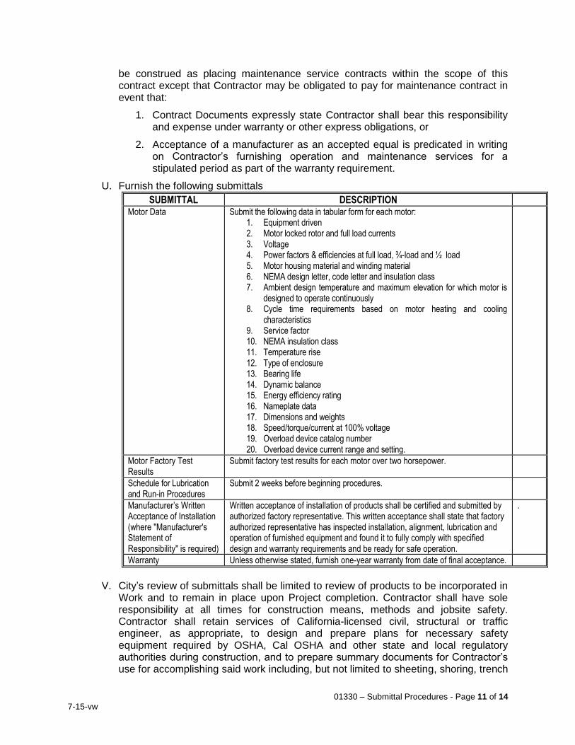
01330 – Submittal Procedures - Page 11 of 14
7-15-vw
be construed as placing maintenance service contracts within the scope of this contract except that Contractor may be obligated to pay for maintenance contract in event that:
1. Contract Documents expressly state Contractor shall bear this responsibility and expense under warranty or other express obligations, or
2. Acceptance of a manufacturer as an accepted equal is predicated in writing on Contractor’s furnishing operation and maintenance services for a stipulated period as part of the warranty requirement.
U. Furnish the following submittals
SUBMITTAL DESCRIPTION Motor Data Submit the following data in tabular form for each motor:
1. Equipment driven 2. Motor locked rotor and full load currents 3. Voltage 4. Power factors & efficiencies at full load, ¾-load and ½ load 5. Motor housing material and winding material 6. NEMA design letter, code letter and insulation class 7. Ambient design temperature and maximum elevation for which motor is
designed to operate continuously 8. Cycle time requirements based on motor heating and cooling
characteristics 9. Service factor 10. NEMA insulation class 11. Temperature rise 12. Type of enclosure 13. Bearing life 14. Dynamic balance 15. Energy efficiency rating 16. Nameplate data 17. Dimensions and weights 18. Speed/torque/current at 100% voltage 19. Overload device catalog number 20. Overload device current range and setting.
Motor Factory Test Results
Submit factory test results for each motor over two horsepower.
Schedule for Lubrication and Run-in Procedures
Submit 2 weeks before beginning procedures.
Manufacturer’s Written Acceptance of Installation (where "Manufacturer's Statement of Responsibility" is required)
Written acceptance of installation of products shall be certified and submitted by authorized factory representative. This written acceptance shall state that factory authorized representative has inspected installation, alignment, lubrication and operation of furnished equipment and found it to fully comply with specified design and warranty requirements and be ready for safe operation.
.
Warranty Unless otherwise stated, furnish one-year warranty from date of final acceptance.
V. City’s review of submittals shall be limited to review of products to be incorporated in
Work and to remain in place upon Project completion. Contractor shall have sole responsibility at all times for construction means, methods and jobsite safety. Contractor shall retain services of California-licensed civil, structural or traffic engineer, as appropriate, to design and prepare plans for necessary safety equipment required by OSHA, Cal OSHA and other state and local regulatory authorities during construction, and to prepare summary documents for Contractor’s use for accomplishing said work including, but not limited to sheeting, shoring, trench
01330 – Submittal Procedures - Page 12 of 14
7-15-vw
plating, excavation protection, falsework, formwork, scaffolding, barricading, pedestrian safety and traffic control. Originals of summary documents, signed and sealed by engineer of record who prepared them, shall be submitted solely as proof this requirement has been fulfilled. Since Contractor has sole responsibility for means, methods and jobsite safety, review of said documents will be limited to verifying preparing engineer’s registration is current and that engineer of record has no active complaints filed against them with California Board for Professional Engineers and Land Surveyors.
W. Use of contract drawing reproductions for shop drawings is subject to rejection. 1.13 Samples
A. Furnish samples, finished as specified, and as intended to be used on or in Work. Send samples to City’s Representative, carriage prepaid.
B. Submit samples at least 21 days before date by which City’s approval is required. Allow at least 14 days for review and return of samples.
C. Submit two of each sample, except for field samples. Attach completed Contractor's submittal form to sample. List items being transmitted, stating proposed use and location, product, color, trade name, lot, style, and model as appropriate.
D. Resubmit samples until acceptable. One of each sample will be returned to Contractor upon acceptance.
E. Samples of finishes shall be 8" x 10" and shall be of minimum thickness consistent with sample presentation. In lieu thereof, submit actual full-size item.
F. Samples of value may be returned to Contractor for use in Work after review, analysis, comparison, and/or testing as may be required by City’s Representative.
G. Furnish one sample of accepted products, colors, or textures to City’s Representative for final record. Show identification previously described including, if finish sample, manufacturer, mix proportion, name of color, building, Contractor, subcontractor, and surfaces to which applied on back of sample.
1.14 Notification of Affected Residences and Businesses
A. Provide written notification, with Contractor's 24-hour emergency phone number, to residences and businesses fronting the project on either side of street for work within City right-of-way or within 500 feet of projects on sites outside of right-of-way. Notify these parties 72 hours in advance of construction which will affect these properties. Door-hangers or other means of notification shall be submitted to and accepted in advance by City’s Representative.
1.15 Unit Prices
A. Payment for submittals and re-submittals, will be included in the price bid for those items of Work for which the submittals are required.
PART 2 - PRODUCTS (Not Applicable) PART 3 - EXECUTION (Not Applicable)
END OF SECTION
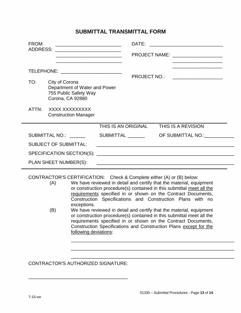
01330 – Submittal Procedures - Page 13 of 14
7-15-vw
SUBMITTAL TRANSMITTAL FORM
FROM: _________________________ ADDRESS: _________________________ _________________________ _________________________ TELEPHONE: _______________________ TO: City of Corona Department of Water and Power 755 Public Safety Way Corona, CA 92880 ATTN: XXXX XXXXXXXXX Construction Manager
DATE: ____________________________ PROJECT NAME: ___________________ ___________________ ___________________ PROJECT NO.: ___________________
THIS IS AN ORIGINAL THIS IS A REVISION
SUBMITTAL NO.: SUBMITTAL OF SUBMITTAL NO.:
SUBJECT OF SUBMITTAL:
SPECIFICATION SECTION(S):
PLAN SHEET NUMBER(S): CONTRACTOR'S CERTIFICATION: Check & Complete either (A) or (B) below:
(A) We have reviewed in detail and certify that the material, equipment or construction procedure(s) contained in this submittal meet all the requirements specified in or shown on the Contract Documents, Construction Specifications and Construction Plans with no exceptions.
(B) We have reviewed in detail and certify that the material, equipment or construction procedure(s) contained in this submittal meet all the requirements specified in or shown on the Contract Documents, Construction Specifications and Construction Plans except for the following deviations:
CONTRACTOR'S AUTHORIZED SIGNATURE:
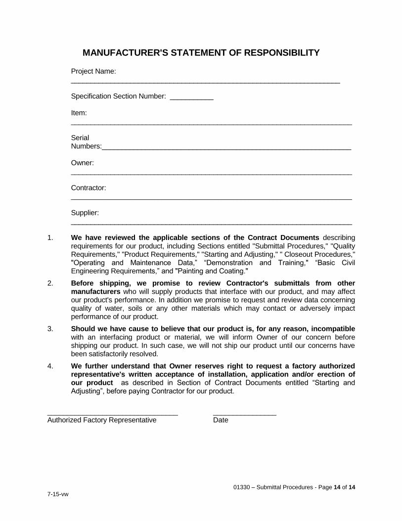
01330 – Submittal Procedures - Page 14 of 14
7-15-vw
MANUFACTURER'S STATEMENT OF RESPONSIBILITY Project Name:
____________________________________________________________________ Specification Section Number: ___________ Item:
_______________________________________________________________________ Serial
Numbers:_______________________________________________________________ Owner:
_______________________________________________________________________ Contractor:
_______________________________________________________________________ Supplier:
_______________________________________________________________________ 1. We have reviewed the applicable sections of the Contract Documents describing
requirements for our product, including Sections entitled "Submittal Procedures," "Quality Requirements," "Product Requirements," "Starting and Adjusting," " Closeout Procedures," "Operating and Maintenance Data,” “Demonstration and Training," “Basic Civil Engineering Requirements,” and "Painting and Coating."
2. Before shipping, we promise to review Contractor's submittals from other manufacturers who will supply products that interface with our product, and may affect our product's performance. In addition we promise to request and review data concerning quality of water, soils or any other materials which may contact or adversely impact performance of our product.
3. Should we have cause to believe that our product is, for any reason, incompatible with an interfacing product or material, we will inform Owner of our concern before shipping our product. In such case, we will not ship our product until our concerns have been satisfactorily resolved.
4. We further understand that Owner reserves right to request a factory authorized representative's written acceptance of installation, application and/or erection of our product as described in Section of Contract Documents entitled “Starting and Adjusting”, before paying Contractor for our product.
_________________________________ ________________ Authorized Factory Representative Date
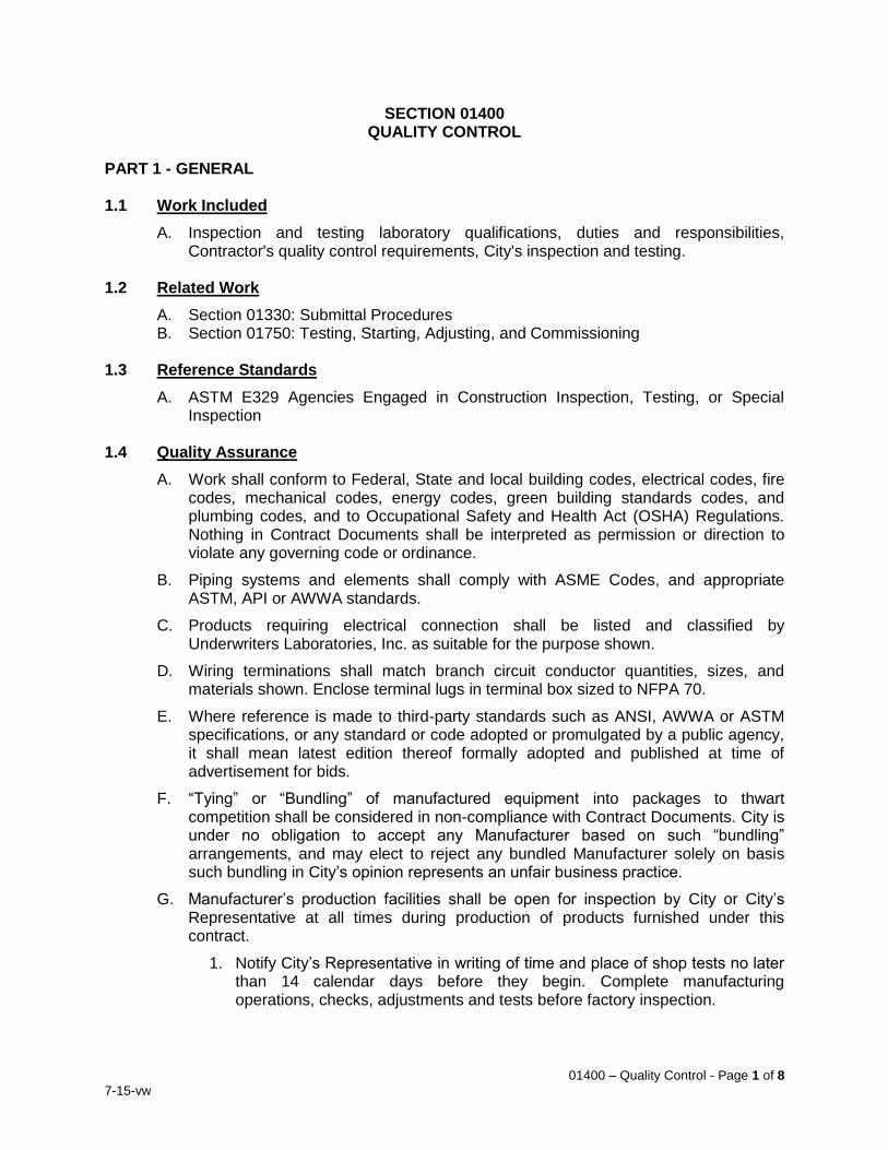
01400 – Quality Control - Page 1 of 8
7-15-vw
SECTION 01400 QUALITY CONTROL
PART 1 - GENERAL 1.1 Work Included
A. Inspection and testing laboratory qualifications, duties and responsibilities, Contractor's quality control requirements, City's inspection and testing.
1.2 Related Work
A. Section 01330: Submittal Procedures B. Section 01750: Testing, Starting, Adjusting, and Commissioning
1.3 Reference Standards
A. ASTM E329 Agencies Engaged in Construction Inspection, Testing, or Special Inspection
1.4 Quality Assurance
A. Work shall conform to Federal, State and local building codes, electrical codes, fire codes, mechanical codes, energy codes, green building standards codes, and plumbing codes, and to Occupational Safety and Health Act (OSHA) Regulations. Nothing in Contract Documents shall be interpreted as permission or direction to violate any governing code or ordinance.
B. Piping systems and elements shall comply with ASME Codes, and appropriate ASTM, API or AWWA standards.
C. Products requiring electrical connection shall be listed and classified by Underwriters Laboratories, Inc. as suitable for the purpose shown.
D. Wiring terminations shall match branch circuit conductor quantities, sizes, and materials shown. Enclose terminal lugs in terminal box sized to NFPA 70.
E. Where reference is made to third-party standards such as ANSI, AWWA or ASTM specifications, or any standard or code adopted or promulgated by a public agency, it shall mean latest edition thereof formally adopted and published at time of advertisement for bids.
F. “Tying” or “Bundling” of manufactured equipment into packages to thwart competition shall be considered in non-compliance with Contract Documents. City is under no obligation to accept any Manufacturer based on such “bundling” arrangements, and may elect to reject any bundled Manufacturer solely on basis such bundling in City’s opinion represents an unfair business practice.
G. Manufacturer’s production facilities shall be open for inspection by City or City’s Representative at all times during production of products furnished under this contract.
1. Notify City’s Representative in writing of time and place of shop tests no later than 14 calendar days before they begin. Complete manufacturing operations, checks, adjustments and tests before factory inspection.
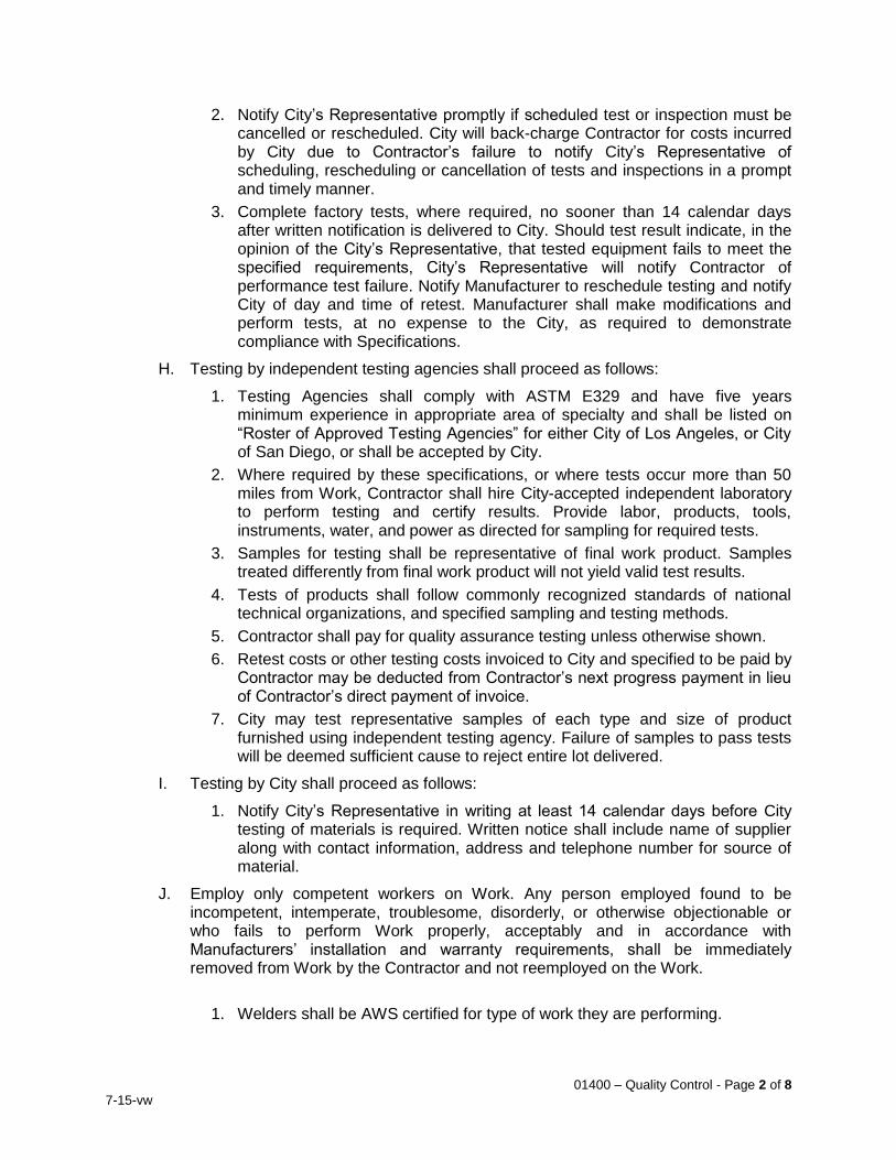
01400 – Quality Control - Page 2 of 8
7-15-vw
2. Notify City’s Representative promptly if scheduled test or inspection must be cancelled or rescheduled. City will back-charge Contractor for costs incurred by City due to Contractor’s failure to notify City’s Representative of scheduling, rescheduling or cancellation of tests and inspections in a prompt and timely manner.
3. Complete factory tests, where required, no sooner than 14 calendar days after written notification is delivered to City. Should test result indicate, in the opinion of the City’s Representative, that tested equipment fails to meet the specified requirements, City’s Representative will notify Contractor of performance test failure. Notify Manufacturer to reschedule testing and notify City of day and time of retest. Manufacturer shall make modifications and perform tests, at no expense to the City, as required to demonstrate compliance with Specifications.
H. Testing by independent testing agencies shall proceed as follows:
1. Testing Agencies shall comply with ASTM E329 and have five years minimum experience in appropriate area of specialty and shall be listed on “Roster of Approved Testing Agencies” for either City of Los Angeles, or City of San Diego, or shall be accepted by City.
2. Where required by these specifications, or where tests occur more than 50 miles from Work, Contractor shall hire City-accepted independent laboratory to perform testing and certify results. Provide labor, products, tools, instruments, water, and power as directed for sampling for required tests.
3. Samples for testing shall be representative of final work product. Samples treated differently from final work product will not yield valid test results.
4. Tests of products shall follow commonly recognized standards of national technical organizations, and specified sampling and testing methods.
5. Contractor shall pay for quality assurance testing unless otherwise shown.
6. Retest costs or other testing costs invoiced to City and specified to be paid by Contractor may be deducted from Contractor’s next progress payment in lieu of Contractor’s direct payment of invoice.
7. City may test representative samples of each type and size of product furnished using independent testing agency. Failure of samples to pass tests will be deemed sufficient cause to reject entire lot delivered.
I. Testing by City shall proceed as follows:
1. Notify City’s Representative in writing at least 14 calendar days before City testing of materials is required. Written notice shall include name of supplier along with contact information, address and telephone number for source of material.
J. Employ only competent workers on Work. Any person employed found to be incompetent, intemperate, troublesome, disorderly, or otherwise objectionable or who fails to perform Work properly, acceptably and in accordance with Manufacturers’ installation and warranty requirements, shall be immediately removed from Work by the Contractor and not reemployed on the Work.
1. Welders shall be AWS certified for type of work they are performing.
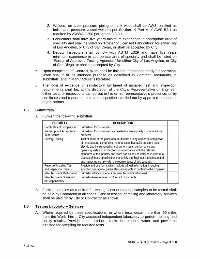
01400 – Quality Control - Page 3 of 8
7-15-vw
2. Welders on steel pressure piping or tank work shall be AWS certified as boiler and pressure vessel welders per Section IX Part A of AWS B2.1 as required by AWWA C200 paragraph 3.3.3.1.
3. Fabricators shall have five years minimum experience in appropriate area of specialty and shall be listed on “Roster of Licensed Fabricators” for either City of Los Angeles, or City of San Diego, or shall be accepted by City.
4. Deputy Inspectors shall comply with ASTM E329 and have five years minimum experience in appropriate area of specialty and shall be listed on “Roster of Approved Testing Agencies” for either City of Los Angeles, or City of San Diego, or shall be accepted by City.
K. Upon completion of Contract, Work shall be finished, tested and ready for operation. Work shall fulfill its intended purpose as described in Contract Documents, in submittals, and in Manufacturer's literature.
L. The form of evidence of satisfactory fulfillment of installed test and inspection requirements shall be, at the discretion of the City’s Representative or Engineer, either tests or inspections carried out in his or his representative's presence; or by certificates and reports of tests and inspections carried out by approved persons or organizations.
1.5 Submittals
A. Furnish the following submittals.
SUBMITTAL DESCRIPTION Certificates of Compliance Furnish on City’s Request .
Transcripts of Acceptance Test Results
Furnish on City’s Request as needed to verify quality of manufactured products
Factory Testing Test of items at the place of manufacture during and/or on completion of manufacture, comprising material tests, hydraulic pressure tests, electric and instrumentation subsystem tests, performance and operating tests and inspections in accordance with the relevant standards of the industry and more particularly as detailed in individual clauses of these specifications to satisfy the Engineer the items tested and inspected comply with the requirements of this contract.
Report of Installed Test and Inspection Results
Provide and use forms which include all test information, including specified operational parameters acceptable in content to the Engineer.
Manufacturer’s Certification Furnish certification letters on manufacturer’s letterhead.
Manufacturer’s Statement of Responsibility
Furnish where required in Contract Documents.
B. Furnish samples as required for testing. Cost of material samples to be tested shall
be paid by Contractor in all cases. Cost of testing, sampling and laboratory services shall be paid for by City or Contractor as shown.
1.6 Testing Laboratory Services
A. Where required by these specifications, or where tests occur more than 50 miles from the Work, hire a City-accepted independent laboratory to perform testing and certify results. Provide labor, products, tools, instruments, water, and power as directed for sampling for required tests.
01400 – Quality Control - Page 4 of 8
7-15-vw
B. Samples for testing shall be representative of final work product. Samples treated differently from final work product will not yield valid test results.
C. Tests of products shall follow commonly recognized standards of national technical organizations, and specified sampling and testing methods.
D. Contractor shall pay for quality assurance testing unless otherwise shown.
E. Retest costs or other testing costs invoiced to City and specified to be paid by Contractor may be deducted from Contractor’s next progress payment in lieu of Contractor’s direct payment of invoice.
F. City may test representative samples of each type and size of product furnished using an independent testing agency. Failure of samples to pass tests will be deemed sufficient cause to reject entire lot delivered.
1.7 Contractor’s Quality Control
A. Arrange work to be readily accessible and easy to operate and maintain where detail drawings are not included in Contract Documents, supplementary drawings or shop drawings and submittals.
B. Combinations of manufactured equipment shall be fully compatible and work safely and successfully as a unit. Furnish necessary mountings, couplings and appurtenances with each unit.
C. Relocate or adjust existing facilities noted in Contract Documents as needed. If existing items are lost or damaged during construction, replace with new items of equal or better quality.
D. Make field measurements needed to fabricate and install Work before ordering or beginning work. Make minor changes in alignments and dimensions as needed to remedy or avoid utilities and structural conflicts.
1.8 Manufacturer’s Certification
A. The manufacturer certifies the equipment is approved for operation. The equipment operates within the allowable limits for vibration. All controls, protective devices, instrumentation, and control panels furnished as part of the equipment package are properly installed, calibrated, and functioning. All Control logic for start-up, shutdown, sequencing, interlocks, and emergency shutdown have been tested and are properly functioning.
B. The equipment has been installed and adjusted in accordance with the manufacturer's requirements and is properly aligned and ready for operation.
C. The equipment has been serviced, lubricated and properly prepared to perform in accordance with the intent of the Contract Documents.
D. The equipment is ready for operation and the City’s Staff is suitably instructed in operation and maintenance of the equipment.
E. The manufacturer's warranty will commence, and be in full force from the date of the final acceptance of the project or applicable portion of the project by the City.
F. The signer has visited the site; inspected the equipment and installation; and certifies the equipment is ready and suitable for full time operation under full load conditions.
01400 – Quality Control - Page 5 of 8
7-15-vw
G. Submit certification letters to include the following on the manufacturer's letterhead for all equipment provided in the Contract
1.9 Project Conditions
A. Ascertain suitability of native soil for backfill before submitting bid. If native soil is found to be unsuitable, provide suitable material for meeting compaction requirements at no additional cost to City.
B. Items furnished shall be capable of fulfilling their intended purpose in environment in which they are installed. Allow for local temperature extremes, climactic conditions and corrosive environments where necessary to ensure proper functioning of furnished products.
1.10 Unit Prices
A. Payment for Contractor-provided testing required in Contract Documents will be included in the price bid for items of work for which Contractor-provided testing is specified.
PART 2 - PRODUCTS (Not Applicable)
PART 3 - EXECUTION 3.1 Inspection
A. Products and Work shall be subject to field and factory inspection and testing in accordance with standards required and defined in Contract Documents. Waiver by City of his right to inspect shall not relieve Contractor of duties to comply with Contract Documents.
B. Contractor shall provide and pay for independent inspection, deputy inspection and testing services required by Contract Documents.
C. City will provide certain inspection and testing duties not required of the Contractor under Contract Documents. Performance of these tests and costs will be borne by City; except, that Contractor shall pay cost of any failing test.
D. Inspection will be provided by City's Representative. Inspection shall not be considered as direct control of the individual workman and his work. Inspections, tests, or approvals by City's Representative or others shall not relieve Contractor from his duty to perform Work in accordance with Contract Documents.
E. Inspection and testing fees imposed by public agencies other than City shall be paid for by Contractor. If Contract Documents, permits, laws, ordinances, rules, regulations or orders of public authorities having jurisdiction require Work to be inspected, tested, or accepted by someone other than the Contractor, give City's Representative notice of readiness in accordance with General Conditions Article 26. Submit the required certificates of inspection, testing or approval to City's Representative.
F. Maintain access to Work for City and City's Representatives. Permit authorized representatives and agents of Federal or State agencies to inspect work, products, and other relevant data and records. Provide safe and proper facilities to access and observe Work and to inspect or perform tests.
01400 – Quality Control - Page 6 of 8
7-15-vw
G. City’s Representative will inspect products after delivery and throughout construction process. Products will be subject to rejection at any time on account of failure to meet Contract Documents even though samples may have been accepted as satisfactory at place of manufacture.
H. Before backfilling, request inspection by City’s Representative to verify proper installation of buried work.
I. Before finishing, request inspection by City’s Representative to verify that no surfaces to receive product have defects or errors which could result in poor or potentially defective application or cause latent defects in workmanship.
J. If Work is covered contrary to written instructions, or Work is covered before Contractor requests and receives inspection, uncover the Work at Contractor's expense, if requested by City's Representative. Replace at Contractor's expense.
K. If City's Representative considers it advisable that covered Work be reinspected or tested by others, at City's Representative's written request, uncover Work in question, furnishing necessary labor, products, and tools. If Work is found defective, Contractor shall pay for uncovering, exposure, observation, inspection and testing and of satisfactory reconstruction. If, Work is not found defective, Contractor will be allowed an increase in Contract Price or an extension of Contract Time, or both, directly attributable to such uncovering, exposure, observation, inspection, testing and reconstruction, and a Change Order will be issued.
3.2 Installation/Application/Erection
A. All materials and equipment shall be installed by specialists properly skilled in the trades and professions required to assure first-class workmanship. Where required by detailed specifications, the Contractor shall cause the installation of specific equipment items to be accomplished under the supervision of factory-trained installation specialists furnished by the equipment manufacturers. Be prepared to document the skills and training of all workmen engaged in the installation of all equipment furnished either by the Contractor or the City.
B. Coordinate with the equipment manufacturer when manufacturer's field services are provided. Provide City at least 30 days written notice prior to the need for manufacturer's field services furnished by other.
C. Install products according to manufacturer's installation and warranty requirements. Install products to tolerances recommended by manufacturer. Unless otherwise shown, install equipment true and level using precision gauges and levels. Do not shim between machined surfaces.
D. Refer variances between manufacturer's installation instructions and Contract Documents to the Engineer.
E. Construct walls plumb, straight, level, square and true. Acceptable deviations from plumb or level shall not exceed 1/4 inch in any 32 inch section. Flatwork shall not deviate from plan elevation by more than 3/4 inch at any location.
F. Welds, unless otherwise shown, shall be continuous, watertight, and conforming to Structural Welding Code of American Welding Society. Welds shall be free of sharp points or edges. Before welding, abutting joints shall be free of strain.
G. Pipework, valves, fittings, tanks and appurtenances shall have no leaks at rated pressures.
01400 – Quality Control - Page 7 of 8
7-15-vw
H. Exposed surfaces shall be finished in appearance. Grind smooth exposed welds. Round or chamfer corners of exposed structural shapes for personal protection.
I. Prime and paint exposed surfaces of ferrous products, piping, and conduit except for stainless steel or galvanized or sherardized surfaces or unless otherwise shown. Clean painted surfaces and touch up bare or marred spots with finish to match factory finish.
J. Buried pipework and conduit shall provide a clear and unobstructed pathway free from obstructions due to pipe or conduit deflection and free from interior debris. Where City has reason to suspect the presence of such obstructions, the City’s Representative reserves the right to require mandrel testing to demonstrate compliance before subsequent work such as paving, before charging or commissioning of piping, or before installation of wire within conduit.
K. If products are furnished which differ from those shown and which require changes to enclosures, mounting and support structures, power and control circuitry or other work to accommodate furnished product, provide changes required at no additional cost to City and of same quality as shown.
L. Upon completion of Contract, Work shall be finished, tested and ready for operation. Work shall fulfill its intended purpose as described in Contract Documents, in submittals, and in manufacturer's literature.
3.3 Field Quality Control
A. Perform sampling and testing at the frequency shown, and at such other times as necessary to document contract compliance.
B. Notify City’s Representative and regulating authorities three days before field tests.
C. Perform field tests in presence of City’s Representative who will record results.
D. Remedy or remove and replace in a manner acceptable to the City’s Representative all Work not conforming to the requirements of the Contract Documents. No compensation will be allowed the Contractor for such removal or replacement.
E. Remove rejected work from jobsite. Work rejected by City's Representative for failure to comply with Contract Documents, shall be removed within 10 calendar days after Written Notice of rejection, whether incorporated in Work or not, unless repairs have been made to City's satisfaction.
F. Defective work or unsuitable materials and/or equipment may be rejected, even though such defective items may have been previously overlooked by the City’s Representative.
G. Promptly replace and re-execute removed Work in accordance with Contract Documents and without expense to City. Contractor shall bear cost of making good Work of other Contractors destroyed or damaged by such removal or replacement.
H. If Contractor does not act to remove rejected Work within 10 calendar days after receipt of Written Notice, City may remove such Work and store products at Contractor's expense.
I. If the Contractor fails to remedy, remove, replace, or correct Work under the provisions of this section, City shall have the authority to cause defective work to be remedied, or removed and replaced, and any unauthorized work to be removed by City forces, or otherwise, and to deduct the costs thereof from any monies due or to become due the Contractor, or to bring suit against the Contractor and the
01400 – Quality Control - Page 8 of 8
7-15-vw
Contractor’s sureties for money damages sustained by City or for specific performance of the contractual obligations of the Contractor.
J. Repair, correct or replace work failing tests or inspection. Repeat tests at Contractor’s expense, until results satisfy specifications. Repair damages resulting from tests.
K. Repair damage to work that is not cause for rejection.
L. Any Work done beyond the lines and grades shown on the Plans, or any extra work done without written authority of the City’s Representative will be considered as unauthorized and no compensation shall be made therefor. Remove all nonconforming materials from the site.
END OF SECTION
01500 – Construction Facilities and Temporary Controls Page 1 of 18
7-15-vw
SECTION 01500 CONSTRUCTION FACILITIES AND TEMPORARY CONTROLS
PART 1 - GENERAL 1.1 Work Included
A. Provide all necessary temporary facilities and controls required for execution of the Work, including, but not limited to storage yard, field offices, sheds, temporary utilities, temporary controls, construction aids, barriers and enclosures, security, establishing fire protection system, access roads and parking areas, and traffic regulation. The costs of these temporary facilities and controls are considered incidental to the Work and shall be included in the Contractor’s bid proposal. A field office for City use is required for this project.
B. Construction of this project may expose the Contractor's workmen to the hazard of materials underground and materials from nearby existing facilities, such as propane gas, sewer gas, wastewater and wastewater sludge with varying degrees of treatment. The Contractor shall certify he is experienced and qualified to anticipate and meet the safety and health requirements of this Project. The Contractor shall require his personnel to observe proper safety and hygienic precautions.
C. The Contractor shall be solely responsible for the storage, usage, handling and application of all hazardous materials encountered or provided as part of the Work.
D. No attempt is made to set out in detail means or methods necessary to satisfy requirements. Recognition of requirements is made to assist Contractor in the identification of necessary costs.
1.2 Related Work
A. Section 01040: Access and Coordination B. Section 01330: Submittal Procedures C. Section 01590: Field Offices D. Section 01740: Cleaning, Final Cleaning, Pollution Prevention and Disposal of
Hazardous Waste E. Section 01770: Closeout Procedures
1.3 Submittals
A. Furnish the following submittals:
SUBMITTAL DESCRIPTION Storage Yard Description of Contractor’s proposed methods for dust and noise control in storage areas
Property owner's written approval for use of property used as storage yard for project.
Construction Facilities Plan
Layout, equipment, materials and procedures proposed for construction of temporary power, telephone, lighting, heating, water, sanitation, field offices and sheds, storm water management, security, dewatering, etc.
Injury and Illness Prevention Program
Description of Contractor’s procedures and requirements for safety and hygiene.
Confined Space Entry Permitting Program
Contractor’s confined space work procedures and rescue plan documentation in accordance with State law and City’s policy.
01500 – Construction Facilities and Temporary Controls Page 2 of 18
7-15-vw
SUBMITTAL DESCRIPTION Excavation and Shoring Plans and Drawings
Detailed plan showing the design of shoring, bracing, sloping, or other provisions to be made for worker protection from the hazard of caving ground during excavation of any trench, pit, or excavation for structure five (5) feet or more in depth.
1.4 Temporary Utilities
A. Power: Purchase or generate on-site construction power for constructing Work where existing outlets are not available.
B. Construction Water: Unless otherwise stated, Contractor shall, at his expense, arrange to develop water sources, furnish and install piping, valves and appurtenances necessary to connect to the water supply, provide backflow protection and supply labor and equipment to collect, load, transport, and apply water as needed for compaction, testing, concrete work, dust control, and other construction use.
Use of the City's water will be under the City’s control, and the Contractor shall follow any requirements or provisions set forth by the City regarding its use. Provide a CDPH approved backflow device and obtain a construction water meter from the City to document water usage. Pay the construction water meter deposit. The Contractor(s) shall not be required to pay for the water used in the prosecution of the Work. If water is taken through fire hydrants, use one 2½-inch connection for construction water. Reserve the remaining outlets for use by fire department. Do not draw water from any fire hydrant, except to extinguish a fire, without obtaining permission from the City.
Construction water shall be clean and free from objectionable deleterious amounts of acids, alkalis, salts, or organic materials. Use reclaimed water for all general construction purposes other than moisture conditioning of backfill in potable waterline and untreated waterline trenches, and flushing of potable waterlines and untreated waterlines, where applicable and when available.
C. Drinking Water: Provide at all times abundant supply of safe drinking water for employees and give orders against the use of, for drinking purposes, any water in the vicinity of the Work known to be unsafe.
D. Sanitation: Provide suitable and conveniently located temporary toilets, sanitation, and hand washing facilities for employees in full compliance with the rules and regulations of the State Board of Health and/or other bodies having jurisdiction. Do not use any City sanitation facilities. Leave Contractor-provided toilets and sanitation facilities at the site until final inspection has been made. Following final inspection remove temporary sanitation facilities and leave site in neat and sanitary condition. Clean toilets at least once per week.
Do not interrupt wastewater conveyance and disposal. Should the Contractor disrupt existing sewer facilities, convey sewage in closed conduits and dispose of in a sanitary sewer system. Submit a proposed bypass system for City review. Do not permit sewage to flow in trenches or be covered by backfill.
Dispose of all rubbish, surplus, and waste materials of any nature occurring at the work site offsite in accordance with local, state, and federal codes and ordinances governing locations and methods of disposal, all at the Contractor’s expense. Establish regular intervals of collection and disposal of such materials and waste.
01500 – Construction Facilities and Temporary Controls Page 3 of 18
7-15-vw
Take care to prevent spillage on haul routes. Contain and remove any such spillage and clean the area.
E. Communications: Make construction telephone available at site at all times when Work is in progress. Cellular phones are acceptable.
F. Lighting: Install temporary lighting when Work is performed at night or under deficient daylight conditions to ensure correct performance, to provide for inspection, and to maintain lighting levels during working hours meeting or exceeding lighting levels required by OSHA and state agency administering OSHA regulations.
1.5 Construction Aids
A. Provide scaffolding, rigging, hoisting and services needed to safely deliver, support, move, and install products. Remove same from premises when installation is complete.
B. Comply with OSHA requirements and applicable laws, ordinances, rules, regulations, and orders pertaining to construction machinery and equipment, hoists, cranes, scaffolding, staging, materials handling facilities, tools, appliances and other construction aids. OSHA requirements shall govern where mandatory; otherwise comply with the most stringent requirements.
C. Provide railings, kick plates, enclosures, safety devices, and controls required by Laws and Regulations and as required for adequate protection of life and property.
D. Design temporary supports with adequate safety factor to assure adequate load bearing capability.
1. When requested, submit design calculations by professional engineer registered in the State of California prior to application of loads.
2. Submitted design calculations are for information and record purposes only.
E. Prepare and implement accident prevention and safety program to include, but not be limited to:
1. Exercise precautions throughout construction for protection of persons and property.
2. Observe safety provisions of applicable Laws and Regulations.
3. Guard machinery and equipment, and eliminate other hazards.
4. Make reports required by authorities having jurisdiction, and permit safety inspections of the Work.
5. Before commencing construction Work, take necessary action to comply with provisions for safety and accident prevention.
F. Adequately identify and guard hazardous areas and conditions by visual warning devices and, where necessary, physical barriers. Devices shall conform to minimum requirements of OSHA and State agency which administers OSHA regulations where Project is located.
G. Mark or guard excavations in areas from which public is excluded, in manner appropriate for hazard.
H. On multi-level structures, provide safety protection that meets requirements of OSHA and State agency which administers OSHA regulations where Project is located.
01500 – Construction Facilities and Temporary Controls Page 4 of 18
7-15-vw
1.6 Access Roads and Parking Areas
A. Construct and maintain access or haul roads required for Project, and personnel movement into and within construction and excavation areas, subject to prior approval by City. Access facilities constructed by the Contractor shall provide for surface drainage. Install and remove earth ramps as needed to protect concrete and asphalt curbs. Grade and restore to original condition areas used for temporary access, haul roads and access from public roads. Grade conditions to City's satisfaction.
B. Do not block any access roads or entrances unless otherwise approved by the City’s Representative. Maintain at least one-way traffic. Provide all signs, traffic cones and other barriers for traffic detours.
C. Maintain emergency access routes open at all times. Do not excavate, store equipment, or otherwise restrict access for emergency vehicles on emergency routes. When work is required in emergency routes, provide necessary traffic control, including flagmen, to provide emergency access. Submit a plan to the City’s Representative for review within 14 calendar days of the Notice to Proceed to maintain emergency access and operator access to all operating facilities during construction. As circumstances and conditions change, submit revised access plans to the City’s Representative. Immediately restore and pave emergency routes when Work is finished.
D. The location of Contractor storage and parking areas on City property will be designated by the City’s Representative, subject to change as operational requirements dictate.
E. Access to the site for Contractor’s and sub-contractor’s employees, materials, tools, and equipment shall be from Quarry Street. Any damage to off-site and on-site roads must be repaired in kind at no cost to City or property owner.
F. Follow the requirements of the traffic control plan for haul routes and site access. If special circumstances require modifications to the established haul routes and site access, consult with City and governing authorities for exceptions to the traffic control plan requirements. If no traffic control plan is in effect, consult with City and governing authorities and establish thoroughfares which will be used as haul routes and site access.
1.7 Temporary Controls
A. Noise Control
Comply with local noise ordinances and OSHA regulations for acceptable noise exposure, including scheduling Work to comply with noise ordinances and installing sound barriers, if needed to comply with noise ordinances and Contract Documents. All internal combustion engines in vehicles and construction equipment shall be equipped with manufacturer-recommended mufflers. Do not operate noise-generating construction equipment except during normal working hours unless written permission is obtained from City’s Representative. Back up bells on equipment may only be operated between 7:00 a.m. and 5:00 p.m. Monday - Friday. Air compressors and diesel engine-driven equipment operation will not be permitted between 5:00 p.m. and 7:00 a.m. Monday-Friday. Temporary generators will be
01500 – Construction Facilities and Temporary Controls Page 5 of 18
7-15-vw
permitted to operate between 7:00 a.m. and 5:00 p.m. Monday – Friday providing the generator noise level will not exceed 85 dB at 3 feet. If noise at doorstep of any private residence exceeds allowable noise specified, City may require Contractor to pay each affected household $200 per day to cover expenses of alternative lodging.
It is the City’s desire to maintain a courteous relationship with the residents adjacent to the construction site. Prior to construction mobilization, the City will prepare and distribute a letter to the surrounding residents informing them of the pending construction and expected schedule of activities. In support of this, the Contractor's employees will be expected to conduct their work in a professional manner compatible with a residential neighborhood environment.
Occupied residences and a public park border all sides of the project site. Noise abatement shall consist of no undue noise and all motors will be equipped with proper mufflers. Install primary sound attenuation measures around air compressors, generators, and other engine-driven devices. All internal combustion engines in vehicles and construction equipment shall be equipped with manufacturer-recommended mufflers.
Occupied residences and businesses border the east and north side of the well site. Noise abatement shall consist of no undue noise and all motors will be equipped with proper mufflers. All internal combustion engines in vehicles and construction equipment shall be equipped with manufacturer-recommended mufflers.
Schedule Work as necessary to minimize noise between 5:00 p.m. and 7:00 a.m. Do not operate noise-generating construction equipment except during normal working hours unless written permission is obtained from City’s Representative.
B. Fire Prevention
Minimize fire danger at and near construction site. Protect surrounding private property from fire damage resulting from construction operations. Provide sufficient number of fire extinguishers of type and capacity required to protect the Work and ancillary facilities, per local fire code requirements.
C. Storm Water Management
Conduct storm water management operations and maintain controls as needed to prevent runoff or seepage from entering excavations and to control erosion in conformance with Federal, State and local regulations and requirements of Specifications Section 01740. Legally dispose of surface and subsurface water. Do not allow mud, silt, or debris to flow on to adjoining or public property.
D. Protection of Existing Improvements
Exercise care to avoid injury to existing improvements, adjacent property, and trees and shrubbery that are not to be moved. Protect from injury or damage trees and shrubbery that are not to be moved, poles, fences, signs, property corners, all underground pipe and conduit, and other improvements within or near the work area. If such objects, or improvements, are injured or damaged by reason of the Contractor's operations, they shall be replaced or restored, at the Contractor's expense, to a condition at least as good as prior to construction operations.
01500 – Construction Facilities and Temporary Controls Page 6 of 18
7-15-vw
E. Protection of Existing Utilities
For the purpose of the Contract Documents, utilities shall be considered as including but not limited to, and irrespective of ownership: pipelines (including irrigation lines), conduits, transmission lines, and appurtenances of “Public Utilities” (as defined in the Public Utilities Act of the State of California), and those of private industry, business, or individuals solely for their own use or their tenants; and storm drains, sanitary sewers, street lighting, traffic signal systems, duct banks, telephone cables, power lines, cable television, fiber optic lines, gas lines, petroleum lines, transmission cables, and completely buried structures, hereafter referred to as utilities.
City has endeavored to locate and indicate on the Contract Documents, utilities that exist within the limits of the project, as derived from information provided by the owners of such utilities. However, the accuracy or completeness of the utilities indicated on the Contract Documents is not guaranteed. No attempt has been made to show service connections on the Contract Documents. It shall be the Contractor’s responsibility to make his own investigations, including exploratory excavations to determine exact location of utilities shown on the Contract Documents and locations of service connections prior to earthwork operations and to notify the City’s Representative of any utility which has been incorrectly shown or omitted from the Contract Documents.
Protect in place, at no additional cost to City, all existing utilities running parallel to proposed pipelines, sewers, conduits, structures and all other improvements. This includes protection in place of all backfill above the utility and pipe bedding.
Work required in connection with utilities, because of interference with Contract Work, will be performed and paid for as specified in this section. However, when directed or approved by the City, changes in line or grade of any structure being built may be made in order to avoid utilities. Any additional costs because of such changes will be paid for by change order as Extra Work.
The right is reserved to governmental agencies and to owners of utilities to enter at any time upon any street, alley, right-of-way, or easement for the purpose of making changes in their facilities and for the purpose of maintaining and making repairs.
The Contract Documents provide guidance regarding disclosure of utilities. This section provides guidance as to payment for protection relocation, or disposal of utilities shown and not shown on the Plans.
Do not begin any trench or excavation work until the Contractor has contacted a regional notification center as defined in California Government Code Section 4215 and the location of all utilities within the Project limits has been identified. If a Contractor hits a utility, take prompt action to make sure employees and the public are not endangered. If a water line is hit, the trench must be evacuated immediately. If an oil or gas line is hit, all employees and the public shall be evacuated from the immediate vicinity. Treat all conduits as though they are high voltage or high current electrical conduits. Do not tamper with any conduit until the owner is called and power shut off. In all cases, call the Fire Department and utility owner immediately.
F. Advance Notification and Exposure of Utilities – In Advance of Work
It shall be the Contractor’s responsibility to determine and notify those agencies requiring advance notification for inspection or other purposes before beginning construction in any jurisdictional area of any agency. Provide at least two full
01500 – Construction Facilities and Temporary Controls Page 7 of 18
7-15-vw
working days (48 hours minimum) advance notice to the various agencies before beginning construction in the area unless specified advance times and other requirements are stated in the Contract Documents or in permit requirements.
Make exploratory excavations to determine the true location and depth of all utilities, services, and buried structures in the vicinity of the proposed work prior to any construction activity. Determine the type of material and condition of any utility which may be affected by or affect the Work. Conduct exploratory excavations at least 1,300 feet ahead of a pipe trench heading a minimum of five (5) days in advance of planned construction to provide sufficient lead-time to resolve utility conflicts.
All costs incurred in exposing utilities shall be included in the various bid items and no additional allowance will be made therefor.
G. Utility Relocations by City
When it is stated in the Contract Documents that a utility is to be relocated, altered, or reconstructed by other than the Contractor, City will conduct all negotiations in respect to such work and the Work will be done at no cost to the Contractor. No additional compensation will be given for delays or inconvenience by others to finish their work on schedule due to unforeseen difficulties.
H. Utility Relocation by Contractor as Shown in the Contract Documents
When work on a utility is specified on the Contract Documents or indicated on the drawings to be done by the Contractor, but is not included as a separate bid item, the Contractor shall make all arrangements and coordinate with the owner of the utility regarding schedule for performance of the Work. Any costs for such Work shall be included in the unit prices or included in the lump sum amounts bid for the various Contract items. Submit a proposed method of relocation or protection of the utility for review. Review by the City will not relieve the Contractor of any responsibility.
I. Utility Relocation by Contractor for Contractor’s Convenience
The temporary relocation or the alteration of any utility, desired by the Contractor solely for convenience in the performance of the Work, to a position or condition other than that provided for on the Contract Documents shall be the Contractor’s own responsibility. Make all arrangements with the property owners regarding such work. Any costs of such work for the Contractor’s own convenience shall be absorbed in the unit prices or included in the lump sum amounts bid for the various Contract items at no additional cost to the City.
J. Unknown Utility Installation by Others During Contract Work
In the event a utility is disclosed or installed subsequent to the award of Contract, such utility not being indicated on the Contract Documents, with reasonable accuracy, and when said utility is found to occupy the space required to be occupied by a part of the permanent works, that, in the judgment of the City’s Representative, such utility requires location, relocation, removal, repair of damages, alteration, support or protection, City will determine the method and manner of accomplishing such work and may order the Contractor to do so pursuant to a change order issued by City. Perform the Work in accordance with Contract Documents provided or approved by City and in accordance with the following:
01500 – Construction Facilities and Temporary Controls Page 8 of 18
7-15-vw
1. When said utility is found to occupy the space required to be occupied by a part of the permanent Works to be constructed under the Contract or parallel to the permanent works and within vertical planes on each side at a distance away equal to the maximum allowable trench width measured at a point 12 inches above the top of the pipe, exclusive of branches or other facilities, as specified in the Specifications for Earthwork, or to be within the specified excavation pay lines (when such are specified in the Contract Documents); City shall arrange for the relocation or alteration of said utility or require the Contractor to do the same.
2. Utilities found to cross the excavation, but not intercepting the permanent works to be constructed or interfering with the construction will be maintained in place at the Contractor’s expense. Utilities which interfere with the construction technique in use will be protected or relocated.
3. When said utility is more or less parallel with, and any portion of it does not lie within the vertical planes specified herein above, or does not lie within the excavation pay lines (when such are specified or shown on the Contract Documents); advise City and owner thereof, and in cooperation with the owner of the utility, provide and place the necessary support for proper protection to guarantee continuous and safe operation of the utility.
4. Maintain continuous sanitary sewer service at all times. Should any existing sanitary sewer or manhole extend within the proposed excavation, submit a method of construction or support for approval by the City and assume all responsibilities therefor. All costs for such work shall be borne by the Contractor.
5. If the Work is done by others, provide time and working space for protection and relocation as required.
6. Where undisclosed utilities are discovered and located by the Contractor when performing this Contract, immediately notify City in writing.
7. City will compensate the Contractor for its direct costs of locating, relocating, removal, repair, support or protection of the undisclosed utilities, together with the cost of equipment used for the Work necessarily idled during such Work. The Contractor will be granted an extension of time for the completion of the Contract equal to the time determined by City, to be reasonably necessary to perform the Extra Work and City will not assess liquidated damages against the Contractor for delay in completion of the Work when such delay was caused by the failure of City to provide for the removal or relocation of such utility facilities.
8. The Contractor will not be entitled to extra compensation or an extension of time when Extra Work is required to repair damage to undisclosed utilities caused by the failure of the Contractor to exercise reasonable care. The Contractor will not be entitled to any compensation for indirect or consequential costs or damages incurred as a result of the Extra Work required.
K. Monuments, Survey Markers, and Bench Marks
1. Do not disturb any monuments, survey markers, or bench marks without permission from the City’s Representative or Engineer.
01500 – Construction Facilities and Temporary Controls Page 9 of 18
7-15-vw
2. Bear the expense of resetting any monuments, survey markers, or bench marks which may be disturbed without permission.
3. File a corner record form referencing survey monuments subject to disturbance in the Office of the County Surveyor prior to start of construction and also prior to completion of construction for replacement of any survey monuments. Such points shall be referenced and replaced with appropriate monumentation by a Registered Land Surveyor or a Registered Civil Engineer authorized to practice land surveying within the State of California.
L. Protect Landscaping, Vegetation, and Irrigation Facilities
1. During the progress of construction take proper precautions to prevent damage to trees, plants, and shrubs. The piling of excavated material, equipment, construction materials, or anything else on top of branches or against the tree trunks will not be permitted. Notify the City of any potential impact to any protected tree or plant, and do not damage, move or otherwise harm said tree or plant prior to investigation and direction from the City. Costs associated with damage to any protected tree or plant shall be the sole responsibility of the Contractor.
2. Protect, or replace in kind, at no additional cost to the City, existing irrigation facilities affected by the Work. Modify irrigation system during the progress of the Work to continue irrigating existing landscaping and vegetation as necessary to maintain the health of existing plants, trees, and vegetation.
M. Historical or Archaeological
Should any items having historical or archaeological interest be discovered in the course of any construction activities, halt work and notify the City’s Representative immediately. Perform an on-site inspection under direction of the City-retained Archaeologist. Use the on-site inspection to make recommendations to the City and other applicable jurisdictions for determination of mitigation actions to be taken.
If cultural resources are encountered at any time during project excavation, avoid altering these materials and their context until a qualified archaeologist has evaluated the situation. Project personnel will not collect or retain cultural resources. Prehistoric resources include, but are not limited to, chert or obsidian flakes, projectile points, mortars, and pestles; and dark, friable soil containing shell and bone, dietary debris, heat-affected rock, or human burials. Historic resources include stone or adobe foundations or walls; structures and remains with square nails; and refuse deposits (glass, metal, wood, and ceramics) often found in old wells and privies.
Records of site inspections will be maintained in the City’s administrative records. Following construction, a post-construction site inspection will be made to determine the degree to which the final site modifications have impacted site descriptions and future access.
N. Human Remains
In the event of accidental discovery or recognition of any human remains, the County Coroner must be notified immediately and construction activities halted. If the remains are found to be Native American, the Native American Heritage Commission
01500 – Construction Facilities and Temporary Controls Page 10 of 18
7-15-vw
must be notified within 24 hours. Follow the guidelines of the Native American Heritage Commission regarding the treatment and disposition of the remains.
O. Protection from Weather
Heat and ventilate work areas to protect the Work from damage by freezing, high temperatures, weather, and to provide safe environment for workers.
P. First Aid Information
Post first aid facilities and information posters conforming to requirements of OSHA and other applicable Laws and Regulations in readily accessible locations.
Q. Vector Control
Provide rodent and pest control as necessary to prevent infestation of construction or storage areas. Employ methods and use materials which will not adversely affect conditions at the site or on adjoining properties.
R. Odor Control
Furnish all labor, materials, and equipment required to carry out effective measures wherever and as often as necessary to prevent the discharge of a nuisance odor from its operation into the atmosphere in such quantity as will violate the regulations of any legally constituted authority. Notify the City’s Representative at least forty-eight (48) hours in advance of any potential odor-causing activities scheduled for construction.
S. Chemicals
The following paragraph does not relieve the Contractor from its responsibility for obtaining prior approval from the City for chemical usage when otherwise required.
Provide four (4) copies of the MSDS to the City’s Representative for all chemicals used during construction or operational activities, prior to bringing them on site, whether defoliant, soil sterilant, herbicide, pesticide, disinfectant, polymer, reactant, or of other classification, which shows approval of either the U.S. Environmental Protection Agency or the U.S. Department of Agriculture. Use and dispose of residues of all such chemicals in strict accordance with the printed instructions of the manufacturer.
T. Explosives for Blasting
The use of explosives on the Work shall not be permitted.
U. Protection of Wildlife
If any work in this Contract might disturb wildlife, even in urban areas, hire a Biological Monitor to provide assistance in the field to assure that biological resources are protected and that project-specific mitigation measures are implemented. The Biological Monitor shall be qualified for the tasks to be performed. If endangered or threatened species are present in the project area and require removal or relocation, the Biological Monitor must hold the appropriate permits and approvals for access and capture or marking of the species of concern. Specific activities of the Biological Monitor may include the following:
01500 – Construction Facilities and Temporary Controls Page 11 of 18
7-15-vw
Marking areas to be protected from construction activity.
Observing construction activities and their impacts on biota.
Capturing and relocating biota as necessary to protect them from construction activities.
Prior to the removal of healthy trees at a worksite, a Biological Monitor must survey the trees to determine if active bird nests are present. If nests of sensitive species are present, tree removal will be scheduled to avoid the nesting season. Provide a written record of whether tree removal is required, and as needed, hire a biologist or provide documentation that nesting birds (listed species of special interest of those as threatened or endangered) are not present in the trees to be removed.
V. Surface Water Diversions and Groundwater Dewatering
Include all costs for providing materials, equipment, power, labor, and related expenses associated with diverting surface water runoff from excavations, dewatering surface water that enters the excavations, and dewatering groundwater within the excavations within each associated bid amount. Construct, operate and remove Well Points (if necessary) or pumping locations in the excavations to adequately remove water from within the excavations during construction.
Perform all dewatering in conformance with all safety regulations and RWQCB requirements. Obtain all permits and clearances from any and all regulatory agencies. Perform monitoring where required by RWQCB.
Construct all permanent improvements in areas free from water. Construct and maintain all permanent or temporary slopes, dikes, levees, drainage ditches, and sumps necessary for removal of water from work areas. Design, furnish, install, maintain, and operate all necessary pumping and other dewatering equipment required for dewatering the various work areas and for maintaining the foundation and other work areas free from water from any and all sources whatsoever.
Perform no excavation below any standing water level regardless of water source until the area has been dewatered. Perform dewatering by use of filtered well points or gravel-packed deep wells in such a manner as to protect adjacent structures.
Accomplish dewatering in a manner that will prevent loss of fines from the foundation, will maintain stability of all excavated slopes and bottoms of excavations, and will permit all construction operations to be performed in the dry. Perform dewatering of excavations to the extent required to permit placement of compacted fill materials in the dry and to prevent sloughing of the excavation side slopes. Lower the groundwater level a minimum of three feet below foundation grade prior to foundation preparation and placement of structural foundations. During the placement and compaction of fill or bedding materials, maintain the water level at every point within the limits of fills being placed a minimum of three feet below fill placement level.
Dewatering shall consist of furnishing all approved Plans, labor, equipment and materials, performing all Work to design, construct, and operate dewatering systems, maintaining in a safe and dewatered condition the areas on which the construction Work will be performed, and removing the dewatering system upon completion of the Work.
01500 – Construction Facilities and Temporary Controls Page 12 of 18
7-15-vw
Submit for the City’s review, drawings and data showing the proposed plan for dewatering of all work areas, which shall include the planned method of dewatering, excavation and shoring plan, location and capacity of such facilities as dewatering wells, well points, pumps, sumps, collection and discharge lines, standby units proposed, and protective fills and ditches required for control of groundwater and surface water Submit the plan for dewatering to the City’s Representative 15 days prior to the start of construction. Furnish such other information as may be required for the complete understanding and analysis of the dewatering and excavation plan by the City’s Representative.
Review by the City’s Representative will not relieve the Contractor of the responsibility for the adequacy of the dewatering and excavation plan or for furnishing all equipment, labor and materials necessary for performing the various parts of the Work. If, during the progress of the Work, it is determined by the City’s Representative the dewatering system and excavation plan are inadequate or the Contractor’s plan of construction is inoperative, the Contractor shall, at his expense, furnish, install, and operate such additional dewatering equipment and make such changes in other features of the plan or operation as may be necessary to perform the Work in a manner satisfactory to the City.
Monitor settlement and groundwater levels around existing structures during dewatering. Keep and evaluate daily records of settlement and groundwater levels. Notify the City’s Representative immediately if excessive settlement or a significant drop in groundwater level is recorded.
Furnish standby equipment of sufficient size and capacity to insure continuous operation of the dewatering system as designed. Repair any damage or settlement to the foundation or other work or any existing structures caused by temporary or permanent failure or operation of the dewatering system to the satisfaction of the City at the Contractor’s expense. The Contractor should consider the use of recharge systems or other methods of protecting existing facilities. The Contractor will be required to perform the dewatering and to maintain the permanent work areas for the length of time as required by the Earthwork Specifications, or for such additional time as necessary for the Work under this contract. Upon completion of the dewatering and control of water operation, remove all temporary works and dewatering facilities in a manner satisfactory to the City.
Dispose of water from dewatering operations in a suitable manner in conformance with the National Pollutant Discharge Elimination System (NPDES) Permit, as approved by the Regional Water Quality Control Board, Santa Ana Region (RWQCB).
1.8 Traffic Regulation
A. Maintain traffic control at all times and protect the work area, equipment, personnel, private property, and the public with adequate barricades, lights, signs, and warning devices per the current Work Area Traffic Control Handbook (WATCH) Manual, or the City-approved traffic control plan prepared for the project, and at the direction of the City’s Representative.
B. Implement whatever traffic control measures may be required to facilitate the Work of this contract, at no additional cost to City.
01500 – Construction Facilities and Temporary Controls Page 13 of 18
7-15-vw
1.9 Safety and Health Regulations
A. Comply with Safety and Health Regulations for Construction, promulgated by the Secretary Standards Act, as set forth in Title 9, C.F.R. Copies of these regulations may be obtained from Labor Building, 14th and Constitution Avenue NW, Washington, DC 20013.
B. Comply with the provisions of the Federal Occupational Safety and Health Act, as amended, and with all applicable State of California, Department of Industrial Relations, Construction Safety Orders (Cal-OSHA) requirements.
C. Prepare and submit one copy of Contractor’s Injury and Illness Prevention Program.
D. Comply with all federal, state, and local laws, regulations, and requirements for handling and storage of chemicals.
E. Monitor for explosive gas levels.
F. Confined Spaces:
1. The Contractor’s attention is directed to the General Industry Safety Orders of the State of California Article 108, Confined spaces, Section 5157. (Title 8 of California Code of Regulations, Sections 5156, 5157, and 5158.)
2. Retain a copy of said regulations on the worksite.
3. State law and City’s policy on confined spaces require a two-week advance notification from the Contractor for work within confined spaces, submittal of Contractor’s confined space work procedures and rescue plan, compliance with Entry Permit procedures, participation in a hazard assessment review of planned precautions and a debriefing upon completion of the confined space operation. Compliance with the General Industry Safety Orders remains the Contractor’s responsibility and City review is for general compliance and coordination only.
4. This notice is provided for bidding purposes. In accordance with the General Industry Safety Orders, Section 5157(c)(8), City will provide available information to the Contractor for each confined space location.
CONFINED SPACE WORK AREA(S)
a. Work areas for which entry is expected to be in accordance with Section 5157 (c)(5), Non-Permit required Confined Spaces;
b. Work areas in which hazardous or potentially hazardous atmospheric conditions exist or may exist shall be in accordance with Section 5157 (d), (e) and (f) (Permit-Required Confined Space):
Tanks
Equipment
Vaults
Manholes
It is the Contractor’s obligation to satisfy all requirements of Title 8, CCR 5157.
Attention is also directed to “Sewer System Entry”, Appendix E to CCR 5157.
NOTE: A permit required confined space may be reclassified by City Safety staff to a non-permit required confined space at the Contractor’s expense
01500 – Construction Facilities and Temporary Controls Page 14 of 18
7-15-vw
through the provisions set forth in 5157 (c)(7), or a listed non-permit required work area may become a permit required confined space work area.
The importance of working safely in confined spaces cannot be over emphasized. Due to the continuous flow of sewage and contaminant that may be contained therein, the atmosphere may suddenly and unpredictably become lethally hazardous. Where there is conflict between applicable safety orders, laws and regulations and policies, the more stringent measures shall apply. Compensation for confined space entry procedures and safety provisions shall be included in the lump-sum bid item for Confined Space Entry and other safety requirements.
G. Job Hazard Analysis:
Comply with the provisions of the Hazards Communication Act (CCR Title 8, Section 5194). If hazardous substances are to be utilized or handled in the course of the Contractor’s activities, before commencing each task conduct a job hazard analysis for the City. The analysis shall document the following:
1. Hazard communications program.
2. Safety precautions for all persons who may be exposed to hazardous substances utilized by the Contractor as presented in the Construction Safety Plan.
3. Number of people to be involved in the Work.
4. Written verification that all safety measures will be carried out.
5. Written verification that required safety equipment is available.
H. Be especially careful to avoid fire hazards in all welding, cutting, and equipment fueling. Furnish all safety devices, fire extinguishers and fire watch personnel required to protect the Work and provide for worksite and public safety.
I. Excavation Plans for Worker Protection Required by California Labor Code Section 6705:
1. All excavations must be performed, protected, and supported as required for safety and in a manner set forth in the operation rules, orders, and regulations prescribed by the CAL/OSHA Construction Safety Orders.
2. Submit to City for acceptance, in advance of excavation, a detailed plan showing the design of shoring, bracing, sloping, or other provisions to be made for worker protection from the hazard of caving ground during the excavation of any trench, pit, or excavation for structures five (5) feet or more in depth. The plan shall be prepared and signed by a California registered civil or structural engineer as required by all applicable laws including CAL/OSHA construction safety orders. As a part of the plan, include a note stating the registered civil or structural engineer certifies the plan complies with the CAL-OSHA Construction Safety Orders, or that the registered civil or structural engineer certifies the plan is not less effective than the shoring, bracing, sloping, or other provisions of the Safety Orders.
3. Include in the shoring and bracing plan the sequence and procedure for installation and removal of the shoring system components.
4. The City or its Engineer(s) may have made investigations of subsurface conditions in areas where the work is to be performed. If so, these
01500 – Construction Facilities and Temporary Controls Page 15 of 18
7-15-vw
investigations are provided for the Contractor’s use, but not made a part of the Contract Documents. Records of such investigations, if performed, are available for inspection at the City’s office. See the Contract General Conditions for more information regarding soils investigations.
5. The detailed plans showing the design of shoring, etc., which the Contractor is required to submit to City for acceptance in advance of excavation, will not be accepted by City if the plan is based on subsurface conditions which are more favorable than those revealed by the investigations made by City or its Engineer(s); nor will the plan be accepted if it is based on soils-related design criteria which are less restrictive than the criteria set forth in the report on the aforesaid investigations of subsurface conditions.
6. Include in the detailed plans showing the design of shoring, etc., the surcharge loads for nearby embankments and structures, for spoil banks, and for construction equipment and other construction loading. Indicate on the plans, for all trench conditions, the minimum horizontal distances from the side of the trench at its top to the near side of the surcharge loads.
7. Maintain excavations within street right-of-way and easements.
8. Do not use a shoring system as a form for cast-in-place concrete. Provide adequate space between structure and shoring system for installation and removal of forms. Where space between shoring and structure is not sufficient to provide adequate backfill compaction equipment, backfill with two-sack sand cement slurry.
9. Nothing contained in this section shall be construed as relieving the Contractor of the full responsibility for providing shoring, bracing, sloping, or other preventive measures which are necessary for worker protection, nor for the liability resulting from the failure to do so.
Excavations Below Four (4) Feet
Perform all work in excavation below four (4) feet in accordance with General Conditions Article 17.
Nothing in this section is intended to relieve the Contractor of the responsibility to fully examine the Contract Documents and the site where the work is to be performed in accordance with the General Conditions; to be familiar with all local conditions and federal, state, and local laws, rules and regulations that may affect the performance of any work; to study all surveys and investigative reports about subsurface and latent physical conditions pertaining to the worksite; to perform such additional surveys and investigations as the Contractor deems necessary to complete the work at the bid price; and to correlate the results of all such data with the requirements of the Contract Documents.
In the event a dispute arises between City and the Contractor involving hazardous waste and whether site conditions differ materially from those the Contractor could or should have discovered by the investigations required by these Contract Documents, the Contractor shall not be excused from the scheduled completion date provided in the Contract Documents and shall proceed with all work in the manner and in the time required by the Contract Documents.

01500 – Construction Facilities and Temporary Controls Page 16 of 18
7-15-vw
J. Open Trenches
1. No trench may be left open overnight unless authorized in writing by the City’s Authorized Representative.
2. Cover open excavations with steel plates in areas requiring vehicle/truck traffic when not in use. Provide safety fencing around the entire area at all other excavations when not in use.
1.10 Site Security
A. Safely guard all Work, materials, equipment and property from loss, theft, damage and vandalism. Project site is subject to vandalism. Contractor's duty to safely guard property shall include the City's property and other private property from injury or loss in connection with the performance of the Contract.
B. Upon completion of each day’s work, leave the work area secure and free of hazards. Provide necessary temporary signs, warning devices, chain link fences, and barricades.
C. Make no claim against the City for damage resulting from trespass. City is not responsible for items lost, damaged, or stolen from construction or storage areas or for injuries to the public due to unsafe conditions.
D. Party responsible for security shall make good all damage to property of City and others arising from failure to provide adequate security.
E. If existing fencing or barriers are breached or removed for purposes of construction, provide and maintain temporary security fencing equal to the existing in a manner satisfactory to the City.
F. Protect temporary and permanent fence, gate, and driveway openings to prevent intrusion by unauthorized persons. Bear responsibility for protection of material on site of the Work when openings are not closed. Provide temporary fencing around construction staging area. Fence temporary openings when openings are no longer necessary.
G. Provide temporary access to all adjacent properties during non-construction hours.
H. During night hours, weekends, holidays, and other times when no work is performed at site, provide temporary closures or enlist services of security guards to protect temporary openings.
I. Install and maintain for the duration of construction a remotely monitored site surveillance system to include video cameras mounted on temporary poles. Install surveillance system to provide full video surveillance of site with connection to monitoring station where police can be notified when unauthorized activity occurs.
J. Maintain security program throughout construction until City's acceptance and occupancy precludes need for Contractor's security program. Remove surveillance system following notice of substantial completion.
K. All costs for security as specified in this Section shall be borne by the Contractor. 1.11 Unit Prices
A. Payment for mobilization, demobilization, including payment for construction, modification, maintenance, removal and restoration associated with access, and
01500 – Construction Facilities and Temporary Controls Page 17 of 18
7-15-vw
storage facilities, will be included in the price bid for major items of Work for which mobilization is required.
B. Payment for verification of field dimensions and utility locations will be included in the price bid for items of Work which may require relocation or refitting if field dimensions differ from those shown on plans.
C. Payment for work necessary to develop water sources for construction use will be included in the price bid for items to which it is appurtenant. Payment under these items will include full compensation for furnishing labor, products, tools and equipment and doing work necessary to develop sufficient water supply and furnishing necessary equipment for applying water as specified.
D. Payment for temporary utilities to be furnished by Contractor for construction use will be included in the price bid for items to which it is appurtenant. Payment under these items will include full compensation for furnishing labor, products, tools, and equipment and doing work necessary to obtain, distribute, and use temporary utilities for construction purposes.
E. Payment for providing construction aids to be furnished by Contractor in support of construction activities will be included in the price bid for items to which it is appurtenant. Payment under these items will include full compensation for furnishing labor, products, tools, and equipment and doing work necessary to obtain, distribute, and use temporary utilities for construction purposes.
F. Payment for dust control, including dust palliatives and water supply and application will be included in the price bid for items of Work for which dust control during construction is appurtenant.
G. Payment for costs arising from fire or prevention of fire will be included in the price bid for items of Work for which fire protection during construction is needed.
H. Payment for noise control facilities will be included in the price bid for items of work where noise control facilities are required during construction.
I. Payment for complying with safety and health regulations will be included in the price bid for items to which it is appurtenant. Payment under these items will include full compensation for furnishing labor, products, tools, and equipment and doing Work necessary to comply with safety regulations and requirements.
J. Payment for providing site security will be included in the price bid for items to which it is appurtenant. Payment under these items will include full compensation for furnishing labor, products, tools, and equipment and doing work necessary to comply with site security requirements.
PART 2 - PRODUCTS (Not Applicable)
PART 3 - EXECUTION (Not Applicable)
END OF SECTION

01500 – Construction Facilities and Temporary Controls Page 18 of 18
7-15-vw
THIS PAGE INTENTIONALLY BLANK
01505 – Mobilization and Demobilization 1 of 4
7-15-vw
SECTION 01505 MOBILIZATION AND DEMOBILIZATION
PART 1 - GENERAL 1.1 Work Included
A. Mobilization shall include the acquisition of all temporary easements and permits; moving onto the site of all plant and equipment; furnishing and erecting plants, temporary buildings, and other construction facilities; and implementing security requirements; all as required for the proper performance and completion of the Work. Mobilization shall include, but not be limited to the following principal items:
1. Obtain temporary easements which Contractor may require for construction activities outside of existing easements and/or rights of way secured by City.
2. Obtain all required permits.
3. Move onto the site of all Contractors' plant and equipment required for construction operations.
4. Install and remove temporary project signs.
5. Install temporary construction power, wiring, and lighting facilities.
6. Provide noise attenuation materials and equipment.
7. Establish fire protection system.
8. Develop construction water supply as required.
9. Provide field office trailer for the Contractor (at Contractor's option).
10. Provide field office trailer for the City.
11. Provide all on-site communication facilities, including telephones and radios for Contractor’s personnel.
12. Provide on-site sanitary facilities and potable water facilities for Contractor’s personnel.
13. Arrange for and establish Contractor's storage yard as required. (Contractor is solely responsible for obtaining property owner agreements to use private property for storage or laydown areas per the Contract Documents.)
14. Construct and implement security features and requirements in compliance with the Contract Documents.
15. Possess all OSHA required notices and establishment of safety programs.
16. Arrange for and establish traffic control.
17. Submit initial submittals.
The mobilization phase will be deemed complete when all items necessary to conduct field operations are on site and operable.
B. When using vacant property to park, service and store products, obtain approval from City’s Representative. Notify adjacent property owners in writing of this proposed use at least seven calendar days prior to use. Obtain written approval from property owner stating requirements which are a condition of this approval. Conform to setbacks and other conditions required by City or County regulations or permits.
C. Remove obstructions in right-of-way before starting construction. Where private property, such as parked cars, must be removed prior to construction, notify
01505 – Mobilization and Demobilization 2 of 4
7-15-vw
respective property owners 72 hours in advance of right-of-way clearing to allow them to remove their property.
D. Remove temporary structures and controls before inspection for Final Completion or when directed. Clean and repair damage caused by installation or use of temporary facilities and controls. Restore existing facilities used during construction to specified or original condition.
1.2 Related Work
A. Section 01040: Access and Coordination B. Section 01330: Submittal Procedures C. Section 01590: Field Offices D. Section 01740: Cleaning, Final Cleaning, Pollution Prevention and Disposal of
Hazardous Waste E. Section 01770: Closeout Procedures
1.3 Submittals
A. Furnish the following submittals:
SUBMITTAL DESCRIPTION Storage Yard Description of Contractor’s proposed methods for dust and noise control in storage areas
Property owner's written approval for use of property used as storage yard for Project.
Project Signs Layout of project signs.
Construction Facilities Plan
Layout, equipment, materials and procedures proposed for construction of temporary power, telephone, lighting, heating, water, sanitation, field offices and sheds, storm water management, security, etc.
The Contractor's site office and other construction facilities shall be of a temporary nature. The Contractor shall be wholly responsible for the security of his site office and laydown area, and for all its plant, materials, equipment and tools at all times.
1.4 Demobilization
A. At the completion of the project, perform the following activities:
1. Remove all equipment, materials, and temporary facilities installed during mobilization and construction phases of the work.
2. Remove and properly dispose of all excess or waste materials, debris, rubbish, and temporary facilities from the site, structures and all facilities.
3. Repair pavement, roads, landscaping, and all other areas affected by construction operations and restore them to original condition or to a minimum condition specified.
4. Remove spatter, grease, stains, fingerprints, direct, dust, labels, tags, packing materials, and other foreign items or substances from interior and exterior surfaces, equipment, signs, and lettering.
5. Repair, patch, and touch up chipped, scratched, dented or otherwise marred surfaces to match specified finish.
6. Remove paint, clean and restore all equipment and material nameplates, labels and other identification markings.
7. Clean all slabs, pavements and ground surfaces.
01505 – Mobilization and Demobilization 3 of 4
7-15-vw
8. Restore site to its original condition. Demobilization and site restoration at a developed site will include, but not be limited to, regrading of the ground surface disturbed during mobilization and construction operations; reconstruction of fences, walls, berms, drains, or other surface features; sweeping of paved areas; repair or replacement of damaged asphalt pavement; curbs, gutters and sidewalks; and replacement of bushes, trees, or ground cover, which were present prior to commencement of work.
1.5 Unit Prices
A. Payment for mobilization, demobilization, including payment for construction, modification, maintenance, removal and restoration associated with access, and storage facilities, will be included in the lump sum bid price for Mobilization/Demobilization.
PART 2 - PRODUCTS (Not Applicable)
PART 3 - EXECUTION (Not Applicable)
END OF SECTION
01505 – Mobilization and Demobilization 4 of 4
7-15-vw
THIS PAGE INTENTIONALLY BLANK

01550 – Traffic Control and Restriping - Page 1 of 8
7-15-vw
SECTION 01550 TRAFFIC CONTROL AND RE-STRIPING
PART 1 - GENERAL 1.1 Work Included
A. Mobilization, temporary signs, barriers, lights and flagging personnel, and striping.
B. Maintain Traffic and Detours for all portions of this contract within or adjacent to public rights-of-way and streets and drives, and replace all striping, reflectors, dots, or other traffic control materials in kind.
C. Maintain traffic throughout Project duration in conformance with Contract Documents and public agency permits. Furnish, construct, maintain and finally remove detours, road closures, lights, signs, barricades, fences, miscellaneous traffic devices, flagmen, and reconstruct paving and other such items and services necessary to safeguard the public from hazard and inconvenience. All such work shall comply with the ordinances, directives, and regulations of authorities with jurisdiction over the public roads in which the construction takes place, and over which detoured traffic is routed by the Contractor.
D. It is the intent of the Contract Documents to provide for adequate traffic detour routing and signing to maintain a smooth and safe flow of traffic through and around construction areas.
1.2 Related Work
A. Section 01040: Access and Coordination B. Section 01330: Submittal Procedures C. Section 01400: Quality Control D. Section 01610: Product Requirements E. Section 01650: Product and Equipment Delivery, Storage and Handling Requirements F. Section 01700: Execution Requirements
1.3 References
A. Caltrans Standard Specifications Section 12-3.01 B. Caltrans Manual of Traffic Controls C. State of California, Department of Public Works "Manual of Warning Signs, Lights,
and Devices for Use in Performance of Work Upon Highways” D. Work Area Traffic Control Handbook (WATCH Manual)
1.4 Submittals
A. Furnish the following submittals.
SUBMITTAL DESCRIPTION Traffic Control Implementation
Include street closure schedule if any . Include names and cell phone numbers of parties responsible for maintenance of traffic control devices.
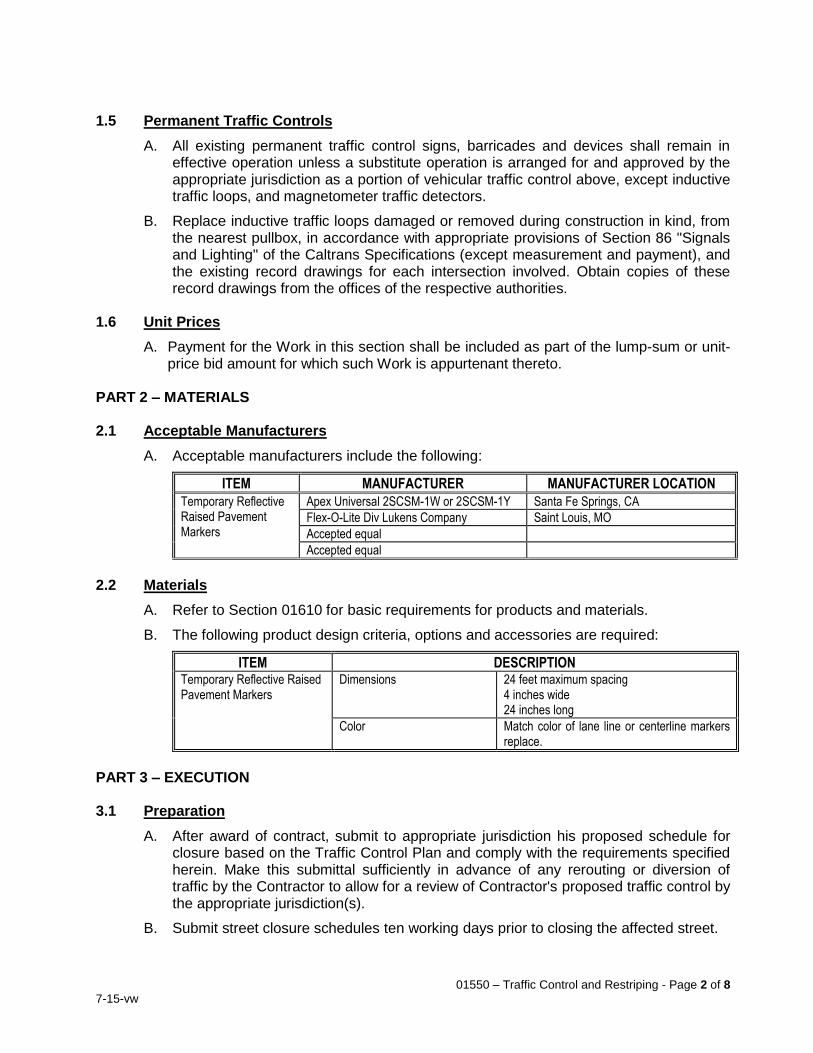
01550 – Traffic Control and Restriping - Page 2 of 8
7-15-vw
1.5 Permanent Traffic Controls
A. All existing permanent traffic control signs, barricades and devices shall remain in effective operation unless a substitute operation is arranged for and approved by the appropriate jurisdiction as a portion of vehicular traffic control above, except inductive traffic loops, and magnetometer traffic detectors.
B. Replace inductive traffic loops damaged or removed during construction in kind, from the nearest pullbox, in accordance with appropriate provisions of Section 86 "Signals and Lighting" of the Caltrans Specifications (except measurement and payment), and the existing record drawings for each intersection involved. Obtain copies of these record drawings from the offices of the respective authorities.
1.6 Unit Prices
A. Payment for the Work in this section shall be included as part of the lump-sum or unit-price bid amount for which such Work is appurtenant thereto.
PART 2 – MATERIALS 2.1 Acceptable Manufacturers
A. Acceptable manufacturers include the following:
ITEM MANUFACTURER MANUFACTURER LOCATION
Temporary Reflective Raised Pavement Markers
Apex Universal 2SCSM-1W or 2SCSM-1Y Santa Fe Springs, CA
Flex-O-Lite Div Lukens Company Saint Louis, MO
Accepted equal
Accepted equal
2.2 Materials
A. Refer to Section 01610 for basic requirements for products and materials.
B. The following product design criteria, options and accessories are required:
ITEM DESCRIPTION Temporary Reflective Raised Pavement Markers
Dimensions 24 feet maximum spacing 4 inches wide 24 inches long
Color Match color of lane line or centerline markers replace.
PART 3 – EXECUTION 3.1 Preparation
A. After award of contract, submit to appropriate jurisdiction his proposed schedule for closure based on the Traffic Control Plan and comply with the requirements specified herein. Make this submittal sufficiently in advance of any rerouting or diversion of traffic by the Contractor to allow for a review of Contractor's proposed traffic control by the appropriate jurisdiction(s).
B. Submit street closure schedules ten working days prior to closing the affected street.

01550 – Traffic Control and Restriping - Page 3 of 8
7-15-vw
C. Before start of construction, provide fire and police departments in whose jurisdiction the project lies with construction schedule showing expected starting date, sequence of work, and timing for each phase of construction completion date, and name and telephone number of two responsible persons who may be contacted at any hour in the event of a condition requiring immediate correction.
D. Inform affected property owners seventy-two (72) hours prior to blocking driveways with any pipe installation or other work. After working hours, backfill trenches and restore access to all driveways. If requested by City’s Representative during working hours, provide access over the trench from any driveway previously blocked.
E. Notify appropriate jurisdiction at least ten working days in advance of closing or partially closing any street or alley and comply with jurisdictional requirements. In addition, notify the appropriate police or sheriff’s department and fire department at least two working days in advance of such closing.
F. Allow passage of public transportation coaches through construction area at all times. Notify appropriate public transit agency at least 48 hours prior to construction affecting bus stop zones to allow said transit agency to temporarily abandon and relocate bus stop zones within construction area.
G. Immediately notify the above parties upon completion of construction work and opening or reopening of any street or alley.
3.2 Installation
A. Refer to Section 01700 for basic execution and installation requirements.
B. Furnish and install traffic control devices at locations shown on Plans and Submittals.
C. The following installation standards shall apply:
1. Manufacturer’s installation and warranty requirements
2. Applicable OSHA and Cal OSHA regulations
3. Caltrans Standard Specifications Section 12-3.01
4. Caltrans Manual of Traffic Controls
5. Work Area Traffic Control Handbook
6. Other applicable code requirements
D. If permanent pavement markings cannot be restored by the end of the work shift in which they are obliterated, provide temporary markings prior to leaving Work site on all streets except any street closed to through traffic. Temporary markings shall be as follows:
1. Temporary lane lines and/or centerlines shall consist of day/night reflectorized raised pavement markers.
2. Right edge lines shall not be simulated with dashes or pavement markers; however, portable delineators, guide markers, etc., may be used where it is considered desirable to enhance the edge of traveled way due to curvilinear alignment or narrowing pavement and shall be used when directed by City’s Representative.
3. Post locations where no-passing zone centerline delineation has been obliterated with sign package consisting of a W20-1 "ROAD WORK AHEAD" and SC13 "DO NOT PASS".
01550 – Traffic Control and Restriping - Page 4 of 8
7-15-vw
4. Where Work causes obliteration of pavement markers and/or delineation, place temporary pavement markers/delineation prior to opening traveled way to traffic. Provide all pavement markers/delineation, including but not limited to lane lines, centerlines, directional arrows, pavement legends, etc, at all times for traveled ways open to traffic.
5. Clean surfaces on which temporary pavement delineation is to be applied. Remove all dirt and loose material, leaving surface dry when pavement delineation is applied. Do not apply temporary pavement markers/delineation over existing pavement delineation or other temporary pavement delineation.
6. Maintain temporary pavement markers/delineation until replaced with permanent pavement markers/delineation. Remove temporary pavement delineation when:
a. it conflicts with permanent pavement delineation;
b. a new traffic pattern is established, or
c. as determined by City’s Representative.
7. Apply temporary reflective raised pavement markers to pavement surface with adhesive in accordance with manufacturer's instructions. Do not use epoxy adhesive to apply temporary reflective raised pavement markers in areas where the pavement will not be removed.
8. Maintain all temporary pavement markings and signs until permanent pavement markings are restored.
9. Temporary lane line or centerline delineation, consisting of temporary reflective raised pavement markers, may be used on lanes opened to public traffic for a maximum of 14 calendar days. Prior to the end of the 14 calendar days, place the planned permanent pavement delineation, except permanent pavement markers. If planned permanent pavement delineation, exclusive of permanent pavement markers, is not placed within 14 calendar days, Contractor shall provide, at his expense, additional temporary pavement delineation as directed by City or agency having jurisdiction. The additional temporary pavement delineation provided shall be equivalent to the pattern specified for permanent traffic lines.
E. Place temporary “No Parking” signs as follows:
1. Post "Temporary No Parking" signs at least seventy two (72) hours in advance of first date of work and required enforcement. If work is to begin on either a Monday or Tuesday, post signs on preceding Friday.
2. Each sign must include text indicating beginning and end dates and hours in effect. "Tow-Away" and "No Parking" must appear on each sign face.
3. If it is required to temporarily restrict parking 24 hours/day, then "Tow-Away" and "No Parking Any Time" must appear on each sign face.
4. Mount signs on either 1” x 2” x 3’ high wood stakes, Type II barricades, or 39-inch high delineators.
5. Place signs at approximately 100’ intervals on affected side(s) of the street. Do not post signs on trees, traffic signal poles, utility poles, street lights, or any other street furniture.
6. Signs shall be professionally made of moisture-resistant, heavy duty cardboard or other approved material.

01550 – Traffic Control and Restriping - Page 5 of 8
7-15-vw
7. Maintain all signs and keep free of graffiti. Replace any sign that becomes illegible or is removed within twenty-four (24) hours.
8. Contractor shall only be permitted to restrict parking for the minimum time necessary to complete on-going work. Remove and repost "Temporary No Parking" signs when work will be delayed more than five (5) consecutive days, or if the work must go beyond the end date shown on the signs, or otherwise directed by City’s Representative.
9. Notify applicable police or sheriff’s department, for review and enforcement. Parking restriction cannot be enforced until Police or Sheriff are notified and signs have been in place 48 hours.
10. Maintain signs through the day of work. Remove all signs on or within one calendar day of Work completion within the restricted parking area.
11. If a street scheduled for slurry or cape sealing was missed, immediately remove all “No Parking” signs and notify all residents and others previously notified, with printed notices, that due to unforeseen circumstances, Contractor was not able to seal the street as previously notified, that the street will be rescheduled in approximately 1 to 2 weeks, and that they will be re-notified. Contractor shall, on the job site prior to the start of each day’s work, have an adequate supply of approved letters of notification to residents for missed streets.
F. Place, or cause to occur, street closures, detours and barricades as follows:
1. Provide notifications of public agencies required above.
2. Install, maintain, and remove all temporary delineators, barricades, lights, warning signs and other devices necessary to control traffic as specified in Contract Documents and approved Traffic Control Plans.
3. Materials for a temporary facility may be provided from new or used materials. If used materials are provided, they shall be sound, in good condition and otherwise meet the requirements of new materials. All traffic control devices shall be free of graffiti, and immediately clean and/or replace any device to the satisfaction of City.
4. Where streets in which improvements are being constructed are specified hereinafter to be closed to through traffic, such closures shall apply only to portions of such streets where construction is actually in progress.
G. Protect open excavations and trenches as follows:
1. Provide temporary railing (Type K) per Caltrans Standard Plan T3, five-foot high chain link fences, or equivalent protection, to completely enclose all open excavations over three feet (3') in depth.
2. Fencing may be removed during working hours to extent necessary to provide access and working room, in which case Contractor shall provide equivalent security, to City’s satisfaction during said periods. Completely backfill any excavation not secured to City’s satisfaction prior to end of each day's construction activities.
3. When backfilling operations of an excavation in the traveled way, whether transverse or longitudinal cannot be completed within a work day, steel plate bridging with a non-skid surface and shoring may be required to preserve unobstructed traffic flow. In such cases, the following conditions shall apply:
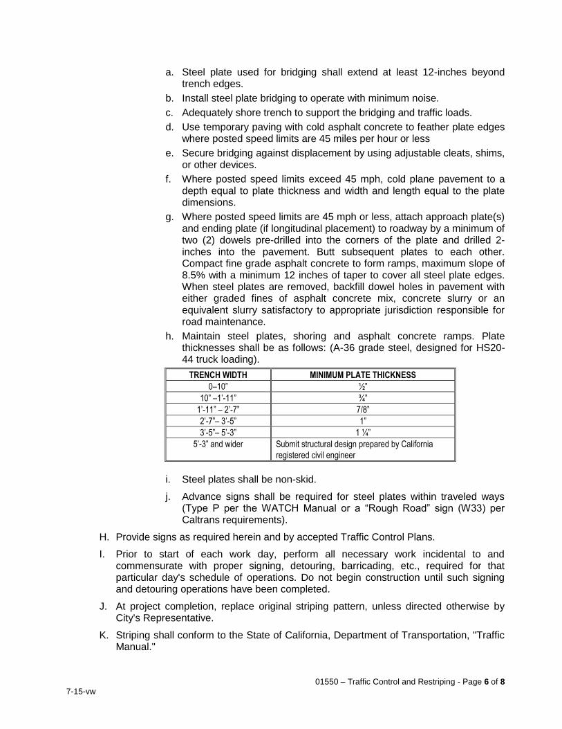
01550 – Traffic Control and Restriping - Page 6 of 8
7-15-vw
a. Steel plate used for bridging shall extend at least 12-inches beyond trench edges.
b. Install steel plate bridging to operate with minimum noise.
c. Adequately shore trench to support the bridging and traffic loads.
d. Use temporary paving with cold asphalt concrete to feather plate edges where posted speed limits are 45 miles per hour or less
e. Secure bridging against displacement by using adjustable cleats, shims, or other devices.
f. Where posted speed limits exceed 45 mph, cold plane pavement to a depth equal to plate thickness and width and length equal to the plate dimensions.
g. Where posted speed limits are 45 mph or less, attach approach plate(s) and ending plate (if longitudinal placement) to roadway by a minimum of two (2) dowels pre-drilled into the corners of the plate and drilled 2-inches into the pavement. Butt subsequent plates to each other. Compact fine grade asphalt concrete to form ramps, maximum slope of 8.5% with a minimum 12 inches of taper to cover all steel plate edges. When steel plates are removed, backfill dowel holes in pavement with either graded fines of asphalt concrete mix, concrete slurry or an equivalent slurry satisfactory to appropriate jurisdiction responsible for road maintenance.
h. Maintain steel plates, shoring and asphalt concrete ramps. Plate thicknesses shall be as follows: (A-36 grade steel, designed for HS20-44 truck loading).
TRENCH WIDTH MINIMUM PLATE THICKNESS
0–10” ½”
10” –1’-11” ¾”
1’-11” – 2’-7” 7/8”
2’-7”– 3’-5” 1”
3’-5”– 5’-3” 1 ¼”
5’-3” and wider Submit structural design prepared by California
registered civil engineer
i. Steel plates shall be non-skid.
j. Advance signs shall be required for steel plates within traveled ways (Type P per the WATCH Manual or a “Rough Road” sign (W33) per Caltrans requirements).
H. Provide signs as required herein and by accepted Traffic Control Plans.
I. Prior to start of each work day, perform all necessary work incidental to and commensurate with proper signing, detouring, barricading, etc., required for that particular day's schedule of operations. Do not begin construction until such signing and detouring operations have been completed.
J. At project completion, replace original striping pattern, unless directed otherwise by City's Representative.
K. Striping shall conform to the State of California, Department of Transportation, "Traffic Manual."
01550 – Traffic Control and Restriping - Page 7 of 8
7-15-vw
L. All signs and barricades shall be illuminated or reflectorized when used after sunset. Provide all delineators, cones, barricades or posts used to divert traffic with flashers or other satisfactory illumination if in place during darkness.
M. Maintain 24-hour emergency service to remove, install, relocate, and maintain warning devices and furnish City's Representative and Police Department with names and telephone numbers of three persons responsible for this emergency service. In the event these persons do not promptly respond when notified by the City's Representative, City's Representative reserves the right to call other forces to accomplish such required emergency service, and Contractor will be held responsible for any and all costs incurred by City.
END OF SECTION
01550 – Traffic Control and Restriping - Page 8 of 8
7-15-vw
THIS PAGE INTENTIONALLY BLANK
01590 – Field Offices - Page 1 of 4
7-15-vw
SECTION 01590 FIELD OFFICES
PART 1 - GENERAL 1.1 Work Included
A. Temporary field office and accessory equipment for City use. 1.2 Temporary City Field Office Building and Access
A. Provide trailer or, with City's consent, construct or rent separate field office building for use by the City from mobilization to notice of completion. Field office and appurtenances or accessories shall remain Contractor's property. Remove field office from site after project completion. Building shall be of watertight construction. Field office characteristics shall be as specified in Table 1. Provide 8-foot-minimum ceiling height. Provide offices, workroom, and restroom as specified. Portable toilet may be provided if no sewer connection is available.
B. If multiple rooms are required per Table 1:
1. Provide floor-to-ceiling walls to separate rooms. Do not use temporary partitions.
2. Provide inter-connecting doors.
3. Provide floor tiles in each room.
C. Provide exterior lights.
D. Provide exterior stairs and railings.
E. Insulate walls and ceiling.
F. Provide utilities, including hot and cold water, gas, electricity, telephone service, and internet access.
G. Provide all upkeep and maintenance temporary field office and equipment.
H. Provide janitorial service.
I. Provide monthly pest control.
J. Pay costs for all utilities including installation costs and monthly charges.
K. Provide all-weather vehicle access and parking.
L. Remove field office from site upon acceptance of entire Work by the City. 1.3 Accessory Equipment
A. Provided electrical fixtures, outlets, lighting, and wiring using Underwriter’s Laboratories, Inc. (UL) approved devices and meeting National Electrical Code (NEC).
B. Protect all electrical circuits with circuit breakers – fuses are not acceptable.
C. Provide warm white fluorescent light fixtures to evenly illuminate the rooms to a minimum of 50 foot-candles and an average of 70 foot-candles measured at desk height. Provide a minimum 60-watt light fixture in the lavatory facility. Provide light switch in each room.
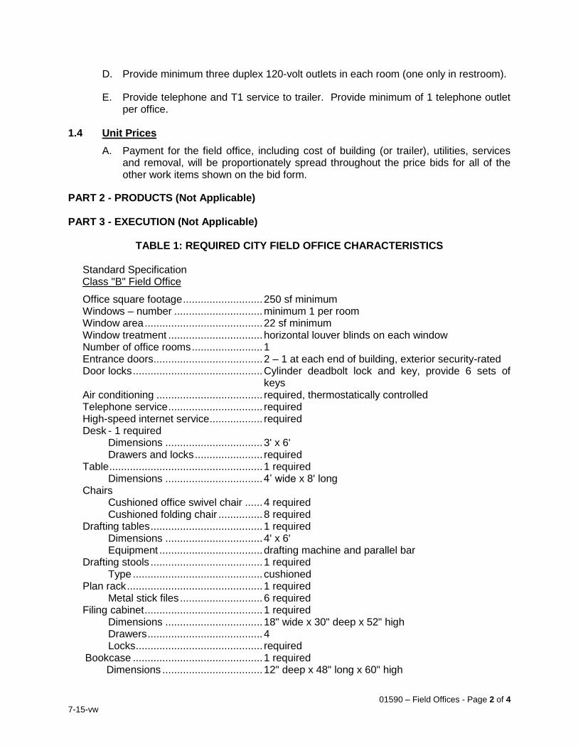
01590 – Field Offices - Page 2 of 4
7-15-vw
D. Provide minimum three duplex 120-volt outlets in each room (one only in restroom).
E. Provide telephone and T1 service to trailer. Provide minimum of 1 telephone outlet per office.
1.4 Unit Prices
A. Payment for the field office, including cost of building (or trailer), utilities, services and removal, will be proportionately spread throughout the price bids for all of the other work items shown on the bid form.
PART 2 - PRODUCTS (Not Applicable) PART 3 - EXECUTION (Not Applicable)
TABLE 1: REQUIRED CITY FIELD OFFICE CHARACTERISTICS
Standard Specification Class "B" Field Office
Office square footage ........................... 250 sf minimum Windows – number .............................. minimum 1 per room Window area ........................................ 22 sf minimum Window treatment ................................ horizontal louver blinds on each window Number of office rooms ........................ 1 Entrance doors ..................................... 2 – 1 at each end of building, exterior security-rated Door locks ............................................ Cylinder deadbolt lock and key, provide 6 sets of
keys Air conditioning .................................... required, thermostatically controlled Telephone service ................................ required High-speed internet service .................. required Desk - 1 required
Dimensions ................................. 3' x 6' Drawers and locks ....................... required
Table .................................................... 1 required Dimensions ................................. 4’ wide x 8' long
Chairs Cushioned office swivel chair ...... 4 required Cushioned folding chair ............... 8 required
Drafting tables ...................................... 1 required Dimensions ................................. 4' x 6' Equipment ................................... drafting machine and parallel bar
Drafting stools ...................................... 1 required Type ............................................ cushioned
Plan rack .............................................. 1 required Metal stick files ............................ 6 required
Filing cabinet ........................................ 1 required Dimensions ................................. 18" wide x 30" deep x 52" high Drawers ....................................... 4 Locks ........................................... required
Bookcase ............................................ 1 required Dimensions .................................. 12" deep x 48" long x 60" high
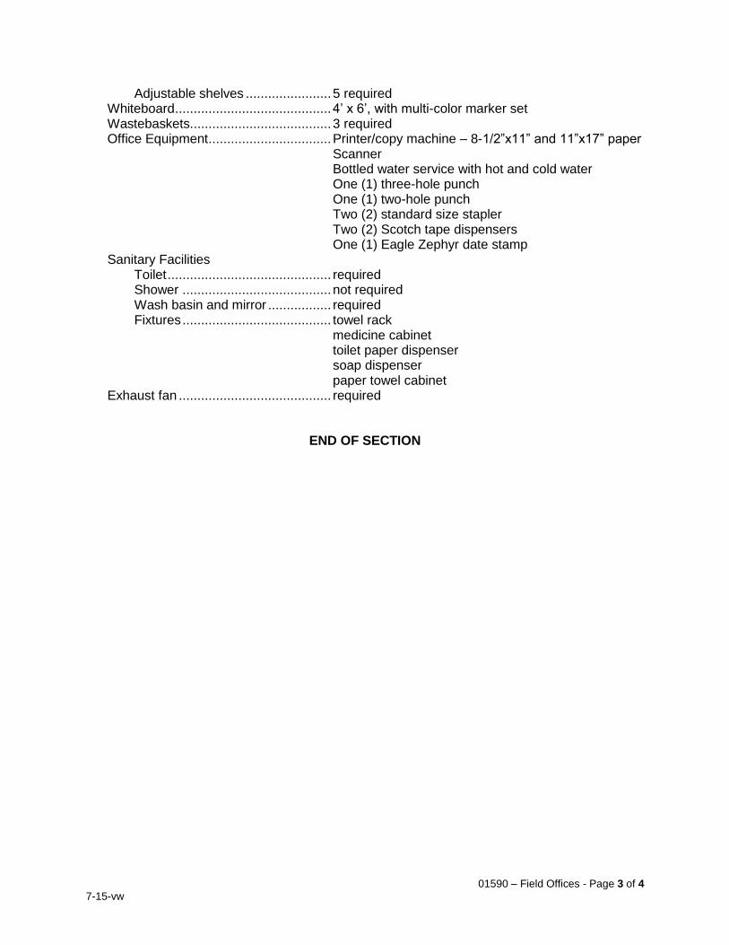
01590 – Field Offices - Page 3 of 4
7-15-vw
Adjustable shelves ....................... 5 required Whiteboard .......................................... 4’ x 6’, with multi-color marker set Wastebaskets...................................... 3 required Office Equipment ................................. Printer/copy machine – 8-1/2”x11” and 11”x17” paper
Scanner Bottled water service with hot and cold water One (1) three-hole punch One (1) two-hole punch Two (2) standard size stapler Two (2) Scotch tape dispensers One (1) Eagle Zephyr date stamp
Sanitary Facilities Toilet ............................................ required Shower ........................................ not required Wash basin and mirror ................. required Fixtures ........................................ towel rack
medicine cabinet toilet paper dispenser soap dispenser paper towel cabinet
Exhaust fan ......................................... required
END OF SECTION
01590 – Field Offices - Page 4 of 4
7-15-vw
THIS PAGE INTENTIONALLY BLANK
01610 – Product Requirements - Page 1 of 4
7-15-vw
SECTION 01610 PRODUCT REQUIREMENTS
PART 1 - GENERAL 1.1 Work Included
A. Basic requirements for all products used in the Work. Products, as used herein, include purchased items for the incorporation into the Work, regardless of whether specifically purchased for the project or taken from Contractor’s stock of previously purchased products. The terms product and equipment shall be used interchangeably. Materials are defined as products which must be substantially cut, shaped, worked, mixed, finished, refined, or otherwise fabricated, processed, installed, or applied to form units of work.
1.2 Related Work
A. Section 01330: Submittal Procedures B. Section 01400: Quality Control C. Section 01630: Product Substitution Procedures D. Section 01650: Product and Equipment Delivery, Storage and Handling
Requirements E. Section 01700: Execution Requirements F. Section 01732: Seismic Restraint G. Section 01770: Closeout Procedures
1.3 Quality Assurance
A. If products are furnished which differ from those shown and which require changes to enclosures, mounting and support structures, power and control circuitry or other work to accommodate furnished product, provide changes required at no additional cost to City and of same quality as shown.
B. Select an option which is compatible with other products or materials where more than one choice is available for Contractor's selection of a product or material.
1.4 Unit Prices
A. Payment for the Work in this section shall be included as part of the lump-sum or unit-price bid for which such Work is appurtenant thereto, and no additional payment will be made specifically for the Work in this Section.
PART 2 - PRODUCTS 2.1 Acceptable Manufacturers
A. Products of listed acceptable manufacturers shall meet specifications notwithstanding the fact that manufacturer is "listed". City reserves right to reject submittals and products from "acceptable manufacturers" if they fail to demonstrate compliance with specifications.
B. Similar items on Project shall be products of same manufacturer.
C. Equipment furnished shall operate through its full operating range powered by amperages specified or shown on Plans. Equipment requiring a larger amperage
01610 – Product Requirements - Page 2 of 4
7-15-vw
than specified or shown is unacceptable in the absence of a written statement from the City confirming the electrical infrastructure and switchgear can support the increased amperage.
D. Where plans and specifications are silent regarding specific acceptable manufacturers, acceptable manufacturers shall meet the minimum requirements outlined in Section 01630 for “approved equals.”
2.2 Materials and Equipment
A. Products shall be new and of current design and manufacture, free from defects and imperfection that might affect serviceability of the product for its intended purpose, unless otherwise stated.
B. Products or work for which no technical specifications are set forth shall be of the best grade in quality and workmanship obtainable in the market from firms of established good reputation, or, if not ordinarily carried in stock, shall conform to usual standards for first class products of the kind required, considering the use to which they are to be put. Work shall be in full conformity and harmony with the intent to secure the best standard of products and construction.
C. Castings shall be sound, clean, free from porosity, cold shots, blisters, holes and defects of any nature that would render them unacceptable. No plugging, filling, brazing or welding of defects will be allowed.
D. Products and workmanship shall match Contractor's submittals as reviewed by Engineer and/or City’s Representative.
E. Connections and mountings required to install products shall comply with connections and mountings shown in Contract Documents and Submittals on a location-specific basis. Do not assume approval of connections or mountings at one location constitutes approval of same at all locations.
F. Notify City’s Representative in writing at least 15 calendar days before testing of materials is required. Written notice shall include name of supplier along with contact information, address and telephone number for source of material.
G. Materials and materials sources shall be reviewed by City’s Representative at least three days before use of materials in Work.
H. Conform to federal, state and local regulations governing VOC content, lead content, percentage solids by volume, and other paint and solvent properties.
I. Corresponding parts of identical products shall be interchangeable.
J. Materials for a complete paint or sealant system, including primer, finish coats, thinners, cleaners and drying agents, and other additives shall be the end products of one manufacturer to ensure product compatibility and unit responsibility.
K. Design and fabrication of products shall ensure products withstand stresses and loads which may occur during testing, installation, start-up and normal operation.
L. Products shall be capable of fulfilling their intended purpose in the environment in which they are installed. Allow for local temperature extremes, climactic conditions and corrosive environments where necessary to ensure proper functioning of furnished products.
01610 – Product Requirements - Page 3 of 4
7-15-vw
M. Stainless steel inscribed nameplates shall be securely fastened in conspicuous locations for mechanical equipment having moving parts. Show manufacturer's name, year of manufacture, serial number, principal rating data and equipment item number. Nameplates shall be in English and use American measuring units.
N. All-thread or close nipples are prohibited.
O. Mating ends of pipe shall match. Mating ends of valves, meters, equipment, and couplings shall match ends of adjacent pipe.
P. Valves shall be marked to show name of manufacturer, year of manufacture, size of valve, maximum working pressure, and arrow to show direction of flow.
Q. Valves shall close drip tight at rated pressures.
R. Valves shall be satisfactory for applications involving valve operation after long periods of inactivity.
S. Minimum working pressure of valves, couplings and fittings shall equal or exceed class of pipe to which they are attached or 150 psi, whichever is higher.
T. Motors shall meet, as minimum requirements, the published standards, rules and regulations of NEMA, ANSI and IEEE as to application, manufacture and tests. Motor windings shall be insulated and braced for full voltage operation.
U. Motors shall develop sufficient torque for required service throughout acceleration range at voltage 10 percent less than motor nameplate rating. Motors shall develop sufficient torque when started using reduced voltage starters.
V. Provide grounding lugs inside conduit boxes for motor frame grounding.
W. Grease fittings shall be standard button-head type. Grease fittings shall be serviceable by a single type of grease gun. Extend fittings as necessary to provide easy access, or as directed by Owner's Representative.
X. Electrical equipment shall be built to NEMA and UL standards for NEC Article 505 Classification specified
Y. If products are furnished which differ from those shown and which require changes to enclosures, mounting and support structures, power and control circuitry or other work to accommodate furnished product, provide changes required at no additional cost to City and of same quality as shown.
2.3 Pre-Selected Materials and Equipment
A. In some instances, materials, and equipment have been pre-selected as of make and model to meet project-specific requirements and/or to match existing “standards” established by the City. These items have undergone extensive review by the Engineer and offer a level of quality, performance, and service acceptable to the City. In these instances, the individual technical specifications will specify a particular manufacturer and model and stipulate that alternative or “or equal” material and equipment will not be acceptable.
01610 – Product Requirements - Page 4 of 4
7-15-vw
PART 3 - EXECUTION
3.1 Installation
A. Furnish mounts, guides, bearing plates, flanges, anchor and attachment bolts and screws, saddles, supports, pads and skids necessary to securely mount products and equipment.
B. Tighten bolts to manufacturers' specifications using torque wrenches. Unless otherwise directed, use lubricant such as Copperkote or blue Teflon when making up bolts.
C. Strictly follow manufacturer's instructions and warranty requirements for installation, application, connection, erection, maintenance, operating, cleaning and conditioning of products.
D. Require manufacturers to furnish technical representative to visit site as needed to provide technical support in resolving field problems associated with manufacturer’s product.
END OF SECTION
01630 – Product Substitution Procedures - Page 1 of 6
7-15-vw
SECTION 01630 PRODUCT SUBSTITUTION PROCEDURES
PART 1 - GENERAL 1.1 Scope
A. Acceptable manufacturers, accepted alternates, and procedures for seeking product substitutions.
1.2 Related Work
A. Section 01330: Submittal Procedures 1.3 General Requirements
A. Deadline for receipt of Substitution Requests shall be in accordance with General Conditions Article 7 - Substitutions.
B. Standard Products - Where products are specified by reference standard, any product meeting the standards referenced may be used. Submit information on such products in accordance with the requirements of Section 01330.
C. Proprietary Products – Where products or processes are specified by trade, patent or proprietary name, said specification, unless marked "no exceptions", or “no substitutions”, shall be deemed to be followed by the words "or accepted equal accepted in writing by City’s Representative." In such case substitution of similar products as “accepted equals” will be considered under this section.
D. Selection of Proprietary Product - Where more than one proprietary name is specified, Contractor may provide any one of the products specified. Use only one manufacturer for each specific application throughout the Work notwithstanding that similar materials or equipment of two or more manufacturers or producers may be specified for the same application.
E. Substitution Request Procedure - Submit a written request on attached form for proposed substitutions to City’s Representative prior to deadline for receipt of substitution requests. Submit proposed substitutions relating to a particular subcontract or trade in a single package. No substitution will be considered after the deadline for receipt of substitution requests has expired.
F. Contractor's Responsibility for Construction Modifications - Drawings have been detailed in compliance with dimensions and International Council of Building Officials (ICBO) Evaluation Report data for products specified. If proposed substitute product is accepted by City’s Representative, Contractor shall assume both responsibility for construction modifications and additional costs required by reason of this acceptance. If substitution results in a decrease in cost, potential savings to City may be submitted to City’s Representative for consideration.
G. Systems of Like Manufacture - Where products are specified in groups to be furnished by one manufacturer, no substitution will be considered that is not similarly furnished by one manufacturer. Where Contractor proposes to use a system of equipment other than that shown in the Contract Documents, propose the substitution as a complete system.
H. No time extension will be allowed for substitution of materials. 1.4 Submittals
A. Furnish the following submittals.
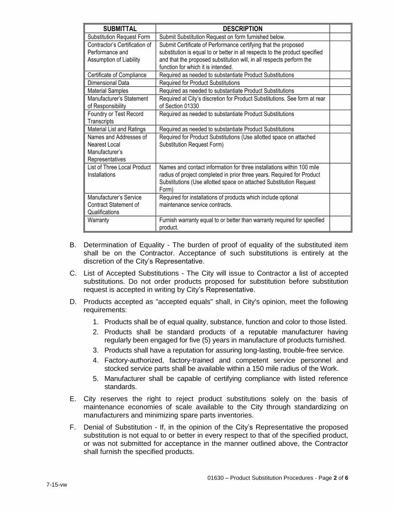
01630 – Product Substitution Procedures - Page 2 of 6
7-15-vw
SUBMITTAL DESCRIPTION Substitution Request Form Submit Substitution Request on form furnished below.
Contractor’s Certification of Performance and Assumption of Liability
Submit Certificate of Performance certifying that the proposed substitution is equal to or better in all respects to the product specified and that the proposed substitution will, in all respects perform the function for which it is intended.
Certificate of Compliance Required as needed to substantiate Product Substitutions
Dimensional Data Required for Product Substitutions
Material Samples Required as needed to substantiate Product Substitutions
Manufacturer’s Statement of Responsibility
Required at City’s discretion for Product Substitutions. See form at rear of Section 01330
Foundry or Test Record Transcripts
Required as needed to substantiate Product Substitutions
Material List and Ratings Required as needed to substantiate Product Substitutions
Names and Addresses of Nearest Local Manufacturer’s Representatives
Required for Product Substitutions (Use allotted space on attached Substitution Request Form)
List of Three Local Product Installations
Names and contact information for three installations within 100 mile radius of project completed in prior three years. Required for Product Substitutions (Use allotted space on attached Substitution Request Form)
Manufacturer’s Service Contract Statement of Qualifications
Required for installations of products which include optional maintenance service contracts.
Warranty Furnish warranty equal to or better than warranty required for specified product.
B. Determination of Equality - The burden of proof of equality of the substituted item
shall be on the Contractor. Acceptance of such substitutions is entirely at the discretion of the City’s Representative.
C. List of Accepted Substitutions - The City will issue to Contractor a list of accepted substitutions. Do not order products proposed for substitution before substitution request is accepted in writing by City’s Representative.
D. Products accepted as "accepted equals" shall, in City's opinion, meet the following requirements:
1. Products shall be of equal quality, substance, function and color to those listed.
2. Products shall be standard products of a reputable manufacturer having regularly been engaged for five (5) years in manufacture of products furnished.
3. Products shall have a reputation for assuring long-lasting, trouble-free service.
4. Factory-authorized, factory-trained and competent service personnel and stocked service parts shall be available within a 150 mile radius of the Work.
5. Manufacturer shall be capable of certifying compliance with listed reference standards.
E. City reserves the right to reject product substitutions solely on the basis of maintenance economies of scale available to the City through standardizing on manufacturers and minimizing spare parts inventories.
F. Denial of Substitution - If, in the opinion of the City’s Representative the proposed substitution is not equal to or better in every respect to that of the specified product, or was not submitted for acceptance in the manner outlined above, the Contractor shall furnish the specified products.
01630 – Product Substitution Procedures - Page 3 of 6
7-15-vw
G. Responsibility for Coordinating Substitutions with Construction Trades – Inform all other trades, vendors, and subcontractors of the effects of substitutions on their work or products. Failure to so notify shall not relieve Contractor of his duty to make payments arising from alterations in specified products or methods needed to complete the Work in an approved and acceptable manner.
1.5 Contractor's Responsibility for Cost of Substitution Reviews
A. Pay all costs incurred by City’s Representative and City to review Requests for Substitutions.
1.6 Substitution of “Inferior” Products
A. Products not meeting the above requirements shall, for purpose of this contract, be deemed “inferior” even if product’s only shortcoming is that Contractor failed to submit a Substitution Request on said product prior to the stipulated deadline.
B. Substitution of "inferior" products shall not occur except where cost savings are offered to and accepted by the City in the form of a Change Order.
1.7 Bid Shopping and Reverse Auctions
A. Substitutions for products and services of manufacturers, system integrators or subcontractors listed at time of bid and/or in Contractor’s initial Submittal will only be permitted under one or more of the following circumstances:
1. Where Contractor-listed manufacturer, system integrator or subcontractor has gone out of business.
2. Where Contractor-listed manufacturer, system integrator or subcontractor has, in City’s opinion, failed to perform or no longer possesses both capability and willingness to perform to standard required by Contract Documents.
3. Where Contractor offers a credit to City sufficient in City’s opinion to justify accepting the substitution in the form of a Change Order.
PART 2 - PRODUCTS (Not Applicable) PART 3 - EXECUTION (Not Applicable)
END OF SECTION

01630 – Product Substitution Procedures - Page 4 of 6
7-15-vw
SUBSTITUTION REQUEST FORM
TO: City of Corona, Department of Water and Power 755 Corporation Yard Way Corona, CA 92880
PROJECT NAME: _____________________________________________________________ FROM CONTRACTOR: ________________________________________________________ We hereby submit for consideration the following product substitution of specified item for above project: DRAWING OR SHEET NUMBER SECTION NO. OR PARAGRAPH SPECIFIED ITEM ____________ _______________ ___________________________________
____________ _______________ ___________________________________
____________ _______________ ___________________________________
____________ _______________ ___________________________________
PROPOSED SUBSTITUTION:____________________________________________________ Attach a brief description of the reason for proposed substitution. Attach complete dimensional information and technical data needed to substantiate product substitution, including ICBO reports and laboratory tests, if applicable. Include complete information on changes to Drawings and/or Specifications which proposed substitution will require for its proper installation. Where product substitutions are proposed at multiple locations, submit copies of plans showing in red each location where the product substitution is proposed. Submit with request all necessary samples and substantiating data to prove equal quality and performance to that which is specified. Clearly mark manufacturer's literature to indicate equality in performance. Differences in quality of materials and construction shall be indicated. Submit Manufacturer’s Statement of Responsibility.
Page 1 of 3
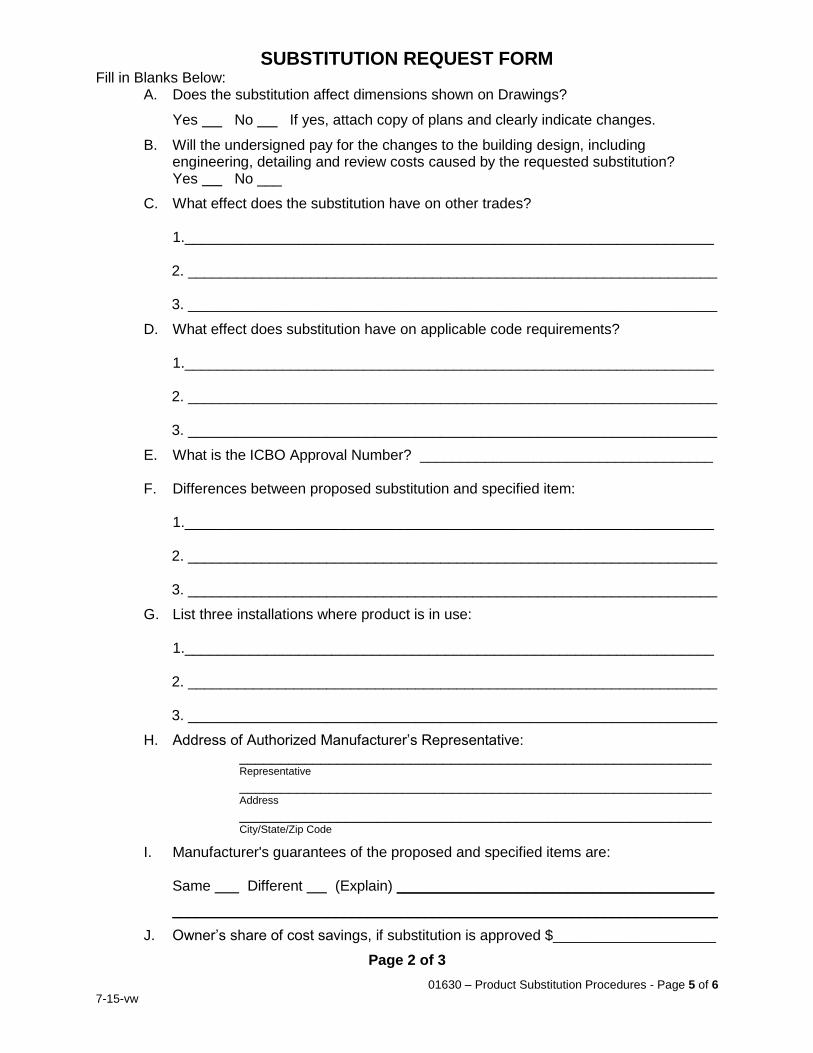
01630 – Product Substitution Procedures - Page 5 of 6
7-15-vw
SUBSTITUTION REQUEST FORM Fill in Blanks Below:
A. Does the substitution affect dimensions shown on Drawings?
Yes No If yes, attach copy of plans and clearly indicate changes.
B. Will the undersigned pay for the changes to the building design, including engineering, detailing and review costs caused by the requested substitution? Yes No ___
C. What effect does the substitution have on other trades?
1._________________________________________________________________ 2. _________________________________________________________________ 3. _________________________________________________________________
D. What effect does substitution have on applicable code requirements? 1._________________________________________________________________
2. _________________________________________________________________ 3. _________________________________________________________________
E. What is the ICBO Approval Number? ____________________________________
F. Differences between proposed substitution and specified item:
1._________________________________________________________________ 2. _________________________________________________________________ 3. _________________________________________________________________
G. List three installations where product is in use: 1._________________________________________________________________
2. _________________________________________________________________ 3. _________________________________________________________________
H. Address of Authorized Manufacturer’s Representative: __________________________________________________________ Representative __________________________________________________________
Address
__________________________________________________________ City/State/Zip Code
I. Manufacturer's guarantees of the proposed and specified items are:
Same Different (Explain) _______________________________________
___________________________________________________________________
J. Owner’s share of cost savings, if substitution is approved $____________________
Page 2 of 3

01630 – Product Substitution Procedures - Page 6 of 6
7-15-vw
SUBSTITUTION REQUEST FORM
CONTRACTOR'S CERTIFICATION OF PERFORMANCE AND ASSUMPTION OF LIABILITY FOR EQUAL PERFORMANCE
I certify that the proposed substitution is equal to or better in all respects to the product specified and that the proposed substitution will, in all respects, perform the function for which it is intended. Submitted By: Signature Title Firm Address Telephone Date
For use by Design Engineer: Accepted Accepted as Noted Not Accepted Received Too Late By Date Remarks Concurrence By: Owner
Signature must be by person having authority to legally bind his firm to the above terms. Failure to provide legally binding signature will result in retraction of approval.
END OF SECTION
Page 3 of 3

01640 – Installation of City-Furnished Products - Page 1 of 4
7-15-vw
SECTION 01640 INSTALLATION OF CITY-FURNISHED PRODUCTS
PART 1 - GENERAL 1.1 Work Included
A. This section includes delivery, storage, handling, installation and startup of City-furnished products.
B. City furnished products for this Project include the following:
1. One (1) Complete Electrical Panel, with:
a. Motor Control Center
b. Lighting Panel
c. Control Panel
d. Main Circuit Breaker
1.2 Related Work
A. Section 01650: Product and Equipment Delivery, Storage and Handling Requirements B. Section 01700: Execution Requirements
1.3 Quality Assurance
A. Use adequate numbers of skilled workmen who are thoroughly trained and experienced in the necessary trades and crafts and who are completely familiar with the specified requirements and methods needed for proper performance of the Work of this section.
B. Handle, store and install City-furnished products in accordance with manufacturers’ printed instructions and warranty requirements for storage, handling and installation of manufacturer’s products.
1.4 Submittals
A. Copies of shop drawings and other submittals will be forwarded to the Contractor by the manufacturer. Review shop drawings and verify adequate space is provided for installation of City-furnished items. In the event that adequate space or utility connections are not available, immediately notify the City’s Representative in writing so that appropriate arrangements can be made.
B. Request, review and comply with manufacturer’s written instructions and warranty requirements for handling, storing and installing manufacturer’s products. In the event compliance with said instructions is not feasible, notify City’s Representative in writing of any exceptions taken to said installation instructions and the City will take appropriate action.
1.5 Delivery, Storage and Handling
A. Refer to Section 01650 for delivery storage and handling requirements.
B. Strictly follow manufacturer’s instruction and warranty requirements for delivery, storage and handling of products.

01640 – Installation of City-Furnished Products - Page 2 of 4
7-15-vw
C. Coordinate with manufacturer and City as required to receive, inspect and properly store City-furnished products.
D. Upon receipt of City-furnished items, thoroughly inspect and inventory delivered item preparing full listing of any noticeable defects or flaws. Submit photograph or videotape evidence of said defects to City’s Representative.
1.6 Unit Prices
A. Payment for the Work in this section shall be included as part of the lump-sum or unit-price bid amount for which such Work is appurtenant thereto.
PART 2 - MATERIALS 2.1 Materials
A. Furnish incidental bolts, nuts, screws, fasteners, anchors, couplings, supports, pipe couplings, junction boxes, electrical connections, grout and other work required to properly mount, set, level and connect City furnished items to other facilities being constructed as part of this Contract.
PART 3 - EXECUTION 3.1 Preparation
A. Make field measurements needed to install City-furnished items. Bring to the City Representative’s attention at the earliest possible moment field conditions which limit Contractor’s ability to properly install said items. Make minor changes in dimensions and alignments as needed to accommodate dimensions of City-furnished items as shown in shop drawings.
3.2 Installation
A. Install equipment in accordance with the requirements of Section 01700 Execution Requirements.
B. Install equipment at locations shown on plans according to manufacturer’s installation and warranty requirements. Strictly follow manufacturer’s requirements for installation, application, connection, erection, maintenance, operating, cleaning, conditioning and startup of products.
C. Install equipment to tolerances recommended by manufacturer. Unless otherwise shown, install equipment true and level using precision gauges and levels.
D. Refer variances between manufacturer’s installation instructions and Contract Documents to City’s Representative.
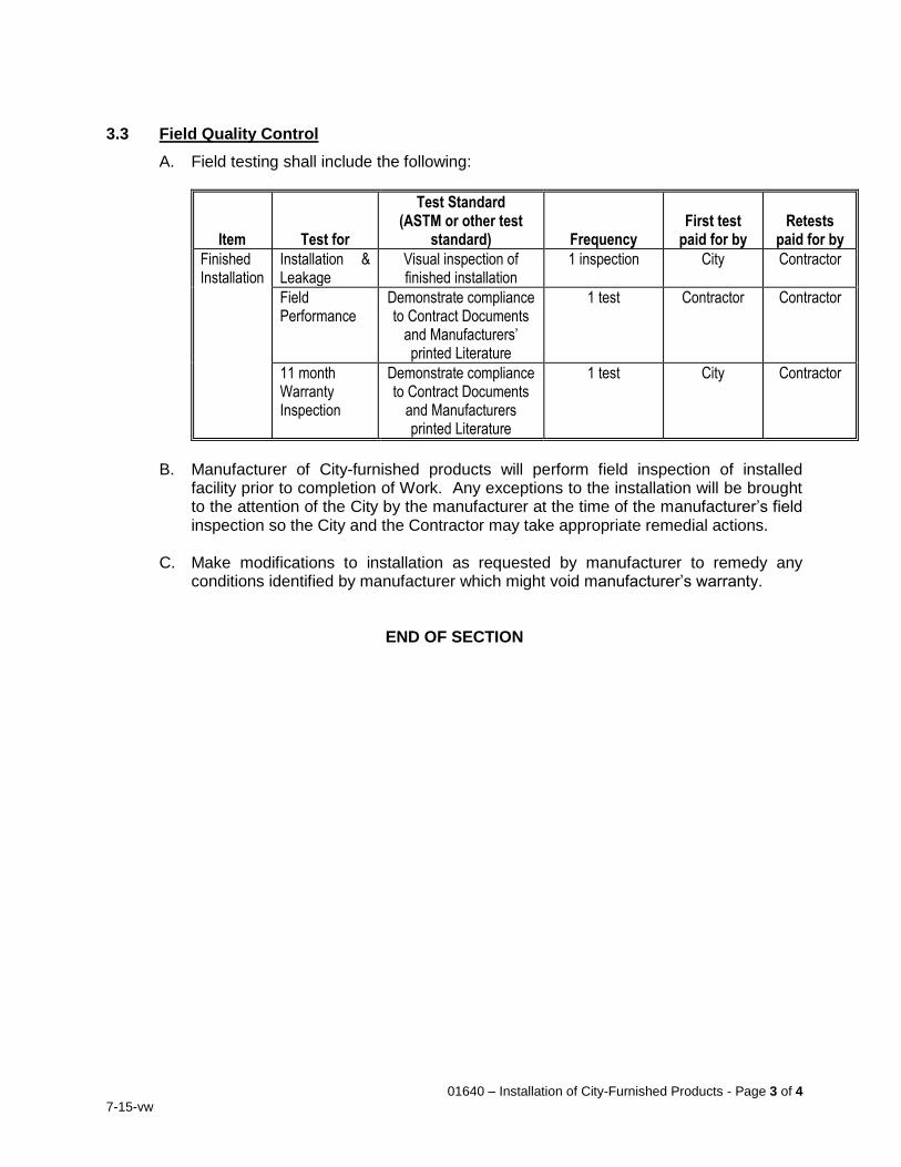
01640 – Installation of City-Furnished Products - Page 3 of 4
7-15-vw
3.3 Field Quality Control
A. Field testing shall include the following:
Item Test for
Test Standard (ASTM or other test
standard) Frequency First test
paid for by Retests
paid for by
Finished Installation
Installation & Leakage
Visual inspection of finished installation
1 inspection City Contractor
Field Performance
Demonstrate compliance to Contract Documents
and Manufacturers’ printed Literature
1 test Contractor Contractor
11 month Warranty Inspection
Demonstrate compliance to Contract Documents
and Manufacturers printed Literature
1 test City Contractor
B. Manufacturer of City-furnished products will perform field inspection of installed
facility prior to completion of Work. Any exceptions to the installation will be brought to the attention of the City by the manufacturer at the time of the manufacturer’s field inspection so the City and the Contractor may take appropriate remedial actions.
C. Make modifications to installation as requested by manufacturer to remedy any
conditions identified by manufacturer which might void manufacturer’s warranty.
END OF SECTION

01640 – Installation of City-Furnished Products - Page 4 of 4
7-15-vw
THIS PAGE INTENTIONALLY BLANK
01650 – Product and Equipment Delivery, Storage, and Handling Requirements - Page 1 of 6
7-15-vw
SECTION 01650 PRODUCT AND EQUIPMENT DELIVERY, STORAGE, AND HANDLING REQUIREMENTS
PART 1 - GENERAL 1.1 Work Included
A. Transportation and handling, storage and protection of products and equipment. 1.2 Related Work
A. Section 01330: Submittal Procedures B. Section 01400: Quality Control C. Section 01610: Product Requirements
1.3 References
A. ANSI/NSF 60 Drinking Water Treatment Chemicals – Health Effects B. ANSI/NSF 61 Drinking Water System Components – Health Effects
1.4 Product Delivery, Storage and Handling
A. Ship and deliver products to jobsite as follows:
1. Do not ship, accept delivery of or store items on site for which applicable submittals have not been accepted.
2. Before shipping, operate valves, motors, pumps, actuators and mechanical equipment at factory to ensure products are complete and in working condition.
3. Before shipping materials and/or equipment, Contractor shall also be responsible for verification of field dimensions, utility locations and electrical compatibility for items of Work which may require relocation, refitting, or different electrical motors and wiring if field dimensions differ from those shown on Plans.
4. In the event Contractor discovers a conflict during surveying, staking, verification of field dimensions, verification of utility locations or verification of electrical compatibility, he shall bring this matter to the City’s attention as soon as conflict is discovered and before materials or equipment are shipped. City will make adjustments to Contract requirements needed to accommodate field conditions, and will pay reasonable costs for upgrades or modifications required to be made at the place of manufacture prior to shipping to accommodate conflicts discovered.
5. City will not pay costs of shipping and returning items to place of manufacture unless:
a. City has acted to prevent Contractor from completing surveys, staking, verification of field dimensions, verification of utility locations or verification of electrical compatibility, and Contractor has notified City of this fact in writing before shipping equipment, or
b. Changes required are a direct result of buried utility conflicts where said utilities were neither shown on the plans in their approximate location, nor located by Underground Service Alert nor evident from surface features.
6. Deliver or store only products of accepted manufacturers at the site.
01650 – Product and Equipment Delivery, Storage, and Handling Requirements - Page 2 of 6
7-15-vw
7. Transport by means to avoid damage and deliver products to jobsite in manufacturer's original, unbroken, unopened, labeled packaging containers or bundles. Tag or label packages, containers or bundles as needed to identify contents and name of equipment of which contents form a part.
8. All items delivered at the site or to any authorized place of storage may be inspected to satisfy the City’s Representative that such items are of the specified quality and workmanship and are in good order and condition at the time of delivery. Be prepared to remove all coverings, containers or crates to permit the City’s Representative to conduct an inspection. Should the City’s Representative find indication of damage or deficient quality of workmanship, provide the necessary documentation or conduct such tests deemed necessary by the City’s Representative to demonstrate compliance.
9. Coordinate with the City and equipment supplier/manufacturer, as necessary, and perform an inventory and inspection to include all necessary unpacking and repacking operations to examine items delivered. Record in writing any apparent defects, damage, or missing portions and provide a copy to the City. For City-furnished products and equipment, the City will make good all deficiencies noted in the inventory and inspection at no cost to Contractor. Once received, Contractor shall be responsible for the City-furnished items the same as for work under the Contract, including proper insurance coverage, except the City will correct any subsequently discovered latent or hidden damage or defects in the City-furnished items that could not be ascertained at the time of delivery and were not caused by the Contractor.
10. Deliver large multi-component assemblies in sections that facilitate field handling and installation.
11. Ship oil-lubricated gearing, bearings and other lubricated components with oil soluble protective coating as described in warranty requirements or recommended by manufacturer. For parts contacting potable water, coating shall be NSF-approved. Coating shall provide protection for one year after final acceptance.
12. Provide equipment and personnel to handle products, materials, and equipment by methods to prevent soiling and damage.
13. Provide protection during handling to prevent marring and otherwise damaging products, packaging, and surrounding surfaces.
B. Store products at jobsite as follows:
1. Store products per manufacturer’s recommendations, and in a protected area at a temperature between 35 °F and 110 °F.
2. Store products with seals and labels intact and legible.
3. Store products so as to preserve their quality and fitness for the Work. Locate stored products and equipment to be incorporated in the Work to facilitate inspection. Inspect products periodically to assure products are undamaged and are maintained under required conditions. Maintain a log of inspections and make available upon request. Contractor shall be responsible for damage or loss to products until Final Acceptance.
4. Protect products against moisture, weather, temperature extremes, dust, debris, tampering, theft, vandalism, ultraviolet radiation, or damage from improper handling, storage, or exposure. Protect exposed metals from rust and corrosion even for items which may be sandblasted or otherwise cleaned before painting.
01650 – Product and Equipment Delivery, Storage, and Handling Requirements - Page 3 of 6
7-15-vw
5. Store items not designed for outdoor exposure off ground and under cover.
6. Store cementitious materials in weather-tight spaces. Keep free from moisture.
7. Store aggregate in well-drained area to minimize change in moisture content. Prevent contamination by other materials.
8. Store fasteners and connectors in original unopened containers until used.
9. Ventilate materials subject to corrosion or moisture damage to prevent condensation.
10. Any corrosion in evidence prior to final acceptance shall be removed, or the product shall be removed or replaced.
11. Cover plastic and similar brittle items to protect from sun exposure and temperature extremes.
12. Cover stored materials with tarpaulin or other covering to prevent soiling or exposure to weather. Fasten coverings to prevent removal by wind.
13. Store flammable products to conform with City, County, State and Federal safety codes for storage of flammable materials.
14. Cover, plug or cap pipe ends, valve ends and equipment openings with rubber, plastic or canvas to prevent intrusion or contamination.
15. String pipe along right-of-way in a manner to not interfere with free passage of vehicles.
16. Do not store pipe on roadway or parkway of streets.
17. Store items in accordance with requirements of Project Storm Water Pollution Prevention Plan (SWPPP), if applicable. If a SWPPP has not been prepared for the Project, store items in accordance with the appropriate best management practices (BMP’s) listed in the California Stormwater Quality Association (CASQA) Stormwater Best Management Practice Handbook for Construction, latest edition. Comply with all City, County, State and Federal pollution prevention laws and permits.
18. Notify City in writing if delivered or stored product is damaged. Deliver items with exterior surfaces in perfect unblemished condition. Do not repair damaged products without prior written approval.
C. Handle products as follows:
1. Handle products with care, using proper equipment according to manufacturer's recommendations. Lift large, heavy items only at points designated by manufacturer. Do not drop, drag, bump, bend or handle products in manner that causes abrasions, bruises, cracks, mars, scars, scratches or other damage. Use padded slings and hooks for lifting as needed to prevent damage. Improper handling shall be cause to reject mishandled products.
2. Use rubber or canvas belt slings or pneumatic-tired cradles to lift, lower, or suspend coated pipe, valves and other products. Sling width shall equal or exceed pipe or product diameter. Do not handle coated products using ropes, hooks, chains, calipers or cables. Store such materials on padded skids.
3. Inspect each product item for damage, defects, completeness and correct operation before installing. Notify City in writing if delivered or stored product is damaged. Do not repair damaged products without prior written approval.
4. Before installation, swab joints and interiors of piping materials to remove foreign matter.
01650 – Product and Equipment Delivery, Storage, and Handling Requirements - Page 4 of 6
7-15-vw
5. Clean and protect machined surfaces and shafting from corrosion using proper type and amount of coating as described in warranty requirements to assure protection to one year after final acceptance.
6. Maintain records for City's review of deliveries to show Contractor's order number, purchase order number and equipment number. Include labeling or shipping tag in records.
7. Cover pipe ends, fitting ends, valve ends, and equipment openings with rubber, plastic, or canvas to prevent intrusion or contamination. Close open ends of pipe with tight-fitting caps or plugs to prevent entrance of foreign contaminants into pipe at all times when pipe installation is not in progress. These provisions shall apply during noon hour as well as overnight. Do not use pipeline as a drain for removing water that has infiltrated into trench. Maintain inside of pipe free from foreign materials and in a clean and sanitary condition until final acceptance.
1.5 Equipment Delivery, Storage and Handling
A. Equipment is defined as any mechanical, electrical, or instrumentation devices, and other items with one or more moving parts requiring an electrical, pneumatic, electronic or hydraulic connection.
B. Adequately and effectively protect all equipment against damage from moisture, dust, handling, or other cause during transport from manufacturer's premises to site. Clearly mark each item or package with the number unique to the specification reference covering the item. Each separate portion of plant shall receive, as far as practicable, a fitting or distinguishing mark which shall be shown on the packing lists. Relieve load on motor bearing during transport by means of jacks or some other method to prevent Brinelling. Use stiffeners where necessary to maintain shapes and to provide rigidity. Deliver parts of equipment in assembled or sub-assembled units where possible.
C. Affix to all equipment items and valves a label or tag in a prominent location displaying the assigned equipment number. Mark valves to show name of manufacturer, year of manufacture, size of valve, maximum working pressure, and arrow to show direction of flow. Equipment item and valves lacking a number shall have a similar tag providing a unique description of the item. Markers shall be of stainless steel or aluminum, affixed to the item in question with stainless steel fasteners or as otherwise approved by the City. Plastic tape labels will not be acceptable.
D. Securely fasten stainless steel inscribed nameplates in conspicuous locations for mechanical equipment having moving parts. Show manufacturer's name, year of manufacture, serial number, principal rating data and equipment item number. Nameplates shall be in English and use American measuring units.
E. During the interval between delivery and installation, store all equipment to be incorporated into the Project in a manner to prevent damage or deterioration. Provide environmental controls, such as heaters or protective encapsulation, to ensure against condensation and moisture damage. Motor space heaters shall be operational at all times when motors are stored on site. In the event prolonged (more than 90 days) storage is required for any item of rotative equipment, institute a preventive maintenance program which shall include grease protection of bare metal surfaces, periodic indexing of rotating parts, renewal of grease in bearings and any procedures recommended by the manufacturer. Maintain adequate records to
01650 – Product and Equipment Delivery, Storage, and Handling Requirements - Page 5 of 6
7-15-vw
demonstrate full compliance with these requirements. Make all equipment available for inspection by the City.
To insure adequate protection of all electrical and instrumentation equipment and panels and electric motors, store all such equipment in a suitable enclosure designed to protect the equipment from dust and moisture. The Contractor shall be responsible for maintaining the storage facilities and equipment stored therein and making provisions for all utilities required. Provide continuous access to the City for all equipment so stored.
1.6 Delivery of Product, Equipment or Material
The City’s personnel or representatives will not accept product, equipment, or material deliveries for the Contractor.
1.7 Unit Prices
A. Payment for the Work in this section shall be included as part of the lump-sum or unit-price bid amount for which such Work is appurtenant thereto.
PART 2 - PRODUCTS (Not Applicable) PART 3 - EXECUTION 3.1 Warranty Requirements
A. Strictly follow manufacturer’s instruction and warranty requirements for delivery, storage and handling of products.
END OF SECTION

01650 – Product and Equipment Delivery, Storage, and Handling Requirements - Page 6 of 6
7-15-vw
THIS PAGE INTENTIONALLY BLANK
01700 – Execution Requirements - Page 1 of 6
7-15-vw
SECTION 01700 EXECUTION REQUIREMENTS
PART 1 - GENERAL 1.1 Work Included
A. Examination of site before bidding, preparation for construction, and execution of Work.
1.2 Related Work
A. Section 01330: Submittal Procedures B. Section 01400: Quality Control C. Section 01610: Product Requirements D. Section 01650: Product and Equipment Delivery, Storage and Handling Requirements E. Section 01732: Seismic Restraint F. Section 01740: Cleaning, Final Cleaning, Pollution Prevention and Disposal of
Hazardous Waste G. Section 01750: Testing, Starting, Adjusting and Commissioning H. Section 01770: Closeout Procedures I. Section 01781: Record Drawings and Photographs J. Section 01787: Product Warranties K. Section 01820: Demonstration, Training and Spare Parts
1.3 Project/Site Conditions
A. Review existing soils reports to ascertain suitability of native soil for backfill before submitting bid. If native soil is found to be unsuitable, provide suitable material for meeting compaction requirements at no additional cost to City.
B. Items furnished shall be capable of fulfilling their intended purpose in environment in which they are installed. Allow for local temperature extremes, climactic conditions and corrosive environments where necessary to ensure proper functioning of furnished products.
C. The action of beginning installation, application or erection of any product shall be deemed sufficient evidence that both the Contractor and the installer accept existing field conditions as acceptable for installation, application or erection of that product, except where written notice is given of Contractor or installer’s concerns before starting applicable work.
1.4 Unit Prices
A. Payment for the Work in this section shall be included as part of the lump-sum or unit-price bid for which such Work is appurtenant thereto, and no additional payment will be made specifically for the Work in this Section.
01700 – Execution Requirements - Page 2 of 6
7-15-vw
PART 2 - PRODUCTS (Not Applicable) 2.1 Materials
A. Dissimilar metals, when used in conjunction with each other shall have suitable insulation provided between adjoining surfaces to eliminate direct contact and resultant current. Insulation shall be bituminous impregnated felt, heavy bituminous coatings, nonmetallic separators, washers, or other accepted materials.
2.2 Equipment
A. Furnish special tools, wrenches and appliances needed to adjust, operate, maintain or repair mechanical equipment supplied.
PART 3 - EXECUTION 3.1 Preparation
A. Contractor represents he has carefully examined the Contract Documents and the site where the work is to be performed and he has familiarized himself with all local conditions and federal, state, and local laws, ordinances, rules, and regulations that may affect in any manner the performance of the work.
B. Before shipping materials and/or equipment, verify field dimensions, utility locations and electrical compatibility for items of Work which may require relocation, refitting, or different electrical motors and wiring if field dimensions differ from those shown on Plans.
C. In the event Contractor discovers a conflict during surveying, staking, verification of field dimensions, verification of utility locations or verification of electrical compatibility, bring this matter to the attention of the City’s Representative as soon as conflict is discovered and before materials or equipment are shipped. City will make adjustments to Contract requirements needed to accommodate field conditions, and will pay reasonable costs for upgrades or modifications required to be made at the place of manufacture prior to shipping to accommodate conflicts discovered.
D. City will not pay costs of shipping and returning items to place of manufacture unless:
1. City has acted to prevent Contractor from completing surveys, staking, verification of field dimensions, verification of utility locations or verification of electrical compatibility, and Contractor has notified Owner of this fact in writing before shipping equipment, or
2. Changes required are a direct result of buried utility conflicts where said utilities were neither shown on the plans in their approximate location, nor located by Underground Service Alert nor evident from surface features.
E. Before beginning work, carefully and thoroughly document condition of site and existing improvements using dated photographs as necessary to resolve any disputes that may arise regarding the conditions prior to and subsequent to construction.
F. Document with photographs the pre-construction condition of the entire construction area and 50 feet beyond the construction area. In addition to the pre-construction photographic survey, perform periodic photographic survey of the site and adjacent areas (at least twice during construction), and then post-construction. Make arrangements with private property owners within 100 feet of the Work to photograph
01700 – Execution Requirements - Page 3 of 6
7-15-vw
the interior of buildings and residences to document pre-existing conditions for comparison with the post-construction survey to document the presence or absence of damage to existing improvements. Perform photography during times of good visibility.
G. Submit preconstruction photographs to City’s Representative before beginning Work which has the potential to disturb or modify public or private property not owned by City. Photographs shall be prepared by a professional photographer and of sufficient quality and thoroughness to fully document preexisting damage or wear to photographed property for which Contractor or City might be asked to compensate property owner were it not for photographic evidence of preexisting damage. Where existing cracks in concrete, masonry or other materials are wider than the thickness of a dime, include a dime or similar visual standard in photo for reference.
H. Prior to commencement of photography, notify the City in writing of the date and time of the work. The City may provide a designated representative to accompany and oversee coverage of all photography operations.
I. Submit CD and paper copy prints with photographs of pre-construction condition documentation within fourteen (14) calendar days of photographing the Project site.
Furnish one set of paper copy prints of color photos, 5”x7” size. Place the following information on each print:
1. Project title
2. Date taken
3. Photograph number
4. Description of view shown in photograph
5. Names of any persons in the view
6. Photographer’s name and current contact information
Furnish one CD with original, date-stamped photographs in .jpeg format and .pdf files of the paper copy prints submitted as described above.
J. Submit copies of documentation to City’s Representative before beginning any work at the project site. Damage not documented as preexisting before start of construction will be attributed to Contractor’s activities in the absence of conclusive evidence to the contrary.
K. Make available all other photographs for review in settling any disputes that may arise.
L. The City may, at its option, take additional preconstruction photographs that may be used to settle disputes, but will not be required to make these photographs available to the Contractor.
M. Carefully lay out work in advance to minimize cutting, channeling, chasing or drilling of structural pads or elements. Review in advance with the City’s Representative all cuts, channeling, drilling, or welding required to accommodate mechanical or electrical equipment. Do not begin such work until notified by City’s Representative. Repair damage to structures, piping equipment or finishes using skilled workers of appropriate trades.
N. Relocations or adjustment of existing facilities needed to facilitate construction must be accepted in writing by City’s Representative and subsequently relocated or
01700 – Execution Requirements - Page 4 of 6
7-15-vw
adjusted by the Contractor as directed. If existing items are lost or damaged during construction, replace with new items of equal or better quality.
O. Perform trimming of existing tree branches and roots required to accommodate construction activities under the direction of a certified arborist.
P. Make field measurements needed to fabricate and install Work before ordering or beginning work. Make minor changes in alignments and dimensions as needed to remedy or avoid utilities and structural conflicts.
Q. Make available and maintain material safety data sheets (MSDS) at Project site. 3.2 Installation / Application / Erection
A. Maintain complete set of Contract Documents including shop drawings at jobsite field office or superintendent's truck at all times.
B. Install products in accordance with the details shown and specified.
C. Install products in accordance with shop drawings and submittals.
D. Install products according to manufacturer's installation recommendations and warranty requirements. Strictly follow manufacturer’s requirements for installation, application, connection, erection, maintenance, operating, cleaning, conditioning and startup of products. Where conflict exists between Contract Document specifications and the manufacturer's installation recommendations and warranty requirements, bring the matter to the attention of the City’s Representative and request a resolution of the conflict. Any additional costs incurred by the Contractor as the result of the City Representative's direction in the resolution of the conflict will be reimbursed as extra work. Any costs incurred by the Contractor, through failure to timely notify the City’s Representative of a conflict, shall be borne by the Contractor.
E. Install products at locations shown on Plans and submittals.
F. Exposed surfaces shall be finished in appearance. Grind smooth exposed welds. Round or chamfer corners of exposed structural shapes for personnel protection.
G. Roofing systems shall be leak free, demonstrated by a 1-hour hose test.
H. Prime and paint exposed surfaces of ferrous products, piping, and conduit except for stainless steel or galvanized or sherardized surfaces or unless otherwise shown. Clean painted surfaces and touch up bare or marred spots with finish to match factory finish.
I. Paint and coat in workmanlike manner so as to produce an even film of uniform thickness. Pay attention to edges, angles, flanges, corners, crevices, and joints to insure that they have been thoroughly cleaned and that they receive specified thickness of paint or coating. Finished surfaces shall be free from runs, drops, ridges, waves, shiners, laps, brush marks, and variations in color, texture and finish. The hiding shall be so complete that addition of another coat would not increase the hiding. Apply coats so as to produce film of uniform thickness.
J. Install valves and equipment so as to be easy to operate and service. Where the geometry of manufactured valves and equipment and field conditions bring about a condition where it is difficult or impossible for an average worker to operate or service an installed valve or piece of equipment, notify City’s Representative of conflict before installing valve or piece of equipment.

01700 – Execution Requirements - Page 5 of 6
7-15-vw
K. Unless otherwise indicated or specified, install all equipment on concrete bases at least 6 inches high. Anchor baseplates to the concrete base with required anchor bolts. For equipment with grouted bases, fill the space beneath with grout as specified. Grout the equipment base after initial fitting and alignment.
L. Unless otherwise shown, encase buried valves and ductile iron pipe and fittings in two layers of 8 mil polyethylene wrap in accordance with ANSI A21.5 and AWWA C105.
M. Install Type 316 stainless steel nuts, bolts, and washers on all underground installations. Liberally apply anti-seize thread lubricant to the threaded portion of all stainless steel bolts during assembly.
3.3 Salvage and Removal of Existing Equipment
A. All existing equipment and appurtenances designated to be demolished or removed, and not to be salvaged, shall be the property of the Contractor, removed from the site, and legally disposed of at Contractor’s expense. Clean and relocate salvaged items to the plant area designated by the City’s Representative. During construction the City’s Representative may designate more items to be salvaged whether the items are indicated to be salvaged or not in the Contract Documents.
B. Furnish all tools, equipment, material, and supplies, and perform all labor required to remove from service, prepare for storage, inventory, package, mark, and deliver to the City any equipment and/or materials designated as salvage in the Plans or Specifications. Prepare and submit a listing of all equipment identified for salvage. After the equipment is removed, revise and resubmit the list to include the date removed, estimated weight, description, and condition of each item.
C. Disassemble and remove equipment carefully to prevent damage, empty all fluids from equipment, and plug all openings. Bubble wrap or double box delicate equipment. Box sizes shall be suitable for the item to be packed with cushioning material, but without bulge, and shall be minimum 200 lb. test weight, taped on all unmade seams using 2" minimum clear 2 mil minimum industrial tape. Provide 48” x 48” pallets with minimum 2x4 main rails and 1-inch thick (nominal) cross stiles nailed on both sides of the main rails. Bolt larger equipment to wooden pallets. Wrap equipment with waterproof plastic. Prepare individual manifests for each equipment container. Insert manifest into a clear cover envelope and tape to the side of the container.
D. Use care in loading and delivering material to prevent damage, splitting and breakage of the material. The City’s Representative will designate the City receiving party for all salvage material at one of the following locations:
1. City warehouse at Corporation Yard
END OF SECTION
01700 – Execution Requirements - Page 6 of 6
7-15-vw
THIS PAGE INTENTIONALLY BLANK
7-15-vw 01732 – Seismic Restraint - 1 of 2
SECTION 01732 SEISMIC RESTRAINT
PART 1 - GENERAL 1.1 Work Included
A. Seismic restraint systems for mechanical and electrical equipment other than tanks, vessels, bins, hoppers, freestanding signs, or storage racks.
B. For seismic restraint of tanks, vessels, bins, hoppers, freestanding signs or storage racks refer to specifications for those sections.
1.2 Related Work
A. Section 01330: Submittal Procedures B. Section 01610: Product Requirements C. Section 01700: Execution
1.3 System Description
A. Furnish and install complete seismic restraint systems, including appurtenant structural, mechanical and/or electrical mountings or connections required for compliance with Manufacturer’s installation requirements and compliance with applicable building codes and standards.
1.4 References
A. ASCE 7 Minimum Design Loads for Buildings and Other Structures Chapter 13 and Chapter 15
B. California Building Code (CBC) Chapter 16 C. MSS SP127 Bracing for Piping Systems Seismic-Wind-Dynamic Design, Selection,
Application D. SMACNA Seismic Restraint Manual Guidelines for Mechanical Systems
1.5 Submittals
A. Furnish the following submittals.
SUBMITTAL DESCRIPTION Shop Drawings Required per structural shop drawing requirements. . Catalog Data Required for pre-manufactured systems per catalog data requirements. Engineering Calculations Required for seismic anchorage systems per engineering calculations
requirements.
B. Refer to Section 01330 for definition of requirements for shop drawings, catalog data and
engineering calculations.
C. Under California Building Code and ASCE 7 Section13.1.4, engineering calculations are not required for:
1. Seismic restraint of components weighing 20 pounds or less.
2. Seismic restraint of components mounted 4 feet or less above floor level weighing 400 pounds or less.
3. Seismic restraint of piping, utility or distribution systems weighing 5 pounds per lineal foot or less.
D. For wall and slab-mounted equipment, requirement for engineering calculations will be waived if Contractor submits unsealed calculations demonstrating to Owner’s satisfaction that either:
7-15-vw 01732 – Seismic Restraint - 2 of 2
1. Bolting strength in shear for floor-mounted equipment exceeds weight of equipment. (For bolt strengths in shear, see CBC Table 1911.2 or ICBO data for concrete anchors)
2. Bolting strength in shear for wall-mounted equipment exceeds twice weight of equipment. (For Bolt strengths in shear, see CBC Table 1911.2 or ICBO data for concrete anchors)
E. Calculations required for seismic restraint of nonstructural components shall be sealed by California-licensed civil or structural engineer and shall follow ASCE 7 Section 13.3 where:
1. Ip shall be assumed to be 1.5 unless otherwise shown on Structural Plans.
2. SDS shall be as shown on Structural Plans or Geotechnical Report. If not shown, use SDS equal to 1.0
3. ap and Rp shall be as shown in ASCE 7 Table 13.5-1 or Table 13.6-1 as appropriate.
4. Under ASCE 7, Section 13.4.2, anchors in concrete and masonry shall be designed for 1.3 times calculated force Fp
5. Where earthquake lateral design loads for nonstructural components are shown on Plans for Contractor’s convenience, typically as a multiple of wet weight (W) of furnished item shown on structural sheets, either this conservative Plan value may be used, or a more exact value based on exact elevation of furnished item may be used and substantiated by calculation.
1.6 Unit Prices
A. Payment for Work in this section shall be included as part of lump-sum or unit-price bid amount for which such Work is appurtenant.
PART 2 - PRODUCTS 2.1 Materials
A. Refer to Section 01610 for basic requirements for products and materials. PART 3 - EXECUTION 3.1 Preparation
A. Make field measurements needed to install seismic restraint systems before submitting shop drawings or ordering. Make minor changes in dimensions and alignments as needed to avoid utilities or structural conflicts.
3.2 Installation
A. Refer to Section 01700 for basic execution and installation requirements.
B. Furnish and install seismic restraint systems as required by code and at locations shown on Plans and Submittals.
C. The following installation standards shall be followed:
1. Manufacturer’s installation and warranty requirements
2. Applicable OSHA and Cal OSHA regulations
3. Applicable building, fire, plumbing, mechanical and electrical code requirements
D. Refer variances between above documents and Contract Documents to Owner’s Representative.
END OF SECTION
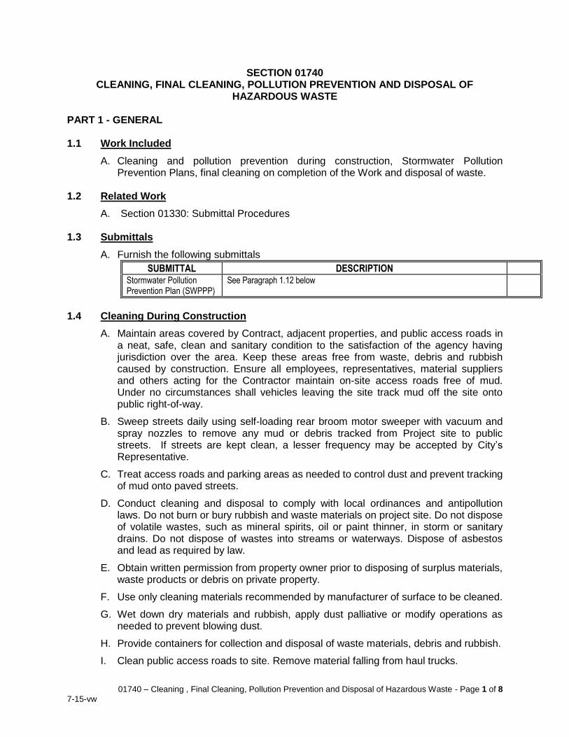
01740 – Cleaning , Final Cleaning, Pollution Prevention and Disposal of Hazardous Waste - Page 1 of 8
7-15-vw
SECTION 01740 CLEANING, FINAL CLEANING, POLLUTION PREVENTION AND DISPOSAL OF
HAZARDOUS WASTE PART 1 - GENERAL 1.1 Work Included
A. Cleaning and pollution prevention during construction, Stormwater Pollution Prevention Plans, final cleaning on completion of the Work and disposal of waste.
1.2 Related Work
A. Section 01330: Submittal Procedures 1.3 Submittals
A. Furnish the following submittals
SUBMITTAL DESCRIPTION Stormwater Pollution Prevention Plan (SWPPP)
See Paragraph 1.12 below
1.4 Cleaning During Construction
A. Maintain areas covered by Contract, adjacent properties, and public access roads in a neat, safe, clean and sanitary condition to the satisfaction of the agency having jurisdiction over the area. Keep these areas free from waste, debris and rubbish caused by construction. Ensure all employees, representatives, material suppliers and others acting for the Contractor maintain on-site access roads free of mud. Under no circumstances shall vehicles leaving the site track mud off the site onto public right-of-way.
B. Sweep streets daily using self-loading rear broom motor sweeper with vacuum and spray nozzles to remove any mud or debris tracked from Project site to public streets. If streets are kept clean, a lesser frequency may be accepted by City’s Representative.
C. Treat access roads and parking areas as needed to control dust and prevent tracking of mud onto paved streets.
D. Conduct cleaning and disposal to comply with local ordinances and antipollution laws. Do not burn or bury rubbish and waste materials on project site. Do not dispose of volatile wastes, such as mineral spirits, oil or paint thinner, in storm or sanitary drains. Do not dispose of wastes into streams or waterways. Dispose of asbestos and lead as required by law.
E. Obtain written permission from property owner prior to disposing of surplus materials, waste products or debris on private property.
F. Use only cleaning materials recommended by manufacturer of surface to be cleaned.
G. Wet down dry materials and rubbish, apply dust palliative or modify operations as needed to prevent blowing dust.
H. Provide containers for collection and disposal of waste materials, debris and rubbish.
I. Clean public access roads to site. Remove material falling from haul trucks.
01740 – Cleaning , Final Cleaning, Pollution Prevention and Disposal of Hazardous Waste - Page 2 of 8
7-15-vw
J. Remove trash and rubbish weekly.
1.5 Engine Emissions
A. Comply with all laws, ordinances, rules, regulations, and orders pertaining to air pollution.
B. Maintain equipment engines in proper tune and operate construction equipment so as to minimize exhaust emissions. Do not discharge air pollutants (dust, smoke, or other air contaminants) into the atmosphere in such quantities that they will cause a violation of the regulations of any legally constituted authority.
C. Visible emissions from any engine shall not be as dark as or darker than No. 1 in the Ringleman Chart for a period or periods aggregating more than three (3) minutes per hour per SCAQMD Rule 401 – Visible Emissions.
1.6 Portable Engine-Driven Equipment
A. Comply with the air quality regulations pertaining to portable engines with rated horsepower of 50 bhp or greater and other applicable portable equipment by meeting the following minimum requirements:
1. The engines or other applicable portable equipment shall have an SCAQMD permit or be registered with CARB.
2. The engines furnished shall satisfy the latest applicable emissions standards, as set forth in Title 13 of the California Code of Regulations (Article 5, Sections 2450-2466) and Title 40 of the Code of Federal Regulations, Part 89.
B. The engines shall be equipped with a non-resettable elapsed operating time meter. Submit activity reports to regulators as required.
C. Portable engines and other portable equipment that are permitted with SCAQMD shall meet the following minimum requirements:
1. If any of the Contractor or subcontractor engine or equipment is to be located at City facilities for more than twelve (12) consecutive months, provide the City with all information necessary for City to revise its Title V operating permit. This information shall include, but is not limited to, detailed equipment description, specifications, emissions information, dispersion modeling, permits, registrations, monitoring records, and source tests reports required by the permit for the subject equipment. Submit this information to the City no later than the end of the sixth month the equipment is located at City facilities. If the Contractor fails to provide the specified information in the specified time frame, the Contractor shall bear all fees, costs, and penalties including, but not limited to, filing fees, attorney fees, fees associated to acquire necessary offsets, fees for excessive emissions, etc. associated with City obtaining necessary variances from SCAQMD.
1.7 Self-Propelled Diesel Fuel Vehicles
A. Pursuant to Title 13 of the California Code, Section 2449(d)(3), ensure all self-propelled diesel-fueled vehicles on the jobsite, 25 horsepower and up and not designed for on-road driving, limit idling to no more than five consecutive minutes, with the following exceptions:
01740 – Cleaning , Final Cleaning, Pollution Prevention and Disposal of Hazardous Waste - Page 3 of 8
7-15-vw
1. idling when queuing;
2. idling to verify the vehicle is in safe operating condition;
3. idling for testing, servicing, repairing, or diagnostic purposes;
4. idling necessary to accomplish work for which the vehicle was designed (such as operating a crane)
5. idling required to bring the machine system to operating temperature; and
6. idling necessary to ensure safe operation of the vehicle.
B. Phase and schedule polluting construction activities to avoid emission peaks.
C. Contractor shall be responsible for promptly paying any fines assessed for noncompliance with Title 13 idling limitations for any equipment owned or rented by Contractor or his subcontractors.
1.8 Fueling of Engine-Driven Equipment
A. Provide responsible personnel in direct control of all vehicle and equipment fueling operations at all times to prevent fuel spills. All fueling must be continually monitored at all times and shall comply with SCAQMD Rule 461, Gasoline Transfer and Dispensing.
1.9 Environmental Contamination
A. Provide methods, means and facilities required to prevent contamination of soil, water or atmosphere by the discharge of noxious substances from construction operations. Provide equipment and personnel required to perform emergency measures required to contain any spillages and to remove contaminated soils or liquids. Excavate and dispose of any contaminated earth off-site and replace with suitable compacted fill and topsoil. Take special measures to prevent harmful substances from entering public waters. Prevent disposal of wastes, effluents, chemicals, or other such substances adjacent to the river, drainages, or in sanitary or storm sewers. Provide systems for control of atmospheric pollutants. Prevent toxic concentrations of chemicals. Prevent harmful dispersal of pollutants into the atmosphere. Contractor's equipment used during construction shall conform to all current federal, state and local laws, ordinances, regulations and standards.
B. Provide adequate protection of the site to prevent leaks and spills of fuel, oil, solvents, grease and other chemicals from affecting the ground and pavement. Place plastic sheeting with berms beneath the compressor, welding machines and fuel/oil storage areas. Place absorbent material on the plastic sheeting, remove when saturated, and replace with fresh absorbent material. Closely monitor fueling and equipment servicing to prevent leaks and spills. Store absorbent material in a dry condition on the site for cleanup of any spills.
1.10 Records of Volatile Organic Compounds
A. Maintain usage records of volatile organic compound (VOC) materials according to SCAQMD Rule 109 and pay annual fees according to Rule 301. The usage records shall contain, at the minimum, the following information:
1. Manufacturer’s Name
2. Product Name/Number
3. Quantity (in gallons)
01740 – Cleaning , Final Cleaning, Pollution Prevention and Disposal of Hazardous Waste - Page 4 of 8
7-15-vw
4. VOC Content (in lb/gal)
5. SCAQMD Rule Number or California Code section 1.11 Lead Paint Notification
A. The Contractor is hereby notified the facility under this Contract (may) contain Lead (Pb) or Chromium (Cr).
B. If any paints containing Lead or Chromium are to be physically disturbed or made airborne during the progress of the Work by activities such as abrasive blasting, welding, cutting or torch burning; provide appropriate worker protection in accordance with OSHA Lead in Construction Standard and any other applicable regulations.
C. Dispose of as hazardous waste all paint removed or disturbed during the progress of the Work or any demolition debris which contains these paints, either of which contains in excess of 5 ppm (mg/l) Lead or Hexavalent Chromium when tested in accordance with the Waste Extraction Test (WET) method of the California Code of Regulations, Title 22. The Contractor shall be responsible for such disposal in accordance with all applicable laws and regulations.
1.12 Pollution Prevention and Stormwater Pollution Prevention Plan (SWPPP)
A. A SWPPP is required for the project. Contractor shall retain a certified SWPPP preparer accepted in writing by City’s Representative to prepare a SWPPP for approval by City and applicable local agency and Regional Water Quality Control Board.
B. Comply with the current California State Water Control Board (SWRCB) General Construction Activity NPDES Stormwater Permit (General Construction Permit) for all construction disturbing one acre or more of land (including all staging areas, access routes, material storage yards, etc.) This permit includes a requirement to develop a Stormwater Pollution Prevention Plan (SWPPP) and Monitoring Plan (MP) which will outline site-specific Best Management Practices (BMPs) to prevent impairment to surface water quality from construction site discharges to surface waters.
C. Pay all fines associated with failure to comply with Stormwater Pollution Prevention Plan (SWPPP) requirements of the Santa Ana Regional Water Quality Control Board, except where such fines are assessed due to the sole negligence of City.
D. Comply fully with all requirements of the SWPPP that govern Contractor’s operations and record keeping requirements.
E. For purposes of preparing a SWPPP, the project has been determined to have a risk level of 1. The certified SWPPP preparer shall verify the risk level.
F. Prohibit rain runoff or other water from entering pipe trenches and infiltrating to the groundwater by redirecting surface flows with berms, temporary drains, or other suitable measures. Pump water out of trenches as necessary to control water in excavations.
1.13 Waterway Protection
A. Enforce strict on-site handling rules to keep construction and maintenance materials out of receiving waters, including, but not limited to:
01740 – Cleaning , Final Cleaning, Pollution Prevention and Disposal of Hazardous Waste - Page 5 of 8
7-15-vw
1. Store all reserve fuel supplies only within the confines of a designated construction staging area.
2. Refuel equipment only within designated construction staging area.
3. Regularly inspect all construction vehicles for leaks.
B. Clearly mark and stake on the ground the construction and staging areas shown on the Plans. Heavy equipment use outside this area shall be prohibited. The construction staging areas must be designed to contain contaminants such as oil, grease, and fuel products, so they do not drain towards receiving waters or storm drain inlets. If heavy-duty construction equipment is stored overnight adjacent to a potential receiving water, drip pans must be placed beneath the machinery engine block and hydraulic systems.
C. Construct a silt fence around disturbed soil areas and take all measures necessary to prevent erosion and transport of sediment into a waterway. Stockpile excavated material within the construction staging area and cover stockpiles with plastic sheets to prevent erosion.
1.14 Fugitive Dust
A. Employ dust control measures to City’s satisfaction continuously throughout the project duration. Dust control operations shall prevent construction dust from harming or annoying persons living in or occupying buildings near Work. Do not allow fugitive dust to be visible beyond City facilities’ property lines.
B. Use reasonable and typical watering and dust preventative techniques to reduce fugitive dust emissions. Furnish all labor, equipment, and means required (including watering or soil binders) and carry out effective measures wherever and as often as necessary to prevent its operation from producing dust in amounts damaging to property, cultivated vegetation, or domestic animals; or that are causing a nuisance as determined by the City. Wet all unpaved demolition and construction areas as necessary during excavation and construction, and use temporary dust covers to reduce dust emissions and meet SCAQMD Rule 403.
C. Cover or wet loads of excavated material or rubbish leaving site or of material being imported to prevent blowing dust.
D. Spread soil binders on site, unpaved roads, and parking areas when needed to control dust and wind-blown particles from causing a nuisance or violating air quality standards.
E. Submit a dust control plan and obtain the City’s approval before beginning work off paved roads or any activity that could stir up dust.
1.15 Disposal of Excess Materials
A. Remove from the site and legally dispose of all materials resulting from demolition work which are not otherwise shown for salvage.
B. Secure a disposal site and legally dispose of all excess materials not used in backfilling operations.
1.16 Disposal of Hazardous Wastes
01740 – Cleaning , Final Cleaning, Pollution Prevention and Disposal of Hazardous Waste - Page 6 of 8
7-15-vw
A. Within the framework of Federal and State laws, and as prescribed by these rules and laws, dispose of all materials identified as hazardous waste by virtue of rulings of Federal, State or County Regional Environmental Control Agencies.
B. Employ a qualified testing laboratory to test for hazardous and toxic components in accordance with California Administrative Code of Environmental Health, Title 22 Division 4.
C. Test results shall include testing laboratory’s determination as to whether or not materials to be disposed of comply with limits set forth in Title 22 for both Soluble Threshold Limit Concentrations (STLC) and Total Threshold Limit Concentration (TTLC) values.
D. Remove, transport, and dispose of products and materials deemed hazardous in strict accordance with Title 22 including items scheduled for demolition as well as paint, spent abrasives, solvents, cleaning compounds and contaminated soils. Provide written notification of intent to dispose of waste to State of California Department of Public Health Services whether sold to a recycling firm or consigned to a hazardous waste hauler.
E. Obtain from the consignee a receipt for disposition of these materials and provide to the City a certified copy showing amounts and destination or end use.
1.17 Handling and Disposing of Asbestos Cement Pipe
A. Within the framework of Federal and State laws, and as prescribed by these rules and laws, remove and dispose of asbestos cement pipe (ACP) in accordance with all applicable local and state laws. All work involved in the removal, salvage or legal disposal of ACP shall be the responsibility and at the expense of the Contractor.
B. Properly manifest all scrap ACP and prepare for transport following state and local criteria. Deliver the scrap material to a landfill permitted for disposal of asbestos containing materials.
C. ACP will be accepted into the landfill if the pipe is intact and if broken edges are encapsulated using approved products and techniques:
1. Small pieces of ACP pipe less than three (3) feet long must have all broken edges encapsulated (sealed) with an approved product and double wrapped in a durable six (6) millimeter plastic which is properly sealed to prevent expulsion of dust particles.
2. Intact ACP over three (3) feet long does not have to be double wrapped in six (6) millimeter plastic. Any broken edges, however, must be encapsulated with an approved product, Certane 1000 Post Removal Encapsulant or equal.
D. Each load for disposal at landfill must be accompanied by manifest indicating that ACP was properly disposed on and not the Owner’s responsibility. The completed copy of the manifest shall be returned to the Owner after disposal.
E. Contractor shall adhere to California Code of Regulations, Title 8, Section 1529, which encompasses construction safety orders regarding dusts, fumes, mists, vapors, and gases associated with asbestos.
1.18 Final Cleaning
A. Restore construction areas to preconstruction conditions after completion of Work and immediately before final inspection.
01740 – Cleaning , Final Cleaning, Pollution Prevention and Disposal of Hazardous Waste - Page 7 of 8
7-15-vw
B. Restore lines and grades of areas used for earthwork storage.
C. Clean, sweep, and wash Work and equipment including finishes.
D. Remove grease, dust, dirt, stains, labels, fingerprints and foreign materials from sight-exposed interior and exterior finished surfaces. Polish surfaces so designated.
E. Repair, patch and touch up marred surfaces to specified finish to match adjacent surfaces.
F. Broom-clean paved surfaces.
G. Rake-clean other surfaces of grounds.
H. Remove from City's property temporary structures and materials, equipment and appurtenances not required as part of, or appurtenant to, completed Work.
I. After Work is complete, remove from site loose concrete, lumber, wire, aggregate or rock piles, reinforcing, rubbish, debris and materials not incorporated in Work. Remove excess pointing mortar materials and other debris within pipes.
1.19 Unit Prices
A. Payment for cleaning will be included in items of Work to which cleaning is appurtenant.
B. The cost for preparation of a SWPPP and compliance with SWPPP requirements shall be included in the various bid items set forth in these documents and no additional compensation will be granted therefore.
C. The cost for processing and disposing of hazardous wastes shall be included in the various bid items set forth in these documents and no additional compensation will be granted therefore.
PART 2 - PRODUCTS (Not Applicable) PART 3 - EXECUTION (Not Applicable)
END OF SECTION
01740 – Cleaning , Final Cleaning, Pollution Prevention and Disposal of Hazardous Waste - Page 8 of 8
7-15-vw
THIS PAGE INTENTIONALLY BLANK

01750 – Testing, Starting, Adjusting, and Commissioning - Page 1 of 6
7-15-vw
SECTION 01750 TESTING, STARTING, ADJUSTING, AND COMMISSIONING
PART 1 – GENERAL 1.1 Work Included
A. Testing, starting, adjusting and balancing, and commissioning of all systems. Manufacturers’ approvals of installation. All commissioning work for the equipment installed under all phases of this contract shall be performed by the Contractor.
1.2 Related Work
A. Section 01330: Submittal Procedures B. Section 01400: Quality Control C. Section 01700: Execution Requirements D. Section 01770: Closeout Procedures E. Section 01783: Operating and Maintenance Data F. Section 01820: Demonstration, Training, and Spare Parts
1.3 Submittals
A. Furnish the following submittals before startup or system demonstration.
SUBMITTAL DESCRIPTION
Equipment and
Systems Testing and
Startup Plan
Step-by-step description of the materials, equipment, and personnel required;
duration of testing and startup operations, list of requirements necessary to
meet for a successful operation; and examples of testing signoff forms to be
used for the specific equipment and systems to be tested.
Manufacturer’s Written Approval of Installation (where "Manufacturer's Statement of Responsibility" is required)
Written approval of installation of products shall be certified and submitted by
authorized factory representative. This written approval shall state that a
factory authorized representative has inspected installation, alignment,
lubrication and operation of furnished equipment and found it to fully comply
with specified design and warranty requirements and be ready for safe
operation.
.
1.4 Testing, Adjusting and Balancing of Systems
A. General Requirements
1. All materials, equipment, and work included in this contract shall be tested and inspected to prove compliance with the contract requirements. Unless otherwise specified, all costs of testing, including temporary facilities and connections, shall be borne by the Contractor. For the purpose of this section, equipment shall mean any mechanical, electrical, instrumentation, or other device with one or more moving parts or devices requiring an electrical, pneumatic or hydraulic connection.
2. Furnish labor, power tools, equipment, instruments, and services required for and incidental to completing functional testing, performance testing, and operational testing. Furnish all power, ventilation, consumables, utilities, and
01750 – Testing, Starting, Adjusting, and Commissioning - Page 2 of 6
7-15-vw
temporary facilities necessary for tests if permanent systems are not available at the time of testing.
3. Provide competent, experienced technical representatives of equipment manufacturers for assembly, installation, startup, and testing guidance.
4. No tests specified herein shall be applied until the item to be tested has been inspected and approval has been given for the application of such tests.
B. Installed Equipment Tests and Inspection
1. All equipment shall be tested by the Contractor and the equipment manufacturers' representatives to verify its specified functionality to the satisfaction of the City’s Representative or Engineer before any facility is put into operation. Tests shall be as specified herein and shall be made to determine whether the equipment has been properly assembled, aligned, adjusted, balanced, and connected. Any changes, adjustments or replacements required to make the equipment operate as specified shall be carried out by the Contractor as part of the Work.
2. Prior to receipt of any progress payments in excess of 60 percent of the Contractor's lump sum bid for the Work, submit to the City details of the procedures proposed to adopt for testing and start-up of all equipment to be operated singly and together, excepting when such procedures have been covered in the Specifications.
3. Divide the procedures into three distinct stages; pre-operation checkout, load test and initial operation, and plant operational tests. Design testing procedures to duplicate, as nearly as possible, all conditions of operation and carefully select procedures to ensure the equipment is not damaged. Once the testing procedures have been reviewed by the City’s Representative or Engineer, provide checkout, alignment, adjustment and calibration sign off forms for each item of equipment. The forms will be used in the field by the Contractor and the City’s Representative or Engineer jointly to ensure that each item of electrical and mechanical equipment has been properly installed and tested. The Contractor is advised that failure to observe these procedures may place the acceptability of the subject equipment in question.
4. The procedures shall incorporate all requirements of these Specifications. Proceed in a logical, step-wise sequence to ensure all equipment has been properly serviced, aligned, balanced, connected, calibrated, and adjusted prior to operation. Pre-operation checkout procedures shall include, but not necessarily be limited to:
a. Alignment of equipment.
b. Pre-operation lubrication. Lubricate mechanical equipment in accordance with manufacturer's instructions. Lubricating oils and greases shall be of type and viscosity recommended by manufacturer. Furnish lubricants with flushing oils as recommended by manufacturer. Following flushing, fill oil lubrication system with "run-in" oil as recommended by manufacturer. Run in equipment at no load condition for 2 hours. Drain and flush equipment again with flushing oil and refill with lubricant recommended by manufacturer.
c. Test all electrical and instrumentation systems for proper connections.
d. Functionally test mechanical and electrical equipment for proper operation after general start-up and testing tasks have been completed.
01750 – Testing, Starting, Adjusting, and Commissioning - Page 3 of 6
7-15-vw
e. Demonstrate proper alignment, speed, flow, pressure, vibration, sound level, adjustments, and calibration. Operate valves and gates and check for binding or interference. Check incoming electric power for voltage amplitude and voltage balance. Check motor driven equipment for correct rotation, power draw, binding and interference. Verify safety equipment is in place. Perform initial checks in the presence of and with the assistance of the manufacturer's representative.
f. Demonstrate proper operation of each instrument loop function including alarms, local and remote controls, instrumentation and other equipment functions. Generate signals with test equipment to simulate operating conditions in each control mode.
5. Once all affected equipment has been subjected to the required pre-operational checkout procedures and the City’s Representative or Engineer has witnessed and has not found deficiencies in that portion of the Work, individual systems may be started and operated under simulated operating conditions to determine as nearly as possible whether the equipment and systems meet the requirements of these Specifications. Perform all load tests and initial operation tests in accordance with the requirements specified in the respective equipment technical specification sections of the Contract Documents.
6. Test media for all systems shall be as specified in the specific equipment specification sections of the Contract Documents. Operate the equipment for a sufficient period of time to determine machine operating characteristics, including temperatures and vibration; to observe performance characteristics; and to permit initial adjustment of operating controls. Test all equipment and structures to their full-flow rated capacity. When testing requires the availability of auxiliary systems such as power, flushing or cooling water or control air which have not yet been placed in service, provide acceptable substitute sources capable of meeting the requirements of the machine, device or system, at no additional cost to the City. Disposal methods for test media shall be subject to review by the City’s Representative.
7. If, under test, any portion of the Work should fail to fulfill the contract requirements and is adjusted, altered, renewed or replaced, tests on that portion when so adjusted, altered, removed or replaced, together with all other portions of the Work as are affected thereby, shall, if so required by the City’s Representative, be repeated within reasonable time and in accordance with the specified conditions. Pay to the City all reasonable expenses incurred by the City as a result of repeating such tests.
8. Once initial operation has been completed, recheck all machines for proper alignment. Realign machines, if necessary, and dowel in place. Check all equipment for loose connections, unusual movement or other indications of improper operating characteristics. Correct any deficiencies to the satisfaction of the City’s Representative or Engineer. Disassemble and inspect all machines or devices exhibiting unusual or unacceptable operating characteristics. Repair or remove from the site any such machines or devices and replace at no cost to the City.
9. Test results shall be within the tolerances set forth in the detailed specification sections of the Contract Documents. If no tolerances have been specified, test results shall conform to tolerances established by recognized
01750 – Testing, Starting, Adjusting, and Commissioning - Page 4 of 6
7-15-vw
industry practice. Where, in the case of an otherwise satisfactory installed test, any doubt, dispute, or difference should arise between the City’s Representative and the Contractor regarding the test results or the methods or equipment used in the performance of such test, the City’s Representative may order the test to be repeated. Costs for repeat testing shall be borne by the Contractor. Where the results of any installed test fail to comply with the contract requirements for such test, then such repeat tests as may be necessary to achieve the contract requirements shall be made by the Contractor at his expense.
10. For all non-submerged motors rated over twenty-five (25) horsepower and their driven devices, collect baseline operating data including amperage and vibration (unfiltered velocity in horizontal, vertical, and axial directions, where possible) and temperature, using a contact-type thermometer, at each bearing. Operate equipment for at least 20 minutes before taking bearing temperatures. Record data for variable speed devices at five (5) speeds, from lowest to highest.
C. Plant Operational Testing
1. After completion of all installed testing and certification by the City’s Representative or Engineer that all equipment complies with the requirements of the Specifications, fill all process units and liquid process systems, except those employing oil or chemicals, with plant water or acceptable substitute. Fill all oil and chemical systems with the specified fluid.
2. Upon completion of the filling operations, run the test media through the completed facility for a period of not less than required in the specific equipment specification section, during which all systems shall be operated as a complete facility at various loading conditions, as required by the City’s Representative or Engineer. Should the operational testing period be halted for any reason related to the facilities constructed or the equipment furnished under this contract, or the Contractor's temporary testing systems, repeat the operational testing program until the specified continuous period has been accomplished without interruption. Bring all process units to full operating conditions, including temperature, pressure, and flow.
3. Immediately correct all defects in material, workmanship, or equipment which became evident during the Operational Test.
1.5 Unit Prices
A. Payment for testing, starting, adjusting, and commissioning, including materials, equipment, devices, labor, travel costs, expenses, and maintenance items, required in Contract Documents will be included in the price bid for items of Work for which testing, starting, adjusting, and commissioning is specified.
B. Payment for services of manufacturer's representatives will be included in the price bid for their products or items to which their products are appurtenant. No additional payment will be made for services or expenses needed for testing, starting, adjusting, and commissioning if duration of services needed to provide complete working system exceeds those expected or exceeds durations stated in writing in correspondence from manufacturer to City, Contractor or other party.
01750 – Testing, Starting, Adjusting, and Commissioning - Page 5 of 6
7-15-vw
PART 2 – PRODUCTS 2.1 Testing Materials
A. Provide gages, meters, recorders and monitors as required to supplement or augment the instrumentation system provided under this contract to properly demonstrate all equipment fully satisfies the requirements of the Contract Documents. Specifically select all devices employed for the purpose of measuring the performance of the facility's equipment and systems to provide a level of uncertainty consistent with the variables to be monitored. All instruments shall be recently calibrated. Be prepared at all times to demonstrate, through re-calibration, the uncertainty of all instruments employed for testing purposes. Perform calibration procedures in accordance with applicable standards of ASTM, ISA and IEEE. The adequacy of all gages, meters, recorders and monitors shall be subject to review of the City’s Representative.
B. Unless otherwise specified, provide at no expense to the City, all power, fuel, water, utilities, supplies, testing media, labor and all other necessary items and work required to complete all tests and inspection specified in this section. Provide at no expense to the City temporary heating, ventilating and air conditioning for any areas requiring it in the case where permanent facilities are not complete and operable at the time of installed tests. Maintain temporary facilities until permanent systems are in service.
C. Provide signoff forms for all installed and operational testing to be accomplished under this contract. Provide sign off forms containing provisions for recording relevant performance data for original testing and not less than three re-tests for each item of mechanical, electrical and instrumentation equipment provided or installed under this contract. Provide separate sections to record values for the pre-operation checkout, initials of representatives of the equipment manufacturers, the Contractor and the Engineer. Sign off forms will include the motor and driven device on the same form and provide the following information, as a minimum:
1. Equipment name
2. Manufacturer
3. Model
4. Serial Number
5. Equipment tag number
6. Diagram showing bearing locations
7. Operating parameters
8. Test equipment
9. Witness signatures
10. Date
D. Maintain a master file of all equipment sign off sheets, which shall be available for inspection by the City’s Representative. Upon completion of testing, furnish the City’s Representative with the original and two copies of the sign off sheet for each equipment item.
01750 – Testing, Starting, Adjusting, and Commissioning - Page 6 of 6
7-15-vw
PART 3 – EXECUTION 3.1 Testing
A. Proceed with testing on a step-by-step basis in accordance with the Contractor's written testing procedures. The Contractor's testing work shall be accomplished by a skilled team of specialists under the direction of a coordinator whose sole responsibility shall be the orderly, systematic testing of all equipment, systems, structures and the complete facility as a unit. Each individual step in the procedures shall be witnessed by the City’s Representative or Engineer.
B. Operate all equipment and systems during the plant operational testing period, to the greatest extent practicable, at conditions which represent the full range of operating parameters as defined by the Contract Documents.
END OF SECTION
01770 – Closeout Procedures - Page 1 of 4
7-15-vw
SECTION 01770 CLOSEOUT PROCEDURES
PART 1 - GENERAL 1.1 Work Included
A. Specific administrative procedures, closeout submittals, and forms to be used at substantial completion and final completion of Work, and project record documents.
1.2 Related Work
A. Section 01301: Schedule of Values B. Section 01330: Submittal Procedures C. Section 01400: Quality Control D. Section 01740: Cleaning, Final Cleaning, Pollution Prevention and Disposal of
Hazardous Waste E. Section 01750: Testing, Starting, Adjusting and Commissioning F. Section 01781: Record Drawings and Photographs G. Section 01783: Operating and Maintenance Data H. Section 01787: Product Warranties I. Section 01820: Demonstration, Training and Spare Parts
1.3 Quality Assurance
A. Upon completion of contract, Work shall be finished, tested and ready for operation. Work shall fulfill its intended purpose as described in Contract Documents, in submittals, and in manufacturers’ literature.
B. Where connections or disruptions have been made to existing work, repair, reactivate, refill and recharge components, restoring them to preconstruction conditions. Follow procedures of authorities having ownership or jurisdiction for work involving existing utilities and services.
1.4 Submittals
A. Furnish the following submittals.
SUBMITTAL DESCRIPTION Monument Survey Show record locations of monuments or benchmarks disturbed and
reset by Contractor. Monument survey, if required shall be sealed by surveyor licensed to practice in California.
.
Schedule of Materials and Equipment Costs
See Section 01301
Record Drawings See Section 01781
O&M Manuals See Section 01783
Warranties See Section 01787
Spare Parts See Section 01820
1.5 Unit Prices
A. Payment for Work required in Contract Documents will be included in the price bid for items of work for which Work is required.
01770 – Closeout Procedures - Page 2 of 4
7-15-vw
PART 2 - PRODUCTS (Not Applicable) PART 3 - EXECUTION 3.1 Field Quality Control
A. Following system demonstration, schedule and attend final inspection and walkthrough with City’s Representative. At walkthrough, City’s Representative will review City-prepared punch list of items requiring correction with Contractor and present punch list to Contractor within 72 hours of meeting. Address the punch list items promptly.
B. Should Contractor elect to protest a punch list item rather than address it to City’s satisfaction, City reserves the right to withhold up to 150% of the value of the Work, in accordance with Public Contracting Code, as payment sufficient to hire a third party to perform unfinished work until such time as dispute between City and Contractor is resolved in Contractor’s favor.
C. Eleven month warranty inspection shall be conducted prior to release of bonds. Any work failing to comply with Specifications or performance standards stated in manufacturers’ submittals or printed promotional literature will at that time be tagged as defective and scheduled for repair. Repair all defective work in strict accordance with the Contract Documents and to the satisfaction of City’s Representative.
1. City will establish inspection date and will notify Contractor at least 30 days in advance.
2. Warranty Inspection Report will be prepared by City’s Representative and delivered to Contractor. It will set forth the number and type of failures observed and the names of persons making the inspection.
3. Repairs shall proceed promptly. Upon completion of inspection and receipt of Inspection Report, City will establish a date for Contractor to proceed with remedial Work. Delay on the part of the Contractor to proceed with remedial work on schedule shall constitute a breach of this contract. In such case, City may proceed to have defects remedied as outlined in Contract Documents.
4. Costs of warranty inspection and repair shall be borne by Contractor, who shall include an appropriate amount for testing and repair in his bid. No additional allowance will be paid by City for warranty inspection and repairs.
3.2 Adjusting and Cleaning
A. Valve box cover elevations are not shown on drawings. Determine and set cover elevations in field so that finished rim elevations are flush with finished pavement or concrete where directed by City's Representative.
3.3 Extra Stock/Spare Parts
A. Supply with the equipment any special tools and the manufacturer's standard spare parts, if required by Contract Documents or for normal operation and maintenance during the first year of operation. Package tools in a steel case, clearly and indelibly marked on the exterior to indicate equipment for which tools are intended.
B. Deliver spare parts in manufacturer's original containers labeled to completely describe contents and equipment for which it is furnished.
01770 – Closeout Procedures - Page 3 of 4
7-15-vw
C. Provide to the City’s Representative a list of all spare and replacement parts with individual prices and location where they are available. Prices shall remain in effect for a period of not less than one year after final acceptance.
END OF SECTION
01770 – Closeout Procedures - Page 4 of 4
7-15-vw
THIS PAGE INTENTIONALLY BLANK
01781 – Record Drawings and Photographs - Page 1 of 4
7-15-vw
SECTION 01781 RECORD DRAWINGS AND PHOTOGRAPHS
PART 1 - SCOPE 1.1 General Requirements
A. Keep one accurate, legible set of record drawings at the site and available for review by City’s Representative in Contractor’s field office or in superintendent’s truck throughout the Project. Record drawings referenced in this Specification and elsewhere in the Contract Documents are commonly referred to as “contractor as-built” drawings. Final project record drawings prepared by the engineer of record will use the “contractor as-built drawings”, and information collected during construction by the City, contract inspectors, and others as the basis for preparing the final project record drawings.
1.2 Related Work
A. Section 01330: Submittal Procedures B. Section 01820: Demonstration, Training, and Spare Parts
1.3 Submittals
A. Furnish the following submittals.
SUBMITTAL DESCRIPTION Record Drawing Prints One (1) working set of record drawings as created
during the course of Work; and One (1) final set of record drawings, certified as to accuracy and signed
.
PDF File of Record Drawings on CD ROM Disc One (1) copy in labeled plastic jewel case
Record Drawing Certifications Submit monthly with progress payment request
Programmers for Instruments and Devices Required as described below
Photograph Digital Files on CD ROM Disc One (1) copy in labeled plastic jewel case
1.4 Record Drawing Requirements
A. Provide record drawings on a single set of full-size project black-line prints of the Contract Drawings and other drawings forming a part of the contract, showing installed locations of improvements and all changes made during construction.
B. Show on record drawings before backfilling trench the locations by key dimensions, depths, elevations of all underground piping, drains, conduit, duct banks, sensor lines, cables, valves, capped ends, branch fittings, pull boxes and other components of the Work whose location differs from that shown on the original Plans or where design is shown schematically and dimensions are not shown on the original Plans. Do not conceal any work until the required record drawing information has been recorded. The City may direct the Contractor to expose concealed work if work was not recorded on the record drawings.
C. Show all record drawing changes in a contrasting color to the original.
D. In showing changes in the Work, or added Work, use the same legends used on the Contract Drawings. Show locations and elevations to the same level of accuracy as the original Contract Documents. Tie dimensions to a permanent point with a two-point tie-down system.
01781 – Record Drawings and Photographs - Page 2 of 4
7-15-vw
E. Report changes and deviations promptly to City's Representative.
F. Incorporate in record drawings addenda, supplementary drawings, working drawings, change orders, responses to requests for information, jobsite memorandums, clarifications, field observations of existing utilities and conditions, informal - no cost changes and corrections requested or accepted by the City’s Representative, and any additional details needed for construction of the Work not otherwise shown on the Plans.
G. Incorporate in record drawings explanatory comments at informal changes where the cause is significant, but not obvious.
H. Locate by survey and identify on the record drawings any substructures encountered while excavating and subsequently left in place.
I. Where the Plans are diagrammatic or lacking precise details, produce dimensioned full size sheets as the record drawings. For installations outside of structures, give the locations by coordinates and elevations. Where substructures are encased in concrete, give the outside dimensions of the encasement. The Contractor may submit additional 24” x 36” sheets detailing record work as approved by the City.
J. Incorporate in record drawings survey notes, field notes and system demonstration logs.
K. Mark record drawings at the time material and equipment are installed to maintain drawings current with all entries reviewed by City’s Representative. Bring record drawings to all progress meetings.
L. Protect the record drawings from damage or loss.
M. Clearly show in record drawings all discrepancies between the Contract Documents and the installed Work.
N. Show actual measured dimensions, not calculated values.
O. Record information on how to maintain and/or service concealed Work.
P. Concealed shall mean construction installed underground or in an area which cannot be readily inspected by use of access panels, inspection plates or other removable features.
Q. Make a record of finalized hydraulic and electrical equipment control settings in the appropriate tables and spaces provided on the record drawings.
R. For any device requiring hardware to program, provide one programmer for each device at each site.
1.5 Photograph Requirements
A. Provide construction progress photographs of all work to be buried or hidden including:
1. Piping;
2. Pipe connections, valves, fittings, and equipment;
3. Conduits, duct banks;
4. Reinforced concrete footings, walls, and foundations with reinforcing steel in place prior to concrete placement; and
5. Other items as directed by City Representative.
01781 – Record Drawings and Photographs - Page 3 of 4
7-15-vw
B. Provide construction site, electrical, and mechanical progress photographs taken not less than weekly showing the progress of the Work.
C. Provide photographs taken by a professional photographer of the completed project, minimum 100 photos, as directed by the City’s Representative.
D. Use digital photography.
1.6 Unit Prices
A. Payment for record drawings and project photographs required in Contract Documents will be included in the price bid for items of work for which record drawings and photographs are required.
B. Progress payment requests may be withheld if daily logs, schedule updates, record drawings, or project photographs are damaged, lost or not kept current to satisfaction of City's Representative.
PART 2 - PRODUCTS (Not Applicable)
PART 3 - EXECUTION 3.1 General
A. Maintain the following in the Contractor’s field office in clean, dry, legible condition: Contract Drawings, Specifications, Addenda, accepted Shop Drawings, Samples, photographs, Change Orders, other Modifications of Contract, test records, survey data, Field Orders, and all other documents pertinent to the Contractor’s Work, including Work by Subcontractors.
B. During progress payment request meetings, submit a signed certification stating all record drawings are complete and accurate as of the date of the payment request, and present current record drawing documents for review.
C. Submit progress photographs on CD and printed in 4”x6” format on 8-1/2”x11” white paper with each monthly pay request. Record the following information on the printed sheet for each photograph:
1. Project title
2. Date taken
3. Photograph number
4. Description of view shown in photograph
5. Names of any persons in the view
6. Photographer’s name and current contact information
D. Make documents available at all time for inspection by the City. Do not use record drawings for any other purpose nor remove them from the office without the City’s approval.
E. At the Completion of the Work and after Final Inspection, copy the record drawing information (as installed) data, using red ink, onto a new set of high quality prints. Certify with signature as to the completeness and accuracy of the "as installed" information indicated on the prints. Deliver as a submittal to the City, for review and approval, both the field developed prints and the final signed prints as a condition precedent to the City's final acceptance of Work and release of any retained funds.
01781 – Record Drawings and Photographs - Page 4 of 4
7-15-vw
City will use the final signed record drawings to create reproducible mylar record drawings.
F. Submit completed project photographs on CD with final record drawings submittal.
END OF SECTION

01783 – Operating and Maintenance Data - Page 1 of 8
7-15-vw
SECTION 01783 OPERATING AND MAINTENANCE DATA
PART 1 - GENERAL 1.1 Work Included
A. Operation and maintenance manual. 1.2 Related Work
A. Section 01330: Submittal Procedures B. Section 01750: Testing, Starting, Adjusting and Commissioning C. Section 01787: Product Warranties D. Section 01820: Demonstration, Training and Spare Parts
1.3 Submittals
A. Furnish the following submittals.
SUBMITTAL DESCRIPTION Operation and Maintenance Manual
Furnish as described below.
Equipment Data Sheets
Submit for equipment furnished under each specification section. Include data sheets in Operation and Maintenance Manual. Use attached form and follow format of attached sample Data Sheet to summarize equipment furnished, nameplate data, and equipment manufacturer's maintenance instructions and recommendations.
1.4 Operation and Maintenance Manual
A. Prepare and submit six (6) copies of Operation and Maintenance Manual containing information itemized and requested in Contract Documents. Contents shall be original and clear, with readable (no faxes) text on reproducible non-colored paper. Deliver 5 copies in D-ring binders tabbed and indexed by specification sections in numerical order as assigned in the Contract Documents. Include table of contents. Label binders with project name, date, and Volume 1 of ____, Volume 2 of ____, and so on. The sixth electronic copy shall include the original MS Word Version 2010 documents and scanned images in PDF format in 300-dpi minimum resolution saved onto a CD Rom disc and delivered to City in a labeled plastic jewel case.
B. Provide the following in each manual:
1. Cover page with equipment name, project name, “City of Corona Department of Water and Power”, date, and appropriate data.
2. Table of Contents, identified by volume number, including general description of information provided within each tab section.
3. Provide in the following order the set of documentation for each device and product:
a. Device data sheets,
b. Accepted shop drawing submittals,
c. Installation, operation, and maintenance manuals,
d. Supplemental drawings and instructions, and
e. Site specific diagrams and programming.
01783 – Operating and Maintenance Data - Page 2 of 8
7-15-vw
C. Include in each section of the Operation and Maintenance Manual the product and equipment submittals (where required by Contract Documents) which have been returned and stamped “accepted”. Provide the following information in the “accepted” submittal or in a supplemental format.
1. List of equipment furnished for Project with manufacturer’s:
a. name,
b. address,
c. telephone number,
d. e-mail address,
e. nearest representative of manufacturer, and
f. nearest supplier of manufacturer's equipment and parts.
2. Manufacturer's identification of equipment furnished, including:
a. order number,
b. model number, and
c. serial number.
3. Equipment data sheet describing function of equipment.
4. Tabulation of motor information, including:
a. nameplate horsepower,
b. nameplate current,
c. field-measured current,
d. overload relay setting, and
e. catalog number for poly-phase motors.
5. Tabulation of mechanical specifications, including:
a. materials,
b. coatings, and
c. linings.
6. Catalog data.
7. Paper prints of certified equipment drawings or reviewed shop drawing data clearly marked for mechanical, electrical, and instrument equipment furnished, including complete systems of multiple pieces of equipment in final form. Provide electrical and instrumentation schematic record drawings.
8. Copies of factory test reports.
9. Copies of field test reports.
10. Installation or application instructions.
11. Complete operating and maintenance instructions for each and every item of equipment, setting forth in detail and step-by-step the procedure for:
a. starting,
b. stopping (including safety precautions and emergency operating shutdown procedures),
c. operating under all modes of operation,
d. adjusting,
e. calibrating,
f. trouble-shooting, and
g. maintaining the entire system as installed.
01783 – Operating and Maintenance Data - Page 3 of 8
7-15-vw
12. Schedule of recommended maintenance intervals.
13. Overhaul instructions including manufacturer’s directions for the:
a. disassembly of the equipment,
b. inspection of the equipment,
c. repair of the equipment,
d. reassembly of the equipment,
e. safety precautions,
f. recommended tolerances, and
g. special tools required for maintenance and repair.
14. Complete parts list of replaceable parts, their part numbers, and the name and address of their nearest vendor. Provide manufacturer’s recommended list of parts for City to stock and any special storage requirements.
15. For equipment requiring lubrication, the manufacturer’s recommended lubricants and lubrication schedule.
16. For equipment containing integral electrical controls:
a. diagrams showing internal and connection wiring,
b. logic diagrams,
c. wiring diagrams for control panels,
d. ladder logic for computer base systems,
e. connections between existing systems and new addition, and
f. adjustments such as calibrating and set points for relays, and control or alarm contact settings.
17. List of fuses, lamps, seals, and other expendable equipment and devices. Specify size, type, and ordering description. List name, address, e-mail address, fax number, and telephone number of vendor.
18. Any special emergency operating instruction and a list of service organizations (including addresses and telephone numbers) capable of rendering emergency service to the various parts of the system.
19. Exploded views where appropriate.
20. Photographs of installed equipment.
21. Copy of manufacturer's equipment guarantees and warranties.
D. Provide manuals for each piece of equipment including individual components and subsystems of complete assemblies. Line out non-applicable text and illustrations. The section of the manual on operation shall describe the functions and limitations of each component and its relationship to the system of which it is a part. Where several models, options, or styles are described, identify in the manual the items actually provided.
E. If the manufacturer's standard brochures and manuals are used to describe O&M procedures, modify such brochures and manuals to reflect only the model or series of equipment used on this Project. Cross out neatly, annotate, or eliminate extraneous material. Brochures shall be loose leaf with durable plastic or fiberboard covers. Each sheet shall be reinforced to prevent tearing from continued use, and each brochure shall have the following information clearly printed on its cover:
1. Project name, name of City, and address.
2. Name and address of City's Representative.
01783 – Operating and Maintenance Data - Page 4 of 8
7-15-vw
3. Name and addresses of contractors and subcontractors and department to contact.
4. Telephone number of contractors, including night and emergency numbers.
5. Major equipment vendors' names and telephone numbers.
F. Operation and maintenance manuals specified herein are in addition to any operation, maintenance, or installation instructions required by the Contractor to install, test, and start up equipment.
1.5 Contractor Submittals
A. Before requesting payment for 80 percent completion point for the total contract, submit two of six required copies of the Operation and Maintenance Manual containing copies of material available at that time.
B. Within 30 calendar days after review and acceptance by City of two-copy submittal, submit remaining three hard copies and one electronic copy of Operation and Maintenance Manual in PDF format.
C. Contractor may submit operating and maintenance instructions by individual specification section or in final form according to the above instructions.
D. If the Contractor chooses to submit the O&M instructions by individual specification section, use the following procedure:
1. Submit two (2) copies of O&M instructions, along with a good quality photocopy of associated Equipment Maintenance Summary sheets, for each specification section for review.
2. Submittals will be returned with a review sheet and comments.
3. Resubmit, if requested by the City’s Representative, and retain all copies of approved submittals until all sections have been approved.
4. When all sections have been approved, organize and bind the manuals for all the sections of the contract specifications according to the above instructions and submit one complete set of O&M instructions for final review. Submit separately and unbound the completed original Equipment Maintenance Summary sheets.
5. Final review will be for the organization and binding of a complete set of manuals as specified and will not include review of previously approved material.
6. When the complete set is approved, submit six (6) complete sets to the City’s Representative as approved and specified.
E. If the Contractor chooses to submit the O&M instructions in final form, without previous approval of individual specification sections, use the following procedure:
1. Submit two (2) complete sets of O&M instructions, along with a good quality photocopy of associated Equipment Maintenance Summary sheets, organized and bound according to the above instructions for review. Place Equipment Maintenance Summary sheets with their associated specification sections for review.
2. The set will be returned with review sheets and comments pertaining to the manual organization and binding, as well as the contents.
3. Continue to resubmit the two (2) complete sets of O&M instructions, as requested by the City’s Representative, until entirely approved.
01783 – Operating and Maintenance Data - Page 5 of 8
7-15-vw
4. When the complete set is approved, submit six (6) complete sets to the City’s Representative as approved and specified. Submit separately and unbound, the completed original Equipment Maintenance Summary sheets.
F. Operation and maintenance manuals specified herein are in addition to any operation, maintenance, or installation instructions required by the Contractor to install, test, and start up equipment. Modify and supplement instructions in O&M Manuals to reflect any field changes or information required by field conditions.
1.6 Payment
A. An acceptable first submittal O&M information package must be delivered to the City before the Contractor can be paid for more than 80 percent of the purchase value of that equipment and prior to installation of the equipment. Purchase value shall be the net price for the equipment as given on the paid invoice. Progress payments for work in excess of 80 percent completion will not be made until acceptable O&M information has been delivered to the City.
1.7 Unit Prices
A. Payment for operation and maintenance manuals required in Contract Documents will be included in the price bid for items of work for which sections of Operation and Maintenance Manuals are required.
PART 2 - PRODUCTS (Not Applicable) PART 3 – EXECUTION (Not Applicable)
END OF SECTION
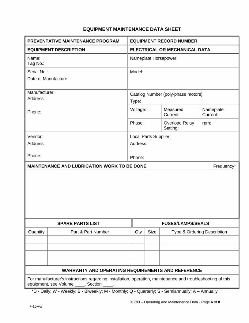
01783 – Operating and Maintenance Data - Page 6 of 8
7-15-vw
EQUIPMENT MAINTENANCE DATA SHEET
PREVENTATIVE MAINTENANCE PROGRAM EQUIPMENT RECORD NUMBER
EQUIPMENT DESCRIPTION ELECTRICAL OR MECHANICAL DATA
Name: Tag No.:
Nameplate Horsepower:
Serial No.:
Date of Manufacture:
Model:
Manufacturer:
Address:
Phone:
Catalog Number (poly-phase motors):
Type:
Voltage: Measured Current:
Nameplate Current:
Phase: Overload Relay Setting:
rpm:
Vendor:
Address:
Phone:
Local Parts Supplier:
Address:
Phone:
MAINTENANCE AND LUBRICATION WORK TO BE DONE Frequency*
SPARE PARTS LIST FUSES/LAMPS/SEALS
Quantity Part & Part Number Qty Size Type & Ordering Description
WARRANTY AND OPERATING REQUIREMENTS AND REFERENCE
For manufacturer's instructions regarding installation, operation, maintenance and troubleshooting of this equipment, see Volume ____, Section ____.
*D - Daily; W - Weekly; B - Biweekly; M - Monthly; Q - Quarterly; S - Semiannually; A – Annually

01783 – Operating and Maintenance Data - Page 7 of 8
7-15-vw
SAMPLE EQUIPMENT MAINTENANCE DATA SHEET
PREVENTATIVE MAINTENANCE PROGRAM EQUIPMENT RECORD NUMBER
EQUIPMENT DESCRIPTION ELECTRICAL OR MECHANICAL DATA
Name: Influent Pump No. 1 Tag No.: P01-1
Nameplate Horsepower: 15 HP
Serial No.: 123456ABC
Date of Manufacture: April 1, 2010
Model: 140T Frame Serial No. 987654ZY Class F Insulation w/ Space Heater
Manufacturer: DEF Motors, Inc.
Address: 465 Mayfair Avenue
Cincinnati, OH 45202
Phone: (365) 453-9089
Catalog Number (poly-phase motors): M36999b
Type: TEFC
Voltage: 480 Measured Current:18 amps
Nameplate Current: 20 amps
Phase: 3 Overload Relay Setting: 25 amps
rpm: 1,800
Vendor: ABC Pump Co.
Address: 1234 Richter Avenue
Irvine, CA 92604 Phone: (951) 752-0505
Local Parts Supplier: XYZ Mechanical
Address: 5678 Main Street
Corona, CA 92880
Phone: (951) 752-0505
MAINTENANCE AND LUBRICATION WORK TO BE DONE Frequency*
1. Operate valves and check such things as a) bearing temperature, b) changes in running sound, c) suction and discharge gage readings, d) pump discharge rate, and e) general condition of the drive equipment.
2. Check packing. 3. Check pumping unit for any dust, dirt or debris. 4. Lubricate bearing frame and motor bearings (consult manufacturer's instructions for type
of grease or oil). 5. Disassemble and change or repair the following: a) impeller, b) shafts, c) shaft sleeve,
d) rotary seals, and e) sleeve bearings.
D D W Q A
SPARE PARTS LIST FUSES/LAMPS/SEALS
Quantity Part & Part Number Qty Size Type & Ordering Description
WARRANTY AND OPERATING REQUIREMENTS AND REFERENCE
For manufacturer's instructions regarding installation, operation, maintenance and troubleshooting of this equipment, see Volume ____, Section ____.
*D - Daily; W - Weekly; B - Biweekly; M - Monthly; Q - Quarterly; S - Semiannually; A – Annually

01783 – Operating and Maintenance Data - Page 8 of 8
7-15-vw
THIS PAGE INTENTIONALLY BLANK
01787 – Product Warranties - Page 1 of 4
7-15-vw
SECTION 01787 PRODUCT WARRANTIES
PART 1 - GENERAL 1.1 Work Included
A. Warranties are required for all Work furnished under this contract.
B. Manufacturer's warranties shall not relieve Contractor of liability required under Contract Documents. Such warranties only shall supplement Contractor's responsibility.
1.2 Related Work
A. Section 01330: Submittal Procedures B. Section 01400: Quality Control C. Section 01750: Testing, Starting, Adjusting and Commissioning D. Section 01770: Closeout Procedures
1.3 Submittals
A. Furnish the following submittals.
SUBMITTAL DESCRIPTION Warranty For equipment bearing manufacturer's warranty in excess of one year, furnish
copy of warranty to City with City named as beneficiary.
1.4 One-Year Product Warranties
A. Warranties shall cover improper assembly or erection, defective workmanship and products, and incorrect or inadequate operation.
B. Furnish one-year warranty for all Work and manufactured items unless otherwise stated. Warranty shall cover parts, labor, and prompt service for repair of defects, performance failure or damage due to normal wear and tear or due to any cause other than acts of God, or intentional or active and extreme abuse of product. Warranty period shall extend one year beyond final acceptance of completed contract by City.
C. In addition to manufacturer's standard warranty, furnish services of factory-authorized and factory-trained service technician to promptly provide repair service for mechanical equipment for specified warranty period. Provide this service at no cost to City and include cost of all replacement parts and labor required during that period.
D. Correct within ten (10) days following receipt of notice thereof from City any defective or imperfect material or workmanship which may be discovered within one (1) year after final acceptance. Make all such corrections of defective or imperfect material or workmanship without extra charge, notwithstanding that it may have been overlooked in previous inspections and estimates and the Work finally accepted by City.
01787 – Product Warranties - Page 2 of 4
7-15-vw
1.5 Inspection of Installation by Manufacturer
A. In the event manufacturer or supplier of any product has reason to suspect said manufacturer’s product has not been installed in accordance with manufacturer’s warranty requirements, Manufacturer shall have right to send their factory authorized representative to inspect facility.
B. In the event manufacturer’s factory authorized representative elects to inspect installation, said manufacturer shall promptly notify City in writing of any observed deficiencies in installation procedures which might affect the warranty.
C. In the event manufacturer elects to forego inspection of installation of his products, said manufacturer shall be precluded from claiming faulty installation by others as relief from honoring furnished warranties.
1.6 Eleven-Month Anniversary Warranty Inspection
A. Warranty inspection shall be conducted during 11th month following completion of Work.
B. Locations found in warranty inspection where paving, coating, or paint has peeled, bubbled or cracked, and locations where rusting is evident will be considered a system failure. Repair defective work identified during warranty inspection by removing deteriorating paving, coating or paint system, cleaning surface, and repaving, recoating or repainting with same system. Electrically test repaired painted areas. If area of failure exceeds 25% of total paved, coated or painted surface for pavement, coating or paint system on any structure or surface, remove and recoat entire paving, coating or paint system per original specification.
C. Repair other failed products found in warranty inspection per warranty requirements.
D. City shall establish date for warranty inspection and shall notify Contractor at least 30 days in advance. If notification of inspection date does not occur within twelve months after final acceptance, the first anniversary inspection shall be considered to be waived.
1.7 Multi-Year Product Warranties and Other Extended Warranties
A. Furnish three-year minimum warranty for the following:
1. Pumps and motors
2. Skid-mount chemical feed systems
3. Tanks
B. Three-year warranty shall be three-year parts-and-labor non-prorated warranty extending from date of City’s final acceptance. Warranty need not exceed five years from date of shipping.
C. Where System Integrators or unit manufacturers are required to furnish skid-mount or packaged chemical feed, air conditioning or refrigeration systems requiring three-year or extended warranties, every component of the furnished system shall be covered under the extended warranty, notwithstanding clauses in other sections which may stipulate a lesser warranty for certain components.
D. Five-year minimum warranty shall be furnished for the following:
1. Glazing
01787 – Product Warranties - Page 3 of 4
7-15-vw
E. Five-year warranty shall be five-year parts-and-labor non-prorated warranty extending from date of City’s final acceptance. Warranty need not exceed seven years from date of shipping.
F. Ten-year minimum warranty shall be furnished for the following:
1. Roofing
2. Door closers
G. Ten-year warranty shall be ten-year parts-and-labor non-prorated warranty extending from date of City’s final acceptance. Warranty need not exceed twelve years from date of shipping.
H. Extended warranty shall cover parts, labor and prompt service for repair of defects, performance failure or damage due to normal wear and tear, or due to any cause other than acts of God, City’s failure to perform minimum maintenance as set forth in O&M instructions furnished with warranty, or intentional or active and extreme abuse of the product. Warranty period shall extend the stipulated number of years beyond final acceptance of completed contract by City.
I. Extended warranties shall cover City’s full cost of restoring non-functional components to their full function as described in Contract Documents and in manufacturer’s published literature. Prorated warranties will not be accepted. Replacement of damaged parts with old or recycled parts will not be accepted
J. In the event manufacturer refuses to provide full extended warranty, Contractor may be required to purchase extended warranty or negotiate with City a fair value for a shorter warranty period.
1.8 City-Furnished Equipment and Materials Warranties
A. Product warranties on City-furnished equipment and materials shall be provided by the equipment and materials manufacturers directly to the City.
B. Contractor is responsible for installing equipment and materials in accordance with the requirements of Specifications Section 01700 – Execution Requirements as necessary to maintain product warranties.
C. Contractor is responsible for correcting and repairing any defects caused by faulty installation during the life of the product warranty.
1.9 General Warranty Clauses
A. Repair or replace any work that may prove to be defective in workmanship and/or materials within the warranty period, along with any other work which may be damaged or displaced during performance of the warranty work, all with no additional expense to the City.
B. Where sections of specifications stipulate a longer warranty period than is stipulated in this section, the longest and most stringent warranty requirement shall apply.
C. Warranty period shall begin on the earliest of the following two milestones:
1. Date of formal notification of completion, or
2. 31 calendar days after both substantial completion and City taking over beneficial use of project.
01787 – Product Warranties - Page 4 of 4
7-15-vw
D. Warranties shall cover the following:
1. Parts
2. Labor
3. Diagnostics
4. Servicing
5. Removal or Installation Charges
6. Setup and Reconfiguration of System with Replacement Parts
7. Shipping
E. Where a part is replaced during warranty period, warranty for replaced part and shipping shall be extended to not less than one year following date of replacement. Warranty for labor shall be unchanged.
F. Following notification of Contractor of a warranty issue, Contractor or his agent shall have two weeks to inspect and 30 days to remedy defective work. Failure to perform within this stipulated period will result in damages being assessed against Contractor and responsible parties retroactive to date of discovery.
1.10 Unit Prices
A. Payment for warranties required in Contract Documents will be included in the price bid for items of work for which warranties are required.
PART 2 - PRODUCTS (Not Applicable) PART 3 – EXECUTION (Not Applicable)
END OF SECTION
01820 – Demonstration, Training and Spare Parts - Page 1 of 8
7-15-vw
SECTION 01820 DEMONSTRATION, TRAINING AND SPARE PARTS
PART 1 - GENERAL 1.1 Work Included
A. System Demonstration and training of City's personnel. Furnish spare parts and maintenance materials.
1.2 Related Work
A. Section 01330: Submittal Procedures B. Section 01750: Testing, Starting, Adjusting and Commissioning C. Section 01783: Operating and Maintenance Data
1.3 Submittals
A. Furnish the following submittals.
SUBMITTAL DESCRIPTION System Demonstration Plan Submit within 30 calendar days following pre-construction meeting.
Outline each test procedure proposed for final testing. Plan shall describe each system to be tested, test methods, test materials, test instruments and recorders, and results to be recorded. In addition to functional testing of each system, system demonstration plan shall include continuous 72-hour demonstration of operation of entire installed system. A shorter demonstration period may be authorized solely by City's Representative if external constraints make a 72-hour test impractical. Procedures shall include demonstration of all instruments, set points, alarms, telemetry, software, safety interlocks and back-up modes of operation. Procedures shall incorporate start-up and demonstration procedures recommended by Manufacturers. City may modify proposed procedures as deemed necessary to demonstrate system operation. System demonstration shall include operation of all new equipment through entire no-load to full-load range.
System Demonstration Log Submit for final operations test period.
Control Software Submit current copy of all control software.
Lesson Plan Submit no less than 30 calendar days prior to scheduled training for City's personnel.
Spare Parts List Submit with System Demonstration Plan
1.4 Unit Prices
A. Payment for system demonstration including materials, equipment, devices, labor, travel costs, expenses, and maintenance items, required in Contract Documents will be included in the price bid for items of work for which systems demonstration and startup is specified.
B. Payment for costs and expenses of representatives of material and equipment suppliers and subcontractors will be included in the price bid for items of work for which systems demonstration and startup is specified.
C. Payment for operation and maintenance training required in Contract Documents shall be included in the price bid for items of work for which operation and maintenance training is required.
01820 – Demonstration, Training and Spare Parts - Page 2 of 8
7-15-vw
D. If it is necessary for any of City’s inspectors or representatives to be present for retests or re-inspections of installed facilities, Contractor shall pay all costs on a per diem rate as established between City and their representative. Said amounts shall be deducted from final payments to Contractor.
E. Payment for spare parts including materials, parts, equipment, storage boxes, and labor required in Contract Documents will be included in the price bid for items of work for which equipment spare parts are specified.
PART 2 - PRODUCTS (Not Applicable) PART 3 – EXECUTION 3.1 System Demonstration
A. System demonstration shall conform to accepted demonstration plan.
B. Notify City's Representative of time and place of system demonstrations 5 working days before they begin.
C. Arrange for representatives of equipment suppliers and subcontractors to be present as required to successfully demonstrate installed system.
D. Furnish and install any temporary valves, fittings, bulkheads, taps or other items necessary for system demonstration.
E. Prior to formal system demonstration, provide test runs as needed and verify all parts are in place and in working order. City’s costs for delays during system demonstration due to Contractor’s failure to pretest system and verify all products are in place and functional will be back-charged to Contractor.
F. Perform systems demonstrations in presence of City's Representative who will record results. Start up and operate individual subsystems, pieces of equipment, instruments, etc.
G. Correct immediately defects and malfunctions disclosed during testing and system demonstration. Replace with new equipment any work that fails to perform its intended function, and cannot be repaired.
H. Disassemble, inspect, and replace defective components of equipment exhibiting unusual or unacceptable operating characteristics.
I. Failure to meet specified requirements shall be cause for retesting at the Contractor’s expense until the requirements are met. Interruption of a continuous operation test due to equipment malfunction shall be cause to restart the test after repairs.
J. SCADA system programming will be provided by City or contract SCADA programmer. Accommodate testing of programming by City or SCADA programmer as necessary during system testing and demonstration. Equipment may be progressively operated and monitored by the SCADA system as programming is tested.
01820 – Demonstration, Training and Spare Parts - Page 3 of 8
7-15-vw
3.2 Field Quality Control
A. Field testing shall include the following:
ITEM TEST FOR
TEST STANDARD (ASTM OR OTHER TEST
STANDARD) FREQUENCY
FIRST TEST PAID
FOR BY
RETESTS PAID FOR
BY Finished Installation
Installation & Leakage
Visual inspection of finished installation
1 inspection City City
System Demonstration
Demonstrate compliance to Contract Documents and
Manufacturer’s printed literature using accepted system
demonstration plan described above
One 72-hour demonstration without interruption. (If test is
interrupted, clock restarts at zero for 72-hour demonstration)
Contractor (City will pay
for test water)
Contractor
11-month Warranty Inspection
Demonstrate compliance to Contract Documents and
Manufacturer’s printed literature
1 test City Contractor
B. Provide qualified technicians and calibrated test instruments as necessary to
perform tests. Provide certifications for test instruments and technical personnel to prove the performance of tested equipment beyond reasonable doubt. In addition, furnish Contractor’s own personnel, as needed, to make adjustments or alterations recommended by the equipment manufacturer’s representative(s).
C. Correct all deficiencies found during system demonstration, including malfunctions of equipment or control systems, leakage, excessive vibration and excessive noise.
D. Following testing, remove all bulkheads and temporary equipment. Dispose of test water according to local regulations and NPDES requirements. Inspect for loose connections, leaking fluids, and any irregularities. Check all field-aligned equipment for required alignment and realign if necessary.
3.3 Extra Stock/Spare Parts
A. Deliver required spare parts in manufacturer's original unopened containers or other protective covering suitable for preventing corrosion or deterioration for the maximum length of storage which may be normally anticipated. Clearly label containers to completely describe contents and equipment for which it is furnished. Deliver spare parts to the jobsite or the City’s supply warehouse, at the City’s discretion.
B. During construction, store parts in building or trailers, with floor, roof, and closed sides protected from weather, condensation, and humidity and in accordance with manufacturers’ recommendations.
C. Provide letter of transmittal to accompany the spare parts to include:
1. Date of letter and transfer of parts and materials.
2. Contract title and number.
3. Contractor’s name and address.
4. A complete inventory of the parts and materials, listing the applicable specification section for each.
5. A place for the City’s Representative to sign and signify receipt of the parts and materials.
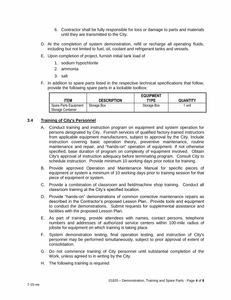
01820 – Demonstration, Training and Spare Parts - Page 4 of 8
7-15-vw
6. Contractor shall be fully responsible for loss or damage to parts and materials until they are transmitted to the City.
D. At the completion of system demonstration, refill or recharge all operating fluids,
including but not limited to fuel, oil, coolant and refrigerant tanks and vessels.
E. Upon completion of project, furnish initial tank load of
1. sodium hypochlorite
2. ammonia
3. salt
F. In addition to spare parts listed in the respective technical specifications that follow, provide the following spare parts in a lockable toolbox:
ITEM DESCRIPTION EQUIPMENT
TYPE QUANTITY Spare Parts Equipment Storage Container
Storage Box Storage Box 1 unit
3.4 Training of City's Personnel
A. Conduct training and instruction program on equipment and system operation for persons designated by City. Furnish services of qualified factory-trained instructors from applicable equipment manufacturers, subject to approval by the City. Include instruction covering basic operation theory, preventive maintenance, routine maintenance and repair, and "hands-on" operation of equipment. If not otherwise specified, base duration of program on complexity of equipment involved. Obtain City's approval of instruction adequacy before terminating program. Consult City to schedule instruction. Provide minimum 10 working days prior notice for training.
B. Provide approved Operation and Maintenance Manual for specific pieces of equipment or system a minimum of 10 working days prior to training session for that piece of equipment or system.
C. Provide a combination of classroom and field/machine shop training. Conduct all classroom training at the City’s specified location.
D. Provide “hands-on” demonstrations of common corrective maintenance repairs as described in the Contractor’s proposed Lesson Plan. Provide tools and equipment to conduct the demonstrations. Submit requests for supplemental assistance and facilities with the proposed Lesson Plan.
E. As part of training, provide attendees with names, contact persons, telephone numbers and addresses of authorized service centers within 100-mile radius of jobsite for equipment on which training is taking place.
F. System demonstration testing, final operation testing, and instruction of City's personnel may be performed simultaneously, subject to prior approval of extent of consolidation.
G. Do not commence training of City personnel until substantial completion of the Work, unless agreed to in writing by the City.
H. The following training is required:
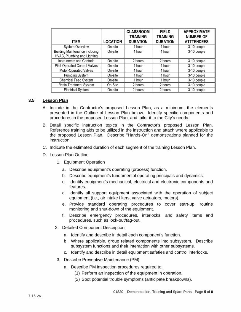
01820 – Demonstration, Training and Spare Parts - Page 5 of 8
7-15-vw
ITEM LOCATION
CLASSROOM TRAINING DURATION
FIELD TRAINING DURATION
APPROXIMATE NUMBER OF
ATTTENDEES System Overview On-site 1 hour 1 hour 3-10 people
Building Maintenance including HVAC, Plumbing and Lighting
On-site 1 hour 1 hour 3-10 people
Instruments and Controls On-site 2 hours 2 hours 3-10 people
Pilot-Operated Control Valves On-site 1 hour 1 hour 3-10 people
Motor-Operated Valves On-site 1 hour 1 hour 3-10 people
Pumping System On-site 1 hour 1 hour 3-10 people
Chemical Feed System On-site 1 hour 1 hour 3-10 people
Resin Treatment System On-Site 2 hours 2 hours 3-10 people
Electrical System On-site 2 hours 2 hours 3-10 people
3.5 Lesson Plan
A. Include in the Contractor's proposed Lesson Plan, as a minimum, the elements presented in the Outline of Lesson Plan below. Identify specific components and procedures in the proposed Lesson Plan, and tailor it to the City’s needs.
B. Detail specific instruction topics in the Contractor's proposed Lesson Plan. Reference training aids to be utilized in the instruction and attach where applicable to the proposed Lesson Plan. Describe "Hands-On" demonstrations planned for the instruction.
C. Indicate the estimated duration of each segment of the training Lesson Plan.
D. Lesson Plan Outline
1. Equipment Operation
a. Describe equipment's operating (process) function.
b. Describe equipment's fundamental operating principals and dynamics.
c. Identify equipment's mechanical, electrical and electronic components and features.
d. Identify all support equipment associated with the operation of subject equipment (i.e., air intake filters, valve actuators, motors).
e. Provide standard operating procedures to cover start-up, routine monitoring and shut-down of the equipment.
f. Describe emergency procedures, interlocks, and safety items and procedures, such as lock-out/tag-out.
2. Detailed Component Description
a. Identify and describe in detail each component's function.
b. Where applicable, group related components into subsystem. Describe subsystem functions and their interaction with other subsystems.
c. Identify and describe in detail equipment safeties and control interlocks.
3. Describe Preventive Maintenance (PM)
a. Describe PM inspection procedures required to:
(1) Perform an inspection of the equipment in operation.
(2) Spot potential trouble symptoms (anticipate breakdowns).
01820 – Demonstration, Training and Spare Parts - Page 6 of 8
7-15-vw
(3) Forecast maintenance requirements (predictive maintenance).
b. Define the recommended PM intervals for each component.
c. Provide lubricant and replacement part recommendations and limitations.
d. Describe appropriate cleaning practices and recommended intervals.
4. Equipment Troubleshooting
a. Define recommended systematic troubleshooting procedures.
b. Provide component specific troubleshooting checklist.
c. Describe applicable equipment testing and diagnostic procedures to facilitate troubleshooting.
5. Equipment Corrective Maintenance
a. Describe recommended equipment preparation requirements.
b. Identify and describe the use of any special tools required for maintenance of the equipment.
c. Describe component removal/installation and disassembly/assembly procedures.
d. Perform at least two "hands-on" demonstrations of common corrective maintenance repairs.
e. Describe recommended measuring instruments and procedures, and provide instruction on interpreting alignment measurements, as appropriate.
f. Define recommended torqueing, mounting, calibration and/or alignment procedures and settings, as appropriate.
g. Describe recommended procedures to check/test equipment following a corrective repair.
3.6 Training Aids
A. Incorporate training aids as appropriate to assist in the instruction. At a minimum, include text and figure handouts with the training aids. Other appropriate training aids are:
1. Audio-Visual Aids (e.g., films, slides, videotapes, overhead transparencies, posters, blueprints, diagrams, catalogue sheets).
2. Equipment Cutaways and Samples (e.g., spare parts, damaged equipment).
3. Tools (e.g., repair tools, customized tools, measuring and calibrating instruments).
B. The Contractor's instructor shall utilize descriptive class handouts during the instruction. Provide good quality reproductions of photocopied class handouts. Provide class handouts during instruction with frequent references made to them. Customized handouts developed especially for the instruction are encouraged. Attach handouts planned for the instruction with the Contractor's proposed Lesson Plan.
3.7 Videography
A. Enlist the services of a professional videographer to record training sessions and “hands-on” demonstrations. The video recording shall be digital format and edited to
01820 – Demonstration, Training and Spare Parts - Page 7 of 8
7-15-vw
provide a professional-quality video product for the City’s use in future training. Include in the edited video introductory titles, captions where necessary, and transitions between scenes. Smoothly edit out of the final product any unproductive time (i.e. breaks, downtime, etc.). Each equipment video shall follow the format of the manufacturer-supplied lesson plan and be 1-hour maximum.
B. Provide a draft video to the City for review in DVD format. Prior to submittal to the City, coordinate a review by the respective manufacturer for content. The City will review the draft video and provide comments on quality and content. The Contractor’s videographer shall edit the video accordingly and re-submit a final video in DVD format.
END OF SECTION
01820 – Demonstration, Training and Spare Parts - Page 8 of 8
7-15-vw
THIS PAGE INTENTIONALLY BLANK
02050-1 G:\Projects\WATER TREATMENT\Resin_Treatment_of_Nitrate_Sources-CIP_No_68510507\01-Administration\01_h-Contract_Documents\Specifications\Division 2 - 17\Sect 02050 Demolition.doc
SECTION 02050
DEMOLITION
PART 1 - GENERAL
1.1 WORK OF THIS SECTION
A. The WORK of this Section includes furnishing materials, equipment and labor necessary to perform demolition work on the project site as shown on the Contract Drawings
B. In areas where demolition is required, cut back flush and seal any pipe stub-outs remaining, and remove exposed piping, conduits, fixtures, junction boxes, light fixtures, water fixtures, and supports. Switches, receptacles, and boxes shall also be removed. Concealed piping and conduits shall be removed or capped and abandoned as necessary to facilitate the demolition work.
1.2 STANDARD SPECIFICATIONS
Except as supplemented or specifically modified herein or shown otherwise on the Contract Drawings, the entire work under this Section shall be in compliance with the provisions in the applicable Sections of the Edition that was in effect on the date that the Contract Drawings were signed and sealed by the Design Engineer and includes all Supplement(s) of the Standard Specifications for Public Works Construction (SSPWC) also known as the “Green Book”.
In case of conflict between any requirements set forth in this Section, the Contract Drawings and any provisions of the foregoing Standard Specifications, the requirements shown on the Contract Drawings shall govern over the requirements set forth herein and the requirements set forth herein and the requirements set forth herein shall govern over the SSPWC.
1.3 SUBMITTALS
A. The following shall be submitted in compliance with Section 01300.
1. Demolition Schedule: The Contractor shall submit a complete coordination schedule for demolition work including shut-off and continuation of utility services prior to start of the WORK. The schedule shall indicate proposed methods and operations of facility demolition, and provide a detailed sequence of demolition and removal work to ensure uninterrupted operation of occupied areas.
PART 2 – PRODUCTS (Not Used)
PART 3 – EXECUTION
3.1 GENERAL
A. Structures shall be demolished and removed in compliance with SSPWC subsection 306-5 and the requirements indicated herein.
3.2 POLLUTION CONTROL
A. Water sprinkling, temporary enclosures, chutes, and other suitable methods shall be used for dust suppression.
B. Water shall not be used when it creates hazardous or objectionable conditions such as flooding, erosion, sedimentation, or pollution.
02050-2 G:\Projects\WATER TREATMENT\Resin_Treatment_of_Nitrate_Sources-CIP_No_68510507\01-Administration\01_h-Contract_Documents\Specifications\Division 2 - 17\Sect 02050 Demolition.doc
3.2 PROTECTION
A. Safe passage of persons around the area of demolition shall be provided. Operations shall be conducted to prevent injury to people and damage to adjacent buildings, structures, and other facilities.
B. Interior and exterior shoring, bracing, or supports shall be provided to prevent movement, settlement or collapse of structures to be demolished.
C. Existing landscaping materials, structures, and appurtenances which are not to be demolished shall be protected and maintained as necessary.
D. Unless otherwise indicated, the Contractor shall protect and maintain all utilities in the proximity of the facilities to be demolished.
E. The Contractor shall protect the nearby existing equipment such as control panels and others from dust caused by demolition activities by covering, drop-curtains and other similar methods.
3.4 STRUCTURE DEMOLITION
A. Building structures and appurtenances shall be demolished, as shown and required to complete work, in compliance with governing regulations.
B. Small structures may be removed intact when approved by authorities having jurisdiction.
C. Demolition shall proceed in a systematic manner, from top of structure to ground.
D. Concrete and masonry shall be demolished in small sections. Use bracing and shoring to prevent collapse.
E. Demolition equipment shall be dispersed throughout structure and demolished materials removed to prevent excessive loads on supporting walls, floors or framing.
3.5 BELOW-GRADE DEMOLITION
A. Footings, foundation walls, below-grade construction and concrete slabs on grade shall be demolished and removed to a depth which will not interfere with new construction, but not less than 12 inches below existing ground surface or future ground surface, whichever is lower. All floors of basements, vaults, and other underground structures shall be broken up.
B. Below-grade areas and voids resulting from demolition of structures shall be completely filled to a minimum compaction of 95%.
C. All fill and compaction shall be in accordance with Section 02200.
D. After fill and compaction, surfaces shall be graded to meet adjacent contours and to provide flow to surface drainage structures, or as indicated.
3.6 DISPOSAL OF DEMOLISHED MATERIALS
A. Demolition and removal of debris shall be conducted to ensure minimum interference with roads, streets, walks, and other adjacent occupied or used facilities which shall not be closed or obstructed without permission from the Owner. Alternate routes shall be provided around closed or obstructed traffic ways.
B. Site debris, rubbish, and other materials resulting from demolition operations shall be removed and disposed of in compliance all laws and regulations. Burning of removed materials from demolished structures shall not be permitted.
02050-3 G:\Projects\WATER TREATMENT\Resin_Treatment_of_Nitrate_Sources-CIP_No_68510507\01-Administration\01_h-Contract_Documents\Specifications\Division 2 - 17\Sect 02050 Demolition.doc
3.7 PATCHING AND REPAIRING
A. The Contractor shall provide patching, replacing, repairing and refinishing of damaged areas involved in demolition as necessary to match the existing adjacent surfaces.
B. The Contractor shall repair all damages caused to adjacent facilities by demolition at no additional cost to the Owner.
C. After patching and repairing has been completed, the Contractor shall carefully remove splatterings of mortar from adjoining work and repair any damage caused by such cleaning operations.
3.8 CLEANING
A. During and upon completion of work, the Contractor shall promptly remove unused tools and equipment, surplus materials, rubbish, debris, and dust and shall leave areas affected by work in a clean condition.
B. Clean adjacent structures and facilities of dust, dirt, and debris caused by demolition and return adjacent areas to condition existing prior to start of work.
*** END OF SECTION ***

02050-4 G:\Projects\WATER TREATMENT\Resin_Treatment_of_Nitrate_Sources-CIP_No_68510507\01-Administration\01_h-Contract_Documents\Specifications\Division 2 - 17\Sect 02050 Demolition.doc
THIS PAGE INTENTIONALLY BLANK
02100-1 G:\Projects\WATER TREATMENT\Resin_Treatment_of_Nitrate_Sources-CIP_No_68510507\01-Administration\01_h-Contract_Documents\Specifications\Division 2 - 17\Sect 02100 Site Preparation.doc
SECTION 02100
SITE PREPARATION
PART 1 - GENERAL
1.1 DESCRIPTION
A. Site preparation shall consist of all clearing, grubbing, stripping, demolition and related work necessary to prepare the project site for construction operations.
B. No open burning of debris, lumber, or other scrap will be permitted.
PART 2 - EXECUTION
2.1 DEMOLITION
Demolish and remove interfering portions of existing concrete, foundations, asphalt, posts, poles, or other structures.
2.2 CLEARING
A. Clearing shall consist of the felling, trimming and cutting of trees, and the removal of downed timber, shrubs, grasses, debris and rubble within the project limits.
2.3 GRUBBING
Grubbing shall consist of the removal and disposal of stumps, roots larger than 3 inches in diameter, and matted roots from the within the property lines. Depressions made by grubbing shall be filled with structural backfill material and compacted to make the surface conform with the original adjacent surface of the ground, unless further excavation is required.
2.4 DISPOSAL
A. Felled Trees and Downed Timber: Dispose of in a legal manner
B. Dispose of remaining vegetation and debris in a legal manner.
2.5 IMPORTED BACKFILL MATERIAL
Import, place and compact imported backfill material in all voids created by removals (except pavement removal), in accordance with Section 02200.
***END OF SECTION***

02100-2 G:\Projects\WATER TREATMENT\Resin_Treatment_of_Nitrate_Sources-CIP_No_68510507\01-Administration\01_h-Contract_Documents\Specifications\Division 2 - 17\Sect 02100 Site Preparation.doc
THIS PAGE INTENTIONALLY BLANK
02200-1 G:\Projects\WATER TREATMENT\Resin_Treatment_of_Nitrate_Sources-CIP_No_68510507\01-Administration\01_h-Contract_Documents\Specifications\Division 2 - 17\Sect 02200 Earthwork.doc
SECTION 02200
EARTHWORK
PART 1 - GENERAL
Earthwork shall include all necessary excavation and trenching for structures, pipes and appurtenances, backfilling, dewatering, compaction and disposing of excess excavated material, all as required for the complete performance of the work for the installation of structures, pipes and appurtenances all as indicated on the plans and as specified herein.
Earthwork, including grading as referred to herein or in connection herewith shall be construed as including any or all of the following described operations:
Excavating all materials of whatever nature encountered; backfilling; fine grading; finish grading for unpaved areas; subgrading for structures and performing any operation which may be necessary to properly complete the entire work as indicated on the plans and specified herein.
PART 2 - PRODUCTS
2.1 EQUIPMENT
Equipment used for earthwork operations shall be at the Contractor's option.
PART 3 - EXECUTION
3.1 EXCAVATION
A. Excavation for Footings: Sides of footings are to be formed. The excavation shall be one foot wider than the footing on each side to permit forming and bracing.
Excavations shall be cut square on the bottom and corners and carefully brought to the required grades. Care shall be taken not to disturb the bottom of the excavation and final removal of the material to grade shall not be made until just before concrete is placed.
B. Correction of Faulty Grade: Where excavation is inadvertently carried below subgrade and/or foundation elevations, suitable provision shall be made at the expense of the Contractor for adjustment of same, as directed by the Owner's representative, to meet requirements incurred by the deeper excavation beneath pipe or structures. Overdepth excavations in such locations shall be rectified by backfilling with approved graded crushed rock or gravel, and shall be compacted to provide a firm and unyielding subgrade and/or foundation, as directed by the Owner's representative, all at the expense of the Contractor.
C. Grading and Stockpiling: The Contractor shall control grading in a manner to prevent water running into excavations. He shall protect the grading against irrigation water. Obstruction of surface drainage shall be avoided and means shall be provided whereby storm runoff can flow uninterrupted in existing gutters, other surface drains, or temporary drains.
Excavated materials, approved by the Owner as suitable for backfill, shall be segregated and placed in temporary stockpiles within the project site. Material shall be stockpiled in a manner to preclude any ponding of water or concentration of storm flow on the project site. The Contractor shall stockpile sufficient approved material in order to perform all required backfilling. Surplus excavated materials or excavated materials considered unsuitable by the Owner for use in the construction of compacted backfill on this project shall become the property of the Contractor and shall be removed from the site, or surplus or unsuitable excavation materials may
02200-2 G:\Projects\WATER TREATMENT\Resin_Treatment_of_Nitrate_Sources-CIP_No_68510507\01-Administration\01_h-Contract_Documents\Specifications\Division 2 - 17\Sect 02200 Earthwork.doc
also be disposed of onsite at the direction of the Owner's representative. Coordinate temporary stock pile location with city off site if there is not adequate space on-site.
D. Unauthorized Excavation: Excavation made below the bottom grade caused by Contractor's error shall be refilled at the expense of the Contractor with select material or gravel fill as may be directed by the Owner in order to ensure the stability of the structures or pipe involved. If the Contractor elects to do so, he may at his own expense fill the unauthorized space with cement slurry.
E. Removal of Unsuitable Material and Replacement with Compacted Gravel Backfill: Material deemed unsuitable by the Owner for footings, foundations or slabs shall be excavated and replaced with compacted gravel backfill. Such additional excavations and backfill work shall be performed only upon specific written authorization by the Owner.
Removal and disposal of unsuitable material and the furnishing and replacement of compacted gravel backfill will be paid for in accordance with the General Provisions.
3.2 FOUNDATIONS
A. Granular Soil: Wherever the term "granular soil" is used in these specifications, it shall be defined as a soil having a minimum sand equivalent of 30 as determined in accordance with the State of California Division of Highways Test Method No. Calif. 217, and not more than 20% of it will pass through a 200-mesh sieve.
B. Imported Sand: Wherever the term "imported sand" is used in these specifications, it shall be defined as sand having a minimum sand equivalent of 30 as determined by the State of California Division of Highways Test Method No. Calif. 217.
C. Foundations in Poor Soil: Unsuitable material encountered at the surface upon which the bedding material is to be placed shall be removed to a depth as determined in the field by the Owner's representative. Unsuitable material shall be as determined by the Owner's representative. If not otherwise specified, removal of material and additional bedding so ordered over and above the amount required will be paid for in accordance with the General Provisions unless, however, the necessity for such additional bedding material has been occasioned by an act or failure to act on the part of the Contractor, in which event the Contractor shall bear the expense of the additional excavation and backfill to the required depth. The Contractor's attention is called to "Dewatering" procedures to ensure that an otherwise stable foundation will not be rendered unfit due to accumulation of water in the trench excavation. However, the Contractor has the responsibility to reasonably ascertain the soil conditions prior to bid. The cost of removing the unsuitable material should have been known prior to bid and be included in the bid price.
D. Gravel Fill: Gravel fill shall be placed where specified, indicated on the plans, or designated by the Owner's representative. The depth and extent of gravel fill utilized may depend on the conditions encountered; therefore, the Owner's representative shall have the authority to increase or limit the application of this material at no change in unit cost. The Owner's representative shall also have the authority to determine whether the conditions encountered require the use of gravel fill or not.
Where gravel is specified, crushed rock may be substituted or added. Crushed rock for foundations shall be as defined for pipe bedding which is described elsewhere in this division.
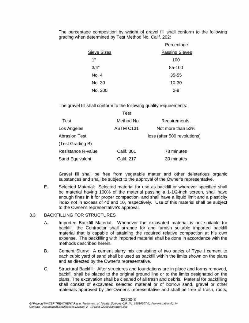
02200-3 G:\Projects\WATER TREATMENT\Resin_Treatment_of_Nitrate_Sources-CIP_No_68510507\01-Administration\01_h-Contract_Documents\Specifications\Division 2 - 17\Sect 02200 Earthwork.doc
The percentage composition by weight of gravel fill shall conform to the following grading when determined by Test Method No. Calif. 202:
Percentage
Sieve Sizes Passing Sieves
1" 100
3/4" 85-100
No. 4 35-55
No. 30 10-30
No. 200 2-9
The gravel fill shall conform to the following quality requirements:
Test
Test Method No. Requirements
Los Angeles ASTM C131 Not more than 52%
Abrasion Test loss (after 500 revolutions)
(Test Grading B)
Resistance R-value Calif. 301 78 minutes
Sand Equivalent Calif. 217 30 minutes
Gravel fill shall be free from vegetable matter and other deleterious organic substances and shall be subject to the approval of the Owner's representative.
E. Selected Material: Selected material for use as backfill or wherever specified shall be material having 100% of the material passing a 1-1/2-inch screen, shall have enough fines in it for proper compaction, and shall have a liquid limit and a plasticity index not in excess of 40 and 10, respectively. Use of this material shall be subject to the Owner's representative's approval.
3.3 BACKFILLING FOR STRUCTURES
A. Imported Backfill Material: Whenever the excavated material is not suitable for backfill, the Contractor shall arrange for and furnish suitable imported backfill material that is capable of attaining the required relative compaction at his own expense. The backfilling with imported material shall be done in accordance with the methods described herein.
B. Cement Slurry: A cement slurry mix consisting of two sacks of Type I cement to each cubic yard of sand shall be used as backfill within the limits shown on the plans and as directed by the Owner's representative.
C. Structural Backfill: After structures and foundations are in place and forms removed, backfill shall be placed to the original ground line or to the limits designated on the plans. The excavation shall be cleaned of all trash and debris. Material for backfilling shall consist of excavated selected material or of borrow sand, gravel or other materials approved by the Owner's representative and shall be free of trash, roots,
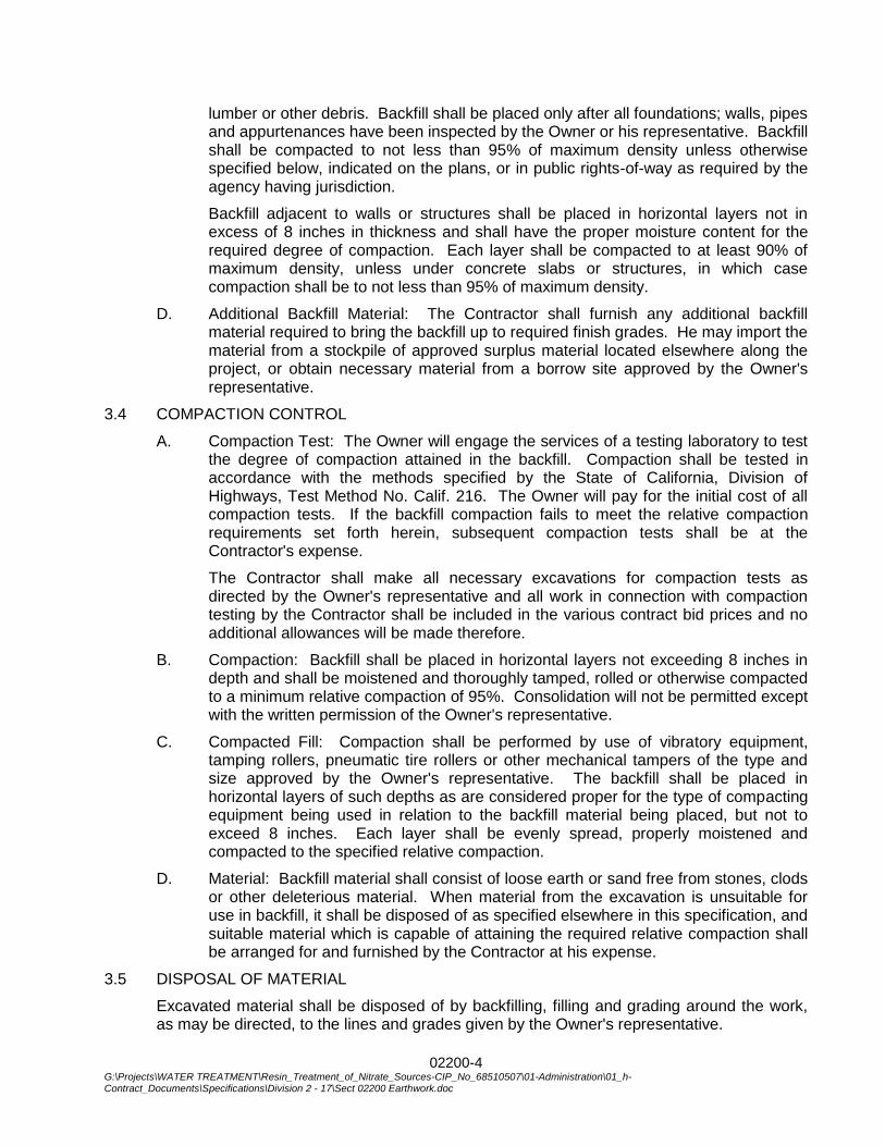
02200-4 G:\Projects\WATER TREATMENT\Resin_Treatment_of_Nitrate_Sources-CIP_No_68510507\01-Administration\01_h-Contract_Documents\Specifications\Division 2 - 17\Sect 02200 Earthwork.doc
lumber or other debris. Backfill shall be placed only after all foundations; walls, pipes and appurtenances have been inspected by the Owner or his representative. Backfill shall be compacted to not less than 95% of maximum density unless otherwise specified below, indicated on the plans, or in public rights-of-way as required by the agency having jurisdiction.
Backfill adjacent to walls or structures shall be placed in horizontal layers not in excess of 8 inches in thickness and shall have the proper moisture content for the required degree of compaction. Each layer shall be compacted to at least 90% of maximum density, unless under concrete slabs or structures, in which case compaction shall be to not less than 95% of maximum density.
D. Additional Backfill Material: The Contractor shall furnish any additional backfill material required to bring the backfill up to required finish grades. He may import the material from a stockpile of approved surplus material located elsewhere along the project, or obtain necessary material from a borrow site approved by the Owner's representative.
3.4 COMPACTION CONTROL
A. Compaction Test: The Owner will engage the services of a testing laboratory to test the degree of compaction attained in the backfill. Compaction shall be tested in accordance with the methods specified by the State of California, Division of Highways, Test Method No. Calif. 216. The Owner will pay for the initial cost of all compaction tests. If the backfill compaction fails to meet the relative compaction requirements set forth herein, subsequent compaction tests shall be at the Contractor's expense.
The Contractor shall make all necessary excavations for compaction tests as directed by the Owner's representative and all work in connection with compaction testing by the Contractor shall be included in the various contract bid prices and no additional allowances will be made therefore.
B. Compaction: Backfill shall be placed in horizontal layers not exceeding 8 inches in depth and shall be moistened and thoroughly tamped, rolled or otherwise compacted to a minimum relative compaction of 95%. Consolidation will not be permitted except with the written permission of the Owner's representative.
C. Compacted Fill: Compaction shall be performed by use of vibratory equipment, tamping rollers, pneumatic tire rollers or other mechanical tampers of the type and size approved by the Owner's representative. The backfill shall be placed in horizontal layers of such depths as are considered proper for the type of compacting equipment being used in relation to the backfill material being placed, but not to exceed 8 inches. Each layer shall be evenly spread, properly moistened and compacted to the specified relative compaction.
D. Material: Backfill material shall consist of loose earth or sand free from stones, clods or other deleterious material. When material from the excavation is unsuitable for use in backfill, it shall be disposed of as specified elsewhere in this specification, and suitable material which is capable of attaining the required relative compaction shall be arranged for and furnished by the Contractor at his expense.
3.5 DISPOSAL OF MATERIAL
Excavated material shall be disposed of by backfilling, filling and grading around the work, as may be directed, to the lines and grades given by the Owner's representative.

02200-5 G:\Projects\WATER TREATMENT\Resin_Treatment_of_Nitrate_Sources-CIP_No_68510507\01-Administration\01_h-Contract_Documents\Specifications\Division 2 - 17\Sect 02200 Earthwork.doc
Unsuitable backfill materials and debris produced by clearing and grubbing and demolition of existing trees, stumps, structures, pavement and trash, shall be immediately removed and disposed of offsite or in areas designated by the Owner's representative. No surplus material shall be dumped on private property unless written permission is furnished by the owner of the property. The Owner's approval shall be obtained prior to commencing disposal procedures. Excess excavated material may be disposed of onsite at the direction of the Owner's representative.
3.6 GRADING AND FINAL CLEANUP
In areas not in streets or roadways, the elevations shown on the plans as existing are taken from the best existing data and are intended to give reasonably accurate information about the existing elevations. They are not precise and the Contractor should satisfy himself as to the exact quantities of excavation and fill required.
Pits and fills used for the erection of the Contractor's construction facilities shall be filled or removed, as the case may be, upon the completion of the work and leveled to meet the existing contours of the adjacent ground.
After all the structures have been completed, the ground surface shall be brought to the finished grade elevations indicated on the plans and shall be restored to match the existing adjacent surface as indicated in plans.
All finished ground surfaces shall be beaded and dressed to present a surface not varying over 0.10 foot as regards local humps or depressions and satisfactory to the Owner.
3.7 PROTECTION OF EXISTING FACILITIES
Existing facilities shall be protected as specified herein. The Contractor's attention is called to requirements described in the General Provisions.
Any method of construction chosen which necessitates heavy equipment imposing loads on the existing pipelines requires approval by the Owner's representative. It shall be the Contractor's responsibility to repair to the satisfaction of the Owner any damage to existing pipes which is caused by construction under this contract. Cost of repairs shall be at the expense of the Contractor.
3.8 DEWATERING
The Contractor shall provide and maintain at all times during construction, ample means and devices with which to promptly remove and properly dispose of all water from any source entering the excavations or other parts of the work. Dewatering shall be accomplished by methods which will ensure a dry excavation and preservation of the final lines and grades of the bottoms of excavations. Said methods may include deep wells, well points, sump pumps, suitable rock or gravel placed below the required bedding for draining and pumping purposes, temporary pipelines and other means, all subject to the approval of the Owner's representative.
If foundation soils are disturbed or loosened by the upward seepage of water or an uncontrolled flow of water, the affected areas shall be excavated and replaced with "gravel fill" at no cost to the Owner.
The Contractor shall dispose of the water from the work in a suitable manner without damage to adjacent property. The Contractor shall be responsible for obtaining all water discharge permits that are required. No water shall be drained into work built or under construction without prior written consent of the Owner's representative.
02200-6 G:\Projects\WATER TREATMENT\Resin_Treatment_of_Nitrate_Sources-CIP_No_68510507\01-Administration\01_h-Contract_Documents\Specifications\Division 2 - 17\Sect 02200 Earthwork.doc
No separate payment will be made for dewatering. All costs shall be included in the price bid for the various items for which such work is appurtenant thereto.
*** END OF SECTION ***

02560-1 G:\Projects\WATER TREATMENT\Resin_Treatment_of_Nitrate_Sources-CIP_No_68510507\01-Administration\01_h-Contract_Documents\Specifications\Division 2 - 17\Sect 02560 Trench Excavation and Backfill.doc
SECTION 02560
TRENCH EXCAVATION AND BACKFILL
PART 1 - GENERAL
Trench excavation and backfill shall include all necessary excavation for pipelines, backfilling, compaction and disposing of excess excavated material, all as required for the complete performance of the work for the installation of pipe as indicated on the plans and as specified herein.
Trench excavation and backfill as referred herein or in connection herewith shall be construed as including any or all of the following described operations:
Excavating all materials of whatever nature encountered; backfilling; sub-grading for pipe and performing any operation which may be necessary to properly complete the entire work as indicated and specified.
PART 2 - PRODUCTS
2.1 EQUIPMENT
Equipment used for trench excavation and backfill shall be at the Contractor's option.
PART 3 - EXECUTION
3.1 EXCAVATION
All trench excavation, backfill, pipeline placement, compaction, et. al. shall be constructed per City of Corona Standard Drawings 150 and 406.
3.2 PAYMENT
Payment for complying with the requirements of this section shall be included in the appurtenant bid items of the proposal and no additional compensation shall be allowed therefor.
*** END OF SECTION ***

02560-2 G:\Projects\WATER TREATMENT\Resin_Treatment_of_Nitrate_Sources-CIP_No_68510507\01-Administration\01_h-Contract_Documents\Specifications\Division 2 - 17\Sect 02560 Trench Excavation and Backfill.doc
THIS PAGE INTENTIONALLY BLANK
02740-1 G:\Projects\WATER TREATMENT\Resin_Treatment_of_Nitrate_Sources-CIP_No_68510507\01-Administration\01_h-Contract_Documents\Specifications\Division 2 - 17\Sect 02740 AC Paving.doc
SECTION 02740
ASPHALT CONCRETE PAVING
PART 1 - GENERAL
1.1 DESCRIPTION
Contractor shall provide all tools, equipment, materials, labor and services for furnishing, placing and compacting of asphalt concrete pavement and aggregate base to the lines, grades and dimensions shown on the Contract Drawings and as specified herein. Where any permit requirements exceed the requirements of this Section, the permit requirements shall govern.
1.2 SYSTEM
The Work of this Section shall include the construction of asphalt concrete pavement for site improvements and pavement replacement areas (trenches and other pavement cuts and repairs) and includes all asphaltic tack coats, prime coats, seal coats and traffic markings, pavement markings and pavement markers as required, specified herein, or shown on the Contract Drawings.
Subgrade preparation is included elsewhere in Division 2 of these specifications.
1.3 STANDARD SPECIFICATION
Except as supplemented or specifically modified herein or shown otherwise on the Contract Drawings, the entire work under this Section shall be in compliance with the provisions in the applicable Sections of the Edition that was in effect on the date that the Contract Drawings were signed and sealed by the Design Engineer and includes all Supplement(s) of the Standard Specifications for Public Works Construction (SSPWC) also known as the “Green Book”.
In case of conflict between any requirements set forth in this Section, the Contract Drawings and any provisions of the foregoing Standard Specifications the requirements shown on the Contract Drawings shall govern over the requirements set forth herein and the requirements set forth herein shall govern over the SSPWC.
PART 2 - MATERIALS
2.1 AGGREGATE BASE
Aggregate base material shall conform to SSPWC Section 200-2.2 (Crushed Aggregate Base or crushed miscellaneous base).
2.2 ASPHALT CONCRETE
Asphalt Concrete (AC) shall conform to the requirements of Section SSPWC 203 (AR-4000), unless otherwise shown on the Contract Drawings or required by local condi-tions.
A. AC Base course(s) material shall be B gradation.
B. AC finish course (wearing course) material shall be C-1 gradation.
C. Asphalt Rubber Hot Mix (ARHM) shall comply with SSPWC Section 203.11.
D. Prime Coat shall be Grade SC-250 liquid asphalt.
E. Tack Coat shall be SS-1h emulsified asphalt.
02740-2 G:\Projects\WATER TREATMENT\Resin_Treatment_of_Nitrate_Sources-CIP_No_68510507\01-Administration\01_h-Contract_Documents\Specifications\Division 2 - 17\Sect 02740 AC Paving.doc
F. Seal Coat shall be SS-1h emulsified asphalt.
2.3 TRAFFIC MARKINGS AND PAVEMENT MARKINGS
Traffic Markings and Pavement Markings shall conform to the requirements of SSPWC Sections 210.1.6 and 210-1.7.
2.4 PAVEMENT MARKERS
Pavement Markers shall conform to the requirements of SSPWC Section 214
PART 3 - EXECUTION
3. 1 GENERAL
Conform to the requirements of SSPWC Sections 203-6, 302.5 and 306-1.5, the Contract Drawings and as stated herein.
A. Pavement Thickness. Asphalt concrete shall be spread and compacted in conformance with SSPWC Table 302-5.5 (A) and shall be the thickness shown on the Contract Drawings or 1-inch thicker than the existing paving, whichever is greater.
B. Pavement Width. Asphalt Concrete and Base Course width shall be a minimum of 18-inches (9-inches each side) wider than the trench width at the existing grade or as shown on the Contract Drawings, whichever is greater.
C. Trench Resurfacing shall be spread and compacted in conformance with SSPWC Table 306-1.5.3.
D. Immediately prior to placing permanent asphalt paving, all existing pavement that is to remain (joined) shall be saw cut to provide a clean and vertical joint for the new asphalt paving. Any other means to provide a clean and vertical joint shall not be acceptable.
3.2 BASE COURSE
Aggregate base shall be constructed as shown on the Contract Drawings and shall be graded and compacted to provide the designated uniform grades and cross sections to receive asphalt concrete paving and shall conform to the applicable requirements of SSPWC Section 301-1. Minimum Base Course shall be 8-inches compacted thickness or 1-inch thicker than the existing base, whichever is greater.
3.3 PRIME COAT
Application of prime coat shall comply with the applicable requirements of SSPWC Sections 203-2 and 302-5.3. Prime coat shall be uniformly distributed over completed subgrade and/or aggregate base course at the application rate of 0.25-gallons per square yard, unless the Owner specifies a different application rate at the time the work is performed. Prime Coat shall be required unless otherwise shown on the Contract Drawings.
3.4 TACK COAT
In conformance with the applicable requirements specified in SSPWC Sections 203-3 and 302-5.4, tack coat shall be applied to all vertical surfaces of concrete gutters, concrete and masonry walls, permanent headers, concrete slabs, pavement joints, and similar faces against which asphalt concrete pavement is to be placed. Tack coat shall be applied at a rate of 0.02 to 0.10 gallons-per-square-yard.
***END OF SECTION***
02831-1 G:\Projects\WATER TREATMENT\Resin_Treatment_of_Nitrate_Sources-CIP_No_68510507\01-Administration\01_h-Contract_Documents\Specifications\Division 2 - 17\Sect 02831 Tubular Steel Picket Fencing.doc
SECTION 02831
TUBULAR STEEL PICKET FENCING
PART 1 - GENERAL
1.1 SCOPE
This specification covers materials and construction requirements for the tubular steel picket fence, gates and appurtenances.
1.2 RELATED SECTIONS
A. The WORK of the following Section applies to the WORK of this Section. Other Sections of the Specifications, not referenced below, shall also apply to the extent required for proper performance of this WORK.
1. Section 03300, Cast-in-Place Concrete
1.3 STANDARD SPECIFICATIONS
A. Except as otherwise indicated in this Section of the Specifications, the CONTRACTOR shall comply with the Standard Specifications for Public Works Construction, 2015 Edition.
1.4 CODES
A. The WORK of this Section shall comply with the current editions of the following codes.
1. Uniform Building Code
1.5 SPECIFICATIONS AND STANDARDS
A. Except as otherwise indicated, the current editions of the following apply to the WORK of this Section.
1. ASTM A 90 Test Method for Weight of Coating on Zinc-Coated (Galvanized) Iron or Steel Articles
1.6 SHOP DRAWINGS AND SAMPLES
A. The following shall be submitted in compliance with Section 01330 prior to fabrication and construction.
1. Manufacturer’s product information including catalog cuts indicating materials.
2. The layout of the fence and gates indicating fence height, post sizes, bracing configurations, corner construction, removable sections, and accessories.
PART 2 - PRODUCTS
2.1 PICKETS
Pickets shall be 1-inch square and shall be made of hot-rolled structural steel. The wall thickness shall be 11-gauge. Tube shall be manufactured per ASTM A513. Tube shall be hot-dipped galvanized per ASTM A525-G90.
02831-2 G:\Projects\WATER TREATMENT\Resin_Treatment_of_Nitrate_Sources-CIP_No_68510507\01-Administration\01_h-Contract_Documents\Specifications\Division 2 - 17\Sect 02831 Tubular Steel Picket Fencing.doc
2.2 RAILS
Rails shall be 2-inch square, made of hot rolled structural steel, wall thickness shall be 11-gauge. Tube shall be manufactured per ASTM A513 and hot-dipped galvanized per ASTM A523-G90.
2.3 POSTS
Posts shall be 4-inch square and shall be hot rolled structural steel. The wall thickness shall be 11-gauge. Tube shall be manufactured per ASTM A513. Tube shall be hot-dipped galvanized per ASTM A525-G90.
2.4 FINIALS
Finials shall be cast of gray iron with minimum 20,000 PSI. Hot-dipped galvanized per ASTM A-48.
2.5 ASSEMBLY
A. Sections shall be assembled using 2, 3 or 4 rail as shown on the plans with pickets welded to rails.
B. Rails shall be attached to posts by means of rail brackets. Rail brackets are attached to posts and to rails using a ¼-inch industrial drive rivet. For any removable fence section, the rail is attached to the posts by means of a rail bracket and ½-inch stainless steel bolts.
C. Finials shall be attached to pickets using a ¼-inch industrial drive rivet.
2.6 COATING
All metal components shall have a galvanized undercoat inside and outside for maximum corrosion resistance.
All metal components then shall be given a polyester resin-based powder coating applied by the electrostatic spray process, to a thickness of 2.5 mils.
PART 3 - EXECUTION
3.1 INSTALLATION OF FENCING
A. All earth, brush, or other obstructions which interfere with the proper alignment of construction of fences shall be removed.
B. Line posts shall be spaced at not more than 8-foot intervals, measured from center-to-center of the posts and generally parallel to the ground slope. Posts shall be set plumb and shall be centered in concrete foundation.
C. Gate post shall be provided with concrete foundation.
D. Install gates plumb, level and secure for full opening without interference. Adjust hardware for smooth operation.
E. Gates shall be equipped with heavy-duty galvanized steel hinges, and shall be equipped with a provision for padlocking.
F. Concrete Footings
1. Drill holes in firm, undisturbed or compacted soil. Footings shall be not less than 8 inches in diameter and shall be 6 inches deeper than the post bottom. Excavate deeper, as required, for adequate support in soft and loose soil, or heavy lateral loads.
02831-3 G:\Projects\WATER TREATMENT\Resin_Treatment_of_Nitrate_Sources-CIP_No_68510507\01-Administration\01_h-Contract_Documents\Specifications\Division 2 - 17\Sect 02831 Tubular Steel Picket Fencing.doc
2. Place concrete around post in a continuous pour. Trowel finish tops of footings and slope or dome to direct water away from posts.
3. Concrete shall be 2,000 pound mix minimum.
G. Clean up debris and unused materials and remove from site.
*** END OF SECTION***

02831-4 G:\Projects\WATER TREATMENT\Resin_Treatment_of_Nitrate_Sources-CIP_No_68510507\01-Administration\01_h-Contract_Documents\Specifications\Division 2 - 17\Sect 02831 Tubular Steel Picket Fencing.doc
THIS PAGE INTENTIONALLY BLANK
03050 - 1 UNDERSLAB VAPOR BARRIER
SECTION 03050
UNDERSLAB VAPOR BARRIER
PART 1 GENERAL
1.01 SECTION INCLUDES
A. Sheet vapor barrier under concrete slabs on grade.
1.02 REFERENCE STANDARDS
A. ASTM E1643 - Standard Practice for Selection, Design, Installation and Inspection of Water Vapor Retarders Used in Contact with Earth or Granular Fill Under Concrete Slabs; 2011.
B. ASTM E1745 - Standard Specification for Plastic Water Vapor Retarders Used in Contact with Soil or Granular Fill under Concrete Slabs; 2011.
1.03 SUBMITTALS
A. See Section 01330 - Administrative Requirements, for submittal procedures.
B. Product Data: Submit manufacturers' data on manufactured products.
C. Samples: Submit samples of underslab vapor barrier to be used.
D. Manufacturer's Installation Instructions: Indicate installation procedures and interface required with adjacent construction.
PART 2 PRODUCTS
2.01 MATERIALS
A. Underslab Vapor Barrier:
1. Water Vapor Permeance: Not more than 0.010 perms (0.6 ng/(s m2 Pa)), maximum.
2. Thickness: 15 mils (0.4 mm).
3. Basis of Design:
a. Stego Industries LLC; Stego Wrap Vapor Barrier (15-mil): www.stegoindustries.com.
B. Accessory Products: Vapor barrier manufacturer's recommended tape, adhesive, mastic, etc., for sealing seams and penetrations in vapor barrier.
PART 3 EXECUTION
3.01 EXAMINATION
A. Verify that surface over which vapor barrier is to be installed is complete and ready before proceeding with installation of vapor barrier.
3.02 INSTALLATION
A. Install vapor barrier in accordance with manufacturer's instructions and ASTM E1643.
B. Install vapor barrier under interior slabs on grade; lap sheet over footings and seal to foundation walls.
C. Lap joints minimum 6 inches (150 mm).
D. Seal joints, seams and penetrations watertight with manufacturer's recommended products and follow manufacturer's written instructions.
E. No penetration of vapor barrier is allowed except for reinforcing steel and permanent utilities.
F. Repair damaged vapor retarder before covering with other materials.
END OF SECTION

03050 - 2 UNDERSLAB VAPOR BARRIER
THIS PAGE INTENTIONALLY BLANK

03100 - 1 G:\Projects\WATER TREATMENT\Resin_Treatment_of_Nitrate_Sources-CIP_No_68510507\01-Administration\01_h-
Contract_Documents\Specifications\Division 2 - 17\Sect 03100 Concrete Forms and Accessories.doc
SECTION 03100
CONCRETE FORMS AND ACCESSORIES
PART 1 – GENERAL
1.1 SECTION INCLUDES
A. Formwork for cast-in place concrete, with shoring, bracing and anchorage.
B. Form accessories.
C. Form stripping.
1.2 RELATED REQUIREMENTS
A. Section 03200 - Concrete Reinforcement.
B. Section 03300 - Cast-in-Place Concrete.
C. Section 03390 - Concrete Curing.
1.3 REFERENCE STANDARDS
A. ACI 117 - Standard Specifications for Tolerances for Concrete Construction and Materials; 2006.
B. ACI 301 - Specifications for Structural Concrete for Buildings; American Concrete Institute; 2005.
C. ACI 318 - Building Code Requirements for Structural Concrete and Commentary; American Concrete Institute; 2008.
D. ACI 347 - Guide to Formwork for Concrete; American Concrete Institute; 2004.
E. PS 1 - Structural Plywood; 2007.
1.4 SUBMITTALS
A. See Section 01300 -submittals
PART 2 – PRODUCTS
2.1 FORMWORK - GENERAL
A. Provide concrete forms, accessories, shoring, and bracing as required to accomplish cast-in-place concrete work.
B. Design and construct to provide resultant concrete that conforms to design with respect to shape, lines, and dimensions.
C. Comply with applicable state and local codes with respect to design, fabrication, erection, and removal of formwork.
D. Comply with relevant portions of ACI 347, ACI 301, and ACI 318.
2.2 WOOD FORM MATERIALS
A. Form Materials: At the discretion of the General Contractor.
2.3 FORMWORK ACCESSORIES
A. Form Release Agent: Colorless mineral oil that will not stain concrete. General Contractor to submit manufacturer's data for review by Owner's Designated
03100 - 2 G:\Projects\WATER TREATMENT\Resin_Treatment_of_Nitrate_Sources-CIP_No_68510507\01-Administration\01_h-
Contract_Documents\Specifications\Division 2 - 17\Sect 03100 Concrete Forms and Accessories.doc
Representative.
B. Nails, Spikes, Lag Bolts, Through Bolts, Anchorages: Sized as required, of sufficient strength and character to maintain formwork in place while placing concrete.
C. Embedded Anchor Shapes, Plates, Angles and Bars: As specified in Section 05120.
PART 3 – EXECUTION
3.1 EXAMINATION
A. Verify lines, levels and centers before proceeding with formwork. Ensure that dimensions agree with drawings.
3.2 EARTH FORMS
A. Hand trim sides and bottom of earth forms. Remove loose soil prior to placing concrete.
3.3 ERECTION - FORMWORK
A. Erect formwork, shoring and bracing to achieve design requirements, in accordance with requirements of ACI 301.
B. Provide bracing to ensure stability of formwork. Shore or strengthen formwork subject to overstressing by construction loads.
C. Arrange and assemble formwork to permit dismantling and stripping. Do not damage concrete during stripping. Permit removal of remaining principal shores.
D. Obtain approval before framing openings in structural members that are not indicated on drawings.
E. Coordinate this section with other sections of work that require attachment of components to formwork.
3.4 APPLICATION - FORM RELEASE AGENT
A. Apply form release agent on formwork in accordance with manufacturer's recommendations.
3.5 INSERTS, EMBEDDED PARTS, AND OPENINGS
A. Locate and set in place items that will be cast directly into concrete.
B. Coordinate with work of other sections in forming and placing openings, slots, reglets, recesses, sleeves, bolts, anchors, other inserts, and components of other work.
3.6 FORMWORK TOLERANCES
A. Construct formwork to maintain tolerances required by ACI 117.
3.7 FORM REMOVAL
A. Do not remove forms or bracing until concrete has gained sufficient strength to carry its own weight and imposed loads.
B. Loosen forms carefully. Do not wedge pry bars, hammers, or tools against finish concrete surfaces scheduled for exposure to view.
C. Store removed forms to prevent damage to form materials or to fresh concrete. Discard damaged forms.
*** END OF SECTION ***
03200 - 1 G:\Projects\WATER TREATMENT\Resin_Treatment_of_Nitrate_Sources-CIP_No_68510507\01-Administration\01_h-Contract_Documents\Specifications\Division 2 - 17\Sect 03200 Concrete Reinforcement.doc
SECTION 03200
CONCRETE REINFORCEMENT
PART 1 – GENERAL
1.1 SECTION INCLUDES
A. Reinforcing steel for cast-in-place concrete.
1.2 RELATED REQUIREMENTS
A. Section 03100 - Concrete Forms and Accessories.
B. Section 03300 - Cast-in-Place Concrete.
1.3 REFERENCE STANDARDS
A. ACI 301 - Specifications for Structural Concrete for Buildings; American Concrete Institute International; 2005.
B. ACI 318 - Building Code Requirements For Structural Concrete and Commentary; American Concrete Institute International; 2008.
C. ACI SP-66 - ACI Detailing Manual; American Concrete Institute International; 2004.
D. ASTM A 615/A 615M - Standard Specification for Deformed and Plain Billet-Steel Bars for Concrete Reinforcement; 2009b.
E. ASTM A 706/A 706M - Standard Specification for Low-Alloy Steel Deformed and Plain Bars for Concrete Reinforcement; 2009b.
F. AWS D1.4/D1.4M - Structural Welding Code - Reinforcing Steel; American Welding Society; 2005.
G. CRSI (DA4) - Manual of Standard Practice; Concrete Reinforcing Steel Institute; 2001.
H. CRSI (P1) - Placing Reinforcing Bars; Concrete Reinforcing Steel Institute; Eighth Edition.
1.4 QUALITY ASSURANCE
A. Perform work of this section in accordance with ACI 301.
B. Welders' Certificates: Submit certifications for welders employed on the project, verifying AWS qualification within the previous 12 months.
PART 2 – PRODUCTS
2.1 REINFORCEMENT
A. Reinforcing Steel: ASTM A 615/A 615M Grade 40 and 60.
B. Reinforcing Steel: ASTM A 706/A 706M, deformed low-alloy steel bars.
2.2 FABRICATION
A. Fabricate concrete reinforcing in accordance with CRSI (DA4) - Manual of Standard Practice.
B. Welding of reinforcement is permitted only with the specific approval of Owner's
03200 - 2 G:\Projects\WATER TREATMENT\Resin_Treatment_of_Nitrate_Sources-CIP_No_68510507\01-Administration\01_h-Contract_Documents\Specifications\Division 2 - 17\Sect 03200 Concrete Reinforcement.doc
Designated Representative. Perform welding in accordance with AWS D1.4.
C. Locate reinforcing splices not indicated on drawings at point of minimum stress.
1. Review locations of splices with Owner's Designated Representative.
PART 3 – EXECUTION
3.1 PLACEMENT
A. Place, support and secure reinforcement against displacement. Do not deviate from required position.
B. Do not displace or damage vapor barrier.
C. Maintain concrete cover around reinforcing as follows:
1. Walls (exposed to weather or backfill): as detailed on drawings.
2. Footings and Concrete Formed Against Earth: 3 inch.
D. Conform to applicable code for concrete cover over reinforcement.
3.2 FIELD QUALITY CONTROL
A. An independent testing agency, as specified in Section 01400, will inspect installed reinforcement for conformance to contract documents before concrete placement.
*** END OF SECTION ***
03300 - 1 G:\Projects\WATER TREATMENT\Resin_Treatment_of_Nitrate_Sources-CIP_No_68510507\01-Administration\01_h-Contract_Documents\Specifications\Division 2 - 17\Sect 03300 Cast-in-Place Concrete.doc
SECTION 03300
CAST-IN-PLACE CONCRETE
PART 1 – GENERAL
1.1 SECTION INCLUDES
A. Concrete footings.
B. Floors and slabs on grade.
C. Concrete reinforcement.
D. Joint devices associated with concrete work.
E. Concrete curing.
1.2 RELATED REQUIREMENTS
A. Section 03100 - Concrete Forms and Accessories: Forms and accessories for formwork.
1.3 REFERENCE STANDARDS
A. ACI 117 - Standard Specifications for Tolerances for Concrete Construction and Materials; American Concrete Institute International; 2006.
B. ACI 211.1 - Standard Practice for Selecting Proportions for Normal, Heavyweight, and Mass Concrete; American Concrete Institute International; 1991 (Reapproved 2002).
C. ACI 301 - Specifications for Structural Concrete for Buildings; American Concrete Institute International; 2005.
D. ACI 302.1R - Guide for Concrete Floor and Slab Construction; American Concrete Institute International; 2004 (Errata 2007).
E. ACI 304R - Guide for Measuring, Mixing, Transporting, and Placing Concrete; American Concrete Institute International; 2000.
F. ACI 308R - Guide to Curing Concrete; American Concrete Institute International; 2001 (Reapproved 2008).
G. ACI 318 - Building Code Requirements for Structural Concrete and Commentary; American Concrete Institute International; 2008.
H. ACI 347 - Guide to Formwork for Concrete; American Concrete Institute International; 2004.
I. ASTM A 615/A 615M - Standard Specification for Deformed and Plain Billet-Steel Bars for Concrete Reinforcement; 2009b.
J. ASTM C 33 - Standard Specification for Concrete Aggregates; 2008.
K. ASTM C 39/C 39M - Standard Test Method for Compressive Strength of Cylindrical Concrete Specimens; 2009a.
L. ASTM C 94/C 94M - Standard Specification for Ready-Mixed Concrete; 2009a.
M. ASTM C 143/C 143M - Standard Test Method for Slump of Hydraulic-Cement Concrete; 2009.

03300 - 2 G:\Projects\WATER TREATMENT\Resin_Treatment_of_Nitrate_Sources-CIP_No_68510507\01-Administration\01_h-Contract_Documents\Specifications\Division 2 - 17\Sect 03300 Cast-in-Place Concrete.doc
N. ASTM C 150 - Standard Specification for Portland Cement; 2007.
O. ASTM C 171 - Standard Specification for Sheet Materials for Curing Concrete; 2007.
P. ASTM C 309 - Standard Specification for Liquid Membrane-Forming Compounds for Curing Concrete; 2007.
Q. ASTM C 618 - Standard Specification for Coal Fly Ash and Raw or Calcined Natural Pozzolan for Use in Concrete; 2008a.
R. ASTM C 1107/C 1107M - Standard Specification for Packaged Dry, Hydraulic-Cement Grout (Nonshrink); 2008.
S. ASTM E 1745 - Standard Specification for Plastic Water Vapor Retarders Used in Contact with Soil or Granular Fill under Concrete Slabs; 2009.
1.4 QUALITY ASSURANCE
A. Perform work of this section in accordance with ACI 301 and ACI 318.
PART 2 – PRODUCTS
2.1 FORMWORK
A. Comply with requirements of Section 03100.
2.2 REINFORCEMENT
A. Comply with requirements of Section 03200.
2.3 CONCRETE MATERIALS
A. Cement: ASTM C 150, Type I - Normal Portland type.
B. Fine and Coarse Aggregates: ASTM C 33.
C. Fly Ash: ASTM C 618, Class C or F.
D. Water: Clean and not detrimental to concrete.
2.4 ACCESSORY MATERIALS
A. Underslab Vapor Retarder: Vapor barrier meeting the requirements of Specifications Section 03050, complying with ASTM E 1745, Class A; stated by manufacturer as suitable for installation in contact with soil or granular fill under concrete slabs. Single ply polyethylene is prohibited.
1. Accessory Products: Vapor retarder manufacturer's recommended tape, adhesive, mastic, prefabricated boots, etc., for sealing seams and penetrations in vapor retarder.
B. Non-Shrink Grout: ASTM C 1107/C 1107M; premixed compound consisting of non-metallic aggregate, cement, water reducing and plasticizing agents.
1. Minimum Compressive Strength at 48 Hours: 2,400 psi.
C. Moisture-Retaining Cover: ASTM C 171; regular curing paper, white curing paper, clear polyethylene, white polyethylene, or white burlap-polyethylene sheet.
D. Liquid Curing Compound: ASTM C 309, Type 1, clear or translucent.
03300 - 3 G:\Projects\WATER TREATMENT\Resin_Treatment_of_Nitrate_Sources-CIP_No_68510507\01-Administration\01_h-Contract_Documents\Specifications\Division 2 - 17\Sect 03300 Cast-in-Place Concrete.doc
2.5 BONDING AND JOINTING PRODUCTS
A. Slab Construction Joint Devices: Combination keyed joint form and screed, galvanized steel, with minimum 1 inch diameter holes for conduit or rebars to pass through at 6 inches on center; ribbed steel stakes for setting.
1. Height: To suit slab thickness.
2.6 CONCRETE MIX DESIGN
A. Proportioning Normal Weight Concrete: Comply with ACI 211.1 recommendations.
1. Replace as much Portland cement as possible with fly ash, ground granulated blast furnace slag, silica fume, or rice hull ash as is consistent with ACI recommendations.
B. Concrete Strength: Establish required average strength for each type of concrete on the basis of field experience, as specified in ACI 301.
1. For trial mixtures method, employ independent testing agency acceptable to Owner's Designated Representative for preparing and reporting proposed mix designs.
C. Normal Weight Concrete:
1. Compressive Strength, when tested in accordance with ASTM C 39/C 39M at 28 days: As indicated on drawings.
2. Fly Ash Content: Maximum 15 percent of cementitious materials by weight.
3. Water-Cement Ratio: Maximum 0.45 percent by weight.
2.7 MIXING
A. Transit Mixers: Comply with ASTM C 94/C 94M.
PART 3 – EXECUTION
3.1 EXAMINATION
A. Verify lines, levels, and dimensions before proceeding with work of this section.
3.2 PREPARATION
A. Verify that forms are clean and free of rust before applying release agent.
B. Coordinate placement of embedded items with erection of concrete formwork and placement of form accessories.
C. Interior Slabs on Grade: Install vapor retarder under interior slabs on grade. Lap joints minimum 6 inches. Seal joints, seams and penetrations watertight with manufacturer's recommended products and follow manufacturer's written instructions. Repair damaged vapor retarder before covering.
3.3 PLACING CONCRETE
A. Place concrete in accordance with ACI 304R.
B. Place concrete for floor slabs in accordance with ACI 302.1R.
C. Notify Owner's Designated Representative not less than 24 hours prior to
03300 - 4 G:\Projects\WATER TREATMENT\Resin_Treatment_of_Nitrate_Sources-CIP_No_68510507\01-Administration\01_h-Contract_Documents\Specifications\Division 2 - 17\Sect 03300 Cast-in-Place Concrete.doc
commencement of placement operations.
D. Ensure reinforcement, inserts, waterstops, embedded parts, and formed construction joint devices will not be disturbed during concrete placement.
E. Repair underslab vapor retarder damaged during placement of concrete reinforcing. Repair with vapor retarder material; lap over damaged areas minimum 6 inches and seal watertight.
F. Install joint devices in accordance with manufacturer's instructions.
G. Install construction joint devices in coordination with floor slab pattern placement sequence. Set top to required elevations. Secure to resist movement by wet concrete.
H. Install joint device anchors for expansion joint assemblies specified in Section 05810. Maintain correct position to allow joint cover to be flush with floor and wall finish.
I. Maintain records of concrete placement. Record date, location, quantity, air temperature, and test samples taken.
J. Place concrete continuously between predetermined expansion, control, and construction joints.
K. Place floor slabs in checkerboard or saw cut pattern indicated.
L. Saw cut joints within 24 hours after placing. Use 3/16 inch thick blade, cut into 1/4 depth of slab thickness.
M. Screed floors level, maintaining surface flatness of maximum 1/4 inch in 10 ft.
3.4 CONCRETE FINISHING
A. Repair surface defects, including tie holes, immediately after removing formwork.
B. Concrete Slabs: Steel trowel finish without local depression or high points and apply a light hair-broom finish. Do not use stiff bristle brooms or brushes. Leave hair broom lines parallel to direction of slab drainage.
3.5 CURING AND PROTECTION
A. Comply with requirements of ACI 308R. Immediately after placement, protect concrete from premature drying, excessively hot or cold temperatures, and mechanical injury.
B. Maintain concrete with minimal moisture loss at relatively constant temperature for period necessary for hydration of cement and hardening of concrete.
C. Surfaces Not in Contact with Forms:
1. Initial Curing: Start as soon as free water has disappeared and before surface is dry. Keep continuously moist for not less than three days by water ponding, water-saturated sand, water-fog spray, or saturated burlap.
2. Final Curing: Begin after initial curing but before surface is dry.
a. Moisture-Retaining Cover: Seal in place with waterproof tape or adhesive.
b. Curing Compound: Apply in two coats at right angles, using
03300 - 5 G:\Projects\WATER TREATMENT\Resin_Treatment_of_Nitrate_Sources-CIP_No_68510507\01-Administration\01_h-Contract_Documents\Specifications\Division 2 - 17\Sect 03300 Cast-in-Place Concrete.doc
application rate recommended by manufacturer.
3.6 FIELD QUALITY CONTROL
A. An independent testing agency will perform field quality control tests, as specified in Section 01400.
B. Provide free access to concrete operations at project site and cooperate with appointed firm.
C. Submit proposed mix design of each class of concrete to inspection and testing firm for review prior to commencement of concrete operations.
D. Compressive Strength Tests: ASTM C 39/C 39M. For each test, mold and cure three concrete test cylinders. Obtain test samples for every 100 cu yd or less of each class of concrete placed.
E. Perform one slump test for each set of test cylinders taken, following procedures of ASTM C 143/C 143M.
3.7 DEFECTIVE CONCRETE
A. Test Results: The testing agency shall report test results in writing to Owner's Designated Representative and General Contractor within 24 hours of test.
B. Defective Concrete: Concrete not conforming to required lines, details, dimensions, tolerances or specified requirements.
C. Repair or replacement of defective concrete will be determined by the Owner's Designated Representative. The cost of additional testing shall be borne by General Contractor when defective concrete is identified.
*** END OF SECTION ***

03300 - 6 G:\Projects\WATER TREATMENT\Resin_Treatment_of_Nitrate_Sources-CIP_No_68510507\01-Administration\01_h-Contract_Documents\Specifications\Division 2 - 17\Sect 03300 Cast-in-Place Concrete.doc
THIS PAGE INTENTIONALLY BLANK
14_0801 / Corona 03350 - 1 CONCRETE FLOOR FINISHES
SECTION 03350
CONCRETE FLOOR FINISHES
PART 1 GENERAL
1.01 SECTION INCLUDES
A. Surface treatments for concrete floors and slabs.
1.02 RELATED REQUIREMENTS
A. Section 03300 - Cast-in-Place Concrete: Finishing of concrete surface to tolerance; floating, troweling, and similar operations; curing.
1.03 SUBMITTALS
A. See Section 01330 - Administrative Requirements, for submittal procedures.
PART 2 PRODUCTS
2.01 CONCRETE FLOOR FINISH APPLICATIONS
A. Clear Epoxy High Build Sealing System:
1. Use at following locations: Chemical Room #101.
2.02 COATINGS
A. Clear Penetrating Sealer and Hardener: Transparent, non-yellowing coating
1. Products: L&M Construction Chemicals, Inc: www.lmcc.com
a. Seal Hard, Concrete Sealer, Densifier, Chemical Hardener
2. Substitutions: See Section 01630 - Product Requirements.
B. Colored Epoxy surface system
1. Product: Sherwin Williams Trafficote 105, Self-Leveling Slurry
a. 1/8" non-skid system at all foot/vehicle traffic areas.
b. 1/16" system at all other areas.
2. Substitutions: See Section 01630.
PART 3 EXECUTION
3.01 EXAMINATION
A. Verify that floor surfaces are acceptable to receive the work of this section.
B. Verify that flaws in concrete have been patched and joints filled with methods and materials suitable for further finishes.
3.02 GENERAL
A. Apply materials in accordance with manufacturer's instructions.
3.03 COATING APPLICATION
A. Verify that surface is free of previous coatings, sealers, curing compounds, water repellents, laitance, efflorescence, fats, oils, grease, wax, soluble salts, residues from cleaning agents, and other impediments to adhesion.
B. Protect adjacent non-coated areas from drips, overflow, and overspray; immediately remove excess material.
C. Apply coatings in accordance with manufacturer's instructions, matching approved mock-ups for color, special effects, sealing and workmanship.
END OF SECTION
14_0801 / Corona 03350 - 2 CONCRETE FLOOR FINISHES
THIS PAGE INTENTIONALLY BLANK
03390 - 1 G:\Projects\WATER TREATMENT\Resin_Treatment_of_Nitrate_Sources-CIP_No_68510507\01-Administration\01_h-
Contract_Documents\Specifications\Division 2 - 17\Sect 03390 Concrete Curing.doc
SECTION 03390
CONCRETE CURING
PART 1 – GENERAL
1.1 SECTION INCLUDES
A. Initial and final curing of horizontal and vertical concrete surfaces.
1.2 RELATED REQUIREMENTS
A. Section 03300 - Cast-in-Place Concrete.
1.3 REFERENCE STANDARDS
A. ACI 301 - Specifications for Structural Concrete for Buildings; American Concrete Institute International; 2005.
B. ACI 302.1R - Guide for Concrete Floor and Slab Construction; American Concrete Institute International; 2004 (Errata 2007).
C. ACI 308R - Guide to Curing Concrete; American Concrete Institute International; 2001 (Reapproved 2008).
D. ASTM C 171 - Standard Specification for Sheet Materials for Curing Concrete; 2007.
E. ASTM C 309 - Standard Specification for Liquid Membrane-Forming Compounds for Curing Concrete; 2007.
1.4 SUBMITTALS
A. See Section 01330 - Submittals
B. Product Data: Provide data on curing compounds and moisture-retaining sheet, including compatibility of different products and limitations.
1.5 QUALITY ASSURANCE
A. Perform Work in accordance with ACI 301 and ACI 302.1R.
1.6 DELIVERY, STORAGE, AND HANDLING
A. Deliver curing materials in manufacturer's sealed packaging, including application instructions.
PART 2 – PRODUCTS
2.1 MATERIALS
A. Membrane Curing Compound: ASTM C 309 Type 1 - Clear or translucent, Class A.
B. Moisture-Retaining Sheet: ASTM C 171.
PART 3 – EXECUTION
3.1 EXAMINATION
A. Verify that substrate surfaces are ready to be cured.
03390 - 2 G:\Projects\WATER TREATMENT\Resin_Treatment_of_Nitrate_Sources-CIP_No_68510507\01-Administration\01_h-
Contract_Documents\Specifications\Division 2 - 17\Sect 03390 Concrete Curing.doc
3.2 EXECUTION - HORIZONTAL SURFACES
A. Cure floor surfaces in accordance with ACI 308R.
B. Cure floor surfaces in accordance with ACI 308.
C. Membrane Curing Compound: Apply curing compound in accordance with manufacturer's instructions in one coat.
3.3 EXECUTION - VERTICAL SURFACES
A. Cure surfaces in accordance with ACI 308R.
B. Cure surfaces in accordance with ACI 308.
3.4 PROTECTION
A. Do not permit traffic over unprotected floor surface.
*** END OF SECTION ***

14_0801 / Corona 03450 - 1 PRECAST ARCHITECTURAL CONCRETE
SECTION 03450
PRECAST ARCHITECTURAL CONCRETE
PART 1 GENERAL
1.01 SECTION INCLUDES
A. Architectural precast concrete quatrefoil.
1. Exposed and sealed finish.
B. Supports, anchors, and attachments.
C. Intermediate and perimeter joint seals.
D. Grouting under panels.
1.02 RELATED REQUIREMENTS
A. Section 07190 - Water Repellents, concrete sealer
B. Section 07900 - Joint Sealers: Perimeter joints with sealant and backing.
1.03 REFERENCE STANDARDS
A. ACI 318 - Building Code Requirements for Structural Concrete and Commentary; American Concrete Institute International; 2011.
B. ASTM A36/A36M - Standard Specification for Carbon Structural Steel; 2014.
C. ASTM A153/A153M - Standard Specification for Zinc Coating (Hot-Dip) on Iron and Steel Hardware; 2009.
D. ASTM A307 - Standard Specification for Carbon Steel Bolts, Studs, and Threaded Rod 60 000 PSI Tensile Strength; 2012.
E. ASTM A563 - Standard Specification for Carbon and Alloy Steel Nuts; 2007a (Reapproved 2014).
F. ASTM A563M - Standard Specification for Carbon and Alloy Steel Nuts [Metric]; 2007.
G. ASTM A615/A615M - Standard Specification for Deformed and Plain Carbon Steel Bars for Concrete Reinforcement; 2014.
H. ASTM A767/A767M - Standard Specification for Zinc-Coated (Galvanized) Steel Bars for Concrete Reinforcement; 2009.
I. ASTM A1064/A1064M - Standard Specification for Carbon-Steel Wire and Welded Wire Reinforcement, Plain and Deformed, for Concrete; 2013.
J. ASTM C618 - Standard Specification for Coal Fly Ash and Raw or Calcined Natural Pozzolan for Use as a Mineral Admixture in Concrete; 2012.
K. ASTM C979/C979M - Standard Specification for Pigments for Integrally Colored Concrete; 2010.
L. ASTM C989/C989M - Standard Specification for Slag Cement for Use in Concrete and Mortars; 2013.
M. ASTM C1240 - Standard Specification for Silica Fume Used in Cementitious Mixtures; 2014.
N. PCI MNL-117 - Manual for Quality Control for Plants and Production of Architectural Precast Concrete Products; Precast/Prestressed Concrete Institute; 2007.
O. PCI MNL-120 - PCI Design Handbook - Precast and Prestressed Concrete; Precast/Prestressed Concrete Institute; Seventh Edition, 2010.
P. PCI MNL-122 - Architectural Precast Concrete; Precast/Prestressed Concrete Institute; 2007, Third Edition.
Q. PCI MNL-123 - Design and Typical Details of Connections for Precast and Prestressed Concrete; Precast/Prestressed Concrete Institute; 1988, Second Edition.
14_0801 / Corona 03450 - 2 PRECAST ARCHITECTURAL CONCRETE
R. PCI MNL-135 - Tolerance Manual for Precast and Prestressed Concrete Construction; Precast/Prestressed Concrete Institute; 2000.
1.04 SUBMITTALS
A. See Section 01330 - Administrative Requirements, for submittal procedures.
B. Product Data: Manufacturer's information on accessory products, including pigments, admixtures, inserts, plates, etc.
C. Shop Drawings: Indicate layout, unit locations, configuration, unit identification marks, reinforcement, integral insulation, insulated panel system connectors, connection details, support items, location of lifting devices, dimensions, openings, and relationship to adjacent materials. Provide erection drawings.
1. Include structural design calculations.
D. Samples: Submit three samples in size adequate to show surface quality and profile quality, illustrating surface finish, color and texture.
1.05 QUALITY ASSURANCE
A. Design Engineer Qualifications: Design precast concrete units under direct supervision of a Professional Structural Engineer experienced in design of precast concrete and licensed in the State in which the Project is located.
B. Fabricator Qualifications:
1. Firm having at least 2 years of documented experience in production of precast concrete of the type required.
2. Plant certified under Precast/Prestressed Concrete Institute Plant Certification Program; product group and category A1 - Architectural Precast Concrete.
C. Copies of Documents at Project Site: Maintain at the project site a copy of each referenced document that prescribes execution requirements.
1.06 DELIVERY, STORAGE, AND HANDLING
A. Handling: Lift and support precast units only from support points.
B. Blocking and Lateral Support During Transport and Storage: Use materials that are clean, non-staining, and non-harmful to exposed surfaces. Provide temporary lateral support to prevent bowing and warping.
C. Protect units to prevent staining, chipping, or spalling of concrete.
PART 2 PRODUCTS
2.01 MANUFACTURERS
A. Architectural Precast Concrete:
1. Manufacturer holding a PCI Group A Plant Certification for the types of products specified; see www.pci.org.
2. Substitutions: See Section 01630.
2.02 PRECAST UNITS
A. Precast Architectural Concrete Units: Comply with PCI MNL-120, PCI MNL-122, PCI MNL-123, PCI MNL-135, and ACI 318.
1. Design Loads: Static loads, anticipated dynamic loading, including positive and negative wind loads, thermal movement loads, and erection forces as defined by applicable code.
2. Calculate structural properties of units in accordance with ACI 318.
3. Other Cementitious Materials: Replace as much Portland cement as possible with fly ash, ground granulated blast furnace slag, silica fume, or rice hull ash as is consistent with strength and appearance requirements.
4. Accommodate construction tolerances, deflection of building structural members, and clearances of intended openings.
5. Provide connections that accommodate building movement and thermal movement and adjust to misalignment of structure without unit distortion or damage.

14_0801 / Corona 03450 - 3 PRECAST ARCHITECTURAL CONCRETE
B. Finish Type C: Sand blast exposed-to-view precast unit surfaces to 10% to 20% percent of unit aggregate surface. Protect adjacent surfaces. Submit THREE different samples of sand blast levels for final selection.
2.03 REINFORCEMENT
A. Reinforcing Steel: ASTM A615/A615M, Grade 40 - 40,000 psi (280 MPa).
1. Galvanized in accordance with ASTM A767/A767M, Class I.
B. Steel Welded Wire Reinforcement (WWR): Plain type, ASTM A1064/A1064M.
1. Mesh Size: 6 x 12 (150 x 300). or as required
2.04 CONCRETE MATERIALS
A. Other Cementitious Materials:
1. Fly Ash or Natural Pozzolans: Comply with ASTM C618.
2. Ground Granulated Blast Furnace Slag: ASTM C989/C989M.
3. Silica Fume: Comply with ASTM C1240.
B. Color Additives: Pure, concentrated mineral pigments specifically intended for mixing into concrete and complying with ASTM C979/C979M.
1. Color(s): As selected by Architect from manufacturer's custom color capabilities.
C. Water: Clean and not detrimental to concrete.
D. Fiber Reinforcement: Synthetic fiber shown to be resistant to long-term deterioration when exposed to moisture and alkalis; 1/2 inch (12 mm) length.
E. Grout:
1. Non-shrink, non-metallic, minimum 10,000 psi (70 MPa), 28 day strength.
2. Epoxy.
2.05 SUPPORT DEVICES
A. Connecting and Support Devices; Anchors and Inserts: ASTM A36/A36M steel; hot-dip galvanized in accordance with ASTM A153/A153M.
1. Clean surfaces of rust, scale, grease, and foreign matter.
2. Prime paint in one coat, except surfaces in direct contact with concrete or requiring field welding.
B. Bolts, Nuts, and Washers: ASTM A193 B8M T-316 heavy hex bolts, with matching nuts and washers.
2.06 FABRICATION
A. Fabricate in conformance with PCI MNL-117 and PCI MNL-135.
B. Use rigid molds, constructed to maintain precast unit uniform in shape, size, and finish.
C. Maintain consistent quality during manufacture.
D. Fabricate connecting devices, plates, angles, items fit to steel framing members, inserts, bolts, and accessories. Fabricate to permit initial placement and final attachment.
E. Embed reinforcing steel, anchors, inserts plates, angles, and other cast-in items.
F. Cure units to develop concrete quality, and to minimize appearance blemishes such as non-uniformity, staining, or surface cracking.
PART 3 EXECUTION
3.01 EXAMINATION
A. Verify that building structure, anchors, devices, and openings are ready to receive work of this section.
3.02 PREPARATION
A. Provide for erection procedures and induced loads during erection. Maintain temporary bracing in place until final support is provided.

14_0801 / Corona 03450 - 4 PRECAST ARCHITECTURAL CONCRETE
3.03 ERECTION
A. Erect units without damage to shape or finish. Replace or repair damaged panels.
B. Erect units level and plumb within allowable tolerances.
C. Align and maintain uniform horizontal and vertical joints as erection progresses.
D. Fasten units in place with mechanical connections.
E. Seal perimeter and intermediate joints.
3.04 TOLERANCES
A. Erect members level and plumb within allowable tolerances. Conform to PCI MNL-135, except as specifically amended below.
1. Plan Location from Building Grid Datum: Plus or minus 3/8 in (9.5 mm).
2. Top Elevation from Nominal Top Elevation: Plus or minus 3/8 inch (9.5 mm).
END OF SECTION
03461-1
R:\SPECS\Corona, City of\Resin Treatment of Nitrate Sources\IX Treatment Plant
SECTION 03461
PRECAST REINFORCED CONCRETE MANHOLES
AND MANHOLE BASES
PART 1 - GENERAL 1.1 DESCRIPTION
This Section includes materials, testing, and installation of precast concrete manholes, manhole bases, manhole frames and covers.
1.2 RELATED WORK SPECIFIED ELSEWHERE
A. Trench Excavation and Backfill: Section 02560.
B. Cast In Place Concrete: Section 03300 1.3. SUBMITTALS A. Submit shop drawings in accordance with the General Requirements, Specification
Section 01330, and the following. B. Submit manufacturer's catalog and test data on precast concrete manholes, frames,
and covers along with installation recommendations for inlet and outlet seals and watertight caulking. Show dimensions and materials of construction by ASTM reference and grade. Show manhole cover lettering and pattern.
PART 2 - MATERIALS 2.1 PRECAST CONCRETE MANHOLES A. General: Precast reinforced concrete manholes shall comply with ASTM C 478 and
IEUA Standard Sewer Manhole Detail. B. Design Load: Design manhole components for light traffic loads and site soil
conditions. C. Concrete: Precast reinforced concrete manhole risers and tops shall be constructed
of Class A concrete with Type V cement per Section 03300, Cast in Place Concrete. D. Manhole Section Configuration: Fabricate manholes only from eccentric taper
sections and standard cylinder units of the proper internal diameter, as indicated by the Construction Plans.
E. Manhole Section Dimensions: Unless noted otherwise, minimum diameter and wall
thickness of manholes and manhole sections shall be as follows:
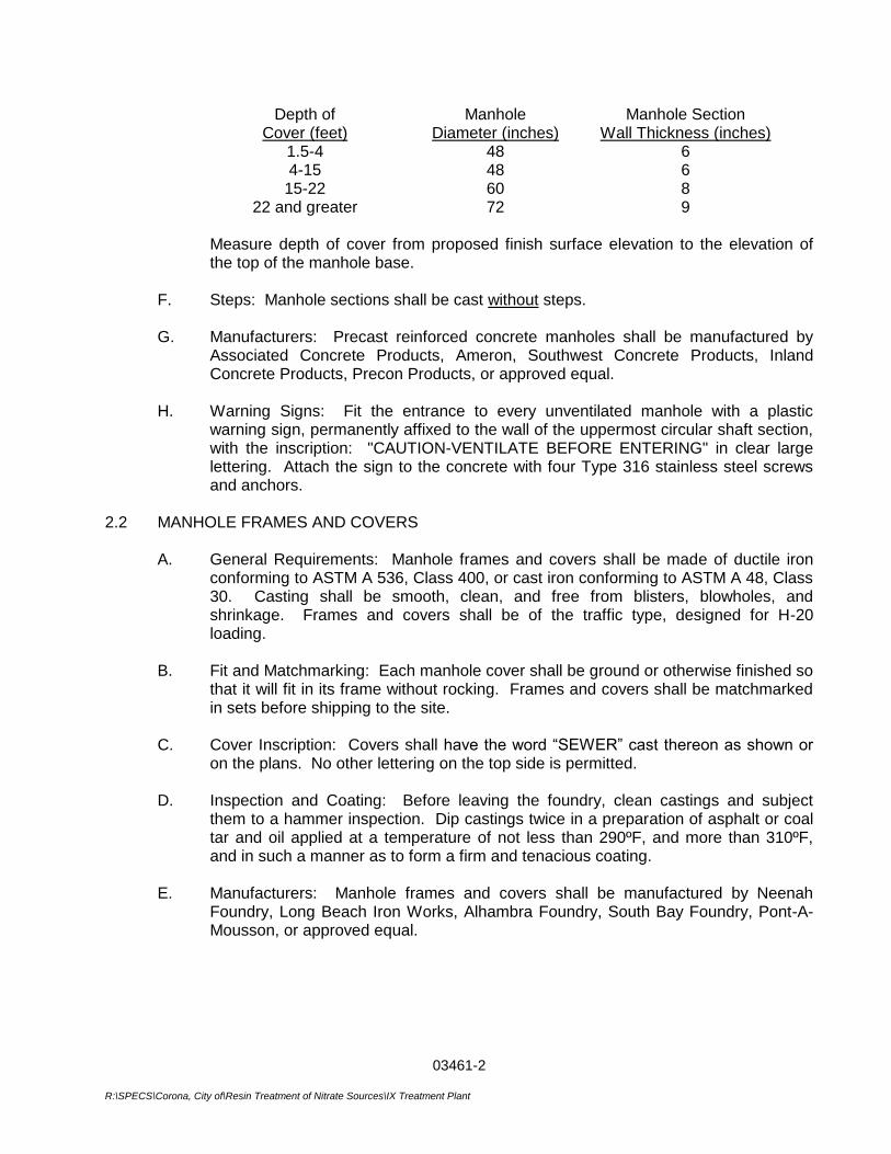
03461-2
R:\SPECS\Corona, City of\Resin Treatment of Nitrate Sources\IX Treatment Plant
Depth of Cover (feet)
Manhole Diameter (inches)
Manhole Section Wall Thickness (inches)
1.5-4 48 6 4-15 48 6
15-22 60 8 22 and greater 72 9
Measure depth of cover from proposed finish surface elevation to the elevation of
the top of the manhole base. F. Steps: Manhole sections shall be cast without steps. G. Manufacturers: Precast reinforced concrete manholes shall be manufactured by
Associated Concrete Products, Ameron, Southwest Concrete Products, Inland Concrete Products, Precon Products, or approved equal.
H. Warning Signs: Fit the entrance to every unventilated manhole with a plastic
warning sign, permanently affixed to the wall of the uppermost circular shaft section, with the inscription: "CAUTION-VENTILATE BEFORE ENTERING" in clear large lettering. Attach the sign to the concrete with four Type 316 stainless steel screws and anchors.
2.2 MANHOLE FRAMES AND COVERS A. General Requirements: Manhole frames and covers shall be made of ductile iron
conforming to ASTM A 536, Class 400, or cast iron conforming to ASTM A 48, Class 30. Casting shall be smooth, clean, and free from blisters, blowholes, and shrinkage. Frames and covers shall be of the traffic type, designed for H-20 loading.
B. Fit and Matchmarking: Each manhole cover shall be ground or otherwise finished so
that it will fit in its frame without rocking. Frames and covers shall be matchmarked in sets before shipping to the site.
C. Cover Inscription: Covers shall have the word “SEWER” cast thereon as shown or
on the plans. No other lettering on the top side is permitted. D. Inspection and Coating: Before leaving the foundry, clean castings and subject
them to a hammer inspection. Dip castings twice in a preparation of asphalt or coal tar and oil applied at a temperature of not less than 290ºF, and more than 310ºF, and in such a manner as to form a firm and tenacious coating.
E. Manufacturers: Manhole frames and covers shall be manufactured by Neenah
Foundry, Long Beach Iron Works, Alhambra Foundry, South Bay Foundry, Pont-A-Mousson, or approved equal.
03461-3
R:\SPECS\Corona, City of\Resin Treatment of Nitrate Sources\IX Treatment Plant
2.3 IMPORTED SAND Imported sand shall comply with Section 02560, Trenching, Backfilling and Compacting. 2.4 CRUSHED ROCK Crushed rock shall comply with Section 02560. Crushed rock shall be the same material as
the pipe bedding. If rock is not used for the pipe bedding, use 3/4-inch crushed rock for the manhole. Crushed rock base material shall extend 1 foot beyond the outside edge of the concrete manhole base.
2.5 MANHOLE BASES Concrete used in pouring the manhole base shall be Class A concrete, Type II or Type V
cement per Section 03300. 2.6 CEMENT-MORTAR GROUT Grout for watertight joints between precast sections shall be composed of one part portland
cement to two parts of clean well-graded sand of such size that all pass a No. 8 sieve. Cement, aggregate, and water for mortar shall conform to the applicable provisions of Section 03602.
2.7 EPOXY GROUT Use epoxy grout in repairing manhole and manhole base surfaces. Make epoxy grout with
epoxy and sand. The sand shall be clean, bagged, graded, and kiln dried silica sand. The prepared grout shall wet the contact surface and provide proper adhesion, or a coat of epoxy shall be applied prior to placing the epoxy grout. The epoxy bonding compound shall be as specified in Section 03603.
2.8 PLASTIC JOINT SEALING COMPOUND Preformed cold-applied ready-to-use plastic joint sealing compound shall be Quick-Seal as
supplied by Associated Concrete Products, Santa Ana, California, or approved equal.
PART 3 - EXECUTION 3.1 WORK WITHIN EXISTING MANHOLES Do no work inside an existing manhole that is part of a sewerage system in service until all
the tests and safety provisions of Article 4, Section 1532 "Confined Spaces" State of California Construction Safety Orders have been made.
3.2 EXCAVATION Excavation for the precast concrete manhole shall be in accordance with Section 02560.
03461-4
R:\SPECS\Corona, City of\Resin Treatment of Nitrate Sources\IX Treatment Plant
3.3 MANHOLE BASE A. General: Pour manhole bases in place against undisturbed soil with Class A
concrete having 3/4-inch-maximum size aggregate and a slump of not greater than 3 inches. Pour the manhole base as one monolithic pour. Observe limitations for site-mixed and ready-mixed concrete set forth in Section 03300. If soil conditions are not adequate as determined by City's Representative, place a 6-inch thick base of 3/4-inch crushed rock prior to the placement of concrete.
B. Manhole Stub Placement: The manhole stubs and sewer main shall be set before
the concrete is placed; recheck them for alignment and grade before the concrete has set. Locate the various sized inlets and outlets to the manhole as indicated on the plans and as detailed in the detail drawings.
C. Matching Pipe Crown Elevations: Invert elevations of connecting sewers may vary
depending upon sizes. The crown elevation of all pipes shall be the same as the crown elevation of the largest pipe unless otherwise indicated on the plans.
D Channel Configuration: Form the invert of the manhole base so as to provide
smooth channels conforming in size and shape to the lower portions of the inlet and outlet pipes. The channel shall vary uniformly in size and shape from inlet to outlet; construct a shelf higher than the pipe as indicated on the drawings. The manhole base shall extend 12-inches below the bottom of the lowest pipe.
E. Transitions: All transitions shall be smooth and of the proper radius to give an
uninterrupted transition of flow. F. Finishing: Shape the concrete base with a wood float and give it a hard steel trowel
finish before the concrete sets. G. Placement of Additional Mortar: In the event additional mortar is required after initial
set has taken place, prime the surface to receive the mortar and mix the mortar with "Willhold Concrete Adhesive" or approved equal in the amounts and proportions recommended by the manufacturer and as directed by City’s Representative in order to secure as chip-proof a result as possible.
H. Curing Time Before Further Construction: Unless approved otherwise by the City, in
advance, the bases shall set a minimum of 24 hours before the manhole construction is continued.
3.4 INSTALLING MANHOLES A. General: Construct manhole as shown on the plans. B. Joints: Set precast concrete manhole units in a bed of grout to make a watertight
joint at least 1/2 inch thick with the concrete base or with the preceding unit. Set manhole sections perfectly plumb. Inside joints shall be pointed; and wipe off the excess grout. Preformed, cold-applied, ready-to-use, plastic joint sealing compound may be substituted for grout between units and must be used when groundwater is encountered.
03461-5
R:\SPECS\Corona, City of\Resin Treatment of Nitrate Sources\IX Treatment Plant
C. Finish Elevation of Manhole Covers: Assemble precast sections so that the cover
conforms to the elevation determined by the manhole location as follows, but limited to a maximum of 9-inches of grade ring unless otherwise instructed by City’s Representative:
1. In Paved Area: Top of cover shall be flush with the paving surface. 2. In Shoulder Areas: Top of cover shall be flush with existing surface where it
is in traveled way or shoulder and 0.1 foot above existing surface where outside limits of traveled way but not in the existing roadside ditch.
3. In Roadside Ditch or Unpaved Open Areas: Top of cover shall be 9-inches
above the ground surface. Guard posts or paddle boards may be required adjacent to manholes in open areas.
D. Manhole Frame and Cover: Bolt the manhole frame to grade ring and secure it with
grout and cement mortar fillet. After the frames are securely set, clean the frames and the covers and scrape them free of foreign materials, and ground or otherwise finish as needed so the cover fits in its frame without rocking.
E. Watertightness: It is the intent of these Specifications that manholes and
appurtenances be watertight and free from infiltration. Band all manholes both inside and outside with cement-mortar grout. Where called for in the plans or supplemental Specifications, manholes that are to be given a protective lining or coating shall be free of any seeping or surface moisture. The adequacy of manholes and appurtenances as to watertightness shall be determined by City’s Representative and shall be tested by the Contractor in accordance with applicable sections of the SSPWC.
F. Stubs: Furnish and install sewer pipe in manholes at the locations shown and in
conformance with the detail drawings and plans. Plug all stubs with stoppers as shown on the plans for various sizes of pipe.
G. Sealing Before Completion: In order to prevent accidental use of the new sewer
before completion and acceptance, seal the inlet to existing tie-in manholes with broken brick and mortar. Installation of these plugs shall be approved by City’s Representative. Remove plugs at the time of final inspection or as directed by City’s Representative.
H. Bulkheads: Install bulkheads at the downstream end of all unused stub channels
over 5 feet long to prevent the creation of a septic condition resulting from ponding of sewage and debris in the unused channels, and until such time as the manhole stub is connected and normal sewage flow can occur. Plug all downstream stubs.
I. New Connections to Existing Manholes: Make new connections to existing
manholes wherein stubs have not been provided by core drilling through the base, as directed by City’s Representative.
03461-6
R:\SPECS\Corona, City of\Resin Treatment of Nitrate Sources\IX Treatment Plant
J. Backfill: Backfill around the precast concrete manhole shall be imported sand; place and compact it in accordance with Section 02560.
K. Grade Rings: Class B concrete rings shall be cast around manhole frames that are
flush with the surface. Place the ring after final grading or paving together with final cleanup.
L. Pavement Replacement: Replacement of bituminous or concrete pavement shall be
in accordance with the requirements of the Agency having jurisdiction. 3.5 MANHOLE AND MANHOLE BASE REPAIRS Manhole sections and bases that exhibit defects in the concrete surface may be rejected.
Repair defective concrete surfaces of manhole sections and bases not rejected by chipping away unsound or imperfect concrete. Edges shall be left sharp and square with the surface. Remove loose material and dust remaining after chipping by means of an air jet. Apply epoxy grout to the surface to be repaired in accordance with the manufacturer's instructions. The grout shall wet the contact surface and provide proper adhesion, or a coat of epoxy shall be applied prior to placing the epoxy grout.
3.6 MANHOLE LINERS
Where called for in the plans, use polyvinyl chloride (PVC) plastic liner and install per plan and in strict accordance with manufacturer’s recommendations and instructions.
***END OF SECTION***
03485-1 R:\SPECS\Corona, City of\Resin Treatment of Nitrate Sources\IX Treatment Plant
SECTION 03485
PRECAST VAULT PART 1 - GENERAL 1.1 DESCRIPTION
A. The Contractor shall provide precast structures as shown on the Drawings and as specified herein.
B. All precast structures shall be manufactured in a plant especially designed for the
purpose. All units shall conform to the design shown on the Drawings, and all work shall be done under strict controlled supervision.
C. Units shall conform to the specific size requirements shown on the Drawings. D. All buried sections of the precast structures shall be coated with 80 mils of coal tar
epoxy. 1.2 REFERENCE STANDARDS
A. H-20“AASHTO” Standard Specifications for Highway Bridges with revisions. B. SS-S-00210 Federal Specification (GSA - FSS) for cold applied preformed
sealing compound. C. ASTM C33 Standard Specification for Concrete Aggregate D. ASTM C150 Standard Specification for Portland Cement E. ASTM C330 Standard Specification for Lightweight Aggregates for
Structural Concrete F. ASTM A615 Standard Specification for Deformed and Plain Billet-Steel
Bars for Concrete Reinforcement G. ASTM A82 Standard Specification for Cold-Drawn Steel Wire for Concrete
Reinforcement. H. ASTM A185 Standard Specification for Welded Steel Wire Fabric for
Concrete Reinforcement. 1.3. SUBMITTALS
The following shall be submitted in compliance with SSPWC 2-5.3:
A. Contractor shall submit for review and approval detailed calculations and drawings, sealed by a Registered Professional Engineer in the State of California.
03485-2 R:\SPECS\Corona, City of\Resin Treatment of Nitrate Sources\IX Treatment Plant
PART 2 - PRODUCTS 2.1 DESIGN LOADS
Design loads shall be consisting of dead load, live load, impact, and in addition, loads due to water table, and any other loads which may be imposed upon the structure. Live loads shall be H-20 per AASHTO. Design wheel load shall be 16 kips plus impact. The live load shall be that loading which produces the maximum shears and bending moments in the structure.
2.2 FORMS
All forms used in placing concrete shall be of metal and sufficiently designed and braced to maintain their alignment under pressures of the concrete during placing.
2.3 CONCRETE
A. Aggregates: All aggregates fine and coarse, other than lightweight aggregate shall conform to specifications out-lined by ASTM C33. Lightweight aggregates fine and coarse shall conform to the specifications outlined by ASTM C330. Aggregates shall be free of deleterious substances causing reactivity with oxidized hydrogen sulfide. Both types of aggregate shall be graded in a manner so as to produce a homogeneous concrete mix. All materials are to be accurately weighed at a central batching facility for mixing.
B. Cement: All cement shall be Portland Cement conforming to ASTM C 150, Type II.
Low alkali cement content shall be sufficient to produce minimum strength of 3,000 PSI, or other design strengths required.
C. Placing: All concrete shall be handled from the mixer or transport vehicle to the place
of final deposit in a continuous manner, as rapidly as practicable, and without segregation or loss of ingredients, until (the approved unit operation) is completed. Concrete shall be placed in layers not over two (2) feet deep. Each layer shall be compacted by mechanical internal or external-vibrating equipment. Duration of the vibration cycle shall be limited to the time necessary to produce satisfactory consolidation without causing objectionable segregation.
D. Curing: For purposes of early re-use of forms, the concrete may be steam cured after
an initial set has taken place. The steam temperature shall not exceed 160 degrees, and the temperature shall be raised from normal ambient temperatures at a rate not to exceed 40 degrees per hour.
The steam cured unit shall not be removed from the forms until sufficient strength is obtained for the unit to withstand any structural strength is obtained for the unit to withstand any structural strain that may be subjected during the form stripping operation. After the stripping of forms further curing by means of water spray or a Membrane Curing Compound may be used, and shall be of clear or white type, conforming to ASTM C 309-58.
03485-3 R:\SPECS\Corona, City of\Resin Treatment of Nitrate Sources\IX Treatment Plant
2.4 REINFORCING STEEL
All reinforcing steel, including welded wire mesh, shall be of the size and in the location as shown on the Plans. All reinforcing shall be sufficiently tied to withstand any displacement during the pouring operation. All bars shall be grade 60 conforming to ASTM A 615.
2.5 ACCESS HATCHES
The valve vault access hatches as shown on plans. 2.6 JOINT SEALING COMPOUND The joint sealing compound shall be permanently adhesive flexible plastic material
complying in every detail to Federal Specification SS-S-00210 (GSA-FSS). Joint sealing compound shall be Quickseal by Associated Concrete Products, or approved equal.
PART 3 - EXECUTION 3.1 FIELD PREPARATION
The Contractor shall prepare a hole large enough to accommodate the outside dimension of the structure as shown on the Drawings. Prior to setting, the Contractor shall provide base material as shown on the Contract Drawings to receive the unit. The base material shall be compacted and graded level and at proper elevation to receive the structure in relation to the conduit grade or ground cover requirements as designated in the Plans.
3.2 INSTALLATION Precast concrete structures shall be installed in strict conformance with the manufacturer’s
written instructions. 3.3 INSPECTION Upon request, the Contractor shall provide the Construction Manager a workman with
ladder or other safe and adequate means for inspection access.
**END OF SECTION**

03485-4 R:\SPECS\Corona, City of\Resin Treatment of Nitrate Sources\IX Treatment Plant
THIS PAGE INTENTIONALLY BLANK
14_0801 / Corona 03490 - 1 GLASS-FIBER REINFORCED CONCRETE
SECTION 03490
GLASS-FIBER REINFORCED CONCRETE
PART 1 GENERAL
1.01 SECTION INCLUDES
A. Architectural precast glass-fiber-reinforced concrete accent trim as shown on Drawings.
B. Supports, anchors, and attachments.
1.02 RELATED REQUIREMENTS
A. Section 07920 - Joint Sealants: Sealing perimeter and intermediate joints.
1.03 REFERENCE STANDARDS
A. ASTM A36/A36M - Standard Specification for Carbon Structural Steel; 2014.
B. ASTM A153/A153M - Standard Specification for Zinc Coating (Hot-Dip) on Iron and Steel Hardware; 2009.
C. ASTM A653/A653M - Standard Specification for Steel Sheet, Zinc-Coated (Galvanized) or Zinc-Iron Alloy-Coated (Galvannealed) by the Hot-Dip Process; 2013.
D. ASTM C150/C150M - Standard Specification for Portland Cement; 2012.
E. ASTM C260/C260M - Standard Specification for Air-Entraining Admixtures for Concrete; 2010a.
F. ASTM C494/C494M - Standard Specification for Chemical Admixtures for Concrete; 2013.
G. ASTM C618 - Standard Specification for Coal Fly Ash and Raw or Calcined Natural Pozzolan for Use in Concrete; 2012.
H. AWS D1.1/D1.1M - Structural Welding Code - Steel; 2010 w/Errata.
I. PCI MNL-128 - Recommended Practice for Glass Fiber Reinforced Concrete Panels; Precast/Prestressed Concrete Institute; 2001, Fourth Edition.
1.04 SUBMITTALS
A. See Section 01330 - Administrative Requirements, for submittal procedures.
B. Shop Drawings: Indicate locations, fabrication details, reinforcement, connection details, dimensions, and relationship to adjacent materials.
C. Manufacturer's Installation Instructions: Indicate surface cleaning instructions.
D. Designer Qualifications.
E. Installer Qualifications.
1.05 QUALITY ASSURANCE
A. Designer Qualifications: Design units under direct supervision of a Professional Structural Engineer experienced in design of this Work and licensed in the State in which the Project is located.
B. Erector Qualifications: Company specializing in performing the work of this section with minimum three years of documented experience.
1.06 MOCK-UP
A. Mock-up may remain as part of the Work.
1.07 PROJECT CONDITIONS
A. Coordinate the Work with installation of backup supporting structure, application of joint sealers.
1.08 DELIVERY, STORAGE, AND HANDLING
A. Handle units to position, consistent with their shape and design. Lift and support only from support points.
B. Protect edges of units to prevent staining, chipping, or spalling of concrete.

14_0801 / Corona 03490 - 2 GLASS-FIBER REINFORCED CONCRETE
PART 2 PRODUCTS
2.01 MANUFACTURERS
A. Glass-Fiber-Reinforced Concrete:
1. Plastrglas, Inc;.: www.plastrglas.com.
2. Stromberg Architectural Products, Inc;.: www.strombergarchitectural.com.
3. Sandstone Designs, Inc; www.sandstonedesigns.com.
4. ClarkPacific Precast; www.clarkpacific.com.
5. Substitutions: See Section 016000 - Product Requirements.
2.02 GLASS-FIBER-REINFORCED CONCRETE UNITS
A. Glass-Fiber-Reinforced Concrete Units: Factory-fabricated, complying with PCI MNL-128, using rigid molds, constructed to maintain unit panel uniform in shape, size and finish.
1. Design and fabricate to comply with applicable code(s).
2. Design to withstand dead loads, positive and negative wind loads, and erection forces.
3. Control deflection of units to maintain fit with adjacent construction and openings within their tolerances.
4. Design connections to accommodate building movement without damage to components, wracking of joint connections, breakage of seals, or moisture penetration.
5. Allow for adjustment of connections to accommodate misalignment of structure without permanent distortion.
6. Concrete Mix: Of strength to accommodate panel configuration, panel size and weight, and manufacturing criteria, air entrained.
7. Welding: Comply with AWS D1.1/D1.1M.
8. Appearance: Ensure exposed-to-view finish surfaces of units are uniform in color and appearance.
9. Final Finish: GFRC to be to be field painted, Custom Color.
2.03 CONCRETE MATERIALS
A. Cement: ASTM C150 Portland Type I - Normal; white color.
B. Concrete Aggregates: ASTM C33.
C. Reinforcement: Alkali resistant chopped glass fiber rovings specifically formulated for use in concrete, with lengths varying from 1-1/2 to 2 inches (38 to 51 mm).
D. Admixtures: Conforming to ASTM C260/C260M, ASTM C494/C494M, and ASTM C618.
2.04 FRAMING MATERIALS
A. Metal Framing Members: Formed from hot-dipped galvanized steel sheet, ASTM A653/A653M, SS Grade 50 (340) Class 1, with G90/Z275 coating.
2.05 SUPPORT DEVICES
A. Connecting and Support Devices: ASTM A36/A36M steel; hot-dip galvanized in accordance with ASTM A153/A153M.
PART 3 EXECUTION
3.01 EXAMINATION
A. Verify that building structure, anchors, devices, and openings are ready to receive work of this section.
3.02 PREPARATION
3.03 ERECTION
A. Coordinate installation with that of structural supports, backup, and opening framing, if any.
B. Erect units without damage to shape or finish. Replace or repair damaged panels.
C. Erect units level and plumb within allowable tolerances.
D. Align and maintain uniform horizontal and vertical joints as erection progresses.
14_0801 / Corona 03490 - 3 GLASS-FIBER REINFORCED CONCRETE
E. When units require adjustment beyond design or tolerance criteria, discontinue affected work and advise Architect.
F. Site cutting of panels not permitted. Unless specifically noted/requested in submitted shop drawings.
G. Fasten units in place with mechanical connections. Unless specifically noted/requested in submitted shop drawings.
3.04 TOLERANCES
A. Maximum Variation from Plane of Location: 1/4 inch in 10 feet and 3/8 inch in 100 feet (6 mm in 3 m and 9 mm in 30 m), non-cumulative.
B. Bowing of Units: Length of Unit/ 360.
C. Exposed Joint Dimension: 1/2 inch (12 mm) plus or minus 1/4 inch (6 mm).
3.05 PROTECTION
A. Protect installed units from damage.
END OF SECTION

14_0801 / Corona 03490 - 4 GLASS-FIBER REINFORCED CONCRETE
THIS PAGE INTENTIONALLY BLANK
03602-1 G:\Projects\WATER TREATMENT\Resin_Treatment_of_Nitrate_Sources-CIP_No_68510507\01-Administration\01_h-Contract_Documents\Specifications\Division 2 - 17\Sect 03602 Non-Metallic Grout.doc
SECTION 03602
NON-METALLIC GROUT
PART 1 - GENERAL 1.1 SUBMITTALS
Submit in writing: manufacturer's name, grout type, composition, product data sheet and application method to Owner for approval.
1.2 PRODUCT DELIVERIES, STORAGE AND HANDLING
Immediately upon receipt at work site, store grout in dry, weather-tight, properly ventilated structure. Prevent grout from absorbing moisture.
1.3 ENVIRONMENTAL REQUIREMENTS
When ambient temperature exceeds 75oF, store grout in cool place and use cold or iced water for mixing. At time of placement, mix temperature shall not exceed 70oF. In cold weather, store grout in warm place and use warm water for mixing. Warm the equipment and foundation with portable heaters or use heated enclosure to maintain temperature of 70oF.
PART 2 - PRODUCTS 2.1 MATERIALS
A. Non-Shrink Grout: Shall be non-metallic, be non-corrosive, not produce gas, and develop 10,000 psi minimum compressive strength at 28 days. Use "Five Star Grout" as manufactured by U.S. Grout Corporation, "Sauereisen No. F-100" as manufactured by Sauereisen Cements Company, or equal.
B. Dry Pack Grout: Non-shrink, dry pack grout shall meet requirements of Section A above
and be capable of being dry packed.
C. Water shall be clean, potable and free from deleterious amounts of oils, acids, alkalis, salts and organic materials.
2.2 MIXING
A. Premixed grout shall require water addition only. Water content shall be as required by manufacturer. Other cement or aggregate material shall not be added to grout.
B. Mix grout thoroughly in paddle-type mixer for 5 minutes minimum. Do not mix by hand.
Do not retemper grout after initial mixing. Clean paddle mixer after each batch.
03602-2 G:\Projects\WATER TREATMENT\Resin_Treatment_of_Nitrate_Sources-CIP_No_68510507\01-Administration\01_h-Contract_Documents\Specifications\Division 2 - 17\Sect 03602 Non-Metallic Grout.doc
PART 3 - EXECUTION 3.1 PREPARATION
A. Remove defective concrete from foundation to provide firm, rough surface free of dirt, oil, grease, paint and dust.
B. Clean underside of equipment and column base plates and bolts to remove oil, grease
and dirt. Set base plates and equipment in place and set to proper line and grade. 3.2 INSTALLATION
Place grout into form from one side to avoid entrapping air. Place grout in continuous operation to prevent segregation. Use metal tools to compact grout and to remove voids. Grout reaching initial set or containing water for more than 15 minutes shall be used. Cure grout in strict conformance with manufacturer's recommendations.
*** END OF SECTION ***
03603-1 G:\Projects\WATER TREATMENT\Resin_Treatment_of_Nitrate_Sources-CIP_No_68510507\01-Administration\01_h-Contract_Documents\Specifications\Division 2 - 17\Sect 03603 Epoxy Grout.doc
SECTION 03603
EPOXY GROUT 1.1 EPOXY GROUT
Epoxy grout shall be used where specified herein or where shown on the Contract Drawings. Epoxy grout may be used to repair surface defects in concrete work.
Epoxy grout shall be made from epoxy putty and sand. Epoxy putty shall be Epibond 530, as manufactured by Furane Plastics; Concressive 1170, as manufactured by Adhesive Engineering Company; or approved equal. Epoxy grout may be formed by mixing not more than two parts sand to one part epoxy putty.
*** END OF SECTION ***

03603-2 G:\Projects\WATER TREATMENT\Resin_Treatment_of_Nitrate_Sources-CIP_No_68510507\01-Administration\01_h-Contract_Documents\Specifications\Division 2 - 17\Sect 03603 Epoxy Grout.doc
THIS PAGE INTENTIONALLY BLANK
04065 - 1 G:\Projects\WATER TREATMENT\Resin_Treatment_of_Nitrate_Sources-CIP_No_68510507\01-Administration\01_h-Contract_Documents\Specifications\Division 2 - 17\Sect 04065 Mortar and Masonry Grout.doc
SECTION 04065
MORTAR AND MASONRY GROUT
PART 1 – GENERAL
1.1 SECTION INCLUDES
A. Mortar for masonry.
B. Grout for masonry.
1.2 RELATED REQUIREMENTS
A. Section 04810 - Unit Masonry Assemblies: Installation of mortar and grout.
1.3 REFERENCE STANDARDS
A. ACI 530/ASCE 5/TMS 402 - Building Code Requirements For Masonry Structures; American Concrete Institute International; 2008.
B. ACI 530.1/ASCE 6/TMS 602 - Specification for Masonry Structures; American Concrete Institute International; 2008.
C. ASTM C 150 - Standard Specification for Portland Cement; 2007.
D. ASTM C 270 - Standard Specification for Mortar for Unit Masonry; 2008a.
E. ASTM C 979 - Standard Specification for Pigments for Integrally Colored Concrete; 2005.
F. IMIAWC (HW) - Recommended Practices & Guide Specifications for Hot Weather Masonry Construction; International Masonry Industry All-Weather Council; current edition.
1.4 SUBMITTALS
A. See Section 01330 – Submittals
1.5 QUALITY ASSURANCE
A. Comply with provisions of ACI 530/ASCE 5/TMS 402 and ACI 530.1/ASCE 6/TMS 602, except where exceeded by requirements of the contract documents.
1.6 DELIVERY, STORAGE, AND HANDLING
A. Maintain packaged materials clean, dry, and protected against dampness, freezing, and foreign matter.
04065 - 2 G:\Projects\WATER TREATMENT\Resin_Treatment_of_Nitrate_Sources-CIP_No_68510507\01-Administration\01_h-Contract_Documents\Specifications\Division 2 - 17\Sect 04065 Mortar and Masonry Grout.doc
1.7 FIELD CONDITIONS
A. Cold and Hot Weather Requirements: Comply with requirements of ACI 530.1/ASCE 6/TMS 602 or applicable building code, whichever is more stringent.
PART 2 – PRODUCTS
2.1 MATERIALS
A. Portland Cement: ASTM C 150, type I or II, low alkali; color as required to produce approved color sample.
B. Water: Clean and potable.
C. Moisture-Resistant Admixture: Water repellent compound designed to reduce capillarity.
2.2 MORTAR MIXING
A. Thoroughly mix mortar ingredients using mechanical batch mixer, in accordance with ASTM C 270 and in quantities needed for immediate use.
B. Maintain sand uniformly damp immediately before the mixing process.
C. Add mortar color in accordance with manufacturer's instructions. Provide uniformity of mix and coloration.
D. Do not use anti-freeze compounds to lower the freezing point of mortar.
E. If water is lost by evaporation, re-temper only within two hours of mixing.
PART 3 – EXECUTION
3.1 PREPARATION
3.2 INSTALLATION
A. Install mortar and grout to requirements of section(s) in which masonry is specified.
***END OF SECTION***
14_0801 / Corona 04270 - 1 GLASS UNIT MASONRY
SECTION 04270
GLASS UNIT MASONRY
PART 1 GENERAL
1.01 SECTION INCLUDES
A. Glass masonry units.
B. Setting and pointing materials.
C. Perimeter treatment.
1.02 RELATED REQUIREMENTS
1.03 REFERENCE STANDARDS
A. ACI 530/530.1/ERTA - Building Code Requirements and Specification for Masonry Structures and Related Commentaries; American Concrete Institute International; 2011.
B. ASTM A123/A123M - Standard Specification for Zinc (Hot-Dip Galvanized) Coatings on Iron and Steel Products; 2013.
C. ASTM C270 - Standard Specification for Mortar for Unit Masonry; 2012.
D. ASTM C979/C979M - Standard Specification for Pigments for Integrally Colored Concrete; 2010.
1.04 SUBMITTALS
A. See Section 01330 - Administrative Requirements, for submittal procedures.
B. Product Data: Provide data for glass units and accessories.
C. Samples: Submit one glass units illustrating color, design, and face pattern.
D. Manufacturer's Installation Instructions: Indicate special procedures, positioning of reinforcement, perimeter conditions requiring special attention.
1.05 QUALITY ASSURANCE
A. Manufacturer Qualifications: Company specializing in manufacturing products specified in this section, with not less than three years of documented experience.
1.06 DELIVERY, STORAGE, AND HANDLING
A. Accept glass units on site on pallets; inspect for damage.
1.07 FIELD CONDITIONS
A. Cold and Hot Weather Requirements: Comply with requirements of ACI 530/530.1/ERTA or applicable building code, whichever is more stringent.
PART 2 PRODUCTS
2.01 MANUFACTURERS
A. Glass Units:
1. Pittsburgh Corning Corporation;.: www.pittsburghcorning.com.
2. Substitutions: See Section 01630 - Product Requirements.
2.02 GLASS UNITS
A. Hollow Glass Units: Permanently seal hollow unit by heat fusing joint; factory coat unit edges to improve bond with mortar.
1. Color: Clear glass.
2. Pattern and Design: Vue Pattern.
2.03 ACCESSORIES
A. Panel Reinforcement: Steel, galvanized after fabrication in accordance with requirements of ASTM A123/A123M:
1. Side Rods: Two 3/16 inch (4.76 mm) diameter rods spaced 2 inch (50.8 mm) apart.
2. Cross Rods: 1/16 inch (1.8 mm) diameter rods welded 8 inch (203.2 mm) on center.
14_0801 / Corona 04270 - 2 GLASS UNIT MASONRY
B. Panel Anchors: Steel strips, at least 20 gage, 0.0359 inch (0.91 mm) thick by 1 3/4 inch (44 mm) wide; punched with three rows of elongated holes, pattern staggered, hot dip galvanized after fabrication in accordance with requirements of ASTM A123/A123M.
C. Asphalt Emulsion: Water based.
2.04 MORTAR AND POINTING MATERIAL
A. Pointing Mortar: ASTM C270, Type M using the Proportion specification with maximum 2 percent ammonium stearate or calcium stearate per cement weight, with beach sand aggregate.
B. Pointing Sealant: Elastomeric; suitable for contact with mortar.
1. Exterior Exposure: Polyurethane sealant. at perimeter adacent to CMU block.
C. Pigments for Colored Mortar: Pure, concentrated mineral pigments specifically intended for mixing into mortar and complying with ASTM C979/C979M.
1. Color(s): As selected by Architect from manufacturer's full range.
2. Manufacturers:
a. Davis Colors: www.daviscolors.com.
b. Lambert Corporation: www.lambertusa.com.
c. Solomon Colors: www.solomoncolors.com.
d. Substitutions: See Section 01600 - Product Requirements.
2.05 MORTAR MIXING
A. Thoroughly mix mortar ingredients in accordance with ASTM C270 in quantities needed for immediate use.
B. Add mortar color in accordance with manufacturer's instructions. Provide uniformity of mix and coloration.
C. If water is lost by evaporation, re-temper only within two hours of mixing.
D. Use mortar within two hours after mixing at temperatures of 90 degrees F (32 degrees C), or two-and-one-half hours at temperatures under 40 degrees F (5 degrees C).
PART 3 EXECUTION
3.01 EXAMINATION
A. Verify that openings are ready to receive work.
3.02 PREPARATION
A. Clean glass units of substances that may impair bond with mortar or sealant.
B. Establish and protect lines, levels, and coursing.
3.03 INSTALLATION
A. Erect glass units and accessories in accordance with manufacturer's instructions.
B. Coat sill under units with asphalt emulsion as a bond breaker, and allow to dry.
C. Set panel anchors in mortar bed directly over coating.
D. Provide full mortar joints. Furrowing is not permitted. Remove excess mortar.
E. Maintain uniform joint width of 1/4 inch (6 mm). Minimum.
F. Place panel reinforcement at every second horizontal joint in full mortar bed and at first course above and below openings within the glass unit panel.
G. Pointing With Mortar:
1. Before mortar sets, rake out joints to depth of 5/8 to 3/4 inch (16 to 19 mm).
2. Fill joints with pointing mortar; press into joint to eliminate voids; neatly tool surface to a concave profile.
3. Remove excess pointing mortar.
H. To accommodate pointing mortar, rake out joints 5/8 to 3/4 inch (16 to 19 mm).
14_0801 / Corona 04270 - 3 GLASS UNIT MASONRY
I. Fill joints with pointing mortar. Pack into voids. Neatly tool surface to a concave profile.
3.04 TOLERANCES
A. Variation From Joint Width: Plus 1/8 inch (3 mm) and minus 0 inches (0 mm).
3.05 CLEANING
A. Clean and polish faces of glass unit masonry, using materials and technique that will not scratch or deface units.
END OF SECTION

14_0801 / Corona 04270 - 4 GLASS UNIT MASONRY
THIS PAGE INTENTIONALLY BLANK
04810 - 1 G:\Projects\WATER TREATMENT\Resin_Treatment_of_Nitrate_Sources-CIP_No_68510507\01-Administration\01_h-Contract_Documents\Specifications\Division 2 - 17\Sect 04810 Unit Masonry Assemblies.doc
SECTION 04810
UNIT MASONRY ASSEMBLIES
PART 1 – GENERAL
1.1 SECTION INCLUDES
A. Concrete Block.
B. Reinforcement and Anchorage.
1.2 RELATED REQUIREMENTS
A. Section 03200 - Concrete Reinforcement: Reinforcing steel for grouted masonry.
B. Section 04065 - Mortar and Masonry Grout.
C. Section 05500 - Metal Fabrications: Loose steel lintels.
1.3 REFERENCE STANDARDS
A. ACI 530/ASCE 5/TMS 402 - Building Code Requirements for Masonry Structures; American Concrete Institute International; 2008.
B. ACI 530.1/ASCE 6/TMS 602 - Specification for Masonry Structures; American Concrete Institute International; 2008.
C. ASTM C 90 - Standard Specification for Loadbearing Concrete Masonry Units; 2009.
D. ASTM C 91 - Standard Specification for Masonry Cement; 2005.
E. ASTM C 144 - Standard Specification for Aggregate for Masonry Mortar; 2004.
F. ASTM C 150 - Standard Specification for Portland Cement; 2007.
G. ASTM C 207 - Standard Specification for Hydrated Lime for Masonry Purposes; 2006.
H. ASTM C 270 - Standard Specification for Mortar for Unit Masonry; 2008a.
I. ASTM C 404 - Standard Specification for Aggregates for Masonry Grout; 2007.
J. ASTM C 476 - Standard Specification for Grout for Masonry; 2009.
1.4 SUBMITTALS
A. See Section 01330 - Submittals
B. Product Data: Provide data for masonry units, fabricated wire reinforcement, mortar, and masonry accessories.
C. Samples: Submit 3 samples of block units to illustrate color, texture, and extremes of color range.
D. Manufacturer's Certificate: Certify that masonry units meet or exceed specified requirements.
1.5 QUALITY ASSURANCE
A. Comply with provisions of ACI 530/ASCE 5/TMS 402 and ACI 530.1/ASCE 6/TMS 602, except where exceeded by requirements of the contract documents.
04810 - 2 G:\Projects\WATER TREATMENT\Resin_Treatment_of_Nitrate_Sources-CIP_No_68510507\01-Administration\01_h-Contract_Documents\Specifications\Division 2 - 17\Sect 04810 Unit Masonry Assemblies.doc
1.6 DELIVERY, STORAGE, AND HANDLING
A. Deliver, handle, and store masonry units by means that will prevent mechanical damage and contamination by other materials.
PART 2 – PRODUCTS
2.1 CONCRETE MASONRY UNITS
A. Concrete Block: Comply with referenced standards and as follows:
1. Concrete Block and Block Color based on Orco Block Co. www.orco.com
2. "or equal," refer to construction manual Vol. 1 Section 00 00 70 Article 10 for procedure requirements for substituting an equal.
3. Size: Standard units with nominal face dimensions of 16 x 8 inches and nominal depth of 8 inches.
4. Load-Bearing Units: ASTM C 90, normal weight.
2.2 MORTAR AND GROUT MATERIALS
A. Mortar and grout: As specified in Section 04065.
B. Masonry Cement: ASTM C 91, Type N.
C. Portland Cement: ASTM C 150, Type I; color as required to produce approved color sample.
D. Hydrated Lime: ASTM C 207, Type S.
E. Mortar Aggregate: ASTM C 144.
F. Grout Aggregate: ASTM C 404.
G. Water: Clean and potable.
2.3 REINFORCEMENT AND ANCHORAGE
A. Reinforcing Steel: Type specified in Section 03200; size as indicated on drawings.
2.4 MORTAR AND GROUT MIXES
A. Mortar for Unit Masonry: ASTM C 270, using the Proportion Specification.
1. Exterior, loadbearing masonry: Type N.
B. Grout: ASTM C 476. Consistency required to fill completely volumes indicated for grouting; fine grout for spaces with smallest horizontal dimension of 2 inches or less; coarse grout for spaces with smallest horizontal dimension greater than 2 inches.
PART 3 – EXECUTION
3.1 EXAMINATION
A. Verify that field conditions are acceptable and are ready to receive masonry.
B. Verify that related items provided under other sections are properly sized and located.
C. Verify that built-in items are in proper location, and ready for roughing into masonry work.
04810 - 3 G:\Projects\WATER TREATMENT\Resin_Treatment_of_Nitrate_Sources-CIP_No_68510507\01-Administration\01_h-Contract_Documents\Specifications\Division 2 - 17\Sect 04810 Unit Masonry Assemblies.doc
3.2 PREPARATION
A. Direct and coordinate placement of metal anchors supplied for installation under other sections.
B. Provide temporary bracing during installation of masonry work. Maintain in place until building structure provides permanent bracing.
3.3 COURSING
A. Establish lines, levels, and coursing indicated. Protect from displacement.
B. Maintain masonry courses to uniform dimension. Form vertical and horizontal joints of uniform thickness.
C. Concrete Masonry Units:
1. Bond: Running.
3.4 PLACING AND BONDING
A. Lay hollow masonry units with face shell bedding on head and bed joints.
B. Buttering corners of joints or excessive furrowing of mortar joints is not permitted.
C. Remove excess mortar and mortar smears as work progresses.
D. Interlock intersections and external corners, except for units laid in stack bond.
E. Do not shift or tap masonry units after mortar has achieved initial set. Where adjustment must be made, remove mortar and replace.
F. Perform job site cutting of masonry units with proper tools to provide straight, clean, unchipped edges. Prevent broken masonry unit corners or edges.
G. Mortar joints to be covered with plaster to be cut flush.
3.5 LINTELS
A. Install loose steel lintels over openings.
3.6 GROUTED COMPONENTS
A. Lap splices minimum 24 bar diameters.
B. Support and secure reinforcing bars from displacement. Maintain position within 1/2 inch of dimensioned position.
C. Place and consolidate grout fill without displacing reinforcing.
3.7 CONTROL AND EXPANSION JOINTS
A. Do not continue horizontal joint reinforcement through control and expansion joints except as noted on drawings.
B. Form expansion joint as detailed.
3.8 BUILT-IN WORK
A. As work progresses, install built-in metal door frames and other items to be built into the work and furnished under other sections.
B. Install built-in items plumb, level, and true to line.
04810 - 4 G:\Projects\WATER TREATMENT\Resin_Treatment_of_Nitrate_Sources-CIP_No_68510507\01-Administration\01_h-Contract_Documents\Specifications\Division 2 - 17\Sect 04810 Unit Masonry Assemblies.doc
3.9 TOLERANCES
A. Maximum Variation from Plane of Wall: 1/4 inch in 10 ft and 1/2 inch in 20 ft or more.
B. Maximum Variation from Plumb: 1/4 inch per story non-cumulative; 1/2 inch in two stories or more.
C. Maximum Variation from Level Coursing: 1/8 inch in 3 ft and 1/4 inch in 10 ft; 1/2 inch in 30 ft.
D. Maximum Variation of Joint Thickness: 1/8 inch in 3 ft.
3.10 FIELD QUALITY CONTROL
A. An independent testing agency will perform field quality control tests, as specified in Section 01400.
3.11 CLEANING
A. Remove excess mortar and mortar droppings.
B. Replace defective mortar. Match adjacent work.
C. Clean soiled surfaces with cleaning solution.
3.12 PROTECTION
A. Without damaging completed work, provide protective boards at exposed external corners that are subject to damage by construction activities.
*** END OF SECTION ***
05425-1
R:\SPECS\Corona, City of\Resin Treatment of Nitrate Sources\IX Treatment Plant\054400 cfs truss guide spec trussteel 110315.doc
SECTION 05425
PRE-ENGINEERED PRE-FABRICATED
COLD-FORMED STEEL TRUSSES
PART 1 GENERAL
1.1 SECTION INCLUDES
A. Pre-engineered cold-formed steel trusses.
B. Cold-formed steel framing accessories
1.2 DEFINITIONS
A. Truss Component Manufacturer: The maker of the components that will be assembled into
trusses by the Truss Manufacturer. See Section 2.1 for acceptable Truss Component
Manufacturer.
B. Truss Manufacturer: An individual or organization engaged in the manufacturing of trusses.
See MANUFACTURERS for acceptable Truss Manufacturers.
C. Truss Design Drawing: Written, graphic and pictorial depiction of an individual truss.
D. Truss Design Engineer: Truss design shall be done by Truss Component Manufacturer and
signed and sealed by an engineer registered in the State of California.
1.3 REFERENCES
A. ANSI/AISI/COS/S100-07/S2-10: North American Specification for the Design of Cold-Formed
Steel Structural Members; American Iron and Steel Institute; 2007 edition including the 2010
Supplement.
B. ANSI/AISI/COFS/S200-07: North American Standard for Cold-Formed Steel Framing -
General Provisions; 2007.
C. ANSI/AISI/COFS/S214-07/S2-08: North American Standard for Cold-Formed Steel Framing -
Truss Design; 2007 edition including the 2008 Supplement.
D. AISI/COFS - Practice Guide - CF06-1: Code of Standard Practice for Cold-Formed Steel
Structural Framing; 2006.
E. ASTM A 370-09 - Standard Test Methods and Definitions for Mechanical Testing of Steel
Products; 2009.
F. ASTM A 500-03a - Standard Specification for Cold-Formed Welded and Seamless Carbon
Steel Structural Tubing in Rounds and Shapes; 2003.
G. ASTM A 653-09 - Standard Specification for Steel Sheet, Zinc-Coated (Galvanized) or Zinc-
Iron Alloy-Coated (Galvannealed) by the Hot-Dip Process; 2009.
H. CFSBCSI - Cold-Formed Steel Building Components Safety Information; Cold-Formed Steel
Council (CFSC); 2008 edition with CFSB3 summary sheet insert.
05425-2
R:\SPECS\Corona, City of\Resin Treatment of Nitrate Sources\IX Treatment Plant\054400 cfs truss guide spec trussteel 110315.doc
I. CFSEI Technical Note 551d - Design Guide for Construction Bracing of Cold-Formed Steel
Trusses; Cold-Formed Steel Engineers Institute; February 1997.
J. CFSEI Technical Note 551e - Design Guide for Permanent Bracing of Cold-Formed Steel
Trusses; Cold-Formed Steel Engineers Institute; February 1998.
1.4 SUBMITTALS
A. Submit under provisions of Section 01330.
B. Product Data: Truss Component Manufacturer's descriptive literature for each item of cold-
formed metal framing and each accessory specified in this section.
C. Truss Design Drawings: Detailed drawings prepared by Truss Manufacturer under the
supervision of the Truss Design Engineer that are in accordance with AISI references. These
drawings may also include referenced detail drawings germane to the trusses.
D. Truss Placement Diagram: Diagram that identifies the assumed location of each individually
designated truss and references the corresponding Truss Design Drawing.
E. Installation Instructions: Truss Component Manufacturer's printed instructions for handling,
storage, and installation of each item of cold-formed metal framing and each accessory
specified in this section.
1.5 QUALITY ASSURANCE
A. Provide design of trusses by Truss Component Manufacturer, using design methodologies
recommended in AISI references.
1. Determine mechanical properties of load bearing components by testing in
accordance with ASTM A 370-09.
2. Provide drawings by a design professional registered in the State in which project is
to be constructed.
3. Provide Truss Manufacturer’s Truss Design Drawings.
B. Pre-Installation Meeting: Meet at job site prior to scheduled beginning of installation to review
requirements:
1. Attendees: Require attendance by representatives of the following:
a. Installer of this section.
b. Other entities directly affecting, or affected by, construction activities of this
section, including but not limited to, the following:
1) Installer of truss support framing.
2) Installer of mechanical systems.
3) Installer of electrical systems.
2. Review potential interface conflicts; coordinate layout and support provisions.
05425-3
R:\SPECS\Corona, City of\Resin Treatment of Nitrate Sources\IX Treatment Plant\054400 cfs truss guide spec trussteel 110315.doc
1.6 DELIVERY, STORAGE, AND HANDLING OF STEEL TRUSSES
A. Pack, ship, handle, unload, and lift shop products in accordance with Truss Component
Manufacturer's recommendations and in manner necessary to prevent damage or distortion.
B. Store and protect products in accordance with Truss Component Manufacturer's
recommendations and in manner necessary to prevent damage, distortion and moisture
buildup.
PART 2 PRODUCTS
2.1 MANUFACTURERS
A. Acceptable Truss Component Manufacturer: TrusSteel Products from TrusSteel, An ITW
Company; 3208 Fisher Court, Arlington, TX 76001. Tel: (888) 565-9181. www.TrusSteel.com.
B. Acceptable Truss Manufacturers: Truss components shall be fabricated into completed
trusses by one of the following fabricators:
3. Steel Truss and Supply,22533 Bridlewood Lane. Palo Cedro, CA 96073, Tel.: (530)
365-3500 E-Mail: [email protected]
4. International Home Exports, Inc., 500 West 16th Street, National City, CA 91450,
Tel.: (619) 336-1331, E-Mail: Pat@ IHExports.com
5. M-Truss and Components, LLC, 4290 N. Pecos Road, Suite 2, N. Las Vegas, NV
89115 Tel.: (702) 222-3303, E-Mail: [email protected]
C. Substitutions: Not permitted.
D. Requests for substitutions will be considered in accordance with provisions of Section
01600.
1. All substitutions must be approved in writing by the Architect or Building Designer.
2. All applications for substitution must include samples and technical data.
2.2 COMPONENTS
A. Pre-Engineered Pre-Fabricated Cold-Formed Steel Trusses: TrusSteel truss components by
TrusSteel, An ITW Company, meeting specified requirements.
1. Truss Type, Span, and Height: As indicated on drawings.
2. Comply with requirements of IBC, Latest Edition
3. Deflection Under All Loads: 1/290th of span, maximum.
4. Deflection Under Live Loads: 1/260th of span, maximum.
5. Shop fabricate in accordance with Truss Design Drawings, using jigging systems to
ensure consistent component placement and alignment of components, and to
maintain specified tolerances; field fabrication is strictly prohibited unless performed
05425-4
R:\SPECS\Corona, City of\Resin Treatment of Nitrate Sources\IX Treatment Plant\054400 cfs truss guide spec trussteel 110315.doc
by authorized Truss Manufacturer using Truss Manufacturer’s shop assemblers and
proper jigging systems.
6. Shop fabrication of other cold-formed steel framing components into assemblies prior
to erection is permitted; fabricate assemblies in accordance with shop drawings.
7. Fasten connections within truss assembly with Truss Component Manufacturer's
screws only and as shown on the Truss Design Drawings; welding and other
fasteners are prohibited.
8. Fabricate straight, level, and true, without rack, and to the tolerances specified in
ANSI/AISI/COFS/S214-07/S2-08:
B. Truss Chord and Web Components: TrusSteel components, with rolled or closed edges to
minimize the danger of cutting during handling; chord and web components without rolled
edges are prohibited.
1. Shapes, Sizes, and Thicknesses: As required to suit design and as indicated on
shop drawings.
2. Chords: Cold-formed from ASTM A 653/A 653M galvanized steel sheet, minimum
G60 coating; minimum yield strength of 55,000 psi (380 MPa) for 22, 20, 18 and 16
GA components or 50,000 psi (345 MPa) for 14 GA and 12 GA components;
minimum tensile strength of 65,000 psi (448 MPa) for 22, 20, 18, 16, 14, and 12 GA
components.
a. Nominal 28 mil (22 GA) members:
1) Minimum bare metal thickness: 0.0284 inch (0.72 mm).
2) Maximum design thickness: 0.0299 inch (0.76 mm).
b. Nominal 33 mil (20 GA) members:
1) Minimum bare metal thickness: 0.0329 inch (0.84 mm).
2) Maximum design thickness: 0.0346 inch (0.88 mm).
c. Nominal 43 mil (18 GA) members:
1) Minimum bare metal thickness: 0.0428 inch (1.09 mm).
2) Maximum design thickness: 0.0451 inch (1.15 mm).
d. Nominal 54 mil (16 GA) members:
1) Minimum bare metal thickness: 0.0538 inch (1.37 mm).
2) Maximum design thickness: 0.0566 inch (1.44 mm).
e. Nominal 68 mil (14 GA) members:
1) Minimum bare metal thickness: 0.0677 inch (1.72 mm).

05425-5
R:\SPECS\Corona, City of\Resin Treatment of Nitrate Sources\IX Treatment Plant\054400 cfs truss guide spec trussteel 110315.doc
2) Maximum design thickness: 0.0713 inch (1.81 mm).
f. Nominal 97 mil (12 GA) members:
1) Minimum bare metal thickness: 0.0966 inch (2.46 mm).
2) Maximum design thickness: 0.1017 inch (2.58 mm).
3. Tube Webs: Cold-formed ASTM A500 steel structural tubing; minimum yield strength
of 45,000 psi (310 MPa); minimum tensile strength of 55,000 psi (380 MPa).
a. Nominal 33 mil (20 GA) members:
1) Minimum bare metal thickness: 0.033 inch (0.84 mm).
2) Maximum design thickness: 0.035 inch (0.89 mm).
b. Nominal 47 mil (18 GA) members:
1) Minimum bare metal thickness: 0.047 inch (1.19 mm).
2) Maximum design thickness: 0.049 inch (1.24 mm).
c. Nominal 63 mil (16 GA) members:
1) Minimum bare metal thickness: 0.063 inch (1.6 mm).
2) Maximum design thickness: 0.065 inch (1.65 mm).
4. Rolled formed Webs: Cold-formed from ASTM A 653/A 653M galvanized steel sheet,
minimum G60 coating; minimum yield strength of 40,000 psi (276 MPa) for 20 and 18
GA components or 50,000 psi (345 MPa) for 16 GA components; minimum tensile
strength of 55,000 psi (379 MPa) for 20 and 18 GA components or 65,000 psi (448
MPa) for 16 GA components.
a. Nominal 33 mil (20 GA) members:
1) Minimum bare metal thickness: 0.0329 inch (0.84 mm).
2) Maximum design thickness: 0.0346 inch (0.88 mm).
b. Nominal 43 mil (18 GA) members:
1) Minimum bare metal thickness: 0.0428 inch (1.09 mm).
2) Maximum design thickness: 0.0451 inch (1.15 mm).
c. Nominal 54 mil (16 GA) members:
1) Minimum bare metal thickness: 0.0538 inch (1.37 mm).
2) Maximum design thickness: 0.0566 inch (1.44 mm).
05425-6
R:\SPECS\Corona, City of\Resin Treatment of Nitrate Sources\IX Treatment Plant\054400 cfs truss guide spec trussteel 110315.doc
C. Fasteners Used in Fabricating Trusses: Fasteners as recommended by Truss Component
Manufacturer, bearing stamp of Truss Component Manufacturer for ready identification.
PART 3 EXECUTION
3.1 EXAMINATION
A. Verify that bearing surfaces and substrates are ready to receive steel trusses.
B. Verify that truss bearing surfaces are within the following tolerances:
1. Variation from Level or Specified Plane: Maximum 1/8 inch in 10 feet (6 mm in 3 m).
2. Variation from Specified Position: Maximum 1/4 inch (6 mm).
C. Verify that rough-in utilities and chases that will penetrate plane of trusses are in correct
locations and do not interfere with truss, bracing, or bridging placement.
D. Inspect conditions under which installation is to be performed and submit written notification if
such conditions are unacceptable to installer.
3. Notify Architect/Building Designer within 24 hours of inspection.
4. Beginning construction activities of this section before unacceptable conditions have
been corrected is prohibited.
5. Beginning construction activities of this section indicates installer's acceptance of
conditions.
3.2 INSTALLATION
A. Install trusses in accordance with Truss Component Manufacturer's instructions and Truss
Manufacturer’s Truss Design Drawings and Truss Placement Diagram. Use correct fasteners as
previously described.
B. Place components at spacings indicated on the Truss Design Drawings.
C. Install all erection (temporary installation) bracing and permanent bracing and bridging before
application of any loads; follow recommendations of the CFSBCSI - Cold-Formed Steel Building
Components Safety Information.
D. Install erection bracing - follow recommendations of the CFSBCSI - Cold-Formed Steel Building
Components Safety Information.
1. Provide bracing that holds trusses straight and plumb and in safe condition until
decking and permanent truss bracing has been fastened to form a structurally sound
framing system.
2. All sub-contractors shall employ proper construction procedures to insure adequate
distribution of temporary construction loads so that the carrying capacity of any single
truss or group of trusses is not exceeded.
E. Install permanent bracing and bridging as shown in the Architect/Building Designer’s drawings and
notes and in the locations shown shown on the Truss Manufacturer’s Truss Design Drawings.
05425-7
R:\SPECS\Corona, City of\Resin Treatment of Nitrate Sources\IX Treatment Plant\054400 cfs truss guide spec trussteel 110315.doc
F. Removal, cutting, or alteration of any truss chord, web or bracing member in the field is prohibited,
unless approved in advance in writing by the Architect/Building Designer and the Truss Design
Engineer.
G. Repair or replace damaged chords, webs, and complete trusses as directed and approved in
writing in advance by the Architect/Building Designer and the Truss Component Manufacturer.
3.3 FIELD QUALITY CONTROL
A. Owner will provide inspection service to inspect field connections; see Section 01400.
***END OF SECTION***

05425-8
R:\SPECS\Corona, City of\Resin Treatment of Nitrate Sources\IX Treatment Plant\054400 cfs truss guide spec trussteel 110315.doc
THIS PAGE INTENTIONALLY BLANK
05500 - 1 G:\Projects\WATER TREATMENT\Resin_Treatment_of_Nitrate_Sources-CIP_No_68510507\01-Administration\01_h-Contract_Documents\Specifications\Division 2 - 17\Sect 05500 Metal Fabrications.doc
SECTION 05500
METAL FABRICATIONS
PART 1 – GENERAL
1.1 SECTION INCLUDES
A. Shop fabricated steel.
1.2 RELATED REQUIREMENTS
A. Section 03300 - Cast-in-Place Concrete: Placement of metal fabrications in concrete.
B. Section 04810 - Unit Masonry Assemblies: Placement of metal fabrications in masonry.
C. Section 04820 - Reinforced Unit Masonry Assemblies: Placement of metal fabrications in masonry.
D. Section 09900 - Paints and Coatings: Paint finish.
1.3 REFERENCE STANDARDS
A. AAMA 611 - Voluntary Specification for Anodized Architectural Aluminum; American Architectural Manufacturers Association; 1998.
B. AAMA 2603 - Voluntary Specification, Performance Requirements and Test Procedures for Pigmented Organic Coatings on Aluminum Extrusions and Panels; 2002.
C. AAMA 2604 - Voluntary Specification, Performance Requirements and Test Procedures for High Performance Organic Coatings on Aluminum Extrusions and Panels; 2005.
D. AAMA 2605 - Voluntary Specification, Performance Requirements and Test Procedures for Superior Performing Organic Coatings on Aluminum Extrusions and Panels; 2005.
E. ANSI A14.3 - American National Standard for Ladders -- Fixed -- Safety Requirements; 2002.
F. ASTM A 36/A 36M - Standard Specification for Carbon Structural Steel; 2008.
G. ASTM A 53/A 53M - Standard Specification for Pipe, Steel, Black and Hot-Dipped, Zinc-Coated, Welded and Seamless; 2007.
H. ASTM A 123/A 123M - Standard Specification for Zinc (Hot-Dip Galvanized) Coatings on Iron and Steel Products; 2009.
I. ASTM A 153/A 153M - Standard Specification for Zinc Coating (Hot-Dip) on Iron and Steel Hardware; 2009.
J. ASTM A 307 - Standard Specification for Carbon Steel Bolts and Studs, 60,000 PSI Tensile Strength; 2007b.
K. ASTM A 325 - Standard Specification for Structural Bolts, Steel, Heat Treated, 120/105 ksi Minimum Tensile Strength; 2009a.
05500 - 2 G:\Projects\WATER TREATMENT\Resin_Treatment_of_Nitrate_Sources-CIP_No_68510507\01-Administration\01_h-Contract_Documents\Specifications\Division 2 - 17\Sect 05500 Metal Fabrications.doc
L. ASTM A 325M - Standard Specification for Structural Bolts, Steel, Heat Treated 830 MPa Tensile Strength (Metric); 2009.
M. ASTM A 500/A 500M - Standard Specification for Cold-Formed Welded and Seamless Carbon Steel Structural Tubing in Rounds and Shapes; 2010.
N. ASTM A 501 - Standard Specification for Hot-Formed Welded and Seamless Carbon Steel Structural Tubing; 2007.
O. ASTM B 209 - Standard Specification for Aluminum and Aluminum-Alloy Sheet and Plate; 2007.
P. ASTM B 209M - Standard Specification for Aluminum and Aluminum-Alloy Sheet and Plate [Metric]; 2007.
Q. ASTM B 221 - Standard Specification for Aluminum and Aluminum-Alloy Extruded Bars, Rods, Wire, Profiles, and Tubes; 2008.
R. ASTM B 221M - Standard Specification for Aluminum and Aluminum-Alloy Extruded Bars, Rods, Wire, Profiles, and Tubes [Metric]; 2007.
S. AWS D1.1/D1.1M - Structural Welding Code - Steel; American Welding Society; 2010.
T. AWS D1.2/D1.2M - Structural Welding Code - Aluminum; American Welding Society; 2003, and Errata 2004.
U. SSPC-Paint 15 - Steel Joist Shop Primer; Society for Protective Coatings; 1999 (Ed. 2004).
V. SSPC-Paint 20 - Zinc-Rich Primers (Type I, "Inorganic," and Type II, "Organic"); Society for Protective Coatings; 2002 (Ed. 2004).
1.4 SUBMITTALS
A. See Section 01300 - Submittals
B. Shop Drawings: Indicate profiles, sizes, connection attachments, reinforcing, anchorage, size and type of fasteners, and accessories. Include erection drawings, elevations, and details where applicable.
PART 2 – PRODUCTS
2.1 MATERIALS - STEEL
A. Steel Sections: ASTM A 36/A 36M.
B. Steel Tubing: ASTM A 500, Grade B cold-formed structural tubing.
C. Pipe: ASTM A 53/A 53M, Grade B Schedule 40, black finish.
D. Aluminum alloy shall conform to following Aluminum Association Specifications and designations.
1. 6061-T6 - Structural shapes, tubes and pipes in corrosive areas, sheets,
plates, wire, rods, bars, bolts and screws.
2. 6063-T6 - Tubes and pipes in non-corrosive areas, handrails and grating.
3. 6066-T6 - Welding and extrusions.
05500 - 3 G:\Projects\WATER TREATMENT\Resin_Treatment_of_Nitrate_Sources-CIP_No_68510507\01-Administration\01_h-Contract_Documents\Specifications\Division 2 - 17\Sect 05500 Metal Fabrications.doc
4. 6151-T6 - Forgings and forging stock.
E. Stainless steel shall conform to AISI Type 316 for sheets and plates, and to AISI Type 316 for bolts and stainless steel items in corrosive areas.
F. Shop and Touch-Up Primer: SSPC-Paint 15, complying with VOC limitations of authorities having jurisdiction.
G. Touch-Up Primer for Galvanized Surfaces: SSPC-Paint 20, Type I - Inorganic, complying with VOC limitations of authorities having jurisdiction.
H. Floor Grating and Frames: Frames shall be galvanized steel, dimensions and types shown on the drawings. Design bearing bars to deflect 1/4 inch or L/240 whichever is less under 100 psf uniform load. Limit individual grating panel weight to 60 pounds to facilitate manual removal. Provide bolted saddle type hold down clips at each corner of panels. Grating panels shall be banded at all open ends to provide additional transverse stiffness and a finished architectural appearance.
I. Anchor Bolts: Anchor bolts ½-inch diameter and larger shall either be 316 stainless steel epoxy anchors or galvanized “J” type cast in place anchors.
2.2 FABRICATION
A. Fit and shop assemble items in largest practical sections, for delivery to site.
B. Fabricate items with joints tightly fitted and secured.
C. Continuously seal joined members by continuous welds.
D. Grind exposed joints flush and smooth with adjacent finish surface. Make exposed joints butt tight, flush, and hairline. Ease exposed edges to small uniform radius.
E. Exposed Mechanical Fastenings: Flush countersunk screws or bolts; unobtrusively located; consistent with design of component, except where specifically noted otherwise.
F. Supply components required for anchorage of fabrications. Fabricate anchors and related components of same material and finish as fabrication, except where specifically noted otherwise.
2.3 FABRICATED ITEMS
A. Ladders: Steel; in compliance with AISI Type 316; with mounting brackets and attachments.
1. Side Rails: 3/8 x 2 inches members spaced at 20 inches.
2. Rungs: one inch diameter solid round bar spaced 12 inches on center.
3. Space rungs 7 inches from wall surface.
4. Cage at interior roof access ladder.
5. Parapet ladder with platform and rails
B. Sill Angles for Tempered Glass Railing Assemblies: ASTM A 36/A 36M steel angles with anchoring devices and sizes as indicated in shop drawings for railing assembly, drilled and tapped for fastener types, sizes, and spacing indicated, prime paint finish.
05500 - 4 G:\Projects\WATER TREATMENT\Resin_Treatment_of_Nitrate_Sources-CIP_No_68510507\01-Administration\01_h-Contract_Documents\Specifications\Division 2 - 17\Sect 05500 Metal Fabrications.doc
C. Door Frames for Overhead Door Openings and Wall Openings: Channel sections; galvanized finish.
2.4 FABRICATION TOLERANCES
A. Squareness: 1/8 inch maximum difference in diagonal measurements.
B. Maximum Offset Between Faces: 1/16 inch.
C. Maximum Misalignment of Adjacent Members: 1/16 inch.
D. Maximum Bow: 1/8 inch in 48 inches.
E. Maximum Deviation From Plane: 1/16 inch in 48 inches.
PART 3 – EXECUTION
3.1 EXAMINATION
A. Verify that field conditions are acceptable and are ready to receive work.
3.2 PREPARATION
A. Clean and strip primed steel items to bare metal where site welding is required.
B. Supply setting templates to the appropriate entities for steel items required to be cast into concrete or embedded in masonry.
3.3 INSTALLATION
A. Install items plumb and level, accurately fitted, free from distortion or defects.
B. Provide for erection loads, and for sufficient temporary bracing to maintain true alignment until completion of erection and installation of permanent attachments.
C. Perform field welding in accordance with AWS D1.1/D1.1M.
D. Obtain approval prior to site cutting or making adjustments not scheduled.
E. After erection, prime welds, abrasions, and surfaces not shop primed or galvanized, except surfaces to be in contact with concrete.
3.4 TOLERANCES
A. Maximum Variation From Plumb: 1/4 inch per story, non-cumulative.
B. Maximum Offset From True Alignment: 1/4 inch.
C. Maximum Out-of-Position: 1/4 inch.
3.5 PAINTING AND PROTECTION
A. Coat aluminum surfaces to be placed in contact with steel with one (1) coat of zinc chromate primer. Allow zinc chromate paint to dry hard prior to assembling parts. Paint steel surfaces to be placed in contact with aluminum with one (1) coat of zinc chromate primer and one (1) coat of paint consisting of 2 pounds of aluminum paste pigment per gallon of varnish. Stainless steel and aluminized, hot-dip galvanized, or electro-galvanized steel placed in contact with aluminum need not be painted.
05500 - 5 G:\Projects\WATER TREATMENT\Resin_Treatment_of_Nitrate_Sources-CIP_No_68510507\01-Administration\01_h-Contract_Documents\Specifications\Division 2 - 17\Sect 05500 Metal Fabrications.doc
B. Aluminum surfaces to be placed in contact with concrete or masonry construction shall receive one (1) heavy coat of alkali-resistant bituminous paint prior to installation. Apply paint as received from manufacturer without adding thinner.
C. Shop painted coatings damaged during handling or installation shall be touched up
in field with prime coat conforming to Section 09900.
D. Field painted finish coats shall conform to Section 09900.
*** END OF SECTION ***

05500 - 6 G:\Projects\WATER TREATMENT\Resin_Treatment_of_Nitrate_Sources-CIP_No_68510507\01-Administration\01_h-Contract_Documents\Specifications\Division 2 - 17\Sect 05500 Metal Fabrications.doc
THIS PAGE INTENTIONALLY BLANK
14_0801 / Corona 06100 - 1 ROUGH CARPENTRY
SECTION 06100
ROUGH CARPENTRY
PART 1 GENERAL
1.01 SECTION INCLUDES
A. Sheathing.
B. Roof-mounted curbs.
C. Roofing nailers.
D. Preservative treated wood materials.
E. Fire retardant treated wood materials.
1.02 RELATED REQUIREMENTS
A. Section 01611 - Volatile Organic Compound (VOC) Content Restrictions.
1.03 REFERENCE STANDARDS
A. ASTM A153/A153M - Standard Specification for Zinc Coating (Hot-Dip) on Iron and Steel Hardware; 2009.
B. AWPA U1 - Use Category System: User Specification for Treated Wood; American Wood Protection Association; 2012.
C. PS 20 - American Softwood Lumber Standard; National Institute of Standards and Technology, Department of Commerce; 2010.
1.04 SUBMITTALS
A. See Section 01330 - Administrative Requirements, for submittal procedures.
B. Product Data: Provide technical data on Fire Retardant treated plywood.
C. Manufacturer's Certificate: Certify that wood products supplied for rough carpentry meet or exceed specified requirements.
1.05 DELIVERY, STORAGE, AND HANDLING
A. General: Cover wood products to protect against moisture. Support stacked products to prevent deformation and to allow air circulation.
B. Fire Retardant Treated Wood: Prevent exposure to precipitation during shipping, storage, or installation.
PART 2 PRODUCTS
2.01 GENERAL REQUIREMENTS
A. Dimension Lumber: Comply with PS 20 and requirements of specified grading agencies.
1. If no species is specified, provide any species graded by the agency specified; if no grading agency is specified, provide lumber graded by any grading agency meeting the specified requirements.
2. Grading Agency: Any grading agency whose rules are approved by the Board of Review, American Lumber Standard Committee (www.alsc.org) and who provides grading service for the species and grade specified; provide lumber stamped with grade mark unless otherwise indicated.
B. Lumber fabricated from old growth timber is not permitted.
2.02 DIMENSION LUMBER FOR CONCEALED APPLICATIONS
A. Sizes: Nominal sizes as indicated on drawings, S4S.
B. Moisture Content: S-dry or MC19.
C. Miscellaneous Framing, Blocking, Nailers, Grounds, and Furring:
1. Lumber: S4S, No. 2 or Standard Grade.
2. Boards: Standard or No. 3.
14_0801 / Corona 06100 - 2 ROUGH CARPENTRY
2.03 ACCESSORIES
A. Fasteners and Anchors:
1. Metal and Finish: Hot-dipped galvanized steel per ASTM A 153/A 153M for high humidity and preservative-treated wood locations, unfinished steel elsewhere.
2.04 FACTORY WOOD TREATMENT
A. Treated Lumber and Plywood: Comply with requirements of AWPA U1 - Use Category System for wood treatments determined by use categories, expected service conditions, and specific applications.
1. Fire-Retardant Treated Wood: Mark each piece of wood with producer's stamp indicating compliance with specified requirements.
2. Preservative-Treated Wood: Provide lumber and plywood marked or stamped by an ALSC-accredited testing agency, certifying level and type of treatment in accordance with AWPA standards.
B. Fire Retardant Treatment:
1. Manufacturers:
a. Arch Wood Protection, Inc; -: www.wolmanizedwood.com.
b. Hoover Treated Wood Products, Inc; -: www.frtw.com.
c. Osmose, Inc; -: www.osmose.com.
d. Substitutions: See Section 016000 - Product Requirements.
C. Preservative Treatment:
1. Preservative Pressure Treatment of Lumber Above Grade: AWPA U1, Use Category UC3B, Commodity Specification A using waterborne preservative to 0.25 lb/cu ft (4.0 kg/cu m) retention.
a. Kiln dry lumber after treatment to maximum moisture content of 19 percent.
b. Treat lumber in contact with masonry or concrete.
PART 3 EXECUTION
3.01 PREPARATION
A. Coordinate installation of rough carpentry members specified in other sections.
3.02 INSTALLATION - GENERAL
A. Select material sizes to minimize waste.
B. Reuse scrap to the greatest extent possible; clearly separate scrap for use on site as accessory components, including: shims, bracing, and blocking.
C. Where treated wood is used on interior, provide temporary ventilation during and immediately after installation sufficient to remove indoor air contaminants.
3.03 BLOCKING, NAILERS, AND SUPPORTS
A. Provide framing and blocking members as indicated or as required to support finishes, fixtures, specialty items, and trim.
3.04 ROOF-RELATED CARPENTRY
A. Coordinate installation of roofing carpentry with deck construction, framing of roof openings, and roofing assembly installation.
B. Provide wood curb at all roof openings except where prefabricated curbs are specified and where specifically indicated otherwise. Form corners by alternating lapping side members.
3.05 TOLERANCES
A. Framing Members: 1/4 inch (6 mm) from true position, maximum.
B. Variation from Plane (Other than Floors): 1/4 inch in 10 feet (2 mm/m) maximum, and 1/4 inch in 30 feet (7 mm in 10 m) maximum.
3.06 CLEANING
A. Waste Disposal: Comply with the requirements of Section 01740.

14_0801 / Corona 06100 - 3 ROUGH CARPENTRY
1. Comply with applicable regulations.
2. Do not burn scrap on project site.
3. Do not burn scraps that have been pressure treated.
4. Do not send materials treated with pentachlorophenol, CCA, or ACA to co-generation facilities or “waste-to-energy” facilities.
B. Do not leave any wood, shavings, sawdust, etc. on the ground or buried in fill.
C. Prevent sawdust and wood shavings from entering the storm drainage system.
END OF SECTION

14_0801 / Corona 06100 - 4 ROUGH CARPENTRY
THIS PAGE INTENTIONALLY BLANK
14_0801 / Corona 07190 - 1 WATER REPELLENTS
SECTION 07190
WATER REPELLENTS
PART 1 GENERAL
1.01 SECTION INCLUDES
A. Water repellents applied to all exposed exterior precast concrete surfaces.
B. Water repellents applied to all exposed interior CMU surfaces.
C. Pressure washing.
1.02 RELATED REQUIREMENTS
A. Section 01611 - Volatile Organic Compound (VOC) Content Restrictions.
B. Section 07900 - Joint Sealers.
1.03 REFERENCE STANDARDS
A. ASTM D3960 - Standard Practice for Determining Volatile Organic Compound (VOC) Content of Paints and Related Coatings; 2005 (Reapproved 2013).
B. ASTM D5095 - Standard Test Method for Determination of the Nonvolatile Content in Silanes, Siloxanes, and Silane-Siloxane Blends Used in Masonry Water Repellent Treatments; 1991 (Reapproved 2013).
1.04 SUBMITTALS
A. See Section 01330 - Administrative Requirements, for submittal procedures.
B. Product Data: Provide product description.
C. Manufacturer's Installation Instructions: Indicate special procedures and conditions requiring special attention; cautionary procedures required during application.
1.05 QUALITY ASSURANCE
A. Manufacturer Qualifications: Company specializing in manufacturing the Products specified in this section with minimum three years documented experience.
1.06 FIELD CONDITIONS
A. Protect liquid materials from freezing.
B. Do not apply water repellent when ambient temperature is lower than 50 degrees F (10 degrees C) or higher than 100 degrees F (38 degrees C).
PART 2 PRODUCTS
2.01 MANUFACTURERS
A. Silane/Siloxane Water Repellents:
1. Tnemec Company, Inc: www.tnemec.com.
2. BASF Construction Chemicals: www.buildingsystems.basf.com.
3. Sherwin-Williams Company: www.sherwin-williams.com.
4. Pecora Corporation: www.pecora.com.
5. PROSOCO, Inc: www.prosoco.com.
6. Substitutions: See Section 01600 - Product Requirements.
2.02 MATERIALS
A. Water Repellent: Non-glossy, colorless, penetrating, water-vapor-permeable, non-yellowing sealer, that dries invisibly leaving appearance of substrate unchanged.
1. Applications: Vertical surfaces and non-traffic horizontal surfaces.
2. Number of Coats: Two.
3. VOC Content: As specified in Section 01611.
4. Maintains dry appearance when wetted.
5. Products: Water-based siloxane, silane, or blend that reacts chemically with concrete and masonry; minimum 20 percent nonvolatile content.
14_0801 / Corona 07190 - 2 WATER REPELLENTS
PART 3 EXECUTION
3.01 EXAMINATION
A. Verify existing conditions before starting work.
B. Verify joint sealants are installed and cured.
C. Verify surfaces to be coated are dry, clean, and free of efflorescence, oil, or other matter detrimental to application of water repellent.
3.02 PREPARATION
A. Protection of Adjacent Work:
1. Protect adjacent landscaping, property, and vehicles from drips and overspray.
2. Protect adjacent surfaces not intended to receive water repellent.
B. Prepare surfaces to be coated as recommended by water repellent manufacturer for best results.
C. Do not start work until concrete substrate is cured a minimum of 60 days.
D. Remove oil and foreign substances with a chemical solvent that will not affect water repellent.
E. Pressure wash surfaces to be coated:
1. Concrete: High pressure wash at 1500 to 4000 psi (10 to 30 MPa), at 24 to 36 inches (600 to 900 mm) from surface.
3.03 APPLICATION
A. Apply water repellent in accordance with manufacturer's instructions, using procedures and application methods recommended as producing the best results.
B. Apply at rate recommended by manufacturer, continuously over entire surface.
C. Apply two coats, minimum.
D. Remove water repellent from unintended surfaces immediately by a method instructed by water repellent manufacturer.
END OF SECTION
14_0801 / Corona 07200 - 1 THERMAL INSULATION
SECTION 07200
THERMAL INSULATION
PART 1 GENERAL
1.01 SECTION INCLUDES
A. Batt insulation and vapor retarder in exterior roof construction as shown in Drawings
1.02 RELATED REQUIREMENTS
A. Section 01611 - Volatile Organic Compound (VOC) Content Restrictions.
B. Section 07540 - Thermoplastic Membrane Roofing: Installation requirements for board insulation over low slope roof deck specified in this section.
1.03 REFERENCE STANDARDS
A. ASTM C552 - Standard Specification for Cellular Glass Thermal Insulation; 2013.
B. ASTM C553 - Standard Specification for Mineral Fiber Blanket Thermal Insulation for Commercial and Industrial Applications; 2011.
C. ASTM C612 - Standard Specification for Mineral Fiber Block and Board Thermal Insulation; 2014.
D. ASTM C665 - Standard Specification for Mineral-Fiber Blanket Thermal Insulation for Light Frame Construction and Manufactured Housing; 2012.
E. ASTM E136 - Standard Test Method for Behavior of Materials in a Vertical Tube Furnace At 750 Degrees C; 2012.
1.04 SUBMITTALS
A. See Section 01330 - Administrative Requirements, for submittal procedures.
B. Product Data: Provide data on product characteristics, performance criteria, and product limitations.
C. Manufacturer's Installation Instructions: Include information on special environmental conditions required for installation and installation techniques.
1.05 FIELD CONDITIONS
A. Do not install insulation adhesives when temperature or weather conditions are detrimental to successful installation.
PART 2 PRODUCTS
2.01 APPLICATIONS
A. Thermal Insulation at Metal Framed roof joists. Batt insulation with integral vapor retarder
2.02 BATT INSULATION MATERIALS
A. Where batt insulation is indicated, either glass fiber or mineral fiber batt insulation may be used, at Contractor's option.
B. Glass Fiber Batt Insulation: Flexible preformed batt or blanket, complying with ASTM C665; friction fit.
1. Combustibility: Non-combustible, when tested in accordance with ASTM E136, except for facing, if any.
2. Manufacturers:
a. CertainTeed Corporation: www.certainteed.com.
b. Johns Manville: www.jm.com.
c. Owens Corning Corp: www.owenscorning.com.
3. Substitutions: See Section 01600 - Product Requirements.
2.03 ACCESSORIES
A. Tape: Bright aluminum self-adhering type, mesh reinforced, 2 inch (50 mm) wide.
B. Insulation Fasteners: Appropriate for purpose intended.
14_0801 / Corona 07200 - 2 THERMAL INSULATION
C. Nails or Staples: Steel wire; electroplated or galvanized; type and size to suit application.
PART 3 EXECUTION
3.01 EXAMINATION
A. Verify that substrate, adjacent materials, and insulation materials are dry and that substrates are ready to receive insulation and adhesive.
B. Verify substrate surfaces are flat, free of honeycomb, fins, irregularities, or materials or substances that may impede adhesive bond.
3.02 BATT INSTALLATION
A. Install insulation and vapor retarder in accordance with manufacturer's instructions.
B. Install in exterior roof spaces without gaps or voids. Do not compress insulation.
C. Trim insulation neatly to fit spaces. Insulate miscellaneous gaps and voids.
D. Fit insulation tightly in cavities and tightly to exterior side of mechanical and electrical services within the plane of the insulation.
E. Install with factory applied vapor retarder membrane facing warm side of building spaces. Lap ends and side flanges of membrane over framing members.
F. Staple or nail facing flanges in place at maximum 6 inches (150 mm) on center.
G. Tape seal butt ends, lapped flanges, and tears or cuts in membrane.
H. PROTECTION
1. Do not permit installed insulation to be damaged prior to its concealment.
END OF SECTION

14_0801 / Corona 07320 - 1 CONCRETE ROOF TILES
SECTION 07320
CONCRETE ROOF TILES
PART 1 GENERAL
1.01 SECTION INCLUDES
A. Concrete roof tiles.
B. Underlayment.
C. Metal roof flashing and counterflashing.
D. Fasteners and accessories.
1.02 RELATED REQUIREMENTS
1.03 REFERENCE STANDARDS
A. ASTM A653/A653M - Standard Specification for Steel Sheet, Zinc-Coated (Galvanized) or Zinc-Iron Alloy-Coated (Galvannealed) by the Hot-Dip Process; 2013.
B. ASTM C91/C91M - Standard Specification for Masonry Cement; 2012.
C. ASTM C144 - Standard Specification for Aggregate for Masonry Mortar; 2011.
D. ASTM C270 - Standard Specification for Mortar for Unit Masonry; 2012.
E. ASTM C332 - Standard Specification for Lightweight Aggregates for Insulating Concrete; 2009.
F. ASTM C1492 - Standard Specification for Concrete Roof Tile; 2003 (Reapproved 2009).
G. ASTM D1970/D1970M - Standard Specification for Self-Adhering Polymer Modified Bituminous Sheet Materials Used as Steep Roofing Underlayment for Ice Dam Protection; 2013.
H. ASTM D4479/D4479M - Standard Specification for Asphalt Roof Coatings - Asbestos-Free; 2007 (Reapproved 2012)e1.
I. ICC-ES AC188 - Acceptance Criteria for Roof Underlayments; 2012.
J. NRCA MS104 - The NRCA Steep Roofing Manual; National Roofing Contractors Association; 2001, Fifth Edition, with interim updates.
K. SMACNA (ASMM) - Architectural Sheet Metal Manual; Sheet Metal and Air Conditioning Contractors’ National Association; 2012.
1.04 SUBMITTALS
A. See Section 01330 - Administrative Requirements, for submittal procedures.
B. Product Data: Manufacturer's data sheets on tile and underlayment, indicating material characteristics, installation instructions, and limitations and precautions.
C. Shop Drawings: For metal flashings and counterflashings, indicate overall configurations and thicknesses, details at complex intersections, jointing methods and locations, and fastening details.
D. Selection Samples: Submit color chips representing manufacturer's full range of available tile colors and finishes.
E. Manufacturer’s Certificates: Certify that tiles supplied for the project meet or exceed specified requirements.
F. Maintenance Materials: Furnish the following for Owner's use in maintenance of project.
1. Extra Roof Tiles: Quantity equal to 1 percent of total installed, including appropriate quantities for each color, size, and shape.
1.05 MOCK-UP
A. Provide a mock-up for evaluation of tile installation workmanship, including typical eave, valley, and ridge detail.
1. Minimum mock-up size: 4 x 4 ft (1220 x 1220 mm).
2. Do not proceed with remaining work until workmanship has been approved by Architect.
14_0801 / Corona 07320 - 2 CONCRETE ROOF TILES
3. Refinish mock-up area as required to produce acceptable work.
4. Approved mock-up may be retained as part of the Work.
1.06 DELIVERY, STORAGE, AND HANDLING
A. Deliver and store materials in manufacturer's unopened packaging, with labels intact, until ready for installation.
B. Store and dispose of solvent-based materials, and materials used with solvent-based materials, in accordance with requirements of local authorities having jurisdiction.
1.07 WARRANTY
A. Correct defective Work within a 5 year period after Date of Substantial Completion including roofing tile and underlayment system.
PART 2 PRODUCTS
2.01 MANUFACTURERS
A. Concrete Roof Tiles:
1. Design is based on Barcelona tiles manufactured by Boral USA, www.boralna.com.
2. Other acceptable manufacturers:
a. Vande Hey-Raleigh Manufacturing, Inc: www.vhr-roof-tile.com.
b. Westile Roofing Products: www.westile.com.
3. Substitutions: See Section 01600 - Product Requirements.
2.02 ROOF TILES
A. Concrete Roof Tiles:
1. Comply with requirements for ASTM C1492, including certification for passing the freeze-thaw testing, and with nail holes made before curing.
2. Tile Size: As selected from manufacturer’s standards.
3. Finish: Natural, uncoated, with integral color from metal oxide pigments.
4. Color: As selected by Architect from manufacturer's standard line.
2.03 SHEET MATERIALS
A. Underlayment: Self-adhering rubber-modified asphalt sheet complying with ASTM D1970; 22 mil (0.55 mm) total thickness; with strippable release film and woven polypropylene sheet top surface.
1. Minimum Requirements: Comply with requirements of ICC-ES AC188 for non-self-adhesive sheet.
2. Self Sealability: Passing nail sealability test specified in ASTM D1970.
3. Low Temperature Flexibility: Passing test specified in ASTM D1970.
4. Products:
a. System Components Corporation, Inc.; FelTex SA300: www.systemcomponents.net.
b. Substitutions: See Section 01600 - Product Requirements.
B. Underlayment: slip sheet/protection sheet as required for installation of roof tile.
C. Flexible Flashing: Self-adhering polymer-modified asphalt sheet complying with ASTM D1970; minimum thickness of 40 mils (1 mm); with strippable release paper and slip-resistant embossed polyethylene sheet top surface.
2.04 METAL FLASHING MATERIALS
A. Provide metal roof flashings as indicated and as required for watertight roofing system, including eave edge and parapet flashing.
1. Form flashings to profiles indicated, or as required to shed water and protect building from water damage.
2. Form sections square, flat, and accurate to profile, in maximum possible lengths, free from distortion or other defects detrimental to function or appearance.
3. Hem exposed edges of flashings minimum 1/4 inch (6 mm) on underside.
4. Coat concealed surfaces of flashings with bituminous paint.
14_0801 / Corona 07320 - 3 CONCRETE ROOF TILES
B. Galvanized Steel Flashing: ASTM A653/A653M, with G90/Z275 zinc coating; 26 gage, 0.0179 inch (0.45 mm) minimum base metal thickness.
C. Slip sheet: Any product designed for separating sheet metal and polymer-modified water proofing underlayment.
D. Bituminous Paint: Asphaltic mastic, ASTM D4479, Type I.
2.05 FASTENERS
A. Tile Fasteners: Stainless steel ring shank nails, 10 gage, 0.134 inch (3.40 mm) diameter, with minimum 3/8 inch (9.5 mm) diameter head, of sufficient length to penetrate 3/4 inch (19 mm) into solid substrate or completely through sheathing.
2.06 ACCESSORIES
A. Attachment Members:
1. Battens: 1 x 2 inch (25 x 50 mm) nominal, spaced as required for tile size.
2. Nailers: Nominal 2 inch (50 mm) thick members, height as required for specific conditions. Treat all wood nailer and field cut ends.
B. Finish Members:
1. End closure piece: "Bird Stop".
C. Mortar:
1. Cement: ASTM C91, Type M.
2. Sand: ASTM C144, uniformly graded and free from organic materials.
3. Lightweight Aggregate: ASTM C332.
4. Mix: Premixed or site mixed, ASTM C270 for Type M mortar.
a. Lightweight Mix: Premix and bag mortar.
PART 3 EXECUTION
3.01 EXAMINATION
A. Examine structural roof deck for compliance with specified requirements. Verify that roof penetrations and roof openings are correctly installed in proper locations.
B. Do not begin installation of tile roofing until substrates have been properly prepared. If substrate preparation is the responsibility of another installer, notify Architect of unsatisfactory preparation before proceeding.
3.02 PREPARATION
A. Prepare roof deck surfaces using methods recommended by tile manufacturer for achieving best results under project conditions.
B. Seal roof deck joints wider than 1/16 inch (1.5 mm) with deck tape.
C. At areas where elastomeric membrane underlayment will be installed, fill knot holes and surface cracks with latex filler, or cover knot holes with sheet metal.
D. Install eave edge and gable edge flashings tight with fascia, in accordance with SMACNA (ASMM) recommendations. Lap joints minimum 2 inches (50 mm) and seal with plastic cement.
3.03 INSTALLATION
A. Install concrete tile roofing system in accordance with recommendations of tile manufacturer and in accordance with recommendations of NRCA Steep Roofing Manual (MS104).
B. Underlayment:
1. Roof Slopes Less Than 4/12: Install one layer of underlayment over entire roof area, perpendicular to roof slope, with ends and edges weather lapped a minimum of 6 inches (150 mm). Stagger end laps of each layer.
C. Valley Protection Membrane: Install full width elastomeric membrane underlayment centered at valleys, in accordance with manufacturer’s installation instructions for project substrate. Weather lap joints a minimum of 12 inches (305 mm).
D. Metal Valley Flashings:
14_0801 / Corona 07320 - 4 CONCRETE ROOF TILES
1. Open Valleys: Install minimum 24 inch (610 mm) wide flashing over valley protection membrane, centered over valley and crimped to guide water; fasten to deck with cleats. Overlap end joints minimum 8 inches (200 mm), blind nailing upper end of each sheet; do not solder joints.
E. Sheet Metal Flashing: Install flashing at other locations as indicated and as required by project conditions.
1. Install flashing at all locations where concrete roof tiles intersect other roofs, walls, parapets, chimneys, ventilators, and similar projections.
2. Install drip edge flashing at eaves prior to installing underlayment.
3. Install drip edge flashing on downslope roof edges after installation of underlayment.
F. Elastomeric Membrane Flashing: Apply self-adhering membrane flashing in concealed locations where metal flashing would be difficult or impossible to apply effectively.
G. Attachment Members:
1. Nailers: Install nailers at ridge and hips, directly over underlayment. Protect with additional layer of underlayment before installing ridge and hip tiles and accessories.
2. Battens: Install battens horizontally, fastening securely to deck through underlayment.
H. Concrete Tile:
1. Install first row of tile at eaves with minimum projection of 1 inches (25 mm).
2. Lay tile square with building lines and parallel with roof slope. Install filler, closure, and mitered pieces as required.
3. Unless otherwise indicated or recommended by tile manufacturer, install tile with minimum of 3 inch (75 mm) headlaps.
4. Nail tiles by driving nails to point where nail heads just clear surface of tile, so tiles hang on nails. Do not overdrive nails, putting pressure on underlying tile, and do not underdrive nails, putting strain on overlying tile.
5. Cut and fit tiles neatly around vents, pipes, and other projections.
6. Install accessories in accordance with manufacturer’s details and recommendations.
3.04 PROTECTION
A. Minimize traffic over finished roof surface. Where walking on roof is absolutely necessary, wear soft-soled shoes and walk on butt of tiles to avoid breakage.
B. Remove and replace damaged or broken tile before Date of Substantial Completion.
END OF SECTION
14_0801 / Corona 07540 - 1 THERMOPLASTIC MEMBRANE ROOFING
SECTION 07540
THERMOPLASTIC MEMBRANE ROOFING
PART 1 GENERAL
1.01 SECTION INCLUDES
A. Adhered system with PVC (polyvinyl-chloride) roofing membrane.
B. Insulation/coverboard, flat and tapered. (composite Polyiso and Cover Board)
C. Tapered insulation/crickets at roof top curb mount equipment.
D. Vapor retarder.
E. Roofing stack boots and walkway pads.
1.02 RELATED REQUIREMENTS
A. Section 06100 - Rough Carpentry: Wood nailers and curbs.
B. Section 07620 - Sheet Metal Flashing and Trim: Counterflashings and reglets.
C. Section 07720 - Roof Accessories: Roof-mounted units; prefabricated curbs.
D. Section 08622 - Tubular Skylights
1.03 REFERENCE STANDARDS
A. ASTM C1289 - Standard Specification for Faced Rigid Cellular Polyisocyanurate Thermal Insulation Board; 2014.
B. ASTM D4434/D4434M - Standard Specification for Poly(Vinyl Chloride) Sheet Roofing; 2012.
C. ASTM D6878/D6878M - Standard Specification for Thermoplastic Polyolefin Based Sheet Roofing; 2013.
D. ASTM E1980 - Standard Practice for Calculating Solar Reflectance Index of Horizontal and Low-Sloped Opaque Surfaces; 2011.
E. FM DS 1-28 - Wind Design; Factory Mutual Research Corporation; 2007.
F. NRCA ML104 - The NRCA Roofing and Waterproofing Manual; National Roofing Contractors Association; Fifth Edition, with interim updates.
G. UL (RMSD) - Roofing Materials and Systems Directory; Underwriters Laboratories Inc.; current edition.
1.04 SUBMITTALS
A. See Section 01330 - Administrative Requirements, for submittal procedures.
B. Product Data: Provide data indicating membrane materials, flashing materials, insulation, vapor retarder, surfacing, and fasteners.
C. Specimen Warranty: For approval.
D. Shop Drawings: Indicate joint or termination detail conditions, conditions of interface with other materials, and paver layout.
E. Manufacturer's Installation Instructions: Indicate membrane seaming precautions and perimeter conditions requiring special attention.
F. Manufacturer's Certificate: Certify that products meet or exceed specified requirements.
G. Manufacturer's Field Reports: Indicate procedures followed, ambient temperatures, humidity, wind velocity during application, and supplementary instructions given.
H. Warranty:
1. Submit manufacturer warranty and ensure that forms have been completed in Owner's name and registered with manufacturer.
2. Submit installer's certification that installation complies with all warranty conditions for the waterproof membrane.
14_0801 / Corona 07540 - 2 THERMOPLASTIC MEMBRANE ROOFING
I. Warranty: Submit manufacturer warranty and ensure forms have been completed in Owner's name and registered with manufacturer.
1.05 QUALITY ASSURANCE
A. Perform work in accordance with NRCA Roofing and Waterproofing Manual.
B. Manufacturer Qualifications: Company specializing in manufacturing the products specified in this section with minimum three years of documented experience.
C. Installer Qualifications: Company specializing in performing the work of this section:
1. With minimum 3 years documented experience.
2. Approved by membrane manufacturer.
1.06 DELIVERY, STORAGE, AND HANDLING
A. Deliver products in manufacturer's original containers, dry, undamaged, with seals and labels intact.
B. Store products in weather protected environment, clear of ground and moisture.
C. Protect foam insulation from direct exposure to sunlight.
1.07 FIELD CONDITIONS
A. Do not apply roofing membrane during unsuitable weather.
B. Do not apply roofing membrane when ambient temperature is below 40 degrees F (5 degrees C) or above 100 degrees F (- degrees C).
C. Do not apply roofing membrane to damp or frozen deck surface or when precipitation is expected or occurring.
D. Do not expose materials vulnerable to water or sun damage in quantities greater than can be weatherproofed the same day.
1.08 SYSTEM APPROVALS
A. Roofing System Assembly shall have previous approvals as follows:
1. Class A Roof Assembly, as defined in CBC Chapter 15, Section 1505.2.
2. Factory Mutual 1-90 approved Roof Assembly.
1.09 WARRANTY
A. See Section 01787 – Product Warranties, for additional warranty requirements.
B. Material Warranty: Provide membrane manufacturer's warranty agreeing to replace material that shows manufacturing defects within 10 years after installation.
C. System Warranty: Provide manufacturer's system warranty agreeing to repair or replace roofing that leaks or is damaged due to wind or other natural causes.
1. Warranty Term: 10 years.
2. For repair and replacement include costs of both material and labor in warranty.
3. Exceptions NOT Permitted:
a. Damage due to wind of speed greater than 56 mph (90 km/h) but less than 90 mph (145 km/h).
PART 2 PRODUCTS
2.01 MANUFACTURERS
A. PVC Membrane Materials:
1. Design based on: Carlisle Roofing Systems, Inc; Sure-Flex KEE HP PVC: www.carlisle-syntec.com.
2. GAF; www.gaf.com.
3. Sika Corporation – Roofing; Sarnafil PVC: usa.sarnafil.sika.com.
B. Insulation/Cover Board:
1. Carlisle SynTec: www.carlisle-syntec.com.
2. Substitutions: See Section 016000 - Product Requirements.
14_0801 / Corona 07540 - 3 THERMOPLASTIC MEMBRANE ROOFING
2.02 ROOFING - UNBALLASTED APPLICATIONS
A. PVC Thermoplastic Membrane Roofing: One ply membrane, fully adhered, over vapor retarder and insulation.
B. Roofing Assembly Requirements:
1. Solar Reflectance Index (SRI): 78, minimum, calculated in accordance with ASTM E1980.
a. Field applied coating may not be used to achieve specified SRI.
2. Roof Covering External Fire-Resistance Classification: UL Class A.
3. Factory Mutual Classification: Class I and windstorm resistance of I-90, in accordance with FM DS 1-28.
2.03 ROOFING MEMBRANE AND ASSOCIATED MATERIALS
A. Membrane:
1. Material: Polyvinyl chloride complying with ASTM D4434/D4434M.
2. Reinforcing: polyester reinforced membrane.
3. Thickness: 0.080 inch (2 mm), minimum.
4. Sheet Width: Factory fabricated into largest sheets possible.
5. Color: White.
B. Seaming Materials: As recommended by membrane manufacturer for Heat Weld application.
1. Cleaning: Seam area to be thoroughly cleaned and prepared per manufacturer's recommendation with cleaning material supplied by Manufacturer or as recommended by manufacturer of roof system.
C. Vapor Retarder: Material approved by roof manufacturer complying with requirements of fire rating classification; compatible with roofing and insulation materials. Vapor Retarder requirement based on obtaining FM approved system.
1. Fire-retardant adhesive.
D. Flexible Flashing Material: Same material as membrane.
2.04 DECK SHEATHING AND COVER BOARDS
A. Cover Board: Polyisocyanurate board, complying with ASTM C1289, Type II, Class 4, glass fiber mat both faces, and with the following characteristics:
1. Compressive Strength: 100 psi (688 kPa).
2. Board Size: 48 x 96 inch (1220 x 2440 mm).
3. Board Thickness: 0.5 inch (13 mm).
4. Thermal Resistance: R-value of 2.5.
5. Manufacturers:
a. Carlisle, SecurShield HD.
6. Substitutions: See Section 01600 - Product Requirements.
2.05 INSULATION
A. Polyisocyanurate Board Insulation: Rigid cellular foam, complying with ASTM C1289, Type II, Class 1, cellulose felt or glass fiber mat both faces; Grade 3 and with the following characteristics:
1. Compressive Strength: 25 psi (172 kPa)
2. Board Size: 48 x 96 inch (1220 x 2440 mm).
3. Board Thickness: 1.0 inch (25 mm). Secureshield Iso, Fire-Rated
4. Tapered Board: Slope as indicated; minimum thickness [____] inch ([____] mm); fabricate of fewest layers possible.
5. Board Edges: Square.
6. Manufacturers:
a. Carlisle Syntec.
7. Substitutions: See Section 01600 - Product Requirements.
B. Cover Board:
1. 1/4" DensDeck Prime Roof Board
14_0801 / Corona 07540 - 4 THERMOPLASTIC MEMBRANE ROOFING
2.06 ACCESSORIES
A. Stack Boots: Prefabricated flexible boot and collar for pipe stacks through membrane; same material as membrane. Fabricated and supplied by Roofing Manufacturer.
B. Pre-Cut Tapered Insulation:
C. Insulation Joint Tape: Glass fiber reinforced type as recommended by insulation manufacturer, compatible with roofing materials; 6 inches (150 mm) wide; self-adhering.
D. Insulation Fasteners: Appropriate for purpose intended and approved by roofing manufacturer.
1. Length as required for thickness of insulation material and penetration of deck substrate, with metal plates.
E. Membrane Adhesive: As recommended by membrane manufacturer and VOC compliant in the State of California.
F. Surface Conditioner for Adhesives: Compatible with membrane and adhesives.
G. Thinners and Cleaners: As recommended by adhesive manufacturer, compatible with membrane.
H. Insulation Adhesive: As recommended by insulation manufacturer.
I. Roofing Nails: Galvanized, hot dipped type, size and configuration as required to suit application.
J. Sealants: As recommended by membrane manufacturer.
K. Walkway Pads: Suitable for maintenance traffic, contrasting color or otherwise visually distinctive from roof membrane.
1. Size: 18 x 18 inch (460 x 460 mm). or manufacturer's standard size.
2. Surface Color: White.
3. Products:
a. Supplied by Roofing Manufacturer..
b. Substitutions: See Section 01600 - Product Requirements.
PART 3 EXECUTION
3.01 INSTALLATION - GENERAL
A. Perform work in accordance with NRCA Roofing and Waterproofing Manual and manufacturer's instructions.
B. Do not apply roofing membrane during unsuitable weather.
C. Do not apply roofing membrane when ambient temperature is outside the temperature range recommended by manufacturer.
D. Do not apply roofing membrane to damp or frozen deck surface or when precipitation is expected or occurring.
E. Do not expose materials vulnerable to water or sun damage in quantities greater than can be weatherproofed the same day.
F. Coordinate the work with installation of associated counterflashings installed by other sections as the work of this section proceeds.
3.02 EXAMINATION
A. Verify that surfaces and site conditions are ready to receive work.
B. Verify deck is supported and secure.
C. Verify deck is clean and smooth, flat, free of depressions, waves, or projections, properly sloped and suitable for installation of roof system.
D. Verify deck surfaces are dry and free of snow or ice.
E. Verify that roof openings, curbs, and penetrations through roof are solidly set, and cant strips are in place.
14_0801 / Corona 07540 - 5 THERMOPLASTIC MEMBRANE ROOFING
3.03 WOOD DECK PREPARATION
A. Verify flatness and tightness of joints of wood decking. Fill knot holes with latex filler.
3.04 VAPOR RETARDER AND INSULATION - UNDER MEMBRANE
A. Apply vapor retarder to deck surface with adhesive in accordance with manufacturer's instructions.
1. Extend vapor retarder under cant strips and blocking to deck edge.
2. Install flexible flashing from vapor retarder to air seal material of wall construction, lap and seal to provide continuity of the air barrier plane.
B. Ensure vapor retarder is clean and dry, continuous, and ready for application of insulation.
C. Attachment of Insulation:
1. Embed first layer of insulation in full bed of adhesive in accordance with roofing and insulation manufacturers' instructions.
2. Mechanically fasten subsequent layer of insulation to deck in accordance with roofing manufacturer's instructions and Factory Mutual requirements.
3. Use the quantity of fasteners per board as required by the manufacturer to obtain the noted warranty and Factory Mutual rating.
D. Lay subsequent layers of insulation with joints staggered minimum 6 inch (150 mm) from joints of preceding layer.
E. Place tapered insulation to the required slope pattern in accordance with manufacturer's instructions.
F. Lay boards with edges in moderate contact without forcing. Cut insulation to fit neatly to perimeter blocking and around penetrations through roof.
G. Tape joints of insulation in accordance with roofing and insulation manufacturers' instructions.
H. At roof drains, use factory-tapered boards to slope down to roof drains over a distance of 18 inches (450 mm).
I. Do not apply more insulation than can be covered with membrane in same day.
3.05 MEMBRANE APPLICATION
A. Roll out membrane, free from wrinkles or tears. Place sheet into place without stretching.
B. Shingle joints on sloped substrate in direction of drainage.
C. Fully Adhered Application: Apply adhesive to substrate at rate as required to obtain the FM rating as noted. Fully embed membrane in adhesive except in areas directly over or within 3 inches (75 mm) of expansion joints. Fully adhere one roll before proceeding to adjacent rolls.
D. Overlap edges and ends and seal seams by heat welding, minimum 3 inches (75 mm). or overlap edges as noted by Manufacturer whichever is greater. Seal permanently waterproof.
E. At intersections with vertical surfaces:
1. Extend membrane up face of parapet wall a minimum of 6 inches (150 mm) onto vertical surfaces.
2. Fully adhere flexible flashing over membrane and up to nailing strips. and/or under parapet cap as detailed in the Drawings.
F. Around roof penetrations, seal flanges and flashings with flexible flashing.
G. Coordinate installation of roof drains and mechanical curbs and tube skylights and related flashings.
3.06 CLEANING
A. Remove bituminous markings from finished surfaces.
B. In areas where finished surfaces are soiled by work of this section, consult manufacturer of surfaces for cleaning advice and conform to their documented instructions.
C. Repair or replace defaced or damaged finishes caused by work of this section.
14_0801 / Corona 07540 - 6 THERMOPLASTIC MEMBRANE ROOFING
3.07 PROTECTION
A. Protect installed roofing and flashings from construction operations.
B. Where traffic must continue over finished roof membrane, protect surfaces using durable materials.
END OF SECTION
14_0801 / Corona 07620 - 1 SHEET METAL FLASHING AND TRIM
SECTION 07620
SHEET METAL FLASHING AND TRIM
PART 1 GENERAL
1.01 SECTION INCLUDES
A. Fabricated sheet metal items, including flashings, counterflashings, gutters, and downspouts.
B. Sealants for joints within sheet metal fabrications.
C. Fabricated Coping Cap
D. Precast concrete splash pads.
1.02 RELATED REQUIREMENTS
A. Section 06100 - Rough Carpentry: Wood nailers for sheet metal work.
B. Section 07720 - Roof Accessories: Manufactured metal roof curbs.
1.03 REFERENCE STANDARDS
A. AAMA 2603 - Voluntary Specification, Performance Requirements and Test Procedures for Pigmented Organic Coatings on Aluminum Extrusions and Panels; 2013.
B. ASTM A653/A653M - Standard Specification for Steel Sheet, Zinc-Coated (Galvanized) or Zinc-Iron Alloy-Coated (Galvannealed) by the Hot-Dip Process; 2013.
C. ASTM B32 - Standard Specification for Solder Metal; 2008 (Reapproved 2014).
D. ASTM B209 - Standard Specification for Aluminum and Aluminum-Alloy Sheet and Plate; 2010.
E. ASTM B209M - Standard Specification for Aluminum and Aluminum-Alloy Sheet and Plate [Metric]; 2010.
F. ASTM C920 - Standard Specification for Elastomeric Joint Sealants; 2014.
1.04 SUBMITTALS
A. See Section 01300 - Administrative Requirements, for submittal procedures.
B. Shop Drawings: Indicate material profile, jointing pattern, jointing details, fastening methods, flashings, terminations, and installation details.
1.05 QUALITY ASSURANCE
A. Perform work in accordance with SMACNA 1793 and CDA A4050 requirements and standard details, except as otherwise indicated.
1.06 DELIVERY, STORAGE, AND HANDLING
A. Stack material to prevent twisting, bending, and abrasion, and to provide ventilation. Slope metal sheets to ensure drainage.
B. Prevent contact with materials that could cause discoloration or staining.
PART 2 PRODUCTS
2.01 SHEET MATERIALS
A. Galvanized Steel: ASTM A653/A653M, with G90/Z275 zinc coating; minimum 0.02 inch (0.6 mm) thick base metal.
1. Sheet Metal widths and profiles as shown in the Drawings and as required for a complete project.
B. Pre-Finished Aluminum gutters and downspouts: ASTM B209 (ASTM B209M); 0.032 inch (0.8 mm) thick; plain finish shop pre-coated with modified silicone coating.
1. Modified Silicone Polyester Coating: Pigmented Organic Coating System, AAMA 2603; baked enamel finish system.
C. Pre-Finished Aluminum Coping Cap: Design based on Pac-Clad, Continuous Cleat Coping (Petersen Aluminum Corporation)
1. Thickness: 0.050 Aluminum
14_0801 / Corona 07620 - 2 SHEET METAL FLASHING AND TRIM
2. Color: Custom Color
3. Lengths: 12' minimum
4. Finish: Kynar 500
5. Profile: As shown on Drawings.
2.02 ACCESSORIES
A. Fasteners: Stainless steel, with soft neoprene washers.
B. Underlayment: Ice and Water shield peal-and-stick flashing
C. Slip Sheet: Rosin sized building paper.
D. Primer: Zinc chromate type.
E. Protective Backing Paint: Zinc molybdate alkyd.
F. Sealant to be Concealed in Completed Work: Non-curing butyl sealant.
G. Sealant to be Exposed in Completed Work: ASTM C920; elastomeric sealant, 100 percent silicone with minimum movement capability of plus/minus 25 percent and recommended by manufacturer for substrates to be sealed; clear.
H. Sealant: Type as required, specified in Section 079005.
I. Plastic Cement: ASTM D4586, Type I.
J. Solder: ASTM B32; Sn50 (50/50) type.
2.03 FABRICATION
A. Form sections true to shape, accurate in size, square, and free from distortion or defects.
B. Form pieces in longest possible lengths.
C. Hem exposed edges on underside 1/2 inch (13 mm); miter and seam corners.
D. Form material with flat lock seams, except where otherwise indicated. At moving joints, use sealed lapped, bayonet-type or interlocking hooked seams.
E. Fabricate corners from one piece with minimum 18 inch (450 mm) long legs; seam for rigidity, seal with sealant.
F. Fabricate vertical faces with bottom edge formed outward 1/4 inch (6 mm) and hemmed to form drip.
2.04 GUTTER AND DOWNSPOUT FABRICATION
A. Gutters: SMACNA Architectural Sheet Metal Manual, OGEE profile.
B. Downspouts: Round profile.
C. Gutters and Downspouts: 5" high Gutters and Min. 4" round Downspouts.
D. Material: Aluminum
E. Accessories: Profiled to suit gutters and downspouts.
1. Anchorage Devices: In accordance with SMACNA requirements. Hidden straps at 24" o.c. max. (Figure 1-19B SMACNA)
2. Downspout Supports: Brackets.
F. Splash Pads: Precast concrete type, of size and profiles indicated; minimum 3000 psi (21 MPa) at 28 days, with minimum 5 percent air entrainment.
G. Seal metal joints.
PART 3 EXECUTION
3.01 EXAMINATION
A. Verify roof openings, curbs, pipes, sleeves, ducts, and vents through roof are solidly set, reglets in place, and nailing strips located.
B. Verify roofing termination and base flashings are in place, sealed, and secure.
14_0801 / Corona 07620 - 3 SHEET METAL FLASHING AND TRIM
3.02 PREPARATION
A. Install starter and edge strips, and cleats before starting installation.
B. Back paint concealed metal surfaces with protective backing paint to a minimum dry film thickness of 15 mil (0.4 mm).
3.03 INSTALLATION
A. Secure flashings in place using concealed fasteners. Use exposed fasteners only where permitted.
B. Apply plastic cement compound between metal flashings and felt flashings.
C. Fit flashings tight in place. Make corners square, surfaces true and straight in planes, and lines accurate to profiles.
D. Solder metal joints for full metal surface contact. After soldering, wash metal clean with neutralizing solution and rinse with water.
E. Secure gutters and downspouts in place using concealed fasteners.
F. Set splash pads under downspouts. Set in place with construction adhesive.
END OF SECTION

14_0801 / Corona 07620 - 4 SHEET METAL FLASHING AND TRIM
THIS PAGE INTENTIONALLY BLANK
14_0801 / Corona 07720 - 1 ROOF ACCESSORIES
SECTION 07720
ROOF ACCESSORIES
PART 1 GENERAL
1.01 SECTION INCLUDES
A. Manufactured curbs.
B. Roof hatches.
1.02 RELATED REQUIREMENTS
A. Section 07540 - Thermoplastic Membrane Roofing
1.03 REFERENCE STANDARDS
A. ASTM A123/A123M - Standard Specification for Zinc (Hot-Dip Galvanized) Coatings on Iron and Steel Products; 2013.
B. ASTM A653/A653M - Standard Specification for Steel Sheet, Zinc-Coated (Galvanized) or Zinc-Iron Alloy-Coated (Galvannealed) by the Hot-Dip Process; 2013.
1.04 SUBMITTALS
A. See Section 01330 - Administrative Requirements, for submittal procedures.
B. Product Data: Manufacturer's data sheets on each product to be used.
1. Preparation instructions and recommendations.
2. Storage and handling requirements and recommendations.
3. Installation methods.
4. Maintenance requirements.
C. Shop Drawings: Submit detailed layout developed for this project. Show dimensioned location and number for each type of roof accessory.
1.05 DELIVERY, STORAGE, AND HANDLING
A. Store products in manufacturer's unopened packaging until ready for installation.
B. Store products under cover and elevated above grade.
PART 2 PRODUCTS
2.01 MANUFACTURED CURBS
A. Manufactured Curbs, Equipment Rails, and Other Roof Mounting Assemblies:
1. AES Industries Inc.: www.aescurb.com.
2. Roof Products & Systems (RPS) by Commercial Products Group of Hart & Cooley, Inc: www.rpscurbs.com.
3. Substitutions: See Section 01630 - Product Substitution Procedures.
B. Manufactured Curbs, Equipment Rails, and Other Roof Mounting Assemblies: Factory-assembled hollow sheet metal construction with fully mitered and welded corners, integral counterflashing, internal reinforcing, and top side and edges formed to shed water.
1. Sheet Metal: Hot-dip zinc coated steel sheet complying with ASTM A653/A653M, SS Grade 33 (230); G60 (Z180) coating designation; 18 gage, 0.048 inch (1.21 mm) thick.
2. Manufacture curb bottom and mounting flanges for installation directly on roof deck, not on insulation; match slope and configuration of roof deck.
3. Provide the layouts and configurations shown on the drawings.
C. Curbs Adjacent to Roof Openings: Provide curb on all sides of opening, with top of curb horizontal for equipment mounting.
1. Provide preservative treated wood nailers along top of curb.
2. Insulate inside curbs with 1-1/2 inch (38 mm) thick fiberglass insulation.
3. Height Above Finished Roof Surface: 6 inches (152 mm), minimum.
D. Pipe, Duct, and Conduit Mounting Pedestals: Vertical posts, minimum 8 inches (400 mm) square unless otherwise indicated.
14_0801 / Corona 07720 - 2 ROOF ACCESSORIES
1. Provide preservative treated wood nailers over entire top surface, for supports to be provided by others.
2. Height Above Finished Roof Surface: 8 inches (203 mm), minimum.
2.02 ROOF HATCHES
A. Manufacturers - Roof Hatches:
1. Bilco Company; Type S (ladder access, standard size, solid cover): www.bilco.com.
2. Dur-Red Products;.: www.dur-red.com.
3. Milcor by Commercial Products Group of Hart & Cooley, Inc;.: www.milcorinc.com.
4. Substitutions: See Section 01630 - Product Substitution Procedures.
B. Roof Hatches: Factory-assembled steel frame and cover, complete with operating and release hardware.
1. Style: Provide flat metal covers unless otherwise indicated.
2. Mounting: Provide frames and curbs suitable for mounting conditions indicated on the drawings.
3. For Ladder Access: Single leaf; 30 by 36 inches (762 by 914 mm).
C. Frames/Curbs: One-piece curb and frame with integral cap flashing to receive roof flashings; extended bottom flange to suit mounting.
1. Material: Galvanized steel, 14 gage, 0.0747 inch (1.90 mm) thick.
2. Finish: Factory prime paint.
3. Insulation: 1 inch (25 mm) rigid glass fiber, located on outside face of curb.
D. Metal Covers: Flush, insulated, hollow metal construction.
1. Capable of supporting 40 psf (1.92 kPa) live load.
2. Material: Galvanized steel; outer cover 14 gage, 0.0747 inch (1.90 mm) thick, liner 22 gage, 0.03 inch (0.76 mm) thick.
3. Finish: Factory prime paint.
4. Insulation: 1 inch (25 mm) rigid glass fiber.
5. Gasket: Neoprene, continuous around cover perimeter.
E. Hardware: Steel, zinc coated and chromate sealed, unless otherwise indicated or required by manufacturer.
1. Lifting Mechanisms: Compression or torsion spring operator with shock absorbers that automatically opens upon release of latch; capable of lifting covers despite 10 psf (475 kPa) load.
2. Hinges: Heavy duty pintle type.
3. Hold open arm with vinyl-coated handle for manual release.
4. Latch: Upon closing, engage latch automatically and reset manual release.
5. Manual Release: Pull handle on interior.
6. Safety: Extension hand post.
7. Locking: Padlock hasp on interior.
PART 3 EXECUTION
3.01 EXAMINATION
A. Do not begin installation until substrates have been properly prepared.
B. If substrate preparation is the responsibility of another installer, notify Architect of unsatisfactory preparation before proceeding.
3.02 PREPARATION
A. Clean surfaces thoroughly prior to installation.
B. Prepare surfaces using the methods recommended by the manufacturer for achieving the best result for the substrate under the project conditions.
3.03 INSTALLATION
A. Install in accordance with manufacturer's instructions, in manner that maintains roofing weather integrity.
14_0801 / Corona 07720 - 3 ROOF ACCESSORIES
3.04 CLEANING
A. Clean installed work to like-new condition.
3.05 PROTECTION
A. Protect installed products until completion of project.
B. Touch-up, repair or replace damaged products before Substantial Completion.
END OF SECTION

14_0801 / Corona 07720 - 4 ROOF ACCESSORIES
THIS PAGE INTENTIONALLY BLANK
14_0801 / Corona 07840 - 1 FIRESTOPPING
SECTION 07840
FIRESTOPPING
PART 1 GENERAL
1.01 SECTION INCLUDES
A. Firestopping systems.
B. Firestopping of all joints and penetrations in fire-resistance rated and smoke-resistant assemblies, whether indicated on drawings or not, and other openings indicated.
1.02 RELATED REQUIREMENTS
A. Section 01611 - Volatile Organic Compound (VOC) Content Restrictions.
B. Section 09260 - Gypsum Board Assemblies: Gypsum wallboard fireproofing.
1.03 REFERENCE STANDARDS
A. ASTM E814 - Standard Test Method for Fire Tests of Penetration Firestop Systems; 2013a.
B. ASTM G21 - Standard Practice for Determining Resistance of Synthetic Polymeric Materials to Fungi; 2013.
C. SCAQMD 1168 - South Coast Air Quality Management District Rule No.1168; current edition; www.aqmd.gov.
D. UL (FRD) - Fire Resistance Directory; Underwriters Laboratories Inc.; current edition.
1.04 SUBMITTALS
A. See Section 01330 - Administrative Requirements, for submittal procedures.
B. Schedule of Firestopping: List each type of penetration, fire rating of the penetrated assembly, and firestopping test or design number.
C. Sustainable Design Submittal: Submit VOC content documentation for all non-preformed materials.
PART 2 PRODUCTS
2.01 FIRESTOPPING - GENERAL REQUIREMENTS
A. Manufacturers:
1. A/D Fire Protection Systems Inc: www.adfire.com.
2. 3M Fire Protection Products: www.3m.com/firestop.
3. Hilti, Inc: www.us.hilti.com.
4. Specified Technologies, Inc: www.stifirestop.com.
5. Substitutions: See Section 016000 - Product Requirements.
B. Firestopping: Any material meeting requirements.
C. Materials: Use any material meeting requirements.
D. Firestopping Materials with Volatile Content: Provide only products having lower volatile organic compound (VOC) content than required by South Coast Air Quality Management District Rule No.1168.
E. Mold Resistance: Provide firestoppping materials with mold and mildew resistance rating of 0 as determined by ASTM G21.
F. Primers, Sleeves, Forms, Insulation, Packing, Stuffing, and Accessories: Type required for tested assembly design.
G. Fire Ratings: See Drawings for required systems and ratings.
2.02 FIRESTOPPING ASSEMBLY REQUIREMENTS
A. Through Penetration Firestopping: Use any system that has been tested according to ASTM E814 to have fire resistance F Rating equal to required fire rating of penetrated assembly.
14_0801 / Corona 07840 - 2 FIRESTOPPING
2.03 FIRESTOPPING PENETRATIONS THROUGH CONCRETE AND CONCRETE MASONRY CONSTRUCTION
A. Penetrations Through Walls By:
1. Uninsulated Metallic Pipe, Conduit, and Tubing:
a. 1 Hour Construction: UL System W-J-1067; Hilti FS-ONE MAX Intumescent Firestop Sealant.
2. Insulated Pipes:
a. 1 Hour Construction: UL System W-J-5028; Hilti FS-ONE Intumescent Firestop Sealant.
2.04 FIRESTOPPING SYSTEMS
A. Firestopping: Any material meeting requirements.
1. Fire Ratings: Use any system listed by UL or tested in accordance with ASTM E814 that has F Rating equal to fire rating of penetrated assembly and T Rating Equal to F Rating and that meets all other specified requirements.
PART 3 EXECUTION
3.01 EXAMINATION
A. Verify openings are ready to receive the work of this section.
3.02 PREPARATION
A. Clean substrate surfaces of dirt, dust, grease, oil, loose material, or other matter that could adversely affect bond of firestopping material.
B. Remove incompatible materials that could adversely affect bond.
C. Install backing materials to arrest liquid material leakage.
3.03 INSTALLATION
A. Install materials in manner described in fire test report and in accordance with manufacturer's instructions, completely closing openings.
B. Do not cover installed firestopping until inspected by authority having jurisdiction.
C. Install labeling required by code.
3.04 CLEANING
A. Clean adjacent surfaces of firestopping materials.
3.05 PROTECTION
A. Protect adjacent surfaces from damage by material installation.
END OF SECTION
07900 - 1 G:\Projects\WATER TREATMENT\Resin_Treatment_of_Nitrate_Sources-CIP_No_68510507\01-Administration\01_h-Contract_Documents\Specifications\Division 2 - 17\Sect 07900 Joint Sealers.doc
SECTION 07900
JOINT SEALERS
PART 1 – GENERAL
1.1 SECTION INCLUDES
A. Sealants and joint backing.
B. Pre-compressed foam sealers.
C. Hollow gaskets.
1.2 REFERENCE STANDARDS
A. ASTM C 834 - Standard Specification for Latex Sealants; 2010.
B. ASTM C 919 - Standard Practice for Use of Sealants in Acoustical Applications; 2008.
C. ASTM C 920 - Standard Specification for Elastomeric Joint Sealants; 2010.
D. ASTM C 1193 - Standard Guide for Use of Joint Sealants; 2009.
E. ASTM D 1056 - Standard Specification for Flexible Cellular Materials--Sponge or Expanded Rubber; 2007.
F. ASTM D 1667 - Standard Specification for Flexible Cellular Materials—Poly (Vinyl Chloride) Foam (Closed-Cell); 2005.
G. ASTM D 2628 - Standard Specification for Preformed Poly-chloroprene Elastomeric Joint Seals for concrete Pavements; 1991 (Reapproved 2005).
1.3 ADMINISTRATIVE REQUIREMENTS
A. Coordinate the work with other sections referencing this section.
1.4 SUBMITTALS
A. See Section 01330 – Submittal Procedures.
B. Manufacturer's Installation Instructions: Indicate special procedures.
1.5 QUALITY ASSURANCE
A. Maintain one copy of each referenced document covering installation requirements on site.
B. Manufacturer Qualifications: Company specializing in manufacturing the Products specified in this section with minimum three years documented experience.
1.6 FIELD CONDITIONS
A. Maintain temperature and humidity recommended by the sealant manufacturer during and after installation.
1.7 WARRANTY
A. See Section 01787 – Product Warranties.
07900 - 2 G:\Projects\WATER TREATMENT\Resin_Treatment_of_Nitrate_Sources-CIP_No_68510507\01-Administration\01_h-Contract_Documents\Specifications\Division 2 - 17\Sect 07900 Joint Sealers.doc
B. Correct defective work within a five year period after Date of Substantial Completion.
C. Warranty: Include coverage for installed sealants and accessories which fail to achieve airtight seal, exhibit loss of adhesion or cohesion, or do not cure.
PART 2 – PRODUCTS
2.1 MANUFACTURERS
A. Silicone Sealants:
1. Bostik Inc: www.bostik-us.com.
2. Momentive Performance Materials, Inc (formerly GE Silicones): www.momentive.com.
3. Pecora Corporation: www.pecora.com.
4. BASF Construction Chemicals-Building Systems: www.chemrex.com.
5. or equal
B. Polyurethane Sealants:
1. Bostik Inc: www.bostik-us.com.
2. Pecora Corporation: www.pecora.com.
3. BASF Construction Chemicals-Building Systems: www.chemrex.com.
4. or equal
C. Polysulfide Sealants:
1. Pecora Corporation: www.pecora.com.
2. BASF Construction Chemicals-Building Systems: www.chemrex.com.
3. or equal
D. Acrylic Sealants (ASTM C 920):
1. Tremco Global Sealants: www.tremcosealants.com.
2. or equal
E. Butyl Sealants:
1. Bostik Inc: www.bostik-us.com.
2. Pecora Corporation: www.pecora.com.
3. or equal
F. Acrylic Emulsion Latex Sealants:
1. Bostik Inc: www.bostik-us.com.
2. Pecora Corporation: www.pecora.com.
3. BASF Construction Chemicals-Building Systems: www.chemrex.com.
4. or equal
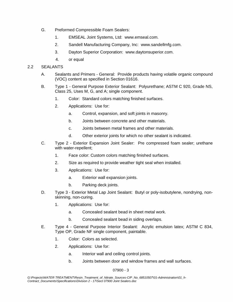
07900 - 3 G:\Projects\WATER TREATMENT\Resin_Treatment_of_Nitrate_Sources-CIP_No_68510507\01-Administration\01_h-Contract_Documents\Specifications\Division 2 - 17\Sect 07900 Joint Sealers.doc
G. Preformed Compressible Foam Sealers:
1. EMSEAL Joint Systems, Ltd: www.emseal.com.
2. Sandell Manufacturing Company, Inc: www.sandellmfg.com.
3. Dayton Superior Corporation: www.daytonsuperior.com.
4. or equal
2.2 SEALANTS
A. Sealants and Primers - General: Provide products having volatile organic compound (VOC) content as specified in Section 01616.
B. Type 1 - General Purpose Exterior Sealant: Polyurethane; ASTM C 920, Grade NS, Class 25, Uses M, G, and A; single component.
1. Color: Standard colors matching finished surfaces.
2. Applications: Use for:
a. Control, expansion, and soft joints in masonry.
b. Joints between concrete and other materials.
c. Joints between metal frames and other materials.
d. Other exterior joints for which no other sealant is indicated.
C. Type 2 - Exterior Expansion Joint Sealer: Pre compressed foam sealer; urethane with water-repellent;
1. Face color: Custom colors matching finished surfaces.
2. Size as required to provide weather tight seal when installed.
3. Applications: Use for:
a. Exterior wall expansion joints.
b. Parking deck joints.
D. Type 3 - Exterior Metal Lap Joint Sealant: Butyl or poly-isobutylene, nondrying, non-skinning, non-curing.
1. Applications: Use for:
a. Concealed sealant bead in sheet metal work.
b. Concealed sealant bead in siding overlaps.
E. Type 4 - General Purpose Interior Sealant: Acrylic emulsion latex; ASTM C 834, Type OP, Grade NF single component, paintable.
1. Color: Colors as selected.
2. Applications: Use for:
a. Interior wall and ceiling control joints.
b. Joints between door and window frames and wall surfaces.
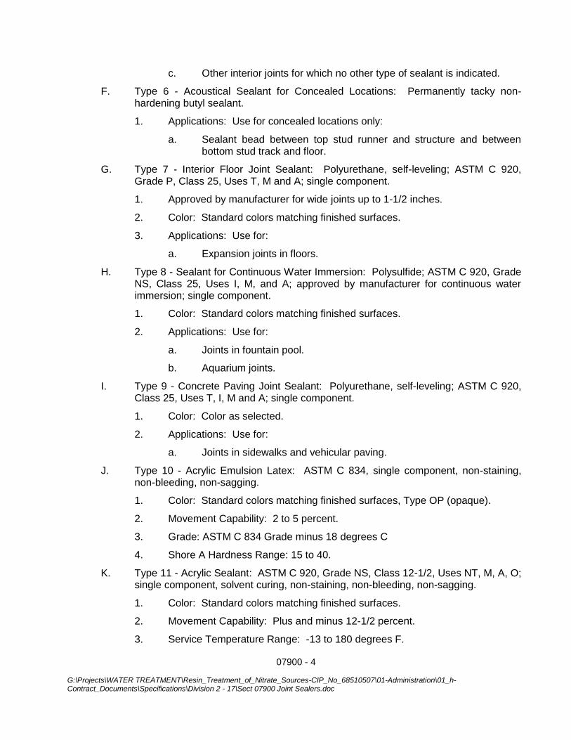
07900 - 4 G:\Projects\WATER TREATMENT\Resin_Treatment_of_Nitrate_Sources-CIP_No_68510507\01-Administration\01_h-Contract_Documents\Specifications\Division 2 - 17\Sect 07900 Joint Sealers.doc
c. Other interior joints for which no other type of sealant is indicated.
F. Type 6 - Acoustical Sealant for Concealed Locations: Permanently tacky non-hardening butyl sealant.
1. Applications: Use for concealed locations only:
a. Sealant bead between top stud runner and structure and between bottom stud track and floor.
G. Type 7 - Interior Floor Joint Sealant: Polyurethane, self-leveling; ASTM C 920, Grade P, Class 25, Uses T, M and A; single component.
1. Approved by manufacturer for wide joints up to 1-1/2 inches.
2. Color: Standard colors matching finished surfaces.
3. Applications: Use for:
a. Expansion joints in floors.
H. Type 8 - Sealant for Continuous Water Immersion: Polysulfide; ASTM C 920, Grade NS, Class 25, Uses I, M, and A; approved by manufacturer for continuous water immersion; single component.
1. Color: Standard colors matching finished surfaces.
2. Applications: Use for:
a. Joints in fountain pool.
b. Aquarium joints.
I. Type 9 - Concrete Paving Joint Sealant: Polyurethane, self-leveling; ASTM C 920, Class 25, Uses T, I, M and A; single component.
1. Color: Color as selected.
2. Applications: Use for:
a. Joints in sidewalks and vehicular paving.
J. Type 10 - Acrylic Emulsion Latex: ASTM C 834, single component, non-staining, non-bleeding, non-sagging.
1. Color: Standard colors matching finished surfaces, Type OP (opaque).
2. Movement Capability: 2 to 5 percent.
3. Grade: ASTM C 834 Grade minus 18 degrees C
4. Shore A Hardness Range: 15 to 40.
K. Type 11 - Acrylic Sealant: ASTM C 920, Grade NS, Class 12-1/2, Uses NT, M, A, O; single component, solvent curing, non-staining, non-bleeding, non-sagging.
1. Color: Standard colors matching finished surfaces.
2. Movement Capability: Plus and minus 12-1/2 percent.
3. Service Temperature Range: -13 to 180 degrees F.
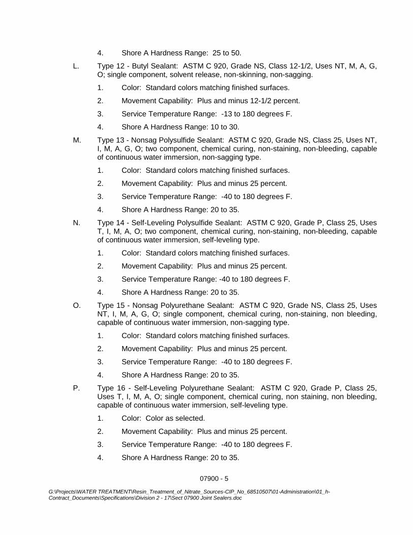
07900 - 5 G:\Projects\WATER TREATMENT\Resin_Treatment_of_Nitrate_Sources-CIP_No_68510507\01-Administration\01_h-Contract_Documents\Specifications\Division 2 - 17\Sect 07900 Joint Sealers.doc
4. Shore A Hardness Range: 25 to 50.
L. Type 12 - Butyl Sealant: ASTM C 920, Grade NS, Class 12-1/2, Uses NT, M, A, G, O; single component, solvent release, non-skinning, non-sagging.
1. Color: Standard colors matching finished surfaces.
2. Movement Capability: Plus and minus 12-1/2 percent.
3. Service Temperature Range: -13 to 180 degrees F.
4. Shore A Hardness Range: 10 to 30.
M. Type 13 - Nonsag Polysulfide Sealant: ASTM C 920, Grade NS, Class 25, Uses NT, I, M, A, G, O; two component, chemical curing, non-staining, non-bleeding, capable of continuous water immersion, non-sagging type.
1. Color: Standard colors matching finished surfaces.
2. Movement Capability: Plus and minus 25 percent.
3. Service Temperature Range: -40 to 180 degrees F.
4. Shore A Hardness Range: 20 to 35.
N. Type 14 - Self-Leveling Polysulfide Sealant: ASTM C 920, Grade P, Class 25, Uses T, I, M, A, O; two component, chemical curing, non-staining, non-bleeding, capable of continuous water immersion, self-leveling type.
1. Color: Standard colors matching finished surfaces.
2. Movement Capability: Plus and minus 25 percent.
3. Service Temperature Range: -40 to 180 degrees F.
4. Shore A Hardness Range: 20 to 35.
O. Type 15 - Nonsag Polyurethane Sealant: ASTM C 920, Grade NS, Class 25, Uses NT, I, M, A, G, O; single component, chemical curing, non-staining, non bleeding, capable of continuous water immersion, non-sagging type.
1. Color: Standard colors matching finished surfaces.
2. Movement Capability: Plus and minus 25 percent.
3. Service Temperature Range: -40 to 180 degrees F.
4. Shore A Hardness Range: 20 to 35.
P. Type 16 - Self-Leveling Polyurethane Sealant: ASTM C 920, Grade P, Class 25, Uses T, I, M, A, O; single component, chemical curing, non staining, non bleeding, capable of continuous water immersion, self-leveling type.
1. Color: Color as selected.
2. Movement Capability: Plus and minus 25 percent.
3. Service Temperature Range: -40 to 180 degrees F.
4. Shore A Hardness Range: 20 to 35.
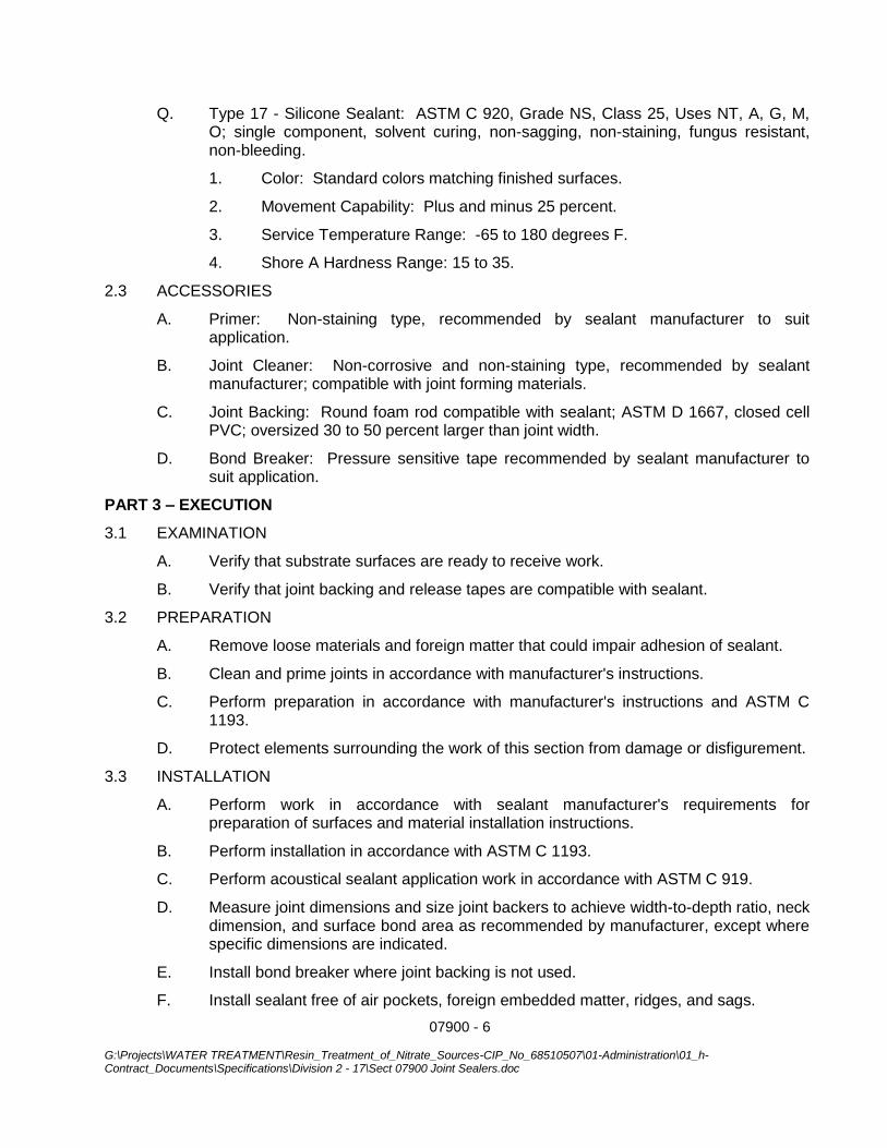
07900 - 6 G:\Projects\WATER TREATMENT\Resin_Treatment_of_Nitrate_Sources-CIP_No_68510507\01-Administration\01_h-Contract_Documents\Specifications\Division 2 - 17\Sect 07900 Joint Sealers.doc
Q. Type 17 - Silicone Sealant: ASTM C 920, Grade NS, Class 25, Uses NT, A, G, M, O; single component, solvent curing, non-sagging, non-staining, fungus resistant, non-bleeding.
1. Color: Standard colors matching finished surfaces.
2. Movement Capability: Plus and minus 25 percent.
3. Service Temperature Range: -65 to 180 degrees F.
4. Shore A Hardness Range: 15 to 35.
2.3 ACCESSORIES
A. Primer: Non-staining type, recommended by sealant manufacturer to suit application.
B. Joint Cleaner: Non-corrosive and non-staining type, recommended by sealant manufacturer; compatible with joint forming materials.
C. Joint Backing: Round foam rod compatible with sealant; ASTM D 1667, closed cell PVC; oversized 30 to 50 percent larger than joint width.
D. Bond Breaker: Pressure sensitive tape recommended by sealant manufacturer to suit application.
PART 3 – EXECUTION
3.1 EXAMINATION
A. Verify that substrate surfaces are ready to receive work.
B. Verify that joint backing and release tapes are compatible with sealant.
3.2 PREPARATION
A. Remove loose materials and foreign matter that could impair adhesion of sealant.
B. Clean and prime joints in accordance with manufacturer's instructions.
C. Perform preparation in accordance with manufacturer's instructions and ASTM C 1193.
D. Protect elements surrounding the work of this section from damage or disfigurement.
3.3 INSTALLATION
A. Perform work in accordance with sealant manufacturer's requirements for preparation of surfaces and material installation instructions.
B. Perform installation in accordance with ASTM C 1193.
C. Perform acoustical sealant application work in accordance with ASTM C 919.
D. Measure joint dimensions and size joint backers to achieve width-to-depth ratio, neck dimension, and surface bond area as recommended by manufacturer, except where specific dimensions are indicated.
E. Install bond breaker where joint backing is not used.
F. Install sealant free of air pockets, foreign embedded matter, ridges, and sags.

07900 - 7 G:\Projects\WATER TREATMENT\Resin_Treatment_of_Nitrate_Sources-CIP_No_68510507\01-Administration\01_h-Contract_Documents\Specifications\Division 2 - 17\Sect 07900 Joint Sealers.doc
G. Apply sealant within recommended application temperature ranges. Consult manufacturer when sealant cannot be applied within these temperature ranges.
H. Tool joints concave.
I. Pre-compressed Foam Sealant: Do not stretch; avoid joints except at corners, ends, and intersections; install with face 1/8 to 1/4 inch below adjoining surface.
J. Compression Gaskets: Avoid joints except at ends, corners, and intersections; seal all joints with adhesive; install with face 1/8 to 1/4 inch below adjoining surface.
3.4 CLEANING
A. Clean adjacent soiled surfaces.
3.5 PROTECTION
A. Protect sealants until cured.
***END OF SECTION***
07900 - 8 G:\Projects\WATER TREATMENT\Resin_Treatment_of_Nitrate_Sources-CIP_No_68510507\01-Administration\01_h-Contract_Documents\Specifications\Division 2 - 17\Sect 07900 Joint Sealers.doc
THIS PAGE INTENTIONALLY BLANK
14_0801 / Corona 08111 - 1 HOLLOW METAL DOORS AND FRAMES
SECTION 08111
HOLLOW METAL DOORS AND FRAMES
PART 1 GENERAL
1.01 SECTION INCLUDES
A. Non-fire-rated steel doors and frames.
B. Thermally insulated steel doors.
C. Accessories, including glazing, louvers, and vision frames.
1.02 RELATED REQUIREMENTS
A. Section 08710 - Door Hardware.
B. Section 08800 - Glazing: Glass for doors and borrowed lites.
C. Section 09911 - Exterior Painting: Field painting.
1.03 REFERENCE STANDARDS
A. ADA Standards - Americans with Disabilities Act (ADA) Standards for Accessible Design; 2010.
B. ANSI/ICC A117.1 - American National Standard for Accessible and Usable Buildings and Facilities; International Code Council; 2009.
C. ANSI/SDI A250.8 - Specifications for Standard Steel Doors and Frames (SDI-100); 2014.
D. ANSI/SDI A250.10 - Test Procedure and Acceptance Criteria for Prime Painted Steel Surfaces for Steel Doors and Frames; 2011.
E. ASTM A653/A653M - Standard Specification for Steel Sheet, Zinc-Coated (Galvanized) or Zinc-Iron Alloy-Coated (Galvannealed) by the Hot-Dip Process; 2013.
F. ASTM C1363 - Standard Test Method for Thermal Performance of Building Assemblies by Means of a Hot Box Apparatus; 2011.
G. BHMA A156.115 - American National Standard for Hardware Preparation in Steel Doors and Steel Frames; 2014. (ANSI/BHMA A156.115)
H. ICC A117.1 - Accessible and Usable Buildings and Facilities; International Code Council; 2009 (ANSI).
I. NAAMM HMMA 840 - Guide Specifications for Installation and Storage of Hollow Metal Doors and Frames; The National Association of Architectural Metal Manufacturers; 2007.
1.04 SUBMITTALS
A. See Section 01330 - Administrative Requirements, for submittal procedures.
B. Product Data: Materials and details of design and construction, hardware locations, reinforcement type and locations, anchorage and fastening methods, and finishes; and one copy of referenced grade standard.
C. Shop Drawings: Details of each opening, showing elevations, glazing, frame profiles, and identifying location of different finishes, if any.
D. Manufacturer's Certificate: Certification that products meet or exceed specified requirements.
1.05 QUALITY ASSURANCE
A. Maintain at the project site a copy of all reference standards dealing with installation.
PART 2 PRODUCTS
2.01 MANUFACTURERS
A. Steel Doors and Frames:
1. Assa Abloy Ceco, Curries, or Fleming: www.assaabloydss.com.
2. Republic Doors: www.republicdoor.com.
3. Steelcraft, an Allegion brand: www.allegion.com/us.
4. Substitutions: See Section 016000 - Product Requirements.
14_0801 / Corona 08111 - 2 HOLLOW METAL DOORS AND FRAMES
2.02 DOORS AND FRAMES
A. Requirements for All Doors and Frames:
1. Accessibility: Comply with ICC A117.1 and ADA Standards.
2. Door Top Closures: Flush with top of faces and edges.
3. Door Edge Profile: Square Edge.
4. Door Texture: Smooth faces.
5. Glazed Lights: Non-removable stops on non-secure side; sizes and configurations as indicated on drawings.
6. Hardware Preparation: In accordance with BHMA A156.115, with reinforcement welded in place, in addition to other requirements specified in door grade standard.
7. Galvanizing: Components hot-dipped zinc-iron alloy-coated (galvannealed) in accordance with ASTM A653/A653M, with manufacturer's standard coating thickness
8. Finish: Factory primed, for field finishing.
B. Combined Requirements: If a particular door and frame unit is indicated to comply with more than one type of requirement, comply with all the specified requirements for each type; for instance, an exterior door that is also indicated as being sound-rated must comply with the requirements specified for exterior doors and for sound-rated doors; where two requirements conflict, comply with the most stringent.
2.03 STEEL DOORS
A. Exterior and Interior Doors:
1. Grade: ANSI/SDI A250.8 (SDI-100); Level 3 - Extra Heavy-Duty, Physical Performance Level A, Model 1 - Full Flush.
2. Core: Polyurethane.
3. Top Closures: Flush with top of faces and edges.
4. Galvanizing: Components hot-dipped zinc-iron alloy-coated (galvannealed) in accordance with ASTM A653/A653M, with manufacturer's standard coating thickness.
5. Insulating Value: U-value of 0.50, when tested in accordance with ASTM C1363.
6. Weatherstripping: Separate, see Section 08710.
7. Finish: Factory primed, and field finished.
2.04 STEEL FRAMES
A. General:
1. Comply with the requirements of grade specified for corresponding door.
2. Finish: Same as for door.
3. Provide mortar guard boxes for hardware cut-outs in frames to be installed in masonry or to be grouted.
B. Exterior Door Frames: Face welded, seamless with joints filled.
1. Galvanizing: Components hot-dipped zinc-iron alloy-coated (galvannealed) in accordance with ASTM A653/A653M, with manufacturer's standard coating thickness.
2. Weatherstripping: Separate, see Section 087100.
2.05 ACCESSORY MATERIALS
A. Louvers: Roll formed steel with overlapping frame; finish same as door components.
1. Style: Sightproof inverted V blade.
2. Fasteners: Concealed fasteners.
3. Product: Anemostat, model no. PLSL,.
4. Finish: Custom Color, Baked Enamel paint
5. Accessories: Security Screws and Insect Screen
B. Framed Door Lites: Roll formed steel with overlapping frame
C. Product: Anemostat, model no. FGS-75, with safety glazing.
1. Finish: Custom Color, Baked Enamel paint.
D. Glazing: As specified in Section 08800.
14_0801 / Corona 08111 - 3 HOLLOW METAL DOORS AND FRAMES
E. Grout for Frames: Portland cement grout of maximum 4-inch slump for hand troweling; thinner pumpable grout is prohibited.
2.06 FINISH MATERIALS
A. Primer: Rust-inhibiting, complying with ANSI/SDI A250.10, door manufacturer's standard.
B. Bituminous Coating: Asphalt emulsion or other high-build, water-resistant, resilient coating.
PART 3 EXECUTION
3.01 EXAMINATION
A. Verify existing conditions before starting work.
B. Verify that opening sizes and tolerances are acceptable.
3.02 PREPARATION
A. Coat inside of frames to be installed in masonry or to be grouted, with bituminous coating, prior to installation.
B. Coat inside of other frames with bituminous coating to a thickness of 1/16 inch (1.5 mm).
3.03 INSTALLATION
A. Install in accordance with the requirements of the specified door grade standard and NAAMM HMMA 840.
B. Coordinate frame anchor placement with wall construction.
C. Grout frames in masonry construction, using hand trowel methods; brace frames so that pressure of grout before setting will not deform frames.
D. Coordinate installation of hardware.
E. Coordinate installation of glazing.
F. Coordinate installation of electrical connections to electrical hardware items.
3.04 TOLERANCES
A. Maximum Diagonal Distortion: 1/16 in (1.5 mm) measured with straight edge, corner to corner.
3.05 ADJUSTING
A. Adjust for smooth and balanced door movement.
B. Adjust sound control doors so that seals are fully engaged when door is closed.
END OF SECTION
14_0801 / Corona 08111 - 4 HOLLOW METAL DOORS AND FRAMES
THIS PAGE INTENTIONALLY BLANK
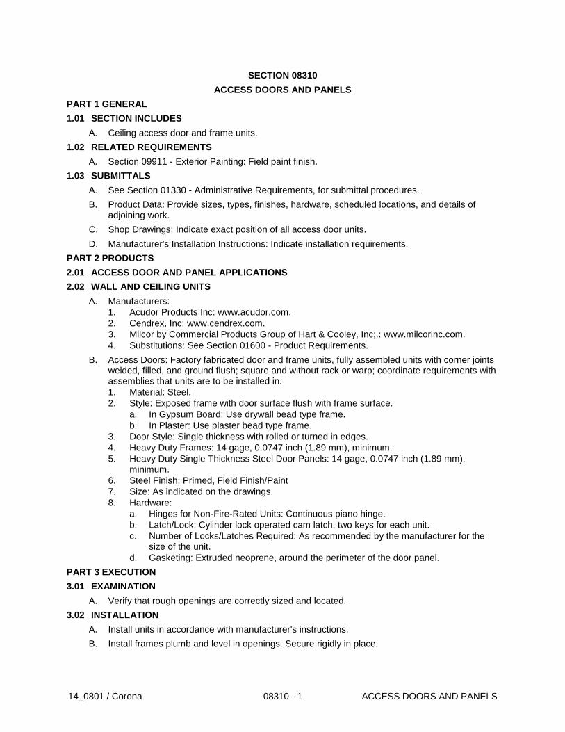
14_0801 / Corona 08310 - 1 ACCESS DOORS AND PANELS
SECTION 08310
ACCESS DOORS AND PANELS
PART 1 GENERAL
1.01 SECTION INCLUDES
A. Ceiling access door and frame units.
1.02 RELATED REQUIREMENTS
A. Section 09911 - Exterior Painting: Field paint finish.
1.03 SUBMITTALS
A. See Section 01330 - Administrative Requirements, for submittal procedures.
B. Product Data: Provide sizes, types, finishes, hardware, scheduled locations, and details of adjoining work.
C. Shop Drawings: Indicate exact position of all access door units.
D. Manufacturer's Installation Instructions: Indicate installation requirements.
PART 2 PRODUCTS
2.01 ACCESS DOOR AND PANEL APPLICATIONS
2.02 WALL AND CEILING UNITS
A. Manufacturers:
1. Acudor Products Inc: www.acudor.com.
2. Cendrex, Inc: www.cendrex.com.
3. Milcor by Commercial Products Group of Hart & Cooley, Inc;.: www.milcorinc.com.
4. Substitutions: See Section 01600 - Product Requirements.
B. Access Doors: Factory fabricated door and frame units, fully assembled units with corner joints welded, filled, and ground flush; square and without rack or warp; coordinate requirements with assemblies that units are to be installed in.
1. Material: Steel.
2. Style: Exposed frame with door surface flush with frame surface.
a. In Gypsum Board: Use drywall bead type frame.
b. In Plaster: Use plaster bead type frame.
3. Door Style: Single thickness with rolled or turned in edges.
4. Heavy Duty Frames: 14 gage, 0.0747 inch (1.89 mm), minimum.
5. Heavy Duty Single Thickness Steel Door Panels: 14 gage, 0.0747 inch (1.89 mm), minimum.
6. Steel Finish: Primed, Field Finish/Paint
7. Size: As indicated on the drawings.
8. Hardware:
a. Hinges for Non-Fire-Rated Units: Continuous piano hinge.
b. Latch/Lock: Cylinder lock operated cam latch, two keys for each unit.
c. Number of Locks/Latches Required: As recommended by the manufacturer for the size of the unit.
d. Gasketing: Extruded neoprene, around the perimeter of the door panel.
PART 3 EXECUTION
3.01 EXAMINATION
A. Verify that rough openings are correctly sized and located.
3.02 INSTALLATION
A. Install units in accordance with manufacturer's instructions.
B. Install frames plumb and level in openings. Secure rigidly in place.

14_0801 / Corona 08310 - 2 ACCESS DOORS AND PANELS
C. Position units to provide convenient access to the concealed work requiring access.
END OF SECTION
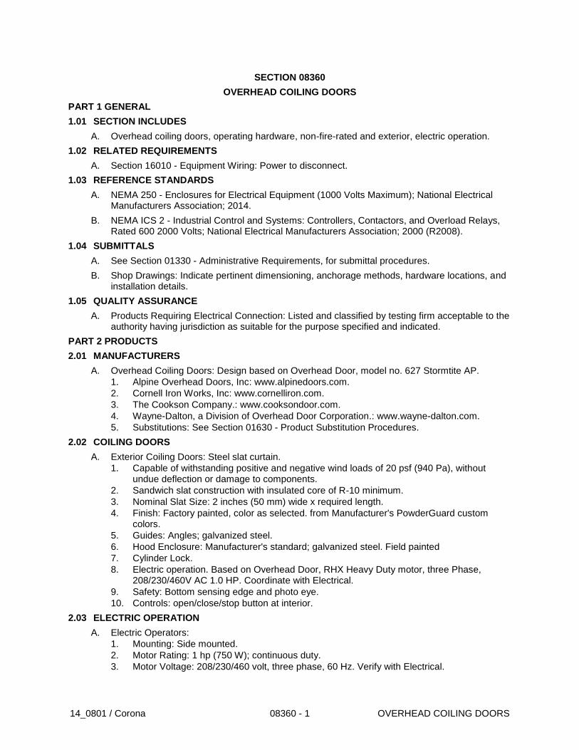
14_0801 / Corona 08360 - 1 OVERHEAD COILING DOORS
SECTION 08360
OVERHEAD COILING DOORS
PART 1 GENERAL
1.01 SECTION INCLUDES
A. Overhead coiling doors, operating hardware, non-fire-rated and exterior, electric operation.
1.02 RELATED REQUIREMENTS
A. Section 16010 - Equipment Wiring: Power to disconnect.
1.03 REFERENCE STANDARDS
A. NEMA 250 - Enclosures for Electrical Equipment (1000 Volts Maximum); National Electrical Manufacturers Association; 2014.
B. NEMA ICS 2 - Industrial Control and Systems: Controllers, Contactors, and Overload Relays, Rated 600 2000 Volts; National Electrical Manufacturers Association; 2000 (R2008).
1.04 SUBMITTALS
A. See Section 01330 - Administrative Requirements, for submittal procedures.
B. Shop Drawings: Indicate pertinent dimensioning, anchorage methods, hardware locations, and installation details.
1.05 QUALITY ASSURANCE
A. Products Requiring Electrical Connection: Listed and classified by testing firm acceptable to the authority having jurisdiction as suitable for the purpose specified and indicated.
PART 2 PRODUCTS
2.01 MANUFACTURERS
A. Overhead Coiling Doors: Design based on Overhead Door, model no. 627 Stormtite AP.
1. Alpine Overhead Doors, Inc: www.alpinedoors.com.
2. Cornell Iron Works, Inc: www.cornelliron.com.
3. The Cookson Company.: www.cooksondoor.com.
4. Wayne-Dalton, a Division of Overhead Door Corporation.: www.wayne-dalton.com.
5. Substitutions: See Section 01630 - Product Substitution Procedures.
2.02 COILING DOORS
A. Exterior Coiling Doors: Steel slat curtain.
1. Capable of withstanding positive and negative wind loads of 20 psf (940 Pa), without undue deflection or damage to components.
2. Sandwich slat construction with insulated core of R-10 minimum.
3. Nominal Slat Size: 2 inches (50 mm) wide x required length.
4. Finish: Factory painted, color as selected. from Manufacturer's PowderGuard custom colors.
5. Guides: Angles; galvanized steel.
6. Hood Enclosure: Manufacturer's standard; galvanized steel. Field painted
7. Cylinder Lock.
8. Electric operation. Based on Overhead Door, RHX Heavy Duty motor, three Phase, 208/230/460V AC 1.0 HP. Coordinate with Electrical.
9. Safety: Bottom sensing edge and photo eye.
10. Controls: open/close/stop button at interior.
2.03 ELECTRIC OPERATION
A. Electric Operators:
1. Mounting: Side mounted.
2. Motor Rating: 1 hp (750 W); continuous duty.
3. Motor Voltage: 208/230/460 volt, three phase, 60 Hz. Verify with Electrical.

14_0801 / Corona 08360 - 2 OVERHEAD COILING DOORS
4. Motor Controller: NEMA ICS 2, full voltage, reversing magnetic motor starter.
5. Controller Enclosure: NEMA 250, Type 1.
6. Opening Speed: 12 inches per second (300 mm/s).
7. Brake: Adjustable friction clutch type, activated by motor controller.
8. Manual override in case of power failure.
B. Control Station: Standard three button (OPEN-STOP-CLOSE) momentary control for each operator.
1. 24 volt circuit.
2. Surface mounted.
PART 3 EXECUTION
3.01 EXAMINATION
A. Verify that opening sizes, tolerances and conditions are acceptable.
3.02 INSTALLATION
A. Install units in accordance with manufacturer's instructions.
B. Use anchorage devices to securely fasten assembly to wall construction and building framing without distortion or stress.
C. Securely and rigidly brace components suspended from structure. Secure guides to structural members only.
D. Fit and align assembly including hardware; level and plumb, to provide smooth operation.
E. Coordinate installation of electrical service with Section 26271.
F. Complete wiring from disconnect to unit components.
G. Install perimeter trim and closures.
3.03 TOLERANCES
A. Maintain dimensional tolerances and alignment with adjacent work.
B. Maximum Variation From Plumb: 1/16 inch (1.5 mm).
C. Maximum Variation From Level: 1/16 inch (1.5 mm).
D. Longitudinal or Diagonal Warp: Plus or minus 1/8 inch per 10 ft (3 mm per 3 m) straight edge.
3.04 ADJUSTING
A. Adjust operating assemblies for smooth and noiseless operation.
3.05 CLEANING
A. Clean installed components.
B. Remove labels and visible markings.
END OF SECTION
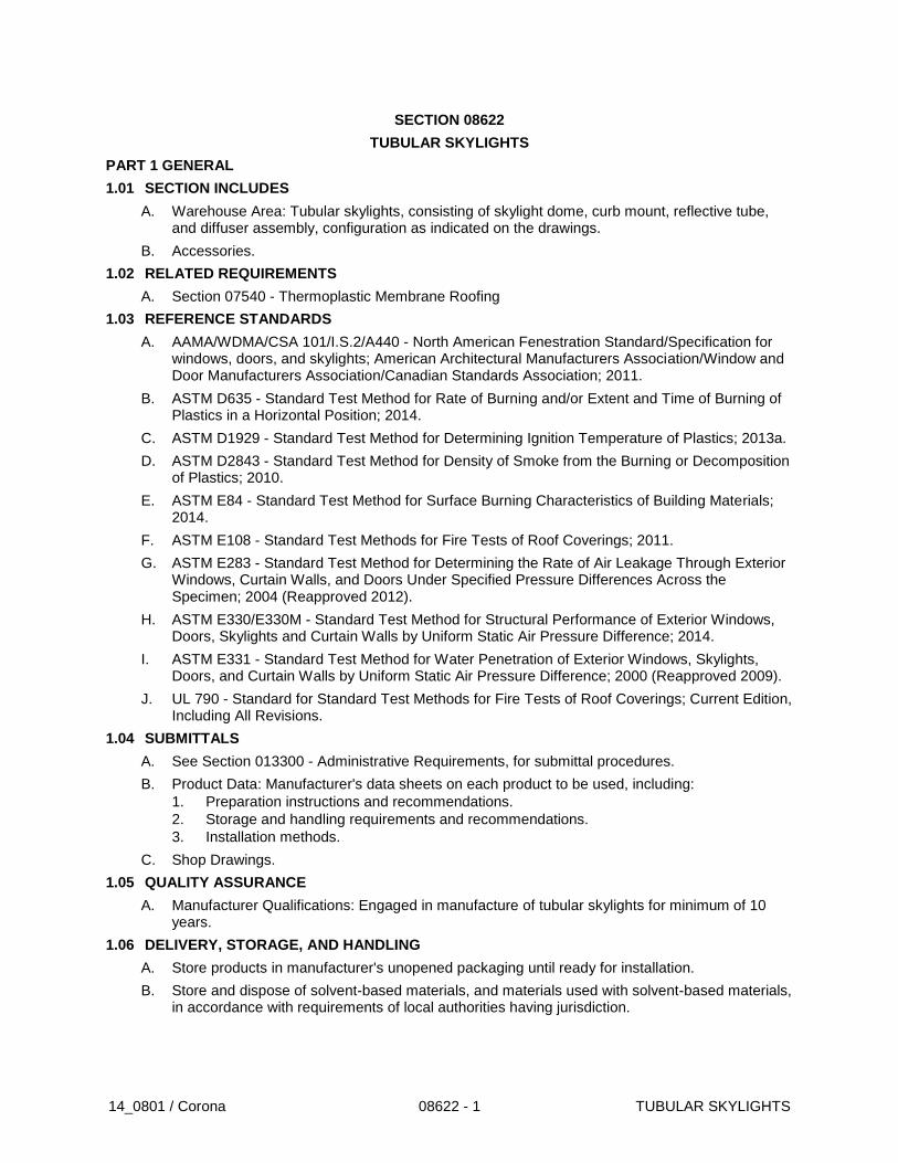
14_0801 / Corona 08622 - 1 TUBULAR SKYLIGHTS
SECTION 08622
TUBULAR SKYLIGHTS
PART 1 GENERAL
1.01 SECTION INCLUDES
A. Warehouse Area: Tubular skylights, consisting of skylight dome, curb mount, reflective tube, and diffuser assembly, configuration as indicated on the drawings.
B. Accessories.
1.02 RELATED REQUIREMENTS
A. Section 07540 - Thermoplastic Membrane Roofing
1.03 REFERENCE STANDARDS
A. AAMA/WDMA/CSA 101/I.S.2/A440 - North American Fenestration Standard/Specification for windows, doors, and skylights; American Architectural Manufacturers Association/Window and Door Manufacturers Association/Canadian Standards Association; 2011.
B. ASTM D635 - Standard Test Method for Rate of Burning and/or Extent and Time of Burning of Plastics in a Horizontal Position; 2014.
C. ASTM D1929 - Standard Test Method for Determining Ignition Temperature of Plastics; 2013a.
D. ASTM D2843 - Standard Test Method for Density of Smoke from the Burning or Decomposition of Plastics; 2010.
E. ASTM E84 - Standard Test Method for Surface Burning Characteristics of Building Materials; 2014.
F. ASTM E108 - Standard Test Methods for Fire Tests of Roof Coverings; 2011.
G. ASTM E283 - Standard Test Method for Determining the Rate of Air Leakage Through Exterior Windows, Curtain Walls, and Doors Under Specified Pressure Differences Across the Specimen; 2004 (Reapproved 2012).
H. ASTM E330/E330M - Standard Test Method for Structural Performance of Exterior Windows, Doors, Skylights and Curtain Walls by Uniform Static Air Pressure Difference; 2014.
I. ASTM E331 - Standard Test Method for Water Penetration of Exterior Windows, Skylights, Doors, and Curtain Walls by Uniform Static Air Pressure Difference; 2000 (Reapproved 2009).
J. UL 790 - Standard for Standard Test Methods for Fire Tests of Roof Coverings; Current Edition, Including All Revisions.
1.04 SUBMITTALS
A. See Section 013300 - Administrative Requirements, for submittal procedures.
B. Product Data: Manufacturer's data sheets on each product to be used, including:
1. Preparation instructions and recommendations.
2. Storage and handling requirements and recommendations.
3. Installation methods.
C. Shop Drawings.
1.05 QUALITY ASSURANCE
A. Manufacturer Qualifications: Engaged in manufacture of tubular skylights for minimum of 10 years.
1.06 DELIVERY, STORAGE, AND HANDLING
A. Store products in manufacturer's unopened packaging until ready for installation.
B. Store and dispose of solvent-based materials, and materials used with solvent-based materials, in accordance with requirements of local authorities having jurisdiction.
14_0801 / Corona 08622 - 2 TUBULAR SKYLIGHTS
1.07 FIELD CONDITIONS
A. Maintain environmental conditions (temperature, humidity, and ventilation) within limits recommended by manufacturer for optimum results. Do not install products under environmental conditions outside manufacturer's absolute limits.
PART 2 PRODUCTS
2.01 MANUFACTURERS
A. Solatube International, Inc: www.solatube.com.
B. Monodraught, Webpage: monodraught.com, phone Number: +44(0)1494 897700.
C. Sunscope, Webpage: sunscope.com, Number: 1.800.449.0644.
D. Design based on Solatube International
2.02 TUBULAR SKYLIGHTS
A. Tubular Skylights: Transparent roof-mounted skylight dome and curb, reflective tube, and ceiling level diffuser assembly, transferring sunlight to interior spaces.
1. Components shall be made and assembled by one manufacturer.
2. Non-Metal Parts: Flammability less than the following.
a. Roof-Top Components: Class B when tested in accordance with ASTM E108 or UL 790.
b. Combustibility - Light Transmitting Parts: Burning extent of 1 inch (25 mm) or less (ICC Class CC-1), when tested in accordance with ASTM D635 in the thickness intended for use.
B. Performance Requirements: Provide products that comply with the following:
1. Grade: AAMA/WDMA/CSA 101/I.S.2/A440 requirements for specific tubular skylight:
a. Product Type: Tubular Daylighting Device, Closed Ceiling (TDDCC).
2. Design and size components to withstand dead and live loads caused by positive and negative wind pressure acting normal to plane of tubular skylight without breakage or permanent damage to any parts, when tested in accordance with ASTM E330/E330M:
a. Design Pressure (DP): In accordance with applicable codes.
b. No permanent deflection in excess of 0.2 percent of span.
c. Live load of 100 psf (4.8 kPa) on dome with safety factor of 3.
3. Air Infiltration: Maximum 0.10 cfm per foot (0.15 L/s/m) of crack length at 6.24 psf (299 Pa) pressure differential when tested in accordance with ASTM E283.
4. Water Resistance: No uncontrolled water leakage at 6.24 psf (299 Pa) pressure differential with water rate of 5 gallons/h/sf (206 L/h/sq m), when tested in accordance with ASTM E331; design to ensure that water will not accumulate inside assembly.
5. Thermal Movement: Fabricate to allow for thermal movement resulting from temperature differential from minus 30 to 180 degrees F (minus 34 to 82 degrees C).
6. Flammability: Non-metal parts complying with the following:
a. Roof-Top Components: Class B when tested in accordance with ASTM E108 or UL 790.
b. Self-Ignition Temperature: Greater than 650 degrees F (343 degrees C), when tested in accordance with ASTM D1929.
c. Smoke Developed Index: Maximum of 450, when tested in accordance with ASTM E84; or maximum rating of 75, when tested in accordance with ASTM D2843.
d. Combustibility - Light Transmitting Parts: Burning extent of 1 inch (25 mm) or less (ICC Class CC-1), when tested in accordance with ASTM D635 in the thickness intended for use.
e. Combustibility - Non-Light Transmitting Parts: Minimum 2.5 inches/min (64 mm/min) (ICC Class CC-2), when tested in accordance with ASTM D635.
C. Roof Assemblies: Transparent, UV and impact resistant dome with flashing base supporting dome and top of tube.
1. Glazing: Polycarbonate plastic, 0.125 inch (3.2 mm) minimum thickness.
14_0801 / Corona 08622 - 3 TUBULAR SKYLIGHTS
2. Tubular Skylight Type: Open Ceiling: SolaMaster Series: Solatube Model 750 DS-O
3. 21 inch (530 mm) Daylighting System:
4. Roof Dome Assembly: Transparent, UV and impact resistant dome with flashing base supporting dome and top of tube.
5. Outer Dome Glazing: Type DA, 0.125 inch (3.2 mm) minimum thickness injection molded acrylic classified as CC2 material; UV inhibited, impact modified acrylic blend.
6. Inner Dome Glazing: Type DPI, 0.115 inch (3 mm) minimum thickness polycarbonate classified as CC1 material.
7. Raybender 3000: Variable prism optic molded into outer dome to capture low angle sunlight and limit high angle sunlight.
8. Roof Flashing Base: Curb Cap, Type FC
9. Flashing Insulator: Type FI, Thermal isolation material for use under flashing
10. Curb Insulator: Type CI, Thermal isolation material for use at curb base
11. Flashing Insulator: Type FI, Thermal isolation material for use under flashing.
12. Reflective Tubes: Aluminum sheet, thickness 0.018 inch (0.5 mm).
13. Diffuser Assemblies for Tubes Not Penetrating Ceilings (Open Ceiling): Solatube Model 750 DS-O. 21 inch (530 mm) diameter diffuser attached directly to bottom of tube. Lens: Type L1 OptiView Fresnel lens design to maximize light output and diffusion.
14. Accessories:
a. Security Bar: Type B Security Bar 0.375 inch (95 mm) stainless steel bar across flashing diameter opening.
b. Security Kit: Type SK Dome Security Kit, rivets with nylon spacers to replace dome screws.
2.03 ACCESSORIES
A. Fasteners: Same material as metals being fastened, non-magnetic steel, non-corrosive metal of type recommended by manufacturer, or injection molded nylon.
B. Sealant: Elastomeric, silicone or polyurethane; compatible with materials being sealed.
PART 3 EXECUTION
3.01 EXAMINATION
A. Do not begin installation until substrates have been properly prepared.
B. If substrate preparation is the responsibility of another installer, notify Architect of unsatisfactory preparation before proceeding.
3.02 PREPARATION
A. Clean surfaces thoroughly prior to installation.
B. Prepare surfaces using the methods recommended by the manufacturer for achieving the best result for the substrate under the project conditions.
3.03 INSTALLATION
A. Install in accordance with manufacturer's written instructions.
B. Set roof assembly flashing in continuous bead of sealant.
C. Seal joints exposed to weather in accordance with sealant manufacturer's written instructions.
D. Conduct field test for water tightness; conduct water test in presence of Architect. Correct defective work and re-test until satisfactory.
3.04 PROTECTION
A. Protect installed products until completion of project.
B. Touch-up, repair or replace damaged products before date of Substantial Completion.
END OF SECTION
14_0801 / Corona 08622 - 4 TUBULAR SKYLIGHTS
THIS PAGE INTENTIONALLY BLANK
14_0801 / Corona 08710 - 1 DOOR HARDWARE
SECTION 08710
DOOR HARDWARE
PART 1 GENERAL
1.01 SECTION INCLUDES
A. General Description of Work: Design/Build and coordination of listed Door Hardware (function) and hardware not listed as needed for a complete finished working system at all openings.
1.02 SECTION INCLUDES
A. Hardware for hollow steel doors.
B. Hardware for fire-rated doors.
C. Thresholds.
D. Weatherstripping, seals and door gaskets.
E. Man Gate locks- Battery Operated Stand Alone.
1.03 RELATED REQUIREMENTS
A. Section 08111 – Hollow Metal Doors and Frames
1.04 REFERENCE STANDARDS
A. 36 CFR 1191 - Americans with Disabilities Act (ADA) Accessibility Guidelines for Buildings and Facilities; Architectural Barriers Act (ABA) Accessibility Guidelines; current edition.
B. BHMA A156.1 - American National Standard for Butts and Hinges; Builders Hardware Manufacturers Association, Inc.; 2013 (ANSI/BHMA A156.1).
C. BHMA A156.3 - American National Standard for Exit Devices; Builders Hardware Manufacturers Association; 2014 (ANSI/BHMA A156.3).
D. BHMA A156.4 - American National Standard for Door Controls - Closers; Builders Hardware Manufacturers Association, Inc.; 2013 (ANSI/BHMA A156.4).
E. BHMA A156.5 - American National Standard for Cylinders and Input Devices for Locks; Builders Hardware Manufacturers Association; 2014 (ANSI/BHMA A156.5).
F. BHMA A156.8 - American National Standard for Door Controls - Overhead Stops and Holders; Builders Hardware Manufacturers Association, Inc.; 2010 (ANSI/BHMA A156.8).
G. BHMA A156.13 - American National Standard for Mortise Locks & Latches Series 1000; Builders Hardware Manufacturers Association; 2012 (ANSI/BHMA A156.13).
H. BHMA A156.18 - American National Standard for Materials and Finishes; Builders Hardware Manufacturers Association, Inc.; 2012 (ANSI/BHMA A156.18).
I. BHMA A156.21 - American National Standard for Thresholds; Builders Hardware Manufacturers Association; 2014 (ANSI/BHMA A156.21).
J. BHMA A156.22 - American National Standard for Door Gasketing and Edge Seal Systems, Builders Hardware Manufacturers Association; 2012 (ANSI/BHMA A156.22).
K. BHMA A156.31 - American National Standard for Electric Strikes and Frame Mounted Actuators; 2013 (ANSI/BHMA A156.31).
L. BHMA A156.115 - American National Standard for Hardware Preparation in Steel Doors and Steel Frames; 2014 (ANSI/BHMA A156.115).
M. BHMA A156.115W - American National Standard for Hardware Preparation in Wood Doors with Wood or Steel Frames; 2006 (ANSI/BHMA A156.115W).
N. DHI (LOCS) - Recommended Locations for Architectural Hardware for Standard Steel Doors and Frames; Door and Hardware Institute; 2004.
O. NFPA 80 - Standard for Fire Doors and Other Opening Protectives; 2013.
P. NFPA 101 - Life Safety Code; National Fire Protection Association; 2012.
14_0801 / Corona 08710 - 2 DOOR HARDWARE
Q. UL (BMD) - Building Materials Directory; Underwriters Laboratories Inc.; current edition.
1.05 ADMINISTRATIVE REQUIREMENTS
A. Coordinate the manufacture, fabrication, and installation of products onto which door hardware will be installed.
B. Furnish templates for door and frame preparation to manufacturers and fabricators of products requiring internal reinforcement for door hardware.
C. Convey Owner's keying requirements to manufacturers.
D. Sequence installation to ensure utility connections are achieved in an orderly and expeditious manner.
1.06 SUBMITTALS
A. See Section 01330 - Administrative Requirements, for submittal procedures.
B. Product Data: Manufacturer's catalog literature for each type of hardware, marked to clearly show products to be furnished for this project.
C. Hardware Schedule: Detailed listing of each item of hardware to be installed on each door. Use door numbering scheme as included in the Contract Documents. Identify electrically operated items and include power requirements.
D. Keying Schedule: Submit for approval of Owner.
E. Project Record Documents: Record actual locations of concealed equipment, services, and conduit.
F. Maintenance Data: Include data on operating hardware, lubrication requirements, and inspection procedures related to preventative maintenance.
1. Submit manufacturer's parts lists and templates.
G. Keys: Deliver with identifying tags to Owner by security shipment direct from hardware supplier.
H. Warranty: Submit manufacturer's warranty and ensure that forms have been completed in Owner's name and registered with manufacturer.
I. Maintenance Materials and Tools: Furnish the following for Owner's use in maintenance of project.
1. See Section 01630 - Product Substitution Requirements, for additional provisions.
2. Extra Lock Cylinders: One for each master keyed group.
3. Tools: One set of all special wrenches or tools applicable to each different or special hardware component, whether supplied by the hardware component manufacturer or not.
J. EXTRA STOCK
1. Lock Cylinders: Two extra cylinders for each master keyed group.
2. Other: One complete sets of each closer, deadlock, and other locking device by type and hand provided for this Project
1.07 QUALITY ASSURANCE
A. Standards for Fire-Rated Doors: Maintain one copy of each referenced standard on site, for use by Architect and Contractor.
B. Manufacturer Qualifications: Company specializing in manufacturing the products specified in this section with minimum three years of documented experience.
C. Hardware Supplier Qualifications: Company specializing in supplying commercial door hardware with five years of experience.
D. Ensure Coordination with other related specification Sections.
E. Ensure Coordination with ACCESS CONTROL and INTRUSION DECTION scope of work.
1.08 DELIVERY, STORAGE, AND HANDLING
A. Package hardware items individually; label and identify each package with door opening code to match hardware schedule.
14_0801 / Corona 08710 - 3 DOOR HARDWARE
1.09 WARRANTY
A. See Section 01787 – Product Warranties, for additional warranty requirements.
B. Provide ten year warranty for door closers.
PART 2 PRODUCTS
2.01 SUPPLIERS
A. Hinges.
1. Interior Exterior: Stanley, McKinney, or Hager.
B. Mechanical Locks: Schlage L 9000 Series mortise locks
1. Lever Type: 03 Lever
C. Door Closers: LCN
D. Exit Devices: Von Duprin, 98 Series
E. Weatherstrip/Threshold: Pemko, National Guard, or Reese.
F. Floor and Wall Stops: Portland, Glynn Johnson, Ives, or Rockwood.
2.02 DOOR HARDWARE - GENERAL
A. Provide hardware specified or required to make doors fully functional, compliant with applicable codes, and secure to the extent indicated.
B. Provide items of a single type of the same model by the same manufacturer.
C. Provide products that comply with the following:
1. Applicable provisions of federal, state, and local codes.
2. Fire-Rated Doors: NFPA 80.
3. Hardware on Fire-Rated Doors, Except Hinges: Listed and classified by UL as suitable for the purpose specified and indicated.
D. Finishes: Provide door hardware of the same finish unless otherwise indicated.
1. Primary Finish: Satin chrome plated over nickel on brass or bronze, 626 (approx US26D).
2. Secondary Finish: Stainless Steel US32 D
3. Finish Definitions: BHMA A156.18.
4. Exceptions:
a. Where base metal is specified to be different, provide finish that is an appearance equivalent according to BHMA A156.18.
b. Aluminum Surface Trim and Gasket Housings: Anodized to match door, not to match other hardware.
E. Fasteners:
1. Concrete and Masonry Substrates: Stainless steel machine screws and lead expansion shields.
2.03 HINGES
A. Heavy Duty Hinges (Exterior and Interior Doors): Stanley FBB199 4.5 x 4.5, permanently lubricated non-detachable ball bearings, Stainless Steel US32D finish.
B. Hinges: Provide hinges on every swinging door.
1. Provide ball-bearing hinges at all doors having closers.
2. Provide non-removable pins on exterior outswinging doors.
C. Quantity of Hinges Per Door:
1. Doors From 60 inches (1.5 m) High up to 90 inches (2.3 m) High: Three hinges.
2. Doors 90 inches (2.3 m) High up to 120 inches (3 m) High: Four hinges.
2.04 LOCKS AND LATCHES
A. Locks: Provide a lock for every door, unless specifically indicated as not requiring locking.
1. Hardware Sets indicate locking functions required for each door.
14_0801 / Corona 08710 - 4 DOOR HARDWARE
2. Trim: Provide lever handle or pull trim on outside of all locks unless specifically stated to have no outside trim.
3. Lock Cylinders: Provide key access on outside of all locks unless specifically stated to have no locking or no outside trim.
B. Lock Cylinders: Manufacturer’s standard tumbler type, seven-pin interchangeable core.
1. Provide cams and/or tailpieces as required for locking devices required.
C. Keying: Grand master keyed.
1. Include construction keying.
2. Key to existing keying system.
2.05 MORTISE LOCKSETS
A. Locking Functions: As defined in BHMA A156.13, and as noted in the Drawings.
B. Lock size, 4" x 5 7/8"
C. Armored front: 8" by 1-1/4"
D. Rosettes: 1 3/4"
E. Cylinders: Removable core, 7 pin cylinder
F. Lever Handles, 03
2.06 EXIT DEVICES
A. Locking Functions: Functions as defined in BHMA A156.3, and as follows:
1. Entry/Exit, Always-Locked: Key outside retracts latchbolt but does not unlock lever, no latch holdback.
2.07 CLOSERS
A. Closers: Complying with BHMA A156.4.
1. Provide surface-mounted, door-mounted closers unless otherwise indicated.
2.08 STOPS AND HOLDERS
A. Stops: Complying with BHMA A156.8; provide a stop for every swinging door, unless otherwise indicated.
1. Provide wall stops, unless otherwise indicated.
2. If wall stops are not practical, due to configuration of room or furnishings, provide overhead stop.
3. Stop is not required if positive stop feature is specified for door closer; positive stop feature of door closer is not an acceptable substitute for a stop unless specifically so stated.
2.09 GASKETING AND THRESHOLDS
A. Gaskets: Complying with BHMA A156.22.
1. On each door in smoke partition, provide smoke gaskets; top, sides, and meeting stile of pairs. If fire/smoke partitions are not indicated on drawings, provide smoke gaskets on each door identified as a "smoke door" and 20-minute rated fire doors.
2. On each exterior door, provide weatherstripping gaskets, unless otherwise indicated; top, sides, and meeting stiles of pairs.
a. Where exterior door is also required to have fire or smoke rating, provide gaskets functioning as both smoke and weather seals.
3. On each exterior door, provide door bottom sweep, unless otherwise indicated.
B. Thresholds: Complying with BHMA A156.21.
1. At each exterior door, provide a threshold unless otherwise indicated.
2. Field cut threshold to frame for tight fit.
C. Fasteners at Exterior Locations: Non-corroding.
2.10 PROTECTION PLATES AND ARCHITECTURAL TRIM
A. Protection Plates:
14_0801 / Corona 08710 - 5 DOOR HARDWARE
1. Kickplate: Provide on push side of every door with closer and every exterior door, except storefront and all-glass doors.
B. Drip Guard: Provide projecting drip guard over all exterior doors unless they are under a projecting roof or canopy.
C. Strike Plate: Provide 12", 12 ga. stainless steel latch guard strike plate
2.11 BATTERY OPERATED STAND ALONE ACCESS HARDWARE AND EXIT DEVICE AT SITE MAN GATES
A. Manufacturer: KABA, www.kabaaccess.com
B. Access Hardware Model: KABA E-Plex 2000
C. Exit Hardware Model: KABA IIco 129 Series Rim Exit Device
D. Finish/Color: satin chrome
E. Exterior Grade finish/material
F. Coordinate with ornamental metal gate.
2.12 KEY CONTROLS
1. Capacity: Holds 10 keys.
2. Finish: Manufacturer's standard black.
3. Manufacturers - Fire Department Lock Box:
a. Knox Company; Knox-Box Rapid Entry System, -: www.knoxbox.com.
PART 3 EXECUTION
3.01 EXAMINATION
A. Verify that doors and frames are ready to receive work; labeled, fire-rated doors and frames are present and properly installed, and dimensions are as indicated on shop drawings.
3.02 INSTALLATION
A. Install hardware in accordance with manufacturer's instructions and applicable codes.
B. Use templates provided by hardware item manufacturer.
C. Do not install surface mounted items until finishes applied to substrate are complete.
D. Install hardware on fire-rated doors and frames in accordance with code and NFPA 80.
E. Mounting heights for hardware from finished floor to center line of hardware item: per CBC and ADA.
F. Set exterior door thresholds with full-width bead of elastomeric sealant on each point of contact with floor; anchor thresholds with stainless steel countersunk screws.
3.03 ADJUSTING
A. Adjust work under provisions of Section 01750.
B. Adjust hardware for smooth operation.
3.04 CLEANING
A. Clean adjacent surfaces soiled by hardware installation. Clean finished hardware per manufacturer's instructions after final adjustments has been made. Replace items that cannot be cleaned to manufacturer's level of finish quality at no additional cost.
3.05 PROTECTION
A. Do not permit adjacent work to damage hardware or finish.
HARDWARE SETS
4.01 GENERAL
A. See Drawings for Door Schedule and Function.
END OF SECTION
14_0801 / Corona 08710 - 6 DOOR HARDWARE
THIS PAGE INTENTIONALLY BLANK

14_0801 / Corona 08800 - 1 GLAZING
SECTION 08800
GLAZING
PART 1 GENERAL
1.01 SECTION INCLUDES
A. Monolithic Glass for Door vision lights.
B. Glazing compounds and accessories.
1.02 RELATED REQUIREMENTS
A. Section 08111 - Hollow Metal Doors and Frames: Glazed doors.
1.03 REFERENCE STANDARDS
A. 16 CFR 1201 - Safety Standard for Architectural Glazing Materials; current edition.
B. ASTM C1036 - Standard Specification for Flat Glass; 2011e1.
C. ASTM C1048 - Standard Specification for Heat-Strengthened and Fully Tempered Flat Glass; 2012.
D. ASTM C1172 - Standard Specification for Laminated Architectural Flat Glass; 2014.
E. ASTM C1193 - Standard Guide for Use of Joint Sealants; 2013.
F. GANA (SM) - GANA Sealant Manual; Glass Association of North America; 2008.
1.04 SUBMITTALS
A. See Section 01330 - Administrative Requirements, for submittal procedures.
B. Product Data on Glass Types: Provide structural, physical and environmental characteristics, size limitations, special handling or installation requirements.
C. Product Data on Glazing Compounds: Provide chemical, functional, and environmental characteristics, limitations, special application requirements. Identify available colors.
D. Samples: Submit two samples [4x4] inch in size of glass and plastic units, showing coloration and design.
E. Samples: Submit 4 inch (100 mm) long bead of glazing sealant, color as selected.
F. Certificates: Certify that products meet or exceed specified requirements.
1.05 QUALITY ASSURANCE
A. Installer Qualifications: Company specializing in performing the work of this section with minimum three years documented experience.
1.06 FIELD CONDITIONS
A. Do not install glazing when ambient temperature is less than 50 degrees F (10 degrees C).
B. Maintain minimum ambient temperature before, during and 24 hours after installation of glazing compounds.
1.07 WARRANTY
A. Laminated Glass: Provide a five (5) year warranty to include coverage for delamination, including replacement of failed units.
PART 2 PRODUCTS
2.01 GLAZING UNITS
A. Type S-1 - Single Vision Glazing:
1. Application: All interior glazing unless otherwise indicated.
2. Type: Laminated float glass, safety glazing
3. Tint: Clear.
4. Thickness: 1/4 inch (6 mm).
14_0801 / Corona 08800 - 2 GLAZING
2.02 GLASS MATERIALS
A. Float Glass Manufacturers:
1. Guardian Industries Corp: www.sunguardglass.com.
2. Pilkington North America Inc: www.pilkington.com/na.
3. PPG Industries, Inc: www.ppgideascapes.com.
4. Substitutions: Refer to Section 01600 - Product Requirements.
B. Float Glass: Provide float glass glazing unless otherwise indicated.
1. Annealed Type: ASTM C1036, Type I, transparent flat, Class 1 clear, Quality Q3 (glazing select).
2. Heat-Strengthened and Fully Tempered Types: ASTM C1048.
C. Laminated Glass: Float glass laminated in accordance with ASTM C1172.
1. Laminated Safety Glass: Comply with 16 CFR 1201 test requirements for Category II.
2. Plastic Interlayer: 0.060 inch (1.52 mm) thick, minimum.
3. Where fully tempered is specified or required, provide glass that has been tempered by the tong-less horizontal method.
2.03 GLAZING COMPOUNDS
A. Manufacturers:
1. Bostik Inc: www.bostik-us.com.
2. BASF Construction Chemicals-Building Systems: www.buildingsystems.basf.com.
3. Substitutions: Refer to Section 016000 - Product Requirements.
2.04 GLAZING ACCESSORIES
A. Setting Blocks: Neoprene, 80 to 90 Shore A durometer hardness; ASTM C864 Option II. Length of 0.1 inch for each square foot (25 mm for each square meter) of glazing or minimum 4 inch (100 mm) x width of glazing rabbet space minus 1/16 inch (1.5 mm) x height to suit glazing method and pane weight and area.
B. Spacer Shims: Neoprene, 50 to 60 Shore A durometer hardness; ASTM C864 Option II. Minimum 3 inch (75 mm) long x one half the height of the glazing stop x thickness to suit application, self-adhesive on one face.
C. Glazing Tape, Back Bedding Mastic Type: Preformed, butyl-based, 100 percent solids compound with integral resilient spacer rod applicable to application indicated; hardness range of 5 to 30 cured Shore A durometer; coiled on release paper; black color.
PART 3 EXECUTION
3.01 EXAMINATION
A. Verify that openings for glazing are correctly sized and within tolerance.
B. Verify that surfaces of glazing channels or recesses are clean, free of obstructions that may impede moisture movement, weeps are clear, and ready to receive glazing.
3.02 PREPARATION
A. Clean contact surfaces with solvent and wipe dry.
B. Seal porous glazing channels or recesses with substrate compatible primer or sealer.
C. Prime surfaces scheduled to receive sealant.
D. Install sealants in accordance with ASTM C1193 and GANA Sealant Manual.
3.03 CLEANING
A. Remove glazing materials from finish surfaces.
B. Remove labels after Work is complete.
C. Clean glass and adjacent surfaces.
14_0801 / Corona 08800 - 3 GLAZING
3.04 PROTECTION
A. After installation, mark pane with an 'X' by using removable plastic tape or paste; do not mark heat absorbing or reflective glass units.
END OF SECTION

14_0801 / Corona 08800 - 4 GLAZING
THIS PAGE INTENTIONALLY BLANK

14_0801 / Corona 09100 - 1 VOLATILE ORGANIC COMPOUND (VOC) CONTENT
RESTRICTIONS
SECTION 09100
VOLATILE ORGANIC COMPOUND (VOC) CONTENT RESTRICTIONS
PART 1 GENERAL
1.01 SECTION INCLUDES
A. Requirements for Indoor-Emissions-Restricted products.
B. Requirements for VOC-Content-Restricted products.
1.02 RELATED REQUIREMENTS
A. Section 01330 - Administrative Requirements: Submittal procedures.
1.03 DEFINITIONS
A. Indoor-Emissions-Restricted Products: All products in the following product categories, whether specified or not:
1. Interior paints and coatings.
2. Interior adhesives and sealants, including flooring adhesives.
3. Flooring.
4. Products making up wall and ceiling assemblies.
5. Thermal and acoustical insulation.
B. VOC-Content-Restricted Products: All products in the following product categories, whether specified or not:
1. Interior paints and coatings.
2. Interior adhesives and sealants, including flooring adhesives.
C. Interior of Building: Anywhere inside the exterior weather barrier.
D. Adhesives: All gunnable, trowelable, liquid-applied, and aerosol adhesives, whether specified or not; including flooring adhesives, resilient base adhesives, and pipe jointing adhesives.
E. Sealants: All gunnable, trowelable, and liquid-applied joint sealants and sealant primers, whether specified or not; including firestopping sealants and duct joint sealers.
F. Inherently Non-Emitting Materials: Products composed wholly of minerals or metals, unless they include organic-based surface coatings, binders, or sealants; and specifically the following:
1. Concrete.
2. Clay brick.
3. Metals that are plated, anodized, or powder-coated.
4. Glass.
5. Ceramics.
1.04 REFERENCE STANDARDS
A. 40 CFR 59, Subpart D - National Volatile Organic Compound Emission Standards for Architectural Coatings; current edition.
B. ASTM D3960 - Standard Practice for Determining Volatile Organic Compound (VOC) Content of Paints and Related Coatings; 2005 (Reapproved 2013).
C. CARB (SCM) - Suggested Control Measure for Architectural Coatings; California Air Resources Board; 2007.
D. SCAQMD 1113 - South Coast Air Quality Management District Rule No.1113; current edition; www.aqmd.gov.
E. SCAQMD 1168 - South Coast Air Quality Management District Rule No.1168; current edition; www.aqmd.gov.
1.05 SUBMITTALS
A. See Section 01300 - Administrative Requirements, for submittal procedures.
B. Product Data: For each VOC-restricted product used in the project, submit evidence of compliance.
14_0801 / Corona 09100 - 2 VOLATILE ORGANIC COMPOUND (VOC) CONTENT
RESTRICTIONS
1.06 QUALITY ASSURANCE
A. VOC Content Test Method: 40 CFR 59, Subpart D (EPA Method 24), or ASTM D3960, unless otherwise indicated.
1. Evidence of Compliance: Acceptable types of evidence are:
a. Report of laboratory testing performed in accordance with requirements.
B. Testing Agency Qualifications: Independent firm specializing in performing testing and inspections of the type specified in this section.
PART 2 PRODUCTS
2.01 MATERIALS
A. All Products: Comply with the most stringent of federal, State, and local requirements, or these specifications.
B. VOC-Content-Restricted Products: VOC content not greater than required by the following:
1. Adhesives, Including Flooring Adhesives: SCAQMD 1168 Rule.
2. Joint Sealants: SCAQMD 1168 Rule.
3. Paints and Coatings: Each color; most stringent of the following:
a. 40 CFR 59, Subpart D.
b. SCAQMD 1113 Rule.
c. CARB (SCM).
PART 3 EXECUTION
3.01 FIELD QUALITY CONTROL
A. Owner reserves the right to reject non-compliant products, whether installed or not, and require their removal and replacement with compliant products at no extra cost to Owner.
B. Additional costs to restore indoor air quality due to installation of non-compliant products will be borne by Contractor.
END OF SECTION

14_0801 / Corona 09205 - 1 METAL LATH
SECTION 09205
METAL LATH
PART 1 GENERAL
1.01 SECTION INCLUDES
A. Metal lath for Portland cement plaster.
B. Furring for metal lath.
C. Metal ceiling framing.
1.02 RELATED REQUIREMENTS
A. Section 09220 - Portland Cement Plastering.
1.03 REFERENCE STANDARDS
A. ASTM C841 - Standard Specification for Installation of Interior Lathing and Furring; 2003 (Reapproved 2013).
B. ASTM C847 - Standard Specification for Metal Lath; 2012.
C. ASTM C1002 - Standard Specification for Steel Self-Piercing Tapping Screws for Application of Gypsum Panel Products or Metal Plaster Bases to Wood Studs or Steel Studs; 2014.
D. ASTM C1063 - Standard Specification for Installation of Lathing and Furring to Receive Interior and Exterior Portland Cement-Based Plaster; 2014b.
1.04 SUBMITTALS
A. See Section 01330 - Administrative Requirements, for submittal procedures.
B. Product Data: Provide data on furring and lathing components, structural characteristics, material limitations, and finish.
1.05 QUALITY ASSURANCE
A. Maintain one copy of each installation standard referenced in PART 3 on site throughout the duration of lathing and plastering work.
PART 2 PRODUCTS
2.01 MANUFACTURERS
A. Metal Lath:
1. Alabama Metal Industries Corporation; -: www.amico-lath.com.
2. Cemco; -: www.cemcosteel.com.
3. Clarkwestern Dietrich Building Systems LLC; -: www.clarkdietrich.com.
4. Semco Southeastern Metals; -: www.semetals.com.
5. Substitutions: See Section 01600 - Product Requirements.
2.02 FRAMING AND LATH ASSEMBLIES
A. Provide completed assemblies with the following characteristics:
1. Maximum Deflection of Horizontal Assemblies: 1:240 deflection under dead loads and wind uplift.
2.03 FRAMING MATERIALS
A. Furring Channels: Formed steel, minimum 0.020 inch (0.5 mm) thick, 3/8 inch (10 mm) deep by 7/8 inch (22 mm) high, splicing permitted; galvanized.
B. Main Ceiling Channels: Formed steel, asphalt coated, minimum 0.05 inch (1.2 mm) thick, 3/4 inch (19 mm) deep by 1-1/2 inch (38 mm) high, single piece, no splicing; galvanized.
C. Hangers: Steel wire, of size and type to suit application, to support ceiling components in place to deflection limits as indicated.
D. Ceiling Hangers: Rolled steel sections, of size and type to suit application, to rigidly support ceiling components in place to deflection limits as indicated; galvanized.
14_0801 / Corona 09205 - 2 METAL LATH
E. Lateral Bracing: Formed steel, minimum 0.060 inch (1.5 mm) thick, size and length as required; galvanized.
2.04 LATH
A. Diamond Mesh Metal Lath: ASTM C847, galvanized; self-furring.
1. Weight: To suit application, comply with deflection criteria, and as specified in ASTM C841 for framing spacing.
B. Corner Mesh: Formed sheet steel, minimum 0.018 inch (0.5 mm) thick, perforated flanges shaped to permit complete embedding in plaster, minimum 2 inch (50 mm) size; same finish as lath.
C. Beads, Screeds, Joint Accessories, and Other Trim: Depth governed by plaster thickness, maximum possible lengths.
1. Material: Formed sheet steel with rust inhibitive primer, expanded metal flanges.
2. Expansion Joints: Accordion profile with factory-installed protective tape, 2 inch (50 mm) wide flanges.
3. Control Joints: Accordion profile with protective tape, 2 inch (50 mm) flanges.
2.05 ACCESSORIES
A. Access Panels - Non-Fire Rated: Formed stainless steel with brushed finish.
B. Anchorage: Tie wire, nails, and other metal supports, of type and size to suit application; to rigidly secure materials in place, galvanized.
C. Fasteners: Self-piercing tapping screws; ASTM C1002.
D. Tie Wire: Annealed galvanized steel.
PART 3 EXECUTION
3.01 EXAMINATION
A. Verify existing conditions before starting work.
B. Verify that substrates are ready to receive work and conditions are suitable for application.
C. Do not begin until unacceptable conditions have been corrected.
D. If substrate preparation is the responsibility of another installer, notify Architect of unsatisfactory preparation before proceeding.
3.02 INSTALLATION - GENERAL
A. Install lath and furring for Portland cement plaster in accordance with ASTM C1063.
3.03 CEILING AND SOFFIT FRAMING
A. Install furring after work above ceiling or soffit is complete. Coordinate the location of hangers with other work.
B. Install furring independent of walls, columns, and above-ceiling work.
C. Securely anchor hangers to structural members or embed in structural slab. Space hangers as required to limit deflection to criteria indicated. Use rigid hangers at exterior soffits.
D. Space main carrying channels at maximum 72 inch (1 800 mm) on center, and not more than 6 inches (150 mm) from wall surfaces. Lap splice securely.
E. Securely fix carrying channels to hangers to prevent turning or twisting and to transmit full load to hangers.
F. Place furring channels perpendicular to carrying channels, not more than 2 inches (50 mm) from perimeter walls, and rigidly secure. Lap splices securely.
G. Reinforce openings in suspension system that interrupt main carrying channels or furring channels with lateral channel bracing. Extend bracing minimum 24 inches (600 mm) past each opening.
H. Laterally brace suspension system.
14_0801 / Corona 09205 - 3 METAL LATH
3.04 CONTROL AND EXPANSION JOINTS
A. Locate joints as indicated on drawings or as required per industry standards.
3.05 ACCESS PANELS
A. Install access panels and rigidly secure in place.
B. Install frames plumb and level in opening. Secure rigidly in place.
C. Position to provide convenient access to concealed work requiring access.
3.06 LATH INSTALLATION
A. Apply metal lath taut, with long dimension perpendicular to supports.
B. Lap ends minimum 1 inch (25 mm). Secure end laps with tie wire where they occur between supports.
C. Continuously reinforce internal angles with corner mesh, except where the metal lath returns 3 inches (75 mm) from corner to form the angle reinforcement; fasten at perimeter edges only.
D. Place corner bead at external wall corners; fasten at outer edges of lath only.
E. Place base screeds at termination of plaster areas; secure rigidly in place.
F. Place 4 inch (100 mm) wide strips of metal lath centered over junctions of dissimilar backing materials. Secure rigidly in place.
G. Place lath vertically above each top corner and each side of door frames to 6 inches (150 mm) above ceiling line.
H. Place casing beads at terminations of plaster finish. Butt and align ends. Secure rigidly in place.
I. Place additional strip mesh diagonally at corners of lathed openings. Secure rigidly in place.
3.07 TOLERANCES
A. Maximum Variation from True Lines and Levels: 1/8 inch in 10 feet (3 mm in 3 m).
END OF SECTION
14_0801 / Corona 09205 - 4 METAL LATH
THIS PAGE INTENTIONALLY BLANK
14_0801 / Corona 09220 - 1 PORTLAND CEMENT PLASTERING
SECTION 09220
PORTLAND CEMENT PLASTERING
PART 1 GENERAL
1.01 SECTION INCLUDES
A. Portland cement plaster for installation over metal lath and masonry.
B. Plaster accent accessories (aluminum)
C. Foam Trim Accents.
1.02 RELATED REQUIREMENTS
A. Section 09205 - Metal Lath: Metal furring and lathing for plaster.
B. Section 09911 – Exterior Painting.
1.03 REFERENCE STANDARDS
A. ASTM C926 - Standard Specification for Application of Portland Cement-Based Plaster; 2014a.
B. PCA EB049 - Portland Cement Plaster/Stucco Manual; Portland Cement Association; 2003.
1.04 SUBMITTALS
A. See Section 01330 - Administrative Requirements, for submittals procedures.
1.05 QUALITY ASSURANCE
A. Installer Qualifications: Company specializing in performing the work of this section with minimum three years documented experience.
1.06 MOCK-UP
A. Construct mock-up of exterior wall, 3 feet (1 m) long by 3 feet (1 m) wide, illustrating surface finish. Provide (3) separate options of smooth finish, noted below, for Architect to review and select from. Mock-up may NOT be a part of the final Work.
1.07 FIELD CONDITIONS
A. Do not apply plaster when substrate or ambient air temperature is under 50 degrees F (10 degrees C) or over 80 degrees F (27 degrees C).
PART 2 PRODUCTS
2.01 PORTLAND CEMENT PLASTER ASSEMBLIES
A. Exterior Stucco: Portland cement plaster system, made of finish, brown, and scratch coat and reinforcing mesh.
1. Provide weather resistive barrier and air barrier as part of the system.
2. Manufacturers:
a. Two-Ply Super Jumbo Tex 60, manufactured by Forifiber Building Systems Group.
2.02 PLASTER MATERIALS
A. Portland Cement, Aggregates, and Other Materials: In accordance with ASTM C926.
B. Premixed Base Coat: Mixture of cement, aggregate, and proprietary admixtures for scratch and brown coats, installed in accordance with ASTM C926.
1. Manufacturers:
a. Amerimix, an Oldcastle brand; AMX 700 SBF: www.amerimix.com.
b. The QUIKRETE Companies; QUIKRETE® Base Coat Stucco Pump Grade: www.quikrete.com.
c. Substitutions: See Section 01600 - Product Requirements.
C. Water: Clean, fresh, potable and free of mineral or organic matter that could adversely affect plaster.
D. Plaster Mix Reinforcement: Glass fibers, chopped to 1/2 inch (13 mm) nominal length, alkali resistant.
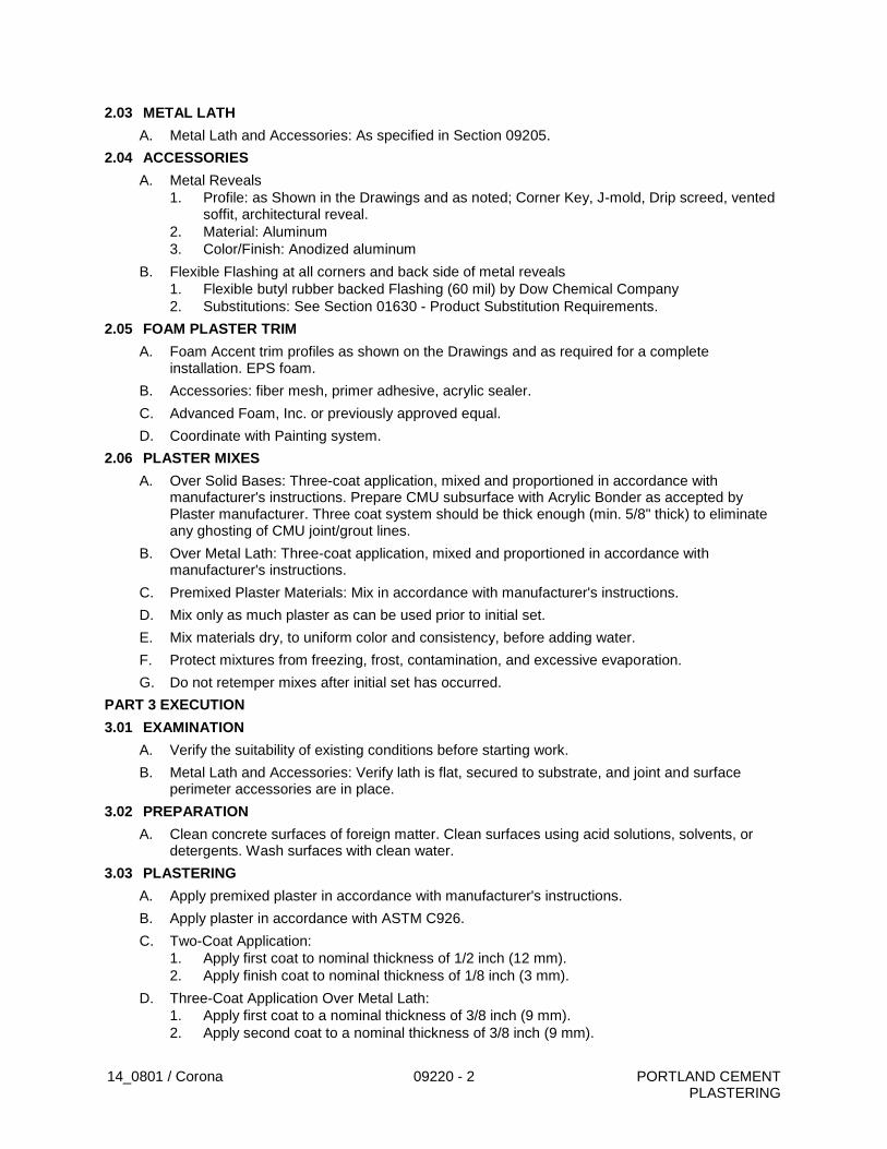
14_0801 / Corona 09220 - 2 PORTLAND CEMENT PLASTERING
2.03 METAL LATH
A. Metal Lath and Accessories: As specified in Section 09205.
2.04 ACCESSORIES
A. Metal Reveals
1. Profile: as Shown in the Drawings and as noted; Corner Key, J-mold, Drip screed, vented soffit, architectural reveal.
2. Material: Aluminum
3. Color/Finish: Anodized aluminum
B. Flexible Flashing at all corners and back side of metal reveals
1. Flexible butyl rubber backed Flashing (60 mil) by Dow Chemical Company
2. Substitutions: See Section 01630 - Product Substitution Requirements.
2.05 FOAM PLASTER TRIM
A. Foam Accent trim profiles as shown on the Drawings and as required for a complete installation. EPS foam.
B. Accessories: fiber mesh, primer adhesive, acrylic sealer.
C. Advanced Foam, Inc. or previously approved equal.
D. Coordinate with Painting system.
2.06 PLASTER MIXES
A. Over Solid Bases: Three-coat application, mixed and proportioned in accordance with manufacturer's instructions. Prepare CMU subsurface with Acrylic Bonder as accepted by Plaster manufacturer. Three coat system should be thick enough (min. 5/8" thick) to eliminate any ghosting of CMU joint/grout lines.
B. Over Metal Lath: Three-coat application, mixed and proportioned in accordance with manufacturer's instructions.
C. Premixed Plaster Materials: Mix in accordance with manufacturer's instructions.
D. Mix only as much plaster as can be used prior to initial set.
E. Mix materials dry, to uniform color and consistency, before adding water.
F. Protect mixtures from freezing, frost, contamination, and excessive evaporation.
G. Do not retemper mixes after initial set has occurred.
PART 3 EXECUTION
3.01 EXAMINATION
A. Verify the suitability of existing conditions before starting work.
B. Metal Lath and Accessories: Verify lath is flat, secured to substrate, and joint and surface perimeter accessories are in place.
3.02 PREPARATION
A. Clean concrete surfaces of foreign matter. Clean surfaces using acid solutions, solvents, or detergents. Wash surfaces with clean water.
3.03 PLASTERING
A. Apply premixed plaster in accordance with manufacturer's instructions.
B. Apply plaster in accordance with ASTM C926.
C. Two-Coat Application:
1. Apply first coat to nominal thickness of 1/2 inch (12 mm).
2. Apply finish coat to nominal thickness of 1/8 inch (3 mm).
D. Three-Coat Application Over Metal Lath:
1. Apply first coat to a nominal thickness of 3/8 inch (9 mm).
2. Apply second coat to a nominal thickness of 3/8 inch (9 mm).
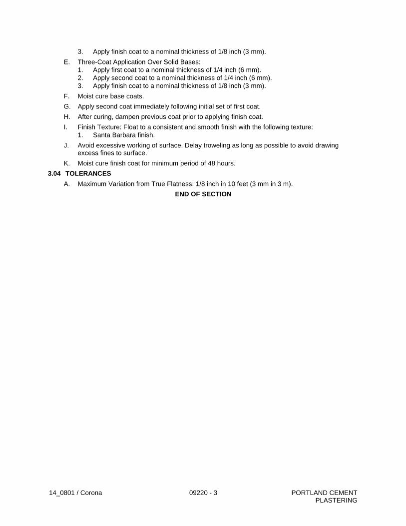
14_0801 / Corona 09220 - 3 PORTLAND CEMENT PLASTERING
3. Apply finish coat to a nominal thickness of 1/8 inch (3 mm).
E. Three-Coat Application Over Solid Bases:
1. Apply first coat to a nominal thickness of 1/4 inch (6 mm).
2. Apply second coat to a nominal thickness of 1/4 inch (6 mm).
3. Apply finish coat to a nominal thickness of 1/8 inch (3 mm).
F. Moist cure base coats.
G. Apply second coat immediately following initial set of first coat.
H. After curing, dampen previous coat prior to applying finish coat.
I. Finish Texture: Float to a consistent and smooth finish with the following texture:
1. Santa Barbara finish.
J. Avoid excessive working of surface. Delay troweling as long as possible to avoid drawing excess fines to surface.
K. Moist cure finish coat for minimum period of 48 hours.
3.04 TOLERANCES
A. Maximum Variation from True Flatness: 1/8 inch in 10 feet (3 mm in 3 m).
END OF SECTION
14_0801 / Corona 09220 - 4 PORTLAND CEMENT PLASTERING
THIS PAGE INTENTIONALLY BLANK
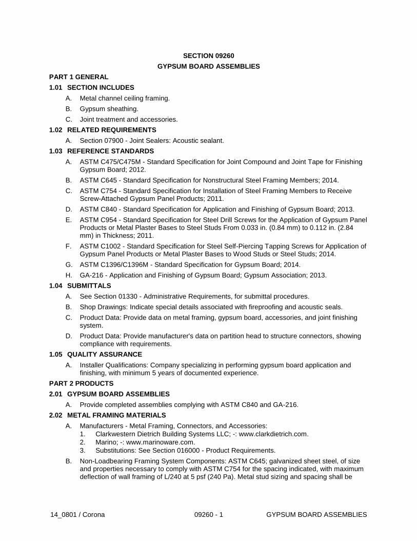
14_0801 / Corona 09260 - 1 GYPSUM BOARD ASSEMBLIES
SECTION 09260
GYPSUM BOARD ASSEMBLIES
PART 1 GENERAL
1.01 SECTION INCLUDES
A. Metal channel ceiling framing.
B. Gypsum sheathing.
C. Joint treatment and accessories.
1.02 RELATED REQUIREMENTS
A. Section 07900 - Joint Sealers: Acoustic sealant.
1.03 REFERENCE STANDARDS
A. ASTM C475/C475M - Standard Specification for Joint Compound and Joint Tape for Finishing Gypsum Board; 2012.
B. ASTM C645 - Standard Specification for Nonstructural Steel Framing Members; 2014.
C. ASTM C754 - Standard Specification for Installation of Steel Framing Members to Receive Screw-Attached Gypsum Panel Products; 2011.
D. ASTM C840 - Standard Specification for Application and Finishing of Gypsum Board; 2013.
E. ASTM C954 - Standard Specification for Steel Drill Screws for the Application of Gypsum Panel Products or Metal Plaster Bases to Steel Studs From 0.033 in. (0.84 mm) to 0.112 in. (2.84 mm) in Thickness; 2011.
F. ASTM C1002 - Standard Specification for Steel Self-Piercing Tapping Screws for Application of Gypsum Panel Products or Metal Plaster Bases to Wood Studs or Steel Studs; 2014.
G. ASTM C1396/C1396M - Standard Specification for Gypsum Board; 2014.
H. GA-216 - Application and Finishing of Gypsum Board; Gypsum Association; 2013.
1.04 SUBMITTALS
A. See Section 01330 - Administrative Requirements, for submittal procedures.
B. Shop Drawings: Indicate special details associated with fireproofing and acoustic seals.
C. Product Data: Provide data on metal framing, gypsum board, accessories, and joint finishing system.
D. Product Data: Provide manufacturer's data on partition head to structure connectors, showing compliance with requirements.
1.05 QUALITY ASSURANCE
A. Installer Qualifications: Company specializing in performing gypsum board application and finishing, with minimum 5 years of documented experience.
PART 2 PRODUCTS
2.01 GYPSUM BOARD ASSEMBLIES
A. Provide completed assemblies complying with ASTM C840 and GA-216.
2.02 METAL FRAMING MATERIALS
A. Manufacturers - Metal Framing, Connectors, and Accessories:
1. Clarkwestern Dietrich Building Systems LLC; -: www.clarkdietrich.com.
2. Marino; -: www.marinoware.com.
3. Substitutions: See Section 016000 - Product Requirements.
B. Non-Loadbearing Framing System Components: ASTM C645; galvanized sheet steel, of size and properties necessary to comply with ASTM C754 for the spacing indicated, with maximum deflection of wall framing of L/240 at 5 psf (240 Pa). Metal stud sizing and spacing shall be
14_0801 / Corona 09260 - 2 GYPSUM BOARD ASSEMBLIES
confirmed in field with criteria listed above. Span requirement shall supersede Drawing sizing and spacing.
1. Ceiling Channels: C-shaped.
C. Ceiling Hangers: Type and size as specified in ASTM C754 for spacing required.
2.03 BOARD MATERIALS
A. Manufacturers - Gypsum-Based Board:
1. American Gypsum Company; -: www.americangypsum.com.
2. CertainTeed Corporation; -: www.certainteed.com.
3. Georgia-Pacific Gypsum; -: www.gpgypsum.com.
4. National Gypsum Company; -: www.nationalgypsum.com.
5. PABCO Gypsum; -: www.pabcogypsum.com.
6. Temple-Inland Building Product by Georgia-Pacific, LLC: www.temple.com.
7. USG Corporation; -: www.usg.com.
8. Substitutions: See Section 016000 - Product Requirements.
B. Ceiling Board: Special sag-resistant gypsum ceiling board as defined in ASTM C1396/C1396M; sizes to minimize joints in place; ends square cut.
1. Application: Ceilings, unless otherwise indicated.
2. Thickness: 5/8 inch (18 mm).
3. Edges: Tapered.
2.04 ACCESSORIES
A. Acoustic Sealant: Non-hardening, non-skinning, for use in conjunction with gypsum board.
B. Joint Materials: ASTM C475 and as recommended by gypsum board manufacturer for project conditions.
1. Tape: 2 inch (50 mm) wide, creased paper tape for joints and corners, except as otherwise indicated.
2. Ready-mixed vinyl-based joint compound.
C. High Build Drywall Surfacer: Vinyl acrylic latex-based coating for spray application, designed to take the place of skim coating and separate paint primer in achieving Level 5 finish.
D. Textured Finish Materials: Latex-based compound; plain.
E. Screws for Attachment to Steel Members Less Than 0.033 inch (0.84 mm) In Thickness, to Wood Members, and to Gypsum Board: ASTM C1002; self-piercing tapping type; cadmium plated for exterior locations.
F. Screws for Attachment to Steel Members From 0.033 to 0.112 inch (0.84 to 2.84 mm) in Thickness: ASTM C954; steel drill screws for application of gypsum board to loadbearing steel studs.
PART 3 EXECUTION
3.01 EXAMINATION
A. Verify that project conditions are appropriate for work of this section to commence.
3.02 FRAMING INSTALLATION
A. Metal Framing: Install in accordance with ASTM C754 and manufacturer's instructions.
B. Suspended Ceilings and Soffits: Space framing and furring members at 24 inches (600 mm) on center. Unless noted otherwise.
1. Level ceiling system to a tolerance of 1/1200.
2. Laterally brace entire suspension system.
C. Openings: Reinforce openings as required for weight of access doors or operable panels, as needed/required.
14_0801 / Corona 09260 - 3 GYPSUM BOARD ASSEMBLIES
3.03 BOARD INSTALLATION
A. Comply with ASTM C 840, GA-216, and manufacturer's instructions. Install to minimize butt end joints, especially in highly visible locations.
B. Single-Layer Non-Rated: Install gypsum board in most economical direction, with ends and edges occurring over firm bearing.
1. Exception: Tapered edges to receive joint treatment at right angles to framing.
C. Installation on Metal Framing: Use screws for attachment of gypsum board except face layer of non-rated double-layer assemblies, which may be installed by means of adhesive lamination.
3.04 INSTALLATION OF TRIM AND ACCESSORIES
A. Control Joints: Place control joints consistent with lines of building spaces and as indicated.
1. Not more than 30 feet (10 meters) apart on walls and ceilings over 50 feet (16 meters) long.
B. Corner Beads: Install at external corners, using longest practical lengths.
C. Edge Trim: Install at locations where gypsum board abuts dissimilar materials (CMU) and as indicated.
3.05 JOINT TREATMENT
A. Paper Faced Gypsum Board: Use paper joint tape, bedded with ready-mixed vinyl-based joint compound and finished with ready-mixed vinyl-based joint compound.
B. Finish gypsum board in accordance with levels defined in ASTM C840, as follows:
1. Level 4: (toilet rooms, lockers, shower rooms): Walls and ceilings to receive paint finish or wall coverings, unless otherwise indicated.
2. Level 5: Typical: Walls and ceilings to receive paint finish of flat to semi-gloss or gloss paint finish and other areas.
3. Level 2: In utility areas, behind cabinetry, and on backing board to receive tile finish.
4. Level 1: Fire rated wall areas above finished ceilings, whether or not accessible in the completed construction.
5. Level 0: Temporary partitions.
C. Tape, fill, and sand exposed joints, edges, and corners to produce smooth surface ready to receive finishes.
1. Feather coats of joint compound so that camber is maximum 1/32 inch (0.8 mm).
D. Where Level 5 finish is indicated, spray apply high build drywall surfacer over entire surface after joints have been properly treated; achieve a flat and tool mark-free finish.
3.06 TEXTURE FINISH
A. Apply finish texture coating by means of spraying apparatus in accordance with manufacturer's instructions and to match approved sample.
B. Typical Texture Required: Smooth flat surface at all locations unless noted otherwise.
3.07 TOLERANCES
A. Maximum Variation of Finished Gypsum Board Surface from True Flatness: 1/8 inch in 10 feet (3 mm in 3 m) in any direction.
END OF SECTION

14_0801 / Corona 09260 - 4 GYPSUM BOARD ASSEMBLIES
THIS PAGE INTENTIONALLY BLANK
09800 - 1 G:\Projects\WATER TREATMENT\Resin_Treatment_of_Nitrate_Sources-CIP_No_68510507\01-Administration\01_h-Contract_Documents\Specifications\Division 2 - 17\Sect 09800 Chemical Resistant Coating for Concrete.doc
SECTION 09800
CHEMICAL RESISTANT COATING FOR CONCRETE
PART 1 - GENERAL
1.1 DESCRIPTION
This section includes materials and installation of a chemical-resistant coating for concrete subject to occasional immersion in strong acid base or other corrosive chemicals. Coat the containment area floor, walls, and top of walls.
1.2 REFERENCES
A. ASTM D 16 - Terminology Relating to Paint, Varnish, Lacquer, and Related Products.
B. ASTM D 4263 - Indicating Moisture in Concrete by the Plastic Sheet Method.
C. ASTM F 1869 - Measuring Moisture Vapor Emission Rate of Concrete Subfloor Using Anhydrous Calcium Chloride.
D. International Concrete Repair Institute (ICRI) Guideline No. 03732 - Selecting and Specifying Concrete Surface Preparation for Sealers, Coatings, and Polymer Overlays.
E. SSPC-SP 1 - Solvent Cleaning.
F. SSPC-SP 2 - Hand Tool Cleaning.
G. SSPC-SP 3 - Power Tool Cleaning.
H. SSPC-SP 5/NACE 1 - White Metal Blast Cleaning.
I. SSPC-SP 6/NACE 3 - Commercial Blast Cleaning.
J. SSPC-SP 10/NACE 2 - Near-White Metal Blast Cleaning.
K. SSPC-SP 13/NACE 6 - Surface Preparation of Concrete.
1.3 DEFINITIONS
A. Definitions of Painting Terms: ASTM D 16, unless otherwise specified.
B. Dry Film Thickness (DFT): Thickness of a coat of paint in fully cured state measured in mils (1/1000 inch).
1.4 SUBMITTALS
A. Comply with Section 01330 - Submittal Procedures.
B. Product Data: Submit manufacturer's product data for each coating, including generic description, complete technical data, surface preparation, and application instructions.
C. Color Samples: Submit manufacturer’s color samples showing full range of standard colors upon Owner’s request.
D. Manufacturer’s Quality Assurance: Submit manufacturer’s certification that coatings comply with specified requirements and are suitable for intended application.
E. Applicator’s Quality Assurance: Submit list of a minimum of 5 completed projects of
09800 - 2 G:\Projects\WATER TREATMENT\Resin_Treatment_of_Nitrate_Sources-CIP_No_68510507\01-Administration\01_h-Contract_Documents\Specifications\Division 2 - 17\Sect 09800 Chemical Resistant Coating for Concrete.doc
similar size and complexity to this Work. Include for each project:
1. Project name and location.
2. Name of owner.
3. Name of contractor.
4. Name of engineer.
5. Name of coating manufacturer.
6. Approximate area of coatings applied.
7. Date of completion.
F. Warranty: Submit manufacturer’s standard warranty.
1.5 QUALITY ASSURANCE
A. Manufacturer’s Qualifications:
1. Specialize in manufacture of coatings with a minimum of 10 years successful experience.
2. Able to demonstrate successful performance on comparable projects.
3. Single Source Responsibility: Coatings and coating application accessories shall be products of a single manufacturer.
B. Applicator’s Qualifications:
1. Experienced in application of specified coatings for a minimum of 5 years on projects of similar size and complexity to this Work.
2. Applicator's Personnel: Employ persons trained for application of specified coatings.
C. Pre-application Meeting: Convene a pre-application meeting 2 weeks before start of application of coating systems. Require attendance of parties directly affecting work of this section, including Contractor, Engineer, applicator, and manufacturer’s representative. Review the following:
1. Environmental requirements.
2. Protection of surfaces not scheduled to be coated.
3. Surface preparation.
4. Application.
5. Disinfection.
6. Repair.
7. Field quality control.
8. Cleaning.
9. Protection of coating systems.
10. One-year inspection.
11. Coordination with other work.
09800 - 3 G:\Projects\WATER TREATMENT\Resin_Treatment_of_Nitrate_Sources-CIP_No_68510507\01-Administration\01_h-Contract_Documents\Specifications\Division 2 - 17\Sect 09800 Chemical Resistant Coating for Concrete.doc
1.6 DELIVERY, STORAGE, AND HANDLING
A. Delivery: Deliver materials to site in manufacturer's original, unopened containers and packaging, with labels clearly identifying:
1. Coating or material name.
2. Manufacturer.
3. Color name and number.
4. Batch or lot number.
5. Date of manufacture.
6. Mixing and thinning instructions.
B. Storage:
1. Store materials in a clean dry area and within temperature range in accordance with manufacturer's instructions.
2. Keep containers sealed until ready for use.
3. Do not use materials beyond manufacturer’s shelf life limits.
C. Handling: Protect materials during handling and application to prevent damage or contamination.
1.7 ENVIRONMENTAL REQUIREMENTS
A. Weather:
1. Air and Surface Temperatures: Prepare surfaces and apply and cure coatings within air and surface temperature range in accordance with manufacturer’s instructions.
2. Surface Temperature: Minimum of 37 degrees F (3 degrees C) above dew point.
3. Relative Humidity: Prepare surfaces and apply and cure coatings within relative humidity range in accordance with manufacturer’s instructions.
4. Precipitation: Do not prepare surfaces or apply coatings in rain, fog, or mist.
5. Wind: Do not spray coatings if wind velocity is above manufacturer’s limit.
B. Dust and Contaminants:
1. Schedule coating work to avoid excessive dust and airborne contaminants.
2. Protect work areas from excessive dust and airborne contaminants during coating application and curing.
PART 2 - PRODUCTS
2.1 MANUFACTURER
A. Belzona California Inc., 2201 E. Winston Rd., Ste. F, Anaheim, CA 92806 Phone (800) 367-8635 Contact Name Dean Popish E-mail: [email protected]
09800 - 4 G:\Projects\WATER TREATMENT\Resin_Treatment_of_Nitrate_Sources-CIP_No_68510507\01-Administration\01_h-Contract_Documents\Specifications\Division 2 - 17\Sect 09800 Chemical Resistant Coating for Concrete.doc
2.2 COATING SYSTEMS FOR SECONDARY CONTAINMENT
A. System Type: Epoxy
1. Surface Preparation: SSPC-SP 13/NACE 6. ICRI CSP 3
2. Primer: Belzona 4311, DFT 10 mils.
3. Finish Coat: Belzona 4311, DFT 10 mils.
4. Finish Color: Gray
2.3 ACCESSORIES
A. Coating Application Accessories:
1. Accessories required for application of specified coatings in accordance with manufacturer’s instructions, including thinners.
2. Products of coating manufacturer.
PART 3 - EXECUTION
3.1 EXAMINATION
A. Examine areas and conditions under which coating systems are to be applied. Notify Engineer of areas or conditions not acceptable. Do not begin surface preparation or application until unacceptable areas or conditions have been corrected.
3.2 PROTECTION OF SURFACES NOT SCHEDULED TO BE COATED
A. Protect surrounding areas and surfaces not scheduled to be coated from damage during surface preparation and application of coatings.
B. Immediately remove coatings that fall on surrounding areas and surfaces not scheduled to be coated.
3.3 SURFACE PREPARATION OF SECONDARY CONTAINMENT
A. Prepare concrete surfaces in accordance with manufacturer’s instructions, SSPC-SP 13/NACE 6, and ICRI 03732; CSP 3.
B. Ensure surfaces are clean, dry, and free of oil, grease, dirt, dust, and other contaminants.
C. Allow concrete to cure for a minimum of 28 days before coating.
D. Test concrete for moisture in accordance with ASTM D 4263 and F 1869.
3.4 APPLICATION
A. Apply coatings in accordance with manufacturer's instructions.
B. Mix and thin coatings, including multi-component materials, in accordance with manufacturer’s instructions.
C. Keep containers closed when not in use to avoid contamination.
D. Do not use mixed coatings beyond pot life limits.
E. Use application equipment, tools, pressure settings, and techniques in accordance with manufacturer’s instructions.
09800 - 5 G:\Projects\WATER TREATMENT\Resin_Treatment_of_Nitrate_Sources-CIP_No_68510507\01-Administration\01_h-Contract_Documents\Specifications\Division 2 - 17\Sect 09800 Chemical Resistant Coating for Concrete.doc
F. Uniformly apply coatings at spreading rate required to achieve specified DFT.
G. Apply coatings to be free of film characteristics or defects that would adversely affect performance or appearance of coating systems.
3.5 REPAIR
A. Materials and Surfaces Not Scheduled to be Coated: Repair or replace damaged materials and surfaces not scheduled to be coated.
B. Damaged Coatings: Touch-up or repair damaged coatings. Touch-up of minor damage shall be acceptable where result is not visibly different from adjacent surfaces. Recoat entire surface where touch-up result is visibly different, either in sheen, texture, or color.
C. Coating Defects: Repair in accordance with manufacturer’s instructions coatings that exhibit film characteristics or defects that would adversely affect performance or appearance of coating systems.
3.6 FIELD QUALITY CONTROL
A. Inspector’s Services:
1. Verify coatings and other materials are as specified.
2. Verify surface preparation and application are as specified.
3. Verify DFT of each coat and total DFT of each coating system are as specified using wet film and dry film gauges.
4. Coating Defects: Check coatings for film characteristics or defects that would adversely affect performance or appearance of coating systems.
5. Report:
a. Submit written reports describing inspections made and actions taken to correct nonconforming work.
b. Report nonconforming work not corrected.
c. Submit copies of report to Engineer and Contractor.
B. Manufacturer’s Field Services: Manufacturer’s representative shall provide technical assistance and guidance for surface preparation and application of coating systems.
3.7 CLEANING
A. Remove temporary coverings and protection of surrounding areas and surfaces.
3.8 PROTECTION OF COATING SYSTEMS
A. Protect surfaces of coating systems from damage during construction.
***END OF SECTION***
09800 - 6 G:\Projects\WATER TREATMENT\Resin_Treatment_of_Nitrate_Sources-CIP_No_68510507\01-Administration\01_h-Contract_Documents\Specifications\Division 2 - 17\Sect 09800 Chemical Resistant Coating for Concrete.doc
THIS PAGE INTENTIONALLY BLANK
09900-1
G:\Projects\WATER TREATMENT\Resin_Treatment_of_Nitrate_Sources-CIP_No_68510507\01-Administration\01_h-Contract_Documents\Specifications\Division 2 - 17\Sect 09900 Painting.doc
SECTION 09900
PAINTING AND COATING
PART 1 - GENERAL 1.1 DESCRIPTION A. The work of this section includes providing all labor, materials, tools and equipment and
performing all tasks required to provide complete painting of the required surfaces as described herein.
B. Also included is the work of furnishing and installing pipe identification and flow arrow
markers on all pipelines. C. All exposed equipment (pumps and motors), piping (including PVC Piping and fittings),
fittings and valves shall be painted or coated.
1.2 WORK NOT INCLUDED
Painting will not be required of the following surfaces unless specifically shown otherwise or described herein:
A. Aluminum products B. Concrete and masonry
C. Plastics including FRP, polypropylene, etc. D. Stainless steel
E. Galvanized steel F. Factory painted Electric Control Panels, Motor Control Centers, etc.
1.3 SUBMITTALS
A. Contractor shall submit manufacturer's product literature and standard color cards and certification of materials for approval by the Owner prior to commencing work on the site. Product literature or certifications shall include descriptions of suitability of each proposed product for its intended use including any approvals required by applicable regulatory agencies relative to contact with recycled water and environmental regulations.
B. The Contractor shall provide at the site a set of commercially prepared metal blast
cleaning samples for use in comparing field results with standard SSPC surface preparation numbers as listed in Part 3.4 of this Section if requested by the Owner.
C. The Contractor shall obtain from the manufacturer, and submit to the Owner for approval
materials and instructions for the touch-up of all shop applied coatings of items of work provided under other sections of these specifications.
09900-2
G:\Projects\WATER TREATMENT\Resin_Treatment_of_Nitrate_Sources-CIP_No_68510507\01-Administration\01_h-Contract_Documents\Specifications\Division 2 - 17\Sect 09900 Painting.doc
1.4 REFERENCE STANDARDS A. SSPC Steel Structures Painting Council
B. ANSI American National Standards Institute C. ASA American Standards Association
D. OSHA General Industry Safety Orders issued by the State Division of Industrial Safety
1.5 DELIVERY STORAGE AND HANDLING A. Deliver all materials in manufacturer's original unbroken containers, package or
wrappings, bearing the manufacturer's brand and name and a description of the contents.
B. Do not bring to the work or site any paint container bearing the label of any material that
has not been approved by the Owner. C. Keep the space used for storage of equipment and material in a clean and orderly
condition. Keep all waste and paint rags in metal containers, tightly covered and safely dispose of them at the end of each working day. Take precaution to avoid fire. Provide an approved type of fire extinguisher immediately outside each paint storage area.
1.6 REGULATORY REQUIREMENTS
All paint products, solvents, application methods and disposal of waste shall conform to all applicable air quality, OSHA and hazardous waste regulations, and where required with FDA and National Sanitation Foundation (NSF), NSF 61; regulations for contact with potable water. Products shall also be labeled with original manufacturer’s label.
1.7 SITE CONDITIONS
A. Do not apply paints during inclement weather (including winds) or if surfaces are not dry, or if they cannot be protected from inclement weather after application until the paint is dry.
B. Provide adequate illumination in enclosed areas.
C. Provide adequate ventilation in enclosed areas.
D. Maintain interior temperature of rooms at 70oF or higher where varnish, lacquer or enamel are being applied and at 50oF or higher during other painting and finishing. Do exterior painting only when air temperature is 40oF or higher and only during dry weather.
1.8 COORDINATION A. All items of work of other sections of these specifications that normally come completely
coated from the manufacturer or the shop, shall be reviewed with the Owner, prior to order and delivery, for acceptance of the coating system proposed.
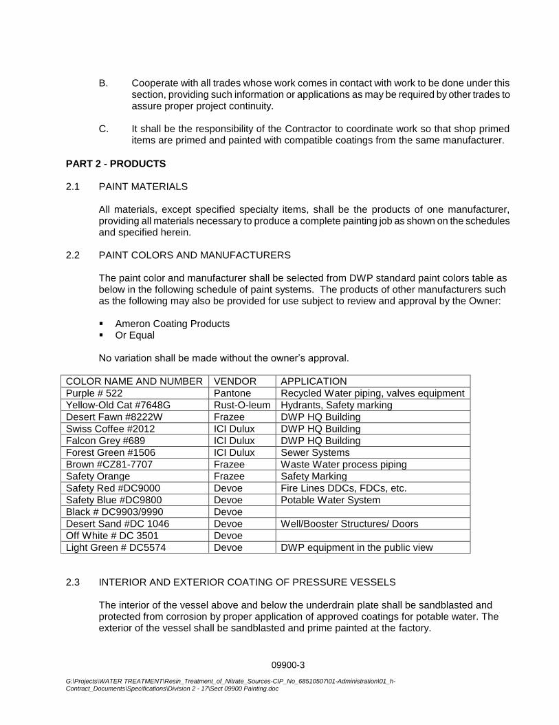
09900-3
G:\Projects\WATER TREATMENT\Resin_Treatment_of_Nitrate_Sources-CIP_No_68510507\01-Administration\01_h-Contract_Documents\Specifications\Division 2 - 17\Sect 09900 Painting.doc
B. Cooperate with all trades whose work comes in contact with work to be done under this
section, providing such information or applications as may be required by other trades to assure proper project continuity.
C. It shall be the responsibility of the Contractor to coordinate work so that shop primed
items are primed and painted with compatible coatings from the same manufacturer.
PART 2 - PRODUCTS 2.1 PAINT MATERIALS
All materials, except specified specialty items, shall be the products of one manufacturer, providing all materials necessary to produce a complete painting job as shown on the schedules and specified herein.
2.2 PAINT COLORS AND MANUFACTURERS
The paint color and manufacturer shall be selected from DWP standard paint colors table as below in the following schedule of paint systems. The products of other manufacturers such as the following may also be provided for use subject to review and approval by the Owner:
Ameron Coating Products Or Equal
No variation shall be made without the owner’s approval.
COLOR NAME AND NUMBER VENDOR APPLICATION
Purple # 522 Pantone Recycled Water piping, valves equipment
Yellow-Old Cat #7648G Rust-O-leum Hydrants, Safety marking
Desert Fawn #8222W Frazee DWP HQ Building
Swiss Coffee #2012 ICI Dulux DWP HQ Building
Falcon Grey #689 ICI Dulux DWP HQ Building
Forest Green #1506 ICI Dulux Sewer Systems
Brown #CZ81-7707 Frazee Waste Water process piping
Safety Orange Frazee Safety Marking
Safety Red #DC9000 Devoe Fire Lines DDCs, FDCs, etc.
Safety Blue #DC9800 Devoe Potable Water System
Black # DC9903/9990 Devoe
Desert Sand #DC 1046 Devoe Well/Booster Structures/ Doors
Off White # DC 3501 Devoe
Light Green # DC5574 Devoe DWP equipment in the public view
2.3 INTERIOR AND EXTERIOR COATING OF PRESSURE VESSELS
The interior of the vessel above and below the underdrain plate shall be sandblasted and protected from corrosion by proper application of approved coatings for potable water. The
exterior of the vessel shall be sandblasted and prime painted at the factory.
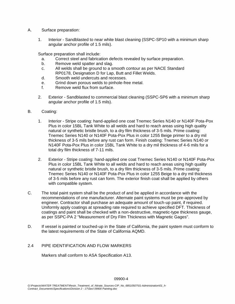
09900-4
G:\Projects\WATER TREATMENT\Resin_Treatment_of_Nitrate_Sources-CIP_No_68510507\01-Administration\01_h-Contract_Documents\Specifications\Division 2 - 17\Sect 09900 Painting.doc
A. Surface preparation:
1. Interior - Sandblasted to near white blast cleaning (SSPC-SP10 with a minimum sharp angular anchor profile of 1.5 mils).
Surface preparation shall include:
a. Correct steel and fabrication defects revealed by surface preparation. b. Remove weld spatter and slag. c. All welds shall be ground to a smooth contour as per NACE Standard
RP0178, Designation D for Lap, Butt and Fillet Welds. d. Smooth weld undercuts and recesses. e. Grind down porous welds to pinhole-free metal. f. Remove weld flux from surface.
2. Exterior - Sandblasted to commercial blast cleaning (SSPC-SP6 with a minimum sharp
angular anchor profile of 1.5 mils).
B. Coating:
1. Interior - Stripe coating: hand-applied one coat Tnemec Series N140 or N140F Pota-Pox Plus in color 15BL Tank White to all welds and hard to reach areas using high quality natural or synthetic bristle brush, to a dry film thickness of 3-5 mils. Prime coating: Tnemec Series N140 or N140F Pota-Pox Plus in color 1255 Beige primer to a dry mil thickness of 3-5 mils before any rust can form. Finish coating: Tnemec Series N140 or N140F Pota-Pox Plus in color 15BL Tank White to a dry mil thickness of 4-6 mils for a total dry film thickness of 7-11 mils.
2. Exterior - Stripe coating: hand-applied one coat Tnemec Series N140 or N140F Pota-Pox
Plus in color 15BL Tank White to all welds and hard to reach areas using high quality natural or synthetic bristle brush, to a dry film thickness of 3-5 mils. Prime coating: Tnemec Series N140 or N140F Pota-Pox Plus in color 1255 Beige to a dry mil thickness of 3-5 mils before any rust can form. The exterior finish coat shall be applied by others with compatible system.
C. The total paint system shall be the product of and be applied in accordance with the recommendations of one manufacturer. Alternate paint systems must be pre-approved by engineer. Contractor shall purchase an adequate amount of touch-up paint, if required. Uniformly apply coatings at spreading rate required to achieve specified DFT. Thickness of coatings and paint shall be checked with a non-destructive, magnetic-type thickness gauge, as per SSPC-PA 2 "Measurement of Dry Film Thickness with Magnetic Gages".
D. If vessel is painted or touched-up in the State of California, the paint system must conform to the latest requirements of the State of California AQMD.
2.4 PIPE IDENTIFICATION AND FLOW MARKERS
Markers shall conform to ASA Specification A13.
09900-5
G:\Projects\WATER TREATMENT\Resin_Treatment_of_Nitrate_Sources-CIP_No_68510507\01-Administration\01_h-Contract_Documents\Specifications\Division 2 - 17\Sect 09900 Painting.doc
PART 3 - EXECUTION 3.1 GENERAL A. It is intended that all ferrous metal items shall be shop primed and field finish coated
unless otherwise noted.
B. Surfaces of equipment items including pumps, motors, blowers, drives, etc., which have a factory finish coating shall be given a minimum of one (1) field coat of the required type and color after installation.
C. Prime coats and surface preparation specified herein will not be required on items
delivered with prime or shop coats already applied and still in a condition satisfactory to the Owner and whose prime coating is compatible with the finish coating.
D. All exposed metal piping shall be color painted as selected by the Owner.
E. Paint all exposed exterior and interior woodwork and architectural metalwork such as
doors and frames, louvers, flashing and sheet metal and gutters and downspouts.
F. Exterior surfaces which may be hidden from view by other items of work but still exposed to the elements shall be painted prior to installing the concealing items of work.
3.2 EXAMINATION A. Examine all surfaces scheduled or specified to be finished under this Section, and if any
defects or discrepancies are discovered, notify the Owner in writing of the specific conditions. Verify that all such defects have been corrected prior to beginning work.
B. Test surfaces for moisture before beginning application with approved moisture meter.
No surface shall exceed 13 percent in moisture content.
3.3 SURFACE PREPARATION - METAL SURFACES
A. Clean all painted metal surfaces of all dust, grease, rust and scale, using benzene, steel wool and wire brushes. Clean damaged areas of factory applied priming coats and repaint with metal primer.
B. Metal surfaces of unprimed material, equipment and items where corrosion is apparent,
shall be blast cleaned before being primed or reprimed.
C. All welds on exposed structural members, and any weld of unacceptable workmanship, must be ground smooth and all grindings and other residue resulting from this operation removed completely from all surfaces. Remaining welds shall be thoroughly chipped, brushed and cleaned using power tools with coarse grade sanding discs and field primed.
D. All cleaned unpainted metal shall be prime coated, as specified, immediately after
cleaning to prevent new rusting or oxidation of cleaned surfaces.
09900-6
G:\Projects\WATER TREATMENT\Resin_Treatment_of_Nitrate_Sources-CIP_No_68510507\01-Administration\01_h-Contract_Documents\Specifications\Division 2 - 17\Sect 09900 Painting.doc
E. All equipment shop primed shall be cleaned of grease, oil and other contaminants prior to field top coating.
F. All steel surfaces shall be prepared as designated by the Steel Structures Painting
Council surface preparation number (SSPC-SP No.) in the "Coating Systems" of this Specification and as outlined below. 1. SSPC-SP1 Solvent Cleaning
Remove all dirt, oil, grease and foreign matter with solvents or commercial cleaners using various methods of cleaning such as wiping, dipping, steam cleaning or vapor degreasing.
Oil and grease removal by solvent cleaning is included in all other SSPC Surface Preparation Specifications. SSPC-SP1 will not be cited separately for the other specifications.
2. SSPC-SP2 Hand Tool Cleaning
Remove all loose rust and mill scale by hand wire brushing, scraping, chipping or sanding.
3. SSPC-SP3 Power Tool Cleaning
Remove all loose rust and mill scale by mechanical means such as power sanders, wire brushes, chipping, hammers, abrasive grinding wheels or needle guns.
4. SSPC-SP5 White Metal Blast Cleaning
Remove all visible rust, mill scale, paint and foreign matter by compressed air nozzle blasting, centrifugal wheels or other specified methods, leaving an overall, uniform gray-white-metallic appearance.
5. SSPC-SP6 Commercial Blast Cleaning
Remove at least two-thirds of all visible rust, mill scale, paint and other foreign matter from each square inch of surface by compressed air nozzle blasting, centrifugal wheels or other specified methods.
6. SSPC-SP7 Brush-Off Blast Cleaning
Remove all loose rust, mill scale, paint and foreign matter from the surface by compressed air nozzle blasting, centrifugal wheels or other specified methods.
7. SSPC-SP8 Pickling Remove all rust, mill scale and foreign matter by chemical reaction or electrolysis in acid solutions to a degree of cleanliness similar to SP5, White Metal Blast Cleaning.
8. SSPC-SP10 Near-White Metal Blast Cleaning
09900-7
G:\Projects\WATER TREATMENT\Resin_Treatment_of_Nitrate_Sources-CIP_No_68510507\01-Administration\01_h-Contract_Documents\Specifications\Division 2 - 17\Sect 09900 Painting.doc
Remove approximately 95 percent of all visible rust, mill scale, paint and other foreign material from each square inch of surface by compressed air nozzle blasting, centrifugal wheels or other specified methods.
3.5 APPLICATION
A. Use all material in accordance with the directions of the manufacturer, subject to the approval of the Owner. Use of thinners at any time must have the approval of the Owner. All coatings shall be applied in accordance with the most recent written application instructions from the manufacturer, by conventional or airless spray wherever possible. The application shall leave no sags, brush marks or other defects.
B. Employ only experienced and competent mechanics. Assume all responsibility for the
work, and repair all damage to the painting work by whomsoever caused.
C. Mix only in a designated space at the site. Provide galvanized steel pans in which all mixing pails or barrels shall be kept. No mixing will be permitted outside the pans.
D. Allow exterior paints and finishes to dry at least 48 hours between coats. Allow interior
paints to dry at least 24 hours between coats. Allow enamels, lacquers and varnishes to dry at least 48 hours between coats. Sand lightly between coats with No. 00 sandpaper and dust well before succeeding coat is applied. Allow additional drying time if conditions warrant, to assure that all coats are perfectly dry before applying succeeding coats.
E. Cleaning and painting shall be scheduled so that dust and other contaminants from the
cleaning process will not fall on wet, newly painted surfaces.
F. All painting shall conform to the following general conditions:
1. The dry film thickness of each coat and of the entire system shall follow the manufacturer's recommendations. Number of coats specified shall be a minimum to achieve the film thickness.
1. Coverage rates are theoretical as calculated by the coating manufacturer and
are, therefore, the maximum allowable. 3. All equipment shall be maintained in good working order and shall be
comparable to that described in the manufacturer's most recent Application Instructions. Equipment shall be thoroughly cleaned and inspected daily. Worn spray nozzles, tips, etc. shall be replaced regularly. Effective oil and water separators shall be used and serviced on all airlines.
4. Except where otherwise specified, thinning shall be done only if necessary for
the workability of the coating material and then only in accordance with the manufacturer's most recent printed application instructions.

09900-8
G:\Projects\WATER TREATMENT\Resin_Treatment_of_Nitrate_Sources-CIP_No_68510507\01-Administration\01_h-Contract_Documents\Specifications\Division 2 - 17\Sect 09900 Painting.doc
3.6 COLORS A. Undercoats
Primer and undercoat shall be of approximate shade of final coat, but each shall be of slightly different tint.
B. OSHA
OSHA safety colors in accordance with ANSI Z53.1 shall be used for marking physical hazards and safety equipment and locations. The following OSHA Safety Color Usage Guide will be used in determining the coating color and type of marking required.
1. SAFETY RED - Fire, Danger, Emergency
a. Fire protection equipment, fire hose boxes, extinguishers, sprinkler
piping.
b. Exit signs.
c. Portable containers of flammable liquids (identified by striping or lettering in yellow against red background).
d. Portable containers of flammable liquids (identified by striping or lettering
in yellow against red background).
e. Emergency stop buttons, bars or switches. f. All metallic non-vinyl coated valve handles.
2. SAFETY ORANGE
a. Gear box housings.
b. Exposed edges of pulleys, gears, etc.
d. Safety starting buttons.
3. SAFETY YELLOW - Physical Hazard Caution (Generally used with Black in checks or stripes). a. Unguarded edges of platforms.
b. Elevator door edges.
c. Pulley blocks.
d. Material handling equipment. 4. SAFETY GREEN - Safety Equipment and Locations
09900-9
G:\Projects\WATER TREATMENT\Resin_Treatment_of_Nitrate_Sources-CIP_No_68510507\01-Administration\01_h-Contract_Documents\Specifications\Division 2 - 17\Sect 09900 Painting.doc
a. First aid kits, stretchers, safety showers, signs and dispensaries. b. Drinking water stations.
5. SAFETY BLUE - Equipment under Repair Caution
Flags, barriers or signs located at control valves or power switches of equipment being repaired.
6. BLACK AND WHITE - Traffic and Housekeeping Areas (May be used either
alone or in check or stripe combinations).
a. Aisle ways and directional signs. b. Floor areas around safety equipment. c. Location of refuse areas. d. Drinking water and food dispensing equipment.
7. SAFETY PURPLE - All Recycle piping, valves, fittings, pumps, motors, etc. and all Radiation Hazards storage areas, containers or equipment.
3.7 FINISH A. Finished surfaces shall be uniform in finish and color and free of brush marks, sagging,
crazing and other imperfections. B. Edges of paint or finish adjoining other materials or colors shall be sharp and clean
without overlapping. C. Finish shall match adjacent work, all returns, edges and recesses which will be exposed
in the finished work and which will be seen from any angle. Finish with flat gray-black paint all surfaces situated behind grilles or any other form of construction which will permit the surface to be seen from any angle, including interior duct surfaces.
3.8 PROTECTION AND CLEANUP A. The Contractor shall be responsible for the cleanliness of his operations, using covers
and masking tape to protect the work wherever such covering is necessary, or if so requested by the Owner. Any paint spoiling unpainted surfaces or surfaces painted a different color shall be carefully removed without damage to any finished paint. If damage does occur, the entire surface adjacent to and including the damaged area shall be repainted without visible lap marks and without additional cost to the Owner.
B. All work not to be coated or previously coated shall be carefully protected during the
coating of adjacent work.
C. Name and data plates on equipment shall not be painted and shall be left clean and legible upon completion of the project.
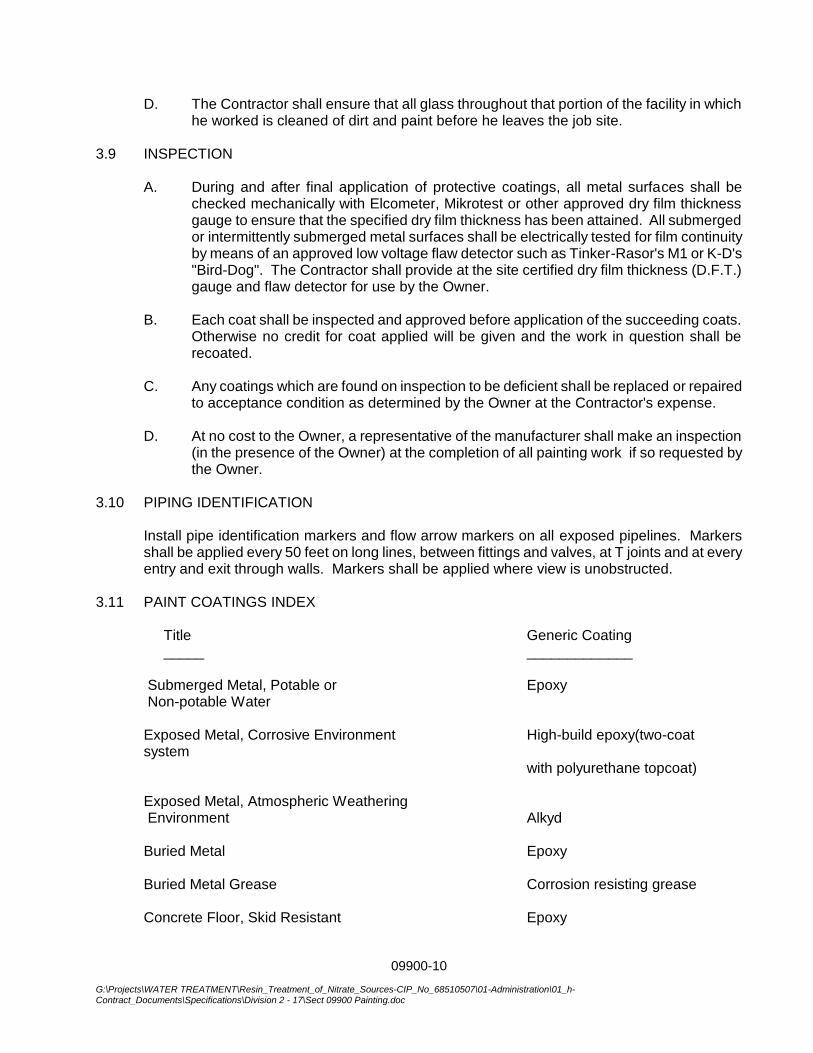
09900-10
G:\Projects\WATER TREATMENT\Resin_Treatment_of_Nitrate_Sources-CIP_No_68510507\01-Administration\01_h-Contract_Documents\Specifications\Division 2 - 17\Sect 09900 Painting.doc
D. The Contractor shall ensure that all glass throughout that portion of the facility in which he worked is cleaned of dirt and paint before he leaves the job site.
3.9 INSPECTION A. During and after final application of protective coatings, all metal surfaces shall be
checked mechanically with Elcometer, Mikrotest or other approved dry film thickness gauge to ensure that the specified dry film thickness has been attained. All submerged or intermittently submerged metal surfaces shall be electrically tested for film continuity by means of an approved low voltage flaw detector such as Tinker-Rasor's M1 or K-D's "Bird-Dog". The Contractor shall provide at the site certified dry film thickness (D.F.T.) gauge and flaw detector for use by the Owner.
B. Each coat shall be inspected and approved before application of the succeeding coats.
Otherwise no credit for coat applied will be given and the work in question shall be recoated.
C. Any coatings which are found on inspection to be deficient shall be replaced or repaired
to acceptance condition as determined by the Owner at the Contractor's expense. D. At no cost to the Owner, a representative of the manufacturer shall make an inspection
(in the presence of the Owner) at the completion of all painting work if so requested by the Owner.
3.10 PIPING IDENTIFICATION
Install pipe identification markers and flow arrow markers on all exposed pipelines. Markers shall be applied every 50 feet on long lines, between fittings and valves, at T joints and at every entry and exit through walls. Markers shall be applied where view is unobstructed.
3.11 PAINT COATINGS INDEX Title Generic Coating _____ _____________ Submerged Metal, Potable or Epoxy Non-potable Water Exposed Metal, Corrosive Environment High-build epoxy(two-coat
system with polyurethane topcoat) Exposed Metal, Atmospheric Weathering Environment Alkyd Buried Metal Epoxy Buried Metal Grease Corrosion resisting grease Concrete Floor, Skid Resistant Epoxy
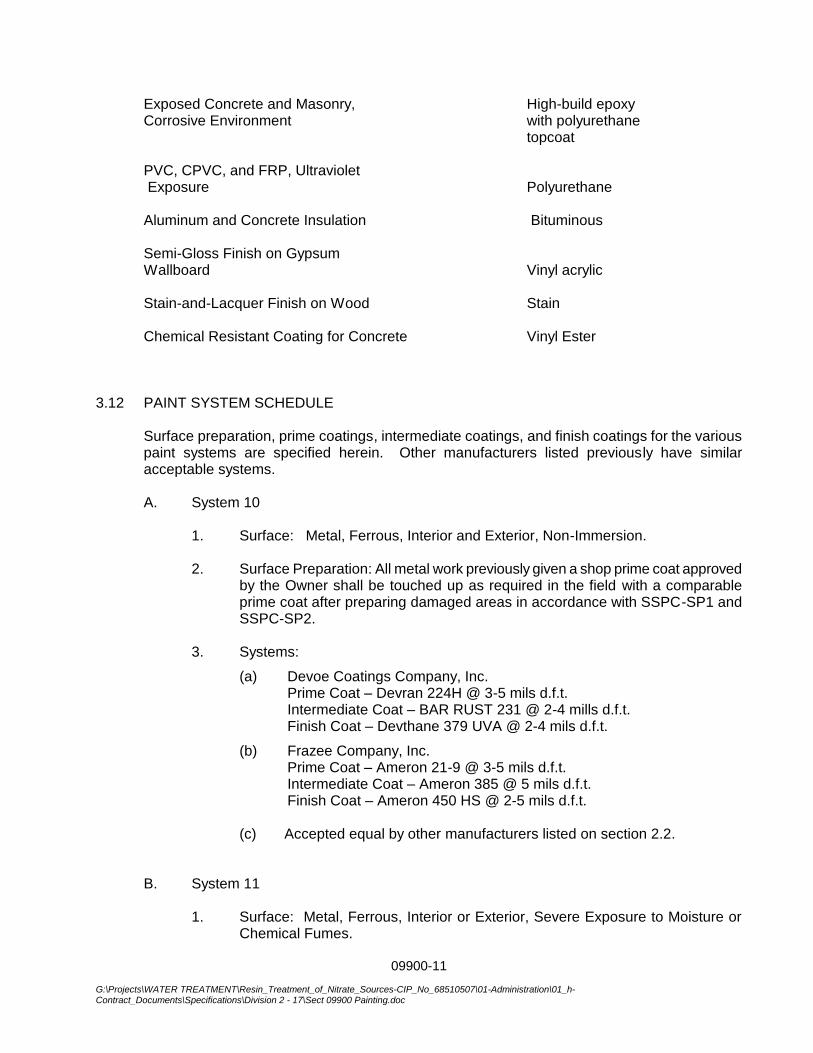
09900-11
G:\Projects\WATER TREATMENT\Resin_Treatment_of_Nitrate_Sources-CIP_No_68510507\01-Administration\01_h-Contract_Documents\Specifications\Division 2 - 17\Sect 09900 Painting.doc
Exposed Concrete and Masonry, High-build epoxy Corrosive Environment with polyurethane topcoat PVC, CPVC, and FRP, Ultraviolet Exposure Polyurethane Aluminum and Concrete Insulation Bituminous Semi-Gloss Finish on Gypsum Wallboard Vinyl acrylic Stain-and-Lacquer Finish on Wood Stain Chemical Resistant Coating for Concrete Vinyl Ester 3.12 PAINT SYSTEM SCHEDULE
Surface preparation, prime coatings, intermediate coatings, and finish coatings for the various paint systems are specified herein. Other manufacturers listed previously have similar acceptable systems.
A. System 10
1. Surface: Metal, Ferrous, Interior and Exterior, Non-Immersion.
2. Surface Preparation: All metal work previously given a shop prime coat approved
by the Owner shall be touched up as required in the field with a comparable prime coat after preparing damaged areas in accordance with SSPC-SP1 and SSPC-SP2.
3. Systems:
(a) Devoe Coatings Company, Inc. Prime Coat – Devran 224H @ 3-5 mils d.f.t. Intermediate Coat – BAR RUST 231 @ 2-4 mills d.f.t. Finish Coat – Devthane 379 UVA @ 2-4 mils d.f.t.
(b) Frazee Company, Inc. Prime Coat – Ameron 21-9 @ 3-5 mils d.f.t. Intermediate Coat – Ameron 385 @ 5 mils d.f.t. Finish Coat – Ameron 450 HS @ 2-5 mils d.f.t.
(c) Accepted equal by other manufacturers listed on section 2.2.
B. System 11
1. Surface: Metal, Ferrous, Interior or Exterior, Severe Exposure to Moisture or Chemical Fumes.

09900-12
G:\Projects\WATER TREATMENT\Resin_Treatment_of_Nitrate_Sources-CIP_No_68510507\01-Administration\01_h-Contract_Documents\Specifications\Division 2 - 17\Sect 09900 Painting.doc
2. Surface Preparation: All metal work previously given a shop prime coat approved
by the Owner shall be touched up as required in the field with a comparable prime coat after preparing damaged areas in accordance with SSPC-SP1 and SSPC-SP2.
All unprimed metal shall be prepared in accordance with SSPC-SP10. 3. Systems:
(a) Devoe Coatings Company, Inc.
Prime Coat – Devran 224H @ 3-4 mils d.f.t. Intermediate Coat – BAR RUST 231 @ 2-4 mills d.f.t. Finish Coat – Devthane 379 UVA@ 2-4 mils d.f.t.
(b) Accepted equal by other manufacturers listed on section 2.2. C. System 12
1. Surface: Metal, Immersion, Potable Liquids
2. Surface Preparation: All metal work previously given a shop prime coat approved by the Owner shall be touched up as required in the field with a comparable prime coat after preparing damaged areas in accordance with SSPC-SP1 and SSPC-SP2. All unprimed metal shall be prepared in accordance with SSPC-SP10.
3. Systems:
(a) Devoe Coatings Company, Inc.
Prime Coat – Bar Rust 233H (NSF) @ 3-5 mils d.f.t. Intermediate Coat – Bar Rust 233H (NSF) @ 4-6 mils d.f.t. Finish Coat – Bar Rust 233H (NSF) @ 4-6 mils d.f.t.
(b) Accepted equal by other manufacturers listed on section 2.2.
Selected system shall have a minimum 11 mils d.f.t. Final Total Coat Thickness
D. System 13
1. Surface: Metal, Immersion, Non-Potable Liquids
2. Surface Preparation: All metal work previously given a shop prime coat approved by the Owner shall be touched up as required in the field with a comparable prime coat after preparing damaged areas in accordance with SSPC-SP1 and SSPC-SP2. All unprimed metal shall be prepared in accordance with SSPC-SP10.
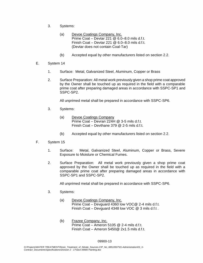
09900-13
G:\Projects\WATER TREATMENT\Resin_Treatment_of_Nitrate_Sources-CIP_No_68510507\01-Administration\01_h-Contract_Documents\Specifications\Division 2 - 17\Sect 09900 Painting.doc
3. Systems:
(a) Devoe Coatings Company, Inc. Prime Coat – Devtar 221 @ 6.0–8.0 mils d.f.t. Finish Coat – Devtar 221 @ 6.0–8.0 mils d.f.t. (Devtar does not contain Coal-Tar)
(b) Accepted equal by other manufacturers listed on section 2.2.
E. System 14
1. Surface: Metal, Galvanized Steel, Aluminum, Copper or Brass
2. Surface Preparation: All metal work previously given a shop prime coat approved by the Owner shall be touched up as required in the field with a comparable prime coat after preparing damaged areas in accordance with SSPC-SP1 and SSPC-SP2.
All unprimed metal shall be prepared in accordance with SSPC-SP6.
3. Systems:
(a) Devoe Coatings Company
Prime Coat – Devran 224H @ 3-5 mils d.f.t. Finish Coat – Devthane 379 @ 2-5 mils d.f.t.
(b) Accepted equal by other manufacturers listed on section 2.2.
F. System 15
1. Surface: Metal, Galvanized Steel, Aluminum, Copper or Brass, Severe Exposure to Moisture or Chemical Fumes.
2. Surface Preparation: All metal work previously given a shop prime coat
approved by the Owner shall be touched up as required in the field with a comparable prime coat after preparing damaged areas in accordance with SSPC-SP1 and SSPC-SP2.
All unprimed metal shall be prepared in accordance with SSPC-SP6.
3. Systems:
(a) Devoe Coatings Company, Inc. Prime Coat – Devguard 4360 low VOC@ 2-4 mils d.f.t. Finish Coat – Devguard 4348 low VOC @ 3 mils d.f.t .
(b) Frazee Company, Inc. Prime Coat – Ameron 5105 @ 2-4 mils d.f.t. Finish Coat – Ameron 5450@ 2x1.5 mils d.f.t.
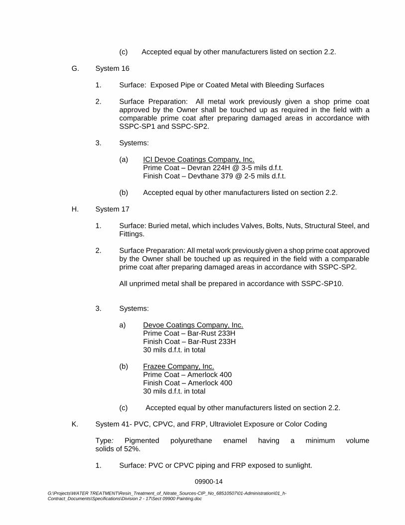
09900-14
G:\Projects\WATER TREATMENT\Resin_Treatment_of_Nitrate_Sources-CIP_No_68510507\01-Administration\01_h-Contract_Documents\Specifications\Division 2 - 17\Sect 09900 Painting.doc
(c) Accepted equal by other manufacturers listed on section 2.2. G. System 16
1. Surface: Exposed Pipe or Coated Metal with Bleeding Surfaces
2. Surface Preparation: All metal work previously given a shop prime coat approved by the Owner shall be touched up as required in the field with a comparable prime coat after preparing damaged areas in accordance with SSPC-SP1 and SSPC-SP2.
3. Systems:
(a) ICI Devoe Coatings Company, Inc.
Prime Coat – Devran 224H @ 3-5 mils d.f.t. Finish Coat – Devthane 379 @ 2-5 mils d.f.t.
(b) Accepted equal by other manufacturers listed on section 2.2.
H. System 17
1. Surface: Buried metal, which includes Valves, Bolts, Nuts, Structural Steel, and Fittings.
2. Surface Preparation: All metal work previously given a shop prime coat approved
by the Owner shall be touched up as required in the field with a comparable prime coat after preparing damaged areas in accordance with SSPC-SP2.
All unprimed metal shall be prepared in accordance with SSPC-SP10.
3. Systems:
a) Devoe Coatings Company, Inc. Prime Coat – Bar-Rust 233H Finish Coat – Bar-Rust 233H 30 mils d.f.t. in total
(b) Frazee Company, Inc. Prime Coat – Amerlock 400 Finish Coat – Amerlock 400
30 mils d.f.t. in total (c) Accepted equal by other manufacturers listed on section 2.2.
K. System 41- PVC, CPVC, and FRP, Ultraviolet Exposure or Color Coding
Type: Pigmented polyurethane enamel having a minimum volume solids of 52%.
1. Surface: PVC or CPVC piping and FRP exposed to sunlight.
09900-15
G:\Projects\WATER TREATMENT\Resin_Treatment_of_Nitrate_Sources-CIP_No_68510507\01-Administration\01_h-Contract_Documents\Specifications\Division 2 - 17\Sect 09900 Painting.doc
2. Surface Preparation: SSPC SP-1. Then lightly abrade the surface with medium-
grain sandpaper. Prime Coat: None.
Finish Coat: One coat of Rustoleum HS9400, Ameron 450 HS, Devoe Devran 379, or equal; applied to a minimum thickness of 2 mils.
***END OF SECTION***
09900-16
G:\Projects\WATER TREATMENT\Resin_Treatment_of_Nitrate_Sources-CIP_No_68510507\01-Administration\01_h-Contract_Documents\Specifications\Division 2 - 17\Sect 09900 Painting.doc
THIS PAGE INTENTIONALLY BLANK
14_0801 / Corona 09911 - 1 ARCHITECTURAL EXTERIOR PAINTING
SECTION 09911
ARCHITECTURAL EXTERIOR PAINTING
PART 1 GENERAL
1.01 SECTION INCLUDES
A. Surface preparation.
B. Field application of paints.
C. Scope: Finish exterior surfaces exposed to view, unless fully factory-finished and unless otherwise indicated, including the following:
D. Do Not Paint or Finish the Following Items:
1. Items factory-finished unless otherwise indicated; materials and products having factory-applied primers are not considered factory finished.
2. Items indicated to receive other finishes.
3. Items indicated to remain unfinished.
4. Fire rating labels, equipment serial number and capacity labels, and operating parts of equipment.
5. Floors, unless specifically indicated.
6. Glass.
7. Concealed pipes, ducts, and conduits.
1.02 RELATED REQUIREMENTS
A. Section 09100 - Volatile Organic Compound (VOC) Content Restrictions.
1.03 REFERENCE STANDARDS
A. MPI (APSM) - Master Painters Institute Architectural Painting Specification Manual; current edition, www.paintinfo.com.
B. SSPC-SP 1 - Solvent Cleaning; 1982 (Ed. 2004).
C. SSPC-SP 2 - Hand Tool Cleaning; 1982 (Ed. 2004).
D. SSPC-SP 3 - Power Tool Cleaning; 1982 (Ed. 2004).
E. SSPC-SP 6 - Commercial Blast Cleaning; Society for Protective Coatings; 2007.
1.04 SUBMITTALS
A. See Section 01330 - Administrative Requirements, for submittal procedures.
B. Product Data: Provide complete list of products to be used, with the following information for each:
1. Manufacturer's name, product name and/or catalog number, and general product category (e.g. "alkyd enamel").
2. MPI product number (e.g. MPI #47).
3. Cross-reference to specified paint system(s) product is to be used in; include description of each system.
4. Manufacturer's installation instructions.
C. Samples: Submit three paper "draw down" samples, 8-1/2 by 11 inches (216 by 279 mm) in size, illustrating range of colors available for each finishing product specified.
1. Where sheen is specified, submit samples in only that sheen.
2. Where sheen is not specified, submit each color in each sheen available.
D. Maintenance Materials: Furnish the following for Owner's use in maintenance of project.
1. See Section 01630 - Product Substitution Procedures, for additional provisions.
2. Extra Paint and Finish Materials: 1 gallon (4 L) of each color; from the same product run, store where directed.
3. Label each container with color in addition to the manufacturer's label.

14_0801 / Corona 09911 - 2 ARCHITECTURAL EXTERIOR PAINTING
1.05 QUALITY ASSURANCE
A. Manufacturer Qualifications: Company specializing in manufacturing the products specified, with minimum three years documented experience.
B. Applicator Qualifications: Company specializing in performing the type of work specified with minimum five years documented experience.
1.06 DELIVERY, STORAGE, AND HANDLING
A. Deliver products to site in sealed and labeled containers; inspect to verify acceptability.
B. Container Label: Include manufacturer's name, type of paint, brand name, lot number, brand code, coverage, surface preparation, drying time, cleanup requirements, color designation, and instructions for mixing and reducing.
C. Paint Materials: Store at minimum ambient temperature of 45 degrees F (7 degrees C) and a maximum of 90 degrees F (32 degrees C), in ventilated area, and as required by manufacturer's instructions.
1.07 FIELD CONDITIONS
A. Do not apply materials when surface and ambient temperatures are outside the temperature ranges required by the paint product manufacturer.
B. Follow manufacturer's recommended procedures for producing best results, including testing of substrates, moisture in substrates, and humidity and temperature limitations.
C. Provide lighting level of 80 ft candles (860 lx) measured mid-height at substrate surface.
PART 2 PRODUCTS
2.01 MANUFACTURERS
A. Provide paints and finishes from the same manufacturer to the greatest extent possible.
1. In the event that a single manufacturer cannot provide specified products, minor exceptions will be permitted provided approval by Architect is obtained using the specified procedures for substitutions.
B. Paints:
1. Base Manufacturer: Sherwin Williams.
2. Glidden Professional, a product of PPG Architectural Coatings: www.gliddenprofessional.com.
3. Benjamin Moore & Co: www.benjaminmoore.com.
4. Pratt & Lambert Paints: www.prattandlambert.com.
5. Sherwin-Williams Company: www.sherwin-williams.com.
C. Primer Sealers: Same manufacturer as top coats.
D. Substitutions: See Section 01600 - Product Requirements.
2.02 PAINTS AND FINISHES - GENERAL
A. Paints and Finishes: Ready mixed, unless required to be a field-catalyzed paint.
1. Provide paints and finishes of a soft paste consistency, capable of being readily and uniformly dispersed to a homogeneous coating, with good flow and brushing properties, and capable of drying or curing free of streaks or sags.
2. Supply each paint material in quantity required to complete entire project's work from a single production run.
3. Do not reduce, thin, or dilute paint or finishes or add materials unless such procedure is specifically described in manufacturer's product instructions.
B. Volatile Organic Compound (VOC) Content: Comply with Section 016116.
C. Sheens: Provide the sheens specified; where sheen is not specified, sheen will be selected later by Architect from the manufacturer's full line.
D. Custom Colors: To be selected from manufacturer's full range of available colors.
1. Selection to be made by Architect after award of contract.
14_0801 / Corona 09911 - 3 ARCHITECTURAL EXTERIOR PAINTING
2. Allow for minimum of three colors for each system, unless otherwise indicated, without additional cost to Owner.
2.03 PAINT SYSTEMS - EXTERIOR
A. General: all paint systems are to be selected from the Professional Grade coating systems as provided by the Manufacturer.
B. Elastomeric System: Exterior Surfaces to be Painted, Unless Otherwise Indicated: Including exterior portland cement plaster.
1. Two top coats and one coat primer.
2. 1st Coat: Primer: S-W Loxon Concrete & Masonry Primer Sealer, A24W8300
3. 2nd and 3rd Coat: S-W ConFlex XL Elastomeric High Build Coating, A5-400 Series
C. Paint ME-OP-3L - Ferrous Metals, Unprimed, Latex, 3 Coat:
1. One coat of latex primer.
2. Semi-gloss: Two coats of latex enamel; -.
D. Paint ME-OP-2L - Ferrous Metals, Primed, Latex, 2 Coat:
1. Touch-up with rust-inhibitive primer recommended by top coat manufacturer.
2. Semi-gloss: Two coats of latex enamel; -.
E. Paint MgE-OP-3L - Galvanized Metals, Latex, 3 Coat:
1. One coat galvanize primer.
2. Semi-gloss: Two coats of latex enamel; -.
2.04 ACCESSORY MATERIALS
A. Accessory Materials: Provide primers, sealers, cleaning agents, cleaning cloths, sanding materials, and clean-up materials as required for final completion of painted surfaces.
B. Patching Material: Latex filler.
C. Fastener Head Cover Material: Latex filler.
PART 3 EXECUTION
3.01 EXAMINATION
A. Verify that surfaces are ready to receive work as instructed by the product manufacturer.
B. Examine surfaces scheduled to be finished prior to commencement of work. Report any condition that may potentially effect proper application.
C. Test shop-applied primer for compatibility with subsequent cover materials.
D. Measure moisture content of surfaces using an electronic moisture meter. Do not apply finishes unless moisture content of surfaces are below the following maximums:
1. Exterior Plaster and Stucco: 12 percent.
3.02 PREPARATION
A. Clean surfaces thoroughly and correct defects prior to application.
B. Prepare surfaces using the methods recommended by the manufacturer for achieving the best result for the substrate under the project conditions.
C. Remove or mask surface appurtenances, including electrical plates, hardware, light fixture trim, escutcheons, and fittings, prior to preparing surfaces for finishing.
D. Seal surfaces that might cause bleed through or staining of topcoat.
E. Remove mildew from impervious surfaces by scrubbing with solution of tetra-sodium phosphate and bleach. Rinse with clean water and allow surface to dry.
F. Exterior Plaster: Fill hairline cracks, small holes, and imperfections with exterior patching plaster. Make smooth and flush with adjacent surfaces. Wash and neutralize high alkali surfaces.
G. Galvanized Surfaces:
1. Prepare surface according to SSPC-SP 2.
14_0801 / Corona 09911 - 4 ARCHITECTURAL EXTERIOR PAINTING
H. Ferrous Metal:
1. Solvent clean according to SSPC-SP1.
2. Remove rust, loose mill scale, and other foreign substances using using methods recommended in writing by paint manufacturer and blast cleaning according to SSPC-SP 6 "Commercial Blast Cleaning". Protect from corrosion until coated.
3.03 APPLICATION
A. Apply products in accordance with manufacturer's written instructions and recommendations in "MPI Architectural Painting Specification Manual".
B. Do not apply finishes to surfaces that are not dry. Allow applied coats to dry before next coat is applied.
C. Apply each coat to uniform appearance.
D. Vacuum clean surfaces of loose particles. Use tack cloth to remove dust and particles just prior to applying next coat.
E. Reinstall electrical cover plates, hardware, light fixture trim, escutcheons, and fittings removed prior to finishing.
3.04 CLEANING
A. Collect waste material that could constitute a fire hazard, place in closed metal containers, and remove daily from site.
3.05 PROTECTION
A. Protect finishes until completion of project.
B. Touch-up damaged finishes after Substantial Completion.
3.06 COLOR SCHEDULE
END OF SECTION

14_0801 / Corona 09911 - 1 EXTERIOR PAINTING
SECTION 09911
EXTERIOR PAINTING
PART 1 GENERAL
1.01 SECTION INCLUDES
A. Surface preparation.
B. Field application of paints.
C. Scope: Finish exterior surfaces exposed to view, unless fully factory-finished and unless otherwise indicated, including the following:
D. Do Not Paint or Finish the Following Items:
1. Items factory-finished unless otherwise indicated; materials and products having factory-applied primers are not considered factory finished.
2. Items indicated to receive other finishes.
3. Items indicated to remain unfinished.
4. Fire rating labels, equipment serial number and capacity labels, and operating parts of equipment.
5. Floors, unless specifically indicated.
6. Glass.
7. Concealed pipes, ducts, and conduits.
1.02 RELATED REQUIREMENTS
A. Section 01611 - Volatile Organic Compound (VOC) Content Restrictions.
1.03 REFERENCE STANDARDS
A. MPI (APSM) - Master Painters Institute Architectural Painting Specification Manual; current edition, www.paintinfo.com.
B. SSPC-SP 1 - Solvent Cleaning; 1982 (Ed. 2004).
C. SSPC-SP 2 - Hand Tool Cleaning; 1982 (Ed. 2004).
D. SSPC-SP 3 - Power Tool Cleaning; 1982 (Ed. 2004).
E. SSPC-SP 6 - Commercial Blast Cleaning; Society for Protective Coatings; 2007.
1.04 SUBMITTALS
A. See Section 01330 - Administrative Requirements, for submittal procedures.
B. Product Data: Provide complete list of products to be used, with the following information for each:
1. Manufacturer's name, product name and/or catalog number, and general product category (e.g. "alkyd enamel").
2. MPI product number (e.g. MPI #47).
3. Cross-reference to specified paint system(s) product is to be used in; include description of each system.
4. Manufacturer's installation instructions.
C. Samples: Submit three paper "draw down" samples, 8-1/2 by 11 inches (216 by 279 mm) in size, illustrating range of colors available for each finishing product specified.
1. Where sheen is specified, submit samples in only that sheen.
2. Where sheen is not specified, submit each color in each sheen available.
D. Maintenance Materials: Furnish the following for Owner's use in maintenance of project.
1. See Section 01630 - Product Substitution Procedures, for additional provisions.
2. Extra Paint and Finish Materials: 1 gallon (4 L) of each color; from the same product run, store where directed.
3. Label each container with color in addition to the manufacturer's label.
14_0801 / Corona 09911 - 2 EXTERIOR PAINTING
1.05 QUALITY ASSURANCE
A. Manufacturer Qualifications: Company specializing in manufacturing the products specified, with minimum three years documented experience.
B. Applicator Qualifications: Company specializing in performing the type of work specified with minimum five years documented experience.
1.06 DELIVERY, STORAGE, AND HANDLING
A. Deliver products to site in sealed and labeled containers; inspect to verify acceptability.
B. Container Label: Include manufacturer's name, type of paint, brand name, lot number, brand code, coverage, surface preparation, drying time, cleanup requirements, color designation, and instructions for mixing and reducing.
C. Paint Materials: Store at minimum ambient temperature of 45 degrees F (7 degrees C) and a maximum of 90 degrees F (32 degrees C), in ventilated area, and as required by manufacturer's instructions.
1.07 FIELD CONDITIONS
A. Do not apply materials when surface and ambient temperatures are outside the temperature ranges required by the paint product manufacturer.
B. Follow manufacturer's recommended procedures for producing best results, including testing of substrates, moisture in substrates, and humidity and temperature limitations.
C. Provide lighting level of 80 ft candles (860 lx) measured mid-height at substrate surface.
PART 2 PRODUCTS
2.01 MANUFACTURERS
A. Provide paints and finishes from the same manufacturer to the greatest extent possible.
1. In the event that a single manufacturer cannot provide specified products, minor exceptions will be permitted provided approval by Architect is obtained using the specified procedures for substitutions.
B. Paints:
1. Base Manufacturer: Sherwin Williams.
2. Glidden Professional, a product of PPG Architectural Coatings: www.gliddenprofessional.com.
3. Benjamin Moore & Co: www.benjaminmoore.com.
4. Pratt & Lambert Paints: www.prattandlambert.com.
5. Sherwin-Williams Company: www.sherwin-williams.com.
C. Primer Sealers: Same manufacturer as top coats.
D. Substitutions: See Section 01600 - Product Requirements.
2.02 PAINTS AND FINISHES - GENERAL
A. Paints and Finishes: Ready mixed, unless required to be a field-catalyzed paint.
1. Provide paints and finishes of a soft paste consistency, capable of being readily and uniformly dispersed to a homogeneous coating, with good flow and brushing properties, and capable of drying or curing free of streaks or sags.
2. Supply each paint material in quantity required to complete entire project's work from a single production run.
3. Do not reduce, thin, or dilute paint or finishes or add materials unless such procedure is specifically described in manufacturer's product instructions.
B. Volatile Organic Compound (VOC) Content: Comply with Section 016116.
C. Sheens: Provide the sheens specified; where sheen is not specified, sheen will be selected later by Architect from the manufacturer's full line.
D. Custom Colors: To be selected from manufacturer's full range of available colors.
1. Selection to be made by Architect after award of contract.

14_0801 / Corona 09911 - 3 EXTERIOR PAINTING
2. Allow for minimum of three colors for each system, unless otherwise indicated, without additional cost to Owner.
2.03 PAINT SYSTEMS - EXTERIOR
A. General: all paint systems are to be selected from the Professional Grade coating systems as provided by the Manufacturer.
B. Elastomeric System: Exterior Surfaces to be Painted, Unless Otherwise Indicated: Including exterior portland cement plaster.
1. Two top coats and one coat primer.
2. 1st Coat: Primer: S-W Loxon Concrete & Masonry Primer Sealer, A24W8300
3. 2nd and 3rd Coat: S-W ConFlex XL Elastomeric High Build Coating, A5-400 Series
C. Paint ME-OP-3L - Ferrous Metals, Unprimed, Latex, 3 Coat:
1. One coat of latex primer.
2. Semi-gloss: Two coats of latex enamel; -.
D. Paint ME-OP-2L - Ferrous Metals, Primed, Latex, 2 Coat:
1. Touch-up with rust-inhibitive primer recommended by top coat manufacturer.
2. Semi-gloss: Two coats of latex enamel; -.
E. Paint MgE-OP-3L - Galvanized Metals, Latex, 3 Coat:
1. One coat galvanize primer.
2. Semi-gloss: Two coats of latex enamel; -.
2.04 ACCESSORY MATERIALS
A. Accessory Materials: Provide primers, sealers, cleaning agents, cleaning cloths, sanding materials, and clean-up materials as required for final completion of painted surfaces.
B. Patching Material: Latex filler.
C. Fastener Head Cover Material: Latex filler.
PART 3 EXECUTION
3.01 EXAMINATION
A. Verify that surfaces are ready to receive work as instructed by the product manufacturer.
B. Examine surfaces scheduled to be finished prior to commencement of work. Report any condition that may potentially effect proper application.
C. Test shop-applied primer for compatibility with subsequent cover materials.
D. Measure moisture content of surfaces using an electronic moisture meter. Do not apply finishes unless moisture content of surfaces are below the following maximums:
1. Exterior Plaster and Stucco: 12 percent.
3.02 PREPARATION
A. Clean surfaces thoroughly and correct defects prior to application.
B. Prepare surfaces using the methods recommended by the manufacturer for achieving the best result for the substrate under the project conditions.
C. Remove or mask surface appurtenances, including electrical plates, hardware, light fixture trim, escutcheons, and fittings, prior to preparing surfaces for finishing.
D. Seal surfaces that might cause bleed through or staining of topcoat.
E. Remove mildew from impervious surfaces by scrubbing with solution of tetra-sodium phosphate and bleach. Rinse with clean water and allow surface to dry.
F. Exterior Plaster: Fill hairline cracks, small holes, and imperfections with exterior patching plaster. Make smooth and flush with adjacent surfaces. Wash and neutralize high alkali surfaces.
G. Galvanized Surfaces:
1. Prepare surface according to SSPC-SP 2.

14_0801 / Corona 09911 - 4 EXTERIOR PAINTING
H. Ferrous Metal:
1. Solvent clean according to SSPC-SP1.
2. Remove rust, loose mill scale, and other foreign substances using using methods recommended in writing by paint manufacturer and blast cleaning according to SSPC-SP 6 "Commercial Blast Cleaning". Protect from corrosion until coated.
3.03 APPLICATION
A. Apply products in accordance with manufacturer's written instructions and recommendations in "MPI Architectural Painting Specification Manual".
B. Do not apply finishes to surfaces that are not dry. Allow applied coats to dry before next coat is applied.
C. Apply each coat to uniform appearance.
D. Vacuum clean surfaces of loose particles. Use tack cloth to remove dust and particles just prior to applying next coat.
E. Reinstall electrical cover plates, hardware, light fixture trim, escutcheons, and fittings removed prior to finishing.
3.04 CLEANING
A. Collect waste material that could constitute a fire hazard, place in closed metal containers, and remove daily from site.
3.05 PROTECTION
A. Protect finishes until completion of project.
B. Touch-up damaged finishes after Substantial Completion.
3.06 COLOR SCHEDULE
END OF SECTION
14_0801 / Corona 09912 - 1 ARCHECTURAL INTERIOR PAINTING
SECTION 09912
ARCHITECTURAL INTERIOR PAINTING
PART 1 GENERAL
1.01 SECTION INCLUDES
A. Surface preparation.
B. Field application of paints.
C. Scope: Finish interior surfaces exposed to view, unless fully factory-finished and unless otherwise indicated.
D. Do Not Paint or Finish the Following Items:
1. Items factory-finished unless otherwise indicated; materials and products having factory-applied primers are not considered factory finished.
2. Items indicated to receive other finishes.
3. Items indicated to remain unfinished.
4. Fire rating labels, equipment serial number and capacity labels, bar code labels, and operating parts of equipment.
5. Floors, unless specifically indicated.
6. Glass.
7. Concealed pipes, ducts, and conduits.
1.02 RELATED REQUIREMENTS
A. Section 09100 - Volatile Organic Compound (VOC) Content Restrictions.
1.03 REFERENCE STANDARDS
A. MPI (APSM) - Master Painters Institute Architectural Painting Specification Manual; current edition, www.paintinfo.com.
B. SSPC V2 (PM2) - Systems and Specifications: Steel Structures Painting Manual, Volume 2; Fourth Edition.
1.04 SUBMITTALS
A. See Section 01330 - Administrative Requirements, for submittal procedures.
B. Product Data: Provide complete list of products to be used, with the following information for each:
1. Manufacturer's name, product name and/or catalog number, and general product category (e.g. "alkyd enamel").
2. MPI product number (e.g. MPI #47).
3. Cross-reference to specified paint system(s) product is to be used in; include description of each system.
C. Samples: Submit three paper "draw down" samples, 8-1/2 by 11 inches (216 by 279 mm) in size, illustrating range of colors available for each finishing product specified.
1. Where sheen is specified, submit samples in only that sheen.
1.05 QUALITY ASSURANCE
A. Manufacturer Qualifications: Company specializing in manufacturing the products specified, with minimum three years documented experience.
B. Applicator Qualifications: Company specializing in performing the type of work specified with minimum five years documented experience.
1.06 DELIVERY, STORAGE, AND HANDLING
A. Deliver products to site in sealed and labeled containers; inspect to verify acceptability.
B. Container Label: Include manufacturer's name, type of paint, brand name, lot number, brand code, coverage, surface preparation, drying time, cleanup requirements, color designation, and instructions for mixing and reducing.
14_0801 / Corona 09912 - 2 ARCHECTURAL INTERIOR PAINTING
C. Paint Materials: Store at minimum ambient temperature of 45 degrees F (7 degrees C) and a maximum of 90 degrees F (32 degrees C), in ventilated area, and as required by manufacturer's instructions.
1.07 FIELD CONDITIONS
A. Do not apply materials when surface and ambient temperatures are outside the temperature ranges required by the paint product manufacturer.
B. Follow manufacturer's recommended procedures for producing best results, including testing of substrates, moisture in substrates, and humidity and temperature limitations.
C. Provide lighting level of 80 ft candles (860 lx) measured mid-height at substrate surface.
PART 2 PRODUCTS
2.01 MANUFACTURERS
A. Provide paints and finishes from the same manufacturer to the greatest extent possible.
1. In the event that a single manufacturer cannot provide specified products, minor exceptions will be permitted provided approval by Architect is obtained using the specified procedures for substitutions.
B. Paints:
1. Base Manufacturer: Sherwin Williams.
2. Behr Process Corporation: www.behr.com.
3. Glidden Professional, a product of PPG Architectural Coatings: www.gliddenprofessional.com.
4. Benjamin Moore & Co: www.benjaminmoore.com.
5. Pratt & Lambert Paints: www.prattandlambert.com.
6. Sherwin-Williams Company: www.sherwin-williams.com.
C. Substitutions: See Section 01630 - Product Substitution Procedures.
2.02 PAINTS AND FINISHES - GENERAL
A. Paints and Finishes: Ready mixed, unless intended to be a field-catalyzed paint.
1. Provide paints and finishes of a soft paste consistency, capable of being readily and uniformly dispersed to a homogeneous coating, with good flow and brushing properties, and capable of drying or curing free of streaks or sags.
2. Supply each paint material in quantity required to complete entire project's work from a single production run.
3. Do not reduce, thin, or dilute paint or finishes or add materials unless such procedure is specifically described in manufacturer's product instructions.
B. Volatile Organic Compound (VOC) Content: Comply with Section 01611.
C. Custom Colors: To be selected from manufacturer's full range of available colors.
1. Selection to be made by Architect after award of contract.
2.03 PAINT SYSTEMS - INTERIOR
A. Paint I-OP - Interior Surfaces to be Painted, Unless Otherwise Indicated: Including gypsum board.
1. Two top coats and one coat primer.
2. Top Coat(s): Institutional Low Odor/VOC Interior Latex; MPI #143, 144, 145, 146, 147, or 148.
a. Products:
1) Sherwin-Williams Harmony Interior Acrylic Latex, Flat. (MPI #143)
2) Sherwin-Williams Harmony Interior Acrylic Latex, Eg-Shel. (MPI #144)
3. Top Coat Sheen:
a. Flat: MPI gloss level 1; use this sheen for ceilings and other overhead surfaces.
14_0801 / Corona 09912 - 3 ARCHECTURAL INTERIOR PAINTING
PART 3 EXECUTION
3.01 EXAMINATION
A. Verify that surfaces are ready to receive work as instructed by the product manufacturer.
B. Examine surfaces scheduled to be finished prior to commencement of work. Report any condition that may potentially effect proper application.
C. Test shop-applied primer for compatibility with subsequent cover materials.
D. Measure moisture content of surfaces using an electronic moisture meter. Do not apply finishes unless moisture content of surfaces are below the following maximums:
1. Gypsum Wallboard: 12 percent.
3.02 PREPARATION
A. Clean surfaces thoroughly and correct defects prior to application.
B. Prepare surfaces using the methods recommended by the manufacturer for achieving the best result for the substrate under the project conditions.
C. Remove or mask surface appurtenances, including electrical plates, hardware, light fixture trim, escutcheons, and fittings, prior to preparing surfaces or finishing.
D. Seal surfaces that might cause bleed through or staining of topcoat.
E. Gypsum Board: Fill minor defects with filler compound. Spot prime defects after repair.
3.03 APPLICATION
A. Apply products in accordance with manufacturer's written instructions and recommendations in "MPI Architectural Painting Specification Manual".
B. Do not apply finishes to surfaces that are not dry. Allow applied coats to dry before next coat is applied.
C. Apply each coat to uniform appearance in thicknesses specified by manufacturer.
D. Vacuum clean surfaces of loose particles. Use tack cloth to remove dust and particles just prior to applying next coat.
E. Reinstall electrical cover plates, hardware, light fixture trim, escutcheons, and fittings removed prior to finishing.
3.04 CLEANING
A. Collect waste material that could constitute a fire hazard, place in closed metal containers, and remove daily from site.
3.05 PROTECTION
A. Touch-up damaged finishes after Substantial Completion.
END OF SECTION
14_0801 / Corona 09912 - 4 ARCHECTURAL INTERIOR PAINTING
THIS PAGE INTENTIONALLY BLANK
14_0801 / Corona 09912 - 1 INTERIOR PAINTING
SECTION 09912
INTERIOR PAINTING
PART 1 GENERAL
1.01 SECTION INCLUDES
A. Surface preparation.
B. Field application of paints.
C. Scope: Finish interior surfaces exposed to view, unless fully factory-finished and unless otherwise indicated.
D. Do Not Paint or Finish the Following Items:
1. Items factory-finished unless otherwise indicated; materials and products having factory-applied primers are not considered factory finished.
2. Items indicated to receive other finishes.
3. Items indicated to remain unfinished.
4. Fire rating labels, equipment serial number and capacity labels, bar code labels, and operating parts of equipment.
5. Floors, unless specifically indicated.
6. Glass.
7. Concealed pipes, ducts, and conduits.
1.02 RELATED REQUIREMENTS
A. Section 01611 - Volatile Organic Compound (VOC) Content Restrictions.
1.03 REFERENCE STANDARDS
A. MPI (APSM) - Master Painters Institute Architectural Painting Specification Manual; current edition, www.paintinfo.com.
B. SSPC V2 (PM2) - Systems and Specifications: Steel Structures Painting Manual, Volume 2; Fourth Edition.
1.04 SUBMITTALS
A. See Section 01330 - Administrative Requirements, for submittal procedures.
B. Product Data: Provide complete list of products to be used, with the following information for each:
1. Manufacturer's name, product name and/or catalog number, and general product category (e.g. "alkyd enamel").
2. MPI product number (e.g. MPI #47).
3. Cross-reference to specified paint system(s) product is to be used in; include description of each system.
C. Samples: Submit three paper "draw down" samples, 8-1/2 by 11 inches (216 by 279 mm) in size, illustrating range of colors available for each finishing product specified.
1. Where sheen is specified, submit samples in only that sheen.
1.05 QUALITY ASSURANCE
A. Manufacturer Qualifications: Company specializing in manufacturing the products specified, with minimum three years documented experience.
B. Applicator Qualifications: Company specializing in performing the type of work specified with minimum five years documented experience.
1.06 DELIVERY, STORAGE, AND HANDLING
A. Deliver products to site in sealed and labeled containers; inspect to verify acceptability.
B. Container Label: Include manufacturer's name, type of paint, brand name, lot number, brand code, coverage, surface preparation, drying time, cleanup requirements, color designation, and instructions for mixing and reducing.
14_0801 / Corona 09912 - 2 INTERIOR PAINTING
C. Paint Materials: Store at minimum ambient temperature of 45 degrees F (7 degrees C) and a maximum of 90 degrees F (32 degrees C), in ventilated area, and as required by manufacturer's instructions.
1.07 FIELD CONDITIONS
A. Do not apply materials when surface and ambient temperatures are outside the temperature ranges required by the paint product manufacturer.
B. Follow manufacturer's recommended procedures for producing best results, including testing of substrates, moisture in substrates, and humidity and temperature limitations.
C. Provide lighting level of 80 ft candles (860 lx) measured mid-height at substrate surface.
PART 2 PRODUCTS
2.01 MANUFACTURERS
A. Provide paints and finishes from the same manufacturer to the greatest extent possible.
1. In the event that a single manufacturer cannot provide specified products, minor exceptions will be permitted provided approval by Architect is obtained using the specified procedures for substitutions.
B. Paints:
1. Base Manufacturer: Sherwin Williams.
2. Behr Process Corporation: www.behr.com.
3. Glidden Professional, a product of PPG Architectural Coatings: www.gliddenprofessional.com.
4. Benjamin Moore & Co: www.benjaminmoore.com.
5. Pratt & Lambert Paints: www.prattandlambert.com.
6. Sherwin-Williams Company: www.sherwin-williams.com.
C. Substitutions: See Section 01630 - Product Substitution Procedures.
2.02 PAINTS AND FINISHES - GENERAL
A. Paints and Finishes: Ready mixed, unless intended to be a field-catalyzed paint.
1. Provide paints and finishes of a soft paste consistency, capable of being readily and uniformly dispersed to a homogeneous coating, with good flow and brushing properties, and capable of drying or curing free of streaks or sags.
2. Supply each paint material in quantity required to complete entire project's work from a single production run.
3. Do not reduce, thin, or dilute paint or finishes or add materials unless such procedure is specifically described in manufacturer's product instructions.
B. Volatile Organic Compound (VOC) Content: Comply with Section 01611.
C. Custom Colors: To be selected from manufacturer's full range of available colors.
1. Selection to be made by Architect after award of contract.
2.03 PAINT SYSTEMS - INTERIOR
A. Paint I-OP - Interior Surfaces to be Painted, Unless Otherwise Indicated: Including gypsum board.
1. Two top coats and one coat primer.
2. Top Coat(s): Institutional Low Odor/VOC Interior Latex; MPI #143, 144, 145, 146, 147, or 148.
a. Products:
1) Sherwin-Williams Harmony Interior Acrylic Latex, Flat. (MPI #143)
2) Sherwin-Williams Harmony Interior Acrylic Latex, Eg-Shel. (MPI #144)
3. Top Coat Sheen:
a. Flat: MPI gloss level 1; use this sheen for ceilings and other overhead surfaces.
14_0801 / Corona 09912 - 3 INTERIOR PAINTING
PART 3 EXECUTION
3.01 EXAMINATION
A. Verify that surfaces are ready to receive work as instructed by the product manufacturer.
B. Examine surfaces scheduled to be finished prior to commencement of work. Report any condition that may potentially effect proper application.
C. Test shop-applied primer for compatibility with subsequent cover materials.
D. Measure moisture content of surfaces using an electronic moisture meter. Do not apply finishes unless moisture content of surfaces are below the following maximums:
1. Gypsum Wallboard: 12 percent.
3.02 PREPARATION
A. Clean surfaces thoroughly and correct defects prior to application.
B. Prepare surfaces using the methods recommended by the manufacturer for achieving the best result for the substrate under the project conditions.
C. Remove or mask surface appurtenances, including electrical plates, hardware, light fixture trim, escutcheons, and fittings, prior to preparing surfaces or finishing.
D. Seal surfaces that might cause bleed through or staining of topcoat.
E. Gypsum Board: Fill minor defects with filler compound. Spot prime defects after repair.
3.03 APPLICATION
A. Apply products in accordance with manufacturer's written instructions and recommendations in "MPI Architectural Painting Specification Manual".
B. Do not apply finishes to surfaces that are not dry. Allow applied coats to dry before next coat is applied.
C. Apply each coat to uniform appearance in thicknesses specified by manufacturer.
D. Vacuum clean surfaces of loose particles. Use tack cloth to remove dust and particles just prior to applying next coat.
E. Reinstall electrical cover plates, hardware, light fixture trim, escutcheons, and fittings removed prior to finishing.
3.04 CLEANING
A. Collect waste material that could constitute a fire hazard, place in closed metal containers, and remove daily from site.
3.05 PROTECTION
A. Touch-up damaged finishes after Substantial Completion.
END OF SECTION

14_0801 / Corona 09912 - 4 INTERIOR PAINTING
THIS PAGE INTENTIONALLY BLANK
14_0801 / Corona 10200 - 1 LOUVERS
SECTION 10200
LOUVERS
PART 1 GENERAL
1.01 SECTION INCLUDES
A. Drainable Louvers, frames, and accessories.
1.02 RELATED REQUIREMENTS
A. Section 07620 - Sheet Metal Flashing and Trim.
B. Section 07900 - Joint Sealers.
1.03 REFERENCE STANDARDS
A. ASTM A653/A653M - Standard Specification for Steel Sheet, Zinc-Coated (Galvanized) or Zinc-Iron Alloy-Coated (Galvannealed) by the Hot-Dip Process; 2013.
1.04 SUBMITTALS
A. See Section 01330 - Administrative Requirements, for submittal procedures.
B. Product Data: Provide data describing design characteristics, maximum recommended air velocity, design free area, materials and finishes.
C. Shop Drawings: Indicate louver layout plan and elevations, opening and clearance dimensions, tolerances; head, jamb and sill details; blade configuration, screens, blankout areas required, and frames.
D. Test Reports: Independent agency reports showing compliance with specified performance criteria.
E. Manufacturer's Certificate: Certify that products meet or exceed specified requirements.
1.05 QUALITY ASSURANCE
A. Manufacturer Qualifications: Company specializing in manufacturing products of the type specified in this section, with minimum three years of documented experience.
1.06 WARRANTY
A. Provide twenty year manufacturer warranty against distortion, metal degradation, and failure of connections.
1. Finish: Include coverage against degradation of exterior finish.
PART 2 PRODUCTS
2.01 MANUFACTURERS
A. Wall Louvers: based on Greenheck, GCI-402 combination louver/intake damper:
1. Airolite Company, LLC; -: www.airolite.com.
2. Construction Specialties, Inc; -: www.c-sgroup.com.
3. PCI Industries, Inc; All-Lite Brand: www.alllite-louvers.com.
4. Substitutions: See Section 01600 - Product Requirements.
2.02 LOUVERS
A. Combination Louver/Damper: Horizontal blade, formed galvanized steel sheet construction.
1. Free Area: 40 percent, minimum.
2. Blades: Straight, with backdraft damper.
3. Frame: 6 inches (150 mm) deep, channel profile; corner joints mitered and, with continuous recessed caulking channel each side.
4. Steel Thickness, Galvanized: Frame 16 gage, 0.0598 inch (1.52 mm) minimum base metal; blades 16 gage, 0.0598 inch (1.52 mm) minimum base metal.
5. Damper: provide gravity damper
6. Steel Finish: baked enamel, finished after fabrication.
7. Color: custom color.
8. Accessories: Security Bars, Filter Rack and 2" pleated Merv 6 filters.
14_0801 / Corona 10200 - 2 LOUVERS
2.03 MATERIALS
A. Steel Sheet: Hot-dipped galvanized steel sheet, ASTM A653/A653M, with G90/Z275 coating.
2.04 ACCESSORIES
A. Flashings: Of same material as louver frame, formed to required shape, single length in one piece per location.
B. Sealant for Setting Sills and Sill Flashing: Non-curing butyl type.
C. Sealant: type as specified in Section 07900. and/or as recommended by manufacturer for adjacent materials.
PART 3 EXECUTION
3.01 EXAMINATION
A. Verify that prepared openings and flashings are ready to receive work and opening dimensions are as indicated on shop drawings.
B. Verify that field measurements are as indicated.
3.02 INSTALLATION
A. Install louver assembly in accordance with manufacturer's instructions.
B. Install louvers level and plumb.
C. Install flashings and align louver assembly to ensure moisture shed from flashings and diversion of moisture to exterior.
D. Secure louver frames in openings with exposed fasteners at interior.
E. Install perimeter sealant and backing rod in accordance with Section 07900.
3.03 ADJUSTING
A. Adjust operable louvers for freedom of movement of control mechanism. Lubricate operating joints.
3.04 CLEANING
A. Strip protective finish coverings.
B. Clean surfaces and components.
END OF SECTION
14_0801 / Corona 10430 - 1 SIGNAGE
SECTION 10430
SIGNAGE
PART 1 GENERAL
1.01 SECTION INCLUDES
A. Room and door signs.
B. Building identification signs.
C. Building address numbers.
1.02 RELATED REQUIREMENTS
A. Section 10401 - Identification for Plumbing Piping and Equipment.
B. Section 16010 - Identification for Electrical Systems.
1.03 REFERENCE STANDARDS
A. 36 CFR 1191 - Americans with Disabilities Act (ADA) Accessibility Guidelines for Buildings and Facilities; Architectural Barriers Act (ABA) Accessibility Guidelines; current edition.
B. ADA Standards - Americans with Disabilities Act (ADA) Standards for Accessible Design; 2010.
C. ICC A117.1 - Accessible and Usable Buildings and Facilities; International Code Council; 2009 (ANSI).
1.04 QUALITY ASSURANCE
A. Manufacturer Qualifications: Company specializing in manufacturing the products specified in this section with minimum three years of documented experience.
1.05 DELIVERY, STORAGE, AND HANDLING
A. Package signs as required to prevent damage before installation.
B. Package room and door signs in sequential order of installation, labeled by floor or building.
PART 2 PRODUCTS
2.01 MANUFACTURERS
A. Flat Signs (Exterior):
1. Best Sign Systems, Inc: www.bestsigns.com.
2. Inpro; Aspen: www.inprocorp.com.
3. Mohawk Sign Systems, Inc: www.mohawksign.com.
4. Substitutions: See Section 016000 - Product Requirements.
B. Dimensional Letter Signs (Address and Exterior Signage):
1. Cosco Industries; Cast Aluminum: www.coscoarchitecturalsigns.com.
2. Gemini Inc.; www.signletters.com.
3. Substitutions: See Section 01600 - Product Requirements.
C. Accessible Path of Travel Directional Signs:
1. Compliance Signs, www.compliancesigns.com.
2. Substitutions: See Section 01600 - Product Requirements.
2.02 SIGNAGE APPLICATIONS
A. Accessibility Compliance: Signs are required to comply with ADA Standards and ICC A117.1 and applicable building codes, unless otherwise indicated; in the event of conflicting requirements, comply with the most comprehensive and specific requirements.
B. Room and Door Signs: Provide a sign for every doorway, whether it has a door or not, not including corridors, lobbies, and similar open areas.
1. Sign Type: Flat signs with applied character panel media as specified.
2. Provide "tactile" signage, with letters raised minimum 1/32 inch (0.8 mm) and Grade II braille.
3. Character Height: 1 inch (25 mm).
14_0801 / Corona 10430 - 2 SIGNAGE
4. Sign Height: 6 inches (150 mm), unless otherwise indicated.
5. Service Rooms: Identify with room names and numbers to be determined later, not those shown on the drawings.
C. Building Identification Signs (Exterior):
1. Use individual metal letters/numbers.
2. Mount on outside wall in location shown on drawings.
3. Color: Custom Paint Color
4. Installation Method: Projected Spacer Mount with studs.
2.03 SIGN TYPES
A. Flat Signs (Exterior): Signage media without frame.
1. Edges: Square.
2. Corners: Square.
3. Wall Mounting of One-Sided Signs: Concealed screws.
B. Color and Font: Unless otherwise indicated:
1. Character Font: Helvetica, Arial, or other sans serif font.
2. Character Case: Upper case only.
3. Background Color: Selected from Manufacturer's standard colors.
4. Character Color: Contrasting color.
2.04 TACTILE SIGNAGE MEDIA
A. Engraved Panels: Laminated colored plastic; engraved through face to expose core as background color:
1. Total Thickness: 1/16 inch (1.6 mm).
B. Applied Character Panels: Acrylic plastic base, with applied acrylic plastic letters and braille.
1. Total Thickness: 1/8 inch (3 mm).
2. Letter Thickness: 1/8 inch (3 mm).
3. Letter Edges: Square.
2.05 DIMENSIONAL LETTERS
A. Metal Letters/numbers:
1. Metal: Aluminum casting.
2. Finish: Painted-Custom.
3. Mounting: Concealed Pins, as shown in the Drawings.
2.06 ACCESSORIES
A. Concealed Screws: Stainless steel, galvanized steel, chrome plated, or other non-corroding metal.
PART 3 EXECUTION
3.01 EXAMINATION
A. Verify that substrate surfaces are ready to receive work.
3.02 INSTALLATION
A. Install in accordance with manufacturer's instructions.
B. Install neatly, with horizontal edges level.
C. Locate signs where indicated:
1. Room and Door Signs: Locate on wall at latch side of door with centerline of sign at 60 inches (1525 mm) above finished floor.
2. If no location is indicated obtain Owner's instructions.
D. Protect from damage until Substantial Completion; repair or replace damage items.
END OF SECTION
14_0801 / Corona 10520 - 1 FIRE PROTECTION SPECIALTIES
SECTION 10520
FIRE PROTECTION SPECIALTIES
PART 1 GENERAL
1.01 SECTION INCLUDES
A. Fire extinguishers.
B. Fire extinguisher cabinets.
C. Accessories.
1.02 REFERENCE STANDARDS
A. NFPA 10 - Standard for Portable Fire Extinguishers; 2013.
1.03 SUBMITTALS
A. See Section 01330 - Administrative Requirements, for submittal procedures.
B. Shop Drawings: Indicate cabinet physical dimensions.
C. Product Data: Provide extinguisher operational features.
D. Manufacturer's Installation Instructions: Indicate special criteria and wall opening coordination requirements.
E. Maintenance Data: Include test, refill or recharge schedules and re-certification requirements.
PART 2 PRODUCTS
2.01 MANUFACTURERS
A. Fire Extinguishers:
1. Ansul, a Tyco Business: www.ansul.com.
2. Pyro-Chem, a Tyco Business; -: www.pyrochem.com.
3. Strike First Corporation of America: www.strikefirstusa.com.
4. Substitutions: See Section 016000 - Product Requirements.
B. Fire Extinguisher Cabinets and Accessories:
1. Ansul, a Tyco Business; -: www.ansul.com.
2. JL Industries, Inc; -: www.jlindustries.com.
3. Potter-Roemer; -: www.potterroemer.com.
4. Pyro-Chem, a Tyco Business; -: www.pyrochem.com.
5. Substitutions: See Section 01600 - Product Requirements.
2.02 FIRE EXTINGUISHERS
A. Fire Extinguishers - General: Comply with product requirements of NFPA 10 and applicable codes, whichever is more stringent.
1. Coordinate with local jurisdiction, for final product approval and final location approval.
B. Dry Chemical Type Fire Extinguishers: Carbon steel tank, with pressure gage.
1. Class: A:B:C.
2. Size: 10 pound (4.54 kg).
3. Finish: Baked polyester powder coat, red color.
2.03 FIRE EXTINGUISHER CABINETS
A. Material:
1. Storage Areas: Formed primed steel sheet; 0.036 inch (0.9 mm) thick base metal.
B. Cabinet Configuration: Surface mounted type.
1. Sized to accommodate accessories.
C. Door: 0.036 inch (0.9 mm) thick, reinforced for flatness and rigidity; latch. Hinge doors for 180 degree opening with continuous piano hinge. Provide nylon catch.
D. Door Glazing: Glass, clear, 1/8 inch (3 mm) thick float. Set in resilient channel gasket glazing.
14_0801 / Corona 10520 - 2 FIRE PROTECTION SPECIALTIES
E. Cabinet Mounting Hardware: Appropriate to cabinet. Pre-drill for anchors.
F. Finish: Interior and Exterior: Finish of Cabinet Exterior Trim and Door: Steel, Red Baked enamel.
2.04 ACCESSORIES
A. Cabinet Signage: FIRE EXTINGUISHER.
PART 3 EXECUTION
3.01 EXAMINATION
A. Verify existing conditions before starting work.
B. Verify rough openings for cabinet are correctly sized and located.
3.02 INSTALLATION
A. Install in accordance with manufacturer's instructions.
B. Secure rigidly in place.
C. Place extinguishers and accessories in cabinets.
3.03 SCHEDULES
A. Provide four (4) total to be located in-field by Fire Marshal.
END OF SECTION
11000-1
G:\Projects\WATER TREATMENT\Resin_Treatment_of_Nitrate_Sources-CIP_No_68510507\01-Administration\01_h-
Contract_Documents\Specifications\Division 2 - 17\Sect 11000 Mechanical Equipment.doc
SECTION 11000
MECHANICAL EQUIPMENT - GENERAL PART 1 - GENERAL 1.1 DESCRIPTION
A. This Section contains general information required to install mechanical equipment as shown on the Drawings and specified on the various individual Specifications.
B. Included shall be all supervision, labor, materials, tools, equipment, and services as
required for installation and test operation of equipment, including the services of manufacturer service engineers, receiving, unloading, storage, protection, installation, and complete erection of all mechanical equipment required in these Specifications.
C. Installation shall include, but not be limited to, placing, shimming, anchoring,
grouting, cleaning, painting, lubricating, assembling, testing, and adjusting of all mechanical equipment. Installation shall also include providing all required miscellaneous parts.
D. The Contractor shall coordinate his work with other disciplines to provide a complete,
operational installation. 1.2 RESPONSIBILITY FOR EQUIPMENT
A. The Contractor shall be liable for all damage to the equipment which is to be furnished and installed under this Contract, as well as for any damage to the building structures or other property, real or personal, resulting from the movement of equipment or installation work. This liability shall continue until the installed equipment is accepted by the Owner's representative.
1.3 QUALITY OF EQUIPMENT AND WORKMANSHIP
A. Equipment and appurtenances shall be designed in conformity with the specified standards as listed herein. Equipment shall be constructed of materials for the conditions of exposure and of such strength to withstand all stresses which may occur during testing, installation, and all conditions of normal operation.
B. All equipment shall be installed true and level and to the locations shown on the
Drawings. All work shall be performed to the satisfaction of the Owner's representative. Precision gauges and levels shall be used in setting all equipment.
C. The Contractor shall be responsible for installation of the equipment in a manner
consistent with the requirements of performance warranties and equipment workmanship of the manufacturer.
D. Machinery parts shall conform exactly to the dimensions shown on the shop
drawings. The corresponding parts of identical machines shall be made interchangeable. Clearance shall be provided for repairs, inspection and adjustment.
11000-2
G:\Projects\WATER TREATMENT\Resin_Treatment_of_Nitrate_Sources-CIP_No_68510507\01-Administration\01_h-
Contract_Documents\Specifications\Division 2 - 17\Sect 11000 Mechanical Equipment.doc
E. Exposed surfaces shall be finished in appearance. All exposed welds shall be
ground smooth and the corners of structural shapes shall be rounded or chamfered for personnel protection.
F. All machinery and equipment shall comply in all respects with the provisions of the
Occupational Safety and Health Act of 1970, and other applicable Federal, State and local laws and regulations.
G. Equipment, together with their appurtenances, shall be designed to withstand the
wind and Seismic forces and loadings accordingly to the California Building Code, latest edition. Seismic and wind forces need not be combined. Structures shall be investigated for various conditions of content levels, including both full and empty. Design shall be based upon the most severe condition. Shop drawings shall show all design forces and reactions and shall be sealed by a registered Professional Engineer licensed in the State of California.
1.4 CONFORMANCE TO DESIGN CRITERIA AND PERFORMANCE GUARANTEE
A. In the bid proposal, the Contractor shall formally acknowledge receipt of and understanding of the design criteria presented in the Specifications and guarantee that the equipment supplied shall perform in compliance with the design criteria.
B. Contractor shall guarantee all equipment provided under this Contract in accordance
with the Contract Documents. PART 2 - PRODUCTS 2.1 ANCHORS AND SUPPORTS
A. The Contractor shall furnish, install, and protect all guides, bearing plates, anchor and attachment bolts, and all other appurtenances required for the installation.
Anchors and supports shall be of ample size and strength for the purpose intended and shall be approved by the Owner's representative.
B. Anchor bolts shall be furnished and set in concrete foundations where required.
Reference the drawings for sizes, locations, and materials.
C. The Contractor shall obtain and use shop drawings and suitable templates when required for installation of equipment.
2.2 LUBRICATION
A. The Contractor shall thoroughly lubricate all equipment in accordance with the equipment manufacturer's instructions. Lubricating oils and greases shall be of the type and viscosity recommended by the equipment manufacturer.
B. All lubricants shall be furnished with flushing oils as recommended by the
Manufacturer. This includes, but is not limited to, all gearing and bearings,
11000-3
G:\Projects\WATER TREATMENT\Resin_Treatment_of_Nitrate_Sources-CIP_No_68510507\01-Administration\01_h-
Contract_Documents\Specifications\Division 2 - 17\Sect 11000 Mechanical Equipment.doc
regardless of whether they have been shipped with or without oil soluble protective coatings.
C. Following flushing, oil lubricating systems shall be filled with "run-in" oil as
recommended by the equipment manufacturer. The equipment shall be "run-in" at the no-load condition for a minimum of two hours. Following "run-in" and inspection, the equipment is to be drained and flushed again with flushing oil and refilled with lubricant as recommended by the manufacturer.
D. The schedule for the above procedures is to be submitted for review by the Owner's
representative, at least two weeks prior to the selected procedure starting date.
E. The grease fittings on all mechanical equipment shall be such that they can be serviced with a single type of grease gun. Grease fitting shall be a standard button-head type.
F. Where locally mounted grease fittings would be difficult to service, the fittings shall
be extended by adequately sized tubing to a point that shall provide accessibility for normal maintenance. Such points shall be located and installed as per the Owner's directive.
2.3 PROTECTIVE COATINGS AND PAINTING
A. All equipment and materials shall be shop painted. Particular attention shall be directed to wetted surfaces and other areas exposed to corrosive, extreme temperature or other hazardous environments.
B. Painting shall be in strict accordance with Section 09900 unless otherwise indicated
in the detailed equipment Specifications.
C. All matched surfaces and shafting shall be cleaned and protected from corrosion by the proper type and amount of coating necessary to assure a minimum protection for two years after shipment.
D. Oil lubricated gearing, bearings, and other lubricated components, shall be shipped
with an oil soluble protective coating as recommended by the manufacturer. The coating shall be selected to provide protection for 2 years.
E. Motors, reducers and electric controls shall have the standard factory finish prior to
delivery except where specific exception is noted in the individual equipment Specifications.
F. Provide two quarts of paint compatible with the equipment finish coat for field touch-
up. 2.4 TOOLS AND ACCESSORIES
The Contractor shall furnish, with each type, make, or size of equipment, any special tools, wrenches and appliances which may be needed to adjust, operate, maintain, or repair the equipment. Such tools and appliances shall be high-grade, properly labeled, and delivered to the Owner with the equipment.
11000-4
G:\Projects\WATER TREATMENT\Resin_Treatment_of_Nitrate_Sources-CIP_No_68510507\01-Administration\01_h-
Contract_Documents\Specifications\Division 2 - 17\Sect 11000 Mechanical Equipment.doc
PART 3 - EXECUTION 3.1 APPROVAL INFORMATION TO BE SUBMITTED BY THE CONTRACTOR
A. Standard drawings, schematics, technical data and all other information as necessary to evaluate compliance with the Specifications.
B. Manufacturer model number and supporting data as required for all major system
components that shall be provided with the equipment to provide a complete operating unit. No changes in such equipment listed with the Bid shall be permitted without prior review and approval by the Owner.
C. Shipping weight and number of pieces, method of shipment, point of origin.
D. Time required from date of contract to furnish certified detail shop drawings for
review.
E. Completion of data sheets when attached to Specifications.
F. A list of recommended spare parts with a price on each item.
G. A list of all special tools to be provided in accordance with Paragraph 2.4.
H. All information that is required in the individual equipment Specifications. I. Anchor bolt, support, and seismic restraint calculations per Section 01732 – Seismic
Restraint. 3.2 NOISE REQUIREMENTS
All equipment specified shall be tested for noise generation after installation. When tested, equipment shall include the complete driver and driven equipment. Three certified copies of the test shall be submitted to the Owner for approval prior to final acceptance.
3.3 SHOP INSPECTION AND SHOP TESTING
A. The Owner shall be granted reasonable access to the production and shop test areas of the equipment manufacturer's facility during manufacturing and testing.
B. The Contractor shall notify the Owner's representative in writing, at least five working
days prior to commencement of shop tests, of the time and place of all shop tests.
C. Inspection by the Owner's representative will not relieve the Contractor of his responsibility for workmanship, materials, and Specification requirements.
D. Manufacturer's standard test procedures shall be required and the Manufacturer
shall demonstrate that equipment meets all the requirements of this Specification.

11000-5
G:\Projects\WATER TREATMENT\Resin_Treatment_of_Nitrate_Sources-CIP_No_68510507\01-Administration\01_h-
Contract_Documents\Specifications\Division 2 - 17\Sect 11000 Mechanical Equipment.doc
3.4 SHIPPING AND IDENTIFICATION
A. All shipments shall be "tagged" by the Contractor with a "wired-on" metal or plastic tag clearly stenciled or lettered with paint or waterproof ink. The information on the tags and cartons should include Contractor's order number, purchase order number, manufacturer's number, and the equipment number. Any expense incurred by the Owner due to the Contractor's failure to do so will be backcharged or deducted from his contract.
B. Each piece of equipment shall be provided with a substantial stainless steel
nameplate, securely fastened in a conspicuous location and clearly inscribed with the Manufacturer's name, year of manufacture, serial number, principal rating data and equipment item number.
C. The equipment covered in these Specifications shall be fabricated in the minimum
number of sub-assemblies necessary for transportation. Small components or assemblies shall be adequately boxed or crated to prevent damage during shipment.
D. Each assembly or package shall be identified with a durable shipping tag securely
attached and plainly marked with the Contractor's order number, manufacturer's purchase order number and equipment number.
E. All openings shall be covered with plywood, plastic or wood plugs or shields to
prevent debris from entering the assemblies. Each assembly or sub-assembly shall have lifting lugs to facilitate erection.
3.5 OPERATING AND MAINTENANCE MANUALS
A. Operation and Maintenance Manuals shall be furnished in accordance with Section 01783.
3.6 OPERATION AND MAINTENANCE INSTRUCTION
A. The Contractor shall provide a minimum of 32 hours of instruction time, after the equipment has been accepted by the Owner's representative. The time shall be used to instruct the Owner's personnel in the proper operation and maintenance of the equipment. The manufacturer shall provide technical personnel familiar with the operation and maintenance of the equipment in making this presentation. The service shall be coordinated with the Owner.
B. Training shall consist of on-site operation training, classroom training, operational,
safety and emergency drills.
C. The Contractor shall recommend additional number of training days that may be required, if necessary, to properly instruct the Owner's operating personnel in the proper use of the equipment. Such additional instruction time shall be included in Bid.
11000-6
G:\Projects\WATER TREATMENT\Resin_Treatment_of_Nitrate_Sources-CIP_No_68510507\01-Administration\01_h-
Contract_Documents\Specifications\Division 2 - 17\Sect 11000 Mechanical Equipment.doc
3.7 INSTALLATION OF EQUIPMENT
A. The Contractor's work procedure shall conform to the manufacturer's installation instructions unless expressly directed otherwise by the Owner's representative.
B. Equipment shall be erected level and plumb on the foundations and supports at the
locations and elevations shown on the Drawings, unless otherwise directed by the Owner's representative during installation.
C. The equipment shall be brought to proper level with wedges, shims, or backing nuts.
After the machine has been leveled and aligned, the nuts on the anchor bolts shall be tightened to anchor the machine firmly into place against the shims and backing nuts. Wedges shall be removed after shimming.
Grout shall be as specified in Section 03602. The grout shall be installed in accordance with the manufacturer's instructions.
All equipment shall be installed in such a manner as to provide access for routine maintenance and lubrication as specified in paragraph 2.2.
Equipment of a portable nature which requires no installation shall be delivered to a location designated by the Owner's representative.
3.8 MECHANICAL START-UP
A. Once the equipment has been installed, complete with all auxiliary and support systems, and is ready for operation, the Contractor shall mechanically check out the equipment to verify that the equipment functions correctly under "non-process" conditions. The equipment shall be fine-tuned, adjusted, water tested, where applicable, and completely checked out before the equipment and support systems are considered ready for process start-up.
B. The Contractor will be responsible for coordinating this effort and providing all
support services and facilities necessary for this work effort.
C. The equipment will not be considered ready for process start-up until the Owner's representative is satisfied that the equipment has been satisfactorily checked-out and successfully passed a "non-process" test run.
3.9 FIELD SERVICE
It is understood that the Contractor and manufacturer share a joint responsibility in this work. The Contractor shall provide the manufacturer's qualified field representative and supporting personnel as required for the equipment furnished and installed under this Contract to perform the following:
A. Assistance during equipment installation shall be provided to align the equipment or
check the alignment of pre-aligned equipment prior to making connections to or anchoring of the equipment.
11000-7
G:\Projects\WATER TREATMENT\Resin_Treatment_of_Nitrate_Sources-CIP_No_68510507\01-Administration\01_h-
Contract_Documents\Specifications\Division 2 - 17\Sect 11000 Mechanical Equipment.doc
B. Inspection during equipment installation work shall be provided to determine compliance with equipment erection methods and procedures recommended by the manufacturer.
C. Written approval of the equipment installation shall be submitted to the Owner after
satisfactory completion of mechanical start-up and "run-in period" of the equipment.
D. Conduct the process start-up necessary to operate, adjust, calibrate and tune the equipment and systems into operating service in accordance with the design criteria described in each detailed equipment Specification.
E. Conduct performance tests to demonstrate compliance with design criteria and
performance guarantee set forth in the Specifications. 3.10 PROCESS START-UP
A. Once the equipment has been considered ready for process start-up and the support systems can deliver the process material, the Contractor shall start-up the equipment under process conditions and conduct performance tests to verify compliance with the Specifications.
B. The Contractor shall provide the necessary supervision and technical personnel and
services required to perform the work. The Owner's representative shall coordinate this phase of the work with the Contractor and provide all necessary support services and facilities to assist the Contractor in performing the work.
C. The equipment shall be considered ready for a performance test only after the
Contractor has demonstrated to the Owner that the equipment can operate continuously, without mechanical interruption under process flow conditions for up to three days, or a such lesser time as may be mutually agreeable to the Owner and Contractor.
D. After it has been determined that the equipment will operate satisfactorily under
process conditions, the performance test shall be made by the Contractor to verify that the equipment can meet the requirements outlined in the Specification. The performance test shall be based on maintaining the design requirements for up to seven consecutive days or such lesser time mutually agreeable to the Owner's representative and the Contractor.
3.11 PERFORMANCE TESTS
A. Performance test procedures shall be prepared by the Contractor and approved (in writing) by the Owner before performance tests are conducted.
B. Costs of all inspections, field service, mechanical start-up, run-in work, process start-
up in Section 3.6 and performance test shall be borne by the Contractor and shall be included in the total price Bid for the work.
C. If the equipment is rejected for failure to meet performance requirements, the
Contractor will modify or replace such equipment with other equipment capable of meeting performance at no cost to the Owner.
11000-8
G:\Projects\WATER TREATMENT\Resin_Treatment_of_Nitrate_Sources-CIP_No_68510507\01-Administration\01_h-
Contract_Documents\Specifications\Division 2 - 17\Sect 11000 Mechanical Equipment.doc
3.12 FAILURE OF TESTS
A. Any defects in the equipment, or deviations from the guarantees or requirements of the Specifications, shall be promptly corrected by the Contractor by replacement and/or Owner's representative approved repair. The decision of the Owner's representative as to whether or not the Contractor has fulfilled his obligations under the Contract shall be final and conclusive. If the Contractor fails to correct any defects or deviations, or if the replaced equipment, when tested, shall fail to meet the guarantees or specified requirements, the Owner, notwithstanding his having made partial payment for work and materials which have entered into the manufacture of such equipment, may reject that equipment and order the Contractor to remove it from the premises at the Contractor's expense.
B. If the Owner's representative rejects a particular item of equipment, then the
Contractor hereby agrees to repay to the Owner all sums of money paid to him for the rejected equipment on progress certificates of otherwise on account of the prices specified. Upon receipt of such monies the Owner will execute and deliver to the Contractor a bill of sale of all his rights, title, and interest in and to the rejected equipment; provided however, that the equipment shall not be removed from the premises until the Owner obtains from other sources equipment to take the place of that rejected. The bill of sale shall not abrogate Owner's right to recover damages for delays, losses, or other conditions arising out of the basic contract. The Owner hereby agrees to obtain alternate equipment within a reasonable time and the Contractor agrees that the Owner may use the original equipment furnished by him without rental or other charge until the alternate equipment is obtained.
C. The Contractor shall also agree to repay the Owner installation costs for the rejected
equipment. The installation costs will be derived by the Owner based on actual costs charged for the installation of the equipment.
PART 4 - PAYMENT Payment for complying with the requirements of this section shall be included in the appurtenant bid items of the proposal and no additional compensation shall be allowed. ***END OF SECTION***
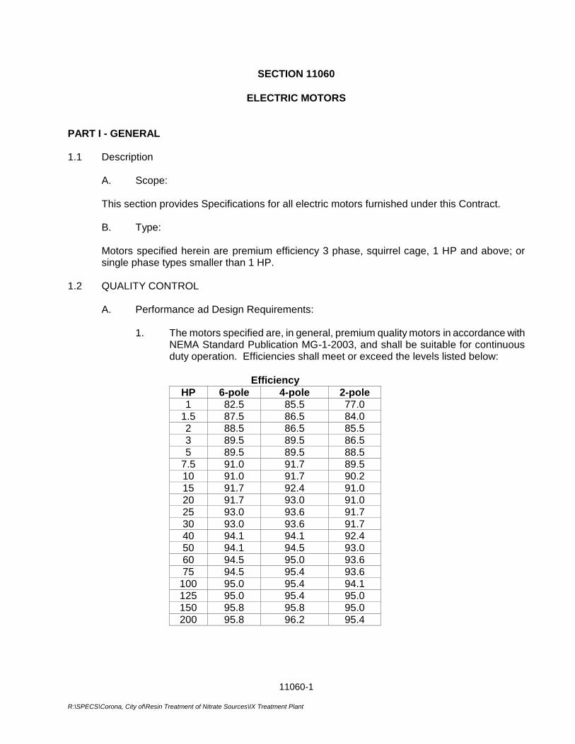
11060-1
R:\SPECS\Corona, City of\Resin Treatment of Nitrate Sources\IX Treatment Plant
SECTION 11060
ELECTRIC MOTORS
PART I - GENERAL 1.1 Description
A. Scope:
This section provides Specifications for all electric motors furnished under this Contract.
B. Type:
Motors specified herein are premium efficiency 3 phase, squirrel cage, 1 HP and above; or single phase types smaller than 1 HP.
1.2 QUALITY CONTROL
A. Performance ad Design Requirements:
1. The motors specified are, in general, premium quality motors in accordance with NEMA Standard Publication MG-1-2003, and shall be suitable for continuous duty operation. Efficiencies shall meet or exceed the levels listed below:
Efficiency
HP 6-pole 4-pole 2-pole 1 82.5 85.5 77.0
1.5 87.5 86.5 84.0 2 88.5 86.5 85.5 3 89.5 89.5 86.5 5 89.5 89.5 88.5
7.5 91.0 91.7 89.5 10 91.0 91.7 90.2 15 91.7 92.4 91.0 20 91.7 93.0 91.0 25 93.0 93.6 91.7 30 93.0 93.6 91.7 40 94.1 94.1 92.4 50 94.1 94.5 93.0 60 94.5 95.0 93.6 75 94.5 95.4 93.6
100 95.0 95.4 94.1 125 95.0 95.4 95.0 150 95.8 95.8 95.0 200 95.8 96.2 95.4
11060-2
R:\SPECS\Corona, City of\Resin Treatment of Nitrate Sources\IX Treatment Plant
2. Each motor shall develop ample torque for its required service throughout its acceleration range at impressed voltages in the range between 10 percent above and below nameplate rating. In addition, all motors shall be selected to be non-overloading at all points along the driven machines' full speed characteristic curve.
Motors with a 1.0 service factor shall not be required to deliver more than 87
percent of rated nameplate horsepower under the specified loading conditions. Motors with 1.15 service factor shall not be required to deliver more than its rated nameplate horsepower under the specified loading condition.
3. Motors supplied under this specification shall be suitable for continuous duty in
outdoor locations where ambient temperatures may range between 30 degrees F and 125 degrees F. Ambient relative humidities will range between 5 and 100 percent.
Enclosures shall be TEFC unless otherwise noted.
B. Standards:
Motors shall be designed and built in accordance with the latest revisions of the following reference standards.
1. NEC; Environmental Operation Requirements. 2. ANSI Requirements for Numbering and Schematic Representation.
3. IEEE Standards for Electric Motors. 4. NEMA MG1 - latest revision. 5. NEMA 4; Requirements for Watertight Equipment. 6. NEMA 4X; Requirements for Outdoor Installations. 7. NEMA 7D; Requirements for Explosive Environments. 8. NEC Requirements for Hazardous Locations. 9. UL Requirements for Motors and their Appurtenances. 10. UL Requirements for Explosive Environments.
C. Performance Tests:
1. Should any motor exhibit indication of questionable performance, the Owner's representative, at his discretion, may request information or load test at any time after delivery of a motor to the job site. If any motor proves to be defective, all costs of testing and repair or replacement of defective motor shall be borne by the Contractor. If any motor proves to be in accordance with recommendations or manufacturer's tolerances, the cost of testing will be borne by the Owner.

11060-3
R:\SPECS\Corona, City of\Resin Treatment of Nitrate Sources\IX Treatment Plant
2. Insulation resistance tests shall be performed by the Contractor. Tests for
acceptability shall be made using a 1000 volt megohm meter (megger). Interpretations of test results for minimum acceptable values of insulation resistance will be made in accordance with IEEE Publication 43.
3. Load tests shall be performed to determine the motor's ability to meet service
factor loading conditions within the temperature limits of the manufacturer's submittal data. Tests shall be conducted in accordance with IEEE Publication 112A. In the event that a motor does not meet the load test requirements, the Contractor shall replace the motor at no cost to the Owner.
1.3 SUBMITTAL DATA
The following material shall be submitted for each size and type of electric motor furnished under this Contract:
A. Descriptive bulletins, including full description of insulation system.
B. Manufacturer's connection diagrams for motors furnished with over-temperature
protectors, heaters, and other auxiliary devices.
C. Sufficient data on over-temperature devices to verify required protection.
D. Service factor.
E. Efficiency at 1/2, 3/4 and 4/4 nameplate horsepower.
F. Power factor at 1/2, 3/4 and 4/4 nameplate horsepower.
G. Temperature rise at service factor horsepower.
H. Guaranteed maximum sound power levels rated in accordance with paragraph 2.04 of this Specification.
I. Bearing information.
PART 2 - PRODUCTS 2.1 GENERAL
Open drip-proof motors shall have openings constructed so that falling liquids or solid particles striking or entering the enclosure at any angle from 0 to 15 degrees from vertical will not interfere with the performance.
Totally enclosed fan cooled and totally enclosed non-ventilated motors shall be provided with drilled and tapped holes to drain all cavities within the motor. Motors with frames 286T or smaller shall have corrosion-resistant plugs in the drain holes. Motors with frame 324T or larger shall be provided with automatic breather-drain devices.
11060-4
R:\SPECS\Corona, City of\Resin Treatment of Nitrate Sources\IX Treatment Plant
Weather protected NEMA Type II (WP-II) motors shall be provided with screens to prevent objects larger than 1/2 inch from entering the enclosure. If weather-protected NEMA Type II enclosures cannot be supplied for the required frame sizes, sub-types B or C motor enclosures may be substituted.
Explosion proof motors shall be UL listed for Class I, Division 1, Group D hazardous locations and be provided with UL approved combination breather drains suitable for hazardous locations.
The motor manufacturer's nameplates shall be engraved or stamped on stainless steel and fastened to the motor frame with No. 4 or larger oval head stainless steel screws or drive pins. Nameplates shall indicate clearly all the items of information enumerated in NEMA Standards MG1-10.37, MG1-10.38, or MG1-20.60, as applicable.
The nameplate shall be positioned to be readily visible for inspection in the complete machine.
2.2 THREE PHASE MOTORS – 1-H.P. AND ABOVE GENERAL REQUIREMENTS
A. General: All motors 1 HP and above shall be 3 phase, squirrel cage, induction motors on NEMA frame 143T or larger. Motors shall be manufactured by U.S. Electrical Motors, or approved equal.
B. Rating:
Motors shall be designed and connected for 460 volt, 3 phase, 60 HZ operation. Dual voltage (230/460) rated motors are acceptable if all leads are brought out to the motor terminal box. All motors shall have a 1.15 continuous duty service factor at 50 degrees C ambient temperature and shall be suitable for 65 degree C ambient with 1.0 service factor, unless noted otherwise. Starting KVA/HP shall not exceed the values given in NEMA Standard MG1-12.34.
C. Insulation:
Insulation systems shall be rated and suitable for inverter duty at maximum rated load, non-hygroscopic, and shall be suitable for use in moisture laden atmospheres and atmospheres containing acid or alkali vapor. Insulation systems shall be manufacturer's premium grade, capable of withstanding contaminated atmospheres.
D. Current Balance:
Current unbalance on polyphase motors shall not exceed the values tabulated below when motor is operating at any load within its service factor rating and is supplied by a balanced voltage system:
Under 5 horsepower 25 percent 5 horsepower and above 10 percent
If, however, the unbalanced currents cause mechanical vibrations, the Contractor shall correct the problem even if the measured unbalance is less than listed above.
11060-5
R:\SPECS\Corona, City of\Resin Treatment of Nitrate Sources\IX Treatment Plant
E. Over-Temperature Protection: Winding over-temperature devices shall be provided for all motors rated 1-horsepower and larger, for all Type E (explosion proof) motors, and for all other motors where specified. Over-temperature devices shall provide a normally closed contact suitable for wiring into the motor control circuit. Any relays or solid state contacts which are required shall be provided in an enclosure on or near the motor.
F. Space Heaters All pump motors shall be provided with 120V space heaters of sufficient wattage, quantity and in proper locations so as to keep the motor interior and windings dry during periods of disuse.
G. Enclosures: All motors shall have cast iron housing, bearing brackets, fan guards and conduit box. Totally-enclosed motors shall be furnished with silicon rubber gaskets at the base of the conduit box and between the halves of the motor terminal box.
H. Reduced Voltage Starting:
Where shown on the drawings, motors 60 HP and larger shall be suitable for solid state reduced voltage starting.
I. Bearings:
Three-phase motor bearings shall be conservatively designed to withstand all stresses of the service specified. Antifriction motor bearings shall be designed to be regreasable and initially shall be filled with grease suitable for ambient temperatures to 50°C. If a
higher ambient temperature is specified for motor insulation rating purposes, bearings shall be sized and designed for the same ambient temperature. Bearing identification by AFBMA number shall be indicated on the motor nameplate.
J. Variable Frequency Drives (VFD)
Where shown on drawings, motors operated via VFD’s shall be inverter duty rated. 2.3 SINGLE-PHASE MOTORS
A. General:
Unless otherwise specified, single-phase motors shall be capacitor-start induction motors. Small single-phase fan motors may be split-phase or shaded-pole type, if such is standard for the equipment. Universal (AC-DC) type single-phase motors are not acceptable unless their specific characteristics are necessary for the application. Conductors shall be copper.
11060-6
R:\SPECS\Corona, City of\Resin Treatment of Nitrate Sources\IX Treatment Plant
Single-phase motors shall be designed and connected for operation on a 115 volt, 60 HZ alternating current electrical system, or 208 volt where indicated.
B. Rating:
Unless otherwise specified, single-phase motors shall not be required to deliver more than its rated nameplate horsepower under any condition of required loading. Single-phase motor locked rotor current shall not be greater than that specified in NEMA Standard MG1-12.32, Design "N".
C. Enclosures:
Unless otherwise specified, single-phase motors shall be TEFC. D. Insulation:
Unless otherwise specified, single-phase motor insulation systems shall be as recommended by the motor manufacturer.
E. Construction:
Unless otherwise specified, single-phase motor construction shall be as recommended by the motor manufacturer.
F. Bearings:
Unless otherwise specified, single-phase motors shall be provided with sealed ball bearings lubricated for 10 years normal use.
*** END OF SECTION ***
11240-1
G:\Projects\WATER TREATMENT\Resin_Treatment_of_Nitrate_Sources-CIP_No_68510507\01-Administration\01_h-Contract_Documents\Specifications\Division 2 - 17\Sect 11240 Chem Feed Pump.doc
SECTION 11240
CHEMICAL FEED PUMP
PART 1 - GENERAL 1.1 GENERAL
This specification covers the supply, installation, and testing of completely functional metering pump feed systems including all necessary accessories and appurtenances as shown on the drawings and described herein. A single chemical metering pump manufacturer shall be responsible for supplying all components of the metering pump feed system.
1.2 QUALITY ASSURANCE
For the purpose of establishing quality assurance, experience, and system reliability, the products described herein are based on those metering pumps manufactured by Milton Roy. All pumps shall be shop-tested for capacity and pressure prior to shipment from the documented results provided.
1.3 WARRANTY
The chemical metering pump manufacturer shall provide a two (2) year warranty on the metering pump mechanical drive and one (1) year on the liquid end.
PART 2 - PRODUCTS 2.1 DESCRIPTION
A. The chemical metering pump(s) shall be microprocessor-controlled, simplex, solenoid-driven, reciprocating, mechanically actuated diaphragm type. All pumping functions shall be set by membrane-switch keypad and status shall be displayed on an illuminated LCD, which is readable at an offset angle of 45 degrees. Keypad will allow for simple scrolling and display of programmed parameters. The housing shall be rated NEMA 4X.
B. The power supply shall be 120 VAC, 60 Hz, single phase. The microprocessor is to automatically compensate for supply voltage variations with 15% of the rated voltage such that the frequency of the pump remains constant.
C. The liquid end shall be physically separated from the drive unit by a backplate with weep hole creating an air gap. An elastomer shaft wiper seal shall prevent contamination of the solenoid if the primary diaphragm fails. The diaphragm shall be constructed of a steel core, vulcanized into nylon-reinforced EPDM, with PTFE-faced fluid contact surface.
2.2 LIQUID END
The liquid end shall be of the self-degassing type, with integral automatic air relief valve for self-priming under maximum rated discharge line pressure. The suction valve shall be of
11240-2
G:\Projects\WATER TREATMENT\Resin_Treatment_of_Nitrate_Sources-CIP_No_68510507\01-Administration\01_h-Contract_Documents\Specifications\Division 2 - 17\Sect 11240 Chem Feed Pump.doc
the double ball check design and discharge valve shall be spring-loaded, horizontally acting single ball design. The liquid end shall be equipped with a contour plate that allows the pump to operate under completely dry or starved suction condition at maximum capacity setting without damage to the diaphragm and pump. Each pump shall have a maximum capacity equal to or exceeding flow rating per schedule and be rated for continuous duty against maximum discharge pressure. Pump nameplate shall reflect this rating.
The process diaphragm shall be Teflon and have a minimum design life of 90,000 hours at rated conditions. A premature failure of diaphragm due to defects or workmanship will warrant metering pump manufacturer to provide replacement diaphragm at no charge.
2.3 PROGRAMMING AND CONTROL
A. Stroke length control shall be manually adjusted between 100% and 0% with a stroke adjustment knob on the pump face control. The LCD shall digitally display stroke length setting in 1% increments in the full range between 100% and 0%.
B. Programming shall allow pump to be calibrated so as to display pump output in gallons/hour or liters/hour. Calibration shall be maintained when stroke length is altered up to plus or minus 10% on the stroke length knob. If stroke length is altered by more than 10%, a yellow warning light will light and a flashing message “calib” will appear.
C. The pump shall be equipped with the programmable function of pressure levels to allow pump to operate at reduced pressures from the maximum rated pressure of the pump.
D. The pump shall be equipped with the programmable function of electronic interlocking of the keypad by access code to prevent unauthorized adjustments to the pump.
E. Keypad shall allow for scrolling and display on LCD such parameters as stroke frequency, stroke length, stroke counter, pump output in gals/hr or L/hr, dosing quantity, mA current input being received by pump, and indication of external mode.
F. Stroke frequency control shall be manually adjusted by touch keypads, with the set stroke rated displayed on the LCD. The metering pump shall be capable of receiving a pulse input via optional external control cable such that one pulse gives one pump stroke rate. The pump shall be capable of remote ON-OFF operation using the pause function via a voltage free contact relay through an optional control cable.
In addition, the pump shall be configured with analog input functionality. The pump shall accept an analog signal such that stroke frequency is proportional to 0/4-20mA or 20-4/0mA, the choice of which is programmable at the pump. The pump shall allow the setting of a maximum stroke rate, which corresponds to the maximum analog signal, with stroke rate proportional to signal strength below that rate. Programming for curve processing shall also be possible, in which any stroke frequency ratio in proportion to the electrical signal can be configured. Analog to digital converters external to the pump shall not be allowed.
11240-3
G:\Projects\WATER TREATMENT\Resin_Treatment_of_Nitrate_Sources-CIP_No_68510507\01-Administration\01_h-Contract_Documents\Specifications\Division 2 - 17\Sect 11240 Chem Feed Pump.doc
G. The pump shall be equipped with the programmable function of auxiliary frequency control, allowing for quick priming of the pump or for slug feed after system shutdown. Stroke frequency shall be programmable to a maximum of 180 spm, and the auxiliary frequency function shall be capable of interfacing with a contact closure relay for control purposes.
2.4 FLOW ASSURANCE
A. Flow Monitor: A flow monitor shall be installed on the discharge line to automatically stoop pumping and annunciate a fault condition on the pump LCD display upon loss of discharge flow. The pump shall be programmable, between 1 and 125 strokes per minute, to actuate the fault annunciation after flow is lost.
B. Relay Output: An SPDT relay shall be installed for fault indication. The metering pump shall have an integral relay to allow remote annunciation of a fault condition (i.e. flow monitor, system faults, and fuse/power supply failure). Configure as (No/NC) contact closure relay.
2.5 ACCESSORIES
A. A pump skid for installation of (2) pumps for each application.
B. Strainer (Wye type), constructed of materials compatible with chemical to be used shall be provided with each pump.
C. A universal control cable with 5-pole round plastic connector and 5-wire cable with loose ends shall be provided with each pump.
D. An adjustable discharge flow monitoring device, compatible with chemical to be used, shall be provided with each pump. The flow monitor shall be capable of signals a fault condition to the pump.
E. A diaphragm failure detector shall be provided to (open/close) a contact for alarm in the event of a diaphragm failure.
F. An in-line, adjustable-pressure, diaphragm-type pressure relief valve, constructed of materials compatible with chemical to be used, shall be provided with each pump.
G. An air-charged, bladder-type pulsation dampener, constructed with materials compatible with chemical to be used, shall be provided with each pump. The pulsation dampener shall be sized to reduce pulsations by at least 90% at full pump capacity.
H. A clear PVC calibration column with FNPT fitting on top and bottom shall be provided. The column shall be sized to provide at least 2 minutes draw down at maximum pump capacity.
I. Fifteen (15) feet of tubing compatible with chemical to be used shall provide with each pump.
11240-4
G:\Projects\WATER TREATMENT\Resin_Treatment_of_Nitrate_Sources-CIP_No_68510507\01-Administration\01_h-Contract_Documents\Specifications\Division 2 - 17\Sect 11240 Chem Feed Pump.doc
2.6 APPLICATION
A. Quantity of Equipment: Provide a total of 2 pumps (1duty, 1 spare), in conformance with the specifications above for each chemical injection system. Provide accessories for 2 pumps only (each chemical injection system).
B. Chemical Services: Ammonia and Sodium Hypochlorite
C. Capacity: Each Ammonia injection pump shall be capable of delivering a flow of 1.2 gph. Each Sodium Hypochlorite injection pump shall be capable of delivering a flow of 5.4gph.
D. Backpressure: Maximum backpressure at each injection point is 20 psi.
2.7 SPARE PARTS AND SPECIAL TOOLS
A. For each identical chemical metering pump per designated chemical service. Provide the following spare parts.
QUANTITY DESCRIPTION
4 Seats for suction and discharge cartridges
4 Check valve balls
1 set Check valve gasket and O-rings
1 Diaphragm
B. Provide a set of all special tools required to perform maintenance and repair.
C. All parts and tools shall clearly identify the equipment to which it applies and be packaged for prolonged storage.
2.8 PAINTING
All exposed metallic metering pump and accessory surfaces shall be prepared and painted with corrosion resistant epoxy paint.
PART 3 – EXECUTION 3.1 MANUFACTURERS’ SERVICES
A factory trained, qualified Manufacturer’s technical personnel and/or designated technical
representative shall be available to provide installation, start up and operational training assistance to Contractor and Owner personnel as required. A start up and commissioning report including completion of final operator training on a Manufacturer start up report form must be completed and signed by all concerned parties for approval of final payment for the chemical feed system.
***END OF SECTION***
11248-1 G:\Projects\WATER TREATMENT\Resin_Treatment_of_Nitrate_Sources-CIP_No_68510507\01-Administration\01_h-
Contract_Documents\Specifications\Division 2 - 17\Sect 11248 Inline Static Mixer.doc
SECTION 11248
INLINE STATIC MIXER
PART 1 - GENERAL
1.1 DESCRIPTION
A. Scope
1. This section describes the supply and installation of inline static mixers. The equipment shall be installed as shown on the plans, as recommended by the manufacturer, and in compliance with al OSHA, local, state, and federal codes and regulations.
2. The Contractor is responsible for furnishing complete and operable equipment that functions automatically in accordance with requirements of the Contract Documents. The equipment shall be provided to the jobsite complete with all necessary accessories as specified and as required for a complete operating installation.
3. The Contractor is responsible for troubleshooting the system after installation until it functions according to the requirements of the Drawings and Specifications. All combinations of manufactured equipment that are provided under these Specifications shall be entirely compatible, and the Contractor shall be responsible for the compatible and successful operation of each component of the equipment items.
4. The Contractor shall refer to the Contract Documents for any additional equipment items or components required for the complete operation of the equipment of this Section, but not specifically described in this specification.
1.2 RELATED WORK SPECIFIED ELSEWHERE
A. Section 05500 Miscellaneous Metals
B. Section 11001 General Equipment Provisions
C. Section 09900 Painting and Coating Systems
1.3 SUBMITTALS
All submittals shall be submitted in accordance with Section 01330.
A. Shop Drawings – Drawings shall include the minimum following items:
1. Dimensions, elevations, and materials for all equipment and/or components covered in this specification.
2. Installation and layout of equipment and appurtenances.
3. Field connection locations.
11248-2 G:\Projects\WATER TREATMENT\Resin_Treatment_of_Nitrate_Sources-CIP_No_68510507\01-Administration\01_h-
Contract_Documents\Specifications\Division 2 - 17\Sect 11248 Inline Static Mixer.doc
4. Total equipment weight.
B. Guarantee and Warranty Information – Submit all guarantee and warranty information described in the paragraph entitled “Guarantee and Warranty”.
C. Operation and Maintenance Manuals – Submit operation and maintenance manuals in accordance with Section 01783.
D. Mixer Data – The following shall be submitted:
1. Name of Manufacturer
2. Type and Model
1.4 QUALITY ASSURANCE
A. Equipment Quality – All equipment specified herein shall be new and of current manufacturer. The equipment furnished shall be designed and constructed in accordance with the best practices and methods and shall operate satisfactorily when installed as shown on the Drawings and operated per the manufacturer’s recommendations. All workmanship and materials used shall be of the highest quality and of proven reliability.
B. Factory Testing – The equipment shall be factory assembled and factory tested prior to being shipped to ensure satisfactory operation. The City may, at their option and own expense, witness the factory testing.
C. Single Supplier – The equipment described in this Section shall be provided by a single supplier, in order to ensure coordination and proper operation of the component pieces of the system. Where two or more items of the same type and/or size of equipment are required, such items shall be produced by the same manufacturer.
1.5 REFERENCE SPECIFICATIONS, CODES, AND STANDARDS
The work in this Section shall comply with applicable provisions and recommendations of the following standards, except as otherwise shown or specified:
ANSI American National Standards Institute
ASCE American Society of Civil Engineers
ASTM American Society for Testing and Materials
AWWA American Water Works Association
NSF National Science Foundation
SSPWC Standard Specifications for Public Works Construction (“Greenbook”) Current Edition
UL Underwriter’s Laboratory
11248-3 G:\Projects\WATER TREATMENT\Resin_Treatment_of_Nitrate_Sources-CIP_No_68510507\01-Administration\01_h-
Contract_Documents\Specifications\Division 2 - 17\Sect 11248 Inline Static Mixer.doc
1.6 GUARANTEE AND WARRANTY
A. The Contractor shall obtain from the Manufacturer, a manufacturer warranty for all material, equipment, and appurtenances specified in this Section.
B. The warranty shall be for a minimum period of twelve (12) months from final acceptance by the City. Equipment warranty shall cover all failures of material or workmanship which occur as the result of normal operation and service excluding normal wear parts. The manufacturer shall repair and/or replace any parts proven to be defective, within the guarantee period, freight on board (FOB) the job site at the manufacturer’s expense.
C. During the warranty period, the Contractor shall provide the services of a trained Manufacturer’s representative to make all adjustments, repairs and replace all defective material and equipment at no cost to the City. The Contractor shall include all costs incurred by the Manufacturer, including travel and expenses, under the terms of the warranty.
D. The Manufacturer(s) shall certify that authorized service personnel reside in the United States.
PART 2 – PRODUCTS
2.1 GENERAL
A. The equipment specified herein shall be inline static mixers, as manufactured by Komax Systems, Inc. of Huntington Beach, CA (City standard, no exceptions).
2.2 DESIGN REQUIREMENTS
A. Mixer shall provide uniform mixing of within the conditions as described in the Service Conditions Table below.
B. Trapezoidal tab type mixing elements shall not be accepted. Mixing elements configured as corrugated metal plates shall not be accepted. Helical, double action mixing elements shall not be accepted.
2.3 CONSTRUCTION AND MATERIALS
A. Mixer shall be static inline with no moving parts.
B. Mixer housing, connecting flanges and internal elements shall be fabricated using Type 316 stainless steel.
C. Mixing elements should be welded to the pipe wall. Mixing shall be stationary rigid elements arranged to split and recombine component streams to provide a homogeneous stream at the mixer outlet.
D. Mixer housing and elements should be fabricated in materials fully compatible with fluids being mixed. The internal of the mixer to be coated with NSF-61 approved epoxy (Potapox) coating.
11248-4 G:\Projects\WATER TREATMENT\Resin_Treatment_of_Nitrate_Sources-CIP_No_68510507\01-Administration\01_h-
Contract_Documents\Specifications\Division 2 - 17\Sect 11248 Inline Static Mixer.doc
2.4 EQUIPMENT IDENTIFICATION
A. Each unit of equipment shall be identified with a Type 316 stainless steel corrosion resistant nameplate, securely affixed in a conspicuous place. Nameplate information shall include equipment Manufacturer and model number, year of manufacture, serial number, Supplier’s name, location, and local telephone number.
PART 3 – EXECUTION
3.1 PRODUCT DELIVERY, STORAGE, AND HANDLING
A. The equipment shall be shipped completely assembled. It shall be capable of being set in place and field erected by the Contractor with minimum field assembly.
B. Packaging shall be as required to prevent damage during shipment and unloading.
C. Deliver materials to the site to insure uninterrupted progress of the work. Deliver anchor bolts and anchorage devices in ample time not to delay that work.
D. The Contractor shall store and temporarily support equipment prior to installation in strict accordance with the manufacturer’s recommendations and instructions. Protect all exposed surfaces. Protect all equipment from being contaminated by dust, dirt, and moisture. Keep records of the storage parameters and the dates that storage procedures were performed. The Contractor shall be responsible for work, equipment, and materials until inspected, tested and finally accepted.
E. Handle all equipment and materials very carefully. Damaged equipment and materials will not be acceptable. Protect all bolt threads, etc. from damage corrosion. Protect all factory applied coatings from damage during shipment, unloading, storage and installation.
3.2 INSTALLATION
A. Install mixer as shown in the drawings and in accordance with manufacturer’s written instructions.
B. Connections to piping shall be properly aligned so as not to impose strain on the connection. Make adjustments required to place system in proper operating condition.
3.3 MANUFACTURER’S FIELD SERVICES
A. The Manufacturer shall provide the services of a competent and experienced factory-trained service representative for one (1) trip for a minimum total of one (1) 8-hour day to provide inspection of installation, equipment startup, and operator and maintenance personnel training services. The representative shall insure that the equipment is handled and installed according to the Manufacturer's recommended procedures. During the initial operation, the representative shall instruct the operation and maintenance personnel of the City on any important operation and maintenance features of the equipment.
B. The Contractor shall notify the City seven (7) days prior to the scheduled day for initial start-up, so the City can notify operation and maintenance personnel of the proposed
11248-5 G:\Projects\WATER TREATMENT\Resin_Treatment_of_Nitrate_Sources-CIP_No_68510507\01-Administration\01_h-
Contract_Documents\Specifications\Division 2 - 17\Sect 11248 Inline Static Mixer.doc
instruction. The Contractor shall include the cost of all the Manufacturer's installation, start-up, and training services in his bid.
C. After installation supervision service by the Manufacturer, the Manufacturer shall submit to the City within 14 days a letter, on the Manufacturer's letterhead, certifying that the equipment was installed per the manufacturer’s recommendations.
3.4 FIELD TESTING
A. The equipment shall also be field tested after erection in the presence of the City to confirm and verify the structural and mechanical compliance to the specification. The field acceptance test shall include demonstrating that the equipment performs the specified functions satisfactorily.
3.5 INSTALLATION, OPERATION, AND MAINTENANCE MANUAL
A. In addition to the normal Installation, Operation, and Maintenance manuals required by the contract, a spare manual will be shipped with the unit in order to allow for proper operation of the equipment prior to the release of all final Installation, Operation, and Maintenance manuals.
***END OF SECTION***

11248-6 G:\Projects\WATER TREATMENT\Resin_Treatment_of_Nitrate_Sources-CIP_No_68510507\01-Administration\01_h-
Contract_Documents\Specifications\Division 2 - 17\Sect 11248 Inline Static Mixer.doc
THIS PAGE INTENTIONALLY BLANK
11300-1 G:\Projects\WATER TREATMENT\Resin_Treatment_of_Nitrate_Sources-CIP_No_68510507\01-Administration\01_h-Contract_Documents\Specifications\Division 2 - 17\Sect 11300 Air Compressors.doc
SECTION 11300
AIR COMPRESSORS
PART 1 GENERAL
1.01 SUMMARY
A. Section includes: This Section describes the requirements for providing the following: 1. Air Compressors. 2. Receiver. 3. Accessories.
B. Related sections: 1. The Contract Documents are complementary; what is called for by one is as
binding as if called for by all. 2. It is the Contractor’s responsibility for scheduling and coordinating the Work of
Sub-contractors, suppliers, and other individuals or entities performing or furnishing any of Contractor’s Work.
3. The following Sections are related to the Work described in this Section. This
list of Related Sections is provided for convenience only and is not intended to excuse or otherwise diminish the duty of the Contractor to see that the completed Work complies accurately with the Contract Documents. a. Section 01330 - Submittal Procedures. b. Section 09900- Painting. c. Section 13621 - Primary Sensors & Field Instruments.
1.02 REFERENCES
A. American Society of Mechanical Engineers (ASME): 1. B16.11 Forge Fittings, Socket-Welding and Threaded. 2. B16.18 Cast Copper Alloy Solder Joint Pressure Fittings. 3. B31.1 Power Piping.
B. ASTM International (ASTM): 1. A 53 - Standard Specification For Pipe, Steel, Black And Hot-Dipped, Zinc-
Coated, Welded And Seamless 2. A 269 - Standard Specification for Seamless and Welded Austenitic Stainless
Steel Tubing for General Service. 3. B 88 - Standard Specification for Seamless Copper Water Tube.
C. National Electrical Manufacturers Association (NEMA): 1. 250 – Enclosure for Electrical Equipment (1000 V Maximum). 2. MG-1 - Motors and Generators.
11300-2 G:\Projects\WATER TREATMENT\Resin_Treatment_of_Nitrate_Sources-CIP_No_68510507\01-Administration\01_h-Contract_Documents\Specifications\Division 2 - 17\Sect 11300 Air Compressors.doc
1.03 DEFINITIONS
A. NEMA: 1. Type 1 enclosure in accordance with NEMA 250. 2. Type 12 enclosure in accordance with NEMA 250.
1.04 SUBMITTALS
A. General: 1. Submit in accordance with the requirements as specified in Section 01330. 2. All of the material required for submittal under this Section shall be furnished in
1 complete package
B. Product data and shop drawings.
C. Certifications: A manufacturer's certificate of satisfactory installation is required for work under this Section.
1.05 ENVIRONMENTAL CONDITIONS
A. The equipment to be provided under this Section shall be suitable for installation and operation under the following conditions: 1. Project site elevation: 642 feet above sea level. 2. Outdoor temperature and humidity:
a. Outside ambient air temperatures range between 32 and 110 degrees Fahrenheit, with relative humidity ranging between 10 and 100 percent (noncondensing).
1.06 MAINTENANCE
A. Spare parts: 1. Supply to the Owner spare parts, any specialized tools required in the
manufacturer's maintenance procedures, and 3 air filters.
1.07 OPERATING AND MAINTENANCE MANUALS
A. Operating and maintenance manuals and maintenance summary sheets for the equipment specified herein shall be furnished as specified in Section 01783.
PART 2 PRODUCTS
2.01 AIR COMPRESSOR
A. Manufacturers: The following or equal: 1. Kaeser, Model SX5T or approved equal.
B. Type: The air compressors shall be a single-stage, oil flooded, air cooled rotary screw compressor completely pre-piped and pre-wired control panel, meeting the following design requirements:

11300-3 G:\Projects\WATER TREATMENT\Resin_Treatment_of_Nitrate_Sources-CIP_No_68510507\01-Administration\01_h-Contract_Documents\Specifications\Division 2 - 17\Sect 11300 Air Compressors.doc
CHARACTERISTICS
Displacement Capacity, cfm 18-24
Operating Pressure, psi 125
Motor Horsepower, hp each 5
Motor Speed, rpm 3600
C. Compressor unit, including crankshaft, cylinders, flywheel, and motor shall be 2 stage, and shall be air cooled, splash lube, completely sealed against dirt, and providing a large oil sump. 1. A finned, multi-tube intercooler shall be provided between stages and shall
include a safety valve to prevent over pressurization. a. A dry-type 3 micron filter silencer shall be provided on the air inlet.
2. A low oil level switch shall be provided to automatically stop the compressor if the oil level gets too low.
3. An air-cooled aftercooler shall lower the discharge air temperature to within 25 degrees Fahrenheit of the ambient air temperature.
4. Compressor bearings shall be oil lubricated. 5. Each compressor shall be driven by an electric motor integral with the
compressor.
D. Motor: 1. Compressor motor: 460 VAC, 3 phase, 60 hertz, TEFC, 1.15 service factor,
severe duty, energy efficient, with self-lubricated ball bearings. Control system shall be 115 VAC, 1 phase, 60 Hz.
2.02 PIPING
A. General: 1. All interconnecting piping and tubing between components of the equipment
package shall be shop installed. 2. Piping from the compressor discharges to the receiver shall be sized not less
than the compressor discharge connection size and shall be ASTM A 53, seamless, Grade B, Schedule 40 black steel pipe with ASME B16.11, Class 3000, forged steel socket-welding fittings or Schedule 80 black steel pipe with Class 3000 forged steel threaded fittings. "Close" nipples will not be acceptable.
B. Pneumatic control and instrument tubing: 1. In accordance with ASTM A 269, Type 316, stainless steel tubing with Parker-
Hannifin "Ferulok," Crawford "Swagelock," or equal, Type 316 stainless steel flareless double ferrule compression fittings.
2. Tubing shall not be less than 1/4 inch OD with a wall thickness of 0.028 inch.
C. All piping and tubing shall be run in vertical and horizontal planes. 1. Piping shall be arranged to ensure that undue stresses, from thermal
expansion, are not transmitted to equipment components.
11300-4 G:\Projects\WATER TREATMENT\Resin_Treatment_of_Nitrate_Sources-CIP_No_68510507\01-Administration\01_h-Contract_Documents\Specifications\Division 2 - 17\Sect 11300 Air Compressors.doc
D. All control and instrument tubing shall be continuously supported.
2.03 CONTROL EQUIPMENT
A. All control equipment for each compressor shall be furnished as required for a complete installation, requiring only field connection of the electrical power supply and alarm output signals.
B. Equipment shall include the following: 1. All control switches, pressure switches, timing relays, auxiliary relays, elapsed
time meters, circuit breaker combination magnetic motor starters, and other accessories required for control of each compressor.
2. Each starter shall include a thermal magnetic circuit breaker with external operating handle.
3. Starter overloads shall be matched to motor current and shall be provided with a reset pushbutton.
C. All control equipment for each compressor package shall be housed in a control panel mounted on the receiver.
D. All system wiring shall be shop installed to terminal blocks in the control panel. 1. Wiring from the panel to system components shall be completely enclosed in
liquid tight flexible conduit.
E. All pneumatic tubing shall be shop installed to bulkhead fittings at the control panel. All field connections shall be made to the fittings at the panel.
F. Control panel enclosure: 1. The control panel shall be NEMA 12, and shall be equipped with a full size
gasketed door with chromium-plated or stainless steel 3 point latch and hinges.
G. Internal panel tubing shall be run in horizontal and vertical planes and shall be rigidly supported to withstand handling and shipping without damage. 1. Compression type bulkhead fittings shall be provided through the panel for all
connections.
H. Panel wiring: 1. Internal panel wiring shall be neatly bundled and tied and identified with
suitable wire markers. 2. Terminal blocks for external connections shall be furnished complete with
marking strips, covers, and pressure connectors. 3. A terminal shall be provided for each conductor of external circuits. 4. All wiring shall be grouped or cabled and securely attached to the panel. 5. Clearance for field wiring shall be provided between the terminal strips and
base.
I. Compressor control: 1. General:
11300-5 G:\Projects\WATER TREATMENT\Resin_Treatment_of_Nitrate_Sources-CIP_No_68510507\01-Administration\01_h-Contract_Documents\Specifications\Division 2 - 17\Sect 11300 Air Compressors.doc
a. The compressed air package shall be furnished with a control system which shall start and stop the compressors as required.
b. The control system shall unload the compressors on shutdown and while coming up to speed during startup.
c. Unloading shall be accomplished by inlet valve control. 2. Control switch:
a. Each compressor shall be provided with a control switch with "Lead-Off-Lag" positions.
b. Two pressure switches with separately adjustable settings shall be furnished for each compressor, 1 for "Lead" and 1 for "Lag" control.
3. The control system shall start and stop the lead compressor at receiver pressures of 80 pounds per square inch gauge and 100 pounds per square inch gauge, respectively, and start and stop the lag compressor at 75 pounds per square inch gauge and 95 pounds per square inch gauge, respectively.
J. Protection controls: 1. A dual protection control system shall be provided for each compressor. 2. The control system shall stop the compressor on either overload or high
discharge air temperature.
K. Miscellaneous controls: 1. A dial type thermometer shall be furnished for each compressor air discharge. 2. A package receiver pressure gauge and the compressor air discharge
thermometers shall be mounted on a wing projection on top of each control panel.
L. White indicating lights shall be provided on the control panel to indicate the following alarm conditions: 1. Motor overload, each compressor. 2. High discharge air temperature, each compressor. 3. Low receiver pressure.
M. Indicating lights shall be heavy-duty, oiltight, push to test, semi-flush type with escutcheon plates to identify the malfunction. 1. A mechanical latching relay circuit with a common "Reset" pushbutton shall be
provided so that the alarm lights remain on until manually reset. 2. The latching relays shall have a contact rated 10 amperes at 120 volts, which
closes on alarm. 3. An alarm light "Test" pushbutton shall also be provided on the front of the
control panel to test the lights simultaneously without actuating the remote alarm.
N. Provide Compressor 1 Fail and Compressor 2 Fail alarm contact outputs of senses as indicated on the Drawings.
O. Provide low receiver pressure alarm contact output of sense as indicated on the Drawings. 1. Contacts to change state when the receiver pressure falls to 25 pounds per
square inch gauge.
11300-6 G:\Projects\WATER TREATMENT\Resin_Treatment_of_Nitrate_Sources-CIP_No_68510507\01-Administration\01_h-Contract_Documents\Specifications\Division 2 - 17\Sect 11300 Air Compressors.doc
2. Contacts shall be rated 10 amperes at 120 volts, 60 hertz.
P. Each compressor shall be provided with an elapsed time hour meter mounted on the front of each control panel.
2.04 ACCESSORIES
A. The compressed air equipment package shall be provided with the following accessory equipment: 1. Safety valves:
a. Safety valves with manual lifting levers shall be installed in the compressor discharge piping and on the receiver.
b. Valves in the compressor discharge piping shall be capable of protecting the compressors from damage when operating against a closed discharge valve and shall be suitable for the maximum compressor discharge air temperature.
c. The safety valve on the receiver shall be capable of protecting the receiver from excessive pressure.
2. Safety guards: All compressor cooling fans shall be provided with safety guards.
3. Intake filter muffler: a. Provide each compressor with a dry type intake filter muffler supported by
the suction pipe and close coupled to the compressor intake connection. b. Intake filter muffler shall have an outer cover and replaceable filter
element. 4. Discharge check valves:
a. A line-mounted check valve shall be provided in the discharge piping leading from each compressor.
b. Check valves shall be sized in accordance with the manufacturer's recommendations and shall be suitable for service with reciprocating compressors at the maximum compressor discharge air temperature.
5. Shutoff valves: a. Type: All shutoff valves shall be ball valves. b. Valves in steel piping shall have carbon steel bodies, chrome-plated or
stainless steel balls, and reinforced teflon seals and seats. c. Valves in the compressor discharge piping shall be suitable for the
maximum compressor discharge air temperature. 6. Receiver vent valve:
a. Provide a globe type vent valve with bronze body and brass stem on each receiver.
7. Pressure gauges: a. As specified in Section 13621.
8. Pressure switches: a. Each pressure switch shall have spdt contacts rated 10 amperes at
120 volts alternating currents and shall be complete with shutoff valve. b. Pressure switches mounted inside the control panel shall have NEMA
Type 1 housings. 9. Thermometers:

11300-7 G:\Projects\WATER TREATMENT\Resin_Treatment_of_Nitrate_Sources-CIP_No_68510507\01-Administration\01_h-Contract_Documents\Specifications\Division 2 - 17\Sect 11300 Air Compressors.doc
a. Thermometers shall be of the remote reading mercury or gas actuated dial type. 1) Thermometers shall have a minimum dial size of 4-1/2 inches,
adjustable pointer, and shall be accurate within 1 percent of full scale.
b. Thermometers shall be furnished complete with a uniformly graduated dial indicator, armored capillary tube, bulb or temperature sensor, and thermal well.
c. Thermometer ranges shall be such that the normal operating reading will be near the midpoint of the range. 1) The units of measurement shall be indicated on the dial face. 2) Spare capillary length shall be neatly coiled and tied.
10. Air piping shall be increased in size at the thermal well location so that the area between the well and pipe is not less than the cross-sectional area of the original size piping. a. The entire sensitive length of the temperature sensor shall be installed
within the airflow stream. b. All air piping shall be Smart Pipe by Kaeser.
11. Temperature switches: a. Temperature switches shall be remote bulb type with spdt contacts rated
10 amperes at 120 volts alternating currents. b. Temperature switches shall have NEMA Type 1 housings, stainless steel
thermal well assemblies, and armored capillaries. 1) Capillary length shall be sufficient for mounting the switch inside the
control panel. 2) Spare capillary length shall be neatly coiled and tied.
B. Finishes: 1. Shop and field painting of piping and equipment shall be as specified in
Section 09900.
PART 3 EXECUTION
3.01 INSTALLATION
A. Install equipment in accordance with these Specifications and the manufacturer's installation instructions.
B. Install piping in such manner as not to place a strain on any part of the equipment.
3.02 FIELD TESTS AND INSPECTION
A. Provide equipment and apparatus required for performing inspections and tests. 1. Correct defects and repeat the respective inspections and tests.
B. Prior to initial operation, the piping system shall be inspected for conformance with the Contract Documents, and in accordance with ASME B31.1.
C. Operational tests:
11300-8 G:\Projects\WATER TREATMENT\Resin_Treatment_of_Nitrate_Sources-CIP_No_68510507\01-Administration\01_h-Contract_Documents\Specifications\Division 2 - 17\Sect 11300 Air Compressors.doc
1. After installation of the equipment, the compressed air package shall be given an operating test in the presence of the Engineer or Owner’s representative.
2. Operating tests shall demonstrate the equipment's ability to operate without excessive vibration or overheating, and to deliver its rated capacity under the specified conditions.
3. All defects or defective equipment revealed by or noted during the tests shall be corrected or replaced promptly at the expense of the Contractor. a. The Contractor shall furnish all labor, piping, equipment, and materials
necessary for conducting the tests. 4. All adjustments necessary to place the equipment in satisfactory working order
shall be made at the time of the above tests. 5. Tests shall include head and discharge measurements sufficient to duplicate
the head-discharge curve submitted with the Shop Drawings.
***END OF SECTION***
11310-1
R:\SPECS\Corona, City of\Resin Treatment of Nitrate Sources\IX Treatment Plant
SECTION 11310
HORIZONTAL SPLIT-CASE PUMPS
PART 1 – GENERAL
1.1 RELATED WORK SPECIFIED ELSEWHERE
A. Section 09900 Painting and Coating B. Section 11060 Electric Motors C. Section 15050 Piping, Valves, and Accessories
1.2 DESCRIPTION
The contractor shall finish and install two (2) Horizontal ANSI, Centrifugal magnetically coupled pumps for brine transfer from brine maker to brine day tanks and (2) Horizontal ANSI, Centrifugal magnetically coupled pumps for brine transfer from day tanks to the vessels, in accordance with plans and as specified herein. The single stage centrifugal pumps, motors, horizontal shafts, horizontal suction impeller, and all appurtenances shall be supplied by the pump manufacturer.
1.3 SUBMITTALS A. Shop Drawings: Submit Product Review Shop Drawings for the pumps and motors.
Include sufficient data to show that equipment conforms to Specification requirements, including prototype performance curves, motor data, and seismic anchorage certification and description. Shop Drawings for the pumps and motors shall be submitted as a complete initial package, including drawings showing connection to suction and discharge piping, and direction of rotation.
B. Factory Testing: Each pump shall be factory and field tested. Certified non-
witnessed factory performance tests in accordance with Standards of the Hydraulic Institute are required for each pump, including but not limited to, determination of head-capacity curves, efficiency, power, speed and net positive suction head required. The Contractor shall provide the Engineer with these test results. Upon receipt of the Engineer's favorable review, the Contractor may have the pumps shipped to the job site. Motor tests shall be conducted as required in Section 11060.
C. Manuals: Furnish manufacturer's installation, lubrication, operation and
maintenance manuals (6 copies), bulletins and spare parts lists. D. Affidavits: Furnish affidavits from the manufacturers stating that the equipment has
been properly installed and tested and is ready for full time operation.
11310-2
R:\SPECS\Corona, City of\Resin Treatment of Nitrate Sources\IX Treatment Plant
E. Furnish seismic anchorage calculations signed/sealed by a California registered civil or structural engineer, certifications, and descriptions.
F. The pump-motor system shall be furnished by the pump manufacturer, who shall
be responsible for the coordination and performance of the pump-motor system. The responsibility shall extend to certification of field installation and meeting requirements for field installed.
1.4 QUALITY ASSURANCE All equipment furnished under this section shall be of a single manufacturer who
has been regularly engaged in the design and manufacture of the equipment for at least 5 years. Demonstrate to the satisfaction of the Engineer that the quality is equal to equipment made by those manufacturers specifically named herein.
1.5 WARNING SIGNS Each piece of driven machinery which can be started manually by any control
station not within 15 feet of the machine, or which can be controlled automatically by any means, shall be identified with a warning sign inscribed:
CAUTION THIS MACHINE IS REMOTELY CONTROLLED AND MAY START AT ANY TIME The word "CAUTION" shall be in yellow block letters on black panel at the top of
the sign which shall have yellow background and text in black block letters. Signs shall be fabricated from 30 gauge copper bearing steel and finish shall be high baked enamel; the finished signs shall be weather resistant. Signs shall be ten inches wide by seven inches high. Signs shall be located in prominent locations at machines and shall be fastened to surfaces previously specified for nameplates.
1.6 GUARANTEE
The manufacturing of the pumping unit and motor shall include a minimum one-year guarantee on parts, shipping and labor required to correct deficiencies and repair failures to their respective equipment. This guarantee will exclude those problems arising out of normal wear, neglect, storm or vandalism. Guarantee shall begin upon final acceptance by the City.
11310-3
R:\SPECS\Corona, City of\Resin Treatment of Nitrate Sources\IX Treatment Plant
PART 2 - PRODUCTS 2.1 HORIZONTAL PUMPING UNITS A. General: The booster pumps shall be horizontal ANSI. A steel base with drip rim of
suitable size for mounting pump and drives shall be furnished. Pump and drives shall be carefully aligned and bolted in place prior to factory shipment. Final alignment shall be checked and certified after installation and prior to actual operation by the City. The pump shall have 125 pound ANSI flanged connections of the sizes as called for on the Plans.
C. Motors: The electric motors shall meet the requirements of Section 11060. D. Casing: The casing shall be of Ductile Iron with ETFE lining; free from blow holes,
pockets, and other detrimental effects. The casing shall be provided with 1/2-inch minimum drain and gauge connections.
E. Impeller: The impeller shall be of CFR ETFE. The impeller shall be in dynamic
balance and keyed to the shaft. H. Shaft and Sleeve: The pump shaft shall be Silicon Carbide. Shaft support shall be
SiC / SiC.
2.2 PUMP MANUFACTURERS
Pump manufacturers shall be Ansimag, Finish Thompson, or approved equal.
PART 3 - EXECUTION 3.1 INSTALLATION Equipment shall be installed in strict conformance with the manufacturer's
installation instructions, including anchor bolting and matching flanged connections. 3.2 FIELD PAINTING Pumps, motors, and appurtenances shall receive a final color coat in the field in
accordance with System 10 on Section 09900. 3.3 FIELD TESTING All pumps shall be field tested and will be witnessed by the Engineer. For further
requirements on performance tests, refer to Section 11000. Before any equipment, piping systems or controls may be tested, the Contractor shall clean such by an appropriate non-damaging method to remove all debris, loose concrete, paint or other foreign matter so that all internal and external surfaces are visibly clean,
11310-4
R:\SPECS\Corona, City of\Resin Treatment of Nitrate Sources\IX Treatment Plant
continuous, and free of foreign matter. Before any equipment may be tested, it shall be made physically operable to the satisfaction of the Engineer.
3.4 FIELD SERVICES The manufacturer of each pump shall supply a competent field service Engineer to
thoroughly check and inspect each pump after installation, place each pump in operation and make necessary adjustments, and instruct Owner's personnel in proper operating and maintenance procedures. Provide at least 8 hours of on-site instruction after successful completion of pump testing, and issue a statement that the Guarantee is in full force.
***END OF SECTION***
11350-1
R:\SPECS\Corona, City of\Resin Treatment of Nitrate Sources\IX Treatment Plant
SECTION 11350
ION EXCHANGE SYSTEM
PART 1 - GENERAL 1.1 GENERAL A. This specification describes a complete operational system to be furnished by a single
responsible equipment manufacturer for both perchlorate and nitrate removal systems. The contractor shall provide the media and all items necessary for a complete and operational system not included in the City provided materials as indicated in the project’s Equipment Schedule.
B. It is the intent of this specification that the resin treatment manufacturer assumes system
and process responsibility for removal of Perchlorate and Nitrate from drinking water. Therefore the resin treatment manufacturer shall provide the filtration media and all appurtenances described in this section of the specification including but not limited to; face piping, valves, controls, etc.
C. This specification has been prepared on the basis of the specific requirements for this
application. These specifications may require modification of manufacturer’s standard equipment design. It will be mandatory that all equipment manufacturers meet all requirements of this specification. Equipment manufacturer shall modify their standard designs and recommended operational parameters to meet all requirements of this specification. Any claims to the contrary, whether specific or implied, indicating that the equipment may not meet the specifications, will be considered grounds for rejection of the bid.
1.2 QUALITY ASSURANCE A. Reference Standards. AWWA, ANSI, ASME, FDA, and NSF. B. Qualification of Manufacturers.
1. All bidding contractors shall base their bids on systems and equipment manufactured by the named base bid manufacturers
- Tonka Equipment Company, Plymouth, MN; - Loprest Water Treatment Company, 2825 Franklin Canyon Road, Rode, CA.
2. Contractors wishing to pre-qualify manufacturers as alternate suppliers shall submit
the following information, in triplicate, to the engineer at least 14 days prior to the published bid date and time.
(1) A list of ten reference systems of identical type and similar size which have been
installed and in successful operation for at least 1 year, using the processes and methods specified herein.
11350-2
R:\SPECS\Corona, City of\Resin Treatment of Nitrate Sources\IX Treatment Plant
(2) Detailed equipment drawings, to scale, and complete detailed information covering equipment, processes and methods specified.
(2a) A minimum of six month’s operation data from three of the above reference installations.
(3) An un-priced proposal indicating the total scope of the work being proposed and containing an itemized list of all equipment, materials and appurtenances, including structural configuration drawings and details.
(4) A calculation of backwash waste volumes based on the backwash production template found in the Equipment Schedule. Manufacturers shall guarantee in writing that their system will not produce a backwash waste volume in excess of the amount indicated in their submitted calculations.
(5) Evidence of manufacturer’s engineering staff experience necessary to complete this project. Included shall be the resume of the supervisory P.E. who will affix his professional engineer stamp on the submittal drawings. Such professional engineer shall be a direct employee of the manufacturer, and be registered in the State of California.
(6) Warranties and Bonds. Proof of ability to furnish warranties and bonds as described elsewhere in this specification.
(7) Failure to submit the pre-qualification documents as described above shall cause rejection of the contractor’s bid.
3. Engineer Review. The above submittal information will be reviewed by the engineer.
Contractors submitting requests for alternate manufacturer approval will be notified by contract addendum 5 days before receipt of bids. All such decisions shall be final.
1.3 SUBMITTALS/SHOP DRAWINGS A. Six (6) sets of submittal information shall be transmitted to the engineer for approval.
Equipment shall not be fabricated until manufacturer receives written approval of submitted information.
B. Six (6) sets of O&M manuals shall be provided. PART 2 - PRODUCTS 2.1 MATERIALS/EQUIPMENT A. All components of the system herein described shall be fabricated and manufactured from
new, unused materials, free from defects, of the highest quality possible. B. The materials and equipment shall be of the configuration, quantity and design features as
described on the Equipment Schedule found in this specification.
2.2 DETAILS OF CONSTRUCTION A. VESSEL
1. All resin treatment pressure vessels shall be manufactured per Section 11400.
11350-3
R:\SPECS\Corona, City of\Resin Treatment of Nitrate Sources\IX Treatment Plant
2.3 PERCHLORATE REMOVAL RESIN
A. Resin shall be of strong base anion type in the chloride form, developed in conjunction with Oak Ridge National Laboratory.
B. Resin shall be certified to ANSI/NSF Standard 61 for drinking water components. C. Resin shall have higher selectivity for perchlorate than for sulfate and nitrate. D. Resin shall be capable to lower the perchlorate concentration to below 1ppb at
discharge point. E. Resin shall be BiQuat (A-530E) by Purolite, or equal. Product data sheet attached.
2.4 NITRATE REMOVAL RESIN
A. Resin shall be of strong base anion re-generable type in the chloride form, suitable for use in potable water applications.
B. Resin shall be certified to ANSI/NSF Standard 61 for drinking water components. C. Resin shall have higher selectivity for nitrate. D. Resin shall be Amberlite PWA 15 by DOW, or equal. Product data sheet attached.
2.5 VESSEL FUNCTION VALVES
A. Vessel function valves shall be provided by the resin treatment manufacturer. Valve size, actuator type, location and quantity are specified in contract drawings.
B. All vessel function valves shall be wafer style butterfly valves, and shall be one piece
disc through shaft constructed with resilient seats to ASTM A-126 Class B or ASTM A-48 Class 40 for mounting between two bolted flanges without the need for gaskets. Body wall thickness shall meet AWWA C504. Disc construction shall be bronze, or cast iron with a welded nickel or 316 stainless steel edge. Coated or plated disks are not acceptable. Valve shaft shall be one piece stainless steel and supported on Teflon coated stainless steel or inert nylon bearings. Seat shall be EPDM or Buna N material. Filter isolation valves shall be flanged body type butterfly valves.
C. Valves supplied shall be Pratt 2FII series; DeZurik BAW series; or City approved
equal.
D. Manual actuators installed in lower than 5-ft height shall be hand wheel type gear with cast iron housing and hand wheel, position indicator, and have adjustable open and closed position stops.
E. Manual actuators installed in higher than 5-ft elevation shall be chain driven type, and have adjustable open and close position stops.
2.6 PNEUMATIC ACTUATORS (OPEN/CLOSE)
A. General.
1. Conform to AWWA C540 and as specified herein.
11350-4
R:\SPECS\Corona, City of\Resin Treatment of Nitrate Sources\IX Treatment Plant
2. The actuator shall be pneumatically operated and must travel 95o at each direction to allow for over travel adjustment.
3. The actuator shall be totally enclosed in a single enclosure with no external moving parts.
4. The actuator shall be factory lubricated with no field lubricated required. 5. Actuators shall be suitable for both on-off and throttling applications.
B. Housing and end caps
1. housing design must have smooth lines to provide for self-drain capability. 2. housing shall be extruded, anodized aluminum alloy and all external fasteners shall be zinc plated carbon steel. 3. End caps shall be die-cast aluminum alloy with corrosion resistant polyester coating. 4. all seals shall be Buna-N and bearing shall be manufactured out of lubricated acetal resin. C. Pistons 1. Pistons shall be die-cast aluminum alloy. 2. Pistons shall be provided with acetal piston guides and rings to extend the life of the actuator and reduce friction. D. Travel Stop
1. The actuator must be supplied with two independent travel stop adjustments (one on each end of travel). Each end of travel (0o and 90o shall have a minimum of +5o to -5o adjustment.
E. Testing:
1. Test each actuator in the shop to ensure proper operation.
F. Mounting: 1. All actuators shall mount directly to the valve mounting flange and stem without need for any brackets or couplings. PART 3 – EXECUTION 3.1 INSTALLATION A. Delivery and Storage.
1. Upon delivery of the equipment to the jobsite, the contractor shall take inventory of the shipment and immediately report to the equipment manufacturer any discrepancies between the equipment manufacturer’s packing lists and shipping documents.
11350-5
R:\SPECS\Corona, City of\Resin Treatment of Nitrate Sources\IX Treatment Plant
2. The contractor shall be responsible for off-loading and protection of all equipment against damage and during on-site storage and installation. All media must be stored on pallets in a manner that protects it from UV, radiation and weather. Damaged equipment and materials will be replaced by the contractor at the contractor’s expense.
B. Manufacturer’s Instructions. Installation shall be as shown on the plans and in accordance
with the manufacturer’s recommendations, installation instructions and assembly drawings. Manufacturer’s installation instructions and assembly drawings shall be submitted and approved by the engineer prior to shipment of equipment. Installation of the filtration system shall be in strict accordance with the details shown on the drawings and in complete conformance to manufacturer’s instructions and procedures.
3.2 FACTORY SERVICES AND START-UP A. Installation Supervision. The contractor shall coordinate with the treatment equipment
manufacturer to provide factory supervision (as outlined on the Equipment Schedule) or direction during critical phases of installation. Critical phases will include setting of equipment, installation of internals, installation of controls, wiring instrumentation and other components critical to the successful operation of the system.
B. Media Installation. Installation of support gravels and filter media shall be under the direct
supervision of an employee of the filter manufacturer experienced in this procedure, in accordance with the Equipment Schedule.
C. System Start-Up and Training
1. The contractor will verify in writing that the project is ready for manufacturer’s field services. Copies of written verification shall be given to the manufacturer, engineer and owner prior to scheduling field services.
2. The contractor shall provide the services of a factory representative during start-up of
the treatment equipment. The contractor shall provide the number of days on site for start-up supervision as outlined in the Equipment Schedule. At a minimum, the equipment manufacturer’s technician shall perform the following start-up functions:
(a) Inspect the final installation to assure proper installation, connection and wiring
of all equipment of the manufacturer’s supply.
(b) Start-up of the equipment in the presence of the Contractor and Owner’s operating personnel.
(c) Training of Owner’s operating personnel in proper operation and maintenance
procedures, start-up/shutdown procedures, response to emergency conditions, and troubleshooting. The responsibility of the Contractor and the factory service representative with regard to start-up shall be fulfilled when the start-up is complete, the equipment is functioning properly, operating personnel have been trained and the equipment has been accepted by the Owner.
11350-6
R:\SPECS\Corona, City of\Resin Treatment of Nitrate Sources\IX Treatment Plant
3.3 WARRANTY AND BONDS
A. Effluent Performance Warranty
1. During start-up, the equipment manufacturer’s representative shall perform raw water and filtered effluent field tests to confirm performance of the equipment. Analytical methods employed for field testing shall be performed.
2. The equipment shall be warrantee for a period of one year from the date of placing it
on-line. The treatment water effluent during this period of time shall be as detailed in the Equipment Schedule.
***END OF SECTION***
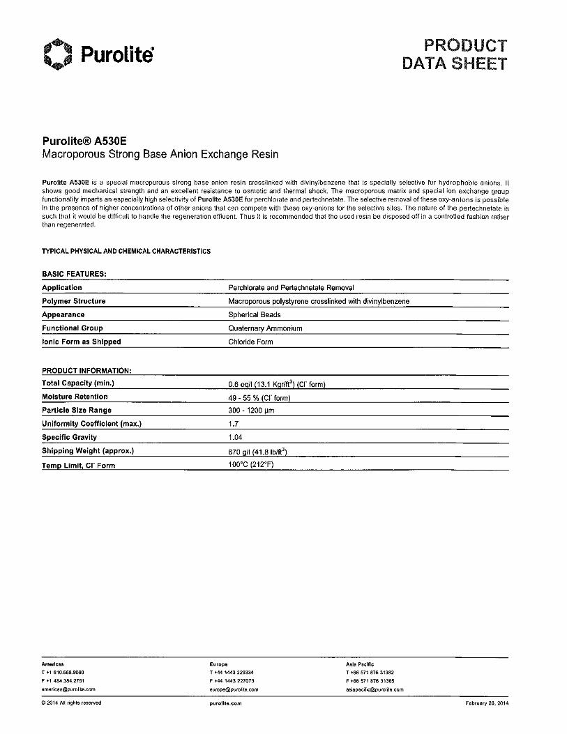
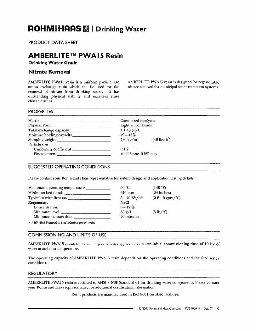
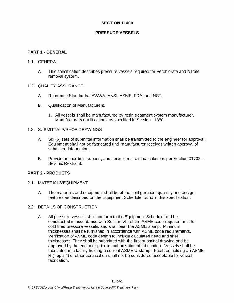
11400-1
R:\SPECS\Corona, City of\Resin Treatment of Nitrate Sources\IX Treatment Plant
SECTION 11400
PRESSURE VESSELS
PART 1 - GENERAL 1.1 GENERAL
A. This specification describes pressure vessels required for Perchlorate and Nitrate removal system.
1.2 QUALITY ASSURANCE
A. Reference Standards. AWWA, ANSI, ASME, FDA, and NSF.
B. Qualification of Manufacturers.
1. All vessels shall be manufactured by resin treatment system manufacturer. Manufacturers qualifications as specified in Section 11350.
1.3 SUBMITTALS/SHOP DRAWINGS
A. Six (6) sets of submittal information shall be transmitted to the engineer for approval. Equipment shall not be fabricated until manufacturer receives written approval of submitted information.
B. Provide anchor bolt, support, and seismic restraint calculations per Section 01732 – Seismic Restraint.
PART 2 - PRODUCTS 2.1 MATERIALS/EQUIPMENT
A. The materials and equipment shall be of the configuration, quantity and design features as described on the Equipment Schedule found in this specification.
2.2 DETAILS OF CONSTRUCTION
A. All pressure vessels shall conform to the Equipment Schedule and be constructed in accordance with Section VIII of the ASME code requirements for cold fired pressure vessels, and shall bear the ASME stamp. Minimum thicknesses shall be furnished in accordance with ASME code requirements. Verification of ASME code design to include calculated head and shell thicknesses. They shall be submitted with the first submittal drawing and be approved by the engineer prior to authorization of fabrication. Vessels shall be fabricated in a facility holding a current ASME U-stamp. Facilities holding an ASME R (“repair”) or other certification shall not be considered acceptable for vessel fabrication.

11400-2
R:\SPECS\Corona, City of\Resin Treatment of Nitrate Sources\IX Treatment Plant
B. All flanges, plates, angles, channels, beams, etc., including side shell to head connections, shall be joined by full penetration welds, each side, continuous welding. Flanges shall be factory welded on split centers prior to shipment.
C. VESSEL MISCELLANEOUS COMPONENTS
1. Structural steel skids shall be provided for support of the vessels. Anchor bolts
shall be furnished by the installing contractor.
2. Pipe nozzles shall be of the size as shown on the contract drawings and shall consist of Sch. 40 steel pipe, projecting and terminating in a flange 6” from the outside face of the side shell. Flanges shall be standard ANSI pattern, welded on split centers and shall be true and plumb.
2.3 FACE PIPING
A. All piping and fittings shall be Sch. 40 steel for pipe sizes smaller than 12-inch and
¼” wall thickness for pipe sizes 12-inch and larger. Flanges on all welded piping shall be slip-on weld type of ANSI (Class 150) construction and bolt pattern.
B. Vessel face piping shall be provided by the resin treatment system manufacturer to
the limits shown on the plans. 2.4 PAINTING
A. Pressure vessels painting and coating per specifications section 09900.2.3.
PART 3 - EXECUTION 3.1 INSTALLATION A. Delivery and Storage.
1. Upon delivery of the equipment to the jobsite, the contractor shall take inventory of the shipment and immediately report to the manufacturer any discrepancies between the manufacturer’s packing lists and shipping documents.
2. The contractor shall be responsible for off-loading and protection of all equipment
against damage and during on-site storage and installation. Damaged equipment and materials will be replaced by the contractor at the contractor’s expense.
B. Manufacturer’s installation instructions and assembly drawings shall be submitted and
approved by the engineer prior to shipment of equipment. Installation of the filtration system shall be in strict accordance with the details shown on the drawings and in complete conformance to manufacturer’s instructions and procedures.
***END OF SECTION***
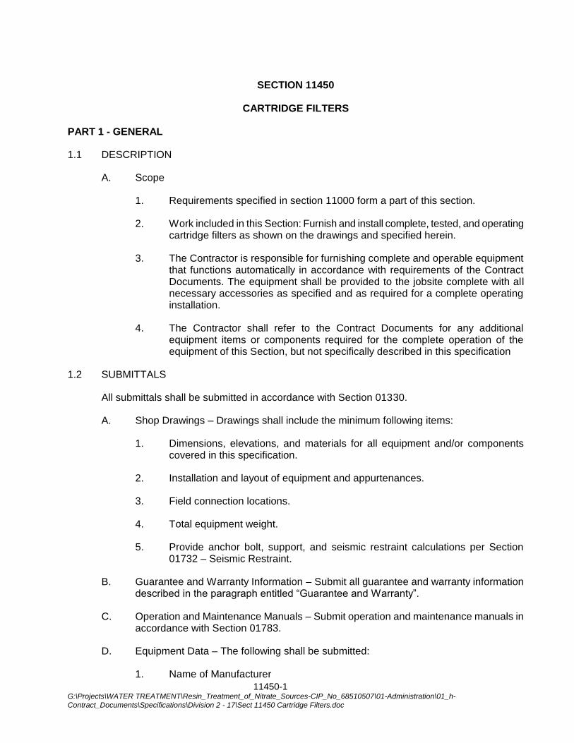
11450-1 G:\Projects\WATER TREATMENT\Resin_Treatment_of_Nitrate_Sources-CIP_No_68510507\01-Administration\01_h-
Contract_Documents\Specifications\Division 2 - 17\Sect 11450 Cartridge Filters.doc
SECTION 11450
CARTRIDGE FILTERS
PART 1 - GENERAL
1.1 DESCRIPTION
A. Scope
1. Requirements specified in section 11000 form a part of this section.
2. Work included in this Section: Furnish and install complete, tested, and operating cartridge filters as shown on the drawings and specified herein.
3. The Contractor is responsible for furnishing complete and operable equipment that functions automatically in accordance with requirements of the Contract Documents. The equipment shall be provided to the jobsite complete with all necessary accessories as specified and as required for a complete operating installation.
4. The Contractor shall refer to the Contract Documents for any additional equipment items or components required for the complete operation of the equipment of this Section, but not specifically described in this specification
1.2 SUBMITTALS
All submittals shall be submitted in accordance with Section 01330.
A. Shop Drawings – Drawings shall include the minimum following items:
1. Dimensions, elevations, and materials for all equipment and/or components covered in this specification.
2. Installation and layout of equipment and appurtenances.
3. Field connection locations.
4. Total equipment weight.
5. Provide anchor bolt, support, and seismic restraint calculations per Section 01732 – Seismic Restraint.
B. Guarantee and Warranty Information – Submit all guarantee and warranty information described in the paragraph entitled “Guarantee and Warranty”.
C. Operation and Maintenance Manuals – Submit operation and maintenance manuals in accordance with Section 01783.
D. Equipment Data – The following shall be submitted:
1. Name of Manufacturer
11450-2 G:\Projects\WATER TREATMENT\Resin_Treatment_of_Nitrate_Sources-CIP_No_68510507\01-Administration\01_h-
Contract_Documents\Specifications\Division 2 - 17\Sect 11450 Cartridge Filters.doc
2. Type and Model
1.3 QUALITY ASSURANCE
A. Equipment Quality – All equipment specified herein shall be new and of current manufacturer. The equipment furnished shall be designed and constructed in accordance with the best practices and methods and shall operate satisfactorily when installed as shown on the Drawings and operated per the manufacturer’s recommendations. All workmanship and materials used shall be of the highest quality and of proven reliability.
B. Factory Testing – The equipment shall be factory assembled and factory tested prior to being shipped to ensure satisfactory operation. The City may, at their option and own expense, witness the factory testing.
C. Single Supplier – The equipment described in this Section shall be provided by a single supplier, in order to ensure coordination and proper operation of the component pieces of the system. Where two or more items of the same type and/or size of equipment are required, such items shall be produced by the same manufacturer.
1.4 REFERENCE SPECIFICATIONS, CODES, AND STANDARDS
The work in this Section shall comply with applicable provisions and recommendations of the following standards, except as otherwise shown or specified:
ANSI American National Standards Institute
ASME American Society of Mechanical Engineers
ASTM American Society for Testing and Materials
AWWA American Water Works Association
NSF National Science Foundation
SSPWC Standard Specifications for Public Works Construction (“Greenbook”) Current Edition
UL Underwriter’s Laboratory
1.5 GUARANTEE AND WARRANTY
A. The Contractor shall obtain from the Manufacturer, a manufacturer warranty for all material, equipment, and appurtenances specified in this Section.
B. The warranty shall be for a minimum period of twelve (12) months from final acceptance by the City. Equipment warranty shall cover all failures of material or workmanship which occur as the result of normal operation and service excluding normal wear parts. The manufacturer shall repair and/or replace any parts proven to be defective, within the guarantee period, freight on board (FOB) the job site at the manufacturer’s expense.
C. During the warranty period, the Contractor shall provide the services of a trained Manufacturer’s representative to make all adjustments, repairs and replace all defective
11450-3 G:\Projects\WATER TREATMENT\Resin_Treatment_of_Nitrate_Sources-CIP_No_68510507\01-Administration\01_h-
Contract_Documents\Specifications\Division 2 - 17\Sect 11450 Cartridge Filters.doc
material and equipment at no cost to the City. The Contractor shall include all costs incurred by the Manufacturer, including travel and expenses, under the terms of the warranty.
PART 2 – PRODUCTS
2.1 GENERAL
A. The equipment specified herein shall be cartridge filter, as manufactured by Parker-Hannifin Corporation of Oxnard, CA (City standard, no exceptions).
2.2 CONSTRUCTION AND MATERIALS
A. Filter cartridges shall be Fulflo Honeycomb Model M19R40A by Parker-Hannifin Corp.
B. Filter housing, connecting flanges and internal elements shall be fabricated using Type 316 stainless steel. Filter housing shall be Model 6LMP103H-3-8FK1 by Parker Hannifin Corp.
2.3 EQUIPMENT IDENTIFICATION
A. Each unit of equipment shall be identified with a Type 316 stainless steel corrosion resistant nameplate, securely affixed in a conspicuous place. Nameplate information shall include equipment Manufacturer and model number, year of manufacture, serial number, Supplier’s name, location, and local telephone number.
PART 3 – EXECUTION
3.1 PRODUCT DELIVERY, STORAGE, AND HANDLING
A. The equipment shall be shipped completely assembled. It shall be capable of being set in place and field erected by the Contractor with minimum field assembly.
B. Packaging shall be as required to prevent damage during shipment and unloading.
C. Deliver materials to the site to insure uninterrupted progress of the work. Deliver anchor bolts and anchorage devices in ample time not to delay that work.
D. The Contractor shall store and temporarily support equipment prior to installation in strict accordance with the manufacturer’s recommendations and instructions. Protect all exposed surfaces. Protect all equipment from being contaminated by dust, dirt, and moisture.
E. Handle all equipment and materials very carefully. Damaged equipment and materials will not be acceptable. Protect all bolt threads, etc. from damage corrosion. Protect all factory applied coatings from damage during shipment, unloading, storage and installation.
3.2 INSTALLATION
A. Install cartridge filters as shown in the drawings and in accordance with manufacturer’s written instructions.
11450-4 G:\Projects\WATER TREATMENT\Resin_Treatment_of_Nitrate_Sources-CIP_No_68510507\01-Administration\01_h-
Contract_Documents\Specifications\Division 2 - 17\Sect 11450 Cartridge Filters.doc
B. Connections to piping shall be properly aligned so as not to impose strain on the connection. Make adjustments required to place system in proper operating condition.
3.3 MANUFACTURER’S FIELD SERVICES
A. The Manufacturer shall provide the services of a competent and experienced factory-trained service representative for one (1) trip for a minimum total of one (1) 8-hour day to provide inspection of installation, equipment startup, and operator and maintenance personnel training services. The representative shall insure that the equipment is handled and installed according to the Manufacturer's recommended procedures. During the initial operation, the representative shall instruct the operation and maintenance personnel of the City on any important operation and maintenance features of the equipment.
B. After installation supervision service by the Manufacturer, the Manufacturer shall submit to the City within 14 days a letter, on the Manufacturer's letterhead, certifying that the equipment was installed per the manufacturer’s recommendations.
3.4 FIELD TESTING
A. The equipment shall also be field tested after erection in the presence of the City to confirm and verify the structural and mechanical compliance to the specification. The field acceptance test shall include demonstrating that the equipment performs the specified functions satisfactorily.
3.5 INSTALLATION, OPERATION, AND MAINTENANCE MANUAL
A. In addition to the normal Installation, Operation, and Maintenance manuals required by the contract, a spare manual will be shipped with the unit in order to allow for proper operation of the equipment prior to the release of all final Installation, Operation, and Maintenance manuals.
***END OF SECTION***
13400-1 R:\SPECS\CORONA, CITY OF\RESIN TREATMENT OF NITRATE SOURCES\SECT 13400 BRINE MAKER.DOC
SECTION 13400
BRINE MAKER
PART 1 - GENERAL
This specification covers the materials of construction, design criteria, physical properties, manufacturing procedures and appurtenances to be used in fabricating a fiberglass reinforced plastic salt-brine process vessel. All lamination and equipment shall be in accordance with the standards of pertinent sections of the standards referenced in below section as well as meeting the criteria contained herein.
1.1 APPLICABLE STANDARDS
The latest edition of the standards listed below is applicable except where more stringent requirements are specified.
1.2 ASTM D-3299 Standard for Filament-Wound Glass-Fiber Reinforced Corrosion Resistant Tanks.
1.3 ASTM D-4097 Standard for contact molded glass fiber reinforced thermo set resin corrosion resistant tanks.
1.4 MATERIALS
A. Resin to be Ashland 7241.
B. The chemical surfacing veil shall be type “C” glass surfacing mat 10-mil thickness.
C. Chopped strand mat woven roving and continuous roving shall be type “E” glass with a saline finish and styrene soluble binder.
D. Continuous roving for filament winding is to be type “E” glass, with a saline finish. This glass will be 250, 450, or 675 yards per pound yield.
1.5 FABRICATION
LAMINATE CONSTRUCTION – The laminate shall consist of an interior surface, an interior layer, a structural layer and an exterior protective surface.
A. The interior surface shall be a reinforced layer of 10 to 20-mil thickness. Resin content is to be greater than 80%.
B. The interior surface shall be free from cracks and crazes; it shall have a smooth finish with an average of no more than two pits per square foot, providing such are no greater than .25” in diameter, are not over .031” deep and are sufficiently covered with resin to protect the interior surface reinforcement.
13400-2 R:\SPECS\CORONA, CITY OF\RESIN TREATMENT OF NITRATE SOURCES\SECT 13400 BRINE MAKER.DOC
C. The interior layer shall back the interior surface to a minimum thickness of 80 mils and will have a content of twenty to thirty percent non-continuous glass strands.
D. The finished laminate shall be as free as commercially practicable from visual defects such as dry spots, foreign inclusions, pinholes and delamination.
The structural layer shall consist of continuous strand filament winding to satisfy hoop strength requirements, chopped glass is to be applied prior to the first cycle of winding and interspersed between subsequent cycles. The vessel bottom and a minimum of the first 6 feet of the vessel wall shall be fabricated without any structural seams.
E. The exterior surface shall consist of resin blended with 0.6 percent paraffin wax to provide a full surface cure and a tack-free corrosion-resistant surface. The translucent vessel shall have two percent ultra-violet inhibitors. If the brine vessel is insulated, the insulated portion will be finished with a white exterior gel coat.
1.6 FITTINGS
A. Standard flanged nozzles shall be entirely of hand lay-up construction with the flange and pipe neck molded as on integral unit.
B. Nozzle wall and flange thickness are to be fabricated for 25 psi pressure rating.
C. The face of the flange shall be perpendicular to the centerline of the pipe to within ½ degree and shall be flat to within 1/16”.
D. The location of a nozzle will be held to 1/4”.
E. All nozzles shall be conically gusseted.
F. All nozzles shall have insulation replaced around lay-up areas.
1.7 TEST PROCEDURES
The following test procedures shall be employed to ascertain quality of vessel construction.
A. HARDNESS TEST – The surface area of the vessel shall be tested with a barcol impresser. Ten readings of a resin rich surface are taken with the two highest and two lowest eliminated. An average is taken of the remaining six readings, which must equal at least ninety percent of the resin manufacturer’s recommendation.
B. Fabricator shall have a written quality control program demonstrating the capability to design and supply equipment conforming to customer
13400-3 R:\SPECS\CORONA, CITY OF\RESIN TREATMENT OF NITRATE SOURCES\SECT 13400 BRINE MAKER.DOC
specification with periodic internal auditing and semi-annual audits such as ISO-9001.
C. The brine vessel shall be certified to NSF 61 and shall be traceable to an NSF authorized production facility.
1.8 ACCEPTABLE MANUFACTURERS
Vessel and accessories shall be by: PLAS-TANKS Industries, Inc., 39 Standen Drive, Hamilton, Ohio 45015 Tel: (513) 942-3800 or approved supplier.
1.9 SHIPPING AND INSTALLATION
A. All vessels shall be shipped on padded saddles.
B. All vessels shall be installed in accordance with the manufacturer’s recommendations.
C. All nozzles shall be covered during shipment to keep out dirt and other contaminates.
D. Vessel shall be filled with salt (Coarse Solar salt by Morton Salt) during start-up.
1.10 SUBMITTALS
A. The manufacturer, after award of contract, shall submit the Drawings (plan and elevation) showing orientation of nozzles and other appurtenances. Details must be submitted of brine outlet system, brine level control. Brine vessel to be 10-ft in diameter, capable of storing 36 tons of salt.
B. The Manufacturer shall submit seismic calculations and anchor bolt design for brine maker supports. The calculations shall be signed and sealed by a professional engineer registered in the State of California.
1.11 ACCESSORIES
Brine vessel shall have the following accessories:
A. 304 stainless steel tie down lugs and 316 stainless steel lifting channels (size & quantity determined by fabricator)
B. 4” conically gusseted flanged nozzle with 4” diameter 316 stainless steel schedule 40 salt unloading pipe with ¾” water injection port, aluminum Kamlock fitting and cap.
C. 2” conically gusseted flanged nozzle brine outlet with internal brine plenum and slotted PVC filter pipe.
D. 2” conically gusseted flanged nozzle with PVC water inlet ring.
13400-4 R:\SPECS\CORONA, CITY OF\RESIN TREATMENT OF NITRATE SOURCES\SECT 13400 BRINE MAKER.DOC
E. 8” gooseneck vent with PVC vent extension, clips to attach to vessel wall, polyester dust bag, rubber connection boot.
F. 24” top flanged man way with cover spring loaded for emergency pressure relief, 316 stainless steel fasteners.
G. 24” side flanged man way with cover, gasket, and 304 stainless steel fasteners.
H. One water level control system to include a pressure sensing transducer, liquid level controller/level indicator and water supply solenoid valve. Pressure sensing transducer to be mounted on the brine maker /salt storage vessel sidewall and PVC isolation ball valve.
I. Liquid level controller/indicator shall be furnished in an FRP Nema 4X enclosures mounted on the sidewall of the vessel. Controller and indicator to run from 120V, single phase, 60HZ, 10-amp power supplied by the Contractor.
J. Level indicator shall be digital, LED to indicate liquid level in feet. Level controller to be adjustable for desired liquid levels, it shall include all relays, contacts and terminals as necessary to energize the water supply solenoid at a desired low-level setting, and de-energize the solenoid to close at the desired upper level setting.
K. Water supply solenoid shall be 1¼” size, normally closed for mounting by the Contractor in the water supply piping. Solenoid to operate from a 120 V power circuit, and to be activated by the level controller unit.
L. Fiberglass encapsulated nameplate. OSHA approved fiberglass ladder with safety cage, mounted to the vessel, but fully supported by concrete or other suitable support base. Attachment fasteners shall be 316 stainless steel.
M. Salt level indication system to measure and display salt level. Digital meter shall be mounted in a Nema 4X fiberglass box.
***END OF SECTION***
13416-1
R:\SPECS\Corona, City of\Resin Treatment of Nitrate Sources\IX Treatment Plant
SECTION 13416
CHEMICAL STORAGE TANKS
PART 1 – GENERAL 1.1 SUMMARY
A. This Section describes the indoor chemical storage tanks. Provide complete, tested and operating tanks as shown on the Drawings and as specified herein.
B. Related Sections:
1. Section 01040: Coordination and Project Requirements
2. Section 11240: Chemical Feed Pump
3. Section 15050: Piping, Valves and Accessories
1.2 SUBMITTALS
A. Shop Drawings: Submit the following as a complete initial submittal in accordance with Section 01330. Sufficient data shall be included to show that the product conforms to Specification requirements. Provide the following additional data:
1. Drawings showing tank dimensions and orientation of nozzles and other appurtenances.
2. Details of tank construction and fittings. Indicate wall thicknesses.
3. Anchorage and lateral restraint calculations that have been verified and stamped by a structural engineer registered in the State of California. Provide anchor bolt design. Lateral restraint system shall be designed for Seismic Zone 4.
4. Tank design calculation as specified, including material properties used in design and loading conditions (handling, vertical loading, discontinuity, and seismic loading). Calculations shall be stamped by a registered engineer in the State of California.
5. Fitting placement verification including molded in outlet (IMFO).
6. A description of tank manufacturer's corrosion resistance charts for the specified chemicals of the chemical concentrations indicated below, in percentage by weight of solution:
Chemical Concentration Approximate Specific Gravity
Ammonia 19.5% 0.93
Sodium Hypochlorite 12% 1.20
7. Form of warranty.
13416-2
R:\SPECS\Corona, City of\Resin Treatment of Nitrate Sources\IX Treatment Plant
B. The manufacturer, after fabrication is complete, shall submit to the Engineer all tank wall nozzle cutouts. These cutouts shall be labeled in accordance with the submittal drawings.
C. Results of shop testing.
D. Results of field-testing. E. Manuals: Furnish manufacturer's installation, operation and maintenance manuals, bulletins, and spare parts lists. Furnish a local 24-hour emergency number for repairs in case of tank damage.
F. Affidavits: Furnish affidavits from the manufacturer stating that the tanks have been
shop and field tested and are properly installed ready for full-time storage of the specified chemicals.
1.3 QUALITY ASSURANCE
A. Products of the same material furnished under this Section shall be supplied by a single manufacturer who has been regularly engaged in the design and manufacture of the tanks. Demonstrate to the satisfaction of the Engineer that the quality is equal to tanks made by the manufacturers named herein. In addition to the minimum design requirements as specified, the tanks shall be designed for the stated specific gravity conditions, maximum operating temperature of 110°F, seismic zone 4 with seismic importance factor I = 1.25, and other superimposed mechanical conditions as described. All components shall be compatible with the chemicals specified in Paragraph 1.02-A.5.
B. Comply with the following Reference Standard: Standard Specification for
Polyethylene Upright Storage Tanks, ASTM D 1998.
C. Comply with the following Regulatory Standards:
1. Uniform Fire Code, Article 80, Hazardous Materials, with local amendments, if any.
2. Uniform Building Code, Chapter 3, with local amendments, if any.
PART 2 – PRODUCTS 2.1 POLYETHYLENE STORAGE TANKS
A. Manufacturer: Tanks shall be as manufactured by Poly Processing (Poly Cal Plastics); Snyder Industries, Inc.; or equal.
B. Tanks shall meet ASTM D 1998 Polyethylene Upright Storage Tanks. The tanks
shall be manufactured of material approved in accordance with NSF-61 for contact with drinking water.
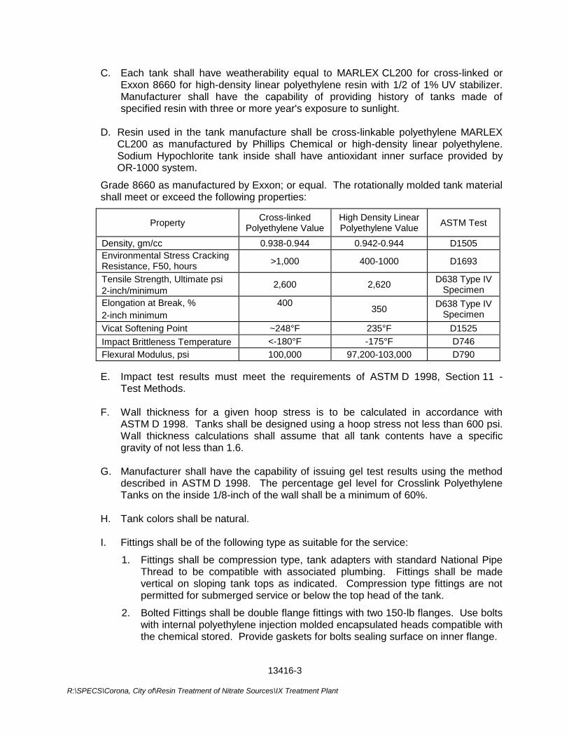
13416-3
R:\SPECS\Corona, City of\Resin Treatment of Nitrate Sources\IX Treatment Plant
C. Each tank shall have weatherability equal to MARLEX CL200 for cross-linked or Exxon 8660 for high-density linear polyethylene resin with 1/2 of 1% UV stabilizer. Manufacturer shall have the capability of providing history of tanks made of specified resin with three or more year's exposure to sunlight.
D. Resin used in the tank manufacture shall be cross-linkable polyethylene MARLEX
CL200 as manufactured by Phillips Chemical or high-density linear polyethylene. Sodium Hypochlorite tank inside shall have antioxidant inner surface provided by OR-1000 system.
Grade 8660 as manufactured by Exxon; or equal. The rotationally molded tank material shall meet or exceed the following properties:
Property Cross-linked
Polyethylene Value High Density Linear Polyethylene Value
ASTM Test
Density, gm/cc 0.938-0.944 0.942-0.944 D1505
Environmental Stress Cracking Resistance, F50, hours
>1,000 400-1000 D1693
Tensile Strength, Ultimate psi
2-inch/minimum 2,600 2,620
D638 Type IV Specimen
Elongation at Break, %
2-inch minimum
400
350
D638 Type IV Specimen
Vicat Softening Point ~248°F 235°F D1525
Impact Brittleness Temperature <-180°F -175°F D746
Flexural Modulus, psi 100,000 97,200-103,000 D790
E. Impact test results must meet the requirements of ASTM D 1998, Section 11 - Test Methods.
F. Wall thickness for a given hoop stress is to be calculated in accordance with
ASTM D 1998. Tanks shall be designed using a hoop stress not less than 600 psi. Wall thickness calculations shall assume that all tank contents have a specific gravity of not less than 1.6.
G. Manufacturer shall have the capability of issuing gel test results using the method
described in ASTM D 1998. The percentage gel level for Crosslink Polyethylene Tanks on the inside 1/8-inch of the wall shall be a minimum of 60%.
H. Tank colors shall be natural. I. Fittings shall be of the following type as suitable for the service:
1. Fittings shall be compression type, tank adapters with standard National Pipe Thread to be compatible with associated plumbing. Fittings shall be made vertical on sloping tank tops as indicated. Compression type fittings are not permitted for submerged service or below the top head of the tank.
2. Bolted Fittings shall be double flange fittings with two 150-lb flanges. Use bolts with internal polyethylene injection molded encapsulated heads compatible with the chemical stored. Provide gaskets for bolts sealing surface on inner flange.
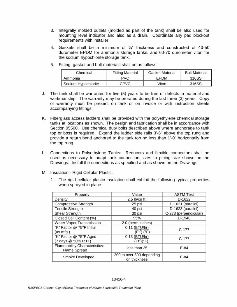
13416-4
R:\SPECS\Corona, City of\Resin Treatment of Nitrate Sources\IX Treatment Plant
3. Integrally molded outlets (molded as part of the tank) shall be also used for mounting level indicator and also as a drain. Coordinate any pad blockout requirements with installer.
4. Gaskets shall be a minimum of ¼” thickness and constructed of 40-50 durometer EPDM for ammonia storage tanks, and 60-70 durometer viton for the sodium hypochlorite storage tank.
5. Fitting, gasket and bolt materials shall be as follows:
Chemical Fitting Material Gasket Material Bolt Material
Ammonia PVC EPDM 316SS
Sodium Hypochlorite CPVC Viton 316SS
J. The tank shall be warranted for five (5) years to be free of defects in material and workmanship. The warranty may be prorated during the last three (3) years. Copy of warranty must be present on tank or on invoice or with instruction sheets accompanying fittings.
K. Fiberglass access ladders shall be provided with the polyethylene chemical storage
tanks at locations as shown. The design and fabrication shall be in accordance with Section 05500. Use chemical duty bolts described above where anchorage to tank top or boss is required. Extend the ladder side rails 3'-6" above the top rung and provide a return bend anchored to the tank top no less than 1'-0" horizontally from the top rung.
L. Connections to Polyethylene Tanks: Reducers and flexible connectors shall be
used as necessary to adapt tank connection sizes to piping size shown on the Drawings. Install the connections as specified and as shown on the Drawings.
M. Insulation - Rigid Cellular Plastic:
1. The rigid cellular plastic insulation shall exhibit the following typical properties when sprayed in place:
Property Value ASTM Test
Density 2.5 lb/cu ft. D-1622
Compressive Strength 25 psi D-1621 (parallel)
Tensile Strength 40 psi D-1623 (parallel)
Shear Strength 30 psi C-273 (perpendicular)
Closed Cell Content (%) 95% D-1940
Water Vapor Transmission 2.0 (perm inches) ---
"K" Factor @ 75°F Initial (as mfg.)
0.11 (BTU/hr) (Ft
2) (°F)
C-177
"K" Factor @ 75°F Aged (7 days @ 50% R.H.)
0.13 (BTU/hr) (Ft
2)(°F)
C-177
Flammability Characteristics: Flame Spread
less than 25 E-84
Smoke Developed 200 to over 500 depending
on thickness E-84
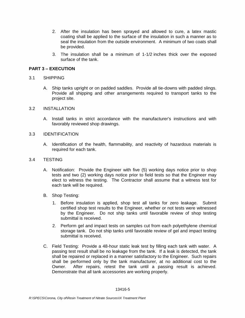
13416-5
R:\SPECS\Corona, City of\Resin Treatment of Nitrate Sources\IX Treatment Plant
2. After the insulation has been sprayed and allowed to cure, a latex mastic coating shall be applied to the surface of the insulation in such a manner as to seal the insulation from the outside environment. A minimum of two coats shall be provided.
3. The insulation shall be a minimum of 1-1/2 inches thick over the exposed surface of the tank.
PART 3 – EXECUTION
3.1 SHIPPING
A. Ship tanks upright or on padded saddles. Provide all tie-downs with padded slings. Provide all shipping and other arrangements required to transport tanks to the project site.
3.2 INSTALLATION
A. Install tanks in strict accordance with the manufacturer's instructions and with favorably reviewed shop drawings.
3.3 IDENTIFICATION
A. Identification of the health, flammability, and reactivity of hazardous materials is required for each tank.
3.4 TESTING
A. Notification: Provide the Engineer with five (5) working days notice prior to shop tests and two (2) working days notice prior to field tests so that the Engineer may elect to witness the testing. The Contractor shall assume that a witness test for each tank will be required.
B. Shop Testing:
1. Before insulation is applied, shop test all tanks for zero leakage. Submit certified shop test results to the Engineer, whether or not tests were witnessed by the Engineer. Do not ship tanks until favorable review of shop testing submittal is received.
2. Perform gel and impact tests on samples cut from each polyethylene chemical storage tank. Do not ship tanks until favorable review of gel and impact testing submittal is received.
C. Field Testing: Provide a 48-hour static leak test by filling each tank with water. A
passing test result shall be no leakage from the tank. If a leak is detected, the tank shall be repaired or replaced in a manner satisfactory to the Engineer. Such repairs shall be performed only by the tank manufacturer, at no additional cost to the Owner. After repairs, retest the tank until a passing result is achieved. Demonstrate that all tank accessories are working properly.
13416-6
R:\SPECS\Corona, City of\Resin Treatment of Nitrate Sources\IX Treatment Plant
D. Affidavits: Furnish the affidavits required in Paragraph 1.2 above.
3.5 CLEANING
A. After satisfactory completion of field-testing, drain the testing water. Rinse the inside with clean, potable water. Hand wipe and dry as required to leave the tank interior clean, dry and ready for storage of the chemical. Clean the tank exterior and accessories and leave in good condition.
***END OF SECTION***
13621-1 G:\Projects\WATER TREATMENT\Resin_Treatment_of_Nitrate_Sources-CIP_No_68510507\01-Administration\01_h-
Contract_Documents\Specifications\Division 2 - 17\Sect 13621 Primary Sensors & Field Instuments.doc
SECTION 13621
PRIMARY SENSORS AND FIELD INSTRUMENTS
PART 1 - GENERAL 1.1 DESCRIPTION
A. Scope:
1. Contractor shall provide all labor, materials, equipment and incidentals required to install, calibrate, test, adjust and place into satisfactory operation all primary sensors and field instruments furnished under this Section.
2. The Drawings and Specifications illustrate and specify functional and general construction requirements of the sensors and field instruments and do not necessarily show or specify all components, wiring, piping and accessories required to make a completely integrated system. Contractor shall provide all components, piping, wiring accessories and labor required for a complete workable and integrated system.
3. Contractor shall be responsible for installing in-line flow elements (magmeter flow tubes) and for providing taps in the process piping systems for installation of other flow, pressure and temperature sensing instrumentation.
B. Coordination: Coordinate the installation of all items specified herein and required to
ensure the complete and proper interfacing of all the components and systems. 1.2 QUALITY ASSURANCE
A. Acceptable Manufacturers:
1. Furnish primary sensors and field instruments by the named manufacturers or equal equipment by other manufacturers.
2. The named manufacturers have been specified to establish the standard of quality and performance of the equipment to be supplied.
3. Obtain all sensors and field instruments of a given type from the same manufacturer.
B. Manufacturers' Responsibilities and Services:
1. Design and manufacture the primary sensors and field instruments in accordance with the applicable general design requirements specified in the detailed specifications herein.
2. Field supervision, inspection, start-up and training in accordance and conjunction with the requirements of Section 15060.
13621-2 G:\Projects\WATER TREATMENT\Resin_Treatment_of_Nitrate_Sources-CIP_No_68510507\01-Administration\01_h-
Contract_Documents\Specifications\Division 2 - 17\Sect 13621 Primary Sensors & Field Instuments.doc
1.3 PRODUCT DELIVERY, STORAGE AND HANDLING
Primary sensors and field instruments shall not be delivered to the site until all product information and system shop drawings for the sensors and instruments have been approved.
1.4 SUBMITTALS
Comply with the requirements specified in Section 01330. 1.5 IDENTIFICATION TAGS
A. All sensors and field instruments shall have identification tags meeting the following requirements:
1. Tag numbers and equipment numbers for sensors and field instruments shall be as listed on the Contract Drawings or as developed by the Contractor.
2. The identifying tag number shall be permanently etched or embossed onto a stainless steel tag which shall be fastened to the device housing with stainless steel rivets or self tapping screws of appropriate size.
3. Where neither of the above fastenings can be accomplished, tags shall be permanently attached to the device by a circlet of 1/16-inch diameter stainless steel wire rope.
4. All sensors and field instruments mounted on or within panels shall have the stainless steel identification tag installed so that the numbers are easily visible to service personnel. Panel mounted devices shall have the tag attached to the rear of the device.
PART 2 - PRODUCTS 2.1 PROCESS TAPS, SENSING LINES AND ACCESSORIES
A. Water Pressure Sensing Lines and Accessories for Flow and Pressure Transmitters:
1. Material: 316 Stainless Steel Water Tube, ASTM B-88, Type L, drawn temper or annealed.
2. Pressure Rating: 300 psi.
3. Size: 1/2-inch O.D. for water.
4. Connections: 316 Stainless Steel Compression Type, "Swagelok" by Crawford, or equal.
5. Shut-off Valves:
a. Type: Ball.
b. Pressure Rating: 300 psi.
13621-3 G:\Projects\WATER TREATMENT\Resin_Treatment_of_Nitrate_Sources-CIP_No_68510507\01-Administration\01_h-
Contract_Documents\Specifications\Division 2 - 17\Sect 13621 Primary Sensors & Field Instuments.doc
c. Body, Ball and Stem: 316 Stainless Steel
d. Packing: High Density TFE.
e. Handle: Nylon with metal travel stops.
f. Support Rings: TFE coated 316 stainless steel.
g. End Connections: Removable "Swageloks", or equal.
h. Manufacturer: Apollo Valves
B. Pressure Tap Sensing Lines and Accessories for Pressure Gauges and Pressure Switches:
1. For Process Sensing Taps in Ductile Iron, Steel and Stainless Steel Piping Systems:
a. Material and Fittings: Type 316 stainless steel pipe (ASTM A 312) and threaded fittings and adapters (ASTM A 403) in accordance with Section 15066.
b. Sizes: 1/2-inch minimum for main sensing piping and 1/4-inch gauge for switch connections and sensing lines.
c. Pressure Rating: Equal to or greater than the applicable system test pressure.
d. Accessories:
1) For applications not requiring diaphragm seals, provide separate 1/4-inch Type 316 stainless steel threaded gauge cocks for each gauge and switch.
2) For applications requiring diaphragm seals, provide a separate 1/2-inch threaded Type 316 stainless steel ball valve for seal process side shutoff for each gauge and switch. Ball valves shall be provided in accordance with Specifications in Section 15050.
2.2 PRESSURE GAUGES
A. Bourdon Tube Pressure Element Type, Liquid Filled Gauges (for pressure ranges of 15 psi and greater and vacuum ranges to 30” Hg):
1. Performance Requirements:
a. Accuracy: ±0.5 percent of span (ANSI B40.1 Grade 2A).
b. Range and Scale: As specified on plans.
2. Construction Features:
a. Case:
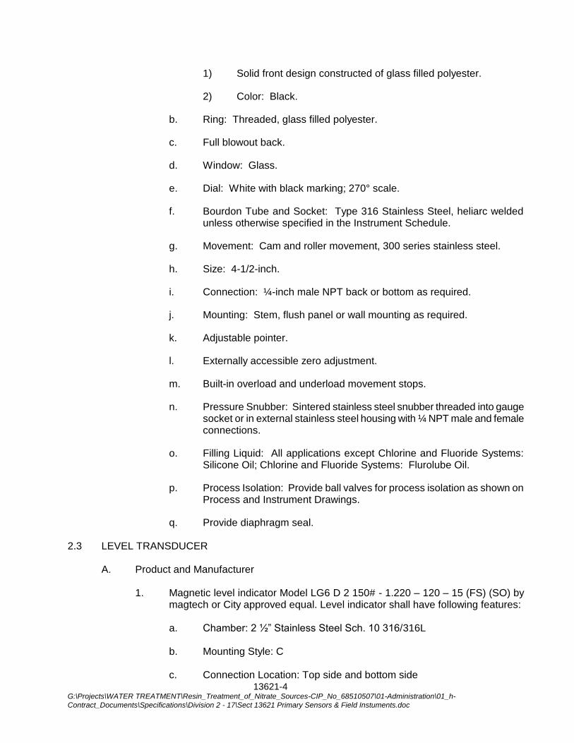
13621-4 G:\Projects\WATER TREATMENT\Resin_Treatment_of_Nitrate_Sources-CIP_No_68510507\01-Administration\01_h-
Contract_Documents\Specifications\Division 2 - 17\Sect 13621 Primary Sensors & Field Instuments.doc
1) Solid front design constructed of glass filled polyester.
2) Color: Black.
b. Ring: Threaded, glass filled polyester.
c. Full blowout back.
d. Window: Glass.
e. Dial: White with black marking; 270° scale.
f. Bourdon Tube and Socket: Type 316 Stainless Steel, heliarc welded unless otherwise specified in the Instrument Schedule.
g. Movement: Cam and roller movement, 300 series stainless steel.
h. Size: 4-1/2-inch.
i. Connection: ¼-inch male NPT back or bottom as required.
j. Mounting: Stem, flush panel or wall mounting as required.
k. Adjustable pointer.
l. Externally accessible zero adjustment.
m. Built-in overload and underload movement stops.
n. Pressure Snubber: Sintered stainless steel snubber threaded into gauge socket or in external stainless steel housing with ¼ NPT male and female connections.
o. Filling Liquid: All applications except Chlorine and Fluoride Systems: Silicone Oil; Chlorine and Fluoride Systems: Flurolube Oil.
p. Process Isolation: Provide ball valves for process isolation as shown on Process and Instrument Drawings.
q. Provide diaphragm seal. 2.3 LEVEL TRANSDUCER
A. Product and Manufacturer
1. Magnetic level indicator Model LG6 D 2 150# - 1.220 – 120 – 15 (FS) (SO) by magtech or City approved equal. Level indicator shall have following features:
a. Chamber: 2 ½” Stainless Steel Sch. 10 316/316L
b. Mounting Style: C
c. Connection Location: Top side and bottom side
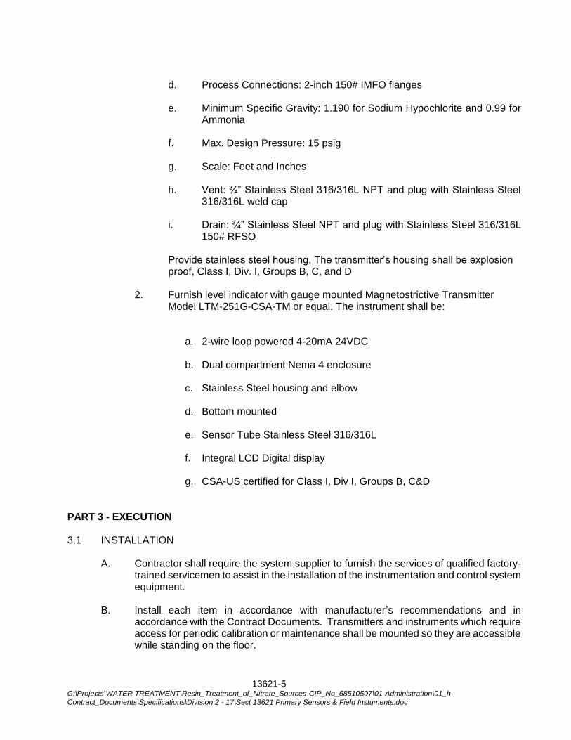
13621-5 G:\Projects\WATER TREATMENT\Resin_Treatment_of_Nitrate_Sources-CIP_No_68510507\01-Administration\01_h-
Contract_Documents\Specifications\Division 2 - 17\Sect 13621 Primary Sensors & Field Instuments.doc
d. Process Connections: 2-inch 150# IMFO flanges
e. Minimum Specific Gravity: 1.190 for Sodium Hypochlorite and 0.99 for
Ammonia
f. Max. Design Pressure: 15 psig
g. Scale: Feet and Inches
h. Vent: ¾” Stainless Steel 316/316L NPT and plug with Stainless Steel 316/316L weld cap
i. Drain: ¾” Stainless Steel NPT and plug with Stainless Steel 316/316L 150# RFSO
Provide stainless steel housing. The transmitter’s housing shall be explosion proof, Class I, Div. I, Groups B, C, and D 2. Furnish level indicator with gauge mounted Magnetostrictive Transmitter Model LTM-251G-CSA-TM or equal. The instrument shall be:
a. 2-wire loop powered 4-20mA 24VDC
b. Dual compartment Nema 4 enclosure
c. Stainless Steel housing and elbow
d. Bottom mounted
e. Sensor Tube Stainless Steel 316/316L
f. Integral LCD Digital display
g. CSA-US certified for Class I, Div I, Groups B, C&D
PART 3 - EXECUTION 3.1 INSTALLATION
A. Contractor shall require the system supplier to furnish the services of qualified factory-trained servicemen to assist in the installation of the instrumentation and control system equipment.
B. Install each item in accordance with manufacturer’s recommendations and in
accordance with the Contract Documents. Transmitters and instruments which require access for periodic calibration or maintenance shall be mounted so they are accessible while standing on the floor.
13621-6 G:\Projects\WATER TREATMENT\Resin_Treatment_of_Nitrate_Sources-CIP_No_68510507\01-Administration\01_h-
Contract_Documents\Specifications\Division 2 - 17\Sect 13621 Primary Sensors & Field Instuments.doc
C. All items shall be mounted and anchored using stainless steel hardware unless otherwise noted.
D. All field instruments shall be rigidly secured to walls, or supported by stands or brackets
independent of tanks and vessels to which they may be mounted, as required by the manufacturer and as shown on the Contract Drawings.
E. Conform to all applicable provisions of the NEMA standards, NEC and local, State and
Federal codes when installing the equipment and interconnecting wiring.
*** END OF SECTION***
15041-1 G:\Projects\WATER TREATMENT\Resin_Treatment_of_Nitrate_Sources-CIP_No_68510507\01-Administration\01_h-Contract_Documents\Specifications\Division 2 - 17\Sect 15041 Chlorination of Dom. Water Lines.doc
SECTION 15041
CHLORINATION OF DOMESTIC WATER LINES
PART 1 - GENERAL 1.1 SCOPE
All domestic water mains, domestic water services, attached appurtenances and connections, if any, shall be disinfected by an approved testing firm and as prescribed by in AWWA Specification C651, and as specified herein. The Contractor shall furnish all equipment in good operating condition, labor and materials, and water necessary for chlorinating and flushing the pipeline and for the certification of the pipeline disinfecting.
PART 2 - PRODUCTS 2.1 MATERIALS
A. Sodium hypochlorite by injection
PART 3 - EXECUTION 3.1 DISINFECTION
A. Before being placed in service, all facilities shall be chlorinated and flushed. Chlorine shall be applied by sodium hypochlorite by injection.
B. All required corporation stops and other plumbing materials necessary for
chlorination or flushing of the main shall be installed by and, abandoned as necessary, at the expense of the Contractor.
C. All pipelines shall be thoroughly flushed prior to disinfection. After the required period of retention of the chlorine solution, the City will test the water for residual chlorine and will make any additional test which may be necessary.
D. For liquid sodium hypochlorite, the chlorinating agent shall be applied at the beginning of the section to be chlorinated and shall be injected through a corporation stop, a hydrant or other connection to ensure treatment of the entire system being disinfected. Water shall be fed slowly into the pipeline with chlorine applied in amounts to produce a dosage of 100 ppm in all sections of the pipeline and appurtenances. Treated water shall be retained in the system for a minimum period of 24 hours and shall produce at the end of the retention period not less than 50 ppm in all sections being disinfected.
E. During the chlorination process, all valves and facilities shall be operated.
15041-2 G:\Projects\WATER TREATMENT\Resin_Treatment_of_Nitrate_Sources-CIP_No_68510507\01-Administration\01_h-Contract_Documents\Specifications\Division 2 - 17\Sect 15041 Chlorination of Dom. Water Lines.doc
F. If the tests are not satisfactory, the Contractor shall provide additional disinfection as required, at no additional cost.
G. Every service connection served by a main which is being disinfected shall be tightly
shut off at the curb stop before water is turned into the main. Care shall be taken to expel all air from the main and services during the filling operation.
H. After chlorination, the water shall be flushed from the line at its extremities until the
replacement water tests are equal chemically and bacteriologically to those of the permanent source of supply. The chlorinated water shall be flushed and dechlorinated by the Contractor. The City will not be responsible for loss or damage resulting from such disposal.
PART 4 - PAYMENT Payment for disinfecting and dechlorinating the water mains and appurtenances shall be included in the appurtenant bid items and no additional compensation shall be allowed therefor.
***END OF SECTION***
15050-1 G:\Projects\WATER TREATMENT\Resin_Treatment_of_Nitrate_Sources-CIP_No_68510507\01-Administration\01_h-Contract_Documents\Specifications\Division 2 - 17\Sect 15050 Piping, Valves and Accessories.doc
SECTION 15050
PIPING, VALVES AND ACCESSORIES
PART 1 - GENERAL 1.1 DESCRIPTION
A. Work included in this Section: The Contractor shall furnish and install all piping, including fittings, valves, supports, and accessories as shown on the Drawings, described in the Specifications and as required to completely interconnect all equipment with piping for complete and operable systems.
1.2. QUALITY ASSURANCE
All materials and equipment furnished under this Section shall be of a manufacturer who has been engaged in the design and manufacture of the specific materials and equipment for a period of at least 5 years.
1.3 SUBMITTALS
A. Shop Drawings:
1. Verify by excavation, inspection and measurement all installation conditions for shop fabricated pipe before preparation of Shop Drawings. Submit field measurements and photos with Shop Drawings where exposed conditions are significantly different than indicated on the Drawings.
2. Layouts and Schematics: Submit detailed installation drawings of all piping.
Schematics may be submitted for piping 4-inches and smaller. The drawings shall include pipe support locations, and types if different than shown on the Drawings and specifications, all fittings, valves, and other appurtenances.
3. Submit data to show that the following items conform to the Specification
requirements:
a. Pipe, fittings, and accessories.
b. Fabricated pipe supports and other pipe supports as required herein.
c. Flexible couplings and flanged adapters.
d. Valves.
4. Submit certified test reports as required herein and by the referenced standard specifications.
5. Pipe, fittings and joint fabrication details for welded steel pipe.
B. Affidavits: The Contractor shall furnish affidavits from the manufacturers for valves.
15050-2 G:\Projects\WATER TREATMENT\Resin_Treatment_of_Nitrate_Sources-CIP_No_68510507\01-Administration\01_h-Contract_Documents\Specifications\Division 2 - 17\Sect 15050 Piping, Valves and Accessories.doc
1.4 APPURTENANCES
Furnish and install all necessary guides, inserts, anchors and assembly bolts; washers nuts, hangers, supports, gaskets, and flanges; all other appurtenant items shown on the Drawings, specified or required for the proper installation and operation of the piping; devices included in or on the piping equipment; and piping accessories. Provide insulation for dissimilar metals with the use of insulating bushings, gasket sets or wrappings, as appropriate.
PART 2 - PRODUCTS 2.1 GENERAL
A. Pipe and valve sizes are nominal inside diameter unless otherwise noted.
B. All materials delivered to the job site shall be new, free from defects, and marked to identify the material, class, and other appropriate data such as thickness for piping.
C. Acceptance of materials shall be subject to strength and quality testing in addition to
inspection of the complete product. Acceptance of installed piping systems shall be based on inspection and leakage tests as specified hereinafter.
D. Cutoff Flanges: Provide at all pipe penetrations for pipes 4-inches and greater in
nominal diameter, and at all penetrations of 3-inch and smaller nominal diameter pipe in wet or potentially wet locations as indicated on the Drawings. Cutoff flange outside diameter shall be at least 85% of the standard connection flange's outside diameter. Link type seals may be substituted for cutoff flanges.
E. Materials/Products/Equipment used on the project must be listed on the City of
Corona Approved List of Materials for Water Facilities (See Appendices). 2.2 GENERAL MATERIAL REQUIREMENTS
A. Gaskets: Unless specifically specified otherwise, all gaskets shall be full face poly-isoprene, by Garlock.
B. Bolts and Tie Rods: Unless specifically specified otherwise, flange bolts and nuts,
washers, tie rods and other flange hardware shall conform to AWWA C110, and be as follows:
1. Exposed: Type 316 stainless steel (with anti-seize lubricant).
2. Encased: Type 316 stainless steel (with anti-seize lubricant).
3. Buried: Type 316 Stainless Steel (with anti-seize lubricant). 2.3 MATERIALS
A. PVC Pipe
1. 2 inches and Smaller
15050-3 G:\Projects\WATER TREATMENT\Resin_Treatment_of_Nitrate_Sources-CIP_No_68510507\01-Administration\01_h-Contract_Documents\Specifications\Division 2 - 17\Sect 15050 Piping, Valves and Accessories.doc
PVC pipe shall meet the following requirements:
Pipe PVC SCH 80 as identified on plans
Joints Solvent Weld
Unions PVC, SCH 80, Solvent Weld
Ball Valves 150 PSI, with TFE true union ends with TFE seats and seals
Check Valves 150 PSI, true union ball check with TFE seats and seals
2. PVC Pipe 4-Inch through 12-Inch
Not allowed.
B. Copper Pipe 2½-inches and Smaller
Copper pipe and appurtenances shall be in accordance with the following:
Pipe Seamless, Type K copper tubing, ASTM B88 below grade
Pipe Joints Soldered, 3-piece, screwed
Fittings Wrought copper, compression type, 3-piece, Parker, Swagelok or equal
Gate Valves 200 psi, WOG, bronze, ends, screwed bonnet, rising stem, solid wedge
Globe Valves 200 psi, WOG, bronze, screwed bonnet, renewable seat
Check Valves 200 psi, WOG, bronze, screwed ends, swing type, bronze disc, screwed cap
C. Ductile Iron Pipe
1. Materials: Pipe, fittings and appurtenances shall conform to the thickness
class Ductile Iron Pipe as designated on the Plans.
All ductile iron pipes shall be new and shall conform to all requirements of Federal Specification WW-P-421C, ANSI A21.51 (latest revision) and AWWA C151 (latest revision); pipe shall be fully restrained without the use of thrust blocks.
All pipe and fittings shall be clearly marked with the name of the manufacturer or with a trademark of the size and type that has been approved by and filed with the Owner.
15050-4 G:\Projects\WATER TREATMENT\Resin_Treatment_of_Nitrate_Sources-CIP_No_68510507\01-Administration\01_h-Contract_Documents\Specifications\Division 2 - 17\Sect 15050 Piping, Valves and Accessories.doc
a. Lining and Coating: All ductile iron pipe and fittings, unless otherwise prescribed in another item of the Contract Documents, shall be coated with bituminous not less than one mil thick and shall be cement mortar lined.
b. Type of Joints: Ductile iron pipe shall have any of the following types
of joints as specified in drawings: Push-on, push-on with locking gasket style restrain, flanged, mechanical with restraint or equal.
c. Specials and Fittings: All fittings for ductile iron pipe, unless
otherwise required by the Drawings or Specifications, shall conform in all respects to AWWA C110 (latest revision).
d. Polyethylene Protective Wrapping: Polywrap shall conform to the
requirements of ANSI/AWWA C105/A21.5 and shall be 8 mil thick tubing of virgin polyethylene (Dupont Alathon, U.S.1. Petrothene resin, or approved equal) or four (4) mil thick high density, cross-laminated (HDCL) polyethylene. The color shall be natural (where exposure to sunlight will be less than 48 hours) or black, containing 2.0 to 2.5 percent well dispersed carbon black with stabilizers (where exposure to sunlight may be up to 10 days). Tubing shall be taped and secured with general purpose polyethylene tape, 2 inches wide and 10 mils thick (Scotchrap No. 50, Plicoflex No. 340, Protecto Wrap No. 200, Polyken No. 900, or approved equal.
e. Delivery and Handling: All pipe and fittings shall be manufactured,
handled, loaded and shipped in such a manner that it is delivered undamaged, in sound condition, and conforming in all respects to these Specifications. Care shall be taken in loading and handling the pipe so as not to injure the pipe coating. No other pipe or material of any kind shall be placed inside any pipe or fitting at any time after the coating has been applied and prior to installation. All pipe and fittings installed on the work shall be new material which has never been previously used for any purpose whatsoever. Pipe shall be shipped, delivered to the jobsite and stored with protective covers over the ends of pipe to prevent contamination prior to installation.
D. Fusion Bonded Epoxy Coating Steel Pipe (8 inches and larger)
Steel pipe shall be seamless (¼-inch thick) conforming to ANSI B36.10. Fittings shall be forged, standard weight conforming to ASTM A-105. Fusion bonded epoxy lining and coating shall be a 100% solids, thermosetting, dry powder epoxy resin: Scotchkote 134 or 206 N, Lilly Powder Coatings “Pipeclad 1500 Red” or equal. epoxy lining shall be 16-mils (minimum thickness) conforming to AWWA C213. All welding shall be in the shop, and no field welding is allowed.
1. Quality of Lining and Coating: The cured lining or coating shall be smooth and glossy, with no graininess or roughness. The lining or coating shall have no blisters, cracks, bubbles, underfilm voids, mechanical damage, discontinuities, or holidays.
15050-5 G:\Projects\WATER TREATMENT\Resin_Treatment_of_Nitrate_Sources-CIP_No_68510507\01-Administration\01_h-Contract_Documents\Specifications\Division 2 - 17\Sect 15050 Piping, Valves and Accessories.doc
2. Factory Testing of Coating: linings and coatings shall be tested per AWWA C213, Section 5.3.3. The coating shall be measured and recorded at 3 points of each piece of pipe section using a coating thickness gauge calibrated at least once per 8 hours work shift. If the thickness at one point is less than the minimum required thickness, measure the thickness at three additional points around the defective area. The average of measurements shall exceed the minimum required thickness.
3. Field Repairs: Field repairs shall be done only for defective areas less than 20 square inches. Patch scratches and damaged areas incurred, during the installation, with a two components 80% solids (minimum) liquid epoxy resin. Wire brush or sandblast the damaged areas per SSPC SP-10. Lightly abrade or sandblast the coating or lining on the sides of the damaged area before applying the liquid epoxy coating. Patched areas shall overlap the base coating a minimum of 0.5 inch. The repair of defective areas more than 20 square inches shall be done at factory.
2.4 PIPE COUPLINGS AND FLEXIBLE PIPE PIECES
A. General: For typical pipe joints refer to pipe material specifications. Other joint devices shall be furnished where called for as specified below.
B. Flexible Couplings and Flange Coupling Adaptors:
1. Sleeve: Cast iron or fabricated steel.
2. Followers: Cast iron, ductile iron, or steel.
3. Sleeve Bolts: ASTM A325, Type 3; malleable iron; or equivalent.
4. Coating: Fusion epoxy line and coat sleeve and followers.
5. Pressure Rating: Pressure rating shall be equal to or greater than that of
pipe being connected as determined by Barlow's Formula.
6. Manufacturers:
a. Flexible Couplings:
1. Connecting Pipe with Identical Outside Diameters: Rockwell 411 or 431; Dresser Style 38 or 53; or equal.
2. Connecting Pipe with Slightly Different Outside Diameters: Rockwell 413; Dresser Style 162; or equal.
b. Flange Coupling Adaptors: Rockwell 912 or 913; Dresser Style 127 or 128; or equal.
c. Victaulic Couplings: Style 44 Type D Vic Ring coupling with ductile iron housing and grade E gasket.
7. Flex Coupling and Flanged Coupling Adapter Gaskets: Oil and grease
resistant; Rockwell Grade 60; Dresser Grade 42; or equal.

15050-6 G:\Projects\WATER TREATMENT\Resin_Treatment_of_Nitrate_Sources-CIP_No_68510507\01-Administration\01_h-Contract_Documents\Specifications\Division 2 - 17\Sect 15050 Piping, Valves and Accessories.doc
8. Joint Restraint: Provide joint harnesses (tie rod lug or attachment plate
assemblies) across all flexible couplings, flange coupling adaptors, except where specifically indicated otherwise on the Drawings. For flanged coupling adaptors, anchor studs may be substituted for the harnesses on pipe up to 12-inch. Design restraint for 1-1/2 times the test pressure of the applicable service.
2.5 VALVES AND ACCESSORIES
A. General Requirements for Valves:
1. All valves of each type shall be the product of one manufacturer, and shall be listed on the City of Corona’s Approved List of Materials for Water Facilities (Appendix A).
2. All valves shall be epoxy lined and coated; and furnished with operators,
handwheels, levers, or other suitable type wrench including handles as specified herein or as shown on the Drawings.
3. All threaded stem valves shall open by turning the valve stem counter-clockwise.
4. All valves and valve operators shall have a nonbleeding shop coat.
B. Valves and Accessory Systems:
1. Combination rate of flow and pressure reducing valve.
a. General: The valves shall be fusion bonded epoxy coated. Pressure
gauge shall be installed in valve inlet.
b. Acceptable Manufacture and Model: CLA-VAL model 49-01
c. Tubing and Fittings: Stainless Steel
2. Check Valves, 6-inch and larger:
a. General: Check Valves shall be swing type. Working pressure shall be 150 psi (minimum).
b. Acceptable Manufacture and Model: M&H Kenflex style 506
c. Body and Cover: Epoxy lined and Coated Cast Iron. d. NSF-61 approved
e. Flanged connection with 316 stainless steel flange bolts, washers,
and nuts.
15050-7 G:\Projects\WATER TREATMENT\Resin_Treatment_of_Nitrate_Sources-CIP_No_68510507\01-Administration\01_h-Contract_Documents\Specifications\Division 2 - 17\Sect 15050 Piping, Valves and Accessories.doc
4. Air/ Vac. Assembly:
a. Acceptable Manufacture and Model: A.R.I. model D-040 for using
inside the building and D-040-C-T for using outside of the building. b. Screws: Stainless Steel
c. Seal: E.P.D.M.
d. Float: Foamed Polypropylene
5. Flow Control Valve: a. General: The valves shall be fusion bonded epoxy coated. Pressure
gauge shall be installed in valve inlet.
b. Acceptable Manufacture and Model: CLA-VAL model 40-01
c. Tubing and Fittings: Stainless Steel
6. Hose Bib: a. Material: 1-inch stainless steel ball valve by Apollo valve.
b. Vacuum Breaker: ¾” Homewerks Worldwide, Brass FPT x MHT
*** END OF SECTION ***

15050-8 G:\Projects\WATER TREATMENT\Resin_Treatment_of_Nitrate_Sources-CIP_No_68510507\01-Administration\01_h-Contract_Documents\Specifications\Division 2 - 17\Sect 15050 Piping, Valves and Accessories.doc
THIS PAGE INTENTIONALLY BLANK
15060-1
G:\Projects\WATER TREATMENT\Resin_Treatment_of_Nitrate_Sources-CIP_No_68510507\01-Administration\01_h-Contract_Documents\Specifications\Division 2 - 17\Sect 15060 Piping - Installation.doces\IX Treatment Plant
SECTION 15060
PIPING - INSTALLATION PART 1 - GENERAL 1.1 DESCRIPTION
A. The work included in this section of the specifications consists of furnishing, installing and testing all piping, fittings and appurtenances, as indicated on the Drawings and specified herein or as required to complete the work.
B. Whenever the word "piping" is used in this section, it shall be understood to refer
to all exposed and buried pipes, fittings, valves, flanges gasketing, hangers and supports or bedding comprising any given system, plastic piping and instrument tubing included.
C. All piping shall be installed to the lines and grades shown on the Drawings or as
required for the mechanical equipment. All piping shall be properly supported and provisions shall be made for expansion and contraction.
D. Dissimilar metals shall be properly insulated with the use of insulating bushings, gasket sets or wrappings.
1.2 RELATED WORK SPECIFIED ELSEWHERE
A. Piping Materials Classifications - Section 15050.
B. Earthwork - Section 02200. 1.3 CODES AND PERMITS
A. Installation shall comply with all applicable federal, state and local laws whether or not explicitly specified.
B. The Contractor shall furnish to the City a certificate of final inspection and
approval from the inspecting authority having jurisdiction. 1.4 INSPECTIONS AND TESTING
A. The quality of all materials, the process of manufacture and finished pipe shall be subject to inspection and approval of the City. Pipe may be inspected at the place of manufacture, and on the work site, and shall be subject to rejection at any time even though submitted samples may have been approved. In addition, the City reserves the right to have any or all pipe or fittings inspected or tested, or both, by an independent inspection service at either the manufacturer's plant or elsewhere. Such inspections and/or tests shall be at the City's expense.
15060-2
G:\Projects\WATER TREATMENT\Resin_Treatment_of_Nitrate_Sources-CIP_No_68510507\01-Administration\01_h-Contract_Documents\Specifications\Division 2 - 17\Sect 15060 Piping - Installation.doces\IX Treatment Plant
B. All pipe, fittings and appurtenances shall be carefully inspected in the field before installation. All piping found to be defective, as determined by the City, shall be pulled out and not installed. Such rejected pipe shall be clearly tagged in such a manner as not to deface or damage it, and the pipe shall then be removed from the job site by the Contractor at his own expense. Results of shop tests which may be required shall be submitted to the City prior to installation of the pipe for which such tests were ordered.
PART 2 - PRODUCTS 2.1 MATERIALS
Piping materials shall conform to requirements specified in Section 15050. PART 3 - EXECUTION 3.1 GENERAL PIPING INSTALLATION PRACTICES
A. Any conflict arising during the erection of piping shall be brought to the attention of the City. No improvising or field changes shall be permitted without the approval of the City.
B. All piping shall be erected in such a manner as to obtain sufficient flexibility and
to prevent excessive stresses in materials and excessive bending moments at joints or connections to equipment.
C. Full lengths of pipe shall be used wherever possible. Short lengths of pipe with
couplings will not be permitted, except as may be approved by the City to eliminate overstressing or misalignment. All pipes shall be cut to exact measurement and shall be installed without forcing or springing.
D. Tool marks and unnecessary pipe threads shall be avoided. Burrs formed when
cutting pipe shall be removed by reaming. Before installing any pipe, care shall be taken that the inside is thoroughly cleaned and free of cuttings and foreign matter.
E. Where piping is pitched for drainage, an accurate grade shall be maintained.
Piping shall be supported in such a manner as to prohibit deflection due to gravity that would be sufficient to pocket the lines when full of liquid. All changes in direction shall be made by using pipe fittings unless otherwise shown on the Drawings or as approved by the City.
F. Unions shall be installed in all piping connections to equipment, regulating
valves, and wherever necessary to facilitate the dismantling of piping and removal of valves and other items requiring maintenance. Flanges on equipment may be considered as unions. At least one union shall be provided in every straight run of pipe unless otherwise noted or permitted.
15060-3
G:\Projects\WATER TREATMENT\Resin_Treatment_of_Nitrate_Sources-CIP_No_68510507\01-Administration\01_h-Contract_Documents\Specifications\Division 2 - 17\Sect 15060 Piping - Installation.doces\IX Treatment Plant
G. Raised face flanges shall not be used for connection to 125-psi cast iron flanges. The raised face shall be removed before use and full-face gaskets shall be employed.
H. In general, all service piping shall come off the top of headers, and if possible,
service piping shall slope for drainage.
I. Pipe anchors, thrust blocks, expansion joints, loops and bends shall be installed as indicated on the Drawings, and as required to properly protect the piping against vibration, misalignment and overstressing.
J. Exposed piping shall be neatly arranged, straight, run parallel to or at right
angles to walls and shall be so graded that the entire system can be drained. Drain valves shall be installed at the low points of piping. Vent valves shall be installed at all high points of the piping.
K. Installed piping shall not interfere with the operations or accessibility of doors or
windows and shall not encroach on aisles, passageways and equipment and shall not interfere with the servicing or maintenance of any equipment. Adjacent piping shall be grouped in the same horizontal or vertical plane.
L. All buried bolts, nuts, lugs, rods, brackets, etc., shall be stainless steel. All
exposed steel pipe supports and hangers shall be cleaned and painted similar to structural steel items as specified under Section 09900.
M. When a pipe joint is made at the intersection of a pipeline with a pump nozzle, all
bolts and nuts shall be installed loose until after the entire pipeline has been installed, aligned and checked.
N. All piping shall be installed in such a manner that it shall be free to expand and
contract without injury to itself, structural steel or anchors. On all piping, self-equalizing type expansion joints of an approved make and quality shall be installed in all straight runs of 90 feet or more, unless otherwise shown on the Contract Drawings.
O. When pipe is cut in the field, the cut end shall be tapered back approximately 1/8
inch, at an angle of 30 degrees with the centerline of the pipe, with a coarse file or grinder to remove any rough edges which might injure a gasket, where applicable.
P. Dissimilar metals shall be properly insulated to preclude galvanic corrosion.
Q. At outlets not indicated to be connected to other pipes, provide coated blind flange with bolts, nuts, and gaskets.
3.2 BURIED PIPING INSTALLATION PRACTICES
A. Installation shall be in accordance with AWWA Standard for Installation of Ductile-Iron Water Mains and Their Appurtenances, AWWA C600-93, AWWA
15060-4
G:\Projects\WATER TREATMENT\Resin_Treatment_of_Nitrate_Sources-CIP_No_68510507\01-Administration\01_h-Contract_Documents\Specifications\Division 2 - 17\Sect 15060 Piping - Installation.doces\IX Treatment Plant
C900-89 and WPCF Manual of Practice No. 9, Design and Construction of Sanitary and Storm Sewer, except as otherwise noted in the Specifications.
B. Joining Push-On, Mechanical Joint and Restraint Joint Piping: After placing a
length of pipe in the trench, the spigot end shall be centered in the socket and the pipe forced "home" and brought to correct line and grade. The pipe shall be secured in place with approved backfill material tamped under and around it. Wherever it is necessary to deflect pipe from a straight line, either in the vertical or horizontal plane, the amount of deflection allowed shall not exceed that required for making a satisfactory joint and shall be subject to the approval of the City.
C. Where it is necessary to join pipes of different types, the Contractor shall furnish
and install the necessary adapter. Adapters shall have ends conforming to specifications for the appropriate type of joint to receive the adjoining pipe.
D. The Contractor shall furnish and install all supports necessary to hold the piping
and appurtenances in a firm, substantial manner at the lines and grades indicated on the Drawings or as directed by the City.
E. Underground bends, tees and other pipeline fittings shall be restrained type
joints per plans and City approved list of materials, Appendix A. F. All buried ductile iron pipe shall be polyethylene double wrapped in accordance
with ANSI/AWWA C105/A21.5. 3.3 PUSH-ON TYPE JOINTS
A. Inspect gasket, socket and spigot for cleanliness. Remove any foreign matter and excessive coating. When cast iron or ductile iron pipe is cut in the field, the cut end can be readily conditioned so that it may be used to make up the joint. The outside of the cut end should be tapered back approximately 1/4 inch, at an angle of about 30 degrees with the centerline of the pipe, with a coarse file or a portable grinder. All sharp or rough edges which otherwise might injure the gasket shall be removed.
B. Insert the gasket in the socket, bulb end toward the inside. Heel of gasket shall
be uniformly seated around the inside of the socket.
C. Lubricate the exposed face of the gasket and the spigot using push-on joint lubricant. Do not use lubricant other than that furnished with pipe and fittings.
D. The fittings and the pipe shall be aligned and the spigot entered into the socket
until it just makes contact with the gasket. Joint assembly shall be completed by forcing the spigot of the entering pipe past the gasket (which is thereby compressed) until it makes contact with the bottom of the socket.
E. If assembly is not accomplished with the application of reasonable force by the
methods indicated, the spigot end of the pipe shall be removed to check for the
15060-5
G:\Projects\WATER TREATMENT\Resin_Treatment_of_Nitrate_Sources-CIP_No_68510507\01-Administration\01_h-Contract_Documents\Specifications\Division 2 - 17\Sect 15060 Piping - Installation.doces\IX Treatment Plant
proper positioning of the gasket. The joint shall be kept in straight alignment during assembly.
3.4 MECHANICAL JOINT PIPING
Spigot ends and bells of pipe and the rubber gaskets shall be washed thoroughly with soapy water to remove all foreign matter which may damage the gaskets. The gaskets shall be either plain rubber, metal tipped, duck tipped, polysulfide rubber tipped, or other special type. The gland shall be placed on the pipe with its raised lip facing the spigot end and at least 3-1/2 inches from that end. The spigot shall be inserted in the socket until it is "home". The gasket shall be pushed into position with the fingers, making sure that it is evenly seated in the socket. Place the gland against the face of the gasket, insert the tee head bolts and tighten the nuts on all bolts by opposite pairs until they are finger-tight. The bolts shall then be tightened in a similar manner until they are snug and bearing evenly against the gland around the circumference of the pipe.
3.5 RESTRAINED JOINT PIPING
Restrained joint piping shall be integrally restrained joint ductile iron pipe of the mechanical joint type with 316SS steel bolting hardware. Installation shall be in accordance with the manufacturer's recommended procedures.
3.6 PVC PIPING
Not allowed. 3.7 COPPER PIPING
A. Solder joints for copper tubing shall be prepared by cleaning the ends of the tubing and the inner surfaces of the fittings with steel wool until they are bright. The cleaned surfaces shall be given a thin coating of approved soldering flux, and the tubing end inserted into the fitting as far as possible. Heating and finishing of the joint shall be done in accordance with the recommendations of the manufacturer of the fittings, using solid string or wire solder. The use of cored solder will not be permitted. All joints shall be allowed to self-cool to prevent chilling of solder.
B. All changes in direction shall be made by using the pipe and fitting unless other
means are approved by the City. 3.8 PIPE HANGERS
A. The Contractor shall furnish all necessary hangers including all clamps, rods,
angles, channels, plates, etc., for supporting the various piping installed by him under this Contract. The Contractor shall obtain the City's approval of the method of supporting the piping before installation. Drawings shall be referenced for standard pipe hanger design.
15060-6
G:\Projects\WATER TREATMENT\Resin_Treatment_of_Nitrate_Sources-CIP_No_68510507\01-Administration\01_h-Contract_Documents\Specifications\Division 2 - 17\Sect 15060 Piping - Installation.doces\IX Treatment Plant
B. Pipes close to the floor may be supported from the floor by structural shapes or by poured concrete blocks or piers as approved by the City. In such cases, care shall be taken to avoid blocking floor drainage.
C. Building steel, as indicated on the structural drawings, shall be used wherever
possible for supporting pipe hangers. Structural members shall not be drilled or welded for hangers without the approval of the City.
D. Expansion bolts not allowed.
E. All vertical piping shall be properly supported with suitable steel brackets to
prevent swinging or sagging. A minimum of two supports shall be provided on all vertical piping. Spacing shall be no more than 6 feet on centers.
F. Heavy valves or fittings shall be supported by hangers, poured concrete blocks
or other special provisions that may be necessary to avoid undue line deflection.
G. Hose and plastic tubing shall be continuously supported in steel angle, channel or tray.
3.9 APPURTENANCES
A. The Contractor shall furnish and install all valves and piping not mentioned in the piping classification, but shown on the Drawings.
B. All valves and drains not mentioned in the classification of piping material
specifications and furnished under this specification shall be as specified on the Drawings.
C. Flanged joints shall be made up with approved full-face gaskets and 316 SS bolts and nuts and coated with non-oxide type grease, except where otherwise noted in the Specifications.
D. All joints shall be made drop tight under all pressures up to the specified field test pressure of the line in which installed.
3.10 FIELD TESTING
A. All pressure piping shall be subjected to hydrostatic pressure of 200 psi (or the pump shut-off pressure) but not exceeding the maximum allowable working pressure of the piping. The normal operating pressures shall be defined by the City. No air testing shall be permitted.
B. Pressure mains shall be tested at 200 psi. Gravity lines shall be subjected to hydrostatic pressure 150 percent of the maximum head that can be imposed upon the piping during operation as defined by the City.
C. Test of buried piping shall be made only after completion of partial or complete backfill as specified and not until at least 36 hours after the last joint to be tested has been made, and at least 36 hours after the last concrete thrust or reaction
15060-7
G:\Projects\WATER TREATMENT\Resin_Treatment_of_Nitrate_Sources-CIP_No_68510507\01-Administration\01_h-Contract_Documents\Specifications\Division 2 - 17\Sect 15060 Piping - Installation.doces\IX Treatment Plant
blocking has been cast with high early strength cement, ASTM C150 Type III. Joints shall be left clear for examination during tests on pressure pipe.
D. Each section of pipeline shall be slowly filled with water and the specified test pressure measured at the point of lowest elevation. Pressure shall be applied by means of a pump connected to the pipe in a manner satisfactory to the City. The pump, pipe connection, gauges, pipe taps and all necessary apparatus, shall be furnished by the Contractor. The Contractor shall provide all necessary assistance for conducting the test. The duration of the test shall be 2 hours, unless otherwise directed by the City. All air must be expelled from the pipeline prior to the test period.
E. During the test, all pipes, fittings, valves, hydrants and joints shall be carefully examined. If found to be cracked or defective, they shall be removed and replaced by the Contractor with sound material in the manner prescribed. The test shall then be repeated until satisfactory to the City.
F. After the pressure test, the pipe shall be tested for leakage. The pressure during the leakage test shall be at the normal operating pressure. The duration of the leakage test shall be 2 hours unless otherwise directed by the City. The test shall be conducted in the same manner as the pressure test except that the Contractor shall provide suitable equipment for measuring the amount of leakage.
G. No pipe installation will be accepted until or unless the leakage for the section of line tested is less than the rate of leakage specified below: Flanges, welded or screwed piping – No measurable leakage Push-on, mechanical joints or caulked – In accordance with AWWA Standard for Installation of Cast-Iron Water Mains, AWWA C600, Sect. 13.7
H. Should any test of a section of pipeline disclose leakage greater than that permitted, the Contractor shall, at his own expense, locate and repair the defective joints and/or pipe until the leakage is within the permitted allowances.
3.11 PIPE SUPPORT DETAILS
Pipe support shall be selected and furnished as required for proper installation and in accordance with the Drawings.
***END OF SECTION***
15060-8
G:\Projects\WATER TREATMENT\Resin_Treatment_of_Nitrate_Sources-CIP_No_68510507\01-Administration\01_h-Contract_Documents\Specifications\Division 2 - 17\Sect 15060 Piping - Installation.doces\IX Treatment Plant
THIS PAGE INTENTIONALLY BLANK
15100-1 R:\SPECS\Corona, City of\Resin Treatment of Nitrate Sources\IX Treatment Plant
SECTION 15100
FANS
PART 1 - GENERAL
1.1 SCOPE
Provide roof mounted, belt drive, centrifugal type fans for cooling and ventilation of the
Process room and chemical storage area.
1.2 REFERENCES
A. Air Movement and Control Association Inc. (AMCA):
1. 99 - Standards Handbook
2. 200 - Publication, Air Systems
3. 201-90 - Publication, Fans and Systems
4. 202-88 - Publication, Troubleshooting
5. 203-90 - Publication, Field Performance Measurement of Fan Systems
6. 211-05 - Publication, Certified Ratings Program – Product Rating Manual for Fan
Air Performance
7. 300-96 - Standard Reverberant Room Method for Sound Testing of Fans
8. 311-05 - Publication Certified Ratings Program – Product Rating Manual for Fan
Sound Performance
9. 99-0401-86 - Classification for Spark Resistant Construction
10. 99-2408-69 - Operating Limits for Centrifugal Fans
B. Air Movement and Control Association Inc. (AMCA), American National Standards
Institute (ANSI):
1. 204-05 - Standard Balance Quality and Vibration Levels for Fans
2. 210-99 - Standard Laboratory Methods of Testing Fans for Aerodynamic
Performance Rating
C. American National Standards Institute (ANSI):
1. 11-r1999 - Method of Evaluating Load Ratings of Bearings
D. American Society of Civil Engineers (ASCE):
1. 7-02 - Minimum Design Loads for Building and Other Structures
E. American Society of Heating, Refrigerating and Air Conditioning Engineers, Inc.
(ASHRAE):
1. Chapter 45 - 2003 Handbook, HVAC Applications
2. Chapter 7 - 2001 Fundamentals Handbook, Sound-Vibration
15100-2 R:\SPECS\Corona, City of\Resin Treatment of Nitrate Sources\IX Treatment Plant
3. Chapter 32 - 2001 Fundamentals Handbook, Duct Design
4. Chapter 18 - 1992 HVAC System and Equipment Handbook, Fans
F. American Society for Testing and Materials (ASTM):
1. E330-02 - Standard Test Method for Structural Performance of Exterior Windows,
Doors, Skylight and Curtain Walls by Uniform Static Air Pressure Difference.
G. National Fire Protection Association (NFPA)
1. 70 - National Electrical Code
2. 90A-02 - Standard for the Installation of Air-Conditioning and Ventilating Systems
3. 92A-06 - Recommend Practice for Smoke-Control System
4. 92B-05 - Standard for Smoke Management System in Malls, Atria, and Large
Areas
5. 96-04 - Standard for Ventilation Control and Fire Protection of Commercial Cooking
Operations.
H. Occupational Safety and Health Administration (OSHA):
1. 1910.212 - General requirements for Machine Guarding
2. 1910.219 - General requirements for guarding safe use of mechanical power
transmission apparatus
3. 1926.300 - General requirements for safe operation and maintenance of hand and
power tools
I. Underwriters Laboratories (UL):
1. 507 - Electric Fans
2. 555 - Fire Dampers
3. 555S - Smoke Dampers
4. 705 - Standard Power Ventilators
5. 762 - Standard Power Roof Ventilators for Restaurant Exhaust Appliances
6. 793 - Snow Load
1.3 QUALITY ASSURANCE
A. Maintain ASHRAE criteria for average noise criteria curves for all equipment at full
load condition.
B. Fan Performance Ratings: Conform to AMCA 210 and bear the AMCA Certified
Rating Seal.
C. Fan Sound Ratings: AMCA 301, tested to AMCA 300, and bear AMCA Certified
Sound Rating Seal.
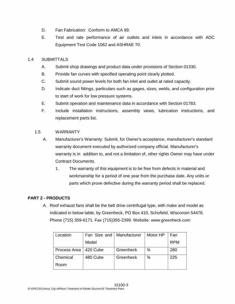
15100-3 R:\SPECS\Corona, City of\Resin Treatment of Nitrate Sources\IX Treatment Plant
D. Fan Fabrication: Conform to AMCA 99.
E. Test and rate performance of air outlets and inlets in accordance with ADC
Equipment Test Code 1062 and ASHRAE 70.
1.4 SUBMITTALS
A. Submit shop drawings and product data under provisions of Section 01330.
B. Provide fan curves with specified operating point clearly plotted.
C. Submit sound power levels for both fan inlet and outlet at rated capacity.
D. Indicate duct fittings, particulars such as gages, sizes, welds, and configuration prior
to start of work for low pressure systems.
E. Submit operation and maintenance data in accordance with Section 01783.
F. Include installation instructions, assembly views, lubrication instructions, and
replacement parts list.
1.5 WARRANTY
A. Manufacturer's Warranty: Submit, for Owner's acceptance, manufacturer's standard
warranty document executed by authorized company official. Manufacturer's
warranty is in addition to, and not a limitation of, other rights Owner may have under
Contract Documents.
1. The warranty of this equipment is to be free from defects in material and
workmanship for a period of one year from the purchase date. Any units or
parts which prove defective during the warranty period shall be replaced.
PART 2 - PRODUCTS
A. Roof exhaust fans shall be the belt drive centrifugal type, with make and model as
indicated in below table, by Greenheck, PO Box 410, Schofield, Wisconsin 54476.
Phone (715) 359-6171. Fax (715)355-2399. Website: www.greenheck.com
Location Fan Size and
Model
Manufacturer Motor HP Fan
RPM
Process Area 420 Cube Greenheck ¾ 280
Chemical
Room
480 Cube Greenheck ¾ 225
15100-4 R:\SPECS\Corona, City of\Resin Treatment of Nitrate Sources\IX Treatment Plant
B. Provide ½-inch galvanized steel mounting plate as shown on the plans.
C. Each fan shall bear AMCA licensed performance ratings for both air and sound.
D. Fans shall be thermostatically controlled by dedicated controls located in the process
area and chemical room.
PART 3 - EXECUTION
3.1 INSTALLATION
A. Do not operate fan for any purpose until bearings are lubricated, and fan has been
test run under observation.
B. Install fans as indicated, with resilient mountings and flexible electrical leads.
3.2 PRE-TEST EXAMINATION
A. Before commencing work, verify that systems are complete and operable. Ensure
the following:
1. Equipment is operable and in a safe and normal condition.
2. Temperature control systems are installed complete and operable.
3. Proper thermal overload protection is in place for electrical equipment.
4. Correct fan rotation.
B. Report any defects of deficiencies noted during performance of services to
Engineer.
*** END OF SECTION ***
15650-1 G:\Projects\WATER TREATMENT\Resin_Treatment_of_Nitrate_Sources-CIP_No_68510507\01-Administration\01_h-Contract_Documents\Specifications\Division 2 - 17\Sect 15650 Flow Measuring Devices.doc
SECTION 15650
FLOW MEASURING DEVICES PART 1 - GENERAL 1.1 DESCRIPTION
Furnish and install flow measuring devices as specified herein and shown on the drawings.
Provide all necessary conduit and wire to connect flow measuring devices as shown on drawings and specified hereafter.
1.2 QUALITY ASSURANCE
A. Manufacturer: Flow measuring devices furnished shall be manufactured by firms regularly and currently engaged in the design and manufacture of similar equipment. All equipment furnished shall be new and of current design.
B. Maintainability: All equipment shall be designed for ease of maintenance and repair, and access to critical parts shall not require a major disassembly. Internal field adjustments where permitted or required herein shall be easily accessible upon removal of a panel or cover.
C. Materials and Installation: Comply with the requirements of the current editions of referenced electrical codes and standards, and the codes and standards referred to shall be used for establishing the minimum quality of the materials and equipment supplied and installed. All equipment of the same type shall be products of the same manufacturer. Capacities of all equipment shall not be less than that indicated on the Drawings or specified.
1.3 SUBMITTALS
A. Shop Drawings: Furnish Shop Drawings for each item of mechanical equipment presenting sufficient data to determine compliance to these Specifications. Submit as a minimum completed ISA S20 forms for each device and physical dimensions. Also submit manufacturer's recommended upstream and downstream straight piping lengths, recommended location of any pressure taps, and estimates of pressure losses through the device.
B. Factory Testing and Calibration: All meters shall be factory and field tested. Certified calibration curves based on factory calibration testing shall be provided for the Engineer's favorable review. Furnish calibration curves in units of output vs. measured flow. Upon receipt of the Engineer's favorable review, the Contractor may have the meters shipped to the job site.
C. Manuals: Furnish manufacturer's installation, lubrication, operation and maintenance manuals, bulletins, and spare parts lists in accordance with Specification Section 01783.

15650-2 G:\Projects\WATER TREATMENT\Resin_Treatment_of_Nitrate_Sources-CIP_No_68510507\01-Administration\01_h-Contract_Documents\Specifications\Division 2 - 17\Sect 15650 Flow Measuring Devices.doc
D. Affidavits: Furnish affidavits from the manufacturers stating that the meters have been properly installed and tested and each is ready for full time operation.
PART 2 - PRODUCTS 2.1 MAGNETIC FLOW METER
All magnetic flow meters shall be E&H Model Promag W 400 (City Standard, no exceptions).
PART 3 - EXECUTION 3.1 INSTALLATION
Provide installation, testing, calibration, verification, starting and instruction in accordance with manufacturer’s recommendations. Provide Operation and Maintenance Manuals in accordance with Section 01783.
***END OF SECTION***
16000-1 G:\Projects\WATER TREATMENT\Resin_Treatment_of_Nitrate_Sources-CIP_No_68510507\01-Administration\01_h-
Contract_Documents\Specifications\Division 2 - 17\Sect 16000 Gen'l Provisions.doc
SECTION 16000
GENERAL PROVISIONS
PART 1 - GENERAL
1.1 DESCRIPTION
A. Scope: Contractor shall provide all labor, materials, equipment and incidentals as shown, specified and required to complete the electrical work. The provisions of this section apply to all the following Division 16 Sections whether specifically referred to in those sections or not.
B. Coordination:
1. Review installation procedures under other Sections and coordinate the
installation of items that must be installed with the formwork, walls, partitions, ceilings and panels.
2. Contractor shall be responsible for the installation of all conduits, inserts and
other items to be embedded in the concrete, or built into walls, partitions, ceilings or panels constructed by other contractors. Contractor shall provide other contractors with detailed plans or sketches of the location of said conduits and other built-in items as may be required. Contractor shall keep himself fully informed of the construction where conduits and other built-in items are to be installed. Contractor shall install said conduits and other built-in items in such a manner and within such time periods as will not unnecessarily delay the work of the other contractors.
C. General:
1. Interpretation of Drawings:
a. Dimensions shown on the Drawings that are related to equipment are
based on one manufacturer's equipment. Coordinate the dimensions of the equipment furnished with the space allocated for that equipment.
b. The Drawings show the principal elements of the electrical installation.
They are not intended as detailed working drawings for the electrical work but as a complement to the Specifications to clarify the principal features of the electrical systems.
c. It is the intent of this Section that all equipment and devices, furnished
and installed under this and other Sections, be properly connected and interconnected with other equipment so as to render the installations complete for successful operation, regardless of whether all the connections and interconnections are specifically mentioned in the Specifications or shown on the Drawings.
16000-2 G:\Projects\WATER TREATMENT\Resin_Treatment_of_Nitrate_Sources-CIP_No_68510507\01-Administration\01_h-
Contract_Documents\Specifications\Division 2 - 17\Sect 16000 Gen'l Provisions.doc
D. Related Sections:
1. Section 02200, Earthwork 2. Section 03300, Cast-In-Place Concrete. 3. Section 09900, Painting.
E. Temporary Power:
1. Temporary light and power for construction purposes shall be provided in
accordance with Section 01500, Construction Facilities and Temporary Controls. 1.2 QUALITY ASSURANCE
A. Requirements of Regulatory Agencies:
1. Permits: Obtain all permits required to commence work and, upon completion of the work, obtain and deliver to the ENGINEER a Certificate of Inspection and Approval from the authority having jurisdiction.
2. Codes: Material and equipment shall be installed in accordance with the current
standards and recommendations of the National Electrical Code, the National Electrical Safety Code, and with local codes which apply. Where discrepancies arise between codes, the most restrictive regulation shall apply.
3. Tests by Independent Regulatory Agencies: All electrical material and
equipment shall be new and shall bear the label of the Underwriters' Laboratories, Inc., or other nationally-recognized, independent testing laboratory, wherever standards have been established and label service regularly applies.
4. Utilities: Electric Utility – Coordinate with City Representative for exact breakers
and cabinets to be used.
5. Inspection Requirements: All equipment shall be inspected and tested at the site as specified in these Contract Documents.
B. Reference Standards: Electrical material and equipment shall conform in all respects to
the latest approved standards of the following:
1. National Electrical Manufacturers Association (NEMA). 2. The American National Standards Institute (ANSI). 3. The Institute of Electrical and Electronic Engineers (IEEE). 4. Insulated Power Cable Engineers Association (IPCEA). 5. National Electrical Code (NEC). 6. National Electrical Safety Code (NESC).
16000-3 G:\Projects\WATER TREATMENT\Resin_Treatment_of_Nitrate_Sources-CIP_No_68510507\01-Administration\01_h-
Contract_Documents\Specifications\Division 2 - 17\Sect 16000 Gen'l Provisions.doc
C. Assembled Products: The major components of any assembly such as motor Control
Centers, switchboards and panels shall be manufactured by the assembly manufacturer. 1.3 SUBMITTALS
A. General:
1. Conform to requirements of Section 01330 and the General Conditions.
B. Shop drawings shall include the following information to the extent applicable to the particular item:
1. Manufacturer's name and product designation or catalog number. 2. Electrical ratings. 3. Conformance to applicable standards or specifications of ANSI, ASTM, ICEA,
IEEE, ISA, NEC, NEMA, NFPA, OSHA, UL, or other organizations. 4. Dimensioned plan, section, and elevations showing means for mounting, conduit
connection, and grounding. 5. Materials and finish specification, including paints. 6. List of components including manufacturer's names and catalog numbers. 7. Internal JIC schematic and wiring diagrams indicating all connection to
components and numbered terminals for external connections.
8. All equipment and material of a similar nature and use shall be of one manufacturer.
1.4 PRODUCT DELIVERY
A. Operation and Maintenance Data:
1. Conform to requirements of Section 01783 and the General Conditions.
B. Record Documents:
1. In addition to the requirements of Section 01330 and the General Conditions, record drawings shall include the following:
a. Single line wiring diagram of the distribution system. b. Actual in place conduit and cable layouts with schedule of conduit sizes
and number and size of conductors. c. Layouts of the grounding system and lighting arrangement.

16000-4 G:\Projects\WATER TREATMENT\Resin_Treatment_of_Nitrate_Sources-CIP_No_68510507\01-Administration\01_h-
Contract_Documents\Specifications\Division 2 - 17\Sect 16000 Gen'l Provisions.doc
d. Control wiring diagrams with terminal numbers and all control devices identified.
1.5 PRODUCT DELIVERY, STORAGE AND HANDLING
A. Delivery of Materials: Contractor shall instruct the manufacturers and vendors as to the maximum shipping sizes of equipment that can be accommodated at the site. Storage and handling of materials shall conform to the manufacturer’s recommendations.
1.6 JOB CONDITIONS
A. Contractor shall examine the site and existing facilities in order to compare them with the Drawings and Specifications with respect to the conditions of the premises, location of and connection to existing facilities and any obstructions which may be encountered.
B. Contractor is cautioned to perform his work with due regard to safety and in a manner
that will not interfere with installed equipment or in any way cause interruption of any of the functions of the facility.
C. Work on energized circuits is prohibited. Contractor shall provide and install temporary
feeders, control circuits and necessary equipment to allow shutdown of the circuits to be worked on. The temporary installation shall be removed on completion of the tie-in or modification work.
1.7 AREA CLASSIFICATIONS
The following lists of locations are not all inclusive. Contractor shall refer to the Contract drawings for determination of actual requirements.
A. Corrosive Locations: The following areas shall be considered corrosive locations:
1. All outdoor areas. 2. All indoor areas below grade unless otherwise specified. All materials, equipment and incidentals in areas identified as corrosive locations shall meet NEC and NEMA requirements for corrosive locations. Enclosures installed in corrosive locations shall be NEMA 4X 316 stainless steel. Conduits shall be PVC jacketed and terminated at enclosures with watertight, threaded hubs. All fittings shall be PVC jacketed.
1.8 GROUNDING
A. Ground rods shall be 3/4-inch by 10 feet long of copper-clad steel with drive heads. B. Ground conductors shall be medium hard drawn, standard copper, bare for direct burial
and green insulated for installation in conduits. They shall be sized to comply with the latest edition of the National Electrical Code.
C. All ground connections shall be made by the exothermic weld method, except ground
connections at ground rods shall be of the bolted clamp type.
16000-5 G:\Projects\WATER TREATMENT\Resin_Treatment_of_Nitrate_Sources-CIP_No_68510507\01-Administration\01_h-
Contract_Documents\Specifications\Division 2 - 17\Sect 16000 Gen'l Provisions.doc
D. The grounding system shall be installed in accordance with the National Electrical Code
and all State and local codes and regulations. E. All non metallic conduit shall have a code sized ground wire installed.
PART 2 - PAYMENT Payment for complying with the requirements of this section shall be included in the appurtenant bid items and no additional compensation shall be allowed therefor.
*** END OF SECTION ***

16000-6 G:\Projects\WATER TREATMENT\Resin_Treatment_of_Nitrate_Sources-CIP_No_68510507\01-Administration\01_h-
Contract_Documents\Specifications\Division 2 - 17\Sect 16000 Gen'l Provisions.doc
THIS PAGE INTENTIONALLY BLANK
16010 - 1
G:\Projects\WATER TREATMENT\Resin_Treatment_of_Nitrate_Sources-CIP_No_68510507\01-Administration\01_h-Contract_Documents\Specifications\Division 2 - 17\Sect 16010 General Electrical Requirements.doc
SECTION 16010
GENERAL ELECTRICAL REQUIREMENTS
PART 1 - GENERAL 1.1 DESCRIPTION
This Section includes materials, installation, and testing of the electrical system.
1.2 RELATED WORK SPECIFIED ELSEWHERE A. One-year Guarantee: General Provisions B. Permits and Licenses: General Provisions
1.3 SUBMITTALS A. Submit shop drawings in accordance with the General Provisions and the following. B. Complete fabrication, assembly, and installation drawings, wiring and schematic
diagrams; and details, specifications, and data covering the materials used and the parts, devices, and accessories forming a part of the equipment furnished shall be submitted in accordance with the submittals section. Submittal data shall be grouped and submitted in three separate stages. The submittal for each stage shall be substantially complete. Individual drawings and data sheets submitted at random intervals will not be accepted for review. Instrument tag numbers indicated on the contract drawings shall be referenced where applicable. Submittal data for multifunctional instruments shall include complete descriptions of the intended functions and configurations of the instruments.
1. First Stage Submittal
a. Product catalog cut sheets clearly marked to show the model number,
optional features, and intended service of the device. b. A detailed list of any exceptions, functional differences, of
discrepancies between the supplier's proposed system and the contract requirements.
2. Second Stage Submittal
a. Complete panel fabrication drawings and details of panel wiring,
piping, and painting. Panel and subpanel drawings shall include overall dimensions, metal thickness, door swing, mounting details, and front of panel arrangement to show general appearance, with spacing and mounting height of instruments and control devices.
16010 - 2
G:\Projects\WATER TREATMENT\Resin_Treatment_of_Nitrate_Sources-CIP_No_68510507\01-Administration\01_h-Contract_Documents\Specifications\Division 2 - 17\Sect 16010 General Electrical Requirements.doc
b. System wiring and installation drawings for all interconnection Wiring between components of the systems furnished and for all interconnecting wiring between the related equipment and the equipment furnished under this section. Wiring diagrams shall show complete circuits and indicate all connections.
c. If panel terminal designations, device interconnections, device features and options, or other features are modified as a result of the fabrication process or factor testing, revised drawings shall be resubmitted.
d. Electronic Files of Shop Drawings: Submit electronic files for all shop drawings in AutoCAD (latest version) format.
e. At the supplier's option, and for projects with very few fabrication
drawings, the first stage and second stage submittal may be combined.
3. Third Stage Submittal
a. Complete system documentation, in the form of operation and
maintenance manuals, shall be provided. Manuals shall include complete product instruction books for each item of equipment furnished.
b. Where instruction booklets cover more than one specific model or
range of instrument, product data sheets shall be included which indicate the instrument model number, calibrated range, and all other special features. A complete set of "as-built wiring, fabrication, and inter connection drawings shall be included with the manuals.
c. Electronic files for shop drawings: Submit as-built electronic files for
all shop drawings in AutoCAD (latest version) format. 1.4 REGULATORY AGENCIES AND STANDARDS
A. Regulatory Agencies: Installations, materials, equipment, and workmanship shall conform to the applicable provisions of the following agencies:
1. National Electrical Code (NEC), 2011 Edition.
2. State Department of Industrial Safety (CAL/OSHA).
3. California Building Code (CBC), latest edition for seismic bracing of non-structural electrical items.
4. Local authorities having lawful jurisdiction pertaining to the work required. B. Underwriters' Laboratories, Inc. (UL): Materials, appliances, equipment, and devices
shall conform to the applicable UL standards. The label of, or listing by, UL is required wherever applicable.
16010 - 3
G:\Projects\WATER TREATMENT\Resin_Treatment_of_Nitrate_Sources-CIP_No_68510507\01-Administration\01_h-Contract_Documents\Specifications\Division 2 - 17\Sect 16010 General Electrical Requirements.doc
C. Standards: Where referenced in these specifications or on the drawings, the
publications and standards of the following organizations apply:
1. American Society of Testing and Materials (ASTM)
2. National Electrical Manufacturers Association (NEMA)
3. National Fire Protection Association (NFPA)
4. American National Standards Institute (ANSI)
5. Institute of Electrical and Electronic Engineers (IEEE)
6. Insulated Power Cable Engineers Association (IPCEA). 1.5 INDUSTRY REGULATIONS AND LAWS
In case of difference between the building codes, Specifications, State law, local ordinances, industry standards, utility company regulations, fire insurance carrier's requirements, and the contract documents, the most stringent shall govern. The Contractor shall promptly notify the City in writing of such differences.
1.6 UTILITY COMPANY REQUIREMENTS AND FEES
A. The City will make application for electric and telephone service. The City will pay
utility company fees, cable charges, and added facilities charges. B. The Contractor shall make any service and installation agreements that the utility
companies may require. C. Install electric service entrance equipment in accordance with the serving utility's
requirements. Coordinate with the servicing utility to ensure timely connection by the utility. Obtain utility company approval of service entrance and metering equipment shop drawings prior to starting fabrication.
PART 2 - MATERIALS 2.1 GENERAL
A. Similar materials and equipment shall be the product of a single manufacturer.
B. Provide only products which are new, undamaged, and in the original cartons or containers.
C. Materials and equipment shall be the standard products of manufacturers regularly
engaged in the production of such material and shall be the manufacturer's current design.
D. Materials and equipment shall be suitable for storage, installation, and operation in
an ambient of 0 C to 50 C except where more stringent conditions are stated in individual equipment specifications.
16010 - 4
G:\Projects\WATER TREATMENT\Resin_Treatment_of_Nitrate_Sources-CIP_No_68510507\01-Administration\01_h-Contract_Documents\Specifications\Division 2 - 17\Sect 16010 General Electrical Requirements.doc
E. Electrical equipment and panels shall be factory finished with manufacturer's
standard primer and enamel topcoats, unless stated otherwise in the individual equipment specifications. Provide one pint of the equipment manufacturer's touchup paint per 500 square feet of painted surface for repair of damaged enamel topcoats.
2.2. OPERATION, MAINTENANCE, AND REPAIR MANUAL
A. The organization of the initial submittals as required by these contract documents shall be compatible to eventual inclusion as one volume of the operation, maintenance, and repair manuals.
B. Operation manuals shall be prepared and submitted to the Owner's Representative
for preliminary review in six copies. When the Owner's Representative is satisfied that these are complete and properly prepared, six final sets shall be delivered to the Owner's Representative.
C. The complete operation manual shall contain all the information included in the
preliminary equipment submittal, the detailed installation submittal, programming instructions, and the additional information required herein, all bound in hard cover binders and arranged for convenient use including tab sheets, all indexed and cross referenced, and all final as-built drawings.
D. The operation manuals shall contain:
1. Calibration and maintenance instructions,
2. Trouble-shooting instructions
3. Instructions for ordering replacement parts.
2.3 AS-BUILT DRAWINGS
A. As-built drawings shall be submitted at the completion of work, which depict the final configuration of all installed equipment. All shop drawings shall be updated by the originator to "As-Built" status. As-Built drawings shall be provided to the Owner in both hardcopy and digital formats. Digital format shall be AutoCAD (latest version).
B. The Contractor shall clearly indicate on As-Built plans the following information:
1. All conduit runs exactly as installed.
2. Location of all underground conduits.
3. Forming, cabling, and identification of all power and control circuits within pull boxes, and terminal boxes.
4. All changes and/or deviations in locations, routing, or dimensions or additions to any part of the Electrical work.
5. Interior views of each pull box identifying each conduit entrance by conduit number.
16010 - 5
G:\Projects\WATER TREATMENT\Resin_Treatment_of_Nitrate_Sources-CIP_No_68510507\01-Administration\01_h-Contract_Documents\Specifications\Division 2 - 17\Sect 16010 General Electrical Requirements.doc
Complete and accurate wiring, schematic, and interconnecting wiring diagrams for all equipment supplied and all work performed.
PART 3 - EXECUTION 3.1 INSTALLATION
A. The drawings indicate connections for typical equipment only. If the equipment
furnished is different from what is shown, provide the modifications necessary for a safe and properly operating installation in accordance with the equipment manufacturer's recommendations.
B. The drawings indicate diagrammatically the desired location and arrangement of
outlets, conduit runs, equipment, and other items. Field determine exact location based on physical size and arrangement of equipment, finished elevations, and obstructions.
C. Work or equipment not indicated or specified which is necessary for the complete
and proper operation of the electrical systems shall be accomplished without additional cost to the Owner.
3.2 FOREIGN POWER ISOLATION IN EQUIPMENT ENCLOSURES
A. Provide foreign power circuit isolation devices in equipment enclosures. PLC input/output circuits for example, are a source of foreign power when they exist in an equipment enclosure such as a local control panel that has a separate source of control power. Circuits that are a source of foreign power shall pass through an isolation device where the wiring enters the equipment enclosure. Isolation devices are required in control cabinets, MCC buckets, etc., to provide an easily accessible isolation point, whenever the power source for the circuit would be considered foreign power in the enclosure. Isolation devices shall be clearly labeled.
B. Equipment manufacturers shall supply isolation devices integral with their equipment
whenever possible (isolation switches integral with disconnect handles on MCC buckets for example).
C. Devices shall allow for the operation of equipment with doors open to allow for
testing and/or maintenance. D. The Contractor shall be responsible for supplying isolation devices as needed such
that the complete system of power distribution installed at the facility complies with this specification.
3.3. IDENTIFICATIONS AND SIGNS
Mark each individual panelboard, motor controller, power panel, transformer, circuit breaker, disconnect switch, timer, relay, and contactor to identify each item with its respective service or function and unique identification number as shown on the drawings. Provide nameplates
16010 - 6
G:\Projects\WATER TREATMENT\Resin_Treatment_of_Nitrate_Sources-CIP_No_68510507\01-Administration\01_h-Contract_Documents\Specifications\Division 2 - 17\Sect 16010 General Electrical Requirements.doc
with engraved lettering not less than 1/4 inch high. Use black-on-white laminated plastic, attached with sheet metal screws or self-adhesive backs.
3.4 PERFORMANCE TESTS
After the electrical installation is complete, test it to demonstrate that the entire system is in proper working order and in accordance with the drawings and specifications.
3.5 COORDINATION STUDY
A. The Contractor shall provide a complete coordination study of relays, fuses, circuit breakers, and all other protective devices.
B. The coordination study shall include the entire distribution system starting with the
smallest 480 volt, 3 phase, 60 Hz circuit protective device on the load end, to the nearest protective device on the power company's line side, or for work in the City's existing facilities, to the nearest protective device on the City's distribution system.
C. The study shall include, but not be limited to, the following:
1. A tabulation of all protective relay and circuit breaker trip settings and
recommended medium-voltage fuse sizes and types. 2. Motor starting profiles for all motors sized 50 hp and above. 3. Transformer damage curves and protection evaluated in accordance with
ANSI/IEEE C57.109.
4. Coordination curve(s) from the power company if available. D. The Contractor shall be responsible for obtaining all of the required relay, fuse, and
circuit breaker coordination curves; transformer damage curves; motor data; etc., for all new and existing electrical equipment.
E. The Contractor shall be responsible for coordinating with the Power Company to obtain the required protective device curves.
F. The Contractor shall be responsible for all field work required to obtain necessary
data on existing relays, circuit breakers, fuses, and transformers to be included in the coordination study.
G. The coordination study shall be bound in a standard 8-1/2 by 11 inch size report.
The study shall be provided in accordance with the submittal section. Final selection of all protective device settings or sizes shall be subject to review and acceptance by the Engineer.
***END OF SECTION***
16111-1 G:\Projects\WATER TREATMENT\Resin_Treatment_of_Nitrate_Sources-CIP_No_68510507\01-Administration\01_h-Contract_Documents\Specifications\Division 2 - 17\Sect 16111 Rigid Conduit.doc
SECTION 16111
RIGID CONDUIT
PART 1 - GENERAL 1.1 DESCRIPTION
A. Scope:
CONTRACTOR shall provide all labor, materials, equipment and incidentals as shown, specified and required to furnish and install conduit and fittings to form complete, coordinated and grounded raceway systems.
B. Coordination:
Coordinate conduit installation with piping, ductwork, lighting fixtures and other systems and equipment and locate so as to avoid interferences and eliminate tripping hazards.
C. Related Sections:
Section 16112, Flexible Conduit.
1.2 QUALITY ASSURANCE
A. Reference Standards:
Comply with applicable provisions and recommendations of the following except where otherwise shown or specified:
1. NEC Article 347, Rigid Nonmetallic Conduit. 2. UL Standard No. 514, Electrical Outlet Boxes and Fittings. 3. UL Standard No. 651, Schedule 40 and 80 PVC Conduit. 4. UL Standard No. 886, Electrical Outlet Boxes and Fittings for Use in Hazardous
Locations. 5. NEMA TC2, Electrical Plastic Tubing, Conduit and Fittings. 6. NEMA TC3, PVC Fittings for Use with Rigid PVC Conduit and Tubing.
1.3 SUBMITTALS
A. Shop Drawings: Submit for approval the following:
1. Manufacturer's catalog cuts and technical information for the conduit, fittings and supports proposed for use.
16111-2 G:\Projects\WATER TREATMENT\Resin_Treatment_of_Nitrate_Sources-CIP_No_68510507\01-Administration\01_h-Contract_Documents\Specifications\Division 2 - 17\Sect 16111 Rigid Conduit.doc
2. Layout drawings showing proposed routing of exposed conduits, conduits
embedded in structural concrete and conduits directly buried in earth. Drawings shall show locations of pull and junction boxes and all penetrations in walls and floor slabs.
3. All material and equipment of similar nature and use shall be of one
manufacturer.
B. Record Drawings: Include the actual routing of exposed and concealed conduit runs on record drawings.
PART 2 -PRODUCTS 2.1 MATERIALS
A. Non-metallic Conduit (buried locations):
1. PVC Plastic:
a. Material: Schedule 40 PVC plastic, NEMA Type EPC-40-PVD, 90°C rated, conforming to UL No. 651.
b. Manufacturer: Provide non-metallic conduit of one of the following:
1) Amoco Chemicals Corporation. 2) Carlon, Division of Indian Head, Incorporated. 3) Or equal.
2. Non-metallic Fittings: Form elbows, bodies, terminations, expansions and
fasteners of same material and manufacturer as base conduit. Provide cement by same manufacturer as base conduit.
3. Minimum conduit size shall be 1-inch diameter.
B. PVC-Coated Conduit (all above grade locations)
1. PVC coated conduit shall be hot-dip galvanized including the threads. The
interior and exterior surfaces shall be coated with a heat polymerizing lacquer 0.005 inch thick. The exterior of the conduit shall be PVC coated to a minimum 40 mil thickness. The PVC coating shall be permanently bonded to the conduit. The coating shall have a minimum tensile strength of 3500 psi. The bond between the conduit and PVC coating shall be greater than the tensile strength of the PVC coating. A PVC coated coupling shall have a 1.5 mils phenolic coating. A PVC coated coupling shall be furnished with each length of the conduit. The PVC sleeve of the coupling shall equal the OD of the coated conduit and shall extend 1-1/2 inches from each end of the coupling.
16111-3 G:\Projects\WATER TREATMENT\Resin_Treatment_of_Nitrate_Sources-CIP_No_68510507\01-Administration\01_h-Contract_Documents\Specifications\Division 2 - 17\Sect 16111 Rigid Conduit.doc
2. Minimum conduit size shall be 1-inch diameter.
C. Conduit Tags:
1. Material: 19 gauge, 1-1/2-inch diameter round brass with backfilled legend, Style #250-BL as manufactured by Seton Nameplate Corporation or equal.
PART 3 - EXECUTION 3.1 INSTALLATION
A. Install in conformance with National Electrical Code. B. Supports:
1. Rigidly support conduits by clamps, hangers or Unistrut channels. 2. Support single conduits by means of one-hole pipe clamps in combination with
one-screw back plates, to raise conduits from the support surface. Support multiple runs of conduits on trapeze type hangers with steel horizontal members and threaded hanger rods, Kindorff or equal. Rods shall be not less than 3/8-inch diameter, and shall be 316 stainless steel.
3. For PVC coated rigid steel conduit runs, supports and hardware shall be PVC
coated or 316 stainless steel.
C. Fastenings: Fasten raceway systems rigidly and neatly to supporting structures by the following methods:
1. To Concrete: Phillips; Hilti Corporation; or equal, epoxy anchors. 2. To Steel: Welded threaded studs, beam clamps or bolts with lockwashers or
locknuts. 3. All hardware, clamps and spacers shall be 316 stainless steel.
D. Exposed Conduit:
1. Install parallel or perpendicular to structural members or walls. 2. Install on structural members in protected locations. 3. Locate clear of interferences. 4. Maintain 1/4 inch from walls. 5. Install vertical runs plumb. Unsecured drop length not to exceed 12 feet.
16111-4 G:\Projects\WATER TREATMENT\Resin_Treatment_of_Nitrate_Sources-CIP_No_68510507\01-Administration\01_h-Contract_Documents\Specifications\Division 2 - 17\Sect 16111 Rigid Conduit.doc
E. Underground Conduits:
1. Install underground conduits a minimum of 24 inches below grade unless otherwise indicated.
2. Perform all excavation, bedding, backfilling and surface restoration including
pavement replacement where required. 3. Make conduit connections watertight.
F. Field Bends: No indentations. Diameter of conduit shall not vary more than 15 percent
at any bend.
G. Joints:
1. Apply conductive compound to all joints before assembly. 2. Make up joints tight and ground thoroughly. 3. Use standard tapered pipe threads for conduit and fittings. 4. Cut conduit ends square and ream to prevent damage to wire and cable. 5. Use full threaded couplings. Split couplings not permitted. 6. Use strap wrenches and vises to install conduit. Replace conduit with wrench
marks.
H. Terminations:
1. Install insulated bushings on conduits entering boxes or cabinets, except threaded hub types.
2. Provide locknuts on both inside and outside of enclosure for grounding. 3. Bushings not to be used in lieu of locknuts.
I. Moisture Protection:
1. Plug or cap conduit ends at time of installation to prevent entrance of moisture or
foreign materials. 2. Make underground and embedded conduit connections watertight. 3. Drainage: Pay particular attention to drainage for conduit runs. Wherever
possible, install conduit runs so as to drain to one end and away from buildings. Avoid pockets or depressions in conduit runs.
16111-5 G:\Projects\WATER TREATMENT\Resin_Treatment_of_Nitrate_Sources-CIP_No_68510507\01-Administration\01_h-Contract_Documents\Specifications\Division 2 - 17\Sect 16111 Rigid Conduit.doc
J. Core drill for individual conduits passing through existing concrete slabs and walls. Obtain authorization from OWNER prior to core drilling. Seal spaces around conduit with epoxy grout. Restore surfaces to original condition unless otherwise noted.
K. Non-metallic Conduit:
1. Install in accordance with manufacturer's recommendations. 2. Join sections in accordance with manufacturer's installation procedures for push-
fit, bell and spigot type joints, if applicable or with manufacturer's recommended cement.
3. During installation provide expansion fittings for expansion and contraction to
compensate for temperature variations. Expansion fittings shall be watertight and of the type suitable for direct burial.
4. Provide watertight expansion/deflection fittings at all wall and floor penetrations
of all buildings and equipment concrete pads. 3.2 TESTING
A. Test conduits by pulling through each conduit a cylindrical mandrel not less then two pipe inside diameters long, having an outside diameter equal to 90 percent of the inside diameter of the conduit.
B. Maintain a record, by number, of all conduits testing clear.
3.3 IDENTIFICATION
A. Tag all conduits at the ends and in all intermediate boxes, chambers, handholes and other enclosures. Fasten tags to conduits with No. 14 AWG insulated copper wire. Where this method is not practical, fasten to the adjacent masonry by means of stainless steel expansion bolts.
B. Use numbers on all conduits as designated in the cable and conduit list and record the
conduit numbers and the cable content by cable designation, size, quantity, origin of conductors, and name of equipment served.
***END OF SECTION***

16111-6 G:\Projects\WATER TREATMENT\Resin_Treatment_of_Nitrate_Sources-CIP_No_68510507\01-Administration\01_h-Contract_Documents\Specifications\Division 2 - 17\Sect 16111 Rigid Conduit.doc
THIS PAGE INTENTIONALLY BLANK

16112-1 G:\Projects\WATER TREATMENT\Resin_Treatment_of_Nitrate_Sources-CIP_No_68510507\01-Administration\01_h-Contract_Documents\Specifications\Division 2 - 17\Sect 16112 Flexible Conduit.doc
SECTION 16112
FLEXIBLE CONDUIT
PART 1 - GENERAL 1.1 DESCRIPTION
A. Scope: CONTRACTOR shall provide all labor, materials, equipment and incidentals as shown, specified and required to furnish and install flexible metallic conduit and fittings.
1.2 QUALITY ASSURANCE
A. Reference Standards: Comply with applicable provisions and recommendations of the following except where otherwise shown or specified.
1. NEC Article 351, Liquid-Tight Flexible Metal Conduit. 2. UL Standard No. 360, Liquid-Tight Flexible Steel Conduit.
1.3 SUBMITTALS
A. Shop Drawings: Submit for approval the following:
1. Manufacturer's catalog cuts and technical information for flexible conduit and fittings proposed for use.
PART 2 - PRODUCTS 2.1 MATERIALS
A. Flexible Conduit: Flexible metal conduit shall be formed from spirally wound galvanized steel strip with successful convolutions that are securely interlocked. Minimum size of the flexible metal conduit shall be ¾-inch. Fittings shall be of the compression type. Lengths shall not exceed 60 inches. Flexible metal tubing shall include a code size insulated green ground conductor.
PART 3 - EXECUTION 3.1 INSTALLATION
A. Install at motors and equipment that are subject to vibration or require movement for maintenance purposes. Provide necessary reducer where equipment furnished cannot accept 3/4-inch size flexible conduit. Limit flexible conduit length to three feet maximum.
B. Install in conformance with National Electrical Code requirements.
***END OF SECTION***

16112-2 G:\Projects\WATER TREATMENT\Resin_Treatment_of_Nitrate_Sources-CIP_No_68510507\01-Administration\01_h-Contract_Documents\Specifications\Division 2 - 17\Sect 16112 Flexible Conduit.doc
THIS PAGE INTENTIONALLY BLANK
16122-1 G:\Projects\WATER TREATMENT\Resin_Treatment_of_Nitrate_Sources-CIP_No_68510507\01-Administration\01_h-Contract_Documents\Specifications\Division 2 - 17\Sect 16122 Volt Cable.doc
SECTION 16122
600-VOLT CABLE
PART 1 - GENERAL 1.1 DESCRIPTION
A. Scope:
1. CONTRACTOR shall provide all labor, materials, equipment and incidentals as shown, specified and required to furnish and install 600 volt cable.
2. Insulated cable is required for installation.
B. Related Sections:
1. Section 16126, Instrumentation Cable.
1.2 QUALITY ASSURANCE
A. Requirements of Regulatory Agencies:
1. Codes: Cable shall be installed in accordance with the standards and recommendations of the National Electrical Code. Where discrepancies arise between codes, the most restrictive regulation shall apply.
2. Tests by Independent Regulatory Agencies: Cable shall bear the label of the
Underwriters' Laboratories, Inc.
B. Reference Standards: Comply with applicable provisions and recommendations of the following except where otherwise shown or specified:
1. ASTM B 3, Soft or Annealed Copper Wire. 2. ASTM B 8, Concentric-Lay-Stranded Copper Conductors, Hard, Medium-hard or
Soft. 3. IPCEA S-66-524, NEMA WC7-1971, Cross-linked-thermosetting-polyethylene-
insulated Wire and Cable for the Transmission and Distribution of Electrical Energy.
4. National Electrical Code. 5. UL Standard No. 44, Wires and Cables, Rubber-Insulated.
1.3 SUBMITTALS
A. Shop Drawings: Submit for approval the following:
1. Manufacturer's literature, specifications, and engineering data for 600 volt insulated cable.
16122-2 G:\Projects\WATER TREATMENT\Resin_Treatment_of_Nitrate_Sources-CIP_No_68510507\01-Administration\01_h-Contract_Documents\Specifications\Division 2 - 17\Sect 16122 Volt Cable.doc
B. Test Records: Submit for review copies of written records of field insulation resistance test results.
PART 2 - PRODUCTS 2.1 MATERIALS
A. Insulated Cable:
1. Material: Single conductor copper cable conforming to ASTM B 3 and B 8 with flame-retardant, moisture and heat resistant thermoplastic insulation with nylon outer jacket rated 90C in dry locations and 75C in wet locations and listed by UL as Type THHN/THWN.
2. Application: Use THHN/THWN for all applications. 3. Wire Sizes: Not smaller than No. 12 AWG for all circuits. 4. Stranding: All 600 volt cable shall be stranded. 5. Manufacturer: Provide cable of one of the following:
a. Pirelli Cable Corporation.
b. Triangle PWC, Incorporated.
c. Cablec Continental Wire and Cable Co.
B. Cable Connectors, Solderless Type:
1. For wire sizes up to #4/0 AWG, use compression indent type. 2. Product and Manufacturer: Provide one of the following:
a. T & B Sta-Kon.
b. Burndy Hylug.
c. Or equal.
3. For sizes #250 MCM and larger, use connectors with at least 2 compression indents and provision for at least 2 bolts for joining to apparatus terminal.
4. Properly size connectors to fit fastening device and wire size.
PART 3 - EXECUTION 3.1 INSTALLATION
A. Install all cables complete with proper terminations at both ends. Check and correct for proper phase sequence and proper motor rotation. Check for proper control connection.
16122-3 G:\Projects\WATER TREATMENT\Resin_Treatment_of_Nitrate_Sources-CIP_No_68510507\01-Administration\01_h-Contract_Documents\Specifications\Division 2 - 17\Sect 16122 Volt Cable.doc
All electrically common wires shall have the identical wire tag number at all points and ends.
B. Pulling:
1. Use insulating types of pulling compounds containing no mineral oil.
2. Pulling tension shall be within the limits recommended by the wire and cable manufacturer.
3. Use a dynamometer where mechanical means are used.
4. Cut off section subject to mechanical means of gripping and pulling.
C. Bending Radius: Limit to 6 times cable overall diameter. D. Slack: Provide maximum slack at all terminal points. E. Splices:
1. Where possible, install cable continuous, without splice, from termination to
termination.
2. Where required, splice in junction box using terminal boards.
3. Splices in conduits not allowed.
4. Splices in below grade pull boxes or manholes not allowed without specific written approval from the ENGINEER for method in each instance.
F. Identification: Identify all conductors by circuit number and phase at each terminal or
splice location.
G. Color code power cables in accordance with OWNER's standards.
3.2 TESTING
A. Test each electrical circuit after permanent cables are in place to demonstrate that the circuit and connected equipment perform satisfactorily and that they are free from improper grounds and short circuits.
B. Individually test 600 volt cables for insulation resistance between phases and from each
phase to ground. Test after cables are installed and again before they are put in service with a Megger whose rating is suitable for the tested circuit. Tests shall meet with the applicable specifications of IPCEA S-66-524 and NEMA WC7-1971.
C. The insulation resistance for any given conductor shall not be less than the value
recommended by the IPCEA or a minimum of 1 megohm for 600 volt and less service, if not IPCEA listed. Any cable not meeting the recommended value or which fails when tested under full load conditions shall be replaced with a new cable for the full length.
***END OF SECTION***

16122-4 G:\Projects\WATER TREATMENT\Resin_Treatment_of_Nitrate_Sources-CIP_No_68510507\01-Administration\01_h-Contract_Documents\Specifications\Division 2 - 17\Sect 16122 Volt Cable.doc
THIS PAGE INTENTIONALLY BLANK
16126-1 G:\Projects\WATER TREATMENT\Resin_Treatment_of_Nitrate_Sources-CIP_No_68510507\01-Administration\01_h-Contract_Documents\Specifications\Division 2 - 17\Sect 16126 Instrumentation Cable.doc
SECTION 16126
INSTRUMENTATION CABLE
PART 1 - GENERAL 1.1 DESCRIPTION
A. Scope:
1. CONTRACTOR shall provide all labor, materials, equipment and incidentals as shown, specified and required to furnish and install instrumentation cable.
2. The types of cable include the following:
a. Twisted shielded instrument cable. b. Twisted unshielded pairs.
1.2 SUBMITTALS
A. Shop Drawings: Submit for approval the following:
Manufacturer's technical information for shielded instrumentation cable proposed for use.
PART 2 - PRODUCTS 2.1 MATERIALS
A. Single Pair or Triplex Shielded Instrument Cable:
1. Tinned copper, stranded conductors, #18 AWG minimum, twisted with 100 percent aluminum-polyester shield, stranded tinned #20 AWG copper drain wire and overall chrome vinyl jacket. Rated for 600 volts minimum.
2. Manufacturer: Provide shielded cable of one of the following:
a. Okonite Company. b. Belden Company. c. Dekoron Wire and Cable Company. d. Alpha Cable Company.
B. Multipair Shielded Instrument Cable:
1. Tinned copper, 7 strand XLPE insulated conductors, #18 AWG, 600V, twisted in
pairs with aluminum-mylar shield over each pair, silicone rubber fiberglass fire
16126-2 G:\Projects\WATER TREATMENT\Resin_Treatment_of_Nitrate_Sources-CIP_No_68510507\01-Administration\01_h-Contract_Documents\Specifications\Division 2 - 17\Sect 16126 Instrumentation Cable.doc
barrier tape, tinned copper drain wire, aluminum mylar overall shield, Hypalon outer jacket.
2. Manufacturer: Provide shielded cable of one of the following:
a. Okonite Company. b. Dekoron Wire and Cable Company. c. Belden Company. d. Alpha Cable Company.
PART 3 - EXECUTION 3.1 INSTALLATION
A. Install in rigid PVC coated conduit separate from power and 110V control circuit cables unless otherwise noted.
B. Ground shield on shielded cables at the power source and as recommended by
instrument manufacturer. C. Terminate stranded conductors with pre-insulated crimp type spade or ring type
terminals properly sized to fit fastening device and wire size. D. Install and terminate vendor furnished cable in accordance with vendor equipment
requirements. E. Install in conformance with the National Electrical Code. F. Conduit sizing is based on single .304 diameter #16 TWSH pair cables, Belden #8179.
Cable of larger diameter or multi-pair cable may require conduit size increases over that shown in the Contract Documents. CONTRACTOR shall bear all additional costs for required revisions.
3.2 TESTING
A. Test all 600 volt wiring in conformance with the requirements of Section 16122, 600 Volt
Cable. B. Test shielded instrumentation cable shields with an ohmmeter for continuity along the full
length of the cable and for shield continuity to ground. C. Connect shielded instrumentation cables to a calibrated 4-20 milliamp DC signal
transmitter and receiver. Test at 4, 12, and 20 milliamp transmitter settings. D. All tests shall be reviewed and approved by the I & C Contractor.
***END OF SECTION***
16131-1 G:\Projects\WATER TREATMENT\Resin_Treatment_of_Nitrate_Sources-CIP_No_68510507\01-Administration\01_h-Contract_Documents\Specifications\Division 2 - 17\Sect 16131 Pull and Junction Boxes.doc
SECTION 16131
PULL AND JUNCTION BOXES
PART 1 - GENERAL 1.1 DESCRIPTION
A. Scope: CONTRACTOR shall provide all labor, materials, equipment and incidentals as shown, specified and required to furnish and install pull and junction boxes.
1.2 QUALITY ASSURANCE
A. Reference Standards: Comply with applicable provisions and recommendations of the following except where otherwise shown or specified:
1. NEC Article 370, Outlet, Switch and Junction Boxes, and Fittings.
2. UL Standard No. 50, Electrical Cabinets and Boxes.
3. UL Standard No. 886, Electrical Outlet Boxes and Fittings for Use in Hazardous Locations.
1.3 SUBMITTALS
A. Shop Drawings: Submit for approval the following:
1. Manufacturer's technical information for pull and junction boxes proposed for use.
PART 2 - PRODUCTS 2.1 MATERIALS
A. NEMA 4X Rated Junction and Pull Boxes:
1. Body and cover: 14 GA Type 316 stainless steel.
2. Seams continuously welded and ground smooth.
3. No knockouts.
4. External mounting flanges.
5. Hinged door and stainless steel screws and clamps.
6. Door with oi-resistant gasket.
B. NEMA 7 and 9 Rated Junction and Pull Boxes:
1. Materials and Construction:
a. Cast gray iron alloy, cast malleable iron bodies and covers, cadmium finish or non-metallic fiberglass reinforced plastic.
16131-2 G:\Projects\WATER TREATMENT\Resin_Treatment_of_Nitrate_Sources-CIP_No_68510507\01-Administration\01_h-Contract_Documents\Specifications\Division 2 - 17\Sect 16131 Pull and Junction Boxes.doc
b. Neoprene gaskets. Gaskets to be of an approved type designed for the purpose. Improvised gaskets not acceptable.
c. Stainless steel Type 316 cover screws, hinges and hardware.
d. External mounting lugs.
e. Drilled and tapped conduit holes.
f. Boxes where conduits enter a building below grade shall have 1/4-inch drain hole.
2. Manufacturer: Provide pull and junction boxes of one of the following:
a. Crouse-Hinds Company.
b. Appleton Electric Company.
c. Hoffman.
d. Carlon
e. Or equal.
3. Large boxes not generally available in cast or non-metallic construction may be fabricated of copper-free aluminum alloy or stainless steel code gage sheet metal.
PART 3 - EXECUTION 3.1 INSTALLATION
A. Mount boxes so that sufficient access and working space is provided. B. Securely fasten boxes to walls or other structural surfaces on which they are mounted.
Provide independent hot dipped galvanized steel support where no walls or other structural surface exists. Space one inch out from walls minimum.
C. Install pull boxes in runs containing more than three 90 degree bends, runs exceeding
200 feet, where indicated on the Drawings and where required to conform with the National Electrical Code.
D. Size junction and pull boxes in accordance with the requirements of the National
Electrical Code plus minimum 20% height, width and depth. E. Provide terminal blocks in all junction boxes where cable terminations or splices are
required.
*** END OF SECTION ***
16134-1 G:\Projects\WATER TREATMENT\Resin_Treatment_of_Nitrate_Sources-CIP_No_68510507\01-Administration\01_h-Contract_Documents\Specifications\Division 2 - 17\Sect 16134 Outlet Boxes.doc
SECTION 16134
OUTLET BOXES
PART 1 - GENERAL 1.1 DESCRIPTION
A. Scope: CONTRACTOR shall provide all labor, materials, equipment and incidentals as shown, specified and required to furnish and install outlet boxes for mounting wiring devices and lighting fixtures.
1.2 QUALITY ASSURANCE
A. Reference Standards: Comply with applicable provisions and recommendations of the following except where otherwise shown or specified:
1. NEC Article 370, Outlet, Switch and Junction Boxes and Fittings.
2. UL Standard No. 514, Electrical Outlet Boxes and Fittings.
PART 2 - PRODUCTS 2.1 MATERIALS
A. Device Boxes (Non Classified Locations):
1. Material: Cast gray iron alloy, or cast malleable iron, with zinc electroplate finish in damp, wet or exterior locations and zinc-coated sheet steel in dry locations.
2. Device Cover Plates:
a. Stainless steel Type 302 alloy for indoor finished areas. b. Gasketed spring door type for devices designated as weather proof. c. Integral with device for hazardous locations. d. Stainless steel screws and hardware.
3. Manufacturer: Provide device boxes of one of the following:
a. Crouse-Hinds Company.
b. Appleton Electric Company. c. Or equal.
B. Device Boxes (Classified Locations):
16134-2 G:\Projects\WATER TREATMENT\Resin_Treatment_of_Nitrate_Sources-CIP_No_68510507\01-Administration\01_h-Contract_Documents\Specifications\Division 2 - 17\Sect 16134 Outlet Boxes.doc
In all Class I, Divisions 1 and 2, hazardous areas, boxes and fittings shall be explosion-proof and shall comply with Article 500 of the NEC. Seals for conduit systems in hazardous atmosphere locations shall be of hot-dip galvanized cast ferrous alloy, and each seal shall be of a suitable configuration for the individual circumstance. Sealing compound shall be UL listed for explosion-proof sealing fittings and shall be of the same manufacture as the fittings.
PART 3 - EXECUTION 3.1 INSTALLATION
A. Fasten boxes rigidly and neatly to supporting structures.
B. For units mounted on masonry or concrete walls, provide suitable 1/2-inch spacers to prevent mounting back of box directly against wall.
C. Leave no open conduit holes in boxes. Close unused openings with capped bushings.
D. Label each circuit in boxes and identify with durable tag.
E. Install in conformance with National Electrical Code.
***END OF SECTION***
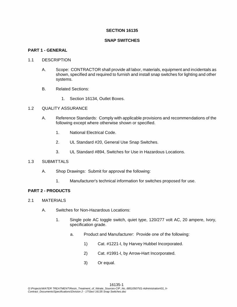
16135-1 G:\Projects\WATER TREATMENT\Resin_Treatment_of_Nitrate_Sources-CIP_No_68510507\01-Administration\01_h-Contract_Documents\Specifications\Division 2 - 17\Sect 16135 Snap Switches.doc
SECTION 16135
SNAP SWITCHES
PART 1 - GENERAL 1.1 DESCRIPTION
A. Scope: CONTRACTOR shall provide all labor, materials, equipment and incidentals as shown, specified and required to furnish and install snap switches for lighting and other systems.
B. Related Sections:
1. Section 16134, Outlet Boxes.
1.2 QUALITY ASSURANCE
A. Reference Standards: Comply with applicable provisions and recommendations of the following except where otherwise shown or specified.
1. National Electrical Code. 2. UL Standard #20, General Use Snap Switches. 3. UL Standard #894, Switches for Use in Hazardous Locations.
1.3 SUBMITTALS
A. Shop Drawings: Submit for approval the following:
1. Manufacturer's technical information for switches proposed for use.
PART 2 - PRODUCTS 2.1 MATERIALS
A. Switches for Non-Hazardous Locations:
1. Single pole AC toggle switch, quiet type, 120/277 volt AC, 20 ampere, Ivory,
specification grade.
a. Product and Manufacturer: Provide one of the following:
1) Cat. #1221-I, by Harvey Hubbel Incorporated.
2) Cat. #1991-I, by Arrow-Hart Incorporated.
3) Or equal.

16135-2 G:\Projects\WATER TREATMENT\Resin_Treatment_of_Nitrate_Sources-CIP_No_68510507\01-Administration\01_h-Contract_Documents\Specifications\Division 2 - 17\Sect 16135 Snap Switches.doc
2. Single pole, 3-way AC toggle switch, quiet type, 120/277 volt AC, 20 ampere, Ivory, specification grade.
a. Product and Manufacturer: Provide one of the following:
1) Cat. #1223-I, by Harvey Hubbell Incorporated.
2) Cat. #1993-I, by Arrow-Hart Incorporated.
3) Or equal.
3. Two pole AC toggle switch, quiet type, 120/277 volt AC, 20 ampere, Ivory, specification grade.
a. Product and Manufacturer: Provide one of the following:
1) Cat. #1222-I, by Harvey Hubbell Incorporated.
2) Cat. #1992-I, by Arrow-Hart Incorporated.
3) Or equal.
PART 3 - EXECUTION 3.1 INSTALLATION
A. Install wiring devices in outlet or device boxes in accordance with Section 16134 in non-hazardous locations.
B. Mount wall switches 4 feet-6 inches above finished floor unless otherwise noted.
C. Install switches in conformance with National Electrical Code.
***END OF SECTION***
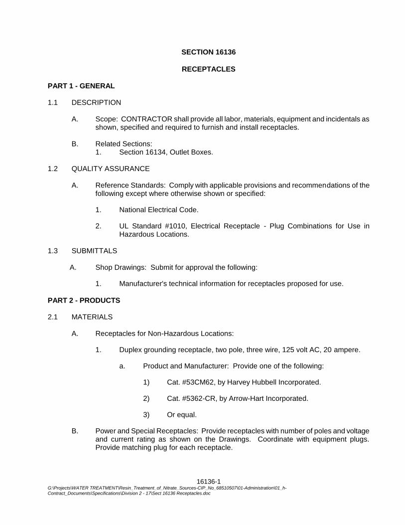
16136-1 G:\Projects\WATER TREATMENT\Resin_Treatment_of_Nitrate_Sources-CIP_No_68510507\01-Administration\01_h-Contract_Documents\Specifications\Division 2 - 17\Sect 16136 Receptacles.doc
SECTION 16136
RECEPTACLES
PART 1 - GENERAL 1.1 DESCRIPTION
A. Scope: CONTRACTOR shall provide all labor, materials, equipment and incidentals as shown, specified and required to furnish and install receptacles.
B. Related Sections:
1. Section 16134, Outlet Boxes. 1.2 QUALITY ASSURANCE
A. Reference Standards: Comply with applicable provisions and recommendations of the following except where otherwise shown or specified:
1. National Electrical Code.
2. UL Standard #1010, Electrical Receptacle - Plug Combinations for Use in Hazardous Locations.
1.3 SUBMITTALS
A. Shop Drawings: Submit for approval the following:
1. Manufacturer's technical information for receptacles proposed for use.
PART 2 - PRODUCTS 2.1 MATERIALS
A. Receptacles for Non-Hazardous Locations:
1. Duplex grounding receptacle, two pole, three wire, 125 volt AC, 20 ampere.
a. Product and Manufacturer: Provide one of the following:
1) Cat. #53CM62, by Harvey Hubbell Incorporated.
2) Cat. #5362-CR, by Arrow-Hart Incorporated.
3) Or equal.
B. Power and Special Receptacles: Provide receptacles with number of poles and voltage and current rating as shown on the Drawings. Coordinate with equipment plugs. Provide matching plug for each receptacle.
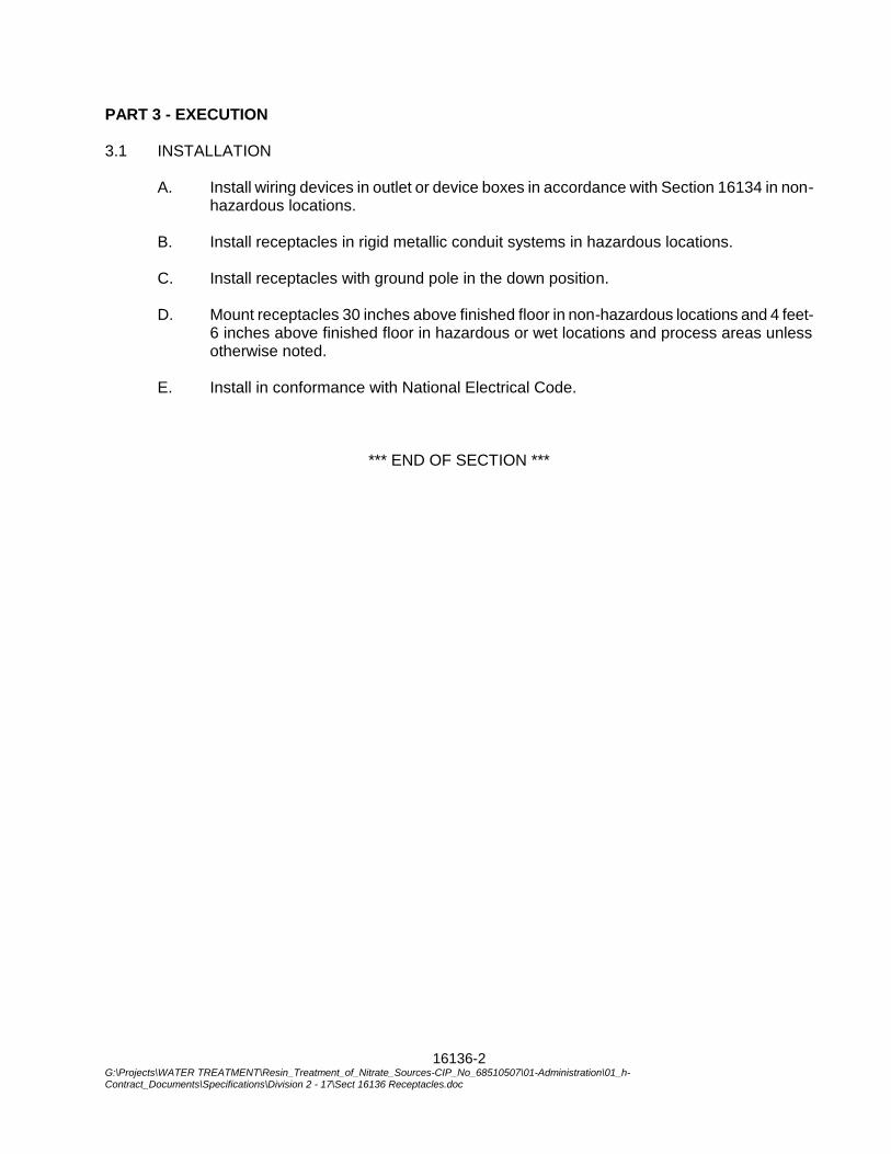
16136-2 G:\Projects\WATER TREATMENT\Resin_Treatment_of_Nitrate_Sources-CIP_No_68510507\01-Administration\01_h-Contract_Documents\Specifications\Division 2 - 17\Sect 16136 Receptacles.doc
PART 3 - EXECUTION 3.1 INSTALLATION
A. Install wiring devices in outlet or device boxes in accordance with Section 16134 in non-hazardous locations.
B. Install receptacles in rigid metallic conduit systems in hazardous locations.
C. Install receptacles with ground pole in the down position.
D. Mount receptacles 30 inches above finished floor in non-hazardous locations and 4 feet-
6 inches above finished floor in hazardous or wet locations and process areas unless otherwise noted.
E. Install in conformance with National Electrical Code.
*** END OF SECTION ***

16360-1 G:\Projects\WATER TREATMENT\Resin_Treatment_of_Nitrate_Sources-CIP_No_68510507\01-Administration\01_h-Contract_Documents\Specifications\Division 2 - 17\Sect 16360 Disconnect Switches.doc
SECTION 16360
DISCONNECT SWITCHES
PART 1 - GENERAL 1.1 DESCRIPTION
A. Scope: CONTRACTOR shall provide all labor, materials, equipment and incidentals as shown, specified and required to furnish and install disconnect switches.
1.2 QUALITY ASSURANCE
A. Reference Standards: Comply with applicable provisions and recommendations of the following except where otherwise shown or specified:
1. National Electrical Code.
2. UL #98, Enclosed Switches.
3. NEMA KS-1, Enclosed Switches. 1.3 SUBMITTALS
A. Shop Drawings: Submit for approval the following:
1. Manufacturer's technical information for disconnect switches proposed for use.
PART 2 - PRODUCTS 2.1 MATERIALS
A. Single Throw, Circuit Disconnect Switches:
1. Type: Fused, horsepower rated, heavy-duty, single throw, quick- make, quick-break mechanism, visible blades in the OFF position and safety handle.
2. Rating: Voltage and number of poles as required for motor or equipment circuits being disconnected. Switches shall bear a UL label.
3. Accessories: Auxiliary contact rated 5A, 250V single pole double throw, mechanically linked and internally mounted. Required as indicated on the Drawings.
B. Double Throw Safety Switches:
1. Type: Fused, double throw with center OFF position, quick-make, quick-break mechanism, visible blades in the OFF position and safety handle.
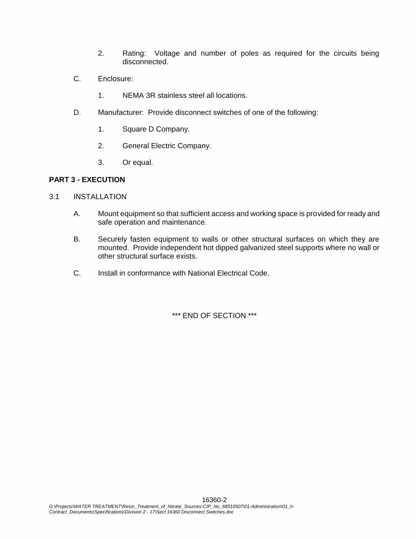
16360-2 G:\Projects\WATER TREATMENT\Resin_Treatment_of_Nitrate_Sources-CIP_No_68510507\01-Administration\01_h-Contract_Documents\Specifications\Division 2 - 17\Sect 16360 Disconnect Switches.doc
2. Rating: Voltage and number of poles as required for the circuits being disconnected.
C. Enclosure:
1. NEMA 3R stainless steel all locations. D. Manufacturer: Provide disconnect switches of one of the following:
1. Square D Company.
2. General Electric Company.
3. Or equal.
PART 3 - EXECUTION 3.1 INSTALLATION
A. Mount equipment so that sufficient access and working space is provided for ready and safe operation and maintenance.
B. Securely fasten equipment to walls or other structural surfaces on which they are
mounted. Provide independent hot dipped galvanized steel supports where no wall or other structural surface exists.
C. Install in conformance with National Electrical Code.
*** END OF SECTION ***
16404 - 1 G:\Projects\WATER TREATMENT\Resin_Treatment_of_Nitrate_Sources-CIP_No_68510507\01-Administration\01_h-Contract_Documents\Specifications\Division 2 - 17\Sect 16404 Manholes and Handholes.doc
SECTION 16404
MANHOLES AND HANDHOLES
PART 1 - GENERAL 1.1 DESCRIPTION
A. Scope: CONTRACTOR shall provide all labor, materials, equipment and incidentals as shown, specified and required to furnish and install manholes and handholes.
B. Coordination: Coordinate manhole and handhole installation with piping, sheet piling
and other underground systems and structures and locate clear of interferences. C. Related Sections:
1. Section 02560, Excavation and Backfill.
2. Section 03200, Concrete Reinforcement.
3. Section 03300, Cast-In-Place Concrete. 1.2 QUALITY ASSURANCE
A. Reference Standards: Comply with applicable provisions and recommendations of the following except where otherwise shown or specified:
1. National Electrical Code.
2. National Electrical Safety Code.
3. ASTM A 48, Gray Iron Castings.
4. OSHA. 1.3 SUBMITTALS
A. Shop Drawings: Submit for approval the following:
1. Manufacturer's technical information for manholes, handholes and accessories proposed for use.
2. Drawings showing interior and exterior dimensions and details of openings, jointing, inserts and reinforcing.
PART 2 - PRODUCTS 2.1 MATERIALS
A. Material and Construction:
1. Precast or cast-in-place type of reinforced concrete.
16404 - 2 G:\Projects\WATER TREATMENT\Resin_Treatment_of_Nitrate_Sources-CIP_No_68510507\01-Administration\01_h-Contract_Documents\Specifications\Division 2 - 17\Sect 16404 Manholes and Handholes.doc
2. Minimum interior dimensions as indicated on the Drawings.
3. Duct entrances sized and located to suit duct banks.
B. Accessories:
1. Frames and Covers:
a. Material: Cast iron conforming to ASTM A 48, Class 30A.
b. Covers: Watertight, round sealed type marked "ELECTRICAL" in raised two inch letters.
c. Frame shall be grouted on the manhole or handhole.
d. Manufacturer: Provide frames and covers of one of the following:
1) Neenah Foundry Company.
2) Flockhart Foundry Company.
3) Campbell Foundry Company.
4) Or equal.
2. Pulling Irons:
a. Material: Galvanized steel.
b. Cast in the wall opposite to the centerline of each incoming duct bank and 12 inches below centerline of bottom line of ducts.
c. Product and Manufacturer: Provide one of the following:
1) Cat. No. DU2T3 by McGraw Edison Company.
2) Cat. No. 8119 by A.B. Chance Company.
3) Or equal.
3. Cable Racks:
a. Material: Galvanized steel.
b. Cable racks shall adequately support cables with space allowed for future cables.
c. Each rack shall be a vertical assembly of 24 inch cable racks extending from within 6 inches of the manhole roof slab to within 6 inches of the manhole floor.
d. Product and Manufacturer: Provide one of the following:
16404 - 3 G:\Projects\WATER TREATMENT\Resin_Treatment_of_Nitrate_Sources-CIP_No_68510507\01-Administration\01_h-Contract_Documents\Specifications\Division 2 - 17\Sect 16404 Manholes and Handholes.doc
1) Cat. No. J-5125 by Joslyn Manufacturing and Supply Company.
2) Cat. No. 2125 by Hubbard and Company.
3) Or equal.
4. Cable Hooks:
a. Material: Galvanized steel.
b. Length: 7-1/2-inch minimum.
c. Product and Manufacturer: Provide one of the following:
1) Cat. No. J-5132 by Joslyn Manufacturing and Supply Company.
2) Cat. No. 2132 by Hubbard and Company.
3) Or equal.
5. Insulators:
a. Material: Porcelain.
b. Product and Manufacturer: Provide one of the following:
1) Cat. No. J-5122 by Joslyn Manufacturing and Supply Company.
2) Cat. No. 2120 by Hubbard and Company.
3) Or equal.
6. Manhole Steps: Non Permitted
PART 3 - EXECUTION 3.1 INSTALLATION
A. Install manholes and handholes where shown on Drawings. Verify final locations in field. CONTRACTOR shall be responsible for all excavation and backfilling required for installation.
B. Complete installation of manholes and handholes so that structures are watertight. C. Cable Racks:
1. Attach with 3-inch by 3/8-inch diameter "tamp-in" studs mounted in 1-inch holes drilled into walls of manholes in the absence of inserts.
2. Provide cable hooks to support each cable on each rack along the cable run within the manholes.
16404 - 4 G:\Projects\WATER TREATMENT\Resin_Treatment_of_Nitrate_Sources-CIP_No_68510507\01-Administration\01_h-Contract_Documents\Specifications\Division 2 - 17\Sect 16404 Manholes and Handholes.doc
3. Individually support each cable at each hook on porcelain insulators.
4. In the manhole securely tie each cable in place at each insulator block to prevent excessive movement of insulators, cables, or fireproof tape. Tie cables with non-metallic 3/4-inch strapping tape as manufactured by 3M or tie down with nylon straps.
D. Grounding: Install a 0.75 inch OD, 10 foot ground rod for each pullbox. Bond all
exposed metal pullbox accessories and the concrete reinforcing rods with No. 4 AWG minimum bare copper wire and connect to the ground rod and to the ductbank ground cable. Extend #4/0 ground cable to ground grid.
E. Manhole Floor: Provide a ¾-inch diameter crushed rock floor (minimum 12 inches). F. Provide grading rings or brick stacks for pullboxes when required to adjust pullbox cover
to proper grade. Stacks shall be minimum of 12 inches in height, constructed on the roof slab or cone section on which the pullbox frame and cover shall be placed. The height of the stack shall be such as is necessary to bring the pullbox frame to the proper grade.
PART 4 - PAYMENT Payment for complying with the requirements of this section shall be included in the appurtenant bid items and no additional compensation shall be allowed therefor.
*** END OF SECTION ***
16450 - 1 G:\Projects\WATER TREATMENT\Resin_Treatment_of_Nitrate_Sources-CIP_No_68510507\01-Administration\01_h-Contract_Documents\Specifications\Division 2 - 17\Sect 16450 Grounding Systems.doc
SECTION 16450
GROUNDING SYSTEMS
PART 1 - GENERAL 1.1 DESCRIPTION
A. Scope: CONTRACTOR shall provide all labor, materials, equipment and incidentals as shown, specified and required to furnish and install complete grounding for the electrical systems. The grounding system shall consist of green wire grounding from power sources, and a supplemental well facility wide ground grid, ground rods, and UFER grounds.
1.2 QUALITY ASSURANCE
A. Reference Standards: Comply with applicable provisions and recommendations of the following except where otherwise shown or specified:
1. NEC Article 250, Grounding.
2. UL Standard #467, Electrical Grounding and Bonding Equipment. 1.3 SUBMITTALS
A. Shop Drawings: Submit for approval the following:
1. Manufacturer's technical information for grounding materials proposed for use.
2. Listing of grounding connector types identifying where they are to be used.
3. Layouts of each structure ground grid.
4. Test point construction details.
5. Results of ground resistance tests at each test point.
PART 2 - PRODUCTS 2.1 MATERIALS
A. Bare Ground Cable:
1. Material: Annealed, bare, stranded copper, No. 6 AWG minimum size for equipment grounding, #4/O minimum for ground loops.
2. Manufacturer: Provide ground cable of one of the following:
a. Continental Wire and Cable Corporation.
b. General Cable Corporation.
16450 - 2 G:\Projects\WATER TREATMENT\Resin_Treatment_of_Nitrate_Sources-CIP_No_68510507\01-Administration\01_h-Contract_Documents\Specifications\Division 2 - 17\Sect 16450 Grounding Systems.doc
c. Rome Cable Company.
d. Or equal.
B. Ground Rods:
1. Material: Copperclad rigid steel rods, 3/4-inch diameter, 10 feet long.
2. Manufacturer: Provide ground rods of by one of the following:
a. Copperweld, Bimetallics Division.
b. ITT Blackburn Company.
c. Or equal.
C. Grounding Connectors:
1. Welded connections shall be by exothermic process utilizing molds, cartridges and hardware designed specifically for the connection to be made.
a. Welded Connections:
1) Cadweld by Erico Products, Incorporated.
2) Therm-O-Weld by Burndy Corporation.
3) Or equal.
D. Insulated Ground Cable: Sizes as shown on the Drawings and required by the NEC, green insulation, type THHN/THWN.
E. Hardware: Silicon bronze.
PART 3 - EXECUTION 3.1 GROUND SYSTEM
A. Provide individual and grouped ground rods and connecting ground loop as shown on the Contract Drawings.
B. Install #4/O bare copper cable around the exterior perimeter of structures linking rods,
minimum 2 feet-6 inches below grade, unless otherwise shown on Drawings. C. Install sufficient ground rods to provide a resistance to ground of less than 5 ohms at
each point on the ground grid. D. For structures with steel columns, install #4/O ground cable from grid to each column
around the perimeter of the structure. Connect cable to steel using exothermic welds. E. Connect grids to a continuous underground water pipe system when practical. Provide
UFER grounds at all structures and buildings and connect to grid.
16450 - 3 G:\Projects\WATER TREATMENT\Resin_Treatment_of_Nitrate_Sources-CIP_No_68510507\01-Administration\01_h-Contract_Documents\Specifications\Division 2 - 17\Sect 16450 Grounding Systems.doc
F. Extend bare copper grounds from the ground grid to all railing, electrical equipment,
tanks, pumps, process equipment, piping, structural steel and to all building and structure loops throughout the site.
G. Provide accessible test points for measuring the ground resistance of each grid, as
shown on the Drawings. H. Weld all buried connections except for test points.
3.2 EQUIPMENT GROUNDING
A. Ground all electrical equipment in compliance with the National Electrical Code and other applicable codes.
B. Equipment supplemental grounding conductors shall be bare stranded copper cable of
adequate size installed in Schedule 80 PVC conduit where necessary for mechanical protection.
C. Connect supplemental ground conductors to metallic conduit with copper clamps, straps
or with grounding bushings. D. Connect supplemental ground conductors to piping by welding or brazing. Use copper
bonding jumpers on all gasketed joints. E. Connect supplemental ground conductors to equipment by means of an indent
compression type lug. Bolt lug to equipment frame using holes or terminals provided on equipment specifically for grounding. Do not use holddown bolts. Where grounding provisions are not included, drill suitable holes in locations designated by ENGINEER.
F. Connect supplemental ground conductor to motors by bolting directly to motor frames,
not to sole plates or supporting structures. G. Connect supplemental ground and green wire ground to service water piping by means
of copper clamps. Use copper bonding jumpers on all gasketed joints.
H. Scrape bolted surfaces clean and coat with a conductive oxide- resistant compound. I. Run green insulated wire grounds with all power conductors, and in all PVC conduit
runs. 3.3 TESTING
A. Test the completed ground systems for continuity and for resistance to ground using an electrical ground resistance tester and submit test reports for all ground rods and ground loops.
*** END OF SECTION ***

16450 - 4 G:\Projects\WATER TREATMENT\Resin_Treatment_of_Nitrate_Sources-CIP_No_68510507\01-Administration\01_h-Contract_Documents\Specifications\Division 2 - 17\Sect 16450 Grounding Systems.doc
THIS PAGE INTENTIONALLY BLANK
16460-1 G:\Projects\WATER TREATMENT\Resin_Treatment_of_Nitrate_Sources-CIP_No_68510507\01-Administration\01_h-
Contract_Documents\Specifications\Division 2 - 17\Sect 16460 480 Volt Switchboards.doc
SECTION 16460
480 VOLT SWITCHBOARDS PART 1 - GENERAL 1.1 DESCRIPTION
A. Scope: Furnish all labor, materials, equipment and incidentals required to provide a NEMA 3R 480 volt switchboard including incoming line and SCE metering compartment in full conformance with utility requirements and as shown and specified.
B. Coordination:
1. Coordinate conduit entries with conduit layouts.
2. Comply with SCE requirements. 1.2 QUALITY ASSURANCE
A. Reference Standards: Comply with applicable provisions and recommendations of ten following except where otherwise shown or specified:
1. NEMA PB-2, Low Voltage Distribution Switchboards.
2. UL Standard No. 891, Dead-Front Electrical Switchboards.
3. ANSI C37.13, Low Voltage AC Power Circuit Breakers.
4. National Electrical Code.
5. National Electrical Safety Code.
6. SCE Requirements. 1.3 SUBMITTALS
A. Shop Drawings: Submit for approval copies of manufacturer's technical information for the 480 volt switchboards proposed for use, including front views, floor plans and complete data for each type of circuit breaker.
B. Submit to SCE all required data and drawings and obtain their approval before release for manufacture.
PART 2 - PRODUCTS 2.1 MATERIALS
A. Switchboard Rating:
1. 480 volt, 3 phase, 60 hertz, 4 wire.
2. Continuous AC main bus ampacity and fault current rating as shown on the Drawings.
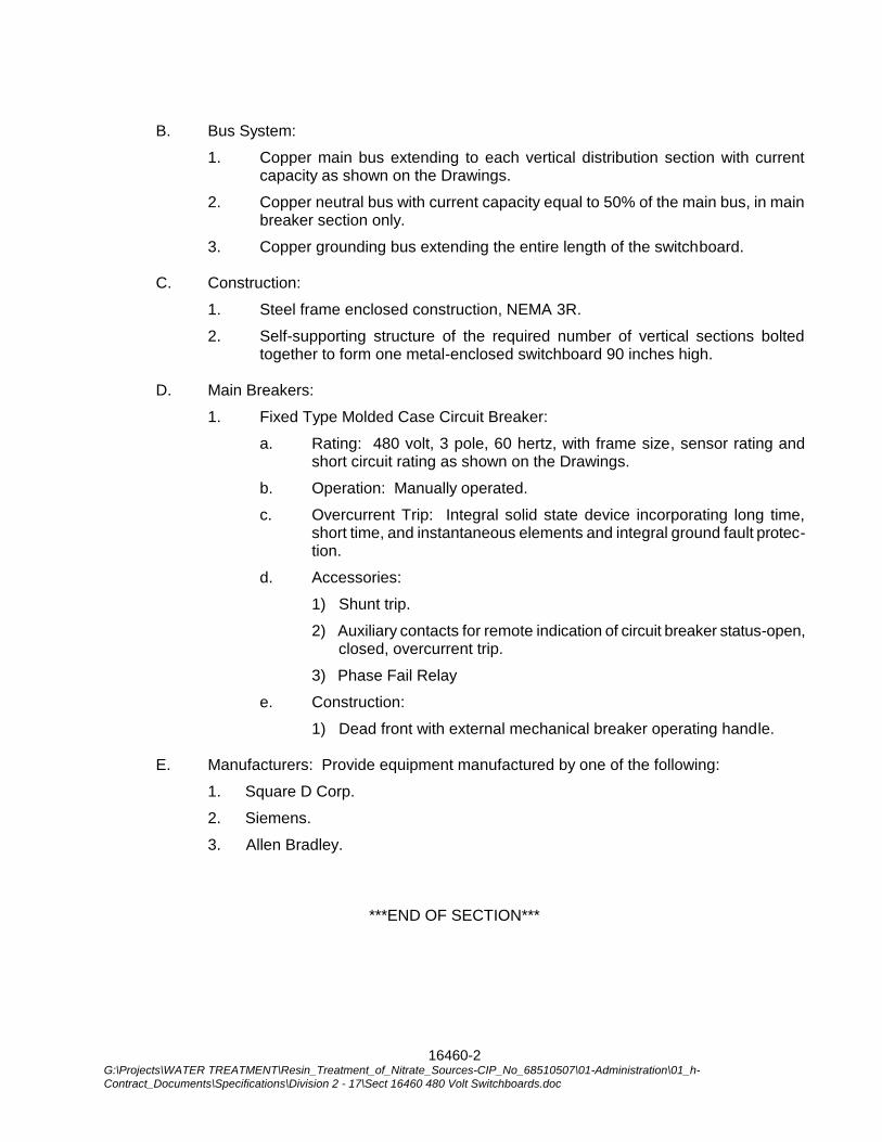
16460-2 G:\Projects\WATER TREATMENT\Resin_Treatment_of_Nitrate_Sources-CIP_No_68510507\01-Administration\01_h-
Contract_Documents\Specifications\Division 2 - 17\Sect 16460 480 Volt Switchboards.doc
B. Bus System:
1. Copper main bus extending to each vertical distribution section with current capacity as shown on the Drawings.
2. Copper neutral bus with current capacity equal to 50% of the main bus, in main breaker section only.
3. Copper grounding bus extending the entire length of the switchboard.
C. Construction:
1. Steel frame enclosed construction, NEMA 3R.
2. Self-supporting structure of the required number of vertical sections bolted together to form one metal-enclosed switchboard 90 inches high.
D. Main Breakers:
1. Fixed Type Molded Case Circuit Breaker:
a. Rating: 480 volt, 3 pole, 60 hertz, with frame size, sensor rating and short circuit rating as shown on the Drawings.
b. Operation: Manually operated.
c. Overcurrent Trip: Integral solid state device incorporating long time, short time, and instantaneous elements and integral ground fault protec-tion.
d. Accessories:
1) Shunt trip.
2) Auxiliary contacts for remote indication of circuit breaker status-open, closed, overcurrent trip.
3) Phase Fail Relay
e. Construction:
1) Dead front with external mechanical breaker operating handle.
E. Manufacturers: Provide equipment manufactured by one of the following:
1. Square D Corp.
2. Siemens.
3. Allen Bradley.
***END OF SECTION***
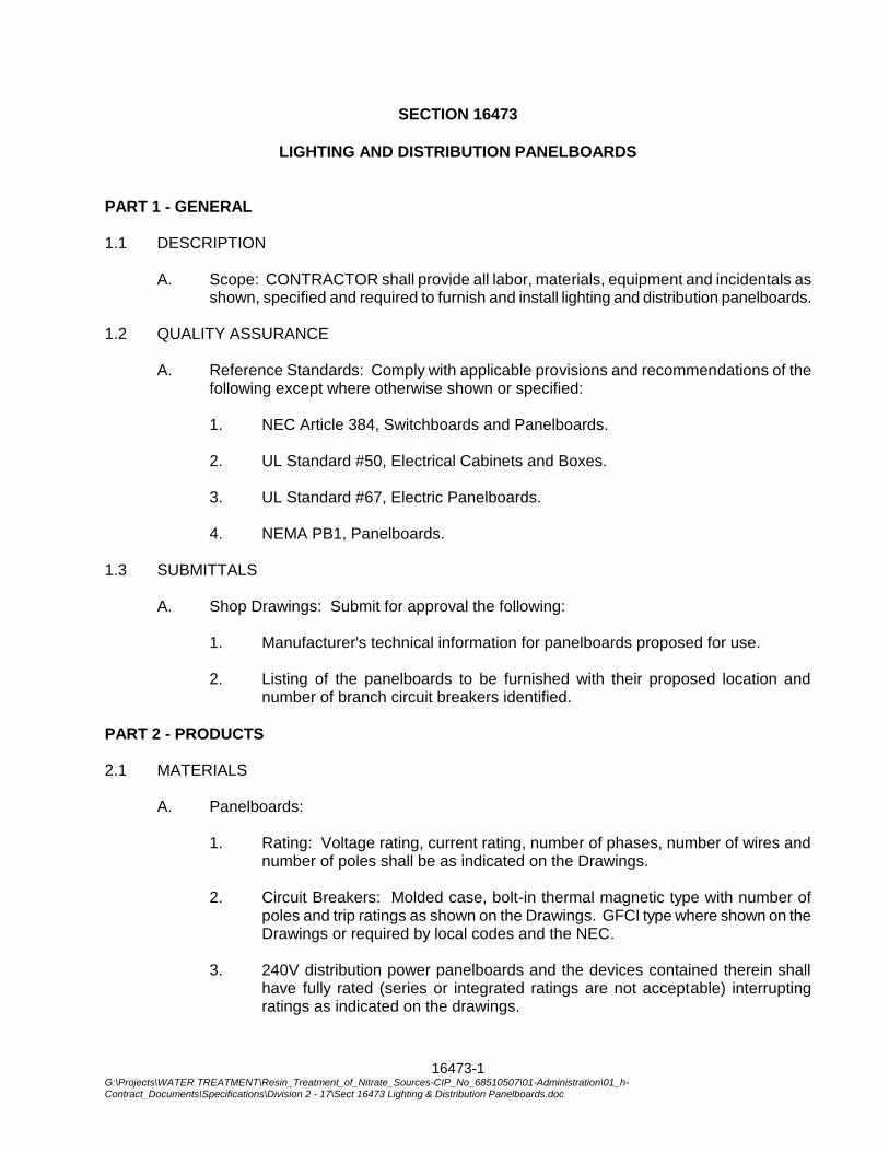
16473-1 G:\Projects\WATER TREATMENT\Resin_Treatment_of_Nitrate_Sources-CIP_No_68510507\01-Administration\01_h-Contract_Documents\Specifications\Division 2 - 17\Sect 16473 Lighting & Distribution Panelboards.doc
SECTION 16473
LIGHTING AND DISTRIBUTION PANELBOARDS
PART 1 - GENERAL 1.1 DESCRIPTION
A. Scope: CONTRACTOR shall provide all labor, materials, equipment and incidentals as shown, specified and required to furnish and install lighting and distribution panelboards.
1.2 QUALITY ASSURANCE
A. Reference Standards: Comply with applicable provisions and recommendations of the following except where otherwise shown or specified:
1. NEC Article 384, Switchboards and Panelboards.
2. UL Standard #50, Electrical Cabinets and Boxes.
3. UL Standard #67, Electric Panelboards.
4. NEMA PB1, Panelboards.
1.3 SUBMITTALS
A. Shop Drawings: Submit for approval the following:
1. Manufacturer's technical information for panelboards proposed for use.
2. Listing of the panelboards to be furnished with their proposed location and number of branch circuit breakers identified.
PART 2 - PRODUCTS 2.1 MATERIALS
A. Panelboards:
1. Rating: Voltage rating, current rating, number of phases, number of wires and number of poles shall be as indicated on the Drawings.
2. Circuit Breakers: Molded case, bolt-in thermal magnetic type with number of
poles and trip ratings as shown on the Drawings. GFCI type where shown on the Drawings or required by local codes and the NEC.
3. 240V distribution power panelboards and the devices contained therein shall
have fully rated (series or integrated ratings are not acceptable) interrupting ratings as indicated on the drawings.
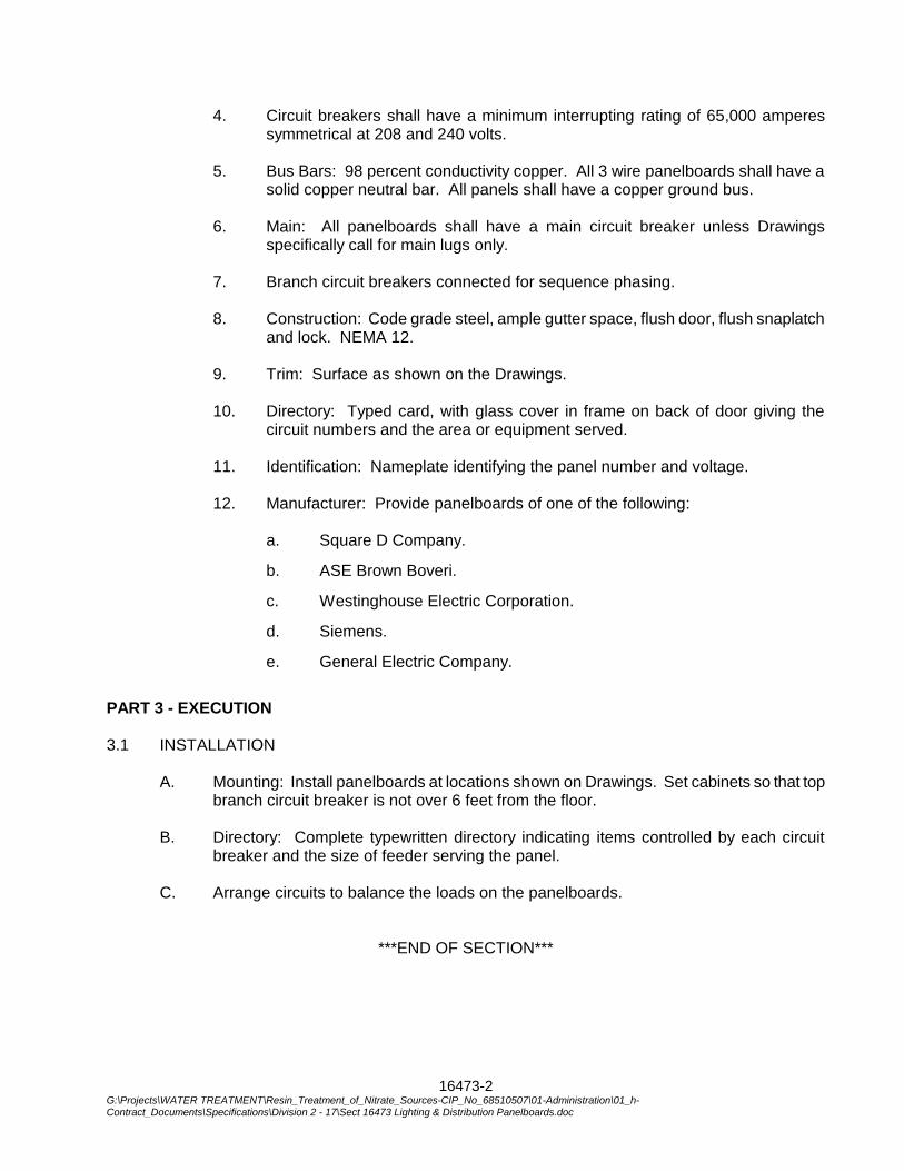
16473-2 G:\Projects\WATER TREATMENT\Resin_Treatment_of_Nitrate_Sources-CIP_No_68510507\01-Administration\01_h-Contract_Documents\Specifications\Division 2 - 17\Sect 16473 Lighting & Distribution Panelboards.doc
4. Circuit breakers shall have a minimum interrupting rating of 65,000 amperes symmetrical at 208 and 240 volts.
5. Bus Bars: 98 percent conductivity copper. All 3 wire panelboards shall have a
solid copper neutral bar. All panels shall have a copper ground bus.
6. Main: All panelboards shall have a main circuit breaker unless Drawings specifically call for main lugs only.
7. Branch circuit breakers connected for sequence phasing.
8. Construction: Code grade steel, ample gutter space, flush door, flush snaplatch
and lock. NEMA 12.
9. Trim: Surface as shown on the Drawings.
10. Directory: Typed card, with glass cover in frame on back of door giving the circuit numbers and the area or equipment served.
11. Identification: Nameplate identifying the panel number and voltage.
12. Manufacturer: Provide panelboards of one of the following:
a. Square D Company.
b. ASE Brown Boveri.
c. Westinghouse Electric Corporation.
d. Siemens.
e. General Electric Company.
PART 3 - EXECUTION 3.1 INSTALLATION
A. Mounting: Install panelboards at locations shown on Drawings. Set cabinets so that top branch circuit breaker is not over 6 feet from the floor.
B. Directory: Complete typewritten directory indicating items controlled by each circuit
breaker and the size of feeder serving the panel.
C. Arrange circuits to balance the loads on the panelboards.
***END OF SECTION***
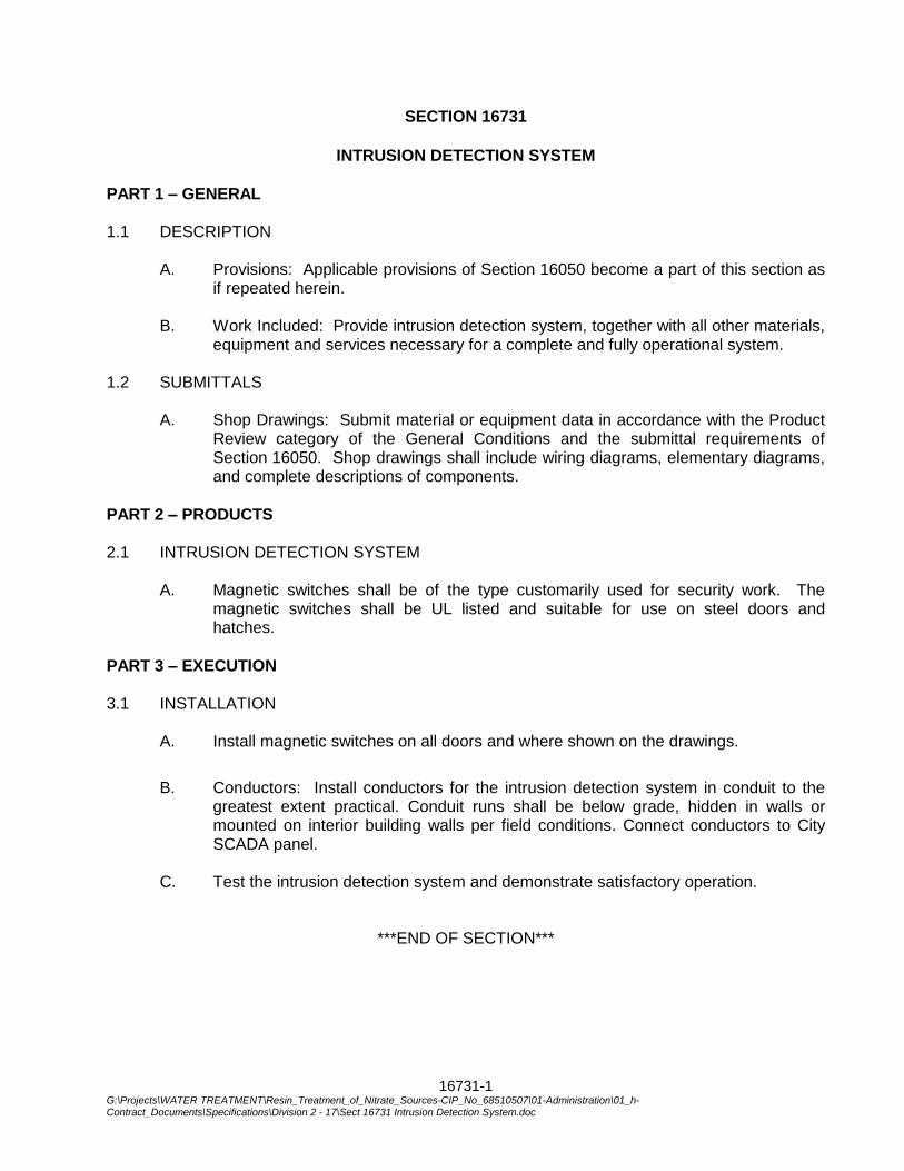
16731-1 G:\Projects\WATER TREATMENT\Resin_Treatment_of_Nitrate_Sources-CIP_No_68510507\01-Administration\01_h-Contract_Documents\Specifications\Division 2 - 17\Sect 16731 Intrusion Detection System.doc
SECTION 16731
INTRUSION DETECTION SYSTEM
PART 1 – GENERAL 1.1 DESCRIPTION
A. Provisions: Applicable provisions of Section 16050 become a part of this section as if repeated herein.
B. Work Included: Provide intrusion detection system, together with all other materials,
equipment and services necessary for a complete and fully operational system.
1.2 SUBMITTALS
A. Shop Drawings: Submit material or equipment data in accordance with the Product Review category of the General Conditions and the submittal requirements of Section 16050. Shop drawings shall include wiring diagrams, elementary diagrams, and complete descriptions of components.
PART 2 – PRODUCTS 2.1 INTRUSION DETECTION SYSTEM
A. Magnetic switches shall be of the type customarily used for security work. The
magnetic switches shall be UL listed and suitable for use on steel doors and hatches.
PART 3 – EXECUTION 3.1 INSTALLATION
A. Install magnetic switches on all doors and where shown on the drawings.
B. Conductors: Install conductors for the intrusion detection system in conduit to the
greatest extent practical. Conduit runs shall be below grade, hidden in walls or mounted on interior building walls per field conditions. Connect conductors to City SCADA panel.
C. Test the intrusion detection system and demonstrate satisfactory operation.
***END OF SECTION***

16731-2 G:\Projects\WATER TREATMENT\Resin_Treatment_of_Nitrate_Sources-CIP_No_68510507\01-Administration\01_h-Contract_Documents\Specifications\Division 2 - 17\Sect 16731 Intrusion Detection System.doc
THIS PAGE INTENTIONALLY BLANK
16950-1 G:\Projects\WATER TREATMENT\Resin_Treatment_of_Nitrate_Sources-CIP_No_68510507\01-Administration\01_h-Contract_Documents\Specifications\Division 2 - 17\Sect 16950 Electrical Testing.doc
SECTION 16950
ELECTRICAL TESTING
PART 1 - GENERAL 1.1 DESCRIPTION
This section includes requirements for acceptance testing of the electrical system, wiring, equipment, and grounding.
1.2 Related Work Specified Elsewhere
A. General Electrical Requirements: 16010 B. Testing, Starting, Adjusting and Commissioning: 01750
1.3 REFERENCES
A. National Electric Testing Association (NETA):
1. ATS-1995 -Acceptance Testing Specifications for Electric Power Distribution
Equipment and Systems. 1.4 SUBMITTALS
A. Pre-Test Submittals:
1. Testing service qualifications. 2. Test personnel qualifications (resumes). 3. Equipment testing schedule. 4. Test data forms.
B. Post -Test Submittals;
1. Summary of testing for the project. 2. Description of the equipment tested. 3. Description of the test and test procedures. 4. Test results. 5. Conclusions and recommendations. 6. Completed test forms, including witness's signatures.
16950-2 G:\Projects\WATER TREATMENT\Resin_Treatment_of_Nitrate_Sources-CIP_No_68510507\01-Administration\01_h-Contract_Documents\Specifications\Division 2 - 17\Sect 16950 Electrical Testing.doc
7. List of test equipment and calibration documents. 8. Date and time. 9. Include the following data tabulated for each piece of equipment:
a. Circuit number. b. Equipment or motor name and tag number (where applicable). c. Nameplate full-load-ampere rating. d. Motor service factor. e. Motor ambient temperature rating. f. Overload relay rating. g. Measured full load current. h. Measured discharge pressures (where applicable).
C. Submit equipment test schedule no later than 7 days prior to scheduled date of
testing. D. Project Record Documents: Note or indicate wiring deviations from Contract
Documents on Project Record Documents. 1.5. QUALITY ASSURANCE
A. The Contractor shall retain a qualified Engineering appraisal and testing organization
to provide inspections, tests, and evaluation to determine that the equipment designated herein is furnished in accordance with specifications and is installed and adjusted for successful energization and operation.
B. Testing Firm:
1. Obtain services of an independent testing service firm that meets the Federal
OSHA criteria for accreditation of testing laboratories, Title 29, Part 1910.7 and has a work history and qualifications acceptable to the Engineer.
2. The appraisal and testing organization shall have two or more years of
experience related to the appraisal and testing of equipment designated herein.
3. The managing or supervising representatives of the appraisal and testing
organization shall have extensive knowledge of the products involved and at least two years experience conducting appraisals and tests. All testing shall be conducted under the supervision of the managing or supervising representatives.
16950-3 G:\Projects\WATER TREATMENT\Resin_Treatment_of_Nitrate_Sources-CIP_No_68510507\01-Administration\01_h-Contract_Documents\Specifications\Division 2 - 17\Sect 16950 Electrical Testing.doc
4. Testing technicians shall be trained and experienced in the testing they
perform. 5. The engineering appraisal and testing organization shall utilize
comprehensive report forms to document engineering appraisal and test results on all equipment's and products. Upon completion of the work, the report forms shall be signed by the managing or supervising engineering representative and included in the final report.
6. Testing shall be done in accordance with the manufacturer's instructions,
these specifications, and applicable ANSI, ASTM and NEMA standards. Applicable product instructions shall be furnished to the Engineer for review.
7. Prequalified Testing Services and Manufacturing Firms:
a. Electro-Test Inc. b. Square D Company Technical Services Divisions. c. General Electric Company.
8. Qualifications of other testing services firms may be submitted.
9. Testing service or testing personnel may be accepted or rejected based on,
but not limited to, the testing equipment intended to be used, the qualifications of the firm, and personnel.
1.6 MEASUREMENT AND PAYMENT
Payment for the work in this section shall be included as part of the lump-sum bid amount for electrical work stated in the proposal.
PART 2 - MATERIALS Not applicable for this Section.
PART 3 - EXECUTION 3.1 EXAMINATION
A. Verify that electrical work is free from improper grounds, short circuits, and
overloads. B. Verify correctness of wiring first by visual comparison of the conductor connections
with connection diagrams. C. Make individual circuit continuity checks by using electrical circuit testers.
16950-4 G:\Projects\WATER TREATMENT\Resin_Treatment_of_Nitrate_Sources-CIP_No_68510507\01-Administration\01_h-Contract_Documents\Specifications\Division 2 - 17\Sect 16950 Electrical Testing.doc
3.2 ACCEPTANCE TESTING
A. Perform testing and allow Owner and Engineer to witness testing. Notify the Owner's representative three days or more in advance when any test is to take place.
B. Perform electrical acceptance testing in accordance with NETA Standards C. Perform tests to assure that electrical equipment specified to be tested will operate
within industry and manufacturers published tolerances, and will perform safely. Record test result data, to be used as a baseline for future tests.
D. Testing of installed equipment shall result in acceptable test data. Equipment for
which acceptable test data has not been submitted, or has been submitted but rejected, shall be deemed as not meeting Contract requirements.
E. Conduct 3 point fall of potential ground test by using equipment of one of the
following manufacturer, or equal: 1. Biddle Company. 2. Associated Research.
F. Test insulation resistance of circuits. Test each complete circuit prior to energizing.
Insulation resistance between conductors and between each conductor and ground shall not be less than 5 megohms. Repair or replace wires or cables in circuits that do not pass this test, and repeat the test.
G. Test project electrical equipment, including 600 volt electrical distribution equipment,
motor control centers, and grounding. Complete test reports for each individual piece of equipment. The following types of electrical equipment shall be tested according to the requirements of this specification section. Refer to the project documents to identify the equipment related to a specific project:
1. Power Distribution Switch 2. Molded Case Circuit Breaker. 3. Motor Circuit Protector, 200 amp and above. 4. Motors, 200 hp and above. 5. Grounding Electrode Systems and Equipment Grounding System (refer to
section 16450 for additional requirements). 6. Protective Relays (relay settings shall be as documented in the project
coordination study, see section 16010). 7. Three Phase Power Transformers.
16950-5 G:\Projects\WATER TREATMENT\Resin_Treatment_of_Nitrate_Sources-CIP_No_68510507\01-Administration\01_h-Contract_Documents\Specifications\Division 2 - 17\Sect 16950 Electrical Testing.doc
H. Ground Fault Protective Equipment: The ground-fault protection system shall be performance tested after installation in accordance with NEC 230-95C. Submit a written record of the test to the Owner's representative. Label on panel above the device with certification and values. Record current pickup level and time delay settings to which the equipment was finally adjusted. Measure and record relay pickup current and the relay time delay at two values above pickup. Test for correct system operation at 57% rated voltage. If relay pickup current is not within 5% of the manufacturer's calibration marks or fixed setting or relay timing does not conform with manufacturer's published time-current characteristic curves, repair or replace equipment and repeat test.
I. Motor Operating Test: Run each motor as nearly as possible to rated operating
conditions. Record current in each phase of each motor 1/2 hp and larger and submit to the Owner's representative. Repair or replace motor or driven equipment if current exceeds motor nameplate current.
J. Power Company Voltage Test: When the installation is essentially complete and the
facility is in operation, check the voltage at the point of termination of the power company supply system to the project. Check voltage amplitude and balance between phases for loaded and unloaded conditions. If the unbalance (as defined by NEMA) exceeds 1%, or if the voltage varies throughout the day and from loaded to unloaded conditions more than +5% of nominal, make a written request to the Power Company that the condition be corrected. If corrections are not made, request that the Power Company official provide a written statement that the voltage variations and/or unbalance are within their normal standards.
3.3 SUMMARY TEST REPORT
A. Upon completion of testing in every area, submit summary test report.
***END OF SECTION***

16950-6 G:\Projects\WATER TREATMENT\Resin_Treatment_of_Nitrate_Sources-CIP_No_68510507\01-Administration\01_h-Contract_Documents\Specifications\Division 2 - 17\Sect 16950 Electrical Testing.doc
THIS PAGE INTENTIONALLY BLANK
Related Documents