Cisco DCNM SAN Management Configuration Guide, Release 11.5(x) First Published: 2020-12-23 Last Modified: 2022-03-04 Americas Headquarters Cisco Systems, Inc. 170 West Tasman Drive San Jose, CA 95134-1706 USA http://www.cisco.com Tel: 408 526-4000 800 553-NETS (6387) Fax: 408 527-0883

Welcome message from author
This document is posted to help you gain knowledge. Please leave a comment to let me know what you think about it! Share it to your friends and learn new things together.
Transcript

Cisco DCNM SAN Management Configuration Guide, Release 11.5(x)First Published: 2020-12-23
Last Modified: 2022-03-04
Americas HeadquartersCisco Systems, Inc.170 West Tasman DriveSan Jose, CA 95134-1706USAhttp://www.cisco.comTel: 408 526-4000
800 553-NETS (6387)Fax: 408 527-0883

THE SPECIFICATIONS AND INFORMATION REGARDING THE PRODUCTS IN THIS MANUAL ARE SUBJECT TO CHANGE WITHOUT NOTICE. ALL STATEMENTS,INFORMATION, AND RECOMMENDATIONS IN THIS MANUAL ARE BELIEVED TO BE ACCURATE BUT ARE PRESENTED WITHOUT WARRANTY OF ANY KIND,EXPRESS OR IMPLIED. USERS MUST TAKE FULL RESPONSIBILITY FOR THEIR APPLICATION OF ANY PRODUCTS.
THE SOFTWARE LICENSE AND LIMITED WARRANTY FOR THE ACCOMPANYING PRODUCT ARE SET FORTH IN THE INFORMATION PACKET THAT SHIPPED WITHTHE PRODUCT AND ARE INCORPORATED HEREIN BY THIS REFERENCE. IF YOU ARE UNABLE TO LOCATE THE SOFTWARE LICENSE OR LIMITED WARRANTY,CONTACT YOUR CISCO REPRESENTATIVE FOR A COPY.
The Cisco implementation of TCP header compression is an adaptation of a program developed by the University of California, Berkeley (UCB) as part of UCB's public domain version ofthe UNIX operating system. All rights reserved. Copyright © 1981, Regents of the University of California.
NOTWITHSTANDING ANY OTHERWARRANTY HEREIN, ALL DOCUMENT FILES AND SOFTWARE OF THESE SUPPLIERS ARE PROVIDED “AS IS" WITH ALL FAULTS.CISCO AND THE ABOVE-NAMED SUPPLIERS DISCLAIM ALL WARRANTIES, EXPRESSED OR IMPLIED, INCLUDING, WITHOUT LIMITATION, THOSE OFMERCHANTABILITY, FITNESS FOR A PARTICULAR PURPOSE AND NONINFRINGEMENT OR ARISING FROM A COURSE OF DEALING, USAGE, OR TRADE PRACTICE.
IN NO EVENT SHALL CISCO OR ITS SUPPLIERS BE LIABLE FOR ANY INDIRECT, SPECIAL, CONSEQUENTIAL, OR INCIDENTAL DAMAGES, INCLUDING, WITHOUTLIMITATION, LOST PROFITS OR LOSS OR DAMAGE TO DATA ARISING OUT OF THE USE OR INABILITY TO USE THIS MANUAL, EVEN IF CISCO OR ITS SUPPLIERSHAVE BEEN ADVISED OF THE POSSIBILITY OF SUCH DAMAGES.
Any Internet Protocol (IP) addresses and phone numbers used in this document are not intended to be actual addresses and phone numbers. Any examples, command display output, networktopology diagrams, and other figures included in the document are shown for illustrative purposes only. Any use of actual IP addresses or phone numbers in illustrative content is unintentionaland coincidental.
All printed copies and duplicate soft copies of this document are considered uncontrolled. See the current online version for the latest version.
Cisco has more than 200 offices worldwide. Addresses and phone numbers are listed on the Cisco website at www.cisco.com/go/offices.
The documentation set for this product strives to use bias-free language. For purposes of this documentation set, bias-free is defined as language that does not imply discrimination based onage, disability, gender, racial identity, ethnic identity, sexual orientation, socioeconomic status, and intersectionality. Exceptions may be present in the documentation due to language thatis hardcoded in the user interfaces of the product software, language used based on standards documentation, or language that is used by a referenced third-party product.
Cisco and the Cisco logo are trademarks or registered trademarks of Cisco and/or its affiliates in the U.S. and other countries. To view a list of Cisco trademarks, go to this URL:https://www.cisco.com/c/en/us/about/legal/trademarks.html. Third-party trademarks mentioned are the property of their respective owners. The use of the word partner does not imply apartnership relationship between Cisco and any other company. (1721R)
© 2020–2022 Cisco Systems, Inc. All rights reserved.
C O N T E N T S
Overview 1C H A P T E R 1
Cisco Data Center Network Manager 1
REST API Tool 2
Dashboard 7C H A P T E R 2
Summary Dashboard 7
Dashlets 8
Storage Dashboard 13
Viewing Storage Enclosures Information 13
Viewing Storage Systems Information 13
Viewing Storage Enclosure Events 18
Viewing Storage Enclosure Topology 19
Viewing Storage Enclosure Traffic 19
Introduction to SAN Insights 20
SAN Insights Dashboard 20
Viewing SAN Insights Metrics 23
ECT Analysis 23
Custom Graphing 27
Trend Identifier 29
Outlier Detection 30
Hosts 31
Viewing Host Enclosures 32
Viewing Host Events 34
Viewing Host Topology 34
View Host Traffic 35
Cisco DCNM SAN Management Configuration Guide, Release 11.5(x)iii

Topology 37C H A P T E R 3
Topology 37
Status 37
Scope 38
Searching 38
Quick Search 39
VLAN 39
VSAN ID/Name 39
Show Panel 39
Layouts 40
Zooming, Panning, and Dragging 41
Switch Slide-Out Panel 41
Beacon 41
Tagging 41
More Details 41
Link Slide-Out Panel 43
24-Hour Traffic 43
vCenter Compute Visualization 43
Enabling vCenter Compute Visualization 44
Using vCenter Compute Visualization 46
Troubleshooting vCenter Compute Visualization 50
Inventory 53C H A P T E R 4
Viewing Inventory Information 53
Viewing Inventory Information for Switches 53
Viewing System Information 58
Viewing Device Manager Information 59
Installing a Switch License 60
Rediscovering Switch Licenses 60
Interfaces 61
VLAN 62
FEX 64
VDCs 68
Cisco DCNM SAN Management Configuration Guide, Release 11.5(x)iv
Contents
Viewing Inventory Information for Modules 74
Viewing Inventory Information for Licenses 75
Discovery 76
Adding, Editing, Re-Discovering, Purging and Removing LAN, LAN Tasks and Switch 76
Adding LAN Switches 76
Editing LAN Devices 77
Removing LAN Devices from Cisco DCNM 78
Moving LAN Devices Under a Task 78
Rediscover LAN Task 78
Adding, Editing, Re-Discovering, Purging and Removing the Managed Fabrics 79
Adding a Fabric 79
Deleting a Fabric 80
Editing a Fabric 80
Moving Fabrics to Another Server Federation 80
Rediscovering a Fabric 81
Purging a Fabric 81
UCS Fabric Interconnect Integration 81
Adding, Editing, Removing, Rediscovering and Refreshing SMI-S Storage 92
Adding SMI-S Provider 92
Deleting SMI-S Provider 93
Editing SMI-S Provider 93
Re-Discover SMI-S Provider 94
Purge SMI-S Provider 94
Adding, Editing, Re-Discovering and Removing VMware Servers 94
Adding a Virtual Center Server 94
Deleting a VMware Server 95
Editing a VMware Server 95
Rediscovering a VMware Server 95
Monitor 97C H A P T E R 5
Monitoring Switch 97
Viewing Switch CPU Information 97
Viewing Switch Memory Information 98
Viewing Switch Traffic and Errors Information 98
Cisco DCNM SAN Management Configuration Guide, Release 11.5(x)v
Contents

Viewing Switch Temperature 98
Enabling Temperature Monitoring 99
Viewing Other Statistics 99
Viewing Switch Custom Port Groups Information 100
Viewing Accounting Information 100
Viewing Events Information 101
Monitoring SAN 101
Monitoring ISL Traffic and Errors 101
Viewing Performance Information for NPV Links 102
Viewing Inventory Information for VSANs 103
Monitoring Performance Information for Ethernet Ports 103
Viewing Inventory Information for Host Ports on FC End Devices 104
Viewing Performance Information on All Ports 104
Viewing FICON Ports 105
Viewing Performance Information for FC Flows 107
Viewing Performance Information on Enclosures 107
Viewing Performance Information on Port Groups 108
SAN Host Redundancy 109
Tests to Run 109
Results 109
Slow Drain Analysis 110
Slow Drain Visualization 111
Viewing Inventory Information for Regular Zones 112
Zone Migration Tool 113
Viewing Inventory Information for IVR Zones 114
Monitoring Insights Flows 115
Viewing Host Enclosures 119
Viewing Storage Enclosures 121
Viewing IT Pairs 122
Monitoring LAN 122
Monitoring Performance Information for Ethernet 123
Monitoring ISL Traffic and Errors 123
Monitoring a vPC 124
Monitoring vPC Performance 126
Cisco DCNM SAN Management Configuration Guide, Release 11.5(x)vi
Contents

Monitoring Report 127
Viewing Reports 127
Scheduling Report Jobs in Federation Setup 128
Generating a Report 128
Creating SAN User Defined Reports 129
Deleting a Report Template 130
Modifying a Custom Report Template 130
Viewing Scheduled Jobs Based on a Report Template 131
Alarms 131
Viewing Alarms and Events 131
Monitoring and Adding Alarm Policies 132
Activating Policies 135
Deactivating Policies 135
Importing Policies 135
Exporting Policies 136
Editing Policies 136
Deleting Policies 136
Enabling External Alarms 136
Health Monitor Alarms 137
Configure 139C H A P T E R 6
Templates 139
Template Library 139
Template Library 139
Configuring Jobs 171
Backup 171
Switch Configuration 171
Copy Configuration 172
View Configuration 173
Delete Configuration 173
Compare Configuration Files 174
Export Configuration 175
Import Configuration File 175
Restore Configuration 176
Cisco DCNM SAN Management Configuration Guide, Release 11.5(x)vii
Contents
Archive Jobs 176
Archives 180
Compare Configuration Files 181
View Configuration 181
Network Config Audit 182
Generating Network Config Audit Reports 182
Image Management 183
Upgrade [ISSU] 184
Upgrade History [ISSU] 184
Switch Level History 191
Patch [SMU] 192
Installation History 192
Switch Installed Patches 195
Package [RPM] 195
Package Installation [RPM] 195
Switch Installed Packages 198
Maintenance Mode [GIR] 199
Maintenance Mode 199
Switch Maintenance History 199
Image and Configuration Servers 201
Add Image or Configuration Server URL 201
Deleting an Image 201
Editing an Image or Configuration Server URL 202
File Browser 202
Image Upload 202
LAN Telemetry Health 203
Health 203
Software Telemetry 204
Flow Telemetry 210
SAN 216
VSANs 216
Information About VSANs 217
Feature Information for Configuring and Managing VSANs 222
Default VSAN Settings 223
Cisco DCNM SAN Management Configuration Guide, Release 11.5(x)viii
Contents
Create VSAN Wizard 223
Delete VSAN 226
Field and Descriptions for VSANs 226
SAN Zoning 231
Zonesets 232
Zones 233
Zone Members 235
Available to Add 236
IVR Zoning 237
Zonesets 239
Zones 240
Zone Members 242
Available to Add 244
Configuring FCIP 245
Port Channels 246
Information About Configuring Port Channels 246
Prerequisites for Configuring Port Channels 256
Guidelines and Limitations for Configuring Port Channels 257
Default Settings 259
Create Port Channel Wizard 259
Edit Existing Port Channel 261
Device Alias 262
Configuration 262
CFS 263
Port Monitoring 264
SAN Insights - Overview 266
Introduction to SAN Insights 266
Prerequisites 267
Guidelines and Limitations 267
Server Properties for SAN Insights 267
Configuring SAN Insights 269
Administration 277C H A P T E R 7
DCNM Server 277
Cisco DCNM SAN Management Configuration Guide, Release 11.5(x)ix
Contents
Starting, Restarting, and Stopping Services 277
Customization 279
Viewing Log Information 280
Server Properties 280
Configuring SFTP/SCP Credentials 281
Modular Device Support 283
Managing Switch Groups 284
Adding Switch Groups 284
Removing a Group or a Member of a Group 285
Moving a Switch Group to Another Group 285
Managing Custom Port Groups 285
Adding Custom Port Groups 285
Configuring Switch and Interface to the Port Group 286
Removing Port Group Member 286
Removing Port Group 287
Viewing Server Federation 287
Elasticsearch Clustering 288
Multi Site Manager 289
Manage Licensing 289
Managing Licenses 289
License Assignments 290
Smart License 291
Switch Smart License 295
Server License Files 295
Switch Features—Bulk Install 296
Management Users 299
Remote AAA 299
Local 300
Radius 300
TACACS+ 300
Switch 301
LDAP 301
Managing Local Users 303
Adding Local Users 303
Cisco DCNM SAN Management Configuration Guide, Release 11.5(x)x
Contents

Deleting Local Users 304
Editing a User 304
User Access 305
Managing Clients 305
Performance Setup 306
Performance Setup LAN Collections 306
Performance Manager SAN Collections 306
Performance Setup Thresholds 307
Configuring User-Defined Statistics 308
Event Setup 309
Viewing Events Registration 309
Notification Forwarding 310
Adding Notification Forwarding 310
Removing Notification Forwarding 311
Configuring EMC CallHome 311
Event Suppression 312
Add Event Suppression Rules 312
Delete Event Suppression Rule 313
Modify Event Suppression Rule 313
Credentials Management 314
SAN Credentials 314
LAN Credentials 315
Credentials Management with Remote Access 317
DCNM Integration with ServiceNow 323C H A P T E R 8
DCNM Integration with ServiceNow 323
Guidelines and Limitations of DCNM Integration with ServiceNow 324
Installing and Configuring the Cisco DCNM Application on ServiceNow 325
Viewing the Dashboard 328
Contact Us 332
Troubleshooting DCNM Integration with ServiceNow 332
Cisco DCNM SAN Management Configuration Guide, Release 11.5(x)xi
Contents

Cisco DCNM SAN Management Configuration Guide, Release 11.5(x)xii
Contents
C H A P T E R 1Overview
• Cisco Data Center Network Manager, on page 1• REST API Tool, on page 2
Cisco Data Center Network ManagerCisco Data Center NetworkManager (Cisco DCNM) automates the infrastructure of Cisco Nexus 5000, 6000,7000, and 9000 Series Switches and Cisco MDS 9000 Series switches. Cisco DCNM enables you to managemultiple devices, while providing ready-to-use capabilities, such as, control, automation, monitoring,visualization, and troubleshooting.
The documentation set for this product strives to use bias-free language. For the purposes of this documentationset, bias-free is defined as language that does not imply discrimination based on age, disability, gender, racialidentity, ethnic identity, sexual orientation, socioeconomic status, and intersectionality. Exceptions may bepresent in the documentation due to language that is hardcoded in the user interfaces of the product software,language used based on RFP documentation, or language that is used by a referenced third-party product.
Note
Configuring the Device Connector is mandatory if you've deployed Cisco DCNM in LAN Fabric mode. Ifyou did not configure Device Connector during installation, a message appears asking you to configure DeviceConnector everytime you login. If you check the Do not show again, the message will not appear. However,an alarm notification will be added under the Alarms icon.
The Cisco DCNM home page contains a navigation pane to the left, and shortcuts to a few Cisco DCNMfeatures in the middle pane.
This guide provides comprehensive information about the UI functionality for Cisco DCNMSAN deployment.
The top pane displays the following UI elements:
• Help: Launches the context-sensitive online help.
• Search: Helps locate records according to the following search criteria:
• Name
• IP Address
• WWN
Cisco DCNM SAN Management Configuration Guide, Release 11.5(x)1
• Alias
• MAC Address
• Serial Number
• User Role: Displays the role of the user who is currently logged in, for example, admin.
• Gear icon: Click on the gear icon to see a drop-down list with the following options:
• Logged in as: displays the user role of the current logged in user.
• DCNM SAN & DM: Click to download the SANClient and DeviceManager setup. You can installFM Client and Device Manager for management.
Your system Java cache remembers the older version of DCNM. Therefore, when you downloadthe latest version on the DCNMSAN andDM, ensure that you clear the Java cache before launchingthe applications.
• Change Password: Allows you to change the password for current logged in user.
If you are a network administrator user, you can modify the passwords of the other users.
• About: Displays the Version, Installation Type, and time since when the Web UI is operational.
• REST API Tool: Allows you to examine the APIs invoked for every operation. See the REST APITool section for more information about the API inspection.
• Logout: Allows you to terminate the Web UI and returns to the login screen.
For more information about Cisco DCNM, see:
https://www.cisco.com/c/en/us/support/cloud-systems-management/data-center-network-manager-11/model.html.
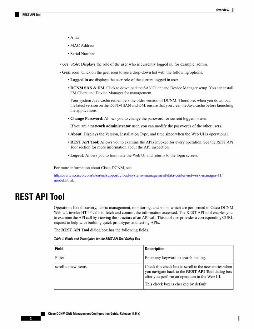
REST API ToolOperations like discovery, fabric management, monitoring, and so on, which are performed in Cisco DCNMWeb UI, invoke HTTP calls to fetch and commit the information accessed. The REST API tool enables youto examine the API call by viewing the structure of an API call. This tool also provides a corresponding CURLrequest to help with building quick prototypes and testing APIs.
The REST API Tool dialog box has the following fields.
Table 1: Fields and Description for the REST API Tool Dialog Box
DescriptionField
Enter any keyword to search the log.Filter
Check this check box to scroll to the new entries whenyou navigate back to the REST API Tool dialog boxafter you perform an operation in the Web UI.
This check box is checked by default.
scroll to new items
Cisco DCNM SAN Management Configuration Guide, Release 11.5(x)2
OverviewREST API Tool

DescriptionField
Click clear log to clear the log in the dialog box.clear log
Click API-docs to view the Cisco DCNM REST APIdocumentation in the Web UI. Clicking this optiontakes you to the following URL:https://DCNM-IP/api-docs
API-docs
All actions you perform in the Cisco DCNMWeb UI appear in the API inspector tool. The followinginformation appears in the APIs invoked for every operation:
• HTTP method
• URI
• Payload
• HTTP status code
• Time taken for the operation
The following image displays how the log appears in the REST API Tool dialog box.
Click the URI to expand or collapse each RESTmethod. You can perform the following actions after expandinga REST method:
• Prettify output: Click this option to arrange the response code in a more presentable way, which otherwiseappears in a single line. Scroll through the response to view it completely.
• Copy response: Click this option to copy the response code to your clipboard.
Cisco DCNM SAN Management Configuration Guide, Release 11.5(x)3
OverviewREST API Tool
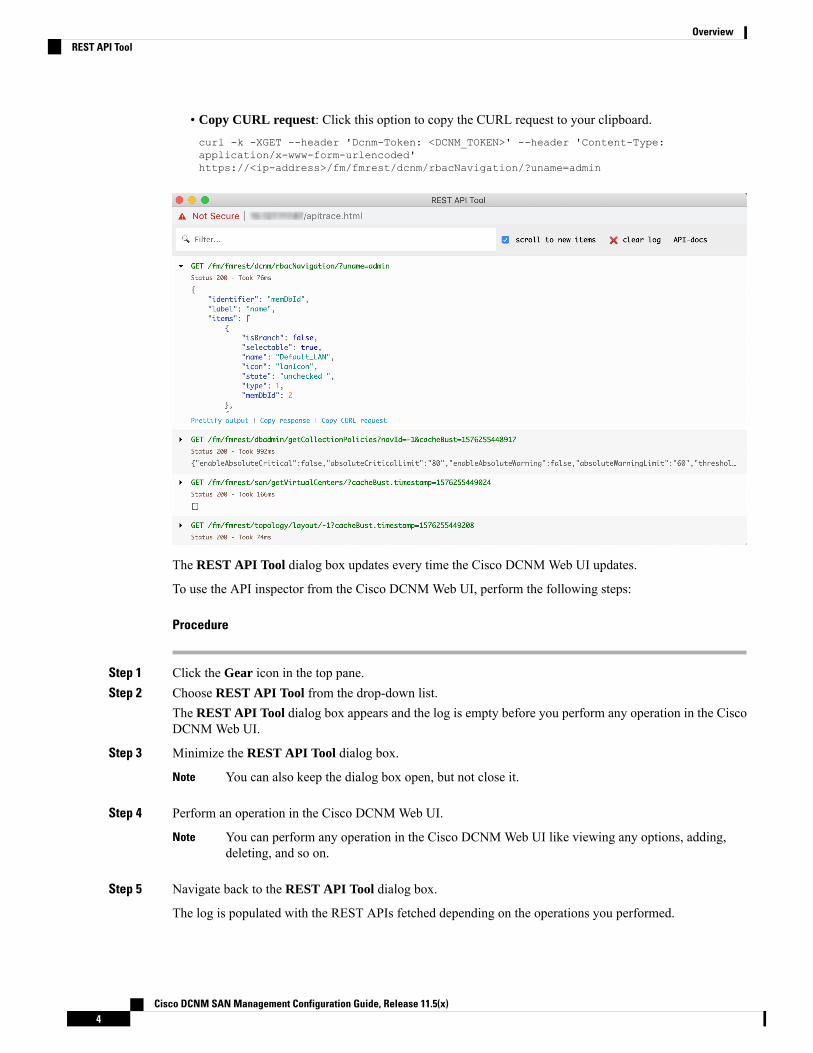
• Copy CURL request: Click this option to copy the CURL request to your clipboard.curl -k -XGET --header 'Dcnm-Token: <DCNM_TOKEN>' --header 'Content-Type:application/x-www-form-urlencoded'https://<ip-address>/fm/fmrest/dcnm/rbacNavigation/?uname=admin
The REST API Tool dialog box updates every time the Cisco DCNMWeb UI updates.
To use the API inspector from the Cisco DCNMWeb UI, perform the following steps:
Procedure
Step 1 Click the Gear icon in the top pane.Step 2 Choose REST API Tool from the drop-down list.
The REST API Tool dialog box appears and the log is empty before you perform any operation in the CiscoDCNMWeb UI.
Step 3 Minimize the REST API Tool dialog box.
You can also keep the dialog box open, but not close it.Note
Step 4 Perform an operation in the Cisco DCNMWeb UI.
You can perform any operation in the Cisco DCNMWeb UI like viewing any options, adding,deleting, and so on.
Note
Step 5 Navigate back to the REST API Tool dialog box.
The log is populated with the REST APIs fetched depending on the operations you performed.
Cisco DCNM SAN Management Configuration Guide, Release 11.5(x)4
OverviewREST API Tool

Closing theREST API Tool dialog box, instead of minimizing it before performing any operations,clears the log.
Note
For a demo on some of the operations that can be performed using the REST API tool, see the Using RESTAPI Tool in Cisco DCNM video.
Cisco DCNM SAN Management Configuration Guide, Release 11.5(x)5
OverviewREST API Tool

Cisco DCNM SAN Management Configuration Guide, Release 11.5(x)6
OverviewREST API Tool
C H A P T E R 2Dashboard
This chapter contains the following topics:
• Summary Dashboard, on page 7• Storage Dashboard, on page 13• Introduction to SAN Insights, on page 20• SAN Insights Dashboard, on page 20• Hosts, on page 31
Summary DashboardThe intent of the Summary dashboard is to enable network and storage administrators to focus on particularareas of concern around the health and performance of data center switching. This information is provided as24-hour snapshots. The functional view of LAN and SAN switching consists of nine dynamic dashlets thatdisplay information in the context of the selected scope by default. The scope can be adjusted in the upperright corner of the window to display focused information that is particular to the managed domain. It offersdetails of a specific topology or set of topologies that is a part of the data center scope.
The various scopes that are available on the Cisco Data Center Network Manager (DCNM) web interface are:
• Data Center
• Default_SAN
• Default_LAN
• Each SAN Fabric
• Custom scopes that you create
From the left menu bar, chooseDashboard > Summary. The Summarywindow displays the default dashlets.
The following are the default dashlets that appear in the Summary window:
• Health
• Events
• Alarms
• Top ISLs/Port Channels
Cisco DCNM SAN Management Configuration Guide, Release 11.5(x)7

• Top SAN End Ports
• SAN Insights
• Errors
• Discards
• Inventory – Port Capacity
From the Dashlets drop-down list, you can choose more dashlets so that they are added to the Summarydashboard.
The panels can be added, removed, and dragged around to reorder.
DashletsBy default, a subset of the available dashlets is automatically displayed in the dashboard. To add a dashletthat is not automatically displayed in a dashboard, from the Cisco DCNMWeb UI, perform the followingsteps:
Procedure
Step 1 Choose Dashboard > Summary.Step 2 From the Dashlets drop-down list, choose the dashlet that you want to add in the dashboard.
In the Dashlets drop-down list, an icon appears before the selected dashlet.
The following table lists the dashlets that you can add on the Summary Dashboard window.
DescriptionDashlet
Displays events with Critical, Error, and Warningseverity. In this dashlet, click the Show
Events
Acknowledged Events link to go to the Monitor >Switch > Events.
Displays alarms with Critical, Major, Minor, andWarning severity. In this dashlet, click the Show
Alarms
Acknowledged Alarms link to go to the Monitor >Alarms > View window. Hover the mouse cursorover the blue i icon for more information about aspecific alarm. ClickACK to acknowledge a specificalarm.
Displays a diagram of Inter-Switch Link (ISL) andsaturation link for transmitting and receiving in thedata center.
Link Traffic
Displays the number of access, spine and leaf devices,and a generic health score for each switch group in
Data Center
the current scope. Devices are aggregated by typewithin a switch group.
Cisco DCNM SAN Management Configuration Guide, Release 11.5(x)8
DashboardDashlets
DescriptionDashlet
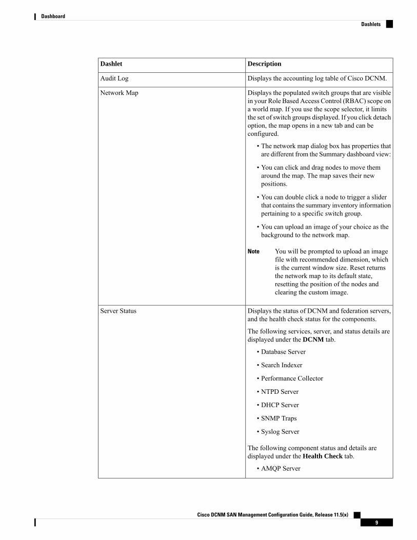
Displays the accounting log table of Cisco DCNM.Audit Log
Displays the populated switch groups that are visiblein your Role Based Access Control (RBAC) scope on
Network Map
a world map. If you use the scope selector, it limitsthe set of switch groups displayed. If you click detachoption, the map opens in a new tab and can beconfigured.
• The network map dialog box has properties thatare different from the Summary dashboard view:
• You can click and drag nodes to move themaround the map. The map saves their newpositions.
• You can double click a node to trigger a sliderthat contains the summary inventory informationpertaining to a specific switch group.
• You can upload an image of your choice as thebackground to the network map.
You will be prompted to upload an imagefile with recommended dimension, whichis the current window size. Reset returnsthe network map to its default state,resetting the position of the nodes andclearing the custom image.
Note
Displays the status of DCNM and federation servers,and the health check status for the components.
Server Status
The following services, server, and status details aredisplayed under the DCNM tab.
• Database Server
• Search Indexer
• Performance Collector
• NTPD Server
• DHCP Server
• SNMP Traps
• Syslog Server
The following component status and details aredisplayed under the Health Check tab.
• AMQP Server
Cisco DCNM SAN Management Configuration Guide, Release 11.5(x)9
DashboardDashlets
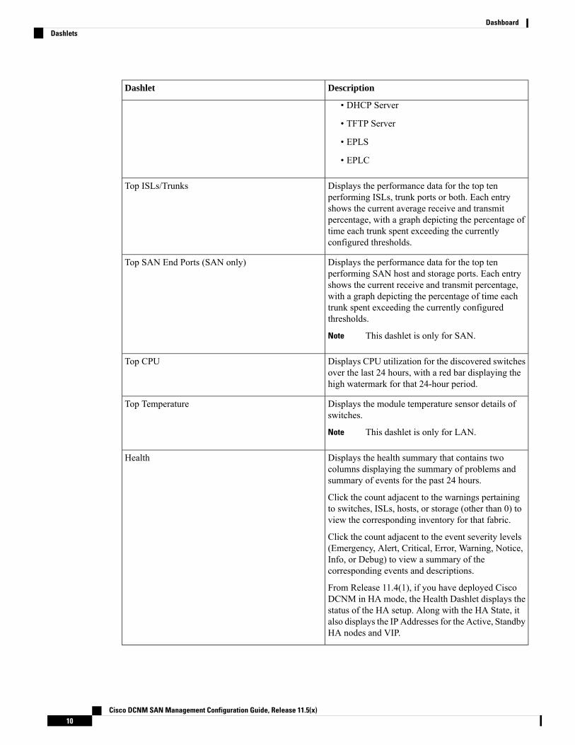
DescriptionDashlet
• DHCP Server
• TFTP Server
• EPLS
• EPLC
Displays the performance data for the top tenperforming ISLs, trunk ports or both. Each entry
Top ISLs/Trunks
shows the current average receive and transmitpercentage, with a graph depicting the percentage oftime each trunk spent exceeding the currentlyconfigured thresholds.
Displays the performance data for the top tenperforming SAN host and storage ports. Each entry
Top SAN End Ports (SAN only)
shows the current receive and transmit percentage,with a graph depicting the percentage of time eachtrunk spent exceeding the currently configuredthresholds.
This dashlet is only for SAN.Note
Displays CPU utilization for the discovered switchesover the last 24 hours, with a red bar displaying thehigh watermark for that 24-hour period.
Top CPU
Displays the module temperature sensor details ofswitches.
Top Temperature
This dashlet is only for LAN.Note
Displays the health summary that contains twocolumns displaying the summary of problems andsummary of events for the past 24 hours.
Health
Click the count adjacent to the warnings pertainingto switches, ISLs, hosts, or storage (other than 0) toview the corresponding inventory for that fabric.
Click the count adjacent to the event severity levels(Emergency, Alert, Critical, Error, Warning, Notice,Info, or Debug) to view a summary of thecorresponding events and descriptions.
From Release 11.4(1), if you have deployed CiscoDCNM in HA mode, the Health Dashlet displays thestatus of the HA setup. Along with the HA State, italso displays the IP Addresses for the Active, StandbyHA nodes and VIP.
Cisco DCNM SAN Management Configuration Guide, Release 11.5(x)10
DashboardDashlets

DescriptionDashlet
Displays the error packets for the selected interface.This information is retrieved from the Errors >
Errors
In-Peak and Errors > Out-Peak columns of theMonitor > LAN / Ethernet page.
Displays the error packets that are discarded for theselected interface.
Discards
The Discards dashlet is only for LAN.Note
Displays the ports inventory summary information.Inventory (Ports)
Displays the switches on which the modules arediscovered, the models name and the count.
Inventory (Modules)
Displays the ISLs inventory summary information,such as the category and count of ISLs.
Inventory (ISLs)
Displays the logical inventory summary information,such as the category and count of logical links.
Inventory (Logical)
Displays the switches inventory summary informationsuch as the switch models and the correspondingcount.
Inventory (Switches)
Displays the port capacity inventory summaryinformation such as the tiers, the number and
Inventory (Port Capacity)
percentage of the available ports, and the remainingdays.
Displays donuts depicting the following:SAN Insights Flows (SAN only)
• Flow summary for Initiator-Target (IT) Pairsand Initiator-Target- LUN(ITL Flows) whenthe SCSI protocol is selected from the protocoldropdown list.
• Flow summary for Initiator-Target (IT) Pairsand Initiator-Target-Namespace (ITN Flows)when the NVMe protocol is selected from theprotocol dropdown list.
You can display data for Read Completion Timeor Write Completion Time by selecting therequired option from the dropdown list. Hoverover the sections on the donuts to displaydeviation percentage values. The percentagevalues can be configured as per your requirementby modifying thesan.telemetry.deviation.low/med/high,san.telemetry.nvme.deviation.low/med/high andsan.telemetry.default.protocol server properties.
Cisco DCNM SAN Management Configuration Guide, Release 11.5(x)11
DashboardDashlets
DescriptionDashlet
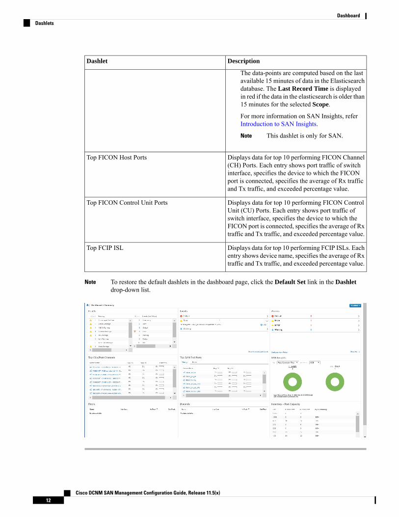
The data-points are computed based on the lastavailable 15 minutes of data in the Elasticsearchdatabase. The Last Record Time is displayedin red if the data in the elasticsearch is older than15 minutes for the selected Scope.
For more information on SAN Insights, referIntroduction to SAN Insights.
This dashlet is only for SAN.Note
Displays data for top 10 performing FICON Channel(CH) Ports. Each entry shows port traffic of switch
Top FICON Host Ports
interface, specifies the device to which the FICONport is connected, specifies the average of Rx trafficand Tx traffic, and exceeded percentage value.
Displays data for top 10 performing FICON ControlUnit (CU) Ports. Each entry shows port traffic of
Top FICON Control Unit Ports
switch interface, specifies the device to which theFICON port is connected, specifies the average of Rxtraffic and Tx traffic, and exceeded percentage value.
Displays data for top 10 performing FCIP ISLs. Eachentry shows device name, specifies the average of Rxtraffic and Tx traffic, and exceeded percentage value.
Top FCIP ISL
To restore the default dashlets in the dashboard page, click the Default Set link in the Dashletdrop-down list.
Note
Cisco DCNM SAN Management Configuration Guide, Release 11.5(x)12
DashboardDashlets
Storage DashboardThe Storage dashboard provides information about the SAN and LAN storage.
To access the Storage dashboard, from the left menu bar, choose Dashboard > Storage.
Viewing Storage Enclosures InformationAfter a datasource is configured and the discovery is completed, the discovered storage systems are displayedunder the Name column in the Storage Enclosures area. In this area, you can view details of SAN StorageEnclosures, Storage Systems, or both.
To view the storage enclosures information from the Cisco DCNMWeb UI, perform the following steps:
Procedure
Step 1 Choose Dashboard > Storage.Step 2 From the Show drop-down list, choose SAN Storage Enclosures.Step 3 Choose the storage name to view more details.
The events, topology, and traffic information are displayed in the dashboard.
Step 4 To edit enclosure name, choose the storage name and click Rename icon. Enter a new name in the RenameEnclosure dialog box.
• You can rename each enclosure name to a different name. Choose the enclosure name, enter a new name,click Save. Repeat this procedure to change required all the required enclosure names, and click Apply.
• You can rename all enclosure names to the same new name. Check Include All Members checkbox,enter a new name, and click Apply.
Step 5 Click the Filter icon to filter the storage enclosures by Name or by IP Address.Step 6 In the Traffic pane, the Enclosure Traffic is displayed by default. Click the Traffic Utilization icon to view
the traffic utilization. The daily average percentage of traffic utilization of the enclosure ports is displayed asa pie chart.
Clicking on an individual port slice of the pie chart displays specific traffic utilization details for that port.
Viewing Storage Systems InformationTo view information about storage systems from the Cisco DCNMWeb UI, perform the following steps:
Procedure
Step 1 Choose Dashboard > Storage.Step 2 From the Show drop-down list, choose Storage Systems.
Cisco DCNM SAN Management Configuration Guide, Release 11.5(x)13
DashboardStorage Dashboard
• The datasource must be configured and discovered at least once to display the discoveredstorage system(s).
• Cisco DCNM now differentiate Block Storage and Filer Storage in terms of what it discoversand displays. Filer storage has additional elements: Shares, Quotas, and Q-trees.
• Shares: Individual storage folders on the file server to which users have access.
• Quotas: File and repository size limitations.
• Q-trees: Tree based quotas. By using Q-trees, you can partition data and take advantageof different backup strategies, security styles, and settings.
Note
Step 3 Click the Click to see more details... icon to view the storage systems summary.
The following are the elements of the Storage Systems area:
Components
Components are containers for a set or subset of the disks in a storage system. The Component elements viewdisplays a table of disks in the collection, total number of disks managed. It also displays a summary of thecollection’s used vs. raw space.
Procedure
Step 1 Use the Storage System drop-down to select the storage system.Step 2 The right pane displays a summary of the storage components. Click each name to go to the item in the left
menu.Step 3 Hover the mouse cursor on the graph to display its details.Step 4 In the left pane, select the storage component to view its details.
The number of disks that are managed along with its details are displayed.
Step 5 Click a Serial Number to display the disk and the mapped LUNs details.Step 6 You can use the search box to search for a specific component.
Pools
Pools are user-defined collections of LUNs displaying the pool storage. The pools elements view displays asummary of the pools, lists the LUNs in the pool, and also displays the total managed and raw space.
Procedure
Step 1 Use the Storage System drop-down to select the storage system.
The bar graph next to each pool indicates the total managed space of that pool.
Step 2 In the left pane, select a pool to display:
Cisco DCNM SAN Management Configuration Guide, Release 11.5(x)14
DashboardComponents
• Status of the pool
• LUNs in the pool displaying the total raw space and the total managed space.
• Raid Type
• Disk Type
• Details of the LUNs in the pool
Step 3 You can use the search box to search for a specific pool.
LUNs
LUNs refer to a storage volume or a collection of volumes that are abstracted into a single volume. It is a unitof storage which can be pooled for access protection and management. Each LUN in the LUN Element Viewis displayed along with the mapping from Hosts to LUNs. If the associated Fabric has also been discovered,additional information concerning the end-to-end connection between a host and LUN is also displayed.
You are able to create and delete LUNs, create and delete host and LUN maps, and create zoning for HLMs.
Procedure
Step 1 Use the Storage System drop-down to select the storage system.Step 2 You can create LUN from Cisco DCNM by choosing Storage > LUNs.
a) In the middle pane, click Add LUN.b) Enter a valid Name for the LUN, and select its Type and Size. The pool which we carve the storage from
is indicated.
The Create LUN pop-up window can also be accessed from a Pool’s details page, when theLUN list view is selected.
Note
c) Click Add.
A confirmation window displays each step. Once confirmed, the status is updated with the results of eachstep.
After LUN creation completes successfully, you can Assign Hosts, or click Close and assign Hosts laterfrom the LUN Details view.
Step 3 Select a LUN in the left navigation pane to view the details.
• The LUN details along with its status and the number of Associated Hosts.
• The Host LUN Mapping details along with the Access (Granted) information.
If the associated fabric has also been discovered, additional information about the switch interfaces and zoningconcerning the end-to-end connection between the Host and LUN is also displayed.
All fabrics that are discoveredmust be licensed or the fabric correlation will be disabled in the CiscoDCNM. When the feature is disabled, all correlation fields display “Unlicensed Fabric.”
Note
Step 4 You can delete LUNs in the SMI-S Storage Enclosure.
Cisco DCNM SAN Management Configuration Guide, Release 11.5(x)15
DashboardLUNs

a) Navigate to Storage > Storage System > LUNs.
A list of LUNs in the SMI-S Storage Enclosure is displayed in the right.
b) Select one LUN from the list and then click Remove.
A confirmation window is displayed at each step. Once confirmed, the status will update with the resultsof each step.
c) Click Apply.
Step 5 You can add mapping from Host to LUN.a) Select the LUNs from a pane on the left.
A list of LUNs in the SMI-S Storage Enclosure is displayed in the right.
b) Select a LUN from the list underneath.
The details for the selected LUN are displayed, including the current Host LUN Mappings for that LUN.
c) Click the Add button.
The Add Hosts to Mask window pops out.
d) Select one or more Hosts, and then clickAdd. The Hosts are then added to the LUNMapping. In addition,each HLM pair is zoned if it is not already zoned.
Host LUN Mappings can also be added through the Host Dashboard. See Viewing HostEnclosures, on page 32, for more information.
Note
Step 6 You can remove mapping from Host to LUN.a) Select the LUNs from the pane on the left.
A list of LUNs in the SMI-S Storage Enclosure is displayed in the right.
b) Select a LUN from the list underneath.
The details for the selected LUN are displayed, including the current Host LUN Mappings for that LUN.
c) Select one or more existing Host LUN Mappings and click the remove icon.
A confirmation window appears and displays each step.
d) Click Apply.
The status will update with the results of each step.
Step 7 (Optional) You can add Zoning to the LUNs.a) Select the LUNs from the left pane.
A list of LUNs in the SMI-S Storage Enclosure is displayed in the right.
b) Select a LUN from the list underneath.
The details for the selected LUN are displayed, including the current Host LUN Mappings for that LUN.One of the columns of the Host LUN Mapping table identifies the existing zones if any of the HLMcurrently has for zoning.
c) Select one or more HLMs which have Unknown or None for zoning, and click Add Zoning.d) Click Apply.
Cisco DCNM SAN Management Configuration Guide, Release 11.5(x)16
DashboardLUNs

The status will update with the results of each step.
Filer Volumes
Filer Volumes are applicable only for NetApp. The Filer Volume Element view displays the Status, ContainingAggregate along with the total capacity and used space.
To view filer volumes from the Cisco DCNMWeb UI, perform the following steps:
Procedure
Step 1 Use the Storage System drop-down to select the storage system.Step 2 In the left pane, select the filer to display:
• The status of the filer along with the containing aggregate name.
• Hover the mouse cursor over the graph to view the total capacity and available storage of the filer.
Step 3 You can use the search box to search for a specific Filer.
Hosts
The Hosts describe the NWWNs associated with a host or host enclosure along with the associated Host-LUNMapping and the Host Ports. If the associated Fabric has also been discovered, additional information concerningthe connection between a host and LUN is also displayed.
To configure hosts from the Cisco DCNMWeb UI, perform the following steps:
Procedure
Step 1 Use the Storage System drop-down to select the storage system.Step 2 In the left pane, select a Host to display:
• The NWWN (Node WWN) is the WWN of the device that is connected to the switch.
• The Host Ports along with the Host LUN Mapping.
• In the Host Ports section, click a Host Enclosure Name to view its Events, Topology, and SAN Traffic.For more information, see the Storage section.
• In the Host Ports sections, click a Host Interface to view the Switch Dashboard.
• In the Host-LUN Mapping section, click a Storage Interface to view the Switch Dashboard.
• In the Host-LUNMapping section, click a Storage Name to view its Events, Topology, and SAN Traffic.For more information, see the Storage section.
If the associated Fabric has also been discovered, additional information about the switch interfaces and zoningconcerning the connection between the Host and LUN is also displayed.
Cisco DCNM SAN Management Configuration Guide, Release 11.5(x)17
DashboardFiler Volumes

All fabrics that are discovered must be licensed or the fabric correlation is disabled in the Web UI.When the feature is disabled, all correlation fields display “Unlicensed Fabric”.
Note
Step 3 You can use the search box to search for a specific host.
Storage Processors
Storage processors are elements on a storage system, which enable some of its features. A storage processorincludes the collection of storage ports it manages. In the Storage Processor Element View, the list of StoragePorts that are associated with a Storage Processor is displayed.
Procedure
Step 1 Use the Storage System drop-down to select the storage system.Step 2 In the left pane, select a storage processor to display:
• The status, adapter details, and the number of ports of the storage processor.
• The storage ports details.
Step 3 You can use the search box to search for a specific storage processor.
Storage Ports
A storage port is a single port on the Storage System. It displays the summary information of each port selected.
Procedure
Step 1 Use the Storage System drop-down to select the storage system.Step 2 In the left pane, select a storage port to display its details.Step 3 You can use the search box to search for a specific storage port.
Viewing Storage Enclosure EventsTo view the storage enclosure events information from the Cisco DCNMWeb UI, perform the followingsteps:
Procedure
Step 1 ChooseDashboard > Storage. Use the drop-down to select All, SAN Storage Enclosures or Storage Systems.
The list of storage enclosures is displayed in a table.
Step 2 Click the Events icon next to the storage enclosure to view the Events panel.
Cisco DCNM SAN Management Configuration Guide, Release 11.5(x)18
DashboardStorage Processors

Step 3 You can use the slider control to resize the panel.
Viewing Storage Enclosure TopologyTo view the storage enclosure topology information from the Cisco DCNMWeb UI, perform the followingsteps:
Procedure
Step 1 Choose Dashboard > Storage. Use the drop-down to select All, SAN Storage Enclosures, or StorageSystems.
The list of storage enclosures in a table is displayed.
Step 2 Select the row to view the topology details.Step 3 Use the mouse scroll wheel to zoom-in and zoom-out.Step 4 Click the Fabric/Network icon to view the Fabric or Network path.Step 5 Click the All Paths icon to view the complete setup.Step 6 Click the First Shortest Path icon to view the shortest path.
Click Map View icon to enable the icons that are listed in the preceding Step 4, 5 and 6.Note
Step 7 Click the Tabular View icon to view the host topology in tabular format.
Viewing Storage Enclosure TrafficTo view the storage enclosure traffic from the Cisco DCNMWeb UI, perform the following steps:
Procedure
Step 1 ChooseDashboard > Storage. Use the drop-down to select All, SAN Storage Enclosures or Storage Systems.
The list of storage enclosures is displayed in the table.
Step 2 Select the row to view the topology details.Step 3 Use the drop-down to select the traffic according to the time duration.Step 4 Select the icons to view the traffic as a Grid, Line Chart or Stacked Chart.Step 5 Click the Show Events icon to view the events.Step 6 Use the options at the bottom of the screen to view a pie chart or a line chart. Click on each name on the chart
to view its details.
Cisco DCNM SAN Management Configuration Guide, Release 11.5(x)19
DashboardViewing Storage Enclosure Topology
Introduction to SAN InsightsThe SAN Insights feature enables you to configure, monitor, and view the flow analytics in fabrics. CiscoDCNM enables you to visualize the health-related indicators in the interface so that you can quickly identifyissues in fabrics. Also, the health indicators enable you to understand the problems in fabrics. The SANInsights feature also provides more comprehensive end-to-end flow-based data from the host to LUN.
FromRelease 11.2(1), CiscoDCNM supports SANTelemetry Streaming (STS) using compact GPB transport,for better telemetry performance and to improve the overall scalability of SAN Insights.
For SAN insights streaming stability and performance, refer to System Requirements section in the CiscoDCNM Installation Guide for SAN Deployment Guide and the section Increasing ElasticsearchDatabase HeapSize of the Cisco DCNM SAN Management Configuration Guide. Ensure system RAM is of adequate size.Use of NTP is recommended to maintain time synchronization between the DCNM and the switches. EnablePM collection for viewing counter statistics.
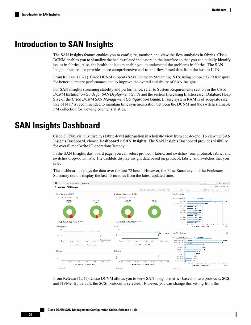
SAN Insights DashboardCisco DCNM visually displays fabric-level information in a holistic view from end-to-end. To view the SANInsights Dashboard, choose Dashboard > SAN Insights. The SAN Insights Dashboard provides visibilityfor overall read/write IO operations/latency.
In the SAN Insights dashboard page, you can select protocol, fabric, and switches from protocol, fabric, andswitches drop-down lists. The dashlets display insight data based on protocol, fabric, and switches that youselect.
The dashboard displays the data over the last 72 hours. However, the Flow Summary and the EnclosureSummary donuts display the last 15 minutes from the latest updated time.
From Release 11.3(1), Cisco DCNM allows you to view SAN Insights metrics based on two protocols, SCSIand NVMe. By default, the SCSI protocol is selected. However, you can change this setting from the
Cisco DCNM SAN Management Configuration Guide, Release 11.5(x)20
DashboardIntroduction to SAN Insights

Administration > DCNM Server > Server Properties. Ensure that you restart the SAN Insights service touse the new properties. (Restart the SanInsight service on Linux or Pause/Resume Post Processor App onSAN-OVA/ISO/SE deployments)
From the Fabric drop-down list, select the SAN Fabric for which you need to see the SAN Insights data andmetrics. The switches that are capable and licensed for SAN Analytics are displayed in the drop-down list.
Click on the title on top of the donuts, to navigate to the relevant page on Monitor > SAN > SAN Insights.You can also click on different colored sections on the donuts to see more detailed counts in percentages.
Note
The total distinct ITL count and the ITN count from the trained baseline is displayed in the top right-handcorner of the Dashboard. The donuts show the active ITL/ITN count only, for the last 15 minutes. The totalITL and ITN count, however, shows the count of all the ITLs and ITN for the scope selected.
The SAN Insights dashboard contains the following dashlets.
• Flow Summary (ECT)
From the drop-down list, select Read Completion Time or Write Completion Time, based on which thedonuts show IT Pairs and ITL Flows. These data-points are computed based on the last available 15minsdata in the Elasticsearch.
• Enclosure Summary (ECT)
From the drop-down list, select Read Completion Time or Write Completion Time, based on which thedonuts display Storage and Hosts. These data-points are computed based on the last available 15minsdata in the Elasticsearch.
• Throughput
Displays the Read and Write throughput rate. Hover the mouse on the graph to view the value at thatinstance. The metrics in these line charts are computed based on the data during the last 72 hours.
• IOPS
Displays the Read and Write IOPs trend. The metrics in these line charts are computed based on the dataduring the last 72 hours.
• Aborts
Displays the Read and Write Aborts trend. The metrics in these line charts are computed based on thedata during the last 72 hours. This metric is computed based on the read_io_aborts andwrite_io_abortsmetric reported by the Cisco MDS SAN Analytics infrastructure.
Click on more details to view the custom graphing for READ IO Aborts/Failures for the switch IPaddress that is selected on the Dashboard page.
• Failures
Displays the Read and Write Failures trend. The metrics in these line charts are computed based on thedata during the last 72 hours. This metric is computed based on the read_io_failures andwrite_io_failuresmetric reported by the Cisco MDS SAN Analytics infrastructure.
Click on more details to view the custom graphing for READ IO Aborts/Failures for the switch IPaddress that is selected on the Dashboard page.
• Top 10 Hosts
Cisco DCNM SAN Management Configuration Guide, Release 11.5(x)21
DashboardSAN Insights Dashboard
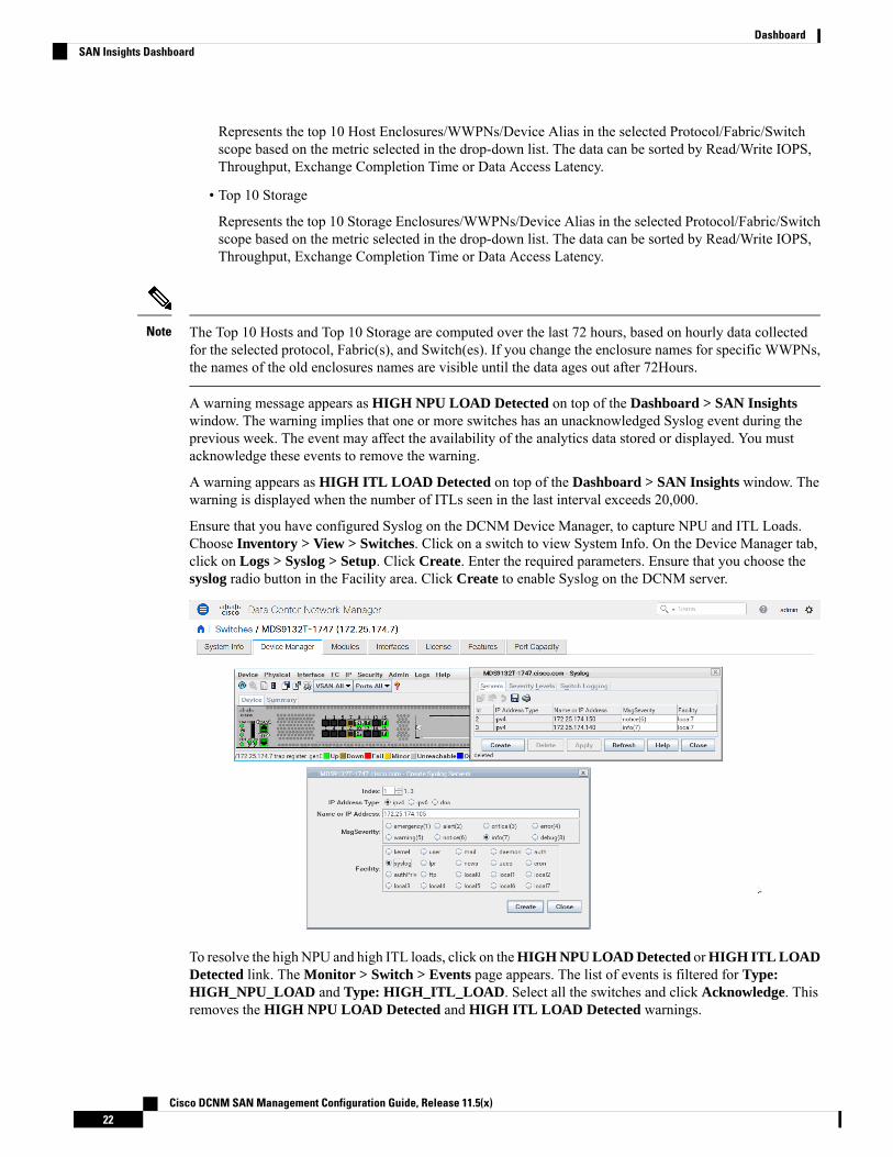
Represents the top 10 Host Enclosures/WWPNs/Device Alias in the selected Protocol/Fabric/Switchscope based on the metric selected in the drop-down list. The data can be sorted by Read/Write IOPS,Throughput, Exchange Completion Time or Data Access Latency.
• Top 10 Storage
Represents the top 10 Storage Enclosures/WWPNs/Device Alias in the selected Protocol/Fabric/Switchscope based on the metric selected in the drop-down list. The data can be sorted by Read/Write IOPS,Throughput, Exchange Completion Time or Data Access Latency.
The Top 10 Hosts and Top 10 Storage are computed over the last 72 hours, based on hourly data collectedfor the selected protocol, Fabric(s), and Switch(es). If you change the enclosure names for specific WWPNs,the names of the old enclosures names are visible until the data ages out after 72Hours.
Note
A warning message appears as HIGH NPU LOAD Detected on top of the Dashboard > SAN Insightswindow. The warning implies that one or more switches has an unacknowledged Syslog event during theprevious week. The event may affect the availability of the analytics data stored or displayed. You mustacknowledge these events to remove the warning.
A warning appears as HIGH ITL LOAD Detected on top of the Dashboard > SAN Insights window. Thewarning is displayed when the number of ITLs seen in the last interval exceeds 20,000.
Ensure that you have configured Syslog on the DCNM Device Manager, to capture NPU and ITL Loads.Choose Inventory > View > Switches. Click on a switch to view System Info. On the Device Manager tab,click on Logs > Syslog > Setup. Click Create. Enter the required parameters. Ensure that you choose thesyslog radio button in the Facility area. Click Create to enable Syslog on the DCNM server.
To resolve the high NPU and high ITL loads, click on theHIGH NPU LOAD Detected orHIGH ITL LOADDetected link. The Monitor > Switch > Events page appears. The list of events is filtered for Type:HIGH_NPU_LOAD and Type: HIGH_ITL_LOAD. Select all the switches and click Acknowledge. Thisremoves the HIGH NPU LOAD Detected and HIGH ITL LOAD Detected warnings.
Cisco DCNM SAN Management Configuration Guide, Release 11.5(x)22
DashboardSAN Insights Dashboard

Viewing SAN Insights MetricsTo view the SAN Insights metrics, choose Dashboard >SAN Insights. The SAN Insights Dashboard pageappears. Click the View SAN Insights Metrics button. From the Use Case drop-down list, choose ECTAnalysis or Custom Graphing.
The dashboard displays the data over the last 72 hours. However, the Flow Summary and the EnclosureSummary donuts display the last 15 minutes from the latest updated time.
The refresh interval for ECT Analysis and Custom Graphing page is 5 minutes. Click on the Play icon ">" torefresh every 5 minutes automatically.
Note
From Release 11.3(1), Cisco DCNM allows you to view SAN Insights metrics based on two protocols, SCSIand NVMe. By default, the SCSI protocol is selected. However, you can change this setting from theAdministration > DCNM Server > Server Properties. Ensure that you restart the SAN Insights service touse the new properties. (Restart the SanInsight service on Linux or Pause/Resume Post Processor App onSAN-OVA/ISO/SE deployments)
ECT AnalysisFrom the Cisco DCNM Web UI > Dashboard > SAN Insights, click on the View SAN Insights Metrics toview the ECT Analysis.
There are four components in ECT Analysis:
• Data table
• ECT Sequencing by Baseline Deviation
• ECT Baseline Deviation Aggregated
• ITL By Time & Baseline Deviation
From Release 11.3(1), Cisco DCNM allows you to view SAN Insights metrics based on two protocols, SCSIand NVMe. By default, the SCSI protocol is selected. However, you can change this setting from theAdministration > DCNM Server > Server Properties. Ensure that you restart the SAN Insights service touse the new properties. (Restart the SanInsight service on Linux or Pause/Resume Post Processor App onSAN-OVA/ISO/SE deployments)
From Release 11.4(1), Cisco DCNM allows you to view data for a time frame of any 14 days within the last90 days. (up to a default maximum of 90 days). You can modify the san.telemetry.expire.rollup propertyon the Web UI > Administration > DCNM Server > Server Properties to modify the maximum defaultdays. You can choose the date using the date picker and view the historical data starting from the selecteddate at hourly granularity.
The default duration of the ECT analysis 30 minutes60 minutes. You can click the Reset button to clear allthe applied data filters.
Note
Cisco DCNM SAN Management Configuration Guide, Release 11.5(x)23
DashboardViewing SAN Insights Metrics
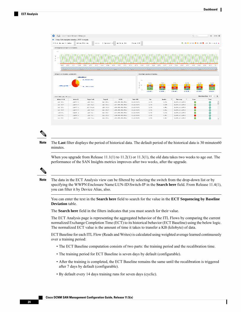
The Last filter displays the period of historical data. The default period of the historical data is 30 minutes60minutes.
Note
When you upgrade from Release 11.1(1) to 11.2(1) or 11.3(1), the old data takes two weeks to age out. Theperformance of the SAN Insights metrics improves after two weeks, after the upgrade.
The data in the ECT Analysis view can be filtered by selecting the switch from the drop-down list or byspecifying the WWPN\Enclosure Name\LUN-ID\Switch-IP in the Search here field. From Release 11.4(1),you can filter it by Device Alias, also.
Note
You can enter the text in the Search here field to search for the value in the ECT Sequencing by BaselineDeviation table.
The Search here field in the filters indicates that you must search for their value.
The ECT Analysis page is representing the aggregated behavior of the ITL Flows by comparing the currentnormalized Exchange Completion Time (ECT) to its historical behavior (ECT Baseline) using the below logic.The normalized ECT value is the amount of time it takes to transfer a KB (kilobyte) of data.
ECTBaseline for each ITL Flow (Reads andWrites) is calculated using weighted average learned continuouslyover a training period:
• The ECT Baseline computation consists of two parts: the training period and the recalibration time.
• The training period for ECT Baseline is seven days by default (configurable).
• After the training is completed, the ECT Baseline remains the same until the recalibration is triggeredafter 7 days by default (configurable).
• By default every 14 days training runs for seven days (cyclic).
Cisco DCNM SAN Management Configuration Guide, Release 11.5(x)24
DashboardECT Analysis

• The percentage (%) deviation shows the deviation of the current normalized ECT compared to the ECTBaseline.
Starting 11.4 release, the deviation of the ECT less than the baselineis considered as negative deviation. TheWeb UI screens are expectedto display negative values for the computed deviation percentage.
Note
Beginning from Release 11.4(1), the flows that have ECT lesser than the baseline is identified as havingnegative deviation. This impacts the average ECT deviation, reducing the severity of momentary spikes.However, it reflects a better true value of ECT performance.
When you upgrade to Release 11.4(1), some pages on the Web UI does not display correct color for olderdata. After two weeks, the new data will show proper color codes.
• To configure the default training period, edit the san.telemetry.train.timeframe parameter(default 7) in the Cisco DCNMAdministration > Server Properties. Restart the DCNMServer process.(Restart the SanInsight service on Linux or Pause/Resume Post Processor App on SAN-OVA/ISO/SEdeployments)
• To configure the recalibration time, edit the san.telemetry.train.reset parameter (default 14days) in the Cisco DCNM Administration > Server Properties. Restart the DCNM Server process.Restart the SanInsight service on Linux or Pause/Resume Post Processor App on SAN-OVA/ISO/SEdeployments.
• For example, to train the baseline for four days and recalibrate the baseline 10 days after the trainingperiod set the training period to four days and the recalibration time to 14 days.
Note
Table 2: Baseline Color Legends
ValueRelation
RedIf ECT is above 50% from Baseline
OrangeIf ECT is above and in range 30–50% from Baseline
YellowIf ECT is above and in range 10–30% from Baseline
Green (implies Normal)If ECT is below 10% from Baseline
The range of value for the Baseline Color Legends can be modified on the Server Properties file. See thesan.telemetry.deviation definitions in the Administration > DCNM Server > Server Properties. Ensurethat you restart the SAN Insights service to use the new properties. Restart the SanInsight service on Linuxor Pause/Resume Post Processor App on SAN-OVA/ISO/SE deployments.
You can click on the Trend Identifier ( ) icon to navigate to Trend Identifier. For more information, seeTrend Identifier, on page 29.
Cisco DCNM SAN Management Configuration Guide, Release 11.5(x)25
DashboardECT Analysis
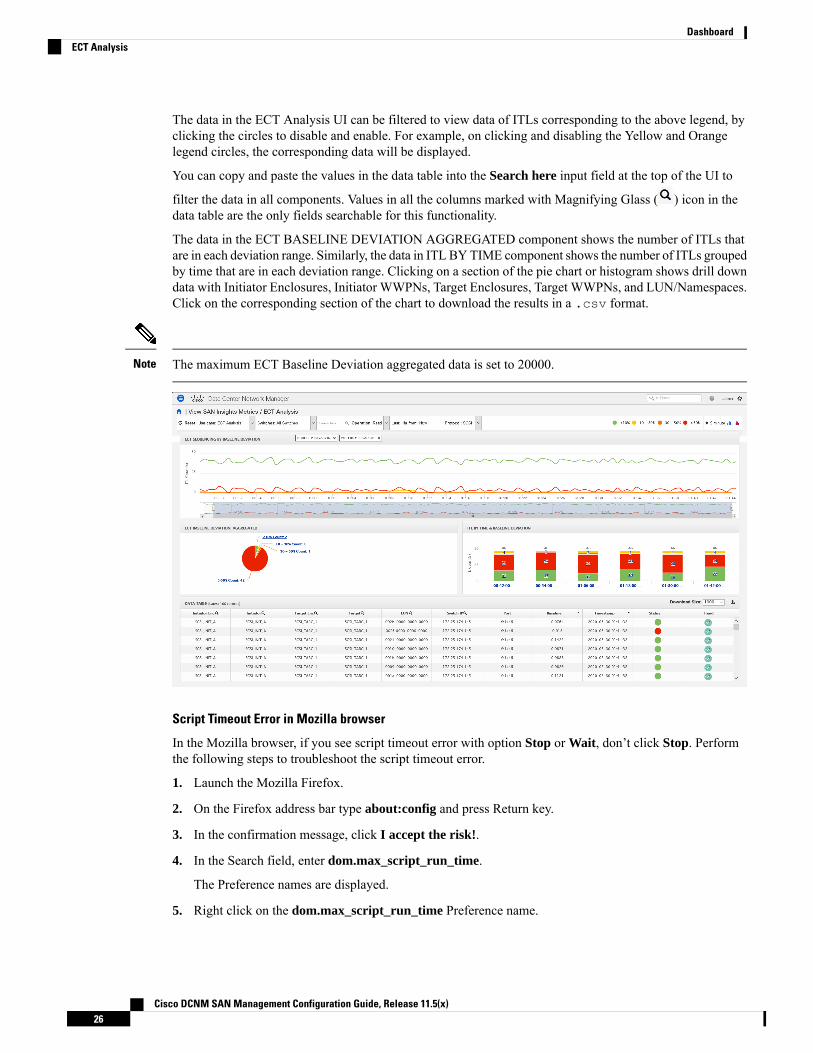
The data in the ECT Analysis UI can be filtered to view data of ITLs corresponding to the above legend, byclicking the circles to disable and enable. For example, on clicking and disabling the Yellow and Orangelegend circles, the corresponding data will be displayed.
You can copy and paste the values in the data table into the Search here input field at the top of the UI to
filter the data in all components. Values in all the columns marked with Magnifying Glass ( ) icon in thedata table are the only fields searchable for this functionality.
The data in the ECT BASELINE DEVIATION AGGREGATED component shows the number of ITLs thatare in each deviation range. Similarly, the data in ITL BYTIME component shows the number of ITLs groupedby time that are in each deviation range. Clicking on a section of the pie chart or histogram shows drill downdata with Initiator Enclosures, Initiator WWPNs, Target Enclosures, Target WWPNs, and LUN/Namespaces.Click on the corresponding section of the chart to download the results in a .csv format.
The maximum ECT Baseline Deviation aggregated data is set to 20000.Note
Script Timeout Error in Mozilla browser
In the Mozilla browser, if you see script timeout error with option Stop or Wait, don’t click Stop. Performthe following steps to troubleshoot the script timeout error.
1. Launch the Mozilla Firefox.
2. On the Firefox address bar type about:config and press Return key.
3. In the confirmation message, click I accept the risk!.
4. In the Search field, enter dom.max_script_run_time.
The Preference names are displayed.
5. Right click on the dom.max_script_run_time Preference name.
Cisco DCNM SAN Management Configuration Guide, Release 11.5(x)26
DashboardECT Analysis

Select Modify.
6. Enter an integer value of 0 or 20 for dom.max_script_run_time.
7. Click OK to confirm.
8. Restart the Mozilla Firefox browser.
Custom GraphingThis is a freestyle dashboard where multiple metrics can be selected and the real-time data for the selectedmetrics is shown in multi-line graph which is configured to refresh every 5 minutes and corresponding rawdata will be shown in the data table.
From Release 11.3(1), Cisco DCNM allows you to view SAN Insights metrics based on two protocols, SCSIand NVMe. By default, the SCSI protocol is selected. However, you can change this setting from theAdministration > DCNM Server > Server Properties. Ensure that you restart the SAN Insights service touse the new properties. (Restart the SanInsight service on Linux or Pause/Resume Post Processor App onSAN-OVA/ISO/SE deployments)
The Auto Refresh option is disabled by default. You must click on the pause icon to enable the Auto Refreshfeature.
Note
There are two components in the custom graphing use case.
• Real Time Graph
• Datatable
The Real Time Graph is plotted with corresponding metrics with from & to date selected. This componenthas the slider present below the graph as per your selection. It’s dynamic in nature as the data can be refreshedevery 5 minutes, and can be converted into a static graph using the pause button.
Starting 11.4 release, Cisco DCNM allows the user to view data for more than two weeks’ time frame (up toa default maximum of 90 days. You can configure this time frame in the server properties. Select the date inthe past using the To: date selector and view up to two weeks historical data from the date selected.
Cisco DCNM SAN Management Configuration Guide, Release 11.5(x)27
DashboardCustom Graphing
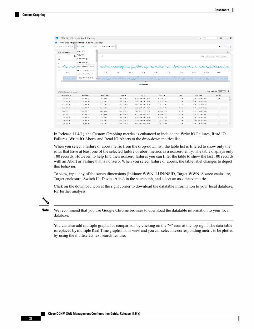
In Release 11.4(1), the Custom Graphing metrics is enhanced to include the Write IO Failures, Read IOFailures, Write IO Aborts and Read IO Aborts to the drop-down metrics list.
When you select a failure or abort metric from the drop-down list, the table list is filtered to show only therows that have at least one of the selected failure or abort metrics as a nonzero entry. The table displays only100 records. However, to help find their nonzero failures you can filter the table to show the last 100 recordswith an Abort or Failure that is nonzero. When you select failure or aborts, the table label changes to depictthis behavior.
To view, input any of the seven dimensions (Initiator WWN, LUN/NSID, Target WWN, Source enclosure,Target enclosure, Switch IP, Device Alias) in the search tab, and select an associated metric.
Click on the download icon at the right corner to download the datatable information to your local database,for further analysis.
We recommend that you use Google Chrome browser to download the datatable information to your localdatabase.
Note
You can also add multiple graphs for comparison by clicking on the "+" icon at the top right. The data tableis replaced bymultiple Real Time graphs in this view and you can select the correspondingmetric to be plottedby using the multiselect text search feature.
Cisco DCNM SAN Management Configuration Guide, Release 11.5(x)28
DashboardCustom Graphing

Trend Identifier
Click the Trend Identifier ( ) icon in the top-right corner to navigate to Trend Identifier.
You can also click on the Trend ( ) icon in each row of the data table to navigate to Trend Identifier, withprepopulated ITL/ITN input fields. There are two components showing data corresponding to selected ITL.Trends ITL Metrics shows area chart of ECT, DAL, IOPs, and Baseline ECT in the selected time interval (1hour selected). Histogram Correlation tab shows the histogram of count of correlated ITLs with current ITLbinned by correlation value. Clicking on any bar in this tab converts the histogram into datatable which showsthe data corresponding to the selected bar.
From Release 11.3(1), Cisco DCNM allows you to view SAN Insights metrics based on two protocols, SCSIand NVMe. By default, the SCSI protocol is selected. However, you can change this setting from theAdministration > DCNM Server > Server Properties. Ensure that you restart the SAN Insights service touse the new properties. (Restart the SanInsight service on Linux or Pause/Resume Post Processor App onSAN-OVA/ISO/SE deployments)
Cisco DCNM SAN Management Configuration Guide, Release 11.5(x)29
DashboardTrend Identifier
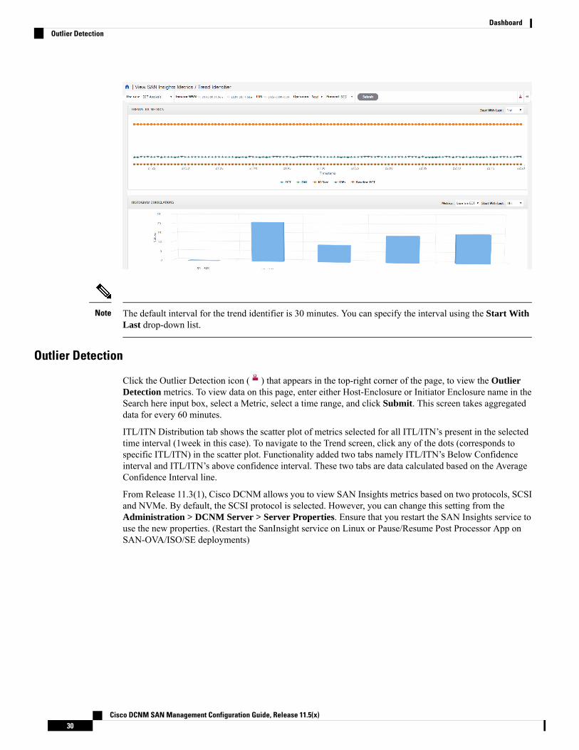
The default interval for the trend identifier is 30 minutes. You can specify the interval using the Start WithLast drop-down list.
Note
Outlier Detection
Click the Outlier Detection icon ( ) that appears in the top-right corner of the page, to view the OutlierDetection metrics. To view data on this page, enter either Host-Enclosure or Initiator Enclosure name in theSearch here input box, select a Metric, select a time range, and click Submit. This screen takes aggregateddata for every 60 minutes.
ITL/ITN Distribution tab shows the scatter plot of metrics selected for all ITL/ITN’s present in the selectedtime interval (1week in this case). To navigate to the Trend screen, click any of the dots (corresponds tospecific ITL/ITN) in the scatter plot. Functionality added two tabs namely ITL/ITN’s Below Confidenceinterval and ITL/ITN’s above confidence interval. These two tabs are data calculated based on the AverageConfidence Interval line.
From Release 11.3(1), Cisco DCNM allows you to view SAN Insights metrics based on two protocols, SCSIand NVMe. By default, the SCSI protocol is selected. However, you can change this setting from theAdministration > DCNM Server > Server Properties. Ensure that you restart the SAN Insights service touse the new properties. (Restart the SanInsight service on Linux or Pause/Resume Post Processor App onSAN-OVA/ISO/SE deployments)
Cisco DCNM SAN Management Configuration Guide, Release 11.5(x)30
DashboardOutlier Detection
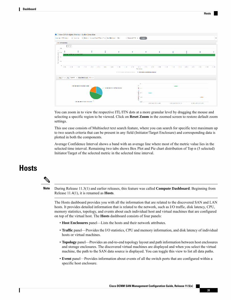
You can zoom in to view the respective ITL/ITN dots at a more granular level by dragging the mouse andselecting a specific region to be viewed. Click on Reset Zoom in the zoomed screen to restore default zoomsettings.
This use case consists of Multiselect text search feature, where you can search for specific text maximum upto two search criteria that can be present in any field (Initiator/Target Enclosure) and corresponding data isplotted in both the components.
Average Confidence Interval shows a band with an average line where most of the metric value lies in theselected time interval. Remaining two tabs shows Box Plot and Pie chart distribution of Top n (5 selected)Initiator/Target of the selected metric in the selected time interval.
Hosts
During Release 11.3(1) and earlier releases, this feature was called Compute Dashboard. Beginning fromRelease 11.4(1), it is renamed as Hosts.
Note
The Hosts dashboard provides you with all the information that are related to the discovered SAN and LANhosts. It provides detailed information that is related to the network, such as I/O traffic, disk latency, CPU,memory statistics, topology, and events about each individual host and virtual machines that are configuredon top of the virtual host. The Hosts dashboard consists of four panels:
• Host Enclosures panel—Lists the hosts and their network attributes.
• Traffic panel—Provides the I/O statistics, CPU and memory information, and disk latency of individualhosts or virtual machines.
• Topology panel—Provides an end-to-end topology layout and path information between host enclosuresand storage enclosures. The discovered virtual machines are displayed and when you select the virtualmachine, the path to the SAN data source is displayed. You can toggle this view to list all data paths.
• Event panel—Provides information about events of all the switch ports that are configured within aspecific host enclosure.
Cisco DCNM SAN Management Configuration Guide, Release 11.5(x)31
DashboardHosts
This section contains the following topics:
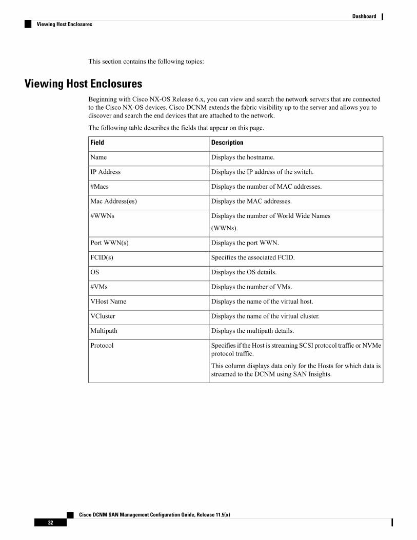
Viewing Host EnclosuresBeginning with Cisco NX-OS Release 6.x, you can view and search the network servers that are connectedto the Cisco NX-OS devices. Cisco DCNM extends the fabric visibility up to the server and allows you todiscover and search the end devices that are attached to the network.
The following table describes the fields that appear on this page.
DescriptionField
Displays the hostname.Name
Displays the IP address of the switch.IP Address
Displays the number of MAC addresses.#Macs
Displays the MAC addresses.Mac Address(es)
Displays the number of World Wide Names
(WWNs).
#WWNs
Displays the port WWN.Port WWN(s)
Specifies the associated FCID.FCID(s)
Displays the OS details.OS
Displays the number of VMs.#VMs
Displays the name of the virtual host.VHost Name
Displays the name of the virtual cluster.VCluster
Displays the multipath details.Multipath
Specifies if the Host is streaming SCSI protocol traffic or NVMeprotocol traffic.
This column displays data only for the Hosts for which data isstreamed to the DCNM using SAN Insights.
Protocol
Cisco DCNM SAN Management Configuration Guide, Release 11.5(x)32
DashboardViewing Host Enclosures

• Beginningwith CiscoNX-OSRelease 6.x, Server Credentials, Servers, and Static Server-AdapterMappingare no longer available.
• Beginning from Cisco DCNM Release 10.1, you are able to assign storage to hosts.
• Collection level in the vCenter settings determines the amount of data that is gathered and displayed incharts. Level 1 is the default Collection Level for all collection intervals. Change the vCenter statisticssettings to Level 2 or higher to collect disk I/O history data.
• From DCNM Release 11.4(1), you can set the default enclosure names from the Device Alias. ChooseAdministration > DCNM Server > Server Properties, and edit the fabric.aliasRE property.
Note
To view the host enclosures from the Cisco DCNMWeb UI, perform the following steps:
Procedure
Step 1 Choose Dashboard > Hosts.
The list of hosts in the host enclosures table is displayed.
Step 2 Choose a host to view more details.
The events, topology, and traffic information on the dashboard are displayed. You can also click thecorresponding icons on a host entry to view the events, topology, and traffic information.
From DCNM Release 11.5(1), traffic icons are added for VHost. It has multiple VM charts such as VHostCPU, and memory, latency, and network I/O. Click the radio button of a host to view respective traffic detailsin the traffic dashboard.
Step 3 To edit the hostname, select the row and click the Rename icon. Enter the new name in the pop-out dialog.
• If the host is not associated with port WWN or the end port is not discovered by DCNM, it is a VHostor LAN Host. The Rename Enclosure dialog box appears only for the existing name.
• If the host is associatedwith portWWNand the end port is discovered byDCNM. TheRename Enclosuredialog appears for the associated host names.
• You can rename each enclosure name to a different name. Choose the enclosure name, enter a newname, click Save. Repeat this procedure to change all the required enclosure names and clickApply.
• You can rename all enclosure names to the same new name. Check the Include All Members checkbox, enter a new name, and click Apply.
Specifying a blank name causes the server to default the name.
Cisco DCNM allows you to change the default assigned Host enclosure name or grouping multipleenclosures into the same enclosure by assigning the same name. Assigning custom enclosure namesto respective WWPNs is supported on the Cisco DCNM SAN Client only.
Note
Step 4 To assign storage to host, you can choose the host, and click the Assign icon next to the Rename icon.
Cisco DCNM SAN Management Configuration Guide, Release 11.5(x)33
DashboardViewing Host Enclosures
The Assign Storage to Host window pops out. The selection of Host is by enclosure, and multiple selectionsof LUNs is allowed. Click Assign. A confirmation message is displayed. After confirmed, the status willupdate with the results of each step.
Step 5 Click Quick Filter drop down to filter host enclosures (not storage) by LAN, SAN, and Virtual.
Viewing Host EventsTo view the host events from the Cisco DCNMWeb UI, perform the following steps:
Procedure
Step 1 Choose Dashboard > Hosts.
The list of hosts in the host enclosures table is displayed.
Step 2 Click the Events icon next to the host enclosure to view the Events panel.
You can use the slider control to resize the panel.
Viewing Host TopologyTo view host topology from the Cisco DCNMWeb UI, perform the following steps:
Procedure
Step 1 Choose Dashboard > Hosts.
The list of hosts in the host enclosures table is displayed.
Step 2 Select the row to view the host topology details.
You can use the mouse scroll wheel to zoom-in and zoom-out.
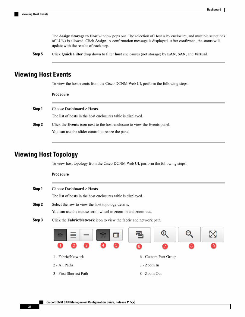
Step 3 Click the Fabric/Network icon to view the fabric and network path.
6 - Custom Port Group1 - Fabric/Network
7 - Zoom In2 - All Paths
8 - Zoom Out3 - First Shortest Path
Cisco DCNM SAN Management Configuration Guide, Release 11.5(x)34
DashboardViewing Host Events
9 - Zoom Fit4 - Map View
5 - Tabular View
Step 4 Click the All Paths icon to view the complete set-up.Step 5 Click the First Shortest Path icon to view the first shortest path.
Click Map View icon to enable the icons that are listed in the preceding step 4, 5 and 6.Note
Step 6 Click the Tabular View icon to view the host topology in tabular format.Step 7 Click the Custom Port Group icon to view the custom port group.
View Host TrafficTo view the host traffic from the Cisco DCNMWeb UI, perform the following steps:
Procedure
Step 1 From the menu bar, choose Dashboard > Hosts.
The list of hosts in the host enclosures table is displayed.
Step 2 Select the row to view the host topology details.Step 3 Use the drop-down to select the traffic according to the time duration.Step 4 Select the icons to view the traffic as a Grid, Line Chart, or Stacked Chart.Step 5 In the Traffic pane, the Enclosure Traffic is displayed by default. Click the Traffic Utilization icon to view
the traffic utilization. The daily average percentage of traffic utilization of the enclosure ports is displayed asa pie chart.
Cisco DCNM SAN Management Configuration Guide, Release 11.5(x)35
DashboardView Host Traffic

Cisco DCNM SAN Management Configuration Guide, Release 11.5(x)36
DashboardView Host Traffic

C H A P T E R 3Topology
• Topology, on page 37
TopologyThe Topology window displays color-encoded nodes and links that correspond to various network elements,including switches, links, fabric extenders, port-channel configurations, virtual port-channels, and more. Forinformation about each of these elements, hover your cursor over the corresponding element. Also, click anode or the line for a link. A slide-in pane appears from the right side of the window. This pane displaysdetailed information about either the switch or the link.
You can open multiple tabs simultaneously and can function side by side to facilitate comparison andtroubleshooting.
Note
StatusThe color coding of each node and link corresponds to its state. The colors and what they indicate are describedin the following list:
• Green: Indicates that the element is in good health and functioning as intended.
• Yellow: Indicates that the element is in warning state and requires attention to prevent any furtherproblems.
• Red: Indicates that the element is in critical state and requires immediate attention.
• Gray: Indicates lack of information to identify the element or the element has been discovered.
Cisco DCNM SAN Management Configuration Guide, Release 11.5(x)37
• In the Topology window, FEX appears in gray (Unknown orn/a) because health is not calculated for FEX.
• After moving a cable from one port to another port, the old fabriclink is retained in the Topology window, and it is shown in thered color indicating that the link is down. The port movementsare not updated in theTopologywindow. You need to rediscoverthe switch for the updated ports to be displayed in DCNM.
Note
• Black: Indicates that the element is down.
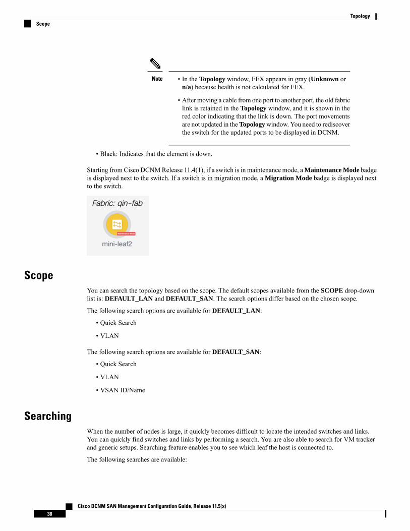
Starting from Cisco DCNMRelease 11.4(1), if a switch is in maintenance mode, aMaintenance Mode badgeis displayed next to the switch. If a switch is in migration mode, a Migration Mode badge is displayed nextto the switch.
ScopeYou can search the topology based on the scope. The default scopes available from the SCOPE drop-downlist is: DEFAULT_LAN and DEFAULT_SAN. The search options differ based on the chosen scope.
The following search options are available for DEFAULT_LAN:
• Quick Search
• VLAN
The following search options are available for DEFAULT_SAN:
• Quick Search
• VLAN
• VSAN ID/Name
SearchingWhen the number of nodes is large, it quickly becomes difficult to locate the intended switches and links.You can quickly find switches and links by performing a search. You are also able to search for VM trackerand generic setups. Searching feature enables you to see which leaf the host is connected to.
The following searches are available:
Cisco DCNM SAN Management Configuration Guide, Release 11.5(x)38
TopologyScope
By default, Quick Search is selected.Note
Quick SearchQuick Search enables you to search for devices by name, IP address, model, serial number, and switch role.As you enter a search parameter in the Search field, the corresponding switches are highlighted in the topology.To perform a search for multiple nodes and links, separate multiple keywords using a comma, for example,ABCD12345, N7K, sw-dc4-12345, core, 172.23.45.67. Cisco DCNM supports wildcard searches too. If youknow a serial number or switch name partially, you can build a search based on these partial terms that arepreceded by an asterisk, for example, ABCD*, sw*12345, core, and so on.
To limit the scope of your search to a parameter, enter the parameter name followed by a space and theparameter in the Search field, for example, name=sw*12345, serialNumber=ABCD12345, and so on.
VLANSearch by a given VLAN ID. VLAN search provides the search for the VLAN configured on the switch orthe links. If STP is enabled, then it provides information that is related to the STP protocol and the STPinformation for links.
VSAN ID/NameSearch by a given VSAN ID. VSAN search provides the search for VSAN configured on the switch or thelinks. In order to view the STP details associated with the VSAN, click STP Details link.
This shows the STP details, if STP is enabled. If the link is blocked, it is marked as red, green in case of aforwarding link, and orange if the link is blocked for one VSAN range and forwarding for the other VSANrange.
This search is applicable to both the default LAN and SAN scopes.
Show PanelYou can choose to view your topology based on the following options:
• Auto Refresh: Check this check box to automatically refresh the topology.
• Switch Health: Check this check box to view the switch's health status.
• FEX: Check this check box to view the Fabric Extender.
The FEX feature is available only on LAN devices. Therefore,checking this check box displays only the Cisco Nexus switches thatsupport FEX.
Note
Cisco DCNM SAN Management Configuration Guide, Release 11.5(x)39
TopologyQuick Search

If a Cisco Nexus Switch is discovered as part of SAN fabric, FEXfeature is not available. FEX is also not supported on Cisco Nexus1000V devices. Therefore, such devices will not be displayed in thetopology when you check the FEX check box.
Note
• Links: Check this check box to view links in the topology. The following options are available:
• Errors Only: Click this radio button to view only links with errors.
• All: Click this radio button to view all the links in the topology.
• VPC Only: Check this check box to view only vPC peer-links and vPCs.
• Bandwidth: Check this check box to view the color coding based on the bandwidth that is consumedby the links.
• UI controls: Check the check box to show or hide the various controls on the Topology window.
• Refresh: You can also perform a topology refresh by clicking the Refresh icon in the upper-right cornerof this panel.
LayoutsThe topology supports different layouts along with a Save Layout option that remembers how you positionedyour topology.
• Hierarchical and Hierarchical Left-Right: Provide an architectural view of your topology. Variousswitch roles can be defined that will draw the nodes on how you configure your CLOS topology.
When running a large-scale setup, being able to easily view all yourswitches on a leaf-tier can become difficult. To mitigate this, DCNMsplits your leaf-tier every 16 switches.
Note
• Random: Nodes are placed randomly on the window. DCNM tries to make a guess and intelligentlyplace nodes that belong together in close proximity.
• Circular and Tiered-Circular: Draw nodes in a circular or concentric circular pattern.
• Custom saved layout: Nodes can be dragged around according to your preference. After you positionas required, click Save to retain the positions. The next time you come to the topology, DCNMwill drawthe nodes based on your last saved layout positions.
Before a layout is chosen, DCNM checks if a custom layout is applied. If a custom layout is applied, DCNMuses it. If a custom layout is not applied, DCNM checks if switches exist at different tiers, and chooses theHierarchical layout or the Hierarchical Left-Right layout. Force-directed layout is chosen if all the otherlayouts fail.
Cisco DCNM SAN Management Configuration Guide, Release 11.5(x)40
TopologyLayouts
Zooming, Panning, and DraggingYou can zoom in and zoom out using the controls that are provided at the bottom left of the windows or byusing your mouse's wheel.
To pan, click and hold anywhere in the whitespace and drag the cursor up, down, left, or right.
To drag switches, click, hold, and move the cursor around the whitespace region of the topology.
Switch Slide-Out PanelYou can click on the switch to display the configured switch name, IP address, switch model, and othersummary information such as status, serial number, health, last-polled CPU utilization, and last-polled memoryutilization.
From DCNM release 11.5(1), switches have only two roles, Core Router and Edge Router.
BeaconThis button will be shown for switches that support the beacon command. After beaconing starts, the buttonwill show a countdown. By default, the beaconing will stop after 60 seconds, but you can stop it immediatelyby clicking Stop Beacon.
The default time can be configured in server.properties file. Search for beacon.turnOff.time. Thetime value is in milliseconds. Note that this requires a server restart to take effect.
Note
TaggingTagging is a powerful yet easy way to organize your switches. Tags can be virtually any string, for example,building 6, floor 2, rack 7, problem switch, and Justin debugging.
Use the search functionality to perform searches based on tags.
More DetailsClick Show more details to display more information under the following tabs: System Info, Modules, FEX,License, Features, VXLAN, VLAN, Capacity and Hosts.
Cisco DCNM SAN Management Configuration Guide, Release 11.5(x)41
TopologyZooming, Panning, and Dragging

Starting from Cisco DCNM Release 11.4(1), the 400G tier has also been added to the Physical Capacitytable under the Capacity tab. However, the Physical Capacity table under the Capacity tab will only showinformation about the physical ports that are present on the switch. For example, if the switch does not havea 400G physical port, the 400G tier is not displayed in the Physical Capacity table.
Cisco DCNM SAN Management Configuration Guide, Release 11.5(x)42
TopologyMore Details

Link Slide-Out PanelYou can click a link to view the status and the port or switches that describe the link.
24-Hour TrafficThis feature requires Performance Monitoring to be turned ON. When Performance Monitoring is ON,traffic information is collected and the aggregate information is displayed along with a graph showing trafficutilization.
vCenter Compute VisualizationIn virtualized environments, any kind of troubleshooting starts with identifying the network attachment pointfor the virtual machines. This means that a quick determination of the server, virtual switch, port group,VLAN, associated network switch, and physical port is critical. This requires multiple touch points andinteractions between the server and the network administrator as well as reference to multiple tools (computeorchestrator, compute manager, network manager, network controller, and so on).
This allows you to visualize the vCenter-managed hosts and their leaf switch connections on the Topologywindow. The visualization options include viewing only the attached physical hosts, only the VMs, or both.When you select both, the topology all the way from the leaf switches to the VMs, including the virtualswitches are displayed. The VM Search option highlights the path of the VM. Hover the cursor over a hostor a connected uplink to view key information relevant to that entity. Up to four vCenters are supported.
VMM supports computes connecting to a border spine. Border Spine is a new switch role managed by easyfabric in Cisco DCNM 11.1(1).
• The vCenter Compute Visualization feature is supported on both the LAN Classic and Easy Fabricsinstallations for the vCenter-managed computes.
• It is not recommended to use special characters in a VMname as vCenter does not escape special charactersused in display names. For more information, see https://vss-wiki.eis.utoronto.ca/display/VSSPublic/Virtual+Machine+Naming.
• Cisco DCNM doesnot support non-Cisco blade servers.
Note
Cisco DCNM SAN Management Configuration Guide, Release 11.5(x)43
TopologyLink Slide-Out Panel
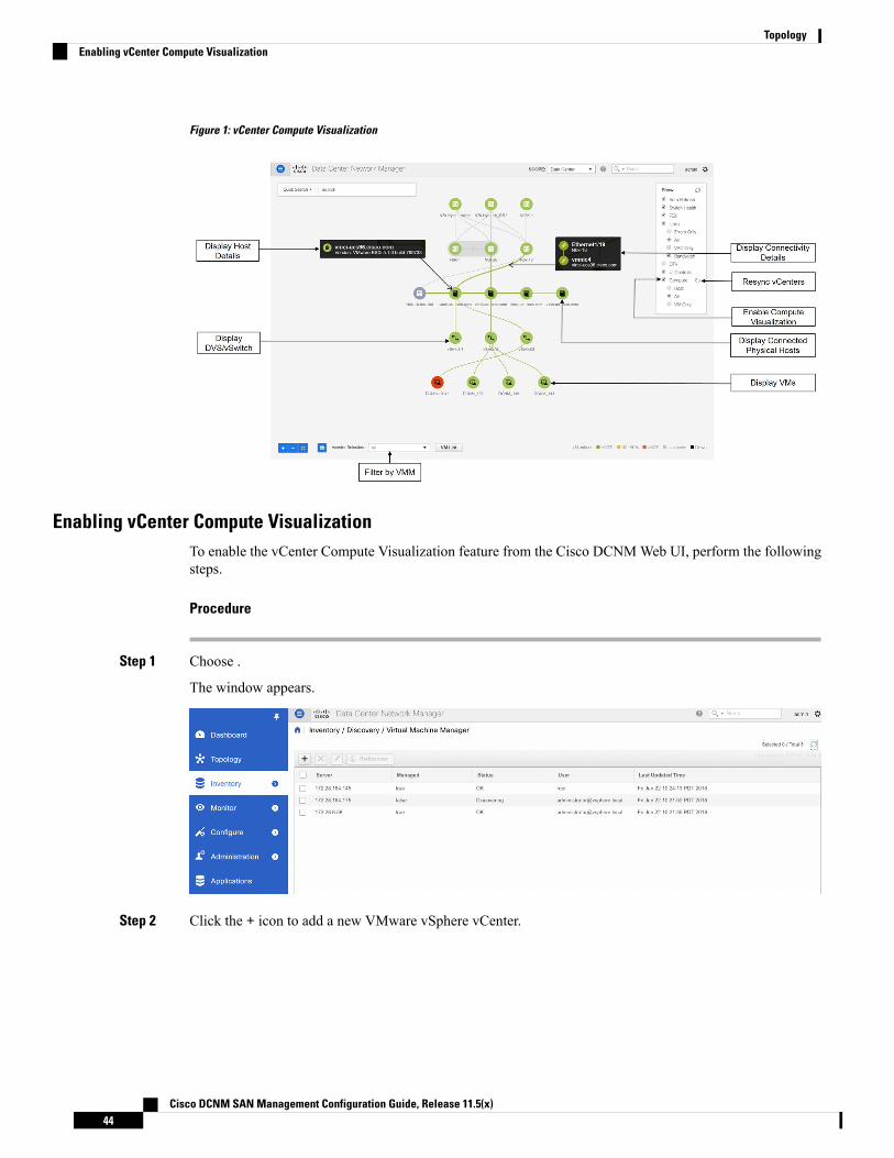
Figure 1: vCenter Compute Visualization
Enabling vCenter Compute VisualizationTo enable the vCenter Compute Visualization feature from the Cisco DCNMWeb UI, perform the followingsteps.
Procedure
Step 1 Choose .
The window appears.
Step 2 Click the + icon to add a new VMware vSphere vCenter.
Cisco DCNM SAN Management Configuration Guide, Release 11.5(x)44
TopologyEnabling vCenter Compute Visualization
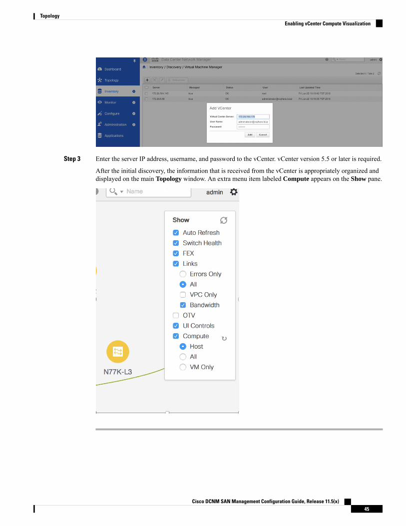
Step 3 Enter the server IP address, username, and password to the vCenter. vCenter version 5.5 or later is required.
After the initial discovery, the information that is received from the vCenter is appropriately organized anddisplayed on the main Topology window. An extra menu item labeled Compute appears on the Show pane.
Cisco DCNM SAN Management Configuration Guide, Release 11.5(x)45
TopologyEnabling vCenter Compute Visualization

Using vCenter Compute VisualizationTo use the vCenter Compute Visualization feature from the Cisco DCNMWeb UI, perform the followingsteps.
Procedure
Step 1 Choose Topology.Step 2 In the Show list, select Compute to enable the compute visibility.
By default, the Host check box is selected. This implies that the topology shows the VMWare vSphere ESXihosts (servers), that are attached to the network switches.
The following options are available in the Compute Visualization feature.
• Host
• All
• VM Only
In the All mode, you can see double-arrows that help you to extend a node. If you double-click this node, youcan see all the hidden child nodes.
Step 3 Click a specific ESXi host to view additional information.
The expanded topology displayed in the following figure, shows the virtual switches (both vSwitch andDistributed Virtual Switch) that are configured on the specific ESXi host.
Cisco DCNM SAN Management Configuration Guide, Release 11.5(x)46
TopologyUsing vCenter Compute Visualization
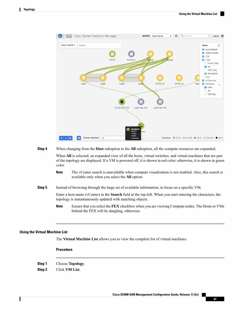
Step 4 When changing from the Host suboption to the All suboption, all the compute resources are expanded.
When All is selected, an expanded view of all the hosts, virtual switches, and virtual machines that are partof the topology are displayed. If a VM is powered off, it is shown in red color; otherwise, it is shown in greencolor.
The vCenter search is unavailable when compute visualization is not enabled. Also, this search isavailable only when you select the All option.
Note
Step 5 Instead of browsing through the large set of available information, to focus on a specific VM.
Enter a host name (vCenter) in the Search field at the top-left. When you start entering the characters, thetopology is instantaneously updated with matching objects.
Ensure that you select the FEX checkbox when you are viewing Compute nodes. The Hosts or VMsbehind the FEX will be dangling, otherwise.
Note
Using the Virtual Machine List
The Virtual Machine List allows you to view the complete list of virtual machines.
Procedure
Step 1 Choose Topology.Step 2 Click VM List.
Cisco DCNM SAN Management Configuration Guide, Release 11.5(x)47
TopologyUsing the Virtual Machine List

Click Export to export the list of virtual machines into a .csv file.
Click on the name of a VM to view additional information about that virtual machine.
When you export the VM List to a .CSV file, the .CSV file may appear correct. However, when the.CSV file is imported intoMicrosoft Excel, it might get reformatted, for example, the VLAN column1-1024 could be reformatted to a date 1/1/2019. Therefore ensure that columns are formatted correctlyin Microsoft Excel while importing the .CSV file.
Note
Cisco DCNM SAN Management Configuration Guide, Release 11.5(x)48
TopologyUsing the Virtual Machine List

Resynchronizing Virtual Machines
Procedure
Step 1 Choose Topology.Step 2 Click Resync vCenters icon next to Compute.
Selecting a Column in the Virtual Machine List
Procedure
Step 1 In the VM List window, click the Columns under the gear icon drop-down list.
Cisco DCNM SAN Management Configuration Guide, Release 11.5(x)49
TopologyResynchronizing Virtual Machines
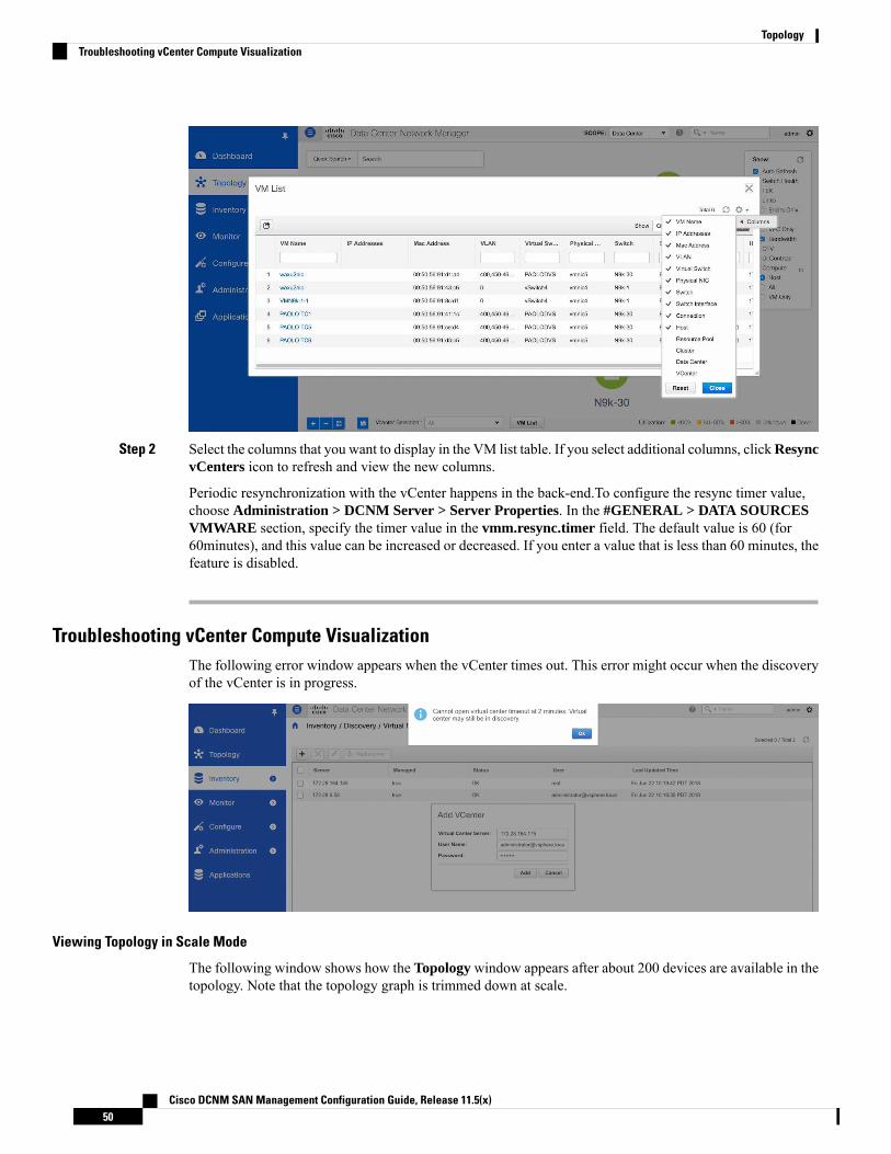
Step 2 Select the columns that you want to display in the VM list table. If you select additional columns, clickResyncvCenters icon to refresh and view the new columns.
Periodic resynchronization with the vCenter happens in the back-end.To configure the resync timer value,choose Administration > DCNM Server > Server Properties. In the #GENERAL > DATA SOURCESVMWARE section, specify the timer value in the vmm.resync.timer field. The default value is 60 (for60minutes), and this value can be increased or decreased. If you enter a value that is less than 60 minutes, thefeature is disabled.
Troubleshooting vCenter Compute VisualizationThe following error window appears when the vCenter times out. This error might occur when the discoveryof the vCenter is in progress.
Viewing Topology in Scale Mode
The following window shows how the Topology window appears after about 200 devices are available in thetopology. Note that the topology graph is trimmed down at scale.
Cisco DCNM SAN Management Configuration Guide, Release 11.5(x)50
TopologyTroubleshooting vCenter Compute Visualization

Cisco DCNM SAN Management Configuration Guide, Release 11.5(x)51
TopologyViewing Topology in Scale Mode

Cisco DCNM SAN Management Configuration Guide, Release 11.5(x)52
TopologyViewing Topology in Scale Mode

C H A P T E R 4Inventory
This chapter contains the following topics:
• Viewing Inventory Information, on page 53• Discovery, on page 76
Viewing Inventory InformationBeginning with Cisco DCNM release 6.x, you can view the inventory and the performance for both SAN andLAN switches by using the global Scope pane. You can select LAN, SAN, or both to view the inventoryinformation. You can also export and print the inventory information.
You can either Print this information or export to Microsoft Excel.
You can use the Print icon to print the information that is displayed or you can also use the Export icon toexport the information that is displayed to a Microsoft Excel spreadsheet. You can also choose the columnthat you want to display.
Note
The Inventory menu includes the following submenus:
Viewing Inventory Information for SwitchesTo view the inventory information for switches from the Cisco DCNMWeb UI, perform the following steps:
Procedure
Step 1 Choose Inventory > View > Switches.
The Switches window with a list of all the switches for a selected Scope is displayed.
Step 2 You can also view the following information.
• Group column displays the switch group to which the switch belongs.
• In the Device Name column, select a switch to display the Switch Dashboard.
Cisco DCNM SAN Management Configuration Guide, Release 11.5(x)53
• IP Address column displays the IP address of the switch.
• WWN/Chassis ID displays the Worldwide Name (WWN) if available or chassis ID.
• Health displays the health situation of the switch.
To refresh and recalculate the latest health data for all the switches on Cisco DCNM, click theRecalculate Health button above the switches table.
Note
• Mode column displays the current mode of the switch. The switch can be in Normal, Maintenance, orMigration mode.
• Status column displays the status of the switch.
• # Ports column displays the number of ports.
• Model column displays the model name of the switch.
• Serial No. column displays the serial number of the switch.
• Release column displays the switch version.
• Up Time column displays the time period for which the switch is active.
• Container Based ISSU Mode column indicates whether the Container Based ISSU Mode is enabled ornot. The container-based ISSU can be enabled for Cisco Nexus 3000 and Cisco Nexus 9000 seriesswitches. This is a one-time configuration on the device.
Enhanced in-service software upgrade (ISSU)—Enables you to upgrade the device software while theswitch continues to forward traffic, which reduces the downtime typically caused by software upgrades(similar to the regular ISSU, also known as a non-disruptive upgrade). However, with container-basedISSU, the software runs inside a separate Linux container (LXC) for the supervisor and line cards, anda third container is created as part of the ISSU procedure and is brought up as a standby supervisor.
Container-based ISSUs are supported on Cisco Nexus 3164Q, 9200 series switches, 9332PQ, 9372PX,9372TX, 9396PX, 9396TX, 93120TX, and 93128TX switches.
For more information about the Cisco Nexus 3000 and 9000 switches, where the Container-based ISSUfeature is supported, see the following URLs:
Cisco Nexus 9000 Series NX-OS Software Upgrade and Downgrade Guide, Release 9.x
Cisco Nexus 3000 Series NX-OS Software Upgrade and Downgrade Guide, Release 9.x
Cisco NX-OS ISSU Support Matrix
Cisco DCNM SAN Management Configuration Guide, Release 11.5(x)54
InventoryViewing Inventory Information for Switches
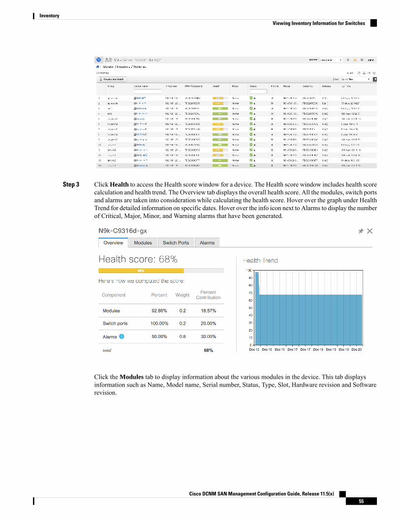
Step 3 Click Health to access the Health score window for a device. The Health score window includes health scorecalculation and health trend. The Overview tab displays the overall health score. All the modules, switch portsand alarms are taken into consideration while calculating the health score. Hover over the graph under HealthTrend for detailed information on specific dates. Hover over the info icon next to Alarms to display the numberof Critical, Major, Minor, and Warning alarms that have been generated.
Click the Modules tab to display information about the various modules in the device. This tab displaysinformation such as Name, Model name, Serial number, Status, Type, Slot, Hardware revision and Softwarerevision.
Cisco DCNM SAN Management Configuration Guide, Release 11.5(x)55
InventoryViewing Inventory Information for Switches
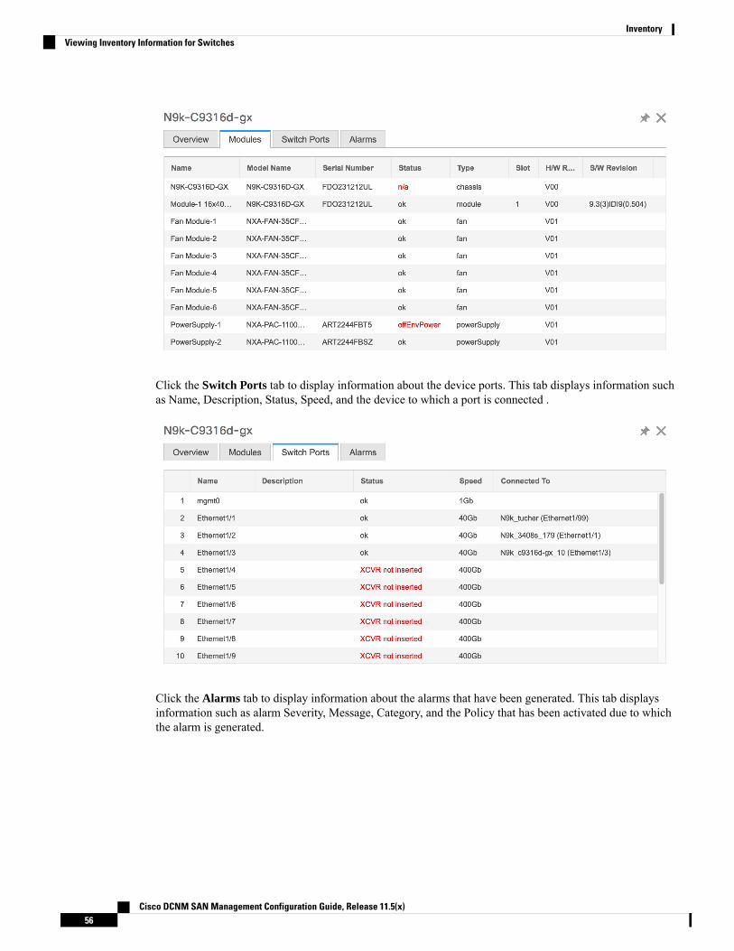
Click the Switch Ports tab to display information about the device ports. This tab displays information suchas Name, Description, Status, Speed, and the device to which a port is connected .
Click the Alarms tab to display information about the alarms that have been generated. This tab displaysinformation such as alarm Severity, Message, Category, and the Policy that has been activated due to whichthe alarm is generated.
Cisco DCNM SAN Management Configuration Guide, Release 11.5(x)56
InventoryViewing Inventory Information for Switches
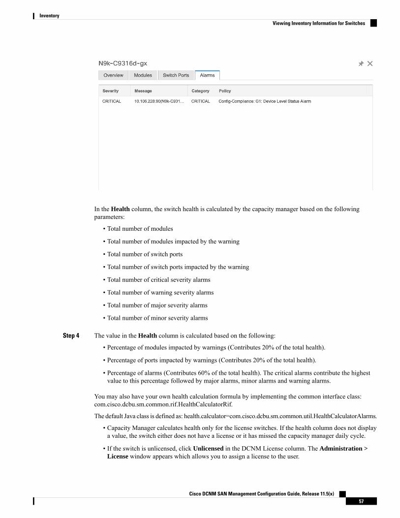
In the Health column, the switch health is calculated by the capacity manager based on the followingparameters:
• Total number of modules
• Total number of modules impacted by the warning
• Total number of switch ports
• Total number of switch ports impacted by the warning
• Total number of critical severity alarms
• Total number of warning severity alarms
• Total number of major severity alarms
• Total number of minor severity alarms
Step 4 The value in the Health column is calculated based on the following:
• Percentage of modules impacted by warnings (Contributes 20% of the total health).
• Percentage of ports impacted by warnings (Contributes 20% of the total health).
• Percentage of alarms (Contributes 60% of the total health). The critical alarms contribute the highestvalue to this percentage followed by major alarms, minor alarms and warning alarms.
You may also have your own health calculation formula by implementing the common interface class:com.cisco.dcbu.sm.common.rif.HealthCalculatorRif.
The default Java class is defined as: health.calculator=com.cisco.dcbu.sm.common.util.HealthCalculatorAlarms.
• Capacity Manager calculates health only for the license switches. If the health column does not displaya value, the switch either does not have a license or it has missed the capacity manager daily cycle.
• If the switch is unlicensed, click Unlicensed in the DCNM License column. The Administration >License window appears which allows you to assign a license to the user.
Cisco DCNM SAN Management Configuration Guide, Release 11.5(x)57
InventoryViewing Inventory Information for Switches
• The capacity manager runs two hours after the DCNM server starts. So, if you discover a device aftertwo hours of the DCNM start time, the health will be calculated 24 hours after this DCNM start time
Starting from Cisco DCNM 11.3(1) Release, you can view information about switch health along with theswitch summary by clicking on a switch in the Topology window or by choosing Control>Fabrics>FabricBuilder, selecting a fabric and clicking on a switch in the Fabric Builder window.
Viewing System InformationThe switch dashboard displays the details of the selected switch.
Procedure
Step 1 From the Cisco DCNM home page, choose Inventory > View > Switches.
An inventory of all the switches that are discovered by Cisco DCNMWeb UI is displayed.
Step 2 Click a switch in the Device Name column.
The Switch dashboard that corresponds to that switch is displayed along with the following information:
Step 3 Click the System Information tab. This tab displays detailed system information such as group name, health,module, time when system is up, serial number, the version number, contact, location, DCNM license, status,system log sending status, CPU and memory utilization, and VTEP IP address are displayed. Click Healthto access the Health score screen, which includes health score calculation and health trend. The popup containsOverview, Modules, Switch Ports, and Events tabs.
• (Optional) Click SSH to access the switch through Secure Shell (SSH).
• (Optional) ClickDevice Manager to view a graphical representation of a CiscoMDS 9000 Family switchchassis, a Cisco Nexus 5000 Series switch chassis, a Cisco Nexus 7000 Series switch chassis, or a CiscoNexus 9000 Series switch chassis including the installed switching modules, the supervisor modules, thestatus of each port within each module, the power supplies, and the fan assemblies.
• (Optional) ClickHTTP to access the switch through Hypertext Transfer Protocol (HTTP) for that switch.
• (Optional) Click Accounting to go to the Viewing Accounting Information window pertaining to thisswitch.
• (Optional) Click Backup to go to the Viewing a Configuration window.
• (Optional) Click Events to go to the Viewing Events Registration, on page 309 window.
• (Optional) Click Show Commands to display the device show commands. TheDevice ShowCommandspage helps you to view commands and execute them.
• (Optional) Click Copy Running Config to Startup Config to copy the running configuration to thestartup configuration.
• Click Generate tac-pac to collect technical support from a device in Cisco DCNM. See the CollectingTechnical Support from Devices section for more information.
Cisco DCNM SAN Management Configuration Guide, Release 11.5(x)58
InventoryViewing System Information
Collecting Technical Support from Devices
You can choose the protocol while generating technical support from a device in Cisco DCNMWeb Client.To collect technical support from a device in Cisco DCNMWeb UI, perform the following steps:
Procedure
Step 1 Choose Inventory > View > Switches.
An inventory of all the switches that are discovered by Cisco DCNM is displayed.
Step 2 Click a switch in the Device Name column.
The switch dashboard that corresponds to that switch appears.
Step 3 In the Actions area, click Generate tac-pac.
The Generate tac-pac dialog box appears.
Step 4 Choose a management interface by clicking the appropriate radio button.
Valid values are default, vrf management, and vrf default. The default value selected is default.
This option is valid only for Nexus switches.Note
Step 5 Choose the transport protocol from switch to DCNM by clicking the appropriate radio button.
Valid values are TFTP, SCP, and SFTP.
If you choose the SCP or SFTP option, enter the DCNM server credentials.Note
Step 6 Click Ok.
After the tac-pac is generated and saved on server, a dialog box appears to open or save the file on your localmachine.
Viewing Device Manager Information
After you install Cisco DCNM for Windows, you must edit and provide credentials in the Cisco DCNM SANServices to Log on. Navigate to Services > Cisco DCNM SAN Server > Cisco DCNM SAN Server Properties> Log On tab. Select This account radio button, and provide username and password. Click Ok. Log on toSSH and stop DCNM services. After you start the DCNM services, you must be able to use Device Manager.
Note
After you install Cisco DCNM for Linux, perform the procedure that is provided on the screen for DeviceManager to be functional. Device Manager requires graphical environment that is configured properly in theLinux/OVA DCNM server.
Note
The switch dashboard displays the details of the selected switch.
Cisco DCNM SAN Management Configuration Guide, Release 11.5(x)59
InventoryCollecting Technical Support from Devices
Procedure
Step 1 From the left menu bar, choose Inventory > View > Switches.
An inventory of switches discovered by Cisco DCNMWeb Client is displayed.
Step 2 Click a switch in the Device Name column.
The Switch dashboard that corresponds to that switch is displayed along with the following information:
Step 3 Click the Device Manager tab. The Device Manager login dialog box appears. Log into the Device Managerapplication. The Device Manager provides a graphic representation of the installed switching modules, thesupervisor modules, the status of each port within each module, the power supplies, and the fan assemblies.
For more information about the Device Manager, go to the following URL:
Cisco DCNM SAN Client Online Help
Installing a Switch LicenseTo install a switch license from the Cisco DCNMWeb UI, perform the following steps:
Procedure
Step 1 Choose Inventory > View > Switches.
Alternatively, you can choose Inventory > View > Switches.
Step 2 Click License in the switch dashboard.Step 3 Click Install to install the switch license file on a switch.
A Switch License Install window appears.
Step 4 Click Select License File, and select the license file from your local system.Step 5 Select the transport method. The available options are:
• TFTP
• SCP
• SFTP
Step 6 Enter the username and password to connect to the DCNM server.Step 7 Click Install.
Rediscovering Switch LicensesTo rediscover switch licenses from the Cisco DCNMWeb UI, perform the following steps:
Cisco DCNM SAN Management Configuration Guide, Release 11.5(x)60
InventoryInstalling a Switch License
Procedure
Step 1 Choose Inventory > View > Switches.
Alternatively, you can choose Inventory > View > Switches.
Step 2 Choose a switch in the Device Name column.Step 3 Click the License tab in the switch dashboard.Step 4 Click Rediscover to rediscover switch licenses on a switch.
Rediscovering the switch licenses takes some time.
Step 5 Click the Last Updated icon to refresh the licenses.
Interfaces
Displaying Interface Show Commands
To display interface show commands from the Cisco DCNMWeb UI, perform the following steps:
Procedure
Step 1 Choose Inventory > View > Switches.You see the Switches window displaying a list of all the switches for a selected Scope.
Step 2 In the Device Name column, select a switch to display Switch Dashboard.Step 3 Click the Interfaces tab.Step 4 Click Show to display the interface show commands.
The Interface Show Commands window helps you to view commands and execute them.
Rediscovering Interfaces
To rediscover interfaces from the Cisco DCNMWeb UI, perform the following steps:
Procedure
Step 1 Choose Inventory > View > Switches.
The Switches window is displayed showing a list of all the switches for a selected Scope.
Step 2 In the Device Name column, select a switch to display Switch Dashboard.Step 3 Click the Interfaces tab.Step 4 ClickRediscover to rediscover the selected interfaces. For example, after you edit or enable an interface, you
can rediscover the interface.
Cisco DCNM SAN Management Configuration Guide, Release 11.5(x)61
InventoryInterfaces
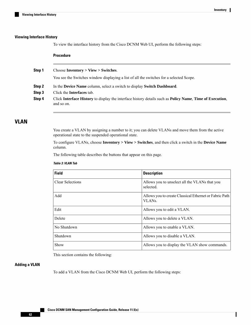
Viewing Interface History
To view the interface history from the Cisco DCNMWeb UI, perform the following steps:
Procedure
Step 1 Choose Inventory > View > Switches.
You see the Switches window displaying a list of all the switches for a selected Scope.
Step 2 In the Device Name column, select a switch to display Switch Dashboard.Step 3 Click the Interfaces tab.Step 4 Click Interface History to display the interface history details such as Policy Name, Time of Execution,
and so on.
VLANYou create a VLAN by assigning a number to it; you can delete VLANs and move them from the activeoperational state to the suspended operational state.
To configure VLANs, choose Inventory > View > Switches, and then click a switch in the Device Namecolumn.
The following table describes the buttons that appear on this page.
Table 3: VLAN Tab
DescriptionField
Allows you to unselect all the VLANs that youselected.
Clear Selections
Allows you to create Classical Ethernet or Fabric PathVLANs.
Add
Allows you to edit a VLAN.Edit
Allows you to delete a VLAN.Delete
Allows you to enable a VLAN.No Shutdown
Allows you to disable a VLAN.Shutdown
Allows you to display the VLAN show commands.Show
This section contains the following:
Adding a VLAN
To add a VLAN from the Cisco DCNMWeb UI, perform the following steps:
Cisco DCNM SAN Management Configuration Guide, Release 11.5(x)62
InventoryViewing Interface History

Procedure
Step 1 Choose Inventory > View > Switches.
You see the Switches window displaying a list of all the switches for a selected Scope.
Step 2 In the Device Name column, select a switch to display the Switch Dashboard.Step 3 Click the VLAN tab.Step 4 Click Add to create Classical Ethernet or Fabric Path VLANs. In the Add VLAN window, specify the
following fields:a) In the Vlan Id field, enter the VLAN ID.b) In the Mode field, specify whether you are adding Classical Ethernet or Fabric Path VLAN.c) Select the Admin State ON check box to specify whether the VLAN is shut down or not.
Editing a VLAN
To edit a VLAN from the Cisco DCNMWeb UI, perform the following steps:
Procedure
Step 1 Choose Inventory > View > Switches.
The Switches window is displayed with a list of all the switches for a selected Scope.
Step 2 In the Device Name column, select a switch to display the Switch Dashboard.Step 3 Select one or more VLANs, and then click the Edit.
Deleting a VLAN
To delete a VLAN from the Cisco DCNMWeb UI, perform the following steps:
Procedure
Step 1 Choose Inventory > View > Switches.
You see the Switches window displaying a list of all the switches for a selected Scope.
Step 2 In the Device Name column, select a switch to display the Switch Dashboard.Step 3 Click VLAN tab.Step 4 Select the VLAN that you want to delete, and then click Delete.
Shutting Down a VLAN
To shut down a VLAN from the Cisco DCNMWeb UI, perform the following steps:
Cisco DCNM SAN Management Configuration Guide, Release 11.5(x)63
InventoryEditing a VLAN
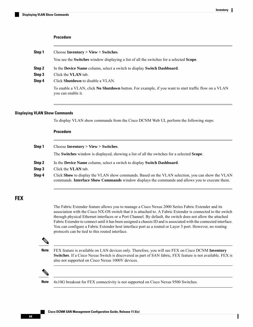
Procedure
Step 1 Choose Inventory > View > Switches.
You see the Switches window displaying a list of all the switches for a selected Scope.
Step 2 In the Device Name column, select a switch to display Switch Dashboard.Step 3 Click the VLAN tab.Step 4 Click Shutdown to disable a VLAN.
To enable a VLAN, click No Shutdown button. For example, if you want to start traffic flow on a VLANyou can enable it.
Displaying VLAN Show Commands
To display VLAN show commands from the Cisco DCNMWeb UI, perform the following steps:
Procedure
Step 1 Choose Inventory > View > Switches.
The Switches window is displayed, showing a list of all the switches for a selected Scope.
Step 2 In the Device Name column, select a switch to display Switch Dashboard.Step 3 Click the VLAN tab.Step 4 Click Show to display the VLAN show commands. Based on the VLAN selection, you can show the VLAN
commands. Interface Show Commands window displays the commands and allows you to execute them.
FEXThe Fabric Extender feature allows you to manage a Cisco Nexus 2000 Series Fabric Extender and itsassociation with the Cisco NX-OS switch that it is attached to. A Fabric Extender is connected to the switchthrough physical Ethernet interfaces or a Port Channel. By default, the switch does not allow the attachedFabric Extender to connect until it has been assigned a chassis ID and is associated with the connected interface.You can configure a Fabric Extender host interface port as a routed or Layer 3 port. However, no routingprotocols can be tied to this routed interface.
FEX feature is available on LAN devices only. Therefore, you will see FEX on Cisco DCNM InventorySwitches. If a Cisco Nexus Switch is discovered as part of SAN fabric, FEX feature is not available. FEX isalso not supported on Cisco Nexus 1000V devices.
Note
4x10G breakout for FEX connectivity is not supported on Cisco Nexus 9500 Switches.Note
Cisco DCNM SAN Management Configuration Guide, Release 11.5(x)64
InventoryDisplaying VLAN Show Commands

The Fabric Extender may connect to the switch through several separate physical Ethernet interfaces or atmost one port channel interface.
Note
This section describes how tomanage Fabric Extender (FEX) on Cisco Nexus Switches through Cisco DCNM.
You can create and manage FEX from Cisco DCNM Inventory > Switches.
FEX tab is visible only if you choose a LAN device.Note
The following table describes the fields that appear on this page.
Table 4: FEX Operations
DescriptionField
Click to add a new FEX to a Cisco Nexus Switch.Add
Select any active FEX radio button and click Edit to edit the FEXconfiguration.
You can create an edit template and use it for editing FEX. Select templatetype as POLICY and sub type as FEX.
Edit
Select the FEX radio button, and click Delete icon to delete the FEXassociated with the switch.
Delete
Allows you to view various configuration details for the selected FEXID. You can select the following from the drop-down list.
• show_diagnostic
• show_fex
• show_fex_detail
• show_fex_fabric
• show_fex_inventory
• show_fex_module
The variables for respective show commands are displayed in theVariables area. Review the Variables and click Execute. The outputappears in the Output area.
You can create a show template for FEX. Select template type as SHOWand sub type as FEX.
Show
Allows you to view the history of the FEX configuration tasks for aparticular FEX. You can review the Event Type, Policy Name, Status,Time of Execution, User Name for the selected FEX.
FEX History
Cisco DCNM SAN Management Configuration Guide, Release 11.5(x)65
InventoryFEX

Table 5: FEX Field and Description
DescriptionField
Uniquely identifies a Fabric Extender that is connected to a Cisco NX-OSdevice.
Fex Id
Description that is configured for the Fabric Extender.Fex Description
Specifies the version of the FEX that is associated with the switch.Fex Version
An integer value that denotes the maximum pinning uplinks of the FabricExtender that is active at a time.
Pinning
Specifies the status of the FEX as associated with the Cisco Nexus Switch.State
Specifies the model of the FEX.Model
Specifies the configured serial number.
If this configured serial number and the serial number of theFabric Extender are not the same, the Fabric Extender will notbe active.
Note
Serial No.
Specifies the port channel number to which the FEX is physicallyconnected to the Switch.
Port Channel
Refers to the physical interfaces to which the FEX is connected.Ethernet
Specifies the vPC ID configured for FEX.vPC ID
This chapter includes the following sections:
Add FEX
To add single-home FEX from the Cisco DCNMWeb UI, perform the following steps:
Before you begin
You can add a Fabric Extender (FEX) to the Cisco Nexus Switches through the Cisco DCNMWeb Client. Ifthe FEX is physically connected to the switch, FEX will become online after it is added. If the FEX is notphysically connected to the switch, the configuration is deployed to the switch, which in turn enables FEXwhen connected.
You can create only single homed FEX through Inventory > Switches > FEX > Add FEX. To create adual-homed FEX, use the vPC wizard through Configure > Deploy > vPC.
Note
Ensure that you have successfully discovered LAN devices and configured LAN credentials before youconfigure FEX.
Cisco DCNM SAN Management Configuration Guide, Release 11.5(x)66
InventoryAdd FEX

Procedure
Step 1 Choose Inventory > Switches > FEX.
The FEX window is displayed.
Step 2 Click the Add FEX icon.Step 3 In the General tab, in the PORTCHANNEL field, enter the interface port channel number which is connected
to the FEX.Step 4 In the INT_RANGE field, enter the interface range within which the FEX is connected to the switch.
Do not enter the interface range, if the interfaces are already a part of port channel.Note
Step 5 In the FEX_ID field, enter the ID for FEX that is connected to a Cisco NX-OS device.
The identifier must be an integer value between 100 to 199.
Step 6 Click Add.
The configured Single-home FEX appears in the list of FEXs associated to the device.
Edit FEX
To edit and deploy FEX from the Cisco DCNMWeb UI, perform the following steps:
Procedure
Step 1 Choose Inventory > Switches > FEX.
The FEX window is displayed.
Step 2 Select the FEX radio button that you must edit. Click Edit FEX icon.Step 3 In the Edit Configuration window, from the Policy drop-down list, select Edit_FEX to edit the FEX
configuration.Step 4 Edit the pinning and FEX_DESC fields, as required.
If you initially configured port 33 on the parent switch as your only fabric interface, all 48 hostinterfaces are pinned to this port. If you provision another port, for example 35, then you mustperform this procedure to redistribute the host interfaces. All host interfaces are brought down andhost interfaces 1 to 24 are pinned to fabric interface 33 and host interfaces 25 to 48 are pinned tofabric interface 35.
Note
Step 5 Click Preview.
You can view the generated configuration for the selected FEX ID. The following is a configuration examplefor FEX ID 101.fex 101pinning max-links 1description test
Cisco DCNM SAN Management Configuration Guide, Release 11.5(x)67
InventoryEdit FEX
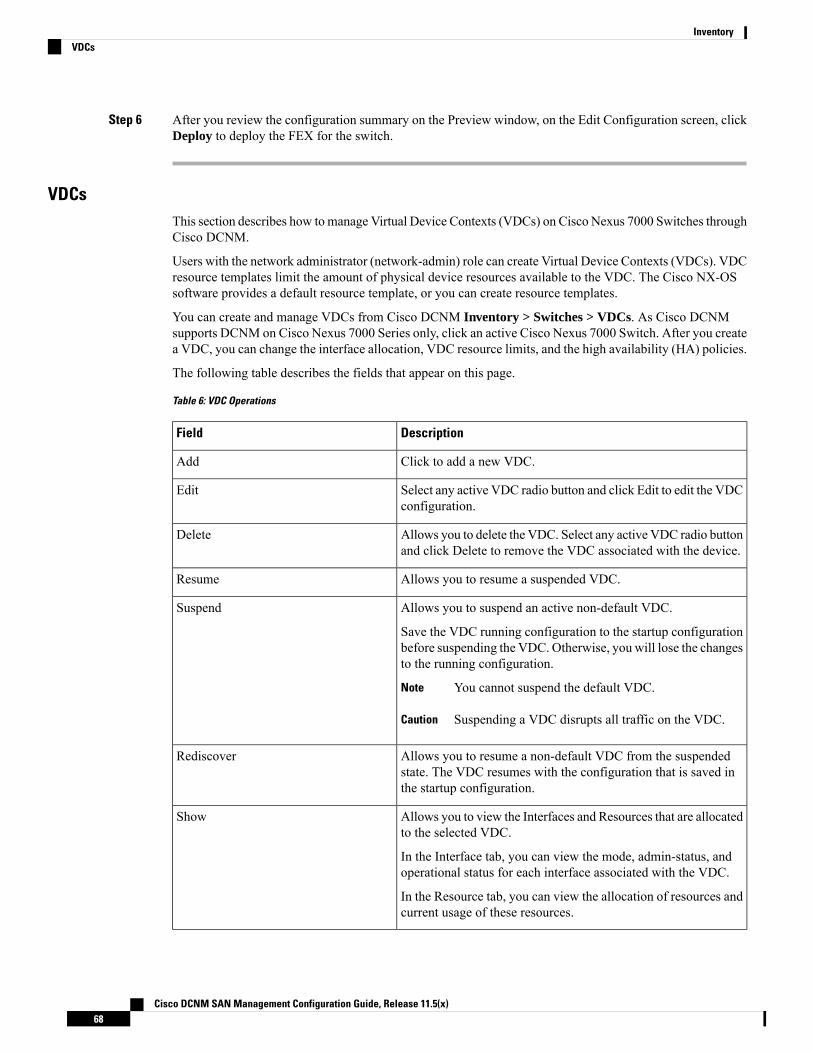
Step 6 After you review the configuration summary on the Preview window, on the Edit Configuration screen, clickDeploy to deploy the FEX for the switch.
VDCsThis section describes how tomanage Virtual Device Contexts (VDCs) on Cisco Nexus 7000 Switches throughCisco DCNM.
Users with the network administrator (network-admin) role can create Virtual Device Contexts (VDCs). VDCresource templates limit the amount of physical device resources available to the VDC. The Cisco NX-OSsoftware provides a default resource template, or you can create resource templates.
You can create and manage VDCs from Cisco DCNM Inventory > Switches > VDCs. As Cisco DCNMsupports DCNM on Cisco Nexus 7000 Series only, click an active Cisco Nexus 7000 Switch. After you createa VDC, you can change the interface allocation, VDC resource limits, and the high availability (HA) policies.
The following table describes the fields that appear on this page.
Table 6: VDC Operations
DescriptionField
Click to add a new VDC.Add
Select any active VDC radio button and click Edit to edit the VDCconfiguration.
Edit
Allows you to delete the VDC. Select any active VDC radio buttonand click Delete to remove the VDC associated with the device.
Delete
Allows you to resume a suspended VDC.Resume
Allows you to suspend an active non-default VDC.
Save the VDC running configuration to the startup configurationbefore suspending the VDC. Otherwise, you will lose the changesto the running configuration.
You cannot suspend the default VDC.Note
Suspending a VDC disrupts all traffic on the VDC.Caution
Suspend
Allows you to resume a non-default VDC from the suspendedstate. The VDC resumes with the configuration that is saved inthe startup configuration.
Rediscover
Allows you to view the Interfaces and Resources that are allocatedto the selected VDC.
In the Interface tab, you can view the mode, admin-status, andoperational status for each interface associated with the VDC.
In the Resource tab, you can view the allocation of resources andcurrent usage of these resources.
Show
Cisco DCNM SAN Management Configuration Guide, Release 11.5(x)68
InventoryVDCs
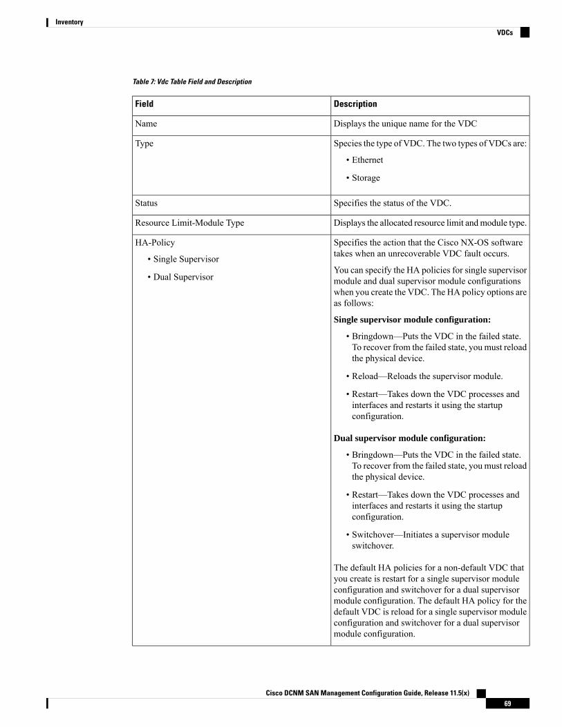
Table 7: Vdc Table Field and Description
DescriptionField
Displays the unique name for the VDCName
Species the type of VDC. The two types of VDCs are:
• Ethernet
• Storage
Type
Specifies the status of the VDC.Status
Displays the allocated resource limit andmodule type.Resource Limit-Module Type
Specifies the action that the Cisco NX-OS softwaretakes when an unrecoverable VDC fault occurs.
You can specify the HA policies for single supervisormodule and dual supervisor module configurationswhen you create the VDC. The HA policy options areas follows:
Single supervisor module configuration:
• Bringdown—Puts the VDC in the failed state.To recover from the failed state, you must reloadthe physical device.
• Reload—Reloads the supervisor module.
• Restart—Takes down the VDC processes andinterfaces and restarts it using the startupconfiguration.
Dual supervisor module configuration:
• Bringdown—Puts the VDC in the failed state.To recover from the failed state, you must reloadthe physical device.
• Restart—Takes down the VDC processes andinterfaces and restarts it using the startupconfiguration.
• Switchover—Initiates a supervisor moduleswitchover.
The default HA policies for a non-default VDC thatyou create is restart for a single supervisor moduleconfiguration and switchover for a dual supervisormodule configuration. The default HA policy for thedefault VDC is reload for a single supervisor moduleconfiguration and switchover for a dual supervisormodule configuration.
HA-Policy
• Single Supervisor
• Dual Supervisor
Cisco DCNM SAN Management Configuration Guide, Release 11.5(x)69
InventoryVDCs
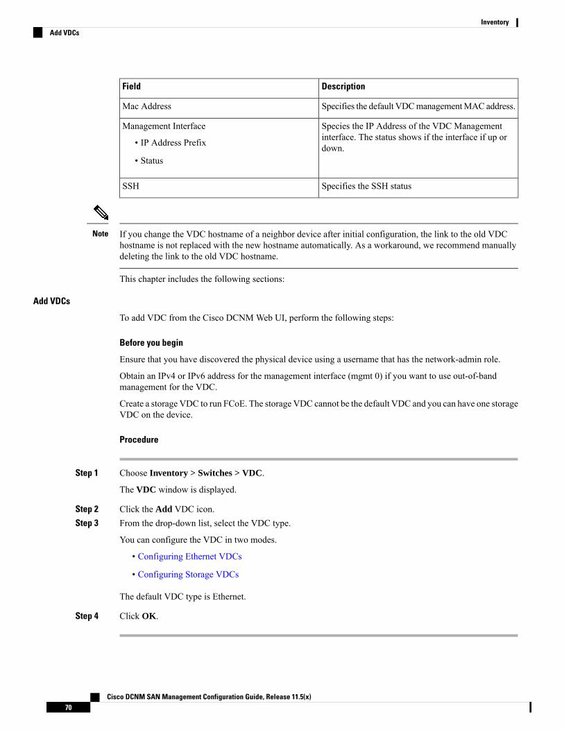
DescriptionField
Specifies the default VDCmanagementMAC address.Mac Address
Species the IP Address of the VDC Managementinterface. The status shows if the interface if up ordown.
Management Interface
• IP Address Prefix
• Status
Specifies the SSH statusSSH
If you change the VDC hostname of a neighbor device after initial configuration, the link to the old VDChostname is not replaced with the new hostname automatically. As a workaround, we recommend manuallydeleting the link to the old VDC hostname.
Note
This chapter includes the following sections:
Add VDCs
To add VDC from the Cisco DCNMWeb UI, perform the following steps:
Before you begin
Ensure that you have discovered the physical device using a username that has the network-admin role.
Obtain an IPv4 or IPv6 address for the management interface (mgmt 0) if you want to use out-of-bandmanagement for the VDC.
Create a storage VDC to run FCoE. The storage VDC cannot be the default VDC and you can have one storageVDC on the device.
Procedure
Step 1 Choose Inventory > Switches > VDC.
The VDC window is displayed.
Step 2 Click the Add VDC icon.Step 3 From the drop-down list, select the VDC type.
You can configure the VDC in two modes.
• Configuring Ethernet VDCs
• Configuring Storage VDCs
The default VDC type is Ethernet.
Step 4 Click OK.
Cisco DCNM SAN Management Configuration Guide, Release 11.5(x)70
InventoryAdd VDCs

Configuring Ethernet VDCs
To configure VDC in Ethernet mode from the Cisco DCNMWeb UI, perform the following steps:
Procedure
Step 1 In the General Parameter tab, specify the VDC Name, Single supervisor HA-policy, Dual supervisorHA-policy, and Resource Limit - Module Type.
Step 2 In the Allocate Interface tab, select the network interfaces (dedicated interfaces membership) to be allocatedto the VDC.
Click Next.
Step 3 In the Allocate Resource tab, specify the resource limits for the VDC.
Select the radio button and choose Select a Template from existing Templates or Create a New ResourceTemplate. VDC resource templates describe the minimum and maximum resources that the VDC can use.If you do not specify a VDC resource template when you create a VDC, the Cisco NX-OS software uses thedefault template, vdc-default.
• If you choose Select a Template from existing Templates, from the Template Name drop-down list, youcan select None, global-default, or vdc-default.
The template resource limits are detailed in the following below:
Table 8: Template Resource Limits
MaximumMinimumResource
Global Default VDC Template Resource Limits
Anycast Bundled
8
Route memory is in megabytes.
8IPv6 multicast route memory
4848IPv4 multicast route memory
3232IPv6 unicast route memory
IPv4 unicast route memory
VDC Default Template Resource Limits
Monitor session extended
Monitor session mx exception
Monitor SRC INBAND
Port Channels
Monitor DST ERSPAN
SPAN Sessions
Cisco DCNM SAN Management Configuration Guide, Release 11.5(x)71
InventoryConfiguring Ethernet VDCs
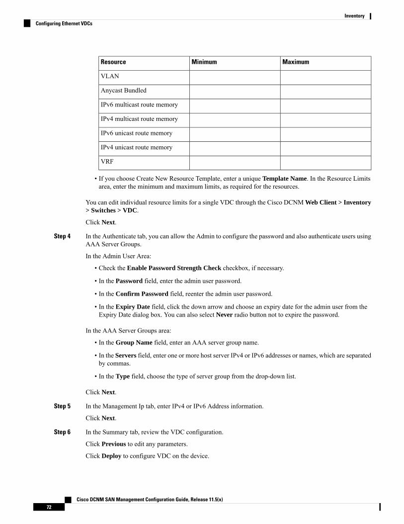
MaximumMinimumResource
VLAN
Anycast Bundled
IPv6 multicast route memory
IPv4 multicast route memory
IPv6 unicast route memory
IPv4 unicast route memory
VRF
• If you choose Create New Resource Template, enter a unique Template Name. In the Resource Limitsarea, enter the minimum and maximum limits, as required for the resources.
You can edit individual resource limits for a single VDC through the Cisco DCNM Web Client > Inventory> Switches > VDC.
Click Next.
Step 4 In the Authenticate tab, you can allow the Admin to configure the password and also authenticate users usingAAA Server Groups.
In the Admin User Area:
• Check the Enable Password Strength Check checkbox, if necessary.
• In the Password field, enter the admin user password.
• In the Confirm Password field, reenter the admin user password.
• In the Expiry Date field, click the down arrow and choose an expiry date for the admin user from theExpiry Date dialog box. You can also select Never radio button not to expire the password.
In the AAA Server Groups area:
• In the Group Name field, enter an AAA server group name.
• In the Servers field, enter one or more host server IPv4 or IPv6 addresses or names, which are separatedby commas.
• In the Type field, choose the type of server group from the drop-down list.
Click Next.
Step 5 In the Management Ip tab, enter IPv4 or IPv6 Address information.
Click Next.
Step 6 In the Summary tab, review the VDC configuration.
Click Previous to edit any parameters.
Click Deploy to configure VDC on the device.
Cisco DCNM SAN Management Configuration Guide, Release 11.5(x)72
InventoryConfiguring Ethernet VDCs
Step 7 In the Deploy tab, the status of the VDC deployment is displayed.
A confirmation message appears. Click Know More to view the commands that are executed to deploy theVDC.
Click Finish to close the VDC configuration wizard and revert to view the list of VDCs configured on thedevice.
Configuring Storage VDCs
To configure VDCs in storage mode from the Cisco DCNMWeb UI, perform the following steps:
Before you begin
Create a separate storage VDC when you run FCoE on the device. Only one of the VDCs can be a storageVDC, and the default VDC cannot be configured as a storage VDC.
You can configure shared interfaces that carry both Ethernet and Fibre Channel traffic. In this specific case,the same interface belongs to more than one VDC. The shared interface is allocated to both an Ethernet anda storage VDC.
Procedure
Step 1 In the General Parameter tab, specify the VDC Name, Single supervisor HA-policy, Dual supervisorHA-policy, and Resource Limit - Module Type.
Step 2 In the Allocate FCoE Vlan tab, select the available Ethernet Vdc from the drop-down list.
The existing Ethernet VLANs range is displayed. Select None not to choose any available Ethernet VDCs.
You can allocate specified FCoE VLANs to the storage VDC and specified interfaces.
Click Next.
Step 3 In the Allocate Interface tab, add the dedicated and shared interfaces to the FCoE VDC.
The dedicated interface carries only FCoE traffic and the shared interface carries both the Ethernetand the FCoE traffic.
Note
You can configure shared interfaces that carry both Ethernet and Fibre Channel traffic. In this specific case,the same interface belongs to more than one VDC. FCoE VLAN and shared interface can be allocated fromsame Ethernet VDC.
Click Next.
Step 4 In the Authenticate tab, you can allow the Admin to configure the password and also authenticate users usingAAA Server Groups.
In the Admin User Area:
• Check the Enable Password Strength Check checkbox, if necessary.
• In the Password field, enter the admin user password.
• In the Confirm Password field, reenter the admin user password.
Cisco DCNM SAN Management Configuration Guide, Release 11.5(x)73
InventoryConfiguring Storage VDCs

• In the Expiry Date field, click the down arrow and choose an expiry date for the admin user from theExpiry Date dialog box. You can also select Never radio button not to expire the password.
In the AAA Server Groups area:
• In the Group Name field, enter an AAA server group name.
• In the Servers field, enter one or more host server IPv4 or IPv6 addresses or names, which are separatedby commas.
• In the Type field, choose the type of server group from the drop-down list.
Click Next.
Step 5 In the Management Ip tab, enter IPv4 or IPv6 Address information.
Click Next.
Step 6 In the Summary tab, review the VDC configuration.
Click Previous to edit any parameters.
Click Deploy to configure VDC on the device.
Step 7 In the Deploy tab, the status of the VDC deployment is displayed.
A confirmation message appears. Click Know More to view the commands that are executed to deploy theVDC.
Click Finish to close the VDC configuration wizard and revert to view the list of VDCs configured on thedevice.
Edit VDC
To edit VDC from the Cisco DCNMWeb UI, perform the following steps:
Procedure
Step 1 Choose Inventory > Switches > VDC.
The VDC window is displayed.
Step 2 Select the VDC radio button that you must edit. Click the Edit VDC icon.Step 3 Modify the parameters as required.Step 4 After you review the configuration summary on the Summary tab, click Deploy the VDC with the new
configuration.
Viewing Inventory Information for ModulesTo view the inventory information for modules from the Cisco DCNMWeb UI, perform the following steps:
Cisco DCNM SAN Management Configuration Guide, Release 11.5(x)74
InventoryEdit VDC
Procedure
Step 1 Choose Inventory > View > Modules.
The Modules window is displayed with a list of all the switches and its details for a selected Scope.
Step 2 You can view the following information.
• Group column displays the group name of the module.
• Switch column displays the switch name on which the module is discovered.
• Name displays the module name.
• ModelName displays the model name.
• SerialNum column displays the serial number.
• 2nd SerialNum column displays the second serial number.
• Type column displays the type of the module.
• Slot column displays the slot number.
• Hardware Revision column displays the hardware version of the module.
• Software Revision column displays the software version of the module.
• Asset ID column displays the asset id of the module.
• OperStatus column displays the operation status of the module.
• IO FPGA column displays the IO field programmable gate arrays (FPGA) version.
• MI FPGA column displays the MI field programmable gate arrays (FPGA) version.
Viewing Inventory Information for LicensesTo view the inventory information for licenses from the Cisco DCNMWeb UI, perform the following steps:
Procedure
Step 1 Choose Inventory > View > Licenses.
The Licenses window is displayed based on the selected Scope.
Step 2 You can view the following information.
• Group column displays the group name of switches.
• Switch column displays the switch name on which the feature is enabled.
• Feature displays the installed feature.
Cisco DCNM SAN Management Configuration Guide, Release 11.5(x)75
InventoryViewing Inventory Information for Licenses

• Status displays the usage status of the license.
• Type column displays the type of the license.
• Warnings column displays the warning message.
DiscoveryStarting from Cisco DCNM release 10.x, Cisco DCNMWeb Client allows the admin to associate user toone or more device scope or group. That means you can only access and configure the associated group orscope devices based on Role Based Access Control (RBAC). Though you might not have the access to otherusers' associated devices, you can still see all the discovered devices under the Inventory > Discovery tab.
From the left menu bar, go to Administration > Management Users. You can create users and associategroups, manage remote authentication, and see all the connected clients. For more information about RBAC,navigate to Managing Local Users.
Adding, Editing, Re-Discovering, Purging and Removing LAN, LAN Tasks andSwitch
Cisco DCNMWeb Client reports information that is obtained by the Cisco DCNM-LAN devices.
If the discovered Device is not in the scope of the current user the check box for the LAN Device in the LANtable grays out.
Tip
This section contains the following:
Adding LAN SwitchesTo add LAN switches from the Cisco DCNMWeb UI, perform the following steps.
For any switch to be successfully imported into DCNM, the user defined on the switch via local or remoteAAA, and used for import into DCNM should have the following permissions:
• SSH access to the switch
• Ability to perform SNMPv3 queries
• Ability to run show commands
Procedure
Step 1 Choose Inventory > Discovery > LAN Switches.
You see the list of LAN devices in the Switch column.
Step 2 Click the Add icon to add LAN.
Cisco DCNM SAN Management Configuration Guide, Release 11.5(x)76
InventoryDiscovery

You see the Add LAN Devicesdialog box.
Step 3 Select Hops from seed Switch or Switch List. The fields vary depending on your selection.Step 4 Enter the Seed Switch IP address for the fabric.
For LAN Switches Discovery, DCNM allow both IPv4 and IPv6 address for the Seed Switch.
Step 5 The options vary depending on the discovery type selected. For example, if you check Use SNMPv3/SSH,varied fields are displayed.
Step 6 Click the drop-down list and choose Auth-Privacy security level.Step 7 Enter the Community, or user credentials.Step 8 Select the LAN group from the LAN groups candidates which is in the scope of the current user.
Select DCNM server and click Add to add LAN switches.Note
Step 9 Click Next to begin the shallow discovery.Step 10 In the LAN Discovery window, you can select all switches by using the checkbox next to the switch name
column or select individual switches. Click Previous to go back and edit the parameters.
.
• In the Status column, if the switch status is timeout or Cannot be contacted, these switchescannot be added. Only the switches that are reachable and not managed yet are available toselect. The checkbox is disabled for the switches that are not available
• When you add or discover LAN devices in DCNM, java is used as a part of the discoveryprocess. If firewall blocks the process then it uses TCP connection port 7 as a discovery process.Ensure that the cdp.discoverPingDisable server property is set to true. Choose Web UI >Administration > DCNM Server > Server Properties to set the server property.
Note
Step 11 Select a switch and click Add to add a switch to the switch group.
If one of more seed switches is not reachable, it is shown as “unknown” on the shallow Discovery window.
Editing LAN DevicesTo edit LAN devices from the Cisco DCNMWeb UI, perform the following steps:
Procedure
Step 1 Choose Inventory > Discovery > LAN Switches.Step 2 Select the check box next to the LAN that you want to edit and click Edit icon.
You see the Edit LAN dialog box.
Step 3 Enter the Username and Password.
Select Credential or Management State to change the Credential or Management state. IfCredential is selected, you can change the SNMP version and Auth-Privacy if v3, username orpassword. If Management State is selected, you can change the status to managed or unmanaged.
Note
Cisco DCNM SAN Management Configuration Guide, Release 11.5(x)77
InventoryEditing LAN Devices

Step 4 Select the LAN status as Managed or Unmanaged.Step 5 Click Apply to save the changes.
Removing LAN Devices from Cisco DCNMYou can remove a LAN switch from Cisco DCNM.
Procedure
Step 1 Choose Inventory > Discovery > LAN Switches.Step 2 Select the check box next to the LAN that you want to remove and click Delete to remove the switches and
all their data.Step 3 Click Yes to review the LAN device.
Moving LAN Devices Under a TaskYou can move LAN devices under a task to a different server using Cisco DCNMWeb Client. This featureis available only in the federation setup and the Move LAN is displayed in the federation setup screen.
You can move the LAN from a server, which is down, to an active server. The management state remains thesame.
Procedure
Step 1 Choose Inventory > Discovery > LAN Switches.Step 2 Choose the LAN devices from the LAN table. Click Move.Step 3 In the Move LAN Tasks to another DCNM Server dialog box, enter the LAN Device to be moved and
specify the DCNM server.
All the LAN devices under the selected tasks will be moved.
Rediscover LAN Task
Procedure
Step 1 Choose Inventory > Discovery > LAN Switches.Step 2 Click Rediscover LAN.Step 3 Click Yes in the pop-up window to rediscover the LAN.
Cisco DCNM SAN Management Configuration Guide, Release 11.5(x)78
InventoryRemoving LAN Devices from Cisco DCNM

Adding, Editing, Re-Discovering, Purging and Removing the Managed FabricsCisco DCNM reports information that is obtained by the Cisco DCNM-SAN on any fabric known to CiscoDCNM-SAN. To view the SAN Switches, choose Inventory > Discovery > SAN Switches.
The Status column of the SAN Switches page displays the fabric status.
• managedContinuously—The fabric is automatically managed when the Cisco DCNM-SAN server startsand continues to be managed until this option is changed to Unmanage.
• managed—The fabric is managed by Cisco DCNM-SAN Server until there are no instances ofDCNM-SAN viewing the fabric.
• unmanaged—Cisco DCNM-SAN Server stops managing this fabric.
This section contains the following:
Adding a Fabric
Before you begin
Before you discover a new fabric, ensure that you create an SNMP user on the switch.
Procedure
Step 1 Choose Inventory > Discovery > SAN Switches.
The SAN Switches window is displayed with a list of fabrics, if any, managed by Cisco DCNM-SAN.
Step 2 Click Add to add a new fabric.
The Add Fabric window appears.
Step 3 Enter the Fabric Seed Switch IP address or DNS name for this fabric.Step 4 (Optional) Check the SNMP check box to use SNMPv3 or SSH. If you check the SNMP check box, the field
Community changes to Username and Password.Step 5 Enter the Username and Password for this fabric.Step 6 Select the privacy settings from the Auth-Privacy drop-down list.Step 7 (Optional) Check the Limit Discovery by VSAN check box to specify the included VSAN list or excluded
VSAN list from the VSANs provided to discover a new fabric.Step 8 (Optional) Check the Enable NPV Discovery in all Fabrics check box. If you check enable NPV discovery
in all fabrics, the changes are applied to all the fabrics that are previously discovered.Step 9 Click Options and specify the UCS Username and UCS Password.Step 10 Select a DCNM server from the DCNM Server drop-down list.
This option is applicable only for Federation setups.Note
Step 11 Click Add to begin managing this fabric.
You can remove single or multiple fabrics from the Cisco DCNMWeb Client.
Cisco DCNM SAN Management Configuration Guide, Release 11.5(x)79
InventoryAdding, Editing, Re-Discovering, Purging and Removing the Managed Fabrics
Deleting a Fabric
Procedure
Step 1 Choose Inventory > Discovery > SAN Switches.Step 2 Select the check box next to the fabric that you want to remove.Step 3 Click Delete to remove the fabric from the datasource and to discontinue data collection for that fabric.
Editing a FabricTo edit a fabric from the Cisco DCNMWeb UI, perform the following steps:
Procedure
Step 1 Choose Inventory > Discovery > SAN Switches.Step 2 Select the check box next to the fabric that you want to edit and click the Edit icon.
You see the Edit Fabric dialog box. You can edit only one fabric at a time.
Step 3 Enter a new fabric Name.Step 4 (Optional) Check the SNMPV3 check box. If you check SNMPV3, theCommunity field change toUsername
and Password.Step 5 Enter the Username and Password, privacy and specify how you want DCNMWeb Client to manage the
fabric by selecting one of the status options.Step 6 Change the fabric management state to Managed, Unmanaged, or Managed Continuously.Step 7 Click Apply to save the changes.Step 8 To modify the password, go to from the Cisco DCNMWeb UI, perform the following steps:
a) Choose Inventory > Discovery > SAN Switches.b) Select the fabric for which the fabric switch password is changed.c) Click Edit, unmanage the fabric, specify the new password, and then manage the fabric.
You will not be able to open the fabric as the new password is not be validated with the database.
You can go toAdministration > Credentials Management > SAN Credentials to validate the password.
Moving Fabrics to Another Server FederationThis feature is only available on the federation setup and the Move Fabric is only displayed in the federationsetup screen.
You can move the fabrics from a server, which is down, to an active server. The management state remainsthe same.
Cisco DCNM SAN Management Configuration Guide, Release 11.5(x)80
InventoryDeleting a Fabric
Procedure
Step 1 Choose Inventory > Discovery > SAN Switches.Step 2 Select the fabric(s) that you want to move to a different server, and then click Move.Step 3 In the Move Fabric dialog box, select the DCNM server where the fabrics will be moved.
The To DCNM Server drop-down list lists only the active servers.
The status of the Fabric will display Unmanaged for a few minutes, and displaysmanagedContinuously, later.
Note
Rediscovering a Fabric
Procedure
Step 1 Choose Inventory > Discovery > SAN Switches.Step 2 Select the check box next to the fabric and click Rediscover.Step 3 Click Yes in the pop-up window.
The Fabric is rediscovered.
Purging a FabricYou can clean and update the fabric discovery table through the Purge option.
Procedure
Step 1 Choose Inventory > Discovery > SAN Switches.Step 2 Select the check box next to the fabric and click Purge fabric icon.Step 3 Click Yes in the pop-up window.
The Fabric is purged.
UCS Fabric Interconnect IntegrationFrom Release 11.3(1), you can discover and manage UCS FI devices.
Enable Discovery
To allow Cisco DCNM to discover UCS FI server blade and service profile information, you must modifythe server.properties file.
Cisco DCNM SAN Management Configuration Guide, Release 11.5(x)81
InventoryRediscovering a Fabric

On the Cisco DCNMWeb UI, choose Administration > DCNM Server > Server Properties. Locate thefabric.enableUcsHttpDiscovery property. Ensure that this value is set to true.
Discovering UCS FI devices
From Release 11.3(1), Cisco DCNM can discover UCS FI server blade and service profile from the Web UI.
To discover UCS FI devices from the Cisco DCNMWeb UI, perform the following steps:
Procedure
Step 1 Choose Inventory > Discovery > SAN Switches.
The SAN Switches window displays list of fabrics, if any, managed by Cisco DCNM-SAN.
Step 2 Click Add (+) icon to add a new fabric.
The Add Fabric window appears.
Step 3 Enter the Fabric Seed Switch IP address or DNS name for this fabric.Step 4 (Optional) Check the SNMP check box to use SNMPv3 or SSH.
If you check the SNMP check box, the field Community changes to Username and Password.
Step 5 Enter the Username and Password for this fabric.Step 6 Select the privacy settings from the Auth-Privacy drop-down list.Step 7 (Optional) Check the Limit Discovery by VSAN check box to specify the included VSAN list or excluded
VSAN list from the VSANs provided to discover a new fabric.Step 8 (Optional) Check the Enable NPV Discovery in all Fabrics check box.
If you check enable NPV discovery in all fabrics, the changes are applied to all the fabrics that are previouslydiscovered.
By default, the Cisco UCS FI is in NPVmode. Therefore, we recommend that you check theEnableNPV Discovery in All Fabrics check box.
Note
Step 9 Click Options and specify the UCS Username and UCS Password.
Username and password is the SNMP credential; while, UCS User Name and password is the UCSFI CLI admin credential.
Note
Step 10 Select a DCNM server from the DCNM Server drop-down list.
This option is applicable only for Federation setups.
Step 11 Click Add to begin managing this fabric.
You can remove single or multiple fabrics from the Cisco DCNMWeb Client.
UCS FI prohibits using SNMP user admin.Note
Cisco DCNM SAN Management Configuration Guide, Release 11.5(x)82
InventoryDiscovering UCS FI devices
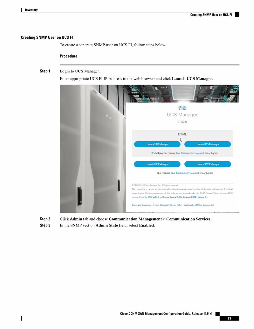
Creating SNMP User on UCS FI
To create a separate SNMP user on UCS FI, follow steps below.
Procedure
Step 1 Login to UCS Manager.
Enter appropriate UCS FI IP Address to the web browser and click Launch UCS Manager.
Step 2 Click Admin tab and choose Communication Management > Communication Services.Step 3 In the SNMP section Admin State field, select Enabled.
Cisco DCNM SAN Management Configuration Guide, Release 11.5(x)83
InventoryCreating SNMP User on UCS FI
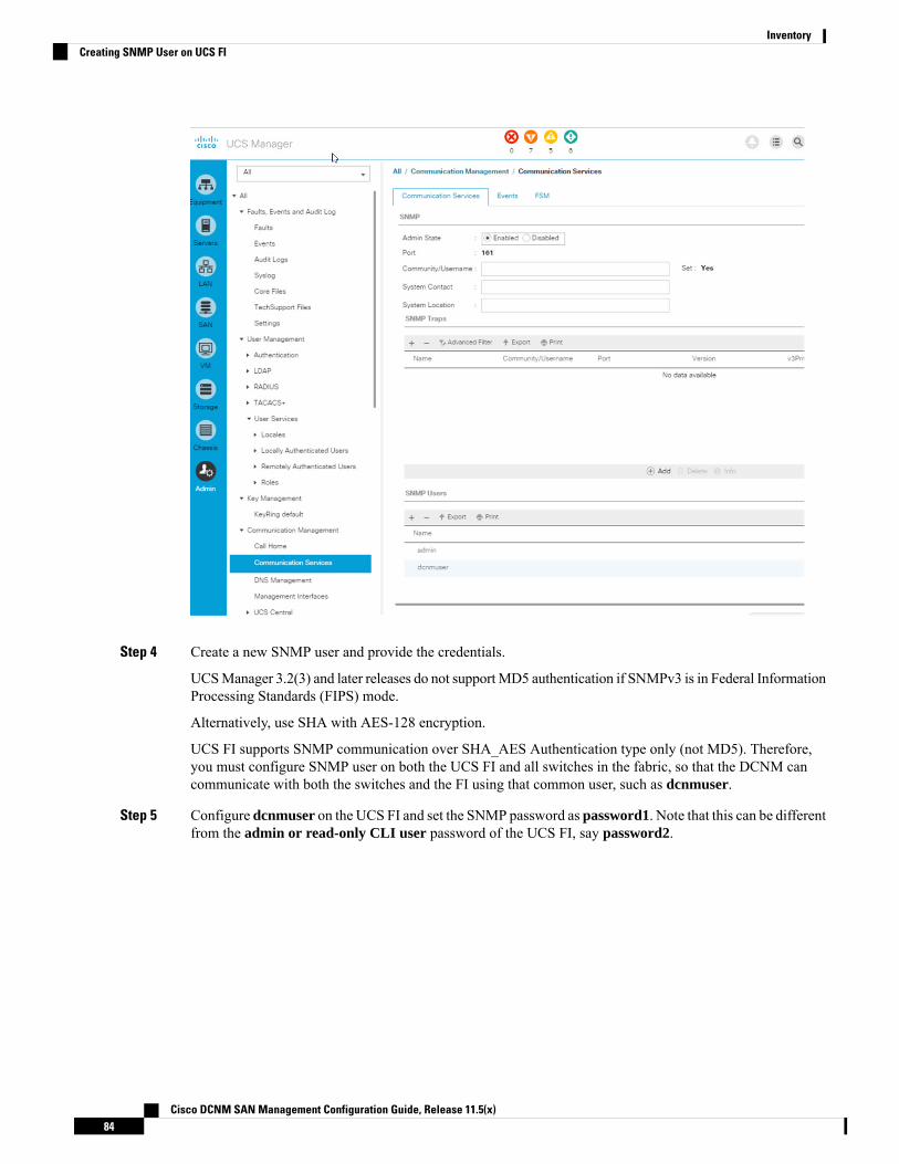
Step 4 Create a new SNMP user and provide the credentials.
UCSManager 3.2(3) and later releases do not supportMD5 authentication if SNMPv3 is in Federal InformationProcessing Standards (FIPS) mode.
Alternatively, use SHA with AES-128 encryption.
UCS FI supports SNMP communication over SHA_AES Authentication type only (not MD5). Therefore,you must configure SNMP user on both the UCS FI and all switches in the fabric, so that the DCNM cancommunicate with both the switches and the FI using that common user, such as dcnmuser.
Step 5 Configure dcnmuser on the UCS FI and set the SNMP password as password1. Note that this can be differentfrom the admin or read-only CLI user password of the UCS FI, say password2.
Cisco DCNM SAN Management Configuration Guide, Release 11.5(x)84
InventoryCreating SNMP User on UCS FI
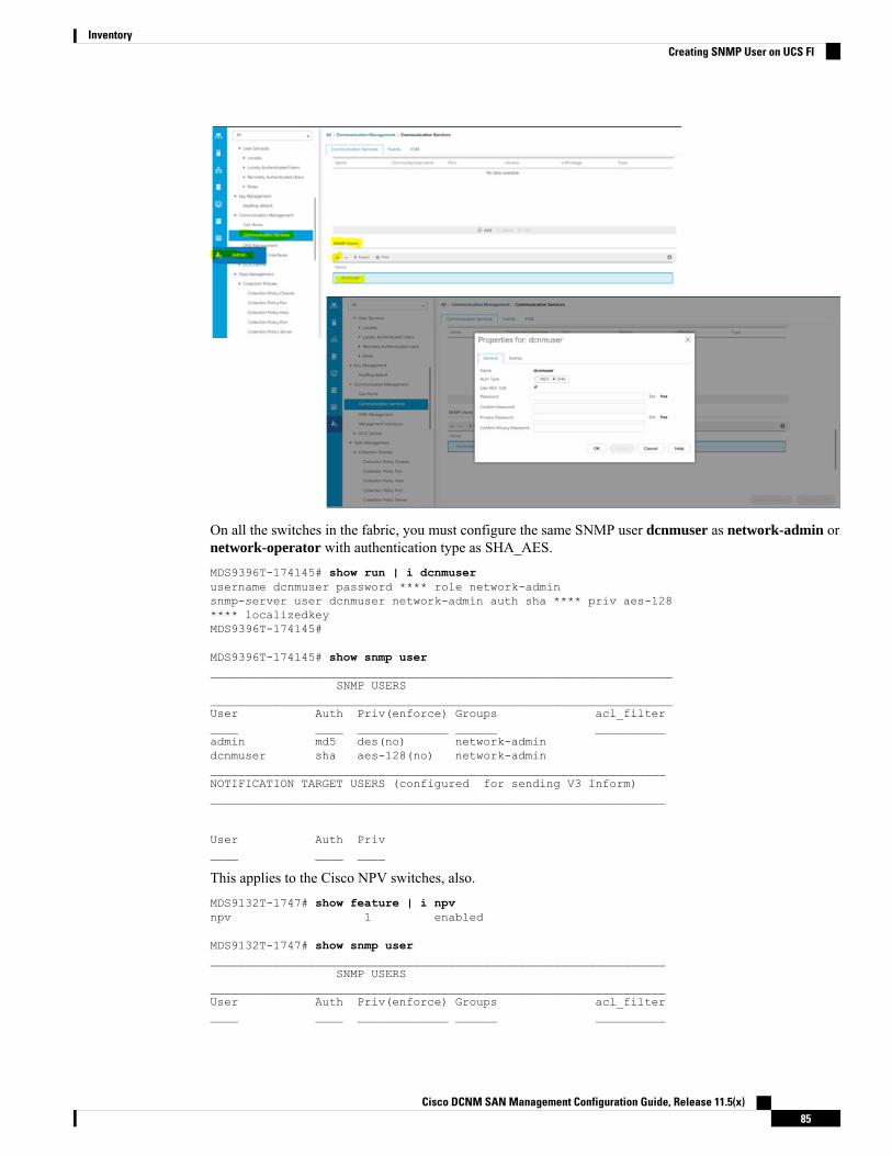
On all the switches in the fabric, you must configure the same SNMP user dcnmuser as network-admin ornetwork-operator with authentication type as SHA_AES.MDS9396T-174145# show run | i dcnmuserusername dcnmuser password **** role network-adminsnmp-server user dcnmuser network-admin auth sha **** priv aes-128**** localizedkeyMDS9396T-174145#
MDS9396T-174145# show snmp user__________________________________________________________________
SNMP USERS__________________________________________________________________User Auth Priv(enforce) Groups acl_filter____ ____ _____________ ______ __________admin md5 des(no) network-admindcnmuser sha aes-128(no) network-admin_________________________________________________________________NOTIFICATION TARGET USERS (configured for sending V3 Inform)_________________________________________________________________
User Auth Priv____ ____ ____
This applies to the Cisco NPV switches, also.MDS9132T-1747# show feature | i npvnpv 1 enabled
MDS9132T-1747# show snmp user_________________________________________________________________
SNMP USERS_________________________________________________________________User Auth Priv(enforce) Groups acl_filter____ ____ _____________ ______ __________
Cisco DCNM SAN Management Configuration Guide, Release 11.5(x)85
InventoryCreating SNMP User on UCS FI

admin md5 des(no) network-admindcnmuser sha aes-128(no) network-admin network-operator_________________________________________________________________NOTIFICATION TARGET USERS (configured for sending V3 Inform)_________________________________________________________________
User Auth Priv____ ____ ____
Step 6 After the USC FI and the switches are accessible using te same credentials, username: dcnmuser and password:password1, you can discover the Fabric.
Choose Inventory > Discovery > SAN Switches, to discover the Fabric.
Note that you must use username: admin or read-only CLI username and password: password2 for UCSFI.
Step 7 Verify if the UCF FI switches are listed on Cisco DCNM Web UI > Inventory > Switches.
Ensure that the status of these switches are correct.
Viewing the UCS FI Switches in the Inventory
You can view the interfaces of the UCSFI switches through Inventory > Switches > UCSFI > Interfaces,on the Cisco DCNMWeb Client.
The Interfaces tab shows the UCS FI interfaces and the Server Blades that they connect to.
Cisco DCNM SAN Management Configuration Guide, Release 11.5(x)86
InventoryViewing the UCS FI Switches in the Inventory

Click on the chart icon under Name column to view the 24 hour traffic data for that port.
System Info tab displays the corresponding Primary UCS FI IP for the Secondary UCS FI.
Blades tab displays information of all server blades attached to the UCS FI. Primary UCS FI only in redundancysetup or standalone UCS FI are displayed.
Cisco DCNM SAN Management Configuration Guide, Release 11.5(x)87
InventoryViewing the UCS FI Switches in the Inventory

vHBAs tab displays the list of vHBA for that particular UCS FI. Click the chart icon to view 24hour trafficfor the vHBA.
Cisco DCNM SAN Management Configuration Guide, Release 11.5(x)88
InventoryViewing the UCS FI Switches in the Inventory
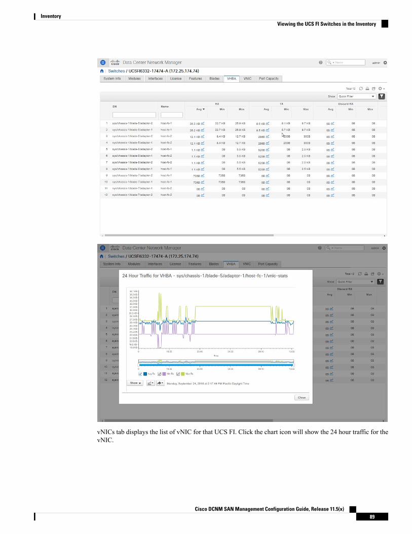
vNICs tab displays the list of vNIC for that UCS FI. Click the chart icon will show the 24 hour traffic for thevNIC.
Cisco DCNM SAN Management Configuration Guide, Release 11.5(x)89
InventoryViewing the UCS FI Switches in the Inventory
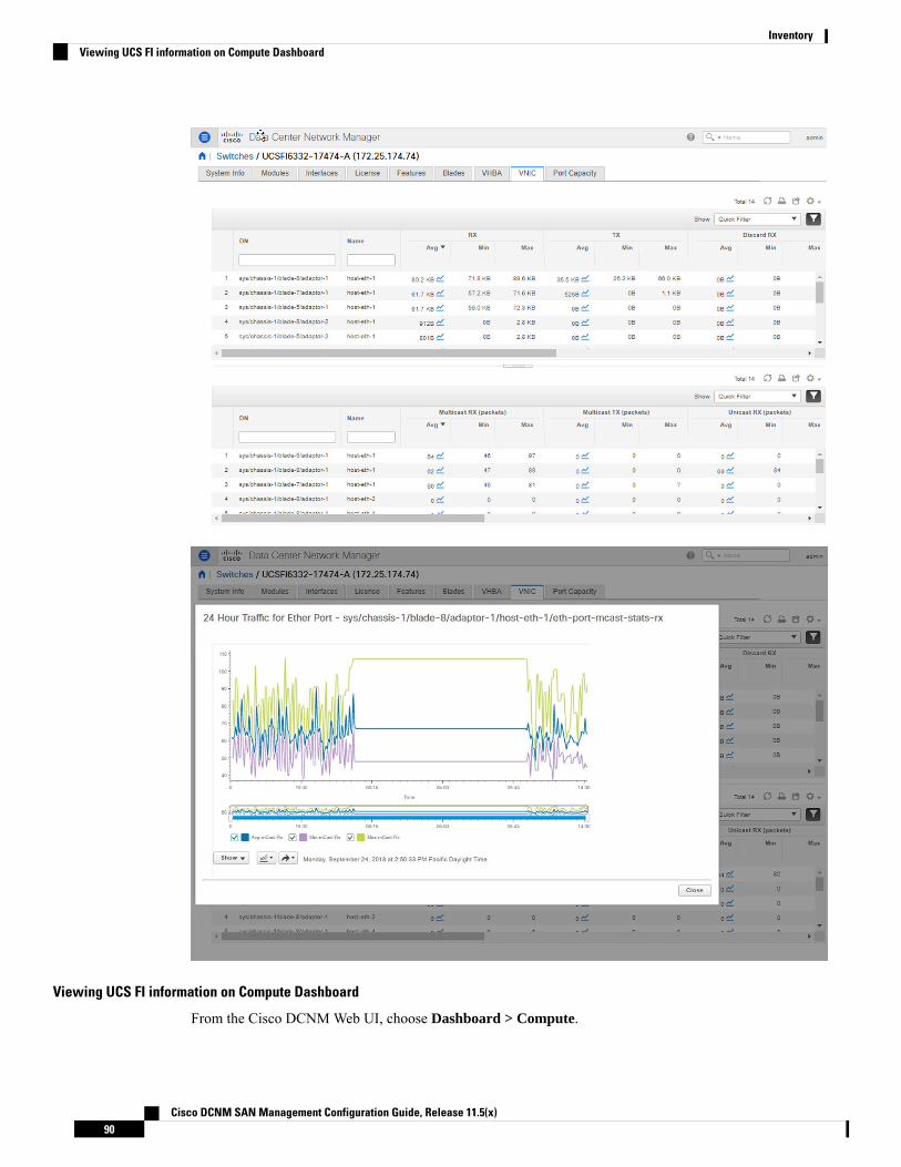
Viewing UCS FI information on Compute Dashboard
From the Cisco DCNMWeb UI, choose Dashboard > Compute.
Cisco DCNM SAN Management Configuration Guide, Release 11.5(x)90
InventoryViewing UCS FI information on Compute Dashboard

Click on the details for Host Enclosure connecting to the UCS FIs to view the topology, the Server Bladeinformation and its service profile.
To view the Blade and Service Profile information, hover over the host enclosure in the topology.
Cisco DCNM SAN Management Configuration Guide, Release 11.5(x)91
InventoryViewing UCS FI information on Compute Dashboard
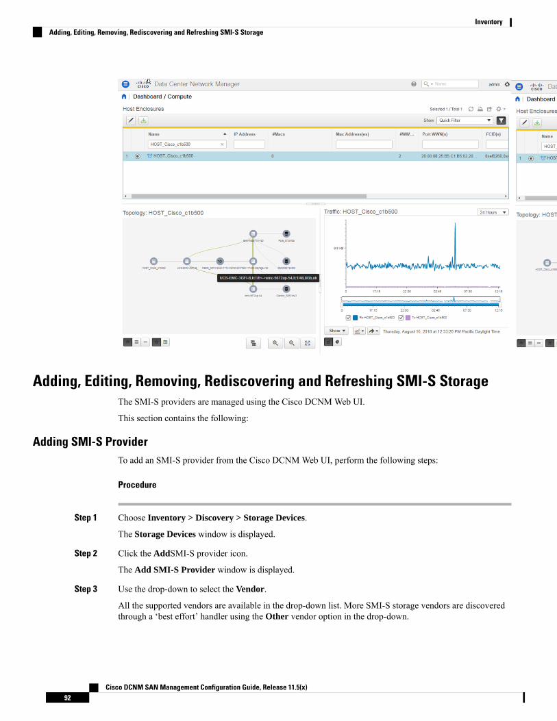
Adding, Editing, Removing, Rediscovering and Refreshing SMI-S StorageThe SMI-S providers are managed using the Cisco DCNMWeb UI.
This section contains the following:
Adding SMI-S ProviderTo add an SMI-S provider from the Cisco DCNMWeb UI, perform the following steps:
Procedure
Step 1 Choose Inventory > Discovery > Storage Devices.
The Storage Devices window is displayed.
Step 2 Click the AddSMI-S provider icon.
The Add SMI-S Provider window is displayed.
Step 3 Use the drop-down to select the Vendor.
All the supported vendors are available in the drop-down list. More SMI-S storage vendors are discoveredthrough a ‘best effort’ handler using the Other vendor option in the drop-down.
Cisco DCNM SAN Management Configuration Guide, Release 11.5(x)92
InventoryAdding, Editing, Removing, Rediscovering and Refreshing SMI-S Storage
At least one valid DCNM license must be provisioned before adding the data sources for SMI-Sstorage discovery.
Note
Step 4 Specify the SMI-S Server IP, Username, and Password.Step 5 Specify the Name Space and Interop Name Space.Step 6 By default, the Port number is prepopulated.
If you select the Secure checkbox, then the default secure port number is populated.
When using the Secure mode with EMC, the default setting is mutual authentication. For more information,see the EMC documentation about adding an SSL certificate to their trust store. Also, you can setSSLClientAuthentication value to None in the Security_Settings.xml configuration file and restart the ECOMservice.
Step 7 Click Add.
The credentials are validated and if it’s valid the storage discovery starts. If the credential check fails, youwill be prompted to enter valid credentials.
Deleting SMI-S ProviderTo delete the SMI-S provider from the Cisco DCNMWeb UI, perform the following steps:
Procedure
Step 1 Choose Inventory > Discovery > Storage Devices.Step 2 Use the check-box to select the SMI-S provider and click Delete icon.
The provider is removed and all data that is associated with the provider is purged from the system.
Editing SMI-S ProviderTo edit the SMI-S provider from the Cisco DCNMWeb UI, perform the following steps:
Procedure
Step 1 Choose Inventory > Discovery > Storage Devices.Step 2 Use the check-box to select the SMI-S provider and click the Edit SMI-S provider icon.Step 3 In the Edit SMI-S Provider window, use the drop-down to select the Vendor.Step 4 Specify the SMI-S Sever IP, User Name and Password.Step 5 Specify the Name Space and Interop Name Space.Step 6 By default, the Port number is pre-populated.
If you select the Secure checkbox, then the default secure port number is populated.
Step 7 Click Apply.
Cisco DCNM SAN Management Configuration Guide, Release 11.5(x)93
InventoryDeleting SMI-S Provider
The storage discovery is stopped and a new task is created using the new information and the storage discoveryis re-started.
Re-Discover SMI-S Provider
Procedure
Step 1 Choose Inventory > Discovery > Storage Devices.Step 2 Use the check box to select the SMI-S provider and click Rediscover SMI-S provider.
Purge SMI-S Provider
Procedure
Step 1 Choose Inventory > Discovery > Storage Devices.Step 2 Use the check box to select the SMI-S provider and click Purge.
The providers are purged.
Adding, Editing, Re-Discovering and Removing VMware ServersCisco DCNM reports information that is gathered by Cisco DCNM-SAN on any VMware servers supportedby Cisco DCNM-SAN.
Ensure that the SANdiscovered before you add the vCenter on the datasource.Note
This section contains the following:
Adding a Virtual Center ServerYou can add a virtual center server from Cisco DCNM.
Procedure
Step 1 Choose Inventory > Discovery > Virtual Machine Manager.
You see the list of VMware servers (if any) that are managed by Cisco DCNM-SAN in the table.
Step 2 Click Add.
Cisco DCNM SAN Management Configuration Guide, Release 11.5(x)94
InventoryRe-Discover SMI-S Provider

You see the Add VCenter window.
Step 3 Enter the Virtual Center Server IP address for this VMware server.Step 4 Enter the User Name and Password for this VMware server.Step 5 Click Add to begin managing this VMware server.
Deleting a VMware ServerYou can remove a VMware server from the Cisco DCNM.
Procedure
Step 1 Choose Inventory > Discovery > Virtual Machine Manager.Step 2 Select the check box next to the VMware server that you want to remove and click Delete to discontinue data
collection for that VMware server.
Editing a VMware ServerYou can edit a VMware server from Cisco DCNMWeb Client.
Procedure
Step 1 Choose Inventory > Discovery > Virtual Machine Manager.Step 2 Check the check box next to the VMware server that you want to edit and click Edit virtual center icon.
You see the Edit VCenter dialog box.
Step 3 Enter a the User Name and Password.Step 4 Select managed or unmanaged status.Step 5 Click Apply to save the changes.
Rediscovering a VMware ServerYou can rediscover a VMware server from Cisco DCNM.
Procedure
Step 1 Choose Inventory > Discovery > Virtual Machine Manager.Step 2 Select the check box next to the VMware that you want to rediscover.Step 3 Click Rediscover.
A dialog box with warning "Please wait for rediscovery operation to complete." appears.
Cisco DCNM SAN Management Configuration Guide, Release 11.5(x)95
InventoryDeleting a VMware Server

Step 4 Click OK in the dialog box.
Cisco DCNM SAN Management Configuration Guide, Release 11.5(x)96
InventoryRediscovering a VMware Server
C H A P T E R 5Monitor
This chapter contains the following topics:
• Monitoring Switch, on page 97• Monitoring SAN, on page 101• Monitoring LAN, on page 122• Monitoring Report, on page 127• Alarms, on page 131
Monitoring SwitchThe Switch menu includes the following submenus:
Viewing Switch CPU InformationTo view the switch CPU information from the Cisco DCNMWeb UI, perform the following steps:
Procedure
Step 1 Choose Monitor > Switch > CPU.
The CPU window is displayed. This window displays the CPU information for the switches in that scope.
Step 2 You can use the drop-down to filter the view by Last 10 Minutes, Last Hour, Last Day, Last Week, LastMonth, and Last Year.
Step 3 In the Switch column, click the switch name to view the Switch Dashboard.Step 4 Click the chart icon in the Switch column to view the CPU utilization.
You can also change the chart timeline to Last 10 Minutes, Last Hour, Last Day, Last Week, Last Month, andLast Year. You can choose the chart type and chart options to show as well.
Cisco DCNM SAN Management Configuration Guide, Release 11.5(x)97

Viewing Switch Memory InformationTo view the switch memory information from the Cisco DCNMWeb UI, perform the following steps:
Procedure
Step 1 Choose Monitor > Switch > Memory.
The memory panel is displayed. This panel displays the memory information for the switches in that scope.
Step 2 Use the drop-down to filter the view by Last 10 Minutes, Last Hour, Last Day, Last Week, Last Month, andLast Year.
Step 3 Click the chart icon in the Switch column to see a graph of the memory usage of the switch.Step 4 In the Switch column, click the switch name to view the Switch Dashboard.Step 5 You can use the drop-down to view the chart in different time lines. Use the chart icons to view the memory
utilization chart in varied views.
Viewing Switch Traffic and Errors InformationTo view the switch traffic and errors information from the Cisco DCNMWeb UI, perform the following steps:
Procedure
Step 1 Choose Monitor > Switch > Traffic.
The Switch Traffic panel is displayed. This panel displays the traffic on that device for the past 24 hours.
Step 2 Use the drop-down to filter the view by 24 hours, Week, Month, and Year.Step 3 Click the Export icon in the upper-right corner to export the data into a spreadsheet.Step 4 Click Save.Step 5 Click the switch name to view the Switch Dashboard section.
Viewing Switch TemperatureCisco DCNM includes the module temperature sensor monitoring feature, using which you can view thesensor temperature of a switch. You can choose an interval by which to filter the sensor list. The defaultinterval is Last Day. Only sensors that have historical temperature data is shown in the list. You can choosebetween Last ten Minutes, Last Hour, Last Day, Last Week, and Last Month.
It is not necessary to configure the LAN or SAN credentials under theConfigure > Credentials Management> LAN Credentials screen to fetch the temperature monitoring data from the switches.
Note
Cisco DCNM SAN Management Configuration Guide, Release 11.5(x)98
MonitorViewing Switch Memory Information
To view the switch temperature information from the Cisco DCNMWeb UI, perform the following steps:
Procedure
Step 1 Choose Monitor > Switch > Temperature.
The Switch Temperature window is displayed with the following columns.
• Scope: The sensor belongs to a switch, which is part of a fabric. The fabric that it belongs to is shownas its scope. When the scope selector at the top of Cisco DCNM is used, the sensor list is filtered by thatscope.
• Switch: Name of the switch the sensor belongs to.• IP Address: IP Address of the switch.• Temperature Module: The name of the sensor module.• Avg/Range: The first number is the average temperature over the interval that is specified at the top ofthe table. The second set of numbers is the range of the temperature over that interval.
• Peak: The maximum temperature over the interval
Step 2 From this list, each row has a chart icon, which you can click.A chart is displayed, which shows historical data for the sensor. The interval for this chart can be changed aswell, between 24 hours, 1 week, and 1 month.
Enabling Temperature MonitoringYou can enable the temperature monitoring feature for LAN switches from the LAN Collections screen, andfor the SAN switches by setting a few properties under Administration > DCNM Server > Server Propertiesscreens.
Enabling Temperature Monitoring for SAN Switches
1. From the menu bar, select Administration > DCNM Server > Server Properties.
2. Navigate to the # PERFORMANCE MANAGER > COLLECTIONS area.
3. Set the environment fields pm.collectSanTemperature & pm.sanSensorDiscovery to TRUE.
4. Click Apply Changes to save the configuration.
5. Restart Cisco DCNM.
Viewing Other StatisticsTo view the statistics in user-defined format from the Cisco DCNMWeb UI, perform the following steps:
Procedure
Step 1 Choose Monitor > Switch > User Defined.
The Other window is displayed.
Cisco DCNM SAN Management Configuration Guide, Release 11.5(x)99
MonitorEnabling Temperature Monitoring

Step 2 You can use the drop-down to filter the view by 24 hours, Week, Month, and Year.
There are variations to this procedure. In addition to these basic steps, you can also do the following:
• Select the time range, and click Filter to filter the display.
• Click the chart icon in the Switch column to see a graph of the performance for this user-defined object.You can change the time range for this graph by selecting it from the drop-down list in the upper rightcorner.
• Use the chart icons to view the traffic chart in varied views.
Viewing Switch Custom Port Groups InformationTo view the custom port group information from the Cisco DCNMWeb UI, perform the following steps:
Procedure
Step 1 Choose Monitor > Switch > Custom Port Groups.
The Custom Port Groups window shows statistics and performance details for custom port groups.
Step 2 You can use the drop-down to filter the view by 24 hours, Week, Month, and Year.Step 3 Click the Export icon in the upper-right corner to export the data into a spreadsheet.Step 4 Click Save.Step 5 Click the switch name to view the Switch Dashboard.
Viewing Accounting InformationTo view the accounting information from the Cisco DCNMWeb UI, perform the following steps:
Procedure
Step 1 Choose Monitor > Switch > Accounting.
The fabric name or the group name along with the accounting information is displayed.
Step 2 SelectAdvanced Filter beside the filter icon to search the accounting information by Source,Username,Time,and Description. Or select Quick Filter to search under each column.
Step 3 You can also select a row and click the Delete icon to delete accounting information from the list.Step 4 You can use the Print icon to print the accounting details and use the Export icon to export the data to a
Microsoft Excel spreadsheet.
Cisco DCNM SAN Management Configuration Guide, Release 11.5(x)100
MonitorViewing Switch Custom Port Groups Information
Viewing Events InformationTo view the events and syslog from the Cisco DCNMWeb UI, perform the following steps:
Procedure
Step 1 Choose Monitor > Switch > Events.
The fabrics along with the switch name and the events details are displayed.
TheCount column displays the number of times the same event has occurred during the time period as shownin the Last Seen and First Seen columns.
Click a switch name in the Switch column to view the switch dashboard.
Step 2 Select an event in the table and click the Add Suppressor icon to open the shortcut of adding an eventsuppressor rule.
Step 3 Select one or more events from the table and click theAcknowledge icon to acknowledge the event informationfor the fabric.
• After you acknowledge the event for a fabric, the acknowledge icon is displayed in the Ack column nextto the fabric.
Step 4 Select the fabric and click the Unacknowledge icon to cancel an acknowledgment for a fabric.Step 5 SelectAdvanced Filter beside the filter icon to search the accounting information by Source,Username,Time,
and Description. Or select Quick Filter to search under each column.Step 6 Select a fabric and use the Delete icon to delete the fabric and event information from the list.Step 7 Click the Print icon to print the event details.Step 8 Click the Export to Excel icon to export the data.
Monitoring SANThe SAN menu includes the following submenus:
Monitoring ISL Traffic and ErrorsTo monitor the ISL traffic and errors from the Cisco DCNMWeb UI, perform the following steps:
Procedure
Step 1 Choose Monitor > SAN > ISLs.
The ISL Traffic and Errorswindow is displayed. This panel displays the ISL information for the end devicesin that scope. You can reduce or expand the scope of what is displayed by using the scope menu.
Step 2 You can use the drop-down to filter the view by 24 hours, Week, Month, and Year.
Cisco DCNM SAN Management Configuration Guide, Release 11.5(x)101
MonitorViewing Events Information
NaN (Not a Number) in the data grid means that the data is not available.Note
It is empty for non-FCIP ports under the FCIP Compression Ratio column.Note
There are variations to this procedure. In addition to these basic steps, you can perform the following stepsto view detailed information for ISLs:
• To change the time range for this graph, select it from the drop-down list in the upper-right corner.
• To view the detailed information for a specific period, drag the slider control to choose the time intervalfor which you need the information.
• Use the chart icons to view the traffic chart in varied views. You can also use the icons to Append,Predict, and Interpolate Data. To view real-time information, choose Refresh icon from in the upperright corner. The real-time data is updated in every 10 seconds.
• To export the data into a spreadsheet, click the Export icon in the upper-right corner and click Save.
• For the Rx/Tx calculation, see the following Rx/Tx calculation formula.
The conversion for Fabrics is 10 bit = 1 byte and for LAN traffic, the conversion is 8 bit = 1byte.
• Average Rx/Tx % = Average Rx/Tx divided by Speed * 100• Peak Rx/Tx % = Peak Rx/Tx divided by Speed * 100
Note
If the performance tables do not contain any data, see the Performance Setup Thresholds section to turn onperformance.
Viewing Performance Information for NPV LinksTo view the performance of NPV links from the Cisco DCNMWeb UI, perform the following steps:
Procedure
Step 1 Choose Monitor > SAN > NPV Links.
The NPV Links window is displayed. This window displays the NPV links for the selected scope.
Step 2 You can use the drop-down to filter the view by 24 hours, Week, Month, and Year.Step 3 Click the chart icon in the Name column to see a list of the traffic for the past 24 hours.
There are variations to this procedure. In addition to these basic steps, you can also perform the followingsteps to view detailed information for NPV links:
• You can change the time range for this information by selecting from the drop-down list in the upper-rightcorner.
• To view the detailed information for a specific period, drag the slider control to choose the time intervalfor which you need the information.
• Use the chart icons to view the traffic chart in varied views. You can also use the icons to Append,Predict, and Interpolate Data.
Cisco DCNM SAN Management Configuration Guide, Release 11.5(x)102
MonitorViewing Performance Information for NPV Links

• To export the data into a spreadsheet, click the Export icon in the upper-right corner and click Save.
• To view real-time information, choose Real Time from the drop-down list in the Chart menu.
If the performance tables do not contain any data, see the Performance Setup Thresholds, on page307 section to turn on performance data collection.
Note
Viewing Inventory Information for VSANsTo view the inventory information for VSANs from the Cisco DCNMWeb UI, perform the following steps:
Procedure
Choose Monitor > SAN > VSANs.
The VSAN window is displayed, showing the VSAN details along with the status and Activated Zonesetdetails.
Monitoring Performance Information for Ethernet PortsTo monitor the performance of Ethernet ports from the Cisco DCNMWeb UI, perform the following steps:
Procedure
Step 1 Choose Monitor > SAN > Ports.
The Ethernet Ports window is displayed.
Step 2 You can use the drop-down to filter the view by 24 hours, Week, Month, and Year.
There are variations to this procedure. In addition to these basic steps, you can also perform the followingsteps:
• Choose an Ethernet port in the Name column to see a graph of the traffic across that Ethernet port forthe past 24 hours. You can change the time range for this graph by selecting it from the drop-down listin the upper-right corner.
• To export the data into a spreadsheet, click the Export icon in the upper-right corner and then Save.
• Use the chart icons to view the traffic chart in varied views. You can also use the icons to Append,Predict, and Interpolate Data.
• For the Rx/Tx calculation, see the following Rx/Tx calculation formula.
Cisco DCNM SAN Management Configuration Guide, Release 11.5(x)103
MonitorViewing Inventory Information for VSANs

The conversion for Fabrics is 10 bit = 1 byte and for LAN traffic, the conversion is 8 bit = 1byte.
• Average Rx/Tx % = Average Rx/Tx divided by Speed * 100• Peak Rx/Tx % = Peak Rx/Tx divided by Speed * 100
Note
If the performance tables do not contain any data, see the Performance Setup Thresholds, on page307 section to turn on performance data collection.
Note
Viewing Inventory Information for Host Ports on FC End DevicesTo view the inventory information for host ports on FC end devices from the Cisco DCNMWeb UI, performthe following steps:
Procedure
Step 1 Choose Monitor > SAN > FC Ports.
The Inventory > End Ports window is displayed with details of the FC End Devices on the host ports.
Step 2 Use the drop-down to view All or Warning information for the FC End devices on host ports.Step 3 Click the Show Filter icon to enable filtering by Enclosure, Device Name, or VSAN.
Viewing Performance Information on All PortsTo view the performance of devices that are connected to all the ports from the Cisco DCNMWebUI, performthe following steps:
Procedure
Step 1 Choose Performance > End Devices.
The End Devices Traffic and Errors window is displayed.
Step 2 You can choose to display All ports, Host ports, or Storage ports from the drop-down list on the upper rightcorner.
Step 3 You can use the drop-down to filter the view by 24 hours, Week, Month, and Year.Step 4 To export the data into a spreadsheet, click the Export icon in the upper-right corner and click Save.Step 5 Click the chart icon in the Name column to see the following:
• A graph of the traffic on that device according to the selected timeline.• Use the chart icons to view the traffic chart in varied views. To view real-time information, click therefresh icon from the drop-down list in the upper right corner. The real-time data is updated in every 10seconds. You can also use the icons to Append, Predict, and Interpolate Data.
Cisco DCNM SAN Management Configuration Guide, Release 11.5(x)104
MonitorViewing Inventory Information for Host Ports on FC End Devices

If the performance tables do not contain any data, see the Performance Setup Thresholds, on page307 section to turn on performance data collection.
Note
Viewing FICON PortsThe following table displays the traffic and error information for every FICON port.
DescriptionField
Specifies the fabric scope, which has the FICON ports.Scope
Click the Show Chart icon to view the port traffic of the selectedswitch interface.
Switch Interface
Specifies the description of the FICON port.Description
Specifies the fibre channel ID.FCID
Specifies the type of port. Valid values are CH and CU. The valueis CH for FICON channels and CU for FICON control unit.
Mode
Specifies the FICON port ID.FICON ID
Specifies the device to which the FICON port is connected.Connected To
Specifies the VSAN ID.VSAN
Specifies the speed of the FICON port.Speed
Specifies the average and peak Rx traffic.Rx
Specifies the average and peak Tx traffic.Tx
Specifies the sum of Rx and Tx traffic.Rx + Tx
Specifies the average and peak input and output errors.Errors
Specifies the average and peak input and output discards.Discards
You can view the Port WWN details by choosing Settings > Columns and choose the Port WWN optionfrom the drop-down list.
Cisco DCNM SAN Management Configuration Guide, Release 11.5(x)105
MonitorViewing FICON Ports
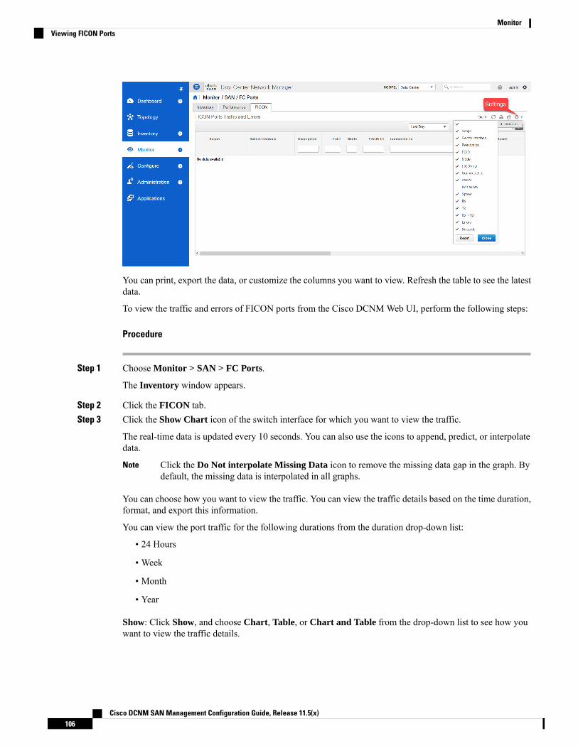
You can print, export the data, or customize the columns you want to view. Refresh the table to see the latestdata.
To view the traffic and errors of FICON ports from the Cisco DCNMWeb UI, perform the following steps:
Procedure
Step 1 Choose Monitor > SAN > FC Ports.
The Inventory window appears.
Step 2 Click the FICON tab.Step 3 Click the Show Chart icon of the switch interface for which you want to view the traffic.
The real-time data is updated every 10 seconds. You can also use the icons to append, predict, or interpolatedata.
Click the Do Not interpolate Missing Data icon to remove the missing data gap in the graph. Bydefault, the missing data is interpolated in all graphs.
Note
You can choose how you want to view the traffic. You can view the traffic details based on the time duration,format, and export this information.
You can view the port traffic for the following durations from the duration drop-down list:
• 24 Hours
• Week
• Month
• Year
Show: Click Show, and choose Chart, Table, or Chart and Table from the drop-down list to see how youwant to view the traffic details.
Cisco DCNM SAN Management Configuration Guide, Release 11.5(x)106
MonitorViewing FICON Ports
If you choose Chart, hover over the traffic chart to view the Rx and Tx values, along the Y axis, for thecorresponding time, along X axis. You can change the time duration values of the X axis by moving the slidersin the time range selector. You can choose the Y-axis values by checking or unchecking the Rx and Tx checkboxes.
If you select Week, Month, or Year as the time duration, you can also view the Peak Rx and PeakTx values along the Y axis.
Note
Select Table to view the traffic information in tabular format.
Chart Type and Chart Options: Choose Area Chart or Line Chart from the Chart Type drop-down list.
You can choose the Show Fill Patterns chart option.
Actions: Export or print the traffic information by choosing the appropriate options from theActions drop-downlist.
Viewing Performance Information for FC FlowsTo view the performance of the FC Flow traffic from the Cisco DCNMWeb UI, perform the following steps:
Procedure
Step 1 Choose Monitor > SAN > FC Flows.
The FC Flows window is displayed.
Step 2 You can use the drop-down to filter the view by 24 hours, Week, Month, and Year.Step 3 To export the data into a spreadsheet, click the Export icon in the upper-right corner and then click Save.Step 4 Click the chart icon in the Name column to see:
• A graph of the traffic on that device according to the selected timeline.
• Use the chart icons to view the traffic chart in varied views. To view real-time information, click theRefresh icon from the drop-down list in the upper right corner.
• You can also use the icons to Append, Predict, and Interpolate Data.
If the performance tables do not contain any data, see the Performance Setup Thresholds, on page307 section to turn on performance data collection.
Note
Viewing Performance Information on EnclosuresTo view the performance of devices that are connected to the host enclosure from the Cisco DCNMWeb UI,perform the following steps:
Cisco DCNM SAN Management Configuration Guide, Release 11.5(x)107
MonitorViewing Performance Information for FC Flows
Procedure
Step 1 Choose Monitor > SAN > Enclosures.
The Enclosures Traffic and Errors window is displayed.
Step 2 You can select to view Host Enclosures or Storage Enclosures from the drop-down list on the upper rightcorner.
Step 3 You can use the drop-down to filter the view by 24 hours, Week, Month, and Year.Step 4 To export the data into a spreadsheet, click the Export icon in the upper-right corner and then click Save.Step 5 Click the chart icon in the Name column to see:
• A graph of the traffic on that device according to the selected timeline.• Use the chart icons to view the traffic chart in varied views.• You can also use the icons to Append, Predict, and Interpolate Data.
If the performance tables do not contain any data, see the Performance Setup Thresholds, on page307 section to turn on performance data collection.
Note
Viewing Performance Information on Port GroupsTo view the performance of devices that connected to the port groups from the Cisco DCNMWebUI, performthe following steps:
Procedure
Step 1 Choose Monitor > SAN > Port Groups.
The Port Group Traffic and Errors window is displayed.
Step 2 You can use the drop-down to filter the view by 24 hours, Week, Month, and Year.Step 3 Click the name port group to see the members of that port group.
There are variations to this procedure. In addition to these basic steps, you can also perform the followingsteps to view detailed information for the port groups:
• To change the time range for this graph, select it from the drop-down list in the upper right corner.
• To view the detailed information for a specific period, drag the slider control to choose the time intervalfor which you need the information.
• Use the chart icons to view the traffic chart in varied views.
• You can also use the icons to Append, Predict, and Interpolate Data.
• To export the data into a spreadsheet, click the Export icon in the upper-right corner and click Save.
Cisco DCNM SAN Management Configuration Guide, Release 11.5(x)108
MonitorViewing Performance Information on Port Groups
If the performance tables do not contain any data, see the Performance Setup Thresholds, on page307 section to turn on performance data collection.
Note
SAN Host RedundancyThe SAN Host Path Redundancy check enables you to view the non-redundant host storage paths. It helpsyou identify the host enclosure errors along with the resolution to fix the errors.
All fabrics that are discovered must be licensed or this feature will be disabled in the Cisco DCNMWebClient. When the feature is disabled, a notification is displayed stating unlicensed fabrics are discovered.
Note
From the menu bar, choose Monitor > SAN > Host Path Redundancy.
You can see two parts in this window:
Tests to Run
Procedure
Step 1 Choose Monitor > SAN > Host Path Redundancy.Step 2 Under the upper Tests to Run area, use the check boxes to select the host redundancy optional checks.Step 3 Check the Automatically Run Check Every 24 hours check box to enable periodic running of the checker.
The checker will run every 24 hours starting 10 minutes after the server starts.Step 4 Check Limit by VSANs check box, and select Inclusion or Exclusion. Enter VSAN or VSAN range in the
text field to include or skip the host enclosures that belong to VSANs from the redundancy check.Step 5 Check other optional checks to do the relevant check.Step 6 Click Clear Results to clear all the errors displayed.Step 7 Click Run Tests Now to run the check at anytime.Step 8 The results are displayed in the below Results area.
Results
Procedure
Step 1 Choose Monitor > SAN > Host Path Redundancy tab.Step 2 The bottom Results area has four tabs that are Host Path Errors, Ignored Hosts, Ignored Storage, and
Ignored Host Storage Pairs.Step 3 Click Host Path Errors tab to display the host path redundancy errors table. On the top of the table, the
colored Good, Skipped, and Errored host enclosure counts, along with the last update time are displayed.
Cisco DCNM SAN Management Configuration Guide, Release 11.5(x)109
MonitorSAN Host Redundancy

a) The Host Enclosure column displays the hosts that contain the errors. These are counts of each path inthe host enclosures seeing an error. The Storage Enclosure/Storage Port column displays the connectedstorage that is involved the errors. In the Fix? column, hover the mouse cursor on the ? icon to view asolution to fix the error.
b) Select a row and click Ignore Hosts to add the selected rows host enclosure to an exclusion list. Theerrors from that host will no longer be reported and the current errors will be purged from the database.
c) Select a row and click Ignore Storage to add the selected rows storage enclosure to an exclusion list.d) Select a row and click Ignore Host Storage Pair to add the selected rows host-storage pair enclosure to
an exclusion list.e) In the drop-down list next to Show on the upper right corner of the table, select Quick Filter. Enter the
keywords in the column headers of the table to filter the items. Select All to display all the items.f) Click the circulation icon on the upper right corner of the table to refresh the table.g) Click the Print icon on the upper right corner of the table to print the errors as tables.h) Click the Export icon on the upper right corner of the table to export the table to a Microsoft excel
spreadsheet.
Step 4 Click the Ignored Hosts tab to display the list of host enclosures that have been skipped or ignored by theredundancy check along with the reason the reason for skipping. The following reasons may be displayed:
• Skipped: Enclosure has only one HBA.• Host was ignored by the user.• Host ports managed by more than one federated servers. Check can't be run.• Skipped: No path to storage found.
Select a host enclosure and click Delete to remove the host from the ignored list and begin receiving errorsabout a host you had chosen to ignore. However, you can delete entries with message Host was ignored byuser.
Step 5 Click the Ignored Storage tab to display the list of storage enclosures that have been selected to be ignoredduring the redundancy check. Select a storage enclosure and click Delete to remove the storage from theignored list and begin receiving errors about the storage you had chosen to ignore.
Step 6 Click the Ignored Host Storage Pair tab to display the list of host-storage pairs that have been selected tobe ignored during the redundancy check. Select a row and click Delete to delete the storage pair from theignored list.
Slow Drain AnalysisThe Slow Drain Analysis enables you to view slow drain statistics at the switch level and the port level. Youcan monitor the slow drain issue within any duration. You can display the data in a chart format and exportthe data for analysis. You can also view the topology that provides a high-level view of txwait, drops, creditloss recovery, over utilization, and port monitor events.
The slow drain statistics are stored in the cache memory. Therefore, the statistics are lost when the server isrestarted or a new diagnostic request is placed.
You can also watch the video and demonstrate how to use SAN Insights to identify if there are any slow drainmetrics incrementing across a fabric using a Cisco DCNM. See Video: SlowDrain Analysis with SAN Insights.
Cisco DCNM SAN Management Configuration Guide, Release 11.5(x)110
MonitorSlow Drain Analysis

The jobs run in the background, even after you log off.Note
Procedure
Step 1 Choose Monitor > SAN > Slow Drain Analysis.Step 2 In the Scope field, select the fabric from the drop-down list.Step 3 In the Duration drop-down list, select Once or Daily for the scheduled daily job. Once includes intervals,
such as 10 min, 30 min, 1 hour, and other hours and run the job immediately. Daily allows you to select astart time, and run the job for the selected interval. Use the radio button to select the desired interval to collectdata.
Only Daily slow drain job sends out report, which can be viewed from Monitor > Report > View.
Step 4 Click Start Collection to begin polling.
The server collects the slow drain statistics based on the scope defined by you. The Time Remaining isdisplayed in the right-side of the page.
Step 5 Click Stop Collection to stop polling.
The server maintains the counters in the cache, until a new diagnostic request is placed. You can stop thepolling before the time is up.
Step 6 Click the arrow next to Current jobs to display the slow drain details for the jobs running on the fabric. TheFabric Name, the Status of polling, Start, End, and Duration icon for each fabric is displayed.
Step 7 Select the fabric and click Result, Delete or Stop to view, delete or stop a job.
A topology of the selected fabric will appear if you select a fabric and click Result, along with the slow draindetails. See Slow Drain Visualization for more information.
Step 8 Click Detail to view the saved information.Step 9 Click Interface chart to display the slow drain value for the switch port in the chart format.Step 10 Click Filter to display the details based on the defined value for each column.Step 11 Select the Data Rows Only check box to filter and display the nonzero entries in the statistics.Step 12 Click Print to print the slow drain details.Step 13 Click Export to export the slow drain statistics to a Microsoft Excel spreadsheet.
Slow Drain VisualizationA topology of the selected fabric appears if you select a fabric and click Result, along with the slow draindetails. The topology window shows color-encoded nodes and links that correspond to various networkelements. For each of the elements, you can hover over to fetch somemore information. The links and switchesare color-coded. Enable performance collections and SNMP traps to view the slow drain information on thetopology. Choose Administration > Performance Setup > SAN Collections and enable the performancecollections. See Performance Manager SAN Collections, on page 306 for more information on enabling theperformance collections. Choose Administration > Event Setup > Registration and enable SNMP traps.See #unique_152 for more information on enabling SNMP traps.
Cisco DCNM SAN Management Configuration Guide, Release 11.5(x)111
MonitorSlow Drain Visualization

The following table lists the color description that is associated with the links and switches.
Table 9: Color Description
DescriptionNameColor
High utilization tx-datarate >= 80%Level 5Blue (light)
No slow drain foundLevel 4Green
Credit loss recoveryLevel 3Red
DropsLevel 2Orange
txwait >= 30%Level 1.5Yellow (dark)
txwait < 30%Level 1Yellow (light)
No DataNo DataGray (light)
A switch color represents the highest level slow drain that is found on any link to switch. The maximum valueis 3 and the minimum value is 1. A switch has two colors if overutilized. The right half of the switch is coloredin light blue to represent the overutilization. A number on the switch represents the number of F ports withthe slow drain. The color around the number represents the highest level slow drain that is found on F portsof the switch. Click the switch to see more slow drain details. Double click the switch to filter the slow draintable to view the slow drain data of that switch alone.
Two parallel lines are used to represent the slow drain on links. Links are bidirectional, hence each directionhas a color to represent the highest level of slow drain. Hover over a link to view the switch and interfacename of the source and destination. Double click a link to filter the slow drain table to view the slow draindata that is related to that link alone.
The highest slow drain level a link can have is Level 4. Valid colors for a link are Green, Red, Orange, Yellow(dark), Yellow (light), and Gray (light).
Note
Viewing Inventory Information for Regular ZonesTo view the inventory information for regular zones from the Cisco DCNMWeb UI, perform the followingsteps:
Procedure
Step 1 Choose Monitor > SAN > Regular Zones.
The Regular Zones window appears.
Step 2 Click the Settings icon to choose the displaying columns.
Cisco DCNM SAN Management Configuration Guide, Release 11.5(x)112
MonitorViewing Inventory Information for Regular Zones

What to do next
From Cisco DCNM Release 11.4(1), you can migrate pWWN-based SAN zones from a Brocade switch to aCisco MDS switch using the Zone Migration tool.
This feature supports migration of Brocade’s fabric switches running Brocade Fabric OS v7.x.x or later inthis release.
Zone Migration ToolFrom Cisco DCNM Release 11.4(1), you can migrate pWWN-based SAN zones from a Brocade switch to aCisco MDS switch. This involves the following steps:
1. Generating Brocade Configuration File
2. Converting Configuration Files Using the Zone Migration Tool
3. Applying the Zoning Output on Cisco MDS Switches
This feature supports migration of Brocade’s fabric switches running Brocade Fabric OS v7.x.x or later inthis release.
Generating Brocade Configuration File
Before you migrate a Brocade SAN zone to a Cisco MDS switch using Cisco DCNM, generate the Brocadeconfiguration files.
You can generate the Brocade configuration files using one of the following options:
• Using CLI: Log in to the Brocade switch terminal using the admin or other equivalent role with adminaccess. Run the cfgshow command. Copy the command output to a text file, and save it.
• Using Brocade Fabric OS Web tools: Download the Zoning Information file from the SwitchAdministrationwindow. See the Viewing and Printing a Switch Report section from the Brocade FabricOS Web Tools Administration Guide for more information.
Converting Configuration Files Using the Zone Migration Tool
To convert the Brocade configuration files using Cisco DCNM, perform the following steps from CiscoDCNMWeb UI:
Procedure
Step 1 Choose Monitor > SAN > Regular Zones.Step 2 Click Zone Migration Tool button.
The Zone Migration Tool dialog box appears.
Step 3 Click Select Input File and choose a Brocade configuration file from your system.Step 4 Enter the VSAN number to which the zone must be added.
The valid range is 1 to 4093.
Step 5 (Optional) Check Enhanced Zone Mode or Enhanced Device-Alias Mode check boxes.
Cisco DCNM SAN Management Configuration Guide, Release 11.5(x)113
MonitorZone Migration Tool
Refer the Configuring and Managing Zones chapter and the Distributing Device Alias Serviceschapter from the Cisco MDS 9000 Fabric Configuration guide to see the advantages of enhancedzone mode and enhanced device-alias mode.
Note
Step 6 Click Convert to start the conversion.
If there are no errors, the converted file will be downloaded to your local system.
• If you try converting any hard zones or interface-based zones, you will get an error.
• If you try to migrate more than 2000 fcAlias zones from Brocade to Cisco MDS, they will beconverted into device-alias zones.
Note
What to do next
Run the downloaded file in a Cisco MDS switch.
Applying the Zoning Output on Cisco MDS Switches
After you convert Brocade configuration files to a format compatible with the Cisco MDS switches, applythem on your Cisco MDS switch.
To apply the output on a Cisco MDS switch, perform the following steps:
Procedure
Step 1 Log into your Cisco MDS switch console.Step 2 Open the converted file using a text editor.Step 3 Open the converted file using a text editor.Step 4 Save the configurations using the copy running-config startup-config command.
The zones are migrated to the Cisco MDS switch.
Viewing Inventory Information for IVR ZonesTo view the inventory information for IVR zones from the Cisco DCNMWeb UI, perform the followingsteps:
Procedure
Step 1 Choose Monitor > SAN > IVR Zones.
The IVR Zones window is displayed with inventory details of the fabrics for the IVR zone.
Cisco DCNM SAN Management Configuration Guide, Release 11.5(x)114
MonitorApplying the Zoning Output on Cisco MDS Switches

Step 2 Click the Settings icon to choose the displaying columns.
Monitoring Insights FlowsThe SAN Insights page displays the health-related indicators in the interface so that you can quickly identifyissues in your environment. You can use health indicators to understand where problems are in your fabrics.
From Release 11.3(1), Cisco DCNM allows you to view SAN Insights metrics based on two protocols, SCSIand NVMe. By default, the SCSI protocol is selected. However, you can change this setting from theAdministration > DCNM Server > Server Properties. Ensure that you restart the SAN Insights service touse the new properties. (Restart the SanInsight service on Linux or Pause/Resume Post Processor App onSAN-OVA/ISO/SE deployments)
If the interface is down, it’s displayed in grey color.Note
Procedure
Step 1 To monitor the SAN Insights feature, choose Monitor > SAN > SAN Insights. The SAN Insights pageappears.
This page provides the basis for Insights data visualization showing counter data, visual topology map withindicators on the map. Also, you can view analytical information and historical insights. From Cisco DCNMRelease 11.3(1), you can choose the data type to stream SAN Insights data. Select SCSI or NVMe to selectthe data type. The system time is displayed at the right corner of the window.
In Monitor > SAN Insights window, you can perform the tasks that are mentioned in the steps below.
Cisco DCNM SAN Management Configuration Guide, Release 11.5(x)115
MonitorMonitoring Insights Flows
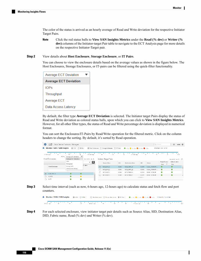
The color of the status is arrived as an hourly average of Read and Write deviation for the respective InitiatorTarget Pairs.
Click the red status balls to View SAN Insights Metrics under the Read (% dev) or Writer (%dev) columns of the Initiator-target Pair table to navigate to the ECT Analysis page for more detailson the respective Initiator-Target pair.
Note
Step 2 View details about Host Enclosure, Storage Enclosure, or IT Pairs.
You can choose to view the enclosure details based on the average values as shown in the figure below. TheHost Enclosures, Storage Enclosures, or IT-pairs can be filtered using the quick-filter functionality.
By default, the filter type Average ECT Deviation is selected. The Initiator target Pairs display the status ofRead and Write deviation as colored status balls, upon which you can click to View SAN Insights Metrics.However, for all other filter types, the status of Read andWrite percentage deviation is displayed in numericalformat.
You can sort the Enclosures/IT-Pairs by Read/Write operation for the filtered metric. Click on the columnheaders to change the sorting. By default, it’s sorted by Read operation.
Step 3 Select time interval (such as now, 6-hours ago, 12-hours ago) to calculate status and fetch flow and portcounters.
Step 4 For each selected enclosure, view initiator target pair details such as Source Alias, SID, Destination Alias,DID, Fabric name, Read (% dev) and Writer (% dev).
Cisco DCNM SAN Management Configuration Guide, Release 11.5(x)116
MonitorMonitoring Insights Flows

You can click the Status circle icon under Read (% dev) or Writer (% dev) columns in the Initiator-targetPair table to navigate to the ECTAnalysis window, with corresponding Initiator and TargetWWPNs prefiltered.
Step 5 Use the map to view end-to-end connectivity from initiator to target. Host, storage, and switch have coloredstatus indications. The color codes in the Topology area are only for the switch status. The switch color isgoverned by the Health score calculated for each switch. Double click on the colored switch icons to viewthe switch overlay for more details.
The switch interfaces also have status indications. The switch interface is rendered as a small circle at the endof the link that is attached to the switch. Selecting a switch interface populates one of the counter tables. Mapdisplays latest connectivity (not affected by time slider setting).
Cisco DCNM SAN Management Configuration Guide, Release 11.5(x)117
MonitorMonitoring Insights Flows
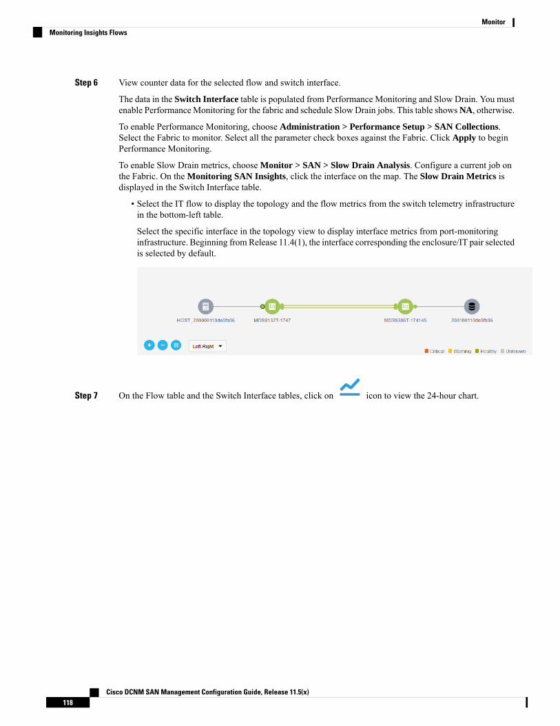
Step 6 View counter data for the selected flow and switch interface.
The data in the Switch Interface table is populated from Performance Monitoring and Slow Drain. You mustenable PerformanceMonitoring for the fabric and schedule Slow Drain jobs. This table showsNA, otherwise.
To enable Performance Monitoring, choose Administration > Performance Setup > SAN Collections.Select the Fabric to monitor. Select all the parameter check boxes against the Fabric. Click Apply to beginPerformance Monitoring.
To enable Slow Drain metrics, choose Monitor > SAN > Slow Drain Analysis. Configure a current job onthe Fabric. On the Monitoring SAN Insights, click the interface on the map. The Slow Drain Metrics isdisplayed in the Switch Interface table.
• Select the IT flow to display the topology and the flow metrics from the switch telemetry infrastructurein the bottom-left table.
Select the specific interface in the topology view to display interface metrics from port-monitoringinfrastructure. Beginning from Release 11.4(1), the interface corresponding the enclosure/IT pair selectedis selected by default.
Step 7 On the Flow table and the Switch Interface tables, click on icon to view the 24-hour chart.
Cisco DCNM SAN Management Configuration Guide, Release 11.5(x)118
MonitorMonitoring Insights Flows

Viewing Host EnclosuresFrom Release 11.3(1), Cisco DCNM allows you to view SAN Insights metrics based on two protocols, SCSIand NVMe. By default, the SCSI protocol is selected. However, you can change this setting from theAdministration > DCNM Server > Server Properties. Ensure that you restart the SAN Insights service touse the new properties. (Restart the SanInsight service on Linux or Pause/Resume Post Processor App onSAN-OVA/ISO/SE deployments)
To view the Host Enclosures from the Cisco DCNMWeb UI, perform the following steps:
1. Choose Monitor > SAN > SAN Insights, and then choose Host Enclosure.
Cisco DCNM SAN Management Configuration Guide, Release 11.5(x)119
MonitorViewing Host Enclosures
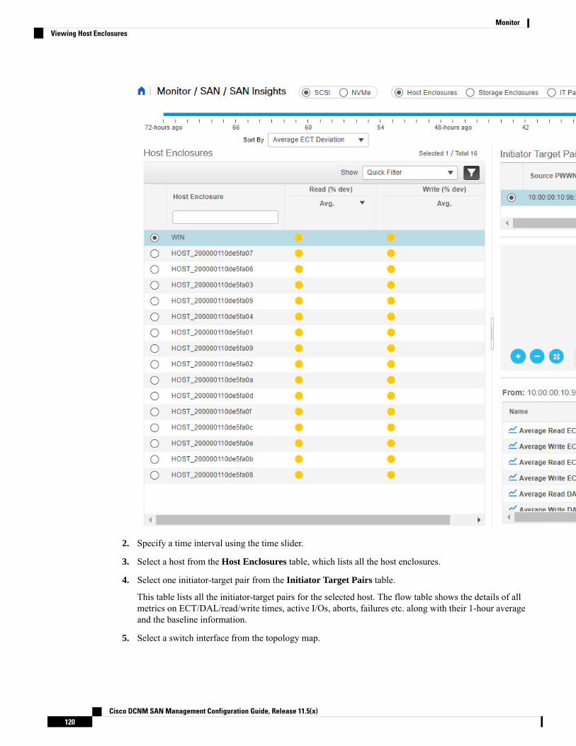
2. Specify a time interval using the time slider.
3. Select a host from the Host Enclosures table, which lists all the host enclosures.
4. Select one initiator-target pair from the Initiator Target Pairs table.
This table lists all the initiator-target pairs for the selected host. The flow table shows the details of allmetrics on ECT/DAL/read/write times, active I/Os, aborts, failures etc. along with their 1-hour averageand the baseline information.
5. Select a switch interface from the topology map.
Cisco DCNM SAN Management Configuration Guide, Release 11.5(x)120
MonitorViewing Host Enclosures

From Release 11.4(1), the switch interface is picked and selected by default. The Switch Interface tabledisplays data for the last hour period selected for the selected interface. The switch name and the interfacename are displayed on top of the switch interface table.
6. Click on the Status circle icon under Read (% dev) or Write (% dev) columns in the Initiator-targetPair table to navigate to the ECT Analysis window, with corresponding Initiator and Target WWPNsprefiltered.
Viewing Storage EnclosuresFrom Release 11.3(1), Cisco DCNM allows you to view SAN Insights metrics based on two protocols, SCSIand NVMe. By default, the SCSI protocol is selected. However, you can change this setting from theAdministration > DCNM Server > Server Properties. Ensure that you restart the SAN Insights service touse the new properties. (Restart the SanInsight service on Linux or Pause/Resume Post Processor App onSAN-OVA/ISO/SE deployments)
To view the Storage Enclosures from the Cisco DCNMWeb UI, perform the following steps:
1. Choose Monitor > SAN > SAN Insights, and then choose Storage Enclosure.
2. Specify a time interval using the time slider.
3. Select a storage enclosure from the Storage Enclosures table.
4. Select an initiator-target pair from the Initiator Target Pairs table.
5. Click on the Status circle icon under Read (% dev) or Write (% dev) columns in the Initiator-targetPair table to navigate to the ECT Analysis window, with corresponding Initiator and Target WWPNsprefiltered.
6. View the topology map represented for the selected initiator-target pair and the flow metrics.
The flow metrics are displayed in the flow table.
7. Select a switch interface from the topology map.
The Switch Interface table displays data for the selected interface. From Release 11.4(1), the switchinterface is picked and selected by default.
Cisco DCNM SAN Management Configuration Guide, Release 11.5(x)121
MonitorViewing Storage Enclosures
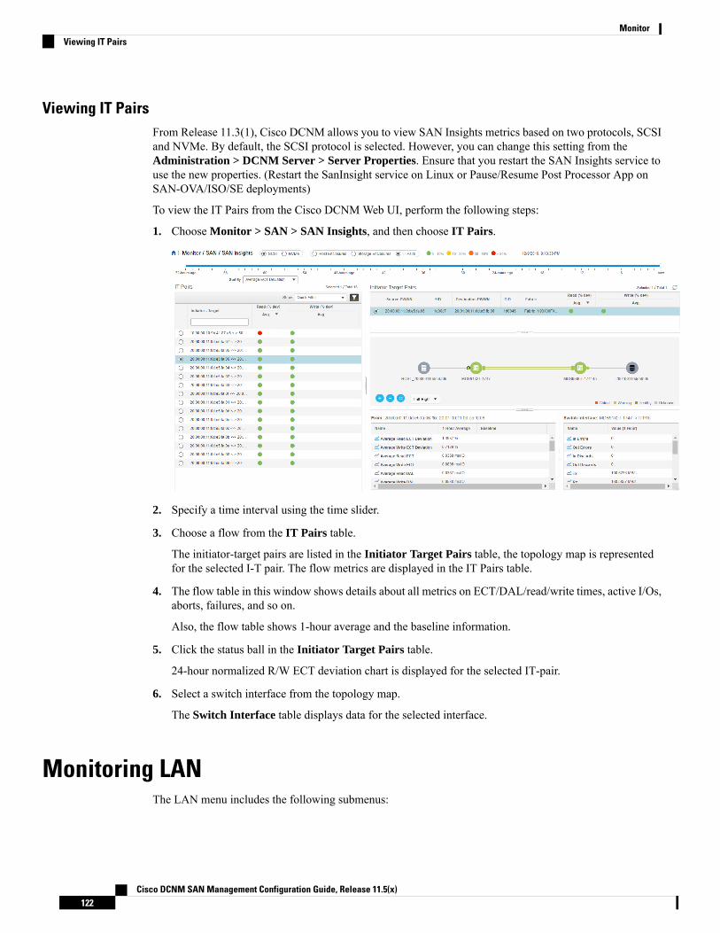
Viewing IT PairsFrom Release 11.3(1), Cisco DCNM allows you to view SAN Insights metrics based on two protocols, SCSIand NVMe. By default, the SCSI protocol is selected. However, you can change this setting from theAdministration > DCNM Server > Server Properties. Ensure that you restart the SAN Insights service touse the new properties. (Restart the SanInsight service on Linux or Pause/Resume Post Processor App onSAN-OVA/ISO/SE deployments)
To view the IT Pairs from the Cisco DCNMWeb UI, perform the following steps:
1. Choose Monitor > SAN > SAN Insights, and then choose IT Pairs.
2. Specify a time interval using the time slider.
3. Choose a flow from the IT Pairs table.
The initiator-target pairs are listed in the Initiator Target Pairs table, the topology map is representedfor the selected I-T pair. The flow metrics are displayed in the IT Pairs table.
4. The flow table in this window shows details about all metrics on ECT/DAL/read/write times, active I/Os,aborts, failures, and so on.
Also, the flow table shows 1-hour average and the baseline information.
5. Click the status ball in the Initiator Target Pairs table.
24-hour normalized R/W ECT deviation chart is displayed for the selected IT-pair.
6. Select a switch interface from the topology map.
The Switch Interface table displays data for the selected interface.
Monitoring LANThe LAN menu includes the following submenus:
Cisco DCNM SAN Management Configuration Guide, Release 11.5(x)122
MonitorViewing IT Pairs
Monitoring Performance Information for EthernetTo monitor the performance information for ethernet from the Cisco DCNMWeb UI, perform the followingsteps:
Procedure
Step 1 Choose Monitor > LAN > Ethernet.
The Ethernet window is displayed.
Step 2 You can use the drop-down to filter the view by Last 10 Minutes, Last Hour, Last Day, Last Week, LastMonth, and Last Year.
There are variations to this procedure. In addition to these basic steps, you can also perform the followingsteps:
• Select the name of an Ethernet port from theName column to see a graph of the traffic across that Ethernetport for the past 24 hours. You can change the time range for this graph by selecting it from the drop-downlist in the upper-right corner.
• To export the data into a spreadsheet, click the Export icon in the upper-right corner and click Save.
• Use the chart icons to view the traffic chart in varied views. You can also use the icons to Append,Predict, and Do not interpolate data.
Set the pmchart.doInterpolate property in the Server Properties window to false to use theDo not interpolate data option.
Note
• For the Rx/Tx calculation, see the following Rx/Tx calculation.
The conversion for Fabrics is 10 bit = 1 byte and for LAN traffic, the conversion is 8 bit = 1byte.
• Average Rx/Tx % = Average Rx/Tx divided by Speed * 100
• Peak Rx/Tx % = Peak Rx/Tx divided by Speed * 100
Note
If the performance tables do not contain any data, see the Thresholds section to turn on performancedata collection.
Note
To change traffic display unit from bytes to bits, FromCiscoDCNMWebUI, chooseAdministration> DCNM Server > Server Properties, enter value as true for pm.showTrafficUnitAsbit property,and click Apply Changes.
Note
Monitoring ISL Traffic and ErrorsTo monitor the ISL traffic and errors from the Cisco DCNMWeb UI, perform the following steps:
Cisco DCNM SAN Management Configuration Guide, Release 11.5(x)123
MonitorMonitoring Performance Information for Ethernet
Procedure
Step 1 Choose Monitor > LAN > Link.
The ISL Traffic and Errorswindow is displayed. This panel displays the ISL information for the end devicesin that scope. You can reduce or expand the scope of what is displayed by using the scope menu.
Step 2 You can use the drop-down to filter the view by Last 10 Minutes, Last Hour, Last Day, Last Week, LastMonth, and Last Year.
NaN (Not a Number) in the data grid means that the data is not available.Note
There are variations to this procedure. In addition to these basic steps, you can perform the following stepsto view detailed information for ISLs:
• To change the time range for this graph, select it from the drop-down list in the upper-right corner.
• To view the detailed information for a specific period, drag the slider control to choose the time intervalfor which you need the information.
• Use the chart icons to view the traffic chart in varied views. You can also use the icons to Append,Predict, and Do not interpolate data.
Set the pmchart.doInterpolate property in the Server Properties window to false to use theDo not interpolate data option.
Note
• To export the data into a spreadsheet, choose Export from the drop-down list in the Chart menu andthen click Save.
• For the Rx/Tx calculation, see the following Rx/Tx calculation.
The conversion for Fabrics is 10 bit = 1 byte and for LAN traffic, the conversion is 8 bit = 1byte.
• Average Rx/Tx % = Average Rx/Tx divided by Speed * 100
• Peak Rx/Tx % = Peak Rx/Tx divided by Speed * 100
Note
If the performance tables do not contain any data, see the Performance Setup Thresholds section toturn on performance.
Note
Monitoring a vPCThe virtual port channel (vPC) feature enables you to view the links that are physically connected to differentdevices as a single port channel. A vPC is an extended form of a port channel which allows you to createredundancy and increase bisectional bandwidth by enablingmultiple parallel paths between nodes and allowingload balancing traffic. Traffic is distributed among two single device vPC endpoints. If there is an inconsistencyin the vPC configurations, the vPC does not function correctly.
Cisco DCNM SAN Management Configuration Guide, Release 11.5(x)124
MonitorMonitoring a vPC
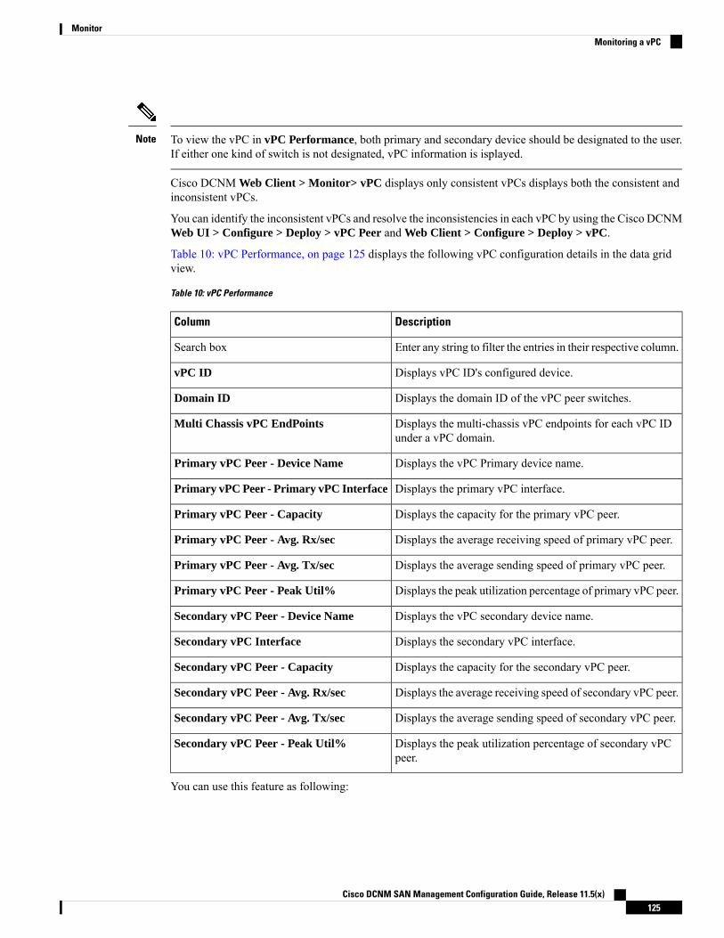
To view the vPC in vPC Performance, both primary and secondary device should be designated to the user.If either one kind of switch is not designated, vPC information is isplayed.
Note
Cisco DCNM Web Client > Monitor> vPC displays only consistent vPCs displays both the consistent andinconsistent vPCs.
You can identify the inconsistent vPCs and resolve the inconsistencies in each vPC by using the Cisco DCNMWeb UI > Configure > Deploy > vPC Peer and Web Client > Configure > Deploy > vPC.
Table 10: vPC Performance, on page 125 displays the following vPC configuration details in the data gridview.
Table 10: vPC Performance
DescriptionColumn
Enter any string to filter the entries in their respective column.Search box
Displays vPC ID's configured device.vPC ID
Displays the domain ID of the vPC peer switches.Domain ID
Displays the multi-chassis vPC endpoints for each vPC IDunder a vPC domain.
Multi Chassis vPC EndPoints
Displays the vPC Primary device name.Primary vPC Peer - Device Name
Displays the primary vPC interface.Primary vPC Peer - Primary vPC Interface
Displays the capacity for the primary vPC peer.Primary vPC Peer - Capacity
Displays the average receiving speed of primary vPC peer.Primary vPC Peer - Avg. Rx/sec
Displays the average sending speed of primary vPC peer.Primary vPC Peer - Avg. Tx/sec
Displays the peak utilization percentage of primary vPC peer.Primary vPC Peer - Peak Util%
Displays the vPC secondary device name.Secondary vPC Peer - Device Name
Displays the secondary vPC interface.Secondary vPC Interface
Displays the capacity for the secondary vPC peer.Secondary vPC Peer - Capacity
Displays the average receiving speed of secondary vPC peer.Secondary vPC Peer - Avg. Rx/sec
Displays the average sending speed of secondary vPC peer.Secondary vPC Peer - Avg. Tx/sec
Displays the peak utilization percentage of secondary vPCpeer.
Secondary vPC Peer - Peak Util%
You can use this feature as following:
Cisco DCNM SAN Management Configuration Guide, Release 11.5(x)125
MonitorMonitoring a vPC

Monitoring vPC PerformanceYou can view the relationship among consistent virtual port channels (vPCs). You can view the statistics ofall member interfaces and the aggregate of the statistics at the port-channel level.
This tab only displays consistent vPCs.Note
To view the VPC performance information from the Cisco DCNMWeb UI, perform the following steps:
Procedure
Step 1 Choose Monitor > LAN > vPC.
The vPC Performance statistics is displayed. The aggregated statistics of all vPCs are displayed in a tabularmanner.
Step 2 Click the vPC ID.
The vPC topology, vPC Details, Peer-link Details, and Peer-link Status are displayed.
The vPC Consistency, Peer-link Consistency, and vPC Type2 Consistency for the vPC are displayed.
• Click the vPC Details tab, you can view the parameter details of vPCBasic Setting andLayer 2 Settingsfor both Primary and Secondary vPC devices.
• Click the Peer-link Details tab, to view the parameter details of peer-link vPC Global Setting and STPGlobal Settings for both Primary and Secondary vPC devices.
• Click the Peer-link Status tab, the vPC Consistency, and Peer-Link Consistency status is displayed.The parameter details of Role Status and vPC Peer keep-alive Status for both Primary and SecondaryvPC devices is also displayed.
Step 3 Click the peer-link icon in front of the Device Name in the Primary vPC peer or Secondary vPC peercolumn to view its member interface.
Step 4 Click the Show Chart icon of the corresponding interface to view its historical statistics.
The traffic distribution statistics appear at the bottom of the vPC window. By default, the Cisco DCNMWebClient displays the historical statistics for 24 hours.
There are variations to this procedure. In addition to these basic steps, you can also perform the followingsteps to view detailed information for flows:
• To change the time range for this graph, select it from the drop-down list in the upper right corner.
• To view the detailed information for a specific period, drag the slider control to choose the time intervalfor which you need the information.
• Use the chart icons to view the traffic chart in varied views.
• You can also use the icons to Append, Predict, and Do not interpolate data.
Set the pmchart.doInterpolate property in the Server Properties window to false to use theDo not interpolate data option.
Note
Cisco DCNM SAN Management Configuration Guide, Release 11.5(x)126
MonitorMonitoring vPC Performance

• To print the vPC Utilization data, click the Print icon in the upper-right corner. The vPC Utilizationpage appears.
• To export the data into a spreadsheet, click the Export icon in the upper-right corner and click Save File.
If the performance tables do not contain any data, see the Thresholds section to turn on performancedata collection.
Note
Monitoring ReportThe Report menu includes the following submenus:
Viewing ReportsYou can view the saved reports that are based on the following selection options:
• By Template
• By User
• From the menu bar, select Monitor > Report > View.
To view the reports from the Cisco DCNMWeb UI, perform the following steps:
Procedure
Step 1 In the left pane, expand By Template or By User folder.Step 2 Select the report that you wish to view.
You can view the report in the main screen or you can select the report in the Report column to view theHTML version of the report in a new browser.
Step 3 To delete a specific report, select the check box and click the Delete icon.Step 4 To delete all reports, check the check box in the header, and click the Delete icon.
If you have multiple fabrics, you can select the DCNM-SAN group in the Scope to view Host toStorage connectivity of multiple fabrics in a single report.
Note
The report is divided into two sections:
• A summary report for all the devices that have faulty modules. The table displays information for everydevice that includes the device hostname, number of faulty modules, and the module number with itsPID.
• The information for the device of the module. The table contains details about the tests failed.
Cisco DCNM SAN Management Configuration Guide, Release 11.5(x)127
MonitorMonitoring Report

Scheduling Report Jobs in Federation SetupTo schedule report job in different servers in Federation, on the Cisco DCNMWeb UI, perform the followingsteps:
1. Schedule pre-defined or user-defined report job in Server1.
ChooseMonitor > Report > Generate. Refer to Generating a Report, on page 128 for detailed instructions.
2. Choose Monitor > Report > Jobs and verify that the job is scheduled correctly.
3. Schedule pre-defined or user-defined report job in Server2.
Ensure that you configure the jobs on primary server, second sever and the third server in theFederation setup in the sequential order.
Note
Generating a ReportYou can generate reports that are based on a selected template or you can schedule the report to run at aspecified time.
Procedure
Step 1 From the menu bar, select Monitor > Report > Generate.
You see the Generate Report window.
Step 2 In the configuration window, use the drop-down to define the scope for report generation.
In the Scope drop-down, you can select a scope group with dual fabrics, the traffic data that is generated byhosts and storage end devices are displayed side by side which enables you to view and compare traffic datathat is generated on dual fabrics. To view this report, in theOther Predefined folder, select Traffic by VSAN(Dual Fabrics). Click Options to select the Device Type and Fabrics. Click Save to save the configuration.
Step 3 In the pane on the left, expand the folders and select the report.Step 4 (Optional) In the pane on the right, you can edit the Report Name.Step 5 (Optional) Check the Export to Csv/Excel check box to export the report to a Microsoft Excel spreadsheet.Step 6 In the Repeat radio buttons, if you select:
• Never - The report is generated only during the current session.
• Once - The report is generated on a specified date and time apart from the current session.
• Daily - The report is generated everyday based on the Start and End date at a specified time.
• Weekly - The report is generated once a week based on the Start and End date at a specified time.
• Monthly - The report is generated once every month based on the Start and End date at a specified time.
Cisco DCNM SAN Management Configuration Guide, Release 11.5(x)128
MonitorScheduling Report Jobs in Federation Setup

When you generate a report for Network Configuration Audit, the daily job generates a report for the selecteddevices for last one day. Similarly, the weekly job generates a report for the last 7 days, and the monthly jobgenerates a report for the last 30 days.
Step 7 Click the Create button to generate a report that is based on the specifications.
You see the report results in a new browser window.
Alternatively, you can view the report by choosing Monitor > Report > View and selecting the report namefrom the report template that you used in the navigation pane.
The Start Date must be at least five minutes earlier than the End Date.Note
The report is divided into two sections:
• A summary report for all the devices that have faulty modules. The table displays information for everydevice that includes the device hostname, number of faulty modules and the module number with itsPID.
• A detailed information for the device of the module. The table contains details about the tests failed.
Creating SAN User Defined ReportsYou can create custom reports from all or any subset of information that is obtained by Cisco DCNM-SAN.You create a report template by selecting events, performance, and inventory statistics you want in your reportand set the desired SAN, fabrics, or VSAN to limit the scope of the template. You can generate and schedulea report of your fabric that is based on this template immediately or later. Cisco DCNMWeb Client saveseach report, which is generated based on the report template, and the time you generate the report.
Since the Cisco MDS NX-OS Release 5.0, the report template design has changed to resolve the limitationsof the earlier versions. With the new design model, you can perform add, delete, and modify functionalitieson a single page. You can choose multiple fabrics and VSANs using the new navigation system, which allowsyou to add new items and categories in the future.
The new design model has three panels:
• Template panel - The Template panel allows you to add new templates, modify existing templates anddelete existing templates.
• Configuration panel - The Configuration panel allows you to configure a new template when it isadded, and modify an existing template. The options in the configuration panel are disabled until youeither add a new template or select an existing template. The upper portion of the configuration panelcontains many categories that you can choose and configure.
• User Selection panel - TheUser Selection panel displays your configuration options in real time. Whilethe configuration panel can display information pertaining to one category at a time, the User Selectionpanel displays all of your selections or configurations.
To create custom reports from the Cisco DCNMWeb UI, perform the following steps:
Procedure
Step 1 Choose Monitor > Report > User Defined.
Cisco DCNM SAN Management Configuration Guide, Release 11.5(x)129
MonitorCreating SAN User Defined Reports

The Create User-Defined window is displayed.
Step 2 In the Template panel, under the Name column, selectCLICK TO ADD NEW CUSTOM to edit the Nameof the new report.
Step 3 In theConfiguration panel, click Scope to define scope of the report. The default scope includes Data Center,SAN, LAN, and Fabric configurations.
Step 4 Click Inventory and use the checkbox to select the inventory information that is required in the report. Youcan also use the drop-down to filter by selecting the Top performance and the timeline that is required in thereport.
Step 5 Click Performance and use the checkbox to select the performance information required in the report.Step 6 Click Health and use the checkbox to select the health information required in the report.Step 7 Click Save to save this report template.
A confirmation message is displayed confirming that the report is saved.
Deleting a Report TemplateTo delete a report template from the Cisco DCNMWeb UI, perform the following steps:
Procedure
Step 1 In the Template panel, select the report template that you want to delete.Step 2 Click the Delete icon to delete the report.Step 3 In the confirmation pop-up, click Yes to delete the template.
Modifying a Custom Report Template
Procedure
Step 1 Choose Monitor > Report > User Defined.
You see the Template, Configuration, and User Selection panels.
Step 2 Select a report from the Template panel.
You see the current information about this report in the User Selection panel.
Step 3 Modify the information in the Configuration panel.Step 4 Click Save to save the report template.
A confirmation message is displayed confirming that the report is saved.
You cannot change the scope for an existing report. Generate a new report for a new scope.Note
Cisco DCNM SAN Management Configuration Guide, Release 11.5(x)130
MonitorDeleting a Report Template

Viewing Scheduled Jobs Based on a Report TemplateTo view the scheduled jobs that are based on a report template from the Cisco DCNMWeb UI, perform thefollowing steps:
Procedure
Step 1 Choose Monitor > Report > Jobs.
The Report Jobs window is displayed with details of the reports that are scheduled for generation along withits status.
Step 2 Select the checkbox for a specific report and click the Delete Job icon to delete a report.
AlarmsThe Alarms menu includes the following submenus:
Viewing Alarms and EventsYou can view the alarms, cleared alarms, and events.
Procedure
Step 1 Choose Monitor > Alarms > View.Step 2 Choose any of the following tabs.
• Alarms: This tab displays the alarms that are generated for various categories. This tab displaysinformation such as ID (optional), Severity, Failure Source, Name, Category, Acknowledged, CreationTime, Last Updated (optional), Policy, and Message. You can specify the Refresh Interval in this tab.You can select one or more alarms and then acknowledge or unacknowledge their status using theChangeStatus drop-down list. In addition, you can select one or more alarms and then click the Delete buttonto delete them.
• Cleared Alarms: This tab displays the cleared alarms. This tab displays information such as ID (optional),Severity, Failure Source, Name, Category, Acknowledged, Creation Time, Cleared At (optional), ClearedBy, Policy, and Message. You can select one or more alarms and then click the Delete button to deletethem.
• Events: This tab displays the events that are generated for the switches. This tab displays informationsuch as Ack, Acknowledged user, Group, Switch, Severity, Facility, Type, Count, Last Seen, andDescription. You can select one or more events and then acknowledge or unacknowledge their statususing the Change Status drop-down list. In addition, you can select one or more alarms and then clickthe Delete button to delete them. If you want to delete all events, click the Delete All button.
Cisco DCNM SAN Management Configuration Guide, Release 11.5(x)131
MonitorViewing Scheduled Jobs Based on a Report Template
Monitoring and Adding Alarm Policies
• Alarm policies are stored in compute nodes. Therefore, run the appmgr backup command on eachcompute node in addition to taking a backup of DCNM.
Note
In Cisco DCNMSAN Federation deployment onWindows and Linux, ensure that the alarm.enable.externalvalue in the Server Properties is set to true on both the Primary and Secondary nodes. Navigate toAdministration > DCNM Server > Server Properties. Locate the alarm.enable.external field, and ensurethat it is set to true. You must restart DCNM Server to bring this into effect.
You can forward alarms to registered SNMP listeners in DCNM. From Cisco DCNM web UI, chooseAdministration > DCNM Server > Server Properties, enter an external port address inalarm.trap.listener.address field, click Apply Changes, and restart DCNM services.
Ensure that you select Forwarding check box inAlarm Policy creation dialog window to enable forwardingalarms to external SNMP listener.
Note
You can add alarm policies for the following:
• Device Health: Device health policies enable you to create alarms when Device ICMP Unreachable,Device SNMP Unreachable, or Device SSH Unreachable. Also, these policies enable you to monitorchassis temperature, CPU, and memory usage.
• Interface Health: Interface health policies enable you to monitor Up or Down, Packet Discard, Error,Bandwidth details of the interfaces. By default all interfaces are selected for monitoring.
• Syslog Alarm: Syslog Alarm Policy defines a pair of Syslog messages formats; one which raises thealarm, and one which clears the alarm.
Procedure
Step 1 Choose Monitor > Alarms > Alarm Policies.Step 2 Select the Enable Alarms check box to enable alarm policies.Step 3 From the Add drop-down list, choose any of the following:
• Device Health Policy: Select the devices for which you want to create policies. Specify the policy name,description, CPU Utilization parameters, Memory Utilization parameters, Environment Temperatureparameters, device availability, and device features. Under Device Features, you can select the BFD,BGP, and HSRP protocols. When these check boxes are selected, alarms are triggered for the followingtraps: BFD- ciscoBfdSessDown, ciscoBfdSessUp, BGP- bgpEstablishedNotification,bgpBackwardTransNotification, cbgpPeer2BackwardTransition (), cbgpPeer2EstablishedNotification,and HSRP- cHsrpStateChange. Please referhttps://snmp.cloudapps.cisco.com/Support/SNMP/do/BrowseOID.do?local=en for detailed trap OIDdefinition.
Cisco DCNM SAN Management Configuration Guide, Release 11.5(x)132
MonitorMonitoring and Adding Alarm Policies
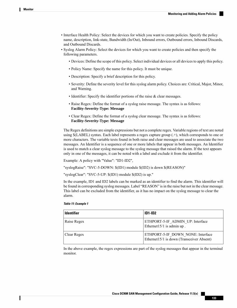
• Interface Health Policy: Select the devices for which you want to create policies. Specify the policyname, description, link-state, Bandwidth (In/Out), Inbound errors, Outbound errors, Inbound Discards,and Outbound Discards.
• Syslog Alarm Policy: Select the devices for which you want to create policies and then specify thefollowing parameters.
• Devices: Define the scope of this policy. Select individual devices or all devices to apply this policy.
• Policy Name: Specify the name for this policy. It must be unique.
• Description: Specify a brief description for this policy.
• Severity: Define the severity level for this syslog alarm policy. Choices are: Critical, Major, Minor,and Warning.
• Identifier: Specify the identifier portions of the raise & clear messages.
• Raise Regex: Define the format of a syslog raise message. The syntax is as follows:Facility-Severity-Type: Message
• Clear Regex: Define the format of a syslog clear message. The syntax is as follows:Facility-Severity-Type: Message
The Regex definitions are simple expressions but not a complete regex. Variable regions of text are notedusing $(LABEL) syntax. Each label represents a regex capture group (.+), which corresponds to one ormore characters. The variable texts found in both raise and clear messages are used to associate the twomessages. An Identifier is a sequence of one or more labels that appear in both messages. An Identifieris used to match a clear syslog message to the syslog message that raised the alarm. If the text appearsonly in one of the messages, it can be noted with a label and exclude it from the identifier.
Example: A policy with "Value": "ID1-ID2",
"syslogRaise": "SVC-5-DOWN: $(ID1) module $(ID2) is down $(REASON)"
"syslogClear": "SVC-5-UP: $(ID1) module $(ID2) is up."
In the example, ID1 and ID2 labels can be marked as an identifier to find the alarm. This identifier willbe found in corresponding syslog messages. Label “REASON” is in the raise but not in the clear message.This label can be excluded from the identifier, as it has no impact on the syslog message to clear thealarm.
Table 11: Example 1
ID1-ID2Identifier
ETHPORT-5-IF_ADMIN_UP: InterfaceEthernet15/1 is admin up .
Raise Regex
ETHPORT-5-IF_DOWN_NONE: InterfaceEthernet15/1 is down (Transceiver Absent)
Clear Regex
In the above example, the regex expressions are part of the syslog messages that appear in the terminalmonitor.
Cisco DCNM SAN Management Configuration Guide, Release 11.5(x)133
MonitorMonitoring and Adding Alarm Policies

Table 12: Example 2
ID1-ID2Identifier
ETH_PORT_CHANNEL-5-PORT_DOWN:$(ID1): $(ID2) is down
Raise Regex
ETH_PORT_CHANNEL-5-PORT_UP: $(ID1):$(ID2) is up
Clear Regex
Table 13: Example 3
ID1-ID2Identifier
ETHPORT-5-IF_SFP_WARNING: Interface$(ID1), High Rx Power Warning
Raise Regex
ETHPORT-5-IF_SFP_WARNING: Interface$(ID1), High Rx Power Warning cleared
Clear Regex
Step 4 Click OK to add the policy.
Syslog Messages in Terminal Monitor and Console
The following examples show how the syslog messages appear in the terminal monitor and theconsole. The regex expression is matched with the part of the syslog messages after the % sign.leaf-9516# terminal monitorleaf-9516# conf tleaf-9516(config)# int e15/1-32leaf-9516(config-if-range)# no shut2019 Aug 2 04:41:27 leaf-9516 %ETHPORT-5-IF_ADMIN_UP: InterfaceEthernet15/1 is admin up .2019 Aug 2 04:41:27 leaf-9516 %ETHPORT-5-IF_DOWN_NONE: InterfaceEthernet15/1 is down (Transceiver Absent)2019 Aug 2 04:41:27 leaf-9516 %ETHPORT-5-IF_ADMIN_UP: InterfaceEthernet15/2 is admin up .2019 Aug 2 04:41:27 leaf-9516 %ETHPORT-5-IF_DOWN_NONE: InterfaceEthernet15/2 is down (Transceiver Absent)2019 Aug 2 04:41:28 leaf-9516 %ETHPORT-5-IF_ADMIN_UP: InterfaceEthernet15/3 is admin up .
The syslog messages in the console have a similar format as they would appear in the terminalmonitor, except for the additional port information enclosed in the %$ signs. However, the regexexpression is matched with the part of the syslog messages after the last % sign.SR-leaf1# 2019 Aug 26 23:55:45 SR-leaf1 %$ VDC-1 %$ %PLATFORM-1-PFM_ALERT: FAN_BAD: fan62019 Aug 26 23:56:15 SR-leaf1 %$ VDC-1 %$ %PLATFORM-1-PFM_ALERT:FAN_BAD: fan62019 Aug 26 23:56:18 SR-leaf1 %$ VDC-1 %$ %ASCII-CFG-2-CONF_CONTROL:System ready2019 Aug 26 23:56:25 SR-leaf1 %$ VDC-1 %$ %PLATFORM-1-PFM_ALERT:FAN_BAD: fan62019 Aug 26 23:56:35 SR-leaf1 %$ VDC-1 %$ %PLATFORM-1-PFM_ALERT:FAN_BAD: fan6
Cisco DCNM SAN Management Configuration Guide, Release 11.5(x)134
MonitorMonitoring and Adding Alarm Policies

2019 Aug 26 23:56:39 SR-leaf1 %$ VDC-1 %$ %VMAN-2-ACTIVATION_STATE:Successfully activated virtual service 'guestshell+'2019 Aug 26 23:56:39 SR-leaf1 %$ VDC-1 %$ %VMAN-2-GUESTSHELL_ENABLED:The guest shell has been enabled. The command 'guestshell' may be usedto access it, 'guestshell destroy' to remove it.2019 Aug 26 23:56:45 SR-leaf1 %$ VDC-1 %$ %PLATFORM-2-FAN_REMOVED: Fanmodule 5 (Serial number ) Fan5(sys_fan5) removed2019 Aug 26 23:56:45 SR-leaf1 %$ VDC-1 %$ %PLATFORM-1-PFM_ALERT:System will shutdown in 2 minutes 0 seconds due to fan policy__pfm_fanabsent_any_singlefan.2019 Aug 26 23:56:45 SR-leaf1 %$ VDC-1 %$ %PLATFORM-1-PFM_ALERT:FAN_BAD: fan62019 Aug 26 23:56:54 SR-leaf1 %$ VDC-1 %$ %PLATFORM-1-PFM_ALERT:System will shutdown in 1 minutes 40 seconds due to fan policy__pfm_fanabsent_any_singlefan.2019 Aug 26 23:56:54 SR-leaf1 %$ VDC-1 %$ %PLATFORM-1-PFM_ALERT:FAN_BAD: fan62019 Aug 26 23:57:03 SR-leaf1 %$ VDC-1 %$ %PLATFORM-2-FANMOD_FAN_OK:Fan module 5 (Fan5(sys_fan5) fan) ok2019 Aug 26 23:57:03 SR-leaf1 %$ VDC-1 %$ %PLATFORM-1-PFM_ALERT:FAN_BAD: fan6
Activating PoliciesAfter you create new alarm policies, activate them.
Procedure
Step 1 Choose Monitor > Alarms > Policies.Step 2 Select the policies that you want to activate and then click the Activate button.
Deactivating PoliciesYou can deactivate the active alarm policies.
Procedure
Step 1 Choose Monitor > Alarms > Policies.Step 2 Select the policies that you want to deactivate and then click the Deactivate button.
Importing PoliciesYou can create alarm policies using the import functionality.
Procedure
Step 1 Choose Monitor > Alarms > Policies and then click the Import button.Step 2 Browse and select the policy file saved on your computer.
Cisco DCNM SAN Management Configuration Guide, Release 11.5(x)135
MonitorActivating Policies
You can only import policies in text format.
Exporting PoliciesYou can export the alarm policies into a text file.
Procedure
Step 1 From the menu bar, choose Monitor > Alarms > Policies.Step 2 Click the Export button and then select a location on your computer to store the exported file.
Editing Policies
Procedure
Step 1 From the menu bar, choose Monitor > Alarms > Policies.Step 2 Select the policy that you want to edit.Step 3 Click the Edit button and then make necessary changes.Step 4 Click the OK button.
Deleting Policies
Procedure
Step 1 From the menu bar, choose Monitor > Alarms > Policies.Step 2 Select the policy that you want to delete.Step 3 Click the Delete button. The policy is deleted.
Enabling External AlarmsYou can enable external alarms using one of the following methods:
• Using Cisco DCNMWeb UI
1. From Cisco DCNMWeb UI, choose Administration > DCNM Server > Server Properties.
2. Locate the alarm.enable.external property.
3. Enter the value in the field as true.
Cisco DCNM SAN Management Configuration Guide, Release 11.5(x)136
MonitorExporting Policies
• Using REST APIs
1. Go the API documentation URL from your DCNM setup: https://<DCNM-ip>/api-docs
2. Navigate to the Alarms section.
3. Click POST > rest/alarms/enabledisableextalarm.
4. Choose the body parameter value as true from the Value drop-down list.
5. Click Try it out!.
• Using CLI
1. Log into the DCNM server using SSH.
2. Set the alarm.enable.external property to true in the server.properties file.
The filepath is /usr/local/cisco/dcm/fm/config/server.properties.
Health Monitor AlarmsStarting from Cisco DCNM Release 11.4(1), alarms are registered and created under the External alarmcategory by the Health Monitor.
Health Monitor: Alarm Policy
The Health Monitor external alarm category policy is automatically activated and enabled on all the devicesin a fabric. The severity level of this alarm policy can be MINOR, MAJOR, or CRITICAL.
Alarms are raised and categorized as CRITICAL for the following events:
• Elasticsearch (ES) Cluster Status is Red: Critical (For Cluster/HA mode only)
• CPU/Memory/Disk Utilization/ES JVM Heap Used Percentage >= 90%
Alarms are raised and categorized as MAJOR for the following events:
• ES Cluster Status is Yellow (For Cluster/HA mode only)
• ES has unassigned shards (For Cluster/HA mode only)
• CPU/Memory/Disk Utilization/ES JVM Heap Used Percentage >= 80% and <90%
Alarms are raised and categorized as MINOR for the following events:
• CPU/Memory/Disk Utilization/ES JVM Heap Used Percentage >= 65% and <80%
• Kafka: Number of partitions without active leader > 0
• Kafka: Qualified partition leader not found. Unclear leaders > 0
Choose Monitor>Alarms>Policies to display the Health Monitor alarm policies. These alarm policies arenot editable on the web UI. Click Activate or Deactivate to activate or deactivate the selected policy.
Cisco DCNM SAN Management Configuration Guide, Release 11.5(x)137
MonitorHealth Monitor Alarms

In case an alarm policy is deactivated using the GUI, any alarms created or cleared for that policy will not bedisplayed in the Monitor>Alarms>View tab. To delete a policy, select the checkbox next to the policy andclickDelete. However, we recommend not deleting a policy from the GUI.When a fabric is deleted, the alarmpolicy along with all the active alarms for the devices in that fabric are deleted.
Health Monitor: Active Alarms
Choose Monitor>Alarms>View to display the active alarms.
To clear active alarms, select the checkbox next to the alarm, click Change Status and select Clear.
To delete active alarms, select the checkbox next to the alarm and click Delete.
Health Monitor: Cleared Alarms
To view the cleared alarms, select Monitor>Alarms>View>Cleared Alarms.
Click the arrow icon to display detailed information about the required alarm.
To delete a cleared alarm from the list of cleared alarms, select the checkbox next to the alarm and clickDelete.
For more information on Alarms and Policies, refer Alarms.
Cisco DCNM SAN Management Configuration Guide, Release 11.5(x)138
MonitorHealth Monitor Alarms

C H A P T E R 6Configure
This chapter contains the following topics:
• Templates, on page 139• Backup, on page 171• Image Management, on page 183• LAN Telemetry Health, on page 203• SAN, on page 216
TemplatesThe Templates menu includes the following option:
Template LibraryTemplate Library includes the following tabs:
Template LibraryYou can add, edit, or delete templates that are configured across different Cisco Nexus and Cisco MDSplatforms using Cisco DCNMWeb client. From Cisco DCNMWeb client home page, choose Configure >Templates > Template Library > Templates. The following parameters are displayed for each templatethat is configured on Cisco DCNMWeb client. Templates support JavaScript. You can use the JavaScriptfunction in a template to perform arithmetic operations and string manipulations in the template syntax.
The following table describes the fields that appear on this page.
Table 14: Templates Operations
DescriptionField
Allows you to add a new template.Add Template
Allows you to create jobs.Launch job creation wizard
Allows you to view the template definition and modify as required.Modify/View Template
Cisco DCNM SAN Management Configuration Guide, Release 11.5(x)139

DescriptionField
Allows you to save the selected template in a different name. Youcan edit the template as required.
Save Template As
Allows you to delete a templateDelete Template
Allows you to import a template from your local directory, one ata time.
Import Template
Allows you to export the template configuration to a local directorylocation.
Export template
Allows you to import .zip file, that contains more than onetemplate that is bundled in a .zip format
All the templates in the ZIP file are extracted and listed in the tableas individual templates.
Import Template Zip File
Notifications appear next to Import Template Zip File if there are issues while loading templates afterrestarting the server. Click the notifications to see the errors in the Issues in loading Template window.Templates with errors are not listed in the Templates window. To import these templates, correct the errors,and import them.
Note
Table 15: Template Properties
DescriptionField
Displays the name of the configured template.Template Name
Displays the description that is provided while configuringtemplates.
Template Description
Displays the tag that is assigned for the template and aids to filtertemplates based on the tags.
Tags
Displays the supported Cisco Nexus platforms compatible with thetemplate. Check the check box of platforms that are supported withthe template.
You can select multiple platforms.Note
Supported Platforms
Displays the type of the template.Template Type
Specifies the sub type that is associated with the template.Template Sub Type
Specifies if it is Jython or Template CLI.Template Content Type
Cisco DCNM SAN Management Configuration Guide, Release 11.5(x)140
ConfigureTemplate Library

Table 16: Advanced Template Properties
DescriptionField
Displays the abstract template to be implemented.Implements
Specifies the specific feature of a switch.Dependencies
Specifies if the template is published or not.Published
Specifies the base template for importing.Imports
In addition, from the menu bar, choose Configure > Templates > Template Library > Templates and youcan also:
• Click Show Filter to filter the templates that is based on the headers.
• Click Print to print the list of templates.
• Click Export to Excel to export the list of template to a Microsoft Excel spreadsheet.
This section contains the following:
Template Structure
The configuration template content mainly consists of four parts. Click the Help icon next to the TemplateContent for information about editing the content of the template.
This section contains the following:
Template Format
This section describes the basic information of the template. The possible fields are as detailed in the tablebelow.
Optional?Valid ValuesDescriptionProperty Name
NoTextThe name of the templatename
YesTextBrief description about thetemplate
description
Yes“true” or “false”Indicates whether the usercreated the template.Value is ‘true’ if usercreated.
userDefined
NoN1K, N3K, N3500, N4K,N5K, N5500, N5600,N6K, N7K, N9K, MDS,VDC, N9K-9000v,IOS-XE, IOS-XR,Others,All Nexus Switches listseparated by comma.
List of device platformssupports thisconfiguration template.Specify ‘All’ to supportall platforms.
supportedPlatforms
Cisco DCNM SAN Management Configuration Guide, Release 11.5(x)141
ConfigureTemplate Structure
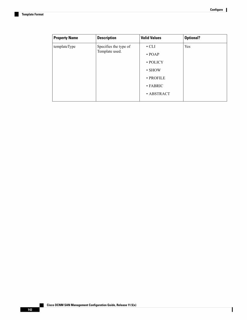
Optional?Valid ValuesDescriptionProperty Name
Yes• CLI
• POAP
• POLICY
• SHOW
• PROFILE
• FABRIC
• ABSTRACT
Specifies the type ofTemplate used.
templateType
Cisco DCNM SAN Management Configuration Guide, Release 11.5(x)142
ConfigureTemplate Format

Optional?Valid ValuesDescriptionProperty Name
Specifies the sub typeassociated with thetemplate.
templateSubType
Cisco DCNM SAN Management Configuration Guide, Release 11.5(x)143
ConfigureTemplate Format
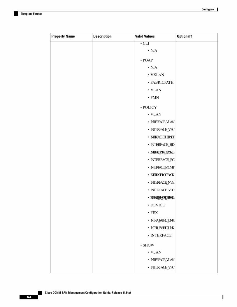
Optional?Valid ValuesDescriptionProperty Name
• CLI
• N/A
• POAP
• N/A
• VXLAN
• FABRICPATH
• VLAN
• PMN
• POLICY
• VLAN
• INTERFACE_VLAN
• INTERFACE_VPC
• INTERFACE_ETHERNET
• INTERFACE_BD
• INTERFACE_PORT_CHANNEL
• INTERFACE_FC
• INTERFACE_MGMT
• INTERFACE_LOOPBACK
• INTERFACE_NVE
• INTERFACE_VFC
• INTERFACE_SAN_PORT_CHANNEL
• DEVICE
• FEX
• INTRA_FABRIC_LINK
• INTER_FABRIC_LINK
• INTERFACE
• SHOW
• VLAN
• INTERFACE_VLAN
• INTERFACE_VPC
Cisco DCNM SAN Management Configuration Guide, Release 11.5(x)144
ConfigureTemplate Format

Optional?Valid ValuesDescriptionProperty Name
• INTERFACE_ETHERNET
• INTERFACE_BD
• INTERFACE_PORT_CHANNEL
• INTERFACE_FC
• INTERFACE_MGMT
• INTERFACE_LOOPBACK
• INTERFACE_NVE
• INTERFACE_VFC
• INTERFACE_SAN_PORT_CHANNEL
• DEVICE
• FEX
• INTRA_FABRIC_LINK
• INTER_FABRIC_LINK
• INTERFACE
• PROFILE
• VXLAN
• FABRIC
• NA
Cisco DCNM SAN Management Configuration Guide, Release 11.5(x)145
ConfigureTemplate Format
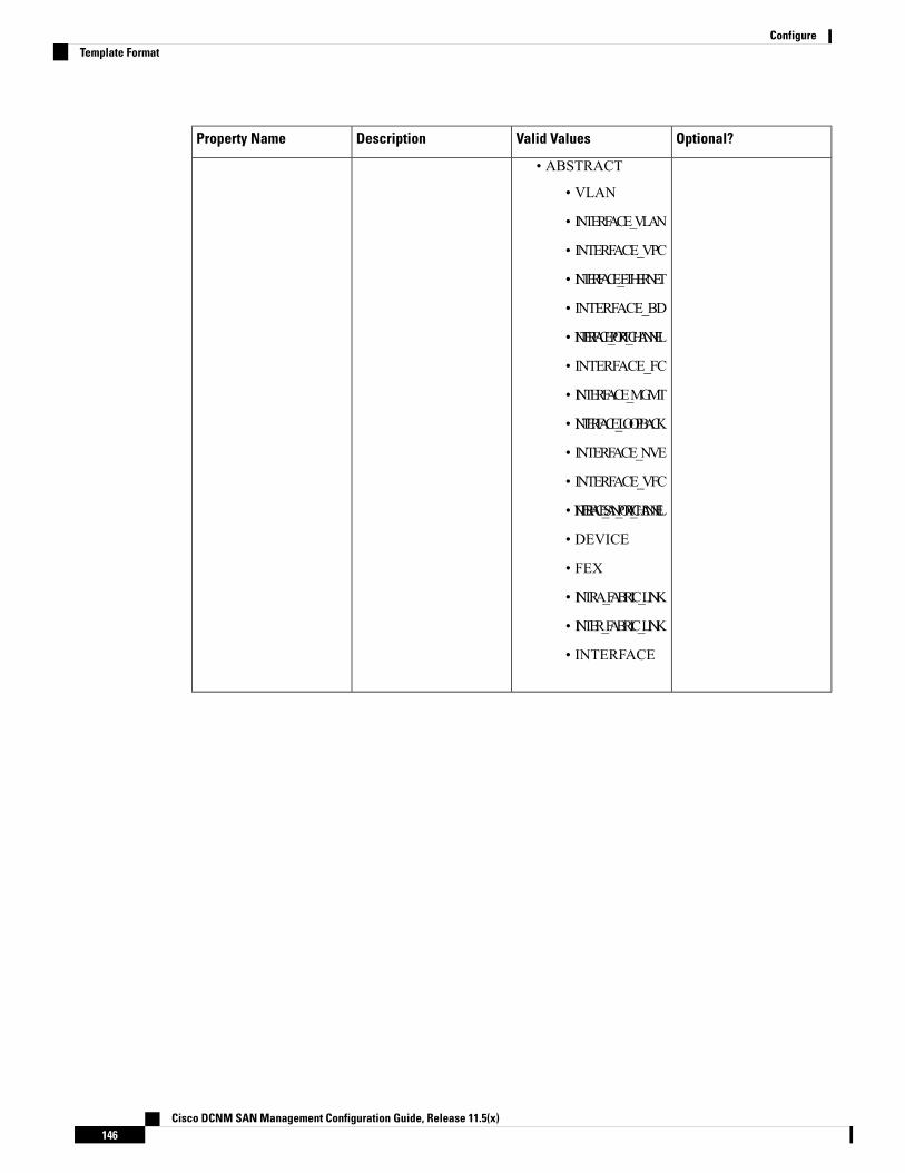
Optional?Valid ValuesDescriptionProperty Name
• ABSTRACT
• VLAN
• INTERFACE_VLAN
• INTERFACE_VPC
• INTERFACE_ETHERNET
• INTERFACE_BD
• INTERFACE_PORT_CHANNEL
• INTERFACE_FC
• INTERFACE_MGMT
• INTERFACE_LOOPBACK
• INTERFACE_NVE
• INTERFACE_VFC
• INTERFACE_SAN_PORT_CHANNEL
• DEVICE
• FEX
• INTRA_FABRIC_LINK
• INTER_FABRIC_LINK
• INTERFACE
Cisco DCNM SAN Management Configuration Guide, Release 11.5(x)146
ConfigureTemplate Format

Optional?Valid ValuesDescriptionProperty Name
Yes• CLI
• TEMPLATE_CLI
• POAP
• TEMPLATE_CLI
• POLICY
• TEMPLATE_CLI
• PYTHON
• SHOW
• TEMPLATE_CLI
• PROFILE
• TEMPLATE_CLI
• PYTHON
• FABRIC
• PYTHON
• ABSTRACT
• TEMPLATE_CLI
• PYTHON
contentType
YesTextUsed to implement theabstract template.
implements
YesTextUsed to select the specificfeature of a switch.
dependencies
Yes“true” or “false”Used toMark the templateas read only and avoidschanges to it.
published
Template Variables
This section contains declared variables, the data type, default values, and valid values conditions for theparameters that are used in the template. These declared variables are used for value substitution in the templatecontent section during the dynamic command generation process. Also these variables are used in decisionmaking and in iteration blocks in the template content section. Variables have predefined data types. You canalso add a description about the variable. The following table describes the syntax and usage for the availabledatatypes.
Cisco DCNM SAN Management Configuration Guide, Release 11.5(x)147
ConfigureTemplate Variables

Iterative?Valid ValueVariable Type
Notrue|falseboolean
NoExample: running-config,startup-config
enum
NoFloating number formatfloat
YesExample: 10.1,50.01
floatRange
NoAny numberInteger
YesContiguous numbers separated by“-“
Discrete numbers separated by “,”
Example: 1-10,15,18,20
integerRange
NoFormat: <if type><slot>[/<subslot>]/<port>
Example: eth1/1, fa10/1/2 etc.
interface
YesExample: eth10/1/20-25,eth11/1-5
interfaceRange
NoIPv4 OR IPv6 addressipAddress
YesYou can have a list of IPv4, IPv6,or a combination of both types ofaddresses.
Example 1: 172.22.31.97,172.22.31.99,172.22.31.105,172.22.31.109
Example 2:2001:0db8:85a3:0000:0000:8a2e:0370:7334,
2001:0db8:85a3:0000:0000:8a2e:0370:7335,
2001:0db8:85a3:1230:0000:8a2f:0370:7334Example 3: 172.22.31.97,172.22.31.99,
2001:0db8:85a3:0000:0000:8a2e:0370:7334,
172.22.31.254
ipAddressList
Cisco DCNM SAN Management Configuration Guide, Release 11.5(x)148
ConfigureTemplate Variables

Iterative?Valid ValueVariable Type
NoExample: 192.168.1.1
orExample: 1:2:3:4:5:6:7:8
ipAddressWithoutPrefix
NoIPv4 addressipV4Address
NoExample: 192.168.1.1/24ipV4AddressWithSubnet
NoIPv6 addressipV6Address
NoExample: 1:2:3:4:5:6:7:8
22
ipV6AddressWithPrefix
NoIPv6 Address with SubnetipV6AddressWithSubnet
NoExample:49.0001.00a0.c96b.c490.00
ISISNetAddress
NoExample: 100long
No14 or 17 character length MACaddress format
macAddress
NoFree text, for example, used for thedescription of a variable
Example:string scheduledTime{
regularExpr=̂ ([01]\d|2[0-3]):([0-5]\d)$;}
string
YesExample: {a,b,c,str1,str2}
string[]
Cisco DCNM SAN Management Configuration Guide, Release 11.5(x)149
ConfigureTemplate Variables

Iterative?Valid ValueVariable Type
No
If the struct variable isdeclared as an array, thevariable is iterative.
Note
Set of parameters that are bundledunder a single variable.
struct <structure namedeclaration > {<parameter type> <parameter1>;<parameter type> <parameter2>;…..} [<structure_inst1>] [,<structure_inst2>] [,<structure_array_inst3 []>];
struct interface_detail {string inf_name;string inf_description;ipAddress inf_host;enum duplex {validValues = auto, full,
half;};}myInterface,myInterfaceArray[];
struct
NoExample:20:01:00:08:02:11:05:03
wwn
(Available only in Cisco DCNMWeb Client)
Example: Template Variables
##template variablesinteger VSAN_ID;string SLOT_NUMBER;integerRange PORT_RANGE;integer VFC_PREFIX;##
Variable Meta Property
Each variable that is defined in the template variable section has a set of meta properties. The meta propertiesare mainly the validation rules that are defined for the variable.
The following table describes the various meta properties applicable for the available variable types.
Cisco DCNM SAN Management Configuration Guide, Release 11.5(x)150
ConfigureVariable Meta Property

Variable Meta PropertyDescriptionVariableType
regularExpr
maxLength
minLength
maxPort
minPort
maxSlot
minSlot
maxmindecimalLength
validValues
defaultValue
YesAbooleanvalue.Example:true
boolean
Yesenum
YesYesYesYesYessignedrealnumber.Example:
75.56,-8.5
float
YesYesYesYesYesrangeofsignedrealnumbersExample:50.5-54.75
floatRange
YesYesYesYessignednumberExample:50,-75
integer
YesYesYesYesRangeofsignednumbersExample:50-65
integerRange
YesYesYesYesYesYesspecifiesinterface/portExample:
Ethernet5/10
interface
YesYesYesYesYesYesinterfaceRange
Cisco DCNM SAN Management Configuration Guide, Release 11.5(x)151
ConfigureVariable Meta Property

Variable Meta PropertyDescriptionVariableType
regularExpr
maxLength
minLength
maxPort
minPort
maxSlot
minSlot
maxmindecimalLength
validValues
defaultValue
YesIPaddressinIPv4orIPv6format
ipAddress
Cisco DCNM SAN Management Configuration Guide, Release 11.5(x)152
ConfigureVariable Meta Property
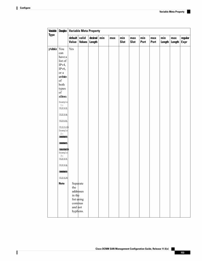
Variable Meta PropertyDescriptionVariableType
regularExpr
maxLength
minLength
maxPort
minPort
maxSlot
minSlot
maxmindecimalLength
validValues
defaultValue
YesYoucanhave alist ofIPv4,IPv6,or acombinationofbothtypesofaddresses.Example1:172.22.31.97,
172.22.31.99,
172.22.31.105,
172.22.31.109Example2:2001:0db8:85a3:0000:0000:8a2e:0370:7334,
2001:0db8:85a3:0000:0000:8a2e:0370:7335,
2001:0db8:85a3:1230:0000:8a2f:0370:7334Example3:172.22.31.97,
172.22.31.99,
2001:0db8:85a3:0000:0000:8a2e:0370:7334,
172.22.31.254
Separatetheaddressesin thelist usingcommasand nothyphens.
Note
ipAddressList
Cisco DCNM SAN Management Configuration Guide, Release 11.5(x)153
ConfigureVariable Meta Property

Variable Meta PropertyDescriptionVariableType
regularExpr
maxLength
minLength
maxPort
minPort
maxSlot
minSlot
maxmindecimalLength
validValues
defaultValue
IPv4orIPv6Address(doesnotrequireprefix/subnet).
ipAddressWithoutPrefix
YesIPv4address
ipV4Address
YesIPv4AddresswithSubnet
ipV4AddressWithSubnet
YesIPv6address
ipV6Address
YesIPv6Addresswithprefix
ipV6AddressWithPrefix
YesIPv6AddresswithSubnet
ipV6AddressWithSubnet
Example:
49.0001.00a0.c96b.c490.00
ISISNetAddress
YesYesYesExample:100
long
MACaddress
macAddress
Cisco DCNM SAN Management Configuration Guide, Release 11.5(x)154
ConfigureVariable Meta Property
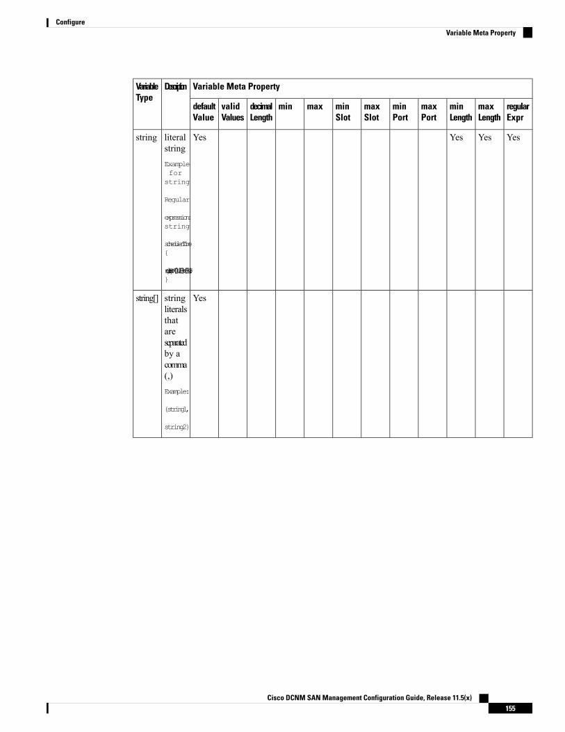
Variable Meta PropertyDescriptionVariableType
regularExpr
maxLength
minLength
maxPort
minPort
maxSlot
minSlot
maxmindecimalLength
validValues
defaultValue
YesYesYesYesliteralstringExampleforstring
Regular
expression:string
scheduledTime{
regularExpr=̂([01]\d|2[0-3]):([0-5]\d)$;}
string
Yesstringliteralsthatareseparatedby acomma(,)Example:
{string1,
string2}
string[]
Cisco DCNM SAN Management Configuration Guide, Release 11.5(x)155
ConfigureVariable Meta Property

Variable Meta PropertyDescriptionVariableType
regularExpr
maxLength
minLength
maxPort
minPort
maxSlot
minSlot
maxmindecimalLength
validValues
defaultValue
Set ofparametersthatarebundledunderasinglevariable.struct
<structurenamedeclaration> {<parametertype>
<parameter1>;<parametertype>
<parameter2>;…..}[<structure_inst1>][,<structure_inst2>][,<structure_array_inst3[]>];
struct
WWNaddress
wwn
Example: Meta Property Usage
##template variables
integer VLAN_ID {min = 100;max= 200;};
string USER_NAME {defaultValue = admin123;minLength = 5;};
struct interface_a{
Cisco DCNM SAN Management Configuration Guide, Release 11.5(x)156
ConfigureVariable Meta Property

string inf_name;string inf_description;ipAddress inf_host;enum duplex {validValues = auto, full, half;};}myInterface;
##
Variable Annotation
You can configure the variable properties marking the variables using annotations.
Variable Annotations are available for POAP only. However, the annotations do not impact on the templatetype ‘CLI’.
Note
The following annotations can be used in the template variable section.
DescriptionValid ValuesAnnotation Key
Copies values from onefield to another
TextAutoPopulate
TextDataDepend
Description of the fieldappearing in the window
TextDescription
Display name of thefield appearing in thewindow
Text
Enclose the textwith quotes, ifthere is space.
Note
DisplayName
Lists the text or numericvalues to select from
Text1, Text2, Text3, and soon
Enum
Validates if the string isalphanumeric
“true” or “false”IsAlphaNumeric
“true” or “false”IsAsn
“true” or “false”IsDestinationDevice
“true” or “false”IsDestinationFabric
“true” or “false”IsDestinationInterface
“true” or “false”IsDestinationSwitchName
“true” or “false”IsDeviceID
“true” or “false”IsDot1qId
Cisco DCNM SAN Management Configuration Guide, Release 11.5(x)157
ConfigureVariable Annotation

DescriptionValid ValuesAnnotation Key
“true” or “false”IsFEXID
Validates if the IPaddress is a gateway
“true” or “false”IsGateway
Makes the fields internaland does not displaythem on the window
Use thisannotationonly for theipAddressvariable.
Note
“true” or “false”IsInternal
“true” or “false”
This annotationmust be markedonly for variable“ipAddress”.
Note
IsManagementIP
Validates if a valueshould be passed to thefield mandatorily
“true” or “false”IsMandatory
“true” or “false”IsMTU
“true” or “false”IsMultiCastGroupAddress
Converts a string field tomultiline string text area
“true” or “false”IsMultiLineString
“true” or “false”IsMultiplicity
“true” or “false”IsPassword
Checks if the value ispositive
“true” or “false”IsPositive
“true” or “false”IsReplicationMode
Displays or hides a fieldon the window
“true” or “false”IsShow
“true” or “false”IsSiteId
“true” or “false”IsSourceDevice
“true” or “false”IsSourceFabric
“true” or “false”IsSourceInterface
Cisco DCNM SAN Management Configuration Guide, Release 11.5(x)158
ConfigureVariable Annotation
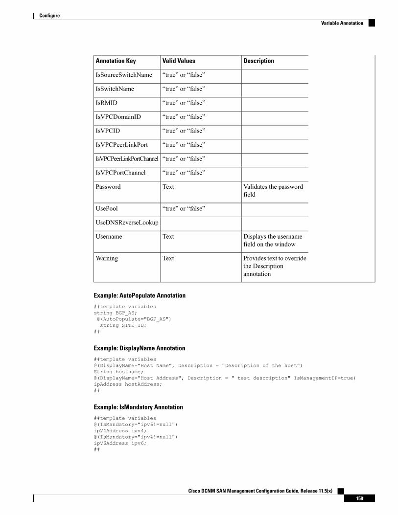
DescriptionValid ValuesAnnotation Key
“true” or “false”IsSourceSwitchName
“true” or “false”IsSwitchName
“true” or “false”IsRMID
“true” or “false”IsVPCDomainID
“true” or “false”IsVPCID
“true” or “false”IsVPCPeerLinkPort
“true” or “false”IsVPCPeerLinkPortChannel
“true” or “false”IsVPCPortChannel
Validates the passwordfield
TextPassword
“true” or “false”UsePool
UseDNSReverseLookup
Displays the usernamefield on the window
TextUsername
Provides text to overridethe Descriptionannotation
TextWarning
Example: AutoPopulate Annotation
##template variablesstring BGP_AS;@(AutoPopulate="BGP_AS")string SITE_ID;
##
Example: DisplayName Annotation
##template variables@(DisplayName="Host Name", Description = "Description of the host")String hostname;@(DisplayName="Host Address", Description = " test description" IsManagementIP=true)ipAddress hostAddress;##
Example: IsMandatory Annotation
##template variables@(IsMandatory="ipv6!=null")ipV4Address ipv4;@(IsMandatory="ipv4!=null")ipV6Address ipv6;##
Cisco DCNM SAN Management Configuration Guide, Release 11.5(x)159
ConfigureVariable Annotation

Example: IsMultiLineString Annotation
##template variables@(IsMultiLineString=true)string EXTRA_CONF_SPINE;##
IsShow Annotation
##template variablesboolean isVlan;@(IsShow="isVlan==true")integer vlanNo;##
##template variablesboolean enableScheduledBackup;@(IsShow="enableScheduledBackup==true",Description="Server time")string scheduledTime;##The condition "enableScheduledBackup==true" evaluates to true/false
##template variables@(Enum="Manual,Back2BackOnly,ToExternalOnly,Both")string VRF_LITE_AUTOCONFIG;@(IsShow="VRF_LITE_AUTOCONFIG!=Manual", Description="Target Mask")integer DCI_SUBNET_TARGET_MASK##The condition "VRF_LITE_AUTOCONFIG!=Manual" matches string comparison to evaluate to trueor false
Example: Warning Annotation
##template variables@(Warning="This is a warning msg")string SITE_ID;
##
Templates Content
This section includes the configuration commands and any parameters that you want to include in the template.These commands can include the variables declared in the template variables section. During the commandgeneration process the variable values are substituted appropriately in the template content.
You must specify the commands that you include as if you were entering them in the global configurationcommand mode on any device. You must consider the command mode when you include commands.
Note
Template content is governed by the usage of variables.
• Scalar variables: does not take a range or array of values which cannot be used for iteration (In the variabletypes table those marked iterate-able as 'No'). Scalar variables must be defined inside the template content.
Syntax: $$<variable name>$$Example: $$USER_NAME$$
• Iterative variables: used for block iteration. These loop variable must be accessed as shown below insidethe iteration block.
Cisco DCNM SAN Management Configuration Guide, Release 11.5(x)160
ConfigureTemplates Content

Syntax:@<loop variable>Example:foreach val in $$INTEGER_RANGE_VALUE$$ {@val}
• Scalar Structure Variable: Structure member variables can be accessed inside the template content.
Syntax: $$<structure instance name>.<member variable name>$$Example: $$myInterface.inf_name$$
• Array Structure Variable: Structure member variables can be accessed inside the template content.
Syntax: $$<structure instance name>.<member variable name>$$Example: $$myInterface.inf_name$$
In addition to the template variables, you can use the conditional and iterative command generation using thefollowing statements:
• if-else if-else Statement: makes a logical decision in inclusion/exclusion of set of configuration commandbased on the value assigned for the variable in it.
Syntax: if(<operand 1> <logical operator> <operand 2>){command1 ..command2....}else if (<operand 3> <logical operator> <operand 4> ){Command3 ..Command4....}else{Command5 ..Command6....}Example: if-else if-else statementif($$USER_NAME$$ == 'admin'){Interface2/10no shut}else {Interface2/10shut}
• foreach Statement: used for iterating a block of commands. The iteration is performed based on theassigned loop variable value.
Syntax:foreach <loop index variable> in $$<loop variable>$$ {@<loop index variable> ..}Example: foreach Statementforeach ports in $$MY_INF_RANGE$${interface @ports
Cisco DCNM SAN Management Configuration Guide, Release 11.5(x)161
ConfigureTemplates Content
no shut}
• Optional parameters: By default all parameters are mandatory. To make a parameter optional, you mustannotate the parameter.
• Interactive command handling: Include prompt and response as part of the template content for handlinginteractive commands.Example:
##template variablesstring srcFile;string srcDir;string password;string vrf;##
##template contentcopy scp://[email protected]/$$srcFile$$ bootflash: vrf $$vrf$$ <prompt:'(yes/no)?',response:'yes'> <prompt:'(y/n)?[n]',response:'y'> <prompt:'password:',response:'$$password$$'>
In the variable section, you can include the following command:
• @(IsMandatory=false)
• Integer frequency;
In the template content section, a command can be excluded or included without using “if” conditioncheck, by assigning a value to the parameter. The optional command can be framed as below:
• probe icmp [frequency frequency-value] [timeout seconds] [retry-count retry-count-value]
Template Content Editor
The template content editor has the following features:
• Syntax highlighting: The editor highlights the syntax, like different types of statements, keywords, andso on, for Python scripting.
• Autocompletion: The editor suggests the template datatypes, annotations, or metaproperties when youstart typing.
• Go to line: You can navigate to the exact line in the template content editor instead of scrolling. PressCommand-L in Mac or Ctrl-L in Windows, and enter the line number to which you want to navigateto in the pop-up window.
If you enter a value greater than the number of lines in the editor, you will be navigated to the last linein the editor window.
• Template search and replace: Press Command-F in Mac or Ctrl-F in Windows, enter the search termin the Search for field, and select the type of search in the search window. You can perform the followingsearches in the editor:
• RegExp Search: You can perform the regular expression search in the editor.
• CaseSensitive Search: You can perform a case-sensitive search in the editor.
Cisco DCNM SAN Management Configuration Guide, Release 11.5(x)162
ConfigureTemplate Content Editor

• Whole Word Search: You can perform a whole word search to find the exact words in the editor.For example, a regular search for the word "play" returns results where it is part of words like"display," but the whole word search returns results only when there is an exact match for the word"play".
• Search In Selection: You can perform a search in the selected content. Select the content to whichyou want to limit the search and enter the search term.
Choose the + icon in the search window to use the replace option. Enter the replacing word in theReplacewith field. You can replace the selected word once by selecting Replace. To replace all the occurrencesof the selected word, select All.
• Code folding: You can expand or group code blocks in the editor by clicking the arrow next to their linenumbers.
• Other features: The editor automatically indents the code, the closing braces, and highlights the matchingparenthesis.
Template Editor Settings
You can edit the following features of a template editor by clicking Template Editor Settings.
• Theme: Select the required theme for the editor from the drop-down list.
• KeyBinding: Select the editor mode from the KeyBinding drop-down list to customize the editor. Vimand Ace modes are supported. The default is Ace.
• Font Size: Select the required font size for the editor.
Advanced Features
The following are the advanced features available to configure templates.
• Assignment Operation
Config template supports assignment of variable values inside the template content section. The valuesare validated for the declared data type of the variable. If there is a mismatch, the value is not assigned.
Assignment operation can be used under the following guidelines:
• The operator on the left must be any of the template parameters or a for loop parameter.
• The operator on the right values can be any of the values from template parameters, for loopparameters, literal string values surrounded by quotes or simple string values.
If a statement does not follow these guidelines, or if it does not suit this format, it will not be consideredas assignment operation. It is substituted during command generation like other normal lines.
Example: Template with assignment operation##template propertiesname =vlan creation;userDefined= true;supportedPlatforms = All;templateType = CLI;published = false;####template variablesintegerRange vlan_range;
Cisco DCNM SAN Management Configuration Guide, Release 11.5(x)163
ConfigureTemplate Editor Settings
@(internal=true)integer vlanName;####template contentforeach vlanID in $$vlan_range$${vlan @vlanID$$vlanName$$=@vlanIDname myvlan$$vlanName$$}##
• Evaluate methods
Config template uses the Java runtime provided Java script environment to perform arithmetic operations(such as ADD, SUBTRACT, and so on), string manipulations, and so on.
Locate the JavaScript file in the template repository path. This file contains primary set of arithmetic,string functions. You can also add custom JavaScript methods.
These methods can be called from config template content section in below format:
Example1:$$somevar$$ = evalscript(add, "100", $$anothervar$$)
Also the evalscript can be called inside if conditions as below:
if($$range$$ > evalscript(sum, $$vlan_id$$, -10)){do something...}
You can call a method that is located at the backend of the Java script file.
• Dynamic decision
Config template provides a special internal variable “LAST_CMD_RESPONSE”. This variable storesthe last command response from the device during the execution of the command. This can be used inthe config template content to make dynamic decisions to deliver the commands that are based on thedevice condition.
The if block must be followed by an else block in a new line, whichcan be empty.
Note
An example use case to create a VLAN, if it is does not exist on the device.Example: Create VLAN##template contentshow vlan id $$vlan_id$$if($$LAST_CMD_RESPONSE$$ contains "not found"){vlan $$vlan_id$$}else{}##
This special implicit variable can be used only in the “IF” blocks.
• Template referencing
Cisco DCNM SAN Management Configuration Guide, Release 11.5(x)164
ConfigureAdvanced Features
You can have a base template with all the variables defined. This base template can be imported tomultiple templates. The base template content is substituted in the appropriate place of the extendingtemplate. The imported template parameters and the contents can be accessed inside the extendingtemplate.Example: Template ReferencingBase template:##template propertiesname =a vlan base;userDefined= true;supportedPlatforms = All;templateType = CLI;published = false;timestamp = 2015-07-14 16:07:52;imports = ;####template variablesinteger vlan_id;####template contentvlan $$vlan_id$$##
Derived Template:##template propertiesname =a vlan extended;userDefined= true;supportedPlatforms = All;templateType = CLI;published = false;timestamp = 2015-07-14 16:07:52;imports = a vlan base,template2;####template variablesinterface vlanInterface;####template content<substitute a vlan base>interface $$vlanInterface$$<substitute a vlan base>##
When you launch the extended template, the parameter inputs for the base template are also obtained.In addition, the substituted content is used for complete CLI command generation.
• Solution POAP Templates for VXLAN and FabricPath
From Cisco DCNM Release 10.0(1), Cisco provides you a set of defined templates to aid in POAPoperations. You can download Cisco-defined templates fromhttps://software.cisco.com/download/release.html.
For instructions on how to download and install POAP templates, see Cisco DCNM Installation Guide,Release 10.0(x).
Adding a Template
To add user-defined templates and schedule jobs from the Cisco DCNMWeb UI, perform the following steps:
Cisco DCNM SAN Management Configuration Guide, Release 11.5(x)165
ConfigureAdding a Template

Procedure
Step 1 Choose Configure > Templates > Template Library > Templates.
The Templates window is displayed with the name of the template along with its description, supportedplatforms, and tags.
Step 2 Click Add to add a new template.
The Template Properties window appears.
Step 3 Specify a template name, description, tags, and supported platforms for the new template.Step 4 Specify a Template Type for the template. Select POAP to make this template available when you power
on the application.
The template is considered as a CLI template if POAP is not selected.Note
Step 5 Select a Template Sub Type and Template Content Type for the template.Step 6 Click the Advanced tab to edit other properties like Implements, Dependencies, Published, and Imports.
Select Published to make the template read-only. You cannot edit a published template.Step 7 From the Imports > Template Name list, check the template check box.
The base template content is displayed in the Template Content window. The base template displays thetemplate properties, template variables, and template content. This template can be imported in to anothertemplate and the base template content is substituted in the appropriate place of the extending template. Whenyou launch the extended template, the parameter inputs for the base template are also obtained. Also, thesubstituted content is used for complete CLI command generation.
The base templates are CLI templates.Note
Step 8 Click OK to save the template properties, or click the cancel icon at the top-right corner of the window torevert the changes.
You can edit the template properties by clicking Template Property.Note
Step 9 Click Template Content to edit the template syntax. For information about the structure of the ConfigurationTemplate, see the Template Structure section.
Step 10 Click Validate Template Syntax to validate the template values.
If an error or a warning message appears, you can check the validation details inValidation Table by clickingthe error and warnings field.
You can continue to save the template if there are warnings only. However, if there is an error, youmust edit the templates to fix the errors before you proceed. Click the line number under the StartLine column to locate the error in the template content. You will get an error if you validate atemplate that does not have a template name.
Note
Step 11 Click Save to save the template.Step 12 Click Save and Exit to save the configuration and go back to the configuring templates screen.
Cisco DCNM SAN Management Configuration Guide, Release 11.5(x)166
ConfigureAdding a Template
Configuring Template Job
To configure and schedule jobs for individual templates from the Cisco DCNMWebUI, perform the followingsteps:
Procedure
Step 1 Choose Configure > Templates > Template Library > Templates.Step 2 Select a template.
Config Job wizard is applicable only for CLI templates.Note
Step 3 Click Launch job creation wizard icon and click Next.Step 4 Use the drop-down to select Device Scope.
The devices that are configured under the selected Device Scope are displayed.
If no devices are displayed, check if the device LAN credentials are configured by choosingAdministration > Credentials Management > LAN Credentials.
Note
Step 5 Use the arrows to move the devices to the right column for job creation and click Next.Step 6 In the Define Variable section, specify the VSAN_ID, VLAN_ID, ETH_SLOT_NUMBER,
VFC_SLOT_NUMBER, SWITCH_PORT_MODE, ETH_PORT_RANGEandALLOWED_VLANSvalues.
Based on the selected template, variables vary.Note
Step 7 In the Edit Variable Per Device section, double click the fields to edit the variables for specific devices andclick Next.
Step 8 If you have selected multiple devices, use the drop-down to select a specific device and preview itsconfiguration. Click Back to edit the configuration or click Next.
Step 9 Specify a job name and description.
The Device Credentials are populated fromAdministration > Credentials Management > LAN Credentials.
Step 10 Use the radio button to select Instant Job or Schedule Job.
If you select Schedule Job, specify the date and time for the job delivery.
Step 11 Use the check box to select Copy Run to Start.Step 12 If you want to configure more transaction and delivery options, use the check box to select Show more
options.Step 13 Under Transaction Options(Optional), if you have a device with rollback feature support, select Enable
Rollback check box and select the appropriate radio button.
You can choose one of the following options by selecting the appropriate radio button:
• Rollback the configuration on a device if there is any failure on that device
• Rollback the configuration on all the devices if there is any failure on any device
• Rollback the configuration on a device if there is any failure on any device and stop furtherconfiguration delivery to remaining devices
Cisco DCNM SAN Management Configuration Guide, Release 11.5(x)167
ConfigureConfiguring Template Job
Step 14 Under Delivery Options (Optional), specify the command response timeout in seconds and use the radiobutton to select a delivery order. The value of command response timeout ranges from 1 to 180.
You can choose one of the following options by selecting the appropriate radio button:
• Deliver configuration one device at a time in sequential
• Delivery configuration in parallel to all devices at the same time
Step 15 Click Finish to create the job.
A confirmation message is displayed that the job has been successfully created. The jobs are listed in the Jobswindow.
Modifying a Template
You can edit the user-defined templates. However, the predefined templates and templates that are alreadypublished cannot be edited.
Procedure
Step 1 From Configure > Templates > Template Library > Templates, select a template.Step 2 Click Modify/View template.Step 3 Edit the template description and tags.
The edited template content is displayed in a pane on the right.
Step 4 From the Imports > Template Name list, check the template check box.
The base template content is displayed in the Template Content window. You can edit the template contentbased on your requirement in the Template Content window. Click the help icon next to the TemplateContent window for information about editing the content of the template.
Step 5 Edit the supported platforms for the template.Step 6 Click Validate Template Syntax to validate the template values.Step 7 Click Save to save the template.Step 8 Click Save and Exit to save the configuration and go back to the configuring templates screen.
Copying a Template
To copy a template from the Cisco DCNMWeb UI, perform the following steps:
Procedure
Step 1 Choose Configure > Templates > Template Library > Templates, and select a template.Step 2 Click Save Template As.Step 3 Edit the template name, description, tags, and other parameters.
Cisco DCNM SAN Management Configuration Guide, Release 11.5(x)168
ConfigureModifying a Template
The edited template content is displayed in the right-hand pane.
Step 4 From the Imports > Template Name list, check the template check box.
The base template content is displayed in the Template Content window. You can edit the template contentthat is based on your requirement in the Template Content window. Click the help icon next to the TemplateContent window for information about editing the content of the template.
Step 5 Edit the supported platforms for the template.Step 6 Click Validate Template Syntax to validate the template values.Step 7 Click Save to save the template.Step 8 Click Save and Exit to save the configuration and go back to the configuring templates screen.
Deleting a Template
You can delete the user-defined templates. However, you cannot delete the predefined templates. From CiscoDCNM Release 11.0(1), you can delete multiple templates at once.
To delete a template from the Cisco DCNMWeb UI, perform the following steps:
Procedure
Step 1 Choose Configure > Templates > Template Library > Templates.Step 2 Use the check box to select a template and click Remove template icon.
The template is deleted without any warning message.
What to do next
The template is deleted from the list of templates on the DCNMWebUI.When you restart the DCNM services,the deleted templates are displayed on the Configure > Templates > Template Library > Templates page.
To delete the template permanently, delete the template that is located in your local directory: CiscoSystems\dcm\dcnm\data\templates\.
Importing a Template
To import a template from the Cisco DCNMWeb UI, perform the following steps:
Procedure
Step 1 Choose Configure > Templates > Template Library > Templates and click Import Template.Step 2 Browse and select the template that is saved on your computer.
You can edit the template parameters, if necessary. For information, see Modifying a Template, on page 168.
The “\n” in the template is considered as a new line character when imported and edited, but it worksfine when imported as a ZIP file.
Note
Cisco DCNM SAN Management Configuration Guide, Release 11.5(x)169
ConfigureDeleting a Template
Step 3 Click Validate Template Syntax to validate the template.Step 4 Click Save to save the template or Save and Exit to save the template and exit.
You can import Cisco-defined FabricPath and IP VXLAN Programmable Fabric POAP Templatesto the Cisco DCNMWeb Client. For more information, see Installing POAP Templates.
Note
Exporting a Template
To export a template from the Cisco DCNMWeb UI, perform the following steps:
Procedure
Step 1 Choose Configure > Templates > Template Library > Templates.Step 2 Use the check box to select a template and click Export Template.
The browser requests you to open or save the template to your directory.
Installing POAP Templates
Cisco DCNM allows you to add, edit, or delete user-defined templates that are configured across differentCisco Nexus platforms. From Cisco DCNM Release 10.0(x), Cisco-defined FabricPath and IP VXLANProgrammable Fabric POAP Templates are provided as a separate download on the official Cisco website.These templates are compatible for use with the DCNM Virtual Appliance (OVA or ISO) for use with Nexus2000, Nexus 5000, Nexus 6000, Nexus 7000, and Nexus 9000 Series switches.
You can download the Cisco-defined templates from https://software.cisco.com/download/release.html.
Perform the following task to install the POAP templates from the Cisco DCNM.
Procedure
Step 1 Navigate to https://software.cisco.com/download/release.html, and download the file.
You can choose one of the following:
• dcnm_ip_vxlan_fabric_templates.10.0.1a.zip
• dcnm_fabricpath_fabric_templates.10.0.1a.zip file
Step 2 Unzip and extract the files to the local directory on your computer.Step 3 Choose Configure > Templates > Template Library > Templates.Step 4 Click Import Template.Step 5 Browse and select the template that is saved on your computer. You can edit the template parameters, if
necessary.Step 6 Check POAP and Publish check box to designate these templates as POAP templates.Step 7 Click Validate Template Syntax to validate the template.
Cisco DCNM SAN Management Configuration Guide, Release 11.5(x)170
ConfigureExporting a Template
Step 8 Click Save to save the template or Save and Exit to save the template and exit.
Configuring JobsTo configure jobs from the Cisco DCNMWeb UI, perform the following steps:
Procedure
Step 1 Choose Configure > Templates > Templates Library > Jobs.
The jobs are listed along with the Job ID, description and status. The latest task will be listed at the top.
If failover is triggered in Native HA, the Job ID sequence number is incremented by 32.Note
Step 2 Click Show Filter to filter the list.
In the Status column, use the drop-down to select the job status.
Step 3 Select a job and click the Delete icon to delete the job.Step 4 To view the status of a job, click the Job ID radio button and click Status.Step 5 To view the command execution status for a device, click the radio button of a device name from the Devices
table in the Job Execution Status window.
You can delete multiple jobs at once, but you cannot view the status of multiple jobs at once.Note
BackupThe Backup menu includes the following submenus:
Switch ConfigurationThis feature allows you to backup device configurations from running configuration as a regular text file inthe file system. However, you can also perform operations on startup configuration. The backup files can bestored in the DCNM server host or on a file server.
You can also configure the archive system to support scheduling of jobs for the selected list of devices. Youcan configure only one job for a switch.
The following tables describe the icons and fields that appear onConfigure > Backup > Switch Configuration.
Table 17: Switch Configuration Operations
DescriptionIcon
Allows you to copy a configuration file of a switchto the bootflash of the selected destination switches.
Copy Configuration to bootflash
Allows you to view the configuration file.View Configuration
Cisco DCNM SAN Management Configuration Guide, Release 11.5(x)171
ConfigureConfiguring Jobs
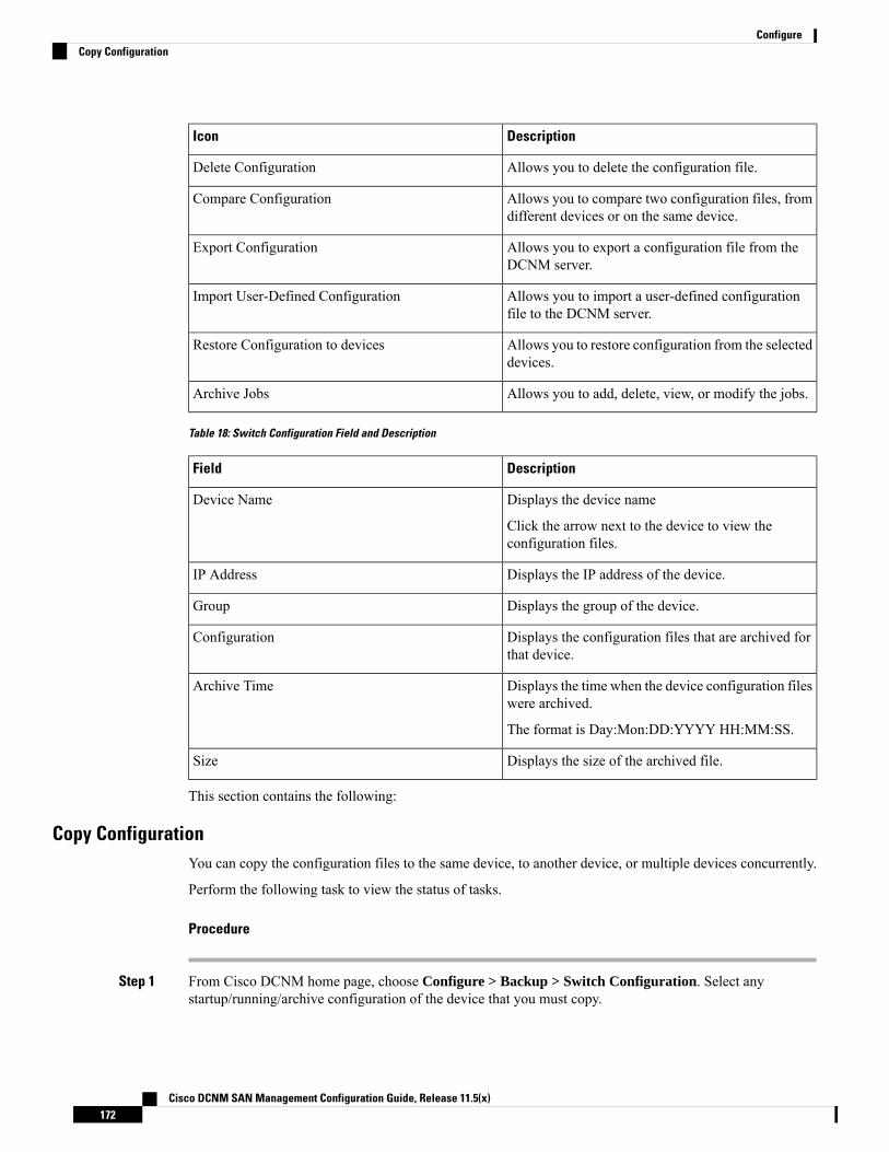
DescriptionIcon
Allows you to delete the configuration file.Delete Configuration
Allows you to compare two configuration files, fromdifferent devices or on the same device.
Compare Configuration
Allows you to export a configuration file from theDCNM server.
Export Configuration
Allows you to import a user-defined configurationfile to the DCNM server.
Import User-Defined Configuration
Allows you to restore configuration from the selecteddevices.
Restore Configuration to devices
Allows you to add, delete, view, or modify the jobs.Archive Jobs
Table 18: Switch Configuration Field and Description
DescriptionField
Displays the device name
Click the arrow next to the device to view theconfiguration files.
Device Name
Displays the IP address of the device.IP Address
Displays the group of the device.Group
Displays the configuration files that are archived forthat device.
Configuration
Displays the time when the device configuration fileswere archived.
The format is Day:Mon:DD:YYYY HH:MM:SS.
Archive Time
Displays the size of the archived file.Size
This section contains the following:
Copy ConfigurationYou can copy the configuration files to the same device, to another device, or multiple devices concurrently.
Perform the following task to view the status of tasks.
Procedure
Step 1 From Cisco DCNM home page, choose Configure > Backup > Switch Configuration. Select anystartup/running/archive configuration of the device that you must copy.
Cisco DCNM SAN Management Configuration Guide, Release 11.5(x)172
ConfigureCopy Configuration
Step 2 Click Copy Configuration to bootflash.
Copy Configuration to bootflash page appears, displaying the Source Configuration Preview and SelectedDevices area.
Source Configuration Preview area shows the contents of running/startup/version configuration file whichis copied to the devices.
Step 3 In the Selected Devices area, check the device name check box to copy the configuration to the device.
You can select multiple destination devices to copy the configuration.Note
The selected devices area shows the following fields:
• Device Name—Specifies the target device name to which the source configuration is copied.
• IP Address—Specifies the IP Address of the destination device.
• Group—Specifies the group to which the device belongs.
• Status—Specifies the status of the device.
Step 4 Click Copy.
A confirmation window appears.
Step 5 Click Yes to copy the configuration to the destination device configuration.
View ConfigurationYou can view or edit the configuration file on the device.
Perform the following task to view or edit the configuration file for the devices.
Procedure
Step 1 From Cisco DCNM home page, choose Configure > Backup > Switch Configuration. Click the arrow nextto the device name to view the configuration files on the device. Select the configuration file radio button toview the configuration file.
Step 2 Click the View Configuration.
The View Configuration window appears showing the configuration file content.
Delete ConfigurationPerform the following task to delete the configuration file from the device.
Ensure that you take a backup of the configuration file before you delete.Note
Cisco DCNM SAN Management Configuration Guide, Release 11.5(x)173
ConfigureView Configuration
Procedure
Step 1 From Cisco DCNM home page, choose Configure > Backup > Switch Configuration. Click the arrow nextto the device name to view the configuration files on the device.
Step 2 Click the configuration file radio button to be deleted.
You can delete multiple configuration files. However, you cannot delete startup, or runningconfiguration files.
Note
Step 3 Click Yes to delete the configuration file.
Compare Configuration FilesThis feature allows you to compare the configuration file with another version of the same device or with theconfiguration file of another device.
Perform the following task to compare the configuration files.
Procedure
Step 1 Navigate to Configure > Backup > Switch Configuration. Click the arrow next to the device name to viewthe configuration files on the device.
Step 2 Check the check box and select two configuration files to compare.
The first file that you selected is designated as Source and the second configuration file is designated as theTarget file.
Step 3 Click Compare Configuration.
View Config Diff page appears, displaying the difference between the two configuration files.
The Source and Target configuration files content is displayed in two columns. From the drop-down list inthe right-top corner, choose All to view the entire configuration. You can also choose Changed to view theconfiguration differences of the configuration files.
The differences in the configuration file are show in the table, with legends.
• Red: Deleted configuration details.
• Green: New added configuration.
• Blue: Modified configuration details.
Step 4 Click Copy to Target to copy the source configuration to the target configuration file. Click Cancel to revertto the configuration details page.
The Copy Configuration window displays the source configuration preview and the target device of thedestination configuration. The selected devices area shows the following fields:
• Device Name—Specifies the target device name to which the source configuration is copied.
• IP Address—Specifies the IP Address of the destination device.
Cisco DCNM SAN Management Configuration Guide, Release 11.5(x)174
ConfigureCompare Configuration Files
• Group—Specifies the group to which the device belongs.
• Status—Specifies the status of the device.
Step 5 Click Yes to copy the configuration to the destination device configuration.
Export ConfigurationYou can export a configuration file from the Cisco DCNM server. Perform the following task to export aconfiguration file.
Procedure
Step 1 From Cisco DCNM home page, choose Configure > Backup, select a configuration to export.Step 2 Click Export Configuration.
The files are downloaded in your local system. You can use the third-party file transfer tools to transfer thesefiles to an external server.
Import Configuration FileYou can import the configuration file from the file server to the Cisco DCNM.
Perform the following task to import a single or multiple configuration files.
Procedure
Step 1 From Cisco DCNM home page, choose Configure > Backup > Switch Configuration and click ImportUser-Defined Configuration.
The file server directory opens.
Step 2 Browse the directory and select the configuration file that you want to import. Click Open.
A confirmation screen appears.
The file name should not contain forward slash (/) or backward slash (\).
The file name can be alphanumeric. It can also have a period (.), underscore (_), and a space. Youcan import only files with the .cfg extension.
Note
Step 3 Click Yes to import the selected file.
The imported configuration file appears as a User Imported file.
Cisco DCNM SAN Management Configuration Guide, Release 11.5(x)175
ConfigureExport Configuration

Restore ConfigurationYou can restore the configuration file from the selected switches. From Cisco DCNM Release 11.0(1), youcan restore configuration based on the selected date as well.
You cannot restore the configuration for SAN switches and FCoE-enabled switches.Note
Perform the following task to restore the configuration from the selected devices.
Procedure
Step 1 From Cisco DCNM home page, choose Configure > Backup > Switch Configuration, and click Restore.Step 2 Select the type of restore from the drop-down list. You can choose Version-based or Date-based.
• If you choose date-based restore, you have to select the date and time. The configurationavailable before the mentioned time is restored.
• If you choose version-based restore, you have to choose a configuration from theConfigurationcolumn. You can view the configuration details in the View column.
Note
Step 3 Check the Device Name check box from which you want to restore the configuration. Click Restore.
The Devices area shows the following fields:
• Device Name—Specifies the device name from which the configuration file is restored.
• IP Address—Specifies the IP Address of the device.
• Group—Specifies the group to which the device belongs.
• Status—Specifies the status of the device.
You can restore the configuration only from the same device. If you select user-importedconfiguration files, you can restore configuration for any number of devices.
Note
Archive JobsThis section contains context-sensitive online help content under Cisco DCNMConfigure > Backup > SwitchConfiguration >Archive Jobs.
The configuration files from the archived jobs are located in the DCNM Server directory:\dcm\dcnm\data\archive\<dcnm-ip-address>\. You can use the third-party file transfer toolsor file transfer commands to transfer these files to an external server.
Note
The following table describes the fields that appear on the Archive Jobs window.
Cisco DCNM SAN Management Configuration Guide, Release 11.5(x)176
ConfigureRestore Configuration

DescriptionField
Specifies who created this job.User
Specifies the group to which this job belongs.Group
Specifies whether it is a group job or a per-device job.The values are true or false.
Group Job
Specifies the schedule of the job. Also show therecurrence information.
Schedule
Specifies the date and time at which this job was lastexecuted.
Last Execution
Specifies if the jobwas successful, scheduled, running,or failure.
Job Status
Running and Scheduled status is notapplicable for existing jobs in an upgradedCisco DCNM.
Note
Specifies the comments or description provided bythe user.
User Comments
Archive Jobs
To add, delete or view the job from the Cisco DCNMWeb UI, perform the following steps:
You must set the SFTP/TFTP/SCP credentials before you configure jobs. On the DCNMWeb Client, navigateto Administration > DCNM Server > Archive FTP Credentials to set the credentials.
Note
Procedure
Step 1 Choose Configure > Backup > Switch Configuration > Archive Jobs > Archive Jobs tab, and click AddJob.
The Create Job screen displays the Schedule, Device Selection and Selected Devices.
A backup is scheduled as defined.
a) In the Schedule area, configure the start time, repeat interval and repeat days.
• Start At: Configure the start time using the hour:minutes:second drop-down lists.
• Once: Configure the job to be executed once, on the particular day. The time at which this jobwill be executed is determined by the Start At field.
• Now—Configure the job to be executed immediately. Cisco DCNM will consider the defaultdate and time as configured on the server.
You can schedule a job to run Now even if a job is already scheduled.Note
Cisco DCNM SAN Management Configuration Guide, Release 11.5(x)177
ConfigureArchive Jobs
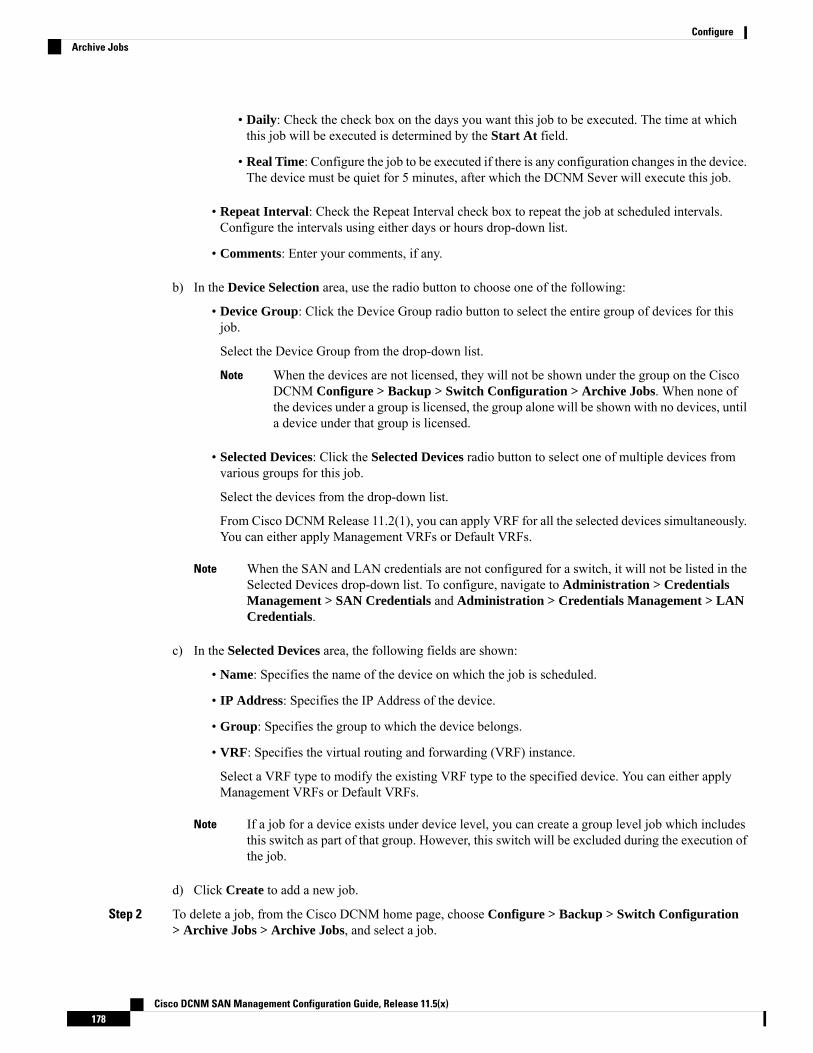
• Daily: Check the check box on the days you want this job to be executed. The time at whichthis job will be executed is determined by the Start At field.
• Real Time: Configure the job to be executed if there is any configuration changes in the device.The device must be quiet for 5 minutes, after which the DCNM Sever will execute this job.
• Repeat Interval: Check the Repeat Interval check box to repeat the job at scheduled intervals.Configure the intervals using either days or hours drop-down list.
• Comments: Enter your comments, if any.
b) In the Device Selection area, use the radio button to choose one of the following:
• Device Group: Click the Device Group radio button to select the entire group of devices for thisjob.
Select the Device Group from the drop-down list.
When the devices are not licensed, they will not be shown under the group on the CiscoDCNM Configure > Backup > Switch Configuration > Archive Jobs. When none ofthe devices under a group is licensed, the group alone will be shown with no devices, untila device under that group is licensed.
Note
• Selected Devices: Click the Selected Devices radio button to select one of multiple devices fromvarious groups for this job.
Select the devices from the drop-down list.
From Cisco DCNM Release 11.2(1), you can apply VRF for all the selected devices simultaneously.You can either apply Management VRFs or Default VRFs.
When the SAN and LAN credentials are not configured for a switch, it will not be listed in theSelected Devices drop-down list. To configure, navigate to Administration > CredentialsManagement > SAN Credentials and Administration > Credentials Management > LANCredentials.
Note
c) In the Selected Devices area, the following fields are shown:
• Name: Specifies the name of the device on which the job is scheduled.
• IP Address: Specifies the IP Address of the device.
• Group: Specifies the group to which the device belongs.
• VRF: Specifies the virtual routing and forwarding (VRF) instance.
Select a VRF type to modify the existing VRF type to the specified device. You can either applyManagement VRFs or Default VRFs.
If a job for a device exists under device level, you can create a group level job which includesthis switch as part of that group. However, this switch will be excluded during the execution ofthe job.
Note
d) Click Create to add a new job.
Step 2 To delete a job, from the Cisco DCNM home page, choose Configure > Backup > Switch Configuration> Archive Jobs > Archive Jobs, and select a job.
Cisco DCNM SAN Management Configuration Guide, Release 11.5(x)178
ConfigureArchive Jobs

a) Click Delete Job.
The Schedule, Device Selection and the Selected devices for this job is displayed.
b) Click Delete.
Step 3 To view the details of the job, from the Cisco DCNM home page, choose Configure > Backup > SwitchConfiguration > Archive Jobs > Archive Jobs, and check the job check box.a) Click View/Modify Job.
The Schedule, Device Selection and the Selected devices for this job is displayed.
b) Modify the required details. Click OK to revert to view the list of jobs.
• You cannot modify a job that is scheduled to be run Now to one that is scheduled to berun Daily.
• You cannot modify the repeat interval duration for an archive job. When you try to modify,the operation fails and the job is deleted. You must delete existing repeat interval archivejob and create a new job.
Note
What to do next
You can also configure the Cisco DCNM to retain the number of archived files per device. ChooseAdministration > DCNM Server > Server Properties, and update the archived.versions.limit field.
Job Execution Details
The Cisco DCNM Web Client > Configure > Backup > Switch Configuration > Archive Jobs > ArchiveJobs > Job Execution Details tab shows the following tabs in the Job Execution History table.
DescriptionField
Displays the system-generated job name.Job Name
Specifies the persona of the person who created the job.User
Specifies fabric or the LAN group under which the job was created.Device Group
Specifies the IP Address of the Device.Device
Specifies the IP Address of the DCNM Server to which the device is associated with.Server
Specifies if the SFTP, TFTP, or SCP protocol is applied.Protocol
Specifies the time at which the job was last executed.Execution time
Specifies the status of the job.
• Skipped
• Failed
• Successful
Status
Cisco DCNM SAN Management Configuration Guide, Release 11.5(x)179
ConfigureJob Execution Details
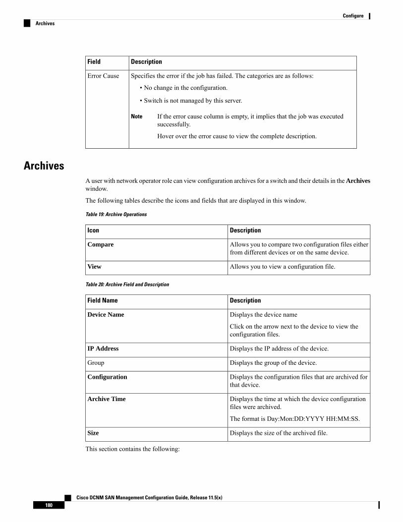
DescriptionField
Specifies the error if the job has failed. The categories are as follows:
• No change in the configuration.
• Switch is not managed by this server.
If the error cause column is empty, it implies that the job was executedsuccessfully.
Hover over the error cause to view the complete description.
Note
Error Cause
ArchivesA user with network operator role can view configuration archives for a switch and their details in theArchiveswindow.
The following tables describe the icons and fields that are displayed in this window.
Table 19: Archive Operations
DescriptionIcon
Allows you to compare two configuration files eitherfrom different devices or on the same device.
Compare
Allows you to view a configuration file.View
Table 20: Archive Field and Description
DescriptionField Name
Displays the device name
Click on the arrow next to the device to view theconfiguration files.
Device Name
Displays the IP address of the device.IP Address
Displays the group of the device.Group
Displays the configuration files that are archived forthat device.
Configuration
Displays the time at which the device configurationfiles were archived.
The format is Day:Mon:DD:YYYY HH:MM:SS.
Archive Time
Displays the size of the archived file.Size
This section contains the following:
Cisco DCNM SAN Management Configuration Guide, Release 11.5(x)180
ConfigureArchives
Compare Configuration FilesYou can compare one version of a configuration file with another version of the same configuration file inthe same device, or the configuration files of two different devices.
To compare the configuration files from the Cisco DCNMWeb UI, perform the following steps:
Procedure
Step 1 Choose Configure > Backup > Archives.Step 2 In the Archives area, click the arrow that is adjacent the name of the device whose configuration files you
want to view. The list of configuration files is displayed.Step 3 Check the check box next to configuration files and select two configuration files to compare.
The first file that you select is designated as the source and the second configuration file is designated as thetarget file.
Step 4 Click Compare.
The View Config Diff page displays the difference between the two configuration files.
The Source and Target configuration files content are displayed in two columns. ChooseAll from the drop-downlist in the right-top corner to view the entire configuration. Choose Changed to view the configurationdifferences between the configuration files.
The differences in the configuration files are shown in a table, with legends.
• Red: Deleted configuration details.
• Green: New added configuration.
• Blue: Modified configuration details.
View ConfigurationYou can view an archived configuration file.
To view or edit the configuration file for the devices from the Cisco DCNMWeb UI, perform the followingsteps:
Procedure
Step 1 Choose Configure > Backup > Archives.
The Archives window is displayed.
Step 2 Click the arrow that is next to the name of the device whose configuration files you want to view.
The list of configuration files are displayed.
Step 3 Select the radio button that is next to the corresponding file you want to view.Step 4 Click the View configuration icon.
Cisco DCNM SAN Management Configuration Guide, Release 11.5(x)181
ConfigureCompare Configuration Files
The View configuration window appears showing the configuration file content in the right column.
Network Config AuditCisco DCNM provides auditing for the configuration changes across the network switches. The NetworkAudit Reporting feature enables you to a generate audit report so that you can track the added, deleted, ormodified configurations. You will be able to generate the network audit reports only when you have existingarchival jobs. Using the generated reports, you can view the config differences on a device for a specifiedperiod.
This section contains the following:
Generating Network Config Audit ReportsTo generate the network config audit reports from the Cisco DCNMWeb UI, perform the following steps:
Procedure
Step 1 Choose Configure > Backup > Network Config Audit.
The Network Audit Report window is displayed.
Step 2 In the Devices drop-down list, choose the devices to generate a report.Step 3 Specify the Start Date and the End Date.Step 4 ClickGenerate Report to view the configuration differences. The configuration differences are color-coded.
• Red: Deleted Configuration• Green: Newly Added Configuration• Blue: Changed configuration• Strikethrough: Old configuration
After you generate a report, you can export the configuration reports into an HTML file.
Creating a Network Config Audit Report
To create a network config audit job and view the configuration differences between the devices from theCisco DCNMWeb UI, perform the following steps:
Procedure
Step 1 Choose Monitor > Report > Generate.
The left pane shows various reports that you can create.
Step 2 Choose Common > Network Config Audit.Step 3 In the Report Name field, enter the name of the report.
Cisco DCNM SAN Management Configuration Guide, Release 11.5(x)182
ConfigureNetwork Config Audit
Step 4 In the Repeat field, choose the appropriate repeat interval, that is, Daily, Weekly, or Monthly.
Daily job generates a report of configuration differences for all the selected devices for last 1 day. Weeklyjob generates a report for the last 7 days, and the monthly job generates a report for the last 30 days.
Step 5 In the Start and End date fields, specify the start and end date for the report.Step 6 In the Email Report field, specify the email delivery options.
• No: Select this option if you do not want to send the report through email.• Link Only: Select this option if you want to send the link to the report.• Contents: Select this option if you want to send the report content.
If you select Link Only or the Contents option, enter the email address and subject in the To and Subjectfields.
Monitoring Network Config Audit Report
To monitor the network config audit report from the Cisco DCNMWeb UI, perform the following steps:
Procedure
Step 1 Choose Monitor > Report > View.Step 2 Choose Common > Network Config Audit in the left pane to the network config audit reports.
Deleting a Network Config Audit Report
To delete a network config audit report from the Cisco DCNMWeb UI, perform the following steps:
Procedure
Step 1 Choose Monitor > Report > View.Step 2 Choose Common > Network Config Audit.
The View Reports window is displayed with the reports that you have created.
Step 3 Select the reports that you want to delete, and click the Delete icon.
Image ManagementUpgrading your devices to the latest software version manually might take a long time and prone to error,which requires a separate maintenance window. To ensure rapid and reliable software upgrades, imagemanagement automates the steps associated with upgrade planning, scheduling, downloading, and monitoring.Image management is supported only for Cisco Nexus switches and Cisco MDS switches.
Cisco DCNM SAN Management Configuration Guide, Release 11.5(x)183
ConfigureMonitoring Network Config Audit Report
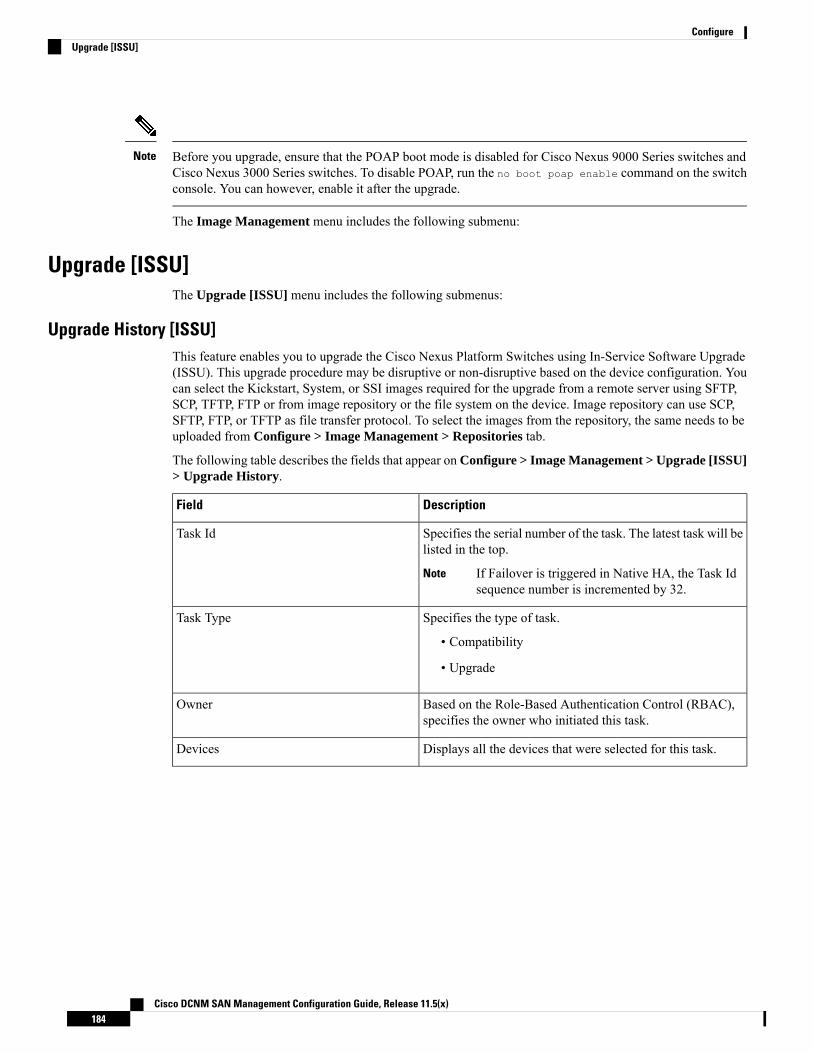
Before you upgrade, ensure that the POAP boot mode is disabled for Cisco Nexus 9000 Series switches andCisco Nexus 3000 Series switches. To disable POAP, run the no boot poap enable command on the switchconsole. You can however, enable it after the upgrade.
Note
The Image Management menu includes the following submenu:
Upgrade [ISSU]The Upgrade [ISSU] menu includes the following submenus:
Upgrade History [ISSU]This feature enables you to upgrade the Cisco Nexus Platform Switches using In-Service Software Upgrade(ISSU). This upgrade procedure may be disruptive or non-disruptive based on the device configuration. Youcan select the Kickstart, System, or SSI images required for the upgrade from a remote server using SFTP,SCP, TFTP, FTP or from image repository or the file system on the device. Image repository can use SCP,SFTP, FTP, or TFTP as file transfer protocol. To select the images from the repository, the same needs to beuploaded from Configure > Image Management > Repositories tab.
The following table describes the fields that appear on Configure > Image Management > Upgrade [ISSU]> Upgrade History.
DescriptionField
Specifies the serial number of the task. The latest task will belisted in the top.
If Failover is triggered in Native HA, the Task Idsequence number is incremented by 32.
Note
Task Id
Specifies the type of task.
• Compatibility
• Upgrade
Task Type
Based on the Role-Based Authentication Control (RBAC),specifies the owner who initiated this task.
Owner
Displays all the devices that were selected for this task.Devices
Cisco DCNM SAN Management Configuration Guide, Release 11.5(x)184
ConfigureUpgrade [ISSU]

DescriptionField
Specifies the status of the job.
• Planned
• In Progress
• Completed
• Completed with Exceptions
If the job fails on a single or multiple devices,the status field shows COMPLETED WITHEXCEPTION indicating a failure.
Note
Job Status
Specifies the time when the task was created.Created Time
Specifies the time when the task is specified to be executed.You can also choose to schedule a task to be executed at alater time.
Scheduled At
Specifies the time when the task was completed.Completed Time
Shows any comments that the Owner has added whileperforming the task.
Comment
After a fresh Cisco DCNM installation, this page will have no entries.Note
You can perform the following:
New Installation
To upgrade the devices that are discovered from the Cisco DCNM, perform the following steps:
Procedure
Step 1 Choose Configure > Image Management > Upgrade [ISSU] > Upgrade History.Step 2 Choose New Installation to install, or upgrade the kickstart and the system images on the devices.
The devices with default VDCs are displayed in the Select Switches window.
Step 3 Select the check box to the left of the switch name.
You can select more than one switch and move the switches to the right column.
Step 4 Click Add or Remove icons to include the appropriate switches for upgrade.
The selected switches appear in a column on the right.
Step 5 Click Next.
The Pre-Post ISSU Reports window appears.
Cisco DCNM SAN Management Configuration Guide, Release 11.5(x)185
ConfigureNew Installation

Pre-Post ISSU Reports are not supported in SAN and Media Controller installations.Note
Step 6 Click Next.
The Specify Software Imageswindow appears. This tab displays the switches that you selected in the previousscreen. You can choose the images for upgrade as well.
• The Auto File Selection check box enables you to specify a file server, an image version, and a pathwhere you can apply the upgraded image to the selected devices.
• In the Select File Server drop-down list, select the one of the file servers that is created in the CiscoDCNM repositories.
• In the Image Version field, specify the image version. For example, enter 7.3.9.D1.1 in the ImageVersion field if you have selected m9700-sf3ek9-kickstart-mz.7.3.0.D1.1.bin as the image version.
• In the Path field, specify the image path. Specify an absolute path if you choose SCP or SFTP. Forexample, //root/images/. Specify a relative path to the FTP or TFTP home directory if you chooseFTP or TFTP. Specify the absolute path of the image if you’re using TFTP server that is provided byCisco DCNM, local DCNM TFTP. You can’t use the same DCNM TFTP server for creating another jobwhen the current job is in progress.
Step 7 Click Select Image in the Kickstart image column.
The Software Image Browser dialog box appears.
• Cisco Nexus 3000 Series and 9000 Series Switches require only the system image to load theCisco NX-OS operating system. Therefore, the option to select kickstart images for thesedevices is disabled.
• If there’s an issue in viewing the Software Image Browser dialog box, reduce the font sizeof your browser and retry.
Note
Step 8 Click Select Image in the System Image column.
The Software Image Browser dialog box appears.
Step 9 On the Software Image Browser dialog box, you can choose the image from File Server or Switch FileSystem.
If you choose File Server:
a) From the Select the File server list, choose the appropriate file server on which the image is stored.
The servers at Configure > Image Management > Repositories are displayed in the drop-down list.
b) From the Select Image list, choose the appropriate image. Check the check box to use the same imagefor all other selected devices of the same platform.
Example: For platform types N7K-C7009 and N7K-C7010, logic matches platform (N7K) and threecharacters (C70) from subplatform. The same logic is used across all platform switches.
Only files with BIN extension are listed if you select File Server. To view other files, chooseAdministration > DCNM Server > Server Properties, set FILE_SELECTION_FILTERto false, and restart the server. It is set to true by default.
Note
c) Choose a VRF from the Select Vrf drop-down list.
Cisco DCNM SAN Management Configuration Guide, Release 11.5(x)186
ConfigureNew Installation

This field does not appear for Cisco MDS switches.
This VRF is selected for other selected devices by default. The default value is management.
Note
d) Click OK.
If the file server selected is either ftp or tftp, in the text box, enter the relative path of the file fromthe home directory.
This image is selected for all other selected devices of same platform type.
If you choose Switch File System:
a) From the Select Image list, choose the appropriate image that is located on the flash memory of the device.
Only files with BIN extension are listed if you select Switch File System. To view other files,choose Administration > DCNM Server > Server Properties, setFILE_SELECTION_FILTER to false, and restart the server. It is set to true by default.
Note
b) Click OK to choose the kickstart image or Cancel to revert to the Specify Software Images dialog box.
Step 10 The Vrf column indicates the name of the virtual routing and forwarding (VRF).
VRF is not applicable for Cisco MDS devices.
Step 11 In the Available Space column, specify the available space for the Primary Supervisor and SecondarySupervisor modules of the switch.
Available Space column shows the available memory in MB on the switch (for less than 1 MB, it’s shownand marked as KB).
Bootflash browser shows the filename, size, and last modified date for all the files and directories on theswitch bootflash. You can delete files by selecting them and clicking Delete to increase the available spaceon the switch.
Step 12 Selected Files Size column shows the size of images that are selected from the SCP or SFTP server.
If the total size of selected images is greater than available space on a switch, the file size is marked in red.We recommend that you create more space on the switch to copy images to it and install.
Step 13 Drag and drop the switches to reorder the upgrade task sequence.Step 14 (Optional) Uncheck Skip Version Compatibility check box if you want to check the compatibility of Cisco
NX-OS software version on your device with the upgraded images that you chose.Step 15 Select Select Parallel Line Card upgrade to upgrade all the line cards at the same time.
Upgrading a parallel line card isn’t applicable for Cisco MDS devices.
Step 16 Click Options under the Upgrade Options column to choose the type of upgrade.
Upgrade Options window appears with two upgrade options. The drop-down list for Upgrade Option 1 hasthe following options:
• Disruptive
• Bios force
• Allow non-disruptive
• Force non-disruptive
Cisco DCNM SAN Management Configuration Guide, Release 11.5(x)187
ConfigureNew Installation
Disruptive is the default value for Cisco Nexus 9000 Series switches. The upgrade option is Not Applicablefor other switches.
When you choose Allow non-disruptive under Upgrade Option 1 and if the switch does not supportnon-disruptive upgrade, then it will go through a disruptive upgrade.
When you choose Force non-disruptive under Upgrade Option 1, the Skip Version Compatibility checkbox will be unchecked because compatibility check is mandatory for non-disruptive upgrade. If the switchesyou choose do not support non-disruptive upgrade, a warning message appears asking you to review the switchselection. Use the check boxes to choose or remove switches.
The drop-down list forUpgrade Option 2 has the following options when you chooseAllow non-disruptiveor Force non-disruptive under Upgrade Option 1:
• NA
• bios-force
When you choose Disruptive or Bios-force under Upgrade Option 1, Upgrade Option 2 is disabled.
Check the Use this Option for all other selected devices check box to use the selected option for all theselected devices and click OK.
• The upgrade options are applicable only for Cisco Nexus 3000 Series and 9000 Series switches.
• Selecting the Allow non-disruptive option for upgrading does not ensure a non-disruptiveupgrade. Perform a compatibility check to ensure that the device supports non-disruptiveupgrade.
Note
Step 17 Click Next.
If you didn’t select Skip Version Compatibility, the Cisco DCNM performs a compatibility check.
You can choose to wait until the check is complete or click Finish Installation Later.
The installation wizard is closed and a compatibility task is created in Configure > Image Management >Upgrade [ISSU] > Upgrade History tasks.
The time that is taken to check the image compatibility depends on the configuration and the load on thedevice.
The Version Compatibility VerificationCompatibility Verification status column displays the status ofverification.
If you skip the version compatibility check by choosing Skip Version Compatibility, Cisco DCNM displaysonly the name of the device. The Current Action column displays Completed, and the CompatibilityVerification column displays Skipped.
You can review the switch selection and check or uncheck the switches for upgrading accordingly.
Step 18 Click Finish Installation Later to perform the upgrade later.Step 19 Click Next.Step 20 Check the Next check box to put a device in maintenance mode before upgrade.Step 21 Check the check box to save the running configuration to the startup configuration before upgrading the
device.Step 22 You can schedule the upgrade process to occur immediately or later.
Cisco DCNM SAN Management Configuration Guide, Release 11.5(x)188
ConfigureNew Installation
a. Select Deploy Now to upgrade the device immediately.
b. Select Choose time to Deploy and specify the time in MMM/DD/YYYY HH:MM:SS format to performthe upgrade later.
This value is relative to the server time. If the selected time to deploy is in the past, the job is executedimmediately.
Step 23 You can choose the execution mode based on the devices and the line cards you have chosen to upgrade.
a. Select Sequential to upgrade the devices in the order you chose them.
This option is disabled if you put the device in maintenance mode.Note
b. Select Concurrent to upgrade all the devices at the same time.
Step 24 Click Finish to begin the upgrade process.
The Installation wizard closes and a task to upgrade is created on the Configure > Image Management >Upgrade [ISSU] > Upgrade History page.
What to do next
After you complete the ISSU on the switch, ensure that you wait for 20 minutes to allow the switch to reboot,and stabilize the SNMP agent. DCNM discovers polling cycles in order to display the new version of theswitch on the Cisco DCNMWeb UI.
Finish Installation
You can choose to complete the installation for tasks which was completed on the Compatibility Checkpage. Perform the following task to complete the upgrade process on the devices.
Procedure
Step 1 Choose Configure > Image Management > Upgrade [ISSU] > Upgrade History, select a task for whichthe compatibility check is complete.
Select only one task at a time.
Step 2 Click Finish Installation.
Software Installation Wizard appears.
Step 3 Review the switch selection and check or uncheck the switches for upgrading accordingly.Step 4 Check the check box to save the running configuration to the startup configuration before upgrading the
device.Step 5 Check the check box to put a device in maintenance mode before upgrade. This option is valid only for the
devices that support maintenance mode.Step 6 You can schedule the upgrade process to occur immediately or later.
a. Select Deploy Now to upgrade the device immediately.
Cisco DCNM SAN Management Configuration Guide, Release 11.5(x)189
ConfigureFinish Installation
b. Select Choose time to Deploy and specify the time in DD/MM/YYYY HH:MM:SS format to performthe upgrade later.
Step 7 You can choose the execution mode that is based on the devices and the line cards that you have chosen toupgrade.
a. Select Sequential to upgrade the devices in the order in which they were chosen.
This option is disabled if you put the device in maintenance mode.Note
b. Select Concurrent to upgrade the devices at the same time.
Step 8 Click Finish to complete the upgrade process.
View
To view the image upgrade history from the Cisco DCNMWeb UI, perform the following steps:
Procedure
Step 1 Choose Configure > Image Management > Upgrade [ISSU] > Upgrade History, check the task ID checkbox.
Select only one task at a time.
Step 2 Click View.
The Installation Task Details window appears.
Step 3 Click Settings. Expand the Columns menu and choose the details you want to view.
You can view the following information in this window:
• Location of the kickstart and system images
• Compatibility check status
• Installation status
• Descriptions
• Logs
Step 4 Select the device.
The detailed status of the task appears. For the completed tasks, the response from the device appears.
If the upgrade task is in progress, a live log of the installation process appears.
Cisco DCNM SAN Management Configuration Guide, Release 11.5(x)190
ConfigureView

• This table autorefreshes every 30 secs for jobs in progress, when you’re on this window.
• The switch-level status for an ongoing upgrade on a CiscoMDS switch doesn't appear for otherusers without SAN credentials. To apply SAN Credentials, choose Administration >Credentials Management > SAN Credentials.
Note
Delete
To delete a task from the Cisco DCNMWeb UI, perform the following steps:
Procedure
Step 1 Choose Configure > Image Management > Upgrade [ISSU] > Upgrade History, and check the Task IDcheck box.
Step 2 Click Delete.Step 3 Click OK to confirm deletion of the job.
Switch Level HistoryYou can view the history of the upgrade process at a switch level. You can view the current version of theswitch and other details.
The following table describes the fields that appear on Configure > Image Management > Upgrade [ISSU]> Switch Level History.
DescriptionField
Specifies the name of the switchSwitch Name
Specifies the IP Address of the switchIP Address
Specifies the Cisco Nexus switch platformPlatform
Specifies the current version on the switch softwareCurrent Version
Click the radio button next to a switch name to select the switch and view its upgrade history. Click View toview the upgrade task history for the selected switch.
The following table describes the fields that appear on Configure > Image Management > Upgrade [ISSU]> Switch Level History > View Device Upgrade Tasks:
DescriptionField
Specifies the owner who initiated the upgrade.Owner
Cisco DCNM SAN Management Configuration Guide, Release 11.5(x)191
ConfigureDelete
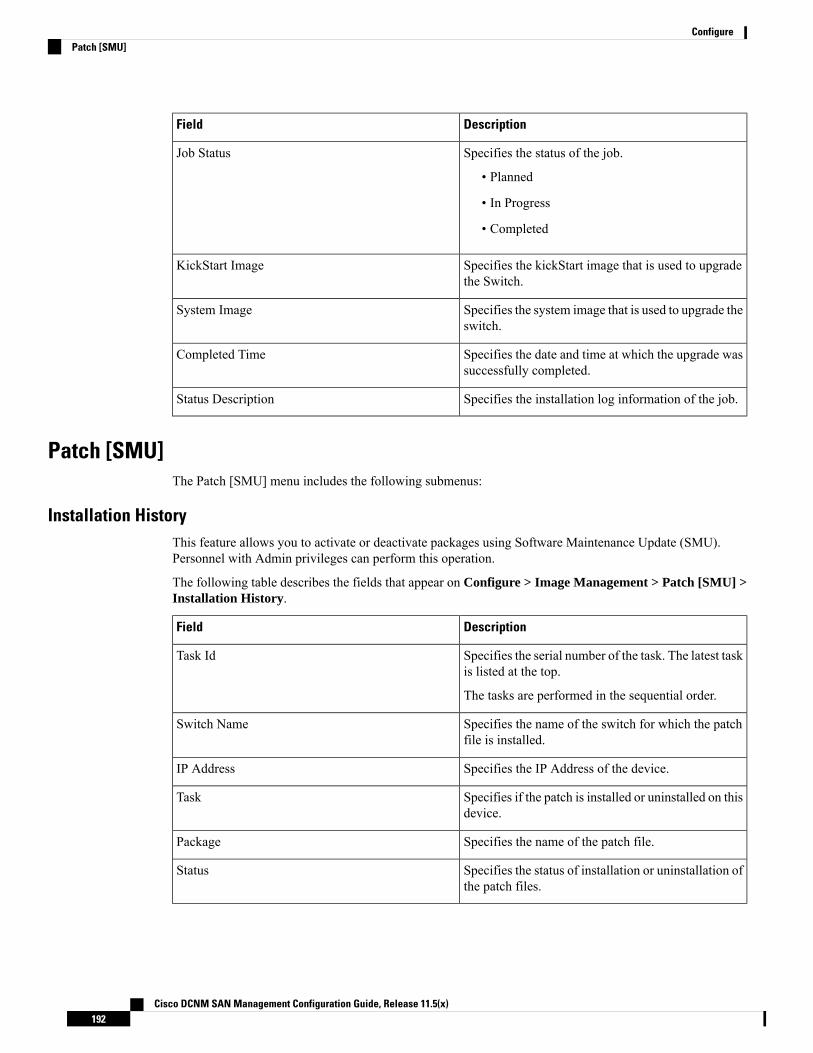
DescriptionField
Specifies the status of the job.
• Planned
• In Progress
• Completed
Job Status
Specifies the kickStart image that is used to upgradethe Switch.
KickStart Image
Specifies the system image that is used to upgrade theswitch.
System Image
Specifies the date and time at which the upgrade wassuccessfully completed.
Completed Time
Specifies the installation log information of the job.Status Description
Patch [SMU]The Patch [SMU] menu includes the following submenus:
Installation HistoryThis feature allows you to activate or deactivate packages using Software Maintenance Update (SMU).Personnel with Admin privileges can perform this operation.
The following table describes the fields that appear on Configure > Image Management > Patch [SMU] >Installation History.
DescriptionField
Specifies the serial number of the task. The latest taskis listed at the top.
The tasks are performed in the sequential order.
Task Id
Specifies the name of the switch for which the patchfile is installed.
Switch Name
Specifies the IP Address of the device.IP Address
Specifies if the patch is installed or uninstalled on thisdevice.
Task
Specifies the name of the patch file.Package
Specifies the status of installation or uninstallation ofthe patch files.
Status
Cisco DCNM SAN Management Configuration Guide, Release 11.5(x)192
ConfigurePatch [SMU]
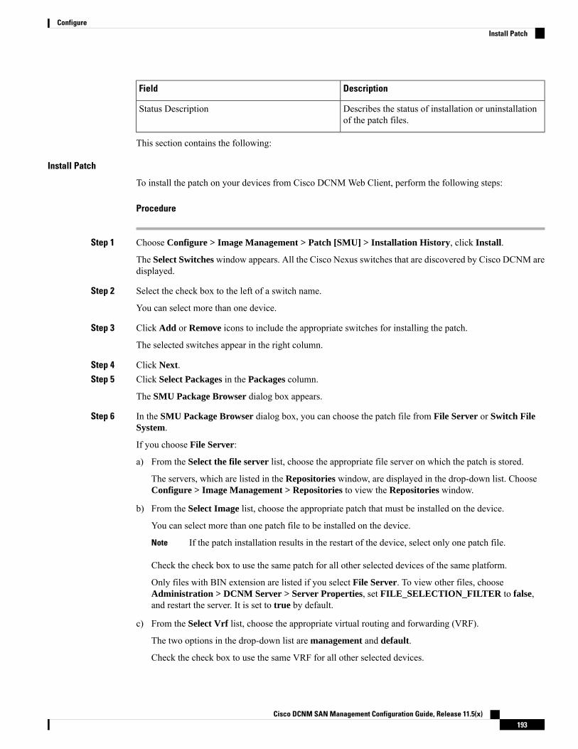
DescriptionField
Describes the status of installation or uninstallationof the patch files.
Status Description
This section contains the following:
Install Patch
To install the patch on your devices from Cisco DCNMWeb Client, perform the following steps:
Procedure
Step 1 Choose Configure > Image Management > Patch [SMU] > Installation History, click Install.
The Select Switches window appears. All the Cisco Nexus switches that are discovered by Cisco DCNM aredisplayed.
Step 2 Select the check box to the left of a switch name.
You can select more than one device.
Step 3 Click Add or Remove icons to include the appropriate switches for installing the patch.
The selected switches appear in the right column.
Step 4 Click Next.Step 5 Click Select Packages in the Packages column.
The SMU Package Browser dialog box appears.
Step 6 In the SMU Package Browser dialog box, you can choose the patch file from File Server or Switch FileSystem.
If you choose File Server:
a) From the Select the file server list, choose the appropriate file server on which the patch is stored.
The servers, which are listed in the Repositories window, are displayed in the drop-down list. ChooseConfigure > Image Management > Repositories to view the Repositories window.
b) From the Select Image list, choose the appropriate patch that must be installed on the device.
You can select more than one patch file to be installed on the device.
If the patch installation results in the restart of the device, select only one patch file.Note
Check the check box to use the same patch for all other selected devices of the same platform.
Only files with BIN extension are listed if you select File Server. To view other files, chooseAdministration > DCNM Server > Server Properties, set FILE_SELECTION_FILTER to false,and restart the server. It is set to true by default.
c) From the Select Vrf list, choose the appropriate virtual routing and forwarding (VRF).
The two options in the drop-down list are management and default.
Check the check box to use the same VRF for all other selected devices.
Cisco DCNM SAN Management Configuration Guide, Release 11.5(x)193
ConfigureInstall Patch

d) Click OK to choose the patch image or Cancel to revert to the SMU installation wizard.
If you choose Switch File System:
a) From the Select Image list, choose the appropriate patch file image that is located on the flash memoryof the device.
You can select more than one patch file to be installed on the device.
Only files with BIN extension are listed if you select Switch File System. To view other files, chooseAdministration > DCNM Server > Server Properties, set FILE_SELECTION_FILTER to false,and restart the server. It is set to true by default.
b) Click OK to choose the image, Clear Selections to uncheck all the check boxes, or Cancel to revert tothe SMU Package Browser dialog box.
Step 7 Click Finish.
You will get a confirmation window. Click OK.
SMU installation may reload the switch if the SMU is reloaded.Note
You can view the list of patches that are installed on the switch in the Switches window by choosing DCNM> Inventory > Switches.
Uninstall Patch
To uninstall the patch on your devices from Cisco DCNMWeb Client, perform the following steps:
Procedure
Step 1 Choose Configure > Image Management > Patch [SMU] > Installation History, click Uninstall.
The Select Switches page appears. The discovered Cisco Nexus switches are displayed.
Step 2 Check the check box on the left of the switch name.
You can select more than one image device.
Step 3 Click Add or Remove icons to include the appropriate switches for installing the patch.
The selected switches appear in a column on the right.
Step 4 Click Next.
The Active Packages page appears.
Step 5 Click Select Packages under the Installed Packages column.
The Packages Installed window appears, which lists the patches that are applied to the switch.
Step 6 Select the patches that you want to uninstall from this device.
You can select more than one patch that is applied on the device.
If the patch uninstallation results in the restart of the device, select only one patch.Note
Cisco DCNM SAN Management Configuration Guide, Release 11.5(x)194
ConfigureUninstall Patch

Step 7 Click Finish to uninstall the patch from the device.
You will get a confirmation window. Click OK.
You can uninstall more than one patch at a time.
SMU uninstallation may reload the switch if the SMU is reloaded.Note
Delete Patch Installation Tasks
To delete the patch installation tasks from the Cisco DCNMWeb UI, perform the following steps:
Procedure
Step 1 Choose Configure > Image Management > Patch [SMU] > Installation History, check the task ID checkbox.
Step 2 Click Delete.Step 3 Click OK to confirm deletion of the patch installation task.
Switch Installed PatchesYou can view the patches that are installed on all the switches in the network. You can refresh the view tosee the latest installed patches.
The following table describes the fields that appear on Configure > Image Management > Patch [SMU] >Switch Installed Patches.
DescriptionField
Specifies the name of the switch.Switch Name
Specifies the IP address of the switch.IP Address
Specifies the Cisco Nexus switch platform.Platform
Specifies the currently installed patches on switches.Installed Patches
Click Refresh to refresh the table.
Package [RPM]The Package [RPM] menu includes the following submenus:
Package Installation [RPM]The package [RPM] feature allows you to install RPM packages. This feature is available for the Cisco Nexus9000 Series and 3000 Series Switches.
Cisco DCNM SAN Management Configuration Guide, Release 11.5(x)195
ConfigureDelete Patch Installation Tasks
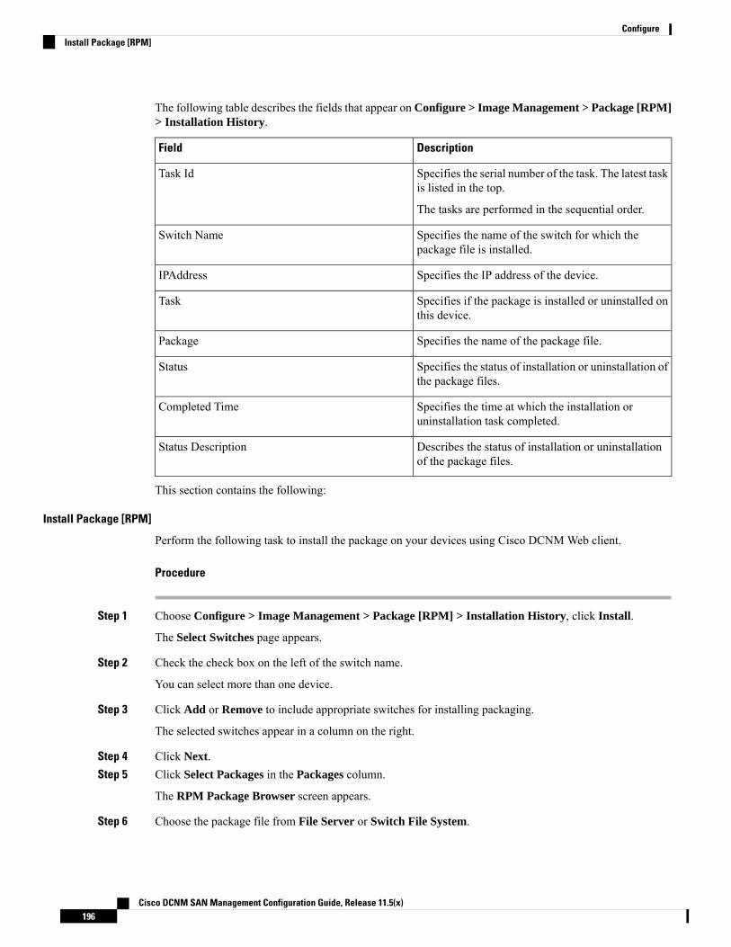
The following table describes the fields that appear on Configure > Image Management > Package [RPM]> Installation History.
DescriptionField
Specifies the serial number of the task. The latest taskis listed in the top.
The tasks are performed in the sequential order.
Task Id
Specifies the name of the switch for which thepackage file is installed.
Switch Name
Specifies the IP address of the device.IPAddress
Specifies if the package is installed or uninstalled onthis device.
Task
Specifies the name of the package file.Package
Specifies the status of installation or uninstallation ofthe package files.
Status
Specifies the time at which the installation oruninstallation task completed.
Completed Time
Describes the status of installation or uninstallationof the package files.
Status Description
This section contains the following:
Install Package [RPM]
Perform the following task to install the package on your devices using Cisco DCNMWeb client.
Procedure
Step 1 Choose Configure > Image Management > Package [RPM] > Installation History, click Install.
The Select Switches page appears.
Step 2 Check the check box on the left of the switch name.
You can select more than one device.
Step 3 Click Add or Remove to include appropriate switches for installing packaging.
The selected switches appear in a column on the right.
Step 4 Click Next.Step 5 Click Select Packages in the Packages column.
The RPM Package Browser screen appears.
Step 6 Choose the package file from File Server or Switch File System.
Cisco DCNM SAN Management Configuration Guide, Release 11.5(x)196
ConfigureInstall Package [RPM]
If you choose File Server:
a) From the Select the file server list, choose the appropriate file server on which the package is stored.
The servers at Configure > Image Management > Repositories are displayed in the drop-down list.
b) From the Select Image list, choose the appropriate package that must be installed on the device.
You can select more than one package file to be installed on the device.
Only files with RPM extension are listed if you select File Server. To view other files, chooseAdministration > DCNM Server > Server Properties, set FILE_SELECTION_FILTER to false,and restart the server. It is set to true by default.
Check the check box to use the same package for all other selected devices of the same platform.
c) Click OK to choose the patch image or Cancel to revert to the RPM Installation Wizard.
If you choose Switch File System:
a) From the Select Image list, choose the appropriate package file image that is located on the flash memoryof the device.
You can select more than one package file to be installed on the device.
Only files with RPM extension are listed if you select Switch File System. To view other files, chooseAdministration > DCNM Server > Server Properties, set FILE_SELECTION_FILTER to false,and restart the server. It is set to true by default.
b) Click OK.
Step 7 In the Installation Type column, choose one of the installation types:
• Normal—Fresh installation• Upgrade—Upgrading the existing RPM• Downgrade—Downgrading the existing RPM
Step 8 Click Finish.
You can view the list of packages that are installed on the switch, on the Web Client > Inventory > Switchespage.
If you are using Cisco DCNM Release 10.1(2), in case of installation of reload RPMs, perform amanual install commit on the switch after it switch reloads.
Note
Uninstall Package [RPM]
To uninstall the RPM on your devices from the Cisco DCNMWeb UI, perform the following steps:
Procedure
Step 1 Choose Configure > Image Management > Package [RPM] > Installation History, click Uninstall.
The Select Switches window appears.
Step 2 Check the check box on the left of the switch name.
Cisco DCNM SAN Management Configuration Guide, Release 11.5(x)197
ConfigureUninstall Package [RPM]

You can select more than one switch.
Step 3 Click the Add or Remove icons to include the appropriate switches for uninstalling the package.
The selected switches appear in a column on the right.
Step 4 Click Next.
The Active Packages page appears.
Step 5 Click Select Packages under the Installed Packages column.
The Packages Installed window appears, which lists the packages that are installed in the switch.
Step 6 Click Finish to uninstall the package from the device.
You will get a confirmation window. Click OK.
You can uninstall more than one package at a time.
• If you are using Cisco DCNM Release 10.1(2), in case of uninstallation of reload RPMs, amanual install commit needs to be performed on the switch once the switch is reloaded.
• RPM uninstallation may reload the switch if the RPM is reload RPM.
Note
Delete Package Installation Tasks
To delete the package installation tasks from the history view from the Cisco DCNMWeb UI, perform thefollowing steps:
Procedure
Step 1 Choose Configure > Image Management > Package [RPM] > Installation History, select the task IDcheck box.
Step 2 Click Delete.Step 3 Click OK to confirm deletion of the task.
Switch Installed PackagesYou can view the RPM packages that are installed on all Switches in the network. You can refresh the viewto see the latest installed packages.
The following table describes the fields that appear onConfigure > Image Management > Packages [RPM]> Switch Installed Packages.
DescriptionField
Specifies the name of the switch.Switch Name
Specifies the IP address of the switch.IP Address
Cisco DCNM SAN Management Configuration Guide, Release 11.5(x)198
ConfigureDelete Package Installation Tasks
DescriptionField
Specifies the Cisco Nexus switch platform.Platform
Specifies the currently installed packages on theswitches and the type of package. The installedpackages can be base packages or non-base packages.
Installed Packages
Click Refresh to refresh the table.
Maintenance Mode [GIR]The Maintenance Mode [GIR] menu includes the following submenus:
Maintenance ModeThe maintenance mode allows you to isolate the Cisco Nexus Switch from the network to perform an upgradeor debug, using Graceful Insertion and Removal (GIR). When the switch maintenance is complete, you canreturn the switch to normal mode. When the switch is in the maintenance mode, all protocols are gracefullybrought down and all physical ports are shut down. When the normal mode is restored, all the protocols andports are initiated again.
Perform the following to change the system mode of the devices.
Procedure
Step 1 Choose Configure > Image Management > Maintenance Mode [GIR] > Maintenance Mode, check theswitch name check box.
You can select multiple switches.
Step 2 Choose one of the following options under the Mode Selection column:
• Shutdown
• Isolate
Click the appropriate option before you change the mode.Note
Step 3 Click Change System Mode.
A confirmation message appears.
Step 4 Click OK to confirm to change the maintenance mode of the device.
The status of operation can be viewed in the System Mode and the Maintenance Status.
Switch Maintenance HistoryYou can view the history of the maintenance mode changes executed from the Cisco DCNM.
Cisco DCNM SAN Management Configuration Guide, Release 11.5(x)199
ConfigureMaintenance Mode [GIR]
The following table describes the fields that appear on Configure > Image Management > MaintenanceMode [GIR] > Switch Maintenance History.
DescriptionField
Specifies the serial number of the task. The latest tasksthat are listed in the top.
Task Id
Specifies the name of the switch for which themaintenance mode was changed.
Switch Name
Specifies the IP address of the switch.IP Address
Specifies the name of the user who initiated themaintenance.
User
Specifies the mode of the system.System Mode
Specifies the mode of the maintenance process.Maintenance Status
Specifies the status of the mode change.Status
Specified the time at which the maintenance modeactivity was completed.
Completed Time
Click the radio button next to the switch name to select the switch for which you need to view the upgradehistory. Click View to view the upgrade task history for the selected switch.
The following table describes the fields that appear on Configure > Image Management > Upgrade [ISSU]> Switch Level History > View > Upgrade Tasks History
DescriptionField
Specifies the owner who initiated the upgrade.Owner
Specifies the status of the job.
• Planned
• In Progress
• Completed
Job Status
Specifies the kickstart image that is used to upgradethe Switch.
KickStart Image
Specifies the system image that is used to upgrade theswitch.
System Image
Specifies the date and time at which the upgrade wassuccessfully completed.
Completed Time
Cisco DCNM SAN Management Configuration Guide, Release 11.5(x)200
ConfigureSwitch Maintenance History
Image and Configuration ServersTo view the Image and Configuration Servers window from the Cisco DCNMWeb UI homepage, chooseConfigure > Image Management > Repositories.
You can view the following details in the Image and Configuration Servers window.
DescriptionsField
Specifies the name of the repository you upload.Name
Specifies the path where you uploaded the repository.URL
Specifies the username of the remote server.Username
Specifies the date and timestamp of the last modification.LastModified
Add Image or Configuration Server URLTo add an image or a configuration server URL to the repository from the Cisco DCNMWeb UI, performthe following steps:
Procedure
Step 1 On the Image and Configuration Servers window, click the Add icon.
The Add Image or Configuration Server URL window is displayed.
Step 2 Specify a name for the image.Step 3 Click the radio button to select the protocol.
The available protocols are SCP, FTP, SFTP, and TFTP. Use the SCP protocol for POAP and ImageManagement.
You can use IPv4 and IPv6 addresses with these protocols.
Step 4 Enter the hostname or IP address and the path to download or upload files.
If you choose SCP or SFTP protocol and the path is root or /directory, adding an image orconfiguration server will not be successful.
Note
Step 5 Specify the username and password.Step 6 Click OK to save.
Deleting an ImageTo delete an image from the repository from the Cisco DCNMWeb UI, perform the following steps:
Cisco DCNM SAN Management Configuration Guide, Release 11.5(x)201
ConfigureImage and Configuration Servers

Procedure
Step 1 Choose Configure > Image Management > Repositories.
The Image and Configuration Servers window appears.
Step 2 Choose an existing image from the list and click the Delete Image icon.
A confirmation window appears.
Step 3 Click Yes to delete the image.
Editing an Image or Configuration Server URLTo edit an image or a configuration server URL to the repository from the Cisco DCNMWeb UI, performthe following steps:
Procedure
Step 1 On the Image and Configuration Servers window, select an existing image and configuration server fromthe list, and click Edit.
Step 2 In the Edit Image or Configuration Server URL window, edit the required fields.Step 3 Click OK to save or click Cancel to discard the changes.
File BrowserYou can view the contents of the server on the Image and Configuration Servers page.
1. In the Image and Configurations page, check the Server Name check box to view the content.
2. Click File Browser to view the contents of this server.
Image UploadTo upload different types of images to the server from the Cisco DCNMWeb UI, perform the following steps:
Devices use these images during POAP or image upgrade.
Your user role should be network-admin to upload an image. You can’t perform this operation with thenetwork-stager user role.
Note
Procedure
Step 1 Choose Configure > Image Management > Repositories.
Cisco DCNM SAN Management Configuration Guide, Release 11.5(x)202
ConfigureEditing an Image or Configuration Server URL

The Image and Configuration Servers window appears.
Step 2 Click Image Upload.
The Select File to Upload dialog box appears.
Step 3 Click Choose file to choose a file from the local repository of your device.Step 4 Choose the file and click Upload.Step 5 Click OK.
The upload takes some time depending on the file size and network bandwidth.
LAN Telemetry HealthStarting fromDCNM11.2(1), Streaming LANTelemetry preview feature in DCNM is obsolete and is replacedby Network Insights Resources (NIR) application. NIR can be deployed using Cisco DCNM ApplicationsFramework on Web UI > Applications. After the NIR is enabled on a fabric, you can monitor the status onthe window in the Cisco DCNMWeb UI.
When the connection status is shown as Disconnected the port configuration may not be accepted by theswitch correctly. On the switch image 7.0(3)I7(6), if a switch already had nxapi configuration, and later itwas managed by DCNM and telemetry was enabled on that fabric, DCNM pushes http port 80 configurationso that it could query some NXAPI commands such as show telemetry transport and show telemetry datacollector details, to monitor telemetry connection statistics. In this case, the switch does not update http port80 in its configuration even though the commandwas executed correctly. In such a scenario, issue the followingcommands on the switch:switch# configureswitch(config)# no feature nxapiswitch(config)# feature nxapiswitch(config)# http port 80
ICAM telemetry commands such as forwarding TCAM and ACL TCAM are not supported on Cisco NexusC9504, C9508, and C9516 Series platforms for switch images 7.0(3)I7(5) and 7.0(3)I7(6)
Note
LAN Telemetry has the following topics:
HealthCisco DCNM allows you to monitor the configuration health attributes of Software Telemetry and FlowTelemetry for each fabric. The attributes are displayed for a particular fabric or all fabrics based on the selectedSCOPE. Data Center scope displays all fabrics by default.
Cisco DCNM SAN Management Configuration Guide, Release 11.5(x)203
ConfigureLAN Telemetry Health

Software Telemetry
The following table describes the fields that appear in the LAN Telemetry > Health > Software Telemetrywindow.
DescriptionField
Displays the fabric name.Fabric Name
Displays the switch name.Switch Name
Displays the switch management IP address.Switch IP
Displays the switch serial number.
This column is hidden by default. Click the Settings icon, and checkthe Switch Serial check box to add it to the columns displayed.
Switch Serial
Cisco DCNM SAN Management Configuration Guide, Release 11.5(x)204
ConfigureSoftware Telemetry
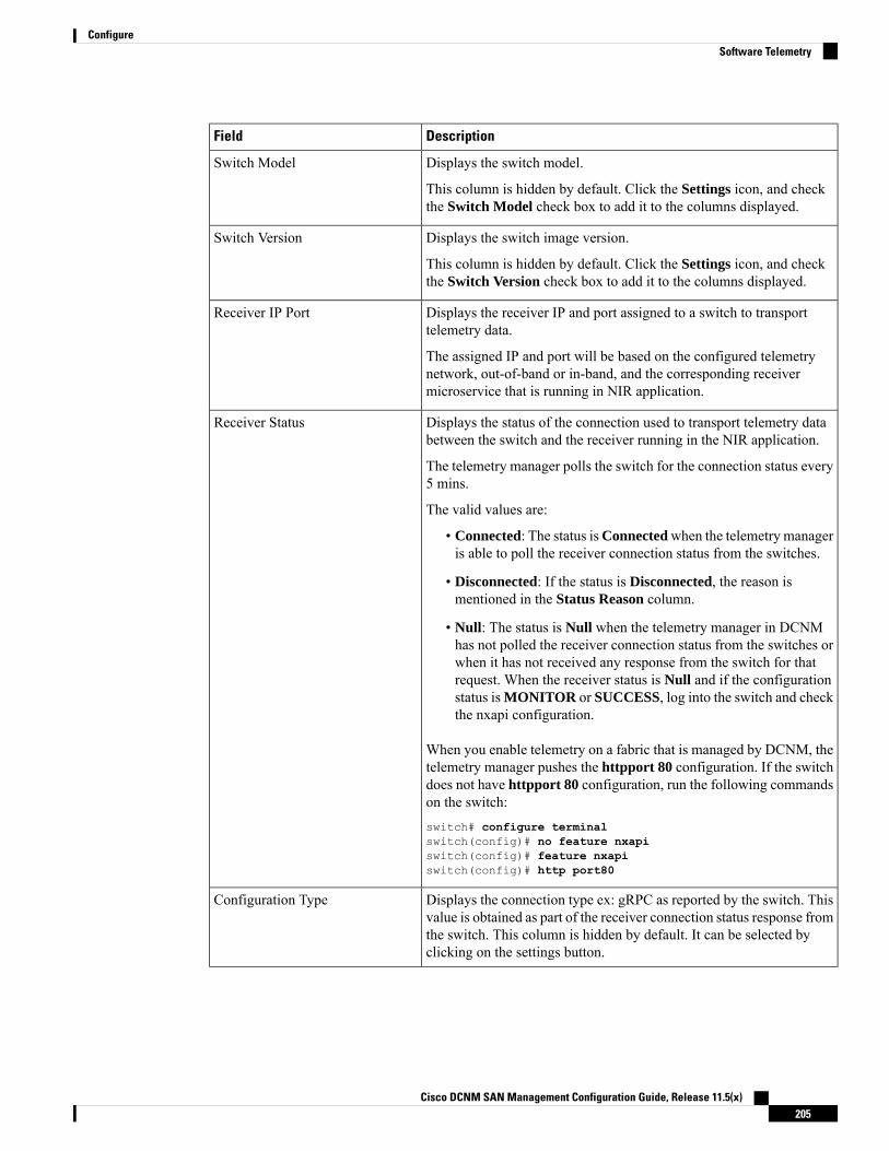
DescriptionField
Displays the switch model.
This column is hidden by default. Click the Settings icon, and checkthe Switch Model check box to add it to the columns displayed.
Switch Model
Displays the switch image version.
This column is hidden by default. Click the Settings icon, and checkthe Switch Version check box to add it to the columns displayed.
Switch Version
Displays the receiver IP and port assigned to a switch to transporttelemetry data.
The assigned IP and port will be based on the configured telemetrynetwork, out-of-band or in-band, and the corresponding receivermicroservice that is running in NIR application.
Receiver IP Port
Displays the status of the connection used to transport telemetry databetween the switch and the receiver running in the NIR application.
The telemetry manager polls the switch for the connection status every5 mins.
The valid values are:
• Connected: The status isConnectedwhen the telemetry manageris able to poll the receiver connection status from the switches.
• Disconnected: If the status is Disconnected, the reason ismentioned in the Status Reason column.
• Null: The status is Null when the telemetry manager in DCNMhas not polled the receiver connection status from the switches orwhen it has not received any response from the switch for thatrequest. When the receiver status is Null and if the configurationstatus isMONITOR or SUCCESS, log into the switch and checkthe nxapi configuration.
When you enable telemetry on a fabric that is managed by DCNM, thetelemetry manager pushes the httpport 80 configuration. If the switchdoes not have httpport 80 configuration, run the following commandson the switch:switch# configure terminalswitch(config)# no feature nxapiswitch(config)# feature nxapiswitch(config)# http port80
Receiver Status
Displays the connection type ex: gRPC as reported by the switch. Thisvalue is obtained as part of the receiver connection status response fromthe switch. This column is hidden by default. It can be selected byclicking on the settings button.
Configuration Type
Cisco DCNM SAN Management Configuration Guide, Release 11.5(x)205
ConfigureSoftware Telemetry
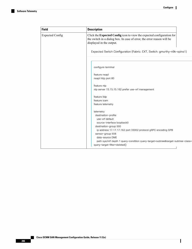
DescriptionField
Click the Expected Config icon to view the expected configuration forthe switch in a dialog box. In case of error, the error reason will bedisplayed in the output.
Expected Config
Cisco DCNM SAN Management Configuration Guide, Release 11.5(x)206
ConfigureSoftware Telemetry
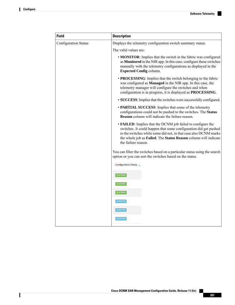
DescriptionField
Displays the telemetry configuration switch summary status.
The valid values are:
• MONITOR: Implies that the switch in the fabric was configuredasMonitored in the NIR app. In this case, configure these switchesmanually with the telemetry configurations as displayed in theExpected Config column.
• PROCESSING: Implies that the switch belonging to the fabricwas configured as Managed in the NIR app. In this case, thetelemetry manager will configure the switches and whenconfiguration is in progress, it is displayed as PROCESSING.
• SUCCESS: Implies that the switches were successfully configured.
• PARTIAL SUCCESS: Implies that some of the telemetryconfigurations could not be pushed to the switches. The StatusReason column will indicate the failure reason.
• FAILED: Implies that the DCNM job failed to configure theswitches. It could happen that some configuration did get pushedto the switches while some did not, in that case also DCNMmarksthe whole job as Failed. The Status Reason column will indicatethe failure reason.
You can filter the switches based on a particular status using the searchoption or you can sort the switches based on the status.
Configuration Status
Cisco DCNM SAN Management Configuration Guide, Release 11.5(x)207
ConfigureSoftware Telemetry

DescriptionField
Displays the sensor configuration status in a distributed color format.The sensor count is divided into three categories:
• Green color (Success): Number of sensor paths that got configuredsuccessfully
• Yellow color (Pending): Number of sensor paths that are pendingto be configured
• Red color (Failed): Number of sensor paths that could not beconfigured
Sensor Status
Displays the failure reasons for telemetry configuration status andreceiver connection status or other information.
Status Reason
Cisco DCNM SAN Management Configuration Guide, Release 11.5(x)208
ConfigureSoftware Telemetry

DescriptionField
Displays the following sensor details:
• Group ID: The group ID to which the sensor path belongs
• Name: The sensor path name as seen on the switch, for example:show processes cpu
• Cadence (Seconds): The sample interval, in seconds, at which theswitch streams that sensor path. For example: If the value is 60,every 60 seconds the switch shall stream that sensor metric.
• Packets: Specifies the number of metric samples that is collectedtill time.
• Job ID: This is the DCNM telemetry job ID that was used toconfigure the sensor path on the switch.
• Status: The status of the job.
• Status Reason: The status reason of the job. In case the job failed,it specifies the failure reason of that job.
Sensor Details
Cisco DCNM SAN Management Configuration Guide, Release 11.5(x)209
ConfigureSoftware Telemetry

Flow Telemetry
The following icons appear in the LAN Telemetry > Health > Flow Telemetry window.
• Retry All: Click the Retry All icon to retry the failed configurations on the switches. However, thisoption does not fix the issue for the unsupported configurations automatically.
• Export: Click the Export icon to download the data in a spreadsheet.
• Settings: Click the Settings icon to add or delete the columns you want to view.
The following table describes the columns in the LAN Telemetry > Health > Flow Telemetry tab.
Table 21: Fields and Description on Flow Telemetry Health tab
DescriptionField
Displays the name of the fabric.Fabric Name
Displays the name of the switch.Switch Name
Displays the switch management IP address.Switch IP
Displays the serial number of the switch. By default,this column is hidden. It can be selected by clickingthe Settings button.
Switch Serial
Displays the switch model. By default, this columnis hidden. It can be selected by clicking the Settingsbutton.
Switch Model
Displays the switch image version. By default, thiscolumn is hidden. It can be selected by clicking theSettings button.
Switch Version
Displays the exporter ID that is configured on theswitch as part of the flow analytics configuration.
Exporter ID
Cisco DCNM SAN Management Configuration Guide, Release 11.5(x)210
ConfigureFlow Telemetry
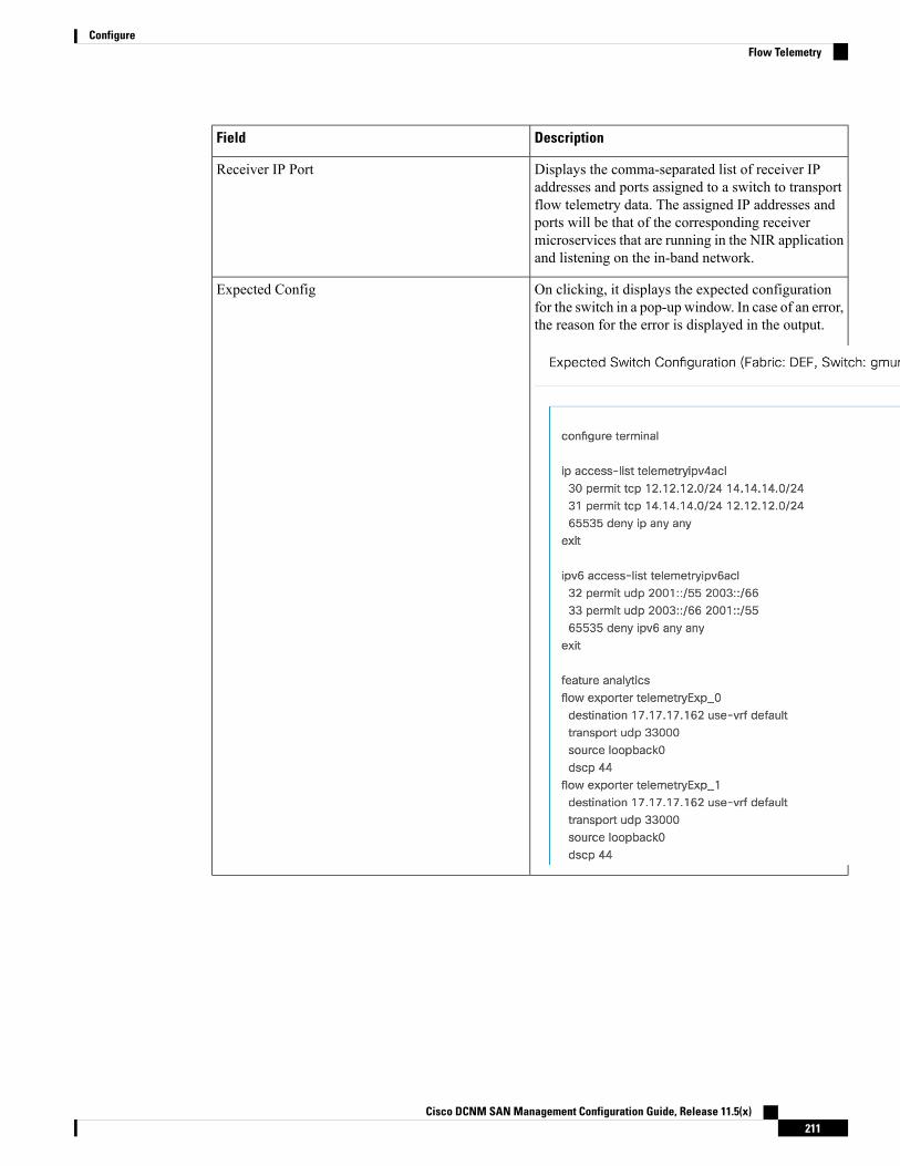
DescriptionField
Displays the comma-separated list of receiver IPaddresses and ports assigned to a switch to transportflow telemetry data. The assigned IP addresses andports will be that of the corresponding receivermicroservices that are running in the NIR applicationand listening on the in-band network.
Receiver IP Port
On clicking, it displays the expected configurationfor the switch in a pop-up window. In case of an error,the reason for the error is displayed in the output.
Expected Config
Cisco DCNM SAN Management Configuration Guide, Release 11.5(x)211
ConfigureFlow Telemetry

DescriptionField
Overall Status
Cisco DCNM SAN Management Configuration Guide, Release 11.5(x)212
ConfigureFlow Telemetry
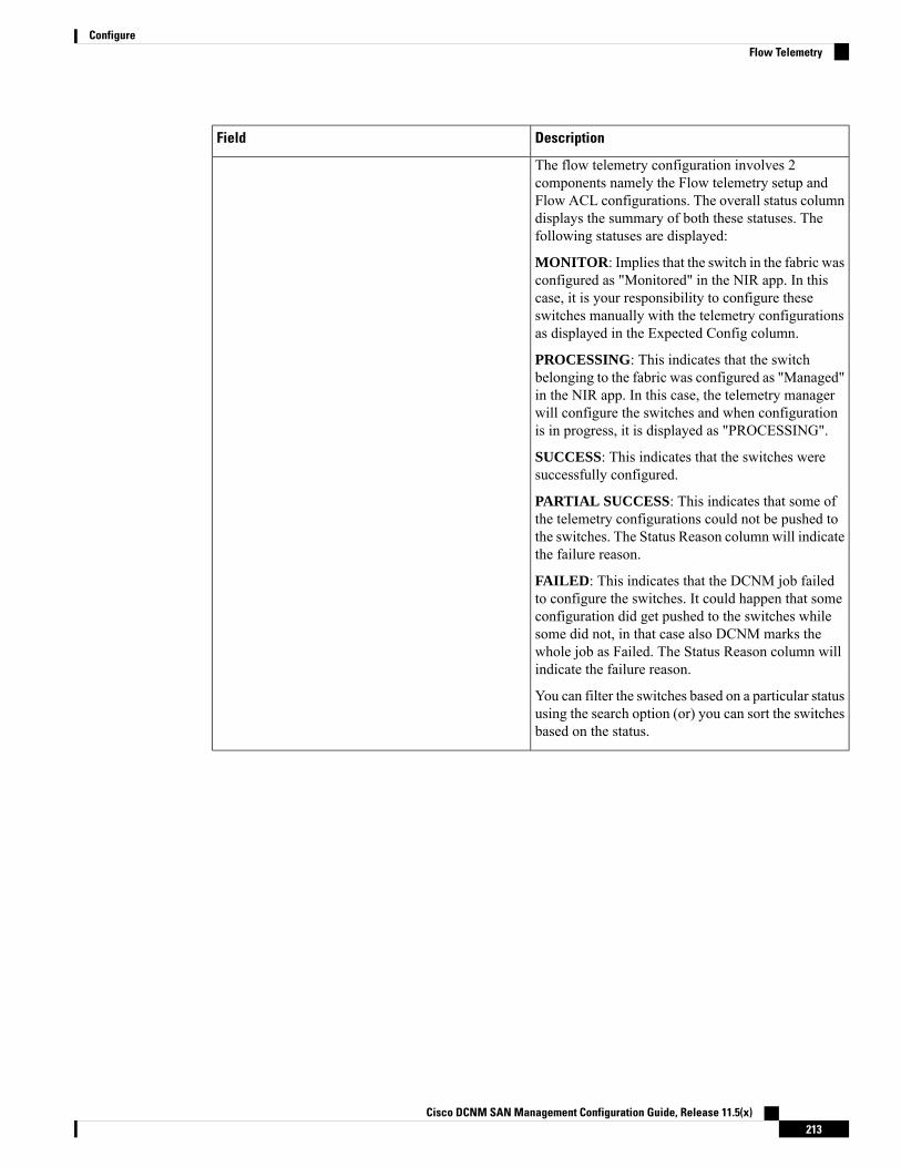
DescriptionField
The flow telemetry configuration involves 2components namely the Flow telemetry setup andFlow ACL configurations. The overall status columndisplays the summary of both these statuses. Thefollowing statuses are displayed:
MONITOR: Implies that the switch in the fabric wasconfigured as "Monitored" in the NIR app. In thiscase, it is your responsibility to configure theseswitches manually with the telemetry configurationsas displayed in the Expected Config column.
PROCESSING: This indicates that the switchbelonging to the fabric was configured as "Managed"in the NIR app. In this case, the telemetry managerwill configure the switches and when configurationis in progress, it is displayed as "PROCESSING".
SUCCESS: This indicates that the switches weresuccessfully configured.
PARTIAL SUCCESS: This indicates that some ofthe telemetry configurations could not be pushed tothe switches. The Status Reason column will indicatethe failure reason.
FAILED: This indicates that the DCNM job failedto configure the switches. It could happen that someconfiguration did get pushed to the switches whilesome did not, in that case also DCNM marks thewhole job as Failed. The Status Reason column willindicate the failure reason.
You can filter the switches based on a particular statususing the search option (or) you can sort the switchesbased on the status.
Cisco DCNM SAN Management Configuration Guide, Release 11.5(x)213
ConfigureFlow Telemetry

DescriptionField
Displays the Flow telemetry setup status. If this showsFailed, it indicated that the flow analytics could notbe enabled on the switches correctly and hence, theflow data cannot be exported from the switches.
FT Setup Status
Displays the Flow ACL configuration status in acolor-coded format.
The flow rules status count is divided into 3categories:
• Green (Success): Number of flow rules (ACEs)that got configured successfully.
• Yellow (Pending): Number of flow rules (ACEs)that are pending to be configured.
• Red (Failed): Number of flow rules (ACEs) thatcould not be configured.
Flow Rules Status (or) Flow ACL Status
Displays the failure reasons for the flow telemetryconfiguration (or) other information.
Status Reason
Cisco DCNM SAN Management Configuration Guide, Release 11.5(x)214
ConfigureFlow Telemetry
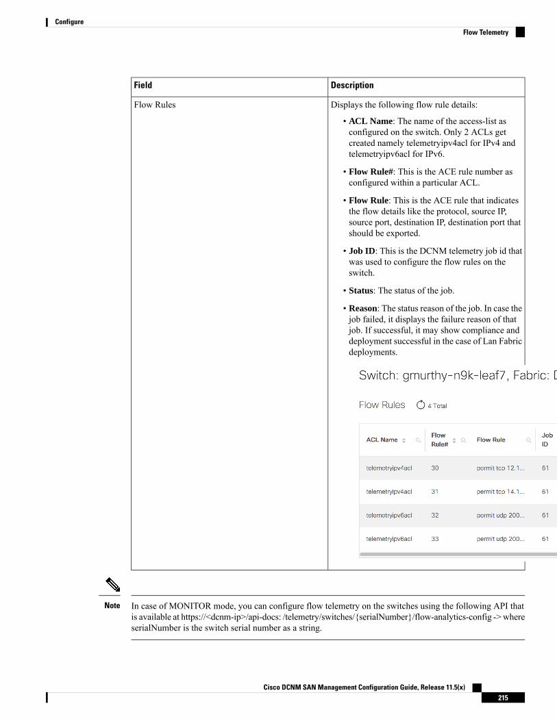
DescriptionField
Displays the following flow rule details:
• ACL Name: The name of the access-list asconfigured on the switch. Only 2 ACLs getcreated namely telemetryipv4acl for IPv4 andtelemetryipv6acl for IPv6.
• Flow Rule#: This is the ACE rule number asconfigured within a particular ACL.
• Flow Rule: This is the ACE rule that indicatesthe flow details like the protocol, source IP,source port, destination IP, destination port thatshould be exported.
• Job ID: This is the DCNM telemetry job id thatwas used to configure the flow rules on theswitch.
• Status: The status of the job.
• Reason: The status reason of the job. In case thejob failed, it displays the failure reason of thatjob. If successful, it may show compliance anddeployment successful in the case of Lan Fabricdeployments.
Flow Rules
In case of MONITOR mode, you can configure flow telemetry on the switches using the following API thatis available at https://<dcnm-ip>/api-docs: /telemetry/switches/{serialNumber}/flow-analytics-config -> whereserialNumber is the switch serial number as a string.
Note
Cisco DCNM SAN Management Configuration Guide, Release 11.5(x)215
ConfigureFlow Telemetry
The Health table data gets refreshed every 70 seconds automatically. It can be manually refreshed by clickingthe Refresh icon.
SANThe SAN menu includes the following submenus:
VSANsBeginning with Cisco DCNM Release 11, you can configure and manage Virtual SANs (VSANs) from theCisco DCNM. From the menu bar, choose Configure > SAN > VSAN to view VSAN information. You canview or configure VSAN for the discovered fabrics, with eitherManageable orManage Continuously status.For the selected fabric, a VSAN Scope tree is displayed in the left panel.
You can achieve higher security and greater stability in Fibre Channel fabrics by using virtual SANs (VSANs)on Cisco Data Center Switches and Cisco MDS 9000 Family switches. VSANs provide isolation amongdevices that are physically connected to the same fabric. With VSANs, you can create multiple logical SANsover a common physical infrastructure. Each VSAN can contain up to 239 switches and has an independentaddress space that allows identical Fibre Channel IDs (FC IDs) to be used simultaneously in different VSANs.
Cisco DCNM doesn’t discover, nor display any suspended VSAN.Note
When changing VSAN of the Switch port in DCNM, If the port was associated with Isolated VSAN, then theprevious VSAN column will be blank.
Note
The information that is associated with the selected VSAN scope appears in the right panel. If a VSAN issegmented, each individual segmented VSAN is a VSAN scope. For every selected VSAN scope, you canview information in tabs.
• Switches tab
• ISLs Tab
• Host Ports Tab
• Storage Tab
• Attributes Tab
• Domain ID Tab
• VSAN Membership Tab
For description on all fields that appear on the tabs, refer Field and Descriptions for VSANs, on page 226.
Cisco DCNM SAN Management Configuration Guide, Release 11.5(x)216
ConfigureSAN

Information About VSANsWith the introduction of VSANs, the network administrator can build a single topology containing switches,links, and one or more VSANs. Each VSAN in this topology has the same behavior and property of a SAN.A VSAN has the following additional features:
• Multiple VSANs can share the same physical topology.
• The same Fibre Channel IDs (FC IDs) can be assigned to a host in another VSAN, thus increasing VSANscalability.
• Every instance of a VSAN runs all required protocols such as FSPF, domain manager, and zoning.
• Fabric-related configurations in one VSAN don’t affect the associated traffic in another VSAN.
• Events causing traffic disruptions in one VSAN are contained within that VSAN and aren’t propagatedto other VSANs.
A VSAN is in the operational state if the VSAN is active and at least one port is up. This state indicates thattraffic can pass through this VSAN. This state can’t be configured.
Interoperability enables the products of multiple vendors to come into contact with each other. Fibre Channelstandards guide vendors towards common external Fibre Channel interfaces. You can enable FICON in upto eight VSANs.
This section describes VSANs and includes the following topics:
VSAN Topologies
The following figure shows a fabric with three switches, one on each floor. The geographic location of theswitches and the attached devices is independent of their segmentation into logical VSANs. No communicationbetween VSANs is possible. Within each VSAN, all members can talk to one another.
Cisco DCNM SAN Management Configuration Guide, Release 11.5(x)217
ConfigureInformation About VSANs

Figure 2: Logical VSAN Segmentation
The following shows a physical Fibre Channel switching infrastructure with two defined VSANs: VSAN 2(dashed) and VSAN 7 (solid). VSAN 2 includes hosts H1 and H2, application servers AS2 and AS3, andstorage arrays SA1 and SA4. VSAN 7 connects H3, AS1, SA2, and SA3.
The four switches in this network are interconnected by trunk links that carry both VSAN 2 and VSAN 7traffic. The inter-switch topology of both VSAN 2 and VSAN 7 are identical. This isn’t a requirement and anetwork administrator can enable certain VSANs on certain links to create different VSAN topologies.
Cisco DCNM SAN Management Configuration Guide, Release 11.5(x)218
ConfigureVSAN Topologies

Figure 3: Example of Two VSANs
Without VSANs, a network administrator would need separate switches and links for separate SANs. Byenabling VSANs, the same switches and links may be shared by multiple VSANs. VSANs allow SANs to bebuilt on port granularity instead of switch granularity. The above figure illustrates that a VSAN is a group ofhosts or storage devices that communicate with each other using a virtual topology defined on the physicalSAN.
The criteria for creating such groups differ based on the VSAN topology:
• VSANs can separate traffic based on the following requirements:
• Different customers in storage provider data centers
• Production or test in an enterprise network
• Low and high security requirements
• Back up traffic on separate VSANs
• Replicating data from user traffic
• VSANs can meet the needs of a particular department or application.
VSAN Advantages
VSANs offer the following advantages:
• Traffic isolation—Traffic is contained within VSAN boundaries and devices reside only in one VSANensuring absolute separation between user groups, if desired.
Cisco DCNM SAN Management Configuration Guide, Release 11.5(x)219
ConfigureVSAN Advantages
• Scalability—VSANs are overlaid on top of a single physical fabric. The ability to create several logicalVSAN layers increases the scalability of the SAN.
• Per VSAN fabric services—Replication of fabric services on a per VSAN basis provides increasedscalability and availability.
• Redundancy—Several VSANs created on the same physical SAN ensure redundancy. If one VSAN fails,redundant protection (to another VSAN in the same physical SAN) is configured using a backup pathbetween the host and the device.
• Ease of configuration—Users can be added, moved, or changed between VSANs without changing thephysical structure of a SAN. Moving a device from one VSAN to another only requires configuration atthe port level, not at a physical level.
Up to 256 VSANs can be configured in a switch. Of these, one is a default VSAN (VSAN 1), and another isan isolated VSAN (VSAN 4094). User-specified VSAN IDs range 2–4093.
VSAN Configuration
VSANs have the following attributes:
• VSAN ID—The VSAN ID identifies the VSAN as the default VSAN (VSAN 1), user-defined VSANs(VSAN 2–4093), and the isolated VSAN (VSAN 4094).
• State—The administrative state of a VSAN can be configured to an active (default) or suspended state.Once VSANs are created, they may exist in various conditions or states.
• The active state of a VSAN indicates that the VSAN is configured and enabled. By enabling aVSAN, you activate the services for that VSAN.
• The suspended state of a VSAN indicates that the VSAN is configured but not enabled. If a port isconfigured in this VSAN, it’s disabled. Use this state to deactivate a VSAN without losing theVSAN’s configuration. All ports in a suspended VSAN are disabled. By suspending a VSAN, youcan preconfigure all the VSAN parameters for the whole fabric and activate the VSAN immediately.
• VSAN name—This text string identifies the VSAN for management purposes. The name can be 1–32characters long and it must be unique across all VSANs. By default, the VSAN name is a concatenationof VSAN and a four-digit string representing the VSAN ID. For example, the default name for VSAN3 is VSAN0003.
A VSAN name must be unique.Note
• Load balancing attributes—These attributes indicate the use of the source-destination ID (src-dst-id) orthe originator exchange OX ID (src-dst-ox-id, the default) for load-balancing path selection.
OX ID-based load balancing of IVR traffic from IVR-enabledswitches isn’t supported on Generation 1 switching modules. OXID-based load balancing of IVR traffic from a non-IVR MDS 9000Family switch should work. Generation 2 switching modules supportOX ID-based load balancing of IVR traffic from IVR-enabledswitches.
Note
Cisco DCNM SAN Management Configuration Guide, Release 11.5(x)220
ConfigureVSAN Configuration

• Load-balancing attributes indicate the use of the source-destination ID (src-dst-id) or the originatorexchange OX ID (src-dst-ox-id, the default) for load-balancing path selection.
Port VSAN Membership
Port VSAN membership on the switch is assigned on a port-by-port basis. By default, each port belongs tothe default VSAN. You can assign VSAN membership to ports using one of two methods:
• Statically—By assigning VSANs to ports
• Dynamically—By assigning VSANs based on the device WWN
This method is referred to as dynamic port VSAN membership (DPVM).
Types of VSAN
The following are the different types of VSAN:
Default VSAN
The factory settings for switches in the Cisco MDS 9000 Family have only the default VSAN 1 enabled. Werecommend that you don’t use VSAN 1 as your production environment VSAN. If no VSANs are configured,all devices in the fabric are considered part of the default VSAN. By default, all ports are assigned to thedefault VSAN.
VSAN 1 can’t be deleted, but it can be suspended.Note
Up to 256 VSANs can be configured in a switch. Of these, one is a default VSAN (VSAN 1), and another isan isolated VSAN (VSAN 4094). User-specified VSAN IDs range 2–4093.
Isolated VSAN
VSAN 4094 is an isolated VSAN. All nontrunking ports are transferred to this VSAN when the VSAN towhich they belong is deleted. This avoids an implicit transfer of ports to the default VSAN or to anotherconfigured VSAN. All ports in the deleted VSAN are isolated (disabled).
When you configure a port in VSAN 4094 or move a port to VSAN 4094, that port is immediately isolated.Note
Don’t use an isolated VSAN to configure ports.Caution
Up to 256 VSANs can be configured in a switch. Of these, one is a default VSAN (VSAN 1), and another isan isolated VSAN (VSAN 4094). User-specified VSAN IDs range 2–4093.
Static VSAN Deletion
When an active VSAN is deleted, all of its attributes are removed from the running configuration. VSAN-relatedinformation is maintained by the system software as follows:
Cisco DCNM SAN Management Configuration Guide, Release 11.5(x)221
ConfigurePort VSAN Membership
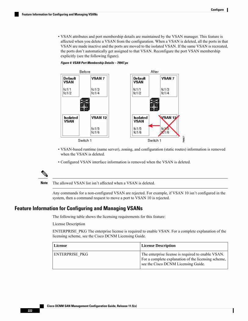
• VSAN attributes and port membership details are maintained by the VSAN manager. This feature isaffected when you delete a VSAN from the configuration. When a VSAN is deleted, all the ports in thatVSAN are made inactive and the ports are moved to the isolated VSAN. If the same VSAN is recreated,the ports don’t automatically get assigned to that VSAN. Reconfigure the port VSAN membershipexplicitly (see the following figure).
Figure 4: VSAN Port Membership Details – 79947.ps
• VSAN-based runtime (name server), zoning, and configuration (static routes) information is removedwhen the VSAN is deleted.
• Configured VSAN interface information is removed when the VSAN is deleted.
The allowed VSAN list isn’t affected when a VSAN is deleted.Note
Any commands for a non-configured VSAN are rejected. For example, if VSAN 10 isn’t configured in thesystem, then a command request to move a port to VSAN 10 is rejected.
Feature Information for Configuring and Managing VSANsThe following table shows the licensing requirements for this feature:
License Description
ENTERPRISE_PKG The enterprise license is required to enable VSAN. For a complete explanation of thelicensing scheme, see the Cisco DCNM Licensing Guide.
License DescriptionLicense
The enterprise license is required to enable VSAN.For a complete explanation of the licensing scheme,see the Cisco DCNM Licensing Guide.
ENTERPRISE_PKG
Cisco DCNM SAN Management Configuration Guide, Release 11.5(x)222
ConfigureFeature Information for Configuring and Managing VSANs
Default VSAN SettingsThe following table lists the default settings for all configured VSANs.
DefaultParameters
VSAN 1.Default VSAN
Active StateState
Concatenation of VSAN and a four-digit stringrepresenting the VSAN ID. For example, VSAN 3 isVSAN0003.
Name
OX ID (src-dst-ox-id).Load-balancing attribute
Create VSAN WizardVSAN Creation Wizard Work flow includes:
• Specify VSAN ID and name.
• Select Switches.
• Specify VSAN attributes.
• Specify VSAN Domain.
• Specify VSAN Members.
Beginning with Release 11, you can configure VSAN using a wizard that facilitates creating VSANs onmultiple switches in a managed Fabric. Choose Configure > SAN > VSAN. After you select a Fabric fromthe drop-down list, click Create VSAN Wizard icon. The Welcome screen of the wizard is displayed.
Ensure that the VSAN isn’t already created.Note
Ensure that you provide Switch credentials, if you are different from the Discover user. To provide SANcredentials, navigate to Administration > Credentials Management > SAN Credentials.
Note
To create and configure VSANs from the Cisco DCNMWeb UI, perform the following steps:
Before you begin
You cannot configure any application-specific parameters for a VSAN before creating the VSAN.
Ensure that the VSAN isn’t already created. Do not create the VSAN in suspended state.
The suspended VSANs aren’t managed.Note
Cisco DCNM SAN Management Configuration Guide, Release 11.5(x)223
ConfigureDefault VSAN Settings

Procedure
Step 1 On the Create VSAN Wizard Welcome screen, click Next.
The Select VSAN ID and Name window is displayed.
Step 2 In the Select VSAN ID and Name window, perform the following steps:a) Ensure that the correct Fabric is against the Fabric field.b) In the VSAN ID field, select VSAN ID from the drop-down list.
The range is 2–4094. Create the list of VSAN ID in at least one Switch in the Fabric. VSAN ID 4079 isfor reserved VSAN.
c) In the Name field, enter a name for VSAN.
If the field is left blank, the Switch assigns a default name to the VSAN.Note
d) Click FICON checkbox to enable FICON on the switch.e) Click Next.
Step 3 In the Select Switches screen, click the checkbox next to the Switch Name, to create the VSAN.
If the switch name is grayed out, it implies that the switch is already a part of VSAN. It may also imply thatthe switch doesn’t have FICON feature enabled, if FICON is checked in the previous step.
Click Next.
Step 4 In the Config VSAN Attributes screen, configure the VSAN attributes.
If you create a VSAN in a suspended state, it doesn’t appear on the Cisco DCNM as DCNM doesn’tmanage suspended VSANs.
Note
a) In the LoadBalancing, select the load balancing type to be used on the VSAN.
The following types are available:
• srcIdDestId: based on only source ID (S_ID) and destination ID (D_ID)
• srcIdDestIdOxId: Originator exchange ID (OX_ID) is also used for load balancing, in addition toS_ID and D_ID. OX_ID is an exchange ID assigned by the originator Interconnect Port for anexchange with the target Interconnect Port.
srcId/DestId/OxId is the default for non-FICONVSAN and it isn’t available for FICONVSAN,srcId/DestId is the default for FICON VSAN.
Note
b) In the InterOp field, select the interoperability value the drop-down list.
The InterOp value is used to interoperate with different vendor devices. You can choose from one of thefollowing:
• 0: implies that the interoperability is disabled.
• 1: implies that the VSAN can interoperate with all the Fibre Channel vendor devices.
• 2: implies that the VSAN can interoperate with specific Fibre Channel vendor devices for basic toadvanced functionalities.
• 3: implies that the VSAN can interoperate with specific Fibre Channel vendor devices for basic toadvanced functionalities.
Cisco DCNM SAN Management Configuration Guide, Release 11.5(x)224
ConfigureCreate VSAN Wizard

• 4: implies that the VSAN can interoperate with specific Fibre Channel vendor devices for basic toadvanced functionalities.
InterOp isn’t supported on FICON VSAN.Note
c) In the Admin State field, select the configurable state for this VSAN.
• active: implies that the VSAN is configured and services for this VSAN is activated.
• suspended: implies that the VSAN is configured, but the service for this VSAN is deactivated.
Choose this state to preconfigure all the VSAN parameters for the whole Fabric.
DCNM doesn’t manage a suspended VSAN, and therefore it does not appear in the VSANscope.
Note
d) Check the Inorder Delivery checkbox to allow in-order delivery.
When the value of fcInorderDelivery is changed, the value of this object is set to the new value of thatobject.
e) In the Add Fabric Binding DB field, check the checkbox if you want to enable the fabric binding for theFICON VSAN.
If the checkbox is selected, the all the peers in the selected switches are added to each switch in the selectedlist.
f) In the All Port Prohibited field, check the checkbox if you want to prohibit all the ports for FICONVSAN.
If the checkbox is selected, the FICON VSAN is created as all Ports prohibited, by default.
g) Click Next.
Step 5 In the Config VSAN Domain screen, configure the static domain IDs for FICON VSAN.a) Select the Use Static Domain IDs field, to configure the domain ID for the switches in the VSAN.b) The Available Domain IDs field shows all the available Domain IDs in the Fabric.
Click Apply Available Domain IDs to assign the domain ID for every switch that is selected to be a partof the VSAN.
c) For every switch in the table, enter the domain ID from the list of available Domain IDs.d) Click Next.
Step 6 In the Config Port VSANMembership screen, for every switch in the VSAN, configure the interfaces, as themember of the new VSAN.
Modifying the Port VSAN may affect the I/O of the interface.Note
Click Next.
Step 7 In the Summary screen, verify if you have configured the VSAN correctly.
Click Previous to navigate to the earlier screen and modify the configuration.
Click Cancel to discard the configuration.
Click Finish to confirm and configure the VSAN. The VSAN creation result is displayed at the bottom of thewindow.
After the VSAN is created, it will take fewminutes for the newVSAN to appear in the VSAN scopetree.
Note
Cisco DCNM SAN Management Configuration Guide, Release 11.5(x)225
ConfigureCreate VSAN Wizard
If the switch port is associated with Isolated VSAN then the previous VSAN information will beblank.
Note
Delete VSANTo delete a VSAN and its attributes from the Cisco DCNMWeb UI, perform the following steps:
Procedure
Step 1 Choose Configure > SAN > VSAN.
The VSAN window is displayed.
Step 2 From the Fabric drop-down list, select the Fabric to which the VSAN is associated.
The VSAN scope tree for the selected Fabric is displayed in the VSAN area.
Step 3 Expand the Fabric and select the VSAN that you want to delete.
You can’t delete Segmented VSAN.Note
Step 4 Click the Delete VSAN icon.
The Delete VSAN screen appears, showing the switches associated with the VSAN.
Step 5 Select the checkbox of the Switch for which you want to remove the VSAN.
Click Delete.
A confirmation window appears.
Step 6 Click Yes to confirm the deletion or click No to close the dialog box without deleting the VSAN.
After the VSAN is deleted, it will take few minutes for the new VSAN to disappear from the VSANscope tree.
Note
Field and Descriptions for VSANsThe Field and Descriptions for all the tabs that are displayed on Cisco Web UI > SAN > VSAN are explainedin the following tables.
• Switches tab, on page 227
• ISLs Tab, on page 227
• Host Ports Tab, on page 228
• Storage Tab, on page 228
• Attributes Tab, on page 229
• Domain ID Tab, on page 230
Cisco DCNM SAN Management Configuration Guide, Release 11.5(x)226
ConfigureDelete VSAN
• VSAN Membership Tab, on page 231
Switches tab
This tab displays Switches in the VSAN scope. Click the Switch name to view the summary information ofthe switch. The following table describes the fields that appear on the Switches tab.
Table 22: Field and Description on Switches Tab
DescriptionField
Specifies the name of the switch in the VSAN.
Click the name to view the switch summary. For description about the fields in the SwitchSummary, refer to Viewing Inventory Information for Switches, on page 53.
Click Show more Details to view complete information.
Name
Specifies an insistent domain ID.Domain ID
Specifies the WorldWide Name (WWN) of the VSAN.VSAN WWN
Specifies the WorldWide Name (WWN) of the switch.
For the principal switch, the value is "self".Note
PrincipalWWN
Specifies the model name of the switch.Model
Specifies the NX-OS version on the switch.Release
Specifies the time from which the switch is up.Uptime
Icons
The number next to Total specifies the entries under this tab.Total
Click the Refresh icon to refresh the entries.Refresh
ISLs Tab
This tab displays information about the ISLs about the switches in the VSAN scope. Click the Switch nameto view the summary information. Click Show more details to view complete information on the selectedswitch. The following table describes the fields that appear on the ISLs tab. If the VSAN is configured onboth the switches across the ISL and if VSAN is not enabled on the ISL, DCNMconsiders VSAN as segmented.Therefore, add the VSAN to the trunked VSANs across the ISL to clear the warning message. Alternatively,you can ignore this warning message.
Table 23: Field and Description on ISLs Tab
DescriptionField
All VSANs which this ISL runs traffic on.VSANs
The source switch of the link.From Switch
The port index of source E_port of the link.From Interface
The switch on the other end of the link.To Switch
Cisco DCNM SAN Management Configuration Guide, Release 11.5(x)227
ConfigureField and Descriptions for VSANs
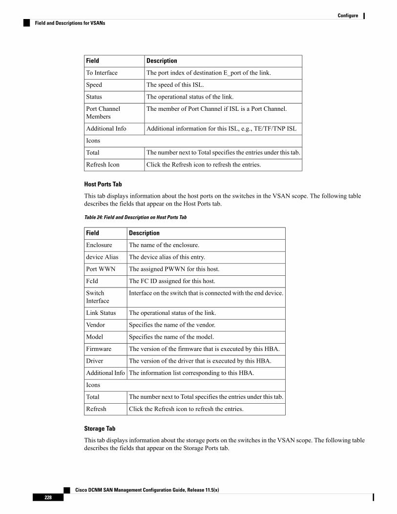
DescriptionField
The port index of destination E_port of the link.To Interface
The speed of this ISL.Speed
The operational status of the link.Status
The member of Port Channel if ISL is a Port Channel.Port ChannelMembers
Additional information for this ISL, e.g., TE/TF/TNP ISLAdditional Info
Icons
The number next to Total specifies the entries under this tab.Total
Click the Refresh icon to refresh the entries.Refresh Icon
Host Ports Tab
This tab displays information about the host ports on the switches in the VSAN scope. The following tabledescribes the fields that appear on the Host Ports tab.
Table 24: Field and Description on Host Ports Tab
DescriptionField
The name of the enclosure.Enclosure
The device alias of this entry.device Alias
The assigned PWWN for this host.Port WWN
The FC ID assigned for this host.FcId
Interface on the switch that is connected with the end device.SwitchInterface
The operational status of the link.Link Status
Specifies the name of the vendor.Vendor
Specifies the name of the model.Model
The version of the firmware that is executed by this HBA.Firmware
The version of the driver that is executed by this HBA.Driver
The information list corresponding to this HBA.Additional Info
Icons
The number next to Total specifies the entries under this tab.Total
Click the Refresh icon to refresh the entries.Refresh
Storage Tab
This tab displays information about the storage ports on the switches in the VSAN scope. The following tabledescribes the fields that appear on the Storage Ports tab.
Cisco DCNM SAN Management Configuration Guide, Release 11.5(x)228
ConfigureField and Descriptions for VSANs
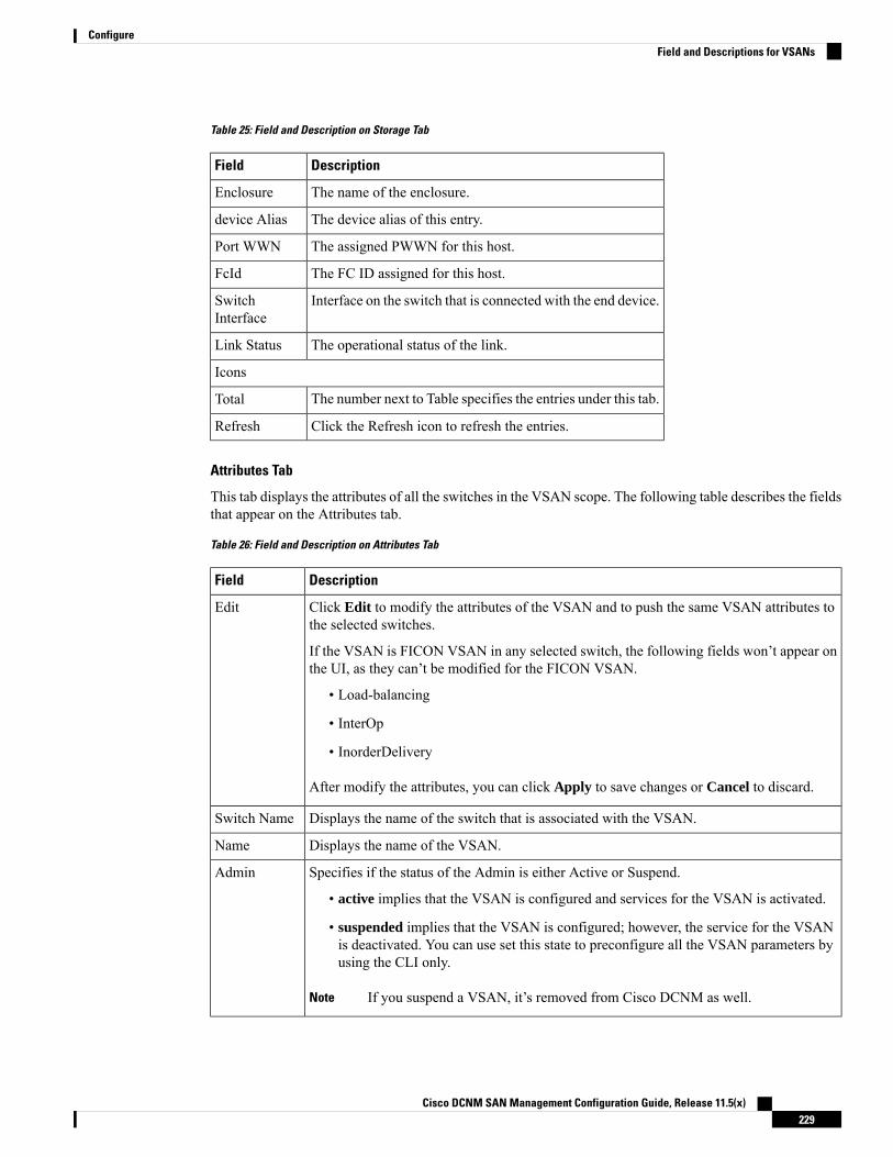
Table 25: Field and Description on Storage Tab
DescriptionField
The name of the enclosure.Enclosure
The device alias of this entry.device Alias
The assigned PWWN for this host.Port WWN
The FC ID assigned for this host.FcId
Interface on the switch that is connected with the end device.SwitchInterface
The operational status of the link.Link Status
Icons
The number next to Table specifies the entries under this tab.Total
Click the Refresh icon to refresh the entries.Refresh
Attributes Tab
This tab displays the attributes of all the switches in the VSAN scope. The following table describes the fieldsthat appear on the Attributes tab.
Table 26: Field and Description on Attributes Tab
DescriptionField
Click Edit to modify the attributes of the VSAN and to push the same VSAN attributes tothe selected switches.
If the VSAN is FICON VSAN in any selected switch, the following fields won’t appear onthe UI, as they can’t be modified for the FICON VSAN.
• Load-balancing
• InterOp
• InorderDelivery
After modify the attributes, you can click Apply to save changes or Cancel to discard.
Edit
Displays the name of the switch that is associated with the VSAN.Switch Name
Displays the name of the VSAN.Name
Specifies if the status of the Admin is either Active or Suspend.
• active implies that the VSAN is configured and services for the VSAN is activated.
• suspended implies that the VSAN is configured; however, the service for the VSANis deactivated. You can use set this state to preconfigure all the VSAN parameters byusing the CLI only.
If you suspend a VSAN, it’s removed from Cisco DCNM as well.Note
Admin
Cisco DCNM SAN Management Configuration Guide, Release 11.5(x)229
ConfigureField and Descriptions for VSANs

DescriptionField
The operational state of the VSAN.Oper
Displays the MTU for the switch.MTU
Specifies the load-balancing type that is used in the VSAN.
The type of load balancing used on this VSAN.
• srcId/DestId—use source and destination ID for path selection
• srcdId/DestId/0xld—use source, destination, and exchange IDs
LoadBalancing
The interoperability mode of the local switch on this VSAN.
• standard
• interop-1
• interop-2
• interop-3
InterOp
The InorderDelivery guarantee flag of device. If true, then the inorder delivery is guaranteed.If false, it’s not guaranteed.
InorderDelivery
True if the VSAN is FICON-enabled.FICON
Icons
The number next to Table specifies the entries under this tab.Total
Click the Refresh icon to refresh the entries.Refresh Icon
Domain ID Tab
This tab displays information about the VSAN domain and its parameters. The following table describes thefields that appear on the Domain ID tab.
Table 27: Field and Description on Domain ID Tab
DescriptionField
Click Edit icon to modify the Domain ID information for the selected switch.Edit
Specifies the switch name in the VSAN.
NPV switches aren’t listed in this column. However, the NPV switches exist in thisVSAN fabric.
Note
SwitchName
Specifies the state of the Switch.State
Specifies if the Domain ID is enabled or disabled.Enable
Specifies the running domain.Running
Specifies the usage of the domain ID type—preferred or static.ConfigType
Cisco DCNM SAN Management Configuration Guide, Release 11.5(x)230
ConfigureField and Descriptions for VSANs
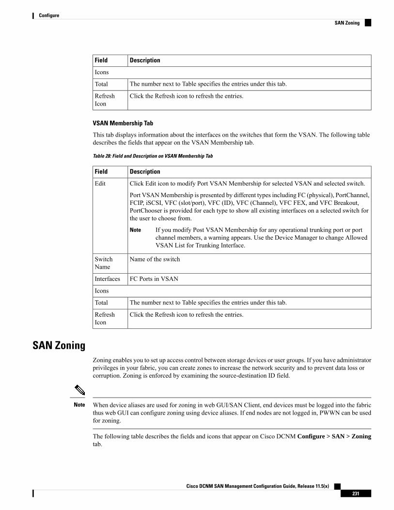
DescriptionField
Icons
The number next to Table specifies the entries under this tab.Total
Click the Refresh icon to refresh the entries.RefreshIcon
VSAN Membership Tab
This tab displays information about the interfaces on the switches that form the VSAN. The following tabledescribes the fields that appear on the VSAN Membership tab.
Table 28: Field and Description on VSAN Membership Tab
DescriptionField
Click Edit icon to modify Port VSAN Membership for selected VSAN and selected switch.
Port VSANMembership is presented by different types including FC (physical), PortChannel,FCIP, iSCSI, VFC (slot/port), VFC (ID), VFC (Channel), VFC FEX, and VFC Breakout,PortChooser is provided for each type to show all existing interfaces on a selected switch forthe user to choose from.
If you modify Post VSAN Membership for any operational trunking port or portchannel members, a warning appears. Use the Device Manager to change AllowedVSAN List for Trunking Interface.
Note
Edit
Name of the switchSwitchName
FC Ports in VSANInterfaces
Icons
The number next to Table specifies the entries under this tab.Total
Click the Refresh icon to refresh the entries.RefreshIcon
SAN ZoningZoning enables you to set up access control between storage devices or user groups. If you have administratorprivileges in your fabric, you can create zones to increase the network security and to prevent data loss orcorruption. Zoning is enforced by examining the source-destination ID field.
When device aliases are used for zoning in web GUI/SAN Client, end devices must be logged into the fabricthus web GUI can configure zoning using device aliases. If end nodes are not logged in, PWWN can be usedfor zoning.
Note
The following table describes the fields and icons that appear on Cisco DCNM Configure > SAN > Zoningtab.
Cisco DCNM SAN Management Configuration Guide, Release 11.5(x)231
ConfigureSAN Zoning

DescriptionField
From the Fabric drop-down list, you can choose thefabric for which you are configuring or viewing theSAN Zoning.
Fabric
From the VSAN drop-down list, you can choose theVSAN for which you are configuring zoning.
VSAN
From the Switch drop-down list, select the switch towhich you want to configure.
Switches
Commits the Zoning configuration changes to all theswitches. This field is only applicable when a zone isin the enhanced or smart mode.
Commit Changes
Distributes the Zoning configuration to all theswitches. This field is only applicable when a zone isin the basic mode.
Distribute
You can export the Zoning configurations to a .csvfile, and save it on your local directory.
Export All
Lists all the Zoneset configured for the selectedFabric, VSAN, and the Switch.
Zonesets
Lists all the Zones that are configured under theselected Zoneset.
Zones
Lists the members present in the selected Zone.Zone Members
Lists the available devices to add to the Zones.Available to Add
Clears the cache on the Cisco DCNM server.Clear Server Cache
Discards the changes in progress.Discard Pending Changes
This section contains the following:
ZonesetsBased on the selected Fabric, VSAN and Switch, the Zoneset area displays the configured zonesets and theirstatus. You can create, copy, delete or edit the zonesets. Further, the zonesets can be activated or deactivated.
Procedure
Step 1 To create zonesets from Cisco DCNMWeb UI, choose Configure > SAN Zoning > Zonesets and clickCreate Zoneset icon.
The Create Zoneset window appears.
Step 2 Enter a valid name for the zoneset, and click Create.
A zoneset is created and is listed in the Zoneset area.
Cisco DCNM SAN Management Configuration Guide, Release 11.5(x)232
ConfigureZonesets

Step 3 Choose the zone radio button and click Clone\Copy Zoneset icon to clone or copy zonesets.
The Clone or Copy Zoneset window shows two options.
• Choose the appropriate Action radio button. You can choose of the of the following:
• Copy: Creates a new zoneset that consists copies of the zones in the initial zoneset.
You can prepend or append a string to identify the copied zoneset. Enter a valid string in the Tagfield, and choose the Prepend or Append radio button.
• Clone: To create a new zoneset with a new name consisting of the same zones as the source zoneset.
In the Name field, enter a valid name for the new zoneset.
• Click OK to clone or copy the zoneset.
The cloned or the copied zoneset appears in the Zoneset area.
Step 4 To delete the zoneset, choose the zoneset radio button and click delete zoneset icon.
A confirmation window appears. Click Yes to delete the zoneset.
Step 5 To edit the zone name, choose the zone radio button and click Rename Zoneset icon.
In the Name field, enter the new name for the zoneset. Click Rename.
Step 6 To activate a zoneset, choose the zoneset radio button and click Activate.
The Zoneset Differences window shows the changes made to the zoneset since it was activated previously.Click Activate.
Step 7 To deactivate a zoneset, choose the zoneset radio button and click Deactivate.
A confirmation window appears. Click Yes to deactivate the zoneset.
ZonesBased on the Zoneset that is selected, the zones that are configured under that zoneset are displayed in theZones area. It also displays true or false only when the VSAN has smart zone that is enabled. You can create,copy, delete, or edit the zones. Furthermore, the zones can be added to or removed from the selected Zoneset.You can also enable or disable the smart zone on the zone table.
Select the Zoneset for which you must alter the zones.
Select Zoneset radio button in the Zonesets area. The zones that are configured on the selected Zoneset andzones on the switch are displayed. The zones that are a part of the Zone are marked with a green check mark.
Note
The Zones area has the following fields and their descriptions.
DescriptionField
Specifies whether a zone is part of a zoneset.In Zoneset
Cisco DCNM SAN Management Configuration Guide, Release 11.5(x)233
ConfigureZones

DescriptionField
Displays true if the zone is part of a zoneset.Otherwise, displays false.
You can search by choosing true or false from the InZoneset drop-down list.
Displays the name of the zone.Zone Name
You can search by specifying the zone name.
Specifies whether a zone is a smart zone.Smart Zone
Displays true if the zone is a smart zone. Otherwise,displays false.
You can search this field by choosing true or falsefrom the Smart Zone drop-down list. This field onlyshows that up when the VSAN has smart zone that isenabled.
Procedure
Step 1 To create zones, choose Configure > SAN > Zoning > Zones, click Create icon.a) In the Create Zone window, enter a valid name for the Zone, and click Create.
A zone is created and is listed in the Zones area.
Step 2 To Clone Zones, choose Configure > SAN > Zoning > Zones, select the Zone radio button and click CloneZone icon.
The Clone Zone window is displayed.
a) In the Name field, enter a valid name for the new zoneset.b) Click Clone to clone the zone.
The cloned zones appear in the Zones area.
Step 3 To add zone to a zoneset, choose Configure > SAN Zoning > Zones, select the zone that is not a part of thezoneset. Click Add Zone icon. You can select more than one zone to be added to the Zoneset.
The zone is added to the selected Zoneset. A green tick mark appears next to the Zone name to indicate thatthe zone is added to the zoneset.
Step 4 To remove zone from a zoneset, chooseConfigure > SAN Zoning > Zones, check theZone check box. ClickRemove Zone icon. You can select more than one Zone to be deleted from the Zoneset.
The zone is removed from the selected Zoneset. A green tick mark disappears next to the Zone name to indicatethat the zone is removed from the zoneset.
Step 5 To Delete Zones, choose Configure > SAN Zoning > Zones, check the Zone check box. Click Delete Zoneicon.
A confirmation window appears.
Cisco DCNM SAN Management Configuration Guide, Release 11.5(x)234
ConfigureZones
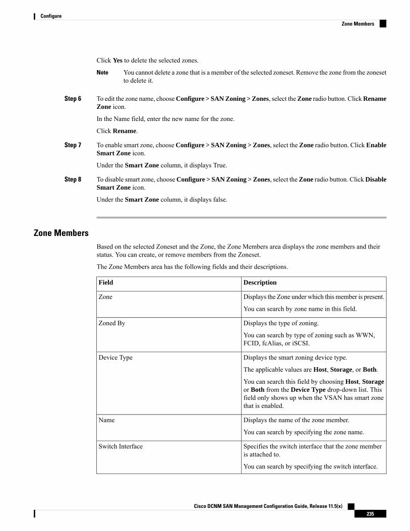
Click Yes to delete the selected zones.
You cannot delete a zone that is a member of the selected zoneset. Remove the zone from the zonesetto delete it.
Note
Step 6 To edit the zone name, chooseConfigure > SAN Zoning > Zones, select theZone radio button. ClickRenameZone icon.
In the Name field, enter the new name for the zone.
Click Rename.
Step 7 To enable smart zone, chooseConfigure > SAN Zoning > Zones, select the Zone radio button. ClickEnableSmart Zone icon.
Under the Smart Zone column, it displays True.
Step 8 To disable smart zone, chooseConfigure > SAN Zoning > Zones, select theZone radio button. ClickDisableSmart Zone icon.
Under the Smart Zone column, it displays false.
Zone MembersBased on the selected Zoneset and the Zone, the Zone Members area displays the zone members and theirstatus. You can create, or remove members from the Zoneset.
The Zone Members area has the following fields and their descriptions.
DescriptionField
Displays the Zone under which this member is present.Zone
You can search by zone name in this field.
Displays the type of zoning.Zoned By
You can search by type of zoning such as WWN,FCID, fcAlias, or iSCSI.
Displays the smart zoning device type.Device Type
The applicable values are Host, Storage, or Both.
You can search this field by choosing Host, Storageor Both from the Device Type drop-down list. Thisfield only shows up when the VSAN has smart zonethat is enabled.
Displays the name of the zone member.Name
You can search by specifying the zone name.
Specifies the switch interface that the zone memberis attached to.
Switch Interface
You can search by specifying the switch interface.
Cisco DCNM SAN Management Configuration Guide, Release 11.5(x)235
ConfigureZone Members

DescriptionField
Specifies the FcID associated with the zone member.FcId
You can search by specifying the FcID associatedwith the zone member.
Specifies the WWN of the switch.WWN
You can search by specifying theWWNof the switch.
Procedure
Step 1 To create zone members, from Cisco DCNM Web Client > Configure > SAN Zoning > Zone Members,click Create icon.a) In the Create and Add Member window, enter the WWN name or Device Alias for the zone member.
You can add only offline members for the device alias zone.Note
b) Click Create and Add.
The create and add feature allows you to add a member to a zone that does not exist in the fabric, currently.This feature can also be utilized when the device discovery did not discover all the devices.With the Availableto add feature, you can add a discovered device to the zone.
Step 2 To Remove Zone Member, from Cisco DCNM Web Client > Configure > SAN Zoning > Zone Members,check the Zone Member check box. Click Remove Member icon.
You can remove more than one zone member at a time, for deletion.
Available to AddThe Available to Add area has the following fields and their descriptions.
DescriptionField
Displays the smart zoning device type.Type
The applicable values are Host or Storage.
You can search this field by choosingHostor Storagefrom the Type drop-down list.
Displays the name of the zone.Name
You can search by specifying the zone name.
Specifies the switch interface that the zone memberis attached to.
Switch Interface
You can search by specifying the switch interface.
Specifies the FcID associated with the zone member.FcId
Cisco DCNM SAN Management Configuration Guide, Release 11.5(x)236
ConfigureAvailable to Add
DescriptionField
You can search by specifying the FcID associatedwith the zone member.
Specifies the WWN of the switch.WWN
You can search by specifying theWWNof the switch.
To add discovered devices to one or more zones from the Cisco DCNMWeb UI, perform the following steps:
Procedure
Step 1 Choose Configure > SAN > Zoning > Available to Add.Step 2 In the Zone by area, select the Ports or Device radio buttons.
The Zone by feature determines if the device must be added to the zone using the device WWN or Devicealias.
A window appears showing the list of End Ports or Devices available to add.
If you choose Zone By: End Port, the devices are added to the zones by WWN. If you choose Zone By:Device Alias, the devices are added to the zones by Device Alias. Based on the zone by option you choose,the devices are displayed.
Step 3 Select the devices to add to a zone.Step 4 Click Add to add the selected devices to the zone.
You can select more than one zone. A dialog appears that shows a list of all the zones that arecurrently selected on the zone table.
Note
IVR ZoningFrom Cisco DCNM Release 11.0(1), IVR Zoning feature is supported. You can use IVR Zoning to create,edit, copy, or delete IVR zones in the web client.
The IVR Zoning page is launched from Cisco DCNM Configure > SAN > IVR Zoning menu item. Afteryou launch the IVR Zoning page, you will see the following fields and sections:
• Fabric
• Region ID
• Switches
• Commit Changes
• Export All
• Clear Server Cache
• Discard Pending Changes
Cisco DCNM SAN Management Configuration Guide, Release 11.5(x)237
ConfigureIVR Zoning
• Zonesets
• Zone Members
• Zones
• Available to Add
The following table describes the fields and icons on Cisco DCNM Configure > SAN > IVR Zoning tab.
DescriptionField
From the Fabric drop-down list, you can choose thefabric for which you are configuring or viewing theIVR Zoning. You must select a fabric to view theoptions of Region ID and Switches.
Fabric
From the Region ID drop-down list, you can choosethe region for a switch.
Region ID
From the Switch drop-down list, select the switch towhich you want to configure. Zone Seed switch isselected by default.
Switches
Commits the IVR zoning configuration changes to allthe switches. This field is only applicable when a zoneis in the enhanced or smart mode.
Commit Changes
You can export the IVR zoning configurations to a.csv file, and save it on your local directory.
Export All
Clears the discovered zoning cache on the CiscoDCNM server.
Clear Server Cache
Discards the changes in progress.Discard Pending Changes
To display the zone sets, you need to select the desired fabric, region ID, and switch. This is different fromregular zoning, which needs the fabric, VSAN, and switch.
Three checks are made when a switch is selected and can result in a warning dialog including one or more ofthe following warnings:
• Check for IVR Cisco Fabric Services enabled.
• Check for NAT and Auto Topology Enabled.
• Check if there is an existing IVR zone merge failure.
If the IVR Cisco Fabric Services feature is not enabled, then Activate, Deactivate, Commit Changes, andDiscard Pending Changesare blocked. If IVR NAT and IVR Auto Topology are not enabled, you will geta warning to enable them.
This section contains the following:
Cisco DCNM SAN Management Configuration Guide, Release 11.5(x)238
ConfigureIVR Zoning

ZonesetsBased on the selected fabric, region and switch, the Zoneset area displays the configured zonesets and theirstatus. You can create, copy or clone, delete, rename, activate, or deactivate a zoneset.
The following table describes the fields and icons that appear on Cisco DCNM Web Client > Configure >SAN > IVR Zoning > Zonesets area.
DescriptionFields
Creates a zoneset.Create Zoneset
• Copy—Creates a zoneset and copies of zones inthe original zoneset. The copied names are theexisting names that are prepended or appendedwith a specified string.
• Clone—Creates only a zoneset with a new nameconsisting the same zones as the original zoneset.
Copy\Clone Zoneset
Deletes the selected zoneset.Delete Zoneset
Renames the selected zoneset.Rename Zoneset
Lists all the zonesets that is configured for the selectedfabric, region ID, and the switch.
Zoneset
Displays if the zoneset is active or not.Status
Displays if the zoneset is modified or not.Modified
Procedure
Step 1 To create zonesets, choose Configure > SAN > IVR Zoning > Zonesets. Click Create Zoneset icon.a) In the Create Zoneset window, enter a valid name for the zoneset.b) Click Create.
A zoneset is created and is listed in the Zoneset area.
Step 2 To clone or copy zonesets, choose Configure > SAN > IVR Zoning > Zonesets. Select the radio button ofthe zoneset to be copied or cloned. Click Clone\Copy Zoneset icon.
The Clone\Copy Zoneset window shows two options.
a) Click the appropriate Action radio button.
You can choose one of the following:
• Copy—You can prepend or append a string to identify the copied zoneset. Enter a valid string in theTag field, and select the Prepend or Append radio button.
• Clone—In the Name field, enter a valid name for the new zoneset.
b) Click OK to clone or copy the zoneset.
Cisco DCNM SAN Management Configuration Guide, Release 11.5(x)239
ConfigureZonesets
The cloned or the copied zoneset appears in the Zoneset area.
Step 3 To delete the zoneset, choose Configure > SAN > IVR Zoning > Zonesets. Select the Zoneset radio button.Click Delete Zoneset icon.
A confirmation window appears.
Click Yes to delete the zoneset.
Step 4 To rename the zonset name, choose Configure > SAN > IVR Zoning > Zonesets. Select the zoneset radiobutton. Click Rename Zoneset icon.
In the Name field, enter the new name for the zoneset.
Click Rename.
Step 5 To activate a zoneset, choose Configure > SAN > IVR Zoning > Zonesets. Select the zoneset radio button.Click Activate.
The Zoneset Differences window shows the changes that are made to the zoneset after the previous activation.
Click Activate.
Step 6 To deactivate a zoneset, chooseConfigure > SAN > IVR Zoning > Zonesets. Select the zoneset radio button.Click Deactivate.
A confirmation window appears.
Click Yes to deactivate the zoneset.
ZonesAll zones that are configured appear under Zones when a zoneset is selected. The zones that belong to theselected zoneset have a green check box. You can create, copy, delete, or edit zones. Furthermore, the zonescan be added to or removed from the selected zoneset. You can also enable or disable the smart zone on thezone table.
The following table describes the fields and icons that appear on Cisco DCNM Configure > SAN > IVRZoning > Zones:
DescriptionFields
Creates a zone.Create Zone
Creates a zone with a new name consisting the samezone members as the source zone.
Clone Zone
Adds a zone to the selected zoneset.Add Zone
Removes the selected zones from a zoneset.Remove Zone
Deletes the selected zones that do not belong to azoneset.
Delete Zone
Renames the selected zone.Rename Zone
Cisco DCNM SAN Management Configuration Guide, Release 11.5(x)240
ConfigureZones

DescriptionFields
Specifies whether a zone is part of a zoneset.
The check box is selected if the zone is part of azoneset.
You can search by choosing true or false from the InZoneset drop-down list.
In Zoneset
Displays the name of the zone.
You can search by specifying the zone name.
Zone Name
Specifies whether a zone is a smart zone.
Displays true if the zone is a smart zone. Otherwise,displays false.
You can search this field by choosing true or falsefrom the Smart Zone drop-down list. This field onlyis displayed when the VSAN has smart zone that isenabled.
Smart Zone
Procedure
Step 1 To create a zone, choose Configure > SAN > IVR Zoning > Zones.Step 2 Click Create Zone.
a) In the Create Zone window, enter a valid name for the zone.b) Click Create.
A zone is created and is listed in the Zones area.
Step 3 To clone a zone, Configure > SAN > IVR Zoning > Zones, select a zoneset.
All the zones in the fabric appear under Zones. From Zones, select a zone and click Clone Zone.
You can clone only one zone at a time.Note
a) In the Clone Zone window, enter a valid name for the new zone.b) Click Clone.
The cloned zones appear under Zones.
Step 4 To add a zone that is not part of a zoneset, choose Configure > SAN > IVR Zoning > Zoneset, select azoneset.
All the zones in the fabric appear under Zones. From Zones, select a zone that is not part of the zoneset. ClickAdd Zone icon.
You can select more than one zone to be added to the zoneset.
The zone are added to the selected zoneset. A green check mark appears next to the zone name to indicatethat the zone is added to the zoneset.
Cisco DCNM SAN Management Configuration Guide, Release 11.5(x)241
ConfigureZones
Step 5 To remove a zone from a zoneset, choose Configure > SAN > IVR Zoning > Zonesets. Select a zoneset.
All the zones in the fabric appear under Zones. From Zones, select a zone that belongs to the selected zonesetand click Remove Zone.
The zone is removed from the selected zoneset. The green check mark next to the zone name disappears toindicate that the zone is removed from the zoneset.
Step 6 To delete a zone from a zoneset, choose Configure > SAN > IVR Zoning > Zonesets, select a zoneset.
All the zones in the fabric appear under Zones. From Zones, select a zone that does not belong to the selectedzoneset and click Delete Zone.
A confirmation window appears. Click Yes to delete the selected zones.
You cannot delete a zone that is a member of the selected zoneset. Remove the zone from the zonesetto delete it.
Note
Step 7 To rename a zone, chooseConfigure > SAN > IVR Zoning > Zonesets, select a zoneset. From Zones, selectthe zone to be renamed and click Rename Zone.
In the Name field, enter the new name for the zone.
Click Rename.
Step 8 To enable a smart zone, choose Configure > SAN > IVR Zoning > Zones. Select a zoneset.
From Zones, select a zone, and click Enable Smart Zone.
Under the Smart Zone column, it displays True.
Step 9 To disable a smart zone, choose Configure > SAN > IVR Zoning > Zonesets, select a zoneset.
From Zones, select a zone, and click Disable Smart Zone.
Under the Smart Zone column, it displays False.
Zone MembersBased on the selected zoneset and zone, the Zone Members area displays the zone members and their status.
The following table describes the fields and icons that appear on Cisco DCNM Configure > SAN > IVRZoning > Zone Members area.
DescriptionField
Creates a zone member and adds it to a zone.Create and Add Member to Zone
Removes a zone member. You can remove more thanone member at a time.
Remove Member
Displays the zone under which this member is present.Zone
You can search by zone name in this field.
Displays the type of zoning.Zoned By
Cisco DCNM SAN Management Configuration Guide, Release 11.5(x)242
ConfigureZone Members
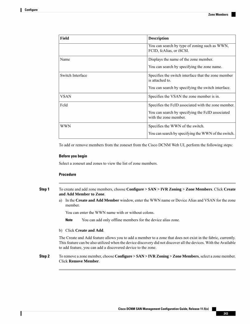
DescriptionField
You can search by type of zoning such as WWN,FCID, fcAlias, or iSCSI.
Displays the name of the zone member.Name
You can search by specifying the zone name.
Specifies the switch interface that the zone memberis attached to.
Switch Interface
You can search by specifying the switch interface.
Specifies the VSAN the zone member is in.VSAN
Specifies the FcID associated with the zone member.FcId
You can search by specifying the FcID associatedwith the zone member.
Specifies the WWN of the switch.WWN
You can search by specifying theWWNof the switch.
To add or remove members from the zoneset from the Cisco DCNMWeb UI, perform the following steps:
Before you begin
Select a zoneset and zones to view the list of zone members.
Procedure
Step 1 To create and add zone members, choose Configure > SAN > IVR Zoning > Zone Members. Click Createand Add Member to Zone.a) In the Create and Add Member window, enter the WWN name or Device Alias and VSAN for the zone
member.
You can enter the WWN name with or without colons.
You can add only offline members for the device alias zone.Note
b) Click Create and Add.
The Create and Add feature allows you to add a member to a zone that does not exist in the fabric, currently.This feature can be also utilized when the device discovery did not discover all the devices.With the Availableto add feature, you can add a discovered device to the zone.
Step 2 To remove a zonemember, chooseConfigure > SAN > IVR Zoning > Zone Members, select a zonemember.Click Remove Member.
Cisco DCNM SAN Management Configuration Guide, Release 11.5(x)243
ConfigureZone Members
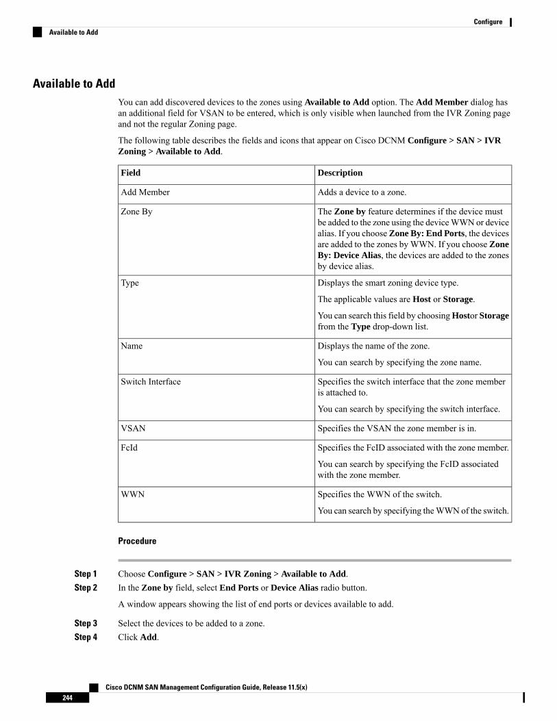
Available to AddYou can add discovered devices to the zones using Available to Add option. The Add Member dialog hasan additional field for VSAN to be entered, which is only visible when launched from the IVR Zoning pageand not the regular Zoning page.
The following table describes the fields and icons that appear on Cisco DCNM Configure > SAN > IVRZoning > Available to Add.
DescriptionField
Adds a device to a zone.Add Member
The Zone by feature determines if the device mustbe added to the zone using the deviceWWNor device
Zone By
alias. If you chooseZone By: End Ports, the devicesare added to the zones by WWN. If you choose ZoneBy: Device Alias, the devices are added to the zonesby device alias.
Displays the smart zoning device type.Type
The applicable values are Host or Storage.
You can search this field by choosingHostor Storagefrom the Type drop-down list.
Displays the name of the zone.Name
You can search by specifying the zone name.
Specifies the switch interface that the zone memberis attached to.
Switch Interface
You can search by specifying the switch interface.
Specifies the VSAN the zone member is in.VSAN
Specifies the FcID associated with the zone member.FcId
You can search by specifying the FcID associatedwith the zone member.
Specifies the WWN of the switch.WWN
You can search by specifying theWWNof the switch.
Procedure
Step 1 Choose Configure > SAN > IVR Zoning > Available to Add.Step 2 In the Zone by field, select End Ports or Device Alias radio button.
A window appears showing the list of end ports or devices available to add.
Step 3 Select the devices to be added to a zone.Step 4 Click Add.
Cisco DCNM SAN Management Configuration Guide, Release 11.5(x)244
ConfigureAvailable to Add

Specify the device type for smart zoning if smart zone is enabled for that zone.
You can select more than one zone. When this occurs, a dialog appears that shows a list of all thezones that are currently selected on the zone table.
Note
Configuring FCIPCisco DCNM allows you to create FCIP links between Gigabit Ethernet ports, enables Fibre Channel writeacceleration and IP compression.
To configure FCIP from the Cisco DCNMWeb UI, perform the following steps:
Procedure
Step 1 Choose Configure > SAN > FCIP.
The Welcome page displays the tasks to configure FCIP using the FCIP Wizard.
Step 2 Click Next to select the switch pair.
FCIP is not supported on Cisco MDS 9000 24/10-Port SAN Extension Module.Note
Step 3 Select two MDS switches to connect via FCIP for Between Switch and Switch from the drop-down list.
Each switch must have an Ethernet port that is connected to an IP network to function correctly.
In the case of a federation setup, both switches must belong to the fabrics that are discovered ormanaged by the same server.
Note
Step 4 Click Next to select the Ethernet ports.Step 5 Select the Ethernet ports to be used in FCIP ISL between the selected switches.
Down ports must be enabled to function correctly. Security can be enforced for unconfigured 14+2, 18+4,9250i and SSN16 Ethernet ports.
Step 6 Click Next to specify the IP addresses and add an IP route.Step 7 Enter the Ethernet ports IP addresses and specify the IP Routes if the port addresses are in a different subnet.
Click Next to apply the changes to IP Address and IP Route.Note
Step 8 Click Next to specify Tunnel properties.Step 9 Specify the following parameters to tunnel the TCP connections.
Enter the parameters.
• Max Bandwidth: Enter the number between 1 to 10000. The unit is Mb.
• Min Bandwidth: Enter the minimum bandwidth value. The unit is Mb.
• Estimated RTT(RoundTrip Time)—Enter the number between 0 to 300000. The unit is us. ClickMeasure to measure the roundtrip time.
Cisco DCNM SAN Management Configuration Guide, Release 11.5(x)245
ConfigureConfiguring FCIP
• Write Acceleration: Check the check box to enable the write acceleration.
If Write Acceleration is enabled, ensure that flows will not load balance across multiple ISLs.Note
• Enable Optimum Compression: Check the check box to enable the optimum compression.
• Enable XRC Emulator: Check the check box to enable XRC emulator.
• Connections: Enter the number of connections from 0 to 100.
Step 10 Click Next to create FCIP ISL.Step 11 Enter the Profile ID and Tunnel ID for the switch pair, and select the FICON Port Address from the
drop-down list.Step 12 Click View Configured to display the Profiles and Tunnels information.Step 13 Select the Trunk Mode from non-Trunk, trunk, and auto. Specify the Port VSAN for non-Trunk and
auto, and allowed VSAN List for Trunk tunnel.Step 14 Click Next to the last summary page.
The Summary view displays what you have selected in the previous steps.
Step 15 Click Deploy to configure FCIP or click Finish complete the configuration and deploy later.
Port ChannelsPort Channels refer to the aggregation of multiple physical interfaces into one logical interface to providehigher aggregated bandwidth, load balancing, and link redundancy. Port Channels can connect to interfacesacross switching modules, so a failure of a switching module cannot bring down the Port Channel link.
Beginning with Cisco Data Center Network Manager 11.0(1), you can configure and edit Port Channels.Navigate to Configure > SAN > Port Channel to create or edit Port Channels.
Click Create New Port Channel to launch the wizard to create new Port Channel.
Click Edit Existing Port Channel to launch the wizard to edit an existing Port Channel.
Information About Configuring Port Channels
Port Channels Overview
Port Channels refer to the aggregation of multiple physical interfaces into one logical interface to providehigher aggregated bandwidth, load balancing, and link redundancy (See below figure). Port Channels canconnect to interfaces across switching modules, so a failure of a switching module cannot bring down the PortChannel link.
Cisco DCNM SAN Management Configuration Guide, Release 11.5(x)246
ConfigurePort Channels

Figure 5: Port Channel Flexibility
Port Channels on Cisco MDS 9000 Family switches allow flexibility in configuration. This illustrates threepossible Port Channel configurations:
• Port Channel A aggregates two links on two interfaces on the same switching module at each end of aconnection.
• Port Channel B also aggregates two links, but each link is connected to a different switching module. Ifthe switching module goes down, traffic is not affected.
• Port Channel C aggregates three links. Two links are on the same switching module at each end, whileone is connected to a different switching module on switch 2.
Port Channeling and Trunking
Trunking is a commonly used storage industry term. However, the Cisco NX-OS software and switches inthe Cisco MDS 9000 Family implement trunking and Port Channeling as follows:
• Port Channeling enables several physical links to be combined into one aggregated logical link.
• Trunking enables a link transmitting frames in the EISL format to carry (trunk) multiple VSAN traffic.For example, when trunking is operational on an E port, that E port becomes a TE port. A TE port isspecific to switches in the Cisco MDS 9000 Family. An industry standard E port can link to other vendorswitches and is referred to as a nontrunking interface (See Figure 6: Trunking Only, on page 247 andFigure 7: Port Channeling and Trunking, on page 248).
Figure 6: Trunking Only
Cisco DCNM SAN Management Configuration Guide, Release 11.5(x)247
ConfigurePort Channeling and Trunking

Figure 7: Port Channeling and Trunking
Port Channeling and trunking are used separately across an ISL.
• Port Channeling—Interfaces can be channeled between the following sets of ports:
• E ports and TE ports
• F ports and NP ports
• TF ports and TNP ports
• Trunking—Trunking permits carrying traffic on multiple VSANs between switches.
• Both Port Channeling and trunking can be used between TE ports over EISLs.
Load Balancing
Two methods support the load-balancing functionality:
• Flow-based—All frames between a source and destination follow the same links for a given flow. Thatis, whichever link is selected for the first exchange of the flow is used for all subsequent exchanges.
• Exchange-based—The first frame in an exchange picks a link and subsequent frames in the exchangefollow the same link. However, subsequent exchanges can use a different link. This provides moregranular load balancing while preserving the order of frames for each exchange.
The following figure illustrates how a source ID 1 (SID1) and destination ID1 (DID1)-based load balancingworks. When the first frame in a flow is received on an interface for forwarding, link 1 is selected. Eachsubsequent frame in that flow is sent over the same link. No frame in SID1 and DID1 utilizes link 2.
Cisco DCNM SAN Management Configuration Guide, Release 11.5(x)248
ConfigureLoad Balancing

Figure 8: SID1 and DID1-Based Load Balancing
The following figure illustrates how exchange-based load balancing works.When the first frame in an exchangeis received for forwarding on an interface, link 1 is chosen by a hash algorithm. All remaining frames in thatparticular exchange are sent on the same link. For exchange 1, no frame uses link 2. For the next exchange,link 2 is chosen by the hash algorithm. Now all frames in exchange 2 use link 2.
Cisco DCNM SAN Management Configuration Guide, Release 11.5(x)249
ConfigureLoad Balancing

Figure 9: SID1, DID1, and Exchange-Based Load Balancing
Port Channel Modes
You can configure each Port Channel with a channel group mode parameter to determine the Port Channelprotocol behavior for all member ports in this channel group. The possible values for a channel group modeare as follows:
• ON (default)—The member ports only operate as part of a Port Channel or remain inactive. In this mode,the Port Channel protocol is not initiated. However, if a Port Channel protocol frame is received from apeer port, the software indicates its nonnegotiable status. This mode is backward compatible with theexisting implementation of Port Channels in releases prior to Release 2.0(1b), where the channel groupmode is implicitly assumed to be ON. In CiscoMDS SAN-OSReleases 1.3 and earlier, the only availablePort Channel mode was the ON mode. Port Channels that are configured in the ON mode require you toexplicitly enable and disable the Port Channel member ports at either end if you add or remove portsfrom the Port Channel configuration. You must physically verify that the local and remote ports areconnected to each other.
• ACTIVE—The member ports initiate Port Channel protocol negotiation with the peer ports regardlessof the channel group mode of the peer port. If the peer port, while configured in a channel group, doesnot support the Port Channel protocol, or responds with a nonnegotiable status, it defaults to the ONmode behavior. The ACTIVE Port Channel mode allows automatic recovery without explicitly enablingand disabling the Port Channel member ports at either end.
The following table compares ON and ACTIVE modes.
Cisco DCNM SAN Management Configuration Guide, Release 11.5(x)250
ConfigurePort Channel Modes
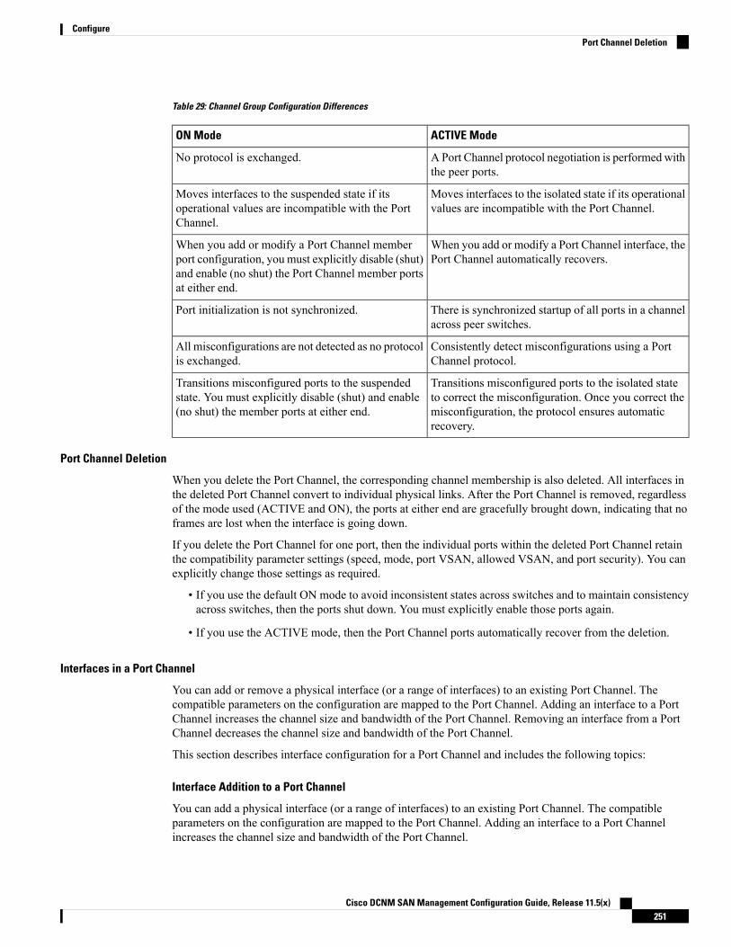
Table 29: Channel Group Configuration Differences
ACTIVE ModeON Mode
APort Channel protocol negotiation is performed withthe peer ports.
No protocol is exchanged.
Moves interfaces to the isolated state if its operationalvalues are incompatible with the Port Channel.
Moves interfaces to the suspended state if itsoperational values are incompatible with the PortChannel.
When you add or modify a Port Channel interface, thePort Channel automatically recovers.
When you add or modify a Port Channel memberport configuration, you must explicitly disable (shut)and enable (no shut) the Port Channel member portsat either end.
There is synchronized startup of all ports in a channelacross peer switches.
Port initialization is not synchronized.
Consistently detect misconfigurations using a PortChannel protocol.
All misconfigurations are not detected as no protocolis exchanged.
Transitions misconfigured ports to the isolated stateto correct the misconfiguration. Once you correct themisconfiguration, the protocol ensures automaticrecovery.
Transitions misconfigured ports to the suspendedstate. You must explicitly disable (shut) and enable(no shut) the member ports at either end.
Port Channel Deletion
When you delete the Port Channel, the corresponding channel membership is also deleted. All interfaces inthe deleted Port Channel convert to individual physical links. After the Port Channel is removed, regardlessof the mode used (ACTIVE and ON), the ports at either end are gracefully brought down, indicating that noframes are lost when the interface is going down.
If you delete the Port Channel for one port, then the individual ports within the deleted Port Channel retainthe compatibility parameter settings (speed, mode, port VSAN, allowed VSAN, and port security). You canexplicitly change those settings as required.
• If you use the default ON mode to avoid inconsistent states across switches and to maintain consistencyacross switches, then the ports shut down. You must explicitly enable those ports again.
• If you use the ACTIVE mode, then the Port Channel ports automatically recover from the deletion.
Interfaces in a Port Channel
You can add or remove a physical interface (or a range of interfaces) to an existing Port Channel. Thecompatible parameters on the configuration are mapped to the Port Channel. Adding an interface to a PortChannel increases the channel size and bandwidth of the Port Channel. Removing an interface from a PortChannel decreases the channel size and bandwidth of the Port Channel.
This section describes interface configuration for a Port Channel and includes the following topics:
Interface Addition to a Port Channel
You can add a physical interface (or a range of interfaces) to an existing Port Channel. The compatibleparameters on the configuration are mapped to the Port Channel. Adding an interface to a Port Channelincreases the channel size and bandwidth of the Port Channel.
Cisco DCNM SAN Management Configuration Guide, Release 11.5(x)251
ConfigurePort Channel Deletion
A port can be configured as a member of a static Port Channel only if the following configurations are thesame in the port and the Port Channel:
• Speed
• Mode
• Rate mode
• Port VSAN
• Trunking mode
• Allowed VSAN list or VF-ID list
After the members are added, regardless of the mode (ACTIVE and ON) used, the ports at either end aregracefully brought down, indicating that no frames are lost when the interface is going down (see the“Generation 1 Port Channel Limitations” section on page -12).
Compatibility Check
A compatibility check ensures that the same parameter settings are used in all physical ports in the channel.Otherwise, they cannot become part of a Port Channel. The compatibility check is performed before a port isadded to the Port Channel.
The check ensures that the following parameters and settings match at both ends of a Port Channel:
• Capability parameters (type of interface, Gigabit Ethernet at both ends, or Fibre Channel at both ends).
• Administrative compatibility parameters (speed, mode, rate mode, port VSAN, allowed VSAN list, andport security).
Ports in shared rate mode cannot form a Port Channel or a trunkingPort Channel.
Note
• Operational parameters (remote switch WWN and trunking mode).
A port addition procedure fails if the capability and administrative parameters in the remote switch areincompatible with the capability and administrative parameters in the local switch. If the compatibility checkis successful, the interfaces are operational and the corresponding compatibility parameter settings apply tothese interfaces.
Suspended and Isolated States
If the operational parameters are incompatible, the compatibility check fails and the interface is placed in asuspended or isolated state based on the configured mode:
• An interface enters the suspended state if the interface is configured in the ON mode.
• An interface enters the isolated state if the interface is configured in the ACTIVE mode.
Cisco DCNM SAN Management Configuration Guide, Release 11.5(x)252
ConfigureInterfaces in a Port Channel
Forcing an Interface Addition
You can force the port configuration to be overwritten by the Port Channel. In this case, the interface is addedto a Port Channel.
• If you use the default ON mode to avoid inconsistent states across switches and to maintain consistencyacross switches, then the ports shut down. You have to explicitly enable those ports again.
• If you use the ACTIVE mode, then the Port Channel ports automatically recover from the addition.
When Port Channels are created from within an interface, the force option cannot be used.Note
After the members are forcefully added, regardless of the mode (ACTIVE and ON) used, the ports at eitherend are gracefully brought down, indicating that no frames are lost when the interface is going down.
Interface Deletion from a Port Channel
When a physical interface is deleted from the Port Channel, the channel membership is automatically updated.If the deleted interface is the last operational interface, then the Port Channel status is changed to a downstate. Deleting an interface from a Port Channel decreases the channel size and bandwidth of the Port Channel.
• If you use the default ON mode to avoid inconsistent states across switches and to maintain consistencyacross switches, then the ports shut down. You must explicitly enable those ports again.
• If you use the ACTIVE mode, then the Port Channel ports automatically recover from the deletion.
After the members are deleted, regardless of the mode (ACTIVE and ON) used, the ports at either end aregracefully brought down, indicating that no frames are lost when the interface is going down.
Port Channel Protocols
In earlier Cisco SAN-OS releases, Port Channels required additional administrative tasks to supportsynchronization. The Cisco NX-OS software provides robust error detection and synchronization capabilities.You can manually configure channel groups or they can be automatically created. In both cases, the channelgroups have the same capability and configurable parameters. Any change in configuration that is applied tothe associated Port Channel interface is propagated to all members of the channel group.
A protocol to exchange Port Channel configurations is available in all Cisco MDS switches. This additionsimplifies Port Channel management with incompatible ISLs. An additional autocreation mode enables ISLswith compatible parameters to automatically form channel groups without manual intervention.
The Port Channel protocol is enabled by default.
The Port Channel protocol expands the Port Channel functional model in Cisco MDS switches. It uses theexchange peer parameters (EPP) services to communicate across peer ports in an ISL. Each switch uses theinformation that is received from the peer ports along with its local configuration and operational values todecide if it should be part of a Port Channel. The protocol ensures that a set of ports is eligible to be part ofthe same Port Channel. They are only eligible to be part of the same Port Channel if all the ports have acompatible partner.
The Port Channel protocol uses two subprotocols:
• Bringup protocol—Automatically detects misconfigurations so you can correct them. This protocolsynchronizes the Port Channel at both ends so that all frames for a given flow (as identified by the source
Cisco DCNM SAN Management Configuration Guide, Release 11.5(x)253
ConfigurePort Channel Protocols

FC ID, destination FC ID and OX_ID) are carried over the same physical link in both directions. Thishelps make applications such as write acceleration, work for Port Channels over FCIP links.
• Autocreation protocol—Automatically aggregates compatible ports into a Port Channel.
This section describes how to configure the Port Channel protocol and includes the following sections:
Channel Group Creation
Channel groups are not supported on internal ports in the Cisco Fabric Switch for HP c-Class BladeSystemand the Cisco Fabric Switch for IBM BladeSystem.
Note
Assuming link A1-B1 comes up first (see Figure 1-9), that link is operational as an individual link. When thenext link comes up, for example, A2-B2, the Port Channel protocol identifies if this link is compatible withlink A1-B1 and automatically creates channel groups 10 and 20 in the respective switches. If link A3-B3 canjoin the channel groups (the Port Channels), the respective ports have compatible configurations. If link A4-B4operates as an individual link, it is because of the incompatible configuration of the two end ports with theother member ports in this channel group.
Figure 10: Autocreating Channel Groups
The channel group numbers are selected dynamically, and as such, the administrative configuration of theports forming the channel group at either end are applicable to the newly created channel group. The channelgroup number being chosen dynamically may be different across reboots for the same set of Port Channelsbased on the order of ports that are initialized in the switch.
Table 1-10 identifies the differences between user-configured and auto-configured channel groups.
Autocreated Channel GroupUser-Configured Channel Group
Created automatically when compatible links come upbetween two compatible switches, if channel groupautocreation is enabled in all ports at both ends.
Manually configured by the user.
None of these ports are members of a user-configuredchannel group.
Member ports cannot participate in autocreationof channel groups. The autocreation featurecannot be configured.
Cisco DCNM SAN Management Configuration Guide, Release 11.5(x)254
ConfigurePort Channel Protocols
All ports included in the channel group participate in thePort Channel—no member port becomes isolated orsuspended; instead, the member port is removed from thechannel group when the link is found to be incompatible.
You can form the Port Channel with a subset ofthe ports in the channel group. Incompatible portsremain in a suspended or isolated state dependingon the ON or ACTIVE mode configuration.
Any administrative configuration that is made to the PortChannel is applied to all ports in the channel group, butthe configurations are saved for the member ports; noconfiguration is saved for the Port Channel interface. Youcan explicitly convert this channel group, if required.
Any administrative configuration that is made tothe Port Channel is applied to all ports in thechannel group, and you can save theconfiguration for the Port Channel interface.
You cannot remove a channel group, or add/remove anyof its members. The channel group is removed when nomember ports exist.
You can remove any channel group and addmembers to a channel group.
Autocreation
The autocreation protocol has the following functionality:
• A port is not allowed to be configured as part of a Port Channel when the autocreation feature is enabled.These two configurations are mutually exclusive.
• Autocreation must be enabled in both the local and peer ports to negotiate a Port Channel.
• Aggregation occurs in one of two ways:
• A port is aggregated into a compatible autocreated Port Channel.
• A port is aggregated with another compatible port to form a new Port Channel.
• Newly created Port Channels are allocated from the maximum Port Channel (128 for Generation 1 or acombination of Generation 1 and Generation 2 switches, or 256 for Generation 2 switches) in a decreasingorder based on availability. If all 128 (or 256) numbers are used up, aggregation is not allowed.
• You cannot change the membership or delete an autocreated Port Channel.
• When you disable autocreation, all member ports are removed from the autocreated Port Channel.
• Once the last member is removed from an autocreated Port Channel, the channel is automatically deletedand the number is released for reuse.
• An autocreated Port Channel is not persistent through a reboot. An autocreated Port Channel can bemanually configured to appear the same as a persistent Port Channel. Once the Port Channel is madepersistent, the autocreation feature is disabled in all member ports.
• You can enable or disable the autocreation feature on a per-port basis or for all ports in the switch. Whenthis configuration is enabled, the channel group mode is assumed to be active. The default for this taskis disabled.
• If autocreation of channel groups is enabled for an interface, you must first disable autocreation beforedowngrading to earlier software versions or before configuring the interface in a manually configuredchannel group.
Cisco DCNM SAN Management Configuration Guide, Release 11.5(x)255
ConfigurePort Channel Protocols
When enabling autocreation in any switch in the Cisco MDS 9000 Family, we recommend that you retain atleast one interconnected port between the switches without any autocreation configuration. If all ports betweentwo switches are configured with the autocreation feature at the same time, you may face a possible trafficdisruption between these two switches as the ports are automatically disabled and reenabled when ports areadded to an autocreated Port Channel.
Note
Manually Configured Channel Groups
A user-configured channel group cannot be converted to an autocreated channel group. However, you canconvert an autocreated channel group to a manual channel group. Once performed, this task is irreversible.The channel group number does not change, but the member ports operate according to the properties of themanually configured channel group, and the autocreation of channel group is implicitly disabled for all memberports.
If you enable persistence, be sure to enable it at both ends of the Port Channel.Tip
Prerequisites for Configuring Port ChannelsBefore configuring a Port Channel, consider the following guidelines:
• Configure the Port Channel across switching modules to implement redundancy on switching modulereboots or upgrades.
• Ensure that one Port Channel is not connected to different sets of switches. Port Channels requirepoint-to-point connections between the same set of switches.
On switches with Generation 1 switching modules, or a combination of Generation 1 and Generation 2switching modules, you can configure a maximum of 128 Port Channels. On switches with only Generation2 switching modules, or Generation 2 and Generation 3 switching modules, you can configure a maximumof 256 Port Channels.
If you misconfigure Port Channels, you may receive a misconfiguration message. If you receive this message,the Port Channel’s physical links are disabled because an error has been detected.
A Port Channel error is detected if the following requirements are not met:
• Each switch on either side of a Port Channel must be connected to the same number of interfaces.
• Each interface must be connected to a corresponding interface on the other side (see Figure 1-11 for anexample of an invalid configuration).
• Links in a Port Channel cannot be changed after the Port Channel is configured. If you change the linksafter the Port Channel is configured, be sure to reconnect the links to interfaces within the Port Channeland reenable the links.
If all three conditions are not met, the faulty link is disabled.
Enter the show interface command for that interface to verify that the Port Channel is functioning as required.
Cisco DCNM SAN Management Configuration Guide, Release 11.5(x)256
ConfigurePrerequisites for Configuring Port Channels
Guidelines and Limitations for Configuring Port ChannelsThis section includes the guidelines and limitations for this feature:
General Guidelines for Cisco MDS 9000 Series Switches
Cisco MDS 9000 Family switches support the following number of Port Channels per switch:
• Switches with only Generation 1 switching modules do not support F and TF Port Channels.
• Switches with Generation 1 switching modules, or a combination of Generation 1 and Generation 2switching modules, support a maximum of 128 Port Channels. Only Generation 2 ports can be includedin the Port Channels.
• Switches with only Generation 2 switching modules or Generation 2 and Generation 3 modules supporta maximum of 256 Port Channels with 16 interfaces per Port Channel.
• A Port Channel number refers to the unique identifier for each channel group. This number ranges fromof 1 to 256.
Generation 1 Port Channel Limitations
This section includes the restrictions on creation and addition of Port Channel members to a Port Channel onGeneration 1 hardware:
• The 32-port 2-Gbps or 1-Gbps switching module.
• The MDS 9140 and 9120 switches.
When configuring the host-optimized ports on Generation 1 hardware, the following Port Channel guidelinesapply:
• If you execute the write erase command on a 32-port switching module, and then copy a savedconfiguration to the switch from a text file that contains the no system default switchport shutdowncommand, you have to copy the text file to the switch again for the E ports to come up without manualconfiguration.
• Any (or all) full line rate ports in the Cisco MDS 9100 Series can be included in a Port Channel.
• The host-optimized ports in the Cisco MDS 9100 Series are subject to the same Port Channel rules as32-port switching modules; only the first port of each group of four ports is included in a Port Channel.
• You can configure only the first port in each 4-port group as an E port (for example, the first portin ports 1–4, the fifth port in ports 5–8, and so on). If the first port in the group is configured as aPort Channel, the other three ports in each group (ports 2–4, 6–8, and so on) are not usable andremain in the shutdown state.
• If any of the other three ports are configured in a no shutdown state, you cannot configure the firstport to be a Port Channel. The other three ports continue to remain in a no shutdown state.
F and TF Port Channel Limitations
The following guidelines and restrictions are applicable for F and TF Port Channels:
• The ports must be in F mode.
Cisco DCNM SAN Management Configuration Guide, Release 11.5(x)257
ConfigureGuidelines and Limitations for Configuring Port Channels

• Automatic creation is not supported.
• The Port Channel interface must be in ACTIVE mode when multiple FCIP interfaces are grouped withWA.
• ONmode is not supported. Only ACTIVE-ACTIVEmode is supported. By default, the mode is ACTIVEon the NPV switches.
• Devices that are logged in through F Port Channel on anMDS switch are not supported in IVR non-NATconfiguration. The devices are supported only in IVR NAT configuration.
• Port security rules are enforced only on physical pWWNs at the single link level.
• FC-SP authenticates only the first physical FLOGI of every Port Channel member.
• Since the FLOGI payload carries only the VF bits to trigger the use of a protocol after the FLOGIexchange, those bits will be overridden. In the case of the NPV switches, the core has a Cisco WWNand tries to initiate the PCP protocol.
• The name server registration of the N ports logging in through an F Port Channel uses the fWWN of thePort Channel interface.
• DPVM configuration is not supported.
• The Port Channel port VSAN cannot be configured using DPVM.
• The Dynamic Port VSAN Management (DPVM) database is queried only for the first physical FLOGIof each member, so that the port VSAN can be configured automatically.
• DPVM does not bind FC_IDs to VSANs, but pWWNs to VSANs. It is queried only for the physicalFLOGI.
Valid and Invalid Port Channel Examples
Port Channels are created with default values. You can change the default configuration just like any otherphysical interface. The following figure provides examples of valid Port Channel configurations.
Figure 11: Valid Port Channel Configurations
The following figure provides examples of invalid configurations. Assuming that the links are brought up inthe 1, 2, 3, 4 sequence, links 3 and 4 will be operationally down as the fabric is misconfigured.
Cisco DCNM SAN Management Configuration Guide, Release 11.5(x)258
ConfigureValid and Invalid Port Channel Examples
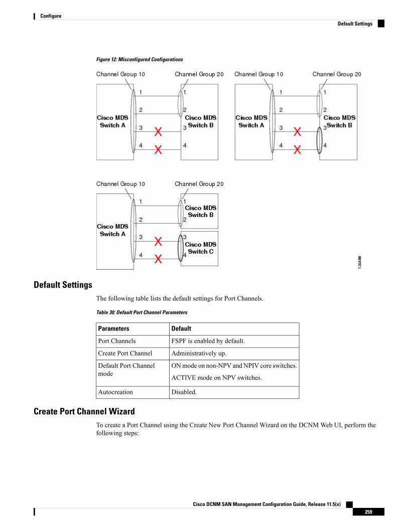
Figure 12: Misconfigured Configurations
Default SettingsThe following table lists the default settings for Port Channels.
Table 30: Default Port Channel Parameters
DefaultParameters
FSPF is enabled by default.Port Channels
Administratively up.Create Port Channel
ONmode on non-NPV andNPIV core switches.
ACTIVE mode on NPV switches.
Default Port Channelmode
Disabled.Autocreation
Create Port Channel WizardTo create a Port Channel using the Create New Port Channel Wizard on the DCNMWeb UI, perform thefollowing steps:
Cisco DCNM SAN Management Configuration Guide, Release 11.5(x)259
ConfigureDefault Settings
Procedure
Step 1 Choose Configure > SAN > Port Channel.
Click Create New Port Channel to launch the Create Port Channel Wizard.
Step 2 In the Select Switch Pair screen, perform the following steps:a) Select the appropriate fabric from the Fabric drop-down.
The list contains switch pairs in the fabric that have an ISL between them, that is not already in a portchannel.
b) Select a switch pair to be linked by an FC Port Channel.
If there are NPV links between NPIV-core and NPV switches, you must enable F Port Trunking andChanneling Protocol using the feature fport-channel-trunk command on the NPIV switch in order tosee the switch-pair and the number of NPV links.
c) Click Next.
Step 3 In the Select ISLs screen, select one or more ISLs or Links to create a new Channel between the switch pair.a) From the list of ISLs in the Available area, select and click right arrow to move the ISL to the Selected
area.b) Click Next.
Step 4 In the Create Port Channel screen, define, or edit the channel attributes.a) Channel ID field is populated with the next unused channel ID. Change the channel ID or description for
each switch, if necessary.
The range of the channel ID is from 1 to 256.
b) FICON Port Address is only enabled if the switches are FICON enabled. From the drop-down list, selectthe appropriate FICON port address on the switch. Select the port address that you want to assign to thePort Channel port.
c) In the Channel Attributes area, to configure the speed, click the appropriate radio button.d) Select the appropriate Trunk Mode radio button to enable trunking on the links in the Port Channel.
• Select trunk if your link is between TE ports.
• Select nonTrunk if your link is between E ports.
• Select auto if you are not sure.
e) In the Port VSAN field, enter the interface ID for port VSAN which must be used when trunking is notenabled.
Every interface must have a port VSAN even if trunking is enabled. If trunking is enabled, this port VSANis not used. However, the switch must configure the port, so that the network knows what VSAN to useby default, if trunking is disabled.
f) VSAN list field provides a list of VSANs you want to allow the port channel to use for trunking.
This field is disabled if the Trunk Mode is set to nonTrunk or auto.
g) In the Core Switch Bandwidth field, select dedicated or shared radio button to allocate the switch bandwidth.
This bandwidth is applicable only for port channels between an NPIV and NPV switch.
Cisco DCNM SAN Management Configuration Guide, Release 11.5(x)260
ConfigureCreate Port Channel Wizard
h) Check the Force Admin, Trunk, Speed, and VSAN attributes to be identical checkbox to ensure thatthe same parameter settings are used in all physical ports in the channel. If these settings are not identical,the ports cannot become part of the Port Channel.
Step 5 Click Previous to return to the previous screen and edit the settings. Click Finish to configure the Port Channel.
A success message appears.
Step 6 Click Close to close the Create Port Channel Wizard.
Edit Existing Port ChannelTo edit a Port Channel using the Edit Port Channel Wizard on the DCNMWeb UI, follow these steps:
Procedure
Step 1 From the Cisco DCNMWeb UI, navigate to Configure > SAN > Port Channel.
Click on Edit Existing Port Channel to launch the Edit Port Channel Wizard.
Step 2 In the Select Switch Pair screen, do the following:a) Select the appropriate fabric from the Fabric drop-down list.
The switch pairs that have port channels between them are listed in the area below.
b) Select a switch pair to edit the port channel.c) Click Next.
Step 3 In the Select Port Channel screen, select a Port Channel to edit.
Click Next.
Step 4 In the Edit Port Channel screen, select the desired ISL.a) Click the right and left arrow to select the available ISLs.
The selected ISLs are contained in the Port Channel after you save the changes. If the SelectedISLs list is empty, the Delete Port Channel is Empty checkbox is enabled.
Note
b) If you do not choose any ISL, check the Delete Port Channel if Empty checkbox to delete the portchannel.
c) Check the Force admin, trunk, speed, VSAN attributes to be identical checkbox to choose identicalvalues for admin, trunk, speed and VSAN attributes.
d) Click Next.
Step 5 Click Finish to apply the changes.
Click Previous to go back to the previous screen and edit the values.
Click Cancel to abort the changes.
Cisco DCNM SAN Management Configuration Guide, Release 11.5(x)261
ConfigureEdit Existing Port Channel
Device AliasA device alias is a user-friendly name for a port WWN. Device alias name can be specified when configuringfeatures such as zoning, QoS, and port security. The device alias application uses the Cisco Fabric Services(CFS) infrastructure to enable efficient database management and fabric-wide distribution.
This section contains context-sensitive online help content under Configure > SAN > Device Alias.
The following table describes the fields that appear under Configure > SAN > Device Alias.
DescriptionField
Displays the device alias seed switch name.Seed Switch
Displays the alias retrieved from the seed switch.Device Alias
Displays the port WWN.pWWN
This section contains the following:
ConfigurationSelect the Fabric from the Fabric drop-down list. The list of device aliases existing on the fabric will beretrieved and displayed.
Before performing any Device Alias configuration, check the status on the CFS tab, to ensure that the statusis "success".
To perform Device Alias configuration from the Cisco DCNMWeb client, the fabric must be configured asDevice Alias enhanced mode.
Note
Procedure
Step 1 To delete the device alias, Cisco DCNM Web Client > Configure > SAN > Device Alias > Configurationtab, check the device alias you need to delete.a) Click Delete.
A confirmation message appears.
Deleting the device alias may cause traffic interruption.Note
b) Click Yes to delete the topic alias.
Step 2 To create the device alias, from Cisco DCNM Web Client > Configure > SAN > Device Alias >Configuration tab, click Create.
The Add Device Alias windows appears.
All the provisioned port WWNs are populated in the table.
a) Enter a device alias name in the Device Alias field to indicate to create a device alias for the selectedpWWN.
Cisco DCNM SAN Management Configuration Guide, Release 11.5(x)262
ConfigureDevice Alias

b) Click Save to exit the inline editor mode.c) Click Apply to assign the device alias to the switches.
You can also create a device alias with a non-provisioned port WWN.
a) Click New Alias to create a new table row in inline editor mode.b) In the pWWN field, enter the non-provisioned port WWN for the new alias.c) Click Save to exit the inline editor mode.d) Click Apply to assign the device alias and the associated pWWN to the switches.
If you close the Add Device Alias window before applying the device alias to the switches, thechanges will be discarded and the device alias will not be created.
Note
Step 3 For end devices with an attached service profile, the service profile name is populated to the Device Aliasfield. This allows the service profile name as device alias name for those devices.
Device Alias creation is CFS auto-committed after clicking Apply. Click CFS tab to check if CFS is properlyperformed after the device alias was created. In case of failure, you must troubleshoot and fix the problem.
CFSSelect the Fabric from the Fabric drop-down list. The list of device aliases existing on the fabric is retrievedand displayed.
CFS information is listed for all the eligible switches in the fabric. Before performing any Device Aliasconfiguration, check the status on the CFS tab to ensure that the status is "success". If the CFS is locked byanother user, or if the previous operation failed, ensure that the CFS session is unlocked.
To view CFS information from the Cisco DCNMWeb UI, perform the following steps:
Procedure
Step 1 Choose Configure > SAN > Device Alias > CFS.Step 2 To commit the CFS configuration, select the Switch radio button.
Click Commit.
The CFS configuration for this switch is committed.
Step 3 To abort the CFS configuration, select the Switch radio button.
Click Abort.
The CFS configuration for this switch is aborted.
Step 4 To clear the lock on the CFS configuration of the switch, select the Switch radio button.
Click Clear Lock.
If the CFS is locked by another user, or if the previous operation failed, ensure that the CFS session is unlocked.
Cisco DCNM SAN Management Configuration Guide, Release 11.5(x)263
ConfigureCFS

Port MonitoringThis feature allows you to save custom Port Monitoring policies in the Cisco DCNM database. It allows youto push the selected custom policy to one or more fabrics or Cisco MDS 9000 Series Switches. The policy isdesignated as active Port-Monitor policy in the switch.
This feature is supported only on the Cisco MDS 9000 SAN Switches and therefore the Cisco DCNM useris allowed to select the MDS switch to push the policy.
Cisco DCNMprovides five templates to customize the policy. The user-defined policies are saved in the CiscoDCNM database. You can select any template or customized policy to push to the selected fabric or switchwith the desired port type.
You can edit only user-defined policies.Note
The following table describes the fields that appear on Cisco DCNM Configure > SAN > Port Monitoring.
DescriptionField
This drop-down list shows the following templatesfor policies:
Templates
• Normal_accessPort
• Normal_allPort
• Normal_trunksPort
• Aggressive_accessPort
• Aggressive_allPort
• Aggressive_trunksPort
• Most-Aggressive_accessPort
• Most-Aggressive_allPort
• Most-Aggressive_trunksPort
• default
• slowdrain
Allows you to save your changes for the user-definedpolicies.
Save
Allows you to save an existing policy as a new policywith a different name.
Save As
This creates another item in the templates as CustomPolicy. The customized policy is saved under thiscategory.
If you click Save As while the policy is edited, thecustomized policy is saved.
Cisco DCNM SAN Management Configuration Guide, Release 11.5(x)264
ConfigurePort Monitoring
DescriptionField
The port type of the customized policy willnot be saved when Save As is selected.
Note
Allows you to delete any user-defined policies.Delete
Allows you to select a fabric or switch and push theselected policies with a desired port type.
Push to switches
The available port types are:
• trunks/Core
• access-port/Edge
• all
If you choose trunks or all, the port guardis disabled.
Note
The following policies select the trunks/Core policytype:
• Normal_trunksPort
• Aggressive_trunksPort
• Most-Aggressive_trunksPort
The following policies select the access-port/Edgepolicy type:
• Normal_accessPort
• Aggressive_accessPort
• Most-Aggressive_accessPort
• slowdrain
The following policies select the all policy type:
• Normal_allPort
• Aggressive_allPort
• Most-Aggressive_allPort
• default
Select the parameters and click Push to push thepolicies to the switches in the fabric.
If there is any active policy with the same or commonport type, the push command configures the samepolicy on the selected devices. This policy replaces
Cisco DCNM SAN Management Configuration Guide, Release 11.5(x)265
ConfigurePort Monitoring

DescriptionField
the existing active policy with the same or commonport type.
If you click Push to Switches while the policy isedited, the customized policy will not be saved.
Specifies the counter type.Counter Description
Move the pointer to the "i" icon next to the counterdescription to view detailed information.
Specifies the upper threshold limit for the countertype.
Rising Threshold
Specifies the type of event to be generated when risingthreshold is reached or crossed.
Rising Event
Specifies the lower threshold limit for the countertype.
Falling Threshold
Specifies the type of event to be generated whenfalling threshold is reached or crossed.
Falling Event
Specifies the time interval to poll for the countervalue.
Poll Interval
Allows you to set an optional threshold value lowerthan the rising threshold value and higher than the
Warning Threshold
falling threshold value to generate syslogs. The rangeis 0–9223372036854775807.
Specifies if the port guard is enabled or disabled. Thevalue can be false, flap, or errordisable.
Port Guard
The default value is "false".
The default value is "true".Monitor ?
SAN Insights - Overview
Introduction to SAN InsightsThe SAN Insights feature enables you to configure, monitor, and view the flow analytics in fabrics. CiscoDCNM enables you to visualize the health-related indicators in the interface so that you can quickly identifyissues in fabrics. Also, the health indicators enable you to understand the problems in fabrics. The SANInsights feature also provides more comprehensive end-to-end flow-based data from the host to LUN.
FromRelease 11.2(1), CiscoDCNM supports SANTelemetry Streaming (STS) using compact GPB transport,for better telemetry performance and to improve the overall scalability of SAN Insights.
For SAN insights streaming stability and performance, refer to System Requirements section in the CiscoDCNM Installation Guide for SAN Deployment Guide and the section Increasing ElasticsearchDatabase HeapSize of the Cisco DCNM SAN Management Configuration Guide. Ensure system RAM is of adequate size.
Cisco DCNM SAN Management Configuration Guide, Release 11.5(x)266
ConfigureSAN Insights - Overview

Use of NTP is recommended to maintain time synchronization between the DCNM and the switches. EnablePM collection for viewing counter statistics.
Prerequisites• The SAN Insights feature is supported for Cisco MDS NX-OS Release 8.3(1) and later.
• The SAN Insights feature isn’t supported on small deployment.
• Every Federation node must consist of three Large DCNM nodes.
• For SAN Insights streaming stability and performance, the recommended Elasticsearch heap size is16GB. To increase the heap size, see Increasing Elasticsearch Database Heap Size, on page 275.
• If SAN Insights streaming was configured with KVGPB encoding using versions of Cisco DCNM SANInsights older than 11.2(1), the switch continues to stream with KVGPB encoding while configuringstreaming with DCNM versions 11.2(1) and above. Compact GPB streaming configuration for SANInsights is supported starting from Cisco DCNM 11.2(1). To stream using Compact GPB, disable theold KVGPB streaming before configuring SAN Insights newly, after the upgrade. To disable analyticsand telemetry, on the Cisco DCNMWeb client, choose Configure > SAN > SAN Insights. ClickContinue. Select the appropriate fabric and clickContinue. On the Switch Selection screen, clickDisableAnalytics to clear all the analytics and telemetry configuration on the selected switches.
Guidelines and Limitations• Ensure that the time configurations in Cisco DCNM and the supported switches are synchronized to thelocal NTP server for deploying the SAN Insights feature.
• Any applicable daylight time savings settings must be consistent across the switches and Cisco DCNM.
• To modify the streaming interval, use the CLI from the switch, and remove the installed query for CiscoDCNM. Modify the san.telemetry.streaming.interval property in the DCNM server properties. Theallowed values for the interval are 30–300 seconds. The default value is 30 seconds. If there is an issuewith the default value or to increase the value, set default value to 60 seconds.Again configure the sameswitch from Cisco DCNM to push the new streaming interval.
• For deploying SAN Insights in HA Federation mode, a 3-node federation setup is necessary for HAperformance of Elastic Search cluster.
• Use the ISL query installation type only for the switches that have storage connected (storage-edgeswitches).
• For the ISL query installation type, in the Configure SAN Insights wizard, analytics can’t be enabled oninterfaces that are members of port-channel ISL to non-MDS platform switches.
• After installing the switch-based FM_Server_PKG license, the Configure SAN Insights wizard may takeupto 5 minutes to detect the installed license.
For information about the SAN Insights dashboard, see SAN Insights Dashboard.
For information about configuring the SAN Insights dashboard, see Configuring SAN Insights, on page 269.
Server Properties for SAN InsightsThe following table describes the property name and its default values. To modify these values, navigate toAdministration > DCNM Server > Server Properties on the Web UI.
Cisco DCNM SAN Management Configuration Guide, Release 11.5(x)267
ConfigurePrerequisites

From Release 11.4(1), you need not stop/start the SAN Insights Post processing application and the SANInsight Pipeline application from the DCNM WebUI > Applications > Catalog page, to refresh serverproperties. Click the Pause, and then Resume on the application icon to apply the modifications to the serverproperties.
After applying changes to the server properties, you must restart all the DCNM services.Note
For LinuxDeployment—Restart the DCNMServices by using the following commands in the same sequence.(dcnm-linux-server)# service FMServer restart(dcnm-linux-server)# service SanInsight restart(dcnm-linux-server)# service PIPELINE restart
If you change the server properties, ensure that you restart the Cisco DCNM to use the new properties value.Restart the SAN Insights service to use the new properties.
Note
Table 31: Server Properties for SAN Insights
Default ValueDescriptionProperty Name
300,000milliseconds
Specifies the SAN Insights processing interval.san.telemetry.processing.interval
30 secondsSpecifies the SAN Insights streaming interval.san.telemetry.streaming.interval
50,000Specifies maximum number of unique flows (ITLs +ITCNs) taken for processingDCNMon virtualmachine.
san.telemetry.va.flow.limit
70,000Specifies maximum number of unique flows (ITLs +ITCNs) taken for processing on Cisco NexusDashboard.
san.telemetry.pa.flow.limit
TRUESpecifies if the noop frames are used in ECT baselinetraining calculation.
san.telemetry.use.noop.data
FALSESpecifies log of all dropped flows explicitlysan.telemetry.log.dropped
7 daysSpecifies the training time frame for flows ECTbaseline.
san.telemetry.train.timeframe
14 daysSpecifies the time duration to periodically restart theECT baseline training after number of days.
san.telemetry.train.reset
2 daysSpecifies the retention policy after which the flows datais deleted.
san.telemetry.expire.flows
7 daysSpecifies the retention policy after which the flows datais deleted.
san.telemetry.expire.flows
14 daysSpecifies the retention policy after which the postprocessed data is deleted.
san.telemetry.expire.baseline
90 daysSpecifies the retention policy after which the hourlyrollups data is deleted.
san.telemetry.expire.rollup
Cisco DCNM SAN Management Configuration Guide, Release 11.5(x)268
ConfigureServer Properties for SAN Insights
Default ValueDescriptionProperty Name
14 daysSpecifies time to keep unseen flow training datasan.telemetry.expire.train
10Specifies the deviation low mark for SCSI telemetrysan.telemetry.deviation.low
30Specifies the deviation medium mark for SCSItelemetry
san.telemetry.deviation.med
50Specifies the deviation high mark for SCSI telemetrysan.telemetry.deviation.high
0Specifies the deviation low mark for NVMe/FCtelemetry
san.telemetry.nvme.deviation.low
2Specifies the deviation medium mark for NVMe/FCtelemetry
san.telemetry.nvme.deviation.med
5Specifies the deviation high mark for NVMe/FCtelemetry
san.telemetry.nvme.deviation.high
SCSISpecifies the desired default protocol selection in theSAN Insights UI pages to view corresponding data:SCSI or NVMe.
san.telemetry.default.protocol
trueAllows you to use telemetry reset based on time gapbetween records
san.telemetry.gap.reset
750 secondsSpecifies themaximum valid time gap between records.san.telemetry.gap.reset.interval
Configuring SAN InsightsTo configure SAN insights from the Cisco DCNMWeb UI, perform the following steps:
Before you begin
From Release 11.3(1), the SAN Insights feature is supported on Cisco DCNM Deployment using OVA/ISOimage with Huge deployment option only.
Note
From Release 11.3(1), the Elasticsearch heap size is set to 25% of the total system RAM, up to a maximumof 32G heap size. SAN Insights require a minimum of 16GB Elasticsearch heap size for proper functioning.As Cisco DCNM SAN deployment with OVA/ISO is already configured with sufficient system requirements,you need not increase the Heap Size manually.
Refer to Increasing Elasticsearch Database Heap Size, on page 275 for more instructions.
Procedure
Step 1 Choose Configure > SAN > SAN Insights.
The Configure SAN Insights wizard appears.
Cisco DCNM SAN Management Configuration Guide, Release 11.5(x)269
ConfigureConfiguring SAN Insights
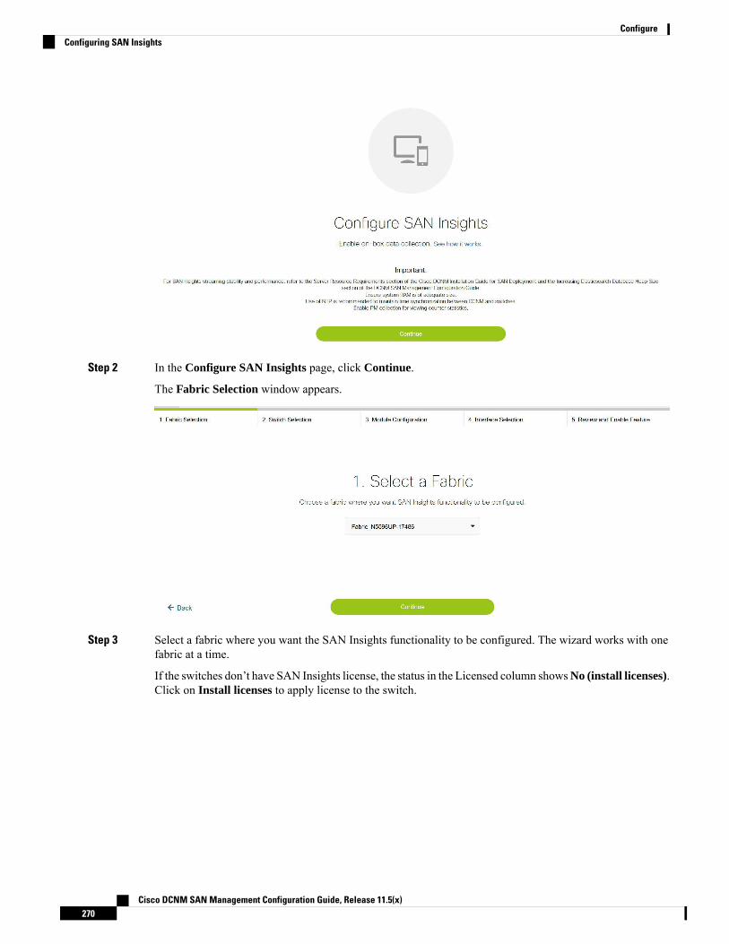
Step 2 In the Configure SAN Insights page, click Continue.
The Fabric Selection window appears.
Step 3 Select a fabric where you want the SAN Insights functionality to be configured. The wizard works with onefabric at a time.
If the switches don’t have SAN Insights license, the status in the Licensed column showsNo (install licenses).Click on Install licenses to apply license to the switch.
Cisco DCNM SAN Management Configuration Guide, Release 11.5(x)270
ConfigureConfiguring SAN Insights
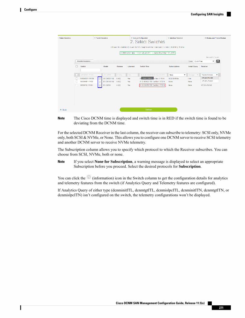
The Cisco DCNM time is displayed and switch time is in RED if the switch time is found to bedeviating from the DCNM time.
Note
For the selected DCNMReceiver in the last column, the receiver can subscribe to telemetry: SCSI only, NVMeonly, both SCSI &NVMe, or None. This allows you to configure one DCNM server to receive SCSI telemetryand another DCNM server to receive NVMe telemetry.
The Subscription column allows you to specify which protocol to which the Receiver subscribes. You canchoose from SCSI, NVMe, both or none.
If you select None for Subscription, a warning message is displayed to select an appropriateSubscription before you proceed. Select the desired protocols for Subscription.
Note
You can click the (information) icon in the Switch column to get the configuration details for analyticsand telemetry features from the switch (if Analytics Query and Telemetry features are configured).
If Analytics Query of either type (dcnminitITL, dcnmtgtITL, dcnmislpcITL, dcnminitITN, dcnmtgtITN, ordcnmislpcITN) isn’t configured on the switch, the telemetry configurations won’t be displayed.
Cisco DCNM SAN Management Configuration Guide, Release 11.5(x)271
ConfigureConfiguring SAN Insights

Step 4 Click Continue. The switches that are capable of streaming analytics are listed in the Select Switches page.Step 5 Select the switches on which SAN Insights must be configured.
Both Cisco DCNM and switch time are recorded and displayed when you navigate to the SelectSwitches page. This helps you to ensure that the clocks of Cisco DCNM and switch are in sync.
Note
Click Disable Analytics to clear all the analytics and telemetry configuration on the selected switches.
If SAN Insights streaming was configured with KVGPB encoding using versions of Cisco DCNM SANInsights older than 11.2(1), the switch continues to streamwith KVGPB encoding while configuring streamingwith DCNM versions 11.2(1) and above. From Cisco DCNM Release 11.2(1), Compact GPB streamingconfiguration for SAN Insights is supported. To stream using Compact GPB, the old KVGPB streaming mustbe disabled before configuring SAN Insights, newly after the upgrade.
In the Install Query column, choose one type of port per switch, and then click Save. You can choose fromthese options: ISL, host, or storage.
• host—lists all ports where hosts or initiators are connected on the switch.
• storage—lists all ports where storage or targets are connected on the switch.
• ISL—lists all ISL and port channel ISL ports on the switch.
• None—indicates that no query is installed.
The following queries are used:
• dcnmtgtITL/dcnmtgtITN—This is the storage-only query.
• dcnminitITL/dcnminitITN—This is the host-only query.
• dcnmislpcITL/dcnmislpcITN—This is the ISL and pc-member query.
Cisco DCNM SAN Management Configuration Guide, Release 11.5(x)272
ConfigureConfiguring SAN Insights
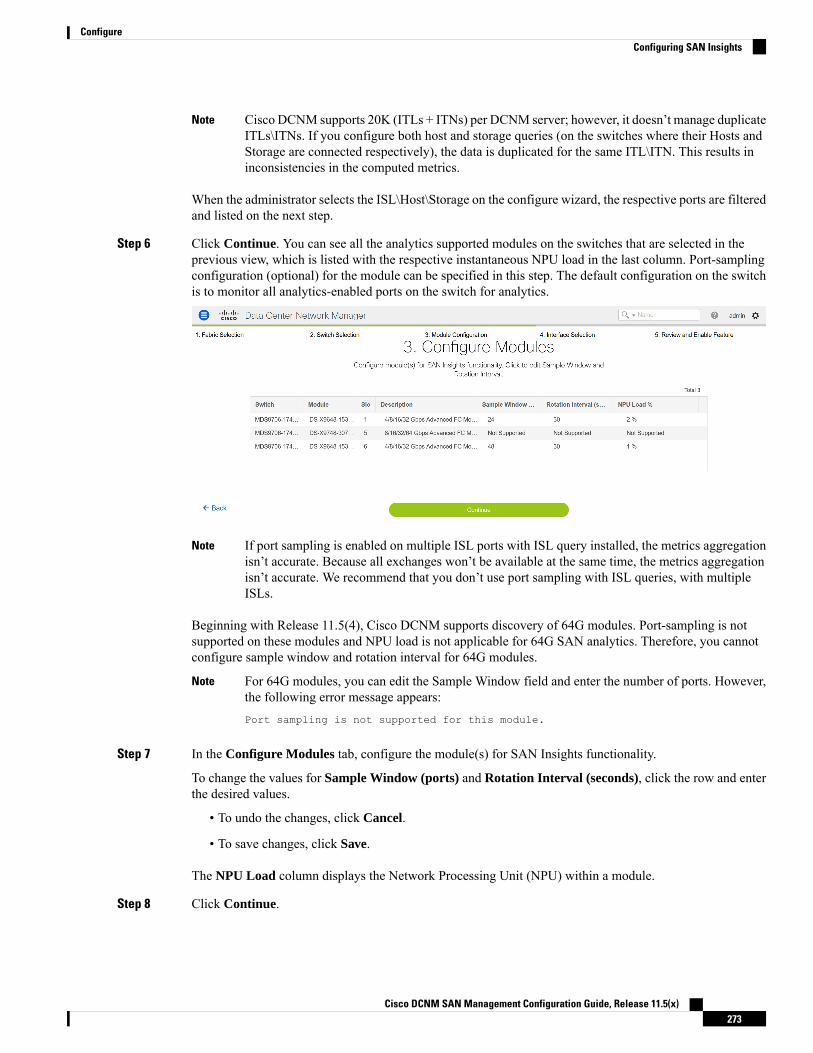
Cisco DCNM supports 20K (ITLs + ITNs) per DCNM server; however, it doesn’t manage duplicateITLs\ITNs. If you configure both host and storage queries (on the switches where their Hosts andStorage are connected respectively), the data is duplicated for the same ITL\ITN. This results ininconsistencies in the computed metrics.
Note
When the administrator selects the ISL\Host\Storage on the configure wizard, the respective ports are filteredand listed on the next step.
Step 6 Click Continue. You can see all the analytics supported modules on the switches that are selected in theprevious view, which is listed with the respective instantaneous NPU load in the last column. Port-samplingconfiguration (optional) for the module can be specified in this step. The default configuration on the switchis to monitor all analytics-enabled ports on the switch for analytics.
If port sampling is enabled on multiple ISL ports with ISL query installed, the metrics aggregationisn’t accurate. Because all exchanges won’t be available at the same time, the metrics aggregationisn’t accurate. We recommend that you don’t use port sampling with ISL queries, with multipleISLs.
Note
Beginning with Release 11.5(4), Cisco DCNM supports discovery of 64G modules. Port-sampling is notsupported on these modules and NPU load is not applicable for 64G SAN analytics. Therefore, you cannotconfigure sample window and rotation interval for 64G modules.
For 64G modules, you can edit the Sample Window field and enter the number of ports. However,the following error message appears:Port sampling is not supported for this module.
Note
Step 7 In the Configure Modules tab, configure the module(s) for SAN Insights functionality.
To change the values for Sample Window (ports) and Rotation Interval (seconds), click the row and enterthe desired values.
• To undo the changes, click Cancel.
• To save changes, click Save.
The NPU Load column displays the Network Processing Unit (NPU) within a module.
Step 8 Click Continue.
Cisco DCNM SAN Management Configuration Guide, Release 11.5(x)273
ConfigureConfiguring SAN Insights
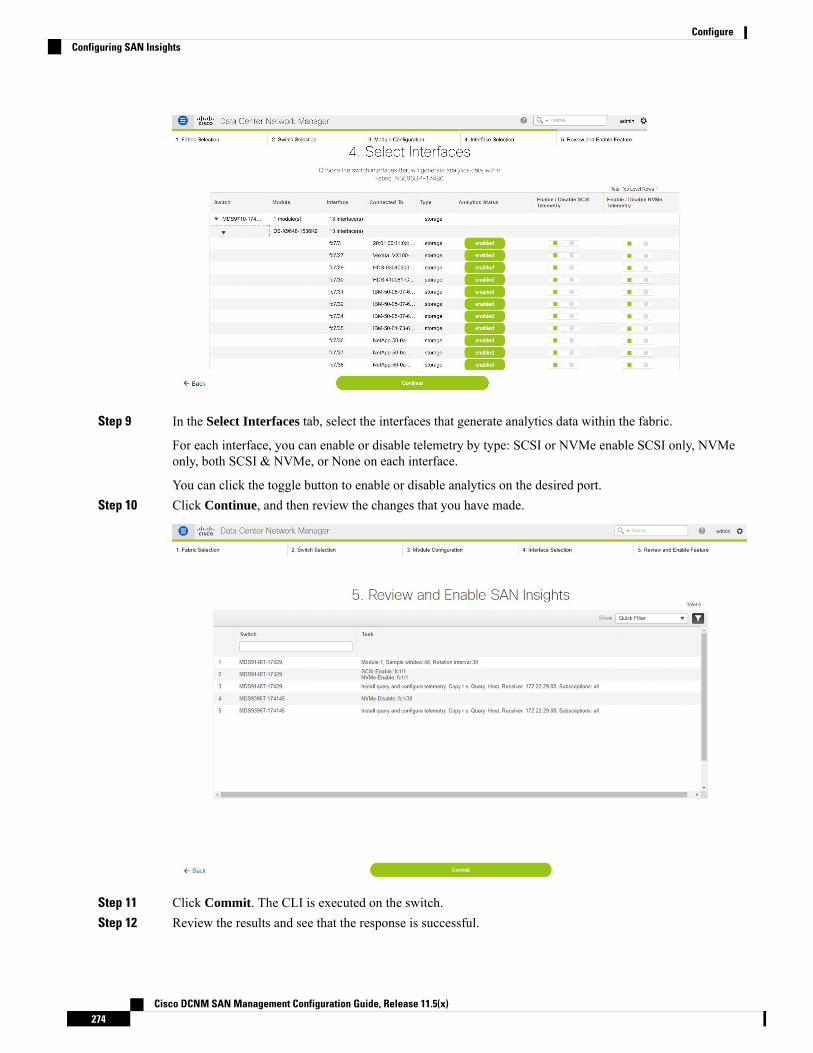
Step 9 In the Select Interfaces tab, select the interfaces that generate analytics data within the fabric.
For each interface, you can enable or disable telemetry by type: SCSI or NVMe enable SCSI only, NVMeonly, both SCSI & NVMe, or None on each interface.
You can click the toggle button to enable or disable analytics on the desired port.Step 10 Click Continue, and then review the changes that you have made.
Step 11 Click Commit. The CLI is executed on the switch.Step 12 Review the results and see that the response is successful.
Cisco DCNM SAN Management Configuration Guide, Release 11.5(x)274
ConfigureConfiguring SAN Insights

Some SAN Insights pages can take up to 2 hours to display data.Note
Step 13 Click Close to return to the home page. Close icon appears only after all CLI commands are executed on theswitch.
Navigate to the Configure > SAN Insights page again, to modify the SAN Insights configurations.
Increasing Elasticsearch Database Heap Size
The Java heap size is the amount of memory allocated to applications running in the Java Virtual Machineused by DCNM server itself. Objects in heapmemory can be shared between threads and improve performance.SAN Insights benefits from an appropriate quantity of heap.
From Release 11.3(1), the Elasticsearch heap size is set to 25% of the total system RAM for RHEL/OVA/ISOSAN deployments, up to amaximum of 32G heap size. SAN Insights require a minimum of 16GBElasticsearchheap size for proper functioning. In Release 11.3(1), with adequate system RAM at the time of deployment,it won't be necessary to modify the Elasticsearch heap size.
Heap size is set during installation for Linux (RHEL) SAN deployments. Due to less system RAM during thetime of install, in case Elasticsearch heap size is set less than 16G, we recommend that you increase the heapsize to minimum 16G after increasing the system RAM.
To specify the Elasticsearch Heap Size on Linux CLI, perform the following steps:
Procedure
Step 1 Stop the Elasticsearch by using the following command:service elasticsearch stop
Step 2 vi <install-folder>/dcm/elasticsearch/config/jvm.options.Step 3 Update -Xms16g and -Xmx16g and save and close the file.Step 4 Start the ElasticSearch by using the following command:
service elasticsearch start
Scripts are located at the relative folder location where Cisco DCNM is installed.Note
The server may experience slowness due to high number of ITLs or large dataset in Elasticsearch databaseover a period of time. In such a scenario, we recommend that you must update the heap size to 32G, and threadpool queue size.
What to do next
We recommend that you update search thread pool queue size. By default, the queue size is 1000.
To increase the queue size to 2000, do the following on all the nodes.
1. Stop the ElasticSearch service.
2. Navigate to the elasticsearch.yml file located at the relative install path on your system.
Cisco DCNM SAN Management Configuration Guide, Release 11.5(x)275
ConfigureIncreasing Elasticsearch Database Heap Size
Path:<your-dcnm-install-path>\dcm\elasticsearch\config\elasticsearch.yml
3. In the elasticsearch.yml, modify the thread pool search value to 2000.
thread_pool.search.queue_size: 2000
4. Restart the ElasticSearch service.
Viewing Services
From Cisco DCNMRelease 11.3(1), there are two different processes on LINUX platforms for SAN Insights.
• PIPELINE service
• SanInsight service
Pipeline Services
To verify the status of nexus-pipeline process on LINUX platforms, run the following commands:
• # service PIPELINE stop
Stops the pipeline receiver service
• # service PIPELINE start
Starts the pipeline receiver service
• # service PIPELINE status
Shows the running status of the pipeline receiver service
SanInsight Services
SanInsight is a postprocessor service. To verify the status of SanInsight process, run the following commands:
• # service SanInsight stop
Stops the SAN Insight postprocessor service
• # service SanInsight start
Starts the SAN Insight postprocessor service
• # service SanInsight status
Shows the running state of the SAN Insight postprocessor service
Cisco DCNM SAN Management Configuration Guide, Release 11.5(x)276
ConfigureViewing Services

C H A P T E R 7Administration
This chapter contains the following topics:
• DCNM Server, on page 277• Manage Licensing, on page 289• Management Users, on page 299• Performance Setup, on page 306• Event Setup, on page 309• Credentials Management, on page 314
DCNM ServerThe DCNM Server menu includes the following submenus:
Starting, Restarting, and Stopping ServicesBy default, the ICMP connectivity between DCNM and its switches validates the connectivity duringPerformance Management. If you disable ICMP, Performance Management data will not be fetched from theswitches. You can configure this parameter in the server properties. To disable ICMP connectivity checkfrom Cisco DCNMWeb UI, choose Administration > DCNM Server > Server Properties, and setskip.checkPingAndManageable parameter value to true.
To clean up the performance manager database (PM DB) stale entries, start, restart, or stop a service, fromthe Cisco DCNMWeb UI, perform the following steps:
Procedure
Step 1 Choose Administration > DCNM Server > Server Status.
The Status window appears that displays the server details.
Step 2 In the Actions column, click the action you want to perform. You can perform the following actions:
• Start or restart a service.
• Stop a service.
• Clean up the stale PM DB entries.
Cisco DCNM SAN Management Configuration Guide, Release 11.5(x)277
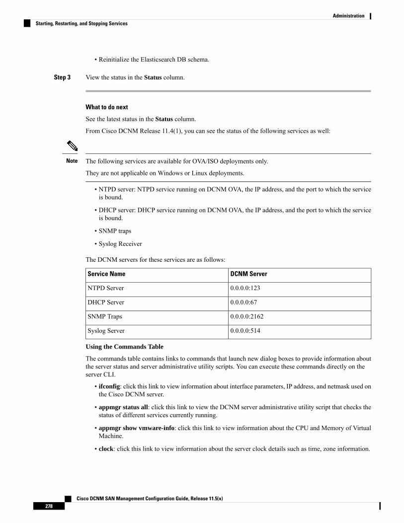
• Reinitialize the Elasticsearch DB schema.
Step 3 View the status in the Status column.
What to do next
See the latest status in the Status column.
From Cisco DCNM Release 11.4(1), you can see the status of the following services as well:
The following services are available for OVA/ISO deployments only.
They are not applicable on Windows or Linux deployments.
Note
• NTPD server: NTPD service running on DCNM OVA, the IP address, and the port to which the serviceis bound.
• DHCP server: DHCP service running on DCNM OVA, the IP address, and the port to which the serviceis bound.
• SNMP traps
• Syslog Receiver
The DCNM servers for these services are as follows:
DCNM ServerService Name
0.0.0.0:123NTPD Server
0.0.0.0:67DHCP Server
0.0.0.0:2162SNMP Traps
0.0.0.0:514Syslog Server
Using the Commands Table
The commands table contains links to commands that launch new dialog boxes to provide information aboutthe server status and server administrative utility scripts. You can execute these commands directly on theserver CLI.
• ifconfig: click this link to view information about interface parameters, IP address, and netmask used onthe Cisco DCNM server.
• appmgr status all: click this link to view the DCNM server administrative utility script that checks thestatus of different services currently running.
• appmgr show vmware-info: click this link to view information about the CPU and Memory of VirtualMachine.
• clock: click this link to view information about the server clock details such as time, zone information.
Cisco DCNM SAN Management Configuration Guide, Release 11.5(x)278
AdministrationStarting, Restarting, and Stopping Services

The commands section is applicable only for the OVA or ISO installations.Note
CustomizationFrom Cisco DCNMRelease 11.3(1), you can modify the background image and message on theWeb UI loginpage. This feature helps you to distinguish between the DCNM instances, when you have many instancesrunning at the same time. You can also use a company-branded background on the login page. Click on RestoreDefaults to reset the customizations to their original default values.
To remove the customizations and restore to the default values, click Restore defaults.
Login Image
This feature allows you to change the background image on the Cisco DCNMWeb UI login page. If you havemany instances of DCNM, this will help you identify the correct DCNM instance based on the backgroundimage.
To edit the default background image for your Cisco DCNMWeb UI login page, perform the following steps:
1. Choose Administration > DCNM Server > Customization.
2. In the Login Image area, click Add (+) icon.
Browse for the image that you need to upload from your local directory. You can choose any of thefollowing format images: JPG, GIF, PNG, and SVG.
3. Select the image and click Open.
A status message appears on the right-bottom corner.
Login imageUpload Successful
We recommend that you upload a scaled image for fast load times.Note
The uploaded image is selected and applied as the background image.
4. To choose an existing image as login image, select the image and wait until you see the message on theright-bottom corner.
5. To revert to the default login image, click Restore Defaults.
Message of the day (MOTD)
This feature allows you to add a message to the Cisco DCNMWeb UI login page. You can a list of messagesthat will rotate on the configured frequency. This feature allows you to convey important messages to the useron the login page.
To add or edit the message of the day on the Cisco DCNMWeb UI login page, perform the following steps:
Cisco DCNM SAN Management Configuration Guide, Release 11.5(x)279
AdministrationCustomization

1. Choose Administration > DCNM Server > Customization.
2. In the Message of the day (MOTD) field, enter the message that must appear on the login page.
3. Click Save.
Viewing Log InformationYou can view the logs for performance manager, SAN management server, SME server, web reports, webserver, and web services. These processes have no corresponding GUI that allows you to view informationabout these log files. If you see errors, preserve these files for viewing.
Logs cannot be viewed from a remote server in a federation.Note
To view the logs from the Cisco DCNMWeb UI, perform the following steps:
Procedure
Step 1 Choose Administration > DCNM Server > Logs.
You see a tree-based list of logs in the left column. Under the tree, there is a node for every server in thefederation. The log files are under the corresponding server node.
Step 2 Click a log file under each node of the tree to view it on the right.Step 3 Double-click the tree node for each server to download a ZIP file containing log files from that server.Step 4 (Optional) Click Generate Techsupport to generate and download files required for technical support.
This file contains more information in addition to log files.
A TAR.GZ file will be downloaded for OVA and ISO deployments, and a ZIP file will be downloadedfor all other deployments. You can use the use appmgr tech_support command in the CLI togenerate the techsupport file.
Note
Step 5 (Optional) Click the Print icon on the upper right corner to print the logs.
Server PropertiesYou can set the parameters that are populated as default values in the DCNM server.
To set the parameters of the DCNM server from the Cisco DCNMWeb UI, perform the following steps:
Procedure
Step 1 Choose Administration > DCNM Server > Server Properties.
Cisco DCNM SAN Management Configuration Guide, Release 11.5(x)280
AdministrationViewing Log Information
Step 2 Click Apply Changes to save the server settings.
Configuring SFTP/SCP CredentialsA file server is required to collect device configuration and restoring configurations to the device.
To configure the SFTP/SCP credentials for a file store from the Cisco DCNMWeb UI, perform the followingsteps:
Procedure
Step 1 Choose Administration > DCNM Server > Archive FTP Credentials.
The Archive FTP Credentials window is displayed.
The credentials are auto-populated for fresh OVA and ISO installations.Note
Step 2 In the Server Type field, use the radio button to select SFTP.
• You must have an SFTP server to perform backup operation. The SFTP server can be anexternal server. The SFTP directory must be an absolute Linux/SSH path format andmust haveread/write access to the SFTP User.
• If you are using an external server, enter its IP address in the server.FileServerAddress fieldin Administration > DCNM Server > Server Properties.
• If the nat.enabled field under Administration > DCNM Server > Server Properties is true,you must enter the NAT device IP in the server.FileServerAddress field and the SFTP servermust be local.
Note
a) Enter the User Name and Password.
From Release 11.3(1), for OVA/ISO installations, use the sysadmin user credentials to accessthe root directory.
Note
b) Enter the Directory path.
The path must be in absolute Linux path format.
If SFTP is unavailable on your device, you can use third-party SFTP applications, such as, mini-SFTP,Solarwinds, and so on. When you use an external SFTP, you must provide the relative path in the STFPDirectory Path. For example, consider the use cases at the end of this procedure.
From Release 11.3(1), for OVA/ISO installations, enter directory as /home/sysadmin.Note
c) From the Verification Switches drop-down list, select a switch.d) Click Apply to save the credentials.e) Click Verify & Apply to verify if SFTP and switch have connectivity and save the configuration.
If there are any failures during the verification, the new changes will not be stored.
f) Click Clear SSH Hosts to clear SSH hosts for all switches or selected switches.
Cisco DCNM SAN Management Configuration Guide, Release 11.5(x)281
AdministrationConfiguring SFTP/SCP Credentials
If there is a failure in any of the switches, an error message appears. Navigate to Configure > Backup >Switch Configuration > Archive Jobs > Job Execution Details to view the number of successful andunsuccessful switches.
Step 3 In the Server Type field, use the radio button to select TFTP.
Cisco DCNM uses a local TFTP server for data transfer. Ensure that there is no external TFTP server runningon the DCNM server.
Ensure that your switch user role includes the copy command. Operator roles receive a permissiondenied error. You can change your credentials in the Discovery window. Navigate to Inventory >Discovery.
Note
a) From the Verification Switch drop-down list, select a switch.b) Click Apply to save the credentials everywhere.c) Click Verify & Apply to verify if TFTP and switch have connectivity and save the configuration.
If there are any failures during the verification, the new changes are not stored.
Step 4 In the Server Type field, use the radio button to select SCP.
• You must have an SCP server to perform backup operation. The SCP server can be an externalserver. The SCP directory must be an absolute Linux/SSH path format andmust have read/writeaccess to the SCP User.
• If you are using an external server, enter its IP address in the server.FileServerAddress fieldunder Administration > DCNM Server > Server Properties.
• If the nat.enabled field under Administration > DCNM Server > Server Properties is true,you must enter the NAT device IP in the server.FileServerAddress field and the server mustbe local.
Note
a) Enter the User Name and Password.b) Enter the Directory path.
The path must be in absolute Linux path format.
If SCP is unavailable on your device, use external SCP applications, such as, mini-SCP, Solarwinds, andso on. When you use an external SCP, you must provide the relative path in the SCP Directory Path. Forexample, consider the use cases at the end of this procedure.
c) From the Verification Switches drop-down, select the switch.d) Click Apply to save the credentials everywhere.e) Click Verify & Apply to verify if SCP and switch have connectivity and save the configuration. If there
are any failures during the verification, the new changes will not be stored.f) Click Clear SSH Hosts to clear SSH hosts for all switches or selected switches.
If there is a failure in any of the switches, an error message is displayed. To view the number of successfuland unsuccessful switches, go to Configure > Backup > Switch Configuration > Archive Jobs > JobExecution Details.
Step 5 Choose Configuration > Templates > Templates Library > Jobs to view individual device verificationstatus.
Cisco DCNM SAN Management Configuration Guide, Release 11.5(x)282
AdministrationConfiguring SFTP/SCP Credentials

The configurations that are backed up are removed from the file server and are stored in the file system.
SFTP Directory Path
Use Case 1:
If Cisco DCNM is installed on Linux platforms, like OVA, ISO, or Linux, and the test folder islocated at /test/sftp/, you must provide the entire path of the SFTP directory. In the SFTPDirectory field, enter /test/sftp.
Use Case 2:
If Cisco DCNM is installed on the Windows platform, and the test folder is located atC://Users/test/sftp/, you must provide the relative path of the SFTP directory. In the SFTPDirectory field, enter /.
For Example:
• If the path in the external SFTP is C://Users/test/sftp/, then the Cisco DCNM SFTPDirectory path must be /.
• If the path in the external SFTP is C://Users/test, then the Cisco DCNM SFTP Directorypath must be /sftp/.
Examples for SCP Directory Path
Use Case 1:
If Cisco DCNM is installed on Linux platforms, like OVA, ISO, or Linux, and the test folder islocated at /test/scp/, youmust provide the entire path of the SCP directory. In the SCP Directoryfield, enter /test/scp.
Use Case 2:
If Cisco DCNM is installed on the Windows platform, and the test folder is located atC://Users/test/scp/, you must provide the relative path of the SCP directory. In the SCPDirectory field, enter /.
For Example:
• If the path in the external SCP is C://Users/test/scp/, then the Cisco DCNM SCPdirectory path must be /.
• If the path in the external SCP is C://Users/test, then the Cisco DCNM SCP directorypath must be /scp/.
Modular Device SupportTo support any new hardware that does not require many major changes, a patch can be delivered instead ofwaiting for the next DCNM release. Modular Device Support helps to deliver and apply the DCNM patchreleases. An authorized DCNM administrator can apply the patch to the production setup. Patch releases areapplicable for the following scenarios:
• Support any new hardware, like chassis or line cards
Cisco DCNM SAN Management Configuration Guide, Release 11.5(x)283
AdministrationModular Device Support

• Support latest NX-OS versions
• Support critical fixes as patches
To view the patch details from Cisco DCNMWeb UI, perform the following steps:
Procedure
Step 1 Choose Administration > DCNM Server > Modular Device Support.
You see the DCNM Servers column on the left in the window and Modular Device support informationwindow on the right.
Step 2 Expand DCNM Servers to view all the DCNM servers.
It includes the list of patches installed along with the version number, corresponding platforms supported,chassis supported, NX-OS version supported, PID supported, backup directory and the last patch deploymenttime in the Modular Device support information table.
What to do next
For more details about how to apply and rollback a patch, go to http://www.cisco.com/go/dcnm for moreinformation.
Managing Switch GroupsYou can configure switch groups by using Cisco DCNMWeb UI. You can add, delete, or move a switch toa group, or move switches from a group to another group.
This section contains the following:
Adding Switch GroupsTo add switch groups from the Cisco DCNMWeb UI, perform the following steps:
Procedure
Step 1 Choose Administration > DCNM Server > Switch Groups.
Step 2 Click the Add icon.
The Add Group window is displayed, that allows you to enter the name for the switch group.
Step 3 Enter the name of the switch group and click Add to complete adding the switch group.
The switch group name validation, and the maximum tree depth is 10. If you do not choose a parent groupbefore adding a new switch group, the new group is added on the top of the hierarchy.
Cisco DCNM SAN Management Configuration Guide, Release 11.5(x)284
AdministrationManaging Switch Groups

Removing a Group or a Member of a GroupYou can delete a group or a member of the group from the Cisco DCNMWeb UI. When you delete a group,the associated groups are deleted. The fabrics or ethernet switches of the deleted groups are moved to thedefault SAN or LAN.
To remove a group or a member of a group from the Cisco DCNMWeb UI, perform the following steps:
Procedure
Step 1 Choose the switch group or members of a group that you want to remove.Step 2 Click the Remove icon.
A dialog box prompts you to confirm the deletion of the switch group or the member of the group.
Step 3 Click Yes to delete or No to cancel the action.
Moving a Switch Group to Another GroupTo move a switch group to another group from the Cisco DCNMWeb UI, perform the following steps:
Procedure
Step 1 Select a switch or switch group.Step 2 Drag the highlighted switch or switch group to another group.
To move multiple switches across different switch groups, use Ctrl key or Shift key.
You can see the switch or switch group. Users are not allowed to move multiple switches in the group levelunder the new group now.
It is not allowed to move multiple switches in the group level. You may not mix a group withswitches.
Note
Managing Custom Port GroupsCustom port groups aid you to test the performance of the interfaces in the group. You can view the definedcustom ports and their configurations.
This section includes the following topics:
Adding Custom Port GroupsTo add a custom port group from the Cisco DCNMWeb UI, perform the following steps:
Cisco DCNM SAN Management Configuration Guide, Release 11.5(x)285
AdministrationRemoving a Group or a Member of a Group
Procedure
Step 1 Choose Administration > DCNM Server > Custom Port Groups.
The Custom Port Groups window is displayed.
Step 2 In the User-Defined Groups block, click the Add icon.Step 3 Enter the name for the custom port group in the Add Group Dialog window.Step 4 Click Add.
A custom port group is created in the User-Defined Groups area.
Configuring Switch and Interface to the Port GroupTo configure the custom port group to include switches and interfaces from the Cisco DCNMWebUI, performthe following steps:
Procedure
Step 1 Choose Administration > DCNM Server > Custom Port Groups.Step 2 In the User-Defined Groups area, select the port group to add the switch and interfaces.Step 3 In the Configurations area, click Add Member.
The Port Configuration window appears for the selected custom port group.
Step 4 In the Switches tab, select the switch to include in the custom port group.
The list of available Interfaces appears.
Step 5 Select all the interfaces to check the performance.Step 6 Click Submit.
The list of interfaces is added to the custom port group.
Removing Port Group MemberTo remove or delete a port group member in a custom port group from Cisco DCNMWeb UI, perform thefollowing steps:
Procedure
Step 1 Choose Administration > DCNM Server > Custom Port Groups.Step 2 In the User Defined Groups area, select a port group.Step 3 In the Configuration area, select the switch name and interface that must be deleted.Step 4 In the User Defined Groups area, select the group from which the member must be deleted.
Cisco DCNM SAN Management Configuration Guide, Release 11.5(x)286
AdministrationConfiguring Switch and Interface to the Port Group

Step 5 Click Remove Member.
A confirmation window appears.
Step 6 Click Yes to delete the member from the custom port group.
Removing Port GroupTo remove or delete a port group from the Cisco DCNMWeb UI, perform the following steps:
Procedure
Step 1 Choose Administration > DCNM Server > Custom Port Groups.Step 2 In the User Defined Groups area, select the group which must be deleted.Step 3 Click Remove.
A confirmation window appears.
Step 4 Click Yes to delete the custom group.
Viewing Server Federation
There must be a minimum of 3 nodes in the Federation set up for failover to function correctly. In a 2 nodeFederation setup, if one of the servers is down, the Elasticsearch cannot form the cluster, and therefore theWeb UI may behave inconsistently. In the case of a 3 node Federation setup, if two servers are down,inconsistent behavior of the WebUI is seen.
Note
Ensure that you clear your browser cache and cookies everytime after a Federation switchover or failover.Note
To view federation server information in Cisco DCNM, perform the following steps:
Procedure
Step 1 Choose Administration > DCNM Server > Federation.
The list of servers along with its IP address, status, location, local time, and data sources are displayed.
Step 2 Use the Enable Automatic Failover check box to turn on or turn off the failover functionality.Step 3 In the Location column, double-click to edit the location.
If the status of one of the servers in the federation is Inactive, some functionality may not work unless theserver status changes to Active.
Cisco DCNM SAN Management Configuration Guide, Release 11.5(x)287
AdministrationRemoving Port Group
Before upgrading Cisco DCNM, ensure that Enable Automatic Failover is unchecked. Otherwise,if one server within the federation is down, the devices are moved to the other DCNM server whichcomes up first after the upgrade. To prevent the automove for DCNM upgrade, you must disablethe automove on all DCNMswithin the federation, and upgrade the DCNM server one by one. Onlyafter all the DCNMs upgrade successfully and run normally, then enable the auto move again.
Note
In DCNM Federation, when Enable Automatic Failover is enabled, if a DCNM is down, thedevices under its management is moved to the other DCNM. However after the DCNM is back, thedevices will not move back.
Note
When you upgrade Cisco DCNM Federation, you need to revisit the Administration > DCNMServer > Federation page, and run the Elasticsearch cluster sync command after the upgrade iscomplete. This will update the Elasticsearch configurations and restart performance monitoring. Torun the Elasticsearch cluster sync command, you need to enable Elasticsearch clustering button inthe Administration > DCNM Server > Federation page. To restart the performance monitoring,choose Administration > DCNM Server > Server Status, and click the green button.
Note
The ElasticSearch Cluster section gives the details about the elastic search. It has the following fields:
DescriptionField
Specifies the name of the elastic search cluster.Name
Specifies the number of instances clustered.Nodes
Specifies if the cluster is enabled or not. If the clusteris not enabled, the status is yellow. If the cluster isenabled, the status is green.
Status
Elasticsearch Clustering
The ElasticSearch Clustering sync-up option is available only on the Primary node in the Federation setup.Note
To sync each of the elastic search nodes that are associated with a federated server, into an elastic searchcluster, perform the following steps:
Procedure
Step 1 In the Federation window, click ElasticSearch Clustering. The Elastic Search Clustering pop-up windowappears.
Step 2 Click Apply.This operation synchronizes each of the elastic search nodes that are associated with a federated server, intoan elastic search cluster. The operation is disruptive to any features using elastic search as a data store. Somefeatures are impacted by ongoing data synchronization operations after the elastic search services are resumed.
Cisco DCNM SAN Management Configuration Guide, Release 11.5(x)288
AdministrationElasticsearch Clustering
Multi Site Manager
Procedure
Step 1 Multi-Site-Manager (MsM) provides a single pane for users to search for switches that are managed by DCNMglobally. MSM can do realtime search to find out which switch globally handles the traffic for a given virtualmachine based on IP address, name or mac address, and supporting VXLAN basing on segment ID as well.It provides hyperlink to launch the switch only. This window also plays the role of remote site registration.The registration only allows the current DCNM server to access the remote DCNM server or site. For theremote site to access the current DCNM server, registration is required on the remote site as well.
Step 2 Choose Administration > DCNM Server > Multi Site Manager.
The MsM window displays the overall health or status of the remote site and the application health.
Step 3 You can search by Switch, VM IP, VM Name, MAC, and Segment ID.Step 4 You can add a new DCNM server by clicking +Add DCNM Server. The Enter Remote DCNM Server
Information window opens. Fill in the information that is required and click OK to save.Step 5 Click Refresh All Sites to display the updated information.
Manage LicensingThe Manage Licensing menu includes the following submenus:
Managing LicensesYou can view the existing Cisco DCNM licenses by choosingAdministration > Manage Licensing > DCNM.You can view and assign licenses in the following tabs:
• License Assignments
• Smart License
• Server License Files
By default, the License Assignments tab appears.Note
The following table displays the SAN and LAN license information.
DescriptionField
Specifies SAN or LAN.License
Specifies the number of free licenses that are purchased out of the total numberof licenses. The total number of licenses for new installations are 50. However,the total number of licenses continues to be 500 for inline upgrade.
Free/Total Server-basedLicenses
Cisco DCNM SAN Management Configuration Guide, Release 11.5(x)289
AdministrationMulti Site Manager
DescriptionField
Specifies the number of unlicensed switches or VDCs out of the total numberof switches or VDCs.
Unlicensed/Total(Switches/VDCs)
Specifies the number of licenses to be purchased.Need to Purchase
This section includes the following topics:
License AssignmentsThe following table displays the license assignment details for every switch or VDC.
DescriptionField
Displays if the group is fabric or LAN.Group
Displays the name of the switch.Switch Name
Displays the world wide name or Chassis ID.WWN/Chassis ID
Displays the model of the device. For example, DS-C9124 orN5K-C5020P-BF.
Model
Displays the license state of the switch that can be one of the following:
• Permanent
• Eval
• Unlicensed
• Not Applicable
• Expired
• Invalid
• Smart
License State
Displays the license type of the switch that can be one of the following:
• DCNM-Server
• Switch
• Smart
• Honor
• Switch-Smart
License Type
Displays the expiry date of the license.
Text under the Expiration Date column is in red for licenses,which expire in seven days.
Note
Expiration Date
Select a row and click this option on the toolbar to assign the license.Assign License
Cisco DCNM SAN Management Configuration Guide, Release 11.5(x)290
AdministrationLicense Assignments

DescriptionField
Select a row and click this option on the toolbar to unassign the license.
If you unassign licenses of all switches in a fabric, even the fabricis unlicensed. However, in a federated setup after you unassign thelicense for a fabric, restart the PM service so that the fabric is nolonger listed in the SAN Collections window. Restarting the PMis required to move the fabric from one node to another nodesuccessfully.
Note
Unassign License
Click this option on the toolbar to refresh the table and assign the licenses forall the items in the table.
Assign All
Click this option on the toolbar to refresh the table and unassign all thelicenses.
Unassign All
You must have network administrator privileges to assign or unassign licenses.Note
When the fabric is first discovered and if the switch does not have a valid switch-based license, a license isautomatically assigned to the fabric from the file license pool until no more licenses are left in the pool. Ifyou have an existing fabric and a new switch is added to the fabric, the new switch is assigned a license ifone is available in the file license pool and if it does not already have a switch-based license.
After you register smart license, if you click Assign License for a switch that does not have a permanentlicense, a smart license is assigned to the switch. The priority of licenses that are assigned are in the followingorder:
1. Permanent
2. Smart
3. Eval
To assign license to switches through POAP, refer to DCNM Licensing Guide.
Disabling smart licensing unassigns licenses of switches that were smart-licensed.
The evaluation license is assigned for switches that do not support smart licensing. The license state is Evaland the license type is DCNM-Server. See Cisco DCNM Licensing Guide, Release 11.x to view the list ofswitches that support smart licensing.
Smart LicenseFromCisco DCNMRelease 11.1(1), you can use the smart licensing feature to manage licenses at device-leveland renew them if required. From Cisco DCNMWeb UI, choose Administration > Manage Licensing >DCNM > Smart License. You will see a brief introduction on Cisco smart licensing, a menu bar, and theSwitch Licenses area.
Cisco DCNM SAN Management Configuration Guide, Release 11.5(x)291
AdministrationSmart License

Introduction to Smart Licensing
Cisco Smart Licensing is a flexible licensingmodel that provides you with an easier, faster, and more consistentway to purchase and manage software across the Cisco portfolio and across your organization. And it’s secure– you control what users can access. With Smart Licensing you get:
• Easy Activation: Smart Licensing establishes a pool of software licenses that can be used across theentire organization—no more PAKs (Product Activation Keys).
• Unified Management: My Cisco Entitlements (MCE) provides a complete view into all of your Ciscoproducts and services in an easy-to-use portal, so you always know what you have and what you areusing.
• License Flexibility: Your software is not node-locked to your hardware, so you can easily use and transferlicenses as needed.
To use Smart Licensing, youmust first set up a Smart Account on Cisco Software Central (software.cisco.com).
For a more detailed overview on Cisco Licensing, go to cisco.com/go/licensingguide.
In the introduction, click Click Here to view the information on smart software licensing.
The menu bar has the following icons:
• Registration Status: Displays details of the current registration in a pop-up window when clicked. Thevalue is UNCONFIGURED if the smart licensing is not enabled. After you enable the smart licensingwithout registering, the value is set to DEREGISTERED. The value is set to REGISTERED after youregister. Click the registration status to view the last action, account details, and other registration detailsin the Registration Details pop-up window.
• License Status: Specifies the status of the license. The value isUNCONFIGURED if the smart licensingis not enabled. After you enable the smart licensing without registering, the value is set toNO LICENSESIN USE. The value is set toAUTHORIZED orOUT-OF-COMPLIANCE after registering and assigninglicenses. Click the license status to view the last action, last authorization attempt, next authorizationattempt, and the authorization expiry in the License Authorization Details pop-up window.
• Control: Allows you to enable or disable smart licensing, register tokens, and renew the authorization.
The following table describes the fields that appear in the Switch Licenses section.
DescriptionField
Specifies the license name.Name
Specifies the number of licenses used.Count
Specifies the status of the licenses used. Valid valuesare Authorized and Out of Compliance.
Status
Specifies the type and details of the license.Description
Specifies the timestamp when switch licenses werelast updated.
Last Updated
Allows you to print the details of switch licenses.Print
Allows you to export the license details.Export
Cisco DCNM SAN Management Configuration Guide, Release 11.5(x)292
AdministrationSmart License
After you remove a product license from your account in Cisco Smart Software Manager, disable the smartlicensing and register it again.
Enabling Smart Licensing
To enable smart licensing from Cisco DCNMWeb UI, perform the following steps:
Procedure
Step 1 Choose Administration > Manage Licensing > DCNM > Smart License.Step 2 Click Control and choose Enable in the drop-down list to enable the smart licensing.
A confirmation window appears.
Step 3 Click Yes.
Instructions to register the DCNM instance appear.
The registration status changes fromUNCONFIGURED toDEREGISTERED, and the license status changesfrom UNCONFIGURED to No Licenses in Use.
Registering a Cisco DCNM Instance
Before you begin
Create a token in Cisco Smart Software Manager.
Procedure
Step 1 Choose Administration > Manage Licensing > DCNM > Smart License.Step 2 Click Control and choose Register in the drop-down list.
The Register window appears.
Step 3 Select the transport option to register the smart licensing agent.
The options are:
• Default - DCNM communicates directly with Cisco’s licensing servers
This option uses the following URL: https://tools.cisco.com/its/service/oddce/services/DDCEService
• Transport Gateway - Proxy via Gateway or Satellite
Enter the URL if you select this option.
• Proxy - Proxy via intermediate HTTP or HTTPS proxy
Enter the URL and the port if you select this option.
Step 4 Enter the registration token in the Token field.Step 5 Click Submit to register the license.
Cisco DCNM SAN Management Configuration Guide, Release 11.5(x)293
AdministrationEnabling Smart Licensing

The registration status changes from DEREGISTERED to REGISTERED. The name, count, and status ofswitch licenses appear.
Click Registration Status: REGISTERED to see the details of the registered token.
The switch details are updated under the Switches/VDCs section of theLicense Assignments tab. The licensetype and the license state of switches that are licensed using the smart license option are Smart.
What to do next
Troubleshoot communication errors, if any, that you encounter after the registration.
Troubleshooting Communication Errors
To resolve the communication errors during registration, perform the following steps:
Procedure
Step 1 Stop the DCNM service.Step 2 Open the server properties file from the following path: /usr/local/cisco/dcm/fm/conf/server.properties
The server properties file for Windows will be in the following location: C:/ProgramFiles/Cisco/dcm/fm/conf/server.properties
Note
Step 3 Include the following property in the server properties file: #cisco.smart.license.production=false#smartlicense.url.transport=https://CiscoSatellite_Server_IP/Transportgateway/services/DeviceRequestHandler
Step 4 Update the Cisco satellite details in Host Database in the /etc/hosts file in the following syntax:Satellite_Server_IP CiscoSatellite
Step 5 Start the DCNM service.
Renew Authorization
You can manually renew the authorization only if you have registered. Automatic reauthorization happensperiodically. Click License Status to view details about the next automatic reauthorization. To renewauthorization from Cisco DCNMWeb UI, perform the following steps:
Procedure
Step 1 Choose Administration > Manage Licensing > DCNM > Smart License.Step 2 ClickControl and chooseRenew Authorization in the drop-down list to renew any licensing authorizations.
A request is sent to Cisco Smart Software Manager to fetch updates, if any. The Smart Licenses window isrefreshed after the update.
Cisco DCNM SAN Management Configuration Guide, Release 11.5(x)294
AdministrationTroubleshooting Communication Errors
Disabling Smart Licensing
To disable smart licensing from Cisco DCNMWeb UI, perform the following steps:
Procedure
Step 1 Choose Administration > Manage Licensing > DCNM > Smart License.Step 2 Select Control and select Disable to disable smart licensing.
A confirmation window appears.
Step 3 Click Yes.
The license status of the switches using this token, under theLicense Assignments tab, changes toUnlicensed.This token is removed from the list under the Product Instances tab in the Cisco Smart Software Manager.
If a smart license is not available and you disable smart licensing, release the license manually from theLicense Assignments tab.
Switch Smart LicenseIf the switch is pre-configured with a smart license, DCNM validates and assigns a switch smart license. Toassign licenses to switch using the Cisco DCNM UI, choose Administration > Manage Licensing >AssignLicense or, AssignAll.
From Cisco NX-OS Release 9.3(6), switch smart license is supported.Note
To enable switch smart license on DCNM:
• Enable smart license feature on the switch, using freeform CLI configuration.
• Configure smart licensing on the switch, using feature license smart or license smart enable commandon the switch.
• Push token of your device to smart account using license smart register idtoken command. Use EXECoption in DCNM to push token. For more details, refer to Running EXEC Mode Commands in DCNM.
For unlicensed switches, licenses are assigned based on this priority:
1. DCNM Smart License
2. DCNM Server License
3. DCNM Eval License
Server License FilesFrom Cisco DCNMWeb UI, choose Administration > Manage Licensing > DCNM > Server LicenseFiles. The following table displays the Cisco DCNM server license fields.
Cisco DCNM SAN Management Configuration Guide, Release 11.5(x)295
AdministrationDisabling Smart Licensing

DescriptionField
Specifies the license file name.Filename
Specifies the licensed feature.Feature
Specifies the product ID.PID
Displays the number of free versus total licenses for SAN.SAN (Free/Total)
Displays the number of free versus total licenses for LAN.LAN (Free/Total)
Displays the expiry date of the license.
Text in theExpiration Date field is in Red for licenses that expiresin seven days.
Note
Expiration Date
Adding Cisco DCNM Licenses
To add Cisco DCNM licenses from Cisco DCNM, perform the following steps:
Before you begin
You must have network administrator privileges to complete the following procedure.
Procedure
Step 1 Choose Administration > Manage Licensing > DCNM to start the license wizard.Step 2 Choose the Server License Files tab.
The valid Cisco DCNM-LAN and DCNM-SAN license files are displayed.
Ensure that the security agent is disabled when you load licenses.
Step 3 Download the license pack file that you received from Cisco into a directory on the local system.Step 4 Click Add License File and select the license pack file that you saved on the local machine.
The file is uploaded to the server machine, which is saved into the server license directory, and then loadedon to the server.
Ensure that you do not edit the contents of the .lic file or the Cisco DCNM software ignores anyfeatures that are associated with that license file. The contents of the file are signed and must remainintact. When you accidentally copy, rename, or insert the license file multiple times, the duplicatefiles are ignored, but the original is counted.
Note
Switch Features—Bulk InstallFromRelease 11.3(1), Cisco DCNM allows you to upload multiple licenses at a single instance. DCNMparsesthe license files and extract the switch serial numbers. It maps the serial numbers in the license files with thediscovered fabric to install the licenses on each switch. License files are moved to bootflash and installed.
Cisco DCNM SAN Management Configuration Guide, Release 11.5(x)296
AdministrationAdding Cisco DCNM Licenses
To bulk install licenses to the switches on the Cisco DCNMWeb Client UI, perform the following steps:
1. Choose Administration > Manage Licensing > Switch features.
2. In the Switch Licenses area, click Upload License files to upload the appropriate license file.
The Bulk Switch License Install window appears.
3. In the Select file, click Select License file(s).
Navigate and choose the appropriate license file located in your local directory.
Click Open.
4. Choose the file transfer protocol to copy the license file from the DCNM server to the switch.
• Choose either TFTP, SCP, or SFTP protocol to upload the license file.
Not all protocols are supported for all platforms. TFTP issupported for Win/RHEL DCNM SAN installation only.However, SFTP/SCP supported for all installation types.
Note
5. Check the VRF check box for the licenses to support VRF configuration.
Enter the VRF name of one of their defined routes.
6. Check the Overwrite file on Switch checkbox, to overwrite the license file with the new uploadedlicense file.
The overwrite command copies the new file over the existing one in boot flash. If the previouslicense was already installed, it won’t override the installation.
Note
7. In the DCNM Server credentials, enter the root username and password for the DCNM server.
Enter the authentication credentials for access to DCNM. For DCNM Linux deployment, this is theusername. For OVA\ISO deployments, use the credentials of the sysadmin user.
8. Click Upload.
The License file is uploaded to the DCNM. The following information is extracted from the license file.
• Switch IP – IP Address of the switch to which this license is assigned.
• License File – filename of the license file
• Features List –list of features supported by the license file
9. Select the set of licenses that you want to upload and install on their respective switches. A license fileis applicable for a single specific switch.
10. Click Install Licenses.
The selected licenses are uploaded and installed on their respective switches. Status messages, includingany issues or errors are updated for each file as it completes.
Cisco DCNM SAN Management Configuration Guide, Release 11.5(x)297
AdministrationSwitch Features—Bulk Install
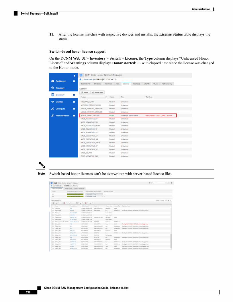
11. After the license matches with respective devices and installs, the License Status table displays thestatus.
Switch-based honor license support
On the DCNM Web UI > Inventory > Switch > License, the Type column displays “Unlicensed HonorLicense” and Warnings column displays Honor started: … with elapsed time since the license was changedto the Honor mode.
Switch-based honor licenses can’t be overwritten with server-based license files.Note
Cisco DCNM SAN Management Configuration Guide, Release 11.5(x)298
AdministrationSwitch Features—Bulk Install

Management Users
Every time you login to DCNM, the DCNM server fetches information from the ISE server for AAAauthentication. The ISE server will not authenticate again, after the first login.
Note
The Management Users menu includes the following submenus:
Remote AAATo configure remote AAA from the Cisco DCNMWeb UI, perform the following steps:
Procedure
Step 1 Choose Administration > Management Users > Remote AAA Properties.
The AAA properties configuration window appears.
Step 2 Use the radio button to select one of the following authentication modes:
• Local: In this mode the authentication authenticates with the local server.
• Radius: In this mode the authentication authenticates against the RADIUS servers specified.
• TACACS+: In this mode the authentication authenticates against the TACACS servers specified.
• Switch: In this mode the authentication authenticates against the switches specified.
• LDAP: In this mode the authentication authenticates against the LDAP server specified.
Step 3 Click Apply.
Cisco DCNM SAN Management Configuration Guide, Release 11.5(x)299
AdministrationManagement Users

Local
Procedure
Step 1 Use the radio button and select Local as the authentication mode.Step 2 Click Apply to confirm the authentication mode.
Radius
Procedure
Step 1 Use the radio button and select Radius as the authentication mode.
When using the DCNMAAA or Radius authentication, you should not specify the hash (#) symbolat the beginning of a secret key. Otherwise, DCNM will try to use # as encrypted, and it will fail.
Note
Step 2 Specify the Primary server details and click Test to test the server.Step 3 (Optional) Specify the Secondary and Tertiary server details and click Test to test the server.Step 4 Click Apply to confirm the authentication mode.
TACACS+
Procedure
Step 1 Use the radio button and select TACACS+ as the authentication mode.
When using the DCNMAAA or Radius authentication, you should not specify the hash (#) symbolat the beginning of a secret key. Otherwise, DCNM will try to use # as encrypted, and it will fail.
Note
Step 2 Specify the Primary server details and click Test to test the server.Step 3 (Optional) Specify the Secondary and Tertiary server details and click Test to test the server.
For IPv6 transport, enter Physical and VIP address for AAA authentication as the order of addresseschanges during failover situation.
Note
Step 4 Click Apply to confirm the authentication mode.
Cisco DCNM SAN Management Configuration Guide, Release 11.5(x)300
AdministrationLocal

Switch
Procedure
Step 1 Use the radio button to select Switch as the authentication mode.
DCNM also supports LAN switches with the IPv6 management interface.
Step 2 Specify the Primary Switch name and click Apply to confirm the authentication mode.Step 3 (Optional) Specify the names for Secondary and Tertiary Switches.Step 4 Click Apply to confirm the authentication mode.
LDAP
Procedure
Step 1 Use the radio button and select LDAP as the authentication mode.
Step 2 In the Host field, enter either the IPv4 or IPv6 address.
If DNS service is enabled, you can enter DNS address (hostname) of the LDAP server.
Step 3 In the Port field, enter a port number.
Enter 389 for non-SSL; enter 636 for SSL. By default, the port is configured for non-SSL.
Step 4 Select the SSL Enabled check box, if SSL is enabled on the AAA server.
You must enter 636 in the Port field, and select SSL Enabled check box to use LDAP over SSL.Note
This ensures the integrity and confidentiality of the transferred data by causing the LDAP client to establisha SSL session, before sending the bind or search request.
Cisco DCNM SAN Management Configuration Guide, Release 11.5(x)301
AdministrationSwitch

Cisco DCNM establishes a secured connection with the LDAP server using TLS. Cisco DCNMsupports all versions of TLS. However, the specific version of TLS is determined by the LDAPserver.
For example, if the LDAP server supports TLSv1.2 by default, DCNMwill connect using TLSv1.2.
Note
Step 5 In the Base DN field, enter the base domain name.
The LDAP server searches this domain. You can find the base DN by using the dsquery.exe user-name<display_name> command on the LDAP server.
For example:ldapserver# dsquery.exe users -name "John Smith"
CN=john smith,CN=Users,DC=cisco,DC=com
The Base DN is DC=cisco,DC=com.
Ensure that you enter the elements within the Base DN in the correct order. This specifies thenavigation of the application when querying Active Directory.
Note
Step 6 In the Filter field, specify the filter parameters.
These values are used to send a search query to the Active Directory. The LDAP search filter string is limitedto a maximum of 128 characters.
For example:
This matches the user principal name.
• CN=$userid,OU=Employees,OU=Cisco Users
This matches the exact user DN.
Step 7 Choose an option to determine a role. Select either Attribute or Admin Group Map.
• Admin Group Map: In this mode, DCNM queries LDAP server for a user based on the Base DN andfilter. If the user is a part of any user group, the DCNM role will be mapped to that user group.
• Attribute: In this mode, DCNM queries for a user attribute. You can select any attribute. When youchoose Attribute, the Role Admin Group field changes to Role Attributes.
Step 8 Enter value for either Roles Attributes or Role Admin Group field, based on the selection in the previousstep.
• If you chose Admin Group Map, enter the name of the admin group in the Role Admin Group field.
• If you chose Attribute, enter the appropriate attribute in the Attributes field.
Step 9 In the Map to DCNM Role field, enter the name of the DCNM role that will be mapped to the user.
Generally, network-admin or network-operator are the most typical roles.
For example:Role Admin Group: dcnm-adminsMap to DCNM Role: network-admin
Cisco DCNM SAN Management Configuration Guide, Release 11.5(x)302
AdministrationLDAP
This example maps the Active Directory User Group dcnm-admins to the network-admin role.
To map multiple Active Directory User Groups to multiple roles, use the following format:Role Admin Group:Map To DCNM Role: dcnm-admins:network-admin;dcnm-operators:network-operator
Note that Role Admin Group is blank, and Map To DCNM Role contains two entries delimited by asemicolon.
Step 10 In the Access Map field, enter the Role Based Access Control (RBAC) device group to be mapped to theuser.
Step 11 Click Test to verify the configuration. The Test AAA Server window appears.Step 12 Enter a valid Username and Password in the Test AAA Server window.
If the configuration is correct, the following message is displayed.Authentication succeeded.The cisco-av-pair should return 'role=network-admin' if this user needs tosee the DCNM Admin pages. 'SME' roles will allow SME page access. All otherroles - even if defined on the switches - will be treatedas network operator.
This message is displayed regardless of 'Role Admin Group' or 'Attribute' mode. It implies that Cisco DCNMcan query your Active Directory, the groups, and the roles are configured correctly.
If the test fails, the LDAP Authentication Failed message is displayed.
Don’t save the configuration unless the test is successful. You cannot access DCNM if you saveincorrect configurations.
Warning
Step 13 Click Apply Changes icon (located in the right top corner of the screen) to save the configuration.Step 14 Restart the DCNM SAN service.
• For Windows – On your system navigate to Computer Management > Services and Applications >Services. Locate and right click on the DCNM application. Select Stop. After a minute, right click onthe DCNM application and select Start to restart the DCNM SAN service.
• For Linux – Go to /etc/init.d/FMServer.restart and hit return key to restart DCNM SAN service.
Managing Local UsersAs an admin user, you can use Cisco DCNMWeb UI to create a new user, assign the role and associate oneor more groups or scope for the user.
This section contains the following:
Adding Local Users
Procedure
Step 1 From the menu bar, choose Administration > Management Users > Local. You see the Local Users page.
Cisco DCNM SAN Management Configuration Guide, Release 11.5(x)303
AdministrationManaging Local Users
Step 2 Click Add User.
You see the Add User dialog box.
Step 3 Enter the username in the User name field.
The username is case sensitive, but the username guest is a reserved name, which is not case sensitive.The guest user can only view reports. The guest user cannot change the guest password, or accessthe Admin options in DCNMWeb Client.
Note
Step 4 From the Role drop-down list, select a role for the user.Step 5 In the Password field, enter the password.
All special characters, except SPACE is allowed in the password.Note
Step 6 In the Confirm Password field, enter the password again.Step 7 Click Add to add the user to the database.Step 8 Repeat Steps 2 through 7 to continue adding users.
Deleting Local UsersTo delete local users from the Cisco DCNMWeb UI, perform the following steps:
Procedure
Step 1 Choose Administration > Management Users > Local.
The Local Users page is displayed.
Step 2 Select one or more users from the Local Users table and click the Delete User button.Step 3 Click Yes on the warning window to delete the local user. Click No to cancel deletion.
Editing a UserTo edit a user from the Cisco DCNMWeb UI, perform the following steps:
Procedure
Step 1 Choose Administration > Management Users > Local.Step 2 Use the checkbox to select a user and click the Edit User icon.Step 3 In the Edit User window, the Username and Role are mentioned by default. Specify the Password and
Confirm Password.Step 4 Click Apply to save the changes.
Cisco DCNM SAN Management Configuration Guide, Release 11.5(x)304
AdministrationDeleting Local Users
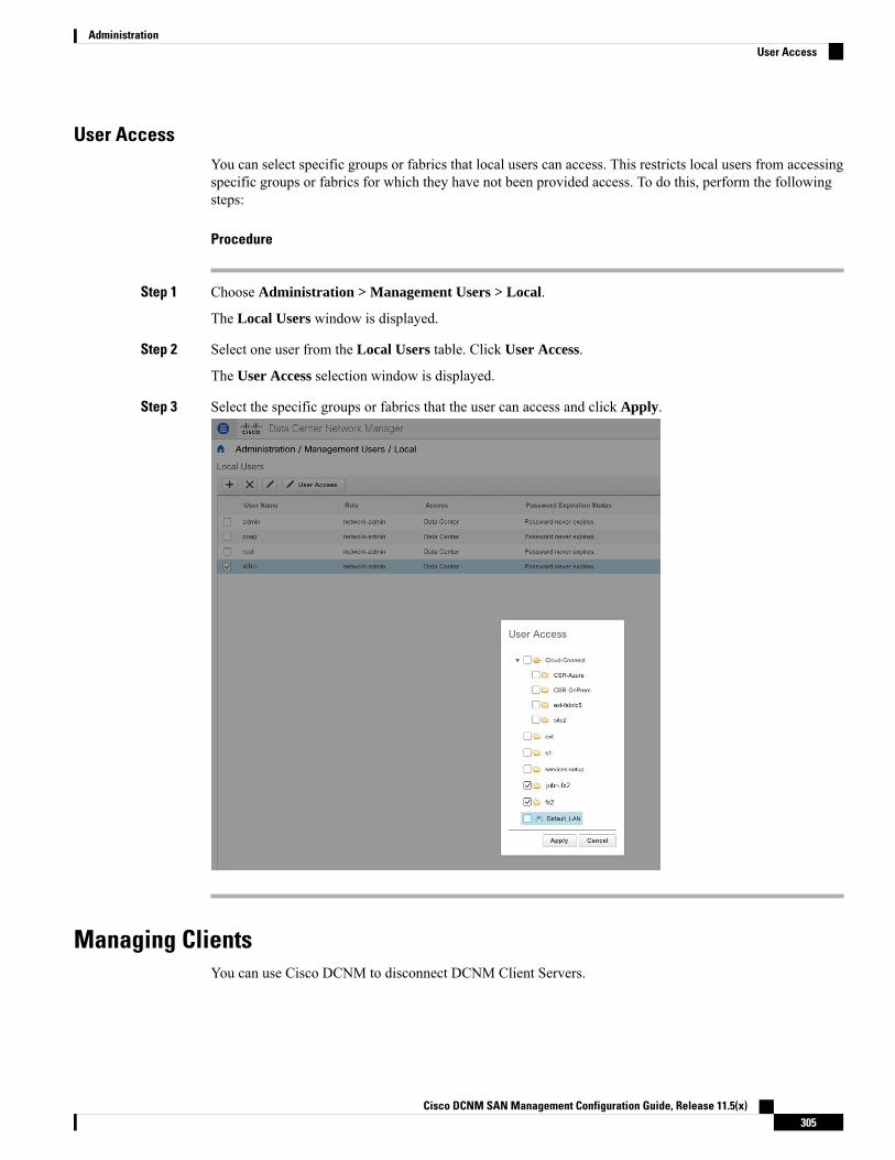
User AccessYou can select specific groups or fabrics that local users can access. This restricts local users from accessingspecific groups or fabrics for which they have not been provided access. To do this, perform the followingsteps:
Procedure
Step 1 Choose Administration > Management Users > Local.
The Local Users window is displayed.
Step 2 Select one user from the Local Users table. Click User Access.
The User Access selection window is displayed.
Step 3 Select the specific groups or fabrics that the user can access and click Apply.
Managing ClientsYou can use Cisco DCNM to disconnect DCNM Client Servers.
Cisco DCNM SAN Management Configuration Guide, Release 11.5(x)305
AdministrationUser Access

Procedure
Step 1 Choose Administration > Management Users > Clients.
A list of DCNM Servers are displayed.
Step 2 Use the check box to select a DCNM server and click Disconnect Client to disconnect the DCNM server.
You cannot disconnect a current client session.Note
Performance SetupThe Performance Setup menu includes the following submenus:
Performance Setup LAN CollectionsIf you are managing your switches with the Performance Manager, you must set up an initial set of flows andcollections on the switch. You can use Cisco DCNM to add and remove performance collections. License theswitch and kept it in the Managed Continuously state before creating a collection for the switch.
To collect Performance Manager data, ICMP ping must be enabled between the switch and DCNM server.Set pm.skip.checkPingAndManageable server property to true and then restart the DCNM. Choose WebUI > Administration > DCNM Server > Server Properties to set the server property.
Note
To add a collection, follow these steps:
Procedure
Step 1 Choose Administration > Performance Setup > LAN Collections.Step 2 For all the licensed LAN switches, use the check boxes to enable performance data collection for Trunks,
Access, Errors & Discards, and Temperature Sensor.Step 3 Use the check boxes to select the types of LAN switches for which you want to collect performance data.Step 4 Click Apply to save the configuration.Step 5 In the confirmation dialog box, click Yes to restart the Performance Manager. The Performance Manager has
to be restarted for any new setting to take effect.
Performance Manager SAN CollectionsIf you are managing your switches with the performance manager, you must set up an initial set of flows andcollections on the switch. You can use Cisco DCNM to add and remove performance collections. License the
Cisco DCNM SAN Management Configuration Guide, Release 11.5(x)306
AdministrationPerformance Setup
switch and keep it in themanagedContinuously state before creating a collection for the switch. Only licensedfabrics appear in this window.
To add a collection, follow these steps:
Procedure
Step 1 Choose Administration > Performance Setup > SAN Collections.Step 2 Select a fabric and select theName, ISL/NPV Links,Hosts, Storage, FC Flows, and FC Ethernet to enable
performance collection for these data types.Step 3 Click Apply to save the configuration.Step 4 In the confirmation dialog box, click Yes to restart the performance collector.
Performance Setup ThresholdsIf you are managing your switches with the Performance Manager, you must set up an initial set of flows andcollections on the switch. You can use Cisco DCNM to add and remove performance collections. License theswitch and keep it in the Managed Continuously state before creating a collection for the switch.
Procedure
Step 1 Choose Administration > Performance Setup > Thresholds.Step 2 Under Generate a threshold event when traffic exceeds % of capacity, use the check box to specify the
Critical at and Warning at values. The range for Critical at is from 5 to 95, and the default is 80. The rangefor Warning at is from 5 to 95, and the default is 60.
Step 3 Select a value for Performance SAN ISL Polling Interval from the drop-down list. Valid values are 5 Mins,4 Mins, 3 Mins, 2 Mins, 1 Min, and 30 Sec. The default is 30 Sec.
Step 4 Select a value for Performance Default Polling Interval from the drop-down list. Valid values are 5 Mins, 10 Mins, and 15 mins. The default value is 5 Mins.
Step 5 Click Apply.
Cisco DCNM SAN Management Configuration Guide, Release 11.5(x)307
AdministrationPerformance Setup Thresholds

Configuring User-Defined StatisticsTo configure user-defined statistics from the Cisco DCNMWeb UI, perform the following steps:
Procedure
Step 1 Choose Administration > Performance Setup > User Defined.
The User-Defined statistics window is displayed.
Step 2 Click Add icon.
The Add SNMP Statistic to Performance Collection window is displayed.
Step 3 From the Switch table, select the switch for which you want to add other statistics.Step 4 From the SNMP OID drop-down list, select the OID.
For SNMP OID ModuleX_Temp,IFHCInOctets.IFINDEX,IFHCOutOctest.IFINDEX, selectedfrom drop-down list, you must replace 'X' with correct module number or the correspondingIFINDEX.
Note
Step 5 In the Display Name box, enter a new name.
Cisco DCNM SAN Management Configuration Guide, Release 11.5(x)308
AdministrationConfiguring User-Defined Statistics
Step 6 From the SNMP Type drop-down list, select the type.Step 7 Click Add to add this statistic.
Event SetupThe Event Setup menu includes the following submenus:
Viewing Events RegistrationTo enable Send Syslog, Send Traps and Delayed Traps you must configure the following in the DCNMSAN client:
• Enabling Send Syslog: Choose Physical Attributes > Events > Syslog > Servers. Click Create Row,provide the required details, and click Create.
• Enabling Send Traps: Choose Physical Attributes > Events > SNMP Traps > Destination. ClickCreate Row, provide the required details, and click Create.
• Enabling Delayed Traps: Choose Physical Attributes > Events > SNMP Traps > Delayed Traps. Inthe Feature Enable column, use the check boxes to enable delayed traps for the switch and specify thedelay in minutes.
Procedure
Step 1 Choose Administration > Event Setup > Registration.
The SNMP and Syslog receivers along with the statistics information are displayed.
Step 2 Check the Enable Syslog Receiver check box and click Apply, to enable the syslog receiver if it is disabledin the server property.
To configure event registration or syslog properties, choose Administration > DCNM Server > ServerProperties and follow the on-screen instructions.
Step 3 Select Copy Syslog Messages to DB and click Apply to copy the syslog messages to the database.
If this option is not selected, the events will not be displayed in the events page of the Web client.
The columns in the second table display the following:
• Switches sending traps
• Switches sending syslog
• Switches sending syslog accounting
• Switches sending delayed traps
Cisco DCNM SAN Management Configuration Guide, Release 11.5(x)309
AdministrationEvent Setup
Notification ForwardingYou can use Cisco DCNMWeb UI to add and remove notification forwarding for system messages.
This section contains the following:
Adding Notification ForwardingCisco DCNMWeb UI forwards fabric events through email or SNMPv1 traps.
Some SMTP servers may require addition of authentication parameters to emails that are sent from DCNMto the SMTP servers. Starting from Cisco DCNM Release 11.4(1), you can add authentication parameters tothe emails that are sent by DCNM to any SMTP server that requires authentication. This feature can beconfigured by setting up the SMTP>Authentication properties in theAdministration>DCNM Server>ServerProperties window. Enter true in the server.smtp.authenticate field, enter the required username in theserver.smtp.username field, and enter the required password in the server.smtp.password field.
To add and remove notification forwarding for system messages from the Cisco DCNMWeb UI, performthe following steps:
Test forwarding works only for the licensed fabrics.Note
Procedure
Step 1 Choose Administration > Event Setup > Forwarding.
The events forwarding scope, the recipient email address, severity of the event and type of the event isdisplayed. The description Regex field is applicable only when the forwarding source is selected as Syslogwhile adding the events forwarder.
Step 2 Check the Enable checkbox to enable events forwarding.Step 3 Specify the SMTP Server details and the From email address.Step 4 Click Apply to save the configuration.Step 5 In the Event Count Filter, add a filter for the event count to the event forwarder.
The forwarding stops forwarding an event if the event count exceeds the limit as specified in the event countfilter. In this field, you can specify a count limit. Before an event can be forwarded, the Cisco DCNM checksif its occurrence exceeds the count limit. If it does, the event will not be forwarded.
Step 6 Select the Snooze checkbox and specify the Start date and time and the End date and time. Click Apply tosave the configuration.
Step 7 Under the Event Forwarder Rules table, click the + icon to add an event forwarder rule.
You see the Add Event Forwarder Rule dialog box.
Step 8 In the Forwarding Method, choose either E-mail or Trap. If you choose Trap, a Port field is added to thedialog box.
Step 9 If you choose the E-mail forwarding method, enter the IP address in the Email Address field. If you choosethe Trap method, enter the trap receiver IP address in the Address field and specify the port number.
You can either enter an IPv4 or IPv6 addresses or DNS server name in the Address field.
Cisco DCNM SAN Management Configuration Guide, Release 11.5(x)310
AdministrationNotification Forwarding

Step 10 For Forwarding Scope, choose the Fabric/LAN or Port Groups for notification.Step 11 In the Source field, select DCNM or Syslog.
If you select DCNM, then:a) From the Type drop-down list, choose an event type.b) Check the Storage Ports Only check box to select only the storage ports.c) From the Minimum Severity drop-down list, select the severity level of the messages to receive.d) Click Add to add the notification.If you select Syslog, then:a) In the Facility list, select the syslog facility.b) Specify the syslog Type.c) In the Description Regex field, specify a description that matches with the event description.d) From the Minimum Severity drop-down list, select the severity level of the messages to receive.e) Click Add to add the notification.
The Minimum Severity option is available only if the Event Type is set to All.Note
The traps that are transmitted by Cisco DCNM correspond to the severity type. A text description is alsoprovided with the severity type.trap type(s) = 40990 (emergency)40991 (alert)40992 (critical)40993 (error)40994 (warning)40995 (notice)40996 (info)40997 (debug)textDescriptionOid = 1, 3, 6, 1, 4, 1, 9, 9, 40999, 1, 1, 3, 0
Removing Notification ForwardingYou can remove notification forwarding.
Procedure
Step 1 Choose Administration > Event Setup > Forwarding.Step 2 Select the check box in front of the notification that you want to remove and click Delete.
Configuring EMC CallHomeTo configure EMC Call Home for EMC supported SAN switches from the Cisco DCNMWeb UI, performthe following steps:
Cisco DCNM SAN Management Configuration Guide, Release 11.5(x)311
AdministrationRemoving Notification Forwarding

Procedure
Step 1 Choose Administration > Event Setup > EMC Call Home.Step 2 Select the Enable check box to enable this feature.Step 3 Use the check box to select the fabrics or individual switches.Step 4 Enter the general email information.Step 5 Click the Apply to update the email options.Step 6 Click Apply and Test to update the email options and test the results.
Event SuppressionCisco DCNMallows you to suppress the specified events that are based on the user-specified suppressor rules.Such events will not be displayed on the Cisco DCNMWeb UI and SAN Client. The events will neither bepersisted to DCNM database, nor forwarded via email or SNMP trap.
You can view, add, modify, and delete suppressor rules from the table. You can create a suppressor rule fromthe existing event table. Select a given event as the template, and invoke the rule dialog window. Event detailsare automatically ported from the selected event in the event table to the input fields of the rule creation dialogwindow.
You cannot suppress EMC Call Home events from the Cisco DCNMWeb UI.Note
This section includes the following:
Add Event Suppression RulesTo add rules to the Event Suppression from the Cisco DCNMWeb UI, perform the following steps:
Procedure
Step 1 Choose Administration > Event Setup > Suppression.
The Suppression window is displayed.
Step 2 Click the Add icon above the Event Suppressors table.
The Add Event Suppressor Rule window is displayed.
Step 3 In the Add Event Suppressor Rule window, specify the Name for the rule.Step 4 Select the required Scope for the rule that is based on the event source.
In the Scope drop-down list, the LAN groups and the port groups are listed separately. You can chooseSANLAN, Port Groups or Any. For SAN and LAN, select the scope of the event at the Fabric or Group orSwitch level. You can only select groups for Port Group scope. If use selectsAny as the scope, the suppressorrule is applied globally.
Cisco DCNM SAN Management Configuration Guide, Release 11.5(x)312
AdministrationEvent Suppression

Step 5 Enter the Facility name or choose from the SAN/LAN Switch Event Facility List.
If you do not specify a facility, wildcard is applied.
Step 6 From the drop-down list, select the Event Type.
If you do not specify the event type, wildcard is applied.
Step 7 In the Description Matching field, specify a matching string or regular expression.
The rule matching engine uses regular expression that is supported by Java Pattern class to find a match againstan event description text.
Step 8 Check the Active Between box and select a valid time range during which the event is suppressed.
By default, the time range is not enabled, i.e., the rule is always active.
In general, you must not suppress accounting events. Suppressor rule for Accounting events can becreated only for certain rare situations where Accounting events are generated by actions of DCNMor switch software. For example, lots of 'sync-snmp-password' AAA syslog events are automaticallygenerated during the password synchronization between DCNM andmanaged switches. To suppressAccounting events, navigate to the Suppressor table and invoke the Add Event Suppressor Ruledialog window.
Note
ChooseMonitor > Switch > Events to create a suppressor rule for a known event. There is no suchshortcut to create suppressor rules for Accounting events.
Note
Delete Event Suppression RuleTo delete event suppressor rules from the Cisco DCNMWeb UI, perform the following steps:
Procedure
Step 1 Choose Administration > Event Setup > Suppression .Step 2 Select the rule from the list and click Delete icon.Step 3 Click Yes to confirm.
Modify Event Suppression RuleTo modify the event suppressor rules, do the following tasks:
Procedure
Step 1 Choose Administration > Event Setup > Suppression.Step 2 Select the rule from the list and click Edit.
You can edit Facility, Type, Description Matching string, and Valid time range.
Cisco DCNM SAN Management Configuration Guide, Release 11.5(x)313
AdministrationDelete Event Suppression Rule

Step 3 Click Apply to save the changes,
Credentials ManagementThe Credential Management menu includes the following submenus:
SAN CredentialsThe Cisco DCNM home page, choose Administration > Credentials Management > SAN Credentialsdisplays the SNMP access details to the fabric seed switch. If the user has validated the access to all the fabrics,the SNMP credentials for all the seed switches of the fabrics is displayed.
The switch credentials window for the Cisco DCNM has the following fields:
DescriptionField
The fabric name to which the switch belongs.Fabric Name
IP address of the switch.Seed Switch
Specifies the username of the Cisco DCNM user.User Name
Displays the encrypted form of the switch SNMP user.Password
Specifies if the SNMP protocol is validated or not.SNMPv3/SSH
The default value is false.
Specifies the Authentication protocolAuth/Privacy
The default value is NOT_SET.
Displays the status of the switchStatus
Before the Cisco DCNM user configures the fabric using SNMP, the user must furnish and validate SNMPcredentials on the seed switch of the fabric. If the user does not provide valid credentials for the fabric seedswitch, the Switch Credentials table shows the default values for SNMPv3/SSH and AuthPrivacy fields.
Click the switch row and enter correct credentials information. Click Save to commit the changes.
If the user changes the configuration, but does not provide a valid switch credential, the user action is rejected.Validate the switch credentials to commit your changes.
You can perform the following operations on this screen.
• To Revalidate the credentials:
1. From the Cisco DCNM home page, choose Administration > Credentials Management > SANCredentials, click the Fabric Name radio button to select a seed switch whose credentials needs tobe validated.
2. Click Revalidate.
A confirmation message appears, stating if the operation was successful or a failure.
Cisco DCNM SAN Management Configuration Guide, Release 11.5(x)314
AdministrationCredentials Management
• To clear the switch credentials:
1. From the Cisco DCNM home page, choose Administration > Credentials Management > SANCredentials, click the Fabric Name radio button to select a seed switch to delete.
2. Click Clear.
A confirmation message appears.
3. Click Yes to delete the switch credential from the DCNM server.
LAN CredentialsWhile changing the device configuration, Cisco DCNMuses the device credentials provided by you. However,if the LAN Switch credentials are not provided, Cisco DCNM prompts you to open the Administration >Credentials Management > LAN Credentials page to configure LAN credentials.
Cisco DCNM uses two sets of credentials to connect to the LAN devices:
• Discovery Credentials—Cisco DCNM uses these credentials during discovery and periodic polling ofthe devices.
• Configuration Change Credentials—Cisco DCNM uses these credentials when user tries to use thefeatures that change the device configuration.
LAN Credentials Management allows you to specify configuration change credentials. Before changing anyLAN switch configuration, you must furnish Configuration Change SSH credentials for the switch. If you donot provide the credentials, the configuration change action will be rejected.
These features get the device write credentials from LAN Credentials feature.
• Upgrade (ISSU)
• Maintenance Mode (GIR)
• Patch (SMU)
• Template Deployment
• POAP-Write erase reload, Rollback
• Interface Creation/Deletion/Configuration
• VLAN Creation/Deletion/Configuration
• VPC Wizard
You must specify the configuration change credentials irrespective of whether the devices were discoveredinitially or not. This is a one-time operation. Once the credentials are set, that will be used for any configurationchange operation.
Default Credentials
Default credentials is used to connect all the devices that the user has access to. You can override the defaultcredentials by specifying credentials for each of the devices in the Switch Table below.
Cisco DCNM SAN Management Configuration Guide, Release 11.5(x)315
AdministrationLAN Credentials
After you enter appropriate credentials in Password, Confirm Password fields and click Save, the ConfirmPassword field is blank. A blank Confirm Password field implies that the password is saved successfully.
Note
Cisco DCNM tries to use individual switch credentials in the Switch Table, to begin with. If the credentials(username/password) columns are empty in the Switch Table, the default credentials will be used.
Switch Table
Switch table lists all the LAN switches that user has access. You can specify the switch credentials individually,that will override the default credentials. In most cases, you need to provide only the default credentials.
You can perform the following operations on this screen.
• Edit Credentials, on page 316
• Validate Credentials, on page 316
• Clear Switch Credentials, on page 317
• Credentials Management with Remote Access
The LAN Credentials for the DCNM User table has the following fields.
DescriptionField
Displays the LAN switch name.Switch
Specifies the IP Address of the switch.IP Address
Specifies the username of the switch DCNM user.User Name
Displays the encrypted form of the SSH password.Password
Displays the group to which the switch belongs.Group
Edit Credentials
Perform the following task to edit the credentials.
1. From the Cisco DCNM home page, choose Administration > Credentials Management > LANCredentials, check the Switch check box for which you need to edit the credentials.
2. Click Edit icon.
3. Specify User Name and Password for the switch.
Validate Credentials
Perform the following task to validate the credentials.
1. From the Administration > Credentials Management > LAN Credentials, check the Switch checkbox for which you need to validate the credentials.
2. Click Validate.
Cisco DCNM SAN Management Configuration Guide, Release 11.5(x)316
AdministrationLAN Credentials
A confirmation message appears, stating if the operation was successful or a failure.
Clear Switch Credentials
Perform the following task to clear the switch credentials.
1. From the Administration > Credentials Management > LAN Credentials, check the Switch checkbox for which you need to clear the credentials.
2. Click Clear.
3. Click Yes to clear the switch credentials from the DCNM server.
Credentials Management with Remote AccessDCNM allows you to authenticate users in different modes such as:
• Local Users - In this mode, you can use the Cisco DCNMWeb UI to create a new user, assign a role,and provide access to one or more fabrics or groups for the user.
• Remote Users - In this mode, you can log in to DCNM. The DCNM server fetches information from theRemote Authentication server, for example, the Cisco Identity Services Engine (ISE), for AAAauthentication. Cisco supports TACACS+, RADIUS, and LDAP options for remote authentication. Formore information, see Remote AAA.
When you configure DCNM for remote authentication, the AAA server handles both authentication andauthorization. DCNM forwards the entered user login and password to the AAA server to check forauthentication. Post authentication, the AAA server returns the appropriate privileges/role assigned to the userthrough the cisco-avpair attribute. This attribute can contain the list of fabrics that a particular user can access.The supported roles for DCNM LAN deployments are as follows:
• network-admin
• network-operator
Both device discovery credentials and LAN credentials provide write access to the devices, but they differ—asthe write operation is performed only with LAN credentials. Device discovery credentials are associated witheach device and entered only once, that is, when you import the device into DCNM. DCNM uses thesecredentials for periodic rediscovery using a mix of SSH and SNMPv3 access to the device. However, LANcredentials are configured for every user on a per-user basis. If a user with an appropriate role has access toDCNM, then that user can enter the LAN credentials to get write access to the devices. The write operationsuse the LAN credentials to access the device, which allows for an appropriate audit trail of the changes madein DCNM by every user and the resultant changes in the device.
When you configure DCNMusing Remote AuthenticationMethods such as TACACS+ or RADIUS, the userscan set their LAN credentials as follows:
• Regular AAA Remote Authentication
• AAA Remote Authentication Passthrough Mechanism
• AAA Remote Authentication Using DCNM Service Account
Cisco DCNM SAN Management Configuration Guide, Release 11.5(x)317
AdministrationCredentials Management with Remote Access

Regular AAA Remote Authentication
Post authentication, when a user with an appropriate role logs in to DCNM for the first time, DCNM promptsthe user to enter the LAN credentials. As mentioned earlier, DCNM uses these credentials to provide writeaccess to the devices. All users must follow this process. Consider that an internal business policy requiresthe users to change password every 3-6 months. Then all the users must update their passwords for deviceaccess in the DCNM LAN Credentials window. Also, they must update their passwords in the AAA server.
For example, let us consider a user named John, who has authentication on the ISE server.
1. John logs in to DCNM with his user credentials.
2. The ISE server authenticates the user credentials of John, and DCNM displays a message to enter hisLAN switch credentials. DCNM uses these credentials to perform various configurations and writeoperations on the devices.
3. John enters his LAN switch credentials. DCNM uses the LAN switch credentials for all write operationstriggered by John on all devices. However, John can also opt to enter LAN switch credentials on aper-device access basis. This per-device access option overrides the access provided by entering the defaultcredentials.
When John logs in to DCNMagain, DCNMdoesn't display anymessage to enter the LAN switch credentialsas it has already captured his LAN switch credentials. John uses the same credentials to log in to DCNMand to the devices that he can access.
Cisco DCNM SAN Management Configuration Guide, Release 11.5(x)318
AdministrationCredentials Management with Remote Access

4. Now, consider that after a few months, the Corporate IT policy changes. Then John must update hispassword in the Remote AAA server, and also perform Step 3 to allow DCNM to update his LAN switchcredentials.
Thus, in this mode, when John logs in to the DCNMWeb GUI with his updated password, DCNM doesn'tdisplay any message to enter LAN credentials. However, John must update the password in LAN Credentials.Updating the password is necessary as it allows DCNM to inherit the newly updated password and performwrite operations on the devices.
AAA Remote Authentication Passthrough Mechanism
In this mode, when a user enters the username and password to log in to DCNM, DCNM automatically copiesthe user credentials to the Default Credentials in the LAN switch credentials settings for that user. As a result,when the user logs in for the first time, DCNMdoesn't display the message to enter the LAN switch credentials.
1. Use SSH to log in to DCNM as a sysadmin user.
2. Log in to the /root/directory using the su command.
3. Navigate to the /usr/local/cisco/dcm/fm/conf/server.properties file.
4. Add the following server property to the file and save the changes.
dcnm.lanSwitch.sameUserAccount=true
5. Restart DCNM using the service FMServer restart command.
6. Now, John logs in to DCNM.
7. After successful authentication, DCNM doesn't display the message to update the LAN switch credentials,as it automatically copies this information to the LAN switch credentials.
Cisco DCNM SAN Management Configuration Guide, Release 11.5(x)319
AdministrationCredentials Management with Remote Access
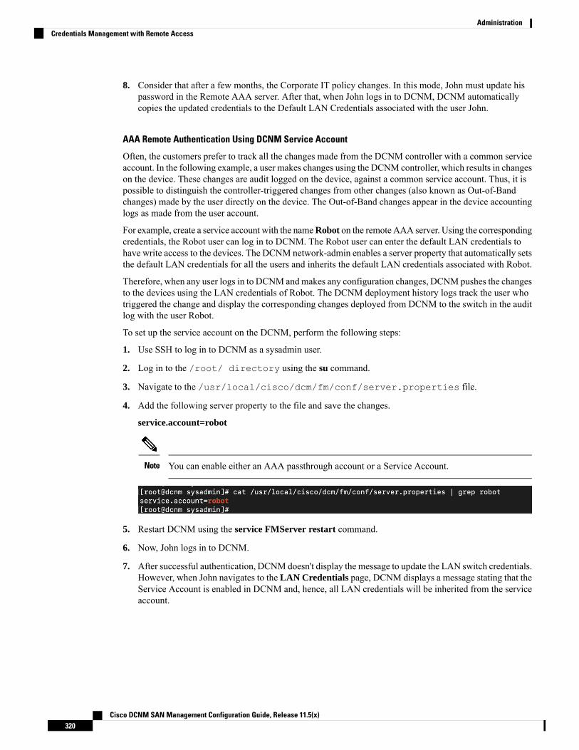
8. Consider that after a few months, the Corporate IT policy changes. In this mode, John must update hispassword in the Remote AAA server. After that, when John logs in to DCNM, DCNM automaticallycopies the updated credentials to the Default LAN Credentials associated with the user John.
AAA Remote Authentication Using DCNM Service Account
Often, the customers prefer to track all the changes made from the DCNM controller with a common serviceaccount. In the following example, a user makes changes using the DCNM controller, which results in changeson the device. These changes are audit logged on the device, against a common service account. Thus, it ispossible to distinguish the controller-triggered changes from other changes (also known as Out-of-Bandchanges) made by the user directly on the device. The Out-of-Band changes appear in the device accountinglogs as made from the user account.
For example, create a service account with the nameRobot on the remote AAA server. Using the correspondingcredentials, the Robot user can log in to DCNM. The Robot user can enter the default LAN credentials tohave write access to the devices. The DCNM network-admin enables a server property that automatically setsthe default LAN credentials for all the users and inherits the default LAN credentials associated with Robot.
Therefore, when any user logs in to DCNM andmakes any configuration changes, DCNMpushes the changesto the devices using the LAN credentials of Robot. The DCNM deployment history logs track the user whotriggered the change and display the corresponding changes deployed from DCNM to the switch in the auditlog with the user Robot.
To set up the service account on the DCNM, perform the following steps:
1. Use SSH to log in to DCNM as a sysadmin user.
2. Log in to the /root/ directory using the su command.
3. Navigate to the /usr/local/cisco/dcm/fm/conf/server.properties file.
4. Add the following server property to the file and save the changes.
service.account=robot
You can enable either an AAA passthrough account or a Service Account.Note
5. Restart DCNM using the service FMServer restart command.
6. Now, John logs in to DCNM.
7. After successful authentication, DCNM doesn't display the message to update the LAN switch credentials.However, when John navigates to the LAN Credentials page, DCNM displays a message stating that theService Account is enabled in DCNM and, hence, all LAN credentials will be inherited from the serviceaccount.
Cisco DCNM SAN Management Configuration Guide, Release 11.5(x)320
AdministrationCredentials Management with Remote Access

Service Account Configuration Audit
The following workflow example allows for verification of the configuration audit while using theDCNM service account feature. However, you must have completed the Service Account Activationprocedure.
1. John creates a test loopback on a device.
2. John deploys the configuration using DCNM.
3. The DCNM Deployment history confirms that John made the recent configuration change.
4. The accounting logs of the device indicate that the DCNM Service Account (that is, Robot, inthis example) has triggered the changes on the NX-OS device.
Cisco DCNM SAN Management Configuration Guide, Release 11.5(x)321
AdministrationCredentials Management with Remote Access

Cisco DCNM SAN Management Configuration Guide, Release 11.5(x)322
AdministrationCredentials Management with Remote Access
C H A P T E R 8DCNM Integration with ServiceNow
• DCNM Integration with ServiceNow, on page 323
DCNM Integration with ServiceNowServiceNow offers applications for IT ServiceManagement (ITSM) and IT OperationsManagement (ITOM).There are four primary modules - inventory discovery, incident management, event management & changemanagement workflows. Starting from Cisco DCNM Release 11.3(1), we provide Cisco DCNM integrationwith ServiceNow. This enables you to integrate end-user IT data with the ServiceNow platform. The integrationprovides a default set of ServiceNow custom tables which are populated with configuration data.
To utilize this functionality, install the DCNM application in the ServiceNow customer instance and providethe DCNMmid-server details. Information or data regarding switch details, port details, and alarms, is retrievedto the ServiceNow Configuration Management Database (CMDB) tables. By default, data is retrieved every15 minutes and displayed.
Details about the switches and ports of each switch are collected from the DCNM inventory. The alarms arecollected by polling DCNM. Alarms are then filtered and categorized based on their type, such as, CPU,MEMORY, POWER, LINKSTATE, EXTERNAL, ICMP, SNMP, and SSH. The alarms are then stored inan Events table. These events are then used to generate incidents for the CPU, MEMORY, SNMP, and SSHcategories. The source, description, severity and category of each alarm is stored. However, when an alarmceases to exist in DCNM, the incident that was raised for it is not updated or cleared on the DCNMServiceNowapplication. When polling of alarms is initiated for the first time, the alarms that were raised in the last sevendays are pulled in from DCNM.
The DCNM application on ServiceNow runs scheduled scripts and connects with the mid-server which inturn connects with DCNM to retrieve data. DCNM sends the requested data to the mid-server which thenpasses on the data to the DCNMapplication on ServiceNow. The tables in the DCNM instance on ServiceNoware then populated with this retrieved data.
Cisco DCNM SAN Management Configuration Guide, Release 11.5(x)323
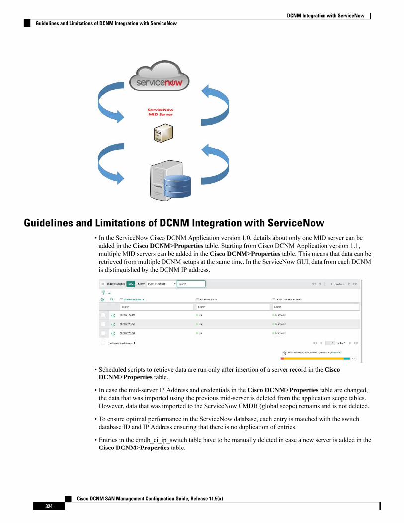
Guidelines and Limitations of DCNM Integration with ServiceNow• In the ServiceNow Cisco DCNM Application version 1.0, details about only one MID server can beadded in the Cisco DCNM>Properties table. Starting from Cisco DCNM Application version 1.1,multiple MID servers can be added in the Cisco DCNM>Properties table. This means that data can beretrieved from multiple DCNM setups at the same time. In the ServiceNow GUI, data from each DCNMis distinguished by the DCNM IP address.
• Scheduled scripts to retrieve data are run only after insertion of a server record in the CiscoDCNM>Properties table.
• In case the mid-server IP Address and credentials in the Cisco DCNM>Properties table are changed,the data that was imported using the previous mid-server is deleted from the application scope tables.However, data that was imported to the ServiceNow CMDB (global scope) remains and is not deleted.
• To ensure optimal performance in the ServiceNow database, each entry is matched with the switchdatabase ID and IP Address ensuring that there is no duplication of entries.
• Entries in the cmdb_ci_ip_switch table have to be manually deleted in case a new server is added in theCisco DCNM>Properties table.
Cisco DCNM SAN Management Configuration Guide, Release 11.5(x)324
DCNM Integration with ServiceNowGuidelines and Limitations of DCNM Integration with ServiceNow
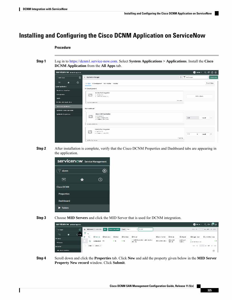
Installing and Configuring the Cisco DCNM Application on ServiceNow
Procedure
Step 1 Log in to https://dcnm1.service-now.com. Select System Applications > Applications. Install the CiscoDCNM Application from the All Apps tab.
Step 2 After installation is complete, verify that the Cisco DCNM Properties and Dashboard tabs are appearing inthe application.
Step 3 Choose MID Servers and click the MID Server that is used for DCNM integration.
Step 4 Scroll down and click the Properties tab. Click New and add the property given below in the MID ServerProperty New record window. Click Submit.
Cisco DCNM SAN Management Configuration Guide, Release 11.5(x)325
DCNM Integration with ServiceNowInstalling and Configuring the Cisco DCNM Application on ServiceNow
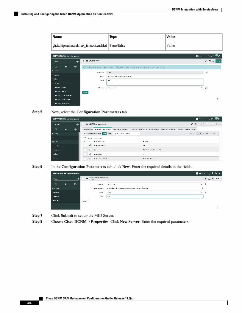
ValueTypeName
FalseTrue/falseglide.http.outbound.max_timeout.enabled
Step 5 Now, select the Configuration Parameters tab.
Step 6 In the Configuration Parameters tab, click New. Enter the required details in the fields.
Step 7 Click Submit to set up the MID Server.Step 8 Choose Cisco DCNM > Properties. Click New Server. Enter the required parameters.
Cisco DCNM SAN Management Configuration Guide, Release 11.5(x)326
DCNM Integration with ServiceNowInstalling and Configuring the Cisco DCNM Application on ServiceNow
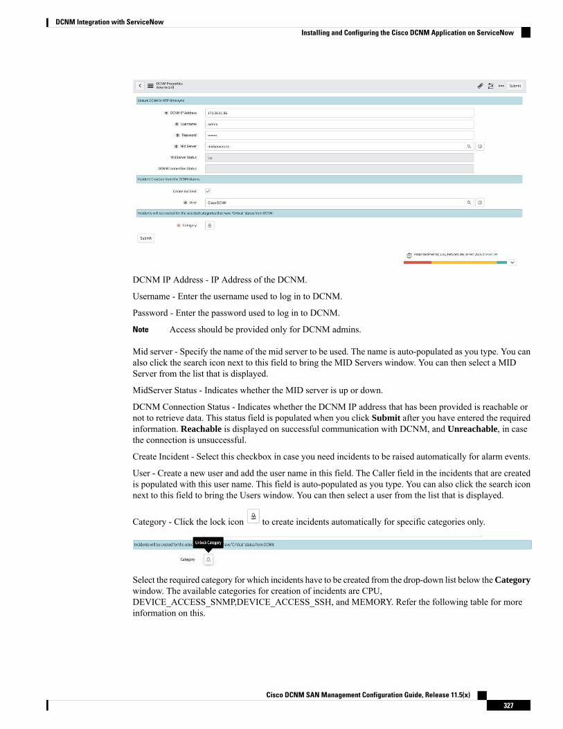
DCNM IP Address - IP Address of the DCNM.
Username - Enter the username used to log in to DCNM.
Password - Enter the password used to log in to DCNM.
Access should be provided only for DCNM admins.Note
Mid server - Specify the name of the mid server to be used. The name is auto-populated as you type. You canalso click the search icon next to this field to bring the MID Servers window. You can then select a MIDServer from the list that is displayed.
MidServer Status - Indicates whether the MID server is up or down.
DCNM Connection Status - Indicates whether the DCNM IP address that has been provided is reachable ornot to retrieve data. This status field is populated when you click Submit after you have entered the requiredinformation. Reachable is displayed on successful communication with DCNM, and Unreachable, in casethe connection is unsuccessful.
Create Incident - Select this checkbox in case you need incidents to be raised automatically for alarm events.
User - Create a new user and add the user name in this field. The Caller field in the incidents that are createdis populated with this user name. This field is auto-populated as you type. You can also click the search iconnext to this field to bring the Users window. You can then select a user from the list that is displayed.
Category - Click the lock icon to create incidents automatically for specific categories only.
Select the required category for which incidents have to be created from the drop-down list below theCategorywindow. The available categories for creation of incidents are CPU,DEVICE_ACCESS_SNMP,DEVICE_ACCESS_SSH, and MEMORY. Refer the following table for moreinformation on this.
Cisco DCNM SAN Management Configuration Guide, Release 11.5(x)327
DCNM Integration with ServiceNowInstalling and Configuring the Cisco DCNM Application on ServiceNow
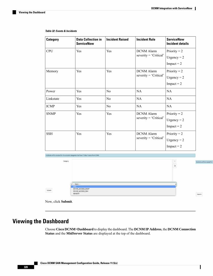
Table 32: Events & Incidents
ServiceNowIncident details
Incident RuleIncident RaisedData Collection inServiceNow
Category
Priority = 2
Urgency = 2
Impact = 2
DCNM Alarmseverity = ‘Critical’
YesYesCPU
Priority = 2
Urgency = 2
Impact = 2
DCNM Alarmseverity = ‘Critical’
YesYesMemory
NANANoYesPower
NANANoYesLinkstate
NANANoYesICMP
Priority = 2
Urgency = 2
Impact = 2
DCNM Alarmseverity = ‘Critical’
YesYesSNMP
Priority = 2
Urgency = 2
Impact = 2
DCNM Alarmseverity = ‘Critical’
YesYesSSH
Now, click Submit.
Viewing the DashboardChooseCisco DCNM>Dashboard to display the dashboard. TheDCNM IP Address, theDCNM ConnectionStatus and the MidServer Status are displayed at the top of the dashboard.
Cisco DCNM SAN Management Configuration Guide, Release 11.5(x)328
DCNM Integration with ServiceNowViewing the Dashboard
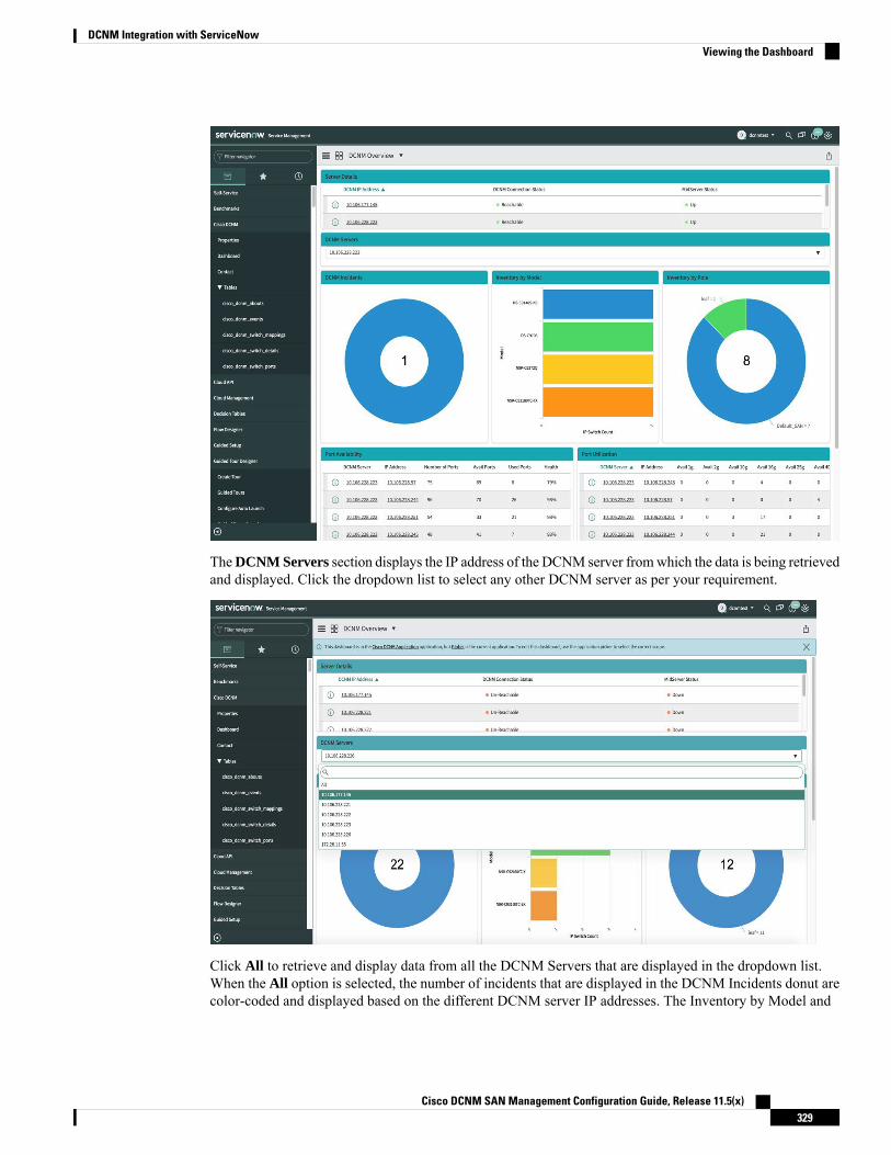
TheDCNM Servers section displays the IP address of the DCNM server fromwhich the data is being retrievedand displayed. Click the dropdown list to select any other DCNM server as per your requirement.
Click All to retrieve and display data from all the DCNM Servers that are displayed in the dropdown list.When the All option is selected, the number of incidents that are displayed in the DCNM Incidents donut arecolor-coded and displayed based on the different DCNM server IP addresses. The Inventory by Model and
Cisco DCNM SAN Management Configuration Guide, Release 11.5(x)329
DCNM Integration with ServiceNowViewing the Dashboard

Inventory by Role donuts also display data from all the DCNM servers. The Port Availability and PortUtilization donuts display data along with the DCNM Server that each IP address belongs to.
DCNM Incidents - This displays the number of incidents that have been raised based on the alarms retrievedfrom DCNM. Click the donut for more details about the
incidents.
Inventory by Model - This displays the number and type of switches present in DCNM. Each band representsa device model. Click a band for more
information.
Cisco DCNM SAN Management Configuration Guide, Release 11.5(x)330
DCNM Integration with ServiceNowViewing the Dashboard

Inventory by Role - This displays the number and types of switch roles present in DCNM. Click the requiredsection to display the number of roles that are operational and click on that pictorial representation to displaymore details about the roles.
The number that is displayed in the Inventory by Role donut does not change in case switches are removedfrom DCNM. The switches that are removed are displayed as Non Operational and there is no change in thenumber that is displayed in the donut.
Note
Port Availability - This displays information about port availability. The DCNM server and IP address alongwith the total number of ports, available ports, used ports and health of the switch is displayed. Click an IPaddress to display more
information.
Port Utilization - This displays information about port utilization based on each IP address. The number ofports having 1G, 2G, 4G, 8G, 10G, 16G, 25G, 32G, 40G, and 100G availability, are displayed. Click an IP
Cisco DCNM SAN Management Configuration Guide, Release 11.5(x)331
DCNM Integration with ServiceNowViewing the Dashboard

address to display more
information.
Contact UsChooseCisco DCNM>Contact to display an email address and a telephone number that can be used to contactCisco Systems for any queries.
Troubleshooting DCNM Integration with ServiceNowIn case data is not being retrieved in the ServiceNow table:
• Check if the MID server is up or down.
• Check for information entries in system logs with the source “x_caci_cisco_dcnm”.
• Check the login credentials added in Cisco DCNM Properties.
• Consider a scenario in which data is being displayed on the ServiceNow dashboard for the selectedDCNM server and then you want to display data for another DCNM server. In such a scenario, theServiceNow dashboard may take some time to load data from the other DCNM server due to a delay inrefreshing the cache. To refresh the data manually, click the Refresh icon that appears on the top rightcorner of the individual tiles when you hover the cursor over the tiles.
Cisco DCNM SAN Management Configuration Guide, Release 11.5(x)332
DCNM Integration with ServiceNowContact Us
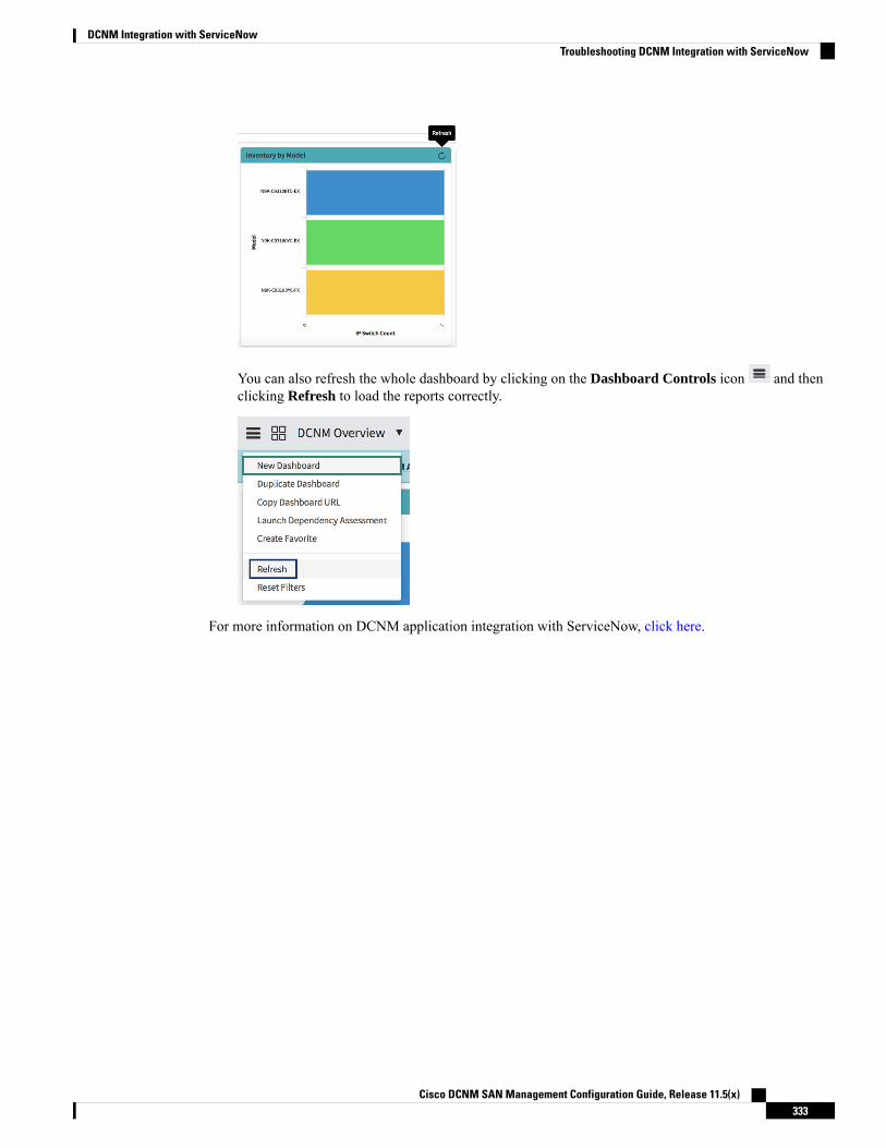
You can also refresh the whole dashboard by clicking on the Dashboard Controls icon and thenclicking Refresh to load the reports correctly.
For more information on DCNM application integration with ServiceNow, click here.
Cisco DCNM SAN Management Configuration Guide, Release 11.5(x)333
DCNM Integration with ServiceNowTroubleshooting DCNM Integration with ServiceNow

Cisco DCNM SAN Management Configuration Guide, Release 11.5(x)334
DCNM Integration with ServiceNowTroubleshooting DCNM Integration with ServiceNow
Related Documents