DE3 CIRCUIT BREAKERS Circuit Breakers 01/15 DE3-1 Selection Guide H-Frame J-Frame L-Frame M-Frame P-Frame R-Frame Description Page Selection Information DE3-2 QO™ and QOU Miniature Circuit Breakers DE3-10 QO™ Miniature Circuit Breakers DE3-10 QO™ Circuit Breaker Accessories DE3-12 QO™ and Multi 9™ Mounting Bases DE3-13 QOU Miniature Circuit Breakers DE3-14 QOU Accessories DE3-15 Multi 9™ Miniature Circuit Breakers DE3-16 PowerPact™ Molded Case Circuit Breakers DE3-21 PowerPact Family DE3-21 H- and J-Frame Circuit Breakers DE3-22 Q-Frame Circuit Breakers DE3-24 L-Frame Circuit Breakers DE3-25 M-Frame Circuit Breakers DE3-26 P-Frame Circuit Breakers DE3-27 R-Frame Circuit Breakers DE3-28 Motor Circuit Protectors DE3-29 PowerPact™ H- and J-Frame Electronic Motor Circuit Protectors DE3-29 H-Frame and J-Frame MCP Selector DE3-30 Motor Circuit Protectors and Motor Protector Circuit Breakers DE3-31 H-, J-, and L-Frame MCP Selection DE3-32 Motor Protection Selection Tables DE3-33 Automatic Switches DE3-34 500 Vdc Circuit Breakers DE3-35 Mission Critical Circuit Breakers DE3-37 PowerPact™ Circuit Breaker Accessories DE3-39 Micrologic™ Electronic Trip Units DE3-46 Masterpact™ Universal Power Circuit Breakers DE3-50 Ground-Fault Protection DE3-51 Dimensions and Shipping Weights DE3-54 Circuit Breaker Enclosures DE3-56 Photovoltaic Circuit Breakers and Switches DE3-59 Molded Case Circuit Breakers DE3-63 F-Frame Circuit Breakers DE3-63 L-Frame Circuit Breakers DE3-64 CDP connector kits DE3-65

Welcome message from author
This document is posted to help you gain knowledge. Please leave a comment to let me know what you think about it! Share it to your friends and learn new things together.
Transcript
DE
3C
IRC
UIT
BR
EA
KE
RS
Circuit Breakers
01/15DE3-1
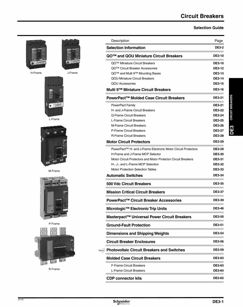
Selection Guide
H-Frame J-Frame
L-Frame
M-Frame
P-Frame
R-Frame
Description Page
Selection Information DE3-2
QO™ and QOU Miniature Circuit Breakers DE3-10
QO™ Miniature Circuit Breakers DE3-10
QO™ Circuit Breaker Accessories DE3-12
QO™ and Multi 9™ Mounting Bases DE3-13
QOU Miniature Circuit Breakers DE3-14
QOU Accessories DE3-15
Multi 9™ Miniature Circuit Breakers DE3-16
PowerPact™ Molded Case Circuit Breakers DE3-21
PowerPact Family DE3-21
H- and J-Frame Circuit Breakers DE3-22
Q-Frame Circuit Breakers DE3-24
L-Frame Circuit Breakers DE3-25
M-Frame Circuit Breakers DE3-26
P-Frame Circuit Breakers DE3-27
R-Frame Circuit Breakers DE3-28
Motor Circuit Protectors DE3-29
PowerPact™ H- and J-Frame Electronic Motor Circuit Protectors DE3-29
H-Frame and J-Frame MCP Selector DE3-30
Motor Circuit Protectors and Motor Protector Circuit Breakers DE3-31
H-, J-, and L-Frame MCP Selection DE3-32
Motor Protection Selection Tables DE3-33
Automatic Switches DE3-34
500 Vdc Circuit Breakers DE3-35
Mission Critical Circuit Breakers DE3-37
PowerPact™ Circuit Breaker Accessories DE3-39
Micrologic™ ElectronicTrip Units DE3-46
Masterpact™ Universal Power Circuit Breakers DE3-50
Ground-Fault Protection DE3-51
Dimensions and Shipping Weights DE3-54
Circuit Breaker Enclosures DE3-56
Photovoltaic Circuit Breakers and Switches DE3-59
Molded Case Circuit Breakers DE3-63
F-Frame Circuit Breakers DE3-63
L-Frame Circuit Breakers DE3-64
CDP connector kits DE3-65
DE3_p01.fm Page 1 Saturday, January 10, 2015 2:04 AM
CIR
CU
ITB
RE
AK
ER
S
DE3_p02.fm Page 2 Saturday, January 10, 2015 2:09 AM
Selection Information
DE3
Miniature Circuit Breakers
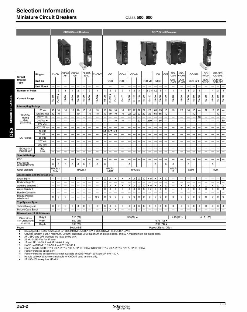
CHOM Circuit Breakers QO™ Circuit Breakers
CircuitBreakerType
Plug-on CHOM CHOM-AFI
CHOM-GFI
CHOM-EPD CHOMT QO QO-H QO-VH QH QOT QO-
CAFIQO-
VHAFI QO-GFI QO-VHGFI
QO-EPDQO-EPE
Bolt-on — — — — — — — — QOB QOB-H — — — QOB-VH QHB — QOB-CAFI
QOB-VHAFI QOB-GFI QOB-
VHGFIQOB-EPDQOB-EPE
Unit Mount — — — — — — — — — — — — — — — — — — — — — — — — — — —
Number of Poles 1 2 1 1 2 1 2 1 1 2 3 2 1 2 3 1 2, 3 a 1,2 3 1 1 1 1 2 3 1 1 2 3
Current Range
15–5
0
15–2
00k
15–2
0
15–2
0
15–5
0
15–2
0
15–5
0
15–5
0b
10–7
0
10–2
00k
10–1
00
15–1
00
15–3
0
15–1
25
15–1
00
15–3
0
15–1
50
15–3
0
15–3
0
15–3
0
15–2
0
15–3
0
15–3
0
15–6
0
15–5
0
15–3
0
15–3
0
15–6
0
15–5
0
Interrupting Ratings
UL/CSARating(kA)
(50/60 Hz)
120 Vac 10 10 10 10 10 10 10 10 10 10 10 10 22 22 22 22 22 65 65 10 10 22 10 10 — 22 10 10 —120/240 Vac 10 10 — — 10 — 10 10 10 10 10 10 22 22 22 22 22 65 65 10 — — — 10 — — — 10 —
208Y/120 — — — — — — — — — — — — — — — — — — — — — — — — 10 — — — —240 Vac d — — — — — — — — — — 10 10 — — 22 — 22d — 65 — — — — — — — — — 10277 Vac — — — — — — — — — — — — — — — — — — — — — — — — — — — — —
480Y/277 Vac — — — — — — — — — — — — — — — — — — — — — — — — — — — — —
DC Ratings
48 Vdc — — — — — — — — 5e 5 e 5 e — — — — — — — — — — — — — — — — — —60 Vdc — — — — — — — — — — — — — — — — — — — — — — — — — — — — —65 Vdc — — — — — — — — — — — — — — — — — — — — — — — — — — — — —125 Vdc — — — — — — — — — — — — — — — — — — — — — — — — — — — — —250 Vdc — — — — — — — — — — — — — — — — — — — — — — — — — — — — —
IEC 60947-2(50/60 Hz)e
IEC(Icu)
— — — — — — — — — — — — — — — — — — — — — — — — — — — — —— — — — — — — — — — — — — — — — — — — — — — — — — — — — —
Special Ratings
CCC — — — — — — — — — — — — — — — — — — — — — — — — — — — — —Fed. SpecsW-C-375B/GEN X X X X X X X X X — — — X — — — — X — X X — X — — X —
Other Standard HACR fNOM HACR f
HACRgNOM HACR g — — — HACR
g— NOM — NOM
Accessories and Modifications
Shunt Trip h — — — — — — — — X X X X X X X X X i X X X — — — — — — — — —Undervoltage Trip — — — — — — — — — — — — — — — — — — — — — — — — — — — — —Auxiliary Switches h — — — — — — — — X X X X X X X X X i X X X — X X X X X X X XAlarm Switch h — — — — — — — — X X X X X X X X X i X X X — X X X X X X X XHandle Operators — — — — — — — — — — — — — — — — — — — — — — — — — — — — —Handle PadlockAttachment X X X — — — — X j X X X X X X X X X X X X X X X X X X X X X
Trip System Type
Thermal-magnetic X X X X X X X X X X X X X X X X X X X X X X X X X X X X XMolded Case Switch — — — — — — — — X X X — — — — — — — — — — — — — — — — — —
Dimensions (1P Unit Mount)
Dimensions(1P Unit Mount)
in. (mm)
Height 3.13 (79) 3.5 (89) a 4.75 (121) 4.12 (103)Width 1.00 (25) 0.75 (19) aDepth 2.98 (76) 2.92 (74) a
Pages Section DE1 Pages DE3-10, DE3-11a See page DE3-54 for dimensions for: QOB2150VH, QOB3110VH, QOB3125VH and QOB3150VH.b CHOMT tandem is 30 A maximum. CHOMT quad has 20 A maximum on outside poles, and 50 A maximum on the inside poles.c AFI, EPD and GFI products are rated 60 Hz only.d 22 kA @ 240 Vac for 3P only.e 1P and 2P, 10–70 A and 3P 10–60 A only.f HACR on CHOM 1P 15–50 A and 2P 15–100 Ag HACR on QO, QOB 1P 10–70 A, 2P 15–100 A, 3P 10–100 A; QOB-VH 1P 15–70 A, 2P 15–125 A, 3P 15–100 A.h Factory-installed option only.i Factory-installed accessories are not available on QOB-VH 2P150 A and 3P 110–150 A.j Handle padlock attachment available for CHOMT quad tandem only.k 2P 150–200 A requires 4P width.
Class 500, 600
01/15DE3-2
01/15
DE3_p03.fm Page 3 Saturday, January 10, 2015 2:05 AM
Selection Information
DE
3C
IRC
UIT
BR
EA
KE
RS
Miniature Circuit Breakers
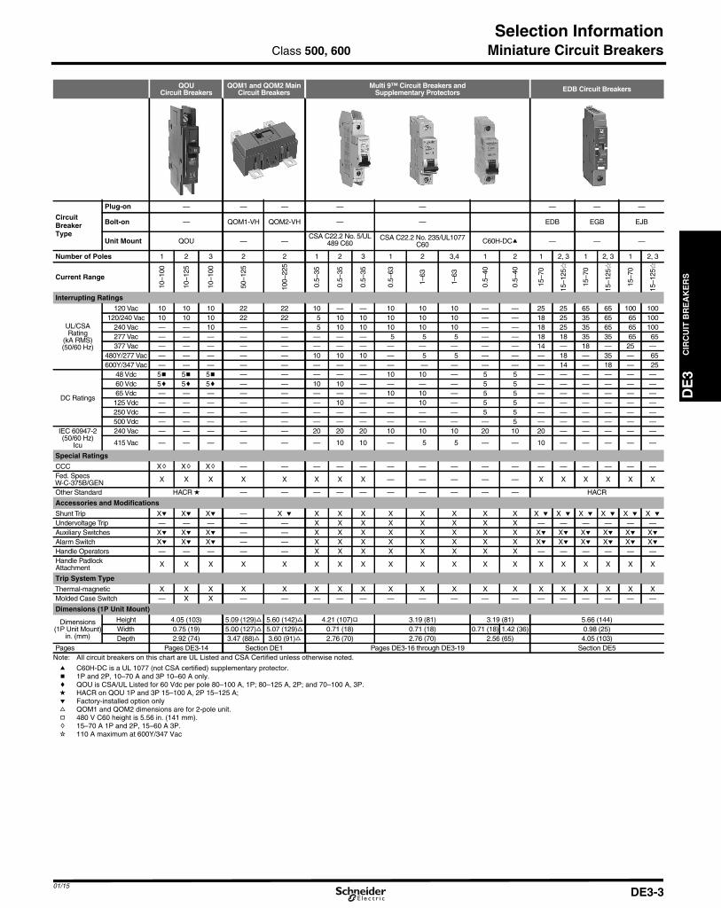
QOUCircuit Breakers
QOM1 and QOM2 MainCircuit Breakers
Multi 9™ Circuit Breakers andSupplementary Protectors EDB Circuit Breakers
CircuitBreakerType
Plug-on — — — — — — — —
Bolt-on — QOM1-VH QOM2-VH — — EDB EGB EJB
Unit Mount QOU — —CSA C22.2 No. 5/UL
489 C60CSA C22.2 No. 235/UL1077
C60 C60H-DCa — — —
Number of Poles 1 2 3 2 2 1 2 3 1 2 3,4 1 2 1 2, 3 1 2, 3 1 2, 3
Current Range
10–1
00
10–1
25
10–1
00
50–1
25
100–
225
0.5–
35
0.5–
35
0.5–
35
0.5–
63
1–63
1–63
0.5–
40
0.5–
40
15–7
0
15–1
25�
15–7
0
15–1
25�
15–7
0
15–1
25�
Interrupting Ratings
UL/CSARating
(kA RMS)(50/60 Hz)
120 Vac 10 10 10 22 22 10 — — 10 10 10 — — 25 25 65 65 100 100120/240 Vac 10 10 10 22 22 5 10 10 10 10 10 — — 18 25 35 65 65 100
240 Vac — — 10 — — 5 10 10 10 10 10 — — 18 25 35 65 65 100277 Vac — — — — — — — — 5 5 5 — — 18 18 35 35 65 65377 Vac — — — — — — — — — — — — — 14 — 18 — 25 —
480Y/277 Vac — — — — — 10 10 10 — 5 5 — — — 18 — 35 — 65600Y/347 Vac — — — — — — — — — — — — — — 14 — 18 — 25
DC Ratings
48 Vdc 5b 5b 5b — — — — — 10 10 — 5 5 — — — — — —60 Vdc 5c 5c 5c — — 10 10 — — — — 5 5 — — — — — —65 Vdc — — — — — — — — 10 10 — 5 5 — — — — — —125 Vdc — — — — — — 10 — — 10 — 5 5 — — — — — —250 Vdc — — — — — — — — — — — 5 5 — — — — — —500 Vdc — — — — — — — — — — — — 5 — — — — — —
IEC 60947-2(50/60 Hz)
Icu
240 Vac — — — — — 20 20 20 10 10 10 20 10 20 — — — — —
415 Vac — — — — — — 10 10 — 5 5 — — 10 — — — — —
Special Ratings
CCC Xh Xh Xh — — — — — — — — — — — — — — — —Fed. SpecsW-C-375B/GEN X X X X X X X X — — — — — X X X X X X
Other Standard HACR d — — — — — — — — — — HACR
Accessories and Modifications
Shunt Trip Xe Xe Xe — X e X X X X X X X X X e X e X e X e X e X eUndervoltage Trip — — — — — X X X X X X X X — — — — — —Auxiliary Switches Xe Xe Xe — — X X X X X X X X Xe Xe Xe Xe Xe XeAlarm Switch Xe Xe Xe — — X X X X X X X X Xe Xe Xe Xe Xe XeHandle Operators — — — — — X X X X X X X X — — — — — —Handle PadlockAttachment X X X X X X X X X X X X X X X X X X X
Trip System Type
Thermal-magnetic X X X X X X X X X X X X X X X X X X XMolded Case Switch — X X — — — — — — — — — — — — — — — —
Dimensions (1P Unit Mount)
Dimensions(1P Unit Mount)
in. (mm)
Height 4.05 (103) 5.09 (129)f 5.60 (142)f 4.21 (107)g 3.19 (81) 3.19 (81) 5.66 (144)Width 0.75 (19) 5.00 (127)f 5.07 (129)f 0.71 (18) 0.71 (18) 0.71 (18) 1.42 (36) 0.98 (25)Depth 2.92 (74) 3.47 (88)f 3.60 (91)f 2.76 (70) 2.76 (70) 2.56 (65) 4.05 (103)
Pages Pages DE3-14 Section DE1 Pages DE3-16 through DE3-19 Section DE5Note: All circuit breakers on this chart are UL Listed and CSA Certified unless otherwise noted.
a C60H-DC is a UL 1077 (not CSA certified) supplementary protector.b 1P and 2P, 10–70 A and 3P 10–60 A only.c QOU is CSA/UL Listed for 60 Vdc per pole 80–100 A, 1P; 80–125 A, 2P; and 70–100 A, 3P.d HACR on QOU 1P and 3P 15–100 A, 2P 15–125 A;e Factory-installed option onlyf QOM1 and QOM2 dimensions are for 2-pole unit.g 480 V C60 height is 5.56 in. (141 mm).h 15–70 A 1P and 2P, 15–60 A 3P.i 110 A maximum at 600Y/347 Vac
Class 500, 600
DE3-3
CIR
CU
ITB
RE
AK
ER
S
DE3_p04.fm Page 4 Saturday, January 10, 2015 2:10 AM
Selection Information
DE3
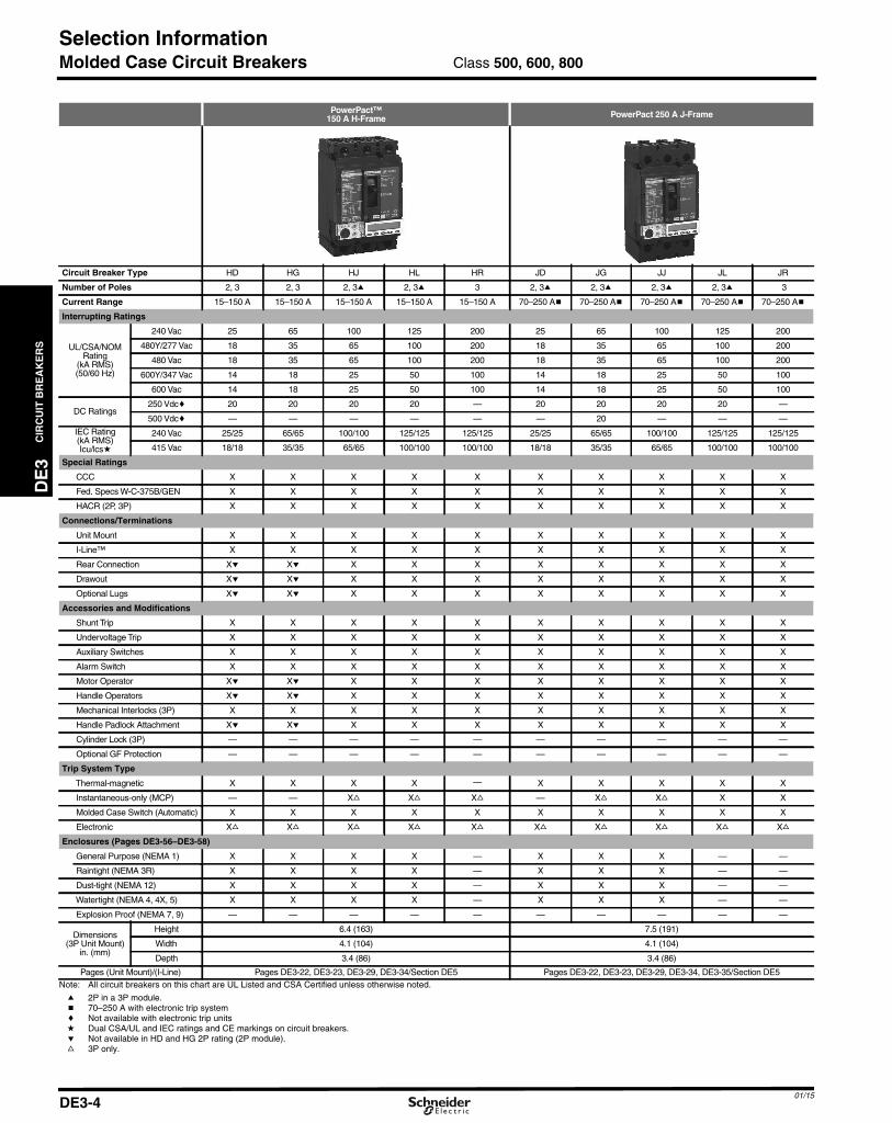
Molded Case Circuit Breakers
PowerPact™150 A H-Frame PowerPact 250 A J-Frame
Circuit Breaker Type HD HG HJ HL HR JD JG JJ JL JR
Number of Poles 2, 3 2, 3 2, 3a 2, 3a 3 2, 3a 2, 3a 2, 3a 2, 3a 3
Current Range 15–150 A 15–150 A 15–150 A 15–150 A 15–150 A 70–250 Ab 70–250 Ab 70–250 Ab 70–250 Ab 70–250 Ab
Interrupting Ratings
UL/CSA/NOMRating
(kA RMS)(50/60 Hz)
240 Vac 25 65 100 125 200 25 65 100 125 200
480Y/277 Vac 18 35 65 100 200 18 35 65 100 200
480 Vac 18 35 65 100 200 18 35 65 100 200
600Y/347 Vac 14 18 25 50 100 14 18 25 50 100
600 Vac 14 18 25 50 100 14 18 25 50 100
DC Ratings250 Vdcc 20 20 20 20 — 20 20 20 20 —
500 Vdcc — — — — — — 20 — — —
IEC Rating(kA RMS)Icu/lcsd
240 Vac 25/25 65/65 100/100 125/125 125/125 25/25 65/65 100/100 125/125 125/125
415 Vac 18/18 35/35 65/65 100/100 100/100 18/18 35/35 65/65 100/100 100/100
Special Ratings
CCC X X X X X X X X X X
Fed. Specs W-C-375B/GEN X X X X X X X X X X
HACR (2P, 3P) X X X X X X X X X X
Connections/Terminations
Unit Mount X X X X X X X X X X
I-Line™ X X X X X X X X X X
Rear Connection Xe Xe X X X X X X X X
Drawout Xe Xe X X X X X X X X
Optional Lugs Xe Xe X X X X X X X X
Accessories and Modifications
Shunt Trip X X X X X X X X X X
Undervoltage Trip X X X X X X X X X X
Auxiliary Switches X X X X X X X X X X
Alarm Switch X X X X X X X X X X
Motor Operator Xe Xe X X X X X X X X
Handle Operators Xe Xe X X X X X X X X
Mechanical Interlocks (3P) X X X X X X X X X X
Handle Padlock Attachment Xe Xe X X X X X X X X
Cylinder Lock (3P) — — — — — — — — — —
Optional GF Protection — — — — — — — — — —
Trip System Type
Thermal-magnetic X X X X — X X X X X
Instantaneous-only (MCP) — — Xf Xf Xf — Xf Xf X X
Molded Case Switch (Automatic) X X X X X X X X X X
Electronic Xf Xf Xf Xf Xf Xf Xf Xf Xf Xf
Enclosures (Pages DE3-56–DE3-58)
General Purpose (NEMA 1) X X X X — X X X — —
Raintight (NEMA 3R) X X X X — X X X — —
Dust-tight (NEMA 12) X X X X — X X X — —
Watertight (NEMA 4, 4X, 5) X X X X — X X X — —
Explosion Proof (NEMA 7, 9) — — — — — — — — — —
Dimensions(3P Unit Mount)
in. (mm)
Height 6.4 (163) 7.5 (191)
Width 4.1 (104) 4.1 (104)
Depth 3.4 (86) 3.4 (86)
Pages (Unit Mount)/(I-Line) Pages DE3-22, DE3-23, DE3-29, DE3-34/Section DE5 Pages DE3-22, DE3-23, DE3-29, DE3-34, DE3-35/Section DE5Note: All circuit breakers on this chart are UL Listed and CSA Certified unless otherwise noted.
a 2P in a 3P module.b 70–250 A with electronic trip systemc Not available with electronic trip unitsd Dual CSA/UL and IEC ratings and CE markings on circuit breakers.e Not available in HD and HG 2P rating (2P module).f 3P only.
Class 500, 600, 800
01/15DE3-4

01/15
i Not available with elect
DE3_p05.fm Page 5 Saturday, January 10, 2015 2:07 AM
Selection Information
DE
3C
IRC
UIT
BR
EA
KE
RS
Molded Case Circuit Breakers
PowerPact 250 A Q-Frame PowerPact 600 A L-Frame
Circuit Breaker Type QB QD QG QJ LD LG LJ LL LR
Number of Poles 2, 3 2, 3 2, 3 2, 3 3, 4 3, 4 3, 4 3, 4 3, 4
Current Range 70–250b 70–250b 70–250b 70–250b 70–600 70–600 70–600 70–600 70–600
Interrupting Ratings
UL/CSA/NOMRating
(kA RMS)(50/60 Hz)
240 Vac 10 25 65 100 25 65 100 125 200
480Y/277 Vac — — — — 18 35 65 100 200
480 Vac — — — — 18 35 65 100 200
600Y/347 Vac — — — — 14 18 25 50 100
600 Vac — — — — 14 18 25 50 100
DC Ratings250 Vdci — — — — — — — — —
500 Vdcci — — — — — — — — —
IEC Rating(kA RMS)Icu/lcsd
240 Vac 10/5 10/5 10/5 10/5 25/25 65/65 100/100 125/125 125/125
415 Vac 10/5 10/5 10/5 10/5 18/18 35/35 65/65 100/100 100/100
Special Ratings
CCC — — — — X X X X X
Fed. Specs W-C-375B/GEN X X X X — — — — —
HACR (2P, 3P) X X X — X X X X X
Connections/Terminations
Unit Mount X X X X X X X X X
I-Line™ X X X X X X X X X
Rear Connection — — — — X X X X X
Drawout — — — — X X X X X
Optional Lugs — — — — X X X X X
Accessories and Modifications
Shunt Trip — — — — X X X X X
Undervoltage Trip — — — — X X X X X
Auxiliary Switches — — — — X X X X X
Alarm Switch — — — — X X X X X
Motor Operator — — — — X X X X X
Handle Operators — — — — X X X X X
Mechanical Interlocks (3P) X X X X X X X X X
Handle Padlock Attachment X X X X X X X X X
Cylinder Lock (3Pf) — — — — — — — — —
Optional GF Protectione — — — — X X X X X
Trip System Type
Thermal-magnetic X X X X — — — — —
Instantaneous-only (MCP) — — — — X X X X X
Molded Case Switch (Automatic) X — — — — X — X X
Electronic — — — — X X X X X
Enclosures (Pages DE3-56–DE3-58)
General Purpose (NEMA 1) X X X X — — — — —
Raintight (NEMA 3R) X X X X — — — — —
Dust-tight (NEMA 12) — — — — — — — — —
Watertight (NEMA 4, 4X, 5) — — — — — — — — —
Explosion Proof (NEMA 7, 9) — — — — — — — — —
Dimensions(3P Unit Mount)
in. (mm)
Height 6.47 (164) 13.38 (340)
Width 4.5 (114) 5.51 (140)
Depth 3.93 (100) 4.33 (110)
Pages (Unit Mount)/(I-Line) Pages DE3-24/Section DE5 Pages DE3-25/DE3-33Note: All circuit breakers on this chart are UL Listed and CSA Certified unless otherwise noted.
a 2P in a 3P module.b I-Line Q-frame circuit breakers are available 70–225 A only. 250 A Q-frame unit-mount circuit breakers are limited to Cu conductors only.c Ungrounded UPS systems only. See page DE3-35. Special DC J-Frame only.d Dual CSA/UL and IEC ratings and CE markings on circuit breakers.e Requires factory-installed “G” shunt trip and 3P module.f Factory-installed option only.g 3P only.h 70–250 A with electronic trip system.
Class 500, 600, 800
DE3-5
ronic trip units.
CIR
CU
ITB
RE
AK
ER
S
DE3_p06.fm Page 6 Saturday, January 10, 2015 2:10 AM
Selection Information
DE3
Molded Case Circuit Breakers
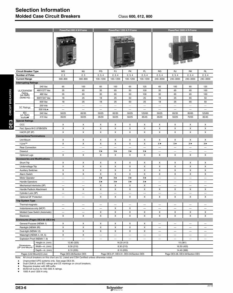
PowerPact 800 A M-Frame PowerPact 1200 A P-Frame PowerPact 3000 A R-Frame
Circuit Breaker Type MG MJ PG PJ PK PL RG RJ RK RL
Number of Poles 2, 3 2, 3 2, 3, 4 2, 3, 4 2, 3, 4 2, 3, 4 2, 3, 4 2, 3, 4 2, 3, 4 2, 3, 4
Current Range 300–800 300–800 100–1200 100–1200 100–1200 100–1200 240–3000 240–3000 240–3000 240–3000
Interrupting Ratings
UL/CSA/NOMRating
(kA RMS)(50/60 Hz)
240 Vac 65 100 65 100 65 125 65 100 65 125
480Y/277 Vac 35 65 35 65 50 100 35 65 65 100
480 Vac 35 65 35 65 50 100 35 65 65 100
600Y/347 Vac 18 25 18 25 50 25 18 25 65 50
600 Vac 18 25 18 25 50 25 18 25 65 50
DC Ratings250 Vdc — — — — — — — — — —
500 Vdca — — — — — — — — — —
IEC(kA RMS)Icu/lcsb
240 Vac 50/25 65/35 50/25 65/35 50/25 125/65 50/25 65/35 85/65 125/65
415 Vac 35/20 50/25 35/20 50/25 50/25 85/45 35/20 50/25 70/55 85/45
Special Ratings
CCC X X X X X X X X X X
Fed. Specs W-C-375B/GEN X X X X X X X X X X
HACR (2P, 3P) X X X X X X X X X X
Connections/Terminations
Unit Mount X X X X X X X X X X
I-Line™ X X X X X X Xe Xe Xe Xe
Rear Connection — — — — — — — — — —
Drawout — — Xd Xd Xd Xd — — — —
Optional Lugs X X X X X X X X X X
Accessories and Modifications
Shunt Trip X X X X X X X X X X
Undervoltage Trip X X X X X X X X X X
Auxiliary Switches X X X X X X X X X X
Alarm Switch X X X X X X X X X X
Motor Operator — — Xd Xd Xd Xd — — — —
Handle Operators — — Xd Xd Xd Xd — — — —
Mechanical Interlocks (3P) — — X X X X — — — —
Handle Padlock Attachment X X X X X X X X X X
Cylinder Lock (3P) — — — — — — — — — —
Optional GF Protection — — X X X X X X X X
Trip System Type
Thermal-magnetic — — — — — — — — — —
Instantaneous-only (MCP) — — — X X — — — — —
Molded Case Switch (Automatic) — — X X X X X X X X
Electronic X X X X X X X X X X
Enclosures (Pages DE3-56–DE3-58)
General Purpose (NEMA 1) X X X X X X — — — —
Raintight (NEMA 3R) X X X X X X — — — —
Dust-tight (NEMA 12) X X X X X X — — — —
Watertight (NEMA 4, 4X, 5) X X — — — — — — — —
Explosion Proof (NEMA 7, 9) — — — — — — — — — —
Dimensions(3P Unit Mount)
Height–in. (mm) 12.80 (325) 16.20 (413) 15 (381)
Width—in. (mm) 8.30 (210) 8.30 (210) 16.50 (420)
Depth—in. (mm) 8.10 (205) 8.10 (205) 14.40 (366)
Pages (Unit Mount)/(I-Line) Page DE3-26/Section DE5 Page DE3-27, DE3-31, DE3-34/Section DE5 Page DE3-28, DE3-34/Section DE5
Note: All circuit breakers on this chart are UL Listed and CSA Certified unless otherwise noted.
a Ungrounded UPS systems only. See page DE3-35.b Dual CSA/UL and IEC ratings and CE markings on circuit breakers.c Requires breaker with WB suffixd 65/50 kA Icu/Ics for 450–600 A ratings.e 1000 A and 1200 A only.
Class 600, 612, 800
01/15DE3-6

01/15
DE3_p07.fm Page 7 Saturday, January 10, 2015 2:10 AM
Selection Information
DE
3C
IRC
UIT
BR
EA
KE
RS
Insulated Case Circuit Breakers
Masterpact 1200 A Masterpact 6000 A
Circuit Breaker Type NT-N NT-H NT-L1 NT-L NT-LF a NW-N NW-H NW-L NW-LF a NW-H NW-L NW-H NW-L
Number of Poles 3, 4 3, 4 3 3 3 3, 4 3, 4 3 3 3, 4 3 3, 4 3
Current Range 100–1200 100–1200 100–1200 100–1200 100–1200 100–2000 100–2000 100–2000 100–2000 640–3000 640–3000 1200–6000 1200–6000
Interrupting Ratings
UL/CSA/NOMRating
(kA RMS)(50/60 Hz)
240 Vac 50 65 100 200 200 65 100 200 200 100 200 100 200
480Y/277 Vac 50 50 65 100 100 65 100 150 150 100 150 100 150
480 Vac 50 50 65 100 100 65 100 150 150 100 150 100 150
600Y/347 Vac 35 50 — — — 50 85 100 100 85 100 85 100
600 Vac 35 50 — — — 50 85 100 100 85 100 85 100
DC Ratings250 Vdc — — — — — — — — — — — — —
500 Vdc — — — — — — — — — — — — —
IECb(kA RMS)
Icu/Ics
240 Vac — — — — — — — — — — — — —
415 Vac — — — — — — — — — — — — —
Special Ratings
CCC — — — — — — — — — — — — —
Fed. Specs W-C-375B/GEN — — — — — — — — — — — — —
HACR (2P, 3P) — — — — — — — — — — — — —
Connections/Terminations
Unit Mount X X X X X X X X X X X X X
I-Line™ — — — — — — — — — — — — —
Rear Connection X X X X X X X X X X X X X
Drawout X X X X X X X X X X X X X
Optional Lugs — — — — — — — — — — — — —
Accessories and Modifications
Shunt Trip X X X X X X X X X X X X X
Undervoltage Trip X X X X X X X X X X X X X
Auxiliary Switches X X X X X X X X X X X X X
Alarm Switch X X X X X X X X X X X X X
Motor Operator X X X X X X X X X X X X X
Handle Operators — — — — — — — — — — — — —
Mechanical Interlocks X X X X X X X X X X X X X
Padlock Attachment X X X X X X X X X X X X X
Cylinder Lock — — — — — — — — — — — — —
Optional GF Protection X X X X X X X X X X X X X
Trip System Type
Thermal-magnetic — — — — — — — — — — — — —
Instantaneous-only (MCP) — — — — — — — — — — — — —
Molded Case Switch (Automatic) X X X X X X X X X X X X X
Electronic X X X X X X X X X X X X X
Enclosures
General Purpose (NEMA 1) — — — — — — — — — — — — —
Raintight (NEMA 3R) — — — — — — — — — — — — —
Dust-tight (NEMA 12) — — — — — — — — — — — — —
Watertight (NEMA 4, 4X, 5) — — — — — — — — — — — — —
Explosion Proof (NEMA 7, 9) — — — — — — — — — — — — —
Dimensions(3P Unit Mount)
in. (mm)
Height 12.67 (322) 17.28 (439) 17.28 (439) 17.28 (439)
Width 11.25 (286) 17.74 (450) 17.74 (450) 30.94 (786)
Depth 13.00 (331) 18.38 (467) 18.38 (467) 18.38 (467)
Pages Page DE3-50 and Catalog 0613CT0001 Page DE3-50 and Catalog 0613CT0001Note: All circuit breakers on this chart are UL Listed and CSA Certified unless otherwise noted.
a Tested to show arc flash hazard risk category as reference by NFPA70E.b See Catalog 0613CT0001 for additional ratings and other information.
Class 600, 800
DE3-7

CIR
CU
ITB
RE
AK
ER
S
DE3_p08.fm Page 8 Saturday, January 10, 2015 2:11 AM
Selection Information
DE3
Molded Case Circuit Breakers
100 A Frame
Circuit Breaker Type FA (240 V) FA FH FHb FH
Number of Poles 1, 2, 3 1 2, 3 1 1 2, 3
Current Range 15–100 15–100 15–100 15–30 35–100 15–100
Interrupting Ratings
UL/CSA/NOMRating
(kA RMS)(50/60 Hz)
240 Vac 10k 25k 25 65 25 65
480Y/277 Vac — 18 18 65 25 25
480 Vac — — 18 — — 25
600Y/347 Vac — — 14 — — 18
600 Vac — — 14 — — 18
DC Ratings250 Vdcl 5c 10c 10 10c 10c 50
500 Vdcal — — — — — 20
IEC Rating(kA RMS)Icu/lcsd
240 Vac — 18/9 — 18/9 — —
415 Vac 10/2.5 10/2.5 10/2.5 10/2.5 10/2.5 10/2.5
Special Ratings
CCC — — — — — —
Fed. Specs W-C-375B/GEN X X X X X X
HACR (2P, 3P) X — X — — —
Connections/Terminations
Unit Mount X X X X X X
I-Line™ X X X X X X
Rear Connection X X X — — —
Drawout — — — — — —
Optional Lugs X X X X X X
Accessories and Modifications
Shunt Trip Xfe — Xf — — Xf
Undervoltage Trip Xfe — Xf — — Xf
Auxiliary Switches Xfe — Xf — — Xf
Alarm Switch Xfe X f Xf Xf Xf Xf
Motor Operator — — X — — X
Handle Operators X — X X X X
Mechanical Interlocks (3P) — — X — — X
Handle Padlock Attachment X X X X X X
Cylinder Lock (3Pf) — — X — — X
Optional GF Protectiong — — X — — X
Trip System Type
Thermal-magnetic X X X X X X
Instantaneous-only (MCP) — — X — — X
Molded Case Switch (Automatic) — — — — — X
Electronic — — — — — —
Enclosures (Pages DE3-56–DE3-58)
General Purpose (NEMA 1) X X X X X X
Raintight (NEMA 3R) X X X X X X
Dust-tight (NEMA 12) X X X X X X
Watertight (NEMA 4, 4X, 5) X X X X X X
Explosion Proof (NEMA 7, 9) X X X X X X
Dimensions(3P Unit Mount)
in. (mm)
Height 6 (152) 6 (152)
Width 4.5 (114) 4.5 (114)
Depth 4.13 (105) 4.13 (105)
Pages (Unit Mount)/(I-Line) DE3-63 / Section DE5 DE3-63 / Section DE5Note: All circuit breakers on this chart are UL Listed and CSA Certified unless otherwise noted.
a Ungrounded UPS systems only. See page DE3-35.b 65 kA @120 Vacc 1Ø 125 Vdc rating only.d Dual CSA/UL and IEC ratings and CE markings on circuit breakers.e Not available on 1P FA (240 V).
f Factory-installed option only.g Requires factory-installed “G” Shunt trip and 3P module.h Not available in HD and HG 2P rating (2P module).i 2P in a 3P module.j 3P only.k 1P FA is 120 Vac.l Not available with electronic trip units
Class 500, 600, 800
01/15DE3-8

01/15
DE3_p09.fm Page 9 Saturday, January 10, 2015 2:11 AM
Selection Information
DE
3C
IRC
UIT
BR
EA
KE
RS
Molded Case Circuit Breaker
400 A L-Frame
Circuit Breaker Type Q4 LA LH
Number of Poles 2, 3 2, 3 2, 3
Current Range 250–400 125–400 125–400
Interrupting Ratings
UL/CSA/NOMRating
(kA RMS)(50/60 Hz)
240 Vac 25 42 65
480Y/277 Vac — 30 35
480 Vac — 30 35
600Y/347 Vac — 22 25
600 Vac — 22 25
DC Ratings250 Vdc — 10 50
500 Vdca — — 20
IEC 60947-2(kA RMS)Icu/lcsb
240 Vac — — —
415 Vac — 20/5 20/5
Special Ratings
CCC — — —
Fed. Specs W-C-375B/GEN X X X
HACR (2P, 3P) — X X
Connections/Terminations
Unit Mount X X X
I-Line™ X X X
Rear Connection X X X
Drawout — — —
Optional Lugs X X X
Accessories and Modifications
Shunt Trip X X X
Undervoltage Trip X X X
Auxiliary Switches X X X
Alarm Switch X X X
Motor Operator X X X
Handle Operators X X X
Mechanical Interlocks (3P) — X� X�
Handle Padlock Attachment X X X
Cylinder Lock (3P) X X X
Optional GF Protection — — —
Trip System Type
Thermal-magnetic X X X
Instantaneous-only (MCP) — X X
Molded Case Switch (Automatic) — — X
Electronic — — —
Enclosures (Pages DE3-56–DE3-58)
General Purpose (NEMA 1) X X X
Raintight (NEMA 3R) X X X
Dust-tight (NEMA 12) X X X
Watertight (NEMA 4, 4X, 5) X X X
Explosion Proof (NEMA 7, 9) — — —
Dimensions(3P Unit Mount)
in. (mm)
Height 11 (279)
Width 6 (152)
Depth 5.84 (148)
Pages (Unit Mount)/(I-Line) DE3-64 / Section DE5Note: All circuit breakers on this chart are UL Listed and CSA Certified unless otherwise noted.
a Ungrounded UPS systems only. See page DE3-35.b Dual CSA/UL and IEC ratings and CE markings on circuit breakers.c Requires circuit breaker with WB suffix .
Class 500, 600, 800
DE3-9
CIR
CU
ITB
RE
AK
ER
S
DE3_p10.fm Page 10 Saturday, January 10, 2015 2:11 AM
QO™ and QOU Miniature Circuit Breakers
DE3
QO™ Miniature Circuit Breakers
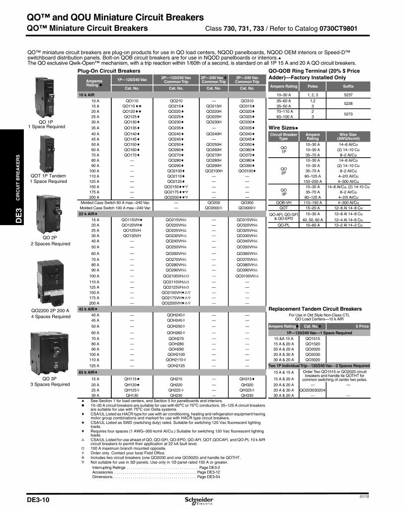
QO™ miniature circuit breakers are plug-on products for use in QO load centers, NQOD panelboards, NQOD OEM interiors or Speed-D™switchboard distribution panels. Bolt-on QOB circuit breakers are for use in NQOD panelboards or interiors.aThe QO exclusive Qwik-Open™ mechanism, with a trip reaction within 1/60th of a second, is standard on all 1P 15 A and 20 A QO circuit breakers.
QO 1P1 Space Required
QOT 1P Tandem1 Space Required
QO 2P2 Spaces Required
4 Spaces RequiredQO2200 2P 200 A
QO 3P3 Spaces Required
Plug-On Circuit Breakers QO-QOB Ring Terminal (20% $ PriceAdder)—Factory Installed Only
AmperesRating b
1P—120/240 Vac 2P—120/240 VacCommonTrip
2P—240 VaccCommonTrip
3P—240 VacCommonTrip
Ampere Rating Poles SuffixCat. No. Cat. No. Cat. No. Cat. No.
10 k AIR 10–30 A 1, 2, 3 5237
10 A QO110 QO210 — QO310 35–60 A 1,25238
15 A QO115cd QO215c QO215H QO315c 35–50 A 320 A QO120 cd QO220c QO220H QO320c 70–110 A 2
527325 A QO125c QO225c QO225H QO325c 60–100 A 330 A QO130c QO230c QO230H QO330c
35 A QO135 c QO235c — QO335c Wire Sizesb40 A QO140 c QO240c QO240H QO340c Circuit Breaker
TypeAmpereRating
Wire Size(AWG/kcmil)45 A QO145c QO245c — QO345c
50 A QO150c QO250c QO250H QO350cQO1P
10–30 A 14–8 Al/Cu60 A QO160c QO260c QO260H QO360c 10–30 A (2) 14–10 Cu70 A QO170c QO270c QO270H QO370c 35–70 A 8–2 Al/Cu80 A — QO280c QO280H QO380c
QO2P
10–30 A 14–8 Al/Cu90 A — QO290c QO290H QO390c 10–30 A (2) 14–10 Cu
100 A — QO2100c QO2100H QO3100c 35–70 A 8–2 Al/Cu110 A — QO2110c — — 80–125 A 4–2/0 Al/Cu125 A — QO2125c — — 150–200 A 4–300 Al/Cu150 A — QO2150cej — —
QO3P
10–30 A 14–8 Al/Cu, (2) 14-10 Cu175 A — QO2175cej — — 35–70 A 8–2 Al/Cu200 A — QO2200cej — — 80–125 A 4–2/0 Al/Cu
Molded Case Switch 60 A max.–240 Vac — QO200 QO300 QOB-VH 110–150 A 4–300 Al/CuMolded Case Switch 100 A max.–240 Vac — QO2000h QO3000h QOT 15–20 A 12–8 Al 14–8 Cu
22 k AIRc QO-AFI, QO-GFI& QO-EPD
15–30 A 12–8 Al 14–8 Cu
15 A QO115VHd QO215VHf — QO315VHf 40, 50, 60 A 12–4 Al 14–6 Cu20 A QO120VHd QO220VHf — QO320VHf QO-PL 10–60 A 12–2 Al 14–2 Cu25 A QO125VH QO225VHf — QO325VHf
30 A QO130VH QO230VH f — QO330VHf
40 A — QO240VHf — QO340VHf
50 A — QO250VHf — QO350VHf
60 A — QO260VHf — QO360VHf
70 A — QO270VHf — QO370VHf
80 A — QO280VHf — QO380VH f
90 A — QO290VHf — QO390VHf
100 A — QO2100VHfg — QO3100VH f
110 A — QO2110VHfg — —125 A — QO2125VHfg — —150 A — QO2150VHefj — —175 A — QO2175VHefj — —200 A — QO2200VHefj — —
42 k AIRc Replacement Tandem Circuit BreakersFor Use in Old Style Non-Class CTL
QO Load Centers—10 k AIR40 A — QOH240h — —45 A — QOH245h — —
50 A — QOH250h — — Ampere Ratingb Cat. No.c $ Price
60 A — QOH260h — — 1P—120/240 Vac—1 Space Required70 A — QOH270 — — 15 &A 15 A QO151580 A — QOH280 — — 15 A & 20 A QO1520 90 A — QOH290 — — 20 A & 20 A QO2020
100 A — QOH2100 — — 20 A & 30 A QO2030110 A — QOH2110h — — 30 A & 20 A QO3020
125 A — QOH2125 — — Two 1P IndividualTrip—120/240Vac—2 Spaces Required
65 k AIRc 15 A & 15 A Order Two QO1515 or QO2020 circuitbreakers and handle tie QOTHT for
common switching of center two poles.15 A QH115d QH215 — QH315c 15 A & 20 A
20 A QH120d QH220 — QH320 20 A & 20 A — —25 A QH125h QH225h — QH325h 20 A & 30 A QO20303020i30 A QH130 QH230 — QH330 30 A & 20 A — —
a See Section 1 for load centers, and Section 5 for panelboards and interiors.b 10–30 A circuit breakers are suitable for use with 60oC or 75oC conductors. 35–125 A circuit breakers
are suitable for use with 75oC con Delta systems.c CSA/UL Listed as HACR type for use with air conditioning, heating and refrigeration equipment having
motor group combinations and marked for use with HACR type circuit breakers.d CSA/UL Listed as SWD (switching duty) rated. Suitable for switching 120 Vac fluorescent lighting
loads.e Requires four spaces (1 AWG–300 kcmil Al/Cu.) Suitable for switching 120 Vac fluorescent lighting
loads.f CSA/UL Listed for use ahead of QO, QO-GFI, QO-EPD, QO-AFI, QOT,QOCAFI, and QO-PL 10 k AIR
circuit breakers to permit their application at 22 kA fault level.g 100 A maximum branch mounted opposite.h Order only. Contact your local Field Office.i Includes two circuit breakers (one QO2030 and one QO3020) and handle tie QOTHT.j Not suitable for use in 3Ø panels. Use only in 1Ø panel rated 150 A or greater.
Interrupting Ratings . . . . . . . . . . . . . . . . . . . . . . . . . . . . . . . . . . . Page DE3-2Accessories . . . . . . . . . . . . . . . . . . . . . . . . . . . . . . . . . . . . . . . . Page DE3-12Dimensions. . . . . . . . . . . . . . . . . . . . . . . . . . . . . . . . . . . . . . . . . Page DE3-54
Class 730, 731, 733 / Refer to Catalog 0730CT9801
01/15DE3-10

01/15
DE3_p011.fm Page 11 Saturday, January 10, 2015 2:12 AM
QO™ and QOU Miniature Circuit Breakers
DE
3C
IRC
UIT
BR
EA
KE
RS
QO™ Miniature Circuit Breakers
QO™ Arc-Fault Circuit Breaker
1PQO-AFI
QO arc-fault circuit breakers provide branch feederprotection for series and parallel-type arcing as required bythe NEC and local code adoption, and comply withUL1699.
QO Arc Fault Circuit Breakersa
Circuit BreakerType AmpereRating
1P 120 Vac 1P 120 Vac
10 k AIR 22 k AIR
1 Space Required 1 Space Required
Cat. No. Cat. No.
Combination Arc-faultInterrupter
15 A QO115CAFI QO115VHCAFI20 A QO120CAFI QO120VHCAFI
QO-GFI2P
QO-GFI1P
QO-GFI
3PQO-GFI
Qwik-Gard™ circuit breakers provide overload and shortcircuit protection, combined with Class A ground faultprotection. Class A denotes a ground fault circuitinterrupter that will trip when a fault current to ground is 6mA or more, for people protection. Do not connect to morethan 250 feet of load conductor for the total one-way run toprevent nuisance tripping.
QO-GFI Circuit Breakers
Am
pere
Rat
ingc
(A) Qwik-Gard Circuit Breakers
With Ground Fault Circuit Interrupter
1P 120 Vac 2P CommonTrip120/240 Vac
10 k AIR 22 k AIR 10 k AIR
1 Space Required 1 Space Required 2 Spaces Required
Cat. No. Cat. No. Cat. No.
15 QO115GFI QO115VHGFI QO215GFI20 QO120GFI QO120VHGFI QO220GFI25 QO125GFI QO125VHGFI QO225GFI30 QO130GFI QO130VHGFI QO230GFI40 — — QO240GFI50 — — QO250GFI60 — — QO260GFId
QO-EPD/EPEQO-EPD/EPE circuit breakers provide overload and shortcircuit protection combined with Class B ground faultprotection. They are designed to provide ground faultprotection of equipment at a 30 milliampere level (EPD) or100 milliamp level (EPE). They are not designed to protectpeople from electrical shock.
QO-EPD Circuit Breakers
Am
pere
Rat
ingc
(A)
1P120 Vac
2P CommonTrip120/240 Vac
3P CommonTrip240 Vac
10 k AIR 10 k AIR 10 k AIR
1 SpaceRequired 2 Spaces Required 3 Spaces Required
Cat. No. Cat. No. Cat. No. Cat. No.
15 QO115EPD QO215EPD QO315EPDe QO315EPEe20 QO120EPD QO220EPD QO320EPDe QO320EPEe25 QO125EPD QO225EPD — —30 QO130EPD QO230EPD QO330EPDe QO330EPEe40 — QO240EPD QO340EPDe QO340EPEe50 — QO250EPD QO350EPDe QO350EPEe60 — QO260EPDd — —
QO-SWN
Two-wireQO-SWN
Three-wireQO-SWN
Switch Neutral Common Trip 2008 NEC™ 514.11
QO-SWN Circuit Breakers
AmpereRatingc
2 Wire 120 Vac 3 Wire 120/240 Vac
10 k AIR 10 k AIR
2 Spaces Required 3 Spaces Required
Cat. No. Cat. No.
10 A QO210SWN —15 A QO215SWN QO315SWN20 A QO220SWN QO320SWN25 A QO225SWN —30 A QO230SWN QO330SWN40 A QO240SWN QO340SWN50 A QO250SWN QO350SWN
QO 1PWith Shunt Trip
HID circuit breakers are for use on circuits feedingfluorescent and high intensity discharge (HID) lightingsystems such as mercury vapor, metal halide, or highpressure sodium. These circuit breakers are physicallyinterchangeable with QO circuit breakers.
QO-HID Circuit Breakers
AmpereRatingc
1P 120/240 Vac 2P CommonTrip120/240 Vac
3P CommonTrip240 Vac
10 k AIR 10 k AIR 10 k AIR
1 Space Required 2 Spaces Required 3 Spaces Required
Cat. No. $ Price Cat. No. $ Price Cat. No. $ Price
15 A QO115HIDb QO215HID QO315HID20 A QO120HIDb QO220HID QO320HID25 A QO125HID QO225HID QO325HID30 A QO130HID QO230HID QO330HID40 A QO140HID QO240HID —50 A QO150HID QO250HID —
QO-K
QO-K KeyOperated
Key operated QO circuit breakers are available in single-pole construction and can be mounted in any single-polespace which will accept a standard QO. These circuitbreakers can be turned ON or OFF or to RESET with aspecial key (catalog number QOK10) included with thecircuit breaker. These circuit breakers are UL Listed andavailable as shown in the table.
QO-K Circuit Breakers120 Vac—10 k AIR (1 Space Required)
Ampere Ratingc Cat. No.
10 A QO110K15 A QO115K20 A QO120K30 A QO130K
QO-HMHigh magnetic trip circuit breakers are recommended forapplications where high initial inrush may occur and forindividual dimmer applications.
QO-HM Circuit Breakers
Ampere Ratingc1P
Cat. No
120 Vac—10 k AIR15 A QO115HMab20 A QO120HMab
Non-automatic (Standard) Miniature SwitchesMiniature non-automatic switches have the same physicalpackaging as miniature circuit breakers, but open onlywhen the handle is switched to the OFF position.Non-automatic switches provide no overcurrent protectionor short circuit protection. They must not be used onsystems that have an available fault current greater thanthe values listed in the table.Non-automatic switches are UL Listed per UL 1087 andare CSA certified.QO, 240 Vac 10 kA
AmpereRating
2P 3P
Cat. No. Cat. No.
60 A QO200 QO300100 A QO2000 QO3000
a CSA/UL Listed as HACR type for use with air conditioning, heating andrefrigeration equipment having motor group combinations and markedfor use with HACR type circuit breakers.
b CSA/UL Listed as SWD (switching duty) rated. Suitable for switching120 Vac fluorescent lighting loads.
c 10–30 A circuit breakers are suitable for use with 60° C or 75° Cconductors. 35–60 A circuit breakers are suitable for use with 75° Cconductors.
d Suitable only for feeding 240 Vac and 208 Vac two-wire loads. Does notcontain load neutral connection.
e See note in Instruction Bulletin when using in an enclosure with aQO403 or QON prefix.
Interrupting Ratings. . . . . . . . . . . . . . . . . . . . . . . . . . . . . . . . . . . . Page DE3-2Accessories . . . . . . . . . . . . . . . . . . . . . . . . . . . . . . . . . . . . . . . . . Page DE3-12Dimensions . . . . . . . . . . . . . . . . . . . . . . . . . . . . . . . . . . . . . . . . . Page DE3-54
Class 685, 690, 730, 912, 950 / Refer to Catalog 0730CT9801
DE3-11
QO-HID

CIR
CU
ITB
RE
AK
ER
S
DE3_p012.fm Page 12 Saturday, January 10, 2015 2:13 AM
QO™ and QOU Miniature Circuit Breakers
DE3
QO™ Circuit Breaker Accessories
Accessories for Use with QO™ and QOB Miniature Circuit BreakersHandle Attachments Description Cat. No.
Handle Tie:Converts any two adjacent 120/240 Vac 1P QO circuit breakers to independent trip 2P QO1HTConverts any two adjacent 120/240 Vac 1P side-by-side QOT circuit breakers to independent trip 2P QOTHTHandle tie and lock-off for three 1P QO, QOB circuit breakers QO3HT
Handle Clamp:Clamp for holding QO 1P handle in ON or OFF position QO1LOClamp for holding QO or Q1 1P, 2P or 3P circuit breaker handles in ON or OFF position HLO1
Handle Padlock Attachment: forPadlocking in ON or OFF position
For padlocking 1P QO circuit breaker in ON or OFF positionLoose attachment QOHPLFixed attachment QO1PA
For padlocking 1P side-by-side QOT circuit breaker in ON or OFF position QOTHPAFor padlocking 2P and 3P QO-GFI, QO-EPD, and QO-EPE in either ON or OFF position, fixed attachment. GFI2PAFor 2P and 3P QO and Q1 standard circuit breakers which require padlocking in either ON or OFF position.
Loose attachment QO1HPLFixed attachment QO1PL
Handle Padlock Attachment: forPadlocking in OFF position
For padlocking 1P QO circuit breaker in OFF position only, fixed attachment. QO1PAFFor padlocking 2P and 3P QO circuit breakers in OFF position only, fixed attachment. QO2PAFFor padlocking 1P QO-GFI, QO-AFI, QO-CAFI, and QO-EPD circuit breakers in OFF position only, fixed attachment. QOGFI1PAFFor padlocking 2P and 3P QO-GFI, QO-EPD, and QO-EPE circuit breakers in OFF position only, fixed attachment. QOGFI2PAF
Sub-Feed Lugs 60 A 2P plug-on – 2 spaces required (6–2 Al/Cu) QO60SL125 A 2P plug-on – 2 spaces required (12–2/0 Al/Cu) QO2125SL225 A 2P plug-on – 4 spaces required (4–300 Al/Cu) QO2225SLa125 A 3P plug-on – 3 spaces required (12–2/0 Al/Cu) QO3125SL
Mechanical Interlock Attachment For interlocking the handles of two 2P or one 2P and one 1P QO and Q1 circuit breakers mounted side-by-side so that only one circuitbreaker can be ON at a time (Not QOU) QO2DTI
With Retaining Kit: QO2DTI mechanical interlock attachment with retaining kits for securing two adjacent back-fed circuit breakers in dual power supplyapplications. Can be used with (2) 2Ps or (1) 2P and (1) 1P QO circuit breakers in QO816L100 load centers. QO2DTIM
a Not suitable for use in 3Ø panels. Use only in 1Ø panel rated 150 A or greater.
QOHPL
QO1PA QO1PL
QO2DTI
QO1HT
QO1HPL
HLO1
QO1LO
QOTHPAQO2PAF
QO1PAF
QOGFI2PAF
Factory-Installed Accessories for Use with QO and QOB Miniature Circuit BreakersFactory-installed electrical accessories take up an additional pole space on QO™, QO-GFI, QO-EPD, QO-SWN andQOU circuit breakers. All AC electrical accessories shown below are rated for 50/60 Hz. Accessories are not availablefor QOB-VH (2P 150 A and 3P 110–150 A) circuit breakers or QO, QOU molded case switches. QO circuit breakers willaccept only one accessory per circuit breaker. Undervoltage trip is not available on miniature circuit breakers. Factory-installed accessories are not available for QO-AFI or QO-CAFI Arc Fault Circuit Breakers or on QO2150, QO2175, orQO2200 circuit breakers.
Factory-Installed Accessories
Accessory Description RatedVoltage
CoilBurden
Cat. No.Suffix Accessory Description Contact
Comb.Max.
VoltageMax.Load
Cat. No.Suffix
Shunt Trip
Trips the circuit breaker from a remotelocation by means of a trip coilenergized from a separate circuit. A120 Vac shunt trip will operate at 55%or more of rated voltage. All other shunttrips will operate at 75% or more ofrated voltage.
Application• For use with momentary or
maintained push button.• Not available on QO-GFI, QO-
EPD, QO-AFI, QOCAFI.• Shunt trip terminals accept
(2) 14–12 AWG Cu.
AC/DC12 60 VA
-1042
AuxiliarySwitches
Monitors circuit breaker contact status andprovides a remote signal indicating the circuitbreaker contacts are OPEN or CLOSED.
Application
• Auxiliary switch terminals accept(2) 14–12 AWG Cu leads.
1A1B
AC 120AC 120
5 A5 A
-1200-1201
24 168 VA
AC120 72 VA
-1021208 228 VA240 288 VA
Alarm Switches
Used with control circuits and is actuated onlywhen the circuit breaker has tripped. Standardconstruction includes a normally-open contact.
Application
• Alarm switch terminals accept(2) 14–12 AWG Cu leads.
1A AC 120 5 A -2100
Class 1130 / Refer to Catalog 0730CT9801
DE3-1201/15
DE3-12

01/15
DE3_p013.fm Page 13 Saturday, January 10, 2015 2:13 AM
QO™ and QOU Miniature Circuit Breakers
DE
3C
IRC
UIT
BR
EA
KE
RS
QO™ and Multi 9™ Mounting Bases
QON2L40
QON120L125I
SN12125
QO OEM Mounting Bases
Voltage System Main LugRating
1PSpaces
Max. No.1P
Mounting Bases Main Wire SizeAWG/kcmilCat. No.
QO Plug-On Mounting Bases—For unit mounting QO, QO-GFI, QO-AFI and QO-EPD circuit breakers
1Ø2W 240 Vac Max. 10 k AIC 70 A 2 2 QON2L70 14–4 Cu, 12–3 Al
1Ø3W 240 Vac Max. 10 k AIC
40 A 2 2 QON2L40 14–6 Cu, 12–6 Al70 A 2 4 QON24L70 14–4 Cu, 12–3 Al
100 A 6 12 QON612L100 8–1/0 Cu/Al100 A 8 16 QON816L100 8–1/0 Cu/Al125 A 12 12 QON112L125I 4–2/0 Cu/Al125 A 16 16 QON116L125I 4–2/0 Cu/Al125 A 20 20 QON120L125I 4–2/0 Cu/Al125 A 32 32 QON132L125I 4–2/0 Cu/Al200 A 12 12 QON124L200I 4–250 Cu/Al200 A 12 12 QON12L200FTLb 4–250 Cu/Al225 A 42 42 QON142L225I 4–300 Cu/Al
3Ø3W 240 Vac Max. 10 k AIC(Without Neutral Assy.)
125 A 12 12 QON312L125 4–2/0 Cu/Al200 A 18 18 QON318L200 4–300 Cu/Al200 A 24 24 QON324L200 4–300 Cu/Al200 A 30 30 QON330L200 4–300 Cu/Al
3Ø4W 240 Vac Max.10 k AIC
60 A 3 3 QON403L60N 12–6 Cu/Al125 A 24 24 QON324L125I 4–2/0 Cu/Al200 A 24 24 QON324L200I 4–300 Cu/Al
QO Plug-On Mounting Bases—For unit mounting QO, QO-GFI and QO-EPD circuit breakers
1Ø2W 240 Vac Max. 10 k AIC(Without Neutral Assembly)
70 A70 A70 A
123
123
QOMB1QOMB2QOMB3
14–4 Cu 12–2 Al14–4 Cu 12–2 Al14–4 Cu 12–2 Al
QOB Bolt-On Mounting Bases—For unit mounting QOB, QOB-GFI, QOB-EPD circuit breakers
3Ø3W 240 Vac Max.10 k AIC(Without Neutral Assembly) 100 A 3 3 QON3Bc 12–1 Cu/Al
b Device comes with factory-installed feed-thru lugs.c UL listed only.
Solid Neutral Assemblies
Main LugRating
Number of BranchNeutralTerminals Cat. No. $ Price
Main Neutral Lug Wire Size Branch NeutralTerminal Wire Size
Cu/Al Cu Al125 A200 A200 A
201230
SN20SN1200SN30
4–2/0 AWG4 AWG–300 kcmil4 AWG–300 kcmil
14–4 AWG14–4 AWG14–4 AWG
12–4 AWG12–4 AWG12–4 AWG
US Mounting Basefor CSA C22.2 No. 5/UL489
C60(3 conductor shown)
Multi-9 Mounting Bases for CSA C22.2 No. 5/UL489 C60, 240 Vac max.
Description Poles AmperesLength
Cat. No.in. mm
One-conductorMounting Base
12
200 A
10.4 264 US1122001824 14.4 366 US1242001836 19 483 US1362001848 23 584 US1482001860 27.5 699 US16020018
Two-conductorMounting Base
12 150 A 10.4 264 US2121501824
200 A
14.4 366 US2242001836 19 483 US2362001848 23 584 US2482001860 27.5 699 US26020018
Three-conductorMounting Base
12 100 A 10.4 264 US3121001824
200 A
14.4 366 US3242001836 19 483 US3362001848 23 584 US3482001860 27.5 699 US36020018
Accessories for US Mounting Base for CSA C22.2 No. 5/UL489 C60Description Cat. No.
Main lug kit for US mounting bases, 1 lug per kit, for 6 AWG to 300 kcmil cable USMBLKTerminal cover for US mounting base; provides IP20 ingress protection per IEC 60529; suitable for jumper bars or cable USMBTC
Class 652 / Catalogs 0730CT9801, 0860CT0201
DE3-13

CIR
CU
ITB
RE
AK
ER
S
DE3_p014.fm Page 14 Saturday, January 10, 2015 2:13 AM
QO™ and QOU Miniature Circuit Breakers Class 720 / Refer to Cat
DE3
QOU Miniature Circuit Breakers
Low Ampere QOU Miniature Circuit BreakersQOU unit mount miniature circuit breakers (cable-in/cable-out) are ideal for OEM applications. They have the Square D™circuit breaker’s unique Visi-Trip™ feature and can be DIN rail-mounted or surface- or flush-mounted using mounting feet.
General Specifications Common to All Low Ampere QOU Circuit Breakers
• For convenient flush mount, surface mount or DIN mount(symmetrical rail 35 x 7.5 DIN/EN 50 022)
• Single handle with internal common trip• Terminal lug wire size (1) 14–2 AWG Cu or Al• Reversible line and load lugs• Field-installable quick connectors
• CSA/UL Listed 48 Vdc (5 k AIR)• CSA/UL Listed as HACR Type: 10–70 A• High magnetic trip circuit breakers (QOU-HM) are recommended
for applications where high initial inrush may occur and forindividual dimmer applications.
Low Ampere QOU
QOU Low Ampere Miniature Circuit Breakers
AmpereRating
1P 120/240 Vac 2P 120/240 Vac 2P 240 Vac 3P 240 Vac
Cat. No. Cat. No. Cat. No.a $ Price Cat. No.
10 k AIR
10 A QOU110 QOU210 — QOU31015 A QOU115 QOU215 QOU215H QOU31520 A QOU120 QOU220 QOU220H QOU32025 A QOU125 QOU225 QOU225H QOU32530 A QOU130 QOU230 QOU230H QOU33035 A QOU135 QOU235 — QOU33540 A QOU140 QOU240 — QOU34045 A QOU145 QOU245 — QOU34550 A QOU150 QOU250 — QOU35060 A QOU160 QOU260 — QOU36070 A QOU170 QOU270 — QOU370
22 k AIR
15 A QOU115VH QOU215VH — QOU315VH20 A QOU120VH QOU220VH — QOU320VH25 A QOU125VH QOU225VH — QOU325VH30 A QOU130VH QOU230VH — QOU330VH35 A QOU135VH QOU235VH — —40 A QOU140VH QOU240VH — —45 A QOU145VH QOU245VH — —50 A QOU150VH QOU250VH — —60 A QOU160VH QOU260VH — —
a QOU-H interrupting rating is 10 kA at 240 Vac.
QOU-HM Miniature Circuit Breakers (10 k AIR)
AmpereRating
1P 120/240 Vac 2P 120/240 Vac 2P 240 Vac 3P 240 Vac
Cat. No. Cat. No. Cat. No. Cat. No.
15 A QOU115HM — — —20 A QOU120HM — — —
High Ampere QOU Circuit Breakers
General Specifications Common to All High Ampere QOU Circuit Breakers
• Flush mount, surface mount, and DIN rail mount.• Internal common trip.• Non-reversible line and load lugs.• Terminal lug wire size (1) 12– 2/0 AWG Cu or Al.• UL Listed 60 Vdc per pole (5 k AIR). (Note: except switches)
• CSA/UL Listed as HACR type, 80–125 A.• Non-automatic switches have the same physical packaging
as miniature circuit breakers, but provide no overcurrent orshort circuit protection. They are UL Listed per UL1087 andare CSA certified.
QOU High Ampere Miniature Circuit Breakers (10 k AIR)
AmpereRating
1P 120/240 Vac 2P 120/240 Vac 2P 240 Vac 3P 240 Vac
Cat. No. Cat. No. Cat. No. Cat. No.
80 A QOU180 QOU280 — QOU38090 A QOU190 QOU290 — QOU390
100 A QOU1100 QOU2100 — QOU3100125 A — QOU2125 — —
High Ampere QOU
QOU Non-Automatic Switches
AmpereRating
1P 120 Vac 2P 120/240 Vac 2P 240 Vac 3P 240 Vac
Cat. No. Cat. No. Cat. No. Cat. No.
60 A — — QOU200 QOU300100 A — — QOU2000 QOU3000125 A — — QOU20001 QOU30001
Interrupting Ratings . . . . . . . . . . . . . . . . . . . . . . . . . . . . . . . . . . . Page DE3-3Accessories . . . . . . . . . . . . . . . . . . . . . . . . . . . . . . . . . Page DE3-12, DE3-15Dimensions. . . . . . . . . . . . . . . . . . . . . . . . . . . . . . . . . . . . . . . . . Page DE3-54
alog 0730CT9801
01/15DE3-14

01/15
DE3_p015.fm Page 15 Saturday, January 10, 2015 2:14 AM
QO™ and QOU Miniature Circuit Breakers
DE
3C
IRC
UIT
BR
EA
KE
RS
QOU Accessories
QOU14100JBAF
4P Jumper BarAssembly Base
Cover and Cover Screw
QOUEC Field-installableQuick Connector
Crimp connectors arenot included withSquare D brand connectors
QOURTField-installableRing Tongue TerminalConnector
2P DIN Mounted QOU Circuit Breakers
Mounting FootQOUMF1
Tapped Mounting FootSuffix–3100
Accessories for QOU Low Ampere Circuit Breakers (Except as Noted)
Description OrderQty. Cat. No.
Factory-installed ring tongue terminal, 10–32 screw, for 1P, 2P, 3P QOU, 10–60 A — Suffix -5283
Hex drive 5/32 in. wire binding screw for QOU — Suffix -5280
For padlocking 1P low ampere QOU circuit breaker in OFF or ON position — QOU1PA
For padlocking 2P and 3P low ampere QOU circuit breaker in OFF or ON position — QOU1PL
For padlocking 1P low ampere QOU circuit breaker in OFF position only — QOU1PAFLA
For padlocking 2P and 3P low ampere QOU circuit breaker in OFF position only — QOU2PAFLA
For padlocking 2P and 3P high ampere QOU circuit breaker in OFF position only — Suffix -7100
Handle lock-out, ON or OFF position — HLO1
4P 100 A Jumper bar assy. w/front wiring with base, cover and screw 1 QOU14100JBAF
4P 100 A Jumper bar assy. w/right side wiring with base, cover and screw 1 QOU14100JBAR
4P 100 A Jumper bar assy. w/left side wiring with base, cover and screw 1 QOU14100JBAL
1Ø, 4P, 100 A Jumper bar base with front wiring 40 QOU14100BAFB
1Ø, 4P, 100 A Jumper bar base with left side wiring 40 QOU14100BALB
1Ø, 4P, 100 A Jumper bar base with right side wiring 40 QOU14100BARB
4P Jumper bar cover 40 QOU14100CAB
Mounting screw for jumper bar cover 40 QOU1CMSB
6P 150 A Jumper bar assy. w/front wiring with base, cover and screw 1 QOU16150JBAF
1Ø, 6P, 150 A Jumper bar base with front wiring 40 QOU16150BAFB
1Ø, 6P, 150 A Jumper bar base with left side wiring 40 QOU16150BALB
1Ø, 6P, 150 A Jumper bar base with right side wiring 40 QOU16150BARB
6P jumper bar cover 40 QOU16150CAB
Vertical rainproof cover 2P and 3P QO, QOU, FA and KA 110
BCVaBCVBa
Horizontal rainproof cover 2P QO, QOU, and 3P Q2, EH 110
BCHaBCHBa
1P Fingersafe™ cover for high ampere QOU circuit breaker 140
QOUHFSC1QOUHFSC1B
1P Fingersafe cover for low ampere QOU circuit breaker 140
QOULFSC1QOULFSC1B
Cover plate for one 2P QOU circuit breaker 140
QOUCP2QOUCP2B
Cover plate for one 3P QOU circuit breaker 140
QOUCP3QOUCP3B
Cover plate for two 2P QOU circuit breakers 140
QOUCP4QOUCP4B
Cover plate for three 2P QOU circuit breakers 140
QOUCP6QOUCP6B
Field-installable ring tongue terminal adaptor 180
QOURTQOURTB
Quick connector end connection wiring 140
QOUECQOUECB
Quick connector forward or reverse wiring 140
QOUFRQOUFRB
1P QOU mounting foot 180
QOUMF1aQOUMF1Ba
2P QOU mounting foot 140
QOUMF2aQOUMF2Ba
3P QOU mounting foot 124
QOUMF3aQOUMF3Ba
Tapped mounting foot for QOU, 1P and 2P 10–70 A, 3P 10–60 A
Packaged with circuit breaker Suffix -3100
Individually packaged 1 QOUMFS1
Bulk packed 80 QOUMFS1B
Mechanical interlock attachment: Used to interlock two circuit breakers mountedside-by-side so that only one circuit breaker can be ON at a time. A 1P or 2P circuit breaker canbe mounted on the left and interlocked with a 2P or 3P circuit breaker on the right.
1 QOU2DTILAb
a For use on low and high ampere QOU.b 10–70 A 1P and 2P, 10–60 A 3P.
For QOUQ Low Ampere Circuit Breakers with Four-Point Quick-ConnectTerminalsQOUQ low ampere circuit breakers with four-point quick-connect terminals are providedwith permanent factory-installed terminals which are affixed to the Load or OFF end of thecircuit breaker. This special terminal will accommodate up to four 1/4-inch insulated femalequick connect wire terminations. Total ampacity of these connections must not exceed therating of the circuit breaker.
QOUQ Four-Point Quick-Connect TerminalsPoles Order Qty. Cat. No.
Four-Point Quick-Connect Terminals1 1
Change QOU toQOUQ2 1
3 1
Electrical Accessories for QOU . . . . . . . . . . . . . . . . . . . . . . . . . Page DE3-12
Class 720 / Refer to Catalog 0730CT9801
DE3-15

CIR
CU
ITB
RE
AK
ER
S
DE3_p016.fm Page 16 Saturday, January 10, 2015 2:14 AM
Multi 9™ Miniature Circuit Breakers
DE3
CSA C22.2 No. 5/UL 489 C60 Miniature Circuit Breakers
Multi 9 C60 CSA C22.2 No. 5/UL 489 Listed 240 VMiniature Circuit Breakers
1P C60Box lug
2P C60Box lug
3P C60Box lug
Ring Tongue C60
• UL 489 Listed and CSA 22.2 No. 5.1 for branchcircuit protection
• Eliminates concerns and uncertainty of using a CSA C22.2No. 235/UL 1077 device where a CSA C22.2 No. 5/UL 489device is required
• Replaces fuses in low-ampere range; 17 ratings up to 35 A
Trip Curve Use Magnetic Release
C For typical loads 7–10 x ampere rating (7–14 for DC)
D For high inrush 10–14 x ampere rating
• 10 k AIR (1P @ 120 Vac; 2P and 3P @ 240 Vac)• 60 Vdc for 1P and 125 Vdc for 2P (on C-curve circuit breakers
only, see table below)• Increased installation flexibility with standard box lugs or
optional ring terminals• Allows easy front-mounting and rear wiring when using ring
terminals• A wide range of electrical and mechanical accessories• Suitable for reverse feeding• Trip-free mechanism• Positive indication of contact disconnect
CSA C22.2 No. 5/UL 489 Circuit Breakers (120/240 V)
Rating (A)
C Curve—7–10Times Ampere Rating (7–14 DC) D Curve—10–14Times Ampere Rating
1Pa 2Pb 3P 1P 2P 3P
Cat. No. Cat. No. Cat. No. Cat. No. Cat. No. Cat. No.
Box Lug/Box Lug
0.5 60100 60134 — 60117 60151 —
1 60101 60135 60168 60118 60152 60184
1.5 60102 60136 60169 60119 60153 60185
2 60103 60137 60170 60120 60154 60186
3 60104 60138 60171 60121 60155 60187
4 60105 60139 60172 60122 60156 60188
5 60106 60140 60173 60123 60157 60189
6 60107 60141 60174 60124 60158 60190
7 60108 60142 60175 60125 60159 60191
8 60109 60143 60176 60126 60160 60192
10 60110 60144 60177 60127 60161 60193
13 60111 60145 60178 60128 60162 60194
15 60112 60146 60179 60129 60163 60195
20 60113 60147 60180 60130 60164 60196
25 60114 60148 60181 60131 60165 60197
30 60115 60149 60182 60132 60166 60198
35 60116 60150 60183 60133 60167 60199
Ring Tongue/Ring Tongue
0.5 60200 60234 — 60217 60251 —
1 60201 60235 60268 60218 60252 60284
1.5 60202 60236 60269 60219 60253 60285
2 60203 60237 60270 60220 60254 60286
3 60204 60238 60271 60221 60255 60287
4 60205 60239 60272 60222 60256 60288
5 60206 60240 60273 60223 60257 60289
6 60207 60241 60274 60224 60258 60290
7 60208 60242 60275 60225 60259 60291
8 60209 60243 60276 60226 60260 60292
10 60210 60244 60277 60227 60261 60293
13 60211 60245 60278 60228 60262 60294
15 60212 60246 60279 60229 60263 60295
20 60213 60247 60280 60230 60264 60296
25 60214 60248 60281 60231 60265 60297
30 60215 60249 60282 60232 60266 60298
35 60216 60250 60283 60233 60267 60299a 1P dual rated 120 Vac/60 Vdc.b 2P dual rated 240 Vac/125 Vdc.
Interrupting ratings . . . . . . . . . . . . . . . . . . . . . . . . . . . . . . . . . . . . Page DE3-3Accessories . . . . . . . . . . . . . . . . . . . . . . . . . . . . . . . . . . . . . . . . Page DE3-20Dimensions. . . . . . . . . . . . . . . . . . . . . . . . . . . . . . . . . . . . . . . . . Page DE3-54Mounting Bases . . . . . . . . . . . . . . . . . . . . . . . . . . . . . . . . . . . . . Page DE3-13
Class 860 / Refer to Catalog 0860CT0201
01/15DE3-16
DE3_p017.fm Page 17 Saturday, January 10, 2015 2:15 AM
Multi 9™ Miniature Circuit BreakersClass 860 / Refer to Catalog 0860CT0201
DE
3C
IRC
UIT
BR
EA
KE
RS
CSA C22.2 No. 5/UL 489 C60 480 Vac C60 Miniature Circuit Breakers
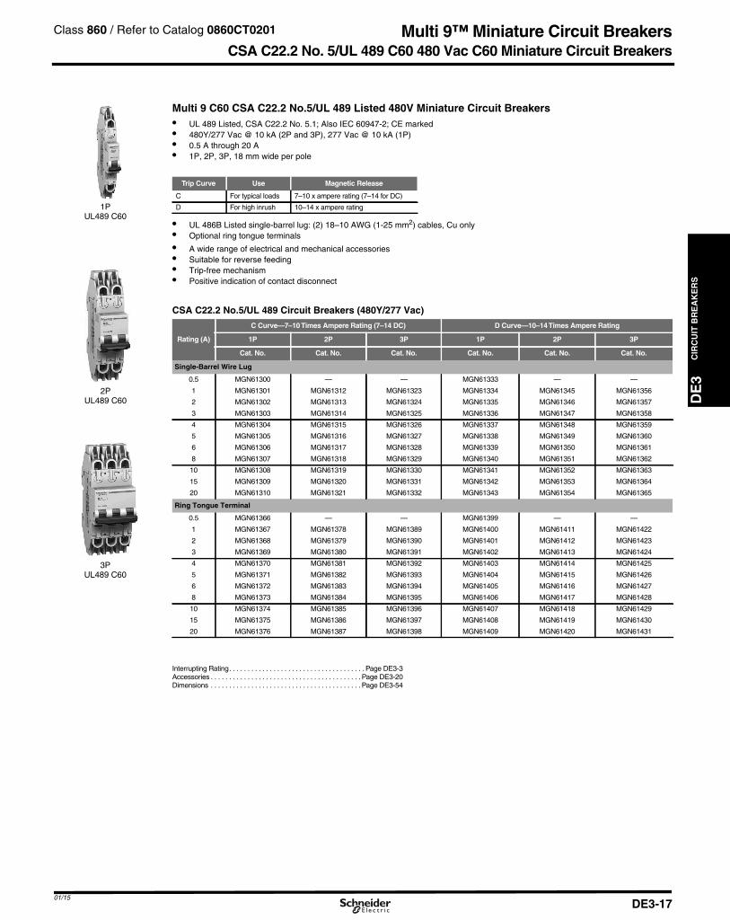
Multi 9 C60 CSA C22.2 No.5/UL 489 Listed 480V Miniature Circuit Breakers
1PUL489 C60
2PUL489 C60
3PUL489 C60
• UL 489 Listed, CSA C22.2 No. 5.1; Also IEC 60947-2; CE marked• 480Y/277 Vac @ 10 kA (2P and 3P), 277 Vac @ 10 kA (1P)• 0.5 A through 20 A• 1P, 2P, 3P, 18 mm wide per pole
Trip Curve Use Magnetic Release
C For typical loads 7–10 x ampere rating (7–14 for DC)
D For high inrush 10–14 x ampere rating
• UL 486B Listed single-barrel lug: (2) 18–10 AWG (1-25 mm2) cables, Cu only• Optional ring tongue terminals
• A wide range of electrical and mechanical accessories• Suitable for reverse feeding• Trip-free mechanism• Positive indication of contact disconnect
CSA C22.2 No.5/UL 489 Circuit Breakers (480Y/277 Vac)
Rating (A)
C Curve—7–10Times Ampere Rating (7–14 DC) D Curve—10–14Times Ampere Rating
1P 2P 3P 1P 2P 3P
Cat. No. Cat. No. Cat. No. Cat. No. Cat. No. Cat. No.
Single-Barrel Wire Lug
0.5 MGN61300 — — MGN61333 — —
1 MGN61301 MGN61312 MGN61323 MGN61334 MGN61345 MGN61356
2 MGN61302 MGN61313 MGN61324 MGN61335 MGN61346 MGN61357
3 MGN61303 MGN61314 MGN61325 MGN61336 MGN61347 MGN61358
4 MGN61304 MGN61315 MGN61326 MGN61337 MGN61348 MGN61359
5 MGN61305 MGN61316 MGN61327 MGN61338 MGN61349 MGN61360
6 MGN61306 MGN61317 MGN61328 MGN61339 MGN61350 MGN61361
8 MGN61307 MGN61318 MGN61329 MGN61340 MGN61351 MGN61362
10 MGN61308 MGN61319 MGN61330 MGN61341 MGN61352 MGN61363
15 MGN61309 MGN61320 MGN61331 MGN61342 MGN61353 MGN61364
20 MGN61310 MGN61321 MGN61332 MGN61343 MGN61354 MGN61365
Ring Tongue Terminal
0.5 MGN61366 — — MGN61399 — —
1 MGN61367 MGN61378 MGN61389 MGN61400 MGN61411 MGN61422
2 MGN61368 MGN61379 MGN61390 MGN61401 MGN61412 MGN61423
3 MGN61369 MGN61380 MGN61391 MGN61402 MGN61413 MGN61424
4 MGN61370 MGN61381 MGN61392 MGN61403 MGN61414 MGN61425
5 MGN61371 MGN61382 MGN61393 MGN61404 MGN61415 MGN61426
6 MGN61372 MGN61383 MGN61394 MGN61405 MGN61416 MGN61427
8 MGN61373 MGN61384 MGN61395 MGN61406 MGN61417 MGN61428
10 MGN61374 MGN61385 MGN61396 MGN61407 MGN61418 MGN61429
15 MGN61375 MGN61386 MGN61397 MGN61408 MGN61419 MGN61430
20 MGN61376 MGN61387 MGN61398 MGN61409 MGN61420 MGN61431
Interrupting Rating. . . . . . . . . . . . . . . . . . . . . . . . . . . . . . . . . . . . . Page DE3-3Accessories . . . . . . . . . . . . . . . . . . . . . . . . . . . . . . . . . . . . . . . . . Page DE3-20Dimensions . . . . . . . . . . . . . . . . . . . . . . . . . . . . . . . . . . . . . . . . . Page DE3-54
01/15DE3-17

CIR
CU
ITB
RE
AK
ER
S
DE3_p018.fm Page 18 Saturday, January 10, 2015 2:15 AM
Multi 9™ Miniature Circuit Breakers
DE3
UL1077 C60H Circuit Breakers
Multi 9 C60H-DC UL 1077 Recognized (not CSA certified) Supplementary Protectors (250 and 500Vdc)
1P C60H-DC
2P C60H-DC
The C60H-DC supplementary protectors are used in direct current circuits (industrial control and automation, transport,renewable energy, etc.). They provide overcurrent protection within appliances or electrical equipment.• Range from 0.5–40 A• 5 k AIR at 250 Vdc (1-pole) and 5 k AIR at 500 Vdc (2-pole, wired in series)• Trip-free mechanism• Positive indication of contact disconnect• C-Curve: 7 to14 times ampere rating• UL 1077, IEC 60947-2, EN 60947-2, GB 14048.2, CCC and CE mark• Not CSA certified.
Multi 9 C60H-DC UL 1077 Recognized (not CSA certified) Supplementary Protectors1-Pole
24–250 Vdc2-Pole
24–500 Vdc
Current (A)a Cat. No. Cat. No.
0.5 MGN61500 MGN615201 MGN61501 MGN615212 MGN61502 MGN615223 MGN61503 MGN615234 MGN61504 MGN615245 MGN61505 MGN615256 MGN61506 MGN6152610 MGN61508 MGN6152813 MGN61509 MGN6152915 MGN61510 MGN6153016 MGN61511 MGN6153120 MGN61512 MGN6153225 MGN61513 MGN6153330 MGN61514 MGN6153432 MGN61515 MGN6153540 MGN61517 MGN61537
a At 25°C/77°F, for other temperatures see temperature derating table in Multi 9 Catalogue 0860CT0201.
Class 860 / Refer to Catalog 0860CT0201
01/15DE3-18

01/15
DE3_p019.fm Page 19 Saturday, January 10, 2015 2:16 AM
Multi 9™ Miniature Circuit Breakers0, 912, 950 / Refer to Catalog 0730CT9801
DE
3C
IRC
UIT
BR
EA
KE
RS
CSA C22.2 No. 235/UL 1077 C60 Supplementary ProtectorsIntended for use within equipment where branch circuitprotection is already provided or not needed
1PUL 1077 C60
2PUL 1077 C60
3PUL 1077 C60
4PUL 1077 C60
• Range from 0.5 to 63 A• 10 k AIR @ 120/240 Vac; 5 k AIR at 480Y/277; 10 k AIR @ 60
Vdc (1P) and 125 Vdc (2P)• Suitable for reverse feeding• DIN mounting for easy installation• Suitable for reverse feeding
• A wide range of electrical and mechanical accessories• Trip-free mechanism• Positive indication of contact disconnect
Trip Curve Use Magnetic Release
B For sensitive equipment 3.2–4.8 x ampere ratingC For typical loads 7–10 x ampere rating (7–14 for DC)D For high inrush 10–14 x ampere rating
CSA C22.2 No. 235/UL 1077 Supplementary ProtectorsRating (A) 1P $ Price 2P 3P 4P
B Curve—Magnetic Setting Between 3.2 and 4.8 Times Ampere Rating
1 MG24110 MG24125 MG24140 MG241551.2 MG17402 MG17432 — —1.5 MG17403 MG17433 — —2 MG24111 MG24126 MG24141 MG241563 MG24112 MG24127 MG24142 MG241574 MG24113 MG24128 MG24143 MG241585 MG17404 MG17434 — —6 MG24114 MG24129 MG24144 MG241597 MG17405 MG17435 — —8 MG24115 MG24130 MG24145 MG2416010 MG24116 MG24131 MG24146 MG2416113 MG24117 MG24132 MG24147 MG2416215 MG17406 MG17436 MG17461 —16 MG24118 MG24133 MG24148 MG2416320 MG24119 MG24134 MG24149 MG2416425 MG24120 MG24135 MG24150 MG2416530 MG17407 MG17437 MG17462 —32 MG24121 MG24136 MG24151 MG2416635 MG17408 MG17438 MG17463 —40 MG24122 MG24137 MG24152 MG2416750 MG24123 MG24138 MG24153 MG2416860 MG17409 MG17439 MG17464 —63 MG24124 MG24139 MG24154 MG24169
C Curve—Magnetic Setting Between 7 and 10 Times Ampere Rating
0.5 MG17411 — — —1 MG24425 MG24442 MG24459 MG24476
1.2 MG17412 MG17442 — —1.5 MG17413 MG17443 — —2 MG24426 MG24443 MG24460 MG244773 MG24427 MG24444 MG24461 MG244784 MG24428 MG24445 MG24462 MG244795 MG17414 MG17444 — —6 MG24430 MG24447 MG24464 MG244817 MG17415 MG17445 — —8 MG24431 MG24448 MG24465 MG2448210 MG24432 MG24449 MG24466 MG2448313 MG24433 MG24450 MG24467 MG2448415 MG17416 MG17446 MG17466 —16 MG24434 MG24451 MG24468 MG2448520 MG24435 MG24452 MG24469 MG2448625 MG24436 MG24453 MG24470 MG2448730 MG17417 MG17447 MG17467 —32 MG24437 MG24454 MG24471 MG2448835 MG17418 MG17448 MG17468 —40 MG24438 MG24455 MG24472 MG2448950 MG24439 MG24456 MG24473 MG2449060 MG17419 MG17449 MG17469 —63 MG24440 MG24457 MG24474 MG24491
D Curve—Magnetic Setting Between 10 and 14 Times Ampere Rating
0.5 MG17421 — — —1 MG24500 MG24516 MG24532 MG24548
1.2 MG17422 MG17452 — —1.5 MG17423 MG17453 — —2 MG24501 MG24517 MG24533 MG245493 MG24502 MG24518 MG24534 MG245504 MG24503 MG24519 MG24535 MG245515 MG17424 MG17454 — —6 MG24504 MG24520 MG24536 MG245527 MG17425 MG17455 — —8 MG24505 MG24521 MG24537 MG2455310 MG24506 MG24522 MG24538 MG2455413 MG24507 MG24523 MG24539 MG2455515 MG17426 MG17456 MG17471 —16 MG24508 MG24524 MG24540 MG2455620 MG24509 MG24525 MG24541 MG2455725 MG24510 MG24526 MG24542 MG2455830 MG17427 MG17457 MG17472 —32 MG24511 MG24527 MG24543 MG2455935 MG17428 MG17458 MG17473 —40 MG24512 MG24528 MG24544 MG2456050 MG24513 MG24529 MG24545 MG2456160 MG17429 MG17459 MG17474 —63 MG24514 MG24530 MG24546 MG24562
Interrupting Ratings. . . . . . . . . . . . . . . . . . . . . . . . . . . . . . . . . . . . Page DE3-3 Dimensions . . . . . . . . . . . . . . . . . . . . . . . . . . . . . . . . . . . . . . . . . Page DE3-54
Class 685, 690, 73
DE3-19
Accessories. . . . . . . . . . . . . . . . . . . . . . . . . . . . . . . . . . . . . . . . . Page DE3-20

CIR
CU
ITB
RE
AK
ER
S
DE3_p020.fm Page 20 Saturday, January 10, 2015 2:16 AM
Multi 9™ Miniature Circuit Breakers
DE3
C60 Accessories
Electrical Accessories for C60 Circuit Breakers and Supplementary Protectors
Possible Combinations
Mounted to the left of the circuit breaker with a maximum width of 54 mm.
+ + + +
Max. 54 mm
SDAlarm Switch
OFAuxiliary Switch
MXShunt trip + Aux
Switch
MNUndervoltage
ReleaseC60
Multi 9 C60 Electrical Accessories
DescriptionsControl Voltage Width in 9 mm
modules
C60UL/IEC
Vac Vdc Cat. No.
OF Auxiliary Switch (1a1b) 12–277 12–125 1 MG26925SD Alarm Switch (1a1b) 12–277 12–125 1 MG26928
MX ShuntTrip + OF Auxiliary Switch(1a1b)
24 24 2 2711848 48 2 27110
110–240–277 125 2 27109
MN Undervoltage Release
24 24 2 2710848 48 2 27106120 — 2 27107240 — 2 27105
SpacerRing TongueTerminal Kit
C60 PadlockAttachment
(1 per 1P,2P, 3P or 4P)
Front Mounting Kit for C601P, 2P, 3P, 4P
(1 per circuit breaker)
Rotary Handle
Multi 9 C60 Mechanical Accessories
DescriptionsC60
Cat. No.
Ring tongue terminal kit for UL1077 C60 For one pole 17400Spacer for DIN rail, Not UL Recognized 9 mm wide MG27062Padlock Attachment (1 per for 1P, 2P, 3P or 4P) 2 per pack MG26970Padlocking Device Left Side Mount, Locks OFF onlya
1 per packMGN26380
Padlocking Device Right Side Mount, Locks OFF onlyb MGN26381
Front Mounting Kit
1P MG269832P MG269843P MG269854P MG26989
Terminal Screw Shield (Not UL Recognized) Bag of two4P shields MG26981
Terminal cover (Not CSA/UL Recognized)
1P MG269752P MG269763P MG26975+MG269764P MG26978
Tooth Caps for UL Comb Bus Bar, Bag of 20 60488
Rotary Handle for C60 (Non UL Recognized)
Operating Subassembly2P/3P/4P
MG27046Door Interlock Handle MG27047Fixed Handle (Front or Lateral) MG27048
Multi-pole Front Mounting Kit
Rail Support (20 of 9 mm modules) 14211Hinged Transparent Cover 14210
MGN26381 Locking DeviceRight Side Mount
MGN26380 LockingDevice Left Side Mount
Multi-poleFront Mounting Kit
a Left-side mounted padlocking device cannot be used in conjunction with accessories SD, OF, MX or MN. Use right-side mounted padlocking device when accessories are required.
b Right-side mounted padlocking device cannot be used in conjunction with VIGI module. Use left-side mountedpadlocking device when VIGI Module is required..
Class 860 / Refer to Catalog 0860CT0201
DE3-20DE3-2001/15
DE3-20

01/15
DE3_p021.fm Page 21 Saturday, January 10, 2015 2:23 AM
PowerPact™ Molded Case Circuit Breakers
DE
3C
IRC
UIT
BR
EA
KE
RS
PowerPact Family
The PowerPact Advantage• Proven Performance: Industry-leading circuit breaker innovation and protection for heavy-duty commercial and industrial
applications.• Smart: Integrated metering options provide a cost-effective solution to reduce energy consumption, optimize energy costs, and
improve energy availablility for your facilities.• Flexible: Full range of thermal-magnetic and electronic trip molded case circuit breakers from 15 A to 3000 A, delivering the ratings,
configurations, and operators for your unique applications.• Simple: Common catalog numbers, standardized ratings, and a full range of field-installable accessories make product selection,
installation and maintenance easier than ever.• Common Design Features: Mounting holes, door trim, and handle accessories.
H-Frame150 A
J-Frame250 A
Q-Frame250 A
L-Frame600 A
M-Frame800 A
P-Frame1200 A
R-Frame3000 A
PowerPact Interrupting Ratings
VoltageInterrupting Rating
B D G J K L R
240 Vac 10 kA 25 kA 65 kA 100 kA 65 kA 125 kA 200 kA
480 Vac 18 kA 35 kA 65 kA 65 kA a 100 kA 200 kA
600 Vac 14 kA 18 kA 25 kA 65 kA a 50 kAb 100 kA
a P-frame K interrupting is 50 kA at 480 and 600 Vac.b P-frame L interrupting is 25 kA at 600 Vac.
Common Catalog Numbering System
Fram
e
Rat
ing
Term
inat
ion
Pol
es
Volta
ge
Am
pera
ge
c
Suf
fixC
ode
Suf
fixC
ode
H G L 3 6 1 5 0 A B S A
110 Vac Shunt Trip2A/2B Auxiliary Switch
Frame Designation Interrupting Rating Terminations
240 Vac 480 Vac 600Vac A I-LineH 150 A Frame B 10 kA L Lugs on Both EndsJ 250 A Frame D 25 kA 18 kA 14 kA F Bus Bar (No Lugs)Q 250 A Frame G 65 kA 35 kA 18 kA M Lugs Line Side OnlyL 600 A Frame J 100 kA 65 kA 25 kA P Lugs Load End OnlyM 800 A Frame K 65 kA 65 kA 65 kA N Plug-inP 1200 A Frame L 125 kA 100 kA 50 kA D DrawoutR 3000 A Frame R 200 kA 200 kA 100 kA S Rear Connected Studs
c For amperage of M-, P- or R-frame circuit breakers, add a zero to the three amperage digits; for example, 120 = 1200 A.
Description. . . . . . . . . . . . . . . . . . . . . . . . . . . . . . . . . . . . . . . . . . . . . . . .PageH- and J-Frame Circuit Breakers . . . . . . . . . . . . . . . . . . . . . . . . . . . . .DE3-22H- and J-Frame Circuit Breakers . . . . . . . . . . . . . . . . . . . . . . . . . . . . .DE3-23Q-Frame Circuit Breakers . . . . . . . . . . . . . . . . . . . . . . . . . . . . . . . . . . .DE3-24L-Frame Circuit Breakers . . . . . . . . . . . . . . . . . . . . . . . . . . . . . . . . . . .DE3-25P-Frame Circuit Breakers . . . . . . . . . . . . . . . . . . . . . . . . . . . . . . . . . . .DE3-27R-Frame Circuit Breakers . . . . . . . . . . . . . . . . . . . . . . . . . . . . . . . . . . .DE3-28PowerPact™ H- and J-Frame Electronic Motor Circuit Protectors . . .DE3-29Motor Circuit Protectors and Motor Protector Circuit Breakers . . . . . .DE3-31Automatic Switches . . . . . . . . . . . . . . . . . . . . . . . . . . . . . . . . . . . . . . . .DE3-34500 Vdc Circuit Breakers. . . . . . . . . . . . . . . . . . . . . . . . . . . . . . . . . . . .DE3-35Mission Critical Circuit Breakers . . . . . . . . . . . . . . . . . . . . . . . . . . . . . .DE3-37PowerPact™ Circuit Breaker Accessories . . . . . . . . . . . . . . . . . . . . . .DE3-39Motor Operators and Rotary Handles . . . . . . . . . . . . . . . . . . . . . . . . .DE3-40Locks, Installation Accessories, and Rear Connections . . . . . . . . . . .DE3-41Mechanical Lugs . . . . . . . . . . . . . . . . . . . . . . . . . . . . . . . . . . . . . . . . . .DE3-41Compression Lugs and Power Distribution Connectors (PDC). . . . . .DE3-43Terminal Nuts, Terminal Pads, Terminal Shields and Accessories . . .DE3-44Plug-In and Drawout Mountings . . . . . . . . . . . . . . . . . . . . . . . . . . . . . .DE3-45Micrologic™ Electronic Trip Units . . . . . . . . . . . . . . . . . . . . . . . . . . . . .DE3-46Micrologic™ Trip Unit Accessories . . . . . . . . . . . . . . . . . . . . . . . . . . . .DE3-48
Class 611
DE3-21

CIR
CU
ITB
RE
AK
ER
S
DE3_p022.fm Page 22 Saturday, January 10, 2015 2:24 AM
PowerPact™ Circuit Breakers
DE3
H- and J-Frame Circuit Breakers
HD and HG 2 PoleThermal-Magnetic Trip Unit
H-FrameThermal-Magnetic Trip Unit
H-frame 150 AThermal-magnetic CSA/UL Current-Limiting ▼ Circuit Breakers (600Vac) with Factory SealedTrip UnitSuitable for Reverse Connection ba
CurrentRating @
40° C
AC MagneticTrip Setting D Interrupting G Interrupting J Interrupting ▼ L Interrupting ▼
TerminalWire Range
Hold Trip CatalogueNumber ▲
CatalogueNumber ▲
CatalogueNumber ▲
CatalogueNumber ▲
2-pole, 600 Vac 50/60 Hz15 350 750 HDL26015 HGL26015 HJL26015 HLL26015
AL150HD#14–#3/0 AWG
Cu or Al
20 350 750 HDL26020 HGL26020 HJL26020 HLL2602025 350 750 HDL26025 HGL26025 HJL26025 HLL2602530 350 750 HDL26030 HGL26030 HJL26030 HLL2603035 400 850 HDL26035 HGL26035 HJL26035 HLL2603540 400 850 HDL26040 HGL26040 HJL26040 HLL2604045 400 850 HDL26045 HGL26045 HJL26045 HLL2604550 400 850 HDL26050 HGL26050 HJL26050 HLL2605060 800 1450 HDL26060 HGL26060 HJL26060 HLL2606070 800 1450 HDL26070 HGL26070 HJL26070 HLL2607080 800 1450 HDL26080 HGL26080 HJL26080 HLL2608090 800 1450 HDL26090 HGL26090 HJL26090 HLL26090100 900 1700 HDL26100 HGL26100 HJL26100 HLL26100110 900 1700 HDL26110 HGL26110 HJL26110 HLL26110125 900 1700 HDL26125 HGL26125 HJL26125 HLL26125150 900 1700 HDL26150 HGL26150 HJL26150 HLL26150
3-pole, 600 Vac 50/60 Hz15 350 750 HDL36015 HGL36015 HJL36015 HLL36015
AL150HD#14–#3/0 AWG
Cu or Al
20 350 750 HDL36020 HGL36020 HJL36020 HLL3602025 350 750 HDL36025 HGL36025 HJL36025 HLL3602530 350 750 HDL36030 HGL36030 HJL36030 HLL3603035 400 850 HDL36035 HGL36035 HJL36035 HLL3603540 400 850 HDL36040 HGL36040 HJL36040 HLL3604045 400 850 HDL36045 HGL36045 HJL36045 HLL3604550 400 850 HDL36050 HGL36050 HJL36050 HLL3605060 800 1450 HDL36060 HGL36060 HJL36060 HLL3606070 800 1450 HDL36070 HGL36070 HJL36070 HLL3607080 800 1450 HDL36080 HGL36080 HJL36080 HLL3608090 800 1450 HDL36090 HGL36090 HJL36090 HLL36090100 900 1700 HDL36100 HGL36100 HJL36100 HLL36100110 900 1700 HDL36110 HGL36110 HJL36110 HLL36110125 900 1700 HDL36125 HGL36125 HJL36125 HLL36125150 900 1700 HDL36150 HGL36150 HJL36150 HLL36150
J-frame 250 AThermal-magnetic (600 Vac) Factory SealedTrip Unit Suitable for Reverse Connection ba
CurrentRating @
40° C
AC MagneticTrip Setting D Interrupting G Interrupting J Interrupting ▼ L Interrupting ▼ R Interrupting ▼
TerminalWire Range
Low High CatalogueNumber ▲
CatalogueNumber ▲
CatalogueNumber ▲
CatalogueNumber ▲
CatalogueNumber ▲
2-pole, 600 Vac 50/60 Hz150 750 1500 JDL26150 JGL26150 JJL26150 JLL26150 – AL175JD
#4–4/0 AWGAl or Cu175 875 1750 JDL26175 JGL26175 JJL26175 JLL26175 –
200 1000 2000 JDL26200 JGL26200 JJL26200 JLL26200 – AL250JD#3/0–350 kcmil
Al or Cu225 1125 2250 JDL26225 JGL26225 JJL26225 JLL26225 –250 1250 2500 JDL26250 JGL26250 JJL26250 JLL26250 –
3-pole, 600 Vac 50/60 Hz150 750 1500 JDL36150 JGL36150 JJL36150 JLL36150 JRL36150 AL175JD
#4–4/0 AWGAl or Cu175 875 1750 JDL36175 JGL36175 JJL36175 JLL36175 JRL36175
200 1000 2000 JDL36200 JGL36200 JJL36200 JLL36200 JRL36200 AL250JD#3/0–350 kcmil
Al or Cu225 1125 2250 JDL36225 JGL36225 JJL36225 JLL36225 JRL36225250 1250 2500 JDL36250 JGL36250 JJL36250 JLL36250 JRL36250
H- and J-frameTermination OptionsA-I-Line (see Section 5)
Plug-in Drawout Rear Connected I-Line®
F = No Lugs (includes terminal nut kit)
L = Lugs both ends
M = Lugs “ON” end Terminal Nut Kit “Off” end
P = Lugs “OFF” end Terminal Nut Kit “On” end
N = Plug-inc
D = Drawoutc
S = Rear Connected c
b See catalogue for circuit breakers with field interchangeable trip units.
a For 100% rated circuit breakers, add a “C” in the 9th character place (for example, HDL36015C or JDL26150C). 100% rated circuit breakers havecopper lugs and can only be used with copper wire.
▼ Circuit breakers with J, L, and R interrupting ratings are CSA/UL certified as current limiting.
c For N,D, and S details see page DE3-45, DE3-41
Class 611 / Refer to Catalog 0611CT1001
Interrupting Ratings (kA)Voltage D G J L R
240 V 25 65 100 125 200
480 V 18 35 65 100 200
600 V 14 18 25 50 100
Accessories - DE3-39Dimensions - DE3-55Enclosures - DE3-56
01/15DE3-22DE3-22DE3-22
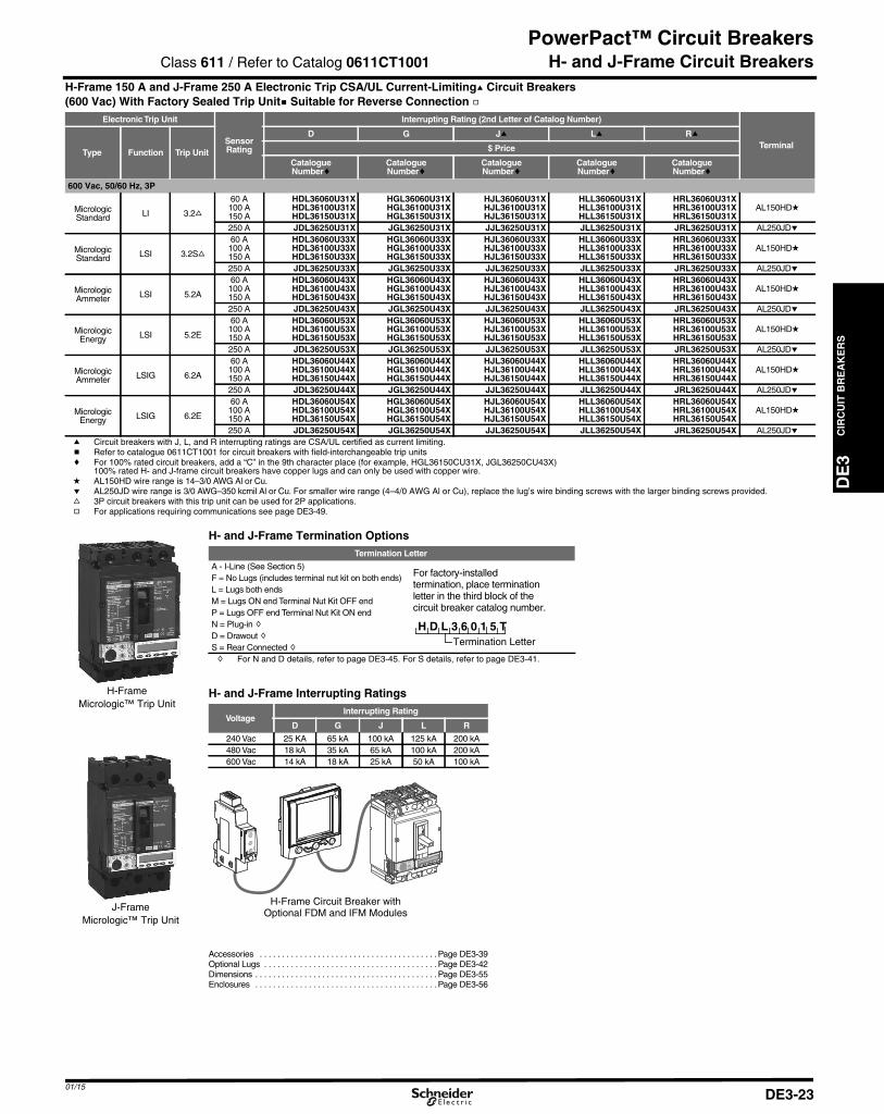
01/15
DE3_p023.fm Page 23 Saturday, January 10, 2015 2:25 AM
PowerPact™ Circuit Breakers
DE
3C
IRC
UIT
BR
EA
KE
RS
H- and J-Frame Circuit BreakersH-Frame 150 A and J-Frame 250 A Electronic Trip CSA/UL Current-Limitinga Circuit Breakers(600 Vac) With Factory Sealed Trip Unitb Suitable for Reverse Connection g
ElectronicTrip Unit
SensorRating
Interrupting Rating (2nd Letter of Catalog Number)
TerminalType Function Trip Unit
D G Ja La Ra
$ Price
CatalogueNumberc
CatalogueNumberc
CatalogueNumberc
CatalogueNumberc
CatalogueNumberc
600 Vac, 50/60 Hz, 3P
MicrologicStandard LI 3.2f
60 A100 A150 A
HDL36060U31XHDL36100U31XHDL36150U31X
HGL36060U31XHGL36100U31XHGL36150U31X
HJL36060U31XHJL36100U31XHJL36150U31X
HLL36060U31XHLL36100U31XHLL36150U31X
HRL36060U31XHRL36100U31XHRL36150U31X
AL150HDd
250 A JDL36250U31X JGL36250U31X JJL36250U31X JLL36250U31X JRL36250U31X AL250JDe
MicrologicStandard LSI 3.2Sf
60 A100 A150 A
HDL36060U33XHDL36100U33XHDL36150U33X
HGL36060U33XHGL36100U33XHGL36150U33X
HJL36060U33XHJL36100U33XHJL36150U33X
HLL36060U33XHLL36100U33XHLL36150U33X
HRL36060U33XHRL36100U33XHRL36150U33X
AL150HDd
250 A JDL36250U33X JGL36250U33X JJL36250U33X JLL36250U33X JRL36250U33X AL250JDe
MicrologicAmmeter LSI 5.2A
60 A100 A150 A
HDL36060U43XHDL36100U43XHDL36150U43X
HGL36060U43XHGL36100U43XHGL36150U43X
HJL36060U43XHJL36100U43XHJL36150U43X
HLL36060U43XHLL36100U43XHLL36150U43X
HRL36060U43XHRL36100U43XHRL36150U43X
AL150HDd
250 A JDL36250U43X JGL36250U43X JJL36250U43X JLL36250U43X JRL36250U43X AL250JDe
MicrologicEnergy LSI 5.2E
60 A100 A150 A
HDL36060U53XHDL36100U53XHDL36150U53X
HGL36060U53XHGL36100U53XHGL36150U53X
HJL36060U53XHJL36100U53XHJL36150U53X
HLL36060U53XHLL36100U53XHLL36150U53X
HRL36060U53XHRL36100U53XHRL36150U53X
AL150HDd
250 A JDL36250U53X JGL36250U53X JJL36250U53X JLL36250U53X JRL36250U53X AL250JDe
MicrologicAmmeter LSIG 6.2A
60 A100 A150 A
HDL36060U44XHDL36100U44XHDL36150U44X
HGL36060U44XHGL36100U44XHGL36150U44X
HJL36060U44XHJL36100U44XHJL36150U44X
HLL36060U44XHLL36100U44XHLL36150U44X
HRL36060U44XHRL36100U44XHRL36150U44X
AL150HDd
250 A JDL36250U44X JGL36250U44X JJL36250U44X JLL36250U44X JRL36250U44X AL250JDe
MicrologicEnergy LSIG 6.2E
60 A100 A150 A
HDL36060U54XHDL36100U54XHDL36150U54X
HGL36060U54XHGL36100U54XHGL36150U54X
HJL36060U54XHJL36100U54XHJL36150U54X
HLL36060U54XHLL36100U54XHLL36150U54X
HRL36060U54XHRL36100U54XHRL36150U54X
AL150HDd
250 A JDL36250U54X JGL36250U54X JJL36250U54X JLL36250U54X JRL36250U54X AL250JDea Circuit breakers with J, L, and R interrupting ratings are CSA/UL certified as current limiting.b Refer to catalogue 0611CT1001 for circuit breakers with field-interchangeable trip unitsc For 100% rated circuit breakers, add a “C” in the 9th character place (for example, HGL36150CU31X, JGL36250CU43X)
100% rated H- and J-frame circuit breakers have copper lugs and can only be used with copper wire.d AL150HD wire range is 14–3/0 AWG Al or Cu.e AL250JD wire range is 3/0 AWG–350 kcmil Al or Cu. For smaller wire range (4–4/0 AWG Al or Cu), replace the lug’s wire binding screws with the larger binding screws provided.f 3P circuit breakers with this trip unit can be used for 2P applications.g For applications requiring communications see page DE3-49.
H-FrameMicrologic™ Trip Unit
J-FrameMicrologic™ Trip Unit
H- and J-Frame Termination OptionsTermination Letter
A - I-Line (See Section 5)
H D L 3 6 0 1 5 T
For factory-installedtermination, place terminationletter in the third block of thecircuit breaker catalog number.
Termination Letter
F = No Lugs (includes terminal nut kit on both ends)L = Lugs both endsM = Lugs ON end Terminal Nut Kit OFF endP = Lugs OFF end Terminal Nut Kit ON endN = Plug-in hD = Drawout hS = Rear Connected hh For N and D details, refer to page DE3-45. For S details, refer to page DE3-41.
H- and J-Frame Interrupting Ratings
VoltageInterrupting Rating
D G J L R
240 Vac 25 KA 65 kA 100 kA 125 kA 200 kA480 Vac 18 kA 35 kA 65 kA 100 kA 200 kA600 Vac 14 kA 18 kA 25 kA 50 kA 100 kA
rci
Mci
gol
oE
2.5
rI%A03>
03>
011>
.9
29.
39.
49.
59.
1
89.
79.
69.
Ir)oIx(
5.1
2
5.2
34
01
8
65
dsI)rIx(
H-Frame Circuit Breaker withOptional FDM and IFM Modules
Accessories . . . . . . . . . . . . . . . . . . . . . . . . . . . . . . . . . . . . . . . . Page DE3-39Optional Lugs . . . . . . . . . . . . . . . . . . . . . . . . . . . . . . . . . . . . . . . Page DE3-42Dimensions . . . . . . . . . . . . . . . . . . . . . . . . . . . . . . . . . . . . . . . . . Page DE3-55Enclosures . . . . . . . . . . . . . . . . . . . . . . . . . . . . . . . . . . . . . . . . . Page DE3-56
Class 611 / Refer to Catalog 0611CT1001
DE3-23

CIR
CU
ITB
RE
AK
ER
S
DE3_p024.fm Page 24 Saturday, January 10, 2015 2:25 AM
PowerPact™ Circuit Breaker
DE3
Q-Frame Circuit Breakers
QBL 3P70–250 A
QBL 2P70–250 A
POWERPACT Q-framea—250 A,Thermal-magnetic Circuit Breaker (240 Vac)
AmpereRating
AC MagneticTrip Settings B Interrupting D Interrupting G Interrupting J Interrupting ✭
TerminalWireRange ■
Hold Trip CatalogueNumber
CatalogueNumber
CatalogueNumber
CatalogueNumber
2-pole, 240 Vac70 1000 1800 QBL22070 QDL22070 QGL22070 QJL22070
#4 AWG - 300 kcmilAl/Cu
80 1000 1800 QBL22080 QDL22080 QGL22080 QJL2208090 1000 1800 QBL22090 QDL22090 QGL22090 QJL22090
100 1200 2400 QBL22100 QDL22100 QGL22100 QJL22100110 1200 2400 QBL22110 QDL22110 QGL22110 QJL22110125 1200 2400 QBL22125 QDL22125 QGL22125 QJL22125150 1200 2400 QBL22150 QDL22150 QGL22150 QJL22150175 1200 2400 QBL22175 QDL22175 QGL22175 QJL22175200 1200 2400 QBL22200 QDL22200 QGL22200 QJL22200225 1200 2400 QBL22225 QDL22225 QGL22225 QJL22225250 1200 2400 QBL22250■ QDL22250■ QGL22250■ QJL22250■
3-pole, 240 Vac70 1000 1800 QBL32070 QDL32070 QGL32070 QJL32070
#4 AWG - 300 kcmilAl/Cu
80 1000 1800 QBL32080 QDL32080 QGL32080 QJL3208090 1000 1800 QBL32090 QDL32090 QGL32090 QJL32090
100 1200 2400 QBL32100 QDL32100 QGL32100 QJL32100110 1200 2400 QBL32110 QDL32110 QGL32110 QJL32110125 1200 2400 QBL32125 QDL32125 QGL32125 QJL32125150 1200 2400 QBL32150 QDL32150 QGL32150 QJL32150175 1200 2400 QBL32175 QDL32175 QGL32175 QJL32175200 1200 2400 QBL32200 QDL32200 QGL32200 QJL32200225 1200 2400 QBL32225 QDL32225 QGL32225 QJL32225250 1200 2400 QBL32250■ QDL32250■ QGL32250■ QJL32250■
▲ Replacement lugs and electrical accessories are not available for POWERPACT Q-frame circuit breakers.■ 250 A lugs are suitable for copper conductors only.– Refer to Catalogue 0734CT0201 for details.
Q-Frame Termination OptionsTermination Letter
A = I-Line (See Section 5)
Q G L 3 2 2 0 0
For factory-installed termination,place termination letter in thethird block of the circuit breakercatalog number.
Termination Letter
E = Bolt-on I-Line (See Section 5)F = No lugsL = Lugs both endsM = Lugs ON end, studs on OFF end
P = Lugs OFF end, studs on ON end
– Add TS suffix for studs on both ends without nuts and washers. See Catalogue0734CT0201 for additional information.
Q-Frame Interrupting Ratings (kA)
Voltage QB QD QG QJ
240 V 10 25 65 100✭
480 V . . . . . . . . . . . .
600 V . . . . . . . . . . . .
✭ 3-pole QJ circuit breakers are rated at 208Y/120 Vac only.
Dimensions DE3-55Enclosures DE3-56
Class 0734 / Refer to Catalogs: 0734CT0201
01/15DE3-24
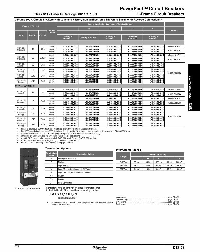
01/15
DE3_p025.fm Page 25 Saturday, January 10, 2015 2:26 AM
PowerPact™ Circuit Breakers
DE
3C
IRC
UIT
BR
EA
KE
RS
L-Frame Circuit BreakersL-Frame 600 A Circuit Breakers with Lugs and Factory-Sealed Electronic Trip Units Suitable for Reverse Connectionfl
ElectronicTrip Unit
SensorRating
Interrupting Rating (2nd Letter of Catalog Number)
D G J h L h R hTerminal
Type Function Trip Unit CatalogueNumber g Catalogue Numberg Catalogue
Number gCatalogueNumber g
CatalogueNumber g
600 Vac, 50/60 Hz, 3P
MicrologicStandard LI 3.3i
250 A LDL36250U31X LGL36250U31X LJL36250U31X LLL36250U31X LRL36250U31X AL400L61K3j
400 A600 A
LDL36400U31XLDL36600U31X
LGL36400U31XLGL36600U31X
LJL36400U31XLJL36600U31X
LLL36400U31XLLL36600U31X
LRL36400U31XLRL36600U31X AL600LS52K3k
MicrologicStandard LSI 3.3Si
250 A LDL36250U33X LGL36250U33X LJL36250U33X LLL36250U33X LRL36250U33X AL400L61K3j
400 A600 A
LDL36400U33XLDL36600U33X
LGL36400U33XLGL36600U33X
LJL36400U33XLJL36600U33X
LLL36400U33XLLL36600U33X
LRL36400U33XLRL36600U33X AL600LS52K3k
MicrologicAmmeter LSI 5.3A 400 A
600 ALDL36400U43XLDL36600U43X
LGL36400U43XLGL36600U43X
LJL36400U43XLJL36600U43X
LLL36400U43XLLL36600U43X
LRL36400U43XLRL36600U43X
AL600LS52K3k
MicrologicEnergy LSI 5.3E 400 A
600 ALDL36400U53XLDL36600U53X
LGL36400U53XLGL36600U53X
LJL36400U53XLJL36600U53X
LLL36400U53XLLL36600U53X
LRL36400U53XLRL36600U53X
MicrologicAmmeter LSIG 6.3A 400 A
600 ALDL36400U44XLDL36600U44X
LGL36400U44XLGL36600U44X
LJL36400U44XLJL36600U44X
LLL36400U44XLLL36600U44X
LRL36400U44XLRL36600U44X
MicrologicEnergy LSIG 6.3E 400 A
600 ALDL36400U54XLDL36600U54X
LGL36400U54XLGL36600U54X
LJL36400U54XLJL36600U54X
LLL36400U54XLLL36600U54X
LRL36400U54XLRL36600U54X
600 Vac, 50/60 Hz, 4P
MicrologicStandard LI 3.3
250 A LDL46250U31X LGL46250U31X LJL46250U31X LLL46250U31X LRL46250U31X AL400L61K4j
400 A600 A
LDL46400U31XLDL46600U31X
LGL46400U31XLGL46600U31X
LJL46400U31XLJL46600U31X
LLL46400U31XLLL46600U31X
LRL46400U31XLRL46600U31X AL600LS52K4k
MicrologicStandard LSI 3.3S
250 A LDL46250U33X LGL46250U33X LJL46250U33X LLL46250U33X LRL46250U33X AL400L61K4j
400 A600 A
LDL46400U33XLDL46600U33X
LGL46400U33XLGL46600U33X
LJL46400U33XLJL46600U33X
LLL46400U33XLLL46600U33X
LRL46400U33XLRL46600U33X AL600LS52K4k
MicrologicAmmeter LSI 5.3A 400 A
600 ALDL46400U43XLDL46600U43X
LGL46400U43XLGL46600U43X
LJL46400U43XLJL46600U43X
LLL46400U43XLLL46600U43X
LRL46400U43XLRL46600U43X
AL600LS52K4k
MicrologicEnergy LSI 5.3E 400 A
600 ALDL46400U53XLDL46600U53X
LGL46400U53XLGL46600U53X
LJL46400U53XLJL46600U53X
LLL46400U53XLLL46600U53X
LRL46400U53XLRL46600U53X
MicrologicAmmeter LSIG 6.3A 400 A
600 ALDL46400U44XLDL46600U44X
LGL46400U44XLGL46600U44X
LJL46400U44XLJL46600U44X
LLL46400U44XLLL46600U44X
LRL46400U44XLRL46600U44X
MicrologicEnergy LSIG 6.3E 400 A
600 ALDL46400U54XLDL46600U54X
LGL46400U54XLGL46600U54X
LJL46400U54XLJL46600U54X
LLL46400U54XLLL46600U54X
LRL46400U54XLRL46600U54X
f Refer to catalogue 0611CT1001 for circuit breakers with field-interchangeable trip unitsg For 100% rated circuit breakers (250 A and 400 A only), add a “C” in the 9th character place (for example, LGL36400CU31X)h Circuit breakers with J, L, and R interrupting ratings are CSA/UL certified as current limiting.i 3P circuit breakers with this trip unit can be used for 2P applications.j AL400L61K3 terminal wire ranges are (1) 2 AWG–600 kcmil Cu or 1) 2 AWG–500 kcmil Al.k AL600LS52K3 terminal wire range is (2) 2/0 AWG–500 kcmil Al/Cu.l For applications requiring communicatins see page DE3-49.
L-Frame Circuit Breaker
Termination Options
TerminationLetter Termination Option
A I-Line (See Section 5)
F No lugs
L Lugs both ends
M Lugs ON end, terminal nut kit OFF end
P Lugs OFF end, terminal nut kit ON end
Nm Plug In
Dm Drawout
Sm Rear Connected
For factory-installed termination, place termination letterin the third block of the circuit breaker catalog number.
Termination Letter
L G L 3 6 6 0 0 U 4 4 X
m For N and D details, please refer to page DE3-45. For S details, pleaserefer to page DE3-41.
Interrupting Ratings
VoltageInterrupting Rating
D G J L R
240 Vac 25 kA 65 kA 100 kA 125 kA 200 kA
480 Vac 18 kA 35 kA 65 kA 100 kA 200 kA
600 Vac 14 kA 18 kA 25 kA 50 kA 100 kA
Accessories . . . . . . . . . . . . . . . . . . . . . . . . . . . . . . . . . . . . . . . . page DE3-39Optional Lugs . . . . . . . . . . . . . . . . . . . . . . . . . . . . . . . . . . . . . . . page DE3-42Dimensions . . . . . . . . . . . . . . . . . . . . . . . . . . . . . . . . . . . . . . . . . page DE3-55Enclosures. . . . . . . . . . . . . . . . . . . . . . . . . . . . . . . . . . . . . . . . . . page DE3-56
Class 611 / Refer to Catalogs: 0611CT1001
DE3-25
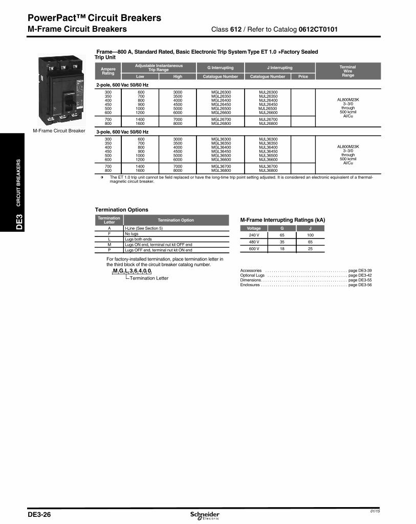
CIR
CU
ITB
RE
AK
ER
S
DE3_p026.fm Page 26 Saturday, January 10, 2015 2:26 AM
PowerPact™ Circuit Breakers
DE3
M-Frame Circuit Breakers
Frame—800 A, Standard Rated, Basic ElectronicTrip SystemType ET 1.0 nFactory SealedTrip Unit
AmpereRating
Adjustable InstantaneousTrip Range G Interrupting J Interrupting Terminal
WireRangeLow High Catalogue Number Catalogue Number Price
2-pole, 600 Vac 50/60 Hz300 600 3000 MGL26300 MJL26300
AL800M23K3–3/0
through500 kcmil
Al/Cu
350 700 3500 MGL26350 MJL26350400 800 4000 MGL26400 MJL26400450 900 4500 MGL26450 MJL26450500 1000 5000 MGL26500 MJL26500600 1200 6000 MGL26600 MJL26600
700 1400 7000 MGL26700 MJL26700800 1600 8000 MGL26800 MJL26800
3-pole, 600 Vac 50/60 Hz300 600 3000 MGL36300 MJL36300
AL800M23K3–3/0
through500 kcmil
Al/Cu
350 700 3500 MGL36350 MJL36350400 800 4000 MGL36400 MJL36400450 900 4500 MGL36450 MJL36450500 1000 5000 MGL36500 MJL36500600 1200 6000 MGL36600 MJL36600
700 1400 7000 MGL36700 MJL36700800 1600 8000 MGL36800 MJL36800
n The ET 1.0 trip unit cannot be field replaced or have the long-time trip point setting adjusted. It is considered an electronic equivalent of a thermal-magnetic circuit breaker.
M-Frame Circuit Breaker
Termination OptionsTermination
Letter Termination Option
A I-Line (See Section 5)F No lugsL Lugs both endsM Lugs ON end, terminal nut kit OFF endP Lugs OFF end, terminal nut kit ON end
M G L 3 6 4 0 0
For factory-installed termination, place termination letter inthe third block of the circuit breaker catalog number.
Termination Letter
M-Frame Interrupting Ratings (kA)Voltage G J
240 V 65 100
480 V 35 65
600 V 18 25
Accessories . . . . . . . . . . . . . . . . . . . . . . . . . . . . . . . . . . . . . . . page DE3-39Optional Lugs . . . . . . . . . . . . . . . . . . . . . . . . . . . . . . . . . . . . . . page DE3-42Dimensions. . . . . . . . . . . . . . . . . . . . . . . . . . . . . . . . . . . . . . . . . page DE3-55Enclosures . . . . . . . . . . . . . . . . . . . . . . . . . . . . . . . . . . . . . . . . . page DE3-56
Class 612 / Refer to Catalog 0612CT0101
01/15DE3-26

01/15
DE3_p027.fm Page 27 Saturday, January 10, 2015 2:26 AM
PowerPact™ Circuit Breakers
DE
3C
IRC
UIT
BR
EA
KE
RS
P-Frame Circuit Breakers
a For 2P and 4P information see Catalog 0612CT0101.b For 100% rated circuit breakers add a “C” in the 9th character place. For example, the catalog number for a 100% trip unit with LI trip functions at 250A would be PGL36025CU31A. 100%
ratings are not available for circuit breakers with ET1.0 Trip Units.c P-frame L-interrupting is available in 480 Vac only.
P-Frame Termination Options P-Frame and R-Frame Interrupting RatingsTermination Letter
VoltageP-Frame Interrupting Rating R-Frame Interrupting Rating
F = No Lugs (Includes terminal nut kit on both ends)
P G L 3 6 0 4 0 U 4 1 A
For factory-installed termination, placetermination letter in the third block ofthe circuit breaker catalog number.
Termination Letter
G J K L G J K L
L = Lugs both ends 240 Vac 65 kA 100 kA 65 kA 125 kA 65 kA 100 kA 65 kA 125 kAM = Lugs ON end, terminal nut kit OFF end 480 Vac 35 kA 65 kA 50 kA 100 kA 35 kA 65 kA 65 kA 100 kAP = Lugs OFF end, terminal nut kit ON end 600 Vac 18 kA 25 kA 50 kA 18 kA 25 kA 65 kA 50 kAD = DrawoutA = I-Line (See Section 5)
R-frame catalog numbers . . . . . . . . . . . . . . . . . . . . . . . . . . . . . . Page DE3-28Dimensions . . . . . . . . . . . . . . . . . . . . . . . . . . . . . . . . . . . . . . . . . Page DE3-55Trip Unit Options . . . . . . . . . . . . . . . . . . . . . . . . . . . . . . . . . . . . . Page DE3-47Optional Lugs . . . . . . . . . . . . . . . . . . . . . . . . . . . . . . . . . . . . . . . Page DE3-42Alternate Rating Plugs . . . . . . . . . . . . . . . . . . . . . . . . . . . . . . . . Page DE3-48Enclosure . . . . . . . . . . . . . . . . . . . . . . . . . . . . . . . . . . . . . . . . . . Page DE3-56Accessories . . . . . . . . . . . . . . . . . . . . . . . . . . . . . . . . . . . . . . . . . Page DE3-39
P Frame - 1200A, (600 Vac, 50/60 Hz) 3P a Circuit Breaker with Electronic Trip UnitElectronicTrip Unit Sensor
Rating
G Interrupting J Interrupting L Interrupting c K InterruptingTerminal
Wire RangeType Function Trip Unit CatalogueNumber.b
CatalogueNumber b
CatalogueNumber b Price
CatalogueNumber b
Basic ElectronicTrip Unit(NotInterchangeable)
Fixed long-time,Adjustable
InstantaneousET1.0I
600 A PGL36060 PJL36060 PLL34060 PKL36060 AL800M23K(3) 3/0 AWG–500 kcmil Al or Cu800 A PGL36080 PJL36080 PLL34080 PKL36080
1000 A PGL36100 PJL36100 PLL34100 PKL36100 AL1200P25K(4) 3/0 AWG–500 kcmil Al or Cu1200 A PGL36120 PJL36120 PLL34120 PKL36120
MicrologicInterchangeableStandardTrip Unit
LI 3.0
250 PGL36025U31A PJL36025U31A PLL34025U31A PKL36025U31A
AL800M23K(3) 3/0 AWG–500 kcmil Al or Cu
400 PGL36040U31A PJL36040U31A PLL34040U31A PKL36040U31A600 PGL36060U31A PJL36060U31A PLL34060U31A PKL36060U31A800 PGL36080U31A PJL36080U31A PLL34080U31A PKL36080U31A1000 PGL36100U31A PJL36100U31A PLL34100U31A PKL36100U31A AL1200P25K
(4) 3/0 AWG–500 kcmil Al or Cu1200 PGL36120U31A PJL36120U31A PLL34120U31A PKL36120U31A
LSI 5.0
250 PGL36025U33A PJL36025U33A PLL34025U33A PKL36025U33A
AL800M23K(3) 3/0 AWG–500 kcmil Al or Cu
400 PGL36040U33A PJL36040U33A PLL34040U33A PKL36040U33A600 PGL36060U33A PJL36060U33A PLL34060U33A PKL36060U33A800 PGL36080U33A PJL36080U33A PLL34080U33A PKL36080U33A1000 PGL36100U33A PJL36100U33A PLL34100U33A PKL36100U33A AL1200P25K
(4) 3/0 AWG–500 kcmil Al or Cu1200 PGL36120U33A PJL36120U33A PLL34120U33A PKL36120U33A
MicrologicInterchangeableAmmeterTrip Unit
LI 3.0A
250 PGL36025U41A PJL36025U41A PLL34025U41A PKL36025U41A
AL800M23K(3) 3/0 AWG–500 kcmil Al or Cu
400 PGL36040U41A PJL36040U41A PLL34040U41A PKL36040U41A600 PGL36060U41A PJL36060U41A PLL34060U41A PKL36060U41A800 PGL36080U41A PJL36080U41A PLL34080U41A PKL36080U41A1000 PGL36100U41A PJL36100U41A PLL34100U41A PKL36100U41A AL1200P25K
(4) 3/0 AWG–500 kcmil Al or Cu1200 PGL36120U41A PJL36120U41A PLL34120U41A PKL36120U41A
LSI 5.0A
250 PGL36025U43A PJL36025U43A PLL34025U43A PKL36025U43A
AL800M23K(3) 3/0 AWG–500 kcmil Al or Cu
400 PGL36040U43A PJL36040U43A PLL34040U43A PKL36040U43A600 PGL36060U43A PJL36060U43A PLL34060U43A PKL36060U43A800 PGL36080U43A PJL36080U43A PLL34080U43A PKL36080U43A1000 PGL36100U43A PJL36100U43A PLL34100U43A PKL36100U43A AL1200P25K
(4) 3/0 AWG–500 kcmil Al or Cu1200 PGL36120U43A PJL36120U43A PLL34120U43A PKL36120U43A
LSIG 6.0A
250 PGL36025U44A PJL36025U44A PLL34025U44A PKL36025U44A
AL800M23K(3) 3/0 AWG–500 kcmil Al or Cu
400 PGL36040U44A PJL36040U44A PLL34040U44A PKL36040U44A600 PGL36060U44A PJL36060U44A PLL34060U44A PKL36060U44A800 PGL36080U44A PJL36080U44A PLL34080U44A PKL36080U44A1000 PGL36100U44A PJL36100U44A PLL34100U44A PKL36100U44A AL1200P25K
(4) 3/0 AWG–500 kcmil Al or Cu1200 PGL36120U44A PJL36120U44A PLL34120U44A PKL36120U44A
MicrologicInterchangeablePowerTrip Unit
LSI 5.0P
250 PGL36025U63AE1 PJL36025U63AE1 PLL34025U63AE1 PKL36025U63AE1
AL800M23K(3) 3/0 AWG–500 kcmil Al or Cu
400 PGL36040U63AE1 PJL36040U63AE1 PLL34040U63AE1 PKL36040U63AE1600 PGL36060U63AE1 PJL36060U63AE1 PLL34060U63AE1 PKL36060U63AE1800 PGL36080U63AE1 PJL36080U63AE1 PLL34080U63AE1 PKL36080U63AE1
1000 PGL36100U63AE1 PJL36100U63AE1 PLL34100U63AE1 PKL36100U63AE1 AL1200P25K(4) 3/0 AWG–500 kcmil Al or Cu1200 PGL36120U63AE1 PJL36120U63AE1 PLL34120U63AE1 PKL36120U63AE1
LSIG 6.0P
250 PGL36025U64AE1 PJL36025U64AE1 PLL34025U64AE1 PKL36025U64AE1
AL800M23K(3) 3/0 AWG–500 kcmil Al or Cu
400 PGL36040U64AE1 PJL36040U64AE1 PLL34040U64AE1 PKL36040U64AE1600 PGL36060U64AE1 PJL36060U64AE1 PLL34060U64AE1 PKL36060U64AE1800 PGL36080U64AE1 PJL36080U64AE1 PLL34080U64AE1 PKL36080U64AE1
1000 PGL36100U64AE1 PJL36100U64AE1 PLL34100U64AE1 PKL36100U64AE1 AL1200P25K(4) 3/0 AWG–500 kcmil Al or Cu1200 PGL36120U64AE1 PJL36120U64AE1 PLL34120U64AE1 PKL36120U64AE1
MicrologicInterchangeableHarmonicTrip Unit
LSI 5.0H
250 PGL36025U73AE1 PJL36025U73AE1 PLL34025U73AE1 PKL36025U73AE1
AL800M23K(3) 3/0 AWG–500 kcmil Al or Cu
400 PGL36040U73AE1 PJL36040U73AE1 PLL34040U73AE1 PKL36040U73AE1600 PGL36060U73AE1 PJL36060U73AE1 PLL34060U73AE1 PKL36060U73AE1800 PGL36080U73AE1 PJL36080U73AE1 PLL34080U73AE1 PKL36080U73AE1
1000 PGL36100U73AE1 PJL36100U73AE1 PLL34100U73AE1 PKL36100U73AE1 AL1200P25K(4) 3/0 AWG–500 kcmil Al or Cu1200 PGL36120U73AE1 PJL36120U73AE1 PLL34120U73AE1 PKL36120U73AE1
LSIG 6.0H
250 PGL36025U74AE1 PJL36025U74AE1 PLL34025U74AE1 PKL36025U74AE1
AL800M23K(3) 3/0 AWG–500 kcmil Al or Cu
400 PGL36040U74AE1 PJL36040U74AE1 PLL34040U74AE1 PKL36040U74AE1600 PGL36060U74AE1 PJL36060U74AE1 PLL34060U74AE1 PKL36060U74AE1800 PGL36080U74AE1 PJL36080U74AE1 PLL34080U74AE1 PKL36080U74AE1
1000 PGL36100U74AE1 PJL36100U74AE1 PLL34100U74AE1 PKL36100U74AE1 AL1200P25K(4) 3/0 AWG–500 kcmil Al or Cu1200 PGL36120U74AE1 PJL36120U74AE1 PLL34120U74AE1 PKL36120U74AE1
Class 612 / Refer to Catalog 0612CT0101
DE3-27
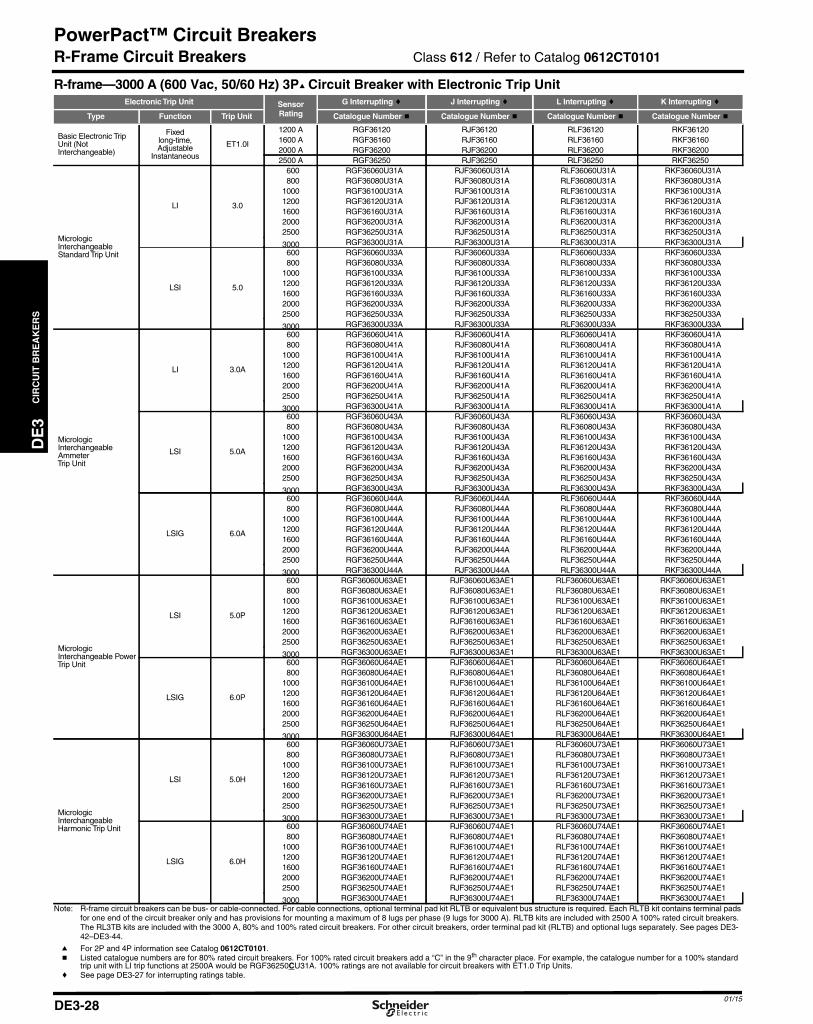
CIR
CU
ITB
RE
AK
ER
S
DE3_p028.fm Page 28 Saturday, January 10, 2015 2:27 AM
PowerPact™ Circuit Breakers
DE3
R-Frame Circuit Breakers
R-frame—3000 A (600 Vac, 50/60 Hz) 3Pa Circuit Breaker with Electronic Trip UnitElectronicTrip Unit Sensor
Rating
G Interrupting c J Interrupting c L Interrupting c K Interrupting c
Type Function Trip Unit Catalogue Number b Catalogue Number b Catalogue Number b Catalogue Number b
Basic Electronic TripUnit (NotInterchangeable)
Fixedlong-time,Adjustable
Instantaneous
ET1.0I
1200 A RGF36120 RJF36120 RLF36120 RKF361201600 A RGF36160 RJF36160 RLF36160 RKF361602000 A RGF36200 RJF36200 RLF36200 RKF362002500 A RGF36250 RJF36250 RLF36250 RKF36250
MicrologicInterchangeableStandard Trip Unit
LI 3.0
600 RGF36060U31A RJF36060U31A RLF36060U31A RKF36060U31A800 RGF36080U31A RJF36080U31A RLF36080U31A RKF36080U31A
1000 RGF36100U31A RJF36100U31A RLF36100U31A RKF36100U31A1200 RGF36120U31A RJF36120U31A RLF36120U31A RKF36120U31A1600 RGF36160U31A RJF36160U31A RLF36160U31A RKF36160U31A2000 RGF36200U31A RJF36200U31A RLF36200U31A RKF36200U31A2500 RGF36250U31A RJF36250U31A RLF36250U31A RKF36250U31A
LSI 5.0
600 RGF36060U33A RJF36060U33A RLF36060U33A RKF36060U33A800 RGF36080U33A RJF36080U33A RLF36080U33A RKF36080U33A
1000 RGF36100U33A RJF36100U33A RLF36100U33A RKF36100U33A1200 RGF36120U33A RJF36120U33A RLF36120U33A RKF36120U33A1600 RGF36160U33A RJF36160U33A RLF36160U33A RKF36160U33A2000 RGF36200U33A RJF36200U33A RLF36200U33A RKF36200U33A2500 RGF36250U33A RJF36250U33A RLF36250U33A RKF36250U33A
MicrologicInterchangeableAmmeterTrip Unit
LI 3.0A
600 RGF36060U41A RJF36060U41A RLF36060U41A RKF36060U41A800 RGF36080U41A RJF36080U41A RLF36080U41A RKF36080U41A
1000 RGF36100U41A RJF36100U41A RLF36100U41A RKF36100U41A1200 RGF36120U41A RJF36120U41A RLF36120U41A RKF36120U41A1600 RGF36160U41A RJF36160U41A RLF36160U41A RKF36160U41A2000 RGF36200U41A RJF36200U41A RLF36200U41A RKF36200U41A2500 RGF36250U41A RJF36250U41A RLF36250U41A RKF36250U41A
LSI 5.0A
600 RGF36060U43A RJF36060U43A RLF36060U43A RKF36060U43A800 RGF36080U43A RJF36080U43A RLF36080U43A RKF36080U43A
1000 RGF36100U43A RJF36100U43A RLF36100U43A RKF36100U43A1200 RGF36120U43A RJF36120U43A RLF36120U43A RKF36120U43A1600 RGF36160U43A RJF36160U43A RLF36160U43A RKF36160U43A2000 RGF36200U43A RJF36200U43A RLF36200U43A RKF36200U43A2500 RGF36250U43A RJF36250U43A RLF36250U43A RKF36250U43A
LSIG 6.0A
600 RGF36060U44A RJF36060U44A RLF36060U44A RKF36060U44A800 RGF36080U44A RJF36080U44A RLF36080U44A RKF36080U44A
1000 RGF36100U44A RJF36100U44A RLF36100U44A RKF36100U44A1200 RGF36120U44A RJF36120U44A RLF36120U44A RKF36120U44A1600 RGF36160U44A RJF36160U44A RLF36160U44A RKF36160U44A2000 RGF36200U44A RJF36200U44A RLF36200U44A RKF36200U44A2500 RGF36250U44A RJF36250U44A RLF36250U44A RKF36250U44A
MicrologicInterchangeable PowerTrip Unit
LSI 5.0P
600 RGF36060U63AE1 RJF36060U63AE1 RLF36060U63AE1 RKF36060U63AE1800 RGF36080U63AE1 RJF36080U63AE1 RLF36080U63AE1 RKF36080U63AE1
1000 RGF36100U63AE1 RJF36100U63AE1 RLF36100U63AE1 RKF36100U63AE11200 RGF36120U63AE1 RJF36120U63AE1 RLF36120U63AE1 RKF36120U63AE11600 RGF36160U63AE1 RJF36160U63AE1 RLF36160U63AE1 RKF36160U63AE12000 RGF36200U63AE1 RJF36200U63AE1 RLF36200U63AE1 RKF36200U63AE12500 RGF36250U63AE1 RJF36250U63AE1 RLF36250U63AE1 RKF36250U63AE1
LSIG 6.0P
600 RGF36060U64AE1 RJF36060U64AE1 RLF36060U64AE1 RKF36060U64AE1800 RGF36080U64AE1 RJF36080U64AE1 RLF36080U64AE1 RKF36080U64AE1
1000 RGF36100U64AE1 RJF36100U64AE1 RLF36100U64AE1 RKF36100U64AE11200 RGF36120U64AE1 RJF36120U64AE1 RLF36120U64AE1 RKF36120U64AE11600 RGF36160U64AE1 RJF36160U64AE1 RLF36160U64AE1 RKF36160U64AE12000 RGF36200U64AE1 RJF36200U64AE1 RLF36200U64AE1 RKF36200U64AE12500 RGF36250U64AE1 RJF36250U64AE1 RLF36250U64AE1 RKF36250U64AE1
MicrologicInterchangeableHarmonic Trip Unit
LSI 5.0H
600 RGF36060U73AE1 RJF36060U73AE1 RLF36060U73AE1 RKF36060U73AE1800 RGF36080U73AE1 RJF36080U73AE1 RLF36080U73AE1 RKF36080U73AE1
1000 RGF36100U73AE1 RJF36100U73AE1 RLF36100U73AE1 RKF36100U73AE11200 RGF36120U73AE1 RJF36120U73AE1 RLF36120U73AE1 RKF36120U73AE11600 RGF36160U73AE1 RJF36160U73AE1 RLF36160U73AE1 RKF36160U73AE12000 RGF36200U73AE1 RJF36200U73AE1 RLF36200U73AE1 RKF36200U73AE12500 RGF36250U73AE1 RJF36250U73AE1 RLF36250U73AE1 RKF36250U73AE1
LSIG 6.0H
600 RGF36060U74AE1 RJF36060U74AE1 RLF36060U74AE1 RKF36060U74AE1800 RGF36080U74AE1 RJF36080U74AE1 RLF36080U74AE1 RKF36080U74AE1
1000 RGF36100U74AE1 RJF36100U74AE1 RLF36100U74AE1 RKF36100U74AE11200 RGF36120U74AE1 RJF36120U74AE1 RLF36120U74AE1 RKF36120U74AE11600 RGF36160U74AE1 RJF36160U74AE1 RLF36160U74AE1 RKF36160U74AE12000 RGF36200U74AE1 RJF36200U74AE1 RLF36200U74AE1 RKF36200U74AE12500 RGF36250U74AE1 RJF36250U74AE1 RLF36250U74AE1 RKF36250U74AE1
Note: R-frame circuit breakers can be bus- or cable-connected. For cable connections, optional terminal pad kit RLTB or equivalent bus structure is required. Each RLTB kit contains terminal padsfor one end of the circuit breaker only and has provisions for mounting a maximum of 8 lugs per phase (9 lugs for 3000 A). RLTB kits are included with 2500 A 100% rated circuit breakers.The RL3TB kits are included with the 3000 A, 80% and 100% rated circuit breakers. For other circuit breakers, order terminal pad kit (RLTB) and optional lugs separately. See pages DE3-42–DE3-44.
a For 2P and 4P information see Catalog 0612CT0101.b Listed catalogue numbers are for 80% rated circuit breakers. For 100% rated circuit breakers add a “C” in the 9th character place. For example, the catalogue number for a 100% standard
trip unit with LI trip functions at 2500A would be RGF36250CU31A. 100% ratings are not available for circuit breakers with ET1.0 Trip Units.c See page DE3-27 for interrupting ratings table.
3000 RGF36300U31A RJF36300U31A RLF36300U31A RKF36300U31A
3000 RGF36300U33A RJF36300U33A RLF36300U33A RKF36300U33A
3000 RGF36300U41A RJF36300U41A RLF36300U41A RKF36300U41A
3000 RGF36300U43A RJF36300U43A RLF36300U43A RKF36300U43A
3000 RGF36300U44A RJF36300U44A RLF36300U44A RKF36300U44A
3000 RGF36300U63AE1 RJF36300U63AE1 RLF36300U63AE1 RKF36300U63AE1
3000 RGF36300U64AE1 RJF36300U64AE1 RLF36300U64AE1 RKF36300U64AE1
3000 RGF36300U73AE1 RJF36300U73AE1 RLF36300U73AE1 RKF36300U73AE1
3000 RGF36300U74AE1 RJF36300U74AE1 RLF36300U74AE1 RKF36300U74AE1
Class 612 / Refer to Catalog 0612CT0101
01/15DE3-28

DE3_p029.fm Page 29 Saturday, January 10, 2015 2:27 AM
Motor Circuit Protectors and Motor Protector Circuit Breakers
DE
3C
IRC
UIT
BR
EA
KE
RS
PowerPact™ H- and J-Frame
Standard
Energy EfficientEnergie EfficaceEnergia Eficiente
Standard
Energy Efficient
Energie Efficace
Energia Eficiente
I
t
Standard
Energy EfficientEnergie Efficace
Motor Type / Tipo de Motor / Type de Moteur
Energia Eficiente
PowerPact H- and J-frame electronic Motor Circuit Protectors (MCP) are magnetic-onlyinstantaneous-trip circuit breakers. They are designed to offer short circuit protection andare Canadian Electrical Code (CEC) and National Electrical Code (NEC) compliant wheninstalled as part of a combination controller having motor overload protection. MCP circuitbreakers accept the same accessories and terminals as the equivalent thermal-magneticcircuit breakers.
Determine the hp rating from the nameplate of the motor. Select a MCP with an ampererating recommended for the hp and voltage involved. When using the automatic settings theMCP microprocessor automatically adjusts the trip settings for both current and time toalign with the start-up characteristic for the motor type, whether it is a standard or energy-efficient motor. This includes a dampening means to accommodate a transient motor in-rush current without nuisance tripping of the circuit breaker.
H- and J-frame Electronic Motor Circuit Protectors (MCP)
Frame Current Full LoadAmperes Range
AdjustableInstantaneousTrip
RangeSuffix
J Interrupting(See SCCRTable
Below)
L Interrupting(See SCCRTable
Below)
Cat. No. Cat. No.
H-frame
30 A 1.5–25 A 9–325 A M71 HJL36030M71 HLL36030M7150 A 14–42 A 84–546 A M72 HJL36050M72 HLL36050M72100 A 30–80 A 180–1040 A M73 HJL36100M73 HLL36100M73150 A 58–130 A 348–1690 A M74 HJL36150M74 HLL36150M74
J-frame 250 A 114–217 A 684–2500 A M75 JJL36250M75 JLL36250M75
Maximum Rating or Setting of Motor Protective Devices▲
Type of MotorPercentage of Full-load Current
Setting Not to Exceed ■
A, B, C, D Standard 800% 1300%
B, E Energy Efficient 1100% 1700%
▲ Based on 2005 NEC Table 430.52.■ See NEC Exception No. 1 to Table 430.52. The NEC 1300% maximum setting may be inadequate for instantaneous
trip circuit breakers to withstand current surges typical of the magnetization current of autotransformer type reducedvoltage starters, or open transition wye-delta starters during transfer from “start” to “run,” constant hp multi-speedmotors, and motors labeled “high efficiency.”
MCP Selection by HP Ratings◆ of Induction-type Squirrel-Cage andWound-rotor Motors★
3Ø 60 Hz Voltages▼Full-Load Amperes Suffix
200 Vac 230 Vac 460 Vac 575 Vac
.5–5 .5–7.5 .75–15 1–20 1.5–25 M71
5–10 5–15 10–30 15–40 14–42 M72
10–25 15–30 25–60 30–75 30–80 M73
20–40 25–50 50–100 60–125 58–130 M74
40–60 50–75 100–150 125–200 114–217 M75
◆ Based on 2005 NEC Table 430.250.★ Per NEC 430.3, part-winding motors should select two circuit breakers, each at not more than one-half the allowable
trip setting for the horsepower rating. The two circuit breakers should operate simultaneously as a disconnectingmeans per NEC 430.103.
▼ Listed voltages are rated motor voltages. Corresponding system voltages are 200 Vac, 220–240 Vac, 440–480 Vacand 550–600 Vac. Select wire and circuit breakers based on horsepower rather than nameplate full-load current perNEC 430.6 (A) for general motor applications.
Short Circuit Current Rating (SCCR)Tested to meet NEC and UL508A requirements for short circuit current ratings as part of anapproved combination controller.
Short Circuit Current Ratings (SCCR)
Contactor/StarterJ Interrupting L Interrupting
200–240 Vac 480 Vac 600 Vac 200–240 Vac 480 Vac 600 Vac
Tesys D-line and F-line 100 kA 65 kA 25 kA 125 kA 100 kA 50 kA
NEMA Type S 100 kA 65 kA 25 kA 125 kA 100 kA 50 kA
Accessories. . . . . . . . . . . . . . . . . . . . . . . . . . . . . . . . . . . . . . . . . Page DE3-39Optional Lugs . . . . . . . . . . . . . . . . . . . . . . . . . . . . . . . . . . . . . . . Page DE3-42Dimensions . . . . . . . . . . . . . . . . . . . . . . . . . . . . . . . . . . . . . . . . . Page DE3-55Enclosures. . . . . . . . . . . . . . . . . . . . . . . . . . . . . . . . . . . . . . . . . . Page DE3-56
Class 611 / Refer to Catalog 0611CT1001
01/15DE3-29

CIR
CU
ITB
RE
AK
ER
S
DE3_p030.fm Page 30 Saturday, January 10, 2015 2:28 AM
Motor Circuit Protectors and Motor Protector Circuit Breakers
DE3
H-Frame and J-Frame MCP Selector
Application of PowerPact® H-frame and J-frame Electronic Motor Circuit Protectors (MCP)Horsepower Rating of Induction-type Squirrel-cage and Wound-rotor Motors 3Ø 60 Hz NEC Full Load
AmperesPowerPact H-frame andJ-frame Electronic MCPStarter Size 200 Vac 230 Vac 480 Vac 575 Vac
00
1/2 0.9 A
HJL36030M71and
HLL36030M71
1/2–10 hp
1/2 1.1 A3/4 1.3 A
3/4 1 1.7 A1 2.1 A
1/2 2.2 A1-1/2 2.4 A
1/2 2.5 A2 2.7 A
1-1/2 3 A3/4 3.2 A
2 3.4 A3/4 3.7 A
3 3.9 A1 4.2 A
1 4.8 A3 4.8 A
1-1/2 6 A5 6.1 A
2 6.8 A1-1/2 6.9 A
0
5 7.6 A2 7.8 A
7-1/2 9 A3 9.6 A
3 7-1/2 10 11 A
1
10 14 A
HJL36050M72and
HLL36050M72
10–25 hp
5 15.2 A15 17 A
5 17.5 A15 21 A
7-1/2 20 22 A7-1/2 25.3 A
2
20 25 27 A10 28 A
30 32 A
HJL36100M73and
HLL36100M73
15–50 hp
10 32.2 A
3
25 34 A30 40 A
40 41 A15 42 A
15 48.3 A40 50 52 A
20 54 A20 60 62 A
HJL36150M74and
HLL36150M74
30–100 hp
50 65 A25 68 A
60 75 77 A25 78.2 A
4
30 80 A30 92 A
75 96 A100 99 A
40 104 A40 120 A
JJL36250M75and
JLL36250M75
50–150 hp
100 124 A
5
125 125 A50 130 A
150 144 A50 150 A
60 154 A125 156 A
60 177.1 A150 180 A
75 200 192 A75 221 A
200 240 A100 248 A
Shaded area is not covered by J-frame electronic motor circuit protector.
Class 611 / Refer to Catalog 0611CT1001
01/15DE3-30

01/15
DE3_p031.fm Page 31 Saturday, January 10, 2015 2:29 AM
Motor Protectors
DE
3C
IRC
UIT
BR
EA
KE
RS
Motor Circuit Protectors and Motor Protector Circuit Breakers
Motor Circuit Protector
Motor Protector CircuitBreaker
Motor Circuit ProtectorsMag-Gard™ Motor Circuit Protectors (MCP) are instantaneous-trip magnetic-only circuit breakers. They have a singleadjustment which simultaneously sets the magnetic trip level of each individual pole. Mag-Gard™ circuit breakerscomply with CEC/NEC requirements for providing motor circuit protection when installed as part of a UL Listedcombination controller having motor overload protection. Interrupting ratings are established for these CSA/ULRecognized Components only when they are used in combination with motor starters with properly sized overloadrelays and contactors.All Mag-Gard circuit breakers will accept the same lugs and accessories as equivalent circuit breakers. Mag-Gardcircuit breakers are available with I-Line construction.d High-interruption (H) construction Mag-Gard circuit breakers(LHL) are also available.
Magnetic Only 3 Pole, 600 Vac, 50/60 Hzd—Three Device Solutionsb
Ampere Rating TripUnit
AdjustableaTrip Range (A) 250 Vdc Multiplier Cat. No.
LAL 400
500–1000 A750–1600 A
1000–2000 A1125–2250 A1250–2500 A1500–3000 A1750–3500 A2000–4000 A
High = 1.2Low = 1.4
LAL3640022MLAL3640028MLAL3640030MLAL3640031MLAL3640032MLAL3640033MLAL3640035MLAL3640036M
For PowerPact L- and P-Frames, an instantaneous-only version of the electronic trip circuti breaker is also available formotor circuit protection. These MCPs comply with CEC/NEC® requirements for providing short-circuit protection wheninstalled as part of a Listed combination controller having motor overload protection.
Magnetic Only 3 Pole, 600 Vac, 50/60 Hzd—Three Device Solutionsb
Sensor Rating TripUnit
AdjustableaTrip Range (A)
Interrupting Rating
G J L R
Cat. No. Cat. No. Cat. No. Cat. No.
PowerPactL-Framed
4001.3 M
500–1200% LGL36400M37X LJL36400M37X LLL36400M37X LRL36400M37X600 500–1200% LGL36600M37X LJL36600M37X LLL36600M37X LRL36600M37X
PowerPactPJL, PLLd
600 1200–10000 A — PJL36060M68 PLL34060M68 —800 1200–10000 A — PJL36080M68 PLL34080M68 —
1000 1500–10000 A — PJL36100M69 PLL34100M69 —1200 1800–10000 A — PJL36120M70 PLL34120M70 —
a CSA/UL magnetic trip tolerances are -20%/+30% from the nominal values shown.b Three-device solutions are the traditional solutionss: motor circuit protector plus motor starter plus overload relay.c 250 Vdc ratings are available. No CSA/UL component recognitiond These electronic magnetic only motor circuit protectors are available with I-Line constructions. Consult the factory.
Motor Protector Circuit BreakersMotor protection circuit breakers provide built-in thermal and magnetic protection. They are used in two-device motorfeeder solutions to provide protection against short-circuits, overloads, and phase unbalance.
H-Frame (150 A), J-Frame (250 A) and L-Frame (600 A) Electronic Trip Motor Protector Circuit Breakers(CSA/UL Ratings)—Two Device Solutionse
ElectronicTrip Unit
TypeFrame Sensor
RatingTripUnit
Full LoadAmperes
Range(FLA)
Isd (x FLA)
Interrupting Rating
G J L R
Cat. No. Cat. No. Cat. No. Cat. No.
Standardf
H-Frame
30
2.2 M
14–25 5-13 x FLA HGL36030M38X HJL36030M38X HLL36030M38X HRL36030M38X
50 14–42 5-13 x FLA HGL36050M38X HJL36050M38X HLL36050M38X HRL36050M38X
100 30–80 5-13 x FLA HGL36100M38X HJL36100M38X HLL36100M38X HRL36100M38X
150 58–130 5-13 x FLA HGL36150M38X HJL36150M38X HLL36150M38X HRL36150M38X
J-Frame 250 114–217 5-13 x FLA JGL36250M38X JJL36250M38X JLL36250M38X JRL36250M38X
L-Frame400
2.3 M190–348 5-13 x FLA LGL36400M38X LJL36400M38X LLL36400M38X LRL36400M38X
600 312–520 5-13 x FLA LGL36600M38X LJL36600M38X LLL36600M38X LRL36600M38X
e Two-device solutions (these electronic motor protector circuit breakers include short circuit and overload protection)—1 electronic motor circuit protector with a Micrologic 2.2 M plus—1 contactor
f The standard trip unit offers Class 5, 10 and 20 and phase unbalance or phase loss protection.
Accessories . . . . . . . . . . . . . . . . . . . . . . . . . . . . . . . . . . . . . . . . . Page DE3-39Optional Lugs . . . . . . . . . . . . . . . . . . . . . . . . . . . . . . . . . . . . . . . PageDE3-42Dimensions . . . . . . . . . . . . . . . . . . . . . . . . . . . . . Pages DE3-54 and DE3-55Enclosures. . . . . . . . . . . . . . . . . . . . . . . . . . . . . . . . . . . . . . . . . . Page DE3-56
Class 580, 585, 680, 685
DE3-31

CIR
CU
ITB
RE
AK
ER
S
DE3_p032.fm Page 32 Saturday, January 10, 2015 2:29 AM
Motor Circuit Protectors
DE3
H-, J-, and L-Frame MCP Selection
Adjustable Instantaneous trip circuit breakers areintended for use in combination with motor starterswith overload relays for the protection of motor circuitsfrom short circuits. Other specific applications includerectifiers and resistance welders. These C/B’s containa magnetic trip element in each pole with the trip pointadjustable from the front. Interrupting ratings aredetermined by testing the instantaneous trip C/B incombination with a contactor and overload relay.Refer to C.E.C. 28-210.
Select instantaneous trip C/B’s as follows:
1. This selection table is suitable for motors withLocked-Rotor Indicating Code Letters as follows;
Horsepower Motor Code Letters1/2 or less A-L
3/4 to 1 1/2 A-K2 to 3 A-J
5 to 25 A-H30 to 125 A-G
150 or more A-F
For other motors order a special thermal-magnetic cir-cuit breaker with magnetic trip settings for the specificmotor - specify motor horsepower, voltage, frequency,full load current and code letter or locked rotor cur-rent.
2. Determine motor HP rating from the motor name-plate.
3. Refer to the table at right and select an instanta-neous trip C/B with an ampere rating recommendedfor the HP and voltage involved.
4. Select an adjustable trip setting of at least 700%,not to exceed 1300%, of the motor full load amperes.(FLA).
5. The 1300% maximum setting may be inadequatefor instantaneous trip circuit breakers to withstandcurrent surges typical of the magnetization current ofauto-transformer type reduced voltage starters, oropen transition wye-delta starters during transfer from“start” to “run”, constant HP multi-speed motors, andmotors labeled “high efficiency”. Select thermal-mag-netic circuit breakers from page DE3-5 for those appli-cations.
6. Part-winding motors, should have two circuit break-ers selected from the above at not more than one halfthe allowable trip setting for the horsepower rating.The two circuit breakers should operate simulta-neously as a disconnecting means.
7. Motor full load currents, 1/2 HP thru 200 HP aretaken from Table 44 of the C.E.C. & Table 430-150 ofthe NEC. Above 200 HP from UL 98, Table 18.2.Select wire and circuit breakers on basis of horse-power rather than nameplate full load current for Gen-eral Motor Applications. Do not use these values toselect overload relay thermal units. See BookCP2 for selection of thermal units when actual fullload is not known. The voltages listed are ratedmotor voltages. Corresponding nominal system volt-ages are 200 to 208, 220 to 240, 440 to 480 and 550to 600 volts.
Adjustable Instantaneous Trip Circuit Breakers For Single Motor Circuit ProtectionBased on 1990 CEC Section 28-210 & Table 44, and 1990 NEC Article 430-52 andTable 430-150.
HP Ratings of Induction Type Full StandardSquirrel-Cage and Load MAG-GARD® Magnetic Trip
Wound Rotor Motors Amps. Circuit Breaker SettingscThree Phase 60 Hz ac (Note7) a Catalogue No. b
200 230 460 575 LO HIVolts Volts Volts Volts
10 14 H( )L36030M38X
500% 1300%
5 15..2 H( )L36030M38X15 17 H( )L36030M38X
5 17.5 H( )L36030M38X15 21 H( )L36030M38X
7-1/2 20 22 H( )L36030M38X7-1/2 25.3 H( )L36030M38X
20 25 27 H( )L36050M38X10 28 H( )L36050M38X
30 32 H( )L36050M38X10 32.2 H( )L36050M38X
25 34 H( )L36050M38X30 40 H( )L36050M38X
40 41 H( )L36050M38X15 42 H( )L36050M38X
15 48.3 H( )L36100M38X40 50 52 H( )L36100M38X
20 54 H( )L36100M38X20 60 62 H( )L36100M38X
50 65 H( )L36100M38X75 221 L( )L36400M38X
200 240 L( )L36400M38X250 242 L( )L36400M38X
100 248 L( )L36400M38X100 285 L( )L36400M38X
300 289 L( )L36400M38X250 302 L( )L36400M38X
125 312 L( )L36400M38X350 336 L( )L36400M38X
125 359 L( )L36600M38X150 360 L( )L36600M38X
300 361 L( )L36600M38X400 382 L( )L36600M38X
150 350 414 L( )L36600M38X500 472 L( )L36600M38X
400 477 L( )L36600M38X200 480 L( )L36600M38X
a Motor full-load currents are taken from NEC Table 430.150. Select wire and circuitbreakers on basis of horsepower rather than nameplate full-load current per NEC430.6 (A) for general motor applications. Do not use these values to select overloadrelay thermal units. The voltages listed are rated motor voltages. Correspondingnominal system voltages are 200–208, 220–240, 440–480 and 550–600 V.
b To complete catalog number, replace the blank with the appropriate rating (G, J, orL). M38X is for standard trip units. For advanced trip units (LCD display, meteringand communication, replace with M58X).
c Only MIN and MAX settings are shown, intermediate settings are available on allcircuit breakers.
d See NEC 430.52(A) for circuit breaker settings above 800%.e If due to motor starting characteristics, trip settings at the 1300% maximum permitted
level are needed, the next size Mag-Gard circuit breaker should be chosen.
Class 680
01/15DE3-32

DE3_p033.fm Page 33 Saturday, Ja
Motor Circuit Protectors
nuary 10, 2015 2:29 AM
DE
3C
IRC
UIT
BR
EA
KE
RS
01/15 DE3-33
Motor Protection Selection Tables
a 8 XHHW requires 3/4 in. conduitfor 3W.b 200 V motors are commonlyused on 208 V services.c Ordinary service for normalstarting duty only, acceleration timeof 10 sec. or less.d Heavy service is jogging orplugging duty or cycling load withover 25 starts per hour or over 5starts per minute. Energy efficientmotors are polyphase motorsdefined in NEMA Standard MG1 andexhibit high starting current.e NEC 430.22 for Single Motor,Smaller conductors may bepermitted for light duty-cycle serviceper 430.22 (B) Exception No. 1. DCmotors operating from rectified 1Øpower supply will require largerconductors per 430.22 (A) ExceptionNo. 1. For motor-generator arcwelders, see 630.11.fMotor full load currents thru 200 hpare taken from NEC Tables 430.147,148 and 150. Above 200 hp from UL98. Select wire size, circuit breakers,or fuses on basis of hp rather thannameplate full load current per NEC430.6. Do not use these values toselect overload relay thermalunits. Voltages listed are ratedmotor voltages. Correspondingnominal system voltages are 110–120 V, 200–208 V, 220–240 V,440–480 V and 550–600 V.g Switch size only is shown in table.Selected fuses should not exceedmaximum percent of full-load currentas given in NEC Table 430.52.Above 50 hp dc switches are not hprated by UL as Motor CircuitSwitches, but as General UseSwitches only and are notnecessarily capable of interruptingthe max. operating overload currentof a motor. See NEC 100 fordefinition of General Use Switch.When protecting a 3Ø, Design Eenergy efficient motor, the switch isrequired by NEC 430.109 to have ahp rating of not less than 1.4 timesthat of a motor rated 3–100 hp, or notless than 1.3 times that of a motorrated over 100 hp. Switches shownin this table do not necessarilycomply with that requirement.h Thermal-magnetic circuit breakerampere ratings recommended areapproximate for average conditions,based on trip characteristics ofSquare D circuit breakers and NECTable 430.52. Under someconditions, the next size larger switchor circuit breaker rating may benecessary to accommodate themotor starting current and ispermitted by NEC 430.52(C)(1)Exception 2. High starting currentsare anticipated with Design E andother energy efficient motors. Forexplanation of Code letter markings,see NEC 430.7(B). For BuswayPlug-in units, see Section DE8.i Thermal-magnetic breakerampere ratings recommended areapproximate for average conditionsand based on trip characteristics ofSquare D circuit breakers and NECTables 430.7(B) and 430.52.jType LC, LI, LX, LXI, and LEcircuit breakers are NOTrecommended for use on singlemotor branch circuits.Contact your local Field Officefor circuit breaker selection onconstant horsepowermulti-speed motors.
Class 601Selection Tables for Conductors, Safety Switches and Thermal-Magnetic Circuit Breakers Based on 2005 NEC® Tables 430.147, 430.148 & 430.150
Horsepower Ratings
Full LoadAmperage
f
Amperage ofThermal-MagnetichjInverseTime Circuit Breaker QMBand
HeavyDuty
SwitchwithTimeDelay
Fusesg
Minimum Size metallicConduit 75° C, C Wire Field-
Installed Sized for 125% FLAeSquirrel-Cage and Wound-Rotor Motors with Norm.
Torque CharacteriticsOperating at usual Speeds
1Ø10 Hz ac
Average DirectCurrent Motors
Operating atBase Speed
For Motor CodeLetter B to E For Motor
Code LetterF to Vi
AWGkcmil
Conduit 3 W
3Ø 60 HzOrdinaryServicec
HeavyServiceand EnergyEfficientd
THHNTHWNXHHW
THW200Vacb
230Vac
460Vac
575Vac
115Vac
200Vacb
230Vac 120 Vdc 240 Vdc
3/4 6.9 A
15 A
15 A
20 A
30 A
14 1/2 in. N/A
1/3 7.2 A5 3.4 7.6 A
20 A
2 7.8 A3/4 7.9 A
1 8.0 A2 8.5 A
7-1/2 9.0 A
25 A
1 9.2 A1 9.5 A
3 9.6 A1/2 9.8 A
1-1/2 10.0 A
20 A3 7-1/2 10 11.0 A
25 A30 A1-1/2 11.5 A
2 12.0 A3 12.2 A
25 A 35 A1-1/2 13.2 A3/4 2 13.8 A
10 14.0 A5 15.2 A
30 A 35 A40 A1 16.0 A
15 3 2 17.0 A 45 A12 1/2 in. N/A5 17.5 A 35 A3 19.6 A 40 A 50 A1-1/2 5 20.0 A
40 A15 21.0 A 45 A 60 A
10 1/2 in. N/A
7-1/2 22.0 A2 24.0 A 45 A 50 A
60 A
3 25.0 A
50 A 70 A7-1/2 25.3 A
60 A20 25 27.0 A10 5 28.0 A
7-1/2 29.0 A
60 A80 A
8 1/2 in.a N/A
30 32.0 A70 A10 32.2 A 90 A25 3 34.0 A
10 38.0 A
80 A80 A 100 A7-1/2 5 40.0 A
41.0 A 90 A 110 A
6 3/4 in. 1 in.
15 42.0 A7--1/2 46.0 A
90 A
110 A
125 A15 48.3 A10 50.0 A
40 50 52.0 A
150 A
100 A
20 54.0 A
4 1 in. 1 in.
15 55.0 A5 56.0 A
125 A10 57.5 A
7-1/2 58.0 A60 62.0 A
100 A 175 A20 62.1 A50 65.0 A
150 A25 68.0 A20 72.0 A 110 A
200 A 3 1 in. 1-1/4 in.10 76.0 A 125 A
175 A60 75 77.0 A
110 A25 78.2 A30 7-1/2 80.0 A
25 89.0 A125 A
225 A
200 A
2 1 in. 1-1/4 in.30 92.0 A
200 A 250 A75 96.0 A
1 1-1/4 in. 1-1/2 in.100 99.0 A150 A10 100.0 A
40 104.0 A 225 A 300 A30 106.0 A 175 A 1/0 1-1/4 in. 1-1/2 in.40 120.0 A 250 A100 124.0 A
200 A350 A 2/0 1-1/2 in. 1-1/2 in.125 125.0 A 250 A
50 130.0 A
300 A40 140.0 A150 144.0 A
400 A 3/0 1-1/2 in. 2 in.50 150.0 A60 154.0 A 225 A 350 A125 156.0 A
50 173.0 A
250 A
400 A
4/0 2 in. 2 in.60 177.0 A400 A 500 A150 180.0 A
75 200 192.0 A 250 2 in. 2 in.75 221.0 A 300 A 450 A 600 A 300 2 in. 2-1/2 in.
200 240.0 A350 A 500 A 350 2-1/2 in. 2-1/2 in.250 242.0 A 700 A100 248.0 A
100 285.0 A400 A 600 A
800 A 500 3 in. 3 in.300 289.0 A250 302.0 A
700 A125 312.0 A 450 A (2) 3/0 (2) 2-1/2 in. (2) 2 in.350 336.0 A 500 A 900 A
(2) 4/0 (2) 2 in. (2) 2 in.125 359.0 A
600 A 800 A
600 A
150 360.0 A1000 A300 361.0 A
400 382.0 A (2)300 (2) 2 in. (2) 2-1/2 in.150 350 414.0 A 900 A
1200 A500 472.0 A
800 A 1000 A (2)350 (2) 2-1/2 in. (2) 2-1/2 in.400 477.0 A
200 480.0 A200 552.0 A
1200 A 1600 A — (3)300 (3) 2 in. (3) 2-1/2 in.500 590.0 A 900 A250 602.0 A

CIR
CU
ITB
RE
AK
ER
S
DE3_p034.fm Page 34 Saturday, January 10, 2015 2:30 AM
Automatic Switches
DE3
J-FrameSwitch
L-FrameSwitch
Automatic molded case switches open instantaneously at a factory preset magnetic trip point, calibrated to protect onlythe molded case switch itself, when it is subjected to high fault currents. The trip point is nonadjustable and provides nooverload or low level fault protection.
Molded case switches open when the handle is switched to the OFF position or in response to an auxiliary trippingdevice such as a shunt trip.
All molded case switches will accept the same lugs and accessories as equivalent thermal-magnetic circuit breakers,with the exception of Q-frame switches which do not have electrical accessories available.Automatic molded case switches are UL Listed per UL 489 and are CSA Certified.
H-Frame, J-Frame, and L-Frame PowerPact™ Automatic Molded Case Switches, 600 Vac
CircuitBreaker Poles Ampere
RatingG Withstand L Withstand R Withstand
Terminal Wire RangeCat. No. Trip Point Cat. No. Trip Point Cat. No. Trip Point
H-FrameJ-Frame
2150 A HGL26000S15a 2250A HLL26000S15 2250 A — — AL150HD 14 AWG–3/0 AWG Al/Cu175 A JGL26000S17 3125 A JLL26000S17 3125 A — — AL175JD 4–4/0 AWG Al/Cu250 A JGL26000S25 3125 A JLL26000S25 3125 A — — AL250JD 3/0 AWG–350 kcmil Al/Cu
3150 A HGL36000S15 2250 A HLL36000S15 2250 A — — AL150HD 14 AWG–3/0 AWG Al/Cu175 A JGL36000S17 3125 A JLL36000S17 3125 A JRL36000S17 3125 A AL175JD 4–4/0 AWG Al/Cu250 A JGL36000S25 3125 A JLL36000S25 3125 A JRL36000S25 3125 A AL250JD 3/0 AWG–350 kcmil Al/Cu
L-Frame3
400 A LGL36000S40X 4800 A LLL36000S40X 4800 A LRL36000S40X 4800 A AL150HD AL600LS52K3(2) 2/0 AWG–500 kcmil Al/Cu600 A LGL36000S60X 6600A LLL36000S60X 6600 A LRL36000S60X 6600 A AL250JD
4400 A LGL46000S40X 4800 A LLL46000S40X 4800 A LRL46000S40X 4800 A AL150HD AL600LS52K4
(2) 2/0 AWG–500 kcmil Al/Cu600 A LGL46000S60X 6600A LLL46000S60X 6600 A LRL46000S60X 6600 A AL250JDa True 2P device. Others are a 2P in a 3P module.
Q-Frame (240 Vac) PowerPact™ Automatic Molded Case Switches
CircuitBreaker Poles Ampere
Rating
J WithstandWire Range
Cat. No. Trip Point
Q-Frameb2 225 A QBL22000S22 4500 A
4 AWG–300 kcmil3 225 A QBL32000S22 4500 A
b Withstand rating of 10 kA at 240 Vac.
P-Frame and R-Frame PowerPact™ Automatic Molded Case Switchesd, 600 Vac
Frame Poles AmpereRating
J Withstand K Withstand L WithstandTerminal Wire Range
Cat. No. Trip Point Cat. No. Trip Point Cat. No. Trip Point
P
2
600 A PJL26000S60 10 kA PKL26000S60 24 kA PLL24000S60c 10 kAAL800M23K (3) 3/0 AWG–500 kcmil
Al or Cu800 A PJL26000S80 10 kA PKL26000S80 24 kA PLL24000S80c 10 kA1000 A PJL26000S10 10 kA PKL26000S10 24 kA PLL24000S10c 10 kA
AL1200P25K (4) 3/0 AWG–500 kcmilAl or Cu1200 A PJL26000S12 10 kA PKL26000S12 24 kA PLL24000S12c 10 kA
3
600 A PJL36000S60 10 kA PKL36000S60 24 kA PLL34000S60c 10 kAAL800M23K (3) 3/0 AWG–500 kcmil
Al or Cu800 A PJL36000S80 10 kA PKL36000S80 24 kA PLL34000S80c 10 kA1000 A PJL36000S10 10 kA PKL36000S10 24 kA PLL34000S10c 10 kA
AL1200P25K (4) 3/0 AWG–500 kcmilAl or Cu1200 A PJL36000S12 10 kA PKL36000S12 24 kA PLL34000S12c 10 kA
R
2
1200 A — — RKF26000S12 57 kA RLF26000S12 48 kA
R-frame circuit breakers can bebus-connected or cable-connected.For cable connections, RLTB kit or
equivalent bus structure is required.Kit is included with 3000 A switches.
For all others, see page DE3-44.
1600 A — — RKF26000S16 57 kA RLF26000S16 48 kA2000 A — — RKF26000S20 57 kA RLF26000S20 48 kA2500 A — — RKF26000S25 57 kA RLF26000S25 48 kA
3
1200 A — — RKF36000S12 57 kA RLF36000S12 48 kA1600 A — — RKF36000S16 57 kA RLF36000S16 48 kA2000 A — — RKF36000S20 57 kA RLF36000S20 48 kA2500 A — — RKF36000S25 57 kA RLF36000S25 48 kA3000 A — — RKF36000S30 57 kA RLF36000S30 48 kA
c P-frame L-interrupting is available in 480 Vac only.d UL magnetic trip tolerances are -20% / +30% from the nominal values shown.
H-, J-, L- P-, and R-Frame Withstand Ratingse
VoltageWithstand
G J K L R
240 Vac 65 kA 100 kA 65 kA 125 kA 200 kA480 Vac 35 kA 65 kA 50 kA * 100 kA 200 kA600 Vac 18 kA 25 kA 50 kA * 50 kA 100 kA
e The withstand rating is the fault current at rated voltage that the molded case switch will withstand without damage when protected by a circuit breakerwith an equal continuous current rating.
* R-Frame withstand rating is 65kA.
Accessories . . . . . . . . . . . . . . . . . . . . . . . . . . . . . . . . . . . . . . . . Page DE3-39Optional Lugs . . . . . . . . . . . . . . . . . . . . . . . . . . . . . . . . . . . . . . . PageDE3-42Dimensions. . . . . . . . . . . . . . . . . . . . . . . . . . . . . . Pages DE3-54 and DE3-55Enclosures . . . . . . . . . . . . . . . . . . . . . . . . . . . . . . . . . Pages DE3-56–DE3-58
Class 600 / Refer to Catalogs 0611CT1001, 0612CT0101
01/15DE3-34

01/15
DE3_p035.fm Page 35 Saturday, January 10, 2015 2:30 AM
500 Vdc Circuit Breakers
DE
3C
IRC
UIT
BR
EA
KE
RS
CSA/UL Listed 500 Vdc Circuit Breakers
CAUTION/PRECAUCION/ATTENTION
Connect only as shown/Conectar solo asi/Francher seulement comme suit:
300 V 300 V
Load/Carga/Charge
600 V MAX.MAX. MAX.
Load/Carga/Charge
oroou
Source = 600 Vdc max. (floating)500 Vdc max. (loaded)
DC Circuit Breaker Label
The CSA/UL Listed thermal-magnetic molded case circuit breakers shown below arespecifically designed for use on ungrounded dc systems having a maximum short-circuitvoltage of 500 Vdc or a maximum floating (unloaded) voltage of 600 Vdc. The circuitbreakers are suitable for use only with UPS (uninterruptable power supplies) andungrounded systems.
This two-level voltage rating allows these circuit breakers to be applied to battery sourceshaving a short-circuit availability of 20,000 amperes for LH, and MH circuit breakers and25,000 amperes for PAF circuit breakers at 500 Vdc.
LH and MH circuit breakers are provided with an adjustable magnetic trip that is readilyaccessible by means of a single adjustment on the face of the circuit breaker. PAF circuitbreakers have a fixed magnetic trip range.These circuit breakers are CSA/UL Listed for the interrupting ratings shown only if appliedwith three poles connected in series (series connection is external to circuit breaker). Seediagram below.NOTE: Due to external series connection, I-Line™ circuit breakers are not available for
this application.
DC Molded Case Circuit Breakers
Ampere Rating Circuit BreakerCat. No.
Adjustable MagneticTrip Range—DCAmperesa Interrupting Rating
@ 500 VdcLow High
100 A JGL37100D81 400 600
20 k AIR125 A JGL37125D81 400 600150 A JGL37150D81 400 600175 A JGL37175D81 400 600200 A JGL37200D82 500 850
20 k AIR225 A JGL37225D82 500 850250 A JGL37250D82 500 850250 A LHL3625025DC 625 1250
20 k AIR300 A LHL3630026DC 750 1500350 A LHL3635029DC 875 1750400 A LHL3640030DC 1000 2000450 A MHL3645031DC 1125 2250
20 k AIR
500 A MHL3650032DC 1250 2500600 A MHL3660033DC 1500 3000700 A MHL3670035DC 1750 3500800 A MHL3680036DC 2000 4000900 A MHL3690039DC 2500 50001000 A MHL36100040DC 2500 50001200 A MHL36120040DCb 2500 5000 25 k AIR450 A MHL3645031DCH 1125 2250
50 k AIR
500 A MHL3650032DCH 1250 2500600 A MHL3660033DCH 1500 3000700 A MHL3670035DCH 1750 3500800 A MHL3680036DCH 2000 4000900 A MHL3690039DCH 2500 50001000 A MHL36100040DCH 2500 50001200 A MHL36120040DCHb 2500 5000 50 k AIR
a Magnetic trip tolerances are -20%/+30% from the nominal values shown.b Suitable for use only in a ventilated enclosure. Minimum enclosure dimensions are 38" h x 20" w x 7" d with a
minimum of 300 square inches of ventilation near the top and bottom of the enclosure.
Ampere Rating Circuit BreakerCat. No.
Fixed MagneticTrip Range—DCAmperesa Interrupting Rating
@ 500 VdcHold Trip
1200 A PAF361200DC 1200 162025 k AIR1600 A PAF361600DC 1600 2160
2000 A PAF362000DC 2000 27002500 A PCF362500DC 2500 3375 25 k AIR
Accessories. . . . . . . . . . . . . . . . . . . . . . . . . . . . . . . . . . . . . . . . . Page DE3-39Optional Lugs . . . . . . . . . . . . . . . . . . . . . . . . . . . . . . . . . . . . . . . Page DE3-42Dimensions . . . . . . . . . . . . . . . . . . . . . . . . . . . . . .Pages DE3-54 and DE3-55Enclosures. . . . . . . . . . . . . . . . . . . . . . . . . . . . . . . . . .Pages DE3-56–DE3-58
Class 500, 600
DE3-35

CIR
CU
ITB
RE
AK
ER
S
DE3_p036.fm Page 36 Saturday, January 10, 2015 2:30 AM
500 Vdc Circuit Breakers
DE3
CSA/UL Listed 500 Vdc NW Circuit Breakers
Masterpact NW DC Circuit Breaker
Masterpact NW DC Circuit Breakers
Ampere Rating Circuit BreakerCat. No.
Interrupting Rating 500 Vdc(max 600 Vdc unloaded)
Fixed Circuit Breaker Drawout Circuit Breaker Cradle
Version C Version C1 Version C Version C1 Version C Version C1
800 A NW08NDC 35 kA1200 A NW12NDC 35 kA1600 A NW16NDC 35 kA2000A NW20NDC 35 kA2500 A NW25NDC 35 kA3000 A NW30NDC 35 kA4000 A NW40NDC 35 kA800 A NW08HDC 85 kA1200 A NW12HDC 85 kA1600 A NW16HDC 85 kA2000A NW20HDC 85 kA2500 A NW25HDC 85 kA3000 A NW30HDC 85 kA4000 A NW40HDC 85 kA
Class 0613DC / Refer to catalog 0613CT0501
CSA/UL Listed Masterpact NW DC circuit breakers are for use on ungrounded systems rated 500Vdc (600 Vdc unloaded) or less. IEC Rated circuit breakers are for use on ungrounded, groundedmiddle point, or grounded negative systems. Please refer to catalog 0613CT0501 for details.
01/15DE3-36

01/15
480 Vac 18 kA
DE3_p037.fm Page 37 Saturday, January 10, 2015 2:31 AM
Mission Critical Circuit Breakers
DE
3C
IRC
UIT
BR
EA
KE
RS
Selective CoordinationDesigned for selectively coordinated systems, mission critical circuit breakers maximize continuity of the electricalservice by allowing the branch circuit breaker to clear the fault.Mission critical circuit breakers are engineered with technology that optimizes current, time and energy selectivityso the fault is cleared by the circuit breaker immediately upstream of the occurrence. This technology (see figurebelow) allows the remaining areas of the electrical system to continue operation without disruption. In addition tounique design attributes, Square D mission critical circuit breakers have also undergone rigorous testingprocedures to certify the coordination with downstream circuit breakers—combining innovative engineering withvalidated test results.Apply Square D mission critical circuit breakers in emergency power distribution systems, data centers, hospitalsor anywhere continuity of service is desired.
The PowerPact™ J- and L-Frame Mission Critical circuit breakers deliver high levels of selective coordination in a flexible design that can be easilyconfigured for a variety of applications. Tested to be selectively coordinated with the QO™ family of miniature circuit breakers and the ED, EG, and EJcircuit breakers, this solution provides peace of mind when power availability is critical.An electronic trip unit provides adjustable long-time settings in four sensor sizes, allowing coverage from 70 A through 600 A on a 120–240, 208Y/120,240, 480Y/277, and 480 V systems.
a Standard rated (80%). Not available in 100% rated.b AL250JD terminal wire range is (1) 3/0 AWG–350 kcmil Al or Cu.
a 250A and 400A MCCB are 100% rated. 600A MCCB are standard (80%) rated.b AL400L61K3 terminal wire ranges are (1) #2 AWG–500 kcmil Al or (1) #2 AWG–600 kcmil Cu.c AL600LS52K3 terminal wire ranges are (2) 2/0 AWG–500 kcmil Al or Cu.
PowerPact J- and L-Frame Mission Critical Circuit BreakersRatings Available Configurations
UL 489 ListedCSA CertifiedVoltage: 480 V
I-Line mountingMain circuit breaker in NQ and NF panelboards
Unit mount for OEM usersPlug-in base for OEM users
Drawout base ofr OEM users
J-Frame 250 A Electronic Trip Mission Critical Circuit Breakers (480/277 Vac)with Factory Sealed Trip Units Suitable for Reverse Connectiona
ElectronicTripUnitType Trip Function Trip Unit Continuous
CurrentD Interrupting G Interrupting J Interrupting L Interrupting Terminal
Cat. No. Cat. No. Cat. No. Cat. No.Standard LI 3.2 W 250 JDL34250WU31X JGL34250WU31X JJL34250WU31X JLL34250WU31X AL250JDbStandard LSI 3.2S-W 250 JDL34250WU33X JGL34250WU33X JJL34250WU33X JLL34250WU33X AL250JDb
High Perf. Ammerter LSI 5.2A-W 250 JDL34250WU43X JGL34250WU43X JJL34250WU43X JJLL34250WU43X AL250JDbHigh Perf. Energy LSI 5.2E-W 250 JDL34250WU53X JGL34250WU53X JJL34250WU53X JLL34250WU53X AL250JDb
High Perf. Ammerter LSIG 6.2A-W 250 JDL34250WU44X JGL34250WU44X JJL34250WU44X JLL34250WU44X AL250JDbHigh Perf. Energy LSIG 6.2E-W 250 JDL34250WU54X JGL34250WU54X JJL34250WU54X JLL34250WU54X AL250JDb
L-Frame 600 A Electronic Trip Mission Critical Circuit Breakers (480/277 Vac)with Factory Sealed Trip Units Suitable for Reverse Connectiona
ElectronicTripUnitType Trip Function Trip Unit Continuous
CurrentD Interrupting G Interrupting J Interrupting L Interrupting Terminal
Cat. No. Cat. No. Cat. No. Cat. No.480/277 Vac, 50/60 Hz, 3P
Standard LI 3.3 W250 LDL34250WU31X LGL34250WU31X LJL34250WU31X LLL34250WU31X AL400L61K3b400 LDL34400WU31X LGL34400WU31X LJL34400WU31X LLL34400WU31X AL600LS52K3c600 LDL34600WU31X LGL34600WU31X LJL34600WU31X LLL34300WU31X
Standard LSI 3.3S-W250 LDL34250WU33X LGL34250WU33X LJL34250WU33X LLL34250WU33X AL400L61K3b400 LDL34400WU33X LGL34400WU33X LJL34400WU33X LLL34400WU33X AL600LS52K3c600 LDL34600WU33X LGL34600WU33X LJL34600WU33X LLL34300WU33X
High Perf. Ammeter LSI 5.3A-W 400 LDL34400WU43X LGL34400WU43X LJL34400WU43X LLL34400WU43X AL600LS52K3c600 LDL34600WU43X LGL34600WU43X LJL34600WU43X LLL34300WU43X
High Perf. Energy LSI 5.3E-W 400 LDL34400WU53X LGL34400WU53X LJL34400WU53X LLL34400WU53X AL600LS52K3c600 LDL34600WU53X LGL34600WU53X LJL34600WU53X LLL34300WU53X
High Perf. Ammeter LSIG 6.3A-W 400 LDL34400WU44X LGL34400WU44X LJL34400WU44X LLL34400WU44X AL600LS52K3c600 LDL34600WU44X LGL34600WU44X LJL34600WU44X LLL34300WU44X
High Perf. Energy LSIG 6.3E-W 400 LDL34400WU54X LGL34400WU54X LJL34400WU54X LLL34400WU54X AL600LS52K3c600 LDL34600WU54X LGL34600WU54X LJL34600WU54X LLL34300WU54X
480/277 Vac, 50/60 Hz, 4P
Standard LI 3.3 W250 LDL44250WU31X LGL44250WU31X LJL44250WU31X LLL44250WU31X AL400L61K4b400 LDL44400WU31X LGL44400WU31X LJL44400WU31X LLL44400WU31X AL600LS52K4c600 LDL44600WU31X LGL44600WU31X LJL44600WU31X LLL44300WU31X
Standard LSI 3.3S-W250 LDL44250WU33X LGL44250WU33X LJL44250WU33X LLL44250WU33X AL400L61K4b400 LDL44400WU33X LGL44400WU33X LJL44400WU33X LLL44400WU33X AL600LS52K4c600 LDL44600WU33X LGL44600WU33X LJL44600WU33X LLL44300WU33X
High Perf. Ammeter LSI 5.3A-W 400 LDL44400WU43X LGL44400WU43X LJL44400WU43X LLL44400WU43X AL600LS52K4c600 LDL44600WU43X LGL44600WU43X LJL44600WU43X LLL44300WU43X
High Perf. Energy LSI 5.3E-W 400 LDL44400WU53X LGL44400WU53X LJL44400WU53X LLL44400WU53X AL600LS52K4c600 LDL44600WU53X LGL44600WU53X LJL44600WU53X LLL44300WU53X
High Perf. Ammeter LSIG 6.3A-W 400 LDL44400WU44X LGL44400WU44X LJL44400WU44X LLL44400WU44X AL600LS52K4c600 LDL44600WU44X LGL44600WU44X LJL44600WU44X LLL44300WU44X
High Perf. Energy LSIG 6.3E-W 400 LDL44400WU54X LGL44400WU54X LJL44400WU54X LLL44400WU54X AL600LS52K4c600 LDL44600WU54X LGL44600WU54X LJL44600WU54X LLL44300WU54X
J-Frame Termination OptionsTermination Letter
A = I-Line (See Section 9)F = No Lugs (includes terminal nut kit on both ends)aL = Lugs both endsM = Lugs ON end Terminal Nut Kit OFF endP = Lugs OFF end Terminal Nut Kit ON endN = Plug-in bD = Drawout bS = Rear Connected ba Add TS suffix for circuit breaker without terminal nut kit.b For N and D termination please refer to page DE3-45. For S termination please refer to page DE3-41.
H- and J-Frame Interrupting Ratings
VoltageInterrupting Rating Accessories . . . . . . . . . . . . . . . . . . . . . . . . . . . . . . . . . . . . . . . .Page DE3-39
Optional Lugs . . . . . . . . . . . . . . . . . . . . . . . . . . . . . . . . . . . . . . .Page DE3-42Dimensions . . . . . . . . . . . . . . . . . . . . . . . . . . . . . . . . . . . . . . . . .Page DE3-55
D G J L240 Vac 25 kA 65 kA 100 kA 125 kA
Plug-in Drawout Rear Connected
H G L 3 6 1 0 0
For factory-installedtermination, place terminationletter in the third block of thecircuit breaker catalog number.
Termination Letter
FAULT
QO 20 A 1P
PowerPact D-Frame Mission Critical Circuit Breaker
QO 100 A 2P
208 Y/120 V 3 Phase Panel
Load
Load
0616
3051
DE3-37
Enclosures . . . . . . . . . . . . . . . . . . . . . . . . . . . . . . . . . . . . . . . . .Page DE3-5635 kA 65 kA 100 kA

CIR
CU
ITB
RE
AK
ER
S
DE3_p038.fm Page 38 Saturday, January 10, 2015 2:31 AM
Mission Critical Circuit Breakers
DE3
Selective Coordination
LA Mission Critical Circuit BreakersThe LA High Magnetic Withstand MC Circuit Breakers are designed to trip at a higher magnetic trip level (18–20 timeshandle rating) than typical molded case circuit breakers (MCCBs) (which trip at 5–10 times the handle rating).The high magnetic withstand value of these LA circuit breakers allow the downstream branch circuit breaker to clearthe fault.
L-Frame—400 A, Thermal-Magnetic, High Magnetic Withstand Circuit Breakers For Mission Critical Loads
AmpereRating
AC Magnetic LevelFactory Set Standard Interrupting High Interrupting Terminal
Hold Trip Cat. No. Cat. No. Cat. No. Wire Range
LA/LH MC Circuit Breaker, 3P, 480 Vac
200 A 3400 A 4000 A LAL34200MC LHL34200MCAL250LAMC (1) 250–350 kcmil Al
(1) 3/0 AWG–350 kcmil Cu225 A 3825 A 4500 A LAL34225MC LHL34225MC250 A 4250 A 5000 A LAL34250MC LHL34250MC
400 A 6000 A 7200 A LAL34400MC LHL34400MC AL400LA (1) 1 AWG–600 kcmil Al or(2) 1 AWG–250 kcmil Al
L-Frame Interrupting Table
LAL LHL
240 Vac 42 kA 65 kA
480 Vac 30 kA 35 kA
Dimensions. . . . . . . . . . . . . . . . . . . . . . . . . . . . . . . . . . . . . . . . . Page DE3-54Enclosures . . . . . . . . . . . . . . . . . . . . . . . . . . . . . . . . . . . . . . . . . Page DE3-56
01/15DE3-38

01/15
DE3_p039.fm Page 39 Saturday, January 10, 2015 2:32 AM
PowerPact™ Circuit Breaker Accessories
DE
3C
IRC
UIT
BR
EA
KE
RS
Electrical Accessories
Electrical Accessories
Accessory Description Rated Voltage
H-, J-, and L-Frame M-, P-, and R-Frame
Factory-Installed
Cat. Suffix
H- and J-Frame L-Frame FactoryInstalled
Cat. Suffix
Field-InstallableCat. No.Field-Installable
Cat. No.Field-Installable
Cat. No.
Auxiliary andAlarm Switches(OF, SD, SDE)
H-, J-, L-, M-, P,and R-Frame
Provides circuitbreaker contactstatus.
Note:The locationof the accessoryin the circuitbreakerdetermines itsfunction.
StandardMin
Load =10mA with
24V
1 auxiliary switch (OF) 1a1b AA S29450 S29450 AA S294502 auxiliary switch (OF) 2a2b AB 2x S29450 2x S29450 AB 2x S294503 auxiliary switch (OF) 3a3b AC — 3x S29450 AC 3x S29450Alarm Switch (SD) 1a1b BC S29450 S29450 BC S29450Overcurrent trip switch (SDE) 1a1b BD — S29450 BD S29450
Consisting of:OF Switch — S29450 — — —
SDE Adapter — S29451 — — —Alarm switch and Overcurrent trip switch BE — 2x S29450 BE 2x S29450
Consisting of:OF Switch — 2x S29450 — — —
SDE Adapter — S29451 — — —Auxiliary Switch/Alarm Switch/Adapter(OF/SD/SDE) Kit — — — — S33801b
Low LevelMin
Load =1mA with
24V
One auxiliary switch (OF) 1a1b AE S29452 S29452 AE S29452Two auxiliary switches (OF) 2a2b AF 2x S29452 2x S29452 AF 2x S294523 auxiliary switches (OF) 3a3b AG — 3x S29452 AG 3x S29452Alarm Switch (SD) 1a1b BH S29452 S29452 BH S29452Overcurrent trip switch (SDE) 1a1b BJ — S29452 BJ � S29452
Consisting of:OF Switch — S29452 — — —
SDE Adapter — S29451 — — —Alarm switch and Overcurrent trip switch BK — 2x S29452 BK� 2x S29452
Consisting of:OF Switch — 2x S29452 — — —
SDE Adapterc — S29451 — — —
Shunt Trip (MX)
H-, J-, andL-Frame
Trips the circuit breaker from aremote location by means of a tripcoil energized from a separatesupply voltage circuit.
AC
24 SK S29384 S29384 SK S3365948 SL S29385 S29385 SL S33660
110-130 SA S29386 S29386 SA S33661220-240 — — — SC S33662208-277 SD S29387 S29387 SD S33663380-480 SH S29388 S29388 SH S33664525-600 SJ S29389 S29389 — —
DC
12 SN S29382 S29382 SN S3365824 SO S29390 S29390 SK S3365930 SU S29391 S29391 SK S3365948 SP S29392 S29392 SL S3366060 SV S29383 S29383 SL S33660125 SR S29393 S29393 SA S33661250 SS S29394 S29394 SC S33662
Undervoltage Trip (MN)
H-, J-, andL-Frame
Instantaneously opens the circuitbreaker when the under-voltagetrip supply voltage drops to a valuebetween 35% and 70% of its ratedvoltage. Closing is allowed whenthe supply voltage of theundervoltage trip reaches 85% ofrated voltage.
AC
24 UK S29404 S29404 UK S3366848 UL S29405 S29405 UL S33669
110-130 UA S29406 S29406 UA S33670220-240 — — — UC S33671208-277 UD S29407 S29407 — —380-480 UH S29408 S29408 UH S33673525-600 UJ S29409 S29409 — —
DC
12 UN S29402 S29402 — —24 UO S29410 S29410 UK S3366830 UU S29411 S29411 UK S3366848 UP S29412 S29412 UL S3366960 UV S29403 S29403 UL S33669125 UR S29413 S29413 UA S33670250 US S29414 S29414 UC S33671
Time Delay UnitUndervoltage trip with externallymounted adjustable time delayunit for UVR of 0.5, 0.9, 1.5, 3.0seconds before circuit breakertrips
AC/DC
48 — S33680 S33680 — S33680a100-130 — S33681 S33681 — S33681a220-250 — S33682 S33682 — S33682a380-480 — — — — S33683a
Undervoltage trip with externallymounted non-adjustable timedelay unit of 0.25 sec before circuitbreaker trips.
AC/DC
48 — S29426 S29426 — —
100-130 — — — — S33684a
200-250 — — — — S33685a
220-240 — S29427 S29427 — —
a Field-installable kit includes time delay module only. Order undervoltage trip separately.b P-frame drawout circuit breaker only.c SDE Adapter used for H- and J-frame only.d Not available on electrically operated P-frame.
Class 0611, 612 / Refer to Catalogs 0611CT1001, 0612CT0101
DE3-39

CIR
CU
ITB
RE
AK
ER
S
DE3_p040.fm Page 40 Saturday, January 10, 2015 2:32 AM
PowerPact™ Circuit Breaker Accessories
DE3
Motor Operators and Rotary HandlesMotor Operators for H-, J-, and L-Frame Circuit Breakers
Description Rated VoltageFactoryInstalled
Cat. No. Suffix
Field--Installable Kit
H-Framea J-Frame L-Frame 600 A
Cat. No. Cat. No. Cat. No.
Motor Operator
Standard motor for electrically-operated circuitbreakersb
AC
48-60 ML S29440 S31548 S432639110-130 MA S29433 S31540 S432640208-277220-240 MD S29434 S31541 S432641
380-415 MF — — S432642440-480 MH S29435 S31542 S432647
DC
24-30 MO S29436 S31543 S43264348-60 MV S29437 S31544 S432644
110-130 MR S29438 S31545 S432645250 MS S29439 S31546 S432646
Communicating motor for electrically-operatedcircuit breakersc AC 220-240 NC S429441 S431549 S432652
Locking deviceMounting hardware — — — S32649
Ronis lock — S41940 S41940 S41940Profalux lock — S42888 S42888 S42888
Mounting hardware plus Ronislock — S429449 S429449 —
Operations counter — — — S32648Adapter for I-Line circuit breaker — S37420 S37420 —
Spring-Charging Motors for Electrically-Operated P-Frame Circuit Breakers
Description Rated VoltageFactory Installed P-Frame (For Field-replacement Only) Replacement Coils
Cat. No. Suffix Spring Charging Motor Cat. No. Opening/Closing Coil Cat. No.
Spring-chargingMotor
Standard motor for electrically-operated circuit breakers.Factory-installed includes motor andopening/closing coils.
AC
48 ML S47391 S33660100-130 MA S47395 S33661220-240 MC S47396 S33662380-415 MF S47398 S33664
DC
24-30 MO S47390 S3365948-60 MV S47391 S33660
110-130 MR S47392 S33661200-250 MS S47393 S33662
Communicating motor mechanism forelectrically operated circuit breakers.Factory-installed includes motorand opening/closing coils.
AC
48 NL S47391 S33034100-130 NA S47395 S33035220-240 NC S47396 S33036380-415 NF S47398 S33038
DC
24-30 NO S47390 S3303348-60 NV S47391 S33034
110-130 NR S47392 S33035200-250 NS S47393 S33036
Rotary Operated Handles
Device Description
H- and J-Framea L-Frame P-Frame
Factory InstalledCat. No. Suffix
Field InstallableCat. No.
Factory InstalledCat. No. Suffix
Field InstallableCat. No.
FactoryInstalled
Cat. No. Suffix
Direct Mounted
Standard black handle Handle only RD10 S29337 RD10 S32597 RD10
Standard black handle withTwo early-break and two early make switches — — — — RD16One early-break switch RD12 S29337 +S29345 RD12 S32597 +S32605 —Two early-make switches RD13 S29337 +S29346 RD13 S32597 +S29346 —
Red handle on yellow bezelHandle only RD20 S29339 RD20 S32599 —One early-break switch RD22 S29339 +S29345 RD22 S32599 +S32605 —Two early-make switches RD23 S29339 +S29346 RD23 S32599 +S29346 —
MCC conversion accessory — S429341 — S32606 —CNOMO conversion accessory — — — S32602 —
Door Mounted
Standard black handle Handle only RE10 S29338 RE10 S32598 RE10
Standard black handlewith:
Two early-break and two early make switches — — — — RE16Two early make switches RE13 S29338 +S29346 RE13 S32598 +S29346 —
Red handle on yellow bezel Handle only RE20 S29340 RE20 S32600 —Rotary Handle Replacement Kit — — — — S33875Telescoping RT10 S29343 RT10 S32603 —
Accessories
Key lock adapter — S429344 — S32604 —
Key locks
Ronis 1351.500 — S41940 — S41940 —Profalux KS5 B24 D4Z — S42888 — S42888 —2 Ronis keylocks with 1 key — S41950 — S41950 —2 Profalux keylocks with 1 key — S42878 — S42878 —
Indication Auxiliary SwitchOne early-break switch — S29445 — S32605 —Two early-make switches — S29346 — S29346 —
Door-MountedHandle
Direct-Mountedhandle
a Not available in H-frame 2P modules.b Factory and field-installed standard motor operators for H- and J-frame circuit breakers
require the SDE switch and SDE adapter (both included).Factory and field-installed standard motor operators for L-frame circuit breakers require theSDE switch (included).
c Installation requires BSCM with NSX Cord. See page DE3-49 for ordering information.
Class 0611, 612 / Refer to Catalogs 0611CT1001, 0612CT0101
01/15DE3-40

01/15
DE3_p041.fm Page 41 Saturday, January 10, 2015 2:41 AM
PowerPact™ Circuit Breaker Accessories
DE
3C
IRC
UIT
BR
EA
KE
RS
Locks, Installation Accessories, and Rear ConnectionsLocks, Interlocking
Device Description
H- and J-Frame Q-Frame L-Frame M- and P-Frame R-Frame
FactoryInstalledCat. No.Suffix
Field-InstalledCat. No.
FactoryInstalledCat. No.Suffix
Field-InstalledCat. No.
FactoryInstalledCat. No.Suffix
Field-InstalledCat. No.
FactoryInstalledCat. No.Suffix
Field-InstalledCat. No.
FactoryInstalledCat. No.Suffix
Field-InstalledCat. No.
HandlePadlockingDevice
Removable (lock OFF only) — S29370 — — S29370 — S44936 — S33996Fixed (lock OFF or ON) YP S29371 YP QBPA YP S32631 YP S32631 YP S32631Fixed (lock OFF only)-2P YQ H2PHLAFixed (lock OFF only)a YQ S37422 YQ QBPAF YQ NJPAF YQ MPRPAF YQ MPRPAF
Interlocking(Not UL listed)
Mechanical for circuit breakers with rotary handlesa — S29369 — — — S32621 — S33890 — —Mechanical for circuit breakers with togglesa — S29354 — QBMIK — S32614 — — — —
Key Locking
Provision only, vertical mount,1 or 2 locks Kirk — — — — — — JA — —
Provisions only, vertical mountingone key interlock includingpadlock provision, open positiononly.
Kirk — — — — — — JEaf — JEf —
Provision only, horizontal mount1 lock, M- and P-frame1 or 2 locks, R-frame
Kirk — — — — — — JK — JK —Ronis — — — — — — JBd — JB —
Profalux — — — — — — JDd — JD —Provision and 1 lock, verticalmount Kirk — — — — — — JG — — —
Provision and 1 lock, horizontalmount
Kirk — — — — — — JL — JL —Ronis — — — — — — JCd — JC —
Profalux — — — — — — JFd — JF —Provision and 2 locks keyed alike Kirk — — — — — — JN — JN —Provision and 2 locks keyeddifferently Kirk — — — — — — JP — JP —
a Not available in M frame or HD and HG 2P modules.b Not available for M, P or P frame drawout. Only available on P frame electronic.c Not available on I-Line
Handle Rubber Boot Door Escutcheon
Terminal Covers
Rear Connection
Removable PadlockAttachment
Fixed PadlockAttachment
Installation Accessories for H-, J-, and L-Frame Circuit Breakers
Description
H- and J-Frame L-Frame
Field-InstalledCat. No.
Field-InstalledCat. No.
Front Panel Escutcheon for Toggle Breakers S29315 32556Front Panel Escutcheon for Rotary Handle, Motor Operator, or extended escutcheon S29317 S32558Phase Barriers (set of 6) S29329 32570Handle Rubber Bootd S29319 S32560Sealing Accessories (for front cover screws) S29375 S29375DIN rail mounting kit (requires 15 mm depth on a 35 mm DIN rail)d S29305 —DIN rail adapter — —Handle Extensions (set of 5) S29313 S432553d Not available in HD and HG 2P modules.
Installation Accessories for M-, P-, and R-Frame Circuit Breakers
Description FrameField-
InstalledCat. No.
Door EscutcheonAccessory Cover
M-, P-Frame S33718R-Frame S33929
Toggle Handle M-, P-Frame S33717Drawout P-Frame S33857
Terminal Covers
Short lug cover 3P
P-Frame
S33932Short lug cover 4P S33933Long lug cover 3P S33934Long lug cover 4P S33935
Replacement HandleStandard R-Frame S33997Standard Short M-, P-Frame S46998Long M-, P-Frame S46996
Rear Connections
Device Description
H-Frame J-Frame L-Frame
PolesFactory-Installed
Termination No.
Field-InstallableCat. No. Poles
Factory-Installed
TerminationNo.
Field-InstalledCat. No. Poles Factory-Installed
Termination No.Field-Installed
Cat. No.
Mixed RearConnection Kite
2 S — 2 S — 3 S S324773 S S37432 3 S S37437 4 S S32478
Consisting of:
Short rear connections (set of 2)2 or 3
— 2x S374332 or 3
— 2x S374383
— 2x S432475Long rear connections (set of 2) — S37434 — S37439f — 2x S432476Short terminal cover (3P) 3 — S37436 3 — S37440 3 — 2x S32562Short terminal cover (4P) 4 — — — — — 4 — 2x S32563
e Kit contains 4 short rear connections, 2 long rear connections (4 long rear connections for 4P), hardware, and 2 terminal covers..f For use with 3P circuit breakers only.
Class 0611, 612 /Refer to Catalogs 0611CT1001, 0612CT0101
DE3-41

CIR
CU
ITB
RE
AK
ER
S
DE3_p042.fm Page 42 Saturday, January 10, 2015 2:42 AM
EPowerPact™ Circuit Breaker Accessories
DE3
Mechanical Lugs
J-Frame Lug
Mechanical Lug Kits for H-Frame and J-Frame Circuit Breakersa
DescriptionCircuit Breaker Application Ampere
RatingNumber of Wires
Per Lug and Wire Range Kit Cat. No. QtyPer KitStandard Ampere Rating Optional
Al Lugs for Use with Al orCu Wire
HD, HG, HJ, HL 15–150 A (1) 14–3/0 AWG Al or Cu AL150HD 3JD, JG, JJ, JL 150–175 A (1) 4-4/0 AWG Al or Cu AL175JD 3JD, JG, JJ, JL 200–250 A JD,JG,JJ,JL 150–175 A (1) 3/0–350 kcmil Al or Cu AL250JD 3
Cu Lugs for Use with CuWire Only
HD,HG,HJ,HL 15–150 A (1) 14–2/0 AWG Cu CU150HD 3JD,JG,JJ,JL 150–250 A (1) 1/0–300 kcmil Cu CU250JD 3
Control Wire Terminal for H-frame lug kit S37423 2Control Wire Terminal for J-frame lug kit S37424 2
L-Frame Lugs
a See page DE3-44 for terminal nuts/bus bar connections.
Mechanical Lug Kits for L-Frame Circuit Breakers
DescriptionCircuit Breaker Application
Number of WiresPer Lug and Wire Range Kit Cat. No. Qty
Per KitAmpereRating Poles Unit Mount I-Line
Al Lugs for Use with Alor Cu Wire
250 3 X X (1) 2 AWG–500 kcmil Al(1) 2 AWG–600 kcmil Cu
AL400L61K3 3
4 X — AL400L61K4 4
400/600 3 X —(2) 2/0 AWG–500 kcmil Al or Cu
AL600LS52K3 3
4 X — AL600LS52K4 4
400/600 3 X X (2) 3/0 AWG–500 kcmil Al or Cu AL600LF52K3 3
Cu Lugs for Use with CuWire Only
250/400 3 X X(1) 2 AWG–600 kcmil Cu
CU400L61K3 3
4 X — CU400L61K4 4
400/600 3 X —(2) 2/0 AWG–500 kcmil Cu
CU600LS52K3 3
4 X — CU600LS52K4 4
400/600 3 X X (2) 3/0 AWG–500 kcmil Cu CU600LF52K3 3
M- and P-Frame Lugs(800 A and below)
P-Frame Lugs(Above 800 A)
Mechanical Lug Kits for M-Frame, P-Frame and R-Frame Circuit Breakerse
DescriptionCircuit Breaker Application
Wires per Lugand Wire Range Cat. No. Lugs
Per KitStandard Rating Optional AmpereRating
Al Lugsfor AL or Cu Wire
M-, P-Frame
800 A — 800 A (3) 3/0 AWG-500 kcmilAL800M23K 3AL800M23K4 4
1200 A PG, PJ, PL, MG, MJ 800 A (4) 3/0 AWG-500 kcmil AL1200P24Kb 1
— PG, PJ, PL, MG, MJ 800 A (2) 3/0 AWG-600 kcmilAL800P6Kb 3AL800P6K4b 4
— PG, PJ, PL, MG, MJ 800 A (2) 3/0 AWG-750 kcmil750 kcmil: compact AL only
AL800P7Kb 3AL800P7K4b 4
P-Frame1200 A PG ,PJ, PL 800 A (4) 3/0 AWG-500 kcmil
AL1200P25Kc 3AL1200P25K4c 4
— PG, PJ,P L 800–1200 A (3) 350-600 kcmilAL1200P6KUc 3AL1200P6KU4c 4
PG,PJ,PL — PG, PJ, PL 1200 A (3) 3/0 AWG-750 kcmil750 kcmil: compact AL only
AL1200P7KUc 3AL1200P7KU4c 4
R-Frame1200 A I-Line — (4) 3/0 AWG-600 kcmil AL1200R53K 12500 A Unit Mount — (1) 3/0 AWG-750 kcmil AL2500RKd 2
Cu Lugsfor Cu Wire Onlyd
M-, P-Frame
— PJ 100–150 A (1) 1-1/0 AWG CU250P1Kf 3
800 A MG, MJ, PG, PJ, PL — (3) 3/0 AWG-500 kcmilCU800M23K 3CU800M23K4 4
1200 A MG, MJ, PG, PJ, PL 800–1200 A (4) 3/0 AWG-500 kcmil CU1200P24Kb 1
P-Frame 1200 A PG, PJ, PL 800–1200 A (4) 3/0 AWG-500 kcmilCU1200P25Kc 3CU1200P25K4 4
R-Frame 1200 A I-Line — (4) 3/0 AWG-500 kcmil CU1200R53K 1
b Does not fit onto ON end of unit-mount P-frame circuit breakers.c For unit-mount circuit breaker only.d All unit-mount R-frame circuit breakers require terminal pads for mounting lugs of any type. See page DE3-44.e For lug with a tapped hole for control wire, add a “T” before the “K” in the catalog number (for example, AL800P6TK).f This lug can only be used on low amp PJ frame breakers where the Instantaneous setting must not be turned OFF. The cables must be laced with rope
per lug instructions.g Not available with tapped hole for control wire.
Class 0611, 612 / Refer to Catalogs 0611CT1001, 0612CT0101
01/15DE3-42

01/15
“A” See Table
DE3_p043.fm Page 43 Saturday, January 10, 2015 2:42 AM
PowerPact™ Circuit Breaker Accessoriesefer to Catalogs
DE
3C
IRC
UIT
BR
EA
KE
RS
Compression Lugs and Power Distribution Connectors (PDC)
J-Frame Compression Lugs
P-Frame Compression Lug Kit
R-Frame Compression Lug Kit
Compression Lug Kits for PowerPact™ Circuit Breakers
Description CircuitBreakerType
AmpereRating System Range Mounting
TypeDimension A
(in)Max. Lugs per
Terminal Cat. No. Qty.Per Kit
Compression Lug Kits for H-Frame and J-Frame Circuit Breakers
AluminumCompressionLug Kits
H-frame60 A 6–2 AWG Al or Cu
Unit
1.2 1 YA060HD 3150 A 1/0–4/0 AWG Al or Cu 2.5 1 YA150HD 3
J-frame150 A 1–3/0 AWG Al or Cu 1.2 1 YA150JD 3250 A 3/0–350 kcmil Al or Cu 2.5 1 YA250J35 3
CopperCompressionLug Kits
H-frame60 A 6–1/0 AWG Cu 1.0 1 CYA060HD 3150 A 4–2/0 AWG Cu 1.2 1 CYA150HD 3
J-frame150 A 6–1/0 AWG Cu 0.7 1 CYA150JD 3250 A 2/0–300 kcmil Cu 1.1 1 CYA250J3 3
Compression Lug Kits for L-Frame Circuit Breakers
AluminumCompressionLug Kits
L-frame
400 A 4-300 kcmil Al/Cu
Unit
1.2 1 YA400L31K3 3600 A 4-300 kcmil Al/Cu 2.5 2 YA600L32K3 6400 A 2/0-500 kcmil Al/Cu 1 YA400L51K3 3600 A 2/0-500 kcmil Al/Cu 2 YA600L52K3 6
400 A 500-750 kcmil Al500 kcmil Cu 1 YA400L71K3 3
400 A 4-300 kcmil Al/Cu 1 YA400L31K4 4600 A 4-300 kcmil Al/Cu 2 YA600L32K4 8400 A 2/0-500 kcmil Al/Cu 1 YA400L51K4 4600 A 2/0-500 kcmil Al/Cu 1.2 2 YA600L52K4 8
400 A 500-750 kcmil Al500 kcmil Cu 2.5 1 YA400L71K4 4
CopperCompressionLug Kits
L-frame
400 A 2/0-300 kcmil Cu
Unit
1.2 1 CYA400L31K3 3600 A 2/0-300 kcmil Cu 2.5 2 CYA600L32K3 6400 A 250-500 kcmil Cu 1 CYA400L51K3 3600 A 250-500 kcmil Cu 2 CYA600L52K3 6400 A 2/0-300 kcmil Cu 1 CYA400L31K4 4600 A 2/0-300 kcmil Cu 2 CYA600L32K4 8400 A 250-500 kcmil Cu 1 CYA400L51K4 4600 A 250-500 kcmil Cu 2 CYA600L52K4 8
Compression Lug Kits for M-Frame, P-Frame, and R-Frame Circuit Breakers
AluminumCompressionLug Kits
M-, P-framec
250 A 2/0-300 kcmil
Unit
3.7 2 YA250P3 1300 A 4/0-500 kcmil 3.9 2 YA300P5 1400 A 2/0-300 kcmil 4.3 2 YA400P3 2400 A 500-750 kcmil 3.7 2 YA400P7 1600 A 4/0-500 kcmil 3.9 2 YA600P5 2800 A 500-750 kcmil 4.3 2 YA800P7 2
R-frameac
1200 A 2/0-300 kcmil
I-line
Unit
3.8 4 YA1200R3 41200 A 4/0-500 kcmil 4.0 4 YA1200R5 41200 A 500-750 kcmil 4.4 4 YA1200R7 42000 A 2/0-300 kcmil a 8 YA2000R3 22000 A 4/0-500 kcmil a 8 YA2000R5 22500 A 500-750 kcmil a 8b YA2500R7 2
CopperCompressionLug Kits
M-, P-framec400 A 4/0-500 kcmil
Unit3.3 2 CYA400P5 1
600 A 4/0-500 kcmil 3.3 2 CYA600P5 2800 A 500-750 kcmil 3.6 2 CYA800P7 2
R-framec1200 A 4/0-500 kcmil
I-Line3.5 4 CYA1200R5 4
1200 A 500-750 kcmil 3.8 4 CYA1200R7 4a All unit-mount R-frame circuit breakers require terminal pads for mounting lugs of any type. See page DE3-44.b 9 lugs for 3000 A circuit breakersc Not for use on I-Line™ circuit breakers unless wire bending space is adequate.
PDC6HD6 PDC6JD4Power Distribution Connectors for H-Frame, J-Frame and L-Frame Circuit BreakersUse with CircuitBreaker Type
Circuit BreakerAmpere Rating
Wires Per Terminal &Wire Range Dimension A (in.) Cat. No. Qty.
Per Kit
HD, HG, HJ, HLd15–150 (6) 14–6 AWG Cu 1.0 PDC6HD6 315–150 (3) 14–2 AWG Cu 1.2 PDC3HD2 3
JD, JG, JJ, JLd150–250 (6) 14–4 AWG Cu 1.0 PDC6JD4 3150–250 (2) 14–1 AWG and (1) 3–2/0 AWG Cu 1.5 PDC3JD20 3
LD, LG, LJ, LL150–600 (3) 14–1 AWG and (2) 3–2/0 AWG 1.28f PDC5DG20L3 3150–600 (12) 14–4 AWG 1.31f PDC12DG4L3 3
Crimp lug or PDC connectors extension past end or circuit breaker “A” See Table
Extremityof
Molded Casew/Mechanical
Lugs
PDC12P4 PDC6P20
d OFF end only when OFF end is the load end.
Power Distribution Connectors for M-Frame and P-Frame Circuit Breakerse
Use for multiple load connections on one circuit breaker in place of standarddistribution block to save space and time.• Use on load end of circuit breaker only• Use in UL508 Industrial Control applications only.• Use in UL1995/CSA C22.2 No. 236 heating and cooling equipment.• For Cu wire only.
Ampere Rating (Wires PerTerminal)Wire Range Cat. No. Qty Per Kit
250–1200 A(6) 12–2/0 AWG Cu PDC6P20 3(6) 12–2/0 AWG Cu PDC6P204 4
250–1200 A (12) 10–4 AWG CuPDC12P4 3PDC12P44 4
e Not for use with I-Line™ circuit breakers.f Kit includes long terminal shield and cover, which adds 1.65 inches to standard lug with short terminal shield.
Class 0611, 612 / R0611CT1001, 0612CT0101
DE3-43

CIR
CU
ITB
RE
AK
ER
S
DE3_p044.fm Page 44 Saturday, January 10, 2015 2:43 AM
PowerPact™ Circuit Breaker Accessories Class 0611, 612 /
DE3
Terminal Nuts, Terminal Pads, Terminal Shields and Accessories
Terminal Nut Insert
H-Frame Lug WithTerminal Nut
Terminal Nuts for Bus Bar Connection of H-Frame and J-Frame Circuit Breakers
Description Frame Tap Cat. No. Qty Per Kit
H-Frame Terminal Nut Insert–English HD/HG/HJ/HL 1/4-20 S37425 2
H-Frame Terminal Nut Insert–English HD/HG/HJ/HL 1/4-20 S37444 3
H-Frame Terminal Nut Insert–Metric HD/HG/HJ/HL M6 S37426 2
J-Frame Terminal Nut Insert–English JD/JG/JJ/JL 1/4-20 S37427 2
J-Frame Terminal Nut Insert–English JD/JG/JJ/JL 1/4-20 S37445 3
J-Frame Terminal Nut Insert–Metric JD/JG/JJ/JL M8 S37428 2
Control Wire Terminal for H-Frame Terminal Nut HD/HG/HJ/HL S37429 2
Control Wire Terminal for J-Frame Terminal Nut JD/JG/JJ/JL S37430 2
Bus Bar Connections Hardware for L-Frame, M-Frame and P-Frame Circuit Breakers
Frame Description Term. No. Poles Cat. No.
L-Frame Set of 4 terminal screws and washers for one side F 4 S36967
M- and P-Frame Bus Connector Kit for one pole, one end 1 S33928
RLTB Terminal Pad Kit
Terminal Pad Kits for R-Frame Circuit Breakers
R-FrameCircuit Breaker
Terminal Pad Kit Field-Installable Kits
Usage Lugs perPhase
3P Kit (OneEnd Only)
4P Kit (One EndOnly)
Cat. No. Cat. No.
3000 A, 100% Rated Required for cable or bus 9 RL3TB RL3TB4
3000 A, Standard (80% Rated) Required for cable or bus
8 RLTB RLTB42500 A, 100% Rated Required for cable or bus
2500 A, Standard (80% Rated) Required for cable, optional for bus
All Other R-Frame CIrcuit Breakers Required for cable, optional for bus
For cable connection to RLTB, use AL2500RK lug. See page DE3-43.
Extremityof
Molded Casew/Mechanical
Lugs
“B” See Table
Phase barrier orterminal shield
extension past endof circuit breaker“B” See Table
H-Frame Short LugShield J-Frame Short Lug
Shield
R-Frame Phase Barrier
Terminal Shields and Phase Barriers
Used With Description Dimension B(in.) Cat. No. Qty Per
Kit
H- and J-FrameMechanical Lugs Short Lug Shielda
Frame Max. Wire Size
H-Frame 60 A 3 AWG 0.50 S37446 1
H-Frame 150 A 3/0 AWG 0.50 S37447 1
J-Frame 350 kcmil 0.24 S37448 1
H- and J-FramePower DistributionConnectors andCompression Lugs
Compatible with:
PDCCompression Lugs
Aluminum Copper
H-Frame Long LugShield
PDC6HD6 YA060HD CYA060HD2.24 S37449 1
PDC3HD2 YA150HD CYA150HD
J-Frame Long LugShield
PDC6JD4 YA150JD CYA150JD1.68 S37450 1
PDC3JD2 b CYA250J3
M-, P-FramePhase Barriers
S336463
R-Frame S33998
a Short lug shields provide IP20 protection for mechanical lugs and are compatible with control wire terminals.b J-frame terminal shield is not compatible with the YA250J35 compression terminal.
Miscellaneous H-, J-, and L-Frame Circuit Breaker Accessories
Accessory Description Field-InstalledCat. No,
Spare Parts
Bag of screws for accessory cover, L-frame S432552
1 spare toggle extension, L-frame 32595
Set of 10 identification labels LV429226
Refer to Catalogs0611CT1001, 0612CT0101
01/15DE3-44

01/15
DE3_p045.fm Page 45 Saturday, January 10, 2015 2:43 AM
PowerPact™ Circuit Breaker Accessories
DE
3C
IRC
UIT
BR
EA
KE
RS
Plug-In and Drawout Mountings
H-Frame and J-FramePlug-in Mounting
H-Frame and J-FrameDrawout Mounting
Plug-In and Drawout Mountings for H- and J-Frame Circuit Breakers (3P or 2P in a 3Pmodule)
DescriptionFactoryInstalledCat. No.
Field-InstalledCat. No.
Complete Factory-AssembledCircuit Breakers
Plug-in base shipped with circuit breaker N
Drawout cradle shipped with circuit breaker D
Special Order Options for Plug-In and Drawout Circuit Breakers
Plug-In BaseCircuit breaker Only HJ00Plug-in base kit S29278
Drawout Cradle
Circuit breaker only HJ00Plug-in base kit S29278Cradle side plates (fixed part of chassis) S29282Circuit breaker side plates (moving part ofchassis) S29283
Accessories for Plug-In andDrawout
H-Frame Shutter Kit (set of two) S37442J-Frame Shutter Kit (set of two) S37443
SecondaryDisconnectBlocks
Fixed part 9-wire connector (mounted onbase) S29273
Moving part 9-wire connector (mounted oncircuit breaker) S29274
Support for 2-moving connectors S29275Extended escutcheon with extended toggle handle S29284Two position indicating switches (connected/disconnected) S29287H-Frame Short Terminal Cover (3P) S37436J-Frame Short Terminal Cover (3P) S37440
L-Frame Plug-InMounting
L-Frame DrawoutMounting
Plug-In and Drawout Mountings for L-Frame Circuit Breakers
Description Poles
Plug-in Mounting Drawout Mounting
FactoryInstalledCat. No.
Field-InstalledCat. No.
FactoryInstalledCat. No.
Field-InstalledCat. No.
Kit (stationary and moving parts)3 N D4 N D
Stationary PartPlug-in base
3 S32514 S325144 S32515 S32515
Fixed part of chassis S32532
Moving Part
Circuit breaker only HJ00 HJ00Moving part of chassis S32533
Short terminal covers3 2x S32562 2x S325624 2x S32563 2x S32563
a Price shown is for quantity of 1.
L-Frame DisconnectingBlocks
L-Frame LockingDevice
Plug-In and Drawout Accessories for L-Frame Circuit Breakers
DescriptionField-
InstalledCat. No.
Secondary Disconnecting Blocks
Fixed Part 9-wire connector S29273
Moving Part9-wire connector S32523
Support for 3 moving connectors S32525Fixed + Moving 9-wire manual auxiliary connector S29272
Shutters Two shutters for plug-in base 32521
Chassis AccessoriesExtended escutcheon for toggle S32534Locking device (key lock is not included) S29286Two position indicating switches (connected/disconnected) 29287
Termination OptionsTermination Letter
L G L 3 6 4 0 0 U31X
For factory-installed termination, placetermination letter in the third block of thecircuit breaker catalog number.
Termination No.
N = Plug-inD = Drawout
P-Frame Drawout Cradle Connections
Drawout Cradle and Accessories for P-Frame Circuit BreakersDescription Cat. No.
Drawout Cradle Product Selector
CradleConnectors
Front Connected Flat (FCF) SFCF12bRear Connected T Horizontal/Vertical (RCTH/RCTV) SRCTV12b
CradleAccessories
Modbus™ cradle communication module S33852Safety shutters S48933Secondary disconnects terminal shield S33763Cradle position switch 1a/1b Form C— Connected/test/disconnected S33170Low level cradle position switch 1a/1b Form C—Connected/test/disconnected S33171Cell keying kit S33767Disconnected position key locking—provision for Kirk or Federal Pioneer Lock S33772Door interlock kit S33786Racking interior kit S33788Door escutcheon (for replacement only, included with circuit breaker) S33857Transparent cover S33859Push-in terminal kit (3 wires) S33098Push-in terminal kit (6 wires) S33099Finger cluster S33166Cluster grease (12 oz. tube) S48899
b Needs 2 kits per cradle.
Class 611, 612 / Refer to Catalogs 0611CT1001, 0612CT0101
DE3-45

CIR
CU
ITB
RE
AK
ER
S
DE3_p046.fm Page 46 Saturday, January 10, 2015 2:44 AM
Micrologic™ Electronic Trip Units
DE3
Micrologic StandardTrip Unit
Micrologic Ammeter andEnergy Trip Unit
PowerPact™ H-, J-, and L-Frame Micrologic™ Trip Units
PowerPact™ H-, J-, and L-frame molded case circuit breakers may bespecified with any of the following Micrologic Electronic Trip Units.
Micrologic Standard 3.2/3.3 Trip Units• True RMS sensing• LI, LSI trip configurations• Field-interchangeable trip units• LED long-time pickup and trip indication• Test kits available• Thermal imaging
Micrologic Ammeter 5.2A/5.3A/6.2A/6.3A Trip UnitsIncludes all features listed for Micrologic standard trip unit, as well as:• Advanced user interface• Neutral protection• Incremental fine tuning of settings• Up to 12 alarms• Digital ammeter—phase and neutral (4-pole only)• Phase loading bar graph• Maintenance indicators including contact wear, number of operations,
operating hours, and load profiles• Cause of trip information for troubleshooting assistance• LCD Display• Zone-selective interlocking (ZSI) (short-time & ground-fault)• Optional Modbus™ communications—PowerLogic™ compatible
Micrologic Energy 5.2E/5.3E/6.2E/6.3E Trip UnitsIncludes all features listed for Micrologic ammeter trip unit, as well as:• Ground-fault trip with programmable ground fault alarm (available on
6.2E/6.3E only)• Power and energy measurement• Power quality measurements• Current demand and power demand measurements
Micrologic Trip Unitsf for PowerPact H-, J-, andL-Frame Circuit breakers
x– Standard Feature o – Available Option
FeaturesStandard Ammeter Energy
3.2/3/3 3.2S/3.3S 5.2A/5.3A 6.2A/6.3A 5.2E/5.3E 6.2E/6.3E
LI xLSIa x x xLSIG / Ground-Fault Tripb x xGround-Fault Alarm/Tripb x xCurrent Setting Directly in Amperes x x x x x xTrue RMS Sensing x x x x x xUL Listed x x x x x xThermal Imaging x x x x x xLED for Long-time Pickup x x x x x xLED for Green “Ready” x x x x x xUp to 12 Alarms Used Together x x x xDigital Ammeter x x x xZone-selective Interlockingc x x x xCommunications o o o o o oLCD Display x x x xFront Display Module FDM121 o o o oAdvanced User Interface x x x xNeutral Protectionb x x x xContact Wear Indicationd x x x xIncremental Fine Tuning of Settings x x x xLoad Profiled,e x x x xPower Measurement x xPower Quality Measurements x xa The LSI with 3.2S/3.3S trip units have fixed short time and long time delays.b Requires neutral current transformer on the three-phase four-wire loadsc ZSI for H/J frames is only OUT. for L-frame ZSI is In and OUT.d Indication available using the communication system only.e % of hours in 4 current ranges: 0–49%, 50–79%, 80–89%, and >90% In.f DC not available with electronic trip units.
Micrologic Trip Unit Settings for H- and J-FrameModel Trip Function Trip Unit Ampere Setting
Standard
LI 3.2
15-20-25-30-35-40-45-50-6035-40-45-50-60-70-80-90-10050-60-70-80-90-100-110-125-15070-80-100-125-150-175-200-225-250
LSI 3.2S
15-20-25-30-35-40-45-50-6035-40-45-50-60-70-80-90-10050-60-70-80-90-100-110-125-15070-80-100-125-150-175-200-225-250
Ammeter
LSI 5.2A
15–6035–10050–15070–250
LSIG 6.2A
15–6035–10050–15070–250
Energy
LSI 5.2E
15–6035–10050–15070–250
LSIG 6.2E
15–6035–10050–15070–250
Micrologic Trip Unit Settings for L-FrameModel Trip Function Trip Unit Ampere Setting
Standard
LI 3.370-80-100-125-150-175-200-225-250125-150-175-200-225-250-300-350-400200-225-250-300-350-400-450-500-600
LSI 3.3S70-80-100-125-150-175-200-225-250125-150-175-200-225-250-300-350-400200-225-250-300-350-400-450-500-600
AmmeterLSI 5.3A
125–400200–600
LSIG 6.3A125–400200–600
EnergyLSI 5.3E
125–400200–600
LSIG 6.3E125–400200–600
Class 611 / Refer to Catalog 0611CT1001
01/15DE3-46
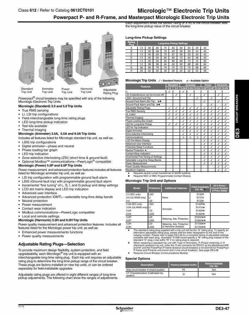
01/15
DE3_p047.fm Page 47 Saturday, January 10, 2015 2:45 AM
Micrologic™ Electronic Trip Unitsfer to Catalog 0612CT0101
DE
3C
IRC
UIT
BR
EA
KE
RS
Powerpact P- and R-Frame, and Masterpact Micrologic Electronic Trip Units
StandardTrip Unit
AmmeterTrip Unit
PowerTrip Unit
HarmonicTrip Unit
AdjustableRating Plug
Powerpact® circuit breakers may be specified with any of the followingMicrologic Electronic Trip Units.Micrologic (Standard) 3.0 and 5.0Trip Units• True RMS sensing• LI, LSI trip configurations• Field-interchangeable long-time rating plugs• LED long-time pickup indication• Test kits available• Thermal imagingMicrologic (Ammeter) 3.0A, 5.0A and 6.0ATrip UnitsIncludes all features listed for Micrologic standard trip unit, as well as:• LSIG trip configurations• Digital ammeter—phase and neutral• Phase loading bar graph• LED trip indication• Zone-selective interlocking (ZSI) (short-time & ground-fault)• Optional Modbus™ communications—PwerLogic® compatibleMicrologic (Power) 5.0P and 6.0PTrip UnitsPower measurement and advanced protection features includes all featureslisted for Micrologic ammeter trip unit, as well as:• LSI trip configuration with programmable ground fault alarm• LSIG (Ground-fault trip) with programmable ground fault alarm• Incremental “fine tuning” of L, S, I, and G pickup and delay settings• LCD dot matrix display and LED trip indication• Advanced user interface• Advanced protection IDMTL—selectable long-time delay bands• Neutral protection• Power measurement• Contact wear indication• Modbus communications—PowerLogic compatible• Local and remote settingsMicrologic (Harmonic) 5.0H and 6.0HTrip UnitsPower quality measurement and advanced protection features. Includes allfeatures listed for the Micrologic power trip unit, as well as:• Enhanced power measurements functions• Power quality measurements
Adjustable Rating Plugs—SelectionTo provide maximum design flexibility, system protection, and fieldupgradeability, each Micrologic® trip unit is equipped with aninterchangeable long-time rating plug. Each trip unit requires an adjustablerating plug to determine the long-time pickup range of the circuit breaker.These plugs are factory-installed on new trip units, or can be orderedseparately for field-installable upgrades.
Adjustable rating plugs are offered in eight different ranges of long-timepickup adjustments. The following chart show the ranges of adjustments.
Each adjustment times the sensor rating (lr X In) of the circuit breaker setsthe long-time pickup value of the circuit breaker.
Long-time Pickup SettingsRatingPlug Long-time Pickup Settings
A 1.0 .90 .80 .70 .63 .60 .50 .45 .40B 1.0 .95 .88 .75 .63 .56 .50 .44 .40C 1.0 .95 .83 .75 .67 .56 .53 .50 .42D 1.0 .95 .93 .90 .80 .70 .64 .48 .40E 1.0 .95 .93 .90 .85 .80 .75 .70 .60F 1.0 .98 .96 .94 .92 .90 .88 .86 .84G .82 .80 .78 .76 .74 .72 .70 .68 .66H .64 .62 .60 .58 .56 .54 .52 .50 .48
MicrologicTrip Units ✓ – Standard Feature o – Available Option
FeaturesStandard Ammeter Power Harmonic3.0 5.0 3.0A 5.0A 6.0A 5.0P 6.0P 5.0H 6.0H
LI ✓ ✓
LSI (Instantaneous can be turned off) ✓ ✓ ✓ ✓
LSIG / Ground-Fault Trip ✓ ✓ ✓
Ground-Fault Alarm (No Trip) ab ✓ ✓
Ground-Fault Alarm and Trip ab ✓ ✓
Adjustable Rating Plugs ✓ ✓ ✓ ✓ ✓ ✓ ✓ ✓ ✓
True RMS Sensing ✓ ✓ ✓ ✓ ✓ ✓ ✓ ✓ ✓
UL Listed ✓ ✓ ✓ ✓ ✓ ✓ ✓ ✓ ✓
Thermal Imaging ✓ ✓ ✓ ✓ ✓ ✓ ✓ ✓ ✓
Phase Loading Bar Graph ✓ ✓ ✓ ✓ ✓ ✓ ✓
LED for Long-time Pickup ✓ ✓ ✓ ✓ ✓ ✓ ✓ ✓ ✓
LED for Trip Indication ✓ ✓ ✓ ✓ ✓ ✓ ✓
Digital Ammeter ✓ ✓ ✓ ✓ ✓ ✓ ✓
Zone-selective Interlocking ✓ ✓ ✓ ✓ ✓ ✓ ✓
Communications o o o ✓ ✓ ✓ ✓
LCD Dot Matrix Display ✓ ✓ ✓ ✓
Advanced User Interface ✓ ✓ ✓ ✓
Protective Relay Functions ✓ ✓ ✓ ✓
Neutral Protection a ✓ ✓ ✓ ✓
Contact Wear Indication ✓ ✓ ✓ ✓
Incremental Fine Tuning of Settings ✓ ✓ ✓ ✓
Selectable Long-time Delay Bands ✓ ✓ ✓ ✓
Power Measurement ✓ ✓ ✓ ✓
Power Quality Measurements ✓ ✓
Waveform Capture ✓ ✓
a Requires neutral current transformer in 3Ø4W systems.b Requires M2C or M6C Programmable Contact Module.
Micrologic Trip Unit and Options
Model Protection Additional Features Field-InstallableCat. No.c
Kit $ Price /Circuit Breaker$ Price Adder
2.0 (IEC only) LSONone
S132R3.0 (UL/ANSI only) LI S131A5.0 LSI S133A2.0A (IEC only) LSO
Ammeter
S142Rd3.0A (UL/ANSI only) LI S141Ad5.0A LSI S143Ad6.0A LSIG S144Ad5.0P LSI
Metering, Adv. ProtectionS163Ade
6.0P LSIG S164Ade5.0H LSI Metering, Adv. Protection
& Harmonic AnalysisS173Ade
6.0H LSIG S174Adec The standard rating plug supplied with a trip unit will be the “A” rating plug. To specify an
alternative adjustable rating plug, please add the letter designation to the end of thecatalog number. Please refer to page DE3-48 for a complete listing of adjustable settingsavailable with each plug. (Example: S143B would specify a “B” rating plug instead of thestandard "A" plug.) Use suffix “N” if no rating plug is required.
d When replacing a standard trip unit with Type A (Ammeter), P (Power metering) or H(Harmonic analysis) trip unit, order the 12-pin connector kit S33101 for the Masterpact NWand NT and the PowerPact P-frame drawout circuit breakers or kit S33100 for PowerPactP-frame and R-frame unit-mount and I-Line circuit breakers. See page DE3-48.
e Requires Circuit Breaker Communications Module.
Special Options
Description Factory-Installed Suffix Field-InstallableCat. No.
Ship circuit breaker in closed position YK N/ACT Characterization (Calibrated tripsystem) Q N/A
Class 612 / Re
DE3-47

CIR
CU
ITB
RE
AK
ER
S
DE3_p048.fm Page 48 Saturday, January 10, 2015 2:45 AM
Micrologic™ Electronic Trip Unit
DE3
Micrologic™ Trip Unit Accessories
Adjustable rating plug "A" is installed as standard on allMicrologic trip unit orders. However, an alternative selectionmay be specified from the "Assembled" table below, andfactory-installed with your trip unit order at no additionalcharge. To order, please attach the appropriate catalogsuffix to the end of the trip unit catalog number (afterspecifying trip unit options). Adjustable rating plugs may alsobe purchased as field-installable components from the tablebelow.
Rating Plugs
Rating PlugaFactory-Installed Field-Installable
Cat. Suffix Cat. No.
A A (standard) S48818B B S48819C C S48820D D S48836E E S48837F F S48838G G S48839H H S48840
a Long-time pickup amperes (Ir) = Sensor Rating (In) X Setting of ratingplug.
• “Fine adjustment tuning” is included on Micrologic Power and Harmonic tripunits, allowing for incremental settings of 1 ampere between the plug settingand .40 X Sensor Rating.
Neutral Current TransformersFor Use with
Circuit Breaker Cat. No. Sensor
H-FrameS429521 60–100S430562 150
J-Frame S430563 250L-Frame S432575 400–600
P-FrameS33575b 250S33576b 400–1600
R-Frame
S48916b 250S34036b 400–1600S48896b 2000S48182b 3000
All NCTWIRING Allb Includes NCTWIRING kit.
Trip Unit AccessoriesDevice Frame Cat. No.
Pocket Tester
H/J/L
S434206UTA Tester STRV00910Spare UTA Tester STRV00911BLuetooth/Modbus for UTA Tester SVW3A8114Spare Power Supply for UTA Tester110–120 Vac TRV00915
Micrologic Cord for UTA Tester TRV00917Micrologic 5/6 Cover, Transparent
H/JS429478
Micrologic 2/3 Cover, Transparent S429481Micrologic 5/6 Cover, Transparent
LS432459
Micrologic 2/3 Cover, Transparent S432461LCD Display for Micrologic 5
H/J/LS429483
LCD Display for Micrologic 6 S429484Hand-held Test Kit
P/R
S33594Primary Injection Test Adaptor S33937Full-function Adapter Kit S48981Full-function Test Kit S33595Seven-pin Test Cable (for connection betweentest kit and trip unit)c S48907
Two-pin Test Cable (for connection betweentest kit and trip unit)d S48908
230 Vac Filtered Power CordeP/R
S48856120 Vac Filtered Power Corde S48855Trip Unit Battery for Trip Indicator Lights S33593Power supply with:
H/J/L/P/R
24–30 Vdc input 68582348/60 Vdc input 685824125 Vdc input 685825110–130 Vac input 685826200–240 Vac input 685827380–415 Vac input 685829
Micrologic A Trip Unit Cover, clearP/R
S33592Micrologic P/H Trip Unit Cover,opaque gray S47067
Trip Unit Seal (6 pieces)for compliance with NEC 240.6(c) H/J/L/P/R MICROTUSEAL
12-pin Trip Unit Connector forNT/NW Masterpact Circuit Breakers
P/R
S33101
12-pin Trip Unit Connector forP- and R-Frame Circuit Breakers S33100
Battery Back-up (12 Hours) 685831
Full Function Test Kit
Trip Unit Seal
Sensor Plug
c Used for testing Micrologic trip units. Included in the price of the Hand-held/Full-function Test Kits. Kit for replacement only.
d Used for testing STR trip units. Included in the price of the Hand-held/Full-function Test Kits. Kit for replacement only.
e Included in the price of the Full-function Test Kit. Kit for replacementonly.
Sensor Plugs for P- and R-Frame Circuit Breakersfh
CircuitBreaker
Sensor PlugRange
Sensor PlugCatalog No. Circuit Breaker Frames Accepting Sensor Plug
P-Frame Circuit Breaker 250 A 400 A 600 A 630 Ag 800 A 1000 A 1200 A 1250 Ag 1600 A
UL
250 A S47052 X400 A S47053 X X X600 A S48823 X X X X800 A S33092 X X X1000 A S33093 X X1200 A S48824 X
IEC
630 A S33091 X X X X X800 A S33092 X X X X1000 A S33093 X X X1250 A S33094 X X1600 A S33095 X
R-Frame Circuit Breaker 600 A 800 A 1000 A 1200 A 1600 A 2000 A 2500 A 3000 A 3200 A
UL
600 A S48823 X X X X800 A S33092 X X X X1000 A S33093 X X X X1200 A S48824 X X X X1600 A S33095 X X X X2000 A S33982 X X X2500 A S33983 X X3000 A S48825 X
IEC
1600 A S33095 X X X X X2000 A S33982 X X X X2500 A S33983 X X X3200 A S33984 X
f For use only with circuit breakers with date codes later than 07011.g IEC Only.h See rating plug for long-time pickup range on page DE3-47.
Class 612 / Refer to Catalog 0612CT0101
01/15DE3-48
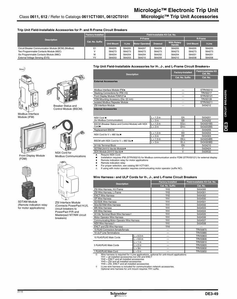
01/15
DE3_p049.fm Page 49 Saturday, January 10, 2015 2:46 AM
Micrologic™ Electronic Trip Unit
DE
3C
IRC
UIT
BR
EA
KE
RS
Micrologic™ Trip Unit Accessories
Trip Unit Field-Installable Accessories for P- and R-Frame Circuit Breakers
Description
Factory-Installed Field-Installable Kit Cat. No.
Cat. No. SuffixP-Frame R-Frame
Unit Mount I-Line Motor Operated Drawout With RotaryHandle Unit Mount I-Line
Circuit Breaker Communication Module (BCM) (Modbus) E1 S64205 S64205 S64207 S64206 S64205 S64205 S64205Two Programmable Contacts Module (M2C) V S64273 S64273 S64273 S64273 S64273 S64273 S64273Six Programmable Contacts Module (M6C) W S64204 S64204 S64204 S64202 S64204 S64201 S64201External Voltage Sensing (EVS) YV S64203 S64203 S64210 S64209 S64210 S64208 S64208
NSX Cord forModbus CommunicationsFront Display Module
(FDM)
SDTAM Module(Remote indication relayfor motor applications)
Breaker Status andControl Module (BSCM)
ZSI Interface Module(Connects PowerPact H/J/Lcircuit breakers toPowerPact P/R andMasterpact NT/NW circuitbreakers)
Modbus InterfaceModule (IFM)
Trip Unit Field-Installable Accessories for H-, J-, and L-Frame Circuit Breakerse
DescriptionFactory-Installed Field-Installable Kit
Cat. No.
Cat. No. Suffix Cat. No.
External Accessories
Modbus Interface Module IFMa — STRV00210Stacking Connections for IFM (10) — TRV00217Front Display Module FDM121a — STRV00121FDM Mounting Accessory (Dia. 22 mm) — TRV00128Isolated Modbus Repeater Module — STRV00211ZSI Interface Module — S434212
Internal Accessories
NSX Cord b(for Modbus Communication)
L = 1.3 m EA S434201L = 3 m EB S434202
BSCM (Breaker Status and Control Module) with NSXCordb
L = 1.3 m EGf S434201BSL = 3 m EHf S434202BS
Replacement BSCM — S434205
NSX Cord for V > 480 VacbL = 1.3 m ED S434204L = 3 m EE S434303
BSCM with NSX Cord for V > 480 VacbL = 1.3 m EKf S434204BSL = 3 m ELf S434303BS
24 Vdc Terminal Block EN S434210SDTAM 24/415 Vac/dc Modulec V S429424SDX Module 24/415 Vac/dcd V S429532a Require NSX Cordb Installation requires IFM (STRV00210) for Modbus communication and/or FDM (STRV00121) for external displayc Remote indication relay for motor applicationsd Remote indication relaye For proper selection, see catalog 0611CT1001.f If using with motor operator requires communicating motor operator (suffix NC).
Wire Harnessg and ULP Cords for H-, J-, and L-Frame Circuit Breakers
DescriptionFactory-Installed Field-Installable Kit Cat. No.
Cat. No. Suffix Cat. No.
ZSI Wire Harness, H/J Frame YH3 S434300ZSI Wire Harness, L-Frame YH3 S434301ENCT Wire Harness YH2 S434302OF Wire Harness YH1 S434500SD/SDE Wire Harness YH1 S434501SDx/SDTAM Wire Harness YH1 S434502MN Wire Harness YH1 S434503MX Wire Harness YH1 S43450424 Vdc Terminal Block Wire Harnessh YH1 S434505Motor Operator Wire Harness YH1 S434506Communicating Motor Operator Wire Harness YH1 S434507NSX Wire Harnessh YH1 S434508ENCT and ZSI Wire Harness YH4 —10 RJ45 Connectors female/female — TRV0087010 ULP Line Terminations — TRV00880
10 RJ45/RJ45 Male CordsL = 0.3 m — TRV00803L = 0.6 m — TRV00806
5 RJ45/RJ45 Male CordsL = 1 m — TRV00810L = 2 m — TRV00820L = 3m — TRV00830
1 RJ45/RJ45 Male Cord L = 5 m — TRV00850g Wire harness is required for I-Line applications, optional for unit-mount applications
YH1 = all installed accessories but ZSI and ENCTYH2 = ENCT and all installed accessoriesYH3 = ZSI and all installed accessoriesYH4 = ZSI, ENCT and all installed accessories
h I-Line wire harness is included for communication network accessories.Optional wire harness for unit mount requires YH1 suffix.
Class 0611, 612 / Refer to Catalogs 0611CT1001, 0612CT0101
DE3-49
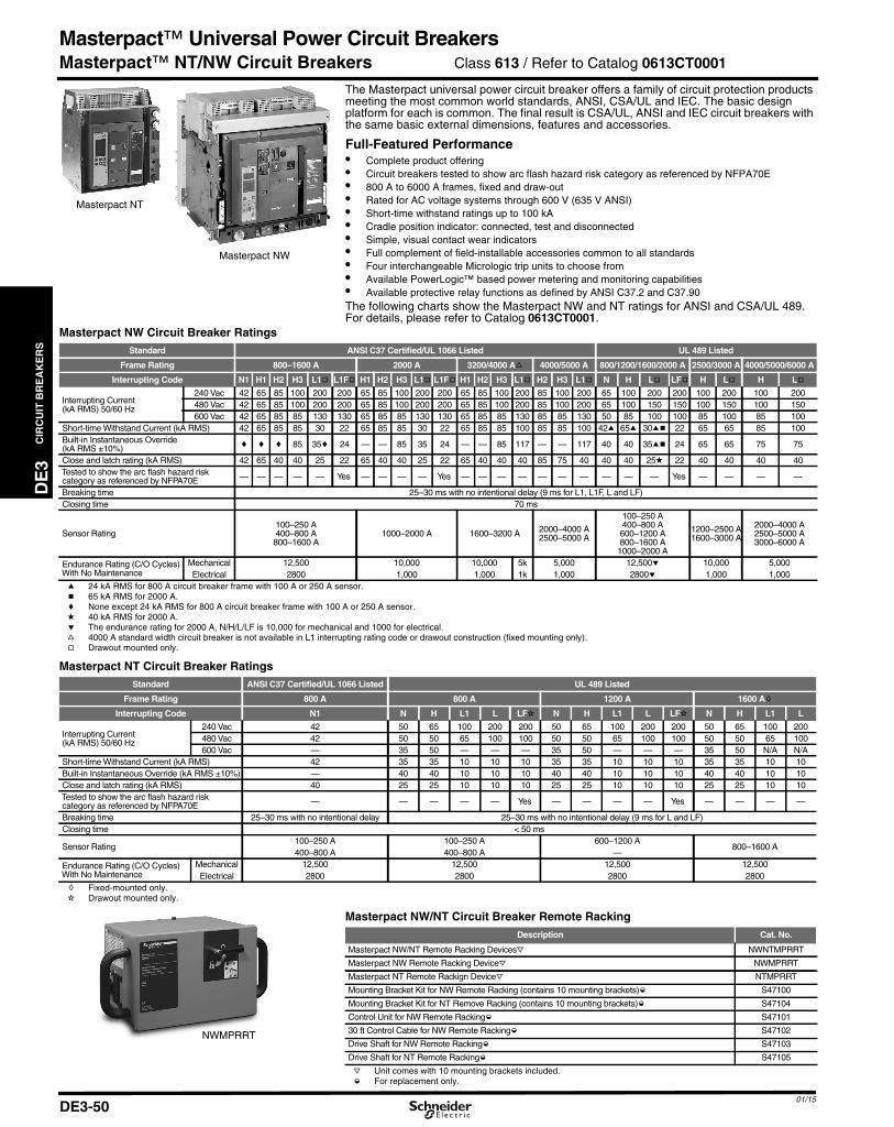
CIR
CU
ITB
RE
AK
ER
S
DE3_p050.fm Page 50 Saturday, January 10, 2015 2:46 AM
Masterpact™ Universal Power Circuit Breakers
DE3
Masterpact™ NT/NW Circuit Breakers
Masterpact NT
Masterpact NW
The Masterpact universal power circuit breaker offers a family of circuit protection productsmeeting the most common world standards, ANSI, CSA/UL and IEC. The basic designplatform for each is common. The final result is CSA/UL, ANSI and IEC circuit breakers withthe same basic external dimensions, features and accessories.
Full-Featured Performance• Complete product offering• Circuit breakers tested to show arc flash hazard risk category as referenced by NFPA70E• 800 A to 6000 A frames, fixed and draw-out• Rated for AC voltage systems through 600 V (635 V ANSI)• Short-time withstand ratings up to 100 kA• Cradle position indicator: connected, test and disconnected• Simple, visual contact wear indicators• Full complement of field-installable accessories common to all standards• Four interchangeable Micrologic trip units to choose from• Available PowerLogic™ based power metering and monitoring capabilities• Available protective relay functions as defined by ANSI C37.2 and C37.90The following charts show the Masterpact NW and NT ratings for ANSI and CSA/UL 489.For details, please refer to Catalog 0613CT0001.
Masterpact NW Circuit Breaker RatingsStandard ANSI C37 Certified/UL 1066 Listed UL 489 Listed
Frame Rating 800–1600 A 2000 A 3200/4000 Af 4000/5000 A 800/1200/1600/2000 A 2500/3000 A 4000/5000/6000 A
Interrupting Code N1 H1 H2 H3 L1g L1Fg H1 H2 H3 L1g L1Fg H1 H2 H3 L1g H2 H3 L1g N H Lg LFg H Lg H Lg
Interrupting Current(kA RMS) 50/60 Hz
240 Vac 42 65 85 100 200 200 65 85 100 200 200 65 85 100 200 85 100 200 65 100 200 200 100 200 100 200480 Vac 42 65 85 100 200 200 65 85 100 200 200 65 85 100 200 85 100 200 65 100 150 150 100 150 100 150600 Vac 42 65 85 85 130 130 65 85 85 130 130 65 85 85 130 85 85 130 50 85 100 100 85 100 85 100
Short-time Withstand Current (kA RMS) 42 65 85 85 30 22 65 85 85 30 22 65 85 85 100 85 85 100 42a 65a 30ab 22 65 65 85 100Built-in Instantaneous Override(kA RMS ±10%) c c c 85 35c 24 — — 85 35 24 — — 85 117 — — 117 40 40 35ab 24 65 65 75 75
Close and latch rating (kA RMS) 42 65 40 40 25 22 65 40 40 25 22 65 40 40 40 85 75 40 40 40 25d 22 40 40 40 40Tested to show the arc flash hazard riskcategory as referenced by NFPA70E — — — — — Yes — — — — Yes — — — — — — — — — — Yes — — — —
Breaking time 25–30 ms with no intentional delay (9 ms for L1, L1F, L and LF)Closing time 70 ms
Sensor Rating100–250 A400–800 A800–1600 A
1000–2000 A 1600–3200 A 2000–4000 A2500–5000 A
100–250 A400–800 A600–1200 A800–1600 A1000–2000 A
1200–2500 A1600–3000 A
2000–4000 A2500–5000 A3000–6000 A
Endurance Rating (C/O Cycles)With No Maintenance
Mechanical 12,500 10,000 10,000 5k 5,000 12,500e 10,000 5,000Electrical 2800 1,000 1,000 1k 1,000 2800e 1,000 1,000
a 24 kA RMS for 800 A circuit breaker frame with 100 A or 250 A sensor.b 65 kA RMS for 2000 A.c None except 24 kA RMS for 800 A circuit breaker frame with 100 A or 250 A sensor.d 40 kA RMS for 2000 A.e The endurance rating for 2000 A, N/H/L/LF is 10,000 for mechanical and 1000 for electrical.f 4000 A standard width circuit breaker is not available in L1 interrupting rating code or drawout construction (fixed mounting only).g Drawout mounted only.
Masterpact NT Circuit Breaker RatingsStandard ANSI C37 Certified/UL 1066 Listed UL 489 Listed
Frame Rating 800 A 800 A 1200 A 1600 Ah
Interrupting Code N1 N H L1 L LFi N H L1 L LFi N H L1 L
Interrupting Current(kA RMS) 50/60 Hz
240 Vac 42 50 65 100 200 200 50 65 100 200 200 50 65 100 200480 Vac 42 50 50 65 100 100 50 50 65 100 100 50 50 65 100600 Vac — 35 50 — — — 35 50 — — — 35 50 N/A N/A
Short-time Withstand Current (kA RMS) 42 35 35 10 10 10 35 35 10 10 10 35 35 10 10Built-in Instantaneous Override (kA RMS ±10%) — 40 40 10 10 10 40 40 10 10 10 40 40 10 10Close and latch rating (kA RMS) 40 25 25 10 10 10 25 25 10 10 10 25 25 10 10Tested to show the arc flash hazard riskcategory as referenced by NFPA70E — — — — — Yes — — — — Yes — — — —
Breaking time 25–30 ms with no intentional delay 25–30 ms with no intentional delay (9 ms for L and LF)Closing time < 50 ms
Sensor Rating100–250 A 100–250 A 600–1200 A
800–1600 A400–800 A 400–800 A —
Endurance Rating (C/O Cycles)With No Maintenance
Mechanical 12,500 12,500 12,500 12,500Electrical 2800 2800 2800 2800
h Fixed-mounted only.i Drawout mounted only.
Masterpact NW/NT Circuit Breaker Remote RackingDescription Cat. No.
Masterpact NW/NT Remote Racking Devicesj NWNTMPRRT
Masterpact NW Remote Racking Devicej NWMPRRT
Masterpact NT Remote Rackign Devicej NTMPRRT
Mounting Bracket Kit for NW Remote Racking (contains 10 mounting brackets)k S47100
Mounting Bracket Kit for NT Remove Racking (contains 10 mounting brackets)k S47104
Control Unit for NW Remote Rackingk S47101
30 ft Control Cable for NW Remote Rackingk S47102
Drive Shaft for NW Remote Rackingk S47103
Drive Shaft for NT Remote Rackingk S47105
j Unit comes with 10 mounting brackets included.
NWMPRRT
Class 613 / Refer to Catalog 0613CT0001
01/15DE3-50
k For replacement only.
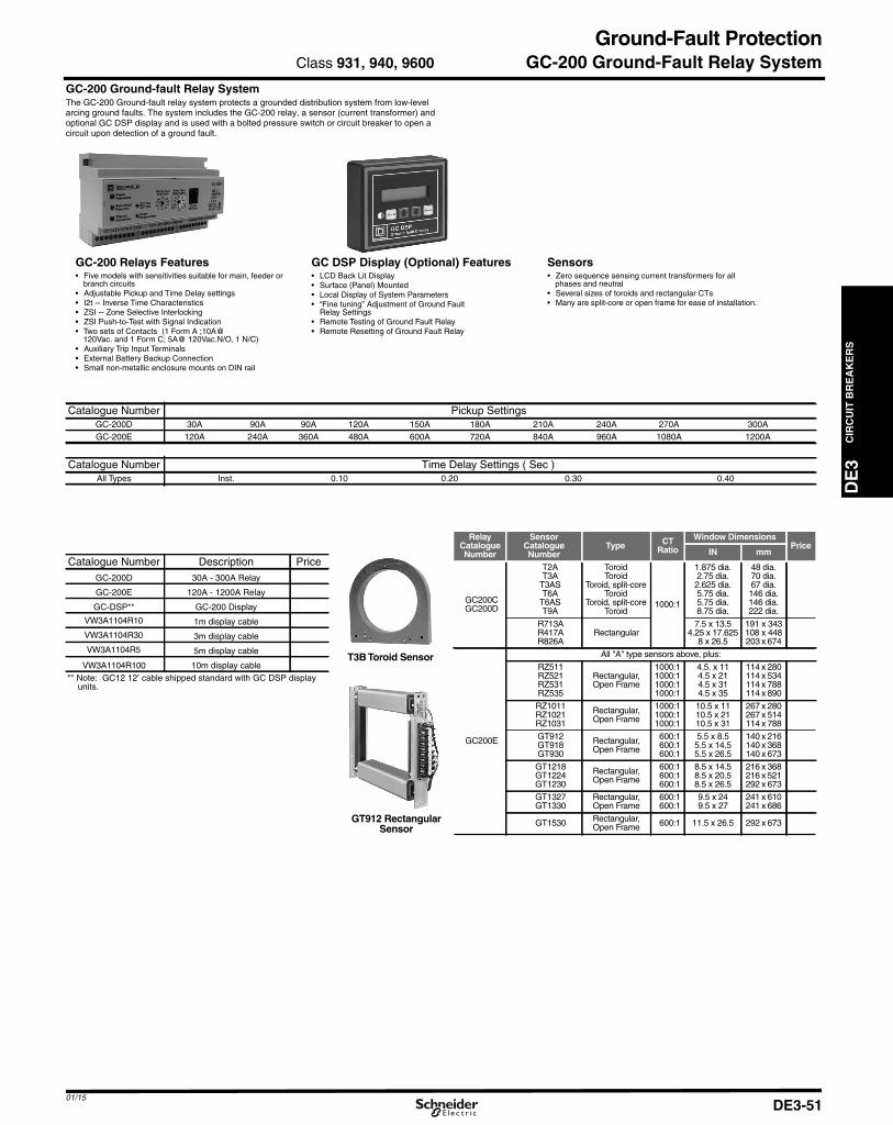
01/15
DE3_p051.fm Page 51 Saturday, January 10, 2015 2:51 AM
Ground-Fault Protection
DE
3C
IRC
UIT
BR
EA
KE
RS
GC-200 Ground-Fault Relay SystemGC-200 Ground-fault Relay SystemThe GC-200 Ground-fault relay system protects a grounded distribution system from low-levelarcing ground faults. The system includes the GC-200 relay, a sensor (current transformer) andoptional GC DSP display and is used with a bolted pressure switch or circuit breaker to open acircuit upon detection of a ground fault.
GC-200 Relays Features• Five models with sensitivities suitable for main, feeder or
branch circuits• Adjustable Pickup and Time Delay settings• I2t -- Inverse Time Characteristics• ZSI -- Zone Selective Interlocking• ZSI Push-to-Test with Signal Indication• Two sets of Contacts (1 Form A ;10A@
120Vac. and 1 Form C; 5A@ 120Vac.N/O, 1 N/C)• Auxiliary Trip Input Terminals• External Battery Backup Connection• Small non-metallic enclosure mounts on DIN rail
GC DSP Display (Optional) Features• LCD Back Lit Display• Surface (Panel) Mounted• Local Display of System Parameters• “Fine tuning” Adjustment of Ground Fault
Relay Settings• Remote Testing of Ground Fault Relay• Remote Resetting of Ground Fault Relay
Sensors• Zero sequence sensing current transformers for all
phases and neutral• Several sizes of toroids and rectangular CTs• Many are split-core or open frame for ease of installation.
Catalogue Number Pickup SettingsGC-200D 30A 90A 90A 120A 150A 180A 210A 240A 270A 300AGC-200E 120A 240A 360A 480A 600A 720A 840A 960A 1080A 1200A
Catalogue Number Time Delay Settings ( Sec )All Types Inst. 0.10 0.20 0.30 0.40
Catalogue Number Description PriceGC-200D 30A - 300A Relay
GC-200E 120A - 1200A Relay
GC-DSP** GC-200 Display
VW3A1104R10 1m display cable
VW3A1104R30 3m display cable
VW3A1104R5 5m display cable
VW3A1104R100 10m display cable** Note: GC12 12’ cable shipped standard with GC DSP display
units.
Class 931, 940, 9600
T3BToroid Sensor
GT912 RectangularSensor
RelayCatalogueNumber
SensorCatalogueNumber
Type CTRatio
Window DimensionsPrice
IN mm
GC200CGC200D
T2A Toroid
1000:1
1.875 dia. 48 dia.T3A Toroid 2.75 dia. 70 dia.
T3AS Toroid, split-core 2.625 dia. 67 dia.T6A Toroid 5.75 dia. 146 dia.
T6AS Toroid, split-core 5.75 dia. 146 dia.T9A Toroid 8.75 dia. 222 dia.
R713ARectangular
7.5 x 13.5 191 x 343R417A 4.25 x 17.625 108 x 448R826A 8 x 26.5 203 x 674
GC200E
All "A" type sensors above, plus:
RZ511Rectangular,Open Frame
1000:1 4.5. x 11 114 x 280RZ521 1000:1 4.5 x 21 114 x 534RZ531 1000:1 4.5 x 31 114 x 788RZ535 1000:1 4.5 x 35 114 x 890
RZ1011 Rectangular,Open Frame
1000:1 10.5 x 11 267 x 280RZ1021 1000:1 10.5 x 21 267 x 514RZ1031 1000:1 10.5 x 31 114 x 788
GT912 Rectangular,Open Frame
600:1 5.5 x 8.5 140 x 216GT918 600:1 5.5 x 14.5 140 x 368GT930 600:1 5.5 x 26.5 140 x 673
GT1218 Rectangular,Open Frame
600:1 8.5 x 14.5 216 x 368GT1224 600:1 8.5 x 20.5 216 x 521GT1230 600:1 8.5 x 26.5 292 x 673
GT1327 Rectangular,Open Frame
600:1 9.5 x 24 241 x 610GT1330 600:1 9.5 x 27 241 x 686
GT1530 Rectangular,Open Frame 600:1 11.5 x 26.5 292 x 673
DE3-51

CIR
CU
ITB
RE
AK
ER
S
DE3_p052.fm Page 52 Saturday, January 10, 2015 2:35 AM
Ground-Fault Protection
DE3
Vigirex™ Ground-Fault Relay System
Vigirex™ Ground-Fault Relay System
RH99M
RH99P
The Vigirex ground-fault relays, with associated sensors (current transformers), measure theresidual current in an electrical installation to detect levels which may be damaging. When usedfor protection, they cause an associated circuit breaker or switch to interrupt the supply of powerto the protected system. They may also be used for monitoring only, with output to an alarm. Theproduct line includes fixed sensitivities from 30 mA to 1 A and adjustable sensitivities up to 30 A.
TheVigirex relays may be easily mounted on DIN rail or may be panel mounted in a meter cutout.Sensors for conductors range from a little more than an inch diameter toroids, to large rectangularsensors measuring 6 x 18 inches. The compact size of the relay and its sensor make it ideal forprotection of OEM equipment as well as branch circuits.
Vigirex Ground-Fault Relays (cUL Listed)
Model Delay Reset Control Voltage Sensitivity CatalogueNo.
DIN Rail Mounted
RH10M Instantaneous Manual
12–24 Vac/12–48 Vdc
30 mA 56300100 mA 56302300 mA 56305500 mA 56306
1 A 56307
110–130 Vac
30 mA 56320100 mA 56322300 mA 56325500 mA 56326
1 A 56327
220–240 Vac
30 mA 56330100 mA 56332300 mA 56335500 mA 56336
1 A 56337
RH21MInstantaneousor 60 mSec(2 settings)
Manual12–24 Vac/12–48 Vdc 30 mA or 300 mA
(2 settings)
56360110–130 Vac 56362220–240 Vac 56363
RH99M
Adjustable(9 settings):
0, 0.06, 0.15,0.23, 0.31, 0.5,0.8, 1.0, 4.5 sec
Manual12–24 Vac/12–48 Vdc
Adjustable(9 settings):
0.03, 0.1, 0.3, 0.5, 1, 3,5, 10, 30 A
56370TD110–130 Vac 56372TD220–240 Vac 56373TD
Automatic12–24 Vac/12–48 Vdc 56390TD
110–130 Vac 56392TD220–240 Vac 56393TD
Panel Mounted
RH10P Instantaneous Manual
12–24 Vac/12–48 Vdc
30 mA 56400100 mA 56402300 mA 56405500 mA 564061 Amp 56407
110–130 Vac
30 mA 56420100 mA 56422300 mA 56425500 mA 564261 Amp 56427
220–240 Vac
30 mA 56430100 mA 56432300 mA 56435500 mA 56436
1 A 56437
RH21PInstantaneousor 60 mSec(2 settings)
Manual12–24 Vac/12–48 Vdc 30 mA or 300 mA
(2 settings)
56460110–130 Vac 56462220–240 Vac 56463
RH99P
Adjustable(9 settings):
0, 0.06, 0.15,0.23, 0.31, 0.5,0.8, 1.0, 4.5 sec
Manual12–24 Vac/12–48 Vdc
Adjustable(9 settings):
0.03, 0.1, 0.3, 0.5, 1, 3,5, 10, 30 A
56470TD110–130 Vac 56472TD220–240 Vac 56473TD
Automatic12–24 Vac/12–48 Vdc 56490TD
110–130 Vac 56492TD220–240 Vac 56493TD
SA200
PA50
Sensors for Vigirex Ground-Fault Relays
Sensors TypeInside Diameter
Catalogue No.IN mm
Closed Toroids, type A
TA30 1.18 30 50437PA50 1.97 50 50438IA80 3.15 80 50439
MA120 4.72 120 50440SA200 7.87 200 50441GA300 11.81 300 50442
Split toroids, type OA POA▲ 1.81 46 50485GOA▲ 4.33 110 50486
Rectangular sensors 280 x 115 11.02 x 4.53 280 x 115 56053470 x 160 18.50 x 6.30 470 x 160 56054
▲ POA and GOA are not cUL recognized
Class 931, 840, 960
01/15DE3-52

01/15
DE3_p053.fm Page 53 Saturday, January 10, 2015 2:35 AM
Ground-Fault Protection Equipment
DE
3C
IRC
UIT
BR
EA
KE
RS
Add-On Ground-Fault and Earth-Leakage Modules
GFM250
Optional GFM25CT
The Micrologic ground-fault module (GFM) is a CSA certified and UL Listed circuit breakeraccessory which protects equipment from damage caused by ground faults. It is an add-onmodule which, when connected to a PowerPact H- or J-frame thermal-magnetic circuit breakeronly, provides ground-fault sensing and ground-fault relay functions.HD/JD Add-on Ground-fault Module Features:• Adjustable ground-fault pickup levels• Adjustable ground-fault time delays• Integral ground fault push-to-test feature and ground-fault indicator• All GFMs are supplied for I-Line® mounting, easily convertible to unit mount by removing the I-Line
brackets• Fault-powered (through the sensing current transformer) for electronics, shunt trip, and integral test
feature.• Optional neutral current transformer GFM25CT for 3-phase 4-wire applications. Refer to instructions
for proper installation• Shunt trip S29382 (12 Vdc): is required for circuit breaker. This may be factory-installed (suffix SN)
or field-installed
NOTE: Ground-fault modules cannot be used for alarming only.
Module/Enclosure Selection Chart a
CompanionCircuit Breaker
Prefix
CatalogueNumberq
Enclosure Space Required Ground-faultPickup Adjustment
RangeI-Line
Switchboard
HD, HG, HJ, HL GFM150HD LA 20–100 AJD, JG, JJ, JL GFM250JD LA 40–200 A
AccessoriesH & J GFM25CT Optional Neutral Current Transformer (required for 4-wire systems)
a At 250 A, the GFM250JD can be used with 80% rated circuit breakers only.
I-Line™ J-Frame with ELM installed
Earth Leakage Module (ELM) for PowerPact H- and J-Frame MCCBsThe Earth Leakage Module (ELM) is an add-on module which, when connected to aPowerPact H- or J-frame MCCB, provides low-level ground-fault sensing and ground-faultrelay functions.Because these ELMs are highly sensitive (30 mA to 3 A), they provide much greaterprotection than GFMs (20 Amps to 200 Amps sensitivity). The ELMs provide greaterprotection of control circuits and other sensitive equipment. The associated circuit breakermust have a 48 Vdc shunt trip, which may be field-installed (kit S29392) or factory-installed(suffix –SP) in the H- or J-Frame circuit breaker.Add-on Earth Leakage Module (ELM) Features:• Adjustable ground-fault pickup levels as low as 30 mA• Adjustable ground-fault time delays from instantaneous to 500 msec
(Time delay can be applied to the 30 mA setting)• Integral ground fault push-to-test feature• Ground-fault indicator (LED for local status; contacts for remote indication)• All ELMs are supplied for I-Line™ mounting and are easily convertible to unit-mount by removing the
I-Line brackets• Three poles; 240 to 600 Vac maximum: 3-wire applications only (no neutral)• Line-power obtained through internal bus to provide power for electronics, shunt trip, and integral
test feature.• A shunt trip is required in the circuit breaker; it may be field-installed or factory-installed in the
PowerPact H and J circuit breakers.• UL 1053 – Ground-fault Sensing and Relaying Equipment
ELM Selection ChartbCompanion Circuit Breakerc Enclosure Space
Required I-LineSwitchboard
Pick-Up AdjustmentRange Catalog Number
Prefix Size
HD, HG, HJ, HL 15–150 A LA 30 mA–3 A ELM150HDJD, JG, JJ, JL 150–250 A LA 30 mA–3 A ELM250JD
b At 250 A, the ELM250JD can be used with 80% rated circuit breakers only.c For Factory Installation of ELM Module: For termination designation (3rd letter of catalog number) use ONLY “M”.
Add factory installed 48 Vdc shunt trip (suffix SP) to breaker plus suffix VL or VM.Use VL for H frame.Use VM for J frame.
Class 931, 940, 960
DE3-53

CIR
CU
ITB
RE
AK
ER
S
DE3_p054.fm Page 54 Saturday, January 10, 2015 2:36 AM
Dimensions and Shipping Weights
DE3
Miniature and Molded Case Circuit Breakers
B E
AG
Figure 2
B E
AG
Figure 1
B E
AG
Figure 3DC
QO, QOB
QO-GFI, QO-PLQO-EPD
DC
Figure 5AG
BE
A
BE
G
Figure 4
B
AG
E
Figure 6AG
B E
Figure 7AG
B E
Figure 8
DC
F
QOU, QYULow Ampere
QOUHigh Ampere
CD
FB
Figure 13A
B
Figure 14A
B
Figure 15A
B
Figure 16A
B
CD
C60
E
Figure 17A
B
Figure 18A
B
Figure 19A
B
Figure 20A
B
Figure 1BE
FA
E
G
C L
FigureBE
E
FA
Figure 3
C L
BD
CG
H HE
E
FA
BG
E
E
FA
DC
Figure 24
Figure 9 Figure 10 Figure 11
Figure 10A
B E
Figure 11A
B E
Figure 12A
B E
QO™, QOU, Multi 9™ Circuit BreakersCircuit BreakerCatalogue No.
Prefix
No.Poles
Fig.No.
Dimensions—Inches
A B C D E F G
QO, QOB
1 1 0.75 3.00a 2.31 2.91 2.25 . . . 0.59
2 2 1.50 3.00a 2.31 2.91 2.25 . . . 1.34
3 3 2.25 3.00a 2.31 2.91 2.25 . . . 2.09
QOB-VH 150 AQOB-VH 110–150 A
2 2 3.0 5.72 2.53 4.90 3.78 . . . 2.85
3 3 4.50 5.72 2.53 4.90 3.78 . . . 4.35
QO-PLQO-GFIQO-EPD
1 4 0.75 4.12b 2.31 2.91 2.25 . . . 0.59
2 5 1.50 4.12b 2.31 2.91 2.25 . . . 1.34
3 5 2.25 4.12b 2.31 2.91 2.25 . . . 2.09
QOULow Ampere
1 6 0.75 4.05c 2.38 2.98 2.25 5.00p 0.62
2 7 1.50 4.05c 2.38 2.98 2.25 5.00p 1.37
3 8 2.25 4.05d 2.38 2.98 2.25 5.00f 2.12
QOUHigh Ampere
1 9 0.75 4.45 2.37 2.96 2.25 6.78 . . .
2 10 1.50 4.45 2.37 2.96 2.25 6.78 . . .
3 11 2.25 4.45 2.37 2.96 2.25 6.78 . . .
Multi 9™ C60
1 13 0.71 3.19 1.73 2.76 1.77 — —
2 14 1.42 3.19 1.73 2.76 1.77 — —
3 15 2.13 3.19 1.73 2.76 1.77 — —
4 16 2.84 3.19 1.73 2.76 1.77 — —
a 35–70 A is 3.12 in; 80–100 A 2-pole and 70–100 A 3-pole are 3.50 in.b QO-PL is 4.55 in.c 80–100 A 1-pole and 80–125 A 2-pole are 4.45 in.d 70–100 A 4.45 in.e 80–100 A 1-pole and 80–125 A 2-pole are 6.78 in.f 70–100 A is 6.78 in.
QB, QD, QG, QJ, Q4, FA, FI, KI, LA, LH Circuit BreakersCircuit BreakerCatalogue No.
Prefix
No.Poles
Fig.No.
Dimensions—Inches
A B C D E F G H
QB, QD,QG, QJ
2 22 6.47 3.00 3.02 3.93 g 4.25 . . . . . .
3 23 6.47 4.50 3.02 3.93 g 4.25 1.50 0.75
FAL, FHL
1 21 6.00 1.50 3.16 4.13 0.44 5.13 1.50 . . .
2 22 6.00 3.00 3.16 4.13 0.44 5.13 . . . . . .
3 23 6.00 4.50 3.16 4.13 0.44 5.13 1.50 0.75
FIL, KIL 2 & 3 23 8.00 4.50 3.66 4.75 0.44 7.13 1.50 0.75
Q4L, LAL, LHL 2 & 3 23 11.00 6.00 4.06 5.84 0.88 9.25 2.00 1.00
g Dimensions E are 1.59 in at ON end and 0.63 in at OFF end.
Shipping Weightsh
Frame Size Approx. ShippingWeight (Lbs.) Frame Size Approx. Shipping
Weight (Lbs.)
FAL, FHL 1P 2 KIL 9
FAL, FHL 2P 3 LAL, LHL 15
FAL, FHL 3P 5 LIL LXIL 25
FIL 8 Q4L 15
QB, QD, QG, QJ 4
h All weights are for 3P circuit breakers unless otherwise noted.
01/15DE3-54

01/15
DE3_P055.fm Page 55 Saturday, January 10, 2015 2:37 AM
Dimensions and Shipping Weights
DE
3C
IRC
UIT
BR
EA
KE
RS
Molded Case Circuit Breakers
A
B
E
F
C
D
Figure 26
A
E
F
B
G
Figure 25
E
G
A
B
C
DF
Figure 27
A
C
D
B
G
F
Figure 28
AAA
E B B E E B
CD
Figure 29 Figure 30 Figure 31
Figure 32
A
E B
CD
F
E
E
A
DCG
BFigure 33
GB
F
EA
DC
Figure 34
HD, HG, HJ, HL, HR, JD, JG, JJ, JL, JR, LG, LJ, LL, and LR CircuitBreakersCircuit Breaker
Cat. No.Prefix
No. ofPoles Fig. No.
Dimensions — Inches
A B C D E F G
HD, HG, HJ,HL, HR
2* 25 6.40 2.74 2.87 4.36 0.74 4.92 —3 26 6.40 4.12 2.87 4.36 0.74 4.92 1.38
JD, JG, JJ,JL, JR 3 27 7.52 4.12 2.87 5.00 1.30 4.92 1.38
LG, LJ, LL, LR 3 28 13.38 5.51 3.75 6.61 2.22 7.87 1.77
* - Only HD and HG are in 2P module. The HJ, HL and HR 2P breakers are in 3P modules
ED, EG and EJ Circuit BreakersCircuit
BreakerCatalogue No.
Prefix
No. ofPoles Fig. No.
Dimensions — Inches
A B C D E
ED, EG, EJ
1 29 0.98 5.66 3.09 4.05 3.32
2 30 1.96 5.66 3.09 4.05 3.32
3 30 2.94 5.66 3.09 4.05 3.32
GJ 3 32 3.54 4.72 2.76 3.94 2.20
MG, MJ, PG, PJ, PL, RG, RJ and RL Circuit BreakersCircuit Breaker
Cat. No.Prefix
No. ofPoles
Fig.No.
Dimensions — Inches
A B C D E F G
MG, MJ(800 A and below) 2, 3 33 12.86 8.27 5.77 8.05 2.49 7.87 7.83
PG, PJ, PK, PL(1000–1200 A) 2, 3 33 16.16 8.27 5.77 8.05 4.19 7.87 7.83
RG, RJ, RL 2, 3 34 16.24 16.54 6.63 14.49 8.73 14.25 15.35
Shipping Weightsa
Frame Size Approx. ShippingWeight (Lbs.) Frame Size Approx. Shipping
Weight (Lbs.)
HD, HG, HJ, HL 2P 4 JD, JG, JJ, JL, JR 5HD, HG, HJ, HL, HR 3P 5 LD, LG, LJ, LL, LR 14
ED, EG, EJ 1P 2 MG, MJ29
ED, EG, EJ 2P 3 PG, PJ, PK, PL 32ED, EG, EJ 3P 4 RG, RJ, RK, RL (Without RLTB) 52
a All weights are for 3P circuit breakers unless otherwise noted.
DE3-55

CIR
CU
ITB
RE
AK
ER
S
DE3_p056.fm Page 56 Friday, January 23, 2015 12:16 AM
Circuit Breaker Enclosures
DE3
Enclosures
FA100S
FA100RB
FA100DS
Circuit breaker enclosures are UL Listed, CSA Certified and are suitable for use as service entrance equipment, exceptas footnoted. The short circuit current rating of an enclosed circuit breaker is equal to the interrupting rating at the supplyvoltage marked on the circuit breaker installed, except as footnoted. Exceptions and restrictions are footnoted. Breakersare ordered and shipped separately for field installation. For enclosure accessories, refer to page DE3-58.
a Enclosures with NRB or RB suffix have provisions for 3/4" through 2-1/2" bolt-on hubs in top endwall. Enclosures with R suffix have blank endwalls andrequire field cut opening.
b Factory installed groundable neutral assembly includes (2) ground lugs and (2) neutral lugs. Equipment ground kit is also included.c Accepts standard rated 80% breakers. Not rated at 100%.d Maximum short circuit rating is 25 kAIR at 600 Vac, 65 kAIR at 480 Vac, 125 kAIR at 240 Vac.e Earth Leakage Module and Ground Fault Module are not compatible with these enclosures.f Maximum short circuit rating is 25 kAIR, 240 Vac.g Order service ground kit PKOGTA2 if required.h Maximum short circuit rating is 18 kAIR, 480 Vac and 240 Vac.i Copper wire only.j When using a CT in the M800S and R enclosure the unit will no longer accommodate a 200% neutral solution.k CE certified per IEC60439-1, IP20D, PE type TN-C or TN-Sl Accepts MGL or MJL standard rated (80%) breakers. Accepts PGL, PJL or PLL circuit breakers rated 80% (1200 A maximum) or
100% rated breakers, (800A maximum).m CE certified per IEC60439-1, IP24D, PE type TN-C or TN-Sn Suitable for rainproof Type 3R application by removing drain screw from bottom endwall.o CE certified per IEC60439-1, IP56, PE type TN-C or TN-Sp NEMA 7—Indoor Hazardous Locations—Division 1 and 2, Class I, Groups C and D; Class II, Groups E, F,and G; Class III.q 80% rated circuit breakers only; SCCR 65 kA @ 240 Vac, 25 kA @ 480 Vac, 18 kA @ 600 Vac.r Not UL Listed due to wire bending space.s NEMA 9—Indoor Hazardous Locations—Division 1 and 2, Class II, Groups E, F,and G; Class III.t Has a tapped 2-1/2 in. conduit opening on top and bottom end wallu Short circuit current rating is 30 k AIR at 480 Vac.v J250SS and M800SS are 316 Grade Stainless Steel Circuit Breaker Enclosures. Type 316 stainless steel circuit breaker enclosures offer superior
corrosion resistance to a wider range of chemicals than Type 304 stainless steel enclosures. Type 316 better resists chloride and is often used in marine,waste treatment and transportation applications.
w cULus marked enclosure. For factory installed viewing window, add suffix VW. For enclosure suitable for use as Service Equipment use Cat. No.CL600NAWK (neutral SN1000MA will be factory installed and bonded)
Accessories . . . . . . . . . . . . . . . . . . . . . . . . . . . . . . . . . . . . . . . . Page DE3-58Dimensions. . . . . . . . . . . . . . . . . . . . . . . . . . . . . . . . . . . . . . . . . Page DE3-58
Circuit Breaker EnclosuresCircuit Breaker Enclosure
Cat. No. Prefix Rating Poles Cat. No. Cat. No. Cat. No.
NEMA 1 Flush NEMA 1 Surface NEMA 3Ra
FAL, FHL 15-100 1, 2, 3 FA100F FA100S FA100RBQBL, QDL, QGL, QJL 100-225
2, 3Q23225NFCb Q23225NSCb Q23225NRBCb
HDL,HGL,HJL, HLL 15-150J250Fcde J250Scde J250Rcde
JDL, JGL, JJL, JLL 150-250HDL 15–100 A 3 — HD100Sfgcei —JDL 150–250 A 3 — JD250Sigfce —
LAL, LHL, Q4L 125-400 2, 3 LA400F LA400S LA400RLAL 125–400 A 3 — LA400LSgit —
MGL, MJL, PGL, PJL, PKL,PLL 300-800 2, 3 M800Sjk M800Rje
PGL, PJL, PKL, PLL* 600-1200 2, 3 P1200Sk P1200Re
NEMA 4, 4X, 5, 3, 3RStainless Steelu
NEMA 12/3R, 12K
With Knockouts (NEMA12K)
Without Knockoutsn(NEMA 12/3R, 5)
FAL, FHL 15-100 1, 2, 3 FA100DS FA100AWKHDL,HGL,HJL, HLL 15-150
2, 3J250DScdeJ250SScde J250AWKcde
JDL, JGL, JJL, JLL 150-250LAL, LHL, Q4L 125-400 LA400DS LA400AWKLDL, LGL, LJL, LLL, LRL 250-600
3— L600AWKw
LGL, LLL, LRL 250-600 — L600AWKMCMGL, MJL, PGL, PJL, PKL,PLL 300-800
2, 3M800DSoM800SSo M800AWKo
PGL, PJL, PKL, PLL* 250-1200 P1200AWKoNema 7e Cast Aluminum Nema 9s Cast Aluminum
JDL, JGLeqr 150–250 A 2, 3 J225X J225Y
Class 610
01/15DE3-56

01/15
DE3_p057.fm Page 57 Saturday, January 10, 2015 2:37 AM
Circuit Breaker Enclosures
DE
3C
IRC
UIT
BR
EA
KE
RS
Enclosed Circuit Breaker Special Applications
Circuit Breaker Type 7 ✸Cast Aluminum
Type 9 ■Cast Aluminum
Catalogue Number Ampere Number Enclosure EnclosurePrefix Rating of Poles Catalogue No. Catalogue No.
FAL, FHL▲15-60 1, 2, 3 FA060X▼ FA060Y➀
15-100 1, 2, 3 FA100X▼ FA100Y➀
✸ NEMA Type 7 – Indoor Hazardous Locations – Class I, Groups C and/or D, Divisions 1 or 2.■ NEMA Type 9 – Indoor Hazardous Locations – Class II, Groups E and/or G, Class III, Divisions 1 or 2.▼ Suitable for rainproof applications–includes PKDB-1 breather and drain kit.▲ Use 75°C Cu conductors only.➀ Not CSA certified.
Note: Circuit breaker enclosures not to be used with MAG-GARD breakers.
FA100X
FA100Y
Class 610
DE3-57
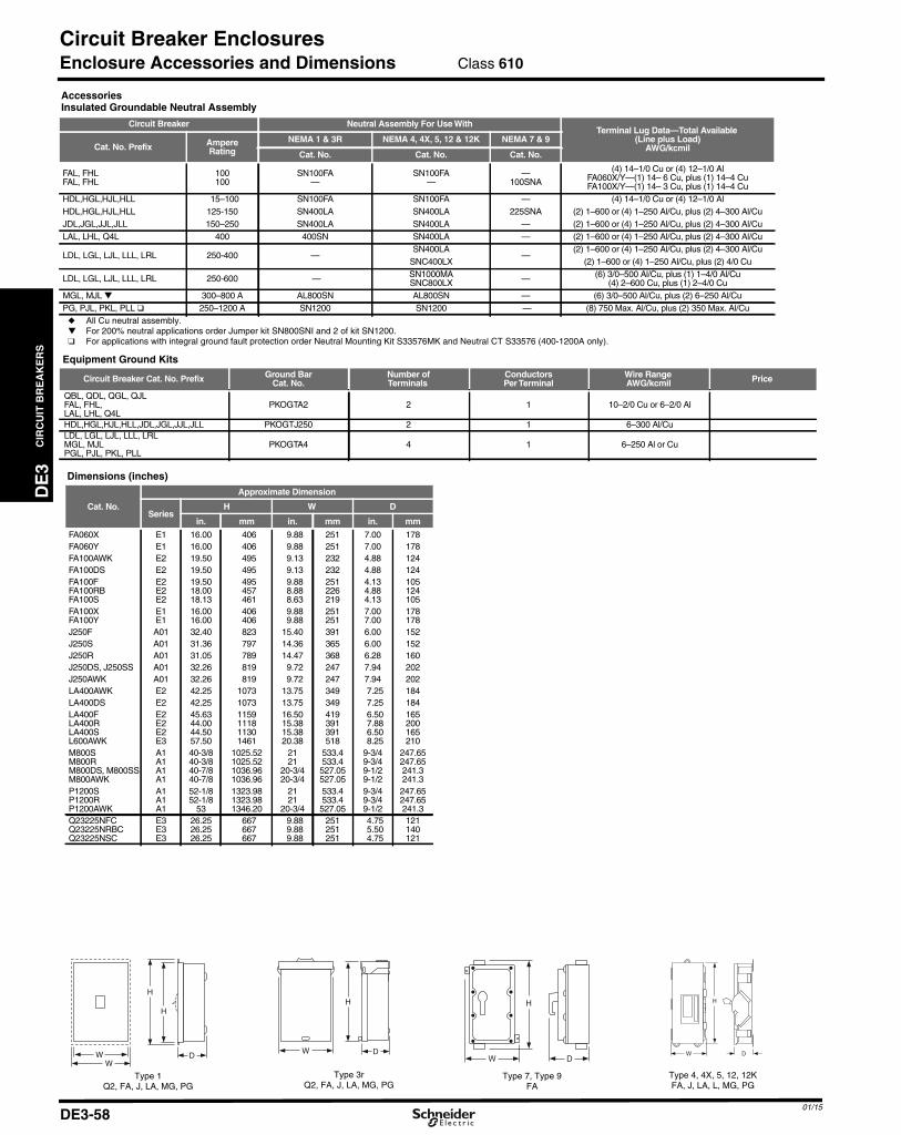
CIR
CU
ITB
RE
AK
ER
S
DE3_p058.fm Page 58 Friday, January 23, 2015 12:20 AM
Circuit Breaker Enclosures
DE3
Enclosure Accessories and Dimensions
AccessoriesInsulated Groundable Neutral Assembly
Circuit Breaker Neutral Assembly For Use WithTerminal Lug Data—Total Available
(Line plus Load)AWG/kcmilCat. No. Prefix Ampere
RatingNEMA 1 & 3R NEMA 4, 4X, 5, 12 & 12K NEMA 7 & 9
Cat. No. Cat. No. Cat. No.
FAL, FHLFAL, FHL
100100
SN100FA—
SN100FA—
—100SNA
(4) 14–1/0 Cu or (4) 12–1/0 AlFA060X/Y—(1) 14– 6 Cu, plus (1) 14–4 CuFA100X/Y—(1) 14– 3 Cu, plus (1) 14–4 Cu
HDL,HGL,HJL,HLL 15–100 SN100FA SN100FA — (4) 14–1/0 Cu or (4) 12–1/0 AlHDL,HGL,HJL,HLL 125-150 SN400LA SN400LA 225SNA (2) 1–600 or (4) 1–250 Al/Cu, plus (2) 4–300 Al/CuJDL,JGL,JJL,JLL 150–250 SN400LA SN400LA — (2) 1–600 or (4) 1–250 Al/Cu, plus (2) 4–300 Al/CuLAL, LHL, Q4L 400 400SN SN400LA — (2) 1–600 or (4) 1–250 Al/Cu, plus (2) 4–300 Al/Cu
LDL, LGL, LJL, LLL, LRL 250-400 —SN400LA
—(2) 1–600 or (4) 1–250 Al/Cu, plus (2) 4–300 Al/Cu
SNC400LX (2) 1–600 or (4) 1–250 Al/Cu, plus (2) 4/0 Cu
LDL, LGL, LJL, LLL, LRL 250-600 — SN1000MASNC800LX — (6) 3/0–500 Al/Cu, plus (1) 1–4/0 Al/Cu
(4) 2–600 Cu, plus (1) 2–4/0 CuMGL, MJL ▼ 300–800 A AL800SN AL800SN — (6) 3/0–500 Al/Cu, plus (2) 6–250 Al/CuPG, PJL, PKL, PLL ❑ 250–1200 A SN1200 SN1200 — (8) 750 Max. Al/Cu, plus (2) 350 Max. Al/Cu
◆ All Cu neutral assembly.▼ For 200% neutral applications order Jumper kit SN800SNI and 2 of kit SN1200.❑ For applications with integral ground fault protection order Neutral Mounting Kit S33576MK and Neutral CT S33576 (400-1200A only).
Equipment Ground Kits
Circuit Breaker Cat. No. Prefix Ground BarCat. No.
Number ofTerminals
ConductorsPerTerminal
Wire RangeAWG/kcmil Price
QBL, QDL, QGL, QJLFAL, FHL,LAL, LHL, Q4L
PKOGTA2 2 1 10–2/0 Cu or 6–2/0 Al
HDL,HGL,HJL,HLL,JDL,JGL,JJL,JLL PKOGTJ250 2 1 6–300 Al/CuLDL, LGL, LJL, LLL, LRLMGL, MJLPGL, PJL, PKL, PLL
PKOGTA4 4 1 6–250 Al or Cu
IK, FA, J, LA, LX, MG, PG
W
H
D
FA, JDL, JGL
W
H
DWW
D
H
H
W D
H
Type 4, 4X, 5, 12, 12KType 7, Type 9Type 3rType 1
Dimensions (inches)
Cat. No.
Approximate Dimension
SeriesH W D
in. mm in. mm in. mm
FA060X E1 16.00 406 9.88 251 7.00 178FA060Y E1 16.00 406 9.88 251 7.00 178FA100AWK E2 19.50 495 9.13 232 4.88 124FA100DS E2 19.50 495 9.13 232 4.88 124FA100FFA100RBFA100S
E2E2E2
19.5018.0018.13
495457461
9.888.888.63
251226219
4.134.884.13
105124105
FA100XFA100Y
E1E1
16.0016.00
406406
9.889.88
251251
7.007.00
178178
J250F A01 32.40 823 15.40 391 6.00 152J250S A01 31.36 797 14.36 365 6.00 152J250R A01 31.05 789 14.47 368 6.28 160J250DS, J250SS A01 32.26 819 9.72 247 7.94 202J250AWK A01 32.26 819 9.72 247 7.94 202LA400AWK E2 42.25 1073 13.75 349 7.25 184LA400DS E2 42.25 1073 13.75 349 7.25 184LA400FLA400RLA400SL600AWK
E2E2E2E3
45.6344.0044.5057.50
1159111811301461
16.5015.3815.3820.38
419391391518
6.507.886.508.25
165200165210
M800SM800RM800DS, M800SSM800AWK
A1A1A1A1
40-3/840-3/840-7/840-7/8
1025.521025.521036.961036.96
2121
20-3/420-3/4
533.4533.4527.05527.05
9-3/49-3/49-1/29-1/2
247.65247.65241.3241.3
P1200SP1200RP1200AWK
A1A1A1
52-1/852-1/8
53
1323.981323.981346.20
2121
20-3/4
533.4533.4527.05
9-3/49-3/49-1/2
247.65247.65241.3
Q23225NFCQ23225NRBCQ23225NSC
E3E3E3
26.2526.2526.25
667667667
9.889.889.88
251251251
4.755.504.75
121140121
Class 610
01/15DE3-58
FA, J, LA, L, MG, PGFAQ2, FA, J, LA, MG, PGQ2, FA, J, LA, MG, PG

DE
3C
IRC
UIT
BR
EA
KE
RS
01/15DE3-59
Photovoltaic Circuit Breakers and Switches600 Vdc and 1000 Vdc PV Circuit Breakers and SwitchesClass 611 / Refer to Catalog 0611CT1302
The UL listed thermal-magnetic molded case circuit breakers and switches shown below are specifically designed for usein PV applications, rated at 50°C, offering grounded or ungrounded configurations.The products are fully tested and calibrated under the PV UL489B standard.The products come ready to install, including specially designed serial connectors for optimal thermal response, andadapted terminal covers for optimal isolation. Circuit Breakers come 100% rated for ease of use and selection.These two new frames are fully compatible with the current line of PowerPact accessories, from aux contacts and shunttrips to motor operators and rotary handles.
a 500 A 80% rated.
PV Molded Case Circuit Breakers
AmpereRating
600 Vdc (3 poles) 1000 Vdc (4 poles)
Ungrounded Grounded Ungrounded Grounded
Part Number Part Number Part Number Part Number50 TGL36050L TGL36050K TBL41050L TBL41050K60 TGL36060L TGL36060K TBL41060L TBL41060K70 TGL36070L TGL36070K TBL41070L TBL41070K80 TGL36080L TGL36080K TBL41080L TBL41080K100 TGL36100L TGL36100K TBL41100L TBL41100K125 TGL36125L TGL36125K TBL41125L TBL41125K150 TGL36150L TGL36150K TBL41150L TBL41150K175 TGL36175L TGL36175K TBL41175L TBL41175K200 TGL36200L TGL36200K TBL41200L TBL41200K225 UGL36225L UGL36225K UCL41225L UCL41225K250 UGL36250L UGL36250K UCL41250L UCL41250K300 UGL36300L UGL36300K UCL41300L UCL41300K350 UGL36350L UGL36350K UCL41350L UCL41350K400 UGL36400L UGL36400K UCL41400L UCL41400K450 UGL36450L UGL36450K UCL41450L UCL41450K
500a N/A UGL36500G UCL41500J UCL41500G
PV Circuit Breaker Max. Interrupting RatingsFrame 600 Vdc 1000 Vdc
T-Frame 10 kA 3 kAU-Frame 10 kA 5 kA
Circuit Breaker NumberingBrand Frame Rating Termination Poles Voltage Amperage Grounding Suffix Code Suffix Code
T G L 3 6 0 5 0 G A B S A
FrameT: T-FrameU: U-Frame
Poles3: 3P4: 4P
Voltage6: 600 Vdc1: 1000 Vdc
Accessory Suffix Cells(See page DE3-60)
Accessory Suffix Cells(See page DE3-60)
Amperage050: 50 A060: 60 A070: 70 A080: 80 A100: 100 A125: 125 A150: 150 A175: 175 A200: 200 A225: 225 A250: 250 A300: 300 A350: 350 A400: 400 A450: 450 A500: 500 A
BrandBlank:
SchneiderElectric
RatingsB: 3 kAC: 5 kA
G: 10 kA
TerminationsL: Lugs Line/Load SideF: Bus BarS: Rear Connected
GroundingG: Grounded, 80% rated (500 A Only)J: Ungrounded, 80% rated (500 A Only)K: Grounded, 100% ratedL: Ungrounded, 100% rated
PV Molded Case Non-Automatic Switches
AmpereRating
600 Vdc (3 poles) 1000 Vdc (4 poles)
Ungrounded Grounded Ungrounded Grounded
Part Number Part Number Part Number Part Number100 TBL36000JZ10 TBL36000GZ10 TBL41000JZ10 TBL41000GZ10150 TBL36000JZ15 TBL36000GZ15 TBL41000JZ15 TBL41000GZ15200 TBL36000JZ20 TBL36000GZ20 TBL41000JZ20 TBL41000GZ20250 UDL36000JZ25 UDL36000GZ25 UDL41000JZ25 UDL41000GZ25300 UDL36000JZ30 UDL36000GZ30 UDL41000JZ30 UDL41000GZ30400 UDL36000JZ40 UDL36000GZ40 UDL41000JZ40 UDL41000GZ40500 UDL36000JZ50 UDL36000GZ50 UDL41000JZ50 UDL41000GZ50
PV Switches Withstand RatingsFrame 600/1000 Vdc
T-Frame 3 kAU-Frame 7.5 kA
Switch NumberingBrand Frame Rating Termination Poles Voltage Amperage Grounding Trip System Suffix Code Suffix Code
T D L 3 6 0 0 0 G Z 1 0 A B S A
FrameT: T-FrameU: U-Frame
Poles3: 3P4: 4P
Voltage6: 600 Vdc1: 1000 Vdc
Accessory Suffix Cells(See page DE3-60)
Accessory Suffix Cells(See page DE3-60)
TerminationsL: Lugs Line/Load SideF: Bus BarS: Rear Connected
Amperage000: Switch
Trip System—##(Z: Non-Automatic Switch)(##: Amerage Rating)Z10: 100 AZ15: 150 AZ20: 200 AZ25: 250 AZ30: 300 AZ40: 400 AZ50: 500 A
BrandBlank:
SchneiderElectric only
RatingsB: 3 kA
D: 7.5 kA
GroundingG: Grounded, 80% ratedJ: Ungrounded, 80% rated
DE3_p059.fm Page 59 Saturday, January 10, 2015 2:38 AM

DE
3C
IRC
UIT
BR
EA
KE
RS
01/15DE3-60
Photovoltaic Circuit Breakers and SwitchesFactory Installed Accessories Class 611 / Refer to Catalog 0611CT1302
a U-Frame only.
NOTE: For a complete list of Field installable accessories anddetails, including also motor operator (electrical only) andlocks, refer to accessories information for the PowerPact,J-Frame (compatible with T-Frame) and L-Frame(Compatible with U-Frame). Or consult Photovoltaic offercatalog 0611CT1302.
a P: Poles, SC: Serial connector.
a The ungrounded configurations (3P or 4P) need 2 short and 2 long rear connectors. Thegrounded configurations only use 2 short rear connectors.
b Parts only, no hardware is included. See table PV U-Frame, below.c P: Poles, SC: Serial connector.
NOTE: For availability dates of field installable accessories inTables above contact Schneider Electric.
Auxiliary Switches
Contacts Factory-InstalledSuffix
Field-Installable KitNo. Kit Qty.
1A/1B Standard AA S29450 1
2A/2B Standard AB S29450 2
3A/3B Standarda AC S29450 3
1A/1B Low-Level (Gold) AE S29452 1
2A/2B Low-Level (Gold) AF S29452 2
3A/3B Low-Level (Gold)a AG S29452 3
Alarm/Overcurrent Trip Switches
Suffix Switch Kit No. Kit Qty.
PowerPact T-Frame
BC Alarm Switch S29450 1
BH Alarm Switch, Low-Level S29452 1
BDOvercurrent Trip Switch, Standard S29450 1
SDE Actuator S29451 1
BJOvercurrent Trip Switch, Low-Level S29452 1
SDE Actuator S29451 1
BEAlarm Switch and Overcurrent Trip Switch, Standard S29450 2
SDE Actuators S29451 2
BKAlarm Switch and Overcurrent Trip Switch, Low-Level S29452 2
SDE Actuators S29451 2
PowerPact U-Frame
BC Alarm Switch S29450 1
BH Alarm Switch, Low-Level S29452 1
BD Overcurrent Trip Switch, Standard S29450 1
BJ Overcurrent Trip Switch, Low-Level S29452 1
BE Alarm Switch and Overcurrent Trip Switch, Standard S29450 2
BK Alarm Switch and Overcurrent Trip Switch, Low-Level S29452 2
Shunt Trips
Voltage
ShuntTrip (MX)
Factory-Installed Suffix Field-InstallableKit No.
120 Vac SA S29386
24 Vdc SO S29390
48 Vdc SP S29392
125 Vdc SR S29393
Rotary Operated Handles
Device DescriptionFactoryInstalled
Suffix
T-Frame U-Frame
FieldInstallable Kit
No.
FieldInstallableKit
No.
DirectMounted
Standard HandleBlack Handle Only RD10 S29337 S32597
DoorMounted
Standard BlackHandle Handle Only RE10 S29338 S32598
Locks
Device DescriptionFactoryInstalled
Suffix
T-Frame U-Frame
Field InstallableKit No.
Field InstallableKit No.
Handle PadlockingDevice
Handle Padlock,ON or OFF YP S29371 S32631
PV Unit Mount Terminal CoversChoose termination “L” for having the termination kit factory installedwith the breaker (Lugs, Term Covers, Serial Connectors)
Fram
e
Descriptiona
Pol
es
ConfigurationField
InstallableCatalog No.
Ungrounded Grounded
Top Bottom Top Bottom
T-Fr
ame
Long Terminal Cover (3P) 3 X S35175Long Terminal Cover (3P/1SC) 3 X X X S35176Long Terminal Cover (4P) 4 X S35177Long Terminal Cover (4P/2SC) 4 X X S35178Long Terminal Cover (4P/1SC) 4 X S35179
U-F
ram
e
Long Terminal Cover (3P) 3 X S32593Extended Term Cover (3P/1SC) 3 X X X S38291Long Terminal Cover (4P) 4 X S32594Extended Term Cover (4P/2SC) 4 X X S38293Extended Term Cover (4P/1SC) 4 X S38294
PV Rear Connection Terminal Covers and ConnectorsChoose termination “S” for having the termination kit included with thebreaker (Rear Connectors, Term Covers, Serial Connectors)
Fram
e
Descriptionc
Pol
es
ConfigurationField
InstallableCatalog No.
Ungrounded Grounded
Top Bottom Top Bottom
T-Fr
ame
Short Terminal Cover (3P) 3 X S29515Long Terminal Cover (3P/1SC) 3 X X X S35169Short Terminal Cover (4P) 4 X S29516Long Terminal Cover (4P/1SC) 4 X S35170Long Terminal Cover (4P/2SC) 4 X X S35178Short Rear Connector (set of 2)a 3, 4 X X S29235Long Rear Connector (set of 2)a 3, 4 X S29236
U-F
ram
e
Short Terminal Cover (3P) 3 X S32562Extended Terminal Cover (3P/1SC) 3 X X X S35171Short Terminal Cover (4P) 4 X S32563Extended Term Cover (4P/1SC) 4 X S35172Extended Term Cover (4P/2SC) 4 X X S38293Short Rear Connector (set of 2)ab 3, 4 X X S432475Long Rear Connector (set of 2)ab 3, 4 X S432476
PV T-Frame Bus Bar and Rear Connections HardwareChoose termination “F” for having the termination kit included with thebreaker (Terminal Nuts, Term Covers, Serial Connectors)
Description Cat. No.
T-Frame Term Nut Insert-Metric/M8 (12) S30554
PV U-Frame Bus Bar and Rear Connections HardwareChoose termination “F” for having the termination kit included with thebreaker (Screws and Washers, Term Covers, Serial Connectors)
Description Cat. No.
Set of 4 M10 x 25 terminal screws and washers for one side S36967
Mechancal Lug Kits for T- and U-Frame Circuit Breakers and Switches
Fram
e
Description
Conductor
Current Cat. No.Qty.PerKitType
No.PerLug
Size
T-Fr
ame
Lug(2) T-Frame,12–4 AWG, Al/Cu
Al 1 #12–#4 AWG(4–25 mm2)
50–60 A S35167 2Cu 1 #14–#4 AWG
(2.5–25 mm2)Lugs(2) T-Frame,4–4/0 AWG, Al/Cu Al/Cu 1 #4–#4/0 AWG
(25–95 mm2) 70–150 A S29255 2
Lug(2) T-Frame,250–350 kcmil, Al/Cu
Al 1 #250–350 AWG(120–185 mm2)
175–200 A S35168 2Cu 1 #2/0–350 AWG
(70–185 mm2)
U-F
ram
e
Lug(2) U-Frame,2/0 AWG–500 kcmil,Al/Cu
Al 2 2/0 AWG–500 kcmil(70–240 mm2)
225–500 A S35180 2Cu 2 2/0 AWG–500 kcmil
(70–240 mm2)
DE3_p060.fm Page 60 Friday, January 23, 2015 12:22 AM

01/15
DE3_p061.fm Page 61 Saturday, January 10, 2015 2:39 AM
Photovoltaic Circuit Breakers and Switches
DE
3C
IRC
UIT
BR
EA
KE
RS
T-Frame Dimensions and Shipping Weights
PV T-Frame Circuit Breaker and Switches DimensionsA2 A3 B1 B2 C2 C3
in 7.40 11.42 4.13 5.51 3.39 4.96mm 188 290 105 140 86 126
C3C2
A2A3
B1 B2
A2: ShortA3: Long
Terminal Cover Configuration According to Wiring Configuration
Wiring ConfigurationConnectionType Terminal Cover Configuration
Unit Mount/Bus Rear Connected Top Bottom
3P UngroundedX Long Long
X Short Long3P Grounded X X Long Long
4P UngroundedX Long Long
X Long Short4P Grounded X X Long Long
Approximate Weights
T-Frames Product Weight(lbs)
Shipping Weights(lbs)
3P Ungrounded 5 83P Grounded 5.5 8.5
4P Ungrounded 6.3 9.34P Grounded 6.7 9.7
Class 611 / Refer to Catalog 0611CT1302
DE3-61
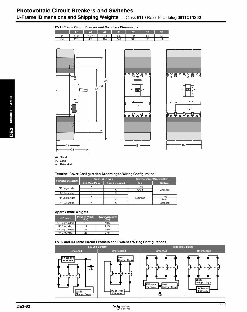
CIR
CU
ITB
RE
AK
ER
S
DE3_p062.fm Page 62 Saturday, January 10, 2015 2:40 AM
Photovoltaic Circuit Breakers and Switches
DE3
U-Frame |Dimensions and Shipping Weights Class 611 / Refer to Catalog 0611CT1302
A2: ShortA3: LongA4: Extended
PV U-Frame Circuit Breaker and Switches DimensionsA2 A3 A4 B1 B2 C2 C3
in 11.2 15.7 19.1 5.5 7.2 4.3 6.6mm 285 400 484 140 183 110 168
Terminal Cover Configuration According to Wiring Configuration
Wiring ConfigurationConnectionType Terminal Cover Configuration
Unit Mount/Bus Rear Connected Top Bottom
3P UngroundedX Long
ExtendedX Short3P Grounded X X
Extended4P UngroundedX Long
X Short4P Grounded X X Extended
Approximate Weights
U-Frames Product Weight(lbs)
Shipping Weights(lbs)
3P Ungrounded 15 19.53P Grounded 17 21.5
4P Ungrounded 21 25.54P Grounded 23 27.5
PV T- and U-Frame Circuit Breakers and Switches Wiring Configurations600 Vdc (3 Poles) 1000 Vdc (3 Poles)
Grounded Ungrounded Grounded Ungrounded
PV Source / FV Fuente
GND
Load / Charge / Carga
Load / Charge / Carga
PV Source / FV Fuente
PV Source / FV Fuente
GND
Load / Charge / Carga PV Source /
FV Fuente
Load / Charge / Carga
01/15DE3-62

01/15
DE3_p063.fm Page 63 Saturday, January 10, 2015 2:40 AM
Moulded Case Circuit Breaker
DE
3C
IRC
UIT
BR
EA
KE
RS
F-Frame Thermal-Magnetic Circuit Breakers
Thermal-magnetic moulded case circuit breakers shown here are permanent trip CSA certified, UL listed,IEC rated. For I-LINE moulded case circuit breakers, see Section DE-5.
Dimensions-DE3-54Enclosures -DE3-56
AmpereRating
AC MagneticTrip Settings
Amperes
One Pole Two Pole Three Pole StandardLug Kit
Wire RangeCatalogue No. Price Catalogue No. Price Catalogue No. Price
100 Ampere FrameFAL Standard Interrupting 120/240Volt
FAL/FHLOne Pole
15-100 Ampere
Hold Trip 120Vac 240Vac 240Vac15 275 600 FAL12015 FAL22015 FAL32015 AL50FA20 275 600 FAL12020 FAL22020 FAL32020 #14-#4 Cu or25 275 600 FAL12025 FAL22025 FAL32025 #12-#4 Al30 275 600 FAL12030 FAL22030 FAL3203035 400 850 FAL12035 FAL22035 FAL32035 AL100FA40 400 850 FAL12040 FAL22040 FAL32040 #14-#1/0 Cu or45 400 850 FAL12045 FAL22045 FAL32045 #12-#1/0 Al50 400 850 FAL12050 FAL22050 FAL3205060 800 1450 FAL12060 FAL22060 FAL3206070 800 1450 FAL12070 FAL22070 FAL3207080 800 1450 FAL12080 FAL22080 FAL3208090 900 1700 FAL12090 FAL22090 FAL32090100 900 1700 FAL12100 FAL22100 FAL32100
FAL Standard Interrupting 277/480 VoltHold Trip 277Vac,125Vdc 480Vac,250Vdc 480Vac,250Vdc
15 275 600 FAL14015 FAL24015 FAL34015 AL50FA20 275 600 FAL14020 FAL24020 FAL34020 #14-#4 Cu or25 275 600 FAL14025 FAL24025 FAL34025 #12-#4 Al FAF/FHL
Two Pole15-100Ampere
30 275 600 FAL14030 FAL24030 FAL3403035 400 850 FAL14035 FAL24035 FAL34035 AL100FA40 400 850 FAL14040 FAL24040 FAL34040 #14-#1/0 Cu or45 400 850 FAL14045 FAL24045 FAL34045 #12-#1/0 Al50 400 850 FAL14050 FAL24050 FAL3405060 800 1450 FAL14060 FAL24060 FAL3406070 800 1450 FAL14070 FAL24070 FAL3407080 800 1450 FAL14080 FAL24080 FAL3408090 900 1700 FAL14090 FAL24090 FAL34090
100 900 1700 FAL14100 FAL24100 FAL34100FAL Standard Interrupting 347/600 Volt
Hold Trip 347Vac,125Vdc 600Vac,250Vdc 600Vac,250Vdc15 275 600 FAL17015 FAL26015 FAL36015 AL50FA20 275 600 FAL17020 FAL26020 FAL36020 #14-#4 Cu or25 275 600 FAL17025 FAL26025 FAL36025 #12-#4 Al30 275 600 FAL17030 FAL26030 FAL3603035 400 850 FAL17035 FAL26035 FAL36035 AL100FA40 400 850 FAL17040 FAL26040 FAL36040 #14-#1/0 Cu or45 400 850 FAL17045 FAL26045 FAL36045 #12-#1/0 Al50 400 850 FAL17050 FAL26050 FAL3605060 800 1450 FAL17060 FAL26060 FAL3606070 800 1450 FAL17070 FAL26070 FAL3607080 800 1450 FAL17080 FAL26080 FAL3608090 900 1700 FAL17090 FAL26090 FAL36090
100 900 1700 FAL17100 FAL26100 FAL36100FHL High Interrupting 347/600 Volt
Hold Trip 347Vac,125Vdc 600Vac,250Vdc 600Vac,250Vdc15 275 600 FHL17015 FHL26015 FHL36015 AL50FA20 275 600 FHL17020 FHL26020 FHL36020 #14-#4 Cu or25 275 600 FHL17025 FHL26025 FHL36025 #12-#4 Al30 275 600 FHL17030 FHL26030 FHL36030 CSA Certified Interrupting Rating35 400 850 FHL17035 FHL26035 FHL36035 AL100FA RMS Symmetrical Amperes40 400 850 FHL17040 FHL26040 FHL36040 #14-#1/0 Cu or Breaker System Voltage AC DC45 400 850 FHL17045 FHL26045 FHL36045 #12-#1/0 Al Catalogue No. 120/ 277/ 347/50 400 850 FHL17050 FHL26050 FHL36050 Prefix 240 480 600 125 25060 800 1450 FHL17060 FHL26060 FHL36060 FAL (240V.)70 800 1450 FHL17070 FHL26070 FHL36070 1-Pole 10k 5k80 800 1450 FHL17080 FHL26080 FHL36080 2, 3-Pole 10k 5k 5k90 900 1700 FHL17090 FHL26090 FHL36090 FAL (480V.)
100 900 1700 FHL17100 FHL26100 FHL36100 1-Pole 18k 18k 10k2, 3-Pole 25k 18k 10k 10k
FAL (600V.)1-Pole 25k 18k 14k 10k2, 3-Pole 25k 18k 14k 10k 10k
FHL1-Pole15-30 65k 65k 18k 10k
35-100 65k 25k 18k 10k2, 3-Pole 65k 25k 18k 50k 50k
FAL/FHLThree Pole
15-100Ampere
DE3-63

CIR
CU
ITB
RE
AK
ER
S
DE3_p064.fm Page 64 Saturday, January 10, 2015 2:34 AM
Moulded Case Circuit Breakers
DE3
Q4L - LAL - LHL
CSA Certified Interrupting RatingRMS Symmetrical Amperes
BreakerCat. No.Prefix
System Voltage AC DC
240 480 600 125 250Q4L 25kLAL 42k 30k 22k 10k 10kLHL 65k 35k 25k 50k 50k
Enclosures - DE3-56Dimensions - DE3-54
AmpereRating
AC Magnetic Two Pole Three Pole StandardTrip Settings Lug Kit
Amperes Catalogue No. Price Catalogue No. Price Wire Range
400 Ampere FrameQ4L Standard Interrupting
LAL/LHLTwo and Three Pole125-400 Amperes
Low High 240Vac 240Vac250 1250 2500 Q4L2250 Q4L3250 AL400LA300 1500 3000 Q4L2300 Q4L3300 1-#1-600 kcmil or350 1750 3500 Q4L2350 Q4L3350 2-#1-250 kcmil400 2000 4000 Q4L2400 Q4L3400 AL400LA
LAL Standard InterruptingLow High 600Vac, 250Vdc 600Vac, 250Vdc
125 625 1250 LAL26125 LAL36125150 750 1500 LAL26150 LAL36150175 875 1750 LAL26175 LAL36175200 1000 2000 LAL26200 LAL36200 AL400LA225 1125 2250 LAL26225 LAL36225 1-#1-600 kcmil or250 1250 2500 LAL26250 LAL36250 2-#1-250 kcmil300 1500 3000 LAL26300 LAL36300350 1750 3500 LAL26350 LAL36350400 2000 4000 LAL26400 LAL36400
LHL High InterruptingLow High 600Vac, 250Vdc 600Vac, 250Vdc
125 625 1250 LHL26125 LHL36125150 750 1500 LHL26150 LHL36150175 875 1750 LHL26175 LHL36175200 1000 2000 LHL26200 LHL36200 AL400LA225 1125 2250 LHL26225 LHL36225 1-#1-600 kcmil or250 1250 2500 LHL26250 LHL36250 2-#1-250 kcmil300 1500 3000 LHL26300 LHL36300350 1750 3500 LHL26350 LHL36350400 2000 4000 LHL26400 LHL36400
01/15DE3-64
DE
3C
IRC
UIT
BR
EA
KE
RS
01/15DE3-65
Moulded Case Circuit BreakersCDP Breaker Cross to Square D
CDP Connector Kits
The CDP connector kits are used to install Square D breakers into existing Federal Pioneer CDP panels and Switchboard distribution interiors that originallyused branch breakers from the Horizon family.Please note that these connector kits are designed to be applied on CDP interiors with Extruded Bus only, (except HDCMH, JDCMH, and LDCMH that can bealso used on CDP interiors with Flat Bus).Please refer to installation bulletins for detailed information on these kits.
Retrofitting or adding new Square D Breakers into CDP InteriorsFederal PioneerHorizon Breaker Amperage Alternate Square D Breaker Connector Mounting Hardware
CE Breaker15A – 100A 15A – 100A Powerpact H ■ HDCMH
150A – 250A 150A – 225A Powerpact J ■ JDCMHCJL Breaker 100A – 400A LA/LH ● LACMH
CJM Breaker* 300A – 600A 400A-600A PowerPact L● ❑ LDCMHCK 250A – 1200A Powerpact P◆ PCDPCMH
■ Need to be replaced in pairs, can not mount a CE breaker back to back with a PowerPact breaker. Not suitable for 100% rated and type HR, JRMCCBs.
● Available only as single mount option. Not available as a double mount or Back to back mount due to dimensional constraints.Condition 1: Panel with all single row branch circuits.A minimum branch circuit height of 8-1/4” is required.Condition 2: Panel with all double row branch circuits.This will require a modification to the trim to remove a section of the trim centre strip in the location where the new breaker is to be installed.A minimum branch circuit height of 9-5/8” is required and the breaker should be located where the centre strip ends. (This space includesone 1 -3/8” wide filler to support the center strip).If the breaker must be located between two sections of a double row trim then the minimum branch circuit height required is 11”. (This spaceincludes two 1-3/8” wide fillers to support both ends of the centre strips)
❑ The PowerPact L-Frame breaker has an overall height of 5-1/2” but will be fitted with a Cover plate to fill the existing branch circuit space of8-1/4”.
◆ Available only for single mount. The CK breaker can not be replaced in existing 12X of branch circuit height, the Square D PowerPact breakerrequires space with a 16X branch nominal height. Contact Schneider Services for installation of PowerPact P breaker and mounting hardware.
* PowerPact L-Frame can also be used to replace Square D LC/LI/LX/LE/LXI installed in CDP panels as a replacement of CJM breakers.
DE3_p065.fm Page 65 Friday, January 23, 2015 12:24 AM
Related Documents