1 Miniature Circuit Breakers FAZ • High-quality miniature circuit breakers for industrial applications and resi- dential applications • Contact position indicator red - green • Guide for secure terminal connection • 3-position DIN rail clip, permits removal from existing busbar system • Comprehensive range of accessories suitable for subsequent installation • Rated currents up to 63 A • Tripping characteristics B, C, D, K, S, Z • Rated breaking capacity up to 15 kA according to IEC/EN 60947-2 FAZ-PN • Tripping characteristic B • Rated breaking capacity up to 6 kA according to IEC/EN 60898-1 • Module width 1MU (1+N-poles) FAZ-HS • Tripping characteristic B • Rated breaking capacity up to 10 kA according to IEC/EN 60898-1 • 1- and 2-poles available SG55812 Miniature Circuit Breakers FAZ, FAZ-PN, FAZ-HS

Welcome message from author
This document is posted to help you gain knowledge. Please leave a comment to let me know what you think about it! Share it to your friends and learn new things together.
Transcript
1
Miniature Circuit Breakers
FAZ
• High-quality miniature circuit breakers for industrial applications and resi-
dential applications
• Contact position indicator red - green
• Guide for secure terminal connection
• 3-position DIN rail clip, permits removal from existing busbar system
• Comprehensive range of accessories suitable for subsequent installation
• Rated currents up to 63 A
• Tripping characteristics B, C, D, K, S, Z
• Rated breaking capacity up to 15 kA according to IEC/EN 60947-2
FAZ-PN
• Tripping characteristic B
• Rated breaking capacity up to 6 kA according to IEC/EN 60898-1
• Module width 1MU (1+N-poles)
FAZ-HS
• Tripping characteristic B
• Rated breaking capacity up to 10 kA according to IEC/EN 60898-1
• 1- and 2-poles available
SG55812
Miniature Circuit Breakers FAZ, FAZ-PN, FAZ-HS
2
Miniature Circuit Breakers
FAZ Miniature Circuit Breakers (MCBs)Characteristic B
Rated Rated Breaking Rated Breaking Type Article No. Units repnoitangiseDyticapacegatlovyticapacegatlovtnerruc
In egakcapot .cca7701LUot .cca)V()A(IEC/EN (V) UL107760947-2 (kA)(kA)
1-poleSG53112
1+N-poleSG55612
11.51.6233.545681012131516202532405063
240/415240/415240/415240/415240/415240/415240/415240/415240/415240/415240/415240/415240/415240/415240/415240/415240/415240/415240/415240/415240/415
151515151515151515151515151515151515151515
277277277277277277277277277277277277277277277277277277277277277
101010101010101010101010101010101010555
FAZ-B1/1FAZ-B1,5/1FAZ-B1,6/1FAZ-B2/1FAZ-B3/1FAZ-B3,5/1FAZ-B4/1FAZ-B5/1FAZ-B6/1FAZ-B8/1FAZ-B10/1FAZ-B12/1FAZ-B13/1FAZ-B15/1FAZ-B16/1FAZ-B20/1FAZ-B25/1FAZ-B32/1FAZ-B40/1FAZ-B50/1FAZ-B63/1
182114182115182116182117182119182120182121182122182123182124182125182126182127182128182129182130182131182132182133182134182135
121212121212121212121212121212121212121212
11.51.622.533.545681012131516202532405063
240240240240240240240240240240240240240240240240240240240240240240
15151515151515151515151515151515151515151515
277277277277277277277277277277277277277277277277277277277277277277
10101010101010101010101010101010101010555
FAZ-B1/1NFAZ-B1,5/1NFAZ-B1,6/1NFAZ-B2/1NFAZ-B2,5/1NFAZ-B3/1NFAZ-B3,5/1NFAZ-B4/1NFAZ-B5/1NFAZ-B6/1NFAZ-B8/1NFAZ-B10/1NFAZ-B12/1NFAZ-B13/1NFAZ-B15/1NFAZ-B16/1NFAZ-B20/1NFAZ-B25/1NFAZ-B32/1NFAZ-B40/1NFAZ-B50/1NFAZ-B63/1N
182136182137182138182139182140182141182142182143182144182145182146182147182148182149182150182151182152182153182154182155182156182157
6666666666666666666666
3
Miniature Circuit Breakers
Rated Rated Breaking Rated Breaking Type Article No. Units repnoitangiseDyticapacegatlovyticapacegatlovtnerruc
In egakcapot .cca7701LUot .cca)V()A(IEC/EN (V) UL107760947-2 (kA)(kA)
2-poleSG55112
3-poleSG53412
11.51.622.533.5456781012131516202532405063
415415415415415415415415415415415415415415415415415415415415415415415
1515151515151515151515151515151515151515151515
480Y/277480Y/277480Y/277480Y/277480Y/277480Y/277480Y/277480Y/277480Y/277480Y/277480Y/277480Y/277480Y/277480Y/277480Y/277480Y/277480Y/277480Y/277480Y/277480Y/277480Y/277480Y/277480Y/277
1010101010101010101010101010101010101010555
182158182159182160182161182162182112182113182175182176182177182178182179182180182181182182182183182184182185182186182188182189182190182191
66666666666666666666666
FAZ-B1/2FAZ-B1,5/2FAZ-B1,6/2FAZ-B2/2FAZ-B2,5/2FAZ-B3/2FAZ-B3,5/2FAZ-B4/2FAZ-B5/2FAZ-B6/2FAZ-B7/2FAZ-B8/2FAZ-B10/2FAZ-B12/2FAZ-B13/2FAZ-B15/2FAZ-B16/2FAZ-B20/2FAZ-B25/2FAZ-B32/2FAZ-B40/2FAZ-B50/2FAZ-B63/2
11.51.622.533.5456781012131516202532405063
415415415415415415415415415415415415415415415415415415415415415415415
1515151515151515151515151515151515151515151515
480Y/277480Y/277480Y/277480Y/277480Y/277480Y/277480Y/277480Y/277480Y/277480Y/277480Y/277480Y/277480Y/277480Y/277480Y/277480Y/277480Y/277480Y/277480Y/277480Y/277480Y/277480Y/277480Y/277
1010101010101010101010101010101010101010555
182192182193182194182195182196182197182198182199182200182201182202182203182204182205182206182207182208182209182210182212182213182214182215
44444444444444444444444
FAZ-B1/3FAZ-B1,5/3FAZ-B1,6/3FAZ-B2/3FAZ-B2,5/3FAZ-B3/3FAZ-B3,5/3FAZ-B4/3FAZ-B5/3FAZ-B6/3FAZ-B7/3FAZ-B8/3FAZ-B10/3FAZ-B12/3FAZ-B13/3FAZ-B15/3FAZ-B16/3FAZ-B20/3FAZ-B25/3FAZ-B32/3FAZ-B40/3FAZ-B50/3FAZ-B63/3
4
Miniature Circuit Breakers
Rated Rated Breaking Rated Breaking Type Article No. Units repnoitangiseDyticapacegatlovyticapacegatlovtnerruc
In egakcapot .cca7701LUot .cca)V()A(IEC/EN (V) UL107760947-2 (kA)(kA)
3+N-poleSG55712
4-poleSG55812
11.51.622.533.545681012131516202532405063
415415415415415415415415415415415415415415415415415415415415415415
15151515151515151515151515151515151515151515
480Y/277480Y/277480Y/277480Y/277480Y/277480Y/277480Y/277480Y/277480Y/277480Y/277480Y/277480Y/277480Y/277480Y/277480Y/277480Y/277480Y/277480Y/277480Y/277480Y/277480Y/277480Y/277
10101010101010101010101010101010101010555
182216182217182218182219182220182221182222182223182224182225182226182227182228182229182230182231182232182233182234182235182236182237
3333333333333333333333
FAZ-B1/3NFAZ-B1,5/3NFAZ-B1,6/3NFAZ-B2/3NFAZ-B2,5/3NFAZ-B3/3NFAZ-B3,5/3NFAZ-B4/3NFAZ-B5/3NFAZ-B6/3NFAZ-B8/3NFAZ-B10/3NFAZ-B12/3NFAZ-B13/3NFAZ-B15/3NFAZ-B16/3NFAZ-B20/3NFAZ-B25/3NFAZ-B32/3NFAZ-B40/3NFAZ-B50/3NFAZ-B63/3N
11.51.622.533.5456781012131516202532405063
415415415415415415415415415415415415415415415415415415415415415415415
1515151515151515151515151515151515151515151515
480Y/277480Y/277480Y/277480Y/277480Y/277480Y/277480Y/277480Y/277480Y/277480Y/277480Y/277480Y/277480Y/277480Y/277480Y/277480Y/277480Y/277480Y/277480Y/277480Y/277480Y/277480Y/277480Y/277
1010101010101010101010101010101010101010555
182238182239182240182241182242182243182244182245182246182247182248182249182250182251182252182253182254182255182256182257182258182259182260
33333333333333333333333
FAZ-B1/4FAZ-B1,5/4FAZ-B1,6/4FAZ-B2/4FAZ-B2,5/4FAZ-B3/4FAZ-B3,5/4FAZ-B4/4FAZ-B5/4FAZ-B6/4FAZ-B7/4FAZ-B8/4FAZ-B10/4FAZ-B12/4FAZ-B13/4FAZ-B15/4FAZ-B16/4FAZ-B20/4FAZ-B25/4FAZ-B32/4FAZ-B40/4FAZ-B50/4FAZ-B63/4
5
Miniature Circuit Breakers
FAZ Miniature Circuit Breakers (MCBs)Characteristic C
Rated Rated Breaking Rated Breaking Type Article No. Units repnoitangiseDyticapacegatlovyticapacegatlovtnerruc
In egakcapot .cca7701LUot .cca)V()A(IEC/EN (V) UL107760947-2 (kA)(kA)
1-poleSG53112
1+N-poleSG55612
0.160.250.50.7511.51.622.533.545681012131516202532405063
240/415240/415240/415240/415240/415240/415240/415240/415240/415240/415240/415240/415240/415240/415240/415240/415240/415240/415240/415240/415240/415240/415240/415240/415240/415240/415
1515151515151515151515151515151515151515151515151515
277277277277277277277277277277277277277277277277277277277277277277277277277277
55101010101010101010101010101010101010101010555
182261182262182263182264182265182266182267182268182269182270182271182272182273182274182275182276182277182278182279182280182281182282182283182284182285182286
1212121212121212121212121212121212121212121212121212
FAZ-C0,16/1FAZ-C0,25/1FAZ-C0,5/1FAZ-C0,75/1FAZ-C1/1FAZ-C1,5/1FAZ-C1,6/1FAZ-C2/1FAZ-C2,5/1FAZ-C3/1FAZ-C3,5/1FAZ-C4/1FAZ-C5/1FAZ-C6/1FAZ-C8/1FAZ-C10/1FAZ-C12/1FAZ-C13/1FAZ-C15/1FAZ-C16/1FAZ-C20/1FAZ-C25/1FAZ-C32/1FAZ-C40/1FAZ-C50/1FAZ-C63/1
0.160.250.50.7511.51.622.533.545681012131516202532405063
240240240240240240240240240240240240240240240240240240240240240240240240240240
1515151515151515151515151515151515151515151515151515
277277277277277277277277277277277277277277277277277277277277277277277277277277
55101010101010101010101010101010101010101010555
182287182288182289182290182291182292182293182294182295182296182297182298182299182300182301182302182303182304182305182306182307182308182309182310182311182312
66666666666666666666666666
FAZ-C0,16/1NFAZ-C0,25/1NFAZ-C0,5/1NFAZ-C0,75/1NFAZ-C1/1NFAZ-C1,5/1NFAZ-C1,6/1NFAZ-C2/1NFAZ-C2,5/1NFAZ-C3/1NFAZ-C3,5/1NFAZ-C4/1NFAZ-C5/1NFAZ-C6/1NFAZ-C8/1NFAZ-C10/1NFAZ-C12/1NFAZ-C13/1NFAZ-C15/1NFAZ-C16/1NFAZ-C20/1NFAZ-C25/1NFAZ-C32/1NFAZ-C40/1NFAZ-C50/1NFAZ-C63/1N
6
Miniature Circuit Breakers
Rated Rated Breaking Rated Breaking Type Article No. Units repnoitangiseDyticapacegatlovyticapacegatlovtnerruc
In egakcapot .cca7701LUot .cca)V()A(IEC/EN (V) UL107760947-2 (kA)(kA)
2-poleSG55112
3-poleSG53412
0.160.250.50.7511.51.622.533.545678101213151620253032405063
415415415415415415415415415415415415415415415415415415415415415415415415415415415415
15151515151515151515151515151515151515151515151515151515
480Y/277480Y/277480Y/277480Y/277480Y/277480Y/277480Y/277480Y/277480Y/277480Y/277480Y/277480Y/277480Y/277480Y/277480Y/277480Y/277480Y/277480Y/277480Y/277480Y/277480Y/277480Y/277480Y/277480Y/277480Y/277480Y/277480Y/277480Y/277
551010101010101010101010101010101010101010101010555
182313182314182315182316182317182318182319182320182321182322182323182324182325182326182327182328182329182330182331182332182333182334182335182336182337182338182339182340
6666666666666666666666666666
FAZ-C0,16/2FAZ-C0,25/2FAZ-C0,5/2FAZ-C0,75/2FAZ-C1/2FAZ-C1,5/2FAZ-C1,6/2FAZ-C2/2FAZ-C2,5/2FAZ-C3/2FAZ-C3,5/2FAZ-C4/2FAZ-C5/2FAZ-C6/2FAZ-C7/2FAZ-C8/2FAZ-C10/2FAZ-C12/2FAZ-C13/2FAZ-C15/2FAZ-C16/2FAZ-C20/2FAZ-C25/2FAZ-C30/2FAZ-C32/2FAZ-C40/2FAZ-C50/2FAZ-C63/2
0.160.250.50.7511.51.622.533.545678101213151620253032405063
415415415415415415415415415415415415415415415415415415415415415415415415415415415415
15151515151515151515151515151515151515151515151515151515
480Y/277480Y/277480Y/277480Y/277480Y/277480Y/277480Y/277480Y/277480Y/277480Y/277480Y/277480Y/277480Y/277480Y/277480Y/277480Y/277480Y/277480Y/277480Y/277480Y/277480Y/277480Y/277480Y/277480Y/277480Y/277480Y/277480Y/277480Y/277
551010101010101010101010101010101010101010101010555
182341182342182163182164182165182166182167182168182169182170182171182172182173182174181651181652181653181654181655181656181657181658181659181660181661181662181663181664
4444444444444444444444444444
FAZ-C0,16/3FAZ-C0,25/3FAZ-C0,5/3FAZ-C0,75/3FAZ-C1/3FAZ-C1,5/3FAZ-C1,6/3FAZ-C2/3FAZ-C2,5/3FAZ-C3/3FAZ-C3,5/3FAZ-C4/3FAZ-C5/3FAZ-C6/3FAZ-C7/3FAZ-C8/3FAZ-C10/3FAZ-C12/3FAZ-C13/3FAZ-C15/3FAZ-C16/3FAZ-C20/3FAZ-C25/3FAZ-C30/3FAZ-C32/3FAZ-C40/3FAZ-C50/3FAZ-C63/3
7
Miniature Circuit Breakers
Rated Rated Breaking Rated Breaking Type Article No. Units repnoitangiseDyticapacegatlovyticapacegatlovtnerruc
In egakcapot .cca7701LUot .cca)V()A(IEC/EN (V) UL107760947-2 (kA)(kA)
3+N-poleSG55712
4-poleSG55812
0.160.250.50.7511.51.622.533.545681012131516202532405063
415415415415415415415415415415415415415415415415415415415415415415415415415415
1515151515151515151515151515151515151515151515151515
480Y/277480Y/277480Y/277480Y/277480Y/277480Y/277480Y/277480Y/277480Y/277480Y/277480Y/277480Y/277480Y/277480Y/277480Y/277480Y/277480Y/277480Y/277480Y/277480Y/277480Y/277480Y/277480Y/277480Y/277480Y/277480Y/277
55101010101010101010101010101010101010101010555
181665181666181667181668181669181670181671181672181673181674181675181676181677181678181679181680181681181682181683181684181685181686181687181688181689181690
33333333333333333333333333
FAZ-C0,16/3NFAZ-C0,25/3NFAZ-C0,5/3NFAZ-C0,75/3NFAZ-C1/3NFAZ-C1,5/3NFAZ-C1,6/3NFAZ-C2/3NFAZ-C2,5/3NFAZ-C3/3NFAZ-C3,5/3NFAZ-C4/3NFAZ-C5/3NFAZ-C6/3NFAZ-C8/3NFAZ-C10/3NFAZ-C12/3NFAZ-C13/3NFAZ-C15/3NFAZ-C16/3NFAZ-C20/3NFAZ-C25/3NFAZ-C32/3NFAZ-C40/3NFAZ-C50/3NFAZ-C63/3N
0.160.250.50.7511.51.622.533.5456781012131516202532405063
415415415415415415415415415415415415415415415415415415415415415415415415415415415
151515151515151515151515151515151515151515151515151515
480Y/277480Y/277480Y/277480Y/277480Y/277480Y/277480Y/277480Y/277480Y/277480Y/277480Y/277480Y/277480Y/277480Y/277480Y/277480Y/277480Y/277480Y/277480Y/277480Y/277480Y/277480Y/277480Y/277480Y/277480Y/277480Y/277480Y/277
5510101010101010101010101010101010101010101010555
181691181692181693181694181695181696181697181698181699181700181701181702181703181704181705181706181707181708181709181710181711181712181713181714181715181716181717
333333333333333333333333333
FAZ-C0,16/4FAZ-C0,25/4FAZ-C0,5/4FAZ-C0,75/4FAZ-C1/4FAZ-C1,5/4FAZ-C1,6/4FAZ-C2/4FAZ-C2,5/4FAZ-C3/4FAZ-C3,5/4FAZ-C4/4FAZ-C5/4FAZ-C6/4FAZ-C7/4FAZ-C8/4FAZ-C10/4FAZ-C12/4FAZ-C13/4FAZ-C15/4FAZ-C16/4FAZ-C20/4FAZ-C25/4FAZ-C32/4FAZ-C40/4FAZ-C50/4FAZ-C63/4
8
Miniature Circuit Breakers
FAZ Miniature Circuit Breakers (MCBs)Characteristic D
Rated Rated Breaking Rated Breaking Type Article No. Units repnoitangiseDyticapacegatlovyticapacegatlovtnerruc
In egakcapot .cca7701LUot .cca)V()A(IEC/EN (V) UL107760947-2 (kA)(kA)
1-poleSG53112
1+N-poleSG55612
0.511.51.622.533.545681012131516202532405063
240/415240/415240/415240/415240/415240/415240/415240/415240/415240/415240/415240/415240/415240/415240/415240/415240/415240/415240/415240/415240/415240/415240/415
1515151515151515151515151515151515151515151010
277277277277277277277277277277277277277277277277277277277277277--
555555555555555555555--
181718181719181720181721181722181723181724181725181726181727181728181729181730181731181732181733181734181735181736181737181738181739181740
1212121212121212121212121212121212121212121212
FAZ-D0,5/1FAZ-D1/1FAZ-D1,5/1FAZ-D1,6/1FAZ-D2/1FAZ-D2,5/1FAZ-D3/1FAZ-D3,5/1FAZ-D4/1FAZ-D5/1FAZ-D6/1FAZ-D8/1FAZ-D10/1FAZ-D12/1FAZ-D13/1FAZ-D15/1FAZ-D16/1FAZ-D20/1FAZ-D25/1FAZ-D32/1FAZ-D40/1FAZ-D50/1FAZ-D63/1
0.511.51.622.533.545681012131516202532405063
240240240240240240240240240240240240240240240240240240240240240240240
1515151515151515151515151515151515151515151010
277277277277277277277277277277277277277277277277277277277277277--
555555555555555555555--
181741181742181743181744181745181746181747181748181749181750181751181752181753181754181755181756181757181758181759181760181761181762181763
66666666666666666666666
FAZ-D0,5/1NFAZ-D1/1NFAZ-D1,5/1NFAZ-D1,6/1NFAZ-D2/1NFAZ-D2,5/1NFAZ-D3/1NFAZ-D3,5/1NFAZ-D4/1NFAZ-D5/1NFAZ-D6/1NFAZ-D8/1NFAZ-D10/1NFAZ-D12/1NFAZ-D13/1NFAZ-D15/1NFAZ-D16/1NFAZ-D20/1NFAZ-D25/1NFAZ-D32/1NFAZ-D40/1NFAZ-D50/1NFAZ-D63/1N
9
Miniature Circuit Breakers
Rated Rated Breaking Rated Breaking Type Article No. Units repnoitangiseDyticapacegatlovyticapacegatlovtnerruc
In egakcapot .cca7701LUot .cca)V()A(IEC/EN (V) UL107760947-2 (kA)(kA)
2-poleSG55112
3-poleSG53412
0.511.51.622.533.5456781012131516202532405063
415415415415415415415415415415415415415415415415415415415415415415415415
151515151515151515151515151515151515151515151010
480Y/277480Y/277480Y/277480Y/277480Y/277480Y/277480Y/277480Y/277480Y/277480Y/277480Y/277480Y/277480Y/277480Y/277480Y/277480Y/277480Y/277480Y/277480Y/277480Y/277480Y/277480Y/277--
5555555555555555555555--
181764181765181766181767181768181769181770181771181772181773181774181775181776181777181778181779181780181781181782181783181785181786181787181788
666666666666666666666666
FAZ-D0,5/2FAZ-D1/2FAZ-D1,5/2FAZ-D1,6/2FAZ-D2/2FAZ-D2,5/2FAZ-D3/2FAZ-D3,5/2FAZ-D4/2FAZ-D5/2FAZ-D6/2FAZ-D7/2FAZ-D8/2FAZ-D10/2FAZ-D12/2FAZ-D13/2FAZ-D15/2FAZ-D16/2FAZ-D20/2FAZ-D25/2FAZ-D32/2FAZ-D40/2FAZ-D50/2FAZ-D63/2
0.511.51.622.533.545678101213151620253032405063
415415415415415415415415415415415415415415415415415415415415415415415415415
15151515151515151515151515151515151515151515101010
480Y/277480Y/277480Y/277480Y/277480Y/277480Y/277480Y/277480Y/277480Y/277480Y/277480Y/277480Y/277480Y/277480Y/277480Y/277480Y/277480Y/277480Y/277480Y/277480Y/277480Y/277480Y/277480Y/277--
55555555555555555555555--
181789181790181791181792181793181794181795181796181797181798181799181800181801181802181803181804181805181806181807181808181809181810181811181812181813
4444444444444444444444444
FAZ-D0,5/3FAZ-D1/3FAZ-D1,5/3FAZ-D1,6/3FAZ-D2/3FAZ-D2,5/3FAZ-D3/3FAZ-D3,5/3FAZ-D4/3FAZ-D5/3FAZ-D6/3FAZ-D7/3FAZ-D8/3FAZ-D10/3FAZ-D12/3FAZ-D13/3FAZ-D15/3FAZ-D16/3FAZ-D20/3FAZ-D25/3FAZ-D30/3FAZ-D32/3FAZ-D40/3FAZ-D50/3FAZ-D63/3
10
Miniature Circuit Breakers
Rated Rated Breaking Rated Breaking Type Article No. Units repnoitangiseDyticapacegatlovyticapacegatlovtnerruc
In egakcapot .cca7701LUot .cca)V()A(IEC/EN (V) UL107760947-2 (kA)(kA)
3+N-poleSG55712
4-poleSG55812
0.511.51.622.533.545681012131516202532405063
415415415415415415415415415415415415415415415415415415415415415415415
1515151515151515151515151515151515151515151010
480Y/277480Y/277480Y/277480Y/277480Y/277480Y/277480Y/277480Y/277480Y/277480Y/277480Y/277480Y/277480Y/277480Y/277480Y/277480Y/277480Y/277480Y/277480Y/277480Y/277480Y/277--
555555555555555555555--
181814181815181816181817181818181819181820181821181822181823181824181825181826181827181828181829181830181639181640181641181642181643181644
33333333333333333333333
FAZ-D0,5/3NFAZ-D1/3NFAZ-D1,5/3NFAZ-D1,6/3NFAZ-D2/3NFAZ-D2,5/3NFAZ-D3/3NFAZ-D3,5/3NFAZ-D4/3NFAZ-D5/3NFAZ-D6/3NFAZ-D8/3NFAZ-D10/3NFAZ-D12/3NFAZ-D13/3NFAZ-D15/3NFAZ-D16/3NFAZ-D20/3NFAZ-D25/3NFAZ-D32/3NFAZ-D40/3NFAZ-D50/3NFAZ-D63/3N
0.511.51.622.533.5456781012131516202532405063
415415415415415415415415415415415415415415415415415415415415415415415415
151515151515151515151515151515151515151515101010
480Y/277480Y/277480Y/277480Y/277480Y/277480Y/277480Y/277480Y/277480Y/277480Y/277480Y/277480Y/277480Y/277480Y/277480Y/277480Y/277480Y/277480Y/277480Y/277480Y/277480Y/277480Y/277--
5555555555555555555555--
181645181646181647181648181649181650181843181844181845181846181847181848181849181850181851181852181853181854181855181856181857181858181859181860
333333333333333333333333
FAZ-D0,5/4FAZ-D1/4FAZ-D1,5/4FAZ-D1,6/4FAZ-D2/4FAZ-D2,5/4FAZ-D3/4FAZ-D3,5/4FAZ-D4/4FAZ-D5/4FAZ-D6/4FAZ-D7/4FAZ-D8/4FAZ-D10/4FAZ-D12/4FAZ-D13/4FAZ-D15/4FAZ-D16/4FAZ-D20/4FAZ-D25/4FAZ-D32/4FAZ-D40/4FAZ-D50/4FAZ-D63/4
11
Miniature Circuit Breakers
FAZ Miniature Circuit Breakers (MCBs)Characteristic K
Rated Rated Breaking Rated Breaking Type Article No. Unitscurrent voltage capacity voltage capacity Designation per In (A) (V) acc. to UL1077 acc. to package
IEC/EN (V) UL107760947-2 (kA)(kA)
1-pole
0.5 240/415 15 277 5 FAZ-K0,5/1 278589 12/1201 240/415 15 277 5 FAZ-K1/1 278590 12/1201.6 240/415 15 277 5 FAZ-K1,6/1 278591 12/1202 240/415 15 277 5 FAZ-K2/1 278592 12/1203 240/415 15 277 5 FAZ-K3/1 278593 12/1204 240/415 15 277 5 FAZ-K4/1 278594 12/1206 240/415 15 277 5 FAZ-K6/1 278595 12/1208 240/415 15 277 5 FAZ-K8/1 278596 12/12010 240/415 15 277 5 FAZ-K10/1 278597 12/12013 240/415 15 277 5 FAZ-K13/1 278598 12/12016 240/415 15 277 5 FAZ-K16/1 278599 12/12020 240/415 15 277 5 FAZ-K20/1 278600 12/12025 240/415 15 277 5 FAZ-K25/1 278601 12/12032 240/415 15 277 5 FAZ-K32/1 278602 12/12040 240/415 15 277 5 FAZ-K40/1 278603 12/12050 240/415 15 277 5 FAZ-K50/1 278604 12/12063 240/415 15 277 5 FAZ-K63/1 278605 12/120
SG53112
1+N-pole
0.5 240 15 277 5 FAZ-K0,5/1N 278702 1/601 240 15 277 5 FAZ-K1/1N 278703 1/601.6 240 15 277 5 FAZ-K1,6/1N 278704 1/602 240 15 277 5 FAZ-K2/1N 278705 1/603 240 15 277 5 FAZ-K3/1N 278706 1/604 240 15 277 5 FAZ-K4/1N 278707 1/606 240 15 277 5 FAZ-K6/1N 278708 1/608 240 15 277 5 FAZ-K8/1N 278709 1/6010 240 15 277 5 FAZ-K10/1N 278710 1/6013 240 15 277 5 FAZ-K13/1N 278711 1/6016 240 15 277 5 FAZ-K16/1N 278712 1/6020 240 15 277 5 FAZ-K20/1N 278713 1/6025 240 15 277 5 FAZ-K25/1N 278714 1/6032 240 15 277 5 FAZ-K32/1N 278715 1/6040 240 15 277 5 FAZ-K40/1N 278716 1/6050 240 15 277 5 FAZ-K50/1N 278717 1/6063 240 15 277 5 FAZ-K63/1N 278718 1/60
SG55612
12
Miniature Circuit Breakers
Rated Rated Breaking Rated Breaking Type Article No. Unitscurrent voltage capacity voltage capacity Designation per In (A) (V) acc. to UL1077 acc. to package
IEC/EN (V) UL107760947-2 (kA)(kA)
2-pole
0.5 415 15 480Y/277 5 FAZ-K0,5/2 278788 1/601 415 15 480Y/277 5 FAZ-K1/2 278789 1/601.6 415 15 480Y/277 5 FAZ-K1,6/2 278790 1/602 415 15 480Y/277 5 FAZ-K2/2 278791 1/603 415 15 480Y/277 5 FAZ-K3/2 278792 1/604 415 15 480Y/277 5 FAZ-K4/2 278793 1/606 415 15 480Y/277 5 FAZ-K6/2 278794 1/608 415 15 480Y/277 5 FAZ-K8/2 278795 1/6010 415 15 480Y/277 5 FAZ-K10/2 278796 1/6013 415 15 480Y/277 5 FAZ-K13/2 278797 1/6016 415 15 480Y/277 5 FAZ-K16/2 278798 1/6020 415 15 480Y/277 5 FAZ-K20/2 278799 1/6025 415 15 480Y/277 5 FAZ-K25/2 278800 1/6032 415 15 480Y/277 5 FAZ-K32/2 278801 1/6040 415 15 480Y/277 5 FAZ-K40/2 278802 1/6050 415 15 480Y/277 5 FAZ-K50/2 278803 1/6063 415 15 480Y/277 5 FAZ-K63/2 278804 1/60
SG55112
3-pole
0.5 415 15 480Y/277 5 FAZ-K0,5/3 278901 1/401 415 15 480Y/277 5 FAZ-K1/3 278902 1/401.6 415 15 480Y/277 5 FAZ-K1,6/3 278903 1/402 415 15 480Y/277 5 FAZ-K2/3 278904 1/403 415 15 480Y/277 5 FAZ-K3/3 278905 1/404 415 15 480Y/277 5 FAZ-K4/3 278906 1/406 415 15 480Y/277 5 FAZ-K6/3 278907 1/408 415 15 480Y/277 5 FAZ-K8/3 278908 1/4010 415 15 480Y/277 5 FAZ-K10/3 278909 1/4013 415 15 480Y/277 5 FAZ-K13/3 278910 1/4016 415 15 480Y/277 5 FAZ-K16/3 278911 1/4020 415 15 480Y/277 5 FAZ-K20/3 278912 1/4025 415 15 480Y/277 5 FAZ-K25/3 278913 1/4032 415 15 480Y/277 5 FAZ-K32/3 278914 1/4040 415 15 480Y/277 5 FAZ-K40/3 278915 1/4050 415 15 480Y/277 5 FAZ-K50/3 278916 1/4063 415 15 480Y/277 5 FAZ-K63/3 278917 1/40
SG53412
13
Miniature Circuit Breakers
Rated Rated Breaking Rated Breaking Type Article No. Unitscurrent voltage capacity voltage capacity Designation per In (A) (V) acc. to UL1077 acc. to package
IEC/EN (V) UL107760947-2 (kA)(kA)
3+N-pole
0.5 415 15 480Y/277 5 FAZ-K0,5/3N 279003 1/301 415 15 480Y/277 5 FAZ-K1/3N 279004 1/301.6 415 15 480Y/277 5 FAZ-K1,6/3N 279005 1/302 415 15 480Y/277 5 FAZ-K2/3N 279006 1/303 415 15 480Y/277 5 FAZ-K3/3N 279007 1/304 415 15 480Y/277 5 FAZ-K4/3N 279008 1/306 415 15 480Y/277 5 FAZ-K6/3N 279009 1/308 415 15 480Y/277 5 FAZ-K8/3N 279010 1/3010 415 15 480Y/277 5 FAZ-K10/3N 279011 1/3013 415 15 480Y/277 5 FAZ-K13/3N 279012 1/3016 415 15 480Y/277 5 FAZ-K16/3N 279013 1/3020 415 15 480Y/277 5 FAZ-K20/3N 279014 1/3025 415 15 480Y/277 5 FAZ-K25/3N 279015 1/3032 415 15 480Y/277 5 FAZ-K32/3N 279016 1/3040 415 15 480Y/277 5 FAZ-K40/3N 279017 1/3050 415 15 480Y/277 5 FAZ-K50/3N 279018 1/3063 415 15 480Y/277 5 FAZ-K63/3N 279019 1/30
SG55712
4-pole
0.5 415 15 480Y/277 5 FAZ-K0,5/4 279089 1/301 415 15 480Y/277 5 FAZ-K1/4 279090 1/301.6 415 15 480Y/277 5 FAZ-K1,6/4 279091 1/302 415 15 480Y/277 5 FAZ-K2/4 279092 1/303 415 15 480Y/277 5 FAZ-K3/4 279093 1/304 415 15 480Y/277 5 FAZ-K4/4 279094 1/306 415 15 480Y/277 5 FAZ-K6/4 279095 1/308 415 15 480Y/277 5 FAZ-K8/4 279096 1/3010 415 15 480Y/277 5 FAZ-K10/4 279097 1/3013 415 15 480Y/277 5 FAZ-K13/4 279098 1/3016 415 15 480Y/277 5 FAZ-K16/4 279099 1/3020 415 15 480Y/277 5 FAZ-K20/4 279100 1/3025 415 15 480Y/277 5 FAZ-K25/4 279101 1/3032 415 15 480Y/277 5 FAZ-K32/4 279102 1/3040 415 15 480Y/277 5 FAZ-K40/4 279103 1/3050 415 15 480Y/277 5 FAZ-K50/4 279104 1/3063 415 15 480Y/277 5 FAZ-K63/4 279105 1/30
SG55812
14
Miniature Circuit Breakers
FAZ Miniature Circuit Breakers (MCBs)Characteristic S
Rated Rated Breaking Rated Breaking Type Article No. Units repnoitangiseDyticapacegatlovyticapacegatlovtnerruc
In egakcapot .cca7701LUot .cca)V()A(IEC/EN (V) UL107760947-2 (kA)(kA)
1-poleSG53112
2-poleSG55112
12346101620253240
240/415240/415240/415240/415240/415240/415240/415240/415240/415240/415240/415
1010101010101010101010
277277277277277277277277277277277
55555555555
181861181862181863181864181865181866181867181868181869181870181871
FAZ-S1/1FAZ-S2/1FAZ-S3/1FAZ-S4/1FAZ-S6/1FAZ-S10/1FAZ-S16/1FAZ-S20/1FAZ-S25/1FAZ-S32/1FAZ-S40/1
12346101620253240
415415415415415415415415415415415
1010101010101010101010
480Y/277480Y/277480Y/277480Y/277480Y/277480Y/277480Y/277480Y/277480Y/277480Y/277480Y/277
55555555555
181872181873181874181875181876181877181878181879181880181881181882
66666666666
1212121212121212121212
FAZ-S1/2FAZ-S2/2FAZ-S3/2FAZ-S4/2FAZ-S6/2FAZ-S10/2FAZ-S16/2FAZ-S20/2FAZ-S25/2FAZ-S32/2FAZ-S40/2
15
Miniature Circuit Breakers
FAZ Miniature Circuit Breakers (MCBs)Characteristic Z
Rated Rated Breaking Rated Breaking Type Article No. Unitscurrent voltage capacity voltage capacity Designation per In (A) (V) acc. to UL1077 acc. to package
IEC/EN (V) UL107760947-2 (kA)(kA)
1-pole
0,5 240/415 15 277 5 FAZ-Z0,5/1 278617 12/1201 240/415 15 277 5 FAZ-Z1/1 278618 12/1201.6 240/415 15 277 5 FAZ-Z1,6/1 278619 12/1202 240/415 15 277 5 FAZ-Z2/1 278620 12/1203 240/415 15 277 5 FAZ-Z3/1 278621 12/1204 240/415 15 277 5 FAZ-Z4/1 278622 12/1206 240/415 15 277 5 FAZ-Z6/1 278623 12/1208 240/415 15 277 5 FAZ-Z8/1 278624 12/12010 240/415 15 277 5 FAZ-Z10/1 278625 12/12013 240/415 15 277 5 FAZ-Z13/1 106020 12/12016 240/415 15 277 5 FAZ-Z16/1 278626 12/12020 240/415 15 277 5 FAZ-Z20/1 278627 12/12025 240/415 15 277 5 FAZ-Z25/1 278628 12/12032 240/415 15 277 5 FAZ-Z32/1 278629 12/12040 240/415 15 277 5 FAZ-Z40/1 278630 12/12050 240/415 15 277 5 FAZ-Z50/1 278631 12/12063 240/415 15 277 5 FAZ-Z63/1 278632 12/120
SG53112
2-pole
0.5 415 15 480Y/277 5 FAZ-Z0,5/2 278816 1/601 415 15 480Y/277 5 FAZ-Z1/2 278817 1/601.6 415 15 480Y/277 5 FAZ-Z1,6/2 278818 1/602 415 15 480Y/277 5 FAZ-Z2/2 278819 1/603 415 15 480Y/277 5 FAZ-Z3/2 278820 1/604 415 15 480Y/277 5 FAZ-Z4/2 278821 1/606 415 15 480Y/277 5 FAZ-Z6/2 278822 1/608 415 15 480Y/277 5 FAZ-Z8/2 278823 1/6010 415 15 480Y/277 5 FAZ-Z10/2 278824 1/6013 415 15 480Y/277 5 FAZ-Z13/2 106021 1/6016 415 15 480Y/277 5 FAZ-Z16/2 278825 1/6020 415 15 480Y/277 5 FAZ-Z20/2 278826 1/6025 415 15 480Y/277 5 FAZ-Z25/2 278827 1/6032 415 15 480Y/277 5 FAZ-Z32/2 278828 1/6040 415 15 480Y/277 5 FAZ-Z40/2 278829 1/6050 415 15 480Y/277 5 FAZ-Z50/2 278830 1/6063 415 15 480Y/277 5 FAZ-Z63/2 278831 1/60
SG55112
16
Miniature Circuit Breakers
Rated Rated Breaking Rated Breaking Type Article No. Unitscurrent voltage capacity voltage capacity Designation per In (A) (V) acc. to UL1077 acc. to package
IEC/EN (V) UL107760947-2 (kA)(kA)
3-pole
0.5 415 15 480Y/277 5 FAZ-Z0,5/3 278918 1/401 415 15 480Y/277 5 FAZ-Z1/3 278919 1/401.6 415 15 480Y/277 5 FAZ-Z1,6/3 278920 1/402 415 15 480Y/277 5 FAZ-Z2/3 278921 1/403 415 15 480Y/277 5 FAZ-Z3/3 278922 1/404 415 15 480Y/277 5 FAZ-Z4/3 278923 1/406 415 15 480Y/277 5 FAZ-Z6/3 278924 1/408 415 15 480Y/277 5 FAZ-Z8/3 278925 1/4010 415 15 480Y/277 5 FAZ-Z10/3 278926 1/4013 415 15 480Y/277 5 FAZ-Z13/3 106022 1/4016 415 15 480Y/277 5 FAZ-Z16/3 278927 1/4020 415 15 480Y/277 5 FAZ-Z20/3 278928 1/4025 415 15 480Y/277 5 FAZ-Z25/3 278929 1/4032 415 15 480Y/277 5 FAZ-Z32/3 278930 1/4040 415 15 480Y/277 5 FAZ-Z40/3 278931 1/4050 415 15 480Y/277 5 FAZ-Z50/3 278932 1/4063 415 15 480Y/277 5 FAZ-Z63/3 278933 1/40
SG53412
4-pole
0.5 415 15 480Y/277 5 FAZ-Z0,5/4 279106 1/601 415 15 480Y/277 5 FAZ-Z1/4 279107 1/601.6 415 15 480Y/277 5 FAZ-Z1,6/4 279108 1/602 415 15 480Y/277 5 FAZ-Z2/4 279109 1/603 415 15 480Y/277 5 FAZ-Z3/4 279110 1/604 415 15 480Y/277 5 FAZ-Z4/4 279111 1/606 415 15 480Y/277 5 FAZ-Z6/4 279112 1/608 415 15 480Y/277 5 FAZ-Z8/4 279113 1/6010 415 15 480Y/277 5 FAZ-Z10/4 279114 1/6013 415 15 480Y/277 5 FAZ-Z13/4 106023 1/6016 415 15 480Y/277 5 FAZ-Z16/4 279115 1/6020 415 15 480Y/277 5 FAZ-Z20/4 279116 1/6025 415 15 480Y/277 5 FAZ-Z25/4 279117 1/6032 415 15 480Y/277 5 FAZ-Z32/4 279118 1/6040 415 15 480Y/277 5 FAZ-Z40/4 279119 1/6050 415 15 480Y/277 5 FAZ-Z50/4 279120 1/6063 415 15 480Y/277 5 FAZ-Z63/4 279121 1/60
SG55812
17
Miniature Circuit Breakers
FAZ-PN Miniature Circuit Breakers (MCBs)Characteristic B
Rated Rated Breaking Breaking Type Article No. Unitscurrent voltage capacity capacity Designation per In (A) (V) acc. to acc. to package
IEC/EN IEC/EN60898-1 60947-2(kA) (kA)
1+N-pole (1MU)
6 240 6 10 FAZ-PN-B6/1N 279146 12/12010 240 6 10 FAZ-PN-B10/1N 279147 12/12013 240 6 10 FAZ-PN-B13/1N 279148 12/12016 240 6 10 FAZ-PN-B16/1N 279149 12/12020 240 6 10 FAZ-PN-B20/1N 279150 12/12025 240 6 10 FAZ-PN-B25/1N 279151 12/12032 240 6 10 FAZ-PN-B32/1N 279152 12/12040 240 6 10 FAZ-PN-B40/1N 279153 12/120
SG54212
FAZ-PN Miniature Circuit Breakers (MCBs)Characteristic C
Rated Rated Breaking Breaking Type Article No. Unitscurrent voltage capacity capacity Designation per In (A) (V) acc. to acc. to package
IEC/EN IEC/EN60898-1 60947-2(kA) (kA)
1+N-pole (1MU)
2 240 6 10 FAZ-PN-C2/1N 279154 12/1204 240 6 10 FAZ-PN-C4/1N 279155 12/1206 240 6 10 FAZ-PN-C6/1N 279156 12/12010 240 6 10 FAZ-PN-C10/1N 279157 12/12013 240 6 10 FAZ-PN-C13/1N 279158 12/12016 240 6 10 FAZ-PN-C16/1N 279159 12/12020 240 6 10 FAZ-PN-C20/1N 279160 12/12025 240 6 10 FAZ-PN-C25/1N 279161 12/12032 240 6 10 FAZ-PN-C32/1N 279162 12/12040 240 6 10 FAZ-PN-C40/1N 279163 12/120
SG54212
18
Miniature Circuit Breakers
FAZ-...-HS Miniature Circuit Breakers (MCBs)Characteristic B
Rated Rated Breaking Type Article No. Unitscurrent voltage capacity Designation per In (A) (V) acc. to package
IEC/EN60898-1(kA)
1-pole
4 240 10 FAZ-B4/1-HS 279274 12/120
wa_sg00114
2-pole
4 240 10 FAZ-B4/2-HS 279275 1/60
SG55512
Accessories:
Auxiliary switch for subsequent installation ZP-IHK 286052 Auxiliary switch for subsequent installation ZP-WHK 286053Tripping signal contact for subsequent installation ZP-NHK 248437Shunt trip release ZP-ASA 248438, 248439Undervoltage release Z-USA 258288, 248289, 248290
Z-USD 248292, 248291Switching interlock Z-IS/SPE-1TE 274418Terminal cover
1-pole Z7-AK-1TE 7507542002-pole Z-CV/SD-2P 2219548003-pole Z-CV/SD-3P 2219549004-pole Z-CV/SD-4P 221953900
FAZ Miniature Circuit Breakers
19
Miniature Circuit Breakers
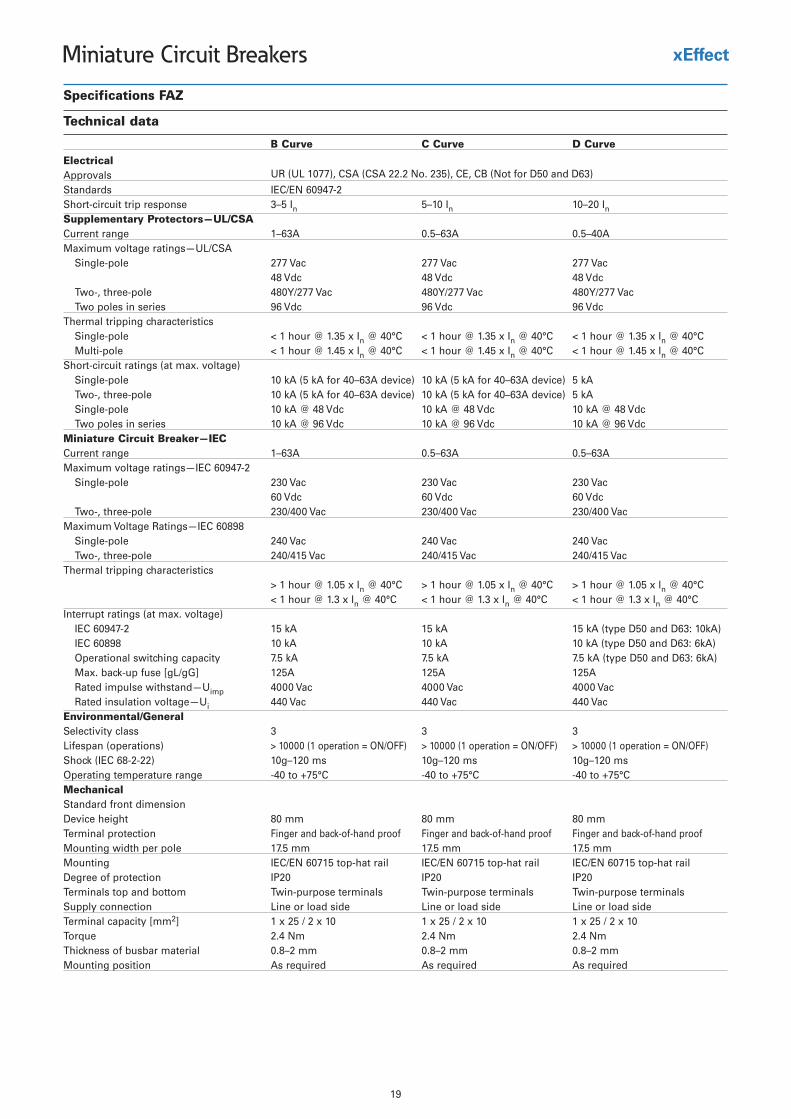
Specifications FAZ
Technical data
B Curve C Curve D Curve
ElectricalApprovals UR (UL 1077), CSA (CSA 22.2 No. 235), CE, CB (Not for D50 and D63)
Standards IEC/EN 60947-2Short-circuit trip response 3–5 In 5–10 In 10–20 InSupplementary Protectors—UL/CSACurrent range 1–63A 0.5–63A 0.5–40AMaximum voltage ratings—UL/CSA
Single-pole 277 Vac 277 Vac 277 Vac48 Vdc 48 Vdc 48 Vdc
Two-, three-pole 480Y/277 Vac 480Y/277 Vac 480Y/277 VacTwo poles in series 96 Vdc 96 Vdc 96 Vdc
Thermal tripping characteristicsSingle-pole < 1 hour @ 1.35 x In @ 40°C < 1 hour @ 1.35 x In @ 40°C < 1 hour @ 1.35 x In @ 40°CMulti-pole < 1 hour @ 1.45 x In @ 40°C < 1 hour @ 1.45 x In @ 40°C < 1 hour @ 1.45 x In @ 40°C
Short-circuit ratings (at max. voltage)Ak 5)ecived A36–04 rof Ak 5( Ak 01)ecived A36–04 rof Ak 5( Ak 01elop-elgniSAk 5)ecived A36–04 rof Ak 5( Ak 01)ecived A36–04 rof Ak 5( Ak 01elop-eerht ,-owT
cdV 84 @ Ak 01cdV 84 @ Ak 01cdV 84 @ Ak 01elop-elgniSTwo poles in series 10 kA @ 96 Vdc 10 kA @ 96 Vdc 10 kA @ 96 Vdc
Miniature Circuit Breaker—IECCurrent range 1–63A 0.5–63A 0.5–63AMaximum voltage ratings—IEC 60947-2
Single-pole 230 Vac 230 Vac 230 Vac60 Vdc 60 Vdc 60 Vdc
Two-, three-pole 230/400 Vac 230/400 Vac 230/400 VacMaximum Voltage Ratings—IEC 60898
Single-pole 240 Vac 240 Vac 240 VacTwo-, three-pole 240/415 Vac 240/415 Vac 240/415 Vac
Thermal tripping characteristics> 1 hour @ 1.05 x In @ 40°C > 1 hour @ 1.05 x In @ 40°C > 1 hour @ 1.05 x In @ 40°C< 1 hour @ 1.3 x In @ 40°C < 1 hour @ 1.3 x In @ 40°C < 1 hour @ 1.3 x In @ 40°C
Interrupt ratings (at max. voltage))Ak01 :36D dna 05D epyt( Ak 51Ak 51Ak 512-74906 CEI
)Ak6 :36D dna 05D epyt( Ak 01Ak 01Ak 0189806 CEI)Ak6 :36D dna 05D epyt( Ak 5.7Ak 5.7Ak 5.7yticapac gnihctiws lanoitarepO
A521A521A521]Gg/Lg[ esuf pu-kcab .xaMRated impulse withstand—Uimp 4000 Vac 4000 Vac 4000 VacRated insulation voltage—Ui 440 Vac 440 Vac 440 Vac
Environmental/GeneralSelectivity class 3 3 3Lifespan (operations) > 10000 (1 operation = ON/OFF) > 10000 (1 operation = ON/OFF) > 10000 (1 operation = ON/OFF)Shock (IEC 68-2-22) 10g–120 ms 10g–120 ms 10g–120 msOperating temperature range -40 to +75°C -40 to +75°C -40 to +75°CMechanicalStandard front dimensionDevice height 80 mm 80 mm 80 mmTerminal protection Finger and back-of-hand proof Finger and back-of-hand proof Finger and back-of-hand proofMounting width per pole 17.5 mm 17.5 mm 17.5 mmMounting IEC/EN 60715 top-hat rail IEC/EN 60715 top-hat rail IEC/EN 60715 top-hat railDegree of protection IP20 IP20 IP20Terminals top and bottom Twin-purpose terminals Twin-purpose terminals Twin-purpose terminalsSupply connection Line or load side Line or load side Line or load sideTerminal capacity [mm2] 1 x 25 / 2 x 10 1 x 25 / 2 x 10 1 x 25 / 2 x 10Torque 2.4 Nm 2.4 Nm 2.4 NmThickness of busbar material 0.8–2 mm 0.8–2 mm 0.8–2 mmMounting position As required As required As required
20
Miniature Circuit Breakers
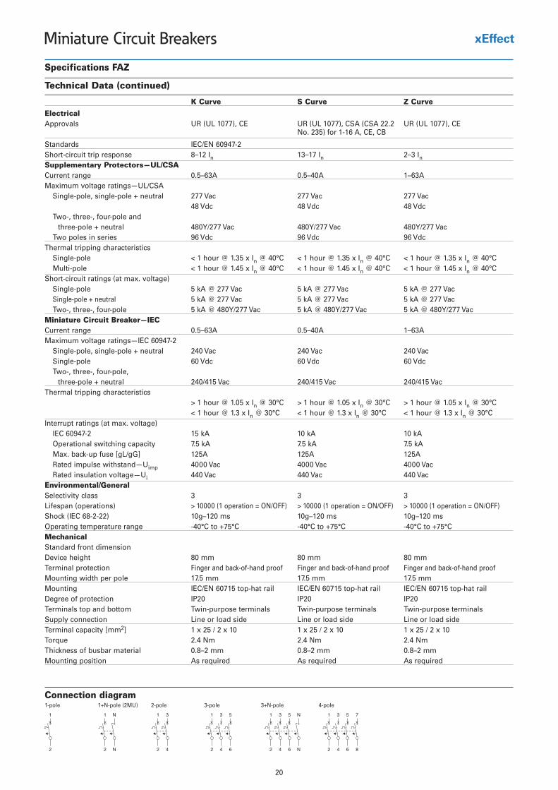
Connection diagram1-pole 1+N-pole (2MU) 2-pole 3-pole 3+N-pole 4-pole
Specifications FAZ
Technical Data (continued)
K Curve S Curve Z Curve
ElectricalApprovals UR (UL 1077), CE UR (UL 1077), CSA (CSA 22.2
No. 235) for 1-16 A, CE, CBUR (UL 1077), CE
Standards IEC/EN 60947-2Short-circuit trip response 8–12 In 13–17 In 2–3 InSupplementary Protectors—UL/CSACurrent range 0.5–63A 0.5–40A 1–63AMaximum voltage ratings—UL/CSA
Single-pole, single-pole + neutral 277 Vac 277 Vac 277 Vac48 Vdc 48 Vdc 48 Vdc
Two-, three-, four-pole and three-pole + neutral 480Y/277 Vac 480Y/277 Vac 480Y/277 Vac
Two poles in series 96 Vdc 96 Vdc 96 VdcThermal tripping characteristics
Single-pole < 1 hour @ 1.35 x In @ 40°C < 1 hour @ 1.35 x In @ 40°C < 1 hour @ 1.35 x In @ 40°CMulti-pole < 1 hour @ 1.45 x In @ 40°C < 1 hour @ 1.45 x In @ 40°C < 1 hour @ 1.45 x In @ 40°C
Short-circuit ratings (at max. voltage)caV 772 @ Ak 5caV 772 @ Ak 5caV 772 @ Ak 5elop-elgniS
Single-pole + neutral 5 kA @ 277 Vac 5 kA @ 277 Vac 5 kA @ 277 VacTwo-, three-, four-pole 5 kA @ 480Y/277 Vac 5 kA @ 480Y/277 Vac 5 kA @ 480Y/277 Vac
Miniature Circuit Breaker—IECCurrent range 0.5–63A 0.5–40A 1–63AMaximum voltage ratings—IEC 60947-2
Single-pole, single-pole + neutral 240 Vac 240 Vac 240 VacSingle-pole 60 Vdc 60 Vdc 60 VdcTwo-, three-, four-pole,
three-pole + neutral 240/415 Vac 240/415 Vac 240/415 VacThermal tripping characteristics
> 1 hour @ 1.05 x In @ 30°C > 1 hour @ 1.05 x In @ 30°C > 1 hour @ 1.05 x In @ 30°C< 1 hour @ 1.3 x In @ 30°C < 1 hour @ 1.3 x In @ 30°C < 1 hour @ 1.3 x In @ 30°C
Interrupt ratings (at max. voltage)Ak 01Ak 01Ak 512-74906 CEIAk 5.7Ak 5.7Ak 5.7yticapac gnihctiws lanoitarepO
A521A521A521]Gg/Lg[ esuf pu-kcab .xaMRated impulse withstand—Uimp 4000 Vac 4000 Vac 4000 VacRated insulation voltage—Ui 440 Vac 440 Vac 440 Vac
Environmental/GeneralSelectivity class 3 3 3Lifespan (operations) > 10000 (1 operation = ON/OFF) > 10000 (1 operation = ON/OFF) > 10000 (1 operation = ON/OFF)Shock (IEC 68-2-22) 10g–120 ms 10g–120 ms 10g–120 msOperating temperature range -40°C to +75°C -40°C to +75°C -40°C to +75°CMechanicalStandard front dimensionDevice height 80 mm 80 mm 80 mmTerminal protection Finger and back-of-hand proof Finger and back-of-hand proof Finger and back-of-hand proofMounting width per pole 17.5 mm 17.5 mm 17.5 mmMounting IEC/EN 60715 top-hat rail IEC/EN 60715 top-hat rail IEC/EN 60715 top-hat railDegree of protection IP20 IP20 IP20Terminals top and bottom Twin-purpose terminals Twin-purpose terminals Twin-purpose terminalsSupply connection Line or load side Line or load side Line or load sideTerminal capacity [mm2] 1 x 25 / 2 x 10 1 x 25 / 2 x 10 1 x 25 / 2 x 10Torque 2.4 Nm 2.4 Nm 2.4 NmThickness of busbar material 0.8–2 mm 0.8–2 mm 0.8–2 mmMounting position As required As required As required
21
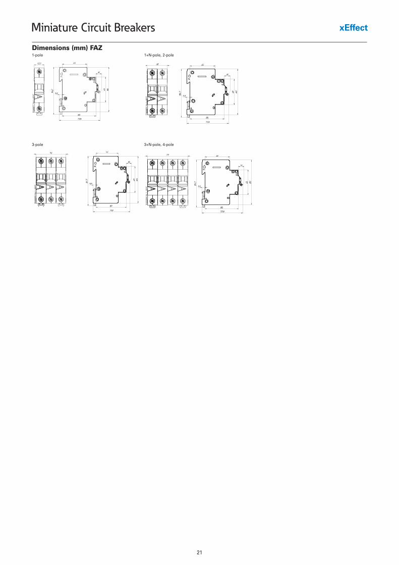
Miniature Circuit Breakers
Dimensions (mm) FAZ1-pole 1+N-pole, 2-pole
3-pole 3+N-pole, 4-pole
22
Miniature Circuit Breakers
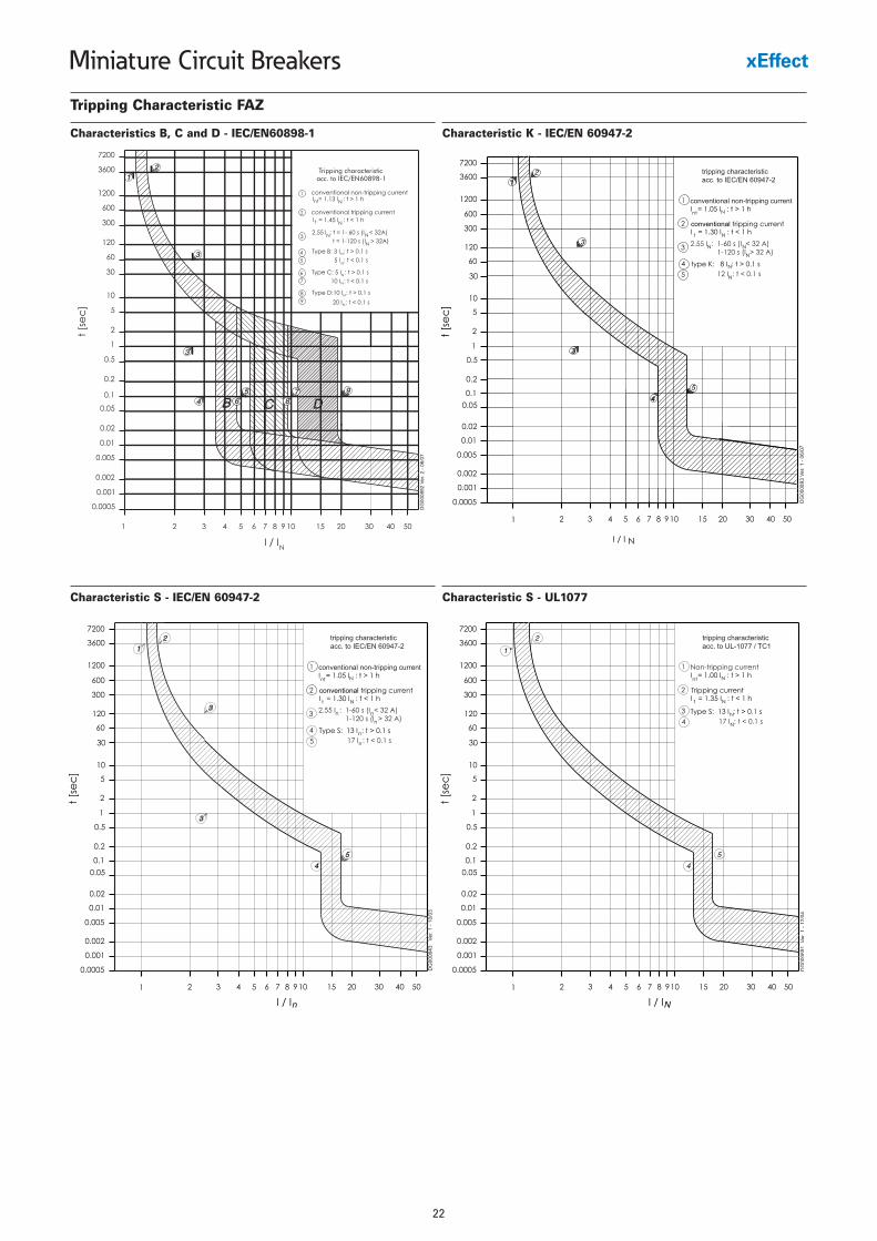
Tripping Characteristic FAZ
Characteristics B, C and D - IEC/EN60898-1 Characteristic K - IEC/EN 60947-2
Characteristic S - IEC/EN 60947-2 Characteristic S - UL1077
23
Miniature Circuit Breakers
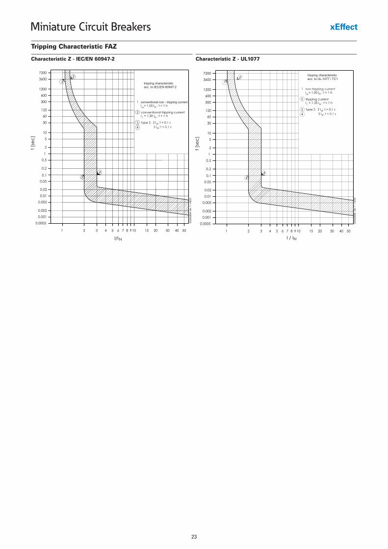
Tripping Characteristic FAZ
Characteristic Z - IEC/EN 60947-2 Characteristic Z - UL1077
24
Miniature Circuit Breakers
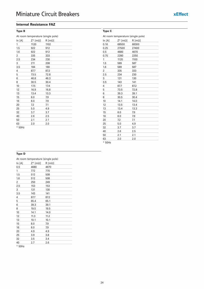
Internal Resistance FAZ
At room temperature (single pole)
In [A] Z* [mΩ] R [m Ω]1 1120 11021.5 922 9121.6 922 9122 335 3332.5 234 2303 211 2083.5 184 1804 87.7 87.25 73.5 72.86 46.8 46.38 30.5 30.410 17.5 17.412 16.9 16.813 13.4 13.315 8.0 7.916 8.0 7.920 7.2 7.125 5.0 4.932 3.7 3.740 2.6 2.550 2.1 2.163 2.0 2.0* 50Hz
Type B
At room temperature (single pole)
In [A] Z* [mΩ] R [m Ω]0.16 68500 683000.25 27500 274000.5 4680 46700.75 2280 22501 1120 11001.5 589 5871.6 589 5872 335 3332.5 234 2303 131 1303.5 143 1414 87.7 87.25 73.5 72.86 39.3 39.18 30.5 30.410 14.1 14.012 13.5 13.413 13.4 13.315 8.0 7.916 8.0 7.920 7.2 7.125 5.0 4.932 3.7 3.740 2.6 2.550 2.1 2.163 2.0 2.0* 50Hz
Type C
At room temperature (single pole)
In [A] Z* [mΩ] R [m Ω]0.5 4680 46701 772 7701.5 512 5081.6 512 5082 250 2492.5 153 1533 131 1303.5 143 1414 87.7 87.25 65.4 65.16 39.3 39.18 19.5 19.510 14.1 14.012 11.3 11.213 10.1 10.115 8.0 7.916 8.0 7.920 4.9 4.925 3.9 3.832 3.5 3.440 2.7 2.6* 50Hz
Type D
25
Miniature Circuit Breakers
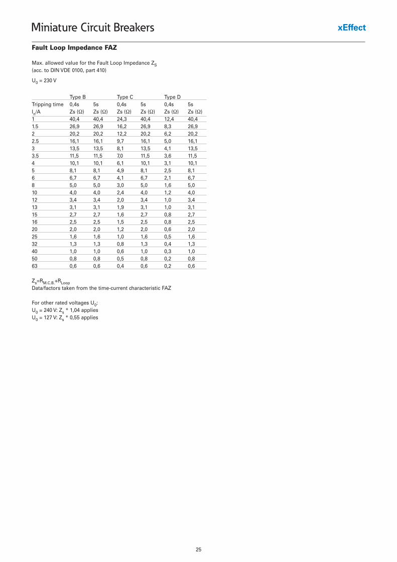
Fault Loop Impedance FAZ
Max. allowed value for the Fault Loop Impedance ZS(acc. to DIN VDE 0100, part 410)
U0 = 230 V
Type B Type C Type DTripping time 0,4s 5s 0,4s 5s 0,4s 5sIn/A Zs (Ω) Zs (Ω) Zs (Ω) Zs (Ω) Zs (Ω) Zs (Ω)1 40,4 40,4 24,3 40,4 12,4 40,41.5 26,9 26,9 16,2 26,9 8,3 26,92 20,2 20,2 12,2 20,2 6,2 20,22.5 16,1 16,1 9,7 16,1 5,0 16,13 13,5 13,5 8,1 13,5 4,1 13,53.5 11,5 11,5 7,0 11,5 3,6 11,54 10,1 10,1 6,1 10,1 3,1 10,15 8,1 8,1 4,9 8,1 2,5 8,16 6,7 6,7 4,1 6,7 2,1 6,78 5,0 5,0 3,0 5,0 1,6 5,010 4,0 4,0 2,4 4,0 1,2 4,012 3,4 3,4 2,0 3,4 1,0 3,413 3,1 3,1 1,9 3,1 1,0 3,115 2,7 2,7 1,6 2,7 0,8 2,716 2,5 2,5 1,5 2,5 0,8 2,520 2,0 2,0 1,2 2,0 0,6 2,025 1,6 1,6 1,0 1,6 0,5 1,632 1,3 1,3 0,8 1,3 0,4 1,340 1,0 1,0 0,6 1,0 0,3 1,050 0,8 0,8 0,5 0,8 0,2 0,863 0,6 0,6 0,4 0,6 0,2 0,6
Zs=RM.C.B.+RLoopData/factors taken from the time-current characteristic FAZ
For other rated voltages U0:U0 = 240 V: Zs * 1,04 appliesU0 = 127 V: Zs * 0,55 applies
26
Miniature Circuit Breakers
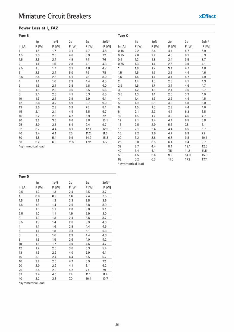
Power Loss at In FAZ
1p 1pN 2p 3p 3pN*
In [A] P [W] P [W] P [W] P [W] P [W]1 1.6 1.7 3.1 4.7 4.81.5 2.3 2.5 4.6 6.9 7.21.6 2.5 2.7 4.9 7.4 7.62 1.4 1.5 2.8 4.1 4.32.5 1.5 1.7 3.1 4.6 4.73 2.5 2.7 5.0 7.6 7.83.5 2.5 2.8 5.1 7.8 8.04 1.4 1.6 2.9 4.4 4.55 1.9 2.1 3.8 5.8 6.06 1.8 2.0 3.6 5.5 5.68 2.1 2.3 4.1 6.3 6.510 1.9 2.1 3.9 5.9 6.112 2.8 3.2 5.9 8.7 9.013 2.5 2.9 5.3 7.8 8.115 2.1 2.4 4.4 6.5 6.716 2.2 2.6 4.7 6.9 7.220 3.2 3.6 6.6 9.8 10.125 3.0 3.5 6.4 9.4 9.732 3.7 4.4 8.1 12.1 12.540 3.4 4.1 7.5 11.2 11.550 4.5 5.4 9.9 14.9 15.363 5.2 6.3 11.5 17.2 17.7*symmetrical load
Type B
1p 1pN 2p 3p 3pN*
In [A] P [W] P [W] P [W] P [W] P [W]0.16 2.2 2.4 4.4 6.7 6.90.25 2.0 2.2 4.0 6.1 6.30.5 1.2 1.3 2.4 3.5 3.70.75 1.3 1.4 2.6 3.9 4.11 1.6 1.7 3.1 4.7 4.81.5 1.5 1.6 2.9 4.4 4.61.6 1.6 1.7 3.1 4.7 4.92 1.4 1.5 2.8 4.1 4.32.5 1.5 1.7 3.1 4.6 4.73 1.2 1.3 2.4 3.6 3.73.5 1.3 1.4 2.6 3.9 4.04 1.4 1.6 2.9 4.4 4.55 1.9 2.1 3.8 5.8 6.06 1.5 1.6 2.9 4.4 4.68 2.1 2.3 4.1 6.3 6.510 1.5 1.7 3.0 4.6 4.712 2.1 2.4 4.4 6.5 6.813 2.5 2.9 5.3 7.8 8.115 2.1 2.4 4.4 6.5 6.716 2.2 2.6 4.7 6.9 7.220 3.2 3.6 6.6 9.8 10.125 3.0 3.5 6.4 9.4 9.732 3.7 4.4 8.1 12.1 12.540 3.4 4.1 7.5 11.2 11.550 4.5 5.4 9.9 14.9 15.363 5.2 6.3 11.5 17.2 17.7*symmetrical load
Type C
1p 1pN 2p 3p 3pN*
In [A] P [W] P [W] P [W] P [W] P [W]0.5 1.2 1.3 2.4 3.5 3.71 0.8 0.9 1.6 2.4 2.51.5 1.2 1.3 2.3 3.5 3.61.6 1.3 1.4 2.5 3.8 3.92 1.0 1.1 2.0 3.0 3.12.5 1.0 1.1 1.9 2.9 3.03 1.2 1.3 2.4 3.6 3.73.5 1.3 1.4 2.6 3.9 4.04 1.4 1.6 2.9 4.4 4.55 1.7 1.8 3.3 5.1 5.36 1.5 1.6 2.9 4.4 4.68 1.3 1.5 2.6 4.0 4.210 1.5 1.7 3.0 4.6 4.712 1.7 2.0 3.6 5.3 5.413 1.9 2.2 4.0 5.9 6.115 2.1 2.4 4.4 6.5 6.716 2.2 2.6 4.7 6.9 7.220 2.0 2.2 4.1 6.1 6.225 2.5 2.9 5.2 7.7 7.932 3.4 4.0 7.4 11.1 11.440 3.2 3.8 7.0 10.4 10.7*symmetrical load
Type D
27
Miniature Circuit Breakers
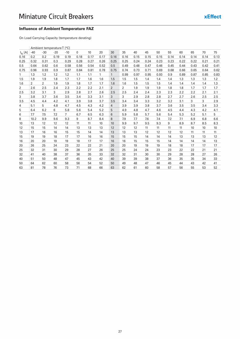
Influence of Ambient Temperature FAZ
On Load Carrying Capacity (temperature derating)
Ambient temperature T [°C]IN [A] -40 -30 -20 -10 0 10 20 30 35 40 45 50 55 60 65 70 75
0.16 0.2 0.2 0.19 0.19 0.18 0.17 0.17 0.16 0.16 0.15 0.15 0.15 0.14 0.14 0.14 0.14 0.130.25 0.32 0.31 0.3 0.29 0.28 0.27 0.26 0.25 0.25 0.24 0.24 0.23 0.23 0.22 0.22 0.21 0.210.5 0.64 0.62 0.6 0.58 0.56 0.54 0.52 0.5 0.49 0.48 0.47 0.46 0.45 0.44 0.43 0.42 0.410.75 0.96 0.93 0.9 0.87 0.84 0.81 0.78 0.75 0.74 0.73 0.71 0.69 0.68 0.66 0.65 0.64 0.621 1.3 1.2 1.2 1.2 1.1 1.1 1 1 0.99 0.97 0.95 0.93 0.9 0.89 0.87 0.85 0.831.5 1.9 1.9 1.8 1.7 1.7 1.6 1.6 1.5 1.5 1.5 1.4 1.4 1.4 1.3 1.3 1.3 1.21.6 2 2 1.9 1.9 1.8 1.7 1.7 1.6 1.6 1.5 1.5 1.5 1.4 1.4 1.4 1.4 1.32 2.6 2.5 2.4 2.3 2.2 2.2 2.1 2 2 1.9 1.9 1.9 1.8 1.8 1.7 1.7 1.72.5 3.2 3.1 3 2.9 2.8 2.7 2.6 2.5 2.5 2.4 2.4 2.3 2.3 2.2 2.2 2.1 2.13 3.8 3.7 3.6 3.5 3.4 3.3 3.1 3 3 2.9 2.8 2.8 2.7 2.7 2.6 2.5 2.53.5 4.5 4.4 4.2 4.1 3.9 3.8 3.7 3.5 3.4 3.4 3.3 3.2 3.2 3.1 3 3 2.94 5.1 5 4.8 4.7 4.5 4.3 4.2 4 3.9 3.9 3.8 3.7 3.6 3.5 3.5 3.4 3.35 6.4 6.2 6 5.8 5.6 5.4 5.2 5 4.9 4.8 4.7 4.6 4.5 4.4 4.3 4.2 4.16 7.7 7.5 7.2 7 6.7 6.5 6.3 6 5.9 5.8 5.7 5.6 5.4 5.3 5.2 5.1 58 10.2 9.9 9.6 9.3 9 8.7 8.4 8 7.9 7.7 7.6 7.4 7.2 7.1 6.9 6.8 6.610 13 12 12 12 11 11 10 10 9.9 9.7 9.5 9.3 9 8.9 8.7 8.5 8.312 15 15 14 14 13 13 13 12 12 12 11 11 11 11 10 10 1013 17 16 16 15 15 14 14 13 13 13 12 12 12 12 11 11 1115 19 19 18 17 17 16 16 15 15 15 14 14 14 13 13 13 1216 20 20 19 19 18 17 17 16 16 15 15 15 14 14 14 14 1320 26 25 24 23 22 22 21 20 20 19 19 19 18 18 17 17 1725 32 31 30 29 28 27 26 25 25 24 24 23 23 22 22 21 2132 41 40 38 37 36 35 33 32 32 31 30 30 29 28 28 27 2640 51 50 48 47 45 43 42 40 39 39 38 37 36 35 35 34 3350 64 62 60 58 56 54 52 50 49 48 47 46 45 44 43 42 4163 81 78 76 73 71 68 66 63 62 61 60 58 57 56 55 53 52
28
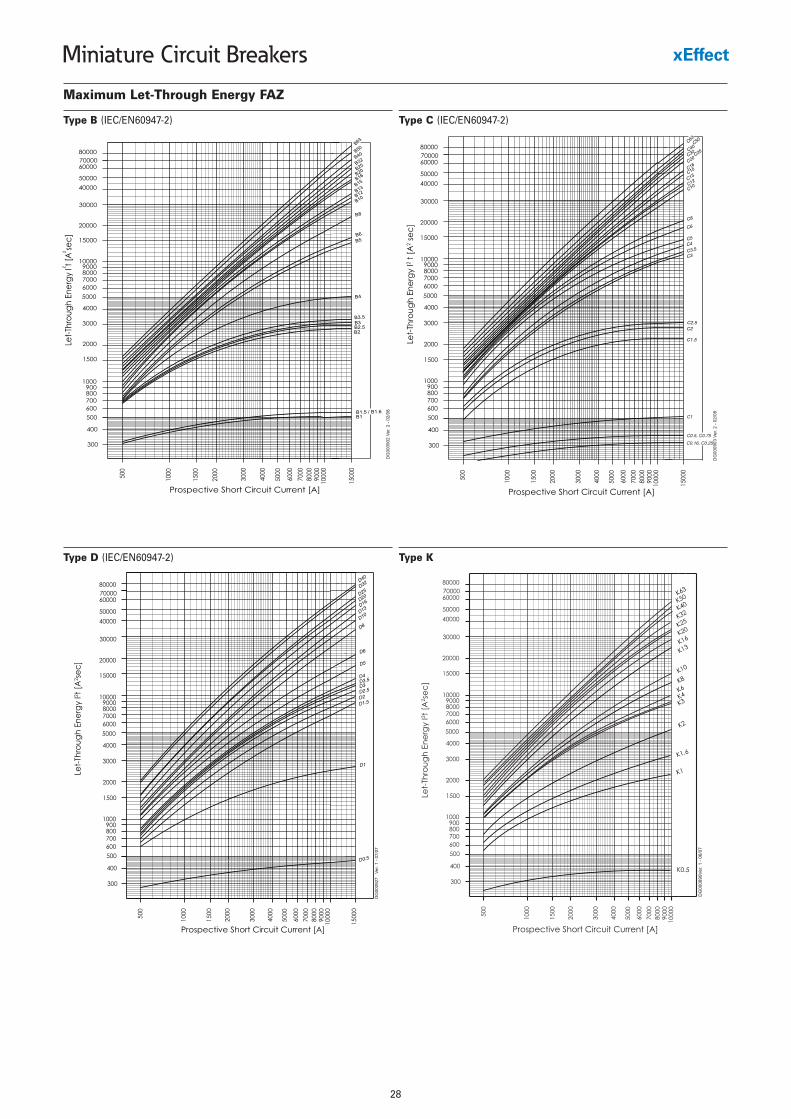
Miniature Circuit Breakers
Maximum Let-Through Energy FAZ
Type B (IEC/EN60947-2) Type C (IEC/EN60947-2)
Type KType D (IEC/EN60947-2)
29
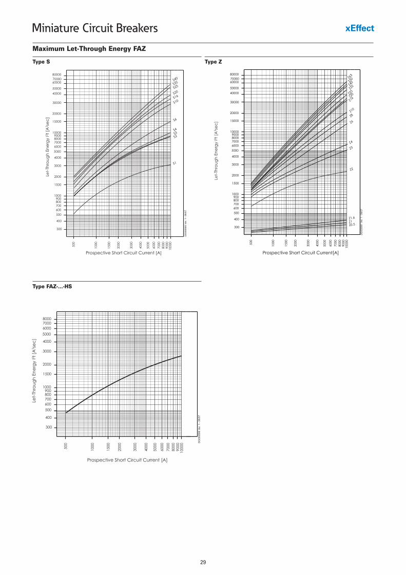
Miniature Circuit Breakers
Maximum Let-Through Energy FAZ
Type ZType S
Type FAZ-...-HS
30
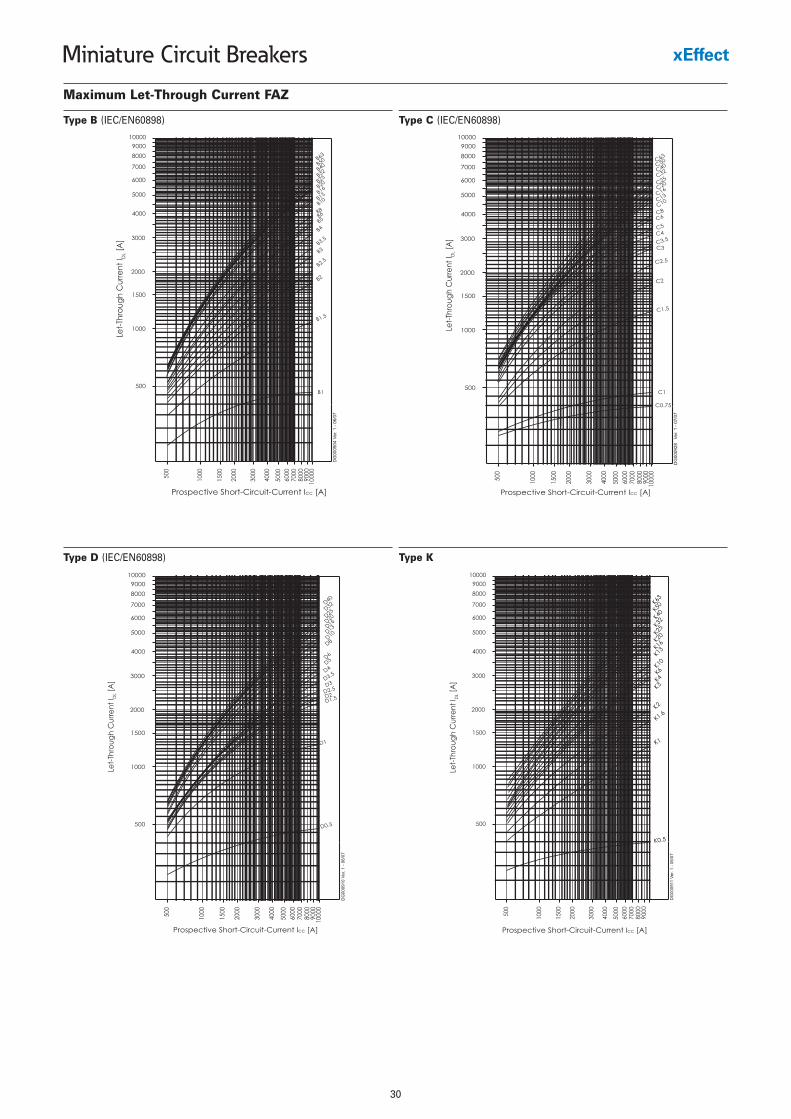
Miniature Circuit Breakers
Maximum Let-Through Current FAZ
Type B (IEC/EN60898) Type C (IEC/EN60898)
Type KType D (IEC/EN60898)
31
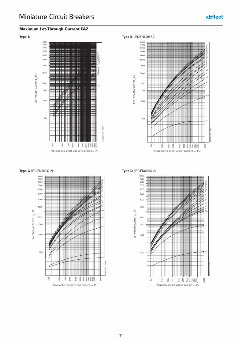
Miniature Circuit Breakers
Maximum Let-Through Current FAZ
Type B (IEC/EN60947-2)Type S
Type C (IEC/EN60947-2) Type D (IEC/EN60947-2)
32
Miniature Circuit Breakers
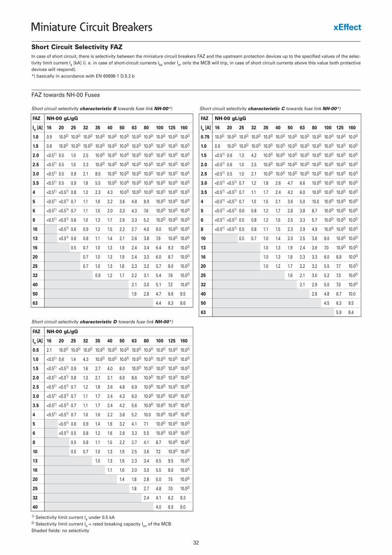
Short Circuit Selectivity FAZ
Short circuit selectivity characteristic B towards fuse link NH-00*)
FAZ NH-00 gL/gG
In [A] 16 20 25 32 35 40 50 63 80 100 125 160
1.0 0.9 10.02) 10.02) 10.02) 10.02) 10.02) 10.02) 10.02) 10.02) 10.02) 10.02) 10.02)
1.5 0.8 10.02) 10.02) 10.02) 10.02) 10.02) 10.02) 10.02) 10.02) 10.02) 10.02) 10.02)
2.0 <0.51) 0.5 1.0 2.5 10.02) 10.02) 10.02) 10.02) 10.02) 10.02) 10.02) 10.02)
2.5 <0.51) 0.5 1.0 2.3 10.02) 10.02) 10.02) 10.02) 10.02) 10.02) 10.02) 10.02)
3.0 <0.51) 0.5 0.9 2.1 8.0 10.02) 10.02) 10.02) 10.02) 10.02) 10.02) 10.02)
3.5 <0.51) 0.5 0.9 1.8 5.5 10.02) 10.02) 10.02) 10.02) 10.02) 10.02) 10.02)
4 <0.51) <0.51) 0.8 1.3 2.3 4.3 10.02) 10.02) 10.02) 10.02) 10.02) 10.02)
5 <0.51) <0.51) 0.7 1.1 1.6 2.2 3.6 4.8 8.9 10.02) 10.02) 10.02)
6 <0.51) <0.51) 0.7 1.1 1.5 2.0 3.3 4.3 7.6 10.02) 10.02) 10.02)
8 <0.51) <0.51) 0.6 1.0 1.3 1.7 2.6 3.3 5.2 10.02) 10.02) 10.02)
10 <0.51) 0.6 0.9 1.2 1.5 2.2 2.7 4.0 9.0 10.02) 10.02)
13 <0.51) 0.6 0.8 1.1 1.4 2.1 2.6 3.8 7.9 10.02) 10.02)
16 0.5 0.7 1.0 1.3 1.9 2.4 3.4 6.4 9.3 10.02)
20 0.7 1.0 1.3 1.9 2.4 3.3 6.0 8.7 10.02)
25 0.7 1.0 1.3 1.8 2.3 3.2 5.7 8.0 10.02)
32 0.9 1.2 1.7 2.2 3.1 5.4 7.6 10.02)
40 2.1 3.0 5.1 7.2 10.02)
50 1.9 2.8 4.7 6.6 9.5
63 4.4 6.3 8.6
Short circuit selectivity characteristic C towards fuse link NH-00*)
FAZ NH-00 gL/gG
In [A] 16 20 25 32 35 40 50 63 80 100 125 160
0.75 10.02) 10.02) 10.02) 10.02) 10.02) 10.02) 10.02) 10.02) 10.02) 10.02) 10.02) 10.02)
1.0 0.9 10.02) 10.02) 10.02) 10.02) 10.02) 10.02) 10.02) 10.02) 10.02) 10.02) 10.02)
1.5 <0.51) 0.6 1.3 4.2 10.02) 10.02) 10.02) 10.02) 10.02) 10.02) 10.02) 10.02)
2.0 <0.51) 0.6 1.0 2.5 10.02) 10.02) 10.02) 10.02) 10.02) 10.02) 10.02) 10.02)
2.5 <0.51) 0.5 1.0 2.1 10.02) 10.02) 10.02) 10.02) 10.02) 10.02) 10.02) 10.02)
3.0 <0.51) <0.51) 0.7 1.2 1.8 2.6 4.7 6.6 10.02) 10.02) 10.02) 10.02)
3.5 <0.51) <0.51) 0.7 1.1 1.7 2.4 4.2 6.0 10.02) 10.02) 10.02) 10.02)
4 <0.51) <0.51) 0.7 1.0 1.5 2.1 3.6 5.0 10.0 10.02) 10.02) 10.02)
5 <0.51) <0.51) 0.6 0.8 1.2 1.7 2.8 3.8 8.7 10.02) 10.02) 10.02)
6 <0.51) <0.51) 0.5 0.8 1.2 1.5 2.5 3.3 5.7 10.02) 10.02) 10.02)
8 <0.51) <0.51) 0.5 0.8 1.1 1.5 2.3 2.9 4.9 10.02) 10.02) 10.02)
10 0.5 0.7 1.0 1.4 2.0 2.5 3.8 8.0 10.02) 10.02)
13 1.0 1.3 1.9 2.4 3.6 7.0 10.02) 10.02)
16 1.0 1.3 1.8 2.3 3.3 6.0 8.8 10.02)
20 1.0 1.2 1.7 2.2 3.2 5.5 7.7 10.02)
25 1.6 2.1 3.0 5.2 7.3 10.02)
32 2.1 2.9 5.0 7.0 10.02)
40 2.8 4.8 6.7 10.0
50 4.5 6.3 9.5
63 5.9 8.4
Short circuit selectivity characteristic D towards fuse link NH-00*)
FAZ NH-00 gL/gG
In [A] 16 20 25 32 35 40 50 63 80 100 125 160
0.5 2.1 10.02) 10.02) 10.02) 10.02) 10.02) 10.02) 10.02) 10.02) 10.02) 10.02) 10.02)
1.0 <0.51) 0,6 1.4 4.3 10.02) 10.02) 10.02) 10.02) 10.02) 10.02) 10.02) 10.02)
1.5 <0.51) <0.51) 0.9 1.6 2.7 4.0 8.0 10.02) 10.02) 10.02) 10.02) 10.02)
2.0 <0.51) <0.51) 0.8 1.3 2.1 3.1 6.0 8.6 10.02) 10.02) 10.02) 10.02)
2.5 <0.51) <0.51) 0.7 1.2 1.8 2.6 4.8 6.9 10.02) 10.02) 10.02) 10.02)
3.0 <0.51) <0.51) 0.7 1.1 1.7 2.4 4.3 6.0 10.02) 10.02) 10.02) 10.02)
3.5 <0.51) <0.51) 0.7 1.1 1.7 2.4 4.2 5.6 10.02) 10.02) 10.02) 10.02)
4 <0.51) <0.51) 0.7 1.0 1.6 2.2 3.8 5.2 10.0 10.02) 10.02) 10.02)
5 <0.51) 0.6 0.9 1.4 1.9 3.2 4.1 7.1 10.02) 10.02) 10.02)
6 <0.51) 0.5 0.8 1.2 1.6 2.6 3.3 5.5 10.02) 10.02) 10.02)
8 0.5 0.8 1.1 1.5 2.2 2.7 4.1 8.7 10.02) 10.02)
10 0.5 0.7 1.0 1.3 1.9 2.5 3.6 7.2 10.02) 10.02)
13 1.0 1.3 1.9 2.3 3.4 6.5 9.5 10.02)
16 1.1 1.6 2.0 3.0 5.5 8.0 10.02)
20 1.4 1.8 2.8 5.0 7.5 10.02)
25 1.8 2.7 4.8 7.0 10.02)
32 2.4 4.1 6.2 9.3
40 4.0 6.0 9.0
In case of short circuit, there is selectivity between the miniature circuit breakers FAZ and the upstream protection devices up to the specified values of the selec-tivity limit current Is [kA] (i. e. in case of short-circuit currents Iks under Is, only the MCB will trip, in case of short circuit currents above this value both protectivedevices will respond).*) basically in accordance with EN 60898-1 D.5.2.b
1) Selectivity limit current Is under 0.5 kA2) Selectivity limit current Is = rated breaking capacity Icn of the MCBShaded fields: no selectivity
FAZ towards NH-00 Fuses
33
Miniature Circuit Breakers
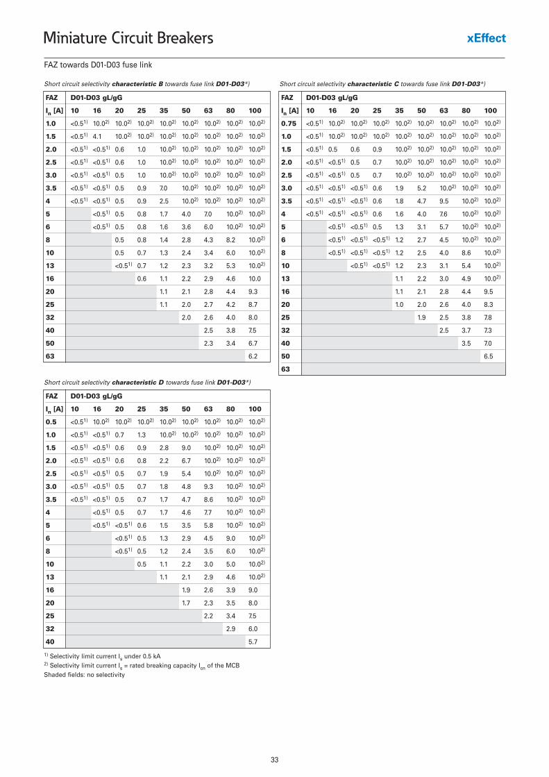
FAZ towards D01-D03 fuse link
1) Selectivity limit current Is under 0.5 kA2) Selectivity limit current Is = rated breaking capacity Icn of the MCBShaded fields: no selectivity
Short circuit selectivity characteristic B towards fuse link D01-D03*)
FAZ D01-D03 gL/gG
In [A] 10 16 20 25 35 50 63 80 100
1.0 <0.51) 10.02) 10.02) 10.02) 10.02) 10.02) 10.02) 10.02) 10.02)
1.5 <0.51) 4.1 10.02) 10.02) 10.02) 10.02) 10.02) 10.02) 10.02)
2.0 <0.51) <0.51) 0.6 1.0 10.02) 10.02) 10.02) 10.02) 10.02)
2.5 <0.51) <0.51) 0.6 1.0 10.02) 10.02) 10.02) 10.02) 10.02)
3.0 <0.51) <0.51) 0.5 1.0 10.02) 10.02) 10.02) 10.02) 10.02)
3.5 <0.51) <0.51) 0.5 0.9 7.0 10.02) 10.02) 10.02) 10.02)
4 <0.51) <0.51) 0.5 0.9 2.5 10.02) 10.02) 10.02) 10.02)
5 <0.51) 0.5 0.8 1.7 4.0 7.0 10.02) 10.02)
6 <0.51) 0.5 0.8 1.6 3.6 6.0 10.02) 10.02)
8 0.5 0.8 1.4 2.8 4.3 8.2 10.02)
10 0.5 0.7 1.3 2.4 3.4 6.0 10.02)
13 <0.51) 0.7 1.2 2.3 3.2 5.3 10.02)
16 0.6 1.1 2.2 2.9 4.6 10.0
20 1.1 2.1 2.8 4.4 9.3
25 1.1 2.0 2.7 4.2 8.7
32 2.0 2.6 4.0 8.0
40 2.5 3.8 7.5
50 2.3 3.4 6.7
63 6.2
Short circuit selectivity characteristic C towards fuse link D01-D03*)
FAZ D01-D03 gL/gG
In [A] 10 16 20 25 35 50 63 80 100
0.75 <0.51) 10.02) 10.02) 10.02) 10.02) 10.02) 10.02) 10.02) 10.02)
1.0 <0.51) 10.02) 10.02) 10.02) 10.02) 10.02) 10.02) 10.02) 10.02)
1.5 <0.51) 0.5 0.6 0.9 10.02) 10.02) 10.02) 10.02) 10.02)
2.0 <0.51) <0.51) 0.5 0.7 10.02) 10.02) 10.02) 10.02) 10.02)
2.5 <0.51) <0.51) 0.5 0.7 10.02) 10.02) 10.02) 10.02) 10.02)
3.0 <0.51) <0.51) <0.51) 0.6 1.9 5.2 10.02) 10.02) 10.02)
3.5 <0.51) <0.51) <0.51) 0.6 1.8 4.7 9.5 10.02) 10.02)
4 <0.51) <0.51) <0.51) 0.6 1.6 4.0 7.6 10.02) 10.02)
5 <0.51) <0.51) 0.5 1.3 3.1 5.7 10.02) 10.02)
6 <0.51) <0.51) <0.51) 1.2 2.7 4.5 10.02) 10.02)
8 <0.51) <0.51) <0.51) 1.2 2.5 4.0 8.6 10.02)
10 <0.51) <0.51) 1.2 2.3 3.1 5.4 10.02)
13 1.1 2.2 3.0 4.9 10.02)
16 1.1 2.1 2.8 4.4 9.5
20 1.0 2.0 2.6 4.0 8.3
25 1.9 2.5 3.8 7.8
32 2.5 3.7 7.3
40 3.5 7.0
50 6.5
63
Short circuit selectivity characteristic D towards fuse link D01-D03*)
FAZ D01-D03 gL/gG
In [A] 10 16 20 25 35 50 63 80 100
0.5 <0.51) 10.02) 10.02) 10.02) 10.02) 10.02) 10.02) 10.02) 10.02)
1.0 <0.51) <0.51) 0.7 1.3 10.02) 10.02) 10.02) 10.02) 10.02)
1.5 <0.51) <0.51) 0.6 0.9 2.8 9.0 10.02) 10.02) 10.02)
2.0 <0.51) <0.51) 0.6 0.8 2.2 6.7 10.02) 10.02) 10.02)
2.5 <0.51) <0.51) 0.5 0.7 1.9 5.4 10.02) 10.02) 10.02)
3.0 <0.51) <0.51) 0.5 0.7 1.8 4.8 9.3 10.02) 10.02)
3.5 <0.51) <0.51) 0.5 0.7 1.7 4.7 8.6 10.02) 10.02)
4 <0.51) 0.5 0.7 1.7 4.6 7.7 10.02) 10.02)
5 <0.51) <0.51) 0.6 1.5 3.5 5.8 10.02) 10.02)
6 <0.51) 0.5 1.3 2.9 4.5 9.0 10.02)
8 <0.51) 0.5 1.2 2.4 3.5 6.0 10.02)
10 0.5 1.1 2.2 3.0 5.0 10.02)
13 1.1 2.1 2.9 4.6 10.02)
16 1.9 2.6 3.9 9.0
20 1.7 2.3 3.5 8.0
25 2.2 3.4 7.5
32 2.9 6.0
40 5.7
34
Miniature Circuit Breakers
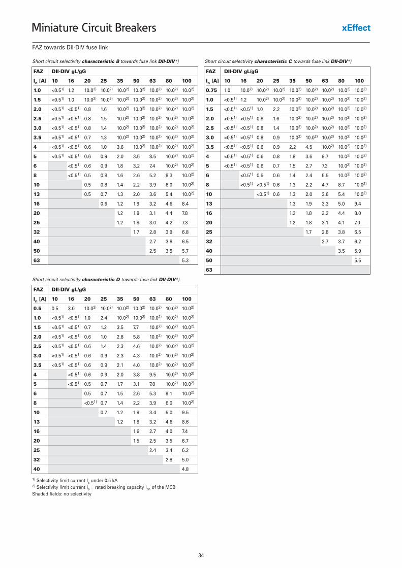
FAZ towards DII-DIV fuse link
1) Selectivity limit current Is under 0.5 kA2) Selectivity limit current Is = rated breaking capacity Icn of the MCBShaded fields: no selectivity
FAZ DII-DIV gL/gG
In [A] 10 16 20 25 35 50 63 80 100
1.0 <0.51) 1.2 10.02) 10.02) 10.02) 10.02) 10.02) 10.02) 10.02)
1.5 <0.51) 1.0 10.02) 10.02) 10.02) 10.02) 10.02) 10.02) 10.02)
2.0 <0.51) <0.51) 0.8 1.6 10.02) 10.02) 10.02) 10.02) 10.02)
2.5 <0.51) <0.51) 0.8 1.5 10.02) 10.02) 10.02) 10.02) 10.02)
3.0 <0.51) <0.51) 0.8 1.4 10.02) 10.02) 10.02) 10.02) 10.02)
3.5 <0.51) <0.51) 0.7 1.3 10.02) 10.02) 10.02) 10.02) 10.02)
4 <0.51) <0.51) 0.6 1.0 3.6 10.02) 10.02) 10.02) 10.02)
5 <0.51) <0.51) 0.6 0.9 2.0 3.5 8.5 10.02) 10.02)
6 <0.51) 0.6 0.9 1.8 3.2 7.4 10.02) 10.02)
8 <0.51) 0.5 0.8 1.6 2.6 5.2 8.3 10.02)
10 0.5 0.8 1.4 2.2 3.9 6.0 10.02)
13 0.5 0.7 1.3 2.0 3.6 5.4 10.02)
16 0.6 1.2 1.9 3.2 4.6 8.4
20 1.2 1.8 3.1 4.4 7.8
25 1.2 1.8 3.0 4.2 7.3
32 1.7 2.8 3.9 6.8
40 2.7 3.8 6.5
50 2.5 3.5 5.7
63 5.3
FAZ DII-DIV gL/gG
In [A] 10 16 20 25 35 50 63 80 100
0.75 1.0 10.02) 10.02) 10.02) 10.02) 10.02) 10.02) 10.02) 10.02)
1.0 <0.51) 1.2 10.02) 10.02) 10.02) 10.02) 10.02) 10.02) 10.02)
1.5 <0.51) <0.51) 1.0 2.2 10.02) 10.02) 10.02) 10.02) 10.02)
2.0 <0.51) <0.51) 0.8 1.6 10.02) 10.02) 10.02) 10.02) 10.02)
2.5 <0.51) <0.51) 0.8 1.4 10.02) 10.02) 10.02) 10.02) 10.02)
3.0 <0.51) <0.51) 0.8 0.9 10.02) 10.02) 10.02) 10.02) 10.02)
3.5 <0.51) <0.51) 0.6 0.9 2.2 4.5 10.02) 10.02) 10.02)
4 <0.51) <0.51) 0.6 0.8 1.8 3.6 9.7 10.02) 10.02)
5 <0.51) <0.51) 0.6 0.7 1.5 2.7 7.3 10.02) 10.02)
6 <0.51) 0.5 0.6 1.4 2.4 5.5 10.02) 10.02)
8 <0.51) <0.51) 0.6 1.3 2.2 4.7 8.7 10.02)
10 <0.51) 0.6 1.3 2.0 3.6 5.4 10.02)
13 1.3 1.9 3.3 5.0 9.4
16 1.2 1.8 3.2 4.4 8.0
20 1.2 1.8 3.1 4.1 7.0
25 1.7 2.8 3.8 6.5
32 2.7 3.7 6.2
40 3.5 5.9
50 5.5
63
Short circuit selectivity characteristic D towards fuse link DII-DIV*)
FAZ DII-DIV gL/gG
In [A] 10 16 20 25 35 50 63 80 100
0.5 0.5 3.0 10.02) 10.02) 10.02) 10.02) 10.02) 10.02) 10.02)
1.0 <0.51) <0.51) 1.0 2.4 10.02) 10.02) 10.02) 10.02) 10.02)
1.5 <0.51) <0.51) 0.7 1.2 3.5 7.7 10.02) 10.02) 10.02)
2.0 <0.51) <0.51) 0.6 1.0 2.8 5.8 10.02) 10.02) 10.02)
2.5 <0.51) <0.51) 0.6 1.4 2.3 4.6 10.02) 10.02) 10.02)
3.0 <0.51) <0.51) 0.6 0.9 2.3 4.3 10.02) 10.02) 10.02)
3.5 <0.51) <0.51) 0.6 0.9 2.1 4.0 10.02) 10.02) 10.02)
4 <0.51) 0.6 0.9 2.0 3.8 9.5 10.02) 10.02)
5 <0.51) 0.5 0.7 1.7 3.1 7.0 10.02) 10.02)
6 0.5 0.7 1.5 2.6 5.3 9.1 10.02)
8 <0.51) 0.7 1.4 2.2 3.9 6.0 10.02)
10 0.7 1.2 1.9 3.4 5.0 9.5
13 1.2 1.8 3.2 4.6 8.6
16 1.6 2.7 4.0 7.4
20 1.5 2.5 3.5 6.7
25 2.4 3.4 6.2
32 2.8 5.0
40 4.8
Short circuit selectivity characteristic B towards fuse link DII-DIV*) Short circuit selectivity characteristic C towards fuse link DII-DIV*)
35
Miniature Circuit Breakers
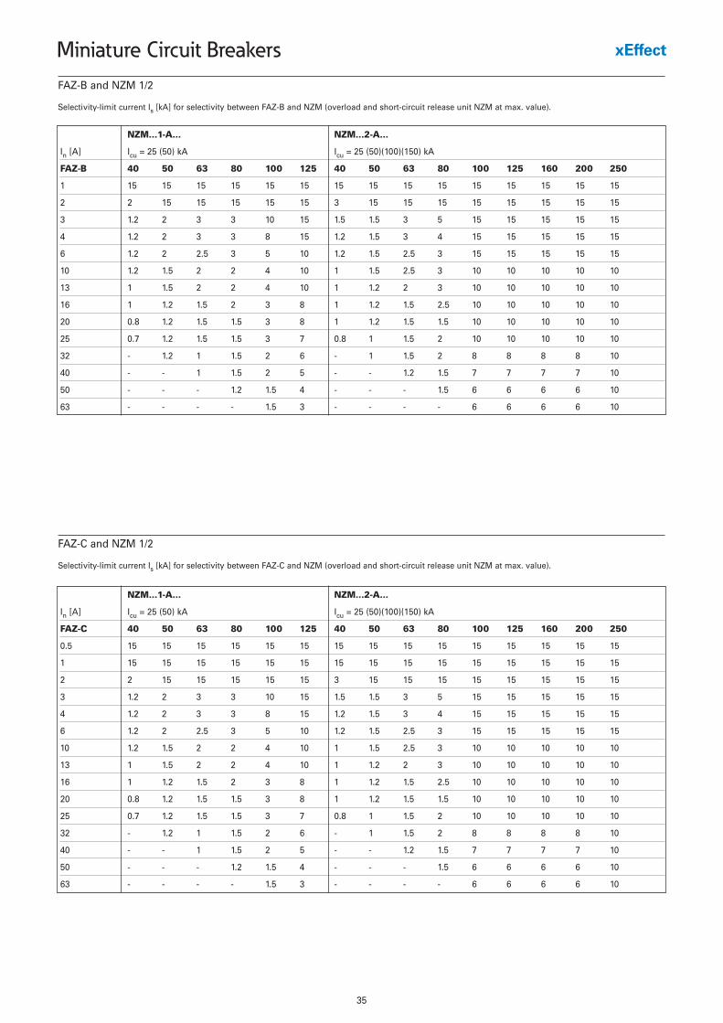
Selectivity-limit current Is [kA] for selectivity between FAZ-B and NZM (overload and short-circuit release unit NZM at max. value).
NZM...1-A... NZM...2-A...
In [A] Icu = 25 (50) kA Icu = 25 (50)(100)(150) kA
FAZ-B 40 50 63 80 100 125 40 50 63 80 100 125 160 200 250
1 15 15 15 15 15 15 15 15 15 15 15 15 15 15 15
2 2 15 15 15 15 15 3 15 15 15 15 15 15 15 15
3 1.2 2 3 3 10 15 1.5 1.5 3 5 15 15 15 15 15
4 1.2 2 3 3 8 15 1.2 1.5 3 4 15 15 15 15 15
6 1.2 2 2.5 3 5 10 1.2 1.5 2.5 3 15 15 15 15 15
10 1.2 1.5 2 2 4 10 1 1.5 2.5 3 10 10 10 10 10
13 1 1.5 2 2 4 10 1 1.2 2 3 10 10 10 10 10
16 1 1.2 1.5 2 3 8 1 1.2 1.5 2.5 10 10 10 10 10
20 0.8 1.2 1.5 1.5 3 8 1 1.2 1.5 1.5 10 10 10 10 10
25 0.7 1.2 1.5 1.5 3 7 0.8 1 1.5 2 10 10 10 10 10
32 - 1.2 1 1.5 2 6 - 1 1.5 2 8 8 8 8 10
40 - - 1 1.5 2 5 - - 1.2 1.5 7 7 7 7 10
50 - - - 1.2 1.5 4 - - - 1.5 6 6 6 6 10
63 - - - - 1.5 3 - - - - 6 6 6 6 10
FAZ-B and NZM 1/2
Selectivity-limit current Is [kA] for selectivity between FAZ-C and NZM (overload and short-circuit release unit NZM at max. value).
NZM...1-A... NZM...2-A...
In [A] Icu = 25 (50) kA Icu = 25 (50)(100)(150) kA
FAZ-C 40 50 63 80 100 125 40 50 63 80 100 125 160 200 250
0.5 15 15 15 15 15 15 15 15 15 15 15 15 15 15 15
1 15 15 15 15 15 15 15 15 15 15 15 15 15 15 15
2 2 15 15 15 15 15 3 15 15 15 15 15 15 15 15
3 1.2 2 3 3 10 15 1.5 1.5 3 5 15 15 15 15 15
4 1.2 2 3 3 8 15 1.2 1.5 3 4 15 15 15 15 15
6 1.2 2 2.5 3 5 10 1.2 1.5 2.5 3 15 15 15 15 15
10 1.2 1.5 2 2 4 10 1 1.5 2.5 3 10 10 10 10 10
13 1 1.5 2 2 4 10 1 1.2 2 3 10 10 10 10 10
16 1 1.2 1.5 2 3 8 1 1.2 1.5 2.5 10 10 10 10 10
20 0.8 1.2 1.5 1.5 3 8 1 1.2 1.5 1.5 10 10 10 10 10
25 0.7 1.2 1.5 1.5 3 7 0.8 1 1.5 2 10 10 10 10 10
32 - 1.2 1 1.5 2 6 - 1 1.5 2 8 8 8 8 10
40 - - 1 1.5 2 5 - - 1.2 1.5 7 7 7 7 10
50 - - - 1.2 1.5 4 - - - 1.5 6 6 6 6 10
63 - - - - 1.5 3 - - - - 6 6 6 6 10
FAZ-C and NZM 1/2
36
Miniature Circuit Breakers
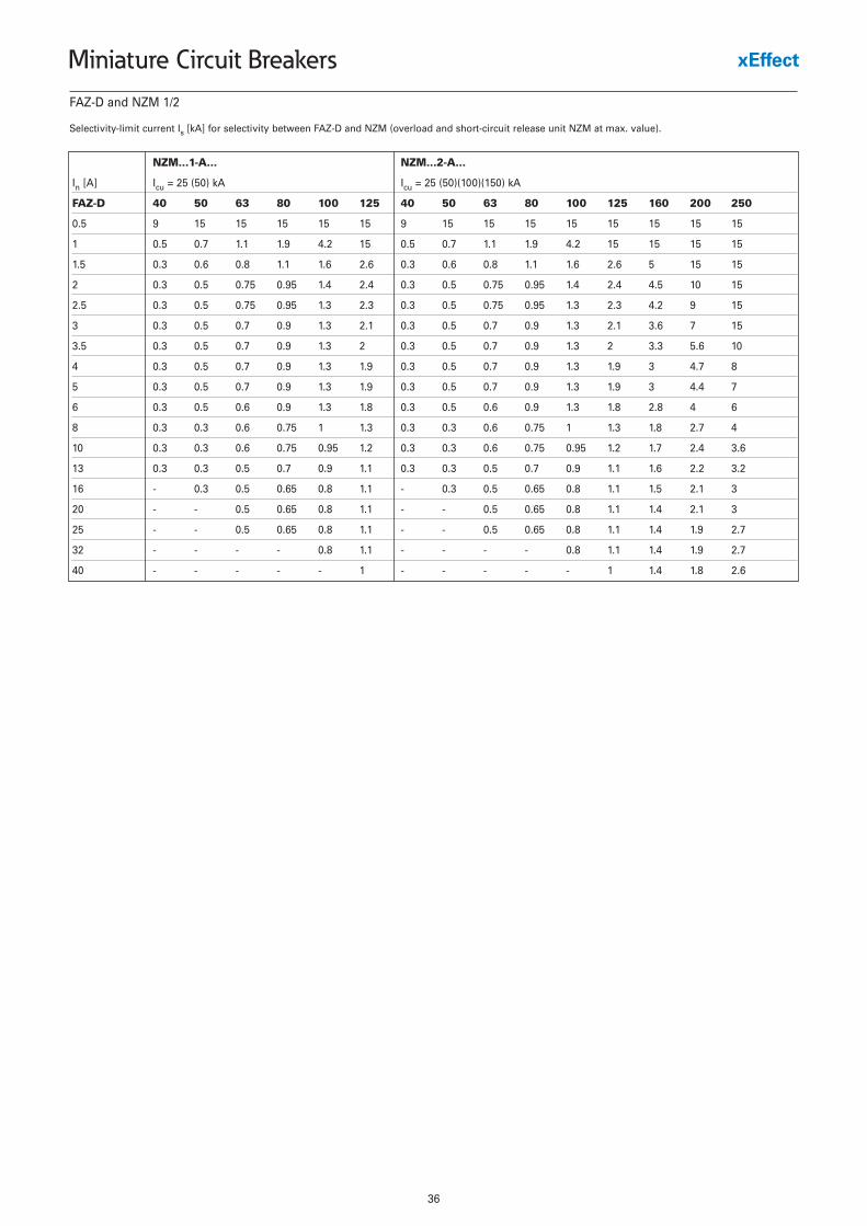
Selectivity-limit current Is [kA] for selectivity between FAZ-D and NZM (overload and short-circuit release unit NZM at max. value).
NZM...1-A... NZM...2-A...
In [A] Icu = 25 (50) kA Icu = 25 (50)(100)(150) kA
FAZ-D 40 50 63 80 100 125 40 50 63 80 100 125 160 200 250
0.5 9 15 15 15 15 15 9 15 15 15 15 15 15 15 15
1 0.5 0.7 1.1 1.9 4.2 15 0.5 0.7 1.1 1.9 4.2 15 15 15 15
1.5 0.3 0.6 0.8 1.1 1.6 2.6 0.3 0.6 0.8 1.1 1.6 2.6 5 15 15
2 0.3 0.5 0.75 0.95 1.4 2.4 0.3 0.5 0.75 0.95 1.4 2.4 4.5 10 15
2.5 0.3 0.5 0.75 0.95 1.3 2.3 0.3 0.5 0.75 0.95 1.3 2.3 4.2 9 15
3 0.3 0.5 0.7 0.9 1.3 2.1 0.3 0.5 0.7 0.9 1.3 2.1 3.6 7 15
3.5 0.3 0.5 0.7 0.9 1.3 2 0.3 0.5 0.7 0.9 1.3 2 3.3 5.6 10
4 0.3 0.5 0.7 0.9 1.3 1.9 0.3 0.5 0.7 0.9 1.3 1.9 3 4.7 8
5 0.3 0.5 0.7 0.9 1.3 1.9 0.3 0.5 0.7 0.9 1.3 1.9 3 4.4 7
6 0.3 0.5 0.6 0.9 1.3 1.8 0.3 0.5 0.6 0.9 1.3 1.8 2.8 4 6
8 0.3 0.3 0.6 0.75 1 1.3 0.3 0.3 0.6 0.75 1 1.3 1.8 2.7 4
10 0.3 0.3 0.6 0.75 0.95 1.2 0.3 0.3 0.6 0.75 0.95 1.2 1.7 2.4 3.6
13 0.3 0.3 0.5 0.7 0.9 1.1 0.3 0.3 0.5 0.7 0.9 1.1 1.6 2.2 3.2
16 - 0.3 0.5 0.65 0.8 1.1 - 0.3 0.5 0.65 0.8 1.1 1.5 2.1 3
20 - - 0.5 0.65 0.8 1.1 - - 0.5 0.65 0.8 1.1 1.4 2.1 3
25 - - 0.5 0.65 0.8 1.1 - - 0.5 0.65 0.8 1.1 1.4 1.9 2.7
32 - - - - 0.8 1.1 - - - - 0.8 1.1 1.4 1.9 2.7
40 - - - - - 1 - - - - - 1 1.4 1.8 2.6
FAZ-D and NZM 1/2
37
Miniature Circuit Breakers
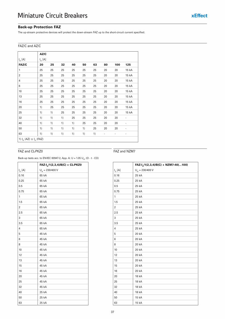
Back-up Protection FAZ
AZ/C
In [A] In [A]
FAZ/C 20 25 32 40 50 63 80 100 125
1 25 25 25 25 25 25 20 20 15 kA
2 25 25 25 25 25 25 20 20 15 kA
4 25 25 25 25 25 25 20 20 15 kA
6 25 25 25 25 25 25 20 20 15 kA
10 25 25 25 25 25 25 20 20 15 kA
13 25 25 25 25 25 25 20 20 15 kA
16 25 25 25 25 25 25 20 20 15 kA
20 1) 25 25 25 25 25 20 20 15 kA
25 1) 1) 25 25 25 25 20 20 15 kA
32 1) 1) 1) 25 25 25 20 20 -
40 1) 1) 1) 1) 25 25 20 20 -
50 1) 1) 1) 1) 1) 25 20 20 -
63 1) 1) 1) 1) 1) 1) - - -
1) In (AZ) ≤ In (FAZ)
FAZ/C and AZ/C
Back-up tests acc. to EN/IEC 60947-2, App. A: U = 1.05 Ue, (O - t - CO)
FAZ-In/1(2,3,4)/B(C) + CL-PKZ0
In [A] Ue = 230/400 V
0.16 65 kA
0.25 65 kA
0.5 65 kA
0.75 65 kA
1 65 kA
1.5 65 kA
2 65 kA
2.5 65 kA
3 65 kA
3.5 65 kA
4 65 kA
5 45 kA
6 45 kA
8 45 kA
10 45 kA
12 45 kA
13 45 kA
15 45 kA
16 45 kA
20 45 kA
25 45 kA
32 45 kA
40 25 kA
50 25 kA
63 25 kA
FAZ and CL-PKZ0
FAZ-In/1(2,3,4)/B(C) + NZM7-40(...100)
In [A] Ue = 230/400 V
0.16 25 kA
0.25 25 kA
0.5 25 kA
0.75 25 kA
1 25 kA
1.5 25 kA
2 25 kA
2.5 25 kA
3 25 kA
3.5 25 kA
4 25 kA
5 20 kA
6 20 kA
8 20 kA
10 20 kA
12 20 kA
13 20 kA
15 20 kA
16 20 kA
20 18 kA
25 18 kA
32 18 kA
40 18 kA
50 15 kA
63 15 kA
FAZ and NZM7
The up-stream protective devices will protect the down-stream FAZ up to the short-circuit current specified.
38
Miniature Circuit Breakers
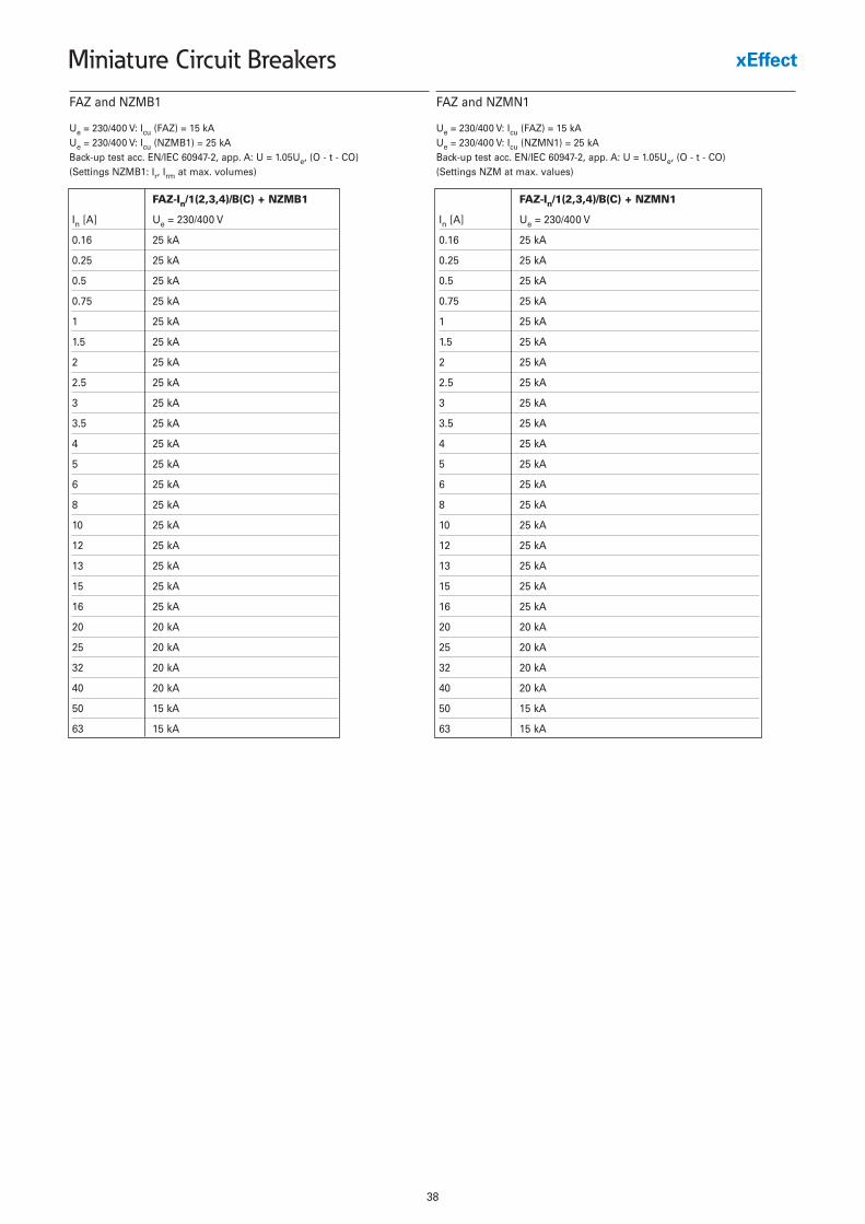
Ue = 230/400 V: Icu (FAZ) = 15 kAUe = 230/400 V: Icu (NZMB1) = 25 kABack-up test acc. EN/IEC 60947-2, app. A: U = 1.05Ue, (O - t - CO)(Settings NZMB1: Ir, Irm at max. volumes)
FAZ-In/1(2,3,4)/B(C) + NZMB1
In [A] Ue = 230/400 V
0.16 25 kA
0.25 25 kA
0.5 25 kA
0.75 25 kA
1 25 kA
1.5 25 kA
2 25 kA
2.5 25 kA
3 25 kA
3.5 25 kA
4 25 kA
5 25 kA
6 25 kA
8 25 kA
10 25 kA
12 25 kA
13 25 kA
15 25 kA
16 25 kA
20 20 kA
25 20 kA
32 20 kA
40 20 kA
50 15 kA
63 15 kA
FAZ and NZMB1
FAZ-In/1(2,3,4)/B(C) + NZMN1
In [A] Ue = 230/400 V
0.16 25 kA
0.25 25 kA
0.5 25 kA
0.75 25 kA
1 25 kA
1.5 25 kA
2 25 kA
2.5 25 kA
3 25 kA
3.5 25 kA
4 25 kA
5 25 kA
6 25 kA
8 25 kA
10 25 kA
12 25 kA
13 25 kA
15 25 kA
16 25 kA
20 20 kA
25 20 kA
32 20 kA
40 20 kA
50 15 kA
63 15 kA
FAZ and NZMN1
Ue = 230/400 V: Icu (FAZ) = 15 kAUe = 230/400 V: Icu (NZMN1) = 25 kABack-up test acc. EN/IEC 60947-2, app. A: U = 1.05Ue, (O - t - CO)(Settings NZM at max. values)
39
Miniature Circuit Breakers
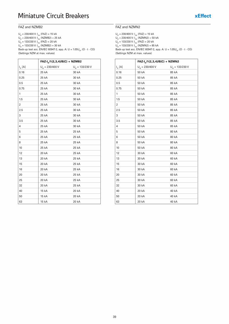
Ue = 230/400 V: Icu (FAZ) = 15 kAUe = 230/400 V: Icu (NZMB2) = 25 kAUe = 133/230 V: Icu (FAZ) = 20 kAUe = 133/230 V: Icu (NZMB2) = 30 kABack-up test acc. EN/IEC 60947-2, app. A: U = 1.05Ue, (O - t - CO)(Settings NZM at max. values)
FAZ-In/1(2,3,4)/B(C) + NZMB2
In [A] Ue = 230/400 V Ue = 133/230 V
0.16 25 kA 30 kA
0.25 25 kA 30 kA
0.5 25 kA 30 kA
0.75 25 kA 30 kA
1 25 kA 30 kA
1.5 25 kA 30 kA
2 25 kA 30 kA
2.5 25 kA 30 kA
3 25 kA 30 kA
3.5 25 kA 30 kA
4 25 kA 30 kA
5 25 kA 25 kA
6 25 kA 25 kA
8 25 kA 25 kA
10 25 kA 25 kA
12 20 kA 25 kA
13 20 kA 25 kA
15 20 kA 25 kA
16 20 kA 25 kA
20 20 kA 25 kA
25 20 kA 25 kA
32 20 kA 25 kA
40 15 kA 20 kA
50 15 kA 20 kA
63 15 kA 20 kA
FAZ and NZMB2
Ue = 230/400 V: Icu (FAZ) = 15 kAUe = 230/400 V: Icu (NZMN2) = 50 kAUe = 133/230 V: Icu (FAZ) = 20 kAUe = 133/230 V: Icu (NZMN2) = 85 kABack-up test acc. EN/IEC 60947-2, app. A: U = 1.05Ue, (O - t - CO)(Settings NZM at max. values)
FAZ-In/1(2,3,4)/B(C) + NZMN2
In [A] Ue = 230/400 V Ue = 133/230 V
0.16 50 kA 85 kA
0.25 50 kA 85 kA
0.5 50 kA 85 kA
0.75 50 kA 85 kA
1 50 kA 85 kA
1.5 50 kA 85 kA
2 50 kA 85 kA
2.5 50 kA 85 kA
3 50 kA 85 kA
3.5 50 kA 85 kA
4 50 kA 85 kA
5 50 kA 80 kA
6 50 kA 80 kA
8 50 kA 80 kA
10 50 kA 80 kA
12 30 kA 60 kA
13 30 kA 60 kA
15 30 kA 60 kA
16 30 kA 60 kA
20 30 kA 60 kA
25 30 kA 60 kA
32 30 kA 60 kA
40 20 kA 40 kA
50 20 kA 40 kA
63 20 kA 40 kA
FAZ and NZMN2

40
Miniature Circuit Breakers
Ue = 230/400 V: Icu (FAZ) = 15 kAUe = 230/400 V: Icu (NZMH2) = 150 kAUe = 133/230 V: Icu (FAZ) = 20 kAUe = 133/230 V: Icu (NZMH2) = 150 kABack-up test acc. EN/IEC 60947-2, app. A: U = 1.05Ue, (O - t - CO)(Settings NZM at max. values)
FAZ-In/1(2,3,4)/B(C) + NZMH2
In [A] Ue = 230/400 V Ue = 133/230 V
0.16 50 kA 85 kA
0.25 50 kA 85 kA
0.5 50 kA 85 kA
0.75 50 kA 85 kA
1 50 kA 85 kA
1.5 50 kA 85 kA
2 50 kA 85 kA
2.5 50 kA 85 kA
3 50 kA 85 kA
3.5 50 kA 85 kA
4 50 kA 85 kA
5 50 kA 80 kA
6 50 kA 80 kA
8 50 kA 80 kA
10 50 kA 80 kA
12 30 kA 60 kA
13 30 kA 60 kA
15 30 kA 60 kA
16 30 kA 60 kA
20 30 kA 60 kA
25 30 kA 60 kA
32 30 kA 60 kA
40 20 kA 40 kA
50 20 kA 40 kA
63 20 kA 40 kA
FAZ and NZMH2
Ue = 230/400 V: Icu (FAZ) = 15 kAUe = 230/400 V: Icu (NZML2) = 150 kAUe = 133/230 V: Icu (FAZ) = 20 kAUe = 133/230 V: Icu (NZML2) = 150 kABack-up test acc. EN/IEC 60947-2, app. A: U = 1.05Ue, (O - t - CO)(Settings NZM at max. values)
FAZ-In/1(2,3,4)/B(C) + NZML2
In [A] Ue = 230/400 V Ue = 133/230 V
0.16 50 kA 85 kA
0.25 50 kA 85 kA
0.5 50 kA 85 kA
0.75 50 kA 85 kA
1 50 kA 85 kA
1.5 50 kA 85 kA
2 50 kA 85 kA
2.5 50 kA 85 kA
3 50 kA 85 kA
3.5 50 kA 85 kA
4 50 kA 85 kA
5 50 kA 80 kA
6 50 kA 80 kA
8 50 kA 80 kA
10 50 kA 80 kA
12 30 kA 60 kA
13 30 kA 60 kA
15 30 kA 60 kA
16 30 kA 60 kA
20 30 kA 60 kA
25 30 kA 60 kA
32 30 kA 60 kA
40 20 kA 40 kA
50 20 kA 40 kA
63 20 kA 40 kA
FAZ and NZML2
41
Miniature Circuit Breakers
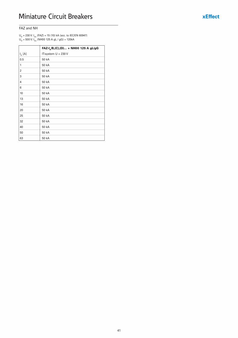
Ue = 230 V: Icu (FAZ) = 15 (10) kA (acc. to IEC/EN 60947)Ue = 500 V: Icu (NH00 125 A gL / gG) = 120kA
FAZ-In/B,(C),(D)... + NH00 125 A gL/gG
In [A] IT-system U = 230 V
0.5 50 kA
1 50 kA
2 50 kA
3 50 kA
4 50 kA
6 50 kA
10 50 kA
13 50 kA
16 50 kA
20 50 kA
25 50 kA
32 50 kA
40 50 kA
50 50 kA
63 50 kA
FAZ and NH
42
Miniature Circuit Breakers
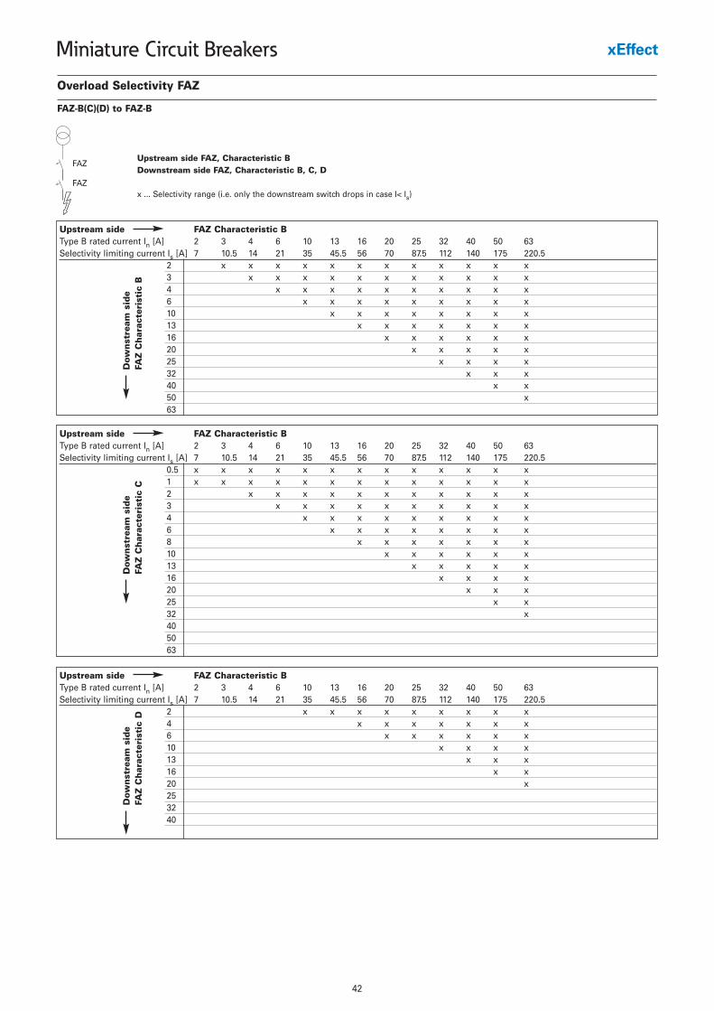
Overload Selectivity FAZ
FAZ-B(C)(D) to FAZ-B
Upstream side FAZ, Characteristic BDownstream side FAZ, Characteristic B, C, D
x ... Selectivity range (i.e. only the downstream switch drops in case I< Is)
Upstream side FAZ Characteristic BType B rated current In [A] 2 3 4 6 10 13 16 20 25 32 40 50 63Selectivity limiting current Is [A] 7 10.5 14 21 35 45.5 56 70 87.5 112 140 175 220.5
2 x x x x x x x x x x x x3 x x x x x x x x x x x4 x x x x x x x x x x6 x x x x x x x x x10 x x x x x x x x13 x x x x x x x16 x x x x x x20 x x x x x25 x x x x32 x x x40 x x50 x63
FAZ
FAZ
Dow
nst
ream
sid
eFA
Z C
har
acte
rist
ic B
Upstream side FAZ Characteristic BType B rated current In [A] 2 3 4 6 10 13 16 20 25 32 40 50 63Selectivity limiting current Is [A] 7 10.5 14 21 35 45.5 56 70 87.5 112 140 175 220.5
0.5 x x x x x x x x x x x x x1 x x x x x x x x x x x x x2 x x x x x x x x x x x3 x x x x x x x x x x4 x x x x x x x x x6 x x x x x x x x8 x x x x x x x10 x x x x x x13 x x x x x16 x x x x20 x x x25 x x32 x405063
Dow
nst
ream
sid
eFA
Z C
har
acte
rist
ic C
Upstream side FAZ Characteristic BType B rated current In [A] 2 3 4 6 10 13 16 20 25 32 40 50 63Selectivity limiting current Is [A] 7 10.5 14 21 35 45.5 56 70 87.5 112 140 175 220.5
2 x x x x x x x x x4 x x x x x x x6 x x x x x x10 x x x x13 x x x16 x x20 x253240
Dow
nst
ream
sid
eFA
Z C
har
acte
rist
ic D
43
Miniature Circuit Breakers
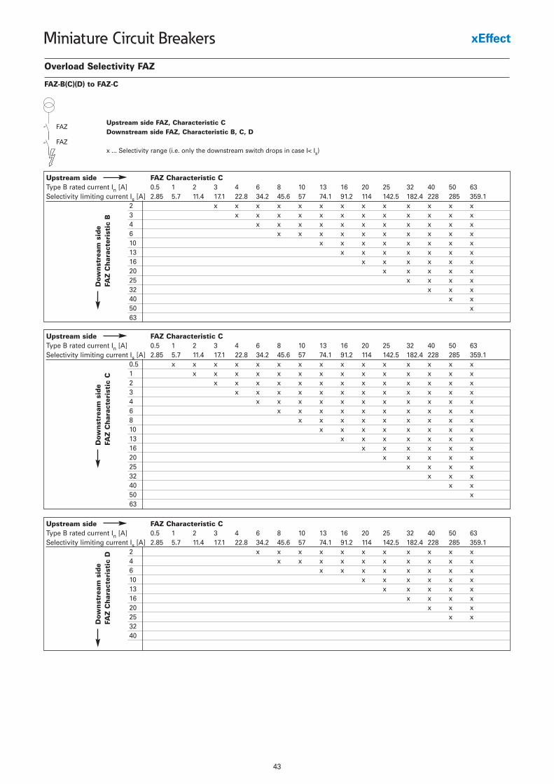
Overload Selectivity FAZ
FAZ-B(C)(D) to FAZ-C
Upstream side FAZ, Characteristic CDownstream side FAZ, Characteristic B, C, D
x ... Selectivity range (i.e. only the downstream switch drops in case I< Is)
Upstream side FAZ Characteristic CType B rated current In [A] 0.5 1 2 3 4 6 8 10 13 16 20 25 32 40 50 63Selectivity limiting current Is [A] 2.85 5.7 11.4 17.1 22.8 34.2 45.6 57 74.1 91.2 114 142.5 182.4 228 285 359.1
2 x x x x x x x x x x x x x3 x x x x x x x x x x x x4 x x x x x x x x x x x6 x x x x x x x x x x10 x x x x x x x x13 x x x x x x x16 x x x x x x20 x x x x x25 x x x x32 x x x40 x x50 x63
FAZ
FAZ
Dow
nst
ream
sid
eFA
Z C
har
acte
rist
ic B
Upstream side FAZ Characteristic CType B rated current In [A] 0.5 1 2 3 4 6 8 10 13 16 20 25 32 40 50 63Selectivity limiting current Is [A] 2.85 5.7 11.4 17.1 22.8 34.2 45.6 57 74.1 91.2 114 142.5 182.4 228 285 359.1
0.5 x x x x x x x x x x x x x x x1 x x x x x x x x x x x x x x2 x x x x x x x x x x x x x3 x x x x x x x x x x x x4 x x x x x x x x x x x6 x x x x x x x x x x8 x x x x x x x x x10 x x x x x x x x13 x x x x x x x16 x x x x x x20 x x x x x25 x x x x32 x x x40 x x50 x63
Dow
nst
ream
sid
eFA
Z C
har
acte
rist
ic C
Upstream side FAZ Characteristic CType B rated current In [A] 0.5 1 2 3 4 6 8 10 13 16 20 25 32 40 50 63Selectivity limiting current Is [A] 2.85 5.7 11.4 17.1 22.8 34.2 45.6 57 74.1 91.2 114 142.5 182.4 228 285 359.1
2 x x x x x x x x x x x4 x x x x x x x x x x6 x x x x x x x x10 x x x x x x13 x x x x x16 x x x x20 x x x25 x x3240
Dow
nst
ream
sid
eFA
Z C
har
acte
rist
ic D
44
Miniature Circuit Breakers
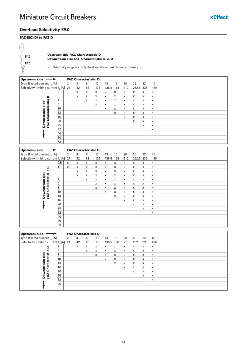
Overload Selectivity FAZ
FAZ-B(C)(D) to FAZ-D
Upstream side FAZ, Characteristic DDownstream side FAZ, Characteristic B, C, D
x ... Selectivity range (i.e. only the downstream switch drops in case I< Is)
Upstream side FAZ Characteristic DType B rated current In [A] 2 4 6 10 13 16 20 25 32 40Selectivity limiting current Is [A] 21 42 63 105 136.5 168 210 262.5 336 420
2 x x x x x x x x x3 x x x x x x x x x4 x x x x x x x x6 x x x x x x x10 x x x x x x13 x x x x x16 x x x x20 x x x25 x x32 x405063
FAZ
FAZ
Dow
nst
ream
sid
eFA
Z C
har
acte
rist
ic B
Upstream side FAZ Characteristic DType B rated current In [A] 2 4 6 10 13 16 20 25 32 40Selectivity limiting current Is [A] 21 42 63 105 136.5 168 210 262.5 336 420
0.5 x x x x x x x x x x1 x x x x x x x x x x2 x x x x x x x x x3 x x x x x x x x x4 x x x x x x x x6 x x x x x x x8 x x x x x x x10 x x x x x x13 x x x x x16 x x x x20 x x x25 x x32 x405063
Dow
nst
ream
sid
eFA
Z C
har
acte
rist
ic C
Upstream side FAZ Characteristic DType B rated current In [A] 2 4 6 10 13 16 20 25 32 40Selectivity limiting current Is [A] 21 42 63 105 136.5 168 210 262.5 336 420
2 x x x x x x x x x4 x x x x x x x x6 x x x x x x x10 x x x x x x13 x x x x x16 x x x x20 x x x25 x x32 x40
Dow
nst
ream
sid
eFA
Z C
har
acte
rist
ic D
45
Miniature Circuit Breakers
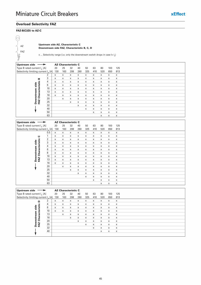
Overload Selectivity FAZ
FAZ-B(C)(D) to AZ-C
Upstream side AZ, Characteristic CDownstream side FAZ, Characteristic B, C, D
x ... Selectivity range (i.e. only the downstream switch drops in case I< Is)
Upstream side AZ Characteristic CType B rated current In [A] 20 25 32 40 50 63 80 100 125Selectivity limiting current Is [A] 130 163 208 260 325 410 520 650 813
2 x x x x x x x x x3 x x x x x x x x x4 x x x x x x x x x6 x x x x x x x x x10 x x x x x x x x x13 x x x x x x x x x16 x x x x x x x x x20 x x x x x x x x25 x x x x x x x32 x x x x x x40 x x x x x50 x x x x63 x x x
AZ
FAZ
Dow
nst
ream
sid
eFA
Z C
har
acte
rist
ic B
Upstream side AZ Characteristic CType B rated current In [A] 20 25 32 40 50 63 80 100 125Selectivity limiting current Is [A] 130 163 208 260 325 410 520 650 813
0.5 x x x x x x x x x1 x x x x x x x x x2 x x x x x x x x x3 x x x x x x x x x4 x x x x x x x x x6 x x x x x x x x x8 x x x x x x x x x10 x x x x x x x x x13 x x x x x x x x x16 x x x x x x x x x20 x x x x x x x x25 x x x x x x x32 x x x x x x40 x x x x x50 x x x x63 x x x
Dow
nst
ream
sid
eFA
Z C
har
acte
rist
ic C
Upstream side AZ Characteristic CType B rated current In [A] 20 25 32 40 50 63 80 100 125Selectivity limiting current Is [A] 130 163 208 260 325 410 520 650 813
2 x x x x x x x x x4 x x x x x x x x x6 x x x x x x x x x10 x x x x x x x x x13 x x x x x x x x16 x x x x x x x20 x x x x x x25 x x x x x32 x x x x40 x x x
Dow
nst
ream
sid
eFA
Z C
har
acte
rist
ic D
46
Miniature Circuit Breakers
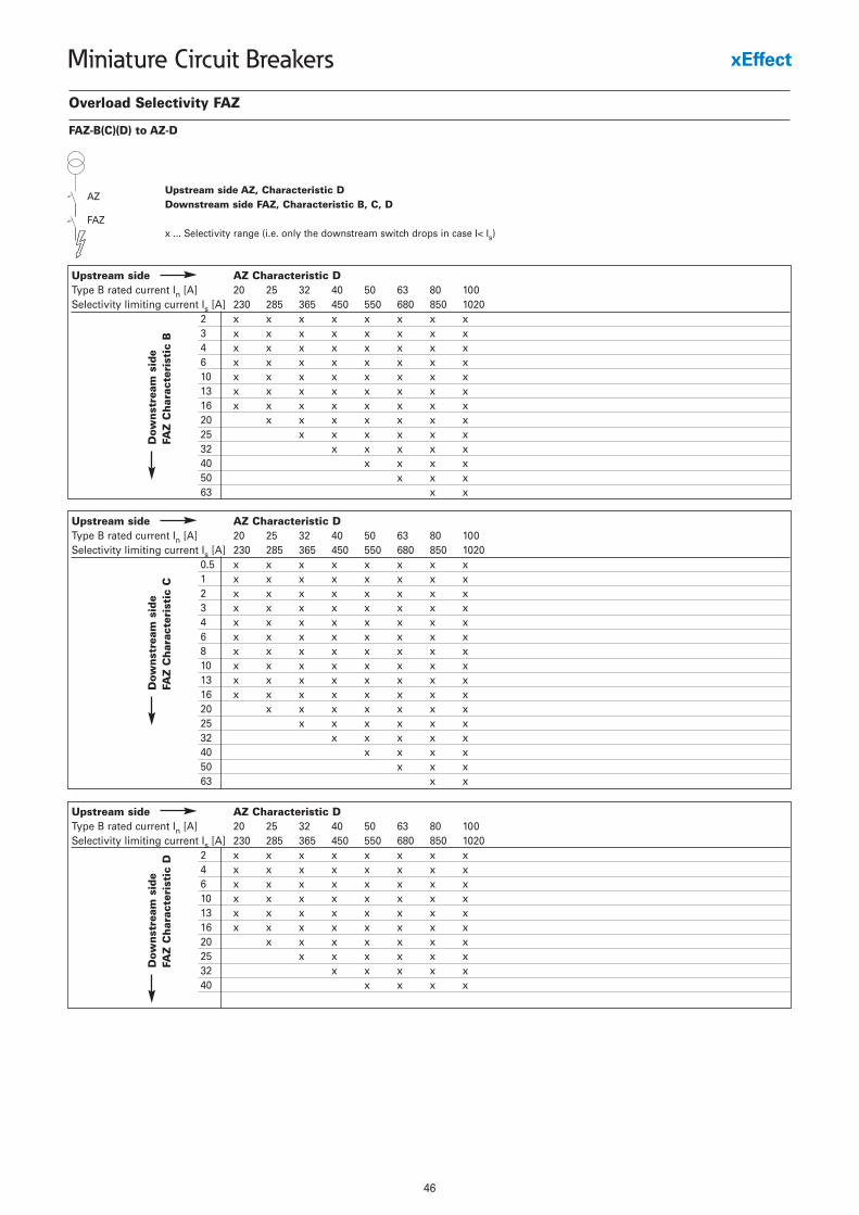
Overload Selectivity FAZ
FAZ-B(C)(D) to AZ-D
Upstream side AZ, Characteristic DDownstream side FAZ, Characteristic B, C, D
x ... Selectivity range (i.e. only the downstream switch drops in case I< Is)
Upstream side AZ Characteristic DType B rated current In [A] 20 25 32 40 50 63 80 100Selectivity limiting current Is [A] 230 285 365 450 550 680 850 1020
2 x x x x x x x x3 x x x x x x x x4 x x x x x x x x6 x x x x x x x x10 x x x x x x x x13 x x x x x x x x16 x x x x x x x x20 x x x x x x x25 x x x x x x32 x x x x x40 x x x x50 x x x63 x x
AZ
FAZ
Dow
nst
ream
sid
eFA
Z C
har
acte
rist
ic B
Upstream side AZ Characteristic DType B rated current In [A] 20 25 32 40 50 63 80 100Selectivity limiting current Is [A] 230 285 365 450 550 680 850 1020
0.5 x x x x x x x x1 x x x x x x x x2 x x x x x x x x3 x x x x x x x x4 x x x x x x x x6 x x x x x x x x8 x x x x x x x x10 x x x x x x x x13 x x x x x x x x16 x x x x x x x x20 x x x x x x x25 x x x x x x32 x x x x x40 x x x x50 x x x63 x x
Dow
nst
ream
sid
eFA
Z C
har
acte
rist
ic C
Upstream side AZ Characteristic DType B rated current In [A] 20 25 32 40 50 63 80 100Selectivity limiting current Is [A] 230 285 365 450 550 680 850 1020
2 x x x x x x x x4 x x x x x x x x6 x x x x x x x x10 x x x x x x x x13 x x x x x x x x16 x x x x x x x x20 x x x x x x x25 x x x x x x32 x x x x x40 x x x x
Dow
nst
ream
sid
eFA
Z C
har
acte
rist
ic D

47
Miniature Circuit Breakers
Influence of the Line Frequency FAZOn the Instantaneous Tripping Current IMA
Line Frequency f [Hz]162/3 50 60 100 200 300 400
IMA(f)/IMA(50Hz) [%] 91 100 101 106 115 134 141
48
Miniature Circuit Breakers
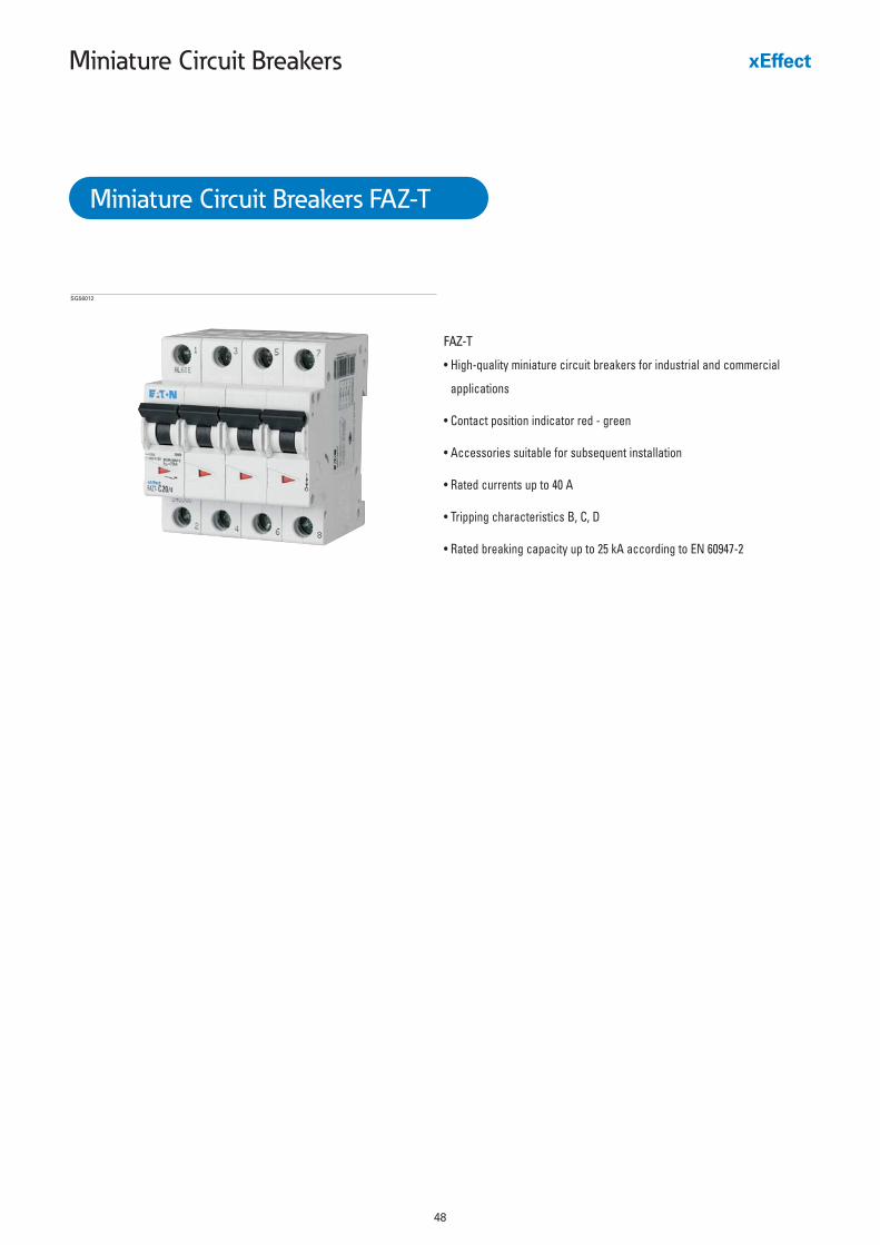
FAZ-T
• High-quality miniature circuit breakers for industrial and commercial
applications
• Contact position indicator red - green
• Accessories suitable for subsequent installation
• Rated currents up to 40 A
• Tripping characteristics B, C, D
• Rated breaking capacity up to 25 kA according to EN 60947-2
SG56012
Miniature Circuit Breakers FAZ-T
49
Miniature Circuit Breakers
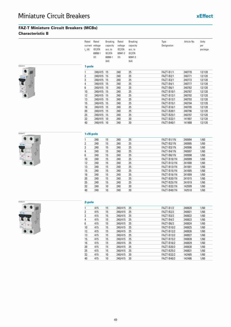
FAZ-T Miniature Circuit Breakers (MCBs)Characteristic B
Rated Rated Breaking Rated Breaking Type Article No. Unitscurrent voltage capacity voltage capacity Designation per In (A) IEC/EN acc. to IEC/EN acc. to package
60898-1 IEC/EN 60947-2 IEC/EN(V) 60898-1 (V) 60947-2
(kA) (kA)
1-pole
1 240/415 15 240 25 FAZT-B1/1 240770 12/1202 240/415 15 240 25 FAZT-B2/1 240771 12/1203 240/415 15 240 25 FAZT-B3/1 240772 12/1204 240/415 15 240 25 FAZT-B4/1 240777 12/1206 240/415 15 240 25 FAZT-B6/1 240782 12/12010 240/415 15 240 25 FAZT-B10/1 240787 12/12012 240/415 15 240 25 FAZT-B12/1 240792 12/12013 240/415 15 240 25 FAZT-B13/1 240793 12/12015 240/415 15 240 25 FAZT-B15/1 240794 12/12016 240/415 15 240 25 FAZT-B16/1 240795 12/12020 240/415 15 240 25 FAZT-B20/1 240796 12/12025 240/415 15 240 25 FAZT-B25/1 240797 12/12032 240/415 10 240 20 FAZT-B32/1 141907 12/12040 240/415 10 240 20 FAZT-B40/1 141908 12/120
SG53212
1+N-pole
1 240 15 240 25 FAZT-B1/1N 240994 1/602 240 15 240 25 FAZT-B2/1N 240995 1/603 240 15 240 25 FAZT-B3/1N 240996 1/604 240 15 240 25 FAZT-B4/1N 240997 1/606 240 15 240 25 FAZT-B6/1N 240998 1/6010 240 15 240 25 FAZT-B10/1N 240999 1/6012 240 15 240 25 FAZT-B12/1N 241000 1/6013 240 15 240 25 FAZT-B13/1N 241001 1/6015 240 15 240 25 FAZT-B15/1N 241005 1/6016 240 15 240 25 FAZT-B16/1N 241009 1/6020 240 15 240 25 FAZT-B20/1N 241015 1/6025 240 15 240 25 FAZT-B25/1N 241019 1/6032 240 10 240 20 FAZT-B32/1N 142509 1/6040 240 10 240 20 FAZT-B40/1N 142510 1/60
SG55412
2-pole
1 415 15 240/415 25 FAZT-B1/2 240820 1/602 415 15 240/415 25 FAZT-B2/2 240821 1/603 415 15 240/415 25 FAZT-B3/2 240822 1/604 415 15 240/415 25 FAZT-B4/2 240823 1/606 415 15 240/415 25 FAZT-B6/2 240824 1/6010 415 15 240/415 25 FAZT-B10/2 240825 1/6012 415 15 240/415 25 FAZT-B12/2 240826 1/6013 415 15 240/415 25 FAZT-B13/2 240827 1/6015 415 15 240/415 25 FAZT-B15/2 240828 1/6016 415 15 240/415 25 FAZT-B16/2 240829 1/6020 415 15 240/415 25 FAZT-B20/2 240830 1/6025 415 15 240/415 25 FAZT-B25/2 240831 1/6032 415 10 240/415 20 FAZT-B32/2 142485 1/6040 415 10 240/415 20 FAZT-B40/2 142486 1/60
SG55212
50
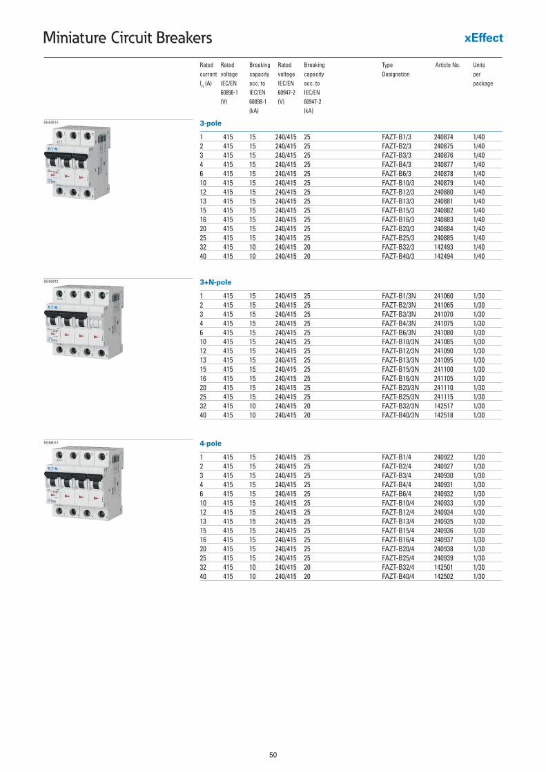
Miniature Circuit Breakers
Rated Rated Breaking Rated Breaking Type Article No. Unitscurrent voltage capacity voltage capacity Designation per In (A) IEC/EN acc. to IEC/EN acc. to package
60898-1 IEC/EN 60947-2 IEC/EN(V) 60898-1 (V) 60947-2
(kA) (kA)
3-pole
1 415 15 240/415 25 FAZT-B1/3 240874 1/402 415 15 240/415 25 FAZT-B2/3 240875 1/403 415 15 240/415 25 FAZT-B3/3 240876 1/404 415 15 240/415 25 FAZT-B4/3 240877 1/406 415 15 240/415 25 FAZT-B6/3 240878 1/4010 415 15 240/415 25 FAZT-B10/3 240879 1/4012 415 15 240/415 25 FAZT-B12/3 240880 1/4013 415 15 240/415 25 FAZT-B13/3 240881 1/4015 415 15 240/415 25 FAZT-B15/3 240882 1/4016 415 15 240/415 25 FAZT-B16/3 240883 1/4020 415 15 240/415 25 FAZT-B20/3 240884 1/4025 415 15 240/415 25 FAZT-B25/3 240885 1/4032 415 10 240/415 20 FAZT-B32/3 142493 1/4040 415 10 240/415 20 FAZT-B40/3 142494 1/40
SG53512
3+N-pole
1 415 15 240/415 25 FAZT-B1/3N 241060 1/302 415 15 240/415 25 FAZT-B2/3N 241065 1/303 415 15 240/415 25 FAZT-B3/3N 241070 1/304 415 15 240/415 25 FAZT-B4/3N 241075 1/306 415 15 240/415 25 FAZT-B6/3N 241080 1/3010 415 15 240/415 25 FAZT-B10/3N 241085 1/3012 415 15 240/415 25 FAZT-B12/3N 241090 1/3013 415 15 240/415 25 FAZT-B13/3N 241095 1/3015 415 15 240/415 25 FAZT-B15/3N 241100 1/3016 415 15 240/415 25 FAZT-B16/3N 241105 1/3020 415 15 240/415 25 FAZT-B20/3N 241110 1/3025 415 15 240/415 25 FAZT-B25/3N 241115 1/3032 415 10 240/415 20 FAZT-B32/3N 142517 1/3040 415 10 240/415 20 FAZT-B40/3N 142518 1/30
SG55912
4-pole
1 415 15 240/415 25 FAZT-B1/4 240922 1/302 415 15 240/415 25 FAZT-B2/4 240927 1/303 415 15 240/415 25 FAZT-B3/4 240930 1/304 415 15 240/415 25 FAZT-B4/4 240931 1/306 415 15 240/415 25 FAZT-B6/4 240932 1/3010 415 15 240/415 25 FAZT-B10/4 240933 1/3012 415 15 240/415 25 FAZT-B12/4 240934 1/3013 415 15 240/415 25 FAZT-B13/4 240935 1/3015 415 15 240/415 25 FAZT-B15/4 240936 1/3016 415 15 240/415 25 FAZT-B16/4 240937 1/3020 415 15 240/415 25 FAZT-B20/4 240938 1/3025 415 15 240/415 25 FAZT-B25/4 240939 1/3032 415 10 240/415 20 FAZT-B32/4 142501 1/3040 415 10 240/415 20 FAZT-B40/4 142502 1/30
SG56012
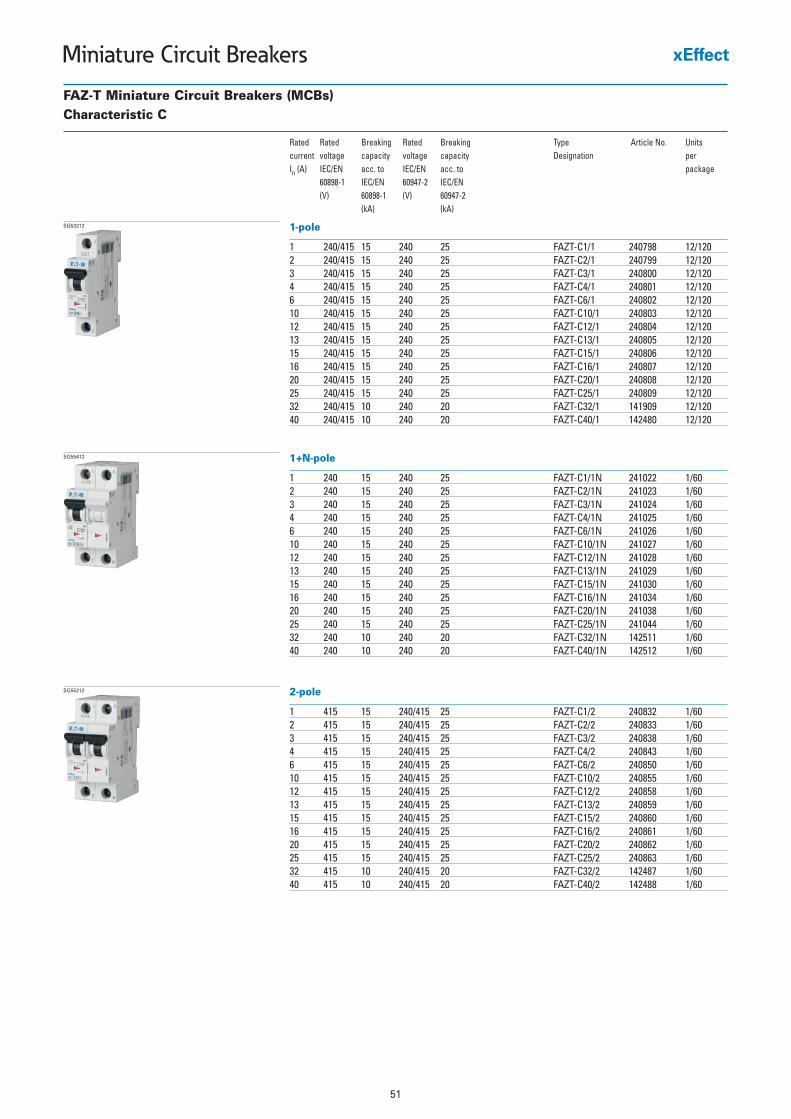
51
Miniature Circuit Breakers
FAZ-T Miniature Circuit Breakers (MCBs)Characteristic C
Rated Rated Breaking Rated Breaking Type Article No. Unitscurrent voltage capacity voltage capacity Designation per In (A) IEC/EN acc. to IEC/EN acc. to package
60898-1 IEC/EN 60947-2 IEC/EN(V) 60898-1 (V) 60947-2
(kA) (kA)
1-pole
1 240/415 15 240 25 FAZT-C1/1 240798 12/1202 240/415 15 240 25 FAZT-C2/1 240799 12/1203 240/415 15 240 25 FAZT-C3/1 240800 12/1204 240/415 15 240 25 FAZT-C4/1 240801 12/1206 240/415 15 240 25 FAZT-C6/1 240802 12/12010 240/415 15 240 25 FAZT-C10/1 240803 12/12012 240/415 15 240 25 FAZT-C12/1 240804 12/12013 240/415 15 240 25 FAZT-C13/1 240805 12/12015 240/415 15 240 25 FAZT-C15/1 240806 12/12016 240/415 15 240 25 FAZT-C16/1 240807 12/12020 240/415 15 240 25 FAZT-C20/1 240808 12/12025 240/415 15 240 25 FAZT-C25/1 240809 12/12032 240/415 10 240 20 FAZT-C32/1 141909 12/12040 240/415 10 240 20 FAZT-C40/1 142480 12/120
SG53212
1+N-pole
1 240 15 240 25 FAZT-C1/1N 241022 1/602 240 15 240 25 FAZT-C2/1N 241023 1/603 240 15 240 25 FAZT-C3/1N 241024 1/604 240 15 240 25 FAZT-C4/1N 241025 1/606 240 15 240 25 FAZT-C6/1N 241026 1/6010 240 15 240 25 FAZT-C10/1N 241027 1/6012 240 15 240 25 FAZT-C12/1N 241028 1/6013 240 15 240 25 FAZT-C13/1N 241029 1/6015 240 15 240 25 FAZT-C15/1N 241030 1/6016 240 15 240 25 FAZT-C16/1N 241034 1/6020 240 15 240 25 FAZT-C20/1N 241038 1/6025 240 15 240 25 FAZT-C25/1N 241044 1/6032 240 10 240 20 FAZT-C32/1N 142511 1/6040 240 10 240 20 FAZT-C40/1N 142512 1/60
SG55412
2-pole
1 415 15 240/415 25 FAZT-C1/2 240832 1/602 415 15 240/415 25 FAZT-C2/2 240833 1/603 415 15 240/415 25 FAZT-C3/2 240838 1/604 415 15 240/415 25 FAZT-C4/2 240843 1/606 415 15 240/415 25 FAZT-C6/2 240850 1/6010 415 15 240/415 25 FAZT-C10/2 240855 1/6012 415 15 240/415 25 FAZT-C12/2 240858 1/6013 415 15 240/415 25 FAZT-C13/2 240859 1/6015 415 15 240/415 25 FAZT-C15/2 240860 1/6016 415 15 240/415 25 FAZT-C16/2 240861 1/6020 415 15 240/415 25 FAZT-C20/2 240862 1/6025 415 15 240/415 25 FAZT-C25/2 240863 1/6032 415 10 240/415 20 FAZT-C32/2 142487 1/6040 415 10 240/415 20 FAZT-C40/2 142488 1/60
SG55212
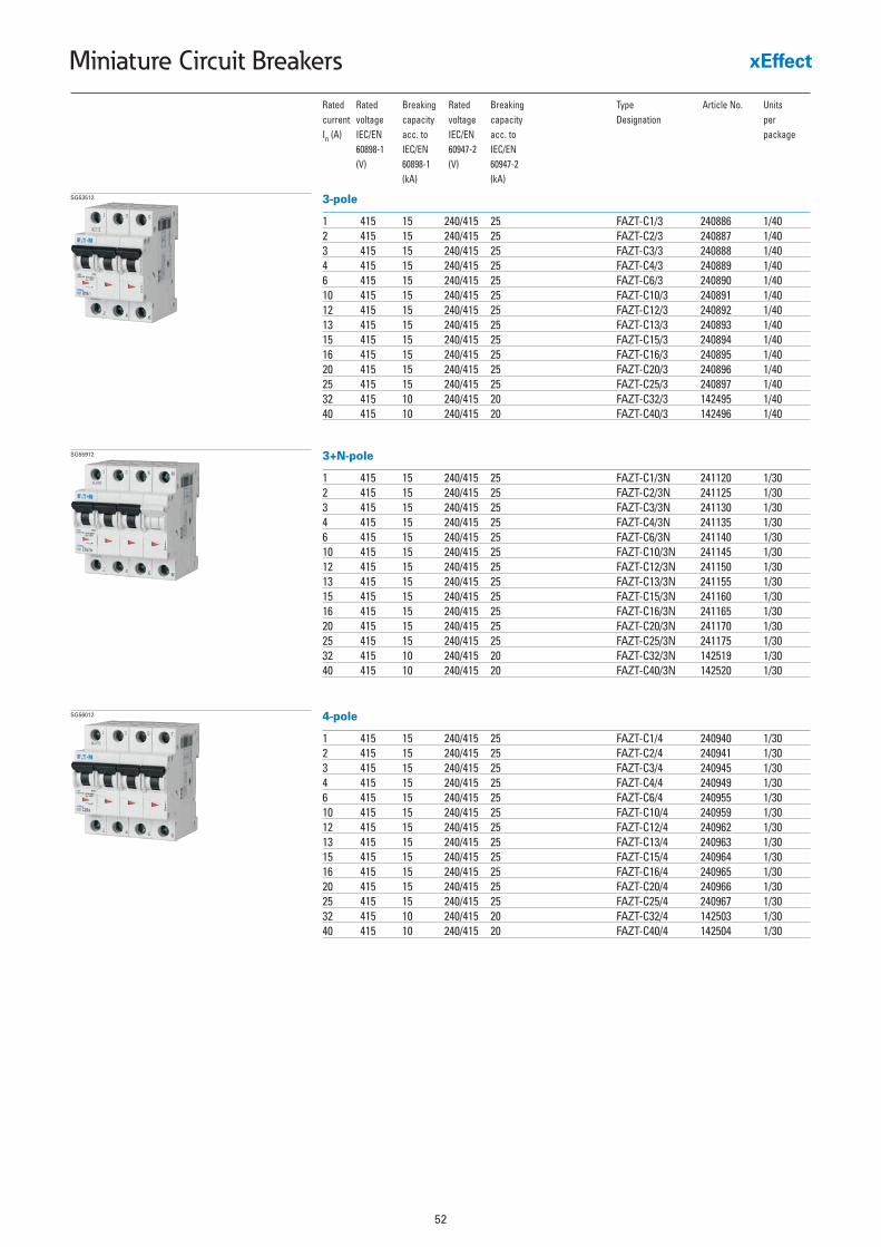
52
Miniature Circuit Breakers
Rated Rated Breaking Rated Breaking Type Article No. Unitscurrent voltage capacity voltage capacity Designation per In (A) IEC/EN acc. to IEC/EN acc. to package
60898-1 IEC/EN 60947-2 IEC/EN(V) 60898-1 (V) 60947-2
(kA) (kA)
3-pole
1 415 15 240/415 25 FAZT-C1/3 240886 1/402 415 15 240/415 25 FAZT-C2/3 240887 1/403 415 15 240/415 25 FAZT-C3/3 240888 1/404 415 15 240/415 25 FAZT-C4/3 240889 1/406 415 15 240/415 25 FAZT-C6/3 240890 1/4010 415 15 240/415 25 FAZT-C10/3 240891 1/4012 415 15 240/415 25 FAZT-C12/3 240892 1/4013 415 15 240/415 25 FAZT-C13/3 240893 1/4015 415 15 240/415 25 FAZT-C15/3 240894 1/4016 415 15 240/415 25 FAZT-C16/3 240895 1/4020 415 15 240/415 25 FAZT-C20/3 240896 1/4025 415 15 240/415 25 FAZT-C25/3 240897 1/4032 415 10 240/415 20 FAZT-C32/3 142495 1/4040 415 10 240/415 20 FAZT-C40/3 142496 1/40
SG53512
3+N-pole
1 415 15 240/415 25 FAZT-C1/3N 241120 1/302 415 15 240/415 25 FAZT-C2/3N 241125 1/303 415 15 240/415 25 FAZT-C3/3N 241130 1/304 415 15 240/415 25 FAZT-C4/3N 241135 1/306 415 15 240/415 25 FAZT-C6/3N 241140 1/3010 415 15 240/415 25 FAZT-C10/3N 241145 1/3012 415 15 240/415 25 FAZT-C12/3N 241150 1/3013 415 15 240/415 25 FAZT-C13/3N 241155 1/3015 415 15 240/415 25 FAZT-C15/3N 241160 1/3016 415 15 240/415 25 FAZT-C16/3N 241165 1/3020 415 15 240/415 25 FAZT-C20/3N 241170 1/3025 415 15 240/415 25 FAZT-C25/3N 241175 1/3032 415 10 240/415 20 FAZT-C32/3N 142519 1/3040 415 10 240/415 20 FAZT-C40/3N 142520 1/30
SG55912
4-pole
1 415 15 240/415 25 FAZT-C1/4 240940 1/302 415 15 240/415 25 FAZT-C2/4 240941 1/303 415 15 240/415 25 FAZT-C3/4 240945 1/304 415 15 240/415 25 FAZT-C4/4 240949 1/306 415 15 240/415 25 FAZT-C6/4 240955 1/3010 415 15 240/415 25 FAZT-C10/4 240959 1/3012 415 15 240/415 25 FAZT-C12/4 240962 1/3013 415 15 240/415 25 FAZT-C13/4 240963 1/3015 415 15 240/415 25 FAZT-C15/4 240964 1/3016 415 15 240/415 25 FAZT-C16/4 240965 1/3020 415 15 240/415 25 FAZT-C20/4 240966 1/3025 415 15 240/415 25 FAZT-C25/4 240967 1/3032 415 10 240/415 20 FAZT-C32/4 142503 1/3040 415 10 240/415 20 FAZT-C40/4 142504 1/30
SG56012

53
Miniature Circuit Breakers
FAZ-T Miniature Circuit Breakers (MCBs)Characteristic D
Rated Rated Breaking Rated Breaking Type Article No. Unitscurrent voltage capacity voltage capacity Designation per In (A) IEC/EN acc. to IEC/EN acc. to package
60898-1 IEC/EN 60947-2 IEC/EN(V) 60898-1 (V) 60947-2
(kA) (kA)
1-pole
1 240/415 15 240 25 FAZT-D1/1 240810 12/1202 240/415 15 240 25 FAZT-D2/1 240811 12/1203 240/415 15 240 25 FAZT-D3/1 240812 12/1204 240/415 15 240 25 FAZT-D4/1 240813 12/1206 240/415 15 240 25 FAZT-D6/1 240814 12/12010 240/415 15 240 25 FAZT-D10/1 240815 12/12012 240/415 15 240 25 FAZT-D12/1 240816 12/12013 240/415 15 240 25 FAZT-D13/1 240817 12/12015 240/415 15 240 20 FAZT-D15/1 240818 12/12016 240/415 15 240 20 FAZT-D16/1 240819 12/12020 240/415 10 240 20 FAZT-D20/1 142481 12/12025 240/415 10 240 15 FAZT-D25/1 142482 12/12032 240/415 10 240 15 FAZT-D32/1 142483 12/12040 240/415 10 240 15 FAZT-D40/1 142484 12/120
SG53212
1+N-pole
1 240 15 240 25 FAZT-D1/1N 241048 1/602 240 15 240 25 FAZT-D2/1N 241051 1/603 240 15 240 25 FAZT-D3/1N 241052 1/604 240 15 240 25 FAZT-D4/1N 241053 1/606 240 15 240 25 FAZT-D6/1N 241054 1/6010 240 15 240 25 FAZT-D10/1N 241055 1/6012 240 15 240 25 FAZT-D12/1N 241056 1/6013 240 15 240 25 FAZT-D13/1N 241057 1/6015 240 15 240 20 FAZT-D15/1N 241058 1/6016 240 15 240 20 FAZT-D16/1N 241059 1/6020 240 10 240 20 FAZT-D20/1N 142513 1/6025 240 10 240 15 FAZT-D25/1N 142514 1/6032 240 10 240 15 FAZT-D32/1N 142515 1/6040 240 10 240 15 FAZT-D40/1N 142516 1/60
SG55412
2-pole
1 415 15 240/415 25 FAZT-D1/2 240864 1/602 415 15 240/415 25 FAZT-D2/2 240865 1/603 415 15 240/415 25 FAZT-D3/2 240866 1/604 415 15 240/415 25 FAZT-D4/2 240867 1/606 415 15 240/415 25 FAZT-D6/2 240868 1/6010 415 15 240/415 25 FAZT-D10/2 240869 1/6012 415 15 240/415 25 FAZT-D12/2 240870 1/6013 415 15 240/415 25 FAZT-D13/2 240871 1/6015 415 15 240/415 20 FAZT-D15/2 240872 1/6016 415 15 240/415 20 FAZT-D16/2 240873 1/6020 415 10 240/415 20 FAZT-D20/2 142489 1/6025 415 10 240/415 15 FAZT-D25/2 142490 1/6032 415 10 240/415 15 FAZT-D32/2 142491 1/6040 415 10 240/415 15 FAZT-D40/2 142492 1/60
SG55212

54
Miniature Circuit Breakers
Rated Rated Breaking Rated Breaking Type Article No. Unitscurrent voltage capacity voltage capacity Designation per In (A) IEC/EN acc. to IEC/EN acc. to package
60898-1 IEC/EN 60947-2 IEC/EN(V) 60898-1 (V) 60947-2
(kA) (kA)
3-pole
1 415 15 240/415 25 FAZT-D1/3 240898 1/402 415 15 240/415 25 FAZT-D2/3 240899 1/403 415 15 240/415 25 FAZT-D3/3 240900 1/404 415 15 240/415 25 FAZT-D4/3 240901 1/406 415 15 240/415 25 FAZT-D6/3 240902 1/4010 415 15 240/415 25 FAZT-D10/3 240903 1/4012 415 15 240/415 25 FAZT-D12/3 240904 1/4013 415 15 240/415 25 FAZT-D13/3 240905 1/4015 415 15 240/415 25 FAZT-D15/3 240910 1/4016 415 15 240/415 25 FAZT-D16/3 240915 1/4020 415 10 240/415 20 FAZT-D20/3 142497 1/4025 415 10 240/415 15 FAZT-D25/3 142498 1/4032 415 10 240/415 15 FAZT-D32/3 142499 1/4040 415 10 240/415 15 FAZT-D40/3 142500 1/40
SG53512
3+N-pole
1 415 15 240/415 25 FAZT-D1/3N 241180 1/302 415 15 240/415 25 FAZT-D2/3N 241181 1/303 415 15 240/415 25 FAZT-D3/3N 241182 1/304 415 15 240/415 25 FAZT-D4/3N 241183 1/306 415 15 240/415 25 FAZT-D6/3N 241184 1/3010 415 15 240/415 25 FAZT-D10/3N 241185 1/3012 415 15 240/415 25 FAZT-D12/3N 241186 1/3013 415 15 240/415 25 FAZT-D13/3N 241187 1/3015 415 15 240/415 25 FAZT-D15/3N 241188 1/3016 415 15 240/415 25 FAZT-D16/3N 241189 1/3020 415 10 240/415 20 FAZT-D20/3N 142521 1/3025 415 10 240/415 15 FAZT-D25/3N 142522 1/3032 415 10 240/415 15 FAZT-D32/3N 142523 1/3040 415 10 240/415 15 FAZT-D40/3N 142524 1/30
SG55912
4-pole
1 415 15 240/415 25 FAZT-D1/4 240968 1/302 415 15 240/415 25 FAZT-D2/4 240969 1/303 415 15 240/415 25 FAZT-D3/4 240970 1/304 415 15 240/415 25 FAZT-D4/4 240971 1/306 415 15 240/415 25 FAZT-D6/4 240975 1/3010 415 15 240/415 25 FAZT-D10/4 240979 1/3012 415 15 240/415 25 FAZT-D12/4 240985 1/3013 415 15 240/415 25 FAZT-D13/4 240989 1/3015 415 15 240/415 25 FAZT-D15/4 240992 1/3016 415 15 240/415 25 FAZT-D16/4 240993 1/3020 415 10 240/415 20 FAZT-D20/4 142505 1/3025 415 10 240/415 15 FAZT-D25/4 142506 1/3032 415 10 240/415 15 FAZT-D32/4 142507 1/3040 415 10 240/415 15 FAZT-D40/4 142508 1/30
SG56012
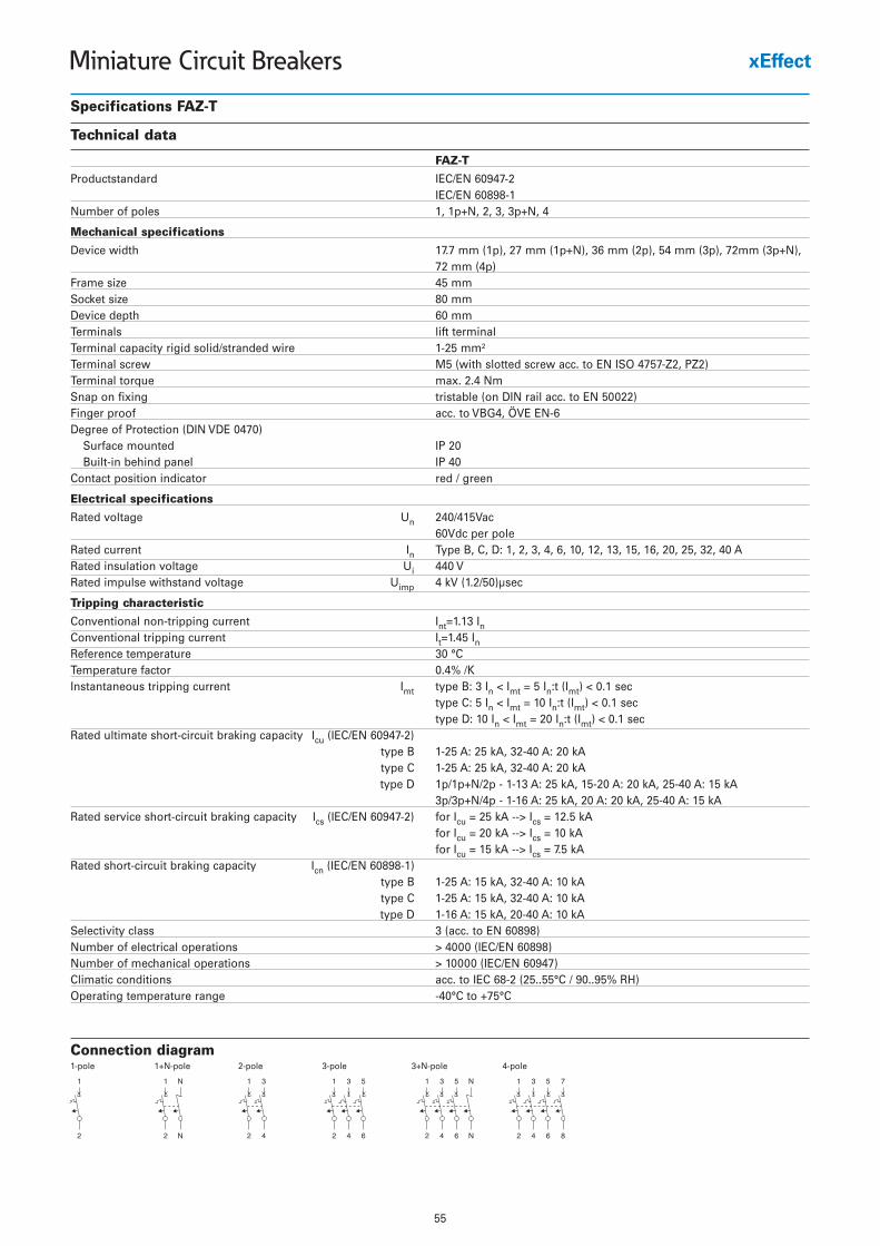
55
Miniature Circuit Breakers
Specifications FAZ-T
Technical data
FAZ-T
Productstandard IEC/EN 60947-2IEC/EN 60898-1
Number of poles 1, 1p+N, 2, 3, 3p+N, 4
Mechanical specifications
Device width 17.7 mm (1p), 27 mm (1p+N), 36 mm (2p), 54 mm (3p), 72mm (3p+N), 72 mm (4p)
Frame size 45 mmSocket size 80 mmDevice depth 60 mmTerminals lift terminalTerminal capacity rigid solid/stranded wire 1-25 mm²Terminal screw M5 (with slotted screw acc. to EN ISO 4757-Z2, PZ2)Terminal torque max. 2.4 NmSnap on fixing tristable (on DIN rail acc. to EN 50022)Finger proof acc. to VBG4, ÖVE EN-6Degree of Protection (DIN VDE 0470)
Surface mounted IP 20Built-in behind panel IP 40
Contact position indicator red / green
Electrical specifications
Rated voltage Un 240/415Vac60Vdc per pole
Rated current In Type B, C, D: 1, 2, 3, 4, 6, 10, 12, 13, 15, 16, 20, 25, 32, 40 ARated insulation voltage Ui 440 VRated impulse withstand voltage Uimp 4 kV (1.2/50)µsec
Tripping characteristic
Conventional non-tripping current Int=1.13 InConventional tripping current It=1.45 InReference temperature 30 °CTemperature factor 0.4% /KInstantaneous tripping current Imt type B: 3 In < Imt = 5 In:t (Imt) < 0.1 sec
type C: 5 In < Imt = 10 In:t (Imt) < 0.1 sectype D: 10 In < Imt = 20 In:t (Imt) < 0.1 sec
Rated ultimate short-circuit braking capacity Icu (IEC/EN 60947-2) type B 1-25 A: 25 kA, 32-40 A: 20 kAtype C 1-25 A: 25 kA, 32-40 A: 20 kAtype D 1p/1p+N/2p - 1-13 A: 25 kA, 15-20 A: 20 kA, 25-40 A: 15 kA
3p/3p+N/4p - 1-16 A: 25 kA, 20 A: 20 kA, 25-40 A: 15 kARated service short-circuit braking capacity Ics (IEC/EN 60947-2) for Icu = 25 kA --> Ics = 12.5 kA
for Icu = 20 kA --> Ics = 10 kAfor Icu = 15 kA --> Ics = 7.5 kA
Rated short-circuit braking capacity Icn (IEC/EN 60898-1)type B 1-25 A: 15 kA, 32-40 A: 10 kAtype C 1-25 A: 15 kA, 32-40 A: 10 kAtype D 1-16 A: 15 kA, 20-40 A: 10 kA
Selectivity class 3 (acc. to EN 60898)Number of electrical operations > 4000 (IEC/EN 60898)Number of mechanical operations > 10000 (IEC/EN 60947)Climatic conditions acc. to IEC 68-2 (25..55°C / 90..95% RH)Operating temperature range -40°C to +75°C
Connection diagram1-pole 1+N-pole 2-pole 3-pole 3+N-pole 4-pole
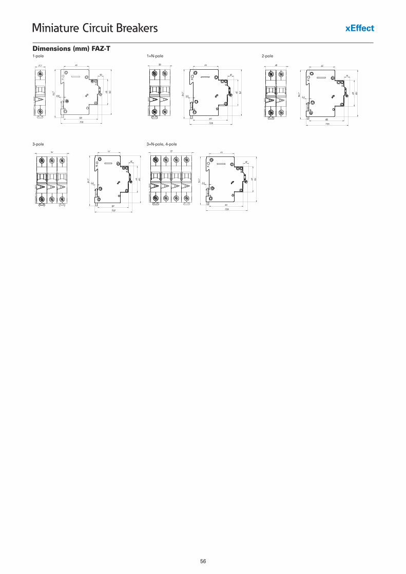
56
Miniature Circuit Breakers
Dimensions (mm) FAZ-T1-pole 1+N-pole 2-pole
3-pole 3+N-pole, 4-pole
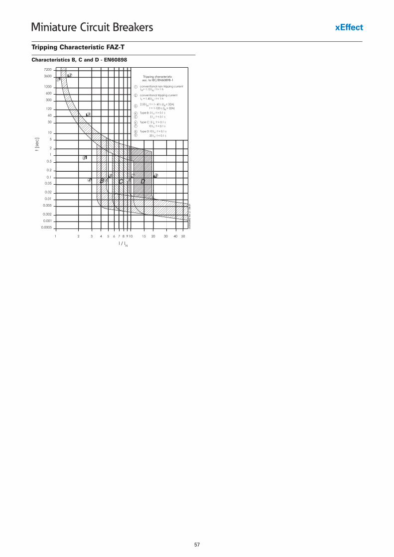
57
Miniature Circuit Breakers
Tripping Characteristic FAZ-T
Characteristics B, C and D - EN60898
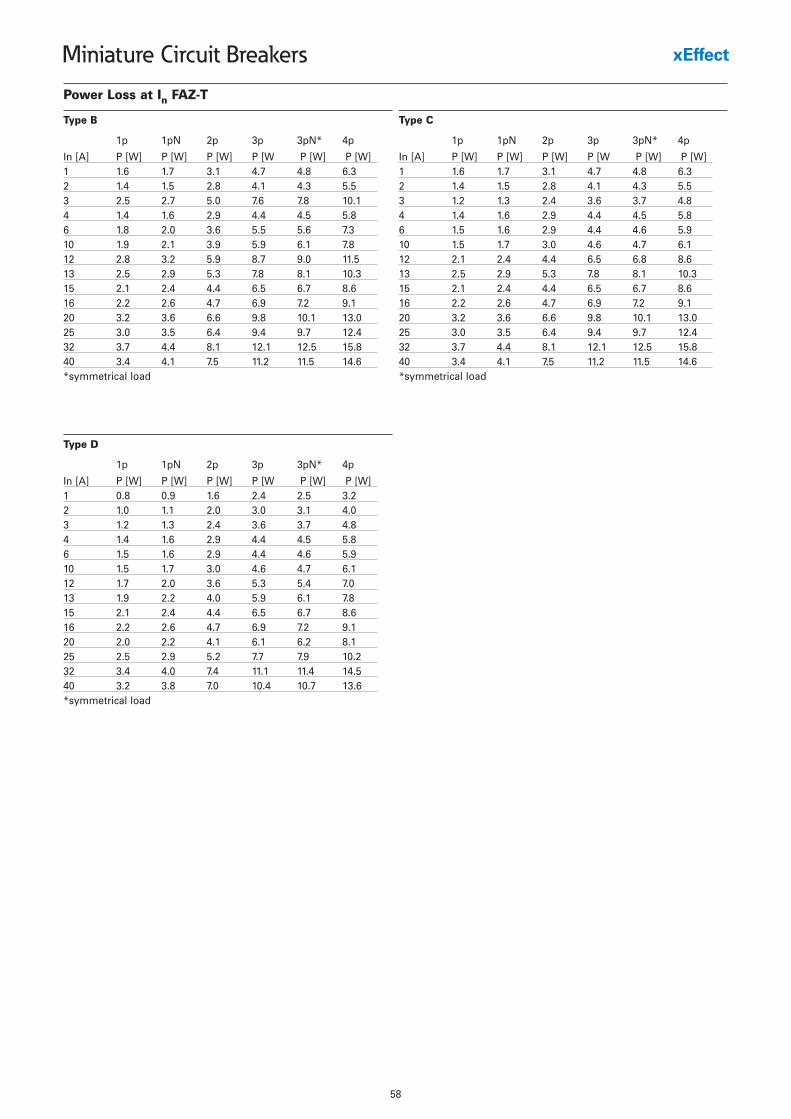
58
Miniature Circuit Breakers
Power Loss at In FAZ-T
1p 1pN 2p 3p 3pN* 4p
In [A] P [W] P [W] P [W] P [W P [W] P [W]1 1.6 1.7 3.1 4.7 4.8 6.32 1.4 1.5 2.8 4.1 4.3 5.53 2.5 2.7 5.0 7.6 7.8 10.14 1.4 1.6 2.9 4.4 4.5 5.86 1.8 2.0 3.6 5.5 5.6 7.310 1.9 2.1 3.9 5.9 6.1 7.812 2.8 3.2 5.9 8.7 9.0 11.513 2.5 2.9 5.3 7.8 8.1 10.315 2.1 2.4 4.4 6.5 6.7 8.616 2.2 2.6 4.7 6.9 7.2 9.120 3.2 3.6 6.6 9.8 10.1 13.025 3.0 3.5 6.4 9.4 9.7 12.432 3.7 4.4 8.1 12.1 12.5 15.840 3.4 4.1 7.5 11.2 11.5 14.6*symmetrical load
Type B
1p 1pN 2p 3p 3pN* 4p
In [A] P [W] P [W] P [W] P [W P [W] P [W]1 1.6 1.7 3.1 4.7 4.8 6.32 1.4 1.5 2.8 4.1 4.3 5.53 1.2 1.3 2.4 3.6 3.7 4.84 1.4 1.6 2.9 4.4 4.5 5.86 1.5 1.6 2.9 4.4 4.6 5.910 1.5 1.7 3.0 4.6 4.7 6.112 2.1 2.4 4.4 6.5 6.8 8.613 2.5 2.9 5.3 7.8 8.1 10.315 2.1 2.4 4.4 6.5 6.7 8.616 2.2 2.6 4.7 6.9 7.2 9.120 3.2 3.6 6.6 9.8 10.1 13.025 3.0 3.5 6.4 9.4 9.7 12.432 3.7 4.4 8.1 12.1 12.5 15.840 3.4 4.1 7.5 11.2 11.5 14.6*symmetrical load
Type C
1p 1pN 2p 3p 3pN* 4p
In [A] P [W] P [W] P [W] P [W P [W] P [W]1 0.8 0.9 1.6 2.4 2.5 3.22 1.0 1.1 2.0 3.0 3.1 4.03 1.2 1.3 2.4 3.6 3.7 4.84 1.4 1.6 2.9 4.4 4.5 5.86 1.5 1.6 2.9 4.4 4.6 5.910 1.5 1.7 3.0 4.6 4.7 6.112 1.7 2.0 3.6 5.3 5.4 7.013 1.9 2.2 4.0 5.9 6.1 7.815 2.1 2.4 4.4 6.5 6.7 8.616 2.2 2.6 4.7 6.9 7.2 9.120 2.0 2.2 4.1 6.1 6.2 8.125 2.5 2.9 5.2 7.7 7.9 10.232 3.4 4.0 7.4 11.1 11.4 14.540 3.2 3.8 7.0 10.4 10.7 13.6*symmetrical load
Type D
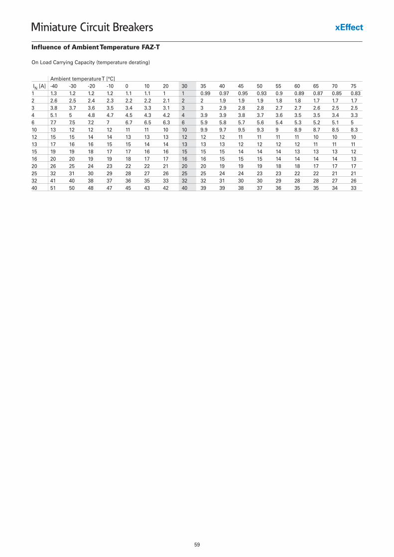
59
Miniature Circuit Breakers
Influence of Ambient Temperature FAZ-T
On Load Carrying Capacity (temperature derating)
Ambient temperature T [°C]IN [A] -40 -30 -20 -10 0 10 20 30 35 40 45 50 55 60 65 70 75
1 1.3 1.2 1.2 1.2 1.1 1.1 1 1 0.99 0.97 0.95 0.93 0.9 0.89 0.87 0.85 0.832 2.6 2.5 2.4 2.3 2.2 2.2 2.1 2 2 1.9 1.9 1.9 1.8 1.8 1.7 1.7 1.73 3.8 3.7 3.6 3.5 3.4 3.3 3.1 3 3 2.9 2.8 2.8 2.7 2.7 2.6 2.5 2.54 5.1 5 4.8 4.7 4.5 4.3 4.2 4 3.9 3.9 3.8 3.7 3.6 3.5 3.5 3.4 3.36 7.7 7.5 7.2 7 6.7 6.5 6.3 6 5.9 5.8 5.7 5.6 5.4 5.3 5.2 5.1 510 13 12 12 12 11 11 10 10 9.9 9.7 9.5 9.3 9 8.9 8.7 8.5 8.312 15 15 14 14 13 13 13 12 12 12 11 11 11 11 10 10 1013 17 16 16 15 15 14 14 13 13 13 12 12 12 12 11 11 1115 19 19 18 17 17 16 16 15 15 15 14 14 14 13 13 13 1216 20 20 19 19 18 17 17 16 16 15 15 15 14 14 14 14 1320 26 25 24 23 22 22 21 20 20 19 19 19 18 18 17 17 1725 32 31 30 29 28 27 26 25 25 24 24 23 23 22 22 21 2132 41 40 38 37 36 35 33 32 32 31 30 30 29 28 28 27 2640 51 50 48 47 45 43 42 40 39 39 38 37 36 35 35 34 33
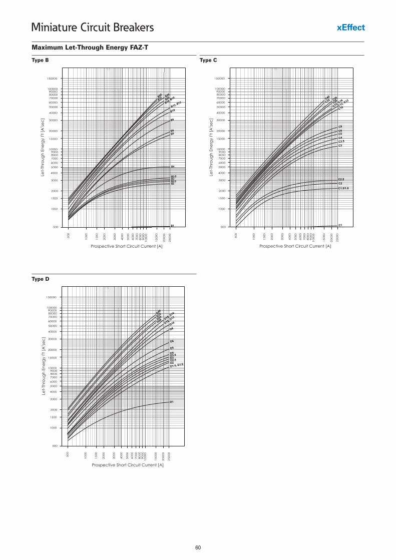
60
Miniature Circuit Breakers
Maximum Let-Through Energy FAZ-T
Type B Type C
Type D
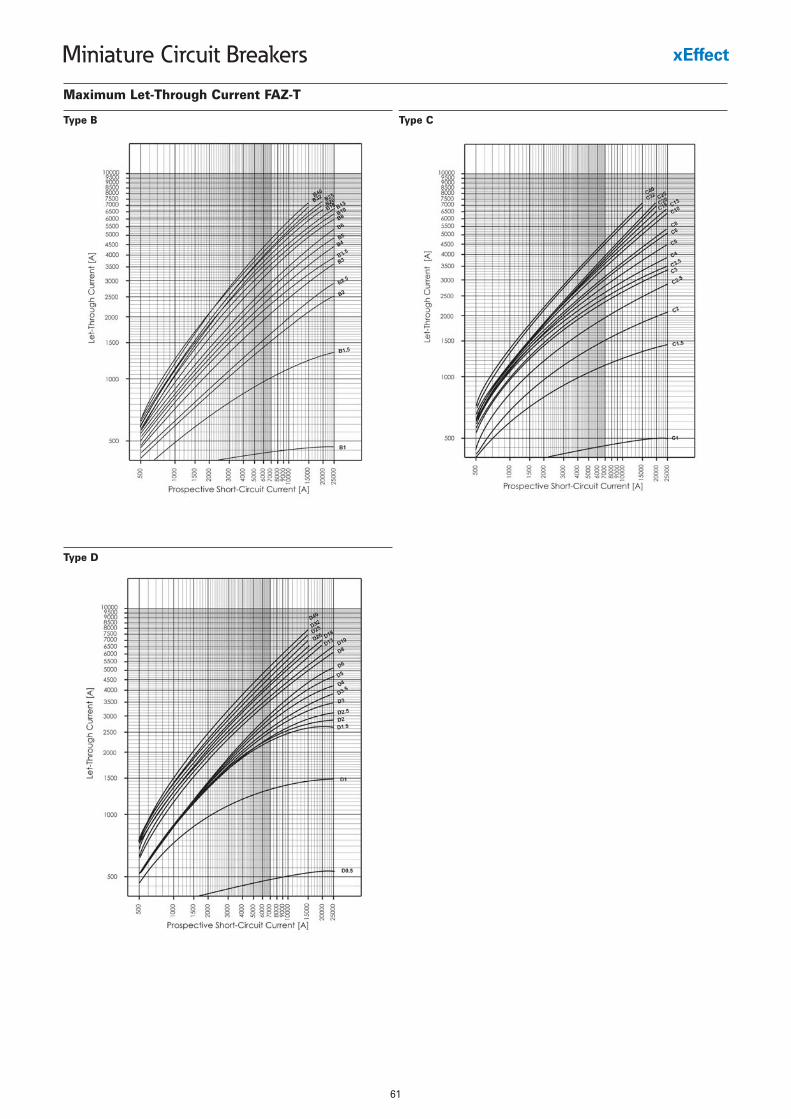
61
Miniature Circuit Breakers
Maximum Let-Through Current FAZ-T
Type B Type C
Type D
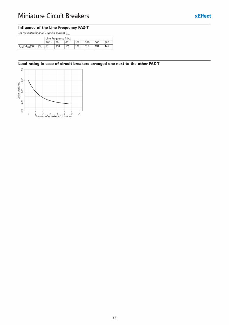
62
Miniature Circuit Breakers
Influence of the Line Frequency FAZ-TOn the Instantaneous Tripping Current IMA
Line Frequency f [Hz]162/3 50 60 100 200 300 400
IMA(f)/IMA(50Hz) [%] 91 100 101 106 115 134 141
Load rating in case of circuit breakers arranged one next to the other FAZ-T
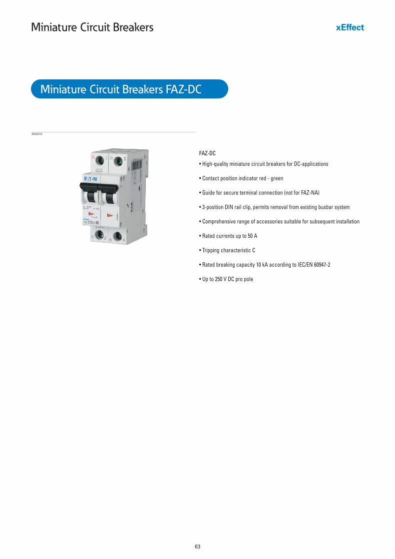
63
Miniature Circuit Breakers
FAZ-DC
• High-quality miniature circuit breakers for DC-applications
• Contact position indicator red - green
• Guide for secure terminal connection (not for FAZ-NA)
• 3-position DIN rail clip, permits removal from existing busbar system
• Comprehensive range of accessories suitable for subsequent installation
• Rated currents up to 50 A
• Tripping characteristic C
• Rated breaking capacity 10 kA according to IEC/EN 60947-2
• Up to 250 V DC pro pole
SG53312
Miniature Circuit Breakers FAZ-DC
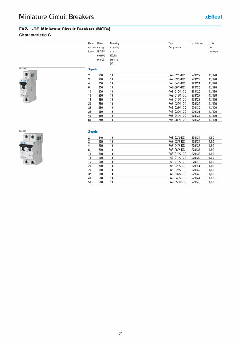
64
Miniature Circuit Breakers
FAZ-...-DC Miniature Circuit Breakers (MCBs)Characteristic C
Rated Rated Breaking Type Article No. Unitscurrent voltage capacity Designation per In (A) IEC/EN acc. to package
60947-2 IEC/EN(V DC) 60947-2
(kA)
1-pole
2 220 10 FAZ-C2/1-DC 279122 12/1203 250 10 FAZ-C3/1-DC 279123 12/1204 250 10 FAZ-C4/1-DC 279124 12/1206 250 10 FAZ-C6/1-DC 279125 12/12010 250 10 FAZ-C10/1-DC 279126 12/12013 250 10 FAZ-C13/1-DC 279127 12/12016 250 10 FAZ-C16/1-DC 279128 12/12020 250 10 FAZ-C20/1-DC 279129 12/12025 250 10 FAZ-C25/1-DC 279130 12/12032 250 10 FAZ-C32/1-DC 279131 12/12040 250 10 FAZ-C40/1-DC 279132 12/12050 250 10 FAZ-C50/1-DC 279133 12/120
SG54512
2-pole
2 440 10 FAZ-C2/2-DC 279134 1/603 500 10 FAZ-C3/2-DC 279135 1/604 500 10 FAZ-C4/2-DC 279136 1/606 500 10 FAZ-C6/2-DC 279137 1/6010 500 10 FAZ-C10/2-DC 279138 1/6013 500 10 FAZ-C13/2-DC 279139 1/6016 500 10 FAZ-C16/2-DC 279140 1/6020 500 10 FAZ-C20/2-DC 279141 1/6025 500 10 FAZ-C25/2-DC 279142 1/6032 500 10 FAZ-C32/2-DC 279143 1/6040 500 10 FAZ-C40/2-DC 279144 1/6050 500 10 FAZ-C50/2-DC 279145 1/60
SG53312
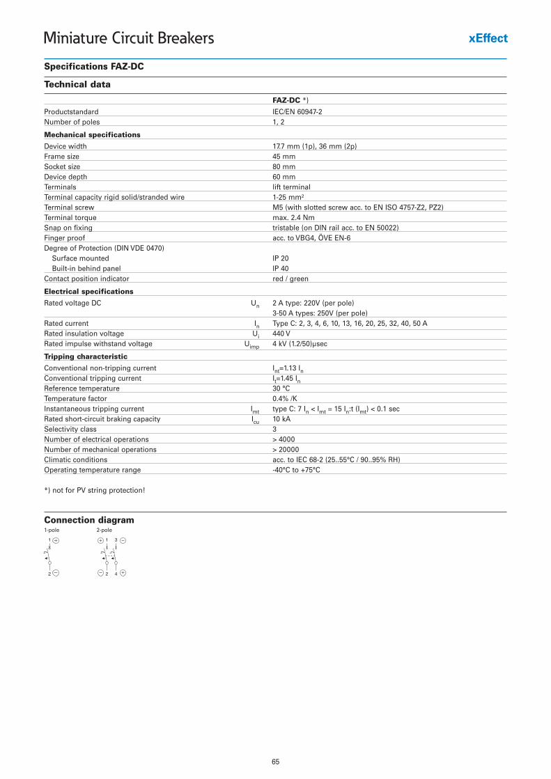
65
Miniature Circuit Breakers
Specifications FAZ-DC
Technical data
FAZ-DC *)
Productstandard IEC/EN 60947-2Number of poles 1, 2
Mechanical specifications
Device width 17.7 mm (1p), 36 mm (2p)Frame size 45 mmSocket size 80 mmDevice depth 60 mmTerminals lift terminalTerminal capacity rigid solid/stranded wire 1-25 mm²Terminal screw M5 (with slotted screw acc. to EN ISO 4757-Z2, PZ2)Terminal torque max. 2.4 NmSnap on fixing tristable (on DIN rail acc. to EN 50022)Finger proof acc. to VBG4, ÖVE EN-6Degree of Protection (DIN VDE 0470)
Surface mounted IP 20Built-in behind panel IP 40
Contact position indicator red / green
Electrical specifications
Rated voltage DC Un 2 A type: 220V (per pole)3-50 A types: 250V (per pole)
Rated current In Type C: 2, 3, 4, 6, 10, 13, 16, 20, 25, 32, 40, 50 ARated insulation voltage Ui 440 VRated impulse withstand voltage Uimp 4 kV (1.2/50)µsec
Tripping characteristic
Conventional non-tripping current Int=1.13 InConventional tripping current It=1.45 InReference temperature 30 °CTemperature factor 0.4% /KInstantaneous tripping current Imt type C: 7 In < Imt = 15 In:t (Imt) < 0.1 secRated short-circuit braking capacity Icu 10 kASelectivity class 3Number of electrical operations > 4000Number of mechanical operations > 20000Climatic conditions acc. to IEC 68-2 (25..55°C / 90..95% RH)Operating temperature range -40°C to +75°C
*) not for PV string protection!
Connection diagram1-pole 2-pole
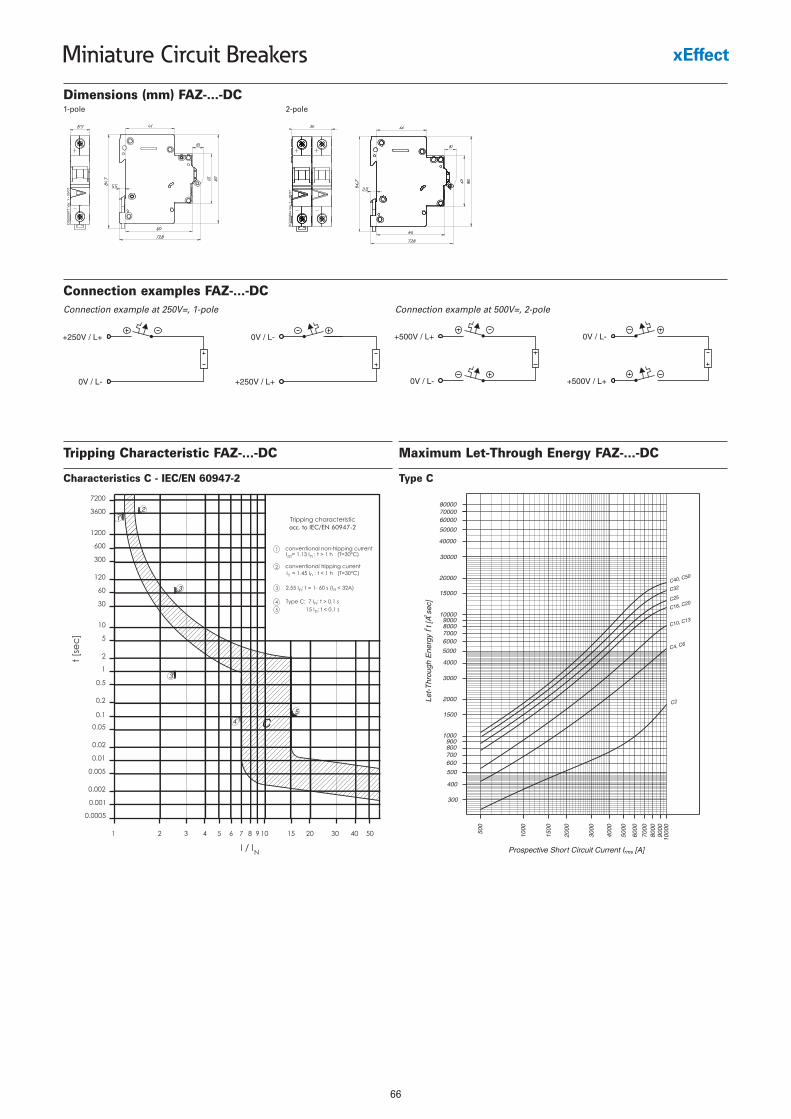
66
Miniature Circuit Breakers
Dimensions (mm) FAZ-...-DC
Connection examples FAZ-...-DCConnection example at 250V=, 1-pole Connection example at 500V=, 2-pole
Tripping Characteristic FAZ-...-DC
Characteristics C - IEC/EN 60947-2
Maximum Let-Through Energy FAZ-...-DC
Type C
1-pole 2-pole
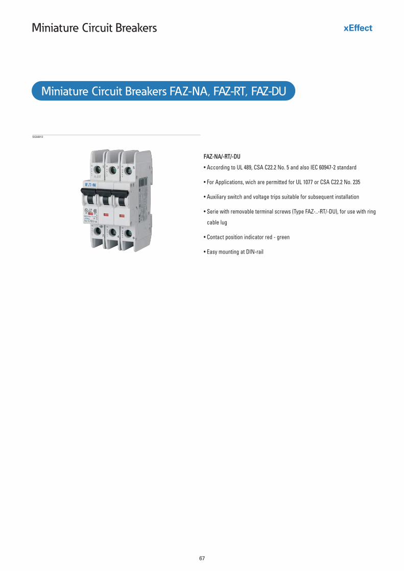
67
Miniature Circuit Breakers
FAZ-NA/-RT/-DUFAZ-NA/-RT/-DU
• According to UL 489, CSA C22.2 No. 5 and also IEC 60947-2 standard
• For Applications, wich are permitted for UL 1077 or CSA C22.2 No. 235
• Auxiliary switch and voltage trips suitable for subsequent installation
• Serie with removable terminal screws (Type FAZ-..-RT/-DU), for use with ring
cable lug
• Contact position indicator red - green
• Easy mounting at DIN-rail
Miniature Circuit Breakers FAZ-NA, FAZ-RT, FAZ-DU
SG56912
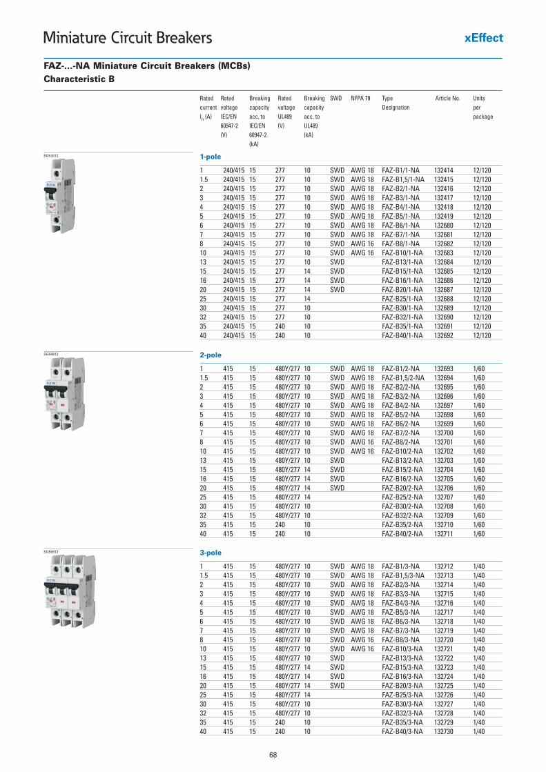
68
Miniature Circuit Breakers
FAZ-...-NA Miniature Circuit Breakers (MCBs)Characteristic B
Rated Rated Breaking Rated Breaking SWD NFPA 79 Type Article No. Unitscurrent voltage capacity voltage capacity Designation per In (A) IEC/EN acc. to UL489 acc. to package
60947-2 IEC/EN (V) UL489(V) 60947-2 (kA)
(kA)
1-pole
1 240/415 15 277 10 SWD AWG 18 FAZ-B1/1-NA 132414 12/1201.5 240/415 15 277 10 SWD AWG 18 FAZ-B1,5/1-NA 132415 12/1202 240/415 15 277 10 SWD AWG 18 FAZ-B2/1-NA 132416 12/1203 240/415 15 277 10 SWD AWG 18 FAZ-B3/1-NA 132417 12/1204 240/415 15 277 10 SWD AWG 18 FAZ-B4/1-NA 132418 12/1205 240/415 15 277 10 SWD AWG 18 FAZ-B5/1-NA 132419 12/1206 240/415 15 277 10 SWD AWG 18 FAZ-B6/1-NA 132680 12/1207 240/415 15 277 10 SWD AWG 18 FAZ-B7/1-NA 132681 12/1208 240/415 15 277 10 SWD AWG 16 FAZ-B8/1-NA 132682 12/12010 240/415 15 277 10 SWD AWG 16 FAZ-B10/1-NA 132683 12/12013 240/415 15 277 10 SWD FAZ-B13/1-NA 132684 12/12015 240/415 15 277 14 SWD FAZ-B15/1-NA 132685 12/12016 240/415 15 277 14 SWD FAZ-B16/1-NA 132686 12/12020 240/415 15 277 14 SWD FAZ-B20/1-NA 132687 12/12025 240/415 15 277 14 FAZ-B25/1-NA 132688 12/12030 240/415 15 277 10 FAZ-B30/1-NA 132689 12/12032 240/415 15 277 10 FAZ-B32/1-NA 132690 12/12035 240/415 15 240 10 FAZ-B35/1-NA 132691 12/12040 240/415 15 240 10 FAZ-B40/1-NA 132692 12/120
SG53012
2-pole
1 415 15 480Y/277 10 SWD AWG 18 FAZ-B1/2-NA 132693 1/601.5 415 15 480Y/277 10 SWD AWG 18 FAZ-B1,5/2-NA 132694 1/602 415 15 480Y/277 10 SWD AWG 18 FAZ-B2/2-NA 132695 1/603 415 15 480Y/277 10 SWD AWG 18 FAZ-B3/2-NA 132696 1/604 415 15 480Y/277 10 SWD AWG 18 FAZ-B4/2-NA 132697 1/605 415 15 480Y/277 10 SWD AWG 18 FAZ-B5/2-NA 132698 1/606 415 15 480Y/277 10 SWD AWG 18 FAZ-B6/2-NA 132699 1/607 415 15 480Y/277 10 SWD AWG 18 FAZ-B7/2-NA 132700 1/608 415 15 480Y/277 10 SWD AWG 16 FAZ-B8/2-NA 132701 1/6010 415 15 480Y/277 10 SWD AWG 16 FAZ-B10/2-NA 132702 1/6013 415 15 480Y/277 10 SWD FAZ-B13/2-NA 132703 1/6015 415 15 480Y/277 14 SWD FAZ-B15/2-NA 132704 1/6016 415 15 480Y/277 14 SWD FAZ-B16/2-NA 132705 1/6020 415 15 480Y/277 14 SWD FAZ-B20/2-NA 132706 1/6025 415 15 480Y/277 14 FAZ-B25/2-NA 132707 1/6030 415 15 480Y/277 10 FAZ-B30/2-NA 132708 1/6032 415 15 480Y/277 10 FAZ-B32/2-NA 132709 1/6035 415 15 240 10 FAZ-B35/2-NA 132710 1/6040 415 15 240 10 FAZ-B40/2-NA 132711 1/60
SG56812
3-pole
1 415 15 480Y/277 10 SWD AWG 18 FAZ-B1/3-NA 132712 1/401.5 415 15 480Y/277 10 SWD AWG 18 FAZ-B1,5/3-NA 132713 1/402 415 15 480Y/277 10 SWD AWG 18 FAZ-B2/3-NA 132714 1/403 415 15 480Y/277 10 SWD AWG 18 FAZ-B3/3-NA 132715 1/404 415 15 480Y/277 10 SWD AWG 18 FAZ-B4/3-NA 132716 1/405 415 15 480Y/277 10 SWD AWG 18 FAZ-B5/3-NA 132717 1/406 415 15 480Y/277 10 SWD AWG 18 FAZ-B6/3-NA 132718 1/407 415 15 480Y/277 10 SWD AWG 18 FAZ-B7/3-NA 132719 1/408 415 15 480Y/277 10 SWD AWG 16 FAZ-B8/3-NA 132720 1/4010 415 15 480Y/277 10 SWD AWG 16 FAZ-B10/3-NA 132721 1/4013 415 15 480Y/277 10 SWD FAZ-B13/3-NA 132722 1/4015 415 15 480Y/277 14 SWD FAZ-B15/3-NA 132723 1/4016 415 15 480Y/277 14 SWD FAZ-B16/3-NA 132724 1/4020 415 15 480Y/277 14 SWD FAZ-B20/3-NA 132725 1/4025 415 15 480Y/277 14 FAZ-B25/3-NA 132726 1/4030 415 15 480Y/277 10 FAZ-B30/3-NA 132727 1/4032 415 15 480Y/277 10 FAZ-B32/3-NA 132728 1/4035 415 15 240 10 FAZ-B35/3-NA 132729 1/4040 415 15 240 10 FAZ-B40/3-NA 132730 1/40
SG56912
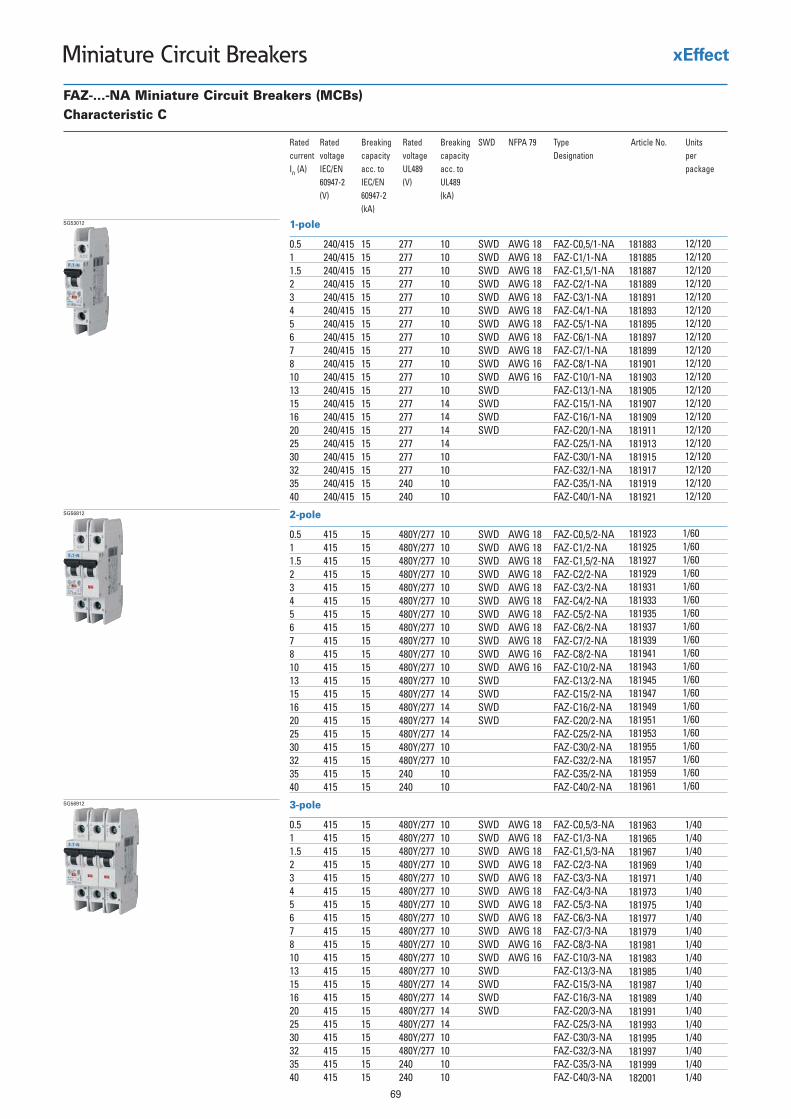
69
Miniature Circuit Breakers
3-pole
0.5 415 15 480Y/277 10 SWD AWG 18 FAZ-C0,5/3-NA1 415 15 480Y/277 10 SWD AWG 18 FAZ-C1/3-NA1.5 415 15 480Y/277 10 SWD AWG 18 FAZ-C1,5/3-NA2 415 15 480Y/277 10 SWD AWG 18 FAZ-C2/3-NA3 415 15 480Y/277 10 SWD AWG 18 FAZ-C3/3-NA4 415 15 480Y/277 10 SWD AWG 18 FAZ-C4/3-NA5 415 15 480Y/277 10 SWD AWG 18 FAZ-C5/3-NA6 415 15 480Y/277 10 SWD AWG 18 FAZ-C6/3-NA7 415 15 480Y/277 10 SWD AWG 18 FAZ-C7/3-NA8 415 15 480Y/277 10 SWD AWG 16 FAZ-C8/3-NA10 415 15 480Y/277 10 SWD AWG 16 FAZ-C10/3-NA13 415 15 480Y/277 10 SWD FAZ-C13/3-NA15 415 15 480Y/277 14 SWD FAZ-C15/3-NA16 415 15 480Y/277 14 SWD FAZ-C16/3-NA20 415 15 480Y/277 14 SWD FAZ-C20/3-NA25 415 15 480Y/277 14 FAZ-C25/3-NA30 415 15 480Y/277 10 FAZ-C30/3-NA32 415 15 480Y/277 10 FAZ-C32/3-NA35 415 15 240 10 FAZ-C35/3-NA40 415 15 240 10 FAZ-C40/3-NA
SG56912
FAZ-...-NA Miniature Circuit Breakers (MCBs)Characteristic C
Rated Rated Breaking Rated Breaking SWD NFPA 79 Type Article No. Unitscurrent voltage capacity voltage capacity Designation per In (A) IEC/EN acc. to UL489 acc. to package
60947-2 IEC/EN (V) UL489(V) 60947-2 (kA)
(kA)
2-pole
0.5 415 15 480Y/277 10 SWD AWG 18 FAZ-C0,5/2-NA1 415 15 480Y/277 10 SWD AWG 18 FAZ-C1/2-NA1.5 415 15 480Y/277 10 SWD AWG 18 FAZ-C1,5/2-NA2 415 15 480Y/277 10 SWD AWG 18 FAZ-C2/2-NA3 415 15 480Y/277 10 SWD AWG 18 FAZ-C3/2-NA4 415 15 480Y/277 10 SWD AWG 18 FAZ-C4/2-NA5 415 15 480Y/277 10 SWD AWG 18 FAZ-C5/2-NA6 415 15 480Y/277 10 SWD AWG 18 FAZ-C6/2-NA7 415 15 480Y/277 10 SWD AWG 18 FAZ-C7/2-NA8 415 15 480Y/277 10 SWD AWG 16 FAZ-C8/2-NA10 415 15 480Y/277 10 SWD AWG 16 FAZ-C10/2-NA13 415 15 480Y/277 10 SWD FAZ-C13/2-NA15 415 15 480Y/277 14 SWD FAZ-C15/2-NA16 415 15 480Y/277 14 SWD FAZ-C16/2-NA20 415 15 480Y/277 14 SWD FAZ-C20/2-NA25 415 15 480Y/277 14 FAZ-C25/2-NA30 415 15 480Y/277 10 FAZ-C30/2-NA32 415 15 480Y/277 10 FAZ-C32/2-NA35 415 15 240 10 FAZ-C35/2-NA40 415 15 240 10 FAZ-C40/2-NA
SG56812
1-pole
0.5 240/415 15 277 10 SWD AWG 18 FAZ-C0,5/1-NA1 240/415 15 277 10 SWD AWG 18 FAZ-C1/1-NA1.5 240/415 15 277 10 SWD AWG 18 FAZ-C1,5/1-NA2 240/415 15 277 10 SWD AWG 18 FAZ-C2/1-NA3 240/415 15 277 10 SWD AWG 18 FAZ-C3/1-NA4 240/415 15 277 10 SWD AWG 18 FAZ-C4/1-NA5 240/415 15 277 10 SWD AWG 18 FAZ-C5/1-NA6 240/415 15 277 10 SWD AWG 18 FAZ-C6/1-NA7 240/415 15 277 10 SWD AWG 18 FAZ-C7/1-NA8 240/415 15 277 10 SWD AWG 16 FAZ-C8/1-NA10 240/415 15 277 10 SWD AWG 16 FAZ-C10/1-NA13 240/415 15 277 10 SWD FAZ-C13/1-NA15 240/415 15 277 14 SWD FAZ-C15/1-NA16 240/415 15 277 14 SWD FAZ-C16/1-NA20 240/415 15 277 14 SWD FAZ-C20/1-NA25 240/415 15 277 14 FAZ-C25/1-NA30 240/415 15 277 10 FAZ-C30/1-NA32 240/415 15 277 10 FAZ-C32/1-NA35 240/415 15 240 10 FAZ-C35/1-NA40 240/415 15 240 10 FAZ-C40/1-NA
SG53012
181883181885181887181889181891181893181895181897181899181901181903181905181907181909181911181913181915181917181919181921
12/120 12/120 12/120 12/120 12/120 12/120 12/120 12/120 12/120 12/120 12/120 12/120 12/120 12/120 12/120 12/120 12/120 12/120 12/120 12/120
181923181925181927181929181931181933181935181937181939181941181943181945181947181949181951181953181955181957181959181961
1/60 1/60 1/60 1/60 1/60 1/60 1/60 1/60 1/60 1/60 1/60 1/60 1/60 1/60 1/60 1/60 1/60 1/60 1/60 1/60
181963181965181967181969181971181973181975181977181979181981181983181985181987181989181991181993181995181997181999182001
1/40 1/40 1/40 1/40 1/40 1/40 1/40 1/40 1/40 1/40 1/40 1/40 1/40 1/40 1/40 1/40 1/40 1/40 1/40 1/40
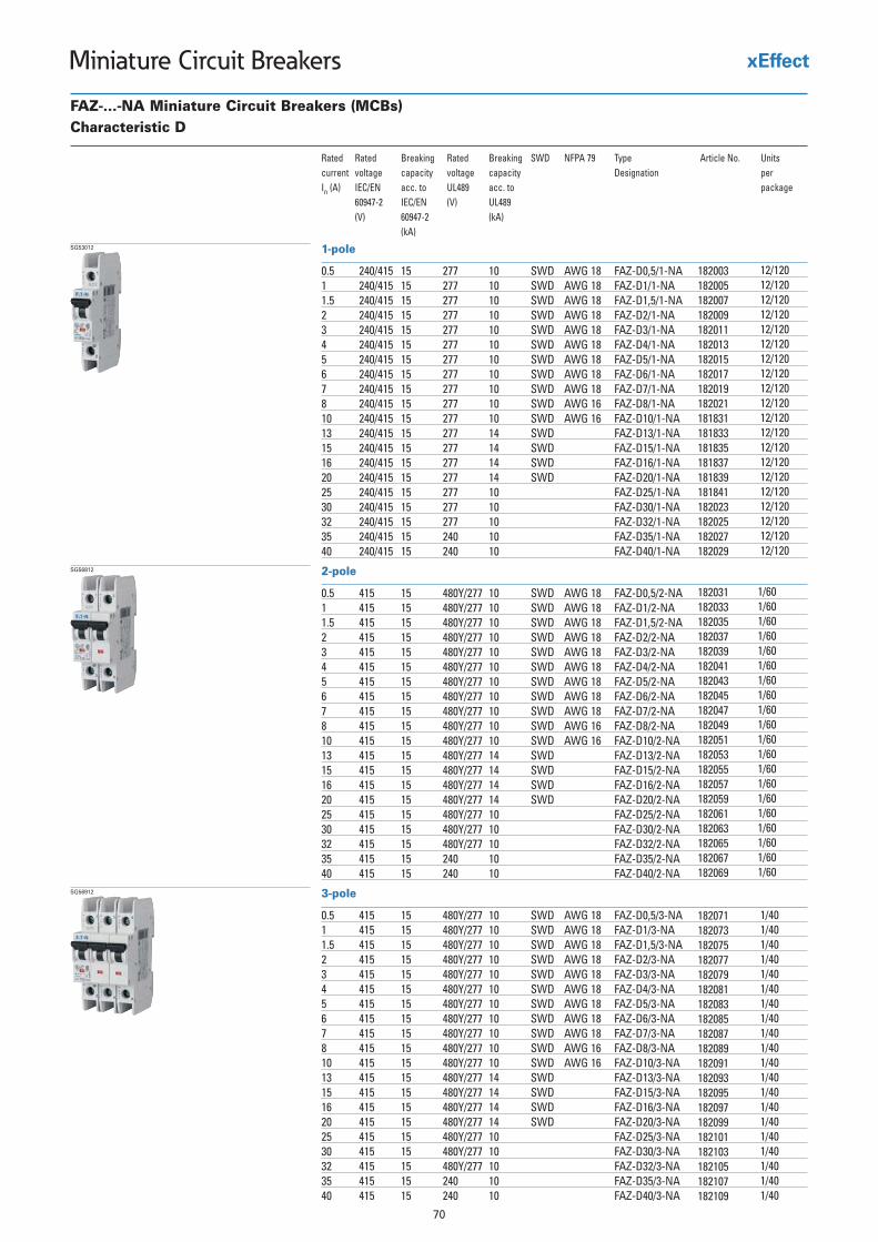
182003182005182007182009182011182013182015182017182019182021181831181833181835181837181839181841182023182025182027182029
12/120 12/120 12/120 12/120 12/120 12/120 12/120 12/120 12/120 12/120 12/120 12/120 12/120 12/120 12/120 12/120 12/120 12/120 12/120 12/120
182031182033182035182037182039182041182043182045182047182049182051182053182055182057182059182061182063182065182067182069
1/60 1/60 1/60 1/60 1/60 1/60 1/60 1/60 1/60 1/60 1/60 1/60 1/60 1/60 1/60 1/60 1/60 1/60 1/60 1/60
182071182073182075182077182079182081182083182085182087182089182091182093182095182097182099182101182103182105182107182109
1/40 1/40 1/40 1/40 1/40 1/40 1/40 1/40 1/40 1/40 1/40 1/40 1/40 1/40 1/40 1/40 1/40 1/40 1/40 1/40
70
Miniature Circuit Breakers
3-pole
0.5 415 15 480Y/277 10 SWD AWG 18 FAZ-D0,5/3-NA1 415 15 480Y/277 10 SWD AWG 18 FAZ-D1/3-NA1.5 415 15 480Y/277 10 SWD AWG 18 FAZ-D1,5/3-NA2 415 15 480Y/277 10 SWD AWG 18 FAZ-D2/3-NA3 415 15 480Y/277 10 SWD AWG 18 FAZ-D3/3-NA4 415 15 480Y/277 10 SWD AWG 18 FAZ-D4/3-NA5 415 15 480Y/277 10 SWD AWG 18 FAZ-D5/3-NA6 415 15 480Y/277 10 SWD AWG 18 FAZ-D6/3-NA7 415 15 480Y/277 10 SWD AWG 18 FAZ-D7/3-NA8 415 15 480Y/277 10 SWD AWG 16 FAZ-D8/3-NA10 415 15 480Y/277 10 SWD AWG 16 FAZ-D10/3-NA13 415 15 480Y/277 14 SWD FAZ-D13/3-NA15 415 15 480Y/277 14 SWD FAZ-D15/3-NA16 415 15 480Y/277 14 SWD FAZ-D16/3-NA20 415 15 480Y/277 14 SWD FAZ-D20/3-NA25 415 15 480Y/277 10 FAZ-D25/3-NA30 415 15 480Y/277 10 FAZ-D30/3-NA32 415 15 480Y/277 10 FAZ-D32/3-NA35 415 15 240 10 FAZ-D35/3-NA40 415 15 240 10 FAZ-D40/3-NA
SG56912
FAZ-...-NA Miniature Circuit Breakers (MCBs)Characteristic D
Rated Rated Breaking Rated Breaking SWD NFPA 79 Type Article No. Unitscurrent voltage capacity voltage capacity Designation per In (A) IEC/EN acc. to UL489 acc. to package
60947-2 IEC/EN (V) UL489(V) 60947-2 (kA)
(kA)
2-pole
0.5 415 15 480Y/277 10 SWD AWG 18 FAZ-D0,5/2-NA1 415 15 480Y/277 10 SWD AWG 18 FAZ-D1/2-NA1.5 415 15 480Y/277 10 SWD AWG 18 FAZ-D1,5/2-NA2 415 15 480Y/277 10 SWD AWG 18 FAZ-D2/2-NA3 415 15 480Y/277 10 SWD AWG 18 FAZ-D3/2-NA4 415 15 480Y/277 10 SWD AWG 18 FAZ-D4/2-NA5 415 15 480Y/277 10 SWD AWG 18 FAZ-D5/2-NA6 415 15 480Y/277 10 SWD AWG 18 FAZ-D6/2-NA7 415 15 480Y/277 10 SWD AWG 18 FAZ-D7/2-NA8 415 15 480Y/277 10 SWD AWG 16 FAZ-D8/2-NA10 415 15 480Y/277 10 SWD AWG 16 FAZ-D10/2-NA13 415 15 480Y/277 14 SWD FAZ-D13/2-NA15 415 15 480Y/277 14 SWD FAZ-D15/2-NA16 415 15 480Y/277 14 SWD FAZ-D16/2-NA20 415 15 480Y/277 14 SWD FAZ-D20/2-NA25 415 15 480Y/277 10 FAZ-D25/2-NA30 415 15 480Y/277 10 FAZ-D30/2-NA32 415 15 480Y/277 10 FAZ-D32/2-NA35 415 15 240 10 FAZ-D35/2-NA40 415 15 240 10 FAZ-D40/2-NA
SG56812
1-pole
0.5 240/415 15 277 10 SWD AWG 18 FAZ-D0,5/1-NA1 240/415 15 277 10 SWD AWG 18 FAZ-D1/1-NA1.5 240/415 15 277 10 SWD AWG 18 FAZ-D1,5/1-NA2 240/415 15 277 10 SWD AWG 18 FAZ-D2/1-NA3 240/415 15 277 10 SWD AWG 18 FAZ-D3/1-NA4 240/415 15 277 10 SWD AWG 18 FAZ-D4/1-NA5 240/415 15 277 10 SWD AWG 18 FAZ-D5/1-NA6 240/415 15 277 10 SWD AWG 18 FAZ-D6/1-NA7 240/415 15 277 10 SWD AWG 18 FAZ-D7/1-NA8 240/415 15 277 10 SWD AWG 16 FAZ-D8/1-NA10 240/415 15 277 10 SWD AWG 16 FAZ-D10/1-NA13 240/415 15 277 14 SWD FAZ-D13/1-NA15 240/415 15 277 14 SWD FAZ-D15/1-NA16 240/415 15 277 14 SWD FAZ-D16/1-NA20 240/415 15 277 14 SWD FAZ-D20/1-NA25 240/415 15 277 10 FAZ-D25/1-NA30 240/415 15 277 10 FAZ-D30/1-NA32 240/415 15 277 10 FAZ-D32/1-NA35 240/415 15 240 10 FAZ-D35/1-NA40 240/415 15 240 10 FAZ-D40/1-NA
SG53012
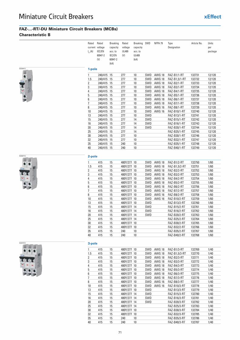
71
Miniature Circuit Breakers
FAZ-...-RT/-DU Miniature Circuit Breakers (MCBs)Characteristic B
Rated Rated Breaking Rated Breaking SWD NFPA 79 Type Article No. Unitscurrent voltage capacity voltage capacity Designation per In (A) IEC/EN acc. to UL489 acc. to package
60947-2 IEC/EN (V) UL489(V) 60947-2 (kA)
(kA)
1-pole
1 240/415 15 277 10 SWD AWG 18 FAZ-B1/1-RT 132731 12/1201.5 240/415 15 277 10 SWD AWG 18 FAZ-B1,5/1-RT 132732 12/1202 240/415 15 277 10 SWD AWG 18 FAZ-B2/1-RT 132733 12/1203 240/415 15 277 10 SWD AWG 18 FAZ-B3/1-RT 132734 12/1204 240/415 15 277 10 SWD AWG 18 FAZ-B4/1-RT 132735 12/1205 240/415 15 277 10 SWD AWG 18 FAZ-B5/1-RT 132736 12/1206 240/415 15 277 10 SWD AWG 18 FAZ-B6/1-RT 132737 12/1207 240/415 15 277 10 SWD AWG 18 FAZ-B7/1-RT 132738 12/1208 240/415 15 277 10 SWD AWG 16 FAZ-B8/1-RT 132739 12/12010 240/415 15 277 10 SWD AWG 16 FAZ-B10/1-RT 132740 12/12013 240/415 15 277 10 SWD FAZ-B13/1-RT 132741 12/12015 240/415 15 277 14 SWD FAZ-B15/1-RT 132742 12/12016 240/415 15 277 14 SWD FAZ-B16/1-RT 132743 12/12020 240/415 15 277 14 SWD FAZ-B20/1-RT 132744 12/12025 240/415 15 277 14 FAZ-B25/1-RT 132745 12/12030 240/415 15 277 10 FAZ-B30/1-RT 132746 12/12032 240/415 15 277 10 FAZ-B32/1-RT 132747 12/12035 240/415 15 240 10 FAZ-B35/1-RT 132748 12/12040 240/415 15 240 10 FAZ-B40/1-RT 132749 12/120
SG56412
2-pole
1 415 15 480Y/277 10 SWD AWG 18 FAZ-B1/2-RT 132750 1/601.5 415 15 480Y/277 10 SWD AWG 18 FAZ-B1,5/2-RT 132751 1/602 415 15 480Y/277 10 SWD AWG 18 FAZ-B2/2-RT 132752 1/603 415 15 480Y/277 10 SWD AWG 18 FAZ-B3/2-RT 132753 1/604 415 15 480Y/277 10 SWD AWG 18 FAZ-B4/2-RT 132754 1/605 415 15 480Y/277 10 SWD AWG 18 FAZ-B5/2-RT 132755 1/606 415 15 480Y/277 10 SWD AWG 18 FAZ-B6/2-RT 132756 1/607 415 15 480Y/277 10 SWD AWG 18 FAZ-B7/2-RT 132757 1/608 415 15 480Y/277 10 SWD AWG 16 FAZ-B8/2-RT 132758 1/6010 415 15 480Y/277 10 SWD AWG 16 FAZ-B10/2-RT 132759 1/6013 415 15 480Y/277 10 SWD FAZ-B13/2-RT 132760 1/6015 415 15 480Y/277 14 SWD FAZ-B15/2-RT 132761 1/6016 415 15 480Y/277 14 SWD FAZ-B16/2-RT 132762 1/6020 415 15 480Y/277 14 SWD FAZ-B20/2-RT 132763 1/6025 415 15 480Y/277 14 FAZ-B25/2-RT 132764 1/6030 415 15 480Y/277 10 FAZ-B30/2-RT 132765 1/6032 415 15 480Y/277 10 FAZ-B32/2-RT 132766 1/6035 415 15 240 10 FAZ-B35/2-RT 132767 1/6040 415 15 240 10 FAZ-B40/2-RT 132768 1/60
SG56712
3-pole
1 415 15 480Y/277 10 SWD AWG 18 FAZ-B1/3-RT 132769 1/401.5 415 15 480Y/277 10 SWD AWG 18 FAZ-B1,5/3-RT 132770 1/402 415 15 480Y/277 10 SWD AWG 18 FAZ-B2/3-RT 132771 1/403 415 15 480Y/277 10 SWD AWG 18 FAZ-B3/3-RT 132772 1/404 415 15 480Y/277 10 SWD AWG 18 FAZ-B4/3-RT 132773 1/405 415 15 480Y/277 10 SWD AWG 18 FAZ-B5/3-RT 132774 1/406 415 15 480Y/277 10 SWD AWG 18 FAZ-B6/3-RT 132775 1/407 415 15 480Y/277 10 SWD AWG 18 FAZ-B7/3-RT 132776 1/408 415 15 480Y/277 10 SWD AWG 16 FAZ-B8/3-RT 132777 1/4010 415 15 480Y/277 10 SWD AWG 16 FAZ-B10/3-RT 132778 1/4013 415 15 480Y/277 10 SWD FAZ-B13/3-RT 132779 1/4015 415 15 480Y/277 14 SWD FAZ-B15/3-RT 132780 1/4016 415 15 480Y/277 14 SWD FAZ-B16/3-RT 132781 1/4020 415 15 480Y/277 14 SWD FAZ-B20/3-RT 132782 1/4025 415 15 480Y/277 14 FAZ-B25/3-RT 132783 1/4030 415 15 480Y/277 10 FAZ-B30/3-RT 132784 1/4032 415 15 480Y/277 10 FAZ-B32/3-RT 132785 1/4035 415 15 240 10 FAZ-B35/3-RT 132786 1/4040 415 15 240 10 FAZ-B40/3-RT 132787 1/40
SG57012
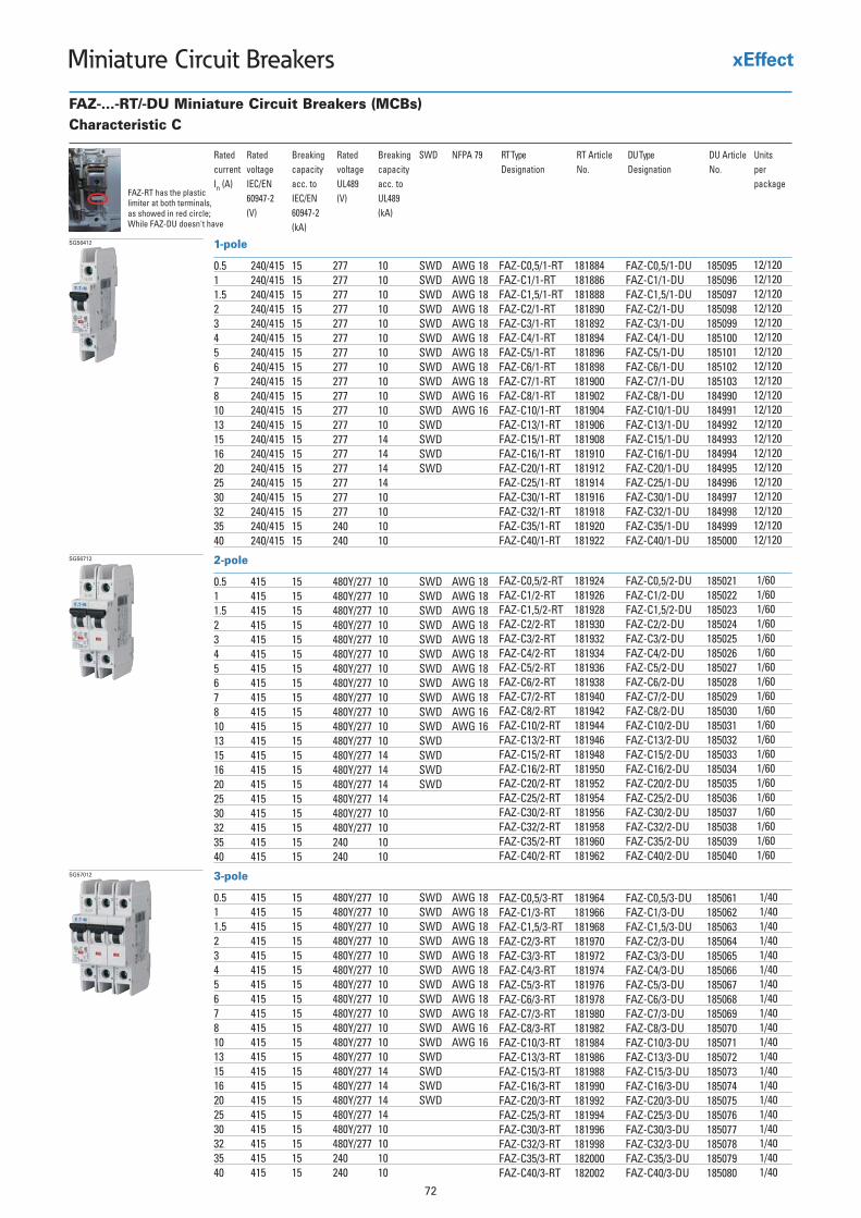
72
Miniature Circuit Breakers
3-pole
0.5 415 15 480Y/277 10 SWD AWG 181 415 15 480Y/277 10 SWD AWG 181.5 415 15 480Y/277 10 SWD AWG 182 415 15 480Y/277 10 SWD AWG 183 415 15 480Y/277 10 SWD AWG 184 415 15 480Y/277 10 SWD AWG 185 415 15 480Y/277 10 SWD AWG 186 415 15 480Y/277 10 SWD AWG 187 415 15 480Y/277 10 SWD AWG 188 415 15 480Y/277 10 SWD AWG 1610 415 15 480Y/277 10 SWD AWG 1613 415 15 480Y/277 10 SWD15 415 15 480Y/277 14 SWD16 415 15 480Y/277 14 SWD20 415 15 480Y/277 14 SWD25 415 15 480Y/277 1430 415 15 480Y/277 1032 415 15 480Y/277 1035 415 15 240 1040 415 15 240 10
SG57012
FAZ-...-RT/-DU Miniature Circuit Breakers (MCBs)Characteristic C
Rated Rated Breaking Rated Breaking SWD NFPA 79current voltage capacity voltage capacityIn (A) IEC/EN acc. to UL489 acc. to
60947-2 IEC/EN (V) UL489(V) 60947-2 (kA)
(kA)
2-pole
0.5 415 15 480Y/277 10 SWD AWG 181 415 15 480Y/277 10 SWD AWG 181.5 415 15 480Y/277 10 SWD AWG 182 415 15 480Y/277 10 SWD AWG 183 415 15 480Y/277 10 SWD AWG 184 415 15 480Y/277 10 SWD AWG 185 415 15 480Y/277 10 SWD AWG 186 415 15 480Y/277 10 SWD AWG 187 415 15 480Y/277 10 SWD AWG 188 415 15 480Y/277 10 SWD AWG 1610 415 15 480Y/277 10 SWD AWG 1613 415 15 480Y/277 10 SWD15 415 15 480Y/277 14 SWD16 415 15 480Y/277 14 SWD20 415 15 480Y/277 14 SWD25 415 15 480Y/277 1430 415 15 480Y/277 1032 415 15 480Y/277 1035 415 15 240 1040 415 15 240 10
SG56712
1-pole
0.5 240/415 15 277 10 SWD AWG 181 240/415 15 277 10 SWD AWG 181.5 240/415 15 277 10 SWD AWG 182 240/415 15 277 10 SWD AWG 183 240/415 15 277 10 SWD AWG 184 240/415 15 277 10 SWD AWG 185 240/415 15 277 10 SWD AWG 186 240/415 15 277 10 SWD AWG 187 240/415 15 277 10 SWD AWG 188 240/415 15 277 10 SWD AWG 1610 240/415 15 277 10 SWD AWG 1613 240/415 15 277 10 SWD15 240/415 15 277 14 SWD16 240/415 15 277 14 SWD20 240/415 15 277 14 SWD25 240/415 15 277 1430 240/415 15 277 1032 240/415 15 277 1035 240/415 15 240 1040 240/415 15 240 10
SG56412
FAZ-RT has the plasticlimiter at both terminals,as showed in red circle;While FAZ-DU doesn't have
RT Article No.Designation
181884181886181888181890181892181894181896181898181900181902181904181906181908181910181912181914181916181918181920181922
FAZ-C0,5/1-RTFAZ-C1/1-RTFAZ-C1,5/1-RTFAZ-C2/1-RTFAZ-C3/1-RTFAZ-C4/1-RTFAZ-C5/1-RTFAZ-C6/1-RTFAZ-C7/1-RTFAZ-C8/1-RTFAZ-C10/1-RTFAZ-C13/1-RTFAZ-C15/1-RTFAZ-C16/1-RTFAZ-C20/1-RTFAZ-C25/1-RTFAZ-C30/1-RTFAZ-C32/1-RTFAZ-C35/1-RTFAZ-C40/1-RT
DU ArticleNo.Designation
185095185096185097185098185099185100185101185102185103184990184991184992184993184994184995184996184997184998184999185000
FAZ-C0,5/1-DUFAZ-C1/1-DUFAZ-C1,5/1-DUFAZ-C2/1-DUFAZ-C3/1-DUFAZ-C4/1-DUFAZ-C5/1-DUFAZ-C6/1-DUFAZ-C7/1-DUFAZ-C8/1-DUFAZ-C10/1-DUFAZ-C13/1-DUFAZ-C15/1-DUFAZ-C16/1-DUFAZ-C20/1-DUFAZ-C25/1-DUFAZ-C30/1-DUFAZ-C32/1-DUFAZ-C35/1-DUFAZ-C40/1-DU
185021185022185023185024185025185026185027185028185029185030185031185032185033185034185035185036185037185038185039185040
FAZ-C0,5/2-DUFAZ-C1/2-DUFAZ-C1,5/2-DUFAZ-C2/2-DUFAZ-C3/2-DUFAZ-C4/2-DUFAZ-C5/2-DUFAZ-C6/2-DUFAZ-C7/2-DUFAZ-C8/2-DUFAZ-C10/2-DUFAZ-C13/2-DUFAZ-C15/2-DUFAZ-C16/2-DUFAZ-C20/2-DUFAZ-C25/2-DUFAZ-C30/2-DUFAZ-C32/2-DUFAZ-C35/2-DUFAZ-C40/2-DU
185061185062185063185064185065185066185067185068185069185070185071185072185073185074185075185076185077185078185079185080
FAZ-C0,5/3-DUFAZ-C1/3-DUFAZ-C1,5/3-DUFAZ-C2/3-DUFAZ-C3/3-DUFAZ-C4/3-DUFAZ-C5/3-DUFAZ-C6/3-DUFAZ-C7/3-DUFAZ-C8/3-DUFAZ-C10/3-DUFAZ-C13/3-DUFAZ-C15/3-DUFAZ-C16/3-DUFAZ-C20/3-DUFAZ-C25/3-DUFAZ-C30/3-DUFAZ-C32/3-DUFAZ-C35/3-DUFAZ-C40/3-DU
FAZ-C0,5/2-RTFAZ-C1/2-RTFAZ-C1,5/2-RTFAZ-C2/2-RTFAZ-C3/2-RTFAZ-C4/2-RTFAZ-C5/2-RTFAZ-C6/2-RTFAZ-C7/2-RTFAZ-C8/2-RTFAZ-C10/2-RTFAZ-C13/2-RTFAZ-C15/2-RTFAZ-C16/2-RTFAZ-C20/2-RTFAZ-C25/2-RTFAZ-C30/2-RTFAZ-C32/2-RTFAZ-C35/2-RTFAZ-C40/2-RT
FAZ-C0,5/3-RTFAZ-C1/3-RTFAZ-C1,5/3-RTFAZ-C2/3-RTFAZ-C3/3-RTFAZ-C4/3-RTFAZ-C5/3-RTFAZ-C6/3-RTFAZ-C7/3-RTFAZ-C8/3-RTFAZ-C10/3-RTFAZ-C13/3-RTFAZ-C15/3-RTFAZ-C16/3-RTFAZ-C20/3-RTFAZ-C25/3-RTFAZ-C30/3-RTFAZ-C32/3-RTFAZ-C35/3-RTFAZ-C40/3-RT
UnitsDU Typeper package
12/120 12/120 12/120 12/120 12/120 12/120 12/120 12/120 12/120 12/120 12/120 12/120 12/120 12/120 12/120 12/120 12/120 12/120 12/120 12/120
181924181926181928181930181932181934181936181938181940181942181944181946181948181950181952181954181956181958181960181962
1/60 1/60 1/60 1/60 1/60 1/60 1/60 1/60 1/60 1/60 1/60 1/60 1/60 1/60 1/60 1/60 1/60 1/60 1/60 1/60
181964181966181968181970181972181974181976181978181980181982181984181986181988181990181992181994181996181998182000182002
1/40 1/40 1/40 1/40 1/40 1/40 1/40 1/40 1/40 1/40 1/40 1/40 1/40 1/40 1/40 1/40 1/40 1/40 1/40 1/40
RT Type
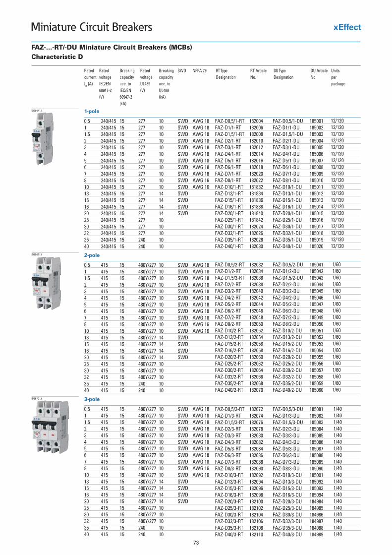
73
Miniature Circuit Breakers
3-pole
0.5 415 15 480Y/277 10 SWD AWG 181 415 15 480Y/277 10 SWD AWG 181.5 415 15 480Y/277 10 SWD AWG 182 415 15 480Y/277 10 SWD AWG 183 415 15 480Y/277 10 SWD AWG 184 415 15 480Y/277 10 SWD AWG 185 415 15 480Y/277 10 SWD AWG 186 415 15 480Y/277 10 SWD AWG 187 415 15 480Y/277 10 SWD AWG 188 415 15 480Y/277 10 SWD AWG 1610 415 15 480Y/277 10 SWD AWG 1613 415 15 480Y/277 14 SWD15 415 15 480Y/277 14 SWD16 415 15 480Y/277 14 SWD20 415 15 480Y/277 14 SWD25 415 15 480Y/277 1030 415 15 480Y/277 1032 415 15 480Y/277 1035 415 15 240 1040 415 15 240 10
SG57012
FAZ-...-RT/-DU Miniature Circuit Breakers (MCBs)Characteristic D
Rated Rated Breaking Rated Breaking SWD NFPA 79current voltage capacity voltage capacityIn (A) IEC/EN acc. to UL489 acc. to
60947-2 IEC/EN (V) UL489(V) 60947-2 (kA)
(kA)
2-pole
0.5 415 15 480Y/277 10 SWD AWG 181 415 15 480Y/277 10 SWD AWG 181.5 415 15 480Y/277 10 SWD AWG 182 415 15 480Y/277 10 SWD AWG 183 415 15 480Y/277 10 SWD AWG 184 415 15 480Y/277 10 SWD AWG 185 415 15 480Y/277 10 SWD AWG 186 415 15 480Y/277 10 SWD AWG 187 415 15 480Y/277 10 SWD AWG 188 415 15 480Y/277 10 SWD AWG 1610 415 15 480Y/277 10 SWD AWG 1613 415 15 480Y/277 14 SWD15 415 15 480Y/277 14 SWD16 415 15 480Y/277 14 SWD20 415 15 480Y/277 14 SWD25 415 15 480Y/277 1030 415 15 480Y/277 1032 415 15 480Y/277 1035 415 15 240 1040 415 15 240 10
SG56712
1-pole
0.5 240/415 15 277 10 SWD AWG 181 240/415 15 277 10 SWD AWG 181.5 240/415 15 277 10 SWD AWG 182 240/415 15 277 10 SWD AWG 183 240/415 15 277 10 SWD AWG 184 240/415 15 277 10 SWD AWG 185 240/415 15 277 10 SWD AWG 186 240/415 15 277 10 SWD AWG 187 240/415 15 277 10 SWD AWG 188 240/415 15 277 10 SWD AWG 1610 240/415 15 277 10 SWD AWG 1613 240/415 15 277 14 SWD15 240/415 15 277 14 SWD16 240/415 15 277 14 SWD20 240/415 15 277 14 SWD25 240/415 15 277 1030 240/415 15 277 1032 240/415 15 277 1035 240/415 15 240 1040 240/415 15 240 10
SG56412
RT Article No.Designation
182004182006182008182010182012182014182016182018182020182022181832181834181836181838181840181842182024182026182028182030
FAZ-D0,5/1-RTFAZ-D1/1-RTFAZ-D1,5/1-RTFAZ-D2/1-RTFAZ-D3/1-RTFAZ-D4/1-RTFAZ-D5/1-RTFAZ-D6/1-RTFAZ-D7/1-RTFAZ-D8/1-RTFAZ-D10/1-RTFAZ-D13/1-RTFAZ-D15/1-RTFAZ-D16/1-RTFAZ-D20/1-RTFAZ-D25/1-RTFAZ-D30/1-RTFAZ-D32/1-RTFAZ-D35/1-RTFAZ-D40/1-RT
DU ArticleNo.Designation
185001185002185003185004185005185006185007185008185009185010185011185012185013185014185015185016185017185018185019185020
FAZ-D0,5/1-DUFAZ-D1/1-DUFAZ-D1,5/1-DUFAZ-D2/1-DUFAZ-D3/1-DUFAZ-D4/1-DUFAZ-D5/1-DUFAZ-D6/1-DUFAZ-D7/1-DUFAZ-D8/1-DUFAZ-D10/1-DUFAZ-D13/1-DUFAZ-D15/1-DUFAZ-D16/1-DUFAZ-D20/1-DUFAZ-D25/1-DUFAZ-D30/1-DUFAZ-D32/1-DUFAZ-D35/1-DUFAZ-D40/1-DU
185041185042185043185044185045185046185047185048185049185050185051185052185053185054185055185056185057185058185059185060
FAZ-D0,5/2-DUFAZ-D1/2-DUFAZ-D1,5/2-DUFAZ-D2/2-DUFAZ-D3/2-DUFAZ-D4/2-DUFAZ-D5/2-DUFAZ-D6/2-DUFAZ-D7/2-DUFAZ-D8/2-DUFAZ-D10/2-DUFAZ-D13/2-DUFAZ-D15/2-DUFAZ-D16/2-DUFAZ-D20/2-DUFAZ-D25/2-DUFAZ-D30/2-DUFAZ-D32/2-DUFAZ-D35/2-DUFAZ-D40/2-DU
185081185082185083185084185085185086185087185088185089185090185091185092185093185094184984184985184986184987184988184989
FAZ-D0,5/3-DUFAZ-D1/3-DUFAZ-D1,5/3-DUFAZ-D2/3-DUFAZ-D3/3-DUFAZ-D4/3-DUFAZ-D5/3-DUFAZ-D6/3-DUFAZ-D7/3-DUFAZ-D8/3-DUFAZ-D10/3-DUFAZ-D13/3-DUFAZ-D15/3-DUFAZ-D16/3-DUFAZ-D20/3-DUFAZ-D25/3-DUFAZ-D30/3-DUFAZ-D32/3-DUFAZ-D35/3-DUFAZ-D40/3-DU
FAZ-D0,5/2-RTFAZ-D1/2-RTFAZ-D1,5/2-RTFAZ-D2/2-RTFAZ-D3/2-RTFAZ-D4/2-RTFAZ-D5/2-RTFAZ-D6/2-RTFAZ-D7/2-RTFAZ-D8/2-RTFAZ-D10/2-RTFAZ-D13/2-RTFAZ-D15/2-RTFAZ-D16/2-RTFAZ-D20/2-RTFAZ-D25/2-RTFAZ-D30/2-RTFAZ-D32/2-RTFAZ-D35/2-RTFAZ-D40/2-RT
FAZ-D0,5/3-RTFAZ-D1/3-RTFAZ-D1,5/3-RTFAZ-D2/3-RTFAZ-D3/3-RTFAZ-D4/3-RTFAZ-D5/3-RTFAZ-D6/3-RTFAZ-D7/3-RTFAZ-D8/3-RTFAZ-D10/3-RTFAZ-D13/3-RTFAZ-D15/3-RTFAZ-D16/3-RTFAZ-D20/3-RTFAZ-D25/3-RTFAZ-D30/3-RTFAZ-D32/3-RTFAZ-D35/3-RTFAZ-D40/3-RT
UnitsDU Typeper package
12/120 12/120 12/120 12/120 12/120 12/120 12/120 12/120 12/120 12/120 12/120 12/120 12/120 12/120 12/120 12/120 12/120 12/120 12/120 12/120
182032182034182036182038182040182042182044182046182048182050182052182054182056182058182060182062182064182066182068182070
1/60 1/60 1/60 1/60 1/60 1/60 1/60 1/60 1/60 1/60 1/60 1/60 1/60 1/60 1/60 1/60 1/60 1/60 1/60 1/60
182072182074182076182078182080182082182084182086182088182090182092182094182096182098182100182102182104182106182108182110
1/40 1/40 1/40 1/40 1/40 1/40 1/40 1/40 1/40 1/40 1/40 1/40 1/40 1/40 1/40 1/40 1/40 1/40 1/40 1/40
RT Type
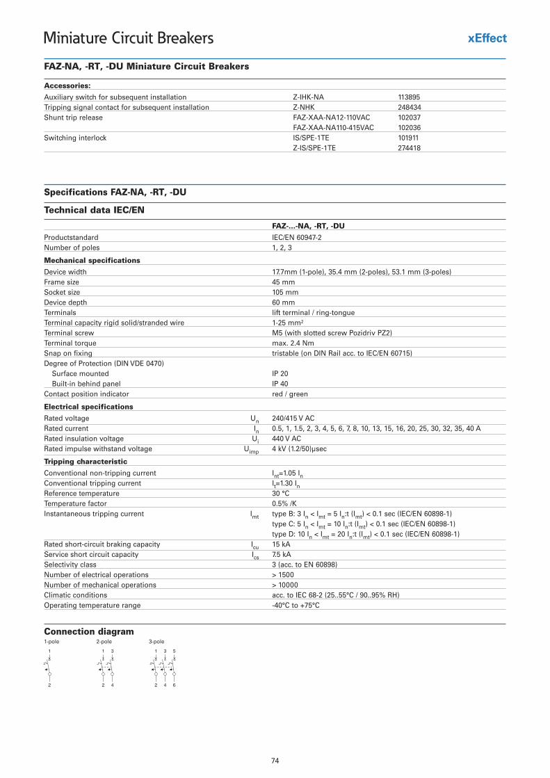
74
Miniature Circuit Breakers
Specifications FAZ-NA, -RT, -DU
Technical data IEC/EN
FAZ-...-NA, -RT, -DU
NE/CEI dradnatstcudorP 60947-2Number of poles 1, 2, 3
Mechanical specifications
Device width 17.7mm (1-pole), 35.4 mm (2-poles), 53.1 mm (3-poles)Frame size 45 mmSocket size 105 mmDevice depth 60 mmTerminals lift terminal / ring-tongueTerminal capacity rigid solid/stranded wire 1-25 mm²Terminal screw M5 (with slotted screw Pozidriv PZ2)Terminal torque max. 2.4 NmSnap on fixing tristable (on DIN Rail acc. to IEC/EN 60715)Degree of Protection (DIN VDE 0470)
Surface mounted IP 20Built-in behind panel IP 40
Contact position indicator red / green
Electrical specifications
Rated voltage Un 240/415 V ACRated current In 0.5, 1, 1.5, 2, 3, 4, 5, 6, 7, 8, 10, 13, 15, 16, 20, 25, 30, 32, 35, 40 ARated insulation voltage Ui 440 V ACRated impulse withstand voltage Uimp 4 kV (1.2/50)µsec
Tripping characteristic
Conventional non-tripping current Int=1.05 InConventional tripping current It=1.30 InReference temperature 30 °CTemperature factor 0.5% /KInstantaneous tripping current Imt type B: 3 In < Imt = 5 In:t (Imt) < 0.1 sec (IEC/EN 60898-1)
type C: 5 In < Imt = 10 In:t (Imt) < 0.1 sec (IEC/EN 60898-1)type D: 10 In < Imt = 20 In:t (Imt) < 0.1 sec (IEC/EN 60898-1)
Rated short-circuit braking capacity Icu 15 kAService short circuit capacity Ics 7.5 kASelectivity class 3 (acc. to EN 60898)Number of electrical operations > 1500Number of mechanical operations > 10000Climatic conditions acc. to IEC 68-2 (25..55°C / 90..95% RH)Operating temperature range -40°C to +75°C
Connection diagram1-pole 2-pole 3-pole
Accessories:
Auxiliary switch for subsequent installation Z-IHK-NA 113895Tripping signal contact for subsequent installation Z-NHK 248434Shunt trip release FAZ-XAA-NA12-110VAC 102037
FAZ-XAA-NA110-415VAC 102036119101 ET1-EPS/SIkcolretni gnihctiwS
Z-IS/SPE-1TE 274418
FAZ-NA, -RT, -DU Miniature Circuit Breakers
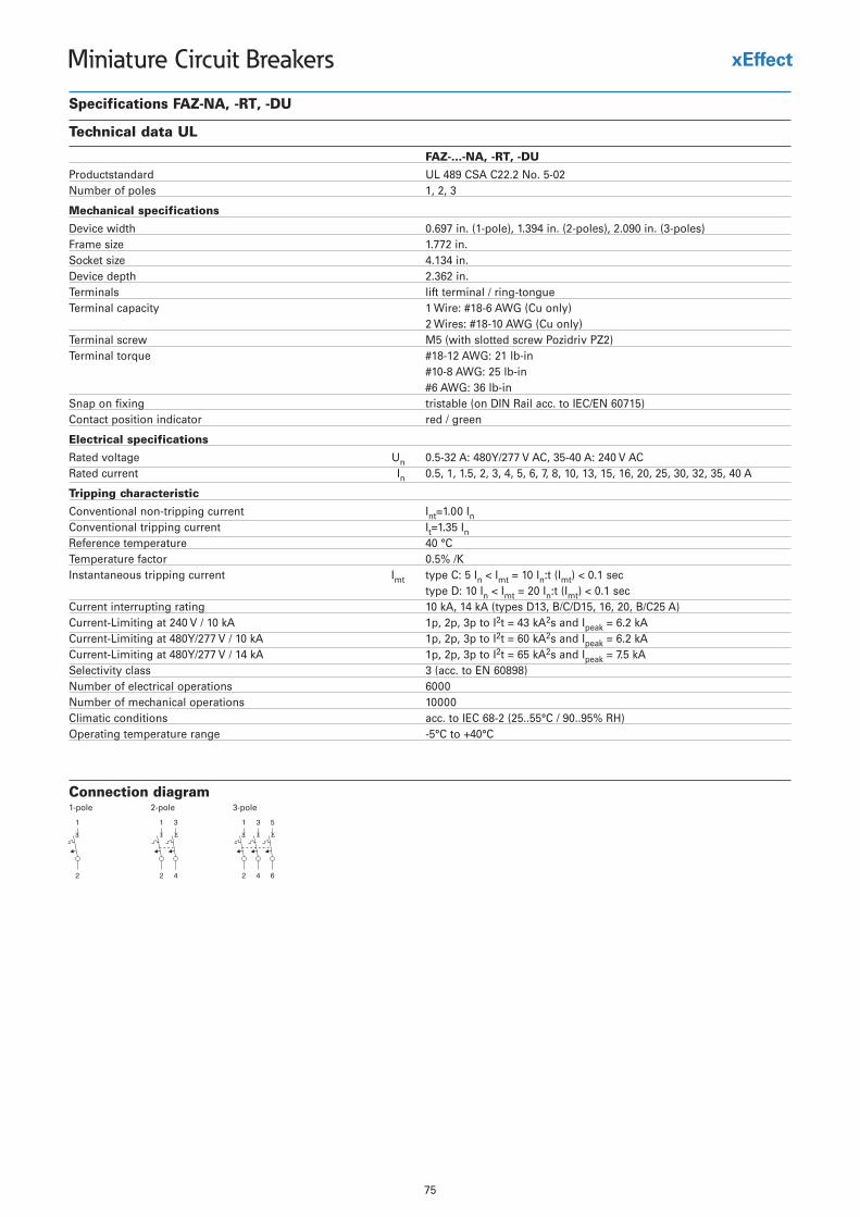
75
Miniature Circuit Breakers
Specifications FAZ-NA, -RT, -DU
Technical data UL
FAZ-...-NA, -RT, -DU
Productstandard UL 489 CSA C22.2 No. 5-02Number of poles 1, 2, 3
Mechanical specifications
Device width 0.697 in. (1-pole), 1.394 in. (2-poles), 2.090 in. (3-poles)Frame size 1.772 in.Socket size 4.134 in.Device depth 2.362 in.Terminals lift terminal / ring-tongueTerminal capacity 1 Wire: #18-6 AWG (Cu only)
2 Wires: #18-10 AWG (Cu only)Terminal screw M5 (with slotted screw Pozidriv PZ2)Terminal torque #18-12 AWG: 21 lb-in
#10-8 AWG: 25 lb-in#6 AWG: 36 lb-in
Snap on fixing tristable (on DIN Rail acc. to IEC/EN 60715)Contact position indicator red / green
Electrical specifications
Rated voltage Un 0.5-32 A: 480Y/277 V AC, 35-40 A: 240 V ACRated current In 0.5, 1, 1.5, 2, 3, 4, 5, 6, 7, 8, 10, 13, 15, 16, 20, 25, 30, 32, 35, 40 A
Tripping characteristic
Conventional non-tripping current Int=1.00 InConventional tripping current It=1.35 InReference temperature 40 °CTemperature factor 0.5% /KInstantaneous tripping current Imt type C: 5 In < Imt = 10 In:t (Imt) < 0.1 sec
type D: 10 In < Imt = 20 In:t (Imt) < 0.1 secCurrent interrupting rating 10 kA, 14 kA (types D13, B/C/D15, 16, 20, B/C25 A)Current-Limiting at 240 V / 10 kA 1p, 2p, 3p to I2t = 43 kA2s and Ipeak = 6.2 kACurrent-Limiting at 480Y/277 V / 10 kA 1p, 2p, 3p to I2t = 60 kA2s and Ipeak = 6.2 kACurrent-Limiting at 480Y/277 V / 14 kA 1p, 2p, 3p to I2t = 65 kA2s and Ipeak = 7.5 kASelectivity class 3 (acc. to EN 60898)Number of electrical operations 6000Number of mechanical operations 10000Climatic conditions acc. to IEC 68-2 (25..55°C / 90..95% RH)Operating temperature range -5°C to +40°C
Connection diagram1-pole 2-pole 3-pole
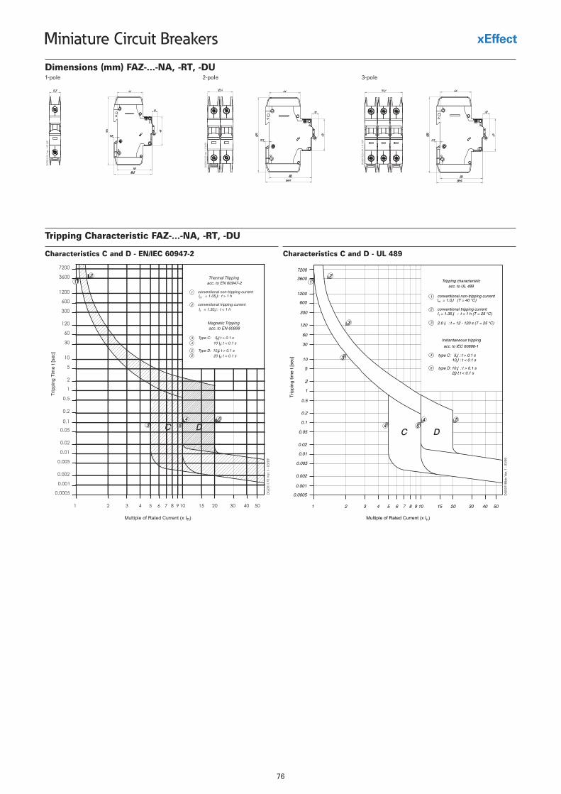
76
Miniature Circuit Breakers
Dimensions (mm) FAZ-...-NA, -RT, -DU
Tripping Characteristic FAZ-...-NA, -RT, -DU
Characteristics C and D - EN/IEC 60947-2 Characteristics C and D - UL 489
1-pole 2-pole 3-pole
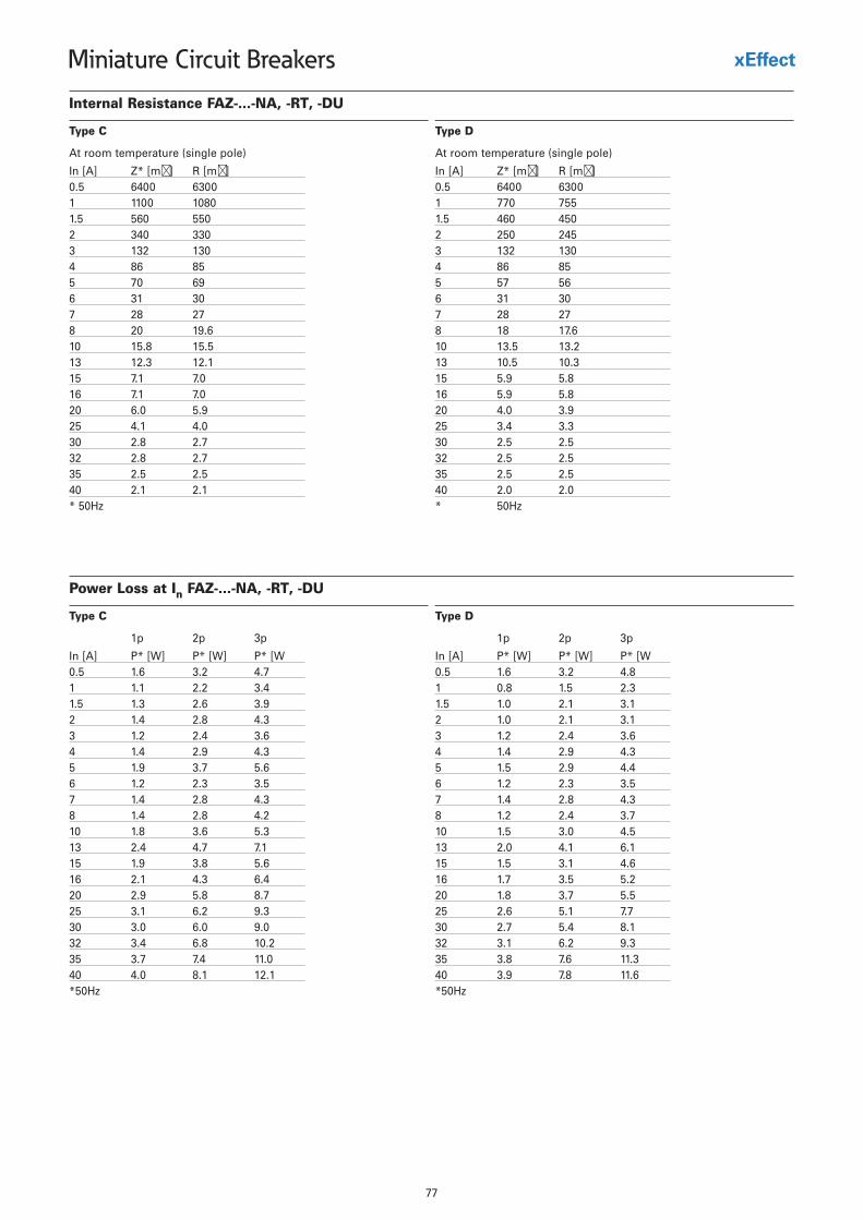
77
Miniature Circuit Breakers
Internal Resistance FAZ-...-NA, -RT, -DU
At room temperature (single pole)
In [A] Z* [m�] R [m �]0.5 6400 63001 1100 10801.5 560 5502 340 3303 132 1304 86 855 70 696 31 307 28 278 20 19.610 15.8 15.513 12.3 12.115 7.1 7.016 7.1 7.020 6.0 5.925 4.1 4.030 2.8 2.732 2.8 2.735 2.5 2.540 2.1 2.1* 50Hz
Type C
At room temperature (single pole)
In [A] Z* [m�] R [m �]0.5 6400 63001 770 7551.5 460 4502 250 2453 132 1304 86 855 57 566 31 307 28 278 18 17.610 13.5 13.213 10.5 10.315 5.9 5.816 5.9 5.820 4.0 3.925 3.4 3.330 2.5 2.532 2.5 2.535 2.5 2.540 2.0 2.0* 50Hz
Type D
Power Loss at In FAZ-...-NA, -RT, -DU
1p 2p 3p
In [A] P* [W] P* [W] P* [W0.5 1.6 3.2 4.71 1.1 2.2 3.41.5 1.3 2.6 3.92 1.4 2.8 4.33 1.2 2.4 3.64 1.4 2.9 4.35 1.9 3.7 5.66 1.2 2.3 3.57 1.4 2.8 4.38 1.4 2.8 4.210 1.8 3.6 5.313 2.4 4.7 7.115 1.9 3.8 5.616 2.1 4.3 6.420 2.9 5.8 8.725 3.1 6.2 9.330 3.0 6.0 9.032 3.4 6.8 10.235 3.7 7.4 11.040 4.0 8.1 12.1*50Hz
Type C
1p 2p 3p
In [A] P* [W] P* [W] P* [W0.5 1.6 3.2 4.81 0.8 1.5 2.31.5 1.0 2.1 3.12 1.0 2.1 3.13 1.2 2.4 3.64 1.4 2.9 4.35 1.5 2.9 4.46 1.2 2.3 3.57 1.4 2.8 4.38 1.2 2.4 3.710 1.5 3.0 4.513 2.0 4.1 6.115 1.5 3.1 4.616 1.7 3.5 5.220 1.8 3.7 5.525 2.6 5.1 7.730 2.7 5.4 8.132 3.1 6.2 9.335 3.8 7.6 11.340 3.9 7.8 11.6*50Hz
Type D
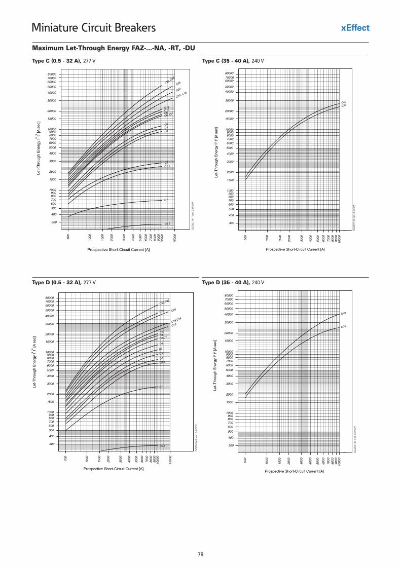
78
Miniature Circuit Breakers
Maximum Let-Through Energy FAZ-...-NA, -RT, -DU
Type C (0.5 - 32 A), 277 V Type C (35 - 40 A), 240 V
Type D (35 - 40 A), 240 VType D (0.5 - 32 A), 277 V
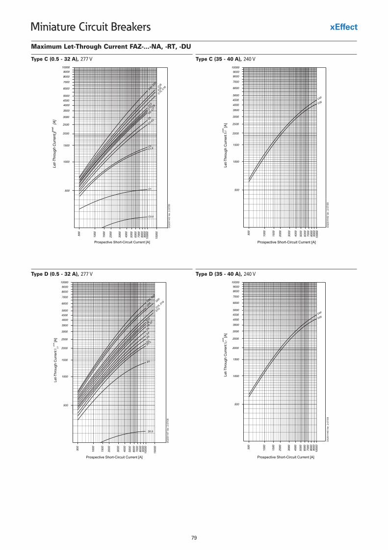
79
Miniature Circuit Breakers
Maximum Let-Through Current FAZ-...-NA, -RT, -DU
Type C (0.5 - 32 A), 277 V Type C (35 - 40 A), 240 V
Type D (35 - 40 A), 240 VType D (0.5 - 32 A), 277 V
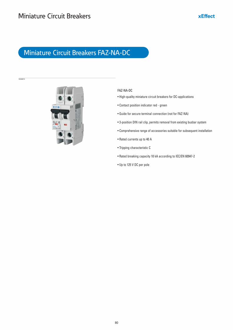
80
Miniature Circuit Breakers
FAZ-NA-DC
• High-quality miniature circuit breakers for DC-applications
• Contact position indicator red - green
• Guide for secure terminal connection (not for FAZ-NA)
• 3-position DIN rail clip, permits removal from existing busbar system
• Comprehensive range of accessories suitable for subsequent installation
• Rated currents up to 40 A
• Tripping characteristic C
• Rated breaking capacity 10 kA according to IEC/EN 60947-2
• Up to 125 V DC per pole
Miniature Circuit Breakers FAZ-NA-DC
SG56612
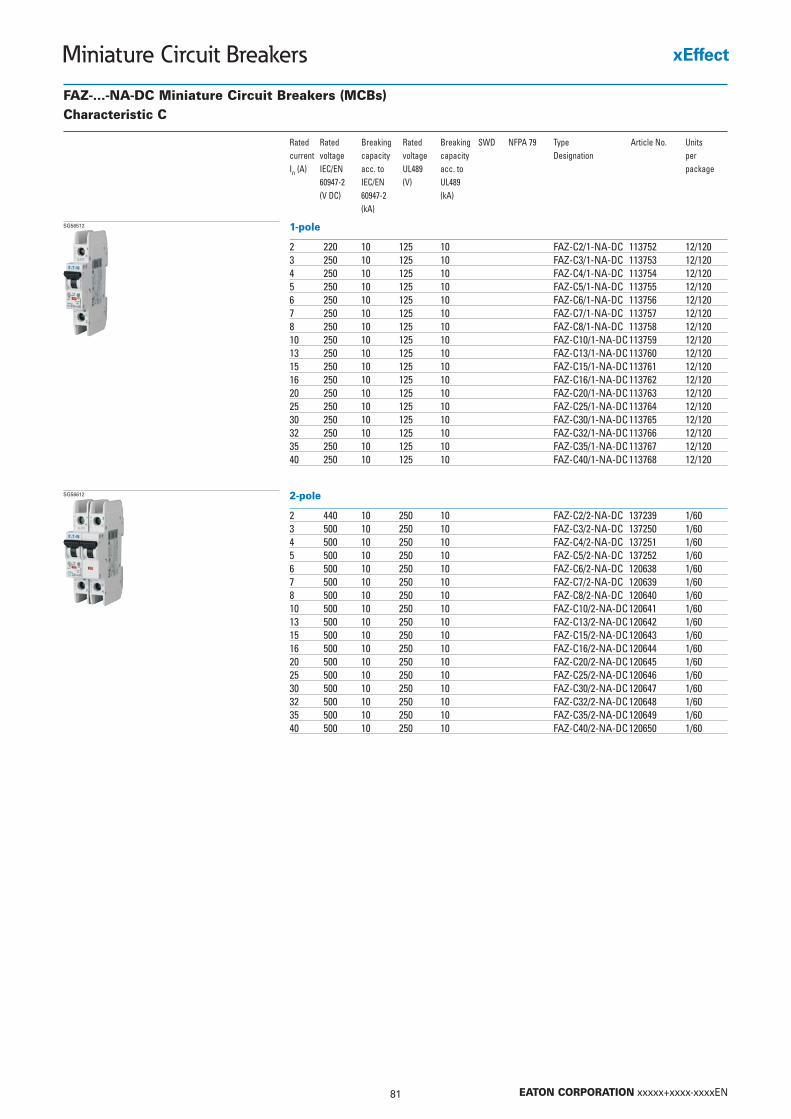
81 EATON CORPORATION xxxxx+xxxx-xxxxEN
Miniature Circuit Breakers
FAZ-...-NA-DC Miniature Circuit Breakers (MCBs)Characteristic C
Rated Rated Breaking Rated Breaking SWD NFPA 79 Type Article No. Unitscurrent voltage capacity voltage capacity Designation per In (A) IEC/EN acc. to UL489 acc. to package
60947-2 IEC/EN (V) UL489(V DC) 60947-2 (kA)
(kA)
1-pole
2 220 10 125 10 FAZ-C2/1-NA-DC 113752 12/1203 250 10 125 10 FAZ-C3/1-NA-DC 113753 12/1204 250 10 125 10 FAZ-C4/1-NA-DC 113754 12/1205 250 10 125 10 FAZ-C5/1-NA-DC 113755 12/1206 250 10 125 10 FAZ-C6/1-NA-DC 113756 12/1207 250 10 125 10 FAZ-C7/1-NA-DC 113757 12/1208 250 10 125 10 FAZ-C8/1-NA-DC 113758 12/12010 250 10 125 10 FAZ-C10/1-NA-DC113759 12/12013 250 10 125 10 FAZ-C13/1-NA-DC113760 12/12015 250 10 125 10 FAZ-C15/1-NA-DC113761 12/12016 250 10 125 10 FAZ-C16/1-NA-DC113762 12/12020 250 10 125 10 FAZ-C20/1-NA-DC113763 12/12025 250 10 125 10 FAZ-C25/1-NA-DC113764 12/12030 250 10 125 10 FAZ-C30/1-NA-DC113765 12/12032 250 10 125 10 FAZ-C32/1-NA-DC113766 12/12035 250 10 125 10 FAZ-C35/1-NA-DC113767 12/12040 250 10 125 10 FAZ-C40/1-NA-DC113768 12/120
SG56512
2-pole
2 440 10 250 10 FAZ-C2/2-NA-DC 137239 1/603 500 10 250 10 FAZ-C3/2-NA-DC 137250 1/604 500 10 250 10 FAZ-C4/2-NA-DC 137251 1/605 500 10 250 10 FAZ-C5/2-NA-DC 137252 1/606 500 10 250 10 FAZ-C6/2-NA-DC 120638 1/607 500 10 250 10 FAZ-C7/2-NA-DC 120639 1/608 500 10 250 10 FAZ-C8/2-NA-DC 120640 1/6010 500 10 250 10 FAZ-C10/2-NA-DC120641 1/6013 500 10 250 10 FAZ-C13/2-NA-DC120642 1/6015 500 10 250 10 FAZ-C15/2-NA-DC120643 1/6016 500 10 250 10 FAZ-C16/2-NA-DC120644 1/6020 500 10 250 10 FAZ-C20/2-NA-DC120645 1/6025 500 10 250 10 FAZ-C25/2-NA-DC120646 1/6030 500 10 250 10 FAZ-C30/2-NA-DC120647 1/6032 500 10 250 10 FAZ-C32/2-NA-DC120648 1/6035 500 10 250 10 FAZ-C35/2-NA-DC120649 1/6040 500 10 250 10 FAZ-C40/2-NA-DC120650 1/60
SG56612
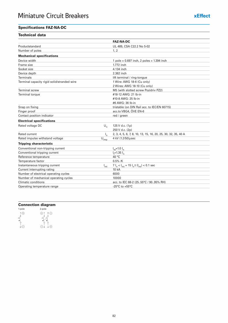
82
Miniature Circuit Breakers
Specifications FAZ-NA-DC
Technical data
FAZ-NA-DC
Productstandard UL 489, CSA C22.2 No 5-02Number of poles 1, 2
Mechanical specifications
Device width 1 pole = 0.697 inch, 2 poles = 1.394 inchFrame size 1.772 inchSocket size 4.134 inchDevice depth 2.362 inchTerminals lift terminal / ring-tongueTerminal capacity rigid solid/stranded wire 1 Wire: AWG 18-6 (Cu only)
2 Wires: AWG 18-10 (Cu only)Terminal screw M5 (with slotted screw Pozidriv PZ2)Terminal torque #18-12 AWG: 21 lb-in
#10-8 AWG: 25 lb-in#6 AWG: 36 lb-in
Snap on fixing tristable (on DIN Rail acc. to IEC/EN 60715)Finger proof acc.to VBG4, ÖVE EN-6Contact position indicator red / green
Electrical specifications
Rated voltage DC Un 125 V d.c. (1p)250 V d.c. (2p)
Rated current In 2, 3, 4, 5, 6, 7, 8, 10, 13, 15, 16, 20, 25, 30, 32, 35, 40 ARated impulse withstand voltage Uimp 4 kV (1.2/50)µsec
Tripping characteristic
Conventional non-tripping current Int=1.0 InConventional tripping current It=1.35 InReference temperature 40 °CTemperature factor 0.5% /KInstantaneous tripping current Imt 7 In < Imt = 15 In:t (Imt) < 0.1 secCurrent interrupting rating 10 kANumber of electrical operating cycles 6000Number of mechanical operating cycles 10000Climatic conditions acc. to IEC 68-2 (25..55°C / 90..95% RH)Operating temperature range -25°C to +55°C
Connection diagram1-pole 2-pole
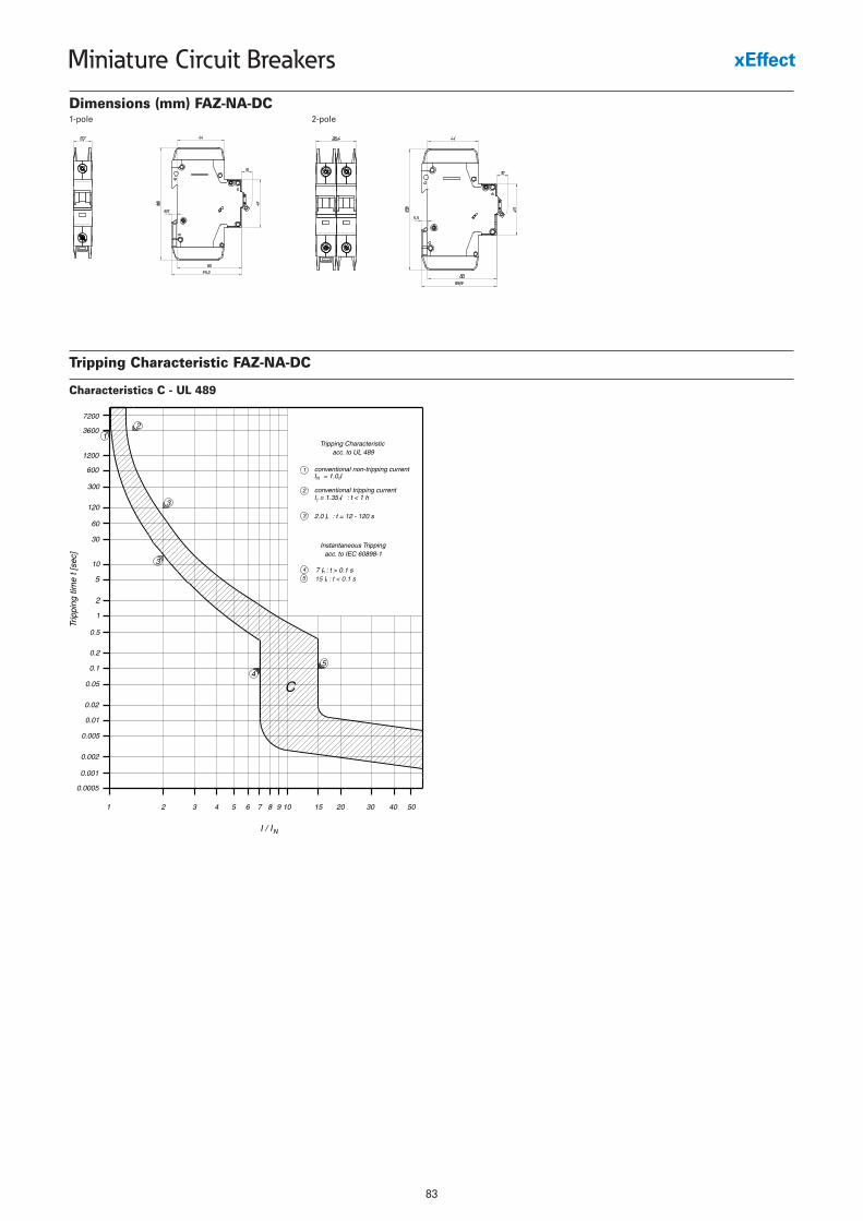
83
Miniature Circuit Breakers
Dimensions (mm) FAZ-NA-DC
Tripping Characteristic FAZ-NA-DC
Characteristics C - UL 489
1-pole 2-pole
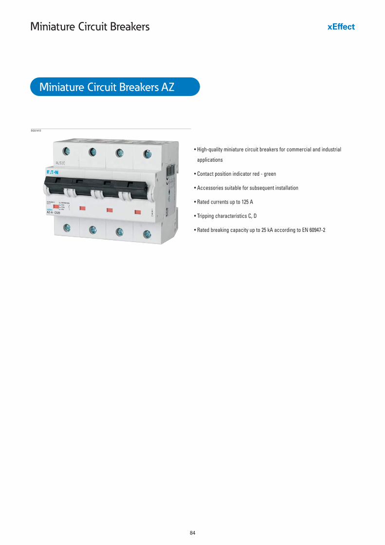
84
Miniature Circuit Breakers
• High-quality miniature circuit breakers for commercial and industrial
applications
• Contact position indicator red - green
• Accessories suitable for subsequent installation
• Rated currents up to 125 A
• Tripping characteristics C, D
• Rated breaking capacity up to 25 kA according to EN 60947-2
SG51412
Miniature Circuit Breakers AZ
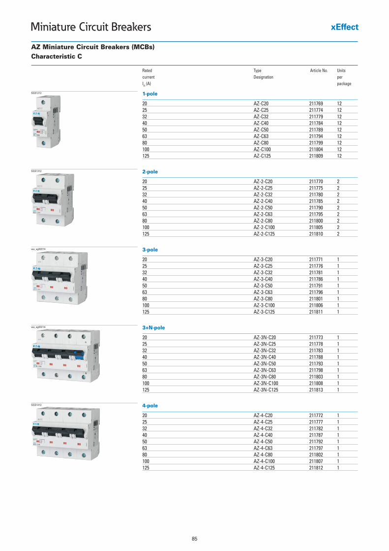
85
Miniature Circuit Breakers
AZ Miniature Circuit Breakers (MCBs)Characteristic C
Rated Type Article No. Unitscurrent Designation per In (A) package
1-pole
20 AZ-C20 211769 1225 AZ-C25 211774 1232 AZ-C32 211779 1240 AZ-C40 211784 1250 AZ-C50 211789 1263 AZ-C63 211794 1280 AZ-C80 211799 12100 AZ-C100 211804 12125 AZ-C125 211809 12
SG51212
2-pole
20 AZ-2-C20 211770 225 AZ-2-C25 211775 232 AZ-2-C32 211780 240 AZ-2-C40 211785 250 AZ-2-C50 211790 263 AZ-2-C63 211795 280 AZ-2-C80 211800 2100 AZ-2-C100 211805 2125 AZ-2-C125 211810 2
SG51312
3-pole
20 AZ-3-C20 211771 125 AZ-3-C25 211776 132 AZ-3-C32 211781 140 AZ-3-C40 211786 150 AZ-3-C50 211791 163 AZ-3-C63 211796 180 AZ-3-C80 211801 1100 AZ-3-C100 211806 1125 AZ-3-C125 211811 1
wa_sg00314
3+N-pole
20 AZ-3N-C20 211773 125 AZ-3N-C25 211778 132 AZ-3N-C32 211783 140 AZ-3N-C40 211788 150 AZ-3N-C50 211793 163 AZ-3N-C63 211798 180 AZ-3N-C80 211803 1100 AZ-3N-C100 211808 1125 AZ-3N-C125 211813 1
wa_sg00214
4-pole
20 AZ-4-C20 211772 125 AZ-4-C25 211777 132 AZ-4-C32 211782 140 AZ-4-C40 211787 150 AZ-4-C50 211792 163 AZ-4-C63 211797 180 AZ-4-C80 211802 1100 AZ-4-C100 211807 1125 AZ-4-C125 211812 1
SG51412
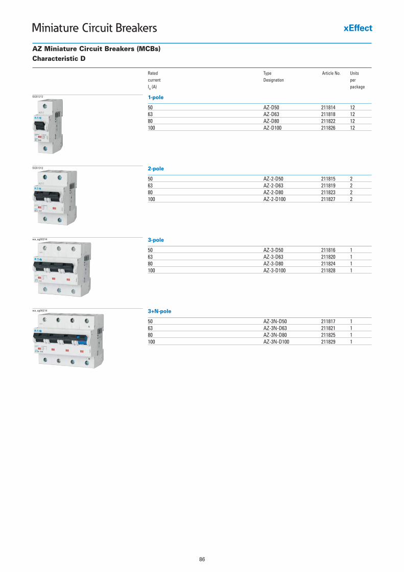
86
Miniature Circuit Breakers
AZ Miniature Circuit Breakers (MCBs)Characteristic D
Rated Type Article No. Unitscurrent Designation per In (A) package
1-pole
50 AZ-D50 211814 1263 AZ-D63 211818 1280 AZ-D80 211822 12100 AZ-D100 211826 12
SG51212
2-pole
50 AZ-2-D50 211815 263 AZ-2-D63 211819 280 AZ-2-D80 211823 2100 AZ-2-D100 211827 2
SG51312
3-pole
50 AZ-3-D50 211816 163 AZ-3-D63 211820 180 AZ-3-D80 211824 1100 AZ-3-D100 211828 1
wa_sg00314
3+N-pole
50 AZ-3N-D50 211817 163 AZ-3N-D63 211821 180 AZ-3N-D80 211825 1100 AZ-3N-D100 211829 1
wa_sg00214
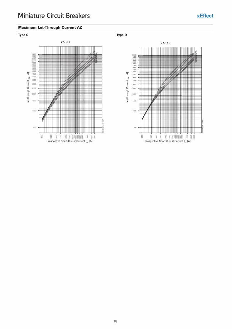
89
Miniature Circuit Breakers
Maximum Let-Through Current AZ
Type C Type D
Let-
thro
ugh
Cur
rent
I DL
[A]
Prospective Short-Circuit Current Icc [A]
Let-
thro
ugh
Cur
rent
I DL
[A]
Prospective Short-Circuit Current Icc [A]
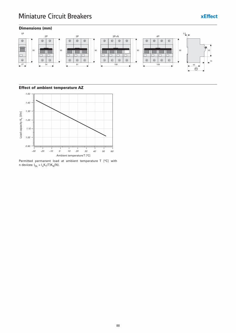
88
Miniature Circuit Breakers
Dimensions (mm)
Effect of ambient temperature AZ
Permitted permanent load at ambient temperature T [°C] with n devices: IDL = InKT(T)KN(N).
Ambient temperature T [°C]
Load
cap
acity
KT
[I/In
]

89
Miniature Circuit Breakers
Maximum Let-Through Current AZ
Type C Type D
Let-
thro
ugh
Cur
rent
I DL
[A]
Prospective Short-Circuit Current Icc [A]
Let-
thro
ugh
Cur
rent
I DL
[A]
Prospective Short-Circuit Current Icc [A]
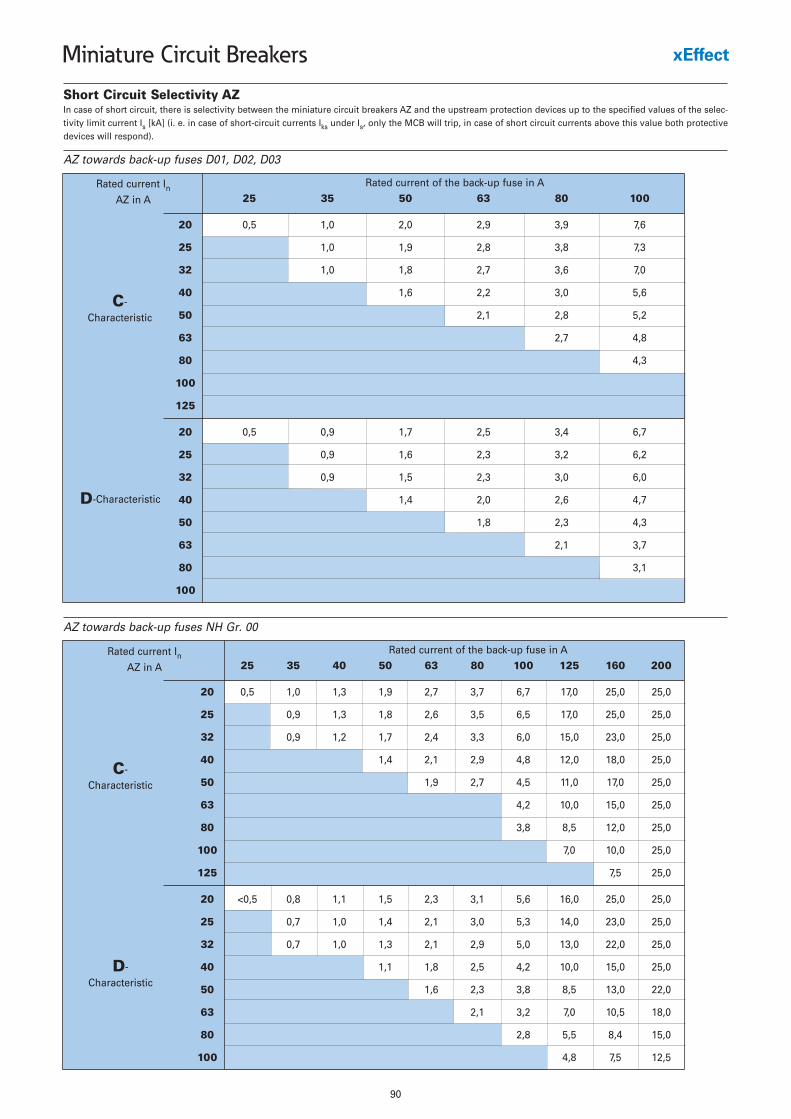
90
Miniature Circuit Breakers
Short Circuit Selectivity AZ
AZ towards back-up fuses D01, D02, D03
AZ towards back-up fuses NH Gr. 00
25 35 50 63 80 100
20 0,5 1,0 2,0 2,9 3,9 7,6
25 1,0 1,9 2,8 3,8 7,3
32 1,0 1,8 2,7 3,6 7,0
40 1,6 2,2 3,0 5,6
50 2,1 2,8 5,2
63 2,7 4,8
80 4,3
100
125
20 0,5 0,9 1,7 2,5 3,4 6,7
25 0,9 1,6 2,3 3,2 6,2
32 0,9 1,5 2,3 3,0 6,0
40 1,4 2,0 2,6 4,7
50 1,8 2,3 4,3
63 2,1 3,7
80 3,1
100
Rated current of the back-up fuse in ARated current InAZ in A
C-
Characteristic
D-Characteristic
25 35 40 50 63 80 100 125 160 200
20 0,5 1,0 1,3 1,9 2,7 3,7 6,7 17,0 25,0 25,0
25 0,9 1,3 1,8 2,6 3,5 6,5 17,0 25,0 25,0
32 0,9 1,2 1,7 2,4 3,3 6,0 15,0 23,0 25,0
40 1,4 2,1 2,9 4,8 12,0 18,0 25,0
50 1,9 2,7 4,5 11,0 17,0 25,0
63 4,2 10,0 15,0 25,0
80 3,8 8,5 12,0 25,0
100 7,0 10,0 25,0
125 7,5 25,0
20 <0,5 0,8 1,1 1,5 2,3 3,1 5,6 16,0 25,0 25,0
25 0,7 1,0 1,4 2,1 3,0 5,3 14,0 23,0 25,0
32 0,7 1,0 1,3 2,1 2,9 5,0 13,0 22,0 25,0
40 1,1 1,8 2,5 4,2 10,0 15,0 25,0
50 1,6 2,3 3,8 8,5 13,0 22,0
63 2,1 3,2 7,0 10,5 18,0
80 2,8 5,5 8,4 15,0
100 4,8 7,5 12,5
Rated current of the back-up fuse in ARated current InAZ in A
C-
Characteristic
D-
Characteristic
In case of short circuit, there is selectivity between the miniature circuit breakers AZ and the upstream protection devices up to the specified values of the selec-tivity limit current Is [kA] (i. e. in case of short-circuit currents Iks under Is, only the MCB will trip, in case of short circuit currents above this value both protectivedevices will respond).
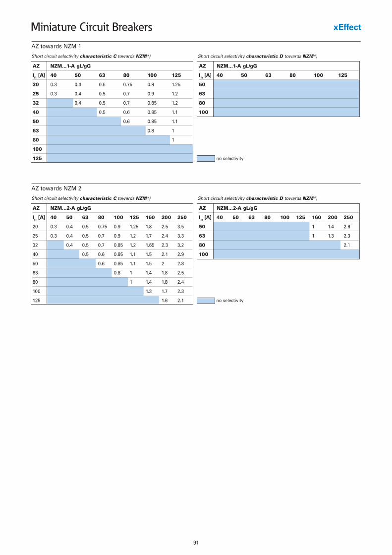
91
Miniature Circuit Breakers
AZ towards NZM 1
Short circuit selectivity characteristic C towards NZM*)
AZ NZM...1-A gL/gG
In [A] 40 50 63 80 100 125
20 0.3 0.4 0.5 0.75 0.9 1.25
25 0.3 0.4 0.5 0.7 0.9 1.2
32 0.4 0.5 0.7 0.85 1.2
40 0.5 0.6 0.85 1.1
50 0.6 0.85 1.1
63 0.8 1
80 1
100
125
Short circuit selectivity characteristic D towards NZM*)
AZ NZM...1-A gL/gG
In [A] 40 50 63 80 100 125
50
63
80
100
no selectivity
AZ towards NZM 2
Short circuit selectivity characteristic C towards NZM*)
AZ NZM...2-A gL/gG
In [A] 40 50 63 80 100 125 160 200 250
20 0.3 0.4 0.5 0.75 0.9 1.25 1.8 2.5 3.5
25 0.3 0.4 0.5 0.7 0.9 1.2 1.7 2.4 3.3
32 0.4 0.5 0.7 0.85 1.2 1.65 2.3 3.2
40 0.5 0.6 0.85 1.1 1.5 2.1 2.9
50 0.6 0.85 1.1 1.5 2 2.8
63 0.8 1 1.4 1.8 2.5
80 1 1.4 1.8 2.4
100 1.3 1.7 2.3
125 1.6 2.1
Short circuit selectivity characteristic D towards NZM*)
AZ NZM...2-A gL/gG
In [A] 40 50 63 80 100 125 160 200 250
50 1 1.4 2.6
63 1 1.3 2.3
80 2.1
100
no selectivity
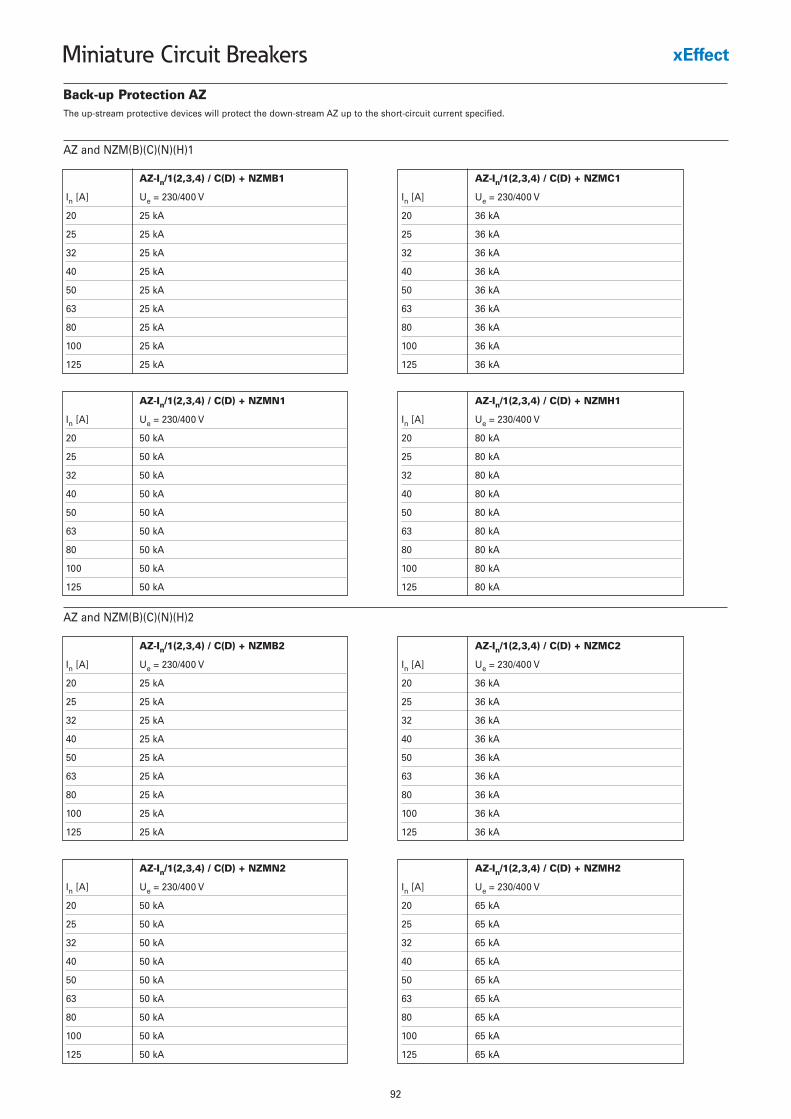
92
Miniature Circuit Breakers
Back-up Protection AZ
AZ-In/1(2,3,4) / C(D) + NZMB1
In [A] Ue = 230/400 V
20 25 kA
25 25 kA
32 25 kA
40 25 kA
50 25 kA
63 25 kA
80 25 kA
100 25 kA
125 25 kA
AZ and NZM(B)(C)(N)(H)1
AZ-In/1(2,3,4) / C(D) + NZMC1
In [A] Ue = 230/400 V
20 36 kA
25 36 kA
32 36 kA
40 36 kA
50 36 kA
63 36 kA
80 36 kA
100 36 kA
125 36 kA
AZ-In/1(2,3,4) / C(D) + NZMN1
In [A] Ue = 230/400 V
20 50 kA
25 50 kA
32 50 kA
40 50 kA
50 50 kA
63 50 kA
80 50 kA
100 50 kA
125 50 kA
AZ-In/1(2,3,4) / C(D) + NZMH1
In [A] Ue = 230/400 V
20 80 kA
25 80 kA
32 80 kA
40 80 kA
50 80 kA
63 80 kA
80 80 kA
100 80 kA
125 80 kA
AZ-In/1(2,3,4) / C(D) + NZMB2
In [A] Ue = 230/400 V
20 25 kA
25 25 kA
32 25 kA
40 25 kA
50 25 kA
63 25 kA
80 25 kA
100 25 kA
125 25 kA
AZ and NZM(B)(C)(N)(H)2
AZ-In/1(2,3,4) / C(D) + NZMC2
In [A] Ue = 230/400 V
20 36 kA
25 36 kA
32 36 kA
40 36 kA
50 36 kA
63 36 kA
80 36 kA
100 36 kA
125 36 kA
AZ-In/1(2,3,4) / C(D) + NZMN2
In [A] Ue = 230/400 V
20 50 kA
25 50 kA
32 50 kA
40 50 kA
50 50 kA
63 50 kA
80 50 kA
100 50 kA
125 50 kA
AZ-In/1(2,3,4) / C(D) + NZMH2
In [A] Ue = 230/400 V
20 65 kA
25 65 kA
32 65 kA
40 65 kA
50 65 kA
63 65 kA
80 65 kA
100 65 kA
125 65 kA
The up-stream protective devices will protect the down-stream AZ up to the short-circuit current specified.
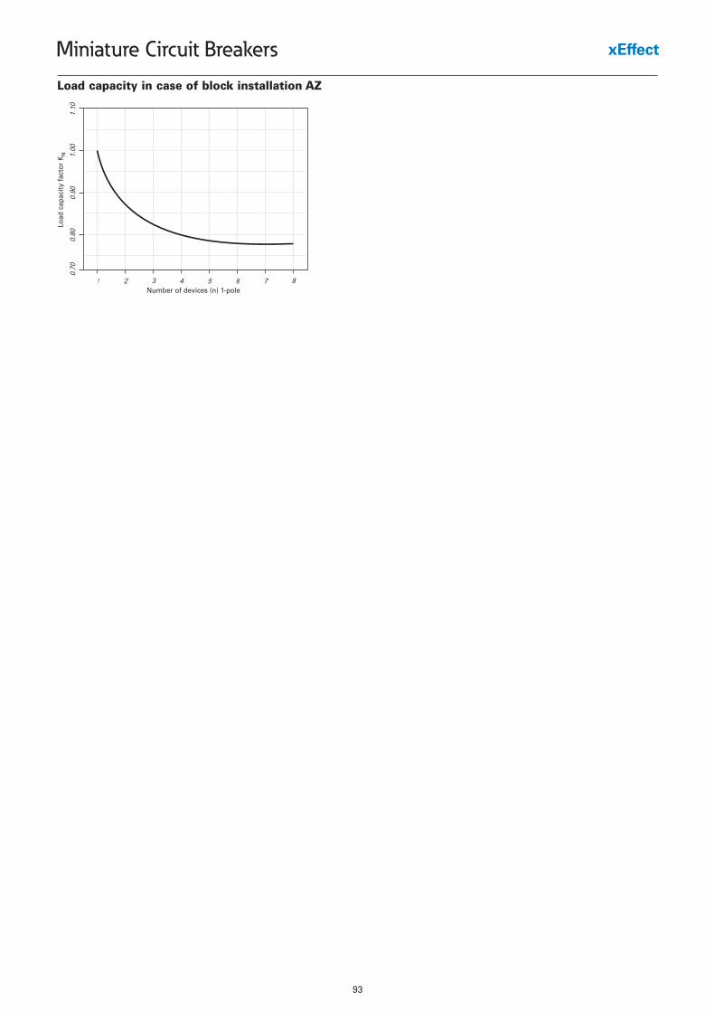
93
Miniature Circuit Breakers
Load capacity in case of block installation AZ
Number of devices (n) 1-pole
Load
cap
acity
fac
tor
KN
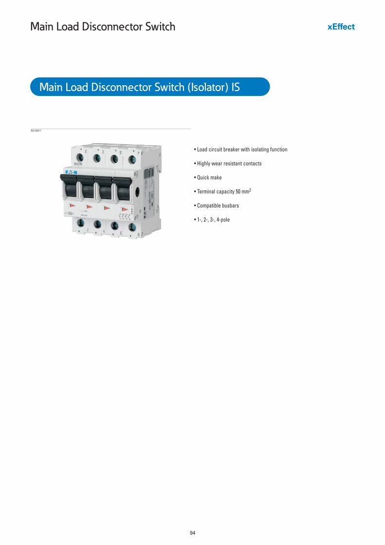
94
Main Load Disconnector Switch
• Load circuit breaker with isolating function
• Highly wear resistant contacts
• Quick make
• Terminal capacity 50 mm2
• Compatible busbars
• 1-, 2-, 3-, 4-pole
SG10911
Main Load Disconnector Switch (Isolator) IS
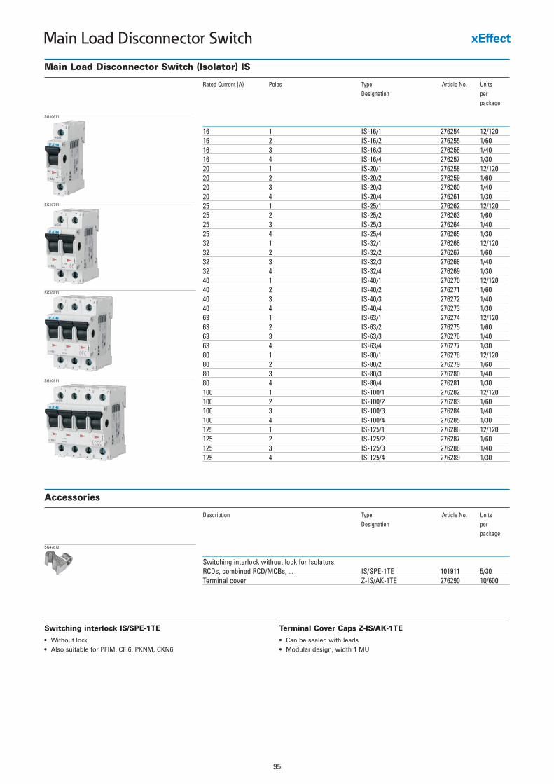
95
Main Load Disconnector Switch
Main Load Disconnector Switch (Isolator) IS
Rated Current (A) Poles Type Article No. UnitsDesignation per
package
16 1 IS-16/1 276254 12/12016 2 IS-16/2 276255 1/6016 3 IS-16/3 276256 1/4016 4 IS-16/4 276257 1/3020 1 IS-20/1 276258 12/12020 2 IS-20/2 276259 1/6020 3 IS-20/3 276260 1/4020 4 IS-20/4 276261 1/3025 1 IS-25/1 276262 12/12025 2 IS-25/2 276263 1/6025 3 IS-25/3 276264 1/4025 4 IS-25/4 276265 1/3032 1 IS-32/1 276266 12/12032 2 IS-32/2 276267 1/6032 3 IS-32/3 276268 1/4032 4 IS-32/4 276269 1/3040 1 IS-40/1 276270 12/12040 2 IS-40/2 276271 1/6040 3 IS-40/3 276272 1/4040 4 IS-40/4 276273 1/3063 1 IS-63/1 276274 12/12063 2 IS-63/2 276275 1/6063 3 IS-63/3 276276 1/4063 4 IS-63/4 276277 1/3080 1 IS-80/1 276278 12/12080 2 IS-80/2 276279 1/6080 3 IS-80/3 276280 1/4080 4 IS-80/4 276281 1/30100 1 IS-100/1 276282 12/120100 2 IS-100/2 276283 1/60100 3 IS-100/3 276284 1/40100 4 IS-100/4 276285 1/30125 1 IS-125/1 276286 12/120125 2 IS-125/2 276287 1/60125 3 IS-125/3 276288 1/40125 4 IS-125/4 276289 1/30
SG10611
SG10711
SG10811
SG10911
Accessories
Description Type Article No. UnitsDesignation per
package
Switching interlock without lock for Isolators, RCDs, combined RCD/MCBs, ... IS/SPE-1TE 101911 5/30Terminal cover Z-IS/AK-1TE 276290 10/600
SG47812
Switching interlock IS/SPE-1TE
• Without lock• Also suitable for PFIM, CFI6, PKNM, CKN6
Terminal Cover Caps Z-IS/AK-1TE
• Can be sealed with leads• Modular design, width 1 MU
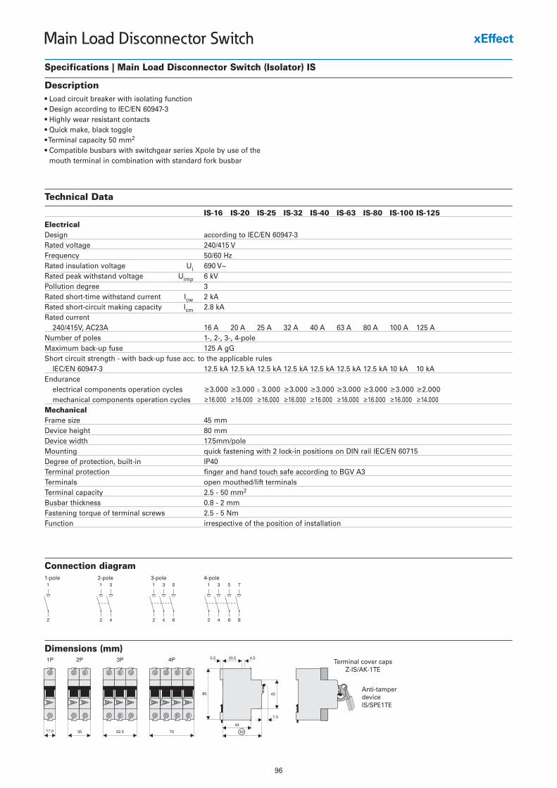
96
Main Load Disconnector Switch
Specifications | Main Load Disconnector Switch (Isolator) IS
Description• Load circuit breaker with isolating function• Design according to IEC/EN 60947-3• Highly wear resistant contacts• Quick make, black toggle• Terminal capacity 50 mm2
• Compatible busbars with switchgear series Xpole by use of themouth terminal in combination with standard fork busbar
Connection diagram1-pole 2-pole 3-pole 4-pole
Technical Data
IS-16 IS-20 IS-25 IS-32 IS-40 IS-63 IS-80 IS-100 IS-125
ElectricalDesign according to IEC/EN 60947-3Rated voltage 240/415 VFrequency 50/60 HzRated insulation voltage Ui 690 V~Rated peak withstand voltage Uimp 6 kVPollution degree 3Rated short-time withstand current Icw 2 kARated short-circuit making capacity Icm 2.8 kARated current
240/415V, AC23A 16 A 20 A 25 A 32 A 40 A 63 A 80 A 100 A 125 ANumber of poles 1-, 2-, 3-, 4-poleMaximum back-up fuse 125 A gGShort circuit strength - with back-up fuse acc. to the applicable rules
IEC/EN 60947-3 12.5 kA 12.5 kA 12.5 kA 12.5 kA 12.5 kA 12.5 kA 12.5 kA 10 kA 10 kAEndurance
electrical components operation cycles ≥3.000 ≥3.000 ≥ 3.000 ≥3.000 ≥3.000 ≥3.000 ≥3.000 ≥3.000 ≥2.000mechanical components operation cycles ≥16.000 ≥16.000 ≥16.000 ≥16.000 ≥16.000 ≥16.000 ≥16.000 ≥16.000 ≥14.000
MechanicalFrame size 45 mmDevice height 80 mmDevice width 17.5mm/poleMounting quick fastening with 2 lock-in positions on DIN rail IEC/EN 60715Degree of protection, built-in IP40Terminal protection finger and hand touch safe according to BGV A3Terminals open mouthed/lift terminalsTerminal capacity 2.5 - 50 mm2
Busbar thickness 0.8 - 2 mmFastening torque of terminal screws 2.5 - 5 NmFunction irrespective of the position of installation
Dimensions (mm)
Anti-tamperdeviceIS/SPE1TE
Terminal cover capsZ-IS/AK-1TE
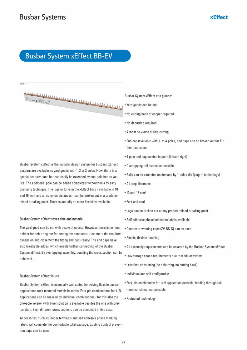
97
Busbar Systems
Busbar System xEffect at a glance:
• Yard goods can be cut
• No cutting back of copper required
• No deburring required
• Almost no waste during cutting
• End capsavailable with 1- to 4-poles, end caps can be broken out for fur-
ther extensions
• 4-pole end cap molded in pairs (leftand right)
• Overlapping rail extension possible
• Rails can be extended on demand by 1-pole rails (plug-in technology)
• All step distances
• 10 and 16 mm2
• Fork and stud
• Lugs can be broken out at any predetermined breaking point
• Self adhesive phase indication labels available
• Contact preventing caps (ZV-BS-G) can be used
• Simple, flexible handling
• All assembly requirements can be covered by the Busbar System xEffect
• Low storage space requirements due to modular system
• Less time consuming (no deburring, no cutting back)
• Individual and self configurable
• Fork-pin combination for 1+N application possible, feeding through rail
(terminal clamp) not possible.
• Protected technology
SG13113
Busbar System xEffect BB-EV
Busbar System xEffect is the modular design system for busbars. xEffect
busbars are available as yard goods with 1, 2 or 3 poles. Now, there is a
special feature: each bar can easily be extended by one-pole bar as you
like. The additional pole can be added completely without tools by easy
clamping technique. The lugs or forks in the xEffect bars - available in 10
and 16 mm2 and all common distances - can be broken out at a predeter-
mined breaking point. There is actually no more flexibility available.
Busbar System xEffect saves time and material
The yard good can be cut with a saw of course. However, there is no need
neither for deburring nor for cutting the conductor. Just cut to the required
dimension and close with the fitting end cap -ready! The end caps have
also breakable edges, which enable further connecting of the Busbar
System xEffect. By overlapping assembly, doubling the cross section can be
achieved.
Busbar System xEffect in use
Busbar System xEffect is especially well suited for solving flexible busbar
applications rack-mounted models in series. Fork-pin combinations for 1+N-
applications can be realized by individual combinations - for this also the
one-pole version with blue isolation is available besides the one with grey
isolation. Even different cross sections can be combined in this case.
Accessories, such as feeder terminals and self adhesive phase marking
labels will complete the comfortable total package. Existing contact preven-
tion caps can be used.
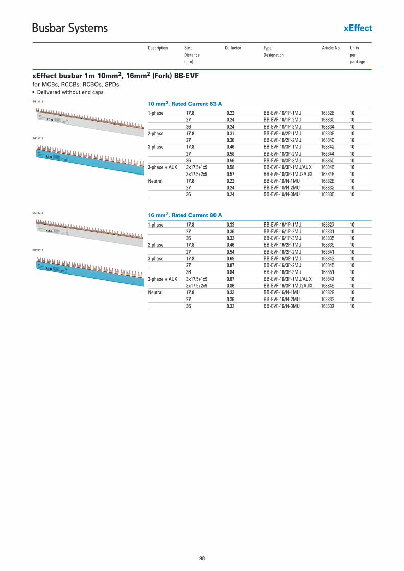
98
Busbar Systems
xEffect busbar 1m 10mm2, 16mm2 (Fork) BB-EVF
10 mm2, Rated Current 63 A
1-phase 17.8 0.22 BB-EVF-10/1P-1MU 168826 1027 0.24 BB-EVF-10/1P-2MU 168830 1036 0.24 BB-EVF-10/1P-3MU 168834 10
2-phase 17.8 0.31 BB-EVF-10/2P-1MU 168838 1027 0.36 BB-EVF-10/2P-2MU 168840 10
3-phase 17.8 0.46 BB-EVF-10/3P-1MU 168842 1027 0.58 BB-EVF-10/3P-2MU 168844 1036 0.56 BB-EVF-10/3P-3MU 168850 10
3-phase + AUX 3x17.5+1x9 0.58 BB-EVF-10/3P-1MU/AUX 168846 103x17.5+2x9 0.57 BB-EVF-10/3P-1MU2AUX 168848 10
Neutral 17.8 0.22 BB-EVF-10/N-1MU 168828 1027 0.24 BB-EVF-10/N-2MU 168832 1036 0.24 BB-EVF-10/N-3MU 168836 10
SG13113
Description Step Cu-factor Type Article No. UnitsDistance Designation per (mm) package
for MCBs, RCCBs, RCBOs, SPDs• Delivered without end caps
SG13413
16 mm2, Rated Current 80 A
1-phase 17.8 0.33 BB-EVF-16/1P-1MU 168827 1027 0.36 BB-EVF-16/1P-2MU 168831 1036 0.32 BB-EVF-16/1P-3MU 168835 10
2-phase 17.8 0.46 BB-EVF-16/2P-1MU 168839 1027 0.54 BB-EVF-16/2P-2MU 168841 10
3-phase 17.8 0.69 BB-EVF-16/3P-1MU 168843 1027 0.87 BB-EVF-16/3P-2MU 168845 1036 0.84 BB-EVF-16/3P-3MU 168851 10
3-phase + AUX 3x17.5+1x9 0.87 BB-EVF-16/3P-1MU/AUX 168847 103x17.5+2x9 0.86 BB-EVF-16/3P-1MU2AUX 168849 10
Neutral 17.8 0.33 BB-EVF-16/N-1MU 168829 1027 0.36 BB-EVF-16/N-2MU 168833 1036 0.32 BB-EVF-16/N-3MU 168837 10
SG13213
SG13613
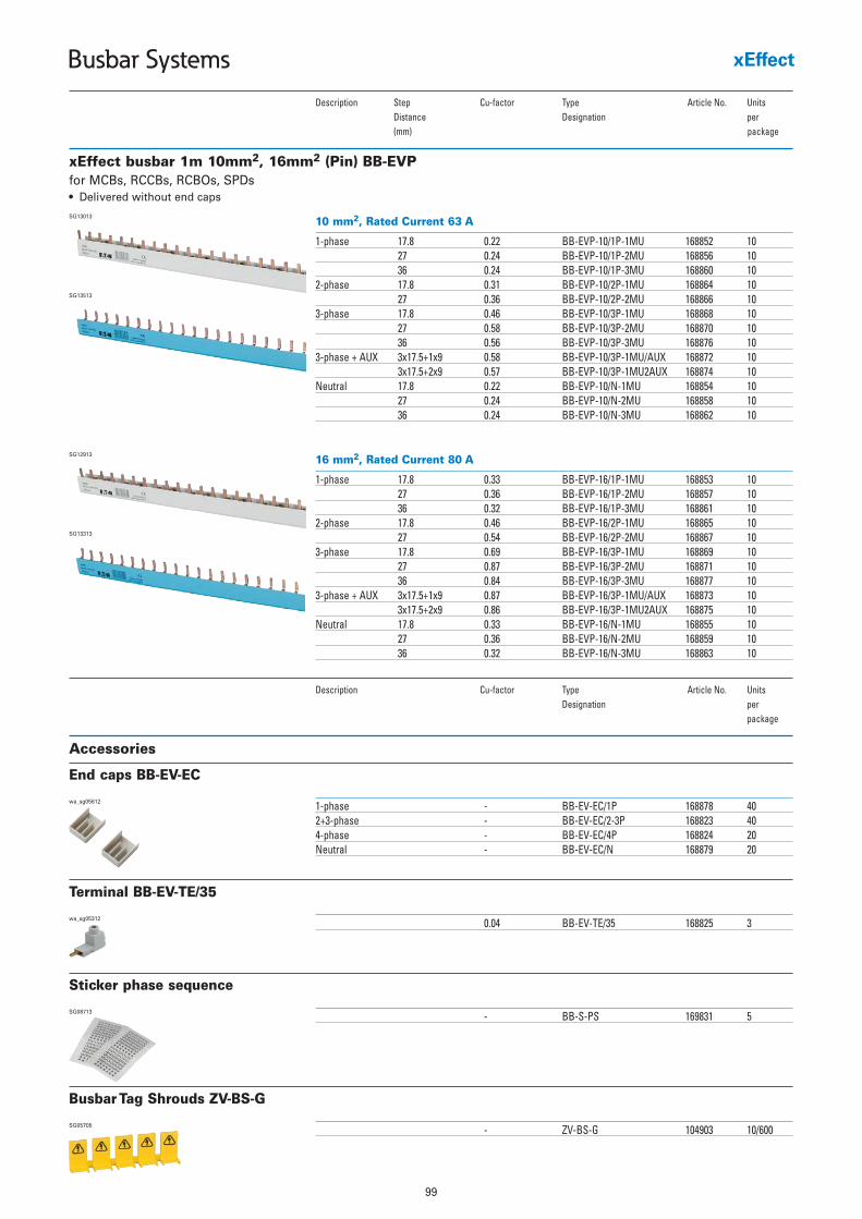
99
Busbar Systems
xEffect busbar 1m 10mm2, 16mm2 (Pin) BB-EVP
10 mm2, Rated Current 63 A
1-phase 17.8 0.22 BB-EVP-10/1P-1MU 168852 1027 0.24 BB-EVP-10/1P-2MU 168856 1036 0.24 BB-EVP-10/1P-3MU 168860 10
2-phase 17.8 0.31 BB-EVP-10/2P-1MU 168864 1027 0.36 BB-EVP-10/2P-2MU 168866 10
3-phase 17.8 0.46 BB-EVP-10/3P-1MU 168868 1027 0.58 BB-EVP-10/3P-2MU 168870 1036 0.56 BB-EVP-10/3P-3MU 168876 10
3-phase + AUX 3x17.5+1x9 0.58 BB-EVP-10/3P-1MU/AUX 168872 103x17.5+2x9 0.57 BB-EVP-10/3P-1MU2AUX 168874 10
Neutral 17.8 0.22 BB-EVP-10/N-1MU 168854 1027 0.24 BB-EVP-10/N-2MU 168858 1036 0.24 BB-EVP-10/N-3MU 168862 10
SG13013
Description Step Cu-factor Type Article No. UnitsDistance Designation per (mm) package
for MCBs, RCCBs, RCBOs, SPDs• Delivered without end caps
SG13513
16 mm2, Rated Current 80 A
1-phase 17.8 0.33 BB-EVP-16/1P-1MU 168853 1027 0.36 BB-EVP-16/1P-2MU 168857 1036 0.32 BB-EVP-16/1P-3MU 168861 10
2-phase 17.8 0.46 BB-EVP-16/2P-1MU 168865 1027 0.54 BB-EVP-16/2P-2MU 168867 10
3-phase 17.8 0.69 BB-EVP-16/3P-1MU 168869 1027 0.87 BB-EVP-16/3P-2MU 168871 1036 0.84 BB-EVP-16/3P-3MU 168877 10
3-phase + AUX 3x17.5+1x9 0.87 BB-EVP-16/3P-1MU/AUX 168873 103x17.5+2x9 0.86 BB-EVP-16/3P-1MU2AUX 168875 10
Neutral 17.8 0.33 BB-EVP-16/N-1MU 168855 1027 0.36 BB-EVP-16/N-2MU 168859 1036 0.32 BB-EVP-16/N-3MU 168863 10
SG12913
SG13313
Accessories
1-phase - BB-EV-EC/1P 168878 402+3-phase - BB-EV-EC/2-3P 168823 404-phase - BB-EV-EC/4P 168824 20Neutral - BB-EV-EC/N 168879 20
wa_sg05612
Description Cu-factor Type Article No. UnitsDesignation per
package
End caps BB-EV-EC
0.04 BB-EV-TE/35 168825 3wa_sg05312
Terminal BB-EV-TE/35
- BB-S-PS 169831 5SG08713
Sticker phase sequence
- ZV-BS-G 104903 10/600SG05705
Busbar Tag Shrouds ZV-BS-G
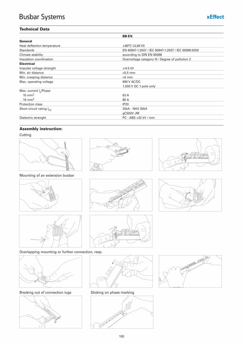
100
Busbar Systems
Technical Data
BB-EV.
GeneralHeat deflection temperature ≥80°C UL94 V0Standards EN 60947-1:2007 / IEC 60947-1:2007 / IEC 60999:2000Climate stability according to DIN EN 60068Insulation coordination Overvoltage category III / Degree of pollution 2ElectricalImpulse voltage strenght ≥4.5 kVMin. air distance >5.5 mmMin. creeping distance >5 mmMax. operating voltage 690 V AC/DC
1,000 V DC 1-pole onlyMax. current Is/Phase
10 mm2 63 A16 mm2 80 A
Protection class IP20Short circuit rating ICC 25kA - NH3 355A
gC500V JMDielectric strenght PC - ABS >32 kV / mm
Assembly instruction:Cutting
Mounting of an extension busbar
Overlapping mounting or further connection, resp.
Brecking out of connection lugs Sticking on phase marking
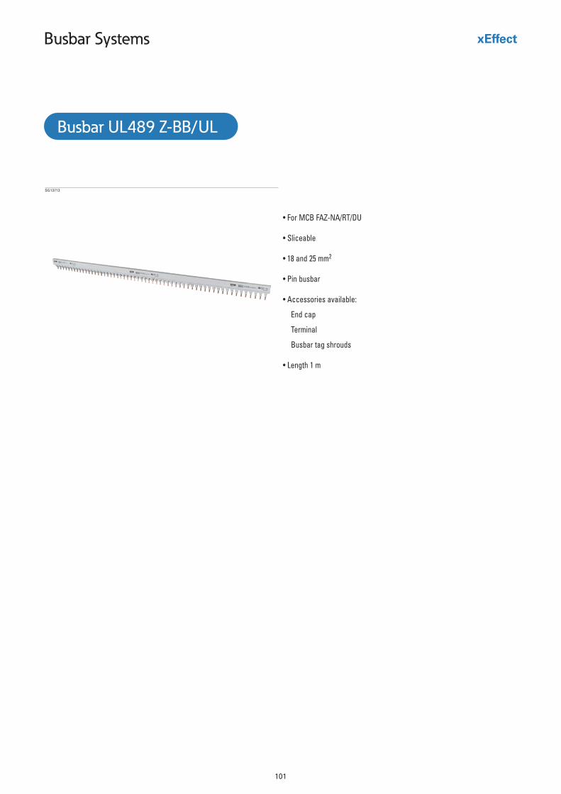
101
Busbar Systems
• For MCB FAZ-NA/RT/DU
• Sliceable
• 18 and 25 mm2
• Pin busbar
• Accessories available:
End cap
Terminal
Busbar tag shrouds
• Length 1 m
SG13713
Busbar UL489 Z-BB/UL
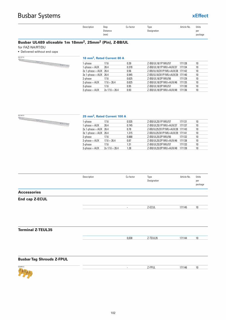
102
Busbar Systems
Busbar UL489 sliceable 1m 18mm2, 25mm2 (Pin), Z-BB/UL
18 mm2, Rated Current 80 A
1-phase 17.6 0.39 Z-BB/UL18/1P1MU/57 171128 101-phase + AUX 26.4 0.378 Z-BB/UL18/1P1MU+AUX/37 171134 102x 1-phase + AUX 26.4 0.56 Z-BB/UL18/2X1P1MU+AUX/38 171142 103x 1-phase + AUX 26.4 0.945 Z-BB/UL18/3X1P1MU+AUX/39 171140 102-phase 17.6 0.625 Z-BB/UL18/2P1MU/56 171129 102-phase + AUX 17.6 + 26.4 0.625 Z-BB/UL18/2P1MU+AUX/46 171135 103-phase 17.6 0.95 Z-BB/UL18/3P1MU/57 171130 103-phase + AUX 2x 17.6 + 26.4 0.93 Z-BB/UL18/3P1MU+AUX/48 171136 10
SG13713
Description Step Cu-factor elcitrA epyT No. UnitsDistance Designation per (mm) package
for FAZ-NA/RT/DU• Delivered without end caps
25 mm2, Rated Current 100 A
1-phase 17.6 0.535 Z-BB/UL25/1P1MU/57 171131 101-phase + AUX 26.4 0.745 Z-BB/UL25/1P1MU+AUX/37 171137 102x 1-phase + AUX 26.4 0.78 Z-BB/UL25/2X1P1MU+AUX/38 171143 103x 1-phase + AUX 26.4 1.315 Z-BB/UL25/3X1P1MU+AUX/39 171141 102-phase 17.6 0.888 Z-BB/UL25/2P1MU/56 171132 102-phase + AUX 17.6 + 26.4 0.87 Z-BB/UL25/2P1MU+AUX/46 171138 103-phase 17.6 1.31 Z-BB/UL25/3P1MU/57 171133 103-phase + AUX 2x 17.6 + 26.4 1.28 Z-BB/UL25/3P1MU+AUX/48 171139 10
SG14213
Accessories
- Z-ECUL 171145 10
Description Cu-factor elcitrA epyT No. UnitsDesignation per
package
End cap Z-ECUL
0,038 Z-TEUL35 171144 10
Terminal Z-TEUL35
- Z-FPUL 171146 10SG08613
Busbar Tag Shrouds Z-FPUL
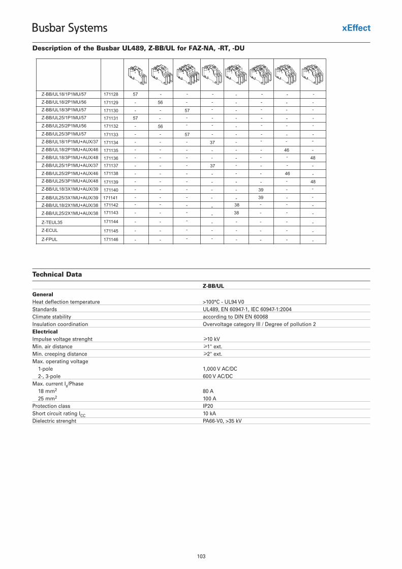
103
Busbar Systems
Technical Data
Z-BB/UL
GeneralHeat deflection temperature >100°C - UL94 V0Standards UL489, EN 60947-1, IEC 60947-1:2004Climate stability according to DIN EN 60068Insulation coordination Overvoltage category III / Degree of pollution 2ElectricalImpulse voltage strenght ≥10 kVMin. air distance ≥1" ext.Min. creeping distance ≥2" ext.Max. operating voltage
CD/CA V 000,1elop-12-, 3-pole 600 V AC/DC
Max. current Is/Phase18 mm2 80 A25 mm2 100 A
Protection class IP20Short circuit rating ICC 10 kADielectric strenght PA66-V0, >35 kV
Description of the Busbar UL489, Z-BB/UL for FAZ-NA, -RT, -DU
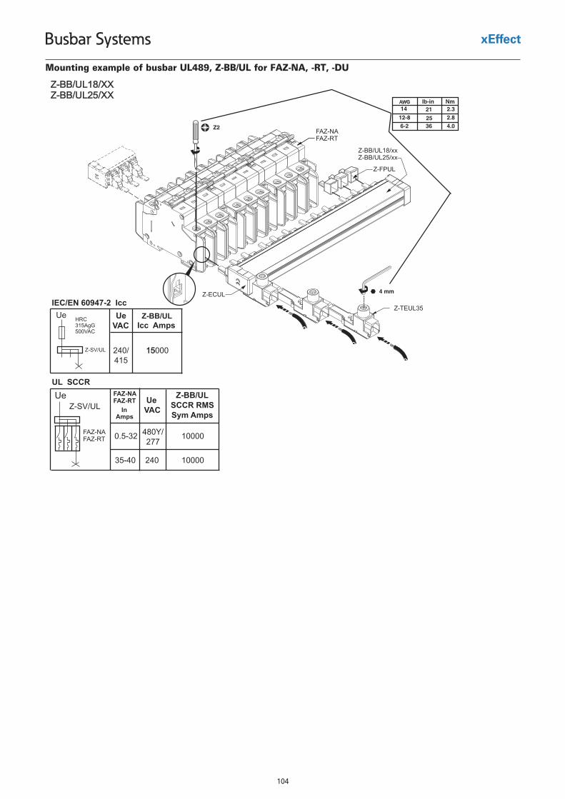
104
Busbar Systems
Mounting example of busbar UL489, Z-BB/UL for FAZ-NA, -RT, -DU
105
Busbar Systems
• For MCB FAZ
• Sliceable
• 18 and 25 mm2
• Pin busbar
• Accessories available:
End caps
Terminals
Busbar tag shrouds
• Length 1 m
Busbar UL508 BB/UL
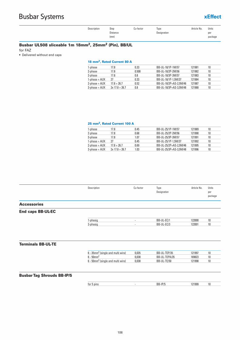
106
Busbar Systems
Busbar UL508 sliceable 1m 18mm2, 25mm2 (Pin), BB/UL
18 mm2, Rated Current 80 A
1-phase 17.8 0.33 BB-UL-18/1P-1M/57 121981 102-phase 17.8 0.508 BB-UL-18/2P-2M/56 121982 103-phase 17.8 0.8 BB-UL-18/3P-3M/57 121983 101-phase + AUX 27 0.33 BB-UL-18/1P-1,5M/37 121984 102-phase + AUX 17.8 + 26.7 0.52 BB-UL-18/2P+AS-2,5M/46 121987 103-phase + AUX 2x 17.8 + 26.7 0.8 BB-UL-18/3P+AS-3,5M/48 121988 10
Description Step Cu-factor Type Article No. UnitsDistance Designation per (mm) package
for FAZ• Delivered without end caps
25 mm2, Rated Current 100 A
1-phase 17.8 0.45 BB-UL-25/1P-1M/57 121989 102-phase 17.8 0.68 BB-UL-25/2P-2M/56 121990 103-phase 17.8 1.07 BB-UL-25/3P-3M/57 121991 101-phase + AUX 27 0.45 BB-UL-25/1P-1,5M/37 121992 102-phase + AUX 17.8 + 26.7 0.69 BB-UL-25/2P+AS-2,5M/46 121995 103-phase + AUX 2x 17.8 + 26.7 1.03 BB-UL-25/3P+AS-3,5M/48 121996 10
Accessories
1-phasig - BB-UL-EC/1 122000 103-phasig - BB-UL-EC/3 122001 10
Description Cu-factor Type Article No. UnitsDesignation per
package
End caps BB-UL-EC
6 - 35mm2 (single and multi wire) 0,035 BB-UL-TEP/35 121997 106 - 50mm2 0,038 BB-UL-TEPA/35 169823 106 - 50mm2 (single and multi wire) 0,038 BB-UL-TE/50 121998 10
Terminals BB-UL-TE
for 5 pins - BB-IP/5 121999 10
Busbar Tag Shrouds BB-IP/5
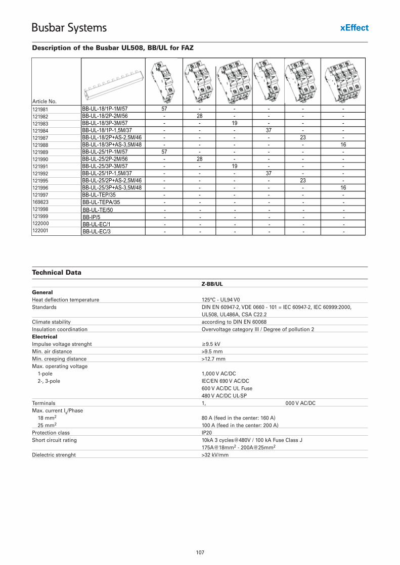
107
Busbar Systems
A/35
Description of the Busbar UL508, BB/UL for FAZ
Article No.
121981121982121983121984121987121988121989121990121991121992121995121996121997169823121998121999122000122001
Technical Data
Z-BB/UL
GeneralHeat deflection temperature 125°C - UL94 V0Standards DIN EN 60947-2, VDE 0660 - 101 = IEC 60947-2, IEC 60999:2000,
UL508, UL486A, CSA C22.2Climate stability according to DIN EN 60068Insulation coordination Overvoltage category III / Degree of pollution 2ElectricalImpulse voltage strenght ≥9.5 kVMin. air distance >9.5 mmMin. creeping distance >12.7 mmMax. operating voltage
1-pole 1,000 V AC/DC2-, 3-pole IEC/EN 690 V AC/DC
600 V AC/DC UL Fuse480 V AC/DC UL-SP
Terminals 1, 000 V AC/DCMax. current Is/Phase
18 mm2 80 A (feed in the center: 160 A)25 mm2 100 A (feed in the center: 200 A)
Protection class IP20Short circuit rating 10kA 3 cycles@480V / 100 kA Fuse Class J
175A@18mm2 - 200A@25mm2
Dielectric strenght >32 kV/mm
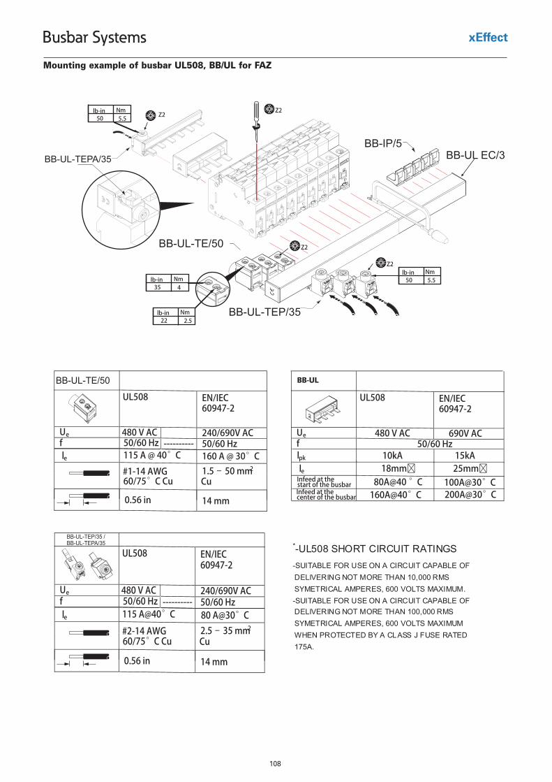
108
Busbar Systems
BB-UL-TEP/35
BB-UL-TE/50
BB-IP/5BB-UL EC/3BB-UL-TEPA/35
Z2
Z2
Z2
Z2
4Nmlb-in
35
2.5Nmlb-in
22
5.5Nmlb-in
50
5.5Nmlb-in
50
Mounting example of busbar UL508, BB/UL for FAZ
UL508 EN/IEC60947-2
Ue 480 V AC 240/690V ACf 50/60 Hz 50/60 Hz
115 A @ 40°C 160 A @ 30°C
1.5 – 50 mm2Cu
0.56 in 14 mm
le
#1-14 AWG 60/75°C Cu
----------
BB-UL-TE/50
UL508
EN/IEC
60947-2
Ue 480 V AC 240/690V ACf 50/60 Hz
50/60 Hz
115 A@40°C
80 A@30°C
2.5 – 35 mm2Cu
0.56 in 14 mm
le
#2-14 AWG 60/75°C Cu
----------
BB-UL-TEP/35 / BB-UL-TEPA/35
UL508 EN/IEC60947-2
Ue 480 V AC 690V ACf
50/60 Hz
leInfeed at the start of the busbarInfeed at the center of the busbar
WBCxxx
25mm�18mm�100A@30°C80A@40 °C
160A@40°C 200A@30°C
lpk 15kA10kA
*-UL508 SHORT CIRCUIT RATINGS -SUITABLE FOR USE ON A CIRCUIT CAPABLE OF DELIVERING NOT MORE THAN 10,000 RMS SYMETRICAL AMPERES, 600 VOLTS MAXIMUM. -SUITABLE FOR USE ON A CIRCUIT CAPABLE OF DELIVERING NOT MORE THAN 100,000 RMS SYMETRICAL AMPERES, 600 VOLTS MAXIMUM WHEN PROTECTED BY A CLASS J FUSE RATED 175A.
BB-UL
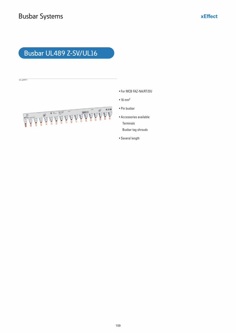
109
Busbar Systems
• For MCB FAZ-NA/RT/DU
• 16 mm2
• Pin busbar
• Accessories available:
Terminals
Busbar tag shrouds
• Several length
wa_sg03511
Busbar UL489 Z-SV/UL16
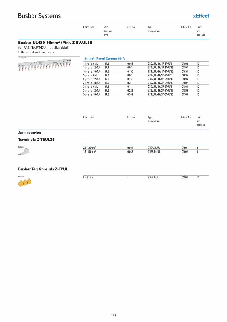
110
Busbar Systems
Busbar UL489 16mm2 (Pin), Z-SV/UL16
16 mm2, Rated Current 80 A
1-phase, 6MU 17.6 0.035 Z-SV/UL-16/1P-1MU/6 104892 101-phase, 12MU 17.6 0.07 Z-SV/UL-16/1P-1MU/12 104893 101-phase, 18MU 17.6 0.105 Z-SV/UL-16/1P-1MU/18 104894 102-phase, 6MU 17.6 0.07 Z-SV/UL-16/2P-2MU/6 104895 102-phase, 12MU 17.6 0.14 Z-SV/UL-16/2P-2MU/12 104896 102-phase, 18MU 17.6 0.21 Z-SV/UL-16/2P-2MU/18 104897 103-phase, 6MU 17.6 0.14 Z-SV/UL-16/3P-3MU/6 104898 103-phase, 12MU 17.6 0.221 Z-SV/UL-16/3P-3MU/12 104899 103-phase, 18MU 17.6 0.332 Z-SV/UL-16/3P-3MU/18 104900 10
wa_sg03511
Description Step Cu-factor elcitrA epyT No. UnitsDistance Designation per (mm) package
for FAZ-NA/RT/DU, not sliceable!!• Delivered with end caps
Accessories
Description Cu-factor elcitrA epyT No. UnitsDesignation per
package
2.5 - 35mm2 0.035 Z-EK/35/UL 104901 31.5 - 50mm2 0.038 Z-EB/50/UL 104902 3
SG07506
Terminals Z-TEUL35
for 3 pins - ZV-BS-UL 104904 10SG07706
Busbar Tag Shrouds Z-FPUL
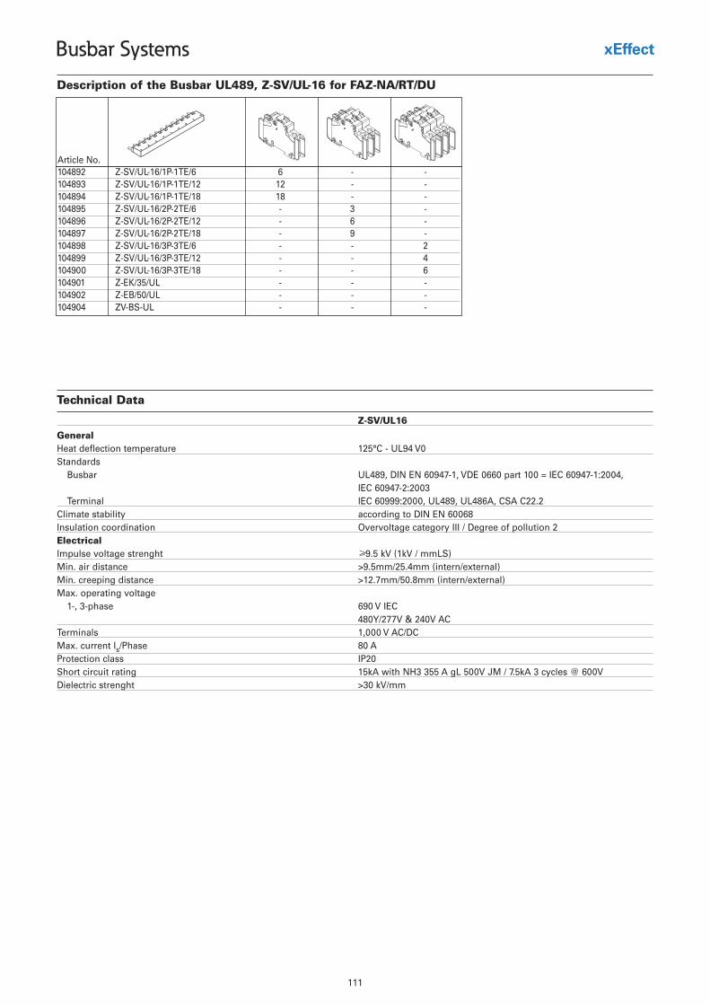
111
Busbar Systems
Description of the Busbar UL489, Z-SV/UL-16 for FAZ-NA/RT/DU
Technical Data
Z-SV/UL16
GeneralHeat deflection temperature 125°C - UL94 V0Standards
Busbar UL489, DIN EN 60947-1, VDE 0660 part 100 = IEC 60947-1:2004, IEC 60947-2:2003
Terminal IEC 60999:2000, UL489, UL486A, CSA C22.2Climate stability according to DIN EN 60068Insulation coordination Overvoltage category III / Degree of pollution 2ElectricalImpulse voltage strenght ≥9.5 kV (1kV / mmLS)Min. air distance >9.5mm/25.4mm (intern/external)Min. creeping distance >12.7mm/50.8mm (intern/external)Max. operating voltage
1-, 3-phase 690 V IEC480Y/277V & 240V AC
Terminals 1,000 V AC/DCMax. current Is/Phase 80 AProtection class IP20Short circuit rating 15kA with NH3 355 A gL 500V JM / 7.5kA 3 cycles @ 600VDielectric strenght >30 kV/mm
Article No.104892 Z-SV/UL-16/1P-1TE/6 6 - -104893 Z-SV/UL-16/1P-1TE/12 12 - -104894 Z-SV/UL-16/1P-1TE/18 18 - -104895 Z-SV/UL-16/2P-2TE/6 - 3 -104896 Z-SV/UL-16/2P-2TE/12 - 6 -104897 Z-SV/UL-16/2P-2TE/18 - 9 -104898 Z-SV/UL-16/3P-3TE/6 - - 2104899 Z-SV/UL-16/3P-3TE/12 - - 4104900 Z-SV/UL-16/3P-3TE/18 - - 6104901 Z-EK/35/UL - - -104902 Z-EB/50/UL - - -104904 ZV-BS-UL - - -
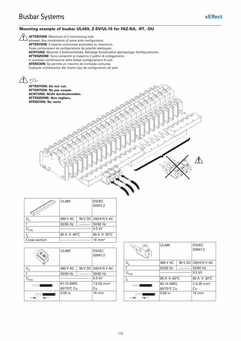
112
Busbar Systems
Mounting example of busbar UL489, Z-SV/UL-16 for FAZ-NA, -RT, -DU
UL489 EN/IEC00947-2
Ue 480 V AC 96 V DC 240/415 V ACzH 06/05----------zH 06/05f
Uimp ---------------------------- 9.5 kV
Ie 80 A @ 40oC 80 A @ 30oCCross section ---------------------------- 16 mm²
ATTENTION: Maximum of 3 commoning linksallowed. Any combination of same pole configuration.ATTENTION: 3 liaisons communes autorisées au maximum.Toute combinaison de configurations de polarité identiques.ACHTUNG: Maximal 3 Schienenblöcke. Beliebige Kombination gleichpoliger Konfigurationen.ATTENZIONE: Sono consentiti al massimo 3 pettini di collegamento in qualsiasi combinazione della stessa configurazione di poli.ATENCION: Se permite un máximo de 3 enlaces comunes.Cualquier combinación del mismo tipo de configuración de polo
!
ATTENTION: Do not cut.ATTENTION: Ne pas couper.ACHTUNG: Nicht durchschneiden.ATTENZIONE: Non tagliare.ATENCION: No corte.
!
UL489 EN/IEC00947-2
Ue 480 V AC 96 V DC 240/415 V ACzH 06/05----------zH 06/05f
Uimp ---------------------------- 9.5 kV
Ie 80 A @ 40oC 80 A @ 30oC#2-14 AWG 2.5-35 mm²60/75oC Cu Cu0.56 in 14 mm
UL489 EN/IEC00947-2
Ue 480 V AC 96 V DC 240/415 V ACzH 06/05----------zH 06/05f
Uimp ---------------------------- 9.5 kV#1-14 AWG 1.5-50 mm²60/75oC Cu Cu0.56 in 14 mm
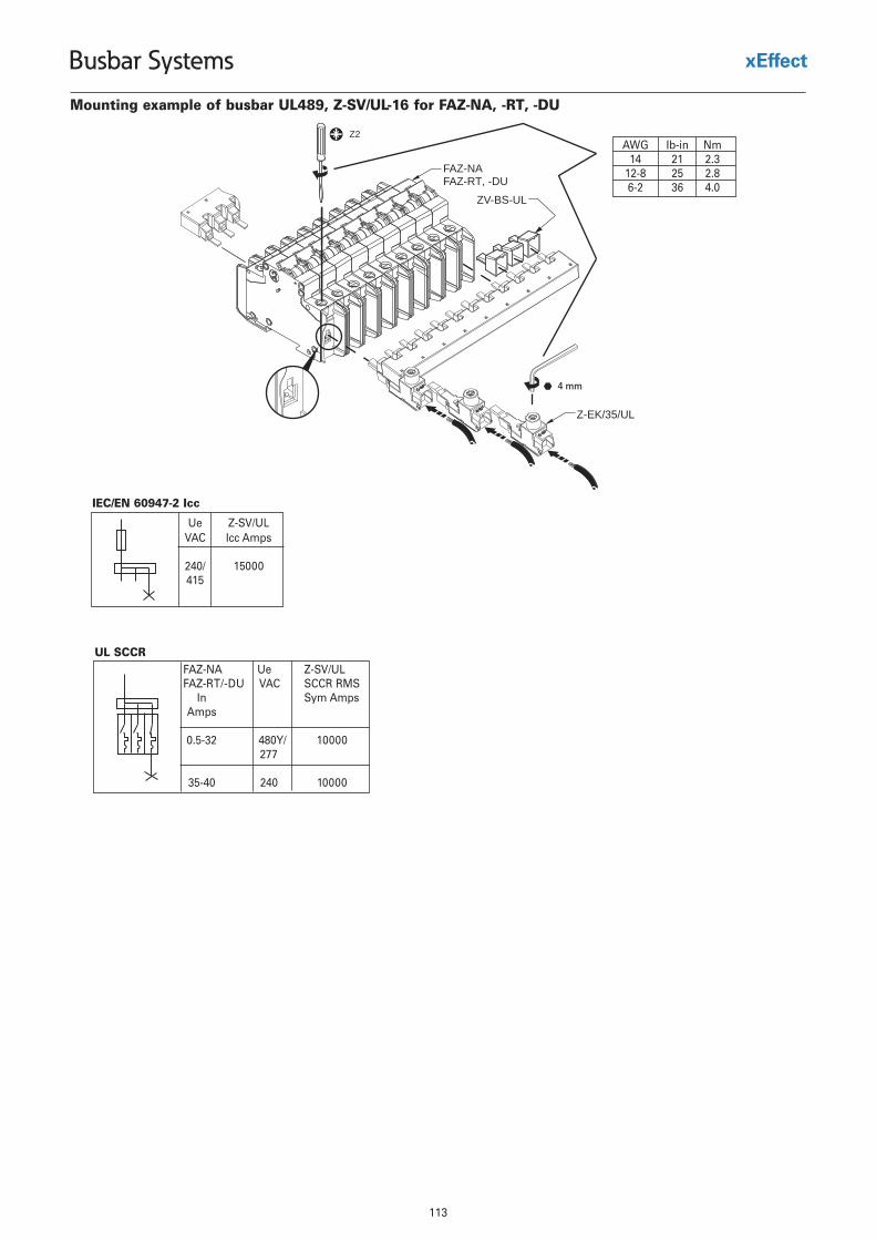
113
Busbar Systems
Z2
FAZ-NAFAZ-RT, -DU
ZV-BS-UL
Z-EK/35/UL
4 mm
Mounting example of busbar UL489, Z-SV/UL-16 for FAZ-NA, -RT, -DU
AWG Ib-in Nm14 21 2.3
12-8 25 2.86-2 36 4.0
Ue Z-SV/ULVAC Icc Amps
240/ 15000415
IEC/EN 60947-2 Icc
FAZ-NA Ue Z-SV/ULFAZ-RT/-DU VAC SCCR RMS
In Sym AmpsAmps
0.5-32277
35-40
480Y/
240
10000
10000
UL SCCR
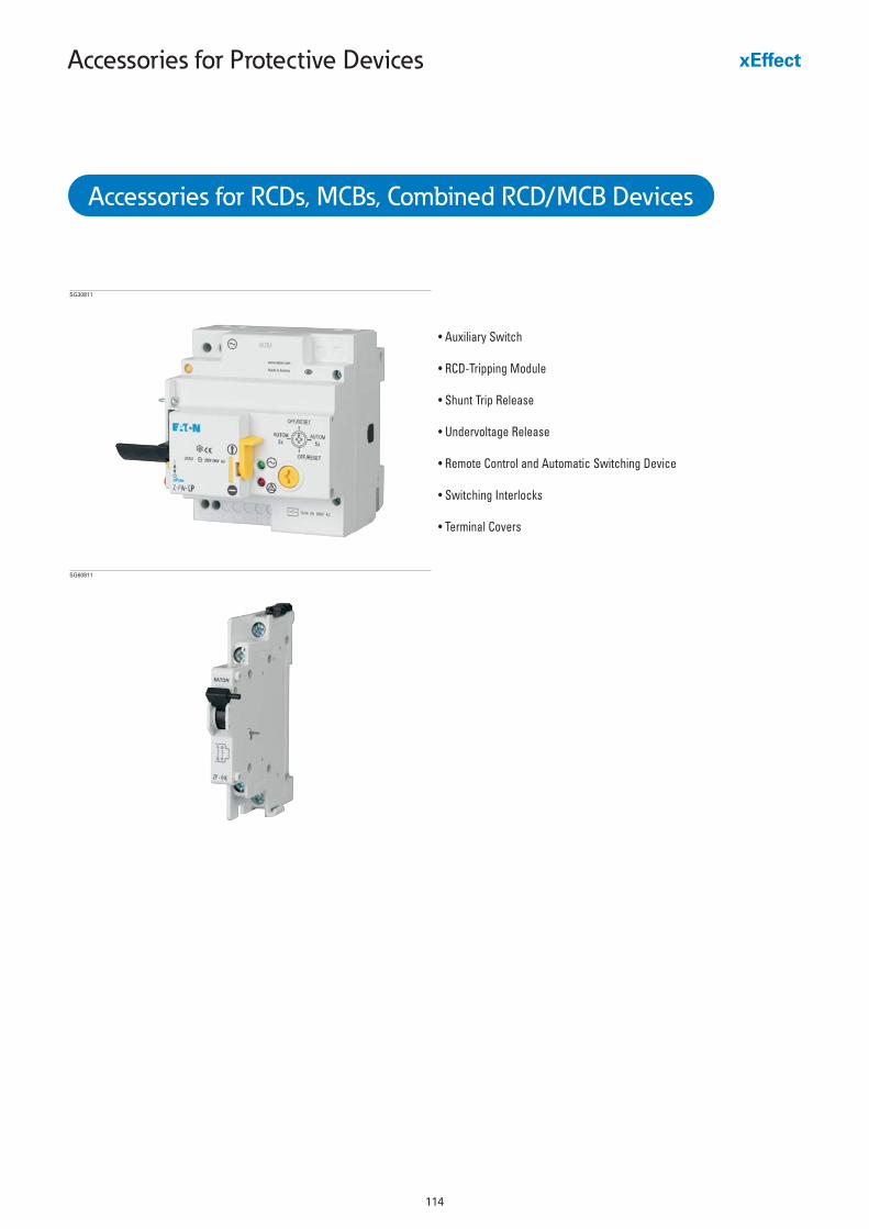
114
Accessories for Protective Devices
• Auxiliary Switch
• RCD-Tripping Module
• Shunt Trip Release
• Undervoltage Release
• Remote Control and Automatic Switching Device
• Switching Interlocks
• Terminal Covers
SG30811
Accessories for RCDs, MCBs, Combined RCD/MCB Devices
SG60811
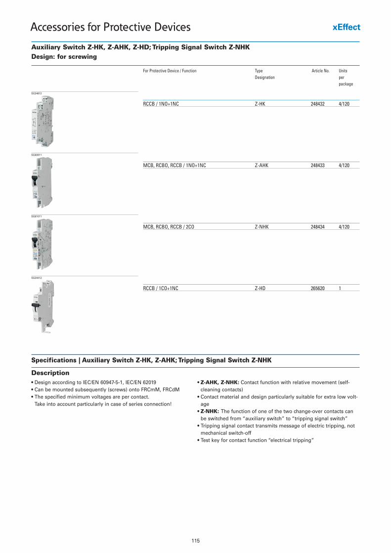
115
Accessories for Protective Devices
Auxiliary Switch Z-HK, Z-AHK, Z-HD; Tripping Signal Switch Z-NHKDesign: for screwing
For Protective Device / Function Type Article No. UnitsDesignation per
package
RCCB / 1NO+1NC Z-HK 248432 4/120
SG34812
MCB, RCBO, RCCB / 1NO+1NC Z-AHK 248433 4/120
SG60911
MCB, RCBO, RCCB / 2CO Z-NHK 248434 4/120
SG61011
RCCB / 1CO+1NC Z-HD 265620 1
SG34412
Specifications | Auxiliary Switch Z-HK, Z-AHK; Tripping Signal Switch Z-NHK
Description• Design according to IEC/EN 60947-5-1, IEC/EN 62019• Can be mounted subsequently (screws) onto FRCmM, FRCdM• The specified minimum voltages are per contact.
Take into account particularly in case of series connection!
• Z-AHK, Z-NHK: Contact function with relative movement (self-cleaning contacts)
• Contact material and design particularly suitable for extra low volt-age
• Z-NHK: The function of one of the two change-over contacts canbe switched from “auxiliary switch” to “tripping signal switch”
• Tripping signal contact transmits message of electric tripping, notmechanical switch-off
• Test key for contact function “electrical tripping”
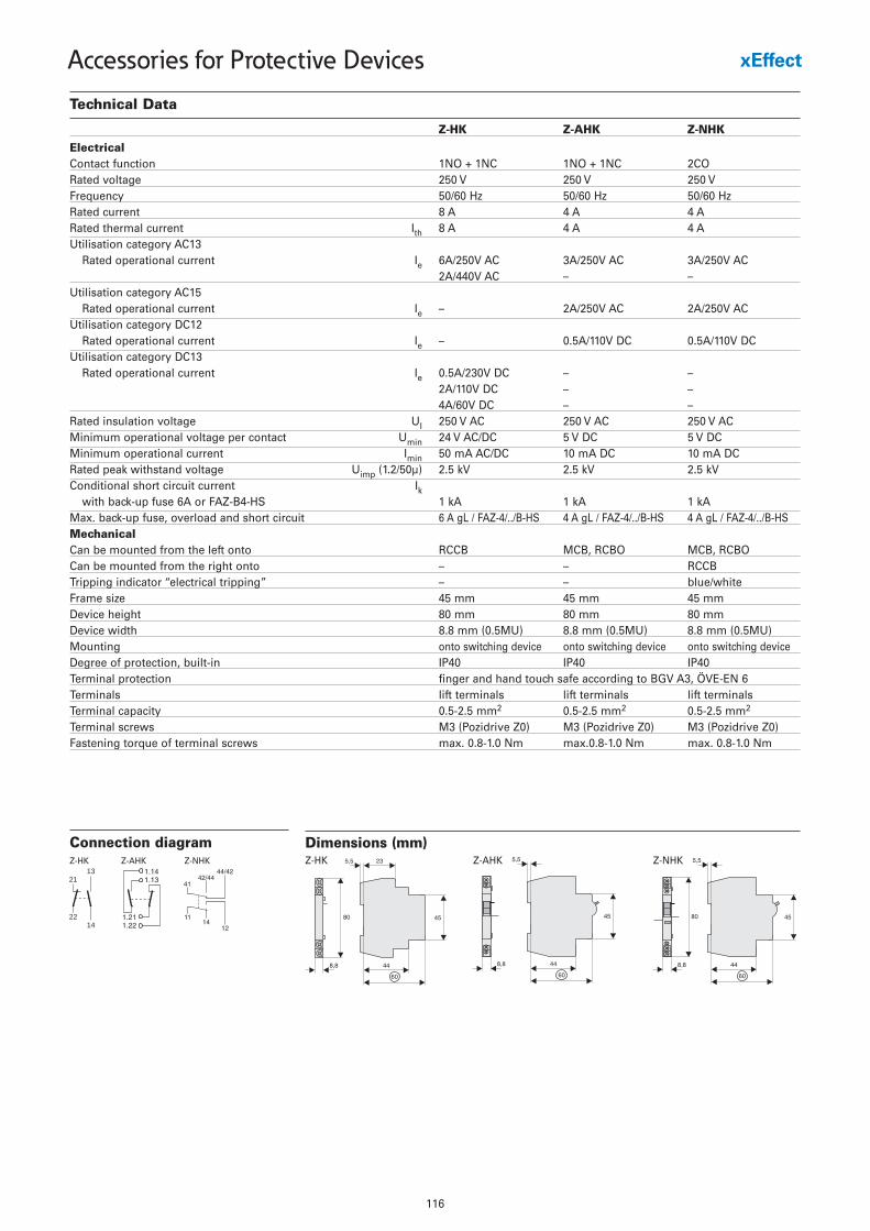
116
Accessories for Protective Devices
Technical Data
Z-HK Z-AHK Z-NHK
ElectricalContact function 1NO + 1NC 1NO + 1NC 2CORated voltage 250 V 250 V 250 VFrequency 50/60 Hz 50/60 Hz 50/60 HzRated current 8 A 4 A 4 ARated thermal current Ith 8 A 4 A 4 AUtilisation category AC13
Rated operational current Ie 6A/250V AC 3A/250V AC 3A/250V AC2A/440V AC – –
Utilisation category AC15Rated operational current Ie – 2A/250V AC 2A/250V AC
Utilisation category DC12Rated operational current Ie – 0.5A/110V DC 0.5A/110V DC
Utilisation category DC13Rated operational current Ie 0.5A/230V DC – –
2A/110V DC – –4A/60V DC – –
Rated insulation voltage UI 250 V AC 250 V AC 250 V ACMinimum operational voltage per contact Umin 24 V AC/DC 5 V DC 5 V DCMinimum operational current Imin 50 mA AC/DC 10 mA DC 10 mA DCRated peak withstand voltage Uimp (1.2/50µ) 2.5 kV 2.5 kV 2.5 kVConditional short circuit current Ik
with back-up fuse 6A or FAZ-B4-HS 1 kA 1 kA 1 kAMax. back-up fuse, overload and short circuit 6 A gL / FAZ-4/../B-HS 4 A gL / FAZ-4/../B-HS 4 A gL / FAZ-4/../B-HSMechanicalCan be mounted from the left onto RCCB MCB, RCBO MCB, RCBOCan be mounted from the right onto – – RCCBTripping indicator “electrical tripping” – – blue/whiteFrame size 45 mm 45 mm 45 mmDevice height 80 mm 80 mm 80 mmDevice width 8.8 mm (0.5MU) 8.8 mm (0.5MU) 8.8 mm (0.5MU)Mounting onto switching device onto switching device onto switching deviceDegree of protection, built-in IP40 IP40 IP40Terminal protection finger and hand touch safe according to BGV A3, ÖVE-EN 6Terminals lift terminals lift terminals lift terminalsTerminal capacity 0.5-2.5 mm2 0.5-2.5 mm2 0.5-2.5 mm2
Terminal screws M3 (Pozidrive Z0) M3 (Pozidrive Z0) M3 (Pozidrive Z0)Fastening torque of terminal screws max. 0.8-1.0 Nm max.0.8-1.0 Nm max. 0.8-1.0 Nm
Connection diagram
2113
2214
Z-HK Z-AHK Z-NHK
Dimensions (mm)Z-HK Z-AHK Z-NHK
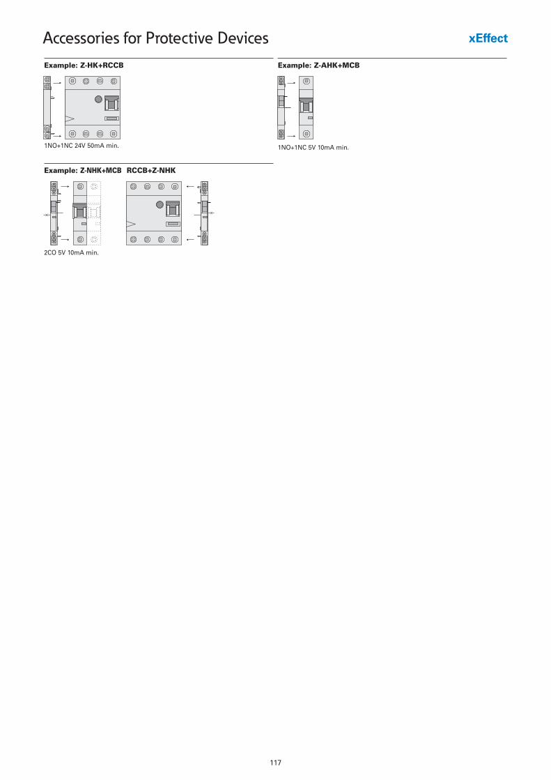
117
Accessories for Protective Devices
Example: Z-HK+RCCB
1NO+1NC 24V 50mA min.
Example: Z-AHK+MCB
1NO+1NC 5V 10mA min.
Example: Z-NHK+MCB RCCB+Z-NHK
2CO 5V 10mA min.
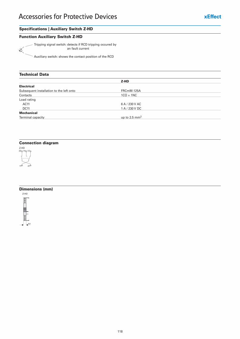
118
Accessories for Protective Devices
Specifications | Auxiliary Switch Z-HD
Function Auxiliary Switch Z-HD
Connection diagramZ-HD
Dimensions (mm)
Tripping signal switch: detects if RCD tripping occured byan fault current
Auxiliary switch: shows the contact position of the RCD
Technical Data
Z-HD
ElectricalSubsequent installation to the left onto FRCmM-125AContacts 1CO + 1NCLoad rating
AC11 6 A / 230 V ACDC11 1 A / 230 V DC
MechanicalTerminal capacity up to 2.5 mm2
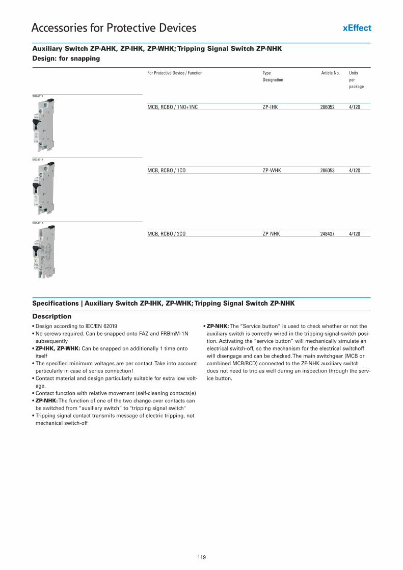
119
Accessories for Protective Devices
Auxiliary Switch ZP-AHK, ZP-IHK, ZP-WHK; Tripping Signal Switch ZP-NHKDesign: for snapping
For Protective Device / Function Type Article No. UnitsDesignation per
package
MCB, RCBO / 1NO+1NC ZP-IHK 286052 4/120
SG60811
MCB, RCBO / 1CO ZP-WHK 286053 4/120
SG34612
MCB, RCBO / 2CO ZP-NHK 248437 4/120
SG34512
Specifications | Auxiliary Switch ZP-IHK, ZP-WHK; Tripping Signal Switch ZP-NHK
Description• Design according to IEC/EN 62019• No screws required. Can be snapped onto FAZ and FRBmM-1N
subsequently• ZP-IHK, ZP-WHK: Can be snapped on additionally 1 time onto
itself• The specified minimum voltages are per contact. Take into account
particularly in case of series connection!• Contact material and design particularly suitable for extra low volt-
age.• Contact function with relative movement (self-cleaning contacts)e)• ZP-NHK:The function of one of the two change-over contacts can
be switched from “auxiliary switch” to "tripping signal switch"• Tripping signal contact transmits message of electric tripping, not
mechanical switch-off
• ZP-NHK:The “Service button” is used to check whether or not theauxiliary switch is correctly wired in the tripping-signal-switch posi-tion. Activating the “service button” will mechanically simulate anelectrical switch-off, so the mechanism for the electrical switchoffwill disengage and can be checked. The main switchgear (MCB orcombined MCB/RCD) connected to the ZP-NHK auxiliary switchdoes not need to trip as well during an inspection through the serv-ice button.
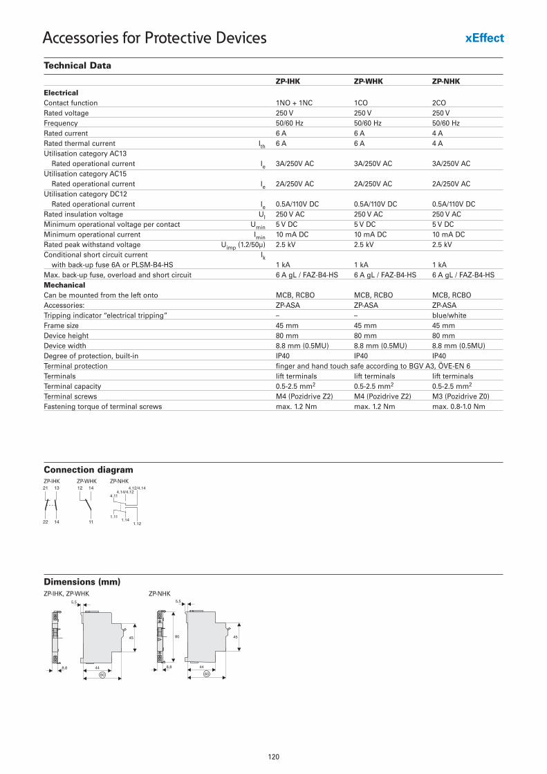
120
Accessories for Protective Devices
Technical Data
ZP-IHK ZP-WHK ZP-NHK
ElectricalContact function 1NO + 1NC 1CO 2CORated voltage 250 V 250 V 250 VFrequency 50/60 Hz 50/60 Hz 50/60 HzRated current 6 A 6 A 4 ARated thermal current Ith 6 A 6 A 4 AUtilisation category AC13
Rated operational current Ie 3A/250V AC 3A/250V AC 3A/250V ACUtilisation category AC15
Rated operational current Ie 2A/250V AC 2A/250V AC 2A/250V ACUtilisation category DC12
Rated operational current Ie 0.5A/110V DC 0.5A/110V DC 0.5A/110V DCRated insulation voltage UI 250 V AC 250 V AC 250 V ACMinimum operational voltage per contact Umin 5 V DC 5 V DC 5 V DCMinimum operational current Imin 10 mA DC 10 mA DC 10 mA DCRated peak withstand voltage Uimp (1.2/50µ) 2.5 kV 2.5 kV 2.5 kVConditional short circuit current Ik
with back-up fuse 6A or PLSM-B4-HS 1 kA 1 kA 1 kAMax. back-up fuse, overload and short circuit 6 A gL / FAZ-B4-HS 6 A gL / FAZ-B4-HS 6 A gL / FAZ-B4-HSMechanicalCan be mounted from the left onto MCB, RCBO MCB, RCBO MCB, RCBOAccessories: ZP-ASA ZP-ASA ZP-ASATripping indicator “electrical tripping” – – blue/whiteFrame size 45 mm 45 mm 45 mmDevice height 80 mm 80 mm 80 mmDevice width 8.8 mm (0.5MU) 8.8 mm (0.5MU) 8.8 mm (0.5MU)Degree of protection, built-in IP40 IP40 IP40Terminal protection finger and hand touch safe according to BGV A3, ÖVE-EN 6Terminals lift terminals lift terminals lift terminalsTerminal capacity 0.5-2.5 mm2 0.5-2.5 mm2 0.5-2.5 mm2
Terminal screws M4 (Pozidrive Z2) M4 (Pozidrive Z2) M3 (Pozidrive Z0)Fastening torque of terminal screws max. 1.2 Nm max. 1.2 Nm max. 0.8-1.0 Nm
Dimensions (mm)ZP-NHKZP-IHK, ZP-WHK
Connection diagramZP-IHK ZP-WHK ZP-NHK
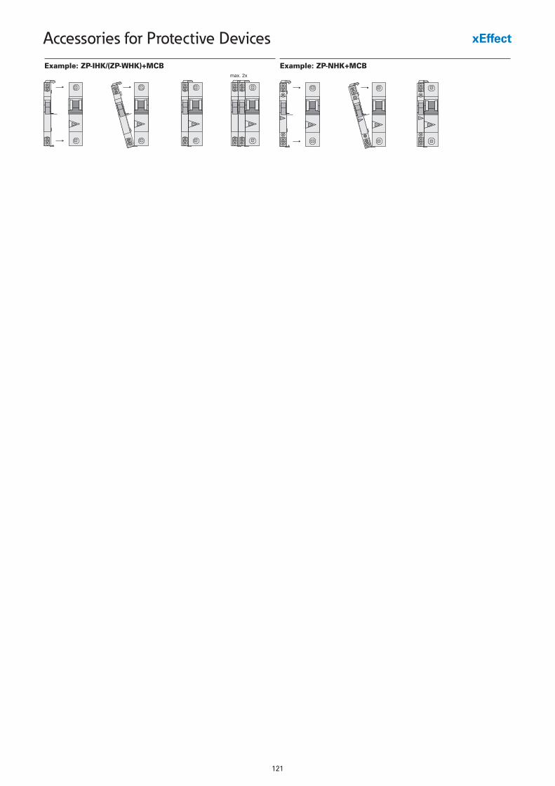
121
Accessories for Protective Devices
Example: ZP-IHK/(ZP-WHK)+MCB Example: ZP-NHK+MCB
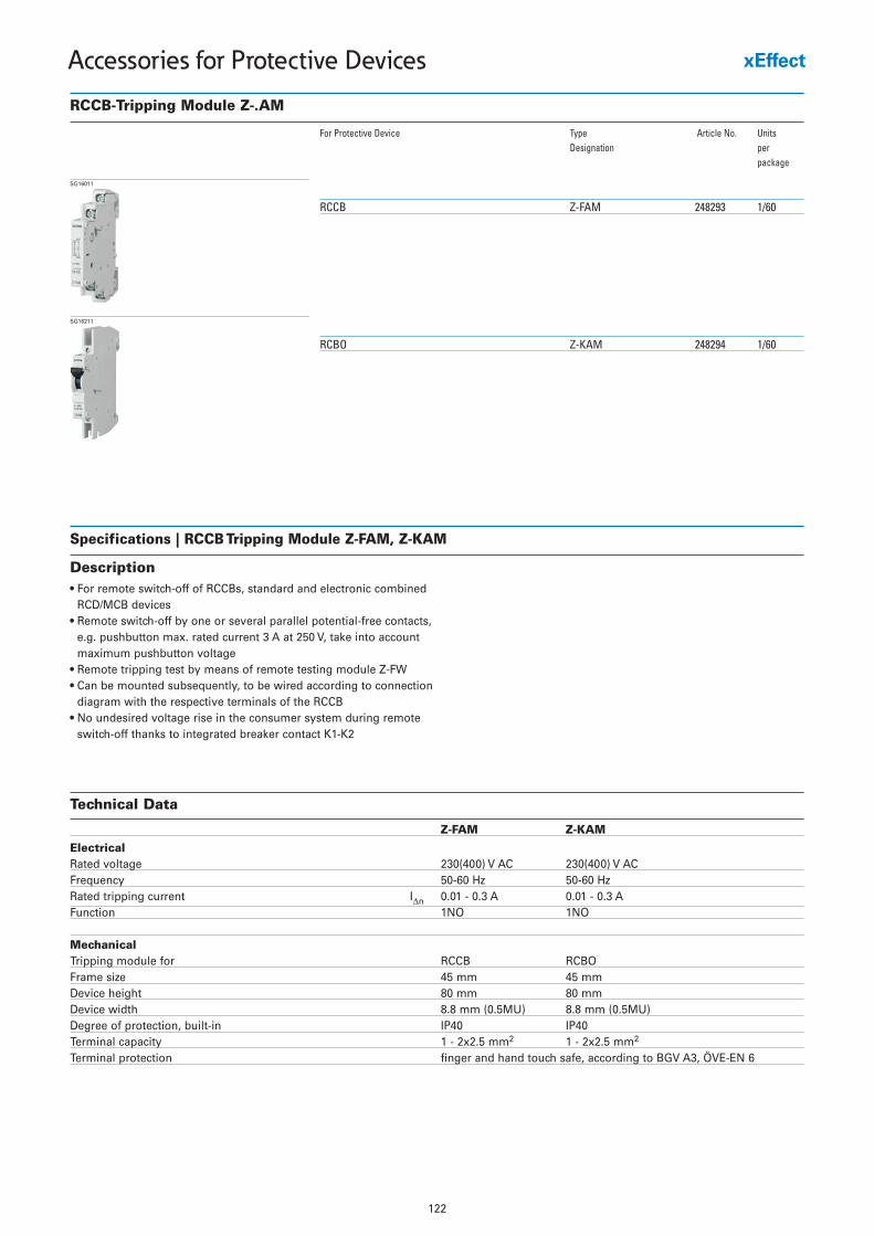
122
Accessories for Protective Devices
RCCB-Tripping Module Z-.AM
For Protective Device Type Article No. UnitsDesignation per
package
RCCB Z-FAM 248293 1/60
SG16011
RCBO Z-KAM 248294 1/60
SG16211
Specifications | RCCB Tripping Module Z-FAM, Z-KAM
Description• For remote switch-off of RCCBs, standard and electronic combined
RCD/MCB devices• Remote switch-off by one or several parallel potential-free contacts,
e.g. pushbutton max. rated current 3 A at 250 V, take into accountmaximum pushbutton voltage
• Remote tripping test by means of remote testing module Z-FW• Can be mounted subsequently, to be wired according to connection
diagram with the respective terminals of the RCCB• No undesired voltage rise in the consumer system during remote
switch-off thanks to integrated breaker contact K1-K2
Technical Data
Z-FAM Z-KAM
ElectricalRated voltage 230(400) V AC 230(400) V ACFrequency 50-60 Hz 50-60 HzRated tripping current IΔn 0.01 - 0.3 A 0.01 - 0.3 AFunction 1NO 1NO
MechanicalTripping module for RCCB RCBOFrame size 45 mm 45 mmDevice height 80 mm 80 mmDevice width 8.8 mm (0.5MU) 8.8 mm (0.5MU)Degree of protection, built-in IP40 IP40Terminal capacity 1 - 2x2.5 mm2 1 - 2x2.5 mm2
Terminal protection finger and hand touch safe, according to BGV A3, ÖVE-EN 6
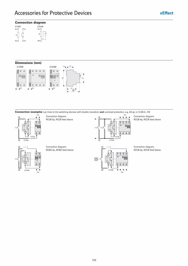
123
Accessories for Protective Devices
Dimensions (mm)
8,8 8,8
Z7-FAM
8,8
4580
23
Z7-KAM
44
60
5,5Z-FAM Z-KAM
Connection examples Lay lines to the switching devices with double insulation and overload protection, e.g. 4A gL or CLS6-4..-HS
Connection diagram: RCCB-2p, RCCB feed above
Connection diagram: RCCB-4p, RCCB feed above
Connection diagram: RCBO-2p, RCBO feed below
Connection diagram: RCCB-4p, RCCB feed below
Z-FAM
Z-FAM
Z-FAM
Z-KAM
Connection diagram
W1 K1
Ω
W2 K2
Z-FAM Z-KAMW1
�
W2
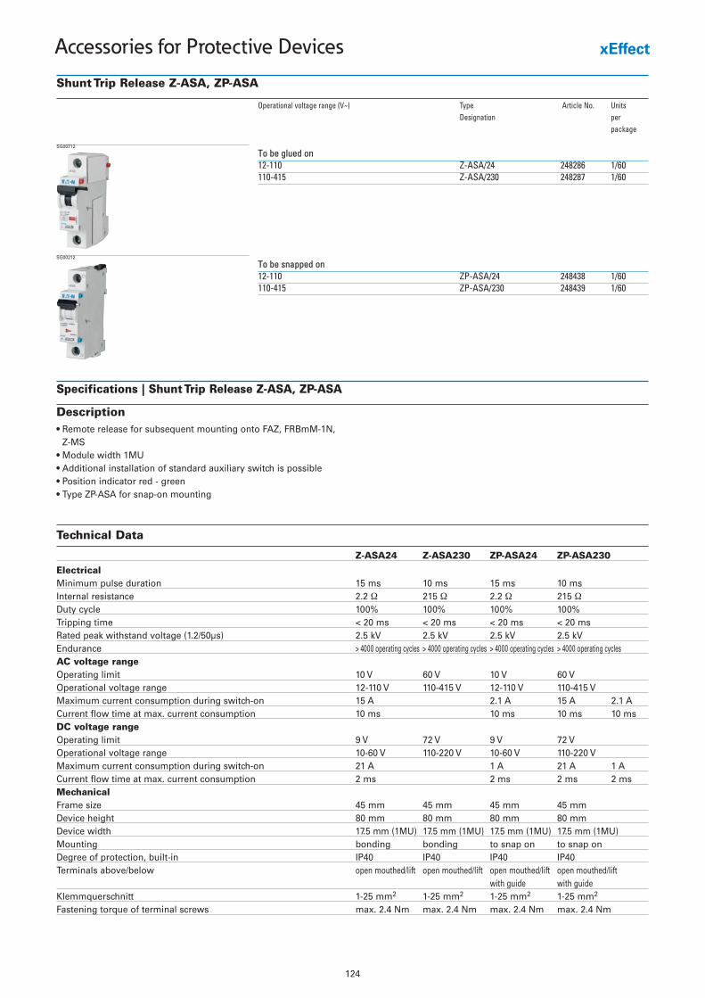
Technical Data
Z-ASA24 Z-ASA230 ZP-ASA24 ZP-ASA230
ElectricalMinimum pulse duration 15 ms 10 ms 15 ms 10 msInternal resistance 2.2 Ω 215 Ω 2.2 Ω 215 ΩDuty cycle 100% 100% 100% 100%Tripping time < 20 ms < 20 ms < 20 ms < 20 msRated peak withstand voltage (1.2/50µs) 2.5 kV 2.5 kV 2.5 kV 2.5 kVEndurance > 4000 operating cycles > 4000 operating cycles > 4000 operating cycles > 4000 operating cyclesAC voltage rangeOperating limit 10 V 60 V 10 V 60 VOperational voltage range 12-110 V 110-415 V 12-110 V 110-415 VMaximum current consumption during switch-on 15 A 2.1 A 15 A 2.1 ACurrent flow time at max. current consumption 10 ms 10 ms 10 ms 10 msDC voltage rangeOperating limit 9 V 72 V 9 V 72 VOperational voltage range 10-60 V 110-220 V 10-60 V 110-220 VMaximum current consumption during switch-on 21 A 1 A 21 A 1 ACurrent flow time at max. current consumption 2 ms 2 ms 2 ms 2 msMechanicalFrame size 45 mm 45 mm 45 mm 45 mmDevice height 80 mm 80 mm 80 mm 80 mmDevice width 17.5 mm (1MU) 17.5 mm (1MU) 17.5 mm (1MU) 17.5 mm (1MU)Mounting bonding bonding to snap on to snap onDegree of protection, built-in IP40 IP40 IP40 IP40Terminals above/below open mouthed/lift open mouthed/lift open mouthed/lift open mouthed/lift
with guide with guideKlemmquerschnitt 1-25 mm2 1-25 mm2 1-25 mm2 1-25 mm2
Fastening torque of terminal screws max. 2.4 Nm max. 2.4 Nm max. 2.4 Nm max. 2.4 Nm
124
Accessories for Protective Devices
Shunt Trip Release Z-ASA, ZP-ASA
Operational voltage range (V~) Type Article No. UnitsDesignation per
package
To be glued on12-110 Z-ASA/24 248286 1/60110-415 Z-ASA/230 248287 1/60
SG00712
To be snapped on12-110 ZP-ASA/24 248438 1/60110-415 ZP-ASA/230 248439 1/60
SG00212
Specifications | Shunt Trip Release Z-ASA, ZP-ASA
Description• Remote release for subsequent mounting onto FAZ, FRBmM-1N,
Z-MS• Module width 1MU• Additional installation of standard auxiliary switch is possible• Position indicator red - green• Type ZP-ASA for snap-on mounting
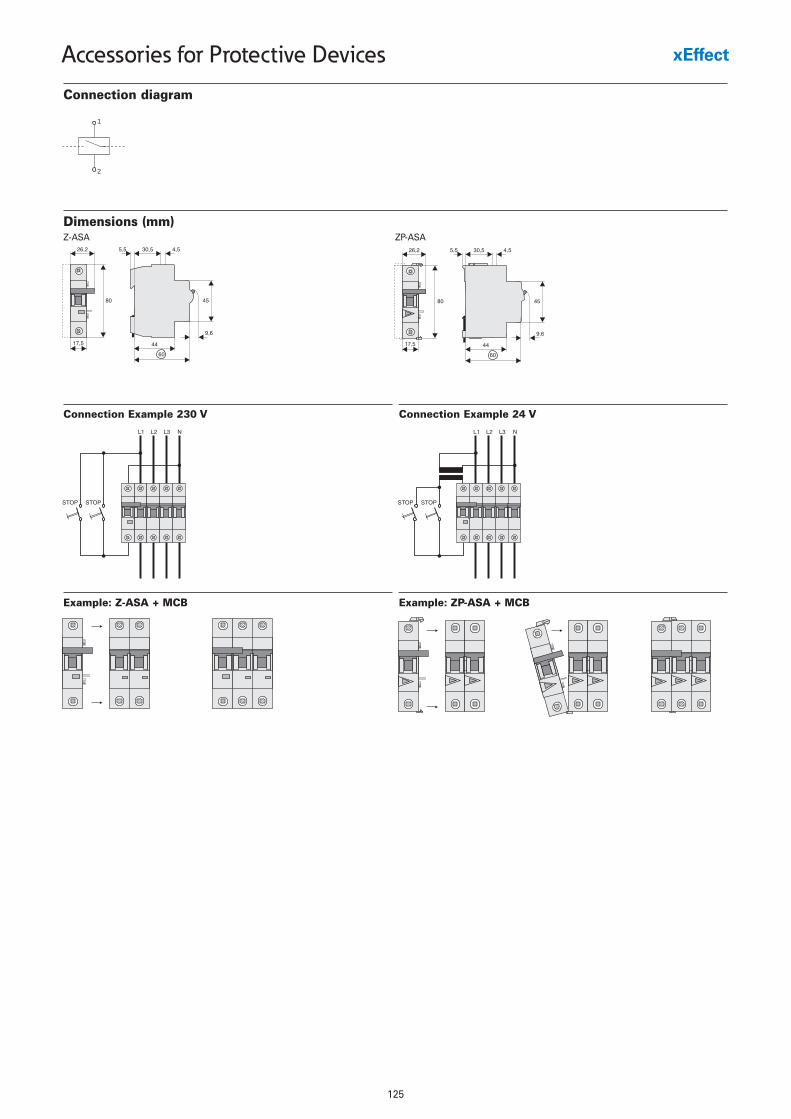
125
Accessories for Protective Devices
Connection diagram
1
2
Dimensions (mm)Z-ASA ZP-ASA
Example: Z-ASA + MCB
Connection Example 230 V
Example: ZP-ASA + MCB
Connection Example 24 V
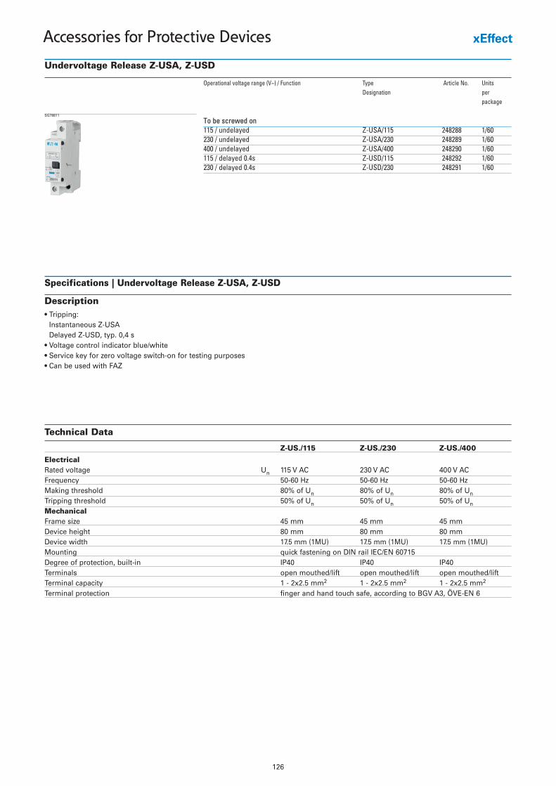
Technical Data
Z-US./115 Z-US./230 Z-US./400
ElectricalRated voltage Un 115 V AC 230 V AC 400 V ACFrequency 50-60 Hz 50-60 Hz 50-60 HzMaking threshold 80% of Un 80% of Un 80% of UnTripping threshold 50% of Un 50% of Un 50% of UnMechanicalFrame size 45 mm 45 mm 45 mmDevice height 80 mm 80 mm 80 mmDevice width 17.5 mm (1MU) 17.5 mm (1MU) 17.5 mm (1MU)Mounting quick fastening on DIN rail IEC/EN 60715Degree of protection, built-in IP40 IP40 IP40Terminals open mouthed/lift open mouthed/lift open mouthed/liftTerminal capacity 1 - 2x2.5 mm2 1 - 2x2.5 mm2 1 - 2x2.5 mm2
Terminal protection finger and hand touch safe, according to BGV A3, ÖVE-EN 6
126
Accessories for Protective Devices
Undervoltage Release Z-USA, Z-USD
Operational voltage range (V~) / Function Type Article No. UnitsDesignation per
package
To be screwed on115 / undelayed Z-USA/115 248288 1/60230 / undelayed Z-USA/230 248289 1/60400 / undelayed Z-USA/400 248290 1/60115 / delayed 0.4s Z-USD/115 248292 1/60230 / delayed 0.4s Z-USD/230 248291 1/60
SG78811
Specifications | Undervoltage Release Z-USA, Z-USD
Description• Tripping:
Instantaneous Z-USADelayed Z-USD, typ. 0,4 s
• Voltage control indicator blue/white• Service key for zero voltage switch-on for testing purposes• Can be used with FAZ
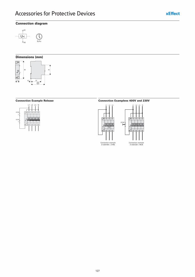
127
Accessories for Protective Devices
Dimensions (mm)
Connection Examplees 400V and 230VConnection Example Release
Connection exampleZ-USA/400 + Z-MS
Connection exampleZ-USA/230 + MCB
Connection diagram
0,4 s
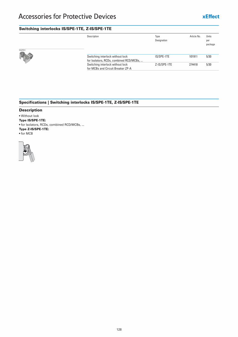
128
Accessories for Protective Devices
Switching interlocks IS/SPE-1TE, Z-IS/SPE-1TE
Description Type Article No. UnitsDesignation per
package
Switching interlock without lock IS/SPE-1TE 101911 5/30for Isolators, RCDs, combined RCD/MCBs, ...Switching interlock without lock Z-IS/SPE-1TE 274418 5/30for MCBs and Circuit Breaker ZP-A
SG47812
Specifications | Switching interlocks IS/SPE-1TE, Z-IS/SPE-1TE
Description• Without lockType IS/SPE-1TE:• for Isolators, RCDs, combined RCD/MCBs, ...Type Z-IS/SPE-1TE:• for MCB
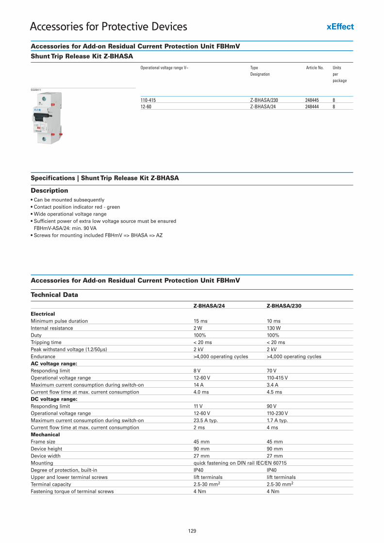
129
Accessories for Protective Devices
Accessories for Add-on Residual Current Protection Unit FBHmVShunt Trip Release Kit Z-BHASA
Operational voltage range V~ Type Article No. UnitsDesignation per
package
110-415 Z-BHASA/230 248445 812-60 Z-BHASA/24 248444 8
SG09411
Specifications | Shunt Trip Release Kit Z-BHASA
Description• Can be mounted subsequently• Contact position indicator red - green• Wide operational voltage range• Sufficient power of extra low voltage source must be ensured
FBHmV-ASA/24: min. 90 VA• Screws for mounting included FBHmV => BHASA => AZ
Technical Data
Z-BHASA/24 Z-BHASA/230
ElectricalMinimum pulse duration 15 ms 10 msInternal resistance 2 W 130 W Duty 100% 100%Tripping time < 20 ms < 20 msPeak withstand voltage (1.2/50µs) 2 kV 2 kVEndurance >4,000 operating cycles >4,000 operating cyclesAC voltage range:Responding limit 8 V 70 VOperational voltage range 12-60 V 110-415 VMaximum current consumption during switch-on 14 A 3.4 ACurrent flow time at max. current consumption 4.0 ms 4.5 msDC voltage range:Responding limit 11 V 90 VOperational voltage range 12-60 V 110-230 VMaximum current consumption during switch-on 23.5 A typ. 1.7 A typ.Current flow time at max. current consumption 2 ms 4 msMechanicalFrame size 45 mm 45 mmDevice height 90 mm 90 mmDevice width 27 mm 27 mmMounting quick fastening on DIN rail IEC/EN 60715Degree of protection, built-in IP40 IP40Upper and lower terminal screws lift terminals lift terminalsTerminal capacity 2.5-30 mm2 2.5-30 mm2
Fastening torque of terminal screws 4 Nm 4 Nm
Accessories for Add-on Residual Current Protection Unit FBHmV
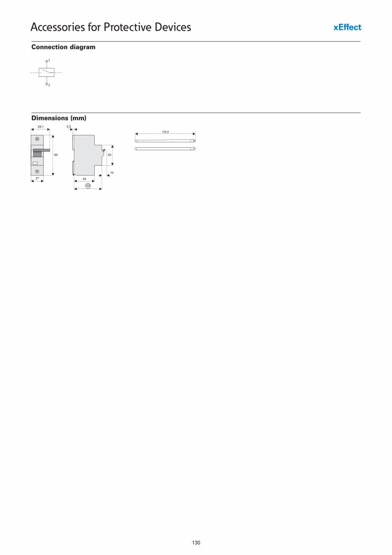
130
Accessories for Protective Devices
Dimensions (mm)
Connection diagram
1
2
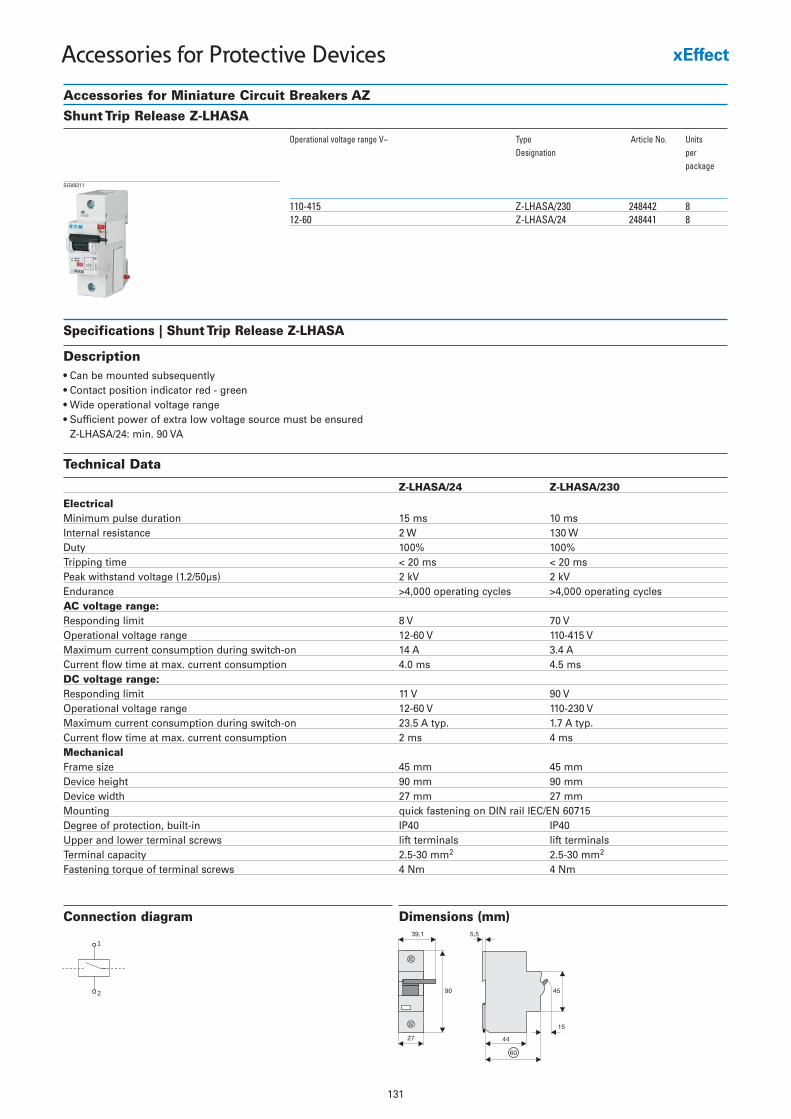
131
Accessories for Protective Devices
Accessories for Miniature Circuit Breakers AZShunt Trip Release Z-LHASA
Operational voltage range V~ Type Article No. UnitsDesignation per
package
110-415 Z-LHASA/230 248442 812-60 Z-LHASA/24 248441 8
SG09311
Specifications | Shunt Trip Release Z-LHASA
Description• Can be mounted subsequently• Contact position indicator red - green• Wide operational voltage range• Sufficient power of extra low voltage source must be ensured
Z-LHASA/24: min. 90 VA
Connection diagram
1
2
Technical Data
Z-LHASA/24 Z-LHASA/230
ElectricalMinimum pulse duration 15 ms 10 msInternal resistance 2 W 130 W Duty 100% 100%Tripping time < 20 ms < 20 msPeak withstand voltage (1.2/50µs) 2 kV 2 kVEndurance >4,000 operating cycles >4,000 operating cyclesAC voltage range:Responding limit 8 V 70 VOperational voltage range 12-60 V 110-415 VMaximum current consumption during switch-on 14 A 3.4 ACurrent flow time at max. current consumption 4.0 ms 4.5 msDC voltage range:Responding limit 11 V 90 VOperational voltage range 12-60 V 110-230 VMaximum current consumption during switch-on 23.5 A typ. 1.7 A typ.Current flow time at max. current consumption 2 ms 4 msMechanicalFrame size 45 mm 45 mmDevice height 90 mm 90 mmDevice width 27 mm 27 mmMounting quick fastening on DIN rail IEC/EN 60715Degree of protection, built-in IP40 IP40Upper and lower terminal screws lift terminals lift terminalsTerminal capacity 2.5-30 mm2 2.5-30 mm2
Fastening torque of terminal screws 4 Nm 4 Nm
Dimensions (mm)
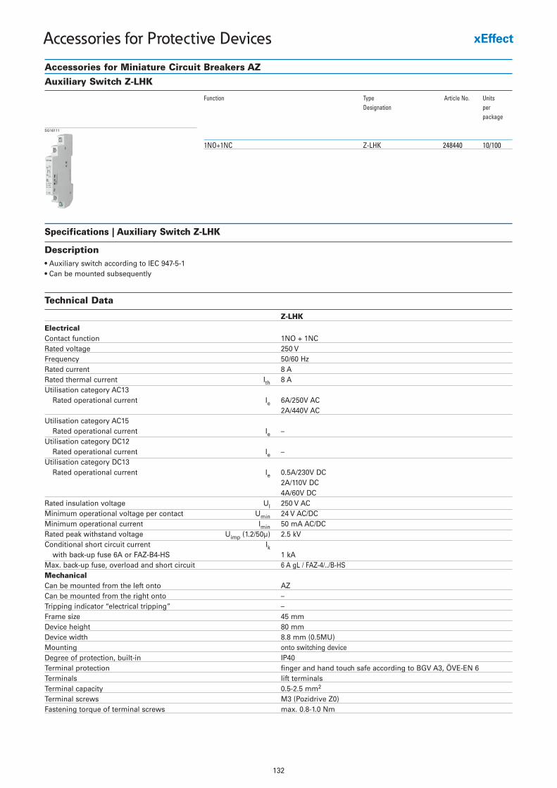
132
Accessories for Protective Devices
Accessories for Miniature Circuit Breakers AZAuxiliary Switch Z-LHK
Function Type Article No. UnitsDesignation per
package
1NO+1NC Z-LHK 248440 10/100
SG16111
Specifications | Auxiliary Switch Z-LHK
Description• Auxiliary switch according to IEC 947-5-1• Can be mounted subsequently
Technical Data
Z-LHK
ElectricalContact function 1NO + 1NC Rated voltage 250 V Frequency 50/60 Hz Rated current 8 A Rated thermal current Ith 8 AUtilisation category AC13
Rated operational current Ie 6A/250V AC 2A/440V AC
Utilisation category AC15Rated operational current Ie –
Utilisation category DC12Rated operational current Ie –
Utilisation category DC13Rated operational current Ie 0.5A/230V DC
2A/110V DC 4A/60V DC
Rated insulation voltage UI 250 V AC Minimum operational voltage per contact Umin 24 V AC/DC Minimum operational current Imin 50 mA AC/DC Rated peak withstand voltage Uimp (1.2/50µ) 2.5 kV Conditional short circuit current Ik
with back-up fuse 6A or FAZ-B4-HS 1 kA Max. back-up fuse, overload and short circuit 6 A gL / FAZ-4/../B-HS MechanicalCan be mounted from the left onto AZCan be mounted from the right onto – Tripping indicator “electrical tripping” – Frame size 45 mm Device height 80 mm Device width 8.8 mm (0.5MU) Mounting onto switching deviceDegree of protection, built-in IP40 Terminal protection finger and hand touch safe according to BGV A3, ÖVE-EN 6Terminals lift terminals Terminal capacity 0.5-2.5 mm2
Terminal screws M3 (Pozidrive Z0) Fastening torque of terminal screws max. 0.8-1.0 Nm
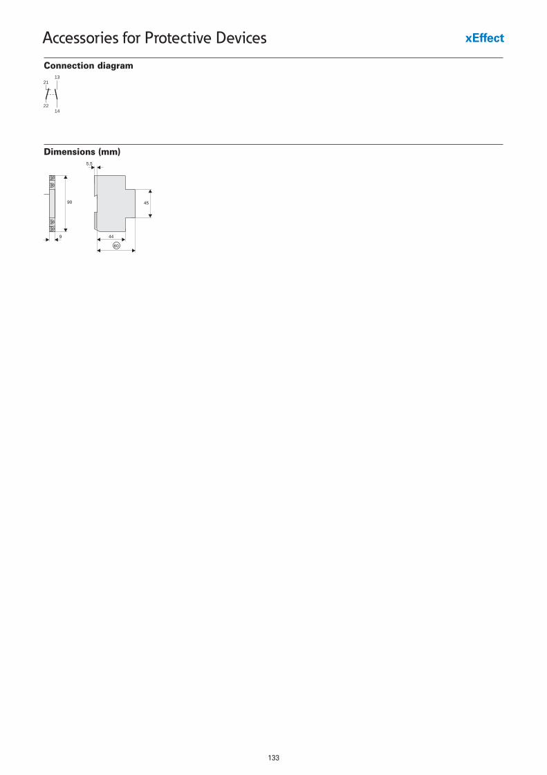
133
Accessories for Protective Devices
Dimensions (mm)
Connection diagram
2113
2214
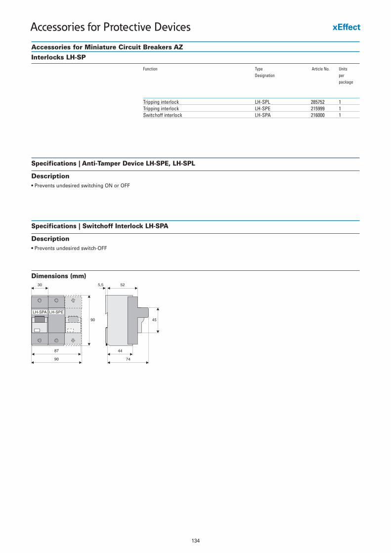
134
Accessories for Protective Devices
Accessories for Miniature Circuit Breakers AZInterlocks LH-SP
Function Type Article No. UnitsDesignation per
package
Tripping interlock LH-SPL 285752 1Tripping interlock LH-SPE 215999 1Switchoff interlock LH-SPA 216000 1
Specifications | Anti-Tamper Device LH-SPE, LH-SPL
Description• Prevents undesired switching ON or OFF
Dimensions (mm)
Specifications | Switchoff Interlock LH-SPA
Description• Prevents undesired switch-OFF
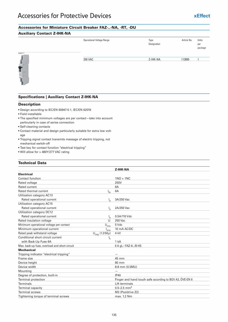
135
Accessories for Protective Devices
Accessories for Miniature Circuit Breaker FAZ-..-NA, -RT, -DUAuxiliary Contact Z-IHK-NA
Operational Voltage Range Type Article No. UnitsDesignation per
package
250 VAC Z-IHK-NA 113895 1
SG60711
Specifications | Auxiliary Contact Z-IHK-NA
Description• Design according to IEC/EN 60947-5-1, IEC/EN 62019• Field installable• The specified minimum voltages are per contact—take into account
particularly in case of series connection• Self-cleaning contacts• Contact material and design particularly suitable for extra low volt-
age• Tripping signal contact transmits message of electric tripping, not
mechanical switch-off• Test key for contact function “electrical tripping”• Will allow for > 480Y/277 VAC rating
Technical Data
Z-IHK-NA
ElectricalContact function 1NO + 1NCRated voltage 250VRated current 6ARated thermal current Ith 6AUtilization category AC13
Rated operational current Ie 3A/250 VacUtilization category AC15
Rated operational current Ie 2A/250 VacUtilization category DC12
Rated operational current Ie 0.5A/110 VdcRated insulation voltage UI 250 VacMinimum operational voltage per contact Umin 5 VdcMinimum operational current Imin 10 mA AC/DCRated peak withstand voltage Uimp (1.2/50µ) 4 kV
I tnerruc tiucric trohs lanoitidnoC kwith Back-Up Fuse 6A 1 kA
Max. back-up fuse, overload and short circuit 6 A gL / FAZ-4/../B-HSMechanicalTripping indicator “electrical tripping” —Frame size 45 mmDevice height 80 mmDevice width 8.8 mm (0.5MU)
— gnitnuoMDegree of protection, built-in IP40Terminal protection Finger and hand touch safe according to BGV A3, ÖVE-EN 6Terminals Lift terminalsTerminal capacity 0.5–2.5 mm2
Terminal screws M3 (Pozidrive Z2)Tightening torque of terminal screws max. 1.2 Nm
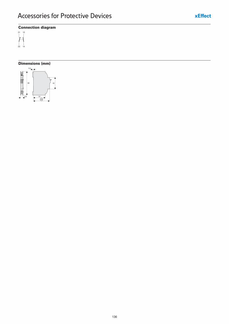
136
Accessories for Protective Devices
Dimensions (mm)
Connection diagram
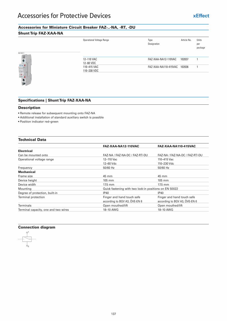
137
Accessories for Protective Devices
Accessories for Miniature Circuit Breaker FAZ-..-NA, -RT, -DUShunt Trip FAZ-XAA-NA
Operational Voltage Range Type Article No. UnitsDesignation per
package
12–110 VAC FAZ-XAA-NA12-110VAC 102037 112–60 VDC
1630201CAV514-011AN-AAX-ZAFCAV 514–011110–230 VDC
SG13511
Specifications | Shunt Trip FAZ-XAA-NA
Description• Remote release for subsequent mounting onto FAZ-NA • Additional installation of standard auxiliary switch is possible • Position indicator red–green
Connection diagram1
2
Technical Data
FAZ-XAA-NA12-110VAC FAZ-XAA-NA110-415VAC
ElectricalCan be mounted onto FAZ-NA / FAZ-NA-DC / FAZ-RT/-DU FAZ-NA / FAZ-NA-DC / FAZ-RT/-DUOperational voltage range 12–110 Vac 110–415 Vac
12–60 Vdc 110–230 VdcFrequency 50/60 Hz 50/60 HzMechanicalFrame size 45 mm 45 mmDevice height 105 mm 105 mmDevice width 17.5 mm 17.5 mmMounting Quick fastening with two lock-in positions on EN 50022Degree of protection, built-in IP40 IP40Terminal protection Finger and hand touch safe
according to BGV A3, ÖVE-EN 6Finger and hand touch safeaccording to BGV A3, ÖVE-EN 6
Terminals Open mouthed/lift Open mouthed/liftTerminal capacity, one and two wires 18–10 AWG 18–10 AWG
138
Accessories for Protective Devices
Terminal Covers
Description Type Article No. UnitsDesignation per
package
Terminal Covers for RCDs2-pole Z-RC/AK-2TE 285385 104-pole Z-RC/AK-4TE 101062 10
Terminal Covers for Add-on Device2-pole Z-CV/AO-2P 221957600 103+4-pole Z-CV/AO-3-4P 221957500 10
Terminal Covers for MCB, RCBO2-pole Z-CV/SD-2P 221954800 103-pole Z-CV/SD-3P 221954900 104-pole Z-CV/SD-4P 221953900 10
Terminal Cover for MCB1-pole Z7-AK-1TE 750754200 10
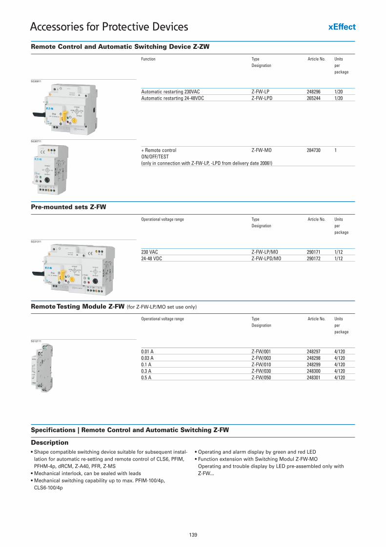
139
Accessories for Protective Devices
Remote Control and Automatic Switching Device Z-ZW
Function Type Article No. UnitsDesignation per
package
Automatic restarting 230VAC Z-FW-LP 248296 1/20Automatic restarting 24-48VDC Z-FW-LPD 265244 1/20
+ Remote control Z-FW-MO 284730 1ON/OFF/TEST(only in connection with Z-FW-LP, -LPD from delivery date 2006!)
SG30811
Specifications | Remote Control and Automatic Switching Z-FW
Description• Shape compatible switching device suitable for subsequent instal-
lation for automatic re-setting and remote control of CLS6, PFIM,PFHM-4p, dRCM, Z-A40, PFR, Z-MS
• Mechanical interlock, can be sealed with leads• Mechanical switching capability up to max. PFIM-100/4p,
CLS6-100/4p
• Operating and alarm display by green and red LED• Function extension with Switching Modul Z-FW-MO
Operating and trouble display by LED pre-assembled only with Z-FW...
Pre-mounted sets Z-FW
Operational voltage range Type Article No. UnitsDesignation per
package
230 VAC Z-FW-LP/MO 290171 1/1224-48 VDC Z-FW-LPD/MO 290172 1/12
SG31311
SG30711
Remote Testing Module Z-FW (for Z-FW-LP./MO set use only)
Operational voltage range Type Article No. UnitsDesignation per
package
0.01 A Z-FW/001 248297 4/1200.03 A Z-FW/003 248298 4/1200.1 A Z-FW/010 248299 4/1200.3 A Z-FW/030 248300 4/1200.5 A Z-FW/050 248301 4/120
SG12111
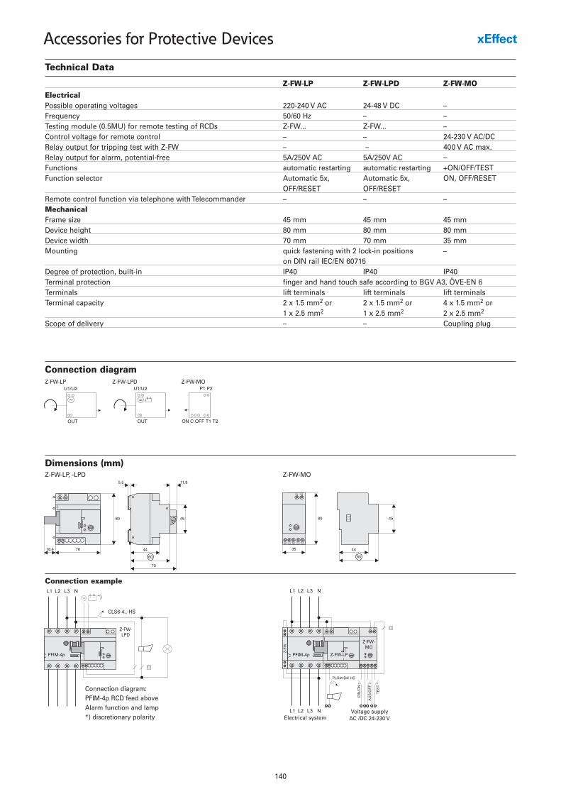
140
Accessories for Protective Devices
Technical Data
Z-FW-LP Z-FW-LPD Z-FW-MO
ElectricalPossible operating voltages 220-240 V AC 24-48 V DC –Frequency 50/60 Hz – –Testing module (0.5MU) for remote testing of RCDs Z-FW... Z-FW... –Control voltage for remote control – – 24-230 V AC/DCRelay output for tripping test with Z-FW – – 400 V AC max.Relay output for alarm, potential-free 5A/250V AC 5A/250V AC –Functions automatic restarting automatic restarting +ON/OFF/TESTFunction selector Automatic 5x, Automatic 5x, ON, OFF/RESET
OFF/RESET OFF/RESETRemote control function via telephone with Telecommander – – –MechanicalFrame size 45 mm 45 mm 45 mmDevice height 80 mm 80 mm 80 mmDevice width 70 mm 70 mm 35 mmMounting quick fastening with 2 lock-in positions –
on DIN rail IEC/EN 60715Degree of protection, built-in IP40 IP40 IP40Terminal protection finger and hand touch safe according to BGV A3, ÖVE-EN 6Terminals lift terminals lift terminals lift terminalsTerminal capacity 2 x 1.5 mm2 or 2 x 1.5 mm2 or 4 x 1.5 mm2 or
1 x 2.5 mm2 1 x 2.5 mm2 2 x 2.5 mm2
Scope of delivery – – Coupling plug
Dimensions (mm)Z-FW-LP, -LPD
Connection example
Connection diagram:PFIM-4p RCD feed aboveAlarm function and lamp*) discretionary polarity
PFIM-4p
Z-FW-LPD
CLS6-4..-HS
Z-FW-MO
PFIM-4p Z-FW-LP
Z-FW-MO
Voltage supplyAC /DC 24-230 VElectrical system
Connection diagramZ-FW-LP Z-FW-LPD Z-FW-MO
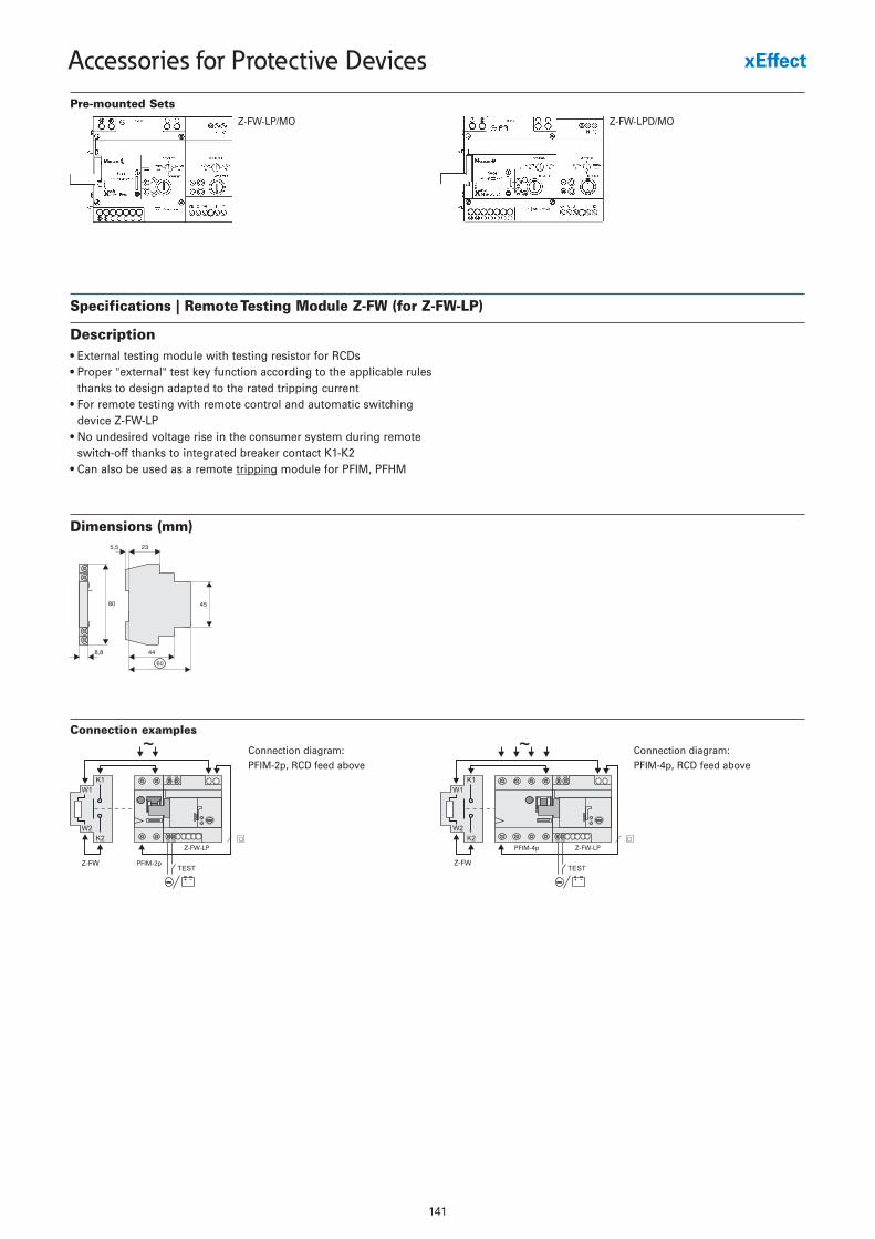
141
Accessories for Protective Devices
Pre-mounted SetsZ-FW-LP/MO Z-FW-LPD/MO
Specifications | Remote Testing Module Z-FW (for Z-FW-LP)
Description• External testing module with testing resistor for RCDs• Proper "external" test key function according to the applicable rules
thanks to design adapted to the rated tripping current• For remote testing with remote control and automatic switching
device Z-FW-LP• No undesired voltage rise in the consumer system during remote
switch-off thanks to integrated breaker contact K1-K2• Can also be used as a remote tripping module for PFIM, PFHM
Dimensions (mm)
Connection examples
Connection diagram: PFIM-2p, RCD feed above
Connection diagram: PFIM-4p, RCD feed above
Z-FW
PFIM-4p Z-FW-LP
Z-FW PFIM-2p
Z-FW-LP
Related Documents