1 CHHATTISGARH SWAMI VIVEKANAND TECHNICAL UNIVERSITY, BHILAI Diploma in EEE Semester : FIFTH S No Board of Study Course Code Course Periods per Week (in hrs) Scheme of Examination Credit L + (T+P) /2 Theory Practical Total Marks ESE CT TA ESE TA L T P 1. EEE 225511 (25) Microprocessor & Microcontroller 4 1 - 100 20 10 - - 130 5 2. ET & T 228511 (28) Instrumentation & Process Control 4 1 - 100 20 20 - - 140 5 3. ET & T 228512 (28) Antenna & Microwave Communication 3 1 - 100 20 20 - - 140 4 4. Electrical 224513 (24) Power Electronics 4 1 - 100 20 10 - - 130 5 5. Electrical 224515 (24) Electrical Machines-II 4 1 - 100 20 10 - - 130 5 6. EEE 225521 (25) Microprocessor & Microcontroller Lab - - 2 - - - 40 20 60 1 7. ET & T 225522 (28) Instrumentation & Process Control Lab - - 2 - - - 40 20 60 1 8. EEE 225523 (25) Antenna & Microwave Communication Lab - - 2 - - - 40 20 60 1 9. Electrical 225524 (24) Power Electronics Lab - - 2 - - - 40 20 60 1 10. Electrical 225525 (24) Electrical Machines-II Lab - - 3 - - - 40 20 60 2 11. EEE 225526 (25) Industrial Training 1 20 10 30 1 Total 19 05 12 500 100 70 220 110 1000 31 L : Lecture hours, T: Tutorial Hours, P : Practical Hours ESE : End of Semester Exam, CT: Class Test, TA: Teachers Assessment *Industrial Training: One month training will be organized after 4 th sem exam and it’s evaluation will be done in 5 th Sem

Welcome message from author
This document is posted to help you gain knowledge. Please leave a comment to let me know what you think about it! Share it to your friends and learn new things together.
Transcript
1
CHHATTISGARH SWAMI VIVEKANAND TECHNICAL UNIVERSITY, BHILAI
Diploma in EEE
Semester : FIFTH
S
No
Board
of Study
Course
Code Course
Periods per
Week
(in hrs)
Scheme of Examination
Credit
L + (T+P)
/2
Theory Practical Total
Marks ESE CT TA ESE TA L T P
1. EEE
225511 (25) Microprocessor &
Microcontroller 4 1 - 100 20 10 - - 130 5
2. ET & T
228511 (28) Instrumentation &
Process Control 4 1 - 100 20 20 - - 140 5
3. ET & T
228512 (28)
Antenna &
Microwave
Communication
3 1 - 100 20 20 - - 140 4
4. Electrical
224513 (24) Power Electronics 4 1 - 100 20 10 - - 130 5
5. Electrical
224515 (24) Electrical Machines-II 4 1 - 100 20 10 - - 130 5
6. EEE
225521 (25) Microprocessor &
Microcontroller Lab - - 2 - - - 40 20 60 1
7. ET & T
225522 (28) Instrumentation &
Process Control Lab - - 2 - - -
40 20 60 1
8. EEE
225523 (25)
Antenna &
Microwave
Communication Lab
- - 2 - - -
40 20 60 1
9. Electrical
225524 (24) Power Electronics
Lab - - 2 - - -
40 20 60 1
10. Electrical
225525 (24) Electrical Machines-II
Lab - - 3 - - -
40 20 60 2
11. EEE
225526 (25) Industrial Training 1 20 10 30 1
Total 19 05 12 500 100 70 220 110 1000 31
L : Lecture hours, T: Tutorial Hours, P : Practical Hours
ESE : End of Semester Exam, CT: Class Test, TA: Teachers Assessment
*Industrial Training: One month training will be organized after 4th sem exam and it’s evaluation will be done in 5th Sem
2
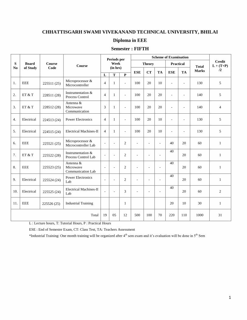
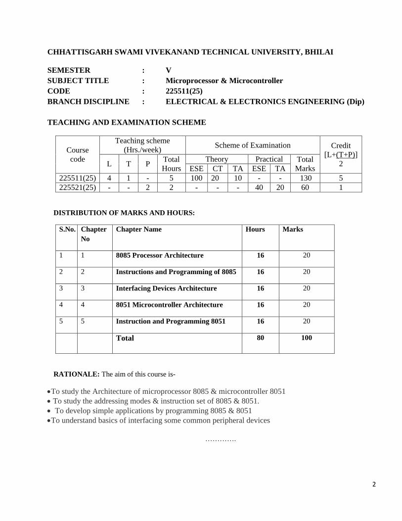
CHHATTISGARH SWAMI VIVEKANAND TECHNICAL UNIVERSITY, BHILAI
SEMESTER : V
SUBJECT TITLE : Microprocessor & Microcontroller
CODE : 225511(25)
BRANCH DISCIPLINE : ELECTRICAL & ELECTRONICS ENGINEERING (Dip)
TEACHING AND EXAMINATION SCHEME
Course
code
Teaching scheme
(Hrs./week) Scheme of Examination Credit
[L+(T+P)]
2 L T P Total
Hours
Theory Practical Total
Marks ESE CT TA ESE TA
225511(25) 4 1 - 5 100 20 10 - - 130 5
225521(25) - - 2 2 - - - 40 20 60 1
DISTRIBUTION OF MARKS AND HOURS:
S.No. Chapter
No
Chapter Name Hours Marks
1 1 8085 Processor Architecture 16 20
2 2 Instructions and Programming of 8085 16 20
3 3 Interfacing Devices Architecture 16 20
4 4 8051 Microcontroller Architecture 16 20
5 5 Instruction and Programming 8051 16 20
Total 80 100
RATIONALE: The aim of this course is-
To study the Architecture of microprocessor 8085 & microcontroller 8051
To study the addressing modes & instruction set of 8085 & 8051.
To develop simple applications by programming 8085 & 8051
To understand basics of interfacing some common peripheral devices
………….
3
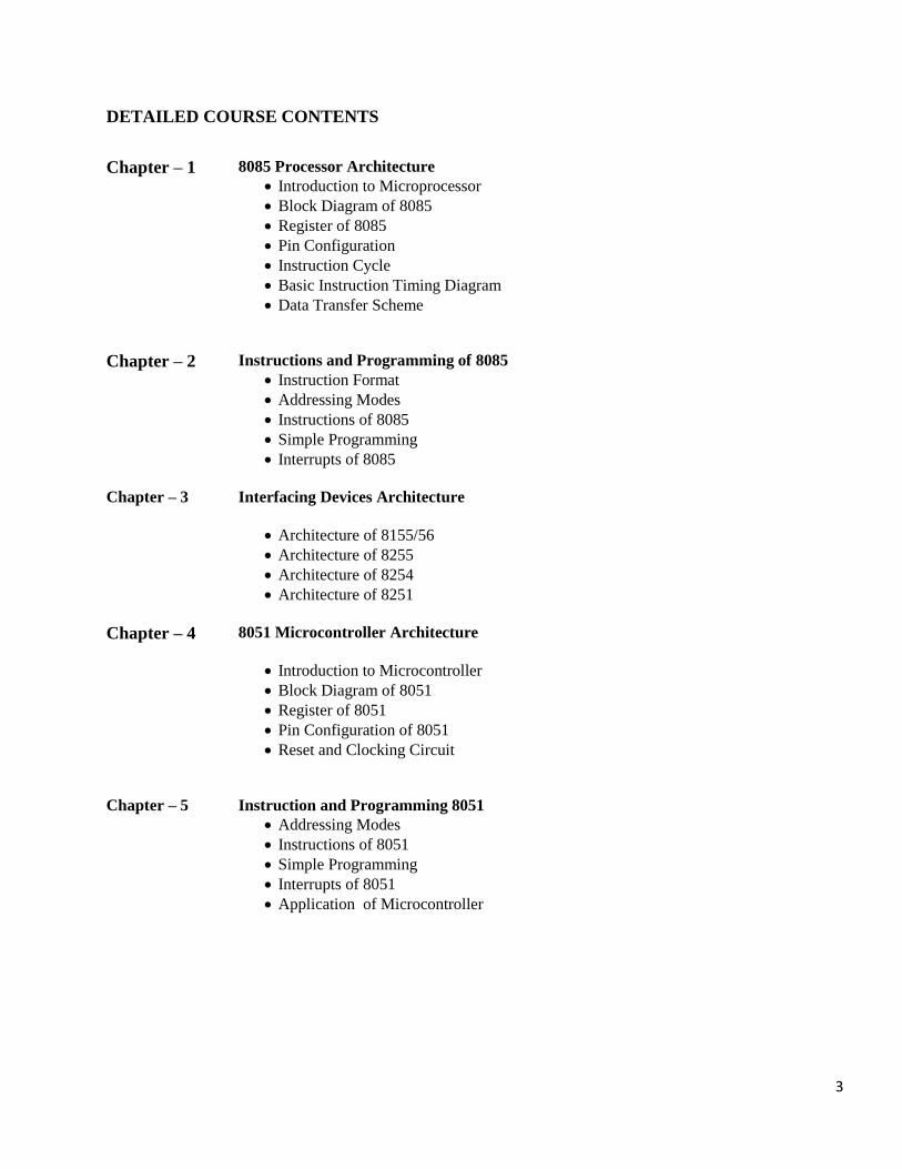
DETAILED COURSE CONTENTS
Chapter – 1 8085 Processor Architecture
Introduction to Microprocessor
Block Diagram of 8085
Register of 8085
Pin Configuration
Instruction Cycle
Basic Instruction Timing Diagram
Data Transfer Scheme
Chapter – 2 Instructions and Programming of 8085
Instruction Format
Addressing Modes
Instructions of 8085
Simple Programming
Interrupts of 8085
Chapter – 3 Interfacing Devices Architecture
Architecture of 8155/56
Architecture of 8255
Architecture of 8254
Architecture of 8251
Chapter – 4 8051 Microcontroller Architecture
Introduction to Microcontroller
Block Diagram of 8051
Register of 8051
Pin Configuration of 8051
Reset and Clocking Circuit
Chapter – 5 Instruction and Programming 8051
Addressing Modes
Instructions of 8051
Simple Programming
Interrupts of 8051
Application of Microcontroller
4
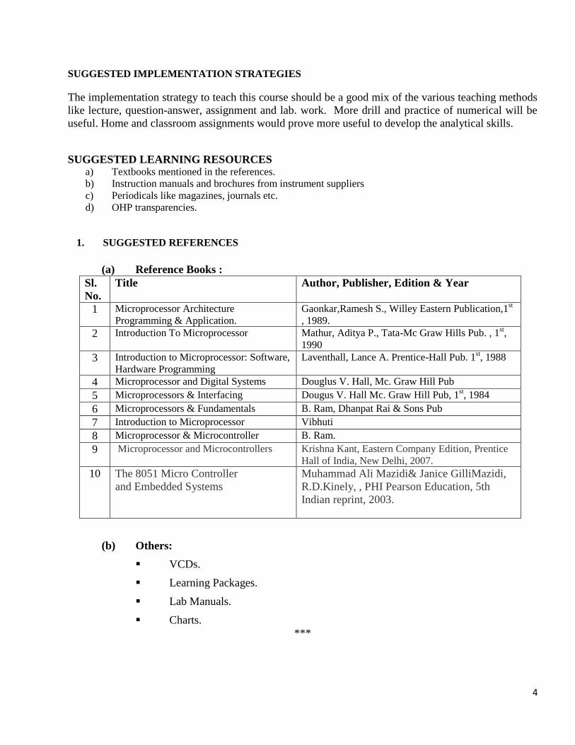
SUGGESTED IMPLEMENTATION STRATEGIES
The implementation strategy to teach this course should be a good mix of the various teaching methods
like lecture, question-answer, assignment and lab. work. More drill and practice of numerical will be
useful. Home and classroom assignments would prove more useful to develop the analytical skills.
SUGGESTED LEARNING RESOURCES a) Textbooks mentioned in the references.
b) Instruction manuals and brochures from instrument suppliers
c) Periodicals like magazines, journals etc.
d) OHP transparencies.
1. SUGGESTED REFERENCES
(a) Reference Books :
Sl.
No.
Title Author, Publisher, Edition & Year
1 Microprocessor Architecture
Programming & Application.
Gaonkar,Ramesh S., Willey Eastern Publication,1st
, 1989.
2 Introduction To Microprocessor Mathur, Aditya P., Tata-Mc Graw Hills Pub. , 1st,
1990
3 Introduction to Microprocessor: Software,
Hardware Programming
Laventhall, Lance A. Prentice-Hall Pub. 1st, 1988
4 Microprocessor and Digital Systems Douglus V. Hall, Mc. Graw Hill Pub
5 Microprocessors & Interfacing Dougus V. Hall Mc. Graw Hill Pub, 1st, 1984
6 Microprocessors & Fundamentals B. Ram, Dhanpat Rai & Sons Pub
7 Introduction to Microprocessor Vibhuti
8 Microprocessor & Microcontroller B. Ram.
9 Microprocessor and Microcontrollers
Krishna Kant, Eastern Company Edition, Prentice
Hall of India, New Delhi, 2007.
10 The 8051 Micro Controller
and Embedded Systems
Muhammad Ali Mazidi& Janice GilliMazidi,
R.D.Kinely, , PHI Pearson Education, 5th
Indian reprint, 2003.
(b) Others:
VCDs.
Learning Packages.
Lab Manuals.
Charts.
***
5
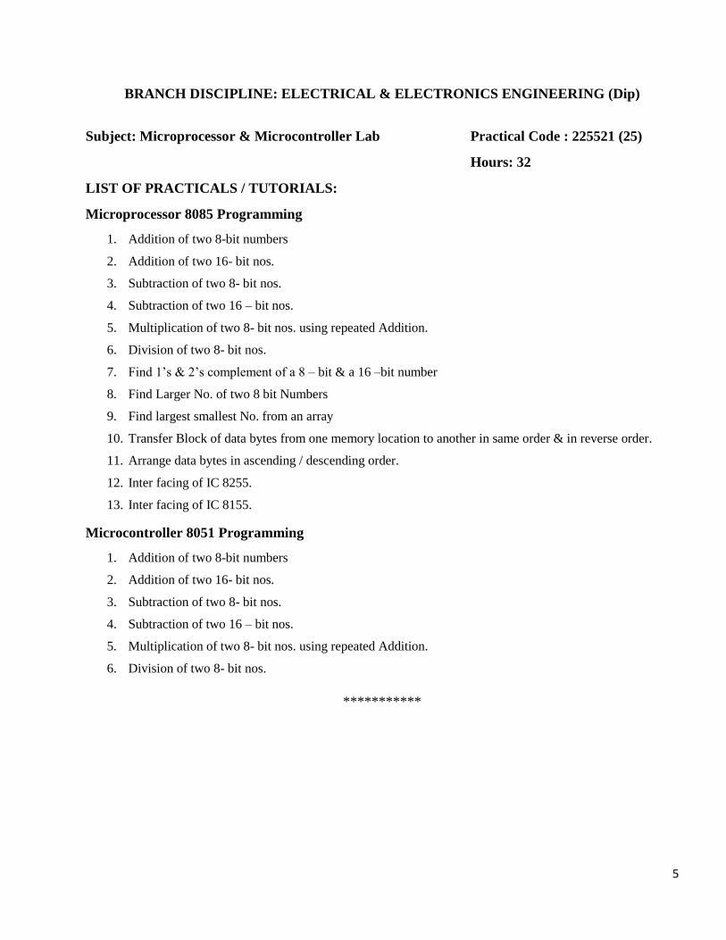
BRANCH DISCIPLINE: ELECTRICAL & ELECTRONICS ENGINEERING (Dip)
Subject: Microprocessor & Microcontroller Lab Practical Code : 225521 (25)
Hours: 32
LIST OF PRACTICALS / TUTORIALS:
Microprocessor 8085 Programming
1. Addition of two 8-bit numbers
2. Addition of two 16- bit nos.
3. Subtraction of two 8- bit nos.
4. Subtraction of two 16 – bit nos.
5. Multiplication of two 8- bit nos. using repeated Addition.
6. Division of two 8- bit nos.
7. Find 1’s & 2’s complement of a 8 – bit & a 16 –bit number
8. Find Larger No. of two 8 bit Numbers
9. Find largest smallest No. from an array
10. Transfer Block of data bytes from one memory location to another in same order & in reverse order.
11. Arrange data bytes in ascending / descending order.
12. Inter facing of IC 8255.
13. Inter facing of IC 8155.
Microcontroller 8051 Programming
1. Addition of two 8-bit numbers
2. Addition of two 16- bit nos.
3. Subtraction of two 8- bit nos.
4. Subtraction of two 16 – bit nos.
5. Multiplication of two 8- bit nos. using repeated Addition.
6. Division of two 8- bit nos.
***********
6
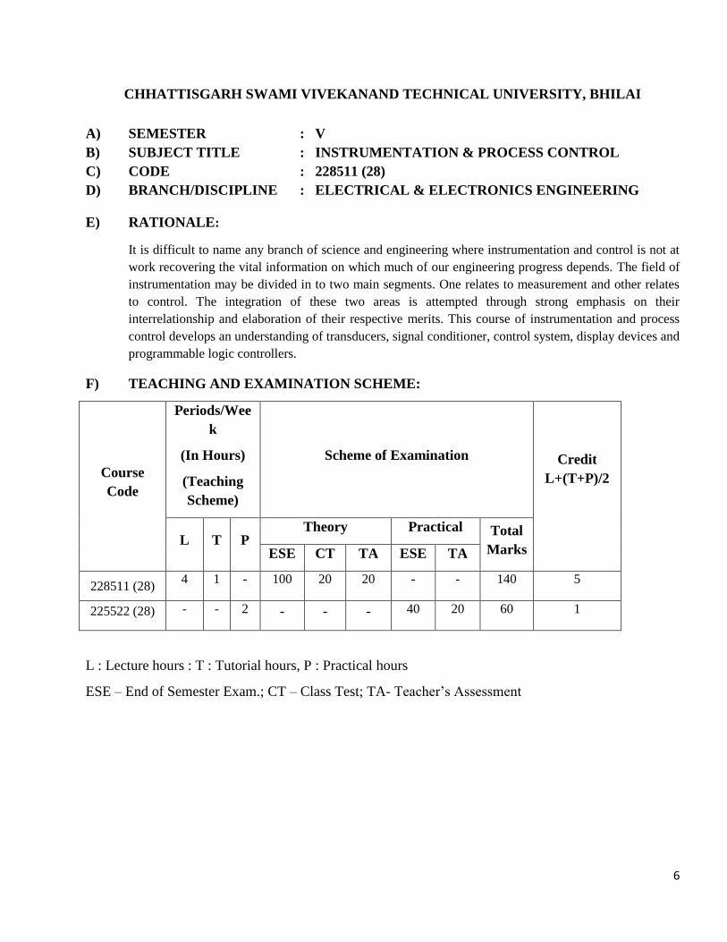
CHHATTISGARH SWAMI VIVEKANAND TECHNICAL UNIVERSITY, BHILAI
A) SEMESTER : V
B) SUBJECT TITLE : INSTRUMENTATION & PROCESS CONTROL
C) CODE : 228511 (28)
D) BRANCH/DISCIPLINE : ELECTRICAL & ELECTRONICS ENGINEERING
E) RATIONALE:
It is difficult to name any branch of science and engineering where instrumentation and control is not at
work recovering the vital information on which much of our engineering progress depends. The field of
instrumentation may be divided in to two main segments. One relates to measurement and other relates
to control. The integration of these two areas is attempted through strong emphasis on their
interrelationship and elaboration of their respective merits. This course of instrumentation and process
control develops an understanding of transducers, signal conditioner, control system, display devices and
programmable logic controllers.
F) TEACHING AND EXAMINATION SCHEME:
Course
Code
Periods/Wee
k
(In Hours)
(Teaching
Scheme)
Scheme of Examination Credit
L+(T+P)/2
L T P Theory Practical Total
Marks ESE CT TA ESE TA
228511 (28) 4 1 - 100 20 20 - - 140 5
225522 (28) - - 2 - - - 40 20 60 1
L : Lecture hours : T : Tutorial hours, P : Practical hours
ESE – End of Semester Exam.; CT – Class Test; TA- Teacher’s Assessment
7
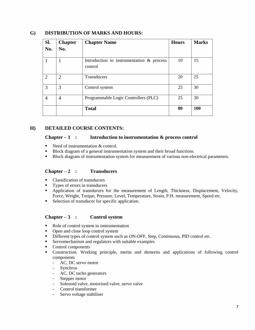
G) DISTRIBUTION OF MARKS AND HOURS:
Sl.
No.
Chapter
No.
Chapter Name Hours Marks
1 1 Introduction to instrumentation & process
control
10 15
2 2 Transducers 20 25
3 3 Control system 25 30
4 4 Programmable Logic Controllers (PLC) 25 30
Total 80 100
H) DETAILED COURSE CONTENTS:
Chapter – 1 : Introduction to instrumentation & process control
Need of instrumentation & control.
Block diagram of a general instrumentation system and their broad functions
Block diagram of instrumentation system for measurement of various non-electrical parameters.
Chapter – 2 : Transducers
Classification of transducers
Types of errors in transducers
Application of transducers for the measurement of Length, Thickness, Displacement, Velocity,
Force, Weight, Torque, Pressure, Level, Temperature, Strain, P.H. measurement, Speed etc.
Selection of transducer for specific application.
Chapter – 3 : Control system
Role of control system in instrumentation
Open and close loop control system
Different types of control system such as ON-OFF, Step, Continuous, PID control etc.
Servomechanism and regulators with suitable examples
Control components
Construction. Working principle, merits and demerits and applications of following control
components
- AC, DC servo motor
- Synchros
- AC, DC tacho generators
- Stepper motor
- Solenoid valve, motorized valve, servo valve
- Control transformer
- Servo voltage stabiliser
8
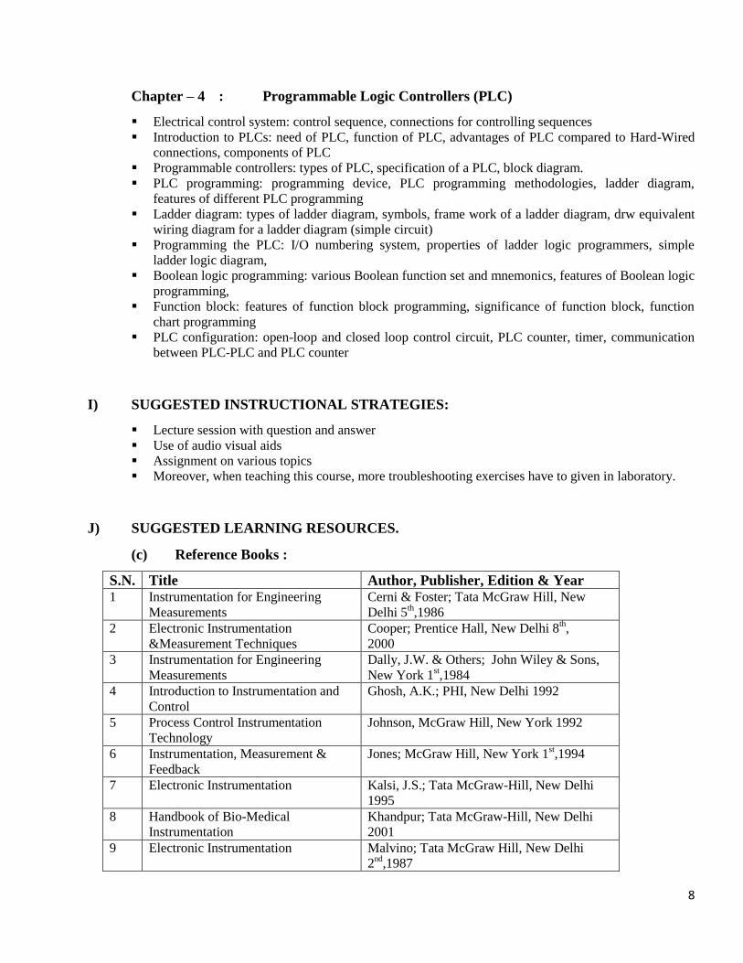
Chapter – 4 : Programmable Logic Controllers (PLC)
Electrical control system: control sequence, connections for controlling sequences
Introduction to PLCs: need of PLC, function of PLC, advantages of PLC compared to Hard-Wired
connections, components of PLC
Programmable controllers: types of PLC, specification of a PLC, block diagram.
PLC programming: programming device, PLC programming methodologies, ladder diagram,
features of different PLC programming
Ladder diagram: types of ladder diagram, symbols, frame work of a ladder diagram, drw equivalent
wiring diagram for a ladder diagram (simple circuit)
Programming the PLC: I/O numbering system, properties of ladder logic programmers, simple
ladder logic diagram,
Boolean logic programming: various Boolean function set and mnemonics, features of Boolean logic
programming,
Function block: features of function block programming, significance of function block, function
chart programming
PLC configuration: open-loop and closed loop control circuit, PLC counter, timer, communication
between PLC-PLC and PLC counter
I) SUGGESTED INSTRUCTIONAL STRATEGIES:
Lecture session with question and answer
Use of audio visual aids
Assignment on various topics
Moreover, when teaching this course, more troubleshooting exercises have to given in laboratory.
J) SUGGESTED LEARNING RESOURCES.
(c) Reference Books :
S.N. Title Author, Publisher, Edition & Year 1 Instrumentation for Engineering
Measurements
Cerni & Foster; Tata McGraw Hill, New
Delhi 5th,1986
2 Electronic Instrumentation
&Measurement Techniques
Cooper; Prentice Hall, New Delhi 8th,
2000
3 Instrumentation for Engineering
Measurements
Dally, J.W. & Others; John Wiley & Sons,
New York 1st,1984
4 Introduction to Instrumentation and
Control
Ghosh, A.K.; PHI, New Delhi 1992
5 Process Control Instrumentation
Technology
Johnson, McGraw Hill, New York 1992
6 Instrumentation, Measurement &
Feedback
Jones; McGraw Hill, New York 1st,1994
7 Electronic Instrumentation Kalsi, J.S.; Tata McGraw-Hill, New Delhi
1995
8 Handbook of Bio-Medical
Instrumentation
Khandpur; Tata McGraw-Hill, New Delhi
2001
9 Electronic Instrumentation Malvino; Tata McGraw Hill, New Delhi
2nd
,1987
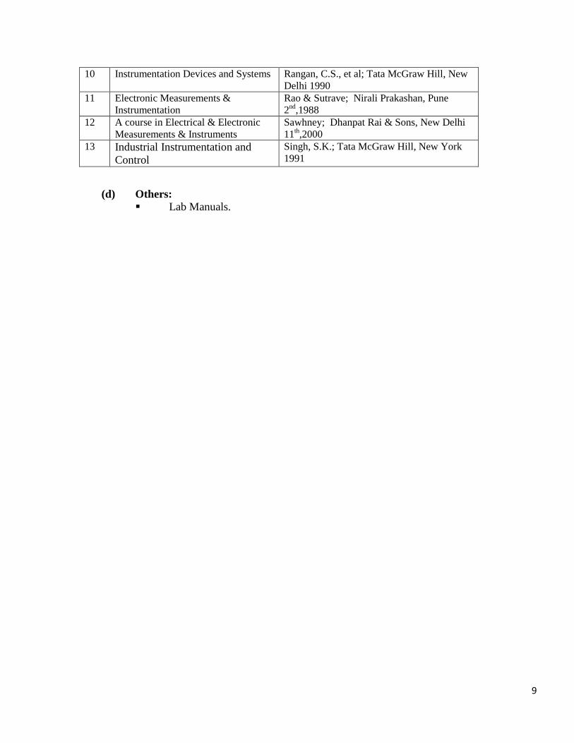
9
10 Instrumentation Devices and Systems Rangan, C.S., et al; Tata McGraw Hill, New
Delhi 1990
11 Electronic Measurements &
Instrumentation
Rao & Sutrave; Nirali Prakashan, Pune
2nd
,1988
12 A course in Electrical & Electronic
Measurements & Instruments
Sawhney; Dhanpat Rai & Sons, New Delhi
11th,2000
13 Industrial Instrumentation and
Control
Singh, S.K.; Tata McGraw Hill, New York
1991
(d) Others:
Lab Manuals.
10
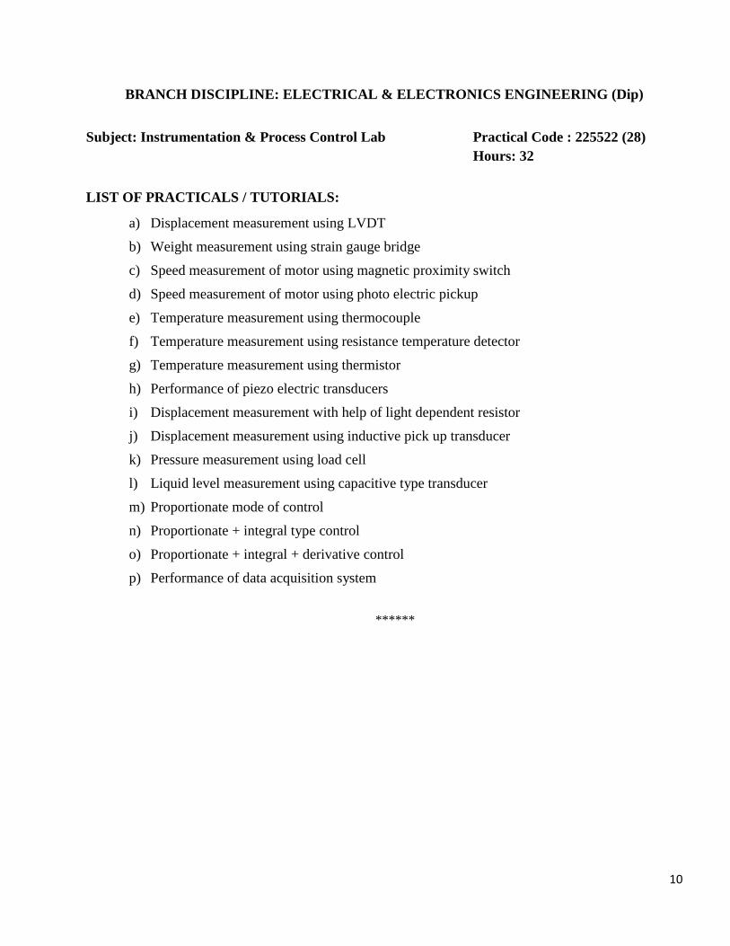
BRANCH DISCIPLINE: ELECTRICAL & ELECTRONICS ENGINEERING (Dip)
Subject: Instrumentation & Process Control Lab Practical Code : 225522 (28)
Hours: 32
LIST OF PRACTICALS / TUTORIALS:
a) Displacement measurement using LVDT
b) Weight measurement using strain gauge bridge
c) Speed measurement of motor using magnetic proximity switch
d) Speed measurement of motor using photo electric pickup
e) Temperature measurement using thermocouple
f) Temperature measurement using resistance temperature detector
g) Temperature measurement using thermistor
h) Performance of piezo electric transducers
i) Displacement measurement with help of light dependent resistor
j) Displacement measurement using inductive pick up transducer
k) Pressure measurement using load cell
l) Liquid level measurement using capacitive type transducer
m) Proportionate mode of control
n) Proportionate + integral type control
o) Proportionate + integral + derivative control
p) Performance of data acquisition system
******
11
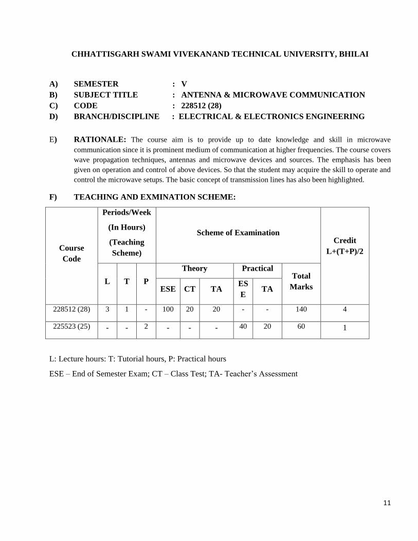
CHHATTISGARH SWAMI VIVEKANAND TECHNICAL UNIVERSITY, BHILAI
A) SEMESTER : V
B) SUBJECT TITLE : ANTENNA & MICROWAVE COMMUNICATION
C) CODE : 228512 (28)
D) BRANCH/DISCIPLINE : ELECTRICAL & ELECTRONICS ENGINEERING
E) RATIONALE: The course aim is to provide up to date knowledge and skill in microwave
communication since it is prominent medium of communication at higher frequencies. The course covers
wave propagation techniques, antennas and microwave devices and sources. The emphasis has been
given on operation and control of above devices. So that the student may acquire the skill to operate and
control the microwave setups. The basic concept of transmission lines has also been highlighted.
F) TEACHING AND EXMINATION SCHEME:
Course
Code
Periods/Week
(In Hours)
(Teaching
Scheme)
Scheme of Examination Credit
L+(T+P)/2
L T P
Theory Practical Total
Marks ESE CT TA ES
E TA
228512 (28) 3 1 - 100 20 20 - - 140 4
225523 (25) - - 2 - - - 40 20 60 1
L: Lecture hours: T: Tutorial hours, P: Practical hours
ESE – End of Semester Exam; CT – Class Test; TA- Teacher’s Assessment
12
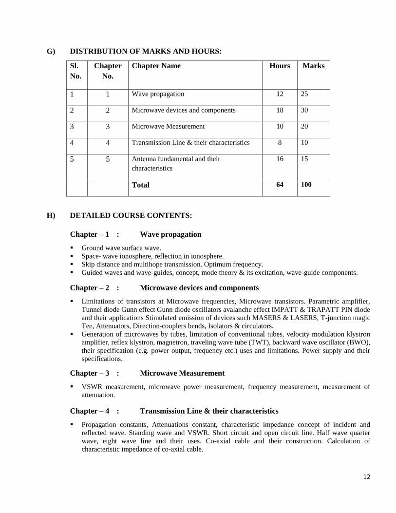
G) DISTRIBUTION OF MARKS AND HOURS:
Sl.
No.
Chapter
No.
Chapter Name Hours Marks
1 1 Wave propagation 12 25
2 2 Microwave devices and components 18 30
3 3 Microwave Measurement 10 20
4 4 Transmission Line & their characteristics 8 10
5 5 Antenna fundamental and their
characteristics
16 15
Total 64 100
H) DETAILED COURSE CONTENTS:
Chapter – 1 : Wave propagation
Ground wave surface wave.
Space- wave ionosphere, reflection in ionosphere.
Skip distance and multihope transmission. Optimum frequency.
Guided waves and wave-guides, concept, mode theory & its excitation, wave-guide components.
Chapter – 2 : Microwave devices and components
Limitations of transistors at Microwave frequencies, Microwave transistors. Parametric amplifier,
Tunnel diode Gunn effect Gunn diode oscillators avalanche effect IMPATT & TRAPATT PIN diode
and their applications Stimulated emission of devices such MASERS & LASERS, T-junction magic
Tee, Attenuators, Direction-couplers bends, Isolators & circulators.
Generation of microwaves by tubes, limitation of conventional tubes, velocity modulation klystron
amplifier, reflex klystron, magnetron, traveling wave tube (TWT), backward wave oscillator (BWO),
their specification (e.g. power output, frequency etc.) uses and limitations. Power supply and their
specifications.
Chapter – 3 : Microwave Measurement
VSWR measurement, microwave power measurement, frequency measurement, measurement of
attenuation.
Chapter – 4 : Transmission Line & their characteristics
Propagation constants, Attenuations constant, characteristic impedance concept of incident and
reflected wave. Standing wave and VSWR. Short circuit and open circuit line. Half wave quarter
wave, eight wave line and their uses. Co-axial cable and their construction. Calculation of
characteristic impedance of co-axial cable.
13
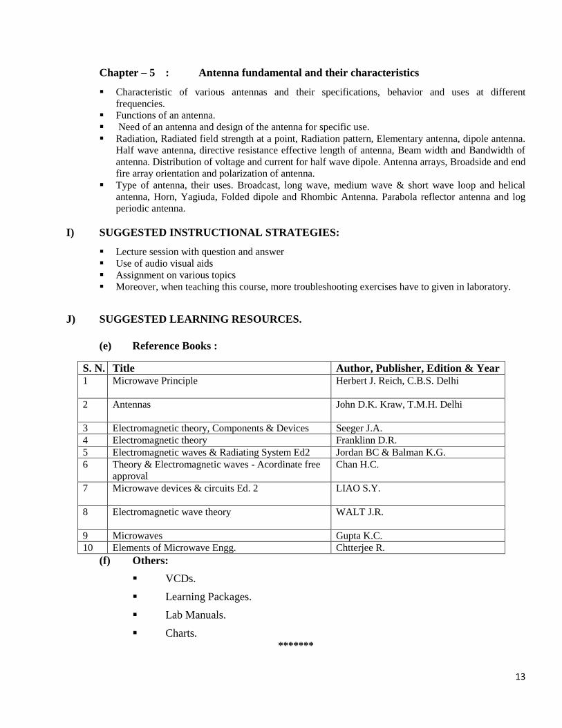
Chapter – 5 : Antenna fundamental and their characteristics
Characteristic of various antennas and their specifications, behavior and uses at different
frequencies.
Functions of an antenna.
Need of an antenna and design of the antenna for specific use.
Radiation, Radiated field strength at a point, Radiation pattern, Elementary antenna, dipole antenna.
Half wave antenna, directive resistance effective length of antenna, Beam width and Bandwidth of
antenna. Distribution of voltage and current for half wave dipole. Antenna arrays, Broadside and end
fire array orientation and polarization of antenna.
Type of antenna, their uses. Broadcast, long wave, medium wave & short wave loop and helical
antenna, Horn, Yagiuda, Folded dipole and Rhombic Antenna. Parabola reflector antenna and log
periodic antenna.
I) SUGGESTED INSTRUCTIONAL STRATEGIES:
Lecture session with question and answer
Use of audio visual aids
Assignment on various topics
Moreover, when teaching this course, more troubleshooting exercises have to given in laboratory.
J) SUGGESTED LEARNING RESOURCES.
(e) Reference Books :
S. N. Title Author, Publisher, Edition & Year 1 Microwave Principle
Herbert J. Reich, C.B.S. Delhi
2 Antennas
John D.K. Kraw, T.M.H. Delhi
3 Electromagnetic theory, Components & Devices Seeger J.A.
4 Electromagnetic theory Franklinn D.R.
5 Electromagnetic waves & Radiating System Ed2 Jordan BC & Balman K.G.
6 Theory & Electromagnetic waves - Acordinate free
approval
Chan H.C.
7 Microwave devices & circuits Ed. 2
LIAO S.Y.
8 Electromagnetic wave theory
WALT J.R.
9 Microwaves Gupta K.C.
10 Elements of Microwave Engg. Chtterjee R.
(f) Others:
VCDs.
Learning Packages.
Lab Manuals.
Charts. *******
14
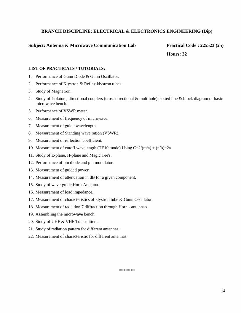
BRANCH DISCIPLINE: ELECTRICAL & ELECTRONICS ENGINEERING (Dip)
Subject: Antenna & Microwave Communication Lab Practical Code : 225523 (25)
Hours: 32
LIST OF PRACTICALS / TUTORIALS:
1. Performance of Gunn Diode & Gunn Oscillator.
2. Performance of Klystron & Reflex klystron tubes.
3. Study of Magnetron.
4. Study of Isolators, directional couplers (cross directional & multihole) slotted line & block diagram of basic
microwave bench.
5. Performance of VSWR meter.
6. Measurement of frequency of microwave.
7. Measurement of guide wavelength.
8. Measurement of Standing wave ration (VSWR).
9. Measurement of reflection coefficient.
10. Measurement of cutoff wavelength (TE10 mode) Using C=2/(m/a) + (n/b)=2a.
11. Study of E-plane, H-plane and Magic Tee's.
12. Performance of pin diode and pin modulator.
13. Measurement of guided power.
14. Measurement of attenuation in dB for a given component.
15. Study of wave-guide Horn-Antenna.
16. Measurement of load impedance.
17. Measurement of characteristics of klystron tube & Gunn Oscillator.
18. Measurement of radiation 7 diffraction through Horn - antenna's.
19. Assembling the microwave bench.
20. Study of UHF & VHF Transmitters.
21. Study of radiation pattern for different antennas.
22. Measurement of characteristic for different antennas.
*******
15
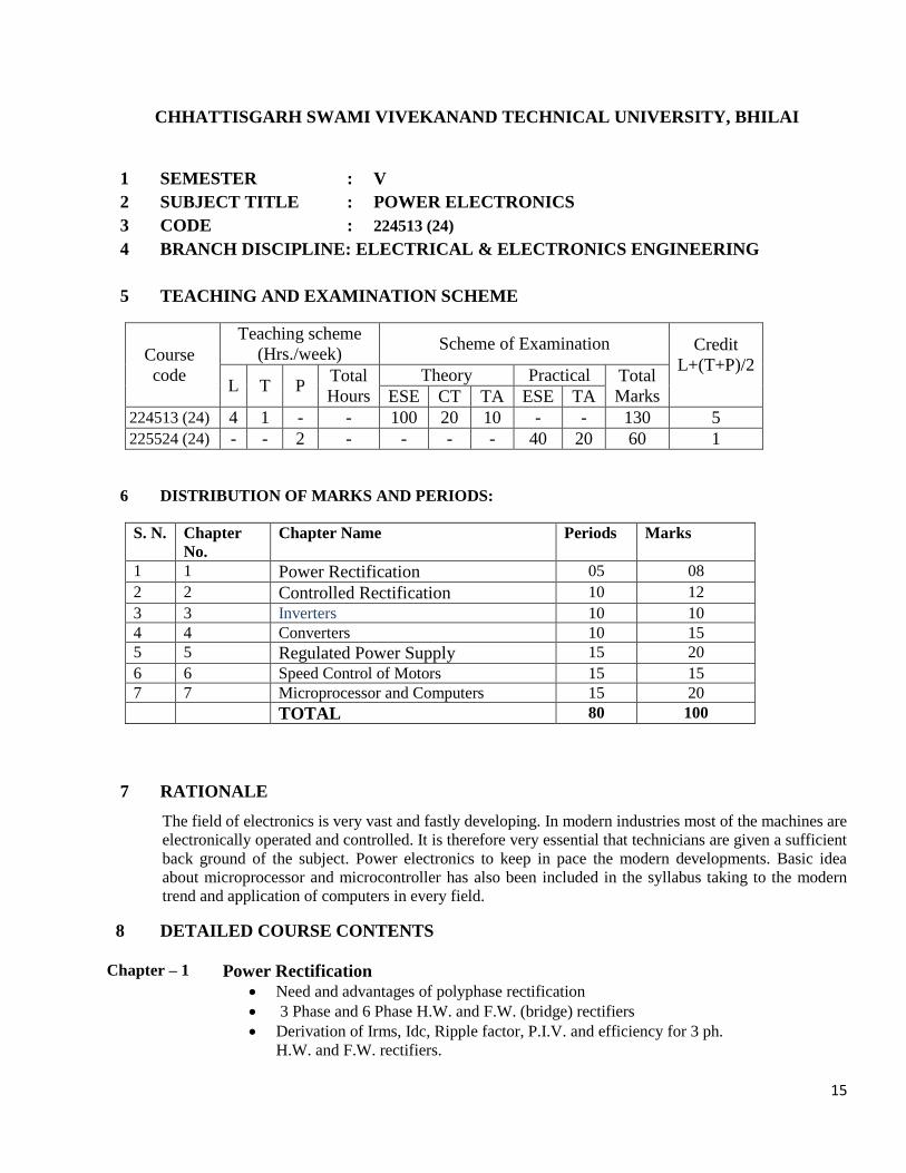
CHHATTISGARH SWAMI VIVEKANAND TECHNICAL UNIVERSITY, BHILAI
1 SEMESTER : V
2 SUBJECT TITLE : POWER ELECTRONICS
3 CODE : 224513 (24)
4 BRANCH DISCIPLINE: ELECTRICAL & ELECTRONICS ENGINEERING
5 TEACHING AND EXAMINATION SCHEME
Course
code
Teaching scheme
(Hrs./week) Scheme of Examination Credit
L+(T+P)/2
L T P Total
Hours
Theory Practical Total
Marks ESE CT TA ESE TA
224513 (24) 4 1 - - 100 20 10 - - 130 5
225524 (24) - - 2 - - - - 40 20 60 1
6 DISTRIBUTION OF MARKS AND PERIODS:
S. N. Chapter
No.
Chapter Name Periods Marks
1 1 Power Rectification 05 08
2 2 Controlled Rectification 10 12
3 3 Inverters 10 10
4 4 Converters 10 15
5 5 Regulated Power Supply 15 20
6 6 Speed Control of Motors 15 15
7 7 Microprocessor and Computers 15 20
TOTAL 80 100
7 RATIONALE
The field of electronics is very vast and fastly developing. In modern industries most of the machines are
electronically operated and controlled. It is therefore very essential that technicians are given a sufficient
back ground of the subject. Power electronics to keep in pace the modern developments. Basic idea
about microprocessor and microcontroller has also been included in the syllabus taking to the modern
trend and application of computers in every field.
8 DETAILED COURSE CONTENTS
Chapter – 1 Power Rectification
Need and advantages of polyphase rectification
3 Phase and 6 Phase H.W. and F.W. (bridge) rectifiers
Derivation of Irms, Idc, Ripple factor, P.I.V. and efficiency for 3 ph.
H.W. and F.W. rectifiers.
16
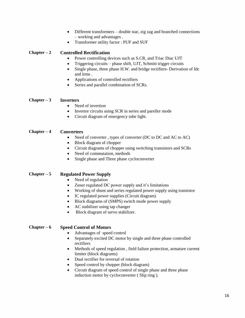
Different transformers – double star, zig zag and branched connections
– working and advantages .
Transformer utility factor : PUF and SUF
Chapter – 2 Controlled Rectification
Power controlling devices such as S.CR, and Triac Diac UJT
Triggering circuits – phase shift, UJT, Schmitt trigger circuits
Single phase, three phase H.W. and bridge rectifiers- Derivation of Idc
and Irms .
Applications of controlled rectifiers
Series and parallel combination of SCRs.
Chapter – 3 Inverters
Need of invertion
Invertor circuits using SCR in series and pareller mode
Circuit diagram of emergency tube light.
Chapter – 4 Converters
Need of converter , types of converter (DC to DC and AC to AC)
Block diagram of chopper
Circuit diagrams of chopper using switching transistors and SCRs
Need of commutation, methods
Single phase and Three phase cycloconverter
Chapter – 5 Regulated Power Supply
Need of regulation
Zener regulated DC power supply and it’s limitations
Working of shunt and series regulated power supply using transistor
IC regulated power supplies (Circuit diagram)
Block diagrams of (SMPS) switch mode power supply
AC stabilizer using tap changer
Block diagram of servo stabilizer.
Chapter – 6 Speed Control of Motors
Advantages of speed control
Separately excited DC motor by single and three phase controlled
rectifiers
Methods of speed regulation , field failure protection, armature current
limiter (block diagrams)
Dual rectifier for reversal of rotation
Speed control by chopper (block diagram)
Circuit diagram of speed control of single phase and three phase
induction motor by cycloconverter ( Slip ring ).
17
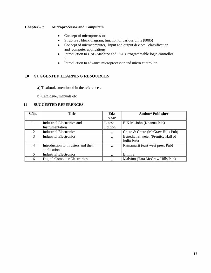
Chapter – 7 Microprocessor and Computers
Concept of microprocessor
Structure , block diagram, function of various units (8085)
Concept of microcomputer, Input and output devices , classification
and computer applications
Introduction to CNC Machine and PLC (Programmable logic controller
)
Introduction to advance microprocessor and micro controller
10 SUGGESTED LEARNING RESOURCES
a) Textbooks mentioned in the references.
b) Catalogue, manuals etc.
11 SUGGESTED REFERENCES
S.No. Title Ed./
Year
Author/ Publisher
1 Industrial Electronics and
Instrumentation
Latest
Edition
B.K.M. John (Khanna Pub)
2 Industrial Electronics ,, Chute & Chute (McGraw Hills Pub)
3 Industrial Electronics ,, Benedict & weier (Prentice Hall of
India Pub)
4 Introduction to thrusters and their
applications
,, Ramamurti (east west press Pub)
5 Industrial Electronics ,, Bhimra
6 Digital Computer Electronics ,, Malvino (Tata McGraw Hills Pub)
18
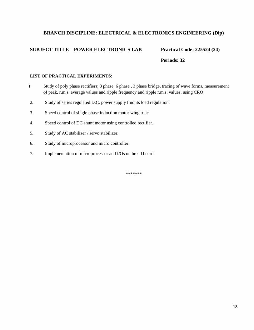
BRANCH DISCIPLINE: ELECTRICAL & ELECTRONICS ENGINEERING (Dip)
SUBJECT TITLE – POWER ELECTRONICS LAB Practical Code: 225524 (24)
Periods: 32
LIST OF PRACTICAL EXPERIMENTS:
1. Study of poly phase rectifiers; 3 phase, 6 phase , 3 phase bridge, tracing of wave forms, measurement
of peak, r.m.s. average values and ripple frequency and ripple r.m.s. values, using CRO
2. Study of series regulated D.C. power supply find its load regulation.
3. Speed control of single phase induction motor wing triac.
4. Speed control of DC shunt motor using controlled rectifier.
5. Study of AC stabilizer / servo stabilizer.
6. Study of microprocessor and micro controller.
7. Implementation of microprocessor and I/Os on bread board.
*******
19
CHHATTISGARH SWAMI VIVEKANAND TECHNICAL UNIVERSITY, BHILAI
1 SEMESTER : V
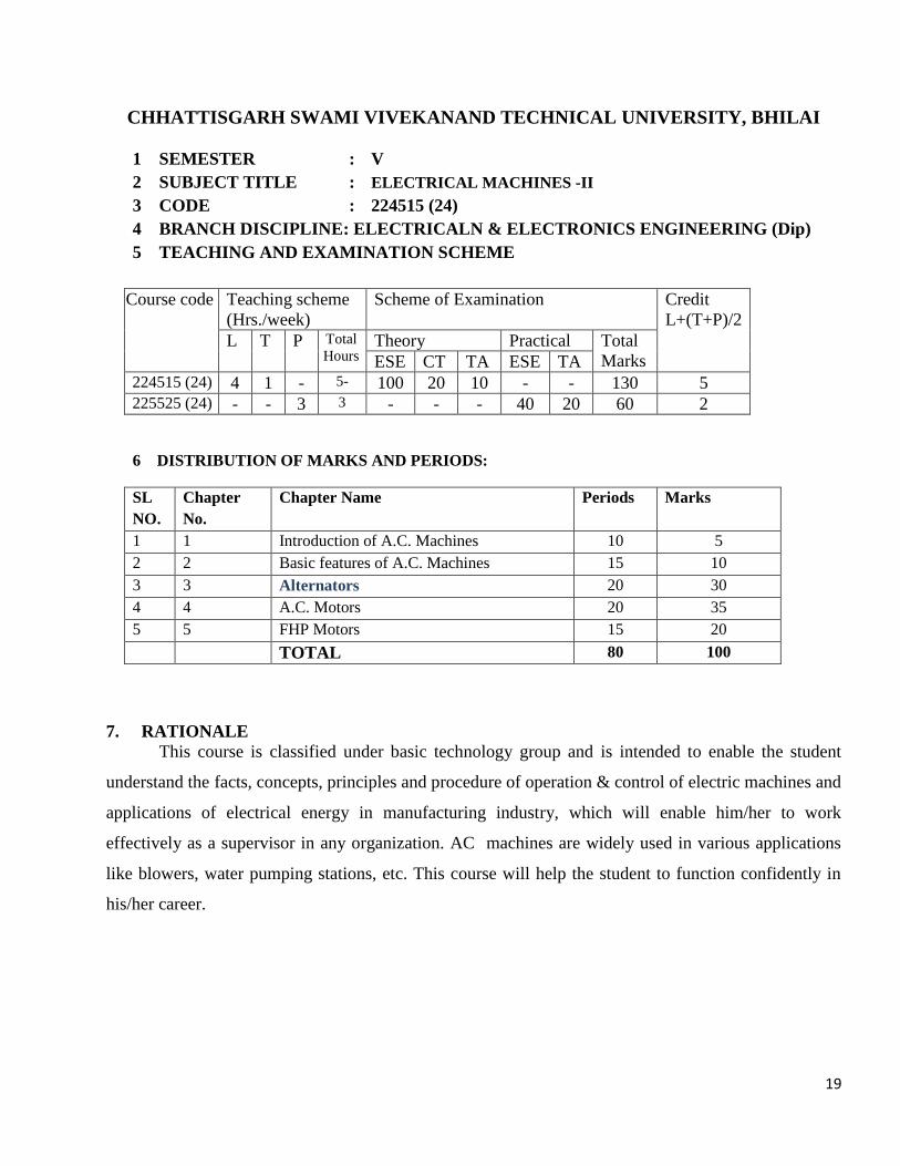
2 SUBJECT TITLE : ELECTRICAL MACHINES -II
3 CODE : 224515 (24)
4 BRANCH DISCIPLINE: ELECTRICALN & ELECTRONICS ENGINEERING (Dip)
5 TEACHING AND EXAMINATION SCHEME
Course code Teaching scheme
(Hrs./week)
Scheme of Examination Credit
L+(T+P)/2
L T P Total
Hours Theory Practical Total
Marks ESE CT TA ESE TA 224515 (24) 4 1 - 5- 100 20 10 - - 130 5 225525 (24) - - 3 3 - - - 40 20 60 2
6 DISTRIBUTION OF MARKS AND PERIODS:
SL
NO.
Chapter
No.
Chapter Name Periods Marks
1 1 Introduction of A.C. Machines 10 5
2 2 Basic features of A.C. Machines 15 10
3 3 Alternators 20 30
4 4 A.C. Motors 20 35
5 5 FHP Motors 15 20
TOTAL 80 100
7. RATIONALE
This course is classified under basic technology group and is intended to enable the student
understand the facts, concepts, principles and procedure of operation & control of electric machines and
applications of electrical energy in manufacturing industry, which will enable him/her to work
effectively as a supervisor in any organization. AC machines are widely used in various applications
like blowers, water pumping stations, etc. This course will help the student to function confidently in
his/her career.
20
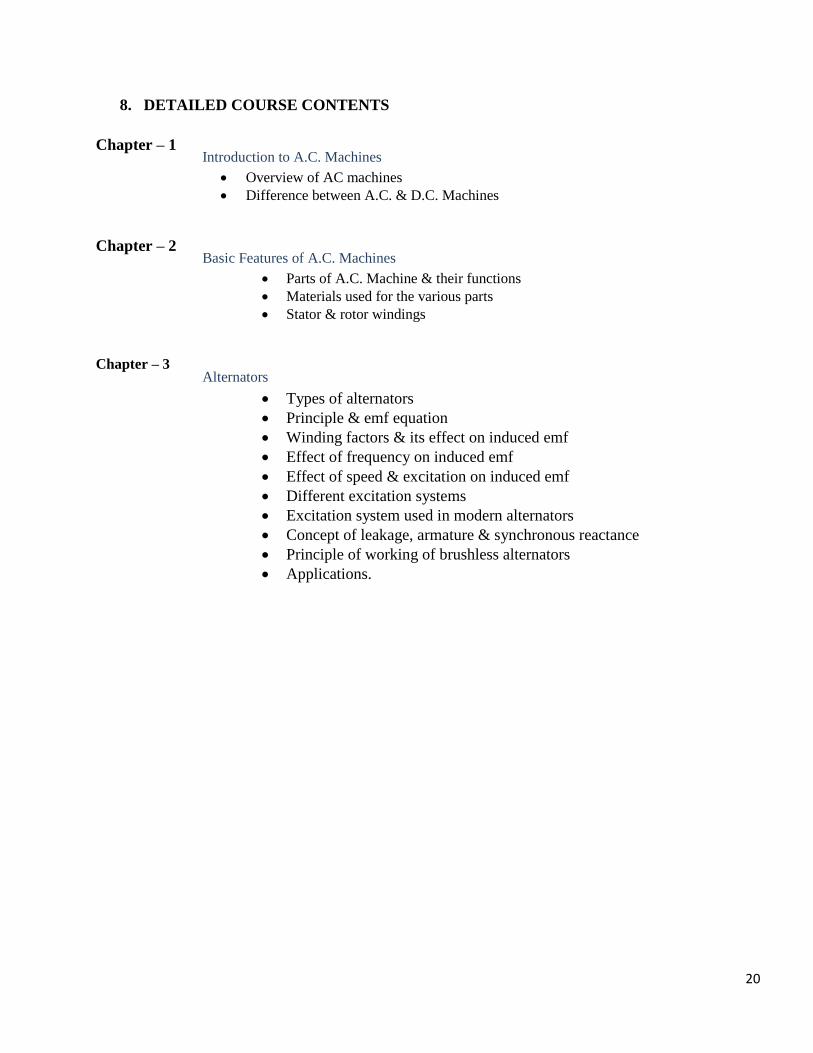
8. DETAILED COURSE CONTENTS
Chapter – 1
Introduction to A.C. Machines
Overview of AC machines
Difference between A.C. & D.C. Machines
Chapter – 2 Basic Features of A.C. Machines
Parts of A.C. Machine & their functions
Materials used for the various parts
Stator & rotor windings
Chapter – 3 Alternators
Types of alternators
Principle & emf equation
Winding factors & its effect on induced emf
Effect of frequency on induced emf
Effect of speed & excitation on induced emf
Different excitation systems
Excitation system used in modern alternators
Concept of leakage, armature & synchronous reactance
Principle of working of brushless alternators
Applications.
21
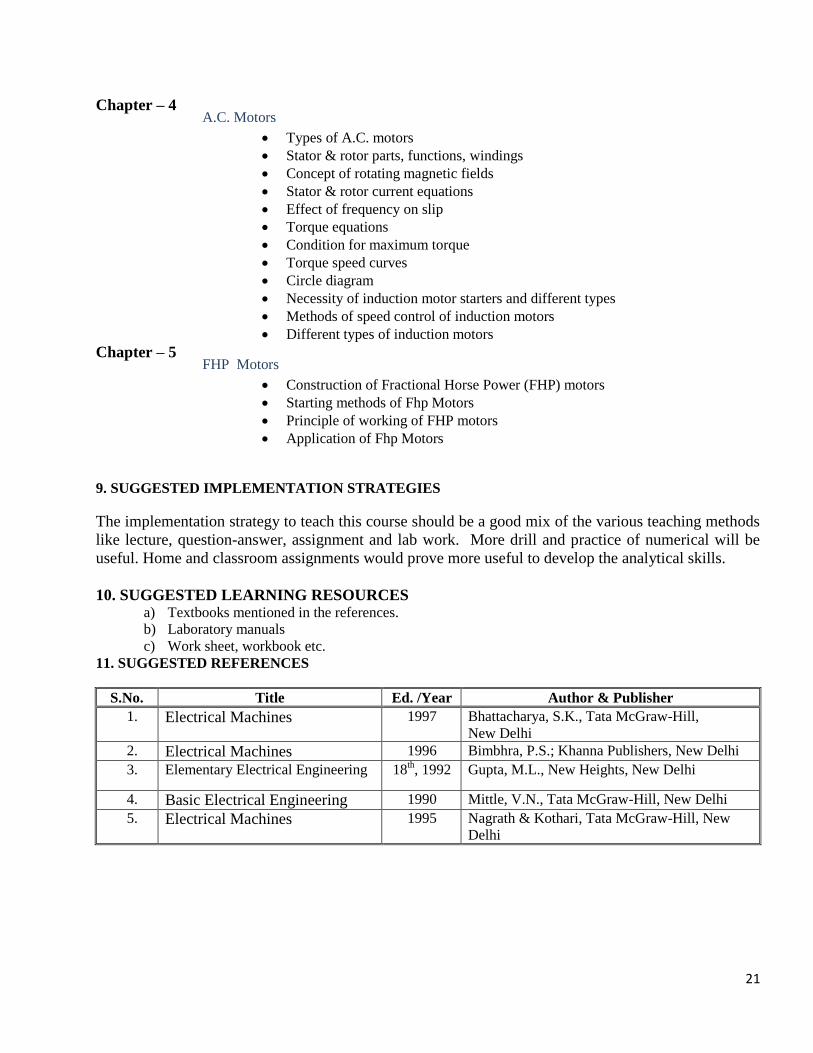
Chapter – 4 A.C. Motors
Types of A.C. motors
Stator & rotor parts, functions, windings
Concept of rotating magnetic fields
Stator & rotor current equations
Effect of frequency on slip
Torque equations
Condition for maximum torque
Torque speed curves
Circle diagram
Necessity of induction motor starters and different types
Methods of speed control of induction motors
Different types of induction motors
Chapter – 5 FHP Motors
Construction of Fractional Horse Power (FHP) motors
Starting methods of Fhp Motors
Principle of working of FHP motors
Application of Fhp Motors
9. SUGGESTED IMPLEMENTATION STRATEGIES
The implementation strategy to teach this course should be a good mix of the various teaching methods
like lecture, question-answer, assignment and lab work. More drill and practice of numerical will be
useful. Home and classroom assignments would prove more useful to develop the analytical skills.
10. SUGGESTED LEARNING RESOURCES a) Textbooks mentioned in the references.
b) Laboratory manuals
c) Work sheet, workbook etc.
11. SUGGESTED REFERENCES
S.No. Title Ed. /Year Author & Publisher
1. Electrical Machines 1997 Bhattacharya, S.K., Tata McGraw-Hill,
New Delhi
2. Electrical Machines 1996 Bimbhra, P.S.; Khanna Publishers, New Delhi
3. Elementary Electrical Engineering 18th, 1992 Gupta, M.L., New Heights, New Delhi
4. Basic Electrical Engineering 1990 Mittle, V.N., Tata McGraw-Hill, New Delhi
5. Electrical Machines 1995 Nagrath & Kothari, Tata McGraw-Hill, New
Delhi
22
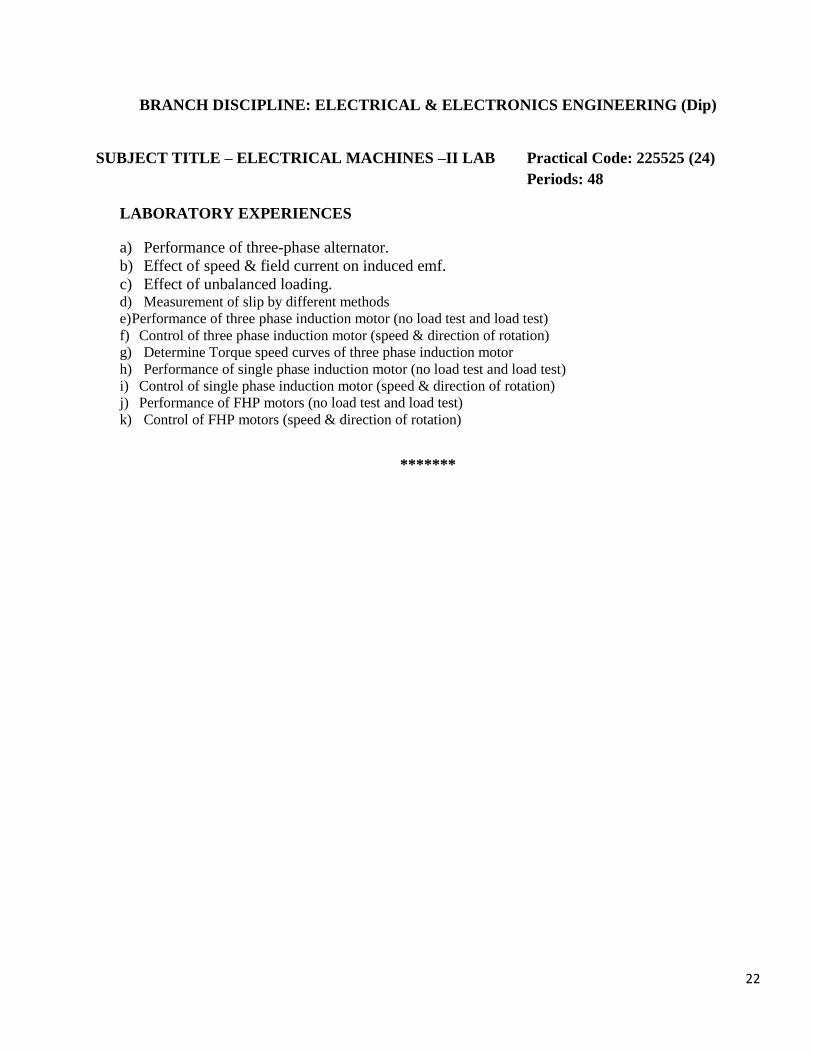
BRANCH DISCIPLINE: ELECTRICAL & ELECTRONICS ENGINEERING (Dip)
SUBJECT TITLE – ELECTRICAL MACHINES –II LAB Practical Code: 225525 (24)
Periods: 48
LABORATORY EXPERIENCES
a) Performance of three-phase alternator.
b) Effect of speed & field current on induced emf.
c) Effect of unbalanced loading. d) Measurement of slip by different methods
e) Performance of three phase induction motor (no load test and load test)
f) Control of three phase induction motor (speed & direction of rotation)
g) Determine Torque speed curves of three phase induction motor
h) Performance of single phase induction motor (no load test and load test)
i) Control of single phase induction motor (speed & direction of rotation)
j) Performance of FHP motors (no load test and load test)
k) Control of FHP motors (speed & direction of rotation)
*******
23
CHHATTISGARH SWAMI VIVEKANAND TECHNICAL UNIVERSITY, BHILAI
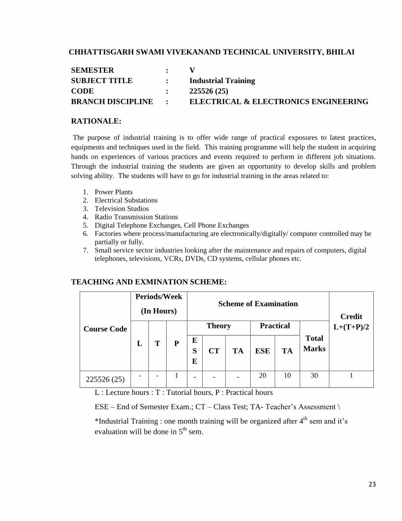
SEMESTER : V
SUBJECT TITLE : Industrial Training
CODE : 225526 (25)
BRANCH DISCIPLINE : ELECTRICAL & ELECTRONICS ENGINEERING
RATIONALE:
The purpose of industrial training is to offer wide range of practical exposures to latest practices,
equipments and techniques used in the field. This training programme will help the student in acquiring
hands on experiences of various practices and events required to perform in different job situations.
Through the industrial training the students are given an opportunity to develop skills and problem
solving ability. The students will have to go for industrial training in the areas related to:
1. Power Plants
2. Electrical Substations
3. Television Studios
4. Radio Transmission Stations
5. Digital Telephone Exchanges, Cell Phone Exchanges
6. Factories where process/manufacturing are electronically/digitally/ computer controlled may be
partially or fully.
7. Small service sector industries looking after the maintenance and repairs of computers, digital
telephones, televisions, VCRs, DVDs, CD systems, cellular phones etc.
TEACHING AND EXMINATION SCHEME:
Course Code
Periods/Week
(In Hours) Scheme of Examination
Credit
L+(T+P)/2
L T P
Theory Practical
Total
Marks E
S
E
CT TA ESE TA
225526 (25) - - 1 - - - 20 10 30 1
L : Lecture hours : T : Tutorial hours, P : Practical hours
ESE – End of Semester Exam.; CT – Class Test; TA- Teacher’s Assessment \
*Industrial Training : one month training will be organized after 4th
sem and it’s
evaluation will be done in 5th
sem.
24
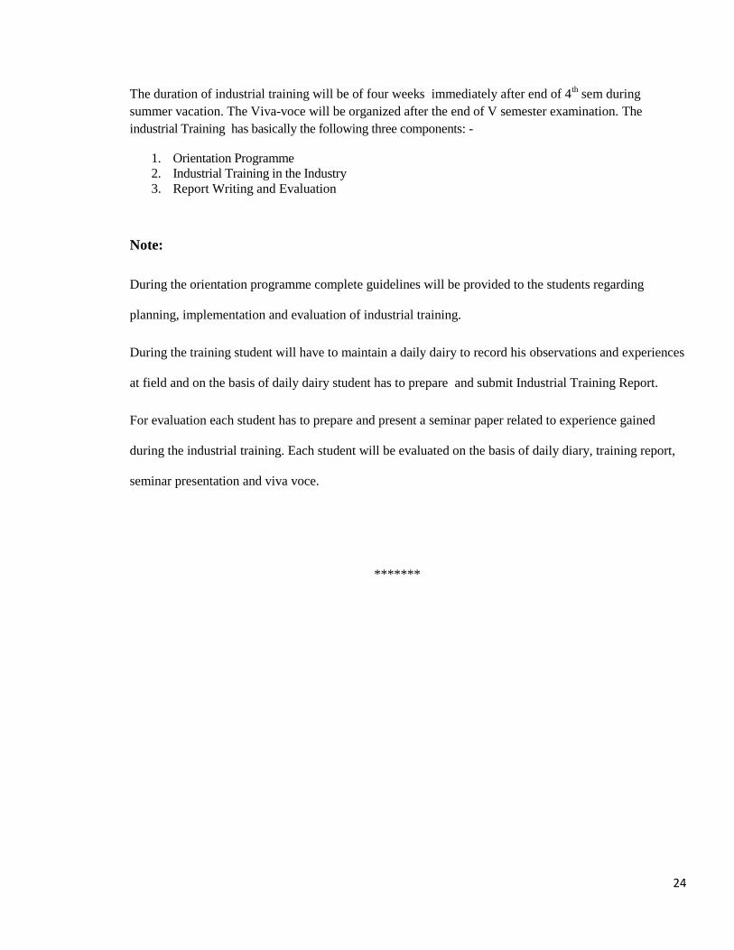
The duration of industrial training will be of four weeks immediately after end of 4th sem during
summer vacation. The Viva-voce will be organized after the end of V semester examination. The
industrial Training has basically the following three components: -
1. Orientation Programme
2. Industrial Training in the Industry
3. Report Writing and Evaluation
Note:
During the orientation programme complete guidelines will be provided to the students regarding
planning, implementation and evaluation of industrial training.
During the training student will have to maintain a daily dairy to record his observations and experiences
at field and on the basis of daily dairy student has to prepare and submit Industrial Training Report.
For evaluation each student has to prepare and present a seminar paper related to experience gained
during the industrial training. Each student will be evaluated on the basis of daily diary, training report,
seminar presentation and viva voce.
*******
Related Documents