Chapter 2:Ferrous Metals 2.0 Iron Productions 1. Iron ores are main material in iron ingot production. 2. In mining process, the iron ore are in pure state. It also found along with other substances such as oxide, sulphade, sulphur, silicon, etc.

Chapter2 (JF302)
Jan 18, 2015
DAPATKAN NOTA INI UNTUK RUJUKAN PELAJAR
Welcome message from author
This document is posted to help you gain knowledge. Please leave a comment to let me know what you think about it! Share it to your friends and learn new things together.
Transcript

Chapter 2:Ferrous Metals2.0 Iron Productions
1. Iron ores are main material in iron ingot production.2. In mining process, the iron ore are in pure state. It also found along with other substances such as oxide, sulphade, sulphur,
silicon, etc.
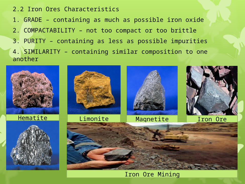
2.2 Iron Ores Characteristics
1. GRADE – containing as much as possible iron oxide
2. COMPACTABILITY – not too compact or too brittle
3. PURITY – containing as less as possible impurities
4. SIMILARITY – containing similar composition to one another
Hematite Limonite Magnetite Iron Ore
Iron Ore Mining

2.3 Iron Production Process Blast Furnace
Iron Ore is smelted in the Blast Furnace in order to remove unwanted impurities such as rocks, clay and sand, and also to separate the Iron from the Oxygen. The result is Iron which is about 95% pure. The remaining impurities are other elements which can be removed later if necessary. A Blast Furnace is about 100ft. high and produces abut 1000 tons of molten Iron a day. It is made from steel.

1. It’s divided into 2 parts :i. combustion chamber/ stove where the hot air from, blast into the furnaceii. fire bricks (furnace) to form a wide space (shaft) to accommodate and discharge the heat


The Blast Furnace Process
1. The Iron Ore, Coke and Limestone, (the Charge), is conveyed to the top of the Furnace.
2. The Charge is stored in Bells until the timing is right for the charge to be dropped into the Furnace.
3. Hot air is then blown through pipes called Tuyeres, to fire the mixture.
4. The Coke burns to increase the temperature in the Furnace.
The Blast Furnace Process
5. The Limestone attracts the impurities in the Iron Ore and forms Slag. This Slag is lighter than the molten Iron and so floats on top of it.
6. As the Furnace fills, the molten Iron is Tapped off. The Slag is also tapped off at regular intervals.
Most Iron is taken straight from the Blast Furnace to the Steel Mill, but some is poured into buckets called Pigs. This Iron is called Pig Iron and is used to make Cast Iron.

Three important chemical processes in the blast furnace :i. carbon from the coke burning with oxygen in the air blastii. oxide reduction to the ironsiii. flushing the gauge and ashes from the iron ores using the limestone
The disadvantages:i. high in cost and capital for operationii. controlling iron composition are weakiii. small furnace using coke are incompetent, huge production from bigger furnace are no necessity.
The output (products) of the blast furnace :i. the iron ingots contains 93% of basic irons, 3% - 5% of carbon, silica, sulphur, phosphorus and manganese.ii. besides, slags also can be used when separated from melting irons in the furnace such as road ways and building blocks

2.4 Steel ProductionBasic Oxygen Process Furnace (BOP)(Using pure oxygen.)
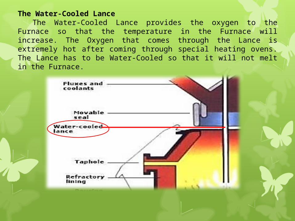
The Water-Cooled LanceThe Water-Cooled Lance provides the oxygen to the Furnace
so that the temperature in the Furnace will increase. The Oxygen that comes through the Lance is extremely hot after coming through special heating ovens. The Lance has to be Water-Cooled so that it will not melt in the Furnace.

The Steel ShellThe main body of the Basic Oxygen Furnace is made
from Steel, as the material is strong and durable, or tough. The Steel Shell does not melt because of the Refractory Lining.
The Refractory LiningThe Refractory Lining is a special type of cement that
has the ability to reflect heat. If you look at the back of an open fireplace, the cement you see on the back wall is a Refractory material, although it would not be of the same quality as the Refractory lining in a Furnace. The Refractory Lining has two purposes. The first is to keep the heat from the furnace in so that less energy is required to keep the Furnace at operating temperature. The second reason is to protect the Steel Shell of the Furnace.

The Molten MetalThe Molten Metal at the bottom of the Furnace is the Steel. The
Steel is below the Slag as it is heavier or denser. The Molten Steel is removed from the Furnace when the Steel is of the correct consistency, through the Tap Hole.
The SlagThe Slag which sits on top of the Molten Metal, because it is less
dense, is the waste material from the process of creating Steel. It consists of the impurities, that is most materials other than Iron and Carbon which were put into the Furnace at the start when the Furnace was being Charged. The Slag is removed from the Furnace when the time is ready.
The slag

The Tap holeThe Tap hole is used to remove the Molten Steel from the Furnace
when it is of the right consistency. During the process of manufacturing the Tap Hole is "plugged" so as not to allow heat to escape from the Furnace.
The Converter Fumes The Converter Fumes has two purposes. The first is to trap the
dangerous gases that the Basic Oxygen Process produces so that they cannot escape into the atmosphere to poison people or create Acid Rain. The gases are "cleaned" or put to other uses. One important use of the gases is to heat the Oxygen that is going through the Water-Cooled Lance. The second purpose is to reduce the amount of heat loss in the Furnace.

1. Scrap ChargingScrap Iron and Steel are tipped into
the Furnace. The Iron and Steel comes from old or scraped cars, bridges, buildings, etc. Also used is Iron or Steel that when manufactured into a product was not of good enough quality to be used for its intended purpose.
2. Molten Iron ChargingMolten Iron, which comes straight
from the Blast Furnace is then tipped into the Furnace. The Furnace is now ready for the blow.
The Basic Oxygen Process
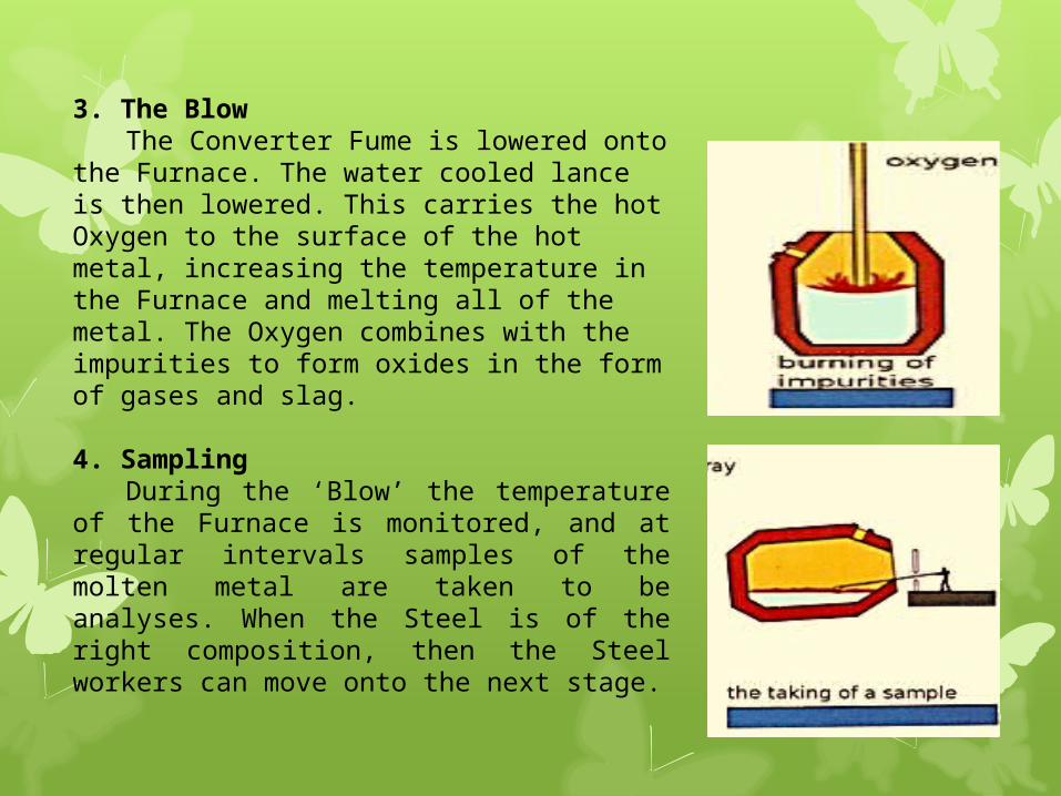
3. The BlowThe Converter Fume is lowered onto
the Furnace. The water cooled lance is then lowered. This carries the hot Oxygen to the surface of the hot metal, increasing the temperature in the Furnace and melting all of the metal. The Oxygen combines with the impurities to form oxides in the form of gases and slag.
4. SamplingDuring the ‘Blow’ the temperature
of the Furnace is monitored, and at regular intervals samples of the molten metal are taken to be analyses. When the Steel is of the right composition, then the Steel workers can move onto the next stage.

5. PouringWhen the Steel is of the right
composition the Converter fume and the water cooled Lance are removed. The molten Steel is then poured out the Tap hole by turning the Furnace to one side. The Steel is then cast into ingots, or processed by continuous casting.
6. SlaggingWhen all of the Steel has been
poured out, the Furnace is turned upside down, in the opposite direction to that when pouring, and the Slag is removed.

This furnace has high ability in production and easier to handle.
Low in oxygen rates made it suitable in producing steel alloy because the metal did not react with the oxygen in the furnace.
This furnace used widely and suitable for upgrading the steel, produces tool steel and high quality alloy steel.
It can produce up to 120 tones of steels within 4 hours.
2.5 Steel ProductionElectric Arc Furnace (EAF)
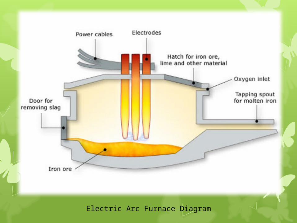
Electric Arc Furnace Diagram

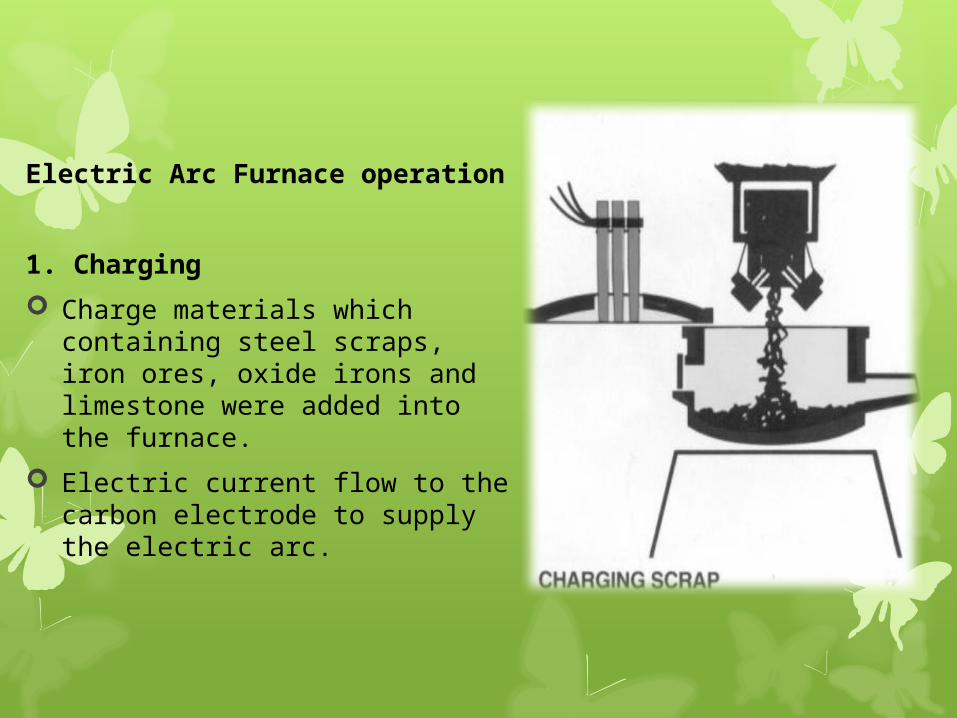
Electric Arc Furnace operation
1. Charging
Charge materials which containing steel scraps, iron ores, oxide irons and limestone were added into the furnace.
Electric current flow to the carbon electrode to supply the electric arc.
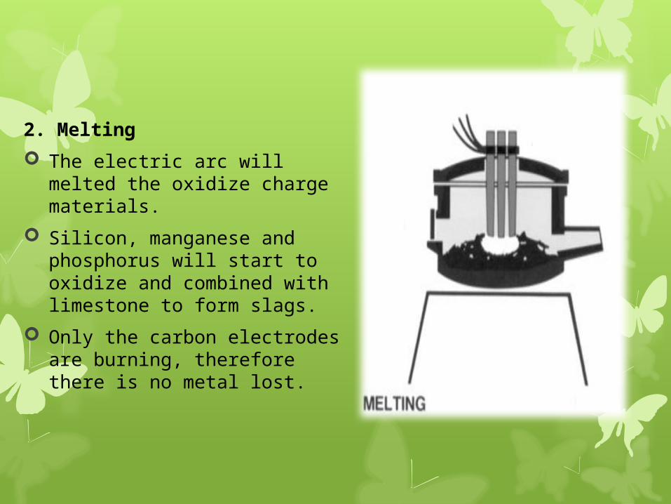
2. Melting
The electric arc will melted the oxidize charge materials.
Silicon, manganese and phosphorus will start to oxidize and combined with limestone to form slags.
Only the carbon electrodes are burning, therefore there is no metal lost.

3. Slagging
The limestone, fluorspars and oxide irons are added to form slags.
After the reaction, it will form the needed steel compositions.
Sulphur then added to the slags as calcium sulphade.
The reaction are shown as below :
FeS + CaO + C CaS + Fe + CO

4. Finishing or tapping
The steel oxidized by aluminum, ferro-silicon or ferro-manganese to retracted the steels.
Slags will be plucked or poured start from its surface and then will be separated or tapped through a hole/ exit channel by leaning the furnace.

The advantages of electric arc furnace :
i. blazing process can be controlled and arranged efficiently
ii. no oxidation gases, so can produce high quality steels
iii. the temperature can be control accurately
iv. free from soils and smokes


2.6 Plain Carbon Steel
Plain carbon steel is an iron carbon alloy containing 0.02 to 2% carbon. All commercial plain carbon steels contains manganese, sulphur, phosphorus and silicon impurities.
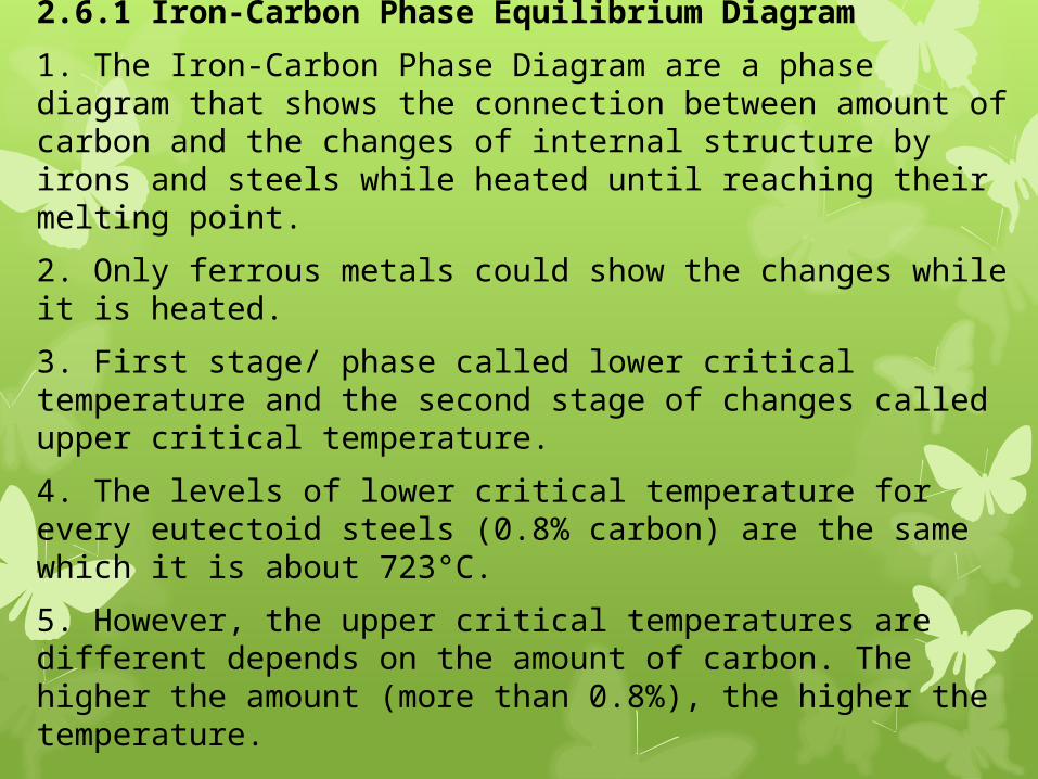
2.6.1 Iron-Carbon Phase Equilibrium Diagram
1. The Iron-Carbon Phase Diagram are a phase diagram that shows the connection between amount of carbon and the changes of internal structure by irons and steels while heated until reaching their melting point.
2. Only ferrous metals could show the changes while it is heated.
3. First stage/ phase called lower critical temperature and the second stage of changes called upper critical temperature.
4. The levels of lower critical temperature for every eutectoid steels (0.8% carbon) are the same which it is about 723°C.
5. However, the upper critical temperatures are different depends on the amount of carbon. The higher the amount (more than 0.8%), the higher the temperature.

2.6.1.1 Irons, Steels and Cast Irons in the Iron-Carbon Phase
Equilibrium Diagram
1. Between the temperature of 1400˚C and 1537˚C, the solid irons exist in body-centered cubic (BCC) and called as pearlite.
2. The temperature between 910˚C and 1400˚C, the crystalline structures are face-centered cubic (FCC) called austenite.
3. The temperature 910˚C and below, the iron structures are body–centered cubic (BCC) called ferrite.
4. At 1125˚C, cementite dissolvability in austenite irons is limited at 2% carbon only.
5. Cementite solid solutions in austenite called ferrite.
6. Eutectoid composition for ferrite and cementite called pearlite which containing a lamellar structure consisting of alternate layers of cementite and ferrite.
7. Ferrite and cementite only transformed from austenite with slow cooling process. But with fast cooling process, the martensite will transformed from austenite.
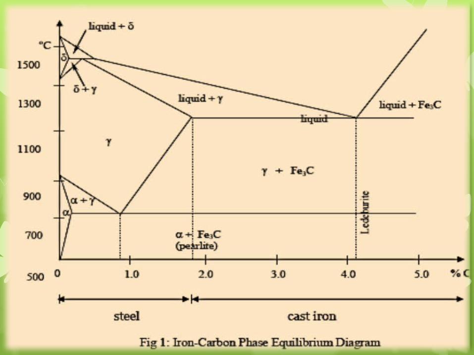

Fig 2: Microstructure for various phase of steel

2.7 Terminologies in Phase Diagram
1. Ferrite / α (alpha-iron)
Ferrite is very soft, ductile and of relatively low strength
2. Austenite / γ (gamma iron)
Austenite is also a soft and ductile phase but stronger and less ductile than ferrite
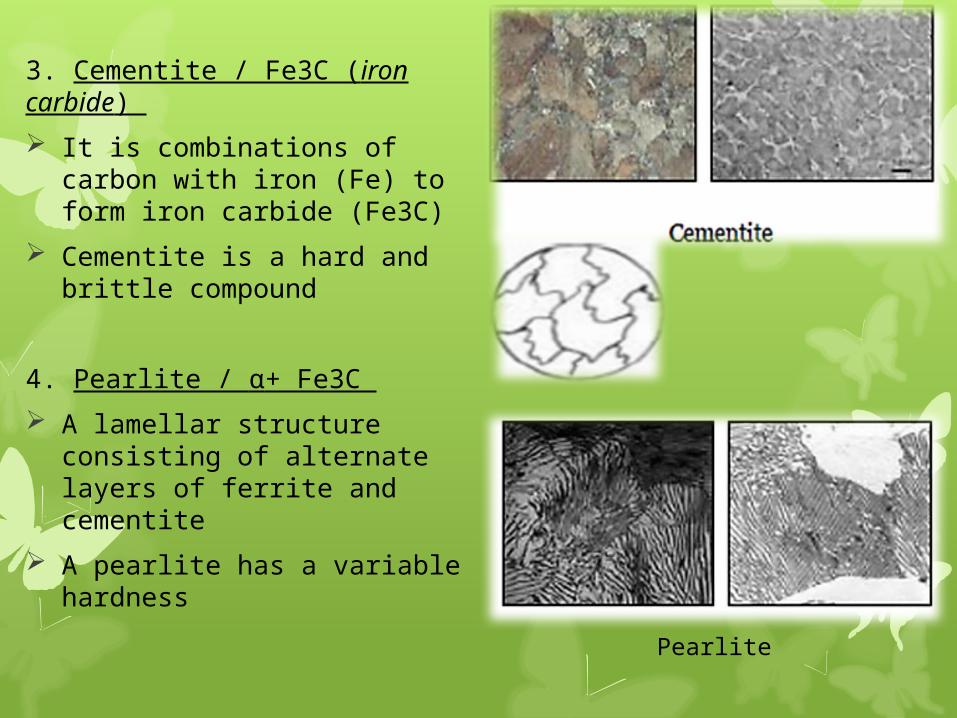
3. Cementite / Fe3C (iron carbide)
It is combinations of carbon with iron (Fe) to form iron carbide (Fe3C)
Cementite is a hard and brittle compound
4. Pearlite / α+ Fe3C
A lamellar structure consisting of alternate layers of ferrite and cementite
A pearlite has a variable hardness
Pearlite
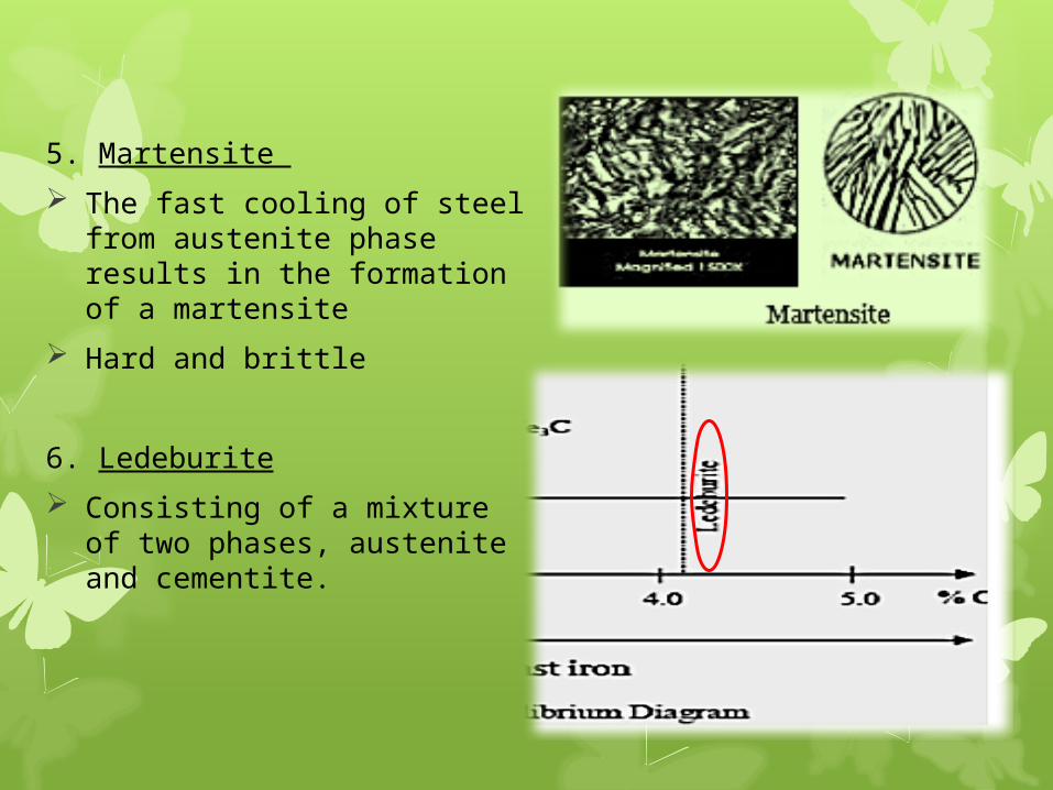
5. Martensite
The fast cooling of steel from austenite phase results in the formation of a martensite
Hard and brittle
6. Ledeburite
Consisting of a mixture of two phases, austenite and cementite.

7. Lower Critical Temperature
It is the temperature, during heating, at which pearlite changes to austenite. This transformation occurs at a fixed temperature of 723˚C irrespective of the composition of the alloy

8. Upper Critical Temperature
It is the temperature, during heating, at which last traces of cementite change into austenite and the alloy becomes completely austenite and it varies from 723˚C to 1148˚C depending upon the carbon content in the alloy

2.8 Types of Carbon Steels
Low carbon steel
Contains less than 0.3% carbon (<0.3% C)
Low strength, good machinability, high ductility, formability and weld ability
Applications : bridge structures, buildings, ships, vehicles, nails, rivets
Good fabrication ductility characteristic and usually used in annealing and normalizing conditions

Medium carbon steel
Contains 0.3 – 0.8% carbon
High strength and ductility after heat treatment, stability, tough and tensile strength
Applications : railways, wheels, shafts, gears, bolts
It can be quenched to form martensite and bainite if using media for quenching such as water and brine

High carbon steel
Contains more than 0.8% carbon (>0.8% C)
Low in strength, high in hardness and wear resistance after heat treatment
Applications : moulds, hammers, knives, milling cutters
Also known as tool steel
Tempering process can accelerate martensite formation and maintain the low strength properties

2.9 Alloy Steels
1. Alloy steel may be defined as carbon steel to which one or more elements are added to get some beneficial effects.
2. Main purposes :
i. to improve the quality of steels
ii. to improve steel characteristics
iii. to make it suitable for engineering works
iv. to make it easier for heat treatment process

3. The commonly added elements to achieve these properties :
i. increase tensile strength
ii. increase hardness and toughness
iii. higher hardenability
iv. changeability for critical temperature
v. increase wear and abrasive resistance
vi. higher corrosion and oxidation resistance
vii. maintaining higher hardness (red hardness) at temperatures up to 600 ˚C, due to the presence of alloy carbides
viii. higher temperability, and maintain the hardness and strength at elevated temperatures (creep strength)

2.9.1 Alloying elements and the effects
Nickel
increase the strength, hardness and toughness
increase the machineability in finishing process
improves the corrosion resistance of steels
Chromium
increase the strength and hardness machineability
Manganese
increase hardness and machineability
act as oxidation agent at higher temperature
high finishability
Silicon
deoxidizer, fixing oxidation resistance at high temperature
increase the critical temperature for heat treatment
increase the tensile strength and creep at higher temperature
Cuprum
gives resistance to corrosion and act as strengthened agent
Aluminium
deoxidation, promotes the fine grain formation and formed as nitriding steel
Boron
increase the hardenability properties
Plumbum
repairing the machineability properties
Bismuth
repairing the machineability properties
Vanadium
deoxidation, promotes the fine grain formation
Molybdenum
easier for hardnessability

2.9.2 Main Classes, Element Contents and Alloy Steels Applications
2.10 Cast Irons 1. An alloy of iron and carbon containing 2 – 4% carbon. 2. Carbon content form in two ways: a) cementite (Fe3C) b) graphite (Fe+C) as free carbon when the cementite is decomposed
2.10.1 Factors In Carbon Forming
Cooling / Solidifying Process Rate The cooling rate depends on the thickness and type of die/mould. 1. Slow cooling : caused the carbon separated as graphite, producing grey cast iron 2. Rapid cooling : prevent the change of graphite and maintain it hardness and difficult to machined, producing white cast iron
Heat Treatment 1. With long heating process, white cast iron will be forming graphite structure and are used to produce malleable steel.
High Carbon Contents 1. With high carbon contents, the cast irons will have the tendency to solidify as grey cast irons. 2. The strength and hardness of irons increased with the increasing of carbon.

2.10.2 Alloying Elements i. Silicon - The higher silicon contents, causing higher
resistance and good magnetic properties ii. Sulphur - Causing the cast irons to be harden, embrittle
and weak iii. Phosphorus - Increasing strength, hardness and
improving the resistance of corrosion iv. Manganese - Causing strength, toughness and high wear
resistance, hard to machine because of the hardness
2.10.3 The Advantages of Cast Irons Widely used in industries as for : i. cheaper and machineable ii. low melting point (1140˚C - 1200˚C) compared to steels iii. liquidity and formability in casting iv. wear resistance and moistureability

2.10.4 Structures, Properties and the Usages of Cast Irons

Related Documents