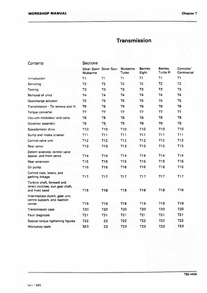
WORKSHOP MANUAL Chapter T Transmission Sections Silver Spirit Silver Spur Mulsanne Mulsanne Turbo f l T1 T 1 Bentley Eight T 1 T2 T3 T4 Bentley Turbo R Tl T2 T3 f4 Comiche/ Continental Tl T2 T3 T4 T5 T6 T7 18 T9 T10 T11 T12 T13 tntroduction Servicing f =sting Removal of units Gearchange actuator Transmission - To remove and fit Torque convener Vacuum modulator and valve T2 r3 T4 T5 16 n T8 T9 Tf 0 ftl T12 T13 Governor assembly Speedometer drive Sump and intake strainer ControI valve unit Rear sew0 .Detenr solenoid. control valve spacer, and fronr servo Rear extenston Oil pump Control rods. levers. and parking linkage Turbine shah. forward and direct ctutches, sun gear shaft. and front band Intermediate clutch. gear unit, centre soppon. and reaction carrier Transmission case Fault diagnosis Spec~al torque tightening f~gures Workshop tools

Welcome message from author
This document is posted to help you gain knowledge. Please leave a comment to let me know what you think about it! Share it to your friends and learn new things together.
Transcript
WORKSHOP MANUAL Chapter T
Transmission
Sections Silver Spirit Silver Spur Mulsanne Mulsanne Turbo
f l T1 T 1
Bentley Eight
T 1
T2
T3
T4
Bentley Turbo R
Tl
T2
T3
f 4
Comiche/ Continental
Tl
T2
T3
T4
T5
T6
T7
18
T9
T10
T11
T12
T13
tntroduction
Servicing
f =sting
Removal of units
Gearchange actuator
Transmission - To remove and fit
Torque convener
Vacuum modulator and valve
T2
r3
T4
T5
16
n T8
T9
Tf 0
f t l
T12
T13
Governor assembly
Speedometer drive
Sump and intake strainer
ControI valve unit
Rear sew0
.Detenr solenoid. control valve spacer, and fronr servo
Rear extenston
Oil pump
Control rods. levers. and parking linkage
Turbine shah. forward and direct ctutches, sun gear shaft. and front band
Intermediate clutch. gear unit, centre soppon. and reaction carrier
Transmission case
Fault diagnosis
Spec~al torque tightening f~gures
Workshop tools

Issue record sheet 1 April 1 985
The dates quoted below refer to the issue date of individual pages within this chapter.
Conrents 1 Sep 82 May 84 Oc? 81 Jan 82 Oct 81 Jan 82 Apr 85 Sep 82 May 84 Apt 85 2 . May 84 Oct 81 Oct 81 Oct 81 Dct 81 ' Apr 85 Sep 82 May 84 Apt 85 3 Sep 82 May 84 M 8 1 Jan82 Oct81 Sep 82 May B4 4 Sep 82 May 84 OH 81 5 Aug 81 Oct 81 6 Aug 81 7 Aug 81 8 Aug 81 9 P ~ g . e i
t o Aug 9' 11 Aug 81 12 Aug 81 13 Aug 81 14 Aug 8 1 15 Aug B f 16 Aug 8 1 17 Aug 81 7 8 Aug 8 1 19 20 2 1 22 2 3 24 - 25 26 27 28
m TS Sections 1 11 4 ~2 Page NO. 1 I
79 T'IO
I
a T a ' ,
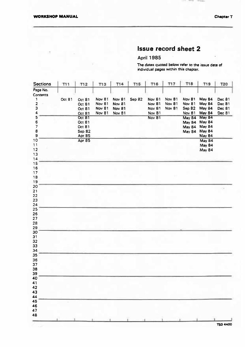
Issue record sheet 2 April 1985 The daes quoted below refer to the issue date of individual pages within this chapter.
4 Oct81 Nov81 Nov81 Nov 81 Nov81 M a y 8 4 Dec81 5 Uct 81 Nov 8 1 Mav 84 May B4
Sections Page No.
6 Oct 8 1 ~ a ; 84 May 84 7 Oct 8 1 May 84 May 84 8 Sep 82 May 84 May 84 9 Apr 85 -- May 84
10 Apr 8 5 May 84 11 May 84 12 May 84 13 14 15
- I I
Contents 1 O c t 8 1 Oct81 Nov81: Nov81 Sep82 Nov81 Nov81 N o v 8 l May84 Dec81 2 Oct81 Nov81 Nov81 N w 8 1 Nov81 Nov8 l M a y 8 4 Dec81 3 O c t 8 1 Nov8t Nov81 Nov 81 Nov 81 Sep 82 May 84 Dec 81

WORKSHOP MANUAL Ch8pt.r T
Issue record sheet 3 September 1 982 The dstrur qumd below refer to the issue das of individual pages within this chapter.
4 b e 8 1 Dec81 5 Dec 81
Dec 8 1 Sep 82 Doe 81
Sections No.
9 Dec 8 1 10 Dec 8 1
m - T21
Dec 81 Dec 81 Dec 8 1
729
14 Dec B1 15 Dec 81

Introduction
Contents
Hydraulic system
Pressure control
Vacuum modulator assembly
Governor assembly
Operation of valves and hydraulic control units
Drive and intermediate - First gear
Drive - Second gear
Drive - Third gear
Part throttle down-change
Detent down-change
Intermediate - Sewnd gear
Low range - First gear
Reverse
Park or NeutraI Engine running
Pages Silver Spid Silver Spur Mulsanne
Tf -4 T1-4
Mu tsanne Turbo
T1-4
T1-4
11 -4
Tl -4
Corniche
- - -
WORKSHOP MANUAL Chmpter T
-
Transmission
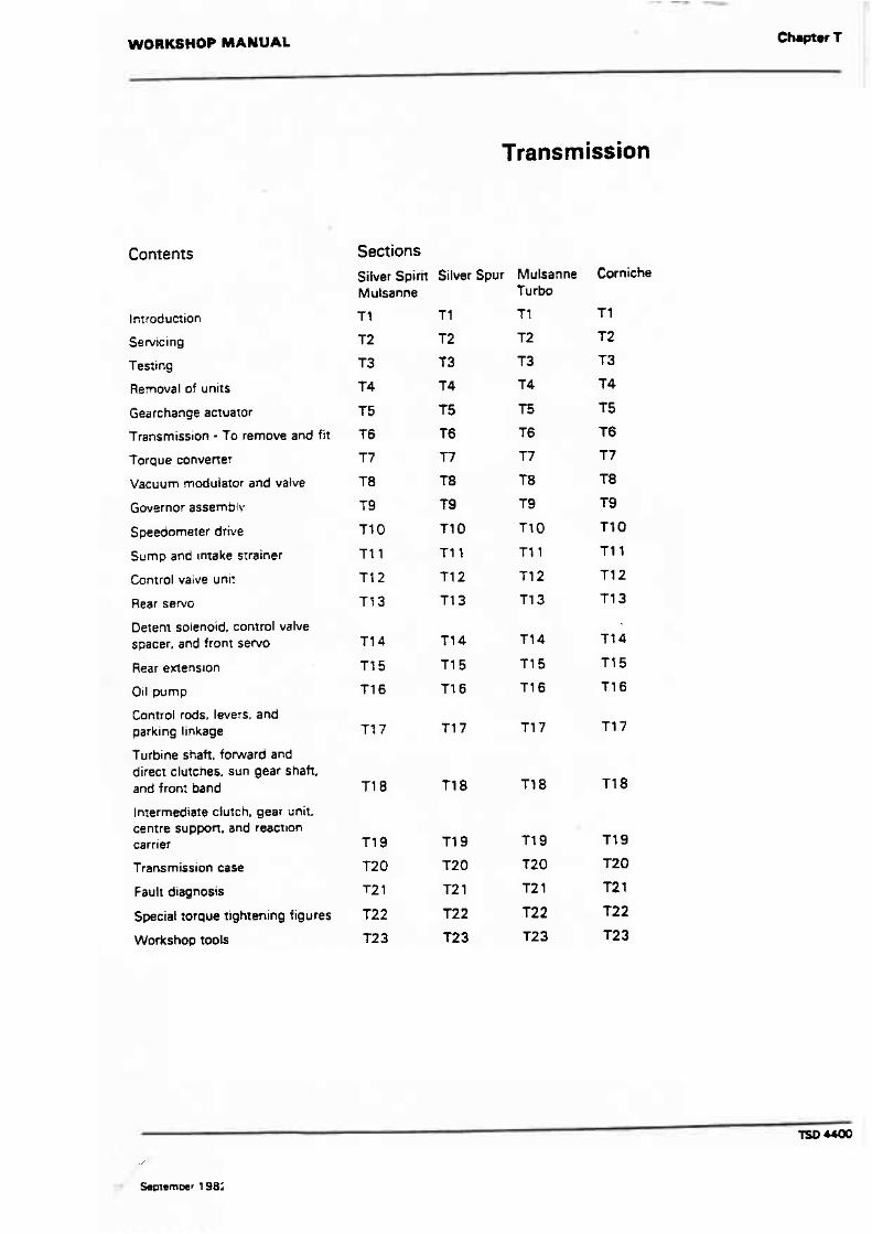
Contents Sections Silver Spirit Silver Spur Mulsanne
Mulsanne Turba
Corniche
T1 Introduction
T2
T3
T4
T 5
T6
T7
T8
T9
T t O
T11
Se wicing T2
T3
T4
T5
T6
T7
T8
T9
T10
f l l
Testing
Removal of units
Gearchange actuator
Transmission - To remove and fit
T arque convener
Vacuum modulator and vatve
Governor assemblv
Speedomerer drive
Sump and ~ntake strainer
Control vaive uuni?
Rear sewo
Detent solenoid. conrrol valve spacer. and front sew0
Rear ertenslon
Oil pump
Control rods, levers, and parking linkage
f urbine shaft, forward and direct clutches. sun gear shaft. and front band
Intermediate clutch, gear unit. centre suppn, and reactlon carrier
Transmission case
Fault diagnosis
Special torque tightening figures
Workshop tools

WORKSHOP MANUAL Section T1
Introduction
f he torque convener transmission i s a fully automatic unit, consisting primarily of a three-element hydraulic torque converter and a compound ptanetary gear train. Three multiple-disc clutches, one roller clutch, one rprag clutch, and two friction bands, provide the elements which are required to obtain the desired functions of the gear train.
A name plate i s fitted to the right-hand side of the transmission, toward the centre of the case. The serial number i s prefixed by either the letters RR, RR-A, RC, or RT and the year in numerals.
The torque converter, clutches and rollers connect the engine to the planetary gears with the aid of pressurized transmission Ruid. Three forward gears and reverse are provided. When necessary,,the torque converter wiil suppkment the gears by multiplying engine torque.
The torque converter is of welded steel construction and connot be dismantled. The unir is made up of two vaned seetions which face each other across a fluid filled housing. The pump half of the converter is connected to the engine and ;he turbine half i s connected to the transmission.
When the engine i s running the converter pump rotates and throws fluid againn the turbine, causing the turbine to rotate. f he fluid then returns ro the pump in a circular flow and continues this cycle as long as the engine i s running.
The converter also has a smaller vaned section, called a Rator. which directs the fluid back to the pump through smaller openings at greater speed. The speeded-up fluid imparts additional force to the engine driven converter pump, thus multiplying engine torque.
A hydraulic synem pressurized by an internall external gear type of pump provides the working pressure required to operate the friction elements and automatic controls.
External control connections The external control connections to the transmission are. 1. An electric war change actuator, connecting rod, and levers. The actuator responds to an electrical signal from a witch on the steering column, then moves the gear change lwer on the transmission to the required posirion. 2. Engine vacuum which operates a vacuum modulator unit. 3. 12 volt dectrical signals to operate an eltctrical detent solenoid.
Gear and torque ratios The gear or rorque ratios of the transmission ark
First - 2.5:1 Second - 1.5:l Third - 1.0:l Reverse - 2.0: 1
Each gear ratio can be multiplied by as much as 2.2. depending upon the slip speed of the converter pump and turbine.
Vatuum modulator A vacuum modulator is used to automatically sense engine torque input t o the transmission. The modulator transmits this signal to the pressure regulator which controls main line pressure, $0 that all the torque requirements of the transmission are met and the correct gear change spacing is obtained at all throttle openings.
Detent solenoid The detent solenoid is activated by a micrmswitch assembly which is mounted t o the toeboard, beneath the accelerator pedal. When the pedal i s in the kick-down position, the micro-swirch i s closed; the solenoid in the transmission is then activated and a down-change will occur at speeds below 113 kmlh (70 milelhl. A t lower speeds a down-change will occur at smaller throttle openings without the aid of the micrswi tch assembly. or the solenoid.
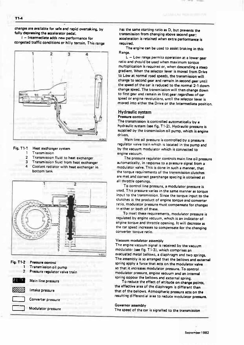
Heat axehanger f he heat exchanger for the transmission fluid is situated in the bortam of the radiator matrix (see fig. Tl-1) .
Selector positions . The transmission guadrant has six selector positions which enable the driver to control the operation of the transmission under varying driving conditions, The six ''
selector positions appear in the following sequence, from left to right; P - Park. R - Reverse, N - Neutnl. D - Drive, 1 - Intermediate and L - Low. The q i m can only be started in the Park and NnutrJ positiarws.
P - Park ppi t ion positively locks the dtprrt &l)t to the transmission casa by means of a loeking prwl r f d prwenrs the car from rolling tither bxkward or fomrrd when parked on a steep incline.
R - Reverse enables the car to operate in & mm8 direction.
N - Neutral enables the engine to bs stnrthd &d run without the car moving.
D - Drive is usad for all normJ driving eondkions and maximum economy. Drivt range has thrrr grrr ratios, from starting to direct d r iv~ . F o ~ d down-
tt4
Ehanges are available for safe and rapid ovenakinp. by fully depressing the accelerator pedal.
1 - Intermediate adds new performance for congested traffic wnditions or hilly terrain. This range
Fig. T1-'I Heat exchanger system 1 Transmission 2 Transmission fluid to heat exchanger 3 Transmission fluid from heat exchanger 4 Coolant radiator with heat exchanger in
bottom tank
Fig. Tl-2 Pmuret control 1 Transm itsion oit pump 2 P r m r e regulator valve train
m Main line pewre
I-1 Convener pressure
r j Modulator pressure
has the same starting ratio as D, but prevents the transmission from changing abve seeand gear: acceleration i s retained when extra performance is required.
The engine can be used to assist braking in t h i s Range.
L - Low range permits operation at a lower gear ratio and should be used when maximum torque multiplication is required or, when descending a steep gradient. When the selector lever is moved from Drive to Low a t normal road speeds, the transmission will change to second gear and remain in second gear until the speed of the car is reduced to the normal 2- 1 doww change speed. The transmission will then change down to first gear and remain in first gear regardless of car sped or engine revolutions, until the selector lever is moved into either the Drive or the Intermediate position.
Hydraut ic system Pressuru wntml The transmission is controlled automatically by a hydraulic system (see fig. T1-21. Hydraulic pressure is supplied by the transmission oil pump. which is engine driven.
Main line oil pressure is controlled by a preswre regulator valve train which is located in the pump and by the vacuum rnoduiatclr which is connected to engine vacuum.
The pressure regulator controls main line oil pressure automatically, in response to a pressure signal from a modulator valve. This i s done in such a manner, that the torque requirements of the trammission clutches are met and correct gearchange spacing is obtained at all throttle openings.
To control line pressure, a modulator pressure i s used. This pressure varies in the same manner as torque input to the transmission. Since the torque input to the clutches is the product of engine torque and converter ratio, rndulator pressure must compensate for changes in either or both of these.
To meet these requirements, modulator pressure is regulated by engine vacuum, which is an indicator of engine torque and throttle opening. It will decrease as the car speed increases to compensate for the changing converter torque ratio.
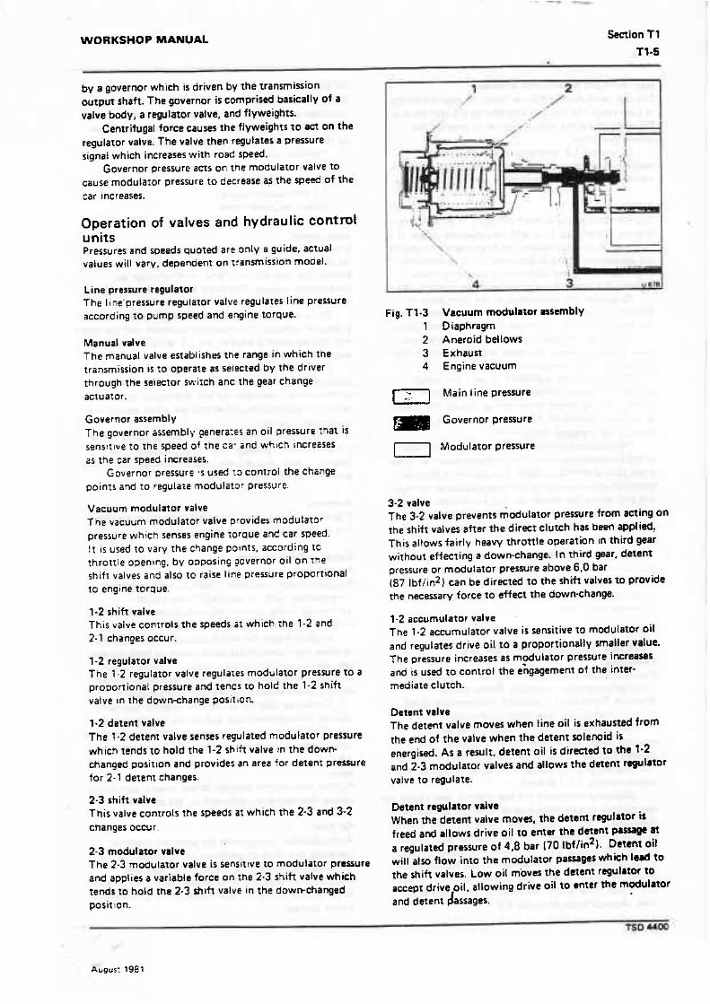
Vacuum modulator assembly The engine vacuum signal is received by the vacuum modulator (see fig. TI-3). which comprises an evacuated metal bellows, a diaphragm and two springs. The assembly is so arranged that the bellows and external spring apply a force that acts on the modulator valve so that.it increases modulator prmura. To control moduiator pressure, engine vacuum and an internal spring oppose the bellows and external spring.
To reduce the effect of attitude on change points, the effmive area of the diaphragm is different than that of the beltows. Atmospheric prewre actson the rerult iq differential area ro rtduce mqdutator prewn.
Governor assembly f he speed of the Car is signalled to the tranmission
WORKSHOP MANUAL Section T l
by a governor which i s driven by the transmission output shaft. The governor is ~0mpriSed basically of a valve body, a regulator valve, and flyweights.
Centrifugal force causes the flyweights t o act on the regulator valve. The valve then regulates a pressure signaf which increases with road speed.
Governor pressure aCrs on the modulator valve to cause modulator pressure to decrease qs the speed of the car increases.
Operation of valves and hydraulic contml units Pressures and speeds quoted are only a guide. actual values will vary, dependent on z:ansmission model.
Line pressure regulator The l i ne'pressure regulator valvs regulates line pressure according to pump speed and engine torque.
Manual valve The manual valve establishes the range in which the transmission IS to operare as selected by the driver through the selector swirch anc the gear change actuator.
Governor assembly The governor Ossembly genetax: an oil pressure m a t i s sensttlve to the speed 04 rhe ca- 2nd which rncrezses as the car speed increases.
Governor Dressure used 13 control the change points and to regulate modulalor pressure.
Vacuum modulator valve The vacuum modulator valve provides modulator pressure which senses engine Torque and car speed. It i s used to vary the c3ange pornts, according rc throrrle openlng, by oDpasing governor oil on the shift: valves and also to raise line pressure proportional fo engine torpue.
1-2 shift valve This valve controls the speeds i t which t h e 1-2 and 2- 1 changes occur.
1-2 regulator valve The 1.2 regulator valve ragulaxes modulator pressure t o a proponionaf pressure and tencs to hold the 1-2 shift valve In the down-change position.
1-2 detent valve The 7-2 detenr valve senses regulated modulator pressure which tends to hold the 1-2 shift valve in the down- changed positton a n d provides an area for detenr pressure for 2-1 detent changes.
2-3 shift valve This valve conrrols the speeds ar which the 2-3 and 3-2 changes occur.
2-3 modulator vafve The 2-3 modulator valve i s sensit~ve to modulator pressure and applies a variable force on :he 2.3 shift valve which tends to hold the 2.3 shlh valve in the dowmchanged positron.
Fig. T1-3 Vacuum modulator assembly 1 Diaphragm 2 Aneroidbellows 3 Exhaust 4 Engine vacuum
11 Main line pressure
Governor pr""re
I] Modulator pressure
3-2 valve The 3-2 valve prevents modulator pressure from aning on the shift valves after the direcr clutch has been applied: This allows fairly heavy throttle operation In third gear without effecting a down-change. I n third gear, detent pressure or modu!ator pressure above 6,0 bar (87 1bfiin2) can be directed t o the shift valves to provide the necessary force to effect the downschange.
1-2 accumulator valve The 1-2 accumulator valve i s sensitive to modulator oi l and regulates drive oil to a proportionally smaller value. The pressure increases as m$ulator pressure inereases and i s used to control the engagement of the inter- mediate clutch.
Detent valve The detent valve moves when line oil is exhausted from the end of the valve when the detent solenoid is energired. As a result, detent oil is directed to the 1-2 and 2.3 modulator valves and allows the detent regulator vafve to regulate.
Detent regulator vdve When the detem valve moves. the detent regulator is freed and allows drive oil to enter the daunt W
a regulated pressure of 4,8 bar 170 lbf/in2). Detant oil will also flow into the modulator passages which lead to the shift vakcs. Low oil moves the detent regulator to accept drive oil, allowing drive oil t o enter the modulator and detem &sages.
Rear sew0 and accumulator assembly The rear servo applies the rear band for engine braking in t o w range (In gear). It also applies the rear band in Reverse to hold the reaction carrier t o provide the reverse gear ratia.
During the 1-2 up-change In Drive and Inter- mediate ranges the servo acrs as an accumulator for the intermediate clutch oil to provide a smooth upchange.
Front servo The front servo appl~es rhe front band t o provide engine braking ir. 2nd gear. Lov.. . and intermediate ranges. I t 15
used also as an accumulator fo r direc: clutch oil durins the application of the direc: clutch. This in conjunction with a series of check balls (which control orifices), controls the firning for the retease of the direct clutch.
T t prevent the application of the front band in Neutral. Drive, or Reverse ranges, oil is directed from the manual valve to the release side of the servo pislon.
In D range, the servo release oil from the manual valve is used to charge the servo in preparation for the application of the direct clutch.
Direct clutch oil IS directed to the front serilo accumulator piston where sprlng force plus direct clutch pressure, stroke the piston up against the force of the servo release oil. This lowers fhe clutch apply pressure for a smooth engageTent.
Tie release of tne direct clutch and the exhausting of the front servo accumu~aror i s slovded down by three check balls and three orifices. This permits a smooth return of the drive load to the intermediate sprag clutc: and aiso allorvs the engine rev mrn to Increase during a detent 3-2 down-change in preparation for the lower gear ratlo. Thts results in a smooth change and better acceleration.
f he position of the shift valves in each range and gear. and the various oil pasrages which are used are shown in figures T1-4 to T1-12. The operation of the valves when each gear is selected is described in the following paragraphs.
Drive and Intermediate - First gear Power flow Forward clutch - applied. Direct clutch - released. lntermediate ctutch - released. Roller clutch - effective. Front band - released. I nrerrnediate sprag clutch - ineffective. Rear band - released.
Wi th the selector lever in e~ther Drive or Inter- mediate range, the forward clutch i s applied. This delivers turblne torque to the mainshaft and turns the rear i n t e r ~ l gear clockwise. (Converter torgue ratio is approximately 2.2:1 at stall).
Clockwise motion of the rear internal gear causes the rear pinions to turn clockw~se to drive the sun gear anti- clockwise. tn turn, the sun gear drives the front pinions clockwise. thus turning the front internal gear. outpu? carrier, and output shaft clockwise in 2 reduction ratia of approxima~ely 2.511. Reaction of :he front pinions agai~st the front internal gear i s taken by the roanion carrier and roller clutch assembly to the transmission case. [Approximate s:a11 ratlc 5.5: 1 i .
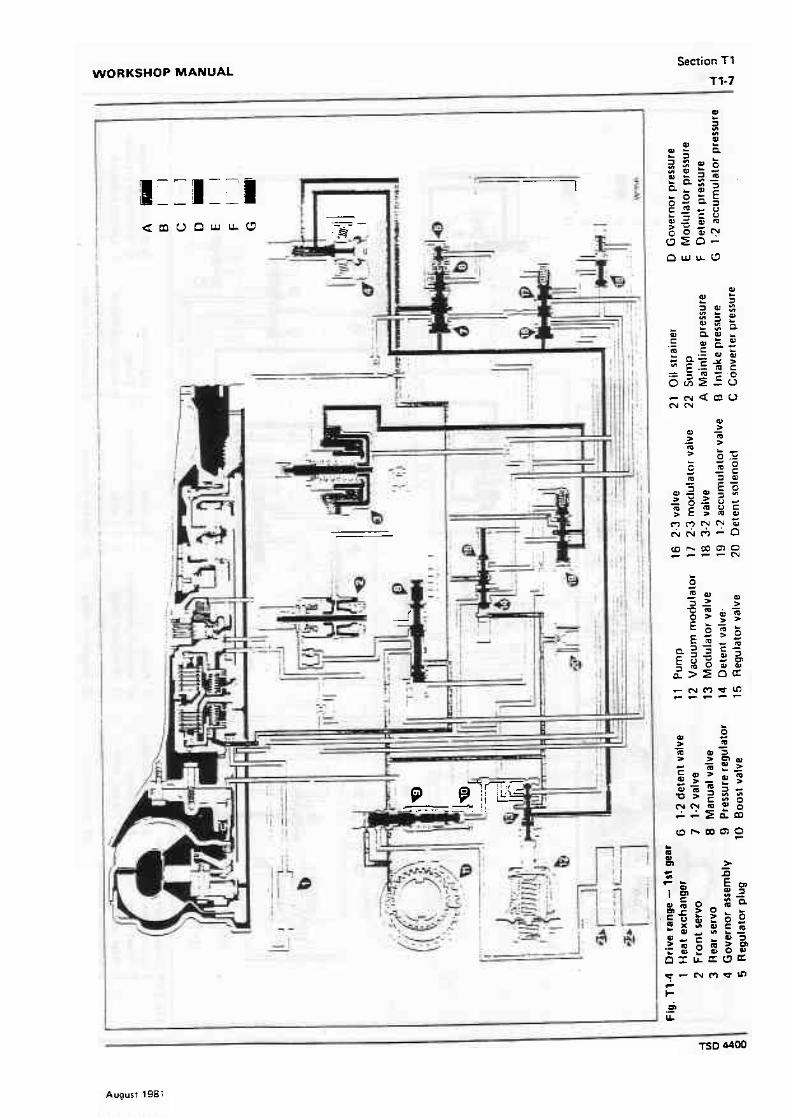
Oil flow When the selector lever is movpd t o either Drive or Intermediate position, the manual valve is reposition& to atlow line pressure to enter the drive circuit. Drive oil then flows to the following (see fig. f 1-41,
Forward clutch 1 *2 shift valve Governor assembly '1-2 accumulator valve Detent regulator valve
Basic control Drive oil IS directed to the forward clutch where i t acts on two areas of the clutch piston to apply the forward clutch. The first, or inner area, is fed through an unrestricied passage. The outer area is fed through an orifice to ensure a smooth change into Drive.
Drive oil a t the governor assembly i s regulated to a variable pressure. This pressure increases with car speed and acts against the ends of the 1-2 and 2-3 shift valves and an area on the modulator valve.
Drive oil is regulated a150 to another variable pressure a t the 1-2 accumulator valve. This pressure is conrrolled by modulator oil and is directed to the rear servo. 7-2 accumulator oi l at the rear servo acts on the accumula:or piaon.
In addition. to ma~ntain the lower pressure in the 1-2 accumulator passage, the 1-2 accumulator valve ~ntermirtenrly uncovers the Low oif passage. Oil is then exhausteo' at the manual valve.
Summary The converter is filled. The forward clutch i s applred. The rransrniss~on is in first gear.
Drive - Second gear Power flow Forward clutch - applied. Direct clutch - reteased. tntermediate clutch - applied. Roller clutch - ineffective. Front band - released. Intermediate sprag clutch - effective. Rear band - released.
In second gear the intermediate clutch i s applied to allow the intermediate sprag clutch to hold the sun gear against anti-clockwise rotation.-Turbine torque through rhe forward clutch is then applied clockwise through the mainshaft to the rear internal gear.
Clockwise rotation of the rear internal gear turns the rear plnlons clockwise agair~st the stationary sun gear. Thts causes the output carrier and output shaft to turn clockw~se rn a reduction ratio of approximately 1.5-1. Note Further reduction i s possible at low speeds. due to the torque multiplication provided by the convener.
Oil flow As rhe speed of the car and the governor pressure increases, the force of governor oil acting on the 1-2 shift valve will overcome the force of regulated modulator oil pressure. This allows t h e 1-2 shift valve to open. permitting drive oil to enter the in~ermediate clutch passage.
WORKSHOP MANUAL Section Tt
Tt-7
August 198;


WORKSHOP MANUAL Section T1
f t -9
d o t
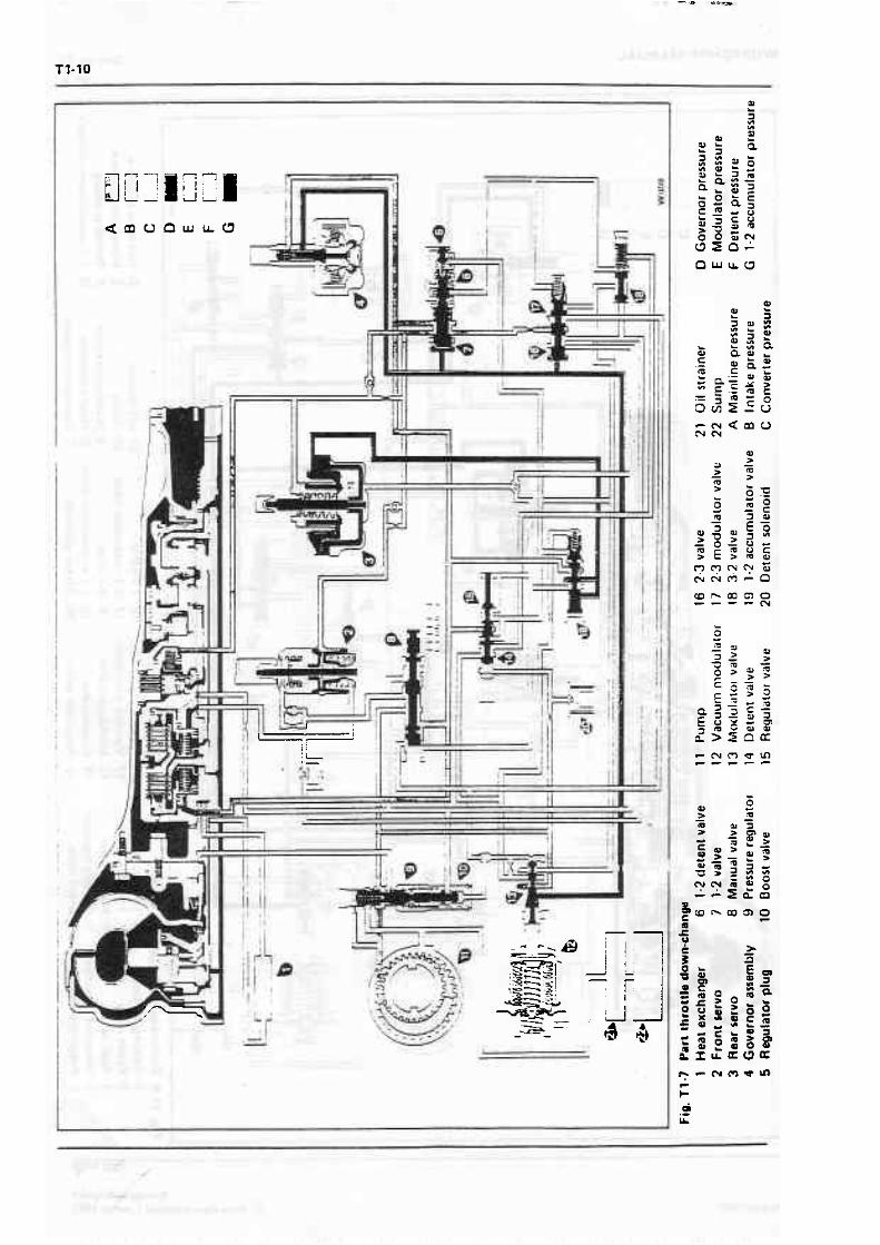
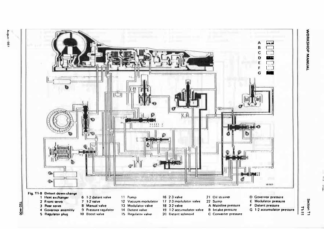
Fig. T1.8 De!tn! down.chanpa 1 Heat exchanger 6 1.2 detent valve 1 1 Punrtl 16 2.3 valve 21 Oil strainer D Governor pressure 2 f font rervo 7 1-2 valve 1 2 Vacuum morlula~or 1 7 2-3 moriulatur valve 22 Sump E Morlulalbt pressure 3 Rear strvo 8 Manual valve 13 Motluiaror valve 10 3-2 value A Mainline pressure F Detent prersure 4 Governor assernl~ly 9 Pressure regulator 14 Detont ualvr! 19 1.2 accomtrlator valve B Intake pressure G 1.2 accumulator pressure
8 5 negulator plug 10 ~ o o s t valve 15 Regulator valve 20 Detcnt sorenoid C Convet ter pressure

WORKSHOP MANUAL Section Tl
Tl-13
l f I p ] Y
TSD 4409


WORKSHOP MANUAL
Augusr !g€!:

T 1-16
Intermediate clutch oil from the 1-2 shift valve is directed to the following (see fig. T1-5).
Intermediate clutch Rear servo Front servo and accumu;aror pistons 2.3 shift valve
Basic control Intermediate ciutch 0;; from ?he 1-2 s7:ft valve seats E
one- ay check ball and flows Through an orifrce to the inlerxediatf clutch plston t o apply the intermediate clurcp. AT t h e same rime, intermediate clutch oil moves the sccumutaror piston against the 1-2 accumulator oil anC accurnulzior spring to maintain lower pressure in the clutch dur:ng a 1-2 shift fo: a smooth clutch appilcation. l nrermediare clu:cft oil seats a second one- way rtleck ball and flows to the front servo and accumulator plsfons. lntermen iate clutch oi l i s also directed to the 2-3 shift valve
Summary The forward and intermed~are clutches are appiied. The transmlss~on is in seconc gear.
Drive - Third gear Power flow Forward clutcr~ - apz~ied. D!rect clutc? - ap3;led. lntermed~ate clutch - applieb. Rofler clutch - ineffective. Front band - released. lntermedisre spraE clutcn - inefiect~ve. Rear band - reteesed.
I n direcr drive, engine torque is transmitted from the converter, Through the forward clu:ch to the maln- shaf; and rear imernal gear. Because the direcr clutch i s appl~ed, equal power is also rransrni!:ed t o the sun gear snaft and rhe sun gear. S~nce both sun gear and internat gears are non turninp a t the same speed, the planetary gear set i s essentially locked and turns as one unit in direct drive or a ra:io of l : i.
Oil fiow As the speed of the car and governor pressure increase, the force of governor oil actlng on the 2-3 shift valve overcomes the force of 2-3 shift valve spring and modulator oil. This allows the 2-3 shift valve to move. feed~ng intermediate clutch oil to the direct clutch passage.
Direct clutch oil from the 2.3 shift valve is directed to the fotlowrng (see fig. T1-61.
D~rect clutch F font accumulator piston 3.2 valve
Basic control Direit ctutch oil from the 2-3 shift valve flows past a one-way check valve to the inner area of the direct clutch piston to apply the dlrect clutch.
Simultaneously, direct clutch oil is fed t o the front accumulator pisfon. Pressure of the direct clutch oil, comnind with the accurnularbr sprinG, moves the accumulator and servo pistons against servo oii, This acrs as an xcumuiator for a smooth dlrect ciutch app!~cation.
Direct clutch oil is supplied also to the 3.2 valve to move the valve against modulator pressure. This cuts off modulator oil to the 1-2 regulator and 2-3 modulator valves. It also allows the transmission t o utilize the torque rnulfiplying cha:acteristics of the convwter during rned~um thror:it operation without down- changing.
Summary The forward, intermed~~te, and direct clutches are applied. The fransm:sr5n IS in third gear idirecr drive).
Part throttle down-change Power Row forward clutch - agplled. D~rect clutch - released in second. Direct clutcil - applied in third. Intermediate ciutch - applied. 3o:ter clutch - ~neffective. Front band - released. Inrermedlate sprag clutch - effective in second. Intermed.cre sprag clutch - ineffective in third. Rear band - released.
In second gear, tne Intermediate clutch i s applied t o allow the intermedive mrag clutch to hold the sun gear against anti-clockw~se ro:atlor;. Turbine torque through the forwarc clcrcl: is then applied clockwise through the mainshai: rs tne rear internal gear.
Clockruise rota:-or ~f the rear internal gear turns the rear pinions c i o t ~ r . j e against the stationary sun gear. Th!s causes the 31:~~: shaft and output carrier to turn clockw~se ir a r~zuct ion ratio of approximalely 1.5: i.
Oil flow A par; throttle 3-2 ooc :-change can be accomplrshed below approximately 53 km:h i33 mileih) by depressing the accelerzzor far enough to raise modulator pressure to a~proximately 6.0 bar (87 Ibf. jn21. Modutaror Dressure and the 3-2 valve spring will move the 3-2 valve against direct clutch oil and allow modula~or 0 1 : to act on the 2-3 modulator valve. This moves the 2.3 valve train against governor oil and changes The ~ra~smission to second gear {see fig. Tt-71. - Detent downchange Power flow forward clutch - aopl led. D lrect clufch - released in second. D~rect clutch - applied in third. Intermediate crutch - applied. Roller clutch - ineffective. Front band - released. Intermediate sprag ctutch - effective in second. I ntermediare rprag clutch - ineffective in third. Rear band - released.
In second gear. the intermediafe clutch i s applied to allow the inrermediate sprag clutch t o hold the urn gear against anticlockn.ise rota1 ion. Turbine torque through rhe forward clutch is !hen applied clockwise through the mainshaft to the rear internal gear.
Clockwise rota:ion of the rear.internal gear turns the rear pinions clockw~se agains~ the srationary sun gear. This causes the output carrier and output shaft to turn c1mkwis.e in a reducf~on ratio of approxtmately 1.5:l.

WORKSHOP MANUAL Section Tl
Oil flow While operating at speeds below approximately l I3 kmlh (70 rnilefhl a forced or detent 3 2 doww change is possible. The downchange is effected by depressing the accelerator pedal so that the kick- down button is depressed and the kick-down switch anuates the detent solenoid. The detent solenoid opens an orifice that altows line oil a t the detent valve to be exhausted, thus permining the detent regulator vatve to operate. L ~ne oil acting on the detent valve and solenoid is supplled by a small orifice.
Drive oil on the detent regulstor valve i s then regulated to a pressure of approximately 4,8 bar (70 lbf/in21 and called detent oil. Detent oil is then routed, ro the following {see fig. T1-8).
Modulator passage 1-2 regulator valve 2-3 modulator valve 3-2 valve 1-2 primary accumulator valve Vacuum modulator vaive Detent oil in the modulator passage and a t the
2-3 modulator valve wilt close the 2-3 shift vatve, changing the transmission to second gear.
A detent 2-1 down-change can also be accomplished below approximate1 y 32 km h (20 milelh) because detent oil is directed to the 1-2 regulator valve exhaust port. This allows detent oil to act on the 1-2 regulator. and 1-2 detent valve to close the 1-2 shift valve. changing the transmlssion to first gear.
Derent oil is directed also to the moduiatar valve to prevent modulator pressure from regulating below 4.8 bar 17C lbf/in2) a t high speeds or a1 high altitudes.
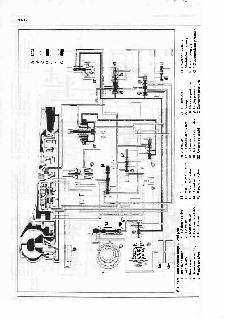
Intermediate - Second gear Power flow Foward clutch - applied. Direct dutch - released. Intermediate dutch - apptieb. Roller clutch - ineffective. Front band - applied. t ntermediate sprag clutch - effective. Rear band - released.
In second gear, the intermediate dutch is applied to allow the intermediate sprag clutch to hold the run gear against anti-clockwise rotation. Turbine torque through the forward clutch is now applied clockwise through the rnainshaft to the rear internal gear.
Clockwise rotarton of the rear internal gear turns the rear pinions clockwise against the stationary sun gear. This causes the ourput carrier and output shaft to turn clockwise in a reduction ratio of approximately 1.5 : l .
In second gear, engine braking is provided by the front band as it halds the sun gear fixed, Without the band applied, the sun gear would overrun the inter- mediate sprag clutch.
Oil Row When the selector lever is in Intermediate range. intermediate oil from the manual valve is directed to the following (see fig. f 1-31,
Pressure boost valve 2-3 shifr valve Intermediate oil a t the boon valve will increase
line pressure to 103 bar (150 lbf/in2 l . This increased intermediate oii pressure a t the 2-3 shift valve will dose the 2-3 shifc valve, regerdlerr of car speed.
For engine braking the front band i s applied by exhausing sew0 oil a t the manual valve. This allows intermediate clutch oil, acting on the servo pirton, to move the pistan and apply the front band. Once the transmission i s in second gear - Intermediate range, it cannot change to third gear regardless of ear sped.
Summary The forward and intermediate clutches and front band are applied. T he transmission is in second gear l Intermediate range].
Low range - First gear Power flow Forward clutch - applied. Direct clutch - released. Intermediate clutch - released. Roller clutch - effective. Front band - released. Intermediate sprag clutch - ineffective. Rear band - applied.
With the selector lever in Low range, the forward clutch i s applied. 1 his delivers turbine torque to the rnainshaft and turns the rear internal gear clockwise. (Converter torque ratio is approximately 2.2 : 1 at stall).
Clockwise motion of the rear internal gear causes the rear pinions to turn clockwise to drive the sun gear ant i-clockwise. In turn, the sur: gear drives the front pinions clockwise, thus turning the front internal gear, output carrier. and outpur shaft clockwise in a reduction ratio of approximately 2.5 : 1. The reaetion of the front pinions against the front internal gear is taken by the reaction carrier and roller clutch assembly to the transmission case. (Total stall ratio is approx;, ima~ely 5.5 : 1 l.
Downhilf or overrun braking is provided in Low range by applying the rear band as this prevents the reaction carrier from overrunning the roller clutch.
Oil flow Maximum downhill braking can be attained at speeds below 64 km/h (40 milelh) with the selector lever in Low position as this directs Cow oil from the manual valve to the following (see fig. f 1-10).
Rear servo 1-2 accumulator valve Detent regulator valve 1-2 shift valve
Basic cornrd When in Low range oil flows past a check ball to the apply side of the rear sew0 piston and to the 1-2 accumulator valve to raise the 1.2 accumulator oil to line pressure for a mooth band application.
Low range oil acts on the detent regulator v&Iv8. Combined with the detent spring, t o w range oil hotds the detent valve against line oil acting on the detent valve. causing drive oil t o flow through the derent regulator valve imo the detent and modulator Pa- Modulator and detent oil at l ine pressure acting On the 1-2 regulator and 1-2 derent ualve overcomes

governor oil and LOW oil on the 1.2 shift valve a t any vehicle sped below approximately 64 kmlh (40 mitelh) and the transmission wi l l change to firrt gear.
In first gear {Low range). the transmission cannot upchange to second gear regardless of car or engine - speed.
Summary The forward clutch and rear band are applied. 1 he transmission is in first gear {Low range).
Reverse Power flow Forvvard clutch - released. Direct clutch - applied. Intermediate clutch - released. Roller clutch - ineffective. Front band - released. intermediate sprag cl uteh - ineffective. R ear band - applied.
In Reverse, the direct clutch is applied t o direct turbine torque to the sun gear shaft and sun gear. The rear band i s also applied, holding the reaction carrier.
Clockwise torque t o the sun gear causes the front pinions and front internal gear to turn anti- clockwise in reduction. The front internal gear is connected directiy to the output shah, thus provrd ing the reverse output gear ratio approximate1 y 2 : 1. The reverse torque mulliplication at stall Iconverter and gear rariosl is approximately 4.4 : 1 .
Oil flow When f h t selector lever i s moved to the Reverse posit~on, the manual valve i s repositioned t o allow oil at line pressure to enter the reverse circuit. Reverse oil then flows t o the following (see fig. T1-l l}.
Direct clutch 2-3 shiR valve Rear sew0 piston Pressure boost valve
Basic control Reverse oil from t h e manual valve flows to the large area of the direct clutch pisron and ro the 2-3 shift valve. From the 2-3 shift valve, i t enters the direct clutch passage and is directed to the small area of the direct clutch piston t o apply the direct clutch.
Reverse oil flows t o the rear servo and acts on the servo piston to apply the rear band. Reverse oil aca also on the pressure boost valve to boon line pressure.
Summary The direct cfureh and the rear band are applied. The transmission is in Reverse.
Park or Neutml - Engine running Power flow Forward clutch - released. Direct clutch - released. Intermediate clutch - released. Roller clutch - ineffective. Front band - reteared. Intermediate sprag clutch - ineffective. Rear band - reteasd.
In Neutrat or Park no bands or clutch= are applied therefore no power is transmitted.
Oil flow Whenever the engine is running at idle with the selector lever in P or N. oil from the pump is directed to !he following lsee fig. Tl-12).
Pressure rmlator valve Torque convener 0 il cooler Lubrication system Manual valve Detent vaiva Detent xrtenoid Vacuum modulator valve Front servo (Neutral only)
Coding and lubrication Oil flows from the pump to the pressure regulator valve wh ieh regulates pump pressure. W!;en the pump output exceeds the demand of line pressure, oil f tom the pressure regulator i s directed to the converter feed passage to f i l l the convener. Oil from the converter is directed to the transmission heat exchanger. Oil from the heat exchanger is directed to the transmission lubrication system.
Line pressure acts on the following. Manual valve Detent valve Detent solenoid Modulator valve Front servo Line pressure at the modulator valve is regulated to
a pressure called modulator oil; which acts on the pressure boost valve, 1-2 accumulator, and primary valves. It then passes through the detem valve and 3-2 valve to the 1-2 and 2.3 valve trains.
Summary The torque converter is filled, and all clutches and bands are released. The transmission is in Neutral.

WORKSHOP MANUAL Section T2 T2- t
Servicing
Careful and regular maintenance of the transmission is necessary to ensure maximum reliability.
For details of the sewicing and maintenance requirements of the transmission. refer to the Service Schedules Manual - TSD 4406.
It is absolutely essential that attention be paid to cleanliness whenever the interior of the rransmission is exposed and when work 1s being carried out on a panicular unit belonging to the f ransmisslon. f he smallest panicle of dirt in the oil may interfere wirh the correct operation of the valves, panicularty in the control valve unlt.
Fluid level - To check and top-up Tne fluid level in :he torque convener fransrnission can be checked accurately onlv when :he car IS standing on a level surface, the englne IS running 2: the idle soeed. and the rransmisslon fluid IS at normal operating temperature. ap~roxirnsrely 77'C. f his is only obtained after 24 kilometres ( 1 5 rnllesl of h~ghway/motorwav driving or after 1 6 k~tornetres { 10 m~les) of city d r~v~ns .
As an init~al check. ttle fluid level mai be checked after staning from cold as follows. 1. With the car on a level surface. appl) the parking brake and chock the road wheels. 2. On Silver Sptrit, Silver Spur. and Mulsanne (~nctud~ng Turbo] cars, remove a w~ndscreen wiper relay, preferably number Three. slruated aalacent to the windscreen washer reservoir. Then, remove the w~ndscreen wlper motor drive mechanum cover Iaf fined). 3. On all cars, start: the engine and run a: the fan- Idle speed. wrth the gear range selector lever in the Park position. 4. Whilst sittrng In the driver's seat, apply the footbrake and move the selector lever through each range, pausing brtefly In each range. before returning to the Park position. 5. Immediately. check the fluid level with the engine at the idle speed. The level should be up to the dimple on The the dipstick (see ftg. T2-1. B], or approximately l0 m m (0.375 in) b l o w the MIN mark (see fig. T2-1. A). depend~ng upon which type of dipstick is fined.
A further check should then be carried out as foilows. 6. Drtve the cavfor avvroxamatety 24 kliometres { 1 5 miles) of h~ghway/rnotorwav drlvlng or 16 kilometres (10 mlles) of clty drtvrng. 7. Wnh the car on a level surface. apply the parking brake and chock the road wheels.
Fig. T2-1 Checking the oil level ? Transmlss~on oil d~pstlck A Ortgtnal dipstick markings B Revised d~pstick markings
8. On Silver Sptrit, Silver Spur. and Mulsanne (including Turbo) cars. remove a w~ndscreen wiper relay. preferably number three. sltuared ad~acent to the windscreen washer reservotr. Then. remove the wtndscreen wiper motor drive mechanlsrn covet [if fined). 9. On all cats. start the engine wrth the gear rsnge selecror lever In the Park posnlon. 10. Whilst sinlng tn the driver's seat. apply the footbrake and move the selector lever through each

range, pausing briefly in each range, before returning to the Park posirion. t l . Immediately. check the fluid lwel with the engine at the idte speed. The level should be between the FILL and MAX HOT marks (see fig. 72-1, B). or between the MI N and MAX marks (see fig. T2- l , A), depending upon which type of dipstick is fined. 12. With the engine running, add fiuid as requrred by pouring it down the filler tube. Note Do not overfill. 13. Replace the windscreen wiper motor drive mechanism cover and relay.
For a complete list of the lubricants currently approved refer to Chapter D.
Transmission dipstick and filler tube The transmission dipstick and filler tube are situated on the right-hand side of rhe engine. close to the bulkhead. The word GEARBOX is marked on the top of the dipstick (see fig. T2-l).
To drain the sump and renew the intake strainer 1. Posit~on the car on a ramp. 2. Place a clean container. minimum capacity 3 litres (5 Imp pt. 6 US pt) under the nut wh~ch secures the filler tube ro the s ~ d e of the sump (see fig. T2-2). 3. Remove the wtndscreen wiper motor drive mechanism cover (if fined]. 4. Slacken the nut securing the dipstrck filler tube to the right-hand side of the transmission sump. W~thdraw and move to one stde the filler-tube and
Fig. 72-2 Transmission sump 1 Fluid filler tube 2 Fluid drain point 3 Gearchange actuator 4 Electronre impulse transmlrter
drain the fluid into the container. 5. Remove the setscrews securing the sump. 6. Remove the sump and discard the gasket. 7. Drain the remainder of the fluid from the sump. 8. Clean the sump with paraffin and dry with- compressed air. 9. Unscrew and remove the stepped bolt securing the intake pipe and strainer assembly to the transmission casing: remove the strainer assembly. 10. Discard the infake strainer but retain the intake pipe which connecrs the stralner to the casing. 1 l . Fit a new rubber '0' ring onto the intake pipe. lubricate the '0' ring with transmission fluid. 12. Ensure a new rubber seal is fitted to the bore in the new intake strainer. Fit the strainer to the intake pipe and secure the strainer with the stepped bat. 13. Fit the sump, using a new gasket. Torque tighten the setscrews (refer 10 Section T22). 14. Fit the oil filler tube and tighten the nut. 15. Add 45 litres (8 Imp pt.9M US pt) of an approved fluid (see Chapter D) to the sump, pouring the fluid down the dipstick filler tube. Note When dratning the sump but not renewing the intake srralner. add only 2.8 litres (5 Imp pt. 6 US p%]. 16. Apply the parking brake and chock the road wheels. 17. Stan and run the engine at the fast-idle speed. 18. Wh~lst sitt~ng in The arlver's seat. apply the footbrake and move the selector lever through each range. pauslng brrefiy In each range. before returning to the Park positron. 19. Immediately. check the fiuid level wnh the engfne at the idle speed. Add flotd as necessaw to bring the level to the drmple (see f~g. T2-1. B), or approximately 1 0 mm (0.3 75 in) below tne M l N mark (see fig, f 2- I .A). depending upon wh~ch ryDe of dipstick rs fmed.
Note Do not overfill, as foam~ng may occur when the f lu~d warms up. If the fluid level is too low. especially when cold. complete loss of dr~ve may result after quick stops. Enremely low flurd levels will result in damage to rhe transmission. 20. Finally, check the transmission fluid level is correct (see Fluid level - To check and top-up. Operations 6 to 13 ~nclus~ve).
Transmission unit (dry) - To f i l l The fluid capacity of the torque convener transmission. ~nctuding the torque converter, is approximately 10,6 litres (1 8.7 5 Imp pt. 22.5 US pt), but the correct level is determined by the marks on the dipsrick rather than by the quantity of fluid added
It is imponant that the correct level is maintainid. When the tnnsmission has been overhauled or a new one fined and 8 complere f i l l is required. including the torque converter. proceed 8s follows. 1 . Pour approxtmately 6.5 litres (1 1.5 imp gt 14 US pr) down through the filler tube. 2. With the car on a level surface. apply the parking brake and chock the road wheels.
WORKSHOP MANUAL
3. Stan and run the engine at the fast-iale speed. 4. Whilst sitting in the driver's seat, apply rhe footbrake and move the selector lever through each range. pausing briefly in each range. before returning to the Park posnion. 5. Immediately, check the fluid level with the engine at the idle speed. Add fluid as necessary to bring the level to the dimple (see fig. T2-1. B), or approximately 10 mm (0.375 in; below the MIN mark (see fig. T2- 1 .A), dependrng upon which type of d~pstlck is f ~tted. 6. Drive the car for approx~mately 24 kilometres (1 5 miles) of highway/motorway driving or 16 kilometres (1 0 m~ies) of city driving, then check the fluid, level again. Topup if necessary, as described in Fluid level - To checir and topup.
The transmlsslon sump should be drarned at the ~ntervals specified In the Sewice Schedule Manual (TSD 4406). New fluid should be added to maintain the correct level on the dipstick.
The fluid intaice system incorporates an intake strainer. This stralner should be renewed at the intervals specified In the Service Scnedule Manual. In the event of a major failure In the rransmlsslon. the stralner must be renewed.
Transmission unit - TO check for leaks Whenever the transmissior. has been dtsmsntled. completelv or panially, the following proceaure musr be observed to m~ntmise the posslDihty of !tu&d leakage. 1 . Always fit new gaske~s and 'D rlng seals. 2. Use a small amount o! petroleum jelly ?g hold a gasket In posltlon during assembly. 3. Do not use a sealing compounc! {e.g. \YeItseall with a gasker. 4. Ensure that :he cork and paper gaskers are not wr~nkled or creaseo when f~rted. or have distorted dur~ng storage. 5. Ensure that The square-sect~oned '0' rings are correctly flned anc! are not twlsted. 6. Ensure that all mating faces are clean and free from burrs and damage. 7. Torque tighten bolts. setscrews. etc., to the torque figures given In Section f 2 2 and Chapter P. 8. When examlnlng the transmlsslon for leaks. determine whether fhe flutd or~ginates from the transmissaon or the engrne. The or~g~nal factory fill ftuid is red in colour. this asststs in locating the source of leakage. If however, the colour cannot be detected in the transmission fluid. add a red aniline dye preparation to the fluid. Red dye appearing In the leaktng fluid will positrvely Identify the source of the leak
If the f lu~d IS known to be leaking from the transmlsszon. examlne the following areas.
Frant end It will be necessarv to remove the bell houslng bottom cover and the lower front cover plate In order to examine the rransmlsslon for leakage at the front end.
To correct a leak at the front end the transmrssion will have to be removed from the car. 1 . If the pump oil seal is suspected of leaking fluid. ensure rhar the seal has been correctly fined and is not damaged.
When fitrtng a new seal (see Section T16) ensure that the seal bore in the case is ciean. Examine the f~nish on the converter neck and the bearing surface In the pump body. 2. Examine the pump squaresectioned 'U ring and the gasket for damage, renew if necessary. 3. Ensure that the rubber coated washers on the pump securing setscrews are correctly fitted and are not damaged. 4. Examine the torque convener for leakage (see Section T7).
Rear extension 1 . Examine !he rear extension housing oil seal for damage. 2. Examine the finlsh on the slid~ng coupling. 3. Ensure that the gasket fined between the joint faces has been correctly fitted and is not damaged. 4. Check the securlng setscrews for correct torque t~ghtness isee Chapter P). 5. Examine rhe housrng for cracks or porosity.
T ransrnission case 1. Examlne the speedometer electronic impulse transmrtter drwe '0' rlng and tlptype seaL Ensure that the securtng setscrew rs torque tightened. 2. Examine the governor cover gasker. Ensure that rhe setscrews are Torque tightened (see Section T22). 3. Examme the electrical connector '0' rlng for damage. 4. Exarn~ne :he parking pawl shaft cup plug for damage. 5. Exam~ne rhe manual shaft '0' rlng for damage. 6 Examine the vacuum modulator '0' rfng for damage. Ensure the retaining setscrew is torque t~ghtened (see Chapter P). 7. Examtne the vacuum modulator for possible damage to the diaphra$m. Note If the transm~ssion is found to be consistently low On fluid. check the modulator to ensure that !here is no split in the diaphragm. Apply suctlon to the vacuum tube and check for leaks. A splrr diaphragm would allow transm~ssion fluld to be drawn into the engine rnduction manifold and vacuum line. This condition Can usually be detected because the exhaust will be excessively smokey due to the rransmission fluid balng added to the combust~on mlxture. 8. Examine the sump gasket Check the toque t~ghtness of ?he securing setscrews (see ChsPI8T P). 9. Check the torque r~ghtness of the mam line pressure tapptng plug (see Section 122). 10. Examine the brearher p~pe for damage. l l . Ensure that f he transmlsslon has not bWn overfilled. 12. Check for coolant tn the transmlssron fluid. 13. Examine the case for cracks or porosity-

14. Ensure that the pump to case gasket is not incorrectly posnioned. 15. Ensure that foreign maner is not between the pump and case. or between the pump cover and body. 16. Ensure that the breather hole in the pomp cover is not obstructed. 1 7. Ensure that the 'U ring on the falter assembly is not cut.
Meat exchanger connections Ensure that the heat exchanger transmission fluid pipes are correcrly firted and are not damaged. Ensure that the nuts are tight.
Dipstick and filler tube Examrne the fla'red end of the dipstick and filler tube for cracks or damage. Examrne the spherical seat in the sump. Ensure that the sleeve nut is tightened sufficiently to nip the tube securely to the sump.
lnterna l leaks Note Ensure that the manual linkage is set correctly before removing the sump. as incorrecr setrings can cause internal kaks at the valves.
If the manual linkage is set correctly. remove the sump. 1. Check the governor pipes for security and damage. 2. Examine the rear servo cover gasket for damage. Ensure that the squaresectioned '0' ring is fitted correctly and is not damaged. Torque tighten the cover securing setscrews (see Section f22) . 3. Examine rhe control valve unit assembly and oil spacer (guide) plate gaskets. Check the torque tightness of the unii securing setscrews (see Section T22). 4. Check the torque t~ghtness of the solenoid securing setscrews (see Sect~on T22). 5. Examine the inrake pipe '0' ring for damage. 6. Check that the case vafve body mounting face is not distorted.
Control joints - To lubricate During initial assembly. the clevis pins in the control linkage are lubricated with Rocol MTS 1000 grease and should be similarly treared whenever they are removed.
When a car is being serviced. the opportunity should b taken to check the controls for correct operatian and to lubricate all the control joints with a few drops of engine oil.
~ r r n k a l shaft To lubricate As pan of the linkage maintenance procedure. it is recommended that the manual shaft be lubricated with a few drops of oil at the point where it enters the transmission case.

WORKSHOP MANUAL Section l3 T3 - 1
Testing
Before road testing the car to check the funtioriing of the transmission, carry out the following checks.
The car ean then be road tested, using all the selecror ranges. Note when any operating faults occur. Check the gearchange pattern as follows. l . Check the fluid level, top-up if necessary. 2. Ensure thaz the engine and transmissron are at normal operating temperature 77OC. 3. Ensure that the gearchange actuator is operating satisfactoriiy. 4. Check the operation of the kickdown switch, adjust if necessary {seechapter K} . 5. If the oil pressure i s to be checked, f i t a gauge. 6. Check the manual linkage.
Gearchange pattern check Drive range 1. Select D range, :hen accelerate he car from stand- still. 2. A 1-2 and a 2-3 up-change should occur a t all throttle openings. Note Tne change points will vary according to throttle open- ing. 3. As the speed of the car decreases to a stop. the 3-2 and the 2-1 down-changes should occur.
Intermediate range 7 . Select I range. 2. Accelerate the car from standstill. 3. A 1-2 up-change should occur at all throttle open. ings. 4. A 2-3 up-change cannot be obtained in this range. 5. The 1.2 up-change point wil l vary according t o throttle opening. 6. As the speed of the car decreases t o a stop. the 2-1 down-change should occur.
Low range 1. Se lm L range. 2. No up-change should occur in this range. regardless of thronle opening.
2nd gear - overrun braking 1. Select D range. 2. When a speed of approximately 56 km/h 135 rnile/h) has been reached, move the selector lever to the I range position. 3. The transmission should change down to 2nd gear. 4. An increase in the speed of the engine as well as an engine braking effect should be observed. 5. Line pressure should change from between 4.1 bar and 6.2 bar (60 tbflin2 and 90 lbf/inZ1 to approximately 10,3 bar (150 lbf/in21.
1st gear - downhill or overrun engine braking 1 . Select I range. 2. When the speed of the car is approximately 48 kmlh (30 mile/h) [ensure that it does not exceed 64 kmP (40 rnilelh)] and at constant throttle, move the selector to L range. 3. An increase in engine revlrnin and a braking effect should be noticed as the downchange occurs.
Oil pressure - To check Before attempting to check the oil pressure or to road rest the car, atways ensure that the level of f luid in the transmission is correct (see Section T2).
The pressure can be checked with the transmission in the car by using an oil pressure gauge coupled to the main line tapping in the left-hand side of the tram- mission case. 1. Clean any dirt from around the line pressure plug; remove the plug. 2. Fit the adapter RH 7914 into the main line tapping; tighten the adapter. . 3. Screw a pressure gauge, capable of reading between 0 bar and 20,6 bar 10 lbf/in2 and 300 lbfl in2 1 onto the ,
adapter then pos~tion the gauge so that it can be seen; -" from the driver's seat. - 4. Connect a tachometer to the engine: this will enable m-
the gear change points to be positively identified. 5. Drive the car unt i l the rransrnilsion has reachd normal operating temperature 77OC. 6. Check the f iuid ievel. top-up i f necessary.
Road testing the car The following checks shwld be carried out d u r i n ~ road testing.
Engine idle pressure check 1. Select D range. Drive the car at approximately 48 kmlh (30 rnilelh) with the thrortle eased back. The line pressure should be 4.8 bar (7 0 lbf/in2 1. 2. Select I range. Drive the car to obtain a stwdy road speed of 40 kmlh (25 rnile/h). Line pressure should be Mtwten 10.0 b r a n d 10.7 bar 1145 lbf/in2 and 155 Ib f l
2 in 1-
Full throttle ptessure check 1. Jack up the rear of the car and position block that the rear wheels are clear of the ground. 2. Disconnect the vacuum line at the indunion manifold. 3. Blank off the orifice in the manifold. 4. Run the engine a t fan-idle (between 800 rev/min and IOW rev/min) i n Neutral. The oil prmure *odd be 10,O bar 1145 lbfl in2).
5. Repeat the procedure in Reverse. Reverse pressure should be between f 0.0 bar and 10,7 bar I145 lbf/in2 and t55 lbf/in21. 6. Connect the vacuum pipe.
Towing The car mun not be towed if any mechanical darnage ta the transmission components i s suspected, or if the torque wnverter transmission fluid level i s low.
Before towing, check the fluid level in the trans- mission. T h e level must be above the MAX mark on the dipnick when the engine i s not running.
Should it be necessary to tow the car, even for a shon distance, a solid tow bar must be used. This is important, as without the engine running to maintain the pressure in the hydraulic systems, the efficiency of thl
the braking systems is reduced. I f the pressure in the hydraulic systems has been
exhausted by operating the footbrake pedal without the engine running. the footbrake would not stop the car. If a sol id tow bar ismot available, the car must be transported.
Always tow the car with the torque converter transmission in Neutral.
To seiect Neutral it is first necessary to insert the ignition key in the switchbox and turn it to the RUN position. Providing that the battery i s in a charged condition, this action will energise the gearchange actuator mechanism and Neutral can then be selected by operating the gear range selector lever. Should the battery be in a discharged condition however. turning the ignition key will not energise the gearchange mechanism and operating the gear range selector lever therefore will not activate the actuator mechanism. In this event, it will not be po$sible to move the trans- mission out of the Park position and it will be necessary to disconnect the gearchange acruator linkage at the manual shaft lever. Then. before the ear can be towed or transported, engage Neutral by moving the manual shaft lever two positions rearwards from the fully forward position.
Normally, wheir the ignition key is removed from the switchbox, Park position is automatically engaged and the parking pawl locks the transmission. If it is required to remove the ignition key and still leave the ear in Neutral for rowing. this can be accomplished by first removing the gearchange actuator thermal cut-out from the fuseboard and then removing the key from the switchbox.
T h e car Ean only be towed for distances of up to &U kilometres (50 miles] and the maximum towing speed must not exceed 56 kmlh (35 rnilelh). For greater distances the propeller shah mun be disconnected or the mr must be transported.
WORKSHOP MANUAL
Removal of units -
Removable unis - Transmission in wr The following uniu can be removed from the trans- mission without the transmission being removed from the car.
The removal procedure for all the units is described in the appropriate section, with the exception of the pressure regulator wlve, details of which are included in this section.
Gearchange acruator (see Section T5). Vacuum modulator and valve Isee Section TB). Governor assembly (see Section T9). Speedometer drive Isee Section T10). Sump, drainer and intake pipe Isee Section T11 l. Control valve unit (see Section T12). Rear servo (see Secrion T13). Detent solenoid, connector, control valve spacer and front servo (see Section T14). Rear esension (see Section T751. Contro! rods, ievers and parking linkage (see Section T17).
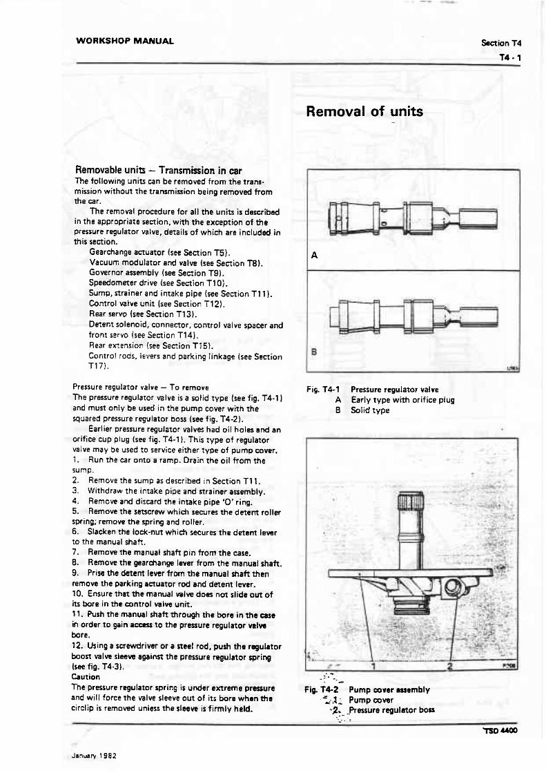
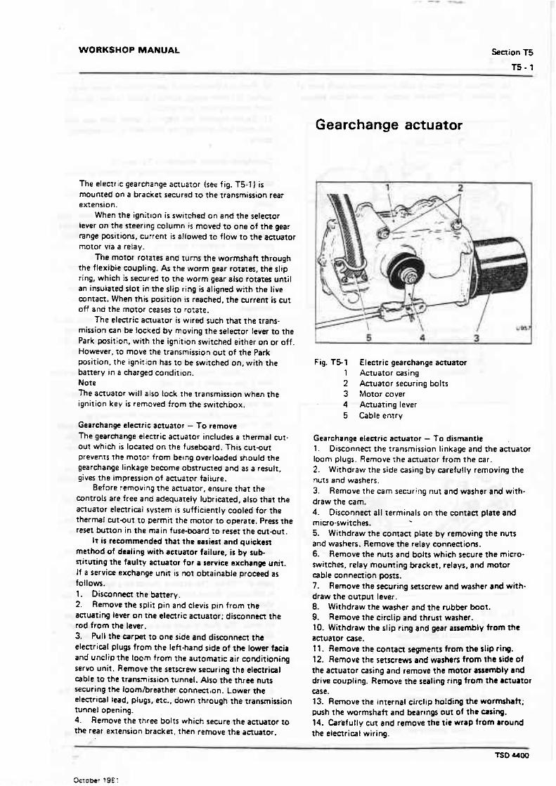
Pressure regulator valve - To remove The pressure regulator valve is a solid type (see f ig. T4-1) and must only be used in the pump cover with the squared pressure regulator boss [see fig. T4-2 1.
Earlier pressure regulator valvei had oil holes and an orifice cup plug (see fig. T4-1 l . This type of regulator valve may be used t o service either type of pump wver. 1. Run the Esr onto a ramp. Drain the oil from the sump. 2 . Remove the sump as described in Section T11. 3. Withdraw the ir.take pipe and strainer assembly. 4. Remove and dircard the intake pipe '0' ring. 5. Remove the seaerew whi& secures the detent roller spring: remove the spring and roller. 6. Slacken the lock-nut which secures the detent lever to the manual shaft. 7. Remove the manual shaft pin from the case. 8. Remove the gear&ange lever from the manual shaft. 9. Prise the detem lever from the manual shaft then remove the parking anuator rod and detent lever. 10. Ensure that t h e manual valve does not slide aut of iu b r e in the control valve unit. l l . Push the manual shaft through the bore in the case in order to gain a- to the pressure regulator MIW b e . 12. Using a screwdriver or a neel rod, push the regulator boon valve sleee against the pressure regulator spring (she fig. T4-3). Caution The pressure regulator spring i s under extreme pmmure and will force the mlve sleeve out of i t s bore when the circlip is removed unless the sleeve is firmly held.
Fig. T4-1 Pressure regulator valve A Early type with orif ice plug B Sofid type

Fig.'T4-3 Removing the pressure regulator vahe A Spring compressed B Circlip removed
Fig. t 4 - 5 Fitt ing the oil pump real 1 Oil seal 2 Seal fitting tool
13. Continue to exert pressure on the valve sleeve then remove the circlip. Gradually relax the pressure on the valve sleeve unfil the spring pressure is released. 14. Carefully remove the regularor boast valve sleeve and valve, then withdraw the regulator spring. Take care not to drop the valves. 15. Remove the pressure regulator valve and spring retainer. Remove the spacers (if f inedl.
Pressurn regulator valve - To f i t Before fitting, wash and examine all parts. 1. Fit t h e spring retainer onto the Rressure regulator spring. Fit any spacen which were previously removed. 2. F i t the prenure regulator valve, stem end first, onto the spring. 3. Fit the host valve into the sleeve with the valve stem outward. Then. hold together all t he parts so that the pressure regulator spring is against the valve sleeve. 4. Fit the complere assembly into the pressure regulator valvc bore, taking care that t h e parts do no t fall. 5. Using a mewdriver o r a steel rod, push the regulator boost valve sleeve against t h e regulator spring praure until the end of the sleeve has passed beyond the c i rd ip groove. 6. Fit t h e urclip then relax t h e pressure on the sleeve. 7. Fit the parking actuator rcd and detent lemr, ensuring that the r o d plunger i s undqr the parking brake backat and over the parking pawl. 8. Slide the manual shaft into t h e utse and through the dotem lewr.
Fig. T4.4 Removing the oil pump sea1 9. Fit the grnrrfiange l a w .

WORKSHOP MANUAL
10. Fit the lock-nut onto the manual haf t . Torque tighten the nut. 11. E m r e that the manual valw is engaging with thc pin on the deteni lever. 12. Retain the man-l-shaft with the pin. Straighten !he pin to lodc it into position. 13. Fit the detent spring and roller assembly; torque tighten the setscrew. 14. Fit the intake pipe and strainer assembly, also the sump as described in Section T l l . 15. Top-up the transmission with an approved fluid (see Chapter 01.
Oil pump seal - To renew 1. pernave the transmission from the car (see Section T61. 2. Carefully drive the point of a chisel under the lip of tbe seal then prise the seal out of the pump body (see fig. T441. 3. Before fitting a new seal, ensure that the body bore is clean and free tfom burrs and that the garter ring is on the seal. 4. Cheek the finish of the convener neck and the bear- ing surface in the pump body. 5. Lightly smear the ourer edge of the seal case with Wellseal then fit the seat to the pump using tool RH 7953 as shown in figure T4-5. 6. Fit the transmission to the car (see Section T61.
WORKSHOP MANUAL Section T5
Gearchange actuator
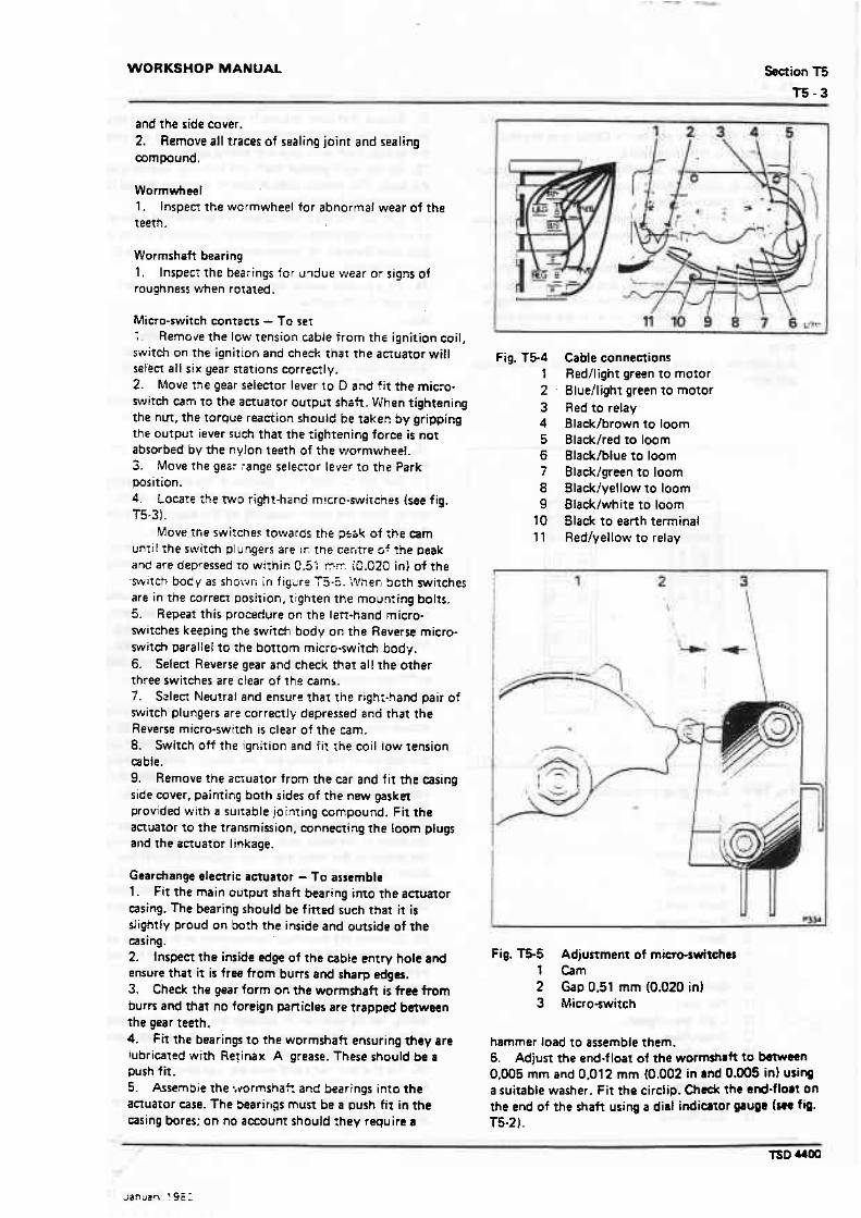
The electric gearchange actuator (see fig. T5-'11 is mounted on a bradiret secured to the transmission rear extension.
When the ignit~on i s switched on and the selector Lever on the steering column i s moved to one of the gear range positions, current is allowed to flow t o the aauator motor via a refay.
The motor rotates and turns the wormshaft through the flexible coupling. As the worm gear rotates, the slip ring, which is secured to the worm gear also rotates until an insulated slot in the slip ring is aligned with the live contact. When this position is reached, the current is cut off and the motor ceases to rotate.
The electric actuator is wired such that the trans- mission can be locked by moving the selector lever to the Park position. with the ignition switched either on or off. However, to move the transmission out of the Park position. the ignition has to be switched on, with the battery in a charged condition. Note The actuator will also tock the transmission when the ignition key is removed from the switchbox.
Gearchange elemric actuator - To remove The gearchange electric aauator includes a thermal cut. out which is located on the fuseboard. This cutout prevents the motor from becng overloaded should the gearchange linkage become obstructed and as a result, gives the impress~on of actuator faiiure.
Before removing the actuator. ensure that the controls are free and adequately luhriated, also that the acruator electrical system i s sufficiently cooled for the thermal cutout to permit the motor to operate. Press the reset bunon in the main fuse-hard to reset the cutsut.
It i s recommended that the easiest and quicken method of dealing with actuafor failure, is by sub- nituting the faulty aetuator for a service ~xchange unit. If a service exchange unif is not obtainable proceed as follows. 1. Disconnm the battery. 2. Remove the split pin and clevis pin from the actuating lever on the electric actuator; disconnect the rod from the lever. 3. Pull the carpet to one side and disconnect the electr id plugs from the left-hand side of the lower facia and unclip-the toom from the automatic air conditioning servo unit. Remove the setscrew securing the electrical able to the transmission tunnel. Also the three nuts securing the loomlbr'eather connectton. Lower the electrical lead. plugs, etc.. down through the transmission tunnel opening. 4. Remove the three bolts which secure the actuator to the rear exrension bracket, then remove the actuator.
Fig. T51 Electric gearchange actuator 1 Actuator casing 2 Actuator securing bolts 3 Motor cover 4 Actuating lever 5 Cable entry
Gearchange efenrie actuator - To dismantle 1. Disconnect the rransmission linkage and the aauator loom plugs. Remove the aauator from the car. 2. Withdraw the side casing by carefully removing the nuts and washers. 3. Remove the cam sec~ring nut and washer and with- draw the cam. 4. Disconnect all terminals on the contact prate and rnicraswitches. - 5. Withdraw the contact plate by removing the nuts and washers. Remove the relay connections. 6. Remove the nuts and bolts which secure the micro- switches. relay mourning bracket. relays, and motor able connection porrs. 7. Remove the securing setscrew and washer and with. draw the output lever. 8. Withdraw the washer and the rubbr boot. 9. Remove the circlip and thrust washer. 10. Withdraw the slip ring and gear assembly from the aetuator case. 1 l . Remove the contact segments from the slip ring. t2. Remove the setscrews and washers from the side 01 the acruator casing and remove the motor assembly and drive coupling. Remove the sealing ring from the rctuator case. 13. Remove the internal circlip ho!ding the w~tmshaff; push rhe wormshah and bearing out of tht wing. 14. Carefully CUT and remove the tie wrap frornrround the electricat wiring.

15. Remove the securing clips from around both ends of the conduit; withdraw the conduit from the cart elbows.
Fig. T5-2 Checking wormshaft end-float 1 Wormshaft 2 Dial indicator gauge 3 Gauge arm 4 Slave gear
Fig. l53 1
2 - A
B C D E F G H J
Micro-switch ~annsetions Reverse micro-switeh Neutral start switch Greedyellow cable Bluehrown cable Whitelbrown wble Brownhlate cable Greenblue cable '
Green/black able Whitelred cable Whitelyellow wble Light greedgreen cable
16. Push out the elenrical leads from the loom plugs. Collect the loom plugs. conduit etbow (tunnel connec- tion), securing clips. and conduit. 17. Fasten together rhe electrical cables with tape and pull them back through the cable exit of the anwtor casing.
Gearchange electric actuator - T a in rp ta 1. Examine the magnesium casing for cracks or other damage. 2. Ensure that the joint faces are clean and free from burrs. 3. Examine the driving dog slot for excessive wear, atso the mating shaft on the drive end of the motor armature shaft. The dog should be a n easy sliding fit on the shatt but without excessive side play. 4. Examine the general condition of the plugs. 5. Examine the eight spring contacts for security on the insulated base.
Care must be taken when handling the assembled bsse plate to that the contacts and the relays are not damaged. 6. Check the height of the contacts from the base plate. The contaet point should be approximately 12,32 mm (0.485 in1 from the contact (lower) side of the base. If excessive wear has occured on the contact points the base assembly should b e renewed. 7. If a Bosch relay assembly i s faulty, it i s recommended that a new assembly be fitted. 8. Ensure that the terminals and the terminal blocks are secure on the insulared base. 9. Examine the general condition of the wiring. 10. i f the components are satisfactory. retain them with adhesive tape until they are required for final assembly. 1 1 . Check the tightness of the setscrews which secure the slip ring arsembly to the shaft. 12. Ensure that a 0.64 mm 10.025 in) air gap exists on each side of the silver plated segmenrs which are secured to the slip ring. 13. Ensure that the edges of the slip ring around the air gap are free from burrs. 14. Examine the slip ring face for signs of tracking. This should not normally occur but, if signs of tracking are found, the slip ring assembly must be renewed. 15. Examine thereeth on t h e worm gear and the worm for damage or uneven wear. 16. Examine the bearing bores in the main casing for signs of fretting. The bearing should be a iight push fit in the casing. Reject the casing if the push f i t cannot be obtained. 17. Examine the bush which supports the output shaft for wear. The shaft should be a running fit in the burh. without excessiw clearance i.e. the shaft should not rock in the bush.
Actuator plugs and cable assembly 1. Inspect the cables where they enter the plugs. 2. Ensure that no corrosion exists and that mnc of the individual cable strands are broken.
Actuator msing 1. Inspect all the sealing faces and the actuator casing
WORKSHOP MANUAL Section T5
l -5 -3
and the side couer. 2. Remove all traces of sealing joint and sealing mmpound.
Wormwheel 1. lnspen the wormwheel for abnormal wear of the teeth.
Wormshaft bearing 1 , lnspecr the bearings for m3ue wear or signs of roughness when rotated.
Micro-switch contacts - To set :. Remtive the low tension cable from the ignition coil, switch on the ignition and check that the actuator will set'ect all six year nations correctly. 2. Move the gear selector lever to D and fit the micro- switch cam to the actuator o u t p ~ t shaft. When tightening the nut. the torque reaction shoulc! be taker: by gripping The output iever such that the rightening force i s not absorbed by the nylon t m h of the wormwheel. 3. Move the gear range se1ec:or lever to the Park position. 4. Focarf :he t w o right-hand m!crc-switcnes [see fig. T5.31.
Move !fie switcnes towards the psbk of :he cam un:i( the srvirch plungers are ~ r , me cer~tre 5 5 the oeak and are depressed to withir. 0.51 ET. IC.OZO in) of the w ~ t c t r body as shorvr; in fig-dre f 5-6. :Ilher. Soth switches arc in the correct position, tighten tne moun:ing bolts. 5. Repeat this procedure on the lait-hand micro- switches keeping the switch body or: the Reverse miero- switch parallel to the bottom micro-switch body. 6. Select Reverse gear and check tha? all the other three switches are clear of the cams. 7. Select Neutral and ensura that the right-hand pair of witch plungers are correctly depressed and that the Reverse micro-switch is clear of the cam. 8. Switch off ?he ignition and fit the coil low tension cable. 9. Remove the acruator from the car and fit the asing side cover. painting both sides of the new gasket provided with a su~table jointing compound. Fit the actuator to the transmission. connecting the loom plugs and the actuator linkage.
Gearhange electric actuator - To assemble 1. Fit the main output shaft bearing into the actuator casing. The bearing should be fitted such that it is slightiy proud on both the inside and outside of the casing. 2. lnspen the inside edge of the cable entry hole and ensure that it is free from burrs and sharp edges. 3. Check the gear form on the wormshah is free from burrs and that no foreign pa~icles are trapped between the gear teeth. 4. fit the bearings to the wormshatt ensuring they are lubricated with Retinax A grease. These should be a push fit. 5. Assernbie the svormshafr and beerings into the actuator case. The Searings must be a push fit in the =sing bores: on no amount should :hey require a
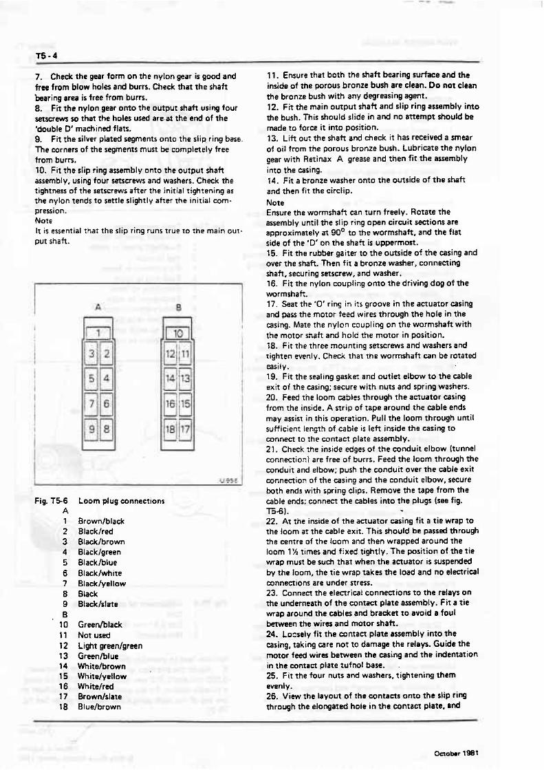
Fig. 1 5 4 I 2 . 3 4 5 6 7 8 9
10 11
Cable connections Redllight green to motor Bluellight green to motor Red to relay Blacklbrown to loom Black/red to loom Blackblue to loom Blacklgreen to loom Blacklyellow to loom Blacklwhite to loom Black to earth terminal Redlyellow to relay
Fig. T5-5 Adjustment of miemswitches t Cam 2 Gap 0.51 mm (0.020 in) 3 Micro-switch
hammer load to assemble them. 6. Adjust the end-f loaf of the worrnsnn)t to bstwaan 0,005 mm and 0.012 mm (0.002 in and O.mS in) U S ~ W
a suitable washer. Fit the circlip. Dadc the end-float on the end of the shaft using a dial indiator pug0 f&. T5-2).
7. Check the gear farm on t h e nylon gear is good and frte from blow holes and burrs. Check that the shaft bearing area i s free from burrs. 8. Fit the nylon gear onto the output shaft using four setscrews so that the holes used are-at the end of the 'double D' machined flats. 9, Fit the silver plated segments onto the s l i ~ ring base. The corners of the segments must be completely free from burrs. 10. Fit the slip ring assembly unto the output shaft assembly, using four setscrews and washers. Check the tightness of the setscrews after the initial tightening as the nylon tends to settle slightly after the initial com- pression. Note It is essential that the slip ring runs true to the main out- put shaft.
Fig. T56 A 1 2 3 4 5 6 7 8 9 B
10 11 I2 I 3 14 15 16 17 1%
Loom plug connections
Brown/black Blackfred Blacklbrown Blacklgreen Blaekhlue Blacklwhite Black/yellaw Black Btadtlslate
Greedblack Not used Light greedgreen Greenblue Whitelbrown Whitelyellow Whitelred Brownlslate Blue/brown
11. Ensure that both the shaft bearing surface and the inside of the porous bronze bush are clean. Do not clean the bronze bush with any degreasing agent. 12. Fit the main ourput shaft and slip ring assembly into the bush. T h i s should slide in and no attempt should be made to force it into position. 13. Lift out the shaft and heck it has received a smear of oil from the porous bronze bush. Lubricate the nylon gear with Retinax A grease and then fit the assembly into the casing. 14. Fir a bronze washer onto the outside of the shaft and then fit the circlip. Note Ensure the wormshaft can turn freely. Rotate the assembly until the slip ring open circuit sections are approximately at 90' to the wormshaft, and the flat side of the 'D' on the shaft is uppermost. 15. Fit the rubber gaiter to the outside of the casing and over the shaft. Then f i t a bronze washer, connecting shaft, securing setscrew, and washer. 16. Fif the nylon coupling onto the driving dog of the wormshaft. 17. Seat the '0' rinq in i t s groove in the actuator casing and pass the motor feed wires through the hole in the casing. Mate The nylon coupling on the wormshaft with the motor shaft and hold the motor in position. 18. f i t the three mounting serscrews and washers and tighten evenly. Check that the wormshaft can be rotared easily. 19. F it the sealing gasket and outlet elbow to the cable exit of the casing: secure with nuts and spring washers. 20. Feed the loom cables through the actuator casing from the inside. A strip of tape around the able ends may assist in this operation. Pull the loom through until sufficient length of cable is l e f t inside the casing to connect to the contact plate assembly. 21. Cheek the inside edges of the conduit elbow (tunnel connection) are free of burrs. Feed the loom through the conduit and elbow: push the conduit over the cable exit connection of the casing and the conduit elbow, secure both ends with spring clips. Remove the tape from the cable ends; connect the cables into the plugs (see fig. T5-6 1. *
22. At the inside of the actuator casing f i t a tie wrap to the loom a t the cable exit. This should be passed through The centre of the loom and then wrapped around the loom 1% times and fixed tightly. The position of the t ie wrap must be such fhat when the actuator is suspended by the loom, the tie wrap takes the load and no electrid connections are under stress. 23. Connect the electricat connections to the relays on the underneath of the contact plate assembly. Fit a tie map around the cables and bracket to awid a foul between the wires and motor shaft. 24. Lozsely fit the contact plate assembly into the casing, taking care not to damage the relays. Guide the motor feed wires between the casing and the indentation in the wntan plate tufnol base. .
25. Fit the four nuts and washers, tightening them evenly. 26. View the layout of the contans onto the slip ring through the elongared hole in the contact plate, and

WORKSHOP MANUAL
Fig. T57 Gearchange actuator motor
ensure that there is a minimum of 127 mm (0.050 in) between adjacent contacts. Also, ensure that there i s approximately 1.58 mm (0.062 in) from either the edge of the segments or the countersinks for the retaining screws. 27. F i t the electrical connections, starting with the longest connections on the contact base, progressing to t h e shoner wires and then finally the micro-switches, suppressor, and motor terminations (see figs. f5-3 and T54 1, 28. Fit the casing lid. with its gasket painted with Wellseal on both sides. Tighten down using nuts and spring washers. 29. Fit the rubber boot over the motor. A smear of . grease inside the beading edge of the boat arsirrs the fitting. Retain the boor onto the motor using a wire clip, which, while needing reasonable tightening should not h allowed to cut into the rubber.
Gearchange actuator motor - To dismantle 1. Tap out the driving pin from the driving shaft ((see fig. T5-7). 2. Unscrew and withdraw the two bolt5 securing the motor housing. remove the housing. 3. Remove the armature f rom the end plate.
Gearchange actuator motor - To inspect 1. Examine the magnets for any damage, cracks. or fractures. 2. Examine the brushes for wear; fit new brushes if necessary. 3. Examine the armature mmmutator for wear or damage; if surred polish with fine emery cloth. If the score marks are heavy and eannot be removed with light palishing, fit a new armature. 4. After polishing carefully clean the commutator slots to remove particles of carbon. 5. Examine the bearing bushes for wear, replace if necessary. 6. Examine the armature shatt for wear on the bearing diameter.
Gearchange actuator motor -To assemble Assemble the actuator motor (see fig. T5-71 by reversing the procedure given for dlmantling. Ten the motor after assembly, if the current consumption exceeds 7.5 A, the armature has an elearical faulr and should be renewed.
Gearchange electric amuator - f o fit 1. Fi t the actuator to the rear extension of the trans- mission. 2. Torque tighten the botts. 3. Feed the plugs through the hole in the transmission tunnel. Secure the elbow t o the tunnel ensuring that a new gasket is fined. Feed the wiring loom behind the automatic air conditioning servo unit clips and connect the electrical plugs. 4. Connect the linkage. 5. Connecl the battery.
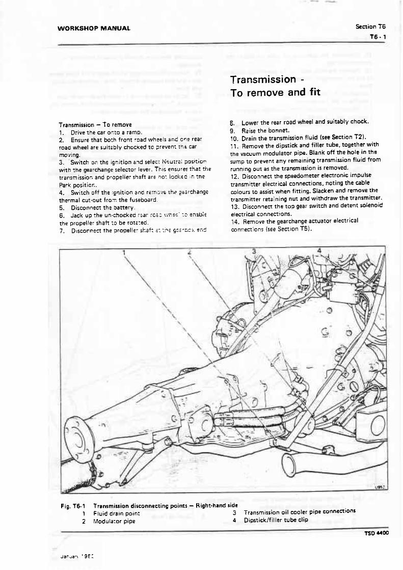
WORKSHOP MANUAL Section T6
16- 1
Transmission - To remove 1. Drive the car or.to a ramp. 2. Ensure that bo:n front r3ad wh;eti Grid G ~ P rear road wheel are suita~ly chocied t o 7:evenI t i t € car moving. 3. 'Switch on the ignition sqd selec: I<su;:ai position with the gearchange selector lever. Ti; is ensure: that the transmissior, and propeller shaft are m: loci:ed ir: fne Park positior.. 4. Switch off the :gqition and r~m-:v; th? ?~;rchange thermal cuf-out fro- the fuseboard 5. Disconnect t h ~ battery. 6. Jack up the un-chocked r2ar rci: vihw' r:. e n l b i ~ the propeller shatt t o be rotzsea. 7. Disconnect the ~ropel le- skak ;: : .+E ~ Z Z * C C ~ . IT~S
Transmission - To remove and fit
6. Lowe: the rear road wheel and suitably chock. 9. Raise the bonnet. 10. Drain the transmission fluid (see Section T2). 1 l . Remove the dipstick and fi l ler tube. together with rhe Mcuum modulator pipe. Blank off the hole in the sump to prevent any remaining transmission fluid from running out as the transmission i s removed. ?2. Disconnect the speedometer electronic impulse transmitter electrical connections, noting the cable cotours t o assist when fitting. Slacken and remove the transmitter retaining nut and withdraw the transmitter. 13. Disconnect the top gear switch and detent solenoid electrical connections. 74. Remove the gearchange actuator electrical mnnectionc {SE Section f5 ) .
Fig. T6-1 Transmission disconnecting points - Right-hand side 1 Fluid drain poir;: 3 Transmission oil cooler pipe connections 2 Modula:or pipe 4 Dipstick/filler tube clip
- -
TSD M W

15. Disconnect the operating rod from the side ot the transmission Case. 16. Remove the bolts securing the gearchange actuator to the rear extensjon; remove the anuator. Note Operations 14, 15, and 16, are only required to assis the handling of the transmission. 17. Remove the right-hand front sitencericata1y:ic converter and fire shield (if f ined) . 18. Remove the front balance.'E.G.R. balance pipe (i f fitted). 19. On cars with a fuel injection system remove The front section of the exhaust system (see Chapter Q) . 20. Or; isft-hand drive cars remove the :hrottle linkage cross-shaft. 2:. Disconnect the two transmission-fluid f lexible pipes leadinp 70 and from the heat exchanger situated in the engine coolant radiator. The pipes should be dis- anneced where the flexible pipe joins rhe solid metal pipe. Note There may be a small quantit)~ 3: transmission fluid in the pipes which will drsin out when the pipes are dis-
connected therefore, ensure a suitable container is available. 22. Remove the setscrews which secure the front mver plate and bell housing bortom cover: remove the plate and cover. 23. Scribe correlation marks onto the converter and flexplate. Then, remove the setscrews which secure the engine flexplate to the torque converter. Note Take care not to damage she flexplate or starter ring when turning the torque converter to gain access to the setscrews. 24. Using a suitable platform to f i t around the trans- mission sump, support the transmission with the aid of a trolley jack and extension. 25. Unscrew the setscrews which secure the transmission to the adapter. 26. Carefully move the transmission towards the rear of the ear until the dowels in the transmission are clear of the mounting plate. 27. Fit the retaining clamp RH 7952 to prevent the converter from beconing disengaged from the trans. mission.
Fig. 16-2 Ttsnsmission disconnecting points - Leh-hand ride 1 Transmission securing setscrews 4 Electronic impulse transmitter 2 Gearchange actuator connecrions 5 Coupling flange 3 Top gear switehldeten: solenoid connections

WORKSHOP MANUAL Sealon T6
Fig. T6-3 Transmission in holding fixture
Note The retaining clamp must be used, otherwise the converter may fall as the transmission is being removed. 28. Lower the jack until the transmission is clear of the h d y , then remove the transmission from beneath the car. 29. If overhaul work is to be carried out, remove the retaining clamp and withdraw the converter. Note A convener containing oil weighs approximately 23 kg (50 Ibl. 30. Fit the transm~srion into the holding fixture RH 7955 as shown in figure T6-3.
Transmission - To fit Fir the transmission by reversing the procedure given for removal, noting the following. 1. Ensure the mating faces of the transmission arid the mounting plate are clean and free from damage. 2. Torque tighten the various nuts, bolts, setscrews. etc. to the figures quoted in Section T22 and Chapter P. 3. A liberal mating of Retinax A grease should be applied all over the convener pilot spigot prior t o fitting the converter. 4. Rotate the converter until the correlation marks Iscribed on during remoual) are aligned and then fit rhe sewews. Do not lever on the staner ring when rotating the m v m e r . 5. If a new transmission is being fitted, the heavy spot marked an the rear face of the flexplate by a radial line of either white or yellow paint must be positioned as close as possible to the lighr spot (white lener L1 on the convener. 6. After wmplerion of the fining operation. fill the transmission with ftuid (see Section T2). 7. Finally, road te? the car for satisfactory operation.

WORKSHOP MANUAL Sectloo T7
Torque converter
The torque converter serves two prlmary functions. t t acts as a flurd coup!!ng ro rransmlt engrne torque smoothly to ?he trarlsmlsslon. I: also multlpiles the englne toraue when addit1o2al performance IS
requ~red. The torque converter comprises three basic
elements: a Dump B ~ u r b i n ~ . and a stator (see fig. T7-l ] .
The convener ;over IS welded to the pump t o seal all three members 15 an oil illled houslng.
On Tur~ocharged cars. the vanes are welded to the outer casing and the convener to flexplate securing lugs are more posirive))r secured for added strengrh.
On 1985 model year Turbocharged cars and onwards. a modifled torque convener is introduced together wt:h an ~ m ~ r o v e c 3zn :hrocle downshiit (3-2). The new torque converter can be fitted to pre 1485 turbo ( R f ) transmissions, providing the new control valve unit is also fined. N ate Mod~fled turbo torode convc?ers milsr never be fitted to non-turbochargec cars.
An englne drrven fiexp!ale bolts d~rectly onto the convener cover In :Tree ptaces (SIX places on T u r b charged carsl. so t?a! The comener Dump 15
mechanlcaljv connetred to :ne engrne and turns whenever tne enqlne rorares.
Nhen :he enslie 1s runnrng and the converter pump IS roratlng, 01 IS picked up a; rhe centre of the pump and d~scharaed at the nm. berween the pump blades.
The pump sheil and biarres are deslgned so that the oil leaves the pump rota:rng clockwise, towards the turblne blaaes. As !he oil strrkes the turb~ne btades. ~t causes :he turb~ne ro rotate
When the enpne IS tdilng. the convener pump rotates slowly and :ne force of oil 1s noT sufflclent to rotate the turbine w t ~ h any eiflc~enc\. Th~s sltuatlon enabks the car to stand rn gear w ~ t h the englne idling. As the englne throttle IS opened. the pump speed Increases and the force of OI! strikrng the turb~ne causes it to transmlt torque to the gear rraln. Aher the oil has ~mpaned ns force to the turblne. the all follows the contour of Ihe turblne shell and blades. leaving the centre of the turbtna. and rotatlng ant~clockw~se.
Because the turbine member has absorbed the force required to rei2erse the d9rectlon of the clockwise rotating oil n now has greater toraue than IS king delivered bv the eqlne.
To prevent the antrcloclrwlse so~nn~ng oil from stnklng the pump o~ades a: an angle that would h~nder it5 rotation. a stalo: assernalv 1s inferposed between the
Fig. T7-1 Torque convener 'I Turb~ne 2 Stator 3 Pump 4 Convener cover
pump and the turhne. f i e purpose of the stator 8s to redtrect the oil returning from the turbine SO that its direction ts altered to suit that of the pump.
The energy of the oil IS then used ro asslst the englne in turnlng the pump. Thts Increases the force of the oil driving the turkne and as a result. muttlplles The torque.
The force of the oil fiowmg from the turbine to the nator blades tends to rotate the stator ant+tloekwise However. a clutch on which the stator is mounted prevents thls.
As both turbrne and car speeds Increase. the direction of the oil Leaving the turb~ne changes. The of1 f l m s clockw~se against the rear srde of the Stmw vaneS. If the stator was flxed. the flaw of the oll wld be impeded. but the clutch'allows the stator to rotate vn ns shah Once the stator becomes tnanlve there IS no further torque rnultlptlcat~on and the converter f u ~ l l ~ ~ as a fluid coupltng at a ratio of 1 : 1

Torqua converter - To remove 1. Remove the rransrnission as described in .Section T6. Note Do not forget to fit-the converter holding clamp RH 7952 otherwise the convener may fall when the transmission is removed. 2. Position a drip tray underneath the converter. 3. Remove the convener retaining clamp from the bell housrng end of the transm~ssion casing; remove the converter. Caution The convener and oil weigh approximately 23 kg (50 Ib]. Therefore. care should be taken when removing the converter to ensure that it.is not dropped or damaged.
Torque converter - To inspect Alter removing the torque convener from the transmission visually inspect as follows. l . Examine the convener for signs of damage. 2. Examine the neck of the convener for wear. 3. Examine the pump drive slots for wear.
For a more detailed procedure of inspection refer ro Sect~on T2 1 - Fault Diagnosis.
Torque conveRer - To fit 1. FI: the convener to the transmissron. ensurmg that the drning slots engage w~rh the tangs in the transm~ssion oil pump. 2. FIT rhe converter holding clamp RH 7952.

WORKSHOP MANUAL Section T7 T7-3a
__________________________________________________________________
Loss of Torque at Low Engine Speed
On high-mileage vehicles under regular city use, it may occur that there is a sudden and permanent loss of torque by a factor of two on start-off. This is usually accompanied by a rattling noise from the region of the torque converter. In this circumstance, the cause is often due to the collapse of the one-way stator sprag clutch within the torque converter. If this is the case, either a service exchange torque converter must be fitted or the fitted torque converter rebuilt. In each case, the torque converter’s input neck should be replaced if there is any noticeable wear groove whatsoever. A new front pump oil seal should be fitted at the same time. Whilst the vehicle may continue to drive in the defective mode, the transmission will be subject to fluid overheating and to mechanical damage by broken sprag clutch debris.
Transmission Leaks from the Bellhousing
On high-mileage vehicles, it has may occur that there is transmission fluid leakage from beneath the bellhousing. In this circumstance, the cause is often due to the failure of the front pump oil seal. In such cases, the torque converter should be removed, the seal replaced, and the torque converter input neck should be replaced if there is any noticeable wear groove whatsoever. In this situation, it is also advisable to renovate the torque converter, fitting a new one-way stator sprag clutch.
__________________________________________________________________________________________
TSD 4400 September 2006
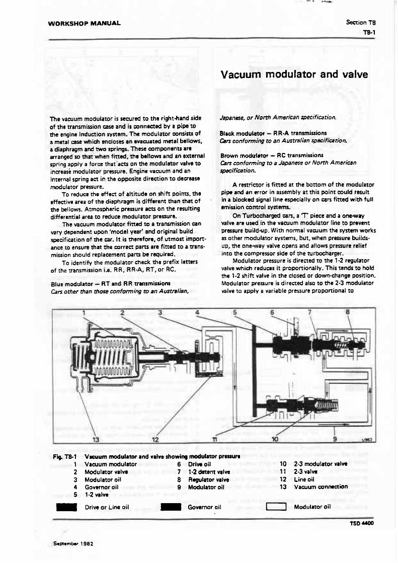
WORKSHOP MANUAL Seaion t8
Vacuum modulator and valve
The vacuum modulator is sewred to the righthand side of the transmission msa and is wnneetad by a pips to the engine induction ryrtem. The modulator consists of a metal case which rnclosrrs an evacuated metal be1lows. a diaphragm and WO springs. These companrntr are arranqed ro thar when fitted, the beltow and an external spring apply a force that'aett on the modulator valve to increase modulator pressure. Engine vacuum and an internal spring act in the opposite direction to decrease d u t a r o r pressure.
To reduce the effect of altitude on shift points. the affective area of the diaphragm is different than that of the bellows. Atmospheric pressure am on the resulting differential area to reduce modulator pranure.
The vacuum modulator fitted to a transmission csn vary dependent upon 'model year' and original build specification of the wr. It is therefore, of mmost import- ance to ensure that the correct pam an fitted to a trans- mission should replacement pam be required.
To identify the modulator check the prefix letters af the transmission i.e. RR, RR-A, R f , or RC.
Blue modulator - R f and RR rrarurnitrionr Cars orher than tfiose conforming m an A ustmlian.
Japans%?, w North American specifimtiom
Black modulator - RR-A trammissions Cers conforming to an Australian pecifiearion.
Brown modulator - RC transmissions Cars confoming to a Japanese or North American specification.
A rsmiaor is fitted at the bottom of the modulator piw and an error in assembly at this point muld result in a blocked signal line especially on a r s fitted with full emission control systems.
On Turbocharged ears, a 7' piece and a o n w r y valve are used in the vacuum modulator line to pmvmt presrure buildup. W i h normal vaeuum the system works as other modulator systems. but, when pressure buifds- up, the one-way valve opens and al tows pressure relief into the compressor side of the turbmharger.
Modulator pressure is directed to the 1-2 regulator valve which reduws it proporrionally. This tends to hold the '1-2 shift valve in the closed or down-change position. Modulator pressure is directed also to the 2-3 modulator mlve to apply a variable pressure proportional to
Fiq T8-1 V w u m modulator and wdw showing d u l m pnrrun l Vaeuum modulator 6 Driw oil 10 2-3 modulator valve 2 Modulnor valm 7 '1-2 datrm mlva 11 2-3valw 3 Modulator oil 8 Regulator nlm I2 Line oil 4 Govsmor oil 9 Modulator oil 13 Vacuum arnndian 5 1-2 vslw
Drive or Line oil Governoroil 1-1 Modulator oil

WORKSHOP MANUAL Section T8 T8.1
Va'cuurn modulator and valve
The vacuum moduiator i s secured to the righthand side of the transmission case and is mnnected by a pipe to the engine induction system. The modulator consists of a metal case which encloses an evacuated metal bellows, a diaphragm and two springs. These Eomponents are arranged so that when fitted, the bellows and an exrernal spring apply a force that'acts on the modulator valve t o increase modulator pressure. Engine vacuum and an internal spring act in the apposite direction to decrease modulator pressure.
To reduce the ef fec t of attitude on shift points, the effective area of the diaphragm is different than that of the bellows. Atmospheric pressure aWon the resutting differential area to reduce modulator pressure.
The vacuum modulator fitted to a transmission can vary dependent upon 'model year' and original build specification of the car. It is therefore, of utmon import- ance to ensure that the correct parrs are fitted to a trans- mission should replacement parts be required.
To identify the modulator check the prefix letters of the transmission i.e. RR, RR-A, RT, or RC.
Blue modulator - R f and R R !-ransmissions Cars other than rhose conforming to an Australian.
Japanese, w North American specifimtion.
Black modulator - RR-A transmissions Cars conforming to an Austmiian ~ecificarion.
1
Brown modubior - RC ttansmi~~ions Cars conforming to a Japanese or Norfh Ameriean qwcific~tion.
A restrictor is fined at the bottom of the modulator pipe and an error in assembly at this point could result in a blocked signal tine especially on cars f i t ted with full emission control systems.
On Turbocharged cars, a T piece and a one-way d in the vawum modulator line t o prevent
pressurL ~ld-up. Wi th normal vaeuum the system works as othdrmodulator systems. but, when pressure builds- up, the one-way valve opens and allows prwsure relief into the compressor side of the turbocharger.
Modulator pressure i s directed to the 1-2 regulnor valve which reduces it proportionaliy. This tends to hold the 1-2 shift valve in the closed or down-change position. Moduiator pressure is directed also to the 2-3 modulator valve to apply a variable pressure proponional to
Fig. TB-1 Vacuum modulator and valve showi- moduhator pressure 1 Vacuum modulator 6 Driw oil 10 2-3 modulator valve 2 Modulator valve 7 1-2 detent valve ?l 2-3 valve 3 Modulator oil 8 Regutator valve 12 Line oil 4 Governor oil 9 Modulator oil 13 Vacuum ~onfisctian 5 1.2valve
Drive or Line oil Govsrnor oil i-1 Modulator oil
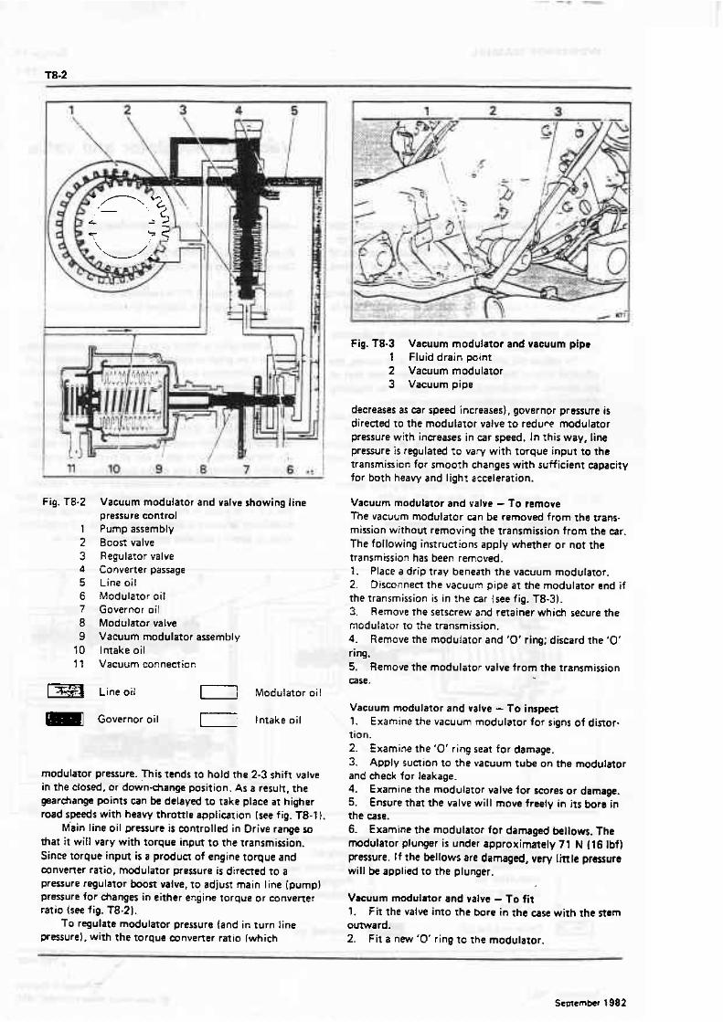
Fig. TB-2 Vacuum modulator and valve showing line pressure control Pump assembly Boost valve Regulator valve Converter passage Line ail Modulator oil Governor oil Modulmor valw Vacuum modulator assembly Intake oil Vacuum connection
Line oiI Modulator oil
Governor oil [ intake oil
modulator pressure. Th is tends to hold the 2-3 shift valve in the closed, or down-change position. As a result, the gearchange points can be delayed to take place at higher road speeds with heavy throttle application [see fig. TB-l 1.
~ ' a i n line oil pressure is c o n t r ~ l l d in Drive range so that it will vary with torque input to the transmission. Since torque input is a produn of engine torque and convener ratio, modulator pressure is direncd to a pressure regulator h o s t vaive, to adjun main line (pump) pressure for changes in either engine torque or converter ratio (see fig. T8.21.
f o regulate modulator pressure (and in turn Iine pressure), with the torque ertnverter ratio (which
Fig. TB-3 Vacuum modulator and vacuum pipe I Fluid drain point 2 Vacuum modulator 3 Vacuum pipe
decreases as car speed increases), governor pressure i s directed to the modulator vaive to redur~ modulator pressure with inueases in car speed. In this way, line pressure i s regulated t o vary with torque input to the transminior; for smooth changes with sufficient capacity for both heavy and light acceteration.
Vacuum modulator and valve - f o remove The vacuum modulator can be removed fromthe trans- mission without removing the transmission from the a r . The following instructions apply whether or not the transmission has been removed. 1. Place a drip tray beneath the vacuum modulator. 2. Disconnect t h e vacuum pipe a t the modulator end if the transmission is in the car (see fig. T8-31. 3. Remove the setscrew and retainer which secure the modulator to the transmission. 4. Remove the modulator and '0' ring: discard the '0' ring. 5. Remove the rnodulstor valve from the transmission case.
Vacuum modulator and valve - To inspect 1. Examlne t he vacuum modulator for signs of dinor- tion. 2. Examine the '0' ring seat for damage. 3. Apply suction to the vacuum tube on the modulator and check far leakage. 4. Examine the modulator valw for scores or damage. 5. Ensure that the valve will move freely in i t s bore in the case. 6- Examine the modularor for damaged bellows. The modulator plunger is under approximately 71 N l16 Ibf) pressure. If the bellows are damaged, very little pressure will be applied to the plunger.
Vacuum maduiHor and valve - To fit 1. f i t the valve into the bore in the case with the stem outward. 2. Fit a new '0' ring to the modulator.

3. Fit the modulator to the ase W*& the vaFuurn pipe wnnsaion toward the ' h n t of the mr. 4. Fit the r e t a i m w t m with the remining #treraw and torque tigtrten (IM -on 6. Con- thh mmum pipe, ensuring that the-rwtrietor is f i e d .

3, Fit the modulator to hthc a r e with the vacuum pipe mnnaetion toward the from of the car. 4. F it the retainer togaher with.phe mtaining.smcraw and torque tightan (m Section TZ2L 5. C o n w the m u m pip, -ring that the mstri~tor k fitted.

WORKSHOP MANUAL Section T9
G overnor assembly
The governor assembly (see fig. T9- I ) fits into the rear of the transmission casing on the right-hand side. The car speed signal for the gear changes is supplied by the governor, which is driven by a gear on the transmission output shaft.
The assembly comprises a regulating valve, two primary weights, two secondary weights. secondary springs. body, and driven gear. The weights are arranged so that oniy the secondary weights act on the valve. The primary weights contribute to the secondary weights through the secondary springs.
On 1984 model year Mulsanne Turbo cars and onwards, the governor springs and weights have been uprated. These governor assemblies are only inter- changeable with 'European' specification transmissions (e.g. RR and RT).
Slight changes in ourput shatt rev/min at low speeds result in small governor pressure changes.
The primary weights add additional force to the secondary weights to obtain greater changes in pressure as road speed and output shaft rev/min increase. As the prlmary we~ghts move out at higher car speeds they reach a stop and no longer become effective. From th~s point. the secondary we~ghts and spnogs only are used to apply pressure on the governor valve.
Drive oil pressure is fed'to the governor where h is regulated by the governor and gives an oil pressure that is proponionat to car road speed.
To initiate the gear change from first to second. governor oil pressure is directed to the end of the 1-2 shrft valve where I! ams against spring pressure which is holding the valve in the down-change (closed) position (see fig. T9-2).
As the road speed of the car and subsequently the governor oil pressure increases sufficiently to overcome the spnng resistance. the 1-2 shift v a k train moves. allowing drive oil to flow into the intermediate clutch passage and through an orifice to apply the intermediate clutch. This makes the intermediate clutch effective which moves the transmission into second gear. Further increases in road speed and governor pressure will cause the rransmission to change into third gear when governor pressure overcomes the 2-3 shift valve spring pressure.
Governor pressure is directed also to the modulator valve to regulate modulator pressure as described in Section'T8.
Governor Iubncarion is provided by a flat in the governor sleeve which allows oil to pass to the moving pans of the governor.
Fig. f 9-1 1 2 3 4 5 6 7
I
Governat assembty Driven gear Drive oil Governor oil Primary weight Spring Value Secondary weight
Drive oil Governor oil.
Fig. T9-2 Governor oil m t i ~ an the 1-2 shih d r a 1 lntermcdiate clutch 2 1.2 valve 3 1-2 detent valve 4 Regulaor valh
Drive and Intermediate clutch oil
Governor ail
-- -
M a y 1984
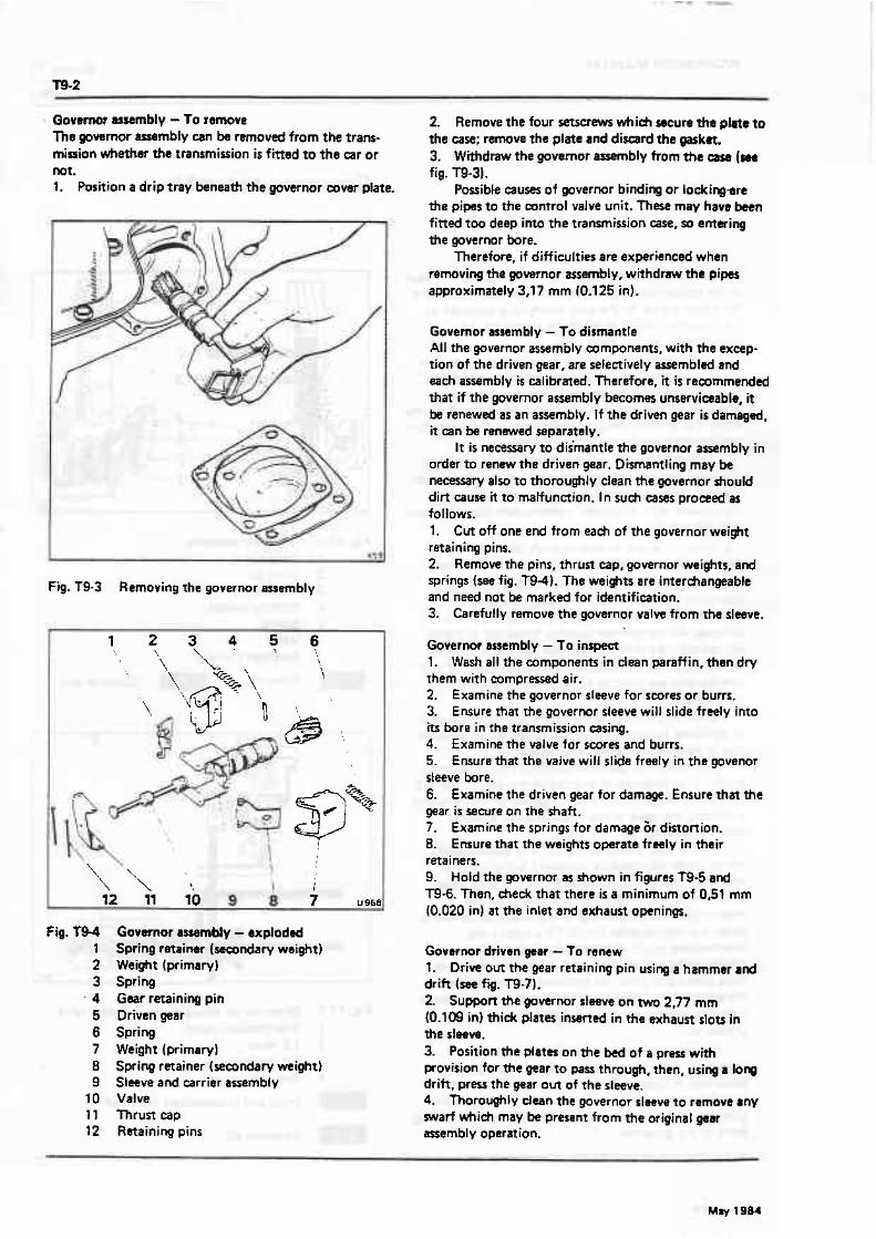
Qavernot auernbly -To remove 2. Remove the four setscrew which secure tha plae to The governor aernbly can be removed from the trans- the csse; remove the plate and dismrd the gaska. mission whether the transmission is f ittd m the car or 3. Withdraw the governor assembly from the ww (m not. fig. m-31. 1. Position a drip tray knaath the governor cover plate. Possible causes of pvernor binding or Lodcirrgare
the pipes to the wntrol valve unit. These may have baen
Fig. T9-3 Removing the governor assembly
fitted too deep into the transmission case, so entering the governor hre.
Thereto*, if difficulties are experienced when removing the governor assembly, withdraw the pipes approximately 3,17 mm (0.125 in).
Governor assembly - To dismantle All the governor assembly components, with the exwp- tion of the driven gear, are selectively assembled and each assembly is calibrated, Therefore, it i s recommended t h a t if the governor assembly becomes unserviaable, it lx renewed as an assembly. If the driven gear is damaged, it can be renewed separately.
It is necessary to dismantle the governor assembly in order to renew the driven gear. Dismantling may be necwary alx, to thoroughly clean the governor should dirt cause it to malfunction. In sueh cases proceed as follows. 1. Cut off one end from each of the governor weight retaining pins. 2. Remove the pins, thrust cap, governor weights, and springs (see fig. T94). The weights are interchangeable and need not be marked for identification. 3. Carefully remove the governor valve from the sleeve.
Fig. Governor u u ~ M y - exploded Spring retainer (secondary weight) Weight (primary) Spring Gaar retaining pin Driven gear Spring Weight (primary) Spring retainer (amndary weight) Sleeve and carrier assembly Valve Thrurt cap Retaining pins
Governor assembly - To irtspect 1. Wash all the components in clean paraffin, thsn dry them with compressed air. 2. Examine the governor sleeve for scores or burrs. 3. Ensure that the governor sleeve will slide freely into its bore in the transmission easing. 4. Examine the valve for scores and burrs. 5. Ensure that the valve will slide freely in t h e govenor sleeve bore. 6. Examine the driven gear for damage. Ensure that the gear is secure on the h a f t . 7. Examine the springs for damage 6r distortion. 8. Ensure that the weights operate freely in their retainers. 9. Hold the gowrnor as shown in figures T9-5 and T9-6- Then. check that there is a minimum of 0,51 mm (0.020 in) at the inlet and exhaust openings.
Governor driven gear - 1 o renew 1. Drive out the gear retaining pin using a hammer a d drift (see fig. T9-71.
I0.109 in) thick plates inserted in the exhaust slots in the sleeve, 3. Position the plates on the M of a press with provision for the gear to pass through, then, using a long drifr, press the gear out of the sleeve. 4. Thoroughly dean the governor slacve to remove any swarf whieh may be present from the original gear assembly operation.

WORKSHOP MANUAL
Fig. 19-5 Cheek valve opening (inlet) 1 0.51 mm 10.020 in} feeler gauge
Fig. T9-6 Check valve opening (exhaust) 1 0,51 mm (0.020 in) feeler gauge
Note Ensure that the new gear is the correct one for the t r a m mission casing in whieh it is to be fitted. 5. Support the governor sleeve o n the twn 2-77 mm (0.109 in) plates. 6. Position the new gear in the sleeve then, using r suitable drift. prerr the gear into the sleeve until it is mar ly seated. 7. Carefully remove any swarf which may have shaved off the gear hub, then, pres the gear down until it abuts the sleeve. B. Mark the position o f a new hole on the sleeve a t 90'
Fig. T9-7 Removing governor driven gear retaining pin
to the original hole, then using a drill of 3.17 mm 10.125 in) diameter, dr i l l a new hole through the sleeve and gear. 9. Fit the gear retaining pin. 10. Thoroughly wash the gear and sleeve assembly in clean paraffin and d.w with compressed air.
Governor assembly - To assemble 1. Lightly o i l the valve then f i t it imo the governor sleeve. 2. Fi t t he governor weights, springs, and thrust cap onto the governor sleeve. 3. Align the pin holes in the thrust cap, governor weight assemblies, and governor sleeve. 4. Fit new pins and crimp both ends of the pins. 5. Ensure that the governor weights are free to operate on the pins and check that the valve moves freely in the sleeve bore.
Governor assembly - To fit 1. Light ly Lubricate the governor sleeve and gear then fit the governor assembly in to the transmission case. 2. Fit the cover, together with a new gasket. 3. F i t the four setscrews and torque tighten (set Section T22 l . 4. When installing the governor assembly ensure that a dearance of approximaly 6.35 mm (0.250 in1 is main- m i n d betweitn the governor pipes and trarmi%simn ease, at a poim 25,40 mm (1 in) f rom the right.rnufe bend of the pipes.
May 1986
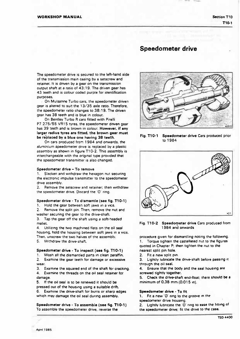
WORKSHOP MANUAL -ion TfO
Speedometer drive
The speedometer drive is secured to the left-hand side of the transm~ssion main casing by a setscrew and retainer. It is driven by a gear on the transmission output shaft ar a ratio of 43: 19. The driven gear has 43 teeth and is colour coded purple for identification purposes.
, On Mulsanne Turbo cars. the speedometer driven gear is altered to suit the 13/35 axle ratio. Therefore. the speedometer ratio changes to 38: 19. The driven gear has 38 teeth and k blue in colour.
On Bentley f urbo R cars fined with Pirelli P7 275/55 VRt 5 tyres, the speedometer driven gear has 39 teeth and is brown in colour. However. if any large; radius tyres are fitted, the brown gear must be replaced by a blue one having 38 teeth.
On cars produced from t 984 and onwards. the aluminium speedometer drlve is replaced by a piastic assembly as shown in figure T10-2. This assembly is interchangeable with the original type provlded that the speedomerer transmitter is also changed.
Speedometer drive - To remove 1. Slacken and wlthdraw the hexagon nut securing rhe electronic impulse transmitter to the speedomerer drlve assembly. 2. Remove the setscrew and retainer; then withdraw the speedometer drive. Discard the '0 ring.
Speedometer drive - To dismantle (see fig. 11 0-1 ) 1 . Hold the gear between soft jaws rn a vice. 2. Remove the split pin. Then, remove the nut and washer securing the gear to the dnve-shaft. 3. Tap the gear off the shah uslng a soft-headed mallet. 4. Utilizing the two rnach~ned flats on the oil seal housing. hold the housing between sob jaws in a vice. Then. unscrew the' two halves of the assemblv. 5. Withdraw the drne-shaft
Speedometsr drive - To inspect (see fig. T10-1) 1 . Wash all the dismantled pans in clean paraffin. 2. Examine the gear teeth for damage or excessive wear. 3. Examine the squared end of the shaft for cracking. 4. f xamine the threads on the oil seal retainer for damage. S. If the oil seal is to be renewed it should be pressed out of the housing using s suitable drift, 6. Examine the driveshaft for burrs or sharp edges which may damage the oil seal dur~ng assembly.
Speedometer d r ~ e To assemble (see fig. TY 0-1 ) To assemble the speedometer drive, reverse the
Fig. f 10-1 Speedometer drive Cars produced prior to 1984
Fig. T10-2 Speedo~e te r drive Cars produced from 1 984 and onwards
procedure glven for dismantling noting the following. 1. Torque t~ghten the castellated nut to the figures quoted in Chapter P: then t~ghten the nut to the nearest split pin hole. 2. Fit a new split pm. 3. Lightly lubricate the drtveshah before passlng n through the oil seal. 4. Ensure that the body and the seal houslng are screwed tightly together. 5. Check the driveshah end-float: there should be a minimum of 0.38 mm I0.015 in).
Spasdometar drive - To fit l . Fit a new ' 0 ring io the growe In the speedometer drive housing. 2. t~ghtly lub~cate the '0' r~ng to ease the frnlng of the speedometer drive; fit the drlve to the case.

3. Fit the retainer and setscrew. f orqrre tighten to the figures quotd.in Section T22. 4. Connect the eketronic impulse rransmirter.

WORKSHOP MANUAL Section T11
T 11-1
Sump and intake strainer
Sump - To remove Transmission fined in t h e car 1. Posirion fhe car on a ranp and raise to 2 suitable working height. 2. Place a clean container with a minimum capacity of 3 litres {5 Imp pt, 6 US p?} under the sieeve nut which secures the dipstick filler tube to the side of the sump. 3. Withdraw the trsnsmission dipstick. Slacken the setscrew securing the filler tube clip to the cyiinder head. 4. Release the nut securino the dips~ick filler tube: withdraw the filler ;ube and move to one side. draining the fluid into the container. 5. Remove the setscrews securing the sump. 6. Remove the rump and discard the gasket. 7. Drain the rema~rlder of :he fluid from the sump. 8. Clean the sump with pariiffin and dry wi;h compressed air.
f ransmission removed from the car 1. Position the trazsmission in the holding iixture RH 7955 with the samp upwards. 2. Carry out Operations 5 to 8 inclusive as described with the transmission !itted in the car.
Sump - To fit To fit the sump reverse the procedure given fo r removal noting the following. 1. Ensure a new gasket i s f rtted. 2. Torque tighten the setscrews to the figures quoted in Section f 22. 3. When filling the transrn~ssion w i ~ h fluid refer to Section T2. Note The amount of fluid added depends on whether the intake strainer has been removed.
Fig. 711-1 Removing intake pipe and strainer ausmbly 1 S~rainer assembly 2 Intake pipe with '0' ring 3 Location tabs
figures quoted in Section T22. 4. Fit the sump and fi l l with fluid. When filling the transmission with fluid refer to Section T2.
1 ntakc strainer - To remove 1. Remove the sump. 2. Unscrew and remove the stepped bolt securing the intake strainer to the valve body assembly. 3. Remove the intake strainer assembly. 4. Discard the intake strainer and the '0' ring from the intake pipe.
Intake strainer - f o fit 1. Fit a new 'Q' ring onto the intake pipe. Lubricate The '0' ring with frrnsmission fluid. 2. Ensure a new rubber seal i s fined to the bore in the new intake strainer, then fit the intake pipe into the strainer. 3. Fit the strainer assembly into the transmission ease; secure with the stepped bolt. Torque tighten to the
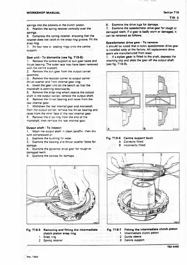
WORKSHOP MANUAL Section Tt 9
springs into the pockets in the clutch piston. 5. Position the spring retainer centrally over the springs. 6. Compress ?he spring retainer. ensuring that the retainer does not catch in the snap ring groove. fit the snap ring. 7. fit four new or1 sealing rings onto the centre support
Gear unit - To dismantle (see fig. Tt 9-81 1. Remove the centre suppon to sun gear races and thrust bearrng. The outer race may have been removed with the centre support. 2. Remove the sun gear from the output carrier assembly. 3. ,Remove the reaction carrier to output carrier thrust washer and front internal gear ring. 4. Invert the gear unit on rhe bench so that the ma~nshaft is poinrlng downwards. 5. Remove the snap ring which retains the output shatt in the output carrier; remove The output shaft. 6. Remove the thrust bearing and races from the rear internal gear. 7. Withdraw the rear internal gear and ma~nshafi from The outplrr carrfer: remove the thrust bearing and races from :he Innew face oi the rear internal gear. 8. Remove the sp,ap rtng from the end of tire ma~nshaft. then r e r o v e the rear Internal gear.
Output shah - 1 b inspect 1 . Wash rne output shaf! In clean paraff~n. then dry w~th compressed al: 2. Exam~ne the b ~ s h ~ n g for wear. 3. Examine the bearing and thrust washer faces for damage. 4. Examine the governor orlve gear for rough or damaged teeth. 5. Examine the s3llnes for damage.
Fig. 119-5 Remoying and fitting the intermediate clutch piston snap ring
1 Snap ring 2 Sprrnc retainer
6. Examine the drive lugs for damage. 7. Examine the spudorneter drive gear for rough or damaged teeth. If a gear is badly worn or damaged. i t can be renewed as, follows.
Speedometer drive gear - To rsmave It should be noted that a nylon speedometer drive gear is installed only at the factory. All replacement drive gears are manufactured from steel. 1. if a nylon gear is fitted to the shak depress the retaining clip and slide the gear off the output shaft (see fig. T19-9).
Fig. Tt 9-6 Centre suppofl bush A Correctly frned B Incorrectly frned
Fig. T19-7 Fitting the intsrmdiatm clutch piston 1 Intermediate clufch piston 2 Guide sleeve 3 Centre suppom
M a v 1984
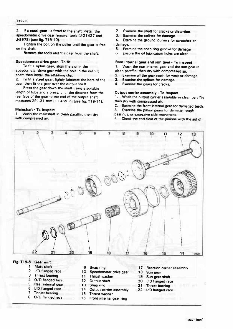
2. If a steel gear is fitted to the s h e install the 2. Examine the shaft for cracks or distortion. speedometer drive gear removal tools (J-2 1427 and 3. Examine t h splines for damage. 5-9578) (see fig. T 19-1 0). 4. Examine the ground journals for scratches or
Tighten the boh on the puller until the gear is free damage. on the shaft. 5. Examine the snap ring groove for damage.
Remove the tools and rhe gear from the s h a k 6. Ensure the oil lubrication holes are clear.
Speedometer drive gsar - f D fit 1. To fit a nylon gear, align the slot in the speedometer drive gear with the hole in the output shaft. then install the retaining clip. 2. To fit a steei gear. lightly lubricate the bore of the gear, then fit the gear over the output shaft.
Press the gear down the shaft using a suitable length of tube and a press, until the distance from the rear face of the gear to the end of the output shaft measures 291.31 mm (1 1.469 in) (see fig. T 19-1 1).
Mainshatt - To inspect 1. Wash the mainshaft in clean paraffin. then dry with compressed air.
Rear internal gear and sun gear - To inspect 1. Wash the rear internal gear and the sun gear in clean paraffin, then dry with compressed air. 2. Examine all the gear teeth for wear or damage. 3. Examine the splines for damage. 4. Examine the gears for cracks.
Output carrier assembly - To inspect 1. Wash the output carrier assembfy in clean paraffin, then dry with compressed air. 2. Examine the front internal gear for damaged teeth. 3. Examine the pinion gears for damage, rough bearings, or excessive side movement 4. Check the end-flom of the pinions with the aid of
Fig. V1 9-8 1 2 3 4 5 6 7 8
Goat unit Main shaft VD flanged race Thrust bearing O/D f langed race Rear intemaf gear \/D flanged race Thrust bearing O/D flanged race
Snap ring 17 Reaction carrier assembly Speedometer drive gear 10 Sun gear Thrust washer 19 Sungear shaft 'Output shaft 20 VD flanged race Snap ring 21 Thrust bearing '
Output catrier assembly 22 I/D flanged race Thrust washer Front internal gear ring

WORKSHOP MANUAL Section T19
T19-7
a feeler gauge (see fig. 1 19-1 2). The end-float should be between 0.23 m m and 0 '61 mm (0.009 in and 0.024 in). 5. Examine the parking pawi lugs for cracks or damage. 6. Examine the splines which drive he output shaft for damage. 7. Exarn~ne the front internal g&ar ring for flaking or cracks.
Reaction carrier assembly - To inspect 1 . Examine the surface on which the rear band applies, for signs of burning or scoring. 2. Examine the roller outer race for scoring or wear. 3. Examine the rhrust washer surfaces for signs of scoring or wear. 4. Examine the bush for damage. If the bush is damaged. the carrler musr be renewed. 5. Exam~ne the pinion gears for damage, rough. bearings, or excessive side movement. 6. Check the pinion end-float. This should be between 0.23 mm and 0.61 mm (0.009 in and 0.024 in].
Pinion gears - To renew 1 . Support the carrier assembly on its front face. 2. Using a 12.70 mm 10.50 in) diameter drill. remove the stake marks from the end of the pinior; pins. Ensure that :he drill does not remove any metal from the carrier as this will weaken the component and could resuft in a cracked carrier.
Fig. Tf 9-9 Removing a:nylon speedometer drive gear
1 Nylon gear 2 Retaming clip
3. u4ng a r a p n d punch, drive or press the pinions out of the carrier. 4. Remove the punch, gears. thrust washers, and needle roller bearings. 5. Examine the pinion thrust faces in-the pinion gear pockets for burrs and stone off as necessary. Thoroughly wash the carrier in clean paraffin and dry with compressed air. 6. Ensure that the new gears are clean and free from burrs. then fir the eighteen needle karings into each pinion gear. Use petroleum jelly to retain the karings and use a pinion pin as a guide when fining the bearings. 7. Fit a bronze and a steel thrust washer on each side of the pinion gear, with a neel washer next to the gear. Hold the washers in place with a smear of petroleum jelly.
On output carrier assemblies onIy, a steel and a bronze washer are always fitted on the thrust side. but two steel washers may be fitted on the non-thrust
I
Fig. Tl9-10 Ramwing s steel spwdocnet~r d f h (I-r .
l (J-9578) 2 Removal boks 3 (J-2 1427)
m urn
Mav 1984

side. However. if tha pinion end-float is outside the tolemnce given, the washers should be mplacsd with'a steel and a bronze on both sides (see fig. T l 9- 1 3). This is wssntial on RT tmnsmissions. 8. . Fit the pinion gear assembly into position in the carrier, then fn a pilot pin through the reer face of the assembly to centralize and hold the pans in position. 9, Drive a new pinion pin imo position from 'the front, rotating the pinion whilst the pin is being driven in. t 0. Ensure that the headed end of the pin is flush or b low the face of the carrier. 1 1. Secure the punch to be used for staking the pins in a bench vice. so that it can be used as an anvil. 12. Support the carrier with the head of the pin resting on the punch. Then, using a chisel with a
Fig.fl9-11 Output shaft 1 Speedometer driving gear 2 Governor driving gear A 29 1.30 mm [l 1.469 in)
radiusad end stake the oppasite end of the pin in threa places {see fig. T19- t 4). Note Both ends of the pin must lie blow the face of the mmer, otherwise a foul may occur between the pin and the adjacent component 13. Repeat the procedure for the remaining pink
Roller clutch - 1 o inspect 1. Wash the assembly in clean paraffin, then dry with compressed air. 2. Examine the roller clutch for damaged rollers or springs. 3. Emmine the roller cage for damage.
Fig. Tl9-f 2 Checking the output carrier pinion end-ftoat
1 023 mm to 0,6 1 mm (0.009 in to 0.024 in)
Fig. l7 9-1 3 Planet pinion gear 1 Pinion pin 2 Stwl washer 3 Steel washer 4 Bronze washer 5 Planet pinion 6 Bronze washer

WORKSHOP MANUAL . Section T l9
Lmerrnediste clutch plates and rear band - To inspect 1. Examine the condition of the composition faced and sreel ptates.Do not diagnose a composition drive plats by colour. 2. Dry composition faced plates with compressed air and inspect the composition face far. a Piing and flaking. b. Wear. c. Gtazing. d. Cracking. a. Charring. f. Metal particles embedded in the lining.
If any of the above conditions are evident replacement is required. 3. Wipe the steel plates dry and check for heat discolouration. If the surface is smooth and an even colour is indicated. the plates shoutd be used again. If severe heat spot discolouration or surface scuffing is indicated. the plates must be replaced. 4. Examine the rear band for cracks or distortion. 5. Examine the ends of the band for damage at the anchor lugs and the apply lug. 6. Examine the lining for cracks, flaking. and burning. 7. Ensure that the lining is secured to the band.
Gear unit and centre support - To aswmbls 1. Ensure that all parts are clean. Lightly lubricate with clean transmission fluid all bushes, journals, gears. bearings. etc. 2. Fit the rear internal gear onto the mainshah. fi the circlip. 3. Fit the races and thrust bearing onto fhe inner face of the rear internal gear. retaining them with a smear of petroleum jelly (see fig. T19-1 5).
Fig. f19-l4 Staking 8 pinion pin 1 Chisel
Fig. T19-15 Fitting the races and thnrat bearing to the inner faca of the mar internal gear
1 W D flanged race 2 Thrust bearing 3 VDflanged race
Fig. 11 9-1 6 Fitting the races a d thmn h d n g to the outer face of the rut intamal gear
1 O/D f langed race 2 Thrust haring 3 VD flangad race

Fig. 719-'17 Fitting the reaction carrier to the output carrier
Fig Tl9-18 F i ing the m m and thrust bearing to the sun gear
1 Thus b r i n g '
2 VD flanged race 3 V D Ranged race
4. Fit the large diameter race first with the outer flange uppermost 5. F it the thrust bearing into the race. 6. Fit the smaller diameter race w e r the bearing with the inner fiange towards the bearing. 7. Ensure that the pinion gears are adequately lubricated then fm the output carrier onto the mainshaft so thst the pinion gears mesh with the rear internal gear. 8. Position the assembly with the mainshaft pointing downwards through a hole in the bench. Take care not to damage the shaft 9. Fit the races and thrust haring onto the outer face of the rear internal gear, retaining them with a smear of petroleum jelly. The small diameter (flanged VD) race must f i e d first with the flange uppermost (see fig. Tl9-16). 10. Fit the thrust bearing into the race. 1 1. Fir the large diameter (flanged O/D) race against rhe bearing with the flange cup over the bearing. 12. Fit the output shaft into the output carrier and fit the circlip. 13. Smear the output shaft to case metal thrust washer with petroleum jelly, then fit the washer into position. 14. Turn the assembly over so that the output shaft points downwards. 15. Smear the reaction carrier to output carrier thrust washer with petroleum jelly, then fit the washer into the output carrier so that the bent tabs engage in the tab packers. Note The factory built transmissions use a nowmetal washer. however.the service replacement thrust washer is metal. 16. Fit the sun gear; ensure that the end with the chamfered inside diameter faces downwards. 1 7. Fit the gear ring over the output carrier. 18. Fit the sun gear shaft with the longest splined end first.
Fig. Tl9-19 F'ltting a roller to the roller clutch =W

WORKSHOP MANUAL Section T19
no11
19. Ensure that the reaction carrier pinion gears are adequately lubriicated, then fit the reanion carrier onto the output carrier as shown in figure Tl9.17. Mesh the pinion gears with the front internal gear. Note W h e n a new output carrier and ./ar reaction carrier is being installed and the front internal gear ring prevents assembly of the carriers, replace the front internal gear ring with the service ring, 20, Smear the centre support to sun gear thrust races and bearing with petroleum jelly and fit as follows (see fig. T19-18). a. The large outer diameter race, with the centre flange up, w e r the sun gear shak b, The thrust bearing onto the large race. c, The small diameter race, with the centre flange
2 1. Smear the centre support to reaction carrier thrust washer with petroleum jelly, then fit the washer into the recess in the centre suppart 22. Fit the rollers that may have come out of the mller clutch cage. by compressing the energizing spring with the forefinger and inserting the roller from the outside (see fig. T19- 1 9). Note Ensure thar the energizing springs are not distorted and that the curved end leaf of the springs are positioned against the rollers. 23. Fit the spacer ring and roller dutch assembly into the reaetion carrier. 24. Fit the centre support assembly into the roller clutch (see fig. Tf 9-20).
Fig. Tt 9-20 Fitting the centre support into the maetion &nkr (roller dutch)
1 Centre suppon 2 Rollerclutch
Note Wrth the reaction carrier held, the centre suppon should turn antklockwism onty.
Intermediate clutch. gear unit centre suppon m d reaction carrier - To fit 1. Fit the rear band assembly into the transmission case so that the band lugs engage with the anchor pins (see fig. T19-2 1 ).
Fig. T19-21 Fitting the rear band
Fig. f 19-22 Locating the eentm wpprt
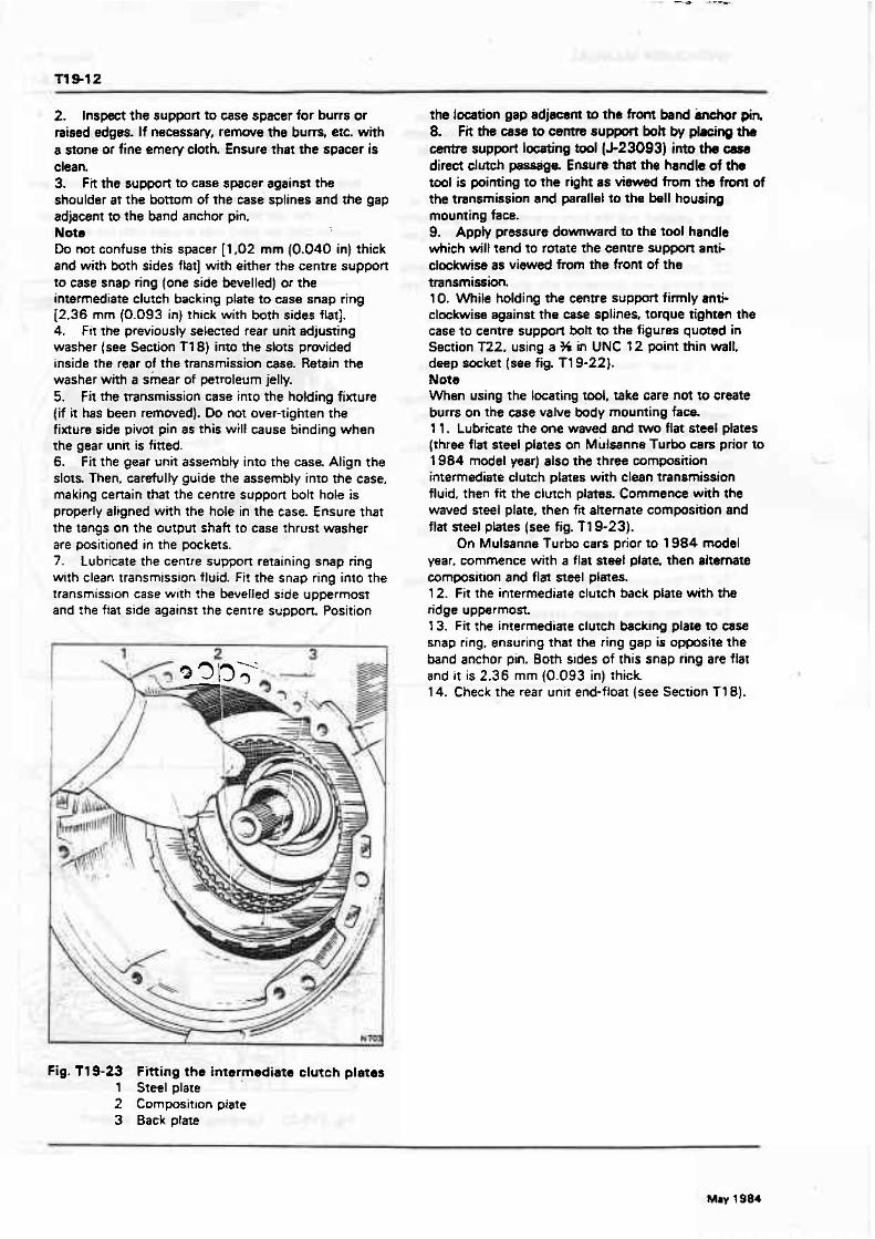
2. Inspect the support to case spacer for burrs or raised edges. If necessaw, remove the burrs. etc. with a stone or fine emery cloth. Ensure that the spacer is clean. 3. Fir the suppofi to case spacer against the shoulder at the bottom of the ease splines and the gap adjacent to the band anchor pin. Nots Do not confuse this spacer [l ,02 mm (0.040 in] thick and with both sides flat] with either the centre support to case snap ring (one side kvelled) or the intermediate clutch backing plate to case snap ring l2.36 mm (0.093 in) thick with both sides flat]. 4. Fit the previously selected rear unit adjusting washer (see Section T7 8) into the slots provided inside the rear of the transmission ease. Retain the washer with a shear of petroleum jelty. 5. F it the mnsmission case into the holding fixture (if it has been removed). Do not over-tighten the fixture side pivot pin as rhis will cause binding when the gear unit is fitted. 6. Fit the gear unit assembly into the case. Align the slots. Then, carefully guide the assembly into the case. making certain that the centre support bolt hole is properly aligned with the hole in the case. Ensure that the tangs on the output shaft to ease thrust washer are positioned in the pockets. 7. Lubrtcate the centre suppon retaining snap ring with clean transmission fluid. Fit the snap ring into the transmission case with the bevelled side uppermost and the flat side against the cenrre support Position
Fig. T19-23 Fitting the intermediate clutch plates 1 Steel plate 2 Composition plate 3 Back plate
the location gap adjacent to the from band inchor pin 8. Fit the case to cem support boh by placing the centre support locating tod (J-23093) into the case direct clutch passage Ensure that the handle of the tool is pointing to the right as viewed from ths front of the transmission and parallel to the bell housing mounting face. 9. Appty pressure downward to the tool handle which wilt tend to rotate the centre suppon anti- clockwise as viewed from the front of the transmission. 10. While holding the cenrre support firmly anti- clockwise against the ease splines, torque tighten the case to centre suppon bol! t o the figures quoted in Section T22, using a 36 in UNC 12 point thin walt, deep socket (see fig. Tl9-22). Nots When using the locating tool, take care not to create burrs on the Case valve body mounting face. 1 1. Lubricate the one waved and two flat steel plates (three f tat steel plates on M ulsanne Turbo cars prior to I984 model year) also the three composition intermediate clutch plates with clean ttansmission fluid. then fit the clutch plates. Commence with the waved steel plate. then fit alternate composition and flat steel pbtes (see fig. Tl9-23).
On Mulsanne Turbo cars prior to 1984 model year, commence with a flat steel plate. then alternate composition and flat steel plates. 12. Fit the intermediate clutch back plate with the ridge uppermost. 13. F i t the inrermediaxe clutch backing plate to case snap ring, ensuring that the ring gap is opposite the band anchor pin. Both sides of this snap ring are flat and it is 2.36 mm (0.093 in) rhick 1 4. Cheek the rear unit end-float (see Section T18).
May 1984
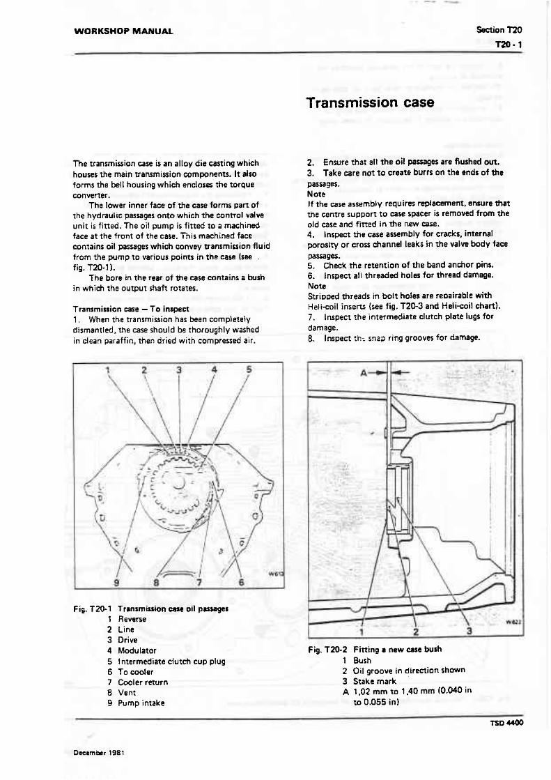
WORKSHOP MANUAL Section T?Q m- l
Transmission case
The transmission case is an alloy die caning which houses the main transmission components. It also forms the bell housing which encloses the torque converter.
The lower inner face of the case forms part of the hydraulic passages onto which the control valve unit is fitted. The oil pump is fitted to a machined face a t the front of the ease, This machined face contains oil passages which convey transmission fluid from the pump to various points in the case (see . fig. T20-1 l.
The bore in the rear of &e case contains a bush in which the output shaft rotates.
Transmission case - To inspect 1 . When the transmission has been completely dismantled, the case should be thoroughly washed in clean paraffin, then dried with compressed air.
Fig. T 20-1 Trrnsmirtion oil pzsmges 1 Reverse 2 Line 3 Drive 4 Modulator 5 Intermediate dutch cup plug 6 To cooler 7 Cwler raurn 8 Vent 9 Pump intake
2. Ensure that all the oil parsages are Rushed out. 3. Take care not to create burrs on the ends of the Pa=g=. Note If the case assembly requires replacement, ensure that the centre suppan to case spacer is removed from the old case and fitted in the new case. 4. l nspect the case assembly for cracks, internal porosify or cross channel leaks in the valve body face pa=w. 5. Check the retention of the band anchor pins. 6. Inspect all threaded holes for thread damage. Note Stripoed threads in bolt holes ate reoairable with Helicoil inserts (see fig. T20-3 and Heli-coil chart). 7. tnspect the intermediate clutch plate lugs for damage. 8. Inspect t k snap ring grooves for damage.
Fig. TZO-2 Fitting a new case bush t Bush 2 Oil groove in direction shwn 3 Stake mark A t ,02 mm to 1.40 mm 10.046 in
to 0.055 in)
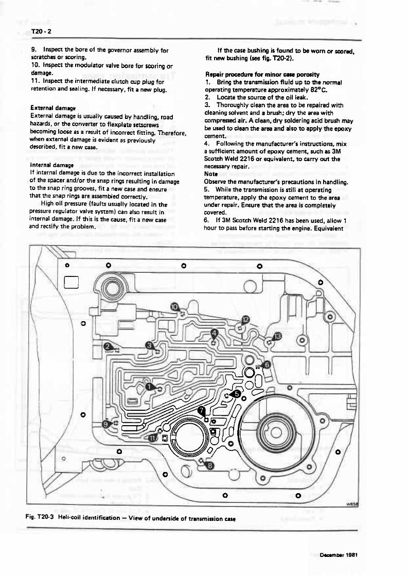
9. Inspect the bore of the governor assembly for If the case bushing is found to be worn or smnd, scratches or scoring. fit new bushing (see fig. 'TZO-2). 10. Inspect the modulator valve bore for scoring or damage. Replir pmdum for minor porosity T l . Inspect the intermediate clutch cup plug for l. Bring the tranrmissionfluid up to the normal retention and sealing. tf necessary, fit a new plug. operating temperature approximately 82OC.
2. Locate the sou= of the oil leak.
External damage External damage is usually caused by handling, road hazards, or the converter to flexplate setscrews becoming loose as a result of imrrect fining. Therefore, when external damage is evident as previously desaibed, fit a new case.
Internal damage If internal damage is due to the incorrect installation of the spacer andlor the snap rings resulting in damage to the snap ring grooves, fit a new case and ensure that the snap rings are assembled correctly.
High oil pressure (faults usually lowted in the pressure regulator valve system) can also result in internal damage. If this is the cause, fit a new case and rectify the problem.
3. Thoroughly clean the area to be repaired with deaning solvent and a brush; dry the area with c o m p r d air. A clean, dry soldering acid brush may be used to dean tfte am and also to apply the epoxy cement. 4. Following the manufa~rer'r inrtructions, mix a sufficient amount of epowy cement, such as 3M Scotch Weld 2216 or equivalent, to carry out the necessary repair. Not* Obsenre the manufacturer's prwautions in handling. 5. While the transmission is still at operating temperature, apply the epoxy cement to the area under repair. Ensure that the area is completely mverd. 6. If 3M Scotch Weld 2216 has been used, allow 1 hour to pass before starting the engine. Equivalent
Fig. T20-3 Heli.mil identification - View of underside of transmission u s a

WORKSHOP MANUAL Section m0
epoxy cements may take longer to cure, therefore, intermdim dutoh wp pluq - 1 o fit always check the manufacturer's instructions. 1. Place the transmission case in the holding 7. Finally. bring the transmission fluid up to the fixture RH 7955 and position it with the front d normat operating temperature of approximately 8Z0C facing upwards. and check rhe transmission for leaks. 2. Ensure that the intermediate dutch cup plug hole
Heli-coil information for Torque Converter Transmission
l
Transmission out of car and partially or completely dismantled
Location Hole number Drill size f ap size Heii-coil size
Pump to case All
I Valve body i to4 8.33 mm - l 8 - 18 STI-NC t o case {see fig. T20-3) (0.328 in) UNC-20
Valve body 5 and 6 6.76 mm :: - 20 % - 20 STI-NC to case (see fig. T20:3 1 (0.266 in1 UNC-ZB
Converx. to A!! 10.30 mm M10 - 7.5 M10- 1.5 X lXD f lexplare (0.406 in1
r
Transmission in car and partially dismantled
Location Hole number Drill size Tap size Heli-mil size
Rear extension R1 ; to case
Governor AII cover to case
Modulator - retainer to case
Speedometer - driven gear assembly to case
Oil sump to case h! I
Rear servo All Cover to Case
Parking lock AI) bracket to ease
9.93 mm '., + 16 ',m + 16 STI-NC (0.391 in) UNC-ZB
8.33 mm S , e - 18 ':,, - 18 STI-NC (0.328 in) UNC.25
8.33 mm '9r 18 f ,, - l 8 STI-NC (0.328 in1 UNC-20
8.33 mm ?I. - 18 ',. - 18 STl-NC (0.328 in) UNC-20
833 mm f*r - l8 ' ~ l r - t8 STI-NC 1 (0.328 in) UNC-20 l 8.33 mm - 18 '/tr - 18 S f l*NC (0.328 in) UN C-2 B
I Valve body 7 to 10 8.33 mm '[W - 18 @:,. - 18 Sfl-NC to case {see fig. T20-3) 10.328 in) UNC-20
Valve body 11 6,76 mm ?4 -20 X - 20 STI-NC to case (see fig. T20-3) (0.266 in) UN C-2 S
I j Solenoid 12 and 13 6.76 mm '1: - 20 % * 20 ST1-NC I to case [see f i?, T20-3) (0.266 in) UNC-28
TSD am

;S thoroughly dean and emcr the intermediate clutch mp plug into the hole. open end out. Drive the plug into the case until it i s flush or slightly below the lop of the hole using a 9.52 mm (0.375 in) diameter rod, approximately 254 mm (1 0 in 1 long. Note Ensure that the diameter of the rod is large enough to locate on the lip edge of the plug and not the bottom of the dug. 3. Stake the plug secvrely in the case.
Case bushing - To remove 1. Support The case in the holding fixture and m e a d the exrension handle (J-27465.131 into the bushlng removal toot U-2 1465-8). Using drive handle (J8092) remove the hush.
Case bushing -To fit 1. Support the transmission case and using rhe adapter (J-21465-91, on the rernoval/fiaing rool (J-214654). together with the drive handle (6-8092) and extension [J-21465-131, press or drive the bush into the case until between 1,02 mm and 1,40 mm (0.040 in and 0.055 in) above the selective thrust washer face (see fig. T20.2). Note Ensure That the bushicc i s f ined with the lubrication passage facing the front o i the transmission case. 2. Srake the bushins tr the oil groove vsing tool (3-21465-101.
Heli-coils Always refer to figure T20.3 and the Heli-coil ~nformation chart. for the correct drill and tap sizes, before commencing any repair work. 1. Blank of f the area around the hole t o be heli- coiled (if possible). to contain any small particles of metal. 2. Drill out the old threads and cIean anv panicles from the hole. Note Drill out only to the depth of the original hole. When drilting hole No.4 (see fig. T20-3), the drill may go through to t h e inside of the case; located just behind this hole are the intermediate clutch splines. Therefore, the burrs must be removed from the clutch splines. 3. Tap the hole with the Helicoil tap. 4. F i t the standard insert {STI) Heli-coil. 5. Break off the tang from the b t t o r n of the Heli-coil. 6. Remove any blanks etc. as described in Operation 1 and ensure that all panides of rnehl, etc. are removed.

WORKSHOP MANUAL Section T2 t
Fault diagnosis
Accurate diagnosis of transmission problems begins with a thorough understanding of normal transmission operation. In particular it is essential to know which u n i ~ are involved in the various gears and speeds, so thar the specific unit or fluid flow can be isolated and investigated further.
f he following sequence of tests may help to simplify the diagnosis of defects and should be performed first. 1. Check the fiuid level. 2. Warm-up the engine and transmission.
3. Check the control linkage. 4. Check the kick-down micro-switch. 5 . Check the vacuum lines and fittings. 6 . Fit a pressure gauge and road test the car.
Note If possible, t e n the car with the customer as a passenger. It i s possible that the conditian which the customer requires correcting is a normal function of the transmission. thus, gnnecessary work can be avoided.
Symptom Possible cause Action
1. No drive in Drive range 1. Incorrect fluid tevel in transmission.
2 . Control linkage.
1. Top-up as necessary {see Section T21. Check for external leaks or the vscuum m;du lator diaphragm leaking.
2. Check and adjust the control linkage (see Section T171.
3. Low oii pressure. 3. (a) Check the vacuum modulator. {b) Check for a restricted intake
strainer, a leak at the intake pipe. grommet. or the '0' ring damaged or missing.
(cl Check that the oil pump assernbty pressure regulator i s not sticking. Also check the pump drive gear tang has not been damaged by the converter.
Id) Check the care for porosity around the intake bore.
( e ) Check the items listed on pageT2 1-13.
4. Control valve assembly.
5. Forward clutch.
4. Check for the manual valve being disconnened from the detent Lever.
5. (a) Check the forward ctutch apply piston for cracks, the seals damaged or missing or the clutch plates burnt (see page T21- 141.
(b) Check the oil seal rings (missing or broken) on the pump cover.
(C) Check for a teak in the fwd circuit or the pump to case gasket mis- positioned or damaged.
(d) Check the clutch housing check kll i s not sticking or missing.
6. Roller clutch assembly. 6. Check the clutch assembly for broken springs or damaged cage.
TSD 4400

Symptom Possible cause
1. No driw in Drive range 7. Actuator inoperative. (continued]
2. (a1 No drive in Reverse range.
(bl Slips in Reverse range
3. Drive in Neutral
1. Incorrect fluid level in transmission.
2. Actuator inoperative.
3. Control linkage.
4. Oil pressure.
5. Control valve assembly.
6. Rear servo and accumulator.
7. Forward clutch.
8. Dirm dutch.
9. Rear band.
1. Control linkage.
2. Forward clutch.
7. {a) Check the thermal wt-out switch on
(bl Cheek the c h a p codition of the battery.
(c) Check the operation of the actuator (see Section W.
1. Top-up as necessary (see Section l2).
2. (a) Check the thermal m-out switch on the fuseboard.
(bl Check the charge condition of the battery.
(cl Check the operation of the aezuator (see Section TV.
3. Check and adjust the control linkage (see Section T171..
4. Check the items listed on page T21-13.
5. fa) Check that the valve bodylspacer plate gaskets are not damaged or incorrect1 y fined.
(bl Check that the 2-3 valve train is not sticking open (this would also cause a 1-3 upchange in Drive range 1.
[c) LowlReverse check ball missing from the case (this will at= cause no overrun braking in Low range).
6. (a1 Check for a damaged rear piston seat.
{b) Check for a short band apply pin {this may also cause no overrun braking or slipping in overrun braking - Low range).
7. Check that the clutch unit will release (if it does not releare'this will also cause drive in Neutral).
8. fa) Check the outer seal for damage. Ibl Check the clutch plates (if burnt, it
may be caused by the check ball sticking in the piston).
(C) Check the items listed on page T21-15.
9. Check the band for burnt or tome linings, apply pin or anchor pins not engaged. or the bend broken.
1. Check and adjust the control linkage (see Smion 1 1 7). .
2. fa) Check that the clutch is releasing, if ?he clutch does not release it

WORKSHOP MANUAL Section T21
Symptom Possible cauw Action
3. Drive in Neutral {continued)
4. Wil l not hold in Park. *
5. No engine braking in Intermediate range - In gear
6. No engine braking in Intermediate range - 2nd gear
will also uwse m Reverse. [bl Chcdr the items iirtd on
f21-14.
3. Pump assembly. 3. Transmission fluid pressure leaking into the forward dutch apply passage.
7. Control linkage. 1. Check and adjust the control tinkaga (see Section Tf 71.
2. Internal parking iinkage. 2. (a) Check the parking brake lever and actuator assembly.
(bl Check the chamfer on the actuator red sleeve.
(c) Check the parking pawl (broken or inoperative).
Id) Check that the parking pawl return spring is not broken, missing, or incorrectlv hooked.
1. Control valve assembly.
2. Rear s e m .
3. Rear band.
1. Front servo and accumulatnr.
2. Front band.
7. No detent down&anges 1. Transmission ease Note electrical plug. Position ?he c8r on a ramp. Switch on ignition, but do not start engine.
1. Check the Low-Reverse check ball (missing from ease).
2. {a) Check for a damaged oil seal ring, bore or piston.
(b) Rear band apply pin short or improperly assembled.
3. (a) Rear band broken or burnt fchedc for cause!.
(bJ Ch& the rear band assembly engages correctly on the anchor pins andlor servo pin.
I. (a) Check for leaking or broken oil sealing rings.
(b) Check for scored bores. (cl Check for a sticking servo piston.
2. (a) Check to ensure that the front band i s not burnt or broken.
(b) Check to ensure that the from band is engaged correctly on the anchor pin andlor servo pin.
1. (a1 Disconnect the eieerrieal connections.
(b) Connect a test lamp to the detent solenoid terminal of the dis- mnneetad wiring loom.
(cl Depress the accelerator fully, from the normal driving porition.
[d) Light off. Incorrectly adjusted or fwrlty. micro-switch. Faulty electrid circuit.
(el Light on. Check the operation of the damm solenoid. If the solenoid annot bs heard to operate this may be due to.

Symptom Pouibie cause Action
7. No detent dwn-changes (wminuedl
(i) Fsulty electrical connection. [ii) Sticking detent vatw train (iii) Restricted oil pasrage.
2. Control valve assembly. 2. (a] 3-2 value sticking, spring missing or broken.
(b) Detent valve train sticking.
8. Transmission noisy 1. Noise in Park, Neutral. l . (a) Check for pump cavitation. and all Drive ranges. i Transmission fluid level low or
high, topup etc. as necessary (see Section TZ).
(ii} Restricted or incorrect strainer assernbl y.
(iii) Intake '0' ring damaged or intake pipe split.
(iv) Porosity at pump face intake port.
(v) Pump to transmission case gasket incorrect1 y fitted.
(vi] Coolant in the transmission fluid.
(b) Check pump assembly for. (i) Defeerive or damaged gears. (ii) Drive gear incorrectly
assembled. (iii 1 Crescent interference. (iv) Sa l rings damaged or worn.
(c) Check converter for. (i) Damage. ( i i ) Loose bolts, converter to
flywheel. (iii) Cracked or broken flexptate.
2. Noise in First, Second, and Reverse.
3. Noise during acceleration in any gear.
4. Squeak at low vehicle speeds.
2. (a) Check that the transmission doer not contact the body.
(b) Check planetary gear train for. (i) Gears or thrust bearings
damaged. Thoroughly clean thrust bearings and thrust races. Closely inspet needles and surfaces for pitting and roughness.
(iiJ Front internal gear ring damaged.
3. [a) Check that the transmission fluid fines to and from the cwler are not fouling.
(b) Check that the engine mounts are not loose or broken.
4. Chedr the speedomacr driven gear shaft seal (lubricate or replace).
5. Slight creaking noise, 5. Check for the converter pilot spigot when accelenting frstting in the crankshaft tail bare gently from the (lubricate the spigot Iiberally with srationary position. Retinax A grease).
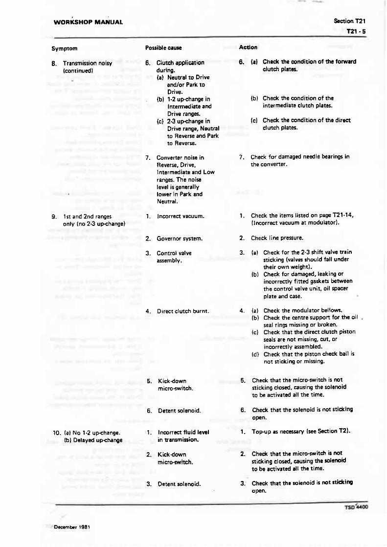
WORKSHOP MANUAL Snion TT 1
T21- 5 -
Symptom Possible cause Action
8. Transmission noisy 6. Clutch application 6. (a] Check the wndition of ths forward (continuedl during. clutch plates.
(a) Neutral to Drive -
andlor Park to Drive.
(bJ 1-2 uwhange in (b) Check the condition of the Intermediate and intermediate clutch plates. Drive ranger.
(C) 2-3 up-change in (C) Check the condition of ?he direct Drive range, Neutral clutch plates. to Reverse and Park m Reverse.
7. Converter noise in 7. Cheek for damaged needle bearings in Reverse. Drive, the converter. lmermediate and Low ranges. The noise tevel i s generally lower in Park and Neutral.
9. 1st and 2nd ranges 1. Incorrecf vacuum. 1. Check the items listed on page RI-14, only (no 23 uvhange) (Incorrect vacuum at modularorl.
2. Governor system. 2. Check line pressure.
3. Contral valve assemblv.
3. (a) Check for the 2-3 shift valve train sticking (valves should fall under their own weight).
(b) Check for damaged, leaking or incorrectly fitted gaskets between t h e control valve unit, oil spacer plate and case.
4. Direct clutch burnt. 4. (a) Check the modulator bellows. (b) Check the centre suppOn for the oil .
seal rings missing or broken. (c] Chedc that the direct clutch piston
seals are not missing, cut, or incorrectly assembled.
(d) Check rhat the piston check ball is not sticking or missing.
5. Kickdown micro-switch.
S. Check that the micro-switch is not sticking closed. causing the solenoid to be activated all the time.
6. Oetent solenoid. 6. Check that the solenoid i s not sticking open.
10. (a) No 1-2 upchange. 1. Inmrrect fiuid l e d 1. Topup as necessary (see %ion m). (h] Delayed upchange in wansrnission.
2, Kickdown mimewitch.
2. Check that the micro-switch is not nidring closed, causing the solenoid to k activated all the time.
3. Oetent solemid. 3; Check that the solenoid i s nrt rtidting open.

10. Ia) No 1-2 upchange. 4. Governor acsernbty. {b) Delayed up-change (continued)
1 1. Rough 1-2 upchange
5. Control valve asrem bl y .
6. Case.
7. Intermediate dutch.
1. Incorrect fluid level in transmission.
2. Vacuum modulator.
3. Oil pressure.
4. Check condition of engine.
5. Control value assembly.
Action
4. (a) Check for the governor ~a1w sticking.
{b) Check that the driven gear is not loose. damaged. or worn (also cheek the output shaft drive gear, if the driven gear show damage).
(C) Check that the driven gear starring pin is not loose. broken, or missing.
5. {a) Check that the 1-2 shift valve train is not sticking closed.
(b) Check that the governor feed channels are not blocked, leaking, or the pipes out of position.
(c) Check t h a t the valve body spacer plate gaskets are not leaking, damaged or incorrecrly find.
6. {a1 Check for the intermediate clutch plug leaking or blown out.
{b) Check for porosiw between channels.
(cl Check that the governor feed channel is not blocked, the governor bore scored or worn allowing a cross pressure leak.
7. (a) Check tha h e clutch piston seals are not cut, improperly fittd, or missing.
Ib) Check t h a t &e centre wppcn oil rings are not missing or broken.
(C) Check that the orifice wp plug is fitted.
1. Topup as necBsary (see Section T21.
2. {a) Check for loose fittings. rmrictions in line, or the modulator assembly inoperative.
(b) Check that the mgdulator valve is not sticking.
3. (a) Check that the oil pump regulator or boost valve has not jammed.
(bJ Check for t h e pump to case gasket being incorrectly fitted or damaged.
4. Tune the engine.
5. (a) Check that the 1-2 acu8mulator valve train is not sticking.
(bl Check that the valve b d y to care bits are not loore.
(c) Check that lhe valve body wm2r plate gaskets are not damaged. incorrectly fined, or the wrong gasket fitted,
WORKSHOP MANUAL %ion T2 1
Symptom Possible uur . Actial . -- . I t . Rough 1-2 u-nge 6. bsa.
(continued)
7. Rear servo ' accumulator
arsem bl y.
8. Intermediate clutch.
12. Slipping 1-2 upcfiange 1. Incorrect fluid level in nansmirrion.
2. Check condition of engine.
3. Vacuum line and components.
4. Line pressure.
5. Control valve assembly.
6. front accumulator.
7. Rear accumrrlator.
8. Oil pump.
6. (a1 Chsdc the intermediate dmh ball {missing or not sealing). ---..
(bl Chsck for porosity bmwsm daannels.
7. (a] Check the oil seal rings for damage. Ibl Check that the pinon has not
jammed. (c) Check that the spring is not broken
or missing. (d) Check that the servo bore is not
damaged.
8. (a) Check tha only one waved plate has k e n fined (not applicable to f urbocharged can).
(b) Cheek that the clutch plates are not burnt.
1. Topup as necessary {see Section T2).
2. Tune the engine.
3. Chedt the vacuum system for response at the modulator.
4. (a1 Cheek the oil pressure (it should vary and respond rapidly to quick changes in throttle openings).
(b) Cheek the vacuum rnodulatar for poai ble failure.
(c) Check that the modulator valve is not sticking.
5. (a) Check for the 1-2 accumulator valve train sticking.
(b) Check for porosity in the valve body or case.
(cl Check the valve body attaching bolts for tightness.
6. Check the dl seal ring (damaged or mirf ng).
7. Check the oil seal ring (damaged or missing) or the case bore damaged.
8. (a) Check that the pump to case gasket is not mispositioned or damagcd.
Ibl Chwk that the pressure regulator valve is not sticking.
9. Care. 9. (a) Check that the intermediate dutch plug is not leaking excessively.
Ib) Check for porosity betwean channal~ W
10. Intermediate dutch. 10. (a) Cheek the piston seals ( d r d or missing). Also ch& for burnt dutch plates.
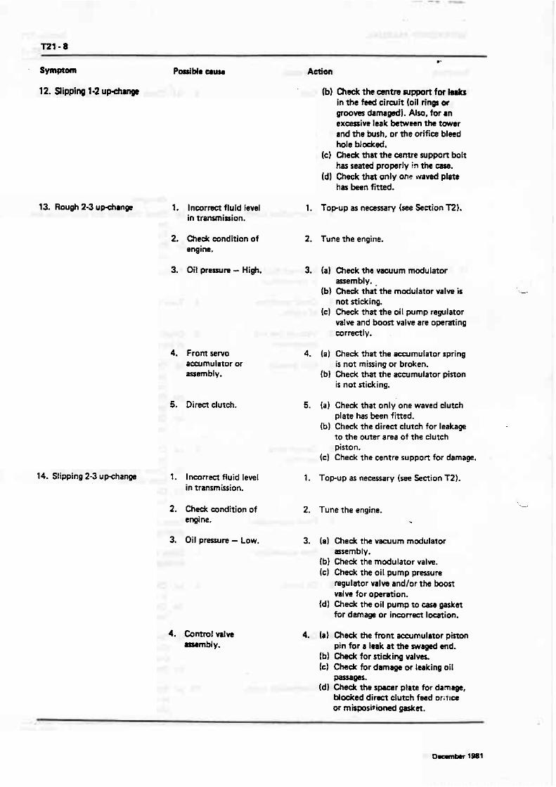
12. Slipping 1-2 upchinpc
13. Rough 2-3
14. Slipping 2-3 uwmge
(bJ Check the wntre support for h* in the fed circxlit (oil rings or grooves damaged). Also, for m ex-iw leak befwetn the tower and the bush, or the orifice bleed hole blocked.
(c) Chedc that the came support bolt has seared properly in the case.
id) Check that only one waved platb has been fitted.
I. Incomct fluid level 1. Topup as n e ~ r y (see Section 72). in tramision.
2. eh& cunditian of 2. Tune the engine. engine.
3. Oii pressure - High. 3. (a) Check the vacuum modulator assembly.
(b) Check that the madulator valw i s not sticking.
(c) Check that the oil pump regulator valve and boost valve are operating wrreetl y .
4. From sew0 accumulator or assembly .
5. Direct clutch.
4. (a] Check that the acrxrrnuIator spring is not missing or broken.
(b) Check that the accumulator pinon is not stidcing.
5. (a) Check that only one waved clutch plate has been fitted.
(b) Check the direct clutch for leakage to the Ourer area of the clutch piston.
(c ) Check the centre support for damage.
1. Inmrrm fluid level 1. Top-up as necessary (see Section TZ). in transmission.
2. Chtdr condition of 2. Tune the engine. engine. *
3. Oil pressure - low. 3. (a1 Check the vacuum modulator assembly.
Ib) Check the modulator valve. (c) Check the oil pump pressure
regulator valw and/or the boost MIW for opration.
{d) Check the oil pump to cam gaskat f o r damags or incorrsn location.
4. Control vrlw ammbly.
4. (a1 Check the front aoeumulator pimn pin for a Imak at the swrgad and.
(bl Check for sticking valves. [cl Check for damage or leaking oil
passaw* Id) Check the spacar plate for damlge,
Modced direct clutch feed oritlce or mbposi*iod W m .
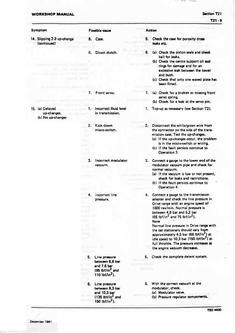
WORKSHOP MANUAL ssetioi ~2 1
14. Slipping 2-3 up-change 5. Care. (mntinued)
15. (a1 Delayed upchanges.
(b) No upchanges
6. Direet dutch.
7. Front servo.
1. Incorrect fluid level in transmission.
2, Kickdown micra.swit&.
5. Check the ease for porosity aort leaks etc.
6. (a) Check the piston seals and check ball for leaks.
(b) Check the centre suppoft oil seal rings for damage and for an excessive leak between the tower and bush.
(c) Cheek that only one waved plate has been fitred.
7. (a) Check for a broken or missing trom servo spring.
Ib) Check for a leak at the servo pin.
1. Topup as necessary (see Section 72).
2. Disconnect the white/green wire from the connector on the side of the tram mission case. Ten the upchanger. [a) If the up-changes occur, the pmblem
is in the micro-switch or wiring. (61 If the fault penis= continue to
Operation 3.
3. lnea~ect modulator 3. Connect a gauge to the lower end of the vacuum. modulator vacuum pipe and check for
normal vacuum. (a) If the vacuum i5 IOW or not pr-nt,
check for leaks and restrictions. (b] If the fault persists continue to
Operation 4.
4. lncarrect line pressure.
5. Line prerrun bstwsan 6,6 bar and 7.6 bar (95 lbffin2 a d l l0 1bfhn2).
4, Connect a gauge to the transmission adapter and check the line praure in Drive range with an engine speed of 1000 revjrnin. Normal pressure is berwwn 4,5 bar and 52 bar (65 lbf/in2 and 75 lbflin2 1. Note Normal line pressure in Orive range with the car stationary should vary from approximately 4,5 bar (65 lbflin2) at idle speed to 10,3 bar (150 ~ b f / i n ~ ) at full throttle. T h e pmrure i n m m the engine vaarum dccrearer.
5. Check the complete detent swam.
6. Line pressure 6. With the oorrect vacuum a t the between 9 9 bar modulator, check. a d 10.3 bar (a) Modulator valve. (1 35 lbf/in2 md (b) Pressure regulator c o r n ~ ~ m t L 150 lbfhn2).

15. (a) Delayed 7. Normal lirte upchanges. prssurre between
(b 1 No upchanges 4.5 bar and (continued 1 . 5 2 bar (65 lbffin2
and 75 lbf/in2).
16. 1-2 Updange - Full throttle only
17. Slips in all ranges
8. Detent system.
1. Kickdown micrwi tch.
2. Derent solenoid.
3. Control valve assembly.
1. Incorrect fluid tevel in transmission.
2. Oil pressure.
3. Case.
4. Forward and direc! c l u t e h ~ slipping.
l . Oil presure.
7. Remove the gowrnor assembly; c h d for freedom of operation and pr- of dirt. etc. Clean if necessary.
8. (a) Chedc that the detent solenoid is not loose or defective.
(bl Check that the solenoid feed orifice is not blocked.
1. Check that the micro-switch is not sticking.
2. Ial Check that the salenoid securing bolts are torque tightened.
Ib) Chedc that the solenoid is no? sticking open.
3. (al Check the valve body spaoer plate gasket for. (i) Leaks. i i Damage. {iii) Incorrectly fitted.
Ibl Check that the detent valw train has not jammed.
(cl Check that the 3-2 valve has not jammed.
4. Check the case for .porosity.
1. Top-up as necessary (see Section T21.
2. {a) Cheek that the vacuum modulator valve is not sticking.
Ib) Check thm the oil strainer assembly is not blocked or leaking. or the grommet or '0' ring missing or damaged.
(cl Check the oil pump assembly for the regulator or boost valve ~idt ing, or for a cross leak.
Id) Cheek that the oil pump to case gasket is not damaged or incorrectly fitted.
3. Check the case for cross leaks or porosity.
4. (a) tf theclutchesappear burnt, look for the cause in 'Burnt cluteh plates* on page T21-14.
(bl Check the oil pump sealing rings on the pump cowr for wear or dam age.
l. Check the vacuum modulator srssmbly. modulator valw, and pressure

WORKSHOP MANUAL SKtion l 7 1
Symptom Parrible cam Action
18. No part throttle downdanges (continutd) -
19. Low or High upchanges
20. Torque converter leaks
21. Torsue converter vibrations
2. Control valve assembly.
1. Oil pressure.
2. Governor.
3. Detent solenoid.
4. Control valve assembly.
5. Case.
1. Converter welding.
2. Damaged or worn convener hub.
1. Conwrterlflex- plate out of balana, or crackd.
regulator valve. etc., for leaks, didcing valves and rertrietions.
2. Check that the 3-2 valve is not stiking, or t h e spring missing or broken.
1. (a) Check the engine vacuum st the transmission end of the modulator pipe.
(b) Cheek for loose vawum conmetions at the engine and transmission. Also, check the modulator valve, pressure regulator valve train, etc., for leaks, sticking valves and restrictions.
2. (a) Check that the governor valve i s not sticking.
(bl Cheek the feed holes, lines, etc.. for leaks or restrictions, or the pipes damaged or mispositioned.
3. Check that the solenoid is not sticking open, or become loose, etc., as this wil l cause late upchanges.
4. (a1 Check the detent wlve train for free movement or resrrietiom.
(b) Check the 3-2 valve train. (C) Check the 1-2 valve train, i f the
1-2 regulator valve is sticking this would cause a constant 1-2 shift point, regardless of throttle opening.
Id) Check that the valve body spacer plate gaskets are not mispositioned, or the spacer plate holes missing or blocked.
5. Check the case for porosity, inter- mediate plug leaking or missing.
1, Check the convener welding and i f a t all suspect, f i t a new converter.
2. Inspect the convener hub for wear, Jro, scoring that can damage the seal.
1. (a) Isolate the cause of the vibration. (b) Alter the position of the convefier
on the flexptate 120~ a t a time until t h e out o f balance condition is . mrrected.
(c) Replam the convwterlflexplste.
2, Converter balance 2. Chsdr the mnverter for the loss of weight. balance weight(s), cham the anvrner
if a balance weight is lost.
3. Crankshaft pilot. 3. (a1 Check t o ensure that the convertrr

Symptom
21. Torque convener vibrations (continued)
22. Torque converter slipping or noisy. (Most converter noise o a r s under light thronle in Drive range with the brakes applied)
1. Loose flexplate to Converter SH- screws.
2. Cracked f lexplatc.
3. Items lined undtr Operation 21 - Torqtle convener vibrations.
4. Fretting of the converter pilot spigot in the crankshaft tail bore.
5. Converter balance weights lifting (spot welds breaking and one end lifting up and catching on the easel.
6. Internal damage to converter.
7. Converter fluid.
Note It is not necessary 10 change the convener if a failure in some other part of the transmission has rasulted in the w n w r t a r containing dark discoloured fluid. The full flow strainer used in the transmission will remove PP harmful residue from
Action
to crankshaft pilot i s not brdcm. {b) Change the mnverter if the pilot
is broken.
1. (a) Check the flexplate and aonverttr for damage.
(b) If no damage i s apparent, tighten the boln.
(c] If damage is apparent replace the components.
2. (a] Check far a cracked flexplate (engine to case dowel pins missing can rerult in a cracked flexplate).
(b) Replace the damaged components.
3. See items listed under Operation 21 - Torque converter vibrations.
4. Apply a liberal coating of Shell Retinax A grease all over the spigot.
5. (a) Check for welds breaking on the balance weights.
(b) Change the convener if the balance weights have broken away.
6. (a] Check the thrust roller bearing. thrust races and roller clutch for damage. Fit a new converter if damage is apparent-
7. {a) Check the colour of the fluid, i f it has the appearance of aluminium paint, the convertTr is damaged internaIly.
(bl Chedc that anti-freeze has not con- faminated the converter fluid.
(c) Fit a new converter.

WORKSHOP MANUAL Section l23
Symptom Possible eruw Aetion
22. Torque converter sli~airq or noisy. (continued)
failures (other than converter to pump failural W o r e the oil is pumped into the mnverter.
Correet the transmission problem, then change the intake strainer and ftuid.
High line pressure I f either the idle or full throttle pressure check i s high, the cause may be as foltows.
1. Vacuum leak a. Full leak (vacuum line disconnected). b. Partial leak in the line from the engine to the modulator. c. Incorrect engine vacuum. d. Leak in vacuum operated accessories.
2. Damaged modulator a. Stickingvalve. b. Water in modulator. c. Incorrect operation o f modulator.
3. Detent system a. Kickdown switch actuated [plunger sticking) or shorted. b. Detent wiring shorted. c. Detent solenoid stidcinq open. d. Detent feed orifice in spacer plate btocked. e. Detent solenoid loose.
4 . Pump a. Pressure regulator andlor boost valve sticking. b. Incorrect pressure regulator spring. c. Excessive number of pressure regulator valve rpacers. d. Faulty pump casting. e. Pressure boost valve installed inconectl y or othemise defective. f. Aluminium bore plug defective. g. Pressure boost bush defective.
5. Control rdve assembly a. Spacer plate-tocase gasket i n c o r r d y fitted. b. l ncorrect plate-10-e gasket.
Low line pressure If either the idle or full throttle pressure eh&$ are law. the cause may be a5 follows.
1. Transmission oil level low
2. Modulator assembly
3. Intake strainer a. Blocked or restrimed. b. '0' ring on intake pipe omitted or damaged. c. l ncorrect strainer fitted.
4. Split or leaking intake pipe
5. Pump a. Pressure regulator or boost valve sticking. b. Gear clearance, damaged or worn (pump will become damaged if the drive gear is installed the wrong way or if *e converter pilot does not enter the crank- shaft freely). c. Pressure regulator spring weak. d. tmufficient spacers i n pressure regulator. e. Pump to ease gasket incorrectly positioned. f. Defective pump body and/or muer.
6. Leaks in the internal circuit a. Fomard clutch leak (pressure normal in Neutral and Reverse - pressure low in Drive).
(il Check pump rings. lii) Check forward clutch seals.
b. Direct clutch leak (pressure normal in Neutral. LOW, Intermediate and Drive -\resure low in Revme).
(i) Check centre support oil seal rings. (ii) Cheek direct clutch outer seal for damage. (iii) Check rear servo and front accumulator pinons
and rings for damage or missing.
7. Case assembly a. Porosity i n intake bore area. b. Check care for intermediate clutch plug; leak or blown out. c. Low - Reverse heck ball incorredy pwitiod or missing (this condition wilt cause no R a m overrun braking in Low range). Note When checking item 3 - Intake strainer, it should be noted that there i s no approved method for eithar checking or cleaning the strainer. I f &a psrfwrrum of the mainer is sus- a new rtrmrwr m m h
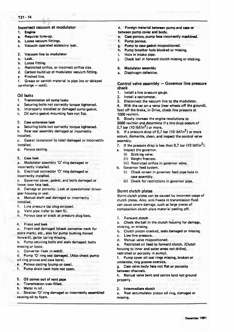
. - Incorrect vacuum at modulator l. EnOinr r. Requires tune-up. b. Loose vacuum fittings. c. Vacuum operated accessory leak.
2. Vacuum line to moduiator a. Leak. b. Loose fitting. c. Restricted orifice, or incorrect orifice size. d. Carbon build-up a t modulator vacuum fitting. e. Pinched line. f. Grease or varnish material in pipe (no or delayed up-cfiange - cold). Oil leaks I. Tranrmirsi.on oil sump leaks a. Securing bolts not correctly torque tightened. b. Improperly installed or damaged sump gasket. c. Oil sump gasket mounting face not flat.
2. Case extension leak a. Securing bolts not correctly torque tightened. b. Rear seal assembly damaged or incorrectly installed. c. Gasket (extension to case) damaged or incorrectly installed. d. Porous casting.
3. Care leak a. Modulator assembly D' ring damaged or incorrectly installed. b. Electrical connector '0' ring damaged or incorrect1 y installed. c. Governor cover, gasket, and bolu damaged or loose; case face leak. d. Damage or porosity. Leak at speedometer driven gear housing or seal. e. Manual shaft seal damaged or inwrractly installed. f. Line pressure tap plug stripped. g. Vent pipe (refer to item 5). h. Porous ease or crack a t pressure plug boss.
4. Front end leak a. Front seal damaged (chack converter neck for score marks. etc., also for pump bushing moved forward], garter spring missing. b. Pump securing bolts and seals damaged; bolts missing or loose, c. Converter (leak in weld). d. Pump '0' ring seal darn-. (Also check pump oil ring groove and case bore). e. Porous carting (pump or case). f. ' Pump drain back hole not open.
5. Oil mmes out of vent pipe a. Transmission over-filled. b. Water in oB. c. Strainer '0' ring damaged or incamctly assembled causing oil to foam.
d. . Foreign material beween pump a d c m or between pump cover a d body. e. Cast prous, pump face incorrectly m b i d . f. Pump porous. g. Pump to m e gasket misporitiomd. h. Pump breather hole blodced or missing. i. Hale in intake pipe. j. Check ball in forward clutch missing or nicking.
6. Modulator asremMy a. Diaphragm defective.
Control valve assembly - Governor line prwsure check 1. Install a line pressure gauge. 2. Install a tachometer. 3. Disconnect the vaarum line to the modulator. 4. With the car on a ramp (rear wheels off the ground), foot off the brake. in Drive, &I& line praure at 1000 revlmin. 5. Slowly increase the engine revolutions to 3000 revlmin and determine if a line drop ocwrs of 0.7 bar 110 lbflin2} or more. 6. If a pressure drop of 0,7 bar (10 lbflin2) or more occurs, dismantle, clean, and inspect ttre control valve assembly. 7. If the pressure drop i s less than 0,7 bar (l0 lbflin21. a. inspect the governor.
(i) Sticking valve. (i i l Weight freeness. (iiiJ Restricted orifice in governor valve.
b. Governor feed system. . IiJ Check screen in governor feed pipe hole in
case assembly. (ii) Check for resaiaions in governor pipe.
Burnt clutch plates Burnt clutch plates can be caused by incorrect usage of clutch plates. Also. anti-freeze in transmission fluid can cause severe damage, such as large pieces of composition clutch plare material peeling off.
I. Fomard dutch a. Check the ball in the clutch h&sing for damage, sticking, or missing. b. Clutch piston cracked, seals damaged or missing. c. Low line pressure. d. Manual valve mispositioned. e. Restricted oil feed to forward clutch. (Clutch housing to inner and omer areas not drilled, restricted or porosity in pump). f. Pump cover oil seal r i w missing, broken or undersire; ring groove oversize. g. Case valve body fm nut flat or porosity beman channels. h. Manual valve bent and centre land not g r o u d properly 0
2. Intermediate dutch a. Rear aearmulator pinon oil ring, damaged or missing.
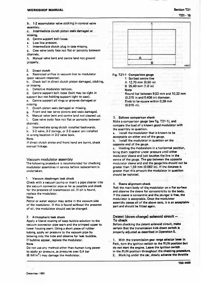
WORKSHOP MANUAL
b. 1-2 accumulator valve sticking in control valve assembly. c. Intermediate clutGh piston seals damaged or missing. d. Centre support bolt loose. e. Low line pressure. f. Intermediate clutch plug in case missing. g. Case valve body face not flat or.porosity between channets. h. Manual valve bent and centre land not ground properly.
3. Direct clutch a. Restricted orifice in vacuum line to modulator (poor vacuum response). b. Check ball in direct clutch piston damaged, sticking, or missing. c. Defective modulator bellows. d. Centre support bolt loose (bolt may be tight in support but not holding support tight to case). e. Centre support oil rings or grooves damaged or missing. f. Clutch piston seals damaged or missing. g. Front and rear servo pistons and seals damaged. h. Manual valve bent and centre land not cleaned up. i. Case valve body face nor flat or porosity between &annets. j. Intermediate sprag clutch installed backwards. k. 3-2 valve, 3-2 springs, or 3-2 spaeer pin installed in wrong iacation in 3-2 valve bore. Note I f direct clutch plates and front band are burnt. check manual linkage.
Vacuum modulator assembly T h e following procedure is recomm~nded for checking modulator assemblies in service before replacement is undertaken.
1. Vaeuum diaphragm leak check Check wirh a vacuum pump or inserl a pipe cleaner into the vacuum connector pipe as far as possible and check for the presence of transmission oil. If oil is found, replace the modulator. Note Petrol or water vapour may settle in the vacuum side of t h e modulator. If this i s found without the presence of oil. the modulator should not be changed.
2. Atmospheric teak check Apply a liberal coating of soap bubble solution to the vacuum EO~IWCtOr pipe seam and the crimped up- to tower housing seam. Using a short piece of rubber tubing. apply air presure to the vacuum pipe by blowing into the tube and observe far leak bubbles. If bubbles appear, replace the modulator. Note Do not use any method other than human lung power to apply air pressure, as pressures over 0.4 bar (6 lbf/in2) may damage the modulator.
Fig. 121-1 Comparison gaugb 1 Scribed centre line A 12f0 mm (050 in) B 25AO mm (1 .O in1 Note Round bar beween 992 mm and 10.32 mm (0.375 in and 0.406 in} diameter. Ends to be square within 0,39 mm 10.015 in).
3. Bellow comparison cheek Mske a comparison gauge (see fig. T21-1). and compare the load of a known good modulator with the assembly in question. a. Install t he modulator that is known to be acceptable on either end of the gauge. b. Install the modulator in quMion on the opposite end of the gauge. c. Holding the modulators in a horizontal position, bring them together under pressure until eithef modulator sleeve end just touches the line in ths centre of the gauge. The gap between the opposite modulator sleeve end and the gauge line shwld not be greater than 159 mm (0.062 in). If the dinanca is greater than t h i s amount t h e modulator in question should be replaced.
4. Sleeve alignment check Roll the main body of the_ modulator on a flat surface and observe the sleeve for ccincentricity to the body. I f the sleeve is concentric and t h e plunger is free, the modulator is acceptable. Once the modulator assembly passes all of the above tesu, it is an =ptrMe part and should be fitted again.
Detent (downdange) solenoid c i w i t - To check Before heeking the detent solemid circuit. mtke certain that t h e transmission kidrdown mfteh b properly adjusted as dmibed in Opsntion 5.
l . With the transmission gear range Islsctor lnnr in Park, Nrn the ignition wi tch to the RUN pasltion but do not r t r ~ the angina. L d s ~ t h e ignition witch in the RUN position thrwghwt t h e &eking pmerdum. 2. Working under the car, slowly rdvma thf'Otti*

position. One click shouid be heard from the trans- mission. 3. Allow the throttle to return to the dosed writion. One click shduld be heard from the transmission. 4. I f the synsm performed as described abve , the detent circuit i s operating properly. ff the syrrem does not perform as described above, proceed to Operation 5. 5. Dirannect the whitelgreen cable from the detent solenoid terminal on the side of t f i e transmission case. Connect a twt lamp into the circuit b e ~ e e n the white/ green cable and the terminal on the side of the trans- mission case. Ensure that the test lamp bulb i l luminat~ when the throttle linkage is in the full throttle position, operated from the normal dn'ving position. The bulb should be extinguished when the throttle is released. a. I f the system operates as described above. but did not perform properly during Operations 1 to 3 inclusiue, replace the solenoid after first checking to see- that the i nternaf wiring is operational. b. I f t h e test lamp bulb fails to illuminate with the throttle in the wide open position, t h e circuit is open, proceed to Operation 6. c. If the test lamp bulb illuminates, with the throttle closed, the circuit i s shoned, proceed to Operation 9. 6. Remove the whitelgreen cable from the trans- mission kick-down switch. Connect the tes t tamp between the switch terminal and a good earth; a t full throttle ensure that the bulb of the test lamp illuminates. a. I f the test lamp bulb illuminates, reconnect the white/green cable to rhe witch. Reeheck the system. b. If the test lamp fails to illuminate, p r o d to Operation 7. 7. Check the white feed cable a t the transmission kickdown switch, with the test lamp connected between the white cable and a good earth. a. If the test lamp bulb illuminates, replace the transmission kickdown switch. Recheck the system. .b. I f the test lamp fails to illuminate, proceed to Operation 8. 8. Check the transmission thermal cut-out on the fuseboard. a. If it i s necessary to reset or repIace the cutsut, recheck the wstem. b. If the cutout is correct it will be necessary to locate the fault in the wiring. Test for circuit continuity from the white feed cable at the kickdown witch to fuse No27 at the fuseboard. 9. Remove the whitelgreen cable a t the transmission kickdown switch. Connect the test lamp h e n the exposed terminal at the witch and a good eanh, with the throttles dosed. a. If t h e test lamp bulb does not illuminate the sysfem is correct. b. If the test lamp bulb illuminates. proceed to Operation 10. 10. With the throttle in the closed position, c a n m the test lamp behveen the white feed cable at the mans- mission kickdown switch and.a good earth. a. I f the t en lamp bulb illuminares, replace the trammission kickdown swirch. Re&eds the system.
b.- If the tart lamp bulb fails to illumiruta, h will be masary trr locate the short in the wiring. T m the cirwit between ?he white feed cable from h kickdown switch and fuse No. 27 at the fusehard.
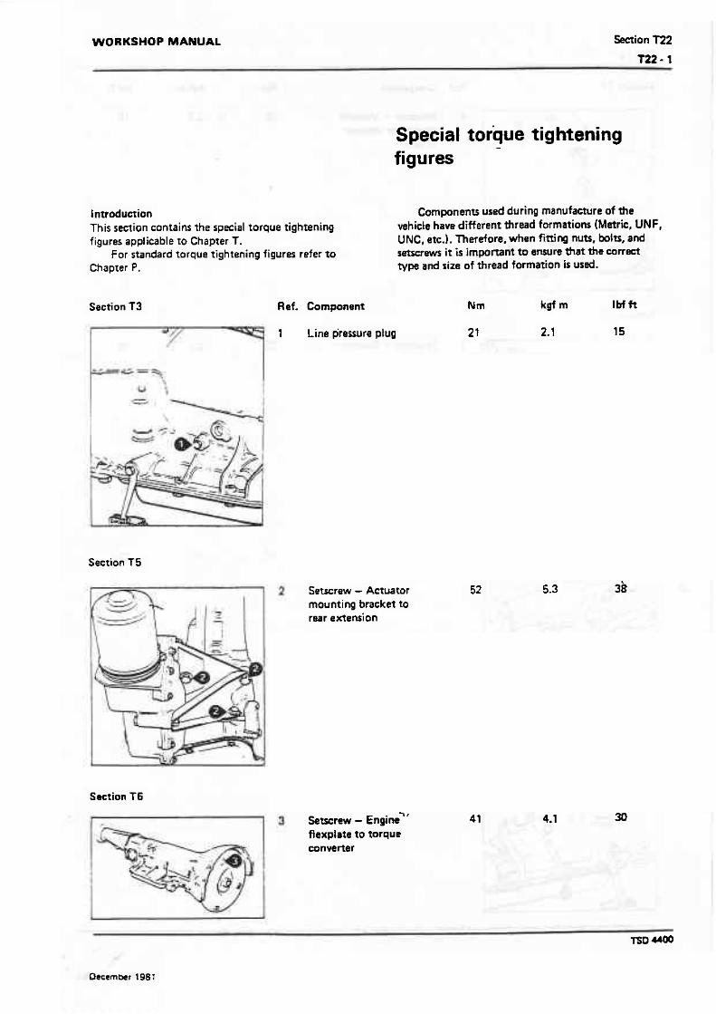
WORKSHOP MANUAL Section l22
Special torque tightening figures
L ntroduction This section contains the special torque tightening figures applicable to Chapter T.
For standard torque tightening figures refer to Chapter P.
Section 13 Ref. Component
* F . 1 Line pressure plug
Components used during manufacture of the vehicle have different thread formations (Metric, WNF, UNC, etc.). Therefore, when fitting nutr, bits, and setsuews it is important to ensuw that the corrfst type and size of thread formation is used.
Section T5
Setscrew - Amator mounting bracket to rear extension
Section f 6
flexplote to torque converter
I
1

Section T8 R d Component
4 Setscrew-Vaeuum modulator retainer to case
--
Section 'F9
Setscrew - Governor to case
Saction T 10
Setscrew - Speedometer drive to case retainer
Section T l l
7 Set~erew - Sump to case

WORKSHOP MANUAL Setion T22
Settions 712, T13, and T14 Rsf Component
b r e w (% UNCI - Control valve unit to ease
Setscrew ('frs UNC) - Control valve unit to case
Setscrew - Rear servo cover to case
Setscrew - Solenoid t o ease
Section T15
I Serscrew - Rear extension to case
Section T16
Setscrew - Pump body to cover
Setrcnw - Pump to cas8

-ion T I 7 R l f Component W m Ibf fl
Section T7 9
Setscrew - Parking lock brackrrt to case
Nut - Manual shaft to detent lever
Nut - Gearchange lever to manual shaft
1H Ytscrew -Caseto centre support
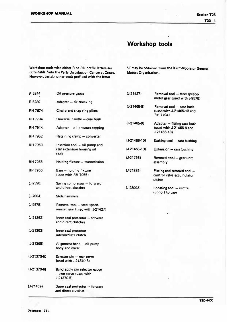
WORKSHOP MANUAL Setion T23
I
Workshop tools
Workshop tools with either R or RH prefix letters are obtainable from the Parts Distribution Centre a t Crewe. However. certain other tools prefixed with the letter
Oil pressure gauge
Adapter - air checking
Circlip and snap ring pliers
Universal handle - case bush
Adapter - oil pressure tapping
Retaining clamp - converter
Insertion tool - oil pump and rear extension housing oil seafs
Holding fixture - transmission
Base - holding fixture {used with RH 7955)
Spring compressor - forward and direm clutches
Siide hammers
Removal too8 - steel speed- ometer gear (used with J-21427)
lnner seal protector - forward and direct clutches
lnner seat protector - intermediate clutch
Alignment band - oil pump body and cover
Selector pin - rear servo (used with 5-21370-6)
Band apply pin seIeetor gauge - rear s e w (used with J-21370-5)
Outer seal protector - fomard and direct clutches
'J' may be obtained from the Ksnt-Moore or Ganenl Motors Organisation.
Removal tool - steel speedo- meter gear (used with J-9578)
Removal tool - case bush (used with 5-21465-1 3 and RH 7794)
Adapter - fitting case bush (used with 5-21465-8 and 5-2 3 465-131
Staking tool - ewe bushing
Extension - case bushing
Removal tool - gear unit assembly
Fitting and removal tool - control vaive acwmulator piston
Locating tool - centre support ta case

WORKSHOP MANUAL Section Tl 2
Control valve unit
The control valve unll comprises a cart iron body containing shift valves and regulator valves that control the gear changes. The unit i s secured to an oil spacer (guide} plate on the bottom face of the transmission.
Drive range When the selector lever on rhe sreering columr: is moved to D, the actuator mover. the manual vatve (through levers and rodsi to allow main line oil pressure to be de!ivered to the forward clutch (see fig. T12-1 I. With the forward clutch appl red, meckanical connection between the turbine shaft and the mainshaft i s provided. The Low roller assembly becomes effective as the result of power flow through the compound planetary gear arrangement whicn moves t h e transrnissio?; into first gear.
As the speed of the car irrcreases, firs1 gear i s no longer suitable and ar: up-change t o second ir required.
To initiate the change f r ~ m first :O second, governor pressure (see Section T9) is directed to the end of the 1-2 shift valve. As the car speed increases, governor pressure moves the ualvs to allow drive oil to apply the intermediate clutch. This mskes the intermediate dutch effect~ve and the transmission changes into second gear.
The change t o ~ h i r d gear i s controlled by the 2-3 shlh valve. The operation oi :he 2-3 shift valve IS similar to rhar of the 1-2 shih valve Springs acting or: the valve tend t o hold the valve closec! against governor pressure. When the speed of t h e car is sufficient, the 2.3 shift valve opens and allows intermediate clutch oil t o appiy the direct clutch. The transmission then moves into third {top) gear. Oil pressure to the direct dutch piston is applied only t o a small icnc- area of the pision in third gear.
Dawn-change When the accelerator pedat IS released and the car i s allowed t o decelera~e to a s;o~, the down-changes wi l l occur automatically as t h e v~!ve springs overcome the diminishing governor pressurs.
Delayed upchange If the hvdraulic system was as basic a5 previouzly described, the gear change points would alwavs occur a t the same road speeds. When accelerating under heavy loads or when maximum performance is required, it is desirable to have the change points occurring at higher road speeds. To achieve th~s. a modulator valve is used Isee Section fa ) .
Clutch applicstion.mntrol To introduce gearchange feel, and to ensure long clutch plate life, the clutch apply pressure i s regulared to suit throttle appIicatioc (see fig. T 12-21. The intermediate
Fig. Tl2-1 Manual valve and forward clutch 1 Forward clutch 2 Manual valve
1 7 Line ait
clutch is controll& according to the throttte opening as follows.
Line pressure i s varied by the modulator. A 1-2 accumulator valve rrain provides a variable
accumulator pressure to cushion the clutch application. The 1-2 accumulator varve train i s supplied with drive oil and is controlled by modulator pressure. During light throttle application, drive oi l is reduced to a low accumulator pressure. During heavy throttle applications, accumulator pressure approaches full main pressure. Accumulator pressure i s made t o a r t on one side of the rear accumulator piston in the rear servo (see Section T13). I n first gear. the accumulator pinon i s strokad to i t s lower position to prepare it for the change to second gear.
When the 1 -2 shift valve owns, intermediate clutch apply oil i s also d i rmed to the rear servo accurnut%tor piston, stroking the piston against the 1-2 accurnulaw oil and the accumulator spring (see fig. T12-31. fhb action absorbs a small amount ot the intermedirtr clutch apply oil and permits the clutch apply time and pressure to be wn.rrolled for the correct gear change fw l .
The direct clutch apply rate is mntroll+d by tM front accumulator pinon. Located in the control v l k

Fig. T12-2 Rear servo accumulator piston - Prior to 7 -2 upchange
1 Servo piston 2 intermediate clutch passage 3 Accumulator piston 4 1-2 accumulator valve
Drive oil
11 Modulator oil
1-1 1-2 accumulator oil
assernbty, i t is part of the front accumulator and servo piston system (see fig. T124). In O range, second gear, the accumulator i s stroked against the accumulator spring by tarvo oil. Because serva oil (main lint pmrurel varies with throttle opening, the pressure in the accumulator also varies. aceording to the thrmle opening.
When the 2-3 shift valve opens, direct clutch oil flows to the direct clmdr a d the front accumulator piston (see fig. T12-51. Diren clvtd pressure rises so that the force from it, plus the accumulator swing force, overcomes the force from the +WO prmure and moves the accumulatar piston to the stop on the accumulator piston pin. This in turn strokes the servo piston the same amount, allowing it to just contact the band apply
fie T t 2.3 Rear servo accumulator piston cushioning intermediate clutch applicnion
1 1.2 accumulator valve 2 Setvo piston 3 Intermediate clutch passage ...
!( Drive and inrsrmediate dutch oif
F] Modulator oil
I] 1-2 accumulator oil
washer on the servo pin. However, it will not move the pin or apply the band. The stroking of the accumulator pinon absorbs an amount of direct dutch oil and permits the direct clutch to apply a t a cerntrolled rate for a smooth 2-3 change.
3 2 valve operation To take full advantage of the torque conwerfer's ability to multiply torque when required, a 3-2 valve is u d . This mlve permits the amlentor to be depressed for moderate a~oleration at low speeds in third gear without musing the transmission to change down. This allows tha torque mnvener to sense the hanges in engine sped and a d thus provide additional converter ratio for improd performance.
The 3.2 valve system is such that it will pennit I 3-2 down.change during maderne to heavy rccslention when modulator pressure reaches approxirmtsty 7.4 bar (108 lbf/in2) (see fig. T1261. Modulaad ail pressure. plus the 3-2 spring pressurn, will move the 3-2 valve against the f ~ r c e of direct clutch oil allowing
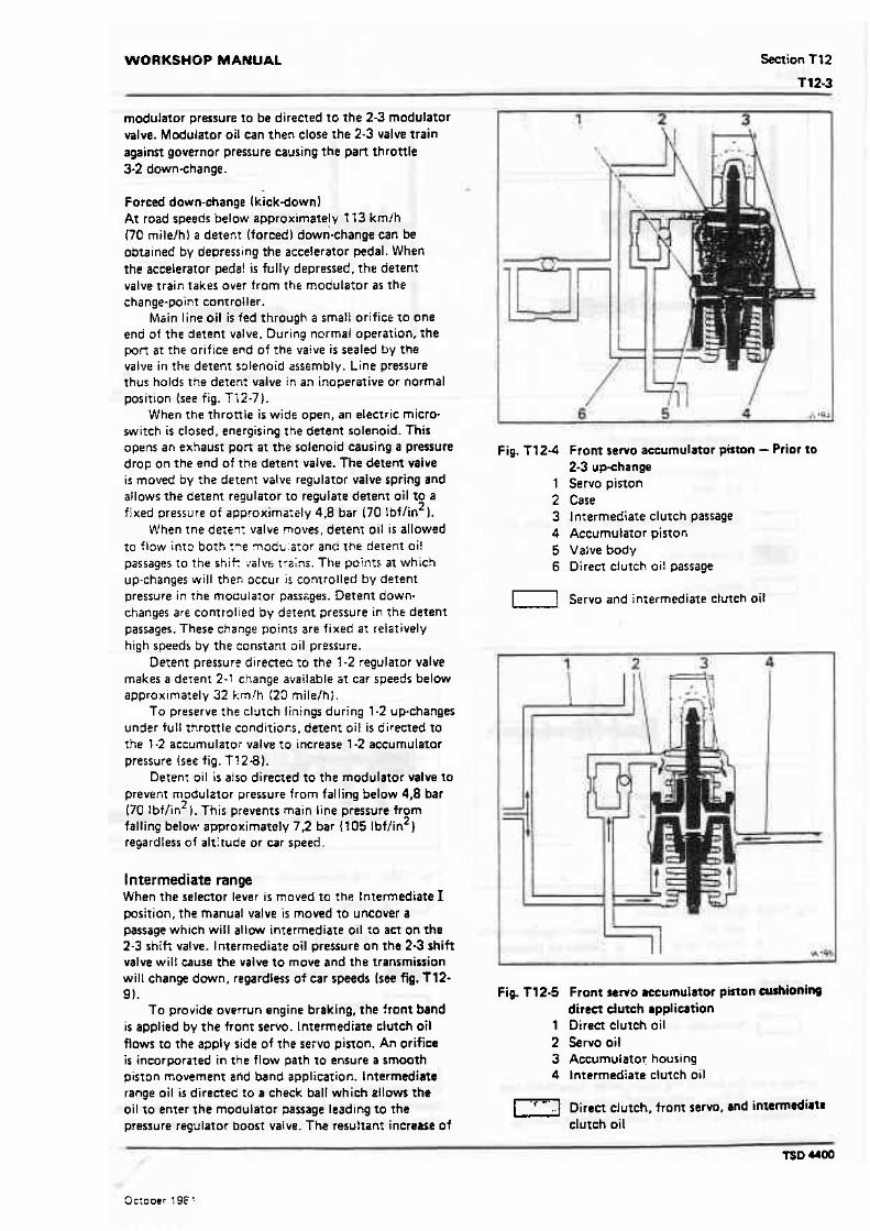
WORKSHOP MANUAL
modulator pressure 10 be directed to the 2-3 modulator valve. Modulator oil can then close the 2-3 valve train against governor pressure causing the part throttle 3-2 downchange.
Forced down-change (kick-down) At road speeds below approximately I f 3 kmih (70 rnile/h) a detent (forced) down-change can be obtained by depressing the accelerator pedal. When the accelerator pede! is fully depressed. the detent valve train takes over from the modutator as the change-point con1 roller.
Main line oil is fed through a small orifice to one end of the detent valve. During normal operation, the pon at the orifice end of the vaive is sealed by the valve in the detent solenoid assembly. Line pressure thus holds the deten: valve in an inoperative or normal position (see fig. Ti2-7).
When the thronle i s wide open, an electric micro- switch is closed, energising the detent solenoid. This opens an exhaust port at the solenoid causing a pressure drop on the end of the detent valve. The detent vaive is moved by the detent valve regulator valve spring and allows the detent regulator to regulate detent oil to a
2 fixed pressure of approxima:ely 4,8 bar 170 lbflin I. When tne deien: valve moves, detenr oil is allowed
t o flow into borh :?e moal;:a:or and t h e detent oi! passages to the shi* ,:atvs trains. The points a t which up-changes will theri occur is controlled by detent pressure in the moculator passsges. Detent down- changes are controlied by cietent pressure in the derent passages. These change points are fixed at relatively high speeds by the constant oil pressure.
Derent pressure directed to the 1-2 regulator valve makes a detent 2-1 change available a t car speeds below approximately 32 kn!h (20 nile/h;.
f o preserve the clutch linings during 1-2 up-changes under full throttle conditiocs. derenr oil is directed to the ? -2 acctlrnulato: valve to increase 1-2 accumulator pressure (see fig. T! 2 8 ) .
Detent oil i s also direeted t o the modulator wlve to prevent rnodulttor pressure from falling below 4,8 bar (70 !bf/in2). This prevents main line pressure from falling below approximately 7.2 bar I105 lbflin2) regardless of altitude or car speed.
lntermediate range When the selector lever is moved to the lntermediate 1 positian, the manual valve i s moved to uncover a passage which will allow intermediate oil to an on the 2-3 shift valve. Intermediate oil pressure on the 2-3 shift valve wilt cause the valve to move and the transmission will change down, regardless of car speeds (see fig. f 12- 9).
To provide overrun engine braking, the front band i s applied by the front servo. lntermediate clutch oil flows to the apply side of the seivo piston. An orifice i s incorporared in the flow path to ensure a smooth piston movement and band application. Intermediate range oil is directed to a check ball which allows the oil to enter the modulator passage leading to the pressure regulator boost valve. The resuftant increase of
Fig. T124 Front sew0 accumulator piston - Prior to 2-3 up-change
1 Servo piston 2 Case 3 lntermediate clutch passage 4 Accumulator piston 5 Valve body 6 Direct clutch oil passage
Servo and intermediate clutch oil
F ig T 12-5 Front sew0 accumulator piston cushioning d i r ~ dutch rppliation
1 Direct clutch oil 2 &NO oil 3 Accumulator housing 4 lntermediate clutch oil
L23 Direct clutch, front servo, and intermdiatm clutch oil
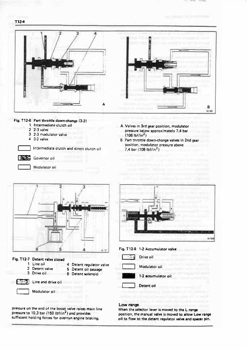
Fig. T12-6 Part throttle down-change (3-21 1 tntermediate'clutch oil 2 2-3 valve 3 2-3 modulator valve 4 3-2 valve
1-1 Intermediat~ clutcn and direct clutch oii
m Governor oil
[ I Modula~or oil
Fig. T72-7 Detent valve closed 1 Line oil 4 Detent regulator valve 2 Detent valve 5 Detent oil passage 3 Drive oil 6 Detent solenoid
Line and drive oil
Modularor oil
pressure on the end of the boon valve raises main line pressure t o 10,3 bar (1 50 lbf/in2 1 and provides sufficient holding forces for overrun engine braking.
A Valves in 3rd gear posirion, modulator pressure below approximately 7.4 bar (108 lbf/in21
B Parr throttle downchange valves in 2nd gear position, modulator pressure above 7,4 bar l108 tbflin2)
Fig. T12-8 1-2 Accumulator valve
Drive oil
1-1 Modulator oil
m 1.2 acarmulmor oil
1 1 Detent oil
Low range When the selmor lever i s moved t o the L range position, the manual valve is moved to allow Low range oil t o flow to the detent regulator valvt md s p a r pin.

WORKSHOP MANUAL Section T12
The spring behind the regulator valve then moves the As a result of this, the 1-2 shift valve will move to cause regulator and detenr valves to the opposite end of the a downchange.at road speeds below approximately valve bore. Low range oil then prevents the regulator 64 kmlh (40 rnilefh 1 and will prevent an upchange, valve from regulating and drive oil passes through the regardless of the cars speed. hole in the regulator valve into the detent and modulator When the 1-2 shift valve closer. the exhausting -
passages at a Low range pressure of 10.3 bar (150 lbf/in2 1. intermediate clutch oil l i f ts two check balls off their
T I
l
--
P
1
L I D N R P Is4
Fig. T 12-9 Valvw - Intermediate range - 1 Intermediate dutch oil 2 Governor oil 3 1-2 valve 4 1-2 detent valve 5 Regularor valve 6 Detent pwage 7 Modulator oil
2nd gear 8 2 3 valve 15 Boost valve 9 23 modulator valve 16 Pnrsure regulator valva
t 0 Direct cl uf eh passage 17 Convener oil 1 1 Detent passage 18 Line oil 12 Manual valve 19 Servo oil piissage 13 Drive oil 20 Front servo 14 Intermediate oif 21 Direct dutch mrge
1- Main line oil Governor oil [l Modulator oil
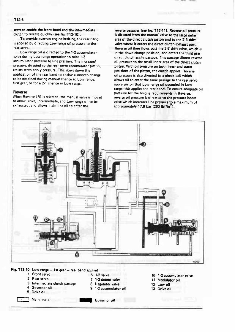
seats to enable the front band and the intermediate clutch to release quickly (see fig. T12-10).
To provide overrun engine braking, the rear band is applied by directing Low range oil pressure t o the rear servo.
Low range oil is directed to the 1-2 accumulator valve during Low range operation t o raise 1-2 accumulator pressure to line pressure. The increased pressure, directed to the rear servo accumutaror piston, resists servo apply pressure. This slows down the application of the rear band to enable a smooth change to be obtained during manual change ro Low range, f i rst gear. or for a 2-1 change in Low range.
Reverse When Reverse ( R I i s selected, the manual valve is moved to allow Drive, Iniermediate, and Low range oil to be exhausted, and aflows main line oil to enter the
reverse passages (see fig. T f 2-1 1 l . Reverse oil pressure is directed from the manual valve to the large outer area of the direct clutch piston and t o the 2-3 shift value where if enters the direct clutch exhaust pon. Reverse oil then flows past the 23 shift valve, which i s in the downchange position, and enters the third gear direa clutch apply passage. This passage direas reverse oil pressure to the small inner area of the direct clutch piston. With oil pressure on both inner and outer positions of the piaon, the clutch applies. Reverse oil pressure is also directed to a check ball which allows oil to enter the same passage t o the rear servo apply piston that Low range oil occupied in Low range: this applies the rear band. To ensure adequate oil pressure for the torque requirements in Reverse, reverse oil pressure i s directed to the pressure boost valve which increases line pressure to a maximum of approximately 17.9 bar I260 1bf/in2).
Fig. T 12-10 Low tangs - 1st p a r - rear band applied 1 Front rervo 6 1-2 valve 2 Rear servo 7 1-2 detent valve 3 Intermediate clutch passage 8 Regulator valve 4 Governor oil 9 1.2 accumulstor oil 5 Drive oil
10 1 -2 accumufator valve I 1 Modulator oil 12 Low oil 13 Drive oil
Main line oil - Governor oil
< -

WORKSHOP MANUAL Section T12
Control valve unit - To remove Note Before removing the control valve unit from a trans- mission installed in a vehicle, take extreme care. as the front servo piston and related parts may fall from the transmission due to the normal freeness of the Teflon oil sealing rings.
The control valve unit may be removed with the transmission in the car. The oil must be drained and the sump removed to gain access to the control valve unit. 1. Unscrew the setscrew which secures the detent spring and roller assembiy. Remove the spring and roller assembly.
2. Remove the setscrews that secure the control valve unit to the transmission case.
Do not m o v e tht rdenoid w r i n g scram, as the solenoid holds the spacer (guide1 plate and gasket in position, therefore. keeping the check balls in their correct positions. 3. Remove the control valve unit, towher with the two governor pipes (see fig. T12-12). Caution Ensure that the manual valve does not dide out of i t s bore. Take care to retsin the front servo piston, should it come out with the control valve assembly.
Remove the governor screen assembly from the end of the governor feed pipe or governor feed pipe hole.
Fig. Tt2-l1 Rwana - rear band applied l Direct claeh 8 Daent oil passage 14 Modulator oil 2 Rear s e m 9 Intermediate oil passage 15 Boost valve 3 Intermediate clutch passage 10 Direct clutch oil 16 Reverse oil 4 1 a 2 ammulator passage 1 1 Reverse oil 17 Pressure regulator mlva 5 Reverre oil 12 Manual valve l 8 Line oil 6 2-3 valve 13 Sew0 oil 19 Converter oil 7 2-3 mdulator valve
1-1 Modulator or intermediate oil 1- Main tine oil

-- p
4. Withdraw the governor pipes from the control valve wernbly; the pipw are interchangeable md need not be marked for identification.
Control vdve unit - To dismantle 1. Hold the control valve unit with the cored passages uppermost and the accumulator piston bore to the front, w shown in figure T12-13. 2. Remove the manual valve f rom its bore. 3. Fit the control valve accumulator installing tool IJ-218851 onto the accumulator piston. 4. Compress the accumutator piston and remove the 'E' ring retainer. 5. Remove the accumulator control valve and spring. 6. Remove the retaining pin, 1-2 sleeve, regulator valve, and spring f rom the upper right-hand bore. 7. Remove the 1-2 detent vatve and the 1-2 valve. 8. Remove the retaining pin, 2-3 valve spring, 2-3 sleeve, 2-3 modulator valve, and the 3-2 intermediate spring from the middle right-hand bore. 9. Remove the 2-3 shift valve. 10. Remove the retaining pin, bore plug, 2-3 spring together with the spacer and the 3-2 valve from the Iower bore. 11. Renove the retaining pin and bore plug from the upper lefthand bore. adjacenr to the manual valve bore.
Fig. T12-12 Removing the control valve unit 12. Remove the detent valve, derent regulator valve, 1 Governor pipes spring, and spacer. 2 Manual valve '13. Ensure that the 1-2 accumulator valve in the
Fig. 112.13 Control valve uni t 1 Retaining pin 2 Bore plug 3 Detent valve 4 Detent regulator valve 5 Spacer 6 Detent spring 7 Manual valve 8 19 valve 9 1-2 detent valve
10 1-2 regulator spring 1 l 1 -2 regulator valve 12 1-2 sleeve 13 Retaining $n
I4 Retaining pin t5 2 3 sleeve 16 2-3 valve spring 17 2-3 modulator valve 18 3-2 intermediate spring 19 2.3 valve 20 1-2 aaumulator primary spring 21 1-2 accumulator primary valve 22 1-2 accumulator sleeve 23 1-2 aowmulator secondary valve 24 1-2 acarmulator sacondav spring 25 Bore plug
26 Retaining pin 27 Retaining pin 28 Bore plug 29 1-2 sceumulator valve 30 1-2 acmmulator primary spring 31 3-2 valve 32 Spacer 33 3-2 spring 34 Bore plug 35 Retaining pin
A R R , RT, and RR-A models B RC model
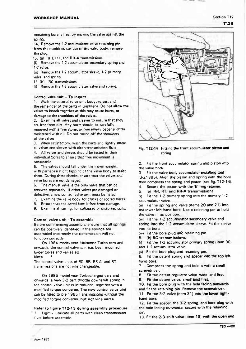
WORKSHOP MANUAL Section TT2
remaining bore i s free, by moving the valve against the spring. 14. Remove the 1.2 accumulator valve retaining pin from the machined surface of the valve body; remove the plug. 15. (a1 RR. RT. and RR-A transmissions I i Remove the ? -2 accumulator se,condary spring and f -2 vaive. (ii) Remove the 1-2 accumulator sleeve. 1-2 prirnary valve, and spring. 15. Ibl RC transmissions ( i ) Remove the '1-2 accumulator valve and spring.
Control valve unit - To inspect 1. Wash the control valve unit body, valves, and the remainder of the parts in Genklene. Do not allow the valves t o knock together as this may cause burrs, or damage to the shoulders of the valves. 2. Examine all valves and sleeves to ensure that they are free from dirt. Any burrs should be carefully removed with a fine stone, or fine emery paper slightly moistened with oil. Do not round-off the shoulders of the valves. 3. When satisfacrory, wash the pans and lightly smear a l l valves and sleeves with clean rransmission fluid. 4. All valves and sieeves should be tested in their individual Sores to ensure Tha: free movemenf is obtainable. 5. The valves should fall under their own weight. with perhaps a sligh; rapping o f the valve body to assist them. During these checks. ensure that the valves and valve bores are not damaged. 6. The manual value i s the only valve that can be renewed separatelb. If other valves are damaged or defective. a new control valve unit must be fitted. 7. Examine the valve body for cracks or scored bores. 8. Ensure that the cored face is f ree from damage. 9. Examine all sprlngs for co!iapsed or distorted coils.
Control valve un i t - To assemble Before commencing assembly. ensure that all sprlngs can be pos~tively Identified. If the springs are assembled Incorrectly the transmission will not function correctty.
On 1984 model year Mulsanne Turbo cars and onwards. the control valve unlt has been mod~fled: larger bores and valves etc. Note ' The control valve unrts of RC, RR. RR-A, and RT transmrsslons are not ~nterchangeable.
On 1985 model year f urbbcharged cars and onwards. a new 3-2 part th:ottle downshift sprlng in the control valve unlt IS ~ntroducecl. togerher with a modified torque convener. The new control valve unit can be fined to pre 1985 transmrsslons wlthout the modified torgue convener. but not vice versa.
Refer to figure T12-l3 during assembly procedure 1. Lrghrlv lubricate all pacs w ~ t h clean transmrsston f Iuld before assemPlv.
Fig. f 12-14 Fitting the front accumulator piston and spring
2. F I ~ the front accumulator spring and piston Into :he valve body. 3. Fit the vaive body accumulator rnstalllng tool (J-21885). Allgn the- plston and spring w ~ t h the bore then compress the spring and plston [see fig. T12-14) 4. Secure the plston with the 'E' rlng reralner. 5. (a) RR, RT. and RR-A transmissions (I) Fi t the 1-2 prlman, sprlng Into the prlmlry 1-2 accumulator valve.
(iiJ Fit the sprlng and valve (11erns 20 and 21 into the lower left-hand bore. Use a retaming pin to hold the valve in tts posltlon. (ill] Fit the 1-2 accumu3ator secondary valve and spring into the 1-2 accumulator sleeve. Fit the sleeve Into its bore. (!v) Fit the bore piug anid retaining pln. 5. (b) RC transmissions (i ) Fit the 1-2 accumulator pr imav sprrng (item 30) and 1-2 accumulator valve. (11) FII the bore plug and relaming pm. 6. Fit the detent spring and spacer Into the top left- hand bore. 7. Compress the sprlng and hold it m t h a Small screwdriver. 8. Fit the detent regulator valve. wide land first 9. Fit the detent vaive. small land first 10. Fit the bore plug with the hole fxing OUWUW~S and flt the retarning pin. Remove the screwdriver. l l . Fit the 3-2 valve {~rem 3 1 } Into the lowr right- hand bore. 12. Fn the spacer. ?he 3-2 spring. and bore plug wlth the hole faclng outwards: secure w~th the retalnanQ ptn. 13. Fit the 2-3 shlh valve l ~ t e m 191 with the own end
TSD 4JOO
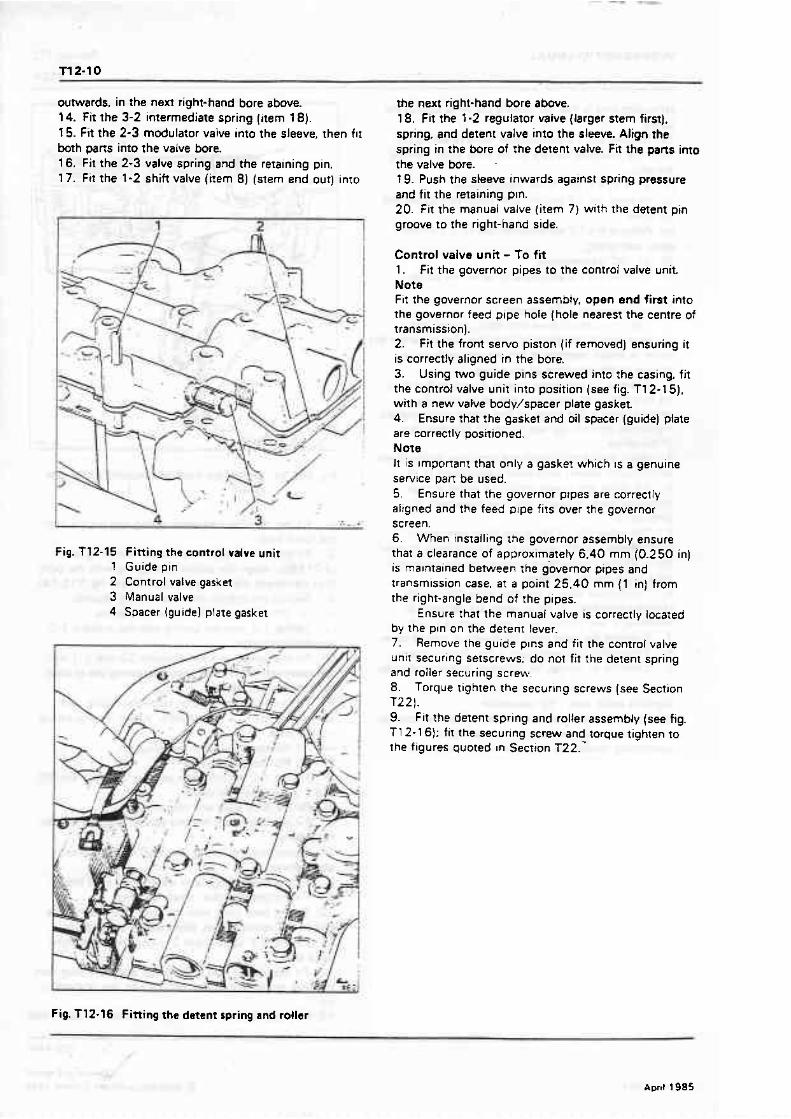
outwards, in the next right-hand bore above. 14. Fit the 3-2 intermediate spring (item 18). 15. Fit the 2-3 modulator valve into the sleeve, then f ~ t both pans into the vaIve bore. 16. Fit the 2-3 valve spring and the retaining pin. 17. Fit the 1-2 shift valve (irem 8) (stem end out) into
Fig. f 12-15 Fitting the control valve unit 1 Guide pin 2 Control valve gasket 3 Manual valve 4 Spacer (guide1 plate gasket
the next right-hand bore above. 18, Fit the 1-2 regulator waive (larger stem first], spring, and detent valve into the sleeve. Align the spring in the bore of the detent valve. Fit the pans into thevalvebore. -
f 9. Push the sleeve inwards against spring pressure and fit the retaining pin. 20. Fit the manual valve (item 7) with the detent pin groove to the right-hand side.
Control valve unit - To fit 1. fit the governor pipes to the control valve uni t Note Fit the gwernor screen assembly, open end first into the governor feed pipe hole (hole nearest the centre of transmission). 2. Fit the front servo piston (if removed) ensuring it is correctly aligned in the bore. 3. Using two guide pins screwed into the casing, fit the controt valve unit into position (see fig. T12- 15). with a new valve body/spacer plate gasket 4. Ensure that the gasket and oil spacer (guide) plate are correctly positioned. Note It is Imponant that only a gasket which IS a genuine service pan be used. 5. Ensure that the governor ptpes are correctly aligned and the feed plpe fits over the governor screen. 6. W h e n installing the governor assembly ensure that a clearance of approximately 6.40 mm (0.250 in) is maintained between the governor pipes and transmission case. a t a point 25.40 mm {l in} from the right-angle bend of the plpes.
Ensure that the manual valve is correcrly located by the pin on the detent lever. 7. Remove the guide plns and fit the control valve unit securing setscrews; do not f i t the detent spring and roller securing screw. - 8. Torque tighten the securing screws (see Sectron T221. 9. Fit the detent spring and roller assembly (see hg. T12-16): fit the secur~ng screw and torque tighten to the figures quoted In Section ~ 2 2 . -
Fig. T12-16 Fitting the detent spring and roller
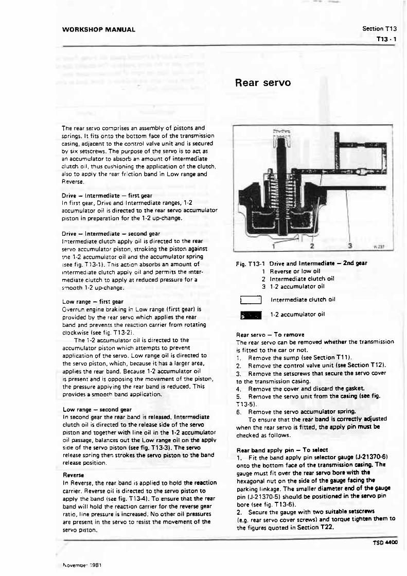
WORKSHOP MANUAL Section T 1 3
The rear servo comprises an assembly of pisrons and wrings. It fits onro the bottom face of the transmission casing, adjacent to the control valve unit and is secured by six setscrews. The purpose o f the servo i s to a a as an accumulator to absorb an amount of intermediate dutch oil, thus cushionins the application of the clutch, also to apply t h e rear fricrion band in Low range and Reverse.
Drive - Intermediate - first gear In first gear, Drive and Intermediate ranges, 1-2 accumulator oil is directed t o the rear servo accumulator p~ston in preparation for the 1-2 up-change.
Drive - Intermediate -second gear I7termediate clutch apply oil is direcred to The rear servo accumulator pisron, stroking the piston against tne 1-2 accumulator oil and the accumulator spring {see fig. f 13-71. This action absorbs an amoum of intermediate clutch apply oil and permits the inter- mediate clutch to apply at reduced pressure for a smooth 1-2 upchange.
Low range - firs; gear Overrun engine braking in Law range (firs1 gear) is provided by the rear servo which applies the rear Sand and prevents the reaction carrier from rota tin^ clockwise~see f i ~ . T13-2i.
The 1-2 accumulator oil is directed to the accumulator piston which attempts to prevent application of the servo. Low range oil is directed ro the servo piston, which, because it has a larger area. applies tne rear band. Because 1-2 accum~llator oil is present and i s o~poring t h e movement of the piston, the pressure applying the rear band is reduced. This provides a smobrh band application.
tow range - second gear In second gear the rear band i s released. Intermediate clutch oil is directed to the release side of rhe s e w piston and togerher with line oil in the 1.2 accumulator oil passage, balances out the tow range oil on the applv side of the servo piston (see fig. T13-3). The s e w release spring then strokes the servo piston to the band release position.
Reverse In Reverse, the rear band is applied to hold ?he reaction carrier. Reverse oil is directed t o the servo pirton to apply the band (s!e fig. T 13-41. To ensure that the rear band wil l hold the reaction carrier for the reverse gear ratio. line pressure i s increased. No other oi l pressures are present in the servo fo resist the movemenr of the servo piston.
Rear servo
Fig. T13-1 Drive and Intermediate - 2nd gear 1 Reverse or IOW oi! 2 Intermediate clutch oil 3 1-2 accumulator oil
v] Intermediate clutch oil
m 1-2 accumulator oil
Rear servo - To remove The rear servo can be removed whether the transmission i s fitted to the car or not. l. Remove the sump Isee Section T11). 2. Remove the control valve unit Isee Section Tf 2). 3. Remove the setscrews that secure the servo cover to the transmission casing. 4. Remove t h e cover and discard the gasket. 5. Remove the servo uni t from the casing h? fig. T13-5). 6. Remove the servo accumulator spring.
To ensure that the rear band i s eormctly adjuned when the rear servo is fined, #t apply pin must be checked as follows.
Raar band apply pin - f o selecl 1. Fit t h e band apply pin selector gauge 15-21370-61 onto the botrorn face of the transmission cuing. f he gauge must f i t over the rear sarvo born with the hexagonal nut on the side of the gauge facing the parking linkage. The smaller diameter end of the gaugd pin (J-21370-5) shou!d.be positioned in the wrvo pin bore (see fig. T 13-61. 2. Secure the gauge with two suitable setsctms (e.g. rear servo cover screws) and torque tighmn *em to the figures quoted in Section T22.
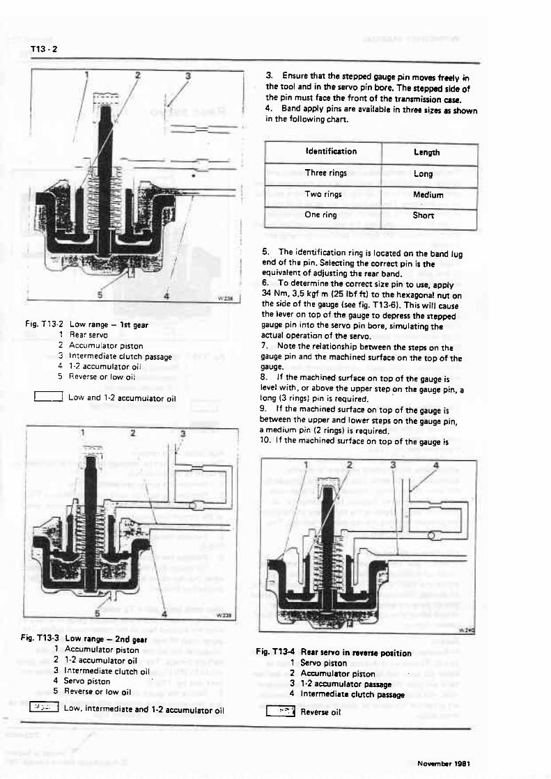
Fig. T13-2 Low range - 1st gear 1 Rear servo 2 Accumulator piston 3 l ntermediate clutch passage 4 1.2 accumulator oil 5 Reverse or low oil
[ 1 Low and 1-2 accumulator oil
Fig. T73-3 Low tangs - 2nd gear 1 Acerrmulator piston 2 1-2 accumulator oil 3 lnrermediate dutch oil 4 Sewo piston 5 Reverse or low oi l
1 Low. intermediate and 1-2 accumulatw oi l
3. Ensure that the stepped gauge pin moves freely in the tool and in the servo pin bore. The stepped side of the pin must face the front of the transmision earc. 4. Band apply pins are available in three s i p s as shown i n the following chart.
5. The identification ring is located on the band lug end of the pin. Selecting the correct pin i s the equivalent of adjusting the rear band. 6. To determine the correct size pin t o use, apply 34 Nm, 3.5 kgf m (25 Ibf ft) to the hexagonal nut on the side of the gauge (see fig. T13-61. This wifl cause the lever on top of the gauge to depress the stepped gauge pin into the servo pin bore, simulating the actual operation of the servo. 7. Note the relationship between the steps on the gauge pin and the machined surface on the top of the gauge. 8. If the machined surface on top of the gauge i s level with, or above the upper step on the gauge pin, a tong (3 rings) pin is required, 9. If the maehined surface on top o f the gauge i s between the upper and tower steps on the gauge pin, a medium pin (2 rings) is required. 10. I f the machined surface on top of the gauge is
T ldentificarion l Length - Three rings I Long
t w o rings I Medium
Fig. 9334 Rarr sewo in mvem position 1 Servo piston 2 Accumulator pinon 3 1-2 aceurnulator passage 4 Intermediate clutch passage
1-i Aevrrne oil
One ring Short

WORKSHOP MANUAL Section T13
1 1 3 . 3
level with, or below the lower step on the gauge pin, a short: (1 ring) pin is required. 1 1 . I f a new pin i s required, make a note of the sire of the required pin. Then remove t h e gauge from the transmission.
Rear seno - To dismantle l , Remove the rear accumulator piston from the rear servo piston [see fig. T13-7). 2 Remove the 'E' rlng which reta~ns rhe rear servo paron or: the band apply pin. 3. Remove the rear servo piston and The seal from t h e b ~ n d apply pin. 4. Remove the washer, spring, and retainer.
Rear servo - To inspect 1. Check the fit of the oil sealing rings in the accumularor piston. The rings should be free to turn in the grooves. 2. F i t the accumutator piston tower oil sealing ring inro i t s bore in the casing and check the ring-to-bore f1:.
3 . Check the fit o f the band apply pin in each piston. 4 E x a n i n e the band apply pin for scores, cracks, or ??E openrng of drilled passages. 5. E x a ~ ~ n e rhe accumulator piston for an open bleed passage. E . Ensure that the pin is the correct size as determined by the check under the heading Rear band asoly pin - f o select.
Rear servo - To assemble i. Fit the spring retainer. spring, and washer onto lhe band apply pin. 2. Fit tne servo piston onto the pin and secure it with fhe 'E' ring. 3. I f necessary, ttt a netet oi l seal ring onto the servo plston.
4. Fit the accumulator piston into the servo piston. Do not remove the Teflon oil seal rings from the
rear accumulator pibon. unless they require replace- ment.
I f the Tefton inner oil-seal ring (small diameter)
Fig. Tf 3-6 Selecting the band apply pin 1 Torque spanner 2 Gauge 3 Gauge pin
P-- * 0'
Fig. 113-7 Rear larva and accumulstor 1 Servo pm 2 Spring retainer 3 Servo spring 4 Washer 5 Oil sealing ring 6 Accumulator piston 7 Oil sealing ring
l - . -1 L'J 8 Servo oil seal - ' L l ---
9 Servo pinon Fig. 713-5 Removing the rear reno 10 'E' ring
TSD uoa
requires rtpl~acemem, usc the aluminium oil seal ring. The rear accumulator piston (large diameter} ring
groove depth. is machined shallower to take the Teflon oil seal ring. Therefore. if replacement is necessary. use only the Teflon oil seal ring.
Rear servo - f o fit , 1. Using clean transmission fluid, lightly lubricate the inner and outer rear servo bores in the transmission casing. 2. Fit !he servo accurnulafor spring into the servo inner bore. Note Before fitting the rear servo to the casing, ensure that the rear band apply lug IS aligned with The servo pin bore ir: the transmission casing. If the lug is not aligned. the servo will not apply the rear band. 3. Position the rear servo assembly in the transrnision casing. 4. Using hanc' pressure, push the setvo into the transmission casing,.ensuring that the rervo piston sealing ring is correctly seated in.the bore. 5. F it the cover together with a new gasket. 6. Torque tighten the setscre~~~s to the figures quoted in Sec:~on T22.
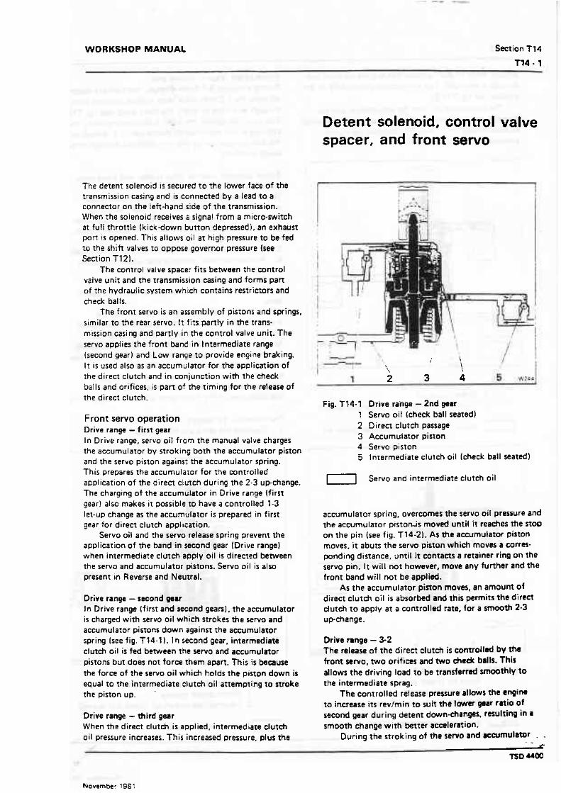
WORKSHOP MANUAL Section T14
T74 1
The detent solenoid i s secured t o the lower face of the transmission casing and is connected by a lead t o a connector on the left-hand side of the transmission. When the solenaid receives a signal from a micro-switch a t full throttle (kick-down button depressed), an exhaust pan is opened. This allows oil at high pressure to be fed ro the shift valves to oppose governor pressure (see Section T121.
The control valve space: fits between the control vatve unit and the transmission casing and forms part of the hydrauiic system which contains restrictors and check balls.
f he front servo is an assembly of pistons and springs. similar to the rear servo. It fits panty in the trans- mission casing and partly in the control valve unif. The servo applies the front band i n lntermediate range (second gear) and Low range t o provide engine braking. It is used also as an accumulator for the application of the direct clutch and in conjunction with the check balls and orifices, is part of the timing for the release of the direct dutch.
Front servo operation Drive range - first gear In Drive range, servo oi! from the manual valve charges the accumulator by stroking both the accumulator piston and the servo piston agains~ the accumulator spring. This prepares t h e accumulaior for the controlled application of the direct clutch during the 2-3 upchange. The charging of the accumulator in Drive range (first gear) also makes it possible to have a controlled 1-3 let-up change as the accumulator is prepared in first gear for direct clutch appt~cation.
Servo oil and the servo release spring prevent the application of the band in second gear (Drive range) when intermediate clutch apply oil is directed between the servo and accumulator pistons. Servo oil is also present in Reverse and Neurral.
Drive range - second gear In Drive range (first and second gears), the accumulator is charged with servo ail which strokes t h e servo and accumularor pirtons down against the accumulator spring (see fig. T14-11. In second gear. intermediate dutch oil is fed berween the servo and accumulator pistons but does not force them apart. This i s because the force of the servo oil which holds the piston down is equal to the intermediate dutch oil attempting to nmke the piston up. '
Drive range - third gwr When the direct clutch is applied, intermedbare clutch oil pressure increases. This increased pressure. plus the
Detent solenoid, control valve spacer, and front servo
Fig. 714-1 Drive range - 2nd gear 1 Servo oil (check ball seated) 2 Direct clutch passage 3 Accumulator piston 4 Servo piston 5 Intermediate clutch oil (check ball seated)
1 7 Servo and intermediate clutch oil
accumulator spring, overcomes the servo oil pressure and the accumulator piston-is moved unti l it reaches the stop on the pin (see fig. f 14-21. As the aeeumulator piston moves. it abuts the re rw piston whieh moves r corm- ponding distance, until it contacts a retainer ring on the servo pin. It will not however, move any further and t h e front band will not be applied.
As the accumulator piston moves, an amount of direct clutch oil i s absorbed and this permits the direct dutch t o apply at a cornrolled rate, for a smooth 2-3 upchange.
Drive t m g e - 3-2 The release of the direct clutch i s cornrollad by lhs front servo. two orifices and two &a& balls. This allows the driving load to be transferred s W t h f y to the intermediate sprag..
The controlled release pressure rllaws the anpin. to increase i t s revlmin t o suit the gear ratio of second gear during detent down-thangas. rssulfing in 8
smooth change wi th better accelermion. During the stroking of the servo and aecrlmulator . - . .
C
TSb MOO
November 198 1
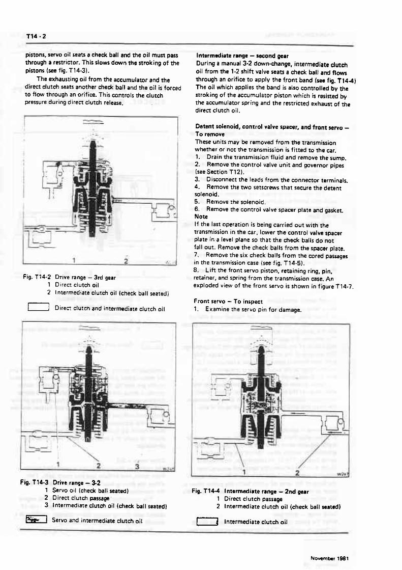
pistons, servrr oil seats a check ball and the oil must pass through a restrictor. This slows down the stroking of the pistons (see fig. T14-31.
The exhausting oil from the accumulator and the direct clutch seats another check ball and the oil is forced to flow through an orifice. This controls the clutch pressure during direct cfvtch release.
Fig. 174-2 Drive range - 3rd gear 1 Di ren clutch oil 2 I ntermediate clutch oil (check ball seated)
1-1 Direa clutch and intermediate clutch oil
Fig. T14-3 Drive range - 3-2 7 Servo oil (check ball seated) 2 Direct clutch piissage' 3 Intermediate dutch oil (check ball seated]
h-1 Servo and intermediate clutch oil -'
Intermediate range - second p a r During a manual 3-2 down-change, intermediate dutch oil from the 1-2 shift valve seats a check ball and flows through an orifice to apply the front band [see fig. T 144) The oil which applies the band i s also controlled by the stroking of the accumulator piston which is resisted by the accumulator spring and the restricted exhaust of fie direct clutch oil.
Detent solenoid, control valve spaeer, and front sew0 - To remove These unirs may be removed from the rransmission whether or not the transmission i s fitted to the car. 1. Drain the transmission fluid and remove the sump. 2. Remove the control valve unit and governor pipes [see Section T12). 3. Disconnect the leads from the connector terminals. 4. Remove the two selserews that secure the detent solenoid. 5. Remove the solenoid. 6. Remove the control valve spaar ptate and gasket. Note If the last operation i s being carried out with the transmission in the car. lower the control valve spacer ptate in a level plane so That the check balls do not fall out. Remove the check balls from the spacer plate. 7. Remove the six check balls from the cored passages in the transmission case (see fig. T14-5). 8. Lift the front servo piston, retaining ring, pin, retainer. and spring from the transmission case. An exploded view of the front servo i s shown in figure T 14-7.
Front servo - To inspect 1. Examine the servo pin for damage.
Fig. T l 4 4 Intermediate range - 2nd gear 1 Direa clutch passage 2 Intermediate clutch oil (check ball seated)
1 7 Intermediate clutch oil

WORKSHOP MANUAL Section 714
2. Examine the oil seal ring groove in the piston for damage. 3. Ensure that lhe ring is free in the groove. 4. Examine the piston for cracks and other damage. 5. Check t h e f i t of the servo pin in the pisron.
Detent sdendd, contrd valve spher, and front rervo - To fit When overhauling the front servo or front aCC~muIat0r piston it will be noticed that the Teflon ring allows The piston to slide very freely in its bore. This i s a normat characteristic of the ring and does not indicate leakage during operation.
When servicing pistons. the following points should be noted.
Only remove a Teflon oil sealing ring from a piston ring groove if the ring i s to be renewed.
Only renew a Tef Ion oii sealing ring i f it shows evidence of leaking during operation or visual damage.
When changing a front sew0 Teflon oil sealing ring, renew with an aluminium sealing ring. 1. Fit two guide bolts into the transmission case.. 2. Place the six cheek balls into the ball seat pockets in the case. 3. I f the transmission is in the car, place the check balls into the bat! seat pockets in the spacer plate. Note One check ball is non-functional, therefore, on RC transmissions omir one ball as shown in figure T14-6. 4. Fit the contral valve spacer plate to case gasket (gasket with extension for detent solenoid). 5. Fit the control valve spacer plate. 6. fir the detent solenoid. Do not tighten the setscrews at this time. 7. Fit the front servo spring and retainer into the bore of the transmission case. 8. Fit the retainer ring onto the front servo pin and install t h e pin into the case so that the tapered end contacts the forward band. Ensure that the retainer ring is installed in the servo pin groove.
9. Pit a nm pirton sealing ring to the wtvo pinon, if the ring has been removed. 10. Fit the servo piston onto the band apply pin with the flat side of the piston positioned towards the transmission sump.
If the transmission is in the Ear, the pans should k assembled 8s a group (see fig. T14.7) and find into the sewo bore. A length of straight clean feeler gauge !approx. imately OS1 mm (0.020 in)) should be used to hold the servo assembly temporarily in position as shown in
iB 3 $*L
Fig. T 14-6 L-ion of check balls - rplwr plata t Spacer plate to case- gaskn 2 Check balls 3 Spacer plate 4 Non-functional ball (omit on RC
transmissions)
Fig.tl4-7 Front ~ r r o 1 Spring 2 Pin
1 3 Piston 4 Oil seal ring
Fig. Tl4-5 Loation of ehack balls - tnnsrniuion 5 Retainer ring 1 Chedt balls 6 Spring ratainer

Fig. T14-8 Method of tsmparsrily holding froni mno piston in position (Transmission in car)
9 Correct position of feeler gauge, allwing the accumutator piston to enter the front seruo bore before the feeler gauge is withdrawn
2 Feeler gauge 3 Front servo piston 4 Spacer plate
figure T14-8. Withdraw the feeler gauge before tightening the control valve body setscrews. .
11. Connect the electrical leads from the top p a r witch and detent solenoid onto the connector. 12. Fit the control valve as described in Section T12 then torque tighten the setscrews and the drtent solenoid setscrews to the figures quoted in Section 122.
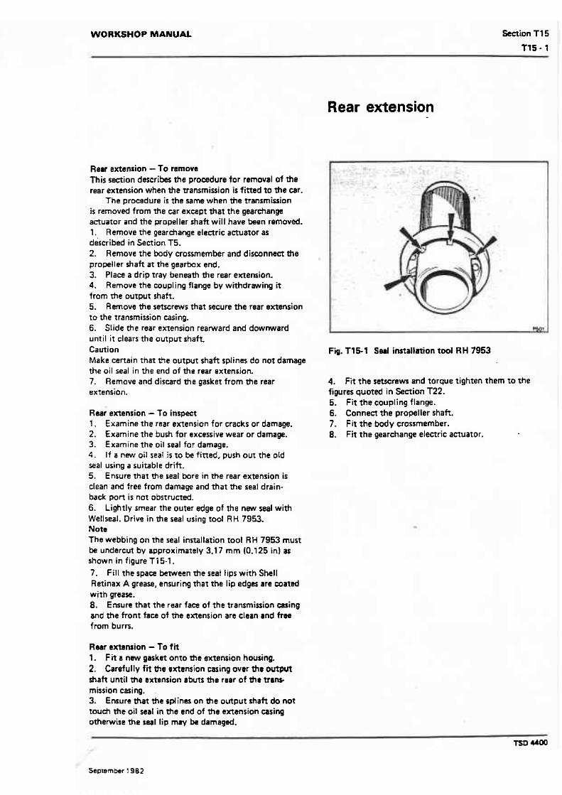
WORKSHOP MANUAL Section Tf 5
Tt5- 1
Rear extension
Rear extension - f o remove T h i s section describes the procedure for removal of the rear extension when the transmission is fitted to the car.
The procedure is the same when the mnrrnission i s removed from the car except that the gearchange actuator and the propeller shaft will have k e n removed. 1. Remove the gearchange electric actuator as described in Section T5. 2. Remove the body crossmember and disconnect the propeller shaft at the geartmx end. 3. Place a drip tray beneath the rear extension. 4. Remove the coupling flange by withdrawing it from the output shaft. 5. Remove the setscrews that secure the rear extension to the transmission casing. 6. SIide the rear extension rearward and downward until it clears t h e output shaft. Caution Make certain tha? the output shaft splines do nor damage the oil seal in the end of t h e rear extension. 7. Remove and discard t h e gasket from the rear extension.
Rear extension - To inspect 1. Examine the rear extension for cracks or damage. 2. Examine the bush for excessive wear or damage. 3. Examine the oil seal for damage. 4. If a new oil seat i s to be fitted. push out the old seal using a suitable drift. 5. Ensure that the seal bore in the rear extension is clean and free from damage and t h a t the seal drain- back port i s not obstructed. 6. Lightly smear the outer edge of the new seal with Wellseal. Drive in the seal using tool RH 7953. Note The webbing on t h e seal installation tool RH 7953 must h undercut by approximately 3.17 mm (0.125 in) at shown in figure T15-1. 7 . F i l l the space between the seat lips with Shell Retinax A grease, ensuring t h a t the lip edges are coated with grease. 8, Ensure that the rear face of the transmission caring and the front face of the extension are clean and free f mm burrs.
Rear extansion - To fit l. Fit a new gasket onto the extension housing. 2. Carefully fit the trKtsnsion casing over the output shaft until the extension abuts the rear of the vans- mission casing. ,
3. Ensure that the splines on the output shaft do not too& the oil seal in the end of the extension casing othewise the seal lip may k damaged.
Fig. T15-1 S d installation tool RH 7953
4. Fit the setscrews and torque tighten them to the figures quoted in Section T22. 5. Fit the coupling flange. 6. Connect the propeller shaft. 7. Fit the body crossmember. 8. Fit the gearchange electric actualor.

WOFIKSHOP MANUAL Section T16
Oil pump
The oil pump is an internallexternal gear type which is secured to the front face of the transmission easing. Contained within the oil pump cover is an oil pressure regulator valve train. The pump is mechanically connected to the engine flexplate and operates whenever the engine is running.
As the engine flexplate rotates it turns fhe torque converter pump which is keyed to the inner gear of bre oil pump. The inner gear turns the outer gear which -uses oil to be lifted from the transmission sump via
an oil strainer. As the gears turn, the oil is carried in pockets formed
by tbe gear teeth, pas a crescent shaped projection of the pump. Beyond the crescent, the gear teeth move doser together causing the oil to be forced out at pressure from between the teeth. At this point the oil is delivered through the pump outlet to the pressure system (see fig. T16-11.
The oil pressure is controlled by a pressure reguhtor valve. As the pressure builds up, the oil is
Fig. T16-1 Oil pump and pressure regulsting rystm~ 1 Driven gear 6 tim pnssun oil 1 1 Transmission sump 2 Pump mescent 7 P n a u n regulator valve 12 Line pressure oil 3 Drivinggear 8 Lubricating oil 1 3 Convsrrsr oil 4 Pump outlet 9 Conwrter return 14 Manual valve 5 Pump intake 10 Smiwr assembly 15 Heat exchanger
Line oil 1 7 Intake and lubricating oil
Tso M00
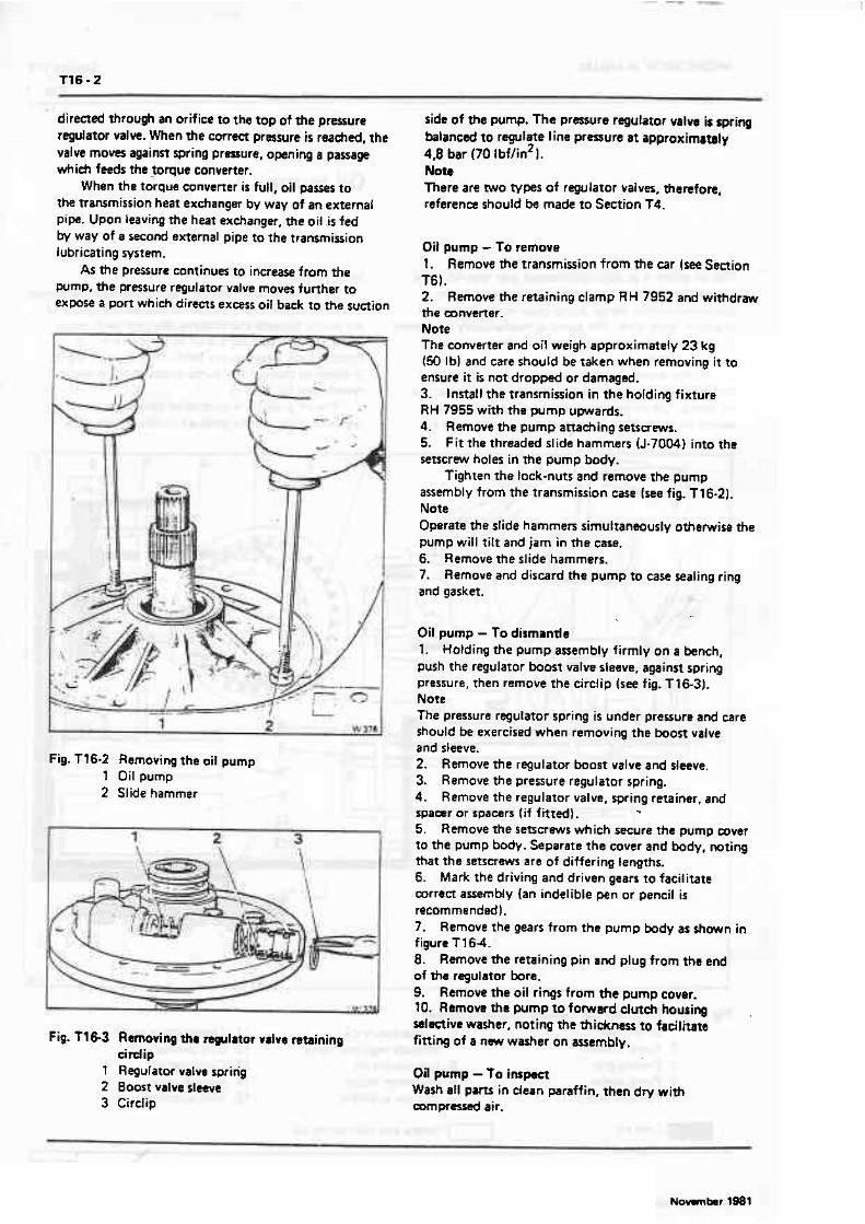
directed through an orifice to the top of the pressure regulator valve. When the correct pressure is reaehd, the valve moves against spring prmure, opening a passage which feeds the torque converter.
When the torque converter is full, oil passes t o the transmission heat exchanger by way of an external pipe. Upon leaving the heat exchanger, the oi l .,is fed by way of a second external pipe to the transmission lubricating system.
As the pressure continues to increase from the pump, the pressure regulator valve moves further to expose a port which directs ex-ss oif back to the suction
Fig. Tt6-2 Removing the oil pump 1 Oil pump 2 Slide hammer
Fig. T 163 Removing thr regulator vatre retaining cirdip
1 Regulator valve spring 2 Boost valve sleeve 3 Circlip
side o f the pump. The pressure regulator valve is spring balanced t o regulate line p rmu re a t appraximamly 4 8 bar (70 lbf/in21. Nott There are WO types of regulator valves, thanfore, reference should be made to Section T4.
Oil pump - To remove l . Remove the transmiwion from the car (see Section T61. 2. Remove the retaining clamp RH 7952 and withdraw the converter. Note The converter and oil weigh approximately 23 kg 150 Ib) and care should be taken when removing it to ensure it is not dropped or damaged. 3. Install the transmission in the holding fixture RH 7955 with the pump upwards. 4. Remove the pump attaching setscrews. 5. F i t the threaded slide hammers (J-7004) into the setscrew holes in the pump body.
Tighten the lock-nuts and remove the pump assembly from the transmission case (see fig. T16-21. Note Operate the slide hammers sirnuttansously otherwise the pump will tilt and jam in the case. 6. Remove the slide hammers. 7. Remove and discard the pump to case sealing ring and gasket.
Oil pump - To dismantle 1. Holding the pump assembly firmly on a bench, push the regulator boost valve sleeve, against spring pressure, then remove the circlip (see fig. T 16-31, Note The pressure regulator spring is under pressure and care should be exercised when removing the boost valve and sleeve. 2. Remove the regulator boost valve and sleeve. 3. Remove the pressure regulator spring. 4. Remove the regulator valve, spring retainer, and tpaar ar spacers [if fitted], ., 5. Remove the setscrews which secure the pump cover to the pump body. Separate the cover and body, noting that the setscrews are of differing lengths. 6. Mark the driving and driven gears to facilitate correct awemMy {an indelible pen or pencil is recommendedl. 7. Remove the gears from the pump body as shown in figure T 1 64. 8. Remove t h e retaining pin a n d plug from the end of the regulator bore. 9. Remove the oil rings from the pump cover. 10. Remow the pump 10 forward clutch housing sslmive washer, noting the thickness to facilitate fitting of a nwv washer on asJambiy.
Oil pump - To inspect Wash all p m in clean paraffin, then dry with m p r d air.
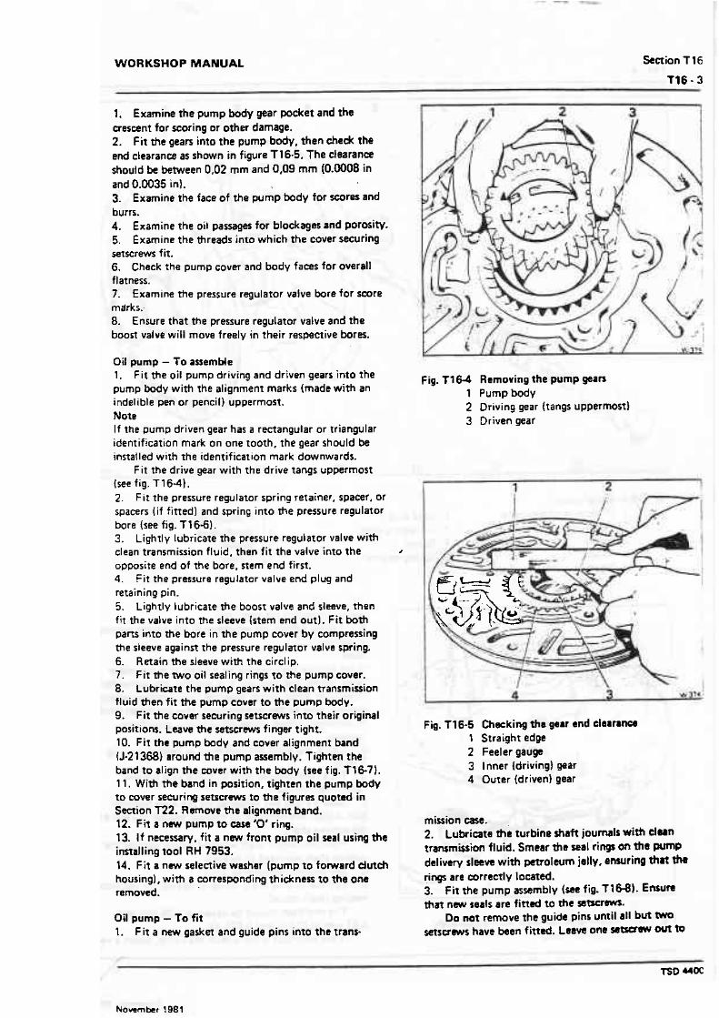
WORKSHOP MANUAL Section T 16
T16 - 3
1. Examine the pump body gear pocket and the crescent for scoring or other damage. 2. Fit the gears into the pump body, then check the end clearance as shown in figure T16.5. The clearance should be between 0,02 mm and 0,09 mm (0.0008 in and 0.0035 in). 3. Examine the face of the pump body for scores and burrs. 4. Examine the oi! passsager for blockages and porosity. 5. Examine the threads into which t h e cover securing setscrews fit. 6. Check the pump cover and body faces for overall flatness. 7. Examine the pressure regulator valve bore for score marks: B. Ensure that the pressure regulator valve and the boost value will move freely in their respective bores.
Oil pump - To aaemMe 1. F i t the oil pump driving and driven gears into the pump body w i th the alignment marks (made with an indelible pen or pencil) uppermost. Note I f the pump driven gear has a rectangular or triangular identification mark on one tooth. the gear should be installed with the identification mark downwards.
F i t the drive gear w i th the drive tangs uppermost tree fig. T16-41. 2. F i t the pressure regulator spring retainer, spacer, or spacers ( i f fitted) and spring in to the pressure regulator bore [see fig. T16-6). 3. Lightly lubricate the pressure regulator valve with clean transmission fluid, then fit the valve into the S
opposite end of the bore. stem end first. 4. F i t the pressure regulator valve end plug and retaining pin. 5. Lightly lubricate the boost valve and sleeve, then fit the valve into the sleeve (stem end out). Fit both parts into the bore i n the pump cover by compressing the sleeve against the pressure regulator valve spring. 6. Retain the sleeve with the circlip. 7. F i t the W O oil sealing rings to the pump cover. 8. Lubricate the pump gears with clean transmission fluid then fit the pump cover to the pump body. 9. F i t the cover securing s e t s c r m into their original positions. Leave t h e setscrews finger tight. 10. Fit the pump body and cover alignment band (5-21368) around t h e pump assembly. Tighten the band to align the mver with the body (see fig. T16-71. 1 1. With the band in position, tighten the pump body to cover securing setscrews to t h e figures quoted in Section T22. Rmnwe t h e alignment band. 12. Fit a n w pump to case '0' ring. 13. I f necessaw. f i t a new front pump o i l seal using the installing too l RH 7953. 14. Fi t a new selective washer [pump to fomard dutch housing), with I corresponding thickness to the one removed.
Oil pump - To fit 1. F i t a new gasket and guide pins into the trans-
Fig. 1164 Removing the pump gears 1 Pump body 2 Driving gear (tangs uppermost) 3 Driven gear
Fig. T16-5 Checking tha gear end clalr lncs 1 Straight edge 2 Feeler gauge 3 Inner (driving) gear 4 Outer (driven) gear
mission wse. 2. Lubricate t h e turbine shaft journals with clwn transmission fluid. Smear the seal rings on the pwnp delivery sleeve with petroleum jelly, ensuring that th rings are correctly lacated. 3. fit the pump assembly (see fig. f 16-8). f nwm tha new seals are fined t o the ssTscrM.
Do not remove the guide pins unti l all but setscrews have been f ittsd. Leave one m w out to

f ig . T 16-6 Pump cover 1 Pressure regulator valve F Bore plug 2 Pump cover 7 Oil sealing rings 3 Gasket 8 Spacer 4 Retaining pin 9 Spring retainer 5 Selective washer
10 Pressure regulator spring 1 1 Boost valve 12 Sleeve 13 Cirelip
Fig. T 16-7 Aligning pump cover with pump body 1 Alignment band
assist in checking the end-float. 4. Torque tighten the setscrews to the figures quoted in Secrion T22. Note I f the turbine shaft cannot be rotated_as the pump is being pulled into position, it is that either the forward or direct clutch housings have not been correctly indexed with all the clutCh plates. This condition must be corrected before the pump is finally pulled into position. 5. Check the front unit end-float as follows (see fig. T16-91. a. Fit a slide hammer bolt (J-7004) into the one remaintng bolt hole. b. Secure a dial test indicator on the slide hammer bolt. Adjust fhe indicator to register against the d of the turbine shaft. c. Hold the output shaft forward whilst pushing lha turbine shaft rearward to i ts stop. d. Sct the dial indicator to zero. e. Pull the turbine shaft forward, noting the indicator reading (shah travel).
The end-float should be between 0.08 mm and 0.61 mm 10.003 in and 0.024 in).
If the end-float is not within the limits. saleet r new

WORKSHOP MANUAL Section T I 6
washer, referring to the following chart. Note An oil soaked warher mw tend to disdouf. Themfore, if ne-. rnssrun the washer to areamin the thick-
I ha-
Black
(0.1 26 in to 0.130 in) Purple
I (0.060 in to i064 in) ; -Yellow I
0
Fig. T16-8 Fitting the oil pump 1 Guide pin
ness. 6. Remove the dial test indicator a d dide hammer
colour -- 1,52 mm to 1.63 mm
bolt.
Fig. ?l69 Checking ?he front unit and-float
Numkr
1,80 mm to t ,90 mm 7. Fit the final pump securing set5crw and =al.
10.071 in to 0.075 in) / Bluq I I ! Torque tighten the xt- to the figures g m c d in I _ I.
I I1 Section T22. 2.08 mm to 2,18 mm I F

WORKSHOP MANUAL Smion T17
Control rods, levers, and parking linkage
The.control rods. levers, and parking linkage consirt of an assembly of levers and rods which are operated by the electric gearchange actuator. The detent lever is connected t o the manual control valve i n the control valve unit and is retained in this position by a spring- loaded detent roller (see fig. T17-1).
The parking pawl acfuating rod causes fhe parking pawl t o engage the transmission whenever Park is selected. This provides a mechanical lock which will hold the car o n the steepest of gradients.
When the gear range selector lever o n the steering column i s moved, wi th the ignition on, the electric actuator wilt move the gearchange operating lever t o the required position via an adjustable rod. The gearcfiange operating lever is secured to the outer end of fie manual shah and the detent lever i s secured to the inner end of the shaft. Therefore, the detent lever wil l move a corresponding distance, moving the manual control valve.
When the gear selector lever on the steering column is moved to Park. the parking pawl actuating rod which is secured t o the derent lever causes the parking pawl t o engage wi th a gear ring on the rear un i t planet carrier. The rear un i t planet carrier is mechanically connected to the transmission output shaft. therefore, the shaft is prevented from rotating.
Control rads. levers. a n d parking linkage - To r u n w e 1. The units may be removed f rom the transmission whether or no t the transmission has been removed from the car. 2. If the transmission has not been removed, drain and remove the sump as described i n Section T11. 3. If the gearchange electric actuator has not ken remaved, disconnect the gearchange operating rod by removing the split p i n and clevis pin. 4. Remove the split p in and clevis p in from the opposite end of the gearchange operating rod; remove the rod. 5. Remove the lock-nut which retains the yeatchange opersting lever to the manual shaft: remove the lever. 6. Remove the setscrew that secures the detent spring and roller assembly to the control valve unk remove the detenr spring assembly. 7. Remove the pin which secures the manual shaft to the case. 8. Slacken the lock-nut securing the detent lever to the manual shaft. 9. Remove t h e detmnt lever from the manual shah Then remove the lock-nut completely. 10. Remove the pah ing pawl actuating rod. detem lever. and manual shaft from the case.
Fig. 177-1 Manud shah md pmrking l inkw 1 Detent roller and spring assembly - 2 Retaining pin 3 Lock-nut 4 Detent lever 5 Parking pawl actuating rod 6 Manual shatt 7 Lip seal 8 Spring retainer 9 Pawl returqspring
10 Parking pawl 11 Pawl shaft 12 Parking lock bracket
Note Do not teinove t h e manual shaft real unless repl- ment is required. 11. Remove the setsumvs securing the w k i ~ IbCir backec remow the bracket. 12. Remove the -king prwl return S ~ i y .
Nuts The following operations am m k c o r n p l d only if one or more of the pam i n v o i d muins n p l m n t 13. Remove t h e spr ing .w iner from the prrki- pm1 shaft. Remove the parking wl shlft cup @W by placing a xrslvdriver betwMfi the p l r k i ~ p m 1 and the caring: tevering outwards (m fig. TIT-2). 14. Removs the psrking ml and Yh0 drr)r.

Contrd rods, levers, and parking linkage - To inspect l . Wash all pans in dean paraffin. then dry them with compressed air. 2. Examine the parking pawl actuator rod for cracks or broken spring retainer lugs. 3. Examine the actuator spring for distortion or damage. Ensure the actuator fits freely on the actuator rod.
Fig. T17-2 Removing the cup plug
[ 2-wd
Fig. T17-3 Fining the patking pawl a d shrft
4. Examine the parking pawl for cracks or wear. 5. Examine the manual shaft for damaged threads or shaft roughness {oil seal surface]. 6. Examine the detent lever for cracks or a loose pin. 7. Examine the parking pawl shaft far damage to the retainer groove. 8. Examine the parking pawl return spring for distortion or damaged ends. 9. Examine the parking lock bracket for cracks or wear. 10. Examine the detent spring and rolter assembly for cracks or damage. 11. Examine the gearchange operating rod for signs of bending. 12. Examine the jaws of the operating rod for cracks or damage.
Central rods, levers, and parking linkage - TV fit 1. F i t the parking paw1 with the tooth towards the centre of the transmission. then fit the parking pawl shaft (see fig. T 17-31. 2. F it the parking pawl shaft retaining clip. 3. Fit the cup plug into the case. using a 9.52 mm (0.375 in) diameter steel rod. to drive the shaft and plug into the case until the shaft bottoms on the case rib. 4. Fit the parking pawl return spring with the squared end hooked around the pawl. 5. Fit rhe parking lock bracket with the guides over the parking pawl, Torque tighten the setscrews to the figures quoted in Section T22. 6. F it the actuator rod plunger under the parking lock bracket and over fhe parking pawl. 7. F it the opposite end of the actuator rod into the . detent lever from the side opposite to the pin. 8. If necessary, fit a new manual shaft to case lip type seal into the case. using a 19.05 mm (0.750 in} diameter steel rod to seat the seal. 9. Lubricate the manual shaft with Shell Retinax A grease. F it the shaft into the case and through t h e detent lever (see fig. T17-41. 10. Fit the lock-nut onto the manual shaft, then torque tighten the nut to the figures quoted in'section T22. I t . F it the retaining pin into the transmission using. aligning it with the groove in the manual shaft (see fig. T17-5). 12. fit t h e detent spring and roller assembly. Torque tighten the setscrew to the figures quoted in Section T22. 13. Fit the gearchange operating lever to the manual shaft. Fit the Lock-nut and torque tighten to the figurs quoted in Secfion T 22. 14. Fit the gearchange operating rod using the dwir pins. Lubricate the jevis pins wifh Rocol MTS 1M#3 grease, then fit new split pins. 15. Fit the sump (see Section T l l ) .
Control Iinkrgs - To check 1. Remove t h e spjit pin and elevis pin'from the gearchange operating rod. a t the actuator end. 2. Select Park on the gearchange actuator. Push the lower end of the gearchange operating lever fully

WORKSHOP MANUAL Sect ion T 1 7
fbward (Park position). jaw and lever, adjust the length of the rod. 3. Ensure rhat both jaws of the operating rod slide 7. Finally. lubricate the clevis pin with Roml MTS easily about the two levers and check the clevis pin wiH 1000 grease. Fit the clevis pin and secure ir with a n m slide into fhe jaw and through the lever. sprit pin.
4 . Select each of the-gear positio~s in turn on the actuator. At each position, ensure that the ctevis pin will slide easily into the jaw and lever. 5. Check that the pin will slide easily into the jaw when Low is selecred after Park and conversely when Park is selected after Low. 6 . I f , in any position the pin wilt not pass through the
Fig. Tf7-4 Fitting the manual shaft
Fig. T17-5 Fitting the rnrnuat shaft retaining pin 1 Manud shaft 2 Retaining pin

WORKSHOP MANUAL Section T 18
Turbine shaft, forward and direct clutches, sun gear shaft, and front band
The rurbine shaft is a splined shaft which connects the torque convener to the fomard clutch.
The fomrard clutch comprises a housing, splined onto the turbine shaft; steel dutch driving plates, which are driven by the clutch housing; composition faced plates, which are splined onto a clutch hub; and a hydraulically operatd clutch piston. The mainshaft i s splined into the forward clutch hub.
The direct clutch i s similar in mnstruction to the forward clutch (see fig. T18-1).
The composition plates are splined to a hub which is integral with the forward clutch back plate. The steel plates are splined to a housing which in turn i s splined to the sun gear shaft. The clutch is applied hydraulically by a piston housed in the direct clutch housing.
The front band i s a lined steel band which is anchored to the transmission case at one end and i s servo operated a the other end. The band fi ts around the direct. clutch housing and when moved by the ssrvo, holds the housing nationary.
Whenever the forward clutch is applied, the drive transmifted by the turbine is connected to the transmission mainshah. When the forward clutch is released the clutch return springs push back the hydraulic piston, the plates are then released and the connection
between the converter and the mainshaft is broken. A5 a result, the transmission is in Neutral.
Whenever the direct clutch is applied, drive from the forward clutch is divided and follows two different paths to the gear unit (see Section Tl91.
By following one path, the drive continua through the forward clutch to the mainshaft and the rear gear unit internal (annulus) gear. The other path is via the forward clutch back piate, through the direct clutch to the sun gear shaft.
As the direct clutch is applied, clockwise torque from the convener causes an intermediate inner sprag race to overrun the sprag clutch assembly.
A summary of the power flow through the trans- mission is given in Section T19.
Turbine shaft, forward and d i e dutcher, sun gear shaft, and front band - To ramwe l . Remove the transmission from the ur: withdraw the convener arsembl y. 2. Remove the oil pump. 3. Withdraw the turbine shaft and The forward clutch from the transmission (see fig. f 18-21. 4. Remove the thrust washer from berween the fomard clutch hub and the direct clutch housing; the
Fig. 118-1 Sectioned view of transmission ahowing tamard a d direct cluteher 1 Forward dutch housing 4 Imrmsdiate sprag dutch 7 Direct dutch hub 2 Front band 5 Sun gear shaft 8 Turbine shaft 3 Direct clutch housing 6 F omard clutch hub
Turbine shaft, fomrard and direct dutcher. sun p a r shaft and front band
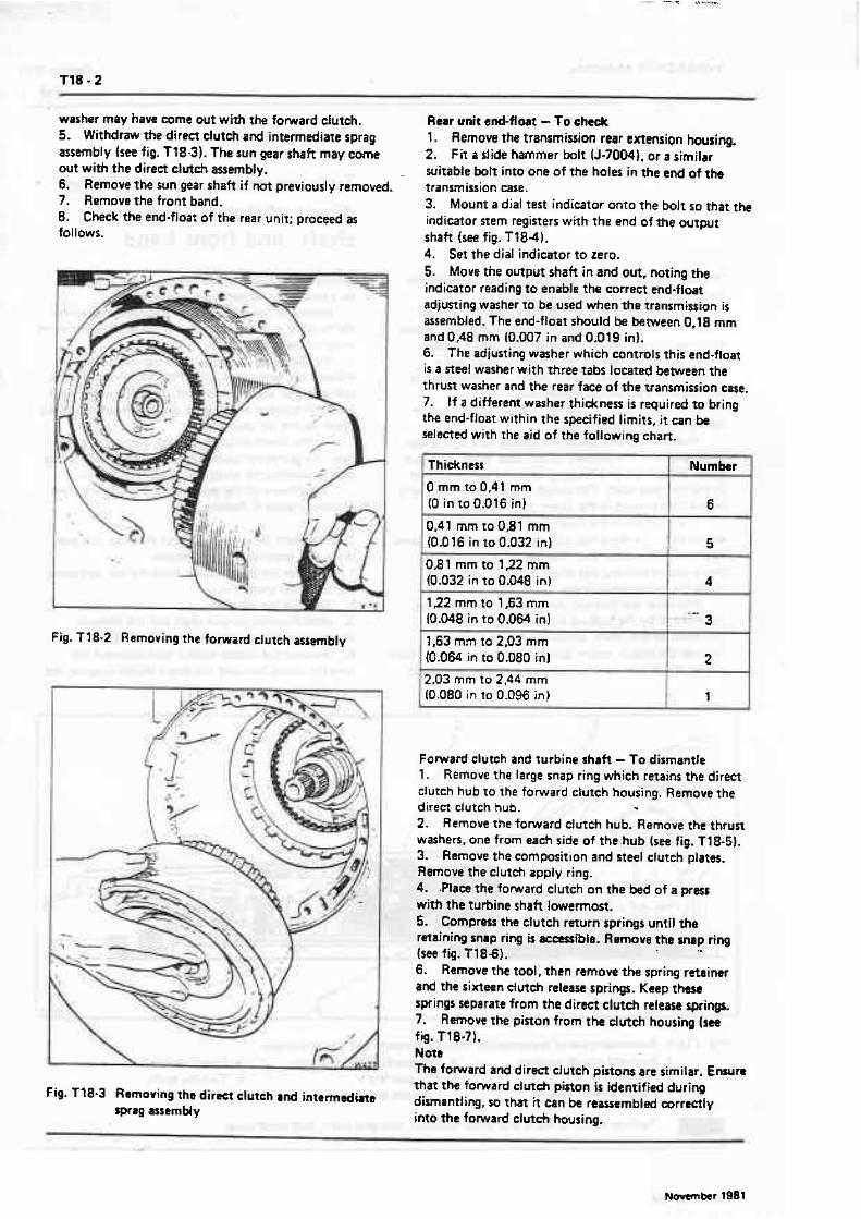
washer may have eame out with the forward ciutch. 5. Withdraw the diretx clutch and intermediate sprag assembly (see fig. Tf8-3). The sun gear shaft may come out with the direct clutch assembly. 6. Remove the sun gear shaft if not previously removed. 7. Remove the front band. 8. Check the tnd-float of the rear unit; proceed as follows.
Rear unit end=flort -To check 1. Remove the transmission rear extension housing. 2. Fit a slide hammer bolt (J-70041. or a similar suitable bolt into one of the holes in the md of the transmission case. 3. Mount a dial test indicator onto the bolt so that the indicator stem registers with the end of the output shaft (see fig. Tt8-41. 4. Ser the dial indicator to zero. 5. Move the output shaft in and out, noting the indicator reading to enable the correct end-float adjusting washer to be used when the transmission i s assembled. The end-float should be between 0,18 mm and 0,48 mm (0.007 in and 0.019 in). 6. The adjusting washer which controls this end-float is a steel washer with three tabs located between the thrun washer and the rear face of the transmission ease. 7. If a different washer thickness is required to bring the end-float within the specified limits, it can be selected with the aid of the following chart.
Fig. T18-2 Removing the forward clutch assembly
I Thickness
0 mm to 0.4 t mm (0 in to 0.016 in)
0.41 mm to D,81 mm
Forward clutch and turbine shaft - To dismantle 1. Remove the large snap ring which retains the direct dutch hub to the fonnrard clutch housing. Remove the direct ctutch hub. *
2. Remove the forward clutch hub. Remove the thrun washers, one from each side of the hub (see fig. T18-5). 3. Remove the composition and steel clutch plates. Remove the clutch apply ring. 4. .Place the forward clutch on the k d of a press with the turbine shaft lowermost. 5. Cornpm the clutch return springs until the rcrsining snap ring is ~ i t r l e . Remove the w p ring (see fig. T1881. 6. Remove the tool; then remow the spring retainer and the sixteen dutch release springs. Keep these springs separate from the direct clutch release springs. 7. Remove the piston from the dutch housing (see fig. Tl8-71. Note The forward and direct clutch pistons are similar. Enurra that the forward dutch piston is identified during
Fig. T18-3 Removing the direct clutch and in ta rnd ine dimantling, tm it can be reassembld rnrr-ly sprsg assembly into the fomard clutch housing,
Number
6 -
, (0.016 in to 0.032 in) 5 " 081 mm to 122 mm (0.032 in to 0.098 in)
122 mm to 1.63 mm (0.048 in to 0.064 in1
1.63 mm to 2,03 mm (0.064 in to 0.080 in1
4
- 3
2 4
I 2.03 mm to 2,44 mm 1 (0.080 in to 0 .D96 in) I 1
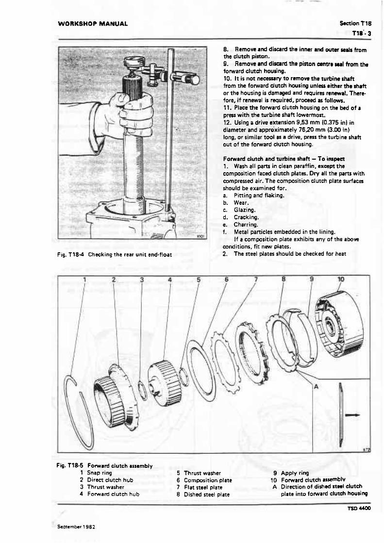
WORKSHOP MANUAL W i o n T 18
8. Remove and discgrd the innar and wtar mb from the clutch piston. 9. Remove and dimrd tho pinon -re wrl from the forward clutch housing. 10. It is not necemry to remow the turbirw h f t from the forward dutch housing unless either the shalt or the housing is damaged and rfquires renewrl. There fore, if renewal is required, proceed as follows. 11. Place the fomard cluteh housing on the bed of a press with the turbine shaft lowermost. 12. Using a drive extension 9,53 mm (0.375 in) in diameter and approximately 7620 mm (3.00 in) long, or similar tool as a drive, press rhe turbine shaft om of the forward clutch housing.
Fomard cluteh and turbine shah - To impact 1. Wash all parts in clean paraffin, e x a p t the composition faced d~rteh plates. Dry all the pans with mpresred air. The composirion clutch plate surfaces should be examined for. a. Pitting and flaking. b. Wear. c. Glazing. d. Cracking. e. Charring. f. Metal particles embedded in the lining.
If a composition plate exhibin any of the above conditions, fit new plates.
f ig . l184 Checking the rear unit end-float 2. The steel plates should be checked for heat
Fig. Tf 8-5 Fomard dutch assembly 1 Snap ring 5 Thrust washer 9 Apply ring 2 Direct dutch hub 6 Commsition plate 10 Forward dutch wemblv 3 Thrust washer 7 Flat steel plate A Direction of dished nael clutch 4 Forward clutch hub 8 Dished steel plate plate into fomard dutth housing
September 1982

discolouration. If the surface is smooth and m awn wlour k .Mimed, the plates can be used again. If. wwre heat spot dimlouration or surfaee scuffing is indicated, fit nm placs. 3. Examine the sixteen clutch release springs for coflapEed mits or signs of distortion. If any springs show
Fig. T18-6 Removing and fining the forward clutch housing snap ring
l Clutch spring compressor 2 Press ram 3 Snap ring
Fig. T f 8-7 Removing the forward dmeh piston
these symptoms, fii sixteen M springs. E m m e hat or burning in thu area of till dutd~
may h a w c w d ~ s p r i n g t o ~ k e a h e a t ~ t , i f t h i s condition is fwd. W sixteen nm rpringr. 4. Examine the dutch hubs for worn s p k . Encura '
that the Iubrieation holes are clear and that the thrust faces a n not scored or damaged. 5. Examine the piston for cracks. 6. Examine the clutch housing for wear. wring and open oil p. 7, Emure that the check ball in the clutch housing is free in its chamber. 8. Ensure that the lubrication holes in the turbin~ shaft are clear. 9. Examine the splines on the turbine shaft for damage and the shaft for cracks or distonion. 10. Examine the bush joumats for damage.
Fomard dute)l and turbine shaft -To assemble If the turbine shaft war removed from the forward dutch housing, proceed as follows. 1. Place the dutch housing on the bed of a pres with the from face (flat side) uppermost. 2. Lightly lubricate the shoner splined end of the turbine shaft then, align the splines with f ie mating splines in the foward clutch housing. Using the prws, carefully press the turbine shaft into the forward clutch housing until the shaft botrorns on the hub of the housing. Note The shaft should be started in the housing, then the pressure on the press arbor relaxed to allow ?he shaft to straighten itself. Repeat this step several times until it is evident that the shaft is squarely aligned with rhe
Fig. Tt 8-8 Fitting the fomnrd dutch piston 1 Fomard dutch piston 2 Inner seal protmor 3 Outer seal proteetor

WORKSHOP MANUAL Section T18
housing. If the shaft is not started squarely, damagoto the shaft or housing spl ines may occur. 3. Invert the forward ctutch housing on the press so that the turbine shaft is downward. 4. Lubricate the new inner and outer clutch piston seats with dean transmission fluid. Lubricate the seal grooves in the pinon with petroleum jelly then fit rhe seats with the seal lip facing away horn the return spring pockets. 5. Lubricate a new piston centre seal with clean rransmission fluid. Lubricate the seal groove in the forward dutch housing with petroleum jelly then fit the seal with the Lip uppermost. 6. Fit the forward and direct ctutch inner seal protector (J-21362) over the f o ~ l a r d ctutch hub. 7. Fit the clutch piston inside the forward and direct clutch piston seal protector (J-214091, then fit the assembly into the forward clutch housing (see fig. Tf8-8). 8. Fit the dutch piston by rotating it clockwise until it is seated in the housing. 9. Fit the sixteen clutch release springs into the spring pockets in the clutch piston. 10. Place the dutch housing on the bed of a press with the turbine shaft lowermost. 1 1. Position the spring retainer on the springs. 12. Compress the springs ensuring that the retainer does nor catch in the snap ring groove. Fir the snap ring then release the tension on the spring. Note Ensure ihat the release springs are not leaning. If necessary, push the springs into an upright position using a small screwdriver.
13. Pit the foward dutch apply ring into the cl- housing. 14. Fit the thrust washerr on either side of the forward dutch hub. Retain the washerr in position with pnroiwm jelly. Ensure the bronze washer is fined to the side of tht hub which faces the forward clutch homing. 15. Fit the forward clutch hub im the forward dutch housing. 16. Lubricate the five flat steel clutch plates, the fiw wrnposition faced plates and the one dished steel clutch plate with clean transmission fluid. 17. Commence by fitting the dished steel plats with the concave side uppermost (away from the clutch piston), then alternate flat steel and composition plates (see fig. T18.5). 18. Fit the direct dutch hub into the foward dutch housing; fit the snap ring.
Direcl clutch and intermediate sprag clutch assembly - To dismantle 1. Remove the snap ring which retains the sprag retainer. 2. Remove the retainer [see fig. T18-9). 3. Remove the sprag outer race, then withdraw the sprag clutch assembly from rhe outer race. 4. Turn the unit over then remove the large snap ring which retains the direct clutch back plate in the clutch housing; remove the back plate. 5. Remove the five composition plates, four steel plates. and one waved steel plate from the clutch housing. Remove the- clutch apply ring.
Fig. T18-9 Direct clutch snd irrtermediate spmg assembly 1 Clutch spring retainer 6 Sprag clutch retainer 2 Clutch release spring ( 14) 7 Snap ring 3 P i o n inner seal 8 tmemediate clutch outer race 13 Snap ring 4 Piston centre seal 9 Direct clutch busing 5 Sprag assembly 10 Piston outer seal
May f 984

On 1 984 model year Mulsanne Turbo cars and onwards. remove six compostion plates. five flat steel plates, and one waved steel plate. Note The direct clutch assembly on the a h cars has been uprated, therefore it should be kept tqether as an assembly. Individual parts are not interchangeable with earlier models. 6. Using the clutch spring compressor (J-2590). compress the clutch release springs and remove the snap ring (see fig. T18-101. 7. Remove the toot and l i f t off the spring retainer. Remove the fourteen clutch release springs. Keep there springs separate from the fomard clutch release springs. 8. Withdraw t h e direct clutch pinon from the clutch housing. Note The forward and direct dutch pistons are simifar. Ensure that the direct clutch piston i s jdenrified during dismantling so that it can be reassembled correctly into the direct clutch housing. 9. Remove and discard the piston inner and outer seats. 10. Remove and discard the piston centre seal from the direct clutch housing.
Direet dutch, sun gear shaft. and intermediate sprag dutch asernMy - To inspect 7. Wash all parts in clean paraffin, except the composition faced clutch plates. Dry all the parts with compressed air. 2. Examine the sprag assembly.
Fig. T18-10 Removing and fitting the direct dutch housing snap ring
1 Snap ring pliers 2 Spring comprewr 3 Snap ring 4 Compressor adapter (seated on retainer)
3. Examine the i n m cm ard outer neh for cartrhsr or wear. 4. Examine the cluteh housing for crocks- E m r e thOt the oil passager are clear and look for G-iva wear on the c l m h plate driving lugs. 5. Examine the campofition faced and steel dutch piates. 6. Cornpasition plater should be dried with compressed air and the composition surfaces inspected for. a. Pining and flaking. b. Wear. c. Glazing. d. Cracking. e. Charring, f. Metal particles embedded in the lining.
If a cornpasition faced plate exhibits any of the above conditions, fit n w plates. 7. S t d plates should be inspected for heat diswlouration. If the surface is smooth and an even colour is indicmed, the plates csn be used again. If severe heat spat discolouration or surface scuffifing is indicated, fit new plates. 8. Examine the back plate for scratches or other damage. 9. Examine t h e sun gear shaft for cracks. Examine the splines for damage. the bush= for scoring and the ground bush journals for damage. Ensure the oil feed hole i s clear. 10. Examine the housing for free operation of the check ball. 11. Examine the piston for cracks. 12. Examine the fourteen springs for collaps& wils or distorrion. If any of these springs requires replace- ment, f i t sixteen new springs. 13. Examine the front friction band for wear at the anchor and apply lugs. also for the presence of metallic panicles in the band lining. Examine the band lining for cracks. flaking, burning, and for the lining becoming loose.
Direct dutch and intermediate sprag clutch assembly - To assemble . 1, lubricate the new inner and outer clutch piston seals with clean transmission fluid. Lubricate the seal grooves in the direct clurch piston, then f i t the sea15 with the lips facing away from the spring pockets. 2. Lubricate a new centre seal with clean transmission fluid. Lubricme the seal groove in the direct clutch housing, then fit the seal with the lip uppermost. Nate Production built transmissions use s direct clutch housing with a check ball. if the housing requires replacement and the replacement housing doss not wntrin a heck ball, replace the d i rm clutch pirton with the service piston which has a check bll. E i h r the dimet dutch housing andtor the piston must contain a check ball otherwise damage may 6ewr W the dimet dutEh and related 3. F it the inner seal protmor (J-2 13621 over the d i m dutch hub. 4. Fit the outer real protector (J-21409) into the
May 1984
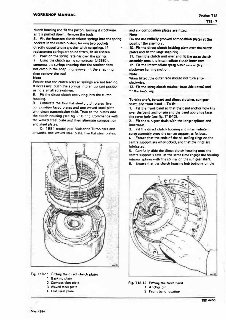
WORKSHOP MANUAL Saction T 18
dutch housing and fit the piston, turning it dockwise as it is pushed down. Remove the tools. 5. fit the fourteen clutch release springs into the spring wets i n the clutch piston. leaving WO pockets directly opposite one another with no springs. If replacement springs are to be fitted, fit a l l sixtacln. 6. Position the spring retainer over the springs. 7. Using r h e clutch spring compressor {J-25901, compress the sprinp ensuring that the retainer does not catch in the snap ring groove. Fit the snap ring. then remove the tw l . Not9 Ensure that the clutch release springs are not leaning. I f necessary, push the springs into an upright position using a small screwdriver. 8. .F i t the direct clutch apply ring into the clutch housing. 9. Lubricate the four flat steel clutch plates. five composition faced plates and one waved steel plate with clean transmission fluid. Then fit the plates into the clutch housing (see fig. 'F1 8-1 l ). Commence with the waved steel plate and then alternate composition and steel plates.
On 1984 model year Mulsanne Turbo cars and onwards, one waved steel plate. five flat steel plates.
Fig. T18.11 Fining *e direct clutch plates 1 Backing plate 2 Composition plate 3 Waved steel plate 4 Flat sreel plaie
and six composition plates are fined Nott Do not use radially grooved commition plates at this point of the asem bl y. 10. F i t the direct d M backing plate over the dutch plates and fit the large snap ring. 11. Turn the dutch unit over and fir the sprag clutdr assembly onto the intermediate clutch inner cam. 12. fit the intermediate sprag outer raw with a clockwise turning motion. Note When fitted. the outer race should not turn anti- clockwise. 13. Fit the sprag clutch retainer Imp side down) and fit the snap ring.
Turbine shaft, fonrvard and direct clutches, sun garr shaft, and front band - TO fit 1. F i t the front band so that t h e band anchor hole f i t s over the band anchor pin and the band apply lug faces the servo hole (see fig. Tl8-12). 2. Fit the sun gear shaft with the longer splined end innermost. 3. F i t the direct clutch housing and intermediate sprag assembly onto the centre support as follows. 4. Ensure that the ends of the oil sealing rings on the centre support are interlocked, and that the rings are lubricated. 5. Carefully slide the direct dut& housing onto the centre supporr sleeve, a t the same time engage the hausing internal splines with the splines on the sun gear shah. 6 . Ensure that the clutch housing hub bottoms on the
Fig. 118-12 Fining the front band 1 Anchor pin 2 Front band location
May 1984

sun gear shalt and drat the splims on the forward end of the sun gear shaft are flush with the splints in the direct clutch housing. Note It wfl be necessary to rotate the clutch housing to allow the sprag outer race to line up with the intermediate clutch plates. If necessary, remove the direct clutd~ driving and driven ptates to facilitate the handling of the housing. 7. Fit the bronze thrust washer onto the forward clutch hub; retain the washer in position with petroleum jelly. 8. Position the transmission horizontally in the transmissian hotding fixture, then fit the fonnrard clutch assembly and the turbine shaft. 9. Ensure that the mainshah bottoms on the end of the forward clutch hub. 10. It will be necessary to rotate the clutch housing to allow the direct clutch driving hub to line up with the clutch plates in the direct clutcfi. 11. When the forward clutch is oarreal y seated it should be approximately 31,75 mm (1.250 in1 from the oil pump face in the transmission caslng. Note The missing inrernal spiines in the fonnrard clutch hub are lubrication passages and do not have to be aligned with any particular splines on the mainshaft. 12. Fit the oil pump.

Section T19 WORKSHOP MANUAL
The intermediate clutch comprises three steel plates ( I waved and 2 flat). three composition plates and an apply piston.
On Mulsanne Turbo cars prior to 1984 model year, three flat steel plates were used together with heavy duty composition plates.
The steel plates are slotted directly into the transmission casing and the composition plates engage in splines machined in the intermediate clutch outer race.
The compound planetary gear unit consists of an internal gear, which is splined onto the mainshaft; an output planet carrier and pinions: an output shaft, which is mechanicaliy connected to the output carrier; and a sun gear. which is splined onto the sun gear shaft (see fig. T19-1).
The centre support is keyed and bclted to the transmission casing and forms part of the reaction carrier roller assembly. The oil delivery sleeve. which supplies oil pressure to the direct clutch and rhe intermediate roller is an integral part of the centre SuppOR The supp~rt also houses the piston that applies the intermediate clutch.
The reaction carrier comprises a housing. a set of planet pinions, and the outer race of the Low roller.
Intermediate clutch, gear unit, centre support, and reaction carrier
When the mainshaft rotates. the splined internal gear is driven clockwise. This causes the rear planet pinions to idle clockwise and drive the sun gear anti- clockwise.
The front and rear sun gears are integrat so they turn as one. As a result the front planet pinions aka idle clockwise and drive the front internal gear dockwise.
The front internal gear is an integral pan of the output carrier and is thus wnnected to the output shaft. This reacts with a force on the front pinions which are trying to drive the front internal gear clmkwise. This reaction tends ta rotate the front carrier assembly anti-ciockwise instead of allowing the force to turn the internal gear and output shaft against the weight of the car.
To make the gear ser effective in driving the car. a roller assembly is used to hold the carrier against anti- clcckwise rotation. This roller assembly is in effect a oneway clutch which allows a rotating part to rum one way only.
The roller assembly is fitted in such a manner thal 31s elements will lock and prevent the reaction carrier from rotating anti-clockwise. This provides the required reaction and causes the front planet pinions
Fig. T19-1 Sectioned v i m of the transmission showing the intermdim clutch md w@r unit 1 Intermediate clutch 5 Output shaft driving flange 9 Front planet pinion 2 Rear band 6 Mainshaft 10 Roller dutch asemW 3 Reaction carrier 7 Rear planet pinions 1 1 Cemm support 4 Output carrier 8 Sungear
m I~ntermediate dutch. gear unit, CentrF support, and reaction carrier
Mav 1984
to drive the front internal gear and output shaft in reduction at a ratio of approximately 2.5:f. This gear ratio. coupled with a maximum torque converter reduction of approximately 2.2:1 gives an werall ratio of almost 5.5:1 in first gear.
ks the speed of the car increases, iess torque rnul;iplication is required so that the coupling will become more efficient therefore, it is desirable to move to a lower ratio. This is accompiished with the aid of the intermediate sprag assembly. intermediate clutch. and sun gear shaft
A sprag assembly is a device having irregular shaped members wedged beween inner and outer races, similar to a roller assembly. It permits a part to rotate in one direction only.
When the intermediate clutch is applied, the drive plates become locked to the reaction plates and by doing so they Iock the intermediate sprag outer race ta the transmission ease.
This, in effect hoids the clutch housing. sun gear shaft, and sun gear against anti-clockwise rotation. When the sun gear is stationary, the power flow is as foltows.
Converter output is transmitted clockwise through the forward clutch to the mainshah and rear internal gear. As the rear internal gear turns clockwise. the rear pinions rotate clockwise on their pins and 'walk around' the stationary sun gear. This moves the output carrier and output shaft clockwise in reduction a! a ratio of approximately 1.5: 1 (or second gear).
The front gear unit is not required for second gear operation. However. because the output carrier is integraf with the fronr internal gear. the front internal gear runs clockwise in reduction. This causes the front planer pinions ro run clockwrse around the stationary sun gear. turning the reaction carrier clockwise. This clockwise rotation of the reaction carrier causes the rear roller assembly to overrull or to become ineffective.
As the speed of the car Increases further, a iower ratio is again required. The transmission is moved to third ar direct gear. This is achieved by applying the direct clutch as well as the forward clutch so that bath the rear internal gear and the sun gear rotate at the same speed.
In order to obtain Reverse. a rear friction band is used. This band locks the reaction carrier against ciockwise rotatron which would cause the Low or rear roller to overrun. Power flow through the transmission in Reverse is as follows.
Turbine torque from the wnwrter is transmhed to the forward clutch housing; the forward clutch is released. thus disconnecting the flow of power to the mainshaft and rear internal gear. Instead of power flowing through the forward clutch. it flows from the turbine shah through the forward clutch housing and through the direct clutch hub to the direct clutch which is applied. This applies power to the sun gear shaft and sun gear. turning them clockwise. With the sun gear driving clockwise, the front pinions revolve anttcloekwise as idlers. This drives the front internar gear and output shaft anti-clockwise or in a reverse
d i redoh The werall ratio in Reverse with &ximum convener mtio and gear reduction L appmximatsiy 4.4: 1.
In Intermediate range (second gearj with h - accelerator pedal relessd, the car will slow d4wn.
using the engine as a brake. In this situation however, the rear wheels wit1 drive the transmission through the output shaft and as a result the intermediate sprag would arternpt to overrun. To prevent this happening the front band is applied to the direct dutch housing. holding it stationary, thus keeping the transmission in second gear to provide effective engine braking
For even greater engine braking. the transmission can be placed into tow range. At speeds below approximately 84km/h (40 mildh) the transmission wilt move to first gear. When the car is in first gear and the throttle is closed, the Low roller tends to overrun. When the Low/Reverse band is applied. the reaction carrier is prevented from overrunning the roller and the transmission is retained in first gear.
The following is a summafy of the flow of power through the transmission in various gears.
Summary of power flow Neutral - Engine running Fomard clutch released, direct clutch released, intermediate dutch released. low roller clutch ineffective, fronr band released, intermediate sprag clutch ineffective, rear band released.
In Neutral, all clutches and bands are released; therefore, no power is transmitted ftom the torque converter turbine to the planetaty gear train Or output shaft.
Drive range - First gear forward clutch applied, direct clutch released, intermediate clutch released, low roller clutch effective. front band released, intermediate sprag clutch ineffective, rear band released.
With the gear range selector in Drive range. the forward ctutch is applied. This deiivers turbine Torque ro the mainshaft and turns the rear internal gear clockwise. Clockwise motion of the rear internal gear causes the pinions to turn clockwis'e. driving the sun gear antkdockwise. In turn, the sun gear drives the front pinions clotkwise. driving the front internal gear. output carrier.and output shah clockwise at a reduction of approximately 2.5: l . The reaction of the front pinions against the front internal gear is taken by the reaction canier and roller clvtch assembly to the transmission case. (The appro~imate stall ratio equals 5.5: 1 1.
Drive range Second gear Forwsrd clurch applied. direct clutch released. intermediate clutch applied. low roller clutch ineffective. front band released, intermediate sprag clutch effeciive. rear band released.
In second gear. the ~ n t e m d i s t e clutch is applied to allow the intermediae sprag clutch to hold the sun gear against anti-clockwise rotation. 7 urbine twque. through the forward ctutch. is apptied clockwi-
May 1984


Fig. T19-3 Removing the reaction carrier assembly 1 Roller clutch assembly 2 Reaction carrier 3 Gear ring 4 Output carrier
Fig. l194 1 2 3 4 5 6 7 8 9
10 11 12
Centre support assembly Oil seal rings Snap ring Intermediate clutch spring retainer Intermediate clutch release springs Intermediate clutch spring guide Intermediate dutch pirton f ntermediate dutch inner seal lntermediate clutch outw seal Centre support assembly Support to case spacer Thrust washer Roller clutch assembly
Centre suppart and intarmediate clutch piatan - To dismmntla l. Remove and discard the four oil seal rings from the cemre supprt (ses fig. T 19-4). 2. Remwe the snap ring (see fig. Tt 9-5). 3. Remove the spring retainer and the clutch rekwe springs. 4. Remove the intermediate clutch piston from the centre suppart 5. Remove and discard the inner and outer seats from the ctutch piston. Note Do not remove the three setscrews which secure the roller dutch inner race to the cemre support
Centre support and intermediate clutch piston To inspect 1. Wash all parts in clean paraffin, then dry with compressed air. 2. Examine the roller clurch inner race for scratches and indentations. Ensure that the lubrication hole is clear. 3. Examine the bush for scoring or wear, Note Ensure that the rear spiral oil groove (looking from the front of the centre suppan) is in a clockwise direction (see fig. T7 9-6).
If repiacement is necessary proceed as follows. a. With the aid of the fitting/remwal tools (J-27465-6 and J-80923, drive out the old bush. b. From the front of the centre support. align the elongated slot in the bush with the drilled hole in the oil delivery sleeve (groove nearest to the intermediate piston). c. Drive the bush squarely into the bore. until rhe bush is flush to 0.25 mm (0.01 0 in) below the top of the oil delivery sleeve. 4. Ensure that the oil ring grooves are clean and are not damaged. 5. Using compressed air check that the lubrication passages are clear and are nm interconnected. 6. Examine the piston bore in the centre support for scratches or damage. 7. Examine the piston seal grwves for damage and ensure that they are clean. 8. Examine the piston for cracks or porosity. 9. Examine the springs for collapsed coils-or signs of distortion. Check the spring length against that of a new spring before deciding whether to renew the complete ser of springs.
Centre support end intermediate clutch piston - To mssemble 1. Lubricate a new inner and a new outer seal with clean transmission fluid. Lubricate the ssal g m s in the intermediate clutch piston and fn the seals with the lips facing away from the spring pockets. 2. Fn the intermediate clutch inner seal prcrtmor (J-2 1 3631 wer the centre suppon hub. 3. Fit the intermediate clutch pinon (see fig. T19-7). Ensure that it seats fully in the centre support 4. Fit the spring guide and the three clutch dease
Related Documents