DESCRIPTION General 08-10-1 Oxygen System 08-10-1 Description 08-10-1 Components and Operation 08-10-1 Controls and Indicators 08-10-2 Crew Oxygen Consumption Data (As per FAR 121.333) (Single Bottle) 08-10-8 Crew Oxygen Consumption Data (As per FAR 121.333) (Dual Bottle) 08-10-9 Emergency Exits 08-10-10 Main Entrance Door 08-10-10 Overwing Emergency Exit 08-10-10 Emergency Egress Lighting 08-10-10 Locating Devices 08-10-10 Components and Operation 08-10-10 Controls and Indicators 08-10-10 Miscellaneous Emergency Equipment 08-10-11 Fire Extinguishers 08-10-11 Crash Axe 08-10-11 First Aid Kit 08-10-12 Life Vest 08-10-12 Life Raft 08-10-13 Smoke Goggle Units 08-10-13 EICAS Messages 08-10-14 SUMMARY Power Supply and Circuit Breaker Summary 08-20-1 LIST OF ILLUSTRATIONS DESCRIPTION Figure 08-10-1 Oxygen System Panel 08-10-3 Figure 08-10-2 Flight Deck Oxygen Masks 08-10-5 Figure 08-10-3 Quick-Donning Oxygen Mask Settings 08-10-6 Figure 08-10-4 Passenger Oxygen Control Panel 08-10-7 Figure 08-10-5 ELT System - Control Panel 08-10-11 EMERGENCY EQUIPMENT Table of Contents Vol. 2 08-00-1 Oct 05/06 CHAPTER 8 - EMERGENCY EQUIPMENT 08-00-1 CL-605 Flight Crew Operating Manual PSP 605-6 TABLE OF CONTENTS Page TABLE OF CONTENTS

Welcome message from author
This document is posted to help you gain knowledge. Please leave a comment to let me know what you think about it! Share it to your friends and learn new things together.
Transcript
DESCRIPTION
General 08−10−1
Oxygen System 08−10−1Description 08−10−1Components and Operation 08−10−1Controls and Indicators 08−10−2Crew Oxygen Consumption Data (As per FAR 121.333) (Single Bottle) 08−10−8Crew Oxygen Consumption Data (As per FAR 121.333) (Dual Bottle) 08−10−9
Emergency Exits 08−10−10Main Entrance Door 08−10−10Overwing Emergency Exit 08−10−10Emergency Egress Lighting 08−10−10
Locating Devices 08−10−10Components and Operation 08−10−10Controls and Indicators 08−10−10
Miscellaneous Emergency Equipment 08−10−11Fire Extinguishers 08−10−11Crash Axe 08−10−11First Aid Kit 08−10−12Life Vest 08−10−12Life Raft 08−10−13Smoke Goggle Units 08−10−13
EICAS Messages 08−10−14
SUMMARY
Power Supply and Circuit Breaker Summary 08−20−1
LIST OF ILLUSTRATIONS
DESCRIPTION
Figure 08−10−1 Oxygen System Panel 08−10−3
Figure 08−10−2 Flight Deck Oxygen Masks 08−10−5
Figure 08−10−3 Quick-Donning Oxygen Mask Settings 08−10−6
Figure 08−10−4 Passenger Oxygen Control Panel 08−10−7
Figure 08−10−5 ELT System − Control Panel 08−10−11
EMERGENCY EQUIPMENTTable of Contents
Vol. 2 08−00−1
Oct 05/06
CHAPTER 8 - EMERGENCY EQUIPMENT
08−00−1
CL−605 Flight Crew Operating Manual
PSP 605−6
TABLE OF CONTENTS
Page
TABLE OF CONTENTS
LIST OF ILLUSTRATIONS
DESCRIPTION
Figure 08−10−6 Crash Axe 08−10−12
Figure 08−10−7 Life Vest 08−10−13
Figure 08−10−8 Smoke Goggle Units 08−10−14
EMERGENCY EQUIPMENTTable of Contents
Vol. 2 08−00−2
Oct 05/06
CL−605 Flight Crew Operating Manual
PSP 605−6
Page
GENERAL
The Challenger 605 is equipped with emergency equipment essential to the safety of the passengersand crew.
The systems covered in this chapter are:
• Oxygen system;
• Emergency exits;
• Locating devices; and
• Miscellaneous emergency equipment.
This chapter deals only with factory-installed equipment. Individual aircraft may have other importantemergency equipment installed. Refer to your Flight Crew Operating Manual and Airplane FlightManual supplements for the use of items installed at the Completion Center.
OXYGEN SYSTEM
Description
An 1,850-psi gaseous oxygen system is installed at the factory to supply oxygen to the flight crewand passengers during an emergency. The oxygen system consists of the following subsystems:
• Flight compartment;
• Passenger compartment;
• Therapeutic; and
• Portable oxygen bottle.
There are two different configurations of oxygen supply bottles installed on the Challenger 605.Although each configuration is unique, there is no difference in operation.
Components and Operation
The oxygen baseline installation is one oxygen bottle of 115 cu. ft., installed in the wardrobe area.
There is the option of a second bottle of 40 cu. ft., which can be installed under the cockpit floor onthe right hand side.
Oxygen for the flight crew is provided through a diluter demand regulating system. Aquick-donning, inflatable harness mask is installed in a container at each side console.
Portable Oxygen Bottle
A portable oxygen bottle is provided for the crew to use in moving around the cabin, and isnormally located in a placarded position behind the pilot.
Passenger Compartment
Dropdown masks installed above all of the passenger seats and in the lavatory providepassenger oxygen. The passenger masks are fixed-dilution (free-flow) type, which provide amixture of oxygen and cabin air at ambient pressure. They are designed for use at cabinpressure altitudes below 25,000 feet. When the passenger oxygen system is active, the PAXOXY ON caution EICAS message is displayed.
EMERGENCY EQUIPMENTDescription
Vol. 2 08−10−1
Oct 05/06
CL−605 Flight Crew Operating Manual
PSP 605−6
OXYGEN SYSTEM (CONT'D)
Therapeutic
Provisions are made to install therapeutic oxygen ports in the passenger compartment. Thissystem is used for first aid, and normally supplies oxygen to four ports (forward left, aft left,forward right and aft right) at mid-height along the cabin.
Controls and Indicators
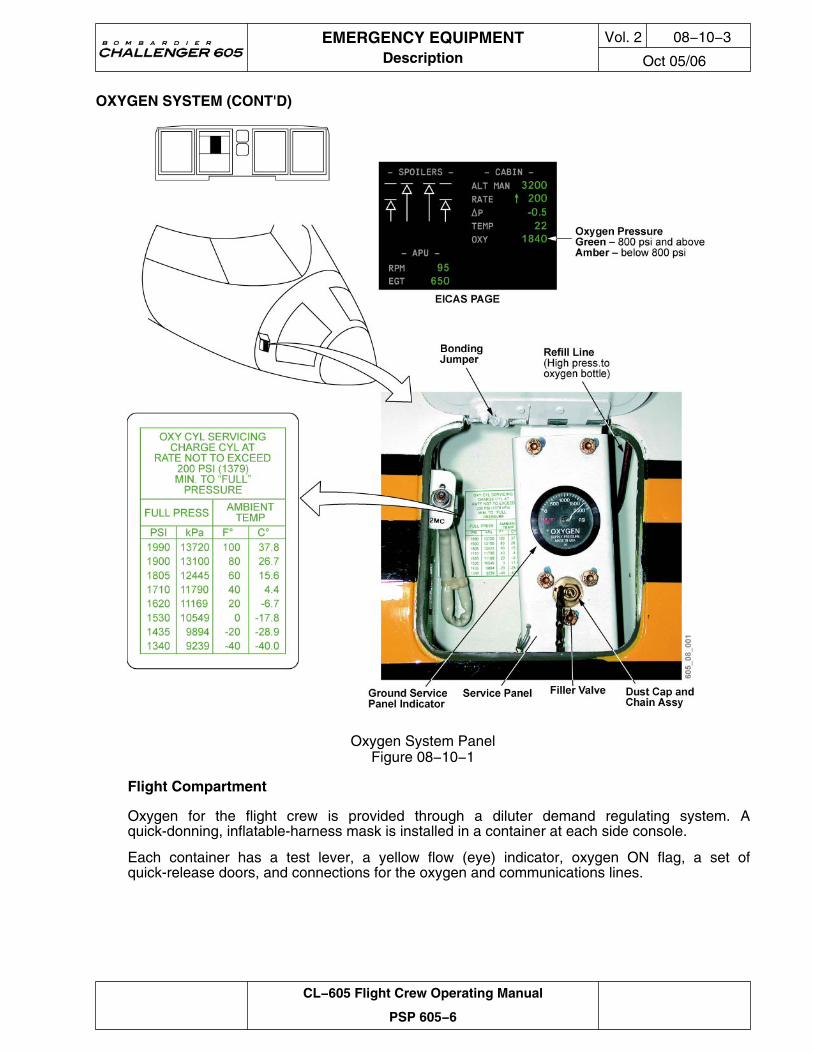
Overboard Discharge Indicator(s)
If the oxygen storage bottle pressure becomes excessive, all oxygen will be vented overboardthrough a relief valve in the right forward fuselage.
A green frangible disk located below and aft of the ground servicing panel will fragment toindicate the relief valve has activated due to an overpressure. The relief valve will activate whenthe HP module pressure exceeds approximately 2,800 psi, or when the LP module pressureexceeds 90 psi.
An amber OXY LO PRESS caution message will be displayed on the EICAS when the oxygenpressure falls below 800 psi.
EMERGENCY EQUIPMENTDescription
Vol. 2 08−10−2
Oct 05/06
CL−605 Flight Crew Operating Manual
PSP 605−6
OXYGEN SYSTEM (CONT'D)
Oxygen System PanelFigure 08−10−1
Flight Compartment
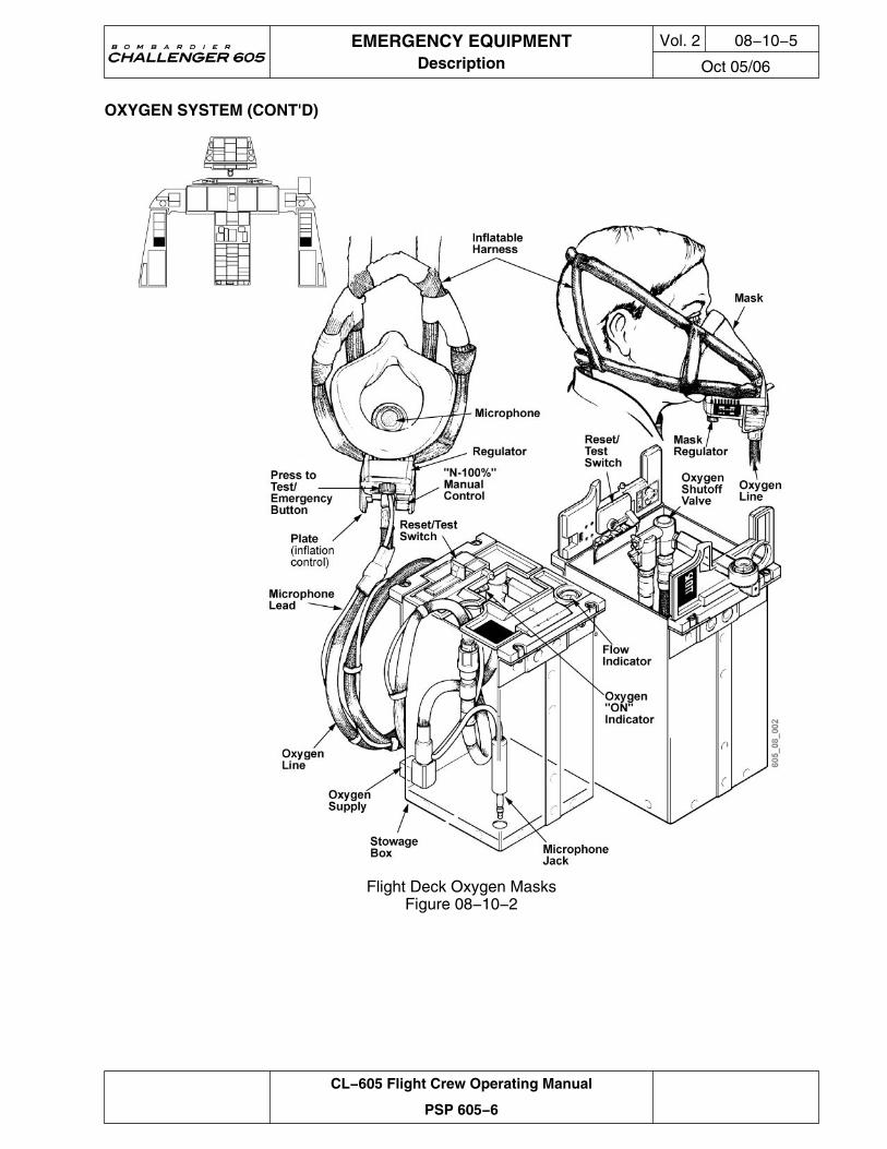
Oxygen for the flight crew is provided through a diluter demand regulating system. Aquick-donning, inflatable-harness mask is installed in a container at each side console.
Each container has a test lever, a yellow flow (eye) indicator, oxygen ON flag, a set ofquick-release doors, and connections for the oxygen and communications lines.
EMERGENCY EQUIPMENTDescription
Vol. 2 08−10−3
Oct 05/06
CL−605 Flight Crew Operating Manual
PSP 605−6
OXYGEN SYSTEM (CONT'D)
Pressing the RESET/TEST switch can test oxygen flow through the regulator. The flow indicator(blinker) displays a yellow cross when oxygen is flowing. The flow indicator is black when thereis no flow. When the mask is in use, a white ON flag comes into view on the left door of thecontainer to indicate that the oxygen shutoff valve is open. When the mask is no longerrequired, closing the container doors and pressing the RESET/TEST switch stops the flow ofoxygen to the mask and removes the white ON flag.
The crew oxygen masks have controls located on the mask. The controls have the followingselections:
Normal/100% Lever
• NORMAL – A diluted mixture of oxygen and ambient air adjusted for cabin altitude; and
• 100% – Pure oxygen (100%) is delivered at a pressure dependent on cabin altitude.
Emergency Flow Control Knob
• NORMAL (unmarked) – Oxygen is regulated on demand;
• EMERGENCY – A constant flow of oxygen is delivered at a positive pressure; and
• PRESS TO TEST (momentary) – Purges the mask of smoke or noxious fumes.
Microphone Control
Each mask has a microphone installed, which can be activated on the audio control panel byselecting MASK/BOOM MIC switch to MASK.
Inflatable Harness Control
The flight deck masks are designed to be removed from their containers and donned with onehand. This is accomplished by squeezing the red tabs on either side of the oxygen line toinflate the harness, while pulling the mask from the container. The inflated harness is placedover the head, and the mask is positioned over the nose and mouth. Releasing the red tabsdeflates the harness, pulling the mask snugly against the face.
NOTE
The harness is not designed to be donned over headsets oreyeglasses. These should be removed prior to using the mask.
EMERGENCY EQUIPMENTDescription
Vol. 2 08−10−4
Oct 05/06
CL−605 Flight Crew Operating Manual
PSP 605−6
OXYGEN SYSTEM (CONT'D)
Flight Deck Oxygen MasksFigure 08−10−2
EMERGENCY EQUIPMENTDescription
Vol. 2 08−10−5
Oct 05/06
CL−605 Flight Crew Operating Manual
PSP 605−6
OXYGEN SYSTEM (CONT'D)
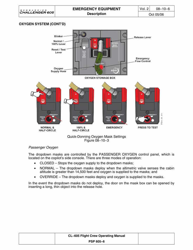
Quick-Donning Oxygen Mask SettingsFigure 08−10−3
Passenger Oxygen
The dropdown masks are controlled by the PASSENGER OXYGEN control panel, which islocated on the copilot’s side console. There are three modes of operation:
• CLOSED – Stops the oxygen supply to the dropdown masks;
• NORMAL – The dropdown masks deploy when the altimetric valve senses the cabinaltitude is greater than 14,500 feet and oxygen is supplied to the masks; and
• OVERRIDE – The dropdown masks deploy and oxygen is supplied to the masks.
In the event the dropdown masks do not deploy, the door on the mask box can be opened byinserting a long, thin object into the release hole.
EMERGENCY EQUIPMENTDescription
Vol. 2 08−10−6
Oct 05/06
CL−605 Flight Crew Operating Manual
PSP 605−6
OXYGEN SYSTEM (CONT'D)
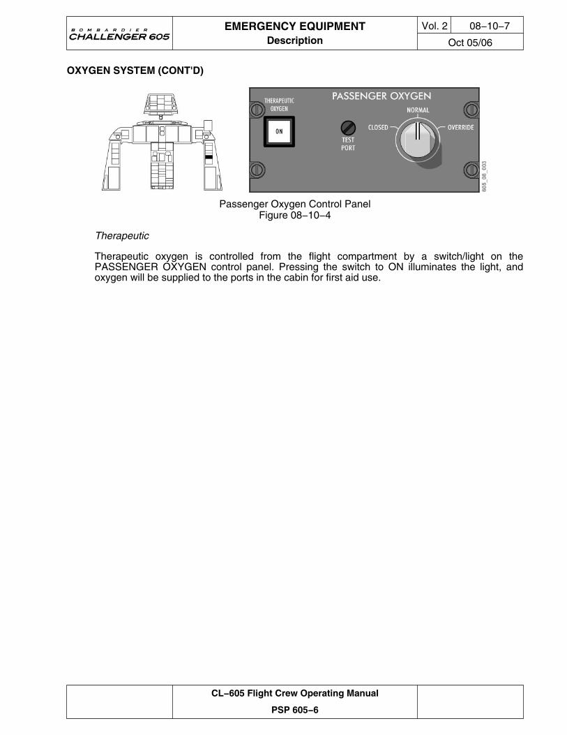
Passenger Oxygen Control PanelFigure 08−10−4
Therapeutic
Therapeutic oxygen is controlled from the flight compartment by a switch/light on thePASSENGER OXYGEN control panel. Pressing the switch to ON illuminates the light, andoxygen will be supplied to the ports in the cabin for first aid use.
EMERGENCY EQUIPMENTDescription
Vol. 2 08−10−7
Oct 05/06
CL−605 Flight Crew Operating Manual
PSP 605−6
OXYGEN SYSTEM (CONT'D)
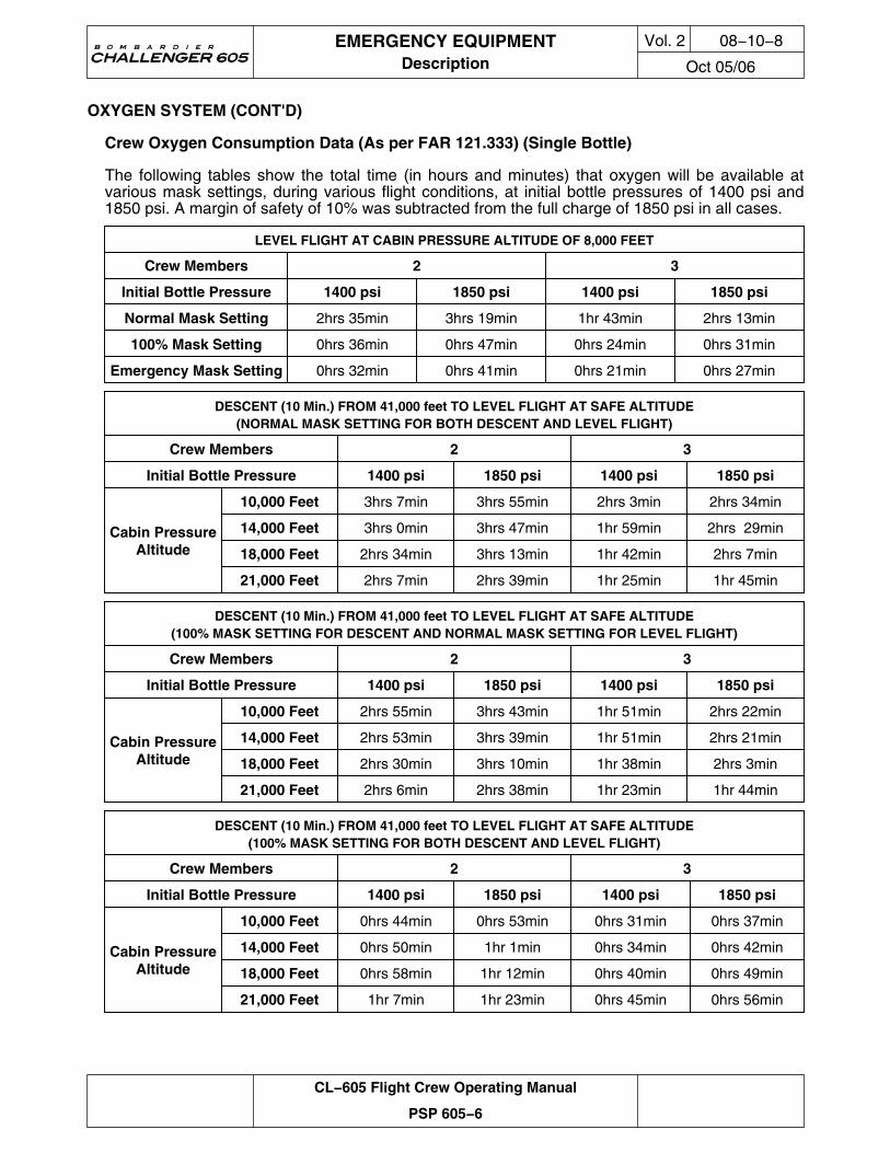
Crew Oxygen Consumption Data (As per FAR 121.333) (Single Bottle)
The following tables show the total time (in hours and minutes) that oxygen will be available atvarious mask settings, during various flight conditions, at initial bottle pressures of 1400 psi and1850 psi. A margin of safety of 10% was subtracted from the full charge of 1850 psi in all cases.
LEVEL FLIGHT AT CABIN PRESSURE ALTITUDE OF 8,000 FEET
Crew Members 2 3
Initial Bottle Pressure 1400 psi 1850 psi 1400 psi 1850 psi
Normal Mask Setting 2hrs 35min 3hrs 19min 1hr 43min 2hrs 13min
100% Mask Setting 0hrs 36min 0hrs 47min 0hrs 24min 0hrs 31min
Emergency Mask Setting 0hrs 32min 0hrs 41min 0hrs 21min 0hrs 27min
DESCENT (10 Min.) FROM 41,000 feet TO LEVEL FLIGHT AT SAFE ALTITUDE(NORMAL MASK SETTING FOR BOTH DESCENT AND LEVEL FLIGHT)
Crew Members 2 3
Initial Bottle Pressure 1400 psi 1850 psi 1400 psi 1850 psi
Cabin PressureAltitude
10,000 Feet 3hrs 7min 3hrs 55min 2hrs 3min 2hrs 34min
14,000 Feet 3hrs 0min 3hrs 47min 1hr 59min 2hrs 29min
18,000 Feet 2hrs 34min 3hrs 13min 1hr 42min 2hrs 7min
21,000 Feet 2hrs 7min 2hrs 39min 1hr 25min 1hr 45min
DESCENT (10 Min.) FROM 41,000 feet TO LEVEL FLIGHT AT SAFE ALTITUDE(100% MASK SETTING FOR DESCENT AND NORMAL MASK SETTING FOR LEVEL FLIGHT)
Crew Members 2 3
Initial Bottle Pressure 1400 psi 1850 psi 1400 psi 1850 psi
Cabin PressureAltitude
10,000 Feet 2hrs 55min 3hrs 43min 1hr 51min 2hrs 22min
14,000 Feet 2hrs 53min 3hrs 39min 1hr 51min 2hrs 21min
18,000 Feet 2hrs 30min 3hrs 10min 1hr 38min 2hrs 3min
21,000 Feet 2hrs 6min 2hrs 38min 1hr 23min 1hr 44min
DESCENT (10 Min.) FROM 41,000 feet TO LEVEL FLIGHT AT SAFE ALTITUDE(100% MASK SETTING FOR BOTH DESCENT AND LEVEL FLIGHT)
Crew Members 2 3
Initial Bottle Pressure 1400 psi 1850 psi 1400 psi 1850 psi
Cabin PressureAltitude
10,000 Feet 0hrs 44min 0hrs 53min 0hrs 31min 0hrs 37min
14,000 Feet 0hrs 50min 1hr 1min 0hrs 34min 0hrs 42min
18,000 Feet 0hrs 58min 1hr 12min 0hrs 40min 0hrs 49min
21,000 Feet 1hr 7min 1hr 23min 0hrs 45min 0hrs 56min
EMERGENCY EQUIPMENTDescription
Vol. 2 08−10−8
Oct 05/06
CL−605 Flight Crew Operating Manual
PSP 605−6
OXYGEN SYSTEM (CONT'D)
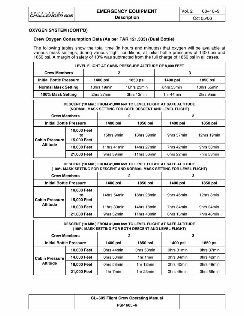
Crew Oxygen Consumption Data (As per FAR 121.333) (Dual Bottle)
The following tables show the total time (in hours and minutes) that oxygen will be available atvarious mask settings, during various flight conditions, at initial bottle pressures of 1400 psi and1850 psi. A margin of safety of 10% was subtracted from the full charge of 1850 psi in all cases.
LEVEL FLIGHT AT CABIN PRESSURE ALTITUDE OF 8,000 FEET
Crew Members 2 3
Initial Bottle Pressure 1400 psi 1850 psi 1400 psi 1850 psi
Normal Mask Setting 13hrs 19min 16hrs 23min 8hrs 53min 10hrs 55min
100% Mask Setting 2hrs 37min 3hrs 13min 1hr 44min 2hrs 9min
DESCENT (10 Min.) FROM 41,000 feet TO LEVEL FLIGHT AT SAFE ALTITUDE(NORMAL MASK SETTING FOR BOTH DESCENT AND LEVEL FLIGHT)
Crew Members 2 3
Initial Bottle Pressure 1400 psi 1850 psi 1400 psi 1850 psi
Cabin PressureAltitude
10,000 Feetto
15,000 Feet15hrs 9min 18hrs 39min 9hrs 57min 12hrs 19min
18,000 Feet 11hrs 41min 14hrs 27min 7hrs 42min 9hrs 33min
21,000 Feet 9hrs 39min 11hrs 56min 6hrs 22min 7hrs 53min
DESCENT (10 Min.) FROM 41,000 feet TO LEVEL FLIGHT AT SAFE ALTITUDE(100% MASK SETTING FOR DESCENT AND NORMAL MASK SETTING FOR LEVEL FLIGHT)
Crew Members 2 3
Initial Bottle Pressure 1400 psi 1850 psi 1400 psi 1850 psi
Cabin PressureAltitude
10,000 Feetto
15,000 Feet14hrs 54min 18hrs 28min 9hrs 46min 12hrs 8min
18,000 Feet 11hrs 33min 14hrs 18min 7hrs 34min 9hrs 24min
21,000 Feet 9hrs 32min 11hrs 48min 6hrs 15min 7hrs 46min
DESCENT (10 Min.) FROM 41,000 feet TO LEVEL FLIGHT AT SAFE ALTITUDE(100% MASK SETTING FOR BOTH DESCENT AND LEVEL FLIGHT)
Crew Members 2 3
Initial Bottle Pressure 1400 psi 1850 psi 1400 psi 1850 psi
Cabin PressureAltitude
10,000 Feet 0hrs 44min 0hrs 53min 0hrs 31min 0hrs 37min
14,000 Feet 0hrs 50min 1hr 1min 0hrs 34min 0hrs 42min
18,000 Feet 0hrs 58min 1hr 12min 0hrs 40min 0hrs 49min
21,000 Feet 1hr 7min 1hr 23min 0hrs 45min 0hrs 56min
EMERGENCY EQUIPMENTDescription
Vol. 2 08−10−9
Oct 05/06
CL−605 Flight Crew Operating Manual
PSP 605−6
EMERGENCY EXITS
Refer to Chapter 1, Airplane General, for operation of the passenger door and the overwingemergency exit.
Main Entrance Door
The main entrance door is classified as a Type I emergency exit, and is the normal means of exitin an emergency.
Overwing Emergency Exit
The overwing emergency exit is a removable plug-type hatch, and provides access to the rightupper wing surface. It is classified as a Type III emergency exit. This emergency exit has anescape rope (lifeline) stored to the right of the exit window, with one end attached to the fuselage.
Emergency Egress Lighting
The Challenger 605 is equipped with an emergency egress lighting system that operates forapproximately 15 minutes from the time of activation. The emergency egress lighting systemlocation and operations are covered in Chapter 16, Lighting.
LOCATING DEVICES
Components and Operation
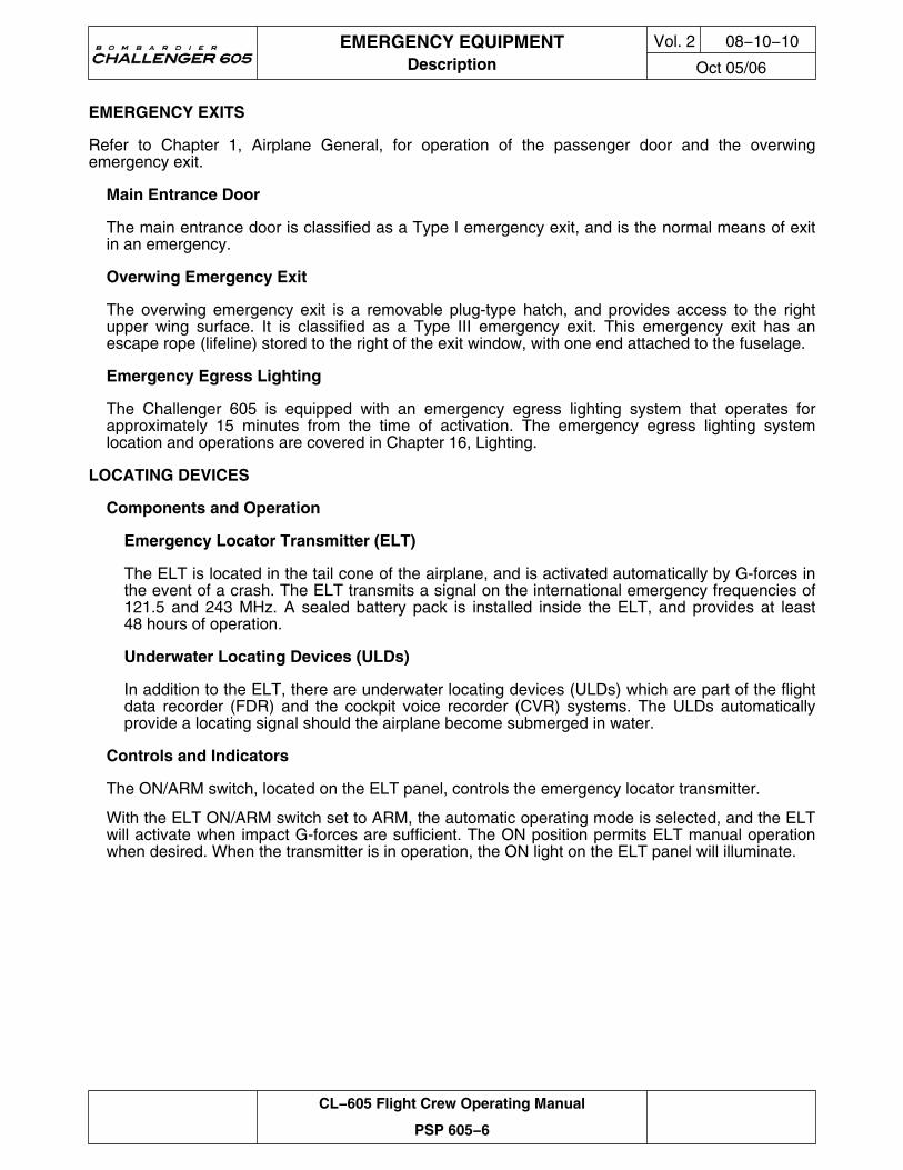
Emergency Locator Transmitter (ELT)
The ELT is located in the tail cone of the airplane, and is activated automatically by G-forces inthe event of a crash. The ELT transmits a signal on the international emergency frequencies of121.5 and 243 MHz. A sealed battery pack is installed inside the ELT, and provides at least48 hours of operation.
Underwater Locating Devices (ULDs)
In addition to the ELT, there are underwater locating devices (ULDs) which are part of the flightdata recorder (FDR) and the cockpit voice recorder (CVR) systems. The ULDs automaticallyprovide a locating signal should the airplane become submerged in water.
Controls and Indicators
The ON/ARM switch, located on the ELT panel, controls the emergency locator transmitter.
With the ELT ON/ARM switch set to ARM, the automatic operating mode is selected, and the ELTwill activate when impact G-forces are sufficient. The ON position permits ELT manual operationwhen desired. When the transmitter is in operation, the ON light on the ELT panel will illuminate.
EMERGENCY EQUIPMENTDescription
Vol. 2 08−10−10
Oct 05/06
CL−605 Flight Crew Operating Manual
PSP 605−6
LOCATING DEVICES (CONT'D)
ELT System − Control PanelFigure 08−10−5
MISCELLANEOUS EMERGENCY EQUIPMENT
Fire Extinguishers
The Challenger 605 normally has two variable-size handheld fire extinguishers. One of theextinguishers is located in the flight compartment on the bulkhead behind the copilot’s seat. Theother is located at a designated area in the cabin, and is marked by a placard. Handheld fireextinguisher operations are covered in Chapter 9, Fire Protection.
WARNING
IF A FIRE EXTINGUISHER IS TO BE DISCHARGED IN THEFLIGHT COMPARTMENT, ALL FLIGHT CREW MUST WEAROXYGEN MASKS WITH EMERGENCY SELECTED (100%OXYGEN).
WARNING
CREW EXPOSURE TO HIGH LEVELS OF HALON VAPORS MAYRESULT IN DIZZINESS, IMPAIRED COORDINATION ANDREDUCED MENTAL ALERTNESS.
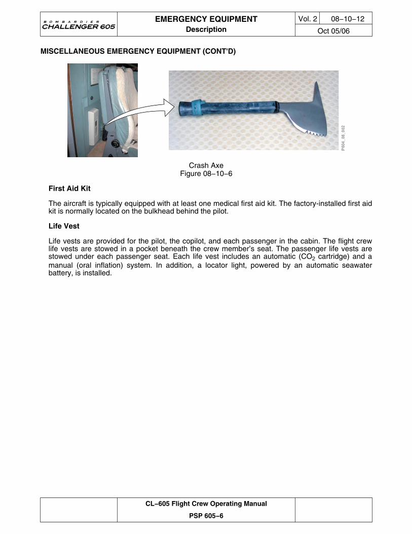
Crash Axe
A crash axe is located on the bulkhead behind the pilot’s seat.
EMERGENCY EQUIPMENTDescription
Vol. 2 08−10−11
Oct 05/06
CL−605 Flight Crew Operating Manual
PSP 605−6
MISCELLANEOUS EMERGENCY EQUIPMENT (CONT'D)
Crash AxeFigure 08−10−6
First Aid Kit
The aircraft is typically equipped with at least one medical first aid kit. The factory-installed first aidkit is normally located on the bulkhead behind the pilot.
Life Vest
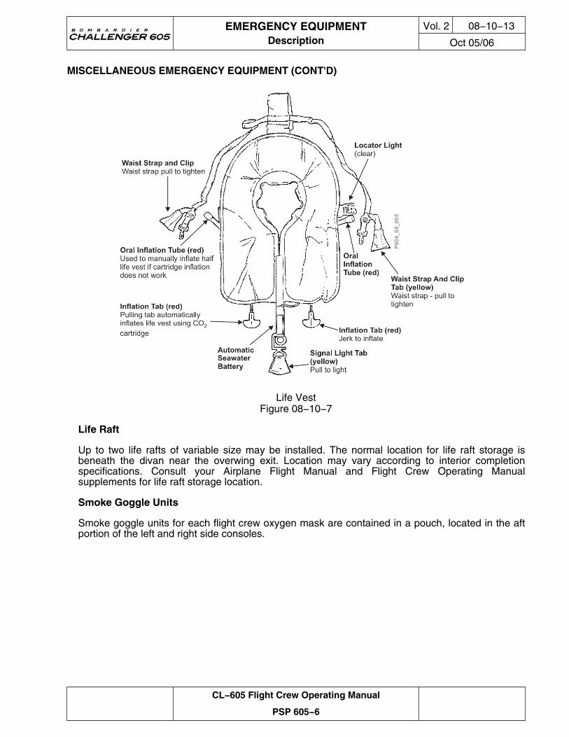
Life vests are provided for the pilot, the copilot, and each passenger in the cabin. The flight crewlife vests are stowed in a pocket beneath the crew member’s seat. The passenger life vests arestowed under each passenger seat. Each life vest includes an automatic (CO2 cartridge) and amanual (oral inflation) system. In addition, a locator light, powered by an automatic seawaterbattery, is installed.
EMERGENCY EQUIPMENTDescription
Vol. 2 08−10−12
Oct 05/06
CL−605 Flight Crew Operating Manual
PSP 605−6
MISCELLANEOUS EMERGENCY EQUIPMENT (CONT'D)
Life VestFigure 08−10−7
Life Raft
Up to two life rafts of variable size may be installed. The normal location for life raft storage isbeneath the divan near the overwing exit. Location may vary according to interior completionspecifications. Consult your Airplane Flight Manual and Flight Crew Operating Manualsupplements for life raft storage location.
Smoke Goggle Units
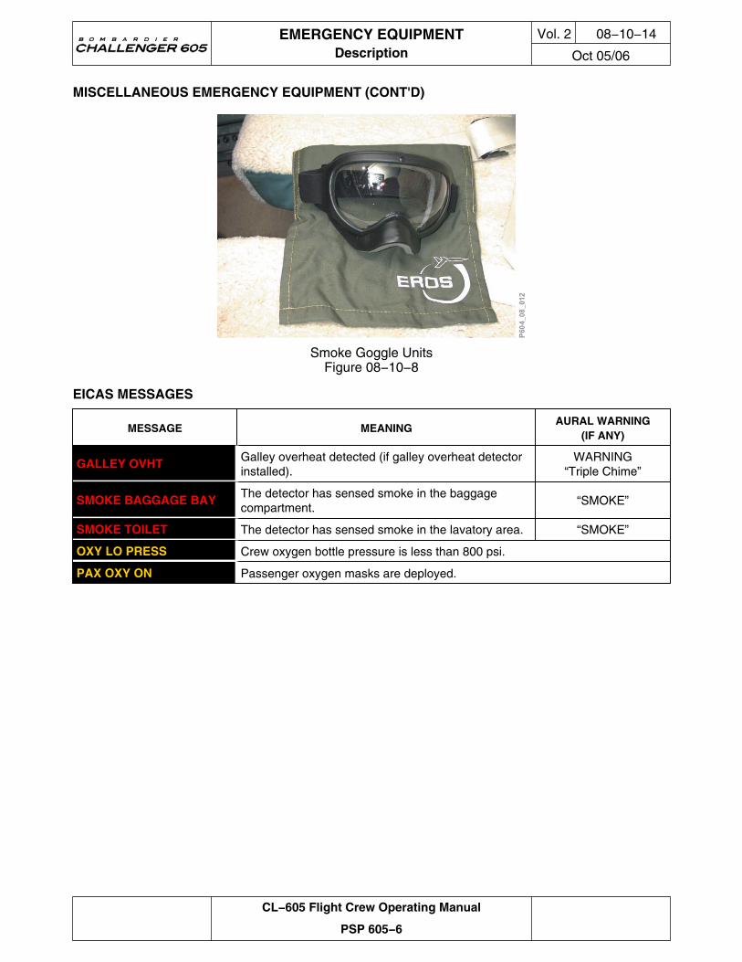
Smoke goggle units for each flight crew oxygen mask are contained in a pouch, located in the aftportion of the left and right side consoles.
EMERGENCY EQUIPMENTDescription
Vol. 2 08−10−13
Oct 05/06
CL−605 Flight Crew Operating Manual
PSP 605−6
MISCELLANEOUS EMERGENCY EQUIPMENT (CONT'D)
Smoke Goggle UnitsFigure 08−10−8
EICAS MESSAGES
MESSAGE MEANINGAURAL WARNING
(IF ANY)
GALLEY OVHT Galley overheat detected (if galley overheat detectorinstalled).
WARNING“Triple Chime”
SMOKE BAGGAGE BAY The detector has sensed smoke in the baggagecompartment.
“SMOKE”
SMOKE TOILET The detector has sensed smoke in the lavatory area. “SMOKE”
OXY LO PRESS Crew oxygen bottle pressure is less than 800 psi.
PAX OXY ON Passenger oxygen masks are deployed.
EMERGENCY EQUIPMENTDescription
Vol. 2 08−10−14
Oct 05/06
CL−605 Flight Crew Operating Manual
PSP 605−6
POWER SUPPLY AND CIRCUIT BREAKER SUMMARY
SYSTEM SUB-SYSTEM CB NAME BUS BARCB
PANELCB LOCATION NOTES
Oxygen System IndicationOXYGENMONITOR
DC BATT 2 P9
EMERGENCY EQUIPMENTSummary
Vol. 2 08−20−1
Oct 05/06
CL−605 Flight Crew Operating Manual
PSP 605−6
EMERGENCY EQUIPMENTSummary
Vol. 2 08−20−2
Oct 05/06
CL−605 Flight Crew Operating Manual
PSP 605−6
THIS PAGE INTENTIONALLY LEFT BLANK
Related Documents