Router and Network Management 6-1 v1.0, April 2007 Chapter 6 Router and Network Management This chapter describes how to use the network management features of your ProSafe Wireless ADSL Modem VPN Firewall Router. These features can be found by clicking on the appropriate heading in the Main Menu of the browser interface. The ProSafe Wireless ADSL Modem VPN Firewall Router offers many tools for managing the network traffic to optimize its performance. You can also control administrator access, be alerted to important events requiring prompt action, monitor the firewall status, perform diagnostics, and manage the firewall configuration file. Performance Management Performance management consists of controlling the traffic through the ProSafe DGFV338 so that the necessary traffic gets through when there is a bottleneck and either reducing unnecessary traffic or rescheduling some traffic to low-peak times to prevent bottlenecks from occurring in the first place. The ProSafe DGFV338 has the necessary features and tools to help the network manager accomplish these goals. Wireless Firewall Features That Reduce Traffic Features of the wireless firewall that can be called upon to decrease WAN-side loading are as follows: • Service blocking • Block sites • Source MAC filtering

Welcome message from author
This document is posted to help you gain knowledge. Please leave a comment to let me know what you think about it! Share it to your friends and learn new things together.
Transcript

Chapter 6Router and Network Management
This chapter describes how to use the network management features of your ProSafe Wireless ADSL Modem VPN Firewall Router. These features can be found by clicking on the appropriate heading in the Main Menu of the browser interface.
The ProSafe Wireless ADSL Modem VPN Firewall Router offers many tools for managing the network traffic to optimize its performance. You can also control administrator access, be alerted to important events requiring prompt action, monitor the firewall status, perform diagnostics, and manage the firewall configuration file.
Performance Management
Performance management consists of controlling the traffic through the ProSafe DGFV338 so that the necessary traffic gets through when there is a bottleneck and either reducing unnecessary traffic or rescheduling some traffic to low-peak times to prevent bottlenecks from occurring in the first place. The ProSafe DGFV338 has the necessary features and tools to help the network manager accomplish these goals.
Wireless Firewall Features That Reduce TrafficFeatures of the wireless firewall that can be called upon to decrease WAN-side loading are as follows:
• Service blocking
• Block sites
• Source MAC filtering
Router and Network Management 6-1
v1.0, April 2007

DGFV338 ProSafe Wireless ADSL Modem VPN Firewall Router Reference Manual
Service Blocking
You can control specific outbound traffic (i.e., from LAN to WAN and from DMZ to WAN). Outbound Services lists all existing rules for outbound traffic. If you have not defined any rules, only the default rule will be listed. The default rule allows all outgoing traffic.
Each rule lets you specify the desired action for the connections covered by the rule:• BLOCK always • BLOCK by schedule, otherwise Allow • ALLOW always • ALLOW by schedule, otherwise Block
As you define your firewall rules, you can further refine their application according to the following criteria:
• LAN users. These settings determine which computers on your network are affected by this rule. Select the desired options:
– Any: All PCs and devices on your LAN.
– Single address: The rule will be applied to the address of a particular PC.
– Address range: The rule is applied to a range of addresses.
– Groups: The rule is applied to a Group. You use the Network Database to assign PCs to Groups (see “Groups and Hosts” on page 6-3).
• WAN Users. These settings determine which Internet locations are covered by the rule, based on their IP address.
– Any: The rule applies to all Internet IP address.
– Single address: The rule applies to a single Internet IP address.
– Address range: The rule is applied to a range of Internet IP addresses.
• Services. You can specify the desired Services or applications to be covered by this rule. If the desired service or application does not appear in the list, you must define it using the Services menu (see “Services” on page 6-3).
• Schedule. You can specify whether the rule is to be applied on the Schedule 1, Schedule 2, or Schedule 3 time schedule (see “Schedule” on page 6-3).
Note: This feature is for Advanced Administrators only! Incorrect configuration will cause serious problems.
6-2 Router and Network Management
v1.0, April 2007

DGFV338 ProSafe Wireless ADSL Modem VPN Firewall Router Reference Manual
See “Using Rules to Block or Allow Specific Kinds of Traffic” on page 4-1 for the procedure on how to use this feature.
Services. The Rules menu contains a list of predefined Services for creating firewall rules. If a service does not appear in the predefined Services list, you can define the service. The new service will then appear in the Rules menu's Services list. See “Quality of Service (QoS) Priorities” on page 4-19 for the procedure on how to use this feature.
Groups and Hosts. You can apply these rules selectively to groups of PCs to reduce the outbound or inbound traffic. The Network Database is an automatically-maintained list of all known PCs and network devices. PCs and devices become known by the following methods:
• DHCP Client Request – By default, the DHCP server in this Router is enabled, and will accept and respond to DHCP client requests from PCs and other network devices. These requests also generate an entry in the Network Database. Because of this, leaving the DHCP Server feature (on the LAN screen) enabled is strongly recommended.
• Scanning the Network – The local network is scanned using standard methods such as ARP. This will detect active devices which are not DHCP clients. However, sometimes the name of the PC or device cannot be accurately determined, and will be shown as Unknown.
See “Managing Groups and Hosts” on page 4-21 for the procedure on how to use this feature.
Schedule. If you have set firewall rules on the Rules screen, you can configure three different schedules (i.e., schedule 1, schedule 2, and schedule 3) for when a rule is to be applied. Once a schedule is configured, it affects all Rules that use this schedule. You specify the days of the week and time of day for each schedule.
See “Setting a Schedule to Block or Allow Specific Traffic” on page 4-31 for the procedure on how to use this feature.
Block SitesIf you want to reduce traffic by preventing access to certain sites on the Internet, you can use the wireless firewall filtering feature. By default, this feature is disabled; all requested traffic from any Web site is allowed.
• Keyword (and domain name) blocking – You can specify up to 32 words that, should they appear in the Web site name (i.e., URL) or in a newsgroup name, will cause that site or newsgroup to be blocked by the wireless firewall.
You can apply the keywords to one or more groups. Requests from the PCs in the groups for which keyword blocking has been enabled will be blocked. Blocking does not occur for the PCs that are in the groups for which keyword blocking has not been enabled.
Router and Network Management 6-3
v1.0, April 2007

DGFV338 ProSafe Wireless ADSL Modem VPN Firewall Router Reference Manual
You can bypass keyword blocking for trusted domains by adding the exact matching domain to the list of Trusted Domains. Access to the domains on this list by PCs even in the groups for which keyword blocking has been enabled will still be allowed without any blocking.
• Web component blocking – You can block the following Web component types: Proxy, Java, ActiveX, and Cookies. Sites on the Trusted Domains list are still subject to Web component blocking when the blocking of a particular Web component has been enabled.
See “Blocking Internet Sites” on page 4-24 for the procedure on how to use this feature.
Source MAC FilteringIf you want to reduce outgoing traffic by preventing Internet access by certain PCs on the LAN, you can use the source MAC filtering feature to drop the traffic received from the PCs with the specified MAC addresses. By default, this feature is disabled; all traffic received from PCs with any MAC address is allowed.
See “To block keywords or Internet domains:” on page 4-27 for the procedure on how to use this feature.
Wireless Firewall Features That Increase TrafficFeatures that tend to increase WAN-side loading are as follows:• Port forwarding• Port triggering• VPN tunnels
Port ForwardingThe firewall always blocks DoS (Denial of Service) attacks. A DoS attack does not attempt to steal data or damage your PCs, but overloads your Internet connection so you can not use it (i.e., the service is unavailable). You can also create additional firewall rules that are customized to block or allow specific traffic.
You can control specific inbound traffic (i.e., from WAN to LAN and from WAN to DMZ). Inbound Services lists all existing rules for inbound traffic. If you have not defined any rules, only the default rule will be listed. The default rule blocks all inbound traffic.
Warning: This feature is for Advanced Administrators only! Incorrect configuration will cause serious problems.
6-4 Router and Network Management
v1.0, April 2007
DGFV338 ProSafe Wireless ADSL Modem VPN Firewall Router Reference Manual
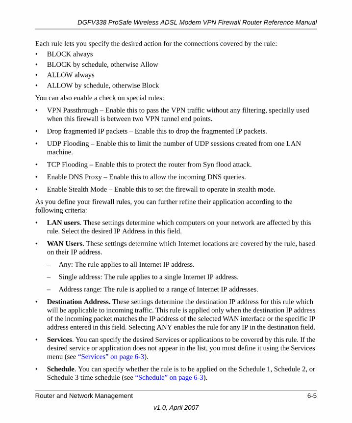
Each rule lets you specify the desired action for the connections covered by the rule:• BLOCK always • BLOCK by schedule, otherwise Allow • ALLOW always • ALLOW by schedule, otherwise Block
You can also enable a check on special rules:
• VPN Passthrough – Enable this to pass the VPN traffic without any filtering, specially used when this firewall is between two VPN tunnel end points.
• Drop fragmented IP packets – Enable this to drop the fragmented IP packets.
• UDP Flooding – Enable this to limit the number of UDP sessions created from one LAN machine.
• TCP Flooding – Enable this to protect the router from Syn flood attack.
• Enable DNS Proxy – Enable this to allow the incoming DNS queries.
• Enable Stealth Mode – Enable this to set the firewall to operate in stealth mode.
As you define your firewall rules, you can further refine their application according to the following criteria:
• LAN users. These settings determine which computers on your network are affected by this rule. Select the desired IP Address in this field.
• WAN Users. These settings determine which Internet locations are covered by the rule, based on their IP address.
– Any: The rule applies to all Internet IP address.
– Single address: The rule applies to a single Internet IP address.
– Address range: The rule is applied to a range of Internet IP addresses.
• Destination Address. These settings determine the destination IP address for this rule which will be applicable to incoming traffic. This rule is applied only when the destination IP address of the incoming packet matches the IP address of the selected WAN interface or the specific IP address entered in this field. Selecting ANY enables the rule for any IP in the destination field.
• Services. You can specify the desired Services or applications to be covered by this rule. If the desired service or application does not appear in the list, you must define it using the Services menu (see “Services” on page 6-3).
• Schedule. You can specify whether the rule is to be applied on the Schedule 1, Schedule 2, or Schedule 3 time schedule (see “Schedule” on page 6-3).
Router and Network Management 6-5
v1.0, April 2007

DGFV338 ProSafe Wireless ADSL Modem VPN Firewall Router Reference Manual
See “Using Rules to Block or Allow Specific Kinds of Traffic” on page 4-1 for the procedure on how to use this feature.
Port TriggeringPort triggering allows some applications to function correctly that would otherwise be partially blocked by the firewall. Using this feature requires that you know the port numbers used by the Application.
Once configured, operation is as follows:
• A PC makes an outgoing connection using a port number defined in the Port Triggering table.
• This Router records this connection, opens the additional INCOMING port or ports associated with this entry in the Port Triggering table, and associates them with the PC.
• The remote system receives the PCs request and responds using the different port numbers that you have now opened.
• This Router matches the response to the previous request and forwards the response to the PC. Without Port Triggering, this response would be treated as a new connection request rather than a response. As such, it would be handled in accordance with the Port Forwarding rules.
– Only one PC can use a Port Triggering application at any time.
– After a PC has finished using a Port Triggering application, there is a time-out period before the application can be used by another PC. This is required because the firewall cannot be sure when the application has terminated.
See “Setting up Port Triggering” on page 4-28 for the procedure on how to use this feature.
VPN TunnelsThe wireless firewall permits up to 50 VPN tunnels at a time. Each tunnel requires extensive processing for encryption and authentication.
See Chapter 5, “Virtual Private Networking” for the procedure on how to use this feature.
Using QoS to Shift the Traffic MixThe QoS priority settings determine the priority and, in turn, the quality of service for the traffic passing through the firewall. The QoS is set individually for each service.
• You can accept the default priority defined by the service itself by not changing its QoS setting.
6-6 Router and Network Management
v1.0, April 2007

DGFV338 ProSafe Wireless ADSL Modem VPN Firewall Router Reference Manual
• You can change the priority to a higher or lower value than its default setting to give the service higher or lower priority than it otherwise would have.
The QoS priority settings conform to the IEEE 802.1D-1998 (formerly 802.1p) standard for class of service tag.
You will not change the WAN bandwidth used by changing any QoS priority settings. But you will change the mix of traffic through the WAN ports by granting some services a higher priority than others. The quality of a service is impacted by its QoS setting, however.
See “Quality of Service (QoS) Priorities” on page 4-19 for the procedure on how to use this feature.
Tools for Traffic ManagementThe ProSafe Wireless ADSL Modem VPN Firewall Router includes several tools that can be used to monitor the traffic conditions of the firewall and control who has access to the Internet and the types of traffic they are allowed to have. See “Monitoring” on page 6-12 for a discussion of the tools.
Administrator and Guest Access Authorization
You can change the administrator and guest passwords, administrator login time-out, and enable remote management. Administrator access is read/write and guest access is read-only.
Changing the Passwords and Login Time-outThe default passwords for the firewall’s Web Configuration Manager is password. NETGEAR recommends that you change this password to a more secure password.
To change the password:
1. Select Administration from the main menu and Set Password from the submenu. The Set Password screen will display.
2. Enter a New User Name if desired.
Note: You can change the Administrator account name; however, you cannot change it to “root”, as this is a Telnet account that already exists on the system.
Router and Network Management 6-7
v1.0, April 2007

DGFV338 ProSafe Wireless ADSL Modem VPN Firewall Router Reference Manual
3. First enter the old password, and then enter the new password—twice. Click Apply.
4. Change the login idle time-out by changing the number of minutes. Click Apply.
The password and time-out values you entered will revert back to password and 5 minutes, respectively, after a factory default reset.
Enabling Remote Management AccessUsing the Remote Management page, you can allow an administrator on the Internet to configure, upgrade, and check the status of your ProSafe DGFV338. You must be logged in locally to enable remote management (see “Logging in and Configuring your Internet Connection” on page 2-3).
Figure 6-1
Note: If you make the administrator login time-out value too large, you will wait a long time before you are able to log back into the router if your previous login was disrupted (i.e., you did not click Logout on the Main Menu bar to log out).
Note: Be sure to change the firewall default configuration password to a very secure password. The ideal password should contain no dictionary words from any language, and should be a mixture of letters (both upper and lower case), numbers, and symbols. Your password can be up to 30 characters. See “Changing the Passwords and Login Time-out” on page 6-7 for the procedure on how to do this.
Change guest
Change administrator
Change administratorlogin time-out
name and password
read-only password
6-8 Router and Network Management
v1.0, April 2007
DGFV338 ProSafe Wireless ADSL Modem VPN Firewall Router Reference Manual
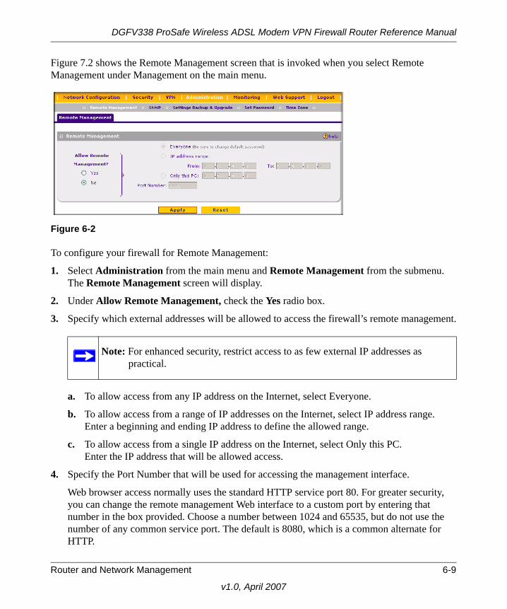
Figure 7.2 shows the Remote Management screen that is invoked when you select Remote Management under Management on the main menu.
To configure your firewall for Remote Management:
1. Select Administration from the main menu and Remote Management from the submenu. The Remote Management screen will display.
2. Under Allow Remote Management, check the Yes radio box.
3. Specify which external addresses will be allowed to access the firewall’s remote management.
a. To allow access from any IP address on the Internet, select Everyone.
b. To allow access from a range of IP addresses on the Internet, select IP address range.Enter a beginning and ending IP address to define the allowed range.
c. To allow access from a single IP address on the Internet, select Only this PC.Enter the IP address that will be allowed access.
4. Specify the Port Number that will be used for accessing the management interface.
Web browser access normally uses the standard HTTP service port 80. For greater security, you can change the remote management Web interface to a custom port by entering that number in the box provided. Choose a number between 1024 and 65535, but do not use the number of any common service port. The default is 8080, which is a common alternate for HTTP.
Figure 6-2
Note: For enhanced security, restrict access to as few external IP addresses as practical.
Router and Network Management 6-9
v1.0, April 2007

DGFV338 ProSafe Wireless ADSL Modem VPN Firewall Router Reference Manual
5. Click Apply to have your changes take effect.
When accessing your firewall from the Internet, the Secure Sockets Layer (SSL) will be enabled. Enter https:// and type your firewall WAN IP address into your browser, followed by a colon (:) and the custom port number. For example, if your WAN IP address is 172.21.4.1 and you use port number 8080, type the following in your browser:
https://172.21.4.1:8080
The router’s remote login URL is https://IP_address:port_number orhttps://FullyQualifiedDomainName:port_number.
If you do not use the SSL https://address, but rather use http://address, the DGFV338 will automatically attempt to redirect to the https://address.
Command Line Interface
You can access the command line interface (CLI) either by using telnet or by connecting a terminal to the console port on the front of the unit.
To access the CLI from a communications terminal when the ProSafe DGFV338 is still set to its factory defaults (or use your own settings if you have changed them), do the following:
1. From the command line prompt, enter the following command:
telnet 192.168.1.1
Note: The first time you remotely connect the DGFV338 with a browser via SSL, you may receive a message regarding the SSL certificate. If you are using a Windows computer with Internet Explorer 5.5 or higher, simply click Yes to accept the certificate.
Tip: If you are using a dynamic DNS service such as TZO, you can always identify the IP address of your DGFV338 by running tracert from the Windows Start menu Run option. For example, tracert your DGFV338.mynetgear.net and you will see the IP address your ISP assigned to the DGFV338.
Note: The command line interface is not supported at this time. Check with the NETGEAR Web site for the latest status.
6-10 Router and Network Management
v1.0, April 2007

DGFV338 ProSafe Wireless ADSL Modem VPN Firewall Router Reference Manual
2. Enter admin and password when prompted for the login and password information (or enter guest and password to log in as a read-only guest).
Any configuration changes made via the CLI are not preserved after a reboot or power cycle unless the user issues the CLI save command after making the changes.
Event Alerts
You can be alerted to important events such as WAN port auto-rollover, WAN traffic limits reached, and login failures and attacks.
Traffic Limits ReachedFigure 6-3 shows the Internet Traffic screen that is invoked by clicking Internet Traffic under WAN Setup on the Main Menu bar. The ADSL and Ethernet ports are programmed separately. A WAN port shuts down once its traffic limit is reached when this feature is enabled.
Note: No password protection exists when using the console port to access the unit.
Router and Network Management 6-11
v1.0, April 2007

DGFV338 ProSafe Wireless ADSL Modem VPN Firewall Router Reference Manual
Monitoring
You can view status information about the firewall, WAN ports, LAN ports, and VPN tunnels and program SNMP connections.
Router Status The Router Status menu provides status and usage information on the LAN port, the ADSL configuration and the Ethernet configuration. From the main menu of the browser interface under Management, select Router Status to view this screen.
Figure 6-3
WAN port shuts down once
Each WAN port is programmed separately.
the traffic limit is reached. Anemail alert can be sent whenthis shutdown happens.
6-12 Router and Network Management
v1.0, April 2007

DGFV338 ProSafe Wireless ADSL Modem VPN Firewall Router Reference Manual
Figure 6-4
Table 6-1. Router Status
Item Description
System Name This is the Account Name that you entered in the Basic Settings page.
Firmware Version This is the current software the router is using. This will change if you upgrade your router.
Router and Network Management 6-13
v1.0, April 2007

DGFV338 ProSafe Wireless ADSL Modem VPN Firewall Router Reference Manual
WAN PortsYou can monitor the status of the ADSL and WAN Ethernet connections, Dynamic DNS services, and Internet traffic information.
To monitor each WAN Port connection status:
1. Select Network Configuration from the main menu, WAN Setup from the submenu and click either the ADSL ISP Settings or the Ethernet ISP Settings tab. Then select the l. The ISP settings screen for the selected settings will display.
2. Click either the Ethernet Status or ADSL Status link. The current connection status for the selected connection will display.
LAN Port Information These are the current settings for MAC address, IP address, DHCP role and Subnet Mask that you set in the LAN IP Setup page. DHCP can be either Server or None.
WAN Port Information
This indicates whether rollover mode is enabled and which LAN connection is primary and which is secondary. It also notes whether NAT is Enabled or Disabled; displays the current settings for MAC address, IP address, DHCP role and Subnet Mask that you set in the Basic Settings page. DHCP can be either Client or None.
Note: The Router Status page displays current settings and statistics for your router. As this information is read-only, any changes must be made on other pages.
Figure 6-5
Table 6-1. Router Status (continued)
Item Description
6-14 Router and Network Management
v1.0, April 2007

DGFV338 ProSafe Wireless ADSL Modem VPN Firewall Router Reference Manual
To check Dynamic DNS status:
1. Select Network Configuration from the main menu and Dynamic DNS from the submenu. The Dynamic DNS Configuration screen will display.
2. Check the DNS provider radio box on the WAN port for which you have service.
3. Click the link at the top of the page for the dynamic DNS service you want to access. Click Show Status. The Status screen for the selected service will display.
Internet Traffic The Internet Traffic screen provides the following information:
• Internet Traffic Statistics – Displays statistics on Internet Traffic via the WAN port. If you have not enabled the Traffic Meter, these statistics are not available.
• Traffic by Protocol – Clicking Traffic by Protocol will show more details of the Internet Traffic. The volume of traffic for each protocol will be displayed in a sub-window. Traffic counters are updated in MBytes scale and the counter starts only when traffic passed is at least 1 MB
Router and Network Management 6-15
v1.0, April 2007

DGFV338 ProSafe Wireless ADSL Modem VPN Firewall Router Reference Manual
Figure 6-6
6-16 Router and Network Management
v1.0, April 2007

DGFV338 ProSafe Wireless ADSL Modem VPN Firewall Router Reference Manual
LAN Ports and Attached Devices
Known PCs and DevicesThe Known PCs and Devices table contains a table of all IP devices that the firewall has discovered on the local network. This screen is accessible from the Administration main menu and the LAN Groups submenu. The Groups and Hosts screen will display showing the Known PCs and Devices table shown below:.
The Groups and Hosts database is an automatically-maintained list of all known PCs and network devices. PCs and devices become known by the following methods:
• DHCP Client Requests. By default, the DHCP server in this Router is enabled, and will accept and respond to DHCP client requests from PCs and other network devices. These requests also generate an entry in the Network Database. Because of this, leaving the DHCP Server feature (on the LAN screen) enabled is strongly recommended.
• Scanning the Network. The local network is scanned using standard methods such as ARP. This will detect active devices which are not DHCP clients. However, sometimes the name of the PC or device cannot be accurately determined and will be shown as Unknown.
Figure 6-7
Router and Network Management 6-17
v1.0, April 2007

DGFV338 ProSafe Wireless ADSL Modem VPN Firewall Router Reference Manual
The Known PCs and Devices table lists all current entries in the Network Database. For each PC or device, the following data is displayed.
DHCP LogThe DHCP Log is accessible from the DHCP Log link on the LAN Setup screen, located under Network Configuration on the main menu.
Table 6-2. Known PCs and Devices table
Item Description
Name The name of the PC or device. Sometimes, this can not be determined, and will be listed as Unknown. In this case, you can edit the entry to add a meaningful name.
IP Address The current IP address. For DHCP clients, where the IP address is allocated by the DHCP Server in this device, this IP address will not change. Where the IP address is set on the PC (as a fixed IP address), you may need to update this entry manually if the IP address on the PC is changed.
MAC Address The MAC address of the PC. The MAC address is a low-level network identifier which is fixed at manufacture.
Group Each PC or device must be in a single group. The Group column indicates which group each entry is in. By default, all entries are in the Default group.
Note: If the firewall is rebooted, the table data is lost until the firewall rediscovers the devices. To force the firewall to look for attached devices, click the Refresh button.
Figure 6-8
6-18 Router and Network Management
v1.0, April 2007

DGFV338 ProSafe Wireless ADSL Modem VPN Firewall Router Reference Manual
Port Triggering StatusThe Port Triggering Status screen is available from the Port Triggering screen accessible under Security on the main menu. Only one PC can use a Port Triggering application at any time. When the PC has finished using the application, a time-out period occurs before another PC can use the Port triggering. You can check status using the Port Triggering Status screen. For a description of the fields, see the following field descriptions in Table 6-3.
Firewall SecurityA log of the firewall activities can be viewed, saved to a syslog server, and sent to an email address.
Figure 6-10 shows the Log screen that is invoked by clicking Logs and Email under Security on the Main Menu bar.
Figure 6-9
Table 6-3. Port Triggering Status data
Item Description
Rule The name of the Rule.
LAN IP Address The IP address of the PC currently using this rule.
Open Ports The Incoming ports which are associated the this rule. Incoming traffic using one of these ports will be sent to the IP address above.
Time Remaining The time remaining before this rule is released, and thus available for other PCs. This timer is restarted whenever incoming or outgoing traffic is received.
Router and Network Management 6-19
v1.0, April 2007

DGFV338 ProSafe Wireless ADSL Modem VPN Firewall Router Reference Manual
Figure 6-10
Select the types
Enable emailing
Enable Syslogs server.
Set a schedule to send email. logs.
of logs to email.
of logs.
Click to view logs
6-20 Router and Network Management
v1.0, April 2007

DGFV338 ProSafe Wireless ADSL Modem VPN Firewall Router Reference Manual
To invoke the Log screen, click the View Log link on the Logs and E-mail screen.
VPN TunnelsYou can view the VPN Logs by selecting Monitoring on the main menu and VPN Logs on the submenu. The VPN Logs screen displays the log contents generated by all VPN policies.
• Click Refresh to view entries made after this screen was invoked.
• Click Clear Log to delete all entries.
Figure 6-11
Figure 6-12
Router and Network Management 6-21
v1.0, April 2007

DGFV338 ProSafe Wireless ADSL Modem VPN Firewall Router Reference Manual
Select VPN from the main menu and Connection Status from the submenu to display the status of IPSec connections. You can change the status of a connection; to either establish or drop the Security Association (SA). Clicking on the VPN Status will show the IPSec Connection status of each VPN tunnel. The field descriptions for the data in the IPSec Connection Status table are in the following Table 6-4.
Using a SNMP ManagerSimple Network Management Protocol (SNMP) lets you monitor and manage your router from an SNMP Manager. It provides a remote means to monitor and control network devices, and to manage configurations, statistics collection, performance, and security.
The SNMP Configuration table lists the SNMP configurations by:
Figure 6-13
Table 6-4. VPN Status Data
Item Description
Policy Name The name of the VPN policy associated with this SA.
Endpoint The IP address on the remote VPN Endpoint.
Tx (KBytes) The amount of data transmitted over this SA.
Tx (Packets) The number of packets transmitted over the SA.
State The current status of the SA for IKE Policies. The status can be either Not Connected or IPSec SA Established.
Action Click Connect to build the SA (connection) or Drop to terminate the SA (connection).
Poll Interval Time, in seconds, after which this screen will automatically reload.
Set Interval Enter a new value in the Poll Interval field and click Set Interval to set a new interval value.
Stop Disables the automatic page refresh feature.
6-22 Router and Network Management
v1.0, April 2007

DGFV338 ProSafe Wireless ADSL Modem VPN Firewall Router Reference Manual
• IP Address: The IP address of the SNMP manager.
• Port: The trap port of the configuration.
• Community: The trap community string of the configuration.
To create a new SNMP configuration entry:
1. Select Administration from the main menu and SNMP from the submenu. The SNMP screen will display.
2. Under Create New SNMP Configuration Entry, enter the IP Address of the SNMP manager in the IP Address field and the Subnet Mask in the Subnet Mask field.
• If you want to allow only the host address to access the wireless firewall and receive traps (for example, see Figure 6-14), enter an IP Address of, for example, 192.168.1.100 with a Subnet Mask of 255.255.255.255.
• If you want to allow a subnet access to the wireless firewall through SNMP, enter an IP address of, for example,192.168.1.100 with a Subnet Mask of 255.255.255.0. The traps will still be received on 192.168.1.100, but the entire subnet will have access through the community string.
• If you want to make the wireless firewall globally accessible using the community string, but still receive traps on the host, enter 0.0.0.0 as the Subnet Mask and an IP Address for where the traps will be received.
3. Enter the trap port number of the configuration in the Port field. The default is 162.
4. Enter the trap community string of the configuration in the Community field.
5. Click Add to create the new configuration. The entry will display in the SNMP Configuration table.
6. Click Edit in the Action column adjacent to the entry to modify or change the selected configuration.
Router and Network Management 6-23
v1.0, April 2007

DGFV338 ProSafe Wireless ADSL Modem VPN Firewall Router Reference Manual
The SNMP System Info link displays the wireless firewall identification information available to the SNMP Manager: System Contact, System Location, and System name.
To modify the SNMP System contact information:
1. Click the SNMP System Info link. The SNMP SysConfiguration screen will display.
2. Modify any of the contact information that you want the SNMP Manager to use.
3. Click Apply to save your settings.
DiagnosticsYou can perform diagnostics such as pinging an IP address, perform a DNS lookup, display the routing table, reboot the firewall, and capture packets.
Figure 6-14
Note: For normal operation, diagnostics are not required
6-24 Router and Network Management
v1.0, April 2007

DGFV338 ProSafe Wireless ADSL Modem VPN Firewall Router Reference Manual
Select Monitoring from the main menu and Diagnostics from the submenu. The Diagnostics screen will display.
.The functionality of the each diagnostic tool is described in the following Table 6-5.
Figure 6-15
Table 6-5. Diagnostics
Item Description
Ping or Trace an IP address
Ping – Use this to send a ping packet request to the specified IP address. This is often used to test a connection. If the request times out (no reply is received), this usually means the destination is unreachable. However, some network devices can be configured not to respond to a ping. The ping results will be displayed in a new screen; click Back to return to the Diagnostics screen.
Trace – Often called Trace Route, this will list all Routers between the source (this device) and the destination IP address. The Trace Route results will be displayed in a new screen; click Back to return to the Diagnostics screen.
Perform a DNS Lookup
A DNS (Domain Name Server) converts the Internet name (e.g. www.netgear.com) to an IP address. If you need the IP address of a Web, FTP, Mail or other Server on the Internet, you can do a DNS lookup to find the IP address.
Display the Routing Table
This operation will display the internal routing table. This information is used by Technical Support and other staff who understand Routing Tables.
Router and Network Management 6-25
v1.0, April 2007

DGFV338 ProSafe Wireless ADSL Modem VPN Firewall Router Reference Manual
Configuration File Management
The configuration settings of the ProSafe DGFV338 are stored within the firewall in a configuration file. This file can be saved (backed up) to a user’s PC, retrieved (restored) from the user’s PC, or cleared to factory default settings. You can also upgrade the firewall software with the latest version from NETGEAR.
Settings Backup and Firmware Upgrade Once you have installed the wireless firewall and have it working properly, you should back up a copy of your setting so that it is if something goes wrong. When you backup the settings, they are saved as a file on your computer. You can then restore the wireless firewall settings from this file. The Settings Backup and Firmware Upgrade screen allows you to:
• Back up and save a copy of your current settings
• Restore saved settings from the backed-up file.
• Revert to the factory default settings.
• Upgrade the wireless firewall firmware from a saved file on your hard disk to use a different firmware version.
Backup and Restore SettingsTo backup and restore settings:
1. Select Administration from the main menu and Settings Backup & Upgrade from the submenu. The Settings Backup and Firmware Upgrade screen will display.
2. Click backup to save a copy of your current settings.
Reboot the Router Use this button to perform a remote reboot (restart). You can use this if the Router seems to have become unstable or is not operating normally.
Note: Rebooting will break any existing connections either to the Router (such as this one) or through the Router (for example, LAN users accessing the Internet). However, connections to the Internet will automatically be re-established when possible.
Packet Trace Click Packet Trace button to Select the interface and start the packet capture on that interface.
Table 6-5. Diagnostics (continued)
Item Description
6-26 Router and Network Management
v1.0, April 2007

DGFV338 ProSafe Wireless ADSL Modem VPN Firewall Router Reference Manual
If your browser isn’t set up to save downloaded files automatically, locate where you want to save the file, specify file name, and click Save. If you have your browser set up to save downloaded files automatically, the file will be saved to your browser's download location on the hard disk.
To restore settings from a backup file:
1. Click Browse. Locate and select the previously saved backup file (by default, netgear.cfg).
2. When you have located the file, click restore.
An Alert page will appear indicating the status of the restore operation. You must manually restart the wireless firewall for the restored settings to take effect.
To reset the router to the original factory default settings:
Click default
You must manually restart the wireless firewall in order for the default settings to take effect. After rebooting, the router's password will be password and the LAN IP address will be 192.168.1.1. The wireless firewall will act as a DHCP server on the LAN and act as a DHCP client to the Internet.
Warning: Once you start restoring settings or erasing the router, do NOT interrupt the process. Do not try to go online, turn off the router, shutdown the computer or do anything else to the router until it finishes restarting!
Warning: When you click default, your router settings will be erased. All firewall rules, VPN policies, LAN/WAN settings and other settings will be lost. Please backup your settings if you intend on using them!
Router and Network Management 6-27
v1.0, April 2007

DGFV338 ProSafe Wireless ADSL Modem VPN Firewall Router Reference Manual
Router Upgrade You can install a different version of the wireless firewall firmware from the Settings Backup and Firmware Upgrade screen. To view the current version of the firmware that your wireless firewall is running, select Monitoring from the main menu. The Router Status screen on the will display all of the wireless firewall router statistics. When you upgrade your firmware, the Firmware Version will change to reflect the new version.
To download a firmware version:
1. Go to the NETGEAR Web site at http://www.netgear.com/support and click on Downloads.
2. From the Product Selection pull-down menu, select your product. Select the software version and follow the To Install steps to download your software.
After downloading an upgrade file, you may need to unzip (uncompress) it before upgrading the router. If Release Notes are included in the download, read them before continuing.
Figure 6-16
Warning: Once you click Upload do NOT interrupt the router!
6-28 Router and Network Management
v1.0, April 2007

DGFV338 ProSafe Wireless ADSL Modem VPN Firewall Router Reference Manual
To upgrade router software:
1. Select Administration from the main menu and Settings Backup and Firmware Upgrade from the submenu. The Settings Backup and Firmware Upgrade screen will display.
2. Click Browse in the Router Upgrade section.
3. Locate the downloaded file and click Upload. This will start the software upgrade to your wireless firewall router. This may take some time. At the conclusion of the upgrade, your router will reboot.
After the wireless firewall has rebooted, select Monitoring and confirm the new firmware version to verify that your router now has the new software installed.
Setting the Time ZoneDate, time and NTP Server designations can be input on the Time Zone screen. Network Time Protocol (NTP) is a protocol that is used to synchronize computer clock times in a network of computers Select Administration from the main menu and Time Zone from the submenu. The Time Zone screen will display.
To set Time, Date and NTP servers:
1. From the Date/Time pull-down menu, select the Local Time Zone. This is required in order for scheduling to work correctly. The wireless firewall includes a Real-Time Clock (RTC), which it uses for scheduling.
2. If supported in your region, check the Automatically Adjust for Daylight Savings Time radio box.
3. Select a NTP Server option by checking one of the following radio boxes:
• Use Default NTP Servers: If this is enabled, then the RTC (Real-Time Clock) is updated regularly by contacting a Default Netgear NTP Server on the Internet.
Warning: Do not try to go online, turn off the router, shutdown the computer or do anything else to the router until the router finishes the upgrade! When the Test light turns off, wait a few more seconds before doing anything.
Note: In some cases, such as a major upgrade, it may be necessary to erase the configuration and manually reconfigure your router after upgrading it. Refer to the Release Notes included with the software to find out if this is required.
Router and Network Management 6-29
v1.0, April 2007

DGFV338 ProSafe Wireless ADSL Modem VPN Firewall Router Reference Manual
• Use Custom NTP Servers: If you prefer to use a particular NTP server, enable this instead and enter the name or IP address of an NTP Server in the Server 1 Name/IP Address field.
If required, you can also enter the address of another NTP server in the Server 2 Name/IP Address field. If you select this option and leave either the Server 1 or Server 2 fields empty, they will be set to the Default Netgear NTP servers.
4. Click Apply to save your settings or click Cancel to revert to your previous settings.
Figure 6-17
6-30 Router and Network Management
v1.0, April 2007
Related Documents