June 2015 Traffic Engineering Manual Chapter 5 5-1 Table of Contents 5-1.00 INTRODUCTION .................................................................................................................. 5-3 5-1.01 Purpose ........................................................................................................................................ 5-3 5-1.02 Scope ........................................................................................................................................... 5-3 5-1.03 Chapter Organization ................................................................................................................... 5-3 5-2.00 GLOSSARY .......................................................................................................................... 5-4 5-2.01 Definitions ..................................................................................................................................... 5-4 5-2.02 Acronyms...................................................................................................................................... 5-7 5-3.00 SYSTEMS ENGINEERING PROCESS ................................................................................ 5-9 5-3.01 Regional ITS Architecture ............................................................................................................. 5-9 5-3.02 Concept of Operations.................................................................................................................. 5-11 5-3.03 System Requirements .................................................................................................................. 5-11 5-3.04 Detailed Design Documents ......................................................................................................... 5-11 5-3.05 Test and Acceptance Plans .......................................................................................................... 5-11 5-3.06 Operations and Maintenance Plan ............................................................................................... 5-11 5-4.00 ITS PLANNING GUIDANCE ................................................................................................ 5-11 5-4.01 Closed Circuit Television (CCTV) ................................................................................................. 5-12 5-4.02 Dynamic Message Signs (DMS)................................................................................................... 5-12 5-4.03 Highway Advisory Radio (HAR) .................................................................................................... 5-13 5-4.04 Road Weather Information Systems (RWIS) ................................................................................ 5-13 5-4.05 Variable Speed Limits (VSL) ......................................................................................................... 5-13 5-4.06 Dynamic Speed Display Signs (DSDS) ........................................................................................ 5-13 5-4.07 Ramp Meters ................................................................................................................................ 5-14 5-4.08 Curve Warning Systems ............................................................................................................... 5-14 5-4.09 Intelligent Work Zones (IWZ) ........................................................................................................ 5-14 5-4.10 Intersection Conflict Warning Systems (ICWS) ............................................................................ 5-15 5-5.00 ITS SYSTEMS ...................................................................................................................... 5-15 5-5.01 Archived Data Management (AD)................................................................................................. 5-18 5-5.02 Advanced Traveler Information Systems (ATIS) ........................................................................... 5-18 5-5.03 Advanced Traffic Management Systems (ATMS) ......................................................................... 5-19 5-5.04 Advanced Public Transportation Systems (APTS) ....................................................................... 5-37 5-5.05 Commercial Vehicle Operations (CVO) ........................................................................................ 5-38 5-5.06 Emergency Management (EM)..................................................................................................... 5-39 5-5.07 Maintenance and Construction Management (MCM) ................................................................... 5-39 5-5.08 Advanced Vehicle Safety Systems (AVSS) .................................................................................. 5-45 5-6.00 POWER, COMMUNICATIONS, AND CONTROL ................................................................ 5-46 5-6.01 Source of Power ........................................................................................................................... 5-46 5-6.02 Electronic Communications .......................................................................................................... 5-46 5-6.03 System Control Software .............................................................................................................. 5-47 5-7.00 ITS DEVELOPMENT ............................................................................................................ 5-47 5-7.01 Role of the Office of Traffic, Safety, and Technology (OTST) ....................................................... 5-47 5-7.02 ITS Office and District Project Solicitation .................................................................................... 5-48 5-8.00 INTERAGENCY AGREEMENTS ......................................................................................... 5-49 5-9.00 REFERENCES ..................................................................................................................... 5-49 CHAPTER 5 - INTELLIGENT TRANSPORTATION SYSTEMS

Welcome message from author
This document is posted to help you gain knowledge. Please leave a comment to let me know what you think about it! Share it to your friends and learn new things together.
Transcript
June 2015 Traffic Engineering Manual Chapter 5
5-1
Table of Contents5-1.00 INTRODUCTION ..................................................................................................................5-3
5-1.01 Purpose ........................................................................................................................................5-35-1.02 Scope ...........................................................................................................................................5-35-1.03 Chapter Organization ...................................................................................................................5-3
5-2.00 GLOSSARY ..........................................................................................................................5-45-2.01 Definitions .....................................................................................................................................5-45-2.02 Acronyms ......................................................................................................................................5-7
5-3.00 SYSTEMS ENGINEERING PROCESS ................................................................................5-95-3.01 Regional ITS Architecture .............................................................................................................5-95-3.02 Concept of Operations ..................................................................................................................5-115-3.03 System Requirements ..................................................................................................................5-115-3.04 Detailed Design Documents .........................................................................................................5-115-3.05 Test and Acceptance Plans ..........................................................................................................5-115-3.06 Operations and Maintenance Plan ...............................................................................................5-11
5-4.00 ITS PLANNING GUIDANCE ................................................................................................5-115-4.01 Closed Circuit Television (CCTV) .................................................................................................5-125-4.02 Dynamic Message Signs (DMS) ...................................................................................................5-125-4.03 Highway Advisory Radio (HAR) ....................................................................................................5-135-4.04 Road Weather Information Systems (RWIS) ................................................................................5-135-4.05 Variable Speed Limits (VSL) .........................................................................................................5-135-4.06 Dynamic Speed Display Signs (DSDS) ........................................................................................5-135-4.07 Ramp Meters ................................................................................................................................5-145-4.08 Curve Warning Systems ...............................................................................................................5-145-4.09 Intelligent Work Zones (IWZ) ........................................................................................................5-145-4.10 IntersectionConflictWarningSystems(ICWS) ............................................................................5-15
5-5.00 ITS SYSTEMS ......................................................................................................................5-155-5.01 Archived Data Management (AD) .................................................................................................5-185-5.02 Advanced Traveler Information Systems (ATIS) ...........................................................................5-185-5.03 AdvancedTrafficManagementSystems(ATMS) .........................................................................5-195-5.04 Advanced Public Transportation Systems (APTS) .......................................................................5-375-5.05 Commercial Vehicle Operations (CVO) ........................................................................................5-385-5.06 Emergency Management (EM) .....................................................................................................5-395-5.07 Maintenance and Construction Management (MCM) ...................................................................5-395-5.08 Advanced Vehicle Safety Systems (AVSS) ..................................................................................5-45
5-6.00 POWER, COMMUNICATIONS, AND CONTROL ................................................................5-465-6.01 Source of Power ...........................................................................................................................5-465-6.02 Electronic Communications ..........................................................................................................5-465-6.03 System Control Software ..............................................................................................................5-47
5-7.00 ITS DEVELOPMENT ............................................................................................................5-475-7.01 RoleoftheOfficeofTraffic,Safety,andTechnology(OTST) .......................................................5-475-7.02 ITSOfficeandDistrictProjectSolicitation ....................................................................................5-48
5-8.00 INTERAGENCY AGREEMENTS .........................................................................................5-495-9.00 REFERENCES .....................................................................................................................5-49
CHAPTER 5 - INTELLIGENT TRANSPORTATION SYSTEMS
June 2015 Traffic Engineering Manual Chapter 5
5-2
List of FiguresFigure 5-1 Highway Advisory Radio (HAR) Sign (Iowa DOT) .......................................................................5-19Figure 5-2 CCTV Camera .............................................................................................................................5-20Figure 5-3 Example Dynamic Message Sign ................................................................................................5-23Figure 5-4 Dynamic Speed Display Sign ......................................................................................................5-24Figure 5-5 Intelligent Lane Control Signals ...................................................................................................5-26Figure 5-6 Intelligent Lane Control Sign Options .........................................................................................5-26Figure 5-7 Ramp Meter .................................................................................................................................5-27Figure 5-8 Variable Speed Limit (VSL) Signs................................................................................................5-31Figure 5-9 Curve Warning Systems ..............................................................................................................5-32Figure 5-10 Loop Based Wrong Way Detection ..............................................................................................5-36Figure 5-11 WIM System.................................................................................................................................5-38Figure 5-12 RWIS System ..............................................................................................................................5-43Figure 5-13 RICWS Minor Road Warning .......................................................................................................5-45Figure5-14 RICWSMajorRoadWarning .......................................................................................................5-45Figure 5-15 IRIS DMS Display ........................................................................................................................5-47
List of TablesTable5-1MNITSDevelopmentObjectives ....................................................................................................5-16
June 2015 Traffic Engineering Manual Chapter 5
5-3
5-1.00 INTRODUCTION
5-1.01 PurposeThis chapter is intended to document currently available Intelligent Transportation System (ITS) technologies andtheirapplications.Thischapterwillpresentuniformguidelines,procedures,andpreferredpracticesusedintheplanning,design,construction,andmaintenanceofITSsystems.
5-1.02 ScopeITSistheapplicationofadvancedtechnologytosolvetransportationproblems,andsupportsthemovementofpeople,goods,andservices. ITS improvestransportationsafetyandmobilityandenhancesproductivitythrough the use of advanced information and communications technologies. ITS encompass a broad range of wireless and wire line communications-based information and electronics technologies. When integrated into thetransportationsystem’sinfrastructure,andinvehiclesthemselves,thesetechnologiesrelievecongestion,improvesafety,andenhanceAmericanproductivity
This chapter is intended as an overview of guidelines and procedures for the process of ITS design and operation in Minnesota. Please refer to the “MnDOT ITS Design Manual” (ITS Design Manual) for detailed information about designing ITS systems.
ITSsystemapplicationscoverawiderangeofuses,includingfreewaymanagement,trafficsignals,andworkzonemanagement.This results in someoverlapbetween this chapterandother chaptersof thismanual,depending on the ITS system being discussed.
References to other applicable documents can be found inSection 5-9.0 of this chapter, the ITSDesignManual,andtheOfficeofTraffic,Safety,andTechnology(OTST) website.
5-1.03 Chapter OrganizationThis chapter is organized into the following sections:
Section 1 - IntroductionSection 2 - GlossarySection 3 - Systems Engineering ProcessSection 4 - ITS Planning GuidanceSection 5 - ITS SystemsSection6-Power,Communications,andControlSection 7 - ITS DevelopmentSection 8 - Interagency AgreementsSection 9 - References
June 2015 Traffic Engineering Manual Chapter 5
5-4
5-2.00 GLOSSARY
5-2.01Definitions
ArchitectureTheorganizational structureofasystem identifying its components, their interfaces,andaconceptofexecution among them.
AutomaticVehicleIdentification(AVI)A technology system using transponders on vehicles and outside sensors to determine if vehicles on toll lanesarecarryingavalid transponderandwhat thevehicle’sclassification is(truckvs.passengercar,SOV vs. HOV). The system also processes the appropriate toll transaction based on the information.
Blank-OutSign(BOS)AtypeofDynamicMessageSignthathasthecapabilitytoshowablankmessageoronefixedmessage.
ChangeableMessageSign(CMS)Asignthatiscapableofdisplayingoneoftwoormorepredefinedmessages,orablankmessage.Thismanual uses the term Dynamic Message Sign for Changeable Message Signs.
ClosedCircuitTelevision(CCTV)Avideomonitoringandsecuritysystemusedtoprovidecontinuoustrafficmonitoringbythefacilityoperatoralong the length of the facility and particularly at points of entry and tolling locations.
ComponentsComponents are the named “pieces” of design and/or actual entities (sub-systems, hardware units,software units) of the system/sub-system. In system/sub-system architectures, components consist ofsub-systems(orothervariations),hardwareunits,softwareunits,andmanualoperations.
DesignThose characteristics of a system or components that are selected by the developer in response to the requirements.
DetectorLoops(LoopDetectorAmplifiers)A loop of electrical wires embedded in the pavement and used to detect and classify the type of vehicles passingoverthem.Theloopsarelinkedtothelanecontrollerandcanbeusedindividuallytocounttraffic,detectvehiclesatatrafficsignal,orintandemtomeasurevehiclespeeds.
DynamicMessageSign(DMS)A sign that is capable of displaying one or more predefined messages automatically without userintervention. This manual uses the term DMS more broadly to include any sign system that can change the messagepresentedtotheviewersuchasVariableMessageSign,ChangeableMessageSign,PortableChangeableMessageSign,andBlank-OutSign(BOS).
Dynamic PricingTollsthatvaryinrealtimeinresponsetochangingcongestionlevels,asopposedtovariablepricingthatfollowsafixedschedule.
Express LanesA lane or set of lanes physically separated from the general-purpose capacity provided within majorroadway corridors. Express lane access is managed by limiting the number of entrance and exit points to thefacility.Expresslanesmaybeoperatedasreversibleflowfacilitiesorbi-directionalfacilities.
FirmwareThe combination of a hardware device and computer instructions and/or computer data that resides as read-only software on the hardware device.
Gap Analysis Atechniquetoassesshowfarcurrent(legacy)capabilitiesarefrommeetingtheidentifiedneeds,tobe
June 2015 Traffic Engineering Manual Chapter 5
5-5
used to prioritize development activities. This is based both on how far the current capabilities are from meetingtheneeds(becauseofinsufficientfunctionality,capabilities,performanceorcapacity)andwhetherthe need is met in some places and not others.
Hardware Articlesmadeofmaterial,suchassignalcontroller,loadswitches,fiberoptics,radardetectors,fittings,andtheircomponents(mechanical,electrical,electronic,hydraulic,andpneumatic).Computersoftwareandtechnical documentation are excluded.
High-OccupancyTollLanes(HOTlanes)Managed, limited-access, and normally barrier-separated highway lanes that provide free or reducedcostaccesstoHOVs,andalsomakeexcesscapacityavailabletoothervehiclesnotmeetingoccupancyrequirements at a market price.
High-OccupancyVehicle(HOV)Apassengervehiclecarryingmorethanaspecifiedminimumnumberofpassengers,suchasanautomobilecarryingmorethanoneperson.HOVsincludecarpools,vanpools,andbuses.
HOV LaneAnexclusivetrafficlaneorfacilitylimitedtocarryingHOVsandcertainotherqualifiedvehicles.
Incident ManagementManaging formsofnon-recurringcongestion,suchasspills,collisions, immobilevehicles,oranyotherimpedimenttosmooth,continuousflowoftrafficonfreeways.
IntelligentTransportationSystems(ITS)Intelligent Transportation Systems (ITS) are electronics, communications, or information processingsystemsorservicesusedtoimprovetheefficiencyandsafetyofthesurfacetransportationsystem.
InterfaceThe functionalandphysical characteristics required toexistatacommonboundary - indevelopment,a relationship among two ormore entities (such as software-software, hardware-hardware, hardware-software,hardware-user,orsoftware-user).
Lane ControllerA microprocessor ETC component that coordinates the activities of all equipment in a single lane and generates the transactions assigned to individual customers using that lane.
Lane Management ToolsAccess – Limiting or metering vehicle ingress to the lane or spacing access so that demand cannot overwhelm HOT lane capacity. See also Limited Access.Eligibility–Limitinglaneusetospecifictypesofusers,suchasHOVs,motorcycles,lowemissionvehicles,ortrucks.FormosttypicalHOTlanesettings,eligibilityrequirementswouldbeusedduringselectedhoursoratspecificaccessramps.Pricing – Imposing a user fee on a lane that helps regulate demand by time-of-day or day-of-week. The fee increases during periods of highest demand.
Legacy SystemThe existing system to which the upgrade or change will be applied.
Level-of-Service(LOS)Alsoknowsas“TrafficService,”LOSisaqualitativemeasuredescribingoperationalconditionswithinatrafficstream.LOSassessesconditionsintermsofspeedandtraveltime,freedomtomaneuver,trafficinterruptions,comfortandconvenience,andsafety.SixlevelsofservicearedefinedbyletterdesignationsfromAtoF,withLOSArepresentingthebestoperatingconditions,andLOSFtheworst.
Market PackagesPotentialproductsorsub-systemsthataddressspecificservices(asusedinanITSarchitecture).
June 2015 Traffic Engineering Manual Chapter 5
5-6
MetropolitanPlanningOrganization(MPO)Federally mandated regional organizations responsible for comprehensive transportation planning and programming in urbanized areas. Work products include the Transportation Plan, the TransportationImprovementProgram,andtheUnifiedPlanningWorkProgram.
National ITS ArchitectureA general framework for planning, defining, and integrating ITS. It was developed to support ITSimplementations over a 20-year time period in urban, interurban, and rural environments across thecountry. The National ITS Architecture is available as a resource for any region and is maintained by the USDOTindependentlyofanyspecificsystemdesignorregioninthenation.
Quality AssuranceAplannedandsystematicpatternofallactionsnecessarytoprovideadequateconfidencethatmanagement,technicalplanning,andcontrolsareadequatetoestablishcorrecttechnicalrequirementsfordesignandmanufacturing,and tomanagedesignactivitystandards,drawings,specifications,orotherdocumentsreferencedondrawings,listsortechnicaldocuments.
Queue JumpElevatedrampsorat-gradelanesthatcanbeusedbymotoristsstoppedintraffictobypasscongestion.
Regional ITS ArchitectureA specific regional framework for ensuring institutional agreement and technical integration for theimplementationofITSprojectsinaparticularregion.
SpecificationAdocumentthatdescribestheessentialtechnicalrequirementsforitems,materials,orservicesincludingthe procedures for determining whether or not the requirements have been met.
StakeholdersThepeopleforwhomthesystemisbeingbuilt,aswellasanyonewhowillmanage,develop,operate,maintain,use,benefitfrom,orotherwisebeaffectedbythesystem.
SystemAnintegratedcompositeofpeople,products,andprocessesthatprovideacapabilitytosatisfyastatedneedorobjective.
System ElementA system element is a balanced solution to a functional requirement or a set of functional requirements that must satisfy the performance requirements of the associated item. A system element is part of the system (hardware,software,facilities,personnel,data,material,services,andtechniques)that,individuallyorincombination,satisfiesafunction(task)thesystemmustperform.
SystemSpecificationA top level set of requirements for a system. A system specification may be a system/sub-systemspecification,PrimeItemDevelopmentSpecification,oraCriticalItemDevelopmentSpecification.
Systems EngineeringAn inter-disciplinary approach and a means to enable the realization of successful systems. Systems engineering requires broad knowledge and a mindset that looks at the big picture. Systems engineers act as facilitators and skilled conductors of teams.
TransportationDemandManagement(TDM)Actions that improve transportation system efficiency by altering transportation system demand usingsuchstrategiesandfacilitiesaspricing,ridesharing,park-and-ridefacilities,transitfriendlydevelopment/zoning,andemployer-basedprogramssuchasstaggeredworkhoursandtelecommuting.TDMprogramsimprovetheefficiencyofexistingfacilitiesbychangingdemandpatternsratherthanembarkingoncapitalimprovements.
June 2015 Traffic Engineering Manual Chapter 5
5-7
TransportationSystemManagement(TSM)Integrated protocols and computerized ITS systems used to manage roadway and transit facilities. TSM techniques improve system capacity without physical expansion or behavioral changes. Typical TSM measuresinvolvecontinuousmanagementandoperationoftrafficsystemsandutilizationof integratedtrafficcontrolsystems,incidentmanagementprograms,andtrafficcontrolcenters.
Variable Message SignsA type of DMS, which allows a user to create and download the message to be displayed into thetemporary memory area of the sign controller. This manual uses the term Dynamic Message Sign for Variable Message Sign.
Video SurveillanceTheuseofpan-tilt-zoom,steerablemovingpicturecamerastosurveyatollplaza,ETCcollectionarea,ora segment of roadway to monitor for incidents.
5-2.02 AcronymsAcronym DefinitionAD Archived Data ManagementADA Americans with Disabilities ActAMBER America’s Missing: Broadcast Emergency ResponseAPTS Advanced Public Transportation SystemATIP Annual Transportation Improvement PlanATIS Advanced Traveler Information SystemATMS AdvancedTrafficManagementSystemATR AutomatedTrafficRecorderAVL Automatic Vehicle LocationAVSS Advanced Vehicle Safety SystemAWOS Automated Weather Observation SystemCAD Computer Aided DispatchCARS Condition Acquisition and Reporting SystemCCTV Closed Circuit TelevisionCICAS Cooperative Intersection Collision Avoidance SystemCVIEW Commercial Vehicle Information Exchange WindowCVISN Commercial Vehicle Information Systems and NetworksCVO Commercial Vehicle OperationsDDS Data Distribution ServerDMS Dynamic Message SignDTN Data Transmission NetworkDVR Digital Video RecordingEAS Emergency Alert SystemEM Emergency ManagementEMS Emergency Medical ServicesEOC Emergency Operations CenterEVP Emergency Vehicle PreemptionFAA Federal Aviation AdministrationFAST Free and Secure TradeFHWA Federal Highway Administration
June 2015 Traffic Engineering Manual Chapter 5
5-8
FIRST Freeway Incident Response Safety TeamFMCSA Federal Motor Carrier Safety AdministrationGIS Geographic Information SystemGPS Global Positioning SystemHAR Highway Advisory RadioHAZMAT Hazardous MaterialsHOT High-Occupancy TollHOV High-Occupancy VehicleHRI Highway-Rail intersectionICM Integrated Corridor ManagementIEEE Institute of Electrical and Electronics EngineersIFTA International Fuel Tax AgreementIRP International Registration PlanISP Information Service ProviderITS Intelligent Transportation SystemsIVR Interactive Voice ResponseIWZ Intelligent Work ZoneLED Light Emitting DiodeLPFM Low Power FM RadioMCM Maintenance and Construction ManagementMCMIS Motor Carrier Management Information SystemMDSS Maintenance Decision Support SystemMDT Mobile Data TerminalMnDOT Minnesota Department of TransportationMPCA Minnesota Pollution Control AgencyMSP Minnesota State PatrolMUTCD ManualonUniformTrafficControlDevicesNOAA National Oceanic and Atmospheric AdministrationOS/OW Oversize/OverweightOTST OfficeofTraffic,Safety,andTechnology(MnDOT)PDA Personal Digital AssistantPRISM Performance and Registration information Systems ManagementPSAP Public Safety Answering PointRASAWI RestAreaSponsorship,Advertising,andWirelessInternetRCA Resource Consumption ApplicationRDS Radio Data ServiceRFID Radio-FrequencyIdentificationRTMC Regional Transportation Management CenterRWIS Road Weather Information SystemSAFER Safety and Fitness Electronic RecordsSEOC State Emergency Operations CenterSOV Single Occupancy VehicleSTIP State Transportation Improvement PlanTMC Transportation/TrafficManagementCenter
June 2015 Traffic Engineering Manual Chapter 5
5-9
TOCC Transportation Operation and Communications CenterTSP Transit Signal PriorityUPA UrbanPartnershipAgreementVSL Variable Speed LimitVWS Virtual Weigh StationWAN Wide Area NetworkWIM Weigh-in-MotionXML Extensible Markup Language
5-3.00 SYSTEMS ENGINEERING PROCESSTheInternationalCouncilofSystemsEngineersusesthefollowingdefinitionfor“systemsengineering”:
Systems Engineering is an interdisciplinary approach and means to enable the realization of successful systems.Itfocusesondefiningcustomerneedsandrequiredfunctionalityearlyinthedevelopmentcycle,documenting requirements, and then proceeding with design synthesis and system validation whileconsidering the complete problem:
1. Operations 2. Cost & Schedule 3. Performance 4. Training & Support 5. Test 6. Manufacturing 7. Disposal
Systems Engineering integrates all the disciplines and specialty groups into a team effort forming a structured development process that proceeds from concept to production to operation. Systems Engineering considers both the business and the technical needs of all customers with the goal of providing a quality product that meets the user needs.
ITSprojectsshallconformtotheNationalITSArchitectureandStandardsanddevelopmentoftheregionalITSarchitectureshouldbeconsistentwiththetransportationplanningprocess.ITSprojectsfundedwithhighwaytrustfundsshallbebasedonasystemsengineeringanalysis.WhichshouldresultinthefinaldesignofallITSprojectsfundedwithhighwaytrustfundsshallbeconsistentwiththeregionalITSarchitecture.
Detailed information can be found in the FHWA document “Systems Engineering for Intelligent Transportation Systems – An Introduction for Transportation Professionals”. The information can be found at: http://ops.fhwa.dot.gov/publications/seitsguide/seguide.pdf.
The following sections provide a brief summary of the steps required in the Systems Engineering Process.
5-3.01 Regional ITS ArchitectureThe MinnesotaStatewideRegionalITSArchitecture,Version2014-OverviewVolumestates:
The Minnesota Statewide Regional Intelligent Transportation Systems (ITS) Architecture Version 2014 is an update of the previous version that was developed in 2009. The purpose of this update is to: 1) foster integration of the deployment of regional ITS systems; 2) facilitate stakeholder coordination in ITSplanning,deploymentandoperations;3)reflectthecurrentstateofITSplanninganddeployment;4) provide a high-level planning for enhancing the state transportation systems using current and future ITS technologies; and 5) conform with the National ITS Architecture and the Federal Highway Administration (FHWA) Final Rule 940 and Federal Transit Administration (FTA) Final Policy on ITS Architecture and Standards.The Final Rule and the Final Policy provide policies and procedures for implementing Section 5206(e)
June 2015 Traffic Engineering Manual Chapter 5
5-10
of the Transportation Equity Act for the 21st Century (TEA–21),pertainingtoconformancewith theNationalITSArchitectureandStandards.TheFinalRuleandtheFinalPolicyensurethatITSprojectscarried out using funds from the Highway Trust Fund including the Mass Transit Account conform to the National ITS Architecture and applicable ITS standards.RegionalITSarchitectureshelpguidetheplanning,implementation,andintegrationofITScomponentsand systems. The National ITS Architecture is a tool to guide the development of regional ITS architectures. It is a common framework that guides agencies in establishing ITS interoperability and helps them choose themost appropriate strategies for processing transportation information,implementingandintegratingITScomponentsandsystems,andimprovingoperations.TheMinnesotaStatewideRegionalITSArchitectureisaspecificapplicationoftheframeworkspecifiedintheNationalITSArchitecture,tailoredtotheneedsofthetransportationstakeholdersinMinnesota.TheMinnesotaStatewideRegionalITSArchitecturegeographicallycoverstheentirestateofMinnesota,encompassing local, regional, and state transportation agencies and transportation stakeholders.It represents a shared vision of how each agency’s systems work together by sharing information andresourcestoenhancetransportationsafety,efficiency,capacity,mobility,reliability,andsecurity.DuringthedevelopmentoftheMinnesotaStatewideRegionalITSArchitecture,agenciesthatownandoperate transportation systems collaboratively consider current and future needs to ensure that the currentsystems,projectsandprocessesarecompatiblewith futureITSprojects inMinnesota.Thecollaboration and information sharing among transportation stakeholders helps illustrate integration options and gain consensus on systematic and cost-effective implementation of ITS technologies and systems.TheMinnesotaStatewideRegional ITSArchitecture isa livingdocumentandwillevolveasneeds,technology,stakeholders,andfundingstreamschange.
The “MinnesotaStatewideRegional ITSArchitecture,Version2014–Volume9: ITSInitiativesandProjectConcepts for Implementation” states:
FHWA Rule 940 (http://ops.fhwa.dot.gov/its_arch_imp/docs/20010108.pdf) provides policies and procedures for implementing Section 5206(e) of the Transportation Equity Act for the 21st Century (TEA–21), Public Law 105–178, 112 Stat. 457, pertaining to conformance with the National ITSArchitectureandStandards.Therulestates, inpart, that thefinaldesignofall ITSprojects fundedwith Highway Trust Funds must accommodate the interface requirements and information exchanges asspecifiedintheregionalITSarchitecture.TheMinnesotaStatewideRegionalITSArchitectureisaspecificapplicationoftheframeworkspecifiedintheNationalITSArchitecture,tailoredtotheneedsofthe transportation stakeholders statewide. AfterfundinghasbeenprogrammedforaspecifiedITSproject,oratransportationprojectincorporatingITSelements,thefocusisonhavingtheITSprojectfollowasoundsystemsengineeringprocess.Thefollowing are activities after funding has been programmed into the State Transportation Improvement Program (STIP):
1. RefineScope/STIPAuthorization:TheMnDOTProjectManager, or if a local project, thelocalProjectManagerwillworkwithpartnerstodevelopagreements,refinescopes,etc.
2. ATIP/STIPAuthorization: If theproject isfederallyfundedprojectsmustbeenteredontheATIP/STIP before authorization can be obtained.
3. IdentificationofProjectstoDemonstrateRule940Conformity: For federally funded ITS projects,severalstepsneedtobefollowedaspartofthesystemsengineeringanalysisandRule940requirements.Rule940statesthatthesystemsengineeringanalysisshallinclude,at a minimum:
• IdentificationofportionsoftheregionalITSarchitecturebeingimplemented.• Identificationofparticipatingagenciesrolesandresponsibilities.• Requirementsdefinitions.• Analysis of alternative system configurations and technology options to meet
requirements.
June 2015 Traffic Engineering Manual Chapter 5
5-11
• Procurement options.• IdentificationofapplicableITSstandardsandtestingprocedures.• Procedures and resources necessary for operations and management of the system.
Therule requirementsareapplicable forall ITSprojects funded through theHighwayTrustFund account. Conformity with the Rule 940 requirements is required for both routine and non-routine projects. However, with routine projects, the effort and the scope of systemsengineeringanalysisshouldbeminimal.Fornon-routineprojects, thescaleof thesystemsengineeringanalysisdependsonthescopeoftheproject.While the use of the architecture and the systems engineering approach is mandatory for federallyfundedprojects,projectdevelopersareencouragedtousethisapproachforanyITSprojectusingstateorlocalfunds,especiallyforprojectsthatintegratewithothersystemsinthe region.More information can be found at the Minnesota Planning and Regional Architecture webpage:http://www.dot.state.mn.us/guidestar/2006_2010/mnitsarchitecture.html.
5-3.02 Concept of OperationsThe Concept of Operations documents the total environment and use of the system to be developed in a non-technical and easy-to-understand manner. The Concept of Operations presents this information from multipleviewpoints,andprovidesabridgefromtheproblemspaceandstakeholderneedstothesystemlevelrequirements.
5-3.03 System RequirementsRequirements are the foundation for building Intelligent Transportation Systems (ITS). They determine what the system must do and drive the system development. Requirements are used to determine (verify) if the projectteambuiltthesystemcorrectly.Therequirementsdevelopmentprocessidentifiestheactivitiesneededtoproduceasetofcompleteandverifiablerequirements.
5-3.04 Detailed Design DocumentsDetailed design documents are developed based on the Concept of Operations and the System Requirements. See the ITS Design Manual for guidance on the development of detailed design documents.
5-3.05 Test and Acceptance PlansThesoftwareandhardwarecomponentsareindividuallyverifiedandthenintegratedtoproducehigher-levelassembliesorsubsystems.Theseassembliesarealsoindividuallyverifiedbeforebeingintegratedwithotherstoproduceyetlargerassemblies,untilthecompletesystemhasbeenintegratedandverified.
5-3.06 Operations and Maintenance PlanOnce thecustomerhasaccepted the ITSsystem, thesystemoperates in its typicalsteadystate.Systemmaintenance is routinely performed and performance measures are monitored. As issues, suggestedimprovements, and technology upgrades are identified, they are documented, considered for addition tothesystembaseline,and incorporatedas fundsbecomeavailable.Anabbreviatedversionof thesystemsengineering process is used to evaluate and implement each change. This occurs for each change or upgrade until the ITS system reaches the end of its operational life.
5-4.00 ITS PLANNING GUIDANCEThe purpose of this section is to assist in the decision making process of determining if an ITS device should be considered or to validate existing device deployments. As part of the ENTERPRISE Pooled Fund research project,planningguidancewasdevelopedfor:
• Closed Circuit Television
June 2015 Traffic Engineering Manual Chapter 5
5-12
• Dynamic Message Signs• Highway Advisory Radio• Road Weather Information Systems• Variable Speed Limit• Dynamic Speed Display Signs• Ramp Meters• Curve Warning Systems• Intelligent Work Zones• IntersectionConflictWarningSystems
Note: “ITS Warrants” changed to “ITS Planning Guidance” in 2014 to eliminate the statutory/legal implications associatedwiththepublicationofofficialwarrants.
The following sections summarize the planning guidance for ITS devices that are available as of the date of this publication. The link below directs you to the ENTERPRISE Pooled Fund Study webpage that includes a linktothecurrentITSPlanningGuidance,whichincludesdetailedinformationregardingeachguideline.Seehttp://enterprise.prog.org/itswarrants/.
5-4.01 ClosedCircuitTelevision(CCTV)ForpurposesoftheITSplanningguidanceprocess,CCTVreferstoavideoorstillpicturecamerasystemusedtocollect imagesandrelay imagestoacentralmonitoring location,andproject imagesontoavideomonitor,televisionscreen,Internetdisplay,orothermonitoringequipment.Six(6)planningguidelineshavebeenidentifiedtocapturethemostcommonpurposesandusesofCCTV.WhilethereareotherpurposesandusesforCCTV,theplanningguidelinesdevelopedtodatehavefocusedonthefollowingsix.
CCTVPlanningGuideline1–TrafficObservationforSignalControlChangesCCTVPlanningGuideline2–TrafficIncidentorEventVerificationCCTVPlanningGuideline3–WeatherVerificationCCTV Planning Guideline 4 – Traveler InformationCCTVPlanningGuideline5–FieldDeviceVerificationCCTV Planning Guideline 6 – Intelligent Work Zone
A detailed description of the CCTV planning guidelines can be found at: http://enterprise.prog.org/itswarrants/cctv.html
5-4.02 DynamicMessageSigns(DMS)ForpurposesoftheITSplanningguidanceprocess,DMSaredefinedaseitherfixedorportablesignscapableof displaying any text message entered by an operator (either locally or through remote access). Eight (8) planningguidelineshavebeenidentifiedtocapturethemostcommonpurposesandusesofDMS.WhilethereareotherpurposesandusesforDMS,thefollowingeightDMSplanningguidelinesdevelopedtodatehavean ITS focus.
DMS Planning Guideline 1 – To Inform Travelers of Weather ConditionsDMSPlanningGuideline2–ToInformTravelersofTrafficConditionsDMSPlanningGuideline3–ChangingTrafficControlorConditionsDMS Planning Guideline 4 – Special EventsDMS Planning Guideline 5 – Parking AvailabilityDMS Planning Guideline 6 – Transit Park and Ride Lot AvailabilityDMS Planning Guideline 7 – Evacuation RoutesDMS Planning Guideline 8 – Jurisdictional Information
A detailed description of the DMS planning guidelines can be found at: http://enterprise.prog.org/itswarrants/dms.html. A detailed description and guide regarding changeable message signs (CMS) can be found at http://www.dot.state.mn.us/trafficeng/workzone/wzmanual.html.
June 2015 Traffic Engineering Manual Chapter 5
5-13
5-4.03 HighwayAdvisoryRadio(HAR)ForpurposesoftheITSplanningguidanceprocess,HighwayAdvisoryRadio(HAR)referstolowpowerAMor FM radio transmissions where localized information is broadcast and travelers are alerted to the presence of the broadcast using static or dynamic signs. The localized transmissions may cover areas that range from 5 miles to 30 miles depending upon the terrain and technologies used. The radio transmissions may be either atfixedpermanentlocationsormobiledevicesthatmaybetemporarilylocatedandmovedasneeded.Four(4)planningguidelineshavebeenidentifiedtocapturethemostcommonpurposesandusesofHAR.WhilethereareotherpurposesandusesforHAR,theplanningguidelinesdevelopedtodatehavefocusedonthefollowing four.
HAR Planning Guideline 1 – Weather and Driving ConditionsHAR Planning Guideline 2 – Venue Parking/Route GuidanceHARPlanningGuideline3–ChangingTrafficConditionsHAR Planning Guideline 4 – Special Events
A detailed description of the HAR planning guidelines can be found at: http://enterprise.prog.org/itswarrants/har.html
5-4.04 RoadWeatherInformationSystems(RWIS)ForpurposesoftheITSplanningguidanceprocess,RWISrefertoin-fieldatmosphericand/orroadweathermonitoring devices that are capable of measuring conditions and reporting conditions back to a central server oraroadsidedevice.Three(3)planningguidelineshavebeenidentifiedtocapturethemostcommonpurposesandusesofRWIS.WhilethereareotherpurposesandusesforRWIS,theplanningguidelinesdevelopedtodate have focused on the following three.
RWIS Planning Guideline 1 – Support Traveler Safety and MobilityRWISPlanningGuideline2–SupportRegional,Statewide,orProvincialWeatherMonitoringRWIS Planning Guideline 3 – Support Traveler Information Systems through RWIS at Key Locations
A detailed description of the RWIS planning guidelines can be found at: http://enterprise.prog.org/itswarrants/rwis.html
5-4.05 VariableSpeedLimits(VSL)ForpurposesoftheITSplanningguidanceprocess,VSLreferstoasigncapableofdisplayingdifferentspeedlimits to travelers (in which the speed limit is either an advisory (recommended) or statutory (mandatory) limit) that are either manually activated or controlled by a combination of detectors and algorithms to select appropriatespeeds.Four(4)planningguidelineshavebeenidentifiedtocapturethemostcommonpurposesandusesofVSL.WhilethereareotherpurposesandusesforVSL,theplanningguidelinesdevelopedtodatehave focused on the following four.
VSL Planning Guideline 1 – Maximize CapacityVSL Planning Guideline 2 – Safe Stopping DistanceVSL Planning Guideline 3 – Safe Travel Speeds for ConditionsVSL Planning Guideline– Work Zones
A detailed description of the VSL planning guidelines can be found at: http://enterprise.prog.org/itswarrants/vsl.html
5-4.06 DynamicSpeedDisplaySigns(DSDS)ForpurposesoftheITSplanningguidanceprocess,DSDSreferstopermanentortemporarysignsthatdetectanddisplayavehicle’scurrentspeedtothedriver.Oftenthespeeddisplayflashesifthevehicleisexceedingthespeed limit.DynamicSpeedDisplaySignsarealsocommonly referred toas “Yourspeed is”signs,or“DriverFeedback” signs.Three (3)planningguidelineshavebeen identified to capture themost commonpurposesandusesofDSDS.While thereareotherpurposesanduses forDSDS, theplanningguidelinesdeveloped to date have focused on the following three.

June 2015 Traffic Engineering Manual Chapter 5
5-14
DSDS Planning Guideline 1 – Transition ZonesDSDS Planning Guideline 2 – Posted Speed AdherenceDSDS Planning Guideline 3 – Intelligent Work Zones
A detailed description of the DSDS planning guidelines can be found at: http://enterprise.prog.org/itswarrants/dsds.html. See also MnDOT Technical Memorandum 13-01-T-01: Dynamic Speed Display Signs.
5-4.07 Ramp MetersForpurposesof the ITSplanningguidanceprocess,RampMetersaredefinedby theManualonUniformTrafficControlDevicesastrafficcontrolsignalsthatcontroltheflowoftrafficenteringafreewayfacility.Three(3)planningguidelineshavebeenidentifiedtocapturethemostcommonpurposesandusesofRampMeters.WhilethereareotherpurposesandusesforRampMeters,theplanningguidelinesdevelopedtodatehavefocused on the following three.
RampMeterPlanningGuideline1–Corridor-wideFreewayTrafficManagementRampMeterPlanningGuideline2–LocalizedFreewayTrafficIssuesRamp Meter Planning Guideline 3 – Work Zone Activity
A detailed description of the Ramp Meter planning guidelines can be found at: http://enterprise.prog.org/itswarrants/rampmeters.html
5-4.08 Curve Warning SystemsForpurposesoftheITSplanningguidanceprocess,CurveWarningSystemsaredefinedasacollectionofdevices deployed with the goal of reducing vehicle crashes and roadway departures within horizontal curves. Technology devicesmay include real-timewarning signs triggered by vehicle factors (e.g. speed, height,weight,etc.)and/or roadwayconditions (snow, ice,and rain)atapproaches tocurves.Three (3)planningguidelineshavebeenidentifiedtocapturethemostcommonpurposesandusesofCurveWarningSystems.WhilethereareotherpurposesandusesforCurveWarningSystems,theplanningguidelinesdevelopedtodate have focused on the following three.
Curve Warning Planning Guideline 1 – Rural Two-Lane Highway CurvesCurve Warning Planning Guideline 2 – High Risk LocationsCurve Warning Planning Guideline 3 – Truck Rollovers on Ramps/Curves
A detailed description of the Curve Warning planning guidelines can be found at: http://enterprise.prog.org/itswarrants/curvewarning.html
5-4.09 IntelligentWorkZones(IWZ)Forpurposesof the ITSplanningguidanceprocess, IntelligentWorkZonesaredefinedasacollectionofdevices that collectively warn travelers of various hazards associated with work zones. The following Intelligent Work Zone Systems are addressed with the planning guidelines. Note that there are additional devices to consider when deploying an IWZ as well as existing system components to consider.
DMSPlanningGuideline3–ChangingTrafficControlorConditionsCCTV Planning Guideline 6 – Intelligent Work ZoneHARPlanningGuideline3–ChangingTrafficConditionsVSL Planning Guideline 4 – Work ZonesDSDS Planning Guideline 3 – Intelligent Work ZoneRamp Meter Planning Guideline 3 – Work Zone Activity
A detailed description of the IWZ guidelines can be found at: http://enterprise.prog.org/itswarrants/workzone.html. Also see the Minnesota IWZ Toolbox Guide found at http://www.dot.state.mn.us/trafficeng/workzone/wzmanual.html.
June 2015 Traffic Engineering Manual Chapter 5
5-15
5-4.10 IntersectionConflictWarningSystems(ICWS)ForpurposesoftheITSplanningguidanceprocess,IntersectionConflictWarningSystemsaredefinedasatrafficcontroldeviceplacedonmajor,minor,orbothroadsofanintersectiontoprovidedriverswithareal-time,dynamicwarningofvehiclesapproachingorwaitingtoentertheintersection.ICWSaretypicallyinstalledto address crash factors associated with limited sight distance and poor gap selection at stop-controlled intersections.
ICWS Planning Guideline 1 – Intersections with High Crash Frequencies or Rates (Reactive Approach)ICWS Planning Guideline 2 – Intersection Characteristics (Proactive Approach)
A detailed description of the ICWS planning guidelines can be found at: http://enterprise.prog.org/itswarrants/icws.html.Informationregardingruralintersectionconflictwarningsystems(RICWS)canbefoundat:http://www.dot.state.mn.us/trafficeng/signals/conflictwarning.html
5-5.00 ITS SYSTEMSMnDOThasdeployednumerousITSsystemsovertheyearsinsupportofthegoalsandobjectivespresentedin the Minnesota Statewide architecture. This section presents an overview of many of the typical ITS systems thathavebeendeployedinordertoprovideanideaofthetoolsthatareavailabletoaddressspecificneedsusing technology. The summaries include:
• Definition• PurposeandUsage• ComponentsUsed
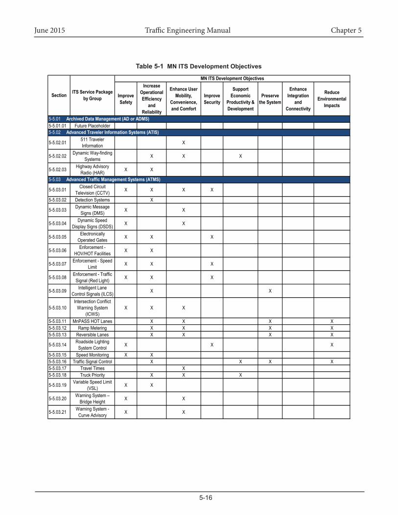
The systems listed here are not all inclusive. The types of systems being deployed in Minnesota and across the country increase every day. Table 5.1 on the following 2 pages is organized by market package group from the Minnesota Statewide Regional ITS Architecture. The Statewide Architecture has established eight ITS developmentobjectives,listedasheadingsacrossthetopofthetable.ThetableillustrateshoweachoftheITSServicePackagesrelatestoeachoftheobjectives.
June 2015 Traffic Engineering Manual Chapter 5
5-16
Table 5-1 MNITSDevelopmentObjectives
Improve Safety
Increase Operational Efficiency
and Reliability
Enhance User Mobility,
Convenience, and Comfort
Improve Security
Support Economic
Productivity & Development
Preserve the System
Enhance Integration
and Connectivity
Reduce Environmental
Impacts
5-5.01.01 Future Placeholder
5-5.02.01 511 Traveler Information X
5-5.02.02 Dynamic Way-finding Systems X X X
5-5.02.03 Highway Advisory Radio (HAR) X X
5-5.03.01 Closed Circuit Television (CCTV) X X X X
5-5.03.02 Detection Systems X
5-5.03.03 Dynamic Message Signs (DMS) X X
5-5.03.04 Dynamic Speed Display Signs (DSDS) X X
5-5.03.05 Electronically Operated Gates X X X
5-5.03.06 Enforcement - HOV/HOT Facilities X X
5-5.03.07 Enforcement - Speed Limit X X X
5-5.03.08 Enforcement - Traffic Signal (Red Light) X X X
5-5.03.09 Intelligent Lane Control Signals (ILCS) X X
5-5.03.10Intersection Conflict
Warning System (ICWS)
X X X
5-5.03.11 MnPASS HOT Lanes X X X X5-5.03.12 Ramp Metering X X X X5-5.03.13 Reversible Lanes X X X X
5-5.03.14 Roadside Lighting System Control X X X
5-5.03.15 Speed Monitoring X X5-5.03.16 Traffic Signal Control X X X X5-5.03.17 Travel Times X5-5.03.18 Truck Priority X X X
5-5.03.19 Variable Speed Limit (VSL) X X
5-5.03.20 Warning System – Bridge Height X X
5-5.03.21 Warning System - Curve Advisory X X
5-5.03 AdvancedTrafficManagementSystems(ATMS)
Section ITS Service Package by Group
MNITSDevelopmentObjectives
5-5.01 ArchivedDataManagement(ADorADMS)
5-5.02 AdvancedTravelerInformationSystems(ATIS)
June 2015 Traffic Engineering Manual Chapter 5
5-17
Improve Safety
Increase Operational Efficiency
and Reliability
Enhance User Mobility,
Convenience, and Comfort
Improve Security
Support Economic
Productivity & Development
Preserve the System
Enhance Integration
and Connectivity
Reduce Environmental
Impacts
5-5.03.22 Warning System - Foggy Conditions X X
5-5.03.23Warning System -
Highway-Rail Grade Crossing
X X
5-5.03.24 Warning System - Icy Pavement Conditions X X
5-5.03.25Warning System - Ramp/Curve Truck
RolloverX X
5-5.03.26Warning System - Stopped or Slow
Traffic AheadX X
5-5.03.27 Warning System – Water on Road X X
5-5.03.28 Warning System – Wildlife X X
5-5.03.29 Wrong Way Movements X X
5-5.04.01 Transit Signal Priority X X X
5-5.04.02 Real-Time Arrival System X X X
5-5.04.03 Transit Customer Information System X X X
5-5.05.01 Weigh-in Motion X X X
5-5.06.01 Future Placeholder X
5-5.07.01 Intelligent Work Zones X x X
5-5.07.02Road and Weather
Information Systems (RWIS)
X X
5-5.07.03Work Zone Accident
Reduction Deployment (WZARD)
X X
5-5.07.04 CAD / AVL x x x
5-5.08.01 Future Placeholder X
5-5.06 EmergencyManagement(EM)
5-5.07 MaintenanceandConstructionManagement(MCM)
5-5.08 AdvancedVehicleSafetySystems(AVSS)
Section ITS Service Package by Group
MNITSDevelopmentObjectives,cont.
5-5.04 AdvancedPublicTransportationSystems(APTS)
5-5.05 CommercialVehicleOperations(CVO)
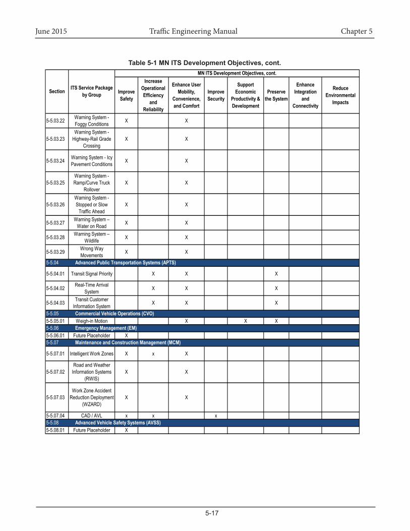
Table5-1MNITSDevelopmentObjectives,cont.
June 2015 Traffic Engineering Manual Chapter 5
5-18
5-5.01ArchivedDataManagement(AD)See the MN Regional ITS Architecture for a complete listing of AD Service Packages.
5-5.01.01 Future Placeholder
5-5.02AdvancedTravelerInformationSystems(ATIS)See the MN Regional ITS Architecture for a complete listing of ATIS Service Packages. The following sections highlight several more common applications.
5-5.02.01 511 Traveler Information
DefinitionTheMinnesotaDepartmentofTransportation’s511TravelerInformationSystemprovidesreal-time,accuratetrafficinformationaboutcurrentroadconditions,including:
• Weather related road conditions• Trafficcrashesandincidents• Construction and maintenance locations and information• Trafficspeeds• Trafficcameraviews• Oversize/overweight truck restrictions.
Purpose and UsageThe Minnesota Department of Transportation’s 511 Traveler Informationwebsites,511Appandphoneprovidesthetravelingpublicwithup-to-dateroadreports24hoursaday,sevendaysaweek. Theprogramallowstravelers to signup fora ‘PersonalizeYour511’account that featuresspecific routes tailored to travelers’needs. The 511 program offers the traveling public a wide range of options in planning their travels.
Components UsedTypical components used for MnDOT’s 511 Traveler Information System include the items listed below. See the ITS Design Manual for further discussion of the components and design considerations.
• Communications• IRIS
5-5.02.02 Dynamic Way-Finding Systems
DefinitionThissystemprovidesguidancetospecificdestinationsbasedonreal-timetrafficconditions.
Purpose and UsageThesesystemsareusedtoguidethemotoringpublic.Basedonreal-timetrafficconditions,messageswouldbedisplayedonfielddevicesandonwebsitesprovidingrecommendationsforthebestroutetothedestination.Thesemessagescouldbegeneratedbytrafficmanagementcenteroperators,orthroughtheuseofcontrolsoftwarethatwouldautomaticallyselecttheroutebasedoncurrentconditions.InMinnesota,dynamicway-findingsystemshavebeendeployedforparkingavailabilityindowntownSt.Paul,andinBloomingtonontheregional system around the Mall of America.
Components UsedTypical components used for a Dynamic Way-Finding System include the items listed below. See the ITS Design Manual for further discussion of the components and design considerations.
• DMS or Hybrid Signing• Communications• Power• Surveillance and/or Detection• Manual Control or control software to select route
June 2015 Traffic Engineering Manual Chapter 5
5-19
5-5.02.03 Highway Advisory Radio (HAR)
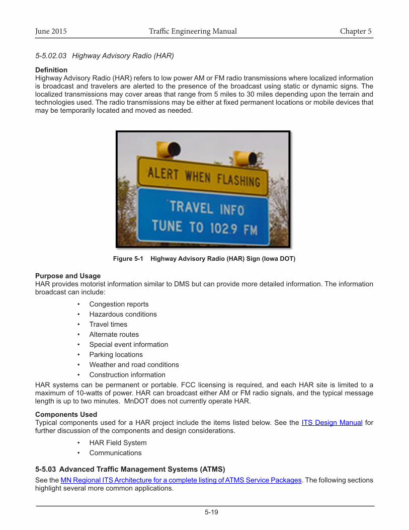
DefinitionHighway Advisory Radio (HAR) refers to low power AM or FM radio transmissions where localized information is broadcast and travelers are alerted to the presence of the broadcast using static or dynamic signs. The localized transmissions may cover areas that range from 5 miles to 30 miles depending upon the terrain and technologiesused.Theradiotransmissionsmaybeeitheratfixedpermanentlocationsormobiledevicesthatmay be temporarily located and moved as needed.
Figure 5-1 HighwayAdvisoryRadio(HAR)Sign(IowaDOT)
Purpose and UsageHAR provides motorist information similar to DMS but can provide more detailed information. The information broadcast can include:
• Congestion reports• Hazardous conditions• Travel times• Alternate routes• Special event information• Parking locations• Weather and road conditions• Construction information
HARsystemscanbepermanentorportable.FCC licensing is required,andeachHARsite is limited toamaximumof10-wattsofpower.HARcanbroadcasteitherAMorFMradiosignals,andthetypicalmessagelength is up to two minutes. MnDOT does not currently operate HAR.
Components Used TypicalcomponentsusedforaHARproject includetheitemslistedbelow.Seethe ITS Design Manual for further discussion of the components and design considerations.
• HAR Field System• Communications
5-5.03AdvancedTrafficManagementSystems(ATMS)See the MN Regional ITS Architecture for a complete listing of ATMS Service Packages. The following sections highlight several more common applications.
June 2015 Traffic Engineering Manual Chapter 5
5-20
5-5.03.01 Closed Circuit Television (CCTV)
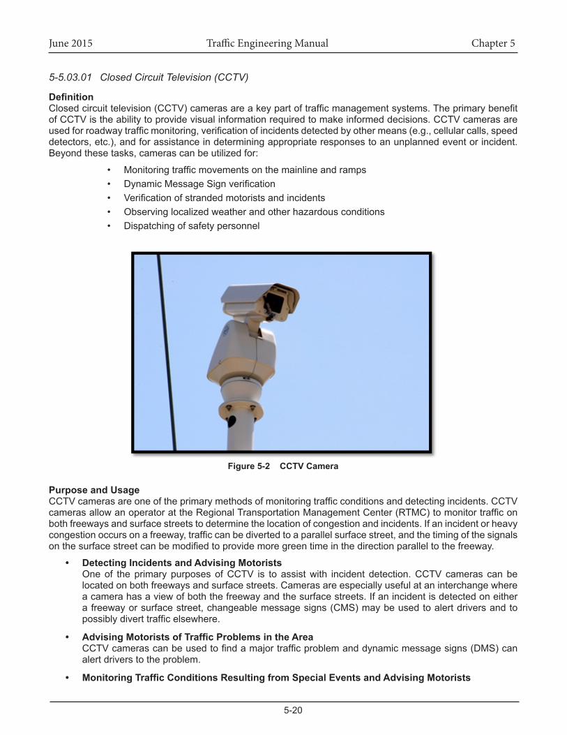
DefinitionClosedcircuittelevision(CCTV)camerasareakeypartoftrafficmanagementsystems.Theprimarybenefitof CCTV is the ability to provide visual information required to make informed decisions. CCTV cameras are usedforroadwaytrafficmonitoring,verificationofincidentsdetectedbyothermeans(e.g.,cellularcalls,speeddetectors,etc.),andforassistanceindeterminingappropriateresponsestoanunplannedeventorincident.Beyondthesetasks,camerascanbeutilizedfor:
• Monitoringtrafficmovementsonthemainlineandramps• DynamicMessageSignverification• Verificationofstrandedmotoristsandincidents• Observing localized weather and other hazardous conditions• Dispatching of safety personnel
Figure 5-2 CCTV Camera
Purpose and UsageCCTVcamerasareoneoftheprimarymethodsofmonitoringtrafficconditionsanddetectingincidents.CCTVcamerasallowanoperatorattheRegionalTransportationManagementCenter(RTMC)tomonitortrafficonboth freeways and surface streets to determine the location of congestion and incidents. If an incident or heavy congestionoccursonafreeway,trafficcanbedivertedtoaparallelsurfacestreet,andthetimingofthesignalsonthesurfacestreetcanbemodifiedtoprovidemoregreentimeinthedirectionparalleltothefreeway.
• Detecting Incidents and Advising MotoristsOne of the primary purposes of CCTV is to assist with incident detection. CCTV cameras can be located on both freeways and surface streets. Cameras are especially useful at an interchange where a camera has a view of both the freeway and the surface streets. If an incident is detected on either afreewayorsurfacestreet,changeablemessagesigns(CMS)maybeusedtoalertdriversandtopossiblydiverttrafficelsewhere.
• AdvisingMotoristsofTrafficProblemsintheAreaCCTVcamerascanbeusedtofindamajortrafficproblemanddynamicmessagesigns(DMS)canalert drivers to the problem.
• MonitoringTrafficConditionsResultingfromSpecialEventsandAdvisingMotorists
June 2015 Traffic Engineering Manual Chapter 5
5-21
CCTVcamerasandDMS(s)areuseful duringspecial events,bothplanned (suchasaconcert orafootballgame),aswellasunplannedemergencies(suchasaterroristattackorastorm).Specialeventscreatetrafficpatternsthatarequitedifferentfromnormal.Manydriversgoingtoaspecialeventmaynotnormallydrive through thecorridor inquestion,andarenot familiarwithalternate routes.Roadwayand laneconfigurationsmaybedifferent; forexample,anormally two-way roadmaybeconvertedtoone-wayinthepeakdirection,oraroadmaybeclosedforsecurityreasonsortoprovideaccess for emergency vehicles.
• Assisting with Parking InformationCCTVcameras,aswellasothertechnologies,canmonitoralargeparkinglottodeterminewhichlotsorsectionsarefull,andCMS(s)(orothermethodsofinformationdissemination)cannotifydriversastowhichparkinglotsarefullorclosed,andtodirectdriverstoparkinglotsthathaveavailablecapacity.
Components Used TypicalcomponentsusedforaCCTVprojectincludetheitemslistedbelow.SeetheITS Design Manual for further discussion of the components and design considerations.
• Camera System• CCTV Mounting• Management System Control Software• Control Cabinet• Power• Communications
5-5.03.02 Detection Systems
DefinitionThedifferenttypesofvehicledetectorsavailableinclude,butarenotlimitedto,thefollowingtypes.
1. Intrusive Detection (in-roadway)• Inductive loop detects a change in resonant frequency by the introduction of a metal in the
magneticfieldofthedetectionzone.• Magnetic/Magnetometerdetectsmovingferrousmetalobjects–pulse.• Microloopdetectsachangebymovingmetal in theearth’smagneticfield–pulse.Small
inductive loop placed on top of a magnetometer.2. Non-IntrusiveDetection(aboveroadwayorsidefire)
• Photo electric/Infrared/laser detects a break in a beam of light – presence or pulse.• Radar/Microwavedetectsmovingobjectsbysendingandreceivingelectronicpulses–pulse.• Ultrasonicdetectssoundwithamicrophone–presenceorpulse.• Video detects a change in a video pixel range – presence or pulse.• Combinationsystems,i.e.combiningvideoandradar.
Normal loop or magnetic detectors will operate in either the pulse mode or presence mode. The magnetic detectorproducesashortoutputpulsewhendetectionoccurs,nomatterhowlongthevehicleremainsinthedetectionarea.Thenormalloopisintendedtoproduceadetectoroutputforaslongasavehicleisinthefieldof detection.
Non-intrusivedetectortechnologiesincludeactiveandpassiveinfrared,microwaveradar,ultrasonic,passiveacoustic, laser, and video image processing.Active infrared, microwave radar, and ultrasonic are activedetectorsthattransmitwaveenergytowardatargetandmeasurethereflectedwave.Passiveinfrared,passiveacoustic,andvideoimageprocessingarepassivedetectorsthatmeasuretheenergyemittedbyatargetorthe image of the detection zone.
Trafficdetectionsystemsplay importantrolesnotonly intraditional transportationmanagementbutalso inadvancedtransportationmanagementsystems.Trafficdetectionsystemsprovidedatatomeetdifferentneedsintransportationfields.
June 2015 Traffic Engineering Manual Chapter 5
5-22
Purpose and UsageThecontroloftrafficrelatestothemovementofvehiclesandpedestrians.Sincethevolumeofthesemovementsgenerallyvariesatdifferenttimesoftheday,itisdesirabletobeabletodetectapproachingmovementsbyplacing one or more devices in the path of approaching vehicles or at a convenient location for the use of pedestrians.
MostadvancedmanagementsystemsandtechnologiesintheITSfieldrelyonreal-timetrafficdata,whichreflectscurrentconditionsoftrafficnetwork.Trafficdetectionisacriticalpartinmanyadvancedtrafficsystems,such as responsive ramp metering control and freeway incident detection.
Ramp metering control is the most common technology for reducing freeway congestion. The system measures freewaymainlinecapacityandtrafficflow,andcontrolstherateatwhichvehiclesenterthefreewaymainline.Manystudiesshow that rampmetering increases freewayefficiency,and reducesaccidentsand recurringcongestion.
In freeway incidentmanagementsystems,detectorsgenerallyareused todetect two typesofcongestion:recurringandnonrecurring.Recurringcongestionispredictableatspecificlocationsandtimes.Nonrecurringcongestioniscausedbyrandom,temporaryincidents,suchasaccidentsandotherunpredictableevents.
Traffic detector technologies are continuously incorporated into new ITS application fields. For example,aportable intelligent transportationsystemprovides traveler information inspecificsites to improvesafetyand operation in work zones. A computerized control system integrates detector (speed sensor) and traveler information dissemination technologies. The control system automatically determines appropriate responses accordingtocurrenttrafficconditions.
Another type of detection is the “speed analysis system”. This system is a hardware assembly composed of two loop detectors and auxiliary logic. The two loops are installed in the same lane a precise distance apart. Avehiclepassingovertheloopsproducestwoactuations.Thetimeintervalbetweenthefirstandthesecondactuation is measured to determine vehicle speed.
Newerinductive-loopdetectorelectronicsunitsandloopconfigurationsarecapableofvehicleclassification.Theelectronicsmoduleusesartificialneuralnetworksoftwaretoclassifythetrafficstreamintothe23categories
Components UsedTypicalcomponentsusedforaCCTVprojectincludetheitemslistedbelow.SeetheITS Design Manual for further discussion of the components and design considerations.
• Detection System (intrusive or non-intrusive)• Control Cabinet• Power• Communications
June 2015 Traffic Engineering Manual Chapter 5
5-23
5-5.03.03 Dynamic Message Signs (DMS)
DefinitionAnysignsystemthatcanchangethemessagepresentedtotheviewersuchasVariableMessageSign(VMS),ChangeableMessageSign(CMS),andBlank-OutSign(BOS).
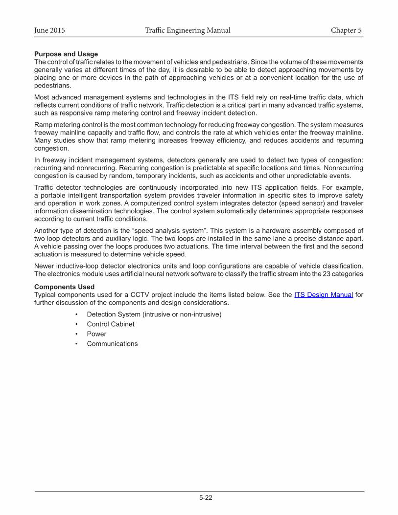
Figure 5-3 Example Dynamic Message Sign
Purpose and UsageAdynamicmessagesignisanelectronictrafficsignoftenusedonroadwaystogivetravelersinformationaboutspecialevents.Suchsignswarnoftrafficcongestion,accidents,incidents,roadworkzones,orspeedlimitsonaspecifichighwaysegment.Inurbanareas,DMSareusedwithinparkingguidanceandinformationsystemstoguidedriverstoavailablecarparkingspaces.Theymayalsoaskvehiclestotakealternativeroutes,limittravelspeed,warnofdurationandlocationoftheincidentsorjustinformofthetrafficconditions.
Acompletemessageonapanelgenerallyincludesaproblemstatementindicatingincident,roadwork,stalledvehicle etc.; a location statement indicating where the incident is located; an effect statement indicating lane closure,delay,etc.andanactionstatementgivingsuggestionwhattodotrafficconditionsahead.Thesesignsare also used for AMBER Alert messages.
Components Used TypicalcomponentsusedforaDMSprojectincludetheitemslistedbelow.SeeITS Design Manual for further discussion of the components and design considerations.
• Dynamic Message Sign• Management System Control Software• Control Cabinet• Power• Communications
June 2015 Traffic Engineering Manual Chapter 5
5-24
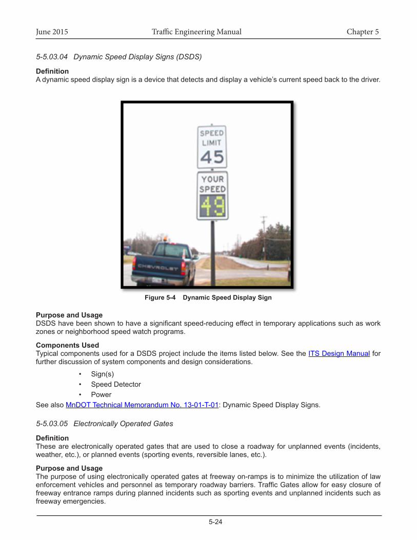
5-5.03.04 Dynamic Speed Display Signs (DSDS)
DefinitionA dynamic speed display sign is a device that detects and display a vehicle’s current speed back to the driver.
Figure 5-4 Dynamic Speed Display Sign
Purpose and UsageDSDShavebeenshowntohaveasignificantspeed-reducingeffectintemporaryapplicationssuchasworkzones or neighborhood speed watch programs.
Components Used TypicalcomponentsusedforaDSDSprojectincludetheitemslistedbelow.SeetheITS Design Manual for further discussion of system components and design considerations.
• Sign(s)• Speed Detector• Power
See also MnDOT Technical Memorandum No. 13-01-T-01: Dynamic Speed Display Signs.
5-5.03.05 Electronically Operated Gates
DefinitionTheseareelectronicallyoperatedgatesthatareusedtoclosearoadwayforunplannedevents(incidents,weather,etc.),orplannedevents(sportingevents,reversiblelanes,etc.).
Purpose and UsageThe purpose of using electronically operated gates at freeway on-ramps is to minimize the utilization of law enforcementvehiclesandpersonnelastemporaryroadwaybarriers.TrafficGatesallowforeasyclosureoffreeway entrance ramps during planned incidents such as sporting events and unplanned incidents such as freeway emergencies.
June 2015 Traffic Engineering Manual Chapter 5
5-25
Examples of electronically operated gates include:
• Interstate and non-interstate snow and ice closure gates• Interstate 394 gate for reversible HOV• Gatesattransitstationstocontroltransitflow• Battery backup may be used for electronically operated gates.
Components UsedTypicalcomponentsusedforanelectronicallyoperatedgateprojectincludetheitemslistedbelow.Seethe ITS Design Manual for further discussion of system components and design considerations.
• Foundation• Gate Pole and Arm with electronic mechanism• Management System Control Software• Control Cabinet• Power• Communications
5-5.03.06 Enforcement - HOV/HOT Facilities
DefinitionThesesystemsprovidepoliceofficersadditionalinformationtoenforcecompliancewithHOV/HOTLanefacilityrequirements.
Purpose and UsageThisisacurrentInnovativeIdeaproject.
Components UsedThis section is reserved for future manual updates.
5-5.03.07 Enforcement - Speed Limit
DefinitionThese systems provide photo enforcement for speeding at locations where there is a history of crashes with excessive speed as a contributing factor or in work zones.
Purpose and UsageThis section is reserved for future manual updates.
Components UsedThis section is reserved for future manual updates.
5-5.03.08 Enforcement – Traffic Signal Red Light Enforcement Enhancement
DefinitionThesearesystemsthatwillprovidepoliceofficerswithphotoevidenceorotherdatatoverifyredlightrunningviolations.
Purpose and UsageThis system represents portable or permanent photo/surveillance systems located at intersections with high crash rates. The purpose is to inform and educate the traveling public of the dangers of running red lights. The system is planned for MnDOT District 6 and evaluated in District 3.InDistrict3,theprojectprovidedon-siteofficerswithphotoandvideoevidencethatcouldbeusedatthetimeof the infraction to verify the violation.
Components UsedThis section is reserved for future manual updates.
June 2015 Traffic Engineering Manual Chapter 5
5-26
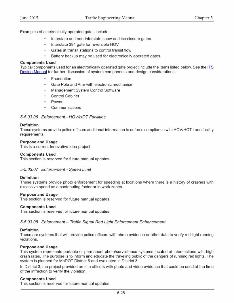
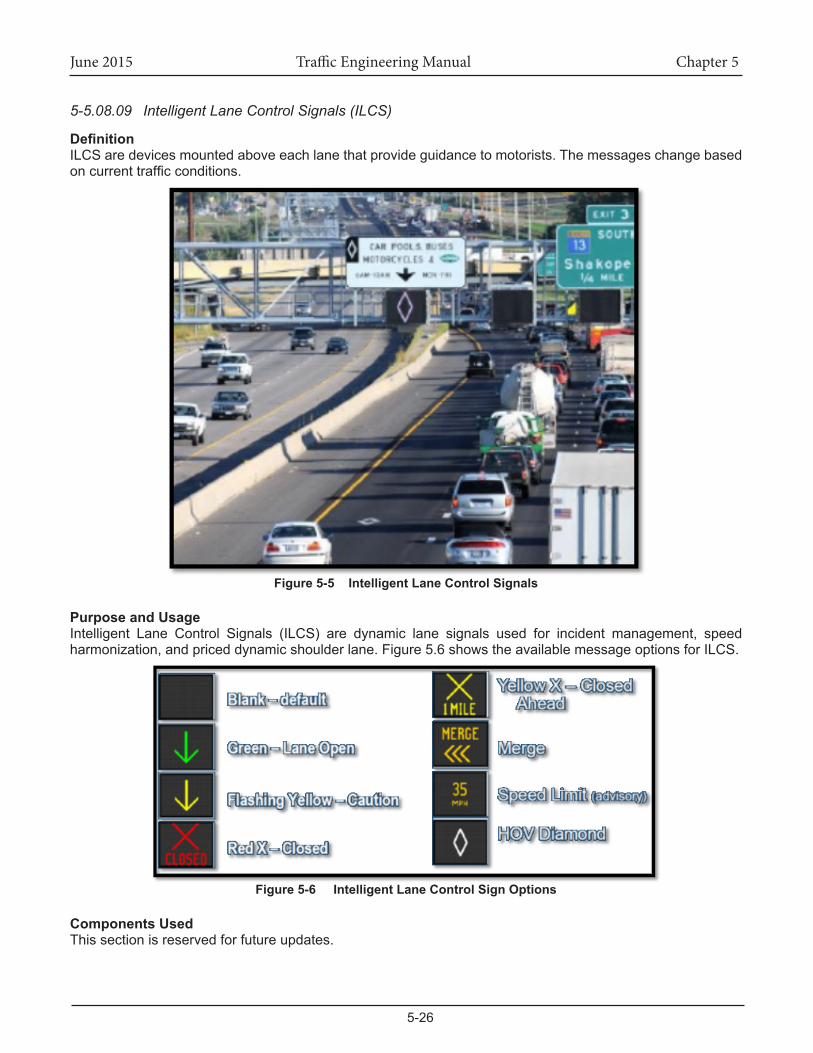
5-5.08.09 Intelligent Lane Control Signals (ILCS)
DefinitionILCS are devices mounted above each lane that provide guidance to motorists. The messages change based oncurrenttrafficconditions.
Figure 5-5 Intelligent Lane Control Signals
Purpose and UsageIntelligent Lane Control Signals (ILCS) are dynamic lane signals used for incident management, speedharmonization,andpriceddynamicshoulderlane.Figure5.6showstheavailablemessageoptionsforILCS.
Figure 5-6 Intelligent Lane Control Sign Options
Components UsedThis section is reserved for future updates.
June 2015 Traffic Engineering Manual Chapter 5
5-27
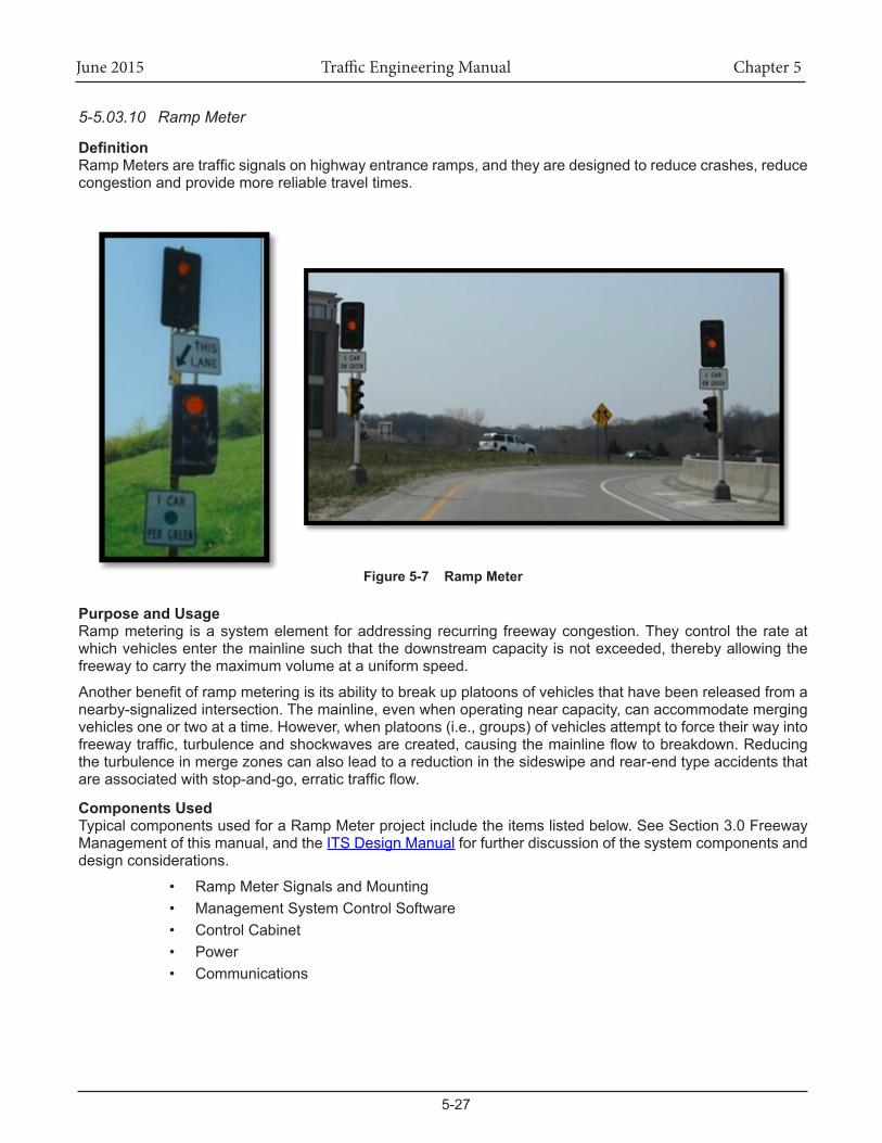
5-5.03.10 Ramp Meter
DefinitionRampMetersaretrafficsignalsonhighwayentranceramps,andtheyaredesignedtoreducecrashes,reducecongestion and provide more reliable travel times.
Figure 5-7 Ramp Meter
Purpose and UsageRamp metering is a system element for addressing recurring freeway congestion. They control the rate at whichvehiclesenterthemainlinesuchthatthedownstreamcapacityisnotexceeded,therebyallowingthefreeway to carry the maximum volume at a uniform speed.
Anotherbenefitoframpmeteringisitsabilitytobreakupplatoonsofvehiclesthathavebeenreleasedfromanearby-signalizedintersection.Themainline,evenwhenoperatingnearcapacity,canaccommodatemergingvehiclesoneortwoatatime.However,whenplatoons(i.e.,groups)ofvehiclesattempttoforcetheirwayintofreewaytraffic,turbulenceandshockwavesarecreated,causingthemainlineflowtobreakdown.Reducingthe turbulence in merge zones can also lead to a reduction in the sideswipe and rear-end type accidents that areassociatedwithstop-and-go,erratictrafficflow.
Components Used TypicalcomponentsusedforaRampMeterprojectincludetheitemslistedbelow.SeeSection3.0FreewayManagementofthismanual,andtheITS Design Manual for further discussion of the system components and design considerations.
• Ramp Meter Signals and Mounting• Management System Control Software• Control Cabinet• Power• Communications
June 2015 Traffic Engineering Manual Chapter 5
5-28
5-5.03.11 Reversible Lanes
DefinitionAreversiblelaneisalaneinwhichtrafficmaytravelineitherdirectiondependingontrafficflowpatterns.
Purpose and UsageThe reversible lanes on I-394 are separated from the general purpose lanes and are controlled by signs and automatedgates.Theflowisreversedforthemorningandafternoonpeakperiods.
Components UsedComponents include:
• Automated gates• DMS• Communications• Power
5-5.03.12 Roadside Lighting System Control
DefinitionThese systems manage electrical systems by monitoring operation conditions and using the lighting controls to carry the amount of light provided along the roadside. These systems allow a center to control lights based ontrafficconditions,timeofday,andtheoccurrenceofincidents.
Purpose and UsageThese systems can increase the safety of a roadway segment by increasing lighting and conserve energy at times when conditions warrant a reduction in the amount of lighting.
Components UsedThe roadway lightingsystemwillbeable tobecontrolled through theRTMC’sfiberopticsystem.Lightinglevels and intensities can be controlled remotely.
5-5.03.13 Speed Monitoring
DefinitionAsystemusedtomonitortrafficspeedsontheroadways.
Purpose and UsageEveryFederalFiscalYear(OctoberthroughSeptember),quarterlyandannualspeedmonitoringreportsarepreparedbyMnDOT’sOfficeofTraffic,Safety,andTechnology(OTST)andsubmittedtotheFederalHighwayAdministration (FHWA) Division Administrator. The results of this program are used to determine speed trends throughouttheUnitedStates.AdditionalreportsaresenttotheCommissioner,allMnDOTDistricts,theMnDOTLibrary,theDepartmentofPublicSafety,andtheLegislativeReferenceLibrary.
Variousmethodsarecurrentlybeingused for thecollectionofdata.Radar transmissiondevices,althoughuseful incertainsituations,arenotused in thespeedmonitoringprogramduetomanpowerrequirements.Below is a list of speed data collection devices.
Weigh-In-Motion (WIM) Stations• These devices are located throughout the State and collect a variety of data including the
weight and speed of vehicles. The information is collected automatically.AutomaticTrafficRecorders(ATR)Sites
• ATRs automatically collect information by means of in-pavement loop detectors. ATRs are located throughout the State and are typically used to determine vehicle counts. A small number of them have been installed to allow the collection of speed data.
Portabledatacollectionmachineswithroadtubes,in-pavementloopdetectors,orportablemagneticsensing devices.
June 2015 Traffic Engineering Manual Chapter 5
5-29
• This method of data collection requires the placement of a sensing device on the road surface which connects to the data collection machine located off the road. This method is undesirable due to manpower requirements.
Components UsedSpeedmonitoringsystemcomponents includeadevice tomeasurespeed,suchas radar, loopdetectors,videodetection, andportable data collectiondevices suchaspneumatic tubes.The systemalso typicallyrequiresapowersource,communications,andacabinetwithcontroldevice/software.Seethe ITS Design Manual for further discussion of system components and design considerations.
5-5.03.14 Tolling - MnPASS HOT Lanes
DefinitionI-394,onthewestsideoftheTwinCities,andI-35W,southofMinneapolis,operatesaHighOccupancyToll(HOT) lane. Carpoolers may use the lane for free and single occupant vehicles may opt to pay a toll to use the lane. The toll charged to single occupant vehicles varies according to conditions. The ongoing operations allows for toll collection to be entirely automated (no manual fare collection).
Purpose and UsageThe purpose of this type of project is to improve travel times and reduce congestion for users along thehighway, and to provideanuncongestedexpress lane for highoccupancy vehiclesand single-occupancyvehiclespayinganelectronictoll.DriversthatusetheMnPASSExpressLanewillexperienceimprovedtrafficflow,reducedcongestion,andbettercommutetimesalongtheroute.
Components UsedThis section is reserved for future manual updates.
5-5.03.15 Traffic Signal Control
DefinitionSeeTrafficSignals,Chapter9ofthismanual.
Purpose and UsageSeeTrafficSignals,Chapter9ofthismanual.
Components UsedSeeTrafficSignals,Chapter9ofthismanual.
5-5.03.16 Travel Times
DefinitionSystems that calculate and disseminate travel times between two points on freeways and non-freeways in a real-time format.
Purpose and UsageIntheMetroarea,theMinnesotaDepartmentofTransportation(MnDOT)calculatesanddisseminatesfreewaytravel times based upon freeway loop detector data. Currently there is not an operational approach toward monitoring or disseminating arterial travel times throughout the Twin Cities. Several recent initiatives now underway,includingtheperformancebasedmeasuresrequiredbyMAP-21,identifytheneedfortraveltimereporting on arterial routes. A key element to Integrated Corridor Management (ICM) is to present travelers withtraveltimecomparisonsforfreeways,arterials,andtransit.MnDOThasexploredseveraloptionsforcosteffective arterial travel time monitoring and estimation.
Components UsedFreewayTravelTimesinthemetroareausefrequentlyspacedloopdetectors,controlcabinets,andafiberopticcablebackbonetocollectdata.AnalgorithmwithintheIRISsoftwarecalculatesthetraveltimedata,anddisplays messages on DMS as desired.
June 2015 Traffic Engineering Manual Chapter 5
5-30
Non-freeway travel time systems that have been tested by MnDOT include:
• SMART-Signal (signalized arterials)• SENSYS Systems• Bluetooth Data• INRIX• Commercial Probe Data• CellPhoneTrafficData• MATT (signalized arterials)• Rural Travel Times During Construction (rural highways)
5-5.03.17 Truck Priority
DefinitionTruckPriorityisasystemtogranttrucksprioritytreatmentatspecifiedsignalizedintersections,typicallytwo-lane highways. Currently there is a truck priority system in use in Sherburne County at Trunk Highway 24 and CSAH 8.
Purpose and UsageTruckPriority isameansto improvetheoperationofheavytruckspassingthroughtrafficsignalcontrolledintersections on rural high-speed highways by detecting the presence of trucks and extending the green time sufficientlyforthetrucktopassthroughtheintersection.
Components UsedThe truck priority system components include two loop detectors spaced 30 feet apart (or other detection that candistinguishheavycommercialvehicles)connected to the trafficsignalcabinet. TruckPriority requiresadditionallogicprogramedintothetrafficsignalcontroller.
June 2015 Traffic Engineering Manual Chapter 5
5-31
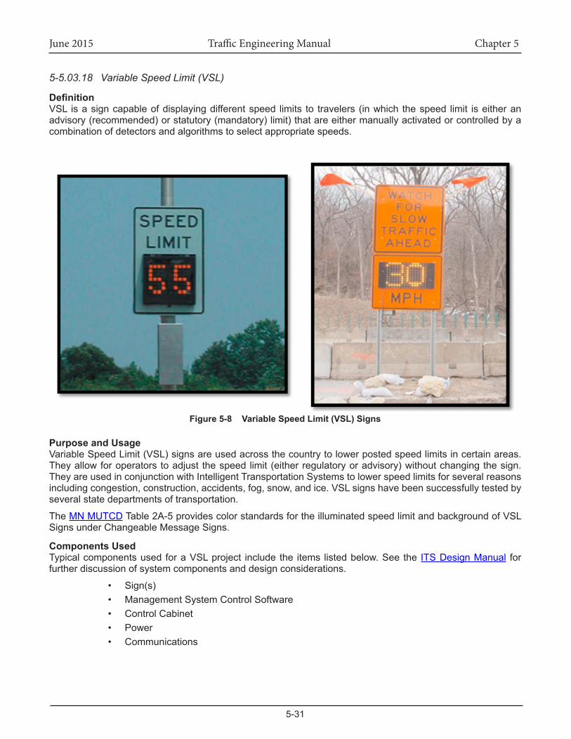
5-5.03.18 Variable Speed Limit (VSL)
DefinitionVSL is a sign capable of displaying different speed limits to travelers (in which the speed limit is either an advisory (recommended) or statutory (mandatory) limit) that are either manually activated or controlled by a combination of detectors and algorithms to select appropriate speeds.
Figure 5-8 VariableSpeedLimit(VSL)Signs
Purpose and UsageVariable Speed Limit (VSL) signs are used across the country to lower posted speed limits in certain areas. Theyallowforoperatorstoadjust thespeedlimit(eitherregulatoryoradvisory)withoutchangingthesign.TheyareusedinconjunctionwithIntelligentTransportationSystemstolowerspeedlimitsforseveralreasonsincludingcongestion,construction,accidents,fog,snow,andice.VSLsignshavebeensuccessfullytestedbyseveral state departments of transportation.
The MNMUTCD Table 2A-5 provides color standards for the illuminated speed limit and background of VSL Signs under Changeable Message Signs.
Components Used TypicalcomponentsusedforaVSLproject includethe items listedbelow.Seethe ITS Design Manual for further discussion of system components and design considerations.
• Sign(s)• Management System Control Software• Control Cabinet• Power• Communications
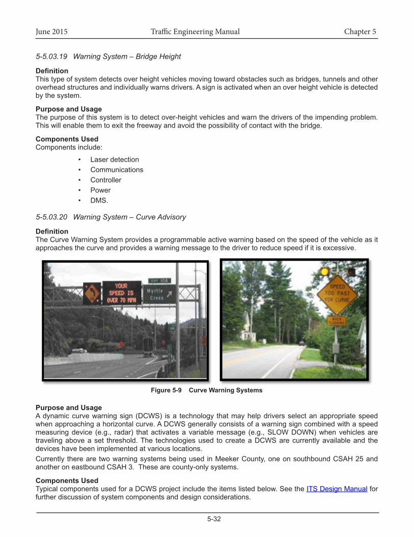
June 2015 Traffic Engineering Manual Chapter 5
5-32
5-5.03.19 Warning System – Bridge Height
DefinitionThistypeofsystemdetectsoverheightvehiclesmovingtowardobstaclessuchasbridges,tunnelsandotheroverhead structures and individually warns drivers. A sign is activated when an over height vehicle is detected by the system.
Purpose and UsageThe purpose of this system is to detect over-height vehicles and warn the drivers of the impending problem. This will enable them to exit the freeway and avoid the possibility of contact with the bridge.
Components UsedComponents include:
• Laser detection• Communications• Controller• Power• DMS.
5-5.03.20 Warning System – Curve Advisory
DefinitionThe Curve Warning System provides a programmable active warning based on the speed of the vehicle as it approaches the curve and provides a warning message to the driver to reduce speed if it is excessive.
Figure 5-9 Curve Warning Systems
Purpose and UsageA dynamic curve warning sign (DCWS) is a technology that may help drivers select an appropriate speed when approaching a horizontal curve. A DCWS generally consists of a warning sign combined with a speed measuringdevice (e.g., radar) thatactivatesa variablemessage (e.g.,SLOWDOWN)whenvehiclesaretraveling above a set threshold. The technologies used to create a DCWS are currently available and the devices have been implemented at various locations. Currently therearetwowarningsystemsbeingused inMeekerCounty,oneonsouthboundCSAH25andanother on eastbound CSAH 3. These are county-only systems.
Components Used TypicalcomponentsusedforaDCWSprojectincludetheitemslistedbelow.SeetheITS Design Manual for further discussion of system components and design considerations.
June 2015 Traffic Engineering Manual Chapter 5
5-33
• Warning Sign• Detection to Determine Speed• Management System Control Software• Control Cabinet• Power• Communications
5-5.03.21 Warning System – Foggy Conditions
DefinitionThis type of system is a highway visibility sensor that measures the density of roadway fog and is linked to traveler information systems.
Purpose and UsageTheneedforahighwayfogwarningsystemhaslongbeeninternationallyrecognized.Withsuchasystem,motoristscanavoidtragicpile-upaccidentscausedbydenseorpatchyfog,whichareoftenfatal.MnDOT does not currently use this system.
Components UsedThis section is reserved for future manual updates.MnDOT does not currently ha
5-5.03.22 Warning System – Highway Rail Grade Crossing
DefinitionThis element represents roadside equipment that alerts motorists of railroad crossings at at-grade intersections. Gates are activated and deactivated as trains are detected approaching and clearing the intersection.
Purpose and UsageThis section is reserved for future manual updates.
Components UsedThis section is reserved for future manual updates.
5-5.03.23 Warning System – Icy Conditions
DefinitionThissystemdetectsconditionswhereicemaybeformingonthepavement,andprovidesnotificationtodriversof this condition.
Purpose and UsageWarning systems for icy conditions are generally installed in locations where experience has shown that icyconditionsarere-occurring,andthatthepotentialforcrashesishigh.Thesystemusesgroundsensorsinstalledintheroadsurface.Thesensorsmeasure(amongotherparameters)thesurfacetemperature,thefreezingpoint temperature, and thepavement surface condition (dry, damp,wet, slippery becauseof ice,black-ice,hoarfrost,orsnow).
Whenicyconditionsareidentified,notificationisgiventothepublicviaDMS,staticsignswithflashingbeacons,and/ormaintenancecrewsarenotifiedofthecondition.MnDOTcurrentlyoperatesastaticwarningsignsystemwithflashingbeaconsonI-35inBurnsvillenexttothe Buck Hill Ski Area. This system is activated by the Regional Transportation Management Center (RTMC) based on communication from Buck Hill staff when snow making operations are being employed.There is also a static sign warning system in Wright County on Trunk Highway 12 between the cities of Dassel and Cokato.
June 2015 Traffic Engineering Manual Chapter 5
5-34
Components UsedComponents include:
• Pavement sensors capable of detecting icy conditions• Power• Control software• DMS• Communications back to a maintenance facility• Staticsignswithflashingbeacons
5-5.03.24 Warning System - Ramp/Curve Truck Rollover
DefinitionRamp/Curve Truck Rollover Warning Systems provide warning to commercial vehicles as they enter a curve or ramp at a speed that is likely to cause a rollover.
Purpose and UsageThe purpose of these systems is to reduce truck rollovers in locations that have a history of this type of incident. MnDOT’s Metro District has installed a system in Washington County at an interchange ramp located atthejunctionofI-694/I-94/I-494andwillbeinstallingasystemonI-94attheLowryHillTunnelinMinneapolis.
Components UsedTypical components used for a Ramp/Curve Truck Rollover Warning System include the items listed below.
• Non-intrusive detection• Weigh-in-motion (WIM) sensors• Loops• Blank out signs with warning beacons or dynamic message signs with warning beacons• Communication systems• Power
One particular type of warning system gathers information on heavy commercial vehicles using WIM technology. This system collects and instantaneously analyses data to determine if a vehicle is traveling too fast for the roadwaygeometry.Ifso,theoperatoriswarnedviaadynamicmessagesign.
Another system gathers information based on vehicle height and speed. If a vehicle determined to be above adefinedheighttravelsataspeedgreaterthanapredeterminedspeed,thevehicleoperatorwillbewarnedvia a dynamic message sign.
5-5.03.25 Warning System - Stopped or Slow Traffic Ahead
DefinitionThissystemprovideswarningtomotoristsaboutstoppedorslowtrafficahead,typicallyinaworkzonesituation.
Purpose and UsageStopped traffic on freeways poses safety and operational concerns to drivers, transportation agencies,construction and maintenance contractors, and enforcement and emergency service personnel. Safetyissues relate to driver ability to make gradual transitions from freeway speeds to stopped conditions without erratic maneuvers or crashes. Operational concerns relate to the reliability and predictability of the freeway network.Theprimary typeofmulti-vehiclecrashona freeway facility is the rear-endcollision, comprisingover50percentoffreewaycrashesbysomeresearchfindings,causedgenerallyduetonormalspeedtrafficencounteringstoppedtrafficonthemainlanesorramps.Driversfrequentlyhaveminimalornowarningaboutdownstreamqueuing,andinformationgivenonstaticsignsisdifficulttokeepcurrentwithrapidlyfluctuatingqueues in congested areas.
June 2015 Traffic Engineering Manual Chapter 5
5-35
Components UsedTypicalcomponentsusedforaStoppedorSlowTrafficAheadWarningSystemincludetheitemslistedbelow.
• Non-intrusive detection• WarningsignswithflashersorportableDMS• Communication systems• Power
See ITS Design Manual and the IWZ Toolbox for further discussion of system components and design considerations.
5-5.03.26 Warning System – Water on Road
DefinitionA highway sensor that measures the presence of water on the roadway and is linked to traveler information systems.
Purpose and UsageThissystemwilldetectthepresenceofwateronaroadway.Onceapredeterminedlevelhasbeenreached,the system will automatically activate a sign warning drivers and advising them not to pass. The system may also send a message to the agency notifying them of the condition.MnDOT does not currently use this system.
Components UsedTypical components used for a Water on Road Warning System include the items listed below.
• Device to detect water levels• Communications• Power• Controlequipment,• Warningsignswithflashers
5-5.03.27 Warning System – Wildlife
DefinitionTheWildlifeWarningSystemdetectsthepresenceoflargewildlife(deer,elk,moose,etc.)onthesideoftheroad and activates signs warning the motoring public of the presence.
Purpose and UsageThe purpose of the Wildlife Warning System is to reduce the number of large wildlife vehicle crashes on instrumentedroadwaysectionsbydetectinglargewildlifeandactivatingaflashingbeacononastandarddeersign,warningmotoristsofthepresenceofdeer.
The Wildlife Warning System consists of two subsystems: detector stations and signs. The detector stations areplacedalongtheroadsideatdistancesofapproximately150to400feet,dependingonterrainconditions.Pairs of passive infrared beams are emitted by the detectors and both must be broken for a detection “event” tooccur.Videodetectionhasalsobeenusedtodetectwildlife.Whenananimalisdetected,acommunicationsdeviceconnectedtothedetectorreceiverbroadcastsauniqueidentifieroveraradionetwork.
Thedurationofbeaconflashandthelistofassociateddetectorsforeachsignisuser-programmablethrougha software application.MnDOT does not currently use this system.
Components UsedTypicalcomponentsusedforaWildlifeWarningSystemprojectincludetheitemslistedbelow.SeetheITS Design Manual for further discussion of system components and design considerations.
• Detection
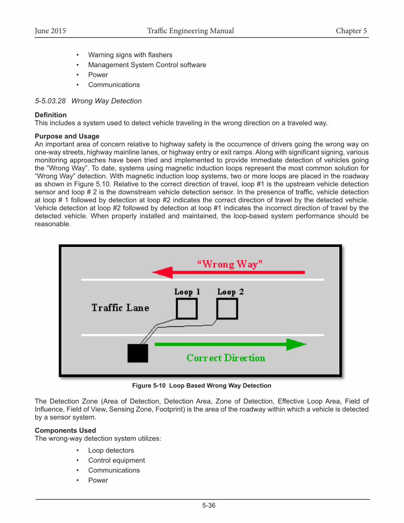
June 2015 Traffic Engineering Manual Chapter 5
5-36
• Warningsignswithflashers• Management System Control software• Power• Communications
5-5.03.28 Wrong Way Detection
DefinitionThis includes a system used to detect vehicle traveling in the wrong direction on a traveled way.
Purpose and UsageAn important area of concern relative to highway safety is the occurrence of drivers going the wrong way on one-waystreets,highwaymainlinelanes,orhighwayentryorexitramps.Alongwithsignificantsigning,variousmonitoring approaches have been tried and implemented to provide immediate detection of vehicles going the“WrongWay”.Todate,systemsusingmagneticinductionloopsrepresentthemostcommonsolutionfor“WrongWay”detection.Withmagneticinductionloopsystems,twoormoreloopsareplacedintheroadwayasshowninFigure5.10.Relativetothecorrectdirectionoftravel,loop#1istheupstreamvehicledetectionsensorandloop#2isthedownstreamvehicledetectionsensor.Inthepresenceoftraffic,vehicledetectionatloop#1followedbydetectionatloop#2indicatesthecorrectdirectionoftravelbythedetectedvehicle.Vehicledetectionatloop#2followedbydetectionatloop#1indicatestheincorrectdirectionoftravelbythedetected vehicle.Whenproperly installedandmaintained, the loop-based systemperformance shouldbereasonable.
Figure 5-10 Loop Based Wrong Way Detection
TheDetection Zone (Area of Detection, DetectionArea, Zone of Detection, Effective LoopArea, Field ofInfluence,FieldofView,SensingZone,Footprint)istheareaoftheroadwaywithinwhichavehicleisdetectedby a sensor system.
Components UsedThe wrong-way detection system utilizes:
• Loop detectors• Control equipment• Communications• Power
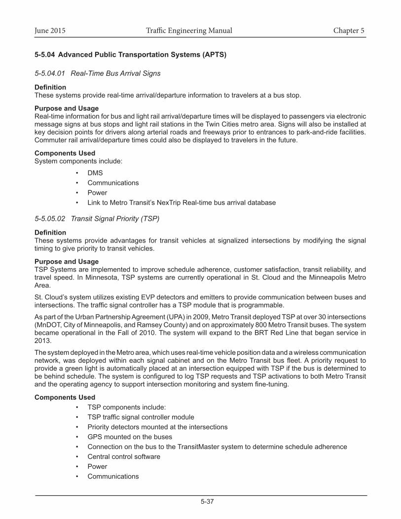
June 2015 Traffic Engineering Manual Chapter 5
5-37
5-5.04 AdvancedPublicTransportationSystems(APTS)
5-5.04.01 Real-Time Bus Arrival Signs
DefinitionThese systems provide real-time arrival/departure information to travelers at a bus stop.
Purpose and Usage Real-time information for bus and light rail arrival/departure times will be displayed to passengers via electronic message signs at bus stops and light rail stations in the Twin Cities metro area. Signs will also be installed at key decision points for drivers along arterial roads and freeways prior to entrances to park-and-ride facilities. Commuter rail arrival/departure times could also be displayed to travelers in the future.
Components UsedSystem components include:
• DMS• Communications• Power• Link to Metro Transit’s NexTrip Real-time bus arrival database
5-5.05.02 Transit Signal Priority (TSP)
DefinitionThese systems provide advantages for transit vehicles at signalized intersections by modifying the signal timing to give priority to transit vehicles.
Purpose and UsageTSPSystemsareimplementedtoimprovescheduleadherence,customersatisfaction,transitreliability,andtravelspeed. InMinnesota,TSPsystemsarecurrentlyoperational inSt.CloudandtheMinneapolisMetroArea.
St. Cloud’s system utilizes existing EVP detectors and emitters to provide communication between buses and intersections.ThetrafficsignalcontrollerhasaTSPmodulethatisprogrammable.
AspartoftheUrbanPartnershipAgreement(UPA)in2009,MetroTransitdeployedTSPatover30intersections(MnDOT,CityofMinneapolis,andRamseyCounty)andonapproximately800MetroTransitbuses.Thesystembecame operational in the Fall of 2010. The system will expand to the BRT Red Line that began service in 2013.
ThesystemdeployedintheMetroarea,whichusesreal-timevehiclepositiondataandawirelesscommunicationnetwork,wasdeployedwithineachsignalcabinetandon theMetroTransitbusfleet.Apriority request toprovide a green light is automatically placed at an intersection equipped with TSP if the bus is determined to bebehindschedule.ThesystemisconfiguredtologTSPrequestsandTSPactivationstobothMetroTransitandtheoperatingagencytosupportintersectionmonitoringandsystemfine-tuning.
Components Used• TSP components include:• TSPtrafficsignalcontrollermodule• Priority detectors mounted at the intersections• GPS mounted on the buses• Connection on the bus to the TransitMaster system to determine schedule adherence• Central control software• Power• Communications
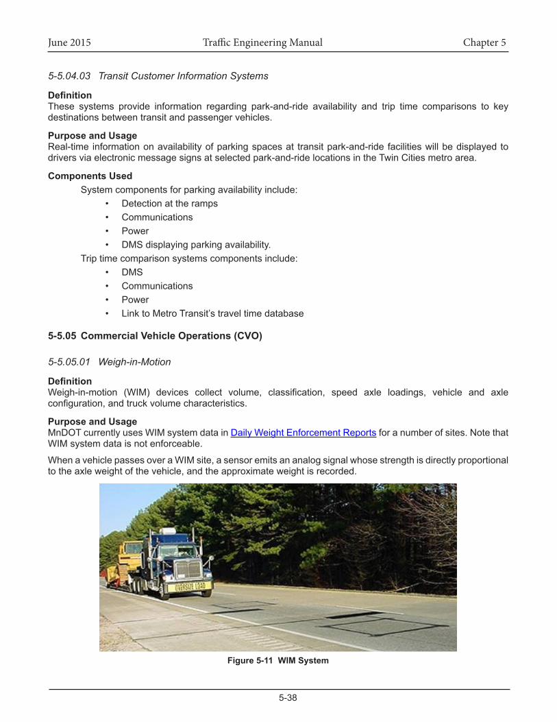
June 2015 Traffic Engineering Manual Chapter 5
5-38
5-5.04.03 Transit Customer Information Systems
DefinitionThese systems provide information regarding park-and-ride availability and trip time comparisons to key destinations between transit and passenger vehicles.
Purpose and UsageReal-time information on availability of parking spaces at transit park-and-ride facilities will be displayed to drivers via electronic message signs at selected park-and-ride locations in the Twin Cities metro area.
Components UsedSystem components for parking availability include:
• Detection at the ramps• Communications• Power• DMS displaying parking availability.
Trip time comparison systems components include:• DMS• Communications• Power• Link to Metro Transit’s travel time database
5-5.05 CommercialVehicleOperations(CVO)
5-5.05.01 Weigh-in-Motion
DefinitionWeigh-in-motion (WIM) devices collect volume, classification, speed axle loadings, vehicle and axleconfiguration,andtruckvolumecharacteristics.
Purpose and UsageMnDOT currently uses WIM system data in Daily Weight Enforcement Reports for a number of sites. Note that WIM system data is not enforceable.
WhenavehiclepassesoveraWIMsite,asensoremitsananalogsignalwhosestrengthisdirectlyproportionaltotheaxleweightofthevehicle,andtheapproximateweightisrecorded.
Figure 5-11 WIM System
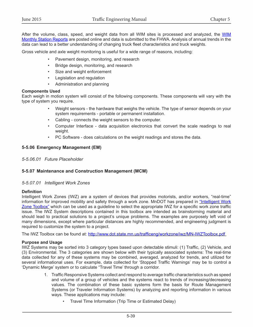
June 2015 Traffic Engineering Manual Chapter 5
5-39
After the volume, class, speed, andweight data fromallWIM sites is processed and analyzed, theWIM Monthly Station Reports are posted online and data is submitted to the FHWA. Analysis of annual trends in the datacanleadtoabetterunderstandingofchangingtruckfleetcharacteristicsandtruckweights.
Grossvehicleandaxleweightmonitoringisusefulforawiderangeofreasons,including:
• Pavementdesign,monitoring,andresearch• Bridgedesign,monitoring,andresearch• Size and weight enforcement• Legislation and regulation• Administration and planning
Components UsedEach weigh in motion system will consist of the following components. These components will vary with the type of system you require.
• Weight sensors - the hardware that weighs the vehicle. The type of sensor depends on your system requirements - portable or permanent installation.
• Cabling - connects the weight sensors to the computer. • Computer Interface - data acquisition electronics that convert the scale readings to real
weight. • PC Software - does calculations on the weight readings and stores the data.
5-5.06 EmergencyManagement(EM)
5-5.06.01 Future Placeholder
5-5.07 MaintenanceandConstructionManagement(MCM)
5-5.07.01 Intelligent Work Zones
DefinitionIntelligentWorkZones (IWZ) are a systemof devices that providesmotorists, and/orworkers, “real-time”information for improved mobility and safety through a work zone. MnDOT has prepared in “Intelligent Work Zone Toolbox”whichcanbeusedasaguidelinetoselecttheappropriateIWZforaspecificworkzonetrafficissue. The IWZ System descriptions contained in this toolbox are intended as brainstorming material and should lead topractical solutions toaproject’suniqueproblems.Theexamplesarepurposely left voidofmanydimensions,exceptwhereparticulardistancesarehighlyrecommended,andengineeringjudgmentisrequiredtocustomizethesystemtoaproject.
The IWZ Toolbox can be found at: http://www.dot.state.mn.us/trafficeng/workzone/iwz/MN-IWZToolbox.pdf
Purpose and UsageIWZSystemsmaybesortedinto3categorytypesbasedupondetectablestimuli:(1)Traffic,(2)Vehicle,and(3) Environmental. The 3 categories are shown below with their typically associated systems: The real-time datacollected foranyof thesesystemsmaybecombined,averaged,analyzed for trends,andutilized forseveral informationaluses.Forexample,datacollected for ‘StoppedTrafficWarnings’maybe tocontrola‘Dynamic Merge’ system or to calculate “Travel Time’ through a corridor.
1. TrafficResponsiveSystemscollectandrespondtoaveragetrafficcharacteristicssuchasspeedand volume of a group of vehicles and the systems react to trends of increasing/decreasing values. The combination of these basic systems form the basis for Route Management Systems (or Traveler Information Systems) by analyzing and reporting information in various ways. These applications may include:
• Travel Time Information (Trip Time or Estimated Delay)
June 2015 Traffic Engineering Manual Chapter 5
5-40
• Speed Advisory Information• Congestion Advisory• StoppedTrafficAdvisory• Dynamic Merge (Late or Early)• TrafficResponsiveTemporarySignals• Temporary Ramp Metering
2. Vehicle Responsive Systems collect and respond to individual vehicle characteristics such as speed,dimensions,and location.Whenadverseconditionsaredetectedbythesesystems,motorists need immediate warnings for quick response. These applications may include:
• Excessive Speed Warning (including Dynamic Speed Display Signs)• Over Dimension Warning• Work Space / Haul Road Intrusion Warning• Construction Vehicle Warnings
3. EnvironmentallyResponsiveSystemscollectandrespondtochangingnon-trafficconditionsofweather,roadwayorworkingcharacteristicssuchasvisibilityconditionsorroadwaysurfaceconditions and hazards. These applications may include:
• HazardousConditionWarnings(Flooding,Ice,Fog,Smoke,Dust,etc.)TemporaryTrafficControlDevicesmaybeequippedwith advanced communicationand/or remote controlcapabilities that do not react “intelligently” to detectable field data, but the devices provide saferworkingconditionsor improve incident response.Although thesedevicesmaynotbe “Intelligent”, theyhavebeenincluded in the IWZ Toolbox as additional safety tools for consideration when an IWZ System is being deployed. These applications may include:
• Changeable Work Zone Signage (WZ Speed Limit Signs)• TrafficSurveillanceCameras(removedfromToolbox)
Components UsedEach IWZ System in the Toolbox is a collection of standard system components which have been combined to produceausefulreal-timesystem.Theindividualcomponentfunctionsincludethecollectionofdata,verifyingtheaccuracyof thedata, transmitting thedata,storingandmanaging thedata,analyzing thedata,and/orproviding the data to the motorist.
Detection ComponentsThe detectors may include:
• Radar• Pneumatic Road Tubes• Light Beams• Acoustical• Ultrasonic• Magnetic • Piezo-Electric• Video• RFID• ProbeInjectionTechnologies,etc.
System Monitoring ComponentsTypical redundancies should be built into most systems (based upon risk assessment for the system failure) andthevarioustypesofqualitycontroltestingorsystemmode,monitoringmaybeutilized.
System Communication ComponentsThetypicalformsoftransmittingdata,someofthesemayinclude:
June 2015 Traffic Engineering Manual Chapter 5
5-41
• Cellular Modems• Internet - Wireless Access Points• Radio• Hard wired• Optical,etc.
System Analysis ComponentsAnalysisalgorithmsaredesignedormodifiedforeachapplicationofanIWZSystemtofittheconditionsoftheproject.Algorithmscanbedesignedwithapparentlimitationsandstrengths,andfieldtestingisnecessarytoensure the quality of the data analysis.
Data Management ComponentsThestorageofdataandanalysisofthedataforvarioustrends,events,etc.mayutilizemanydifferentdatabasesystems.
Dynamic Informational ComponentsDynamic components provide information to the motorists and may include:
• 511Systems(internet&phone/cellphone),• Dynamic Message Signs (DMS) in dynamic mode• Staticsignswithdynamicfeatures,• Remotelyactivatedtrafficcontroldevices,• Audibleorvisualalarms,• Real-timehighwayadvisoryradio(HAR),• Publicmediaannouncements,• CBRadio,etc.
Supplementing Existing System Components:MnDOT, through its Regional Transportation Management Center (RTMC) and out-state TransportationOperationandCommunicationsCenters (TOCC’s),has thecapability toprovideavarietyof IWZSystemsforMnDOTconstructionandmaintenanceprojects.However,MnDOT’sdetectiondevices,communicationsnetworks or traveler information systems may not be adequate for a proposed IWZ System. Discrepancies maybeduetoconstructioninterruptingpermanentinstallations,orthattheexistingsystemcomponentsdonotextendtotheprojectarea.
IWZSystemcomponentsprovidedbyacontractorwouldsupplementtheservicesoftheRTMCorTOCC’s,when various devices/services are not currently available and may include any of the component types listed above.
5-5.07.02 Road and Weather Information Systems (RWIS)
DefinitionA roadweather information system (RWIS) is a combination of technologies that collects, transmits, anddisseminates weather and road condition information. The component of an RWIS that collects weather data is theenvironmental sensor station (ESS).AnESS isa fixed roadway locationwithoneormoresensorsmeasuring atmospheric, surface (i.e., pavement and soil), and/or hydrologic (i.e., water level) conditionsincluding:
• Atmosphericsensors–airtemperature,barometricpressure,relativehumidity,windspeedanddirection,precipitationtypeandrate,visibilitydistance
• Surfacesensors–pavementtemperatureandcondition(dry,wet,ice,freezepoint,chemicalconcentration),subsurfacetemperature,subsurfacefreeze/thawcycles)
• Hydrologicsensors(stream,riverandtidelevels)
June 2015 Traffic Engineering Manual Chapter 5
5-42
DatacollectedfromenvironmentalsensorsinthefieldarestoredonsiteinaRemoteProcessingUnit(RPU)locatedinacabinet.InadditiontotheRPU,cabinetstypicallyhousepowersupplyandbatteryback-updevices.The RPU transmits environmental data to a central location via a communication system. Central RWIShardwareandsoftwarecollectfielddata fromnumerousESS,processdata tosupportvariousoperationalapplications,anddisplayordisseminateroadweatherdatainaformatthatcanbeeasilyinterpretedbyauser.Environmentaldatamaybeintegratedintoautomatedmotoristwarningsystems,andtransmittedtoTMCs,emergency operations centers and maintenance facilities for decision support. This information may also be usedtoenhanceforecastsandsupplementmesoscaleenvironmentalmonitoringnetworks(i.e.,mesonets).
Weather service providers (who are often RWIS/ESS vendors) also use the data to develop tailored weather servicesandproducts,including:
• pavementtemperature/bridgeicingforecasts,• iceandsnowprediction,• optimization of treatment routes and resource allocation and • thermal mapping.
Thermal mapping is a process to quantify the variation in nighttime road surface temperatures across the roadwaynetwork.Thisvariationcanbe10°Forgreater(dependingonexposure,altitude, traffic,androadmaterials),whichcanimpactwhichareasmaybecomeicybeforeothers.
Types of Road Weather Management StrategiesTransportation managers utilize environmental data to implement three types of road weather management strategies:advisory,controlandtreatment.
AdvisoryAdvisory strategies provide information on prevailing and predicted conditions to both transportation managers and motorists.
ControlControlstrategiesalterthestateofroadwaydevicestopermitorrestricttrafficflowandregulateroadwaycapacity.
TreatmentTreatment strategies supply resources to roadways to minimize or eliminate weather impacts. Many treatmentstrategiesinvolvecoordinationoftraffic,maintenance,andemergencymanagementagencies.
Wintermaintenancemanagersutilizeroadweatherinformationtoassessthenatureandmagnitudeofthreats,make staffing decisions, plan treatment strategies,minimize costs (i.e., labor, equipment,materials), andassesstheeffectivenessoftreatmentactivities(byagencystafforsubcontractors).Trafficmanagersmayalterrampmetering rates,modify incidentdetectionalgorithms,varyspeed limits, restrictaccess todesignatedroutes,lanes,orvehicletypes(e.g.,tractor-trailers)anddisseminateroadweatherinformationtomotoristsinordertoinfluencetheirtraveldecisions.SomeTrafficManagementCentersintegrateweatherdatawithtrafficmonitoring and control software.
Emergency managers may employ decision support systems that integrate weather observations and forecasts withpopulationdata,topographicdata,aswellasroadnetworkandtrafficdata.Whenfacedwithflooding,tornadoes,hurricanes,orwildfires;emergencymanagersmayusethisdatatoevacuatevulnerableresidents,closethreatenedroadwaysandbridges,anddisseminateinformationtothepublic.
Note: RWIS uses a different key than other cabinets.
Minnesota’sRWISisasystemthatautomaticallycollects,processes,anddistributescurrentandforecastedweather and road surface information.
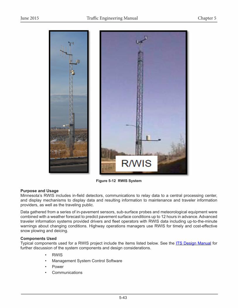
June 2015 Traffic Engineering Manual Chapter 5
5-43
Figure 5-12 RWIS System
Purpose and UsageMinnesota’sRWISincludes in-fielddetectors,communicationstorelaydatatoacentralprocessingcenter,and display mechanisms to display data and resulting information to maintenance and traveler information providers,aswellasthetravelingpublic.
Datagatheredfromaseriesofin-pavementsensors,sub-surfaceprobesandmeteorologicalequipmentwerecombined with a weather forecast to predict pavement surface conditions up to 12 hours in advance. Advanced travelerinformationsystemsprovideddriversandfleetoperatorswithRWISdataincludingup-to-the-minutewarnings about changing conditions. Highway operations managers use RWIS for timely and cost-effective snow plowing and deicing.
Components Used TypicalcomponentsusedforaRWISprojectincludetheitemslistedbelow.SeetheITS Design Manual for further discussion of the system components and design considerations.
• RWIS• Management System Control Software• Power• Communications
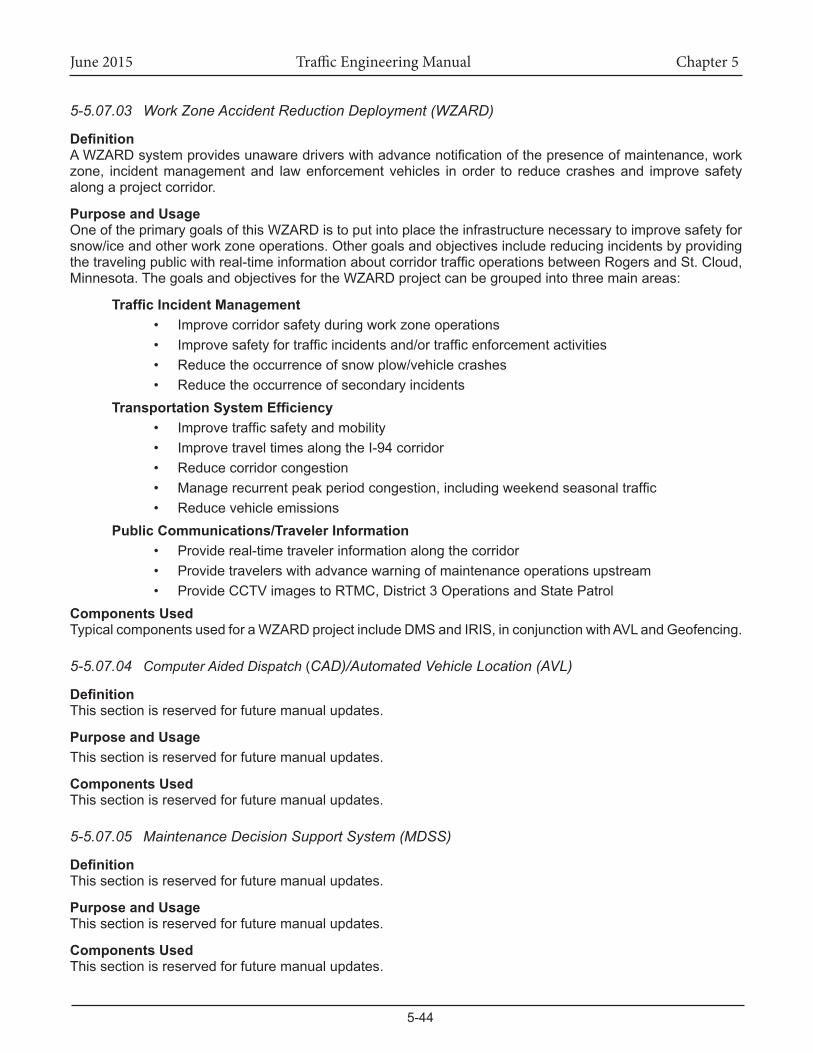
June 2015 Traffic Engineering Manual Chapter 5
5-44
5-5.07.03 Work Zone Accident Reduction Deployment (WZARD)
DefinitionAWZARDsystemprovidesunawaredriverswithadvancenotificationofthepresenceofmaintenance,workzone, incidentmanagementand lawenforcementvehicles inorder to reducecrashesand improvesafetyalongaprojectcorridor.
Purpose and UsageOne of the primary goals of this WZARD is to put into place the infrastructure necessary to improve safety for snow/iceandotherworkzoneoperations.Othergoalsandobjectivesincludereducingincidentsbyprovidingthetravelingpublicwithreal-timeinformationaboutcorridortrafficoperationsbetweenRogersandSt.Cloud,Minnesota.ThegoalsandobjectivesfortheWZARDprojectcanbegroupedintothreemainareas:
TrafficIncidentManagement• Improve corridor safety during work zone operations• Improvesafetyfortrafficincidentsand/ortrafficenforcementactivities• Reduce the occurrence of snow plow/vehicle crashes• Reduce the occurrence of secondary incidents
TransportationSystemEfficiency• Improvetrafficsafetyandmobility• Improve travel times along the I-94 corridor• Reduce corridor congestion• Managerecurrentpeakperiodcongestion,includingweekendseasonaltraffic• Reduce vehicle emissions
PublicCommunications/TravelerInformation• Provide real-time traveler information along the corridor• Provide travelers with advance warning of maintenance operations upstream• ProvideCCTVimagestoRTMC,District3OperationsandStatePatrol
Components UsedTypicalcomponentsusedforaWZARDprojectincludeDMSandIRIS,inconjunctionwithAVLandGeofencing.
5-5.07.04 Computer Aided Dispatch (CAD)/Automated Vehicle Location (AVL)
DefinitionThis section is reserved for future manual updates.
Purpose and UsageThis section is reserved for future manual updates.
Components UsedThis section is reserved for future manual updates.
5-5.07.05 Maintenance Decision Support System (MDSS)
DefinitionThis section is reserved for future manual updates.
Purpose and UsageThis section is reserved for future manual updates.
Components UsedThis section is reserved for future manual updates.
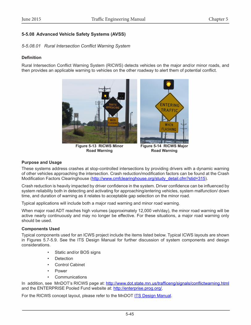
June 2015 Traffic Engineering Manual Chapter 5
5-45
5-5.08 AdvancedVehicleSafetySystems(AVSS)
5-5.08.01 Rural Intersection Conflict Warning System
Definition
RuralIntersectionConflictWarningSystem(RICWS)detectsvehiclesonthemajorand/orminorroads,andthenprovidesanapplicablewarningtovehiclesontheotherroadwaytoalertthemofpotentialconflict.
Purpose and UsageThese systems address crashes at stop-controlled intersections by providing drivers with a dynamic warning ofothervehiclesapproachingtheintersection.Crashreduction/modificationfactorscanbefoundattheCrashModificationFactorsClearinghouse(http://www.cmfclearinghouse.org/study_detail.cfm?stid=315).
Crashreductionisheavilyimpactedbydriverconfidenceinthesystem.Driverconfidencecanbeinfluencedbysystemreliabilitybothindetectingandactivatingforapproaching/enteringvehicles,systemmalfunction/downtime,anddurationofwarningasitrelatestoacceptablegapselectionontheminorroad.
Typicalapplicationswillincludebothamajorroadwarningandminorroadwarning.
WhenmajorroadADTreacheshighvolumes(approximately12,000veh/day),theminorroadwarningwillbeactivenearlycontinuouslyandmaynolongerbeeffective.Forthesesituations,amajorroadwarningonlyshould be used.
Components UsedTypicalcomponentsusedforanICWSprojectincludetheitemslistedbelow.TypicalICWSlayoutsareshownin Figures 5.7-5.9. See the ITS Design Manual for further discussion of system components and design considerations.
• Static and/or BOS signs• Detection• Control Cabinet• Power• Communications
Inaddition,seeMnDOT’sRICWSpageat:http://www.dot.state.mn.us/trafficeng/signals/conflictwarning.html and the ENTERPRISE Pooled Fund website at: http://enterprise.prog.org/.
FortheRICWSconceptlayout,pleaserefertotheMnDOTITS Design Manual.
Figure 5-13 RICWS Minor Road Warning
Figure 5-14 RICWSMajorRoad Warning
June 2015 Traffic Engineering Manual Chapter 5
5-46
5-6.00 POWER, COMMUNICATIONS, AND CONTROL
5-6.01 Source of PowerMost ITS systems currently operate on 120 Volts AC with a power drop from the local utility company. Some systemsoperateusingalowvoltageDCpowersource,facilitatingbattery,solarpower,orwindpoweroptions.
ITS systems usually include sensitive electronics located in an outdoor environment and mounted on metal poles. A lightning storm can cause the equipment to fail if it is not properly protected. Every control cabinet should have a quality properly rated solid state surge suppression device located where the power conductors terminate in the cabinet. In addition to the grounding required by the National Electrical Code at the service cabinet,thecontrolcabinetshouldalsohaveagroundingconductorgoingfromitsgroundbustoagroundrod. The ground rod may be the one used by the service cabinet or a different one if the cabinets are not co-located.Ifthesystemincludestallmountingpolesandisnotconnectedbymetalconduit,thepoleinstallationshouldalsoincludeagroundrod.AspertheNationalElectricalCode,itisessentialthatallmetalcabinets,poles,housings,conduits,etc.allbeconnectedtogetherintoaproperlybondedandgroundedsystem.Allcommunicationsandvideofield cables shouldhavesurgesuppressionat bothendswhere theyenteranenclosure or cabinet. Much unfortunate experience has shown that systems that are not properly grounded or protected from surges will not last long in the outdoor roadside environment.
PartofthedesignofanITSsystemshouldbeconsiderationoffailuremodes.Anysourceofpowerissubjectto failure. Some ITS systems are not safety critical and can tolerate the occasional power outage. For safety criticalsystems,batterybackupisanoption.Batterybackupcankeepthesystemoperationalforacertainperiod of time when utility power is out. The size of the battery backup system can be calculated based on the load drawn by the system and the length of time it must run on battery power. One consideration of battery backupisthatthebatterieswillneedtobereplacedperiodically,maybeeveryfivetosevenyears,toensurethat they can still hold a charge. Battery backup should also be checked every six months to ensure that the systems are ready to work when called upon.
Inremoteruralareas,obtainingautilitypowerdropcanbeveryexpensiveiftherearenoelectricalutilitiesinthearea.Forsomelow-powerITSapplications,solarand/orwindpowerisanoption.Theseoptionsarealso environmentally friendly. Resources are available to aid in designing the solar power. Factors include theamountofpowerthesystemneeds,thepercentofthetimethesystemisoperating(suchasflashersthatonlyflashuponcertaininfrequentevents),theamountoftimethesystemmustoperateintheabsenceofanysunlight,andthegeographiclocationwhichaffectstheamountofsunlightreceived.
It is a good idea to over design the solar power system with large safety margins. Experience has seen several solar powered systemswhoseoperationwasdisrupteddue to inadequate solar power configurations. InMinnesotainmid-winter,hoursofsunlightarelimitedandthecoldcausesthebatteriestobeinefficient,whichmakes it a challenge for solar powered systems. Wind power provides a nice complement to solar power. Cloudy times having less sunlight are often accompanied by higher winds. Wind turbines work better the highertheyaremounted,andsomountingheightcouldbecomeacostissue.
Similar to solar power, resources are available to aid in designingwind powered systems. Off the shelfsystemsforsolarandwind, includingcontrollers,areavailablefrommultiplesources.Undergroundbatteryboxesforsolarpoweredsystemsmayfillwithwaterandberuined.Batteryboxeslocatedonsignstructuresrequire that the sign post be breakaway (u-channel post mounting is not appropriate.
5-6.02 Electronic CommunicationsDatacommunicationsbetweenthecentralserverandfieldmicroprocessorsareachievedinavarietyofways.Traditionally,coppercableshavebeenusedwithstandardmodemsoneachend,butnewerdevicesuseanetworkoffiber-opticcommunicationlines.SeetheITS Design Manualforguidanceinfiberopticdesign.TheRTMChadsomeissueswithicecrushcausingproblemswithfibercables.
SolicitinformationfromtheRTMCwheninstallingfibercables.Theycanprovidevaluableinformationregardingthe best installation method.
Wireless communications is another option. With wireless communications you have to do a site survey to
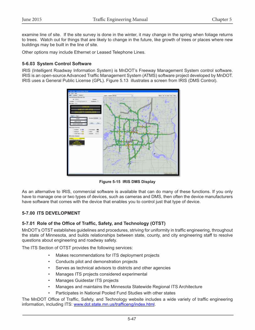
June 2015 Traffic Engineering Manual Chapter 5
5-47
examinelineofsite.Ifthesitesurveyisdoneinthewinter,itmaychangeinthespringwhenfoliagereturnstotrees.Watchoutforthingsthatarelikelytochangeinthefuture,likegrowthoftreesorplaceswherenewbuildings may be built in the line of site.
Other options may include Ethernet or Leased Telephone Lines.
5-6.03 System Control SoftwareIRIS (Intelligent Roadway Information System) is MnDOT’s Freeway Management System control software. IRISisanopen-sourceAdvancedTrafficManagementSystem(ATMS)softwareprojectdevelopedbyMnDOT.IRIS uses a General Public License (GPL). Figure 5.13 illustrates a screen from IRIS (DMS Control).
Figure 5-15 IRIS DMS Display
AsanalternativetoIRIS,commercialsoftwareisavailablethatcandomanyofthesefunctions.Ifyouonlyhavetomanageoneortwotypesofdevices,suchascamerasandDMS,thenoftenthedevicemanufacturershavesoftwarethatcomeswiththedevicethatenablesyoutocontroljustthattypeofdevice.
5-7.00 ITS DEVELOPMENT
5-7.01 RoleoftheOfficeofTraffic,Safety,andTechnology(OTST)MnDOT’sOTSTestablishesguidelinesandprocedures,strivingforuniformityintrafficengineering,throughoutthestateofMinnesota,andbuildsrelationshipsbetweenstate,county,andcityengineeringstafftoresolvequestions about engineering and roadway safety.
The ITS Section of OTST provides the following services:
• MakesrecommendationsforITSdeploymentprojects• Conductspilotanddemonstrationprojects• Serves as technical advisors to districts and other agencies• ManagesITSprojectsconsideredexperimental• ManagesGuidestarITSprojects• Manages and maintains the Minnesota Statewide Regional ITS Architecture• Participates in National Pooled Fund Studies with other states
TheMnDOTOfficeofTraffic,Safety,andTechnologywebsite includesawidevarietyof trafficengineeringinformation,includingITS:www.dot.state.mn.us/trafficeng/index.html.
June 2015 Traffic Engineering Manual Chapter 5
5-48
5-7.02 ITSOfficeandDistrictProjectSolicitationMnDOT’sOfficeofTraffic,Safety,andTechnology’sITSSectionsolicitsMnDOTDistrictsandOfficesforITSprojectsinMinnesotawithupto$1millionperyearinfundingoverfouryears.Thisfundingprogramisintendedtoencourage ITS deployment by providing dedicated funds that do not compete with other construction priorities.
Projectscanbestand-aloneITSprojectsorITScomponentsofotherconstructionprojects.Projectscanbeforanydollaramountuptotheentiredollaramountavailableperyear.TobeconsideredanITSproject,theprojectmustfitthedescriptionofoneormoreoftheITS“ServicePackages”thatmakeuptheNationalITSArchitecture. A description of the service packages can be found at: http://local.iteris.com/itsarch.
FundingfortheprogramwillbeDistrictCFederalSTPfundsintheStateRoadConstruction(SRC)appropriation,with the following intended purpose as stated in state law:
“Thisappropriationisfortheactualconstruction,reconstruction,andimprovementoftrunkhighways,including design-build contracts and consultant usage to support these activities. This includes the costofactualpaymenttolandownersforlandsacquiredforhighwayrights-of-way,paymenttolessees,interestsubsidies,andrelocationexpenses.”
THESE FEDERAL FUNDS WILL REQUIRE A 20 PERCENT NON-FEDERAL MATCH FROM THE DISTRICT. ThedistrictwillberesponsibleforincludingselectedprojectsintheSTIPandobtainingappropriatestateandfederalprojectnumbers.ThisprogramwillnotfundoperationsandmaintenanceoftheITSproject,technologyand/or equipment. The OTST ITS section will provide funding numbers for the federal funds.
According to Federal Final Rule 940, ITS projects using federal funds must fit within a regional ITSarchitecture and must follow a systems engineering process. Minnesota has a “Minnesota Statewide Regional ITS Architecture (Version 2014)” meeting the requirements of this rule. (http://www.dot.state.mn.us/guidestar/2006_2010/mnitsarchitecture.html).Dependinguponthescopeoftheproposedproject,theprojectmay require development of a Concept of Operations document and a Functional Requirements document. The ITS section can provide assistance in determining what is needed and how to best meet the requirements ofFinalRule940andwillworkwiththedistrictswhoseprojectsareselected.
ITSprojectsshouldaddressidentifiedneeds.Section4ofthisChapterexplainssomedraftITSwarrantsthatmayhelpjustifytheproject,andSection5providealistofprojectsthathavebeensuccessfullyimplementedelsewhere in the state. The OTST ITS Section anticipates issuing this solicitation annually for any unused funds from the previous solicitation plus new funds for the year subsequent to the previous solicitation time frame.
PROCESS FOR SUBMITTING APPLICATIONS:1. Obtain an application from OTST2. FillouttheOffice/DistrictITSSolicitationApplicationForminMicrosoftWordformat(.docor
.docx).3. Submit the application electronically to Susan Sheehan at [email protected]. Applications are typically due in April.
EVALUATION AND SELECTION OF APPLICATIONSAnevaluationcommitteeconsistingofOTSTITSSectionstaff,OTSTmanagementandpossiblyDistrictStaffandarepresentativefromtheOfficeofCapitolProgramsandPerformanceMeasureswillevaluateandselectproposals.Criteriatobeconsideredinselectingprojectsincludethefollowing:
• Projectidentifiesadocumentedneed• ProjectmeetsanITSwarrant• ProjectfitsintoalargerITSplanorcomplementsotherconstructionprojects• Projectutilizesproventechnologies• Office/Districthasidentifiedaplanforoperatingandmaintainingthesystem
June 2015 Traffic Engineering Manual Chapter 5
5-49
• Office/Districthasidentifiedaplanfordeliveringtheproject• Office/Districthasidentifiedasourceofstatematch
Formoreinformation,contact:SusanSheehan,OTST–[email protected]
5-8.00 INTERAGENCY AGREEMENTSITS projects can require permits, agreements, or partnerships with other agencies. Typical items to bediscussed in an interagency agreement could include but are not limited to:
• Permits for acquiring power and/or communications• Cost-sharing (infrastructure and ongoing)• Maintenance • CommunicationsSharing(fiber-opticcable)• Sharing of video and/or data• Shared operations of devices
PleasecontactOTSTorthePermitsofficeformoreinformationandsampleagreements.
5-9.00 REFERENCESThe pages contained within the manual are current at the time of publishing. Please keep in mind that the referencematerial is periodically updated, so the user is cautioned against using the referencematerialsincludedinthemanualindefinitely,withoutcheckingtheoriginalsourcesforupdates.
The following is a list of the reference material used for this manual.
1. Systems Engineering for Intelligent Transportation Systems – An Introduction for Transportation Professionals,FHWA.http://ops.fhwa.dot.gov/publications/seitsguide/seguide.pdf
2. DefinitionofITSApplicationAreas,USDOT-RITA.http://www.itsoverview.its.dot.gov/faq.asp3. USDOTAGuideforHOTLaneDevelopment,Glossary.http://ntl.bts.gov/lib/jpodocs/repts_
te/13668_files/images/13668.pdf4. FHWA Systems Engineering Guidebook for ITS. www.fhwa.dot.gov/cadiv/segb/index.htm 5. MinnesotaStatewideRegionalITSArchitectureUpdate1.www.dot.state.mn.us/
guidestar/2006_2010/mnitsarchitecture.html 6. Enterprise-WarrantsfortheInstallationandUseofTechnologyDevicesforTransportation
Operations and Maintenance. http://enterprise.prog.org/itswarrants/ 7. FHWATrafficDetectorHandbook:ThirdEdition—VolumeI.http://www.fhwa.dot.gov/publications/
research/operations/its/06108/ 8. FHWAOfficeofOperations-TrafficControlSystemsHandbook.http://ops.fhwa.dot.gov/
publications/fhwahop06006/index.htm 9. FHWA Work Zone ITS Implementation Guide (Jan 2014). http://www.ops.fhwa.dot.gov/
publications/fhwahop14008/10. MnDOTEvaluationofNon-IntrusiveTechnologiesforTrafficDetection.http://www.dot.state.
mn.us/guidestar/2006_2010/nit_phaseIII/FINAL%20REPORT.pdf
Related Documents