Chapter 4 Propeller Balance (Revision 4, July 2007) “Propeller Balance” is an analyzer function that is accessed from the analyzer’s Main Menu banner screen as shown in the illustration below. Selecting this function from the main menu brings up the “Propeller Balance” banner screen menu (also shown below). Each of the listings on this banner screen menu is an option within the function. Descriptions of each of these options follow, along with the information required to complete the menu screens within the options, and the steps necessary to perform propeller balance function.

Welcome message from author
This document is posted to help you gain knowledge. Please leave a comment to let me know what you think about it! Share it to your friends and learn new things together.
Transcript
Chapter 4
Propeller Balance
(Revision 4, July 2007)
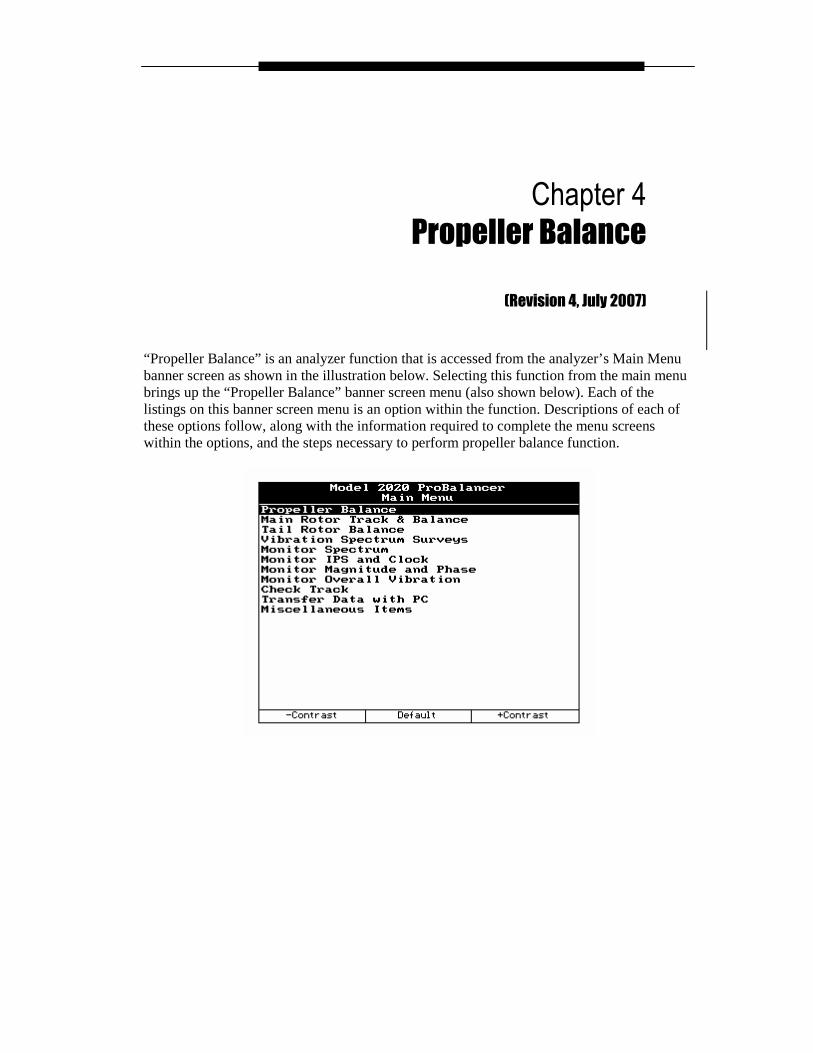
“Propeller Balance” is an analyzer function that is accessed from the analyzer’s Main Menu banner screen as shown in the illustration below. Selecting this function from the main menu brings up the “Propeller Balance” banner screen menu (also shown below). Each of the listings on this banner screen menu is an option within the function. Descriptions of each of these options follow, along with the information required to complete the menu screens within the options, and the steps necessary to perform propeller balance function.
4-2 – Propeller Balance 4
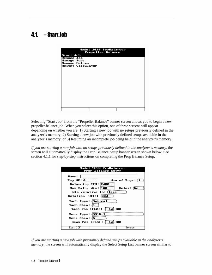
4.1. – Start Job
Selecting “Start Job” from the “Propeller Balance” banner screen allows you to begin a new propeller balance job. When you select this option, one of three screens will appear depending on whether you are: 1) Starting a new job with no setups previously defined in the analyzer’s memory; 2) Starting a new job with previously defined setups available in the analyzer’s memory; or 3) Resuming an incomplete job being held in the analyzer’s memory.
If you are starting a new job with no setups previously defined in the analyzer’s memory, the screen will automatically display the Prop Balance Setup banner screen shown below. See section 4.1.1 for step-by-step instructions on completing the Prop Balance Setup.
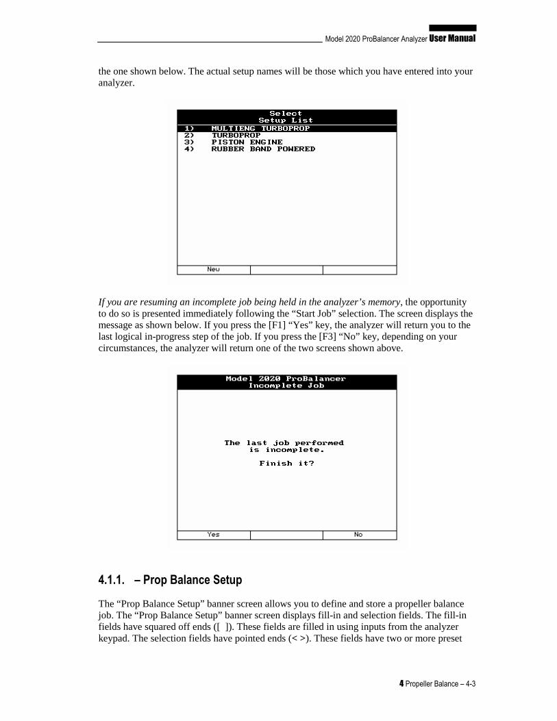
If you are starting a new job with previously defined setups available in the analyzer’s memory, the screen will automatically display the Select Setup List banner screen similar to
Model 2020 ProBalancer Analyzer User Manual
4 Propeller Balance – 4-3
the one shown below. The actual setup names will be those which you have entered into your analyzer.
If you are resuming an incomplete job being held in the analyzer’s memory, the opportunity to do so is presented immediately following the “Start Job” selection. The screen displays the message as shown below. If you press the [F1] “Yes” key, the analyzer will return you to the last logical in-progress step of the job. If you press the [F3] “No” key, depending on your circumstances, the analyzer will return one of the two screens shown above.
4.1.1. – Prop Balance Setup
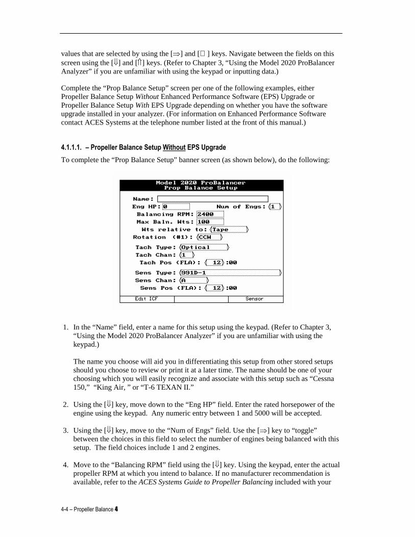
The “Prop Balance Setup” banner screen allows you to define and store a propeller balance job. The “Prop Balance Setup” banner screen displays fill-in and selection fields. The fill-in fields have squared off ends ([ ]). These fields are filled in using inputs from the analyzer keypad. The selection fields have pointed ends (< >). These fields have two or more preset
4-4 – Propeller Balance 4
values that are selected by using the [⇒] and [⇐] keys. Navigate between the fields on this screen using the [⇓] and [⇑] keys. (Refer to Chapter 3, “Using the Model 2020 ProBalancer Analyzer” if you are unfamiliar with using the keypad or inputting data.)
Complete the “Prop Balance Setup” screen per one of the following examples, either Propeller Balance Setup Without Enhanced Performance Software (EPS) Upgrade or Propeller Balance Setup With EPS Upgrade depending on whether you have the software upgrade installed in your analyzer. (For information on Enhanced Performance Software contact ACES Systems at the telephone number listed at the front of this manual.)
4.1.1.1. – Propeller Balance Setup Without EPS Upgrade
To complete the “Prop Balance Setup” banner screen (as shown below), do the following:
1. In the “Name” field, enter a name for this setup using the keypad. (Refer to Chapter 3, “Using the Model 2020 ProBalancer Analyzer” if you are unfamiliar with using the keypad.) The name you choose will aid you in differentiating this setup from other stored setups should you choose to review or print it at a later time. The name should be one of your choosing which you will easily recognize and associate with this setup such as “Cessna 150,” “King Air, ” or “T-6 TEXAN II.”
2. Using the [⇓] key, move down to the “Eng HP” field. Enter the rated horsepower of the engine using the keypad. Any numeric entry between 1 and 5000 will be accepted.
3. Using the [⇓] key, move to the “Num of Engs” field. Use the [⇒] key to “toggle” between the choices in this field to select the number of engines being balanced with this setup. The field choices include 1 and 2 engines.
4. Move to the “Balancing RPM” field using the [⇓] key. Using the keypad, enter the actual propeller RPM at which you intend to balance. If no manufacturer recommendation is available, refer to the ACES Systems Guide to Propeller Balancing included with your
Model 2020 ProBalancer Analyzer User Manual
4 Propeller Balance – 4-5
Model 2020 analyzer. A low cruise RPM is usually best. This field will accept any numeric value.
5. Using the [⇓] key, move to the “Max Baln.Wts” field. Enter the maximum total trim balance weight (in grams) allowed for this installation. If the manufacturer doesn’t specify a weight, refer to the ACES Systems Guide to Propeller Balancing. Acceptable values are numeric entries between 0 and 9999.
6. Using the [⇓] key, move to the “Wts relative to” field. Select “Tape” or “Sensor” using the [⇒] key. If using predetermined weight locations, select “Tape.” Decide if you wish to measure angles from the reflective tape or the vibration sensor as an index point. The field choices are Tape or Sensor. (Refer to the Chapter 2, Analyzer Description for a detailed explanation of how to use the Propeller Protractor and the referencing tape or sensor.)
7. Move down to the “Rotation (#1)” field using the [⇓] key. Using the [⇒] key, Select CW (Clockwise) or CCW (Counter-Clockwise) for the rotation of the propeller as viewed standing Forward of the propeller Looking Aft toward the tail of the airplane (FLA).
8. Using the [⇓] key, move to the “Tach Type” field. Using the [⇒] key, select the type of tachometer you are using. Tach Type selections for this field include:
“Optical” - Includes the Phototach and LaseTach. “Mag (Lo)” - A magnetic interrupter with an output of 120mV or less. “Mag (Hi)” - A magnetic interrupter with an output of more than 120 mV and not more than 5 volt. “Monopole” - A monopole type pickup with an output of 120mV or greater. “Tach Gen” - A one to three pole tachometer generator with an output of 390mV or more. (This type of input is normally used for synchronous vibration surveys and not for a once per rev signal used to calculate phase angles in balancing.)
9. Using the [⇓] key, move to the “Tach Chan” field. Using the [⇒] key, select “TACH 1” or “TACH 2” according to the analyzer’s tach input channel you intend to use. The default for single sensor input is TACH 1.
10. Using the [⇓] key, move to the “Tach Pos (FLA)” field. Using the [⇒] key, select the tach position. The tach position is determined by standing Forward of the propeller Looking Aft (FLA) toward the tail of the aircraft. From this viewpoint, determine the approximate clock position (1:00 to 12:00) of the tachometer pickup.
CAUTION
Sensors connected to Channel A and Channel B must b e of the same type. Using different sensors during the same job will cause er roneous readings and problems
achieving good balance results.
4-6 – Propeller Balance 4
11. Move down to the “Sens Type” field using the [⇓] key. Select the sensor type from the available options using the [⇒] key.
12. Move to the next field, “Sens Chan” using the [⇓] key. Select sensor channel “A” or “B” according to which of the analyzer’s input channels you intend to use. The default for single-sensor input is Channel A. Use the [⇒] key to make the selection.
13. Using the [⇓] key, move to the “Sens Pos (FLA)” field. Using the [⇒] key, select the vibration sensor position. The sensor position is determined by standing Forward of the propeller Looking Aft (FLA) toward the tail of the aircraft. From this viewpoint, determine the approximate clock position (1:00 to 12:00) of the sensing axis of the vibration sensor.
4.1.1.1.1. – Edit ICF
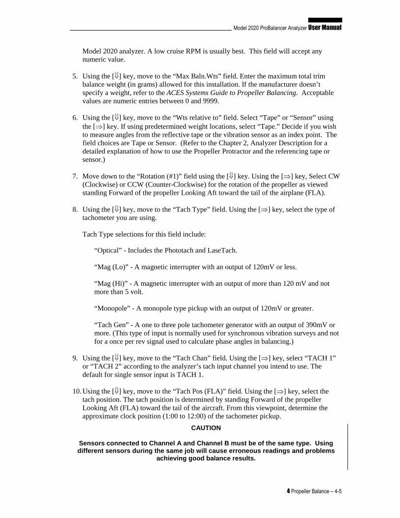
The “Edit ICF” (which corresponds to the [F1] key) selection appears at the bottom left of the “Prop Balance Setup” banner screen. Press the [F1] key if you wish to define the Influence Coefficients for this setup. The following “Edit ICF” banner screen is displayed.
If you do not have ICF information for the balance setup, press the [F1] “Default” key. This sets the ICF at the default for the known conditions. The ICF default value is added automatically when the Setup is created. The user may use this key at any time to reset the ICF to default. If an ICF has been calculated by the analyzer and stored from previous runs, the “Samples” field displays the number of samples included in the calculation. (The Samples field is a display-only field and cannot be edited by the user.)
When satisfied with the displayed ICF, press [BACKUP] to return to the “Prop Balance Setup” banner screen.
Model 2020 ProBalancer Analyzer User Manual
4 Propeller Balance – 4-7
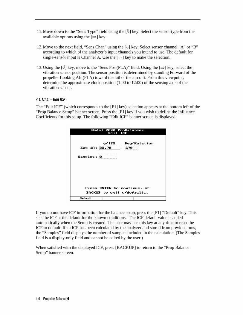
4.1.1.1.2. – Sensor Setup
Pressing the [F3] “Sensor” key from the “Prop Balance Setup” banner screen displays the “Sensor Setup” banner screen shown below. The information on this screen should correspond to the sensor you selected for this setup in Step 11 of Section 4.1.1.1 above.
This is an information-only screen for use in verifying the parameters of the vibration sensor you have chosen. You may not edit or otherwise enter information on this screen. If this sensor does not possess the specifications you require for this setup, you may enter a new sensor in the “Sensor Setup” screen, or choose another sensor from the existing list. Press [BACKUP] or [ENTER] to exit this screen and return to the “Prop Balance Setup” banner screen.
When all fields are completed to your satisfaction, press the [ENTER] key to accept and store the setup. The analyzer will display the message, “Store this new setup?” If you choose to store this new setup in the analyzer’s memory, press the [F1] key for “Yes,” otherwise press [F2] for “No.”
4.1.1.2. – Propeller Balance Setup With EPS Upgrade
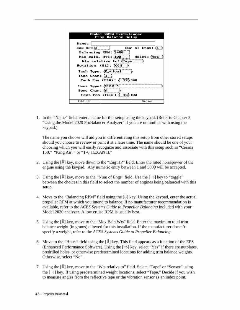
To complete the “Prop Balance Setup” banner screen (as shown below), do the following:
4-8 – Propeller Balance 4
1. In the “Name” field, enter a name for this setup using the keypad. (Refer to Chapter 3, “Using the Model 2020 ProBalancer Analyzer” if you are unfamiliar with using the keypad.) The name you choose will aid you in differentiating this setup from other stored setups should you choose to review or print it at a later time. The name should be one of your choosing which you will easily recognize and associate with this setup such as “Cessna 150,” “King Air, ” or “T-6 TEXAN II.”
2. Using the [⇓] key, move down to the “Eng HP” field. Enter the rated horsepower of the engine using the keypad. Any numeric entry between 1 and 5000 will be accepted.
3. Using the [⇓] key, move to the “Num of Engs” field. Use the [⇒] key to “toggle” between the choices in this field to select the number of engines being balanced with this setup.
4. Move to the “Balancing RPM” field using the [⇓] key. Using the keypad, enter the actual propeller RPM at which you intend to balance. If no manufacturer recommendation is available, refer to the ACES Systems Guide to Propeller Balancing included with your Model 2020 analyzer. A low cruise RPM is usually best.
5. Using the [⇓] key, move to the “Max Baln.Wts” field. Enter the maximum total trim balance weight (in grams) allowed for this installation. If the manufacturer doesn’t specify a weight, refer to the ACES Systems Guide to Propeller Balancing.
6. Move to the “Holes” field using the [⇓] key. This field appears as a function of the EPS (Enhanced Performance Software). Using the [⇒] key, select “Yes” if there are nutplates, predrilled holes, or otherwise predetermined locations for adding trim balance weights. Otherwise, select “No”.
7. Using the [⇓] key, move to the “Wts relative to” field. Select “Tape” or “Sensor” using the [⇒] key. If using predetermined weight locations, select “Tape.” Decide if you wish to measure angles from the reflective tape or the vibration sensor as an index point.
Model 2020 ProBalancer Analyzer User Manual
4 Propeller Balance – 4-9
(Refer to the Chapter 2, Analyzer Description for a detailed explanation of how to use the Propeller Protractor and the referencing tape or sensor.)
8. Move down to the “Rotation (#1)” field using the [⇓] key. Using the [⇒] key, Select CW (Clockwise) or CCW (Counter-Clockwise) for the rotation of the propeller as viewed standing Forward of the propeller Looking Aft toward the tail of the airplane (FLA).
9. Using the [⇓] key, move to the “Tach Type” field. Using the [⇒] key, select the type of tachometer you are using. Tach Type selections for this field include:
“Optical” - Includes the Phototach and LaseTach. “Mag (Lo)” - A magnetic interrupter with an output of 120mV or less. “Mag (Hi)” - A magnetic interrupter with an output of more than 120 mV and not more than 5 volt. “Monopole” - A monopole type pickup with an output of 120mV or greater. “Tach Gen” - A one to three pole tachometer generator with an output of 390mV or more. (This type of input is normally used for synchronous vibration surveys and not for a once per rev signal used to calculate phase angles in balancing.)
10. Using the [⇓] key, move to the “Tach Chan” field. Using the [⇒] key, select “TACH 1” or “TACH 2” according to the analyzer’s tach input channel you intend to use. The default for single sensor input is TACH 1.
11. Using the [⇓] key, move to the “Tach Pos (FLA)” field. Using the [⇒] key, select the tach position. The tach position is determined by standing Forward of the propeller Looking Aft (FLA) toward the tail of the aircraft. From this viewpoint, determine the approximate clock position (1:00 to 12:00) of the tachometer pickup.
CAUTION
Sensors connected to Channel A and Channel B must b e of the same type. Using different sensors during the same job will cause er roneous readings and problems
achieving good balance results.
12. Move down to the “Sens Type” field using the [⇓] key. Select the sensor type from the available options using the [⇒] key.
13. Move to the next field, “Sens Chan” using the [⇓] key. Select sensor channel “A” or “B” according to which of the analyzer’s input channels you intend to use. The default for single-sensor input is Channel A. Use the [⇒] key to make the selection.
14. Using the [⇓] key, move to the “Sens Pos (FLA)” field. Using the [⇒] key, select the vibration sensor position. The sensor position is determined by standing Forward of the propeller Looking Aft (FLA) toward the tail of the aircraft. From this viewpoint,
4-10 – Propeller Balance 4
determine the approximate clock position (1:00 to 12:00) of the sensing axis of the vibration sensor.
4.1.1.2.1. – Edit ICF
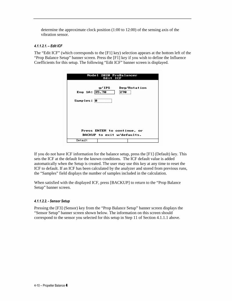
The “Edit ICF” (which corresponds to the [F1] key) selection appears at the bottom left of the “Prop Balance Setup” banner screen. Press the [F1] key if you wish to define the Influence Coefficients for this setup. The following “Edit ICF” banner screen is displayed.
If you do not have ICF information for the balance setup, press the [F1] (Default) key. This sets the ICF at the default for the known conditions. The ICF default value is added automatically when the Setup is created. The user may use this key at any time to reset the ICF to default. If an ICF has been calculated by the analyzer and stored from previous runs, the “Samples” field displays the number of samples included in the calculation.
When satisfied with the displayed ICF, press [BACKUP] to return to the “Prop Balance Setup” banner screen.
4.1.1.2.2. - Sensor Setup
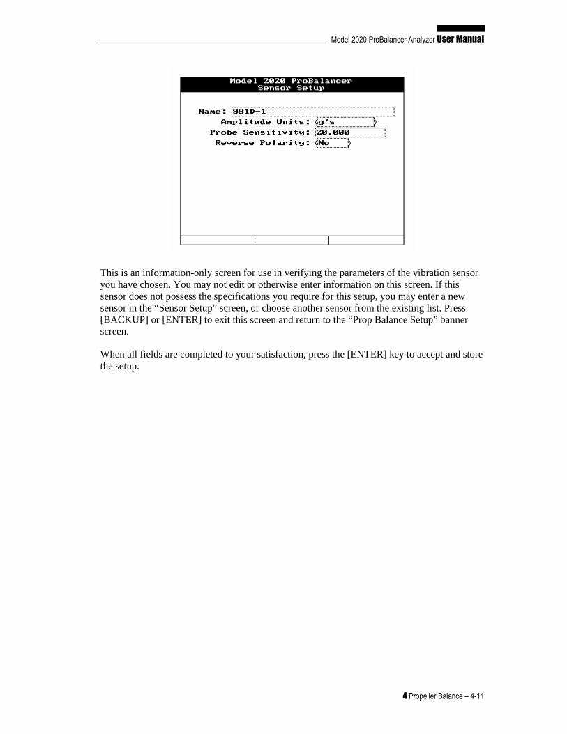
Pressing the [F3] (Sensor) key from the “Prop Balance Setup” banner screen displays the “Sensor Setup” banner screen shown below. The information on this screen should correspond to the sensor you selected for this setup in Step 11 of Section 4.1.1.1 above.
Model 2020 ProBalancer Analyzer User Manual
4 Propeller Balance – 4-11
This is an information-only screen for use in verifying the parameters of the vibration sensor you have chosen. You may not edit or otherwise enter information on this screen. If this sensor does not possess the specifications you require for this setup, you may enter a new sensor in the “Sensor Setup” screen, or choose another sensor from the existing list. Press [BACKUP] or [ENTER] to exit this screen and return to the “Prop Balance Setup” banner screen.
When all fields are completed to your satisfaction, press the [ENTER] key to accept and store the setup.
4-12 – Propeller Balance 4
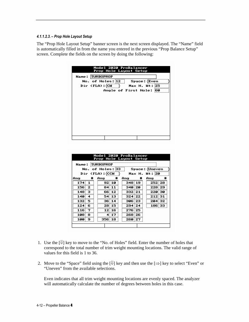
4.1.1.2.3. – Prop Hole Layout Setup
The “Prop Hole Layout Setup” banner screen is the next screen displayed. The “Name” field is automatically filled in from the name you entered in the previous “Prop Balance Setup” screen. Complete the fields on the screen by doing the following:
1. Use the [⇓] key to move to the “No. of Holes” field. Enter the number of holes that correspond to the total number of trim weight mounting locations. The valid range of values for this field is 1 to 36.
2. Move to the “Space” field using the [⇓] key and then use the [⇒] key to select “Even” or “Uneven” from the available selections. Even indicates that all trim weight mounting locations are evenly spaced. The analyzer will automatically calculate the number of degrees between holes in this case.
Model 2020 ProBalancer Analyzer User Manual
4 Propeller Balance – 4-13
If you select “Uneven,” and then use the [⇓] key to move away from the field, several fields (“Ang” and “#”) appear at the bottom of the screen. You will complete these fields later in the process at Step 5.
3. Use the [⇓] key to move to the next field, “Dir (FLA).” Complete this field by using the [⇒] key, select CW for clockwise or CCW for counter-clockwise to indicate the direction of increasing hole numbers as viewed from forward looking aft.
4. Move to the “Max H. Wt” field using the [⇓] key. Using the keypad, enter the maximum allowable weight (in grams) for any single hole. Use the [⇓] key to move to the next field.
5. Complete the next fields differently depending on data you input in Step 2 above. If you selected “Even” in Step 2 - The “Angle of First Hole” field is displayed. Use the keypad to enter the angle of hole number 1 as viewed from the front of the engine looking aft. To determine this angle, do the following. With mag switches OFF, rotate the propeller to align the tachometer pickup and its triggering device (magnetic interrupter, reflective tape, etc.). With the propeller in this position, use the 12:00 position as the “0” or “360 degrees” (index point) and measure clockwise to the angle of hole number 1. For example, if the #1 hole is at the 3:00 position, the angle would be 90 degrees; if at the 9:00 position it would be 270 degrees. The measurement to hole number 1 must always be in a clockwise direction regardless of the direction of rotation of the propeller or the direction of hole numbering. The analyzer’s logic corrects for these factors. If you selected “Uneven” in Step 2 – Multiple angle/hole number fields are displayed. Each hole angle must be defined individually. Using the keypad, complete each field by entering a hole number (“#”) and its corresponding angular (“Ang”) location as viewed from the front of the engine looking aft. Use the [⇓] and [⇑] keys to move between these fields.
To determine these values, do the following. With mag switches OFF, rotate the propeller to align the tachometer pickup and its triggering device (magnetic interrupter, reflective tape, etc.). With the propeller in this position, use the 12:00 position as the “0” or “360 degrees” (index point) and measure clockwise to the angle of each hole number and record that angle adjacent to the hole number. (See the example “Prop Hole Layout Setup” screen shown at the beginning of the section.) For example, if the number 1 hole is near the 6:00 position, the angle may be measured as 174 degrees. On the screen, use the keypad to enter the angle of hole number 1 as “174.” Then, using the [⇓] key to move to the adjacent field (“#”), input the number “1.” Next, measure to hole number 2. If hole number two is measured as 156 degrees, enter that value and “2” in the adjacent field. Continue this process until all angles for all holes are defined. The measurement must always be in a clockwise direction regardless of the direction of rotation of the propeller or the direction of hole numbering. The analyzer’s logic corrects for these factors.
6. When all fields are complete, press [ENTER] to accept the settings and continue. The analyzer will display the message, “Store this new setup?” If you choose to store this new setup in the analyzer’s memory, press the [F1] key for “Yes,” otherwise press [F2] for “No.”
4-14 – Propeller Balance 4
4.1.2. – Customer Information
At this point in the “Propeller Balance” process, you should have completed the following steps: selected “Propeller Balance” from the Main Menu; selected “Start Job;” and completed the “Prop Balance Setup” screen which included editing ICF and sensor setup, or you selected a setup from a list of predefined setups. Depending on whether or not you have Enhanced Performance Software installed, you may have also defined values for a number of trim weight mounting holes.
If these steps have been completed, then the “Customer Information” banner screen will be displayed. Customer information is optional but will appear on the job printout if entered and will assist you in identifying this job when stored in memory. Complete the information fields using the keypad. Press [ENTER] to continue.
NOTE If no customer information is entered, the job will be commonly labeled “Unnamed” in
the resume and manage job lists. This will complica te finding a specific job, as multiple jobs are stored. We recommended you enter a customer name.
4.1.3. – Engine Information
The “Engine Information” banner screen is displayed. This information is optional but will appear on the job printout if entered and will assist you in identifying this job when stored in memory. Complete the information fields using the keypad. When finished, press [ENTER] to continue.
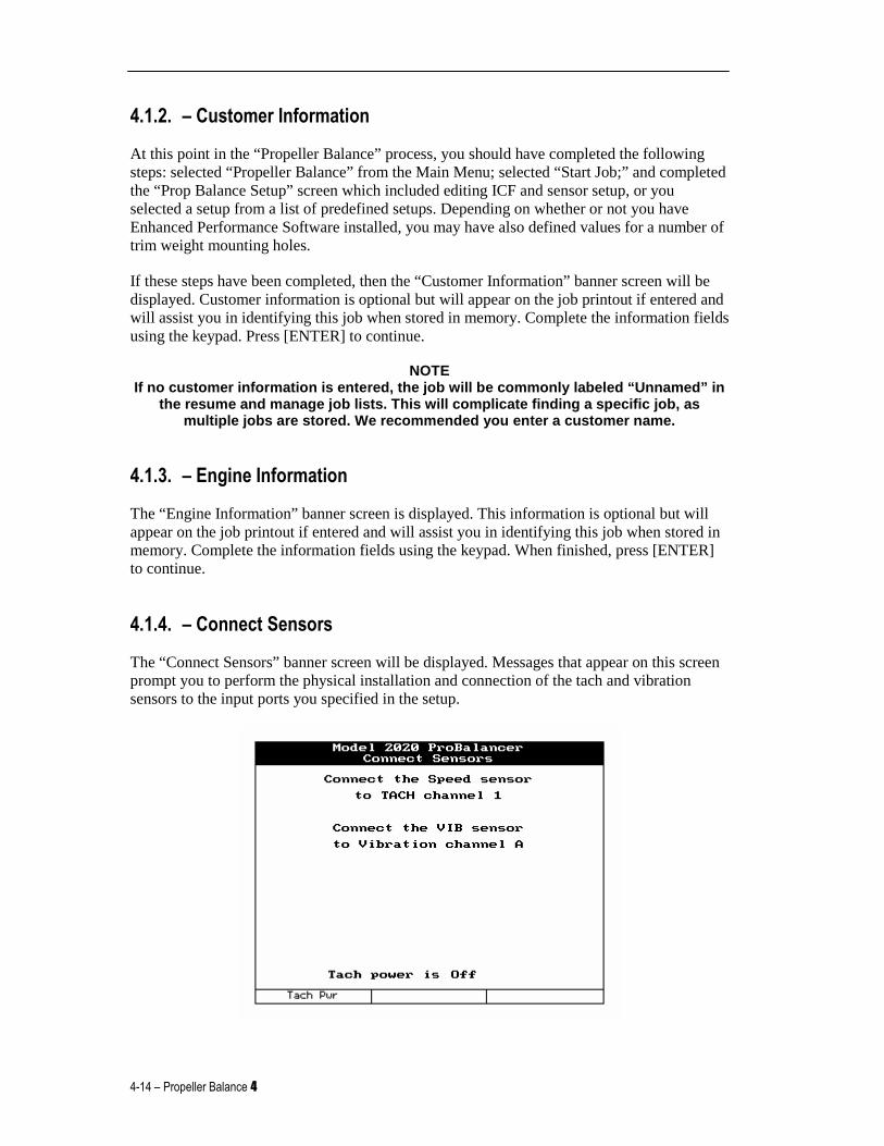
4.1.4. – Connect Sensors
The “Connect Sensors” banner screen will be displayed. Messages that appear on this screen prompt you to perform the physical installation and connection of the tach and vibration sensors to the input ports you specified in the setup.
Model 2020 ProBalancer Analyzer User Manual
4 Propeller Balance – 4-15
4.1.4.1. – Tachometer Setup
To install the tachometer, do the following:
1. Near the bottom of the screen, ensure that the message, “Tach Power is off” is displayed.
2. Install the Phototach at the position specified in the setup. The Phototach should be not less than 4 inches but no greater than 18 inches from the back surface of the target blade. Use speed tape or duct tape to secure the 3x3 base mount to the cowling surface. An angle of approximately 5 degrees from perpendicular to the target blade will produce the best results.
3. Connect the tachometer cable to the Phototach connector. Route the cable away from hot areas and electrical equipment back to the cockpit and attach to the tach channel specified in the setup you are using. Secure the cable along its route with duct tape or tie wraps. Press the [F1] “Tach Pwr” key so that the message, “Tach Power is On” is displayed near the bottom of the screen.
WARNING Insure mag switches are off prior to any movement o f the propeller.
4. Rotate the propeller to visually align the Phototach with a point on the backside of the target blade where you intend to place the reflective tape. Clean this area thoroughly to insure adhesion of the tape.
5. Cut a strip of reflective tape (3M Tape, Model 7610 is recommended) approximately 1.5 to 2 inches long. With the tape backing still in place, hold the tape in position on the propeller blade and move the propeller blade back and forth in front of the Phototach beam.
NOTE To insure quality reflective action back to the Pho totach, use 3M 7610 reflective tape.
Use of other reflective tape or devices may result in poor signals back to the Phototach.
NOTE If balancing large-diameter or high-speed propeller s, refer to Chapter 15, Equipment and Accessory Setup and Troubleshooting f or information on
reflective tape width requirements for these applic ations.
6. With an inspection mirror, watch the red LED gate indicator light on the aft end of the Phototach illuminate and extinguish as the tape crosses the beam. This indicates the position of the tape is correct.
7. Remove the tape backing and attach the reflective tape to the propeller at that location. Be sure to smooth out any wrinkles or bubbles in the tape. Ensure the edges are smoothed and firmly attached.
8. Connect the vibration sensor cable to the sensor connector. Route the cable away from hot areas and electrical equipment back to the cockpit and attach to the sensor channel specified in the setup you are using. Secure the cable along its route with duct tape or tie wraps.
4-16 – Propeller Balance 4
NOTE All trim balance weights installed during previous dynamic balance procedures should be removed before proceeding beyond this point. Ref er to the ACES Systems’ Guide to
Propeller Balancing (included with your Model 2020) for a full list of FAA-approved inspection requirements.
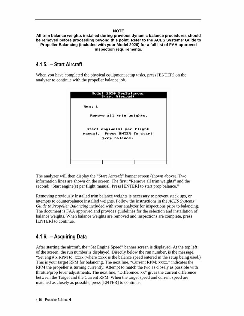
4.1.5. – Start Aircraft
When you have completed the physical equipment setup tasks, press [ENTER] on the analyzer to continue with the propeller balance job.
The analyzer will then display the “Start Aircraft” banner screen (shown above). Two information lines are shown on the screen. The first: “Remove all trim weights” and the second: “Start engine(s) per flight manual. Press [ENTER] to start prop balance.”
Removing previously installed trim balance weights is necessary to prevent stack ups, or attempts to counterbalance installed weights. Follow the instructions in the ACES Systems’ Guide to Propeller Balancing included with your analyzer for inspections prior to balancing. The document is FAA approved and provides guidelines for the selection and installation of balance weights. When balance weights are removed and inspections are complete, press [ENTER] to continue.
4.1.6. – Acquiring Data
After starting the aircraft, the “Set Engine Speed” banner screen is displayed. At the top left of the screen, the run number is displayed. Directly below the run number, is the message, “Set eng # x RPM to: xxxx (where xxxx is the balance speed entered in the setup being used.) This is your target RPM for balancing. The next line, “Current RPM: xxxx.” indicates the RPM the propeller is turning currently. Attempt to match the two as closely as possible with throttle/prop lever adjustments. The next line, “Difference: xx” gives the current difference between the Target and the Current RPM. When the target speed and current speed are matched as closely as possible, press [ENTER] to continue.
Model 2020 ProBalancer Analyzer User Manual
4 Propeller Balance – 4-17
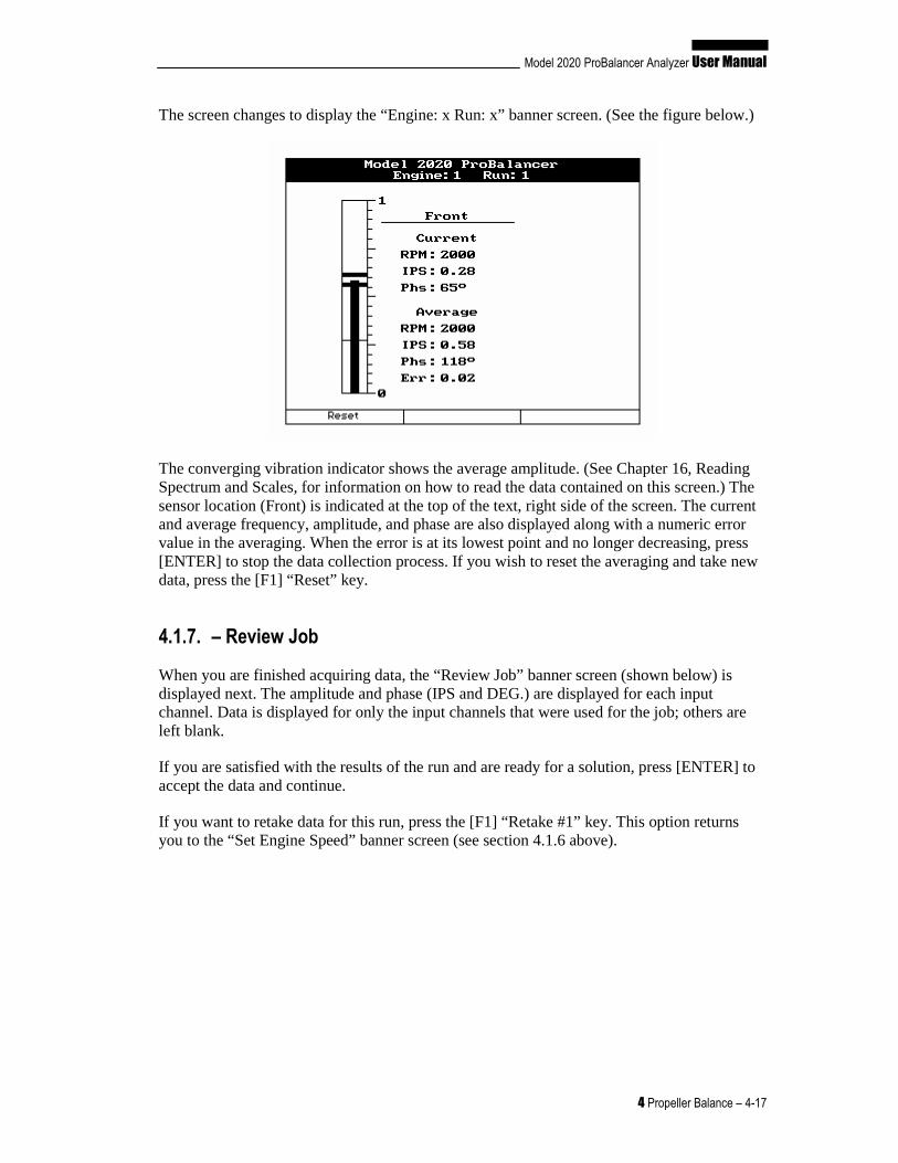
The screen changes to display the “Engine: x Run: x” banner screen. (See the figure below.)
The converging vibration indicator shows the average amplitude. (See Chapter 16, Reading Spectrum and Scales, for information on how to read the data contained on this screen.) The sensor location (Front) is indicated at the top of the text, right side of the screen. The current and average frequency, amplitude, and phase are also displayed along with a numeric error value in the averaging. When the error is at its lowest point and no longer decreasing, press [ENTER] to stop the data collection process. If you wish to reset the averaging and take new data, press the [F1] “Reset” key.
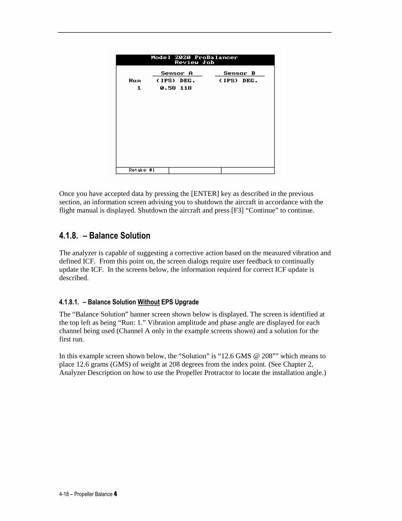
4.1.7. – Review Job
When you are finished acquiring data, the “Review Job” banner screen (shown below) is displayed next. The amplitude and phase (IPS and DEG.) are displayed for each input channel. Data is displayed for only the input channels that were used for the job; others are left blank.
If you are satisfied with the results of the run and are ready for a solution, press [ENTER] to accept the data and continue.
If you want to retake data for this run, press the [F1] “Retake #1” key. This option returns you to the “Set Engine Speed” banner screen (see section 4.1.6 above).
4-18 – Propeller Balance 4
Once you have accepted data by pressing the [ENTER] key as described in the previous section, an information screen advising you to shutdown the aircraft in accordance with the flight manual is displayed. Shutdown the aircraft and press [F3] “Continue” to continue.
4.1.8. – Balance Solution
The analyzer is capable of suggesting a corrective action based on the measured vibration and defined ICF. From this point on, the screen dialogs require user feedback to continually update the ICF. In the screens below, the information required for correct ICF update is described.
4.1.8.1. – Balance Solution Without EPS Upgrade
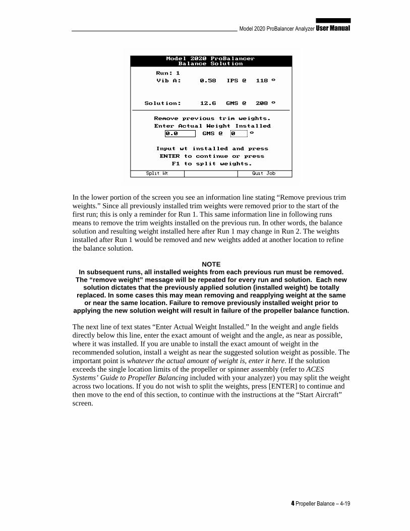
The “Balance Solution” banner screen shown below is displayed. The screen is identified at the top left as being “Run: 1.” Vibration amplitude and phase angle are displayed for each channel being used (Channel A only in the example screens shown) and a solution for the first run.
In this example screen shown below, the “Solution” is “12.6 GMS @ 208°” which means to place 12.6 grams (GMS) of weight at 208 degrees from the index point. (See Chapter 2, Analyzer Description on how to use the Propeller Protractor to locate the installation angle.)
Model 2020 ProBalancer Analyzer User Manual
4 Propeller Balance – 4-19
In the lower portion of the screen you see an information line stating “Remove previous trim weights.” Since all previously installed trim weights were removed prior to the start of the first run; this is only a reminder for Run 1. This same information line in following runs means to remove the trim weights installed on the previous run. In other words, the balance solution and resulting weight installed here after Run 1 may change in Run 2. The weights installed after Run 1 would be removed and new weights added at another location to refine the balance solution.
NOTE In subsequent runs, all installed weights from each previous run must be removed.
The “remove weight” message will be repeated for ev ery run and solution. Each new solution dictates that the previously applied solut ion (installed weight) be totally
replaced. In some cases this may mean removing and reapplying weight at the same or near the same location. Failure to remove previo usly installed weight prior to
applying the new solution weight will result in fai lure of the propeller balance function.
The next line of text states “Enter Actual Weight Installed.” In the weight and angle fields directly below this line, enter the exact amount of weight and the angle, as near as possible, where it was installed. If you are unable to install the exact amount of weight in the recommended solution, install a weight as near the suggested solution weight as possible. The important point is whatever the actual amount of weight is, enter it here. If the solution exceeds the single location limits of the propeller or spinner assembly (refer to ACES Systems’ Guide to Propeller Balancing included with your analyzer) you may split the weight across two locations. If you do not wish to split the weights, press [ENTER] to continue and then move to the end of this section, to continue with the instructions at the “Start Aircraft” screen.
4-20 – Propeller Balance 4
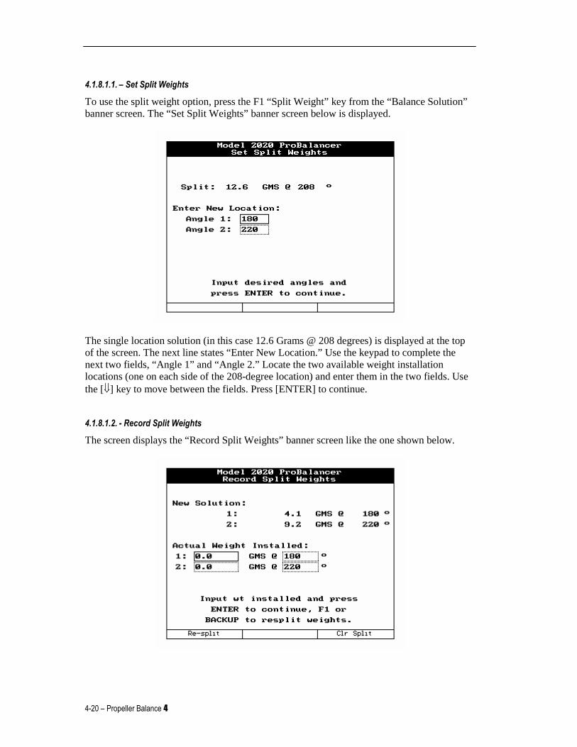
4.1.8.1.1. – Set Split Weights
To use the split weight option, press the F1 “Split Weight” key from the “Balance Solution” banner screen. The “Set Split Weights” banner screen below is displayed.
The single location solution (in this case 12.6 Grams @ 208 degrees) is displayed at the top of the screen. The next line states “Enter New Location.” Use the keypad to complete the next two fields, “Angle 1” and “Angle 2.” Locate the two available weight installation locations (one on each side of the 208-degree location) and enter them in the two fields. Use the [⇓] key to move between the fields. Press [ENTER] to continue.
4.1.8.1.2. - Record Split Weights
The screen displays the “Record Split Weights” banner screen like the one shown below.
Model 2020 ProBalancer Analyzer User Manual
4 Propeller Balance – 4-21
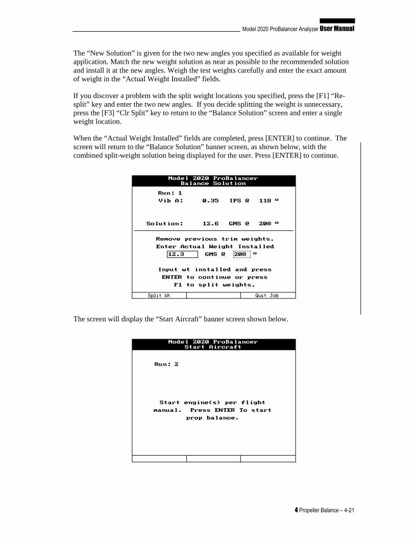
The “New Solution” is given for the two new angles you specified as available for weight application. Match the new weight solution as near as possible to the recommended solution and install it at the new angles. Weigh the test weights carefully and enter the exact amount of weight in the “Actual Weight Installed” fields.
If you discover a problem with the split weight locations you specified, press the [F1] “Re-split” key and enter the two new angles. If you decide splitting the weight is unnecessary, press the [F3] “Clr Split” key to return to the “Balance Solution” screen and enter a single weight location.
When the “Actual Weight Installed” fields are completed, press [ENTER] to continue. The screen will return to the “Balance Solution” banner screen, as shown below, with the combined split-weight solution being displayed for the user. Press [ENTER] to continue.
The screen will display the “Start Aircraft” banner screen shown below.
4-22 – Propeller Balance 4
The “Start Aircraft” banner screen indicates the upcoming run number and directs you to “Start engine(s) per flight manual”. Press [ENTER] to start prop balance.” Then repeat the procedures described above starting with item, 4.1.6 until the level of vibration is at or better than an acceptable level. See the ACES Systems Guide to Propeller Balancing for details of vibration levels and weight installation procedures.
NOTE If the engine/propeller assembly is mechanically so und, a normal balance job should
take no more than three runs to complete. The analy zer will only allow you to complete 6 runs in attempts to balance. If the balance job i s not completed by the sixth run you should suspect possible problems with your techniqu e or mechanical faults with the engine and/or propeller assembly. Mechanical faults may also be indicated by drastic
changes in suggested weight or angle from one solut ion to the next.
4.1.8.2. – Balance Solution With EPS Upgrade
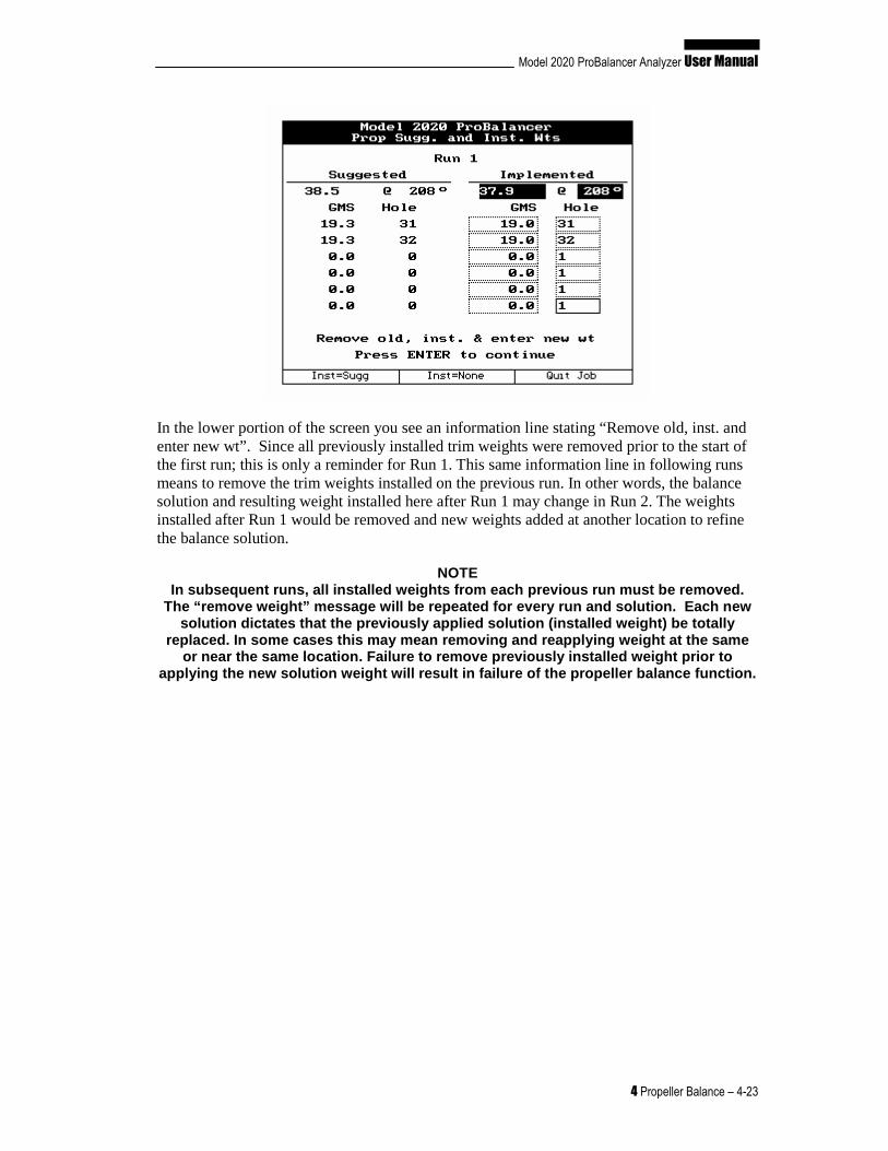
The “Prop Sugg. and Inst. Wts” banner screen shown below is displayed. The screen is identified at the top as being “Run: 1”. The left side of the screen shows, from top to bottom, the suggested combined effective weight of the individual hole weights. Listed below the combined effective weight are the individual hole weights and numbers required for weight installation. The right side of the screen shows, from top to bottom, the implemented combined effective weight of the individual hole weights. Listed below the combined effective weight, are the individual hole weights and numbers actually used.
In the example screen shown below, the “Suggested” installation is “38.5 GMS @ 208°” which means to place 38.5 grams (GMS) of weight at 208 degrees from the index point. (See Paragraph 4.1.1.2.3 – Prop Hole Layout Setup on how to use the Propeller Protractor to locate the hole angles.) This is done by entering the individual hole weights and numbers under GMS and Hole. Navigate through the fields using the [⇑] [⇓] arrow keys. These entries will be recalculated to display the combined effective weight shown directly under the Implemented text. This will allow you to see how closely the implemented installation is to the suggested solution. In the example below, the closest available weight to 19.3 grams was 19.0 grams. This weight was entered in the GMS box adjacent to the hole where it was actually installed. The effective weight was recalculated and found to be slightly below the suggested weight at the same angle. The analyzer will use this information along with the vibration readings from the next run to update the ICF and provide subsequent solutions.
Model 2020 ProBalancer Analyzer User Manual
4 Propeller Balance – 4-23
In the lower portion of the screen you see an information line stating “Remove old, inst. and enter new wt”. Since all previously installed trim weights were removed prior to the start of the first run; this is only a reminder for Run 1. This same information line in following runs means to remove the trim weights installed on the previous run. In other words, the balance solution and resulting weight installed here after Run 1 may change in Run 2. The weights installed after Run 1 would be removed and new weights added at another location to refine the balance solution.
NOTE In subsequent runs, all installed weights from each previous run must be removed.
The “remove weight” message will be repeated for ev ery run and solution. Each new solution dictates that the previously applied solut ion (installed weight) be totally
replaced. In some cases this may mean removing and reapplying weight at the same or near the same location. Failure to remove previo usly installed weight prior to
applying the new solution weight will result in fai lure of the propeller balance function.
4-24 – Propeller Balance 4
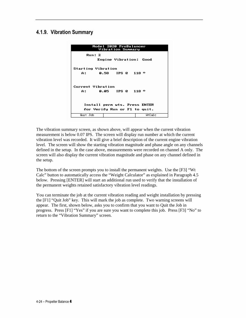
4.1.9. Vibration Summary
The vibration summary screen, as shown above, will appear when the current vibration measurement is below 0.07 IPS. The screen will display run number at which the current vibration level was recorded. It will give a brief description of the current engine vibration level. The screen will show the starting vibration magnitude and phase angle on any channels defined in the setup. In the case above, measurements were recorded on channel A only. The screen will also display the current vibration magnitude and phase on any channel defined in the setup.
The bottom of the screen prompts you to install the permanent weights. Use the [F3] “Wt Calc” button to automatically access the “Weight Calculator” as explained in Paragraph 4.5 below. Pressing [ENTER] will start an additional run used to verify that the installation of the permanent weights retained satisfactory vibration level readings.
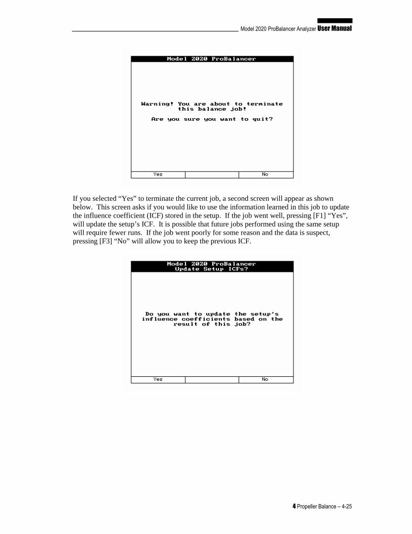
You can terminate the job at the current vibration reading and weight installation by pressing the [F1] “Quit Job” key. This will mark the job as complete. Two warning screens will appear. The first, shown below, asks you to confirm that you want to Quit the Job in progress. Press [F1] “Yes” if you are sure you want to complete this job. Press [F3] “No” to return to the “Vibration Summary” screen.
Model 2020 ProBalancer Analyzer User Manual
4 Propeller Balance – 4-25
If you selected “Yes” to terminate the current job, a second screen will appear as shown below. This screen asks if you would like to use the information learned in this job to update the influence coefficient (ICF) stored in the setup. If the job went well, pressing [F1] “Yes”, will update the setup’s ICF. It is possible that future jobs performed using the same setup will require fewer runs. If the job went poorly for some reason and the data is suspect, pressing [F3] “No” will allow you to keep the previous ICF.
4-26 – Propeller Balance 4
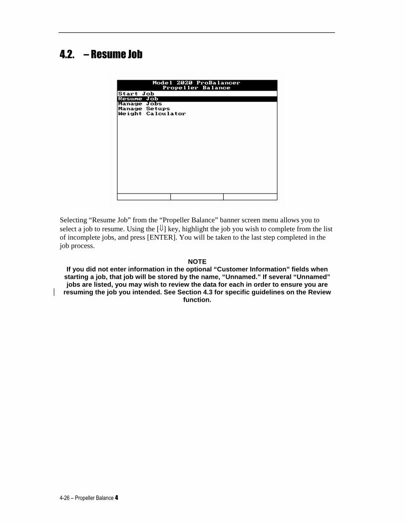
4.2. – Resume Job
Selecting “Resume Job” from the “Propeller Balance” banner screen menu allows you to select a job to resume. Using the [⇓] key, highlight the job you wish to complete from the list of incomplete jobs, and press [ENTER]. You will be taken to the last step completed in the job process.
NOTE If you did not enter information in the optional “C ustomer Information” fields when
starting a job, that job will be stored by the name , “Unnamed.” If several “Unnamed” jobs are listed, you may wish to review the data fo r each in order to ensure you are
resuming the job you intended. See Section 4.3 for specific guidelines on the Review function.
Model 2020 ProBalancer Analyzer User Manual
4 Propeller Balance – 4-27
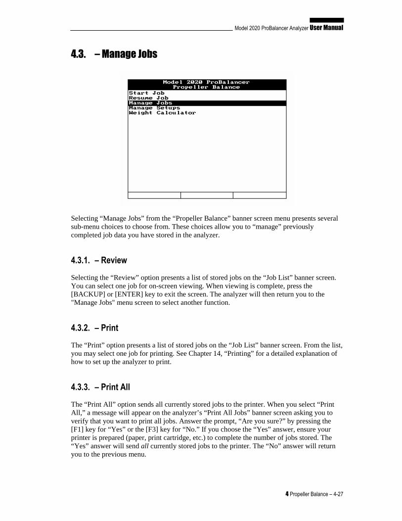
4.3. – Manage Jobs
Selecting “Manage Jobs” from the “Propeller Balance” banner screen menu presents several sub-menu choices to choose from. These choices allow you to “manage” previously completed job data you have stored in the analyzer.
4.3.1. – Review
Selecting the “Review” option presents a list of stored jobs on the “Job List” banner screen. You can select one job for on-screen viewing. When viewing is complete, press the [BACKUP] or [ENTER] key to exit the screen. The analyzer will then return you to the "Manage Jobs" menu screen to select another function.
4.3.2. – Print
The “Print” option presents a list of stored jobs on the “Job List” banner screen. From the list, you may select one job for printing. See Chapter 14, “Printing” for a detailed explanation of how to set up the analyzer to print.
4.3.3. – Print All
The “Print All” option sends all currently stored jobs to the printer. When you select “Print All,” a message will appear on the analyzer’s “Print All Jobs” banner screen asking you to verify that you want to print all jobs. Answer the prompt, “Are you sure?” by pressing the [F1] key for “Yes” or the [F3] key for “No.” If you choose the “Yes” answer, ensure your printer is prepared (paper, print cartridge, etc.) to complete the number of jobs stored. The “Yes” answer will send all currently stored jobs to the printer. The “No” answer will return you to the previous menu.
4-28 – Propeller Balance 4
4.3.4. – Delete
The “Delete” option presents a list of stored jobs on the “Job List” banner screen. From the list, you may select one job for deletion. After making your selection, the “Delete Job” banner screen will appear, asking you to verify your intent to delete the selected job by pressing the [F1] key for “Yes” or the [F3] key for “No.” You may wish to print the job for reference or permanent record prior to deleting. Once deleted, the job cannot be retrieved from the analyzer.
4.3.5. – Delete All
The “Delete All” option will delete all currently stored jobs. After selecting this option, the “Delete All Job” banner screen will appear, asking you to verify your intent to delete all the jobs by pressing the [F1] key for “Yes” or the [F3] key for “No.” You may wish to print the jobs for reference or permanent record prior to deleting. Once deleted, the jobs cannot be retrieved from the analyzer.
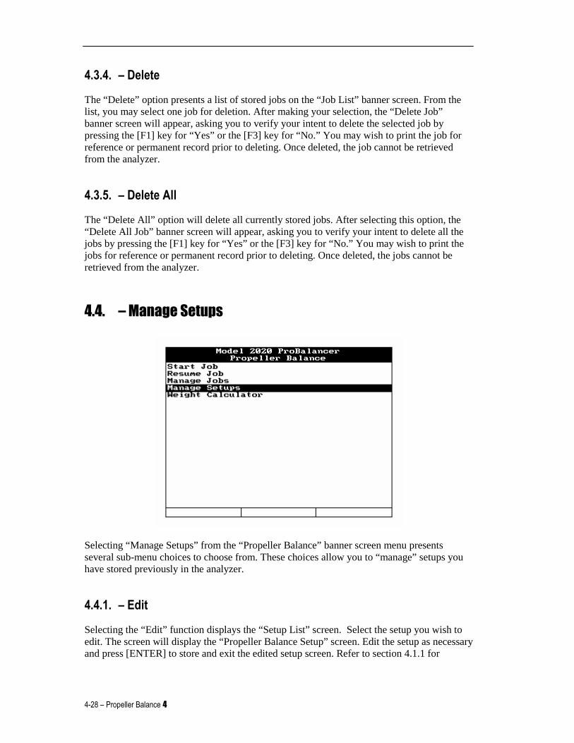
4.4. – Manage Setups
Selecting “Manage Setups” from the “Propeller Balance” banner screen menu presents several sub-menu choices to choose from. These choices allow you to “manage” setups you have stored previously in the analyzer.
4.4.1. – Edit
Selecting the “Edit” function displays the “Setup List” screen. Select the setup you wish to edit. The screen will display the “Propeller Balance Setup” screen. Edit the setup as necessary and press [ENTER] to store and exit the edited setup screen. Refer to section 4.1.1 for
Model 2020 ProBalancer Analyzer User Manual
4 Propeller Balance – 4-29
detailed instructions on how to complete/edit the fields in the “Propeller Balance Setup” screen.
4.4.2. – New
Selecting “New” will allow you to build a new propeller setup. After selecting “New”, the screen will display the fields necessary for building the new setup. Refer to section 4.1.1.
4.4.3. – Print
Selecting the "Print” function displays the “Setup List” screen. Ensure your printer is turned on and connected to the analyzer with the COMM/Print cable supplied with your analyzer. Select the setup you wish to print. (See Chapter 14, “Printing” for a detailed explanation of how to set up the analyzer to print.)
4.4.4. – Print All
Selecting “Print All” sends all currently stored setups to the printer. When making this selection, you will be asked to verify “Are you sure?” by pressing the [F1] key for “Yes,” or the [F3] key for “No.” If choosing the “Yes” answer, ensure your printer is prepared (paper, print cartridge, etc.) to complete the number of jobs stored. The “Yes” answer will send all currently stored setups to the printer. The “No” answer will return you to the previous menu.
4.4.5. – Delete
The “Delete” option presents you with a list of stored setups. From the list, you may select one setup for deletion. If you wish to delete all stored setups, you must delete them individually. After making your selection, you will be asked to verify your intent to delete the selected job by pressing the [F1] key for “Yes,” or the [F3] key for “No.” We highly recommend you print the setup for reference or permanent record prior to deleting them. Once deleted, the setups cannot be retrieved from the analyzer.
4-30 – Propeller Balance 4
4.5. – Weight Calculator
CAUTION
Before installing any permanent weights, the test w eights must be removed. The test weights will be replaced by the weight suggested in the analyzer to compensate for the
change in arm of the permanent installation locatio n.
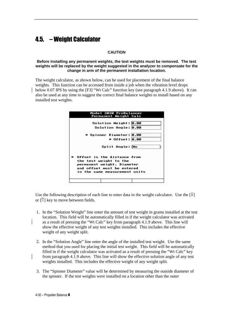
The weight calculator, as shown below, can be used for placement of the final balance weights. This function can be accessed from inside a job when the vibration level drops below 0.07 IPS by using the [F3] “Wt Calc” function key (see paragraph 4.1.9 above). It can also be used at any time to suggest the correct final balance weights to install based on any installed test weights.
Use the following description of each line to enter data in the weight calculator. Use the [⇓] or [⇑] key to move between fields.
1. In the “Solution Weight” line enter the amount of test weight in grams installed at the test location. This field will be automatically filled in if the weight calculator was activated as a result of pressing the “Wt Calc” key from paragraph 4.1.9 above. This line will show the effective weight of any test weights installed. This includes the effective weight of any weight split.
2. In the “Solution Angle” line enter the angle of the installed test weight. Use the same method that you used for placing the initial test weight. This field will be automatically filled in if the weight calculator was activated as a result of pressing the “Wt Calc” key from paragraph 4.1.9 above. This line will show the effective solution angle of any test weights installed. This includes the effective weight of any weight split.
3. The “Spinner Diameter” value will be determined by measuring the outside diameter of the spinner. If the test weights were installed on a location other than the outer
Model 2020 ProBalancer Analyzer User Manual
4 Propeller Balance – 4-31
circumference of the spinner, use the measurement from the location where the test weights were installed. This value will typically be in inches.
4. The “Offset” is the distance the radius will change between the test weight location and the final weight location. This value must be entered in the same measurement units as used to enter the Spinner Diameter.
5. By selecting “No”, the final weight can be reinstalled at a single weight location. Or, using the “Split Angle” toggle field, you can select “Yes” to bring up the Split Weight screen as shown in paragraph 4.1.8.1.1 above.
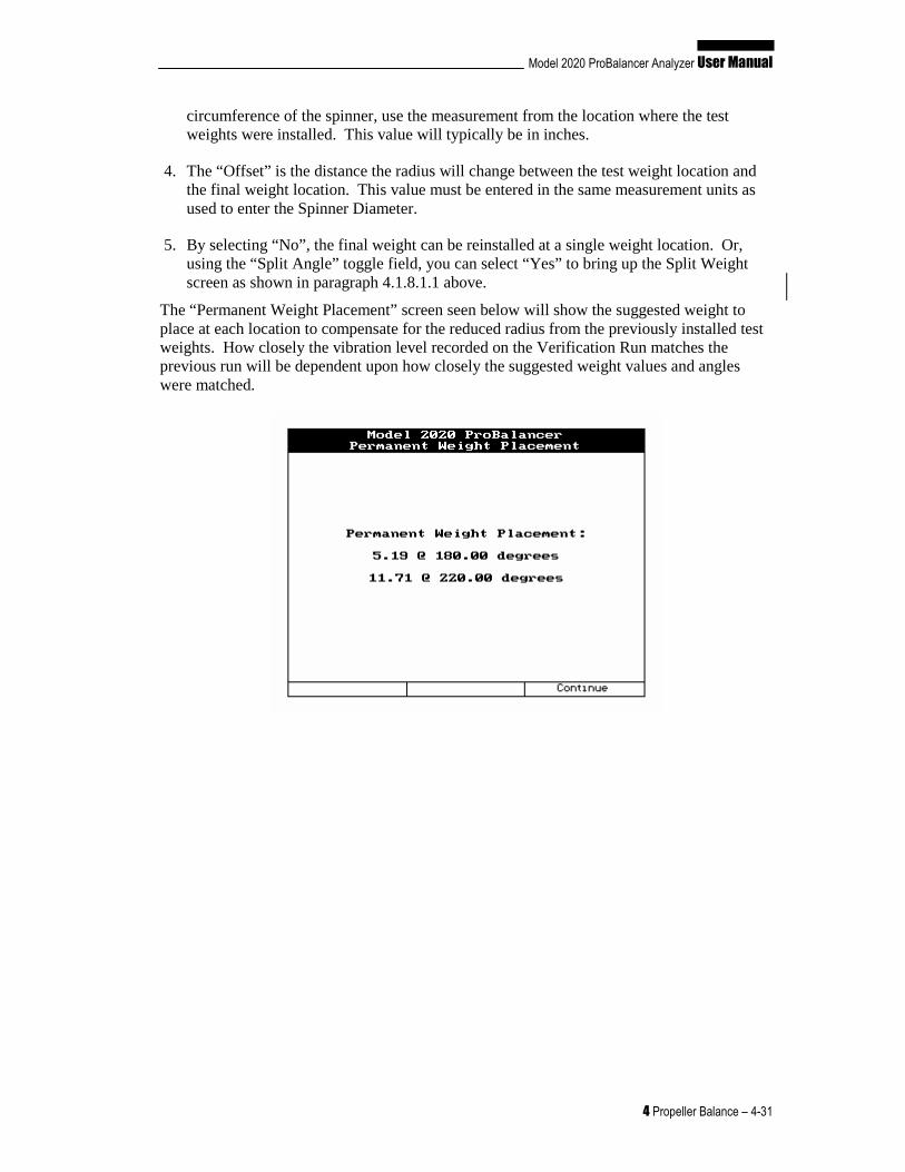
The “Permanent Weight Placement” screen seen below will show the suggested weight to place at each location to compensate for the reduced radius from the previously installed test weights. How closely the vibration level recorded on the Verification Run matches the previous run will be dependent upon how closely the suggested weight values and angles were matched.
Related Documents