Manual No. 170 61-13-70 Revision 1 October 2014 Hartzell Propeller Inc. One Propeller Place Piqua, Ohio 45356-2634 U.S.A. Phone: 937.778.4200 Fax: 937.778.4391 Composite Propeller Blade Field Maintenance and Minor Repair Manual Legacy Composite N-shank Composite Bantam Composite B7421( ) N7605(B,K)( ) 75A01-2( ) ( )7690( ) N7605C(B,K)( ) L76A01X( ) 7890K N76M05C( )X H79A06X( ) E8190K N( )7893( ) E9193(B,K) N( )8301( ) M10083(K) NC8834( ) A10460(E)(K) NC9208( ) LM10585(A)(N)(B,K)+4 M10877K E10950P(C)(B,K) E11990K E12902K E13890K

Welcome message from author
This document is posted to help you gain knowledge. Please leave a comment to let me know what you think about it! Share it to your friends and learn new things together.
Transcript
Manual No. 17061-13-70Revision 1October 2014
Hartzell Propeller Inc.One Propeller PlacePiqua, Ohio 45356-2634 U.S.A.Phone: 937.778.4200Fax: 937.778.4391
Composite Propeller Blade Field Maintenance and Minor Repair
Manual
Legacy Composite N-shank Composite Bantam Composite
B7421( ) N7605(B,K)( ) 75A01-2( )( )7690( ) N7605C(B,K)( ) L76A01X( )7890K N76M05C( )X H79A06X( )E8190K N( )7893( )E9193(B,K) N( )8301( )M10083(K) NC8834( )A10460(E)(K) NC9208( )LM10585(A)(N)(B,K)+4M10877KE10950P(C)(B,K)E11990KE12902KE13890K

Cover Back COVER 61-13-70 Rev. 1 Oct/14
COMPOSITE PROPELLER BLADE FIELD MAINTENANCE AND MINOR REPAIR MANUAL
170
(This page is intentionally blank.)
© 2013, 2014 - Hartzell Propeller Inc. - All rights reserved
Page 1 REVISION HIGHLIGHTS 61-13-70 Rev. 1 Oct/14
COMPOSITE PROPELLER BLADE FIELD MAINTENANCE AND MINOR REPAIR MANUAL
170
REVISION HIGHLIGHTS
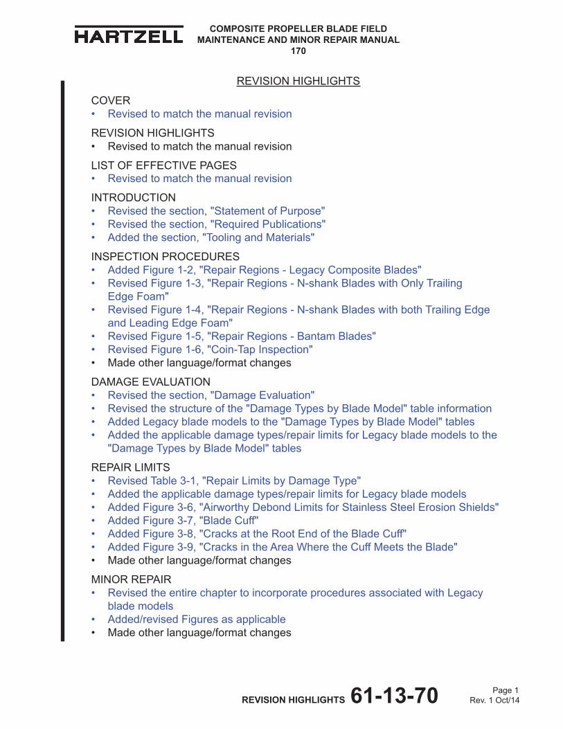
COVER • Revisedtomatchthemanualrevision
REVISION HIGHLIGHTS • Revisedtomatchthemanualrevision
LIST OF EFFECTIVE PAGES • Revisedtomatchthemanualrevision
INTRODUCTION • Revisedthesection,"StatementofPurpose" • Revisedthesection,"RequiredPublications" • Addedthesection,"ToolingandMaterials"
INSPECTION PROCEDURES • AddedFigure1-2,"RepairRegions-LegacyCompositeBlades" • RevisedFigure1-3,"RepairRegions-N-shankBladeswithOnlyTrailing EdgeFoam" • RevisedFigure1-4,"RepairRegions-N-shankBladeswithbothTrailingEdge andLeadingEdgeFoam" • RevisedFigure1-5,"RepairRegions-BantamBlades" • RevisedFigure1-6,"Coin-TapInspection" • Madeotherlanguage/formatchanges
DAMAGEEVALUATION • Revisedthesection,"DamageEvaluation" • Revisedthestructureofthe"DamageTypesbyBladeModel"tableinformation • AddedLegacyblademodelstothe"DamageTypesbyBladeModel"tables • Addedtheapplicabledamagetypes/repairlimitsforLegacyblademodelstothe "DamageTypesbyBladeModel"tables
REPAIRLIMITS • RevisedTable3-1,"RepairLimitsbyDamageType" • Addedtheapplicabledamagetypes/repairlimitsforLegacyblademodels • AddedFigure3-6,"AirworthyDebondLimitsforStainlessSteelErosionShields" • AddedFigure3-7,"BladeCuff" • AddedFigure3-8,"CracksattheRootEndoftheBladeCuff" • AddedFigure3-9,"CracksintheAreaWheretheCuffMeetstheBlade" • Madeotherlanguage/formatchanges
MINORREPAIR • RevisedtheentirechaptertoincorporateproceduresassociatedwithLegacy blademodels • Added/revisedFiguresasapplicable • Madeotherlanguage/formatchanges

Page2 REVISION HIGHLIGHTS 61-13-70 Rev. 1 Oct/14
COMPOSITE PROPELLER BLADE FIELD MAINTENANCE AND MINOR REPAIR MANUAL
170
REVISIONHIGHLIGHTS-CONTINUED
TOOLINGANDMATERIALS • Removedthesections,"Roller"and"CompositeBladeRepairBlanket" • Addedthesection,"SpecialTools" • Revisedthesection,"Materials" • RemovedTable5-1,"ConsumableMaterials"
Page3 REVISION HIGHLIGHTS 61-13-70 Rev. 1 Oct/14
COMPOSITE PROPELLER BLADE FIELD MAINTENANCE AND MINOR REPAIR MANUAL
170
REVISION HIGHLIGHTS
1. Introduction
A. General
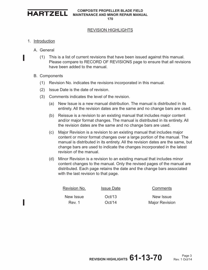
(1) Thisisalistofcurrentrevisionsthathavebeenissuedagainstthismanual.PleasecomparetoRECORDOFREVISIONSpagetoensurethatallrevisionshavebeenaddedtothemanual.
B. Components
(1) RevisionNo.indicatestherevisionsincorporatedinthismanual.
(2) IssueDateisthedateofrevision.
(3) Commentsindicatestheleveloftherevision.
(a) NewIssueisanewmanualdistribution.Themanualisdistributedinitsentirety.Alltherevisiondatesarethesameandnochangebarsareused.
(b) Reissueisarevisiontoanexistingmanualthatincludesmajorcontentand/ormajorformatchanges.Themanualisdistributedinitsentirety.Alltherevisiondatesarethesameandnochangebarsareused.
(c) MajorRevisionisarevisiontoanexistingmanualthatincludesmajorcontentorminorformatchangesoveralargeportionofthemanual.Themanualisdistributedinitsentirety.Alltherevisiondatesarethesame,butchangebarsareusedtoindicatethechangesincorporatedinthelatestrevisionofthemanual.
(d) MinorRevisionisarevisiontoanexistingmanualthatincludesminorcontentchangestothemanual.Onlytherevisedpagesofthemanualaredistributed.Eachpageretainsthedateandthechangebarsassociatedwiththelastrevisiontothatpage.
RevisionNo. Issue Date Comments
NewIssue Oct/13 NewIssueRev. 1 Oct/14 MajorRevision

Page 4 REVISION HIGHLIGHTS 61-13-70 Rev. 1 Oct/14
COMPOSITE PROPELLER BLADE FIELD MAINTENANCE AND MINOR REPAIR MANUAL
170
(Thispageisintentionallyblank.)
Page 1 RECORD OF REVISIONS 61-13-70 Oct/13
COMPOSITE PROPELLER BLADE FIELD MAINTENANCE AND MINOR REPAIR MANUAL
170
Revision Number
Issue Date
Date Inserted
Inserted By
Original Oct/13 Oct/13 HPI
1 Oct/14 Oct/14 HPI
Revision Number
Issue Date
Date Inserted
Inserted By
RECORD OF REVISIONS
This is a permanent historical record of revisions inserted into this manual.
Page 2 RECORD OF REVISIONS 61-13-70 Oct/13
COMPOSITE PROPELLER BLADE FIELD MAINTENANCE AND MINOR REPAIR MANUAL
170
Revision Number
Issue Date
Date Inserted
Inserted By
Revision Number
Issue Date
Date Inserted
Inserted By
RECORD OF REVISIONS
This is a permanent historical record of revisions inserted into this manual.

Page 1 RECORD OF TEMPORARY REVISIONS 61-13-70 Oct/13
COMPOSITE PROPELLER BLADE FIELD MAINTENANCE AND MINOR REPAIR MANUAL
170
RecORd Of TempORaRy RevisiOns
Update this page to show all Temporary Revisions inserted into this manual.
TemporaryRevision no.
section/page
issuedate
dateinserted
insertedBy
dateRemoved
RemovedBy
Page 2 RECORD OF TEMPORARY REVISIONS 61-13-70 Oct/13
COMPOSITE PROPELLER BLADE FIELD MAINTENANCE AND MINOR REPAIR MANUAL
170
RecORd Of TempORaRy RevisiOns
Update this page to show all Temporary Revisions inserted into this manual.
TemporaryRevision no.
section/page
issuedate
dateinserted
insertedBy
dateRemoved
RemovedBy
Page 1 SERVICE DOCUMENT LIST 61-13-70 Oct/13
COMPOSITE PROPELLER BLADE FIELD MAINTENANCE AND MINOR REPAIR MANUAL
170
Service Document Number
IncorporationRev./Date
Service Document Number
IncorporationRev./Date
SeRvIce DOcumeNt LISt
cAutION 1: DO NOt uSe OBSOLete OR OutDAteD INFORmAtION. PeRFORm ALL INSPectIONS OR WORK IN AccORDANce WItH tHe mOSt ReceNt RevISION OF tHe SeRvIce DOcumeNt. INFORmAtION cONtAINeD IN A SeRvIce DOcumeNt mAY Be SIGNIFIcANtLY cHANGeD FROm eARLIeR RevISIONS. FAILuRe tO cOmPLY WItH INFORmAtION cONtAINeD IN A SeRvIce DOcumeNt OR tHe uSe OF OBSOLete INFORmAtION mAY cReAte AN uNSAFe cONDItION tHAt mAY ReSuLt IN DeAtH, SeRIOuS BODILY INJuRY, AND/OR SuBStANtIAL PROPeRtY DAmAGe.
cAutION 2: tHe INFORmAtION FOR tHe DOcumeNtS LISteD INDIcAteS tHe RevISION LeveL AND DAte At tHe tIme tHAt tHe DOcumeNt WAS INItIALLY INcORPORAteD INtO tHIS mANuAL. INFORmAtION cONtAINeD IN A SeRvIce DOcumeNt mAY Be SIGNIFIcANtLY cHANGeD FROm eARLIeR RevISIONS. ReFeR tO tHe APPLIcABLe SeRvIce DOcumeNt INDex FOR tHe mOSt ReceNt RevISION LeveL OF tHe SeRvIce DOcumeNt.
Page 2 SERVICE DOCUMENT LIST 61-13-70 Oct/13
COMPOSITE PROPELLER BLADE FIELD MAINTENANCE AND MINOR REPAIR MANUAL
170
Service Document Number
IncorporationRev./Date
Service Document Number
IncorporationRev./Date
SeRvIce DOcumeNt LISt

Page 1 AIRWORTHINESS LIMITATIONS 61-13-70 Oct/13
COMPOSITE PROPELLER BLADE FIELD MAINTENANCE AND MINOR REPAIR MANUAL
170
AirwOrthiness LimitAtiOns
1. Airworthiness Limitations information
A. For airworthiness limitations information, refer to the applicable hartzell Propeller inc. owner's manual.

COMPOSITE PROPELLER BLADE FIELD MAINTENANCE AND MINOR REPAIR MANUAL
170
Page 2 AIRWORTHINESS LIMITATIONS 61-13-70 Oct/13
(this page is intentionally blank.)
Page 1 LIST OF EFFECTIVE PAGES 61-13-70 Rev. 1 Oct/14
COMPOSITE PROPELLER BLADE FIELD MAINTENANCE AND MINOR REPAIR MANUAL
170
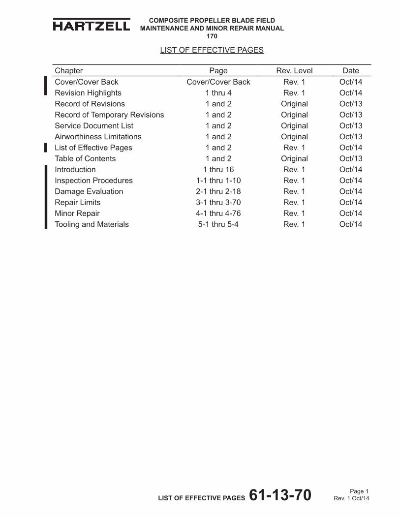
LIST OF EFFECTIVE PAGES
Chapter Page Rev. Level DateCover/Cover Back Cover/Cover Back Rev. 1 Oct/14Revision Highlights 1 thru 4 Rev. 1 Oct/14Record of Revisions 1 and 2 Original Oct/13Record of Temporary Revisions 1 and 2 Original Oct/13Service Document List 1 and 2 Original Oct/13Airworthiness Limitations 1 and 2 Original Oct/13List of Effective Pages 1 and 2 Rev. 1 Oct/14Table of Contents 1 and 2 Original Oct/13Introduction 1 thru 16 Rev. 1 Oct/14Inspection Procedures 1-1 thru 1-10 Rev. 1 Oct/14Damage Evaluation 2-1 thru 2-18 Rev. 1 Oct/14Repair Limits 3-1 thru 3-70 Rev. 1 Oct/14Minor Repair 4-1 thru 4-76 Rev. 1 Oct/14Tooling and Materials 5-1 thru 5-4 Rev. 1 Oct/14

Page 2 LIST OF EFFECTIVE PAGES 61-13-70 Rev. 1 Oct/14
COMPOSITE PROPELLER BLADE FIELD MAINTENANCE AND MINOR REPAIR MANUAL
170
(This page is intentionally blank.)

COMPOSITE PROPELLER BLADE FIELD MAINTENANCE AND MINOR REPAIR MANUAL
170
Page 1 TABLE OF CONTENTS 61-13-70 Oct/13
TABLE OF CONTENTS
REVISION HIGHLIGHTS .................................................................................................1RECORD OF REVISIONS ...............................................................................................1RECORD OF TEMPORARY REVISIONS ........................................................................1SERVICE DOCUMENT LIST............................................................................................1AIRWORTHINESS LIMITATIONS ....................................................................................1LIST OF EFFECTIVE PAGES ..........................................................................................1TABLE OF CONTENTS ....................................................................................................1INTRODUCTION ..............................................................................................................1INSPECTION PROCEDURES ......................................................................................1-1DAMAGE EVAULATION ................................................................................................2-1REPAIR LIMITS .............................................................................................................3-1MINOR REPAIR ............................................................................................................4-1TOOLING AND MATERIALS .........................................................................................5-1

COMPOSITE PROPELLER BLADE FIELD MAINTENANCE AND MINOR REPAIR MANUAL
170
Page 2 TABLE OF CONTENTS 61-13-70 Oct/13
(This page is intentionally blank.)

COMPOSITE PROPELLER BLADE FIELD MAINTENANCE AND MINOR REPAIR MANUAL
170
Page 1 INTRODUCTION 61-13-70 Rev. 1 Oct/14
INTRODUCTION - CONTENTS
1. Statement of Purpose ............................................................................................3A. General.............................................................................................................3
2. Required Publications ............................................................................................4A. Hartzell Propeller Inc. Publications...................................................................4
3. Personnel Requirements .......................................................................................6A. Personnel Requirements ..................................................................................6B. Minor Repair .....................................................................................................6C. Major Repair .....................................................................................................6
4. Safe Handling of Paints and Chemicals ................................................................65. Component Life and Service .................................................................................7
A. Calendar Limits ................................................................................................7B. Component Life ................................................................................................7C. Propeller Critical Parts......................................................................................8
6. Manual Arrangement .............................................................................................9A. Introduction.......................................................................................................9B. Inspection Procedures......................................................................................9C. Damage Evaluation ..........................................................................................9D. Repair Limits ....................................................................................................9E. Minor Repair .....................................................................................................9F. Tooling and Materials .......................................................................................9
7. Tooling and Materials ...........................................................................................10A. Special Tooling ...............................................................................................10B. Consumable Materials....................................................................................10
8. Definitions ............................................................................................................ 119. Abbreviations .......................................................................................................16

COMPOSITE PROPELLER BLADE FIELD MAINTENANCE AND MINOR REPAIR MANUAL
170
Page 2 INTRODUCTION 61-13-70 Rev. 1 Oct/14
(This page is intentionally blank.)

COMPOSITE PROPELLER BLADE FIELD MAINTENANCE AND MINOR REPAIR MANUAL
170
Page 3 INTRODUCTION 61-13-70 Rev. 1 Oct/14
1. Statement of Purpose
A. General
(1) This manual has been reviewed and accepted by the FAA. Additionally, this manual contains data that has been approved in a manner acceptable to the FAA Administrator.
(2) Thismanualprovidesfieldmaintenanceandminorrepairproceduresfor Hartzell Propeller Inc. composite propeller blades.
(a) The propeller blade models addressed in this manual may be Type CertificatedbytheFAA,ormaybeexperimental.Experimentalpartsmustnotbeinstalledonatypecertifiedpropeller.AlwaysrefertotheaircraftTypeCertificate(TC)orSupplementalTypeCertificates(STC)todetermine installation eligibility of any propeller. If installation eligibility is notidentifiable,anadditionalinstallationapproval,suchasFAA form337fieldapprovalorSupplementalTypeCertificatemayberequired.If in doubt, contact Hartzell Propeller Inc. Product Support.
(3) Contact the Product Support Department of Hartzell Propeller Inc. about any maintenance problems or to request information not included in this publication.
NOTE: When calling from outside the United States, dial (001) before dialing the telephone numbers below.
(a) Hartzell Propeller Inc. Product Support may be reached during business hours (8:00 a.m. through 5:00 p.m., United States Eastern Time) at (937) 778-4379 or at (800) 942-7767, toll free from the United States and Canada.
(b) HartzellPropellerInc.ProductSupportcanalsobereachedbyfaxat (937) 778-4391, and by e-mail at [email protected].
(c) After business hours, you may leave a message on our 24 hour product support line at (937) 778-4376 or at (800) 942-7767, toll free from the United States and Canada. A technical representative will contact you during normal business hours. Urgent AOG support is also available 24 hours per day, seven days per week via this message service.
(d) Additional information is available on the Hartzell Propeller Inc. website at www.hartzellprop.com.
(4) Wherepossible,thismanualiswrittenintheformatspecifiedby ATA iSpec 2200.
COMPOSITE PROPELLER BLADE FIELD MAINTENANCE AND MINOR REPAIR MANUAL
170
Page 4 INTRODUCTION 61-13-70 Rev. 1 Oct/14
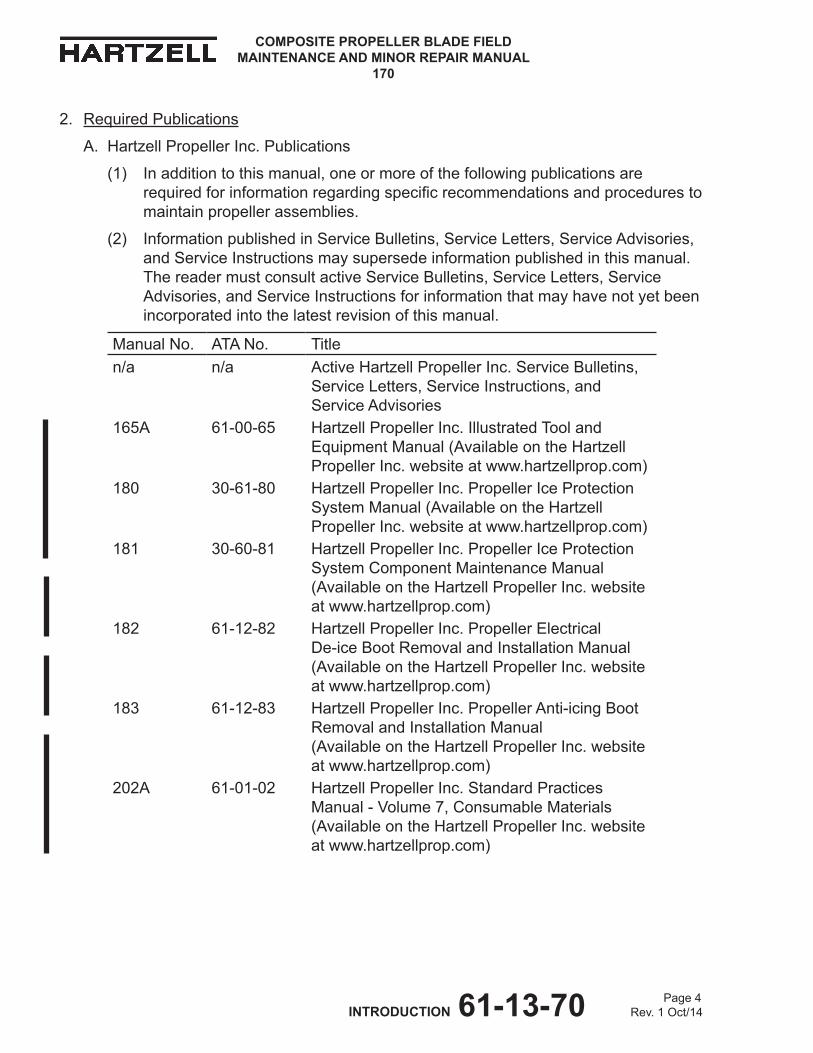
2. Required Publications
A. Hartzell Propeller Inc. Publications
(1) In addition to this manual, one or more of the following publications are requiredforinformationregardingspecificrecommendationsandprocedurestomaintain propeller assemblies.
(2) Information published in Service Bulletins, Service Letters, Service Advisories, and Service Instructions may supersede information published in this manual. The reader must consult active Service Bulletins, Service Letters, Service Advisories, and Service Instructions for information that may have not yet been incorporated into the latest revision of this manual.
Manual No. ATA No. Titlen/a n/a Active Hartzell Propeller Inc. Service Bulletins,
Service Letters, Service Instructions, and Service Advisories
165A 61-00-65 Hartzell Propeller Inc. Illustrated Tool and Equipment Manual (Available on the Hartzell Propeller Inc. website at www.hartzellprop.com)
180 30-61-80 Hartzell Propeller Inc. Propeller Ice Protection System Manual (Available on the Hartzell Propeller Inc. website at www.hartzellprop.com)
181 30-60-81 Hartzell Propeller Inc. Propeller Ice Protection System Component Maintenance Manual (Available on the Hartzell Propeller Inc. website at www.hartzellprop.com)
182 61-12-82 Hartzell Propeller Inc. Propeller Electrical De-ice Boot Removal and Installation Manual (Available on the Hartzell Propeller Inc. website at www.hartzellprop.com)
183 61-12-83 Hartzell Propeller Inc. Propeller Anti-icing Boot Removal and Installation Manual (Available on the Hartzell Propeller Inc. website at www.hartzellprop.com)
202A 61-01-02 Hartzell Propeller Inc. Standard Practices Manual - Volume 7, Consumable Materials (Available on the Hartzell Propeller Inc. website at www.hartzellprop.com)
COMPOSITE PROPELLER BLADE FIELD MAINTENANCE AND MINOR REPAIR MANUAL
170
Page 5 INTRODUCTION 61-13-70 Rev. 1 Oct/14
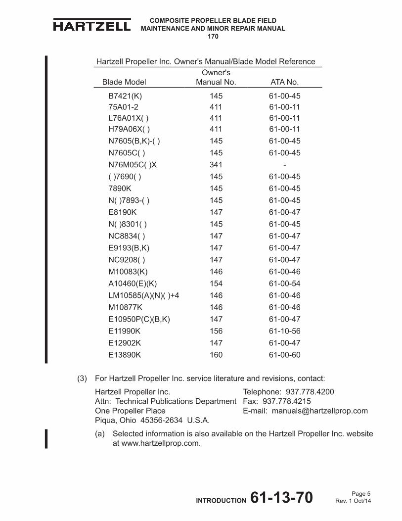
(3) For Hartzell Propeller Inc. service literature and revisions, contact:
Hartzell Propeller Inc. Telephone: 937.778.4200 Attn:TechnicalPublicationsDepartment Fax:937.778.4215 One Propeller Place E-mail: [email protected] Piqua, Ohio 45356-2634 U.S.A.
(a) Selected information is also available on the Hartzell Propeller Inc. website at www.hartzellprop.com.
Hartzell Propeller Inc. Owner's Manual/Blade Model Reference
Blade ModelOwner's
Manual No. ATA No.
B7421(K) 145 61-00-4575A01-2 411 61-00-11L76A01X( ) 411 61-00-11H79A06X( ) 411 61-00-11N7605(B,K)-( ) 145 61-00-45N7605C( ) 145 61-00-45N76M05C( )X 341 -( )7690( ) 145 61-00-457890K 145 61-00-45N( )7893-( ) 145 61-00-45E8190K 147 61-00-47N( )8301( ) 145 61-00-45NC8834( ) 147 61-00-47E9193(B,K) 147 61-00-47NC9208( ) 147 61-00-47M10083(K) 146 61-00-46A10460(E)(K) 154 61-00-54LM10585(A)(N)( )+4 146 61-00-46M10877K 146 61-00-46E10950P(C)(B,K) 147 61-00-47E11990K 156 61-10-56E12902K 147 61-00-47E13890K 160 61-00-60
COMPOSITE PROPELLER BLADE FIELD MAINTENANCE AND MINOR REPAIR MANUAL
170
Page 6 INTRODUCTION 61-13-70 Rev. 1 Oct/14
3. Personnel Requirements
A. Personnel Requirements
(1) Compliance to the applicable regulatory requirements established by the Federal Aviation Administration (FAA) or appropriate Aviation Authority is mandatory for anyone performing or accepting responsibility for any inspection and/or repair of any Hartzell Propeller Inc. product.
(2) Any person signing for or performing inspections and/or repairs to Hartzell Propeller Inc. composite parts should be familiar with the objectives and procedures associated with the inspection and/or repair of composite parts.
B. Minor Repair
(1) Damagethatiswithintheminorrepairlimitsasspecifiedinthismanualmayberepairedbyacertifiedairframeandpowerplantmechanic,orinternationalequivalent in accordance with the Minor Repairs chapter in this manual.
C. Major Repair
(1) Majorrepairworkisthatwhichexceedstheminorrepairlimitsasspecifiedinthis manual.
(2) To perform composite blade major repair, the propeller repair station must employ at least one individual with valid Composite Blade Overhaul, Major Repair,andRecertificationIndividualCertificationfromHartzellPropellerInc.
(3) All major repairs must be completed in a propeller repair station that is licensed by a government agency, e.g., FAA, EASA, CAA.
(4) Refer to the Hartzell Propeller Inc. website at www.hartzellprop.com or contact the Hartzell Propeller Inc. Product Support Department for a current list of authorized facilities.
4. Safe Handling of Paints and ChemicalsA. Alwaysusecautionwhenhandlingorbeingexposedtopaintsand/orchemicals
during propeller repair procedures.B. Before using paint or chemicals, always read the manufacturer’s label on the
containerandfollowspecifiedinstructionsandproceduresforstorage,preparation,mixing,andapplication.
C. Refer to the product’s Material Safety Data Sheet (MSDS) for detailed information about physical properties, health, and physical hazards of any chemical.
COMPOSITE PROPELLER BLADE FIELD MAINTENANCE AND MINOR REPAIR MANUAL
170
Page 7 INTRODUCTION 61-13-70 Rev. 1 Oct/14
5. Component Life and ServiceA. Calendar Limits
(1) Theeffectsofexposuretotheenvironmentoveraperiodoftimecreatea needforpropelleroverhaulregardlessofflighttime(aviation),oroperating time (non-aviation).
(2) AcalendarlimitbetweenoverhaulsisspecifiedinHartzellPropellerInc. Service Letters HC-SL-61-61Y and HM-SL-001, and in the applicable propeller owner's manual.
(3) Experiencehasshownthatspecialcare,suchaskeepinganaircraftinahangar,isnotsufficienttopermitextensionofthecalendarlimit.
(4) Thestartdateforthecalendarlimitiswhenthepropellerisfirstinstalledonanengine.
(5) The calendar limit is not interrupted by subsequent removal and/or storage.(6) The start date for the calendar limit must not be confused with the warranty
startdate,thatiswithcertainexceptions,thedateofinstallationbythefirstretail customer.
B. Component Life
(1) Certain components, or in some cases an entire propeller, may be life limited.
(a) It is a regulatory requirement that a record of the time since new be maintained for all life limited parts.
(b) Refer to the Airworthiness Limitations chapter in the applicable Hartzell Propeller Inc. Owner's Manual for a list of life limited components.
(2) Componentlifeisexpressedintermsofhoursofservice(TimeSinceNew,TSN)and in terms of hours of service since overhaul (Time Since Overhaul, TSO).
NOTE: TSN/TSO is considered as the time accumulated between rotation andlanding,i.e.,flighttime.
(3) BothTSNandTSOarenecessaryfordefiningthelifeofthecomponent.Somepartsare"lifelimited,"whichmeansthattheymustbereplacedafteraspecifiedperiod of use (TSN).
(4) When a component or assembly undergoes an overhaul, the TSO is returned to zero hours.
(a) Time Since New (TSN) can never be returned to zero.
(b) Repair without overhaul does not affect TSO or TSN.
(5) Time Since New (TSN) and Time Since Overhaul (TSO) records must be maintained in the propeller logbook.

COMPOSITE PROPELLER BLADE FIELD MAINTENANCE AND MINOR REPAIR MANUAL
170
Page 8 INTRODUCTION 61-13-70 Rev. 1 Oct/14
(6) Blades and hubs are sometimes replaced while in service or at overhaul.
(a) Maintaining separate TSN and TSO histories for a replacement hub or blade is required.
(b) Otherpropellercomponentsdonotrequiretimetrackingunlessspecifiedin Hartzell Propeller Inc. service publications.
(c) Hub replacement
1 If the hub is replaced, the replacement hub serial number must be recorded (the entry signed and dated) in the propeller logbook.
2 Thepropellerwillbeidentifiedwiththeserialnumberofthereplacement hub.
NOTE: Propeller assembly serial numbers are impression stamped on the hub. For stamping information, refer to the Parts IdentificationandMarkingchapterofHartzellPropellerInc.Standard Practices Manual 202A (61-01-02).
3 The TSN and TSO of the replacement hub must be recorded and maintained in the propeller logbook.
4 The TSN and TSO of the remaining propeller components that are requiredtobetrackedasdefinedabove,arenotaffectedbythehubreplacement and must be maintained separately.
C. Propeller Critical Parts
(1) Procedures in this manual involve Propeller Critical Parts (PCP).
(a) These procedures have been substantiated based on Engineering analysisthatexpectsthisproductwillbeoperatedandmaintainedusingthe procedures and inspections provided in the Instructions for Continued Airworthiness (ICA) for this product.
(2) Numerous propeller system parts can produce an aircraft Major or Hazardous effect, even though those parts may not be considered as Propeller Critical Parts. The operating and maintenance procedures and inspections provided intheICAforthisproductare,therefore,expectedtobeaccomplishedforallpropeller system parts.

COMPOSITE PROPELLER BLADE FIELD MAINTENANCE AND MINOR REPAIR MANUAL
170
Page 9 INTRODUCTION 61-13-70 Rev. 1 Oct/14
6. Manual Arrangement
A. Introduction
(1) The Introduction chapter gives general instructions for using this manual including.
(a) A list of required publications
(b) Personnel and repair station requirements
(c) A description of chapters in this manual
(d) Definitionsoftermsusedinthismanual
B. Inspection Procedures
(1) The Inspection Procedures chapter gives instructions for required procedures, andindentifiesthedifferentinspectionregionsforblademodelsaffectedbythisservice manual.
C. Damage Evaluation
(1) The Damage Evaluation chapter lists each damage type, and provides the applicable repair limits for blade models affected by this service manual.
D. Repair Limits
(1) The Repair Limits chapter gives dimensional limits for Airworthy Damage and Minor Repair.
E. Minor Repair
(1) TheMinorRepairchapterspecifiesminorrepairprocedures.
F. Tooling and Materials
(1) The Tooling and Materials chapter gives information about tooling and materials referenced in this manual.
COMPOSITE PROPELLER BLADE FIELD MAINTENANCE AND MINOR REPAIR MANUAL
170
Page 10 INTRODUCTION 61-13-70 Rev. 1 Oct/14
7. Tooling and Materials
NOTE: SpecificHartzellPropellerInc.manualsandservicedocumentsareavailableon the Hartzell website at www.hartzellprop.com. Refer to the Required Publications section in the Introduction chapter of this manual for the identificationofthesepublications.
A. Special Tooling
(1) Special tooling may be required for procedures in this manual. The reference numberforaspecialtoolwillappearwiththeprefix"TE"directlyfollowing thetoolnametowhichitapplies.Forexample,arollerthatisreference number 330 will appear as: roller TE330.
(a) For further tooling information, refer to Hartzell Propeller Inc. Illustrated Tool and Equipment Manual 165A (61-00-65).
B. Consumable Materials
(1) Consumable materials are referenced in certain sections throughout this manual. The reference number for a consumable material will appear with the prefix"CM"directlyfollowingthematerialtowhichitapplies.Forexample,anadhesive that is reference number 16 will appear as: adhesive CM16. Only thoseitemsspecifiedmaybeused.
(a) Specificapprovedmaterialsandtheirshelflife,potlife,etc.arelistedin Hartzell Propeller Inc. Standard Practices Manual 202A - Volume 7, Consumable Materials (61-01-02).

COMPOSITE PROPELLER BLADE FIELD MAINTENANCE AND MINOR REPAIR MANUAL
170
Page 11 INTRODUCTION 61-13-70 Rev. 1 Oct/14
8. Definitions
Term Description
AviationCertified ........................ intended for FAA or international equivalent type certificatedaircraftapplications.ATCandPCnumber must be stamped on the hub, and a PC number must be stamped on blades.
AviationExperimental ................ intended for aircraft/propeller applications not certifiedbytheFAAorinternationalequivalent.Products marked with an “X” at or near the end of the model number, part number, or serial number are notcertifiedbytheFAAorinternationalequivalentandarenotintendedtouseoncertificatedaircraft.
Bantam Composite Blades ......... a composite blade that is used in Bantam series propellers
BladePitchAxis ......................... an imaginary reference line through the length of a blade around which the blade rotates
Blade Station .............................. refers to a location on an individual blade for blade inspection purposes. It is a measurement from the blade "zero" station to a location on a blade, used toapplybladespecificationdatainbladeoverhaulmanuals NOTE: Do not confuse blade station with reference blade radius; they may not originate at the same location.
Camber ...................................... the surface of the blade that is directed toward the front of the aircraft. It is the low pressure, or suction, sideoftheblade.Thecambersideisconvexinshape over the entire length of the blade.
Chord Line .................................. a straight line drawn between the leading and trailing edge radii of the blade
Chordwise .................................. a direction that is generally from the leading edge to the trailing edge of an airfoil
Co-bonded ................................. the act of bonding a composite laminate and simultaneously curing it to some other prepared surface.
COMPOSITE PROPELLER BLADE FIELD MAINTENANCE AND MINOR REPAIR MANUAL
170
Page 12 INTRODUCTION 61-13-70 Rev. 1 Oct/14
Term Description
Composite Blade Traveler .......... a form that lists the applicable steps required for the overhaulofaspecificblademodel
Composite Material ....................Kevlar®,carbon,orfiberglassfibersboundtogetherwithorencapsulatedwithinanepoxyresin
Corrosion .................................... gradual wearing away or deterioration due to chemical action
Crack .......................................... irregularly shaped separation within a material, usually visible as a narrow opening at the surface
Debond ....................................... separation of two materials that were originally bonded in a separate operation
Delamination .............................. internal separation of the layers of a composite material
Depression ................................. surface area where the material has been compressed but not removed
Distortion .................................... alteration of the original shape or size of a component
Erosion ....................................... gradual wearing away or deterioration caused by action of the elements
Exposure .................................... leaving material open to action of the elements
Face ........................................... the surface of the blade that is directed toward the rear of the aircraft. The face side is the high pressure, or thrusting, side of the blade. The blade airfoil sections are normally cambered or curved suchthatthefacesideoftheblademaybeflatoreven concave in the midblade and tip region.
Face Alignment .......................... distance from the blade centerline to the highest point on the face side perpendicular to the chord line
Fretting ....................................... damage that develops when relative motion of small displacement takes place between contacting parts, wearing away the surface
Gouge ........................................ surface area where material has been removed
Hazardous Propeller Effect ........ thehazardouspropellereffectsaredefinedin Title 14 CFR section 35.15(g)(1)
Horizontal Balance ..................... balance between the tip and the butt of the blade
COMPOSITE PROPELLER BLADE FIELD MAINTENANCE AND MINOR REPAIR MANUAL
170
Page 13 INTRODUCTION 61-13-70 Rev. 1 Oct/14
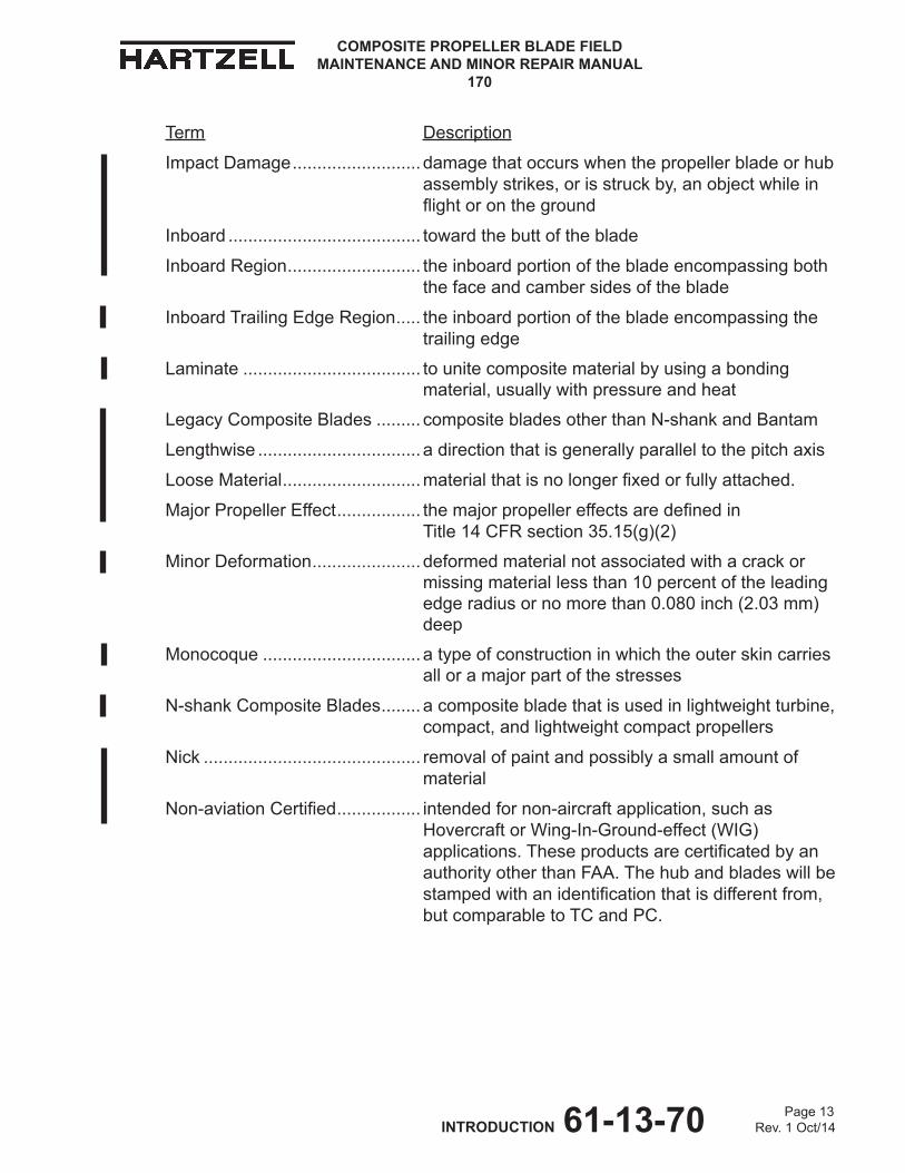
Term Description
Impact Damage .......................... damage that occurs when the propeller blade or hub assembly strikes, or is struck by, an object while in flightorontheground
Inboard ....................................... toward the butt of the blade
Inboard Region ........................... the inboard portion of the blade encompassing both the face and camber sides of the blade
Inboard Trailing Edge Region ..... the inboard portion of the blade encompassing the trailing edge
Laminate .................................... to unite composite material by using a bonding material, usually with pressure and heat
Legacy Composite Blades ......... composite blades other than N-shank and Bantam
Lengthwise .................................adirectionthatisgenerallyparalleltothepitchaxis
Loose Material ............................materialthatisnolongerfixedorfullyattached.
Major Propeller Effect ................. themajorpropellereffectsaredefinedin Title 14 CFR section 35.15(g)(2)
Minor Deformation ...................... deformed material not associated with a crack or missing material less than 10 percent of the leading edge radius or no more than 0.080 inch (2.03 mm) deep
Monocoque ................................ a type of construction in which the outer skin carries all or a major part of the stresses
N-shank Composite Blades ........ a composite blade that is used in lightweight turbine, compact, and lightweight compact propellers
Nick ............................................ removal of paint and possibly a small amount of material
Non-aviationCertified ................. intended for non-aircraft application, such as Hovercraft or Wing-In-Ground-effect (WIG) applications.Theseproductsarecertificatedbyanauthority other than FAA. The hub and blades will be stampedwithanidentificationthatisdifferentfrom,but comparable to TC and PC.
COMPOSITE PROPELLER BLADE FIELD MAINTENANCE AND MINOR REPAIR MANUAL
170
Page 14 INTRODUCTION 61-13-70 Rev. 1 Oct/14
Term Description
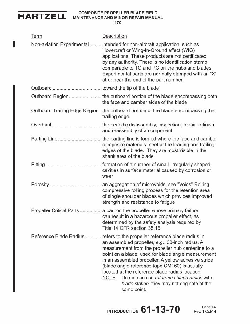
Non-aviationExperimental ......... intended for non-aircraft application, such as Hovercraft or Wing-In-Ground effect (WIG) applications.Theseproductsarenotcertificatedbyanyauthority.Thereisnoidentificationstampcomparable to TC and PC on the hubs and blades. Experimentalpartsarenormallystampedwithan“X”at or near the end of the part number.
Outboard .................................... toward the tip of the blade
Outboard Region ........................ the outboard portion of the blade encompassing both the face and camber sides of the blade
Outboard Trailing Edge Region .. the outboard portion of the blade encompassing the trailing edge
Overhaul ..................................... theperiodicdisassembly,inspection,repair,refinish,and reassembly of a component
Parting Line ................................ the parting line is formed where the face and camber composite materials meet at the leading and trailing edges of the blade. They are most visible in the shank area of the blade
Pitting ......................................... formation of a number of small, irregularly shaped cavities in surface material caused by corrosion or wear
Porosity ...................................... an aggregation of microvoids; see "Voids" Rolling compressive rolling process for the retention area of single shoulder blades which provides improved strength and resistance to fatigue
Propeller Critical Parts ................ a part on the propeller whose primary failure can result in a hazardous propeller effect, as determined by the safety analysis required by Title 14 CFR section 35.15
Reference Blade Radius ............ refers to the propeller reference blade radius in an assembled propeller, e.g., 30-inch radius. A measurement from the propeller hub centerline to a point on a blade, used for blade angle measurement in an assembled propeller. A yellow adhesive stripe (blade angle reference tape CM160) is usually located at the reference blade radius location. NOTE: Do not confuse reference blade radius with blade station; they may not originate at the same point.

COMPOSITE PROPELLER BLADE FIELD MAINTENANCE AND MINOR REPAIR MANUAL
170
Page 15 INTRODUCTION 61-13-70 Rev. 1 Oct/14
Term Description
Scratch ....................................... same as “Nick”
Shot Peening .............................. process where steel shot is impinged on a surface to create compressive surface stress, that provides improved strength and resistance to fatigue
Split ............................................delaminationofacompositebladeextendingtotheblade surface, normally found near the trailing edge or tip
Station Line ................................ see "Blade Station"
Track .......................................... in an assembled propeller, a measurement of the location of the blade tip with respect to the plane of rotation, used to verify face alignment and to compare blade tip location with respect to the locations of the other blades in the assembly
Trailing Edge .............................. the aft edge of an airfoil over which the air passes last
Unidirectional Material ................acompositematerialinwhichthefibersaresubstantially oriented in the same direction
Vertical Balance ......................... balance between the leading and trailing edges; this cannot be changed on composite blades
Voids .......................................... air or gas that has been trapped and cured into a composite material or adhesive
Woven Fabric ............................. a material constructedbyinterlacingfiberstoformafabric pattern
Wrinkle ....................................... overlap or fold within the material
COMPOSITE PROPELLER BLADE FIELD MAINTENANCE AND MINOR REPAIR MANUAL
170
Page 16 INTRODUCTION 61-13-70 Rev. 1 Oct/14
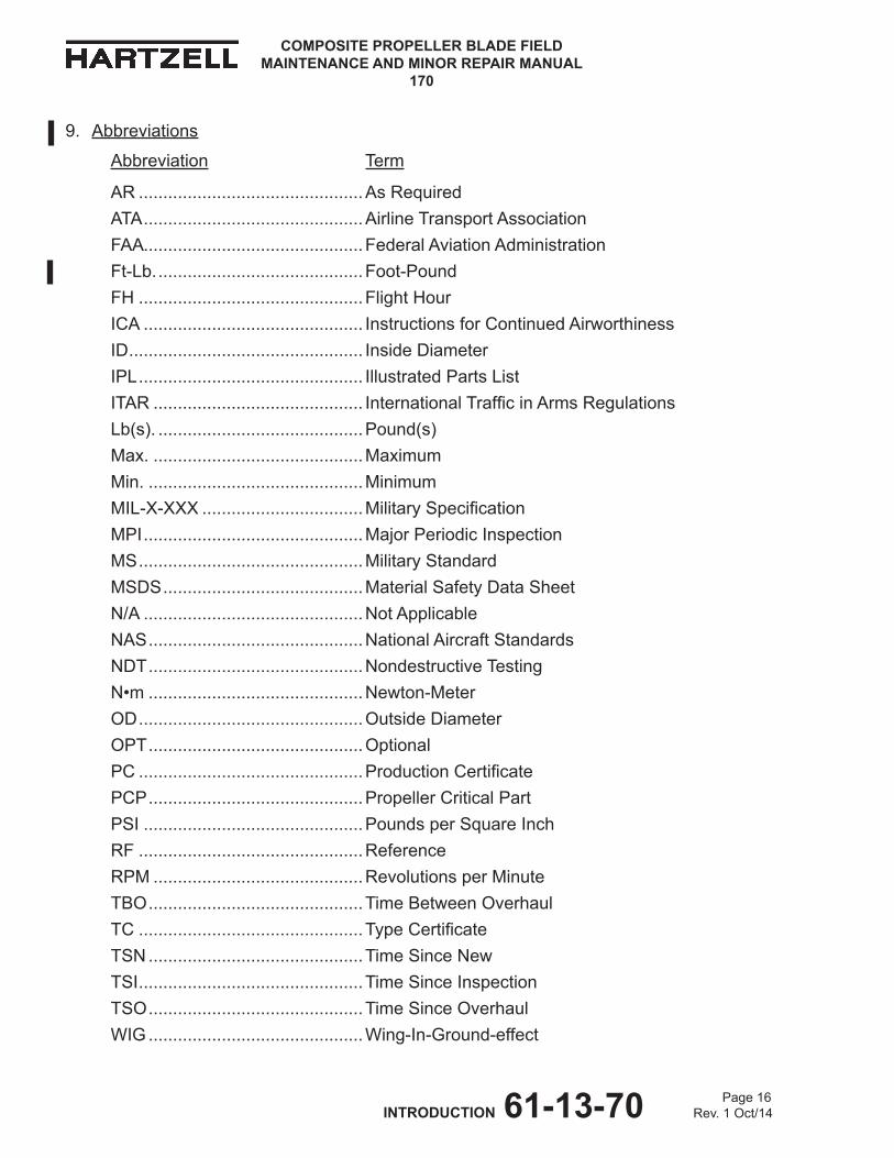
9. Abbreviations
Abbreviation Term
AR ..............................................As RequiredATA .............................................Airline Transport AssociationFAA .............................................Federal Aviation AdministrationFt-Lb. ..........................................Foot-PoundFH ..............................................Flight HourICA ............................................. Instructions for Continued AirworthinessID ................................................ Inside DiameterIPL .............................................. Illustrated Parts ListITAR ........................................... InternationalTrafficinArmsRegulationsLb(s). ..........................................Pound(s)Max. ...........................................MaximumMin. ............................................MinimumMIL-X-XXX .................................MilitarySpecificationMPI .............................................Major Periodic InspectionMS ..............................................Military StandardMSDS .........................................Material Safety Data SheetN/A .............................................Not ApplicableNAS ............................................National Aircraft Standards NDT ............................................Nondestructive Testing N•m ............................................Newton-MeterOD ..............................................Outside DiameterOPT ............................................OptionalPC ..............................................ProductionCertificatePCP ............................................Propeller Critical PartPSI .............................................Pounds per Square Inch RF ..............................................ReferenceRPM ...........................................Revolutions per MinuteTBO ............................................Time Between OverhaulTC ..............................................TypeCertificateTSN ............................................Time Since NewTSI ..............................................Time Since InspectionTSO ............................................Time Since OverhaulWIG ............................................Wing-In-Ground-effect
Page 1-1 INSPECTION PROCEDURES 61-13-70 Rev. 1 Oct/14
COMPOSITE PROPELLER BLADE FIELD MAINTENANCE AND MINOR REPAIR MANUAL
170
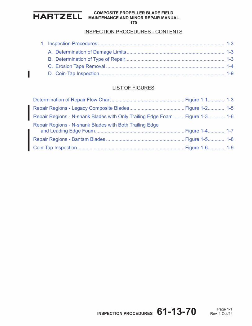
INSPECTION PROCEDURES - CONTENTS
1. Inspection Procedures ............................................................................................. 1-3
A. Determination of Damage Limits ........................................................................ 1-3B. Determination of Type of Repair ......................................................................... 1-3C. Erosion Tape Removal ....................................................................................... 1-4D. Coin-Tap Inspection............................................................................................ 1-9
LIST OF FIGURES
Determination of Repair Flow Chart ..................................................... Figure 1-1 ............. 1-3
Repair Regions - Legacy Composite Blades ........................................ Figure 1-2 ............. 1-5
Repair Regions - N-shank Blades with Only Trailing Edge Foam ........ Figure 1-3 ............. 1-6
Repair Regions - N-shank Blades with Both Trailing Edge and Leading Edge Foam ................................................................. Figure 1-4 ............. 1-7
Repair Regions - Bantam Blades ......................................................... Figure 1-5 ............. 1-8
Coin-Tap Inspection .............................................................................. Figure 1-6 ............. 1-9

Page 1-2 INSPECTION PROCEDURES 61-13-70 Rev. 1 Oct/14
COMPOSITE PROPELLER BLADE FIELD MAINTENANCE AND MINOR REPAIR MANUAL
170
(This page is intentionally left blank)

Page 1-3 INSPECTION PROCEDURES 61-13-70 Rev. 1 Oct/14
COMPOSITE PROPELLER BLADE FIELD MAINTENANCE AND MINOR REPAIR MANUAL
170
1. Inspection Procedures
CAUTION: INSTRUCTIONS AND PROCEDURES IN ThIS SECTION INvOLvE PROPELLER CRITICAL PARTS. REFER TO ThE INTRODUCTION ChAPTER OF ThIS mANUAL FOR INFORmATION ABOUT PROPELLER CRITICAL PARTS.
A. Determination of Damage Limits
(1) Uponinspectionofacompositepropellerblade,anoperatorshouldfirstdetermine whether the type of damage is airworthy or unairworthy. Refer to Figure 1-1 to determine the type of repair.
(a) If the damage is determined to be airworthy, the craft may continue in service; however, the operator should make arrangements to have repairs performed as soon as practical.
(b) Any damage that exceeds the airworthiness limitations stated in this manualmustberepairedbeforefurtherflight/operation.
B. Determination of Type of Repair
(1) Becauseoftheinfinitetypesofdamagepossible,notalltypesofdamagethatcan be considered airworthy are covered in this manual. If there is any doubt about the airworthiness of the blade, contact hartzell Propeller Inc.
Damaged Blade Inspection
Airworthy defined in chapter 3,
Repair Limits
Unairworthy defined in chapter 3,
Repair Limits
Minor Repair limits and instructions defined in chapter 3,
Repair Limits
Major Repair exceeds minor
repair limits
Factory Repair exceeds minor and major
repair limits
Determination of Repair Flow Chart Figure 1-1
Page 1-4 INSPECTION PROCEDURES 61-13-70 Rev. 1 Oct/14
COMPOSITE PROPELLER BLADE FIELD MAINTENANCE AND MINOR REPAIR MANUAL
170
C. Erosion Tape Removal
NOTE: Depending on the location of the damage, it may be necessary to remove the erosion tape Cm158 before inspection and/or repair. Blades with ice-protection boots do not have erosion tape installed.
(1) If erosion tape Cm158 is installed in the damage/inspection area, remove as follows:
CAUTION: USE ExTREmE CARE NOT TO DAmAGE ThE BLADE whILE REmOvING ThE EROSION TAPE.
(a) Carefully lift one edge of the erosion tape Cm158.(b) work around the perimeter of the erosion tape Cm158, lifting the edge of
the tape from the blade.
(c) After the edge of the erosion tape Cm158 is pulled up from the blade, pull the erosion tape off one side of the blade toward the leading edge.
(d) with the erosion tape Cm158 stuck to only one side of the blade, grasp one end of the erosion tape and pull toward the other end.
(e) Discard the removed erosion tape Cm158.
wARNING: ADhESIvES AND SOLvENTS ARE FLAmmABLE AND TOxIC TO ThE SKIN, EYES, AND RESPIRATORY TRACT. SKIN AND EYE PROTECTION ARE REQUIRED. AvOID PROLONGED CONTACT AND BREAThING OF vAPORS. USE SOLvENT RESISTANT GLOvES TO mINImIzE SKIN CONTACT AND wEAR SAFETY GLASSES FOR EYE PROTECTION. USE IN A wELL vENTILATED AREA AwAY FROm SPARKS AND FLAmE. READ AND OBSERvE ALL wARNING LABELS.
(f) Using a clean cloth dampened with solvent Cm106 (mEK), Cm219 (mPK), or Cm41 (Toluene) remove all visible adhesive from the blade.

Page 1-5 INSPECTION PROCEDURES 61-13-70 Rev. 1 Oct/14
COMPOSITE PROPELLER BLADE FIELD MAINTENANCE AND MINOR REPAIR MANUAL
170
Repair Regions - Legacy Composite Blades Figure 1-2
TI-1
3500
2
"A"Distance From the Blade Tip to the Inboard Region of the Blade, measured Along the
Blade Pitch Axis
Blade model "A" "B" "C"
B7421(K) 18.00 inches (457.2 mm) An Inboard Trailing Edge Region hasnotbeendefinedforthisblade. 18.00 inches (457.2 mm)
( )7690( ) 18.50 inches (469.9 mm) An Inboard Trailing Edge Region hasnotbeendefinedforthisblade. 18.50 inches (469.9 mm)
7890K 19.00 inches (482.6 mm) An Inboard Trailing Edge Region hasnotbeendefinedforthisblade. 19.00 inches (482.6 mm)
E8190K 19.00 inches (482.6 mm) An Inboard Trailing Edge Region hasnotbeendefinedforthisblade. 19.00 inches (482.6 mm)
E9193(B,K) 21.56 inches (547.6 mm) An Inboard Trailing Edge Region hasnotbeendefinedforthisblade. 21.56 inches (547.6 mm)
m10083(K) 22.61 inches (574.2 mm) An Inboard Trailing Edge Region hasnotbeendefinedforthisblade. 22.61 inches (574.2 mm)
A10460(E)(K) 24.65 inches (626.1 mm) An Inboard Trailing Edge Region hasnotbeendefinedforthisblade. 24.65 inches (626.1 mm)
Lm10585(A)(N)(B,K)+4 24.86 inches (631.4 mm) An Inboard Trailing Edge Region hasnotbeendefinedforthisblade. 24.86 inches (631.4 mm)
m10877K 24.74 inches (628.3 mm) An Inboard Trailing Edge Region hasnotbeendefinedforthisblade. 24.74 inches (628.3 mm)
E10950P(C)(B,K) 26.06 inches (661.9 mm) 5.00 inches (127.0 mm) 33.12 inches (841.2 mm)
E11990 28.56 inches (725.4 mm) An Inboard Trailing Edge Region hasnotbeendefinedforthisblade. 28.56 inches (725.4 mm)
E12902K 31.06 inches (788.9 mm) An Inboard Trailing Edge Region hasnotbeendefinedforthisblade. 31.06 inches (788.9 mm)
E13890K 33.12 inches (841.2 mm) An Inboard Trailing Edge Region hasnotbeendefinedforthisblade. 33.12 inches (841.2 mm)
Outboard Region
"C"
Tip and Trailing Edge Region"B"
Inboard Trailing Edge Region
Inboard Region
Refer to the Damage Evaluation chapter in this manual to identify the applicable damage type and repair limit for the blade models and affected regions shown in this table.
Page 1-6 INSPECTION PROCEDURES 61-13-70 Rev. 1 Oct/14
COMPOSITE PROPELLER BLADE FIELD MAINTENANCE AND MINOR REPAIR MANUAL
170
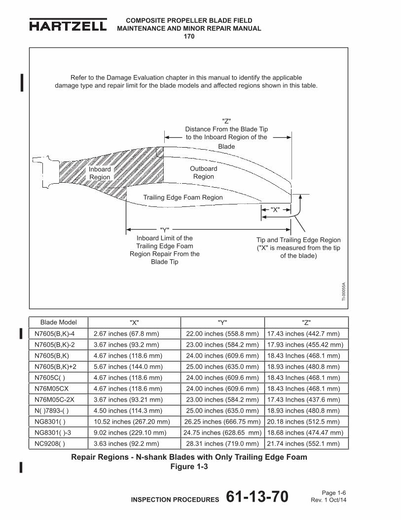
Repair Regions - N-shank Blades with Only Trailing Edge Foam Figure 1-3
Blade model "x" "Y" "z"
N7605(B,K)-4 2.67 inches (67.8 mm) 22.00 inches (558.8 mm) 17.43 inches (442.7 mm)
N7605(B,K)-2 3.67 inches (93.2 mm) 23.00 inches (584.2 mm) 17.93 inches (455.42 mm)
N7605(B,K) 4.67 inches (118.6 mm) 24.00 inches (609.6 mm) 18.43 Inches (468.1 mm)
N7605(B,K)+2 5.67 inches (144.0 mm) 25.00 inches (635.0 mm) 18.93 inches (480.8 mm)
N7605C( ) 4.67 inches (118.6 mm) 24.00 inches (609.6 mm) 18.43 Inches (468.1 mm)
N76m05Cx 4.67 inches (118.6 mm) 24.00 inches (609.6 mm) 18.43 Inches (468.1 mm)
N76m05C-2x 3.67 inches (93.21 mm) 23.00 inches (584.2 mm) 17.43 Inches (437.6 mm)
N( )7893-( ) 4.50 inches (114.3 mm) 25.00 inches (635.0 mm) 18.93 inches (480.8 mm)
NG8301( ) 10.52 inches (267.20 mm) 26.25 inches (666.75 mm) 20.18 inches (512.5 mm)
NG8301( )-3 9.02 inches (229.10 mm) 24.75 inches (628.65 mm) 18.68 inches (474.47 mm)
NC9208( ) 3.63 inches (92.2 mm) 28.31 inches (719.0 mm) 21.74 inches (552.1 mm)
TI-0
0055
A
Tip and Trailing Edge Region ("x" is measured from the tip
of the blade)
Trailing Edge Foam Region
"Y"Inboard Limit of theTrailing Edge Foam
Region Repair From the Blade Tip
"z"Distance From the Blade Tip to the Inboard Region of the
Blade
"x"
Inboard Region
Outboard Region
Refer to the Damage Evaluation chapter in this manual to identify the applicable damage type and repair limit for the blade models and affected regions shown in this table.
Page 1-7 INSPECTION PROCEDURES 61-13-70 Rev. 1 Oct/14
COMPOSITE PROPELLER BLADE FIELD MAINTENANCE AND MINOR REPAIR MANUAL
170
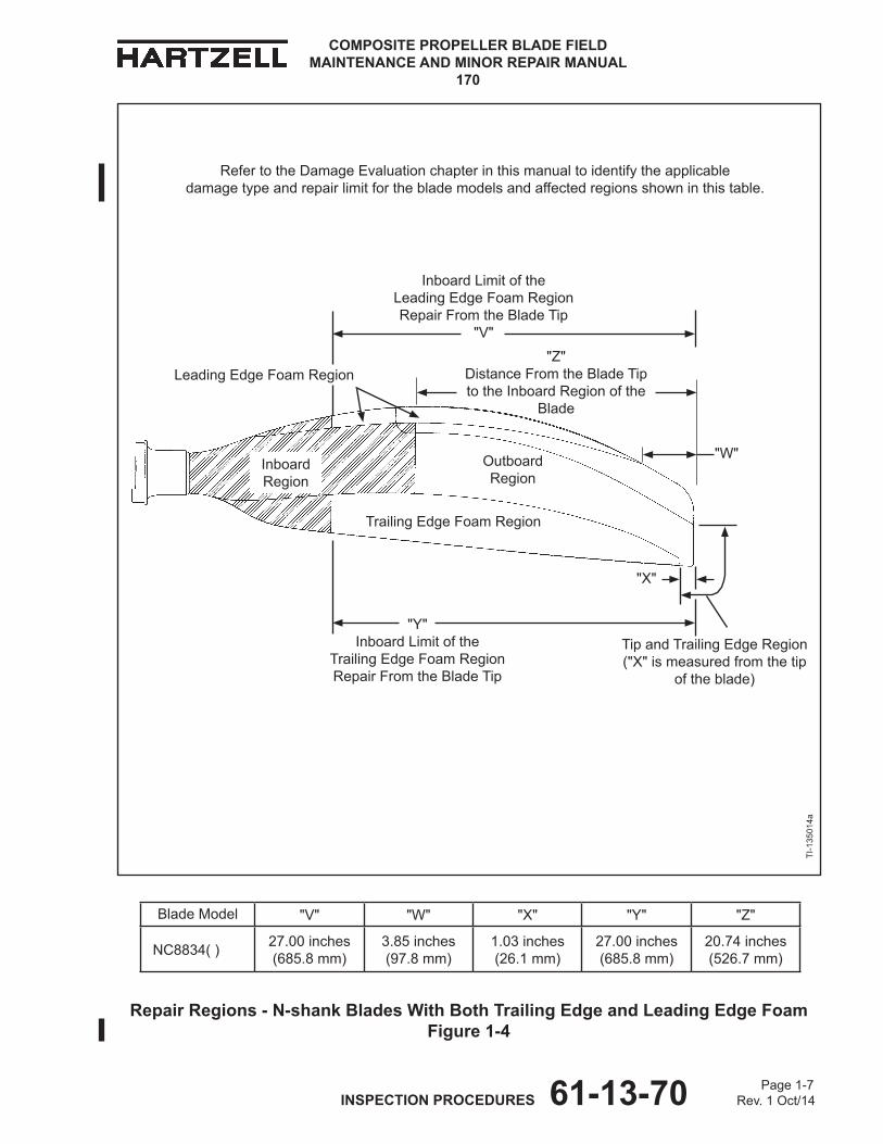
Blade model "v" "w" "x" "Y" "z"
NC8834( ) 27.00 inches (685.8 mm)
3.85 inches (97.8 mm)
1.03 inches (26.1 mm)
27.00 inches (685.8 mm)
20.74 inches (526.7 mm)
Repair Regions - N-shank Blades With Both Trailing Edge and Leading Edge Foam Figure 1-4
TI-1
3501
4a
Tip and Trailing Edge Region ("x" is measured from the tip
of the blade)
Trailing Edge Foam Region
"Y"Inboard Limit of the
Trailing Edge Foam Region Repair From the Blade Tip
"x"
Inboard Region
Outboard Region
"w"
Leading Edge Foam Region
Inboard Limit of theLeading Edge Foam Region Repair From the Blade Tip
"v""z"
Distance From the Blade Tip to the Inboard Region of the
Blade
Refer to the Damage Evaluation chapter in this manual to identify the applicable damage type and repair limit for the blade models and affected regions shown in this table.
Page 1-8 INSPECTION PROCEDURES 61-13-70 Rev. 1 Oct/14
COMPOSITE PROPELLER BLADE FIELD MAINTENANCE AND MINOR REPAIR MANUAL
170
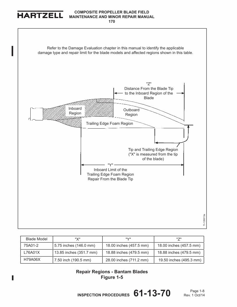
Repair Regions - Bantam Blades Figure 1-5
Blade model "x" "Y" "z"75A01-2 5.75 inches (146.0 mm) 18.00 inches (457.5 mm) 18.00 inches (457.5 mm)
L76A01x 13.85 inches (351.7 mm) 18.88 inches (479.5 mm) 18.88 inches (479.5 mm)
h79A06x 7.50 inch (190.5 mm) 28.00 inches (711.2 mm) 19.50 inches (495.3 mm)
TI-1
3501
3a
Trailing Edge Foam Region
Inboard Region
Outboard Region
Tip and Trailing Edge Region ("x" is measured from the tip
of the blade)"Y"
Inboard Limit of theTrailing Edge Foam Region Repair From the Blade Tip
"z"Distance From the Blade Tip to the Inboard Region of the
Blade
Refer to the Damage Evaluation chapter in this manual to identify the applicable damage type and repair limit for the blade models and affected regions shown in this table.

Page 1-9 INSPECTION PROCEDURES 61-13-70 Rev. 1 Oct/14
COMPOSITE PROPELLER BLADE FIELD MAINTENANCE AND MINOR REPAIR MANUAL
170
D. Coin-Tap Inspection
(1) Composite blades are inspected for delaminations and debonds by tapping the entire surface of the blade with a washer-shaped metal tapper or "coin". If an audible change is apparent, sounding hollow or dead, a debond or delamination is likely.
(a) Refer to the Tooling and materials chapter of this manual for the description of a "coin".
(b) Composite blades incorporate a separate foam trailing edge and some models also have a foam leading edge. The foam regions have a different tone when coin-tapped.
1 To avoid confusing sounds, coin-tap the foam region(s) and the transition area between the foam region(s) and the blade separately from the blade area. Refer to Figures 1-2 thru 1-5.
(2) "mapping" of the area to be coin-tapped is desirable to make sure that the entiresurfaceissufficientlyinspected.RefertoFigure 1-6
(a) make a coin-tap inspection within an imaginary grid or matrix consisting of 2 inch (51 mm) squares on the composite blade surface.
(b) A careful coin-tapping of the erosion shield is necessary because of its size and shape.
1 Tap in a smaller grid pattern up and down the length of the erosion shield.
2 Look and feel for any slight deformation of the erosion shield that may indicate a debonded area.
3 If a deformation is found, use more care in that area when doing the coin-tap inspection.
Coin-Tap Inspection Figure 1-6
“Coin-tap” on composite blade surface to check for delamination
“Coin-tap” along entire surface of erosion shield to check for debond

Page 1-10 INSPECTION PROCEDURES 61-13-70 Rev. 1 Oct/14
COMPOSITE PROPELLER BLADE FIELD MAINTENANCE AND MINOR REPAIR MANUAL
170
(This page is intentionally blank.)
Page 2-1 DAMAGE EVALUATION 61-13-70 Rev. 1 Oct/14
COMPOSITE PROPELLER BLADE FIELD MAINTENANCE AND MINOR REPAIR MANUAL
170
DAMAGE EVALUATION - CONTENTS1. Damage Evaluation ................................................................................................. 2-3
A. Determining the Damage Type and Repair Limits .............................................. 2-3
LIST OF TABLES
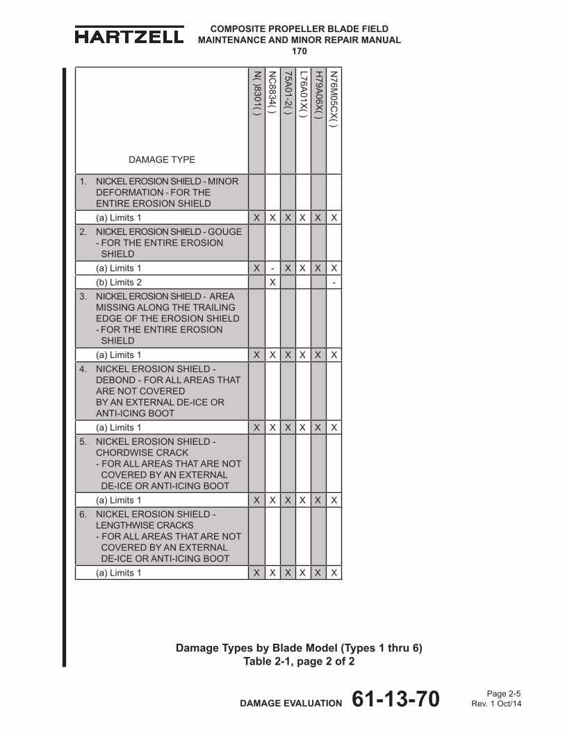
Damage Types by Blade Model (Types 1 thru 6) ..................................Table 2-1 ............. 2-4
1. Nickel Erosion Shield - Minor Deformation - For the entire erosion shield 2. Nickel Erosion Shield - Gouge - For the entire erosion shield 3. Nickel Erosion Shield - Area Missing Along the Trailing Edge of the Erosion Shield - For the entire erosion shield 4. Nickel Erosion Shield - Debond - For all areas that are not covered by an external de-ice or anti-icing boot 5. Nickel Erosion Shield - Chordwise Crack - For all areas that are not covered by an external de-ice or anti-icing boot 6. Nickel Erosion Shield - Lengthwise Cracks - For all areas that are not covered by an external de-ice or anti-icing boot
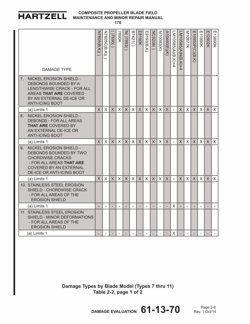
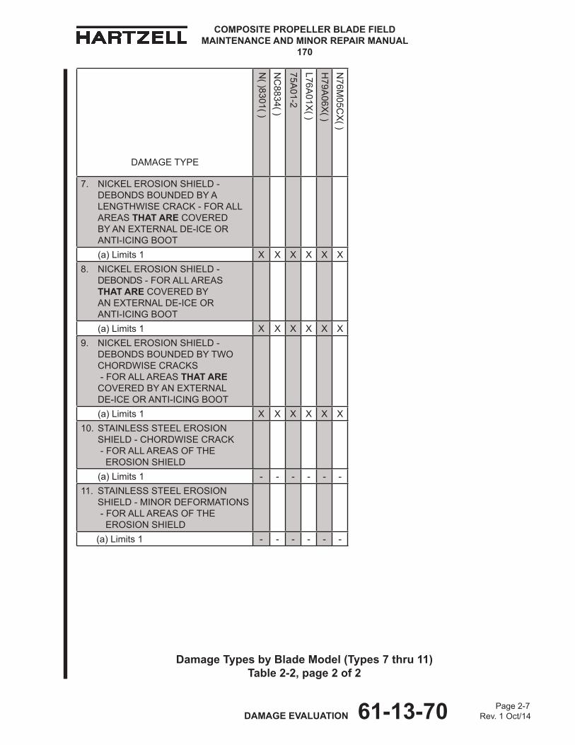
Damage Types by Blade Model (Types 7 thru 11) .................................Table 2-2 ............. 2-6
7. Nickel Erosion Shield - Debonds Bounded by a Lengthwise Crack - For all areas that are covered by an external de-ice or anti-icing boot 8. Nickel Erosion Shield - Debonds - For all areas that are covered by an external de-ice or anti-icing boot 9. Nickel Erosion Shield - Debonds Bounded by Two Chordwise Cracks - For all areas that are covered by an external de-ice or anti-icing boot 10. Stainless Steel Erosion Shield - Chordwise Crack - For all areas of the erosion shield 11. Stainless Steel Erosion Shield - Minor Deformations - For all areas of the erosion shield
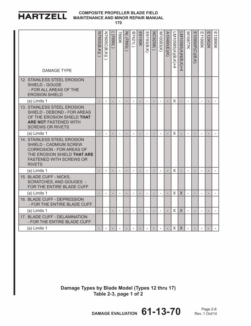
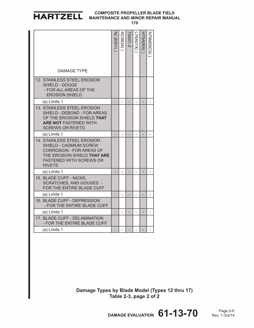
Damage Types by Blade Model (Types 12 thru 17) ..............................Table 2-3 ............. 2-8
12. Stainless Steel Erosion Shield - Gouge - For all areas of the erosion shield 13. Stainless Steel Erosion Shield - Debond - For areas of the erosion shield that are not fastened with screws or rivets 14. Stainless Steel Erosion Shield - Cadmium Screw Corrosion - For areas of the erosion shield that are fastened with screws or rivets 15. Blade Cuff - Nicks, Scratches, and Gouges - For the entire blade cuff 16. Blade Cuff - Depression - For the entire blade cuff 17. Blade Cuff - Delamination - for the entire blade cuff

Page 2-2 DAMAGE EVALUATION 61-13-70 Rev. 1 Oct/14
COMPOSITE PROPELLER BLADE FIELD MAINTENANCE AND MINOR REPAIR MANUAL
170
LIST OF TABLES -continued
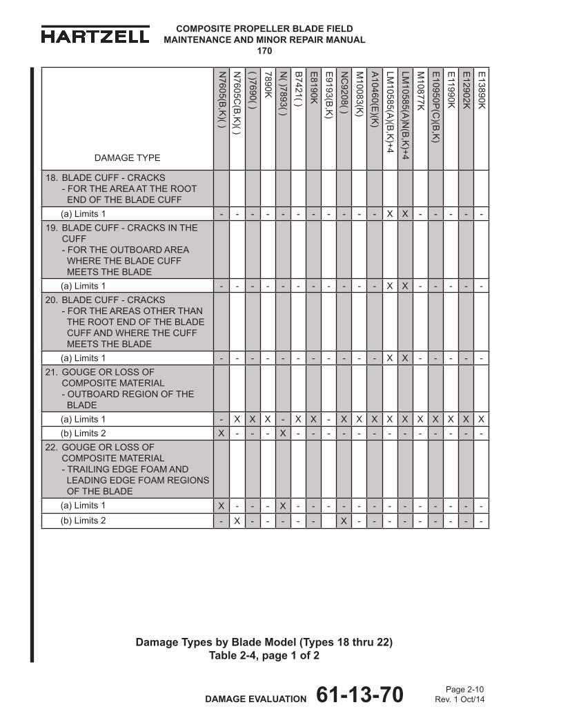
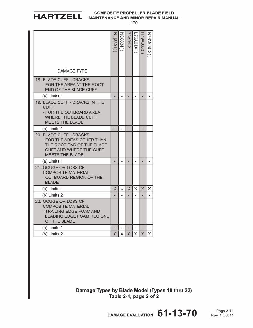
Damage Types by Blade Model (Types 18 thru 22) ..............................Table 2-4 ...........2-10 18. Blade Cuff - Cracks - For the area at the root end of the blade cuff
19. Blade Cuff - Cracks in the Cuff - For the outboard area where the blade cuff meets the blade 20. Blade Cuff - Cracks - For the areas other than the root end of the blade cuff and ... where the cuff meets the blade 21. Gouge or Loss of Composite Material - Outboard region of the blade 22. Gouge or Loss of Composite Material - Trailing edge foam and leading edge foam regions of the blade
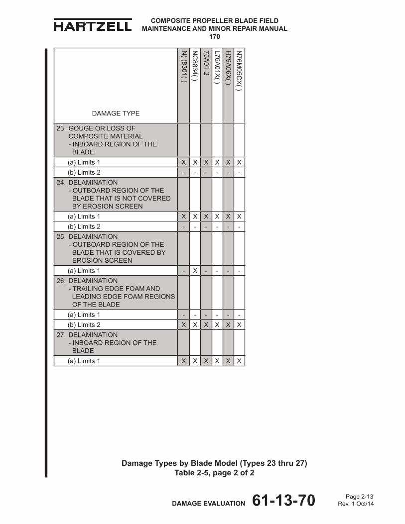
Damage Types by Blade Model (Types 23 thru 27) ..............................Table 2-5 ...........2-12 23. Gouge or Loss of Composite Material - Inboard region of the blade
24. Delamination - Outboard region of the blade that is not covered by erosion screen 25. Delamination - Outboard region of the blade that is covered by erosion screen 26. Delamination - Trailing edge foam and leading edge foam regions of the blade 27. Delamination - Inboard region of the blade
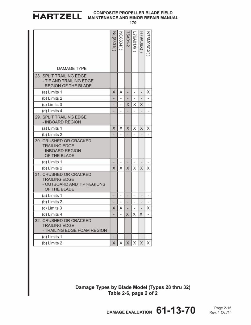
Damage Types by Blade Model (Types 28 thru 32) ..............................Table 2-6 ...........2-14
28. Split Trailing Edge -Tip and trailing edge region of the blade 29. Split Trailing Edge - Inboard region 30. Crushed or Cracked Trailing Edge - Inboard region of the blade 31. Crushed or Cracked Trailing Edge - Outboard and tip regions of the blade 32. Crushed or Cracked Trailing Edge -Trailing edge foam region
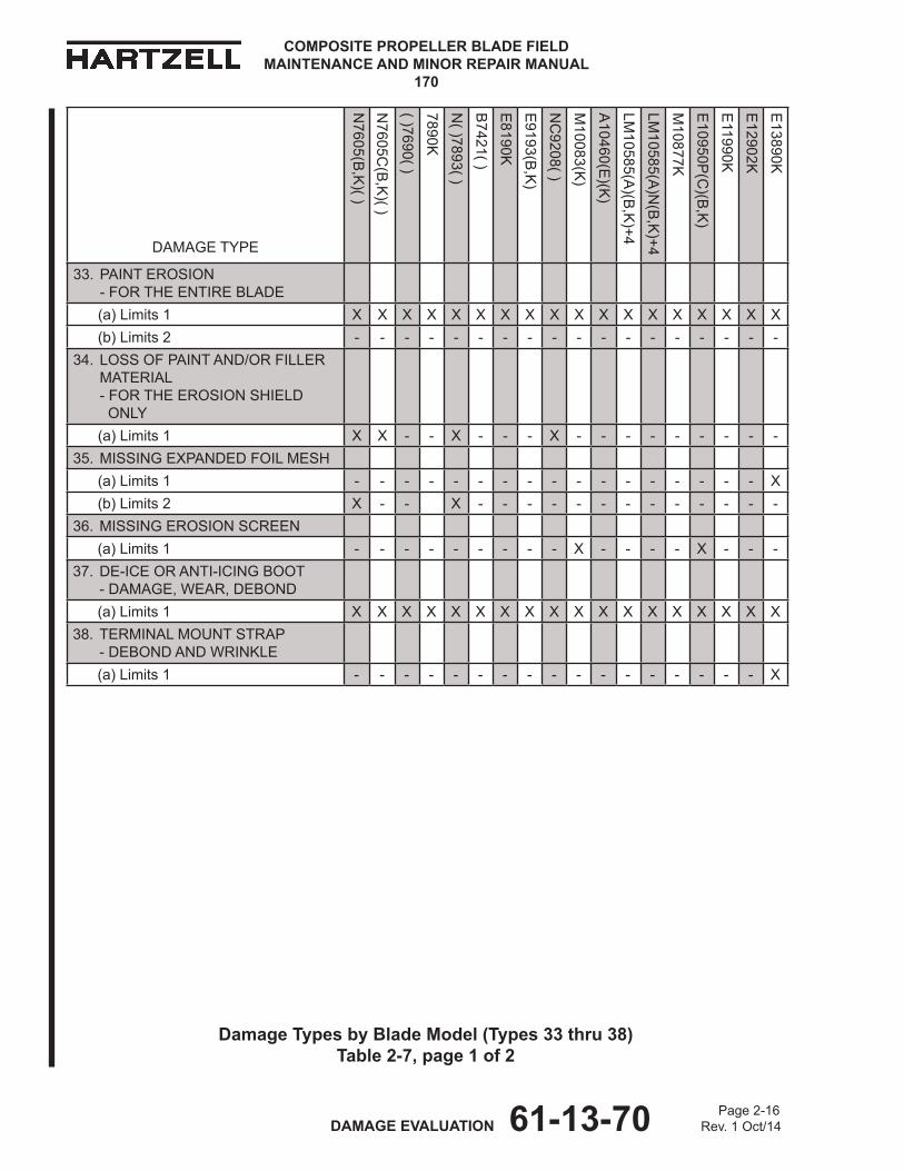
Damage Types by Blade Model (Types 33 thru 38) ..............................Table 2-7 ...........2-16 33. Paint Erosion - for the entire blade
34. Loss of Paint and/or Filler Material - for the erosion shield only 35. Missing Expanded Foil Mesh 36. Missing Erosion Screen 37. De-ice or Anti-icing Boot - Damage, Wear, Debond 38. Terminal Mount Strap - Debond and Wrinkle
Page 2-3 DAMAGE EVALUATION 61-13-70 Rev. 1 Oct/14
COMPOSITE PROPELLER BLADE FIELD MAINTENANCE AND MINOR REPAIR MANUAL
170
1. Damage Evaluation
CAUTION: INSTRUCTIONS AND PROCEDURES IN ThIS SECTION INVOLVE PROPELLER CRITICAL PARTS. REFER TO ThE INTRODUCTION ChAPTER OF ThIS MANUAL FOR INFORMATION ABOUT PROPELLER CRITICAL PARTS.
A. Determining the Damage Type and Repair Limits
(1) Inspection identifies the location and type of damage for each area of damage on the blade.(a) Refer to Figure 1-2 thru Figure 1-5 as applicable, for definitions of blade
regions by model.
(2) Using Table 2-1 thru Table 2-7, locate the applicable damage type based on the location and type of damage identified in the inspection.
(3) Use the applicable Table to determine the repair limit for the specific blade model.
(4) Refer to the Repair Limits chapter in this manual for specific information about Airworthy Damage and Minor Repair Limits for each damage type.

Page 2-4 DAMAGE EVALUATION 61-13-70 Rev. 1 Oct/14
COMPOSITE PROPELLER BLADE FIELD MAINTENANCE AND MINOR REPAIR MANUAL
170
DAMAGE TYPE
N7605(B
,K)( )
N7605C
(B,K
)( )
( )7690( )7890KN
( )7893( )B
7421( )E
8190KE
9193(B,K
)N
C9208( )
M10083(K
)A
10460(E)(K
)LM
10585(A)(B
,K)+4
LM10585(A
)N(B
,K)+4
M10877K
E10950P
(C)(B
,K)
E11990K
E12902K
E13890K
1. NICKEL EROSION ShIELD - MINOR DEFORMATION - FOR ThE ENTIRE EROSION ShIELD (a) Limits 1 x x x x x x x x x x x - x x x x x x
2. NICKEL EROSION ShIELD - GOUGE - FOR ThE ENTIRE EROSION ShIELD (a) Limits 1 x x x x x x x x x x x - x x x x x x(b) Limits 2 - - -- - - - - - - - - - - - - - - -
3. NICKEL EROSION ShIELD - AREA MISSING ALONG ThE TRAILING EDGE OF ThE EROSION ShIELD - FOR ThE ENTIRE EROSION ShIELD (a) Limits 1 x x x x x x x x x x x - x x x x x x
4. NICKEL EROSION ShIELD - DEBOND - FOR ALL AREAS ThAT ARE NOT COVERED BY AN ExTERNAL DE-ICE OR ANTI-ICING BOOT(a) Limits 1 x x x x x x x x x x x - x x x x x x
5. NICKEL EROSION ShIELD - ChORDWISE CRACK - FOR ALL AREAS ThAT ARE NOT COVERED BY AN ExTERNAL DE-ICE OR ANTI-ICING BOOT(a) Limits 1 x x x x x x x x x x x - x x x x x x
6. NICKEL EROSION ShIELD - LENGThWISE CRACKS - FOR ALL AREAS ThAT ARE NOT COVERED BY AN ExTERNAL DE-ICE OR ANTI-ICING BOOT(a) Limits 1 x x x x x x x x x x x - x x x x x x
Damage Types by Blade Model (Types 1 thru 6)Table 2-1, page 1 of 2
Page 2-5 DAMAGE EVALUATION 61-13-70 Rev. 1 Oct/14
COMPOSITE PROPELLER BLADE FIELD MAINTENANCE AND MINOR REPAIR MANUAL
170
DAMAGE TYPE
N( )8301( )
NC
8834( )
75A01-2( )
L76A01x
( )h
79A06x
( )N
76M05C
x( )
1. NICKEL EROSION ShIELD - MINOR DEFORMATION - FOR ThE ENTIRE EROSION ShIELD (a) Limits 1 x x x x x x
2. NICKEL EROSION ShIELD - GOUGE - FOR ThE ENTIRE EROSION ShIELD (a) Limits 1 x - x x x x(b) Limits 2 x -
3. NICKEL EROSION ShIELD - AREA MISSING ALONG ThE TRAILING EDGE OF ThE EROSION ShIELD - FOR ThE ENTIRE EROSION ShIELD (a) Limits 1 x x x x x x
4. NICKEL EROSION ShIELD - DEBOND - FOR ALL AREAS ThAT ARE NOT COVERED BY AN ExTERNAL DE-ICE OR ANTI-ICING BOOT(a) Limits 1 x x x x x x
5. NICKEL EROSION ShIELD - ChORDWISE CRACK - FOR ALL AREAS ThAT ARE NOT COVERED BY AN ExTERNAL DE-ICE OR ANTI-ICING BOOT(a) Limits 1 x x x x x x
6. NICKEL EROSION ShIELD - LENGThWISE CRACKS - FOR ALL AREAS ThAT ARE NOT COVERED BY AN ExTERNAL DE-ICE OR ANTI-ICING BOOT(a) Limits 1 x x x x x x
Damage Types by Blade Model (Types 1 thru 6)Table 2-1, page 2 of 2
Page 2-6 DAMAGE EVALUATION 61-13-70 Rev. 1 Oct/14
COMPOSITE PROPELLER BLADE FIELD MAINTENANCE AND MINOR REPAIR MANUAL
170
DAMAGE TYPE
N7605(B
,K)( )
N7605C
(B,K
)( )
( )7690( )7890KN
( )7893( )B
7421( )E
8190KE
9193(B,K
)N
C9208( )
M10083(K
)A
10460(E)(K
)LM
10585(A)(B
,K)+4
LM10585(A
)N(B
,K)+4
M10877K
E10950P
(C)(B
,K)
E11990K
E12902K
E13890K
7. NICKEL EROSION ShIELD - DEBONDS BOUNDED BY A LENGThWISE CRACK - FOR ALL AREAS ThAT ARE COVERED BY AN ExTERNAL DE-ICE OR ANTI-ICING BOOT(a) Limits 1 x x x x x x x x x x x - x x x x x x
8. NICKEL EROSION ShIELD - DEBONDS - FOR ALL AREAS ThAT ARE COVERED BY AN ExTERNAL DE-ICE OR ANTI-ICING BOOT(a) Limits 1 x x x x x x x x x x x - x x x x x x
9. NICKEL EROSION ShIELD - DEBONDS BOUNDED BY TWO ChORDWISE CRACKS - FOR ALL AREAS ThAT ARE COVERED BY AN ExTERNAL DE-ICE OR ANTI-ICING BOOT(a) Limits 1 x x x x x x x x x x x - x x x x x x
10. STAINLESS STEEL EROSION ShIELD - ChORDWISE CRACK - FOR ALL AREAS OF ThE EROSION ShIELD(a) Limits 1 - - - - - - - - - - - x - - - - - -
11. STAINLESS STEEL EROSION ShIELD - MINOR DEFORMATIONS - FOR ALL AREAS OF ThE EROSION ShIELD
(a) Limits 1 - - - - - - - - - - - x - - - - - -
Damage Types by Blade Model (Types 7 thru 11)Table 2-2, page 1 of 2
Page 2-7 DAMAGE EVALUATION 61-13-70 Rev. 1 Oct/14
COMPOSITE PROPELLER BLADE FIELD MAINTENANCE AND MINOR REPAIR MANUAL
170
DAMAGE TYPE
N( )8301( )
NC
8834( )
75A01-2
L76A01x
( )h
79A06x
( )N
76M05C
x( )
7. NICKEL EROSION ShIELD - DEBONDS BOUNDED BY A LENGThWISE CRACK - FOR ALL AREAS ThAT ARE COVERED BY AN ExTERNAL DE-ICE OR ANTI-ICING BOOT(a) Limits 1 x x x x x x
8. NICKEL EROSION ShIELD - DEBONDS - FOR ALL AREAS ThAT ARE COVERED BY AN ExTERNAL DE-ICE OR ANTI-ICING BOOT(a) Limits 1 x x x x x x
9. NICKEL EROSION ShIELD - DEBONDS BOUNDED BY TWO ChORDWISE CRACKS - FOR ALL AREAS ThAT ARE COVERED BY AN ExTERNAL DE-ICE OR ANTI-ICING BOOT(a) Limits 1 x x x x x x
10. STAINLESS STEEL EROSION ShIELD - ChORDWISE CRACK - FOR ALL AREAS OF ThE EROSION ShIELD(a) Limits 1 - - - - - -
11. STAINLESS STEEL EROSION ShIELD - MINOR DEFORMATIONS - FOR ALL AREAS OF ThE EROSION ShIELD
(a) Limits 1 - - - - - -
Damage Types by Blade Model (Types 7 thru 11)Table 2-2, page 2 of 2
Page 2-8 DAMAGE EVALUATION 61-13-70 Rev. 1 Oct/14
COMPOSITE PROPELLER BLADE FIELD MAINTENANCE AND MINOR REPAIR MANUAL
170
DAMAGE TYPE
N7605(B
,K)( )
N7605C
(B,K
)( )
( )7690( )7890KN
( )7893( )B
7421( )E
8190KE
9193(B,K
)N
C9208( )
M10083(K
)A
10460(E)(K
)LM
10585(A)(B
,K)+4
LM10585(A
)N(B
,K)+4
M10877K
E10950P
(C)(B
,K)
E11990K
E12902K
E13890K
12. STAINLESS STEEL EROSION ShIELD - GOUGE - FOR ALL AREAS OF ThE EROSION ShIELD
(a) Limits 1 - - - - - - - - - - - x - - - - - -13. STAINLESS STEEL EROSION
ShIELD - DEBOND - FOR AREAS OF ThE EROSION ShIELD ThAT ARE NOT FASTENED WITh SCREWS OR RIVETS
(a) Limits 1 - - - - - - - - - - - x - - - - - -14. STAINLESS STEEL EROSION
ShIELD - CADMIUM SCREW CORROSION - FOR AREAS OF ThE EROSION ShIELD ThAT ARE FASTENED WITh SCREWS OR RIVETS
(a) Limits 1 - - - - - - - - - - - x - - - - - -15. BLADE CUFF - NICKS,
SCRATChES, AND GOUGES - FOR ThE ENTIRE BLADE CUFF
(a) Limits 1 - - - - - - - - - - - x x - - - - -16. BLADE CUFF - DEPRESSION
- FOR ThE ENTIRE BLADE CUFF (a) Limits 1 - - - - - - - - - - - x x - - - - -17. BLADE CUFF - DELAMINATION
- FOR ThE ENTIRE BLADE CUFF (a) Limits 1 - - - - - - - - - - - x x - - - - -
Damage Types by Blade Model (Types 12 thru 17)Table 2-3, page 1 of 2
Page 2-9 DAMAGE EVALUATION 61-13-70 Rev. 1 Oct/14
COMPOSITE PROPELLER BLADE FIELD MAINTENANCE AND MINOR REPAIR MANUAL
170
DAMAGE TYPE
N( )8301( )
NC
8834( )
75A01-2
L76A01x
( )h
79A06x
( )N
76M05C
x( )
12. STAINLESS STEEL EROSION ShIELD - GOUGE - FOR ALL AREAS OF ThE EROSION ShIELD
(a) Limits 1 - - - - - -13. STAINLESS STEEL EROSION
ShIELD - DEBOND - FOR AREAS OF ThE EROSION ShIELD ThAT ARE NOT FASTENED WITh SCREWS OR RIVETS
(a) Limits 1 - - - - - -14. STAINLESS STEEL EROSION
ShIELD - CADMIUM SCREW CORROSION - FOR AREAS OF ThE EROSION ShIELD ThAT ARE FASTENED WITh SCREWS OR RIVETS
(a) Limits 1 - - - - - -15. BLADE CUFF - NICKS,
SCRATChES, AND GOUGES - FOR ThE ENTIRE BLADE CUFF
(a) Limits 1 - - - - - -16. BLADE CUFF - DEPRESSION
- FOR ThE ENTIRE BLADE CUFF (a) Limits 1 - - - - - -17. BLADE CUFF - DELAMINATION
- FOR ThE ENTIRE BLADE CUFF (a) Limits 1 - - - - - -
Damage Types by Blade Model (Types 12 thru 17)Table 2-3, page 2 of 2
Page 2-10 DAMAGE EVALUATION 61-13-70 Rev. 1 Oct/14
COMPOSITE PROPELLER BLADE FIELD MAINTENANCE AND MINOR REPAIR MANUAL
170
DAMAGE TYPE
N7605(B
,K)( )
N7605C
(B,K
)( )
( )7690( )7890KN
( )7893( )B
7421( )E
8190KE
9193(B,K
)N
C9208( )
M10083(K
)A
10460(E)(K
)LM
10585(A)(B
,K)+4
LM10585(A
)N(B
,K)+4
M10877K
E10950P
(C)(B
,K)
E11990K
E12902K
E13890K
18. BLADE CUFF - CRACKS - FOR ThE AREA AT ThE ROOT END OF ThE BLADE CUFF
(a) Limits 1 - - - - - - - - - - - x x - - - - -19. BLADE CUFF - CRACKS IN ThE
CUFF - FOR ThE OUTBOARD AREA WhERE ThE BLADE CUFF MEETS ThE BLADE
(a) Limits 1 - - - - - - - - - - - x x - - - - -20. BLADE CUFF - CRACKS
- FOR ThE AREAS OThER ThAN ThE ROOT END OF ThE BLADE CUFF AND WhERE ThE CUFF MEETS ThE BLADE
(a) Limits 1 - - - - - - - - - - - x x - - - - -21. GOUGE OR LOSS OF
COMPOSITE MATERIAL - OUTBOARD REGION OF ThE BLADE
(a) Limits 1 - x x x - x x - x x x x x x x x x x (b) Limits 2 x - - - x - - - - - - - - - - - - -22. GOUGE OR LOSS OF
COMPOSITE MATERIAL - TRAILING EDGE FOAM AND LEADING EDGE FOAM REGIONS OF ThE BLADE
(a) Limits 1 x - - - x - - - - - - - - - - - - - (b) Limits 2 - x - - - - - x - - - - - - - - -
Damage Types by Blade Model (Types 18 thru 22)Table 2-4, page 1 of 2
Page 2-11 DAMAGE EVALUATION 61-13-70 Rev. 1 Oct/14
COMPOSITE PROPELLER BLADE FIELD MAINTENANCE AND MINOR REPAIR MANUAL
170
DAMAGE TYPE
N( )8301( )
NC
8834( )
75A01-2
L76A01x
( )h
79A06x
( )N
76M05C
x( )
18. BLADE CUFF - CRACKS - FOR ThE AREA AT ThE ROOT END OF ThE BLADE CUFF
(a) Limits 1 - - - - - -19. BLADE CUFF - CRACKS IN ThE
CUFF - FOR ThE OUTBOARD AREA WhERE ThE BLADE CUFF MEETS ThE BLADE
(a) Limits 1 - - - - - -20. BLADE CUFF - CRACKS
- FOR ThE AREAS OThER ThAN ThE ROOT END OF ThE BLADE CUFF AND WhERE ThE CUFF MEETS ThE BLADE
(a) Limits 1 - - - - - -21. GOUGE OR LOSS OF
COMPOSITE MATERIAL - OUTBOARD REGION OF ThE BLADE
(a) Limits 1 x x x x x x (b) Limits 2 - - - - - -22. GOUGE OR LOSS OF
COMPOSITE MATERIAL - TRAILING EDGE FOAM AND LEADING EDGE FOAM REGIONS OF ThE BLADE
(a) Limits 1 - - - - - - (b) Limits 2 x x x x x x
Damage Types by Blade Model (Types 18 thru 22)Table 2-4, page 2 of 2

Page 2-12 DAMAGE EVALUATION 61-13-70 Rev. 1 Oct/14
COMPOSITE PROPELLER BLADE FIELD MAINTENANCE AND MINOR REPAIR MANUAL
170
DAMAGE TYPE
N7605(B
,K)( )
N7605C
(B,K
)( )
( )7690( )7890KN
( )7893( )B
7421( )E
8190KE
9193(B,K
)N
C9208( )
M10083(K
)A
10460(E)(K
)LM
10585(A)(B
,K)+4
LM10585(A
)N(B
,K)+4
M10877K
E10950P
(C)(B
,K)
E11990K
E12902K
E13890K
23. GOUGE OR LOSS OF COMPOSITE MATERIAL - INBOARD REGION OF ThE BLADE
(a) Limits 1 x x - - x - - x x - - - - - - - - x (b) Limits 2 - - x x - x x - - x x x x x x x x -24. DELAMINATION
- OUTBOARD REGION OF ThE BLADE ThAT IS NOT COVERED BY EROSION SCREEN
(a) Limits 1 - x x x - x x - x x x x x x x x x x (b) Limits 2 x - - - x - - - - - - - - - - - - -25. DELAMINATION
- OUTBOARD REGION OF ThE BLADE ThAT IS COVERED BY EROSION SCREEN
(a) Limits 1 - - - - - - - x - x - - - - x - - -26. DELAMINATION
- TRAILING EDGE FOAM AND LEADING EDGE FOAM REGIONS OF ThE BLADE
(a) Limits 1 x - - - x - - - - - - - - - - - - - (b) Limits 2 - x - - - - - - x - - - - - - - - -27. DELAMINATION
- INBOARD REGION OF ThE BLADE
(a) Limits 1 x x x x x x x x x x x x x x x x x x
Damage Types by Blade Model (Types 23 thru 27)Table 2-5, page 1 of 2
Page 2-13 DAMAGE EVALUATION 61-13-70 Rev. 1 Oct/14
COMPOSITE PROPELLER BLADE FIELD MAINTENANCE AND MINOR REPAIR MANUAL
170
DAMAGE TYPE
N( )8301( )
NC
8834( )
75A01-2
L76A01x
( )h
79A06x
( )N
76M05C
x( )
23. GOUGE OR LOSS OF COMPOSITE MATERIAL - INBOARD REGION OF ThE BLADE
(a) Limits 1 x x x x x x (b) Limits 2 - - - - - -24. DELAMINATION
- OUTBOARD REGION OF ThE BLADE ThAT IS NOT COVERED BY EROSION SCREEN
(a) Limits 1 x x x x x x (b) Limits 2 - - - - - -25. DELAMINATION
- OUTBOARD REGION OF ThE BLADE ThAT IS COVERED BY EROSION SCREEN
(a) Limits 1 - x - - - -26. DELAMINATION
- TRAILING EDGE FOAM AND LEADING EDGE FOAM REGIONS OF ThE BLADE
(a) Limits 1 - - - - - - (b) Limits 2 x x x x x x27. DELAMINATION
- INBOARD REGION OF ThE BLADE
(a) Limits 1 x x x x x x
Damage Types by Blade Model (Types 23 thru 27)Table 2-5, page 2 of 2

Page 2-14 DAMAGE EVALUATION 61-13-70 Rev. 1 Oct/14
COMPOSITE PROPELLER BLADE FIELD MAINTENANCE AND MINOR REPAIR MANUAL
170
DAMAGE TYPE
N7605(B
,K)( )
N7605C
(B,K
)( )
( )7690( )7890KN
( )7893( )B
7421( )E
8190KE
9193(B,K
)N
C9208( )
M10083(K
)A
10460(E)(K
)LM
10585(A)(B
,K)+4
LM10585(A
)N(B
,K)+4
M10877K
E10950P
(C)(B
,K)
E11990K
E12902K
E13890K
28. SPLIT TRAILING EDGE - TIP AND TRAILING EDGE REGION OF ThE BLADE
(a) Limits 1 - x x x - x x - x x x x x x - x x - (b) Limits 2 - - - - - - - - - - - - - - x - - - (c) Limits 3 - - - - - - - - - - - - - - - - - x (d) Limits 4 x - - - x - - - - - - - - - - - - -29. SPLIT TRAILING EDGE
- INBOARD REGION (a) Limits 1 x x x x x x x x x x x x x x x x x (b) Limits 2 - - - - - - - - - - - - - - x - - -30. CRUShED OR CRACKED
TRAILING EDGE - INBOARD REGION OF ThE BLADE
(a) Limits 1 - - - - - - - - - - - - - - x - - - (b) Limits 2 x x x x x x x x x x x x x - x x x31. CRUShED OR CRACKED
TRAILING EDGE - OUTBOARD AND TIP REGIONS OF ThE BLADE
(a) Limits 1 x - x x x x x - - x x x x x - x x - (b) Limits 2 - - - - - - - - - - - - - - x - - - (c) Limits 3 - x - - - - - - x - - - - - - - - x (d) Limits 4 - - - - - - - - - - - - - - - - - -32. CRUShED OR CRACKED
TRAILING EDGE - TRAILING EDGE FOAM REGION
(a) Limits 1 x - - - x - - - - - - - - - - - - - (b) Limits 2 - x - - - - - - x - - - - - - - - -
Damage Types by Blade Model (Types 28 thru 32)Table 2-6, page 1 of 2
Page 2-15 DAMAGE EVALUATION 61-13-70 Rev. 1 Oct/14
COMPOSITE PROPELLER BLADE FIELD MAINTENANCE AND MINOR REPAIR MANUAL
170
DAMAGE TYPE
N( )8301( )
NC
8834( )
75A01-2
L76A01x
( )h
79A06x
( )N
76M05C
x( )
28. SPLIT TRAILING EDGE - TIP AND TRAILING EDGE REGION OF ThE BLADE
(a) Limits 1 x x - - - x (b) Limits 2 - - - - - - (c) Limits 3 - - x x x - (d) Limits 4 - - - - - -29. SPLIT TRAILING EDGE
- INBOARD REGION (a) Limits 1 x x x x x x (b) Limits 2 - - - - - -30. CRUShED OR CRACKED
TRAILING EDGE - INBOARD REGION OF ThE BLADE
(a) Limits 1 - - - - - - (b) Limits 2 x x x x x x31. CRUShED OR CRACKED
TRAILING EDGE - OUTBOARD AND TIP REGIONS OF ThE BLADE
(a) Limits 1 - - - - - - (b) Limits 2 - - - - - - (c) Limits 3 x x - - - x (d) Limits 4 - - x x x -32. CRUShED OR CRACKED
TRAILING EDGE - TRAILING EDGE FOAM REGION
(a) Limits 1 - - - - - - (b) Limits 2 x x x x x x
Damage Types by Blade Model (Types 28 thru 32)Table 2-6, page 2 of 2
Page 2-16 DAMAGE EVALUATION 61-13-70 Rev. 1 Oct/14
COMPOSITE PROPELLER BLADE FIELD MAINTENANCE AND MINOR REPAIR MANUAL
170
DAMAGE TYPE
N7605(B
,K)( )
N7605C
(B,K
)( )
( )7690( )7890KN
( )7893( )B
7421( )E
8190KE
9193(B,K
)N
C9208( )
M10083(K
)A
10460(E)(K
)LM
10585(A)(B
,K)+4
LM10585(A
)N(B
,K)+4
M10877K
E10950P
(C)(B
,K)
E11990K
E12902K
E13890K
33. PAINT EROSION - FOR ThE ENTIRE BLADE
(a) Limits 1 x x x x x x x x x x x x x x x x x x (b) Limits 2 - - - - - - - - - - - - - - - - - -34. LOSS OF PAINT AND/OR FILLER
MATERIAL - FOR ThE EROSION ShIELD ONLY
(a) Limits 1 x x - - x - - - x - - - - - - - - -35. MISSING ExPANDED FOIL MESh (a) Limits 1 - - - - - - - - - - - - - - - - - x (b) Limits 2 x - - x - - - - - - - - - - - - -36. MISSING EROSION SCREEN (a) Limits 1 - - - - - - - - - x - - - - x - - -37. DE-ICE OR ANTI-ICING BOOT
- DAMAGE, WEAR, DEBOND (a) Limits 1 x x x x x x x x x x x x x x x x x x38. TERMINAL MOUNT STRAP
- DEBOND AND WRINKLE (a) Limits 1 - - - - - - - - - - - - - - - - - x
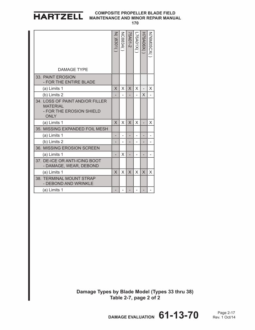
Damage Types by Blade Model (Types 33 thru 38)Table 2-7, page 1 of 2
Page 2-17 DAMAGE EVALUATION 61-13-70 Rev. 1 Oct/14
COMPOSITE PROPELLER BLADE FIELD MAINTENANCE AND MINOR REPAIR MANUAL
170
DAMAGE TYPE
N( )8301( )
NC
8834( )
75A01-2
L76A01x
( )h
79A06x
( )N
76M05C
x( )
33. PAINT EROSION - FOR ThE ENTIRE BLADE
(a) Limits 1 x x x x - x (b) Limits 2 - - - - x -34. LOSS OF PAINT AND/OR FILLER
MATERIAL - FOR ThE EROSION ShIELD ONLY
(a) Limits 1 x x x x - x35. MISSING ExPANDED FOIL MESh (a) Limits 1 - - - - - - (b) Limits 2 - - - - - -36. MISSING EROSION SCREEN (a) Limits 1 - x - - - -37. DE-ICE OR ANTI-ICING BOOT
- DAMAGE, WEAR, DEBOND (a) Limits 1 x x x x x x38. TERMINAL MOUNT STRAP
- DEBOND AND WRINKLE (a) Limits 1 - - - - - -
Damage Types by Blade Model (Types 33 thru 38)Table 2-7, page 2 of 2

Page 2-18 DAMAGE EVALUATION 61-13-70 Rev. 1 Oct/14
COMPOSITE PROPELLER BLADE FIELD MAINTENANCE AND MINOR REPAIR MANUAL
170
(This page is intentionally blank.)
Page 3-1 REPAIR LIMITS 61-13-70 Rev. 1 Oct/14
COMPOSITE PROPELLER BLADE FIELD MAINTENANCE AND MINOR REPAIR MANUAL
170
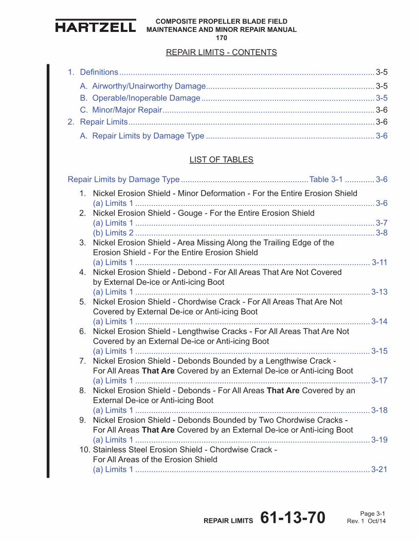
REPAIR LIMITS - CONTENTS
1. Definitions ................................................................................................................ 3-5
A. Airworthy/UnairworthyDamage.......................................................................... 3-5B. Operable/InoperableDamage ............................................................................ 3-5C. Minor/MajorRepair ............................................................................................. 3-6
2. RepairLimits ............................................................................................................ 3-6
A. RepairLimitsbyDamageType .......................................................................... 3-6
LIST OF TABLES
RepairLimitsbyDamageType ........................................................Table3-1 ............. 3-6
1. NickelErosionShield-MinorDeformation-FortheEntireErosionShield (a) Limits1 ......................................................................................................... 3-6 2. NickelErosionShield-Gouge-FortheEntireErosionShield (a) Limits1 ......................................................................................................... 3-7 (b)Limits2 ......................................................................................................... 3-8 3. NickelErosionShield-AreaMissingAlongtheTrailingEdgeofthe ErosionShield-FortheEntireErosionShield (a)Limits1 ....................................................................................................... 3-11 4. NickelErosionShield-Debond-ForAllAreasThatAreNotCovered byExternalDe-iceorAnti-icingBoot (a)Limits1 ....................................................................................................... 3-13 5. NickelErosionShield-ChordwiseCrack-ForAllAreasThatAreNot CoveredbyExternalDe-iceorAnti-icingBoot (a) Limits1 ....................................................................................................... 3-14 6. NickelErosionShield-LengthwiseCracks-ForAllAreasThatAreNot CoveredbyanExternalDe-iceorAnti-icingBoot (a) Limits1 ....................................................................................................... 3-15 7. NickelErosionShield-DebondsBoundedbyaLengthwiseCrack- ForAllAreasThat AreCoveredbyanExternalDe-iceorAnti-icingBoot (a) Limits1 ....................................................................................................... 3-17 8. NickelErosionShield-Debonds-ForAllAreasThat AreCoveredbyan ExternalDe-iceorAnti-icingBoot (a)Limits1 ....................................................................................................... 3-18 9. NickelErosionShield-DebondsBoundedbyTwoChordwiseCracks- ForAllAreasThat AreCoveredbyanExternalDe-iceorAnti-icingBoot (a)Limits1 ....................................................................................................... 3-19 10.StainlessSteelErosionShield-ChordwiseCrack- ForAllAreasoftheErosionShield (a) Limits1 ....................................................................................................... 3-21
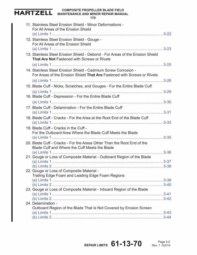
COMPOSITE PROPELLER BLADE FIELD MAINTENANCE AND MINOR REPAIR MANUAL
170
Page 3-2 REPAIR LIMITS 61-13-70 Rev. 1 Oct/14
11.StainlessSteelErosionShield-MinorDeformations- ForAllAreasoftheErosionShield (a) Limits1 ....................................................................................................... 3-22
12.StainlessSteelErosionShield-Gouge- ForAllAreasoftheErosionShield (a) Limits1 ....................................................................................................... 3-23
13.StainlessSteelErosionShield-Debond-ForAreasoftheErosionShield That Are NotFastenedwithScrewsorRivets
(a) Limits1 ....................................................................................................... 3-25 14.StainlessSteelErosionShield-CadmiumScrewCorrosion-
ForAreasoftheErosionShieldThat AreFastenedwithScrewsorRivets (a) Limits1 ....................................................................................................... 3-26 15.BladeCuff-Nicks,Scratches,andGouges-FortheEntireBladeCuff (a) Limits1 ....................................................................................................... 3-29
16.BladeCuff-Depression-FortheEntireBladeCuff (a) Limits1 ....................................................................................................... 3-30 17.BladeCuff-Delamination-FortheEntireBladeCuff
(a) Limits1 ....................................................................................................... 3-31 18.BladeCuff-Cracks-FortheAreaattheRootEndoftheBladeCuff
(a) Limits1 ....................................................................................................... 3-33 19.BladeCuff-CracksintheCuff-
FortheOutboardAreaWheretheBladeCuffMeetstheBlade (a) Limits1 ....................................................................................................... 3-35
20.BladeCuff-Cracks-FortheAreasOtherThantheRootEndofthe BladeCuffandWheretheCuffMeetstheBlade (a) Limits1 ....................................................................................................... 3-36 21.GougeorLossofCompositeMaterial-OutboardRegionoftheBlade (a) Limits1 ....................................................................................................... 3-37 (b)Limits2 ....................................................................................................... 3-38 22.GougeorLossofCompositeMaterial- TrailingEdgeFoamandLeadingEdgeFoamRegions (a) Limits1 ....................................................................................................... 3-39 (b)Limits2 ....................................................................................................... 3-40 23.GougeorLossofCompositeMaterial-InboardRegionoftheBlade (a) Limits1 ....................................................................................................... 3-41 (b)Limits2 ....................................................................................................... 3-42 24.Delamination- OutboardRegionoftheBladeThatIsNotCoveredbyErosionScreen (a) Limits1 ....................................................................................................... 3-43 (b)Limits2 ....................................................................................................... 3-44

Page 3-3 REPAIR LIMITS 61-13-70 Rev. 1 Oct/14
COMPOSITE PROPELLER BLADE FIELD MAINTENANCE AND MINOR REPAIR MANUAL
170
25.Delamination- OutboardRegionoftheBladeThatIsCoveredbyErosionScreen (a) Limits1 ....................................................................................................... 3-45
26.Delamination- TrailingEdgeFoamandLeadingEdgeFoamRegionsoftheBlade (a) Limits1 ....................................................................................................... 3-46 (b)Limits2 ....................................................................................................... 3-47 27.Delamination-InboardRegionoftheBlade (a) Limits1 ....................................................................................................... 3-48 28.SplitTrailingEdge-TipandTrailingEdgeRegionoftheBlade (a) Limits1 ....................................................................................................... 3-49 (b)Limits2 ....................................................................................................... 3-50 (c)Limits3 ....................................................................................................... 3-51 (d)Limits4 ....................................................................................................... 3-52 29.SplitTrailingEdge-InboardRegionoftheBlade (a) Limits1 ....................................................................................................... 3-53 (b)Limits2 ....................................................................................................... 3-54
30.CrushedorCrackedTrailingEdge-InboardRegionoftheBlade (a) Limits1 ....................................................................................................... 3-55 (b)Limits2 ....................................................................................................... 3-56 31.CrushedorCrackedTrailingEdge- OutboardandTipRegionsoftheBlade (a) Limits1 ....................................................................................................... 3-57 (b)Limits2 ....................................................................................................... 3-58 (c)Limits3 ....................................................................................................... 3-59 (d)Limits4 ....................................................................................................... 3-60 32.CrushedorCrackedTrailingEdge- TrailingEdgeFoamRegionoftheBlade (a) Limits1 ....................................................................................................... 3-61 (b)Limits2 ....................................................................................................... 3-62
33.PaintErosion-FortheEntireBlade (a) Limits1 ....................................................................................................... 3-63 (b)Limits2 ....................................................................................................... 3-64 34.LossofPaintand/orFillerMaterial-FortheErosionShieldOnly (a) Limits1 ....................................................................................................... 3-65
35.MissingExpandedFoilMesh (a) Limits1 ....................................................................................................... 3-66 (b)Limits2 ....................................................................................................... 3-67
36.MissingErosionScreen (a) Limits1 ....................................................................................................... 3-68 37.De-iceorAnti-icingBoot-Damage,Wear,Debond (a) Limits1 ....................................................................................................... 3-69 38.TerminalMountStrap-DebondandWrinkle (a) Limits1 ....................................................................................................... 3-70
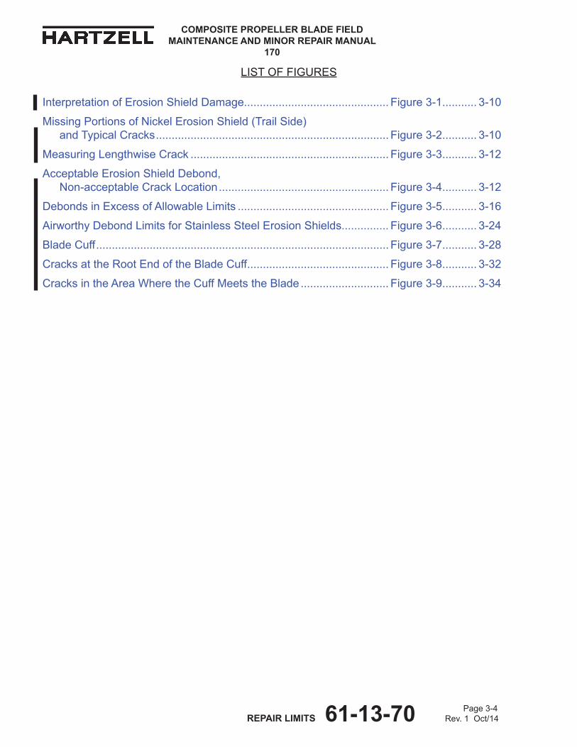
COMPOSITE PROPELLER BLADE FIELD MAINTENANCE AND MINOR REPAIR MANUAL
170
Page 3-4 REPAIR LIMITS 61-13-70 Rev. 1 Oct/14
LISTOFFIGURES
InterpretationofErosionShieldDamage..............................................Figure3-1 ........... 3-10
MissingPortionsofNickelErosionShield(TrailSide) andTypicalCracks ..........................................................................Figure3-2 ........... 3-10
MeasuringLengthwiseCrack ...............................................................Figure3-3 ........... 3-12
AcceptableErosionShieldDebond, Non-acceptableCrackLocation ......................................................Figure3-4 ........... 3-12
DebondsinExcessofAllowableLimits ................................................Figure3-5 ........... 3-16
AirworthyDebondLimitsforStainlessSteelErosionShields...............Figure3-6 ........... 3-24
BladeCuff .............................................................................................Figure3-7 ........... 3-28
CracksattheRootEndoftheBladeCuff .............................................Figure3-8 ........... 3-32
CracksintheAreaWheretheCuffMeetstheBlade ............................Figure3-9 ........... 3-34

Page 3-5 REPAIR LIMITS 61-13-70 Rev. 1 Oct/14
COMPOSITE PROPELLER BLADE FIELD MAINTENANCE AND MINOR REPAIR MANUAL
170
1. Definitions
A. Airworthy/UnairworthyDamage
(1) AirworthydamageisaspecificconditiontoabladeinstalledonanaviationproductthatiswithintheairworthydamagelimitsasspecifiedinTable3-1inthischapter.
(a) Airworthydamagedoesnotaffectthesafetyorflightcharacteristicsofthepropellerandconformstoitstypedesign.
(b) Damagethatiswithintheairworthylimitsdoesnotrequirerepairbeforefurtherflight,butshouldberepairedassoonasposibletopreventdegradationofthedamage.
(2) UnairworthydamageisaspecificconditiontoabladeinstalledonanaviationproductthatexceedstheairworthydamagelimitsasspecifiedinTable3-1inthischapter.
(a) Unairworthydamagecanaffectthesafetyorflightcharacteristicsofthepropelleranddoesnotconformtoitstypedesign.
(b) Thisconditionmakesthecomponentunairworthy,requiringappropriatecorrectiveactiontorepairorremoveitfromservice,asapplicable.
B. Operable/InoperableDamage
(1) Operabledamageisaspecificconditiontoabladeinstalledonanon-aviationproductthatdoesnotaffectthesafetyoroperationalcharacteristicsofthepropellerblade.
(a) Forabladethatisusedonanon-aviationapplication,allreferencesinthismanualtoairworthydamageapplytooperabledamage.
(b) Althoughablademaycontinueinservicewithoperabledamage,thistypeofdamageshouldberepairedattheearliestpracticaltimetopreventthedamagefromprogressingtoaconditionthatcouldrequireamoreextensiverepairtotheblade.
(2) Inoperabledamageisaspecificconditiontoabladeinstalledonnon-aviationproductthatexceedstheairworthydamagelimitsasspecifiedinTable3-1.
(a) Inoperabledamagecanaffectthesafetyoroperationalcharacteristicsofthepropelleranddoesnotconformtoitstypedesign.
(b) Thisconditionmakesthecomponentinoperable,requiringappropriatecorrectiveactiontorepairorremoveitfromservice,asapplicable.

COMPOSITE PROPELLER BLADE FIELD MAINTENANCE AND MINOR REPAIR MANUAL
170
Page 3-6 REPAIR LIMITS 61-13-70 Rev. 1 Oct/14
C. Minor/MajorRepair
(1) Minorrepairisthatwhichmaybedonesafelyinthefieldbyacertifiedaircraftmechanic.
(2) MajorrepairworkisthatwhichexceedstheminorrepairlimitsasspecifiedinTable3-1inthischapter.
2. RepairLimits
CAUTION: INSTRUCTIONSANDPROCEDURESINThISSECTIONINvOLvEPROPELLERCRITICALPARTS.REFERTOThEINTRODUCTIONChAPTEROFThISMANUALFORINFORMATIONABOUTPROPELLER CRITICAL PARTS.
NOTE: SpecifichartzellPropellerInc.manualsandservicedocumentsareavailableonthehartzellwebsiteatwww.hartzellprop.com.RefertotheRequiredPublicationssectionintheIntroductionchapterofthismanualfortheidentificationofthesepublications.
A. RepairLimitsbyDamageType(RefertoTable3-1)
CAUTION: REFERTOTABLE2-1INThEDAMAGEEvALUATIONChAPTEROFThISMANUALFORThEAPPLICABLEDAMAGETyPEANDREPAIRLIMITSByBLADEMODEL.REFERTOThISTABLEFORThEAIRWORThyANDMINORREPAIRLIMITSFOREAChDAMAGETyPE.
1. NICKELEROSIONShIELD - MINOR dEFORMATION - FORThEENTIREEROSIONShIELD
LIMITS dESIgNATIoN
AIRWoRTHY dAMAgE LIMITS
MINoR REPAIR INSTRUCTIoNS
(a) LIMITS 1 Deformedmaterialnotassociatedwithacrackormissingmateriallessthan10%oftheleadingedgeradiusornomorethan0.080inch(2.03mm)deepbecauseofimpactdamageorerosion.
Minorrepairisnotauthorized. Majorrepairmaybepermitted, refertotheNOTEatthebottomofthispage.
NOTE:FORPERSONNELAUThORIzEDTOPERFORMMAjORREPAIR, REFER TO ThEINTRODUCTIONChAPTEROFThISSERvICEMANUAL.
Repair Limits by damage Type Table 3-1
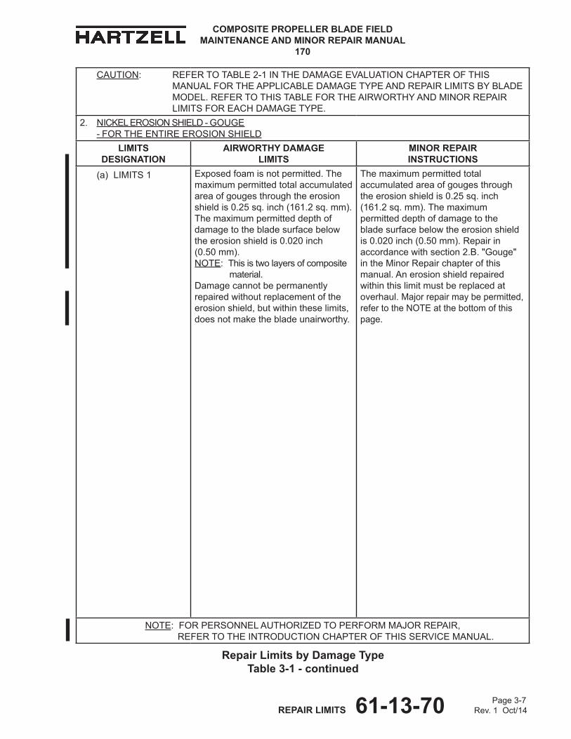
Page 3-7 REPAIR LIMITS 61-13-70 Rev. 1 Oct/14
COMPOSITE PROPELLER BLADE FIELD MAINTENANCE AND MINOR REPAIR MANUAL
170
Repair Limits by damage Type Table 3-1 - continued
CAUTION: REFERTOTABLE2-1INThEDAMAGEEvALUATIONChAPTEROFThISMANUALFORThEAPPLICABLEDAMAGETyPEANDREPAIRLIMITSByBLADEMODEL.REFERTOThISTABLEFORThEAIRWORThyANDMINORREPAIRLIMITSFOREAChDAMAGETyPE.
2. NICKELEROSIONShIELD-GOUGE - FORThEENTIREEROSIONShIELD
LIMITS dESIgNATIoN
AIRWoRTHY dAMAgE LIMITS
MINoR REPAIR INSTRUCTIoNS
(a) LIMITS 1 Exposedfoamisnotpermitted.Themaximumpermittedtotalaccumulatedareaofgougesthroughtheerosionshieldis0.25sq.inch(161.2sq.mm).Themaximumpermitteddepthofdamagetothebladesurfacebelowtheerosionshieldis0.020inch (0.50mm). NOTE:Thisistwolayersofcomposite material. Damagecannotbepermanentlyrepairedwithoutreplacementoftheerosionshield,butwithintheselimits,doesnotmakethebladeunairworthy.
Themaximumpermittedtotalaccumulatedareaofgougesthroughtheerosionshieldis0.25sq.inch(161.2sq.mm).Themaximumpermitteddepthofdamagetothebladesurfacebelowtheerosionshieldis0.020inch(0.50mm).Repairinaccordancewithsection2.B."Gouge" in theMinorRepairchapterofthismanual.Anerosionshieldrepairedwithinthislimitmustbereplacedatoverhaul.Majorrepairmaybepermitted, refertotheNOTEatthebottomofthispage.
NOTE:FORPERSONNELAUThORIzEDTOPERFORMMAjORREPAIR, REFER TO ThEINTRODUCTIONChAPTEROFThISSERvICEMANUAL.
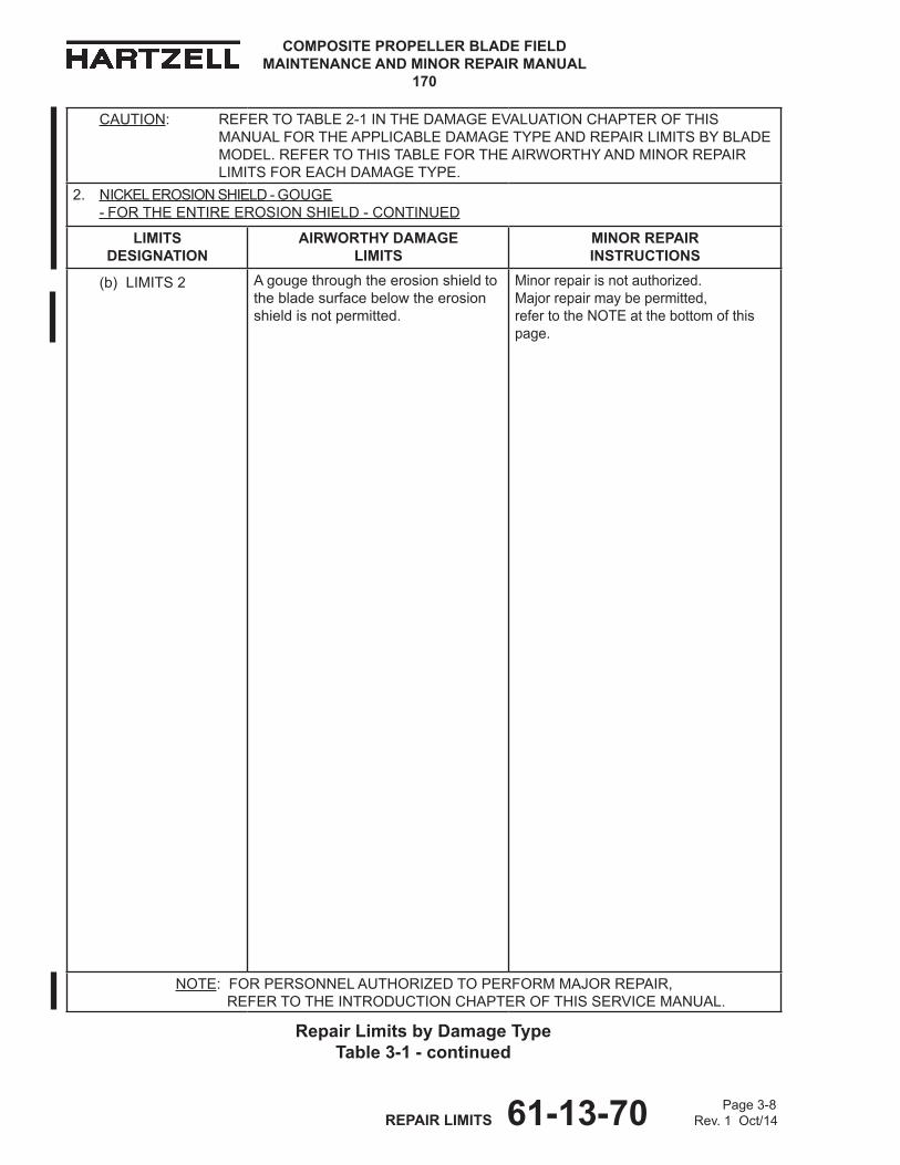
COMPOSITE PROPELLER BLADE FIELD MAINTENANCE AND MINOR REPAIR MANUAL
170
Page 3-8 REPAIR LIMITS 61-13-70 Rev. 1 Oct/14
Repair Limits by damage Type Table 3-1 - continued
CAUTION: REFERTOTABLE2-1INThEDAMAGEEvALUATIONChAPTEROFThISMANUALFORThEAPPLICABLEDAMAGETyPEANDREPAIRLIMITSByBLADEMODEL.REFERTOThISTABLEFORThEAIRWORThyANDMINORREPAIRLIMITSFOREAChDAMAGETyPE.
2. NICKELEROSIONShIELD-GOUGE - FORThEENTIREEROSIONShIELD-CONTINUED
LIMITS dESIgNATIoN
AIRWoRTHY dAMAgE LIMITS
MINoR REPAIR INSTRUCTIoNS
(b) LIMITS 2 Agougethroughtheerosionshieldtothebladesurfacebelowtheerosionshieldisnotpermitted.
Minorrepairisnotauthorized.Majorrepairmaybepermitted, refertotheNOTEatthebottomofthispage.
NOTE:FORPERSONNELAUThORIzEDTOPERFORMMAjORREPAIR, REFER TO ThEINTRODUCTIONChAPTEROFThISSERvICEMANUAL.

Page 3-9 REPAIR LIMITS 61-13-70 Rev. 1 Oct/14
COMPOSITE PROPELLER BLADE FIELD MAINTENANCE AND MINOR REPAIR MANUAL
170
(Thispageisintentionallyblank.)
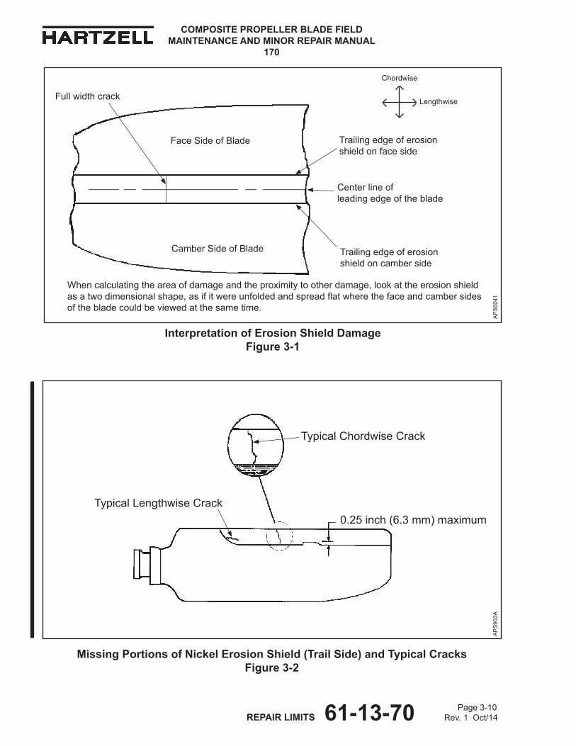
COMPOSITE PROPELLER BLADE FIELD MAINTENANCE AND MINOR REPAIR MANUAL
170
Page 3-10 REPAIR LIMITS 61-13-70 Rev. 1 Oct/14
Interpretation of Erosion Shield damage Figure 3-1
CAMBER SIdE OF BLAdE
FACE SIdE OF BLAdE
Centerlineof leadingedgeoftheblade
Trailingedgeoferosionshieldonfaceside
Chordwise
Lengthwise
AP
S60
41
Whencalculatingtheareaofdamageandtheproximitytootherdamage,lookattheerosionshieldasatwodimensionalshape,asifitwereunfoldedandspreadflatwherethefaceandcambersidesofthebladecouldbeviewedatthesametime.
Fullwidthcrack
Missing Portions of Nickel Erosion Shield (Trail Side) and Typical Cracks Figure 3-2
Trailingedgeoferosionshieldoncamberside
FaceSideofBlade
CamberSideofBlade
TypicalChordwiseCrack
TypicalLengthwiseCrackA
PS
903A
0.25inch(6.3mm)maximum

Page 3-11 REPAIR LIMITS 61-13-70 Rev. 1 Oct/14
COMPOSITE PROPELLER BLADE FIELD MAINTENANCE AND MINOR REPAIR MANUAL
170
Repair Limits by damage Type Table 3-1 - continued
CAUTION: REFERTOTABLE2-1INThEDAMAGEEvALUATIONChAPTEROFThISMANUALFORThEAPPLICABLEDAMAGETyPEANDREPAIRLIMITSByBLADEMODEL.REFERTOThISTABLEFORThEAIRWORThyANDMINORREPAIRLIMITSFOREAChDAMAGETyPE.
3. NICKELEROSIONShIELD-AREAMISSINGALONGThETRAILINGEDGEOFThEEROSIONShIELD - FORThEENTIREEROSIONShIELD
REFER TO FIGURE3-1 ANd FIGURE3-2
LIMITS dESIgNATIoN
AIRWoRTHY dAMAgE LIMITS
MINoR REPAIR INSTRUCTIoNS
(a) LIMITS 1 Piecesofmaterialfromthetrailingedgeoftheerosionshieldmaybemissingbecauseoferosionorsandingperformedduringtheerosionshieldinstallationprocedure.Themissingareamustbenofartherthan0.25inch(6.3mm)fromthetrailingedgeoftheerosionshield.RefertoFigure3-2foranexampleofpermittedmissingmaterial.Damagecannotbepermanentlyrepairedwithoutreplacementoftheerosionshield,butwithintheselimits,doesnotmakethebladeunairworthy.
Anareamissingalongthetrailingedgeoftheerosionshieldthatis withintheairworthydamagelimitsmayberepairedinaccordancewithsection2.C."MissingAreaofTrailSideorInboardEnd"intheMinorRepairchapterofthismanual.Majorrepairmaybepermitted,refertotheNOTEatthebottomofthispage.
NOTE:FORPERSONNELAUThORIzEDTOPERFORMMAjORREPAIR, REFER TO ThEINTRODUCTIONChAPTEROFThISSERvICEMANUAL.

COMPOSITE PROPELLER BLADE FIELD MAINTENANCE AND MINOR REPAIR MANUAL
170
Page 3-12 REPAIR LIMITS 61-13-70 Rev. 1 Oct/14
Measuring Lengthwise Crack Figure 3-3
W10001
Measurementoflengthwisecrack
"Lengthwisecrack"refersonlytothelengthofthecrack.Todeterminethelength,measureparalleltothepitchaxisofthebladefromthemostinboardlocationtothemostoutboardlocation.
Acceptable Erosion Shield debond, Non-acceptable Crack Location Figure 3-4
AP
S60
42
NOTE: Theboundedareaofacrackextendstobothedgesoftheerosionshield.
FACE
CAMBER
Boundedareaofcrack
Thesetwocracksareinviolationofbeingwithinthesamelinearlength.Notethatthecracksareonoppositesidesoftheblade.
Areaofdebond,intheboundedareathat
iswithinmaximumpermittedlimits
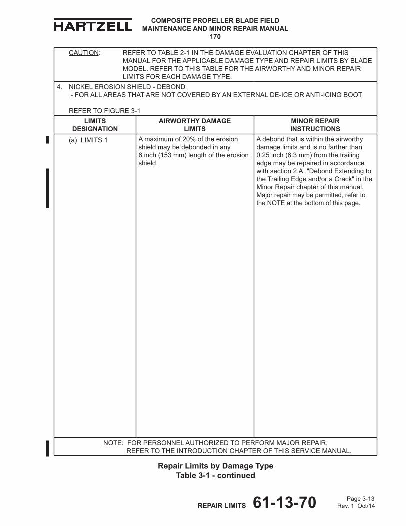
Page 3-13 REPAIR LIMITS 61-13-70 Rev. 1 Oct/14
COMPOSITE PROPELLER BLADE FIELD MAINTENANCE AND MINOR REPAIR MANUAL
170
Repair Limits by damage Type Table 3-1 - continued
CAUTION: REFERTOTABLE2-1INThEDAMAGEEvALUATIONChAPTEROFThISMANUALFORThEAPPLICABLEDAMAGETyPEANDREPAIRLIMITSByBLADEMODEL.REFERTOThISTABLEFORThEAIRWORThyANDMINORREPAIRLIMITSFOREAChDAMAGETyPE.
4. NICKELEROSIONShIELD-DEBOND -FORALLAREASThATARENOTCOvERED ByANExTERNALDE-ICEORANTI-ICING BOOT
REFER TO FIGURE3-1
LIMITS dESIgNATIoN
AIRWoRTHY dAMAgE LIMITS
MINoR REPAIR INSTRUCTIoNS
(a) LIMITS 1 Amaximumof20%oftheerosionshieldmaybedebondedinany 6inch(153mm)lengthoftheerosionshield.
Adebondthatiswithintheairworthydamagelimitsandisnofartherthan0.25inch(6.3mm)fromthetrailingedgemayberepairedinaccordancewith section2.A."DebondExtendingtotheTrailingEdgeand/oraCrack" in theMinorRepairchapterofthismanual. Majorrepairmaybepermitted,refertotheNOTEatthebottomofthispage.
NOTE:FORPERSONNELAUThORIzEDTOPERFORMMAjORREPAIR, REFER TO ThEINTRODUCTIONChAPTEROFThISSERvICEMANUAL.
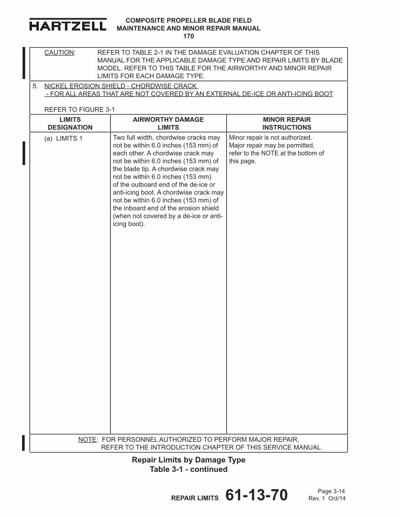
COMPOSITE PROPELLER BLADE FIELD MAINTENANCE AND MINOR REPAIR MANUAL
170
Page 3-14 REPAIR LIMITS 61-13-70 Rev. 1 Oct/14
CAUTION: REFERTOTABLE2-1INThEDAMAGEEvALUATIONChAPTEROFThISMANUALFORThEAPPLICABLEDAMAGETyPEANDREPAIRLIMITSByBLADEMODEL.REFERTOThISTABLEFORThEAIRWORThyANDMINORREPAIRLIMITSFOREAChDAMAGETyPE.
5. NICKELEROSIONShIELD-ChORDWISECRACK -FORALLAREASThATARENOTCOvEREDByANExTERNALDE-ICEORANTI-ICING BOOT
REFER TO FIGURE3-1
LIMITS dESIgNATIoN
AIRWoRTHY dAMAgE LIMITS
MINoR REPAIR INSTRUCTIoNS
(a) LIMITS 1 Twofullwidth,chordwisecracksmaynotbewithin6.0inches(153mm)ofeachother.Achordwisecrackmaynotbewithin6.0inches(153mm)ofthebladetip.Achordwisecrackmaynotbewithin6.0inches(153mm)oftheoutboardendofthede-iceoranti-icingboot.Achordwisecrackmaynotbewithin6.0inches(153mm)oftheinboardendoftheerosionshield(whennotcoveredbyade-iceoranti-icingboot).
Minorrepairisnotauthorized. Majorrepairmaybepermitted, refertotheNOTEatthebottomof thispage.
NOTE:FORPERSONNELAUThORIzEDTOPERFORMMAjORREPAIR, REFER TO ThEINTRODUCTIONChAPTEROFThISSERvICEMANUAL.
Repair Limits by damage Type Table 3-1 - continued
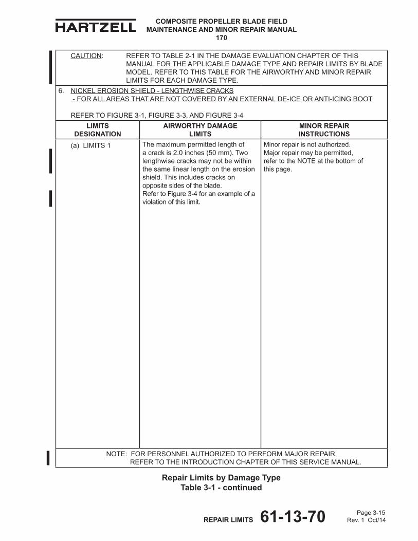
Page 3-15 REPAIR LIMITS 61-13-70 Rev. 1 Oct/14
COMPOSITE PROPELLER BLADE FIELD MAINTENANCE AND MINOR REPAIR MANUAL
170
CAUTION: REFERTOTABLE2-1INThEDAMAGEEvALUATIONChAPTEROFThISMANUALFORThEAPPLICABLEDAMAGETyPEANDREPAIRLIMITSByBLADEMODEL.REFERTOThISTABLEFORThEAIRWORThyANDMINORREPAIRLIMITSFOREAChDAMAGETyPE.
6. NICKELEROSIONShIELD-LENGThWISECRACKS -FORALLAREASThATARENOTCOvEREDByANExTERNALDE-ICEORANTI-ICING BOOT
REFER TO FIGURE3-1,FIGURE3-3,ANDFIGURE3-4
LIMITS dESIgNATIoN
AIRWoRTHY dAMAgE LIMITS
MINoR REPAIR INSTRUCTIoNS
(a) LIMITS 1 Themaximumpermittedlengthofacrackis2.0inches(50mm).Twolengthwisecracksmaynotbewithinthesamelinearlengthontheerosionshield.Thisincludescracksonoppositesidesoftheblade. RefertoFigure3-4foranexampleofaviolationofthislimit.
Minorrepairisnotauthorized. Majorrepairmaybepermitted, refertotheNOTEatthebottomof thispage.
NOTE:FORPERSONNELAUThORIzEDTOPERFORMMAjORREPAIR, REFER TO ThEINTRODUCTIONChAPTEROFThISSERvICEMANUAL.
Repair Limits by damage Type Table 3-1 - continued
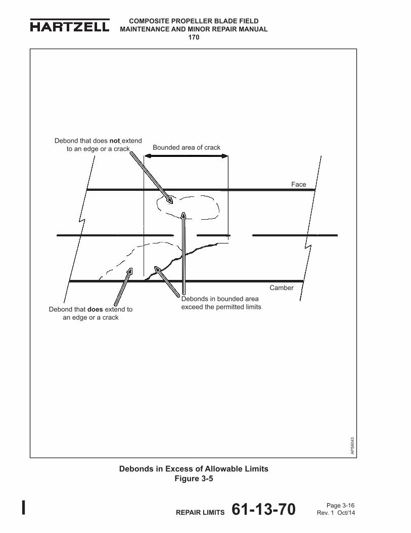
COMPOSITE PROPELLER BLADE FIELD MAINTENANCE AND MINOR REPAIR MANUAL
170
Page 3-16 REPAIR LIMITS 61-13-70 Rev. 1 Oct/14
debonds in Excess of Allowable Limits Figure 3-5
Face
AP
S60
43
Debondsinboundedareaexceedthepermittedlimits
BoundedareaofcrackDebondthatdoesnotextend
toanedgeoracrack
Debondthatdoesextendtoanedgeoracrack
Camber
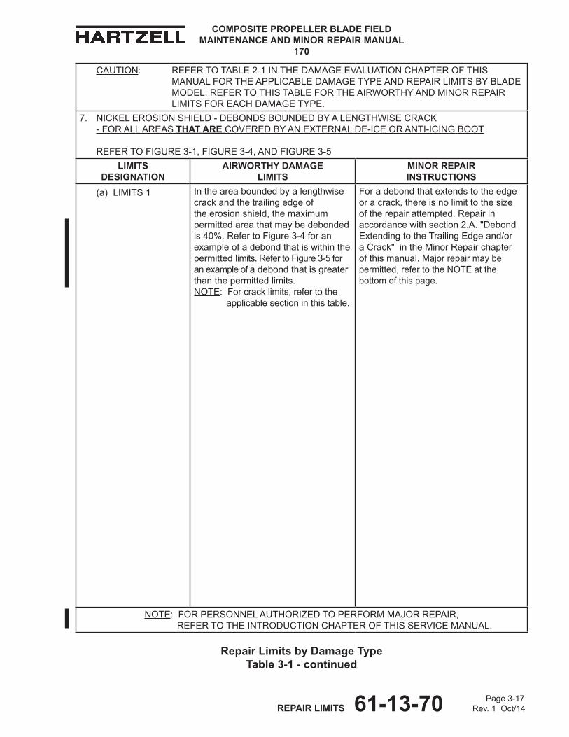
Page 3-17 REPAIR LIMITS 61-13-70 Rev. 1 Oct/14
COMPOSITE PROPELLER BLADE FIELD MAINTENANCE AND MINOR REPAIR MANUAL
170
CAUTION: REFERTOTABLE2-1INThEDAMAGEEvALUATIONChAPTEROFThISMANUALFORThEAPPLICABLEDAMAGETyPEANDREPAIRLIMITSByBLADEMODEL.REFERTOThISTABLEFORThEAIRWORThyANDMINORREPAIRLIMITSFOREAChDAMAGETyPE.
7. NICKELEROSIONShIELD-DEBONDSBOUNDEDByALENGThWISECRACK - FOR ALL AREAS THAT ARE COvERED ByANExTERNALDE-ICEORANTI-ICING BOOT
REFER TO FIGURE3-1,FIGURE3-4,ANDFIGURE3-5
LIMITS dESIgNATIoN
AIRWoRTHY dAMAgE LIMITS
MINoR REPAIR INSTRUCTIoNS
(a) LIMITS 1 Intheareaboundedbyalengthwisecrackandthetrailingedgeoftheerosionshield,themaximumpermittedareathatmaybedebondedis40%. RefertoFigure3-4foranexampleofadebondthatiswithinthepermittedlimits.RefertoFigure3-5foranexampleofadebondthatisgreaterthanthepermittedlimits. NOTE:Forcracklimits,refertothe applicablesectioninthistable.
Foradebondthatextendstotheedgeoracrack,thereisnolimittothesizeoftherepairattempted.Repairinaccordancewithsection2.A."DebondExtendingtotheTrailingEdgeand/oraCrack" in theMinorRepairchapterofthismanual.Majorrepairmaybepermitted,refertotheNOTEatthebottomofthispage.
NOTE:FORPERSONNELAUThORIzEDTOPERFORMMAjORREPAIR, REFER TO ThEINTRODUCTIONChAPTEROFThISSERvICEMANUAL.
Repair Limits by damage Type Table 3-1 - continued
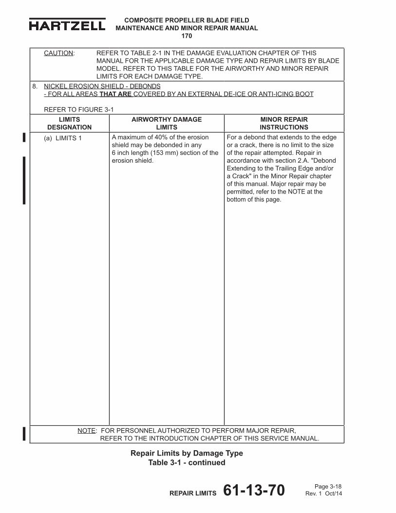
COMPOSITE PROPELLER BLADE FIELD MAINTENANCE AND MINOR REPAIR MANUAL
170
Page 3-18 REPAIR LIMITS 61-13-70 Rev. 1 Oct/14
CAUTION: REFERTOTABLE2-1INThEDAMAGEEvALUATIONChAPTEROFThISMANUALFORThEAPPLICABLEDAMAGETyPEANDREPAIRLIMITSByBLADEMODEL.REFERTOThISTABLEFORThEAIRWORThyANDMINORREPAIRLIMITSFOREAChDAMAGETyPE.
8. NICKELEROSIONShIELD-dEBONdS - FOR ALL AREAS THAT ARE COvERED ByANExTERNALDE-ICEORANTI-ICING BOOT
REFER TO FIGURE3-1
LIMITS dESIgNATIoN
AIRWoRTHY dAMAgE LIMITS
MINoR REPAIR INSTRUCTIoNS
(a) LIMITS 1 Amaximumof40%oftheerosionshieldmaybedebondedinany 6inchlength(153mm)sectionoftheerosionshield.
Foradebondthatextendstotheedgeoracrack,thereisnolimittothesizeoftherepairattempted.Repairinaccordancewithsection2.A. "DebondExtendingtotheTrailingEdgeand/oraCrack"intheMinorRepairchapterofthismanual.Majorrepairmaybepermitted,refertotheNOTEatthebottomofthispage.
NOTE:FORPERSONNELAUThORIzEDTOPERFORMMAjORREPAIR, REFER TO ThEINTRODUCTIONChAPTEROFThISSERvICEMANUAL.
Repair Limits by damage Type Table 3-1 - continued
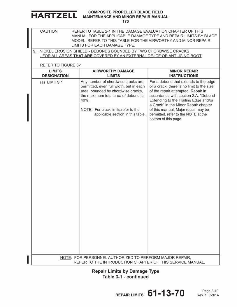
Page 3-19 REPAIR LIMITS 61-13-70 Rev. 1 Oct/14
COMPOSITE PROPELLER BLADE FIELD MAINTENANCE AND MINOR REPAIR MANUAL
170
CAUTION: REFERTOTABLE2-1INThEDAMAGEEvALUATIONChAPTEROFThISMANUALFORThEAPPLICABLEDAMAGETyPEANDREPAIRLIMITSByBLADEMODEL.REFERTOThISTABLEFORThEAIRWORThyANDMINORREPAIRLIMITSFOREAChDAMAGETyPE.
9. NICKELEROSIONShIELD-dEBONDSBOUNDEDByTWOChORDWISECRACKS - FOR ALL AREAS THAT ARE COvERED ByANExTERNALDE-ICEORANTI-ICING BOOT
REFER TO FIGURE3-1
LIMITS dESIgNATIoN
AIRWoRTHY dAMAgE LIMITS
MINoR REPAIR INSTRUCTIoNS
(a) LIMITS 1 Anynumberofchordwisecracksarepermitted,evenfullwidth,butineacharea,boundedbychordwisecracks,themaximumtotalareaofdebondis40%. NOTE:Forcracklimits,refertothe applicablesectioninthistable.
Foradebondthatextendstotheedgeoracrack,thereisnolimittothesizeoftherepairattempted.Repairinaccordancewithsection2.A. "DebondExtendingtotheTrailingEdgeand/oraCrack" in theMinorRepairchapterofthismanual.Majorrepairmaybepermitted,refertotheNOTEatthebottomofthispage.
NOTE:FORPERSONNELAUThORIzEDTOPERFORMMAjORREPAIR, REFER TO ThEINTRODUCTIONChAPTEROFThISSERvICEMANUAL.
Repair Limits by damage Type Table 3-1 - continued

COMPOSITE PROPELLER BLADE FIELD MAINTENANCE AND MINOR REPAIR MANUAL
170
Page 3-20 REPAIR LIMITS 61-13-70 Rev. 1 Oct/14
(Thispageisintentionallyblank.)

Page 3-21 REPAIR LIMITS 61-13-70 Rev. 1 Oct/14
COMPOSITE PROPELLER BLADE FIELD MAINTENANCE AND MINOR REPAIR MANUAL
170
CAUTION: REFERTOTABLE2-1INThEDAMAGEEvALUATIONChAPTEROFThISMANUALFORThEAPPLICABLEDAMAGETyPEANDREPAIRLIMITSByBLADEMODEL.REFERTOThISTABLEFORThEAIRWORThyANDMINORREPAIRLIMITSFOREAChDAMAGETyPE.
10. STAINLESSSTEELEROSIONShIELD-ChORDWISECRACk -FORALLAREASOFThEEROSIONShIELD
LIMITS dESIgNATIoN
AIRWoRTHY dAMAgE LIMITS
MINoR REPAIR INSTRUCTIoNS
(a) LIMITS 1 Ascrewholeorrivetholewithachordwisecrackextendingfromitmaynotalsohavealengthwisecrackextendingfromit.Achordwisecrackmustbeseparatedfromanyotherchordwisecrackbyaminimumof 6.0inches(153mm).Themaximumpermittedlengthofalengthwisecrackis2.0inches(50mm)andmustnotconnecttworivetorscrewholes.
Minorrepairisnotauthorized.Majorrepairmaybepermitted, refertotheNOTEatthebottomof thispage.
NOTE:FORPERSONNELAUThORIzEDTOPERFORMMAjORREPAIR, REFER TO ThEINTRODUCTIONChAPTEROFThISSERvICEMANUAL.
Repair Limits by damage Type Table 3-1 - continued
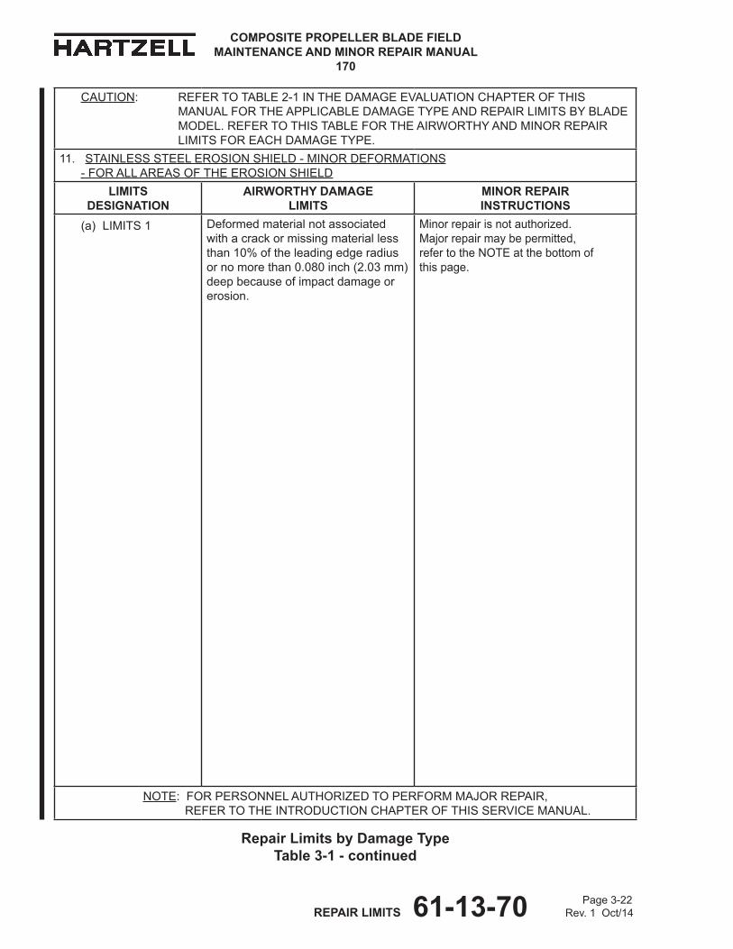
COMPOSITE PROPELLER BLADE FIELD MAINTENANCE AND MINOR REPAIR MANUAL
170
Page 3-22 REPAIR LIMITS 61-13-70 Rev. 1 Oct/14
CAUTION: REFERTOTABLE2-1INThEDAMAGEEvALUATIONChAPTEROFThISMANUALFORThEAPPLICABLEDAMAGETyPEANDREPAIRLIMITSByBLADEMODEL.REFERTOThISTABLEFORThEAIRWORThyANDMINORREPAIRLIMITSFOREAChDAMAGETyPE.
11. STAINLESSSTEELEROSIONShIELD-MINOR dEFORMATIONS -FORALLAREASOFThEEROSIONShIELD
LIMITS dESIgNATIoN
AIRWoRTHY dAMAgE LIMITS
MINoR REPAIR INSTRUCTIoNS
(a) LIMITS 1 Deformedmaterialnotassociatedwithacrackormissingmateriallessthan10%oftheleadingedgeradiusornomorethan0.080inch(2.03mm)deepbecauseofimpactdamageorerosion.
Minorrepairisnotauthorized.Majorrepairmaybepermitted, refertotheNOTEatthebottomof thispage.
NOTE:FORPERSONNELAUThORIzEDTOPERFORMMAjORREPAIR, REFER TO ThEINTRODUCTIONChAPTEROFThISSERvICEMANUAL.
Repair Limits by damage Type Table 3-1 - continued
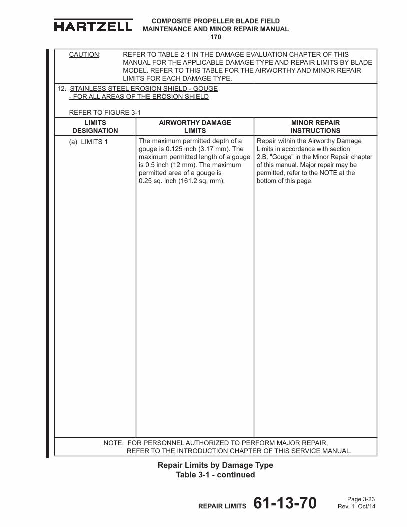
Page 3-23 REPAIR LIMITS 61-13-70 Rev. 1 Oct/14
COMPOSITE PROPELLER BLADE FIELD MAINTENANCE AND MINOR REPAIR MANUAL
170
CAUTION: REFERTOTABLE2-1INThEDAMAGEEvALUATIONChAPTEROFThISMANUALFORThEAPPLICABLEDAMAGETyPEANDREPAIRLIMITSByBLADEMODEL.REFERTOThISTABLEFORThEAIRWORThyANDMINORREPAIRLIMITSFOREAChDAMAGETyPE.
12. STAINLESSSTEELEROSIONShIELD-GOUGE -FORALLAREASOFThEEROSIONShIELD
REFER TO FIGURE3-1
LIMITS dESIgNATIoN
AIRWoRTHY dAMAgE LIMITS
MINoR REPAIR INSTRUCTIoNS
(a) LIMITS 1 Themaximumpermitteddepthofagougeis0.125inch(3.17mm).Themaximumpermittedlengthofagougeis0.5inch(12mm).Themaximumpermittedareaofagougeis 0.25sq.inch(161.2sq.mm).
RepairwithintheAirworthyDamage Limitsinaccordancewithsection 2.B."Gouge"intheMinorRepairchapterofthismanual.Majorrepairmaybepermitted,refertotheNOTEatthebottomofthispage.
NOTE:FORPERSONNELAUThORIzEDTOPERFORMMAjORREPAIR, REFER TO ThEINTRODUCTIONChAPTEROFThISSERvICEMANUAL.
Repair Limits by damage Type Table 3-1 - continued
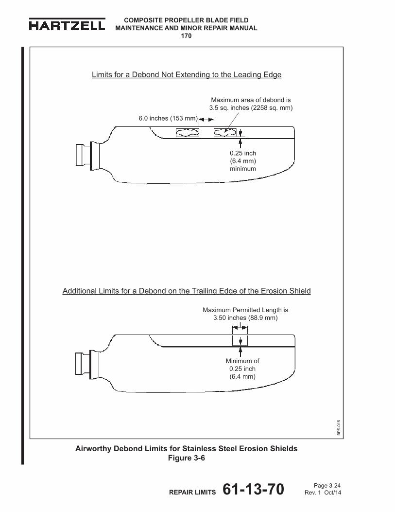
COMPOSITE PROPELLER BLADE FIELD MAINTENANCE AND MINOR REPAIR MANUAL
170
Page 3-24 REPAIR LIMITS 61-13-70 Rev. 1 Oct/14
Airworthy debond Limits for Stainless Steel Erosion Shields Figure 3-6
Minimumof0.25inch(6.4mm)
BP
S-0
15
AdditionalLimitsforaDebondontheTrailingEdgeoftheErosionShield
6.0inches(153mm)
0.25inch (6.4mm)minimum
MaximumPermittedLengthis3.50inches(88.9mm)
LimitsforaDebondNotExtendingtotheLeadingEdge
Maximumareaofdebondis 3.5sq.inches(2258sq.mm)

Page 3-25 REPAIR LIMITS 61-13-70 Rev. 1 Oct/14
COMPOSITE PROPELLER BLADE FIELD MAINTENANCE AND MINOR REPAIR MANUAL
170
CAUTION: REFERTOTABLE2-1INThEDAMAGEEvALUATIONChAPTEROFThISMANUALFORThEAPPLICABLEDAMAGETyPEANDREPAIRLIMITSByBLADEMODEL.REFERTOThISTABLEFORThEAIRWORThyANDMINORREPAIRLIMITSFOREAChDAMAGETyPE.
13. STAINLESSSTEELEROSIONShIELD-DEBOND -FORAREASOFThEEROSIONShIELDTHAT ARE NoT FASTENEDWIThSCREWSORRIvETS
REFER TO FIGURE3-1ANDFIGURE3-6
LIMITS dESIgNATIoN
AIRWoRTHY dAMAgE LIMITS
MINoR REPAIR INSTRUCTIoNS
(a) LIMITS 1 Foradebondnotextendingtotheleadingedge,themaximumlengthofadebondthatisonthetrailingedgeis3.50inches(88.9mm).Adebondmustbeaminimumof0.25inch(6.4mm)fromthetrailingedge.Themaximumpermittedareaofadebondis 3.5squareinches(2258sq.mm).Adebondmustbeseparatedfromanyotherdebondareaonthesamebladesurfacebyaminimumof6.0inches(153mm).Themaximumpermittedtotalaccumulatedareaofalldebondsis10.0squareinches(6451sq.mm).
IfthedebondiswithintheAirworthyDamageLimits,repairinaccordancewithsection2.D."Debond"intheMinorRepairchapterofthismanual.Majorrepairmaybepermitted,refertotheNOTEatthebottomofthispage.
NOTE:FORPERSONNELAUThORIzEDTOPERFORMMAjORREPAIR, REFER TO ThEINTRODUCTIONChAPTEROFThISSERvICEMANUAL.
Repair Limits by damage Type Table 3-1 - continued
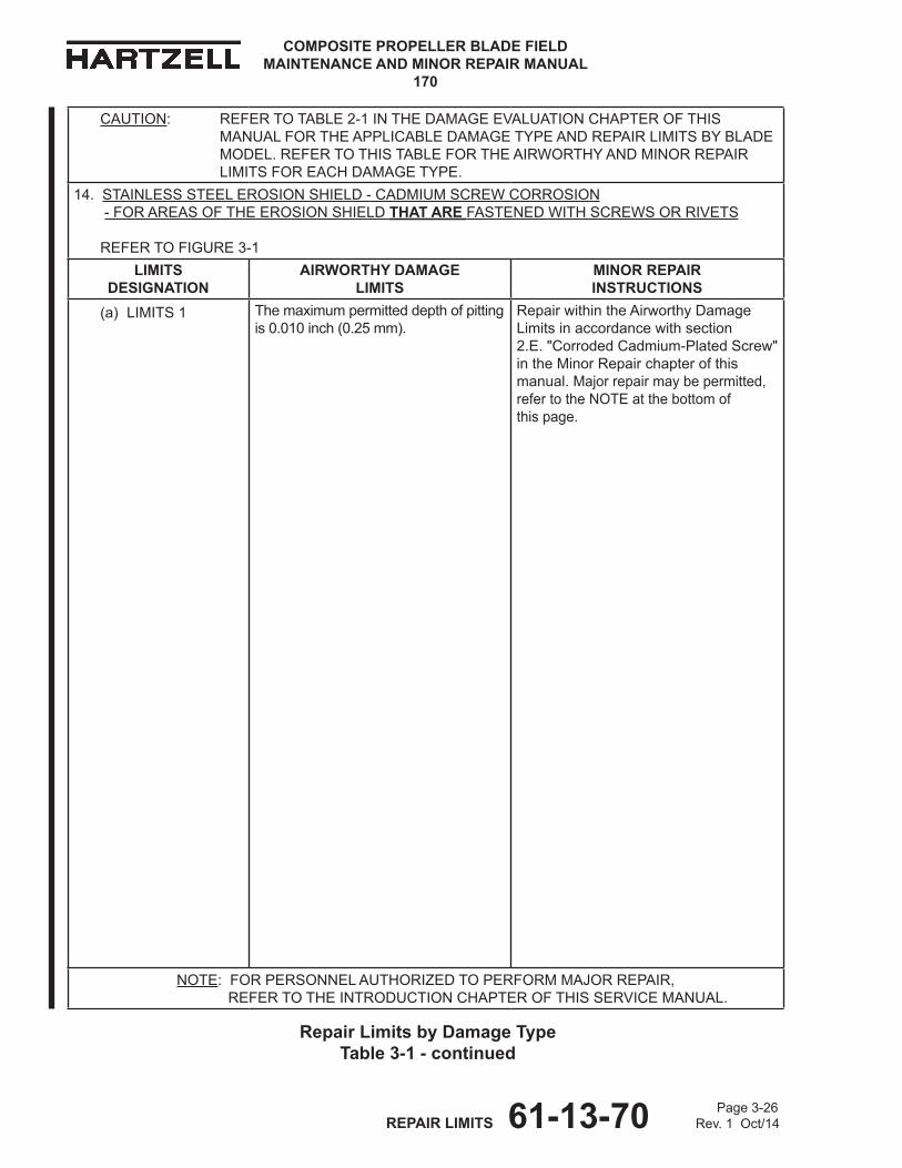
COMPOSITE PROPELLER BLADE FIELD MAINTENANCE AND MINOR REPAIR MANUAL
170
Page 3-26 REPAIR LIMITS 61-13-70 Rev. 1 Oct/14
CAUTION: REFERTOTABLE2-1INThEDAMAGEEvALUATIONChAPTEROFThISMANUALFORThEAPPLICABLEDAMAGETyPEANDREPAIRLIMITSByBLADEMODEL.REFERTOThISTABLEFORThEAIRWORThyANDMINORREPAIRLIMITSFOREAChDAMAGETyPE.
14. STAINLESSSTEELEROSIONShIELD-CADMIUMSCREWCORROSION -FORAREASOFThEEROSIONShIELDTHAT ARE FASTENEDWIThSCREWSORRIvETS
REFER TO FIGURE3-1
LIMITS dESIgNATIoN
AIRWoRTHY dAMAgE LIMITS
MINoR REPAIR INSTRUCTIoNS
(a) LIMITS 1 Themaximumpermitteddepthofpittingis0.010inch(0.25mm).
RepairwithintheAirworthyDamageLimitsinaccordancewithsection 2.E."CorrodedCadmium-PlatedScrew"intheMinorRepairchapterofthismanual.Majorrepairmaybepermitted, refertotheNOTEatthebottomof thispage.
NOTE:FORPERSONNELAUThORIzEDTOPERFORMMAjORREPAIR, REFER TO ThEINTRODUCTIONChAPTEROFThISSERvICEMANUAL.
Repair Limits by damage Type Table 3-1 - continued

Page 3-27 REPAIR LIMITS 61-13-70 Rev. 1 Oct/14
COMPOSITE PROPELLER BLADE FIELD MAINTENANCE AND MINOR REPAIR MANUAL
170
(Thispageisintentionallyblank.)
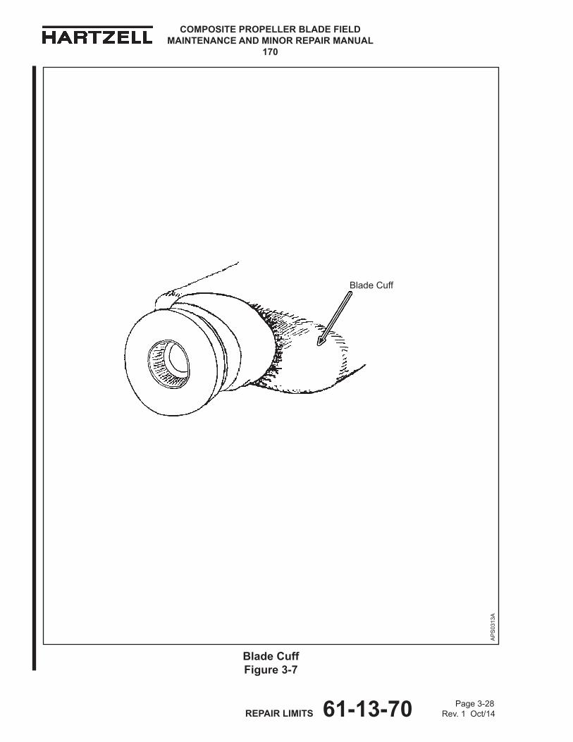
COMPOSITE PROPELLER BLADE FIELD MAINTENANCE AND MINOR REPAIR MANUAL
170
Page 3-28 REPAIR LIMITS 61-13-70 Rev. 1 Oct/14
AP
S03
13A
BladeCuff
Blade Cuff Figure 3-7

Page 3-29 REPAIR LIMITS 61-13-70 Rev. 1 Oct/14
COMPOSITE PROPELLER BLADE FIELD MAINTENANCE AND MINOR REPAIR MANUAL
170
CAUTION: REFERTOTABLE2-1INThEDAMAGEEvALUATIONChAPTEROFThISMANUALFORThEAPPLICABLEDAMAGETyPEANDREPAIRLIMITSByBLADEMODEL.REFERTOThISTABLEFORThEAIRWORThyANDMINORREPAIRLIMITSFOREAChDAMAGETyPE.
15. BLADECUFF-NICKS,SCRATChES,ANDGOUGES -FORThEENTIREBLADECUFF
REFER TO FIGURE3-7
LIMITS dESIgNATIoN
AIRWoRTHY dAMAgE LIMITS
MINoR REPAIR INSTRUCTIoNS
(a) LIMITS 1 Anick,scratch,orgougethatisnotassociatedwithadebondanddoesnotexposethefoamispermitted.
Repairwithinthelimitsgivenfortherepairprocedureinaccordancewithsection3.B."Nick,Scratch,Gouge,Crack,orDelamination"intheMinorRepairchapterofthismanual. Majorrepairmaybepermitted, refertotheNOTEatthebottomof thispage.
NOTE:FORPERSONNELAUThORIzEDTOPERFORMMAjORREPAIR, REFER TO ThEINTRODUCTIONChAPTEROFThISSERvICEMANUAL.
Repair Limits by damage Type Table 3-1 - continued
COMPOSITE PROPELLER BLADE FIELD MAINTENANCE AND MINOR REPAIR MANUAL
170
Page 3-30 REPAIR LIMITS 61-13-70 Rev. 1 Oct/14
CAUTION: REFERTOTABLE2-1INThEDAMAGEEvALUATIONChAPTEROFThISMANUALFORThEAPPLICABLEDAMAGETyPEANDREPAIRLIMITSByBLADEMODEL.REFERTOThISTABLEFORThEAIRWORThyANDMINORREPAIRLIMITSFOREAChDAMAGETyPE.
16. BLADECUFF-dEPRESSION -FORThEENTIREBLADECUFF
REFER TO FIGURE3-7
LIMITS dESIgNATIoN
AIRWoRTHY dAMAgE LIMITS
MINoR REPAIR INSTRUCTIoNS
(a) LIMITS 1 Themaximumpermittedareaofadepressionis1.0squareinch (645sq.mm).Themaximumpermitteddepthofadepressionis0.25inch (6.3mm).Adepressionthatisassociatedwithadelaminationisnotpermitted.
Minorrepairisnotauthorized. Majorrepairmaybepermitted, refertotheNOTEatthebottomof thispage.
NOTE:FORPERSONNELAUThORIzEDTOPERFORMMAjORREPAIR, REFER TO ThEINTRODUCTIONChAPTEROFThISSERvICEMANUAL.
Repair Limits by damage Type Table 3-1 - continued
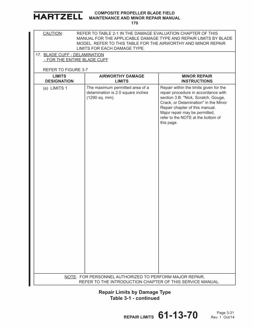
Page 3-31 REPAIR LIMITS 61-13-70 Rev. 1 Oct/14
COMPOSITE PROPELLER BLADE FIELD MAINTENANCE AND MINOR REPAIR MANUAL
170
CAUTION: REFERTOTABLE2-1INThEDAMAGEEvALUATIONChAPTEROFThISMANUALFORThEAPPLICABLEDAMAGETyPEANDREPAIRLIMITSByBLADEMODEL.REFERTOThISTABLEFORThEAIRWORThyANDMINORREPAIRLIMITSFOREAChDAMAGETyPE.
17. BLADECUFF-dELAMINATION -FORThEENTIREBLADECUFF
REFER TO FIGURE3-7
LIMITS dESIgNATIoN
AIRWoRTHY dAMAgE LIMITS
MINoR REPAIR INSTRUCTIoNS
(a) LIMITS 1 Themaximumpermittedareaofadelaminationis2.0squareinches (1290sq.mm).
Repairwithinthelimitsgivenfortherepairprocedureinaccordancewithsection3.B."Nick,Scratch,Gouge,Crack,orDelamination"intheMinorRepairchapterofthismanual. Majorrepairmaybepermitted, refertotheNOTEatthebottomof thispage.
NOTE:FORPERSONNELAUThORIzEDTOPERFORMMAjORREPAIR, REFER TO ThEINTRODUCTIONChAPTEROFThISSERvICEMANUAL.
Repair Limits by damage Type Table 3-1 - continued
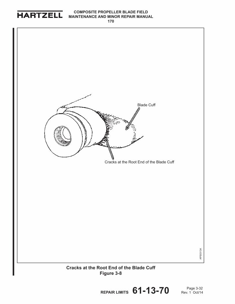
COMPOSITE PROPELLER BLADE FIELD MAINTENANCE AND MINOR REPAIR MANUAL
170
Page 3-32 REPAIR LIMITS 61-13-70 Rev. 1 Oct/14
BladeCuff
CracksattheRootEndoftheBladeCuff
Cracks at the Root End of the Blade Cuff Figure 3-8
AP
S03
13A
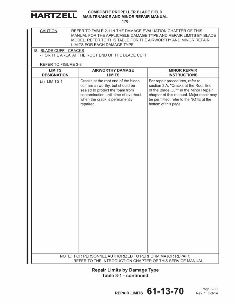
Page 3-33 REPAIR LIMITS 61-13-70 Rev. 1 Oct/14
COMPOSITE PROPELLER BLADE FIELD MAINTENANCE AND MINOR REPAIR MANUAL
170
CAUTION: REFERTOTABLE2-1INThEDAMAGEEvALUATIONChAPTEROFThISMANUALFORThEAPPLICABLEDAMAGETyPEANDREPAIRLIMITSByBLADEMODEL.REFERTOThISTABLEFORThEAIRWORThyANDMINORREPAIRLIMITSFOREAChDAMAGETyPE.
18. BLADECUFF-CRACkS -FORThEAREAATThEROOTENDOFThEBLADECUFF
REFER TO FIGURE3-8
LIMITS dESIgNATIoN
AIRWoRTHY dAMAgE LIMITS
MINoR REPAIR INSTRUCTIoNS
(a) LIMITS 1 Cracksattherootendofthebladecuffareairworthy,butshouldbesealedtoprotectthefoamfromcontaminationuntiltimeofoverhaulwhenthecrackispermanentlyrepaired.
Forrepairprocedures,referto section3.A."CracksattheRootEndoftheBladeCuff"intheMinorRepairchapterofthismanual.Majorrepairmaybepermitted,refertotheNOTEatthebottomofthispage.
NOTE:FORPERSONNELAUThORIzEDTOPERFORMMAjORREPAIR, REFER TO ThEINTRODUCTIONChAPTEROFThISSERvICEMANUAL.
Repair Limits by damage Type Table 3-1 - continued
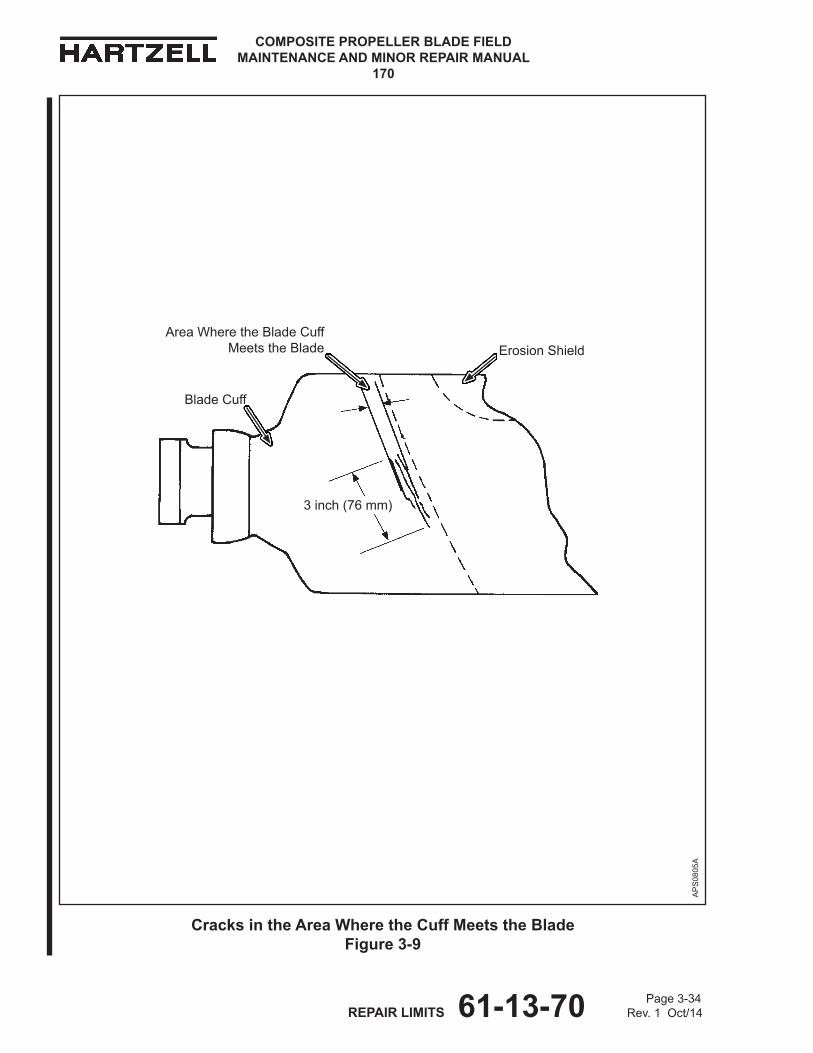
COMPOSITE PROPELLER BLADE FIELD MAINTENANCE AND MINOR REPAIR MANUAL
170
Page 3-34 REPAIR LIMITS 61-13-70 Rev. 1 Oct/14
BladeCuff
ErosionShield
Cracks in the Area Where the Cuff Meets the Blade Figure 3-9
AreaWheretheBladeCuff MeetstheBlade
3inch(76mm)
AP
S08
05A

Page 3-35 REPAIR LIMITS 61-13-70 Rev. 1 Oct/14
COMPOSITE PROPELLER BLADE FIELD MAINTENANCE AND MINOR REPAIR MANUAL
170
CAUTION: REFERTOTABLE2-1INThEDAMAGEEvALUATIONChAPTEROFThISMANUALFORThEAPPLICABLEDAMAGETyPEANDREPAIRLIMITSByBLADEMODEL.REFERTOThISTABLEFORThEAIRWORThyANDMINORREPAIRLIMITSFOREAChDAMAGETyPE.
19. BLADECUFF-CRACKSINThECUFF -FORThEOUTBOARDAREAWhEREThEBLADECUFFMEETSThEBLADE
REFER TO FIGURE3-8ANDFIGURE3-9
LIMITS dESIgNATIoN
AIRWoRTHY dAMAgE LIMITS
MINoR REPAIR INSTRUCTIoNS
(a) LIMITS 1 CracksinthecuffwherethebladecuffmeetstheblademustbewithinthelimitshowninFigure3-9.
CrackswherethebladecuffmeetsthebladethatarewithinthelimitsforminorrepairshowninFigure3-9mayberepairedinaccordancewithsection3.B."Nick,Scratch,Gouge,Crack,orDelamination"intheMinorRepairchapterofthismanual.Majorrepairmaybepermitted,refertotheNOTEatthebottomofthispage.
NOTE:FORPERSONNELAUThORIzEDTOPERFORMMAjORREPAIR, REFER TO ThEINTRODUCTIONChAPTEROFThISSERvICEMANUAL.
Repair Limits by damage Type Table 3-1 - continued
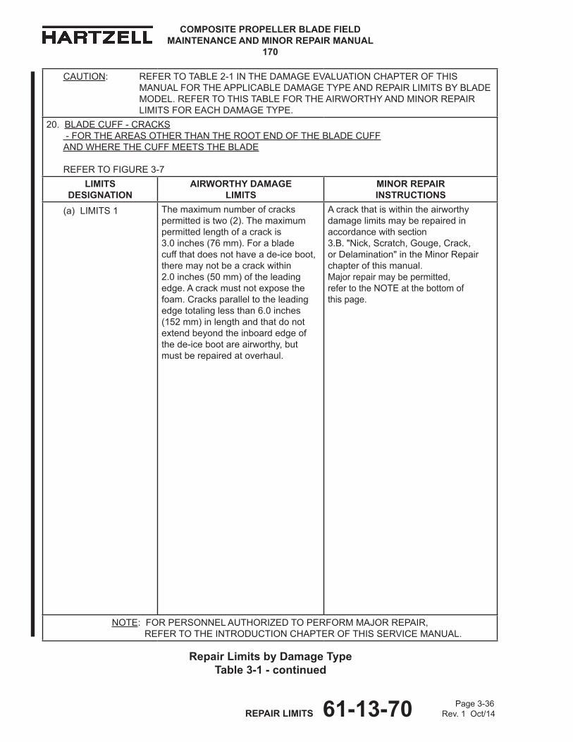
COMPOSITE PROPELLER BLADE FIELD MAINTENANCE AND MINOR REPAIR MANUAL
170
Page 3-36 REPAIR LIMITS 61-13-70 Rev. 1 Oct/14
CAUTION: REFERTOTABLE2-1INThEDAMAGEEvALUATIONChAPTEROFThISMANUALFORThEAPPLICABLEDAMAGETyPEANDREPAIRLIMITSByBLADEMODEL.REFERTOThISTABLEFORThEAIRWORThyANDMINORREPAIRLIMITSFOREAChDAMAGETyPE.
20. BLADECUFF-CRACkS -FORThEAREASOThERThANThEROOTENDOFThEBLADECUFF ANd WhEREThECUFFMEETSThEBLADE
REFERTOFIGURE3-7
LIMITS dESIgNATIoN
AIRWoRTHY dAMAgE LIMITS
MINoR REPAIR INSTRUCTIoNS
(a) LIMITS 1 Themaximumnumberofcrackspermittedistwo(2).Themaximumpermittedlengthofacrackis 3.0inches(76mm).Forablade cuffthatdoesnothaveade-iceboot,theremaynotbeacrackwithin 2.0inches(50mm)oftheleadingedge.Acrackmustnotexposethefoam.Cracksparalleltotheleadingedgetotalinglessthan6.0inches (152mm)inlengthandthatdonotextendbeyondtheinboardedgeofthede-icebootareairworthy,butmustberepairedatoverhaul.
Acrackthatiswithintheairworthydamagelimitsmayberepairedinaccordancewithsection 3.B."Nick,Scratch,Gouge,Crack,orDelamination"intheMinorRepairchapterofthismanual. Majorrepairmaybepermitted, refertotheNOTEatthebottomof thispage.
NOTE:FORPERSONNELAUThORIzEDTOPERFORMMAjORREPAIR, REFER TO ThEINTRODUCTIONChAPTEROFThISSERvICEMANUAL.
Repair Limits by damage Type Table 3-1 - continued

Page 3-37 REPAIR LIMITS 61-13-70 Rev. 1 Oct/14
COMPOSITE PROPELLER BLADE FIELD MAINTENANCE AND MINOR REPAIR MANUAL
170
CAUTION: REFERTOTABLE2-1INThEDAMAGEEvALUATIONChAPTEROFThISMANUALFORThEAPPLICABLEDAMAGETyPEANDREPAIRLIMITSByBLADEMODEL.REFERTOThISTABLEFORThEAIRWORThyANDMINORREPAIRLIMITSFOREAChDAMAGETyPE.
21. GOUGEORLOSSOFCOMPOSITEMATERIAL -OUTBOARDREGIONOFThEBLADE
LIMITS dESIgNATIoN
AIRWoRTHY dAMAgE LIMITS
MINoR REPAIR INSTRUCTIoNS
(a) LIMITS 1
NOTE:Donotinclude paintwhen measuring thedepthofa gougeorloss ofcomposite material.
Themaximumpermitteddiameterorequivalentarea(0.20sq.inchor129sq.mm)ofagougeorlossofmaterialis0.500inch(12.70mm).Themaximumpermittedlengthofagougeorlossofmaterialis2.5inches (63mm).Themaximumpermitteddepthofagougeorlossofmaterialis0.020inch(0.50mm).
Themaximumpermittedareaofagougeorlossofcompositematerialis 2.0sq.inches(1290sq.mm). Themaximumpermitteddepthofagougeorlossofcompositematerialis0.020inch(0.50mm).Repairinaccordancewithsection4.A."Gouge,Delamination,orLossofCompositeMaterial"intheMinorRepairchapterofthismanual.Majorrepairmaybepermitted,refertotheNOTEatthebottomofthispage.
NOTE:FORPERSONNELAUThORIzEDTOPERFORMMAjORREPAIR, REFER TO ThEINTRODUCTIONChAPTEROFThISSERvICEMANUAL.
Repair Limits by damage Type Table 3-1 - continued
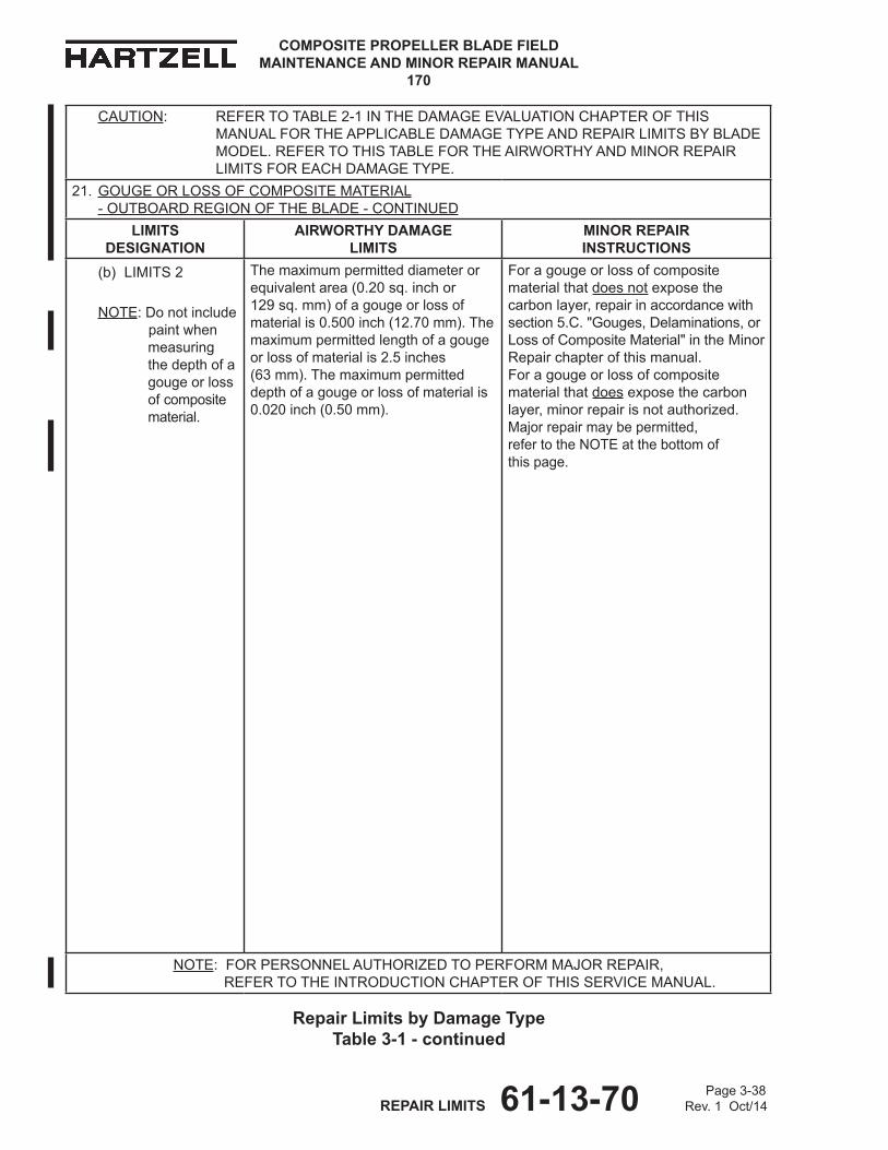
COMPOSITE PROPELLER BLADE FIELD MAINTENANCE AND MINOR REPAIR MANUAL
170
Page 3-38 REPAIR LIMITS 61-13-70 Rev. 1 Oct/14
CAUTION: REFERTOTABLE2-1INThEDAMAGEEvALUATIONChAPTEROFThISMANUALFORThEAPPLICABLEDAMAGETyPEANDREPAIRLIMITSByBLADEMODEL.REFERTOThISTABLEFORThEAIRWORThyANDMINORREPAIRLIMITSFOREAChDAMAGETyPE.
21. GOUGEORLOSSOFCOMPOSITEMATERIAL -OUTBOARDREGIONOFThEBLADE-CONTINUED
LIMITS dESIgNATIoN
AIRWoRTHY dAMAgE LIMITS
MINoR REPAIR INSTRUCTIoNS
(b) LIMITS 2
NOTE:Donotinclude paintwhen measuring thedepthofa gougeorloss ofcomposite material.
Themaximumpermitteddiameterorequivalentarea(0.20sq.inchor129sq.mm)ofagougeorlossofmaterialis0.500inch(12.70mm).Themaximumpermittedlengthofagougeorlossofmaterialis2.5inches (63mm).Themaximumpermitteddepthofagougeorlossofmaterialis0.020inch(0.50mm).
Foragougeorlossofcompositematerialthatdoesnotexposethecarbonlayer,repairinaccordancewithsection5.C."Gouges,Delaminations,orLossofCompositeMaterial" intheMinorRepairchapterofthismanual. Foragougeorlossofcompositematerialthatdoesexposethecarbonlayer,minorrepairisnotauthorized.Majorrepairmaybepermitted, refertotheNOTEatthebottomof thispage.
NOTE:FORPERSONNELAUThORIzEDTOPERFORMMAjORREPAIR, REFER TO ThEINTRODUCTIONChAPTEROFThISSERvICEMANUAL.
Repair Limits by damage Type Table 3-1 - continued

Page 3-39 REPAIR LIMITS 61-13-70 Rev. 1 Oct/14
COMPOSITE PROPELLER BLADE FIELD MAINTENANCE AND MINOR REPAIR MANUAL
170
CAUTION: REFERTOTABLE2-1INThEDAMAGEEvALUATIONChAPTEROFThISMANUALFORThEAPPLICABLEDAMAGETyPEANDREPAIRLIMITSByBLADEMODEL.REFERTOThISTABLEFORThEAIRWORThyANDMINORREPAIRLIMITSFOREAChDAMAGETyPE.
22. GOUGEORLOSSOFCOMPOSITEMATERIAL -TRAILINGEDGEFOAMANDLEADINGEDGEFOAMREGIONS
LIMITS dESIgNATIoN
AIRWoRTHY dAMAgE LIMITS
MINoR REPAIR INSTRUCTIoNS
(a) LIMITS 1
NOTE:Donotinclude paintwhen measuring thedepthofa gougeorloss ofcomposite material.
Themaximumpermitteddiameterorequivalentareaofagougeorlossofcompositematerialis0.500inch(12.70mm).Themaximumpermittedlengthis2.5inch(63mm). Themaximumpermitteddepthis0.020inch(0.50mm).Exposedfoamoradelaminationisnotpermitted.
Repairwithinthelimitsgivenfortherepairprocedureinaccordancewithsection5.C."Gouges,Delaminations,orLossofCompositeMaterial"intheMinorRepairchapterofthismanual. Majorrepairmaybepermitted, refertotheNOTEatthebottomof thispage.
NOTE:FORPERSONNELAUThORIzEDTOPERFORMMAjORREPAIR, REFER TO ThEINTRODUCTIONChAPTEROFThISSERvICEMANUAL.
Repair Limits by damage Type Table 3-1 - continued
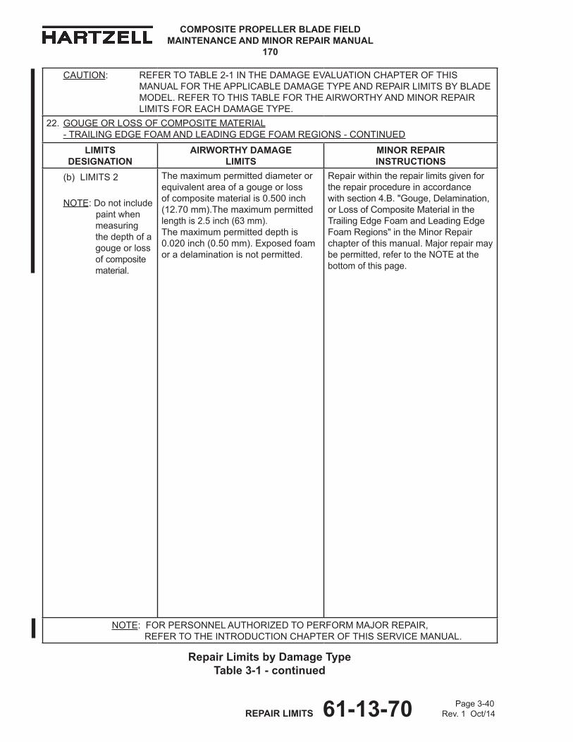
COMPOSITE PROPELLER BLADE FIELD MAINTENANCE AND MINOR REPAIR MANUAL
170
Page 3-40 REPAIR LIMITS 61-13-70 Rev. 1 Oct/14
CAUTION: REFERTOTABLE2-1INThEDAMAGEEvALUATIONChAPTEROFThISMANUALFORThEAPPLICABLEDAMAGETyPEANDREPAIRLIMITSByBLADEMODEL.REFERTOThISTABLEFORThEAIRWORThyANDMINORREPAIRLIMITSFOREAChDAMAGETyPE.
22. GOUGEORLOSSOFCOMPOSITEMATERIAL -TRAILINGEDGEFOAMANDLEADINGEDGEFOAMREGIONS-CONTINUED
LIMITS dESIgNATIoN
AIRWoRTHY dAMAgE LIMITS
MINoR REPAIR INSTRUCTIoNS
(b) LIMITS 2
NOTE:Donotinclude paintwhen measuring thedepthofa gougeorloss ofcomposite material.
Themaximumpermitteddiameterorequivalentareaofagougeorlossofcompositematerialis0.500inch(12.70mm).Themaximumpermittedlengthis2.5inch(63mm). Themaximumpermitteddepthis0.020inch(0.50mm).Exposedfoamoradelaminationisnotpermitted.
Repairwithintherepairlimitsgivenfortherepairprocedureinaccordancewithsection4.B."Gouge,Delamination,orLossofCompositeMaterialintheTrailingEdgeFoamandLeadingEdgeFoamRegions"intheMinorRepairchapterofthismanual.Majorrepairmaybepermitted,refertotheNOTEatthebottomofthispage.
NOTE:FORPERSONNELAUThORIzEDTOPERFORMMAjORREPAIR, REFER TO ThEINTRODUCTIONChAPTEROFThISSERvICEMANUAL.
Repair Limits by damage Type Table 3-1 - continued
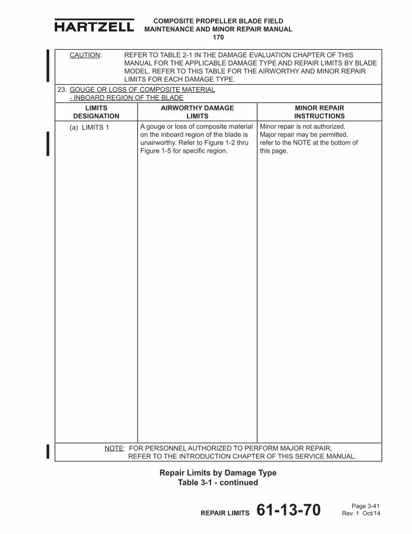
Page 3-41 REPAIR LIMITS 61-13-70 Rev. 1 Oct/14
COMPOSITE PROPELLER BLADE FIELD MAINTENANCE AND MINOR REPAIR MANUAL
170
CAUTION: REFERTOTABLE2-1INThEDAMAGEEvALUATIONChAPTEROFThISMANUALFORThEAPPLICABLEDAMAGETyPEANDREPAIRLIMITSByBLADEMODEL.REFERTOThISTABLEFORThEAIRWORThyANDMINORREPAIRLIMITSFOREAChDAMAGETyPE.
23. GOUGEORLOSSOFCOMPOSITEMATERIAL -INBOARDREGIONOFThEBLADE
LIMITS dESIgNATIoN
AIRWoRTHY dAMAgE LIMITS
MINoR REPAIR INSTRUCTIoNS
(a) LIMITS 1 Agougeorlossofcompositematerialontheinboardregionofthebladeisunairworthy.RefertoFigure1-2thruFigure 1-5 forspecificregion.
Minorrepairisnotauthorized.Majorrepairmaybepermitted, refertotheNOTEatthebottomof thispage.
NOTE:FORPERSONNELAUThORIzEDTOPERFORMMAjORREPAIR, REFER TO ThEINTRODUCTIONChAPTEROFThISSERvICEMANUAL.
Repair Limits by damage Type Table 3-1 - continued
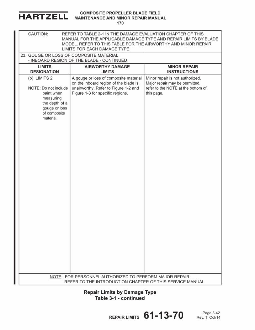
COMPOSITE PROPELLER BLADE FIELD MAINTENANCE AND MINOR REPAIR MANUAL
170
Page 3-42 REPAIR LIMITS 61-13-70 Rev. 1 Oct/14
CAUTION: REFERTOTABLE2-1INThEDAMAGEEvALUATIONChAPTEROFThISMANUALFORThEAPPLICABLEDAMAGETyPEANDREPAIRLIMITSByBLADEMODEL.REFERTOThISTABLEFORThEAIRWORThyANDMINORREPAIRLIMITSFOREAChDAMAGETyPE.
23. GOUGEORLOSSOFCOMPOSITEMATERIAL -INBOARDREGIONOFThEBLADE-CONTINUED
LIMITS dESIgNATIoN
AIRWoRTHY dAMAgE LIMITS
MINoR REPAIR INSTRUCTIoNS
(b)LIMITS2
NOTE:Donotinclude paintwhen measuring thedepthofa gougeorloss ofcomposite material.
Agougeorlossofcompositematerialontheinboardregionofthebladeisunairworthy.RefertoFigure1-2andFigure1-3forspecificregions.
Minorrepairisnotauthorized.Majorrepairmaybepermitted, refertotheNOTEatthebottomof thispage.
NOTE:FORPERSONNELAUThORIzEDTOPERFORMMAjORREPAIR, REFER TO ThEINTRODUCTIONChAPTEROFThISSERvICEMANUAL.
Repair Limits by damage Type Table 3-1 - continued
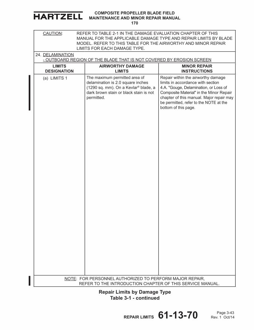
Page 3-43 REPAIR LIMITS 61-13-70 Rev. 1 Oct/14
COMPOSITE PROPELLER BLADE FIELD MAINTENANCE AND MINOR REPAIR MANUAL
170
CAUTION: REFERTOTABLE2-1INThEDAMAGEEvALUATIONChAPTEROFThISMANUALFORThEAPPLICABLEDAMAGETyPEANDREPAIRLIMITSByBLADEMODEL.REFERTOThISTABLEFORThEAIRWORThyANDMINORREPAIRLIMITSFOREAChDAMAGETyPE.
24. dELAMINATION -OUTBOARDREGIONOFThEBLADEThATISNOTCOvEREDByEROSIONSCREEN
LIMITS dESIgNATIoN
AIRWoRTHY dAMAgE LIMITS
MINoR REPAIR INSTRUCTIoNS
(a) LIMITS 1 Themaximumpermittedareaofdelaminationis2.0squareinches (1290sq.mm).OnaKevlar®blade,adarkbrownstainorblackstainisnotpermitted.
Repairwithintheairworthydamagelimitsinaccordancewithsection4.A."Gouge,Delamination,orLossofCompositeMaterial"intheMinorRepairchapterofthismanual.Majorrepairmaybepermitted,refertotheNOTEatthebottomofthispage.
NOTE:FORPERSONNELAUThORIzEDTOPERFORMMAjORREPAIR, REFER TO ThEINTRODUCTIONChAPTEROFThISSERvICEMANUAL.
Repair Limits by damage Type Table 3-1 - continued
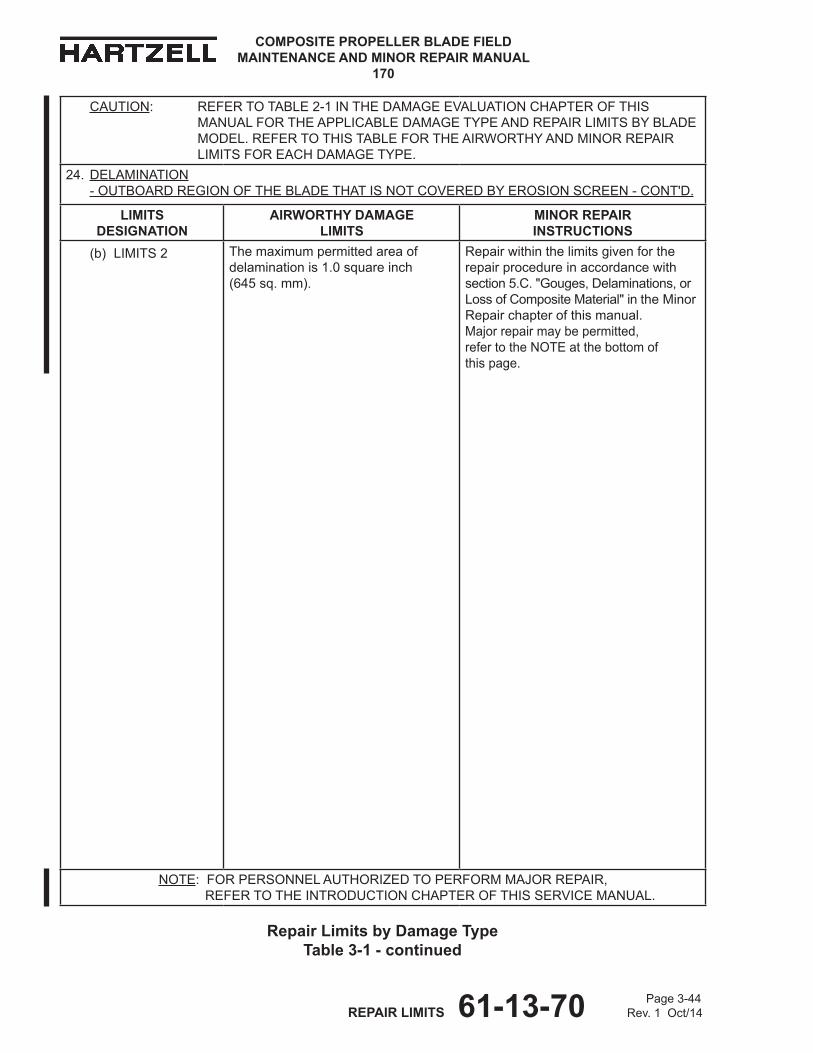
COMPOSITE PROPELLER BLADE FIELD MAINTENANCE AND MINOR REPAIR MANUAL
170
Page 3-44 REPAIR LIMITS 61-13-70 Rev. 1 Oct/14
CAUTION: REFERTOTABLE2-1INThEDAMAGEEvALUATIONChAPTEROFThISMANUALFORThEAPPLICABLEDAMAGETyPEANDREPAIRLIMITSByBLADEMODEL.REFERTOThISTABLEFORThEAIRWORThyANDMINORREPAIRLIMITSFOREAChDAMAGETyPE.
24. dELAMINATION -OUTBOARDREGIONOFThEBLADEThATISNOTCOvEREDByEROSIONSCREEN-CONT'D.
LIMITS dESIgNATIoN
AIRWoRTHY dAMAgE LIMITS
MINoR REPAIR INSTRUCTIoNS
(b) LIMITS 2 Themaximumpermittedareaofdelaminationis1.0squareinch (645sq.mm).
Repairwithinthelimitsgivenfortherepairprocedureinaccordancewithsection5.C."Gouges,Delaminations,orLossofCompositeMaterial"intheMinorRepairchapterofthismanual. Majorrepairmaybepermitted, refertotheNOTEatthebottomof thispage.
NOTE:FORPERSONNELAUThORIzEDTOPERFORMMAjORREPAIR, REFER TO ThEINTRODUCTIONChAPTEROFThISSERvICEMANUAL.
Repair Limits by damage Type Table 3-1 - continued
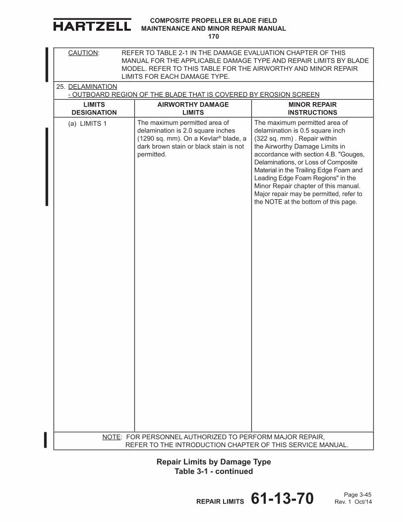
Page 3-45 REPAIR LIMITS 61-13-70 Rev. 1 Oct/14
COMPOSITE PROPELLER BLADE FIELD MAINTENANCE AND MINOR REPAIR MANUAL
170
CAUTION: REFERTOTABLE2-1INThEDAMAGEEvALUATIONChAPTEROFThISMANUALFORThEAPPLICABLEDAMAGETyPEANDREPAIRLIMITSByBLADEMODEL.REFERTOThISTABLEFORThEAIRWORThyANDMINORREPAIRLIMITSFOREAChDAMAGETyPE.
25. dELAMINATION -OUTBOARDREGIONOFThEBLADEThATISCOvEREDByEROSIONSCREEN
LIMITS dESIgNATIoN
AIRWoRTHY dAMAgE LIMITS
MINoR REPAIR INSTRUCTIoNS
(a) LIMITS 1 Themaximumpermittedareaofdelaminationis2.0squareinches(1290sq.mm).OnaKevlar®blade,adarkbrownstainorblackstainisnotpermitted.
Themaximumpermittedareaofdelaminationis0.5squareinch (322sq.mm).RepairwithintheAirworthyDamageLimitsinaccordancewithsection4.B."Gouges,Delaminations,orLossofCompositeMaterialintheTrailingEdgeFoamandLeadingEdgeFoamRegions"intheMinorRepairchapterofthismanual.Majorrepairmaybepermitted,refertotheNOTEatthebottomofthispage.
NOTE:FORPERSONNELAUThORIzEDTOPERFORMMAjORREPAIR, REFER TO ThEINTRODUCTIONChAPTEROFThISSERvICEMANUAL.
Repair Limits by damage Type Table 3-1 - continued
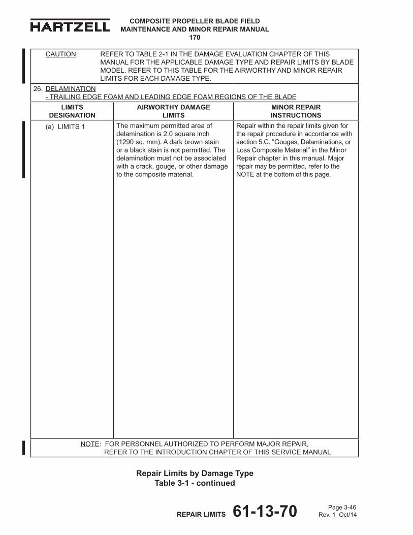
COMPOSITE PROPELLER BLADE FIELD MAINTENANCE AND MINOR REPAIR MANUAL
170
Page 3-46 REPAIR LIMITS 61-13-70 Rev. 1 Oct/14
CAUTION: REFERTOTABLE2-1INThEDAMAGEEvALUATIONChAPTEROFThISMANUALFORThEAPPLICABLEDAMAGETyPEANDREPAIRLIMITSByBLADEMODEL.REFERTOThISTABLEFORThEAIRWORThyANDMINORREPAIRLIMITSFOREAChDAMAGETyPE.
26. dELAMINATION -TRAILINGEDGEFOAMANDLEADINGEDGEFOAMREGIONSOFThEBLADE
LIMITS dESIgNATIoN
AIRWoRTHY dAMAgE LIMITS
MINoR REPAIR INSTRUCTIoNS
(a) LIMITS 1 Themaximumpermittedareaofdelaminationis2.0squareinch(1290sq.mm).Adarkbrownstainorablackstainisnotpermitted.Thedelaminationmustnotbeassociatedwithacrack,gouge,orotherdamagetothecompositematerial.
Repairwithintherepairlimitsgivenfortherepairprocedureinaccordancewithsection5.C."Gouges,Delaminations,orLossCompositeMaterial"intheMinorRepairchapterinthismanual.Majorrepairmaybepermitted,refertotheNOTEatthebottomofthispage.
NOTE:FORPERSONNELAUThORIzEDTOPERFORMMAjORREPAIR, REFER TO ThEINTRODUCTIONChAPTEROFThISSERvICEMANUAL.
Repair Limits by damage Type Table 3-1 - continued

Page 3-47 REPAIR LIMITS 61-13-70 Rev. 1 Oct/14
COMPOSITE PROPELLER BLADE FIELD MAINTENANCE AND MINOR REPAIR MANUAL
170
CAUTION: REFERTOTABLE2-1INThEDAMAGEEvALUATIONChAPTEROFThISMANUALFORThEAPPLICABLEDAMAGETyPEANDREPAIRLIMITSByBLADEMODEL.REFERTOThISTABLEFORThEAIRWORThyANDMINORREPAIRLIMITSFOREAChDAMAGETyPE.
26. dELAMINATION -TRAILINGEDGEFOAMANDLEADINGEDGEFOAMREGIONSOFThEBLADE-CONTINUED
LIMITS dESIgNATIoN
AIRWoRTHY dAMAgE LIMITS
MINoR REPAIR INSTRUCTIoNS
(b) LIMITS 2 Themaximumpermittedareaofdelaminationis2.0squareinch (1290sq.mm).
WithintheAirworthyDamageLimits, repairinaccordancewithsection 4.B."Gouge,Delamination,orLossofCompositeMaterialintheTrailingEdgeFoamandLeadingEdgeFoamRegions" intheMinorRepairchapterofthismanual.Majorrepairmaybepermitted,refertotheNOTEatthebottomofthispage.
NOTE:FORPERSONNELAUThORIzEDTOPERFORMMAjORREPAIR, REFER TO ThEINTRODUCTIONChAPTEROFThISSERvICEMANUAL.
Repair Limits by damage Type Table 3-1 - continued
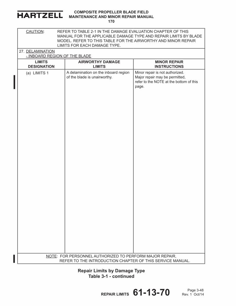
COMPOSITE PROPELLER BLADE FIELD MAINTENANCE AND MINOR REPAIR MANUAL
170
Page 3-48 REPAIR LIMITS 61-13-70 Rev. 1 Oct/14
Repair Limits by damage Type Table 3-1 - continued
CAUTION: REFERTOTABLE2-1INThEDAMAGEEvALUATIONChAPTEROFThISMANUALFORThEAPPLICABLEDAMAGETyPEANDREPAIRLIMITSByBLADEMODEL.REFERTOThISTABLEFORThEAIRWORThyANDMINORREPAIRLIMITSFOREAChDAMAGETyPE.
27. dELAMINATION -INBOARDREGIONOFThEBLADE
LIMITS dESIgNATIoN
AIRWoRTHY dAMAgE LIMITS
MINoR REPAIR INSTRUCTIoNS
(a) LIMITS 1 Adelaminationontheinboardregionofthebladeisunairworthy.
Minorrepairisnotauthorized.Majorrepairmaybepermitted, refertotheNOTEatthebottomofthispage.
NOTE:FORPERSONNELAUThORIzEDTOPERFORMMAjORREPAIR, REFER TO ThEINTRODUCTIONChAPTEROFThISSERvICEMANUAL.
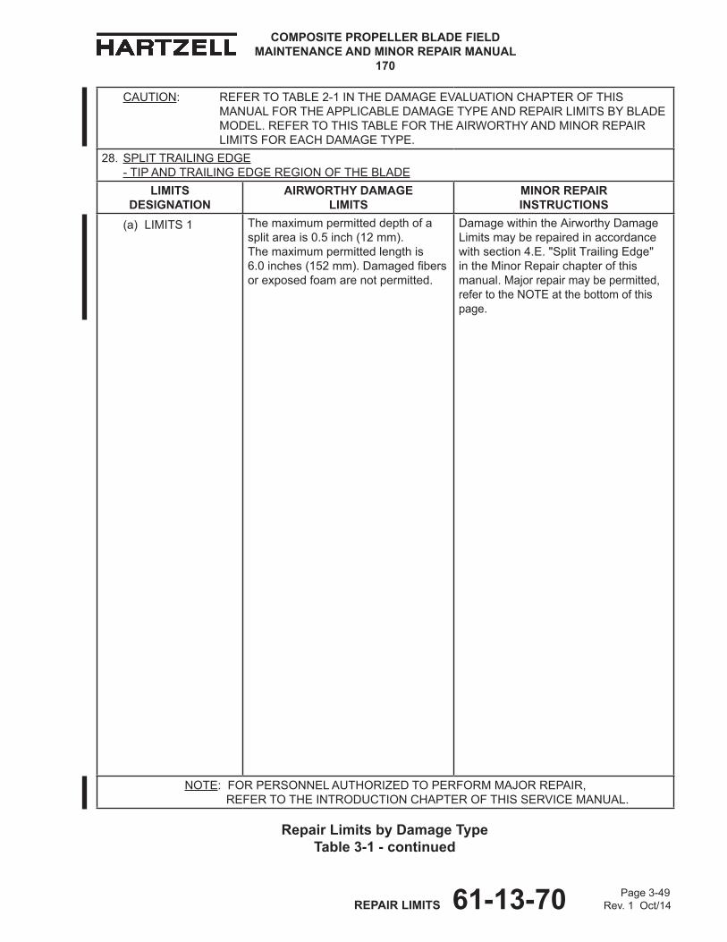
Page 3-49 REPAIR LIMITS 61-13-70 Rev. 1 Oct/14
COMPOSITE PROPELLER BLADE FIELD MAINTENANCE AND MINOR REPAIR MANUAL
170
CAUTION: REFERTOTABLE2-1INThEDAMAGEEvALUATIONChAPTEROFThISMANUALFORThEAPPLICABLEDAMAGETyPEANDREPAIRLIMITSByBLADEMODEL.REFERTOThISTABLEFORThEAIRWORThyANDMINORREPAIRLIMITSFOREAChDAMAGETyPE.
28. SPLITTRAILINGEDGE -TIPANDTRAILINGEDGEREGIONOFThEBLADE
LIMITS dESIgNATIoN
AIRWoRTHY dAMAgE LIMITS
MINoR REPAIR INSTRUCTIoNS
(a) LIMITS 1 Themaximumpermitteddepthofasplitareais0.5inch(12mm). Themaximumpermittedlengthis 6.0inches(152mm).Damagedfibersorexposedfoamarenotpermitted.
DamagewithintheAirworthyDamageLimitsmayberepairedinaccordancewithsection4.E."SplitTrailingEdge"intheMinorRepairchapterofthismanual.Majorrepairmaybepermitted,refertotheNOTEatthebottomofthispage.
NOTE:FORPERSONNELAUThORIzEDTOPERFORMMAjORREPAIR, REFER TO ThEINTRODUCTIONChAPTEROFThISSERvICEMANUAL.
Repair Limits by damage Type Table 3-1 - continued
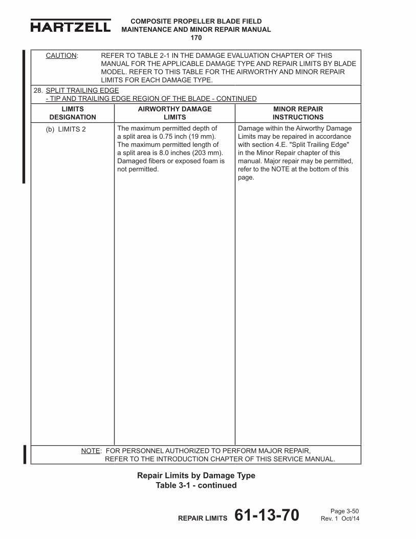
COMPOSITE PROPELLER BLADE FIELD MAINTENANCE AND MINOR REPAIR MANUAL
170
Page 3-50 REPAIR LIMITS 61-13-70 Rev. 1 Oct/14
Repair Limits by damage Type Table 3-1 - continued
CAUTION: REFERTOTABLE2-1INThEDAMAGEEvALUATIONChAPTEROFThISMANUALFORThEAPPLICABLEDAMAGETyPEANDREPAIRLIMITSByBLADEMODEL.REFERTOThISTABLEFORThEAIRWORThyANDMINORREPAIRLIMITSFOREAChDAMAGETyPE.
28. SPLITTRAILINGEDGE -TIPANDTRAILINGEDGEREGIONOFThEBLADE-CONTINUED
LIMITS dESIgNATIoN
AIRWoRTHY dAMAgE LIMITS
MINoR REPAIR INSTRUCTIoNS
(b) LIMITS 2 Themaximumpermitteddepthofasplitareais0.75inch(19mm).Themaximumpermittedlengthofasplitareais8.0inches(203mm).Damagedfibersorexposedfoamisnotpermitted.
DamagewithintheAirworthyDamageLimitsmayberepairedinaccordancewithsection4.E."SplitTrailingEdge"intheMinorRepairchapterofthismanual.Majorrepairmaybepermitted,refertotheNOTEatthebottomofthispage.
NOTE:FORPERSONNELAUThORIzEDTOPERFORMMAjORREPAIR, REFER TO ThEINTRODUCTIONChAPTEROFThISSERvICEMANUAL.
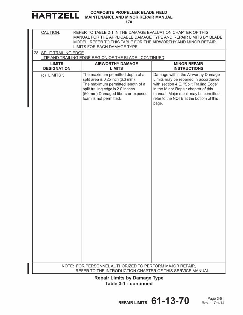
Page 3-51 REPAIR LIMITS 61-13-70 Rev. 1 Oct/14
COMPOSITE PROPELLER BLADE FIELD MAINTENANCE AND MINOR REPAIR MANUAL
170
CAUTION: REFERTOTABLE2-1INThEDAMAGEEvALUATIONChAPTEROFThISMANUALFORThEAPPLICABLEDAMAGETyPEANDREPAIRLIMITSByBLADEMODEL.REFERTOThISTABLEFORThEAIRWORThyANDMINORREPAIRLIMITSFOREAChDAMAGETyPE.
28. SPLITTRAILINGEDGE -TIPANDTRAILINGEDGEREGIONOFThEBLADE-CONTINUED
LIMITS dESIgNATIoN
AIRWoRTHY dAMAgE LIMITS
MINoR REPAIR INSTRUCTIoNS
(c) LIMITS 3 Themaximumpermitteddepthofasplitareais0.25inch(6.3mm). Themaximumpermittedlengthofasplittrailingedgeis2.0inches (50mm).Damagedfibersorexposedfoamisnotpermitted.
DamagewithintheAirworthyDamageLimitsmayberepairedinaccordancewithsection4.E."SplitTrailingEdge" intheMinorRepairchapterofthismanual.Majorrepairmaybepermitted,refertotheNOTEatthebottomofthispage.
NOTE:FORPERSONNELAUThORIzEDTOPERFORMMAjORREPAIR, REFER TO ThEINTRODUCTIONChAPTEROFThISSERvICEMANUAL.
Repair Limits by damage Type Table 3-1 - continued
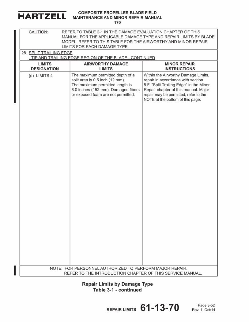
COMPOSITE PROPELLER BLADE FIELD MAINTENANCE AND MINOR REPAIR MANUAL
170
Page 3-52 REPAIR LIMITS 61-13-70 Rev. 1 Oct/14
Repair Limits by damage Type Table 3-1 - continued
CAUTION: REFERTOTABLE2-1INThEDAMAGEEvALUATIONChAPTEROFThISMANUALFORThEAPPLICABLEDAMAGETyPEANDREPAIRLIMITSByBLADEMODEL.REFERTOThISTABLEFORThEAIRWORThyANDMINORREPAIRLIMITSFOREAChDAMAGETyPE.
28. SPLITTRAILINGEDGE -TIPANDTRAILINGEDGEREGIONOFThEBLADE-CONTINUED
LIMITS dESIgNATIoN
AIRWoRTHY dAMAgE LIMITS
MINoR REPAIR INSTRUCTIoNS
(d) LIMITS 4 Themaximumpermitteddepthofasplitareais0.5inch(12mm). Themaximumpermittedlengthis 6.0inches(152mm).Damagedfibersorexposedfoam arenotpermitted.
WithintheAirworthyDamageLimits, repairinaccordancewithsection 5.F."SplitTrailingEdge"intheMinorRepairchapterofthismanual.Majorrepairmaybepermitted,refertotheNOTEatthebottomofthispage.
NOTE:FORPERSONNELAUThORIzEDTOPERFORMMAjORREPAIR, REFER TO ThEINTRODUCTIONChAPTEROFThISSERvICEMANUAL.
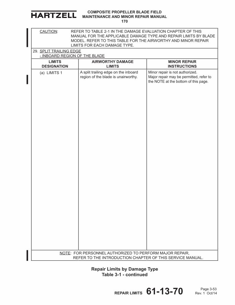
Page 3-53 REPAIR LIMITS 61-13-70 Rev. 1 Oct/14
COMPOSITE PROPELLER BLADE FIELD MAINTENANCE AND MINOR REPAIR MANUAL
170
CAUTION: REFERTOTABLE2-1INThEDAMAGEEvALUATIONChAPTEROFThISMANUALFORThEAPPLICABLEDAMAGETyPEANDREPAIRLIMITSByBLADEMODEL.REFERTOThISTABLEFORThEAIRWORThyANDMINORREPAIRLIMITSFOREAChDAMAGETyPE.
29. SPLITTRAILINGEDGE -INBOARDREGIONOFThEBLADE
LIMITS dESIgNATIoN
AIRWoRTHY dAMAgE LIMITS
MINoR REPAIR INSTRUCTIoNS
(a) LIMITS 1 Asplittrailingedgeontheinboardregionofthebladeisunairworthy.
Minorrepairisnotauthorized. Majorrepairmaybepermitted,refertotheNOTEatthebottomofthispage.
NOTE:FORPERSONNELAUThORIzEDTOPERFORMMAjORREPAIR, REFER TO ThEINTRODUCTIONChAPTEROFThISSERvICEMANUAL.
Repair Limits by damage Type Table 3-1 - continued

COMPOSITE PROPELLER BLADE FIELD MAINTENANCE AND MINOR REPAIR MANUAL
170
Page 3-54 REPAIR LIMITS 61-13-70 Rev. 1 Oct/14
Repair Limits by damage Type Table 3-1 - continued
CAUTION: REFERTOTABLE2-1INThEDAMAGEEvALUATIONChAPTEROFThISMANUALFORThEAPPLICABLEDAMAGETyPEANDREPAIRLIMITSByBLADEMODEL.REFERTOThISTABLEFORThEAIRWORThyANDMINORREPAIRLIMITSFOREAChDAMAGETyPE.
29. SPLITTRAILINGEDGE -INBOARDREGIONOFThEBLADE-CONTINUED
LIMITS dESIgNATIoN
AIRWoRTHY dAMAgE LIMITS
MINoR REPAIR INSTRUCTIoNS
(b) LIMITS 2 Themaximumpermitteddepthofasplitareais0.5inch(12mm).Themaximumpermittedlengthofasplitareais6.0inch(152mm).Damagedfibersorexposedfoamarenotpermitted.
DamagewithintheAirworthyDamageLimitsmayberepairedinaccordancewithsection4.E."SplitTrailingEdge" intheMinorRepairchapterofthismanual.Majorrepairmaybepermitted,refertotheNOTEatthebottomofthispage.
NOTE:FORPERSONNELAUThORIzEDTOPERFORMMAjORREPAIR, REFER TO ThEINTRODUCTIONChAPTEROFThISSERvICEMANUAL.

Page 3-55 REPAIR LIMITS 61-13-70 Rev. 1 Oct/14
COMPOSITE PROPELLER BLADE FIELD MAINTENANCE AND MINOR REPAIR MANUAL
170
CAUTION: REFERTOTABLE2-1INThEDAMAGEEvALUATIONChAPTEROFThISMANUALFORThEAPPLICABLEDAMAGETyPEANDREPAIRLIMITSByBLADEMODEL.REFERTOThISTABLEFORThEAIRWORThyANDMINORREPAIRLIMITSFOREAChDAMAGETyPE.
30. CRUShEDORCRACKEDTRAILINGEDGE -INBOARDREGIONOFThEBLADE
LIMITS dESIgNATIoN
AIRWoRTHY dAMAgE LIMITS
MINoR REPAIR INSTRUCTIoNS
(a) LIMITS 1 Themaximumpermitteddepthofacrushedorcrackedareais0.125inch(3.17mm).Themaximumpermittedlengthofacrushedorcrackedareais1.0inch(25mm).
WithintheAirworthyDamageLimits,repairinaccordancewithsection 4.C."CrushedorCrackedTrailingEdge"intheMinorRepairchapterofthismanual.Majorrepairmaybepermitted,refertotheNOTEatthebottomofthispage.
NOTE:FORPERSONNELAUThORIzEDTOPERFORMMAjORREPAIR, REFER TO ThEINTRODUCTIONChAPTEROFThISSERvICEMANUAL.
Repair Limits by damage Type Table 3-1 - continued

COMPOSITE PROPELLER BLADE FIELD MAINTENANCE AND MINOR REPAIR MANUAL
170
Page 3-56 REPAIR LIMITS 61-13-70 Rev. 1 Oct/14
Repair Limits by damage Type Table 3-1 - continued
CAUTION: REFERTOTABLE2-1INThEDAMAGEEvALUATIONChAPTEROFThISMANUALFORThEAPPLICABLEDAMAGETyPEANDREPAIRLIMITSByBLADEMODEL.REFERTOThISTABLEFORThEAIRWORThyANDMINORREPAIRLIMITSFOREAChDAMAGETyPE.
30. CRUShEDORCRACKEDTRAILINGEDGE -INBOARDREGIONOFThEBLADE-CONTINUED
LIMITS dESIgNATIoN
AIRWoRTHY dAMAgE LIMITS
MINoR REPAIR INSTRUCTIoNS
(b) LIMITS 2 Acrushedorcrackedtrailingedgeontheinboardregionofthebladeisunairworthy.
Minorrepairisnotauthorized. Majorrepairmaybepermitted,refertotheNOTEatthebottomofthispage.
NOTE:FORPERSONNELAUThORIzEDTOPERFORMMAjORREPAIR, REFER TO ThEINTRODUCTIONChAPTEROFThISSERvICEMANUAL.
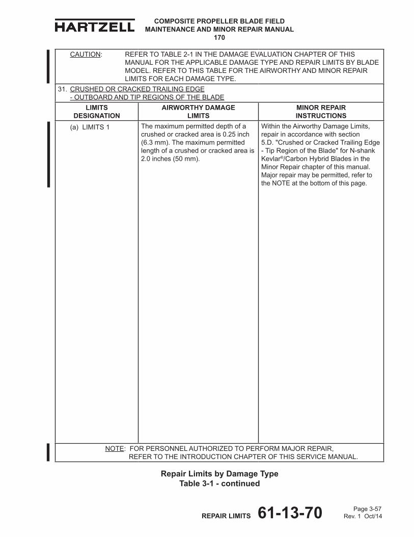
Page 3-57 REPAIR LIMITS 61-13-70 Rev. 1 Oct/14
COMPOSITE PROPELLER BLADE FIELD MAINTENANCE AND MINOR REPAIR MANUAL
170
CAUTION: REFERTOTABLE2-1INThEDAMAGEEvALUATIONChAPTEROFThISMANUALFORThEAPPLICABLEDAMAGETyPEANDREPAIRLIMITSByBLADEMODEL.REFERTOThISTABLEFORThEAIRWORThyANDMINORREPAIRLIMITSFOREAChDAMAGETyPE.
31. CRUShEDORCRACKEDTRAILINGEDGE -OUTBOARDANDTIPREGIONSOFThEBLADE
LIMITS dESIgNATIoN
AIRWoRTHY dAMAgE LIMITS
MINoR REPAIR INSTRUCTIoNS
(a) LIMITS 1 Themaximumpermitteddepthofacrushedorcrackedareais0.25inch(6.3mm).Themaximumpermittedlengthofacrushedorcrackedareais2.0inches(50mm).
WithintheAirworthyDamageLimits, repairinaccordancewithsection 5.D."CrushedorCrackedTrailingEdge-TipRegionoftheBlade"forN-shankKevlar®/CarbonhybridBladesintheMinorRepairchapterofthismanual. Majorrepairmaybepermitted,refertotheNOTEatthebottomofthispage.
NOTE:FORPERSONNELAUThORIzEDTOPERFORMMAjORREPAIR, REFER TO ThEINTRODUCTIONChAPTEROFThISSERvICEMANUAL.
Repair Limits by damage Type Table 3-1 - continued
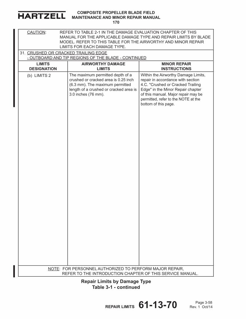
COMPOSITE PROPELLER BLADE FIELD MAINTENANCE AND MINOR REPAIR MANUAL
170
Page 3-58 REPAIR LIMITS 61-13-70 Rev. 1 Oct/14
Repair Limits by damage Type Table 3-1 - continued
CAUTION: REFERTOTABLE2-1INThEDAMAGEEvALUATIONChAPTEROFThISMANUALFORThEAPPLICABLEDAMAGETyPEANDREPAIRLIMITSByBLADEMODEL.REFERTOThISTABLEFORThEAIRWORThyANDMINORREPAIRLIMITSFOREAChDAMAGETyPE.
31. CRUShEDORCRACKEDTRAILINGEDGE -OUTBOARDANDTIPREGIONSOFThEBLADE-CONTINUED
LIMITS dESIgNATIoN
AIRWoRTHY dAMAgE LIMITS
MINoR REPAIR INSTRUCTIoNS
(b) LIMITS 2 Themaximumpermitteddepthofacrushedorcrackedareais0.25inch(6.3mm).Themaximumpermittedlengthofacrushedorcrackedareais3.0inches(76mm).
WithintheAirworthyDamageLimits,repairinaccordancewithsection 4.C."CrushedorCrackedTrailingEdge"intheMinorRepairchapterofthismanual.Majorrepairmaybepermitted,refertotheNOTEatthebottomofthispage.
NOTE:FORPERSONNELAUThORIzEDTOPERFORMMAjORREPAIR, REFER TO ThEINTRODUCTIONChAPTEROFThISSERvICEMANUAL.

Page 3-59 REPAIR LIMITS 61-13-70 Rev. 1 Oct/14
COMPOSITE PROPELLER BLADE FIELD MAINTENANCE AND MINOR REPAIR MANUAL
170
CAUTION: REFERTOTABLE2-1INThEDAMAGEEvALUATIONChAPTEROFThISMANUALFORThEAPPLICABLEDAMAGETyPEANDREPAIRLIMITSByBLADEMODEL.REFERTOThISTABLEFORThEAIRWORThyANDMINORREPAIRLIMITSFOREAChDAMAGETyPE.
31. CRUShEDORCRACKEDTRAILINGEDGE -OUTBOARDANDTIPREGIONSOFThEBLADE-CONTINUED
LIMITS dESIgNATIoN
AIRWoRTHY dAMAgE LIMITS
MINoR REPAIR INSTRUCTIoNS
(c) LIMITS 3 Themaximumpermitteddepthofacrushedorcrackedareais0.25inch(6.3mm).Themaximumpermittedlengthofacrushedorcrackedareais2.0inches(50mm).
WithintheAirworthyDamageLimits, repairinaccordancewithsection 4.C."CrushedorCrackedTrailingEdge"intheMinorRepairchapterofthismanual.Majorrepairmaybepermitted,refertotheNOTEatthebottomofthispage.
NOTE:FORPERSONNELAUThORIzEDTOPERFORMMAjORREPAIR, REFER TO ThEINTRODUCTIONChAPTEROFThISSERvICEMANUAL.
Repair Limits by damage Type Table 3-1 - continued
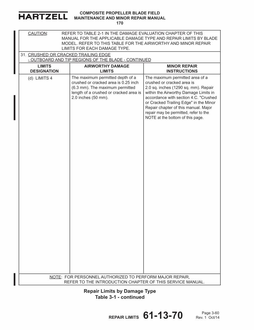
COMPOSITE PROPELLER BLADE FIELD MAINTENANCE AND MINOR REPAIR MANUAL
170
Page 3-60 REPAIR LIMITS 61-13-70 Rev. 1 Oct/14
Repair Limits by damage Type Table 3-1 - continued
CAUTION: REFERTOTABLE2-1INThEDAMAGEEvALUATIONChAPTEROFThISMANUALFORThEAPPLICABLEDAMAGETyPEANDREPAIRLIMITSByBLADEMODEL.REFERTOThISTABLEFORThEAIRWORThyANDMINORREPAIRLIMITSFOREAChDAMAGETyPE.
31. CRUShEDORCRACKEDTRAILINGEDGE -OUTBOARDANDTIPREGIONSOFThEBLADE-CONTINUED
LIMITS dESIgNATIoN
AIRWoRTHY dAMAgE LIMITS
MINoR REPAIR INSTRUCTIoNS
(d) LIMITS 4 Themaximumpermitteddepthofacrushedorcrackedareais0.25inch(6.3mm).Themaximumpermittedlengthofacrushedorcrackedareais2.0inches(50mm).
Themaximumpermittedareaofacrushedorcrackedareais 2.0sq.inches(1290sq.mm).RepairwithintheAirworthyDamageLimitsinaccordancewithsection4.C."CrushedorCrackedTrailingEdge"intheMinorRepairchapterofthismanual.Majorrepairmaybepermitted,refertotheNOTEatthebottomofthispage.
NOTE:FORPERSONNELAUThORIzEDTOPERFORMMAjORREPAIR, REFER TO ThEINTRODUCTIONChAPTEROFThISSERvICEMANUAL.
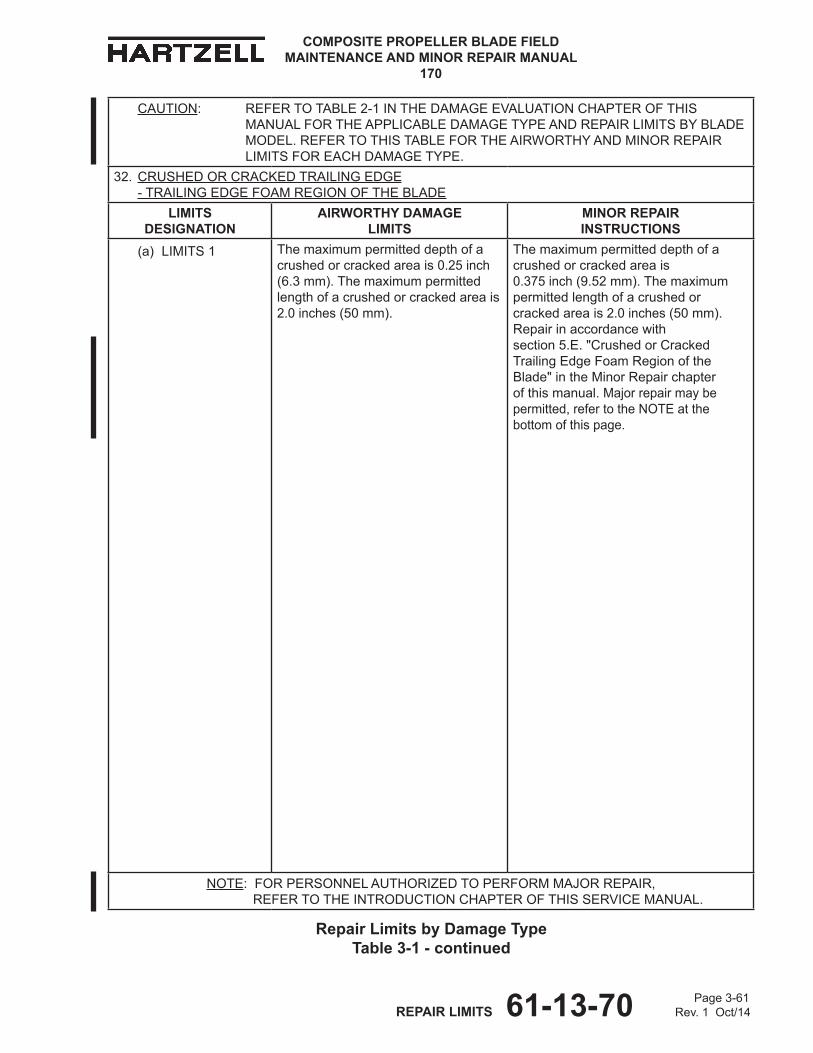
Page 3-61 REPAIR LIMITS 61-13-70 Rev. 1 Oct/14
COMPOSITE PROPELLER BLADE FIELD MAINTENANCE AND MINOR REPAIR MANUAL
170
CAUTION: REFERTOTABLE2-1INThEDAMAGEEvALUATIONChAPTEROFThISMANUALFORThEAPPLICABLEDAMAGETyPEANDREPAIRLIMITSByBLADEMODEL.REFERTOThISTABLEFORThEAIRWORThyANDMINORREPAIRLIMITSFOREAChDAMAGETyPE.
32. CRUShEDORCRACKEDTRAILINGEDGE -TRAILINGEDGEFOAMREGIONOFThEBLADE
LIMITS dESIgNATIoN
AIRWoRTHY dAMAgE LIMITS
MINoR REPAIR INSTRUCTIoNS
(a) LIMITS 1 Themaximumpermitteddepthofacrushedorcrackedareais0.25inch(6.3mm).Themaximumpermittedlengthofacrushedorcrackedareais2.0inches(50mm).
Themaximumpermitteddepthofacrushedorcrackedareais 0.375inch(9.52mm).Themaximumpermittedlengthofacrushedorcrackedareais2.0inches(50mm).Repairinaccordancewith section5.E."CrushedorCrackedTrailingEdgeFoamRegionoftheBlade"intheMinorRepairchapterofthismanual.Majorrepairmaybepermitted,refertotheNOTEatthebottomofthispage.
NOTE:FORPERSONNELAUThORIzEDTOPERFORMMAjORREPAIR, REFER TO ThEINTRODUCTIONChAPTEROFThISSERvICEMANUAL.
Repair Limits by damage Type Table 3-1 - continued
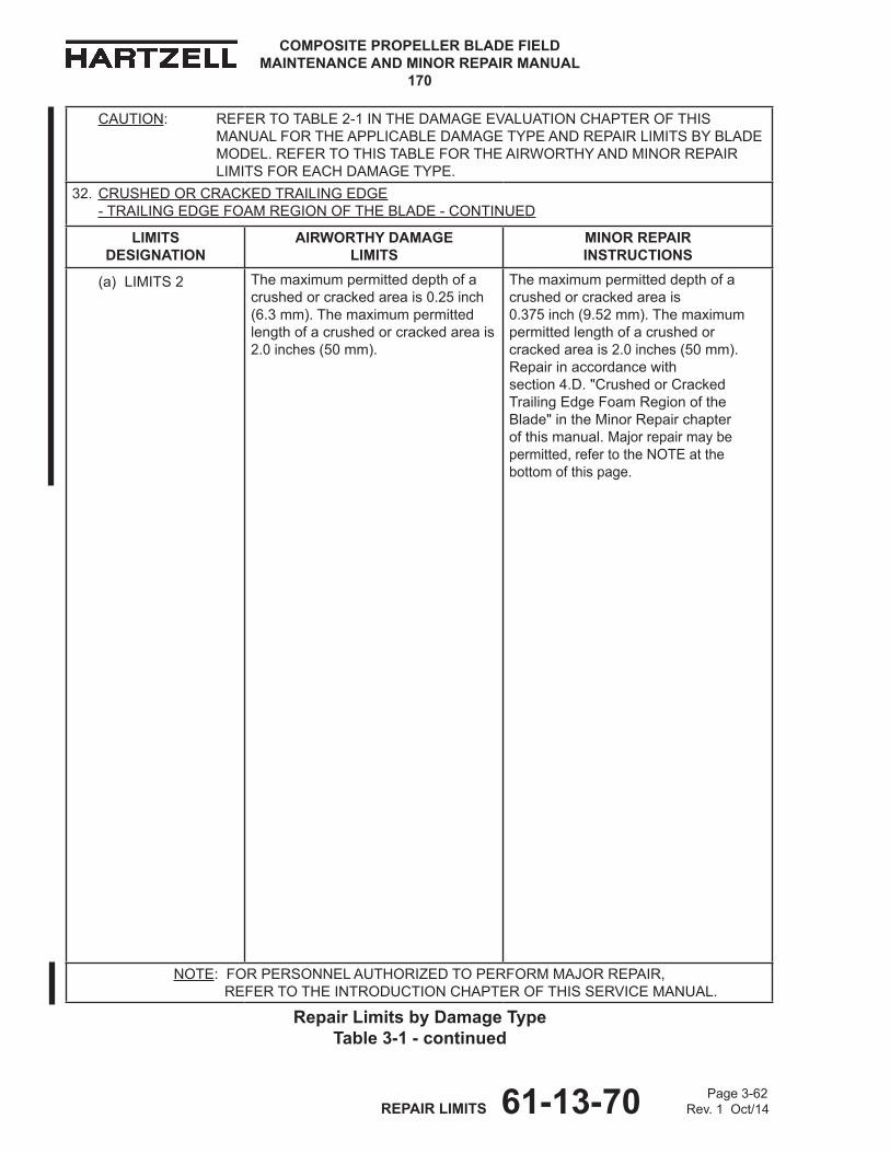
COMPOSITE PROPELLER BLADE FIELD MAINTENANCE AND MINOR REPAIR MANUAL
170
Page 3-62 REPAIR LIMITS 61-13-70 Rev. 1 Oct/14
Repair Limits by damage Type Table 3-1 - continued
CAUTION: REFERTOTABLE2-1INThEDAMAGEEvALUATIONChAPTEROFThISMANUALFORThEAPPLICABLEDAMAGETyPEANDREPAIRLIMITSByBLADEMODEL.REFERTOThISTABLEFORThEAIRWORThyANDMINORREPAIRLIMITSFOREAChDAMAGETyPE.
32. CRUShEDORCRACKEDTRAILINGEDGE -TRAILINGEDGEFOAMREGIONOFThEBLADE-CONTINUED
LIMITS dESIgNATIoN
AIRWoRTHY dAMAgE LIMITS
MINoR REPAIR INSTRUCTIoNS
(a) LIMITS 2 Themaximumpermitteddepthofacrushedorcrackedareais0.25inch(6.3mm).Themaximumpermittedlengthofacrushedorcrackedareais2.0inches(50mm).
Themaximumpermitteddepthofacrushedorcrackedareais 0.375inch(9.52mm).Themaximumpermittedlengthofacrushedorcrackedareais2.0inches(50mm).Repairinaccordancewith section4.D."CrushedorCrackedTrailingEdgeFoamRegionoftheBlade"intheMinorRepairchapterofthismanual. Majorrepairmaybepermitted,refertotheNOTEatthebottomofthispage.
NOTE:FORPERSONNELAUThORIzEDTOPERFORMMAjORREPAIR, REFER TO ThEINTRODUCTIONChAPTEROFThISSERvICEMANUAL.
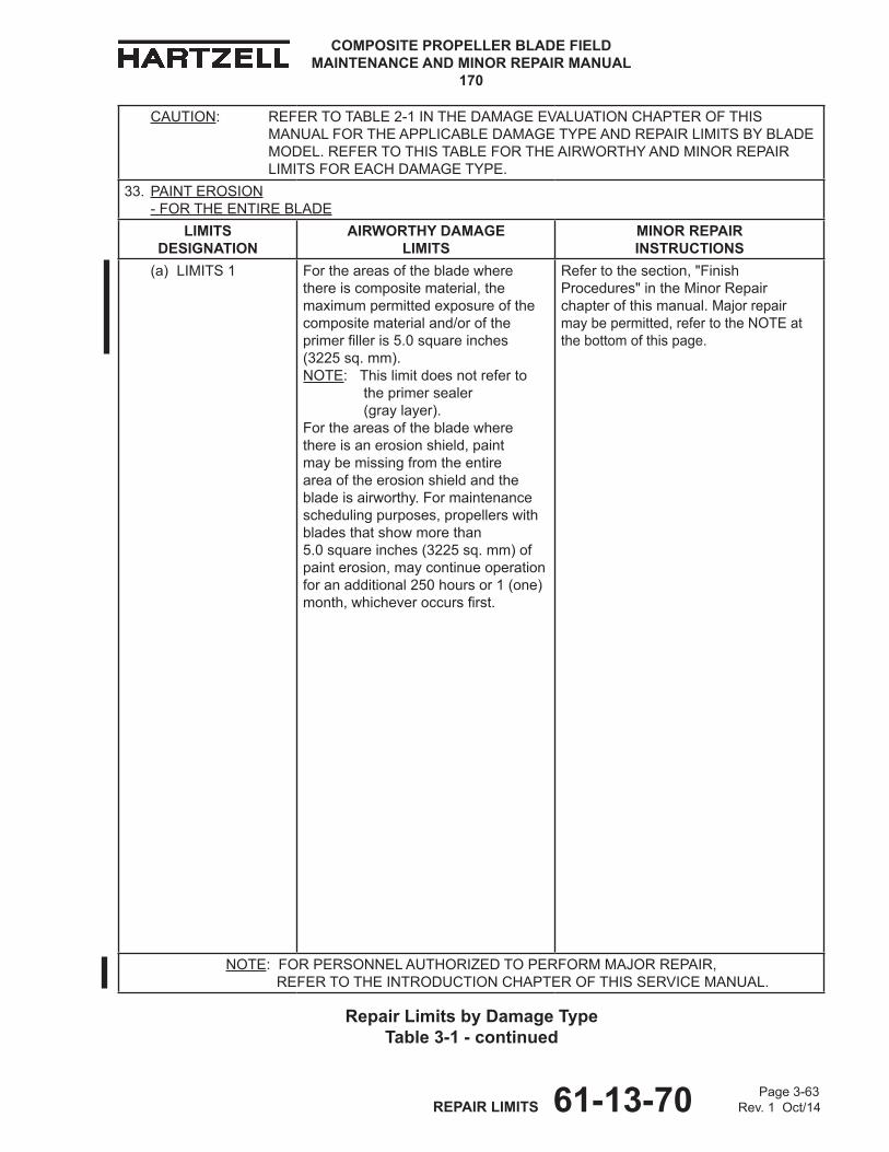
Page 3-63 REPAIR LIMITS 61-13-70 Rev. 1 Oct/14
COMPOSITE PROPELLER BLADE FIELD MAINTENANCE AND MINOR REPAIR MANUAL
170
CAUTION: REFERTOTABLE2-1INThEDAMAGEEvALUATIONChAPTEROFThISMANUALFORThEAPPLICABLEDAMAGETyPEANDREPAIRLIMITSByBLADEMODEL.REFERTOThISTABLEFORThEAIRWORThyANDMINORREPAIRLIMITSFOREAChDAMAGETyPE.
33. PAINT EROSION -FORThEENTIREBLADE
LIMITS dESIgNATIoN
AIRWoRTHY dAMAgE LIMITS
MINoR REPAIR INSTRUCTIoNS
(a) LIMITS 1 Fortheareasofthebladewherethereiscompositematerial,themaximumpermittedexposureofthecompositematerialand/oroftheprimerfilleris5.0squareinches (3225sq.mm). NOTE: Thislimitdoesnotreferto theprimersealer (graylayer). Fortheareasofthebladewherethereisanerosionshield,paintmaybemissingfromtheentireareaoftheerosionshieldandthebladeisairworthy.Formaintenanceschedulingpurposes,propellerswithbladesthatshowmorethan 5.0squareinches(3225sq.mm)ofpainterosion,maycontinueoperationforanadditional250hoursor1(one)month,whicheveroccursfirst.
Refertothesection,"FinishProcedures"intheMinorRepairchapterofthismanual.Majorrepair maybepermitted,refertotheNOTEatthebottomofthispage.
NOTE:FORPERSONNELAUThORIzEDTOPERFORMMAjORREPAIR, REFER TO ThEINTRODUCTIONChAPTEROFThISSERvICEMANUAL.
Repair Limits by damage Type Table 3-1 - continued

COMPOSITE PROPELLER BLADE FIELD MAINTENANCE AND MINOR REPAIR MANUAL
170
Page 3-64 REPAIR LIMITS 61-13-70 Rev. 1 Oct/14
Repair Limits by damage Type Table 3-1 - continued
CAUTION: REFERTOTABLE2-1INThEDAMAGEEvALUATIONChAPTEROFThISMANUALFORThEAPPLICABLEDAMAGETyPEANDREPAIRLIMITSByBLADEMODEL.REFERTOThISTABLEFORThEAIRWORThyANDMINORREPAIRLIMITSFOREAChDAMAGETyPE.
33. PAINT EROSION -FORThEENTIREBLADE-CONTINUED
LIMITS dESIgNATIoN
AIRWoRTHY dAMAgE LIMITS
MINoR REPAIR INSTRUCTIoNS
(b) LIMITS 2 Fortheareasofthebladewherethereiscompositematerial,themaximumpermittedexposureofthecompositematerialand/oroftheprimerfilleris5.0squareinches (3225sq.mm). NOTE: Thislimitdoesnotreferto theprimersealer (graylayer).Fortheareasofthebladewherethereisanerosionshield,paintmaybemissingfromtheentireareaoftheerosionshieldandthebladeisairworthy.Formaintenanceschedulingpurposes,propellerswithbladesthatshowmorethan 5.0squareinches(3225sq.mm)ofpainterosion,maycontinueoperationforanadditional250hoursor1(one)month,whicheveroccursfirst.
h79A06xbladesarefinishcoatedwithapaintthatisrestrictedbyU.S.lawandissubjecttoITARcontrols.ContacttheairframemanufacturerforbladerepairinformationorreturnthebladetohartzellPropellerInc.
NOTE:FORPERSONNELAUThORIzEDTOPERFORMMAjORREPAIR, REFER TO ThEINTRODUCTIONChAPTEROFThISSERvICEMANUAL.
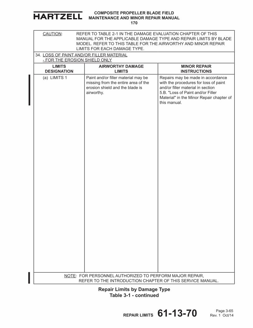
Page 3-65 REPAIR LIMITS 61-13-70 Rev. 1 Oct/14
COMPOSITE PROPELLER BLADE FIELD MAINTENANCE AND MINOR REPAIR MANUAL
170
CAUTION: REFERTOTABLE2-1INThEDAMAGEEvALUATIONChAPTEROFThISMANUALFORThEAPPLICABLEDAMAGETyPEANDREPAIRLIMITSByBLADEMODEL.REFERTOThISTABLEFORThEAIRWORThyANDMINORREPAIRLIMITSFOREAChDAMAGETyPE.
34. LOSS OF PAINT ANd/OR FILLER MATERIAL - FORThEEROSIONShIELDONLy
LIMITS dESIgNATIoN
AIRWoRTHY dAMAgE LIMITS
MINoR REPAIR INSTRUCTIoNS
(a) LIMITS 1 Paintand/orfillermaterialmaybemissingfromtheentireareaoftheerosionshieldandthebladeisairworthy.
Repairsmaybemadeinaccordancewiththeproceduresforlossofpaintand/orfillermaterialinsection 5.B."LossofPaintand/orFillerMaterial"intheMinorRepairchapterofthismanual.
NOTE:FORPERSONNELAUThORIzEDTOPERFORMMAjORREPAIR, REFER TO ThEINTRODUCTIONChAPTEROFThISSERvICEMANUAL.
Repair Limits by damage Type Table 3-1 - continued

COMPOSITE PROPELLER BLADE FIELD MAINTENANCE AND MINOR REPAIR MANUAL
170
Page 3-66 REPAIR LIMITS 61-13-70 Rev. 1 Oct/14
Repair Limits by damage Type Table 3-1 - continued
CAUTION: REFERTOTABLE2-1INThEDAMAGEEvALUATIONChAPTEROFThISMANUALFORThEAPPLICABLEDAMAGETyPEANDREPAIRLIMITSByBLADEMODEL.REFERTOThISTABLEFORThEAIRWORThyANDMINORREPAIRLIMITSFOREAChDAMAGETyPE.
35. MISSINGExPANDEDFOILMESh
LIMITS dESIgNATIoN
AIRWoRTHY dAMAgE LIMITS
MINoR REPAIR INSTRUCTIoNS
(a) LIMITS 1 Theexpandedfoilmeshmaybecompletelymissing,buttheexpandedfoilmeshistheretominimizedamagefromalightningstrike.Ifabladewithoutexpandedfoilmeshisstruckbylightning,damagewillbemoreextensive.
Minorrepairisnotauthorized.Majorrepairmaybepermitted,refertotheNOTEatthebottomofthispage.
NOTE:FORPERSONNELAUThORIzEDTOPERFORMMAjORREPAIR, REFER TO ThEINTRODUCTIONChAPTEROFThISSERvICEMANUAL.
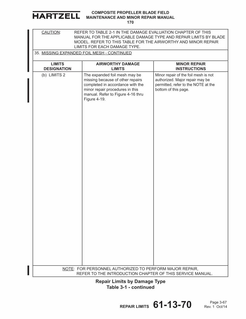
Page 3-67 REPAIR LIMITS 61-13-70 Rev. 1 Oct/14
COMPOSITE PROPELLER BLADE FIELD MAINTENANCE AND MINOR REPAIR MANUAL
170
CAUTION: REFERTOTABLE2-1INThEDAMAGEEvALUATIONChAPTEROFThISMANUALFORThEAPPLICABLEDAMAGETyPEANDREPAIRLIMITSByBLADEMODEL.REFERTOThISTABLEFORThEAIRWORThyANDMINORREPAIRLIMITSFOREAChDAMAGETyPE.
35. MISSINGExPANDEDFOILMESh-CONTINUED
LIMITS dESIgNATIoN
AIRWoRTHY dAMAgE LIMITS
MINoR REPAIR INSTRUCTIoNS
(b) LIMITS 2 Theexpandedfoilmeshmaybemissingbecauseofotherrepairscompletedinaccordancewiththeminorrepairproceduresinthismanual.RefertoFigure4-16thruFigure4-19.
Minorrepairofthefoilmeshisnotauthorized.Majorrepairmaybepermitted,refertotheNOTEatthebottomofthispage.
NOTE:FORPERSONNELAUThORIzEDTOPERFORMMAjORREPAIR, REFER TO ThEINTRODUCTIONChAPTEROFThISSERvICEMANUAL.
Repair Limits by damage Type Table 3-1 - continued
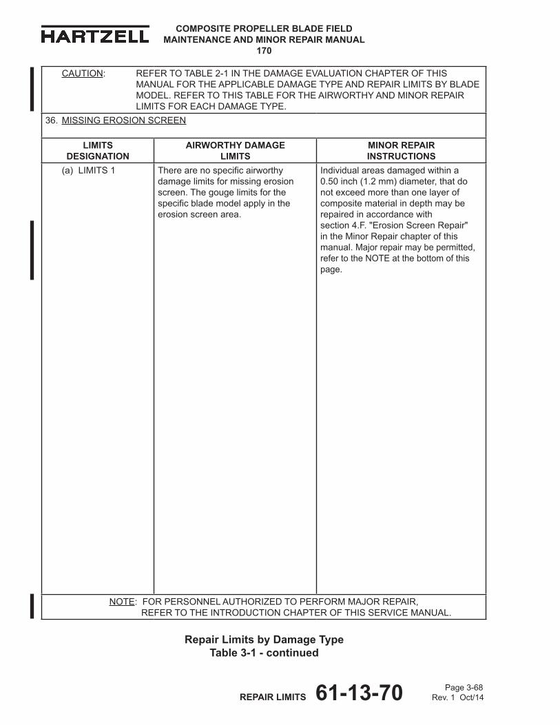
COMPOSITE PROPELLER BLADE FIELD MAINTENANCE AND MINOR REPAIR MANUAL
170
Page 3-68 REPAIR LIMITS 61-13-70 Rev. 1 Oct/14
Repair Limits by damage Type Table 3-1 - continued
CAUTION: REFERTOTABLE2-1INThEDAMAGEEvALUATIONChAPTEROFThISMANUALFORThEAPPLICABLEDAMAGETyPEANDREPAIRLIMITSByBLADEMODEL.REFERTOThISTABLEFORThEAIRWORThyANDMINORREPAIRLIMITSFOREAChDAMAGETyPE.
36. MISSINGEROSIONSCREEN
LIMITS dESIgNATIoN
AIRWoRTHY dAMAgE LIMITS
MINoR REPAIR INSTRUCTIoNS
(a) LIMITS 1 Therearenospecificairworthydamagelimitsformissingerosionscreen.Thegougelimitsforthespecificblademodelapplyintheerosionscreenarea.
Individualareasdamagedwithina 0.50inch(1.2mm)diameter,thatdonotexceedmorethanonelayerofcompositematerialindepthmayberepairedinaccordancewith section4.F."ErosionScreenRepair" intheMinorRepairchapterofthismanual.Majorrepairmaybepermitted,refertotheNOTEatthebottomofthispage.
NOTE:FORPERSONNELAUThORIzEDTOPERFORMMAjORREPAIR, REFER TO ThEINTRODUCTIONChAPTEROFThISSERvICEMANUAL.
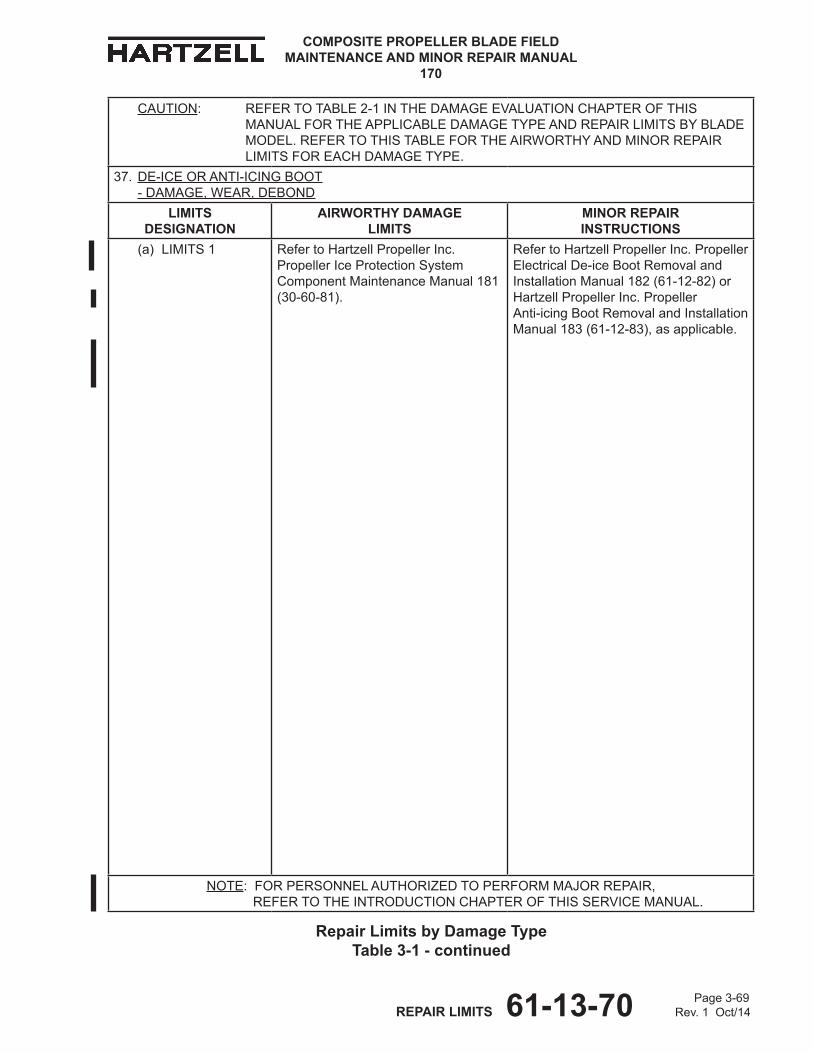
Page 3-69 REPAIR LIMITS 61-13-70 Rev. 1 Oct/14
COMPOSITE PROPELLER BLADE FIELD MAINTENANCE AND MINOR REPAIR MANUAL
170
CAUTION: REFERTOTABLE2-1INThEDAMAGEEvALUATIONChAPTEROFThISMANUALFORThEAPPLICABLEDAMAGETyPEANDREPAIRLIMITSByBLADEMODEL.REFERTOThISTABLEFORThEAIRWORThyANDMINORREPAIRLIMITSFOREAChDAMAGETyPE.
37. DE-ICEORANTI-ICINGBOOT -DAMAGE,WEAR,DEBOND
LIMITS dESIgNATIoN
AIRWoRTHY dAMAgE LIMITS
MINoR REPAIR INSTRUCTIoNS
(a) LIMITS 1 RefertohartzellPropellerInc.PropellerIceProtectionSystemComponentMaintenanceManual181 (30-60-81).
RefertohartzellPropellerInc.PropellerElectricalDe-iceBootRemovalandInstallationManual182(61-12-82)orhartzellPropellerInc.Propeller Anti-icingBootRemovalandInstallationManual183(61-12-83),asapplicable.
NOTE:FORPERSONNELAUThORIzEDTOPERFORMMAjORREPAIR, REFER TO ThEINTRODUCTIONChAPTEROFThISSERvICEMANUAL.
Repair Limits by damage Type Table 3-1 - continued
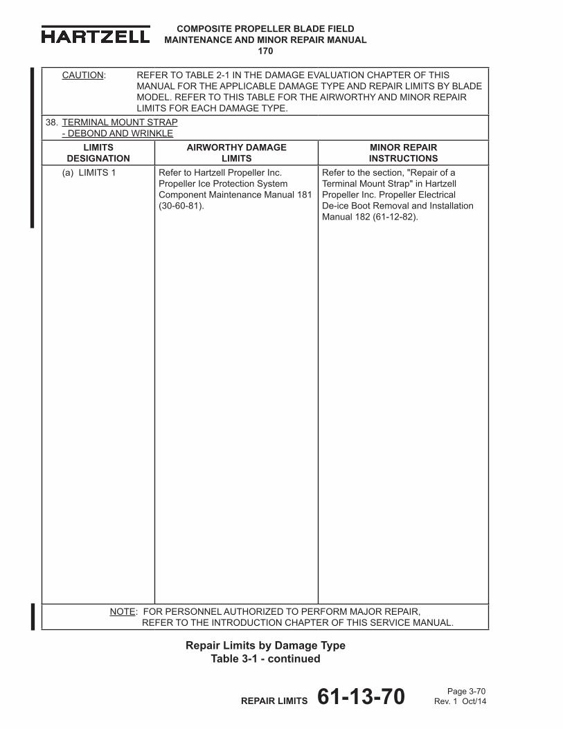
COMPOSITE PROPELLER BLADE FIELD MAINTENANCE AND MINOR REPAIR MANUAL
170
Page 3-70 REPAIR LIMITS 61-13-70 Rev. 1 Oct/14
CAUTION: REFERTOTABLE2-1INThEDAMAGEEvALUATIONChAPTEROFThISMANUALFORThEAPPLICABLEDAMAGETyPEANDREPAIRLIMITSByBLADEMODEL.REFERTOThISTABLEFORThEAIRWORThyANDMINORREPAIRLIMITSFOREAChDAMAGETyPE.
38. TERMINALMOUNTSTRAP -DEBONDANDWRINKLE
LIMITS dESIgNATIoN
AIRWoRTHY dAMAgE LIMITS
MINoR REPAIR INSTRUCTIoNS
(a) LIMITS 1 RefertohartzellPropellerInc.PropellerIceProtectionSystemComponentMaintenanceManual181(30-60-81).
Refertothesection,"RepairofaTerminalMountStrap"inhartzellPropellerInc.PropellerElectrical De-iceBootRemovalandInstallationManual182(61-12-82).
NOTE:FORPERSONNELAUThORIzEDTOPERFORMMAjORREPAIR, REFER TO ThEINTRODUCTIONChAPTEROFThISSERvICEMANUAL.
Repair Limits by damage Type Table 3-1 - continued

61-13-70 Page 4-1Rev. 1 Oct/14MINOR REPAIR
COMPOSITE PROPELLER BLADE FIELD MAINTENANCE AND MINOR REPAIR MANUAL
170
MINOR REPAIR - CONTENTS1. General ...............................................................................................................4-32. Erosion Shield.....................................................................................................4-5
A. Debond Extending to the Trailing Edge and/or a Crack ...............................4-5B. Gouge............................................................................................................4-7C. Missing Area of Trail Side or Inboard End .....................................................4-9D. Debond ........................................................................................................4-11E. Corroded Cadmium-Plated Screw...............................................................4-16
3. Blade Cuff .........................................................................................................4-19A. Cracks at the Root End of the Blade Cuff ...................................................4-19B. Nick, Scratch, Gouge, Crack, or Delamination ............................................4-20
4. Blade Repairs for All Except N-shank Kevlar®/Carbon Hybrid Blades ..............4-24A. Gouge, Delamination, or Loss of Composite Material .................................4-24B. Gouge, Delamination, or Loss of Composite Material
in the Trailing Edge Foam and Leading Edge Foam Regions .....................4-30C. Crushed or Cracked Trailing Edge ..............................................................4-35D. Crushed or Cracked Trailing Edge - Foam Region of the Blade .................4-39E. Split Trailing Edge .......................................................................................4-43F. Erosion Screen Repair ................................................................................4-45
5. Blade Repairs for N-shank Kevlar®/Carbon Hybrid Blades Only ......................4-50A. Repair Area Limits .......................................................................................4-50B. Loss of Paint and/or Filler Material ..............................................................4-52C. Gouges, Delaminations, or Loss of Composite Material .............................4-54D. Crushed or Cracked Trailing Edge - Tip Region of the Blade .....................4-57E. Crushed or Cracked Trailing Edge Foam Region of the Blade ...................4-61F. Split Trailing Edge .......................................................................................4-66
6. Curing Procedures ............................................................................................4-67A. Cure of Trailing Edge Repairs .....................................................................4-67B. Cure of Surface Repairs (excluding trailing edge repairs)...........................4-71
7. Finish Procedures .............................................................................................4-73A. Paint ............................................................................................................4-73B. Erosion Tape ...............................................................................................4-74
8. Documenting the Repair ...................................................................................4-76A. Blade Damage Repair Sheet.......................................................................4-76B. Propeller Logbook .......................................................................................4-76

61-13-70 Page 4-2Rev. 1 Oct/14MINOR REPAIR
COMPOSITE PROPELLER BLADE FIELD MAINTENANCE AND MINOR REPAIR MANUAL
170
LIST OF FIGURES
Repair of Debond at Edge of Nickel Erosion Shield ............... Figure 4-1 .....................4-4Using C-Clamps to Apply Pressure
to Erosion Shield Debond Repair ...................................... Figure 4-2 .....................4-4Field Repair of Minor Damage in Erosion Shield.................... Figure 4-3 .....................4-7Determining Method for Repair
of Stainless Steel Erosion Shield Debond......................... Figure 4-4 ...................4-11Using Screws to Repair Debond
in Stainless Steel Erosion Shield ..................................... Figure 4-5 ...................4-12Using Rivets to Repair Debond
in Stainless Steel Erosion Shield ...................................... Figure 4-6 ...................4-14Blade Cuff Crack Repair ......................................................... Figure 4-7 ...................4-18Cracks in the Blade Cuff ......................................................... Figure 4-8 ...................4-21Material Layers for a Blade Cuff Repair ................................. Figure 4-9 ...................4-23Unidirectional Material and Woven Material
in a Sanded Area of a Carbon Blade................................. Figure 4-10 .................4-26Laminating Pattern ................................................................ Figure 4-11..................4-27Material Layers for a Repair in the Trailing Edge Foam ......... Figure 4-12 .................4-32Crushed Blade Trailing Edge Repair (Cross Section View) .... Figure 4-13 .................4-34Bevel Length and Damaged Material Depth........................... Figure 4-14 .................4-35Bevel Length and Depth of Damaged Material Removed ...... Figure 4-15 .................4-39N-shank Kevlar®/Carbon Hybrid Blade Repair Limits ............. Figure 4-16 .................4-48N-shank Kevlar®/Carbon Hybrid Blade Repair Limits ............. Figure 4-17 .................4-48N-shank Kevlar®/Carbon Hybrid Blade Repair Limits ............. Figure 4-18 .................4-49N-shank Kevlar®/Carbon Hybrid Blade Repair Limits ............. Figure 4-19 .................4-49Sanding to Expose Erosion Shield ......................................... Figure 4-20 .................4-53Material Layers of the N-shank Kevlar®/Carbon Hybrid Blade Figure 4-21 .................4-54Symetrical Repairs ................................................................. Figure 4-22 .................4-58Repair Layers ......................................................................... Figure 4-23 .................4-62
LIST OF TABLES
Repair Materials ..................................................................... Table 4-1 .....................4-31Erosion Tape Length/Location ................................................ Table 4-2 .....................4-74
61-13-70 Page 4-3Rev. 1 Oct/14MINOR REPAIR
COMPOSITE PROPELLER BLADE FIELD MAINTENANCE AND MINOR REPAIR MANUAL
170
1. General
WARNING: ADHESIVES AND SOLVENTS ARE FLAMMABLE AND TOXIC TO THE SKIN, EYES, AND RESPIRATORY TRACT. SKIN AND EYE PROTECTION ARE REQUIRED. AVOID PROLONGED CONTACT AND BREATHING OF VAPORS. USE SOLVENT RESISTANT GLOVES TO MINIMIzE SKIN CONTACT AND WEAR SAFETY GLASSES FOR EYE PROTECTION. USE IN A WELL VENTILATED AREA AWAY FROM SPARKS AND FLAME. READ AND OBSERVE ALL WARNING LABELS.
CAUTION: INSTRUCTIONS AND PROCEDURES IN THIS SECTION INVOLVE PROPELLER CRITICAL PARTS. REFER TO THE INTRODUCTION CHAPTER OF THIS MANUAL FOR INFORMATION ABOUT PROPELLER CRITICAL PARTS.
NOTE: SpecificHartzellPropellerInc.manualsandservicedocumentsareavailableontheHartzellwebsiteatwww.hartzellprop.com.RefertotheRequired Publications section in the Introduction chapter of this manual fortheidentificationofthesepublications.
A. Fordefinitionandpersonnelrequirementsofminorrepair,refertotheIntroductionchapter of this manual.
B. De-ice or anti-icing boot replacement is considered minor repair.
(1) Forde-icebootremovalandinstallation,refertoHartzellPropellerInc.Propeller Electrical De-ice Boot Removal and Installation Manual 182 (61-12-82).
(2) Foranti-icingbootremovalandinstallation,refertoHartzellPropellerInc. Propeller Anti-icing Boot Removal and Installation Manual 183 (61-12-83).
C. For cure time, pot life, storage temperature, and shelf life of adhesives, refer totheConsumableMaterialschapterofHartzellPropellerInc.StandardPracticesManual 202A (61-01-02).
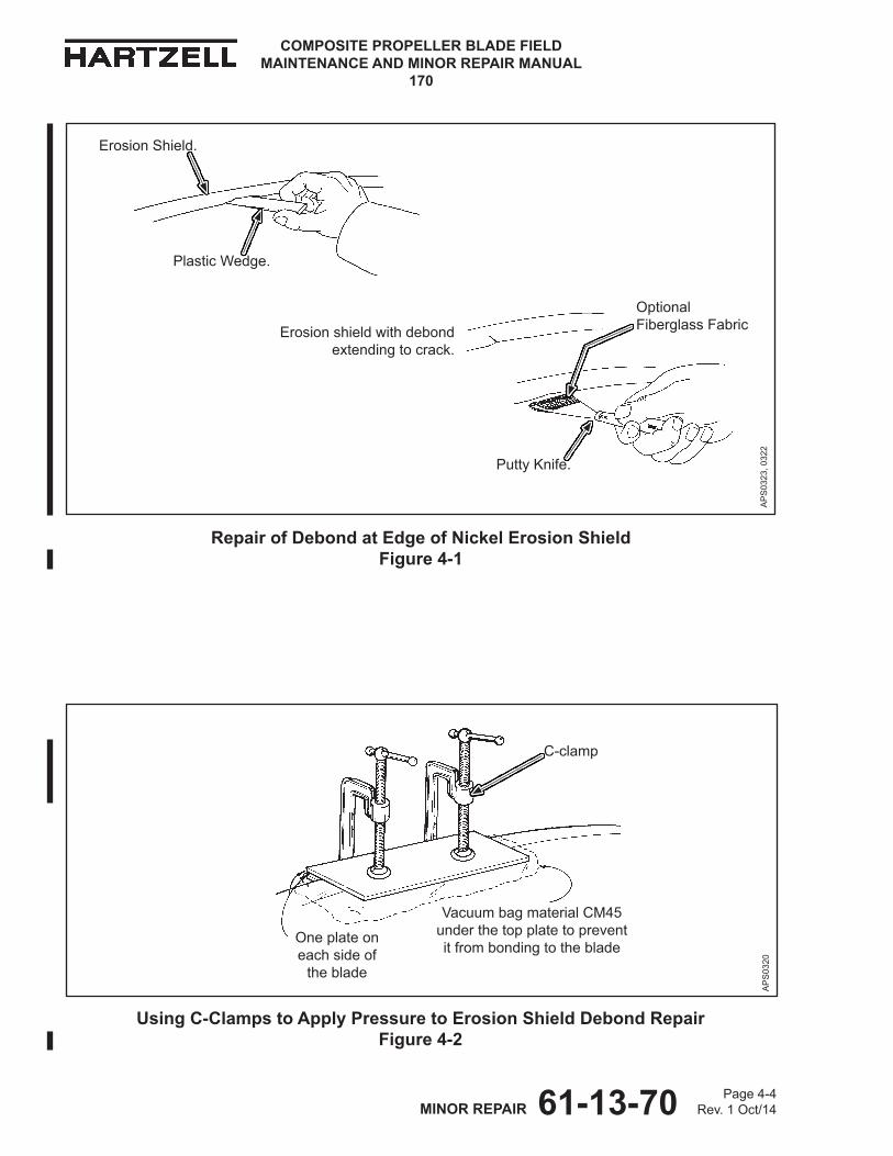
61-13-70 Page 4-4Rev. 1 Oct/14MINOR REPAIR
COMPOSITE PROPELLER BLADE FIELD MAINTENANCE AND MINOR REPAIR MANUAL
170
Repair of Debond at Edge of Nickel Erosion Shield Figure 4-1
AP
S03
23, 0
322
Optional Fiberglass FabricErosion shield with debond
extending to crack.
Using C-Clamps to Apply Pressure to Erosion Shield Debond Repair Figure 4-2
AP
S03
20
One plate on each side of
the blade
Vacuum bag material CM45 under the top plate to prevent it from bonding to the blade
C-clamp
Putty Knife.
Plastic Wedge.
Erosion Shield.
61-13-70 Page 4-5Rev. 1 Oct/14MINOR REPAIR
COMPOSITE PROPELLER BLADE FIELD MAINTENANCE AND MINOR REPAIR MANUAL
170
2. Erosion Shield
CAUTION: INSTRUCTIONS AND PROCEDURES IN THIS SECTION INVOLVE PROPELLER CRITICAL PARTS. REFER TO THE INTRODUCTION CHAPTER OF THIS MANUAL FOR INFORMATION ABOUT PROPELLER CRITICAL PARTS.
A. Debond Extending to the Trailing Edge and/or a Crack
(1) General
(a) This repair may be performed in accordance with the airworthy damagelimitsandtheminorrepairlimitsspecifiedintheRepairLimitschapter of this manual.
(2) Procedure (Refer to Figure 4-1)
(a) Perform a "Coin-Tap Inspection" in accordance with the Inspection Procedures chapter of this manual.
1 Using a pencil or felt-tip marker, outline the area of the debond of the erosion shield.
WARNING: ADHESIVES AND SOLVENTS ARE FLAMMABLE AND TOXIC TO THE SKIN, EYES, AND RESPIRATORY TRACT. SKIN AND EYE PROTECTION ARE REQUIRED. AVOID PROLONGED CONTACT AND BREATHING OF VAPORS. USE SOLVENT RESISTANT GLOVES TO MINIMIzE SKIN CONTACT AND WEAR SAFETY GLASSES FOR EYE PROTECTION. USE IN A WELL VENTILATED AREA AWAY FROM SPARKS AND FLAME. READ AND OBSERVE ALL WARNING LABELS.
(b) Using a small plastic wedge or equivalent, gently lift the erosion shield and clean the debonded area with solvent acetone CM173, MEK CM106, or MPK CM219.
(c) Permit the solvent acetone CM173, MEK CM106, or MPK CM219 to dry.
(d) In a container that is free from contamination, mix adhesive CM14 in accordance with the manufacturer's instructions.
(e) While using one thin wedge to gently pry up the erosion shield, use a small putty knife or other thin instrument to force adhesive CM14 into the debond.
1 If the debond occurred at a crack or where the erosion shield has been physically distorted and will not return to the original position, fiberglassfabricCM42maybeusedtofillthedebond.
a Ifneeded,cutfiberglassfabricCM42sothatwhenfoldedinhalfitisthesizeofthedebond.
61-13-70 Page 4-6Rev. 1 Oct/14MINOR REPAIR
COMPOSITE PROPELLER BLADE FIELD MAINTENANCE AND MINOR REPAIR MANUAL
170
b UsingadhesiveCM14,saturatethefiberglassfabricCM42.
c PutthefiberglassfabricCM42thatissaturatedwithadhesiveCM14 in the debond cavity.
(f) Remove all tooling from the debond.
(g) If the erosion shield returns to the original position, permit the adhesive CM14 to cure for 12 hours at room temperature or 2 hours at 145° ± 5° F (63° ± 2° C).
(h) Ifthereisahumpordeformation,oriffiberglassfabricCM42wasusedtofillthedebond,applypressurewhencuringtheadhesiveCM14asfollows:
1 Put a piece of vacuum bag material CM45 over the repaired area to prevent the plates from bonding to the blade. Refer to Figure 4-2.
2 Put plates made of metal, plastic, Masonite®, or other semi-rigid material over the repaired area; one on the face side and one on the camber side of the blade.
3 Put C-clamps on the plates, and tighten the C-clamps enough to apply moderate pressure to the repair.
CAUTION: MAKE SURE THAT THE RAISED PORTIONS OF THE EROSION SHIELD ARE HELD FLAT BEFORE THE ADHESIVE CURES.
4 Permit the adhesive CM14 to cure for 12 hours at room temperature for 2 hours at 145° ± 5° F (63° ± 2° C).
5 Remove the C-clamps, plates, and vacuum bag material CM45.
(i) Using no coarser than 60 grit sandpaper, sand the repaired area smooth.
(j) Perform a "Coin-Tap Inspection" in accordance with the Inspection Procedures chapter of this manual.
1 Delaminations or voids are not permitted.
2 Iftheareaofrepairisnotwithinthelimitsspecified,repairinaccordance with the applicable repair instructions.
3 Repeat the inspections and repair until the repair is satisfactory.
(k) TherepairmustbewithintheairworthydamagelimitsspecifiedintheRepair Limits chapter of this manual before being released to service.
(l) Refinishthebladeinaccordancewiththesection,"FinishProcedures"inthis chapter.
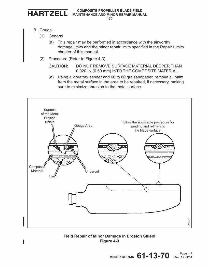
61-13-70 Page 4-7Rev. 1 Oct/14MINOR REPAIR
COMPOSITE PROPELLER BLADE FIELD MAINTENANCE AND MINOR REPAIR MANUAL
170
Field Repair of Minor Damage in Erosion Shield Figure 4-3
Surfaceof the Metal
ErosionShield
Gouge Area
Composite Material
Follow the applicable procedure for sandingandrefinishing
the blade surface.
Undercut
BP
S00
17
B. Gouge(1) General
(a) This repair may be performed in accordance with the airworthy damagelimitsandtheminorrepairlimitsspecifiedintheRepairLimitschapter of this manual.
(2) Procedure (Refer to Figure 4-3).
CAUTION: DO NOT REMOVE SURFACE MATERIAL DEEPER THAN 0.020 IN (0.50 mm) INTO THE COMPOSITE MATERIAL.
(a) Using a vibratory sander and 60 to 80 grit sandpaper, remove all paint from the metal surface in the area to be repaired, if necessary, making suretominimizeabrasiontothemetalsurface.
Foam
61-13-70 Page 4-8Rev. 1 Oct/14MINOR REPAIR
COMPOSITE PROPELLER BLADE FIELD MAINTENANCE AND MINOR REPAIR MANUAL
170
WARNING: ADHESIVES AND SOLVENTS ARE FLAMMABLE AND TOXIC TO THE SKIN, EYES, AND RESPIRATORY TRACT. SKIN AND EYE PROTECTION ARE REQUIRED. AVOID PROLONGED CONTACT AND BREATHING OF VAPORS. USE SOLVENT RESISTANT GLOVES TO MINIMIzE SKIN CONTACT AND WEAR SAFETY GLASSES FOR EYE PROTECTION. USE IN A WELL VENTILATED AREA AWAY FROM SPARKS AND FLAME. READ AND OBSERVE ALL WARNING LABELS.
(b) Using a clean cloth CM159 or equivalent dampened with solvent acetone CM173, MEK CM106, or MPK CM219, wipe the area.
(c) Permit the solvent acetone CM173, MEK CM106, or MPK CM219 to dry.(d) In a container that is free from contamination, mix adhesive CM14 or
CM15 in accordance with the manufacturer's directions.
CAUTION: MAKE SURE THAT THE MILLED FIBERS CM56 ARE COMPLETELY SATURATED WITH ADHESIVE CM14 OR CM15.
(e) AddtotheadhesiveCM14anamountofmilledfibersCM56thatisequalto the amount of adhesive, creating a paste. 1 Add adhesive CM14 to the mixture as necessary to make sure that
themilledfibersCM56arecompletelysaturated.(f) Fill the area to be repaired with the mixture of adhesive CM14 and milled
fibersCM56.(g) Permit the adhesive CM14 to cure for 12 hours at room temperature or
2 hours at 145° ± 5° F (63° ± 2° C).(h) Using no coarser than 60 grit sandpaper, sand the repaired area smooth.(i) Visually examine the repaired area for adhesion and correct shape.(j) Refinishthebladeinaccordancewiththesection,"FinishProcedures"in
this chapter.
61-13-70 Page 4-9Rev. 1 Oct/14MINOR REPAIR
COMPOSITE PROPELLER BLADE FIELD MAINTENANCE AND MINOR REPAIR MANUAL
170
C. Missing Area of Trail Side or Inboard End
(1) General
(a) This repair may be performed in accordance with the airworthy damagelimitsandtheminorrepairlimitsspecifiedintheRepairLimitschapter of this manual.
(2) Procedure
(a) Using no coarser than 60 grit sandpaper, sand by hand the area under the missing area of the erosion shield, just enough to remove the smooth surface.
NOTE: Sanding to remove the smooth surface will permit the new composite material to adhere better.
(b) Using no coarser than 60 grit sandpaper, sand smooth any burrs, rough, or sharp areas around the missing area.
WARNING: ADHESIVES AND SOLVENTS ARE FLAMMABLE AND TOXIC TO THE SKIN, EYES, AND RESPIRATORY TRACT. SKIN AND EYE PROTECTION ARE REQUIRED. AVOID PROLONGED CONTACT AND BREATHING OF VAPORS. USE SOLVENT RESISTANT GLOVES TO MINIMIzE SKIN CONTACT AND WEAR SAFETY GLASSES FOR EYE PROTECTION. USE IN A WELL VENTILATED AREA AWAY FROM SPARKS AND FLAME. READ AND OBSERVE ALL WARNING LABELS.
(c) Using a clean cloth CM159 or equivalent dampened with solvent acetone CM173, MEK CM106, or MPK CM219, wipe the area.
(d) Permit the solvent acetone CM173, MEK CM106, or MPK CM219 to dry.
(e) Cut two pieces of E-glass CM55 to the shape of the missing area.
1 Alternately,fourlayersoffiberglassfabricCM42maybeused.
(f) PutonelayerofE-glassCM55orfiberglassfabricCM42onthearea to be repaired.
(g) Using adhesive CM14, completely saturate the layer of E-glass CM55 or fiberglassfabricCM42.
(h) PutthesecondlayerofE-glassCM55orfiberglassfabricCM42onthearea to be repaired, making sure that the layer is completely saturated.
1 ApplyadditionaladhesiveCM14andlayersoffiberglassfabricCM42,if necessary.
(i) Permit the adhesive CM14 to cure for 12 hours at room temperature, or for 2 hours at 145° ± 5° F (63° ± 2° C).
(j) Using no coarser than 60 grit sandpaper, sand to the original shape.
61-13-70 Page 4-10Rev. 1 Oct/14MINOR REPAIR
COMPOSITE PROPELLER BLADE FIELD MAINTENANCE AND MINOR REPAIR MANUAL
170
(k) Perform a "Coin-Tap Inspection" in accordance with the Inspection Procedures chapter of this manual.
1 Delaminations or voids are not permitted.
2 Iftheareaofrepairisnotwithinthelimitsspecified,repairinaccordance with the applicable repair instructions.
3 Repeat the inspections and repair until the repair is satisfactory.
(l) Refinishthebladeinaccordancewiththesection,"FinishProcedures"inthis chapter.

61-13-70 Page 4-11Rev. 1 Oct/14MINOR REPAIR
COMPOSITE PROPELLER BLADE FIELD MAINTENANCE AND MINOR REPAIR MANUAL
170
Determining Method for Repair of Stainless Steel Erosion Shield Debond Figure 4-4
Use stainless steel machine screws inboard of the
36 inch (914 mm) radius
Measured from the Centerline of Hub 36 inch (914 mm) Radius
Usesoft,flatheadcopperrivetsoutboardof the 36 inch (914 mm) radius
BP
S00
18A
D. Debond
(1) General
(a) This repair may be performed in accordance with the airworthy damagelimitsandtheminorrepairlimitsspecifiedintheRepairLimitschapter of this manual.
1 If the airworthy damage limits are exceeded, replace the erosion shield with a nickel erosion shield.
(b) If the debond is inboard of the 36 inch (914 mm) blade radius, use 6-32 x 0.375 inch stainless steel machine screws for repair.
(c) If the debond is outboard of the 36 inch (914 mm) blade radius, use copper rivets for repair.
(d) RefertoFigure4-4todeterminethemethodforfieldrepairofthestainlesssteel erosion shield damage.
1 It is recommended that any blade requiring rivet or screw repair have the identical repair performed to the opposite blade of a set to maintain proper balance.
a As an alternative, lead weight may be added or subtracted, or dynamic balance may be used.

61-13-70 Page 4-12Rev. 1 Oct/14MINOR REPAIR
COMPOSITE PROPELLER BLADE FIELD MAINTENANCE AND MINOR REPAIR MANUAL
170
Using Screws to Repair Debond in Stainless Steel Erosion Shield Figure 4-5
CP
S00
58
Inboard of 36 inch (914 mm) radius
0.375 inch (9.53 mm)
0.250 inch (6.35 mm)
Clean the head of each screwandfilltherepairedarea with adhesive
Install a machine screw in each hole
Countersink each hole to a depth slightly below that neededforaflushfitofeach screw head
Using a tap, prepare each hole for a screw
Drill to a depth0.020 inch (0.50 mm) more than the length of the screw
NOTE: When tightened, the head of the screw must beflushwiththesurfaceof the erosion shield
Sand the area smooth and blend it to the original airfoil shape ready for refinishing
0.750 to 1.25 inch (19.05 to 31.8 mm)
(2) Using Screws for Repair (Refer to Figure 4-5.)
CAUTION: WHEN SCREWS ARE USED TO REPAIR A DEBOND INBOARD OF THE 36 INCH (914 mm) RADIUS, MAKE SURE THEY DO NOT INTERFERE WITH RETENTION SCREWS ON THE OPPOSITE SIDE OF THE BLADE.
(a) Determine the spacing for the screws on a line 0.250 inch (6.35 mm) in from where the composite material and stainless steel erosion shield meet.
61-13-70 Page 4-13Rev. 1 Oct/14MINOR REPAIR
COMPOSITE PROPELLER BLADE FIELD MAINTENANCE AND MINOR REPAIR MANUAL
170
(b) Mark the location for a screw at each end of the debond.1 Evenly space marks in between so screws will be no closer than
0.750 inch (19.05 mm) and no further apart than 1.25 inch (31.7 mm). 2 Use only the number of screws needed for adequate repair of the
debond area.(c) Center punch the erosion shield at each screw location.(d) Using a 0.109 inch bit, drill a hole at each screw location to a depth
0.040 inch (1.016 mm) deeper than the length of the screw.1 Penetration into the foam core is permitted, but once the foam has
been penetrated, there is no reason to go deeper.(e) Using a 6-32 tap, tap each hole.
CAUTION: DO NOT COUNTERSINK DEEPER THAN NECESSARY.
(f) Using a 0.500 inch, 90 degree countersink tool, countersink the area at each holetoadepthslightlybelowthatneededforaflushfitofeachscrewhead.
WARNING: ADHESIVES AND SOLVENTS ARE FLAMMABLE AND TOXIC TO THE SKIN, EYES, AND RESPIRATORY TRACT. SKIN AND EYE PROTECTION ARE REQUIRED. AVOID PROLONGED CONTACT AND BREATHING OF VAPORS. USE SOLVENT RESISTANT GLOVES TO MINIMIzE SKIN CONTACT AND WEAR SAFETY GLASSES FOR EYE PROTECTION. USE IN A WELL VENTILATED AREA AWAY FROM SPARKS AND FLAME. READ AND OBSERVE ALL WARNING LABELS.
(g) Using a clean cloth CM159 or equivalent dampened with solvent acetone CM173, MEK CM106, or MPK CM219, thoroughly clean each screw.
(h) Permit the solvent acetone CM173, MEK CM106, or MPK CM219 to dry.(i) In a container that is free from contamination, mix the adhesive CM14 or
CM15 in accordance with manufacturer's instructions.(j) Put some of the adhesive CM14 or CM15 in each hole that has been
prepared for a screw.(k) Install a screw in each hole.(l) Using a clean cloth CM159 or equivalent dampened with solvent acetone
CM173, MEK CM106, or MPK CM219, clean the head of each screw and the surrounding area.
(m) Permit the solvent acetone CM173, MEK CM106, or MPK CM219 to dry.(n) UsingadhesiveCM14orCM15,fillthescrewheads.(o) Permit the adhesive CM14 or CM15 to cure for 12 hours at room
temperature or 2 hours at 145° ± 5° F (63° ± 2° C).
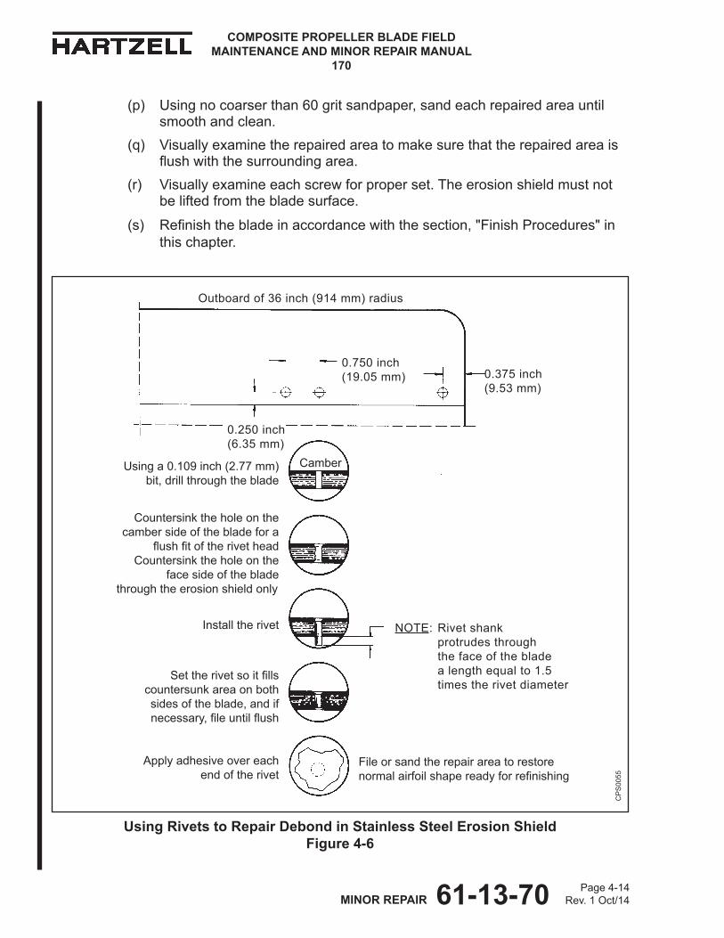
61-13-70 Page 4-14Rev. 1 Oct/14MINOR REPAIR
COMPOSITE PROPELLER BLADE FIELD MAINTENANCE AND MINOR REPAIR MANUAL
170
(p) Using no coarser than 60 grit sandpaper, sand each repaired area until smooth and clean.
(q) Visually examine the repaired area to make sure that the repaired area is flushwiththesurroundingarea.
(r) Visually examine each screw for proper set. The erosion shield must not be lifted from the blade surface.
(s) Refinishthebladeinaccordancewiththesection,"FinishProcedures"inthis chapter.
CP
S00
55
Using Rivets to Repair Debond in Stainless Steel Erosion Shield Figure 4-6
Outboard of 36 inch (914 mm) radius
0.750 inch (19.05 mm) 0.375 inch
(9.53 mm)
0.250 inch (6.35 mm)
Camber
Apply adhesive over each end of the rivet
Settherivetsoitfillscountersunk area on both sides of the blade, and if necessary,fileuntilflush
Install the rivet
Countersink the hole on the camber side of the blade for a
flushfitoftherivetheadCountersink the hole on the
face side of the bladethrough the erosion shield only
Using a 0.109 inch (2.77 mm) bit, drill through the blade
NOTE: Rivet shank protrudes through the face of the blade a length equal to 1.5 times the rivet diameter
File or sand the repair area to restore normalairfoilshapereadyforrefinishing
61-13-70 Page 4-15Rev. 1 Oct/14MINOR REPAIR
COMPOSITE PROPELLER BLADE FIELD MAINTENANCE AND MINOR REPAIR MANUAL
170
(3) Using Rivets for Repair (Refer to Figure 4-6.)
(a) On the camber side of the blade, determine the spacing for rivets on a line 0.250 inch (6.35 mm) in from where the composite material and stainless steel erosion shield meet.
(b) Mark the location for a rivet at each end of the debond.
1 Evenly space marks in between so that the rivets will be no closer than 0.750 inch (19.05 mm) and no farther apart than 1.25 inch (31.8 mm).
(c) Centerpunch the erosion shield at each rivet location.
CAUTION: ALIGN THE DRILL SO THAT THE CENTERLINE OF THE EXIT HOLE IS AT LEAST 0.250 INCH (6.35 mm) FROM THE TRAILING EDGE OF THE EROSION SHIELD ON THE FACE OF THE BLADE.
(d) Using a 0.109 inch (2.769 mm) bit, drill a hole completely through the blade at each rivet location.
CAUTION: DO NOT COUNTERSINK DEEPER THAN NECESSARY.
(e) Using a 0.500 inch, 90° countersink tool on the camber side of the blade, countersink the area at each holetoadepthsufficientforchamferingthesteelerosionshieldtogetaflushfitoftherivethead.
CAUTION: DO NOT PENETRATE THE COMPOSITE MATERIAL.
(f) On the face side of the blade, countersink through the erosion shield, making sure not to penetrate the composite material.
(g) Insert a rivet from the camber side of the blade.1 The length of the rivet extending through the hole on the face-side of
the blade must be at least 1.5 times the diameter of the rivet.
(h) From face-side of the blade, cut the rivet to the correct length.1 The correct length of the rivet on the face-side of the blade is
1.5 times the diameter of the rivet.(i) Seteachrivetdeepenoughtofillthecountersunkareaonbothsidesof
the blade.(j) Fileeachrivetflushwiththeedgeonbothsidesofthebladeasnecessary.(k) If there is a void, use the following steps:
1 In a container that is free from contamination, mix adhesive CM14 or CM15 in accordance with the manufacturer's instructions.
2 On each side of the blade, apply a small amount of adhesive CM14 or CM15 to the end of each rivet.
3 Permit the adhesive CM14 or CM15 to cure for 12 hours at room temperature or 2 hours at 145° ± 5° F (63° ± 2° C).

61-13-70 Page 4-16Rev. 1 Oct/14MINOR REPAIR
COMPOSITE PROPELLER BLADE FIELD MAINTENANCE AND MINOR REPAIR MANUAL
170
(l) Using no coarser than 60 grit sandpaper, sand each repaired area until smooth.
(m) Visually examine tomakesurethattherepairedareaisflushwiththesurrounding area.
(n) Visually inspect each rivet for proper set. The erosion shield must not be lifted from the blade surface.
(o) Refinishthebladeinaccordancewiththesection,"FinishProcedures" in this chapter.
E. Corroded Cadmium-Plated Screw
(1) General
(a) This repair may be performed in accordance with the airworthy damagelimitsandtheminorrepairlimitsspecifiedintheRepairLimitschapter of this manual.
(2) Screw Repair
CAUTION: REMOVE THE LEAST POSSIBLE AMOUNT OF MATERIAL FROM A CORRODED SCREW HEAD.
(a) Using a vibratory sander with no coarser than 60 grit sandpaper, remove all of corrosion from the surface of the screw head.
WARNING: ADHESIVES AND SOLVENTS ARE FLAMMABLE AND TOXIC TO THE SKIN, EYES, AND RESPIRATORY TRACT. SKIN AND EYE PROTECTION ARE REQUIRED. AVOID PROLONGED CONTACT AND BREATHING OF VAPORS. USE SOLVENT RESISTANT GLOVES TO MINIMIzE SKIN CONTACT AND WEAR SAFETY GLASSES FOR EYE PROTECTION. USE IN A WELL VENTILATED AREA AWAY FROM SPARKS AND FLAME. READ AND OBSERVE ALL WARNING LABELS.
(b) Using a clean cloth CM159 or equivalent dampened with solvent acetone CM173, MEK CM106, or MPK CM219, thoroughly clean the head of the screw.
(c) Permit the solvent acetone CM173, MEK CM106, or MPK CM219 to dry.
(d) Apply a layer of primer CM67 for corrosion protection.
(e) In a container that is free from contamination, mix adhesive CM14 or CM15 in accordance with the manufacturer's instructions.
(f) UsingadhesiveCM14orCM15,filltheslotinthemachinescrewheadandthe surrounding area.
(g) Permit the adhesive CM14 or CM15 to cure for 12 hours at room temperature or 2 hours at 145° ± 5° F (63° ± 2° C).
61-13-70 Page 4-17Rev. 1 Oct/14MINOR REPAIR
COMPOSITE PROPELLER BLADE FIELD MAINTENANCE AND MINOR REPAIR MANUAL
170
(h) Using no coarser than 60 grit sandpaper, sand the repaired area until smooth and blended to the normal airfoil shape.
(i) Using a clean cloth CM159 or equivalent dampened with solvent acetone CM173, MEK CM106, or MPK CM219, wipe the repaired area.
(j) Permit the solvent acetone CM173, MEK CM106, or MPK CM219 to dry.
(k) Asnecessary,refinishthebladeinaccordancewiththesection, "Finish Procedures" in this chapter.
(3) Screw Replacement
(a) Remove the paint primer and adhesive from the slot in the head of the screw.
CAUTION: USE A MINIMUM AMOUNT OF HEAT TO SOFTEN THE ADHESIVE THAT HOLDS THE SCREW.
(b) Heat a screwdriver to soften the adhesive that holds the screw. Insert the screwdriver into the slot, and apply gentle loosening pressure.
(c) As the pressure and heat loosen the screw, remove the screw from the blade.
(d) Retap the threaded hole.
(e) In a container free from contamination, mix the adhesive CM14 or CM15 in accordance with the manufacturer's instructions.
(f) Apply a layer of adhesive CM14 or CM15 to the threads of a new screw.
(g) Insert the screw in the hole.
(h) Tighten the screw.
(i) Permit the adhesive CM14 or CM15 to cure for 12 hours at room temperature or 2 hours at 145° ± 5° F (63° ± 2° C).
(j) Using no coarser than 60 grit sandpaper, sand the surface area until smooth and blended into the normal airfoil shape.
(k) Using a clean cloth CM159 or equivalent dampened with solvent acetone CM173, MEK CM106, or MPK CM219, wipe the repaired area.
(l) Permit the solvent acetone CM173, MEK CM106, or MPK CM219 to dry.
(m) Asnecessary,refinishthebladeinaccordancewiththesection, "Finish Procedures" in this chapter.
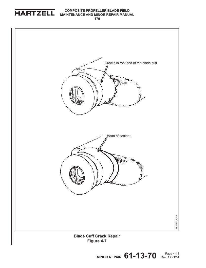
61-13-70 Page 4-18Rev. 1 Oct/14MINOR REPAIR
COMPOSITE PROPELLER BLADE FIELD MAINTENANCE AND MINOR REPAIR MANUAL
170
Blade Cuff Crack Repair Figure 4-7
Bead of sealant
Cracks in root end of the blade cuff
AP
S03
13, 0
312

61-13-70 Page 4-19Rev. 1 Oct/14MINOR REPAIR
COMPOSITE PROPELLER BLADE FIELD MAINTENANCE AND MINOR REPAIR MANUAL
170
3. Blade Cuff
CAUTION: INSTRUCTIONS AND PROCEDURES IN THIS SECTION INVOLVE PROPELLER CRITICAL PARTS. REFER TO THE INTRODUCTION CHAPTER OF THIS MANUAL FOR INFORMATION ABOUT PROPELLER CRITICAL PARTS.
A. Cracks at the Root End of the Blade Cuff
(1) General
(a) This repair may be performed in accordance with the airworthy damagelimitsandtheminorrepairlimitsspecifiedintheRepairLimitschapter of this manual.
(2) Procedure - Refer to Figure 4-7
(a) Using no coarser than 60 grit sandpaper, sand the area by hand.
WARNING: ADHESIVES AND SOLVENTS ARE FLAMMABLE AND TOXIC TO THE SKIN, EYES, AND RESPIRATORY TRACT. SKIN AND EYE PROTECTION ARE REQUIRED. AVOID PROLONGED CONTACT AND BREATHING OF VAPORS. USE SOLVENT RESISTANT GLOVES TO MINIMIzE SKIN CONTACT AND WEAR SAFETY GLASSES FOR EYE PROTECTION. USE IN A WELL VENTILATED AREA AWAY FROM SPARKS AND FLAME. READ AND OBSERVE ALL WARNING LABELS.
(b) Using a clean cloth CM159 or equivalent dampened with solvent acetone CM173, MEK CM106, or MPK CM219, clean the area.
(c) Permit the solvent acetone CM173, MEK CM106, or MPK CM219 to dry.
(d) Apply a bead of sealant CM9 around the entire area of the crack, blending the sealant to the normal airfoil shape.
(e) Permit the sealant CM9 to cure.
(f) Visually examine the repaired area for correct adhesion and coverage.
CAUTION: DO NOT MOVE THE SEALANT CM9 WHEN REFINISHING THE BLADE.
(g) Refinishthebladeinaccordancewiththesection,"FinishProcedures"inthis chapter, being careful not to disturb the sealant.
61-13-70 Page 4-20Rev. 1 Oct/14MINOR REPAIR
COMPOSITE PROPELLER BLADE FIELD MAINTENANCE AND MINOR REPAIR MANUAL
170
B. Nick, Scratch, Gouge, Crack, or Delamination
(1) General
(a) The following procedure may be performed on a cuff that has no obvious damage to the foam.
(b) Repairability is determined after the damaged composite material has been removed.
(c) Following the removal of damaged composite material, repairability is determined by the amount of exposed foam, if any.
(2) Procedure
CAUTION 1: DO NOT REMOVE MATERIAL ANY DEEPER THAN NECESSARY TO FULLY REMOVE THE DAMAGE.
CAUTION 2: DO NOT REMOVE CUFF FOAM OR KEVLAR® BLADE MATERIAL.
(a) Using a grinder or sander with no coarser than 60 grit sandpaper, remove damaged composite material in the area to be repaired:
1 While removing material, make a bevel 0.25 to 0.50 inch (6.3 to 12.7 mm) for each 0.010 inch (0.25 mm) depth of damaged material removed.
2 Stop periodically and examine the progress.
WARNING: ADHESIVES AND SOLVENTS ARE FLAMMABLE AND TOXIC TO THE SKIN, EYES, AND RESPIRATORY TRACT. SKIN AND EYE PROTECTION ARE REQUIRED. AVOID PROLONGED CONTACT AND BREATHING OF VAPORS. USE SOLVENT RESISTANT GLOVES TO MINIMIzE SKIN CONTACT AND WEAR SAFETY GLASSES FOR EYE PROTECTION. USE IN A WELL VENTILATED AREA AWAY FROM SPARKS AND FLAME. READ AND OBSERVE ALL WARNING LABELS.
NOTE: Wiping the area with a clean cloth CM159 or equivalent dampened with solvent acetone CM173, MEK CM106, or MPKCM219canhelptovisuallyfindthedefect.
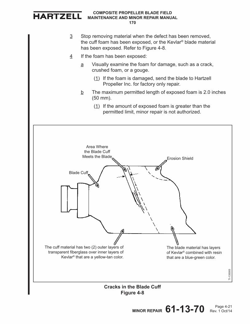
61-13-70 Page 4-21Rev. 1 Oct/14MINOR REPAIR
COMPOSITE PROPELLER BLADE FIELD MAINTENANCE AND MINOR REPAIR MANUAL
170
3 Stop removing material when the defect has been removed, the cuff foam has been exposed, or the Kevlar® blade material has been exposed. Refer to Figure 4-8.
4 If the foam has been exposed:
a Visually examine the foam for damage, such as a crack, crushed foam, or a gouge.
(1) Ifthefoamisdamaged,sendthebladetoHartzellPropeller Inc. for factory only repair.
b The maximum permitted length of exposed foam is 2.0 inches (50 mm).
(1) If the amount of exposed foam is greater than the permittedlimit,minorrepairisnotauthorized.
Blade Cuff
Erosion Shield
TI-1
3500
5
Cracks in the Blade Cuff Figure 4-8
Area Where the Blade Cuff
Meets the Blade
The cuff material has two (2) outer layers of transparentfiberglassoverinnerlayersof
Kevlar® that are a yellow-tan color.
The blade material has layers of Kevlar® combined with resin that are a blue-green color.
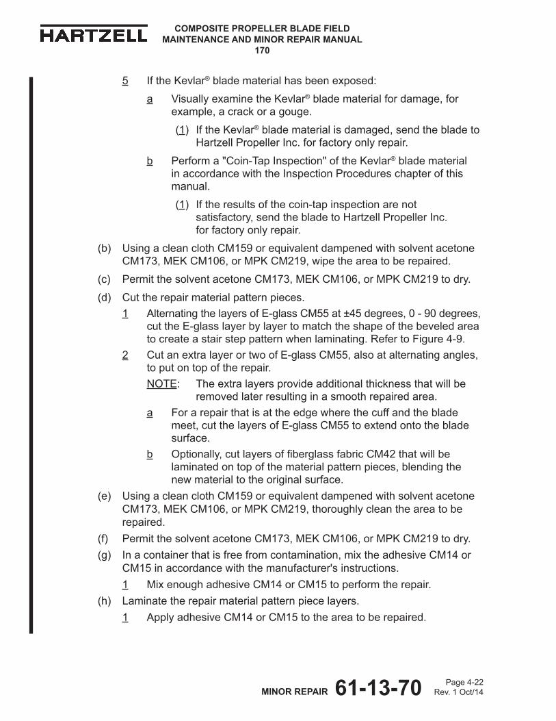
61-13-70 Page 4-22Rev. 1 Oct/14MINOR REPAIR
COMPOSITE PROPELLER BLADE FIELD MAINTENANCE AND MINOR REPAIR MANUAL
170
5 If the Kevlar® blade material has been exposed:
a Visually examine the Kevlar® blade material for damage, for example, a crack or a gouge.
(1) If the Kevlar® blade material is damaged, send the blade to HartzellPropellerInc.forfactoryonlyrepair.
b Perform a "Coin-Tap Inspection" of the Kevlar® blade material in accordance with the Inspection Procedures chapter of this manual.
(1) If the results of the coin-tap inspection are not satisfactory,sendthebladetoHartzellPropellerInc. for factory only repair.
(b) Using a clean cloth CM159 or equivalent dampened with solvent acetone CM173, MEK CM106, or MPK CM219, wipe the area to be repaired.
(c) Permit the solvent acetone CM173, MEK CM106, or MPK CM219 to dry.
(d) Cut the repair material pattern pieces. 1 Alternating the layers of E-glass CM55 at ±45 degrees, 0 - 90 degrees,
cut the E-glass layer by layer to match the shape of the beveled area to create a stair step pattern when laminating. Refer to Figure 4-9.
2 Cut an extra layer or two of E-glass CM55, also at alternating angles, to put on top of the repair. NOTE: The extra layers provide additional thickness that will be
removed later resulting in a smooth repaired area.a For a repair that is at the edge where the cuff and the blade
meet, cut the layers of E-glass CM55 to extend onto the blade surface.
b Optionally,cutlayersoffiberglassfabricCM42thatwillbelaminated on top of the material pattern pieces, blending the new material to the original surface.
(e) Using a clean cloth CM159 or equivalent dampened with solvent acetone CM173, MEK CM106, or MPK CM219, thoroughly clean the area to be repaired.
(f) Permit the solvent acetone CM173, MEK CM106, or MPK CM219 to dry.(g) In a container that is free from contamination, mix the adhesive CM14 or
CM15 in accordance with the manufacturer's instructions.1 Mix enough adhesive CM14 or CM15 to perform the repair.
(h) Laminate the repair material pattern piece layers.1 Apply adhesive CM14 or CM15 to the area to be repaired.
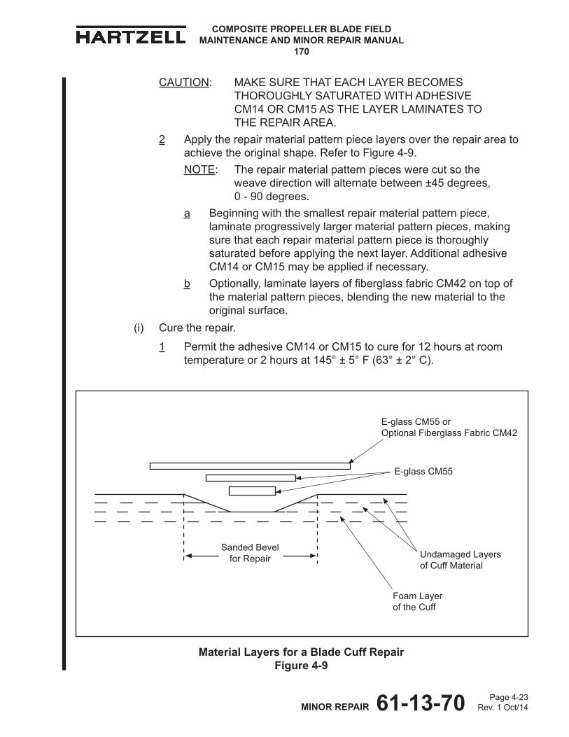
61-13-70 Page 4-23Rev. 1 Oct/14MINOR REPAIR
COMPOSITE PROPELLER BLADE FIELD MAINTENANCE AND MINOR REPAIR MANUAL
170
E-glass CM55 or Optional Fiberglass Fabric CM42
E-glass CM55
Foam Layer of the Cuff
Undamaged Layers of Cuff Material
Sanded Bevel for Repair
Material Layers for a Blade Cuff Repair Figure 4-9
CAUTION: MAKE SURE THAT EACH LAYER BECOMES THOROUGHLY SATURATED WITH ADHESIVE CM14 OR CM15 AS THE LAYER LAMINATES TO THE REPAIR AREA.
2 Apply the repair material pattern piece layers over the repair area to achieve the original shape. Refer to Figure 4-9.NOTE: The repair material pattern pieces were cut so the
weave direction will alternate between ±45 degrees, 0 - 90 degrees.
a Beginning with the smallest repair material pattern piece, laminate progressively larger material pattern pieces, making sure that each repair material pattern piece is thoroughly saturated before applying the next layer. Additional adhesive CM14 or CM15 may be applied if necessary.
b Optionally,laminatelayersoffiberglassfabricCM42ontopofthe material pattern pieces, blending the new material to the original surface.
(i) Cure the repair.
1 Permit the adhesive CM14 or CM15 to cure for 12 hours at room temperature or 2 hours at 145° ± 5° F (63° ± 2° C).
61-13-70 Page 4-24Rev. 1 Oct/14MINOR REPAIR
COMPOSITE PROPELLER BLADE FIELD MAINTENANCE AND MINOR REPAIR MANUAL
170
(j) Sand the repair.
CAUTION: DO NOT REMOVE ORIGINAL MATERIAL WHEN SANDING.
1 Sand the repaired area to the original shape using caution not to remove original material.
2 Usingprogressivelyfinergritsandpaper,sanduntiltheoriginalshape is achieved.
3 Use140gritorfinersandpaperforfinalsanding.(k) Visually examine the repaired area.
1 The repaired area must be smooth and free from wrinkles, voids, or resin rich areas.
(l) Perform a "Coin-Tap Inspection" of the repaired area in accordance with the Inspection Procedures chapter of this manual.
1 Delaminations or voids are not permitted.
2 Iftheareaofrepairisnotwithinthelimitsspecified,repairinaccordance with the applicable repair instructions.
3 Repeat the inspections and repair until the repair is satisfactory.
(m) Refinishthebladeinaccordancewiththesection,"FinishProcedures"inthis chapter.
4. Blade Repairs for All Except N-shank Kevlar®/Carbon Hybrid Blades
CAUTION: INSTRUCTIONS AND PROCEDURES IN THIS SECTION INVOLVE PROPELLER CRITICAL PARTS. REFER TO THE INTRODUCTION CHAPTER OF THIS MANUAL FOR INFORMATION ABOUT PROPELLER CRITICAL PARTS.
A. Gouge, Delamination, or Loss of Composite Material
(1) General
(a) This repair may be performed in accordance with the airworthy damagelimitsandtheminorrepairlimitsspecifiedintheRepairLimitschapter of this manual.
61-13-70 Page 4-25Rev. 1 Oct/14MINOR REPAIR
COMPOSITE PROPELLER BLADE FIELD MAINTENANCE AND MINOR REPAIR MANUAL
170
(2) Procedure
CAUTION 1: DO NOT REMOVE MATERIAL ANY DEEPER THAN NECESSARY TO FULLY REMOVE THE DAMAGE.
CAUTION 2: DO NOT SAND INTO THE UNIDIRECTIONAL (UD) MATERIAL OF THE BLADE.
(a) Using a grinder or sander with no coarser than 60 grit sandpaper, remove damaged composite material in the area to be repaired.
1 While removing material, make a bevel 0.50 to 1.00 inch (12.7 to 25.4 mm) for each 0.010 inch (0.25 mm) depth of damaged material removed.
a If the area requiring removal extends to an edge, maintain the bevel to the edge.
b If the area requiring removal extends outside of the original region and into another region, extend the bevel into the new region.
(1) The boundary of the region applies to the damage, not to the boundary of the repair.
2 Stop periodically and examine the progress.
WARNING: ADHESIVES AND SOLVENTS ARE FLAMMABLE AND TOXIC TO THE SKIN, EYES, AND RESPIRATORY TRACT. SKIN AND EYE PROTECTION ARE REQUIRED. AVOID PROLONGED CONTACT AND BREATHING OF VAPORS. USE SOLVENT RESISTANT GLOVES TO MINIMIzE SKIN CONTACT AND WEAR SAFETY GLASSES FOR EYE PROTECTION. USE IN A WELL VENTILATED AREA AWAY FROM SPARKS AND FLAME. READ AND OBSERVE ALL WARNING LABELS.
NOTE: Wiping the area with a clean cloth CM159 or equivalent dampened with solvent acetone CM173, MEK CM106, or MPKCM219canhelptovisuallyfindthedefect.
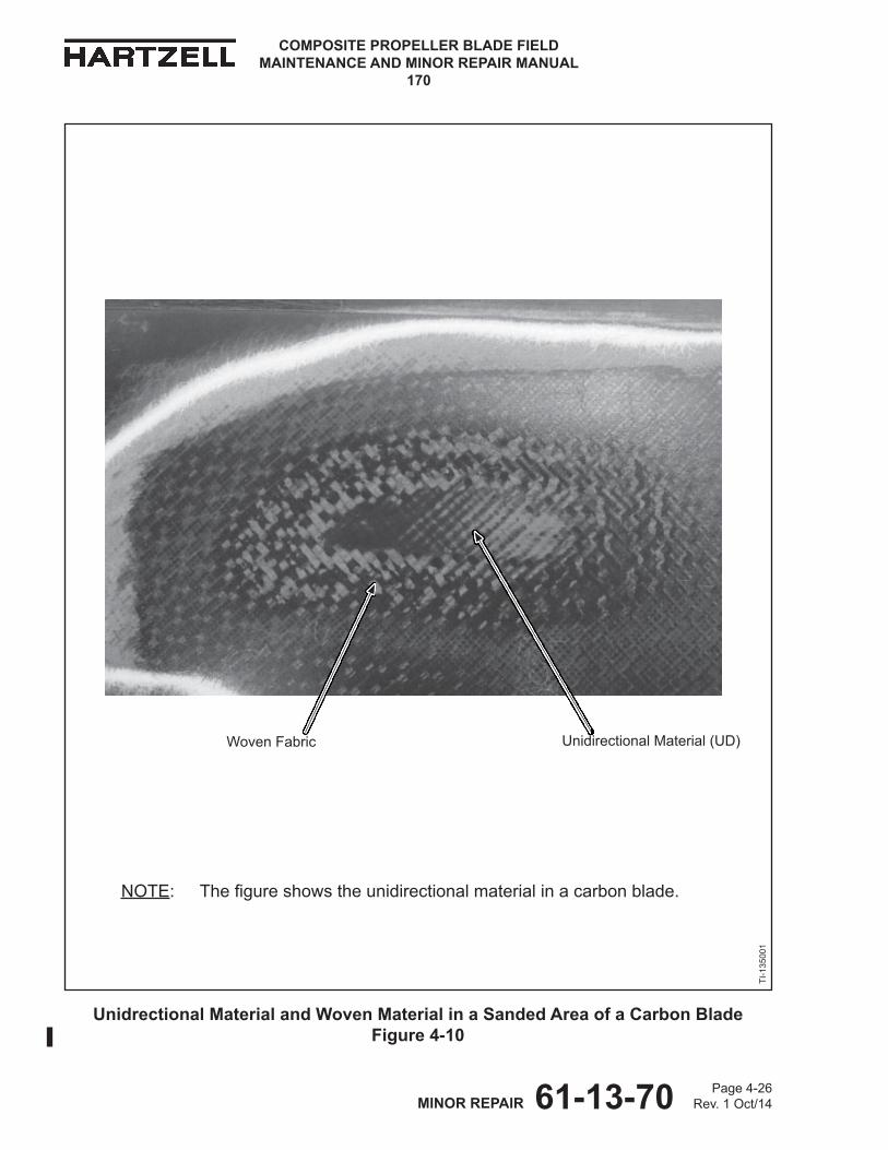
61-13-70 Page 4-26Rev. 1 Oct/14MINOR REPAIR
COMPOSITE PROPELLER BLADE FIELD MAINTENANCE AND MINOR REPAIR MANUAL
170
Unidrectional Material and Woven Material in a Sanded Area of a Carbon Blade Figure 4-10
Unidirectional Material (UD)Woven Fabric
NOTE: Thefigureshowstheunidirectionalmaterialinacarbonblade.
TI-1
3500
1
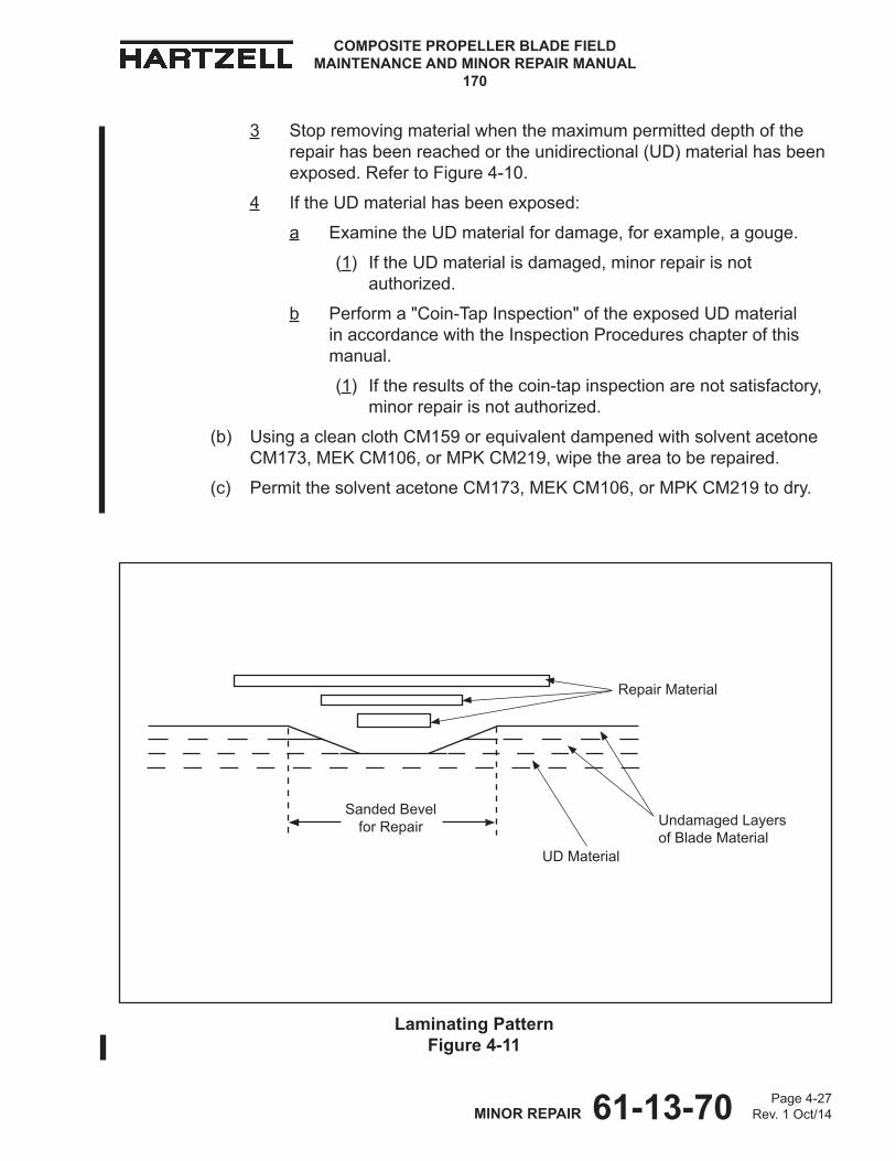
61-13-70 Page 4-27Rev. 1 Oct/14MINOR REPAIR
COMPOSITE PROPELLER BLADE FIELD MAINTENANCE AND MINOR REPAIR MANUAL
170
3 Stop removing material when the maximum permitted depth of the repair has been reached or the unidirectional (UD) material has been exposed. Refer to Figure 4-10.
4 If the UD material has been exposed:
a Examine the UD material for damage, for example, a gouge.
(1) If the UD material is damaged, minor repair is not authorized.
b Perform a "Coin-Tap Inspection" of the exposed UD material in accordance with the Inspection Procedures chapter of this manual.
(1) If the results of the coin-tap inspection are not satisfactory, minorrepairisnotauthorized.
(b) Using a clean cloth CM159 or equivalent dampened with solvent acetone CM173, MEK CM106, or MPK CM219, wipe the area to be repaired.
(c) Permit the solvent acetone CM173, MEK CM106, or MPK CM219 to dry.
Laminating Pattern Figure 4-11
Repair Material
UD Material
Undamaged Layers of Blade Material
Sanded Bevel for Repair
61-13-70 Page 4-28Rev. 1 Oct/14MINOR REPAIR
COMPOSITE PROPELLER BLADE FIELD MAINTENANCE AND MINOR REPAIR MANUAL
170
(d) Cut the repair material pattern pieces.
1 From Table 4-1 choose the correct repair materials and make a note of the cured ply thickness.
2 Alternating the layers of repair material at ± 45 degrees, 0 - 90 degrees, cut the repair material layer by layer to match the shape of the beveled area to create a stair step pattern when laminating. Refer to Figure 4-11.
3 Cut an extra layer or two of the repair material, also at alternating angles, to put on top of the repair.
NOTE: The extra layers provide additional thickness that will be removed later resulting in a smooth repaired area.
a For a Kevlar®bladeonly:Optionally,laminatelayersoffiberglassfabric CM42 on top of the material pattern pieces, blending the new material to the original surface.
(e) Using a clean cloth CM159 or equivalent dampened with solvent acetone CM173, MEK CM106, or MPK CM219, thoroughly clean the area to be repaired.
(f) Permit the solvent acetone CM173, MEK CM106, or MPK CM219 to dry.
(g) In a container that is free from contamination, mix the adhesive CM14 or CM15 in accordance with the manufacturer's instructions.1 Mix enough adhesive CM14 or CM15 to perform the repair.
(h) Laminate the repair material pattern piece layers.1 Apply adhesive CM14 or CM15 to the area to be repaired.
CAUTION: MAKE SURE THAT EACH LAYER BECOMES THOROUGHLY SATURATED WITH ADHESIVE CM14 OR CM15 AS THE LAYER LAMINATES TO THE REPAIR AREA.
2 Apply the repair material pattern piece layers over the repair area to achieve the original shape. Refer to Figure 4-11.NOTE: The repair material pattern pieces were cut so the weave
direction will alternate between ± 45 degrees, 0 - 90 degrees.a Beginning with the smallest repair material pattern piece,
laminate progressively larger material pattern pieces, making sure that each repair material pattern piece is thoroughly saturated before applying the next layer. Additional adhesive CM14 or CM15 may be applied if necessary.
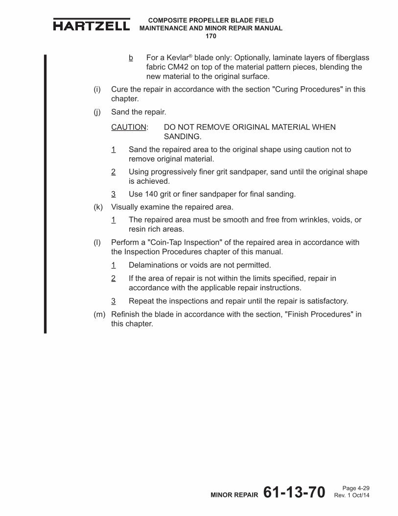
61-13-70 Page 4-29Rev. 1 Oct/14MINOR REPAIR
COMPOSITE PROPELLER BLADE FIELD MAINTENANCE AND MINOR REPAIR MANUAL
170
b For a Kevlar®bladeonly:Optionally,laminatelayersoffiberglassfabric CM42 on top of the material pattern pieces, blending the new material to the original surface.
(i) Cure the repair in accordance with the section "Curing Procedures" in this chapter.
(j) Sand the repair.
CAUTION: DO NOT REMOVE ORIGINAL MATERIAL WHEN SANDING.
1 Sand the repaired area to the original shape using caution not to remove original material.
2 Usingprogressivelyfinergritsandpaper,sanduntiltheoriginalshapeis achieved.
3 Use140gritorfinersandpaperforfinalsanding.(k) Visually examine the repaired area.
1 The repaired area must be smooth and free from wrinkles, voids, or resin rich areas.
(l) Perform a "Coin-Tap Inspection" of the repaired area in accordance with the Inspection Procedures chapter of this manual.
1 Delaminations or voids are not permitted.
2 Iftheareaofrepairisnotwithinthelimitsspecified,repairinaccordance with the applicable repair instructions.
3 Repeat the inspections and repair until the repair is satisfactory.
(m) Refinishthebladeinaccordancewiththesection,"FinishProcedures"inthis chapter.

61-13-70 Page 4-30Rev. 1 Oct/14MINOR REPAIR
COMPOSITE PROPELLER BLADE FIELD MAINTENANCE AND MINOR REPAIR MANUAL
170
B. Gouge, Delamination, or Loss of Composite Material in the Trailing Edge Foam and Leading Edge Foam Regions
(1) General
(a) The following procedure may be performed on a blade that has no obvious damage to the foam.
(b) Repairability is determined after the damaged composite material has been removed.
(c) Following the removal of damaged composite material, repairability is determined by the amount of exposed foam, if any.
(2) Procedure
CAUTION 1: DO NOT REMOVE MATERIAL ANY DEEPER THAN NECESSARY TO FULLY REMOVE THE DAMAGE.
CAUTION 2: DO NOT SAND INTO THE FOAM MATERIAL OF THE BLADE.
(a) Using a grinder or sander with no coarser than 60 grit sandpaper, remove damaged composite material in the area to be repaired.
1 While removing material, make a bevel 0.50 to 1.00 inch (12.7 to 25.4 mm) for each 0.010 inch (0.25 mm) depth of damaged material removed.
a If the area requiring removal extends to an edge, maintain the bevel to the edge.
2 Stop periodically and examine the progress.
WARNING: ADHESIVES AND SOLVENTS ARE FLAMMABLE AND TOXIC TO THE SKIN, EYES, AND RESPIRATORY TRACT. SKIN AND EYE PROTECTION ARE REQUIRED. AVOID PROLONGED CONTACT AND BREATHING OF VAPORS. USE SOLVENT RESISTANT GLOVES TO MINIMIzE SKIN CONTACT AND WEAR SAFETY GLASSES FOR EYE PROTECTION. USE IN A WELL VENTILATED AREA AWAY FROM SPARKS AND FLAME. READ AND OBSERVE ALL WARNING LABELS.
NOTE: Wiping the area with a clean cloth CM159 or equivalent dampened with solvent acetone CM173, MEK CM106, or MPKCM219canhelptovisuallyfindthedefect.
3 Stop removing material when the damage has been removed or the foam material has been exposed.
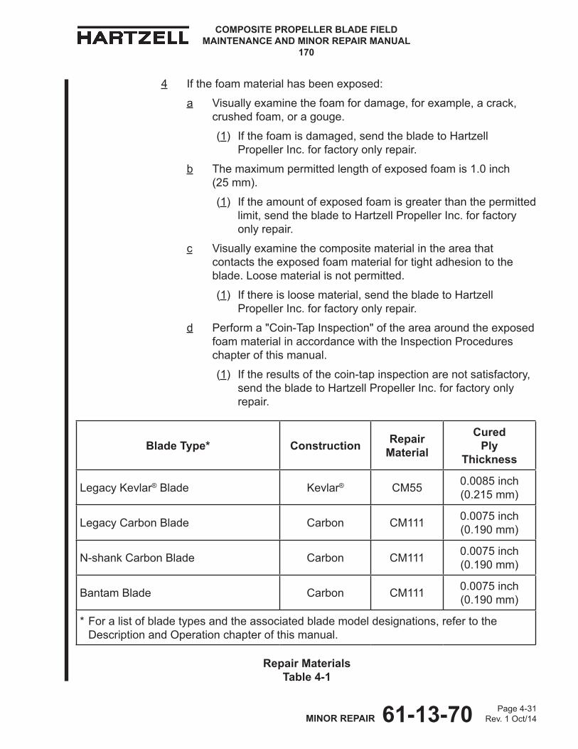
61-13-70 Page 4-31Rev. 1 Oct/14MINOR REPAIR
COMPOSITE PROPELLER BLADE FIELD MAINTENANCE AND MINOR REPAIR MANUAL
170
4 If the foam material has been exposed:
a Visually examine the foam for damage, for example, a crack, crushed foam, or a gouge.
(1) Ifthefoamisdamaged,sendthebladetoHartzellPropeller Inc. for factory only repair.
b The maximum permitted length of exposed foam is 1.0 inch (25 mm).
(1) If the amount of exposed foam is greater than the permitted limit,sendthebladetoHartzellPropellerInc.forfactoryonly repair.
c Visually examine the composite material in the area that contacts the exposed foam material for tight adhesion to the blade. Loose material is not permitted.
(1) Ifthereisloosematerial,sendthebladetoHartzellPropeller Inc. for factory only repair.
d Perform a "Coin-Tap Inspection" of the area around the exposed foam material in accordance with the Inspection Procedures chapter of this manual.
(1) If the results of the coin-tap inspection are not satisfactory, sendthebladetoHartzellPropellerInc.forfactoryonlyrepair.
Repair Materials Table 4-1
Blade Type* Construction Repair Material
Cured Ply
Thickness
Legacy Kevlar® Blade Kevlar® CM55 0.0085 inch (0.215 mm)
Legacy Carbon Blade Carbon CM111 0.0075 inch (0.190 mm)
N-shank Carbon Blade Carbon CM111 0.0075 inch (0.190 mm)
Bantam Blade Carbon CM111 0.0075 inch (0.190 mm)
* For a list of blade types and the associated blade model designations, refer to the Description and Operation chapter of this manual.

61-13-70 Page 4-32Rev. 1 Oct/14MINOR REPAIR
COMPOSITE PROPELLER BLADE FIELD MAINTENANCE AND MINOR REPAIR MANUAL
170
(b) Using a clean cloth CM159 or equivalent dampened with solvent acetone CM173, MEK CM106, or MPK CM219, wipe the area to be repaired.
(c) Permit the solvent acetone CM173, MEK CM106, or MPK CM219 to dry.
(d) Cut the repair material pattern pieces.
1 From Table 4-1 choose the correct repair materials and make a note of the cured ply thickness.
2 Alternating the layers of repair material at ±45 degrees, 0 - 90 degrees, cut the repair material layer by layer to match the shape of the beveled area to create a stair step pattern when laminating. Refer to Figure 4-12.
3 Cut an extra layer or two of the repair material, also at alternating angles, to put on top of the repair.
NOTE: The extra layers provide additional thickness that will be removed later resulting in a smooth repaired area.
(e) Using a clean cloth CM159 or equivalent dampened with solvent acetone CM173, MEK CM106, or MPK CM219, thoroughly clean the area to be repaired.
(f) Permit the solvent acetone CM173, MEK CM106, or MPK CM219 to dry.
(g) In a container that is free from contamination, mix the adhesive CM14 or CM15 in accordance with the manufacturer's instructions.1 Mix enough adhesive CM14 or CM15 to perform the repair.
Material Layers for a Repair in the Trailing Edge Foam Figure 4-12
Repair Material
Foam Material
Undamaged Layers of Blade Material
Sanded Bevel for Repair
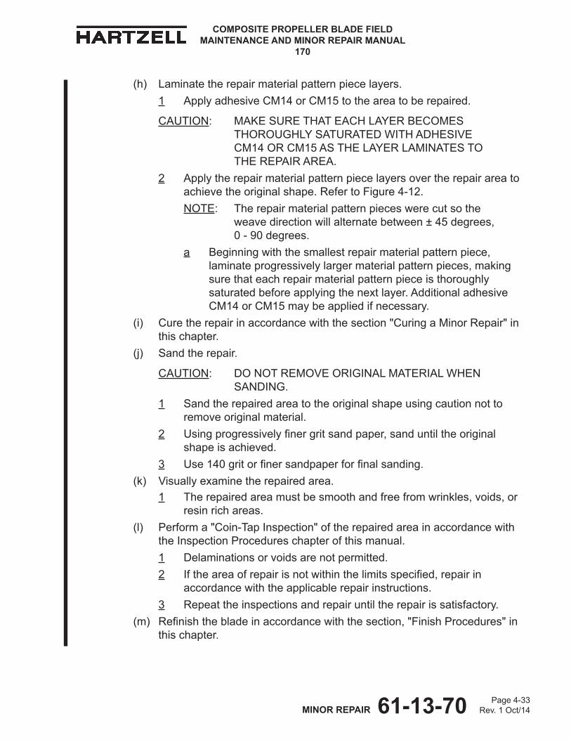
61-13-70 Page 4-33Rev. 1 Oct/14MINOR REPAIR
COMPOSITE PROPELLER BLADE FIELD MAINTENANCE AND MINOR REPAIR MANUAL
170
(h) Laminate the repair material pattern piece layers.1 Apply adhesive CM14 or CM15 to the area to be repaired.
CAUTION: MAKE SURE THAT EACH LAYER BECOMES THOROUGHLY SATURATED WITH ADHESIVE CM14 OR CM15 AS THE LAYER LAMINATES TO THE REPAIR AREA.
2 Apply the repair material pattern piece layers over the repair area to achieve the original shape. Refer to Figure 4-12.NOTE: The repair material pattern pieces were cut so the
weave direction will alternate between ± 45 degrees, 0 - 90 degrees.
a Beginning with the smallest repair material pattern piece, laminate progressively larger material pattern pieces, making sure that each repair material pattern piece is thoroughly saturated before applying the next layer. Additional adhesive CM14 or CM15 may be applied if necessary.
(i) Cure the repair in accordance with the section "Curing a Minor Repair" in this chapter.
(j) Sand the repair.
CAUTION: DO NOT REMOVE ORIGINAL MATERIAL WHEN SANDING.
1 Sand the repaired area to the original shape using caution not to remove original material.
2 Usingprogressivelyfinergritsandpaper,sanduntiltheoriginalshape is achieved.
3 Use140gritorfinersandpaperforfinalsanding.(k) Visually examine the repaired area.
1 The repaired area must be smooth and free from wrinkles, voids, or resin rich areas.
(l) Perform a "Coin-Tap Inspection" of the repaired area in accordance with the Inspection Procedures chapter of this manual.1 Delaminations or voids are not permitted.2 Iftheareaofrepairisnotwithinthelimitsspecified,repairin
accordance with the applicable repair instructions.3 Repeat the inspections and repair until the repair is satisfactory.
(m) Refinishthebladeinaccordancewiththesection,"FinishProcedures"inthis chapter.
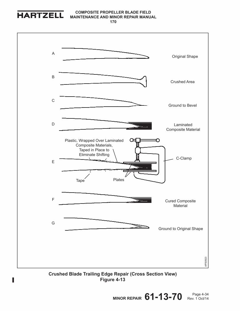
61-13-70 Page 4-34Rev. 1 Oct/14MINOR REPAIR
COMPOSITE PROPELLER BLADE FIELD MAINTENANCE AND MINOR REPAIR MANUAL
170
AP
S09
23
Crushed Blade Trailing Edge Repair (Cross Section View) Figure 4-13
Ground to Original Shape
Cured Composite Material
Ground to Bevel
Crushed Area
Laminated Composite Material
Original Shape
C-Clamp
Plates
Plastic, Wrapped Over Laminated Composite Materials,
Taped in Place to Eliminate Shifting
Tape
A
B
C
D
E
F
G
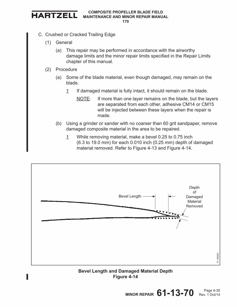
61-13-70 Page 4-35Rev. 1 Oct/14MINOR REPAIR
COMPOSITE PROPELLER BLADE FIELD MAINTENANCE AND MINOR REPAIR MANUAL
170
C. Crushed or Cracked Trailing Edge
(1) General
(a) This repair may be performed in accordance with the airworthy damagelimitsandtheminorrepairlimitsspecifiedintheRepairLimitschapter of this manual.
(2) Procedure
(a) Some of the blade material, even though damaged, may remain on the blade.
1 If damaged material is fully intact, it should remain on the blade.
NOTE: If more than one layer remains on the blade, but the layers are separated from each other, adhesive CM14 or CM15 will be injected between these layers when the repair is made.
(b) Using a grinder or sander with no coarser than 60 grit sandpaper, remove damaged composite material in the area to be repaired.
1 While removing material, make a bevel 0.25 to 0.75 inch (6.3 to 19.0 mm) for each 0.010 inch (0.25 mm) depth of damaged material removed. Refer to Figure 4-13 and Figure 4-14.
Bevel Length and Damaged Material Depth Figure 4-14
Bevel Length
Depth of
Damaged Material
Removed
TI-1
3500
3
61-13-70 Page 4-36Rev. 1 Oct/14MINOR REPAIR
COMPOSITE PROPELLER BLADE FIELD MAINTENANCE AND MINOR REPAIR MANUAL
170
2 Stop periodically and examine the progress.
WARNING: ADHESIVES AND SOLVENTS ARE FLAMMABLE AND TOXIC TO THE SKIN, EYES, AND RESPIRATORY TRACT. SKIN AND EYE PROTECTION ARE REQUIRED. AVOID PROLONGED CONTACT AND BREATHING OF VAPORS. USE SOLVENT RESISTANT GLOVES TO MINIMIzE SKIN CONTACT AND WEAR SAFETY GLASSES FOR EYE PROTECTION. USE IN A WELL VENTILATED AREA AWAY FROM SPARKS AND FLAME. READ AND OBSERVE ALL WARNING LABELS.
NOTE: Wiping the area with a clean cloth CM159 or equivalent dampened with solvent acetone CM173, MEK CM106, or MPKCM219canhelptovisuallyfindthedefect.
3 Stopremovingmaterialwhenthedamagehasbeensufficientlyremoved or when the airworthy damage limit has been reached.
a If damaged material remains after reaching the airworthy damage limit,minorrepairisnotauthorized.
b Perform a "Coin-Tap Inspection" of the repaired area in accordance with the Inspection Procedures chapter of this manual.
(1) If the results of the coin-tap inspection are not satisfactory, minorrepairisnotauthorized.
(c) Using a clean cloth CM159 or equivalent dampened with solvent acetone CM173, MEK CM106, or MPK CM219, wipe the area to be repaired.
(d) Permit the solvent acetone CM173, MEK CM106, or MPK CM219 to dry.
(e) Cut the repair material pattern pieces for each side of the blade.
1 From Table 4-1, choose the correct repair materials and make a note of the cured ply thickness.
2 Alternating the layers of repair material at ± 45 degrees, 0 - 90 degrees, cut the repair material layer by layer to create a stair step pattern that matches the shape of the beveled area and extends approximately 0.25 inch (6.3 mm) beyond the trailing edge of the blade. Refer to Figure 4-14.
NOTE: It is easier to apply more material than is needed instead of trying to match the shape of the blade.
3 Alternating angles, cut an extra layer or two of the repair material that is large enough to cover the repair on each side of the blade.
NOTE: The extra layers provide additional thickness that will be removed later resulting in a smooth, repaired area.
61-13-70 Page 4-37Rev. 1 Oct/14MINOR REPAIR
COMPOSITE PROPELLER BLADE FIELD MAINTENANCE AND MINOR REPAIR MANUAL
170
(f) Using a clean cloth CM159 or equivalent dampened with solvent acetone CM173, MEK CM106, or MPK CM219, thoroughly clean the area to be repaired.
CAUTION: MAKE SURE THAT THE SOLVENT IS DRY BETWEEN THE COMPOSITE MATERIAL LAYERS, IF APPLICABLE.
(g) Permit the solvent acetone CM173, MEK CM106, or MPK CM219 to dry.
1 Additional drying time may be needed for solvent acetone CM173, MEK CM106, or MPK CM219 that is between the composite layers.
(h) In a container that is free from contamination, mix adhesive CM14 or CM15 in accordance with the manufacturer's instructions.
1 Mix enough adhesive CM14 or CM15 to perform the repair.
(i) If applicable, inject adhesive CM14 or CM15 with a syringe CM3 between all the layers of the original material remaining in the damaged area.
(j) Laminate the repair material pattern piece layers.
1 Apply adhesive CM14 or CM15 to the area to be repaired.
CAUTION: MAKE SURE THAT EACH LAYER BECOMES THOROUGHLY SATURATED WITH ADHESIVE CM14 OR CM15 AS THE LAYER LAMINATES TO THE REPAIR AREA.
2 Apply the repair material pattern piece layers over the repair area to achieve the original shape. Refer to Figure 4-13.
NOTE: The repair material pattern pieces were cut so the weave direction will alternate between ± 45 degrees, 0 - 90 degrees.
a Beginning with the smallest repair material pattern piece, laminate progressively larger material pattern pieces, making sure that each repair material pattern piece is thoroughly saturated before applying the next layer. Additional adhesive CM14 or CM15 may be applied if necessary.
b Laminate a layer or two of the repair material that is large enough to cover the repair.
3 Holdingallofthelayersfirmlyinplace,carefullyturnthebladeovertothe other side.
NOTE: Holdingortemporarilytapingaflatplateoverthelayerswillhelp hold the layers in place when turning the blade.
4 Apply adhesive CM14 or CM15 to the area to be repaired.
61-13-70 Page 4-38Rev. 1 Oct/14MINOR REPAIR
COMPOSITE PROPELLER BLADE FIELD MAINTENANCE AND MINOR REPAIR MANUAL
170
CAUTION: MAKE SURE THAT EACH LAYER BECOMES THOROUGHLY SATURATED WITH ADHESIVE CM14 OR CM15 AS THE LAYER LAMINATES TO THE REPAIR AREA.
5 Apply the repair material pattern piece layers over the repair area to achieve the original shape. Refer to Figure 4-13.
NOTE: The repair material pattern pieces were cut so the weave direction will alternate between ± 45 degrees, 0 - 90 degrees.
a Beginning with the smallest repair material pattern piece, laminate progressively larger material pattern pieces, making sure that each repair material pattern piece is thoroughly saturated before applying the next layer. Additional adhesive CM14 or CM15 may be applied if necessary.
b Laminate a layer or two of the repair material that is large enough to cover the repair on one side of the blade and extend approximately 0.05 inch (12 mm) beyond the edge of the blade.
(k) Cure the repair in accordance with the Curing Procedures section in this chapter.
(l) Sand the repair.
CAUTION: DO NOT REMOVE ORIGINAL MATERIAL WHEN SANDING.
1 Sand the repaired area to the original shape using caution not to remove original material.
2 Usingprogressivelyfinergritsandpaper,sanduntiltheoriginalshapeis achieved. Refer to Figure 4-13.
3 Use140gritorfinersandpaperforfinalsanding.(m) Visually examine the repaired area.
1 The repaired area must be smooth and free from wrinkles, voids, or resin rich areas.
(n) Perform a "Coin-Tap Inspection" of the repaired area in accordance with the Inspection Procedures chapter of this manual.
1 Delaminations or voids are not permitted.
2 Iftheareaofrepairisnotwithinthelimitsspecified,repairinaccordance with the applicable repair instructions.
3 Repeat the inspections and repair until the repair is satisfactory.
(o) Refinishthebladeinaccordancewiththesection,"FinishProcedures"inthis chapter.
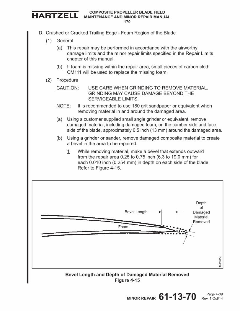
61-13-70 Page 4-39Rev. 1 Oct/14MINOR REPAIR
COMPOSITE PROPELLER BLADE FIELD MAINTENANCE AND MINOR REPAIR MANUAL
170
D. Crushed or Cracked Trailing Edge - Foam Region of the Blade
(1) General(a) This repair may be performed in accordance with the airworthy
damagelimitsandtheminorrepairlimitsspecifiedintheRepairLimitschapter of this manual.
(b) If foam is missing within the repair area, small pieces of carbon cloth CM111 will be used to replace the missing foam.
(2) Procedure
CAUTION: USE CARE WHEN GRINDING TO REMOVE MATERIAL. GRINDING MAY CAUSE DAMAGE BEYOND THE SERVICEABLE LIMITS.
NOTE: It is recommended to use 180 grit sandpaper or equivalent when removing material in and around the damaged area.
(a) Using a customer supplied small angle grinder or equivalent, remove damaged material, including damaged foam, on the camber side and face side of the blade, approximately 0.5 inch (13 mm) around the damaged area.
(b) Using a grinder or sander, remove damaged composite material to create a bevel in the area to be repaired.
1 While removing material, make a bevel that extends outward from the repair area 0.25 to 0.75 inch (6.3 to 19.0 mm) for each 0.010 inch (0.254 mm) in depth on each side of the blade. Refer to Figure 4-15.
Bevel Length and Depth of Damaged Material Removed Figure 4-15
TI-1
3500
4
Bevel Length
Depth of
Damaged Material
RemovedFoam
61-13-70 Page 4-40Rev. 1 Oct/14MINOR REPAIR
COMPOSITE PROPELLER BLADE FIELD MAINTENANCE AND MINOR REPAIR MANUAL
170
2 Stop periodically and examine the progress.
WARNING: ADHESIVES AND SOLVENTS ARE FLAMMABLE AND TOXIC TO THE SKIN, EYES, AND RESPIRATORY TRACT. SKIN AND EYE PROTECTION ARE REQUIRED. AVOID PROLONGED CONTACT AND BREATHING OF VAPORS. USE SOLVENT RESISTANT GLOVES TO MINIMIzE SKIN CONTACT AND WEAR SAFETY GLASSES FOR EYE PROTECTION. USE IN A WELL VENTILATED AREA AWAY FROM SPARKS AND FLAME. READ AND OBSERVE ALL WARNING LABELS.
NOTE: Wiping the area with a clean cloth CM159 or equivalent dampened with solvent acetone CM173, MEK CM106, or MPKCM219canhelptovisuallyfindthedefect.
3 Stopremovingmaterialwhenthedamagehasbeensufficientlyremoved or the minor repair limit has been reached.
(c) After removing material, examine the repair area.
1 The remaining layers must be fully bonded.
2 If damaged material remains after reaching the minor repair limit, sendthebladetoHartzellPropellerInc.forfactoryonlyrepair.
3 Perform a "Coin-Tap Inspection" of the repaired area in accordance with the Inspection Procedures chapter of this manual.
a If the coin-tap inspection is not satisfactory, send the blade to HartzellPropellerInc.forfactoryonlyrepair.
(d) Using a cloth saturated with solvent acetone CM173, MEK CM106, or MPK CM219, wipe the repair area.
(e) Permit the solvent acetone CM173, MEK CM106, or MPK CM219 to dry.
(f) Cut the repair material pattern pieces for each side of the blade.
1 From Table 4-1 choose the correct repair materials and make a note of the cured ply thickness.
2 Alternating the layers of repair material at ± 45 degrees, 0 - 90 degrees, cut the repair material layer by layer to create a stair step pattern that matches the shape of the beveled area and extends approximately 0.25 inch (6.3 mm) beyond the trailing edge of the blade. Refer to Figure 4-15.
NOTE: It is easier to apply more material than is needed instead of trying to match the shape of the blade.
61-13-70 Page 4-41Rev. 1 Oct/14MINOR REPAIR
COMPOSITE PROPELLER BLADE FIELD MAINTENANCE AND MINOR REPAIR MANUAL
170
3 Alternating angles, cut an extra layer or two of the repair material that is large enough to cover the repair on each side of the blade.
NOTE: The extra layers provide additional thickness that will be removed later resulting in a smooth repaired area.
(g) Using a clean cloth CM159 or equivalent dampened with solvent acetone CM173, MEK CM106, or MPK CM219, thoroughly clean the area to be repaired.
(h) Permit the solvent acetone CM173, MEK CM106, or MPK CM219 to dry.
(i) In a container that is free from contamination, mix adhesive CM14 or CM15 in accordance with the manufacturer's instructions.
1 Mix enough adhesive CM14 or CM15 to perform the repair.(j) Laminate the repair material pattern piece layers.
1 Apply adhesive CM14 or CM15 to the area to be repaired.
CAUTION: MAKE SURE THAT EACH LAYER BECOMES THOROUGHLY SATURATED WITH ADHESIVE CM14 OR CM15 AS THE LAYER LAMINATES TO THE REPAIR AREA.
2 Apply the repair material pattern piece layers over the repair area to achieve the original shape. Refer to Figure 4-13.NOTE: The repair material pattern pieces were cut so the
weave direction will alternate between ± 45 degrees, 0 - 90 degrees.
a Beginning with the smallest repair material pattern piece, laminate progressively larger material pattern pieces, making sure that each repair material pattern piece is thoroughly saturated before applying the next layer. Additional adhesive CM14 or CM15 may be applied if necessary.
b Laminate a layer or two of the repair material that is large enough to cover the repair.
3 Holdingallofthelayersfirmlyinplace,carefullyturnthebladeovertothe other side.
NOTE: Holdingortemporarilytapingaflatplateoverthelayerswillhelp hold the layers in place when turning the blade.
4 Apply adhesive CM14 or CM15 to the area to be repaired.
61-13-70 Page 4-42Rev. 1 Oct/14MINOR REPAIR
COMPOSITE PROPELLER BLADE FIELD MAINTENANCE AND MINOR REPAIR MANUAL
170
CAUTION: MAKE SURE THAT EACH LAYER BECOMES THOROUGHLY SATURATED WITH ADHESIVE CM14 OR CM15 AS THE LAYER LAMINATES TO THE REPAIR AREA.
5 Usingverysmallpiecesofrepairmaterial,fillintheareawherefoamis missing, if applicable.
6 Apply the repair material pattern piece layers over the repair area to achieve the original shape. Refer to Figure 4-15.NOTE: The repair material pattern pieces were cut so the
weave direction will alternate between ±45 degrees, 0 - 90 degrees.
a Beginning with the smallest repair material pattern piece, laminate progressively larger material pattern pieces, making sure that each repair material pattern piece is thoroughly saturated before applying the next layer. Additional adhesive CM14 or CM15 may be applied if necessary.
b Laminate a layer or two of the repair material that is large enough to cover the repair.
CAUTION: DO NOT USE OPTION NO. 2, BLADE REPAIR BLANKET CURE WHEN CURING A TRAILING EDGE FOAM REPAIR.
(k) Cure the repair in accordance with the Curing Procedures section in this chapter.
(l) Sand the repair.
CAUTION: DO NOT REMOVE ORIGINAL MATERIAL WHEN SANDING.
1 Sand the repaired area to the original shape using caution not to remove original material.
2 Usingprogressivelyfinergritsandpaper,sanduntiltheoriginalshapeis achieved. Refer to Figure 4-13.
3 Use140gritorfinersandpaperforfinalsanding.(m) Visually examine the repaired area.
1 The repaired area must be smooth and free from wrinkles, voids, or resin rich areas.
61-13-70 Page 4-43Rev. 1 Oct/14MINOR REPAIR
COMPOSITE PROPELLER BLADE FIELD MAINTENANCE AND MINOR REPAIR MANUAL
170
(n) Perform a "Coin-Tap Inspection" of the repaired area in accordance with the Inspection Procedures chapter of this manual.
1 Delaminations or voids are not permitted.
2 Iftheareaofrepairisnotwithinthelimitsspecified,repairinaccordance with the applicable repair instructions.
3 Repeat the inspections and repair until the repair is satisfactory.
(o) Refinishthebladeinaccordancewiththesection,"FinishProcedures"inthis chapter.
E. Split Trailing Edge(1) General
(a) This repair may be performed in accordance with the airworthy damagelimitsandtheminorrepairlimitsspecifiedintheRepairLimitschapter of this manual.
(2) Procedure(a) Using a clean tongue depressor, utility knife, or other similar tool, gently
pry apart the split edge and remove any contaminates.
WARNING: ADHESIVES AND SOLVENTS ARE FLAMMABLE AND TOXIC TO THE SKIN, EYES, AND RESPIRATORY TRACT. SKIN AND EYE PROTECTION ARE REQUIRED. AVOID PROLONGED CONTACT AND BREATHING OF VAPORS. USE SOLVENT RESISTANT GLOVES TO MINIMIzE SKIN CONTACT AND WEAR SAFETY GLASSES FOR EYE PROTECTION. USE IN A WELL VENTILATED AREA AWAY FROM SPARKS AND FLAME. READ AND OBSERVE ALL WARNING LABELS.
(b) Using a clean cloth CM159 or equivalent dampened with solvent acetone CM173, MEK CM106, or MPK CM219, wipe the repair area.
CAUTION: MAKE SURE THAT THE SOLVENT IS DRY BETWEEN THE COMPOSITE MATERIAL LAYERS, IF APPLICABLE.
(c) Permit the solvent acetone CM173, MEK CM106, or MPK CM219 to dry. 1 Additional drying time may be needed for solvent acetone CM173,
MEK CM106, or MPK CM219 that is between the composite layers.
(d) In a container that is free from contamination, mix adhesive CM14 or CM15 in accordance with the manufacturer's instructions.
(e) Using adhesive CM14 or CM15 in a syringe CM3, inject as much adhesive as possible in the split, making sure of coverage of the entire surface.1 Alternately, push the adhesive CM14 or CM15 into the split using a
clean,flattool.
61-13-70 Page 4-44Rev. 1 Oct/14MINOR REPAIR
COMPOSITE PROPELLER BLADE FIELD MAINTENANCE AND MINOR REPAIR MANUAL
170
(f) For a Kevlar®bladeonly:Optionally,laminatelayersoffiberglassfabricCM42 on top of the material pattern pieces on one side of the blade and foldthefiberglassfabricCM42overtotheothersideoftheblade,blendingthe new material to the original surface.
NOTE: UsingtheCM42helpspreventfuzzingoftheKevlar® material when sanding the repaired area.
(g) Cure the repair in accordance with the Curing Procedures section in this chapter.
(h) Sand the repair.
CAUTION: DO NOT REMOVE ORIGINAL BLADE MATERIAL WHEN SANDING.
1 Using no coarser than 60 grit sandpaper, sand to remove excess adhesiveCM14orCM15andfiberglassfabricCM42ifapplicable.
a Afterthefinalsandingtheblademusthaveasmoothsurface.
(i) Visually examine the repaired area to make sure that it is the original airfoil shape.
1 Iftheoriginalairfoilshapeisnotachieved,sendthebladetoHartzellPropeller Inc. for factory only repair.
(j) Perform a "Coin-Tap Inspection" of the repaired area in accordance with the Inspection Procedures chapter of this manual.
a Delaminations or voids are not permitted.
b Iftheareaofrepairisnotwithinthelimitsspecified,repairinaccordance with the applicable repair instructions.
c Repeat the inspections and repair as necessary until the repair is satisfactory.
(k) Refinishthebladeinaccordancewiththesection,"FinishProcedures"inthis chapter.
61-13-70 Page 4-45Rev. 1 Oct/14MINOR REPAIR
COMPOSITE PROPELLER BLADE FIELD MAINTENANCE AND MINOR REPAIR MANUAL
170
F. Erosion Screen Repair
CAUTION: INSTRUCTIONS AND PROCEDURES IN THIS SECTION INVOLVE PROPELLER CRITICAL PARTS. REFER TO THE INTRODUCTION CHAPTER OF THIS MANUAL FOR INFORMATION ABOUT PROPELLER CRITICAL PARTS.
(1) General
(a) This repair may be performed in accordance with the airworthy damagelimitsandtheminorrepairlimitsspecifiedintheRepairLimitschapter of this manual.
(2) Procedure
CAUTION 1: DO NOT REMOVE MATERIAL ANY DEEPER THAN NECESSARY TO FULLY REMOVE THE DAMAGE.
CAUTION 2: DO NOT SAND INTO THE UNIDIRECTIONAL (UD) MATERIAL OF THE BLADE.
(a) Using a grinder or sander with no coarser than 60 grit sandpaper, remove damaged screen, and if applicable, composite material in the area to be repaired. When all damage has been removed, there should be no loose or deformed screen wire.NOTE: Only remove damaged material.
(b) Examine the repair area.
1 If more than one composite layer has been removed or if the total areaisgreaterthantheminordamagesizelimit,retirethebladeinaccordancewiththePartRetirementProcedureschapterofHartzellPropeller Inc. Standard Practices Manual 202A (61-01-02) orsendthebladetoHartzellPropellerInc.forevaluation.
2 From the surface of the blade with the paint removed, the total depth of the screen and one layer of composite will be 0.022 inch (0.55 mm).
(c) Perform a "Coin-Tap Inspection" of the repaired area in accordance with the Inspection Procedures chapter of this manual.
1 Ifthecointapindicationisgreaterinsizethanthelimitsdefinedinthe Minor Repair Limits, retire the blade in accordance with the Part RetirementProcedureschapterofHartzellPropellerInc.StandardPracticesManual202A(61-01-02)orsendthebladetoHartzellPropeller Inc. for evaluation.
2 If the coin tap indication is within Minor Repair Limits, remove delaminated material and re-inspect in accordance with 4.F.(2)(a) and 4.F.(2)(b) in this chapter.
61-13-70 Page 4-46Rev. 1 Oct/14MINOR REPAIR
COMPOSITE PROPELLER BLADE FIELD MAINTENANCE AND MINOR REPAIR MANUAL
170
WARNING: ADHESIVES AND SOLVENTS ARE FLAMMABLE AND TOXIC TO THE SKIN, EYES, AND RESPIRATORY TRACT. SKIN AND EYE PROTECTION ARE REQUIRED. AVOID PROLONGED CONTACT AND BREATHING OF VAPORS. USE SOLVENT RESISTANT GLOVES TO MINIMIzE SKIN CONTACT AND WEAR SAFETY GLASSES FOR EYE PROTECTION. USE IN A WELL VENTILATED AREA AWAY FROM SPARKS AND FLAME. READ AND OBSERVE ALL WARNING LABELS.
(d) Using a clean cloth CM159 or equivalent dampened with solvent acetone CM173, MEK CM106, or MPK CM219, wipe the area to be repaired.
(e) Permit the solvent acetone CM173, MEK CM106, or MPK CM219 to dry.
(f) Cut the repair material pattern pieces.
1 From Table 4-1 choose the correct repair materials and make a note of the cured ply thickness.
2 Alternating the layers of repair material at ± 45 degrees, 0 - 90 degrees, cut the repair material layer by layer to match the shape of the repair area.
3 Cut an extra layer or two of the repair material, also at alternating angles, to put on top of the repair.
NOTE: The extra layers provide additional thickness that will be removed later resulting in a smooth repaired area.
4 ForaKevlar®bladeonly:Optionally,laminatelayersoffiberglassfabric CM42 on top of the material pattern pieces, blending the new material to the original surface.
(g) Using a clean cloth CM159 or equivalent dampened with solvent acetone CM173, MEK CM106, or MPK CM219, thoroughly clean the area to be repaired.
(h) Permit the solvent acetone CM173, MEK CM106, or MPK CM219 to dry.
(i) In a container that is free from contamination, mix the adhesive CM14 or CM15 in accordance with the manufacturer's instructions.
1 Mix enough adhesive CM14 or CM15 to perform the repair.
(j) Laminate the repair material pattern piece layers.
1 Apply adhesive CM14 or CM15 to the area to be repaired.
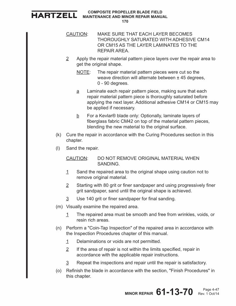
61-13-70 Page 4-47Rev. 1 Oct/14MINOR REPAIR
COMPOSITE PROPELLER BLADE FIELD MAINTENANCE AND MINOR REPAIR MANUAL
170
CAUTION: MAKE SURE THAT EACH LAYER BECOMES THOROUGHLY SATURATED WITH ADHESIVE CM14 OR CM15 AS THE LAYER LAMINATES TO THE REPAIR AREA.
2 Apply the repair material pattern piece layers over the repair area to get the original shape.
NOTE: The repair material pattern pieces were cut so the weave direction will alternate between ± 45 degrees, 0 - 90 degrees.
a Laminate each repair pattern piece, making sure that each repair material pattern piece is thoroughly saturated before applying the next layer. Additional adhesive CM14 or CM15 may be applied if necessary.
b For a Kevlar® blade only: Optionally, laminate layers of fiberglassfabricCM42ontopofthematerialpatternpieces,blending the new material to the original surface.
(k) Cure the repair in accordance with the Curing Procedures section in this chapter.
(l) Sand the repair.
CAUTION: DO NOT REMOVE ORIGINAL MATERIAL WHEN SANDING.
1 Sand the repaired area to the original shape using caution not to remove original material.
2 Startingwith80gritorfinersandpaperandusingprogressivelyfinergrit sandpaper, sand until the original shape is achieved.
3 Use140gritorfinersandpaperforfinalsanding.
(m) Visually examine the repaired area.
1 The repaired area must be smooth and free from wrinkles, voids, or resin rich areas.
(n) Perform a "Coin-Tap Inspection" of the repaired area in accordance with the Inspection Procedures chapter of this manual.
1 Delaminations or voids are not permitted.
2 Iftheareaofrepairisnotwithinthelimitsspecified,repairinaccordance with the applicable repair instructions.
3 Repeat the inspections and repair until the repair is satisfactory.
(o) Refinishthebladeinaccordancewiththesection,"FinishProcedures"inthis chapter.
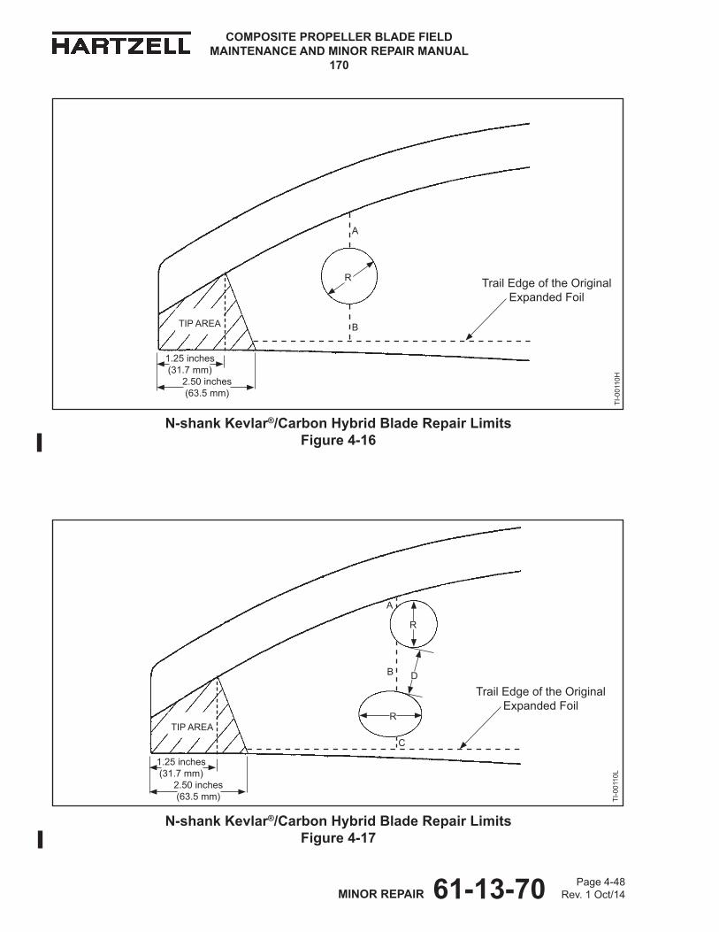
61-13-70 Page 4-48Rev. 1 Oct/14MINOR REPAIR
COMPOSITE PROPELLER BLADE FIELD MAINTENANCE AND MINOR REPAIR MANUAL
170
N-shank Kevlar®/Carbon Hybrid Blade Repair Limits Figure 4-16
N-shank Kevlar®/Carbon Hybrid Blade Repair Limits Figure 4-17
1.25 inches (31.7 mm)
2.50 inches (63.5 mm)
TIP AREA
R
B
A
1.25 inches (31.7 mm)
2.50 inches (63.5 mm)
TIP AREA
R
R
D
C
B
ATI
-001
10H
TI-0
0110
L
Trail Edge of the Original Expanded Foil
Trail Edge of the Original Expanded Foil
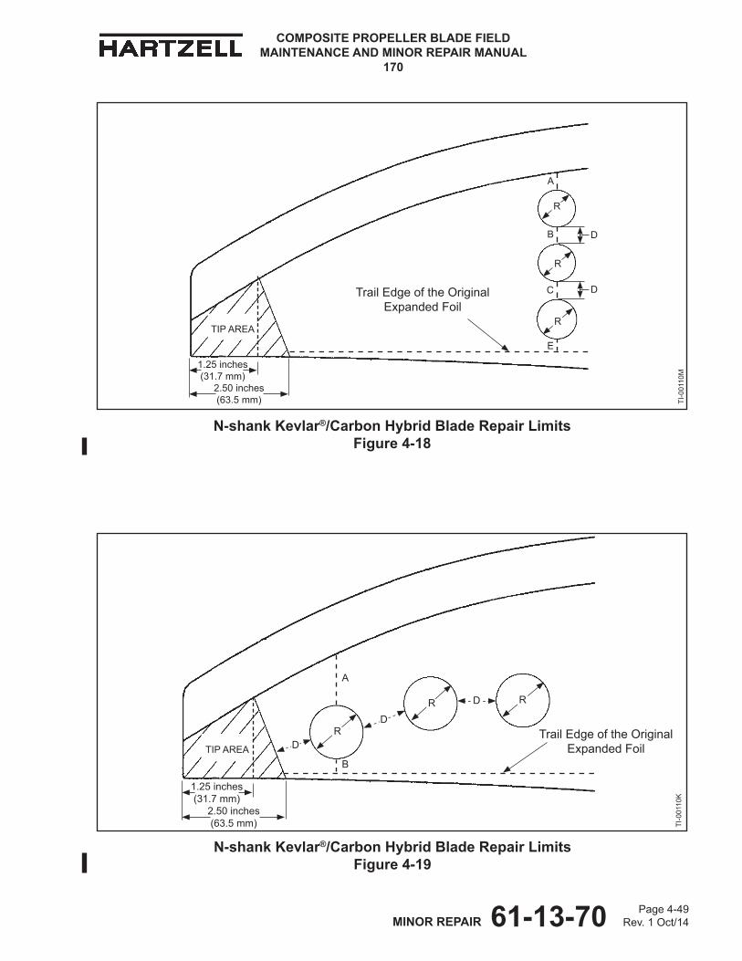
61-13-70 Page 4-49Rev. 1 Oct/14MINOR REPAIR
COMPOSITE PROPELLER BLADE FIELD MAINTENANCE AND MINOR REPAIR MANUAL
170
N-shank Kevlar®/Carbon Hybrid Blade Repair Limits Figure 4-18
N-shank Kevlar®/Carbon Hybrid Blade Repair Limits Figure 4-19
1.25 inches (31.7 mm)
2.50 inches (63.5 mm)
TIP AREA
B
A
C
E
R
R
R
D
1.25 inches (31.7 mm)
2.50 inches (63.5 mm)
TIP AREA
A
R
R RD
D
D
B
TI-0
0110
KTI
-001
10M
Trail Edge of the Original Expanded Foil
Trail Edge of the Original Expanded Foil
D
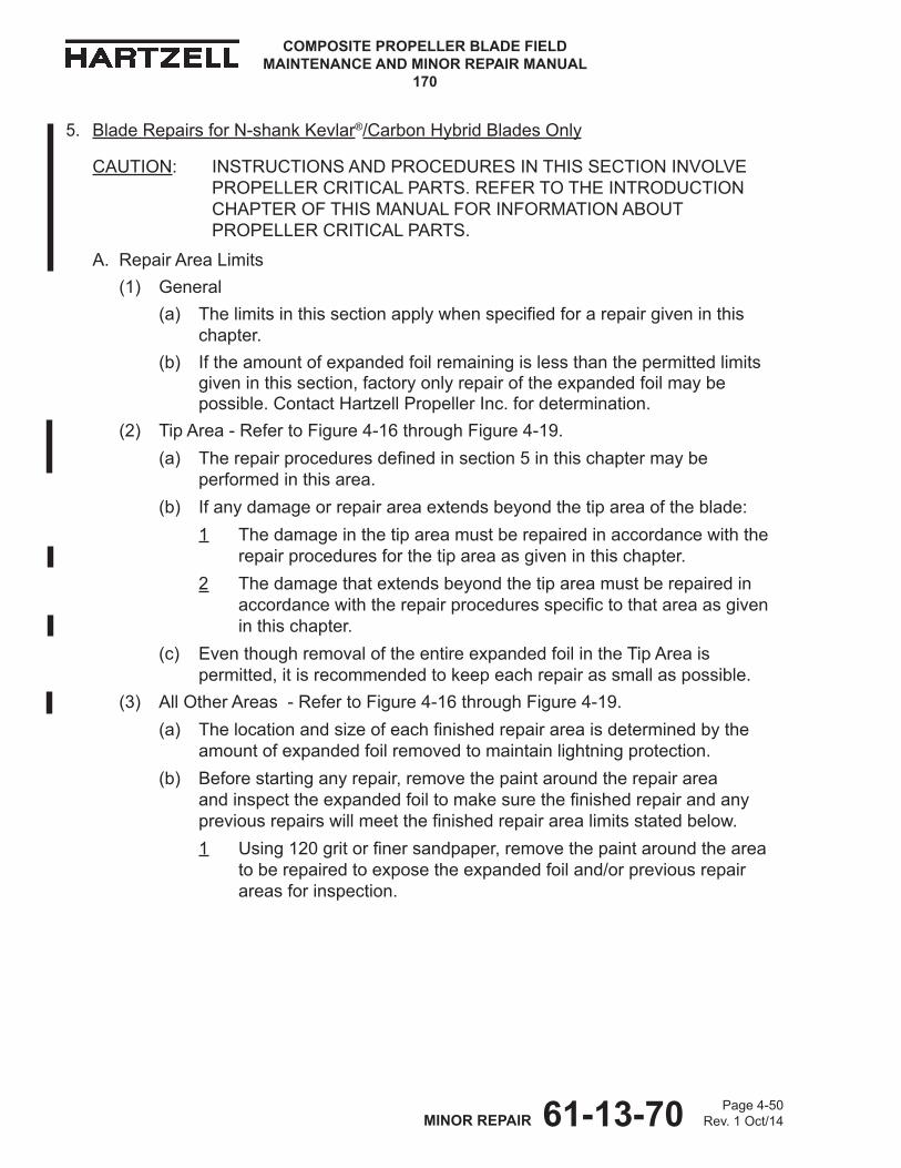
61-13-70 Page 4-50Rev. 1 Oct/14MINOR REPAIR
COMPOSITE PROPELLER BLADE FIELD MAINTENANCE AND MINOR REPAIR MANUAL
170
5. Blade Repairs for N-shank Kevlar®/Carbon Hybrid Blades Only
CAUTION: INSTRUCTIONS AND PROCEDURES IN THIS SECTION INVOLVE PROPELLER CRITICAL PARTS. REFER TO THE INTRODUCTION CHAPTER OF THIS MANUAL FOR INFORMATION ABOUT PROPELLER CRITICAL PARTS.
A. Repair Area Limits(1) General
(a) Thelimitsinthissectionapplywhenspecifiedforarepairgiveninthischapter.
(b) If the amount of expanded foil remaining is less than the permitted limits given in this section, factory only repair of the expanded foil may be possible.ContactHartzellPropellerInc.fordetermination.
(2) Tip Area - Refer to Figure 4-16 through Figure 4-19.(a) Therepairproceduresdefinedinsection5inthischaptermaybe
performed in this area.(b) If any damage or repair area extends beyond the tip area of the blade:
1 The damage in the tip area must be repaired in accordance with the repair procedures for the tip area as given in this chapter.
2 The damage that extends beyond the tip area must be repaired in accordancewiththerepairproceduresspecifictothatareaasgivenin this chapter.
(c) Even though removal of the entire expanded foil in the Tip Area is permitted, it is recommended to keep each repair as small as possible.
(3) All Other Areas - Refer to Figure 4-16 through Figure 4-19.(a) Thelocationandsizeofeachfinishedrepairareaisdeterminedbythe
amount of expanded foil removed to maintain lightning protection. (b) Before starting any repair, remove the paint around the repair area
andinspecttheexpandedfoiltomakesurethefinishedrepairandanypreviousrepairswillmeetthefinishedrepairarealimitsstatedbelow.1 Using120gritorfinersandpaper,removethepaintaroundthearea
to be repaired to expose the expanded foil and/or previous repair areas for inspection.
61-13-70 Page 4-51Rev. 1 Oct/14MINOR REPAIR
COMPOSITE PROPELLER BLADE FIELD MAINTENANCE AND MINOR REPAIR MANUAL
170
(c) Thefollowingfinishedrepairedarealimitsapply:1 Risthelargestpermitteddimensionofanyindividualfinishedrepairarea.2 R must be less than or equal to 2.75 inches (69.8 mm). 3 Disthedistancebetweentwoindividualfinishedrepairareas.4 D must be equal to or greater than R.5 After the repair is completed, there must be a minimum total of
1.60 inches (40.6 mm) measured in a straight line of original expanded foil remaining between the trail edge of the erosion shield and the trail edge of the original expanded foil at any blade section.
a Examples:
(1) In Figure 4-16 and Figure 4-19 the sum of A and B must be equal to or greater than 1.60 inches (40.6 mm).
(2) In Figure 4-17 the sum of A, B, and C must be equal to or greater than 1.60 inches (40.6 mm).
(3) In Figure 4-18 the sum of A, B, C and E must be equal to or greater than 1.60 inches (40.6 mm).
(d) Example:
1 Choosetwofinishedrepairedareas.
2 DetermineRforeachfinishedrepairedarea(mustbelessthanorequal to 2.75 inches [69.8 mm]).
3 SelectthelargestRofthetwofinishedrepairedareas.
4 DetermineDbetweenthetwoindividualfinishedrepairareas.
5 D must be equal to or greater than the largest R.
61-13-70 Page 4-52Rev. 1 Oct/14MINOR REPAIR
COMPOSITE PROPELLER BLADE FIELD MAINTENANCE AND MINOR REPAIR MANUAL
170
B. Loss of Paint and/or Filler Material
(1) General
(a) This repair may be performed in accordance with the airworthy damagelimitsandtheminorrepairlimitsspecifiedintheRepairLimitschapter of this manual.
(2) Repair Procedure
(a) Using120gritorfinersandpaper,removethepaintandexposetheentirearea to be repaired.
1 Feather the area into the non-repair area of the blade.
CAUTION: DO NOT SAND THROUGH THE MESH MATERIAL. USE EXTREME CARE WHEN SANDING DOWN TO THE BLADE SURFACE. AN N-SHANK COMPOSITE BLADE HAS ALUMINUM MESH ON THE BLADE SURFACE THAT FORMS PART OF THE LIGHTNING PROTECTION SYSTEM.
(b) Ifthedamagedareastillcontainsfillermaterial,continuetosandtheareausing120gritorfinersandpaperuntilallfillermaterialanddamagedmaterial is removed.
WARNING: ADHESIVES AND SOLVENTS ARE FLAMMABLE AND TOXIC TO THE SKIN, EYES, AND RESPIRATORY TRACT. SKIN AND EYE PROTECTION ARE REQUIRED. AVOID PROLONGED CONTACT AND BREATHING OF VAPORS. USE SOLVENT RESISTANT GLOVES TO MINIMIzE SKIN CONTACT AND WEAR SAFETY GLASSES FOR EYE PROTECTION. USE IN A WELL VENTILATED AREA AWAY FROM SPARKS AND FLAME. READ AND OBSERVE ALL WARNING LABELS.
(c) Using cheesecloth CM159 or equivalent, dampened with solvent acetone CM173, MEK CM106, or MPK CM219, thoroughly wipe the area.
(d) Permit the solvent acetone CM173, MEK CM106, or MPK CM219 to dry.
(e) Apply wash primer Mix Number 3 to the exposed erosion shield in accordancewiththePaintandFinishchapterofHartzellPropellerInc.Standard Practices Manual 202A (61-01-02).
(f) Permit the wash primer Mix Number 3 to dry.
(g) In a container that is free from contamination, mix adhesive CM14 or CM15 in accordance with the manufacturer's instructions.
(h) UsingadhesiveCM14orCM15,laminateenoughfiberglassfabricCM42in individual layers to permit sanding the repair area down to the original airfoil shape.
(i) Permit the adhesive CM14 or CM15 to dry.
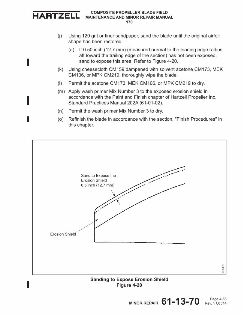
61-13-70 Page 4-53Rev. 1 Oct/14MINOR REPAIR
COMPOSITE PROPELLER BLADE FIELD MAINTENANCE AND MINOR REPAIR MANUAL
170
(j) Using120gritorfinersandpaper,sandthebladeuntiltheoriginalairfoilshape has been restored.
(a) If 0.50 inch (12.7 mm) (measured normal to the leading edge radius aft toward the trailing edge of the section) has not been exposed, sand to expose this area. Refer to Figure 4-20.
(k) Using cheesecloth CM159 dampened with solvent acetone CM173, MEK CM106, or MPK CM219, thoroughly wipe the blade.
(l) Permit the acetone CM173, MEK CM106, or MPK CM219 to dry.
(m) Apply wash primer Mix Number 3 to the exposed erosion shield in accordancewiththePaintandFinishchapterofHartzellPropellerInc.Standard Practices Manual 202A (61-01-02).
(n) Permit the wash primer Mix Number 3 to dry.
(o) Refinishthebladeinaccordancewiththesection,"FinishProcedures"inthis chapter.
Sanding to Expose Erosion Shield Figure 4-20
Sand to Expose the Erosion Shield 0.5 inch (12.7 mm)
TI-0
0076
Erosion Shield

61-13-70 Page 4-54Rev. 1 Oct/14MINOR REPAIR
COMPOSITE PROPELLER BLADE FIELD MAINTENANCE AND MINOR REPAIR MANUAL
170
C. Gouges, Delaminations, or Loss of Composite Material
(1) General
(a) This repair may be performed in accordance with the airworthy damagelimitsandtheminorrepairlimitsspecifiedintheRepairLimitschapter of this manual.
(2) Procedure
(a) Using a grinder or sander, remove material to create a bevel that extends outward from the repair area 0.50 inch (12.7 mm) for each 0.010 inch (0.254 mm) in depth. Refer to Figure 4-21.
1 If the bevel extends into the leading edge, the erosion shield must be removed to complete the repair.
a Replacement of the erosion shield is a major repair performed at overhaul.
2 For repaired area limits, refer to the section "Repair Area Limits" for N-shank blades in this chapter.
Material Layers of the N-shank Kevlar®/Carbon Hybrid Blade Figure 4-21
Fiberglass Fabric CM42
E-glass CM55
E-glass CM55
Carbon Layer of the Blade
Kevlar® Layerof the Blade
E-glass CM55 Layerof the Blade
Sanded Bevel for Repair
61-13-70 Page 4-55Rev. 1 Oct/14MINOR REPAIR
COMPOSITE PROPELLER BLADE FIELD MAINTENANCE AND MINOR REPAIR MANUAL
170
WARNING: ADHESIVES AND SOLVENTS ARE FLAMMABLE AND TOXIC TO THE SKIN, EYES, AND RESPIRATORY TRACT. SKIN AND EYE PROTECTION ARE REQUIRED. AVOID PROLONGED CONTACT AND BREATHING OF VAPORS. USE SOLVENT RESISTANT GLOVES TO MINIMIzE SKIN CONTACT AND WEAR SAFETY GLASSES FOR EYE PROTECTION. USE IN A WELL VENTILATED AREA AWAY FROM SPARKS AND FLAME. READ AND OBSERVE ALL WARNING LABELS.
(b) Using solvent acetone CM173, MEK CM106, or MPK CM219, clean the area.
(c) Permit the solvent acetone CM173, MEK CM106, or MPK CM219 to dry.(d) Determine the number of layers of E-glass CM55 needed for the repair,
based on the depth of the damage. 1 The maximum permitted number of layers of E-glass CM55 that may
be used is two.2 Each cured layer of E-glass CM55 is 0.0085 inch (0.215 mm) thick. 3 Cut layers of E-glass CM55 to match the shape of the beveled area
to create a stair step pattern when laminating. Refer to Figure 4-21.a Cut each layer at a ± 45 degree angle relative to the blade pitch
axis.(e) In a container that is free from contamination, mix adhesive CM14 or
CM15 in accordance with the manufacturer's instructions.(f) Using adhesive CM14 or CM15, laminate one or two layers of E-glass
CM55. (g) Using adhesive CM14 or CM15, laminate an additional layer(s) of
fiberglassfabricCM42overtheentirerepairareatoachievetheoriginalairfoil shape and to aid in the transition.NOTE: This layer(s) helps blend the layers and most of it may be
sanded away.(3) Cure the repair in accordance with the Curing Procedures section in this
chapter.
61-13-70 Page 4-56Rev. 1 Oct/14MINOR REPAIR
COMPOSITE PROPELLER BLADE FIELD MAINTENANCE AND MINOR REPAIR MANUAL
170
(4) After Curing(a) Using no coarser than 60 grit sandpaper, sand the repaired area to the
original airfoil shape.(b) Make a visual inspection of the repaired area.
1 Repair any delaminations or voids.
(c) Perform a "Coin-Tap Inspection" of the repaired area in accordance with the Inspection Procedures chapter of this manual. 1 Delaminations or voids are not permitted.2 Iftheareaofrepairisnotwithinthelimitsspecified,repairin
accordance with the applicable repair instructions.3 Repeat the inspections and repair until the repair is satisfactory.
(d) Makeaninspectionofthefinishedrepairedareainaccordancewiththesection "Repair Area Limits" for N-shank blades.
(e) Refinishthebladeinaccordancewiththesection,"FinishProcedures"inthis chapter.
61-13-70 Page 4-57Rev. 1 Oct/14MINOR REPAIR
COMPOSITE PROPELLER BLADE FIELD MAINTENANCE AND MINOR REPAIR MANUAL
170
D. Crushed or Cracked Trailing Edge - Tip Region of the Blade
(1) General(a) This repair may be performed in accordance with the airworthy
damagelimitsandtheminorrepairlimitsspecifiedintheRepairLimitschapter of this manual.
(2) Repair Procedure(a) Using a grinder or sander, remove loose surface material.
1 Some of the blade material, even though damaged, may remain on the blade. a If damaged material is fully intact, it should remain on the blade. NOTE: If more than one layer remains on the blade, but the layers
are separated from each other, adhesive CM14 or CM15 will be injected between these layers when the repair is made.
(b) Using a grinder or sander, remove material to create a bevel that extends outward from the repair area 0.500 inch (12.7 mm) for each 0.010 inch (0.254 mm) in depth on each side of the blade. Refer to Figure 4-21.
1 If the bevel extends into the leading edge, the erosion shield must be removed to complete the repair.a Replacement of the erosion shield is a major repair performed at
overhaul.2 For repaired area limits, refer to the section "Repair Area Limits" for
N-shank blades in this chapter.
WARNING: ADHESIVES AND SOLVENTS ARE FLAMMABLE AND TOXIC TO THE SKIN, EYES, AND RESPIRATORY TRACT. SKIN AND EYE PROTECTION ARE REQUIRED. AVOID PROLONGED CONTACT AND BREATHING OF VAPORS. USE SOLVENT RESISTANT GLOVES TO MINIMIzE SKIN CONTACT AND WEAR SAFETY GLASSES FOR EYE PROTECTION. USE IN A WELL VENTILATED AREA AWAY FROM SPARKS AND FLAME. READ AND OBSERVE ALL WARNING LABELS.
(c) Using solvent acetone CM173, MEK CM106, or MPK CM219, wipe the repair area.
(d) Permit the solvent acetone CM173, MEK CM106, or MPK CM219 to dry.
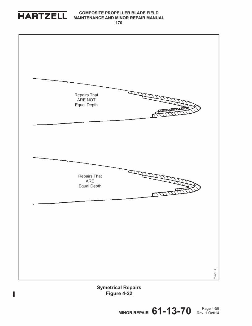
61-13-70 Page 4-58Rev. 1 Oct/14MINOR REPAIR
COMPOSITE PROPELLER BLADE FIELD MAINTENANCE AND MINOR REPAIR MANUAL
170
Symetrical Repairs Figure 4-22
TI-0
0113
Repairs That ARE
Equal Depth
Repairs That ARE NOT
Equal Depth
61-13-70 Page 4-59Rev. 1 Oct/14MINOR REPAIR
COMPOSITE PROPELLER BLADE FIELD MAINTENANCE AND MINOR REPAIR MANUAL
170
(e) Determine the number of layers of E-glass CM55 needed for each side of the repair, based on the depth of the damage.
1 In areas where the depth of repairs on both sides is equal, the repair materials may be folded to both sides of the blade. Refer to Figure 4-22.
2 In areas where the depth of repairs on both sides is not equal, use additional layers(s) on the deeper side, then the repair materials may be folded to both sides of the blade. Refer to Figure 4-22.
3 The maximum permitted number of layers of E-glass CM55 that may be used on each side is three.
4 Each cured layer of E-glass CM55 is 0.0085 inch (0.215 mm) thick. 5 Cut each layer of E-glass CM55 at a ± 45 degree angle relative to the
blade pitch axis to match the shape of the beveled area to create a stair step pattern when laminating. Refer to Figure 4-22.
(f) In a container that is free from contamination, mix adhesive CM14 or CM15 in accordance with the manufacturer's directions.
(g) If applicable, inject adhesive CM14 or CM15 with a syringe CM3, or equivalent, between all the layers of the original material remaining in the damaged area.
(h) Put the previously cut E-glass CM55 layers on the repair area.
(a) Using adhesive CM14 or CM15, saturate each layer of E-glass CM55 after it is applied to the repair area.
(i) UsingadhesiveCM14orCM15,putlayer(s)offiberglassfabricCM42overthe entire repair area to achieve the original airfoil shape and to aid in the transition.
NOTE: ThefiberglassfabricCM42helpstoblendthelayersandmostof it may be sanded away.
(3) Cure the repair in accordance with the Curing Procedures section in this chapter.

61-13-70 Page 4-60Rev. 1 Oct/14MINOR REPAIR
COMPOSITE PROPELLER BLADE FIELD MAINTENANCE AND MINOR REPAIR MANUAL
170
(4) After Curing
(a) Using no coarser than 60 grit sandpaper, sand or grind to the original airfoil shape. Refer to Figure 4-13 G.
(b) Make a visual inspection of the repaired area. Repair any delaminations or voids.
(c) Perform a "Coin-Tap Inspection" of the repaired area in accordance with the Inspection Procedures chapter of this manual.
1 Delaminations or voids are not permitted.
2 Iftheareaofrepairisnotwithinthelimitsspecified,repairinaccordance with the applicable repair instructions.
3 Repeat the inspections and repair as necessary until the repair is satisfactory.
(d) Inspectthefinishedrepairedareainaccordancewiththesection"RepairArea Limits" for N-shank blades in this chapter.
(e) Refinishthebladeinaccordancewiththesection,"FinishProcedures"inthis chapter.
61-13-70 Page 4-61Rev. 1 Oct/14MINOR REPAIR
COMPOSITE PROPELLER BLADE FIELD MAINTENANCE AND MINOR REPAIR MANUAL
170
E. Crushed or Cracked Trailing Edge Foam Region of the Blade
(1) General(a) This repair may be performed in accordance with the airworthy
damagelimitsandtheminorrepairlimitsspecifiedintheRepairLimitschapter of this manual.
(b) If foam is missing within the repair area, small pieces of E-glass CM55 will be used to replace the missing foam.
(2) Procedure
CAUTION: USE CARE WHEN GRINDING TO REMOVE MATERIAL. GRINDING MAY CAUSE DAMAGE BEYOND THE SERVICEABLE LIMITS.
NOTE: It is recommended to use 180 grit sandpaper or equivalent when removing material in and around the damaged area.
(a) Using a customer supplied small angle grinder or equivalent, remove damaged material, including damaged foam, on the camber side and face side of the blade, approximately 0.5 inch (13 mm) around the damaged area.
(b) Using a grinder or sander, remove damaged composite material to create a bevel in the area to be repaired.
1 While removing material, make a bevel that extends outward from the repair area 0.25 to 0.75 inch (6.3 to 19.0 mm) for each 0.010 inch (0.254 mm) in depth on each side of the blade. Refer to Figure 4-21.
2 Stop periodically and examine the progress.
NOTE: Wiping the area with a clean cloth CM159 or equivalent dampened with solvent acetone CM173, MEK CM106, or MPKCM219canhelptovisuallyfindthedefect.
3 For repaired area limits, refer to the section "Repair Area Limits" for N-shank blades in this chapter.
4 Stopremovingmaterialwhenthedamagehasbeensufficientlyremoved or the minor repair limit has been reached.
(c) After removing material, examine the repair area.
1 The remaining layers must be fully bonded.
2 If damaged material remains after reaching the minor repair limit, sendthebladetoHartzellPropellerInc.forfactoryonlyrepair.
3 Perform a "Coin-Tap Inspection" of the repaired area in accordance with the Inspection Procedures chapter of this manual.
a If the results of the coin-tap inspection are not satisfactory, send thebladetoHartzellPropellerInc.forfactoryonlyrepair.
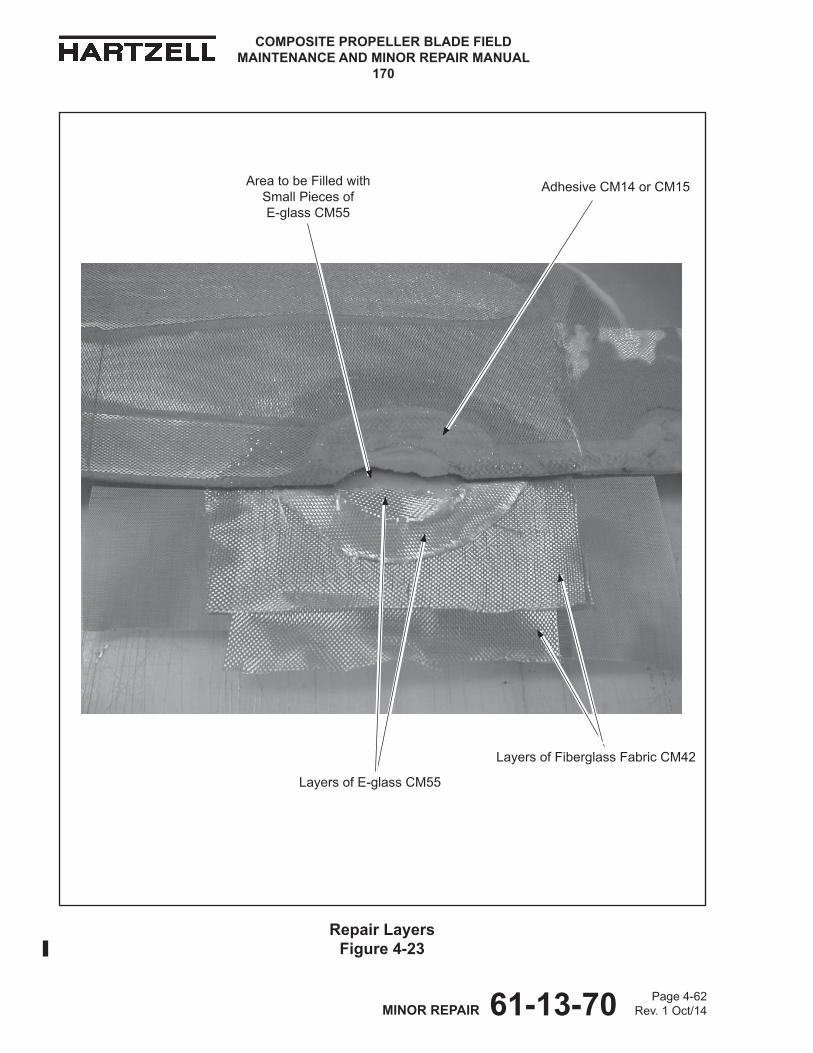
61-13-70 Page 4-62Rev. 1 Oct/14MINOR REPAIR
COMPOSITE PROPELLER BLADE FIELD MAINTENANCE AND MINOR REPAIR MANUAL
170
Repair Layers Figure 4-23
Layers of Fiberglass Fabric CM42
Adhesive CM14 or CM15
Layers of E-glass CM55
Area to be Filled with Small Pieces of E-glass CM55
61-13-70 Page 4-63Rev. 1 Oct/14MINOR REPAIR
COMPOSITE PROPELLER BLADE FIELD MAINTENANCE AND MINOR REPAIR MANUAL
170
WARNING: ADHESIVES AND SOLVENTS ARE FLAMMABLE AND TOXIC TO THE SKIN, EYES, AND RESPIRATORY TRACT. SKIN AND EYE PROTECTION ARE REQUIRED. AVOID PROLONGED CONTACT AND BREATHING OF VAPORS. USE SOLVENT RESISTANT GLOVES TO MINIMIzE SKIN CONTACT AND WEAR SAFETY GLASSES FOR EYE PROTECTION. USE IN A WELL VENTILATED AREA AWAY FROM SPARKS AND FLAME. READ AND OBSERVE ALL WARNING LABELS.
(d) Using a cloth saturated with solvent acetone CM173, MEK CM106, or MPK CM219, wipe the repair area.
(e) Permit the solvent acetone CM173, MEK CM106, or MPK CM219 to dry.
(f) CutlayersofE-glassCM55andfiberglassfabricCM42.RefertoFigure4-23.
1 Cut layers of E-glass CM55.
a Cut each layer at a 45 degree angle relative to the blade pitch axis to match the shape of the beveled area to create a stair step pattern when laminating. Refer to Figure 4-22.
b Cut each layer large enough to cover the repair area on one side of the blade and to wrap around the trail edge of the blade and cover the repair area on the opposite side of the blade.
2 CutlayersoffiberglassfabricCM42largeenoughtocovertherepairarea on one side of the blade and to wrap around the trail edge of the blade and cover the repair area on the opposite side of the blade.
(g) In a container free from contamination, mix adhesive CM14 or CM15 in accordance with the manufacturer's instructions.
(h) On one side of the blade, apply adhesive CM14 or CM15 to the repair area.
(i) Put layers of the precut E-glass CM55 in the repair area and align the layerstofitwithintherepairareaadjacenttothefoamsurfaceandtheKevlar® surface. Refer to Figure 4-23.
1 Using adhesive CM14 or CM15, saturate each layer of E-glass CM55 after it is applied to the repair area.
2 Use the layers of precut E-glass CM55 that were cut to wrap around the trail edge of the blade and cover the opposite side of the repair area, but do not wrap the layers around the blade at this time.
61-13-70 Page 4-64Rev. 1 Oct/14MINOR REPAIR
COMPOSITE PROPELLER BLADE FIELD MAINTENANCE AND MINOR REPAIR MANUAL
170
(j) Applylayer(s)ofprecutfiberglassfabricCM42overtheentirerepairareato achieve the original airfoil shape, but do not wrap the layer(s) around to the other side of the blade at this time. Refer to Figure 4-23.
NOTE: ThefiberglassfabricCM42helpstoblendthelayersandmostof it may be sanded away.
1 UsingadhesiveCM14orCM15,saturatethefiberglassfabricCM42.
(k) Holdingallofthelayersfirmlyinplace,carefullyturnthebladeovertotheother side.
NOTE: Holdingortemporarilytapingaflatplateoverthelayerswillhelphold the layers in place when turning the blade.
(l) UsingverysmallpiecesofE-glassCM55,fillintheareawherethefoamismissing. Refer to Figure 4-23.
1 Using adhesive CM14 or CM15, saturate the E-glass CM55 that was usedtofillintheareawherethefoamismissingandtheentirerepairarea.
(m) Wrap E-glass CM55 from the other side of the blade around the blade and apply to the repair area on this side of the blade.
1 AligneachlayerofE-glassCM55tofitwithintherepairareaadjacentto the foam surface and the Kevlar® surface.
2 Using adhesive CM14 or CM15, saturate each layer of E-glass CM55 after it is applied to the repair area.
(n) WrapthefiberglassfabricCM42fromtheothersideofthebladearoundthe blade and over the entire repair area to achieve the original airfoil shape.
1 UsingadhesiveCM14orCM15,saturatethefiberglassfabricCM42.
CAUTION: DO NOT USE OPTION NO. 2, BLADE REPAIR BLANKET CURE WHEN CURING A TRAILING EDGE FOAM REPAIR.
(3) Cure the repair in accordance with the Curing Procedures section in this chapter.
61-13-70 Page 4-65Rev. 1 Oct/14MINOR REPAIR
COMPOSITE PROPELLER BLADE FIELD MAINTENANCE AND MINOR REPAIR MANUAL
170
(4) After Curing
(a) Using no coarser than 60 grit sandpaper, sand or grind to the original airfoil shape. Refer to Figure 4-13 G.
(b) Make a visual inspection of the repaired area.
(c) Repair any delaminations or voids.
(d) Perform a "Coin-Tap Inspection" of the repaired area in accordance with the Inspection Procedures chapter of this manual.
1 Delaminations or voids are not permitted.
2 Iftheareaofrepairisnotwithinthelimitsspecified,repairinaccordance with the applicable repair instructions.
3 Repeat the inspections and repair until the repair is satisfactory.
(e) Inspectthefinishedrepairedareainaccordancewiththesection"RepairArea Limits" for N-shank blades in this chapter.
(f) Refinishthebladeinaccordancewiththesection,"FinishProcedures"inthis chapter.

61-13-70 Page 4-66Rev. 1 Oct/14MINOR REPAIR
COMPOSITE PROPELLER BLADE FIELD MAINTENANCE AND MINOR REPAIR MANUAL
170
F. Split Trailing Edge(1) General
(a) This repair may be performed in accordance with the airworthy damagelimitsandtheminorrepairlimitsspecifiedintheRepairLimitschapter of this manual.
(2) Procedure(a) Using a clean tongue depressor, utility knife, or other similar tool, gently
pry apart the split edge and remove any contaminates.
WARNING: ADHESIVES AND SOLVENTS ARE FLAMMABLE AND TOXIC TO THE SKIN, EYES, AND RESPIRATORY TRACT. SKIN AND EYE PROTECTION ARE REQUIRED. AVOID PROLONGED CONTACT AND BREATHING OF VAPORS. USE SOLVENT RESISTANT GLOVES TO MINIMIzE SKIN CONTACT AND WEAR SAFETY GLASSES FOR EYE PROTECTION. USE IN A WELL VENTILATED AREA AWAY FROM SPARKS AND FLAME. READ AND OBSERVE ALL WARNING LABELS.
(b) Using a clean cloth CM159 or equivalent dampened with solvent acetone CM173, MEK CM106, or MPK CM219, wipe the repair area.
CAUTION: MAKE SURE THAT THE SOLVENT IS DRY BETWEEN THE COMPOSITE MATERIAL LAYERS, IF APPLICABLE.
(c) Permit the solvent acetone CM173, MEK CM106, or MPK CM219 to dry. 1 Additional drying time may be needed for solvent acetone CM173,
MEK CM106, or MPK CM219 that is between the composite layers.
(d) In a container that is free from contamination, mix adhesive CM14 or CM15 in accordance with the manufacturer's instructions.
(e) Using adhesive CM14 or CM15 in a syringe CM3, inject as much adhesive as possible in the split, making sure of coverage of the entire surface.1 Alternately, push the adhesive CM14 or CM15 into the split using a
clean,flattool.
(f) Cure the repair in accordance with the Curing Procedures section in this chapter.
(g) Sand the repair.
CAUTION: DO NOT REMOVE ORIGINAL BLADE MATERIAL WHEN SANDING.
1 Using no coarser than 60 grit sandpaper, sand to remove excess adhesiveCM14orCM15andfiberglassfabricCM42ifapplicable.
a Afterthefinalsanding,theblademusthaveasmoothsurface.
61-13-70 Page 4-67Rev. 1 Oct/14MINOR REPAIR
COMPOSITE PROPELLER BLADE FIELD MAINTENANCE AND MINOR REPAIR MANUAL
170
(h) Visually examine the repaired area to make sure that it is the original airfoil shape.
1 Iftheoriginalairfoilshapeisnotachieved,sendthebladetoHartzellPropeller Inc. for factory only repair.
(i) Perform a "Coin-Tap Inspection" of the repaired area in accordance with the Inspection Procedures chapter of this manual.
a Delaminations or voids are not permitted.
b Iftheareaofrepairisnotwithinthelimitsspecified,repairinaccordance with the applicable repair instructions.
c Repeat the inspections and repair as necessary until the repair is satisfactory.
(j) Make an inspection of the repaired area in accordance with the section, "Repair Area Limits" for N-shank blades in this chapter.
(k) Refinishthebladeinaccordancewiththesection,"FinishProcedures"inthis chapter.
6. Curing Procedures
A. Cure of Trailing Edge Repairs
(1) General
CAUTION: DO NOT USE CURE OPTION 2 FOR CURING A TRAILING EDGE FOAM REPAIR.
(a) There are two options for curing the repair.
1 Cure Option 1 uses a room temperature or oven cure cycle for curing the repair.
a Plates and clamps are used to apply even pressure to the repaired area.
2 Cure Option 2 uses a blade repair blanket TE304 that supplies heat for accelerated curing of the repair.
a The blade repair blanket TE304 and clamps are used to apply even pressure to the repaired area.
(2) Preparing the Repaired Area for Curing
(a) Optionally,useTeflon® bleeder cloth CM58 and polyester absorbent cloth CM59.
NOTE: UsingtheTeflon® bleeder cloth CM58 and polyester absorbent clothCM59willabsorbexcessresin,minimizesanding,andmake clean-up easier.
61-13-70 Page 4-68Rev. 1 Oct/14MINOR REPAIR
COMPOSITE PROPELLER BLADE FIELD MAINTENANCE AND MINOR REPAIR MANUAL
170
1 CutapieceofTeflon® bleeder cloth CM58 large enough to cover and extend beyond the repaired area on one side of the blade and fold over to cover and extend beyond the repaired area on the other side of the blade.
NOTE: MakingtheTeflon® bleeder cloth CM58 approximately 1 inch (25.4 mm) larger than the repaired area will prevent sticking of the vacuum bagging material to the repaired area.
2 PutthepieceofTeflon® bleeder cloth CM58 over the repaired area on one side of the blade and fold it over to cover the repaired area on the other side of the blade.
a If necessary to hold in place, apply tape to the edges of the Teflon® bleeder cloth CM58 outside of the repaired area.
3 Cut a piece of polyester absorbent cloth CM59 large enough to cover the repaired area on one side of the blade and fold over to cover the repaired area on the other side of the blade.
NOTE: Making the polyester absorbent cloth CM59 slightly smallerthantheTeflon® bleeder cloth CM58 will reduce the sanding needed.
4 PutthepieceofpolyesterabsorbentclothCM59overtheTeflon® bleeder cloth CM58 in the repaired area on one side of the blade and fold it over to cover the repaired area on the other side of the blade.
a If necessary to hold in place, apply tape to the edges of the polyester absorbent cloth CM59 outside of the repaired area.
(b) Cut a piece of vacuum bag material CM45 large enough to cover the entire repaired area on one side of the blade and fold over to cover the repaired area on the other side of the blade.
(c) Put the piece of vacuum bag material CM45 on the repaired area on one side of the blade and fold it over to cover the repaired area on the other side of the blade.
1 If necessary to hold in place, apply tape to the edges of the vacuum bag material CM45 outside of the repaired area.
61-13-70 Page 4-69Rev. 1 Oct/14MINOR REPAIR
COMPOSITE PROPELLER BLADE FIELD MAINTENANCE AND MINOR REPAIR MANUAL
170
(3) Curing the Repair
(a) Cure Option 1, Room Temperature Cure
1 Prepare two semi-rigid plates to clamp over the repaired area.
a Make the plates from metal, plastic, Masonite®, or other semi-rigid material.
b Make one plate long enough so that when the plates are clamped on the blade, the plates will extend beyond the repaired area.
c When the repair is to a curved area of the blade, a layer of compressive material, such as foam rubber, may be used between the repair area and the plate to help apply uniform pressure when curing the repaired area.
2 Put one plate over the repaired area on each side of the blade.
a If necessary to hold in place, apply tape to the plate outside of the repaired area.
CAUTION: EXCESSIVE CLAMP FORCE WILL DAMAGE THE BLADE. SECURE THE PLATE TO THE BLADE WITH MINIMAL FORCE.
3 Install clamps as necessary to apply even pressure to the repaired area.
4 Permit the adhesive to cure for 12 hours at room temperature or for 2 hours at 145° ± 5° F (63° ± 2° C).
5 Remove the plates and the cure materials from the blade.
CAUTION: DO NOT USE CURE OPTION 2 FOR CURING A TRAILING EDGE FOAM REPAIR.
(b) Cure Option 2, Blade Repair Blanket Cure
CAUTION: DO NOT PUT THE TEMPERATURE INDICATING STRIPS DIRECTLY ON TOP OF THE REPAIR .
1 Put two temperature indicating strips, one each of TE306 and TE307, on each side of the blade adjacent to the repair area to monitor the temperature during the cure cycle.
a One strip TE306 has a temperature range of 120° to 180° F.
b The second strip TE307 has a temperature range of 190° to 220° F.
61-13-70 Page 4-70Rev. 1 Oct/14MINOR REPAIR
COMPOSITE PROPELLER BLADE FIELD MAINTENANCE AND MINOR REPAIR MANUAL
170
c Monitoring of the temperature of both sides of the blade is necessary because the blade repair blanket TE304 is constructed with two heating elements, one for each side of the blade.
(1) Each element is independently controlled by a nonadjustable controller contained within the blade repair blanket TE304.
2 Cut a piece of vacuum bag material that is large enough to prevent adhesive from getting on the blade repair blanket TE304 when it is applied.
a Put the piece of vacuum bag material CM45 over the blade.
CAUTION: DO NOT LET THE HINGE OF THE BLADE REPAIR BLANKET TE304 CRUSH THE LAMINATED COMPOSITE MATERIALS OF THE REPAIR .
3 Put the blade repair blanket TE304 on the trailing edge of the blade, centered over the repair, making sure that the hinge of the blade repair blanket does not crush the laminated composite materials.
4 Put a minimum of two C-clamps on the metal strip of the blade repair blanket TE304, in such a way that the clamping pressure is distributed over the entire repaired area.
WARNING: DO NOT OPERATE THE BLADE REPAIR BLANKET TE304 IN A WET ENVIRONMENT OR ON A WET BLADE. DOING SO MAY CREATE AN ELECTRICAL HAzARD.
5 Connect the blade repair blanket TE304 to a 120 volt power source for a minimum of 130 minutes.
NOTE: The minimum time includes 2 hours for curing plus 10 minutes to permit the blade repair blanket to warm to the correct temperature.
6 Unplug the blade repair blanket TE304.
7 Remove the blade repair blanket TE304 and the repair hardware from the blade.
61-13-70 Page 4-71Rev. 1 Oct/14MINOR REPAIR
COMPOSITE PROPELLER BLADE FIELD MAINTENANCE AND MINOR REPAIR MANUAL
170
8 Examine the readings of the temperature indicating strips TE306 and TE307.
a The temperature readings must be greater than 120° F and less than 180° F.
NOTE: Temperature indicating strips consist of four silver/white dots.Eachdotisidentifiedwiththetemperatureatwhichitwill turn black. When examining the temperature indicating strips, after removal of the blade repair blanket TE304, the "120° F" dot must be black while the "180° F" through the "220° F" dots must be white. The colors of the "140° F" and "160° F" dots do not matter.
b If the indicated temperature is below 120° F, inadequate heating occurred. Permit the repair to cure 12 hours at room temperature.
c If the indicated temperature is above 180° F, the composite materialmaybedamaged.RetirethebladeorcontactHartzellPropeller Inc. to arrange for evaluation.
(4) After cure, return to applicable repair procedure for additional requirements.
B. Cure of Surface Repairs (excludes trailing edge repairs)
(1) Procedure for Curing a Blade Surface Repair - Clamping Method
(a) Optionally,Teflon® bleeder cloth CM58 and polyester absorbent cloth CM59 may be used.
NOTE: UsingtheTeflon® bleeder cloth CM58 and polyester absorbent clothCM59willabsorbexcessresin,minimizesanding,andmake clean up easier.
1 PutthepieceofTeflon® bleeder cloth CM58 over the repaired area.
NOTE: MakingtheTeflon® bleeder cloth CM58 approximately 1 inch (25.4 mm) larger than the repaired area will prevent sticking of the vacuum bagging material to the repaired area.
a If necessary to hold in place, apply tape to the edges of the Teflon® bleeder cloth CM58 outside of the repaired area.
2 PutapieceofpolyesterabsorbentclothCM59overtheTeflon® bleeder cloth CM58 in the repaired area.
NOTE: Making the polyester absorbent cloth CM59 slightly smallerthantheTeflon® bleeder cloth CM58 will reduce the sanding needed.
a If necessary to hold in place, apply tape to the edges of the polyester absorbent cloth CM59 outside of the repaired area.
61-13-70 Page 4-72Rev. 1 Oct/14MINOR REPAIR
COMPOSITE PROPELLER BLADE FIELD MAINTENANCE AND MINOR REPAIR MANUAL
170
(b) Cut a piece of vacuum bag material CM45 large enough to cover the entire repaired area.
(c) Put the piece of vacuum bag material CM45 on the repaired area.
(d) Prepare two semi-rigid plates to clamp over the repaired area.
1 Make the plates from metal, plastic, Masonite®, or other semi-rigid material.
2 Make one plate long enough so that when the plates are clamped on the blade, the plates will extend beyond the repaired area.
3 When the repair is to a curved area of the blade, a layer of compressive material, such as foam rubber, may be used between the repair area and the plate to help apply uniform pressure when curing the repaired area.
(e) Put one plate over the repaired area and the other plate on the other side of the blade.
1 If necessary to hold in place, apply tape to the plate.
CAUTION: EXCESSIVE CLAMP FORCE WILL DAMAGE THE BLADE. SECURE THE PLATE TO THE BLADE WITH MINIMAL FORCE.
2 Install clamps as necessary to apply even pressure to the repaired area.
3 Permit the adhesive to cure for 12 hours at room temperature or for 2 hours at 145° ± 5° F (63° ± 2° C).
4 Remove the plates and the cure materials from the blade.
(2) After cure, return to applicable repair procedure for additional requirements.
61-13-70 Page 4-73Rev. 1 Oct/14MINOR REPAIR
COMPOSITE PROPELLER BLADE FIELD MAINTENANCE AND MINOR REPAIR MANUAL
170
7. Finish Procedures
CAUTION: INSTRUCTIONS AND PROCEDURES IN THIS SECTION INVOLVE PROPELLER CRITICAL PARTS. REFER TO THE INTRODUCTION CHAPTER OF THIS MANUAL FOR INFORMATION ABOUT PROPELLER CRITICAL PARTS.
NOTE: SpecificHartzellPropellerInc.manualsandservicedocumentsareavailableontheHartzellwebsiteatwww.hartzellprop.com.RefertotheRequiredPublications section in the Introduction chapter of this manual for the identificationofthesepublications.
A. Paint
(1) Propellerbladesarepaintedwithadurablespecializedcoatingthatisresistantto abrasion. If this coating becomes eroded, it is necessary to repaint the blades to provide proper corrosion and erosion protection.
(2) Polane®finishcoatingisamoredurablecoatingthantheaerosolfinishcoating.However,theaerosolfinishcoatingisaquickerprocessandisanacceptableoptionforfieldrepairsgiventimeandlocationconstraints.
(a) Regardlessofthefinishoption,washprimerMixNumber3isneededforgood paint adhesion to the erosion shield.
1 Wash primer Mix Number 3 is required for use with the Polane finish option when refinishing any portion of the erosion shield.
2 Wash primer Mix Number 3 is not required for use with the aerosol finish option.
3 When applying wash primer Mixture Number 3, do so in accordance with the section, "Mixtures" in the Tooling and Materials chapter in this manual.
(b) If the Polane® finish coat is preferred, contact one of the following:
1 Anauthorizedpropellerrepairfacilitytocompletethefinishprocedure.
2 HartzellPropellerInc.ProductSupportfortheapplicableprocedureinformationfromHartzellPropellerInc.StandardPracticesManual202A (61-01-02)
(c) Iftheaerosolfinishcoatispreferred,refinishtherepairedarea(s)in accordance with the Painting of Composite Blades section of the MaintenacePracticeschapterintheapplicableHartzellPropellerInc.propeller owner's manual.
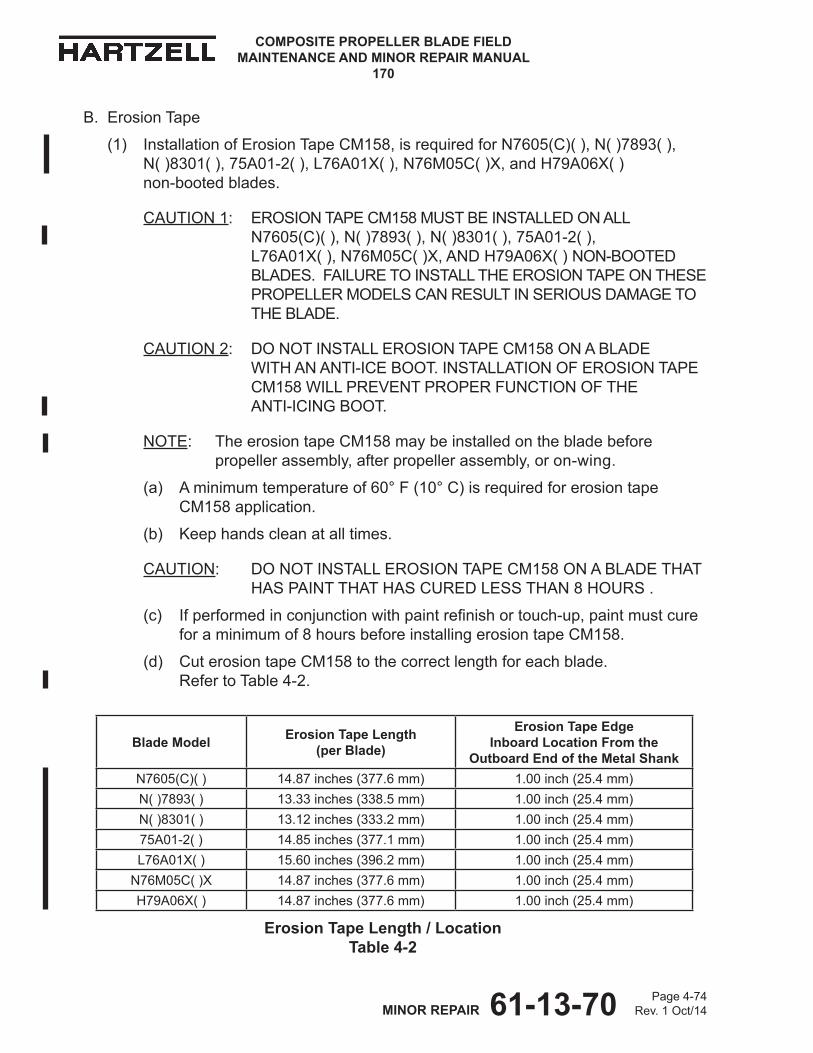
61-13-70 Page 4-74Rev. 1 Oct/14MINOR REPAIR
COMPOSITE PROPELLER BLADE FIELD MAINTENANCE AND MINOR REPAIR MANUAL
170
B. Erosion Tape
(1) Installation of Erosion Tape CM158, is required for N7605(C)( ), N( )7893( ), N( )8301( ), 75A01-2( ), L76A01X( ), N76M05C( )X, and H79A06X( ) non-booted blades.
CAUTION 1: EROSION TAPE CM158 MUST BE INSTALLED ON ALL N7605(C)( ), N( )7893( ), N( )8301( ), 75A01-2( ), L76A01X( ), N76M05C( )X, AND H79A06X( ) NON-BOOTED BLADES. FAILURE TO INSTALL THE EROSION TAPE ON THESE PROPELLER MODELS CAN RESULT IN SERIOUS DAMAGE TO THE BLADE.
CAUTION 2: DO NOT INSTALL EROSION TAPE CM158 ON A BLADE WITH AN ANTI-ICE BOOT. INSTALLATION OF EROSION TAPE CM158 WILL PREVENT PROPER FUNCTION OF THE ANTI-ICING BOOT.
NOTE: The erosion tape CM158 may be installed on the blade before propeller assembly, after propeller assembly, or on-wing.
(a) A minimum temperature of 60° F (10° C) is required for erosion tape CM158 application.
(b) Keep hands clean at all times.
CAUTION: DO NOT INSTALL EROSION TAPE CM158 ON A BLADE THAT HAS PAINT THAT HAS CURED LESS THAN 8 HOURS .
(c) Ifperformedinconjunctionwithpaintrefinishortouch-up,paintmustcurefor a minimum of 8 hours before installing erosion tape CM158.
(d) Cut erosion tape CM158 to the correct length for each blade. Refer to Table 4-2.
Blade Model Erosion Tape Length (per Blade)
Erosion Tape Edge Inboard Location From the
Outboard End of the Metal ShankN7605(C)( ) 14.87 inches (377.6 mm) 1.00 inch (25.4 mm)N( )7893( ) 13.33 inches (338.5 mm) 1.00 inch (25.4 mm)N( )8301( ) 13.12 inches (333.2 mm) 1.00 inch (25.4 mm)75A01-2( ) 14.85 inches (377.1 mm) 1.00 inch (25.4 mm)L76A01X( ) 15.60 inches (396.2 mm) 1.00 inch (25.4 mm)
N76M05C( )X 14.87 inches (377.6 mm) 1.00 inch (25.4 mm)H79A06X( ) 14.87 inches (377.6 mm) 1.00 inch (25.4 mm)
Erosion Tape Length / Location Table 4-2
61-13-70 Page 4-75Rev. 1 Oct/14MINOR REPAIR
COMPOSITE PROPELLER BLADE FIELD MAINTENANCE AND MINOR REPAIR MANUAL
170
(e) Radius the corners of the erosion tape CM158 to 0.5 inch (13 mm) to remove any sharp corners.
(f) Using a pencil or a ball-point pen, measure and make a mark on the non-adhesive side of the erosion tape CM158 to indicate the centerline of the erosion tape.
(g) Using a non-graphite pencil CM162 (or equivalent), measure and make a mark on the blade outboard of the metal blade shank near the leading edge. Refer to Table 4-2 for the correct measurement.
1 This alignment mark on the blade will be used to align the inboard edge of the erosion tape at installation.
WARNING: ADHESIVES AND SOLVENTS ARE FLAMMABLE AND TOXIC TO THE SKIN, EYES, AND RESPIRATORY TRACT. SKIN AND EYE PROTECTION ARE REQUIRED. AVOID PROLONGED CONTACT AND BREATHING OF VAPORS. USE SOLVENT RESISTANT GLOVES TO MINIMIzE SKIN CONTACT AND WEAR SAFETY GLASSES FOR EYE PROTECTION. USE IN A WELL VENTILATED AREA AWAY FROM SPARKS AND FLAME. READ AND OBSERVE ALL WARNING LABELS.
(h) Using a clean cloth dampened with solvent CM106 (MEK), CM219 (MPK) or CM41 (toluene), thoroughly clean the area of the blade where the erosion tape CM158 will be installed.
1 Using a clean, lint-free cloth, immediately wipe the area dry.
2 Permit the area to air dry.
3 Repeat the cleaning and drying of the area.
(i) Application of Optional Adhesive Promoter CM124
NOTE: Adhesive promoter CM124 will increase the adhesion between the erosion tape CM158 and the blade.
1 Apply masking tape or equivalent as masking material to the perimeter of the area where the erosion tape CM158 will be installed.
2 Apply a thin, uniform layer of adhesive promoter CM124 to the area of the blade where the erosion tape CM158 will be installed.
3 Remove the masking material.
CAUTION: THE ADHESIVE PROMOTER CM124 WILL BEGIN TO LOSE ADHESION AFTER 60 MINUTES AT ROOM TEMPERATURE.
4 Permit the adhesive promoter CM124 to dry at room temperature for a minimum of 15 minutes and a maximum of 60 minutes.
61-13-70 Page 4-76Rev. 1 Oct/14MINOR REPAIR
COMPOSITE PROPELLER BLADE FIELD MAINTENANCE AND MINOR REPAIR MANUAL
170
(j) Peel the backing material from the erosion tape CM158.
(k) Holding the erosion tape CM158 with the adhesive side toward the blade, align the end of the erosion tape with the alignment mark on the blade (outboard of the metal blade shank and near the leading edge), while aligning the centerline that was marked on the erosion tape with the leading edge of the blade.
(l) Press the erosion tape CM158 into position on the leading edge of the bladewhilemaintaininglighttensionontheerosiontapetominimizeairbubbles and keep the tape straight.
1 Usingaroller,suchasTE330orTE331,orfingers,presstheerosiontape CM158 down onto the leading edge of the blade.
(m) Usingaroller,suchasTE330orTE331,orfingers,worktheerosiontapeCM158 into position on one side of the blade.
1 Starting at the outboard end of the blade and working toward the shank, use a hard rubber or nylon roller, such as TE330 or TE331, or fingers,tofirmlyseattheerosiontapeCM158totheblade.
2 Make sure that there are no wrinkles and that no air is trapped under the erosion tape CM158.
CAUTION: DO NOT DAMAGE THE BLADE WHEN REMOVING AIR BUBBLES.
3 Remove air bubbles under the erosion tape by carefully puncturing the erosion tape CM158 with a sharp pin and pressing out the trapped air.
4 Repeat step 7.B.(1)(m) (1 thru 3) on the other side of the blade.
8. Documenting the Repair
NOTE: SpecificHartzellPropellerInc.manualsandservicedocumentsareavailableontheHartzellwebsiteatwww.hartzellprop.com.RefertotheRequiredPublications section in the Introduction chapter of this manual for the identificationofthesepublications.
A. Blade Damage Repair Sheet
(1) CompletetheBladeDamageRepairSheetfromtheapplicableHartzellPropeller Inc. propeller owner's manual.
B. Propeller Logbook
(1) Make an entry in the propeller logbook that a repair has been made in accordance with this service manual and reference the applicable Blade Damage Repair Sheet.
Page 5-1 TOOLING AND MATERIALS 61-13-70 Rev. 1 Oct/14
COMPOSITE PROPELLER BLADE FIELD MAINTENANCE AND MINOR REPAIR MANUAL
170
TOOLING AND MATERIALS - CONTENTS
1. Tooling ..................................................................................................................... 5-3
A. "Coin" ................................................................................................................. 5-3B. Special Tools ...................................................................................................... 5-3
2. Materials .................................................................................................................. 5-4
A. Consumable Materials........................................................................................ 5-43. Mixtures ................................................................................................................... 5-4
A. Mixture Number 3, Wash Primer ........................................................................ 5-4
LIST OF FIGURES
Example of a "Coin" .............................................................................. Figure 5-1 ............. 5-3

Page 5-2 TOOLING AND MATERIALS 61-13-70 Rev. 1 Oct/14
COMPOSITE PROPELLER BLADE FIELD MAINTENANCE AND MINOR REPAIR MANUAL
170
(This page is intentionally blank.)

Page 5-3 TOOLING AND MATERIALS 61-13-70 Rev. 1 Oct/14
COMPOSITE PROPELLER BLADE FIELD MAINTENANCE AND MINOR REPAIR MANUAL
170
1. Tooling
A. "Coin"
(1) A tool, or "coin", is needed for the coin-tap inspection.
(a) The coin should be a washer-shaped metal tapper, approximately 2.5 inches (64 mm) OD x 1.25 inches (32 mm) ID x 0.25 inch (6.4 mm) thick, and weighing no less than 3 oz. (85.05 g). Refer to Figure 5-1.
B. Special Tools
NOTE: SpecificHartzellPropellerInc.manualsandservicedocumentsareavailableontheHartzellwebsiteatwww.hartzellprop.com.RefertotheRequired Publications section in the Introduction chapter of this manual for theidentificationofthesepublications.
(1) Special tooling may be required for procedures in this manual. The reference numberforaspecialtoolwillappearwiththeprefix"TE"directlyfollowingthetool name to which it applies. For example, a roller that is reference number 330 will appear as: roller TE330.
(a) Forfurthertoolinginformation,refertoHartzellPropellerInc.IllustratedTool and Equipment Manual 165A (61-00-65).
Example of a "Coin" Figure 5-1
TI-c
oin
Page 5-4 TOOLING AND MATERIALS 61-13-70 Rev. 1 Oct/14
COMPOSITE PROPELLER BLADE FIELD MAINTENANCE AND MINOR REPAIR MANUAL
170
2. Materials
A. Consumable Materials
NOTE: SpecificHartzellPropellerInc.manualsandservicedocumentsareavailableontheHartzellwebsiteatwww.hartzellprop.com.RefertotheRequired Publications section in the Introduction chapter of this manual for theidentificationofthesepublications.
(1) Consumable materials are referenced throughout this manual. The reference numberforaconsumablematerialwillappearwiththeprefix"CM"directlyfollowing the material to which it applies. For example, an adhesive that is reference number 16 will appear as: adhesive CM16. Only those items specifiedmaybeused.
(a) Specificapprovedmaterialsandtheirshelflife,potlife,etc.arelistedinHartzellPropellerInc.StandardPracticesManual202A-Volume7,Consumable Materials (61-01-02).
3. Mixtures
A. Mixture Number 3, Washer Primer
4 parts Wash Primer (CM24)
4 parts Reducer, Wash Primer (CM25)
1 part Acid Diluent (CM26)
Let stand 1/2 hour before using
NOTE: TheHartzellPropellerInc.requiredmixratioisasshownhere.Themixratio differs from the manufacturer's label. Make sure to use the mix ratio thatisspecifiedbyHartzellPropellerInc.
Related Documents