Chapter 4 Plasma Formation Using a Double Saddle Coil Antenna The use of the double saddle coil antenna has dominated helicon wave research since the early experiments by Boswell [14]. Until the present, very little was known about the coupling between the antenna and the plasma. All experimental systems, including the antenna configuration, were empirically designed. In order to design an antenna which will efficiently couple power to the plasma it is necessary to understand what modes will be excited by a particular antenna geometry - which will then determine the consequent plasma regime. Previous experimental measurements have been made of the wavefields, but only for a limited range of conditions and with ambiguous identification of wave modes. This chapter describes detailed wavefield and plasma measurements over a wide pa- rameter range, though only one frequency. A comparison is made between experimental measurements of dispersion and radiation resistance measurements and results from a 70

Welcome message from author
This document is posted to help you gain knowledge. Please leave a comment to let me know what you think about it! Share it to your friends and learn new things together.
Transcript
Chapter 4
Plasma Formation Using
a Double Saddle Coil Antenna
The use of the double saddle coil antenna has dominated helicon wave research since the
early experiments by Boswell [14]. Until the present, very little was known about the
coupling between the antenna and the plasma. All experimental systems, including the
antenna configuration, were empirically designed. In order to design an antenna which
will efficiently couple power to the plasma it is necessary to understand what modes will
be excited by a particular antenna geometry - which will then determine the consequent
plasma regime. Previous experimental measurements have been made of the wavefields,
but only for a limited range of conditions and with ambiguous identification of wave
modes.
This chapter describes detailed wavefield and plasma measurements over a wide pa-
rameter range, though only one frequency. A comparison is made between experimental
measurements of dispersion and radiation resistance measurements and results from a
70
L
a
a
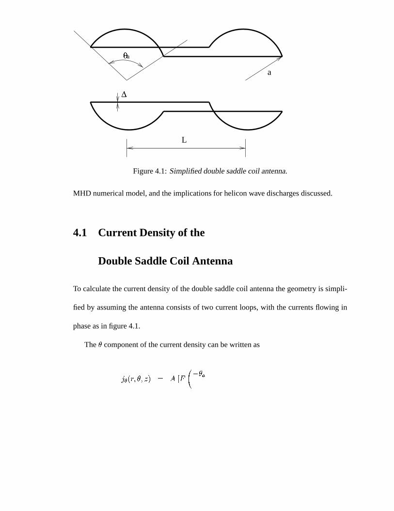
Figure 4.1: Simplified double saddle coil antenna.
MHD numerical model, and the implications for helicon wave discharges discussed.
4.1 Current Density of the
Double Saddle Coil Antenna
To calculate the current density of the double saddle coil antenna the geometry is simpli-
fied by assuming the antenna consists of two current loops, with the currents flowing in
phase as in figure 4.1.
The component of the current density can be written as
(4.1)
71
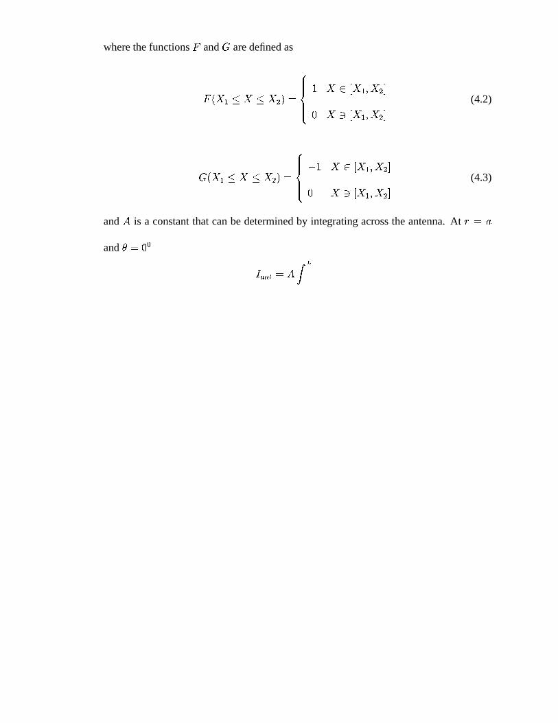
where the functions and are defined as
(4.2)
(4.3)
and is a constant that can be determined by integrating across the antenna. At
and
(4.4)
where is the antenna current, giving
(4.5)
Equation 4.1 can be Fourier transformed into the more useful coordinates of the az-
imuthal mode number , and the wave number .
(4.6)
Examples of the wave number and the azimuthal wave number spectrums for a typical
double saddle antenna can be seen in figure 4.2.
72
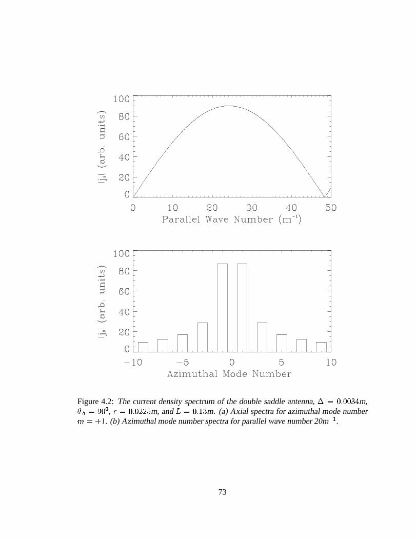
Figure 4.2: The current density spectrum of the double saddle antenna, m,, m, and m. (a) Axial spectra for azimuthal mode number
. (b) Azimuthal mode number spectra for parallel wave number 20m .
73
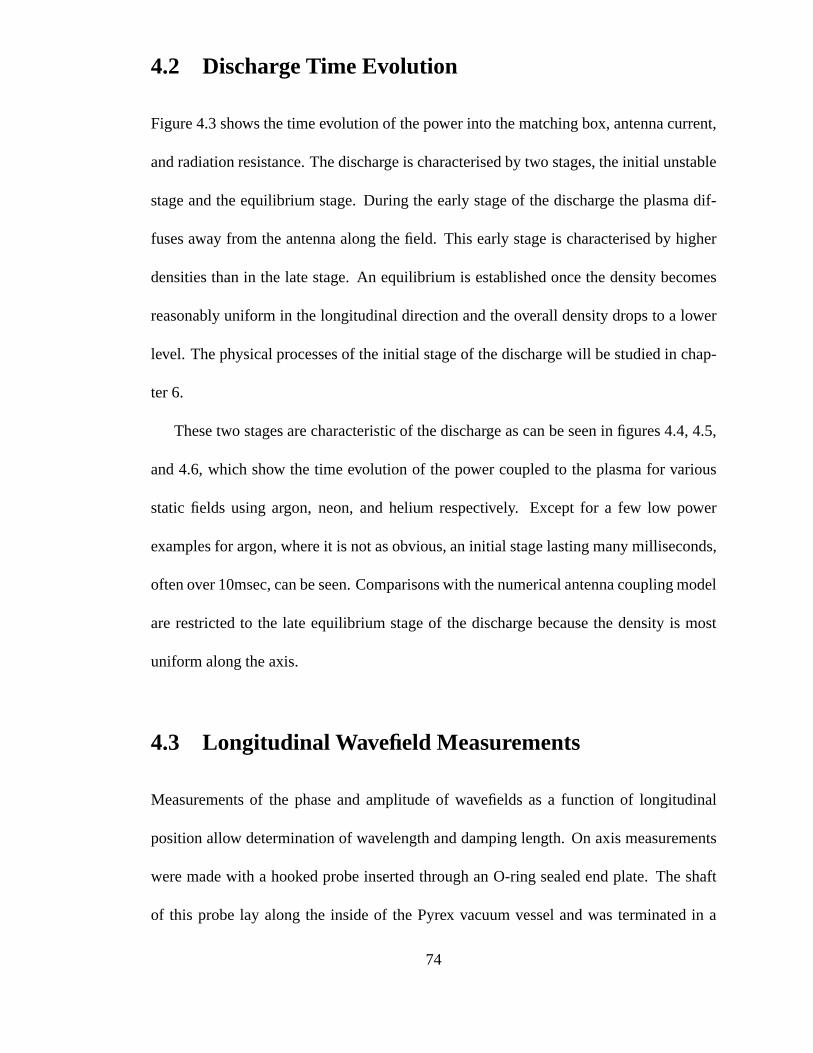
4.2 Discharge Time Evolution
Figure 4.3 shows the time evolution of the power into the matching box, antenna current,
and radiation resistance. The discharge is characterised by two stages, the initial unstable
stage and the equilibrium stage. During the early stage of the discharge the plasma dif-
fuses away from the antenna along the field. This early stage is characterised by higher
densities than in the late stage. An equilibrium is established once the density becomes
reasonably uniform in the longitudinal direction and the overall density drops to a lower
level. The physical processes of the initial stage of the discharge will be studied in chap-
ter 6.
These two stages are characteristic of the discharge as can be seen in figures 4.4, 4.5,
and 4.6, which show the time evolution of the power coupled to the plasma for various
static fields using argon, neon, and helium respectively. Except for a few low power
examples for argon, where it is not as obvious, an initial stage lasting many milliseconds,
often over 10msec, can be seen. Comparisons with the numerical antenna coupling model
are restricted to the late equilibrium stage of the discharge because the density is most
uniform along the axis.
4.3 Longitudinal Wavefield Measurements
Measurements of the phase and amplitude of wavefields as a function of longitudinal
position allow determination of wavelength and damping length. On axis measurements
were made with a hooked probe inserted through an O-ring sealed end plate. The shaft
of this probe lay along the inside of the Pyrex vacuum vessel and was terminated in a
74
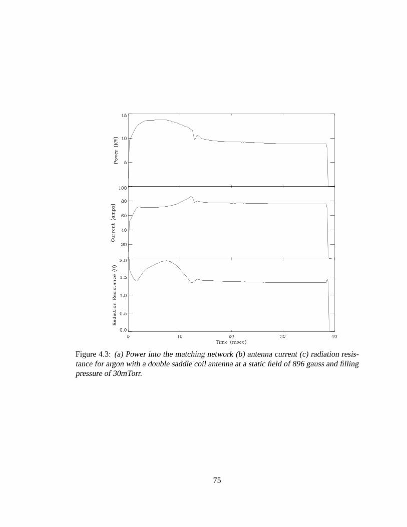
Figure 4.3: (a) Power into the matching network (b) antenna current (c) radiation resis-tance for argon with a double saddle coil antenna at a static field of 896 gauss and fillingpressure of 30mTorr.
75
Figure 4.4: Time evolution of the power coupled to the plasma at different static fields forargon.
76

Figure 4.5: Time evolution of the power coupled to the plasma at different static fields forneon.
77

Figure 4.6: Time evolution of the power coupled to the plasma at different static fields forhelium.
78
Langmuir probe and a 3 component magnetic probe 3cm apart. It was found that this
probe significantly disturbed plasma produced by the double saddle coil antenna. When
the probe was used, plasma perturbations were monitored using the floating potential of
the radial probe placed on axis. Using a set of plasma conditions which were reasonably
robust, and not overly disturbed by the probe, a complete set of on-axis measurements
were made, with early and late stage measurements shown in figures 4.7 and 4.8.
Longitudinal wavefield measurements could also be made by drawing the azimuthal
probe array along the vacuum vessel. The wavelength measurements taken by the az-
imuthal and axial probes agreed very well, as expected from simple wave theory. Thus
all wavelengths were determined by the azimuthal array, which had the advantage of not
disturbing the plasma. The wavelength was determined by Fourier analysis of the ampli-
tude and phase of each of the array elements individually and averaging the results. In
some cases more than one wavelength was evident in the early stage of the discharge.
The advantage of this technique compared with measuring the slope of the phase is that,
with the latter method, there are significant errors caused by interference by other wave
numbers. The Fourier technique was also used to determine the parallel wave number in
the numerical model.
Figures 4.7 and 4.8 present results from the early and late stage of the discharge.
In the early stage the plasma has not reached an equilibrium and the plasma density is
high. There is also a large density hump at the end of the discharge even though the
apparent wave energy density is negligible in this region (this is discussed in chapter 6).
Corresponding to the higher density measured in the initial stage of the discharge, the
average wavelength is shorter than at the later time when equilibrium has been reached.
79
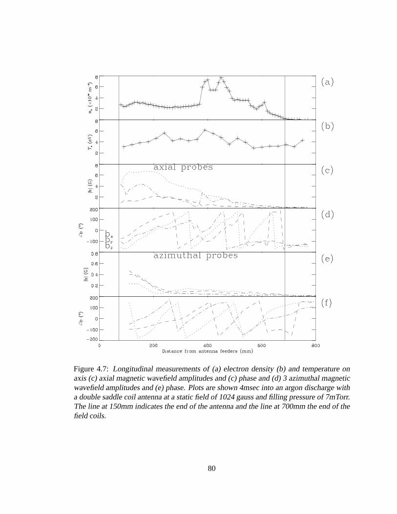
Figure 4.7: Longitudinal measurements of (a) electron density (b) and temperature onaxis (c) axial magnetic wavefield amplitudes and (c) phase and (d) 3 azimuthal magneticwavefield amplitudes and (e) phase. Plots are shown 4msec into an argon discharge witha double saddle coil antenna at a static field of 1024 gauss and filling pressure of 7mTorr.The line at 150mm indicates the end of the antenna and the line at 700mm the end of thefield coils.
80
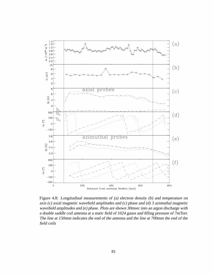
Figure 4.8: Longitudinal measurements of (a) electron density (b) and temperature onaxis (c) axial magnetic wavefield amplitudes and (c) phase and (d) 3 azimuthal magneticwavefield amplitudes and (e) phase. Plots are shown 30msec into an argon discharge witha double saddle coil antenna at a static field of 1024 gauss and filling pressure of 7mTorr.The line at 150mm indicates the end of the antenna and the line at 700mm the end of thefield coils
81
The shortest wavelengths are measured in the region of the density peak. This agrees with
similar axial measurements by Chen et al [32] in which the wavelength scales inversely
with increasing axial density. In the latter case the density has dropped and the wavelength
has correspondingly increased. The on axis wavefields have become dominated by the
and components, but the z component has become very small, which is consistent with
an azimuthal mode as confirmed by the azimuthal probe. The wavefields are
more heavily damped in the early stage, consistent with higher collision frequencies at
higher densities.
4.4 Azimuthal Magnetic Wavefields
The main deficiency in previous helicon measurements has been the lack of azimuthal
profiles for the direct identification of azimuthal mode numbers. Azimuthal profiles for
mode identification were also performed recently by Ellingboe and Boswell [48], who
used a hooked magnetic probe inserted axially and rotated azimuthally. The double sad-
dle coil antenna has no preference for azimuthal sign and while the modes
dominate, the modes are not insignificant. One would then expect the azimuthal
profiles to be a key diagnostic in determining which helicon mode occurs experimentally.
Until now comparison with the dispersion relation (usually calculated for a uniform plas-
mas) and radial wavefield profiles have been used for mode identification. Due to the
intrusive nature of magnetic probes, the technically difficult nature of making them small
and avoiding (or, in our case, rejecting) capacitive coupling to the electric wavefield, their
use has been limited to radial profiles and sparse longitudinal measurements for the de-
82
termination of . These indirect means of determining azimuthal modes have a large
uncertainty, making their use of limited value.
For Basil it was decided to attempt a direct measurement of azimuthal profiles with
an array of 8 theta component probes on the outside of the Pyrex vacuum vessel. While
this avoids using an intrusive probe it has the disadvantage of measuring the edge of the
wavefields outside the plasma. Since the amplitude of the fields in Basil is of the order of a
few gauss, the measurement techniques described in chapter 2 is reliable for most modes.
However this technique has only limited capabilities to measure modes such as , the
theta component of which is small at the plasma boundary. It is very reliable for resolving
the modes. Thus azimuthal profiles are not reliable for determining the overall
percentage make up of the total wave, but when moved axially, do allow unambiguous
determination of wavelengths for different mode numbers.
The effects of the near field of the antenna on the azimuthal probe were determined
by taking measurements with a typical antenna current but very low filling pressure. The
antenna near field was found to be less than 5% of typical wavefields 10cm from the
antenna. By Fourier analysing the data the azimuthal mode amplitudes were determined.
The azimuthal array was also drawn along the tube for longitudinal measurements which
were used to determine wavelengths and damping lengths for individual azimuthal modes.
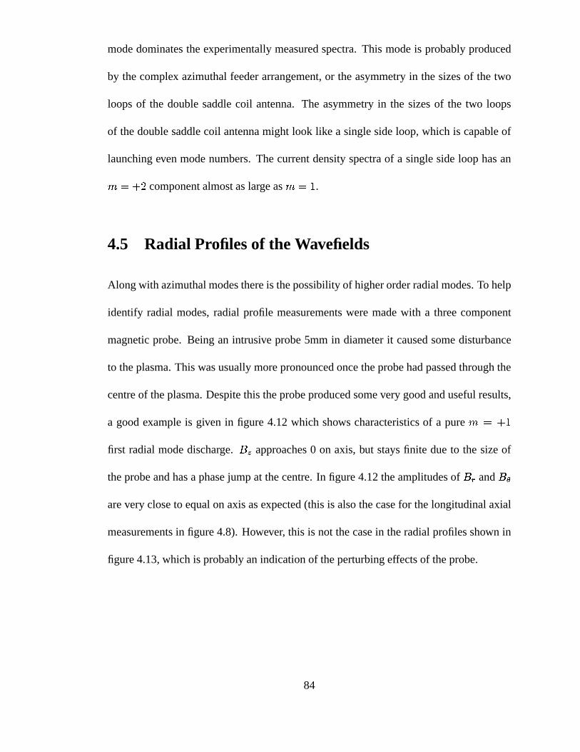
All measurements in the stable late stage of the discharge show a very strong dom-
inance of the mode. Two examples are shown in figures 4.9 and 4.10. These
examples are used as they span a wide parameter regime but still show identical features.
Figure 4.11 is an azimuthal profile taken during the early stage of the discharge. While
the simple antenna used in the numerical model has no mode component this
83
mode dominates the experimentally measured spectra. This mode is probably produced
by the complex azimuthal feeder arrangement, or the asymmetry in the sizes of the two
loops of the double saddle coil antenna. The asymmetry in the sizes of the two loops
of the double saddle coil antenna might look like a single side loop, which is capable of
launching even mode numbers. The current density spectra of a single side loop has an
component almost as large as .
4.5 Radial Profiles of the Wavefields
Along with azimuthal modes there is the possibility of higher order radial modes. To help
identify radial modes, radial profile measurements were made with a three component
magnetic probe. Being an intrusive probe 5mm in diameter it caused some disturbance
to the plasma. This was usually more pronounced once the probe had passed through the
centre of the plasma. Despite this the probe produced some very good and useful results,
a good example is given in figure 4.12 which shows characteristics of a pure
first radial mode discharge. approaches 0 on axis, but stays finite due to the size of
the probe and has a phase jump at the centre. In figure 4.12 the amplitudes of and
are very close to equal on axis as expected (this is also the case for the longitudinal axial
measurements in figure 4.8). However, this is not the case in the radial profiles shown in
figure 4.13, which is probably an indication of the perturbing effects of the probe.
84
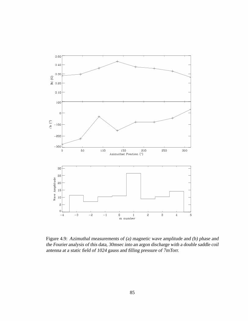
Figure 4.9: Azimuthal measurements of (a) magnetic wave amplitude and (b) phase andthe Fourier analysis of this data, 30msec into an argon discharge with a double saddle coilantenna at a static field of 1024 gauss and filling pressure of 7mTorr.
85
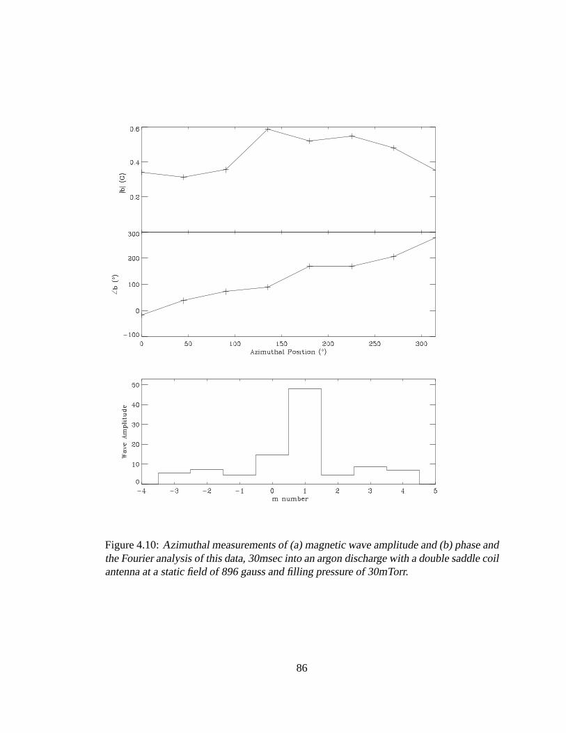
Figure 4.10: Azimuthal measurements of (a) magnetic wave amplitude and (b) phase andthe Fourier analysis of this data, 30msec into an argon discharge with a double saddle coilantenna at a static field of 896 gauss and filling pressure of 30mTorr.
86
Figure 4.11: Azimuthal measurements of (a) magnetic wave amplitude and (b) phase andthe Fourier analysis of this data, 5msec into an argon discharge with a double saddle coilantenna at a static field of 896 gauss and filling pressure of 30mTorr.
87
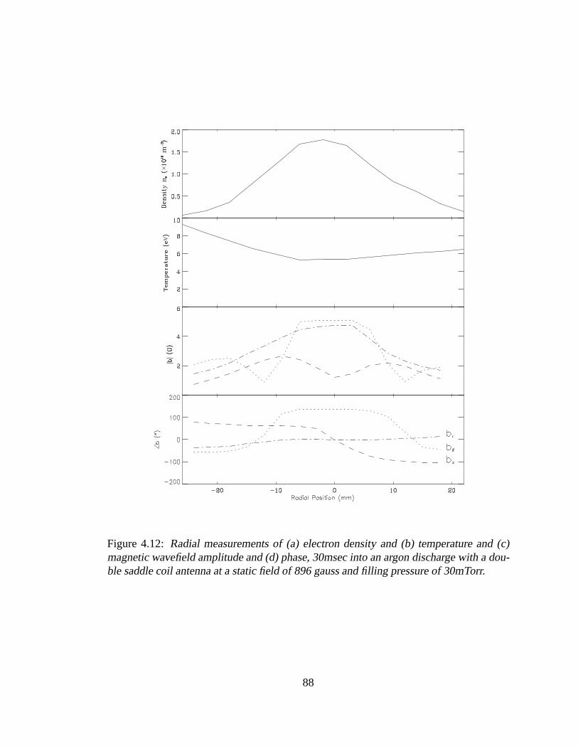
Figure 4.12: Radial measurements of (a) electron density and (b) temperature and (c)magnetic wavefield amplitude and (d) phase, 30msec into an argon discharge with a dou-ble saddle coil antenna at a static field of 896 gauss and filling pressure of 30mTorr.
88

Figure 4.13: Radial measurements of (a) electron density and (b) temperature and (c)magnetic wavefield amplitude and (d) phase, 30msec into an argon discharge with a dou-ble saddle coil antenna at a static field of 1024 gauss and filling pressure of 7mTorr.
89
4.6 Wave Dispersion, Radiation Resistance,
and Damping
In the latter stage of the discharge formed by the helicon wave, when the density becomes
relatively uniform, it is possible to compare experimental measurements with the numer-
ical model, which assumes longitudinal uniformity of the density. the model requires as
input measurements of the plasma density profile in order to calculate wavelength and ra-
diation resistance spectra. Examples of the measured profiles are shown for argon, neon,
and helium at a range of magnetic fields in figures 4.14, 4.15, and 4.16. Although the
radial profiles were only taken at one axial location, it is assumed that the profiles are
similar along the tube.
Figure 4.17 compares the measured and calculated dispersion of the helicon wave.
Note that this is not a dispersion “curve” as each modelled point is calculated for different
density profiles. However it does closely resemble the simplified dispersion relation for a
helicon wave propagating as an infinite plane wave with
(4.7)
This is shown as the solid line in figure 4.17. A similar result was first obtained by
Lehane and Thonemann [78]. However, these authors applied an unexplained multiplying
factor to their density measurements. No correction factors have been included in the
present results. The value for used in equation 4.7 is the average density calculated by
integrating under the density profile curve fitted to the experimental data, which was used
90

Figure 4.14: Radial electron densities for argon with a double saddle coil antenna atdifferent static fields late in the discharge.
91
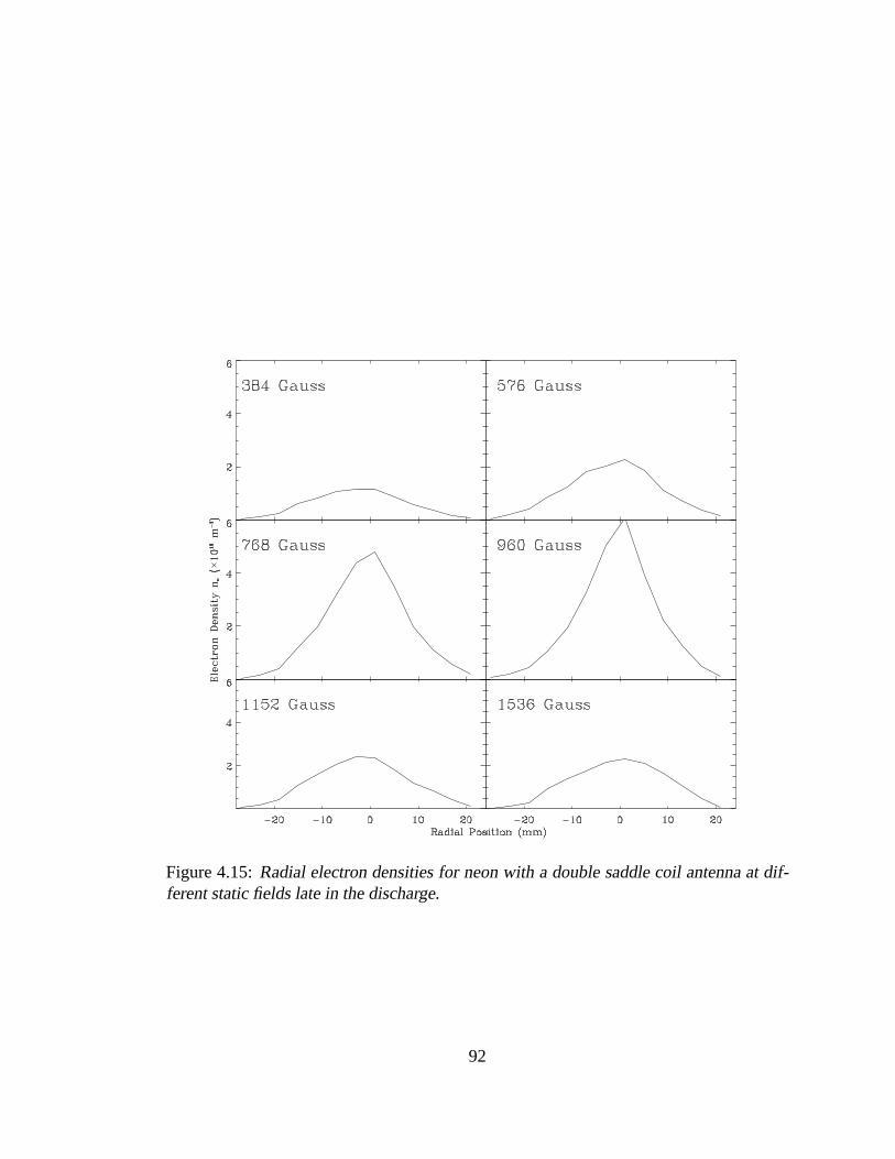
Figure 4.15: Radial electron densities for neon with a double saddle coil antenna at dif-ferent static fields late in the discharge.
92
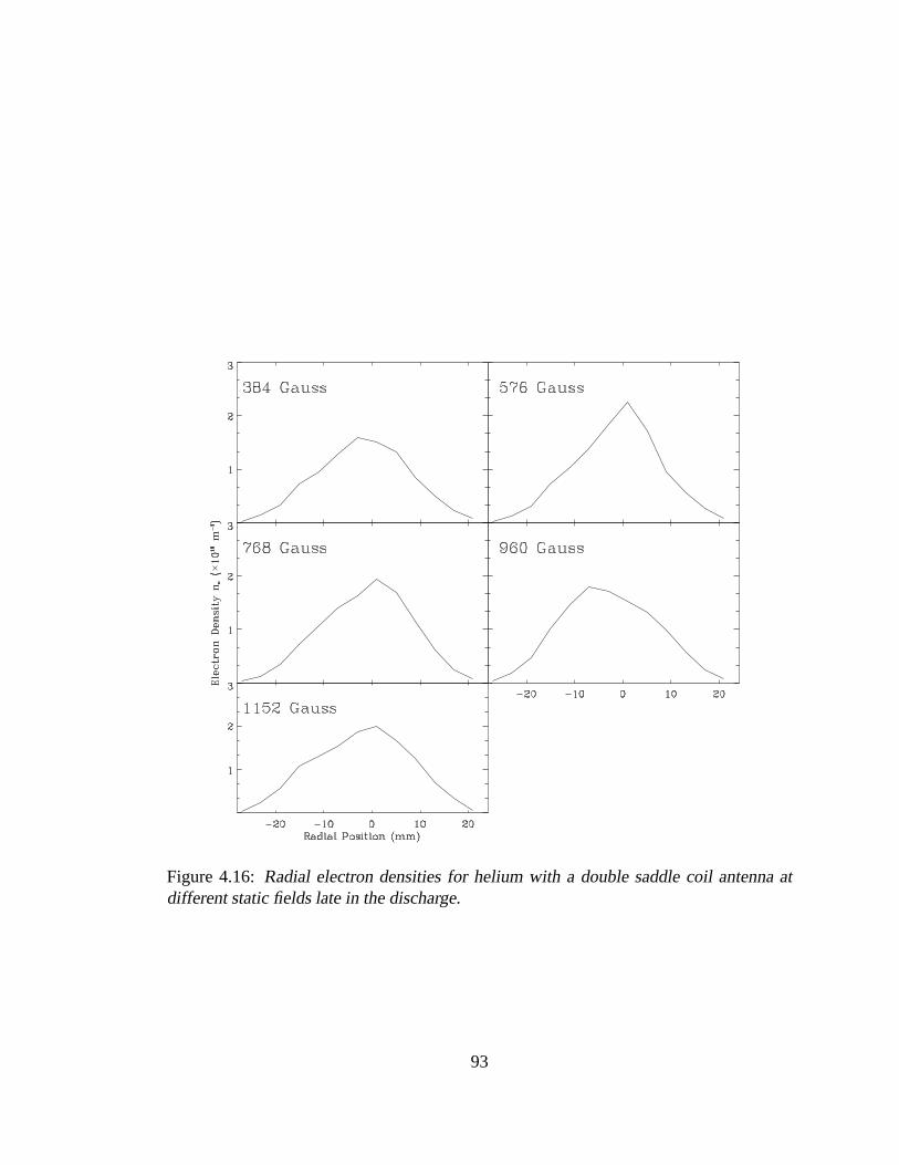
Figure 4.16: Radial electron densities for helium with a double saddle coil antenna atdifferent static fields late in the discharge.
93
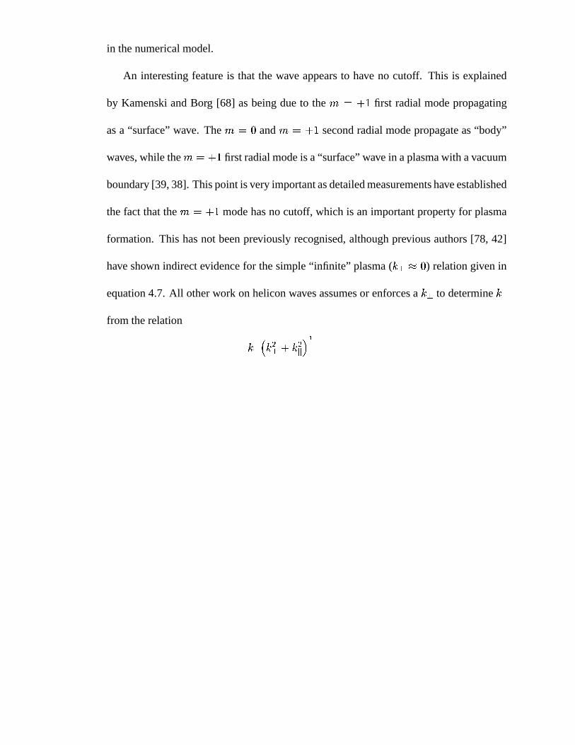
in the numerical model.
An interesting feature is that the wave appears to have no cutoff. This is explained
by Kamenski and Borg [68] as being due to the first radial mode propagating
as a “surface” wave. The and second radial mode propagate as “body”
waves, while the first radial mode is a “surface” wave in a plasma with a vacuum
boundary [39, 38]. This point is very important as detailed measurements have established
the fact that the mode has no cutoff, which is an important property for plasma
formation. This has not been previously recognised, although previous authors [78, 42]
have shown indirect evidence for the simple “infinite” plasma ( ) relation given in
equation 4.7. All other work on helicon waves assumes or enforces a to determine
from the relation
(4.8)
However for a small radius device like Basil, an estimate of an effective , from the first
non-zero root of the first order Bessel function, gives a large perpendicular wave number,
m , much larger than . From equation 4.8 it might then be concluded that
(4.9)
which does not agree with the results presented in figure 4.17.
In studying helicon waves most theory [70] has concentrated on understanding how
different parameter limits effect wave dispersion and wavefield profiles. It is still poorly
understood how the helicon wave maintains a plasma. Arguably the most important factor
is how much energy can be coupled to the wave regardless of how it is dissipated in the
94
Figure 4.17: Comparison of measured and calculated dispersion of the helicon wavelaunched by the double saddle coil antenna.
95
plasma. Deciding what modes will be launched by an antenna has been limited to calcu-
lating the current density spectra of the antenna and concluding that any modes present
in the antenna spectra are possibly coupled to the plasma. However, the modes launched
by an antenna will depend on the ability of the antenna to couple power to these modes
for the relevant plasma conditions. The power coupled to the wave from an antenna will
be seen by the antenna as a resistance, i.e. the radiation resistance of the wave. The nu-
merical MHD model by Kamenski [68] can calculate radiation resistance spectra of wave
modes for a specified antenna and plasma conditions. Experimentally the total radiation
resistance of all modes can be measured which can then be compared to the model results.
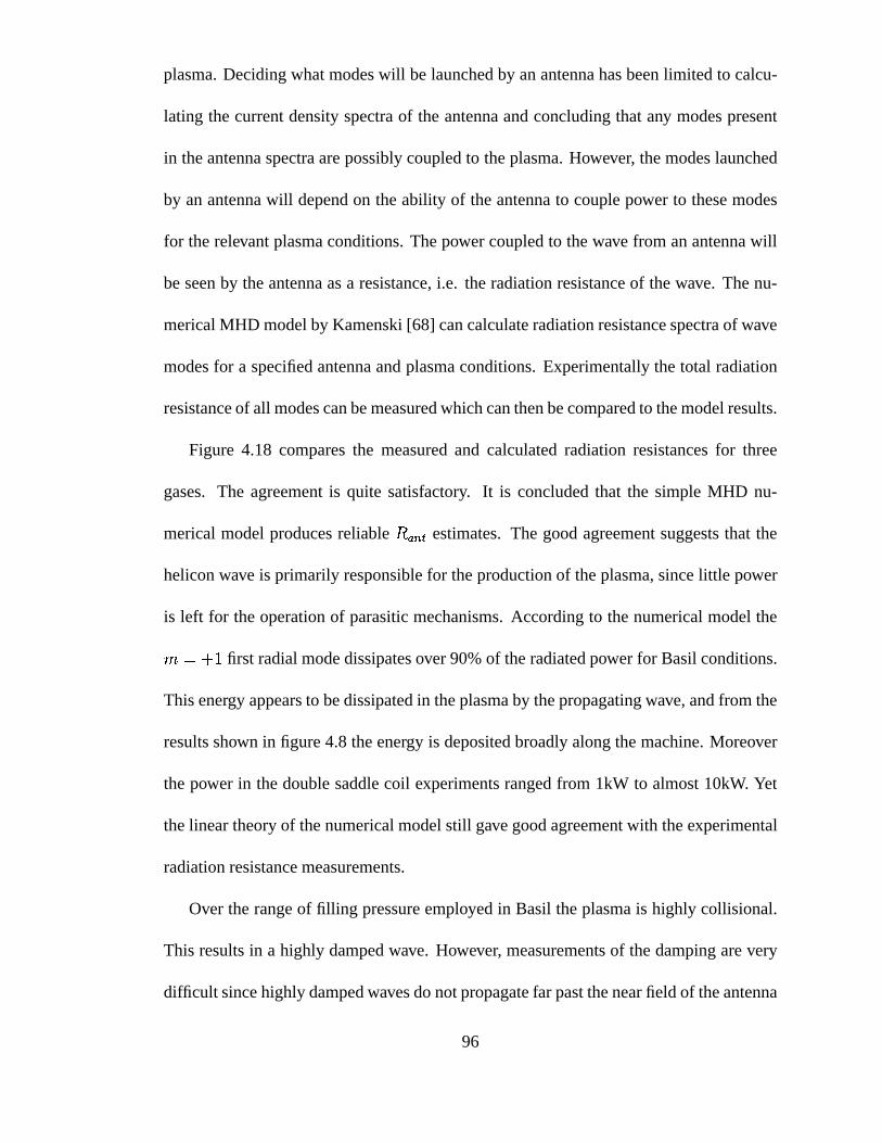
Figure 4.18 compares the measured and calculated radiation resistances for three
gases. The agreement is quite satisfactory. It is concluded that the simple MHD nu-
merical model produces reliable estimates. The good agreement suggests that the
helicon wave is primarily responsible for the production of the plasma, since little power
is left for the operation of parasitic mechanisms. According to the numerical model the
first radial mode dissipates over 90% of the radiated power for Basil conditions.
This energy appears to be dissipated in the plasma by the propagating wave, and from the
results shown in figure 4.8 the energy is deposited broadly along the machine. Moreover
the power in the double saddle coil experiments ranged from 1kW to almost 10kW. Yet
the linear theory of the numerical model still gave good agreement with the experimental
radiation resistance measurements.
Over the range of filling pressure employed in Basil the plasma is highly collisional.
This results in a highly damped wave. However, measurements of the damping are very
difficult since highly damped waves do not propagate far past the near field of the antenna
96
Figure 4.18: Comparison between measured and calculated radiation resistance of thedouble saddle coil antenna.
97

and so are difficult to identify and measurements of waves with low damping are compli-
cated by the effects of the reflected wave at the end of the plasma. Figure 4.19 compares
the measured damping with damping calculated due to a combination of electron-ion,
electron-neutral collisions, and Landau damping. The calculation of collisional and Lan-
dau damping uses the results of section 3.4. Collisional damping is dominant with both
collision frequencies being approximately equal, while the effective Landau collision fre-
quency comprises less than 15% of the total. It is very noticeable that the damping is
much stronger at high values of , which is consistent with the collisional nature of
the plasma and the increase of the collision frequency increasing with density.
In all results no adjustable parameters have been used to make the comparisons be-
tween experiment and theory. However, there is the possibility of considerable systematic
errors in the experimental results. Estimation of errors in experimental results, such as
Langmuir probe measurements, is very difficult and measurements of the density, which
could not be calibrated against other diagnostics, could be expected to have systematic
errors of up to 20%. This has important implications when these results are employed
in the numerical model. It would be expected that results from the model for
values which have a parallel wave number near the peak in the parallel wave number
spectra should be less sensitive to errors than results where the current density spec-
tra has the greatest slope. Thus the resultant error in the model results, due to any
systematic errors in the experimental results, would be greatest for values away from
m T for the double saddle coil antenna used in the experiment.
This is likely to explain why agreement between experimental and modelled values are
good for low values of , but decrease as m T .
98

Figure 4.19: Comparison between measured damping lengths and calculated dampinglengths.
99
4.7 Discussion
Kamenski [68] suggests that the inability of the double saddle coil antenna to launch the
negative azimuthal modes, in particular the mode, is due to two main factors:
peaking of the density profile on axis, and the antenna being external to the plasma. To-
gether these prevent the negative azimuthal modes from penetrating the plasma. In prac-
tice, is more efficiently excited in large radius devices already used for plasma
processing [48].
The radiation resistance is an important factor to consider in designing helicon plasma
sources. The most obvious reason for maximising the radiation resistance is there will be
a lower antenna current for a given power. This results in a reduction of the radiation
resistive losses and lower antenna voltages in the matching network and antenna. The
additional cost of cooling systems to a commercial processing machine can be consider-
able especially if water cooling is needed. In most helicon systems the antennas are very
reactive and the usual limitation on the power applied to the antenna is due to insulation
breakdown in matching network components. The average power is given by the current
squared times the resistance, . Since the current is limited proportionally to the
voltage, the only way to increase the power without increasing the voltage is by increasing
the resistance. It must be emphasised that simply increasing the source power does not
necessarily increase the power deposited into the plasma. Therefore reaching a desired
density will depend on factors such as the ohmic losses in the matching network and the
antenna length (since the radiation resistance decreases as the wavelength approaches the
antenna length).
100
4.8 Summary
Detailed wavefield measurements of helicon waves launched by a double saddle coil an-
tenna have been made in a long, high density plasma. In a discharge which has reached
equilibrium a wave was found to propagate from the antenna and radial and azimuthal
profiles were used to identify it as a single radial azimuthal mode. No other sig-
nificant modes were observed in the latter stages of the discharge, however in the early,
high density stage was observed. It is unclear why this mode is excited.
A numerical MHD model used measured radial plasma profiles to calculate the radi-
ation resistance spectra of helicon waves launched by a double saddle coil antenna. The
good agreement between measured and calculated radiation resistance confirms that the
plasma is being produced by the deposition of power from the helicon wave. This con-
clusion is not in anyway altered by the damping rate of the wave. The dominance of the
mode can be explained by the high radiation resistance of this mode resulting in
most of the power being coupled to it. Despite the non-equilibrium behaviour in the early
phase of the discharge, the latter phase of the discharge wave physics appears to be well
described by linear helicon wave theory.
101
Related Documents