Li, F., Duan, L. "Seismic Design Philosophies and Performance-Based Design Criteria." Bridge Engineering Handbook. Ed. Wai-Fah Chen and Lian Duan Boca Raton: CRC Press, 2000

Welcome message from author
This document is posted to help you gain knowledge. Please leave a comment to let me know what you think about it! Share it to your friends and learn new things together.
Transcript

Li, F., Duan, L. "Seismic Design Philosophies and Performance-Based Design Criteria." Bridge Engineering Handbook. Ed. Wai-Fah Chen and Lian Duan Boca Raton: CRC Press, 2000

37Seismic Design
Philosophies andPerformance-Based
Design Criteria
37.1 Introduction
37.2 Design PhilosophiesNo-Collapse-Based Design • Performance-Based Design
37.3 No-Collapse-Based Design Approaches AASHTO-LRFD Specifications • Caltrans Bridge Design Specifications
37.4 Performance-Based Design ApproachesCaltrans Practice • New Caltrans Seismic Design Polices • ATC Recommendations
37.5 Sample Performance-Based CriteriaDetermination of Demands • Determination of Capacities • Performance Acceptance Criteria • Acceptable Force D/C Ratios and Limiting Values for Structural Members
37.6 Summary
37.1 Introduction
Seismic design criteria for highway bridges have been improving and advancing based on researchfindings and lessons learned from past earthquakes. In the United States, prior to the 1971 SanFernando earthquake, the seismic design of highway bridges was partially based on lateral forcerequirements for buildings. Lateral loads were considered as levels of 2 to 6% of dead loads. In1973, the California Department of Transportation (Caltrans) developed new seismic design criteriarelated to site, seismic response of the soils at the site, and the dynamic characteristics of bridges.The American Association of State Highway and Transportation Officials (AASHTO) modified theCaltrans 1973 Provisions slightly, and adopted Interim Specifications. The Applied TechnologyCouncil (ATC) developed guidelines ATC-6 [1] for seismic design of bridges in 1981. AASHTOadopted ATC-6 [1] as the Guide Specifications in 1983 and later incorporated it into the StandardSpecifications for Highway Bridges in 1991.
Lian Duan California Department
of Transportation
Fang LiCalifornia Department
of Transportation
© 2000 by CRC Press LLC

Since the 1989 Loma Prieta earthquake in California [2], extensive research [3-15] has beenconducted on seismic design and retrofit of bridges in the United States, especially in California.The performance-based project-specific design criteria [16,17] were developed for importantbridges. Recently, ATC published improved seismic design criteria recommendations for Californiabridges [18] in 1996, and for U.S. bridges and highway structures [19] in 1997, respectively. Caltranspublished the new seismic Design Methodology in 1999. [20] The new Caltrans Seismic DesignCriteria [43] is under development. Great advances in earthquake engineering have been madeduring this last decade of the 20th century.
This chapter first presents the bridge seismic design philosophy and the current practice in theUnited States. It is followed by an introduction to the newly developed performance-based criteria[17] as a reference guide.
37.2 Design Philosophies
37.2.1 No-Collapse-Based Design
For seismic design of ordinary bridges, the basic philosophy is to prevent collapse during severeearthquakes [21-26]. To prevent collapse, two alternative approaches are commonly used in design.The first is a conventional force-based approach where the adjustment factor Z for ductility andrisk assessment [26], or the response modification factor R [23], is applied to elastic member forcesobtained from a response spectra analysis or an equivalent static analysis. The second approach isa more recent displacement-based approach [20] where displacements are a major considerationin design. For more-detailed information, reference can be made to a comprehensive discussion inSeismic Design and Retrofit of Bridges by Priestley, Seible, and Calvi [15].
37.2.2 Performance-Based Design
Following the 1989 Loma Prieta earthquake, bridge engineers [2] have faced three essential challenges:
• Ensure that earthquake risks posed by new construction are acceptable.
• Identify and correct unacceptable seismic safety conditions in existing structures.
• Develop and implement a rapid, effective, and economic response mechanism for recoveringstructural integrity after damaging earthquakes.
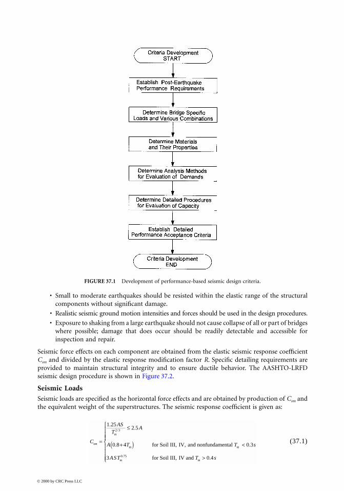
In the California, although the Caltrans Bridge Design Specifications [26] have not been formallyrevised since 1989, project-specific criteria and design memoranda have been developed and imple-mented for the design of new bridges and the retrofitting of existing bridges. These revised orsupplementary criteria included guidelines for development of site-specific ground motion esti-mates, capacity design to preclude brittle failure modes, rational procedures for joint shear design,and definition of limit states for various performance objectives [14]. As shown in Figure 37.1, theperformance requirements for a specific project must be established first. Loads, materials, analysismethods, and detailed acceptance criteria are then developed to achieve the expected performance.
37.3 No-Collapse-Based Design Approaches
37.3.1 AASHTO-LRFD Specifications
Currently, AASHTO has issued two design specifications for highway bridges: the second editionof AASHTO-LRFD [23] and the 16th edition of the Standard Specifications [24]. This section mainlydiscusses the design provisions of the AASHTO-LRFD Specifications.
The principles used for the development of AASHTO-LRFD [23] seismic design specificationsare as follows:
© 2000 by CRC Press LLC
• Small to moderate earthquakes should be resisted within the elastic range of the structuralcomponents without significant damage.
• Realistic seismic ground motion intensities and forces should be used in the design procedures.
• Exposure to shaking from a large earthquake should not cause collapse of all or part of bridgeswhere possible; damage that does occur should be readily detectable and accessible forinspection and repair.
Seismic force effects on each component are obtained from the elastic seismic response coefficientCsm and divided by the elastic response modification factor R. Specific detailing requirements areprovided to maintain structural integrity and to ensure ductile behavior. The AASHTO-LRFDseismic design procedure is shown in Figure 37.2.
Seismic LoadsSeismic loads are specified as the horizontal force effects and are obtained by production of Csm andthe equivalent weight of the superstructures. The seismic response coefficient is given as:
(37.1)
FIGURE 37.1 Development of performance-based seismic design criteria.
C
AST
A
A T T s
AST T s
sm
m
m m
m m
=
≤
+( ) <
>
1 252 5
0 8 4 0 3
3 0 4
2 3
0 75
..
. .
.
/
.
for Soil III, IV, and nonfundamental
for Soil III, IV and
© 2000 by CRC Press LLC

where A is the acceleration coefficient obtained from a contour map (Figure 37.3) which representsthe 10% probability of an earthquake of this size being exceeded within a design life of 50 years; Sis the site coefficient and is dependent on the soil profile types as shown in Table 37.1; Tm is thestructural period of the mth mode in second.
Analysis MethodsFour seismic analysis methods specified in AASHTO-LRFD [23] are the uniform-load method, thesingle-mode spectral method, the multimode spectral method, and the time history method.Depending on the importance, site, and regularity of a bridge structure, the minimum complexityanalysis methods required are shown in Figure 37.2. For single-span bridges and bridges locatedseismic Zone 1, no seismic analysis is required.
The importance of bridges is classified as critical, essential, and other in Table 37.2 [23], whichalso shows the definitions of a regular bridge. All other bridges not satisfying the requirements ofTable 37.2 are considered irregular.
FIGURE 37.2 AASHO-LRFD seismic design procedure.
© 2000 by CRC Press LLC

FIGURE 37.3 AASHTO-LRFD seismic contour map.
© 2000 by CRC Press LLC

Component Design Force EffectsDesign seismic force demands for a structural component are determined by dividing the forcescalculated using an elastic dynamic analysis by appropriate response modification factor R
TABLE 37.1 AASHTO-LRFD Site Coefficient — S
Soil Profile Type Descriptions
Site Coefficient, S
I • Rock characterized by a shear wave velocity > 765 m/s 1.0• Stiff soil where the soil depth < 60 m and overlying soil are stable deposits of sands, gravel,
or stiff claysII Stiff cohesive or deep cohesionless soil where the soil depth > 60 m and the overlying soil
are stable deposits of sands, gravel, or stiff clays1.2
III Stiff to medium-stiff clays and sands, characterized by 9 m or more soft to medium-stiff clays without intervening layers of sands or other cohesionless soils
1.5
IV Soft clays of silts > 12 m in depth characterized by a shear wave velocity < 153 m/s 2.0
TABLE 37.2 AASHTO-LRFD Bridge Classifications for Seismic Analysis
Importance Critical • Remain open to all traffic after design earthquake• Usable by emergency vehicles and for security/defense purposes immediately after a large
earthquake (2500-year return period event)Essential Remain open emergency vehicles and for security/defense purposes immediately after the design
earthquake (475-year return period event)Others Not required as critical and essential bridges
Regularity Regular Structural Features Number of Span 2 3 4 5 6Maximum subtended angles for a curved bridge 90°Maximum span length ratio from span to span 3 2 2 1.5 1.5Maximum bent/pier stiffness ratio from span to span
excluding abutments — 4 4 3 2
Irregular Multispan not meet requirement of regular bridges
TABLE 37.3 Response Modification Factor, R
Important Category
Structural Component Critical Essential Others
Substructure Wall-type pier — Large dimension 1.5 1.5 2.0Reinforced concrete pile bent• Vertical pile only• With batter piles
1.51.5
2.01.5
3.02.0
Single column 1.5 2.0 3.0Steel or composite steel and concrete pile bents• Vertical pile only• With batter piles
1.51.5
3.52.0
5.03.0
Multiple column bents 1.5 3.5 5.0Foundations 1.0
Connection Substructure to abutment 0.8Expansion joints with a span of the superstructure 0.8Column, piers, or pile bents to cap beam or superstructure 1.0Columns or piers to foundations 1.0
© 2000 by CRC Press LLC

(Table 37.3) to account for inelastic behavior. As an alternative to the use of R factor for connection,the maximum force developed from the inelastic hinging of structures may be used for designingmonolithic connections.
To account for uncertainty of earthquake motions, the elastic forces obtained from analysis ineach of two perpendicular principal axes shall be combined using 30% rule, i.e., 100% of the absoluteresponse in one principal direction plus 30% of the absolute response in the other.
The design force demands for a component should be obtained by combining the reducedseismic forces with the other force effects caused by the permanent and live loads, etc. Designresistance (strength) are discussed in Chapter 38 for concrete structures and Chapter 39 for steelstructures.
37.3.2 Caltrans Bridge Design Specifications
The current Caltrans Bridge Design Specifications [26] adopts a single-level force-based designapproach based on the no-collapse design philosophy and includes:
• Seismic force levels defined as elastic acceleration response spectrum (ARS);
• Multimodal response spectrum analysis considering abutment stiffness effects;
• Ductility and risk Z factors used for component design to account for inelastic effects;
• Properly designed details.
Seismic LoadsA set of elastic design spectra ARS curves are recommended to consider peak rock accelerations(A), normalized 5% damped rock spectra (R), and soil amplification factor (S). Figure 37.4 showstypical ARS curves.
Analysis MethodsFor ordinary bridges with well-balanced span and bent/column stiffness, an equivalent static analysiswith the ARS times the weight of the structure applied at the center of gravity of total structurescan be used. This method is used mostly for hinge restrainer design. For ordinary bridges withsignificantly irregular geometry configurations, a dynamic multimodal response spectrum analysisis recommended. The following are major considerations in seismic design practice:
• A beam-element model with three or more lumped masses in each span is usually used[25-27].
• A larger cap stiffness is often used to simulate a stiff deck.
• Gross section properties of columns are commonly used to determine force demands, andcracked concrete section properties of columns are used for displacement demands.
• Soil–spring elements are used to simulate the soil–foundation–structure–interaction. Adjust-ments are often made to meet force–displacement compatibility, particularly for abutments.The maximum capacity of the soil behind abutments with heights larger than 8 ft (2.44 m)is 7.7 ksf (369 kPa) and lateral pile capacity of 49 kips (218 kN) per pile.
• Compression and tension models are used to simulate the behavior of expansion joints.
Component Design Force EffectsSeismic design force demands are determined using elastic forces from the elastic response analysisdivided by the appropriate component- and period-based (stiffness) adjustment factor Z, as shownin Figure 38.4a to consider ductility and risk. In order to account for directional uncertainty ofearthquake motions, elastic forces obtained from analysis of two perpendicular seismic loadings arecombined as the 30% rule, the same as the AASHTO-LRFD [23].
© 2000 by CRC Press LLC

FIGURE 37.4 Caltrans ARS curves.
© 2000 by CRC Press LLC

37.4 Performance-Based Design Approaches
37.4.1 Caltrans Practice
Since 1989, the design criteria specified in Caltrans BDS [26] and several internal design manuals[20,25,27] have been updated continuously to reflect recent research findings and development in thefield of seismic bridge design. Caltrans has been shifting toward a displacement-based design approachemphasizing capacity design. In 1994 Caltrans established the seismic performance criteria listed inTable 37.4. A bridge is categorized as an “important” or “ordinary” bridge. Project-specific two-levelseismic design procedures for important bridges, such as the R-14/I-5 Interchange replacement [16],the San Francisco–Oakland Bay Bridge (SFOBB) [17], and the Benicia-Martinez Bridge [28], arerequired and have been developed. These performance-based seismic design criteria include site-specificARS curves, ground motions, and specific design procedures to reflect the desired performance of thesestructures. For ordinary bridges, only one-level safety-evaluation design is required. The followingsection briefly discusses the newly developed seismic design methodology for ordinary bridges.
37.4.2 New Caltrans Seismic Design Methodology (MTD 20-1, 1999)
To improve Caltrans seismic design practice and consolidate new research findings, ATC-32 recom-mendations [18] and the state-of-the-art knowledge gained from the recent extensive seismic bridgedesign, Caltrans engineers have been developing the Seismic Design Methodology [20] and theSeismic Design Criteria (SDC) [43] for ordinary bridges.
TABLE 37.4 Caltrans Seismic Performance Criteria
Ground motions at the site Minimum (ordinary bridge) performance level Important bridge performance levelFunctional evaluation Immediate service; repairable damage Immediate service level; minimum damageSafety evaluation Limited service level; significant damage Immediate service level; repairable damage
Definitions: Important Bridge (one of more of following items present):• Bridge required to provide secondary life safety• Time for restoration of functionality after closure creates a major economic impact• Bridge formally designed as critical by a local emergency plan
(Ordinary Bridge: Any bridge not classified as an important bridge.)Functional Evaluation Ground Motion (FEGM): Probabilistic assessed ground motions that have a 40% probability ofoccurring during the useful lifetime of the bridge. The determination of this event shall be reviewed by a Caltrans-approvedconsensus group. A separate functionality evaluation is required for important bridges. All other bridges are only requiredto meet the specified design requirement to assure minimum functionality performance level compliance.
Safety Evaluation Ground Motion (SEGM): Up to two methods of defining ground motion may be used:• Deterministically assessed ground motions from the maximum earthquake as defined by the Division of Mines and Geology
Open-File Report 92-1 [1992].• Probabilistically assessed ground motions with a long return period (approximately 1000–2000 years).
For important bridges both methods should be given consideration; however, the probabilistic evaluation should be reviewedby a Caltrans-approved consensus group. For all other bridges, the motions should be based only on the deterministic evaluation.In the future, the role of the two methods for other bridges should be reviewed by a Caltrans-approved consensus group.
Immediate Service Level: Full access to normal traffic available almost immediately (following the earthquake).Repairable Damage: Damage that can be repaired with a minimum risk of losing functionality.Limited Service Level: Limited access (reduced lanes, light emergency traffic) possible with in days. Full service restorationwithin months.Significant Damage: A minimum risk of collapse, but damage that would require closure for repairs.
Note: Above performance criteria and definitions have been modified slightly in the proposed provisions for CaliforniaBridges (ACT-32, 1996) and the U.S. Bridges (ATC-18, 1997) and Caltrans (1999) MTD 20-1 (920).
© 2000 by CRC Press LLC

Ordinary Bridge CategoryAn ordinary bridge can be classified as a “standard” or “nonstandard” bridge. An nonstandardbridge may feature irregular geometry and framing (multilevel, variable width, bifurcating, or highlyhorizontally curved superstructures, different structure types, outriggers, unbalanced mass and/orstiffness, high skew) and unusual geologic conditions (soft soil, moderate to high liquefactionpotential, and proximity to an earthquake fault). A standard bridge does not contain nonstandardfeatures. The performance criteria and the service and damage levels are shown in Table 37.4.
Basic Seismic Design ConceptThe objective of seismic design is to ensure that all structural components have sufficient strength and/orductility to prevent collapse — a limit state where additional deformation will potentially render abridge incapable of resisting its self-weight during a maximum credible earthquake (MCE). Collapseis usually characterized by structural material failure and/or instability in one or more components.
Ductility is defined as the ratio of ultimate deformation to the deformation at first yield and isthe predominant measure of structural ability to dissipate energy. Caltrans takes advantage ofductility and postelastic strength and does not design ordinary bridges to remain elastic duringdesign earthquakes because of economic constraints and the uncertainties in predicting futureseismic demands. Seismic deformation demands should not exceed structural deformation capacityor energy-dissipating capacity. Ductile behavior can be provided by inelastic actions either throughselected structural members and/or through protective systems — seismic isolations and energydissipation devices. Inelastic actions should be limited to the predetermined regions that can beeasily inspected and repaired following an earthquake. Because the inelastic response of a concretesuperstructure is difficult to inspect and repair and the superstructure damage may cause the bridgeto be in an unserviceable condition, inelastic behavior on most bridges should preferably be locatedin columns, pier walls, backwalls, and wingwalls (see Figure 38.1).
To provide an adequate margin of strength between ductile and nonductile failure modes, capacitydesign is achieved by providing overstrength against seismic load in superstructure and foundations.Components not explicitly designed for ductile performance should be designed to remain essen-tially elastic; i.e., response in concrete components should be limited to minor cracking or limitedto force demands not exceeding the strength capacity determined by current Caltrans SDC, andresponse in steel components should be limited to force demands not exceeding the strength capacitydetermined by current Caltrans SDC.
Displacement-Based Design ApproachThe objective of this approach is to ensure that the structural system and its individual componentshave enough capacity to withstand the deformation imposed by the design earthquake. Usingdisplacements rather than forces as a measurement of earthquake damage allows a structure to fulfillthe required functions.
In a displacement-based analysis, proportioning of the structure is first made based on strengthand stiffness requirements. The appropriate analysis is run and the resulting displacements arecompared with the available capacity which is dependent on the structural configuration androtational capacity of plastic hinges and can be evaluated by inelastic static push-over analysis (seeChapter 36). This procedure has been used widely in seismic bridge design in California since 1994.Alternatively, a target displacement could be specified, the analysis performed, and then designstrength and stiffness determined as end products for a structure [29,30]. In displacement-baseddesign, the designer needs to define criteria clearly for acceptable structural deformation based onpostearthquake performance requirements and the available deformation capacity. Such criteria arebased on many factors, including structural type and importance.
© 2000 by CRC Press LLC

Seismic Demands on Structural ComponentsFor ordinary bridges, safety-evaluation ground motion shall be based on deterministic assessmentcorresponding to the MCE, the largest earthquake which is capable of occurring based on currentgeologic information. The ARS curves (Figure 37.5) developed by ATC-32 are adopted as standardhorizontal ARS curves in conjunction with the peak rock acceleration from the Caltrans SeismicHazard Map 1996 to determine the horizontal earthquake forces. Vertical acceleration should beconsidered for bridges with nonstandard structural components, unusual site conditions, and/orclose proximity to earthquake faults and can be approximated by an equivalent static vertical forceapplied to the superstructure.
For structures within 15 km of an active fault, the spectral ordinates of the appropriate standardARS curve should be increased by 20%. For long-period structures (T ≥ 1.5 s) on deep soil sites(depth of alluvium ≥ 75 m) the spectral ordinates of the appropriate standard ARS curve shouldbe increased by 20% and the increase applies to the portion of the curves with periods greaterthan 1.5 s.
Displacement demands should be estimated from a linear elastic response spectra analysis ofbridges with effective component stiffness. The effective stiffness of ductile components shouldrepresent the actual secant stiffness of the component near yield. The effective stiffness shouldinclude the effects of concrete cracking, reinforcement, and axial load for concrete components;residual stresses, out-of-straightness, and axial load for steel components; the restraints of thesurrounding soil for pile shafts. Attempts should be made to design bridges with dynamic charac-teristics (mass and stiffness) so that the fundamental period falls within the region between 0.7 and3 s where the equal displacement principle applies. It is also important that displacement demandsalso include the combined effects of multidirectional components of horizontal acceleration (forexample, 30% rules).
For short-period bridges, linear elastic analysis underestimates displacement demands. Theinability to predict displacements of a linear analysis accurately can be overcome by designing thebridge to perform elastically, multiplying the elastic displacement by an amplification factor, orusing seismic isolation and energy dissipation devices to limit seismic response. For long-period (T> 3 s) bridges, a linear elastic analysis generally overestimates displacements and linear elasticdisplacement response spectra analysis should be used.
Force demands for essentially elastic components adjacent to ductile components should bedetermined by the joint–force equilibrium considering plastic hinging capacity of the ductile com-ponent multiplied by an overstrength factor. The overstrength factor should account for the varia-tions in material properties between adjacent components and the possibility that the actual strengthof the ductile components exceeds its estimated plastic capacity. Force demands calculated from alinear elastic analysis should not be used.
Seismic Capacity of Structural ComponentsStrength and deformation capacity of a ductile flexural element should be evaluated bymoment–curvature analysis (see Chapters 36 and 38). Strength capacity of all components shouldbe based on the most probable or expected material properties, and anticipated damages. The impactof the second-order P-∆ and P-δ effects on the capacity of all members subjected to combinedbending and compression should be considered. Components may require re-design if the P-∆ andP-δ effects are significant.
Displacement capacity of a bridge system should be evaluated by a static push-over analysis (seeChapter 36). The rotational capacity of all plastic hinges should be limited to a safe performancelevel. The plastic hinge regions should be designed and detailed to perform with minimal strengthdegradation under cyclic loading.
© 2000 by CRC Press LLC

FIGURE 37.5 ATC-32 recommended ARS curves.
© 2000 by CRC Press LLC
Seismic Design Practice• Bridge type, component selection, member dimensions, and aesthetics should be investigated
to reduce the seismic demands to the greatest extent possible. Aesthetics should not be theprimary reason for producing undesirable frame and component geometry.
• Simplistic analysis models should be used for initial assessment of structural behavior. Theresults of more-sophisticated models should be checked for consistency with the resultsobtained from the simplistic models. The rotational and translational stiffness of abutmentsand foundations modeled in the seismic analysis must be compatible with their structuraland geotechnical capacity. The energy dissipation capacity of the abutments should be con-sidered for bridges whose response is dominated by the abutments.
• The estimated displacement demands under design earthquake should not exceed the globaldisplacement capacity of the structure and the local displacement capacity of any of itsindividual components.
• Adjacent frames should be proportioned to minimize the differences in the fundamentalperiods and skew angles, and to avoid drastic changes in stiffness. All bridge frames mustmeet the strength and ductility requirements in a stand-alone condition. Each frame shouldprovide a well-defined load path with predetermined plastic hinge locations and utilizeredundancy whenever possible.
• For concrete bridges, structural components should be proportioned to direct inelastic dam-age into the columns, pier walls, and abutments. The superstructure should have sufficientoverstrength to remain essentially elastic if the columns/piers reach their most probable plasticmoment capacity. The superstructure-to-substructure connection for nonintegral caps maybe designed to fuse prior to generating inelastic response in the superstructure. The girders,bent caps, and columns should be proportioned to minimize joint stresses. Moment-resistingconnections should have sufficient joint shear capacity to transfer the maximum plasticmoments and shears without joint distress.
• For steel bridges, structural components should be generally designed to ensure that inelasticdeformation only occur in the specially detailed ductile substructure elements. Inelasticbehavior in the form of controlled damage may be permitted in some of the superstructurecomponents, such as the cross frames, end diaphragms, shear keys, and bearings. The inertialforces generated by the deck must be transferred to the substructure through girders, trusses,cross frames, lateral bracings, end diaphragms, shear keys, and bearings. As an alternative,specially designed ductile end-diaphragms may be used as structural mechanism fuses toprevent damage in other parts of structures.
• Initial sizing of columns should be based on slenderness ratios, bent cap depth, compressivestress ratio, and service loads. Columns should demonstrate dependable post-yield-displacementcapacity without an appreciable loss of strength. Thrust–moment–curvature (P–M–Φ) relation-ships should be used to optimize the performance of a column under service and seismic loads.Concrete columns should be well proportioned, moderately reinforced, and easily constructed.Abrupt changes in the cross section and the capacity of columns should be avoided. Columnsmust have sufficient rotation capacity to achieve the target displacement ductility requirements.
• Steel multicolumn bents or towers should be designed as ductile moments-resisting frames(MRF) or ductile braced frames such as concentrically braced frames (CBF) and eccentricallybraced frames (EBF). For components expected to behave inelastically, elastic buckling (localcompression and shear, global flexural, and lateral torsion) and fracture failure modes shouldbe avoided. All connections and joints should preferably be designed to remain essentiallyelastic. For MRFs, the primary inelastic deformation should preferably be columns. For CBFs,diagonal members should be designed to yield when members are in tension and to buckleinelastically when they are in compression. For EBFs, a short beam segment designated as alink should be well designed and detailed.
© 2000 by CRC Press LLC

• Force demands on the foundation should be based on the most probable plastic capacity ofthe columns/piers with an appropriate amount of overstrength. Foundation elements shouldbe designed to remain essentially elastic. Pile shaft foundations may experience limitedinelastic deformation when they are designed and detailed in a ductile manner.
• The ability of an abutment to resist bridge seismic forces should be based on its structuralcapacity and the soil resistance that can be reliably mobilized. Skewed abutments are highlyvulnerable to damage. Skew angles at abutments should be reduced, even at the expense ofincreasing the bridge length.
• Necessary restrainers and sufficient seat width should be provided between adjacent framesat all intermediate expansion joints, and at the seat-type abutments to eliminate the possibilityof unseating during a seismic event.
37.4.3 ATC Recommendations
ATC-32 Recommendations to CaltransThe Caltrans seismic performance criteria shown in Table 37.4 provide the basis for developmentof the ATC-32 recommendations [18]. The major changes recommended for the Caltrans BDS areas follows:
• The importance of relative (rather than absolute) displacement in the seismic performanceof bridges is emphasized.
• Bridges are classified as either “important or ordinary.” Structural configurations are dividedinto Type I, simple (similar to regular bridges), and Type II, complex (similar to irregularbridges). For important bridges, two-level design (safety evaluation and function evaluation)approaches are recommended. For ordinary bridges, a single-level design (safety evaluation)is recommended. Minimum analyses required are shown in Table 37.5.
• The proposed family of site-dependent design spectra (which vary from the current Caltranscurves) are based on four of six standard sites defined in a ground motion workshop [31].
• Vertical earthquake design loads may be taken as two thirds of the horizontal load spectrafor typical sites not adjacent to active faults.
• A force-based design approach is retained, but some of the inherent shortcomings have beenovercome by using new response modification factors and modeling techniques which moreaccurately estimate displacements. Two new sets of response modification factors Z(Figure 38.4b) are recommended to represent the response of limited and full ductile struc-tural components. Two major factors are considered in the development of the new Z factors:the relationship between elastic and inelastic response is modeled as a function of the naturalperiod of the structure and the predominate period of the ground motion; the distributionof elastic and inelastic deformation within a structural component is a function of its com-ponent geometry and framing configuration.
TABLE 37.5 ATC-32 Minimum Required Analysis
Bridge Type Functional Evaluation Safety Evaluation
Ordinary Bridge Type I None required Equivalent static analysis or elastic dynamic analysisType II None required Elastic dynamic analysis
Important Bridge Type I Equivalent static analysis or elastic dynamic analysisType II Elastic dynamic analysis Elastic dynamic analysis or inelastic static analysis or
inelastic dynamic analysis
© 2000 by CRC Press LLC
• P-∆ effects should be included using inelastic dynamic analysis unless the following relationis satisfied:
(37.2)
where Vo is base shear strength of the frame obtained from plastic analysis; W is the deadload; δu is maximum design displacement; and H is the height of the frame. The inequalityin Eq. (37.2) is recommended to keep bridge columns from being significantly affected by P-∆ moments.
• A adjustment factor, Rd, is recommended to adjust the displacement results from an elasticdynamic analysis to reflect the more realistic inelastic displacements that occur during anearthquake.
(37.3)
where T is the natural period of the structure, T* is the predominant period of ground motion,and Z is force-reduction coefficient defined in Figure 38.4b.
• Modification was made to the design of ductile elements, the design of nonductile elementsusing capacity design approach, and the detailing of reinforced concrete for seismic resistancebased on recent research findings.
• Steel seismic design guidelines and detailing requirements are very similar to building coderequirements.
• Foundation design guidelines include provisions for site investigation, determination of sitestability, modeling and design of abutments and wing-walls, pile and spread footing foun-dations, drilled shafts, and Earth-retaining structures.
ATC-18 Recommendation to FHWAThe ATC recently reviewed current seismic design codes and specifications for highway structuresworldwide and provided recommendations for future codes for bridge structures in the UnitedStates [19]. The recommendations have implemented significant changes to current specifications,most importantly the two-level design approach, but a single-level design approach is included. Themajor recommendations are summarized in Tables 37.6 and 37.7.
37.5 Sample Performance-Based Criteria
This section introduces performance-based criteria as a reference guide. A complete set of criteriawill include consideration of postearthquake performance criteria, determination of seismic loadsand load combinations, material properties, analysis methods, detailed qualitative acceptance cri-teria. The materials presented in this section are based on successful past experience, various codesand specifications, and state-of-the-art knowledge. Much of this section is based on the SeismicRetrofit Design Criteria developed for the SFOBB west span [17]. It should be emphasized that thesample criteria provided here should serve as a guide and are not meant to encompass all situations.
The postearthquake performance criteria depending on the importance of bridges specified inTable 37.4 are used. Two levels of earthquake loads, FEGM and SEGM, defined in Table 37.4 arerequired. The extreme event load combination specified by AASHTO-LRFD [23] should be con-sidered (see Chapter 5).
V
W Ho u≥ 4
δ
RZ
TT Zd = −
+ ≥1
1 11*
© 2000 by CRC Press LLC
37.5.1 Determination of Demands
Analysis MethodsFor ordinary bridges, seismic force and deformation demands may be obtained by equivalent staticanalysis or elastic dynamic response spectrum analysis. For important bridges, the following guide-lines may apply:
1. Static linear analysis should be used to determine member forces due to self-weight, wind,water currents, temperature, and live load.
2. Dynamic response spectrum analysis [32] should be used for local and regional stand-alonemodels and the simplified global model to determine mode shapes, periods, and initialestimates of seismic force and displacement demands. The analysis may be used on globalmodels prior to a time history analysis to verify global behavior, eliminate modeling errors,
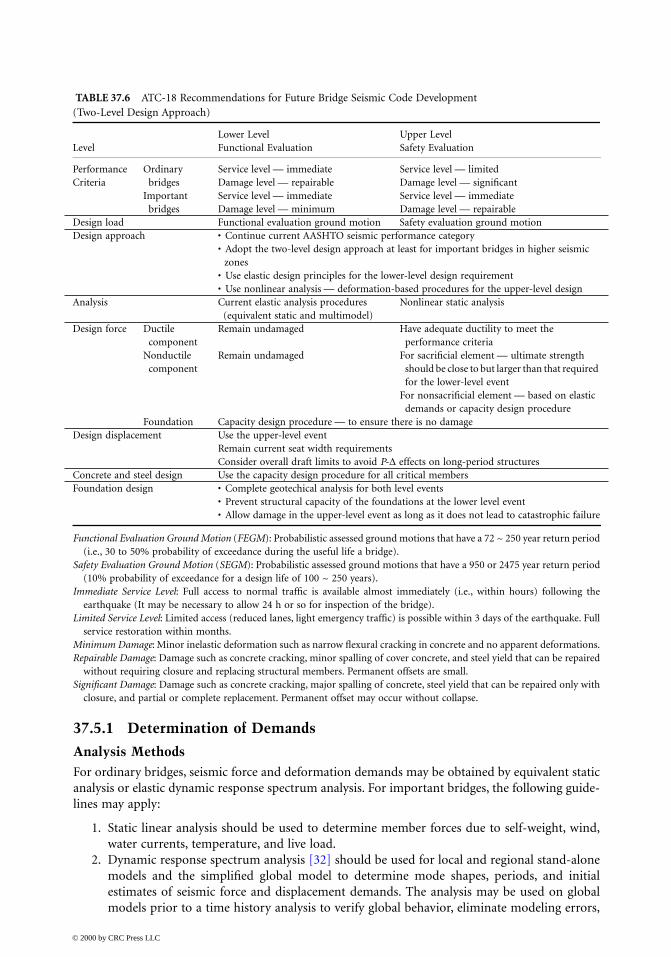
TABLE 37.6 ATC-18 Recommendations for Future Bridge Seismic Code Development (Two-Level Design Approach)
LevelLower Level Functional Evaluation
Upper Level Safety Evaluation
PerformanceCriteria
Ordinary bridges
Service level — immediateDamage level — repairable
Service level — limitedDamage level — significant
Important bridges
Service level — immediateDamage level — minimum
Service level — immediateDamage level — repairable
Design load Functional evaluation ground motion Safety evaluation ground motionDesign approach • Continue current AASHTO seismic performance category
• Adopt the two-level design approach at least for important bridges in higher seismic zones
• Use elastic design principles for the lower-level design requirement• Use nonlinear analysis — deformation-based procedures for the upper-level design
Analysis Current elastic analysis procedures (equivalent static and multimodel)
Nonlinear static analysis
Design force Ductile component
Remain undamaged Have adequate ductility to meet the performance criteria
Nonductile component
Remain undamaged For sacrificial element — ultimate strength should be close to but larger than that required for the lower-level event
For nonsacrificial element — based on elastic demands or capacity design procedure
Foundation Capacity design procedure — to ensure there is no damageDesign displacement Use the upper-level event
Remain current seat width requirementsConsider overall draft limits to avoid P-∆ effects on long-period structures
Concrete and steel design Use the capacity design procedure for all critical membersFoundation design • Complete geotechical analysis for both level events
• Prevent structural capacity of the foundations at the lower level event• Allow damage in the upper-level event as long as it does not lead to catastrophic failure
Functional Evaluation Ground Motion (FEGM): Probabilistic assessed ground motions that have a 72 ~ 250 year return period(i.e., 30 to 50% probability of exceedance during the useful life a bridge).
Safety Evaluation Ground Motion (SEGM): Probabilistic assessed ground motions that have a 950 or 2475 year return period(10% probability of exceedance for a design life of 100 ~ 250 years).
Immediate Service Level: Full access to normal traffic is available almost immediately (i.e., within hours) following theearthquake (It may be necessary to allow 24 h or so for inspection of the bridge).
Limited Service Level: Limited access (reduced lanes, light emergency traffic) is possible within 3 days of the earthquake. Fullservice restoration within months.
Minimum Damage: Minor inelastic deformation such as narrow flexural cracking in concrete and no apparent deformations.Repairable Damage: Damage such as concrete cracking, minor spalling of cover concrete, and steel yield that can be repaired
without requiring closure and replacing structural members. Permanent offsets are small.Significant Damage: Damage such as concrete cracking, major spalling of concrete, steel yield that can be repaired only with
closure, and partial or complete replacement. Permanent offset may occur without collapse.
© 2000 by CRC Press LLC

and identify initial regions or members where inelastic behavior needs further refinementand inelastic nonlinear elements. In the analysis:
• Site-specific ARS curves should be used with 5% damping.
• Modal response should be combined using the complete quadratic combination (CQC)method and the resulting orthogonal responses should be combined using either thesquare root of the sum of the squares (SRSS) method or the “30%” rule as defined byAASHTO-LRFD [1994].
3. Dynamic Time History Analysis: Site-specific multisupport dynamic time histories shouldbe used in a dynamic time history analysis [33].
• Linear elastic dynamic time history analysis is defined as a dynamic time history analysiswith consideration of geometric linearity (small displacement), linear boundary condi-tions, and elastic members. It should only be used to check regional and global models.
• Nonlinear elastic dynamic time history analysis is defined as a dynamic time historyanalysis with consideration of geometric nonlinearity, linear boundary conditions, andelastic members. It should be used to determine areas of inelastic behavior prior toincorporating inelasticity into regional and global models.
• Nonlinear inelastic dynamic time history analysis, level I, is defined as a dynamic timehistory analysis with consideration of geometric nonlinearity, nonlinear boundary condi-tions, inelastic elements (for example, seismic isolators and dampers), and elastic mem-bers. It should be used for final determination of force and displacement demands forexisting structures in combination with static gravity, wind, thermal, water current, andlive loads as specified in AASHTO-LRFD [23].
TABLE 37.7 ATC-18 Recommendations for Future Bridge Seismic Code Development (One-Level Approach)
Design philosophy For lower-level earthquake, there should be only minimum damageFor a significant earthquake, collapse should be prevented but significant damage may
occur; damage should occur at visible locationsThe following addition to Item 2 is required if different response modification (R and Z)
factors are used for important or ordinary bridgesItem 2 as it stands would apply to ordinary bridgesFor important bridges, only repairable would be expected during a significant earthquake
Design load Single-level — safety evaluation ground motion — 950 or 2475 year return period for the eastern and western portions of the U.S.
Design approach • Continue current AASHTO seismic performance category• Use nonlinear analysis deformation-based procedures with strength and stiffness
requirements being derived from appropriate nonlinear response spectraAnalysis Nonlinear static analysis should be part of any analysis requirement
At a minimum, nonlinear static analysis is required for important bridgesCurrent elastic analysis and design procedure may be sufficient for small ordinary bridgesIncorporate both current R-factor elastic procedure and nonlinear static analysis
Design Force Ductile component
R-factor elastic design procedure or nonlinear static analysis
Nonductile component
For sacrificial element, should be designed using a guideline that somewhat correspond to the design level of an unspecified lower-level event, for example, one half or one third of the force required for the upper-level event
For nonsacrificial element, should be designed for elastic demands or capacity design procedure
Foundation Capacity design procedure — to ensure there is no damageDesign displacement Maintain current seat width requirements
Consider overall draft limits to avoid P-∆ effects on long-period structuresConcrete and steel design Use the capacity design procedure for all critical membersFoundation design • Complete geotechical analysis for the upper-level event
• For nonessential bridges, a lower level (50% of the design acceleration) might be appropriate
© 2000 by CRC Press LLC

• Nonlinear inelastic dynamic time history analysis, level II, is defined as a dynamic timehistory analysis with consideration of geometric nonlinearity, nonlinear boundary condi-tions, inelastic elements (for example, dampers), and inelastic members. It should be usedfor the final evaluation of response of the structures.
Modeling Considerations
1. Global, Regional, and Local ModelsThe global models consider overall behavior and may include simplifications of complexstructural elements (Figure 37.6a). Regional models concentrate on regional behavior(Figure 37.6b). Local models (Figure 37.6c) emphasize the localized behavior, especially complexinelastic and nonlinear behavior. In regional and global models where more than one foundationlocation is included in the model, multisupport time history analysis should be used.
FIGURE 37.6 (a) Global, (b) Regional models for towers, and (c) local model for PW-1 for San Francisco–Oakland Bay Bridge west spans.
© 2000 by CRC Press LLC

2. Boundary ConditionsAppropriate boundary conditions should be included in regional models to represent theinteraction between the region and the adjacent structure. The adjacent portion is not explic-itly modeled but may be simplified using a combination of springs, dashpots, and lumpedmasses. Appropriate nonlinear elements such as gap elements, nonlinear springs, seismicresponse modification devices (SRMDs), or specialized nonlinear finite elements should beincluded where the behavior and response of the structure is sensitive to such elements.
3. Soil–Foundation–Structure InteractionThis interaction may be considered using nonlinear or hysteretic springs in global andregional models. Foundation springs to represent the properties of the soil at the base of thestructure should be included in both regional and global models (see Chapter 42).
4. DampingWhen nonlinear material properties are incorporated in the model, Rayleigh damping shouldbe reduced (perhaps 20%) from the elastic properties.
5. Seismic Response Modification DevicesThe SRMDs should be modeled explicitly with hysteretic characteristics determined by exper-imental data. See Chapter 41 for a detailed discussion of this behavior.
37.5.2 Determination of Capacities
Limit States and Resistance FactorsThe limit state is defined as that condition of a structure at which it ceases to satisfy the provisionsfor which it was designed. Two kinds of limit state corresponding to SEGM and FEGM specifiedin Table 37.4 apply for seismic design and retrofit. To account for unavoidable inaccuracies in thetheory, variation in the material properties, workmanship, and dimensions, nominal strength ofstructural components should be modified by a resistance factor φ specified by AASHTO-LRFD[23] or project-specific criteria to obtain the design capacity or strength (resistance).
Nominal Strength of Structural ComponentsThe strength capacity of structural members should be determined in accordance with specifiedcode formula [23,26, Chapters 38 and 39], or verified with experimental and analytical computermodels, or project-specific criteria [19].
Structural Deformation CapacityStructural deformation capacity should be determined by nonlinear inelastic analysis and based onacceptable damage levels as shown in Table 37.4. The quantitative definition of the damage corre-sponding to different performance requirements has not been specified by the current Caltrans BDS[26], AASHTO-LRFD [23], and ATC recommendations [18,19] because of the lack of consensus.As a starting point, Table 37.8 provides a quantitative strain and ductility limit corresponding tothe three damage levels.
The displacement capacity should be evaluated considering both material and geometric non-linearities. Proper boundary conditions for various structures should be carefully considered. Astatic push-over analysis (see Chapter 36) may be suitable for most bridges. A nonlinear inelasticdynamic time history analysis, Level II, may be required for important bridges. The availabledisplacement capacity is defined as the displacement corresponding to the most critical of (1) 20%load reduction from the peak load or (2) the strain limit specified in Table 37.8.
Seismic Response Modification DevicesSRMDs include energy dissipation and seismic isolation devices. Energy dissipation devices increasethe effective damping of the structure, thereby reducing reaction forces and deflections. Isolationdevices change the fundamental mode of vibration so that the response of the structure is lowered;however, the reduced force may be accompanied by an increased displacement.
© 2000 by CRC Press LLC

The properties of SRMDs should be determined by the specified testing program. References aremade to AASHTO [34], Caltrans [35], and Japan Ministry of Construction (JMC) [36]. Consider-ation of following items should be made in the test specifications:
• Scales — at least two full-scale test specimens are required;
• Loading (including lateral and vertical) history and rate;
• Durability — design life;
• Deterioration — expected levels of strength and stiffness.
37.5.3 Performance Acceptance Criteria
To achieve the performance objectives in Table 37.4, various structural components should satisfythe acceptable demand/capacity ratios (DCaccept,) specified in this section. The form of the equationis:
(37.4)
where demand, in terms of factored moments, shears, and axial forces, and displacement androtation deformations, should be determined by a nonlinear inelastic dynamic time history analysis,level I, for important bridges, and dynamic response spectrum analysis for ordinary bridges definedin Section 37.5.1, and capacity, in terms of factored strength and deformation capacities, should beobtained according to Section 37.5.2.
Structural Component ClassificationsStructural components are classified into two categories: critical or other. It is the aim that othercomponents may be permitted to function as fuses so that the critical components of the bridgesystem can be protected during the functionality evaluation earthquake (FEE) and the safety eval-uation earthquake (SEE). As an example, Table 37.9 shows structural component classifications andtheir definition for a suspension bridge.
TABLE 37.8 Damage Levels, Strain, and Ductility
Strain Ductility
Damage level Concrete Steel Curvature µφ Displacement µ∆
Significant εcu εsh 8 ~ 10 4 ~ 6
Repairable Larger Larger 4 ~ 6 2 ~ 4
Minimum Larger Larger 2 ~ 4 1 ~ 2
εcu = ultimate concrete compression strain depending of confinement (see Chapter 36)εy = yield strain of steelεsh = hardening strain of steelµφ = curvature ductility (φu/φy)µ∆ = displacement ductility (∆u/∆y) (see Chapter 36)
0 005
2
3
.
εcu
0 08
2
3
.
ε y
0 004.
εcu
0 03
15
.
ε y
DemandCapacity accept≤ DC
© 2000 by CRC Press LLC

Steel Structures
1. General Design ProcedureSeismic design of steel members should be in accordance with the procedure shown inFigure 37.7. Seismic retrofit design of steel members should be in accordance with the pro-cedure shown in Figure 37.8.
2. ConnectionsConnections should be evaluated over the length of the seismic event. For connecting mem-bers with force D/C ratios larger than 1.0, 25% greater than the nominal capacity of theconnecting members should be used in connection design.
3. General Limiting Slenderness Parameters and Width–Thickness RatiosFor all steel members (regardless of their force D/C ratios), the slenderness parameter foraxial load dominant members (λc) and for flexural dominant members (λb) should not exceedthe limiting values (0.9λcr or 0.9λbr for critical, λcr or λbr for Others) shown in Table 37.10.
4. Acceptable Force D/C Ratios and Limiting ValuesAcceptable force D/C ratios, DCaccept and associated limiting slenderness parameters andwidth–thickness ratios for various members are specified in Table 37.10. For all memberswith D/C ratios larger than 1.0, slenderness parameters and width–thickness ratios shouldnot exceed the limiting values specified in Table 37.10. For existing steel members with D/Cratios less than 1.0, width–thickness ratios may exceed λr specified in Table 37.11 and AISC-LRFD [37].
The following symbols are used in Table 37.10. Mu is the factored moment demand; Pu is thevactored axial force demand; Mn is the nominal moment strength of a member; Pn is the nominalaxial strength of a member; λ is the width–thickness (b/t or h/tw) ratio of a compressive element;
, the slenderness parameter of axial load dominant members; ,the slenderness parameter of flexural moment dominant members; λcp = 0.5, the limiting columnslenderness parameter for 90% of the axial yield load based on AISC-LRFD [37] column curve; λbp
is the limiting beam slenderness parameter for plastic moment for seismic design; λcr = 1.5, thelimiting column slenderness parameter for elastic buckling based on AISC-LRFD [37] column curve;λbr is the limiting beam slenderness parameter for elastic lateral torsional buckling;
TABLE 37.9 Structural Component Classification
Component Classification Definition Example (SFOBB West Spans)
Critical Components on a critical path that carry bridge gravity load directly
The loss of capacity of these components would have serious consequences on the structural integrity of the bridge
Suspension cablesContinuous trussesFloor beams and stringersTower legsCentral anchorage A-FramePiers W-1 and W2Bents A and BCaisson foundationsAnchorage housingsCable bents
Other All components other than Critical
All other components
Note: Structural components include members and connections.
λ πc yKL r F E= ( )/ / λb yL r= /
© 2000 by CRC Press LLC

FIGURE 37.7 Steel member seismic design procedure.
λbr
r
LL
r
L x
yf x
JA
M
X
FX F
MF S
F S
=
+ +
=
57 000
1 112
2
,for solid rectangular bars and box sections
for doubly symmetric I-shaped members and channels
for I - shaped member
for solid rectangular and box section
XS
EGJA
x1 2
= πX
C
I
S
G Jsw
y
x=
4F
F
F FL
yw
yf r
=−
smaller
© 2000 by CRC Press LLC

where A is the cross-sectional area, in.2; L is the unsupported length of a member; J is the torsionalconstant, in.4; r is the radius of gyration, in.; ry is the radius of gyration about minor axis, in.; Fy isthe yield stress of steel; Fyw is the yield stress of web, ksi; Fyf is the yield stress of flange, ksi; E is themodulus of elasticity of steel (29,000 ksi); G is the shear modulus of elasticity of steel (11,200 ksi);Sx is the section modulus about major axis, in.3; Iy is the moment of inertia about minor axis, in.4
and Cw is the warping constant, in.6 For doubly symmetric and singly symmetric I-shaped memberswith compression flange equal to or larger than the tension flange, including hybrid members(strong axis bending):
(37.5)
FIGURE 37.8 Steel member seismic retrofit design procedure.
λbpy
yf
M M
Fother
Fcritical
=
+[ ]
3600 2200
300
1 2 for members
for members
© 2000 by CRC Press LLC

FIGURE 37.9 Typical cross sections for steel members: (a) rolled I section; (b) hollow structured tube; (c) built-up channels; (d) built-up box section; (e) longitudinally stiffened built-up box section; (f) built-up box section.
© 2000 by CRC Press LLC

in which M1 is larger moment at end of unbraced length of beam; M2 is smaller moment at end ofunbraced length of beam; (M1/M2) is positive when moments cause reverse curvature and negativefor single curvature.
For solid rectangular bars and symmetric box beam (strong axis bending):
(37.6)
in which Mp is plastic moment (ZxFy); Zx is plastic section modulus about major axis; and λr, λp,λp–Seismic are limiting width thickness ratios specified by Table 37.11.
(37.7)
For axial load dominant members (Pu/Pn ≥ Mu/Mn)
(37.8)
For flexural moment dominant members (Mu/Mn > Pu/Pn)
TABLE 37.10 Acceptable Force Demand/Capacity Ratios and Limiting Slenderness Parameters and Width/Thickness Ratios
Acceptable Force
D/C RatioDCacceptMember Classification
Limiting Ratios
Slenderness Parameter (λc and λb)
Width/Thickness λ (b/t or h/tw)
Critical Axial load dominantPu/Pn ≥ Mu/Mn
0.9λcr
λcpr
λcp
λr
λpr
λp
DCr = 1.0
1.0 ~ 1.2DCp = 1.2
Flexural moment dominantMu/Mn > Pu/Pn
0.9λbr
λbpr
λbp
λr
λpr
λp
DCr = 1.0
1.2 ~ 1.5DCp = 1.5
Other Axial load dominantPu/Pn ≥ Mu/Mn
λcr
λcpr
λcp
λr
λpr
λp-Seismic
DCr = 1.0
1.0 ~ 2.0DCp = 2
Flexural moment dominantMu/Mn > Pu/Pn
λbr
λbpr
λbp
λr
λpr
λp-Seismic
DCr = 1.0
1.0 ~ 2.5DCp = 2.5
λbpy y
p
M M
F Fother
MJA critical
=
+ ( ) ≥
5000 3000 3000
3750
1 2 for members
for members
λ
λ λ λ
λ λ λpr
p r pp
p r
p r pp
p r
DC DC
DC DCcritical
DC DC
DC DCother
=
+ −( ) −−
+ −( ) −−
accept
-Seismic -Seismicaccept
for members
for members
λλ λ λ
λ λ λcpr
cp cr cpp
p r
cr cpp
p r
DC DC
DC DCcritical
DC DC
DC DC other
=+ −( ) −
−
+ −( ) −−
0 9. accept
cpaccept
for members
for members
© 2000 by CRC Press LLC

TABLE 37.11 Limiting Width
No Description of Elements λp λp-Seismic
1 Flanges of I-shaped rolledchannels in flexure
2 Outstanding legs of pairscontinuous contact; flanin axial compression; anprojecting from beams omembers
3 Flanges of square and rectahollow structural sectionthickness subject to bencompression; flange covdiaphragm plates betweefasteners or welds.
(tubes)
(others)
4 Unsupported width of coperforated with a succesholes
© 2000 by CRC Press LLC
-Thickness Ratios
Examples
Width-Thickness
Ratios λr
Unstiffened Elements
beams and Figure 37.19aFigure 37.19c
b/t
of angles in ges of channels gles and plates r compression
Figure 37.19dFigure 37.19eFigure 37.19f
b/t
Stiffened Elements
ngular box and of uniform
ding or er plates and n lines of
Figure 37.19b b/t
ver plates sion of access
Figure 37.19d b/t

(w/lacing)
(others)
For
For
For
For
Provisions [1997].
1994]
flange and taken at the base of the stiffener
TABLE 37.11
Limiting Width-Thickness Ratios
No Description of Elements Examples
Width-Thickness
Ratios
λ
r
λ
p
λ
p-Seismic
5 All other uniformly compressed stiffened elements, i.e., supported along two edges.
Figures 37.19a, c,d,f b/th/tw
6 Webs in flexural compression Figures 37.19a,c,d,f h/tw
7 Webs in combined flexural and axial compression
Figures 37.19a,c,d,f h/tw
8 Longitudinally stiffened plates in compression
Figure 37.19e b/t
Notes:1. Width–thickness ratios shown in bold are from AISC-LRFD [1993] and AISC-Seismic 2. k = buckling coefficient specified by Article 6.11.2.1.3a of AASHTO-LRFD [AASHTO,
for n = 1, k = (8Is / bt3)1/3 ≤ 4.0; for n = 2, 3, 4, and 5, k = (14.3Is / bt3n4)1/3 ≤ 4.0n = number of equally spaced longitudinal compression flange stiffenersIs = moment of inertia of a longitudinal stiffener about an axis parallel to the bottom
© 2000 by CRC Press LLC

(37.9)
Concrete Structures
1.
General
For all concrete compression members (regardless of
D
/
C
ratios), the slenderness parameter(
KL/r
) should not exceed 60.
For
critical
components, force
DC
accept
= 1.2 and deformation
DC
accept
= 0.4
.
For
other
components, force
DC
accept
= 2.0 and deformation
DC
accept
= 0.67.
2.
Beam–Column
(
Bent Cap
)
Joints
For concrete box-girder bridges, the beam–column (bent cap) joints should be evaluated anddesigned in accordance with the following guidelines [38,39]:a. Effective Superstructure Width: The effective width of superstructure (box girder) on
either side of a column to resist longitudinal seismic moment at bent (support) shouldnot be taken as larger than the superstructure depth.• The immediately adjacent girder on either side of a column within the effective super-
structure width is considered effective.• Additional girders may be considered effective if refined bent–cap torsional analysis
indicates that the additional girders can be mobilized.b. Minimum Bent–Cap Width: Minimum cap width outside column should not be less than
D
/4 (
D
is column diameter or width in that direction) or 2 ft (0.61 m).c. Acceptable Joint Shear Stress:
• For existing unconfined joints, acceptable principal tensile stress should be taken as If the principal tensile stress demand exceeds this limiting
value, the joint shear reinforcement specified in Item d should be provided.• For new joints, acceptable principal tensile stress should be taken as psi
( MPa).• For existing and new joints, acceptable principal compressive stress shall be taken as .
d. Joint Shear Reinforcement• Typical flexure and shear reinforcement (see Figures 37.10 and 37.11) in bent caps
should be supplemented in the vicinity of columns to resist joint shear. All joint shearreinforcement should be well distributed and provided within
D
/2 from the face ofcolumn.
• Vertical reinforcement including cap stirrups and added bars should be 20% of thecolumn reinforcement anchored into the joint. Added bars shall be hooked aroundmain longitudinal cap bars. Transverse reinforcement in the join region should consistof hoops with a minimum reinforcement ratio of 0.4(column steel area)/(embedmentlength of column bar into the bent cap)
2
.• Horizontal reinforcement should be stitched across the cap in two or more intermediate
layers. The reinforcement should be shaped as hairpins, spaced vertically at not morethan 18 in. (457 mm). The hairpins should be 10% of column reinforcement. Spacingshould be denser outside the column than that used within the column.
• Horizontal side face reinforcement should be 10% of the main cap reinforcementincluding top and bottom steel.
λλ λ λ
λ λ λbpr
bp br bpp
p r
bp br bpp
p r
DC DC
DC DCcritical
DC DC
DC DCother
+ −( ) −−
+ −( ) −−
0 9. accept
accept
for members
for members
3 5. .′ ′( )f fc c psi 0.29 MPa
12 ′fc
1 0. ′fc
′fc
© 2000 by CRC Press LLC
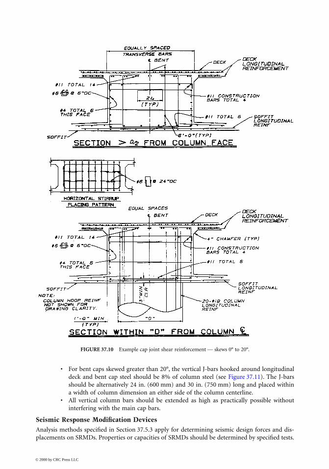
• For bent caps skewed greater than 20°, the vertical J-bars hooked around longitudinaldeck and bent cap steel should be 8% of column steel (see Figure 37.11). The J-barsshould be alternatively 24 in. (600 mm) and 30 in. (750 mm) long and placed withina width of column dimension an either side of the column centerline.
• All vertical column bars should be extended as high as practically possible withoutinterfering with the main cap bars.
Seismic Response Modification Devices
Analysis methods specified in Section 37.5.3 apply for determining seismic design forces and dis-placements on SRMDs. Properties or capacities of SRMDs should be determined by specified tests.
FIGURE 37.10
Example cap joint shear reinforcement — skews 0° to 20°.
© 2000 by CRC Press LLC

SRMDs should be able to perform their intended function and maintain their design parametersfor the design life (for example, 40 years) and for an ambient temperature range (for example, from30 to 125°F). The devices should be accessible for inspection, maintenance, and replacement. Ingeneral, SRMDs should satisfy at least the following requirements:
• Strength and stability must be maintained under increasingly large displacement. Stiffnessdegradation under repeated cyclic load is unacceptable.
• Energy must be dissipated within acceptable design displacement limits, for example, a limiton the maximum total displacement of the device to prevent failure, or the device can begiven a displacement capacity 50% greater than the design displacement.
FIGURE 37.11
Example cap joint shear reinforcement — skews > 20°.
© 2000 by CRC Press LLC
• Heat builtup must be withstood and dissipated during “reasonable” seismic displacementtime history.
• The device must survive subjected to the number of cycles of displacement expected underwind excitation during the life of the device and continue to function at maximum windforce and displacement levels for at least a given duration.
37.5.4 Acceptable Force
D/C
Ratios and Limiting Values for Structural Members
It is impossible to design bridges to withstand seismic forces elastically and the nonlinear inelasticresponse is expected. Performance-based criteria accept certain seismic damage in
other
componentsso the
critical
components will remain essentially elastic and functional after the SEE and FEE. Thissection presents the concept of acceptable force
D
/
C
ratios, limiting member slenderness parameters,and limiting width–thickness ratios, as well as expected ductility.
Definition of Force Demand/Capacity (D/C) Ratios
For members subjected to a single load, force demand is defined as a factored single force, such asfactored moment, shear, or axial force. This may be obtained by a nonlinear dynamic time historyanalysis, level I, as specified in Section 37.5.1 and capacity is prescribed in Section 37.5.2.
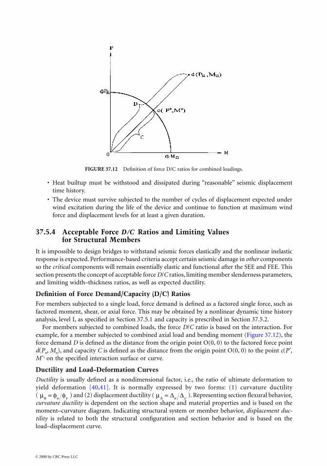
For members subjected to combined loads, the force
D
/
C
ratio is based on the interaction. Forexample, for a member subjected to combined axial load and bending moment (Figure 37.12), theforce demand
D
is defined as the distance from the origin point O(0, 0) to the factored force point
d
(
P
u
,
M
u
), and capacity
C
is defined as the distance from the origin point O(0, 0) to the point
c
(
P
*
,
M*) on the specified interaction surface or curve.
Ductility and Load–Deformation CurvesDuctility is usually defined as a nondimensional factor, i.e., the ratio of ultimate deformation toyield deformation [40,41]. It is normally expressed by two forms: (1) curvature ductility( ) and (2) displacement ductility ( ). Representing section flexural behavior,curvature ductility is dependent on the section shape and material properties and is based on themoment–curvature diagram. Indicating structural system or member behavior, displacement duc-tility is related to both the structural configuration and section behavior and is based on theload–displacement curve.
FIGURE 37.12 Definition of force D/C ratios for combined loadings.
µ =φ φ φu y µ =∆ ∆ ∆u y
© 2000 by CRC Press LLC

A typical load–deformation curve, including both ascending and descending branches, is shownin Figure 37.13. The yield deformation (∆y or φy) corresponds to a loading state beyond which thestructure responds inelastically. The ultimate deformation (∆u or φu) refers to the loading state atwhich a structural system or member can sustain without losing significant load-carrying capacity.Depending on performance requirements, it is proposed that the ultimate deformation (curvatureor displacement) be defined as the most critical of (1) that deformation corresponding to a loaddropping a maximum of 20% from the peak load or (2) that specified strain limit shown inTable 37.8.
Force D/C Ratios and DuctilityThe following discussion will give engineers a direct measure of the seismic damage incurred bystructural components during an earthquake. Figure 37.14 shows a typical load–response curve fora single-degree-of-freedom system. Displacement ductility is defined as
FIGURE 37.13 Load–deformation cCurves.
FIGURE 37.14 Response of a single-degree of freedom system.
© 2000 by CRC Press LLC
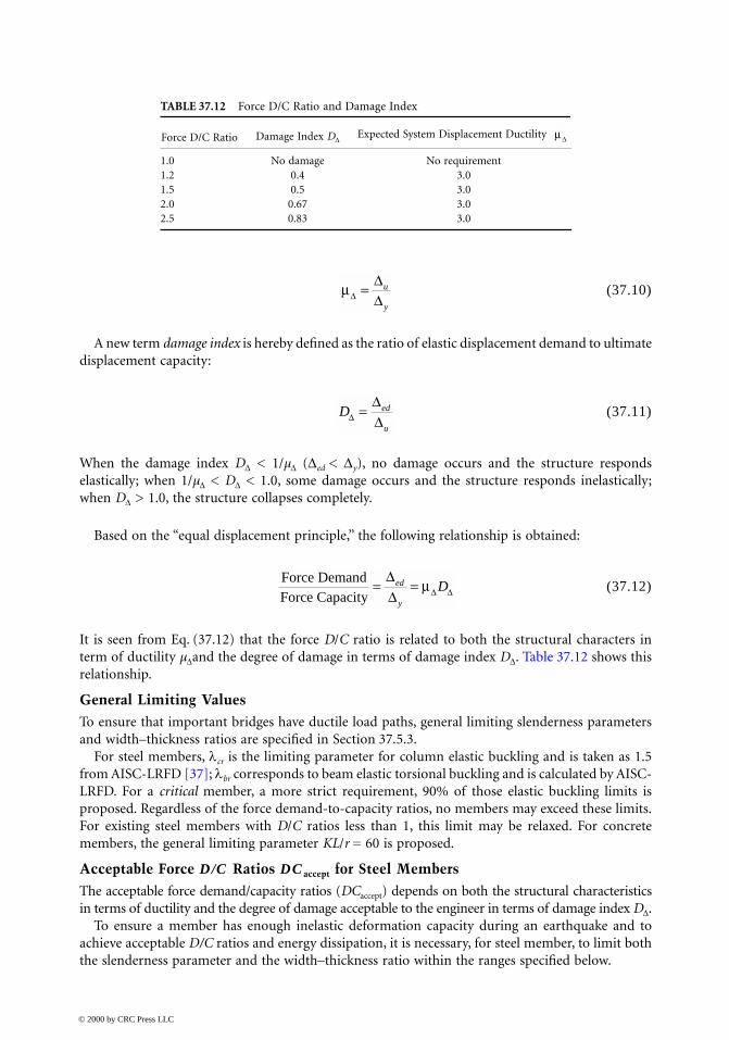
(37.10)
A new term damage index is hereby defined as the ratio of elastic displacement demand to ultimatedisplacement capacity:
(37.11)
When the damage index D∆ < 1/µ∆ (∆ed < ∆y), no damage occurs and the structure respondselastically; when 1/µ∆ < D∆ < 1.0, some damage occurs and the structure responds inelastically;when D∆ > 1.0, the structure collapses completely.
Based on the “equal displacement principle,” the following relationship is obtained:
(37.12)
It is seen from Eq. (37.12) that the force D/C ratio is related to both the structural characters interm of ductility µ∆and the degree of damage in terms of damage index D∆. Table 37.12 shows thisrelationship.
General Limiting ValuesTo ensure that important bridges have ductile load paths, general limiting slenderness parametersand width–thickness ratios are specified in Section 37.5.3.
For steel members, λcr is the limiting parameter for column elastic buckling and is taken as 1.5from AISC-LRFD [37]; λbr corresponds to beam elastic torsional buckling and is calculated by AISC-LRFD. For a critical member, a more strict requirement, 90% of those elastic buckling limits isproposed. Regardless of the force demand-to-capacity ratios, no members may exceed these limits.For existing steel members with D/C ratios less than 1, this limit may be relaxed. For concretemembers, the general limiting parameter KL/r = 60 is proposed.
Acceptable Force D/C Ratios DCaccept for Steel MembersThe acceptable force demand/capacity ratios (DCaccept) depends on both the structural characteristicsin terms of ductility and the degree of damage acceptable to the engineer in terms of damage index D∆.
To ensure a member has enough inelastic deformation capacity during an earthquake and toachieve acceptable D/C ratios and energy dissipation, it is necessary, for steel member, to limit boththe slenderness parameter and the width–thickness ratio within the ranges specified below.
TABLE 37.12 Force D/C Ratio and Damage Index
Force D/C Ratio Damage Index D∆Expected System Displacement Ductility
1.0 No damage No requirement1.2 0.4 3.01.5 0.5 3.02.0 0.67 3.02.5 0.83 3.0
µ∆
µ∆∆∆
= u
y
D ed
u∆
∆∆
=
Force DemandForce Capacity
= =∆∆ ∆ ∆
ed
y
Dµ
© 2000 by CRC Press LLC
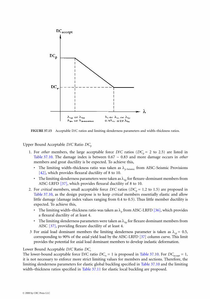
Upper Bound Acceptable D/C Ratio DCp
1. For other members, the large acceptable force D/C ratios (DCp = 2 to 2.5) are listed inTable 37.10. The damage index is between 0.67 ~ 0.83 and more damage occurs in othermembers and great ductility is be expected. To achieve this,
• The limiting width–thickness ratio was taken as λp-Seismic from AISC-Seismic Provisions[42], which provides flexural ductility of 8 to 10.
• The limiting slenderness parameters were taken as λbp for flexure-dominant members fromAISC-LRFD [37], which provides flexural ductility of 8 to 10.
2. For critical members, small acceptable force D/C ratios (DCp = 1.2 to 1.5) are proposed inTable 37.10, as the design purpose is to keep critical members essentially elastic and allowlittle damage (damage index values ranging from 0.4 to 0.5). Thus little member ductility isexpected. To achieve this,
• The limiting width–thickness ratio was taken as λp from AISC-LRFD [36], which providesa flexural ductility of at least 4.
• The limiting slenderness parameters were taken as λbp for flexure dominant members fromAISC [37], providing flexure ductility of at least 4.
3 For axial load dominant members the limiting slenderness parameter is taken as λcp = 0.5,corresponding to 90% of the axial yield load by the AISC-LRFD [37] column curve. This limitprovides the potential for axial load dominant members to develop inelastic deformation.
Lower Bound Acceptable D/C Ratio DCr
The lower-bound acceptable force D/C ratio DCrc = 1 is proposed in Table 37.10. For DCaccept = 1,it is not necessary to enforce more strict limiting values for members and sections. Therefore, thelimiting slenderness parameters for elastic global buckling specified in Table 37.10 and the limitingwidth–thickness ratios specified in Table 37.11 for elastic local buckling are proposed.
FIGURE 37.15 Acceptable D/C ratios and limiting slenderness parameters and width–thickness ratios.
© 2000 by CRC Press LLC
Acceptable D/C Ratios between Upper and Lower Bounds DCr < DCaccept < DCp
When acceptable force D/C ratios are between the upper and the lower bounds, DCr < DCaccept <DCp, a linear interpolation (Eqs. 37.7 to 37.9) as shown in Figure 37.15 is proposed to determinethe limiting slenderness parameters and width–thickness ratios.
37.6 Summary
Seismic bridge design philosophies and current practice in the United States have been discussed.“No-collapse” based design is usually applied to ordinary bridges, and performance-based designis used for important bridges. Sample performance-based seismic design criteria are presented tobridge engineers as a reference guide. This chapter attempted to address only some of the manyissues incumbent upon designers of bridges for adequate performance under seismic load. Engineersare always encouraged to incorporate to the best of their ability the most recent research findingsand the most recent experimental evidence learned from past performance under real earthquakes.
References
1. ATC, Seismic Design Guidelines for Highway Bridges, Report No. ATC-6, Applied TechnologyCouncil, Redwood City, CA, 1981.
2. Housner, G. W. Competing against Time, Report to Governor George Deuknejian from the Gov-ernor’s Broad of Inquiry on the 1989 Loma Prieta Earthquake, Sacramento, 1990.
3. Caltrans, The First Annual Seismic Research Workshop, Division of Structures, California Depart-ment of Transportation, Sacramento, 1991.
4. Caltrans, The Second Annual Seismic Research Workshop, Division of Structures, CaliforniaDepartment of Transportation, Sacramento, 1993.
5. Caltrans, The Third Annual Seismic Research Workshop, Division of Structures, California Depart-ment of Transportation, Sacramento, 1994.
6. Caltrans, The Fourth Caltrans Seismic Research Workshop, Engineering Service Center, CaliforniaDepartment of Transportation, Sacramento, 1996.
7. Caltrans, The Fifth Caltrans Seismic Research Workshop, Engineering Service Center, CaliforniaDepartment of Transportation, Sacramento, 1998.
8. FHWA and Caltrans, Proceedings of First National Seismic Conference on Bridges and Highways, SanDiego, 1995.
9. FHWA and Caltrans, Proceedings of Second National Seismic Conference on Bridges and Highways,Sacramento, 1997.
10. Kawashima, K. and Unjoh, S., The damage of highway bridges in the 1995 Hyogo-Ken Naubuearthquake and its impact on Japanese seismic design, J. Earthquake Eng., 1(2), 1997, 505.
11. Park, R., Ed., Seismic design and retrofitting of reinforced concrete bridges, in Proceedings of theSecond International Workshop, held in Queenstown, New Zealand, August, 1994.
12. Astaneh-Asl, A. and Roberts, J. Eds., Seismic Design, Evaluation and Retrofit of Steel Bridges, Pro-ceedings of the First U.S. Seminar, San Francisco, 1993.
13. Astaneh-Asl, A. and Roberts, J., Ed., Seismic Design, Evaluation and Retrofit of Steel Bridges, Pro-ceedings of the Second U.S. Seminar, San Francisco, 1997.
14. Housner, G.W., The Continuing Challenge — The Northridge Earthquake of January 17, 1994, Reportto Director, California Department of Transportation, Sacramento, 1994.
15. Priestley, M. J. N., Seible, F. and Calvi, G. M., Seismic Design and Retrofit of Bridges, John Wiley &Sons, New York, 1996.
16. Caltrans, Design Criteria for SR-14/I-5 Replacement, California Department of Transportation,Sacramento, 1994.
© 2000 by CRC Press LLC

17. Caltrans, San Francisco–Oakland Bay Bridge West Spans Seismic Retrofit Design Criteria, Preparedby Reno, M. and Duan, L., Edited by Duan, L., California Department of Transportation, Sacra-mento, 1997.
18. ATC, Improved Seismic Design Criteria for California Bridges: Provisional Recommendations,Report No. ATC-32, Applied Technology Council, Redwood City, CA, 1996.
19. Rojahn, C., et al., Seismic Design Criteria for Bridges and Other Highway Structures, Report NCEER-97-0002, National Center for Earthquake Engineering Research, State University of New York at Buffalo,Buffalo, 1997. Also refer as ATC-18, Applied Technology Council, Redwood City, CA, 1997.
20. Caltrans, Bridge Memo to Designers (20-1) — Seismic Design Methodology, California Depart-ment of Transportation, Sacramento, January 1999.
21. FHWA, Seismic Design and Retrofit Manual for Highway Bridges, Report No. FHWA-IP-87-6,Federal Highway Administration, Washington, D.C., 1987.
22. FHWA. Seismic Retrofitting Manual for Highway Bridges, Publ. No. FHWA-RD-94-052, FederalHighway Administration, Washington, D.C., 1995.
23. AASHTO, LRFD Bridge Design Specifications, 2nd. ed., American Association of State Highway andTransportation Officials, Washington, D.C., 1994 and 1996.
24. AASHTO, Standard Specifications for Highway Bridges, 16th ed., American Association of StateHighway and Transportation Officials, Washington, D.C., 1996.
25. Caltrans, Bridge Memo to Designers (20-4), California Department of Transportation, Sacramento, 1995.26. Caltrans, Bridge Design Specifications, California Department of Transportation, Sacramento, 1990.27. Caltrans, Bridge Design Aids, California Department of Transportation, Sacramento, 1995.28. IAI, Benicia-Martinez Bridge Seismic Retrofit — Main Truss Spans Final Retrofit Strategy Report,
Imbsen and Association, Inc., Sacramento, 1995.29. Priestley, N., Myths and fallacies in earthquake engineering — conflicts between design and reality,
in Proceedings of Tom Paulay Symposium — Recent Development in Lateral Force Transfer in Build-ings, University of California, San Diego, 1993.
30. Kowalsky, M. J., Priestley, M. J. N., and MacRae, G. A., Displacement-Based Design, Report No.SSRP-94/16, University of California, San Diego, 1994.
31. Martin, G. R. and Dobry, R., Earthquake Site Response and Seismic Code Provisions, NCEERBulletin, Vol. 8, No. 4, National Center for Earthquake Engineering Research, Buffalo, NY, 1994.
32. Gupta, A. K. Response Spectrum Methods in Seismic Analysis and Design of Structures, CRC Press,Boca Raton, FL, 1992.
33. Clough, R. W. and Penzien, J., Dynamics of Structures, 2nd ed., McGraw-Hill, New York, 1993.34. AASHTO, Guide Specifications for Seismic Isolation Design, American Association of State Highway
and Transportation Officials, Washington, D.C., 1997.35. Caltrans, Full Scale Isolation Bearing Testing Document (Draft), Prepared by Mellon, D., California
Department of Transportation, Sacramento, 1997.36. Japan Ministry of Construction (JMC), Manual of Menshin Design of Highway Bridges, (English
version: EERC, Report 94/10, University of California, Berkeley), 1994.37. AISC, Load and Resistance Factor Design Specification for Structural Steel Buildings, 2nd ed., Amer-
ican Institute of Steel Construction, Chicago, IL, 1993.38. Zelinski, R., Seismic Design Memo, Various Topics, Preliminary Guidelines, California Department
of Transportation, Sacramento, 1994.39. Caltrans, Seismic Design Criteria for Retrofit of the West Approach to the San Francisco–Oakland
Bay Bridge. Prepared by M. Keever, California Department of Transportation, Sacramento, 1996.40. Park, R. and Paulay, T., Reinforced Concrete Structures, John Wiley & Sons, New York, 1975.41. Duan, L. and Cooper, T. R., Displacement ductility capacity of reinforced concrete columns, ACI
Concrete Int., 17(11), 61–65, 1995.42. AISC, Seismic Provisions for Structural Steel Buildings, American Institute of Steel Construction,
Chicago, IL, 1991.43. Caltrans, Seismic Design Criteria, Vers. 1.0, California Department of Transportation, Sacramento, 1999.
© 2000 by CRC Press LLC
Related Documents