Chapter 25 Solutions 25.1 a) = −̂ b) Δ= ∙ = −̂∙̂ = c) Capacitance is found using = Δ = = THINK: You could stop here but that is a bad idea….this result is pretty meaningless. You know = for a plate. This will simplify the result. = = d) As decreases, capacitance increases! e) Increase area to increase capacitance. f) ≈56pF g) In parallel plates we know electric field magnitude is given by = Δ Rearranging and plugging values gives = Δ ≈ 9V 3×10 V m ≈3μm h) We know = = = = ≈834nC i) Use = ℎ × ℎ ℎ = ℎ = ≈5.2×10 electrons

Welcome message from author
This document is posted to help you gain knowledge. Please leave a comment to let me know what you think about it! Share it to your friends and learn new things together.
Transcript

Chapter 25 Solutions
25.1
a) ��� = ��� �−�
b) Δ� = � ��� ∙ ������������ = � �
�� �−� ∙ ���� = ��
��
c) Capacitance is found using
� = �Δ�
� = � �!�
� = � !� �
THINK: You could stop here but that is a bad idea….this result is pretty meaningless.
You know = "# for a plate. This will simplify the result.
� = � !�$�%&�
� = !�%�
d) As � decreases, capacitance increases!
e) Increase area to increase capacitance.
f) � ≈ 56pF
g) In parallel plates we know electric field magnitude is given by
� = ��
Rearranging and plugging values gives
� = Δ�� ≈ 9V
3 × 10² Vm≈ 3μm
h) We know
� = !�
= !��
�% = !��
� = !�%�
� ≈ 834nC
i) Use
��9� = :;<=>?@ABCℎE@F?� G × : =EF;HI<�?ABA;?CℎE@F?G
;<=>?@ABCℎE@F?� = �
=EF;HI<�?ABA;?CℎE@F?
J = �?
J ≈ 5.2 × 10MNelectrons

25.2
a) ��� = − V"WX @
b) Potential difference is
Δ� = −Y ���Z
�∙ ���
In this case we move radially outwards as we go from one conductor to the other.
This implies ��� = �@@.
Δ� = −Y :−[�@N @G
Z
�∙ ��@@�
Δ� = Y [�@N �@
Z
��@ ∙ @�
Δ� = [�Y �@@N
Z
�
Δ� = [� \−1@]�
Z
Δ� = [� \+1@]Z
�
Δ� = [� \1E −1>]
_` = ab�c − d�cd
c) Capacitance is found using
� = �Δ�
� = �[��> − E�
>E
� = >E[�> − E�
e = fghicd�c − d�
d) When c → ∞
Δ� = [� \1E −1>] →
[�E
elmnodpqrmstquq = fghid
25.3
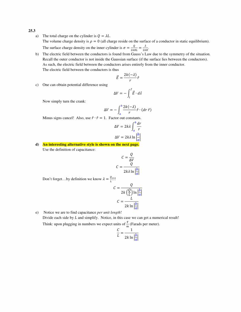
a) The total charge on the cylinder is � = vw.
The volume charge density is x = 0 (all charge reside on the surface of a conductor in static equilibrium).
The surface charge density on the inner cylinder is = "Nyz{ =
|Nyz.
b) The electric field between the conductors is found from Gauss’s Law due to the symmetry of the situation.
Recall the outer conductor is not inside the Gaussian surface (if the surface lies between the conductors).
As such, the electric field between the conductors arises entirely from the inner conductor.
The electric field between the conductors is thus
��� = 2[�−v�@ @
c) One can obtain potential difference using
Δ� = −Y ��� ∙ ����
�
Now simply turn the crank:
Δ� = −Y 2[�−v�@ @ ∙ ��@@�
Z
�
Minus signs cancel! Also, use @ ∙ @ = 1. Factor out constants.
Δ� = 2[vY �@@
Z
�
Δ� = 2[v ln }>E} d) An interesting alternative style is shown on the next page.
Use the definition of capacitance:
� = �Δ�
� = �2[v ln ~>E~
Don’t forget…by definition we know v = "{!!!
� = �2[ $�w& ln ~
>E~
� = w2[ ln ~>E~
e) Notice we are to find capacitance per unit length!
Divide each side by w and simplify. Notice, in this case we can get a numerical result!
Think: upon plugging in numbers we expect units of �� (Farads per meter).
�w = 1
2[ ln ~>E~

Alternative solution to problem 25.3
Consider the cross-sectional view shown at right.
Imagine building the total capacitance by considering each of the colored slices as a
single capacitor.
All one need do is add up the small differential capacitances in series.
Said another way
1��� =
1�M +
1�N +⋯ 1
��
��� = 1 1�M +
1�N +⋯ 1
��
where J is the number of slices.
Using calculus to do the sum gives
��� = 1� 1
��
Now we need only determine �� for a single slice.
Consider the green slice at right.
If we slice it thinly, it is well approximately by a parallel plate capacitor.
�� = !�%� = !��2�@w�
�@
Therefore
��� = 1� 1
���zNz
��� = 1� �@
2�!�@wZ�
��� = 2�!�w� �@
@Z�
��� = w2[ ln >E
@

25.4 The result of 23.15 was
����9��� = 2[v : 1� + � +
1� + � − �G
From there, use our standard procedure:
• Determine Δ� from Δ� = −���� ∙ ���. • Take the absolute value and shove into � = "
|��|.
∆� = −Y ��� ∙ ����
�
∆���i�9��� = −Y 2[v : 1� + � +
1� + � − �G ∙ ��
���
���
Since we are going from a plus charge to a minus charge we expect
the result should be ∆���i�9��� � 0.
Use an online integration program to check this result.
If you care, ask me and I’ll write it up more thoroughly.
�
+v −v
� �
� � − �

25.5 On this page I work all the way down to get the equivalent capacitance.
On the next page I work my way back up to get b, _`, and � for each capacitor.
+ 1.5 V -
5 µF 15 µF
8.25 µF
24 µF
+ 1.5 V -
3.75 µµµµF
8.25 µF
24 µF
Get Ceq
for the
two in
series on
the top
+ 1.5 V -
12 µµµµF 24 µF
Get Ceq
for the
two in
parallel
+ 1.5 V -
8 µµµµF
Get Ceq
for the
two in
series
��� = �M�N�M + �N
��� = �5μF��15μF�5μF ^ 15μF
��� � 3.75μF
��� � �M ^ �N
��� � 3.75μF ^ 8.25μF
��� � 12μF
��� ��M�N
�M ^ �N
��� ��12μF��24μF�
12μF ^ 24μF
��� � 8μF
We now have a single Cap in a circuit with the battery.
Now we know ��������9W � �Z����W�.
Use � � �� & � �M
N�Δ� to determine the
values shown at left.
Δ� � 1.5Vbecauseinparallelwithbattery � � Δ�� � �1.5V��8μF� � 12μC
� �1
2�Δ� �
1
2�12μC��1.5V� � 9μJ

Problem 25.5 continued…
Start at the bottom of the page and work upwards to get b, _`, and � for each capacitor.
+ 1.5 V -
5 µF 15 µF
8.25 µF
24 µF
+ 1.5 V -
3.75 µF
8.25 µF
24 µF
+ 1.5 V -
12 µF 24 µF
+ 1.5 V -
8 µF SERIES combination:
Each Cap has
SAME b
as equivalent Cap � � 12μC
Δ� � 1.5V
� � 9μJ
From work on previous page
� � 12μC�sameasequivalent�
� ��
��12μC
12μF� 1.0V
� �1
2�Δ� �
1
2�12μC��1.0V� � 6μJ
PARALLEL combination: Each Cap has
SAME _` as equivalent Cap
SERIES combination: Each Cap has
SAME b as equivalent Cap
PARALLEL combination: Verify the
SUM of b’s = bq¡
SERIES combination: Verify the
SUM of _`’s = _`q¡
SERIES combination: Verify the
SUM of ¢`’s = ¢`q¡
� � 12 μC �same as equivalent� Δ� � �� � 12 μC24 μF � 0.5 V � � 12 �Δ� � 12 �12 μC��0.5 V� � 3 μJ
Final Check:
The sum of all �’s is equal to
��� at the bottom of the page!
Δ� � 1.0 V �same as equivalent� � � Δ�� � �1.0 V��3.75 μF� � 3.75 μC
� � 12 �Δ� � 12 �3.75 μC��1.0 V� � 1.875 μJ
Δ� � 1.0 V �same as equivalent� � � Δ�� � �1.0 V��8.25 μF� � 8.25 μC
� � 12 �Δ� � 12 �8.25 μC��1.0 V� � 4.125 μJ
�previously determined … � � � 12 μC Δ� � 0.5 V � � 3 μJ
�previously determined … � � � 12 μC Δ� � 0.5 V � � 3 μJ �previously determined … � � � 8.25 μC Δ� � 1.0 V � � 4.125 μJ
� � 3.75 μC �same as equivalent� Δ� � �� � 3.75 μC5 μF � 0.75 V � � 12 �Δ� � 12 �3.75 μC��0.75 V� � 1.406 μJ
� � 3.75 μC �same as equivalent� Δ� � �� � 3.75 μC15 μF � 0.25 V � � 12 �Δ� � 12 �3.75 μC��0.25 V� � 0.469 μJ

25.6
Answers to A through D in table. Answers to E & F in circuit pictures below.
A �MN ¥ �M equiv. cap is larger than either cap in parallel!
B �M � �N smaller cap carries less charge in parallel
C Δ�M � Δ�N caps have same voltage across in parallel
D �M � �N smaller cap stores less energy in parallel
For most people the above results seem fairly intuitive. Hopefully you got 3 or 4 guesses correct. The circuit and its
equivalent are shown with the details of the calculation below.
¦
¦
�MN � �M ^ �N � 5�
Δ�MN � ¦
�MN � 5¦�
�MN � 12 �MNΔ�MN � 52 ¦N� � 2.5¦N�
�N � 4� In ∥ caps have same Δ� as equiv. Δ�N � Δ�MN � ¦ Now use �N � Δ�N�N to find �N � ¦�4�� � 4¦�
�N � 12 �NΔ�N � 2¦N�
�M � � In ∥ caps have same Δ� as equiv. Δ�M � Δ�MN � ¦ Now use �M � Δ�M�M to find �M � ¦��� � ¦�
�M � 12 �MΔ�M � 12 ¦N�
Notice total energy and total charge match the equivalent circuit.

25.7
Answers to A through D in table. Answers to E & F in circuit pictures below.
A �MN � �M equiv. cap is smaller than either cap in series!
B �M � �N caps carry same charge in series
C Δ�M ¥ Δ�N smaller cap has greater voltage across in series!
D �M ¥ �N smaller cap stores more energy in series!
The circuit and its equivalent are shown below. Notice the larger capacitor has a smaller potential difference in a
series capacitor network! I think of it like this: in series any extra charge on the bottom plate of the upper capacitor
must come from the upper plate of the lower capacitor (assuming there are no sparks across the capacitor). This
helps me see why capacitors in series must have the same charge. In turn, less voltage need be applied across the
larger capacitor to store the same amount of charge in series. As a result, it also stores less energy in series!
¦
�M � �
In series caps have same charge as equiv.
�M � �MN � 45 ¦�
Now rearrange �M � Δ�M�M to find
Δ�M � �M�M � 45 ¦�� � 45 ¦
�M � 12 �MΔ�M � 825 ¦N� � 0.32¦N� ¦
�MN � �M�N�M ^ �N � 4�N5� � 45 �
Δ�MN � ¦
�MN � 45 ¦�
�MN � 12 �MNΔ�MN � 25 ¦N� � 0.40¦N�
�N � 4� In series caps have same charge as equiv.
�N � �MN � 45 ¦�
Now rearrange �N � Δ�N�N to find
Δ�N � �N�N � 45 ¦�4� � 15 ¦
�N � 12 �NΔ�N � 225 ¦N� � 0.08¦N�
Notice total energy and total charge match the equivalent circuit.
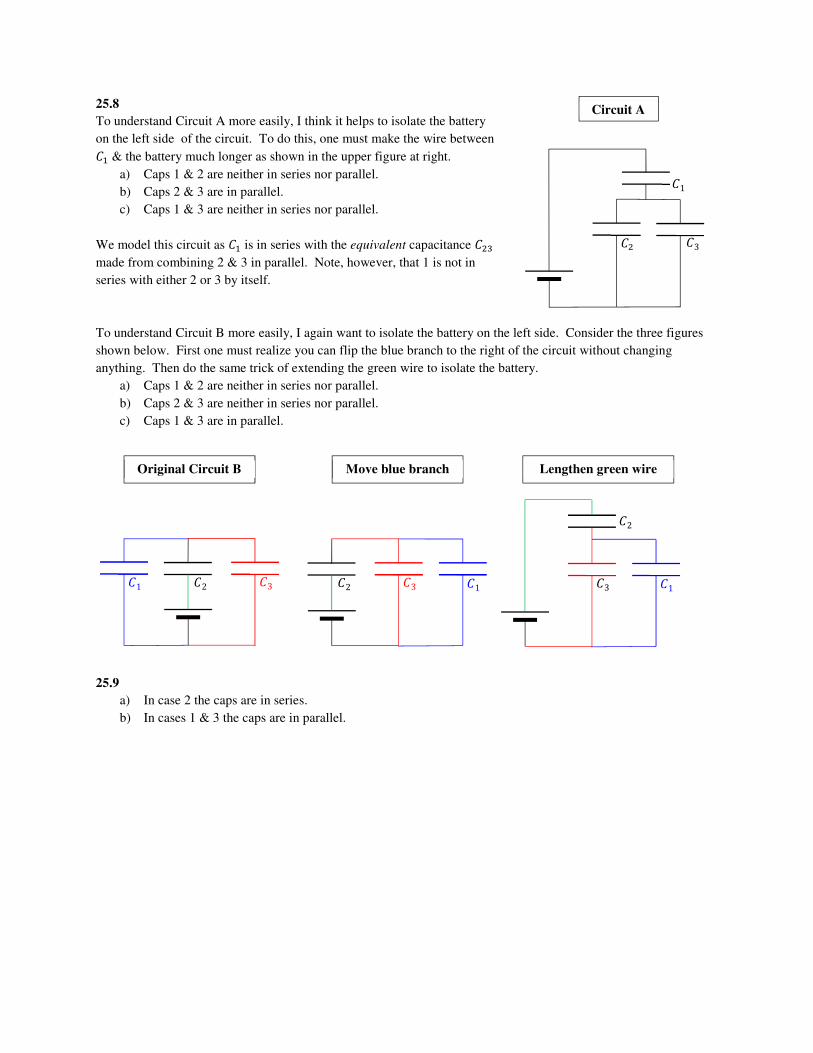
25.8
To understand Circuit A more easily, I think it helps to isolate the battery
on the left side of the circuit. To do this, one must make the wire between �M & the battery much longer as shown in the upper figure at right.
a) Caps 1 & 2 are neither in series nor parallel.
b) Caps 2 & 3 are in parallel.
c) Caps 1 & 3 are neither in series nor parallel.
We model this circuit as �M is in series with the equivalent capacitance �N¨
made from combining 2 & 3 in parallel. Note, however, that 1 is not in
series with either 2 or 3 by itself.
To understand Circuit B more easily, I again want to isolate the battery on the left side. Consider the three figures
shown below. First one must realize you can flip the blue branch to the right of the circuit without changing
anything. Then do the same trick of extending the green wire to isolate the battery.
a) Caps 1 & 2 are neither in series nor parallel.
b) Caps 2 & 3 are neither in series nor parallel.
c) Caps 1 & 3 are in parallel.
25.9
a) In case 2 the caps are in series.
b) In cases 1 & 3 the caps are in parallel.
�N
�1
�3
Circuit A
�2 �1 �3
Original Circuit B
�2 �1 �3
Move blue branch
�2
�1 �3
Lengthen green wire
25.10
a) As seen in the previous examples, to increase a circuit’s equivalent capacitance you must add capacitors in
parallel.
b) Yes. If you insert a single extra capacitor in parallel we know the voltage across each capacitor is the same
as the voltage across the battery. If added in parallel, the extra capacitor will not change the charge,
potential difference, or stored energy for the original capacitor in the circuit.
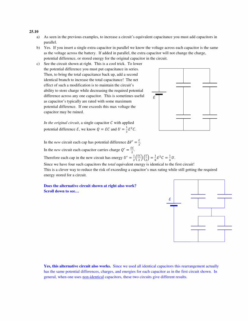
c) See the circuit shown at right. This is a cool trick. To lower
the potential difference you must put capacitance in series.
Then, to bring the total capacitance back up, add a second
identical branch to increase the total capacitance! The net
effect of such a modification is to maintain the circuit’s
ability to store charge while decreasing the required potential
difference across any one capacitor. This is sometimes useful
as capacitor’s typically are rated with some maximum
potential difference. If one exceeds this max voltage the
capacitor may be ruined.
In the original circuit, a single capacitor � with applied
potential difference ¦, we know � � ¦� and � � MN ¦N�.
In the new circuit each cap has potential difference Δ�′ � ¦N.
In the new circuit each capacitor carries charge �ª � ¦«N .
Therefore each cap in the new circuit has energy �ª � MN $¦«N & $¦N& � M¬ ¦N� � M �.
Since we have four such capacitors the total equivalent energy is identical to the first circuit!
This is a clever way to reduce the risk of exceeding a capacitor’s max rating while still getting the required
energy stored for a circuit.
Does the alternative circuit shown at right also work?
Scroll down to see…
Yes, this alternative circuit also works. Since we used all identical capacitors this rearrangement actually
has the same potential differences, charges, and energies for each capacitor as in the first circuit shown. In
general, when one uses non-identical capacitors, these two circuits give different results.
¦
¦

25.11 First I would redraw the original circuit as shown at right. All I did was
make the green wire in the figure really long so I could isolate the battery.
a) Start with the red branch; those caps are in series so use
�N¨ � �N�¨�N ^ �¨ � 65 �
Next combine the red and blue branches; they are in parallel so use
�N¨ � �N¨ ^ � � �N�¨�N ^ �¨ ^ � � 115 �
Finally, caps �M and �N¨ are in series so use
�MN¨ � �M�N¨�M ^ �N¨ � �M $ �N�¨�N ^ �¨ ^ �&�M ^ $ �N�¨�N ^ �¨ ^ �& � � $115 �&
� ^ $115 �& � 1116 � � i. ®¯°±e
b) At first things seem hopeless as we do not know the voltage of the battery. It
feels like there is no way to start. Don’t worry. Assume the battery voltage is ¦
and go about business as usual. At the end you will have algebraic expressions
for charges on each capacitor. You can use that expression to determine ¦ in
terms of the known quantities.
Total charge is �MN¨ � ¦�MN¨ � MMM2 ¦�.
We know �MN¨ came from a series combination of �N¨ and �M. This means both caps have the same charge as �MN¨.
This means �M � �N¨ � �MN¨ � ¦�MN¨ � MMM2 ¦�.
We can use this fact and � � Δ�� to find the potential difference across �N¨.
Rearranging we have Δ� � "«.
ΔVN¨ � �N¨�N¨ � ¦�MN¨�N¨ � 1116 ¦�115 � � 516 ¦ � 0.3125¦
We know �N¨ came from �N¨ and � in parallel.
This means �N¨ and � have the same potential difference as �N¨.
In symbols we say ΔVN¨ � Δ�N¨ � Δ�.
We use this fact and � � Δ�� to find the charge on �N¨.
�N¨ � Δ�N¨�N¨ � ΔVN¨�N¨ � : 516 ¦G :65 �G � 38 ¦� � 0.375¦�
We know �N¨ came from a series combination of �N and �¨. This means both caps have the same charge as �N¨.
This means �N � �¨ � �N¨ � ¬ ¦� � 0.375¦�.
From the problem statement we know �¨ � �.
Rearrange to solve for ¦.
² � ¯b³e ' ´. ®° be
c) We previously found the voltage across � was Δ� � ΔVN¨ � �M2 ¦ � 0.3125¦.
I know three forms of the capacitor energy equation: � � MN �Δ� � "XN« � MN �Δ��N�.
Since we know voltage (after part b) and capacitance we choose to use the third form:
� � 12 �Δ��N� � 12 : 516 ¦GN � � 25512 ²N� � 25512 :¯b³eGN � � 16004608 ∙ �N� � 2572 ∙ �N
� � 0.347 �N�
�N
�1
�3
�4
�23
�1
�4
�234
�1
�1234

25.12 First I might list my knowns as shown in the table at right.
Next I look at the circuit. I notice caps 2 & 3 are in series and have equivalent capacitance
�N¨ � �N�¨�N ^ �¨ � ��¨� ^ �¨
The series combination of 2 & 3 (�N¨) must have potential difference equal to the battery. Δ�N¨ � ¦
From there I determine the charge on �N¨ using
�N¨ � Δ�N¨�N¨ � ¦ ��¨� ^ �¨
Since 2 & 3 are in series, they must have equal charge
�N � �¨ � �N¨ � ¦ ��¨� ^ �¨
I want to get the energy involved as it is in my list of knowns. I have an equation for charge already. I rearrange the
energy equation in terms of � and �.
�¨ � 12 �¨Δ�
�¨ � �N2�¨
I plug in all my knowns and solve for �¨.
� � $¦ ��¨� ^ �¨&N2�¨
2��¨ � ¦N�N� N�N ^ 2��¨ ^ � N
2���N ^ 2��¨ ^ � N� � ¦N�N�¨
�N ^ 2��¨ ^ � N � ¦N2� �N�¨
� N ^ µ2� − ¦N�N2� ¶ �¨ ^ �N � 0
It will make life easier to divide all terms by �N to create a unitless parameter � � «·« .
�N ^ µ2 − ¦N�2� ¶ � ^ 1 � 0
Do quadratic formula using E � 1, > � 2 − ¦XN¸« and C � 1
� � − :2 − ¦N�2� G ± º:2 − ¦N�2� GN − 42
Square that thing in the radical and clean up a bit.
� � − :2 − ¦N�2� G ± »¦�N4�N − ¦N�2�2 � − :2 − ¦N�2� G ± »¦N�2� :¦N�2� − 1G2
Clean up the minus sign on first term & divide term before ± by two and terms inside radical by 4.
� � µ¦N�4� − 1¶ ± º¦N�8� µ¦N�2� − 1¶ � µ¦N�4� − 1¶ ± º¦N�4� µ¦N�4� − 12
Notice the term in red is approximately ¦X«¸ after taking the square root. We can tell the red term is larger than the
blue term which implies we should use the positive root. Continues next page…
Δ�Z����W� � ¦
�M � �
�N � �
�¨ � �
�¨ �?

Now we know
� � µ¦N�4� − 1¶ ^ º¦N�4� µ¦N�4� − 12
Recall we used � � «·« . If we multiply both sides by � we have solved for �¨.
This was the answer that I asked for.
How could we check this result?
The simplest way might be to use an online simulation.
Pick values for the caps (remember we used �M � �N � �).
Use a known battery and compute the energy �¨ � �.
Then use the values of �, ¦, and � with our formula to compute the predicted value of �¨.
Verify our formula produces the value of �¨ you used in your simulation.
Repeat for several oddball combinations of numbers to increase your confidence in your result.
Is there another, more annoying, method?
Try a simple case with numbers and verify our formula gives the same results as numerical work.
For instance, assume we used ¦ � 1.00 V with � � 1.00 F. We know the energy stored in �M is given by
�M � 12 �Δ��N�M � 0.500 J For the branch with 2 & 3 in series, we expect �N¨ should be smaller than either �N � � or �¨.
This means this branch must have less capacitance for the same potential difference.
We expect it has less stored energy.
This means we should pick a value of � � 0.500 J or our problem won’t make sense!
Notice this is a good check on our result! Our result gives a negative number under the square root if � � 0.500 J! Let us assume then that �¨ � � � 0.200 J. Our formula predicts
� � µ 1.00N4�0.200��1.00� − 1¶ ^ º �1.00�N
4�0.200��1.00� µ �1.00�N4�0.200��1.00� − 12
� � �0.25� ^ ½1.25�0.75�
� � 1.1875 � 1916
�¨ � 1.1875�
Now you have a number for e³ you could use to check with series parallel rules.
Use ¦ � 1.00 V, �M � �N � � � 1.00 F & �¨ � 1.1875 F. Verify the stored energy on 3 is �¨ � 0.200 J.

25.13
a) To simplify the circuit, imagine grabbing the two nodes and
stretching the circuit. If you connect at nodes X & Y, imagine
grabbing those two nodes and stretching the circuit vertically.
The left branch of the circuit (in red) has two caps in series.
This branch has capacitance
����� � ��� ^ � � �2
Same thing for the right branch (in blue) gives
�W�¾¿� � ��� ^ � � �2
All three branches are in parallel giving eq¡ � e ^ eoqÀp ^ eulÁtp � ´e
b) If we connect at X & Z, we grab those
two nodes and stretch.
The red branch has equivalent
capacitance of �W�� � «««Â« � «N.
That branch is in parallel with the
black branch giving
�W��&Z���V � �2 ^ � � 32 �
The combo of red and black is in series
with the green branch giving
�W��,¾W���&Z���V � � $32 �&� ^ 32 � � 35 �
Add the blue branch in parallel to get ��� � �Z�Å� ^ �W��,¾W���&Z���V
��� � � ^ 35 �
eq¡ � ± e � Æ. ®e
Z
X
Y
Original Circuit
Z
X
Y
Grab XY & Stretch
Z
X
Y
Original Circuit
Z
X
Y
Grab XZ & Stretch Grab XZ & Stretch
Z
X
Y
25.14 First combine 2 & 3 in parallel to give �N¨ � �N ^ �¨ � 5�.
Next combine 1, the 2-3 combo, and 4 in series: 1��� � 1�M ^ 1�N¨ ^ 1�
1��� � 1� ^ 15� ^ 14�
1��� � 2020� ^ 420� ^ 520�
1��� � 2920�
HEY YOU!!! Don’t forget to flip the final answer upside down!
��� � 2029 �
Think: when combining caps in series, equivalent capacitance is always smaller than the smallest cap. Checks out!
The total charge is ��� � ¦��� � N�NÇ ¦�.
Since we combined 1, 2-3 combo and 4 in series we know �M � �N¨ � � � N�NÇ ¦�.
Now use � � �� to find
Δ�N¨ � �N¨�N¨ � 2029 ¦� 5� � 429 ¦
While unnecessary to determine each cap’s charge, I found Δ�M � "È«È � X�Xɦ« « � N�NÇ ¦ and Δ� � "Ê«Ê � X�Xɦ«
« � �NÇ ¦.
Notice the sum of the voltages adds up to the voltage across the ideal battery. This is a check on my work.
Moving on, since we combined 2 & 3 in parallel we know Δ�N � Δ� � NÇ ¦.
Now use � � �� to find
�N � Δ�N�N � 829 ¦�
�¨ � Δ� �¨ � 1229 ¦�
Double check this result. Since 2 & 3 were in parallel we expect �N ^ �¨ � �N¨…checks out!

25.15 This is one of those circuits where it helps to imagine
stretching the wires.
First do 1 & 4 in series giving
�M � �M��M ^ � � ��2� � �2
Next add in 3 in parallel giving
�M¨ � �¨ ^ �M � � ^ �2 � 3�2
Now add in 5 in series giving
�M¨� � ���M¨�� ^ �M¨ � � 3�2� ^ 3�2 � 32 �N 5�2 � 3�5
Now add in 2 in parallel giving
�MN¨� � �N ^ �M¨� � � ^ 3�5 � 8�5
Now I should be able to work backwards to determine charge on, potential difference across, or stored energy for
each cap. When I do this type of thing, I like to check my results using by verifying the sum of the individual cap
energies equals the total equivalent cap energy. I used a calculator to avoid dealing with all those fractions…
TIP: you could pretend ¦ � 1 V and � � 1 then do all the math.
After getting numbers, multiply all final voltages by ¦, final charges by ¦� & all energies by ¦N�.
On a test, Jorstad is fine with fractions or decimals.
Typically, if you are given values with three sig figs in a problem you should not write fractions.
If you use fractions they must be simplified.
If you use decimals, the answers should be correct to 3 sig figs.
I am fine with using 4 sig figs (to avoid subsequent intermediate rounding errors) but not 2 or 5+ sig figs.
�M � � �N � � �¨ � � � � � �� � � ��� � 8�5
�M � 15 ¦� �N � ¦� �¨ � 25 ¦� � � 15 ¦� �� � 35 ¦� ��� � 85 ¦�
Δ�M � 15 ¦ Δ�N � ¦ Δ� � 25 ¦ Δ� � 15 ¦ Δ�� � 35 ¦ Δ��� � ¦
�M � 150 ¦N� �N � 12 ¦N� �¨ � 225 ¦N� � � 150 ¦N� �� � 950 ¦N� ��� � 45 ¦N�
Z
X
Y
Original Circuit Grab XZ & Stretch
Z
X
Y
1
2 3 4
5 2
1
4
5
3

25.16 ALTERNATIVE SOL’N ON NEXT PAGE…
See figure at right.
I don’t know the voltage of the battery but I can still give it the name ¦.
Combine 1 & 2 in parallel �MN � �M ^ �N � 3�
Now combine the 1-2 combo in series with 3
�MN¨ � �MN�¨�MN ^ �¨ � 3��3� ^ � � 34 �
Check on answer: when combining in series ��� � �=EËË?�I �. Looks good.
One can also determine ��� � ¦� and ��� � ¬ ¦N�.
Now I re-read problem statement.
We are given info about �N…I work towards getting all info on �N and ignore the rest.
On a test, if I finish all other questions, I come back and get all info for all �ª� and use it to check my answer.
Since we combined 1-2 combo in series with 3 I can use �MN � �¨ � �MN¨ � ¦�.
The voltage across the 1-2 combo is thus
Δ�MN � �MN�MN � 34 ¦� 3� � 14 ¦
Check on answer: in series the larger cap requires less voltage to store same charge. Looks good.
Since we combined 1 & 2 combo in parallel with 3 I can use Δ�M � Δ�N � Δ�MN � M ¦.
We were given the energy stored in cap 2 was �N � �.
I skip straight to energy using
�N � 12 �NΔ�N � 12 �Δ�N�N�Δ�N � 12 Δ�NN�N � 12 :14 ¦GN 2� � 116 ¦N�
In this problem I recall we want to solve for the unknown voltage ¦.
Rearranging gives
² � fº�e
Strictly speaking, when you take the square root you should always consider the ± options. In this case, the
negative root also seems reasonable. It would simply mean putting in the battery upside down. This is called
“reversing the polarity” of the battery. This would produce the same results in this case.
�N � 2� �M � �
�¨ � �
¦ �?

Alternative 25.16 Solution
We know the energy stored on �N � �.
We can use this to determine �N & Δ�N.
�N � �NN2�N → �N � ½2�N�N � √4�� � 2√��
�N � Δ�N�N → Δ�N � �N�N � 2√��2� Δ�N � º��
Since �M & �N are in parallel they share the same potential difference
Δ�M � Δ�N � º��
Now use this potential difference to determine charge on 1
�M � Δ�M�M � �º�� � √��
Notice the charge stored on the parallel combination of �M & �N is �MN � �M ^ �N �MN � √�� ^ 2√�� �MN � 3√��
Notice �¨ is in series with the combination of �M & �N.
We expect �¨ should share the same charge as the combination of �M & �N. �¨ � �MN � 3√��
Use this information to determine potential difference across �¨.
�¨ � Δ� �¨ → Δ� � �¨�¨ � 3√��� � 3º��
Finally, we know potential difference across the battery is the sum of voltages across �¨ and the combo of �M & �N. ¦ � Δ� ^ Δ�MN
¦ � 3º�� ^ º��
² � fº�e
�N � 2� �M � �
�¨ � �
¦ �?

25.17
a) In parallel each cap has the same voltage as the equivalent. For part a we get the following table: �M � � �N � � ��� � 2�
�M � ¦� �N � ¦� ��� � 2¦�
It’s just too ¦� Δ�M � ¦ Δ�N � ¦ Δ��� � ¦
�M � 12 ¦N� �N � 12 ¦N� ��� � ¦N�
b) For part b, inserting the dielectric with switch kept open (battery out of circuit) we get the table below.
Hint: first compute equivalent capacitance.
Then use this fact: Changing capacitance with open switch ���ª � ��� . With the switch open there is no
path for net excess charge to enter or leave the capacitor network (charge is conserved).
Use this to get Δ���ª .
Use that to get voltage across each cap (in parallel Δ���ª � Δ�Mª � Δ�Nª). From there you are home free…
�Mª � � �Nª � Í� ���ª � ��1 ^ Í�
�Mª � 2¦1 ^ Í � �Nª � 2¦1 ^ Í Í�
���ª � 2¦�
It’s STILL too ¦�! Changing ��� with switch
open, no path for equivalent charge to move!
Δ�Mª � 2¦1 ^ Í Δ�Nª � 2¦1 ^ Í Δ���ª � ���ª
���ª � 2¦���1 ^ Í� � 2¦1 ^ Í
When Í � 1 we get back result of part a.
�Mª � 2¦N��1 ^ Í�N �Nª � 2ͦN��1 ^ Í�N ���ª � 2¦N�1 ^ Í
When Í � 1 we get back result of part a.
Checks on your work:
• If Í � 1, the results should be the same as no dielectric (same as part a).
• We should find the sum of cap energies equals total cap energy. Does ���ª � �Mª ^ �Nª ? Yes.
�Mª ^ �Nª � 2¦N��1 ^ Í�N ^ 2ͦN��1 ^ Í�N � 2¦N��1 ^ Í�N �1 ^ Í� � 2¦N�1 ^ Í

25.18
a) In series each cap has the same charge as the equivalent. For part a we get the following table:
�M � � �N � � ��� � 12 �
�M � 12 ¦� �N � 12 ¦� ��� � 12 ¦�
Δ�M � ¦2 Δ�N � ¦2 Δ��� � ¦
�M � 18 ¦N� �N � 18 ¦N� ��� � 14 ¦N�
b) For part b, inserting the dielectric with switch kept closed (battery in circuit) we get the table below.
Hint: first compute equivalent capacitance.
Then use this fact: Changing capacitance with closed switch Δ���ª � Δ��� . With the switch closed the
battery keeps the equivalent voltage held at a fixed value (causing charges to move in the process).
Use this to get ���ª .
Use that to get charge on each cap (in series ���ª � �Mª � �Nª ).
From there you are home free…
�Mª � � �Nª � Í� ���ª � �Mª�Nª�Mª ^ �Nª � Í�1 ^ Í
�Mª � ͦ�1 ^ Í �Nª � ͦ�1 ^ Í ���ª � Δ���ª ���ª � ͦ�1 ^ Í
When Í � 1 we get back result of part a.
Δ�Mª � �Mª�Mª � ͦ�1 ^ Í � � ͦ1 ^ Í Δ�Nª � �Nª�Nª � ͦ�1 ^ Í Í� � ¦1 ^ Í Δ���ª � ¦
�Mª � ÍN¦N�2�1 ^ Í�N �Nª � ͦN�2�1 ^ Í�N ���ª � ͦN�2�1 ^ Í�
When Í � 1 we get back result of part a.
Checks on your work:
• If Í � 1, the results should be the same as no dielectric (same as part a).
• We should find the sum of cap energies equals total cap energy. Does ���ª � �Mª ^ �Nª ? Yes.
�Mª ^ �Nª � ÍN¦N�2�1 ^ Í�N ^ ͦN�2�1 ^ Í�N � ͦN�2�1 ^ Í�N �Í ^ 1� � ͦN�2�1 ^ Í�
Summary of previous two problems:
Changing capacitance with closed switch
• Δ���ª � Δ���
• If ��� goes up, ��� goes up.
Changing capacitance with open switch
• ���ª � ���
• If ��� goes up, ��� goes down!

25.19
a) Use �N � Δ�N�N
Δ�N � �N�N � 3¦2
b) I made a video for this one: https://www.youtube.com/watch?v=WhyCoUhofQg
c) We know �M ^ �N � 4¦� � �Mª ^ �Nª which can be rearranged to give �Nª � 4¦� − �Mª Δ�M′ � Δ�N′ �Mª�M � �Nª�N
�Mª� � �Nª2�
2�Mª � �Nª 2�Mª � 4¦� − �Mª
�Mª � 43 ¦�
From this we can now compute
�Nª � 4¦� − �Mª � 83 ¦�
In the original picture we see ¦� is represented by 3 plus charges. The final picture should show 4 charges
on �M and 8 charges on �N.
25.20 This time use �M − �N � 2¦� � �Mª ^ �Nª which can be rearranged to give �Nª � 2¦� − �Mª .
One finds �Mª � N ¦� and �Nª � ¦�. I hope drawing the pictures gives you a feel for how charge is conserved. I
hope you are beginning to see how charge conservation and energy conservation apply to capacitor circuits.

25.21
a) Once the switch is closed there is no way for the 24.0 mC of excess charge to neutralized (assuming no
sparks across the capacitors’ gaps). Charge is conserved. When the switch closes, the excess charge
redistributes between the two capacitors. Note: strictly speaking electrons move from the top plate of �N
towards the top plate of �M. This partially cancels the excess positive charge on the upper plate of �M while
leaving and absence of electrons (an excess positive charge) on the upper plate of �N. �M ^ �N � �Mª ^ �Nª �M ^ 0 � �Mª ^ �Nª �M � �Mª ^ �Nª
Furthermore, energy must be conserved going around the loop. In practice, this tells us Δ�Mª � Δ�Nª This can be rewritten in terms of charge using � � Δ�� �Mª�Mª � �Nª�Nª
In this problem, we haven’t modified the capacitors at all…just the charges on them.
We know �Mª � �M and �Nª � �N. Rewriting the previous line with this in mind gives �Mª�M � �Nª�N
�Nª � �N�M �Mª
Plug this junk into the blue equation to get
�M � �Mª ^ �N�M �Mª
�M � :1 ^ �N�MG �Mª
�Mª � �M$1 ^ �N�M&
bƪ � 24.0 mC$1 ^ 4.00 mF2.00 mF& � ¯. ii mCmCmCmC
The rest of the original 24.0 mC must reside on the other cap since charge is conserved. bª � Æ®. i mCmCmCmC
b) Now use � � �� for each cap to verify the size of each potential difference is the same (as predicted by
conservation of energy). I found Δ�Mª � "ÈΫÈÎ � 4.00 V & Δ�Nª � "XΫXÎ � 4.00 V. Looks good!
c) I found �Mª � 16.0 mJ and �Nª � 32.0 mJ. This gives ��9���ª � �Mª ^ �Nª � 48.0 mJ. Notice the energy change is %Δ� � ¸ÐÑ¸Ò¸Ò × 100% � −66.7%.
Be careful with the way you say things:
• The change is −66.7%.
• The capacitors lost 66.7% of the energy.
• Do not say “the capacitors lost −83.3%” because that is stating the negative sign twice.
d) As the charges move, even in an ideal situation, they must radiate energy as electromagnetic waves.
Energy is still conserved in the universe but not in this capacitor system. We will learn more about
electromagnetic waves in a later chapter.

25.22
a) Initially we have �M � 24.0 mC and �M � 144 mJ while �N � 96.0 mC and �N � 1152 mJ. The total
initial stored energy is ��9� � 1296 mJ. b) We know negative charges will move around in the wires. We assume no negatives can jump the gap in
the capacitors. The excess charge on the upper plates of each capacitor should remain positive.
c) Since the excess charge on each top plate is positive we know �M ^ �N � �Mª ^ �Nª
After switch is closed the net potential difference going around the circuit must be zero (energy is
conserved). Said in equation form, we know Δ�Mª � Δ�Nª �Mª�Mª � �Nª�Nª
We know �Mª � �M and �Nª � �N (capacitors have not been modified). �Mª�M � �Nª�N
�Nª � �N�M �Mª
Plug this junk into the blue equation to get
�M ^ �N � �Mª ^ �N�M �Mª
�M ^ �N � :1 ^ �N�MG �Mª
�Mª � �M ^ �N$1 ^ �N�M&
bƪ � 120.0 mC$1 ^ 4.00 mF2.00 mF& � fi. i mCmCmCmC
The rest of the original 120.0 mC must reside on the other cap since charge is conserved. bª � ¯i. i mCmCmCmC
Now use � � �� for each cap to verify the size of each potential difference is the same (as predicted by
conservation of energy). I found Δ�Mª � "ÈΫÈÎ � 20.0 V & Δ�Nª � "XΫXÎ � 20.0 V. Looks good!
d) I found �Mª � 400 mJ and �Nª � 800 mJ. This gives ��9���ª � �Mª ^ �Nª � 1200 mJ. Notice the energy change is %Δ� � ¸ÐÑ¸Ò¸Ò × 100% � −7.41%.
Be careful with the way you say things:
• The change is −7.41%.
• The capacitors lost 7.41% of the energy.
• Do not say “the capacitors lost −7.41%” because that is stating the negative sign twice.

25.23
a) When wired in parallel to the battery, each capacitor should have the same potential difference as the
battery. We know each capacitor has � � 12.0 V. Initially we have �M � 24.0 mC and �M � 144 mJ while �N � 48.0 mC and �N � 288 mJ. The total initial stored energy is ��9� � 432 mJ.
b) We know negative charges will move around in the wires. We assume no negatives can jump the gap in
the capacitors. The excess negative charge on the upper plate of �N is larger than he excess positive charge
on the upper plate of �M. Negative charges will flow over to �M and cancel the excess positive.
Furthermore, additional excess negative charges are available and will spread out to be shared between the
two top plates. In the end we expect the top plates of each capacitor will be negative.
c) Since the excess charge on the top plates are opposite signs is positive we know �M − �N � �Mª ^ �Nª
After switch is closed the net potential difference going around the circuit must be zero (energy is
conserved). Said in equation form, we know Δ�Mª � Δ�Nª �Mª�Mª � �Nª�Nª
We know �Mª � �M and �Nª � �N (capacitors have not been modified). �Mª�M � �Nª�N
�Nª � �N�M �Mª
Plug this junk into the red equation to get
�M − �N � �Mª ^ �N�M �Mª
�M − �N � :1 ^ �N�MG �Mª
�Mª � �M − �N$1 ^ �N�M&
bƪ � 24.0 mC$1 ^ 4.00 mF2.00 mF& � ¯. ii mCmCmCmC
bª � Æ®. i mCmCmCmC
Now use � � �� for each cap to verify the size of each potential difference is the same (as predicted by
conservation of energy). I found Δ�Mª � "ÈΫÈÎ � 4.00 V & Δ�Nª � "XΫXÎ � 4.00 V. Looks good!
d) I found �Mª � 16.0 mJ and �Nª � 32.0 mJ. This gives ��9���ª � �Mª ^ �Nª � 48.0 mJ. Notice the energy change is %Δ� � ¸ÐÑ¸Ò¸Ò × 100% � −88.8%.
The capacitors lost 88.8% of the energy.
25.24
a) When wired in series to the battery, each capacitor should have the same charge. We then disconnect the
caps, flip one upside down and rewire together. When you close the switch you have exactly the same
amount of excess positive and negative charge on the top left and top right plates. When the switch is
closed the charges will balance and no net charge will be on either plate!!!
b) Everything is zero.
25.25
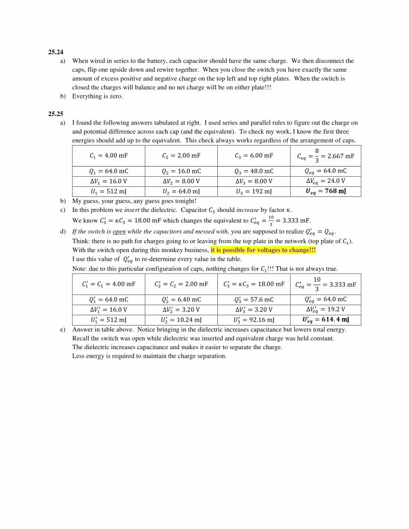
a) I found the following answers tabulated at right. I used series and parallel rules to figure out the charge on
and potential difference across each cap (and the equivalent). To check my work, I know the first three
energies should add up to the equivalent. This check always works regardless of the arrangement of caps.
�M � 4.00 mF �N � 2.00 mF �¨ � 6.00 mF ��� � 83 � 2.667 mF
�M � 64.0 mC �N � 16.0 mC �¨ � 48.0 mC ��� � 64.0 mC Δ�M � 16.0 V Δ�N � 8.00 V Δ� � 8.00 V Δ��� � 24.0 V �M � 512 mJ �N � 64.0 mJ �¨ � 192 mJ �q¡ � °®¯ mJmJmJmJ b) My guess, your guess, any guess goes tonight!
c) In this problem we insert the dielectric. Capacitor �¨ should increase by factor Í.
We know � ª � Í�¨ � 18.00 mF which changes the equivalent to ���ª � M� � 3.333 mF.
d) If the switch is open while the capacitors and messed with, you are supposed to realize ���ª � ��� .
Think: there is no path for charges going to or leaving from the top plate in the network (top plate of �M).
With the switch open during this monkey business, it is possible for voltages to change!!!
I use this value of ���ª to re-determine every value in the table.
Note: due to this particular configuration of caps, nothing changes for �M!!! That is not always true.
�Mª � �M � 4.00 mF �Nª � �N � 2.00 mF � ª � Í�¨ � 18.00 mF ���ª � 103 � 3.333 mF
�Mª � 64.0 mC �Nª � 6.40 mC �ª � 57.6 mC ���ª � 64.0 mC Δ�Mª � 16.0 V Δ�Nª � 3.20 V Δ�ª � 3.20 V Δ���ª � 19.2 V �Mª � 512 mJ �Nª � 10.24 mJ �ª � 92.16 mJ �q¡ª � ®Æf. f mJmJmJmJ e) Answer in table above. Notice bringing in the dielectric increases capacitance but lowers total energy.
Recall the switch was open while dielectric was inserted and equivalent charge was held constant.
The dielectric increases capacitance and makes it easier to separate the charge.
Less energy is required to maintain the charge separation.
25.26
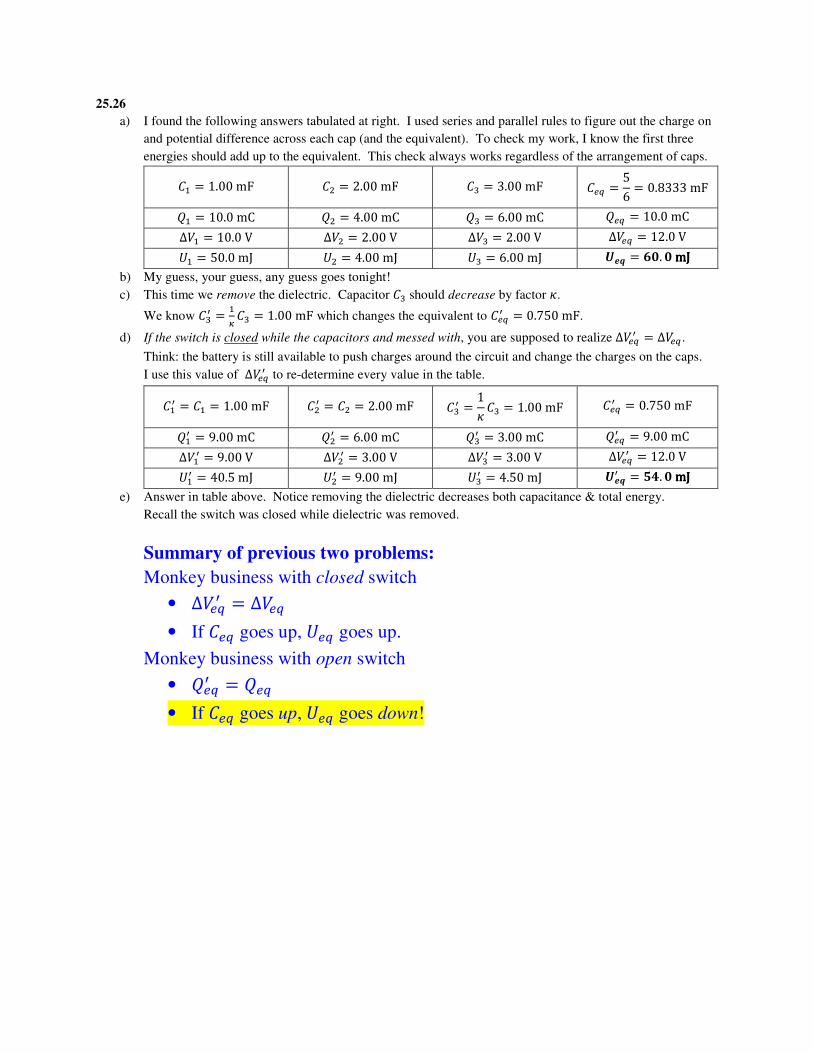
a) I found the following answers tabulated at right. I used series and parallel rules to figure out the charge on
and potential difference across each cap (and the equivalent). To check my work, I know the first three
energies should add up to the equivalent. This check always works regardless of the arrangement of caps.
�M � 1.00 mF �N � 2.00 mF �¨ � 3.00 mF ��� � 56 � 0.8333 mF
�M � 10.0 mC �N � 4.00 mC �¨ � 6.00 mC ��� � 10.0 mC Δ�M � 10.0 V Δ�N � 2.00 V Δ� � 2.00 V Δ��� � 12.0 V �M � 50.0 mJ �N � 4.00 mJ �¨ � 6.00 mJ �q¡ � ®i. i mJmJmJmJ b) My guess, your guess, any guess goes tonight!
c) This time we remove the dielectric. Capacitor �¨ should decrease by factor Í.
We know � ª � MÓ �¨ � 1.00 mF which changes the equivalent to ���ª � 0.750 mF.
d) If the switch is closed while the capacitors and messed with, you are supposed to realize Δ���ª � Δ��� .
Think: the battery is still available to push charges around the circuit and change the charges on the caps.
I use this value of Δ���ª to re-determine every value in the table.
�Mª � �M � 1.00 mF �Nª � �N � 2.00 mF � ª � 1Í �¨ � 1.00 mF ���ª � 0.750 mF
�Mª � 9.00 mC �Nª � 6.00 mC �ª � 3.00 mC ���ª � 9.00 mC Δ�Mª � 9.00 V Δ�Nª � 3.00 V Δ�ª � 3.00 V Δ���ª � 12.0 V �Mª � 40.5 mJ �Nª � 9.00 mJ �ª � 4.50 mJ �q¡ª � ±f. i mJmJmJmJ e) Answer in table above. Notice removing the dielectric decreases both capacitance & total energy.
Recall the switch was closed while dielectric was removed.
Summary of previous two problems:
Monkey business with closed switch
• Δ���ª � Δ���
• If ��� goes up, ��� goes up.
Monkey business with open switch
• ���ª � ���
• If ��� goes up, ��� goes down!
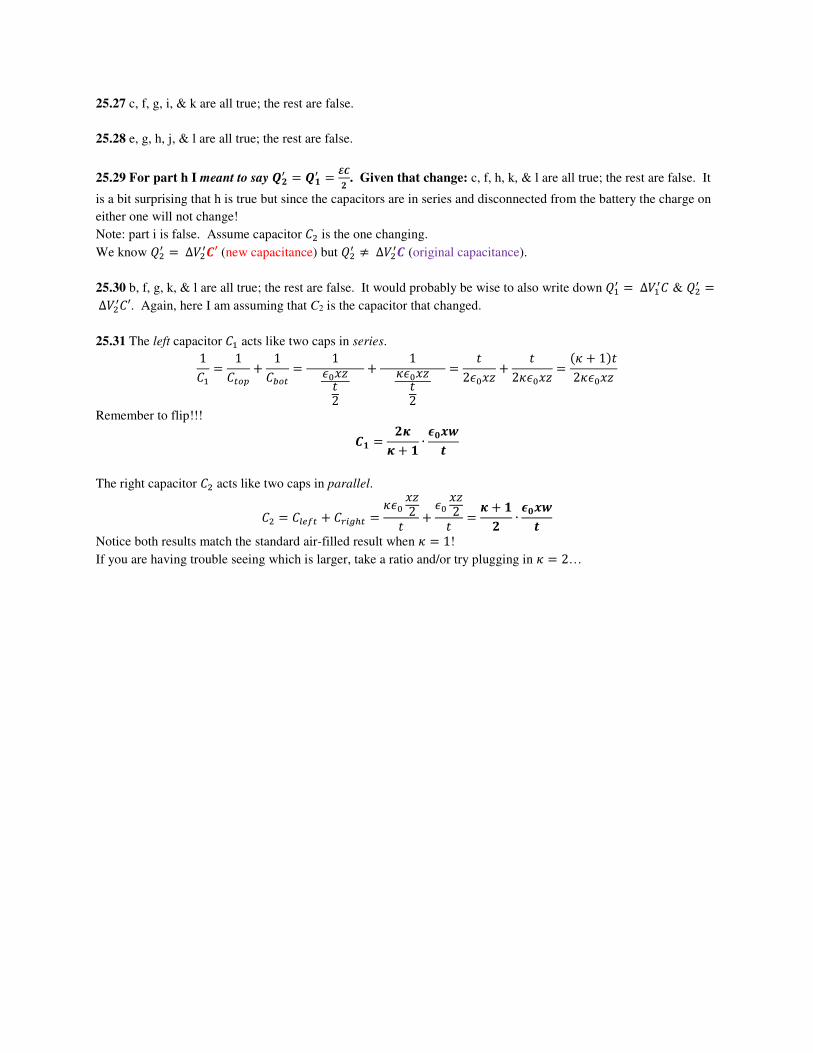
25.27 c, f, g, i, & k are all true; the rest are false.
25.28 e, g, h, j, & l are all true; the rest are false.
25.29 For part h I meant to say bª � bƪ � ²e. Given that change: c, f, h, k, & l are all true; the rest are false. It
is a bit surprising that h is true but since the capacitors are in series and disconnected from the battery the charge on
either one will not change!
Note: part i is false. Assume capacitor �N is the one changing.
We know �Nª � ∆�Nªe′ (new capacitance) but �Nª ≠ ∆�Nªe (original capacitance).
25.30 b, f, g, k, & l are all true; the rest are false. It would probably be wise to also write down �Mª � ∆�Mª� & �Nª � ∆�Nª�′. Again, here I am assuming that C2 is the capacitor that changed.
25.31 The left capacitor �M acts like two caps in series. 1�M � 1��9� ^ 1�Z9� � 1 !��ÕI2 ^ 1
Í!��ÕI2 � I2!��Õ ^ I2Í!��Õ � �Í ^ 1�I2Í!��Õ
Remember to flip!!!
eÆ � ´ÖÖ ^ Æ ∙ hi×Øp
The right capacitor �N acts like two caps in parallel.
�N � ����� ^ �W�¾¿� � Í!� �Õ2I ^ !� �Õ2I � Ö ^ Æ´ ∙ hi×Øp
Notice both results match the standard air-filled result when Í � 1!
If you are having trouble seeing which is larger, take a ratio and/or try plugging in Í � 2…
Related Documents