Welcome message from author
This document is posted to help you gain knowledge. Please leave a comment to let me know what you think about it! Share it to your friends and learn new things together.
Transcript

Introduction
• As discussed in Chapter 1, TL can be segmented into two groups:
1) Those that support TEM mode (TEM TL)
2) Those that do not (Higher Order TL)
• Higher-order TL that do not support TEM mode is called WaveguidesWaveguides.


WAVEGUIDES (WG)• Another mean of transporting EM wave from Source
to the Load consist of a hollow, metal tube through which waves propagate.
• The tube wall provides distributed inductance, while the empty space between the tube walls provide distributed capacitance
• Waveguides are practical only for signals of extremely high frequency, where the wavelength approaches the cross-sectional dimensions of the waveguide.
• Below such frequencies, waveguides are useless as electrical transmission lines.
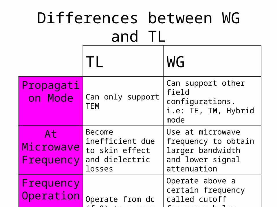
Differences between WG and TL
TL WG
Propagation Mode
Can only support TEMCan support other field configurations. i.e: TE, TM, Hybrid mode
At Microwave Frequency
Become inefficient due to skin effect and dielectric losses
Use at microwave frequency to obtain larger bandwidth and lower signal attenuation
Frequency Operation
Operate from dc (f=0) to a very high frequency
Operate above a certain frequency called cutoff frequency below which WG are useless (High-Pass Filter)

Advantages of WG over TL• Low lossLow loss. That is, the wave travels along the
guide without greatly attenuating as it goes.
• RouteableRouteable. This means that we can gently bend the guiding structure without losing contact with the wave, without generating reflections, and without incurring much additional loss.

WG
Waveguides conduct microwave energy at lower loss than coaxial cables

WG
• WG can have various cross sections– Rectangular– Circular– Elliptical
• At the same time, it can be rigidrigid or flexibleflexible
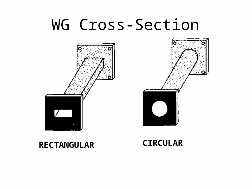
RECTANGULAR CIRCULAR
WG Cross-Section
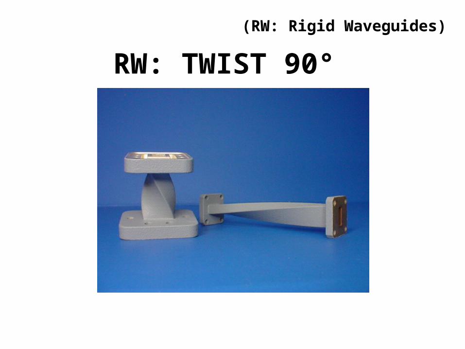
RW: TWIST 90°
(RW: Rigid Waveguides)

RW: DIRECTIONAL AND CROSS COUPLERS
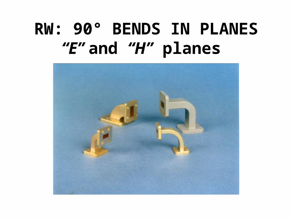
RW: 90° BENDS IN PLANES “E” and “H” planes

RW: WAVEGUIDE STRAIGHT SECTION
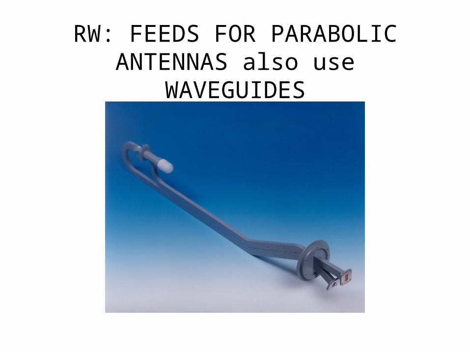
RW: FEEDS FOR PARABOLIC ANTENNAS also use WAVEGUIDES
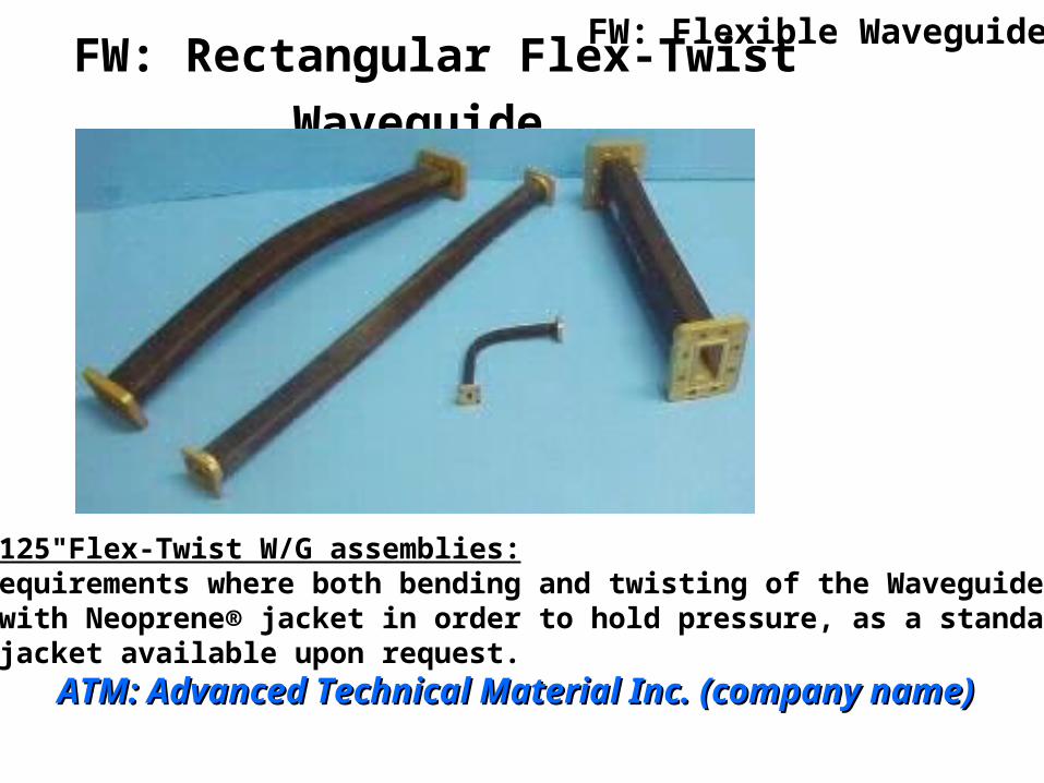
FW: Rectangular Flex-Twist Waveguide
ATM Type "125"Flex-Twist W/G assemblies:•Used in requirements where both bending and twisting of the Waveguide is needed.•Supplied with Neoprene® jacket in order to hold pressure, as a standard model.•Silicone jacket available upon request.
FW: Flexible Waveguides
ATM: Advanced Technical Material Inc. (company name)ATM: Advanced Technical Material Inc. (company name)

FW: Rectangular Flex Waveguide,High Power, Non-Twistable
ATM Type "124" flexible, non twist W/G assemblies:For use in Hi Power Applications.Finished with high temperature paint.
ATM: Advanced Technical Material Inc. (company name)ATM: Advanced Technical Material Inc. (company name)
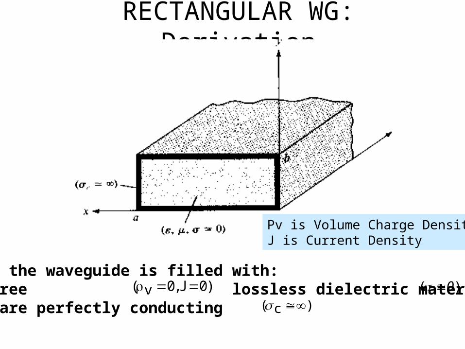
RECTANGULAR WG: Derivation
Assume that the waveguide is filled with:•A source-free lossless dielectric material with •Its walls are perfectly conducting
)0J,0v( )( 0)c(
Ρv is Volume Charge DensityJ is Current Density

RECTANGULAR WG: Derivation
• The fields inside the rectangular waveguide can be obtained from the solutions to the wave equation which satisfies the boundary conditions for a rectangular waveguide of infinite length.
• Thus, two basic sets of solutions exist and each of them defining a set of modes.
• Thus, there are two modes of propagation possible inside a hollow metal waveguide which we will discuss later.
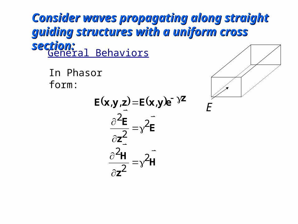
General Behaviors
In Phasor form:
Hz
H
Ez
E
zeyxEzyxE
22
2
22
2
,,,
Consider waves propagating along straight guiding Consider waves propagating along straight guiding structures with a uniform cross section:structures with a uniform cross section:
E
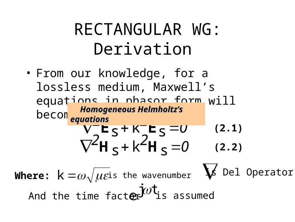
• From our knowledge, for a lossless medium, Maxwell’s equations in phasor form will become:
022 sks EE022 sks HH
Where: k
(2.1)
(2.2)
And the time factor tje
is assumed
Homogeneous Helmholtz’s equationsHomogeneous Helmholtz’s equations
RECTANGULAR WG: Derivation
is Del Operatoris the wavenumber

HOW TO SOLVE HOW TO SOLVE HOMOGENEOUS HEMHOLTZ’S HOMOGENEOUS HEMHOLTZ’S
EQUATIONEQUATION
0sE2k2z
2
2y
2
2x
2
0sE2ksE2

• In this case,
)zsE,ysExsE(s E)zsH,ysH,xsH(s H
(2.4)
(2.5)
Thus, to obtain Thus, to obtain EE and and HH fields, we have to solve six fields, we have to solve six scalar equations Helmholtz equations scalar equations Helmholtz equations (you can see this in Eq. 2.4 and 2.5)(you can see this in Eq. 2.4 and 2.5)
RECTANGULAR WG: Derivation

• For instance, to find z-component, Eq. 2.1 will become:
• Eq. 2.6 can be solved by separation of variable (product solution):
022
2
2
2
2
2
zsEk
z
zsE
y
zsE
x
zsE(2.6)
Partial Differential Equation
)z(Z)y(Y)x(X)z,y,x(zsE (2.7)
In this case, X(x), Y(y) and Z(z) are the functions of x, y and zIn this case, X(x), Y(y) and Z(z) are the functions of x, y and z
RECTANGULAR WG: Derivation
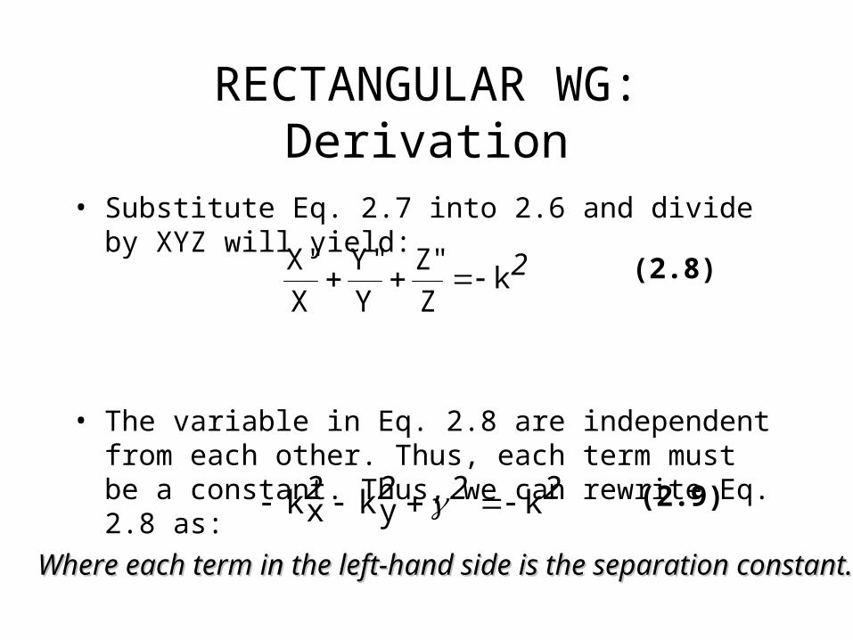
• Substitute Eq. 2.7 into 2.6 and divide by XYZ will yield:
• The variable in Eq. 2.8 are independent from each other. Thus, each term must be a constant. Thus, we can rewrite Eq. 2.8 as:
2kZ
"Z
Y
"Y
X
"X (2.8)
2222 kykxk (2.9)
Where each term in the left-hand side is the separation constant. Where each term in the left-hand side is the separation constant.
RECTANGULAR WG: Derivation

• Hence, Eq. 2.8 can be separated as:
• We obtain the solution to Eq. 2.9 as:
02 Xxk"X
02 Yyk"Y
02 Z"Z
(2.9a)
(2.9b)
(2.9c)
xxksincxxkcosc)x(X 21 yyksincyykcosc)y(Y 43
ZecZec)z(Z 65
(2.10a)(2.10b)(2.10c)
RECTANGULAR WG: Dervation

• Substituting Eq. 2.10 into Eq. 2.7 will give us:
• if we assume that the wave propagates along the waveguide in the +z direction,
(because the wave has to be finite at infinity).
• Thus, Eq. 2.11 will become:
)ZecZec)(yyksincyykcosc)(xxksincxxkcosc()z,y,x(zsE 654321(2.11)
05 c
Ze)yyksinAyykcosA)(xxksinAxxkcosA()z,y,x(zsE 4321 (2.12)
622611 ccA,ccA Where: and so on so forth
RECTANGULAR WG: Derivation

• will then be:
• Instead of solving other field components Exs, Eys,Hxs and Hys in the same manner, we can simply use Maxwell’s equations to determine them from Ezs and Hzs from:
Ze)yyksinByykcosB)(xxksinBxxkcosB()z,y,x(zsH 4321
zsH(2.13)
sjs HE sjs EH
RECTANGULAR WG: Derivation
The curl of vector E
The curl of vector H
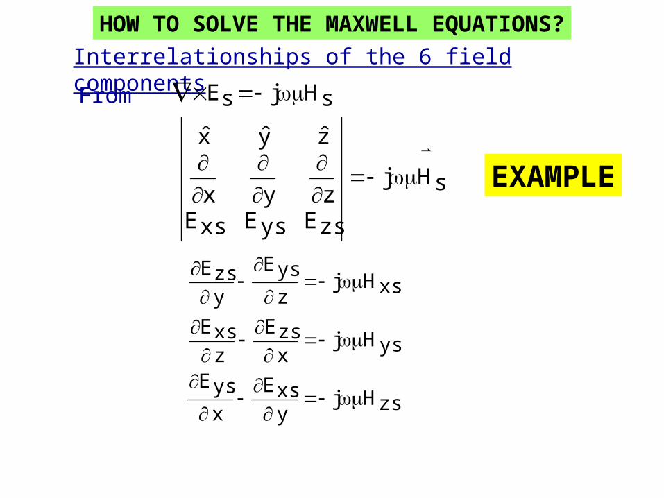
Interrelationships of the 6 field components
From sHjsE
sHj
zsEysExsEzyx
zyx
zsHjyxsE
xysE
ysHjxzsE
zxsE
xsHjzysE
yzsE
HOW TO SOLVE THE MAXWELL EQUATIONS?
EXAMPLE
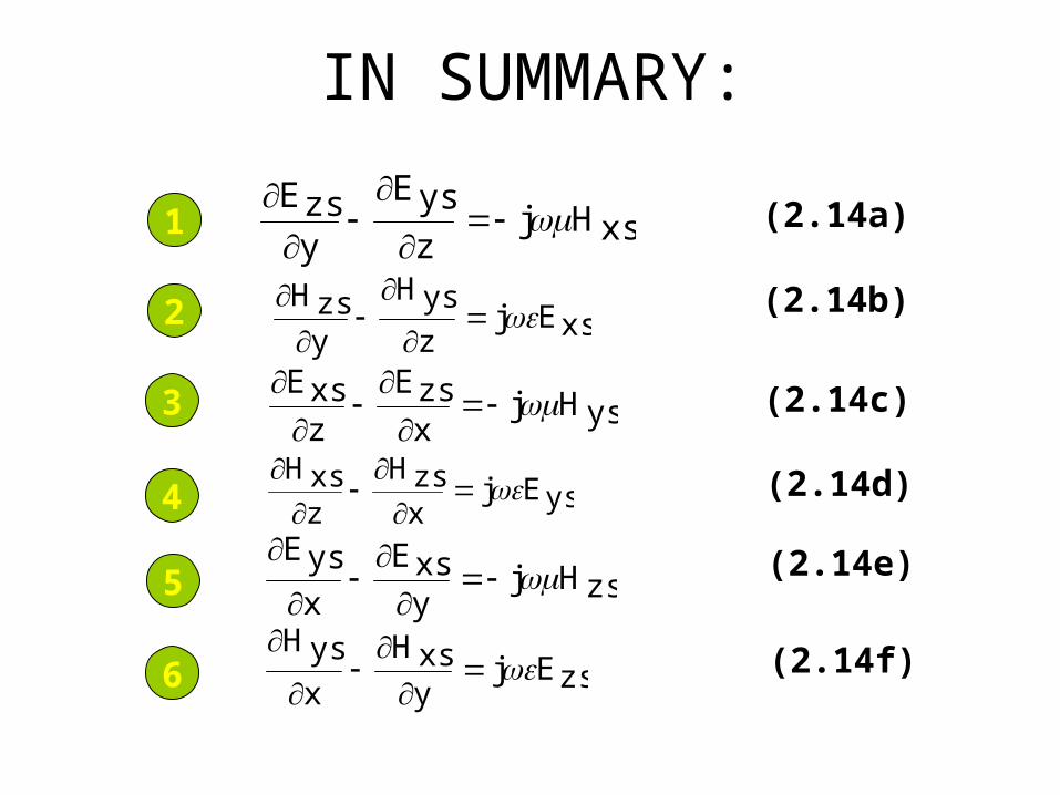
IN SUMMARY:
xsHjz
ysE
yzsE
xsEjz
ysH
yzsH
ysHjxzsE
zxsE
ysEjxzsH
zxsH
zsHjyxsE
x
ysE
zsEjyxsH
x
ysH
1
2
3
4
5
6
(2.14a)
(2.14b)
(2.14c)
(2.14d)
(2.14e)
(2.14f)

Our goal now is to express Exs, Eys, Hxs and Hys in
terms of Ezs and Hzs

• If we combine Eq. 2.14b and 2.14c, we will get:
• From Eq. 2.11 and 2.12, all the field components vary with z according to . Thus,
• Thus,
zxzsE
z
xsE
jyzsH
xsEj2
2
21
(2.15)
ze~zsE ze~xsE
ze
,
zsEzzsE
xsE22z
xsE2
,
RECTANGULAR WG: Derivation
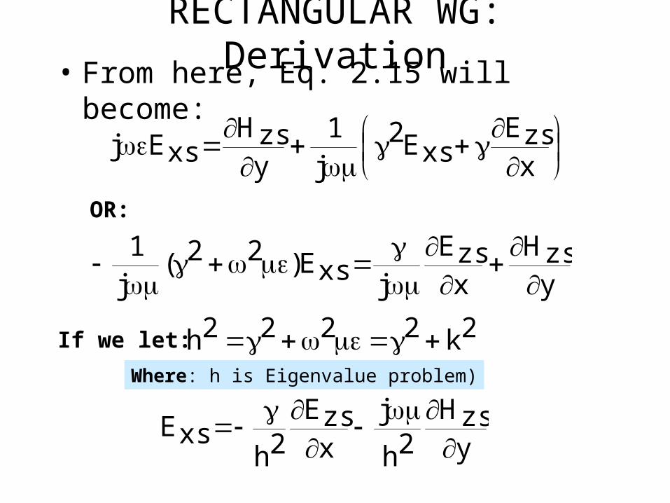
• From here, Eq. 2.15 will become:
xzsE
xsE2j1
yzsH
xsEj
yzsH
xzsE
jxsE)22(j1
OR:
2k2222h If we let:
yzsH
2h
jxzsE
2hxsE
RECTANGULAR WG: Derivation
Where: h is Eigenvalue problem)
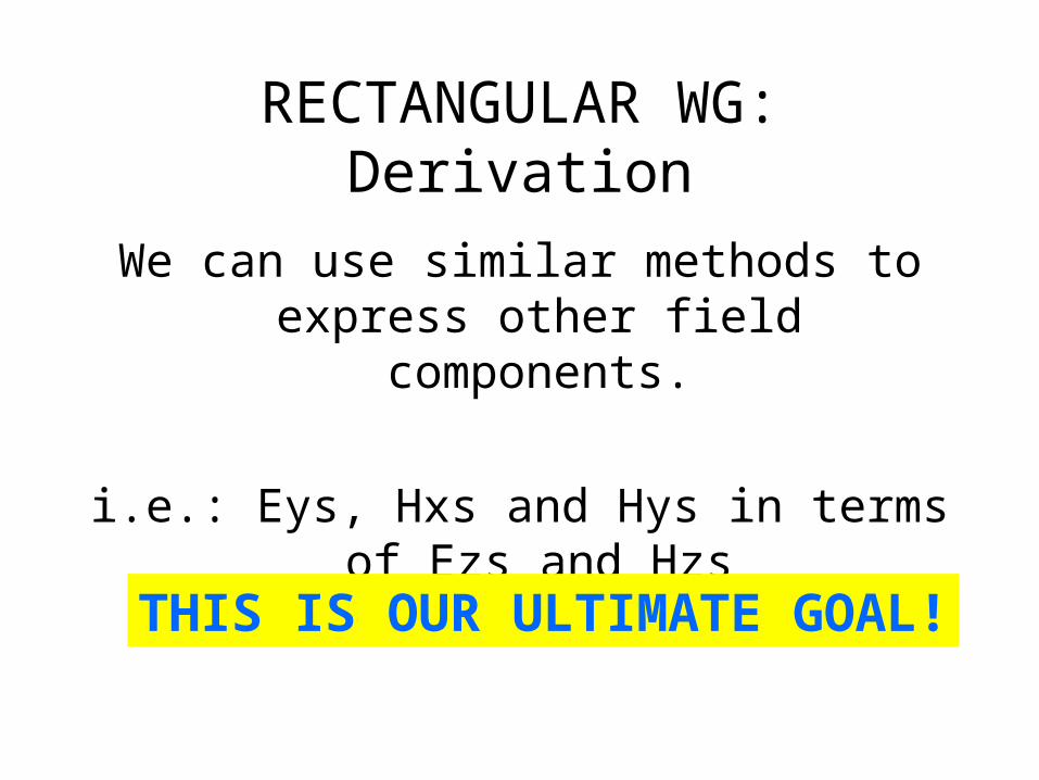
We can use similar methods to express other field components.
i.e.: Eys, Hxs and Hys in terms of Ezs and Hzs
THIS IS OUR ULTIMATE GOAL!
RECTANGULAR WG: Derivation
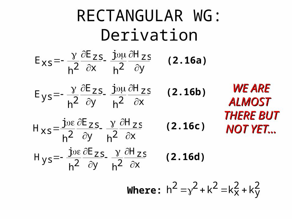
yzsH
2h
jxzsE
2hxsE
xzsH
2h
jyzsE
2hysE
xzsH
2hyzsE
2h
jxsH
xzsH
2hyzsE
2h
jysH
2yk2
xk2k22h Where:
WE AREWE AREALMOST ALMOST
THERE BUTTHERE BUTNOT YET…NOT YET…
(2.16a)
(2.16b)
(2.16c)
(2.16d)
RECTANGULAR WG: Derivation
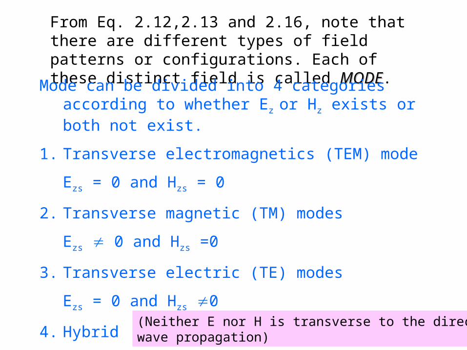
From Eq. 2.12,2.13 and 2.16, note that there are different types of field patterns or configurations. Each of these distinct field is called MODEMODE.
Mode can be divided into 4 categories according to whether Ez or Hz exists or both not exist.
1. Transverse electromagnetics (TEM) mode
Ezs = 0 and Hzs = 0
2. Transverse magnetic (TM) modes
Ezs 0 and Hzs =0
3. Transverse electric (TE) modes
Ezs = 0 and Hzs 0
4. Hybrid electric (HE) modes
Ezs 0 and Hzs 0
(Neither E nor H is transverse to the direction ofwave propagation)
Mode of Propagation in TL andWG
• Mode of Propagation in normal TL is different from the one in Waveguides TEM modeTEM mode
• Waveguides are single-conductor elements, the propagation of electrical energy down a waveguide is of a very different nature than the propagation of electrical energy down a two-conductor transmission line. TE and TM ModesTE and TM Modes
TEM in TL• All electromagnetic waves consist of electric and magnetic
fields propagating in the same direction of travel, but perpendicular to each other.
• Along the length of a normal transmission line, both both electric and magnetic fields are perpendicular (transverse) to the direction of wave travel.
• This is known as the principal mode, or TEM (Transverse Electric and Magnetic) mode.
• This mode of wave propagation can exist only where there exist only where there are two conductorsare two conductors, and it is the dominant mode of wave propagation where the cross-sectional dimensions of the transmission line are small compared to the wavelength of the signal

TEM in TL

Twin lead (Parallel Conductor) transmission line propagation: TEM mode
conductor
conductor

TE vs TM mode
• When an electromagnetic wave propagates down a hollow tube, only one of the fields; eithereither electric or magnetic field will actually be transverse to the direction of propagation.
• The other field will “loop” longitudinally to the direction of travel, but still be perpendicular to the other field.
• Whichever field remains transverse to the direction of travel determines whether the wave propagates in TE mode (Transverse Electric) or TM (Transverse Magnetic) mode.

TE vs TM mode
• If E is transverse to the direction of propagation TE modes
• If H is transverse to the direction of propagation TM modes

Waveguide (TE) transverse electric and (TM) transverse magnetic modes
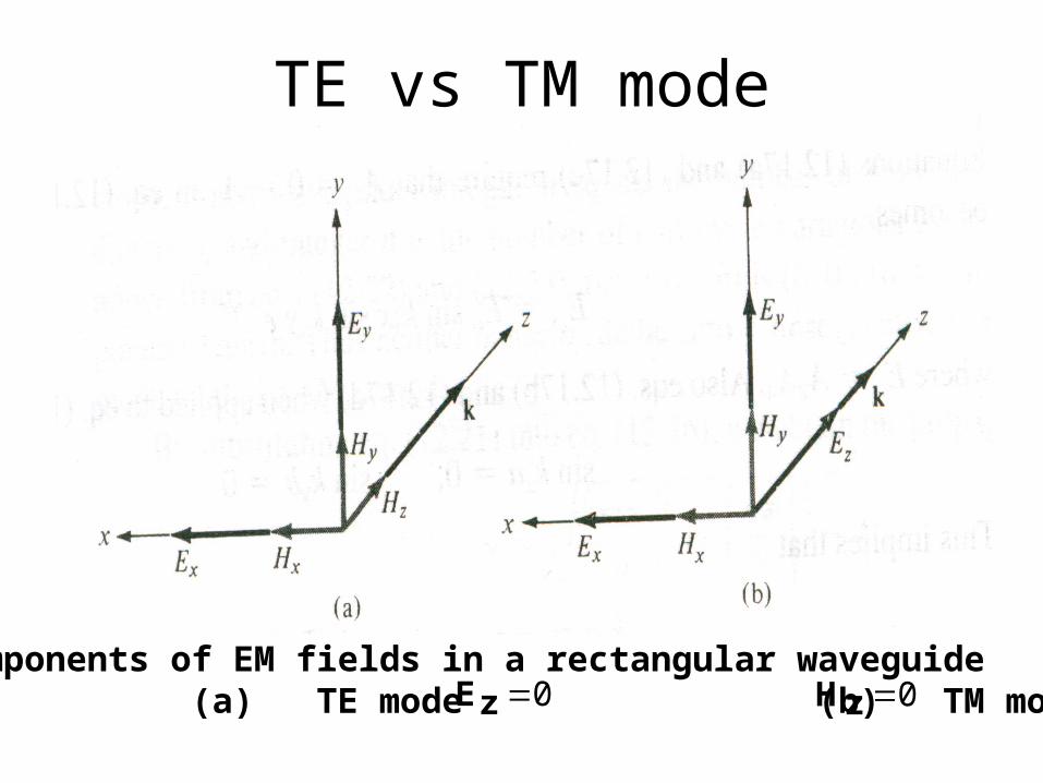
TE vs TM mode
Components of EM fields in a rectangular waveguide (a) TE mode (b) TM mode 0zE 0zH
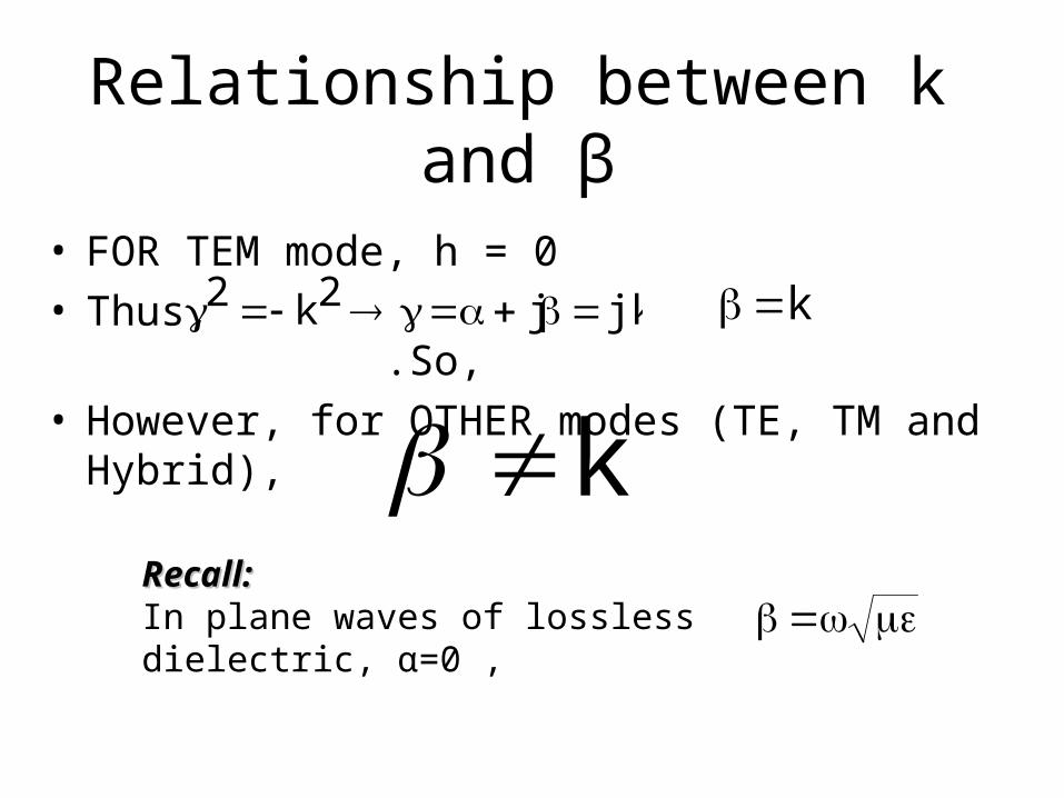
Relationship between k and β
• FOR TEM mode, h = 0• Thus, .So, • However, for OTHER modes (TE, TM and Hybrid),
jkj2k2 k
kRecall:Recall:In plane waves of lossless dielectric, α=0 ,

THE ULTIMATE GOAL! Our goal is to express Exs, Eys, Hxs and
Hys in terms of Ezs and Hzs
This can be done by using Eq. 2.16 with Eq. 2.12 and 2.13 and setting the boundary condition for each type of modes.
i.e.: Different mode will have different expressions for Exs, Eys, Hxs and Hys.
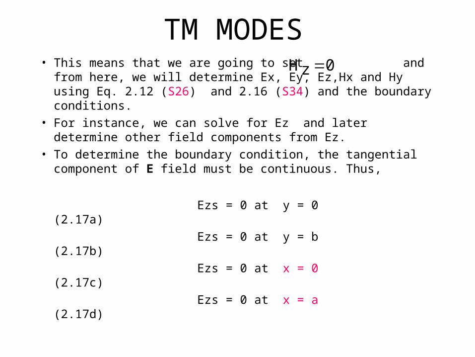
TM MODES• This means that we are going to set and from here,
we will determine Ex, Ey, Ez,Hx and Hy using Eq. 2.12 (S26) and 2.16 (S34) and the boundary conditions.
• For instance, we can solve for Ez and later determine other field components from Ez.
• To determine the boundary condition, the tangential component of E field must be continuous. Thus,
Ezs = 0 at y = 0 (2.17a)
Ezs = 0 at y = b (2.17b)
Ezs = 0 at x = 0 (2.17c)
Ezs = 0 at x = a (2.17d)
0zH
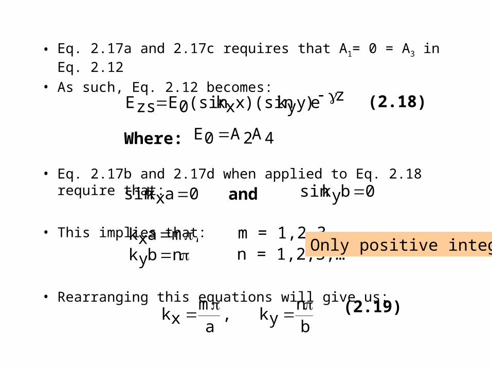
• Eq. 2.17a and 2.17c requires that A1= 0 = A3 in Eq. 2.12
• As such, Eq. 2.12 becomes:
• Eq. 2.17b and 2.17d when applied to Eq. 2.18 require that:
• This implies that:
• Rearranging this equations will give us:
ze)yyk)(sinxxk(sin0EzsE
4A2A0E Where:
(2.18)
0axksin and 0byksin
,maxk nbyk
m = 1,2,3,…n = 1,2,3,…
bn
yk,a
mxk
(2.19)
Only positive integer

• Thus, Eq. 2.18 will become:
• We can obtain other field components from Eq. 2.20 and 2.14 (S29) with Hzs = 0. Hence,
Zeb
ynsin
axm
sin0EzsE
(2.20)
Zeb
ynsin
a
xmcos0E
a
m2h
xsE
Zeb
yncos
a
xmsin0E
b
n2h
ysE
Zeb
yncos
a
xmsin0E
b
n2h
jxsH
Zeb
ynsin
a
xmcos0E
a
m2h
jysH
(2.21a)
(2.21b)
(2.21c)
(2.21d)
2
b
n2
a
m2yk2
xk2h
Where:
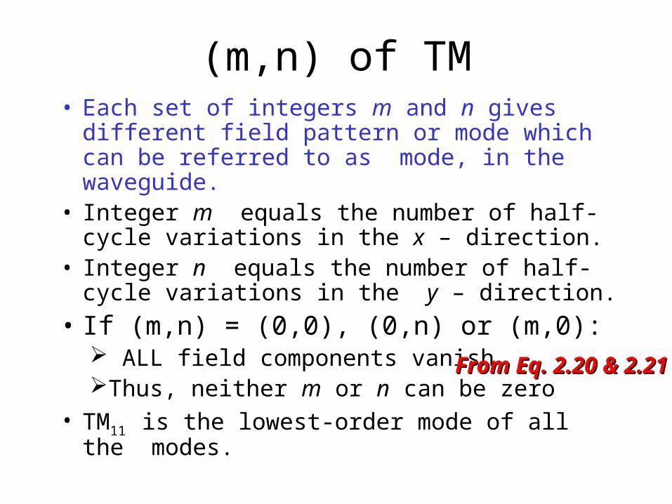
(m,n) of TM• Each set of integers m and n gives different field
pattern or mode which can be referred to as mode, in the waveguide.
• Integer m equals the number of half-cycle variations in the x – direction.
• Integer n equals the number of half-cycle variations in the y – direction.
• If (m,n) = (0,0), (0,n) or (m,0): ALL field components vanish Thus, neither m or n can be zero
• TM11 is the lowest-order mode of all the modes.
From Eq. 2.20 & 2.21From Eq. 2.20 & 2.21
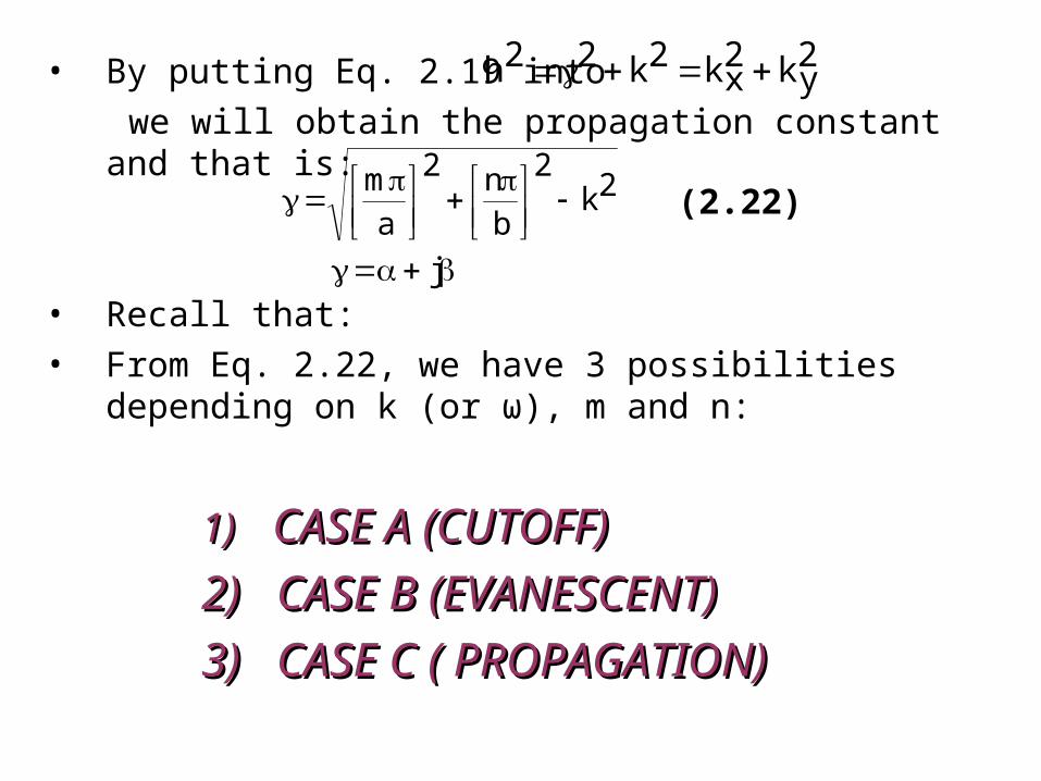
• By putting Eq. 2.19 into
we will obtain the propagation constant and that is:
• Recall that:
• From Eq. 2.22, we have 3 possibilities depending on k (or ω), m and n:
1)1) CASE A (CUTOFF)CASE A (CUTOFF)
2)2) CASE B (EVANESCENT)CASE B (EVANESCENT)
3)3) CASE C ( PROPAGATION)CASE C ( PROPAGATION)
2yk2
xk2k22h
2k2
bn2
am
(2.22)
j

CASE A (CUTOFF)
2yk2
xk2k22h
2
b
n2
a
m22k
If:
0 OR 0
RECALL: j
The value of ω that causes this is called the cutoff angular frequency, ωc where:
2
bn2
am1
c
(2.23)
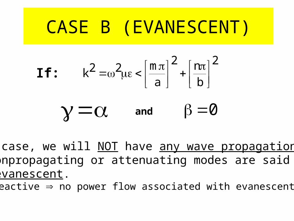
CASE B (EVANESCENT)
2
b
n2
a
m22k
If:
and 0
•In this case, we will NOT have any wave propagation at all. •These nonpropagating or attenuating modes are said to be evanescent.• Purely Reactive no power flow associated with evanescent waves.
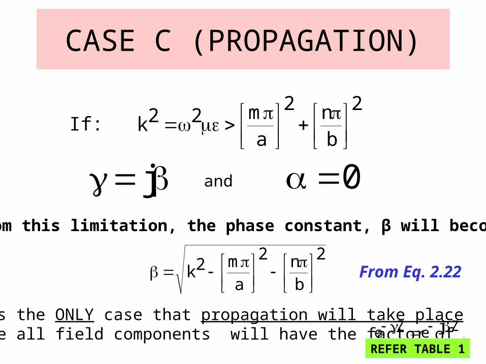
CASE C (PROPAGATION)
2
b
n2
a
m22k
If:
j and 0From this limitation, the phase constant, β will become:
2
bn2
am2k
This is the ONLY case that propagation will take place because all field components will have the factor of .ZjeZe
From Eq. 2.22
REFER TABLE 1
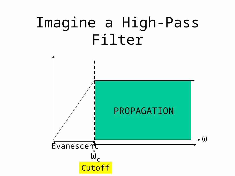
Imagine a High-Pass Filter
ωc
Evanescentω
PROPAGATION
Cutoff

Cutoff Frequency, fc• For EACH mode, there will be a corresponding cutoff
frequency, fc
• Definition: TheThe frequency below which attenuation occurs frequency below which attenuation occurs and above which propagation takes placeand above which propagation takes place
• As mentioned before, a waveguide also acts as a high-pass filter. Thus, it has its own cutoff frequency.
• From Eq. 2.23, the cutoff frequency is:
2
bn2
am
21
2c
cf
2
bn2
am
2'u
cf
OR
Where phase velocity of uniform plane wave in the lossless dielectric medium filling the waveguide.
1
'u
),,( 0

Cutoff Wavelength, λc
cf'u
c
2
bn2
am
2c
OR
(2.24)
(2.25)

Phase Constant, β
2
fcf1
OR
2
fcf1'
Where: phase constant of uniform plane wave in the dielectric medium
'u'
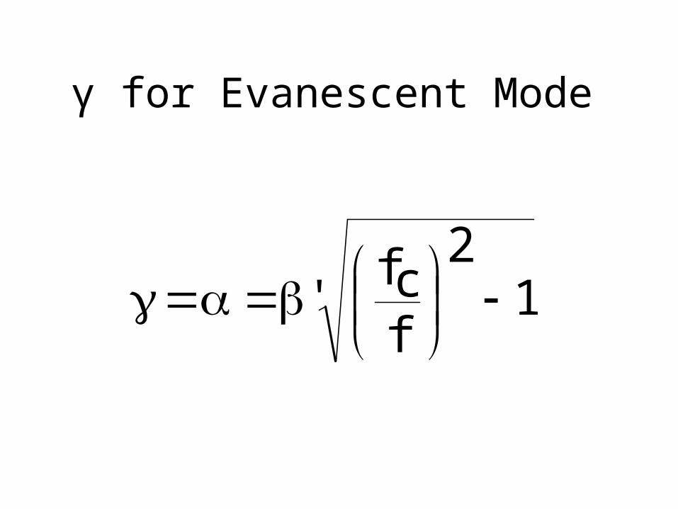
γ for Evanescent Mode
12
fcf'

Phase Velocity, )pv,pu,phvor(phu
phu
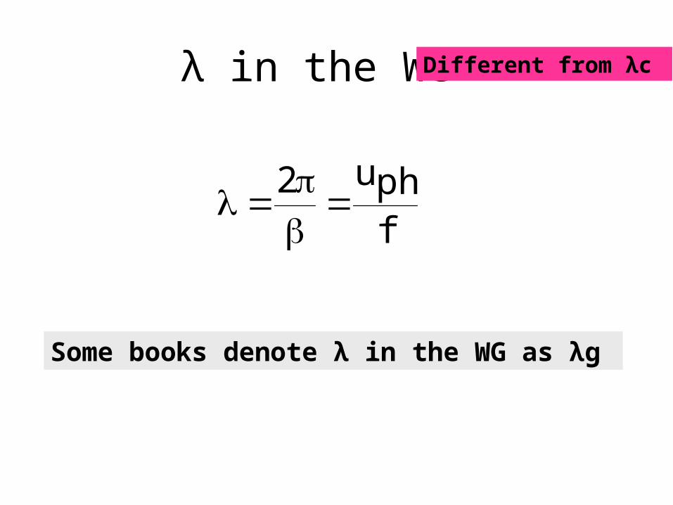
λ in the WG
fphu2
Some books denote λ in the WG as λg
Different from λc

Intrinsic Wave Impedance of the mode or ηTM as γ = jβ
There is a characteristic impedance associated with wave propagation in any uniform medium.
In this case we use the Greek letter “Eta” (η) for intrinsic impedance.
The intrinsic impedance is a measure of the ratio of the electric field to the magnetic field.
xHyE
yHxE
TM
2
fcf1
2
fcf1'TM
OR:
Some books use ZSome books use ZTMTM to denote to denote ηη
is intrinsic impedance of uniform plane wave in the dielectric medium.
'
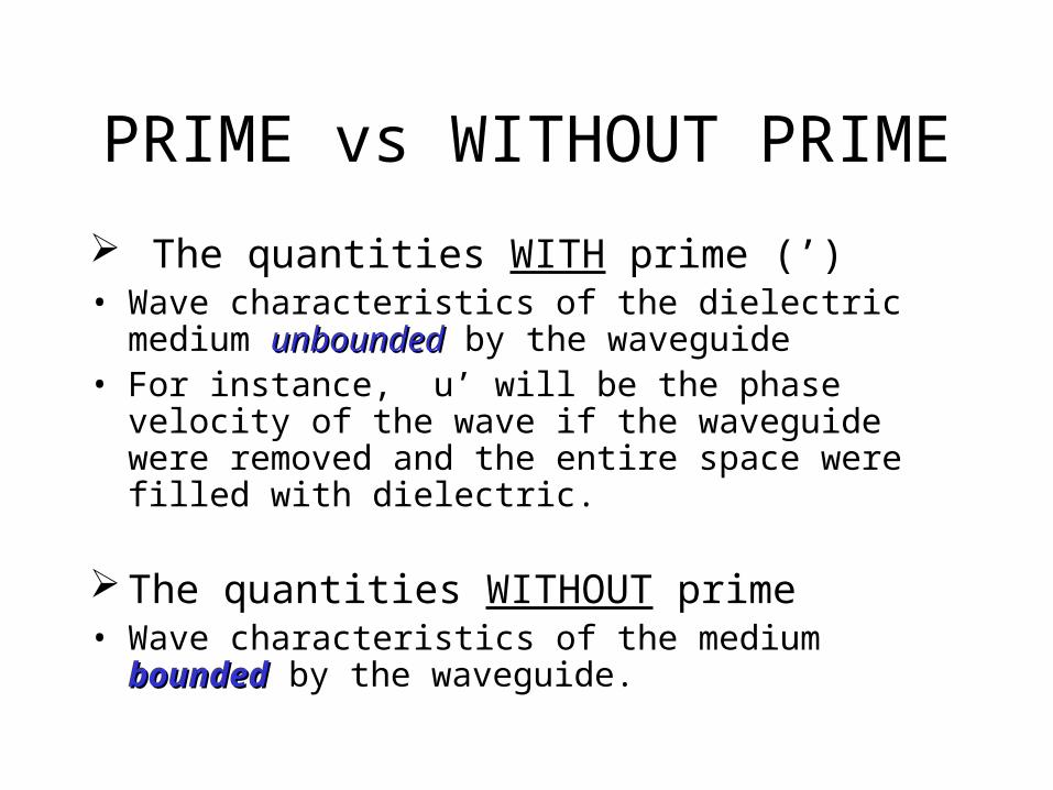
PRIME vs WITHOUT PRIME
The quantities WITH prime (’)• Wave characteristics of the dielectric medium unboundedunbounded
by the waveguide• For instance, u’ will be the phase velocity of the wave if
the waveguide were removed and the entire space were filled with dielectric.
The quantities WITHOUT prime • Wave characteristics of the medium boundedbounded by the
waveguide.
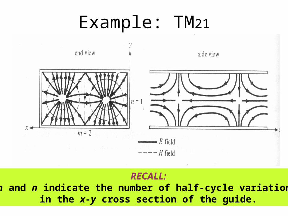
Example: TM21
RECALL:m and n indicate the number of half-cycle variations
in the x-y cross section of the guide.

TE Modes• In this type of mode, the electric field, E is transverse (or
normal) to the direction of propagation. T
• The procedure is the same as the previous mode but in this case we set
• First let us determine the boundary condition:
Exs = 0 at y = 0 (2.26a)
Exs = 0 at y = b (2.26b)
Exs = 0 at x = 0 (2.26c)
Exs = 0 at x = a (2.26d)
0zE
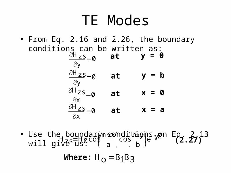
TE Modes• From Eq. 2.16 and 2.26, the boundary conditions can be
written as:
• Use the boundary conditions on Eq. 2.13 will give us:
0yzsH
0yzsH
0xzsH
0xzsH
at
at
at
at
y = 0
y = b
x = 0
x = a
Zeb
yncos
axm
cos0HzsH
3B1BoH Where:
(2.27)

TE Modes• Determine other field components using Eq. 2.27 and 2.16:
Zeb
ynsin
a
xmcos0H
b
n2h
jxsE
Zeb
yncos
axm
sin0Ha
m2h
jysE
Zeb
yncos
a
xmsin0H
a
m2h
xsH
Zeb
ynsin
a
xmcos0H
b
n2h
ysH
(2.28a)
(2.28b)
(2.28c)
(2.28d)
But for TE modes: m = 0,1,2,3,…… n = 0,1,2,3,……

(m,n) for TE
• (m,n) can be (0,1),(1,0) but not (0,0)
• Both m and n cannot be zero at the same time because this will force the field components to vanish.
• This implies that the lowest mode can be either depending on the values of a and b which is the dimension of the waveguide.
• It is standard to practice that:
• Thus, TE10 is the lowest mode because
• At the same time, TE10 is also known as DOMINANT MODEDOMINANT MODE
01TEor10TE
2b/12a/1thatsoba
b2'u
01cTEfa2'u
10cTEf
DO U KNOW THAT?
• Lowest-order mode
Mode with the lowest cutoff frequency in the mode Mode with the lowest cutoff frequency in the mode itself (i.e.: TE OR TM mode)itself (i.e.: TE OR TM mode)
• Dominant mode
Mode with the lowest cutoff frequency from both Mode with the lowest cutoff frequency from both modes (i.e.: TE AND TM mode)modes (i.e.: TE AND TM mode)
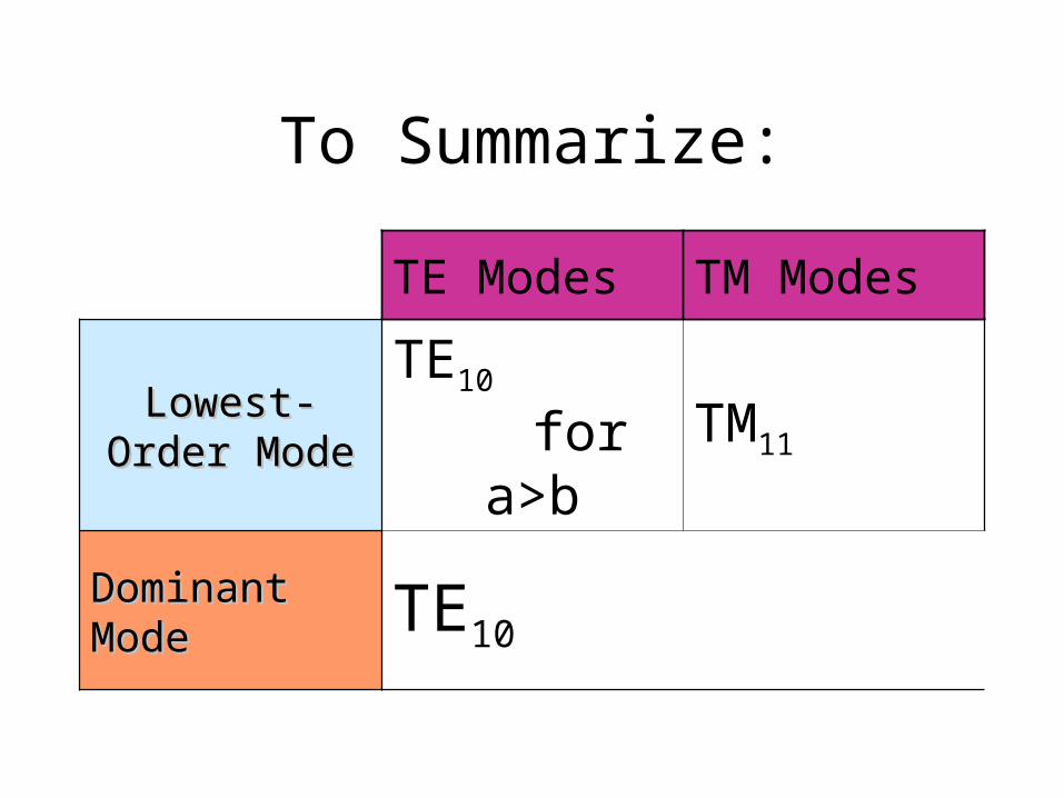
To Summarize:
TE Modes TM Modes
Lowest-Order Lowest-Order ModeMode
TE10 for a>b
TM11
Dominant ModeDominant Mode TE10
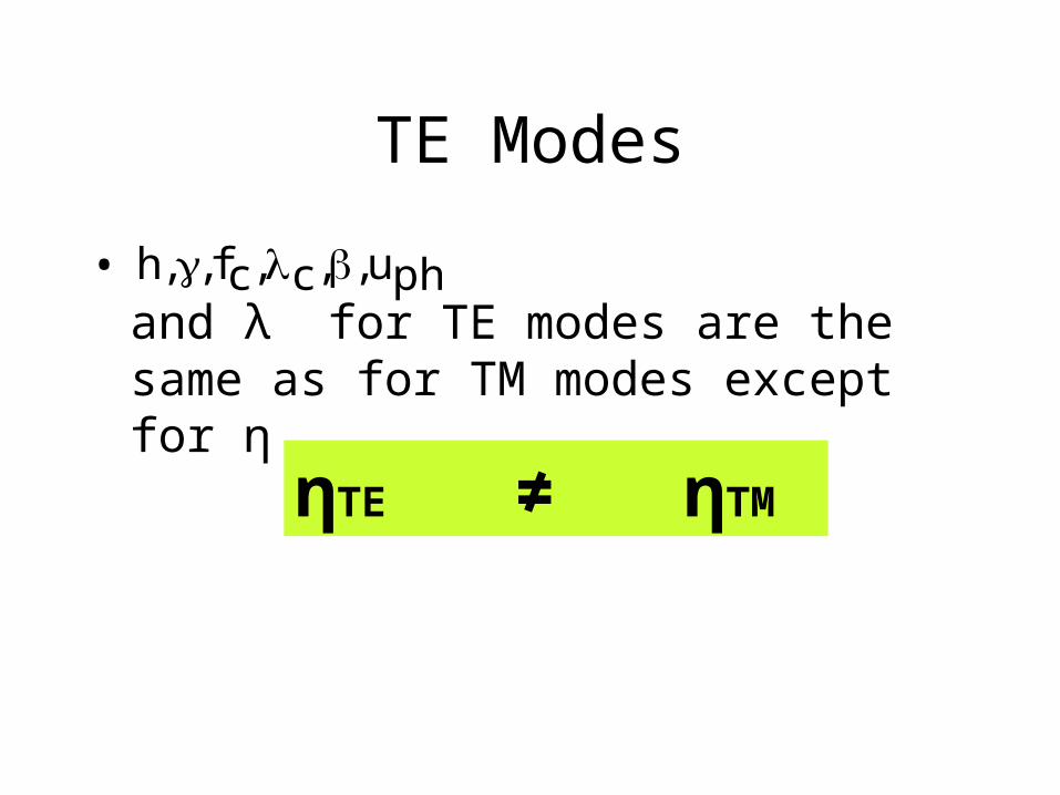
TE Modes
• and λ for TE modes are the same as for TM modes except for η
phu,,c,cf,,h
ηTE ≠ ηTM
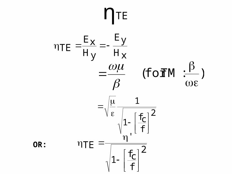
ηTE
xHyE
yHxE
TE
):TMfor(
2
fcf1
1
2
fcf1
'TE
OR:

Variation of ηTE and ηTM ηTE and ηTM are purelyresistive and they vary with frequency as can be seen in the figure
2'TETM

TE Modes in Rectangular Waveguide

fc and λc for TE10 modes
• For TE10 mode in rectangular waveguide:
a2'u
10cf
a210c
You have to also note that any EM wave with frequency
will not be propagatedwill not be propagated in the guide since TE10 is the dominant mode. 10cff )10cor(

Usable Frequency Range
• Single mode propagation is highly desirable to reduce dispersion
• This occurs between cutoff frequency for This occurs between cutoff frequency for TETE1010 mode and twice that frequency mode and twice that frequency
• It’s not good to use guide at the extremes of this range. WHY?WHY?
Note: The keyword is Single Mode Propagation
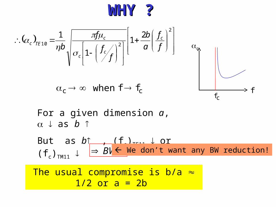
c when cff cf
f
c
For a given dimension a, as b
But as b , (fc)TE11 or (fc)TM11
BW
The usual compromise is b/a 1/2 or a = 2b
2
210
21
1
1
f
f
a
b
ff
f
bc
cc
cTEc
WHY ?WHY ?
We don’t want any BW reduction!
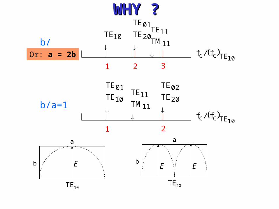
1 2 3
b/a=1/2
11
11
TM
TE
20
01
TE
TE
10TE
10TEcc ff /
1 2
b/a=1
11
11
TM
TE
20
02
TE
TE
10
01
TE
TE
10TEcc ff /
TE10
a
b
a
TE20
a
b
a
E
E
E
WHY ?WHY ?
Or: a = 2b

EXAMPLE 1
• By using Table 1, write down and sketch the instantaneous field expressions of
for TE10 mode.
E ,E E H H Hxs ys, zs, xs, ys, zs
Hints: You have to convert from phasor form to time domain
Trigonometric Identities involved:
Asin2
Acos
Acos2
Asin
Recall that:
2j
ej
2j
ej
ztcos)zt(je
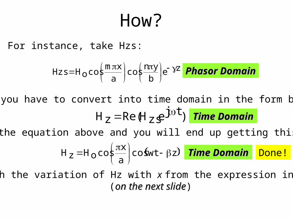
How?
zeb
yncos
a
xmcosoHHzs
1. For instance, take Hzs:
Phasor DomainPhasor Domain
2. Now you have to convert into time domain in the form below:
)tjezsHRe(zH 3. Solve the equation above and you will end up getting this expression:
zwtcosa
xcosoHzH
Done!
4. Sketch the variation of Hz with x from the expression in Step 4 (on the next slideon the next slide)
Time DomainTime Domain
Time DomainTime Domain
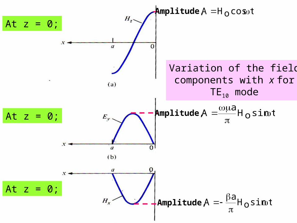
Variation of the fieldcomponents with x for
TE10 mode
Amplitude,
Amplitude,
Amplitude, tcosoHA
tsinoHa
A
tsinoHa
A
At z = 0;
At z = 0;
At z = 0;

EXAMPLE 2
• A rectangular waveguide with dimensions a=2.5cm and b=1cm is to operate below
15.1GHz. How many TE and TM modes can the waveguide transmit if the guide is filled with a medium characterized by σ=0, ε=4εo, μr=1? Calculate the cutoff frequencies of the modes.

Hints:
1.1. Let us fix m firstLet us fix m first
TE01, TE02, TE03,… Maximum n = 2
2. Fix n Fix n
TE10, TE20, TE30, TE40, TE50, TE60Maximum m = 5
3.3. Set n=1Set n=1, TE11, TM11, TE21, TM21,TE31, TM31,TE41, TM41, TE51, TM51
4.4. Set n=2Set n=2, TE12, TM12, TE22, TM22, TE32, TM32, TE42, TM42, TE52, TM52
5. It is evident that fix m and increase n will quickly give us
fc,mn>15.1GHz

Answer:
11 TE modes and 4 TM modes

Example 3• From Example 2, calculate the phase
constant, phase velocity and wave impedance for TE10 and TM11 modes at the operating frequency of 15GHz.
Answer:For TE10, β=615.6rad/m; uph=1.5381 X 10⁸ m/s; ηTE=192.4ΩFor TM11, β=529.4rad/m; uph=1.78 X 10⁸ m/s; ηTM=158.8Ω
EXAMPLE 4An air-filled 5-by 2-cm waveguide has:
at 15GHz.
(a) What mode is being propagated?
(b) Find β
(c) Determine Ey/Ex
m/Vzje)y50sin()x40sin(20zsE
Answer: (a) TM21 (b) 241.3rad/m (c) 1.25tan(40πx)cot(50 πy)

Example 5
• In a rectangular waveguide for which a=1.5cm, b=0.8cm, σ=0, μ= μo and ε= 4εo
m/Azt1110sinby3
cosax
sin2xH
Determine:(a) The mode of operation(b) The cutoff frequency(c) The phase constant(d) The propagation constant(e) The intrinsic wave impedance
Answer: (a) Can be both TM13 or TE13. Let it be TM13. TE13 is left as an exercise. (b) 28.57GHz (c) 1718.81 rad/m (d) γ=jβ=j1718.81 /m (e) 154.7Ω
In Summary: for Rectangular Waveguides
• Dominant mode is TE10
– 1 half cycle along long dimension (a)
– No half cycles along short dimension (b)
– Cutoff for a = c/2
• Modes with next higher cutoff frequency are TE01 and TE20 (Usable Frequency Range)
– Both have cutoff frequency twice that for TE10
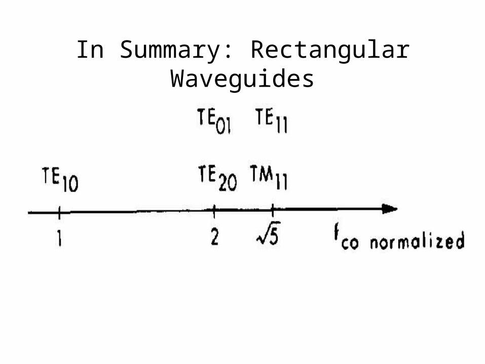
In Summary: Rectangular Waveguides
Wave Propagation in the Guide
• A wave within the waveguide can be resolved into a combination of plane waves reflected from the waveguide walls.
• Electric and Magnetic field distribution in the guide is basically formed by the superposition of a pair of TEM waves

Concept of WavefrontBold line : constant phase at the maximum value Lighter line : constant phase at the minimum value
)0E()0E(
(a) A y-polarized TEM wave propagate in the +z direction (b) Wavefront view of the wave or Plane Wave

Wavefront or Plane Wave

• Now consider a pair of identical TEM waves in (a).
• These waves are combined together in (b).
• Notice that horizontal lines can be drawn on the superposed waves that correspond to zero total field (intersection between maximum and minimum)
We take two identical y-polarized TEM waves, rotate one by + and the other by – as shown in (a), and combine them in (b).
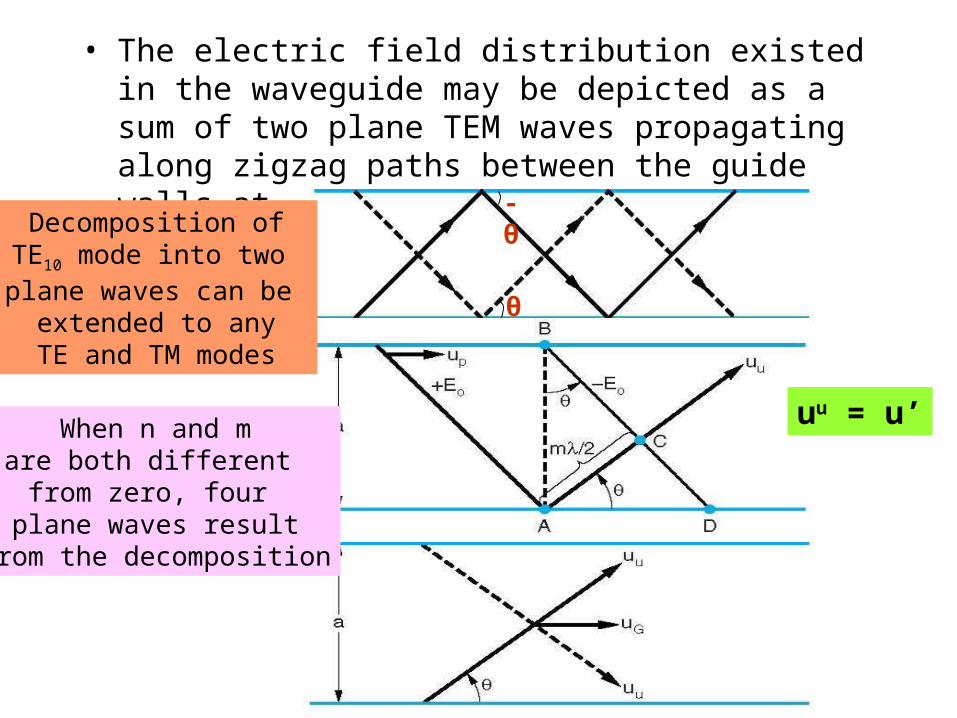
• The electric field distribution existed in the waveguide may be depicted as a sum of two plane TEM waves propagating along zigzag paths between the guide walls at x = a and x = b
-θ
θ
uu = u’
Decomposition ofTE10 mode into two plane waves can be
extended to anyTE and TM modes
When n and mare both different from zero, four
plane waves resultfrom the decomposition
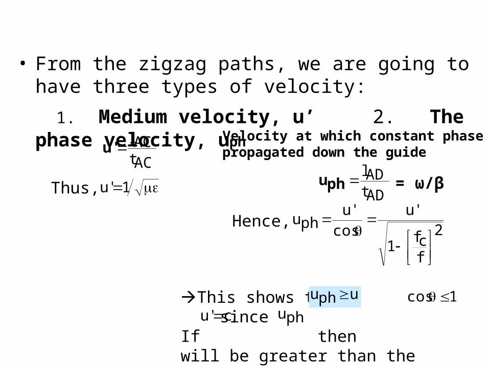
• From the zigzag paths, we are going to have three types of velocity:
1. Medium velocity, u’ 2. The phase velocity, uph
ACtAClu'
1'uThus,
Velocity at which constant phase are propagated down the guide
ADtADlphu
2
fcf1
'ucos
'uphu
Hence,
This shows that since If then will be greater than the speed of light in the vacuum.
'uphu 1cos ,c'u phu
= ω/β

3. The group velocity, ug • Essentially the velocity of propagation of the electric field
distribution along the waveguide
• It is the energy propagation velocity and is always less than equal to u’
• The wave component in the +z-direction has a different wavelength from that of the plane waves. This wavelength along the axis of the guide is called waveguide wavelength and is given by:
dd
1gu
2
fcf1'ucos'ugu
OR:
2'uguphu Note that:
2
fcf1
'g
where f'u'

The Idea of Group Velocity, Ug• The velocity with which the envelope – or equivalently the wave group – travels through the medium is called the group velocity, ug • As such, ug is the velocity of the energy carried by the wave group and of the information encoded in it.
Modulated waveform representsthe wave group
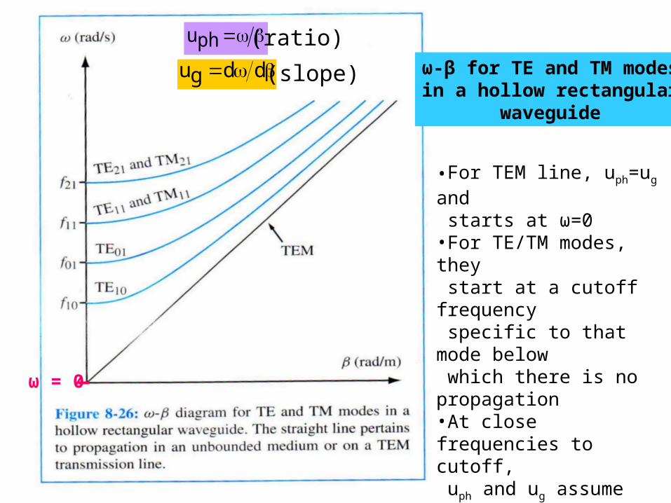
ω-β for TE and TM modesin a hollow rectangular
waveguide
phu
ddgu
•For TEM line, uph=ug and starts at ω=0•For TE/TM modes, they start at a cutoff frequency specific to that mode below which there is no propagation•At close frequencies to cutoff, uph and ug assume very different values i.e.: At cutoff, uph = ∞, ug = 0• As frequency increases,
ω-β curves of TE/TM modes approach the TEM line.
ω = 0
(ratio)
(slope)
NOTE THAT:
• Above cutoff (f > fc),
uph ≥ u’ and ug ≤ u’
• As f ∞ , TE and TM modes approach TEM case in which uph = ug = u’
DO U KNOW THAT? Information travels in group
velocity which must be less than the speed of light or else Einstein’s Theory of Relativity will be violated.
Phase velocity on the other hand can easily exceed the speed of light
Einstein Theory of Relativity states that:Messages cannot travel faster than the speed of light!Messages cannot travel faster than the speed of light!

Example 6
A standard air-filled rectangular waveguide with dimensions a=8.636cm, b=4.318cm is fed by a 4GHz carrier from a coaxial cable. Determine if a TE10 mode will be propagated.
If so, calculate the phase velocity and the group velocity.
Answer: TE10 will be propagated; 3.33x10⁸ m/s; 2.702 x 10⁸ m/s

Example 7
Repeat Example 6 for TM11
Answer: TM11 = 3.88 GHZ will be propagated, Vph = 12.29 x 10⁸ m/s; Vg = 7.293 x 10⁷ m/s

POWER TRANSMISSIONPOWER TRANSMISSION
• In order to determine the power flow in the waveguide, we have to find the average Poynting vector at first.
• Since the vector has direction, we know that the Poynting vector is along the +z-direction. Thus,
Where η = ηTE for TE modes or η = ηTM for TM modes
)*ssRe(
21
aveP HE
z)*xsHysE*
ysHxsERe(2
1aveP a
z2
2ysE2
xsEa

• The total average power transmitted across the cross section of the waveguide will then be:
• We are more concern with attenuation in We are more concern with attenuation in the lossy waveguides.the lossy waveguides.
SdavePaveP
dydxa
0x
b
0y 2
2ysE2
xsE
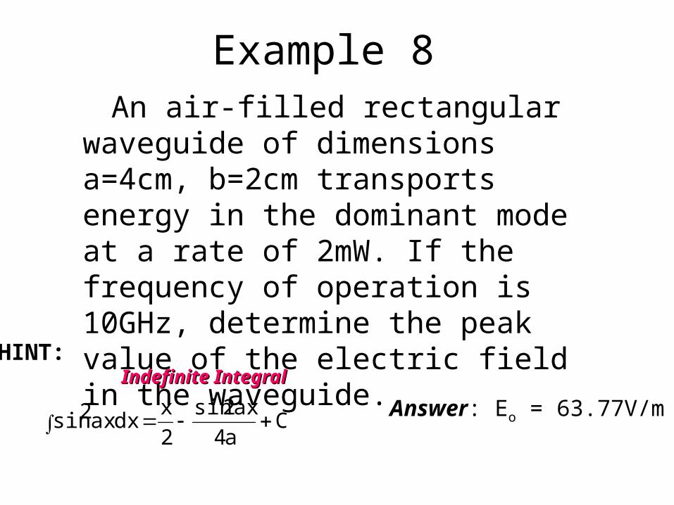
Example 8 An air-filled rectangular waveguide of
dimensions a=4cm, b=2cm transports energy in the dominant mode at a rate of 2mW. If the frequency of operation is 10GHz, determine the peak value of the electric field in the waveguide.
Answer: Eo = 63.77V/m
HINT: Indefinite IntegralIndefinite Integral
Ca4
ax2sin
2
xdxax2sin

Attenuation in Lossy Waveguides
• When the dielectric medium is lossy (σ ≠ 0) and the guide walls are not perfectly conducting (σc ≠ ∞), there will be a continuous loss of power as the wave propagates along the guide.
• Thus, the power flow in the guide will be in the form of:
z2eoPaveP
Where Po is the input power to the guide
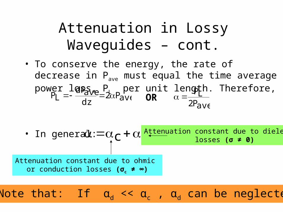
• To conserve the energy, the rate of decrease in Pave must equal the time average power loss, PL per unit length. Therefore,
• In general:
aveP2dzavedP
LP ORaveP2LP
dc
Attenuation constant due to ohmic or conduction losses (σc ≠ ∞)
Attenuation constant due to dielectriclosses (σ ≠ 0)
Attenuation in Lossy Waveguides – cont.
Note that: If αd << αc , αd can be neglected!

Test for Lossless Dielectric Medium
• Use loss tangent test:
If
Assume lossless dielectric mediumAssume lossless dielectric medium
1
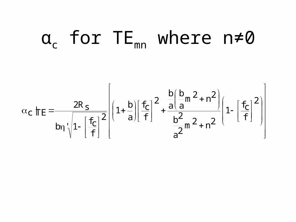
αc for TEmn where n≠0
2
fcf1
2n2m2a
2b
2n2mab
ab
2
fcf
a
b1
2
fcf1'b
sR2TE|c

αc for TE10
2
fcf
a
b
2
12
fcf1'b
sR210TE|c

αc for TMmn
2n2m2ab
2n2m3ab2
fcf1'b
sR2TM|c
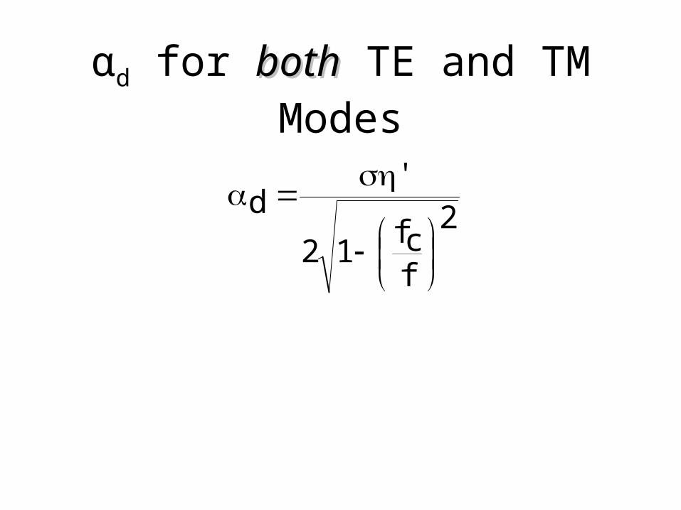
αd for bothboth TE and TM Modes
2
fcf12
'd
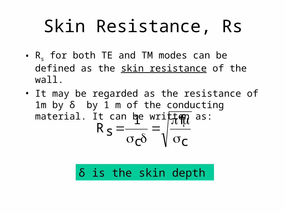
Skin Resistance, Rs
• Rs for both TE and TM modes can be defined as the skin resistance of the wall.
• It may be regarded as the resistance of 1m by δ by 1 m of the conducting material. It can be written as:
c
f
c
1sR
δ is the skin depth

Example 9
A copper-plated waveguide (σc=5.8×10⁷ mhos/m) operating at 4.8GHz is supposed to deliver a minimum power of 1.2kW to an antenna. If the guide is filled with polystyrene (σ=10-17 S/m, ε=2.55εo) and its dimensions are a=4.2cm, b=2.6cm.
Calculate the power dissipated in a length 60cm of the guide in the TE10 mode.
Note that: If αd << αc , αd can be neglected!

Surface current on guide wall for TE10 mode
E & H field for TE10 mode
Waveguide Current and Mode ExcitationWaveguide Current and Mode Excitation
• A WG is usually fed or excited by a coaxial line or another WG.• A probe (central conductor of a coaxial line is often used) to established field intensities of desired mode and achieve maximum power transfer• The probe is located to produce E and H that are roughly parallel to the lines E and H of the desired mode.
The probe is located at x = a/2
to excite TE10 mode

RECALL:Anatomy of Coaxial Cable
Inner conductor of a coaxialcable acts as a probe

MODE EXCITATIONMODE EXCITATIONIN THE IN THE
WAVEGUIDEWAVEGUIDE
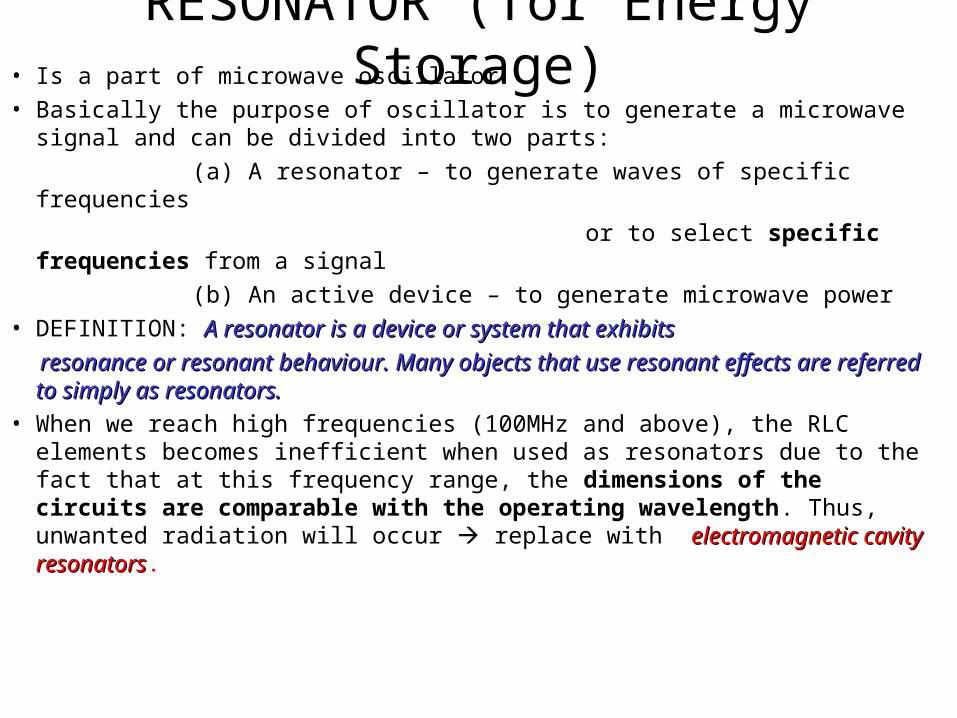
RESONATOR (for Energy Storage)• Is a part of microwave oscillator
• Basically the purpose of oscillator is to generate a microwave signal and can be divided into two parts:
(a) A resonator – to generate waves of specific frequencies
or to select specific frequencies from a signal
(b) An active device – to generate microwave power
• DEFINITION: A resonator is a device or system that exhibitsA resonator is a device or system that exhibits
resonance or resonant behaviour. Many objects that use resonant effects are resonance or resonant behaviour. Many objects that use resonant effects are referred to simply as resonators.referred to simply as resonators.
• When we reach high frequencies (100MHz and above), the RLC elements becomes inefficient when used as resonators due to the fact that at this frequency range, the dimensions of the circuits are comparable with the operating wavelength. Thus, unwanted radiation will occur replace with electromagnetic cavity resonatorselectromagnetic cavity resonators.
CAVITY?CAVITY?
RECALL BACK: RLC Circuit
• An RLC circuit (also known as a resonant circuit or a tuned circuit) is an electrical circuit consisting of a resistor (R), an inductor (L), and a capacitor (C), connected in series or in parallel.
• Tuned circuits have many applications particularly for oscillating circuits and in radio and communication engineering.
• They can be used to select a certain narrow range of frequencies from the total spectrum of ambient radio waves.
• For example, AM/FM radios with analog tuners typically use an RLC circuit to tune a radio frequency.
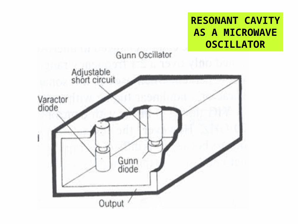
• Most commonly a variable capacitor (varactor diode) is attached to the tuning knob, which allows you to change the value of C in the circuit and tune to stations on different frequencies.
RESONANCE• The tendency of a system to oscillate at maximum amplitude
at a certain frequency
• This frequency is the system’s natural frequency of vibration, resonant frequency or eigenfrequency
• A resonant object, whether mechanical, acoustic or electrical will probably have more than one resonance frequency
• It will be easy to vibrate at those frequency and more difficult to vibrate at other frequencies
• In effect, the object will filter out all frequencies other than it resonant frequency.
Electromagnetic Cavity Resonators
• A cavity resonator, usually used in reference to electromagnetic resonators, is one in which the waves one in which the waves exist in a hollow space inside the device. exist in a hollow space inside the device.
• Such resonator cavities are used in Klystron tubes, bandpass filters and wave meters.
• Microwave oven on the other hand consists of a power supply, a waveguide feed and an oven cavity.
RESONANT CAVITYAS A BANDPASS
FILTER
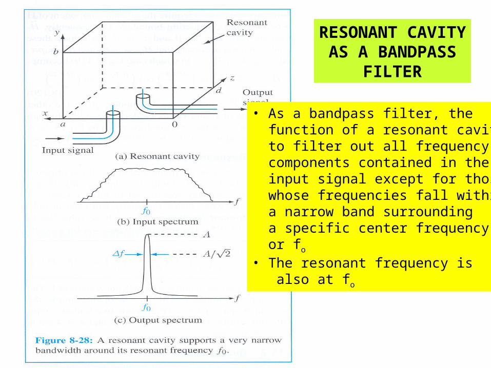
• As a bandpass filter, the function of a resonant cavity is to filter out all frequency components contained in the input signal except for those whose frequencies fall within a narrow band surrounding a specific center frequency or fo • The resonant frequency is also at fo
RESONANT CAVITYAS A MICROWAVE
OSCILLATOR
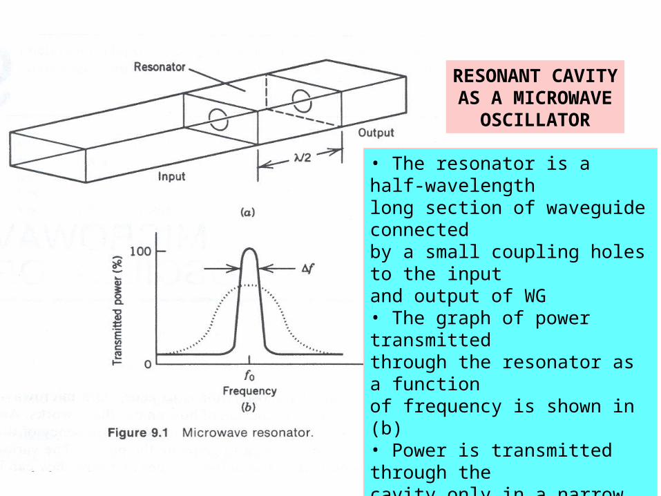
• The resonator is a half-wavelengthlong section of waveguide connected by a small coupling holes to the input and output of WG• The graph of power transmittedthrough the resonator as a functionof frequency is shown in (b)• Power is transmitted through the cavity only in a narrow frequencyrange around fo • The most power is transmitted at fo
when a half-wavelength of themicrowave field exactly fits into the cavity
DO YOU KNOW THAT?
The cavity resonant frequency, fThe cavity resonant frequency, foo can be can be
fixed or mechanically changed by altering fixed or mechanically changed by altering the cavity dimensions or electronically the cavity dimensions or electronically changed.changed.
RESONANT CAVITYAS A MICROWAVE
OSCILLATOR
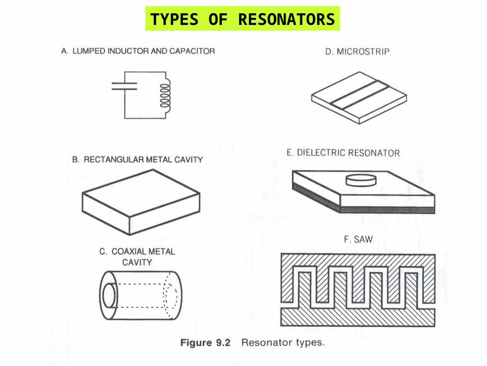
TYPES OF RESONATORS
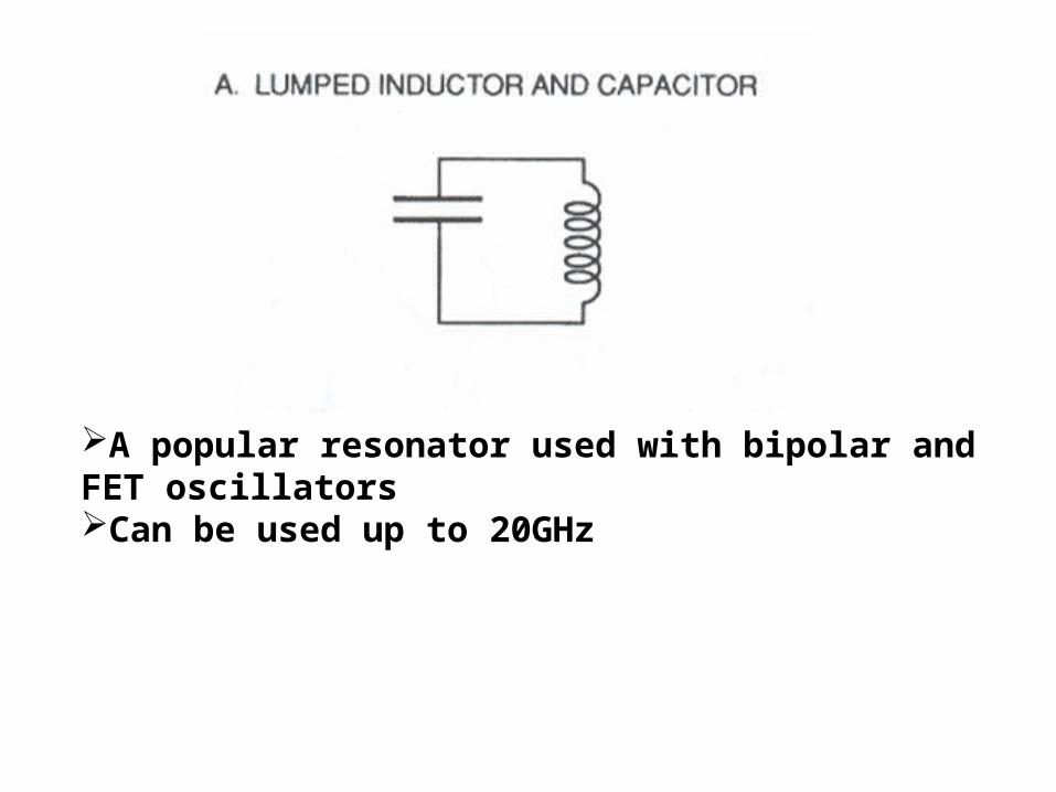
A popular resonator used with bipolar and FET oscillatorsCan be used up to 20GHz
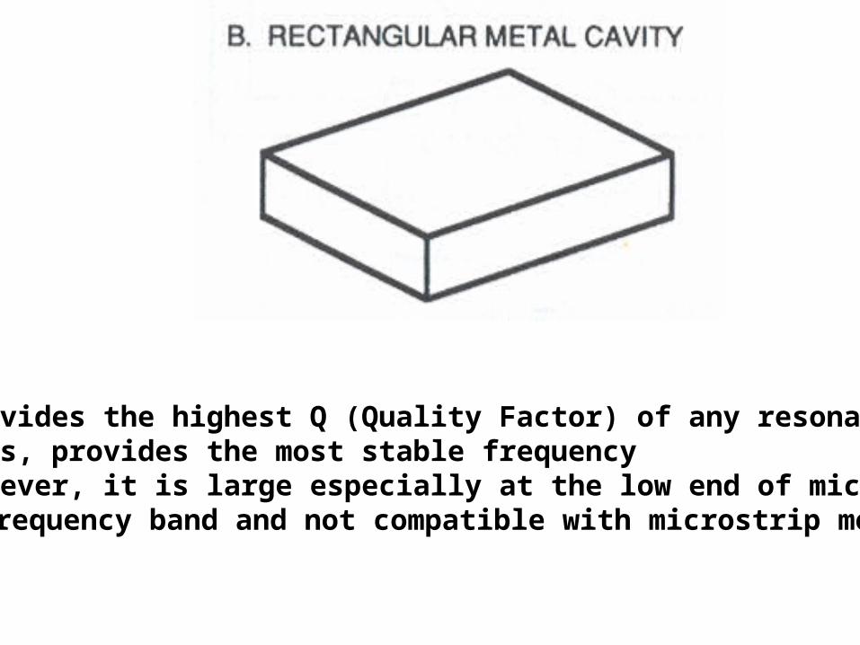
Provides the highest Q (Quality Factor) of any resonator Thus, provides the most stable frequency However, it is large especially at the low end of microwave frequency band and not compatible with microstrip mounting
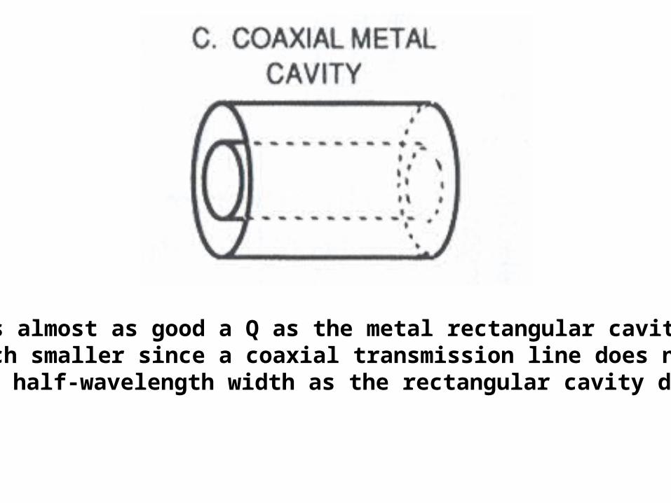
Has almost as good a Q as the metal rectangular cavity Much smaller since a coaxial transmission line does not need a half-wavelength width as the rectangular cavity does

Easy to fabricate but has low Q Oscillators using it have poor frequency stability
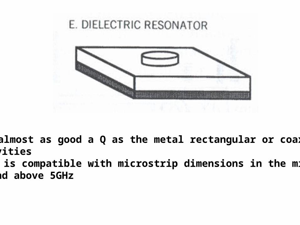
Has almost as good a Q as the metal rectangular or coaxial cavities Size is compatible with microstrip dimensions in the microwave band above 5GHz
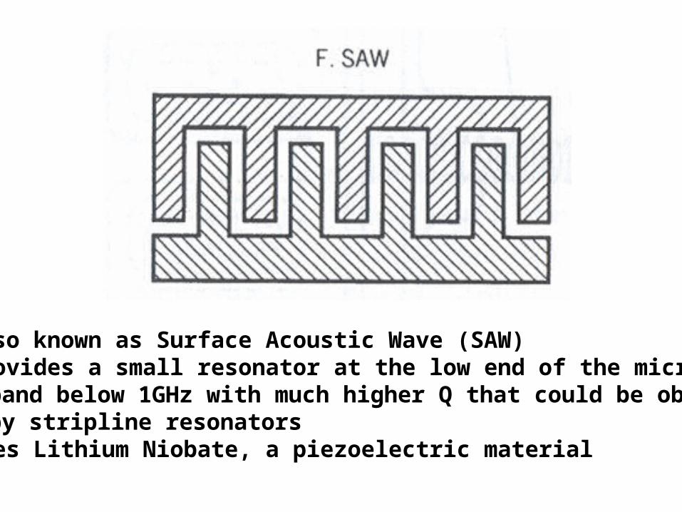
Also known as Surface Acoustic Wave (SAW) Provides a small resonator at the low end of the microwave band below 1GHz with much higher Q that could be obtained by stripline resonators Uses Lithium Niobate, a piezoelectric material

Rectangular Cavity

Rectangular Cavity• Consider a rectangular cavity (or closed conducting box).• Noticed that the cavity is simply a rectangular waveguides shorted at
both ends.• The cavity has interior surfaces which reflect a wave of a specific
frequency.• When a wave that is resonant with the cavity enters, it bounces back and
forth within the cavity, with low loss.• As more wave energy enters the cavity, it combines with and reinforces
the standing wave.• The field constitute a standing waves along x- and y-direction and along a propagating wave along z-direction• In cavity, there is no unique propagation direction because there is no In cavity, there is no unique propagation direction because there is no
propagation but instead, standing waves exist along all three directions.propagation but instead, standing waves exist along all three directions.• For consistency, we will continue to define transverse direction to be
any direction contained in the plane perpendicular to z-direction.

TM Modes to z-directionHz = 0 and as usual we let:
• The boundary conditions are such that:
Ez = 0 at x = 0,a
Ez = 0 at y = 0,b
Ey = 0, Ex = 0 at z = 0, c
• We will get:
)z(Z)y(Y)x(X)z,y,x(zsE xxksin2cxxkcos1c)x(X yyksin4cyykcos3c)y(Y zzksin6czzkcos5c)z(Z
22zk2
yk2xk2k
c
zpcos
b
ynsin
a
xmsinoEzsE 5c4c2coE
p = 0,1,2,3,…Where:
Where:
and:
(2.29)
(2.30a)(2.30b)
(2.30c)
(2.31)
(2.32a)
(2.32b)
(2.32c)
Other field components can be found from Eq. 2.33 and 2.16
(2.33)
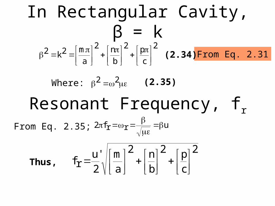
In Rectangular Cavity, β = k2
c
p2
b
n2
a
m2k2
From Eq. 2.31
Resonant Frequency, fr
22Where:
'urrf2
(2.34)
(2.35)
From Eq. 2.35;
2
cp2
bn2
am
2'u
rf
Thus,

Resonant Wavelength, λr
2
cp2
bn2
am
2
rf
'ur
NOTE THAT:
The lowest-order TM mode is TM110

• Let Ez = 0. Thus,
• The boundary conditions will then be:
TE Modes to z-direction
)zzksinzzkcos5b)(yyksin4byykcos3b)(xxksin2bxxkcos1b(zsH (2.36)
0zsH
0xzsH
0yzsH
at
at
at
c,0z
a,0x
b,0y
(2.37a)
(2.37b)
(2.37c)
Using this boundary conditions on Eq. 2.36 will give us:
czp
cosb
yncos
axm
cos0HzsH
p = 1,2,3,…
(2.38)
Other field components can be find from Eq. 2.38 and 2.16
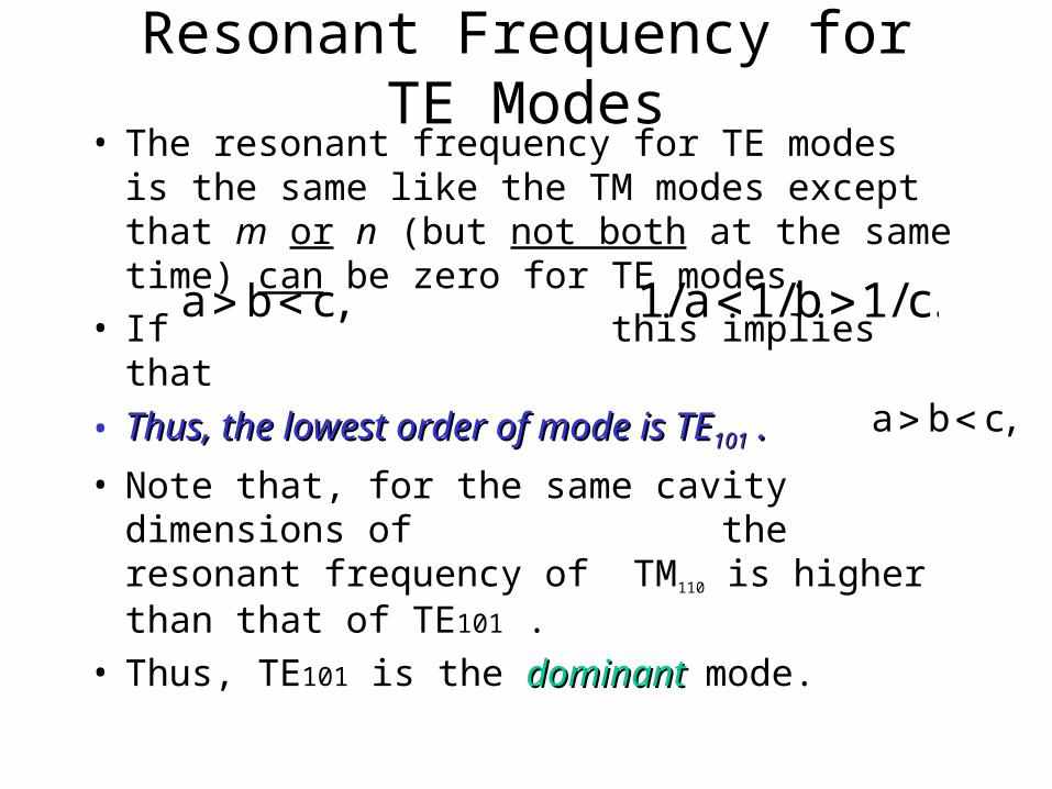
Resonant Frequency for TE Modes• The resonant frequency for TE modes is the same
like the TM modes except that m or n (but not both at the same time) can be zero for TE modes.
• If this implies that
• Thus, the lowest order of mode is TEThus, the lowest order of mode is TE101101 . .
• Note that, for the same cavity dimensions of the resonant frequency of TM110 is higher than that of TE101 .
• Thus, TE101 is the dominant dominant mode.
,cba .c/1b/1a/1
,cba

To Summarize:
TE Modes TM Modes
Lowest-Order Lowest-Order ModeMode
TE101 for a > b < c
TM110
Dominant ModeDominant Mode TE101
DEGENERATE MODES• When different modes have the same
resonant frequency, the modes are degenerate degenerate – one mode will dominate others depending on how the cavity is excited.
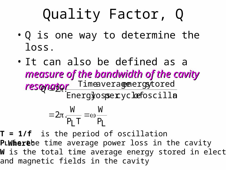
Quality Factor, Q• Q is one way to determine the loss.
• It can also be defined as a measure of the measure of the bandwidth of the cavity resonatorbandwidth of the cavity resonator
noscillatioofcycleperlossEnergystoredenergyaverageTime
.2Q
LPW
TLPW
.2
T = 1/f is the period of oscillation PL is the time average power loss in the cavity W is the total time average energy stored in electric and magnetic fields in the cavity
Where:

QTE101
• Q is usually high for a cavity resonator compared with the RLC resonant circuit.
• Thus, cavity resonator is better than RLC resonant circuit
• Q ↑, the lower the LOSS
)]2c2a(ac)3c3a(b2[
abc)2c2a(101TEQ
co101f1
Where: is the skin depth of the
cavity walls
Advantages of Waveguide filters and Cavity Resonators in SatComm applications
• Waveguide filters and cavity resonators are larger and heavier than the microstrip and other transmission line equivalents but they have the following advantages for Satellite Communication applications in terms of:Power handling capacityLower losses (resistive and dielectric)Dimensional stability against vibration, changes in
temperature and pressureFrequency and bandpass response stabilityEase of tuning after manufactureRobustnessNo dielectric. Thus, non-linearities in high fields are less.
Example 10
(a) A resonant mode in cavity is denoted by TEmnp or TMmnp mode. What does the subscripts m, n and p correspond to?
(b) An air-filled cubical cavity operates at a resonant frequency of 2 GHz when excited at TE101 mode.
Determine the dimensions of the cavity.

Additional Example
Design a rectangular waveguide with an aspect ratio of 3 to 1 for use in the k-band (18 – 26.5GHz). Assume the guide is air-filled.

Additional Example
An air-filled rectangular waveguide has a=6cm and b=3cm. Given that:
Calculate the intrinsic impedance of this mode and the average power flow in the guide.
m/Vzt1210cosb
y3sin
a
x2sin5zE

Additional Example
A rectangular waveguide with cross-sections in figure below has dielectric discontinuity. Calculate the standing wave ratio if the guide operates at 8GHz in the dominant mode.
oo o25.2,o
1 2
zx
y
5cm
2.5cm
Hint: 12
12

PLEASE STUDY FOR YOUR QUIZ 2!
Related Documents