Progress In Electromagnetics Research, PIER 103, 285–303, 2010 ELECTROMAGNETIC WAVE PROPAGATION IN CHIRAL H-GUIDES A. L. Topa, C. R. Paiva, and A. M. Barbosa Instituto de Telecomunica¸ c˜ oes Department of Electrical and Computer Engineering Instituto Superior T´ ecnico Av. Rovisco Pais 1, 1049-001 Lisboa, Portugal Abstract—Guided-wave propagation in chiral H-guides is analyzed, using a building-block approach. In a first stage, a 2D chiral parallel-plate waveguide is studied using a lossless frequency dispersion model for the optically active medium, where the constitutive chiral parameter is assumed to be dependent on the gyrotropic parameter. In the second stage, the mode matching technique and the transverse resonance method are used to characterize the 3D structure. A full parametric study is presented for a fixed frequency. The operational and dispersion diagrams for the chiral H-guide are presented. By replacing the common isotropic slab with a chiral slab, chirality provides an extra degree of freedom in the design of new devices. 1. INTRODUCTION Chiral media are known to exhibit optical activity, while keeping reciprocity. Therefore, unlike magnetically biased ferrites, these media can be useful in the design of some reciprocal devices such as mode converters, polarizers and phase shifters (see [1] and references therein). The application of chiral media to closed metallic waveguides, originally termed as chirowaveguides, and to open slab waveguides and circular rods has been exhaustively studied in the last years [2–14]. However, to the authors’ best knowledge, no work has been published yet on their application to hybrid waveguides as an H-guide. The major reason for this may be the unfeasibility of an exact closed solution for any rectangular geometry waveguide, due to the coupled differential equations that govern the transverse variation of the field Corresponding author: A. L. Topa ([email protected]).

Welcome message from author
This document is posted to help you gain knowledge. Please leave a comment to let me know what you think about it! Share it to your friends and learn new things together.
Transcript

Progress In Electromagnetics Research, PIER 103, 285–303, 2010
ELECTROMAGNETIC WAVE PROPAGATION INCHIRAL H-GUIDES
A. L. Topa, C. R. Paiva, and A. M. Barbosa
Instituto de TelecomunicacoesDepartment of Electrical and Computer EngineeringInstituto Superior TecnicoAv. Rovisco Pais 1, 1049-001 Lisboa, Portugal
Abstract—Guided-wave propagation in chiral H-guides is analyzed,using a building-block approach. In a first stage, a 2D chiralparallel-plate waveguide is studied using a lossless frequency dispersionmodel for the optically active medium, where the constitutive chiralparameter is assumed to be dependent on the gyrotropic parameter.In the second stage, the mode matching technique and the transverseresonance method are used to characterize the 3D structure. A fullparametric study is presented for a fixed frequency. The operationaland dispersion diagrams for the chiral H-guide are presented. Byreplacing the common isotropic slab with a chiral slab, chiralityprovides an extra degree of freedom in the design of new devices.
1. INTRODUCTION
Chiral media are known to exhibit optical activity, while keepingreciprocity. Therefore, unlike magnetically biased ferrites, thesemedia can be useful in the design of some reciprocal devices such asmode converters, polarizers and phase shifters (see [1] and referencestherein). The application of chiral media to closed metallic waveguides,originally termed as chirowaveguides, and to open slab waveguides andcircular rods has been exhaustively studied in the last years [2–14].However, to the authors’ best knowledge, no work has been publishedyet on their application to hybrid waveguides as an H-guide. Themajor reason for this may be the unfeasibility of an exact closedsolution for any rectangular geometry waveguide, due to the coupleddifferential equations that govern the transverse variation of the field
Corresponding author: A. L. Topa ([email protected]).

286 Topa, Paiva, and Barbosa
components. In fact, TE and TM modes cannot propagate whenevermetallic rectangular cross-section waveguiding structures are filledwith chiral materials. Some numerical analyses have been presentedin the literature for the metallic rectangular waveguide totally filledwith a chiral material [2–4], based on the finite-element or finite-difference methods. Exact analytical solutions are only available for themetallic circular waveguide [2], for a ground chiral slab [5], and for theparallel-plate waveguide [6–10], totally or partially filled. The analysisof isotropic-chiral material discontinuities in rectangular waveguides,using the coupled mode method combined with the mode matchingtechnique, has been presented in [11]. The same approach has beenused for the analysis of a parallel-plate waveguide partially filled witha chiral media [12]. On the other hand, for very small values of thechirality parameter χ, the solutions to the modal equation can beexpressed in terms of this parameter up to first order [13, 14], thezero order term being the solutions for the achiral waveguide and thefirst order term, which is proportional to χ, would give the impact ofchirality on the solution. With this approach, it is possible to grantinsight into the transition from TE/TM modes, in the achiral case,to hybrid modes in the chiral case. But this approach is limited togeometries for which an analytical solution of the modal equation canbe derived.
This paper addresses the guided-wave propagation in an H-guide when the common isotropic slab is replaced by a chiral slab(Fig. 1). The main advantage of H-guides is the possibility of frequencyscaling. Therefore, devices based on chiral waveguides, operating in themicrowave regime [1], can be realized at higher frequencies (e.g., in themillimeter-wave regime) using chiral H-guides.
Several examples of H-guides, involving other types of complexmedia, have been already published in the literature, namely, the
y
2b
x
2l
Figure 1. Chiral H-guide.

Progress In Electromagnetics Research, PIER 103, 2010 287
cases when the isotropic slab is replaced by a uniaxial crystal [15], atransversely magnetized ferrite [16], an omega medium [17] or a double-negative metamaterial [18]. However, so far, no analysis has beenpublished for the chiral H-guide. This can be an interesting structureas chirality may provide an important degree of freedom and allow newpotential applications.
A semi-analytical method, based on a building-block approach,is used in this paper. When compared with fully numerical methods(like the finite-element method), this approach allows more physicalinsight into the results. The procedure is based on the transverseresonance method together with a mode matching technique, as anextension of the method used in [19, 20], after the method originallyderived by Peng and Oliner [21]. The building-block approach isdivided in two stages. In a first stage, a chiral parallel-plate waveguideis studied using a frequency dispersion model for the optically activemedium. When operating at lower frequencies, far below the resonancefrequency of the chiral particles, losses may be neglected and dispersionmay be characterized by the simple Condon model. A constitutivechiral parameter based on the gyrotropic parameter is assumed [22].This study provides the elementary modes propagating in the innerregion, which are then used for the complete full-wave analysis. Severalnumerical results for the chiral H-guide are presented in the last section.
2. THE CHIRAL PARALLEL-PLATE WAVEGUIDE
The parallel-plate waveguide is the elementary constitutive 2Dstructure of an H-guide. In this Section, we analyze the chiral parallel-plate waveguide depicted in Fig. 2. Since this is a completely closedstructure, with perfectly conducting planes placed at x = ±b, onlydiscrete modes may propagate.
x
z
2b
Figure 2. Chiral parallel-plate waveguide.

288 Topa, Paiva, and Barbosa
2.1. Chiral Media
For a chiral medium, the constitutive relations may be written as[DB
]=
[ε0ε −j
√ε0µ0χ
j√
ε0µ0χ µ0µ
] [EH
](1)
with ε0Z0 = µ0Y0 =√
ε0µ0 = 1/c, where c is the vacuum light velocityand χ is the normalized chirality parameter, which can be modeledby χ(ω) = cgω, where g is the gyrotropy parameter. The chiralityparameter, responsible for the optical activity and spatial dispersion,is an odd function of frequency and vanishes in the steady-state regime.
Considering plane wave propagation of the form exp [−j(kz − ωt)],and using Maxwell’s equations for source-free regions in the frequencydomain [ ∇× I 0
0 −∇× I
] [EH
]= −jω
[BD
](2)
where I is the unit dyadic, we can easily see that, in unbounded chiralmedia, there are two TEM characteristic waves: a RCP (right-handcircularly polarized) wave and a LCP (left-hand circularly polarized)wave and hence, in optically active media, the polarization plane oflinearly polarized light rotates with propagation.
Using now Bohren’s decomposition [23], one may write
D± = ε0ε±E± (3)B± = µ0µ±H (4)
where ε± = ε ± ycχ and µ± = µ ± χ/yc with yc = Yc/Y0 =√
ε/µ.Therefore, Maxwell Equation (2) are recast into
∇×E± = −jωµ0µ±H± (5)∇×H± = jωε0ε±E± (6)
Choosing Ey and Hy as the field supporting components
Ey(x, y, z, t) = F (x) exp [−j(kz − ωt)] (7)Hy(x, y, z, t) = G(x) exp [−j(kz − ωt)] (8)
the other field components may be obtained from (5) and (6) accordingto
E±x =
k
ωε0ε±H±
y (9)
E±z = − j
ωε0ε±
∂H±y
∂x(10)
H±x = − k
ωµ0µ±E±
y (11)

Progress In Electromagnetics Research, PIER 103, 2010 289
H±z =
j
ωµ0µ±
∂E±y
∂x(12)
while E±y satisfy to the Helmholtz equation
∇2E±y + k2
±E±y = 0 (13)
with k± = (√
εµ ± χ)k0 = ε±k0/yc = ycµ±k0. According to Bohren’sdecomposition,
Ey = E+y + E−
y (14)
Hy = H+y + H−
y = jYc(E+y − E−
y ) (15)
WritingE±
y = Ψ±(x) exp [−j(kz − ωt)] (16)
one has
F (x) = Ψ+(x) + Ψ−(x) (17)G(x) = jYc [Ψ+(x)−Ψ−(x)] (18)
where, according to (13), Ψ±(x) obey to the following Helmholtzequation
∇2Ψ± + (k2± − k2)Ψ± = 0 (19)
Owing to the symmetry of the structure, the propagating modescan be divided into even and odd modes. Therefore, the solutionsof (19) can be written as
Ψ± = A± cos(h±x) (20)
for the even modes, and
Ψ± = A± sin(h±x) (21)
for the odd modes, where h2± = k2± − k2.
2.2. Dispersion Diagram
Due to the perfectly conducting planes, placed at x = ±b, one musthave Ey(x = ±b) = 0 and Ez(x = ±b) = 0. Imposing these boundaryconditions to the six field components derived in Appendix A, ahomogeneous set of algebraic equations, for the coefficients A± in (20)and (21), is obtained. For a nontrivial solution, the determinant of thecorrespondent matrix must be zero, leading to the following two modalequationsε−h+ + ε+h−
2sin [(h+ + h−)b]± ε−h+ − ε+h−
2sin [(h+ − h−)b] = 0.
(22)

290 Topa, Paiva, and Barbosa
where the plus sign stands for the even modes and the minus sign forthe odd modes,
At the cutoff, one has k = 0 or, according to (19), h± = k±. Atthis point, one can use ε−h+ = ε+h− in the modal Equations (22),to obtain sin [(k+ + k−)b] = 0, or b/λ = n/(4
√εµ), with n being an
integer. The fundamental even mode, with no cutoff frequency, isobtained for n = 0.
The dispersion diagram for the first even and odd hybrid modesis depicted in Fig. 3, for ε = 4, µ = 1, b = 0.001m and g =10−21 s2/m. The two dashed oblique lines in this figure correspond tothe asymptotic limiting values of k = k+ and k = k−. For all modes,k goes to k+ when b/λ →∞, although transiently they may approachk−. Moreover, except for the fundamental mode, all dispersion curvesstart at the cutoff for k = 0. One should note that the cutoff values ofthe odd modes are exactly the same as for the even modes.
This diagram is very important as it provides the numerical valuesfor the wavenumbers of the elementary modes propagating obliquelyalong the chiral slab of the H-guide. These values are necessary in themode matching technique applied to the transverse resonance method,as it will be discussed in the next section.
0
0.5
1
1.5
2
2.5
0 0.1 0.2 0.3 0.4 0.5 0.6 0.7 0.8
b/λ
k/k
0
Figure 3. Dispersion diagram for the first propagating modes of achiral parallel-plate waveguide, with ε = 4, µ = 1, b = 0.001m andg = 10−21 s2/m: (a) Even modes (thick lines); (b) Odd modes (thinlines).

Progress In Electromagnetics Research, PIER 103, 2010 291
3. THE CHIRAL STEP DISCONTINUITY
3.1. Scattering Matrix under Oblique Incidence
In this section, the step discontinuity in a parallel-plate waveguidedepicted in Fig. 4 is analyzed and its scattering matrix under obliqueincidence is derived. The mathematical framework presented in thissection is quite different from the formalism used in [19, 20], where theelementary modes were pure TE and TM modes, and the waveguideunder consideration was a completely open structure. In fact, themodal propagation along the chiral H-guide can be seen as thetransverse resonance of the elementary hybrid modes of a parallel-platewaveguide propagating obliquely and bouncing back and forth at twolateral step discontinuities.
The structure coordinates (x, y, z) and the wave coordinates(x, u, v) can be simply related through
[xyz
] = [ 1 0 00 sin θ cos θ0 − cos θ sin θ
] [xuv
](23)
For an incident mode, one has
ki = βvEi = {Exx + Euu + Evv} exp(−jβv)Hi = {Hxx + Huu + Hvv} exp(−jβv)
(24)
where {u = sin θ y − cos θ zv = cos θ y + sin θ z (25)
u
x
v
y
z
θ
χ
Figure 4. Step discontinuity in a chiral parallel-plate waveguide andthe corresponding coordinate systems (x, y, z) and (x, u, v).
292 Topa, Paiva, and Barbosa
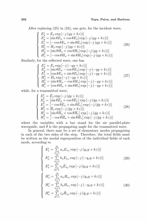
After replacing (25) in (24), one gets, for the incident wave,
Eix = Ex exp [−j (qy + kz))]
Eiy = [sin θEu + cos θEv] exp [−j (qy + kz))]
Eiz = [− cos θEu + sin θEv] exp [−j (qy + kz))]
H ix = Hx exp [−j (qy + kz))]
H iy = [sin θHu + cos θHv] exp [−j (qy + kz))]
H iz = [− cos θHu + sin θHv] exp [−j (qy + kz))]
(26)
Similarly, for the reflected wave, one has
Erx = Ex exp [−j (−qy + kz))]
Ery = [sin θEu − cos θEv] exp [−j (−qy + kz))]
Erz = [cos θEu + sin θEv] exp [−j (−qy + kz))]
Hrx = Hx exp [−j (−qy + kz))]
Hry = [sin θHu − cos θHv] exp [−j (−qy + kz))]
Hrz = [cos θHu + sin θHv] exp [−j (−qy + kz))]
(27)
while, for a transmitted wave,
Etx = Ex exp [−j (qy + kz))]
Ety =
[sin θEu + cos θEv
]exp [−j (qy + kz))]
Etz =
[− cos θEu + sin θEv
]exp [−j (qy + kz))]
Htx = Hx exp [−j (qy + kz))]
H iy =
[sin θHu + cos θHv
]exp [−j (qy + kz))]
Htz =
[− cos θHu + sin θHv
]exp [−j (qy + kz))]
(28)
where the variables with a bar stand for the air parallel-platewaveguide, and θ is the propagating angle for the transmitted wave.
In general, there may be a set of elementary modes propagatingin each of the two sides of the step. Therefore, the total fields mustbe written as the modal superposition of the individual fields of eachmode, according to
Eix =
∞∑n=1
anExn exp [−j (qny + kz))]
Erx =
∞∑n=1
bnExn exp [−j (−qny + kz))]
Etx =
∞∑p=1
cpExp exp [−j (qny + kz))]
(29)
H ix =
∞∑n=1
anHxn exp [−j (qny + kz))]
Hrx =
∞∑n=1
bnHxn exp [−j (−qny + kz))]
Htx =
∞∑p=1
cpHxp exp [−j (qny + kz))]
(30)

Progress In Electromagnetics Research, PIER 103, 2010 293
Eiz =
∞∑n=1
an [− cos θnEun + sin θnEvn ] exp [−j (qny + kz))]
Erz =
∞∑n=1
bn [cos θnEun + sin θnEvn ] exp [−j (−qny + kz))]
Etz =
∞∑p=1
cp
[− cos θpEup + sin θpEvp
]exp [−j (qny + kz))]
(31)
and
H iz =
∞∑n=1
an [− cos θnHun + sin θnHvn ] exp [−j (qny + kz))]
Hrz =
∞∑n=1
bn [cos θnHun + sin θnHvn ] exp [−j (−qny + kz))]
Htz =
∞∑p=1
cp
[− cos θpHup + sin θpHvp
]exp [−j (qny + kz))]
(32)
The boundary conditions at y = 0 may be written in the followingform:
Eix(0) + Er
x(0) = Etx(0) (33)
H ix(0) + Hr
x(0) = Htx(0) (34)
Eiz(0) + Er
z(0) = Etz(0) (35)
H iz(0) + Hr
z (0) = Htz(0) (36)
Replacing (29) in (33) one gets∞∑
n=1
(an + bn)Exn =∞∑
p=1
cpExp (37)
On the other hand, replacing (30) in (34) one has∞∑
n=1
(an + bn)Hxn =∞∑
p=1
cpHxp (38)
Replacing (31) in (35) one has
−∞∑
n=1
(an − bn) cos θnEun +∞∑
n=1
(an + bn) sin θnEvn
=∞∑
p=1
cp
[− cos θpEup + sin θpEvp
](39)

294 Topa, Paiva, and Barbosa
Finally, after replacing (32) in (36), one gets
−∞∑
n=1
(an − bn) cos θnHun +∞∑
n=1
(an + bn) sin θnHvn
=∞∑
p=1
cp
[− cos θpHup + sin θpHvn
](40)
3.2. Orthogonality Relations
Introducing the following vector inner product
〈f ,g〉 =
b∫
−b
(f1g1 + f2g2)dx. (41)
the orthogonality relations for the hybrid modes can be written in thefollowing form
Opm = 〈W ·ϕm, ϕn〉 = δmn (42)
where δmn stands for the Kronecker delta,
φm = [ Eum Hum ]T (43)
and
W =1∆
[ε jχjχ −µ
]. (44)
On the other hand,
ψ = −βW ·ϕ (45)
withψ = [ Hx Ex ]T . (46)
Therefore,
Opm = −βp 〈W ·ϕp,ϕm〉 =
b∫
−b
(HxpEum + ExpHum)dx = −βpδpm.
(47)
3.3. Mode Matching
Multiplying Equation (38) by Eum(x) and Equation (37) by Hum(x),adding and integrating between−b and +b, and using the orthogonality

Progress In Electromagnetics Research, PIER 103, 2010 295
relations, one can get the amplitude coefficients cm of the transmittedwaves
cm = − 1βm
∞∑
n=1
(an + bn)Pnm (48)
where
Pnm = −βn 〈W ·ϕn, ϕm〉 =
b∫
−b
(HxnEum + ExnHum)dx (49)
On the other hand, multiplying Equation (39) by Hxm(x) andEquation (40) by Exm(x), adding and integrating between −b and +b,and using the orthogonality relation one can get
−∞∑
n=1
(an − bn) cos θnQmn +∞∑
n=1
(an + bn) sin θnRmn
= cm cos θmβm +∞∑
p=1
cp sin θpSmp (50)
where
Qmn = −βm
⟨W · ϕm, ϕn
⟩=
b∫
−b
(HxmEun + ExmHun)dx (51)
and
Rmn = −βm
⟨W · ϕm, κn
⟩=
b∫
−b
(HxmEvn + ExmHvn)dx (52)
Smp = −βm
⟨W · ϕm, κp
⟩=
b∫
−b
(HxmEvp + ExmHvp)dx (53)
with κ = [ Ev Hv ]T . The bi-orthogonality relations (49) and (51)are derived in Appendix B. Finally, replacing (48) in (50) one has
∞∑
n=1
an
cos θnQmn−sin θnRmn−cos θmPnm−
∞∑
p=1
1βp
sin θpPnpSmp
=∞∑
n=1
bn
cos θnQmn+sin θnRmn+cos θmPnm+
∞∑
p=1
1βp
sin θpPnpSmp
(54)

296 Topa, Paiva, and Barbosa
Defining
a = [ a1, a2, . . . , an, . . . ]T (55)
b = [ b1, b2, . . . , bn, . . . ]T (56)
Equation (54) can be written in the following matrix form
A · a = B · b, (57)
where
Amn=cos θnQmn−sin θnRmn−cos θmPnm−∞∑
p=1
1βp
sin θpPnpSmp (58)
Bmn=cos θnQmn+sin θnRmn+cos θmPnm+∞∑
p=1
1βp
sin θpPnpSmp (59)
Finally, Equation (57) may be rewritten as
(C + D) · a = (C−D) · b, (60)
where
Cmn = cos θnQmn (61)
Dmn = − sin θnRmn − cos θmPnm −∞∑
p=1
1βp
sin θpPnpSmp (62)
4. THE CHIRAL H-GUIDE
4.1. Transverse Resonance
Referring to the waveguide depicted in Fig. 1, the plane y = 0 is ageometrical symmetry plane. Therefore, one has only to analyze theregion y ≥ 0. In fact, relatively to y, the supermodes can be dividedinto even and odd modes.
In that case, for the even modes, the boundary conditions at y = 0are
H ix(0) + Hr
x(0) = 0 (63)H i
z(0) + Hrz (0) = 0, (64)
whilst, for the odd modes they are written as
Eix(0) + Er
x(0) = 0 (65)Ei
z(0) + Erz(0) = 0. (66)

Progress In Electromagnetics Research, PIER 103, 2010 297
From (63) and (64), one has
a = −L · b (67)
whereL = diag( e−j2q1 l, e−j2q2 l, . . . , e−j2qn l, . . . ) (68)
On the other hand, from (65) and (66), one has
a = L · b (69)
Therefore, it is possible to write
a =←Γ · b (70)
where ←Γ = Γ L (71)
and Γ = +1 for the even modes and Γ = −1 for the odd modes.Replacing (67) in (57) it is possible to get
(A · ←Γ−B) · b = 0, (72)
or, from (60), [C (
←Γ− I) + D (
←Γ + I)
]· b = 0, (73)
where, again, I stands for the unit matrix. Non-trivial solutions of (73)are only possible when
det
[I +
D (←Γ + I)
C (←Γ− I)
]= 0. (74)
Equation (74) is the modal equation of the waveguide in Fig. 1,which was derived using the transverse resonance method.
4.2. Numerical Results
In this section, some numerical results for the chiral H-guide, depictedin Fig. 1, are presented. These results have been obtained using theformalism developed in the previous sections. All the elementarysurface modes in each region, propagating above cutoff, have beenincluded in the analysis.
The dispersion diagram for the modes in a chiral-parallel platewaveguide and for an empty parallel-plate waveguide are both depictedin Fig. 5. For example, using b/λ = 0.3, the vertical line drawn inthis diagram dictates the number of modes propagating above cutoffand the values for their longitudinal wavenumbers. These elementarymodes are necessary for the analysis of the chiral H-guide.

298 Topa, Paiva, and Barbosa
0
0.2
0.4
0.6
0.8
1
1.2
1.4
1.6
1.8
0 0.1 0.2 0.3 0.4 0.5
b/λ
k/k
0
H0
H1
H2
TM0
TE1
Figure 5. Dispersion diagramfor the even modes of a chiralparallel-plate waveguide, with ε =2, µ = 1, b = 1mm, andg = 10−21 s2m−1 (thick lines).The thin lines are for the emptyparallel-plate waveguide.
0
0.2
0.4
0.6
0.8
1
1.2
1.4
1.6
1.8
0.5 1 1.5 2
g [10-21
s2m
-1]
k/k
0
β1I
2I
1II
2II
β
β
β
Figure 6. Variation of thelongitudinal wavenumbers withthe girotropy parameter, whenε = 2, µ = 1, b = 1 mm, andb/λ = 0.3 (thick lines). The thinlines are for the empty parallel-plate waveguide.
The variation of the longitudinal wavenumbers of these modeswith the girotropy parameter is depicted in Fig. 6. Again, for agiven value of the girotropy parameter, e.g., g = 10−21 s2m−1, thevertical line drawn in this diagram gives the values for the longitudinalwavenumbers of these modes.
The operational diagram for a chiral H-guide is depicted in Fig. 7.The vertical dashed line gives the cutoff values for the slab half-width,telling how many modes are propagating in the structure for a given setof parameters. The modes are termed Hn, meaning that they are allhybrid, with n being the order of the mode and expressing the numberof maximums in the inner region. As was already pointed out, due tothe waveguide spatial symmetry relatively to the central plane y = 0,every propagating mode has either even or odd symmetry.
The effect of the slab width in the value of the longitudinalwavenumber for the first propagating modes is illustrated in Fig. 8.Results for the case of an H-guide with vanishing chirality (i.e., usinga conventional dielectric) are also depicted to put in evidence thedifferences between the chiral and the achiral cases. As was expected,for the chiral case, there is also a fundamental mode with no cutoff,while mode coupling between some of the modal curves can be easilyidentified.

Progress In Electromagnetics Research, PIER 103, 2010 299
0
1
2
3
4
5
6
0.5 1 1.5 2
g [10-21
s2m
-1]
lc [
mm
]
H0
H5
H4
H3
H2
H1
H6
Figure 7. Operational diagramfor a chiral H-guide with b =1mm, when ε = 2, µ = 1, andf = 100 GHz.
2
2.2
2.4
2.6
2.8
3
3.2
0 0.5 1 1.5 2 2.5 3 3.5 4
l [mm]
k[r
ad/m
m]
H0
H3
H2
H1
Figure 8. Effect of the slabwidth on the H-guide performancefor g = 10−21 s2m−1 (dashed linesare for vanishing chirality).
5. CONCLUSIONS
We have proposed a semi-analytical method based on a building-blockapproach, suitable to analyze 3D chiral waveguides with rectangulargeometry. So far, this type of waveguides had only been analyzedthrough the use of fully numerical methods. In this paper, theconventional mode matching technique and the usual transverseresonance method have been generalized to be applied to the hybridguided modes of chiral waveguides with rectangular geometry. Theproposed method was successfully applied to the analysis of a chiralH-guide. A full parametric study was presented for a chiral H-guideoperating at a fixed frequency. The numerical results show thatchirality may provide an extra degree of freedom useful for the designof new devices.
ACKNOWLEDGMENT
This work was partially funded by FCT (Fundacao para a Ciencia e aTecnologia), Portugal.
APPENDIX A. FIELD COMPONENTS FOR THE EVENHYBRID MODES OF THE CHIRAL PARALLEL-PLATEWAVEGUIDE
For a chiral parallel-plate waveguide, one has

300 Topa, Paiva, and Barbosa
{Ey = A [cos(h+x) + Q cos(h−x)]Hy = jYcA [cos(h+x)−Q cos(h−x)] (A1)
Ex = A jYckωε0
[1
ε+cos(h+x)− Q
ε− cos(h−x)]
Hx = −A kωµ0
[1
µ+cos(h+x) + Q
µ− cos(h−x)] (A2)
Ez = A Ycωε0
[−h+
ε+sin(h+x) + h−Q
ε− sin(h−x)]
Hz = A jωµ0
[−h+
µ+sin(h+x)− h−Q
µ− sin(h−x)] (A3)
The case of an air parallel plate waveguide can be recovered bymaking ε+ = ε− = 1, µ+ = µ− = 1, Yc = Y0 and h+ = h− = hm =mπ/(2b), with m = 1, 2, 3 . . .. The fundamental mode TM0, with nocutoff frequency, is obtained for m = 0. For TE modes one has Q = 1while for TM modes Q = −1.
APPENDIX B. BI-ORTHOGONALITY RELATIONS
The bi-orthogonality relation Pnm between the modes of each regionis defined as
Pnm = −βn 〈W ·ϕn, ϕm〉 =
b∫
−b
(HxnEum + ExnHum)dx (B1)
or
Pnm = −AnAmkn
ω
(1
µ+µ0+
YcY0
ε+ε0
) b∫
−b
cos(h+nx) cos(hmx)dx
+Qm
(1
µ+µ0− YcY0
ε+ε0
) b∫
−b
cos(h+nx) cos(hmx)dx
+Qn
(1
µ−µ0− YcY0
ε−ε0
) b∫
−b
cos(h−nx) cos(hmx)dx
+ QnQm
(1
µ−µ0+
YcY0
ε−ε0
) b∫
−b
cos(h−nx) cos(hmx)dx
(B2)

Progress In Electromagnetics Research, PIER 103, 2010 301
Finally,
Pnm = −2kn
ω
{ 1+Qm
µ0µ++ 1−Qm
ε+ε0YcY0
h2+n− h2
m
[h+n sin(h+nb) cos(hmb)− hm cos(h−nb) sin(hmb)]
+1+Qm
µ0µ− − 1−Qm
ε−ε0YcY0
h2−n− h2
m
Qn
[h−n sin(h−nb) cos(hmb)− hm cos(h−nb) sin(hmb)]} (B3)
The bi-orthogonality relation Qmn between the modes of eachregion is defined as
Qmn = −βm
⟨W · ϕm,ϕn
⟩=
b∫
−b
(HxmEun + ExmHun)dx (B4)
or
Qmn = −AmAnkm
ω
(1µ0
+YcY0
ε0
) b∫
−b
cos(h+mx) cos(hnx)dx
+Qn
(1µ0− YcY0
ε0
) b∫
−b
cos(h+mx) cos(hnx)dx
+Qm
(1µ0− YcY0
ε0
) b∫
−b
cos(h−mx) cos(hnx)dx
+ QmQn
(1µ0
+YcY0
ε0
) b∫
−b
cos(h−mx) cos(hnx)dx
(B5)
Finally,
Qmn = −2km
ω
{1+Qn
µ0+ 1−Qn
ε0YcY0
h2+m
− h2n
[h+m sin(h+mb) cos(hnb)− hn cos(h−mb) sin(hnb)]
+1+Qn
µ0− 1−Qn
ε0YcY0
h2−m− h2
n
Qm
[h−m sin(h−mb) cos(hnb)− hn cos(h−mb) sin(hnb)]} (B6)

302 Topa, Paiva, and Barbosa
REFERENCES
1. Cory, H., “Chiral devices — An overview of canonical problems,”Journal of Electromagnetic Waves and Applications, Vol. 9, No. 5–6, 805–829, 1995.
2. Svedin, J. A. M., “Finite-element analysis of chirowaveguides,”Electronics Lett., Vol. 26, No. 13, 928–929, June 1990.
3. Pelet, P. and N. Engheta, “Modal analysis for rectangularchirowaveguides with metallic walls using the finite-differencemethod,” Journal of Electromagnetic Waves and Applications,Vol. 6, No. 9, 1277–1285, 1992.
4. Cory, H., “Wave propagation along a closed rectangularchirowaveguide,” Microwave Opt. Technol. Lett., Vol. 6, No. 14,797–800, November 1993.
5. Paiva, C. R. and A. M. Barbosa, “A method for the analysisof biisotropic planar waveguides — Application to a groundedchiroslabguide,” Electromagnetics, Vol. 11, No. 1, 209–221, March1991.
6. Engheta, N. and P. Pelet, “Modes in chirowaveguides,” OpticsLett., Vol. 14, No. 11, 593–595, June 1989.
7. Pelet, P. and N. Engheta, “The theory of chirowaveguides,” IEEETrans. Antennas Propagat. Vol. 38, No. 1, 90–98, 1990.
8. Mahamoud, S. F., “On mode bifurcation in chirowaveguides withperfect electric walls,” Journal of Electromagnetic Waves andApplications, Vol. 6, No. 10, 1381–1392, 1992.
9. Toscano, A. and L. Vegni, “Effects of chirality admittance on thepropagating modes in a parallel-plate waveguide partially filledwith a chiral slab,” Microwave Opt. Technol. Lett., Vol. 6, No 14,806–809, November 1993.
10. Cory, H. and S. Waxman, “Wave propagation along a fully ora partially loaded parallel plate chirowaveguides,” IEE Proc.-Microw. Antennas Propag., Vol. 141, No. 4, 299–306, August 1994.
11. Gomez, A., A. Lakhtakia, J. Margineda, G. J. Molina-Cuberos, M. J. Nunez, J. A. S. Ipina, A. Vegas, andM. A. Solano, “Full-wave hybrid technique for 3-D isotropic-chiral-material discontinuities in rectangular waveguides: Theoryand experiment,” IEEE Trans. Microwave Theory Tech., Vol. 56,2815–2825, 2008.
12. Gomez, A., A. Vegas, and M. A. Solano, “A brief discussion on thedifferent formulations of the coupled mode method in chiral media:Application to the parallel-plate chirowaveguide,” Microwave Opt.Technol. Lett., Vol. 42, No. 3, 181–185, August 2004.

Progress In Electromagnetics Research, PIER 103, 2010 303
13. Herman, W. N., “Polarization eccentricity of the transverse fieldfor modes in chiral core planar waveguides,” J. Opt. Soc. Am. A,Vol. 18, No. 11, 2806–2818, 2001.
14. Bahar, E., “Mueller matrices for waves reflected and transmittedthrough chiral materials: Waveguide modal solutions andapplications,” J. Opt. Soc. Am. B, Vol. 24, No. 7, 1610–1619,2007.
15. Cesar, A. and R. Souza, “Uniaxial anisotropy effect on thenon-radiative dielectric (NRD) waveguide performance,” PIERSProceedings, Vol. 1, 207, Hong Kong, January 1997.
16. Cesar, A. and R. Souza, “Full-wave analysis of a transverselymagnetized ferrite nonradiative dielectric waveguide,” IEEETrans. Microwave Theory Tech., Vol. 41, 647–651, April 1993.
17. Topa, A. L., C. R. Paiva, and A. M. Barbosa, “Full-wave analysisof a nonradiative dielectric waveguide with a pseudochiral omegaslab,” IEEE Trans. Microwave Theory Tech., Vol. 46, 1263–1269,September 1998.
18. Topa, A. L., C. R. Paiva, and A. M. Barbosa, “Novel propagationfeatures of double negative H-guides and H-guide couplers,”Microwave Opt. Technol. Lett., Vol. 47, No. 2, 185–190, October2005.
19. Topa, A. L., C. R. Paiva, and A. M. Barbosa, “Electromagneticwave propagation in omega waveguides: Discrete complexmodes and application to a ridge waveguide,” Progress InElectromagnetic Research, PIER 49, 309–331, 2004.
20. Topa, A. L., C. R. Paiva, and A. M. Barbosa, “Guidanceand leakage behavior of uniaxial ridge waveguides,” Journal ofElectromagnetic Waves and Applications, Vol. 23, No. 13, 1675–1684, 2009.
21. Oliner, A. A., S.-T. Peng, T.-H. Hsu, and A. Sanchez, “Guidanceand leakage properties of a class of open dielectric waveguides:Part II — New physical effects,” IEEE Trans. Microwave TheoryTech., Vol. 29, 855–869, 1981.
22. Condon, E. U., “Theory of optical rotatory power,” Rev. Mod.Phys., Vol. 9, 432–457, 1937.
23. Lakhtakia, A., V. K. Varadan, and V. V. Varadan, “Bohren’sdecomposition,” Time-Harmonic Electromagnetic Fields in ChiralMedia, Vol. 335, 30–33, Edited by A. Lakhtakia, V. K. Varadan,and V. V. Varadan, Springer, Lecture Notes in Physics, 1989.
Related Documents