Item # 1 Comment Seq # 1 UPC 2012 – (Chapter 1 - Appendix L): SUBMITTER: Rand Ackroyd Chair, UPC Correlation Task Group RECOMMENDATION: The following is recommended by the Correlation Task Group (see Correlation Task Group Report Item 135). Revise text as follows: CHAPTER 1 ADMINISTRATION 101.4.1.1.2 Existing building sewers and building drains shall be permitted to be used in connection with new buildings or new plumbing and drainage work only when where they are found on examination and test to conform in all respects to the require- ments governing new work, and the proper Authority Having Jurisdiction shall notify the owner to make any changes neces- sary to conform to this code. No building, or part thereof, shall be erected or placed over any a part of a drainage system that is constructed of materials other than those approved elsewhere in this code for use under or within a building. 101.4.2 Additions, alterations, repairs, and replacement of plumbing systems shall comply be in accordance with the provisions for new systems except as otherwise provided in Section 101.5. 101.5.2 Health and Safety. Whenever compliance with the provisions of this code fails to eliminate or alleviate a nuisance, or any other dangerous or insanitary condition that may involves health or safety hazards, the owner or the owner’s agent shall install such additional plumbing and drainage facilities or shall make such repairs or alterations as may be ordered by the Authority Having Jurisdiction. 101.5.3 Existing Installation. Plumbing systems lawfully in existence at the time of the adoption of this code may shall have their use, maintenance, or repair continued if the use, maintenance, or repair is in accordance with the original design and loca- tion and no hazard to life, health, or property has been created by such plumbing system. 101.5.4 Changes in Building Occupancy. Plumbing systems that are a part of any a building or structure undergoing a change in use or occupancy, as defined in the Building Code, shall comply be in accordance with to the requirements of this code that may be are applicable to the new use or occupancy. 102.2.2 Right of Entry. Whenever it is necessary to make an inspection to enforce the provisions of this code, or whenever the Authority Having Jurisdiction has reasonable cause to believe that there exists in any a building or upon any a premises any a condition or violation of this code that makes the building or premises unsafe, insanitary, dangerous, or hazardous, the Authority Having Jurisdiction shall be permitted to enter the building or premises at all reasonable times to inspect or to perform the duties imposed upon the Authority Having Jurisdiction by this code, provided that if such building or premises is occupied, the Authority Having Jurisdiction shall present credentials to the occupant and request entry. If Where such building or premises is unoccu- pied, the Authority Having Jurisdiction shall first make a reasonable effort to locate the owner or other person having charge or control of the building or premises and request entry. If Where entry is refused, the Authority Having Jurisdiction has recourse to every remedy provided by law to secure entry. When the Authority Having Jurisdiction shall have first obtained a proper inspection warrant or other remedy provided by law to secure entry, no owner, occupant, or person having charge, care, or control of any a building or premises shall fail or neglect, after proper request is made as herein provided, to promptly permit entry herein by the Authority Having Jurisdiction for the purpose of inspection and examination pursuant to this code. 102.2.6 Liability. The Authority Having Jurisdiction charged with the enforcement of this code, acting in good faith and without malice in the discharge of the Authority Having Jurisdiction’s duties, shall not thereby be rendered personally liable for any damage that may accrues to persons or property as a result of any an act or by reason of any an act or omission in the 1

Welcome message from author
This document is posted to help you gain knowledge. Please leave a comment to let me know what you think about it! Share it to your friends and learn new things together.
Transcript
Item # 1 Comment Seq # 1
UPC 2012 – (Chapter 1 - Appendix L):
SUBMITTER: Rand Ackroyd
Chair, UPC Correlation Task Group
RECOMMENDATION:
The following is recommended by the Correlation Task Group (see Correlation Task Group Report Item 135).
Revise text as follows:
CHAPTER 1
ADMINISTRATION
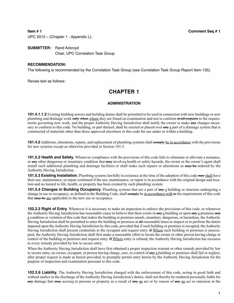
101.4.1.1.2 Existing building sewers and building drains shall be permitted to be used in connection with new buildings or newplumbing and drainage work only when where they are found on examination and test to conform in all respects to the require-ments governing new work, and the proper Authority Having Jurisdiction shall notify the owner to make any changes neces-sary to conform to this code. No building, or part thereof, shall be erected or placed over any a part of a drainage system that isconstructed of materials other than those approved elsewhere in this code for use under or within a building.
101.4.2 Additions, alterations, repairs, and replacement of plumbing systems shall comply be in accordance with the provisionsfor new systems except as otherwise provided in Section 101.5.
101.5.2 Health and Safety. Whenever compliance with the provisions of this code fails to eliminate or alleviate a nuisance,or any other dangerous or insanitary condition that may involves health or safety hazards, the owner or the owner’s agent shallinstall such additional plumbing and drainage facilities or shall make such repairs or alterations as may be ordered by theAuthority Having Jurisdiction.
101.5.3 Existing Installation. Plumbing systems lawfully in existence at the time of the adoption of this code may shall havetheir use, maintenance, or repair continued if the use, maintenance, or repair is in accordance with the original design and loca-tion and no hazard to life, health, or property has been created by such plumbing system.
101.5.4 Changes in Building Occupancy. Plumbing systems that are a part of any a building or structure undergoing achange in use or occupancy, as defined in the Building Code, shall comply be in accordance with to the requirements of this codethat may be are applicable to the new use or occupancy.
102.2.2 Right of Entry. Whenever it is necessary to make an inspection to enforce the provisions of this code, or wheneverthe Authority Having Jurisdiction has reasonable cause to believe that there exists in any a building or upon any a premises anya condition or violation of this code that makes the building or premises unsafe, insanitary, dangerous, or hazardous, the AuthorityHaving Jurisdiction shall be permitted to enter the building or premises at all reasonable times to inspect or to perform the dutiesimposed upon the Authority Having Jurisdiction by this code, provided that if such building or premises is occupied, the AuthorityHaving Jurisdiction shall present credentials to the occupant and request entry. If Where such building or premises is unoccu-pied, the Authority Having Jurisdiction shall first make a reasonable effort to locate the owner or other person having charge orcontrol of the building or premises and request entry. If Where entry is refused, the Authority Having Jurisdiction has recourseto every remedy provided by law to secure entry.
When the Authority Having Jurisdiction shall have first obtained a proper inspection warrant or other remedy provided by lawto secure entry, no owner, occupant, or person having charge, care, or control of any a building or premises shall fail or neglect,after proper request is made as herein provided, to promptly permit entry herein by the Authority Having Jurisdiction for thepurpose of inspection and examination pursuant to this code.
102.2.6 Liability. The Authority Having Jurisdiction charged with the enforcement of this code, acting in good faith andwithout malice in the discharge of the Authority Having Jurisdiction’s duties, shall not thereby be rendered personally liable forany damage that may accrues to persons or property as a result of any an act or by reason of any an act or omission in the
1
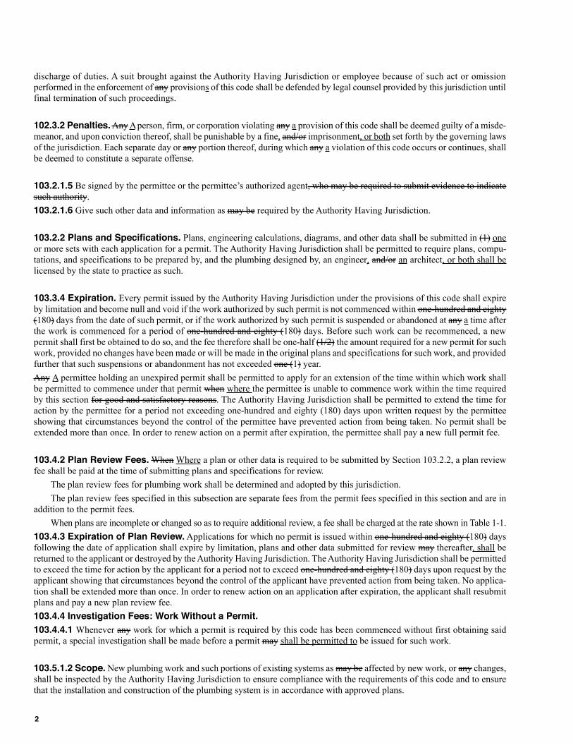
discharge of duties. A suit brought against the Authority Having Jurisdiction or employee because of such act or omissionperformed in the enforcement of any provisions of this code shall be defended by legal counsel provided by this jurisdiction untilfinal termination of such proceedings.
102.3.2 Penalties. Any Aperson, firm, or corporation violating any a provision of this code shall be deemed guilty of a misde-meanor, and upon conviction thereof, shall be punishable by a fine, and/or imprisonment, or both set forth by the governing lawsof the jurisdiction. Each separate day or any portion thereof, during which any a violation of this code occurs or continues, shallbe deemed to constitute a separate offense.
103.2.1.5 Be signed by the permittee or the permittee’s authorized agent, who may be required to submit evidence to indicatesuch authority.
103.2.1.6 Give such other data and information as may be required by the Authority Having Jurisdiction.
103.2.2 Plans and Specifications. Plans, engineering calculations, diagrams, and other data shall be submitted in (1) oneor more sets with each application for a permit. The Authority Having Jurisdiction shall be permitted to require plans, compu-tations, and specifications to be prepared by, and the plumbing designed by, an engineer, and/or an architect, or both shall belicensed by the state to practice as such.
103.3.4 Expiration. Every permit issued by the Authority Having Jurisdiction under the provisions of this code shall expireby limitation and become null and void if the work authorized by such permit is not commenced within one-hundred and eighty(180) days from the date of such permit, or if the work authorized by such permit is suspended or abandoned at any a time afterthe work is commenced for a period of one-hundred and eighty (180) days. Before such work can be recommenced, a newpermit shall first be obtained to do so, and the fee therefore shall be one-half (1/2) the amount required for a new permit for suchwork, provided no changes have been made or will be made in the original plans and specifications for such work, and providedfurther that such suspensions or abandonment has not exceeded one (1) year.
Any A permittee holding an unexpired permit shall be permitted to apply for an extension of the time within which work shallbe permitted to commence under that permit when where the permittee is unable to commence work within the time requiredby this section for good and satisfactory reasons. The Authority Having Jurisdiction shall be permitted to extend the time foraction by the permittee for a period not exceeding one-hundred and eighty (180) days upon written request by the permitteeshowing that circumstances beyond the control of the permittee have prevented action from being taken. No permit shall beextended more than once. In order to renew action on a permit after expiration, the permittee shall pay a new full permit fee.
103.4.2 Plan Review Fees. When Where a plan or other data is required to be submitted by Section 103.2.2, a plan reviewfee shall be paid at the time of submitting plans and specifications for review.
The plan review fees for plumbing work shall be determined and adopted by this jurisdiction.
The plan review fees specified in this subsection are separate fees from the permit fees specified in this section and are inaddition to the permit fees.
When plans are incomplete or changed so as to require additional review, a fee shall be charged at the rate shown in Table 1-1.
103.4.3 Expiration of Plan Review. Applications for which no permit is issued within one-hundred and eighty (180) daysfollowing the date of application shall expire by limitation, plans and other data submitted for review may thereafter, shall bereturned to the applicant or destroyed by the Authority Having Jurisdiction. The Authority Having Jurisdiction shall be permittedto exceed the time for action by the applicant for a period not to exceed one-hundred and eighty (180) days upon request by theapplicant showing that circumstances beyond the control of the applicant have prevented action from being taken. No applica-tion shall be extended more than once. In order to renew action on an application after expiration, the applicant shall resubmitplans and pay a new plan review fee.
103.4.4 Investigation Fees: Work Without a Permit.
103.4.4.1 Whenever any work for which a permit is required by this code has been commenced without first obtaining saidpermit, a special investigation shall be made before a permit may shall be permitted to be issued for such work.
103.5.1.2 Scope. New plumbing work and such portions of existing systems as may be affected by new work, or any changes,shall be inspected by the Authority Having Jurisdiction to ensure compliance with the requirements of this code and to ensurethat the installation and construction of the plumbing system is in accordance with approved plans.
2
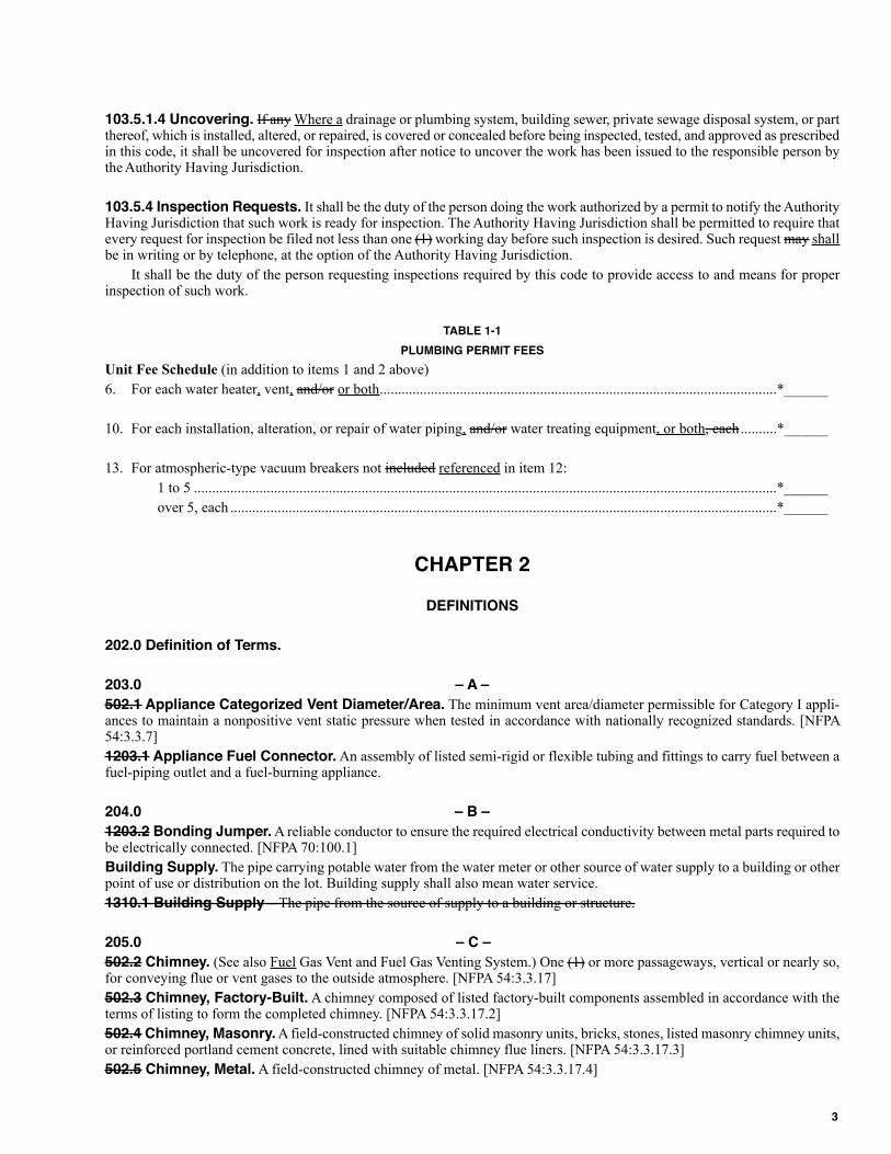
103.5.1.4 Uncovering. If any Where a drainage or plumbing system, building sewer, private sewage disposal system, or partthereof, which is installed, altered, or repaired, is covered or concealed before being inspected, tested, and approved as prescribedin this code, it shall be uncovered for inspection after notice to uncover the work has been issued to the responsible person bythe Authority Having Jurisdiction.
103.5.4 Inspection Requests. It shall be the duty of the person doing the work authorized by a permit to notify the AuthorityHaving Jurisdiction that such work is ready for inspection. The Authority Having Jurisdiction shall be permitted to require thatevery request for inspection be filed not less than one (1) working day before such inspection is desired. Such request may shallbe in writing or by telephone, at the option of the Authority Having Jurisdiction.
It shall be the duty of the person requesting inspections required by this code to provide access to and means for properinspection of such work.
TABLE 1-1
PLUMBING PERMIT FEES
Unit Fee Schedule (in addition to items 1 and 2 above)
6. For each water heater, vent, and/or or both.............................................................................................................*______
10. For each installation, alteration, or repair of water piping, and/or water treating equipment, or both, each..........*______
13. For atmospheric-type vacuum breakers not included referenced in item 12:
1 to 5 ................................................................................................................................................................*______
over 5, each ......................................................................................................................................................*______
CHAPTER 2
DEFINITIONS
202.0 Definition of Terms.
203.0 – A –
502.1 Appliance Categorized Vent Diameter/Area. The minimum vent area/diameter permissible for Category I appli-ances to maintain a nonpositive vent static pressure when tested in accordance with nationally recognized standards. [NFPA54:3.3.7]
1203.1 Appliance Fuel Connector. An assembly of listed semi-rigid or flexible tubing and fittings to carry fuel between afuel-piping outlet and a fuel-burning appliance.
204.0 – B –
1203.2 Bonding Jumper. A reliable conductor to ensure the required electrical conductivity between metal parts required tobe electrically connected. [NFPA 70:100.1]
Building Supply. The pipe carrying potable water from the water meter or other source of water supply to a building or otherpoint of use or distribution on the lot. Building supply shall also mean water service.
1310.1 Building Supply – The pipe from the source of supply to a building or structure.
205.0 – C –
502.2 Chimney. (See also Fuel Gas Vent and Fuel Gas Venting System.) One (1) or more passageways, vertical or nearly so,for conveying flue or vent gases to the outside atmosphere. [NFPA 54:3.3.17]
502.3 Chimney, Factory-Built. A chimney composed of listed factory-built components assembled in accordance with theterms of listing to form the completed chimney. [NFPA 54:3.3.17.2]
502.4 Chimney, Masonry. A field-constructed chimney of solid masonry units, bricks, stones, listed masonry chimney units,or reinforced portland cement concrete, lined with suitable chimney flue liners. [NFPA 54:3.3.17.3]
502.5 Chimney, Metal. A field-constructed chimney of metal. [NFPA 54:3.3.17.4]
3
Combination Thermostatic/Pressure Balancing Valve. A mixing valve that senses outlet temperature and incominghot and cold water pressure and compensates for fluctuations in incoming hot and cold water temperatures, and/or pressures, orboth to stabilize outlet temperatures.
1310.2 Critical Care Area. Those special care units, intensive care units, coronary care units, angiography laboratories,cardiac catheterization laboratories, delivery rooms, operating rooms, post anesthesia recovery rooms, emergency departments,and similar areas in which patients are intended to be subjected to invasive procedures and connected to line-operated, patient-care-related electrical appliances. [NFPA 99:3.3.138.1]
206.0 – D –
502.7 Direct-Vent Appliances. Appliances that are constructed and installed so that air for combustion is derived directlyfrom the outside atmosphere and all flue gases are discharged to the outside atmosphere. [NFPA 54:3.3.6.3]
208.0 – F –
1504.2 F Rating. The time period that the penetration firestop system limits the spread of fire through the penetration, whentested in accordance with ASTM E 814 or UL 1479.
502.8 Flue Collar. That portion of an appliance designed for the attachment of a draft hood, vent connector, or venting system.[NFPA 54:3.3.45]
1203.3 Fuel Gas. Natural, manufactured, liquefied petroleum, or a mixture of these.
502.12 Fuel Gas Vent. A passageway used to convey flue gases from the gas utilization appliances or their vent connectorsto the outside atmosphere. [NFPA 54:3.3.103]
502.14 Fuel Gas Venting System. A continuous open passageway from the flue collar or draft hood of a gas-burning appli-ance to the outside atmosphere for the purpose of removing flue or vent gases. [NFPA 54:3.3.96.6]
209.0 – G –
1203.4 Gas Piping. Any An installation of pipe, valves, or fittings that is used to convey fuel gas, installed on any premisesor in any building, but shall not include:
(1) Any A portion of the service piping.
(2) Any An approved piping connection six (6) feet (1,829 mm) or less in length between an existing gas outlet and a gas appli-ance in the same room with the outlet.
1203.5 Gas-Piping System. Any An arrangement of gas piping or regulators after the point of delivery and each arrange-ment of gas piping serving a building, structure, or premises, whether individually metered or not.
502.9 Gas Vent, Type B. A vent for venting-listed gas appliances with draft hoods and other Category I appliances listed foruse with Type B gas vents. [NFPA 54:3.3.105.2.2]
502.10 Gas Vent, Type L. A vent for venting appliances listed for use with Type L vents and appliances listed for use withType B gas vents. [NFPA 54:3.3.105.2.4]
1310.3 General Care Areas. General care areas are patient bedrooms, examining rooms, treatment rooms, clinics, and similarareas in which it is intended that the patient will come in contact with ordinary appliances such as a nurses-call system, electricbeds, examining lamps, telephones, and entertainment devices. [NFPA 99:3.3.138.2]
1602.0 Gray Water. Untreated waste water that has not come into contact with toilet waste, kitchen sink waste, dishwasherwaste or similarly contaminated sources. Gray water includes waste water from bathtubs, showers, bathroom wash basins,clothes-washers, and laundry tubs.
1203.6 Grounding Electrode. A device that establishes an electrical connection to the earth.
210.0 – H –
316.1.11 Heat Fusion Weld Joints. This type of joint is used in some thermoplastic systems to connect pipe to fittings orpipe lengths directly to one another (butt-fusion). This method of joining pipe to fittings includes socket-fusion, electro-fusion,and saddle-fusion. This method of welding involves the application of heat and pressure to the components, allowing them tofuse together forming a bond between the pipe and fitting.
211.0 – I –
502.11 Indirect-Fired Water Heater. A water heater consisting of a storage tank equipped with an internal or external heatexchanger used to transfer heat from an external source to heat potable water. The storage tank either contains heated potablewater or water supplied from an external source, such as a boiler.
4
214.0 – L –
1203.7 Liquefied Petroleum Gas (LPG) Facilities. Liquefied petroleum gas (LPG) facilities means tanks, containers,
container valves, regulating equipment, meters, and/or appurtenances, or both for the storage and supply of liquefied petroleum
gas for any a building, structure, or premises.
215.0 – M –
1310.5 Medical Air. For purposes of this standard, medical air is air supplied from cylinders, bulk containers, medical air
compressors, or has been reconstituted from oxygen USP and oil-free, dry nitrogen NF. Medical air shall be required to have
the following characteristics [NFPA 99:3.3.106]:
(1) Be supplied from cylinders, bulk containers, medical air compressor sources, or be reconstituted from oxygen USP and oil-
free dry nitrogen NF.
(2) Meet the requirements of medical air USP.
(3) Have no detectable liquid hydrocarbons.
(4) Have less than 25 parts per million gaseous hydrocarbons.
(5) Have equal to or less than 5 milligrams per cubic meters (mg/m3) of permanent particulates sized one micron or larger in
the air at normal atmospheric pressure. [NFPA 99:5.1.3.5.1(1) to through 99:5.1.3.5.1(5)]
1310.6 Medical Gas. Gas used in a medical facility, including oxygen, nitrous oxide, carbon dioxide, helium, medical air, and
mixtures of these gases. Standards of purity apply.
1310.4 Medical Gas Manifold. A device for connecting outlets of one or more gas cylinders to the central piping system for
that specific gas. [NFPA 99:3.3.103]
1310.7 Medical Gas System. Complete system consisting of a central supply system (manifold, bulk, or compressors),
including control equipment and piping extending to station outlets at the points where medical gases are required.
1310.8 Medical Vacuum System. See 1310.19 Vacuum System – Level 1.
216.0 – N –
1310.9 Nitrogen, NF (Oil-Free, Dry) (Nitrogen for Brazing and Testing). Nitrogen complying, at a minimum, with oil-
free, dry nitrogen NF. [NFPA 99:3.3.120.1]
218.0 – P –
1310.10 Patient Care Area. Any A portion of a health care facility wherein patients are intended to be examined or treated.
[NFPA 99:3.3.138]
1504.1 Penetration Firestop System. A specific assemblage of field-assembled materials, or a factory-made device, which
has been tested to a standard test method and, when installed properly on penetrating piping materials, is capable of maintaining
the fire- resistance rating of assemblies penetrated.
Plumbing Appliance. Any one (1) of a A special class of devices or equipment that is intended to perform a special plumbing
function. Its operation, and/or control, may or both shall be dependent upon one (1) or more energized components, such as
motors, controls, heating elements, or pressure- or temperature-sensing elements. Such device or equipment may operate auto-
matically through one (1) or more of the following actions: a time cycle, a temperature range, a pressure range, a measured
volume or weight; or the device or equipment may be manually adjusted or controlled by the user or operator.
224.0 Plumbing Vent. A pipe provided to ventilate a plumbing system, to prevent trap siphonage and back-pressure, or to
equalize the air pressure within the drainage system.
224.0 Plumbing Vent System. A pipe or pipes installed to provide a flow of air to or from a drainage system or to provide
a circulation of air within such system to protect trap seals from siphonage and back-pressure.
316.1.9 Pressed Fitting. This is a mechanical connection for joining copper tubing that uses a crimping tool to affix the O-
ring seal copper or copper alloy fitting to the tubing. The tubing shall be inserted into the fitting, and the crimp shall be made
using the tool recommended by the manufacturer.
316.1.8 Pressure-Lock-Type Connection. This is a mechanical connection that depends on an internal retention device
to prevent pipe or tubing separation. Connection is made by inserting the pipe or tubing into the fitting to a prescribed depth.
1203.8 Provision for Location of Point of Delivery. The location of the point of delivery shall be acceptable to the serving
gas supplier. [NFPA 54:5.2]
5
1310.11 Purge, Flow. The removal of oxygen from a system by oil-free dry nitrogen during brazing.
1310.12 Purge, System. The removal of nitrogen from a system with the medical gas required for that system.
313.1.10 Push-fit Fitting. A mechanical fitting where the connection is assembled by pushing the tube or pipe into the fittingand is sealed with an “O” ring.
219.0 – Q –
1203.9 Quick-Disconnect Device. A hand-operated device that provides a means for connecting and disconnecting anappliance or an appliance connector to a gas supply and that is equipped with an automatic means to shut off the gas supply whenthe device is disconnected.
220.0 – R –
1614.0 Reclaimed Water. Nonpotable water that meets or as a result of treatment, meets federal requirements for its intendeduses. The level of treatment and quality of the reclaimed water shall be approved by the Authority Having Jurisdiction.
221.0 – S –
1310.13 SCFM. Standard cubic feet per minute. [NFPA 99:3.3.163]
1203.10 Service Piping. The piping and equipment between the street gas main and the gas piping system inlet that is installedby, and is under the control and maintenance of, the serving gas supplier.
1310.14 Special Hazard Area. An area such as a kitchen or electrical switch-gear room.
1310.15 Station Inlet. An inlet point in a medical-surgical piped vacuum distribution system at which the user makes connec-tions and disconnections. [NFPA 99:3.3.171]
1310.16 Station Outlet. An inlet point in a piped medical/surgical vacuum distribution system at which the user makesconnections and disconnections. [NFPA 99:3.3.172]
222.0 – T –
1504.2 T Rating. The time period that the penetration firestop system, including the penetrating item, limits the maximumtemperature rise of 325ºF (163ºC) above its initial temperature through the penetration on the nonfire side, when tested in accor-dance with ASTM E 814 or UL 1479.
1203.11 Transition Gas Riser. Any A listed or approved section or sections of pipe and fittings used to convey fuel gas andinstalled in a gas piping system for the purpose of providing a transition from below ground to above ground.
223.0 – U –
1310.17 Use Point. A room or area of a room where medical gases are dispensed to a single patient for medical purposes. Ause point is permitted to be comprised of a number of station outlets of different gases. [NFPA 99:3.3.180]
1310.18 User Outlet. See Station Outlet.
224.0 – V –
1310.19 Vacuum System – Level 1. A system consisting of central vacuum-producing equipment with pressure and oper-ating controls, shutoff valves, alarm warning systems, gauges, and a network of piping extending to and terminating with suit-able station inlets at locations where patient suction could be required. [NFPA 99:3.3.91]
1310.20 Valve, Isolation. A valve that isolates one (1) piece of equipment from another.
1310.21 Valve, Riser. A valve at the base of a vertical riser that isolates that riser.
1310.22 Valve, Service. A valve serving horizontal piping extending from a riser to a station outlet or inlet.
1310.23 Valve, Source. A single valve at the source that controls a number of units that make up the source.
1310.24 Valve, Zone. A valve that controls the gas or vacuum to a particular area.
502.13 Vent Connector. The pipe or duct that connects a fuel-gas-burning appliance to a vent or chimney. [NFPA 54:3.3.106]
225.0 – W –
1310.25 Waste Anesthetic Gas Disposal. The process of capturing and carrying away gases vented from the patientbreathing circuit during the normal operation of gas anesthesia or analgesia equipment. [NFPA 99:3.3.184]
502.15 Water Heater. An appliance for supplying hot water for domestic or commercial purposes. [NFPA 54:3.3.55.7]
6
CHAPTER 3
GENERAL REGULATIONS
301.1.3 Standards. Standards listed or referred to in this chapter or other chapters cover materials that will conform to therequirements of this code, when where used in accordance with the limitations imposed in this or other chapters thereof and theirlisting. Where a standard covers materials of various grades, weights, quality, or configurations, there may be only a portion ofthe listed standard that is applicable shall be permitted. Design and materials for special conditions or materials not provided forherein shall be permitted to be used only by special permission of the Authority Having Jurisdiction after the Authority HavingJurisdiction has been satisfied as to their adequacy. A list of accepted plumbing materials standards is included referenced inTable 14-1. IAPMO Installation Standards are included referenced in Appendix I for the convenience of the users of this code.They are not considered as a part of this code unless formally adopted as such by the Authority Having Jurisdiction.
301.2.1.2 The Authority Having Jurisdiction shall have the authority to require tests to be made or repeated if, at any time, thereis reason to believe that any a material or device no longer conforms to the requirements on which its approval was based.
306.1 It shall be unlawful for any a person to deposit, by any means whatsoever, into any a plumbing fixture, floor drain, inter-ceptor, sump, receptor, or device, which is connected to any a drainage system, public sewer, private sewer, septic tank, orcesspool, any ashes; cinders; solids; rags; inflammable, poisonous, or explosive liquids or gases; oils; grease; or any other thingwhatsoever that would, or could, will cause damage to the drainage system or public sewer.
307.2 Sewage or other waste from a plumbing system that may be becomes deleterious to surface or subsurface waters shallnot be discharged into the ground or into any a waterway unless it has first been rendered safe by some acceptable form of treat-ment as required by the Authority Having Jurisdiction.
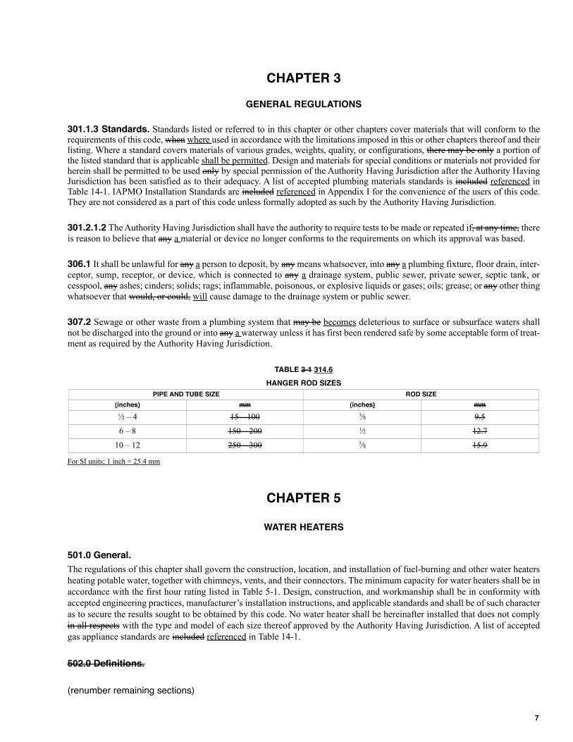
TABLE 3-1 314.6
HANGER ROD SIZES
For SI units: 1 inch = 25.4 mm
CHAPTER 5
WATER HEATERS
501.0 General.
The regulations of this chapter shall govern the construction, location, and installation of fuel-burning and other water heaters
heating potable water, together with chimneys, vents, and their connectors. The minimum capacity for water heaters shall be in
accordance with the first hour rating listed in Table 5-1. Design, construction, and workmanship shall be in conformity with
accepted engineering practices, manufacturer’s installation instructions, and applicable standards and shall be of such character
as to secure the results sought to be obtained by this code. No water heater shall be hereinafter installed that does not comply
in all respects with the type and model of each size thereof approved by the Authority Having Jurisdiction. A list of accepted
gas appliance standards are included referenced in Table 14-1.
502.0 Definitions.
(renumber remaining sections)
PIPE AND TUBE SIZE ROD SIZE
(inches) mm (inches) mm
1⁄2 – 4 15 – 100 3⁄8 9.5
6 – 8 150 – 200 1⁄2 12.7
10 – 12 250 – 300 5⁄8 15.9
7
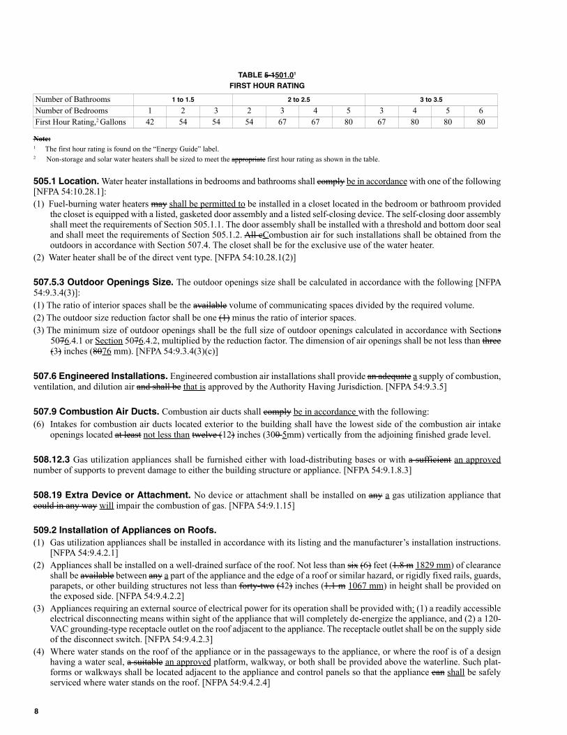
TABLE 5-1501.01
FIRST HOUR RATING
Note:1 The first hour rating is found on the “Energy Guide” label.2 Non-storage and solar water heaters shall be sized to meet the appropriate first hour rating as shown in the table.
505.1 Location. Water heater installations in bedrooms and bathrooms shall comply be in accordance with one of the following[NFPA 54:10.28.1]:
(1) Fuel-burning water heaters may shall be permitted to be installed in a closet located in the bedroom or bathroom providedthe closet is equipped with a listed, gasketed door assembly and a listed self-closing device. The self-closing door assemblyshall meet the requirements of Section 505.1.1. The door assembly shall be installed with a threshold and bottom door sealand shall meet the requirements of Section 505.1.2. All cCombustion air for such installations shall be obtained from theoutdoors in accordance with Section 507.4. The closet shall be for the exclusive use of the water heater.
(2) Water heater shall be of the direct vent type. [NFPA 54:10.28.1(2)]
507.5.3 Outdoor Openings Size. The outdoor openings size shall be calculated in accordance with the following [NFPA54:9.3.4(3)]:
(1) The ratio of interior spaces shall be the available volume of communicating spaces divided by the required volume.
(2) The outdoor size reduction factor shall be one (1) minus the ratio of interior spaces.
(3) The minimum size of outdoor openings shall be the full size of outdoor openings calculated in accordance with Sections5076.4.1 or Section 5076.4.2, multiplied by the reduction factor. The dimension of air openings shall be not less than three(3) inches (8076 mm). [NFPA 54:9.3.4(3)(c)]
507.6 Engineered Installations. Engineered combustion air installations shall provide an adequate a supply of combustion,ventilation, and dilution air and shall be that is approved by the Authority Having Jurisdiction. [NFPA 54:9.3.5]
507.9 Combustion Air Ducts. Combustion air ducts shall comply be in accordance with the following:
(6) Intakes for combustion air ducts located exterior to the building shall have the lowest side of the combustion air intakeopenings located at least not less than twelve (12) inches (300 5mm) vertically from the adjoining finished grade level.
508.12.3 Gas utilization appliances shall be furnished either with load-distributing bases or with a sufficient an approvednumber of supports to prevent damage to either the building structure or appliance. [NFPA 54:9.1.8.3]
508.19 Extra Device or Attachment. No device or attachment shall be installed on any a gas utilization appliance thatcould in any way will impair the combustion of gas. [NFPA 54:9.1.15]
509.2 Installation of Appliances on Roofs.
(1) Gas utilization appliances shall be installed in accordance with its listing and the manufacturer’s installation instructions.[NFPA 54:9.4.2.1]
(2) Appliances shall be installed on a well-drained surface of the roof. Not less than six (6) feet (1.8 m 1829 mm) of clearanceshall be available between any a part of the appliance and the edge of a roof or similar hazard, or rigidly fixed rails, guards,parapets, or other building structures not less than forty-two (42) inches (1.1 m 1067 mm) in height shall be provided onthe exposed side. [NFPA 54:9.4.2.2]
(3) Appliances requiring an external source of electrical power for its operation shall be provided with: (1) a readily accessibleelectrical disconnecting means within sight of the appliance that will completely de-energize the appliance, and (2) a 120-VAC grounding-type receptacle outlet on the roof adjacent to the appliance. The receptacle outlet shall be on the supply sideof the disconnect switch. [NFPA 54:9.4.2.3]
(4) Where water stands on the roof of the appliance or in the passageways to the appliance, or where the roof is of a designhaving a water seal, a suitable an approved platform, walkway, or both shall be provided above the waterline. Such plat-forms or walkways shall be located adjacent to the appliance and control panels so that the appliance can shall be safelyserviced where water stands on the roof. [NFPA 54:9.4.2.4]
Number of Bathrooms 1 to 1.5 2 to 2.5 3 to 3.5
Number of Bedrooms 1 2 3 2 3 4 5 3 4 5 6
First Hour Rating,2 Gallons 42 54 54 54 67 67 80 67 80 80 80
8
510.1.1 Categories. The operating characteristics of vented gas utilization appliances can shall be categorized with respect
to (1) positive or negative pressure within the venting system, and (2) whether or not the appliance generates flue or vent gases
that can condense are capable of condensing in the venting system. See NFPA 54, Section 3.3 for the definition of these vented
appliance categories. [NFPA 54:12.2.2]
510.3.1 Minimum Safe Performance. A venting system shall be designed and constructed so as to develop a positive flow
adequate to remove flue or vent gases to the outside atmosphere. [NFPA 54:12.1]
510.3.4.4 Vent connectors serving appliances vented by natural draft shall not be connected into any portion of mechanical draft
systems operating under positive pressure. [NFPA 54:12.4.3.4]
510.5.2.1 A chimney for a residential-type or low-heat gas utilization appliance shall extend at least three (3) feet (0.914 mm)
above the highest point where it passes through the roof of a building and at least two (2) feet (0.610 mm) exceeding higher than
any a portion of a building within a horizontal distance of ten (10) feet (3.0 3048 mm). [See Figure 5-1.] [NFPA 54:12.6.2.1]
510.5.4 Inspection of Chimneys.
(D) When Where inspection reveals that an existing chimney is not safe for the intended application, it shall be repaired, rebuilt,
lined, relined, or replaced with a vent or chimney to conform to in accordance with NFPA 211, Standard for Chimneys, Fire-
places, Vents, and Solid-Fuel-Burning Appliances, and shall be suitable approved for the appliances to be attached. [NFPA
54:12.6.4.4]
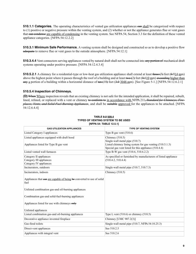
TABLE 5-2 509.4
TYPED OF VENTING SYSTEM TO BE USED
[NFPA 54: TABLE 12.5.1]
GAS UTILIZATION APPLIANCES TYPE OF VENTING SYSTEM
Listed Category I appliances Type B gas vent (510.6)
Listed appliances equipped with draft hood
Appliances listed for Type B gas vent
Chimney (510.5)
Single-wall metal pipe (510.7)
Listed chimney lining system for gas venting (510.5.1.3)
Special gas vent listed for this appliance (510.4.4)
Listed vented wall furnaces Type B-W gas vent (510.6, 510.6.2.2)
Category II appliances
Category III appliances
Category IV appliances
As specified or furnished by manufacturers of listed appliance
(510.4.2, 510.4.4)
Incinerators, outdoors Single-wall metal pipe (510.7, 510.7.3)
Incinerators, indoors
Appliances that can are capable of being be converted to use of solid
fuel
Unlisted combination gas-and oil-burning appliances
Combination gas-and solid-fuel-burning appliances
Appliances listed for use with chimneys only
Unlisted appliances
Chimney (510.5)
Listed combination gas-and oil-burning appliances Type L vent (510.6) or chimney (510.5)
Decorative appliance invented fireplace Chimney [UMC 907.2(3)]
Gas-fired toilets Single-wall metal pipe (510.7, NFPA 54:10.25.3)
Direct-vent appliances See 510.2.5
Appliances with integral vent See 510.2.6
9
510.6.1.1 Type B or Type L vents shall extend in a generally vertical direction with offsets not exceeding 45 degrees (0.79 rad),except that a vent system having not more than one 60 degree (1.05 rad) offset shall be permitted. Any An angle greater than45 degrees (0.79 rad) from the vertical is considered horizontal. The total horizontal distance of a vent plus the horizontal ventconnector serving draft-hood-equipped appliances shall not exceed 75 percent of the vertical height of the vent. [NFPA54:12.7.3.2]
Exception: Systems designed and sized as provided in this chapter or in accordance with other approved engineering methods.
510.6.2 A gas vent shall terminate in accordance with one of the following [NFPA 54:12.7.2(1)]:
(1) Above the roof surface with a listed cap or listed roof assembly. Gas vents twelve (12) inches (3005 mm) in size or smallerwith listed caps shall be permitted to be terminated in accordance with Figure 5-2, provided they are at least not less thaneight (8) feet (2.4 2438 mm) from a vertical wall or similar obstruction. Other gas vents shall terminate not less than two(2) feet (0.610 mm) above the highest point where they pass through the roof and at least not less than two (2) feet (0.610mm) exceeding higher than any a portion of a building within ten (10) feet (3.1 3048 mm). [NFPA 54:12.7.2(1)(a) and (b)]
510.6.4.2 Gas utilization appliances connected to the common vent shall be located in rooms separated from a habitable space.Each of these rooms shall have provisions for an adequate supply of combustion, ventilation, and dilution air that is not suppliedfrom a habitable space. (See Figure 5-3.) [NFPA 54:12.7.4.2]
The size of the connectors and common segments of multistory venting systems for gas utilization appliances listed for usewith Type B double-wall gas vent shall be in accordance with Table 5-14 provided [NFPA 54:12.7.4.3]:
(1) The available total height (H) for each segment of a multistory venting system is the vertical distance between the level ofthe highest draft hood outlet or flue collar on that floor and the centerline of the next highest interconnection tee. (SeeFigure G.1(K).) [NFPA 54:12.7.4.3(1)]
(2) The size of the connector for a segment is determined from its gas utilization appliance heat input and available connectorrise, and shall not be smaller than the draft hood outlet or flue collar size. [NFPA 54:12.7.4.3(2)]
(3) The size of the common vertical vent segment, and of the interconnection tee at the base of that segment, shall be based onthe total gas utilization appliance heat input entering that segment and its available total height. [NFPA 54:12.7.4.3(3)]
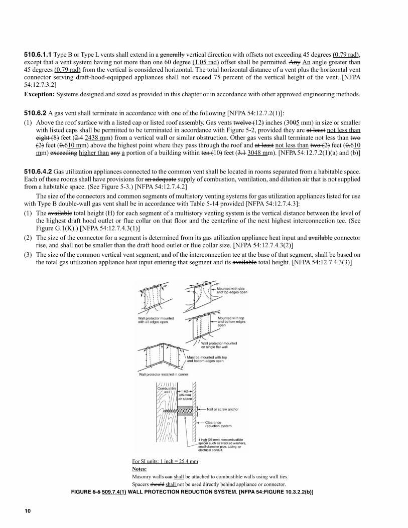
For SI units: 1 inch = 25.4 mm
Notes:
Masonry walls can shall be attached to combustible walls using wall ties.
Spacers should shall not be used directly behind appliance or connector.
FIGURE 5-5 509.7.4(1) WALL PROTECTION REDUCTION SYSTEM. [NFPA 54:FIGURE 10.3.2.2(b)]
10
510.7.4.4 Single-wall metal pipe used for venting an incinerator shall be exposed and readily examinable for its full length andshall have suitable required clearances maintained. [NFPA 54:12.8.4.3]
510.7.5.2 Where a single-wall metal pipe is used and has a shape other than round, it shall have an equivalent effective areaequal to the effective area of the round pipe for which it is substituted, and the internal dimension of the pipe shall be at leasttwo (2) inches (510 mm). [NFPA 54:12.8.5(2)]
510.8.4 Through-the-wall vents for Category II and Category IV appliances and noncategorized condensing appliances shallnot terminate over public walkways or over an area where condensate or vapor could create is capable of creating a nuisance orhazard or could be detrimental to the operation of regulators, relief valves, or other equipment. Where local experience indicatesthat condensate is a problem with Category I and Category III appliances, this provision shall also apply.
Drains for condensate shall be installed in accordance with the manufacturer’s installation instructions. [NFPA 54-09:12.9.4]
510.10.2.5 A vent connector for non-residential low-heat appliance shall be a factory-built chimney section or steel pipe havingresistance to heat and corrosion equivalent to that for the appropriate galvanized pipe as specified in Table 5-5 509.10.2. Factory-built chimney sections shall be joined together in accordance with the chimney manufacturer’s instructions. [NFPA 54:12.11.2.5]
510.10.11 Chimney Connection. Where entering a flue in a masonry or metal chimney, the vent connector shall be installedabove the extreme bottom to avoid stoppage. Where a thimble or slip joint is used to facilitate removal of the connector, theconnector shall be firmly attached to or inserted into the thimble or slip joint to prevent the connector from falling out. Meansshall be employed to prevent the connector from entering so far as to restrict the space between its end and the opposite wall ofthe chimney flue. [NFPA 54:12.11.11]
511.2.22 Combinations of pipe sizes, single-wall, and double-wall metal pipe shall be allowed within any a connector run or withinthe common vent, provided ALL of the appropriate tables permit ALL of the desired sizes and types of pipe, as if they were used forthe entire length of the subject connector or vent. Where single-wall and Type B double-wall metal pipes are used for vent connec-tors within the same venting system, the common vent must shall be sized using Tables 5-15 or 5-17 as appropriate. [NFPA 54:13.2.25]
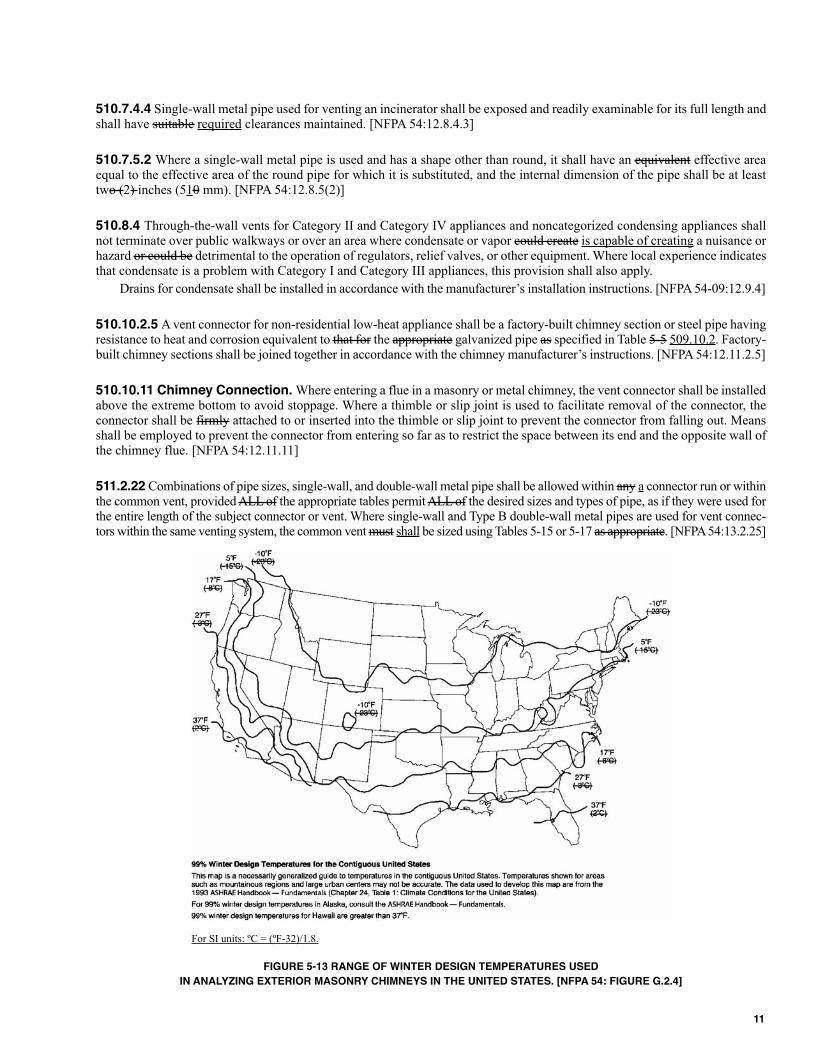
For SI units: ºC = (ºF-32)/1.8.
FIGURE 5-13 RANGE OF WINTER DESIGN TEMPERATURES USED
IN ANALYZING ExTERIOR MASONRY CHIMNEYS IN THE UNITED STATES. [NFPA 54: FIGURE G.2.4]
11
CHAPTER 6
WATER SUPPLY AND DISTRIBUTION
603.4.8 Water-cooled compressors, degreasers, or any other water-cooled equipment shall be protected by a backflow preventerinstalled in accordance with the requirements of this chapter. Note: Water-cooled equipment that produces back-pressure shallbe equipped with the appropriate protection.
605.2 A fullway valve controlling outlets shall be installed on the discharge side of each water meter and on each unmeteredwater supply. Water piping supplying more than one (1) building on any one (1) premises shall be equipped with a separatefullway valve to each building, so arranged that the water supply can be turned on or off to any an individual or separate buildingprovided; however, that supply piping to a single-family residence and building accessory thereto shall be permitted to becontrolled on one (1) valve. Such shutoff valves shall be accessible at all times. A fullway valve shall be installed on the dischargepiping from water supply tanks at or near the tank. A fullway valve shall be installed on the cold water supply pipe to eachwater heater at or near the water heater.
606.2.3 Slip Joints. In water piping, slip joints shall be permitted to be used only on the exposed fixture supply.
609.1 Installation. Water piping shall be adequately supported in accordance with Section 314.0. Burred ends shall be reamedto the full bore of the pipe or tube. Changes in direction shall be made by the appropriate use of fittings, except that changes indirection in copper tubing may shall be permitted to be made with bends, provided that such bends are made with bendingequipment that does not deform or create a loss in the cross-sectional area of the tubing. Changes in direction are allowed withflexible pipe and tubing without fittings in accordance with the manufacturer’s installation instructions. Provisions shall bemade for expansion in hot-water piping. Piping, equipment, appurtenances, and devices shall be installed in a workmanlikemanner in conformity with the provisions and intent of the code. Water service yard piping shall be not less than twelve (12)inches (305 mm) below the average local frost depth. The cover shall be not less than twelve (12) inches (305 mm) below finishgrade.
609.2 Water pipes shall not be run or laid in the same trench as building sewer or drainage piping constructed of clay or mate-rials that are not approved for use within a building unless both of the following conditions are met:
609.2.1 The bottom of the water pipe, at all points, shall be not less than twelve (12) inches (305 mm) above the top of the seweror drain line.
609.7 Nothing contained in this code shall be construed to prohibit the use of all or part of an abutting lot to:
610.10 Sizing for Flushometer Valves. When using Table 6-6 to size water supply systems serving flushometer valves,the number of flushometer fixture units assigned to every section of pipe, whether branch or main, shall be determined by thenumber and category of flushometer valves served by that section of pipe, in accordance with Table 6-7. Piping supplying aflushometer valve shall be not less in size than the valve inlet.
When Where using Table 6-7 to size water piping, care must shall be exercised to assign flushometer fixture units basedon the number and category of fixtures served.
CHAPTER 7
SANITARY DRAINAGE
702.3 For a continuous flow into a drainage system, such as from a pump, sump ejector, air conditioning equipment, or similardevice, two (2) fixture units shall be allowed for equal to each gallon per minute (3.78 L/m 0.06 L/s) of flow.
708.0 Grade of Horizontal Drainage Piping.
Horizontal drainage piping shall be run in practical alignment and a uniform slope of not less than one-fourth (1⁄4) of an inch perfoot (20.8 mm/m) or 2 percent toward the point of disposal provided that, where it is impractical due to the depth of the streetsewer, to the structural features, or to the arrangement of any a building or structure to obtain a slope of one-fourth (1⁄4) of aninch per foot (20.8 mm/m) or 2 percent, any such pipe or piping four (4) inches (100 mm) or larger in diameter may shall be
12
permitted to have a slope of not less than one-eighth (1⁄8) of an inch per foot (10.4 mm/m) or 1 percent, when where first approvedby the Authority Having Jurisdiction.
710.6 Backwater Valves. Backwater valves, gate valves, fullway ball valves, unions, motors, compressors, air tanks, and othermechanical devices required by this section shall be located where they will be accessible for inspection and repair at all timesand, unless continuously exposed, shall be enclosed in a masonry pit fitted with an adequately sized removable cover.
Backwater valves shall have bodies of cast-iron, plastic, brass, or other approved materials; shall have noncorrosive bear-ings, seats, and self-aligning discs; and shall be constructed so as to ensure a positive mechanical seal. Such backwater valvesshall remain sufficiently open during periods of low flows to avoid screening of solids and shall not restrict capacities or causeexcessive turbulence during peak loads. Unless otherwise listed, valve access covers shall be bolted type with gasket, and eachvalve shall bear the manufacturer’s name cast into the body and the cover.
722.1 Every An abandoned building (house) sewer, or part thereof, shall be plugged or capped in an approved manner withinfive (5) feet (1,524 mm) of the property line.
722.2 Every A cesspool, septic tank, and seepage pit that has been abandoned or has been discontinued otherwise from furtheruse, or to which no waste or soil pipe from a plumbing fixture is connected, shall have the sewage removed therefrom and becompletely filled with earth, sand, gravel, concrete, or other approved material.
722.3 The top cover or arch over the cesspool, septic tank, or seepage pit shall be removed before filling, and the filling shallnot extend above the top of the vertical portions of the sidewalls or above the level of any the outlet pipe until inspection hasbeen called and the cesspool, septic tank, or seepage pit has been inspected. After such inspection, the cesspool, septic tank, orseepage pit shall be filled to the level of the top of the ground.
723.0 Building Sewer Test.
Building sewers shall be tested by plugging the end of the building sewer at its points of connection with the public sewer orprivate sewage disposal system and completely filling the building sewer with water from the lowest to the highest point thereof,or by approved equivalent low-pressure air test. Plastic DWV piping systems shall not be tested by the air test method. Thebuilding sewer shall be water-tight at all points.
CHAPTER 8
INDIRECT WASTES
810.1 No steam pipe shall be directly connected to any part of a plumbing or drainage system, nor shall any water having atemperature above 140°F (60°C) be discharged under pressure directly into any part of a drainage system. Pipes from boilers shalldischarge by means of indirect waste piping, as determined by the Authority Having Jurisdiction or the boiler manufacturer’srecommendations. Such pipes shall be permitted to be indirectly connected by discharging into an open or closed condenser oran intercepting sump of an approved type that will prevent the entrance of steam or such water under pressure into the drainagesystem. Closed condensers or sumps shall be provided with a vent that shall be taken off the top and extended separately, full sizeabove the roof. Condensers and sumps shall be properly trapped at the outlet with a deep seal trap extending to within six (6) inches(152 mm) of the bottom of the tank. The top of the deep seal trap shall have a three-fourths (3⁄4) of an inch (19.1 mm) openinglocated at the highest point of the trap to serve as a siphon breaker. Outlets shall be taken off from the side in such a manner as toallow a waterline to be maintained that will permanently occupy not less than one-half (1/2) the capacity of the condenser orsump. Inlets shall enter above the waterline. Wearing plates or baffles shall be installed in the tank to protect the shell. The sizesof the blowoff line inlet, the water outlets, and the vent shall be as shown in Table 8-1 810.1. The contents of condensers receivingsteam or hot water under pressure must shall pass through an open sump before entering the drainage system.
CHAPTER 9
VENTS
901.1 Vents Required.
Each plumbing fixture trap, except as otherwise provided in this code, shall be protected against siphonage and back-pressure,and air circulation shall be ensured throughout all parts of the drainage system by means of vent pipes installed in accordancewith the requirements of this chapter and as otherwise required by this code.
13
904.1 Size. The size of vent piping shall be determined from its length and the total number of fixture units connected thereto,as set forth in Table 7-5 703.2. The diameter of an individual vent shall be not less than one and one-fourth (1-1⁄4) inches (32mm) nor less than one-half (1/2) the diameter of the drain to which it is connected. In addition, the drainage piping of eachbuilding and each connection to a public sewer or a private sewage disposal system shall be vented by means of one (1) or morevent pipes, the aggregate cross-sectional area of which shall be not less than that of the largest required building sewer, as deter-mined from Table 7-5 703.2. Vent pipes from fixtures located upstream from pumps, ejectors, backwater valves, or other devicesthat in any way obstruct the free flow of air and other gases between the building sewer and the outside atmosphere shall notbe used for meeting the cross-sectional area venting requirements of this section.
Exception: When Where connected to a common building sewer, the drainage piping of two (2) or more buildings located onthe same lot and under one (1) ownership shall be permitted to be vented by means of piping sized in accordance with Table 7-5 703.2, provided the aggregate cross-sectional area of vents is not less than that of the largest required common building sewer.
CHAPTER 10
TRAPS AND INTERCEPTORS
1002.1 Each plumbing fixture trap, except as otherwise provided in this code, shall be protected against siphonage, back-pres-sure, and air circulation shall be assured throughout all parts of the drainage system by means of a vent pipe installed in accor-dance with the requirements of this code.
1006.0 Floor Drain Traps.
Floor drains shall connect into a trap so constructed that it can be readily cleaned and of a size to serve efficiently the purposefor which it is intended. The drain inlet shall be so located that it is at all times in full view. When subject to reverse flow ofsewage or liquid waste, such drains shall be equipped with an approved backwater valve.
1014.3.4.1 Each grease interceptor shall be so installed and connected that it shall be at all times easily accessible for inspec-tion, cleaning, and removal of the intercepted grease. A gravity grease interceptor complying in accordance with IAPMO Z1001,shall not be installed in any part of a building where food is handled. Location of the grease interceptor shall meet the approvalof the Authority Having Jurisdiction.
CHAPTER 11
STORM DRAINAGE
1101.5.1 Subsoil drains shall be provided around the perimeter of buildings having basements, cellars, crawl spaces or floorsbelow grade. Such subsoil drains shall be permitted to be positioned inside or outside of the footing, shall be of perforated oropen-jointed approved drain tile or pipe, not less than three (3) inches (80 mm) in diameter, and shall be laid in gravel, slag,crushed rock, approved three-quarter (¾) of an inch (19.1 mm) crushed, recycled glass aggregate, or other approved porous mate-rial with not less than four (4) inches (102 mm) surrounding the pipe on all sides. Filter media shall be provided for exteriorsubsoil piping.
1109.2.1 Water Test. After piping has been installed, the water test shall be applied to the drainage system, either to the entiresystem or to sections. If Where the test is applied to the entire system, all openings in the piping shall be tightly closed exceptfor the highest opening, and the system shall be filled with water to the point of overflow. If Where the system is tested insections, each opening shall be tightly plugged except for the highest opening of the section under test, and each section shallbe filled with water, but no section shall be tested with less than a ten (10) foot (3,048 mm) head of water. In testing successivesections, not less than the upper ten (10) foot (3,048 mm) of the next preceding section shall be tested so that no joint of pipein the building (except the uppermost ten (10) foot (3,048 mm) of a roof drainage system, which shall be filled with water tothe flood level of the uppermost roof drain) shall have been submitted to a test of less than a ten (10) foot (3,048 mm) head ofwater. The water shall be kept in the system or in the portion under test for not less than fifteen (15) minutes before inspectionstarts; the system shall then be tight at all points.
14
CHAPTER 12
FUEL PIPING
1201.0 Scope of Gas Piping.
(C) This code shall not apply to the following (reference standards for some of which appear in Chapter 14 [NFPA 54:1.1.1.2]):
(1) Portable LP-Gas appliances of all types that are not connected to a fixed fuel piping system.
1203.0 Definitions
(renumber remaining sections)
1209.4.1 General Considerations. Gas-piping systems shall be of such size and so installed as to provide a supply of gassufficient to meet the maximum demand and supply gas to each appliance inlet at not less than the minimum supply pressurerequired by the appliance. [NFPA 54-09:5.4.1]
1209.5.1.2 Used Materials. Pipe, fittings, valves, or other materials shall not be used again unless they are free of foreignmaterials and have been ascertained to be adequate approved for the service intended. [NFPA 54:5.6.1.2]
1209.5.1.3 Other Materials. Material not covered by the standards specifications listed herein shall be investigated and testedto determine that it is safe and suitable approved for the proposed service and, in addition, shall be recommended for that serviceby the manufacturer and shall be acceptable to the Authority Having Jurisdiction. [NFPA 54:5.6.1.3]
1209.5.8 Metallic Piping Joints and Fittings. The type of piping joint used shall be suitable approved for the pressure-temperature conditions and shall be selected giving consideration to joint tightness and mechanical strength under the serviceconditions. The joint shall be able to sustain the maximum end force due to the internal pressure and any additional forces dueto temperature expansion or contraction, vibration, fatigue, or to the weight of the pipe and its contents. [NFPA 54:5.6.8]
1209.5.8.3 Flared Joints. Flared joints shall be used only in systems constructed from nonferrous pipe and tubing where expe-rience or tests have demonstrated that the joint is suitable approved for the conditions and where provisions are made in the designto prevent separation of the joints. [NFPA 54:5.6.8.3]
1209.5.8.4 Metallic Fittings (Including Valves, Strainers, Filters). Metallic fittings shall be in accordance with thefollowing requirements:
1209.5.11 Flange Gaskets. The material for gaskets shall be capable of withstanding the design temperature and pressureof the piping system and the chemical constituents of the gas being conducted without change to its chemical and physical prop-erties. The effects of fire exposure to the joint shall be considered in choosing the material. [NFPA 54:5.6.11] Flange gasketsshall be in accordance with the following requirements:
1209.7.5 Venting.
(A) Line Gas Pressure Regulators. Line gas pressure regulators shall be in accordance with the following requirements:
(C) Discharge of Vents. Discharge of vents shall be in accordance with the following requirements:
1211.1.1 Clearances. Underground gas piping shall be installed with sufficient approved clearance from any other under-ground structures to avoid contact therewith, to allow maintenance, and to protect against damage from proximity to other struc-tures. In addition, underground plastic piping shall be installed with sufficient approved clearance or shall be insulated from anysources of heat so as to prevent the heat from impairing the serviceability of the pipe. [NFPA 54:7.1.1]
1211.2.6 Hangers, Supports, and Anchors.
(A) Piping shall be supported with metal pipe hooks, metal pipe straps, metal bands, metal brackets, metal hangers, or buildingstructural components, suitable approved for the size of piping, of adequate strength and quality; and located at intervals so as
15
to prevent or damp out excessive vibration. Piping shall be anchored to prevent undue strains on connected equipment and shallnot be supported by other piping. Pipe hangers and supports shall conform to be in accordance with the requirements of MSSSP-58, Pipe Hangers and Supports Materials, Design and Manufacture. [NFPA 54:7.2.6.1]
1211.3.5 Piping in Floors. In industrial occupancies, gas piping in solid floors such as concrete shall be laid in channels inthe floor and covered to permit access to the piping with minimum damage to the building. Where piping in floor channelscould be is capable of being exposed to excessive moisture or corrosive substances, the piping shall be protected in an approvedmanner. [NFPA 54:7.3.5.1]
Exception: In other than industrial occupancies and where approved by the Authority Having Jurisdiction, gas piping embeddedin concrete floor slabs constructed with portland cement shall be surrounded with a minimum not less than of one and one half(11⁄2) inches (38 mm) of concrete and shall not be in physical contact with other metallic structures such as reinforcing rods orelectrically neutral conductors. Piping, fittings, and risers shall be protected against corrosion in accordance with Section1209.5.6. Piping shall not be embedded in concrete slabs containing quick-set additives or cinder aggregate. [NFPA 54:7.3.5.2]
1211.9.1 Location and Installation. Outlets shall be located and installed in accordance with the following requirements:
1211.11.2 Valves Controlling Multiple Systems.
(A) Accessibility of Gas Valves. Main gas shutoff valves controlling several gas piping systems shall be readily accessiblefor operation and installed so as to be protected from physical damage. They shall be marked with a metal tag or other perma-nent means attached by the installing agency so that the gas piping systems supplied through them can be are readily identified.[NFPA 54:7.9.2.1]
1212.2 Suspended Low-Intensity Infrared Tube Heaters. Suspended low-intensity infrared tube heaters shall beconnected to the building piping system with a connector listed for the application in accordance with CSA Z21.24/CGA 6.10,Connectors for Gas Appliances and the following requirements:. [NFPA 54-09:9.6.1.3]
1212.3 Use of Nonmetallic Gas Hose Connectors. Listed nonmetallic gas hose connectors shall be used in accordancewith the terms of their listing and as follows indicated in the following sections. [NFPA 54:9.6.2]:
1212.4 Connection of Portable and Mobile Industrial Gas Appliance.
(A) Where portable industrial gas utilization appliances, or appliances requiring mobility or subject to vibration, are connectedto the building gas piping system by the use of a flexible hose, the hose shall be suitable approved and safe for the conditionsunder which it can shall be used. [NFPA 54:9.6.3.1]
(B) Where industrial gas utilization appliances requiring mobility are connected to the rigid piping by the use of swivel jointsor couplings, the swivel joints or couplings shall be suitable approved for the service required, and only the minimum numberrequired shall be installed. [NFPA 54:9.6.3.2]
(C) Where industrial gas utilization appliances subject to vibration are connected to the building piping system by the use ofall-metal flexible connectors, the connectors shall be suitable approved for the service required. [NFPA 54:9.6.3.3]
1214.1.5 A piping system shall be tested as a complete unit or in sections. Under no circumstances shall a valve in a line beused as a bulkhead between gas in one (1) section of the piping system and test medium in an adjacent section, unless two (2)valves are installed in series with a valved “telltale” located between these valves. A valve shall not be subjected to the test pres-sure unless it can be is determined that the valve, including the valve-closing mechanism, is designed to safely withstand thepressure. [NFPA 54:8.1.1.5]
1214.6.2 Placing in Operation. When Where piping full of air is placed in operation, the air in the piping shall be displacedwith fuel gas, except where such piping is required by Table 12-6 to be purged with an inert gas prior to introduction of fuel gas.The air can be shall be permitted to be safely displaced with fuel gas provided that a moderately rapid and continuous flow offuel gas is introduced at one (1) end of the line and air is vented out at the other end. The fuel gas flow shall be continuedwithout interruption until the vented gas is free of air. The point of discharge shall not be left unattended during purging. Afterpurging, the vent shall then be closed. Where required by Table 12-6, the air in the piping shall first be displaced with an inertgas, and the inert gas shall then be displaced with fuel gas. [NFPA 54:8.3.2]
1216.1 The following regulations, as set forth in this section and in Section 12176.0, Required Gas Piping Size, shall be thestandard for the installation of gas piping. Natural gas regulations and tables are based on the use of gas having a specific gravityof sixty-hundredths (0.60), supplied at six (6) to eight (8) inches (152 to 203 mm) water column (1.5 kPa to 1.9 kPa) pressureat the outlet of the meter or regulator. For undiluted liquefied petroleum gas, gas piping shall be permitted to be sized at eleven
16
(11) inches (279 mm) water column (2.7 kPa) pressure at the outlet of the meter or regulator and specific gravity of one and fifty-hundredths (1.50). Note: Where gas of a different specific gravity is to be delivered, the serving gas supplier should shall bepermitted to be contacted for specific gravity conversion factors to use in sizing piping systems from the pipe sizing tables inthis chapter.
CHAPTER 13
HEALTH CARE FACILITIES AND MEDICAL GAS AND VACUUM SYSTEMS
1310.0 Definitions.
(renumber remaining sections)
1311.2 Certification of medical gas and medical vacuum systems shall conform to be in accordance with the requirements ofSection 1328.0 of this code, the Authority Having Jurisdiction, and NFPA 99, Standard for Health Care Facilities, Section5.1.12.
1316.3 Tubes shall be hard-drawn seamless copper ASTM B 819 medical gas tube, Type L, except that where operating pres-sures are exceeding a gauge pressure of one-hundred and eighty-five (185) psi (1,2756 kPa), Type K shall be used for sizesexceeding DN80 (NPS 3) (80 mm) (31⁄8 inches. O.D.).
ASTM B 819 medical gas tube shall be identified by the manufacturer’s markings “OXY,” “MED,” “OXY/MED,”“OXY/ACR,” or “ACR/MED” in blue (Type L) or green (Type K). [NFPA 99:5.1.10.1.4, 5.1.10.1.5]
Piping for vacuum systems shall be constructed of any one of the following:
(1) Hard-drawn seamless copper tube in accordance with one of the following:
(a) ASTM B 88, Standard Specification for Seamless Copper Water Tube, (Types K, L, M).
(b) ASTM B 280, Standard Specification for Seamless Copper Tubing for Air Conditioning and Refrigeration Field Service(copper ACR tube).
(c) ASTM B 819, Standard Specification for Seamless Copper Tube for Medical Gas Systems, copper medical gas tubing(Type K or L).
1318.8 Piping shall be supported from the building structure in accordance with MSS Standard Practice SP-69, Piping Hangersand Supports – Selection and Application. [NFPA 99:5.1.10.10.4.1]
Hangers and supports shall comply be in accordance with MSS Standard Practice SP-58, Pipe Hangers and Supports -Materials, Design, and Manufacture. [NFPA 99:5.1.10.10.4.2]
Hangers for copper tube shall have a copper finish and be sized for copper tube. [NFPA 99:5.1.10.10.4.3]
In potentially damp locations, copper tube hangers or supports that are in contact with the tube shall be plastic-coated orotherwise be insulated from the tube. [NFPA 99:5.1.10.10.4.4]
Maximum support spacing shall be in accordance with Table 13-7. [NFPA 99: Table 5.1.10.4.5]
1319.3 The interior surfaces of tubes, fittings, and other components that are cleaned for oxygen service shall be stored andhandled to avoid contamination prior to assembly and brazing. [NFPA 99:5.1.10.5.3.1]
The exterior surfaces of tube ends shall be cleaned prior to brazing to remove any surface oxides. [NFPA 99:5.1.10.5.3.2]
When Where cleaning the exterior surfaces of tube ends, no matter shall be permitted to enter the tube. [NFPA99:5.1.10.5.3.3]
If Where the interior surfaces of fitting sockets become contaminated prior to brazing, they shall be recleaned for oxygenin accordance with Section 1317.1 and shall be cleaned for brazing with a clean, oil-free wire brush. [NFPA 99:5.1.10.5.3.4]
1319.4 Flux shall only be used when where brazing dissimilar metals such as copper and bronze or brass, using a silver (BAgseries) brazing filler metal. [NFPA 99:5.1.10.5.4.1]
Surfaces shall be cleaned for brazing in accordance with Section 1319.3. [NFPA 99:5.1.10.5.4.2]
Flux shall be applied sparingly to minimize contamination of the inside of the tube with flux. [NFPA 99:5.1.10.5.4.3]
17

The flux shall be applied and worked over the cleaned surfaces to be brazed using a stiff bristle brush to ensure completecoverage and wetting of the surfaces with flux. [NFPA 99:5.1.10.5.4.4]
Where possible, sShort sections of copper tube shall be brazed onto the noncopper component and the interior of thesubassembly shall be cleaned of flux prior to installation in the piping system. [NFPA 99:5.1.10.5.4.5]
On joints DN20 (NPS 3⁄4) (7⁄8 in. O.D.) size and smaller, flux-coated brazing rods shall be permitted to be used in lieu ofapplying flux to the surfaces being joined. [NFPA 99:5.1.10.5.4.6]
1319.7 After brazing, the outside of all joints shall be cleaned by washing with water and a wire brush to remove any residueand permit clear visual inspection of the joint. [NFPA 99:5.1.10.5.7.1]
Where flux has been used, the wash water shall be hot. [NFPA 99:5.1.10.5.7.2]
Each brazed joint shall be visually inspected after cleaning the outside surfaces. [NFPA 99:5.1.10.5.7.3]
Joints exhibiting the following conditions shall not be permitted:
(1) Flux or flux residue (when where flux or flux-coated BAg series rods are used with dissimilar metals).
(2) Base metal melting or erosion.
(3) Unmelted filler metal.
(4) Failure of the filler metal to be clearly visible all the way around the joint at the interface between the socket and the tube.
1325.2 The medical air compressors shall draw their air from a source of clean air located where no contamination is antici-pated from engine exhausts, fuel storage vents, medical-surgical vacuum system discharges, particulate matter, or odor of anytype. [NFPA 99:5.1.3.5.13.1]
1325.6 Medical Air Receivers. Receivers for medical air shall meet the following requirements:
(1) Be made of corrosion-resistant materials or otherwise be made corrosion resistant.
(2) Comply Be in accordance with Section VIII, Unfired Pressure Vessels, of the ASME Boiler and Pressure Vessel Code.
(3) Be equipped with a pressure-relief valve, automatic drain, manual drain, sight glass, and pressure indicator.
(4) Be of a capacity sufficient to prevent the compressor from short cycling. [NFPA 99:5.1.3.5.6]
Piping within compressor systems upstream of the source shutoff valve shall comply be in accordance with Sections 1316.0and Section 1319.0, except that stainless steel shall be permitted to be used as a piping material.
1326.0 Medical Vacuum Pump System.
The vacuum plant shall be installed in a well-lit, ventilated, and clean location with ample accessibility. The location shall beprovided with drainage facilities. The vacuum plant, when where installed as a source, shall be located separately from othermedical vacuum system sources, and shall be readily accessible for maintenance.
1326.1.1 Pumps. Additional pumps shall automatically activate when where the pumps in operation are incapable ofadequately maintaining the required vacuum.
Automatic or manual alternation of pumps shall allow division of operating time. If Where automatic alternation of pumpsis not provided, the facility staff shall arrange a schedule for manual alternation. [NFPA 99:5.1.3.6.6.1, 5.1.3.6.6.2]
1326.2.1 Vacuum exhausts from multiple pumps shall be permitted to be joined together to one (1) common exhaust where thefollowing conditions are met:
(1) The common exhaust is sized to minimize back-pressure in accordance with the pump manufacturer’s recommendations.
(2) Each pump can shall be isolated by manual or check valve, blind flange, or tube cap to prevent open exhaust piping whenwhere pumps are removed for service and consequent flow of exhaust air into the room. [NFPA 99:5.1.3.6.7.6]
1326.3 Receivers for vacuum shall meet the following requirements:
(1) Be made of ferrous, and/or nonferrous, or both materials.
(2) Comply Be in accordance with Section VIII, Unfired Pressure Vessels, of the ASME Boiler and Pressure Vessel Code.
(3) Be capable of withstanding Withstand a gauge pressure of sixty (60) psi (4154 kPa) and twenty-nine and nine-tenths (29.9)inch (760 mm) gauge HgV.
(4) Be equipped with a manual drain.
(5) Be of a capacity based on the technology of the pumps. [NFPA 99:5.1.3.6.3]
18
1327.8 Cross-Connection Test – Piped Gas Systems. It shall be determined that no cross-connections exist betweenthe various medical gas and vacuum piping systems. [NFPA 99:5.1.12.2.4]
Piping systems shall be reduced to atmospheric pressure. [NFPA 99:5.1.12.2.4.1]
Sources of test gas shall be disconnected from piping systems except for the one (1) system being tested. [NFPA99:5.1.12.2.4.2]
1328.1 Prior to any a medical gas system being placed in service, each and every system such system shall be certified, asdescribed in accordance with Section 1328.2.
CHAPTER 15
FIRESTOP PROTECTION
1504.0 Definitions.
(renumber remaining sections)
1505.4 When Where piping penetrates a rated assembly, combustible piping shall not connect to noncombustible piping unlessit can be demonstrated that the transition complies with the requirements is in accordance with of Section 1505.3.
1505.6 Sleeves. When Where sleeves are used, the sleeves should shall be securely fastened to the fire-resistance-ratedassembly. The (inside) annular space between the sleeve and the penetrating item and the (outside) annular space between thesleeve and the fire-resistance-rated assembly shall be firestopped in accordance with the this chapter requirements for a sleevepenetrating item.
1506.2 When Where penetrating a fire-resistance-rated wall, partition, floor, floor-ceiling assembly, roof-ceiling assembly, orshaft enclosure, the fire-resistance rating of the assembly shall be restored to its original rating.
Exceptions:
(1) Concrete, mortar, or grout shall be permitted to be used to fill the annular spaces around cast-iron, copper, or steel pipingthat penetrates concrete or masonry fire-resistant-rated assemblies. The nominal diameter of the penetrating item should shallnot exceed six (6) inches (15.20 cmm), and the opening size shall not exceed one-hundred and forty-four (144) squareinches (929 0.093 cm m2).
The thickness of concrete, mortar, or grout should shall be the full thickness of the assembly or the thickness neces-sary to provide a fire-resistance rating not less than the required fire-resistance rating of the assembly penetrated, or.
(2) The material used to fill the annular space shall prevent the passage of flame and hot gases sufficient capable of igniting toignite cotton waste for the time period equivalent to the fire-resistance rating of the assembly, when where tested to stan-dard(s) referenced in Section 1506.3.
1506.6 Sleeves. Where sleeves are used, the sleeves should shall be securely fastened to the fire-resistance-rated assembly.The (inside) annular space between the sleeve and the penetrating item and the (outside) annular space between the sleeve andthe fire-resistance-rated assembly shall be firestopped in accordance with the requirements for a sleeve-penetrating item thischapter.
1507.4 The Authority Having Jurisdiction shall compare the field installations with the documentation supplied by the installerto determine the following:
(1) The required F ratings (one (1-hour), two (2-hour), three (3-hour), or four (4-hour) and T ratings (zero (0-hour), one (1-hour),two (2-hour), three (3-hour), or four (4-hour) of the firestop penetration firestop systems are suitable for shall be in accor-dance with the assembly being penetrated.
(2) The penetrating firestop systems are appropriate for the penetrating items, shall be in accordance with as documentedationthrough testing of the systems conducted by an independent testing agency.
(3) The penetrating firestop system is installed as tested.
19
CHAPTER 16
NONPOTABLE WATER REUSE SYSTEMS
1602.0 Definition.
(renumber remaining sections)
1604.0 Drawings and Specifications.
The Authority Having Jurisdiction may shall be permitted to require any or all of the following information to be included withor in the plot plan before a permit is issued for a gray water system, or at any a time during the construction thereof:
1609.0 Holding Tank Construction.
(H) If Where a holding tank is installed underground, the system must shall be designed so that the tank overflow will gravitydrain to the existing sewer line or septic tank. The tank shall be protected against sewer line backflow by a backwater valve.
1614.0 Definitions.
(renumber remaining sections)
1616.0 Drawings and Specifications.
The Authority Having Jurisdiction shall be permitted to require any or all of the following information to be included with orin the plot plan before a permit is issued for a reclaimed water system.:
1618.0 Installation.
(C) Reclaimed water pipes shall not be run or laid in the same trench as potable water pipes. A ten (10) foot (3,048 mm) hori-zontal separation shall be maintained between pressurized, buried reclaimed and potable water piping. Buried potable water pipescrossing pressurized reclaimed water pipes shall be laid not less than twelve (12) inches (305 mm) above the reclaimed waterpipes. Reclaimed water pipes laid in the same trench or crossing building sewer or drainage piping shall be installed in compli-ance accordance with Sections 609.0 and Section 720.0 of this code. Reclaimed water pipes shall be protected similar to in thesame manner as potable water pipes.
1620.0 Inspection and Testing.
(B) An initial and subsequent annual inspection and test shall be performed on both the potable and reclaimed water systems.The potable and reclaimed water system shall be isolated from each other and independently inspected and tested to ensurethere is no cross-connection as follows:
(iii) Fixtures, potable and reclaimed, shall be tested and inspected for flow. Flow from any a reclaimed water systemoutlet shall indicate a cross-connection. No flow from a potable water outlet would shall indicate that it is connectedto the reclaimed water system.
(viii) Fixtures, potable and reclaimed, shall be tested and inspected for flow. Flow from any a potable water system outletshall indicate a cross-connection. No flow from a reclaimed water outlet would shall indicate that it is connected tothe potable water system.
APPENDIx A
RECOMMENDED RULES FOR SIZING THE WATER SUPPLY SYSTEM
A 4.2 If Where copper tubing or brass pipe is to be used for the supply piping and if the character of the water is such that onlyslight changes in the hydraulic characteristics may be are expected, Chart A-4 4.1 shall be permitted to be used.
20
A 4.3 Chart A-5 4.1(1) should shall be used for ferrous pipe with only the most favorable water supply in regards to corrosionand caking. If Where the water is hard or corrosive, Chart A-6 4.1(2) or A-7 4.1(3) will be applicable. For extremely hard water,it will be advisable to make additional allowances for the reduction of capacity of hot-water lines in service.
A 5.2 Fixture branches to the building supply, if where they are sized for the same permissible friction loss per one-hundred(100) feet (30,480 mm) of pipe as the branches and risers to the highest level in the building, may lead to inadequate water supplyto the upper floor of a building. This may shall be controlled by the following:
(1) sSelecting the sizes of pipe for the different branches so that the total friction loss in each lower branch is approximatelyequal to the total loss in the riser, including both friction loss and loss in static pressure;.
(2) tThrottling each such branch by means of a valve until the preceding balance is obtained;.
(3) iIncreasing the size of the building supply and risers above the minimum required to meet the maximum permissible fric-tion loss.
A 6.2 If Where a pressure-reducing valve is used in the building supply, the developed length of supply piping and the permis-sible friction loss should shall be computed from the building side of the valve.
APPENDIx B
ExPLANATORY NOTES ON COMBINATION WASTE AND VENT SYSTEMS
(See Section 910.0 of the UPC for specific limitations.)
B 1.0 Combination waste and vent systems, as outlined in Section 910.0 of this code, cover the horizontal wet venting of a seriesof traps by means of a common waste and vent pipe. Pipe sizes at least not less than two (2) pipe sizes larger than those requiredfor a conventional system are designed to maintain a wetted perimeter or flow line low enough in the waste pipe to allowadequate air movement in the upper portion, thus balancing the system. Sinks, lavatories, and other fixtures that rough in abovethe floor, should shall not be permitted on a combination waste and vent system, which, at best, is merely an expedient designedto be used in locations where it would be structurally impractical to provide venting in the conventional manner.
Combination waste and vent systems are intended primarily for extensive floor or shower drain installations where sepa-rate venting is not practical, for floor sinks in markets, demonstration or work tables in school buildings, or for similar appli-cations where the fixtures are not adjacent to walls or partitions. Due to its oversize characteristics, such a waste system is notself-scouring and, consequently, care should shall be exercised as to the type of fixtures connected thereto and to the locationof cleanouts. In view of its grease-producing potential, restaurant kitchen equipment should shall not be connected to a combi-nation waste and vent system.
B 2.0 Caution must be exercised to exclude appurtenances delivering large quantities or surges of water (such as pumps, sandinterceptors, etc.) from combination waste and vent systems in order that adequate venting will be maintained. Small fixtureswith a waste-producing potential of less than seven and one-half (71⁄2) gallons per minute (gpm) (28.4 L/min. 0.47 L/s) shall bepermitted to be safely assigned a loading value of one (1) unit. Long runs should shall be laid at the minimum permissible slopein order to keep tailpieces as short as possible. Tailpieces should shall not exceed two (2) feet (610 mm) in length, which mayshall necessitate slopes up to forty-five (45) degrees (0.79 rad) (see definition of horizontal pipe) on some branches.
B 3.0 It is essential that the pneumatics of such a system be properly engineered, as the air pressure within the line must shallat all times balance that of outside atmosphere in order to prevent either trap seal loss or air locking between traps. Long mainsshall be provided with additional relief vents located at intervals not exceeding one-hundred (100) feet (30,480 mm). Each suchrelief vent should shall equal at least not less than one-half (1/2) of the inside cross-sectional area of the drain pipe served.
B 4.0 Trap sizes are required to be equivalent to the branches they serve (two (2) pipe sizes larger than normal), and tailpiecesbetween fixtures or floor drains and such traps should shall be reduced to normal size.
B 5.0 Duplicate layout drawings of each such proposed piping system must shall be presented to the Authority Having Juris-diction and approval obtained before any an installation is made. Complicated layouts should shall be checked by qualifiedpersonnel.
21
B 5.1 Example of Sizing.
A floor drain normally requires a two (2) inch (50 mm) trap and waste. On a combination waste and vent system, both trap andwaste must shall be increased two (2) pipe sizes (through 2-“inches and 3“inches) (65 50 mm and 80 mm), which would makethe trap three (3) inches (80 mm). Pipe sizes recognized for this purpose are 2 inches., 2-1⁄2 inches., 3 inches., 3-1⁄2 inches., 4inches., 4-1⁄2 inches., 5 inches., 6 inches., etc. (50 mm, 65 mm, 80 mm, 90 mm, 100 mm, 115 mm, 125 mm, 150 mm, etc.). Thetailpiece between the floor drain and its trap should shall be two (2) inches (50 mm) (or normal size) to ensure that the amountof wastewater entering the trap only partially fills the waste branch. A three (3) inch (80 mm) floor drain would thus require afour (4) inch (100 mm) trap, a four (4) inch (100 mm) floor drain, and five (5) inch (125 mm) trap, etc., for the reasons previ-ously stated.
APPENDIx LC
ALTERNATE PLUMBING SYSTEMS
LC 1.4 Components, materials, and equipment must conform to be in accordance with standards and specifications listed in Table14-1 1401.0 of this code and other national consensus standards applicable to plumbing systems and materials.
LC 2.2 Inspection and Installation. In other than one- and two-family dwellings, the designer of the system is to provideperiodic inspection of the installation on a schedule found suitable to the Authority Having Jurisdiction. Prior to the finalapproval, the designer must verify to the Authority Having Jurisdiction that the installation is in compliance accordance withthe approved plans, specifications, and data and such amendments thereto. The designer must shall also certify to the AuthorityHaving Jurisdiction that the installation is in compliance accordance with the applicable engineered design criteria.
LC 2.3 Owner Information. The designer of the system must shall provide the building owner with information concerningthe system, considerations applicable for any subsequent modifications to the system, and maintenance requirements as appli-cable.
LC 4.2 The listed water supply fixture unit values in Table LC-1 4.1 reflect the load of entire bathroom groups on the cold-waterservice. Individual hot and cold water branch piping to the fixtures should shall be permitted to be sized according to Chapter6 and Appendix A.
APPENDIx D
SIZING STORM WATER DRAINAGE SYSTEMS
D 1.0 Roof Drainage.
The rainfall rates in Table D-1.0 should shall be permitted to be used for design unless higher values are established locally.
D 3.0 Sizing by Roof Area.
Storm drainage systems can be sized using the roof area served by each section of the drainage system. Maximum allowableroof areas with various rainfall rates are listed in Table 11-1 1101.11 and Table 11-2 1101.7, along with the required pipe sizes.Using this method, it may be necessary shall be permitted to interpolate between two listed rainfall rate columns (inches perhour). To determine the allowable roof area for a listed pipe size at a listed slope, divide the allowable square feet of roof for aone (1) in./hr. inch per hour (in/h) (25.4 mm/h) rainfall rate by the listed rainfall rate for the local area. For example, the allow-able roof area for a six (6) inch (150 mm) drain at one-eighth (1⁄8) inch per foot (3.2 mm 10.4 mm/m) slope with a rainfall rateof 3.2 inches (in/h) (81 mm/h) is 21,400/3.2 = 6,688 square feet (621.3 m2).
D 4.0 Capacity of Rectangular Scuppers.
Table D-24.0 lists the discharge capacity of rectangular roof scuppers of various widths with various heads of water. Themaximum allowable level of water on the roof should shall be obtained from the structural engineer, based on the design of theroof.
22
APPENDIx E
MANUFACTURED/MOBILE HOME PARKS AND RECREATIONAL VEHICLE PARKS
E 8.0 Drainage (Sewage) Lines.
Drainage (sewage) collection lines shall be located in trenches of at sufficient a depth to be free of breakage from traffic or othermovements and shall be separated from the park water supply system as specified in this code. Drainage (sewage) lines shallhave a minimum size and slope as specified in Tables E-1 and E-2.
E 12.0 M/H Drain Connector.
(A) A M/H shall be connected to the lot drainage inlet by means of a drain connector consisting of approved pipe not less thanSchedule 40, appropriate approved fittings and connectors, and not less in size than the M/H drainage outlet. An approvedcleanout shall be provided between the M/H and the lot drainage inlet. The fitting connected to the lot drainage inlet shallbe a directional fitting to discharge the flow into the drainage inlet.
E 13.0 General Requirements.
An accessible and adequate approved supply of potable water shall be provided in each M/H park. Where a public supply ofwater of satisfactory approved quantity, quality, and pressure is available at or within the boundary of the park site, connectionshall be made thereto and its supply used exclusively. When Where a satisfactory an approved public water supply is not avail-able, a private water supply system shall be developed and used as approved by the Authority Having Jurisdiction.
E 28.0 Gas Meters.
E 28.1 Support of Meters. Where installed, gas meters shall be adequately supported by a post or bracket placed on a firmfooting or other means providing equivalent support and shall not depend on the gas outlet riser for support. [NFPA 501A: 4.2.3.1]
E 36.0 Gas Piping Installations.
E 36.1 Minimum Burial Below Ground Level and Clearances. Gas piping installed below ground level shall have anminimum earth cover of not less than eighteen (18) inches (457 mm) and shall be installed with not less than twelve (12) inches(305 mm) of clearance in any direction from any other underground utility systems. [NFPA 501A: 4.3.7.1]
E 36.3 Plastic Gas Piping. Plastic gas piping shall only be used underground and shall be installed with an electricallyconductive wire for locating the pipe. The wire used to locate the plastic pipe shall be copper, not less than No. 18 AWG, withinsulation approved for direct burial. Every Pportions of a plastic gas piping system consisting of metallic pipe shall be cathod-ically protected against corrosion. [NFPA 501A: 4.3.7.3]
E 39.4 Special Rules on Atmospherically Controlled Regulators. Atmospherically controlled regulators shall beinstalled in such a manner that moisture cannot enter the regulator vent and accumulate above the diaphragm. Where the regu-lator vent is obstructed due to snow, and icing conditions, shields, hoods, or other suitable approved devices shall be providedto guard against closing of the vent opening. [NFPA 501A: 4.4.4]
E 39.5.1 The fuel gas piping test shall consist of air pressure of not less than ten (10) inch water column or more than fourteen(14) inch water column [six (6) oz./in.2 to eight (8) oz./in.2 (2,490 Pa to 3,486 Pa)] (2.4 kPa to 3.5 kPa). The system shall beisolated from the air pressure source and shall maintain this pressure for ten (10) minutes or more without perceptible leakage.Upon satisfactory completion of the test, the appliance valves shall be opened, and the gas appliance connectors shall be testedwith soapy water or bubble solution while under the pressure remaining in the piping system. Solutions used for testing forleakage shall not contain corrosive chemicals. Pressure shall be measured with either a manometer, slope gauge, or gauge thatis calibrated in either water inch or psi, with increments of either one-tenth (1⁄10) inch (2.5 mm 0.02 kPa) or one-tenth (1⁄10) psi(0.67 kPa gauge), as applicable. Upon satisfactory completion of the test, the M/H gas supply connector shall be installed, andthe connections shall be tested with soapy water or bubble solution. [NFPA 501A: 4.4.5.1.1 - 4.4.5.1.6]
W A R N I N G
Do not overpressurize the fuel gas piping system. Damage to valves, regulators, and appliances can occur is capable of occur-ring due to pressurization beyond the maximums specified. [NFPA 501A: 4.4.5.2]
E 41.1 Fuel Gas Piping and Equipment Installations. Fuel gas piping and equipment installed within a permanentbuilding in a M/H community shall comply be in accordance with nationally recognized appliance and fuel gas piping codes
23
and standards adopted by the Authority Having Jurisdiction. Where the state or other political subdivision does not assumejurisdiction, such fuel gas piping and equipment installations shall be designed and installed in accordance with the appropriateprovisions of NFPA 54, National Fuel Gas Code, or NFPA 58, Liquefied Petroleum Gas Code. [NFPA 501A: 4.6.1]
E 41.3 Oil-Burning Equipment and Installation. Oil-burning equipment and installation within a building constructed in aM/H community in accordance with the local Building Code or a nationally recognized building code shall comply be in accor-dance with nationally recognized codes and standards adopted by the Authority Having Jurisdiction. Where the state or other polit-ical subdivision does not assume jurisdiction, such oil-burning equipment and installation shall be designed and installed inaccordance with the appropriate provisions of NFPA 31, Standard for the Installation of Oil-Burning Equipment. [NFPA 501A: 4.6.3]
E 61.0 Quality.
The supply or supplies of water shall comply be in accordance with the appropriate potable water standards of the state, localhealth authority or, in the absence thereof, with the Drinking Water Standard of the Federal Environmental Protection Agency.(See 42 CFR Part 72, subpart J.)
E 71.0 An adequate and approved drainage system shall be provided in all RV parks for conveying and disposing of all sewage.Where available, parks shall be connected to a public sewer system.
E 78.0 The sewer riser pipe shall be firmly imbedded in the ground and protected against damage from movement. It shall beprovided with a tight-fitting plug or cap, which shall be secured by a durable chain (or equivalent) to prevent loss.
APPENDIx F
FIREFIGHTER BREATHING AIR REPLENISHMENT SYSTEMS
F 6.1 Cabinet Requirements. Each cylinder fill panel shall be installed in a metal cabinet constructed of minimum not lessthan 18-gauge carbon steel or equivalent. The depth of the cabinet shall not create an exit obstruction when where installed inbuilding stairwells. With the exception of the shutoff valve, pressure gauges, fill hoses, and ancillary components; no systemcomponents shall be visible and shall be contained behind a minimum not less than 18-gauge interior panel.
F 10.2 Fill Panels or Stations Location. Cylinder fill panels or stations shall be installed in the interior of buildings in accor-dance with the as followsing sections:
CHAPTER 5PART II (SECTIONS G.1 THROUGH G.2.4)
APPENDIx G
SIZING OF VENTING SYSTEMS SERVING APPLIANCES EQUIPPED WITH DRAFT HOODS, CATEGORY IAPPLIANCES, AND APPLIANCES LISTED FOR USE WITH TYPE B VENTS
G.1 Examples Using Single Appliance Venting Tables. See Figure G.1(a) through Figure G.1(n).
APPENDIx KH
PRIVATE SEWAGE DISPOSAL SYSTEMS
HK 5.0 Septic Tank Construction.
(M) Materials.
(1) Concrete Septic Tanks. All mMaterials used in constructing a concrete septic tank shall be in accordance with applicablestandards in Chapter 14, Table 14-1.
24
HK 6.0 Disposal Fields.
(A) Distribution lines shall be constructed of clay tile laid with open joints, perforated clay pipe, perforated bituminous fiberpipe, perforated high-density polyethylene pipe, perforated ABS pipe, perforated PVC pipe, or other approved materials, providedthat sufficient openings are available for distribution of the effluent into the trench area.
HK 7.0 Seepage Pits.
(H) The top of the arch or cover must shall be not less than eighteen (18) inches (457 mm) but not exceed more than four (4)feet (1219 mm) below the surface of the ground.
(I) An approved vented inlet fitting shall be provided in every the seepage pit so arranged as to prevent the inflow from damagingthe sidewall.
HK 9.0 Commercial or Industrial Special Liquid-Waste Disposal.
(G) Recommended Design Criteria. A formula may be shall be permitted to be adapted to other types of occupancies withsimilar wastes. (See Recommended Design Criteria on next page).
HK 11.0 Abandoned Sewers and Sewage Disposal Facilities.
(B) Every A cesspool, a septic tank, and or a seepage pit that has been abandoned or has been discontinued otherwise from furtheruse, or to which no waste or soil pipe from a plumbing fixture is connected, shall have the sewage removed therefrom and becompletely filled with the earth, sand, gravel, concrete, or other approved material.
CHAPTER 5PART II (SECTIONS J.1)
APPENDIx J
COMBINATION OF INDOOR AND OUTDOOR COMBUSTION
AND VENTILATION OPENING DESIGN
SUBSTANTIATION:
In December 2009, the IAPMO Standards Council approved the use of the “Manual of Style”. The purpose of thismanual is to provide guidelines for how to create a code document. Guidelines including: enforceable language,metric conversions, and general layout requirements to name a few.
COMMITTEE ACTION: Accept as Amended by the TC
Amend proposal as follows:
101.5.3 Existing Installation. Plumbing systems lawfully in existence at the time of the adoption of this code shall bepermitted to have their use, maintenance, or repair continued if the use, maintenance, or repair is in accordance with the orig-inal design and location and no hazard to life, health, or property has been created by such plumbing system.
103.2.1.5 Be signed by the permittee or the permittee’s authorized agent,. The Authority Having Jurisdiction shall be permittedto require evidence to indicate such authority.
103.2.2 Plans and Specifications. Plans, engineering calculations, diagrams, and other data shall be submitted in one ormore sets with each application for a permit. The Authority Having Jurisdiction shall be permitted to require plans, computa-tions, and specifications to be prepared by, and the plumbing designed by, an engineer, an architect, or both who shall be licensedby the state to practice as such.
214.0
Liquefied Petroleum Gas (LPG) Facilities. Liquefied petroleum gas (LPG) facilities means tanks, containers, containervalves, regulating equipment, meters, appurtenances, or both or any combination thereof for the storage and supply of liquefiedpetroleum gas for a building, structure, or premises.
25
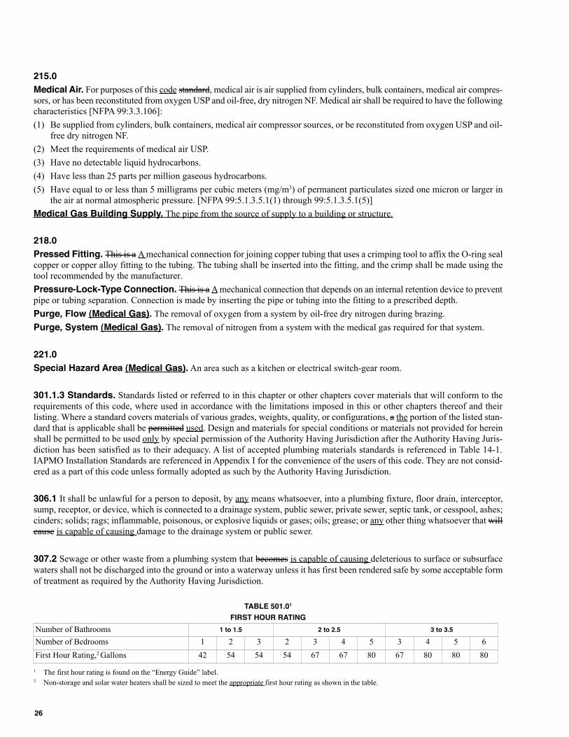
215.0
Medical Air. For purposes of this code standard, medical air is air supplied from cylinders, bulk containers, medical air compres-sors, or has been reconstituted from oxygen USP and oil-free, dry nitrogen NF. Medical air shall be required to have the followingcharacteristics [NFPA 99:3.3.106]:
(1) Be supplied from cylinders, bulk containers, medical air compressor sources, or be reconstituted from oxygen USP and oil-free dry nitrogen NF.
(2) Meet the requirements of medical air USP.
(3) Have no detectable liquid hydrocarbons.
(4) Have less than 25 parts per million gaseous hydrocarbons.
(5) Have equal to or less than 5 milligrams per cubic meters (mg/m3) of permanent particulates sized one micron or larger inthe air at normal atmospheric pressure. [NFPA 99:5.1.3.5.1(1) through 99:5.1.3.5.1(5)]
Medical Gas Building Supply. The pipe from the source of supply to a building or structure.
218.0
Pressed Fitting. This is a A mechanical connection for joining copper tubing that uses a crimping tool to affix the O-ring sealcopper or copper alloy fitting to the tubing. The tubing shall be inserted into the fitting, and the crimp shall be made using thetool recommended by the manufacturer.
Pressure-Lock-Type Connection. This is a A mechanical connection that depends on an internal retention device to preventpipe or tubing separation. Connection is made by inserting the pipe or tubing into the fitting to a prescribed depth.
Purge, Flow (Medical Gas). The removal of oxygen from a system by oil-free dry nitrogen during brazing.
Purge, System (Medical Gas). The removal of nitrogen from a system with the medical gas required for that system.
221.0
Special Hazard Area (Medical Gas). An area such as a kitchen or electrical switch-gear room.
301.1.3 Standards. Standards listed or referred to in this chapter or other chapters cover materials that will conform to therequirements of this code, where used in accordance with the limitations imposed in this or other chapters thereof and theirlisting. Where a standard covers materials of various grades, weights, quality, or configurations, a the portion of the listed stan-dard that is applicable shall be permitted used. Design and materials for special conditions or materials not provided for hereinshall be permitted to be used only by special permission of the Authority Having Jurisdiction after the Authority Having Juris-diction has been satisfied as to their adequacy. A list of accepted plumbing materials standards is referenced in Table 14-1.IAPMO Installation Standards are referenced in Appendix I for the convenience of the users of this code. They are not consid-ered as a part of this code unless formally adopted as such by the Authority Having Jurisdiction.
306.1 It shall be unlawful for a person to deposit, by any means whatsoever, into a plumbing fixture, floor drain, interceptor,sump, receptor, or device, which is connected to a drainage system, public sewer, private sewer, septic tank, or cesspool, ashes;cinders; solids; rags; inflammable, poisonous, or explosive liquids or gases; oils; grease; or any other thing whatsoever that willcause is capable of causing damage to the drainage system or public sewer.
307.2 Sewage or other waste from a plumbing system that becomes is capable of causing deleterious to surface or subsurface
waters shall not be discharged into the ground or into a waterway unless it has first been rendered safe by some acceptable form
of treatment as required by the Authority Having Jurisdiction.
TABLE 501.01
FIRST HOUR RATING
1 The first hour rating is found on the “Energy Guide” label.2 Non-storage and solar water heaters shall be sized to meet the appropriate first hour rating as shown in the table.
Number of Bathrooms 1 to 1.5 2 to 2.5 3 to 3.5
Number of Bedrooms 1 2 3 2 3 4 5 3 4 5 6
First Hour Rating,2 Gallons 42 54 54 54 67 67 80 67 80 80 80
26
508.19 Extra Device or Attachment. No device or attachment shall be installed on a gas utilization appliance that will
impair is capable of impairing the combustion of gas. [NFPA 54:9.1.15]
509.2 Installation of Appliances on Roofs.
(remaining text unchanged)
(4) Where water stands on the roof of the appliance or in the passageways to the appliance, or where the roof is of a design
having a water seal, an approved platform, walkway, or both shall be provided above the waterline. Such platforms or walk-
ways shall be located adjacent to the appliance and control panels so that the appliance is capable of being shall be safely
serviced where water stands on the roof. [NFPA 54:9.4.2.4]
510.3.1 Minimum Safe Performance. A venting system shall be designed and constructed so as to develop a positive flow
adequate to remove flue or vent gases to the outside atmosphere. [NFPA 54:12.1]
27
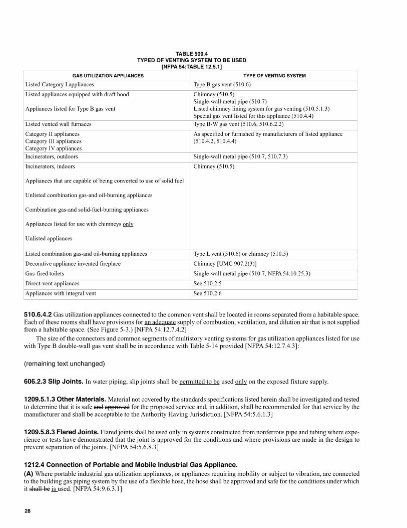
TABLE 509.4TYPED OF VENTING SYSTEM TO BE USED
[NFPA 54:TABLE 12.5.1]
510.6.4.2 Gas utilization appliances connected to the common vent shall be located in rooms separated from a habitable space.Each of these rooms shall have provisions for an adequate supply of combustion, ventilation, and dilution air that is not suppliedfrom a habitable space. (See Figure 5-3.) [NFPA 54:12.7.4.2]
The size of the connectors and common segments of multistory venting systems for gas utilization appliances listed for usewith Type B double-wall gas vent shall be in accordance with Table 5-14 provided [NFPA 54:12.7.4.3]:
(remaining text unchanged)
606.2.3 Slip Joints. In water piping, slip joints shall be permitted to be used only on the exposed fixture supply.
1209.5.1.3 Other Materials. Material not covered by the standards specifications listed herein shall be investigated and testedto determine that it is safe and approved for the proposed service and, in addition, shall be recommended for that service by themanufacturer and shall be acceptable to the Authority Having Jurisdiction. [NFPA 54:5.6.1.3]
1209.5.8.3 Flared Joints. Flared joints shall be used only in systems constructed from nonferrous pipe and tubing where expe-rience or tests have demonstrated that the joint is approved for the conditions and where provisions are made in the design toprevent separation of the joints. [NFPA 54:5.6.8.3]
1212.4 Connection of Portable and Mobile Industrial Gas Appliance.
(A) Where portable industrial gas utilization appliances, or appliances requiring mobility or subject to vibration, are connectedto the building gas piping system by the use of a flexible hose, the hose shall be approved and safe for the conditions under whichit shall be is used. [NFPA 54:9.6.3.1]
GAS UTILIZATION APPLIANCES TYPE OF VENTING SYSTEM
Listed Category I appliances Type B gas vent (510.6)
Listed appliances equipped with draft hood
Appliances listed for Type B gas vent
Chimney (510.5)
Single-wall metal pipe (510.7)
Listed chimney lining system for gas venting (510.5.1.3)
Special gas vent listed for this appliance (510.4.4)
Listed vented wall furnaces Type B-W gas vent (510.6, 510.6.2.2)
Category II appliances
Category III appliances
Category IV appliances
As specified or furnished by manufacturers of listed appliance
(510.4.2, 510.4.4)
Incinerators, outdoors Single-wall metal pipe (510.7, 510.7.3)
Incinerators, indoors
Appliances that are capable of being converted to use of solid fuel
Unlisted combination gas-and oil-burning appliances
Combination gas-and solid-fuel-burning appliances
Appliances listed for use with chimneys only
Unlisted appliances
Chimney (510.5)
Listed combination gas-and oil-burning appliances Type L vent (510.6) or chimney (510.5)
Decorative appliance invented fireplace Chimney [UMC 907.2(3)]
Gas-fired toilets Single-wall metal pipe (510.7, NFPA 54:10.25.3)
Direct-vent appliances See 510.2.5
Appliances with integral vent See 510.2.6
28
(B) Where industrial gas utilization appliances requiring mobility are connected to the rigid piping by the use of swivel jointsor couplings, the swivel joints or couplings shall be approved for the service required, and only the minimum number requiredshall be installed. [NFPA 54:9.6.3.2]
(C) Where industrial gas utilization appliances subject to vibration are connected to the building piping system by the use ofall-metal flexible connectors, the connectors shall be approved for the service required. [NFPA 54:9.6.3.3]
1216.1 The following regulations, as set forth in this section and in Section 1216.0, shall be the standard for the installation ofgas piping. Natural gas regulations and tables are based on the use of gas having a specific gravity of 0.60, supplied at 6 to 8inches water column (1.5 kPa to 1.9 kPa) pressure at the outlet of the meter or regulator. For undiluted liquefied petroleum gas,gas piping shall be permitted to be sized at 11 inches water column (2.7 kPa) pressure at the outlet of the meter or regulator andspecific gravity of 1.50. Where gas of a different specific gravity is to be delivered, the serving gas supplier shall be permittedto be contacted for specific gravity conversion factors provided by the serving gas supplier shall be used to use in sizing pipingsystems from the pipe sizing tables in this chapter.
1319.4 Flux shall only be used where brazing dissimilar metals such as copper and bronze or brass, using a silver (BAg series)brazing filler metal. [NFPA 99:5.1.10.5.4.1]
(remaining text unchanged)
1319.7 After brazing, the outside of all joints shall be cleaned by washing with water and a wire brush to remove residue andpermit clear visual inspection of the joint. [NFPA 99:5.1.10.5.7.1]
(remaining text unchanged)
1325.6 Medical Air Receivers. Receivers for medical air shall meet the following requirements:
(1) Be made of corrosion-resistant materials or otherwise be made corrosion resistant.
(2) Be in accordance with Section VIII of the ASME Boiler and Pressure Vessel Code.
(3) Be equipped with a pressure-relief valve, automatic drain, manual drain, sight glass, and pressure indicator.
(4) Be of a capacity sufficient to prevent the compressor from short cycling. [NFPA 99:5.1.3.5.6]
Piping within compressor systems upstream of the source shutoff valve shall be in accordance with Section 1316.0 andSection 1319.0, except that stainless steel shall be permitted to be used as a piping material.
1326.3 Receivers for vacuum shall meet the following requirements:
(1) Be made of ferrous, nonferrous, or both materials.
(2) Be in accordance with Section VIII of the ASME Boiler and Pressure Vessel Code.
(3) Withstand a gauge pressure of 60 psi (414 kPa) and 29.9 inch (760 mm) gauge HgV.
(4) Be equipped with a manual drain.
(5) Be of a capacity based on the technology of the pumps. [NFPA 99:5.1.3.6.3]
1507.4 The Authority Having Jurisdiction shall compare the field installations with the documentation supplied by the installerto determine the following:
(1) The required F ratings (1-hour, 2-hour, 3-hour, or 4-hour) and T ratings (0-hour, 1-hour, 2-hour, 3-hour, or 4-hour) of thepenetration firestop systems shall be in accordance with are at least the same as the hourly rating of the assembly being pene-trated.
(2) The penetrating firestop systems for includes the penetrating items shall be in accordance with as documented throughtesting of the systems conducted by an independent testing agency.
(3) The penetrating firestop system is installed as tested.
A 5.2 Fixture branches to the building supply, where they are sized for the same permissible friction loss per 100 feet (30 480mm) of pipe as the branches and risers to the highest level in the building, lead to is capable of providing inadequate watersupply to the upper floor of a building. This shall be controlled by one or more of the following:
(remaining text unchanged)
29
E 8.0 Drainage (Sewage) Lines.
Drainage (sewage) collection lines shall be located in trenches at a an approved depth to be free of breakage from traffic or othermovements and shall be separated from the park water supply system as specified in this code. Drainage (sewage) lines shallhave a minimum size and slope as specified in Tables E-1 and E-2.
E 28.0 Gas Meters.
E 28.1 Support of Meters. Where installed, gas meters shall be adequately supported by a post or bracket placed on a firmfooting or other means providing equivalent support and shall not depend on the gas outlet riser for support. [NFPA 501A:4.2.3.1]
E 36.3 Plastic Gas Piping. Plastic gas piping shall only be used underground and shall be installed with an electricallyconductive wire for locating the pipe. The wire used to locate the plastic pipe shall be copper, not less than No. 18 AWG, withinsulation approved for direct burial. Portions of a plastic gas piping system consisting of metallic pipe shall be cathodicallyprotected against corrosion. [NFPA 501A: 4.3.7.3]
E 39.5.1 The fuel gas piping test shall consist of air pressure of not less than 10 inch water column or more than 14 inch watercolumn (2.4 kPa to 3.5 kPa). The system shall be isolated from the air pressure source and shall maintain this pressure for 10minutes or more without perceptible leakage. Upon satisfactory completion of the test, the appliance valves shall be opened, andthe gas appliance connectors shall be tested with soapy water or bubble solution while under the pressure remaining in thepiping system. Solutions used for testing for leakage shall not contain corrosive chemicals. Pressure shall be measured with eithera manometer, slope gauge, or gauge that is calibrated in either water inch or psi, with increments of either 1⁄10 inch (0.02 kPa)or 1⁄10 psi (0.7 kPa gauge), as applicable. Upon satisfactory completion of the test, the M/H gas supply connector shall be installed,and the connections shall be tested with soapy water or bubble solution. [NFPA 501A: 4.4.5.1.1 - 4.4.5.1.6]
(remaining text unchanged)
H 6.0 Disposal Fields.
(A) Distribution lines shall be constructed of clay tile laid with open joints, perforated clay pipe, perforated bituminous fiberpipe, perforated high-density polyethylene pipe, perforated ABS pipe, perforated PVC pipe, or other approved materials, providedthat approved openings are available for distribution of the effluent into the trench area.
COMMITTEE STATEMENT:
The purpose for the modifications are to clarify the intent of the code within the boundaries of the Manual of Style.
A PUBLIC COMMENT(S) WAS SUBMITTED FOR REVIEW AND CONSIDERATION.
PUBLIC COMMENT:
SUBMITTER: April Trafton, Donald Dickerson Associates
RECOMMENDATION:
Request to accept the code change proposal as modified by this public comment.
101.3 Plans Required. The Authority Having Jurisdiction shall be permitted to require the submission of plans, specifica-tions, drawings, and such other information as required by the Authority Having Jurisdiction, prior to the commencement of,and at any a time during the progress of, any work regulated by this code. The issuance of a permit upon plans and specifica-tions shall not prevent the Authority Having Jurisdiction from thereafter requiring the correction of errors in said plans andspecifications or from preventing construction operations being carried on thereunder when where in violation of this code orof any other pertinent ordinance or from revoking any a certificate of approval when where issued in error.
101.5.5 Maintenance. Plumbing systems, materials, and appurtenances, both existing and new, and parts thereof shall bemaintained in proper operating condition. Devices or safeguards required by this code shall be maintained in conformanceaccordance with the code edition under which installed. The owner or the owner’s designated agent shall be responsible for main-tenance of plumbing systems. To determine compliance with this subsection, the Authority Having Jurisdiction shall be permittedto cause any a plumbing system to be reinspected.
30
102.2.2 Right of Entry. Whenever Where it is necessary to make an inspection to enforce the provisions of this code, orwhenever where the Authority Having Jurisdiction has reasonable cause to believe that there exists in a building or upon a prem-ises a condition or violation of this code that makes the building or premises unsafe, insanitary, dangerous, or hazardous, theAuthority Having Jurisdiction shall be permitted to enter the building or premises at reasonable times to inspect or to performthe duties imposed upon the Authority Having Jurisdiction by this code, provided that if where such building or premises is occu-pied, the Authority Having Jurisdiction shall present credentials to the occupant and request entry. Where such building or prem-ises is unoccupied, the Authority Having Jurisdiction shall first make a reasonable effort to locate the owner or other personhaving charge or control of the building or premises and request entry. Where entry is refused, the Authority Having Jurisdic-tion has recourse to every remedy provided by law to secure entry.
When Where the Authority Having Jurisdiction shall have first obtained a proper an inspection warrant or other remedyprovided by law to secure entry, no owner, occupant, or person having charge, care, or control of a building or premises shallfail or neglect, after proper a request is made as herein provided, to promptly permit entry herein by the Authority Having Juris-diction for the purpose of inspection and examination pursuant to this code.
102.2.5 Authority to Condemn. Whenever Where the Authority Having Jurisdiction ascertains that any a plumbing systemor portion thereof, regulated by this code, has become hazardous to life, health, or property, or has become insanitary, theAuthority Having Jurisdiction shall order in writing that such plumbing either be removed or placed in a safe or sanitary condi-tion, as appropriate. The order shall fix a reasonable time limit for compliance. No person shall use or maintain defectiveplumbing after receiving such notice.
When Where such plumbing system is to be disconnected, written notice shall be given. In cases of immediate danger tolife or property, such disconnection shall be permitted to be made immediately without such notice.
103.2.3 Information on Plans and Specifications. Plans and specifications shall be drawn to scale upon substantialpaper or cloth and shall be of sufficient clarity to indicate the location, nature, and extent of the work proposed and show in detailthat it will conform to is in accordance with the provisions of this code and relevant laws, ordinances, rules, and regulations.
103.3.4 Expiration. Every A permit issued by the Authority Having Jurisdiction under the provisions of this code shall expireby limitation and become null and void if where the work authorized by such permit is not commenced within 180 days fromthe date of such permit, or if where the work authorized by such permit is suspended or abandoned at a time after the work iscommenced for a period of 180 days. Before such work can be is recommenced, a new permit shall first be obtained to do so,and the fee therefore shall be one-half the amount required for a new permit for such work, provided no changes have been madeor will be made in the original plans and specifications for such work, and provided further that such suspensions or abandon-ment has not exceeded 1 year.
(remaining text unchanged)
103.4.4.1 Whenever Wherever work for which a permit is required by this code has been commenced without first obtainingsaid permit, a special investigation shall be made before a permit shall be permitted to be issued for such work.
103.4.4.2 Fees. An investigation fee, in addition to the permit fee, shall be collected whether or not a permit is then or subse-quently issued. The investigation fee shall be equal to the amount of the permit fee that would be is required by this code if apermit were to be issued. The payment of such investigation fee shall not exempt any a person from compliance with otherprovisions of this code, nor from any a penalty prescribed by law.
103.5.4 Inspection Requests. It shall be the duty of the person doing the work authorized by a permit to notify the AuthorityHaving Jurisdiction that such work is ready for inspection. The Authority Having Jurisdiction shall be permitted to require thatevery a request for inspection be filed not less than one working day before such inspection is desired. Such request shall be inwriting or by telephone, at the option of the Authority Having Jurisdiction.
It shall be the duty of the person requesting inspections required by this code to provide access to and means for properinspection of such work.
103.5.5.1 Defective Systems. An air test shall be used in testing the sanitary condition of the drainage or plumbing systemof any building premises when where there is reason to believe that it has become defective. In buildings or premises condemnedby the proper Authority Having Jurisdiction because of an insanitary condition of the plumbing system or part thereof, the alter-ations in such system shall conform to be in accordance with the requirements of this code.
103.5.6.2 Retesting. If Where the Authority Having Jurisdiction finds that the work will not pass the test, necessary correc-tions shall be made, and the work shall then be resubmitted for test or inspection.
31
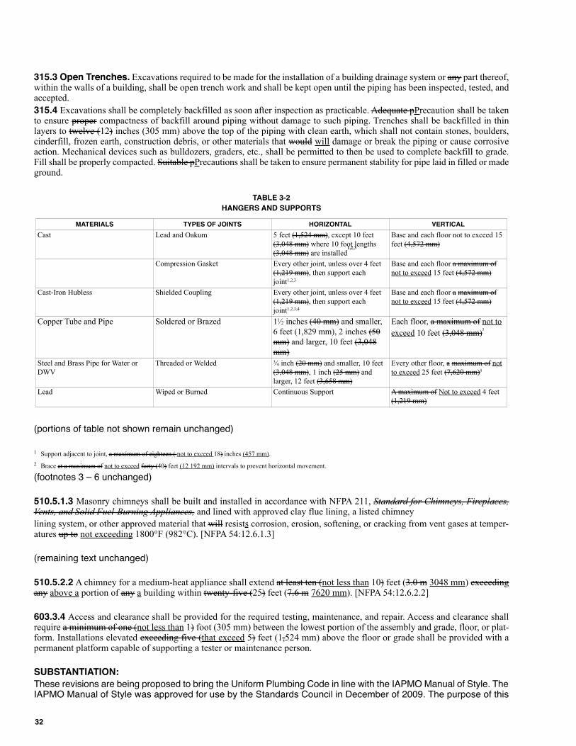
315.3 Open Trenches. Excavations required to be made for the installation of a building drainage system or any part thereof,within the walls of a building, shall be open trench work and shall be kept open until the piping has been inspected, tested, andaccepted.
315.4 Excavations shall be completely backfilled as soon after inspection as practicable. Adequate pPrecaution shall be takento ensure proper compactness of backfill around piping without damage to such piping. Trenches shall be backfilled in thinlayers to twelve (12) inches (305 mm) above the top of the piping with clean earth, which shall not contain stones, boulders,cinderfill, frozen earth, construction debris, or other materials that would will damage or break the piping or cause corrosiveaction. Mechanical devices such as bulldozers, graders, etc., shall be permitted to then be used to complete backfill to grade.Fill shall be properly compacted. Suitable pPrecautions shall be taken to ensure permanent stability for pipe laid in filled or madeground.
TABLE 3-2
HANGERS AND SUPPORTS
(portions of table not shown remain unchanged)
1 Support adjacent to joint, a maximum of eighteen ( not to exceed 18) inches (457 mm).
2 Brace at a maximum of not to exceed forty (40) feet (12 192 mm) intervals to prevent horizontal movement.
(footnotes 3 – 6 unchanged)
510.5.1.3 Masonry chimneys shall be built and installed in accordance with NFPA 211, Standard for Chimneys, Fireplaces,Vents, and Solid Fuel-Burning Appliances, and lined with approved clay flue lining, a listed chimney
lining system, or other approved material that will resists corrosion, erosion, softening, or cracking from vent gases at temper-atures up to not exceeding 1800°F (982°C). [NFPA 54:12.6.1.3]
(remaining text unchanged)
510.5.2.2 A chimney for a medium-heat appliance shall extend at least ten (not less than 10) feet (3.0 m 3048 mm) exceedingany above a portion of any a building within twenty-five (25) feet (7.6 m 7620 mm). [NFPA 54:12.6.2.2]
603.3.4 Access and clearance shall be provided for the required testing, maintenance, and repair. Access and clearance shallrequire a minimum of one (not less than 1) foot (305 mm) between the lowest portion of the assembly and grade, floor, or plat-form. Installations elevated exceeding five (that exceed 5) feet (1,524 mm) above the floor or grade shall be provided with apermanent platform capable of supporting a tester or maintenance person.
SUBSTANTIATION:
These revisions are being proposed to bring the Uniform Plumbing Code in line with the IAPMO Manual of Style. TheIAPMO Manual of Style was approved for use by the Standards Council in December of 2009. The purpose of this
MATERIALS TYPES OF JOINTS HORIZONTAL VERTICAL
Cast Lead and Oakum 5 feet (1,524 mm), except 10 feet
(3,048 mm) where 10 foot lengths
(3,048 mm) are installed1,2,3
Base and each floor not to exceed 15
feet (4,572 mm)
Compression Gasket Every other joint, unless over 4 feet
(1,219 mm), then support each
joint1,2,3
Base and each floor a maximum of
not to exceed 15 feet (4,572 mm)
Cast-Iron Hubless Shielded Coupling Every other joint, unless over 4 feet
(1,219 mm), then support each
joint1,2,3,4
Base and each floor a maximum of
not to exceed 15 feet (4,572 mm)
Copper Tube and Pipe Soldered or Brazed 11⁄2 inches (40 mm) and smaller,
6 feet (1,829 mm), 2 inches (50
mm) and larger, 10 feet (3,048
mm)
Each floor, a maximum of not to
exceed 10 feet (3,048 mm)5
Steel and Brass Pipe for Water or
DWV
Threaded or Welded 3⁄4 inch (20 mm) and smaller, 10 feet
(3,048 mm), 1 inch (25 mm) and
larger, 12 feet (3,658 mm)
Every other floor, a maximum of not
to exceed 25 feet (7,620 mm)5
Lead Wiped or Burned Continuous Support A maximum of Not to exceed 4 feet
(1,219 mm)
32
manual is to provide guidelines for how to layout a code document (i.e. general provisions, administration, technicalstyle, editorial style, units of measurement, etc.).
COMMITTEE ACTION: Accept the public comment as submitted
TOTAL ELIGIBLE TO VOTE: 28
VOTING RESULTS: AFFIRMATIVE: 28
The TCC has the responsibility to resolve conflicts and achieve correlation among the recommendations of the TCs.The TCC shall have the authority to choose between alternative text recommended by the TC, but only as neces-sary for correlation, consistency, and the correction of errors and omissions in accordance with Section 3-4 of theRegulations Governing Committee Projects. Actions taken on UPC Item #1 for “direct-vent appliances” and UMC Item#70 resulted in a conflict within this code. In order to correlate language the following Technical CorrelatingCommittee proposed action to the UPC is shown as follows:
206.0 -D-
Direct-Vent Appliances. Appliances that are constructed and installed so that air for combustion is derived directly from theoutdoors and all flue gases are discharged to the outside atmosphere outdoors. [NFPA 54:3.3.6.3]
TCC COMMITTEE ACTION: Accept as Submitted
TCC COMMITTEE STATEMENT: The above revisions to the definition for “direct-vent appliances” in the 2012 UPCare necessary to correlate with the 2012 UMC and 2009 version of NFPA 54.
The following proposed action moves forward as approved by the TCC and supersedes the recommendation fromthe UPC TC for action taken on Section 206.0 in regards to the definition for “direct-vent appliances”.
The TCC has the responsibility to resolve conflicts and achieve correlation among the recommendations of the TCs.The TCC shall have the authority to choose between alternative text recommended by the TC, but only as neces-sary for correlation, consistency, and the correction of errors and omissions in accordance with Section 3-4 of theRegulations Governing Committee Projects. Actions taken on UPC Item #1 for “welded joint” and “welded seam”,and UMC Item #6 resulted in a conflict within this code. In order to correlate language the following Technical Corre-lating Committee proposed action to the UPC is shown as follows:
225.0 – W –
Welded Joint or Seam. A joint or seam obtained by the joining of metal parts in the plastic molten state.
212.0 –J–
Joint, Welded. A gas-tight joint obtained by the joining of metal parts in the plastic molten state.
221.0 –S–
Seam, Welded. See JOINT, WELDED.
TCC COMMITTEE ACTION: Accept as Submitted
TCC COMMITTEE STATEMENT: The revisions to the definition for “welded joint or seam” in the 2012 UPC arenecessary to correlate with the actions taken by the Technical Committee for Item 6 of the 2012 UMC.
The following proposed action moves forward as approved by the TCC and supersedes the recommendation fromthe UPC TC for action taken on Sections 212.0, 221.0, and 225.0 in regards to the definitions for “welded joint” and“welded seam”.
33
The TCC has the responsibility to resolve conflicts and achieve correlation among the recommendations of the TCs.The TCC shall have the authority to choose between alternative text recommended by the TC, but only as neces-sary for correlation, consistency, and the correction of errors and omissions in accordance with Section 3-4 of theRegulations Governing Committee Projects. Actions taken on UPC Item #1 for “fuel gas requirements for manufac-tured homes and sites” and UMC Item #1 resulted in a conflict within this code. In order to correlate language thefollowing Technical Correlating Committee proposed action to the UPC is shown as follows:
E 23.1 Gas Supply Connections. Gas supply connections at sites, where provided from an underground gas supply pipingsystem, shall be located and arranged to permit attachment to a manufactured home (M/H) occupying the site in a work-likemanner. For the installation of liquefied petroleum gas (LPG) storage systems, the applicable provisions of NFPA
58 shall be followed. [NFPA 501A: 4.1.2.1, 4.1.2.2]
E 23.2 Location of Gas Supply Connection. The gas supply to the M/H shall be located within 4 feet (1219 mm) of theM/H stand.
Exception: The above requirements shall not apply to gGas supply connections for manufactured homes located on all weatherwood, concrete, concrete block foundation systems or on foundations constructed in accordance with the local building codeor, in the absence of a local code, with a recognized model building code. [NFPA 501A: Section 4.1.3]
E 24.1.2.2 Requirements. The open-ended gastight conduit shall conform to the following [NFPA 501A:4.2.1.2]:
(1) & (2) (remaining text unchanged)
(3) The conduit shall extend to a point not less than 4 inches (102 mm) beyond the outside wall of the M/H, accessory building,or structure, and the outer ends shall not be sealed. [NFPA 501A: 4.2.1.2.3]
(4) Where the conduit terminates within a M/H, accessory building, or structure, it shall be readily accessible, and the spacebetween the conduit and the gas piping shall be sealed to prevent leakage of gas into the building. [NFPA 501A: 4.2.1.2.4]
E 25.0 Manufactured Home Site Gas Shutoff Valve.
E 25.1 General. Each M/H site shall have a listed gas shutoff valve installed upstream of the M/H site gas outlet. The gas shutoff
valve shall be located on the outlet riser at a height of not less than 6 inches (152 mm) above grade. A gas shutoff valve shall
not be located under a M/H. The outlet shall be equipped with a cap or plug to prevent discharge of gas whenever where the
M/H site outlet is not connected to an M/H. [NFPA 501A: 4.2.2.1 - 4.2.2.4]
Exception: Gas shutoff valves for manufactured homes located on foundations constructed in accordance with the local building
code or, in the absence of a local code, with a recognized model building code. [NFPA 501A:4.2.2]
E 30.0 Required Gas Supply.
E 30.1 General. The minimum hourly volume of gas required at each M/H site outlet or a section of the M/H community gas
piping system shall be calculated as shown in Table E 30.0. [NFPA 501A:4.3.4.1]
TABLE E 30.0
DEMAND FACTORS FOR USE IN CALCULATING GAS PIPING
SYSTEMS IN M/H COMMUNITIES
[NFPA 501A:TABLE 4.3.4.1]
(portions of table not shown remain unchanged)
E 35.0 Oil Supply.
E 35.1 General. The following three methods of supplying oil to an individual M/H site shall be permitted:
(1) – (3) (remaining text unchanged)
NUMBER OF MANUFACTURED HOMESITES M/HSITES
MANUFACTURED HOME SITE (British thermal unitsper hour per homesite) BRITISH THERMAL UNITS
PER HOUR PER M/H SITE
34
E 35.2 Oil Supply Connections – General. Oil supply connections at M/H sites, where provided from a centralized oil
distribution system, shall be located and arranged to permit attachment in a work-like manner to a manufactured home M/H
utilizing the stand. The installation of such facilities shall be in accordance comply with the following requirements:
(remaining text unchanged)
E 36.1 Flexible Gas Connector. Each gas supply connector shall be listed for outside M/H use, shall be not more than 6
feet (1829 mm) in length, and shall have a capacity rating adequate to supply the connected load. [NFPA 501A:4.4.1]
(remaining text unchanged)
E 36.5.1 Procedures. The fuel gas piping test shall consist of air pressure of not less than 10 inch water column or more than
14 inch water column (2.45 kPa to 3.5 kPa). The system shall be isolated from the air pressure source and shall maintain this
pressure for 10 minutes or more without perceptible leakage. Upon satisfactory completion of the test, the appliance valves
shall be opened, and the gas appliance connectors shall be tested with soapy water or bubble solution while under the pressure
remaining in the piping system. Solutions used for testing for leakage shall not contain corrosive chemicals. Pressure shall be
measured with either a manometer, slope gauge, or gauge that is calibrated in either water inch or psi, with increments of either1⁄10 of an inch water column (0.02 kPa) or 1⁄10 psi (0.7 kPa gauge), as applicable. Upon satisfactory completion of the test, the
M/H gas supply connector shall be installed, and the connections shall be tested with soapy water or bubble solution. [NFPA
501A:4.4.5.1.1 - 4.4.5.1.6]
E 36.6 Oil Tanks. Not less more than one 660 gallon (2498 L) tank or two tanks with aggregate capacity 660) gallons (2498
L) or less shall be connected to one oil burning appliance. Two supply tanks, where used, shall be cross-connected and provided
with a single fill and vent as described in accordance with NFPA 31, and shall be on a common slab and rigidly secured one to
the other. Tanks having a capacity of 660 gallons (2498 L) or less shall be securely supported by rigid, noncombustible supports
to prevent settling, sliding, or lifting. [NFPA 501A:4.4.6]
E 36.6.2 Capacity. A tank with a capacity not larger than 60 gallons (227 L) shall be permitted to be a DOT-5 shipping
container (drum) and so marked, or a tank meeting constructed in accordance with the provisions of UL 80. Tanks other than
DOT-5 shipping containers having a capacity of not more than 660 gallons (2498 L) shall meet be constructed in accordance
with the provisions of UL 80. Pressure tanks shall be built constructed in accordance with Section VIII of the ASME Boiler, and
Pressure Vessel Code. [NFPA 501A: 4.4.6.2.1 - 4.4.6.2.2]
E 37.0 Manufactured Home Accessory Building Fuel Supply Systems.
E 37.1 General. Fuel gas supply systems installed in a M/H accessory building or structure shall be in accordance with the
applicable provisions of NFPA 54 and NFPA 58. Fuel oil supply systems shall comply with the applicable provisions of NFPA
31. [NFPA 501A:4.5.1-4.5.2]
E 38.2 Oil Supply Systems in M/H Communities. Oil-burning equipment and installation within a M/H community shall
be designed and constructed in accordance with the applicable codes and standards adopted by the Authority Having Jurisdic-
tion. Where the state or other political subdivision does not assume jurisdiction, such installation shall be designed and
constructed in accordance with the applicable provisions of NFPA 31. [NFPA 501A:4.6.2]
TCC COMMITTEE ACTION: Accept as Submitted
TCC COMMITTEE STATEMENT: The revisions to Appendix E of the 2012 UPC are necessary to correlate with the2012 UMC and 2009 version of NFPA 501A that is referenced in Table 1401.1 of the UPC.
The following proposed action moves forward as approved by the TCC and supersedes the recommendation fromthe UPC TC for action taken on Appendix E.
35
The TCC has the responsibility to resolve conflicts and achieve correlation among the recommendations of the TCs.The TCC shall have the authority to choose between alternative text recommended by the TC, but only as neces-sary for correlation, consistency, and the correction of errors and omissions in accordance with Section 3-4 of theRegulations Governing Committee Projects. Actions taken on UPC Item #1 for “manufacturer’s installation instruc-tions” and “manufacturer’s instructions”, and UMC Item #1 resulted in a conflict within this code. In order to corre-late language the following Technical Correlating Committee proposed action to the UPC is shown as follows:
101.4.1.4 Conflicts Between Codes. Where the requirements within the jurisdiction of this plumbing code conflict withthe requirements of the mechanical code, this code shall prevail. In instances where the code, applicable standards, or the manu-facturer’s installation instructions conflict, the more stringent provisions shall prevail. Where there is a conflict between ageneral requirement and a specific requirement, the specific requirement shall prevail.
402.9 Installation. Water-conserving fixtures shall be installed in strict accordance with the manufacturer’s installation instruc-tions to maintain their rated performance.
409.6 Installation and Access. Bathtubs and whirlpool bathtubs shall be installed in accordance with the manufacturer’sinstallation instructions. Access openings shall be of size and opening to permit the removal and replacement of the circulationpump.
(remaining text unchanged)
414.6 Overflows in Flush Tanks. Flush tanks shall be provided with overflows discharging into the water closet or urinalconnected thereto. Overflows supplied as original parts with the fixture shall be of sufficient size to prevent tank flooding at themaximum rate at which the tank is supplied with water under normal operating conditions and where installed per in accordancewith the manufacturer’s installation instructions.
416.3 Installation. Emergency eyewash and shower equipment shall be installed in accordance with the manufacturer’s instal-lation instructions.
501.0 General.
The regulations of this chapter shall govern the construction, location, and installation of fuel-burning and other water heatersheating potable water, together with chimneys, vents, and their connectors. The minimum capacity for storage water heaters shallbe in accordance with the first hour rating listed in Table 501.0. Design, construction, and workmanship shall be in accordancewith accepted engineering practices, manufacturer’s installation instructions, and applicable standards and shall be of such char-acter as to secure the results sought to be obtained by this code. No water heater shall be hereinafter installed that does notcomply with the type and model of each size thereof approved by the Authority Having Jurisdiction. A list of accepted gas appli-ance standards are referenced in Table 1401.1.
504.3.1 Listed Water Heaters. The clearances shall be not such as to interfere with combustion air, draft hood clearance andrelief, and accessibility for servicing. Listed water heaters shall be installed in accordance with their listings and the manufac-turer’s installation instructions. [NFPA 54:10.28.2.1]
504.4 Pressure-Limiting Devices. A water heater installation shall be provided with overpressure protection by means ofan approved, listed device, installed in accordance with the terms of its listing and the manufacturer’s installation instructions.[NFPA 54:10.28.3]
504.5 Temperature-Limiting Devices. A water heater installation or a hot water storage vessel installation shall be providedwith over temperature protection by means of an approved, listed device installed in accordance with the terms of its listing andthe manufacturer’s installation instructions. [NFPA 54:10.28.4]
504.6 Temperature, Pressure, and Vacuum Relief Devices. The installation of temperature, pressure, and vacuumrelief devices or combinations thereof, and automatic gas shutoff devices, shall be installed in accordance with the terms oftheir listings and the manufacturer’s installation instructions. A shutoff valve shall not be placed between the relief valve andthe water heater or on discharge pipes between such valves and the atmosphere. The hourly Btu discharge capacity or the ratedsteam relief capacity of the device shall be not less than the input rating of the water heater. [NFPA 54:10.28.5]
36
509.3.4.1 Listing. Mechanical draft systems shall be listed and shall be installed in accordance with both the appliance andthe mechanical draft system manufacturer’s installation instructions. [NFPA 54:12.4.3.1]
509.5.6 Support of Chimneys. Portions of chimneys shall be supported for the design and weight of the materials employed.Listed factory-built chimneys shall be supported and spaced in accordance with their listings and the manufacturer’s installa-tion instructions. [NFPA 54:12.6.6]
TABLE 509.7.4(1)
REDUCTION OF CLEARANCES WITH SPECIFIED FORMS FOR PROTECTION [NFPA 54: TABLE 10.2.3(B)]
(portions of the table not shown remain unchanged)
11 Listed single-wall connectors shall be installed in accordance with the terms of their listing and the manufacturer’s installa-tion instructions.
509.10.2.4 Non-Residential Low-Heat Appliances. A vent connector for a non-residential low-heat appliance shall be afactory-built chimney section or steel pipe having resistance to heat and corrosion equivalent to the galvanized pipe specifiedin Table 509.10.2. Factory-built chimney sections shall be joined together installed in accordance with the chimney manufac-turer’s installation instructions. [NFPA 54:12.11.2.5]
509.10.2.5 Medium-Heat Appliances. Vent connectors for medium-heat appliances, and commercial and industrial incin-erators, shall be constructed of factory-built, medium-heat chimney sections or steel of a thickness not less than that specifiedin Table 509.10.2(1) and shall be in accordance comply with the following [NFPA 54:12.11.2.6]:
(1) – (3) (remaining text unchanged)
(4) Factory-built chimney sections, where employed, shall be joined together installed in accordance with the chimney manu-facturer’s installation instructions.
509.10.6 Joints. Joints between sections of connector piping and connections to flue collars or draft hood outlets shall befastened in accordance with one of the following methods [NFPA 54:12.11.7]:
(1) (remaining text unchanged)
(2) Vent connectors of listed vent material shall be assembled and connected to flue collars or draft hood outlets in accordancewith the manufacturer’s installation instructions.
(3) (remaining text unchanged)
509.10.7 Slope. A vent connector shall be installed without any dips or sags and shall slope upward toward the vent or chimneynot less than 1⁄4 inch per foot (20.8 mm/m). [NFPA 54:12.11.8]
Exception: Vent connectors attached to a mechanical draft system installed in accordance with the appliance and draft systemmanufacturer’s installation instructions.
509.11.3 Draft-Control Devices. Where a draft control device is part of the appliance or is supplied by the appliance manu-facturer, it shall be installed in accordance with the manufacturer’s installation instructions. In the absence of manufacturer’sinstallation instructions, the device shall be attached to the flue collar of the appliance or as near to the appliance as practical.[NFPA 54:12.13.3]
509.11.4 Additional Devices. Appliances (except incinerators) requiring controlled chimney draft shall be permitted to beequipped with a listed double-acting barometric draft regulator installed and adjusted in accordance with the manufacturer’sinstallation instructions. [NFPA 54:12.13.4]
509.14 Obstructions. Devices that retard the flow of vent gases shall not be installed in a vent connector, chimney, or vent.The following shall not be considered as obstructions [NFPA 54:12.16]:
(1) - (4) (remaining text unchanged)
(5) Approved economizers, heat reclaimers, and recuperators installed in venting systems of appliances not required to beequipped with draft hoods, provided the appliance manufacturer’s installation instructions cover the installation of such adevice in the venting system and performance in accordance with Section 509.3.1 and Section 509.3.2 is obtained.
37
510.1 Installation. These venting tables shall be not used where obstructions are installed in the venting system. The instal-lation of vents serving listed appliances with vent dampers shall be installed in accordance with the appliance manufacturer’sinstallation instructions or in accordance with the following [NFPA 54:13.1.1]:
(1) & (2) (remaining text unchanged)
510.2.1 Obstructions and Vent Damper. These venting tables shall be not used where obstructions are installed in theventing system. The installation of vents serving listed appliances with vent dampers shall be installed in accordance with theappliance manufacturer’s installation instructions or in accordance with the following [NFPA 54:13.2.1]:
(remaining text unchanged)
603.4.7 Integral Backflow Preventers. Fixtures, appliances, or appurtenances with integral backflow preventers or inte-gral airgaps manufactured as a unit shall be installed in accordance with their listing requirements and the manufacturer’s instal-lation instructions.
603.5.14 Deck-Mounted and Equipment-Mounted Vacuum Breakers. Deck-mounted or equipment-mounted vacuumbreakers shall be installed in accordance with their listing and the manufacturer’s installation instructions, with the critical levelnot less than 1 inch (25.4 mm) above the flood-level rim.
605.1 Asbestos Cement Pipe and Joints. Joining methods for asbestos cement pipe and fittings shall be installed inaccordance with the manufacturer’s installation instructions and shall comply with Section 605.1.1.
605.2 Brass Pipe and Joints. Joining methods for brass pipe and fittings shall be installed in accordance with the manu-facturer’s installation instructions and shall comply with Section 605.2.1 through Section 605.2.3.
605.3 Copper Pipe, Tubing and Joints. Joining methods for copper pipe, tubing, and fittings shall be installed in accor-dance with the manufacturer’s installation instructions and shall comply with Section 605.3.1 through Section 605.3.7.
605.4 CPVC Plastic Pipe and Joints. CPVC plastic pipe and fittings joining methods shall be installed in accordance withthe manufacturer’s installation instructions and shall comply with Section 605.4.1 through Section 605.4.3.
605.5 Ductile Iron Pipe and Joints. Ductile iron pipe and fittings joining methods shall be installed in accordance with themanufacturer’s installation instructions and shall comply with Section 605.5.1 and Section 605.5.2.
605.6 Galvanized Steel Pipe and Joints. Galvanized steel pipe and fitting joining methods shall be installed in accordancewith the manufacturer’s installation instructions and shall comply with Section 605.6.1 and Section 605.6.2.
605.7 PE Plastic Pipe/Tubing and Joints. PE plastic pipe or tubing and fittings joining methods shall be installed in accor-dance with the manufacturer’s installation instructions and shall comply with Section 605.7.1 and Section 605.7.2.
605.8 PE-AL-PE Plastic Pipe/Tubing and Joints. PE-AL-PE plastic pipe or tubing and fitting joining methods shall beinstalled in accordance with the manufacturer’s installation instructions and shall comply with Section 605.8.1 and Section605.8.1.1.
605.11 PEx-AL-PEx Plastic Tubing and Joints. PEX-AL-PEX plastic pipe or tubing and fitting joining methods shallbe installed in accordance with the manufacturer’s installation instructions and shall comply with Section 605.11.1 and Section605.11.1.1.
605.12 Polypropylene (PP) Piping and Joints. PP pipe and fittings shall be installed in accordance with the manufac-turer’s installation instructions and shall comply with Section 605.12.1 through Section 605.12.3.
38
605.12.2 Mechanical and Compression Sleeve Joints. Mechanical and compression sleeve joints shall be installed inaccordance with the manufacturer’s installation instructions.
605.13 PVC Plastic Pipe and Joints. PVC plastic pipe and fittings joining methods shall be installed in accordance withthe manufacturer’s installation instructions and shall comply with Sections 605.13.1 through Section 605.13.3.
605.14 Stainless Steel Pipe and Joints. Joining methods for stainless steel pipe and fittings shall be installed in accor-dance with the manufacturer’s installation instructions and shall comply with Section 605.14.1 and Section 605.14.2.
605.17 Joints Between Various Materials. Joints between various materials shall be installed in accordance with themanufacturer’s installation instructions and shall comply with Section 605.17.1 through Section 605.17.3.
609.2 Excessive Water Pressure. Where static water pressure in the water supply piping is exceeding 80 psi (552 kPa),an approved-type pressure regulator preceded by an adequate strainer shall be installed and the static pressure reduced to 80 psi(552 kPa) or less. Pressure regulator(s) equal to or exceeding 11⁄2 inches (38 mm) shall not require a strainer. Such regulator(s)shall control the pressure to water outlets in the building unless otherwise approved by the Authority Having Jurisdiction. Eachsuch regulator and strainer shall be accessibly located aboveground or in a vault equipped with a properly sized and slopedbore-sighted drain to daylight, shall be protected from freezing, and shall have the strainer readily accessible for cleaning withoutremoving the regulator or strainer body or disconnecting the supply piping. Pipe size determinations shall be based on 80 percentof the reduced pressure where using Table 611.4. An approved expansion tank shall be installed in the cold water distributionpiping downstream of each such regulator to prevent excessive pressure from developing due to thermal expansion and to main-tain the pressure setting of the regulator. Expansion tanks used in potable water systems intended to supply drinking water shallbe in accordance with NSF 61. The expansion tank shall be properly sized and installed in accordance with the manufacturer’sinstallation instructions and listing. Systems designed by registered engineers shall be permitted to use approved pressure reliefvalves in lieu of expansion tanks provided such relief valves have a maximum pressure relief setting of 100 psi (689 kPa) orless.
609.3 Expansion Tanks and Combination Pressure and Temperature Relief Valves. A water system provided witha check valve, backflow preventer, or other normally closed device that prevents dissipation of building pressure back into thewater main shall be provided with an approved, listed, and adequately sized expansion tank or other approved device having asimilar function to control thermal expansion. Such expansion tank or other approved device shall be installed on the buildingside of the check valve, backflow preventer, or other device and shall be sized and installed in accordance with the manufac-turer’s recommendation installation instructions.
A water system containing storage water heating equipment shall be provided with an approved, listed, adequately sizedcombination pressure and temperature relief valve, except for listed nonstorage instantaneous heaters having an inside diameterof not more than 3 inches (80 mm). Each such approved combination temperature and pressure relief valve shall be installed onthe water-heating device in an approved location based on its listing requirements and the manufacturer’s installation instruc-tions. Each such combination temperature and pressure relief valve shall be provided with a drain as required in Section 609.5.
610.1 Installation. Water piping shall be adequately supported in accordance with Table 312.1. Burred ends shall be reamedto the full bore of the pipe or tube. Changes in direction shall be made by the appropriate use of fittings, except that changes indirection in copper tubing shall be permitted to be made with bends, provided that such bends are made with bending equip-ment that does not deform or create a loss in the cross-sectional area of the tubing. Changes in direction are allowed with flex-ible pipe and tubing without fittings in accordance with the manufacturer’s installation instructions. Provisions shall be madefor expansion in hot-water piping. Piping, equipment, appurtenances, and devices shall be installed in a workmanlike mannerin accordance with the provisions and intent of the code. Building supply yard piping shall be not less than 12 inches (305 mm)below the average local frost depth. The cover shall be not less than 12 inches (305 mm) below finish grade.
705.1 ABS and ABS Co-Extruded Plastic Pipe and Joints. Joining methods for ABS plastic pipe and fittings shall beinstalled in accordance with the manufacturer’s installation instructions and shall comply with Section 705.1.1 through Section705.1.3.
705.2 Asbestos Cement Pipe and Joints. Joining methods for asbestos cement pipe and fittings shall be installed inaccordance with the manufacturer’s installation instructions and shall comply with Section 705.2.1.
39
705.3 Brass Pipe and Joints. Joining methods for brass pipe and fittings shall be installed in accordance with the manu-facturer’s installation instructions and shall comply with Section 705.3.1 through Section 705.3.3.
705.4 Cast-Iron Pipe and Joints. Joining methods for cast-iron pipe and fittings shall be installed in accordance with themanufacturer’s installation instructions and shall comply with Section 705.4.1 and Section 705.4.2.
705.5 Copper Pipe (DWV) and Joints. Joining methods for copper pipe and fittings shall be installed in accordance withthe manufacturer’s installation instructions and shall comply with Section 705.5.1 through Section 705.5.4.
705.6 Galvanized Steel Pipe and Joints. Joining methods for galvanized steel pipe and fittings shall be installed in accor-dance with the manufacturer’s installation instructions and shall comply with Section 705.6.1 and Section 705.6.2.
705.7 PVC and PVC Co-Extruded Plastic Pipe and Joining Methods. Joining methods for PVC plastic pipe andfittings shall be installed in accordance with the manufacturer’s installation instructions and shall comply with Section 705.7.1through Section 705.7.3.
705.8 Stainless Steel Pipe and Joints. Joining methods for stainless steel pipe and fittings shall be installed in accordancewith the manufacturer’s installation instructions and shall comply with Section 705.8.1 and Section 705.8.2.
705.9 Vitrified Clay Pipe and Joints. Joining methods for vitrified clay pipe and fittings shall be installed in accordancewith the manufacturer’s installation instructions and shall comply with Section 705.9.1.
705.11 Joints Between Various Materials. Joints between various materials shall be installed in accordance with themanufacturer’s installation instructions and shall comply with Section 705.11.1 through Section 705.11.4.
710.12.1 Discharge Piping. The discharge piping shall be sized per the manufacturer’s installation instructions and shall benot less than 11⁄4 inches (32 mm) in diameter. A check valve and fullway-type shutoff valve shall be located within the dischargeline.
710.13.2 Discharge Piping. The discharge piping shall be sized in accordance with manufacturer’s instructions and shall benot less than 3⁄4 inches (20 mm) in diameter. The developed length of the discharge piping shall not exceed the manufacturer’srecommendations instructions. A check valve and fullway-type shutoff valve shall be located within the discharge line or inter-nally within the device.
1014.2.1 Flow Control Devices. Plumbing fixtures or equipment connected to a Type A and B hydromechanical greaseinterceptor shall discharge through an approved type of vented flow control installed in a readily accessible and visible loca-tion. Flow control devices shall be designed and installed so that the total flow through such device or devices shall at no timebe greater than the rated flow of the connected grease interceptor. No flow control device having adjustable or removable partsshall be approved. The vented flow control device shall be located such that no system vent shall be between the flow controland the grease interceptor inlet. The vent or air inlet of the flow control device shall connect with the sanitary drainage ventsystem, as elsewhere required by this code, or shall terminate through the roof of the building, and shall not terminate to the freeatmosphere inside the building.
Exception: Listed grease interceptors with integral flow controls or restricting devices shall be installed in an accessible loca-tion in accordance with the manufacturers’ manufacturer’s installation instructions.
1015.4 Sizing Application and Installation. FOG disposal systems shall be engineered, sized, and installed in accordancewith the manufacturers’ specifications manufacturer’s installation instructions and as specified in ASME A112.14.6, as listed inChapter 14, Table 1401.1 of this code.
1208.4.3 Sizing Methods. Gas piping shall be sized in accordance with one of the following:
(1) & (2) (remaining text unchanged)
(3) Sizing tables included in a listed piping system manufacturer’s installation instructions. [NFPA 54:5.4.3]
40
1208.5.9 Plastic Piping, Joints, and Fittings. Plastic pipe, tubing, and fittings shall be joined installed in accordancewith the manufacturers’ manufacturer’s installation instructions. The following sections shall be observed where making suchjoints. [NFPA 54:5.6.9]
1209.1 General. Where automatic excess flow valves are installed, they shall be listed, sized, and installed in accordancewith the manufacturer’s installation instructions. [NFPA 54:5.13]
1210.2.5.2 Spacing. Spacing of supports in gas-piping installations shall not exceed the distance shown in Table 1210.2.5.2.Spacing of supports for CSST shall be in accordance with the CSST manufacturer’s instructions. [NFPA54:7.2.6.2]
1211.1 Connecting Gas Appliances. Appliances shall be connected to the building piping in accordance with Section1211.5 and Section 1211.6 by one of the following [NFPA 54:9.6.1]:
(1) & (2) (remaining text unchanged)
(3) A listed connector installed in accordance with CSAANSI Z21.24/CSA 6.10. The connector shall be used installed in accor-dance with the manufacturer’s installation instructions and shall be in the same room as the appliance. One connector shallbe used installed for each per appliance. [NFPA 54:9.6.1(3)]
(4) & (5) (remaining text unchanged)
(6) Commercial cooking appliances that are moved for cleaning and sanitation purposes shall be connected installed in accor-dance with the connector manufacturer’s installation instructions using a listed appliance connector that is in accordancewith CSAANSI Z21.69/CSA 6.22. The commercial cooking appliance connector installation shall be configured in accor-dance with the manufacturer’s installation instructions. (NFPA 54:9.6.1.1)
(7) & (8) (remaining text unchanged)
1211.3 Use of Nonmetallic Gas Hose Connectors. Listed nonmetallic gas hose connectors shall be used installed inaccordance with the manufacturer’s installation instructions and as indicated in the following sections. [NFPA 54-12:9.6.2]
1211.9 Gas Convenience Outlets. Appliances shall be permitted to be connected to the building piping by means of alisted gas convenience outlet, in conjunction with a listed appliance connector, used installed in accordance with the manufac-turer’s installation instructions. Gas convenience outlets shall be listed in accordance with CSA Z21.90 and installed in accor-dance with the manufacturer’s installation instructions. [NFPA 54:9.6.6]
1302.1 Manufacturer’s Instructions. The installation of individual components shall be made in accordance with theinstructions of the manufacturer’s installation instructions. Such instructions shall include directions and information deemedby the manufacturer to be adequate for attaining proper operation, testing, and maintenance of the medical gas and vacuumsystems. Copies of the manufacturer’s instructions shall be left with the system owner. [NFPA 99:5.1.10.10.9.1 – 5.1.10.10.9.3]
1307.1 General. Where a sterilizer has provision for a vapor vent and such a vent is required by the manufacturer, the ventshall be extended to the outdoors above the roof. Sterilizer vapor vents shall be installed in accordance with the manufacturer’sinstallation instructions and shall be not connected to a drainage system vent.
1321.0 Station Outlets/Inlets. Station outlets and inlets shall be installed in strict accordance with the manufacturer’s instal-lation instructions.
1503.1 Materials. Firestop systems shall be installed in accordance with this chapter, the building code, and the manufacturer’sinstallation instructions.
1506.2 Examination. The Authority Having Jurisdiction shall conduct a thorough examination of sufficient representativeinstallations, including destructive inspection, to provide verification of satisfactory compliance with this chapter, the appropriatemanufacturer’s installation standards instructions applied by the installer, construction documents, specifications, and appli-cable manufacturer’s product information.
41
C 7.1.3 Piping Network. The piping network shall be under a continuous vacuum and shall be designed to withstand 150percent of the vacuum (negative pressure) created by the vacuum source within the system without leakage or collapse. Sizingthe piping network shall be in accordance with the manufacturer’s installation instructions. The water closet outlet fitting shallconnect with a piping network having not less than a 11/2 inch (40 mm) nominal inside diameter.
C 7.3 Drainage Fixture Units. Drainage fixture units shall be determined by the manufacturer’s installation instructions. Thepump discharge load from the collector tanks shall be in accordance with this chapter.
C 7.4 Water Supply Fixture Units. Water supply fixture units shall be determined by the manufacturer’s installation instruc-tions.
C 7.8 Manufacturer’s Installation Instructions. Manufacturer’s installation instructions shall be provided for the purposeof providing information regarding safe and proper operating instructions whether or not as part of the condition of listing inorder to determine compliance. Such instructions shall be submitted and approved by the Authority Having Jurisdiction.
H 6.2 Filter Material. Before placing filter material or drain lines in a prepared excavation, smeared or compacted surfacesshall be removed from trenches by raking to a depth of 1 inch (25.4 mm) and the loose material removed. Clean stone, gravel,slag, or similar filter material acceptable to the Authority Having Jurisdiction, varying in size from 3⁄4 of an inch to 21⁄2 inches(19.1 mm to 64 mm), shall be placed in the trench to the depth and grade required by this section. Drain pipe shall be placed onfilter material in an approved manner. The drain lines shall then be covered with filter material to the minimum depth requiredby this section, and this material covered with untreated building paper, straw, or similar porous material to prevent closure ofvoids with earth backfill. No earth backfill shall be placed over the filter material cover until after inspection and acceptance.
Exception: Listed or approved plastic leaching chambers shall be permitted to be used in lieu of pipe and filter material. Chamberinstallations shall follow the rules for disposal fields, where applicable, and shall comply with the manufacturer’s installationinstructions.
K 104.2.1 Filtration Devices. Potable water filters shall comply with NSF 53 and shall be installed in accordance with themanufacturer’s installation instructions.
L 301.1 Installation. Plumbing systems covered by this appendix shall be installed in a manner conforming to in accordancewith this code, other applicable codes, and the manufacturer’s installation and operating instructions.
L 504.2.1 Filtration Devices. Potable water filters shall comply with NSF 53 and shall be installed in accordance with themanufacturer’s installation instructions.
TCC COMMITTEE ACTION: Accept as Submitted
TCC COMMITTEE STATEMENT: These revisions bring correlation throughout the 2012 UPC by properly refer-encing “manufacturer’s installation instructions” where installation of equipment, appliances, devices, etc. is implied.Where operation, sizing, design, or maintenance are implied, the term “manufacturer’s instructions” should be refer-enced.
The following proposed action moves forward as approved by the TCC and supersedes the recommendation fromthe UPC TC for action taken on Chapter 1, Chapter 4 through Chapter 7, Chapter 10, Chapter 12 through Chapter13, Chapter 15, Appendix C, Appendix H, and Appendix K through Appendix L in regards to the use of the terms“manufacturer’s installation instructions” and “manufacturer’s instructions”.
42

Item # 2 Comment Seq # 2
UPC 2012 – (Chapter 1):
SUBMITTER: Dave LevangerChair, Technical Correlating Committee
RECOMMENDATION:
The following is recommended by the Technical Correlating Committee (see TCC Items of Discussion Report Chapter 1).
Revise text as follows:
101.4.1.4 Conflicts Between Codes. When Where the requirements within the jurisdiction of this plumbing code conflictwith the requirements of the mechanical code, this code shall prevail. In instances where the code, applicable standards, or themanufacturer’s instructions conflict, the more stringent provisions shall prevail. Where there is a conflict between a generalrequirement and a specific requirement, the specific requirement shall be applicable.
310.4 Installation Practices. Plumbing systems shall be installed in a manner conforming to this code, applicable stan-dards, and the manufacturer’s installation instructions. In instances where the code, applicable standards, or the manufacturer’sinstructions conflict, the more stringent provisions shall prevail. When there is a conflict between a general requirement and aspecific requirement, the specific requirement shall be applicable.
101.4.3 The provisions in the appendices are intended to supplement the requirements of this code and shall not be consideredpart of this code unless formally adopted as such.
103.8.2 Wherever in this code reference is made to an appendix, the provisions in the appendix shall not apply unless specif-ically adopted.
102.1 Authority Having Jurisdiction. The Authority Having Jurisdiction shall be the Authority duty appointed to enforcethis code. For such purposes, the Authority Having Jurisdiction shall have the powers of a law enforcement officer. The AuthorityHaving Jurisdiction shall have the power to render interpretations of this code and to adopt and enforce rules and regulationssupplemental to this code as deemed necessary in order to clarify the application of the provisions of this code. Such interpre-tations, rules, and regulations shall be in accordance with the intent and purpose of this code.
102.2.1 The Authority Having Jurisdiction shall be permitted to appoint such assistants, deputies, inspectors, or other employeesas necessary to carry out the functions of the department and this code. Cooperation of Other Officials and Officers. TheAuthority Having Jurisdiction shall be permitted to request, and shall receive, the assistance and cooperation of other officialsof this jurisdiction so far as required in the discharge of the duties required by this code or other pertinent law or ordinance.
102.3 Board of Appeals.
102.3.1 General. In order to hear and decide appeals of orders, decisions, or determinations made by the Authority HavingJurisdiction relative to the application and interpretations of this code, there shall be and is hereby created a Board of Appealsconsisting of members who are qualified by experience and training to pass upon matters pertaining to plumbing design, construc-tion, and maintenance and the public health aspects of plumbing systems and who are not employees of the jurisdiction. TheAuthority Having Jurisdiction shall be an ex-officio member and shall act as secretary to said board but shall have no vote upona matter before the board. The Board of Appeals shall be appointed by the governing body and shall hold office at its pleasure.The board shall adopt rules of procedure for conducting its business and shall render decisions and findings in writing to theappellant with a duplicate copy to the Authority Having Jurisdiction.
102.3.2 Limitations of Authority. The Board of Appeals shall have no authority relative to interpretation of the administra-tive provisions of this code, nor shall the board be empowered to waive requirements of this code.
SUBSTANTIATION:
The technical correlating committee is submitting these proposals as part of their responsibility to resolve conflicts,achieve correlation between the UPC and UMC, along with correcting errors and omissions. For informationalpurposes the code language from the UMC is shown as follows based on action taken by the TCC:
43
103.2 Conflicts. Where, in any a specific case, different sections of this code or referenced standards specifydifferent materials, methods of construction, or other requirements, the most restrictive shall govern as determinedby the Authority Having Jurisdiction. When Where there is a conflict between a general requirement and a specificrequirement, the specific requirement shall be applicable.
103.2.1 Conflicts Between Codes. Where the requirements within the jurisdiction of this mechanical code conflictwith the requirements of the plumbing code, the plumbing code shall prevail.
303.1 Installation Practices. Mechanical systems shall be installed in a manner conforming to this code, appli-cable standards, and the manufacturer’s installation instructions.
103.4 Appendices. The standards contained in Appendix A shall be considered as part of this code. Appendices Band C contain recommended practices that shall not apply unless specifically adopted. Appendix D contains conver-sion tables and a table for determining the approximate minimum thickness for carbon sheet steel. The provisionsin the appendices are intended to supplement the requirements of this code and shall not be considered part of thiscode unless formally adopted as such.
108.1 General. The Authority Having Jurisdiction is hereby authorized and directed to enforce the provisions of thiscode. For such purposes, the Authority Having Jurisdiction shall have the powers of a law enforcement officer. TheAuthority Having Jurisdiction shall have the power to render interpretations of this code and to adopt and enforcerules and regulations supplemental to this code as may be deemed necessary in order to clarify the application ofthe provisions of this code. Such interpretations, rules, and regulations shall be in accordance with the intent andpurpose of this code.
108.9 Cooperation of Other Officials and Officers. The Authority Having Jurisdiction shall be permitted to request,and shall receive, the assistance and cooperation of other officials of this jurisdiction so far as required in thedischarge of the duties required by this code or other pertinent law or ordinance.
110.0 Board of Appeals.
110.1 General. In order to hear and decide appeals of orders, decisions, or determinations made by the AuthorityHaving Jurisdiction relative to the application and interpretations of this code, there shall be and is hereby createda Board of Appeals consisting of members who are qualified by experience and training to pass upon matterspertaining to mechanical design, construction, and maintenance and the public health aspects of mechanical systemsand who are not employees of the jurisdiction. The Authority Having Jurisdiction shall be an ex-officio member andshall act as secretary to said board but shall have no vote upon any a matter before the board. The Board of Appealsshall be appointed by the governing body and shall hold office at its pleasure. The board shall adopt rules of proce-dure for conducting its business and shall render all decisions and findings in writing to the appellant with a dupli-cate copy to the Authority Having Jurisdiction.
110.2 Limitations of Authority. The Board of Appeals shall have no authority relative to interpretation of the admin-istrative provisions of this code, nor shall the board be empowered to waive requirements of this code.
COMMITTEE ACTION: Accept as Amended by the TC
Amend proposal as follows:
101.4.1.4 Conflicts Between Codes. Where the requirements within the jurisdiction of this plumbing code conflict withthe requirements of the mechanical code, this code shall prevail. In instances where the code, applicable standards, or the manu-facturer’s instructions conflict, the more stringent provisions shall prevail. Where there is a conflict between a general require-ment and a specific requirement, the specific requirement shall be applicable prevail.
102.1 Authority Having Jurisdiction. The Authority Having Jurisdiction shall be the Authority duly appointed to enforcethis code. For such purposes, the Authority Having Jurisdiction shall have the powers of a law enforcement officer. The AuthorityHaving Jurisdiction shall have the power to render interpretations of this code and to adopt and enforce rules and regulationssupplemental to this code as deemed necessary in order to clarify the application of the provisions of this code. Such interpre-tations, rules, and regulations shall be in accordance with the intent and purpose of this code. The Authority Having Jurisdic-tion shall be permitted to appoint such assistants, deputies, inspectors, or other employees as necessary to carry out the functionsof the department and this code.
44
102.2.1 Cooperation of Other Officials and Officers. The Authority Having Jurisdiction shall be permitted to request,and shall receive, the assistance and cooperation of other officials of this jurisdiction so far as required in the discharge of theduties required by this code or other pertinent law or ordinance.
COMMITTEE STATEMENT:
The modification clarifies that specific requirements take precedence over general requirements. Language fromSection 102.2.1 needed to be retained in order to apply the cooperation of other officials and officers.
The TCC has the responsibility to resolve conflicts and achieve correlation among the recommendations of the TCs.The TCC shall have the authority to choose between alternative text recommended by the TC, but only as neces-sary for correlation, consistency, and the correction of errors and omissions in accordance with Section 3-4 of theRegulations Governing Committee Projects. Actions taken on UPC Item #2 for “Authority Having Jurisdiction” andUMC Item # 1 resulted in a conflict within this code. In order to correlate language the following Technical Corre-lating Committee proposed action to the UPC is shown as follows:
102.1 Authority Having Jurisdiction. The Authority Having Jurisdiction shall be the Authority duly appointed to enforcethis code. For such purposes, the Authority Having Jurisdiction shall have the powers of a law enforcement officer. The AuthorityHaving Jurisdiction shall have the power to render interpretations of this code and to adopt and enforce rules and regulationssupplemental to this code as deemed necessary in order to clarify the application of the provisions of this code. Such interpre-tations, rules, and regulations shall be in accordance with the intent and purpose of this code. In accordance with the prescribedprocedures and with the approval of the appointing authority, the Authority Having Jurisdiction shall be permitted to appointsuch number of technical officers, inspectors and other employees as shall be authorized from time to time. The AuthorityHaving Jurisdiction shall be permitted to deputize such inspectors or employees as may be necessary to carry out the functionsof the code enforcement agency.
TCC COMMITTEE ACTION: Accept as Submitted
TCC COMMITTEE STATEMENT: The additional language added in Section 102.1 provides correlation between theUPC and Section 108.2 of the UMC.
The following proposed action moves forward as approved by the TCC and supersedes the recommendation fromthe UPC TC for action taken on Section 102.1 in regards to the powers of the Authority Having Jurisdiction.
A PUBLIC COMMENT(S) WAS SUBMITTED FOR REVIEW AND CONSIDERATION.
PUBLIC COMMENT:
SUBMITTER: Charles Hernandez, Plumbing Manufacturers Institute
RECOMMENDATION:
Request to accept the code change proposal as modified by this public comment.
101.4.1.4 Conflicts Between Codes. Where the requirements within the jurisdiction of this plumbing code conflict withthe requirements of the mechanical code, this code shall prevail. In instances where the code, applicable standards, or the manu-facturer’s instructions conflict, the more stringent provisions shall prevail. Providing the manufacturer’s warranty is not compro-mised. Where there is a conflict between a general requirement and a specific requirement, the specific requirement shall prevail.
SUBSTANTIATION:
The current language may create a “subjective interpretation”. A manufacturer’s warranty may be null and voidif local authorities overrule manufacture’s installation requirements, possibly harming the consumer by causingan unsafe condition.
COMMITTEE ACTION: Reject the public comment
45
COMMITTEE STATEMENT:
The proposed text is overly restrictive, unenforceable, and subjective. Such language may lead to non-uniformenforcement. In addition, there are no means to establish compliance or conflicts between the code and themanufacturer’s warranty.
TOTAL ELIGIBLE TO VOTE: 28
VOTING RESULTS: AFFIRMATIVE: 28
46
Item # 5 Comment Seq # 3
UPC 2012 – (203.0):
SUBMITTER: Jack BeuschelStudor, Inc.
RECOMMENDATION:
Add new text as follows:
203.0
Air Admittance Valves. One-way valves designed to allow air to enter the plumbing drainage system when negative pres-sures develop in the piping system. The device closes by gravity, seals the vent terminal at zero differential pressure (no flowconditions) and under positive internal pressures. The purpose of an air admittance valve is to provide a method of allowing airto enter the plumbing drainage system to prevent siphonage of plumbing fixture traps.
SUBSTANTIATION:
In plumbing installations it has been necessary to extend vent pipes to the atmosphere. This has resulted in prob-lems relating to extensive vent piping, roof penetrations requiring vent pipe flashings that eventually leak, floor pene-trations requiring fire-stopping devices, weakening of building frames, and frost closures as well as pollution of theenvironment and indoor air by sewer gas, commonly referred to as “sick building syndrome”.
Air admittance valves (AAV’s) can resolve these problems and permit a relatively easier solution than venting to theatmosphere. Since there are less open vent pipes, the possibility of water entering the building through vent piperoof flashings is substantially reduced. The AAV opens under negative pressure conditions allowing air to enter theDWV system preventing siphonage of the water trap. The valve closes by gravity under neutral and positive pres-sure, preventing the escape of sewer gas. It operates by means of a pressure/gravity-activated sealing assemblythat acts as a one-way valve. Positive pressure will find relief through the open pipe relief vent required on thebuilding drain when AAV’s are installed. Systems in which AAV’s are installed in conjunction with a minimum of oneopen vent pipe protect fixture traps against siphonage and back-pressure, and air circulation is ensured throughoutall parts of the system in compliance with the intent of Section 901.0 of the UPC. Studies have proven that byinstalling AAV’s in the DWV system both positive and negative pressure transients are reduced and better controlledthan in an open pipe vent system. Installation of AAV’s has no adverse effect on the operation of the system andprovides benefits in terms of trap seal protection under all conditions. AAV’s have been installed in Europe since 1972and in the USA since 1988. The valves have been field tested and have proven to be a safe alternative to open pipevents. The performance standards for AAV’s are ANSI/ASSE 1051 and ANSI/NSF 14. Standards ANSI/ASSE 1051and ANSI/NSF 14 have been revised and the new editions published in 2009.
COMMITTEE ACTION: Accept as Amended by the TC
Amend proposal as follows:
203.0
Air Admittance Valves. One-way valves designed to allow air to enter the plumbing drainage system when negative pres-sures develop in the piping system. The device closes by gravity, seals the vent terminal at zero differential pressure (no flowconditions) and under positive internal pressures. The purpose of an air admittance valve is to provide a method of allowing airto enter the plumbing drainage system to prevent siphonage of plumbing fixture traps.
COMMITTEE STATEMENT:
The modification deletes commentary text that does not belong in the definition.
NOTE: Item 5 failed to achieve the necessary 2⁄3 affirmative vote of returned ballots. In accordance with Section 4-3.5.2 of the Regulations Governing Committee Projects, a public comment is requested for this proposal. The tech-nical committee will reconsider this proposal as a public comment.
47
A PUBLIC COMMENT(S) WAS SUBMITTED FOR REVIEW AND CONSIDERATION.
PUBLIC COMMENT 1 (Assembly Action):
SUBMITTER: David Mann, Plumbers & Steamfitters Local 342
RECOMMENDATION:
Request to reject the code change proposal by this public comment.
SUBSTANTIATION:
There are no guarantees that an air admittance valve will provide adequate airflow throughout the DWV system.
COMMITTEE ACTION: Accept the public comment as submitted
TOTAL ELIGIBLE TO VOTE: 28
VOTING RESULTS: AFFIRMATIVE: 19 NEGATIVE: 8 ABSTENTION: 1
ExPLANATION OF NEGATIVE:
BALLANCO: The one sentence substantiation is an embarrassment for the Technical Committee to consider.Furthermore, the statement is incorrect. If one took the time to read all of the justification submitted by the propo-nent, including test reports, studies, and field history, one would really understand that there is adequate justifica-tion to accept air admittance valves. Air admittance valves have been used in this country successfully for morethan 25 years. They have been used worldwide for a longer period of time. My home state of Indiana has acceptedair admittance valves since 1988. The alleged problems and catastrophic failures have not occurred as predictedby those opposed to this change.
BROWN: Air admittance valves are proven technology approved within American National Standards and otherplumbing codes. These devices have been successfully used for decades. This code should provide regulation onhow to install and use these devices.
BUUCK: The committee needs to recognize that this product is listed and certified for use through IAPMO R&T. Theargument that DWV systems where AAV’s are installed do not adequately equalize differences in pressure can berefuted by Prof. John Swaffield's book "Transient Airflow in Building Drainage Systems." His studies show thatreplacing upper open stack terminations with an AAV’s has proven effective on limiting positive air pressure transientsas well as the base stack pressure by cutting down on the volume of air in the system. Furthermore, there was notechnical documentation to support the claim made in the comment's substantiation.
CABOT: There is no technical justification to ignore the use of AAV’s in the UPC. The UPC is failing to provide guid-ance on these widely used and acceptable devices.
CHANG: Air admittance valves have been used successfully for many years and are approved within AmericanNational Standards and other North America plumbing codes.
CHURCH: Adequate technical reasons for rejection were not given.
PAPE: The opponents have not supplied valid scientific evidence that AAV's are a significantly greater health threatthan traditional venting. No venting system is fail-proof. The definitions section, Chapter 2, is not the place to debatebiases not founded on scientific evidence.
STACK: As long as there is enough venting for the rest of the home, an AAV will draw enough air to properly vent afixture.
48
ExPLANATION OF ABSTENTION:
SCARANO: I am abstaining due to my close association with a family involved with air admittance valves.
PUBLIC COMMENT 2:
SUBMITTER: Jack Beuschel, Studor, Inc.
RECOMMENDATION:
Request to replace the code change proposal by this public comment.
203.0
Air Admittance Valves. One-way valves designed to allow air to enter the plumbing drainage system when negative pres-sures develop in the piping system.
SUBSTANTIATION:
The explanation of negative centers around alleged failures during pre-installation pressure tests in Wisconsin, reliefof positive pressure and air circulation. Let me address each of these negatives.
Wisconsin
The State of Wisconsin is the only jurisdiction in the world that requires this test. The reason it is not required else-where is that all valves are tested for tightness at the manufacturing facility before packaging and shipping, and thatfield testing will not always produce accurate results as proven by the NSF test report dated March 5, 2010 (Exhibit1). This report proves that the drop in pressure indicated on the testing device is not due to a leaking air admittancevalve (AAV) but due to the cooling of air in the tester when testing is performed in the field on job sites. In June 2010the State of Wisconsin accepted the results of the NSF test report, revised the test protocol, and renewed the productapprovals for AAV’s through December 31, 2013.
Positive Pressure
All DWV systems in which AAV’s are installed require a minimum of one open vent pipe to atmosphere which willrelieve positive pressure should it develop in the system. This requirement is stated in Section 911.7 (Vent toOutdoors) in the code change proposal. Further, as stated by Professor John Swaffield (the technical advisor to theWHO and WPC) many times and most recently in his book “Transient Airflow in Building Drainage Systems”, AAV’sdrastically reduce stack airflow which in turn limits the positive air pressure transients thus lowering positive pres-sure in the system. This counters the claim that AAV systems do not relieve back pressure (transients). In fact theopposite is true that AAV’s help reduce the effect, with one open vent as required and the rest of the stacks cappedusing AAV’s, the building has greater protection against positive pressure than with open pipe vents (Exhibit 2).
DWV systems in which AAV’s are installed meet the requirements of Section 901.2 (Trap Seal Protection) sincethey prevent the trap seal from being exposed to a pressure differential that exceeds one (1) inch of a water column(249 PA) on the outlet side of the trap.
Air Circulation
There is no section in the UPC that specifies how much air circulation in terms of CFM is required in DWV systems.The only reference to air circulation is in Section 901.1 (Vents Required) and Section 1002.1 (Traps Protected byVent Pipes), but neither section specifies how much is required. Table 7-5 (Maximum Unit Loading and MaximumLength of Drainage and Vent Piping) specifies the site of drainage and vent pipes required based on DFU loadfactors. Section 1.2.3 Rating in the AAV ASSE Standards 1050 and 1051 specifies the drainage stack pipe sizerequired and maximum DFUs. A comparison of the two tables shows that the DFU load factors in AAV systems areequal to or in most cases more restrictive than open pipe systems (Exhibits 3 & 4).
The balance of the comments in the explanation of negatives are nothing more than opinions and innuendoes notsupported by documented evidence.
49
COMMITTEE ACTION: Reject the public comment
COMMITTEE STATEMENT:
Based on the findings of Dr. Phyllis Fox, air admittance valves do not relieve positive pressure, only negative pres-sure. In addition, these products do not adequately deal with backpressure against the trap seal and are less thanequivalent to an open vent system. Therefore, a definition is not warranted.
TOTAL ELIGIBLE TO VOTE: 28
VOTING RESULTS: AFFIRMATIVE: 19 NEGATIVE: 8 ABSTENTION: 1
ExPLANATION OF NEGATIVE:
BALLANCO: The proponent justified the inclusion of the definition for air admittance valve in the UPC.
BROWN: Air admittance valves are proven technology approved within American National Standards and otherplumbing codes. These devices have been successfully used for decades. This code should provide regulation onhow to install and use these devices.
BUUCK: The committee needs to recognize that this product is listed and certified for use through IAPMO R&T. Theargument that DWV systems where AAV’s are installed do not adequately equalize differences in pressure can berefuted by Prof. John Swaffield's book "Transient Airflow in Building Drainage Systems." His studies show thatreplacing upper open stack terminations with an AAV has proven effective on limiting positive air pressure transientsas well as the base stack pressure by cutting down on the volume of air in the system. Furthermore, the findings ofDr. Phyllis Fox referred to in the committee statement do not address the performance of AAV’s in their installed state;they address the toxicity of sewer gases and, therefore, have no bearing on this topic. An appellate court in Californiadecided in Studor's favor where her findings were used in litigation against AAV’s.
CABOT: There is no technical justification to ignore the use of AAV’s in the UPC. The UPC is failing to provide guid-ance on these widely used and acceptable devices.
CHANG: Air admittance valves have been used successfully for many years and are approved within AmericanNational Standards and other North America plumbing codes.
CHURCH: Adequate technical reasons for rejection were not provided by the TC.
PAPE: The opponents have not supplied valid scientific evidence that AAV's are a health threat. No venting systemis fail-proof. Air admittance valves are proven technology approved within standards and other plumbing codes.These devices have been successfully used for decades. This code needs to enter the 21st century.
STACK: Wake up, it's the 21st century. AAV’s are here to stay. Allow them, but have a say in how they are used.
ExPLANATION OF ABSTENTION:
SCARANO: I am abstaining due to my close association with a family involved with air admittance valves.
50
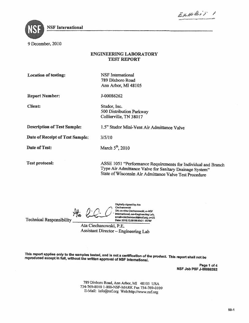
50-1
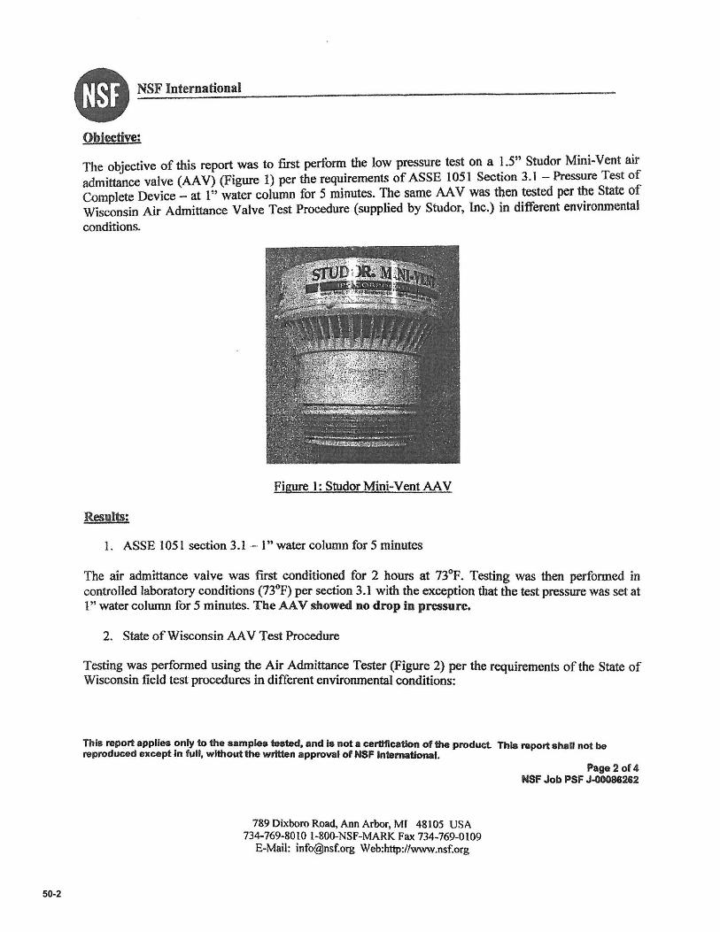
50-2
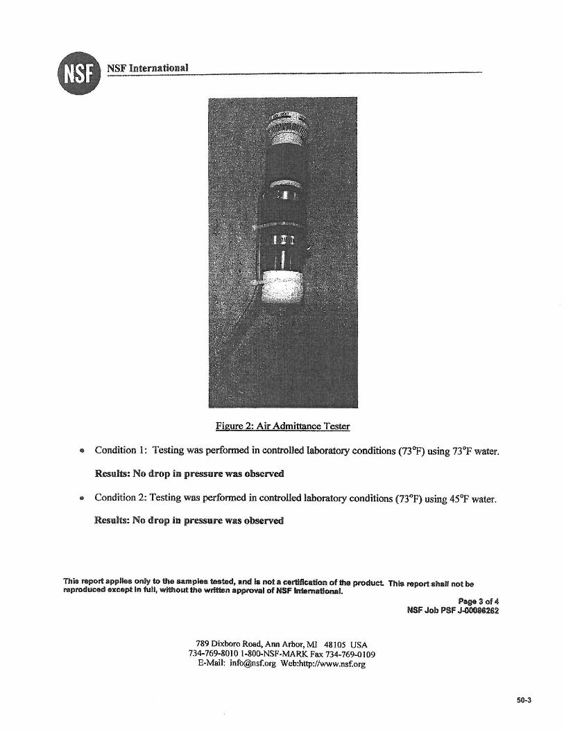
50-3

50-4
50-5
50-6
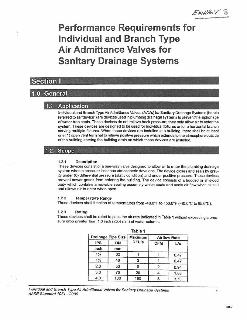
50-7
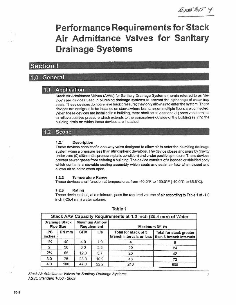
50-8
Item # 6 Comment Seq # 4
UPC 2012 – (204.0, 218.0, 225.0, 604.1, Table 6 – 4, 609.6 – 609.7.2, 610.8, 610.9, Table 6 – 6):
SUBMITTER: Rand Ackroyd
Chair, UPC Correlation Task Group
RECOMMENDATION:
The following is recommended by the Correlation Task Group (see Correlation Task Group Report Item 1).
Revise text as follows:
204.0
Building Supply – The pipe carrying potable water from the water meter or other source of water supply to a building or otherpoint of use or distribution on the lot. Building supply shall also mean water service.
218.0
Plumbing System. Includes all potable water, water service building supply, and distribution pipes; all plumbing fixtures andtraps; all drainage and vent pipes; and all building drains and building sewers, including their respective joints and connections,devices, receptors, and appurtenances within the property lines of the premises and shall include potable water piping, potablewater treating or using equipment, medical gas and medical vacuum systems, liquid and fuel gas piping, and water heaters andvents for same.
225.0
Water-Distributingon System Pipe. In a building or premises, beginning at the entrance of a structure, a pipe system thatconveys potable water from the water service building supply pipe to the point of usage. plumbing fixtures and other wateroutlets.
Water Service. A pipe from the water main or source of potential water supply to the water distribution pipe of the buildingor premises served irrespective of the water meter location.
Water Supply System. The water service building supply pipe, the water-distributing pipes, and the necessary connectingpipes, fittings, control valves, backflow prevention devices, and all appurtenances carrying or supplying potable water in oradjacent to the building or premises.
604.0 Materials.
604.1 Pipe, tube, and fittings carrying water used in potable water systems intended to supply drinking water shall meet therequirements of NSF 61 as found in Table 14-1. Materials used in the water supply system, except valves and similar devices,shall be of a like material, except where otherwise approved by the Authority Having Jurisdiction.
Materials for building water service piping and building supply water distribution piping shall be in accordance with theapplicable standards referenced in Table 6-4.
51
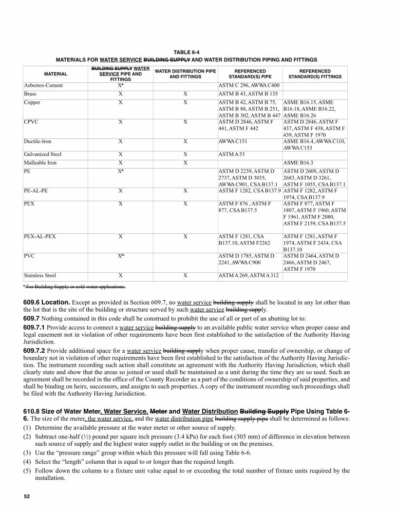
TABLE 6-4
MATERIALS FOR WATER SERVICE BUILDING SUPPLY AND WATER DISTRIBUTION PIPING AND FITTINGS
1 For Building Supply or cold-water applications.
609.6 Location. Except as provided in Section 609.7, no water service building supply shall be located in any lot other thanthe lot that is the site of the building or structure served by such water service building supply.
609.7 Nothing contained in this code shall be construed to prohibit the use of all or part of an abutting lot to:
609.7.1 Provide access to connect a water service building supply to an available public water service when proper cause andlegal easement not in violation of other requirements have been first established to the satisfaction of the Authority HavingJurisdiction.
609.7.2 Provide additional space for a water service building supply when proper cause, transfer of ownership, or change ofboundary not in violation of other requirements have been first established to the satisfaction of the Authority Having Jurisdic-tion. The instrument recording such action shall constitute an agreement with the Authority Having Jurisdiction, which shallclearly state and show that the areas so joined or used shall be maintained as a unit during the time they are so used. Such anagreement shall be recorded in the office of the County Recorder as a part of the conditions of ownership of said properties, andshall be binding on heirs, successors, and assigns to such properties. A copy of the instrument recording such proceedings shallbe filed with the Authority Having Jurisdiction.
610.8 Size of Water Meter, Water Service, Meter and Water Distribution Building Supply Pipe Using Table 6-6. The size of the meter, the water service, and the water distribution pipe building supply pipe shall be determined as follows:
(1) Determine the available pressure at the water meter or other source of supply.
(2) Subtract one-half (1⁄2) pound per square inch pressure (3.4 kPa) for each foot (305 mm) of difference in elevation betweensuch source of supply and the highest water supply outlet in the building or on the premises.
(3) Use the “pressure range” group within which this pressure will fall using Table 6-6.
(4) Select the “length” column that is equal to or longer than the required length.
(5) Follow down the column to a fixture unit value equal to or exceeding the total number of fixture units required by theinstallation.
MATERIALBUILDING SUPPLY WATER
SERVICE PIPE ANDFITTINGS
WATER DISTRIBUTION PIPEAND FITTINGS
REFERENCEDSTANDARD(S) PIPE
REFERENCEDSTANDARD(S) FITTINGS
Asbestos-Cement X1 ASTM C 296, AWWA C400
Brass X X ASTM B 43, ASTM B 135
Copper X X ASTM B 42, ASTM B 75,
ASTM B 88, ASTM B 251,
ASTM B 302, ASTM B 447
ASME B16.15, ASME
B16.18, ASME B16.22,
ASME B16.26 CPVC X X ASTM D 2846, ASTM F
441, ASTM F 442
ASTM D 2846, ASTM F
437, ASTM F 438, ASTM F
439, ASTM F 1970 Ductile-Iron X X AWWA C151 ASME B16.4, AWWA C110,
AWWA C153 Galvanized Steel X X ASTM A 53
Malleable Iron X X ASME B16.3
PE X1 ASTM D 2239, ASTM D
2737, ASTM D 3035,
AWWA C901, CSA B137.1
ASTM D 2609, ASTM D
2683, ASTM D 3261,
ASTM F 1055, CSA B137.1 PE-AL-PE X X ASTM F 1282, CSA B137.9 ASTM F 1282, ASTM F
1974, CSA B137.9 PEX X X ASTM F 876 , ASTM F
877, CSA B137.5
ASTM F 877, ASTM F
1807, ASTM F 1960, ASTM
F 1961, ASTM F 2080,
ASTM F 2159, CSA B137.5
PEX-AL-PEX X X ASTM F 1281, CSA
B137.10, ASTM F2262
ASTM F 1281, ASTM F
1974, ASTM F 2434, CSA
B137.10 PVC X1 ASTM D 1785, ASTM D
2241, AWWA C900
ASTM D 2464, ASTM D
2466, ASTM D 2467,
ASTM F 1970 Stainless Steel X X ASTM A 269, ASTM A 312
52
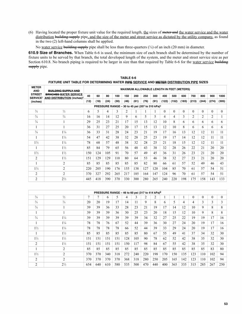
(6) Having located the proper fixture unit value for the required length, the sizes of meter and the water service and the waterdistribution building supply pipe, and the size of the meter and street service as dictated by the utility company, as foundin the two (2) left-hand columns shall be applied.
No water service building supply pipe shall be less than three-quarters (3⁄4) of an inch (20 mm) in diameter.
610.9 Size of Branches. When Table 6-6 is used, the minimum size of each branch shall be determined by the number offixture units to be served by that branch, the total developed length of the system, and the meter and street service size as perSection 610.8. No branch piping is required to be larger in size than that required by Table 6-6 for the water service buildingsupply pipe.
TABLE 6-6
FIxTURE UNIT TABLE FOR DETERMINING WATER PIPE SERVICE AND METER DISTRIBUTION PIPE SIZES
METER
AND
STREET
SERVICE1
(inches)
BUILDING SUPPLY AND
BRNCHES WATER SERVICE
AND DISTRIBUTION (inches)3
MAxIMUM ALLOWABLE LENGTH IN FEET (METERS)
40 60 80 100 150 200 250 300 400 500 600 700 800 900 1000
(12) (18) (24) (30) (46) (61) (76) (91) (122) (152) (183) (213) (244) (274) (305)
PRESSURE RANGE – 30 to 45 psi (207 to 310 kPa)2
3⁄4 1⁄2 6 5 4 3 2 1 1 1 0 0 0 0 0 0 03⁄4 3⁄4 16 16 14 12 9 6 5 5 4 4 3 2 2 2 13⁄4 1 29 25 23 21 17 15 13 12 10 8 6 6 6 6 6
1 1 36 31 27 25 20 17 15 13 12 10 8 6 6 6 63⁄4 11⁄4 36 33 31 28 24 23 21 19 17 16 13 12 12 11 11
1 11⁄4 54 47 42 38 32 28 25 23 19 17 14 12 12 11 11
11⁄2 11⁄4 78 68 57 48 38 32 28 25 21 18 15 12 12 11 11
1 11⁄2 85 84 79 65 56 48 43 38 32 28 26 22 21 20 20
11⁄2 11⁄2 150 124 105 91 70 57 49 45 36 31 26 23 21 20 20
2 11⁄2 151 129 129 110 80 64 53 46 38 32 27 23 21 20 20
1 2 85 85 85 85 85 85 82 80 66 61 57 52 49 46 43
11⁄2 2 220 205 190 176 155 138 127 120 104 85 70 61 57 54 51
2 2 370 327 292 265 217 185 164 147 124 96 70 61 57 54 51
2 21⁄2 445 418 390 370 330 300 280 265 240 220 198 175 158 143 133
PRESSURE RANGE – 46 to 60 psi (317 to 414 kPa)2
3⁄4 1⁄2 7 7 6 5 4 3 2 2 1 1 1 0 0 0 03⁄4 3⁄4 20 20 19 17 14 11 9 8 6 5 4 4 3 3 33⁄4 1 39 39 36 33 28 23 21 19 17 14 12 10 9 8 8
1 1 39 39 39 36 30 25 23 20 18 15 12 10 9 8 83⁄4 11⁄4 39 39 39 39 39 39 34 32 27 25 22 19 19 17 16
1 11⁄4 78 78 76 67 52 44 39 36 30 27 24 20 19 17 16
11⁄2 11⁄4 78 78 78 78 66 52 44 39 33 29 24 20 19 17 16
1 11⁄2 85 85 85 85 85 85 80 67 55 49 41 37 34 32 30
11⁄2 11⁄2 151 151 151 151 128 105 90 78 62 52 42 38 35 32 30
2 11⁄2 151 151 151 151 150 117 98 84 67 55 42 38 35 32 30
1 2 85 85 85 85 85 85 85 85 85 85 85 85 85 83 80
11⁄2 2 370 370 340 318 272 240 220 198 170 150 135 123 110 102 94
2 2 370 370 370 370 368 318 280 250 205 165 142 123 110 102 94
2 21⁄2 654 640 610 580 535 500 470 440 400 365 335 315 285 267 250
53
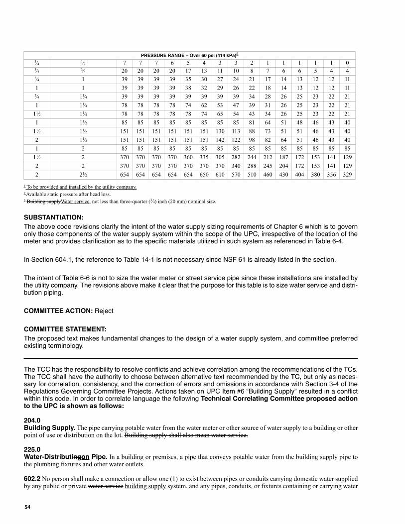
1 To be provided and installed by the utility company.2 Available static pressure after head loss.3 Building supplyWater service, not less than three-quarter (3⁄4) inch (20 mm) nominal size.
SUBSTANTIATION:
The above code revisions clarify the intent of the water supply sizing requirements of Chapter 6 which is to governonly those components of the water supply system within the scope of the UPC, irrespective of the location of themeter and provides clarification as to the specific materials utilized in such system as referenced in Table 6-4.
In Section 604.1, the reference to Table 14-1 is not necessary since NSF 61 is already listed in the section.
The intent of Table 6-6 is not to size the water meter or street service pipe since these installations are installed bythe utility company. The revisions above make it clear that the purpose for this table is to size water service and distri-bution piping.
COMMITTEE ACTION: Reject
COMMITTEE STATEMENT:
The proposed text makes fundamental changes to the design of a water supply system, and committee preferredexisting terminology.
The TCC has the responsibility to resolve conflicts and achieve correlation among the recommendations of the TCs.The TCC shall have the authority to choose between alternative text recommended by the TC, but only as neces-sary for correlation, consistency, and the correction of errors and omissions in accordance with Section 3-4 of theRegulations Governing Committee Projects. Actions taken on UPC Item #6 “Building Supply” resulted in a conflictwithin this code. In order to correlate language the following Technical Correlating Committee proposed actionto the UPC is shown as follows:
204.0Building Supply. The pipe carrying potable water from the water meter or other source of water supply to a building or otherpoint of use or distribution on the lot. Building supply shall also mean water service.
225.0Water-Distributingon Pipe. In a building or premises, a pipe that conveys potable water from the building supply pipe tothe plumbing fixtures and other water outlets.
602.2 No person shall make a connection or allow one (1) to exist between pipes or conduits carrying domestic water suppliedby any public or private water service building supply system, and any pipes, conduits, or fixtures containing or carrying water
PRESSURE RANGE – Over 60 psi (414 kPa)2
3⁄4 1⁄2 7 7 7 6 5 4 3 3 2 1 1 1 1 1 03⁄4 3⁄4 20 20 20 20 17 13 11 10 8 7 6 6 5 4 43⁄4 1 39 39 39 39 35 30 27 24 21 17 14 13 12 12 11
1 1 39 39 39 39 38 32 29 26 22 18 14 13 12 12 113⁄4 11⁄4 39 39 39 39 39 39 39 39 34 28 26 25 23 22 21
1 11⁄4 78 78 78 78 74 62 53 47 39 31 26 25 23 22 21
11⁄2 11⁄4 78 78 78 78 78 74 65 54 43 34 26 25 23 22 21
1 11⁄2 85 85 85 85 85 85 85 85 81 64 51 48 46 43 40
11⁄2 11⁄2 151 151 151 151 151 151 130 113 88 73 51 51 46 43 40
2 11⁄2 151 151 151 151 151 151 142 122 98 82 64 51 46 43 40
1 2 85 85 85 85 85 85 85 85 85 85 85 85 85 85 85
11⁄2 2 370 370 370 370 360 335 305 282 244 212 187 172 153 141 129
2 2 370 370 370 370 370 370 370 340 288 245 204 172 153 141 129
2 21⁄2 654 654 654 654 654 650 610 570 510 460 430 404 380 356 329
54
from any other source or containing or carrying water that has been used for any purpose whatsoever, or any piping carryingchemicals, liquids, gases, or any substances whatsoever, unless there is provided a backflow prevention device approved for thepotential hazard and maintained in accordance with this code. Each point of use shall be separately protected when potentialcross-contamination of individual units exists.
604.8 Epoxy coating used on existing water service building supply or water distribution piping systems shall be in accordancewith NSF 61 and AWWA C210.
604.89 Approved plastic materials shall be permitted to be used in water service building supply piping, provided that wheremetal water service building supply piping is used for electrical grounding purposes, replacement piping therefore shall be oflike materials.
Exception: Where a grounding system acceptable to the Authority Having Jurisdiction is installed, inspected, and approved,metallic pipe shall be permitted to be replaced with nonmetallic pipe. Plastic materials for water service building supply pipingoutside underground shall have a blue insulated copper tracer wire or other approved conductor installed adjacent to the piping.Access shall be provided to the tracer wire or the tracer wire shall terminate above ground at each end of the nonmetallic piping.The tracer wire size shall be not less than 18 AWG and the insulation type shall be suitable for direct burial.
(renumber the remaining sections)
609.1 Installation. Water piping shall be adequately supported in accordance with Section 314.0. Burred ends shall be reamedto the full bore of the pipe or tube. Changes in direction shall be made by the appropriate use of fittings, except that changes indirection in copper tubing may be made with bends, provided that such bends are made with bending equipment that does notdeform or create a loss in the cross-sectional area of the tubing. Changes in direction are allowed with flexible pipe and tubingwithout fittings in accordance with the manufacturer's installation instructions. Provisions shall be made for expansion in hot-water piping. Piping, equipment, appurtenances, and devices shall be installed in a workmanlike manner in conformity with theprovisions and intent of the code. Water service Building supply yard piping shall be not less than twelve (12) inches (305 mm)below the average local frost depth. The cover shall be not less than twelve (12) inches (305 mm) below finish grade.
609.8 Low-Pressure Cutoff Required on Booster Pumps for Water Distribution Systems. When a booster pump(excluding a fire pump) is connected to a water service building supply or underground water pipe, a low-pressure cutoff switchon the inlet side of the pump shall be installed not more than five (5) feet (1,524 mm) of the inlet. The cutoff switch shall be setfor not less than ten (10) psi (69 kPa). A pressure gauge shall be installed between the shutoff valve and the pump.
TABLE 6-5
WATER SUPPLY FIxTURE UNITS (WSFU) AND MINIMUM FIxTURE BRANCH PIPE SIZES3
(portions of table not shown remain unchanged)
3 The listed fixture unit values represent their load on their cold water service building supply. The separate cold water and hot water fixture unit value for
fixtures having both hot and cold water connections may each be taken as three-quarter of the listed total value of the fixture.
TABLE A-2
WATER SUPPLY FIxTURE UNITS (WSFU) AND MINIMUM FIxTURE BRANCH PIPE SIZES3
(portions of table not shown remain unchanged)
3 The listed fixture unit values represent their total load on the cold water service building supply. The separate cold water and hot water fixture unit value
for fixtures having both cold and hot water connections may each be taken as three-quarter of the listed total value of the fixture.
L 4.2 The listed water supply fixture unit values in Table L-1 reflect the load of entire bathroom groups on the cold-waterservice building supply. Individual hot and cold water branch piping to the fixtures should be sized according to Chapter 6 andAppendix A.
55
TCC COMMITTEE ACTION: Accept as Submitted
TCC COMMITTEE STATEMENT: The Plumbing TC rejected Item #6 that would have changed “building supply” to“water service” in various sections, but not all, throughout the UPC. The above revisions provide correlationthroughout the entire UPC by changing all references to “water service” to “building supply”.
A PUBLIC COMMENT(S) WAS SUBMITTED FOR REVIEW AND CONSIDERATION.
PUBLIC COMMENT:
SUBMITTER: Julius Ballanco, American Society of Plumbing Engineers
RECOMMENDATION:
Request to accept the code change proposal as submitted by this public comment.
SUBSTANTIATION:
Item # 6 should be approved as submitted based on the following reasons:
1. The same terminology (building supply) that was used in the 1958 UPC is still being used today. The term “waterservice” is the correct terminology, and is indicated as such in several of the referenced standards in Table 6-4(i.e. ASTM B 88, ASTM F 877, ASTM F 1974, AWWA C151, AWWA C901, etc.). It should be noted that the term“building supply” is not indicated in a single standard outlined in Table 6-4.
2. The term “water service” is indicated by the other two major plumbing codes (International Plumbing Code andNational Standard Plumbing Code) as the pipe ran from the water main, or other water supply source, to thebuilding.
3. The footnote for Table 6-4 needs to be deleted since it has caused confusion amongst Authorities Having Juris-diction, plumbing contractors, and engineers. As the footnote is written, it has been interpreted that asbestos-cement, PE, and PVC can be used for cold water applications within a building. However, that is not the intentsince such piping is not designed for the pressures and temperatures that are required of piping used for waterdistribution within a building. The original intent of the footnote was to recognize that asbestos-cement, PE, andPVC are approved for cold water applications outside of a building where the risk of hot water crossover is notpossible. Therefore, since Table 6-4 deals with water distribution within a building the footnote needs to bedeleted to avoid further confusion.
COMMITTEE ACTION: Reject the public comment
COMMITTEE STATEMENT:
The existing language is preferred over the proposed language, and the current text has not caused misapplicationsor confusion in the industry.
TOTAL ELIGIBLE TO VOTE: 28
VOTING RESULTS: AFFIRMATIVE: 21 NEGATIVE: 6 ABSTENTION: 1
ExPLANATION OF NEGATIVE:
BALLANCO: The UPC uses the incorrect terminology. The proper term is "water service." Every other plumbingdocument refers to water service. If you read the definition of "building supply," it can also mean “water service”. Thereneeds to be a correct use of terminology in the UPC.
BROWN: This change is creating inconsistent terminology with most national standards and other model plumbingcodes.
CABOT: Water service is the commonly used term.
56
PAPE: The code needs to change its terminology to conform with the industry. "Building Supply" is an obtuse termthat needs to be updated.
TABAKH, TRAFTON: Water service is the common term used in industry. The proposal to change the title “buildingsupply pipe” to “water service” was good. This is the terminology used by the City of Los Angeles.
ExPLANATION OF ABSTENTION:
BEACH: The terminology should be consistent with other building and plumbing codes. However, I don't work withother plumbing codes, therefore I can't personally verify which term is consistent.
57
Item # 10 Comment Seq # 5
UPC 2012 – (208.0):
SUBMITTER: Rand Ackroyd
Chair, UPC Correlation Task Group
RECOMMENDATION:
The following is recommended by the Correlation Task Group (see Correlation Task Group Report Item 4).
Add new text as follows:
208.0
Faucets. A valve end of a water pipe by means of which water can be drawn from or held within the pipe.
Metering Faucet. A faucet that after actuation dispenses water of a predetermined volume or for a predetermined periodof time for each cycle.
Self-Closing Faucet. A faucet that is designed to close itself as soon as the activating mechanism is released.
SUBSTANTIATION:
These terms are referenced in Chapter 4, and should be defined in order to apply their meaning used in the bodyof the code.
COMMITTEE ACTION: Reject
COMMITTEE STATEMENT:
The proposed definitions are inaccurate and do not address the issues within the code. No technical substantiationhas been provided to justify that the definitions are necessary.
A PUBLIC COMMENT(S) WAS SUBMITTED FOR REVIEW AND CONSIDERATION.
PUBLIC COMMENT:
SUBMITTER: Charles Hernandez, Plumbing Manufacturers Institute
RECOMMENDATION:
Request to replace the code change proposal by this public comment.
Faucet. A device that controls and guides the flow of water into a sink fixture.
Metering Faucet. A self-closing faucet that dispenses, for each cycle, a fixed volume of water for a fixed period of time.
Self-Closing Faucet. A faucet that closes itself after the actuation or control mechanism is deactivated.
SUBSTANTIATION:
Definition of a faucet should be harmonized with the existing standards.
COMMITTEE ACTION: Reject the public comment
COMMITTEE STATEMENT:
The substantiation lacks technical justification in that the proposed definitions are not warranted in order to clarify the
code. The proposed definitions are subjective and confusing in that the definition for faucet only references sinks without
applications for lavatories, bathtubs, etc.
58
TOTAL ELIGIBLE TO VOTE: 28
VOTING RESULTS: AFFIRMATIVE: 25 NEGATIVE: 3
ExPLANATION OF NEGATIVE:
BROWN: The UPC should utilize the definition consistent with the national standard for plumbing fixture fittings.
CHURCH: PMI's proposed definition is correct.
PAPE: The code needs to change and define its terminology to adapt, adopt, and conform to the evolving industry.
59
Item # 13 Comment Seq # 6
UPC 2012 – (TIA UPC – 001-09, Sections 211.0 and 405.2):
SUBMITTER: Lawrence BrownNational Associations of Home Builders
RECOMMENDATION:
Revise text as follows:
211.0
Insanitary. A condition that is contrary to sanitary principles or is injurious to health.
Conditions to which “insanitary” shall apply include the following:
(1) Any trap that does not maintain a proper trap seal.
(2) Any opening in a drainage system, except where lawful, that is not provided with an approved liquid water sealed trap.
(3) Any plumbing fixture or other waste discharging receptor or device that is not supplied with water sufficient to flush and main-tain the fixture or receptor in a clean condition.
(3) (4) Any defective fixture, trap, pipe, or fitting.
(4) (5)Any trap, except where in this code exempted, directly connected to a drainage system, the seal of which is not protectedagainst siphonage and backpressure by a vent pipe.
(5) (6)Any connection, cross-connection, construction, or condition, temporary or permanent, that would permit or make possibleby any means whatsoever for any unapproved foreign matter to enter a water distribution system used for domestic purposes.
(6) (7) The foregoing enumeration of conditions to which the term “insanitary” shall apply, shall not preclude the application ofthat term to conditions that are, in fact, insanitary.
405.2 Prohibited Urinals. Trough urinals and urinals with an invisible seal shall be prohibited.
Exception: Non-water urinals.
SUBSTANTIATION:
Technical Merit:
This TIA is to address the conflict in the code in Sections 211.0, 1005.0 and 405.2 due to the inclusion of non-waterurinals and revising the definition of “water” seal trap to “liquid” seal trap in Section 1005.0 of the 2009 UPC. Section402.3.1 for non-water urinals was added in the 2009 UPC that allows the use and installation of non-water urinals.Non-water urinals use a barrier liquid sealant to maintain a trap seal. Non-water urinals do not have a visible sealas described in Section 405.2 therefore was revised to include an exception. Section 211.0 (3) was deleted due tothe added language and not all plumbing fixtures use water such as non-water urinals, floor drains and floor sinks.This TIA eliminates conflicting code language in the 2009 UPC.
Emergency Nature:
Per IAPMO’s Regulations Governing Committee Projects, Section 5-2, determination of an emergency nature include“the document contains a conflict within the document.” As pointed out above, there is a conflict between Sections211.0, 405.2, 1005.0 due to the inclusion of non-water urinals and revising the term “water” versus “liquid” seal traps.
COMMITTEE ACTION: Accept as Submitted
A PUBLIC COMMENT(S) WAS SUBMITTED FOR REVIEW AND CONSIDERATION.
PUBLIC COMMENT (Assembly Action):
SUBMITTER: Arnold Rodio, Pace Setter Plumbing
RECOMMENDATION:
Request to reject the code change proposal by this public comment.
SUBSTANTIATION:
Plumbing fixtures that are not flushed with water can result in an insanitary condition.
COMMITTEE ACTION: Accept the public comment as submitted
60
TOTAL ELIGIBLE TO VOTE: 28
VOTING RESULTS: AFFIRMATIVE: 25 NEGATIVE: 3
ExPLANATION OF NEGATIVE:
BROWN: There needs to be an exemption for waterless urinals to resolve a conflict in the code.
BUUCK: The same change was fully accepted by the committee when it deliberated on the TIA. It should not bereverting its decision and thus reinstating the conflict.
PAPE: The definition should reflect the code. Chapter 2 is not the place to promote biases without evidence and re-debate an issue resolve many years ago.
61
Item # 17 Comment Seq # 7UPC 2012 – (222.0):
SUBMITTER: Rand Ackroyd
Chair, UPC Correlation Task Group
RECOMMENDATION:
The following is recommended by the Correlation Task Group (see Correlation Task Group Report Item 9).
Add new text as follows:
222.0
Thermal Shock. A rapid change in the water temperature that is felt by the user and is sufficient to produce a potentiallyhazardous reaction.
SUBSTANTIATION:
This term is referenced in Chapter 4, and should be defined in order to apply its meaning used in the body of thecode.
COMMITTEE ACTION: Reject
COMMITTEE STATEMENT:
The proposed definition is not needed within the UPC because it does not provide any benefits to the end user.
A PUBLIC COMMENT(S) WAS SUBMITTED FOR REVIEW AND CONSIDERATION.
PUBLIC COMMENT:
SUBMITTER: Charles Hernandez, Plumbing Manufacturers Institute
RECOMMENDATION:
Request to accept the code change proposal as modified by this public comment.
222.0
Thermal Shock. A rapid change in the outlet water temperature that is felt by the user and is sufficient to produce a poten-tially hazardous reaction.
SUBSTANTIATION:
The proposed definition for “thermal shock” is needed within the UPC since the term is used in Section 418.0, andis only defined currently within industry standards. This definition as written would harmonize with the definition usedin both ASSE 1016 and ASME A112.18.1/CSA B125.1 in regards to valves that provide scald and thermal shockprotection.
COMMITTEE ACTION: Reject the public comment
COMMITTEE STATEMENT:
The proposed text does not provide additional benefits or clarification for the installation or inspection of tempera-ture control valves or devices.
TOTAL ELIGIBLE TO VOTE: 28
VOTING RESULTS: AFFIRMATIVE: 27 NEGATIVE: 1
ExPLANATION OF NEGATIVE:
CHURCH: PMI's change provides better clarity for the definition.
62
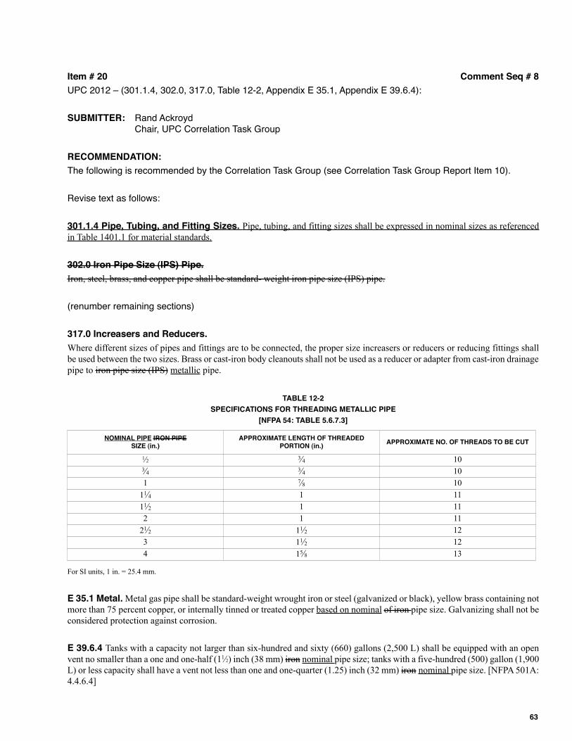
Item # 20 Comment Seq # 8
UPC 2012 – (301.1.4, 302.0, 317.0, Table 12-2, Appendix E 35.1, Appendix E 39.6.4):
SUBMITTER: Rand AckroydChair, UPC Correlation Task Group
RECOMMENDATION:
The following is recommended by the Correlation Task Group (see Correlation Task Group Report Item 10).
Revise text as follows:
301.1.4 Pipe, Tubing, and Fitting Sizes. Pipe, tubing, and fitting sizes shall be expressed in nominal sizes as referenced
in Table 1401.1 for material standards.
302.0 Iron Pipe Size (IPS) Pipe.
Iron, steel, brass, and copper pipe shall be standard- weight iron pipe size (IPS) pipe.
(renumber remaining sections)
317.0 Increasers and Reducers.
Where different sizes of pipes and fittings are to be connected, the proper size increasers or reducers or reducing fittings shall
be used between the two sizes. Brass or cast-iron body cleanouts shall not be used as a reducer or adapter from cast-iron drainage
pipe to iron pipe size (IPS) metallic pipe.
TABLE 12-2
SPECIFICATIONS FOR THREADING METALLIC PIPE
[NFPA 54: TABLE 5.6.7.3]
For SI units, 1 in. = 25.4 mm.
E 35.1 Metal. Metal gas pipe shall be standard-weight wrought iron or steel (galvanized or black), yellow brass containing not
more than 75 percent copper, or internally tinned or treated copper based on nominal of iron pipe size. Galvanizing shall not be
considered protection against corrosion.
E 39.6.4 Tanks with a capacity not larger than six-hundred and sixty (660) gallons (2,500 L) shall be equipped with an open
vent no smaller than a one and one-half (11⁄2) inch (38 mm) iron nominal pipe size; tanks with a five-hundred (500) gallon (1,900
L) or less capacity shall have a vent not less than one and one-quarter (1.25) inch (32 mm) iron nominal pipe size. [NFPA 501A:
4.4.6.4]
NOMINAL PIPE IRON PIPESIZE (in.)
APPROxIMATE LENGTH OF THREADEDPORTION (in.)
APPROxIMATE NO. OF THREADS TO BE CUT
1⁄2 3⁄4 10 3⁄4 3⁄4 10
1 7⁄8 10
11⁄4 1 11
11⁄2 1 11
2 1 11
21⁄2 11⁄2 12
3 11⁄2 12
4 15⁄8 13
63
SUBSTANTIATION:
Iron pipe size has been replaced with nominal pipe size (NPS) based on ASME B36.10 and ASME B36.19. Pipesizing is based on two non-dimensional numbers: a nominal pipe size based on inches and a schedule. In order tonot cause confusion and misapplication this term should be deleted.
COMMITTEE ACTION: Accept as Submitted
A PUBLIC COMMENT(S) WAS SUBMITTED FOR REVIEW AND CONSIDERATION.
PUBLIC COMMENT 1 (Assembly Action):
SUBMITTER: Arnold Rodio, Pace Setter Plumbing
RECOMMENDATION:
Request to reject the code change proposal by this public comment.
SUBSTANTIATION:
Iron pipe size is still recognized within the industry, and therefore should not be deleted from the UPC.
COMMITTEE ACTION: Accept the public comment as submitted
TOTAL ELIGIBLE TO VOTE: 28
VOTING RESULTS: AFFIRMATIVE: 26 NEGATIVE: 1 ABSTENTION: 1
ExPLANATION OF NEGATIVE:
BALLANCO: Iron pipe size is an archaic term that is no longer used in codes and standards. The values in this tablecome from ASME. ASME has changed all of its standards to "nominal pipe size." ASTM has done the same. If youlook at ASTM A 53, the table states nominal pipe size. ASTM A 53 regulates steel pipe which is made from iron. Itis time for the UPC to be updated to the correct term.
ExPLANATION OF ABSTENTION:
BLOICE: I do not think that standards should be in the body of the code. Most plumbers that use the code don't evenknow what these standards represent.
PUBLIC COMMENT 2:
SUBMITTER: Rand Ackroyd, Rand Technical Consulting
RECOMMENDATION:
Request to accept the code change proposal as modified by this public comment.
301.1.4 Pipe, Tubing, and Fitting Sizes. Pipe, tubing, and fitting sizes shall be expressed in nominal or standard sizes asreferenced in Table 1401.1 for material standards.
317.0 Increasers and Reducers.
Where different sizes of pipes and fittings are to be connected, the proper size increasers or reducers or reducing fittings shallbe used between the two sizes. Brass or cast-iron body cleanouts shall not be used as a reducer or adapter from cast-iron drainagepipe to metallic pipe.
64
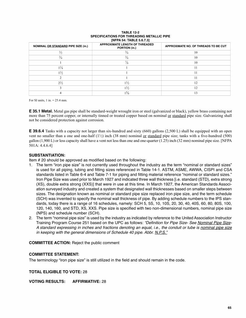
TABLE 12-2 SPECIFICATIONS FOR THREADING METALLIC PIPE
[NFPA 54: TABLE 5.6.7.3]
For SI units, 1 in. = 25.4 mm.
E 35.1 Metal. Metal gas pipe shall be standard-weight wrought iron or steel (galvanized or black), yellow brass containing notmore than 75 percent copper, or internally tinned or treated copper based on nominal or standard pipe size. Galvanizing shallnot be considered protection against corrosion.
E 39.6.4 Tanks with a capacity not larger than six-hundred and sixty (660) gallons (2,500 L) shall be equipped with an open
vent no smaller than a one and one-half (11⁄2) inch (38 mm) nominal or standard pipe size; tanks with a five-hundred (500)
gallon (1,900 L) or less capacity shall have a vent not less than one and one-quarter (1.25) inch (32 mm) nominal pipe size. [NFPA
501A: 4.4.6.4]
SUBSTANTIATION:Item # 20 should be approved as modified based on the following:1. The term “iron pipe size” is not currently used throughout the industry as the term “nominal or standard sizes”
is used for all piping, tubing and fitting sizes referenced in Table 14-1. ASTM, ASME, AWWA, CISPI and CSAstandards listed in Table 6-4 and Table 7-1 for piping and fitting material reference “nominal or standard sizes.”Iron Pipe Size was used prior to March 1927 and indicated three wall thickness [i.e. standard (STD), extra strong(XS), double extra strong (XXS)] that were in use at this time. In March 1927, the American Standards Associ-ation surveyed industry and created a system that designated wall thicknesses based on smaller steps betweensizes. The designation known as nominal or standard pipe size replaced iron pipe size, and the term schedule(SCH) was invented to specify the nominal wall thickness of pipe. By adding schedule numbers to the IPS stan-dards, today there is a range of 16 schedules, namely: SCH 5, 5S, 10, 10S, 20, 30, 40, 40S, 60, 80, 80S, 100,120, 140, 160, and STD, XS, XXS. Pipe size is specified with two non-dimensional numbers, nominal pipe size(NPS) and schedule number (SCH).
2. The term “nominal pipe size” is used by the industry as indicated by reference to the United Association InstructorTraining Program Course 251 based on the UPC as follows: “Definition for Pipe Size- See Nominal Pipe Size-
A standard expressing in inches and fractions denoting an equal, i.e., the conduit or tube is nominal pipe size
in keeping with the general dimensions of Schedule 40 pipe. Abbr. N.P.S.”
COMMITTEE ACTION: Reject the public comment
COMMITTEE STATEMENT:
The terminology “iron pipe size” is still utilized in the field and should remain in the code.
TOTAL ELIGIBLE TO VOTE: 28
VOTING RESULTS: AFFIRMATIVE: 28
NOMINAL OR STANDARD PIPE SIZE (in.)APPROxIMATE LENGTH OF THREADED
PORTION (in.)APPROxIMATE NO. OF THREADS TO BE CUT
1⁄2 3⁄4 10
3⁄4 3⁄4 10
1 7⁄8 10
11⁄4 1 11
11⁄2 1 11
2 1 11
21⁄2 11⁄2 12
3 11⁄2 12
4 15⁄8 13
65
Item # 20.01 Comment Seq # 9
UPC 2012 – (301.1.1):
SUBMITTER: UPC Technical Committee Proposal
RECOMMENDATION:
Revise text as follows:
301.1 Minimum Standards.
301.1.1 Approvals. All pipe, pipe fittings, traps, fixtures, material, and devices used in a plumbing system shall be listed orlabeled (third-party certified) by a listing agency (accredited conformity assessment body) and shall conform to approved appli-cable recognized standards referenced in this code, and shall be free from defects. Plastic pipe and the fittings used for plasticpipe, other than those for gas, shall meet the requirements of NSF 14. Unless otherwise provided for in this code, all materials,fixtures, or devices used or entering into the construction of plumbing systems, or parts thereof, shall be submitted to theAuthority Having Jurisdiction for approval.
COMMITTEE ACTION: Accept as Submitted
A PUBLIC COMMENT(S) WAS SUBMITTED FOR REVIEW AND CONSIDERATION.
PUBLIC COMMENT:
SUBMITTER: Tim Ross, Self
RECOMMENDATION:
Request to accept the code change proposal as modified by this public comment.
301.1 Minimum Standards.
301.1.1 Approvals. All pipe, pipe fittings, traps, fixtures, material, and devices used in a plumbing system shall be listed orlabeled (third-party certified) by a listing agency (accredited conformity assessment body) and shall conform to approved appli-cable recognized standards referenced in this code, and shall be free from defects. Plastic pipe and the fittings used for plasticpipe, other than those for gas, shall meet the requirements of NSF 14. Unless otherwise provided for in this code, all materials,fixtures, or devices used or entering into the construction of plumbing systems, or parts thereof, shall be submitted to theAuthority Having Jurisdiction for approval.
SUBSTANTIATION:
Item # 20.01 should be modified because the text “plastic pipe” is stated twice in the same sentence, and thereforeis redundant.
COMMITTEE ACTION: Reject the public comment
COMMITTEE STATEMENT:
Current text is necessary for addressing any confusion where plastic pipe and fittings shall be listed and/or labeledin accordance with applicable standards.
TOTAL ELIGIBLE TO VOTE: 28
VOTING RESULTS: AFFIRMATIVE: 18 ABSTENTION: 10
ExPLANATION OF ABSTENTION:
ADLER, AGUILAR, BERGER, MANN: I believe this to be proprietary. The first sentence reads "...and shall conformto approved applicable recognized standards referenced in this code...." To add the reference for NSF 14 is unnec-essary and proprietary.
66
FEEHAN: I disagree with the entire proposal. Listing the NSF 14 Standard is redundant and the standard doescover gas piping systems.
FISCHER: I believe the inclusion of reference standards anywhere within the Code or the appendix without includingan appropriate extract is a practice that should be avoided. This committee for the most part is not aware of changeswithin standards until after the publication of the UPC that could affect the interpretation of any UPC section, andthus the TC would be unable to correct the code if needed.
HAMILTON: Standards should not be included in the body of the code.
LEVAN: Adding the reference to NSF 14 in the general requirements is confusing. The reference should occur inChapters 6, 7, and 11 where the plastic pipe products are referenced. I also do not feel any standards related toquality control or materials standards should be added into the individual chapters but should remain in Chapter 14unless all products are given the same consideration and are added to the appropriate chapters.
RODIO: I am abstaining as I disagree with the current code change. The insertion of NSF into the code is confusingand adds nothing that benefits the end user.
TABAKH: The clarity of Chapter 14 should be revised so that there is no question that NSF 14 applies to, and onlyto, piping that serves water supply applications. It makes no sense to make a specific reference to NSF 14 for clarityregarding plastic pipe in a section referring to the listing and labeling of all piping materials in the plumbing system.
I am opposed to the original revision under Item #20.01 that was accepted by the committee. The revision specifi-cally refers to listing and labeling of plastic pipe in an area that applies to all types of piping materials for all plumbinguses. This issue needs to be addressed within Chapter 14, not by adding a specific requirement for one type ofmaterial under a code section that applies to all plumbing materials. Further, the Uponor PEX pipe samples that wehappen to have in our office indicate NSF-pw but not specifically NSF 14. Should this section be added, these pipeswould be turned down by plumbing inspectors.
67
Item # 25 Comment Seq # 10
UPC 2012 – (306.0, 306.1):
SUBMITTER: Rand Ackroyd
Chair, UPC Correlation Task Group
RECOMMENDATION:
The following is recommended by the Correlation Task Group (see Correlation Task Group Report Item 14).
Delete text without substitution:
306.0 Damage to Drainage System or Public Sewer.
306.1 It shall be unlawful for any person to deposit, by any means whatsoever, into any plumbing fixture, floor drain, interceptor,sump, receptor, or device, which is connected to any drainage system, public sewer, private sewer, septic tank, or cesspool, anyashes; cinders; solids; rags; inflammable, poisonous, or explosive liquids or gases; oils; grease; or any other thing whatsoeverthat would, or could, cause damage to the drainage system or public sewer.
(renumber remaining sections)
SUBSTANTIATION:
Section 306.1 is already addressed in Section 714.1. The purpose for Chapter 3 is to provide general regulations as theypertain to the code, and not specific code language that deals with materials, appliances, methods, or installations thatare better addressed by other sections of the code. Several sections in Chapter 3 are already present, or sufficientlyaddressed, in other sections of the UPC. For informational purposes, Section 714.1 is shown as follows: It shall beunlawful for any person to deposit, by any means whatsoever, into any plumbing fixture, floor drain, interceptor, sump,receptor, or device which is connected to any drainage system, public sewer, private sewer, septic tank, or cesspool, anyashes; cinders; solids; rags; flammable, poisonous, or explosive liquids or gases; oils; grease; and any other thing what-soever that would or could cause damage to the public sewer, private sewer, or private sewage disposal system.
COMMITTEE ACTION: Reject
COMMITTEE STATEMENT:
The proposed deletion of Section 306.1 is a general requirement and belongs in Chapter 3.
A PUBLIC COMMENT(S) WAS SUBMITTED FOR REVIEW AND CONSIDERATION.
PUBLIC COMMENT 1:
SUBMITTER: April Trafton, Donald Dickerson Associates
RECOMMENDATION:
Request to accept the code change proposal as modified by this public comment.
306.0 Damage to Drainage System or Public Sewer.
306.1 It shall be unlawful for any person to deposit, by any means whatsoever, into any plumbing fixture, floor drain, interceptor,sump, receptor, or device, which is connected to any drainage system, public sewer, private sewer, septic tank, or cesspool, anyashes; cinders; solids; rags; inflammable, poisonous, or explosive liquids or gases; oils; grease; or any other thing whatsoeverthat would, or could, cause damage to the drainage system or public sewer, private sewer, or private sewage disposal system.
714.1 It shall be unlawful for any person to deposit, by any means whatsoever, into any plumbing fixture, floor drain, interceptor,sump, receptor, or device which is connected to any drainage system, public sewer, private sewer, septic tank, or cesspool, anyashes; cinders; solids; rags; flammable, poisonous, or explosive liquids or gases; oils; grease; and any other thing whatsoeverthat would or could cause damage to the public sewer, private sewer, or private sewage disposal system.
68
SUBSTANTIATION:
The TC rejected Item #25 because the committee felt that Section 306.1 belongs in Chapter 3 as a general require-ment. If that is the case, Section 714.1 should be deleted as it is a duplication of the same provisions in Section 306.1.
COMMITTEE ACTION: Reject the public comment (Failed Ballot)
TOTAL ELIGIBLE TO VOTE: 28
VOTING RESULTS: AFFIRMATIVE: 16 NEGATIVE: 12
NOTE: Item 25 (Public Comment 1) failed to achieve the necessary 2⁄3 affirmative vote of returned ballots. In accor-dance with Section 4-4.6.4 of the Regulations Governing Committee Projects, the TC action shall be reported in theROC as rejected.
ExPLANATION OF NEGATIVE:
ADLER, BERGER, MANN: This section should remain as is. This code change would eliminate the protection of thedrainage system.
AGUILAR: This section should remain as is. The original TC rejection correctly assessed the proposed code change.If passed, as modified by this comment, the Code would not protect the drainage system.
BALLANCO: Chapter 3 is for general regulations. This is a specific regulation regarding sanitary drainage. There-fore, it belongs in Chapter 7, and not Chapter 3.
BLOICE: This should remain as is due to the fact that the code already addresses the protection of the sewersystem.
CABOT: Coverage belongs in Chapter 7.
FEEHAN: This comment removes the protection of the DWV systems. Damaging products may be introduced intoDWV systems within buildings as well. This language may seem redundant, however it is necessary language forclarification.
FISCHER: I believe the inclusion of reference standards anywhere within the Code or the appendix without includingan appropriate extract is a practice that should be avoided. This committee for the most part is not aware of changeswithin standards until after the publication of the UPC that could affect the interpretation of any UPC section, andthus the TC would be unable to correct the code if needed.
HAMILTON: The section should remain as is. The information fits within the section title.
LEVAN: By removing "drainage system", the proposed modification would allow damaging materials to be in contactwith the drainage system.
RODIO: This section is titled “Damage to Drainage System or Public Sewer”. This code change then deletes thephrase “drainage system” from the body of the text. This section of the code should remain as is.
PUBLIC COMMENT 2:
SUBMITTER: Julius Ballanco, JB Engineering and Code Consulting, P.C.
69
RECOMMENDATION:
Request to accept the code change proposal as submitted by this public comment.
SUBSTANTIATION:
I believe that the Correlation Task Group had a valid comment regarding the deletion of this section. There is no needto repeat requirements throughout the code. The appropriate location for this text is in Chapter 7.
COMMITTEE ACTION: Reject the public comment
COMMITTEE STATEMENT:
This public comment is being rejected in favor of Public Comment 1, which removes redundant language and keepsthe provisions within their proper location in the UPC.
TOTAL ELIGIBLE TO VOTE: 28
VOTING RESULTS: AFFIRMATIVE: 25 NEGATIVE: 3
ExPLANATION OF NEGATIVE:
BALLANCO: Chapter 3 is for general regulations. This is a specific regulation regarding sanitary drainage. There-fore, it belongs in Chapter 7, and not Chapter 3.
CABOT: Coverage belongs in Chapter 7.
SOSKIN: This section should remain as is. This code change eliminates the protection of the drainage system.
70
Item # 27 Comment Seq # 11
UPC 2012 – (307.0 – 307.2, 811.0, 811.1):
SUBMITTER: Rand Ackroyd
Chair, UPC Correlation Task Group
RECOMMENDATION:
The following is recommended by the Correlation Task Group (see Correlation Task Group Report Item 16).
Revise text as follows:
307.0 Industrial Wastes.
307.1 Wastes detrimental to the public sewer system or detrimental to the functioning of the sewage treatment plant shall betreated and disposed of as found necessary and directed by the Authority Having Jurisdiction.
307.2 Sewage or other waste from a plumbing system that may be deleterious to surface or subsurface waters shall not bedischarged into the ground or into any waterway unless it has first been rendered safe by some acceptable form of treatment asrequired by the Authority Having Jurisdiction.
(renumber remaining sections)
811.0 Chemical and Industrial Wastes.
811.1 Chemical or industrial liquid wastes that are likely to damage or increase maintenance costs on the sanitary sewer system,detrimentally affect sewage treatment, or contaminate surface or subsurface waters shall be pretreated to render them innocuousprior to discharge into a drainage system. Detailed plans and specifications of the pretreatment facilities shall be required by theAuthority Having Jurisdiction.
Sewage or other waste from a plumbing system that are deleterious to surface or subsurface waters shall not be dischargedinto the ground or into any waterway unless it has first been rendered safe as required by the Authority Having Jurisdiction.
Piping conveying industrial, chemical, or process wastes from their point of origin to sewer-connected pretreatment facil-ities shall be of such material and design as to adequately perform its intended function to the satisfaction of the AuthorityHaving Jurisdiction. Drainage discharge piping from pretreatment facilities or interceptors shall conform to standard drainageinstallation procedures.
Copper tube shall not be used for chemical or industrial wastes as defined in this section.
SUBSTANTIATION:
The above code revision incorporates Section 307.0 into Section 811.0. The purpose for Chapter 3 is to providegeneral regulations as they pertain to the code, and not specific code language that deals with materials, appli-ances, methods, or installations that are better addressed by other sections of the code. Several sections in Chapter3 are already present, or sufficiently addressed, in other sections of the UPC.
COMMITTEE ACTION: Reject
COMMITTEE STATEMENT:
The proposed language added to Section 811.1 does not deal with the intent of the section which is chemical andindustrial wastes.
A PUBLIC COMMENT(S) WAS SUBMITTED FOR REVIEW AND CONSIDERATION.
PUBLIC COMMENT:
SUBMITTER: Julius Ballanco, JB Engineering and Code Consulting, P.C.
RECOMMENDATION:
Request to accept the code change proposal as submitted by this public comment.
71
SUBSTANTIATION:
I believe that the Correlation Task Group had a valid comment regarding the deletion of this section and the place-ment of the requirements in Chapter 8. This is the more logical location for such requirements.
COMMITTEE ACTION: Reject the public comment
COMMITTEE STATEMENT:
The provisions for industrial wastes should remain in Chapter 3 as they are considered by the TC as general regu-lations that should not be removed or added to another section of the code.
TOTAL ELIGIBLE TO VOTE: 28
VOTING RESULTS: AFFIRMATIVE: 27 NEGATIVE: 1
ExPLANATION OF NEGATIVE:
BALLANCO: Chapter 3 is for general regulations. Industrial wastes contain specific requirements. This belongs inChapter 8. The Federal Regulations identify industrial waste and chemical waste as one in the same. The UPCshould be updated to be consistent with Federal Regulations.
72
Item # 28 Comment Seq # 12
UPC 2012 – (311.0 – 311.8, 316.4 – 316.4.2):
SUBMITTER: Rand Ackroyd
Chair, UPC Correlation Task Group
RECOMMENDATION:
The following is recommended by the Correlation Task Group (see Correlation Task Group Report Item 76).
Revise text as follows:
311.0 701.0 Prohibited Fittings, Joints, Connections, and Practices.
701.1 Drainage System. The following fittings, joints, connections, and practices shall be prohibited as follows:
311.1 (1) No double hub fitting, single or double tee branch, single or double tapped tee branch, side inlet quarter bend,running thread, band, or saddle shall be used as a drainage fitting, except that a double hub sanitary tapped tee shallbe permitted to be used on a vertical line as a fixture connection.
311.2 (2) No drainage or vent piping shall be drilled and tapped for the purpose of making connections thereto and.
(3) No cast-iron soil pipe shall be threaded.
311.3 (4) No waste connection shall be made to a closet bend or stub of a water closet or similar fixture.
311.4 Except as hereinafter provided in Sections 908.0, 909.0, and 910.0, no vent pipe shall be used as a soil or waste pipe, norshall any soil or waste pipe be used as a vent. Also, single-stack drainage and venting systems with unvented branch lines areprohibited.
311.5 (5) No fitting, fixture and piping connection, appliance, device, or method of installation that obstructs or retards theflow of water, wastes, sewage, or air in the drainage or venting systems, in an amount exceeding the normal fric-tional resistance to flow, shall be used unless it is indicated as acceptable in this code or is approved per Section301.1 of this code. The enlargement of a three (3) inch (80 mm) closet bend or stub to four (4) inches (100 mm)shall not be considered an obstruction.
311.6 (6) Except for necessary valves, where inter-membering or mixing of dissimilar metals occurs, the point of connec-tion shall be confined to exposed or accessible locations.
311.7 (7) Valves, pipes, and fittings shall be installed in correct relationship to the direction of flow.
311.8 Screwed Fittings. Screwed fittings shall be ABS, cast-iron, copper, copper alloy, malleable iron, PVC, steel, or otherapproved materials. Threads shall be tapped out of solid metal or molded in solid ABS or PVC.
316.4 Prohibited Joints and Connections.
316.4.1 (8) Any fitting or connection that has an enlargement, chamber, or recess with a ledge, shoulder, or reduction of pipearea that offers an obstruction to flow through the drain shall be prohibited.
316.4.2 (9) No fitting or connection that offers abnormal obstruction to flow shall be used. The enlargement of a three (3) inch(80 mm) closet bend or stub to four (4) inches (100 mm) shall not be considered an obstruction.
(10) The addition of leak-sealing additives to joint packing.
(11) Saddle type fittings and drilled or tapped fittings.
SUBSTANTIATION:
The above code revisions incorporate Sections 311.0 and 316.4 into Section 701.0. Section 311.4 has been deletedbecause it is already addressed in Chapter 9. The other section that deals with enlargement is relocated to Item 52Section 402.6.1. The purpose for Chapter 3 is to provide general regulations as they pertain to the code, and notspecific code language that deals with materials, appliances, methods, or installations that are better addressed byother sections of the code. Several sections in Chapter 3 are already present, or sufficiently addressed, in othersections of the UPC.
COMMITTEE ACTION: Reject
COMMITTEE STATEMENT:
The deletion of Section 311.4 removes a link to Chapter 9. The proposal eliminates the restriction on single stacksystems.
73
A PUBLIC COMMENT(S) WAS SUBMITTED FOR REVIEW AND CONSIDERATION.
PUBLIC COMMENT:
SUBMITTER: Julius Ballanco, American Society of Plumbing Engineers
RECOMMENDATION:
Request to replace the code change proposal by this public comment.
311.0 701.5 Prohibited Fittings, Joints, Connections, and Practices. The following fittings, joints, connections, and prac-tices shall be prohibited:
311.1 (1) No A double hub fitting, single or double tee branch, single or double tapped tee branch, side inlet quarter bend, runningthread, band, or saddle shall be used as a drainage fitting, except that a double hub sanitary tapped tee shall be permitted tobe used on a vertical line as a fixture connection.
311.2 (2) No A drainage or vent pipe piping shall be drilled and tapped for the purpose of making connections thereto and.
(3) No A threaded cast-iron soil pipe shall be threaded.
311.3 (4) No A waste connection shall be made to a closet bend or stub of a water closet or similar fixture.
311.4 Except as hereinafter provided in Sections 908.0, 909.0, and 910.0, no vent pipe shall be used as a soil or waste pipe, nor shallany soil or waste pipe be used as a vent. Also, single-stack drainage and venting systems with unvented branch lines are prohibited.
311.5 (5) No A fitting, fixture and piping connection, appliance, device, or method of installation that obstructs or retards theflow of water, wastes, sewage, or air in the drainage or venting systems, in an amount exceeding that exceeds the normalfrictional resistance to flow, shall be used unless it is except indicated as acceptable in this code or is approved per aspermitted in Section 301.1 of this code.
The enlargement of a three (3) inch (80 mm) closet bend or stub to four (4) inches (100 mm) shall be not be consid-ered an obstruction.
311.6 (6) Except for necessary valves, w Where the inter-membering or mixing of dissimilar metals occurs, the point of connec-tion shall be confined to is located in an exposed or inaccessible locations.
311.7 (7) Valves, pipes, and fittings shall be not installed in correct relationship to the direction of flow.
311.8 Screwed Fittings. Screwed fittings shall be ABS, cast-iron, copper, copper alloy, malleable iron, PVC, steel, or otherapproved materials. Threads shall be tapped out of solid metal or molded in solid ABS or PVC.
316.4 Prohibited Joints and Connections.
316.4.1 (8) Any A fitting or connection that has an enlargement, chamber, or recess with a ledge, shoulder, or reduction of pipe areathat offers an obstruction to flow through the drain shall be prohibited.
316.4.2 (9) No A fitting or connection that offers abnormal obstruction to flow shall be used. The enlargement of a three (3) inch(80 mm) closet bend or stub to four (4) inches (100 mm) shall be not be considered an obstruction.
(10) The addition of leak-sealing additives to joint packing.
(11) A saddle-type, drilled, or tapped fitting.
(12) A vent pipe used as a soil or waste pipe, or a soil or waste pipe used as a vent, except as permitted in Chapter 9.
(13) A single-stack drainage and vent system with unvented branch lines.
SUBSTANTIATION:
Item # 28 should be approved as modified based on the following reasons:
1. This public comment simply places all the provisions for DWV prohibited fittings, joints, connections, and prac-tices in a list format that is more user-friendly. The provisions in Section 311.4 have been move to Sections701.5(12) and 701.5(13) within the proposal. Section 311.8 is being deleted as provisions for DWV threadedfittings are already addressed in Sections 701.2 and 705.0.
2. Since the above provisions are in regards to DWV fittings, joints, connections, and practices they should belocated within Chapter 7 versus Chapter 3.
3. The language should be revised in accordance with IAPMO’s Manual of Style that now dictates the technical andeditorial layout of all IAPMO code documents.
COMMITTEE ACTION: Reject the public comment
74
COMMITTEE STATEMENT:
The existing language provides clear and concise language for the enforcement of prohibited fittings, joints, connec-tions, and practices. The proposed text is confusing, and such requirements should not be moved to Chapter 7 asthey are considered by the TC as general regulations that should remain in Chapter 3.
TOTAL ELIGIBLE TO VOTE: 28
VOTING RESULTS: AFFIRMATIVE: 26 NEGATIVE: 2
ExPLANATION OF NEGATIVE:
BALLANCO: This change was properly substantiated and should be approved.
TRAFTON: The change should be done per the Manual of Style.
75
Item # 35 Comment Seq # 13
UPC 2012 – (316.2 – 316.2.3):
SUBMITTER: Rand Ackroyd
Chair, UPC Correlation Task Group
RECOMMENDATION:
The following is recommended by the Correlation Task Group (see Correlation Task Group Report Item 71).
Revise text as follows:
316.2 Special Joints.
316.2.1 Copper Tubing to Screw Pipe Joints. Joints from copper tubing to threaded pipe shall be made by the use of brassadapter fittings. The joint between the copper tubing and the fitting shall be a soldered brazed flared, or pressed joint and theconnection between the threaded pipe and the fitting shall be made with a standard pipe size screw joint. Solder shall conformto the requirements of Section 316.1.3. Brazed joints shall conform to the requirements of Section 316.1.7. Flared joints shallconform to the requirements of Section 316.1.4. Pressed joints shall conform to the requirements of 316.1.9.
316.2.3 Plastic Pipe to Other Materials. When connecting plastic pipe to other types of piping, only approved types offittings and adapters designed for the specific transition intended shall be used.
605.13 Joints Between Various Materials. Joints between various materials shall be in accordance with Section 605.13.1through Section 605.13.3.
605.13.1 Plastic Pipe to Other Materials. Where connecting plastic pipe to other types of piping, approved types of adapterfittings designed for the specific transition intended shall be used.
605.13.2 Copper Pipe or Tubing to Screw Pipe Joints. Joints from copper pipe or tubing to threaded pipe shall be madeby the use of brass adapter, brass nipple [minimum 6 inches (152 mm)], dielectric fitting or dielectric union in accordance withASSE 1079. The joint between the copper pipe or tubing and the fitting shall be a soldered, brazed, flared, or pressed joint andthe connection between the threaded and the fittings shall be made with a standard pipe size screw joint.
605.13.3 Stainless Steel to Other Materials. Where connecting stainless steel pipe to other types of piping, mechanicaljoints of the compression type, dielectric fitting, or dielectric union in accordance with ASSE 1079 and designed for the specifictransition intended shall be used.
SUBSTANTIATION:
The above code language provides the joining methods of the referenced standards outlined in Table 6-4 to assistthe end user. Provisions for solder, brazed joints, flared joints, and pressed joints have been deleted from Sections316.2 through 316.2.3.
COMMITTEE ACTION: Accept as Amended by the TC
Amend proposal as follows:
605.13.1 Plastic Pipe to Other Materials. Where connecting plastic pipe to other types of piping, approved types of adapteror transition fittings designed for the specific transition intended shall be used.
COMMITTEE STATEMENT:
The modification includes the term “transition” with adapter fittings to clarify approved types of fittings.
A PUBLIC COMMENT(S) WAS SUBMITTED FOR REVIEW AND CONSIDERATION.
PUBLIC COMMENT:
SUBMITTER: Rand Ackroyd, Rand Technical Consulting
76
RECOMMENDATION:
Request to accept the code change proposal as modified by this public comment.
605.13 Joints Between Various Materials. Joints between various materials shall be installed in accordance with the
manufacturer’s instructions and shall in accordance comply with Section 605.13.1 through Section 605.13.3.
605.13.2 605.13.1 Copper Pipe or Tubing to Screw Threaded Pipe Joints. Joints from copper pipe or tubing to
threaded pipe shall be made by the use of brass adapter, brass nipple [minimum 6 inches (152 mm)], dielectric fitting or dielec-
tric union in accordance with ASSE 1079. The joint between the copper pipe or tubing and the fitting shall be a soldered, brazed,
flared, or pressed joint and the connection between the threaded pipe and the fittings shall be made with a standard pipe size
screw threaded joint.
605.13.1 605.13.2 Plastic Pipe to Other Materials. Where connecting plastic pipe to other types of piping, approved
types of adapter or transition fittings designed for the specific transition intended shall be used.
605.13.3 Stainless Steel to Other Materials. Where connecting stainless steel pipe to other types of piping, mechanical
joints of the compression type, dielectric fitting, or dielectric union in accordance with ASSE 1079 and designed for the specific
transition intended shall be used.
SUBSTANTIATION:
Item # 35 should be approved as modified based on the following reasons:
1. Language should be added to clarify that all materials and methods used to form pipe joints should be in accor-dance with the manufacturer’s instructions. This language is important since the manufacturer’s instructionsinclude reference to the applicable standards and approved testing.
2. In Section 605.13.1, the term “screw” should be replaced with “threaded” which is the correct terminology usedin ASME B.1.20.1.
3. Sections should be renumbered to place in alphanumeric order, and editorial revisions should be made, in accor-dance with IAPMO’s Manual of Style.
COMMITTEE ACTION: Accept the public comment as submitted
TOTAL ELIGIBLE TO VOTE: 28
VOTING RESULTS: AFFIRMATIVE: 28
77
Item # 38 Comment Seq # 14
UPC 2012 – (401.0 – 401.1, 406.0, 406.2 – 406.4, 401.2, 406.1, 405.0 – 405.3):
SUBMITTER: Rand AckroydChair, UPC Correlation Task Group
RECOMMENDATION:
The following is recommended by the Correlation Task Group (see Correlation Task Group Report Item 18).
Revise text as follows:
401.0 Materials – General Requirements.
401.1 Quality of Fixtures. Plumbing fixtures shall be constructed of dense, durable, nonabsorbent materials, and shall havesmooth, impervious surfaces free from unnecessary concealed fouling surfaces. Except as permitted elsewhere in this code, fixturesshall conform in quality and design to nationally recognized applicable standards included referenced in Table 14-1 1401.1.
406.0 Special Fixtures and Specialties.
406.2 401.2 Materials for Specialty Fixtures. Restaurant kitchen and other special use sinks shall be permitted to be madeof approved-type bonderized and galvanized sheet steel of not less than No. 16 U.S. gauge (0.0625 inches) (1.6 mm). Sheet metalplumbing fixtures shall be adequately designed, constructed, and braced in an approved manner to satisfactorily accomplish theirintended purpose.
406.3 401.3 Special Use Fixtures. Special use fixtures shall be made of one of the following:
(1) Soapstone
(2) Chemical stoneware
(3) Copper-based alloy
(4) Nickel-based alloy
(5) Corrosion-resistant steel
(6) Other materials suited for the intended use of the fixture.
406.4 401.4 Zinc Alloy Components. Zinc alloy components shall meet the applicable standards nationally recognizedreferenced in Table 1401.1 and shall be used in accordance with their listing.
401.2 401.5 Lead. Sheet lead shall be not less than the following: Sheet lead for safe pans shall be not less than 4 pounds persquare foot (lb/ft2) (20 kg/m2) or 1⁄16 of an inch (1.6 mm) thick. (See Table 14-1)
406.1 401.6 Water and Waste Connections. Baptisteries, ornamental and lily ponds, aquaria, ornamental fountain basins,and similar fixtures and specialties requiring water and/or, waste connections or both shall be submitted for approval to theAuthority Having Jurisdiction prior to installation.
405.0 401.7 Prohibited Fixtures.
405.1 Water closets having an invisible seal, an unventilated space or having walls which are not thoroughly washed at eachdischarge shall be prohibited. Any water closet that might permit siphonage of the contents of the bowl back into the tank shallbe prohibited. Drinking fountains shall not be installed in public toilet rooms.
405.2 Prohibited Urinals Trough urinals and urinals with an invisible seal shall be prohibited.
Exception: Non water urinals. This provision shall not apply to nonwater urinals.
405.3 Fixed wooden, or tile wash trays or sinks for domestic use shall not be installed in any building designed or used for humanhabitation. No sheet metal-lined wooden bathtub shall be installed or reconnected.
No dry or chemical closet (toilet) shall be installed in any building used for human habitation, unless first approved by theHealth Officer.
SUBSTANTIATION:
In Section 401.1, the change is editorial. In accordance with the IAPMO Manual of Style, “referenced” should be usedin lieu of “included” and Table 1401.1 was revised to include referenced sections that apply.
In Section 406.0-406.4 and 401.2, code language was relocated appropriately to under “General Requirements.” Norevision to the intent of the original code language.
78
In Section 405.0, all prohibited fixture requirements can now be found under a single section verses being spreadthroughout the UPC. Code language was relocated appropriately to under “General Requirements”. In addition, reloca-tion of the text for drinking fountains was relocated to Section 411.4, Item 30 in Correlation Task Group Report.
COMMITTEE ACTION: Reject
COMMITTEE STATEMENT:
The proposed text creates confusion to the end user and the current text provides the intended clarification.
A PUBLIC COMMENT(S) WAS SUBMITTED FOR REVIEW AND CONSIDERATION.PUBLIC COMMENT:
SUBMITTER: Julius Ballanco, American Society of Plumbing Engineers
RECOMMENDATION: Request to accept the code change proposal as submitted by this public comment.
SUBSTANTIATION:The argument made by the TC that this proposal creates confusion should be challenged considering nothing ofsubstance changed. The only changes involved with this code proposal were the material requirements were relo-cated into a single section within Chapter 4, and the text was formatted in accordance with the IAPMO Manual ofStyle. If anything, this proposal makes it easier for the end user to find the material requirements in regards toplumbing fixtures.
COMMITTEE ACTION: Reject the public comment
COMMITTEE STATEMENT:
The technical committee preferred existing language that addresses material requirements in various sectionsthroughout Chapter 4 and maintains harmonization with other revisions made throughout the chapter.
TOTAL ELIGIBLE TO VOTE: 28
VOTING RESULTS: AFFIRMATIVE: 26 NEGATIVE: 2
ExPLANATION OF NEGATIVE:
BALLANCO: This change was properly substantiated and should be approved.
CABOT: The revisions are consistent with the Manual of Style and are properly substantiated.
79
Item # 40 Comment Seq # 15
UPC 2012 – (402.0 – 402.2, 408.0 – 408.1, 408.2, 225.0):
SUBMITTER: Rand Ackroyd
Chair, UPC Correlation Task Group
RECOMMENDATION:
The following is recommended by the Correlation Task Group (see Correlation Task Group Report Item 20).
Revise text as follows:
402.0 Water Conserving Fixtures and Fittings.
402.1 Flush volumes for low-consumption and water-saver water closets and urinals shall be in accordance with applicable stan-dards referenced in Table 14-1.
402.2 Water Closets. Water closets, either flush tank, flushometer tank, or flushometer valve operated, shall have an averageconsumption of a maximum of 1.6 gallons (6.1 liters) of water per flush.
408.0 Water Closets.403.0 Water Closets.
408.1 403.1 Application. Water closets shall be in accordance with applicable standards referenced in Table 1401.1. Watercloset bowls for public use shall be of the elongated type. In nurseries, schools, and other similar places where plumbing fixturesare provided for the use of children less than six years of age, water closets shall be of a size and height suitable for children’suse. Water closets shall be equipped with seats as required below.
403.2 Water Consumption. Water closets shall have a maximum consumption of not more than 1.6 gallons (6.1 L) of waterper flush.
403.2.1 Gravity, Pressure Assisted and Electro-Hydraulic Tank Type Water Closet. Gravity, pressure assisted, andelectro-hydraulic tank type water closet shall have a maximum flush volume of 1.28 gallons (4.84 L) of water per flush in accor-dance with ASME A 112.19.2/CSA B45.1 or ASME A 112.19.14 and shall be listed to the EPA WaterSense Tank-Type High Effi-ciency Toilet Specification. The effective flush volume for dual flush water closets shall be defined as the composite, averageflush volume of two reduced flushes and one full flush.
403.2.2 Flushometer Valve Activated Water Closets. Flushometer valve activated water closets shall have a maximumflush volume of not more than 1.6 gallons (6.1 L) of water per flush in accordance with ASME A 112.19.2/CSA B 45.1.
403.3 408.2 Water Closet Seats. 408.2.3 Water closet seats shall be properly sized for the water closet bowl type. 408.2.1Water closet seats shall be of smooth, nonabsorbent material. Seats for public use shall conform to the applicable standard refer-enced in Table l4-1. 408.2.2 Water closet Seats for public use shall be of the elongated type and either of the open front typeor have an automatic seat cover dispenser and be in accordance with the applicable standards referenced in Table l401.1.
225.0
WaterSense. A voluntary program of the U.S. Environmental Protection Agency designed to identify and promote water-effi-cient products and practices.
SUBSTANTIATION:
In Section 403.1, the new code language in the first sentence makes it clear that the intent of the UPC is to only permitproducts that are listed and labeled per approved standards in Table 1401.1. The purpose for the above code revisionsis to reorganize the fixtures from Table 4-1 into a more user-friendly format. The user can now find all of the applica-tion, water consumption, backflow, and material requirements for a fixture in the same section verses spread throughoutthe UPC. Section 403.2 – 403.2.2 incorporates language from the IAPMO Green Plumbing and Mechanical CodeSupplement.
The term “WaterSense” is referenced in the IAPMO Green Plumbing and Mechanical Code Supplement. It is includedin Chapter 4 proposed changes for listing requirements.
COMMITTEE ACTION: Reject
COMMITTEE STATEMENT:
The proposed text is in conflict with 1.6 GPF Federal regulations for water consumption.
80
A PUBLIC COMMENT(S) WAS SUBMITTED FOR REVIEW AND CONSIDERATION.
PUBLIC COMMENT 1:
SUBMITTER: Dan Buuck, National Association of Home Builders
RECOMMENDATION:
Request to replace the code change proposal by this public comment.
402.0 Water Conserving Fixtures and Fittings.
402.1 Flush volumes for low-consumption and water-saver water closets and urinals shall be in accordance with applicable stan-dards referenced in Table 14-1.
402.2 Water Closets. Water closets, either flush tank, flushometer tank, or flushometer valve operated, shall have an averageconsumption of a maximum of 1.6 gallons (6.1 liters) of water per flush.
408.0 403.0 Water Closets.
408.1 403.1 Application. Water closets shall comply with ASME A112.19.2/CSA B45.1, ASME A112.19.3/CSA B45.4, CSAB45.5, or IAPMO Z124.4. Water closet bowls for public use shall be of the elongated type. In nurseries, schools, and othersimilar places where plumbing fixtures are provided for the use of children less than six years of age, water closets shall be ofa size and height suitable for children’s use. Water closets shall be equipped with seats as required below.
403.2 Water Consumption. Water closets shall have a maximum consumption of not more than 1.6 gallons (6.1 L) of waterper flush.
403.2.1 Gravity, Pressure Assisted and Electro-Hydraulic Tank Type Water Closet. Gravity, pressure assisted, andelectro-hydraulic tank type water closet shall have a maximum flush volume of 1.6 gallons (6.1 L) of water per flush in accor-dance with ASME A112.19.2/CSA B45.1 or ASME A112.19.14. The effective flush volume for dual flush water closets shallbe defined as the composite, average flush volume of two reduced flushes and one full flush.
403.2.2 Flushometer Valve Activated Water Closets. Flushometer valve activated water closets shall have a maximumflush volume of not more than 1.6 gallons (6.1 L) of water per flush in accordance with ASME A 112.19.2/CSA B 45.1.
408.2 403.3 Water Closet Seats. 408.2.3 Water closet seats shall be properly sized for the water closet bowl type. 408.2.1Water closet seats shall be of smooth, nonabsorbent material. Seats for public use shall conform to the applicable standard refer-enced in Table l4-1. 408.2.2 Water closet Seats for public use shall be of the elongated type and either of the open front typeor have an automatic seat cover dispenser. Plastic seats shall comply with IAPMO Z124.5.
SUBSTANTIATION:
Item # 40 should be approved as modified based on the following:
1. This code proposal places all material, water consumption, and application requirements for water closets intoa single section of code. This format will be more user-friendly for the end user than having to search throughoutChapter 4 to obtain such requirements.
2. The applicable reference standards have been added to Sections 403.1 and 403.3 to assist the end user inidentifying approved water closets and water closet seats in accordance with the UPC without having to searchthroughout Table 14-1. The importance of referencing the correct standard(s) in the body of the code providesclear and concise requirements and avoids specifying the use of proprietary materials, methods, and productsin addition to the following:
a) Standards referenced in the body of the code are to be an extension of the code requirements that increasethe level of public safety and health.
b) Standards are considered a basis for comparison and codes tell the user what to do and when and underwhat circumstances to do it.
c) Enforceable part of the code without conflicting requirements (does not leave areas open to interpretationor question).
d) A standard by itself has no legal standing of its own unless it is adopted into the code.
e) Incorporation by reference in order to eliminate error when trying to locate the appropriate referenced stan-dard that applies to a specific material or device.
f) Consistency and leveling the playing field for manufacturers.
81
The standard provides the performance criteria and the user does not need the standard, or even parts thereof,in order to enforce its application. All codes require that such materials be listed or labeled by a listing agencyand conform to approved recognized standards. Thereby, specifying the standard(s) in the body of the codeprovides the enforcement community, engineer, and designer the clarification needed in order to verify compli-ance.
3. References to EPA WaterSense have been removed as this is a voluntary program and therefore should not bemandated within the UPC.
4. Flush volumes less than 1.6 gallons have been removed as they are not in compliance with the performancerequirements in ASME A112.19.2/CSA B45.1 or ASME A112.19.14.
COMMITTEE ACTION: Reject the public comment (Failed Ballot)
TOTAL ELIGIBLE TO VOTE: 28
VOTING RESULTS: AFFIRMATIVE: 16 NEGATIVE: 12
NOTE: Item 40 (Public Comment 1) failed to achieve the necessary 2⁄3 affirmative vote of returned ballots. In accor-dance with Section 4-4.6.4 of the Regulations Governing Committee Projects, the TC action shall be reported in theROC as rejected.
ExPLANATION OF NEGATIVE:
ADLER, AGUILAR, BERGER, MANN: Referenced standards should not be included in the body of the Code. Refer-enced standards are modified without public comment and any voting by IAPMO's Technical Committee.
BLOICE: The reference standards should not be in the body of the code since most plumbers don't know what theyare and what they represent.
FEEHAN: Listing the standards in the body of the code is redundant and not necessary.
FISCHER: I believe the inclusion of reference standards anywhere within the Code or the appendix without includingan appropriate extract is a practice that should be avoided. This committee for the most part is not aware of changeswithin standards until after the publication of the UPC that could affect the interpretation of any UPC section, andthus the TC would be unable to correct the code if needed.
HAMILTON: Standards should not be in the body of the code.
LEVAN: Adding some standards into the individual chapters is confusing and has the effect of allowing only thoseproducts which are manufactured to the standards in that section when other products which are found in Chapter14 would be excluded. This adds confusion and places the burden on each manufacturer or seller of a product tohave their standard in every chapter of the code. This creates a barrier to use of products which are manufacturedto standards which are acceptable but not found in the individual chapters. Until all product standards for eachchapter are added none should be added to the individual chapters.
RODIO: The insertion of standards into the body of the code should be limited to very rare instances. The standardsare properly referenced in Chapter 14. The insertion of the standards into the body of the code allows them to bemodified with no input from IAPMO or even a review. As the standard bodies modify the standards the changes areautomatically incorporated into our code as the listed standards have no reference dates. The argument that Chapter14 has the dates does not stand if Chapter 14 is not adopted by the AHJ. Also the standards are confusing to thebasic users of the code (plumbers and inspectors). Plumbers and inspectors do not carry around thousands ofdollars worth of standards that are constantly being updated and modified. The standards are mainly for the benefitof the manufacturers. The listing process and Chapter 14 is where the standards should be referenced and utilized.
82
83
SOSKIN: Referenced standards should be included in Chapter 14 not in the body of the code.
TABAKH: I am fundamentally opposed to identifying the specific standards for each material and each fixture withinthe body of the code. The code needs to remain clear and concise. Listing the specific standards within the body ofcode for each material or fixture is redundant. These standards are already listed in Chapter 14.
Having a phrase referring the reader to Table 1401.1 at every code section for each individual plumbing fixtureis a waste of space in the code. This phrase already appears in Section 401.1 as a general requirement to apply forall fixtures. It does not need to be repeated throughout the code.
Changes need to be made to Chapter 14 so that it is easier to look up the standards associated with materialsand products. Having the standards in alphabetical and numeric order is of very little use to an engineer trying to specout fixtures and materials or to an inspector trying to verify that an installation meets the code. The people who usethe code on a daily basis are concerned with finding acceptable fixtures and materials, not in finding individual stan-dards. We don’t select materials by reading down an alphabetical list of standards. Chapter 14 needs an alphabet-ical list of materials and fixtures.
A table in Chapter 14 needs to be added to show each separate material and fixture in its own category with acomplete list of all the standards that apply to that specific material or fixture. This will allow a designer to quicklydetermine acceptable materials for the job. This will reduce the time and difficulty associated with inspecting plumbinginstallations because all the standards associated with each type of fixture will be contained in one place and in oneChapter rather than throughout the entire code book.
PUBLIC COMMENT 2:
SUBMITTER: Thomas Pape, Alliance For Water Efficiency
RECOMMENDATION:
Request to accept the code change proposal as submitted by this public comment.
SUBSTANTIATION:
The TC statement for rejection was: “The proposed text is in conflict with 1.6 GPF Federal regulations for waterconsumption.” This is an incorrect statement; the Federal preemption has expired and DOE has issued Docket No.EERE–2010–BT–STD–WAV–0045 to verify such. The TC needs to re-evaluate this proposal to either accept, orreject with valid substantiation to establish an accurate record for its decision on this proposal.
COMMITTEE ACTION: Reject the public comment
COMMITTEE STATEMENT:
This public comment is being rejected in favor of Public Comment 1 which is based on federal requirements andprovides clarification for enforcement.
TOTAL ELIGIBLE TO VOTE: 28
VOTING RESULTS: AFFIRMATIVE: 27 NEGATIVE: 1
ExPLANATION OF NEGATIVE:
SOSKIN: Referenced standards should be included in Chapter 14 not in the body of the code.
Item # 41 Comment Seq # 16
UPC 2012 – (402.3, 402.3.1, 409.0, Table 4-1):
SUBMITTER: Rand AckroydChair, UPC Correlation Task Group
RECOMMENDATION:
The following is recommended by the Correlation Task Group (see Correlation Task Group Report Item 21).
Revise text as follows:
402.3 Urinals. Urinals shall have an average water consumption of a maximum of 1 gallon (3.8 liters) of water per flush.
404.0 Urinals.
404.1 Application. Urinals shall conform to applicable standards referenced in Table 1401.1.
404.2 Water Consumption. Urinals shall have a maximum flush volume of not more than 0.5 gallons (1.9 L) of water perflush in accordance with ASME A112.19.2/CSA B45.1 or IAPMO Z124.9 and shall be listed to the EPA WaterSense FlushingUrinal Specification.
402.3.1 404.3 Nonwater Urinals. Nonwater urinals shall be in accordance with ASME A 112.19.3/CSA B 45.4, ASME A112.19.19, or IAPMO Z 124.9. Nonwater urinals shall be listed and comply with the applicable standards referenced in Table14-1. Nonwater urinals shall have a barrier liquid sealant to maintain a trap seal. Nonwater urinals shall permit the uninhibitedflow of waste through the urinal to the sanitary drainage system. Nonwater urinals shall be cleaned and maintained in accor-dance with the manufacturer’s instructions after installation. Where nonwater urinals are installed they shall have a water distri-bution line roughed in to the urinal location at not less than 56 inches (1422 mm) to allow for the installation of an approvedbackflow prevention device in the event of a retrofit. Such water distribution line shall be provided with a shutoff valve locatedas close as possible to the distribution main to prevent the creation of dead ends. Where nonwater urinals are installed, not lessthan one water supplied fixture rated at not less than 1 water supply fixture unit (wsfu) shall be installed upstream on the samedrain line to facilitate drain line flow and rinsing.
Footnote 5 (from Table 4-1)
404.4 Substitution. For each urinal added in excess of the minimum required, one water closet shall be permitted to bededucted. The number of water closets shall not be reduced to less than two-thirds (2⁄3) of the minimum requirement.
409.0 Urinals.
404.5 Backflow Protection. Every The water supply to a urinal shall be protected by an approved-type vacuum breaker orother approved backflow prevention device as described in accordance with Section 603.4.
Footnote 10 (from Table 4-1)
General. In applying this schedule of facilities, consideration shall be given to the accessibility of the fixtures. Conformitypurely on a numerical basis may not result in an installation suited to the needs of the individual establishment. For example,schools should be provided with toilet facilities on each floor having classrooms.
a. Surrounding materials, wall, and floor space to a point two (2) feet (610 mm) in front of urinal lip and four (4) feet(1,219 mm) above the floor, and not less than two (2) feet (610 mm) to each side of the urinal shall be lined with non-absorbent materials.
404.6 Floor and Wall Materials. Surrounding material, wall and floor space to a point 2 feet (610 mm) in front of urinal and4 feet (1219 mm) above the floor, and not less than 2 feet (610 mm) to each side of the urinal shall be lined with nonabsorbentmaterials.
SUBSTANTIATION:
The new code language in Section 404.1 makes it clear that the intent of the UPC is to only permit products that arelisted and labeled per approved standards in Table 1401.1. Section 404.2 is based on the IAPMO Green Plumbingand Mechanical Code Supplement.
84
The purpose for the above code revision is to reorganize the footnotes, and footnotes from Table 4-1 into a moreuser-friendly format. The user can now find all of the application, water consumption, backflow, and material require-ments for a fixture in the same section verses spread throughout the UPC. No revision to the intent of the originalcode language.
Section 404.3 incorporates language from the IAPMO Green Plumbing and Mechanical Code Supplement.
COMMITTEE ACTION: Reject
COMMITTEE STATEMENT:
The proposed text is in conflict with Federal regulations of 1.0 GPF for water consumption. “Schedule of facilities”is currently not defined in the code.
A PUBLIC COMMENT(S) WAS SUBMITTED FOR REVIEW AND CONSIDERATION.
PUBLIC COMMENT 1:
SUBMITTER: Dan Buuck, National Association of Home Builders
RECOMMENDATION:
Request to replace the code change proposal by this public comment.
402.3 Urinals. Urinals shall have an average water consumption of a maximum of 1 gallon (3.8 liters) of water per flush.
404.0 Urinals.
404.1 Application. Urinals shall comply with ASME A112.19.2/CSA B45.1, CSA B45.5, or IAPMO Z124.9.
404.2 Water Consumption. Urinals shall have a maximum flush volume of not more than 1.0 gallons (3.8 L) of water perflush in accordance with ASME A112.19.2/CSA B45.1 or IAPMO Z124.9.
402.3.1 404.3 Nonwater Urinals. Nonwater urinals shall comply with ASME A 112.19.3/CSA B 45.4, ASME A112.19.19,or IAPMO Z 124.9. Nonwater urinals shall be listed and comply with the applicable standards referenced in Table 14-1. Nonwaterurinals shall have a barrier liquid sealant to maintain a trap seal. Nonwater urinals shall permit the uninhibited flow of wastethrough the urinal to the sanitary drainage system. Nonwater urinals shall be cleaned and maintained in accordance with themanufacturer’s instructions after installation. Where nonwater urinals are installed they shall have a water distribution lineroughed in to the urinal location at not less than 56 inches (1422 mm) to allow for the installation of an approved backflowprevention device in the event of a retrofit. Such water distribution line shall be provided with a shutoff valve located as closeas possible to the distribution main to prevent the creation of dead ends. Where nonwater urinals are installed, not less than onewater supplied fixture rated at not less than 1 water supply fixture unit (wsfu) shall be installed upstream on the same drain lineto facilitate drain line flow and rinsing.
Footnote 5 (from Table 4-1) 404.4 Substitution. For each urinal added in excess of the minimum required, one water closetshall be permitted to be deducted. The number of water closets shall not be reduced to less than two-thirds (2/3) of the minimumrequirement.
409.0 Urinals. 404.5 Backflow Protection. Every The water supply to a urinal shall be protected by an approved-typevacuum breaker or other approved backflow prevention device as described in accordance with Section 603.4.
Footnote 10(a) (from Table 4-1) 404.6 Floor and Wall Materials. Surrounding material, wall and floor space to a point 2feet (610 mm) in front of urinal and 4 feet (1219 mm) above the floor, and not less than 2 feet (610 mm) to each side of the urinalshall be lined with nonabsorbent materials.
SUBSTANTIATION:
Item # 41 should be approved as modified based on the following:
1. This code proposal places all material, water consumption, backflow protection, and application requirementsfor urinals into a single section of code. This format will be more user-friendly for the end user than having tosearch throughout Chapter 4 to obtain such requirements.
85
2. The applicable reference standards have been added to Section 404.1 to assist the end user in identifyingapproved urinals in accordance with the UPC without having to search throughout Table 14-1. The importanceof referencing the correct standard(s) in the body of the code provides clear and concise requirements andavoids specifying the use of proprietary materials, methods, and products in addition to the following:
a) Standards referenced in the body of the code are to be an extension of the code requirements that increasethe level of public safety and health.
b) Standards are considered a basis for comparison and codes tell the user what to do and when and underwhat circumstances to do it.
c) Enforceable part of the code without conflicting requirements (does not leave areas open to interpretationor question).
d) A standard by itself has no legal standing of its own unless it is adopted into the code.
e) Incorporation by reference in order to eliminate error when trying to locate the appropriate referenced stan-dard that applies to a specific material or device.
f) Consistency and leveling the playing field for manufacturers.
The standard provides the performance criteria and the user does not need the standard, or even parts thereof,in order to enforce its application. All codes require that such materials be listed or labeled by a listing agencyand conform to approved recognized standards. Thereby, specifying the standard(s) in the body of the codeprovides the enforcement community, engineer, and designer the clarification needed in order to verify compli-ance.
3. References to EPA WaterSense have been removed as this is a voluntary program and therefore should not bemandated within the UPC.
4. Flush volumes less than 1.0 gallons have been removed as they are not in compliance with the performancerequirements in ASME A112.19.2/CSA B45.1 or IAPMO Z124.9.
5. Based on the actions of the TC in approving Item #62 (New Table 4-1), footnotes 5 and 10(a) should be relo-cated within this proposal since the footnotes pertain to urinals (refer to Sections 404.4 and 404.6).
COMMITTEE ACTION: Reject the public comment (Failed Ballot)
TOTAL ELIGIBLE TO VOTE: 28
VOTING RESULTS: AFFIRMATIVE: 16 NEGATIVE: 12
NOTE: Item 41 (Public Comment 1) failed to achieve the necessary 2⁄3 affirmative vote of returned ballots. In accor-dance with Section 4-4.6.4 of the Regulations Governing Committee Projects, the TC action shall be reported in theROC as rejected.
ExPLANATION OF NEGATIVE:
ADLER, AGUILAR, BERGER, MANN: Referenced standards should not be included in the body of the Code. TheseReferenced standards are modified without public comment and any voting by IAPMO's Technical Committee.
BLOICE: The reference standards should not be in the body of the code since most plumbers don't know what theyare and what they represent.
FEEHAN: Listing the standards in the body of the code is redundant and not necessary.
FISCHER: I believe the inclusion of reference standards anywhere within the Code or the appendix without includingan appropriate extract is a practice that should be avoided. This committee for the most part is not aware of changeswithin standards until after the publication of the UPC that could affect the interpretation of any UPC section, andthus the TC would be unable to correct the code if needed.
86
HAMILTON: Standards should not be in the body of the code.
LEVAN: Adding some standards into the individual chapters is confusing and has the effect of allowing only thoseproducts which are manufactured to the standards in that section when other products which are found in Chapter14 would be excluded. This adds confusion and places the burden on each manufacturer or seller of a product tohave their standard in every chapter of the code. This creates a barrier to use of products which are manufacturedto standards which are acceptable but not found in the individual chapters. Until all product standards for eachchapter are added none should be added to the individual chapters.
RODIO: The insertion of standards into the body of the code should be limited to very rare instances. The standardsare properly referenced in Chapter 14. The insertion of the standards into the body of the code allows them to bemodified with no input from IAPMO or even a review. As the standard bodies modify the standards the changes areautomatically incorporated into our code as the listed standards have no reference dates. The argument that Chapter14 has the dates does not stand if Chapter 14 is not adopted by the AHJ. Also the standards are confusing to thebasic users of the code (plumbers and inspectors). Plumbers and inspectors do not carry around thousands ofdollars worth of standards that are constantly being updated and modified. The standards are mainly for the benefitof the manufacturers. The listing process and Chapter 14 is where the standards should be referenced and utilized.
SOSKIN: Referenced standards should be included in Chapter 14 not in the body of the code.
TABAKH: I am fundamentally opposed to identifying the specific standards for each material and each fixture withinthe body of the code. The code needs to remain clear and concise. Listing the specific standards within the body ofcode for each material or fixture is redundant. These standards are already listed in Chapter 14.
Having a phrase referring the reader to Table 1401.1 at every code section for each individual plumbing fixtureis a waste of space in the code. This phrase already appears in Section 401.1 as a general requirement to apply forall fixtures. It does not need to be repeated throughout the code.
Changes need to be made to Chapter 14 so that it is easier to look up the standards associated with materialsand products. Having the standards in alphabetical and numeric order is of very little use to an engineer trying to specout fixtures and materials or to an inspector trying to verify that an installation meets the code. The people who usethe code on a daily basis are concerned with finding acceptable fixtures and materials, not in finding individual stan-dards. We don’t select materials by reading down an alphabetical list of standards. Chapter 14 needs an alphabet-ical list of materials and fixtures.
A table in Chapter 14 needs to be added to show each separate material and fixture in its own category with acomplete list of all the standards that apply to that specific material or fixture. This will allow a designer to quicklydetermine acceptable materials for the job. This will reduce the time and difficulty associated with inspecting plumbinginstallations because all the standards associated with each type of fixture will be contained in one place and in oneChapter rather than throughout the entire code book.
PUBLIC COMMENT 2:
SUBMITTER: Thomas Pape, Alliance For Water Efficiency
RECOMMENDATION:
Request to accept the code change proposal as submitted by this public comment.
SUBSTANTIATION:
The TC statement for rejection was “The proposed text is in conflict with Federal regulations of 1.0 GPF for waterconsumption. ‘Schedule of facilities’ is currently not defined in the code.” The Federal pre-emption on these prod-ucts has expired and DOE has issued Docket No. EERE–2010–BT–STD–WAV–0045 to verify such. The term“schedule of facilities” already exists in the UPC 2009; this proposal does not introduce a term that is not already inuse. The TC needs to re-evaluate this proposal to either accept, or provide more valid statements for rejection toestablish an accurate record for its decision on this proposal.
87
COMMITTEE ACTION: Reject the public comment
COMMITTEE STATEMENT:
This public comment is being rejected in favor of Public Comment 1 which provides the correct flow rates based onthe applicable referenced standards and is in accordance with applicable federal regulations for water consumption.
TOTAL ELIGIBLE TO VOTE: 28
VOTING RESULTS: AFFIRMATIVE: 26 NEGATIVE: 2
ExPLANATION OF NEGATIVE:
SOSKIN: Referenced standards should be included in Chapter 14 not in the body of the code.
TABAKH: I am fundamentally opposed to identifying the specific standards for each material and each fixture withinthe body of the code. The code needs to remain clear and concise. Listing the specific standards within the body ofcode for each material or fixture is redundant. These standards are already listed in Chapter 14.
Having a phrase referring the reader to Table 1401.1 at every code section for each individual plumbing fixtureis a waste of space in the code. This phrase already appears in Section 401.1 as a general requirement to apply forall fixtures. It does not need to be repeated throughout the code.
Changes need to be made to Chapter 14 so that it is easier to look up the standards associated with materialsand products. Having the standards in alphabetical and numeric order is of very little use to an engineer trying to specout fixtures and materials or to an inspector trying to verify that an installation meets the code. The people who usethe code on a daily basis are concerned with finding acceptable fixtures and materials, not in finding individual stan-dards. We don’t select materials by reading down an alphabetical list of standards. Chapter 14 needs an alphabet-ical list of materials and fixtures.
A table in Chapter 14 needs to be added to show each separate material and fixture in its own category with acomplete list of all the standards that apply to that specific material or fixture. This will allow a designer to quicklydetermine acceptable materials for the job. This will reduce the time and difficulty associated with inspecting plumbinginstallations because all the standards associated with each type of fixture will be contained in one place and in oneChapter rather than throughout the entire code book.
88
Item # 43 Comment Seq # 17
UPC 2012 – (402.4, 404.3, 403.0, 413.1):
SUBMITTER: Rand AckroydChair, UPC Correlation Task Group
RECOMMENDATION:
The following is recommended by the Correlation Task Group (see Correlation Task Group Report Item 22).
Revise text as follows:
402.4 Metered Faucets. Self-closing or self-closing metering faucets shall be installed on lavatories intended to serve thetransient public, such as those in, but not limited to, service stations, train stations, airports, restaurants, and convention halls.Metered faucets shall deliver a maximum of 0.26 gallons (1.0 liter) of water per use.
405.0 Lavatories.
405.1 Application. Lavatories shall be in accordance with the applicable standards referenced in Table 1401.1. Footnote8Group lavatories 24 lineal inches (610 mm) of wash sink or 18 inches (457 mm) of a circular basin, when where provided withwater outlets for such space, shall be considered equivalent to one lavatory.
405.2 Water Consumption. The maximum water flow rate of faucets shall be in accordance with Section 405.2.1 throughSection 405.2.2.
405.2.1 Lavatory Faucets in Residences, Apartments and Private Bathrooms in Lodging Facilities, Hospitalsand Patient Care Facilities. The maximum flow rate for lavatory faucets installed in residences, apartments, and private bath-rooms in lodging, hospitals and patient care facilities (including skilled nursing and long term care facilities) shall be 1.5 gallonsper minute (gpm) at 60 pounds-force per square inch (psi) (0.09 L/s at 414 kPa) in accordance with ASME A112.18.1/CSAB125.1 and shall be listed to the EPA WaterSense High Efficiency Lavatory Faucet Specification.
405.2.2 Lavatory Faucets in Other than Residences, Apartments, and Private Bathrooms in Lodging Facili-ties. Lavatory faucets installed in bathrooms of buildings or occupancies other than those specified in Section 405.2.1 shall bein accordance with Section 405.2.2.1 or Section 405.2.2.2.
405.2.2.1 Maximum Flow Rate. The maximum flow rate for lavatory faucets shall be 0.5 gpm at 60 psi (0.03 L/s at 414 kPa)in accordance with ASME A112.18.1/CSA B125.1.
405.2.2.2 Metering Faucets. The maximum flow rate for metering lavatory faucets shall deliver not more than 0.25 gallons(0.95 L) of water per cycle.
413.1 405.3 Limitation of Hot Water Temperature for Public Lavatories. Hot water delivered from public-use lava-tories shall be limited to a maximum temperature of 120˚F (49˚C) by a device that conforms to ASSE 1070 or CSA B125.3. TheWater heater thermostats shall not be considered a control for meeting this provision.
404.3 405.4 Waste Outlet. Lavatories shall have a waste outlet and fixture tailpiece not less than 1¼ inches (32 mm) indiameter. Continuous wastes and Fixture tailpieces shall be constructed from the materials specified in Section 701.1 for drainagepiping, provided, however, that such connections where exposed or accessible shall be permitted to be of seamless drawn brassnot less than No. 20 B & S Gauge (0.032 inches) (0.8 mm). Each such tailpiece, continuous waste, or waste and overflow shallbe not less than one and one-half (1-1/2) inches (40 mm) O.D. for sinks, dishwashers, laundry tubs, bathtubs, urinals, and similarfixtures, and not less than one and one-quarter (1-1/4) inches (32 mm) for lavatories, drinking fountains, and similar smallfixtures. Waste outlets shall be provided with an approved stopper and strainer.
403.0 405.5 Overflow. When any fixture is Where provided with an overflow, the waste shall be arranged that the standingwater in the fixture shall not rise in the overflow when the stopper is closed or remain in the overflow when the fixture is empty.The overflow pipe from a fixture shall be connected on the inlet side of the fixture trap. except that overflow on flush tanks shallbe permitted to discharge into the water closets or urinals served by them, but it shall be unlawful to connect such overflowswith any other part of the drainage system.
SUBSTANTIATION:
The new code language in the first sentence of Section 405.1 makes it clear that the intent of the UPC is to onlypermit products that are listed and labeled per approved standards in Table 1401.1. The second sentence has notbeen revised from the intent of the original code language and has been relocated into the appropriate section. Foot-note 8 from Table 14-1 have been reorganized into a more user-friendly format.
89
The proposed new text in Section 405.2 is based on the IAPMO Green Plumbing and Mechanical Code Supplement.
In Section 405.4, continuous waste and fixture tailpiece provisions are now provided for each appropriate fixture.
In Section 405.5, overflow provisions are now included for each appropriate fixture. The purpose for the above coderevisions reorganizes the fixtures from Table 4-1 into a more user-friendly format. The user can now find all of theapplication, water consumption, backflow, and material requirements for a fixture in the same section verses spreadthroughout the UPC.
COMMITTEE ACTION: Reject
COMMITTEE STATEMENT:
The proposed text in Section 405.2.1 is more restrictive than current federal regulations. EPA WaterSense is a volun-tary program and therefore not mandated by the code.
A PUBLIC COMMENT(S) WAS SUBMITTED FOR REVIEW AND CONSIDERATION.
PUBLIC COMMENT 1:
SUBMITTER: Dan Buuck, National Association of Home Builders
RECOMMENDATION:
Request to replace the code change proposal by this public comment.
402.4 Metered Faucets. Self-closing or self-closing metering faucets shall be installed on lavatories intended to serve thetransient public, such as those in, but not limited to, service stations, train stations, airports, restaurants, and convention halls.Metered faucets shall deliver a maximum of 0.26 gallons (1.0 liter) of water per use.
405.0 Lavatories.
405.1 Application. Lavatories shall comply with ASME A112.19.1/CSA B45.2, ASME A112.19.2/CSA B45.1, ASMEA112.19.3/CSA B45.4, CSA B45.11, or IAPMO Z124.3. Footnote 8 of Table 4-1 Group lavatories 24 lineal inches (610 mm)of wash sink or 18 inches (457 mm) of a circular basin, when where provided with water outlets for such space, shall be consid-ered equivalent to one lavatory.
405.2 Water Consumption. The maximum water flow rate of faucets shall comply with Section 405.2.1 through Section405.2.2.
405.2.1 Maximum Flow Rate. The maximum flow rate for public lavatory faucets shall not exceed 0.5 gpm at 60 psi (0.03 L/sat 414 kPa) and 2.2 gpm at 60 psi (0.14 at 414 kPa) for private lavatory faucets in accordance with ASME A112.18.1/CSA B125.1.
405.2.2 Metering Faucets. The maximum flow rate for metering lavatory faucets shall deliver not more than 0.25 gallons(0.95 L) of water per cycle in accordance with ASME A112.18.1/CSA B125.1.
413.1 405.3 Limitation of Hot Water Temperature for Public Lavatories. Hot water delivered from public-use lava-tories shall be limited to a maximum temperature of 120˚F (49˚C) by a device that conforms to ASSE 1070 or CSAB125.3. TheWater heater thermostats shall not be considered a control for meeting this provision.
404.3 405.4 Waste Outlet. Lavatories shall have a waste outlet and fixture tailpiece not less than 11⁄4 inches (32 mm) indiameter. Continuous wastes and Fixture tailpieces shall be constructed from the materials specified in Section 701.1 for drainagepiping, provided, however, that such connections where exposed or accessible shall be permitted to be of seamless drawn brassnot less than No. 20 B & S Gauge (0.032 inches) (0.8 mm). Each such tailpiece, continuous waste, or waste and overflow shallbe not less than one and one-half (1-1/2) inches (40 mm) O.D. for sinks, dishwashers, laundry tubs, bathtubs, urinals, and similarfixtures, and not less than one and one-quarter (1-1/4) inches (32 mm) for lavatories, drinking fountains, and similar smallfixtures. Waste outlets shall be provided with an approved stopper and strainer.
405.5 Overflow. Overflows shall be installed in accordance with Section 403.0.
SUBSTANTIATION:
Item # 43 should be approved as modified based on the following:
1. This code proposal places all material, water consumption, and application requirements for lavatories into asingle section of code. This format will be more user-friendly for the end user than having to search throughoutChapter 4 to obtain such requirements.
90
2. The applicable reference standards have been added to Section 405.1 to assist the end user in identifyingapproved lavatories in accordance with the UPC without having to search throughout Table 14-1. The importanceof referencing the correct standard(s) in the body of the code provides clear and concise requirements andavoids specifying the use of proprietary materials, methods, and products in addition to the following:
a) Standards referenced in the body of the code are to be an extension of the code requirements that increasethe level of public safety and health.
b) Standards are considered a basis for comparison and codes tell the user what to do and when and underwhat circumstances to do it.
c) Enforceable part of the code without conflicting requirements (does not leave areas open to interpretationor question).
d) A standard by itself has no legal standing of its own unless it is adopted into the code.
e) Incorporation by reference in order to eliminate error when trying to locate the appropriate referenced stan-dard that applies to a specific material or device.
f) Consistency and leveling the playing field for manufacturers.
The standard provides the performance criteria and the user does not need the standard, or even parts thereof,in order to enforce its application. All codes require that such materials be listed or labeled by a listing agencyand conform to approved recognized standards. Thereby, specifying the standard(s) in the body of the codeprovides the enforcement community, engineer, and designer the clarification needed in order to verify compli-ance.
3. References to EPA WaterSense have been removed as this is a voluntary program and therefore should not bemandated within the UPC.
4. Flow rates have been revised in accordance with ASME A112.18.1/CSA B125.1 for public and private lavatoryfaucets as some of those listed in the original proposal were more restrictive than the ASME standard.
COMMITTEE ACTION: Reject the public comment (Failed Ballot)
TOTAL ELIGIBLE TO VOTE: 28
VOTING RESULTS: AFFIRMATIVE: 16 NEGATIVE: 12
NOTE: Item 43 (Public Comment 1) failed to achieve the necessary 2⁄3 affirmative vote of returned ballots. In accor-dance with Section 4-4.6.4 of the Regulations Governing Committee Projects, the TC action shall be reported in theROC as rejected.
ExPLANATION OF NEGATIVE:
ADLER, AGUILAR, BERGER, MANN: Referenced standards should not be included in the body of the Code. Refer-enced standards are modified without public comment and any voting by IAPMO's Technical Committee.
BLOICE: The reference standards should not be in the body of the code since most plumbers don't know what theyare and what they represent.
FEEHAN: Listing the standards in the body of the code is redundant and not necessary.
FISCHER: I believe the inclusion of reference standards anywhere within the Code or the appendix without includingan appropriate extract is a practice that should be avoided. This committee for the most part is not aware of changeswithin standards until after the publication of the UPC that could affect the interpretation of any UPC section, andthus the TC would be unable to correct the code if needed.
HAMILTON: Standards should not be in the body of the code.
91
LEVAN: Adding some standards into the individual chapters is confusing and has the effect of allowing only thoseproducts which are manufactured to the standards in that section when other products which are found in Chapter14 would be excluded. This adds confusion and places the burden on each manufacturer or seller of a product tohave their standard in every chapter of the code. This creates a barrier to use of products which are manufacturedto standards which are acceptable but not found in the individual chapters. Until all product standards for eachchapter are added none should be added to the individual chapters.
RODIO: The insertion of standards into the body of the code should be limited to very rare instances. The standardsare properly referenced in Chapter 14. The insertion of the standards into the body of the code allows them to bemodified with no input from IAPMO or even a review. As the standard bodies modify the standards the changes areautomatically incorporated into our code as the listed standards have no reference dates. The argument that Chapter14 has the dates does not stand if Chapter 14 is not adopted by the AHJ. Also the standards are confusing to thebasic users of the code (plumbers and inspectors). Plumbers and inspectors do not carry around thousands ofdollars worth of standards that are constantly being updated and modified. The standards are mainly for the benefitof the manufacturers. The listing process and Chapter 14 is where the standards should be referenced and utilized.
SOSKIN: Referenced standards should be included in Chapter 14 not in the body of the code.
TABAKH: I am fundamentally opposed to identifying the specific standards for each material and each fixture withinthe body of the code. The code needs to remain clear and concise. Listing the specific standards within the body ofcode for each material or fixture is redundant. These standards are already listed in Chapter 14.
Having a phrase referring the reader to Table 1401.1 at every code section for each individual plumbing fixtureis a waste of space in the code. This phrase already appears in Section 401.1 as a general requirement to apply forall fixtures. It does not need to be repeated throughout the code.
Changes need to be made to Chapter 14 so that it is easier to look up the standards associated with materialsand products. Having the standards in alphabetical and numeric order is of very little use to an engineer trying to specout fixtures and materials or to an inspector trying to verify that an installation meets the code. The people who usethe code on a daily basis are concerned with finding acceptable fixtures and materials, not in finding individual stan-dards. We don’t select materials by reading down an alphabetical list of standards. Chapter 14 needs an alphabet-ical list of materials and fixtures.
A table in Chapter 14 needs to be added to show each separate material and fixture in its own category with acomplete list of all the standards that apply to that specific material or fixture. This will allow a designer to quicklydetermine acceptable materials for the job. This will reduce the time and difficulty associated with inspecting plumbinginstallations because all the standards associated with each type of fixture will be contained in one place and in oneChapter rather than throughout the entire code book.
PUBLIC COMMENT 2:
SUBMITTER: Thomas Pape, Alliance For Water Efficiency
RECOMMENDATION:
Request to replace the code change proposal by this public comment.
402.4 Metered Faucets. Self-closing or self-closing metering faucets shall be installed on lavatories intended to serve thetransient public, such as those in, but not limited to, service stations, train stations, airports, restaurants, and convention halls.Metered faucets shall deliver a maximum of 0.26 gallons (1.0 liter) of water per use.
405.0 Lavatories.
405.1 Application. Lavatories shall be in accordance with the applicable standards referenced in Table 1401.1 Footnote 8
Group lavatories 24 lineal inches (610 mm) of wash sink or 18 inches (457 mm) of a circular basin, when where provided withwater outlets for such space, shall be considered equivalent to one lavatory.
405.2 Water Consumption. The maximum water flow rate of faucets shall comply with Section 405.2.1 through Section405.2.2.
405.2.1 Lavatory Faucets in Residences, Apartments and Private Bathrooms in Lodging Facilities, Hospitalsand Patient Care Facilities. The maximum flow rate for lavatory faucets installed in residences, apartments, and private bath-
92
Related Documents