Dimensioning Chapter 9

Welcome message from author
This document is posted to help you gain knowledge. Please leave a comment to let me know what you think about it! Share it to your friends and learn new things together.
Transcript

Dimensioning
Chapter 9

2Technical Drawing 13th EditionGiesecke, Mitchell, Spencer, Hill Dygdon, Novak, Lockhart
© 2009 Pearson Education, Upper Saddle River, NJ 07458.
All Rights Reserved.
Objectives
• Use conventional dimensioning techniques to describe size and shape accurately on an engineering drawing
• Create and read a drawing at a specified scale
• Correctly place dimension lines, extension lines, angles, and notes

3Technical Drawing 13th EditionGiesecke, Mitchell, Spencer, Hill Dygdon, Novak, Lockhart
© 2009 Pearson Education, Upper Saddle River, NJ 07458.
All Rights Reserved.
Objectives (cont.)
• Use aligned and unidirectional dimensioning systems
• Dimension circles, arcs, and inclined surfaces
• Identify precision ranges for typical manufacturing operations
• Apply finish symbols and notes to a drawing

4Technical Drawing 13th EditionGiesecke, Mitchell, Spencer, Hill Dygdon, Novak, Lockhart
© 2009 Pearson Education, Upper Saddle River, NJ 07458.
All Rights Reserved.
Objectives (cont.)
• Dimension contours• Use standard practices for
dimensioning prisms, cylinders, holes, curves
• List practices for dimensioning a solid model as documentation
• Identify guidelines for the do’s and don’ts of dimensioning

5Technical Drawing 13th EditionGiesecke, Mitchell, Spencer, Hill Dygdon, Novak, Lockhart
© 2009 Pearson Education, Upper Saddle River, NJ 07458.
All Rights Reserved.
Understanding Dimensioning• Drawings for products must be
dimensioned so that production personnel all over the world can make mating parts that will fit properly when assembled or when used to replace parts

6Technical Drawing 13th EditionGiesecke, Mitchell, Spencer, Hill Dygdon, Novak, Lockhart
© 2009 Pearson Education, Upper Saddle River, NJ 07458.
All Rights Reserved.
Aspects of Good Dimensioning• Dimensions are given in the form
of distances, angles, and notes regardless of the dimensioning units being used
• The ability to create good dimensions requires:• Technique of dimensioning• Placement of dimensions• Choice of dimensions

7Technical Drawing 13th EditionGiesecke, Mitchell, Spencer, Hill Dygdon, Novak, Lockhart
© 2009 Pearson Education, Upper Saddle River, NJ 07458.
All Rights Reserved.
Tolerance
• When a finished part is measured it may vary slightly from the exact dimension specified
• Tolerance is the total amount that the feature on the actual part is allowed to vary from what is specified by the dimension

8Technical Drawing 13th EditionGiesecke, Mitchell, Spencer, Hill Dygdon, Novak, Lockhart
© 2009 Pearson Education, Upper Saddle River, NJ 07458.
All Rights Reserved.
Lines Used in Dimensioning• Dimension line – a thin, dark, solid
line terminated by arrowheads, indicating the direction and extent of a dimension

9Technical Drawing 13th EditionGiesecke, Mitchell, Spencer, Hill Dygdon, Novak, Lockhart
© 2009 Pearson Education, Upper Saddle River, NJ 07458.
All Rights Reserved.
Lines Used in Dimensioning• Extension line – a thin, dark, solid
line that extends from a point on the drawing to which a dimension refers

10Technical Drawing 13th EditionGiesecke, Mitchell, Spencer, Hill Dygdon, Novak, Lockhart
© 2009 Pearson Education, Upper Saddle River, NJ 07458.
All Rights Reserved.
Lines Used in Dimensioning• Centerline – a
thin, dark line alternating long and short dashes commonly used in locating holes and other symmetrical features

11Technical Drawing 13th EditionGiesecke, Mitchell, Spencer, Hill Dygdon, Novak, Lockhart
© 2009 Pearson Education, Upper Saddle River, NJ 07458.
All Rights Reserved.
Using Dimension and Extension Lines• Shorter dimension lines are nearest
the object outline• Dimension lines should not cross
extension lines• A dimension line should never
coincide with or extend any line of the drawing
• Avoid crossing dimension lines when possible

12Technical Drawing 13th EditionGiesecke, Mitchell, Spencer, Hill Dygdon, Novak, Lockhart
© 2009 Pearson Education, Upper Saddle River, NJ 07458.
All Rights Reserved.
Using Dimension and Extension Lines

13Technical Drawing 13th EditionGiesecke, Mitchell, Spencer, Hill Dygdon, Novak, Lockhart
© 2009 Pearson Education, Upper Saddle River, NJ 07458.
All Rights Reserved.
Using Dimension and Extension Lines• Dimensions should be lined up and
grouped together as much as possible

14Technical Drawing 13th EditionGiesecke, Mitchell, Spencer, Hill Dygdon, Novak, Lockhart
© 2009 Pearson Education, Upper Saddle River, NJ 07458.
All Rights Reserved.
Using Dimension and Extension Lines• When extension lines or center
lines cross visible object lines, gaps should not be left in the lines

15Technical Drawing 13th EditionGiesecke, Mitchell, Spencer, Hill Dygdon, Novak, Lockhart
© 2009 Pearson Education, Upper Saddle River, NJ 07458.
All Rights Reserved.
Arrowheads
• Arrowheads indicate the extent of dimensions
• They should be uniform in size and style throughout the drawing

16Technical Drawing 13th EditionGiesecke, Mitchell, Spencer, Hill Dygdon, Novak, Lockhart
© 2009 Pearson Education, Upper Saddle River, NJ 07458.
All Rights Reserved.
Leaders
• A leader is a thin solid line directing attention to a note or dimension and starting with an arrowhead or dot

17Technical Drawing 13th EditionGiesecke, Mitchell, Spencer, Hill Dygdon, Novak, Lockhart
© 2009 Pearson Education, Upper Saddle River, NJ 07458.
All Rights Reserved.
Drawing Scale and Dimensioning• Drawings are usually made to a
scale which is indicated in the title block
• A heavy straight line should be drawn under any single dimension value that is not to scale• If an entire drawing is not prepared to a
standard, note NONE in the scale area of the title block

18Technical Drawing 13th EditionGiesecke, Mitchell, Spencer, Hill Dygdon, Novak, Lockhart
© 2009 Pearson Education, Upper Saddle River, NJ 07458.
All Rights Reserved.
Direction of Dimension Values and Notes• All dimension values and notes are
lettered horizontally and should read from the bottom of the sheet• The exception is when dimensioning
from a baseline as in coordinate dimensioning

19Technical Drawing 13th EditionGiesecke, Mitchell, Spencer, Hill Dygdon, Novak, Lockhart
© 2009 Pearson Education, Upper Saddle River, NJ 07458.
All Rights Reserved.
Direction of Dimension Values and Notes

20Technical Drawing 13th EditionGiesecke, Mitchell, Spencer, Hill Dygdon, Novak, Lockhart
© 2009 Pearson Education, Upper Saddle River, NJ 07458.
All Rights Reserved.
Dimension Units
• Dimension values are shown using the metric system or decimal inch values
• It is standard practice to omit millimeter designations and inch marks on drawings and note the units in the title block except when there is a possibility of misunderstanding

21Technical Drawing 13th EditionGiesecke, Mitchell, Spencer, Hill Dygdon, Novak, Lockhart
© 2009 Pearson Education, Upper Saddle River, NJ 07458.
All Rights Reserved.
Dimension Units
• Either meters or feet and inches and fractional inches are used in architectural and structural work • In U.S. structural and architectural
drafting, all dimensions of 1 foot or over are usually expressed in feet and inches

22Technical Drawing 13th EditionGiesecke, Mitchell, Spencer, Hill Dygdon, Novak, Lockhart
© 2009 Pearson Education, Upper Saddle River, NJ 07458.
All Rights Reserved.
Millimeter Values
• The millimeter is the commonly used unit for most metric engineering drawings• One-place millimeter decimals are
used when tolerance limits permit• Two or more-place millimeter
decimals are used when higher tolerances are required

23Technical Drawing 13th EditionGiesecke, Mitchell, Spencer, Hill Dygdon, Novak, Lockhart
© 2009 Pearson Education, Upper Saddle River, NJ 07458.
All Rights Reserved.
Decimal Inch Values
• Two-place decimals are typical when tolerance limits permit• In two-place decimals, the second
place preferably should be an even digit so that when the dimension is divided by 2 the results will still be a two-place decimal

24Technical Drawing 13th EditionGiesecke, Mitchell, Spencer, Hill Dygdon, Novak, Lockhart
© 2009 Pearson Education, Upper Saddle River, NJ 07458.
All Rights Reserved.
Rules for Dimension Values• Where the metric dimension is a
whole number, do not show a decimal point or a zero
• Where the metric dimension is less than 1mm, a zero precedes the decimal point
• Where the decimal-inch dimension is used, a zero is not used before the decimal point of values less than 1

25Technical Drawing 13th EditionGiesecke, Mitchell, Spencer, Hill Dygdon, Novak, Lockhart
© 2009 Pearson Education, Upper Saddle River, NJ 07458.
All Rights Reserved.
Rounding Values
• If the number following the rounding position is a 5, round to an even number
• If the number following the rounding position is less then 5, make no change
• If the number following the rounding position is more than 5, round up

26Technical Drawing 13th EditionGiesecke, Mitchell, Spencer, Hill Dygdon, Novak, Lockhart
© 2009 Pearson Education, Upper Saddle River, NJ 07458.
All Rights Reserved.
Dual Dimensioning
• Dual dimensioning is used to show metric and decimal inch dimensions on the same drawing

27Technical Drawing 13th EditionGiesecke, Mitchell, Spencer, Hill Dygdon, Novak, Lockhart
© 2009 Pearson Education, Upper Saddle River, NJ 07458.
All Rights Reserved.
Dimension Symbols

28Technical Drawing 13th EditionGiesecke, Mitchell, Spencer, Hill Dygdon, Novak, Lockhart
© 2009 Pearson Education, Upper Saddle River, NJ 07458.
All Rights Reserved.
Placing Dimensions
• Never letter a dimension value over any line on the drawing
• In a group of parallel dimension lines, the dimension values should be staggered
• Do not crowd dimension figures into limited spaces making them illegible

29Technical Drawing 13th EditionGiesecke, Mitchell, Spencer, Hill Dygdon, Novak, Lockhart
© 2009 Pearson Education, Upper Saddle River, NJ 07458.
All Rights Reserved.
Placing Dimensions
• Place dimensions between views when possible, but only attached to a single view
• Dimensions should not be placed on a view unless doing so promotes the clarity of the drawing

30Technical Drawing 13th EditionGiesecke, Mitchell, Spencer, Hill Dygdon, Novak, Lockhart
© 2009 Pearson Education, Upper Saddle River, NJ 07458.
All Rights Reserved.
Placing Dimensions
• When a dimension must be placed in a hatched area or on the view, leave an opening in the hatching or a break in the lines for the dimension value

31Technical Drawing 13th EditionGiesecke, Mitchell, Spencer, Hill Dygdon, Novak, Lockhart
© 2009 Pearson Education, Upper Saddle River, NJ 07458.
All Rights Reserved.
Placing Dimensions
• Avoid dimensioning to hidden lines• Do not attach dimensions to visible
lines where the meaning is not clear• Notes for holes are usually placed
where you see the circular shape of the hole• An external cylindrical shape is
dimensioned where it appears rectangular

32Technical Drawing 13th EditionGiesecke, Mitchell, Spencer, Hill Dygdon, Novak, Lockhart
© 2009 Pearson Education, Upper Saddle River, NJ 07458.
All Rights Reserved.
Placing Dimensions
• Give dimensions where the contours of the object are defined

33Technical Drawing 13th EditionGiesecke, Mitchell, Spencer, Hill Dygdon, Novak, Lockhart
© 2009 Pearson Education, Upper Saddle River, NJ 07458.
All Rights Reserved.
Superfluous Dimensions
• All necessary dimensions must be shown but avoid giving unnecessary dimensions
• Do not repeat dimensions on the same view or on different views, or give the same information two different ways

34Technical Drawing 13th EditionGiesecke, Mitchell, Spencer, Hill Dygdon, Novak, Lockhart
© 2009 Pearson Education, Upper Saddle River, NJ 07458.
All Rights Reserved.
Superfluous Dimensions

35Technical Drawing 13th EditionGiesecke, Mitchell, Spencer, Hill Dygdon, Novak, Lockhart
© 2009 Pearson Education, Upper Saddle River, NJ 07458.
All Rights Reserved.
Dimensioning Angles
• You should dimension angles by specifying the angle in degrees and a linear dimension

36Technical Drawing 13th EditionGiesecke, Mitchell, Spencer, Hill Dygdon, Novak, Lockhart
© 2009 Pearson Education, Upper Saddle River, NJ 07458.
All Rights Reserved.
Dimensioning Arcs
• A circular arc is dimensioned in the view where you see its true shape by giving the value for its radius preceded by the abbreviation R

37Technical Drawing 13th EditionGiesecke, Mitchell, Spencer, Hill Dygdon, Novak, Lockhart
© 2009 Pearson Education, Upper Saddle River, NJ 07458.
All Rights Reserved.
Fillets and Rounds
• Individual fillets and rounds are dimensioned like other arcs• If there are only a few and they are
obviously the same size, giving one typical radius is preferred
• Fillets radii can also be given in a general note

38Technical Drawing 13th EditionGiesecke, Mitchell, Spencer, Hill Dygdon, Novak, Lockhart
© 2009 Pearson Education, Upper Saddle River, NJ 07458.
All Rights Reserved.
Size Dimensions: Prisms

39Technical Drawing 13th EditionGiesecke, Mitchell, Spencer, Hill Dygdon, Novak, Lockhart
© 2009 Pearson Education, Upper Saddle River, NJ 07458.
All Rights Reserved.
Size Dimensions: Cylinders

40Technical Drawing 13th EditionGiesecke, Mitchell, Spencer, Hill Dygdon, Novak, Lockhart
© 2009 Pearson Education, Upper Saddle River, NJ 07458.
All Rights Reserved.
Size Dimensions: Holes

41Technical Drawing 13th EditionGiesecke, Mitchell, Spencer, Hill Dygdon, Novak, Lockhart
© 2009 Pearson Education, Upper Saddle River, NJ 07458.
All Rights Reserved.
Dimensioning Various Shapes

42Technical Drawing 13th EditionGiesecke, Mitchell, Spencer, Hill Dygdon, Novak, Lockhart
© 2009 Pearson Education, Upper Saddle River, NJ 07458.
All Rights Reserved.
Dimensioning Curves

43Technical Drawing 13th EditionGiesecke, Mitchell, Spencer, Hill Dygdon, Novak, Lockhart
© 2009 Pearson Education, Upper Saddle River, NJ 07458.
All Rights Reserved.
Dimensioning Curved Surfaces

44Technical Drawing 13th EditionGiesecke, Mitchell, Spencer, Hill Dygdon, Novak, Lockhart
© 2009 Pearson Education, Upper Saddle River, NJ 07458.
All Rights Reserved.
Dimensioning Rounded-end Shapes

45Technical Drawing 13th EditionGiesecke, Mitchell, Spencer, Hill Dygdon, Novak, Lockhart
© 2009 Pearson Education, Upper Saddle River, NJ 07458.
All Rights Reserved.
Dimensioning Threads

46Technical Drawing 13th EditionGiesecke, Mitchell, Spencer, Hill Dygdon, Novak, Lockhart
© 2009 Pearson Education, Upper Saddle River, NJ 07458.
All Rights Reserved.
Dimensioning Tapers

47Technical Drawing 13th EditionGiesecke, Mitchell, Spencer, Hill Dygdon, Novak, Lockhart
© 2009 Pearson Education, Upper Saddle River, NJ 07458.
All Rights Reserved.
Dimensioning Chamfers

48Technical Drawing 13th EditionGiesecke, Mitchell, Spencer, Hill Dygdon, Novak, Lockhart
© 2009 Pearson Education, Upper Saddle River, NJ 07458.
All Rights Reserved.
Shaft Centers

49Technical Drawing 13th EditionGiesecke, Mitchell, Spencer, Hill Dygdon, Novak, Lockhart
© 2009 Pearson Education, Upper Saddle River, NJ 07458.
All Rights Reserved.
Dimensioning Keyways

50Technical Drawing 13th EditionGiesecke, Mitchell, Spencer, Hill Dygdon, Novak, Lockhart
© 2009 Pearson Education, Upper Saddle River, NJ 07458.
All Rights Reserved.
Dimensioning Knurls

51Technical Drawing 13th EditionGiesecke, Mitchell, Spencer, Hill Dygdon, Novak, Lockhart
© 2009 Pearson Education, Upper Saddle River, NJ 07458.
All Rights Reserved.
Finish Marks
• A finish mark is used to indicate that a surface is to be machined

52Technical Drawing 13th EditionGiesecke, Mitchell, Spencer, Hill Dygdon, Novak, Lockhart
© 2009 Pearson Education, Upper Saddle River, NJ 07458.
All Rights Reserved.
Surface Roughness

53Technical Drawing 13th EditionGiesecke, Mitchell, Spencer, Hill Dygdon, Novak, Lockhart
© 2009 Pearson Education, Upper Saddle River, NJ 07458.
All Rights Reserved.
Location Dimensions

54Technical Drawing 13th EditionGiesecke, Mitchell, Spencer, Hill Dygdon, Novak, Lockhart
© 2009 Pearson Education, Upper Saddle River, NJ 07458.
All Rights Reserved.
Location Dimensions

55Technical Drawing 13th EditionGiesecke, Mitchell, Spencer, Hill Dygdon, Novak, Lockhart
© 2009 Pearson Education, Upper Saddle River, NJ 07458.
All Rights Reserved.
Location Dimensions

56Technical Drawing 13th EditionGiesecke, Mitchell, Spencer, Hill Dygdon, Novak, Lockhart
© 2009 Pearson Education, Upper Saddle River, NJ 07458.
All Rights Reserved.
Location Dimensions

57Technical Drawing 13th EditionGiesecke, Mitchell, Spencer, Hill Dygdon, Novak, Lockhart
© 2009 Pearson Education, Upper Saddle River, NJ 07458.
All Rights Reserved.
Mating Dimensions

58Technical Drawing 13th EditionGiesecke, Mitchell, Spencer, Hill Dygdon, Novak, Lockhart
© 2009 Pearson Education, Upper Saddle River, NJ 07458.
All Rights Reserved.
Tabular Dimensions
59Technical Drawing 13th EditionGiesecke, Mitchell, Spencer, Hill Dygdon, Novak, Lockhart
© 2009 Pearson Education, Upper Saddle River, NJ 07458.
All Rights Reserved.
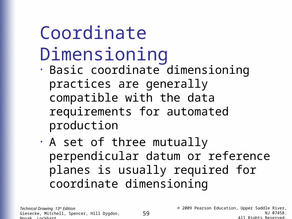
Coordinate Dimensioning
• Basic coordinate dimensioning practices are generally compatible with the data requirements for automated production
• A set of three mutually perpendicular datum or reference planes is usually required for coordinate dimensioning

60Technical Drawing 13th EditionGiesecke, Mitchell, Spencer, Hill Dygdon, Novak, Lockhart
© 2009 Pearson Education, Upper Saddle River, NJ 07458.
All Rights Reserved.
Coordinate Dimensioning

61Technical Drawing 13th EditionGiesecke, Mitchell, Spencer, Hill Dygdon, Novak, Lockhart
© 2009 Pearson Education, Upper Saddle River, NJ 07458.
All Rights Reserved.
Coordinate Dimensioning

62Technical Drawing 13th EditionGiesecke, Mitchell, Spencer, Hill Dygdon, Novak, Lockhart
© 2009 Pearson Education, Upper Saddle River, NJ 07458.
All Rights Reserved.
Machine, Pattern, and Forging Dimensions

63Technical Drawing 13th EditionGiesecke, Mitchell, Spencer, Hill Dygdon, Novak, Lockhart
© 2009 Pearson Education, Upper Saddle River, NJ 07458.
All Rights Reserved.
Sheet-Metal Bends
• In sheet-metal dimensioning, allowance must be made for bends

64Technical Drawing 13th EditionGiesecke, Mitchell, Spencer, Hill Dygdon, Novak, Lockhart
© 2009 Pearson Education, Upper Saddle River, NJ 07458.
All Rights Reserved.
Notes
• It is usually necessary to supplement the direct dimensions with notes
• Notes should be worded to allow only one interpretation
• Notes should be lettered horizontally

65Technical Drawing 13th EditionGiesecke, Mitchell, Spencer, Hill Dygdon, Novak, Lockhart
© 2009 Pearson Education, Upper Saddle River, NJ 07458.
All Rights Reserved.
Standards
• Dimensions should be given to make use of readily available materials, tools, parts, and gages
• The dimensions for many commonly used machine elements are standardized and can be obtained from standard manuals or catalogs
Related Documents