Channel Assignment Techniques for 802.11 based Multi-Radio Wireless Mesh Networks Ante Prodan and Vinod Mirchandani Faculty of Information Technology University of Technology, Sydney, (UTS) PO Box 123, Broadway, Sydney, NSW 2007, Australia [email protected] [email protected] Abstract This chapter gives an in-depth coverage of the area of channel assignment in 802.11 based multi-radio wireless mesh networks (MR-WMN). Multiple channels in a MR-WMN can substantially increase the aggregate capacity of the Wireless Mesh Networks (WMN) if the channels are assigned to the nodes such that the overall interference is limited. To this end, use of graph theory to understand and address this problem facilitated by different representations of MR-WMNs is explained. Further, the inherent properties of the 802.11 radio’s physical layer are identified to explain their influence on channel interference. We also examine the ways by which the emerging 802.11k standard will help to carry out an effective channel assignment. The usefulness of this chapter is made complete by giving a taxonomy of existing solutions, which is used as a preview to provide an extensive survey of the key research approaches proposed in the literature for channel assignment. We have contributed by way of putting together a comprehensive overview of the work in this area, which we believe does not exist with a similar scope. This chapter has been written such that it can be enjoyed and grasped by students as well as professionals.

Welcome message from author
This document is posted to help you gain knowledge. Please leave a comment to let me know what you think about it! Share it to your friends and learn new things together.
Transcript

Channel Assignment Techniques for 802.11 based Multi-Radio Wireless Mesh Networks
Ante Prodan and Vinod Mirchandani
Faculty of Information Technology
University of Technology, Sydney, (UTS)
PO Box 123, Broadway, Sydney, NSW 2007, Australia
Abstract
This chapter gives an in-depth coverage of the area of channel assignment in 802.11 based multi-radio wireless mesh networks (MR-WMN). Multiple channels in a MR-WMN can substantially increase the aggregate capacity of the Wireless Mesh Networks (WMN) if the channels are assigned to the nodes such that the overall interference is limited. To this end, use of graph theory to understand and address this problem facilitated by different representations of MR-WMNs is explained. Further, the inherent properties of the 802.11 radio’s physical layer are identified to explain their influence on channel interference. We also examine the ways by which the emerging 802.11k standard will help to carry out an effective channel assignment. The usefulness of this chapter is made complete by giving a taxonomy of existing solutions, which is used as a preview to provide an extensive survey of the key research approaches proposed in the literature for channel assignment. We have contributed by way of putting together a comprehensive overview of the work in this area, which we believe does not exist with a similar scope. This chapter has been written such that it can be enjoyed and grasped by students as well as professionals.

2
Overview
This chapter is organised as follows: Section 1 provides an introduction to the chapter based on the terminology that is pertinent to the concepts discussed. In Section 2, we provide a background information on the core problem in channel assignment for multi-radio wireless mesh network (MR-WMN), and then explain the use of graph theory for channel assignment along with its aspects for MR-WMN model representation. Section 3, describes the key issues that are associated with the physical layers of 802.11a/b/g radios. These are relevant for investigation because the channel assignment problem stems from the limiting attributes of the radio’s physical layer. Further in section 3, we describe the spectrum management capabilities of 802.11a/b/g radios and review the radio resource management mechanisms, which are proposed in 802.11k (draft 7). The taxonomy of the approaches to address the channel assignment problem in MR-WMN along with some of the key algorithms proposed in this regard are detailed out in section 4. The thoughts for practitioners and directions for future research are provided in sections 5 and 6, respectively. Conclusions that can be drawn from this chapter are provided in section 7.
1.0 Introduction
The throughput obtained at the physical layer of a wireless network is largely dependant on following functional procedures that are associated with the wireless medium:
• Channel selection • Link adoption • Transmit power control (TPC) • Error correction schemes In this chapter, we study the problem of channel assignment for 802.11 based
multi-radio wireless mesh networks (MR-WMN). MR-WMNs discussed are multi hop, multi-radio wireless networks based on IEEE1 802.11 suite of standards. The “multi radio” feature means that each wireless router has two or more radio interfaces that operate independently on different channels. Therefore, each router is capable of transmitting and receiving data simultaneously, albeit on different channels, as well as it can communicate with one or more neighbours. Further, the “multi-hop” feature signifies that each router, which is also called a node, can relay traffic from other nodes towards its final destination.
In this introductory section, we are going to familiarise the reader first with the basic terms and concepts that are necessary to understand the material provided in
1 Institute of Electrical and Electronics Engineers
3
following sections. We will initiate with the definitions of terms such as radio spectrum, channel and band, which will be followed by an explanation of radio interference. We then provide a brief introduction to spectrum regulation and graph theory and end this section with an overview of IEEE 802.11 suite of standards.
1.1 What is a radio spectrum, radio channel and radio band?
The term radio spectrum is broadly used to describe the collection of electromagnetic wave frequencies within the range of approximately 3 Hz to 300 GHz. A radio channel represents the radio spectrum within a limited range (e.g. 2.47-2.55 GHz), which is used to create a communications link between a transmitter and receiver. In this text, we also use the term band to describe spectrum range that includes more than one channel (e.g. 2 – 2.5 GHz – 802.11b/g band). Further on in this chapter, we will omit the term radio and use only terms such as spectrum, channel and band.
1.2 Spectrum regulation
Governmental regulatory bodies create policies that control as to who can do what, when, and how with a certain band of the radio spectrum. In US this responsibility is carried out by an independent government agency called Federal Communication Commission (FCC).
There are many different bands, and within bands different classes of applications (e.g. analogue and digital TV and radio). Communication transmissions from services such as TV, radio broadcasting and cellular phone get an exclusive access to their specified bands, while others such as those used for 802.11 are shared with other transmission systems. The regulators determine factors such as: transmit power levels, exact frequency range occupied by a particular band, and several other technical parameters. The general trend in recent years has been to use an auction process to lease the available spectrum to the highest bidder for example, the spectrum for new cellular services. This process is accompanied with less regulation of specific technologies and other technical details. However, some portions of spectrum have been made available to the public free of charge for limited-range applications, like cordless phones and wireless LANs. These, so called, Industrial, Scientific and Medical (ISM) radio bands were originally reserved in most countries for industrial, scientific and medical purposes rather than for general public communications. Further information about ISM bands in relation to IEEE 802.11 standards will be provided in the following sections.

4
Fig. 2. Constructive interference
Fig. 1. Destructive interference
Spectrum regulation is a very complex topic and for those who are interested in enhancing their knowledge in this area, we recommend a book authored by (Nuechterlein and J.Weiser 2005).
1.3 Channel Interference
In this chapter, we will examine interference as an important fac-tor that influences the ability of two linked nodes to reliably communicate with each other at the desired communication rate. Within the scope of 802.11 based wireless networks, we distinguish between two types of interference: radio interference
and channel contention interference. Radio interference represents a physical interference that influences the entire
spectrum of electromagnetic waves. Physical interference has two distinctive subtypes: destructive interference and constructive interference. Destructive interference is depicted in Fig. 1.2 where 3 waveforms can be seen: the first
waveform on the top (in red) represents message signal, the second waveform in the middle represents an unwanted interference signal and the bottom waveform represents the resulting signal waveform. As it can be observed in Fig. 1, the destructive interference has a detrimental effect on the transmitted radio signal, which often results in a loss of
transmitted data. On the other hand, in the second type of interference i.e. the constructive interference depicted in Fig. 2 (waveforms are in the same order as in Fig.1) has the converse effect on the signal as it results in an increase of its amplitude. However, the waveforms used in these two examples are synchronised in time, which is very rarely the case in reality. This means that in most of the cases both forms of interference have a detrimental affect on the signal.
2 The figures used to illustrate destructive and constructive interference are frames from the animation that is available on the website of Physics Department of Boston University:
http://physics.bu.edu/~duffy/semester1/c21_interference.html

5
The second type of interference mentioned at the beginning of this section - contention interference is not a physical interference as in the previous cases although it also produces a negative effect. Contention interference stems from the Carrier sense multiple access with collision avoidance (CSMA/CA) based MAC layer of 802.11 protocol that defines the behaviour of the
802.11 station, which has to wait until a channel is free to commence its transmission. Therefore, the channel may be occupied by transmission from any node that uses the same channel within the communication range. Due to the license free availability of 802.11 band this issue is even more pronounced in urban areas that contain a large number of 802.11 based networks. Thus, in urban areas all the co-located networks compete for the use of limited number of channels. In sections 2 and 3, we will examine ways of modelling and measuring interference that can provide the information necessary for an effective channel assignment process.
In addition to the term interference it is important to clearly define two related terms: communication range and interference range. Communication range is the range in which a reliable communication between two nodes is possible and interference range is the range in which transmissions from one node can detrimentally affect the transmissions from other nodes on a same or partially overlapping channel. It is important to note that the interference range is always larger than the communication range as shown in Fig. 3.
1.4 Graph Theory - Fundamentals
To model the behaviour of interconnected structures mathematicians have developed the realm of graph theory. The fundamentals of this theory have their roots in the paper about the bridges of Königsberg by Leonhard Euler presented to the St. Petersburg Academy on August 26, 1735 (Euler 1741). In this subsection, we describe the basic elements that are necessary to understand the graph based models, which are discussed further on in this chapter.
At any point in time all important elements of a WMN can be represented as a graph. A graph, G, is defined as a set of vertices V and a set of edges E and can be denoted as G = (V,E). The sets V and E have to be non-empty and finite. An edge is a link between two vertices which joins the vertices i and j is denoted by (i, j).
R-1 R-2
Interference Range
Communication Range
Fig. 3. Communication Range and Interference Range

6
The vertices i and j are the end-vertices of this edge. If an edge exists between two vertices, then these two vertices are called adjacent or neighbouring vertices of G. Two edges are called adjacent if they have one common end-vertex. An example of a graph is depicted in Fig. 4. To the edges of a graph, specific values or weights may be assigned for example to represent an interference level, in which case the graph is called a weighted graph (Hekmat 2006).
R-3
R-1
R-5
R-4
R-2
R-6
R-7
R-8
R-9
R-10
Fig. 4: The graph - representation of a mesh network
For a graphical representation of MR-WMN, we can use the following simple mapping: Each vertex in a graph represents a router in a MR-WMN and each edge between two vertices represents a radio link between a pair of peer interfaces of two routers. See Fig. 4; routers are labelled from R-1 to R-10.
In addition to the mapping, we can also define sets of important elements. For example, we define the set of neighbours NX as the set of routers that can be connected to X and that belong to the same network. We also define a set of routers IRX that have the ability to receive a signal transmitted on a specific channel but which can be influenced by simultaneous transmission from a router X that also uses the same or a partially overlapping channel. It is important to note that router X does not have to belong to the same network as the affected routers, but it can belong to any of different co-located networks.
In this model, we assume that the link between a pair of nodes is , bi-directional (undirected). A link is said to be operational between two nodes if the signals transmitted from one node can be received above a minimum required power threshold by the peer node and vice versa. We define that two nodes are connected if there is a link between them.
This basic graph model enables us to explore in details the fundamental properties of mesh networks, including the connectivity, mutual interference, degree distribution and hop count.
For a further insight into graph theory and its applications in computer science refer to (Bondy and Murty 1982; Bornholdt and Schuster 2003; Diestel 2005).

7
1.5 Introduction to IEEE 802.11 set of standards
The IEEE 802.11 family of standards was conceived in 1997, and since then it has been gradually evolving. For example, the 802.11b supplement standard defines the high rate direct sequence spread spectrum (HR/DSSS) transmission mode with a chip rate of 11Mchip/s, which provides the same occupied channel bandwidth and channelization scheme as Direct-Sequence Spread Spectrum (DSSS) in legacy standard. A higher data rate is achieved through a transmission mode, which is based on eight chip complementary code keying (CCK) modulation. The code set of complementary codes is richer than the set of Walsh codes that are used in DSSS (Walke, Mangold et al. 2006).
In the period from 2000–2003, the 802.11b extension was the first technology that captured a significant market share. When it was initially released in 1999 the wireless networks based on physical layer augmentations of 802.11b and 802.11a were meant to be deployed as an extension to the existing wired LANs. However, as new wireless networks rapidly gained popularity the need for an amendment and further development of standards has arisen. Initially, networks based on 802.11a extension did not achieve the transmission rates of 802.11b networks. This was mainly due to higher prices and somewhat reduced range due to the use of 5GHz spectrum. However, vendors continued with the refinement of the chipset technology, which has resulted in an improvement of 802.11a radio features. Today, this standard has captured a significant share of the corporate market. Another spinoff of the 802..11 standard is the 802.11g standard, which is fully backward compatible with 802.11b but offers higher data rates to be achieved through the use of orthogonal frequency-division multiplexing (OFDM). OFDM is the scheme that is also used in the physical layer of the 802.11a. In 2003 a third amendment for 802.11g was ratified.
Further increase in the number of deployed wireless LAN networks has lead to a higher level of interference in the congested 802.11b/g band that contains 11-14 channels (depending on regulatory domain). This is mainly due to the limited number of non-overlapping3 channels. It can be inferred from Fig. 5 that only channels 1, 6 and 11 are not overlapping. Further discussion on the limitations of 802.11 physical layers will be provided in section 2.2.
Readers interested in a detailed analysis of IEEE 802.11 family of standards should refer to (IEEE Task Group 802.11b 1999; Walke, Mangold et al. 2006).
3 The terms non-overlapping and orthogonal have the same meaning and will be used interchangeably in this chapter

8
2.401-2.423
2.400GHz 2.500GHz
2.406-2.428
2.411-2.433
2.411-2.433
2.416-2.438
2.421-2.443
2.426-2.448
2.431-2.453
2.436-2.458
2.441-2.463
2.451-2.473
2.456-2.478
2.461-2.483
Ch 1Ch 2Ch 3Ch 4Ch 5Ch 6Ch 7Ch 8Ch 9Ch 10Ch 11Ch 12Ch 13
Fig. 5. Available channels in 2.4 GHz ISM band that are used for 802.11b/g.
2.0 Background
In this section, we will provide a detailed insight into the problem of channel assignment in 802.11 based mesh networks. We will also introduce few network models from three different perspectives of link, connectivity and interference.
2.1 Channel assignment problem definition
For two 802.11 based interfaces to communicate with each other, they need to be assigned to a common channel. In a nutshell, a solution to a channel assignment problem determines which one of all available channels should be assigned to a given 802.11 interface. However, the number of available channels is limited and as more interfaces within the same interference range are assigned to the same radio channel or a partially overlapping channels, the effective bandwidth available to each interface decreases. Therefore, a good channel assignment algorithm needs to effectively balance between the goals of maintaining connectivity and increasing aggregate bandwidth. The problem definition will increase in complexity when we combine the constraints associated with routing and topology control along with the channel selection problem.

9
R-1 R-3R-2
Fig. 6. A simple topology to illustrate Graph colouring
2.2 Different models, representations and perspectives used for the channel assignment problem
In this sub-section, we will: (i) Introduce channel selection problem models based on graph theory; (ii) review few network representations from three different aspects: link, connectivity and interference and (iii) we will examine in details IEEE 802.11 standard physical layers and their limitations that are pertinent to the channel assignment problem.
2.2.1 Models based on graph theory
The graph colouring theory is used as a base for the theoretical modelling of channel assignment problem. In the early days of mobile telephony the channel assignment problem was modelled as an ordinary graph colouring problem, and graph colouring algorithms were used to solve it. Practical experience revealed that these solutions have a number of deficiencies. In the following few paragraphs, we provide an introduction to this type of modelling accompanied with an overview of its use in the literature.
In this type of model there is a vertex on a graph corresponding to each node (e.g. a mesh router) on a wireless network. An edge between two vertices on the
graph represents the link between two nodes. This model does not contain an explicit representation for interfaces and assumes one interface per router;
consequently it cannot be used to model MR-WMN. The colour of each vertex represents a non-overlapping channel and the goal of the channel assignment is to cover all vertices with the minimum number of colours such that no two adjacent vertices use the same channel. This model is illustrated in Fig. 6 – fill patterns are used instead of colours to represent different channels.
A different representation of graph colouring problem is necessary to capture multiple interfaces on each router. As depicted in Fig. 7 the colours are assigned to edges instead of vertices. In this example, we use different patterns instead of colours. Edge colouring assigns a colour to each edge so that no two incident edges share the same colour. This approach can always be transformed into the
R-1
R-3
R-2
Fig. 7. Graph colouring for MR-WMN

10
vertex version because edge colouring of a graph is just the vertex colouring of its line graph.
However, since the number of non-overlapping channels on 802.11b/g network is limited to just 3, to enable an efficient channel assignment, it is necessary to introduce a weight associated with each edge on a graph. The weight indicates the importance of using different colours for corresponding vertices.
The theory on graph colouring is extensive; here we provide the fundamental formal definition of weighted colouring problem as given in literature (Diestel 2005) : “A proper colouring of a graph G is an assignment of a colour to each vertex so that adjacent vertices receive distinct colours.” Equivalently, it is a partition of the vertices into stable sets, where a set of vertices in G is stable (or independent) if no two are adjacent. This problem is known to be NP hard (Garey, Johnson et al. 1974; Garey and Johnson 1979).
A comprehensive overview of techniques used for channel assignment in cellular mobile telephony is provided in (Katzela and Naghshineh 1996). This reference is recommended to anyone who wishes to examine the detailed history and development of the problem. Mishra et. al. in (Mishra, Banerjeeb et al. 2005) use weighted graph colouring with the weight calculation based on a number of clients that are affected by the interference affecting an access point (AP) on a particular channel. Leith et. al. (Leith and Clifford 2006) also use weighted graph colouring in the form of an interference graph. In their model each vertex represents a WLAN and edges represent interference between corresponding WLANs. Jain et. al (Jain, Padhye et al. 2003) use the same type of graph model as Mishra et. al. but they use it in conjunction with other techniques to compute the optimum throughput that wireless network can support. Ramachandran et al. (Ramachandran, Belding et al. 2006) extend the conflict graph model further into multi-radio conflict graph (MCG). This model differs in a way that represents edges between the mesh radios as vertices instead of representing edges between the mesh routers as vertices as in the original conflict graph. In the literature use is also made of a unit disk graph (UDG) model that is again based on graph theory to reduce transmit power levels. In this way topology control and interference reduction is achieved. Although, the models based on graph colouring theory have proven their usefulness in modelling interference on infrastructure based WLANs, we agree with the conclusion of (Raniwala and Chiueh 2005) that graph colouring models do not adequately capture all the constraints of a multi radio WMN. In particular, the constraints such as: representations of partially overlapping channels and the interference when the source is external to the network.
2.2.2 Network representation from 3 different aspects
The aim of this sub-section is to introduce the reader to different ways of representing a MR-WMN. The models described herein serve only as examples

11
that illustrate several possibilities for representing WMN and are not necessarily the optimal representations.
Link Graph Connectivity Graph Interference Graph
R-3
66
R-1 R-26
R-3
1
R-1 R-26
R-3
R-1 R-2
R-1 R-26 R-1 R-2 R-1 R-2
R-3
R-1 R-2
R-3
R-1 R-2
R-3
R-1 R-2
A
B
C
A link on channel 6 between two routers
with single interface .
There is only one possible link in
the communication range .
There is no link which represents a possible source of interference
3 links on channel 6 connect 3 single interface routers
There are 3 possible links in the communication range .
Since all 3 links are on the channel 6 there is contention
interference between all of them .
2 links on channels 1 and 6 connect 3 routers . R-1 has two interfaces and R-2 and R-3 have only one interface each .
There are 4 possible links in the communication range .
There is no interference between 2 links on orthogonal channels .
Fig. 8 (part 1). A comparative study of different MR-WMN representations
Fig. 8 has two parts: We depict five network models (rows A-E in figure 8 part 1 and 2) drawn from three aspects in order to demonstrate a variety of MR-WMN representations that are relevant to the channel selection problem, The three aspects used are explained below:
• Link Graph - In this representation each edge i.e. line between nodes represents a link that exists between interfaces of two nodes. A channel number is used for each link that is assigned.
• Connectivity graph- In this representation each edge represents a potential connection between two interfaces i.e. an edge exists between any two interfaces that are within each others communication range.

12
• Interference graph- In this representation edges between the nodes represent the interference between two links. An edge is depicted for each link that can be a source of interference, which is independent of its type i.e. physical or contention interference. Consequently, such a graph can be without any edges if all the channels used are orthogonal to each other.
The complexity of the depicted network varies from a simple network
consisting of 2 single interface routers (i.e. row A in figure 8 – part 1) to a more complex network that contains 4 routers of which each has 2 interfaces (in row E of figure 8 – part 2).
R-4
11
R-3
1
R-1 R-26
11
11
R-3
1
R-1 R-26
R-4R-3
R-1 R-2
R-3
R-1 R-2
R-3
R-1 R-2
D
E R-3
R-1 R-2
R-4
Link Graph Connectivity Graph Interference Graph
4 routers are connected with 4 links on channels 1,6,11 and 11. R-1,2,3 have 2 interfaces and R-4 has one interface .
There are 18 possible links in the
communication range .
Since links between R-3,R-4 and R-3,R2 are using the same
channel 11 there is a contention interference between them .
3 links on channels 1,6 and 11 connect 3 routers of which each has 2 interfaces.
There are 11 possible links in the communication range .
There is no interference between 3 links on orthogonal channels .
Fig. 8 (part 2). A comparative study of different MR-WMN representations
A key inference made from Fig. 8 (parts 1&2) is that the complexity of graph representation for a connectivity graph (column 2 in Fig 8) increases significantly with each additional interface.

13
3.0 IEEE 802.11 - Physical Layers and their Limitations
The suitable assignment of channels in a MR-WMN is closely associated with the nature of the underlying physical layers of the 802.11 radio. Therefore in this section, we will study most significant aspects of 802.11 physical layers. Reasons for examining in details the 802.11 physical layers as well as identifying their limitations are enumerated below:
• The root causes of the interference related to the issues in 802.11a,b/g based networks are in the restrictive features of their respective physical layers such as: spectrum availability and contention mechanism defined in Medium Access Control (MAC) Layer.
• Interference is a cornerstone issue of channel assignment. As such, it is not feasible to design an effective channel assignment algorithm without taking into consideration the possible effects of interference on the underlying physical layers of the wireless network.
• An insight into the operation of the physical layers in a realistic scenario is necessary for the development, assessment and optimisation of any channel assignment algorithm. This process will facilitate the reduction in the number of steps necessary for the channel assessment as well as to alleviate its performance
The discussion provided in this section will be limited only to the amendments of 802.11 given in 802.11a, 802.11b, 802.11g and the draft 2 proposal of 802.11n from February 2007 (IEEE Task Group 802.11n 2007). Further the amendments related to radio resource measurements part in 802.11k are covered by section 3.2, which is relevant to 802.11n. As draft 2 proposal of 802.11n makes use of the 802.11k draft 4 as a reference for its spectrum measurement functions therefore the above stated amendments are discussed within the scope of section 3.
802.11a and 802.11g as well as 802.11n use transmission techniques based on orthogonal frequency division multiplexing (OFDM). Specifications for the individual components of OFDM for 802.11a are given in Table 1. The relatively higher data rates and robustness offered by such a modulation sceme has caused the 802.11g embedded devices to become increasingly popular within the period from 2003-2006. However, two major drawbacks related to the OFDM modulation, which as stated is used in 802.11g, are evident from the literature. These are:
1) Reduced range in comparison to 802.11b. 2) Drop in the transmission throughput when a mix of 802.11b and 802.11g
based devices operate within the same network. These drawbacks constitute the main reasons for an initial low penetration of 802.11g interfaces used as nodes in public APs or nodes in mesh networks. However, due to an increase in demand for higher network throughput rates the proportion of 802.11g based interfaces for public AP has significantly increased in the last 2 years.

14
Over time, the deployment of 802.11 continued in the area of home networking and mobile computing platforms. The growth in the number of APs as well as inherent complexity of wireless networks has reflected the limitations of physical layer in 802.11.
Table 1: Specifications of Modulation Schemes in 802.11a.
PHY mode Pmin R (dBm)
Number of data bits per symbol
1472 bytes transfer duration (µs)
SINRmin (dBm)
PHY Data rate
(Mbits/s)
Bandwidth factor
(is equal to PHY Data rate divided by 6Mbps)
BPSK ½ -82 24 2012 18 6 1
BPSK ¾ -81 36 1344 21 9 1.497
QPSK ½ -79 48 1008 22 12 1.996
QPSK ¾ -77 72 672 25 18 2.994
16QAM ½ -72 96 504 25 24 3.992
16QAM ¾ -70 144 336 32 36 5.988
64QAM 2/3 -66 192 252 34 48 7.984
64QAM ¾ -65 216 224 35 54 8.982
3.1 ISM bands used for 802.11 physical layers
The ISM bands have been defined by the International Telecommunication Union Recommendation (ITU-R) in articles 5.138, 5.150, and 5.280 of the Radio Regulations. Individual countries' allocation of the bands designated in these sections may differ due to variations in national radio regulations. In USA use of the ISM bands is governed by Part 18 of the FCC rules, while Part 15 Subpart B contains the rules for unlicensed communication devices, including those that use the ISM frequencies. Thus, designers of equipment operating in the ISM bands in USA should be familiar with the relevant portions of Part 18 and Part 15 Subpart B of the FCC Rules.4
Three ISM bands used for IEEE 802.11 are: • 2.400-2.500 GHz (centre frequency 2.450 GHz - used for 802.11b/g) • 5.150-5.350 GHz (centre frequency 5.250 GHz - used for 802.11a) • 5.725-5.875 GHz (centre frequency 5.800 GHz - used for 802.11a)
It is important to note that 802.11b/g uses one ISM band with a size of 100 MHz. On the other hand 802.11a uses 2 bands with a total size of 350 MHz.
4 In this chapter US standards will be used whenever not specified otherwise.

15
Therefore, the number of non-overlapping channels available for 802.11a is much higher than that for 802.11b/g.
As mentioned in the introduction, ISM bands are open for use by anyone, Furthermore they are extensively regulated (maximum power of transmitter is limited and depends on a regulatory domain). More information on ISM band and its use can be found on the ITU and FCC websites (Federal Communication Commission (FCC) 2007).
3.2 Effect of interference on link throughput in 802.11 based networks
The main factor that affects network connectivity is the distance between the peer nodes. In addition other factors that influence radio wave propagation are: (i) obstacles in the path between a transmitter and receiver and (ii) interference from
other possible prominent radio sources. Interference causes a drop in signal strength, which triggers a change in the modulation type. This chain of events depicted in the Fig. 9, eventually leads to a reduction in the link throughput. To exemplify the significance of interference reduction: let us consider an extreme case when a channel suffers from a high noise and interference, which results in a 18 dBm SINR. If our algorithm selects an alternate channel with a SINR of 35 dBm this will as per Table 1 result in an increase of available bandwidth of almost 9 times! Furthermore, packet loss is proportional to interference. A high packet loss in turn can render a link unusable for QoS sensitive traffic such as voice over IP (VoIP). The interference caused by the use of partially overlapping channels can be analysed with the help of Signal to Noise Ratio (SNR)
interference factor, which is termed as the i-factor and is provided by Mishra et. al. in (Mishra, Rozner et al. 2005; Mishra, Shrivastava et al. 2006). The i-factor (provided in table 2) can be used as a guidance for selecting partially overlapping channels once all non-overlapping channels in a single interference domain are used up. The i–factor given in Table 2 is based on the drop in SNR of partially overlapping channels when the transmission occurs on channel 6. We can observe from table 2 that the drop in SNR is decreased when partially overlapping channels further away from channel 6 are selected (e.g. channels 3 or 9). In this
Physical Interference
Drop in signal to noise ratio (SNIR)
Change of Modulation Scheme
Reduction in link throughput
Fig. 9. Effect of interference on link throughput on 802.11 networks.

16
way the interference can be kept under control and the overall network throughput increased.
Table 2: Interference factor (i-factor) between partially overlapping channels.
Channel 1 2 3 4 5 6 7 8 9 10 11 SNR i-factor
0 0.22 0.60 0.72 0.77 1.00 0.96 0.77 0.66 0.39 0
In the past year, wireless equipment based on draft 802.11n standard has
gained an increase in popularity. However, these equipments use channel binding feature which enables the use of more than one non-overlapping channel for a single link to increase the net throughput. The channel binding feature has thus resulted in a more pronounced interference problem.
3.3 IEEE 802.11k – spectrum awareness of 802.11 based equipment
At the outset IEEE 802.11 based networks were meant for use in a small area that serviced a limited number of APs. Due to this mindset, the incorporated radio resources and other measurement functions were inherent and very limited. However, a vast increase in the popularity of equipment based on these standards and its deployment in public hot spots such as airports and train stations have resulted in a higher spatial density. In turn, this has caused an increase in the level of mutual interference between co-located networks which has motivated further work on extensions to the standard.
First such extensions were prompted by the European regulatory requirements for the 5GHz frequency range used by 802.11a based devices. IEEE task group 802.11h addressed these requirements in 2003. Focal point of the 802.11h amendment is the internal use of measurement data to attain dynamic frequency selection (DFS) and transmit power control (TPC).
To co-ordinate and accomplish these functions successfully, cellular system such as Universal Mobile Telecommunication System (UMTS) and Global System for Mobile communications (GSM) specify the exchange of a variety of related information. As IEEE 802.11 networks have cellular like structure, which is similar to UMTS and GSM networks so an analogous functionality can be developed within the scope of 802.11.
An increase in demand for networks that cover metropolitan areas has resulted in an increase in density of APs and therefore an increase in interference. This is another important impetus for the introduction of new measurements procedures. With time, a need has arisen for the extension of the scope of information exchange between stations as well as a unified measurement mechanism for both

17
frequency ranges (2.4GHz – 802.11b/g and 5GHz - 802.11a). This has led to the establishment of the IEEE Task Group 802.11k. At the moment this standard proposal is in the late draft 7.0 stage and the final approval is expected by the end of 2007. The main difference between 802.11h and 802.11k is that the former does not consider the use of measurement data on tasks such as TPC or dynamic frequency assignment; instead it focuses on the measurement and the transfer of measurement information between stations.
The significance of 802.11k in the development of channel assignment algorithms is twofold:
(i) It facilitates in the development of an advanced TPC mechanism that reduces interference effects in MR-WMN.
(ii) It carries out a comprehensive link assessment and link selection process that is useful for the above point.
Although, some of these functions for the improvement of channel assignment mechanisms can be achieved with the use of previously discussed 802.11 amendments (see section 3) only the 802.11k amendment offers an inherent protocol for radio resource measurements and the propagation of the results of such measurements through the wireless network.
The IEEE 802.11k amendment is specifically dedicated to the radio resource measurement. It introduces 3 additional information elements: (i) AP Channel Report (ii) Neighbour Report and (iii) Receive Channel Power Indication (RCPI). Also, nine additional request types are defined of which eight result in a report and one in a measurement pause. The AP channel report is periodically transmitted along with the beacon. The main objective of this transmission is to enable an easy identification of other APs, which in turn facilitates a fast handover.
In MR-WMN the ad-hoc mode of 802.11 is used and a fast handover facilitated by 802.11k does not represent an important factor (here we don’t consider mobile clients and mesh nodes are considered to be static). On the other hand, beacon signals that are heard by all stations in the ad hoc mode and in particular the Neighbour Report can be used to expeditiously create a list of neighbouring stations. This is a possible way by which the number of steps and hence the resulting execution time of any measurement based algorithm could be reduced. Similar to 802.11h, most of the measurement type requests in 802.11k apply generic request fields, which are described in details in the draft standard documents.
4.0 Algorithms for channel selection
It has been well established by now in the chapter that channel selection is a very challenging issue that influences the overall performance of the MR-WMN. To quickly comprehend as to why channel selection is challenging, we consider a simple approach to channel selection with the help of an example algorithm -

18
called “first available channel”. This approach simply selects the first channel from a pool of available channels; once all channels in the pool are exhausted new links cannot be created. However, this approach does not facilitate an efficient use of the spectrum and produces far from optimum results. In recent times, the research community has developed a significant number of algorithms that provide major improvements in spectrum usage. We commence this section with the taxonomy of existing solutions and then embark on a comprehensive review of the key algorithms for channel selection with specific attention on a mix of quantitative and qualitative attributes such as: performance, complexity, scalability and stability.
4.1 Taxonomy of existing algorithms
Many approaches to addressing the channel assignment problem are available in the contemporary literature. Historically they are almost all based on the developments made in cellular mobile telephony. To gain a further insight into this problem, we provide a brief classification that is categorically listed below and is with respect to:
• Locality of channel assignment process which is based on: : o Centralised solutions. o Distributed solutions.
• Dynamics of assignment process, which is based on: : o Fixed channel assignment.
� Specific channel can only be used in designated cells, different groups of channels may be assigned to adjacent cells, the same group can be assigned to the cells that are outside mutual interference range.
o Dynamic channel assignment. � All channels assignments are temporary, from time to
time the situation is re-assessed and channels are reassigned according to certain criteria.
o Hybrid channel assignment � Available channels are divided in two groups, one
group is used for fixed channel allocation and other is used for dynamic allocation
• Strategies deployed , which are:
o Planning based strategies � Everything is pre-defined in a master plan.
o Co-ordination based strategies

19
� The channel selection is achieved through different co-ordination strategies between stakeholders.
o Measurement based strategies � Periodical measurements are undertaken to assess the
available band. Based on the results channels are assigned.
o Hybrid strategies � These strategies involve mechanisms such as co-
ordinated measurements, planning augmented by periodic measurements and combined strategies.
4.2 Review of algorithms for channel selection
Solutions that we are going to focus on in this chapter are dynamic
measurements based. These comprise algorithms that not only take into account interference produced by a single network but also other co-located networks. Noise, that is generated by other transmissions in the band being used is also considered in these algorithms.
The work of (Ko, Misra et al. 2005) specifically targets the channel assignment
problem on WMN. Authors have adopted their theoretical work in (Ko and Rubenstein 2003) and created a self-stabilising distributed protocol and an algorithm for channel assignment.
The method of (Ko, Misra et al. 2005) assumes that the interference is symmetric and is based on an interference range of three hops. Their method results in improvements of only 20% compared to random channel assignment. In reality, most of the times interference will be asymmetric because neighbouring node interface may transmit on the same channel at different powers. In contrast, a better proposal would not assume symmetric interference and would not require a dedicated channel for frequency co-ordination, which is a significant advantage. Further the interference cost function in (Ko, Misra et al. 2005) has not been justified i.e. the cost function has not been based on an interference model. The other main limitation of their proposal, as well as the one by (Raniwala and Chiueh 2005) is the usage of a common channel on each node for the management of channel assignment. We believe that his approach should be avoided because it can be wasteful of bandwidth and imposes severe limitations on network capacity especially when nodes have only two interfaces. Furthermore, a strong source of interference on the frequency that is used for the co-ordination of channels can render the throughput of parts or the whole network unsatisfactory.
In (Jain, Padhye et al. 2003), contrary to previous findings, authors state that the addition of new nodes can actually improve a per-node throughput because the

20
richer connectivity provides increased opportunities for routing around interference “hotspots" in the network that offsets the increase in traffic load caused by the new nodes. They explain this by the fact that previous research has been done under the assumption that nodes always have data to send and are ready to transmit as fast as their wireless connection will allow. However, in realistic settings, sources tend to be bursty, so nodes on an average transmit at a slower rate than the speed of their wireless link.
In (Jain, Padhye et al. 2003) authors use liner programming to model maximum achievable flow between the source and destination in absence of wireless interference and heuristics to obtain lower and upper bounds on the throughput. Also, they avoid making assumptions about the homogeneity of nodes with regards to radio range or other characteristics as well as regularity in communication patterns. The conclusion from the work in (Jain, Padhye et al. 2003) was that neither multi-path routing nor doubling the range of the radio increases cumulative throughput. On the other hand, by using two channels instead of one, the network may achieve the maximum possible throughput. Scenarios provided in (Jain, Padhye et al. 2003) illustrate that the model they have developed could be a useful tool for analysis and capacity planning in wireless multi-hop networks. However, we believe that their model suffers from oversimplification. Although valid theoretical capacity bounds can be produced most of real world deployments are more complex – that involve neighbouring or co-located networks with unknown interference characteristic. Consequently in realistic circumstances we cannot simply obtain information that has to be fed into the proposed model and the capacity predicted by the model and in reality may vary significantly.
In (Leung and Kim 2003) the authors have deployed heuristics that is based on interference measurements. Still, they do not define a threshold value range and a mechanism to keep a channel change under control. This may result in an infinite loop of channel changes that is caused by a slight variation in noise or by cyclical interference. Furthermore, it is not clear how much time (steps) the algorithm needs to achieve acceptable results as well if it can cope with dynamic environment.
Reference (Raniwala and Chiueh 2005) considers a combined solution for channel assignment and routing issues in (Raniwala and Chiueh 2004) and extend their previous proposal with the usage of a virtual control network instead of a dedicated interface-channel on each router. In other words this means that certain fraction of bandwidth is used on each channel for channel assignment and other management purposes rather than dedicating one exclusive channel. Their work contains careful analysis of all aspects of resource allocation problems relevant for 802.11 based WMN.
In (Subramanian, Krishnan et al. 2005) authors propose the usage of partially overlapping channels. Their interference model is theoretically based on a conflict graph and the interference data is acquired through the measurement of link pair interference. Reference (Subramanian, Krishnan et al. 2005) uses integer linear

21
programming to obtain bounds of optimal solution and evaluate the proposed algorithm.
Reference (Kyasanur and Vaidya 2005) approach is based on the assumption that an interface can dynamically switch over from one channel to another. They present a distributed interface hybrid assignment strategy and their routing strategy selects routes that have low switching and diversity cost. However, a co-ordination protocol is required to assign the channels to fixed channels in the hybrid nodes i.e. nodes having an interface assigned with fixed channel and the other interfaces with switchable channels.
(Raniwala, Gopalan et al. 2004) also propose a load aware based channel assignment. Although the work presented in their paper is of a good value but it assumes a centralised method for channel assignment, which also needs to keep track of the load in different parts of the WMN. Their work is thus not scalable. However, they have shown a circular dependency between channel assignment, load on each link and routing.
In (Ramachandran, Belding et al. 2006) the authors base interference estimate on the number of interfering radios on each channel supported by each router. An interfering radio is defined as a simultaneously operating radio that is visible to a router but external to the mesh. A visible radio is one whose packet(s) pass frame check sequence (FCS) checks and are therefore correctly received. However, this method is incomplete since it neglects interference caused by transmissions that are too weak for the signal to be decoded but still result with degradation of SNR on particular link. The other main drawback of last two proposals is the scalability since centralised algorithms are used. However, both proposals motivate further investigation since they indicate a 40% performance gains in comparison to static assignment.
Table 3 summarises and compares the primary attributes associated with the key algorithms provided in the literature.
Table 3. A comparative study of some algorithms recently published in the literature.
Related Work
Attributes
(Raniwala and Chiueh 2004; Raniwala and Chiueh 2005)
(Ko, Misra et al. 2007)
(Kaufmann, Baccelli et al. 2005)
(Subramanian, Krishnan et al. 2005)
Algorithm that should be aimed for.
Type of algorithm
Distributed/ Centralised
Self-organising
Self-organizing
Centralised & Distributed
Self-organizing and Distributed
Parameters
Interference + Load
Interference
Interference,
Interference
Interference +

22
infrastructure mode
Load
Dedicated Channel for assignment
NO NO (YES for previous work)
NO NO NO
Non-orthogonal channels used
NO NO NO YES YES
Transmit Power Control
NO NO NO NO Should be incorporated.
Scalability
Addressed Addressed
Not relevant
Partially Addressed
Should be addressed
Stability
Not addressed
YES NO NO Should be addressed
Capacity analysis
None specified
Non specified
None specified
Not specified Should be specified
5.0 Thoughts for Practitioners
We list below some of the key thoughts that have been assimilated as a result of our work on this chapter:
• A good channel assignment algorithm needs to effectively balance
between the goals of maintaining connectivity and increasing aggregate bandwidth. The problem definition will increase in complexity when we combine the constraints associated with routing and topology control along with the channel selection problem.

23
• A key inference made from the use of graph theory for channel assignment is that the complexity of representation for a connectivity graph of a network system increases significantly with each additional radio interface.
• 802.11k draft standard will be useful in the development of channel
assignment algorithms as it will enable:
- The development of an advanced TPC mechanism that reduces interference effects in MR-WMN.
- A comprehensive link assessment and link selection process that is useful for the above point. This is because the 802.11k encompasses an inherent protocol for radio resource measurements and the propagation of the results of such measurements through the wireless network.
6.0 Directions for Future Research
This chapter has progressively built on the topic of channel assignment in multi-radio wireless mesh network by systematically explaining the concepts behind channel assignments. It has then explained the grand challenges posed by the channel assignment task in MR-WMN and some of the key works that have been proposed in the literature. We have contributed also to this research area through our work such as (Mirchandani, Prodan et. al 2007 and Mirchandani, Prodan et. al 2007) and as such we believe that the next possible steps to engage in would be:
1) Create an algorithm for channel assignment in MR-WMN that combines
the approaches of topology control with Interference cost reduction. It is expected that this should lead to an increase in the overall channel capacity of the MR-WMN system as well as spectral efficiency. Some of the preliminary work done by us in this regard can be viewed at the following URL: http://www-staff.it.uts.edu.au/~debenham/prodan/
2) Create a mechanism that additionally takes into consideration the traffic
load on the links in the system i.e. carries out channel assignment using topology control plus Interference cost reduction plus load distribution. As more factors are combined the creation of an efficient algorithm will be more complex.
3) The expected 4th generation (4G) of networks will encompass several
heterogeneous wired and wireless networks offering seamless

24
connectivity. In such a 4G environment the MR-WMN will be constituted of heterogeneous wireless routers using a mix of radio types. This will pose additional issues such as those associated with heterogeneous radio resource management, which could be another area of research.
7.0 Conclusions
Multi-Radio Wireless Mesh Networks (MR-WMN) need to have a suitable channel assignment approach so that an increase in the overall capacity gain is realised. However, the problem is very challenging especially because the 802.11 based radios have only a limited number of channels. As such, it is difficult to make the channel allocation without affecting the performance. In order to cater to a diverse reader audience, in this chapter simple terms ranging from channel, spectrum to more complex ones such as graph theory were first adequately explained with the help of simple illustrations. Further, to enable any interested reader to follow the chapter it was gradually approached for example by examining the ways in which 802.11 physical layer influences the channel interference and strategically providing recommendations for useful literature at several places within the text. Apart from explaining the emerging 802.11k standard and graph theory to alleviate the channel assignment problem, we also provided a critical review of the different approaches for channel assignment in MR-WMN. Overall this chapter draws out that even though a lot of effort has been put into addressing the channel assignment problem in MR-WMN but still this problem remains a fascinating area of research that needs to be explored further. By the time the readers have finished this chapter, they should have a clear grasp of how to successfully model a channel assignment problem with an emphasis on interference reduction.
Acknowledgments
This research is performed as part of an Australian Research Council Linkage Grant between Bell-Labs, Alcatel-Lucent and the University of Technology, Sydney (UTS), Australia.
Questions and Exercises
1.) What is a channel and what as a partially-overlapping channel?
25
Answer: A radio channel represents the radio spectrum within a limited
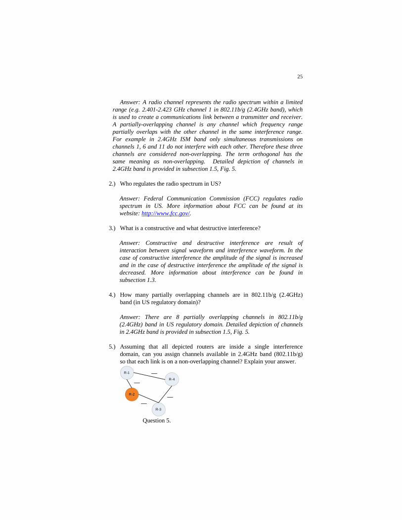
range (e.g. 2.401-2.423 GHz channel 1 in 802.11b/g (2.4GHz band), which is used to create a communications link between a transmitter and receiver. A partially-overlapping channel is any channel which frequency range partially overlaps with the other channel in the same interference range. For example in 2.4GHz ISM band only simultaneous transmissions on channels 1, 6 and 11 do not interfere with each other. Therefore these three channels are considered non-overlapping. The term orthogonal has the same meaning as non-overlapping. Detailed depiction of channels in 2.4GHz band is provided in subsection 1.5, Fig. 5.
2.) Who regulates the radio spectrum in US?
Answer: Federal Communication Commission (FCC) regulates radio spectrum in US. More information about FCC can be found at its website: http://www.fcc.gov/.
3.) What is a constructive and what destructive interference?
Answer: Constructive and destructive interference are result of interaction between signal waveform and interference waveform. In the case of constructive interference the amplitude of the signal is increased and in the case of destructive interference the amplitude of the signal is decreased. More information about interference can be found in subsection 1.3.
4.) How many partially overlapping channels are in 802.11b/g (2.4GHz) band (in US regulatory domain)? Answer: There are 8 partially overlapping channels in 802.11b/g (2.4GHz) band in US regulatory domain. Detailed depiction of channels in 2.4GHz band is provided in subsection 1.5, Fig. 5.
5.) Assuming that all depicted routers are inside a single interference domain, can you assign channels available in 2.4GHz band (802.11b/g) so that each link is on a non-overlapping channel? Explain your answer.
R-4
R-1
R-3
R-2
Question 5.

26
Answer: The answer is NO. Since there are only 3 non-overlapping channels in 2.4GHz band it is not possible to assign a separate non-overlapping channel to each link. However, if the link load is known the same channel can be assigned to two links with the lowest load on the network. See the figure above.
6.) Suggest four channels in 2.4 GHz band for four links that are going to be
used in a single interference range. Take into account that one of 4 links will be under high traffic load, one will be under low traffic load and remaining 2 will be under average traffic load. Show how you have obtained your results.
Answer: The answer is provided with the help of figure 5. If we use the network depicted in Fig. 5 and assume that the link R3-R4 is under heavy load, the link R1-R4 is under low load and the links between R1-R2 and R2-R3 are under average traffic load the Other equally accurate answers are possible as long as the links with the lower load shares channel with a single link with the average load and all other links are on non-overlapping channels.
7.) Draw a connectivity graph for the network described in question 6. (Use
illustrations in subsection 2.2.2 for guidance.)
8.) Draw an interference graph for the network described in question 6. (Use illustrations in subsection 2.2.2 for guidance.)
R-4
R-1
R-3
R-2
Question 7.
R-4
R-1
R-3
R-2
Question 7.

27
9.) Figure given bellow depicts a MR-WMN with five routers of which three have two radio interfaces and two have a single interface each. The gray dotted circle around each router shows the interference domain of that specific router. How would you assign channels in 802.11b/g band to minimise the interference in this network?
Answer: The answer shown in the above figure results when the network is free of interference as channel 1 is used twice in separate interference domains.
R-5
R-1
R-3R-2
R-4
R-5
R-1
R-3R-2
R-4
1
6
11
1
Question 9. Answer 9.
R-4
R-1
R-3
R-2
1
1
Answer 8.

28
10.) Figure given bellow depicts a MR-WMN with 6 routers; the gray dotted circle around each router shows the interference domain of that specific router. How would you assign channels in 802.11b/g band to minimise the interference in this network?

29
Answer: Figure 10a provides above result when the network has two links in a single interference domain on the same channel i.e. channel 1. In other words, links R2-R3 and R3-R4 are sharing a single contention
R-5
R-1
R-3R-2
R-4
R-6
1
1
6
11
1
R-5
R-1
R-3R-2
R-4
R-6
1
11
6
11
1
Answer 10a. Answer 10b.
R-5
R-1
R-3R-2
R-4
R-6
Question 10.

30
domain so only one of them can be used to transmit data successfully at the same time. Although, the link R5-R6 uses the same channel 1, it is far enough to be in a separate interference domain therefore it can be used independently. On the other hand answer 10b provided above is free of interference because links which reuse channels 1 and 11 are in different interference domains.

31
References
Bondy, J. A. and U. S. R. Murty (1982). Graph Theory with Applications. London, The Macmillan Press Ltd.
Bornholdt, S. and H. G. Schuster (2003). Handbook of graphs and networks : from the Genome to the Internet. Weinheim ; [Cambridge], Wiley-VCH.
Diestel, R. (2005). Graph Theory. Heidelberg, New York, Springer-Verlag. Euler, L. (1741). "The Seven Bridges of Königsberg " Commentarii academiae scientiarum
Petropolitanae 8: 12. Federal Communication Commission (FCC). (2007). "Home Page." Retrieved 15th November,
2007, from http://www.fcc.gov/. Garey, M. R. and D. S. Johnson (1979). Computers and intractability : a guide to the theory of
NP-completeness. San Francisco, W. H. Freeman. Garey, M. R., D. S. Johnson, et al. (1974). Some simplified NP-complete problems. Sixth annual
ACM symposium on Theory of computing Seattle, Washington, United States, ACM. Hekmat, R. (2006). Ad-hoc Networks: Fundamental Properties and Network Topologies.
Dordrecht, The Netherlands, Springer. IEEE Task Group 802.11b (1999). Higher-Speed Physical Layer Extension in the 2.4 GHz Band,
The Institute of Electrical and Electronics Engineers: 97. IEEE Task Group 802.11n (2007). Part 11: Wireless LAN Medium Access Control (MAC) and
Physical Layer (PHY) specifications: Amendment 11n: Enhancements for Higher Throughput. New York, The Institute of Electrical and Electronics Engineers.
Jain, K., J. Padhye, et al. (2003). Impact of interference on multi-hop wireless network performance. ACM Annual Internationa Conference on Mobile Computing and Networking (MOBICOM).
Katzela, I. and M. Naghshineh (1996). "Channel Assigment Schemas for Cellular Mobile Telecommunication Systems- a Comprehensive Survey." IEEE Personal Communications 3: 10-31.
Kaufmann, B., F. Baccelli, et al. (2005). Self Organization of Interfering 802.11 Wireless Access Networks: 22.
Ko, B.-J., V. Misra, et al. (2005). Distributed Channel Assignment in Multi-Radio 802.11 Mesh Networks. New York, Columbia University.
Ko, B.-J. and D. Rubenstein (2003). A Distributed, Self-stabilizing Protocol for Placement of Replicated Resources in Emerging Networks. 11th IEEE International Conference on Network Protocols (ICNP), Atlanta, GA, USA, IEEE.
Ko, B. J., V. Misra, et al. (2007). Distributed Channel Assignment in Multi-Radio 802.11 Mesh Networks. WCNC Hong Kong, China, IEEE.
Kyasanur, P. and N. Vaidya (2005). Routing and Interface Assignment in Multi-Channel Multi-Interface Wireless Networks. IEEE Wireless Communications and Networking Conference, New Orleans, LA, USA.
Leith, D. J. and P. Clifford (2006). A Self-Managed Distributed Channel Selection. Algorithm for WLANs. RAWNET, Boston, MA, USA.
Leung, B. J. and K. K. Kim (2003). Frequency Assignment for IEEE 802.11 Wireless Networks. 58th IEEE Vehicular Technology Conference (VTC 2003 - Fall).
Mirchandani V Prodan A et. al (2007) A Method and Study of Topology Control based Self-Organization in Mesh Networks”, IEEE AccessNets 2007, Ottawa.
Mirchandani, V Prodan A et. al. (2007) Impact of Topology Control on the Performance of a Self-Organization Scheme for Wireless Mesh Networks, Proc. ACM WICON, Austin, USA.
Mishra, A., S. Banerjeeb, et al. (2005). "Weighted Coloring based Channel Assignment for WLANs." ACM SIGMOBILE Mobile Computing and Communications Review.

32
Mishra, A., E. Rozner, et al. (2005). Exploiting partially overlapping channels in wireless networks: Turning a peril into an advantage. ACM/USENIX Internet Measurement Conference.
Mishra, A., V. Shrivastava, et al. (2006). Partially Overlapped Channels Not Considered Harmful. SIGMetrics/Performance, Saint Malo, France, ACM.
Nuechterlein, J. E. and P. J.Weiser (2005). Digital Crossroads American Telecommunications Policy in the Internet Age. Cambridge, Massachusetts, USA, The
MIT Press. Ramachandran, K. N., E. M. Belding, et al. (2006). Interference-Aware Channel Assignment in
Multi-Radio Wireless Mesh Networks. Infocom 2006, Barcelona, Spain. Raniwala, A. and T.-c. Chiueh (2004). Architecting a High-Capacity Last-Mile Wireless Mesh
Network. MobiCom, Philadelphia, USA, ACM. Raniwala, A. and T.-c. Chiueh (2005). Architecture and Algoriths for an IEEE 802.11-Based
Multi-Channel Wireles Mesh Network IEEE Infocom, Miami, USA. Raniwala, A., K. Gopalan, et al. (2004). "Centralized Channel Assignment and Routing
Algorithms for Multi-channel wireless mesh networks." Mobile Computing and Communications Review 8(2): 15.
Subramanian, A. P., R. Krishnan, et al. (2005). Minimum Interference Channel Assignment in Multi-Radio Wireless Mesh Networks. 13th International Conference on Network Protocols (ICNP 2005), Boston, USA.
Walke, B. H., S. Mangold, et al. (2006). IEEE 802 Wireless Systems: Protocols, Multi-Hop Mesh/Relaying, Performance and Spectrum Coexistence, John Wiley & Sons, Ltd.

33
List of Acronyms
AP – Access Point CCK – Complementary Code Keying CSMA/CA – Carrier Sense Multiple Access with Collision Avoidance FCC – Federal Communication Commission GSM – Global System for Mobile communications HR/DSSS – High Rate Direct Sequence Spread Spectrum IEEE – Institute of Electrical and Electronics Engineers ISM – Industrial, Scientific and Medical (radio bands) LAN – Local Are Network MAC – Medium Access Control MR-WMN – Multi-Radio Wireless Mesh Network OFDM – Orthogonal Frequency-Division Multiplexing TPC – Transmit Power Control UMTS – Universal Mobile Telecommunication System WMN – Wireless Mash Network

34
Keywords and their Definitions 1. Channel selection
The process of choosing appropriate channel for a link between two nodes. To minimise interference this process requires information about the usage of the band by existing links within the same interference domain.
2. Communication range
Is the range in which a reliable communication between two nodes is possible.
3. Graph theory
Is the area of mathematics that models the behaviour of interconnected structures.
4. Interference range
Is the range in which transmissions from one node can detrimentally affect the transmissions from other nodes on a same or partially overlapping channel. Interference range is always bigger than communication range. This is because even when signal degrades to a level that can not be successfully decoded by a receiver it still causes degradation of other signals that are simultaneously transmitted on the same or partially overlapping channel.
5. Multi-Radio Wireless Mesh Networks (MR-WMN)
Is a mesh network that connects routers that contains more than one radio interface.
6. Orthogonal channels or Non overlapping channels
The frequency range used by these channels is not overlapping; consequently there is no interference when these channels are used for simultaneous transmission within the same interference range.
7. Partially overlapping channels
The frequency range used by these channels is partially overlapping. When two or more links are created by using partially overlapping channels within the same interference range the interference occurs.
8. Radio band
The term band is used to describe spectrum range that includes more than one channel (e.g. 2 – 2.5 GHz – 802.11b/g band). Related terms: radio spectrum and radio channel.

35
9. Radio channel A radio channel represents the radio spectrum within a specific range (e.g. 2.47-2.55 GHz), which is used to create a communications link between a transmitter and receiver. Related terms: radio spectrum and radio band.
10. Radio spectrum
The term radio spectrum is broadly used to describe the collection of electromagnetic wave frequencies within the range of approximately 3 Hz to 300 GHz. Related terms: radio channel and radio band.
Related Documents