General rights Copyright and moral rights for the publications made accessible in the public portal are retained by the authors and/or other copyright owners and it is a condition of accessing publications that users recognise and abide by the legal requirements associated with these rights. Users may download and print one copy of any publication from the public portal for the purpose of private study or research. You may not further distribute the material or use it for any profit-making activity or commercial gain You may freely distribute the URL identifying the publication in the public portal If you believe that this document breaches copyright please contact us providing details, and we will remove access to the work immediately and investigate your claim. Downloaded from orbit.dtu.dk on: Apr 17, 2020 A multi-radio, multi-hop ad-hoc radio communication network for Communications- Based Train Control (CBTC) with optimized frequency separation Farooq, Jahanzeb; Bro, Lars; Karstensen, Rasmus Thystrup; Soler, José Published in: Proceedings of the 2018 IEEE 87th Vehicular Technology Conference Link to article, DOI: 10.1109/VTCSpring.2018.8417752 Publication date: 2018 Document Version Peer reviewed version Link back to DTU Orbit Citation (APA): Farooq, J., Bro, L., Karstensen, R. T., & Soler, J. (2018). A multi-radio, multi-hop ad-hoc radio communication network for Communications-Based Train Control (CBTC) with optimized frequency separation. In Proceedings of the 2018 IEEE 87th Vehicular Technology Conference IEEE. https://doi.org/10.1109/VTCSpring.2018.8417752

Welcome message from author
This document is posted to help you gain knowledge. Please leave a comment to let me know what you think about it! Share it to your friends and learn new things together.
Transcript

General rights Copyright and moral rights for the publications made accessible in the public portal are retained by the authors and/or other copyright owners and it is a condition of accessing publications that users recognise and abide by the legal requirements associated with these rights.
Users may download and print one copy of any publication from the public portal for the purpose of private study or research.
You may not further distribute the material or use it for any profit-making activity or commercial gain
You may freely distribute the URL identifying the publication in the public portal If you believe that this document breaches copyright please contact us providing details, and we will remove access to the work immediately and investigate your claim.
Downloaded from orbit.dtu.dk on: Apr 17, 2020
A multi-radio, multi-hop ad-hoc radio communication network for Communications-Based Train Control (CBTC) with optimized frequency separation
Farooq, Jahanzeb; Bro, Lars; Karstensen, Rasmus Thystrup; Soler, José
Published in:Proceedings of the 2018 IEEE 87th Vehicular Technology Conference
Link to article, DOI:10.1109/VTCSpring.2018.8417752
Publication date:2018
Document VersionPeer reviewed version
Link back to DTU Orbit
Citation (APA):Farooq, J., Bro, L., Karstensen, R. T., & Soler, J. (2018). A multi-radio, multi-hop ad-hoc radio communicationnetwork for Communications-Based Train Control (CBTC) with optimized frequency separation. In Proceedingsof the 2018 IEEE 87th Vehicular Technology Conference IEEE.https://doi.org/10.1109/VTCSpring.2018.8417752

A multi-radio, multi-hop ad-hoc radiocommunication network for Communications-Based
Train Control (CBTC) with optimized frequencyseparation
Jahanzeb Farooq1,2, Lars Bro3, Rasmus Thystrup Karstensen1 and José Soler2
1Siemens A/S, Ballerup, Denmark2DTU Fotonik, Technical University of Denmark, Lyngby, Denmark
3Nyantec UG, Berlin, [email protected], [email protected], [email protected], [email protected]
Abstract—Communications-Based Train Control (CBTC) isa modern signalling system that uses radio communication totransfer train control information between train and wayside.The trackside networks in these systems are mostly based onconventional infrastructure Wi-Fi (IEEE 802.11). It means a trainhas to continuously associate (i.e. perform handshake) with thetrackside Wi-Fi Access Points (AP) as it moves, which incurscommunication delays. Additionally, these APs are connected tothe wayside infrastructure via optical fiber cables that incur hugeinstallation costs. Our earlier work presented a novel design inwhich trackside nodes function in ad-hoc Wi-Fi mode, whichmeans no handshake has to be performed with them priorto transmitting. A node upon receiving packets from a trainforwards these packets to the next node, forming a chain ofnodes. Following this chain, packets reach the destination. Tomake the design resilient against interference between the nodes,transmissions are separated on multiple frequencies, ensuring acertain separation between the transmissions. Nonetheless, theresults show that despite this separation, a significant amount ofinterference is experienced along the chain due to the interferencerange being greater than the frequency separation distance. Thispaper proposes an extension to the design in which additionalfrequencies are employed in an interleaving fashion to optimizethe frequency separation distance and presents the results froman extensive simulation study.
Index Terms—Railway signalling, CBTC, radio communica-tion, Wi-Fi, IEEE 802.11, ad-hoc, multi-radio, multi-hop
I. INTRODUCTION
Communications-Based Train Control (CBTC) is a widelypopular modern railway signalling system that uses radiocommunication to transfer train control information betweenthe train and the wayside. This results in high resolution andreal-time train control information which increases the linecapacity by safely reducing the distance (headway) betweentrains running on the same track. Despite its short range andlack of support for mobility, the IEEE 802.11 WLAN, alsoknown as Wi-Fi, has prevailed as the radio technology ofchoice for CBTC systems, mainly due to its cost-effectiveness.
In these systems, hundreds of Wi-Fi Access Points (APs)are installed at the trackside to enable uninterrupted wirelessconnectivity. Each AP is connected to the wayside (normally
a Traffic Control Center (TCC)) via optical fiber cables. Justlike in an ordinary infrastructure Wi-Fi network, the train mustfirst associate (i.e. perform handshake) to an AP to be ableto transmit. However, there are a number of disadvantagesof this design. Firstly, installation of cables to connect eachAP to the wayside is time-consuming and incurs high costs.Secondly, the train must handover from one AP to otheras the it moves. The IEEE 802.11 technology lacks thesupport for mobility as it was originally developed for usersin stationary environments. This results in employment ofcomplex handover algorithms in CBTC systems to enableseamless mobility. A completely seamless operation is stillnot feasible, leading to delays in communication as well aslimitations on the maximum train speed.
In [1], we presented a novel design for an ad-hoc basedradio communication network (patent pending [2]) in whichthere are no conventional "APs". Nodes function as ordinaryWi-Fi nodes, in an ad-hoc manner. A node broadcasts packetsto any nodes within its range. As a nearby node receives thepacket, it re-transmits (forwards) it, to be picked up by thenext nearby node. This forms a chain of nodes. Followingthis chain, the packets reach the last node in the chain, whichis typically connected to TCC. Thus, a train is not requiredto establish an association with an AP, and as a result, tohandover between APs. Wired links between the nodes andwayside backbone are no longer needed except for the twonodes at each end of the chain. To make the chain resilientagainst failures, redundancy is introduced in a way that eachnode forwards packets to two of its neighbors in each directioninstead of one.
In a conventional multi-hop ad-hoc network where all nodesoperate on a single frequency, the capacity degrades sharplywith the growing size of the network as a result of theincreased interference as well as contention for the medium[3], [4], [5], [6], [7], [8], [9]. Thus, to make the chain resilientagainst interference, in the proposed design, transmissionsare separated on multiple frequencies to introduce a certainseparation between nodes transmitting on the same frequency.

The results from an extensive simulation study presentedin [1] and in this paper verify the effectiveness of the designprimarily in terms of resiliency, redundancy, and scalability.However, the results also highlight a limitation of the design.They show that despite the inherent frequency separation, thedesign under-estimates the interference produced by the nodesoutside the frequency separation distance in ideal propagationconditions. As a result, a significantly high packet loss is seenas the packets are transferred across the chain. This paperinvestigates the problem further and proposes a mechanismto optimize the frequency separation distance by employingadditional frequencies in an interleaving fashion. Additionally,it describes the proposed design in greater clarity.
The rest of this paper is laid out as follows. SectionII presents a brief overview of CBTC systems. Section IIIprovides an overview of the proposed design. Section Vprovides an overview of the extended design together with thesimulation study and the results. Section VI discusses futurework. Finally, Section VII concludes the paper.
II. OVERVIEW OF CBTC SYSTEMS
A brief overview of CBTC is presented here. For a moredetailed version, refer to [10]. In CBTC, radio communicationis used to exchange train control information between the trainand the wayside, enabling Automatic Train Control (ATC)functions. The train regularly sends its state to the waysideover the radio connection. The state information includes thecurrent speed, direction, and location of the train. Based onthis information, the wayside ATC equipment calculates the"limit of movement authority" (LMA) information and sendsit back to the train. LMA includes the maximum speed anddistance the train is permitted to travel. Based on LMA, theonboard ATC equipment ensures that the train speed and thesafety distance to the preceding trains conforms to the requiredlimits. Due to this real-time communication between train andwayside, the precise location of the trains can be determined.This enables the so-called "moving block operation" thatallows trains to run closer to each other. Furthermore, thenumber of trackside equipment—such as color light signalsand track circuits—is minimized. Fig. 1 illustrates typicalwayside—which includes trackside—components of a CBTCsystem. The wayside ATC subsystems additionally performfunctions including scheduling trains and determining theirdestination/dwell times. These subsystems are often collec-tively referred to as the Traffic Control Center (TCC).
A large number of Wi-Fi APs are deployed at the tracksideto guarantee that the train has a radio connection all the time.Each AP is connected (over a wired link) to the waysidecomponents through the backbone network. A train has tocontinuously search for a new suitable AP (a process calledscanning) and re-associate as it moves along. To assist inhandover, APs are placed in a way that their coverage areasoverlap. Fig. 1 uses the green and red colors to differentiatebetween the APs’ coverage areas. A critical aspect of handoverin CBTC is how the train smoothly switches from one AP toanother, without causing interruptions in the communication.
Zone Controller
ATOATP
Interlocking
ATSControl Centre
ATS – Automatic Train SupervisionATO – Automatic Train OperationATP – Automatic Train Protection
Wi-Fi Access Point(AP)
AP's radiocoverage area
Radio connectionOnboard antenna
Way
sid
eTr
acks
ide
Train
Fig. 1. CBTC wayside components
A large handover latency might result in a train failing toreceive information about the minimum permitted distance tothe preceding train in-time. Normally a smooth transition isensured by equipping a train with at least two radios, one ateach end, such that one of these radios stays associated to thecurrent AP while the other switches to a new AP [10].
Normally, CBTC control messages are sent at regular, shortintervals of 100-600 milliseconds. This guarantees that the twosides always receive the most updated information (i.e. trainstate and LMA) from each other [10].
III. PROPOSED NETWORK DESIGN
A brief description of the proposed design—albeit revisedto add more clarity—is presented here. Refer to [1] for details.Fig. 2 (a) illustrates the conventional network design forCBTC trackside. In the proposed design, at its basic, a trainbroadcasts packets which are then picked up by a node in thechain and forwarded to its neighboring node, and so on, asillustrated in Fig. 2 (b). No AP scanning and association arethereby required.
(a) Conventional design
(b) Proposed design
Fig. 2. CBTC trackside network: Conventional vs. proposed design
A. Frequency separation and redundancy
A conventional multi-hop ad-hoc network operating on asingle frequency presents two major challenges. Firstly, asnoted above, if all nodes transmit on the same frequency, theprobability of interference rises sharply. Additionally relevantis the well-known "hidden node problem" in which two nodesare in the transmission range of a common node but not
Node 1 Node 2 Node 3 Node 4 Node 5TrainTraffic ControlCenter (TCC)
Colors represent 3 frequencies All transmissions are broadcast Nodes 1-5 are chain nodes Train and TCC are terminal nodes Top antenna on a chain node only
receives Side antenna on a chain node both
receives and transmitsOmni-directional antennaUni-directional antenna
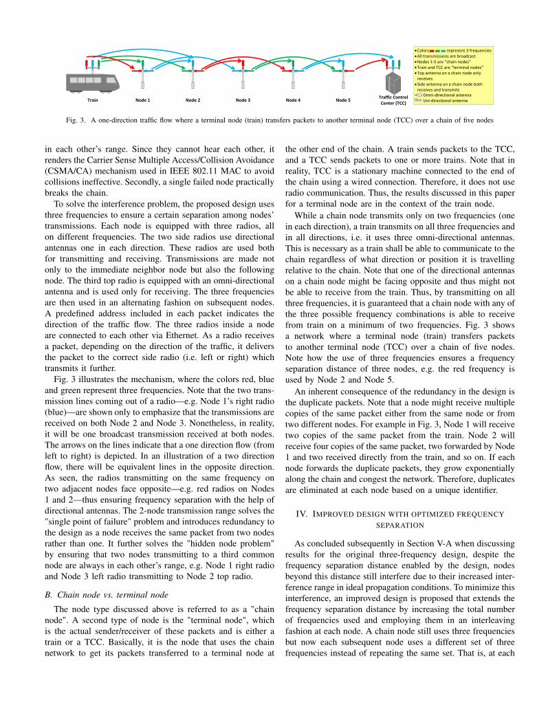
Fig. 3. A one-direction traffic flow where a terminal node (train) transfers packets to another terminal node (TCC) over a chain of five nodes
in each other’s range. Since they cannot hear each other, itrenders the Carrier Sense Multiple Access/Collision Avoidance(CSMA/CA) mechanism used in IEEE 802.11 MAC to avoidcollisions ineffective. Secondly, a single failed node practicallybreaks the chain.
To solve the interference problem, the proposed design usesthree frequencies to ensure a certain separation among nodes’transmissions. Each node is equipped with three radios, allon different frequencies. The two side radios use directionalantennas one in each direction. These radios are used bothfor transmitting and receiving. Transmissions are made notonly to the immediate neighbor node but also the followingnode. The third top radio is equipped with an omni-directionalantenna and is used only for receiving. The three frequenciesare then used in an alternating fashion on subsequent nodes.A predefined address included in each packet indicates thedirection of the traffic flow. The three radios inside a nodeare connected to each other via Ethernet. As a radio receivesa packet, depending on the direction of the traffic, it deliversthe packet to the correct side radio (i.e. left or right) whichtransmits it further.
Fig. 3 illustrates the mechanism, where the colors red, blueand green represent three frequencies. Note that the two trans-mission lines coming out of a radio—e.g. Node 1’s right radio(blue)—are shown only to emphasize that the transmissions arereceived on both Node 2 and Node 3. Nonetheless, in reality,it will be one broadcast transmission received at both nodes.The arrows on the lines indicate that a one direction flow (fromleft to right) is depicted. In an illustration of a two directionflow, there will be equivalent lines in the opposite direction.As seen, the radios transmitting on the same frequency ontwo adjacent nodes face opposite—e.g. red radios on Nodes1 and 2—thus ensuring frequency separation with the help ofdirectional antennas. The 2-node transmission range solves the"single point of failure" problem and introduces redundancy tothe design as a node receives the same packet from two nodesrather than one. It further solves the "hidden node problem"by ensuring that two nodes transmitting to a third commonnode are always in each other’s range, e.g. Node 1 right radioand Node 3 left radio transmitting to Node 2 top radio.
B. Chain node vs. terminal node
The node type discussed above is referred to as a "chainnode". A second type of node is the "terminal node", whichis the actual sender/receiver of these packets and is either atrain or a TCC. Basically, it is the node that uses the chainnetwork to get its packets transferred to a terminal node at
the other end of the chain. A train sends packets to the TCC,and a TCC sends packets to one or more trains. Note that inreality, TCC is a stationary machine connected to the end ofthe chain using a wired connection. Therefore, it does not useradio communication. Thus, the results discussed in this paperfor a terminal node are in the context of the train node.
While a chain node transmits only on two frequencies (onein each direction), a train transmits on all three frequencies andin all directions, i.e. it uses three omni-directional antennas.This is necessary as a train shall be able to communicate to thechain regardless of what direction or position it is travellingrelative to the chain. Note that one of the directional antennason a chain node might be facing opposite and thus might notbe able to receive from the train. Thus, by transmitting on allthree frequencies, it is guaranteed that a chain node with any ofthe three possible frequency combinations is able to receivefrom train on a minimum of two frequencies. Fig. 3 showsa network where a terminal node (train) transfers packetsto another terminal node (TCC) over a chain of five nodes.Note how the use of three frequencies ensures a frequencyseparation distance of three nodes, e.g. the red frequency isused by Node 2 and Node 5.
An inherent consequence of the redundancy in the design isthe duplicate packets. Note that a node might receive multiplecopies of the same packet either from the same node or fromtwo different nodes. For example in Fig. 3, Node 1 will receivetwo copies of the same packet from the train. Node 2 willreceive four copies of the same packet, two forwarded by Node1 and two received directly from the train, and so on. If eachnode forwards the duplicate packets, they grow exponentiallyalong the chain and congest the network. Therefore, duplicatesare eliminated at each node based on a unique identifier.
IV. IMPROVED DESIGN WITH OPTIMIZED FREQUENCYSEPARATION
As concluded subsequently in Section V-A when discussingresults for the original three-frequency design, despite thefrequency separation distance enabled by the design, nodesbeyond this distance still interfere due to their increased inter-ference range in ideal propagation conditions. To minimize thisinterference, an improved design is proposed that extends thefrequency separation distance by increasing the total numberof frequencies used and employing them in an interleavingfashion at each node. A chain node still uses three frequenciesbut now each subsequent node uses a different set of threefrequencies instead of repeating the same set. That is, at each

node, one of the existing three frequencies is replaced with anew one by iterating over the total number of frequencies.
Note that no modifications are required to be made to thechain node’s equipment as it is still equipped with three radios.On the contrary, the train node is now required to be equippedwith additional radios. Fig. 4 illustrates the mechanism.
Node 1 Node 2 Node 3 Node 4 Node 5
Node 1 Node 2 Node 3 Node 4 Node 5
Train
Train
Fig. 4. Frequency separation guaranteed with 3 and 4 frequencies
The top part of Fig. 4 shows the original three-frequencydesign. Here, for example, the blue frequency is used byNode 1 and Node 4, i.e. a frequency separation distance ofthree nodes. The bottom part of the figure uses one additionalfrequency (black—used by Nodes 2, 3 and 4). As seen, thisextends the frequency separation distance from three nodes tofour nodes as the blue frequency is now repeated at Node 5instead of Node 4. Increasing the number of frequencies tofive and six further extends the frequency separation distancelikewise.
A train node is required to be equipped with additional ra-dios because, as discussed in III-B, it must use all frequenciesto be able to transmit to the chain and receive from it. Notethat it is normal to employ various—e.g. up to four—radiosper train in conventional CBTC systems in order to ensurehigh availability [10]. Thus, this additional radio on the traindoes not necessarily increase the system’s cost.
V. SIMULATION STUDY
Simulations were carried out using a discrete-event simula-tor [11]. Table I lists the key simulation parameters and theirvalues used in the simulations. An inter-node distance of 600meters has been used in all simulations as it could be directlyrelated to the distance currently used in the Copenhagen’s S-train CBTC system based on the conventional CBTC technol-ogy. As the design requires that a node be heard by two ofits neighbors, transmission power and receive sensitivity wereadjusted to transmit to a distance of 1200 meters.
The proposed design relies on the assumption that theseparation provided by the three-frequency design is sufficientand signals from nodes beyond that distance will not interfere.However, this is far from reality as minor changes in thepropagation conditions have shown to dramatically increasethe signal range in railway environments [10]. Our simulationmodel uses the simulation tool’s default Free-Space Path Loss(FSPL) propagation model. The FSPL model assumes a freespace between the sender and receiver and therefore does not
TABLE ISIMULATION PARAMETERS
Parameters ValueWLAN technology IEEE 802.11a OFDM at 54 Mbps
Frequency channels (MHz) 5170, 5230, 5290, 5735, 5795, 5815
Transmission power (dBm) 7
Receive sensitivity (dBm) -76
Antenna gain (dBi) 14
Packet size (bytes) 512
Inter-node distance (m) 600
Nodes 100
Packet rate (per second) 1000
Simulation time (s) 60
consider signal loss that occurs due to obstacles. Thus, itenables exceptionally large signal range which provides theworst case scenario necessary to validate the proposed design.
In the simulation scenarios discussed, two terminal nodes—train and TCC—placed at the two ends of the chain transmitpackets which are then transferred to the other terminal nodeover the chain. This results in two packet flows, one in eachdirection. A packet rate of 1000 packets per second is used(per flow), resulting in a combined data rate of 8.2 Mbps. Anetwork size of 100 nodes has been used in our simulationsas it will more likely be the largest network size used in theactual CBTC deployments, both in terms of the number ofnodes and the actual length (about 60 kilometers). In actualdeployments, the existing network infrastructure available atthe train stations will be used to provide a wired connectionto the two nearest nodes of the chain. Thus, chain length willbe much smaller.
When discussing results, we are particularly interested insix performance indicators, namely unique packets received,duplicate packets received, total packets received, collisions,erroneous packets received, and, packets lost. Number ofunique packets received serves as our key parameter as it indi-cates how many of the original unique packets (i.e. excludingduplicates) sent by the train are successfully transferred overthe network. Note that this number for a node is essentiallyequivalent to the number of packets forwarded by the node.Total packets received includes duplicate packets. Erroneouspackets are a result of interference between transmissions fromdifferent nodes (including collisions). These packets are dis-carded and do not count towards the aforementioned packetsreceived numbers. Packets lost is the number of packets that,out of the original unique packets sent, were not received atthe receiving end, for example owing to errors.
Note that while we discuss results for a select set of chainnodes as well, we are primarily interested in results for theterminal nodes.
A. Results for the original design
In the first part of the study, the performance of the originaldesign with three frequencies is studied. Fig. 5 shows theresults for the above mentioned six parameters against each
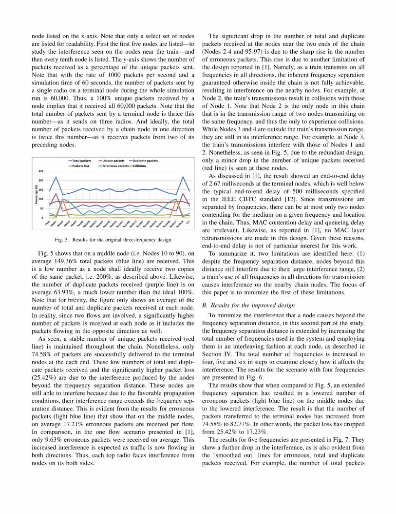
node listed on the x-axis. Note that only a select set of nodesare listed for readability. First the first five nodes are listed—tostudy the interference seen on the nodes near the train—andthen every tenth node is listed. The y-axis shows the number ofpackets received as a percentage of the unique packets sent.Note that with the rate of 1000 packets per second and asimulation time of 60 seconds, the number of packets sent bya single radio on a terminal node during the whole simulationrun is 60,000. Thus, a 100% unique packets received by anode implies that it received all 60,000 packets. Note that thetotal number of packets sent by a terminal node is thrice thisnumber—as it sends on three radios. And ideally, the totalnumber of packets received by a chain node in one directionis twice this number—as it receives packets from two of itspreceding nodes.
0
50
100
150
200
250
Percentage (%)
Total packets Unique packets Duplicate packets
Packets lost Erroneous packets Collisions
Fig. 5. Results for the original three-frequency design
Fig. 5 shows that on a middle node (i.e. Nodes 10 to 90), onaverage 149.36% total packets (blue line) are received. Thisis a low number as a node shall ideally receive two copiesof the same packet, i.e. 200%, as described above. Likewise,the number of duplicate packets received (purple line) is onaverage 63.93%, a much lower number than the ideal 100%.Note that for brevity, the figure only shows an average of thenumber of total and duplicate packets received at each node.In reality, since two flows are involved, a significantly highernumber of packets is received at each node as it includes thepackets flowing in the opposite direction as well.
As seen, a stable number of unique packets received (redline) is maintained throughout the chain. Nonetheless, only74.58% of packets are successfully delivered to the terminalnodes at the each end. These low numbers of total and dupli-cate packets received and the significantly higher packet loss(25.42%) are due to the interference produced by the nodesbeyond the frequency separation distance. These nodes arestill able to interfere because due to the favorable propagationconditions, their interference range exceeds the frequency sep-aration distance. This is evident from the results for erroneouspackets (light blue line) that show that on the middle nodes,on average 17.21% erroneous packets are received per flow.In comparison, in the one flow scenario presented in [1],only 9.63% erroneous packets were received on average. Thisincreased interference is expected as traffic is now flowing inboth directions. Thus, each top radio faces interference fromnodes on its both sides.
The significant drop in the number of total and duplicatepackets received at the nodes near the two ends of the chain(Nodes 2-4 and 95-97) is due to the sharp rise in the numberof erroneous packets. This rise is due to another limitation ofthe design reported in [1]. Namely, as a train transmits on allfrequencies in all directions, the inherent frequency separationguaranteed otherwise inside the chain is not fully achievable,resulting in interference on the nearby nodes. For example, atNode 2, the train’s transmissions result in collisions with thoseof Node 1. Note that Node 2 is the only node in this chainthat is in the transmission range of two nodes transmitting onthe same frequency, and thus the only to experience collisions.While Nodes 3 and 4 are outside the train’s transmission range,they are still in its interference range. For example, at Node 3,the train’s transmissions interfere with those of Nodes 1 and2. Nonetheless, as seen in Fig. 5, due to the redundant design,only a minor drop in the number of unique packets received(red line) is seen at these nodes.
As discussed in [1], the result showed an end-to-end delayof 2.67 milliseconds at the terminal nodes, which is well belowthe typical end-to-end delay of 500 milliseconds specifiedin the IEEE CBTC standard [12]. Since transmissions areseparated by frequencies, there can be at most only two nodescontending for the medium on a given frequency and locationin the chain. Thus, MAC contention delay and queueing delayare irrelevant. Likewise, as reported in [1], no MAC layerretransmissions are made in this design. Given these reasons,end-to-end delay is not of particular interest for this work.
To summarize it, two limitations are identified here: (1)despite the frequency separation distance, nodes beyond thisdistance still interfere due to their large interference range, (2)a train’s use of all frequencies in all directions for transmissioncauses interference on the nearby chain nodes. The focus ofthis paper is to minimize the first of these limitations.
B. Results for the improved design
To minimize the interference that a node causes beyond thefrequency separation distance, in this second part of the study,the frequency separation distance is extended by increasing thetotal number of frequencies used in the system and employingthem in an interleaving fashion at each node, as described inSection IV. The total number of frequencies is increased tofour, five and six in steps to examine closely how it affects theinterference. The results for the scenario with four frequenciesare presented in Fig. 6.
The results show that when compared to Fig. 5, an extendedfrequency separation has resulted in a lowered number oferroneous packets (light blue line) on the middle nodes dueto the lowered interference. The result is that the number ofpackets transferred to the terminal nodes has increased from74.58% to 82.77%. In other words, the packet loss has droppedfrom 25.42% to 17.23%.
The results for five frequencies are presented in Fig. 7. Theyshow a further drop in the interference, as is also evident fromthe "smoothed out" lines for erroneous, total and duplicatepackets received. For example, the number of total packets
0
50
100
150
200
250
Percentage (%)
Total packets Unique packets Duplicate packets
Packets lost Erroneous packets Collisions
Fig. 6. Results for the design with 4 frequencies
received by a middle node has increased to 170.6% on average,compared to 149.36% seen in Fig. 5. As a result, the packetloss seen at the terminal nodes has further dropped to 16.22%.
0
50
100
150
200
250
Percentage (%)
Total packets Unique packets Duplicate packets
Packets lost Erroneous packets Collisions
Fig. 7. Results for the design with 5 frequencies
Finally, Fig. 8 shows the results for the six-frequencydesign. As expected, a significant further drop in the erro-neous packets is seen. Specifically, on the middle nodes, onaverage only 1.93% erroneous packets are received comparedto 17.21% seen in the three-frequency scenario (Fig. 5). As aresult, the packet loss at terminal nodes drops to 14.54%, asignificant drop from 25.42% seen in Fig. 5.
0
50
100
150
200
250
Percentage (%)
Total packets Unique packets Duplicate packets
Packets lost Erroneous packets Collisions
Fig. 8. Results for the design with 6 frequencies
Notably, despite that now the number of erroneous packetscaused by the chain nodes due to the insufficient frequencyseparation has dropped to only 1.93% per node, the totalpacket loss seen at a terminal node is still 14.54%. This indi-cates that the interference caused by the terminal nodes at theirnearby nodes (Nodes 2-4 and 95-97) is a greater contributor ofthe total packet loss. Employing additional frequencies might
thus not improve the situation significantly unless the interfer-ence from the terminal nodes is also minimized. Specifically,the results indicate that out of the 25.42% packet loss seen inthe original three-frequency scenario, approximately 10.88%was introduced by the interference from the nodes inside thechain and 14.54% by the terminal node.
C. Comparison of the original and the improved design
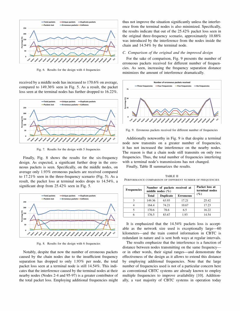
For the sake of comparison, Fig. 9 presents the number oferroneous packets received for different number of frequen-cies. As seen, increasing the frequency separation distanceminimizes the amount of interference dramatically.
0
25
50
75
Percentage (%)
Number of erroneous packets received
Three frequencies Four frequencies Five frequencies Six frequencies
Fig. 9. Erroneous packets received for different number of frequencies
Additionally noteworthy in Fig. 9 is that despite a terminalnode now transmits on a greater number of frequencies,it has not increased the interference on the nearby nodes.The reason is that a chain node still transmits on only twofrequencies. Thus, the total number of frequencies interferingwith a terminal node’s transmissions has not changed.
Finally, Table II summarizes the results.
TABLE IIPERFORMANCE COMPARISON OF DIFFERENT NUMBER OF FREQUENCIES
FrequenciesNumber of packets received atmiddle nodes (%)
Packet loss atterminal nodes(%)Total Duplicate Erroneous
3 149.36 63.93 17.21 25.42
4 164.4 74.21 10.67 17.23
5 170.6 78.6 6.5 16.22
6 176.5 83.67 1.93 14.54
It is emphasized that the 14.54% packets loss is accept-able as the network size used is exceptionally large—60kilometers—and the train control information in CBTC isredundant in nature and is sent both ways at regular intervals.
The results emphasize that the interference is a function ofdistance between nodes transmitting on the same frequency—or in other words, their signal ranges—and demonstrate theeffectiveness of the design as it allows to extend this distanceby employing additional frequencies. Note that the largenumber of frequencies used is not of a particular concern hereas conventional CBTC systems are already known to employmultiple frequencies to improve availability [10]. Addition-ally, a vast majority of CBTC systems in operation today

work in the license-free Industrial, Scientific and Medical(ISM) frequency band [10]. Furthermore, the objective hereprimarily is to demonstrate that such a solution is feasible.As discussed above, our simulations use the simplistic FSPLpropagation model. The results show that more realistic, lessfavorable propagation conditions will improve the performanceby negatively affecting the signal range and thus loweringthe interference. Thus, a design with a fewer number offrequencies, e.g. four, might as well yield the desired results.
VI. FUTURE WORK
Future work will focus on proposing solutions to minimizethe interference caused by the train’s transmissions as well asscenarios with a greater number of trains and mobility.
VII. CONCLUSIONS
This paper extends the previously presented design of anad-hoc based trackside radio communication network for trainto trackside communication in CBTC. A node in this designfunctions in ad-hoc mode, receiving broadcast packets andforwarding to its neighbors, thus forming a chain of nodes. Thetrain thus does not have to perform a handshake with the nodes(as in conventional infrastructure Wi-Fi) as it moves and thecostly optical fiber cables connecting the nodes are no moreneeded. The design offers resiliency against interference byemploying multiple frequencies. Nonetheless, the result showa significant amount of packet loss due to the interferenceinside the chain. This paper extends the design by employingadditional frequencies in an interleaving fashion in order to op-timize the frequency separation distance. The results show thatincreasing the frequency separation distance very effectivelyminimizes the interference. As a result, a significantly largenumbers of packets can be transferred across large networkswith only limited packet loss.
ACKNOWLEDGMENTS
The authors would like to thank Simon Staudt, KasperTipsmark Therkildsen and Kell Quist Jensen for their supportin carrying out this work.
REFERENCES
[1] J. Farooq, L. Bro, R. T. Karstensen, and J. Soler, “A multi-radio,multi-hop ad-hoc radio communication network for Communications-Based Train Control (CBTC),” in Proc. IEEE 86th Vehicular TechnologyConference (VTC 2017-Fall), sep 2017.
[2] Siemens AG, “Ad-hoc kommunikationsnetzwerk,” Patent Application 102017 203 040.2, feb 24, 2017.
[3] S. Xu and T. Saadawi, “Does the IEEE 802.11 MAC protocol work wellin multihop wireless ad hoc networks?” IEEE Commun. Mag., vol. 39,no. 6, pp. 130–137, jun 2001.
[4] J. Li, C. Blake, D. S. De Couto, H. I. Lee, and R. Morris, “Capacity ofad hoc wireless networks,” in Proc. 7th Annual International Conferenceon Mobile Computing and Networking (MobiCom ’01). New York, NY,USA: ACM, 2001, pp. 61–69.
[5] K. Xu, M. Gerla, and S. Bae, “How effective is the IEEE 802.11RTS/CTS handshake in ad hoc networks,” in Proc. IEEE GlobalTelecommunications Conference (GLOBECOM ’02), nov 2002.
[6] F. Ye, S. Yi, and B. Sikdar, “Improving spatial reuse of IEEE 802.11based ad hoc networks,” in Proc. IEEE Global TelecommunicationsConference (GLOBECOM ’03), dec 2003.
[7] Q. Dong, S. Banerjee, and B. Liu, “Throughput optimization and fairbandwidth allocation in multi-hop wireless LANs,” in Proc. IEEEInternational Conference on Computer Communications (INFOCOM’06), apr 2006.
[8] T. Tainaka, H. Masuyama, S. Kasahara, and Y. Takahashi, “Performanceanalysis of burst transmission mechanism for IEEE 802.11-based multi-hop wireless LANs,” IEEE Trans. Wireless Commun., vol. 10, no. 9, pp.2908–2917, 2011.
[9] Z. Zeng, Y. Yang, and J. C. Hou, “How physical carrier sense affectssystem throughput in IEEE 802.11 wireless networks,” in Proc. IEEEInternational Conference on Computer Communications (INFOCOM’08), apr 2008.
[10] J. Farooq and J. Soler, “Radio communication for communications-basedtrain control (CBTC): A tutorial and survey,” IEEE Commun. SurveysTuts., vol. 19, no. 3, pp. 1377–1402, 2017.
[11] “OPNET Modeler,” Riverbed Technology,https://www.riverbed.com/dk/products/steelcentral/opnet.html.
[12] Communications-Based Train Control (CBTC) Performance and Func-tional Requirements, IEEE Std. 1474.1, 2004.
Related Documents