Challenges During a Top Down Design and Construction Approach of Foothills Parkway Bridge No. 8 Geohazards Impacting Transportation in Appalachia Knoxville, TN August 2016 KHALID T. MOHAMED, P.E., PMP FHWA, WASHINGTON, DC MOHAMMED ELIAS, PHD, P.E. FHWA, STERLING, VA

Welcome message from author
This document is posted to help you gain knowledge. Please leave a comment to let me know what you think about it! Share it to your friends and learn new things together.
Transcript
Challenges During a Top Down Design and Construction Approach of Foothills Parkway Bridge No. 8
Geohazards Impacting Transportation in AppalachiaKnoxville, TNAugust 2016
KHALID T. MOHAMED, P.E. , PMPFHWA, WASHINGTON, DC
MOHAMMED ELIAS, PHD, P.E.FHWA, STERLING, VA
Introduction Project Location Foothills Parkway
History General Geologic
Conditions Design & Construction
Constraints Bridge Foundation
Design Changes Foundation
Construction Bridge Construction
OUTLINE
INTRODUCTION
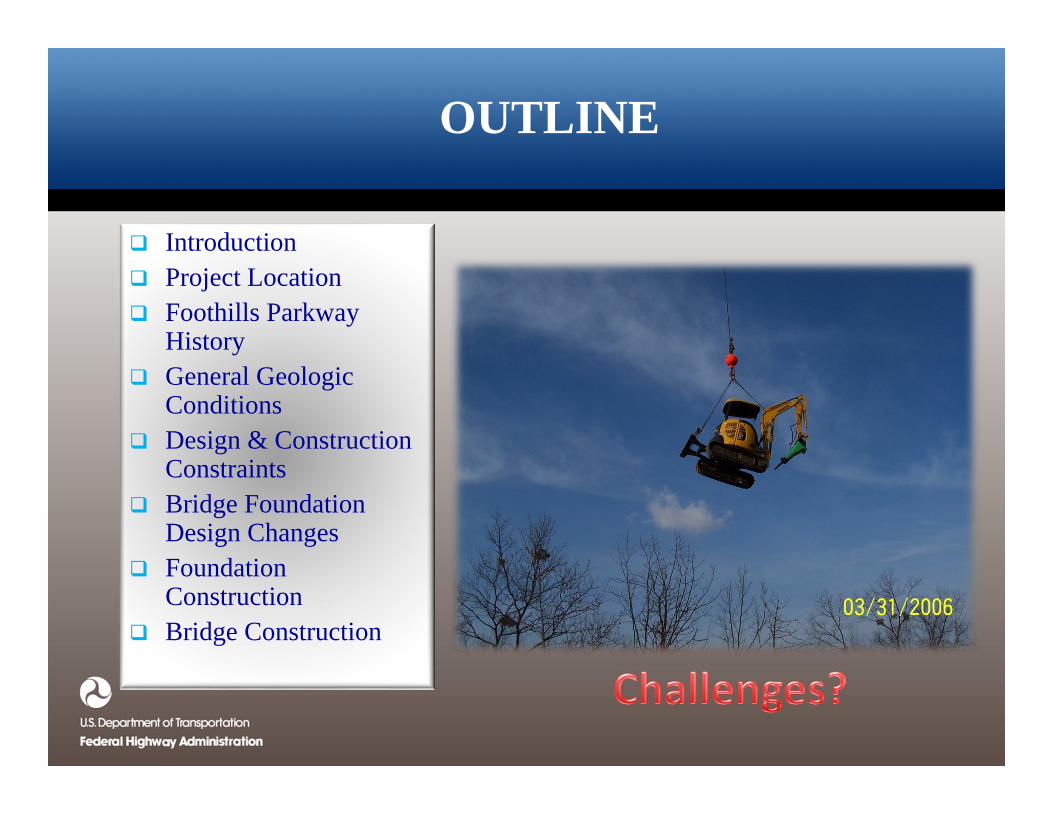
Foothills Bridge No. 8 is One of 10 Proposed Bridges Along “Missing Link”
The “Missing Link” section of the Parkway is 1.65-mile long
Bridge No. 9 and 10 were completed in 2001
Bridge No. 1 was Replaced by a Geogrid Reinforced Limestone Shot rock Embankment
Bridge 2 Was Completed in 2013
Remaining Bridges are Under Construction
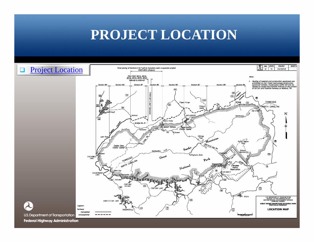
PROJECT LOCATION
Project Location
FOOTHILLS PARKWAY HISTORY
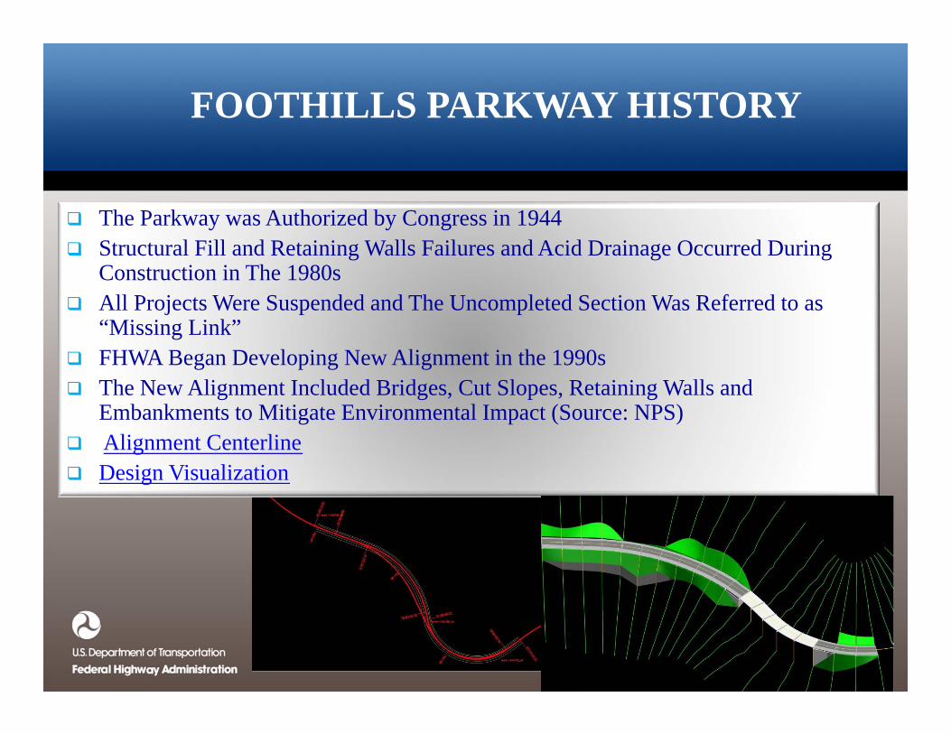
The Parkway was Authorized by Congress in 1944 Structural Fill and Retaining Walls Failures and Acid Drainage Occurred During
Construction in The 1980s All Projects Were Suspended and The Uncompleted Section Was Referred to as
“Missing Link” FHWA Began Developing New Alignment in the 1990s The New Alignment Included Bridges, Cut Slopes, Retaining Walls and
Embankments to Mitigate Environmental Impact (Source: NPS) Alignment Centerline Design Visualization
GENERAL GEOLOGIC CONDITIONS
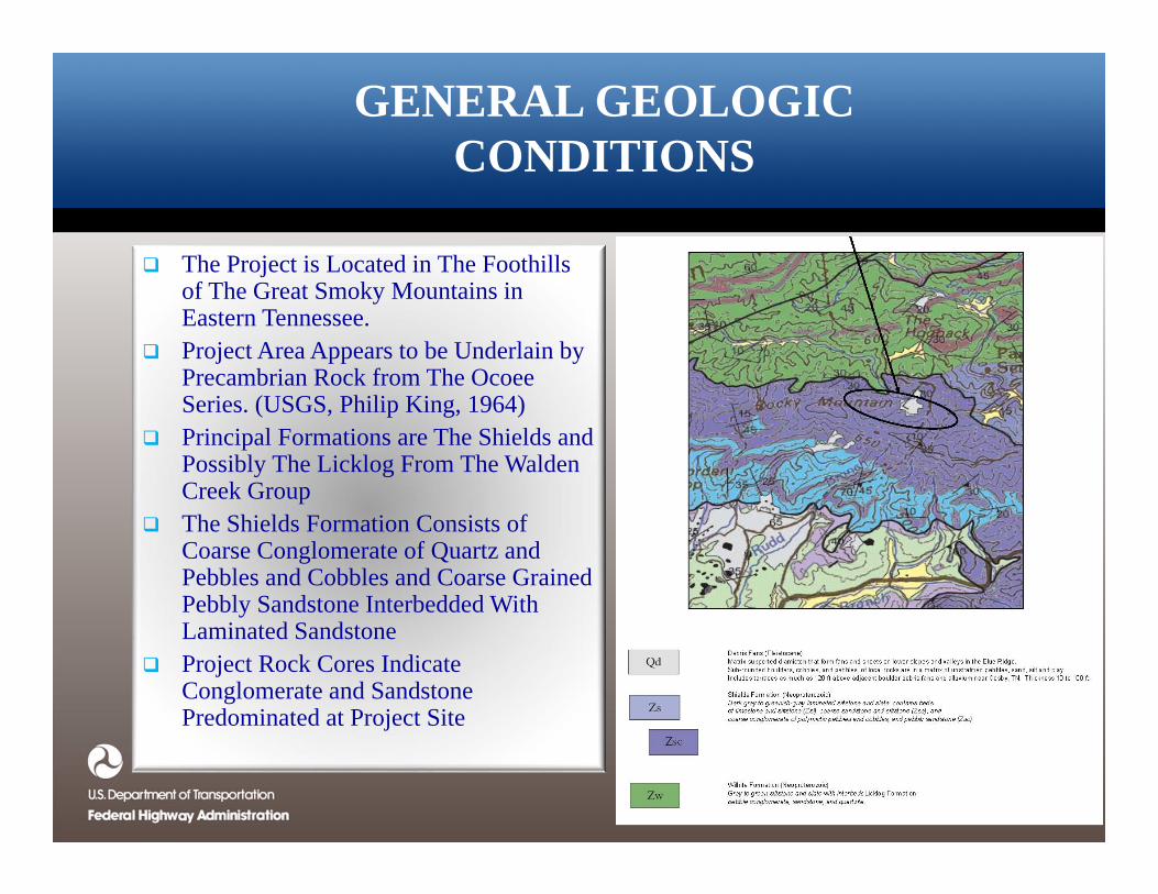
The Project is Located in The Foothills of The Great Smoky Mountains in Eastern Tennessee.
Project Area Appears to be Underlain by Precambrian Rock from The Ocoee Series. (USGS, Philip King, 1964)
Principal Formations are The Shields and Possibly The Licklog From The Walden Creek Group
The Shields Formation Consists of Coarse Conglomerate of Quartz and Pebbles and Cobbles and Coarse Grained Pebbly Sandstone Interbedded With Laminated Sandstone
Project Rock Cores Indicate Conglomerate and Sandstone Predominated at Project Site
DESIGN AND CONSTRUCTION CONSTRAINS
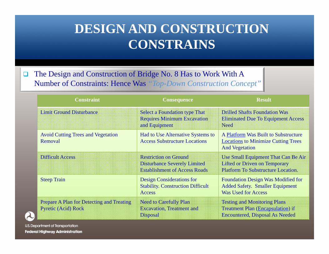
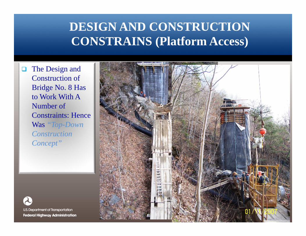
The Design and Construction of Bridge No. 8 Has to Work With A Number of Constraints: Hence Was “Top-Down Construction Concept”
Constraint Consequence Result
Limit Ground Disturbance Select a Foundation type That Requires Minimum Excavationand Equipment
Drilled Shafts Foundation WasEliminated Due To Equipment Access Need
Avoid Cutting Trees and Vegetation Removal
Had to Use Alternative Systems to Access Substructure Locations
A Platform Was Built to Substructure Locations to Minimize Cutting Trees And Vegetation
Difficult Access Restriction on Ground Disturbance Severely Limited Establishment of Access Roads
Use Small Equipment That Can Be Air Lifted or Driven on Temporary Platform To Substructure Location.
Steep Train Design Considerations for Stability. Construction Difficult Access
Foundation Design Was Modified for Added Safety. Smaller Equipment Was Used for Access
Prepare A Plan for Detecting and Treating Pyretic (Acid) Rock
Need to Carefully Plan Excavation, Treatment and Disposal
Testing and Monitoring Plans Treatment Plan (Encapsulation) if Encountered, Disposal As Needed
DESIGN AND CONSTRUCTION CONSTRAINS (Platform Access)
The Design and Construction of Bridge No. 8 Has to Work With A Number of Constraints: Hence Was “Top-Down Construction Concept”
DESIGN AND CONSTRUCTION CONSTRAINS (Pyritic (Acid) Rock)
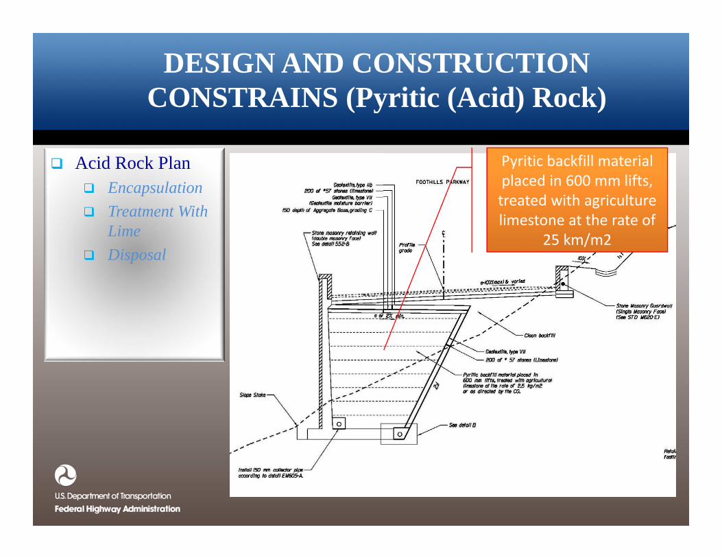
Acid Rock Plan Encapsulation Treatment With
Lime Disposal
Pyritic backfill material placed in 600 mm lifts, treated with agriculture limestone at the rate of
25 km/m2
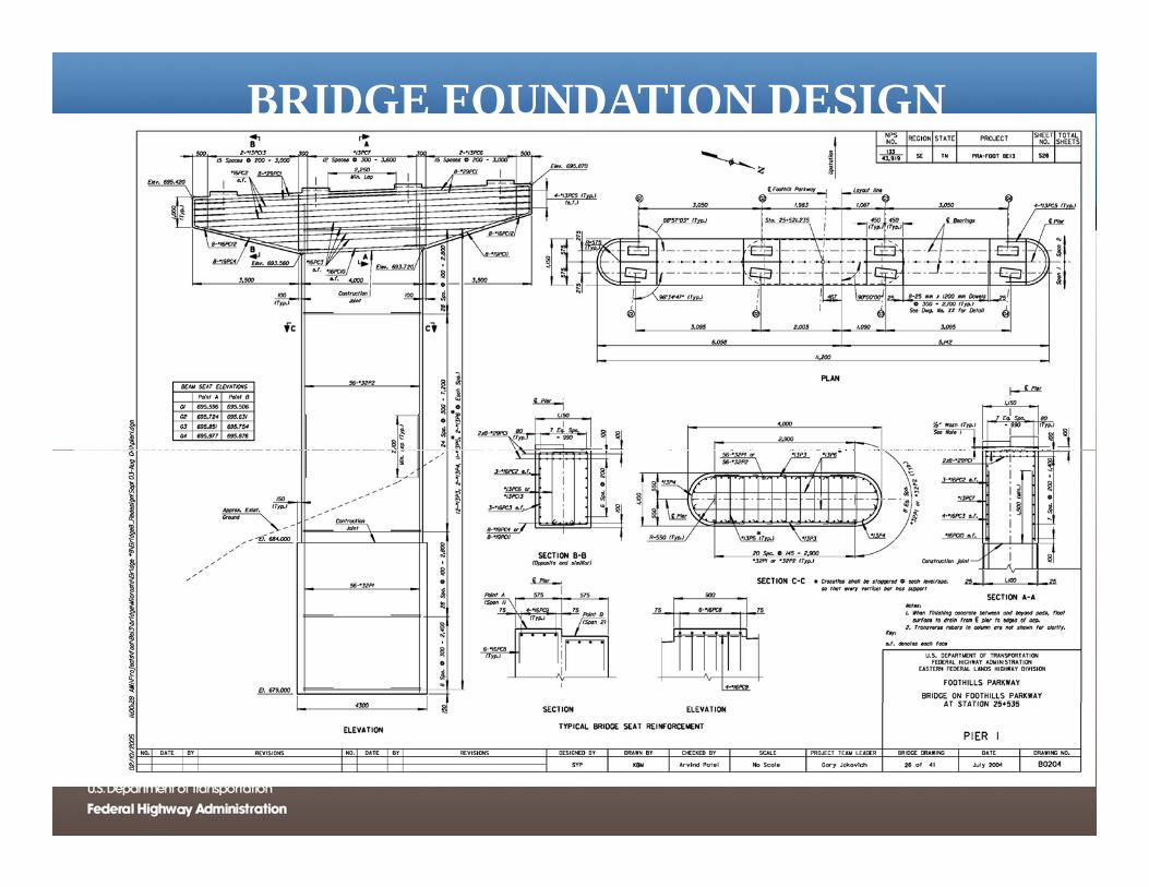
BRIDGE FOUNDATION DESIGN(1996)
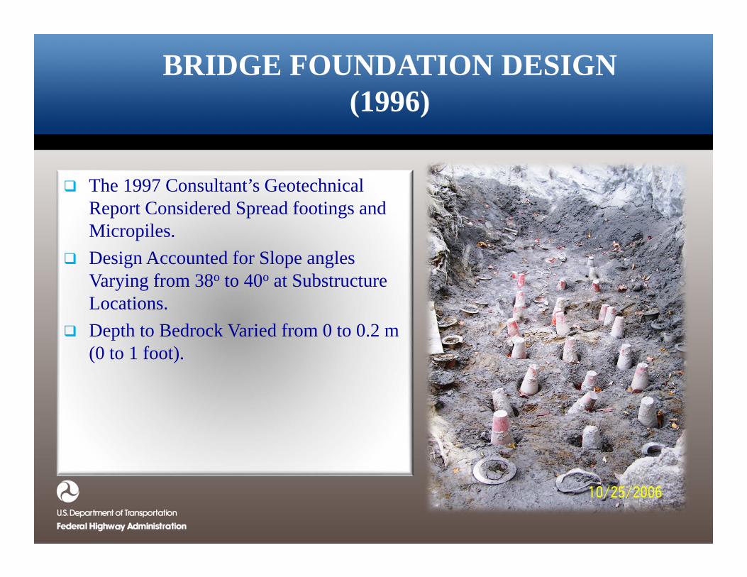
The 1997 Consultant’s Geotechnical Report Considered Spread footings and Micropiles.
Design Accounted for Slope angles Varying from 38o to 40o at Substructure Locations.
Depth to Bedrock Varied from 0 to 0.2 m (0 to 1 foot).
BRIDGE FOUNDATION DESIGN(1996)
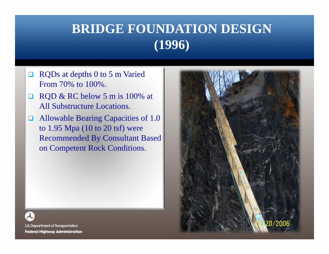
RQDs at depths 0 to 5 m Varied From 70% to 100%.
RQD & RC below 5 m is 100% at All Substructure Locations.
Allowable Bearing Capacities of 1.0 to 1.95 Mpa (10 to 20 tsf) were Recommended By Consultant Based on Competent Rock Conditions.
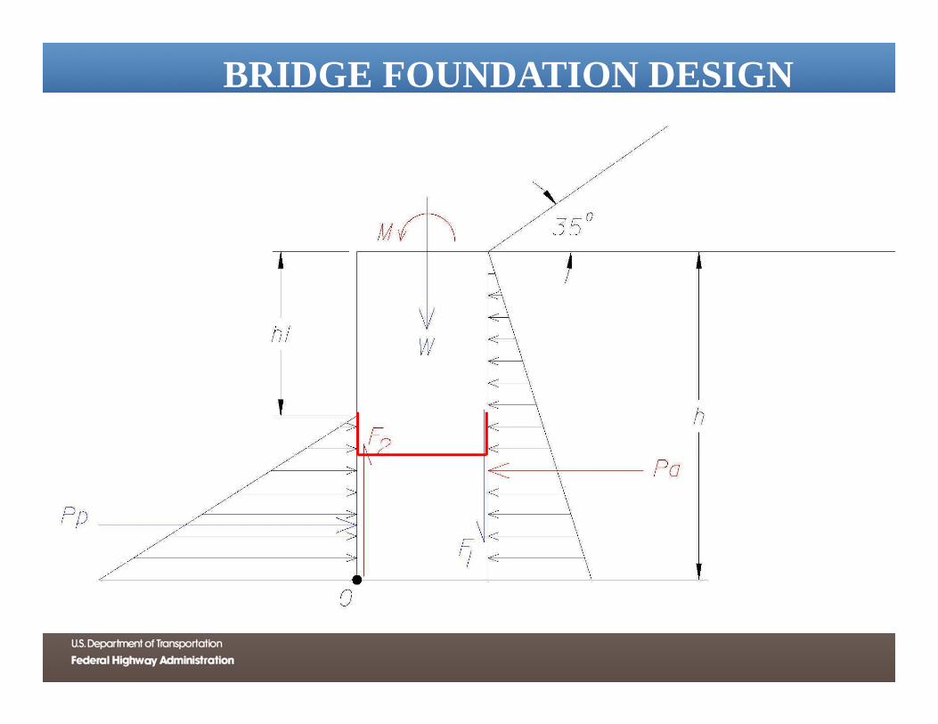
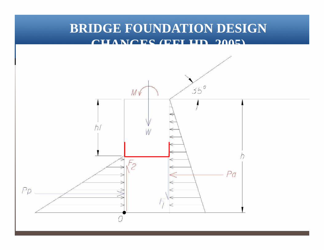
BRIDGE FOUNDATION DESIGN CHANGES (EFLHD, 2005)
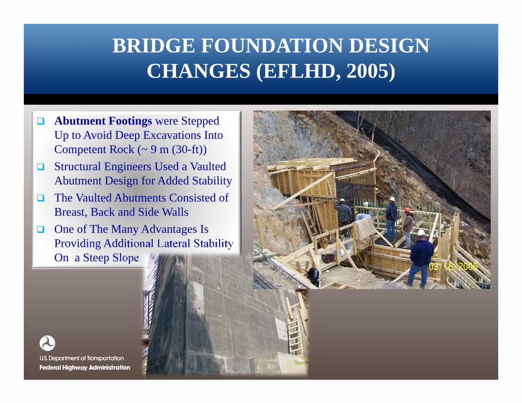
Abutment Footings were Stepped Up to Avoid Deep Excavations Into Competent Rock (~ 9 m (30-ft))
Structural Engineers Used a Vaulted Abutment Design for Added Stability
The Vaulted Abutments Consisted of Breast, Back and Side Walls
One of The Many Advantages Is Providing Additional Lateral Stability On a Steep Slope
BRIDGE FOUNDATION DESIGN CHANGES (EFLHD, 2005)
Piers 1 & 2 Foundations Embedment Depth Into Bedrock Was Modified for Additional Lateral Stability
Foundations Embedment Depth Was Extended to 5 (16.5 ft)Meters Below Ground Low Point Into 100% RC & RQD Competent Rock
The New Design is Similar To A Socketed Shaft That Can be Constructed Using Small Equipment
Drilled Shafts Were Not Selected Due To Equipment Access Requirements
BRIDGE FOUNDATION DESIGN CHANGES (EFLHD, 2005)
Piers 1 & 2 Foundations Embedment Depth Into Bedrock Was Modified for Additional Lateral Stability
Foundation Embedment Depth Was Extended to 5 (16.5 ft) Meters Below Ground Low Point Into 100% RC & RQD Competent Rock
The New Design is Similar To A Socketed Shaft That Can be Constructed Using Small Equipment
Drilled Shafts Were Not Selected Due To Equipment Access Requirements
BRIDGE FOUNDATION DESIGN CHANGES (EFLHD, 2005)
Piers 1 & 2 Foundations Embedment Depth Into Bedrock Was Modified for Additional Lateral Stability
Foundation Embedment Depth Was Extended to 5 Meters (16.5 ft) Below Ground Low Point Into 100% RC & RQD Competent Rock
The New Design is Similar To A Socketed Shaft That Can be Constructed Using Small Equipment
Drilled Shafts Were Not Selected Due To Equipment Access Requirements
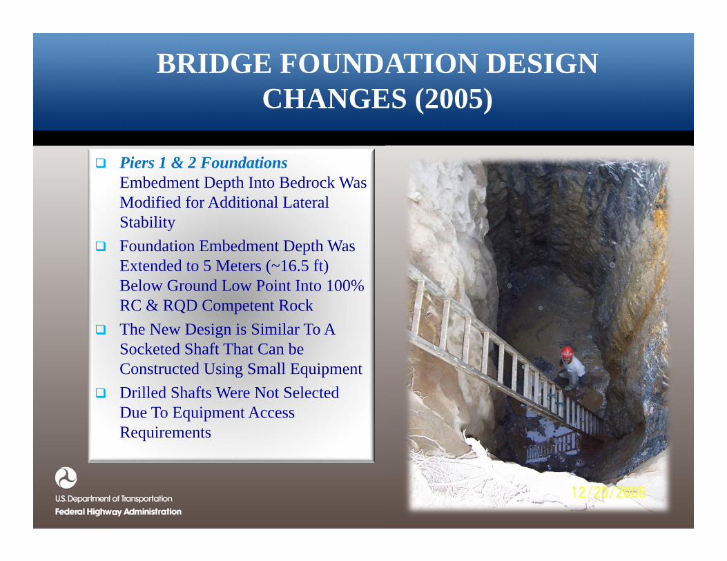
BRIDGE FOUNDATION DESIGN CHANGES (2005)
Piers 1 & 2 Foundations Embedment Depth Into Bedrock Was Modified for Additional Lateral Stability
Foundation Embedment Depth Was Extended to 5 Meters (~16.5 ft) Below Ground Low Point Into 100% RC & RQD Competent Rock
The New Design is Similar To A Socketed Shaft That Can be Constructed Using Small Equipment
Drilled Shafts Were Not Selected Due To Equipment Access Requirements
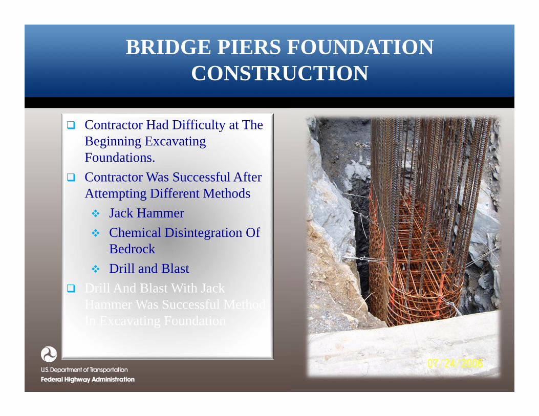
BRIDGE PIERS FOUNDATION CONSTRUCTION
Contractor Had Difficulty at The Beginning Excavating Foundations.
Contractor Was Successful After Attempting Different Methods Jack Hammer Chemical Disintegration Of
Bedrock Drill and Blast
Drill And Blast With Jack Hammer Was Successful Method In Excavating Foundation
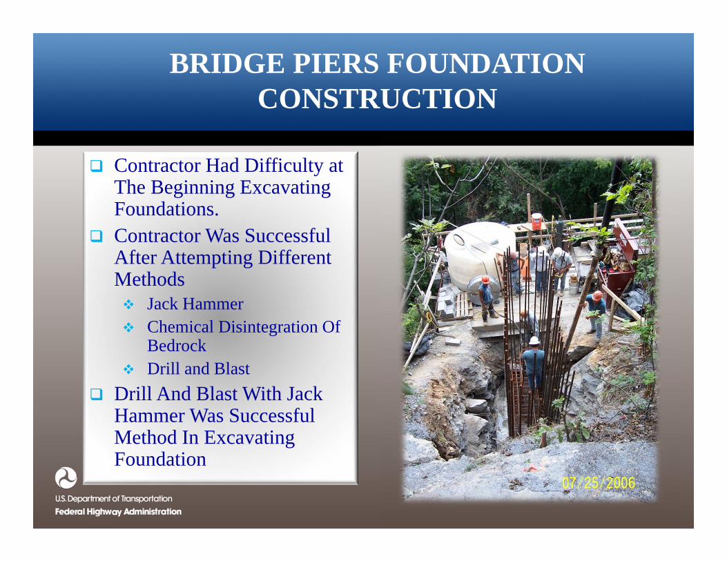
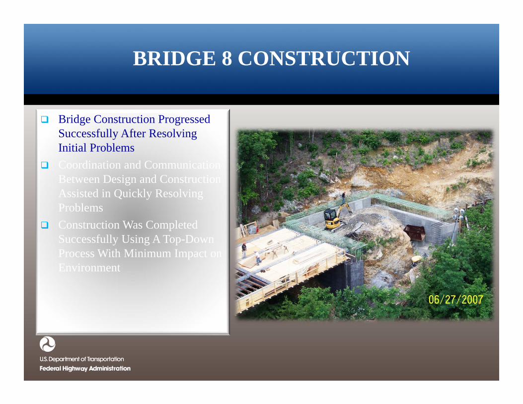
BRIDGE 8 CONSTRUCTION
Bridge Construction Progressed Successfully After Resolving Initial Problems
Coordination and Communication Between Design and Construction Assisted in Quickly Resolving Problems
Construction Was Completed Successfully Using A Top-Down Process With Minimum Impact on Environment
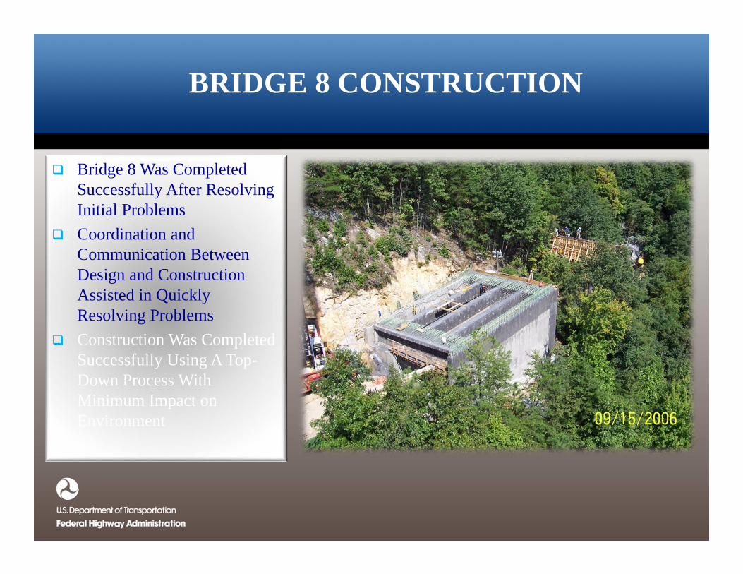
BRIDGE 8 CONSTRUCTION
Bridge 8 Was Completed Successfully After Resolving Initial Problems
Coordination and Communication Between Design and Construction Assisted in Quickly Resolving Problems
Construction Was Completed Successfully Using A Top-Down Process With Minimum Impact on Environment
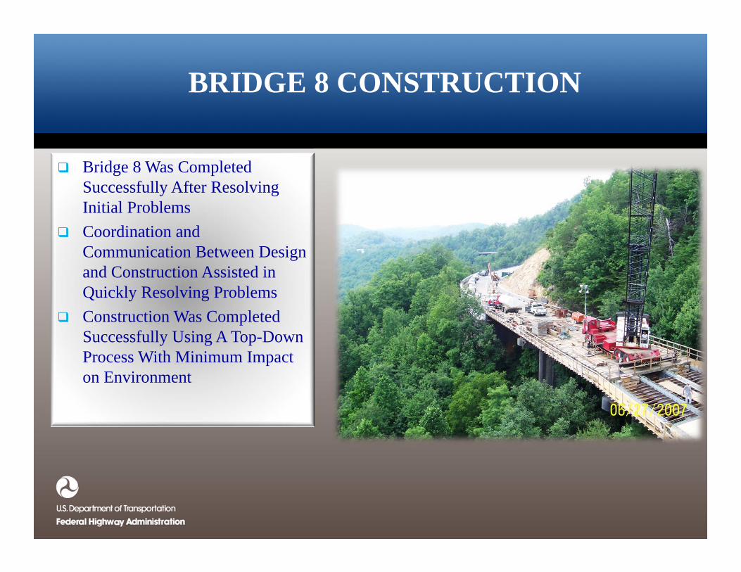
BRIDGE 8 CONSTRUCTION
Bridge 8 Was Completed Successfully After Resolving Initial Problems
Coordination and Communication Between Design and Construction Assisted in Quickly Resolving Problems
Construction Was Completed Successfully Using A Top-Down Process With Minimum Impact on Environment
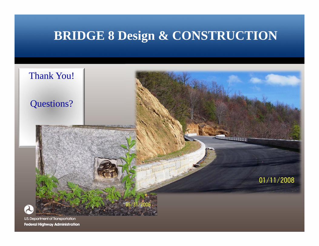
BRIDGE 8 Design & CONSTRUCTION
Thank You!
Questions?
Related Documents