Chapter 3: Method of Analysis (dc) BEE1133 : Circuit Analysis I

Ch3_Method of Analysis (Dc)
Nov 21, 2014
Welcome message from author
This document is posted to help you gain knowledge. Please leave a comment to let me know what you think about it! Share it to your friends and learn new things together.
Transcript

Chapter 3: Method of Analysis (dc)
BEE1133 : Circuit Analysis I

3.1 Nodal analysis
3.2 Application of Cramer’s rule
3.3 Nodal analysis with voltage sources: supernode
3.4 Mesh analysis
3.5 Mesh analysis with current sources: supermesh
3.6 Nodal versus mesh analysis
Method of Analysis : Syllabus

Nodal Analysis
• Without voltage source
• With voltage sources
• Understand the concept of nodal voltage
• Analyze dc circuit using nodal analysis
• Apply Cramer rule to solve simultaneous equations
• Understand the concept of supernode
Nodal Analysis:Lesson Outcomes

• Nodal analysis applies KCL to find unknown voltages value.
• To analyze a circuit using nodal analysis, node voltages are used as a circuit variables instead of element voltages to reduce number of equations.
• In the first section, circuits with no voltage sources are considered.
Nodal Analysis

Steps to determine node voltages:
1. Choose a reference node.
2. Assign node voltages to the other nodes.
3.Apply KCL to each node other than the reference node; express currents in terms of node voltages.
4. Solve the resulting system of linear equations.
Nodal Analysis : Steps
Nodal Analysis w/o voltage source
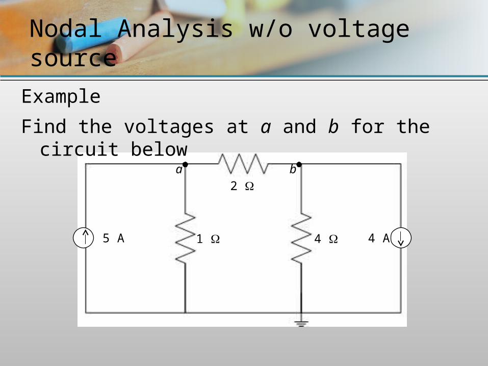
Example
Find the voltages at a and b for the circuit below
1 4
2
5 A 4 A
a b

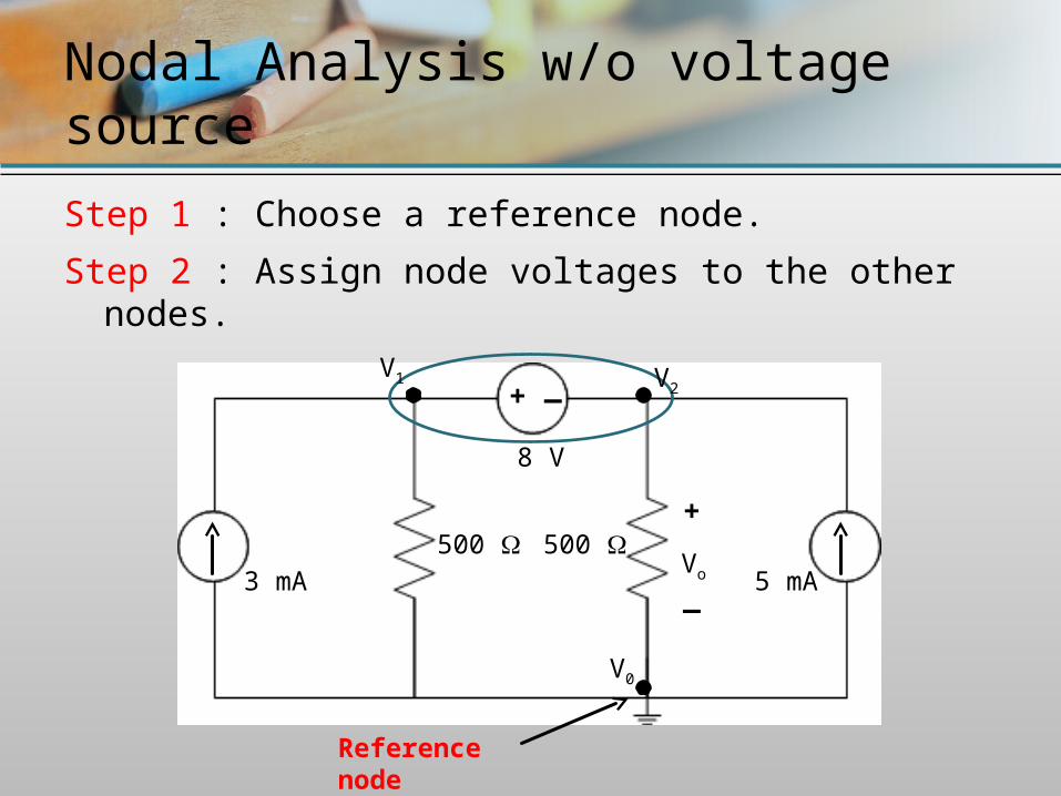
Step 1 : Choose a reference node.
Step 2 : Assign node voltages to the other nodes.
Nodal Analysis w/o voltage source
2
1 4
V1
V0
V2
Reference node

Step 3 : Apply KCL to each node other than the reference node (in term of node voltage).
At node a :
i1 = i2 + i3 (apply KCL)
(in term of node voltage)
At node b :
i2 = i4 + i5 (apply KCL)
Nodal Analysis w/o voltage source
2
1 4
V1 V2
V0
i1 i2i3 i4
i5
125 0121 VVVV
442
0221
VVVV
5 A 4 A
i2

Step 4 : Solve the resulting system of linear equations.
Nodal Analysis w/o voltage source
)1(12
5 0121 VVVV
)2(442
0221
VVVV
0 0
125 121 VVV
121 210 VVV
442
221 VVV
16)(2 221 VVV
1632 21 VV21310 VV
103 21 VV

11
The above equations can be solved by using 2 methods:i) Simultaneous equations / elimination techniqueii) Cramer’s rule
For elimination technique: (x3) … (1)
… (2)
By subtracting eq.(2) from (1) and solving for V1 & V2
Nodal Analysis w/o voltage source
1632 21 VV
103 21 VV 3039 21 VV
14163029 11 VVVV 21
1632 21 VV4163 2 V VV 42
(1) – (2)

Application of Cramer’s rule
12
To use Cramer’s rule, we need to put the equations in matrix form as below:
Determinant of the matrix is:
Solve for V1 and V2
16
10
32
13
2
1
V
V
7)21()33(32
13
?7
1630316
110
11
V ?7
2048162
103
22
V
Nodal Analysis w/o voltage source
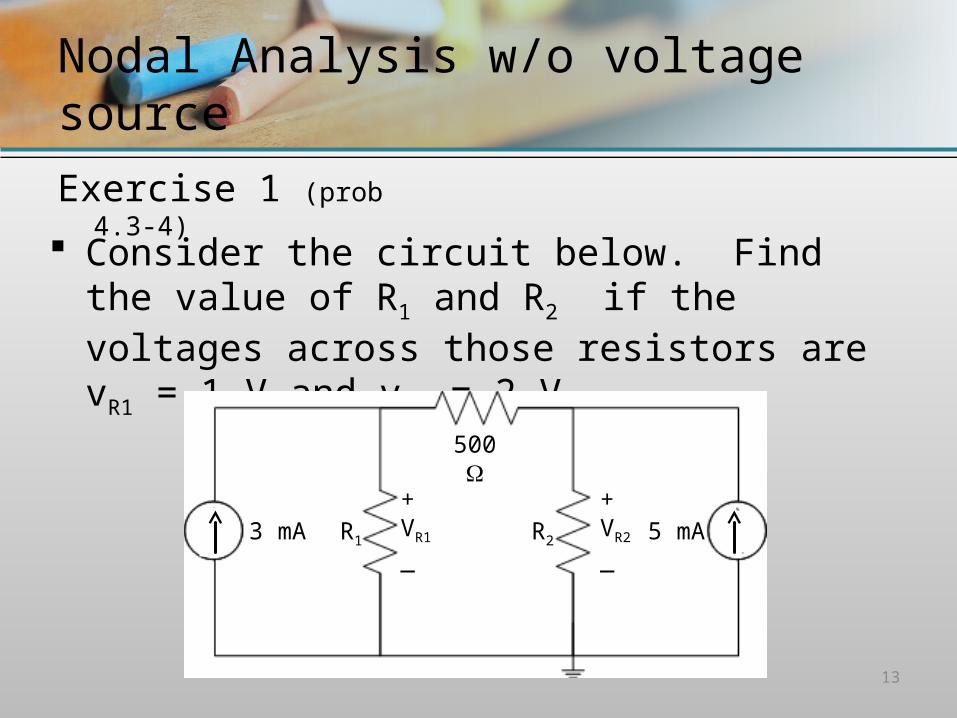
Exercise 1 (prob 4.3-4)
13
Consider the circuit below. Find the value of R1 and R2 if the voltages across those resistors are vR1 = 1 V and vR2 = 2 V .
500
3 mA 5 mA+VR1
_
+VR2
_R1 R2

Nodal Analysis w/o voltage source
Exercise 2 (prob 4.3-5)
14
Consider the circuit below. Find the voltage value at each non-reference node.
500
1 mA
500
250
250 125 v1 v3
v2
Ans: V1 = ? V2 = ? V3 = ?
V1 - V3 = 21.7 mV
Nodal Analysis with voltage source
There are 2 possibilities of a circuit with voltage source:i) A voltage source between reference node and a non-
reference nodeii) A voltage source between two non-reference nodes
(these two nodes form a supernode) For the case in (i), we simply set the voltage at the non-
reference node equal to the voltage source value. The rest of the non-reference nodes are treated like
previous steps for nodal analysis.

Nodal Analysis with voltage source
Example (case i)
Using nodal analysis, find vo for the circuit below
+_
8 3
6
10
90 V
45 V+_

+_
8 3
6
10
90 V
45 V+_
Step 1 : Choose a reference node.
Step 2 : Assign node voltages to the other nodes.
Nodal Analysis with voltage source
V1
V0
V2

+_
8
3
6
10
90 V45 V
Step 3 : Apply KCL to each node other than the reference node (in term of node voltage).
At node V1 :
i1 + i2 = i3 (apply KCL)
(in term of node voltage)
At node V2 and V3 :
V2 = 90 V
V3 = 45 V
Nodal Analysis with voltage source
V2
V1
V0
i2
i3
6183011213 VVVVVV
i1
+_
V3

Step 4 : Solve the resulting system of linear equations.
Nodal Analysis with voltage source
0
6183011213 VVVVVV
6
0
18
90
3
45 111
VVV
111 390)45(6 VVV
36010 1 V111 3906270 VVV
VV 361

Nodal Analysis with voltage source
Exercise 3 (prob 3.14)
20
Using nodal analysis, find v1 and v2 for the circuit below.
+_
+_
2 8
4
1
40 V20 V
5 A
+
_V1
Ans: V1 = 27.27 V2 = 42.73
V2V1

Nodal Analysis with voltage source
Exercise 4 (prob 4.4-8)
21
Using nodal analysis, find voltage value at each non-reference node for the circuit below.
+_
2 2
3 4
12 V
1 A
Ans: V1 = ? V2 = 12.0 V3 = ?
V1 - V3 = 3.33
V1 V3V2

Nodal Analysis with voltage source
A supernode is formed by enclosing:i) A voltage source connected between 2 non-
reference nodesii) and any elements connected in parallel with it.
Below are the properties of supernode:i) voltage source inside supernode provides constraint
equation to solve for node voltagesii) Supernode has no voltage of its owniii)Supernode requires the application of both KCL &
KVL.
Nodal Analysis with voltage source
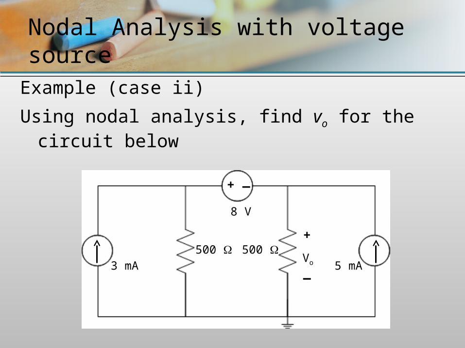
Example (case ii)
Using nodal analysis, find vo for the circuit below
500 3 mA
8 V
500 5 mA
_+
+
_Vo
500 3 mA
8 V
500 5 mA
_+
+
_Vo
Step 1 : Choose a reference node.
Step 2 : Assign node voltages to the other nodes.
Nodal Analysis w/o voltage source
Reference node
V0
V1 V2

Step 3 : Apply KCL to each node other than the reference node (in term of node voltage).
At supernode :
i1 + i2 = i3 + i4 (apply KCL)
3 mA + 5 mA (in term of node voltage)
Apply KVL at supernode :
V1 = V2 + 8 (apply KVL)
Nodal Analysis w/o voltage source
i1i3 i4
i2
5005000201 VVVV
500 3 mA
8 V
500 5 mA
_+V1 V2

Step 4 : Solve the resulting system of linear equations.
8 mA
…(1) …(2)
Solve above equations by using elimination technique:
(1) – (2) :
Nodal Analysis w/o voltage source
0 0
5005000201 VVVV
421 VV
821 VV
821 VV
84)( 2121 VVVV
02 2 VV 61 V

Nodal Analysis with voltage source
Exercise 5 (exp 8.22)
27
Using nodal analysis, find voltage value at V1 and V2 for the circuit below.
10
4
12 V
6 A 2 4 A
_+V1 V2
Ans: V1 = -10.67 V2 = -1.33
Nodal Analysis with voltage source
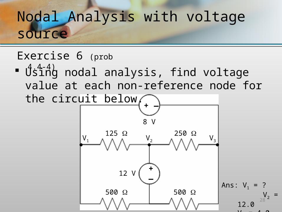
Exercise 6 (prob 4.4-4)
28
Using nodal analysis, find voltage value at each non-reference node for the circuit below.
+_
125 250
500 500
12 V
8 V
_+
Ans: V1 = ? V2 = 12.0 V3 = 4.0
V1 V2 V3

Mesh Analysis
• Without current source
• With current sources

• Understand the concept of mesh current
• Analyze dc circuit using mesh analysis
• Understand the concept of supermesh
• Evaluate the better method between nodal and mesh analysis for a particular circuit problem
Mesh Analysis:Lesson Outcomes
• Mesh analysis applies KVL to find unknown currents value.
• Using mesh currents instead of element currents as circuit variables is easier because it reduces the number equations to be solved simultaneously.
• A mesh is loop that does not contain any other loop within it.
Mesh Analysis

Steps to determine mesh currents:
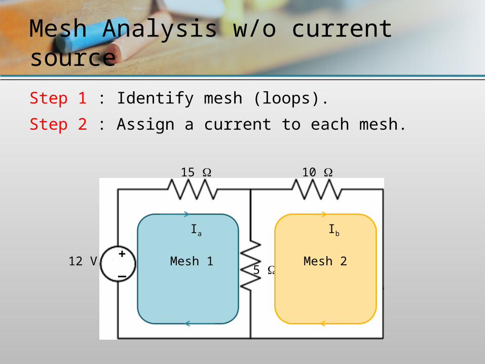
1. Identify mesh (loops).
2. Assign a current to each mesh.
3. Apply KVL around each loop to get an equation in terms of the loop currents.
4. Solve the resulting system of linear equations.
Mesh Analysis : Steps
Steps of Mesh Analysis
1. Identify mesh (loops).
2. Assign a current to each mesh.
3. Apply KVL around each loop to get an equation in terms of the loop currents.
4. Solve the resulting system of linear equations.
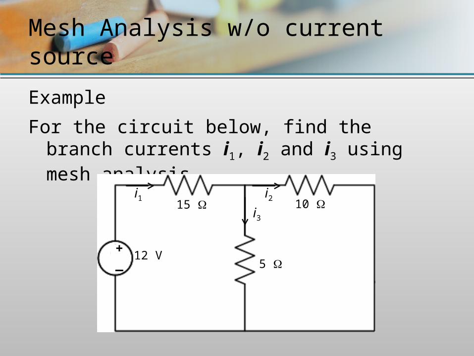
Example
For the circuit below, find the branch currents i1, i2 and i3 using mesh analysis
Mesh Analysis w/o current source
5
10 15
12 V
i1 i2i3
+_
Mesh Analysis w/o current source
5
10 15
12 V +_
Step 1 : Identify mesh (loops).
Step 2 : Assign a current to each mesh.
Mesh 2Mesh 1
Ia Ib

Mesh Analysis w/o current source
5
10 15
12 V
+_
Step 3 : Apply KVL around each loop to get an equation in terms of the loop currents.
For mesh 1: -Vs + VR15 + VR5 = 0
-12 + 15Ia + 5(Ia - Ib) = 0
20Ia - 5Ib = 12
For mesh 2: VR10 + VR5 = 0
10Ib + 5(Ib - Ia) = 0
-5Ia + 15Ib = 0
Ia Ib

Step 4 : Solve the resulting system of linear equations.
• The above equations can be solved by using 2 methods:
i) Simultaneous equations / elimination technique
ii) Cramer’s rule
• For elimination technique:
20Ia - 5Ib = 12 (x3) 60 Ia - 15 Ib = 36 …(1)
-5 Ia + 15 Ib = 0 …(2)
By adding eq.(2) from (1) and solving for Ia & Ib
60 Ia - 5 Ia = 36 Ia = 36/55 = 0.65 A
From eq. (2) Ib = (5 x 0.65)/15 = 0.22 A
Mesh Analysis w/o current source

Application of Cramer’s rule
37
To use Cramer’s rule, we need to put the equations in matrix form as below:
Determinant of the matrix is:
Solve for Ia and Ib
0
12
155
520
b
a
I
I
275)55()1520(155
520
AI aa 65.0
275
180150
512
AI bb 22.0
275
60005
1220

Mesh Analysis w/o current source
Exercise 7 (exa 8.18)
38
Find the current through the 10 resistor of the circuit below by using mesh analysis.
+_
10
5
2 3
8
15 V
IR10
Ans: IR10 = 1.22 A

Mesh Analysis w/o current source
Exercise 8 (exer 4.6-1)
39
Use mesh analysis to determine the current, IR2 for the circuit shown below.
6
2 4 12 28 V
8 V
_
+
+_
I
Ans: IR2 = 1 A
Mesh Analysis with current source
Steps of Mesh Analysis
1. Identify mesh (loops).
2. Assign a current to each mesh.
3. Apply KVL around each loop to get an equation in terms of the loop currents.
4. Solve the resulting system of linear equations.
There are 2 possibilities of a circuit with current source:i) A current source exist only in one meshii) A current source exist between two meshes. (these
requires a supermesh analysis) For the case in (i),
Mesh Analysis with current source
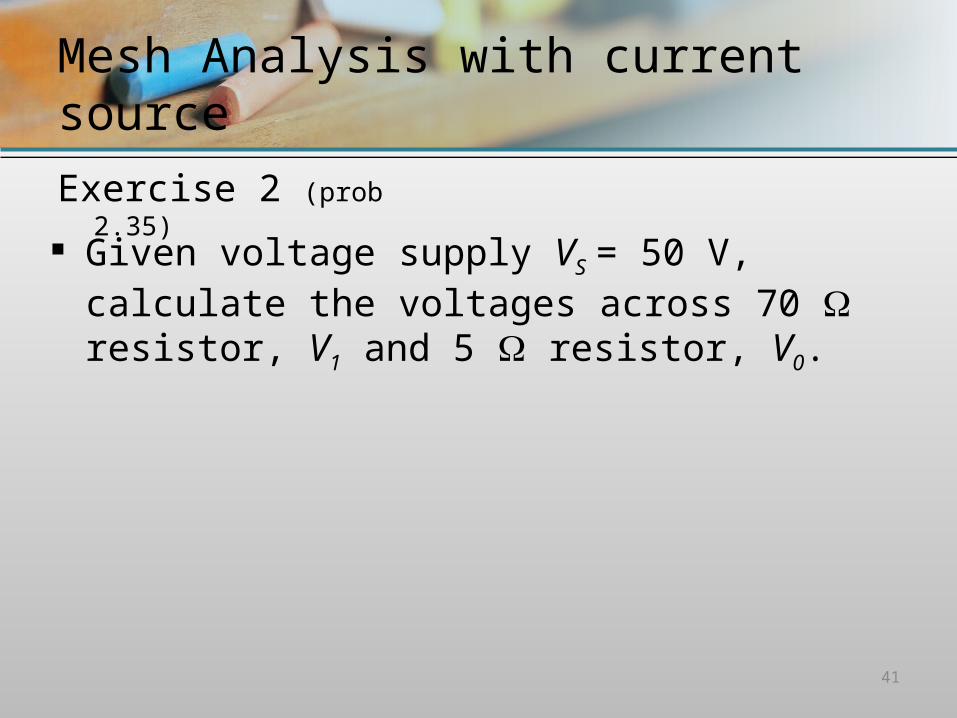
Exercise 2 (prob 2.35)
41
Given voltage supply VS = 50 V, calculate the voltages across 70 resistor, V1 and 5 resistor, V0.

Conclusion

The EndThe End
Related Documents