Ch.2 Part A: Requirements, State Charts EECE **** Embedded System Design

Welcome message from author
This document is posted to help you gain knowledge. Please leave a comment to let me know what you think about it! Share it to your friends and learn new things together.
Transcript
Ch.2 Part A: Requirements, State Charts
EECE **** Embedded System Design
2
Department of Electrical and Computer EngineeringCollege of Engineering, Technology and Computer
Science
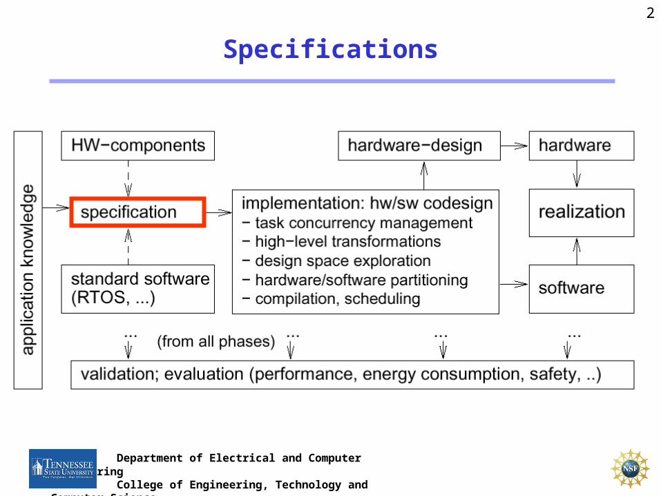
Specifications

3
Department of Electrical and Computer EngineeringCollege of Engineering, Technology and Computer
Science
Specification of embedded systems: Requirements for specification techniques (1)
• HierarchyHumans not capable to understand systemscontaining more than ~5 objects.
Most actual systems require more objects Hierarchy
– Behavioral hierarchyExamples: states, processes, procedures.
– Structural hierarchyExamples: processors, racks,printed circuit boards
• HierarchyHumans not capable to understand systemscontaining more than ~5 objects.
Most actual systems require more objects Hierarchy
– Behavioral hierarchyExamples: states, processes, procedures.
– Structural hierarchyExamples: processors, racks,printed circuit boards
proc proc proc

4
Department of Electrical and Computer EngineeringCollege of Engineering, Technology and Computer
Science
Specification of embedded systems: Requirements for specification techniques (2)
• Timing behavior.
• State-oriented behaviorRequired for reactive systems;classical automata insufficient.
• Event-handling(external or internal events)
• No obstacles for efficient implementation
• Timing behavior.
• State-oriented behaviorRequired for reactive systems;classical automata insufficient.
• Event-handling(external or internal events)
• No obstacles for efficient implementation

5
Department of Electrical and Computer EngineeringCollege of Engineering, Technology and Computer
Science
Requirements for specification techniques (3)
• Support for the design of dependable systemsUnambiguous semantics, ...
• Exception-oriented behaviorNot acceptable to describe exceptions for every state.
• Support for the design of dependable systemsUnambiguous semantics, ...
• Exception-oriented behaviorNot acceptable to describe exceptions for every state.
We will see, how all the arrows labeled k can be replaced by a single one..

6
Department of Electrical and Computer EngineeringCollege of Engineering, Technology and Computer
Science
Requirements for specification techniques (4)
• ConcurrencyReal-life systems are concurrent
• Synchronization and communicationComponents have to communicate!
• Presence of programming elementsFor example, arithmetic operations, loops, and function calls should be available
• Executability (no algebraic specification)• Support for the design of large systems ( OO)• Domain-specific support
7
Department of Electrical and Computer EngineeringCollege of Engineering, Technology and Computer
Science
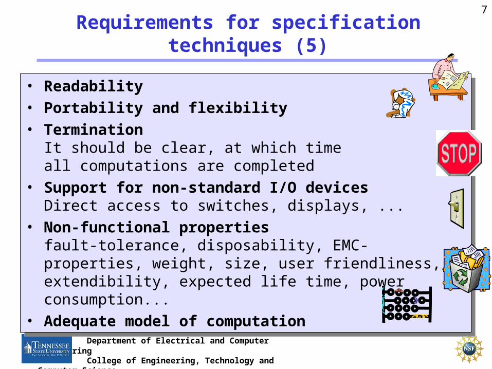
Requirements for specification techniques (5)
• Readability
• Portability and flexibility
• TerminationIt should be clear, at which time all computations are completed
• Support for non-standard I/O devicesDirect access to switches, displays, ...
• Non-functional propertiesfault-tolerance, disposability, EMC-properties, weight, size, user friendliness, extendibility, expected life time, power consumption...
• Adequate model of computation

8
Department of Electrical and Computer EngineeringCollege of Engineering, Technology and Computer
Science
StateCharts: recap of classical automata
Classical automata:Classical automata:
• Moore-automata:Y = (Z); Z+ = (X, Z)
• Mealy-automataY = (X, Z); Z+ = (X, Z)
• Moore-automata:Y = (Z); Z+ = (X, Z)
• Mealy-automataY = (X, Z); Z+ = (X, Z)
Internal state Zinput X output Y
Next state Z+ computed by function Output computed by function
Z0 Z1
Z2Z3
e=1
e=1
e=1
e=1
0 1
23
clockMoore- + Mealy automata=finite state machines (FSMs)
Moore- + Mealy automata=finite state machines (FSMs)

9
Department of Electrical and Computer EngineeringCollege of Engineering, Technology and Computer
Science
Introducing hierarchy
FSM will be in exactly one of the substates of S if S is active(either in A or in B or ..)
FSM will be in exactly one of the substates of S if S is active(either in A or in B or ..)
Classical automata not useful for complex systems (complex graphs cannot be understood by humans).
Introduction of hierarchy StateCharts [Harel, 1987]
StateChart = the only unused combination of
„flow“ or „state“ with „diagram“ or „chart“
Classical automata not useful for complex systems (complex graphs cannot be understood by humans).
Introduction of hierarchy StateCharts [Harel, 1987]
StateChart = the only unused combination of
„flow“ or „state“ with „diagram“ or „chart“

10
Department of Electrical and Computer EngineeringCollege of Engineering, Technology and Computer
Science
Definitions
• Current states of FSMs are also called active states.• States which are not composed of other states are called basic states.• States containing other states are called super-states.• For each basic state s, the super-states containing s are called
ancestor states.• Super-states S are called OR-super-states, if exactly one of the sub-
states of S is active whenever S is active.
ancestor state of Esuperstate
substates

11
Department of Electrical and Computer EngineeringCollege of Engineering, Technology and Computer
Science
Default state mechanism
Try to hide internal structure from outside world!
Default state
Filled circleindicates sub-state entered whenever super-state is entered.
Not a state by itself!
Try to hide internal structure from outside world!
Default state
Filled circleindicates sub-state entered whenever super-state is entered.
Not a state by itself!

12
Department of Electrical and Computer EngineeringCollege of Engineering, Technology and Computer
Science
History mechanism
For input m, S enters the state it was in before S was left (can be A, B, C, D, or E). If S is entered for the very first time, the default mechanism applies.
History and default mechanisms can be used hierarchically.
For input m, S enters the state it was in before S was left (can be A, B, C, D, or E). If S is entered for the very first time, the default mechanism applies.
History and default mechanisms can be used hierarchically.
(behavior different from last slide)
km

13
Department of Electrical and Computer EngineeringCollege of Engineering, Technology and Computer
Science
Combining history and default state mechanism
same meaning

14
Department of Electrical and Computer EngineeringCollege of Engineering, Technology and Computer
Science
Concurrency
Convenient ways of describing concurrency are required.
AND-super-states: FSM is in all (immediate) sub-states of a super-state; Example:
Convenient ways of describing concurrency are required.
AND-super-states: FSM is in all (immediate) sub-states of a super-state; Example:
15
Department of Electrical and Computer EngineeringCollege of Engineering, Technology and Computer
Science
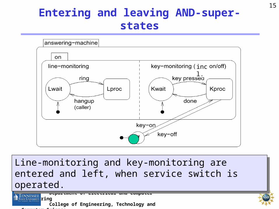
Entering and leaving AND-super-states
Line-monitoring and key-monitoring are entered and left, when service switch is operated.
Line-monitoring and key-monitoring are entered and left, when service switch is operated.
incl.
16
Department of Electrical and Computer EngineeringCollege of Engineering, Technology and Computer
Science
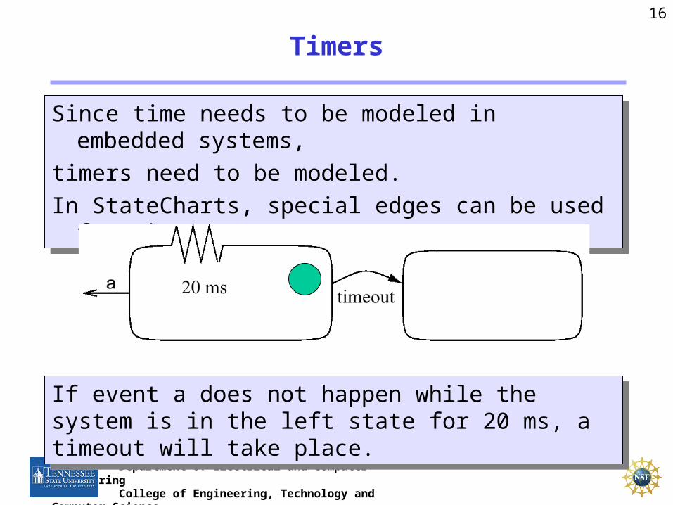
Timers
Since time needs to be modeled in embedded systems,
timers need to be modeled.
In StateCharts, special edges can be used for timeouts.
Since time needs to be modeled in embedded systems,
timers need to be modeled.
In StateCharts, special edges can be used for timeouts.
If event a does not happen while the system is in the left state for 20 ms, a timeout will take place.
If event a does not happen while the system is in the left state for 20 ms, a timeout will take place.

17
Department of Electrical and Computer EngineeringCollege of Engineering, Technology and Computer
Science
Using timers in answering machine

18
Department of Electrical and Computer EngineeringCollege of Engineering, Technology and Computer
Science
General form of edge labels
Events:• Exist only until the next evaluation of the model• Can be either internally or externally generatedConditions:• Refer to values of variables that keep their value until they are
reassignedReactions:• Can either be assignments for variables or creation of eventsExample:• service-off [not in Lproc] / service:=0
event [condition] / reaction

19
Department of Electrical and Computer EngineeringCollege of Engineering, Technology and Computer
Science
The StateCharts simulation phases (StateMate Semantics)
How are edge labels evaluated?
Three phases:
1. Effect of external changes on events and conditions is
evaluated,
2. The set of transitions to be made in the current step and right
hand sides of assignments are computed,
3. Transitions become effective, variables obtain new values.
Separation into phases 2 and 3 guarantees deterministic
and reproducible behavior.

20
Department of Electrical and Computer EngineeringCollege of Engineering, Technology and Computer
Science
Example
In phase 2, variables a and b are assigned to temporary variables. In phase 3, these are assigned to a and b. As a result, variables a and b are swapped.
In a single phase environment, executing the left state first would assign the old value of b (=0) to a and b. Executing the right state first would assign the old value of a (=1) to a and b. The execution would be non-deterministic.
21
Department of Electrical and Computer EngineeringCollege of Engineering, Technology and Computer
Science
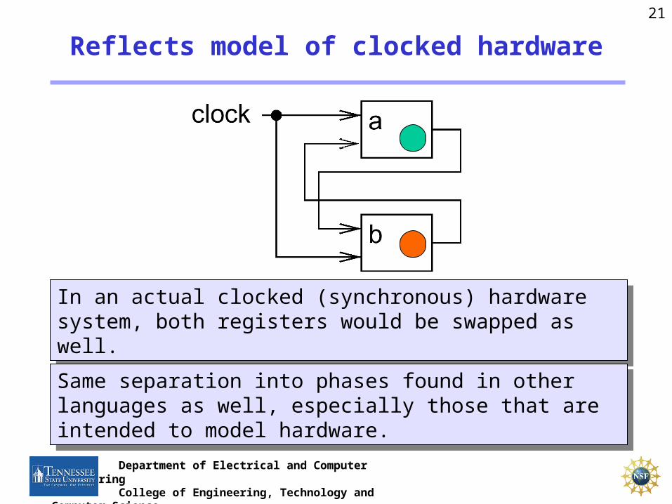
Reflects model of clocked hardware
In an actual clocked (synchronous) hardware system, both registers would be swapped as well.
In an actual clocked (synchronous) hardware system, both registers would be swapped as well.
Same separation into phases found in other languages as well, especially those that are intended to model hardware.
Same separation into phases found in other languages as well, especially those that are intended to model hardware.

22
Department of Electrical and Computer EngineeringCollege of Engineering, Technology and Computer
Science
Steps
Execution of a StateChart model consists of a sequence of (status, step) pairs
Execution of a StateChart model consists of a sequence of (status, step) pairs
Status= values of all variables + set of events + current time
Step = execution of the three phases (StateMate semantics)
Status= values of all variables + set of events + current time
Step = execution of the three phases (StateMate semantics)
Statusphase 2
phase 3
phase 1
23
Department of Electrical and Computer EngineeringCollege of Engineering, Technology and Computer
Science
Evaluation of StateCharts (1)
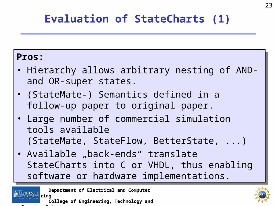
Pros:• Hierarchy allows arbitrary nesting of AND- and OR-super
states.• (StateMate-) Semantics defined in a follow-up paper to
original paper.• Large number of commercial simulation tools available
(StateMate, StateFlow, BetterState, ...)• Available „back-ends“ translate StateCharts into C or
VHDL, thus enabling software or hardware implementations.

24
Department of Electrical and Computer EngineeringCollege of Engineering, Technology and Computer
Science
Evaluation of StateCharts (2)
Cons:• Generated C programs frequently inefficient,• Not useful for distributed applications,• No program constructs,• No description of non-functional behavior,• No object-orientation,• No description of structural hierarchy.
Cons:• Generated C programs frequently inefficient,• Not useful for distributed applications,• No program constructs,• No description of non-functional behavior,• No object-orientation,• No description of structural hierarchy.
Extensions:• Module charts for description of structural hierarchy.
Extensions:• Module charts for description of structural hierarchy.
Related Documents