Ch.2 Part C: Message Sequence Charts, UML EECE **** Embedded System Design

Welcome message from author
This document is posted to help you gain knowledge. Please leave a comment to let me know what you think about it! Share it to your friends and learn new things together.
Transcript
Ch.2 Part C: Message Sequence Charts, UML
EECE **** Embedded System Design

2
Department of Electrical and Computer EngineeringCollege of Engineering, Technology and Computer
Science
Message sequence charts (MSC)
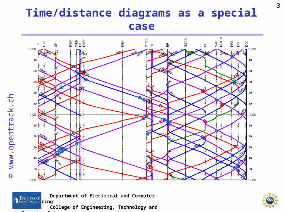
Graphical means for representing schedules; time used vertically, geographical distribution horizontally.
Graphical means for representing schedules; time used vertically, geographical distribution horizontally.
No distinction between accidental overlap and synchronizationNo distinction between accidental overlap and synchronization
3
Department of Electrical and Computer EngineeringCollege of Engineering, Technology and Computer
Science
Time/distance diagrams as a special case©
ww
w.o
pen
tra
ck.c
h

4
Department of Electrical and Computer EngineeringCollege of Engineering, Technology and Computer
Science
Example 1: establishing an(old-fashioned) modem connection
5
Department of Electrical and Computer EngineeringCollege of Engineering, Technology and Computer
Science
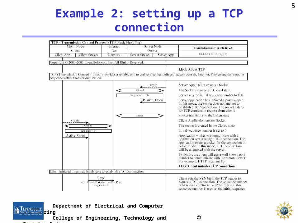
Example 2: setting up a TCP connection
© Eventhelix.com

6
Department of Electrical and Computer EngineeringCollege of Engineering, Technology and Computer
Science
PROs:• Appropriate for visualizing schedules,• Proven method for representing schedules in transportation.• Standard defined: ITU-TS Recommendation Z.120: Message
Sequence Chart (MSC), ITU-TS, Geneva, 1996.• Semantics also defined: ITU-TS Recommendation Z.120:
Message Sequence Chart (MSC)—Annex B: Algebraic Semantics of Message Sequence Charts, ITU-TS, Geneva.
CONS:• describes just one case, no timing tolerances: "What does an MSC
specification mean: does it describe all behaviors of a system, or does it describe a set of sample behaviors of a system?” *
* H. Ben-Abdallah and S. Leue, “Timing constraints in message sequence chart specifications,” in Proc. 10th International Conference on Formal Description Techniques FORTE/PSTV’97, Chapman and Hall, 1997.
Message sequence charts

7
Department of Electrical and Computer EngineeringCollege of Engineering, Technology and Computer
Science
Heavy usage of MSCs in UML
(known as sequence diagram);
No precise timing.
Many kinds of additional elements
Heavy usage of MSCs in UML
(known as sequence diagram);
No precise timing.
Many kinds of additional elements
Use in UML

8
Department of Electrical and Computer EngineeringCollege of Engineering, Technology and Computer
Science
UML (Unified modeling language)- designing with a sequence of refinements -
9
Department of Electrical and Computer EngineeringCollege of Engineering, Technology and Computer
Science
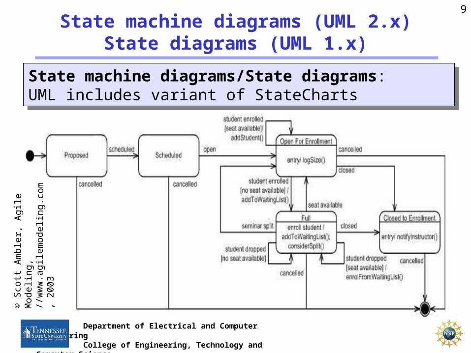
State machine diagrams (UML 2.x)State diagrams (UML 1.x)
State machine diagrams/State diagrams:UML includes variant of StateCharts
State machine diagrams/State diagrams:UML includes variant of StateCharts
© S
cott
Am
bler
, A
gile
Mod
elin
g,//
ww
w.a
gile
mod
elin
g.co
m,
2003

10
Department of Electrical and Computer EngineeringCollege of Engineering, Technology and Computer
Science
Activity diagram
© Cris Kobryn: UML 2001: A Standardization Odyssey, CACM, October, 1999
Extended Petri nets. Include decisions (like in flow charts). Graphical notation similar to SDL.
11
Department of Electrical and Computer EngineeringCollege of Engineering, Technology and Computer
Science
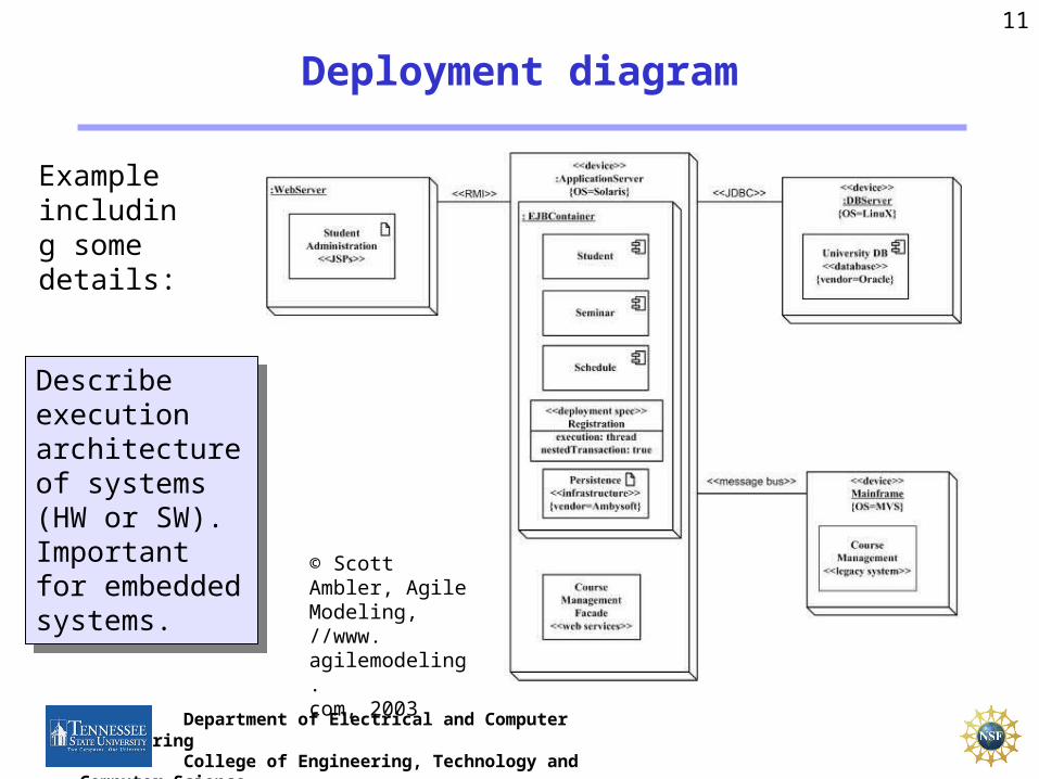
Deployment diagram
Describe execution architecture of systems (HW or SW). Important for embedded systems.
Describe execution architecture of systems (HW or SW). Important for embedded systems.
Example including some details:
© Scott Ambler, Agile Modeling,//www.agilemodeling.com, 2003
12
Department of Electrical and Computer EngineeringCollege of Engineering, Technology and Computer
Science
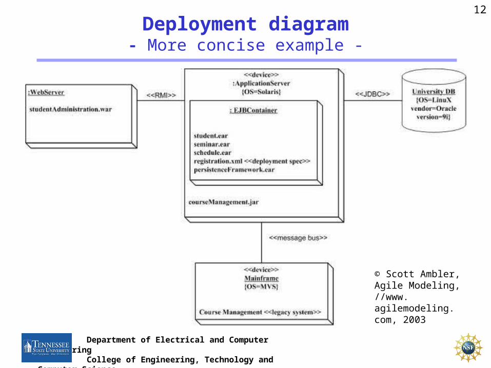
Deployment diagram- More concise example -
© Scott Ambler, Agile Modeling, //www.agilemodeling.com, 2003

13
Department of Electrical and Computer EngineeringCollege of Engineering, Technology and Computer
Science
Use case diagram
Captures typical application scenariosCaptures typical application scenarios
//sds.hss.cmu.edu/courses/Syllabi/ids/271/umlfaq.asp#ucdefinition
© Scott Ambler, Agile Modeling,//www.agilemodeling.com, 2003

14
Department of Electrical and Computer EngineeringCollege of Engineering, Technology and Computer
Science
Package diagram
Represents the partitioning into packages. Introduces hierarchy.
Example: Use case package diagram.
Represents the partitioning into packages. Introduces hierarchy.
Example: Use case package diagram.
© Scott Ambler, Agile Modeling,//www.agilemodeling.com, 2003
15
Department of Electrical and Computer EngineeringCollege of Engineering, Technology and Computer
Science
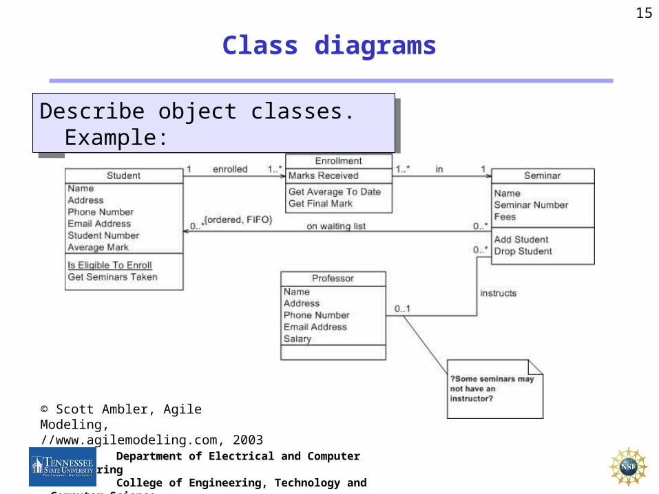
Class diagrams
Describe object classes. Example:Describe object classes. Example:
© Scott Ambler, Agile Modeling,//www.agilemodeling.com, 2003
16
Department of Electrical and Computer EngineeringCollege of Engineering, Technology and Computer
Science
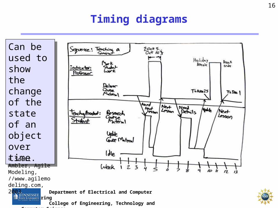
Timing diagrams
Can be used to show the change of the state of an object over time.
Can be used to show the change of the state of an object over time.
© Scott Ambler, Agile Modeling,//www.agilemodeling.com, 2003
17
Department of Electrical and Computer EngineeringCollege of Engineering, Technology and Computer
Science
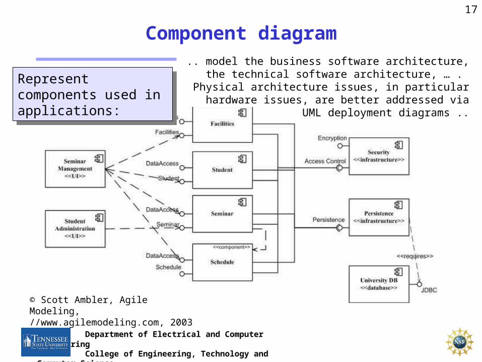
Component diagram
© Scott Ambler, Agile Modeling,//www.agilemodeling.com, 2003
.. model the business software architecture, the technical software architecture, … . Physical architecture issues, in particular hardware issues, are better addressed via UML
deployment diagrams ..
Represent components used in applications:
Represent components used in applications:

18
Department of Electrical and Computer EngineeringCollege of Engineering, Technology and Computer
Science
Additional diagrams
• Communication diagram (called collaboration diagram in UML 1.x)
• Object diagrams• Interaction overview diagrams• Composite structure diagrams
• Communication diagram (called collaboration diagram in UML 1.x)
• Object diagrams• Interaction overview diagrams• Composite structure diagrams
Less frequently used
19
Department of Electrical and Computer EngineeringCollege of Engineering, Technology and Computer
Science
Evaluation
Precise specification of semantics?Typically combined with SDL or C++
Precise specification of semantics?Typically combined with SDL or C++
20
Department of Electrical and Computer EngineeringCollege of Engineering, Technology and Computer
Science
UML for real-time?
Initially not designed for real-time.
Lacking features (1998):• Partitioning of software into tasks and processes• specifying timing• specification of hardware components
Projects on defining real-time UML based on previous work• ROOM [Selic] is an object-oriented methodology for real-time
systems developed originally at Bell-Northern Research. • „UML profile for schedulability, performance and time“
http://www.rational.com/uml/resources/documentation• …
Related Documents