Centre for Wireless Communications Wireless Sensor Networks Introduction Instructor: Carlos Pomalaza- Ráez Fall 2004 University of Oulu, Finland

Centre for Wireless Communications Wireless Sensor Networks Introduction Instructor: Carlos Pomalaza-Ráez Fall 2004 University of Oulu, Finland.
Dec 21, 2015
Welcome message from author
This document is posted to help you gain knowledge. Please leave a comment to let me know what you think about it! Share it to your friends and learn new things together.
Transcript

Centre for Wireless Communications
Wireless Sensor NetworksIntroduction
Instructor: Carlos Pomalaza-Ráez
Fall 2004University of Oulu, Finland
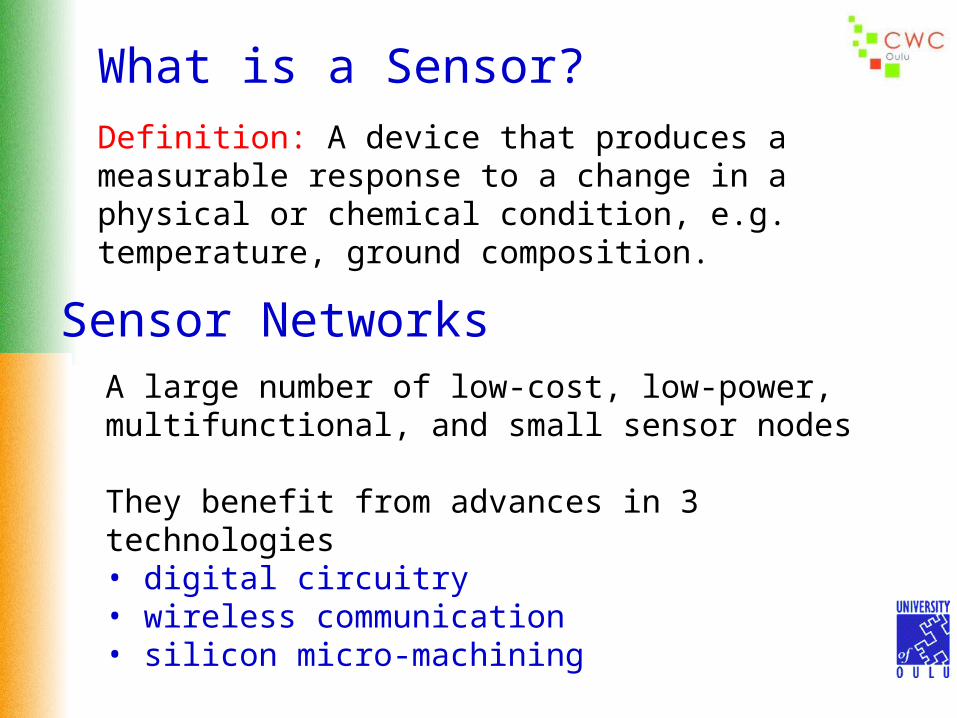
What is a Sensor?Definition: A device that produces a measurable response to a change in a physical or chemical condition, e.g. temperature, ground composition.
Sensor NetworksA large number of low-cost, low-power, multifunctional, and small sensor nodes
They benefit from advances in 3 technologies• digital circuitry• wireless communication• silicon micro-machining
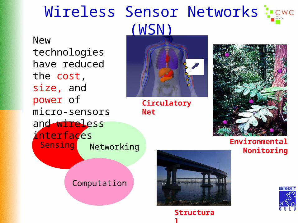
Wireless Sensor Networks (WSN)
Sensing
Computation
Networking
Circulatory Net
New technologies have reduced the cost, size, and power of micro-sensors and wireless interfaces
EnvironmentalMonitoring
Structural

Applications
BattlefieldDetection, classification and
tracking
Habitat MonitoringMicro-climate and wildlife monitoring Examples:
– ZebraNet (Princeton)
– Seabird monitoring in Maine’s Great Duck Island(Berkeley & Intel)
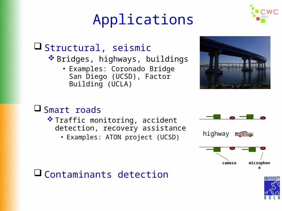
Applications
Structural, seismic Bridges, highways, buildings
• Examples: Coronado Bridge San Diego (UCSD), Factor Building (UCLA)
Smart roads Traffic monitoring, accident detection,
recovery assistance• Examples: ATON project (UCSD)
highway
camera microphone
Contaminants detection

Communication Architecture
Sensor field
Sensor nodes
Internet
Sink
Manager Node
Sensing nodeSensor nodes can bedata originators anddata routers

Examples of Sensor Nodes
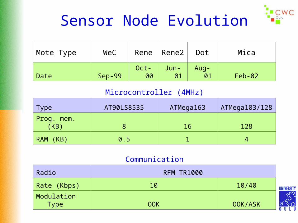
Sensor Node Evolution
Mote Type WeC ReneRene
2Dot Mica
Date Sep-99 Oct-00 Jun-01 Aug-01 Feb-02
Microcontroller (4MHz)
Type AT90LS8535 ATMega163ATMega103/12
8
Prog. mem. (KB) 8 16 128
RAM (KB) 0.5 1 4
Communication
Radio RFM TR1000
Rate (Kbps) 10 10/40
Modulation Type OOK OOK/ASK

WIRO PlatformWIRO (WIreless Research Object ) is a modular embedded system developedby the Centre for Wireless Communications, Oulu, Finland. The system consists of a set of boards 35 mm x 35 mm in size. They are: CPU board - Controls all other WIRO boards and is needed in all WIRO stacks. It has an
AVR Mega128 microcontroller running at 7.37 MHz and a 4 Mb serial flash memory. The CPU has a 128 kB flash memory for programs, 4 kB of SRAM, and 8 ADCs
RF board – It has an RFM model TR3100 radio transceiver chip capable of up to 576kbit/s speeds. The radio interface on this board is configured for 230.4 kbps. Data encoding & decoding can use the onboard CPLD (Complex Programmable Logic Device) or the microcontroller on the CPU board. The transceiver uses ASK modulation
Power supply board – It has electronics to charge a battery pack from the USB bus and to provide the other boards with 5V, +3.3V and +1.8V voltages
Sensor board – It has 2-axis accelerometer, 2-axis magnetometer, pressure, temperature and humidity sensors
Prototype board and Test-Pad board
CPU Board 2 Euro coin & RF Board WIRO Box

WIRO – Power ConsumptionCPU Board
CPU Active CPU SleepCPLD 3 mA/3.3 V 9.9 mW 0.01 mA/3.3 V 0.033 mW
AT mega128 15 mA/3.3 V 49.5 mW 0.04 mA/3.3 V 0.13 mW
Flash-memory
4 mA/3.3 V 13.2 mW 0.002 mA/3.3 V 0.007 mW
RF Board
Tx Rx SleepCPLD 3mA/3.3V 9.9mW 3mA/3.3V 9.9mW 0.01mA/3.3V 0.033mW
RF-Transceiver
10mA/3.3V 33mW 5.8mA/3.3V 19mW 0.7μA/3.3V 0.0023mW
Other Circuitry
0.5mA/5V 2.5mW 0.5mA/5V 2.5mW 0.5mA/5V 2.5mW
RF Board TotalPower Consumption
45.5
31.5
2.5
0
10
20
30
40
50
Pow
er (
mW
)
Tx Rx Sleep

WIRO – Power ConsumptionSensor Board
Active Sleep
Magnetometer 20mA/5V 100mW 0 0
Accelerometer 0.6mA/3.3V 2mW 0.6mA/3.3V 2mW
Humidity Sensor 0.55mA/3.3V 2mW 0.3μA/5V 0.0015mW
Pressure Sensor 6mA/5V 30mW 0 0
CPLD 3mA/3.3V 9.9mW 0.01mA/3.3V 0.033mW
Amplifier 0.5mA/5V 2.5mW 0.5mA/5V 2.5mW
150
4.5
0
50
100
150
Pow
er (
mW
)
Active Sleep
Sensor Board TotalPower Consumption

WIRO – Power ConsumptionPower Supply Board
Connected to the USB-bus Not Connected to the USB-bus
CPLD 1mA/3.3V 3.3mW 0.01mA/3.3V 0.033mW
EEPROM 1mA/5V 5mW 0.005mA/5V 0.025mW
USB 25mA/5V(from USB) 125mW 0.2mA/5V 1mW
Estimated Operation Time on Battery Power
ton /tidle Avg Power Avg Battery Current
Op Time/550mAh
Op Time/100mA
100% 325.3mW 104mA 5.3h 0.3h
10% 44.2mW 14.1mA 39h 2.3h
1% 16.1mW 5.2mA 107h 6.2h
0.1% 13.3mW 4.3mA 129h 7.5h
0% 13.0mW 4.2mA 132h 7.7h
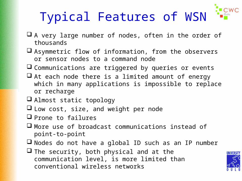
Typical Features of WSN A very large number of nodes, often in the order of thousands Asymmetric flow of information, from the observers or sensor
nodes to a command node Communications are triggered by queries or events At each node there is a limited amount of energy which in
many applications is impossible to replace or recharge Almost static topology Low cost, size, and weight per node Prone to failures More use of broadcast communications instead of point-to-
point Nodes do not have a global ID such as an IP number The security, both physical and at the communication level, is
more limited than conventional wireless networks
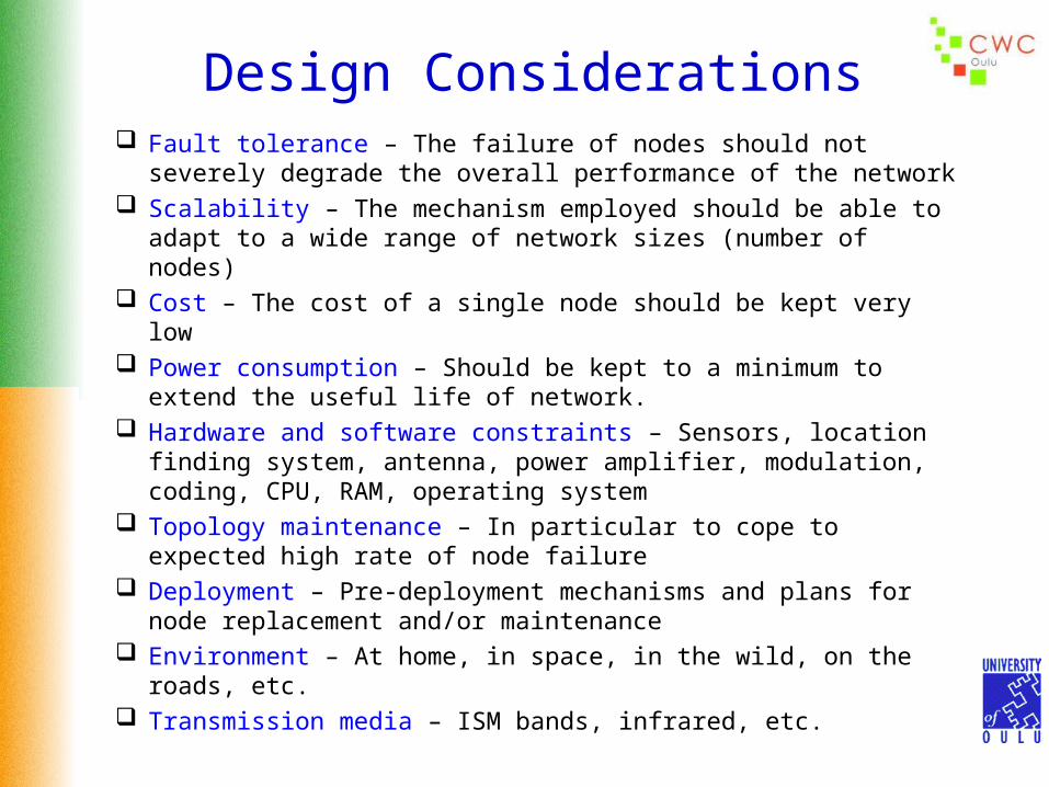
Design Considerations Fault tolerance – The failure of nodes should not severely degrade
the overall performance of the network Scalability – The mechanism employed should be able to adapt to a
wide range of network sizes (number of nodes) Cost – The cost of a single node should be kept very low Power consumption – Should be kept to a minimum to extend the
useful life of network. Hardware and software constraints – Sensors, location finding
system, antenna, power amplifier, modulation, coding, CPU, RAM, operating system
Topology maintenance – In particular to cope to expected high rate of node failure
Deployment – Pre-deployment mechanisms and plans for node replacement and/or maintenance
Environment – At home, in space, in the wild, on the roads, etc. Transmission media – ISM bands, infrared, etc.

Node Energy Consumption Projections
20002000 20022002 20042004
10,0010,0000
1,0001,000
100100
1010
11
.1.1
Avera
ge P
ow
er
(mW
) • Deployed (5W)
• (50 mW)
(1mW)
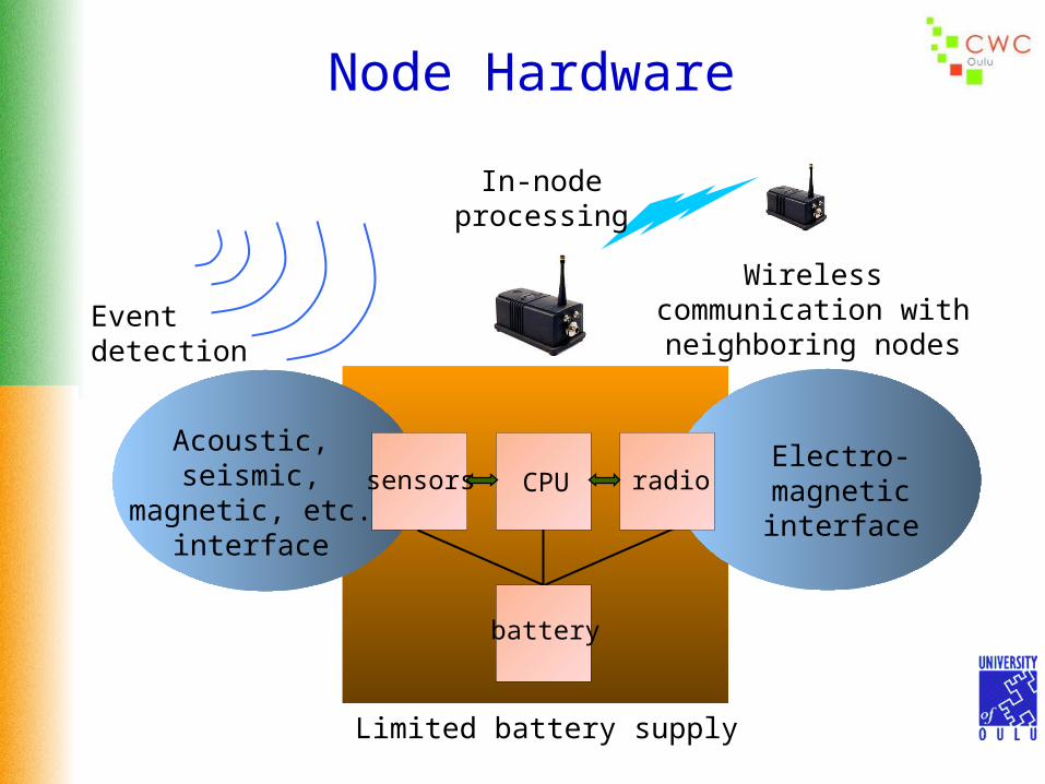
Node Hardware
sensors CPU radio
battery
Acoustic, seismic, magnetic, etc.
interface
Electro-magnetic interface
Limited battery supply
Eventdetection
Wireless communication with neighboring nodes
In-node processing

Energy Limitations
Power consumption of node subsystems
0
5
10
15
20
Pow
er
(mW
)
Sensing
CPU TX RX
IDLE SLEEP
Each sensor node has limited energy supply Nodes may not be rechargeable Energy consumption in
Sensing Data processing Communication (most energy intensive)

TR 1000 Parameters
0.02
14.88
12.50 12.36
0.00
4.00
8.00
12.00
16.00
Transmit Receive Idle Off
Pow
er C
onsu
mpt
ion
(mW
)
Parameter Value Transition time from sleep to receive mode 500 μs
Transition time from sleep to transmit mode 16 μs
Transition time from transmit to receive mode 500 μs
Transition time from receive to transmit mode 12 μs
Bit rate 115.2 kbps

Medusa II Sensor Node (UCLA)
Power Analysis
MCU Mode
Sensor Mode
Radio Mode Modulation
Data-Rate
Power (mW)
Active On
Tx(Power:0.74 mW) OOK 2.4 kb/s 24.58
Tx(Power:0.01 mW) OOK 2.4 kb/s 19.24
Tx(Power:0.74 mW) OOK 19.2 kb/s 25.37
Tx(Power:0.01 mW) OOK 19.2 kb/s 20.05
Tx(Power:0.74 mW) ASK 2.4 kb/s 26.55
Tx(Power:0.01 mW) ASK 2.4 kb/s 21.26
Tx(Power:0.74 mW) ASK 19.2 kb/s 27.46
Tx(Power:0.01 mW) ASK 19.2 kb/s 22.06
Active On Rx Any Any 22.20
Active On Idle Any Any 22.06
Active On Off Any Any 9.72
Idle On Off Any Any 5.92
Sleep Off Off Any Any 0.02

Sensor Network Protocol Stack
Transport
Data Link
Physical
Network
Pow
er
Managem
ent
Application
Mobility
Managem
ent
Task M
anagem
ent
Power Management – How the sensor uses its power, e.g. turns off its circuitry after receiving a message.
Mobility Management – Detects and register the movements of the sensor nodes
Task Management – Balances and schedules the sensing tasks given to a specific region
Physical Layer
Physical
Data Link
Network
Transport
Application
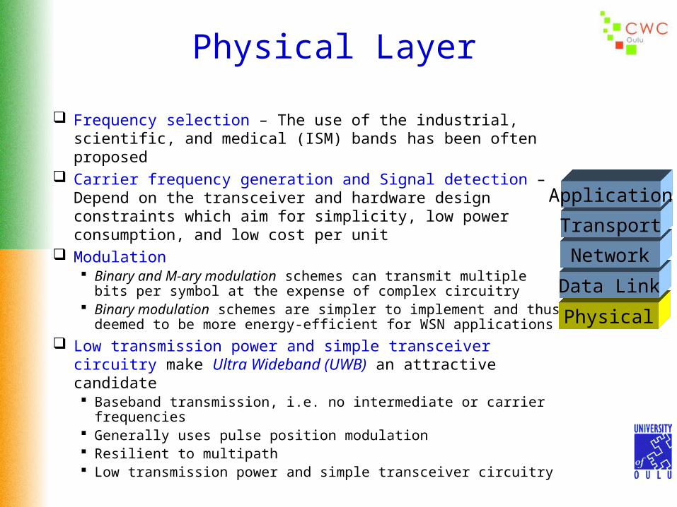
Frequency selection – The use of the industrial, scientific, and medical (ISM) bands has been often proposed
Carrier frequency generation and Signal detection – Depend on the transceiver and hardware design constraints which aim for simplicity, low power consumption, and low cost per unit
Modulation Binary and M-ary modulation schemes can transmit multiple bits
per symbol at the expense of complex circuitry Binary modulation schemes are simpler to implement and thus
deemed to be more energy-efficient for WSN applications
Low transmission power and simple transceiver circuitry make Ultra Wideband (UWB) an attractive candidate Baseband transmission, i.e. no intermediate or carrier frequencies Generally uses pulse position modulation Resilient to multipath Low transmission power and simple transceiver circuitry
Physical Layer
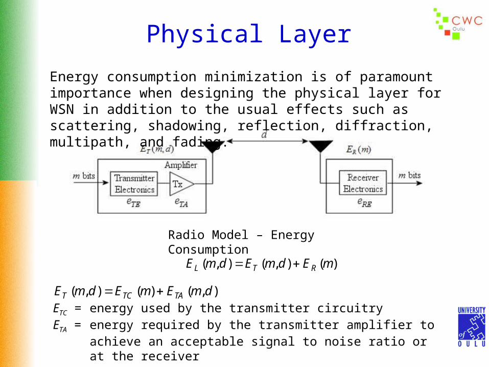
Radio Model – Energy Consumption
Energy consumption minimization is of paramount importance when designing the physical layer for WSN in addition to the usual effects such as scattering, shadowing, reflection, diffraction, multipath, and fading.
)(),(),( mEdmEdmE RTL
),()(),( dmEmEdmE TATCT ETC = energy used by the transmitter circuitryETA = energy required by the transmitter amplifier to achieve an acceptable
signal to noise ratio or at the receiver

Physical Layer
Assuming a linear relationship for the energy spent per bit by the transmitter
and receiver circuitry
deemdmE TATCT ),( RCR memE )(
eTC, eTA, and eRC are hardware dependent parameters
An explicit expression for can be derived as,
))()((
4))()(( 0
bitampant
Rxr
TA RG
BWNNFN
S
e

Physical Layer
(S/N)r = minimum required signal to noise ratio at the receiver’s demodulator for an acceptable Eb/N0
NFrx = receiver noise figureN0 = thermal noise floor in a 1 Hertz bandwidth (Watts/Hz)BW = channel noise bandwidthλ = wavelength in metersα = path loss exponent whose value varies from 2 (for free space)
to 4 (for multipath channel models)Gant = antenna gainηamp = transmitter power efficiencyRbit = raw bit rate in bits per second
rTA N
Se
))()((
4))()(( 0
bitampant
Rx
RG
BWNNF

Data Link Layer
Medium Access Control (MAC) – Let multiple radios share the same communication media
Functions: Local Topology Discovery and Management Media Partition By Allocation or Contention Provide Logical Channels to Upper Layers
TimeCode
Frequ
ency
Physical
Data Link
Network
Transport
ApplicationThe data link layer is responsible for the multiplexing of data stream, data frame detection, medium access and error control. Ensures reliable point-to-point and point-to-multipoint connections in a communication network
MAC protocol for sensor network must have built-in power conservation mechanisms, and strategies for the proper management of node mobility or failure

Wireless MAC ProtocolsWireless MAC protocols can be classified into two categories, distributed and centralized, according of the type of network architecture for which they have been designed. Protocols can be further classified, based on the mode of operation, into random access protocols, guaranteed access protocols, and hybrid access protocols
Wireless MAC protocols
DistributedMAC protocols
CentralizedMAC protocols
Randomaccess
Randomaccess
Guaranteedaccess
Hybridaccess
Since it is desirable to turn off the radio as much as possible in order to conserve energy some type of TDMA mechanism is often suggested for WSN applications. Constant listening times and adaptive rate control schemes have also been proposed.

Power Saving Mechanisms The amount of time and power needed to wake-up (start-up) a radio is not
negligible and thus just turning off the radio whenever is not being used is not necessarily efficient
The energy characteristics of the start-up time should also be taken into account when designing the size of the data link packets. The values shown in the figure below clearly indicate that when the start-up energy consumption is taken into account the energy per bit requirements can be significantly higher for the transmission of short packets than for longer ones
TR 1000 (115kbps)
0
10
20
30
40
50
60
10 100 1000 10000
Packet Size (bits)
Eb
it (
pJ )

Power Saving Mechanisms
Sleeping nodes
Communicating nodes
Based on using an ultra low power radio to wake-up the neighbors. This second radio uses much less power via either a low duty cycle or hardware
design Usually this second radio can only transmit a busy tone This broadcast tone should not disrupt any on-going data transmission, e.g. use
a different channel

Error ControlError control is an important issue in any radio link. There are two important modes of error control:
Forward Error Correction (FEC) – There is a direct tradeoff between the overhead added to the code and the number of errors that can be corrected. The number of bits in the code word impacts the complexity of the receiver and transmitter. If the associated processing power is greater than the coding gain, then the whole process in energy inefficiency.
Automatic Repeat Request (ARQ) – Based on the retransmission of packets that have been detected to be in error. Packets carry a checksum which is used by the receiver to detect errors. Requires a feedback channel.
With FEC one pays an a priori battery power consumption overhead and packet delay by computing the FEC code and transmitting the extra code bits. In return one gets a reduced probability of packet loss. With ARQ one gambles that the packet will get through and if it does not one has to pay battery energy and delay due to the retransmission process. Whether FEC or ARQ or a hybrid error control system is most energy efficient will depend of the channel conditions and the network requirements such as throughput, delay.

Network Layer
Physical
Data Link
Network
Transport
ApplicationBasic issues to take into account when designing the network layer for a WSN are:
Power efficiency Data centric – The nature of the data (interest requests
and advertisement of sensed data) determines the traffic flow
Data aggregation is useful to manage the potential implosion of traffic because of the data centric routing
Rather than conventional node addresses an ideal sensor network uses attribute-based addressing, e.g. “region where humidity is below 5%”
Locationing systems, i.e. ability for the nodes to establish position information
Internetworking with external networks via gateway or proxy nodes
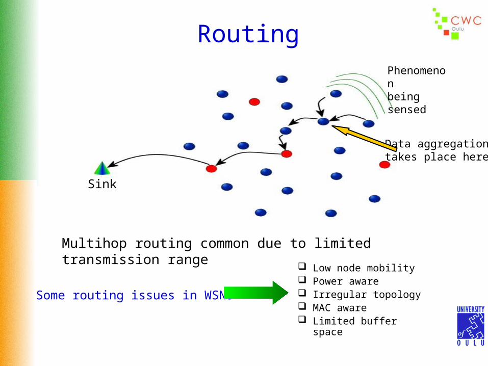
Routing
Multihop routing common due to limited transmission range
Phenomenonbeing sensed
Sink
Low node mobility Power aware Irregular topology MAC aware Limited buffer space
Some routing issues in WSNs
Data aggregationtakes place here

Data Aggregation
It is a technique used to solve the problem of implosion in WSNs. This problem arises when packets carrying the same information arrive a node. This situation can happen when more than one node sense the same phenomenon. This is different than the problem of “duplicate packets” in conventional ad hoc networks. Here it is the high level interpretation of the data in the packets is what determines if the packets are the “same.” Even for the case when the packets are deemed to be different they could still be aggregated into a single packet before the relaying process continues. In this regard data aggregation can be considered as data fusion.
Data coming from multiple sensor nodes are aggregated, if they have about the same attributes of the phenomenon being sensed, when they reach a common routing or relaying node on their way to the sink. In this view the routing mechanism in a sensor network can be considered as a form of reverse multicast tree.
Phenomenon being sensed

Data CentralityIn data-centric routing, an “interest ” dissemination is performed in order to assign the sensing tasks to the sensor nodes. This dissemination can take different forms such as:
The sink or controlling nodes broadcast the nature of the interest, e.g. “four legged animals of at least 50 Kg in weight”
Sink
Four-legged animal of at least 50 Kg
Flow of the request

Data Centrality Sensor nodes broadcast an advertisement of available sensed data and wait for a
request from the interested sinks
Sink
Flow of the advertisement
Tiger, tiger, burning bright,In the forest of the night,
What immortal hand or eyeCould frame thy fearful symmetry?

Flooding & GossipingFlooding is a well known technique used to disseminate information across a network. It is a simple, easy to implement reactive mechanism that could be used for routing in WSNs but it has severe drawbacks such as,
Implosion – When duplicated messages are sent to the same node Overlap – When two or more nodes share the same observing region, they may
sense the same stimuli at the same time. As a result, neighbor nodes receive duplicated messages
Resource blindness – Does not take into account the available energy resources. Control of the energy consumption is of paramount importance in WSNs, a promiscuous routing technique such as flooding wastes energy unnecessarily
Gossiping is a variation of flooding attempting to correct some of its drawbacks. Nodes do not indiscriminately broadcast but instead send a packet to a randomly selected neighbor who once it receives the packet it repeats the process. It is not as simple to implement as the flooding mechanism and it takes longer for the propagation of messages across the network.

Proposed Routing TechniquesSPIN – Sensor Protocols for Information via Negotiation – Attempts to correct the major deficiencies of classical flooding in particular the indiscriminate flow of packets with the related energy waste. The sensor nodes minimize the amount of traffic and transmissions by first sending and advertisement of the nature of the sensed data in a concise manner followed by the transmission of the actual data to only those nodes that are interested in receiving it.
SPIN messages ADV- advertise data REQ- request specific data DATA- requested data
Resource management Nodes decide their capability of
participation in data transmissions
A B
A B
A B
ADV
REQ
DATA

Proposed Routing TechniquesData Funneling – Attempts to minimize the amount of communication from the sensors to the information consumer node (sink). It facilitates data aggregation and tries to concentrate, e.g. funnel, the packet flow into a single stream from the group of sensors to the sink. It also attempts to reduce (compress) the data by taking advantage that the destination is not that interested in a particular order of how the data packets arrive.
Controller divides the sensing area into regions
Controller performs a directional flood towards each region
When the packet reaches the region the first receiving node becomes a border node and modifies the packet (add fields) for route cost estimations within the region
Border node flood the region with modified packet
Sensor nodes in the region use cost information to schedule which border nodes to use
Setup phase:

Proposed Routing Techniques
When a sensor has data it uses the schedule to choose the border node that is to be used
It then waits for time inversely proportional to the number of hops from the border
Along the way to the border node, the data packets joined together until they reach the border node
The border node collects all packets and then sends one packet with all the data back to the controller
Data FunnelingData Communication Phase:
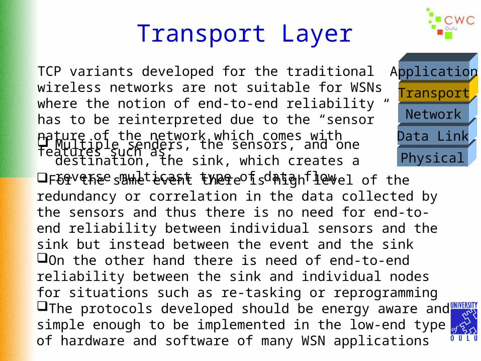
Transport Layer
Physical
Data Link
Network
Transport
ApplicationTCP variants developed for the traditional wireless networks are not suitable for WSNs where the notion of end-to-end reliability has to be reinterpreted due to the “sensor” nature of the network which comes with features such as:
Multiple senders, the sensors, and one destination, the sink, which creates a reverse multicast type of data flow
For the same event there is high level of the redundancy or correlation in the data collected by the sensors and thus there is no need for end-to-end reliability between individual sensors and the sink but instead between the event and the sinkOn the other hand there is need of end-to-end reliability between the sink and individual nodes for situations such as re-tasking or reprogrammingThe protocols developed should be energy aware and simple enough to be implemented in the low-end type of hardware and software of many WSN applications

Proposed Transport Layer Techniques
Pump Slowly, Fetch Quickly (PFSQ) – Designed to distribute data from a source node by pacing the injection of packets into the network at relatively low speed (pump slowly) which allows nodes that experience data loss to aggressively recover missing data from their neighbors (fetch quickly). Goals of this protocols are:
Ensure that all data segments are delivered to the intended destinations with minimum especial requirements on the nature of the lower layersMinimize number of transmissions to recover lost informationOperate correctly even in situations where the quality of the wireless links is very poorProvide loose delay bounds for data delivery to all intended receivers
PFSQ) has been designed to guarantee sensor-to-sensor delivery and to provide end-to-end reliability for control management distribution from the control node (sink) to the sensors. It does not address congestion control

Proposed Transport Layer Techniques
Event-to-Sink Reliable Transport (ESRT) – Designed to achieve reliable event detection (at the sink node) with a protocol that is energy aware and has congestion control mechanisms. Salient features are:Self-configuration – even in the case of a dynamic topologyEnergy awareness – sensor nodes are notified to decrease their frequency of reporting if the reliability level at the sink node are above the minimumCongestion control – takes advantage of the high level of correlation between the data flows corresponding to the same eventCollective identification – sink only interested in the collective information from a group of sensors not in their individual reportsBiased implementation – most of the complexity of the protocol falls on the sink node minimizing the requirements on the sensor nodes

Application Layer
Physical
Data Link
Network
Transport
ApplicationThere has not been a lot of development on this layer for WSNs. Some potential applications have been suggested as listed below but little work of substance has been reported on any particular area.
Authentication, key distribution, and other security tasks Sensor movement management
Sensor Management Protocol (SMP) – Carries out tasks such as: Turning sensors on and off Exchanging data related to the location finding algorithms
Interest Dissemination – Interest is send to a sensor or a group of sensors. The interest is expressed in terms of an attribute or a triggering event.
Advertisement of Sensed Data – Sensor nodes advertise sensed data in a concise and descriptive way and users reply with requests of data they are interested in receiving

Distributed Source Coding (DSC)
Application LayerAims to take advantage of the high level of correlation of the data collected by spatially close sensor nodes in response to an event.
The goal is to remove this redundancy in a distributed manner. There is the need to be able to make reliable decisions from the contribution of a large number of individual unreliable components with a considerable amount of system redundancy. Any method that can strip this redundancy in a distributed manner, e.g. minimizing inter-node communications, will make efficient use of the bandwidth and also save energy.
One way to remove the redundancy is by joint processing based on exchange of information between the sensors. What is then the price for minimizing this exchange (to save energy)? Proposed DSC methods make use of the Slepian-Wolf coding theorem that states if the joint distribution quantifying the senor correlation structure is known then there is no theoretical loss in performance under certain conditions.
S. Pradhan, K. Ramchandran, “Distributed Source Coding Using Syndromes (DISCUS): Design and Construction,” IEEE Trans. Information Theory, vol. 49, no. 3, March 2003, pp. 626-643

Distributed Source Coding (DSC)
The encoders collaborate and a rate of H(X,Y) is sufficient
Encoder 1
Encoder 2
Joint Decoder
X
Y
YX ˆ,ˆ
The encoders do not collaborate. The Slepian-Wolf theorem says that a rate H(X,Y) is also sufficient provided the decoding of X and Y are done jointly. It puts more burden on the decoding side
Encoder 1
Encoder 2
Joint Decoder
X
Y
YX ˆ,ˆ

Distributed Source Coding (DSC)
A
B
C D
Suppose node A wants to collect the readings from the other sensor nodes. Let’s assume that the readings are all a 3-binary values, and that the reading of each “child” node is correlated with the one from its “parent” node in a manner that the Hamming distance between their readings is no more than 1 bit.Application of the Slepian-Wolf theorem results in nodes C and D communicating their 3-bit readings to their parent, node B, using 2-bit syndromes. Node B relay these messages to node A, along with its own 2-bit syndrome with respect to node A. Node A performs a successive decoding process by first decoding its correlated node B (using its own reading) and then decoding the readings of C and D relative to the decoded reading of B.

Cross-Layer Design
Avoid Conflicting Behavior – For example a routing protocol that favors smaller hops to save transmission energy consumption does require a proper MAC protocol to coordinate the transmissions along the data flow that minimizes contention and keeps the transceivers off as much as possible
Remove Unnecessary Layers – Some applications do not require all layers
New Paradigm – WSNs does not have many of the feature of the conventional networks for which the OSI protocol layer stack model has proven to be successful. Therefore it is quite possible that a different mix of layers might prove to be more efficient for many WSN applications
Motivations:
Related Documents