Rotation Right/left Forward/backward Angled Max. allowable load weight: 1000 kg (MACM10) Centering Unit Contributes to space saving on conveyor lines Heavy workpieces can now be aligned and positioned with small cylinders, resulting in compact conveyor lines. Alignment and positioning of transferred workpieces External photo sensor For lock/unlock confirmation External photo sensor mountable Select from lock port side or opposite side of port installation. Locking port Unlocking port Built-in air locking mechanism Table can be held in any position. Workpieces can be moved in any direction: forward/backward, right/left, at an angle, and even rotated (360°). Ball bearings allow for smooth operation. Table centering accuracy ±1 mm or less (Workpiece not loaded) (Stroke) Table center Table center movable range Max. ø 100 mm (MACM10-50) ø100 50 3 types of table material can be selected. Stainless steel Ultra high molecular weight polyethylene Cast nylon Table P-E16-22A MACM Series

Welcome message from author
This document is posted to help you gain knowledge. Please leave a comment to let me know what you think about it! Share it to your friends and learn new things together.
Transcript

Rotation
Right/left
Forward/backwardAngled
Max. allowable load weight: 1000 kg (MACM10)
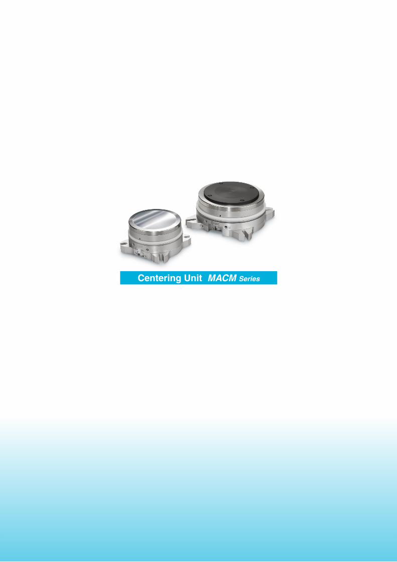
Centering Unit
Contributes to space saving on conveyor linesHeavy workpieces can now be aligned and positioned with small cylinders, resulting in compact conveyor lines.
Alignment and positioning of transferred workpieces
External photo sensor
For lock/unlock confirmationExternal photo sensor mountableSelect from lock port side or opposite side of port installation.
Locking port Unlocking port
Built-in air locking mechanismTable can be held in any position.
Workpieces can be moved in any direction: forward/backward, right/left, at an angle, and even rotated (360°). Ball bearings allow for smooth operation.
Table centering accuracy
±1 mm or less (Workpiece not loaded)
(Stroke)
Table center
Table center movable range
Max. ø100 mm (MACM10-50)
ø100
50
3 types of table material can be selected.
Stainless steelUltra high molecular weight polyethylene Cast nylon
Table
P-E16-22A
MACM Series

Transferred workpieces are stoppedWorkpieces transferred at an angle are stopped at an alignment point (stops where the centering unit is installed).
Centering unit risesCylinder rises to lift the workpiece (separates roller conveyor from workpiece).
Centering unit descends/workpiece is transferred to next stepCylinder descends, places workpiece back on the roller conveyor, and transfers it to the next step.
Workpiece alignment/table lockAlignment cylinder corrects skewed workpieces and realigns them.After alignment, the table of the centering unit is locked to maintain the corrected position even after the adjustment cylinders are released.
Centering unit condition after correcting skew
Cylinder rises
Stopper cylinder
Skew is corrected by alignment cylinder
Alignment cylinder
Alignment cylinder
Up/down cylinder
Workpiece Alignment point
Roller conveyor
Centering unit
Centering unit
Cylinder descends
Workpiece stops Workpiece rises
Roller conveyor
Conveyor Line<Application Examples>
Up/down cylinder
1
2
3
4
1
Centering Unit MACM Series

Conveyor line
Liquid crystal cassette
Centering unitCentering unit
Alignment cylinder
Liquid crystal cassette
Liquid Crystal Cassette Transfer
Alignment of cassette/table lock
Stops in front of rack Is stored in rackIs transferred to and stopped in front of the rack where skewed liquid crystal cassettes are to be stored
The alignment cylinder corrects skewed workpieces and aligns the liquid crystal cassettes.After alignment, the table of the centering unit is locked to maintain the corrected position even after the alignment cylinders are released.
Centering unit
Alignment cylinderCentering unit
Skew is corrected by alignment cylinder
1
3
2
2
Centering Unit MACM Series

qTable
wBearing
eSpring for returning to center
rCenter shaftBearing cage
Body
Movement
qTablerCenter shaft
yPiston for locking
tBearing holder plate
Clearance
Locking portUnlocking port
wBearing
rCenter shaft
tBearing holder plate
Locking portUnlocking port
yPiston for locking
Neutral (Centering) condition
Unlocked condition
Movable condition
Locked condition
¡�When a force is applied to q the table in the lateral direction, w the bearing slides. When the bearing slides, e the spring for returning to center also expands and contracts.¡�When the force in the lateral direction is released, r the center shaft is returned to the neutral position by e the
spring for returning to center.
¡�When air is supplied from the locking port, y the piston for locking descends and pushes r the center shaft down.When r the center shaft lowers, t the bearing holder plate is pressed, and the table is locked.¡�When air is supplied from the unlocking port, y the piston for locking ascends and releases the lock.
The table becomes free when unlocked. The table is locked in place when locked.
Working Principle
Lock Mechanism
3
Centering Unit MACM Series

How to Order
Specifications
Model MACM2-12 MACM4-20 MACM6-30 MACM10-50Max. allowable load weight [KN] 2 4 6 10
Stroke [mm] 12 20 30 50
Table center movable range [mm] ø24 ø40 ø60 ø100
Centering accuracy [mm] ±1 or less
Cylinder for lock
Action Double acting
Fluid Air
Operating temperature [°C] 0 to 60
Operating pressure [MPa] 0.4 to 0.7
Proof pressure [MPa] 1
Lubrication Non-lube
Weight [kg] 0.7 1 2 7
X1144 P20MACM
Centering unit Made to order (Table material)X114 Stainless steel
X115 Ultra high molecular weight polyethylene
X116 Cast nylon
Relief portNil No
V Yes
Sensor typeNil Unsupported
P Port side photo sensor mounted type
B Port back side photo sensor mounted type
StrokeSymbol Stroke (Applicable model)
12 12 mm (MACM2)
20 20 mm (MACM4)
30 30 mm (MACM6)
50 50 mm (MACM10)
Allowable load weightSymbol Allowable load weight
2 2 KN
4 4 KN
6 6 KN
10 10 KN
Centering Unit
MACM Series
Caution1. Use the product within the movable range.2. Use the product within the allowable load weight.3. Load workpieces within the load range.4. Load workpieces within the allowable inclination range.5. Do not use the product in applications where excessive
external force or impact force is applied to it.Improper handling includes the following: · Applying impact on the side of the table to move it to full stroke
· Continuously moving the table in a circle while the table is at a full stroke
· Repeating reciprocation of the table at full stroke · Holding the body and swinging the table
6. Prevent over strokes.7. Secure the table in place when transporting the product
or the equipment it is mounted on.8. This is not a clean room series product.
Operating Precautions
PrecautionsBe sure to read this before handling the products. For safety instructions, actuator and auto switch precautions, refer to the “Handling Precautions for SMC Products” and the “Operation Manual” on the SMC website: http://www.smcworld.com
4

øW (Workpiece loadable range)
4 x D
CDBDA
øAøB
HQ
PB
E
P (Unlocking port)PE
PA P
D
P (Relief port)(Option V only)
P (Locking port)
PCPCPC PC
PEP (Relief port)(Option V only)
PD
HT
øWøU
F
Sø (A + 2 x S)
Dimensions
X114
MACM4, MACM6 MACM2, MACM10
X115, X116
At maximum offset
DimensionsModel A B C D DA DB E F H P PA PB PC PD PE Q S T U W
MACM2X114
68 74 76
6.6
60 64
12
3046
M5
19 17
22.5°
7
10° 27.4 12— —
34X115 52 662
X116 50 4
MACM4X114
86 90 90 72 78 32.550
18°
19 32 20— — 33
X115 56 678
40X116 54 4 40
MACM6X114
118 125 125 97 113 33.853
28 33.3 30— — 43
X115 59 698
60X116 57 4 60
MACM10X114
185 197 198 11 152 182 18 53.877
31 24 13° 0° 53.3 50— —
70X115 83 6108
X116 81 4
[mm]
5
MACM Series

192 x M3 thread depth 4(Holes for mounting photo sensor)
4
Commercially available bolt Sensor
Dimensions
P: Port side photo sensor mounted type
P: Port side photo sensor mounted type
B: Port back side photo sensor mounted type
Mounted example of EE-SX671m made by OMRON
* The above photo sensor made by OMRON should be provided by the customer.
* Mounting position adjustment may be required depending on the individual differences of the sensor.
6
Centering Unit MACM Series
Centering Unit MACM Series
Related Documents