Welcome message from author
This document is posted to help you gain knowledge. Please leave a comment to let me know what you think about it! Share it to your friends and learn new things together.
Transcript


P a g e | 2
Contents
Really Important things (site survey) …………….Pg 3
Overview of outside of product …………….Pg 4
Overview of Inside …………….Pg 5 Pedestal Installation …………….Pg 6
Wall mount installation …………….Pg 7 Power IN module …………….Pg 7
Cellular module in detail …………….Pg 8 Wiring relays …………….Pg 8
Keypad / Prox module in detail …………….Pg 9 Connecting slave devices …………….Pg 9
Inserting SIM …………….Pg 10 Powering up and LEDs …………….Pg 10
Installing the Programming APP …………….Pg 11 Begin Programming a New Install …………….Pg 12
Begin Programming Existing Install …………….Pg 12
Programming Check Reception …………….Pg 13
Activate clock sync …………….Pg 14 Activate daily activity …………….Pg 14
Program dial out and dial in numbers …………….Pg 15 Volumes …………….Pg 17
Dialling & Talk Times …………….Pg 17 Service Calls …………….Pg 18
Info Screen …..…….Pg 18 Pass Codes …………….Pg 20 Relay Times …………….Pg 20 Notifications …………….Pg 21
Keypad Programming …………….Pg 21
Automatic Triggering Times …………….Pg 24
Client List on iphone …………….Pg 24 Client list on Android …………….Pg 25
Do Not Disturb …………….Pg 25 After Hours …………….Pg 26
PROX card Programming …………….Pg 26
Complete List of Parameters …………….Pg 29
Control by SMS …………….Pg 31
Troubleshooting …………….Pg 31

P a g e | 3
Really Important things you Need to Know..
Please read this entire manual before installing
this product.
To be installed by certified and qualified
personnel / gate automation dealer only. Not for DIY install!
Ensure there is good At&T or T-Mobile 4G
signal at the gate/door of the install site BEFORE installing this product. (This unit will also fall back to 3G service in some locations
depending on network).
Set up on a bench in workshop BEFORE going to site. Program the unit in the comfort of your work bench and call technical support should
you have questions.
This product requires a SIM card from either
At&T or T-Mobile, however T-Mobile may not have matching band coverage in your area!
The SIM should be a voice and text plan. Do not use a DATA only SIM.
Ensure your SIM has VOLTE (HD Voice calling service is enabled).
Manufacturer warranty does NOT cover lighting / storm damage. You MUST fit external surge
protection and lightning rod in order to maintain warranty on this product.
Evidence of surge protection will be requested on generation of RGA numbers.
5
Preferred!
1 2
3 4
6

P a g e | 4
Now lets have a look around the product…
Call button
Speaker grill
Hinged front door
Optional Keypad
Architectural
Wall Mount
Traditional Hooded
Wall Mount
Security Screw Access
(Open top screws only)
Hinged front door
Microphone
Built in antenna Security access
key Pedestal
Mount
Version
Optional Keypad
Optional Prox
Reader
Optional Prox badge reader
Call Button

P a g e | 5
Overview of Inside…
Push button
Optional
Keypad
module
Antenna
Connection
Optional
Prox reader
module
Optional
Prox Coil
Cable Entry
Hole
Mounting
Holes
Wall
Mount
Version
Cellular
Module
Lock Push button
Cellular
PCB
Optional
Prox Coil
Optional
Keypad
module
Optional
Prox reader
module
Surge &
Power
Conditioning
Module
Pedestal
Mount
Version

P a g e | 6
Pedestal Installation
!
!
3
1 After fitting the box to the
gooseneck, re-fit the module
and connect a 14 gauge earth
wire to the earth terminal. 2
Earth Rod
(close as
possible)
Maintain manufacturer’s
warranty by adhering to the
guidelines shown. Use 110v
surge protected supply.
Surge protected 110v
4 24v dc PSU
16 gauge MIN
25 feet MAX
Call box
Use minimum 16 gauge wire
from the 24v dc adaptor provided
to the terminals shown. 12v
installs should use SOLAR
input terminals.
Remove 4 screws
and remove power
conditioning module
(if needed)

P a g e | 7
Wall Mount Installation
!
!
24vdc out - +
+ -
+ -
Earth Rod
24v DC
OUT 24v DC IN from PSU
To Earth Rod
Weatherproof
enclosure
Use 110V surge
protection to maintain
warranty Wall or Pillar
(side view)
Wall mount
call station
IMPORTANT
18 gauge MIN
10 feet MAX
Solar IN or 12v IN from Battery
24vdc IN (do not use 12v here)
500mA quick blow
output fuse
Earth Rod
Connection
Optional Battery
Connection leads
3Ah 12v dc max 1A quick blow
input fuse
Power
Module
in
Detail…

P a g e | 8
Relay 2
Wiring
Relays
Gate Position
Limit switch
(optional)
Note: The manufacturer is
not responsible for wiring to
third party devices. Please
consult an experienced
security installer.
Electric Gates
Pedestrian
gates or door
Magnetic
lock
Exit button Separate lock Power
supply (not supplied)
Sta
rt
Exit Button
Com
mon
To Call
Button
12v dc 100mA
(backlighting)
24v dc IN
(pre-wired)
Relay 1
CPU Status
Signal Status
Power
Cellular
Module in
Detail…
SIM holder Modem Status
Antenna
connection
N/O
COM
N/C
N/O
COM
N/C

P a g e | 9
1 2 3 24v
OUT
IN
OUT
INOUT
IN
1 2 3 24v
OUT
IN
1 2 3 24v
1 2 3 24v
Keypad /
PROX
Modules
in
Detail…
1 2
Slave OUT connections
Slave IN connections
Slave IN
Slave OUT
3
Optional
PROX
module
Baud jumper (remove
for older intercoms)
Keypad
Module
To next
device
Optional
Keypad
Optional
Prox reader
Optional Slave
Keypad
24v out
Optional Slave
Prox Reader
CAT5 (30ft max)
300ft if device powered
separately
To next
device
GND
Connecting
Slave
Devices

P a g e | 10
Inserting the SIM card
Powering Up & LEDs
Perform a final check of wiring and ensure the antenna is connected before switching on the
power. Once the power is switched on, the power LED should illuminate.
WARNING Ensure power is OFF. Do not hot
insert or remove while power on.
Preferred!
45 chamfer OUT
Pads DOWN
Ensure SIM is activated.
Pre-pay SIM will need credit first.
At&T preferred. T-Mobile also
compatible in certain areas.
CPU
Flashing = standby
Constant ON/OFF = busy
SIGNAL STRENGTH
1 flash = poor (1 bar)
2 flashes = low (2 bars)
3 flashes = good (3 bars)
4 flashes = Strong (4 bars)
5 flashes = searching
POWER
MODEM
Flashing = standby
Constant ON/OFF = searching


P a g e | 13
Programming Now that you have either entered a new client, or selected an existing client from the client list,
you are now ready to begin programming.
Note: SMS string= *20#
Step 1A: Check Reception
Go to MORE>INFO to reveal the screen shown.
Press the reception check button. On Android the app will
automatically send a SMS string (*20#) to the intercom.
On iphone, users will be taken to their SMS screen to
confirm before sending the string.
The intercom should reply with a signal level between 1 & 31.
1-12
Poor
13-20
Medium
21-31
Good
For good performance, signal level should be at least 13 or
better if 4G reception is available.
TIP: If signal is lower than recommended, then take IMMEDIATE
action. Change network if possible, or use an optional high gain
antenna. Check power cable is within recommended
specification. (Poor power cable can lower reception).
SMS message sent to intercom.
SMS reply to your phone.
Step1B: Set APN (for VOLTE / 4G voice calling)
This feature is needed in order to make 4G voice calls with At&T. Check the APN of your provider and then enter it in the blue section below and send as SMS to the intercom. (For At&T cards from the store, you can use “nxtgenphone”. For Tracfone provided SIM, then set the APN to “RESELLER”.
9999#97APNinfo#
Pass code
Function code
APN info for network
Step1C: Reboot the Intercom
The intercom will need to be rebooted in order to log on to the network with the new APN which you have stored. If you send another reception check (*20#), you may find that if it was on 3G signal strength before, that it is now on 4G signal.

P a g e | 14
Step2: Activate Clock Sync
This feature makes the intercom send itself a SMS after a power failure. This feature must be activated to maintain proper time (the intercom re-calibrates its time from an incoming SMS message). SMS Programming Format:
9999#86telephonenumber#
Pass code
Function code
Phone number of the SIM
card in the intercom
Step 3: Activate Daily Activity
This feature is needed for 2 reasons: 1.To prevent some cellular carriers disconnecting the 4G LTE due to inactivity on the device. 2.To keep time synchronisation in regions where there are summer daylight saving time changes.
It is recommended to set the number of days to 01 which will send SMS every day. Depending on carrier provider, this may be chargeable to the customer. NOTE: Must be 2 characters, e.g. 01, 02 etc.
9999#87??#
Pass code
Function code1-99 days
00= no SMS sheduling


P a g e | 16
Programming Additional Features The intercom should now be able to call users and have some basic Caller ID access. Now you
may wish to program additional features for the client, including keypad codes, dialling times (to
avoid voicemail on un-answered calls, auto-trigger times etc.
Mic & SPK Volume
Avoid voicemail
picking up un-
answered calls
Service Calls
(prevent SIM being
turned off due to
inactivity)
Diagnostics
Programmer and
user pass codes
Default relay pulse
times
Turn on SMS
notifications when
gates triggered.
Program keypad
code (some models)
Time clock
automatic opening
and closing times
Adjust, add or
delete clients on
your client list
Turn on do not
disturb to disable
call button at night Turn on Auto-clock
sync after power
failures
Program proximity
cards (model
dependant)

P a g e | 17
1.Volumes Adjust speaker and microphone volumes.
Enter required level (1-9) for optimum speech. TIP: Set as low as possible for good acoustics. Default = 5
SMS string for Speaker Volume:
9999#3X# (X=1-9, default = 5)
SMS string for Microphone Volume:
9999#4X# (X=1-9, default = 5)
Press SAVE. TIP: Iphone users will be taken to SMS screen to confirm message. Android devices will automatically send the SMS.
2. Dialling Times & Talk Time
Change ringing times on each number to avoid voicemail picking up a call on un-answered call so the unit can roll over to the next number. Note: Default 20 secs (includes 5-8 sec connection time).
Dialling time for first number (default 20 secs)
Dialling time for second number (default 20 secs)
Dialling time for third number (default 20 secs)
Set MAX talking time for all numbers (default 60 secs)
TIP: Iphone users will be taken to SMS screen to confirm message. Android devices will auto send the SMS.
SMS strings:
9999#45XX# (X=dialling time for first number) 9999#46XX# (X=dialling time for second number) 9999#47XX# (X=dialling time for third number) 9999#53XXXX# (X= talking time in seconds, 9999 max)

P a g e | 18
4.Info
Choose SMS or CALL
3.Service Calls
This feature is normally only used on intercoms which are seldom used and only for SIM cards which are likely to be de-activated by the network due to inactivity. It can be programmed to make a chargeable outgoing call or SMS to a number of your choice using this screen.
Enter the phone number which is to receive the call
Enter the frequency of calls (1-60 days).
TIP: This will call or SMS at the time at which the feature was activated. So, if you set this feature up at 5pm, it will make the service call or SMS at 5pm at the next interval.
SMS string for choosing SMS or CALL:
9999#58X# (For calls, X=2, for SMS, X=1)
SMS string for entering phone number:
9999#77XXXXXXX# (X=cell phone number) 77*# to delete.
SMS string for frequency of calls:
9999#57XX#
Check signal strength Check stored phone numbers
Check stored keypad
codes
Check relay status
Check who opened the
gate, when it was opened
and by what method
TIP: Iphone users will be
taken to SMS screen to
confirm message. Android
devices will auto send the
SMS.

P a g e | 19
SIGNAL STRENTH Will reply with signal range 1-31 Should be higher than 10.
STORED NUMBERS O=Dial out number. I=Dial IN Caller ID number.
STORED CODES NORM=Permanent codes. TEMP=Temporary codes. PLAN=Time restricted codes.
RELAY STATUS OPEN – Shows status of the input terminals called STATUS on the intercom, can be used with a limit switch. Relay status shown to check if any relay is latched.
Last 5 digits of phone number which answered the gate
Last 5 digits of caller ID user phone number
Last 2 digits of keypad code used
ACTIVITY LOG Use this to see who used the intercom and when. Which pin codes were used, who used caller ID, who answered the call. TIP: Time and date is in international military format.

P a g e | 20
5. Pass Codes
CAUTION: Take care when changing pass codes. There are 2 levels of 4-digit code (both must be different): 1. Engineers/Programmers code (default 9999) 2. Access/user code (default 1234) You may wish to change both from their defaults for security.
Restore the app to using default codes (does not restore the intercom)
Enter new programmers code (default 9999)
Enter new user/access code (default 1234)
If changing default codes, then you will now need to update the client list before you can do any further programming. If the 1234 user access code is changed, then you will also need to change it on the home owners app.
SMS Strings: 9999#01XXXX# (X=new programmers code) 9999#02XXXX# (X=new user access code)
6.Relay Times Relay default trigger times are 1 second. Use this feature to change a relay for a longer time perhaps for a magnetic door lock or to make one relay a momentary relay and the other a 1 hour relay for example.
SMS string for relay 1:
9999#50XXXX# (X=time in seconds, 1-9999)
SMS string for relay 2:
9999#51XXXX# (X=time in seconds, 1-9999)
Enter time in SECONDS then press SAVE to send SMS
TIP: Iphone users will be taken to SMS screen to
confirm message. Android devices will auto send the
SMS.

P a g e | 21
8.Keypad Programming
For Permanent 24/7
Codes
For Time Restricted
Codes (codes that work
during certain times &
days of the week
For temporary codes
(codes which auto-expire
in a pre-set time)
For deleting codes
7.Notifications
This feature is commonly used to allow one home user to receive SMS alerts each time the INTERCOM is used to trigger the gates and grant access.
Quick Enable / disable this feature
Enter the phone number to receive the SMS alert and press SAVE
Enter text which you want the user to receive when access is granted, then press SAVE MESSAGE
SMS string for turning ON or OFF:
9999#80X# (X=2 to enable. X=1 to disable)
SMS string for entering phone number to receive notification:
9999#78XXXXXXX# (X=cell phone number) 78*# to delete.
SMS string for entering text to display:
9999#79XXXXXXX# (X is any text message you wish to
display on the phone. E.g. Gates Opened)

P a g e | 22
Time (Restricted) Code Stores up to 20 codes which will only work during pre-set times and days of the week. (Relay 1 only).
Enter 4 digit code
Enter Start and Finish time (Military format without any colons. E.g. 8am = 0800. 11pm = 2300)
Select days of the week the code is to be active.
SMS String for time restricted code:
9999#83#day,day,day#time1,time2#code#
Pass code
Function code
Enter start and end time in
24hr 4 digit format (no
colon), and separate with
comma. e.g. 0800,2300Select days (up to 7)
3 digit format, separate
with commas.
E.g. mon,tue,wed,thu,fri
4 digit code
Permanent Keypad Code Stores up to 200 codes, all of which can be used to gain access 24/7.
Enter 4 digit code
Choose Relay 1 or Relay 2
Enter activation time. (0-9999 seconds) Use 1 second for gate trigger. Use approx. 5 secs for magnetic locks. Use 0 for latching or toggle code. Use 3600 secs for 1 hour hold open on gates
SMS String for adding keypad codes:
9999#811code#time#
Pass code
Function
code4 digit user
code1 = Relay 1
2 = Relay 2
=SECONDS
1-9999
0 = Latching

P a g e | 23
Enter 4 digit code
Enter countdown time in hours (1-168 hrs)
Delete Codes
You can use these buttons to delete a recently stored temp or time restricted code (codes shown beside the delete button)
Delete any known code
Delete ALL codes
SMS String for deleting a known code:
9999#84code#
Pass code
Function
codeCode to be deleted
Deleting ALL codes: 9999#84*#
Temporary Code Stores up to 30 codes at any time which will auto expire after a pre-set countdown time (1-168 hours) (Relay 1 only)
SMS String for temporary code:
9999#82#hours#code#
Pass code
Function
codeCan be between
1-168 hours
4 digit code

P a g e | 25
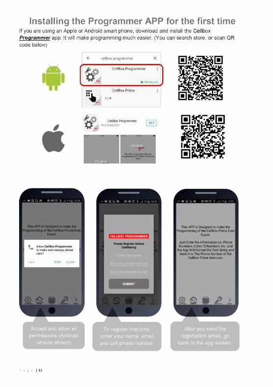
10. Client list on android
The client list allows you to save sim phone number, customer name and pass codes for all your installs.
On any previous install, you can load the customer and then re-program their intercom.
Press & HOLD to select Client
Press to save changes
Press to load details &
begin programming
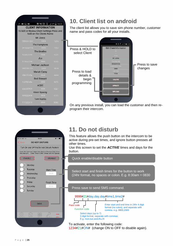
11. Do not disturb
This feature allows the push button on the intercom to be active during pre-set times, and ignore button presses all other times. Use this screen to set the ACTIVE times and days for the button.
Quick enable/disable button
Select start and finish times for the button to work (24hr format, no spaces or colon. E.g. 8:30am = 0830
Press save to send SMS command.
9999#21#day,day,day#time1,time2#
Pass code
Function code
Enter start and end time in 24hr 4 digit
format (no colon), and separate with
comma. e.g. 0800,2300
Select days (up to 7)
3 digit format, separate with commas.
E.g. mon,tue,wed,thu,fri
To activate, enter the following code: 1234#21#ON# (change ON to OFF to disable again).

P a g e | 26
13.Programming Proximity Cards
12. After Hours / Out of Hours
If you have activated the do not disturb feature, the push button will not call anyone after the pre-set time threshold. However, sometimes it is useful to have the intercom call a different number after hours. For example, in commercial premises it can call the office phones during business hours, and then call a security guard after hours.
1.Enter phone number to call after hours.
2. Enter button number (enter 1 for single button system)
3. Press SAVE to confirm and send SMS
9999#211telephonenumber#
Pass code
Function code
(add number)
Data
Button number
(1-10)
Telephone number
position 1-4
Select which unit you have (2G/3G OR 4G) Up to 200 Prox cards
can be added
Time restricted Prox cards or tags (20)
Temporary Prox cards or tags (30)
Delete cards or tags

P a g e | 27
13a. Permanent Prox card/tag
Add up to 200 cards or tags for RFID access. Note: On 4G version, you may enter a nickname for a card which can be useful when identifying card users later. For 2G and 3G versions, ignore the name field.
Enter nickname up to 5 digits long.
Enter the 10 digit card ID number.
Select relay 1 or 2.
Enter relay activation time in seconds.
13b. Time Restricted card/tag
Add up to 20 cards or tags for time restricted access for certain times or days of the week (relay 1 only). 1.Enter serial number of card (last 6 digits).
2.Enter start time (24hr format, no colon or spaces)
3. Enter end time (24hr format, no colon or spaces)
SMS String for time restricted code:
9999#83#day,day,day#time1,time2#code#
Pass code
Function code
Enter start and end time in
24hr 4 digit format (no
colon), and separate with
comma. e.g. 0800,2300Select days (up to 7)
3 digit format, separate
with commas.
E.g. mon,tue,wed,thu,fri
4 digit code
4. Select days of the week
SMS String for adding Prox cards/tags:
9999#611cardID#time#
Pass code
Function
code10 digit card ID1 = Relay 1
2 = Relay 2
=SECONDS
1-9999
0 = Latching
SMS String for time restricted card/tag:
9999#63#day,day,day#time1,time2#cardID#
Pass code
Function code
Enter start and end time in
24hr 4 digit format (no
colon), and separate with
comma. e.g. 0800,2300Select days (up to 7)
3 digit format, separate
with commas.
E.g. mon,tue,wed,thu,fri
10 digit ID

P a g e | 28
13c. Temporary card/tag
Add up to 30 cards which will only be active for a certain time period, from 1-168 hours and then will be auto deleted from the system.
1.Enter serial number of card.
2. Enter countdown time in hours.
13d. Deleting cards
This screen allows any known card ID to be deleted (by serial number), and it will also show the last stored cards for each type of card.
Delete the last stored temporary card.
Delete the last stored time restricted card.
Delete any known card ID.
Delete ALL stored cards.
SMS String for temporary card/tag:
9999#62#hours#cardID#
Pass code
Function
codeCan be between
1-168 hours
Card ID
SMS String for deleting a known code:
9999#64cardID#
Pass code
Function
codeCard ID to be deleted
Deleting ALL codes: 9999#64*#

P a g e | 29
Complete list of parameters
The table below show the complete list of features. Programming messages below must begin with 9999# (assuming 9999 is still the programming passcode)…
Changing pass codes
9999#01????# Change programming password 9999
9999#02????# Change access control password (SMS control of relays, or non-stored numbers can call intercom & enter code to activate output 1).
1234
9999#03????# Change monitoring mode password (user can call the intercom, enter this pass code to listen in and speak)
5555
Dial out numbers
9999#1XY????# Store dialling out numbers. (X = button number 1-9 & 0 for button 10) (Y = number dialled 1-4) (???? = phone number)
N/A
9999#1XY*# Delete a dial out number. (X = button number) (Y = number position 1-4)
N/A
Volume controls
9999#3?# Speaker volume. Where ? = 1-9. 1 = lowest, 9 = highest. 5
9999#4?# Microphone volume. Where ? = 1-9. 1 = lowest, 9 = highest. 5
Timings
9999#50?# Relay 1 time. ? = seconds, 1-9999 1 sec
9999#51?# Relay 2 time. ? = seconds, 1-9999. 1 sec
9999#45??# Calling time for first number, adjust this to avoid voicemail picking up a call (10-99 secs)
20 secs
9999#46??# Calling time for second number, adjust this to avoid voicemail picking up a call (10-99 secs)
20 secs
9999#47??# Calling time for third number, adjust this to avoid voicemail picking up a call (10-99 secs)
20 secs
9999#53????# Talking time. 5-9999 seconds. 60 secs
9999#55??# Max monitoring time (for listen in mode when calling the intercom) 00-60 mins. 00 = no limit.
10 mins
Scheduled service calls
9999# 77number#
Store a service number to receive a scheduled call or SMS from the unit. Useful for SIM cards which are not often used to prevent switch off by the network provider.
N/A
9999#57??# Set the time schedule for the intercom to make a scheduled call or SMS to the service number. 00-60 day time schedule. 00 = no call or SMS.
00
9999#58?# Choose between making a scheduled call or scheduled SMS. 1 = SMS. 2 = call.
1
9999#77*# Delete the stored service number N/A
Caller ID features
9999# 72number#
Store caller ID number. Max 14 digits. Only last 6 digits compared.
N/A
9999# 73number#
Delete caller ID number. N/A

P a g e | 30
9999#73*# Delete all caller ID numbers N/A
Service & diagnostic messages (no passcode required for some of these!)
*20# Check reception level 1-31 (no passcode needed) N/A
*21# Check stored numbers. O = dial out number. I = dial in number. E = end of message. (no passcode needed)
N/A
*22# Check input status and relay status. (No passcode needed) N/A
*23# Sends SMS messages of the last 20 events. N/A
1234#25# Check stored keypad codes. N/A
Keypad Programming
9999# 81Xcode#time#
Permanent codes - X=1 or 2 for relay 1 or 2. Code = 4-6 digits. Time = 1-9999 seconds, or 0 for latching code.
N/A
9999# 83#day,day,day #time1,time2# code#
Time restricted codes Day = day of the week e.g. mon,tue,wed,thur,fri. Time1 = start time. Time2 = end time (24 hr format, no colon. E.g. 11:30pm = 2330. 8.30am = 0830. Code = pin code 4-6 digits.
N/A
9999# 82#hours# code#
Temporary codes Hours = time to expire in hours (1-168 hours). Code = Pin code 4-6 digit code.
N/A
9999#84code# Delete code – Code=known code to be deleted. N/A
9999#84*# Delete all codes. N/A
Notifications
9999#80X# X=1 to disable. X=2 to enable. N/A
9999#78XXX# X=phone number to send notifications to. (*=delete number) N/A
9999#79text# X=text to send to the receiving phone e.g. “gate opened” N/A
Automatic Time Clock Trigger Times
1234#X# day,day,day# time#
X=1,2.3 (trigger, latch, unlatch relay 1) 4,5,6 (relay 2) Day = days of the week (mon,tue,wed,thur,fri,sat,sun) Time = time of day (24 hr format, no colon. E.g. 8:30am = 0830)
N/A
1234*X# Delete ALL automatic trigger times. N/A
Clock Sync - Auto Time Calibration after Power Fail
9999#86XXX# X=telephone number of SIM inside the intercom. N/A
9999#86*# Delete the phone number. N/A
Summer Daylight Auto Correct
9999#87??# ?? = number of days between SMS calibration SMS should be sent. 0 = no message sending.
N/A
Do Not Disturb (push button de-activated during set times)
1234#21#ON# ON = activated. OFF = de-activated. OFF
9999# 21#day,day,day #time1,time2#
Enter all active days during which button should operate. Enter start and end time button should operate (24 hr format, no colon. E.G 8:30am = 0830)
N/A

P a g e | 31
Alternate Number to Call During Do Not Disturb Times.
9999# 21X????#
X = button number (1-9. Enter 1 for 1 button system. Enter 0 for button 10) ???? = Alternative phone number to call out of hours.
Restore Defaults
9999#999# Send with passcode string to clear all programming. N/A
Control by SMS This intercom allows the user to send SMS commands to control the relays and check status as
follows…
1234#1# - Relay 1 momentary trigger. 1234#2# - Relay 1 latch ON or hold ON. 1234#3# - Relay 1 unlatch or switch OFF.
1234#4# - Relay 2 momentary trigger. 1234#5# - Relay 2 latch ON or hold ON. 1234#6# - Relay 2 unlatch or switch OFF.
Troubleshooting guide
Q. The unit will not power up. No LEDs on.
A. Check power supply voltage at intercom is within 14.8V DC. Cable length from PSU to intercom
should be less than 25 feet and in 14 gauge. Check the fuse.
Q. The unit powers up but is not showing network reception or will not respond to SMS.
A. This means the unit is not able to detect the network for some reason.
-Power off the unit, remove the SIM and check it in a mobile phone to verify it can make a call and
has calling credit.
-Disable any PIN code request if active on the SIM card.
-Check the SIM is a standard voice capable SIM. If you are unsure, contact your SIM card
provider to verify. Compatible networks are At&T and T-Mobile.
-Check the reception is medium or good. Poor reception is not sufficient.
-Power off, remove the SIM, use fine sand paper to lightly sand the SIM pads and contacts on the
GSM unit, lightly bend the contacts upwards so that they make better contact with the SIM and try
again.
Q. The unit calls the first number, but there is not enough time to answer before it diverts
to the next number.
A. Increase the no answer time as per programming instructions.
Q. The unit calls the first number but voicemail comes on before it can ring the second
number.
A. Decrease the no answer time as per programming instructions.
Q. The caller ID part does not work.
A. Be sure to program the caller ID part under 72 feature. If your number is a private or number
withheld, then it will not work.
-Even if you have already programmed a number to receive a call from the intercom, if you also
want that number to have caller ID access, it must be programmed under the 72 feature also.

P a g e | 32
-Ensure the number is entered as you would normally dial it from another phone.
-For US customers, ensure the numbers have been entered with a leading 1. If this does not work,
try again without the leading 1.
Q. There is no audio from the gate, but the person at the gate can hear ok.
A. This can be due to low reception or excessively long power cables.
-Check reception level by *20#.
-Change SIM card if necessary to another network which may have better coverage.
-Purchase a high gain antenna.
This may also be caused by a defective microphone, water on a microphone from a sprinkler for
example, or dirt/insects blocking the microphone hole. If reception is optimum and the problem
persists, contact your supplier or installer.
Q. The audio quality that can be heard on the remote telephone is poor or humming
(buzzing).
A. A small amount of GSM buzz can be considered normal on GSM intercoms, but not so much
that causes inability to hear the person speaking. This is a symptom of poor reception. Try above
steps on checking and improving reception. Consider fitting an external high gain antenna.
Q. The trigger keys do not work when the intercom calls a phone.
A. Check if you can hear the relay clicking at the gate when the keys are pressed during a call. If it
can be heard, then the system is working, check wiring between the relay and the lock or gate
panel. If the relays do not make a clicking sound, then check this feature on a different mobile cell
phone or landline. If it works on a different phone, check the settings on the phone in question
under DTMF tones.
Failure of DTMF tones to operate correctly is also a symptom of low reception or insufficient
power cabling. Check steps above on improving reception or addressing the power problem.
-Also check that the relays are not already latched with the *22# command. If they are latched,
they need unlatched before the trigger keys will work.
-Sometimes excessively long power cables or thin power cables can cause this problem. Prove it
by connecting a temporary extension lead and the power supply directly to the unit.
Q. The system was operating the gates fine, but now it will not trigger the gates.
99% of the time, this is cause by the user accidentally latching the relay. This latches the output
relay permanently on. Send the intercom the following SMS *22#. The intercom should reply with
a message detailing the relay status.. If it has been latched, then the message will state “the relay
is ON”. In this case refer to the user guide to read how to unlatch it again.
Q. The unit no longer calls out to phones but I can make a call to it from my phone.
A – Check there is balance on the SIM card.
A – Switch off the power, remove the SIM, put it into a phone, and check that a call can be made
from a phone. This will verify if the SIM is still working and in service.
Q. The Android App shows an error message “Command Failed” when I try to use a
function.
A – Go to phone settings/application manager/cellbox prime/permissions, and ensure all
permissions are turned ON. Also ensure the app settings screen has a valid phone number
stored.

P a g e | 33

P a g e | 34
Regulatory Compliance
FCC Id: 2ALPX-PRIME6-XXXX-ZZ-4GA-YYY (XXX = style & color, YYY is brand label, ZZ is mounting style) Grantee: Advanced Electronic Solutions Global LLC This device complies with Part 15 of FCC rules. Operation is subject to the following two conditions: (1) this device may not cause harmful interference, and (2) this device must accept any interference received, including interference that may cause undesired operation. Output power listed is ERP below 1GHz for Part 22 and EIRP above 1GHz for Part 24. RF exposure compliance is addressed for 1.1310 and 2.1091 MPE limits. The antenna(s) used for this transmitter must be installed to provide a separation distance of at least 20 cm from all persons. End Users must be provided with transmitter operation conditions for satisfying RF exposure compliance.

P a g e | 35

Related Documents