- 49 - EFDA Technology / Vessel-In Vessel / Plasma Facing Components CEFDA01-585 Task Title: TW1-TVP-TESTAN: MONITORING AND ANALYSIS OF THERMAL FATIGUE TESTING OF DIVERTOR PROTOTYPES 200 kW electron beam gun test INTRODUCTION This contract concerns the monitoring and the analysis of thermal fatigue testing of PFCs at FE200 facility. Four mock-ups were tested from April 2003 to December 2004: - Hypervapotron armoured with CFC flat tiles (mock-up HVCFC-8) - CuCrZr/SS first wall mock-ups (mock-up FW7) - CFC monoblocks (mock-up Baffle) - CFC and W monoblocks (mock-up VTFS) The contract is now completed, a final report [1] including analysis of the 4 testing campaign (18 intermediate reports) was available in April 2005. 2004 ACTIVITIES HYPERVAPOTRON ARMOURED WITH FLAT TILES (MOCK-UP HVCFC-8) The hypervapotron concept adapted to a CuCrZr heat sink armoured with Carbon Fibre Composite (CFC) or Tungsten was envisaged for the vertical targets of the ITER divertor since the beginning of ITER EDA, but finally abandoned for two main reasons : it was suspected that the joint temperature between CFC or W and CuCrZr may be too high as well as a possible occurrences of a “cascade tile failure” effect. Last experimental results accompanied with progress in modelling have shown excellent behaviour of flat tiles armoured hypervapotron with regards to the two mentioned supposed disadvantageous arguments : temperature of the armour/heat sink joint - strongly dependent on the flow velocity – can be driven below a tolerated limit even under ITER slow-transient heat flux of 20 MW/m² and cascade tile failure occurrence under ITER nominal heat flux of 10 MW/m² was not experimentally observed. In order to validate the hypervapotron concept as a design solution for the ITER divertor, thermal fatigue testing has been successfully performed on a medium scale mock-up (figure 1b). Mock-ups description The mock-up was manufactured by Plansee AG : it consisted of a CuCrZr heat sink (741 mm length x 27 mm width) armoured with 25 flat tiles (18.5 mm length x 6 mm thick) of the 3D carbon fibre composite (CFC) material SEPcarb NS31 assembled with pure Copper by Active Metal Casting (AMC) (figure 1a). The manufacturing route respected the main technological features of a TORE SUPRA toroidal limiter finger element: in first AMC tiles were electron beam welded on the CuCrZr bar, then fins and slots inspired from neutral beam JET design were machined into the bar, afterwards, the bar was closed with a thick CuCrZr rear plug including hydraulics connections then electron beam welded onto the sidewalls. The mock- up was equipped with 6 K-type thermocouple positioned at the Copper/CuCrZr joint. ITER spec. FE200 TSEFEY-M 3000 cycles 10 MW/m² 3000 cycles 15 MW/m² 3000 cycles 15 MW/m² 300 cycles 20 MW/m² 800 cycles 5 MW/m² 1000 cycles 25 MW/m² Critical Heat Flux a few cycles > 30 MW/m² a few cycles > 30 MW/m² Figure 1 : a) view of the mock-up and b) main results of the HHF testing 27 20 6 a) b)

Welcome message from author
This document is posted to help you gain knowledge. Please leave a comment to let me know what you think about it! Share it to your friends and learn new things together.
Transcript
- 49 - EFDA Technology / Vessel-In Vessel / Plasma Facing Components
CEFDA01-585 Task Title: TW1-TVP-TESTAN: MONITORING AND ANALYSIS OF
THERMAL FATIGUE TESTING OF DIVERTOR PROTOTYPES 200 kW electron beam gun test INTRODUCTION This contract concerns the monitoring and the analysis of thermal fatigue testing of PFCs at FE200 facility. Four mock-ups were tested from April 2003 to December 2004: - Hypervapotron armoured with CFC flat tiles (mock-up HVCFC-8) - CuCrZr/SS first wall mock-ups (mock-up FW7) - CFC monoblocks (mock-up Baffle) - CFC and W monoblocks
(mock-up VTFS) The contract is now completed, a final report [1] including analysis of the 4 testing campaign (18 intermediate reports) was available in April 2005. 2004 ACTIVITIES HYPERVAPOTRON ARMOURED WITH FLAT TILES (MOCK-UP HVCFC-8) The hypervapotron concept adapted to a CuCrZr heat sink armoured with Carbon Fibre Composite (CFC) or Tungsten was envisaged for the vertical targets of the ITER divertor since the beginning of ITER EDA, but finally abandoned for two main reasons : it was suspected that the joint
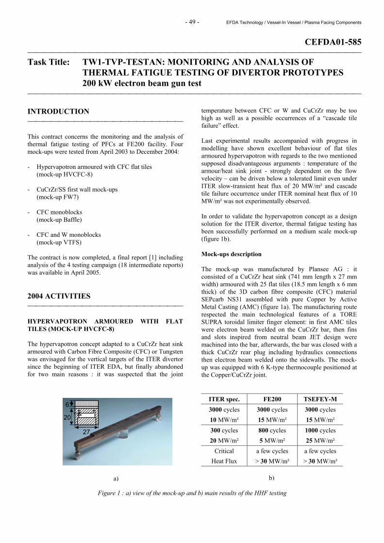
temperature between CFC or W and CuCrZr may be too high as well as a possible occurrences of a “cascade tile failure” effect. Last experimental results accompanied with progress in modelling have shown excellent behaviour of flat tiles armoured hypervapotron with regards to the two mentioned supposed disadvantageous arguments : temperature of the armour/heat sink joint - strongly dependent on the flow velocity – can be driven below a tolerated limit even under ITER slow-transient heat flux of 20 MW/m² and cascade tile failure occurrence under ITER nominal heat flux of 10 MW/m² was not experimentally observed. In order to validate the hypervapotron concept as a design solution for the ITER divertor, thermal fatigue testing has been successfully performed on a medium scale mock-up (figure 1b). Mock-ups description The mock-up was manufactured by Plansee AG : it consisted of a CuCrZr heat sink (741 mm length x 27 mm width) armoured with 25 flat tiles (18.5 mm length x 6 mm thick) of the 3D carbon fibre composite (CFC) material SEPcarb NS31 assembled with pure Copper by Active Metal Casting (AMC) (figure 1a). The manufacturing route respected the main technological features of a TORE SUPRA toroidal limiter finger element: in first AMC tiles were electron beam welded on the CuCrZr bar, then fins and slots inspired from neutral beam JET design were machined into the bar, afterwards, the bar was closed with a thick CuCrZr rear plug including hydraulics connections then electron beam welded onto the sidewalls. The mock-up was equipped with 6 K-type thermocouple positioned at the Copper/CuCrZr joint.
ITER spec. FE200 TSEFEY-M 3000 cycles 10 MW/m²
3000 cycles 15 MW/m²
3000 cycles 15 MW/m²
300 cycles 20 MW/m²
800 cycles 5 MW/m²
1000 cycles 25 MW/m²
Critical Heat Flux
a few cycles > 30 MW/m²
a few cycles > 30 MW/m²
Figure 1 : a) view of the mock-up and b) main results of the HHF testing
27
20
6
a) b)
- 50 - EFDA Technology / Vessel-In Vessel / Plasma Facing Components
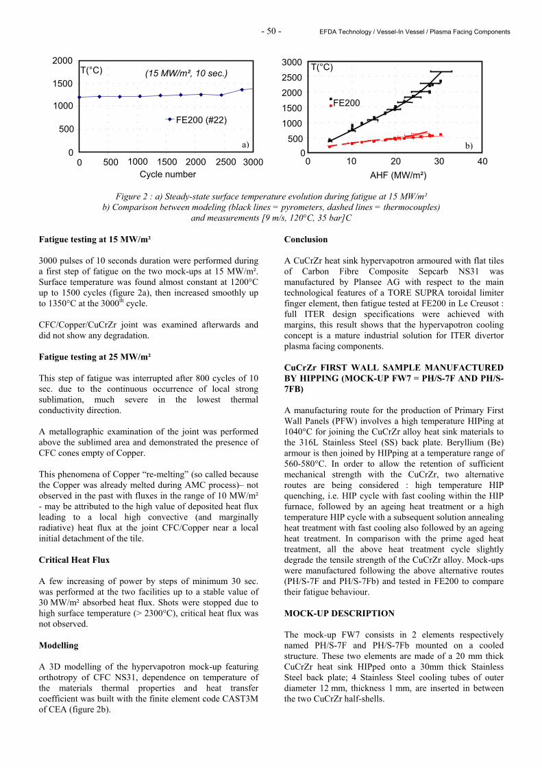
Figure 2 : a) Steady-state surface temperature evolution during fatigue at 15 MW/m² b) Comparison between modeling (black lines = pyrometers, dashed lines = thermocouples)
and measurements [9 m/s, 120°C, 35 bar]C Fatigue testing at 15 MW/m² 3000 pulses of 10 seconds duration were performed during a first step of fatigue on the two mock-ups at 15 MW/m². Surface temperature was found almost constant at 1200°C up to 1500 cycles (figure 2a), then increased smoothly up to 1350°C at the 3000th cycle. CFC/Copper/CuCrZr joint was examined afterwards and did not show any degradation. Fatigue testing at 25 MW/m² This step of fatigue was interrupted after 800 cycles of 10 sec. due to the continuous occurrence of local strong sublimation, much severe in the lowest thermal conductivity direction. A metallographic examination of the joint was performed above the sublimed area and demonstrated the presence of CFC cones empty of Copper. This phenomena of Copper “re-melting” (so called because the Copper was already melted during AMC process)– not observed in the past with fluxes in the range of 10 MW/m² - may be attributed to the high value of deposited heat flux leading to a local high convective (and marginally radiative) heat flux at the joint CFC/Copper near a local initial detachment of the tile. Critical Heat Flux A few increasing of power by steps of minimum 30 sec. was performed at the two facilities up to a stable value of 30 MW/m² absorbed heat flux. Shots were stopped due to high surface temperature (> 2300°C), critical heat flux was not observed. Modelling A 3D modelling of the hypervapotron mock-up featuring orthotropy of CFC NS31, dependence on temperature of the materials thermal properties and heat transfer coefficient was built with the finite element code CAST3M of CEA (figure 2b).
Conclusion A CuCrZr heat sink hypervapotron armoured with flat tiles of Carbon Fibre Composite Sepcarb NS31 was manufactured by Plansee AG with respect to the main technological features of a TORE SUPRA toroidal limiter finger element, then fatigue tested at FE200 in Le Creusot : full ITER design specifications were achieved with margins, this result shows that the hypervapotron cooling concept is a mature industrial solution for ITER divertor plasma facing components. CuCrZr FIRST WALL SAMPLE MANUFACTURED BY HIPPING (MOCK-UP FW7 = PH/S-7F AND PH/S-7FB) A manufacturing route for the production of Primary First Wall Panels (PFW) involves a high temperature HIPing at 1040°C for joining the CuCrZr alloy heat sink materials to the 316L Stainless Steel (SS) back plate. Beryllium (Be) armour is then joined by HIPping at a temperature range of 560-580°C. In order to allow the retention of sufficient mechanical strength with the CuCrZr, two alternative routes are being considered : high temperature HIP quenching, i.e. HIP cycle with fast cooling within the HIP furnace, followed by an ageing heat treatment or a high temperature HIP cycle with a subsequent solution annealing heat treatment with fast cooling also followed by an ageing heat treatment. In comparison with the prime aged heat treatment, all the above heat treatment cycle slightly degrade the tensile strength of the CuCrZr alloy. Mock-ups were manufactured following the above alternative routes (PH/S-7F and PH/S-7Fb) and tested in FE200 to compare their fatigue behaviour. MOCK-UP DESCRIPTION The mock-up FW7 consists in 2 elements respectively named PH/S-7F and PH/S-7Fb mounted on a cooled structure. These two elements are made of a 20 mm thick CuCrZr heat sink HIPped onto a 30mm thick Stainless Steel back plate; 4 Stainless Steel cooling tubes of outer diameter 12 mm, thickness 1 mm, are inserted in between the two CuCrZr half-shells.
0 500
1000
1500
2000
2500
3000
0 10 20 30 40 AHF (MW/m²)
T(°C)
FE200
b) 0
500
1000
1500
2000
0 500 1000 1500 2000 2500 3000 Cycle number
T(°C)
FE200 (#22)
(15 MW/m², 10 sec.)
a)
- 51 - EFDA Technology / Vessel-In Vessel / Plasma Facing Components
Each element is equipped with 2 type K thermocouples located at two deepness (Tref 1 and 3 at 30 mm, 2 and 4 at 40 mm). The cooling tubes are welded to inlet and outlet manifolds for connection to water supply system, allowing the parallel flowing of the 2 elements. Dimensions of each element are 250mm x 88mm x 50mm (figure 3).
Figure 3 : View of the mock-up FW7 (reference view from the gun :
HP an BP in correspondence with FE200 connections) Fatigue testing at 5 MW/m² The cooling water conditions for these tests were selected at inlet temperature 100 °C, flow rate 3kg/s (i.e. 4.8 m/s), inlet pressure 3.3 MPa (ITER first wall relevant conditions).
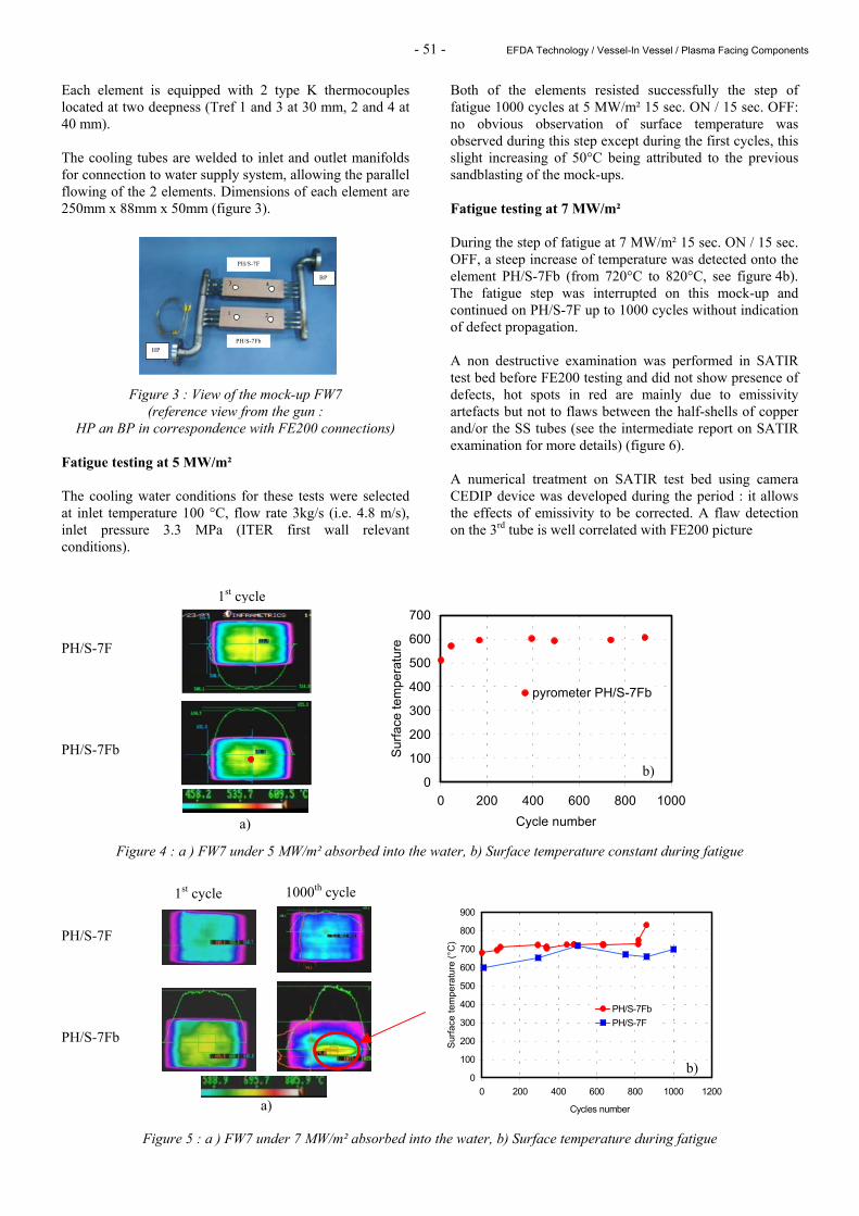
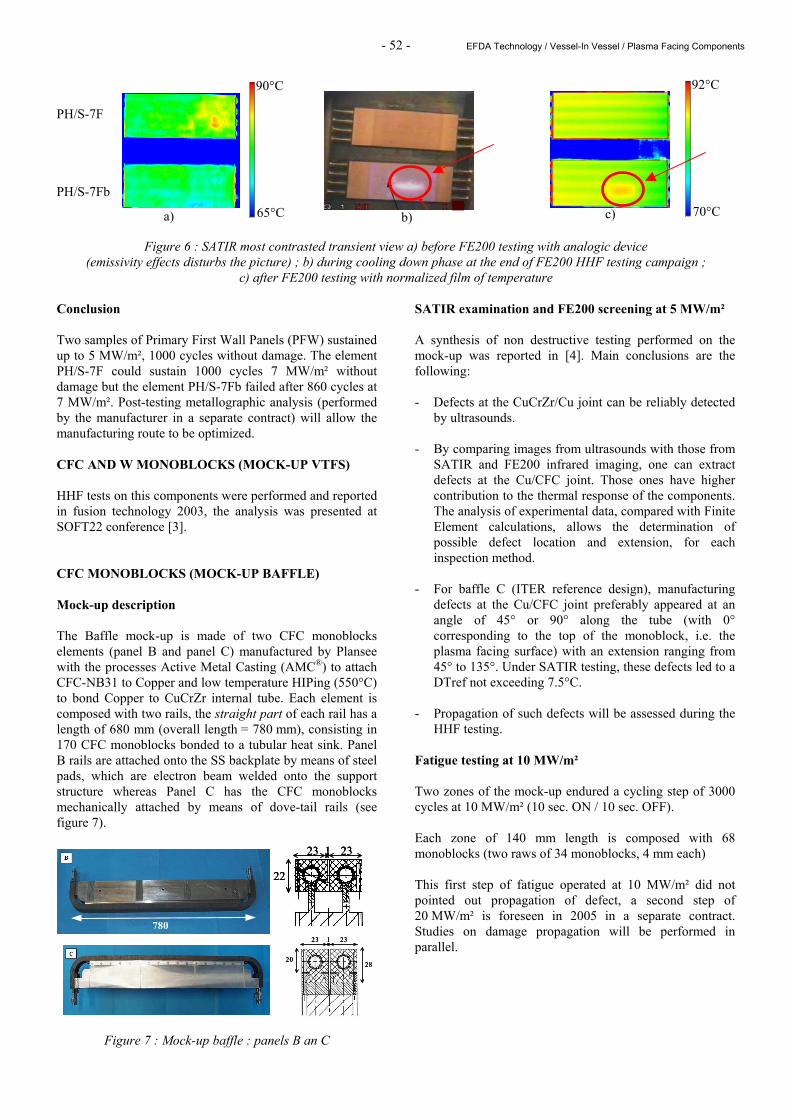
Both of the elements resisted successfully the step of fatigue 1000 cycles at 5 MW/m² 15 sec. ON / 15 sec. OFF: no obvious observation of surface temperature was observed during this step except during the first cycles, this slight increasing of 50°C being attributed to the previous sandblasting of the mock-ups. Fatigue testing at 7 MW/m² During the step of fatigue at 7 MW/m² 15 sec. ON / 15 sec. OFF, a steep increase of temperature was detected onto the element PH/S-7Fb (from 720°C to 820°C, see figure 4b). The fatigue step was interrupted on this mock-up and continued on PH/S-7F up to 1000 cycles without indication of defect propagation. A non destructive examination was performed in SATIR test bed before FE200 testing and did not show presence of defects, hot spots in red are mainly due to emissivity artefacts but not to flaws between the half-shells of copper and/or the SS tubes (see the intermediate report on SATIR examination for more details) (figure 6). A numerical treatment on SATIR test bed using camera CEDIP device was developed during the period : it allows the effects of emissivity to be corrected. A flaw detection on the 3rd tube is well correlated with FE200 picture
PH/S-7F PH/S-7Fb
Figure 4 : a ) FW7 under 5 MW/m² absorbed into the water, b) Surface temperature constant during fatigue PH/S-7F PH/S-7Fb
Figure 5 : a ) FW7 under 7 MW/m² absorbed into the water, b) Surface temperature during fatigue
PH/S-7F
PH/S-7Fb
4
1 2
3
HP
BP
0
100
200
300
400
500
600
700
0 200 400 600 800 1000Cycle number
Surfa
ce te
mpe
ratu
re
pyrometer PH/S-7Fb
1st cycle
a)
b)
0
100
200
300
400
500
600
700
800
900
0 200 400 600 800 1000 1200
Cycles number
Surfa
ce te
mpe
ratu
re (°
C)
PH/S-7FbPH/S-7F
1st cycle 1000th cycle
a)
b)
- 52 - EFDA Technology / Vessel-In Vessel / Plasma Facing Components
PH/S-7F PH/S-7Fb
Figure 6 : SATIR most contrasted transient view a) before FE200 testing with analogic device (emissivity effects disturbs the picture) ; b) during cooling down phase at the end of FE200 HHF testing campaign ;
c) after FE200 testing with normalized film of temperature Conclusion Two samples of Primary First Wall Panels (PFW) sustained up to 5 MW/m², 1000 cycles without damage. The element PH/S-7F could sustain 1000 cycles 7 MW/m² without damage but the element PH/S-7Fb failed after 860 cycles at 7 MW/m². Post-testing metallographic analysis (performed by the manufacturer in a separate contract) will allow the manufacturing route to be optimized. CFC AND W MONOBLOCKS (MOCK-UP VTFS) HHF tests on this components were performed and reported in fusion technology 2003, the analysis was presented at SOFT22 conference [3]. CFC MONOBLOCKS (MOCK-UP BAFFLE) Mock-up description The Baffle mock-up is made of two CFC monoblocks elements (panel B and panel C) manufactured by Plansee with the processes Active Metal Casting (AMC®) to attach CFC-NB31 to Copper and low temperature HIPing (550°C) to bond Copper to CuCrZr internal tube. Each element is composed with two rails, the straight part of each rail has a length of 680 mm (overall length = 780 mm), consisting in 170 CFC monoblocks bonded to a tubular heat sink. Panel B rails are attached onto the SS backplate by means of steel pads, which are electron beam welded onto the support structure whereas Panel C has the CFC monoblocks mechanically attached by means of dove-tail rails (see figure 7).
Figure 7 : Mock-up baffle : panels B an C
SATIR examination and FE200 screening at 5 MW/m² A synthesis of non destructive testing performed on the mock-up was reported in [4]. Main conclusions are the following: - Defects at the CuCrZr/Cu joint can be reliably detected
by ultrasounds. - By comparing images from ultrasounds with those from
SATIR and FE200 infrared imaging, one can extract defects at the Cu/CFC joint. Those ones have higher contribution to the thermal response of the components. The analysis of experimental data, compared with Finite Element calculations, allows the determination of possible defect location and extension, for each inspection method.
- For baffle C (ITER reference design), manufacturing
defects at the Cu/CFC joint preferably appeared at an angle of 45° or 90° along the tube (with 0° corresponding to the top of the monoblock, i.e. the plasma facing surface) with an extension ranging from 45° to 135°. Under SATIR testing, these defects led to a DTref not exceeding 7.5°C.
- Propagation of such defects will be assessed during the
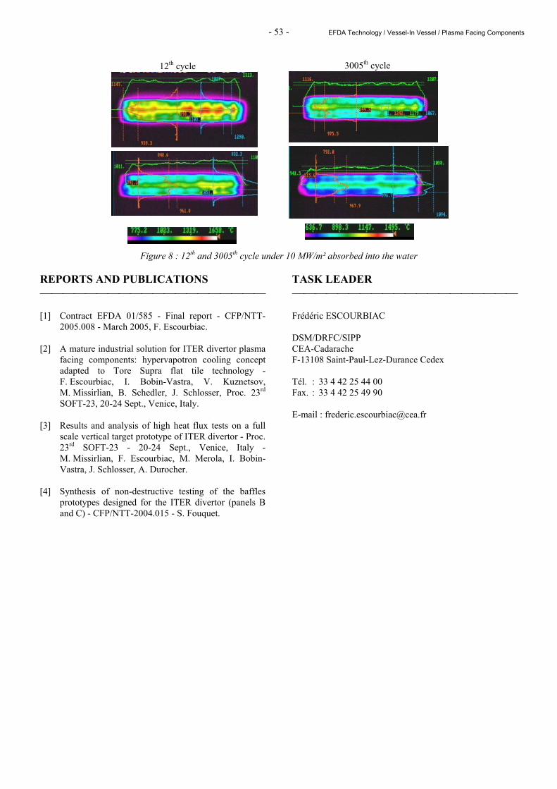
HHF testing. Fatigue testing at 10 MW/m² Two zones of the mock-up endured a cycling step of 3000 cycles at 10 MW/m² (10 sec. ON / 10 sec. OFF). Each zone of 140 mm length is composed with 68 monoblocks (two raws of 34 monoblocks, 4 mm each) This first step of fatigue operated at 10 MW/m² did not pointed out propagation of defect, a second step of 20 MW/m² is foreseen in 2005 in a separate contract. Studies on damage propagation will be performed in parallel.
22
23 23 1
22 22
23 23 1 23 23 1
23 231
2028
23 23123 231
20202828
780
70°C
92°C
c) a) 65°C
90°C
b)
- 53 - EFDA Technology / Vessel-In Vessel / Plasma Facing Components
Figure 8 : 12th and 3005th cycle under 10 MW/m² absorbed into the water REPORTS AND PUBLICATIONS [1] Contract EFDA 01/585 - Final report - CFP/NTT-
2005.008 - March 2005, F. Escourbiac. [2] A mature industrial solution for ITER divertor plasma
facing components: hypervapotron cooling concept adapted to Tore Supra flat tile technology - F. Escourbiac, I. Bobin-Vastra, V. Kuznetsov, M. Missirlian, B. Schedler, J. Schlosser, Proc. 23rd SOFT-23, 20-24 Sept., Venice, Italy.
[3] Results and analysis of high heat flux tests on a full
scale vertical target prototype of ITER divertor - Proc. 23rd SOFT-23 - 20-24 Sept., Venice, Italy - M. Missirlian, F. Escourbiac, M. Merola, I. Bobin-Vastra, J. Schlosser, A. Durocher.
[4] Synthesis of non-destructive testing of the baffles
prototypes designed for the ITER divertor (panels B and C) - CFP/NTT-2004.015 - S. Fouquet.
TASK LEADER Frédéric ESCOURBIAC DSM/DRFC/SIPP CEA-Cadarache F-13108 Saint-Paul-Lez-Durance Cedex Tél. : 33 4 42 25 44 00 Fax. : 33 4 42 25 49 90 E-mail : [email protected]
12th cycle 3005th cycle

- 54 - EFDA Technology / Vessel-In Vessel / Plasma Facing Components

Not available on line

Not available on line

Not available on line

Not available on line

Not available on line

Not available on line

Not available on line

Not available on line

- 63 - EFDA Technology / Vessel-In Vessel / Plasma Facing Components
CEFDA03-1051 Task Title: TW4-TVD-ACCEPT: STUDY ON ACCEPTANCE CRITERIA FOR
THE ITER DIVERTOR VERTICAL TARGET INTRODUCTION This study on acceptance criteria for the ITER divertor vertical target components was performed under European contract 03-1051 with EFDA organization [a] [1]. The divertor system is aimed at exhausting the alpha particles and helium produced by the fusion reaction as well as other impurities resulting from plasma-wall interaction. It is made of 54 modules or “cassettes”, located at the bottom of the vacuum vessel. Each cassette supports a set of three actively cooled carbon fibre composite (CFC) or tungsten (W) armoured plasma facing components (PFCs): an inner and an outer vertical target that must tolerate high heat loads (10 - 20 MW m-2), and a dome (figure 1). The reference design is “monoblock” (or “tube in tile”) geometry for the CFC part and “flat tile” geometry for the W armour. A high-quality bonding between the armour and the heat sink is essential to ensure the lifetime of the components.
Figure 1 : Schematic view of the ITER divertor With Tore Supra toroidal pump limiter (TPL), CEA has developed a large experience of acceptance criteria for actively-cooled high heat flux elements armoured with CFC flat tiles using infrared thermography (“SATIR” infrared test bench at CEA). The testing protocol consists in inducing a thermal transient within the heat sink structure by an alternative hot/cold water flow. The surface temperature of the tiles is monitored by an infrared camera. The transients are compared with those of a reference element, afterwards the maximum difference of temperature – called ∆Tref_max – is evaluated for each tile. For Tore Supra TPL tiles, the applied acceptance criterion was ∆Tref_max = 3°C, i.e. the maximum acceptable difference of temperature between the controlled tile and the reference element during a cooling down transient. The transient infrared thermography method is well established for flat tiles. The work is now focused on control and acceptance of CFC monoblocks for the ITER divertor.
2004 ACTIVITIES ANALYSIS OF THE EXPERIMENTAL DATABASE: EXPERIENCE GAINED WITH THE ITER VERTICAL TARGET MOCK-UPS In the frame of the ITER divertor design, various mock-ups or prototypes have been manufactured and controlled using ultrasounds or transient infrared thermography [2]. They were also extensively tested under high heat flux loading (FE200 facility at Framatome, Le Creusot). The identified mock-ups are PRODIV (a 500 mm long CFC monoblock component), VTMS (Vertical Target Medium Scale), VTMSdef (Vertical Target Medium Scale with calibrated defects), which are prototypes for the divertor, Baffle samples, Critical Heat Flux CFC monoblocks, Round Robin Tests samples, VTFS (Vertical Target Full Scale), Baffle prototypes [3]. The identification of the manufacturing defects within CFC monoblocks and the evaluation of their possible propagation is essential, in order to be able to take the decision of the acceptance. Considering the monoblock geometry, a methodology based on the experience of the existing mock-ups has been developed to determine reliably the location (CuCrZr/Cu or Cu/CFC joint), position (θ) and extension (∆θ) of the defects (figure 2).
Figure 2 : CFC monoblock geometry; θ is the position and ∆θ the extension of the defect
To start with, ultrasonic inspection of the components gives precise information (position and extension) about the defects located at the CuCrZr/Cu joint. Defects above 2 mm can be distinguished. The second step consists in transient infrared thermography (SATIR) examination of the top surface and the lateral surfaces of the monoblocks. While the inspection of the top surface provides poor information in case of large CFC thickness (17 mm), a better detection is gained from the lateral surfaces (CFC thickness of 5.5 mm).
Inner vertical target
Outer vertical target
Inboard cassette to vessel
attachment
Dome
Outboard cassette to vessel
attachment
Pumping slot
���������������������������
���������������������������
Monoblock
Flat tile
CuCrZr tube (inner/outer diameter: 12/15 mm)
48
CFC (17 mm above the Cu layer) Cu (1 mm)
θ = 30°
∆θ = 60°
28
A1
A2 A3
- 64 - EFDA Technology / Vessel-In Vessel / Plasma Facing Components
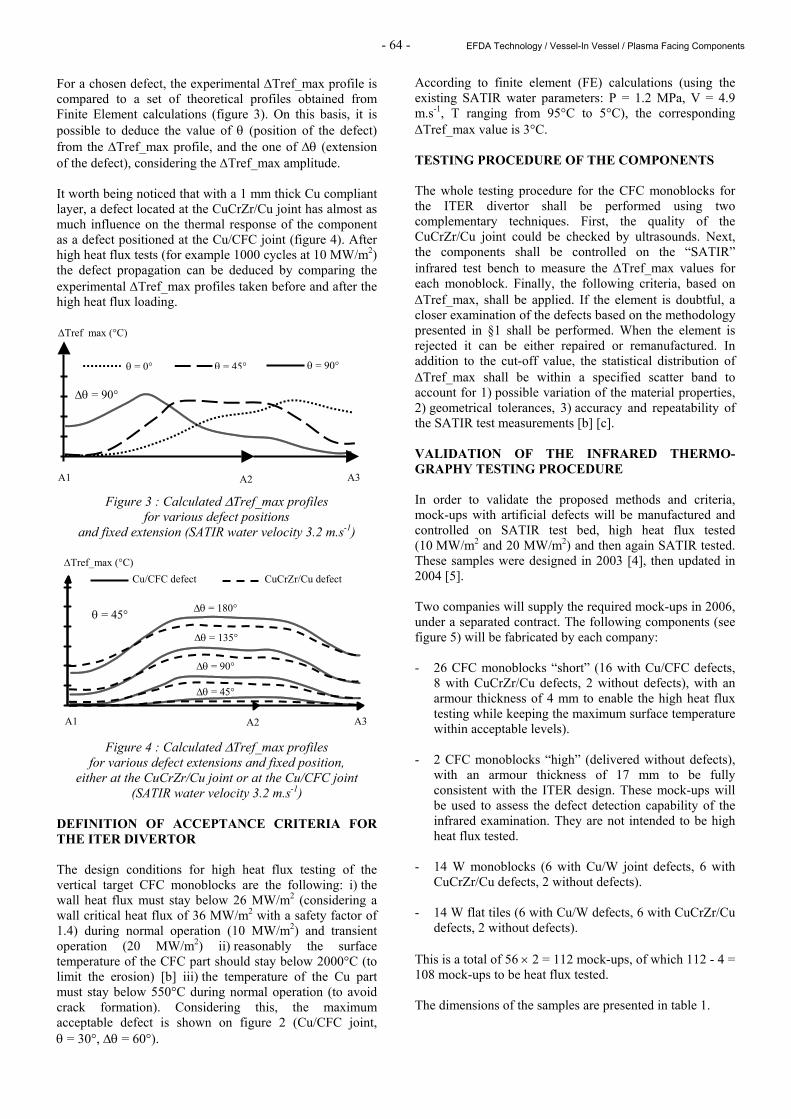
For a chosen defect, the experimental ∆Tref_max profile is compared to a set of theoretical profiles obtained from Finite Element calculations (figure 3). On this basis, it is possible to deduce the value of θ (position of the defect) from the ∆Tref_max profile, and the one of ∆θ (extension of the defect), considering the ∆Tref_max amplitude. It worth being noticed that with a 1 mm thick Cu compliant layer, a defect located at the CuCrZr/Cu joint has almost as much influence on the thermal response of the component as a defect positioned at the Cu/CFC joint (figure 4). After high heat flux tests (for example 1000 cycles at 10 MW/m2) the defect propagation can be deduced by comparing the experimental ∆Tref_max profiles taken before and after the high heat flux loading.
Figure 3 : Calculated ∆Tref_max profiles for various defect positions
and fixed extension (SATIR water velocity 3.2 m.s-1)
Figure 4 : Calculated ∆Tref_max profiles for various defect extensions and fixed position,
either at the CuCrZr/Cu joint or at the Cu/CFC joint (SATIR water velocity 3.2 m.s-1)
DEFINITION OF ACCEPTANCE CRITERIA FOR THE ITER DIVERTOR The design conditions for high heat flux testing of the vertical target CFC monoblocks are the following: i) the wall heat flux must stay below 26 MW/m2 (considering a wall critical heat flux of 36 MW/m2 with a safety factor of 1.4) during normal operation (10 MW/m2) and transient operation (20 MW/m2) ii) reasonably the surface temperature of the CFC part should stay below 2000°C (to limit the erosion) [b] iii) the temperature of the Cu part must stay below 550°C during normal operation (to avoid crack formation). Considering this, the maximum acceptable defect is shown on figure 2 (Cu/CFC joint, θ = 30°, ∆θ = 60°).
According to finite element (FE) calculations (using the existing SATIR water parameters: P = 1.2 MPa, V = 4.9 m.s-1, T ranging from 95°C to 5°C), the corresponding ∆Tref_max value is 3°C. TESTING PROCEDURE OF THE COMPONENTS The whole testing procedure for the CFC monoblocks for the ITER divertor shall be performed using two complementary techniques. First, the quality of the CuCrZr/Cu joint could be checked by ultrasounds. Next, the components shall be controlled on the “SATIR” infrared test bench to measure the ∆Tref_max values for each monoblock. Finally, the following criteria, based on ∆Tref_max, shall be applied. If the element is doubtful, a closer examination of the defects based on the methodology presented in §1 shall be performed. When the element is rejected it can be either repaired or remanufactured. In addition to the cut-off value, the statistical distribution of ∆Tref_max shall be within a specified scatter band to account for 1) possible variation of the material properties, 2) geometrical tolerances, 3) accuracy and repeatability of the SATIR test measurements [b] [c]. VALIDATION OF THE INFRARED THERMO-GRAPHY TESTING PROCEDURE In order to validate the proposed methods and criteria, mock-ups with artificial defects will be manufactured and controlled on SATIR test bed, high heat flux tested (10 MW/m2 and 20 MW/m2) and then again SATIR tested. These samples were designed in 2003 [4], then updated in 2004 [5]. Two companies will supply the required mock-ups in 2006, under a separated contract. The following components (see figure 5) will be fabricated by each company: - 26 CFC monoblocks “short” (16 with Cu/CFC defects,
8 with CuCrZr/Cu defects, 2 without defects), with an armour thickness of 4 mm to enable the high heat flux testing while keeping the maximum surface temperature within acceptable levels).
- 2 CFC monoblocks “high” (delivered without defects),
with an armour thickness of 17 mm to be fully consistent with the ITER design. These mock-ups will be used to assess the defect detection capability of the infrared examination. They are not intended to be high heat flux tested.
- 14 W monoblocks (6 with Cu/W joint defects, 6 with
CuCrZr/Cu defects, 2 without defects). - 14 W flat tiles (6 with Cu/W defects, 6 with CuCrZr/Cu
defects, 2 without defects). This is a total of 56 × 2 = 112 mock-ups, of which 112 - 4 = 108 mock-ups to be heat flux tested. The dimensions of the samples are presented in table 1.
CuCrZr/Cu defect Cu/CFC defect
∆θ = 180°
∆θ = 135°
∆θ = 90°
∆θ = 45°
∆Tref_max (°C)
A1 A2 A3
θ = 45°
∆Tref_max (°C)
θ = 0° θ = 45° θ = 90°
A1 A2 A3
∆θ = 90°
- 65 - EFDA Technology / Vessel-In Vessel / Plasma Facing Components
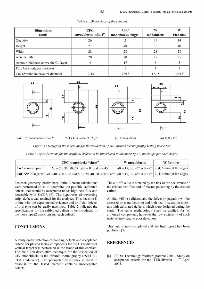
Table 1 : Dimensions of the samples
Dimensions (mm)
CFC monoblocks “short”
CFC monoblocks “high”
W monoblocks
W Flat tiles
Quantity 26 2 14 14 Height 27 48 36 40 Width 28 28 28 28 Axial length 20 20 12 25 Armour thickness above the Cu layer 4 17 5 5 Pure Cu interlayer thickness 1 1 1 1 CuCrZr tube inner/outer diameter 12/15 12/15 12/15 12/15
Figure 5 : Design of the mock-ups for the validation of the infrared thermography testing procedure
Table 2 : Specifications for the artificial defects to be introduced in the mock-ups (2 mock-ups per each defect)
CFC monoblocks “short” W monoblocks W flat tiles Cu / armour joint ∆θ = 20, 35, 50, 65° at θ = 0° and θ = 45° ∆θ = 15, 30, 45° at θ = 0° 2, 4, 6 mm (at the edge)
CuCrZr / Cu joint ∆θ = 40° at θ = 0° and ∆θ = 20, 40, 60° at θ = 45° ∆θ = 15, 30, 45° at θ = 0° 2, 4, 6 mm (at the edge) For each geometry, preliminary Finite Element calculations were performed so as to determine the possible calibrated defects that would be acceptable under high heat flux and detectable with SATIR [6]. The hypothesis of traversing strips defects was retained for the analyses. This decision is in line with the experimental evidence and artificial defects of this type can be easily machined. Table 2 indicates the specifications for the calibrated defects to be introduced in the mock-ups (2 mock-ups per each defect). CONCLUSIONS A study on the detection of bonding defects and acceptance criteria for plasma facing components for the ITER divertor vertical target was performed in the frame of this contract. The main non-destructive technique for the inspection of CFC monoblocks is the infrared thermography (“SATIR”, CEA Cadarache). The parameter ∆Tref_max is used to establish if the tested element contains unacceptable defects.
The cut-off value is dictated by the risk of the occurrence of the critical heat flux and of plasma poisoning by the eroded carbon. All that will be validated and the defect propagation will be assessed by manufacturing and high heat flux testing mock-ups with calibrated defects, which were designed during the study. The same methodology shall be applied for W armoured components however the low emissivity of such material may lead to poor detection. This task is now completed and the final report has been published [7]. REFERENCES [a] EFDA Technology Workprogramme 2004 - Study on
acceptance criteria for the ITER divertor - 10th April 2003.
(a) CFC monoblock “short” (b) CFC monoblock “high” (c) W monoblock (d) W flat tile
- 66 - EFDA Technology / Vessel-In Vessel / Plasma Facing Components
[b] E. D’Agata, R. Tivey - Toward the development of the workable acceptance criteria for the divertor CFC monoblock armour - Proc. 23rd Symp. on Fusion Technology (SOFT) - Venice, Sept. 20-24 (2004), to be published.
[c] M. Merola, W. Dänner, M. Pick and the EU ITER
Participating Team - EU R&D on divertor components - Proc. 23rd Symp. on Fusion Technology (SOFT) - Venice, Sept. 20-24 (2004), to be published.
REPORTS AND PUBLICATIONS [1] S. Fouquet, J. Schlosser, M. Merola, A. Durocher,
F. Escourbiac, A. Grosman, M. Missirlian, C. Portafaix - Acceptance criteria for the ITER divertor vertical target - 7th International Symposium on Fusion Nuclear Technology (ISFNT) - Tokyo, May 22-27 (2005), to be published.
[2] S. Fouquet - Study on acceptance criteria for the ITER
divertor - Intermediate report 2:experimental database, CFP/NTT-2004.014.
[3] S. Fouquet - Synthesis of non-destructive testing of
the baffles prototypes designed for the ITER divertor (panels B and C) - CFP/NTT-2004.015.
[4] S. Fouquet - Study on acceptance criteria for the ITER
divertor - Intermediate report 1: design of the samples with artificial defects - CFP/NTT-2004.003.
[5] M. Merola, S. Fouquet - Study of acceptance criteria
for the ITER divertor: summary report of the progress meeting on the 7th December 2004 - Cadarache, CFP/CRR-2004.014.
[6] C. Portafaix, S. Fouquet - Study on acceptance criteria
for the ITER divertor - Intermediate report 3: Thermal calculations for CFC and W monoblocks - CFP/NTT-2004.030.
[7] S. Fouquet, J. Schlosser - Study on acceptance criteria
for the ITER divertor - Final report - CFP/NTT-2004.035.
TASK LEADER Jacques SCHLOSSER DSM/DRFC/SIPP/GCFP CEA-Cadarache F-13108 Saint-Paul-Lez-Durance Cedex Tél. : 33 4 42 25 25 44 Tél. : 33 4 42 25 49 90 E-mail : [email protected]

Not available on line

Not available on line

Not available on line

Not available on line
- 71 - EFDA Technology / Vessel-In Vessel / Plasma Facing Components
TW0-T438-01 Task Title: DEVELOPMENT AND TESTING OF TIME RESOLVED EROSION
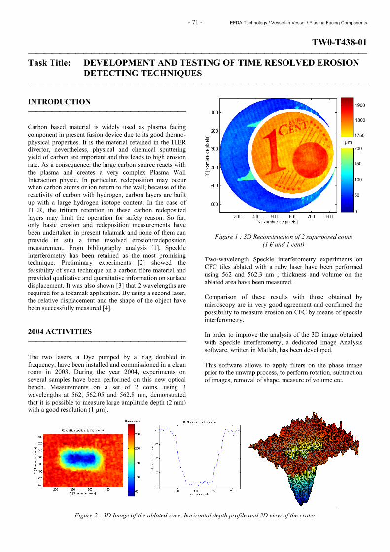
DETECTING TECHNIQUES INTRODUCTION Carbon based material is widely used as plasma facing component in present fusion device due to its good thermo-physical properties. It is the material retained in the ITER divertor, nevertheless, physical and chemical sputtering yield of carbon are important and this leads to high erosion rate. As a consequence, the large carbon source reacts with the plasma and creates a very complex Plasma Wall Interaction physic. In particular, redeposition may occur when carbon atoms or ion return to the wall; because of the reactivity of carbon with hydrogen, carbon layers are built up with a large hydrogen isotope content. In the case of ITER, the tritium retention in these carbon redeposited layers may limit the operation for safety reason. So far, only basic erosion and redeposition measurements have been undertaken in present tokamak and none of them can provide in situ a time resolved erosion/redeposition measurement. From bibliography analysis [1], Speckle interferometry has been retained as the most promising technique. Preliminary experiments [2] showed the feasibility of such technique on a carbon fibre material and provided qualitative and quantitative information on surface displacement. It was also shown [3] that 2 wavelengths are required for a tokamak application. By using a second laser, the relative displacement and the shape of the object have been successfully measured [4]. 2004 ACTIVITIES The two lasers, a Dye pumped by a Yag doubled in frequency, have been installed and commissioned in a clean room in 2003. During the year 2004, experiments on several samples have been performed on this new optical bench. Measurements on a set of 2 coins, using 3 wavelengths at 562, 562.05 and 562.8 nm, demonstrated that it is possible to measure large amplitude depth (2 mm) with a good resolution (1 µm).
Figure 1 : 3D Reconstruction of 2 superposed coins (1 € and 1 cent)
Two-wavelength Speckle interferometry experiments on CFC tiles ablated with a ruby laser have been performed using 562 and 562.3 nm ; thickness and volume on the ablated area have been measured. Comparison of these results with those obtained by microscopy are in very good agreement and confirmed the possibility to measure erosion on CFC by means of speckle interferometry. In order to improve the analysis of the 3D image obtained with Speckle interferometry, a dedicated Image Analysis software, written in Matlab, has been developed. This software allows to apply filters on the phase image prior to the unwrap process, to perform rotation, subtraction of images, removal of shape, measure of volume etc.
Figure 2 : 3D Image of the ablated zone, horizontal depth profile and 3D view of the crater
µm
0
50
100
150
200
1750
1900
1800

- 72 - EFDA Technology / Vessel-In Vessel / Plasma Facing Components
Finally, experiments at long distance has been investigated. Both the reference and the analysis beam, in order to save the coherence of the two beams, have been extended from 55 to 145 cm. Except the lateral resolution which decreases due to the larger field of view, there is no visible effect, in particular the depth resolution is unchanged. From this result, we can conclude that measurement at long distance will not be an issue in a tokamak.
Figure 3 : 2D Images of 1€ coin taken at a distance of 55 cm and 145 cm
The Final report on this task T438-01 has been sent to and accepted by EFDA in November. This task is now finished. CONCLUSIONS Speckle interferometry optical bench is now fully operational in laboratory in CEA Cadarache. Additional development needs to be done in laboratory, prior to the installation of a Speckle interferometry diagnostic on a tokamak. In particular, the effects of the vibrations need to be investigated in detail. The task T438-01 is finished and further developments are needed that could be done under a new task agreement, if any.
REFERENCES [1] G. Roupillard - CFP/NTT.2000.031 - CEA Cadarache,
2000. [2] CEA rapport DSM/DRFC T438-01 2000. [3] A. W. Koch, M. Ruprecht, and R. Wilhelm - Laser
Speckle Techniques for in situ-Monitoring of Erosion and Redeposition at Inner Walls in Large Experimental Fusion Devices - Max-Planck-Institut Für Plasmaphysik Garching bei München (1995).
[4] CEA rapport DSM/DRFC T438-01 2002. REPORTS AND PUBLICATIONS Mesures tridimentionelles par microscopie confocale -DIAG/CRM-2004.001 (2004) - P. Dore, E. Gauthier. Procédure d'entretien du laser en salle blanche du bâtiment 507 - DIAG/NTT-2004.015 (2004) - P. Dore. Mesure de Vibration sur le Limiteur Pompé Toroïdal - DIAG/NTT-2004.016 (2004) - P. Dore. Mesure de Vibration sur le Limiteur Pompé Toroïdal (en choc et hors choc) - DIAG/NTT-2004.031 (2004) - P. Dore. Final report TW0-T438-01 - CFP/NTT-2004.033 (2004) - E. Gauthier, P. Dore. Etude de l'érosion des composants face au plasma par interférométrie de speckle - 5ème Colloque Int. Francophone : Méthodes et Techniques Optiques pour l'Industrie, (2004) - P. Dore, E. Gauthier. TASK LEADER Eric GAUTHIER DSM/DRFC/SIPP CEA-Cadarache F-13108 Saint-Paul-Lez-Durance Cedex Tél. : 33 4 42 25 42 04 Fax : 33 4 42 25 49 90 E-mail : [email protected]
55 cm
145 cm
Related Documents