CAViT: a Consistency Maintenance Framework based on Transformation Contracts Pieter Van Gorp, Dirk Janssens Formal Techniques in Software Engineering, Universiteit Antwerpen, {pieter.vangorp,dirk.janssens}@ua.ac.be Abstract. Model driven engineering is a software engineering methodology that aims to manage the complexity of frameworks by relying on models and trans- formations. Unfortunately it is only poorly understood where and how this new methodology differs from traditional methodologies. Therefore, this paper for- malizes how contract based model transformation extends existing design by con- tract theory. The key extension is that transformation contracts can be maintained automatically by mapping consistency invariants to the postconditions of trans- formation rules. When an invariant is violated, the corresponding transformation rule will be called provided that its precondition is satisfied. This paper presents the Contract Aware Visual Transformation (CAViT) framework, an implemen- tation of declarative middleware for contract based model transformation. We illustrate how CAViT can be used to integrate UML based visual model transfor- mations with OCL based transformation contracts. Introduction Integrating packages and applications written in a variety of languages is a major chal- lenge for the software engineering community [1]. Luckily, programming languages and their associated libraries have gone a long way. Thanks to modern integration plat- forms such as J2EE [2] one can, for example, connect mainstream ERP packages such as SAP [3] with legacy applications written in COBOL and a reasoning engine writ- ten in PROLOG. Unfortunately, this flexibility comes at the cost of high complexity. Managing entities and processes that are scattered over all applications is problematic when there is a lack of documentation on how all applications relate to the overall requirements. Even when such documentation is in place, it is often unfeasible to up- date all sources and documentation affected by a particular business change without advanced tool support. This paper formalizes the mechanics of model-driven engineer- ing tools (1) by defining how the languages used to program such tools relate to object oriented design by contract and controlled graph rewriting and (2) by describing their architecture. Section 1 introduces the reader to design by contract and model-driven en- gineering, section 2 presents domain specific models of a sample application, section 3 explains how these models can be kept consistent using a new contract aware visual model transformation approach and section 4 describes the architecture of the tool that validates this approach. Section 5 relates this contribution to related work and section 6 concludes this paper. Dagstuhl Seminar Proceedings 05161 Transformation Techniques in Software Engineering http://drops.dagstuhl.de/opus/volltexte/2006/429

Welcome message from author
This document is posted to help you gain knowledge. Please leave a comment to let me know what you think about it! Share it to your friends and learn new things together.
Transcript
CAViT: a Consistency Maintenance Framework basedon Transformation Contracts
Pieter Van Gorp, Dirk Janssens
Formal Techniques in Software Engineering, Universiteit Antwerpen,{pieter.vangorp,dirk.janssens}@ua.ac.be
Abstract. Model driven engineering is a software engineering methodology thataims to manage the complexity of frameworks by relying on models and trans-formations. Unfortunately it is only poorly understood where and how this newmethodology differs from traditional methodologies. Therefore, this paper for-malizes how contract based model transformation extends existing design by con-tract theory. The key extension is that transformation contracts can be maintainedautomatically by mapping consistency invariants to the postconditions of trans-formation rules. When an invariant is violated, the corresponding transformationrule will be called provided that its precondition is satisfied. This paper presentsthe Contract Aware Visual Transformation(CAViT) framework, an implemen-tation of declarative middleware for contract based model transformation. Weillustrate how CAViT can be used to integrate UML based visual model transfor-mations with OCL based transformation contracts.
Introduction
Integrating packages and applications written in a variety of languages is a major chal-lenge for the software engineering community [1]. Luckily, programming languagesand their associated libraries have gone a long way. Thanks to modern integration plat-forms such as J2EE [2] one can, for example, connect mainstream ERP packages suchas SAP [3] with legacy applications written in COBOL and a reasoning engine writ-ten in PROLOG. Unfortunately, this flexibility comes at the cost of high complexity.Managing entities and processes that are scattered over all applications is problematicwhen there is a lack of documentation on how all applications relate to the overallrequirements. Even when such documentation is in place, it is often unfeasible to up-date all sources and documentation affected by a particular business change withoutadvanced tool support. This paper formalizes the mechanics of model-driven engineer-ing tools (1) by defining how the languages used to program such tools relate to objectoriented design by contract and controlled graph rewriting and (2) by describing theirarchitecture. Section 1 introduces the reader to design by contract and model-driven en-gineering, section 2 presents domain specific models of a sample application, section 3explains how these models can be kept consistent using a new contract aware visualmodel transformation approach and section 4 describes the architecture of the tool thatvalidates this approach. Section 5 relates this contribution to related work and section 6concludes this paper.
Dagstuhl Seminar Proceedings 05161Transformation Techniques in Software Engineeringhttp://drops.dagstuhl.de/opus/volltexte/2006/429
1. SUPPORTING TECHNOLOGIES
1 Supporting Technologies
This section first describes two methodologies that were succesfully applied to tacklethe complexity of large scale software development: design by contract (DBC) andmodel driven engineering (MDE). In the context of MDE, we describe “contract basedmodel transformation”, a new application of the design by contract foundations formaintaining the consistency between related models. Finally, this sections covers ModelDriven Architecture (MDA) and visual model transformation.
1.1 Design by Contract
DBC is a software correctness methodology for procedural and object-oriented soft-ware. It relies on logical assertions to detect implementation mistakes at run-time or toprove the absence thereof at compile-time.
The fundamentals of DBC were developed by Floyd and Hoare in the late sixties[4,5]. By formalizing the effect of programming language constructs on the state ofvariables in axioms and inference rules, Hoare illustrated the feasibility of proving pro-gram correctness. The proposed proof systems are based onstate assertions, which arelogical expressions about the values of program variables. These state assertions areused to state that a programSwill ensure a state assertionq (called thepostcondition)provided that state assertionp (called theprecondition) holds right before it is executed,or {p}S{q}. A correctness proof consists of a deductive sequence of state assertions andaxioms or inference rules from precondition to postcondition.
In the early seventies, Hoare and Wirth published a proof system for the program-ming language PASCAL [6]. Meanwhile, verfication condition generators based onbackward substitution were built to automatically derive proof obligations [7]. Findingwhat rules form the shortest path from precondition to postcondition remains a creativeactivity but a theorem proover can help discharging proof obligations given a librarywith the required axioms and inference rules. Today, one can rely on industial-strengthproof assistants with inference rules for object-oriented languages [8].
DBC has also found its way into incomplete verification methods. In this context,the precondition and postcondition are checked at test execution time. For this purpose,Meyer included support for expressing assertions in the Eiffel programming language[9] while Kramer built iContract for extracting assertions from Java comments [10]. Theadvantage of the testing approach is that it is applicable even when complete coverage isunfeasible. On the other hand, deviations between the contracts and the implementationmay find their way to the production environment due to an incomplete set of test cases.
1.2 Model Driven Engineering
MDE is a methodology that proposes to tackle the complexity of software developmentby treating models and transformations as first-class software artifacts [11].
1.2.1 Terminology By collecting the mainstream definitions for the core MDE con-cepts, this section can be used as an introduction and refererence to the MDE terminol-ogy adopted in this paper.
2
1. SUPPORTING TECHNOLOGIES
Definition 1. A model is a simplified representation of a part of the world named thesystem [12].
Studies in human-computer interation distinguish between conceptual and mental mod-els [13]. The former refer to representations made by a teacher (or designer) to explaina system to a user (or maintainer). A mental model on the other hand is the systemrepresentation that a user (or maintainer) actually applies in his mind when workingwith (or on) the system. In MDE, one proposes to mapmodelsin their conceptual senseto source code by means of transformations [11]. MDE is a relevant methodology inthose cases where source code is too far from the mental models of the designers andmaintainers of the software. It allows these stakeholders to work and communicate withmodels that match their minds more closely.
Kleppe et al. define a transformation as “the automatic generation of a target modelfrom a source model, according to a transformation definition” [14]. We generalize thisdefinition in order to support transformations that are carried out manually:
Definition 2. A transformation is the construction of a set of target models from a setof source models. A transformation is automatic if it can be applied mechanically ac-cording to a transformation definition.
Since model transformation is the heart and soul of MDE [15] it is not restricted toparticular modeling languages, compilers or execution platforms. Rather than enforc-ing one language for cognitive modeling (like the UML [16]) it embraces the varietyof languages and libraries that need to be reconciled in heterogenous software architec-tures. The fundamental difference with Rapid Application Development (RAD [17]) isthat transformation definitions can be created and/or optimized by software architects.
Since a model transformation is intended to manipulate a set of models one cancall it a metaprogram. The structure of the input and output modeling languages isrepresented by so-calledmetamodelswhile a transformation definitionconsists of (1)references to the set of models as data and (2) transformation rules as behavior. Basedon Favre’s observations on metamodels [18] we define:
Definition 3. A metamodel is a structural model of a language. It consists of (1) a typesystem (classes with attributes and associations with cardinalities) for the abstract syn-tax elements and (2) well-formedness rules that capture syntactic validity constraintsnot covered by (1).
Type systemmodeling can be done with either UML class diagrams or Entity Relation-ship (E/R [19]) diagrams but fundamentally one tends to rely on graph based modelswith attributed nodes and edges. In the graph transformation community, the type sys-tem of a modeling language can be encoded in atype graph.Type graphs cannot enforcethat for example “the name of a class should be unique within its package”. Suchwell-formedness rulesneed to be enforced with additional graph constraints, some of whichcannot be represented visually. In the context of object-oriented metamodeling, theycorrespond to the invariants of metaclasses.
Kleppe et al. define a transformation definition as a set of transformation rules thattogether describe how a model in the target language can be constructed from a model
3
1. SUPPORTING TECHNOLOGIES
in the source language [14]. We generalize this definition by considering transformationdefinitions that manage any non-zero number of models. Moreover, we do not restrict amodel to be used as in- or output exclusively:
Definition 4. A transformation definition contains (1) a set of models conforming tometamodels and (2) a set of transformation rules that together describe how its modelscan be constructed from one another.
Defining model transformations in a general purpose programming language such asJava lies quite far from the conceptual task of model (graph) transformation. InRe-flective MDEone defines model transformations by means of models themselves [20].Such transformation models abstract from the complexities and evolution of modelmanagement frameworks such as the NetBeans MetaData Repository (MDR [21]) orthe Eclipse Modeling Framework (EMF [22]) [23]. Section 1.2.3 will illustrate thattransformation models expressed in a visual modeling language based on the UML andgraph transformation appear to match people’s mental models of the domain very well.
Definition 5. A transformation rule is a description of how one or more constructs inone model can be constructed from one or more constructs in another model.
Again, this definition is based on the work of Kleppe et al. [14]. Note that these au-thors promote to represent transformation rules as objects. This enables one to store thesource-target relationships of a transformation in the object state of the rule that createdthe target from the source. Instead, we propose to representtransformation definitionsas objects. This design choice was motivated by our intention to represent models andtransformations with ordinary object-oriented data structures. Nevertheless, there areMDE applications that need to reason explicitly about the source-target relationships(so-calledtraceability links) between models and model elements that were createdfrom one another. The following definition allows one to describe where this informa-tion is stored:
Definition 6. A traceability model consists of relations between models and/or modelelements that are generated from one another by one or more model transformations.
1.2.2 Contract based Model TransformationContract based model transformationis a new application of the design by contract foundations targeted at maintaining theconsistency between related models.
Definition 7. A transformation contract is a pair of constraints (called the pre- andpostcondition) that describe the effect of a transformation rule on the set of modelscontained in its transformation definition. The postcondition describes the model con-sistency states that the rule can establish provided that its precondition is satisfied. Thepostcondition of a transformation rule corresponds to an invariant of the transforma-tion definition in which it is contained.
The notion of transformation contracts can be used to formalize the notion of incremen-tal consistency maintenance:
4
1. SUPPORTING TECHNOLOGIES
Definition 8. A transformation contract of a rule can be maintained automatically bycalling the rule (1) as soon as the invariant corresponding to its postcondition is vio-lated and (2) provided that its precondition is satisfied.
Note that in model inconsistency states where the preconditions of more than one ruleare satisfied, transformation engines are allowed to call the rules in arbitrary order.Some model inconsistency states cannot be resolved automatically. These states do notsatisfy the precondition of any transformation rule whose postcondition describes a con-sistent model state. For simple contracts, one can automatically generate the satisfyingtransformation rules. On the other hand, complex cases require the manual develop-ment of transformation rules. For example, in the context of the WODN case study[24] we considered constraints that asserted that for a particular match in the sourcemodel, there should be an element in the target model that shares particular propertieswith some elements from the source model. A simple violation scenario (or rulepre-condition) is the case where one has developed an initial version of the source modeland the target model has not been generated yet. A transformation engine can automat-ically instantiate a target model and populate it with a model element that satisfies theconstraint.
Contract aware transformation engines should support the creation oftraceabilitylinks between model elements that are created from one another. Such links shouldbe accessible in a model transformation language that integrates with the constraintchecking language. This enables the manual development of model transformationsfor violations occurring in models that were previously generated from one another.Generating transformation rules for such “co-evolution conflicts” is beyond the state-of-the-art of today’s transformation engines and perhaps even unfeasible since thereare a lot of ways to reconcile existing models automatically and expert knowledge isrequired to decide what manual (external) changes to the models should be preserved oroverriden. As noted before, Kleppe et al. proposed to include traceability models insidetransformation rules but they did not describe how the traceability information could beused for model reconciliation.
1.2.3 Visual Model Transformation Writing transformations manually can be fa-cilitated by using specialized transformation languages (such as YATL [25]) since theyhide the algorithmic details of navigating and manipulating the object graphs represent-ing the models. YATL is a textual transformation language that has been succesfullyapplied to a number of MDE case studies. However, it is relatively young comparedto the languages developed in the domain of graph rewriting. In this domain there is ageneral consensus that representing transformations visually makes them most under-standable to humans [26]. Therefore, in visual model transformation, one applies thefoundations of graph rewriting to model driven engineering by interpreting models asgraphsand metamodels astype graphs[23]. The fundamental research topics raised bythe new application domain are transformation contracts (see Definition 7) and trace-ability models (see Definition 6).
1.2.4 Model Driven Architecture Model Driven Architecture (MDA) is an OMGinitiative to develop a set of standards for integrating MDE tools [27]. In order to enable
5
1. SUPPORTING TECHNOLOGIES
more stakeholders to exchange models in a language that matches their mental modelinglanguage to an acceptable degree, the UML was extended with a range of new syntaxconstructs [28].
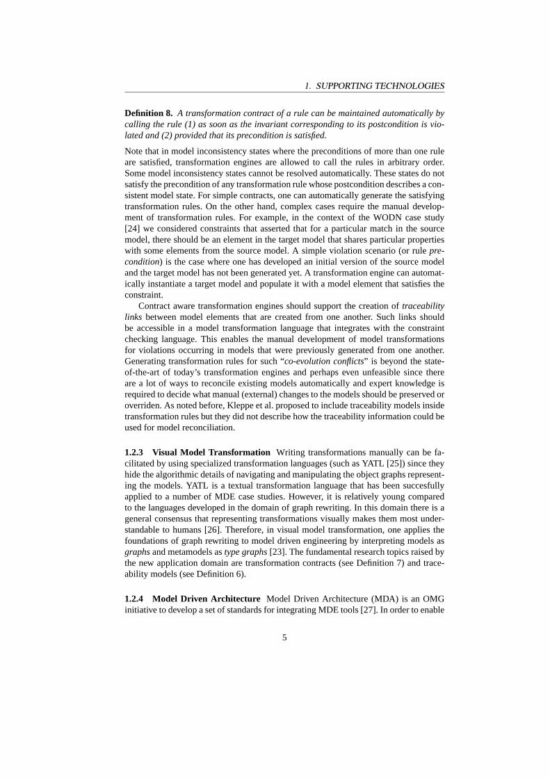
MDA would not be a standard for MDE if it would concern only one modelinglanguage. Therefore, it defines a language called MOF which is responsible for definingmodeling languages. It is based on an extension of UML class diagrams (see Fig. 1)and OCL (see Fig. 2). The former should be used to model the structure of a metamodelwhereas the latter should be used to encode its well-formedness rules. More and moreUML tools [29,30] and data warehousing tools [31] provide a MOF based interface totheir repository, either message-based with Java (based on the JMI standard [32]) ordocument-based with XML (based on the XMI standard [33]).
Although model transformations can already be implemented by using these lan-guages, the OMG has also recognized the need for a dedicated MOF transformationlanguage [34]. OCL based transformation contracts fully comply with the OMG’s re-quest for a declarative transformation language. A MOF framework that would allowone to integrate model transformations written manually in imperative transformationlanguages (such as YATL) would enable transformation writers to compensate for thelimitations of today’s OCL based transformation engines [24].
+context
+behavior
0..1
*Guard
expression: BooleanExpression
ModelElement
StateMachine
Transition1
0..1 +guard
StateVertex
+source +outgoing
+incoming+target
1 *
1 *
State1+top
FinalState
Fig. 1. MOF diagram displaying an excerpt of the statemachine part of UML 1.5. Astatemachine is a model element that represents thebehaviorof anothercontextmodelelement. A statemachine contains exactly onetop state that is connected to other statesby transitions (incomingandoutgoing) that can contain aguard.
6
2. MODELS OF A MEETING SCHEDULER
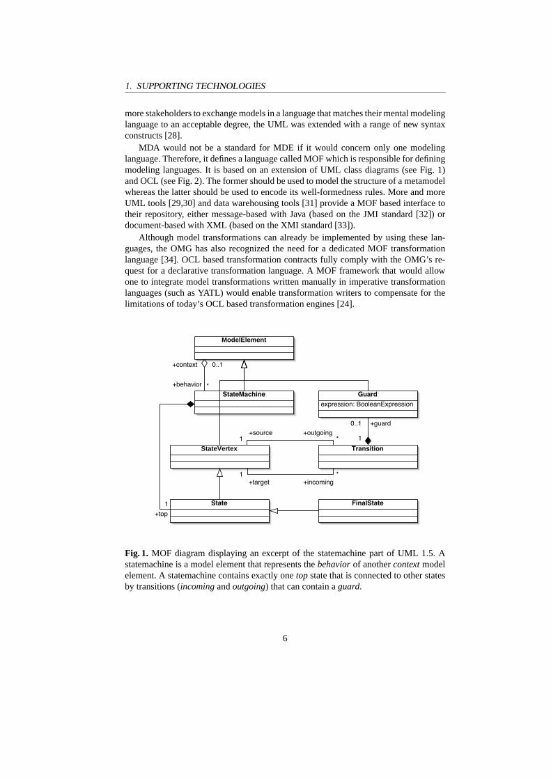
1 context FinalState:2 self.outgoing->size = 0
Fig. 2. OCL Well-formedness rule from the UML metamodel stating that a final stateshould never have outgoing transitions.
2 Models of a Meeting Scheduler
To give a realistic idea of models that need to be kept consistent, this section presentssome domain specific models of a sample application. The application is based on theMeeting Schedulerproblem statement that was proposed by Van Lamsweerde et al. [35]as a benchmark for requirements elicitation and software specification techniques. Theproblem statement of the benchmark was published deliberately imprecise and incom-plete [36]. The first part of the problem statement reads as follows:
Meetings are typically arranged in the following way. A meeting initiator asksall potential meeting attendees for the following information based on theirpersonal agenda:
– a set of dates on which they cannot attend the meeting (hereafter referredas exclusion set);
– a set of dates on which they would prefer the meeting to take place (here-after referred as preference set).
A meeting date is defined by a pair (calendar date, time period). The exclu-sion and preference sets are contained in some time interval prescribed by themeeting initiator (hereafter referred as date range).The initiator also asks active participants to provide any special equipment re-quirements on the meeting location (e.g., overhead-projector, workstation, net-work connection, telephones, etc.). He/she may also ask important participantsto state preferences about the meeting location.
Sections 2.1, 2.2 and 2.3 present some illustrativeconceptual, robustnessandphysicaldatamodels repectively. The fragments in this paper should merely illustrate some re-alistic dependencies between models in different languages and should not be regardedas a complete nor stable specification of a meeting scheduler.
2.1 Conceptual Models
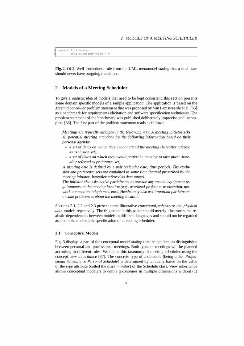
Fig. 3 displays a part of the conceptual model stating that the application distinguishesbetween personal and professional meetings. Both types of meetings will be plannedaccording to different rules. We define this taxonomy of meeting schedules using theconceptview inheritance[37]. The concrete type of a schedule (being eitherProfes-sional Scheduleor Personal Schedule) is determined dynamically based on the valueof the typeattribute (called thediscriminator) of the Schedule class. View inheritanceallows conceptual modelers to define taxonomies in multiple dimensions without (1)
7
2. MODELS OF A MEETING SCHEDULER
having to define artificial classes that apply multiple inheritance for all possible com-binations of subclasses from the different taxonomies or (2) restricting the number ofinheritance lattices to one and using the strategy pattern [38] for encoding the otherdimensions.
Time Interval on Same Day
Schedule
+type : Schedule Type [1]+acceptableLimit : int+cancelLimit : int
+plan()
Professional Schedule
+plan()
Personal Schedule
+plan()
<<enumeration>>Schedule Type
professionalpersonal
Time
0..* 1
0..*
+from
1
0..*
+to
1
<<view>>
{discriminator=type, value=professional}
<<view>>
{value=personal, discriminator=type}
0..*
+conventional hours 1..*
Fig. 3.Data structure for representing the planning dimension (orview).
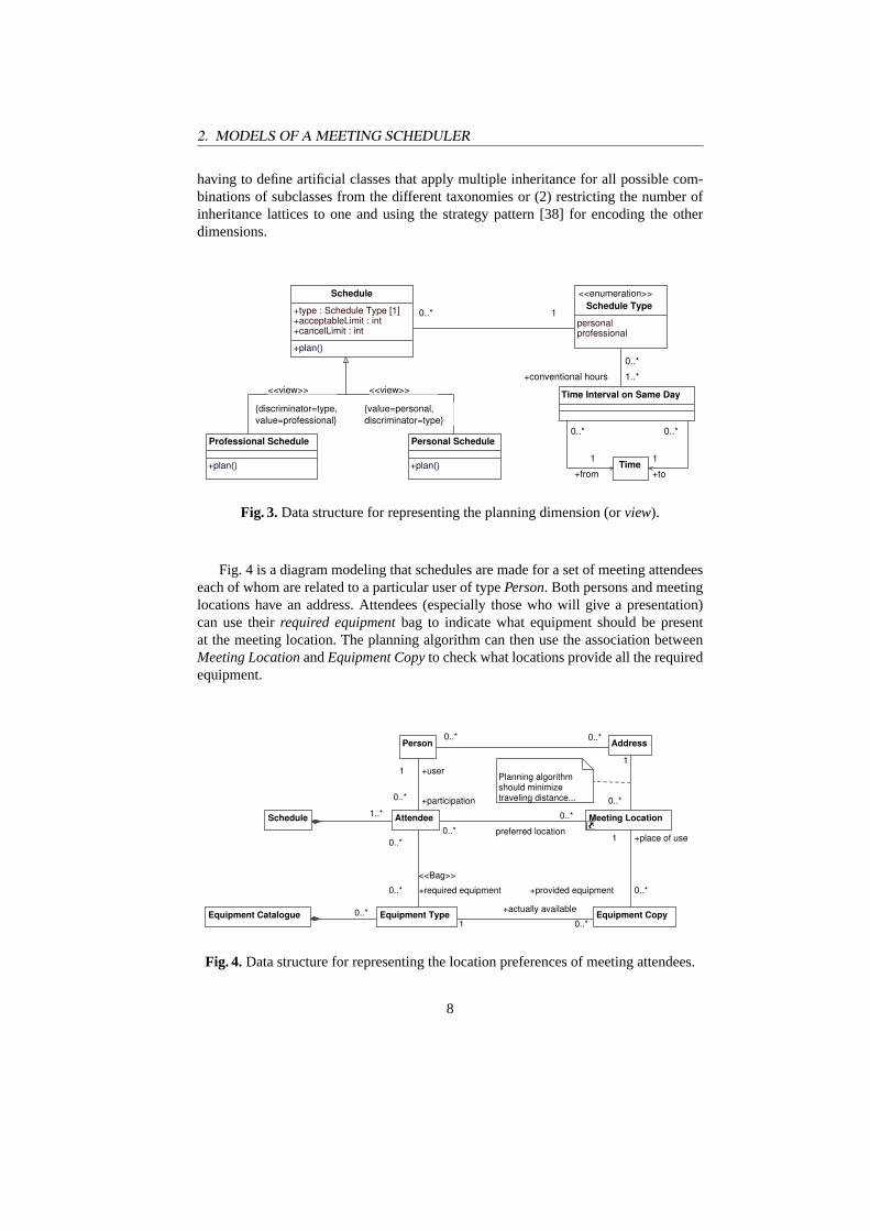
Fig. 4 is a diagram modeling that schedules are made for a set of meeting attendeeseach of whom are related to a particular user of typePerson. Both persons and meetinglocations have an address. Attendees (especially those who will give a presentation)can use theirrequired equipmentbag to indicate what equipment should be presentat the meeting location. The planning algorithm can then use the association betweenMeeting LocationandEquipment Copyto check what locations provide all the requiredequipment.
Equipment Catalogue
Meeting Location
Equipment CopyEquipment Type
AttendeeSchedule
AddressPerson
Planning algorithm should minimize traveling distance...
0..* 0..*
preferred location0..*
0..*
1
+actually available
0..*
1..*
0..*
<<Bag>>
+required equipment0..*
+place of use1
+provided equipment 0..*
0..*
0..*
1
+participation0..*
+user1
Fig. 4.Data structure for representing the location preferences of meeting attendees.
8
2. MODELS OF A MEETING SCHEDULER
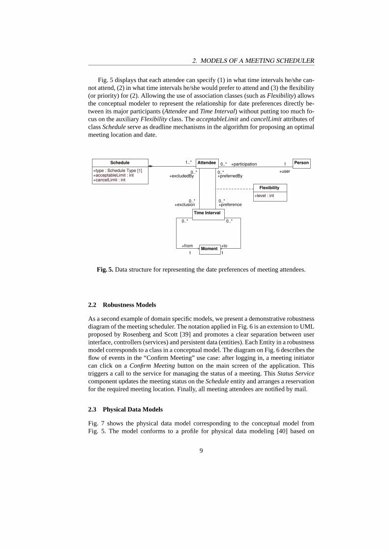
Fig. 5 displays that each attendee can specify (1) in what time intervals he/she can-not attend, (2) in what time intervals he/she would prefer to attend and (3) the flexibility(or priority) for (2). Allowing the use of association classes (such asFlexibility) allowsthe conceptual modeler to represent the relationship for date preferences directly be-tween its major participants (AttendeeandTime Interval) without putting too much fo-cus on the auxiliaryFlexibility class. TheacceptableLimitandcancelLimitattributes ofclassScheduleserve as deadline mechanisms in the algorithm for proposing an optimalmeeting location and date.
Schedule
+type : Schedule Type [1]+acceptableLimit : int+cancelLimit : int
Flexibility
+level : int
Time Interval
Attendee
Moment
Person+participation0..*
+user
11..*
+excludedBy0..*
+exclusion0..*
+preferredBy0..*
+preference0..*
0..*
+from
1
0..*
+to
1
Fig. 5.Data structure for representing the date preferences of meeting attendees.
2.2 Robustness Models
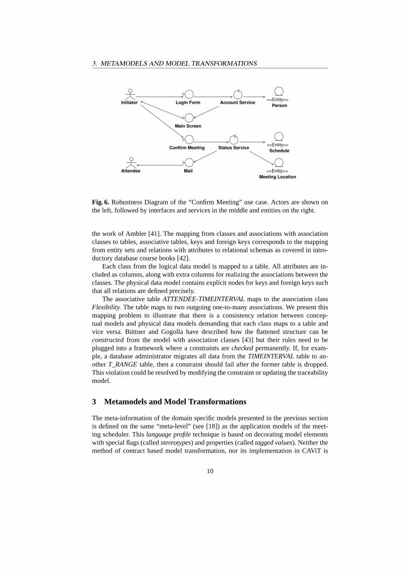
As a second example of domain specific models, we present a demonstrative robustnessdiagram of the meeting scheduler. The notation applied in Fig. 6 is an extension to UMLproposed by Rosenberg and Scott [39] and promotes a clear separation between userinterface, controllers (services) and persistent data (entities). Each Entity in a robustnessmodel corresponds to a class in a conceptual model. The diagram on Fig. 6 describes theflow of events in the “Confirm Meeting” use case: after logging in, a meeting initiatorcan click on aConfirm Meetingbutton on the main screen of the application. Thistriggers a call to the service for managing the status of a meeting. ThisStatus Servicecomponent updates the meeting status on theScheduleentity and arranges a reservationfor the required meeting location. Finally, all meeting attendees are notified by mail.
2.3 Physical Data Models
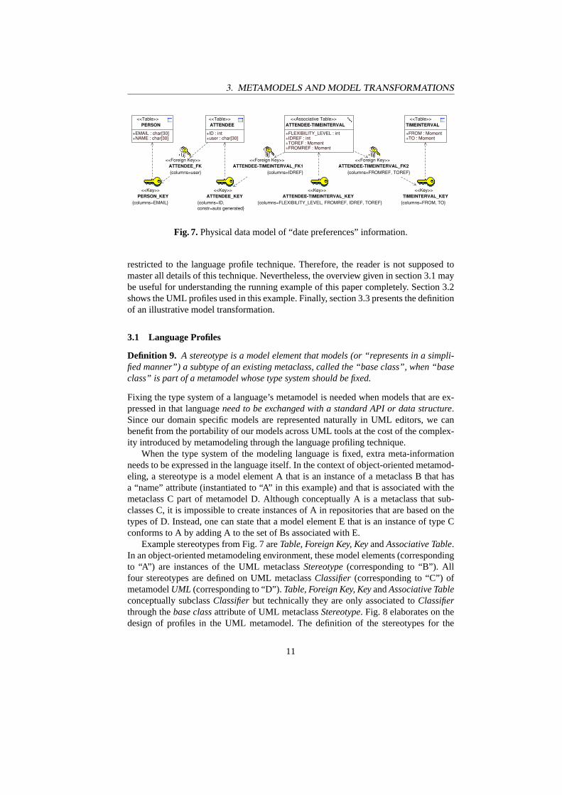
Fig. 7 shows the physical data model corresponding to the conceptual model fromFig. 5. The model conforms to a profile for physical data modeling [40] based on
9
3. METAMODELS AND MODEL TRANSFORMATIONS
Confirm Meeting
Account Service
<<Entity>>Meeting Location
Status Service
Main Screen
Login Form
<<Entity>>Schedule
<<Entity>>Person
Attendee
Initiator
Fig. 6. Robustness Diagram of the “Confirm Meeting” use case. Actors are shown onthe left, followed by interfaces and services in the middle and entities on the right.
the work of Ambler [41]. The mapping from classes and associations with associationclasses to tables, associative tables, keys and foreign keys corresponds to the mappingfrom entity sets and relations with attributes to relational schemas as covered in intro-ductory database course books [42].
Each class from the logical data model is mapped to a table. All attributes are in-cluded as columns, along with extra columns for realizing the associations between theclasses. The physical data model contains explicit nodes for keys and foreign keys suchthat all relations are defined precisely.
The associative tableATTENDEE-TIMEINTERVALmaps to the association classFlexibility. The table maps to two outgoing one-to-many associations. We present thismapping problem to illustrate that there is a consistency relation between concep-tual models and physical data models demanding that each class maps to a table andvice versa. Büttner and Gogolla have described how the flattened structure can beconstructedfrom the model with association classes [43] but their rules need to beplugged into a framework where a constraints arecheckedpermanently. If, for exam-ple, a database administrator migrates all data from theTIMEINTERVALtable to an-otherT_RANGEtable, then a constraint should fail after the former table is dropped.This violation could be resolved by modifying the constraint or updating the traceabilitymodel.
3 Metamodels and Model Transformations
The meta-information of the domain specific models presented in the previous sectionis defined on the same “meta-level” (see [18]) as the application models of the meet-ing scheduler. Thislanguage profiletechnique is based on decorating model elementswith special flags (calledstereotypes) and properties (calledtagged values). Neither themethod of contract based model transformation, nor its implementation in CAViT is
10
3. METAMODELS AND MODEL TRANSFORMATIONS
<<Key>>ATTENDEE-TIMEINTERVAL_KEY
{columns=FLEXIBILITY_LEVEL, FROMREF, IDREF, TOREF}
<<Foreign Key>>ATTENDEE-TIMEINTERVAL_FK1
{columns=IDREF}
<<Foreign Key>>ATTENDEE-TIMEINTERVAL_FK2
{columns=FROMREF, TOREF}
<<Associative Table>>ATTENDEE-TIMEINTERVAL
+FLEXIBILITY_LEVEL : int
+FROMREF : Moment+TOREF : Moment+IDREF : int
<<Key>>ATTENDEE_KEY
{columns=ID, constr=auto generated}
<<Key>>TIMEINTERVAL_KEY
{columns=FROM, TO}
<<Foreign Key>>ATTENDEE_FK{columns=user}
<<Table>>PERSON
+EMAIL : char[30]+NAME : char[30]
<<Table>>TIMEINTERVAL
+FROM : Moment+TO : Moment
<<Key>>PERSON_KEY
{columns=EMAIL}
<<Table>>ATTENDEE
+user : char[30]+ID : int
Fig. 7.Physical data model of “date preferences” information.
restricted to the language profile technique. Therefore, the reader is not supposed tomaster all details of this technique. Nevertheless, the overview given in section 3.1 maybe useful for understanding the running example of this paper completely. Section 3.2shows the UML profiles used in this example. Finally, section 3.3 presents the definitionof an illustrative model transformation.
3.1 Language Profiles
Definition 9. A stereotype is a model element that models (or “represents in a simpli-fied manner”) a subtype of an existing metaclass, called the “base class”, when “baseclass” is part of a metamodel whose type system should be fixed.
Fixing the type system of a language’s metamodel is needed when models that are ex-pressed in that languageneed to be exchanged with a standard API or data structure.Since our domain specific models are represented naturally in UML editors, we canbenefit from the portability of our models across UML tools at the cost of the complex-ity introduced by metamodeling through the language profiling technique.
When the type system of the modeling language is fixed, extra meta-informationneeds to be expressed in the language itself. In the context of object-oriented metamod-eling, a stereotype is a model element A that is an instance of a metaclass B that hasa “name” attribute (instantiated to “A” in this example) and that is associated with themetaclass C part of metamodel D. Although conceptually A is a metaclass that sub-classes C, it is impossible to create instances of A in repositories that are based on thetypes of D. Instead, one can state that a model element E that is an instance of type Cconforms to A by adding A to the set of Bs associated with E.
Example stereotypes from Fig. 7 areTable, Foreign Key, KeyandAssociative Table.In an object-oriented metamodeling environment, these model elements (correspondingto “A”) are instances of the UML metaclassStereotype(corresponding to “B”). Allfour stereotypes are defined on UML metaclassClassifier(corresponding to “C”) ofmetamodelUML (corresponding to “D”).Table, Foreign Key, KeyandAssociative Tableconceptually subclassClassifierbut technically they are only associated toClassifierthrough thebase classattribute of UML metaclassStereotype. Fig. 8 elaborates on thedesign of profiles in the UML metamodel. The definition of the stereotypes for the
11
3. METAMODELS AND MODEL TRANSFORMATIONS
physical data modeling profile is visualized on Fig. 9. On Fig. 7,Table is applied tomodel element Person (corresponding to “E”).
Definition 10. A tagged value is a model element that models an attribute of a stereo-type.
Example tagged values from Fig. 7 arecolumnsandconstrwhich are defined on Fig. 9.Stereotypes and tagged values are distributed in packages, calledprofiles, that can
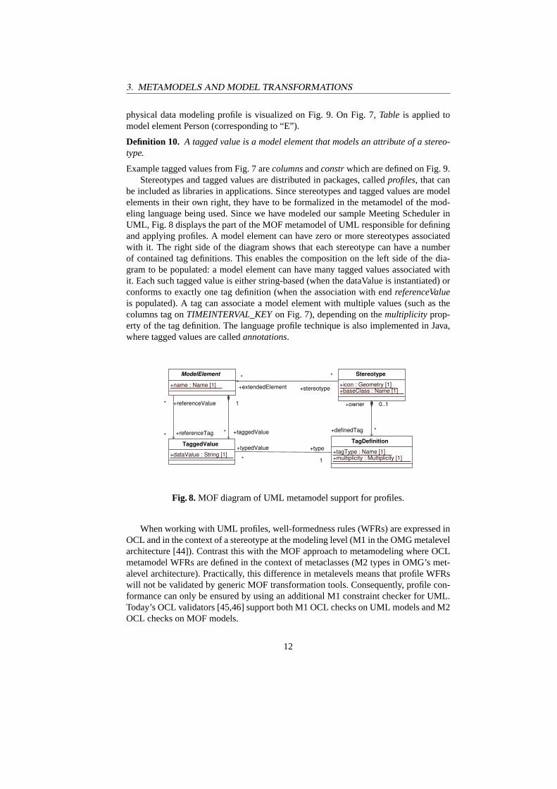
be included as libraries in applications. Since stereotypes and tagged values are modelelements in their own right, they have to be formalized in the metamodel of the mod-eling language being used. Since we have modeled our sample Meeting Scheduler inUML, Fig. 8 displays the part of the MOF metamodel of UML responsible for definingand applying profiles. A model element can have zero or more stereotypes associatedwith it. The right side of the diagram shows that each stereotype can have a numberof contained tag definitions. This enables the composition on the left side of the dia-gram to be populated: a model element can have many tagged values associated withit. Each such tagged value is either string-based (when the dataValue is instantiated) orconforms to exactly one tag definition (when the association with endreferenceValueis populated). A tag can associate a model element with multiple values (such as thecolumns tag onTIMEINTERVAL_KEYon Fig. 7), depending on themultiplicity prop-erty of the tag definition. The language profile technique is also implemented in Java,where tagged values are calledannotations.
TagDefinition
+multiplicity : Multiplicity [1]+tagType : Name [1]
ModelElement
+name : Name [1]
Stereotype
+baseClass : Name [1]+icon : Geometry [1]
TaggedValue
+dataValue : String [1]
+stereotype
*
+extendedElement
*
+typedValue
* 1
+type
+referenceValue*
+referenceTag*
1
+taggedValue* +definedTag *
+owner 0..1
Fig. 8.MOF diagram of UML metamodel support for profiles.
When working with UML profiles, well-formedness rules (WFRs) are expressed inOCL and in the context of a stereotype at the modeling level (M1 in the OMG metalevelarchitecture [44]). Contrast this with the MOF approach to metamodeling where OCLmetamodel WFRs are defined in the context of metaclasses (M2 types in OMG’s met-alevel architecture). Practically, this difference in metalevels means that profile WFRswill not be validated by generic MOF transformation tools. Consequently, profile con-formance can only be ensured by using an additional M1 constraint checker for UML.Today’s OCL validators [45,46] support both M1 OCL checks on UML models and M2OCL checks on MOF models.
12
3. METAMODELS AND MODEL TRANSFORMATIONS
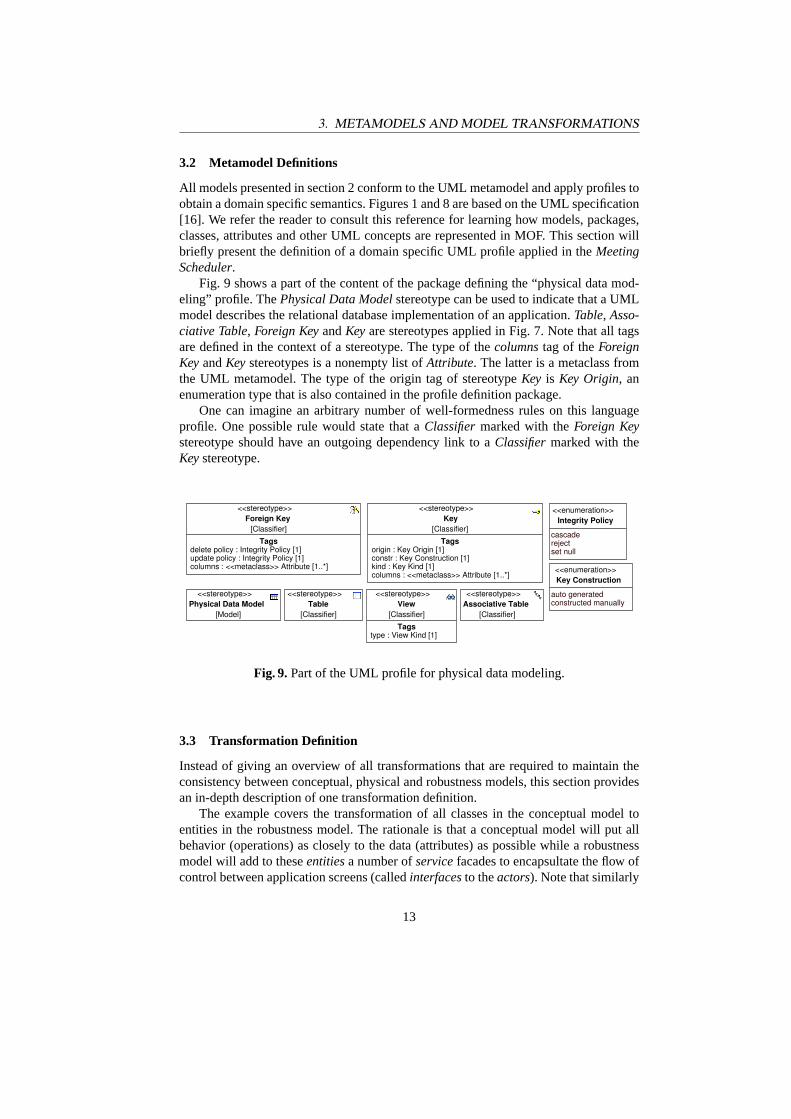
3.2 Metamodel Definitions
All models presented in section 2 conform to the UML metamodel and apply profiles toobtain a domain specific semantics. Figures 1 and 8 are based on the UML specification[16]. We refer the reader to consult this reference for learning how models, packages,classes, attributes and other UML concepts are represented in MOF. This section willbriefly present the definition of a domain specific UML profile applied in theMeetingScheduler.
Fig. 9 shows a part of the content of the package defining the “physical data mod-eling” profile. ThePhysical Data Modelstereotype can be used to indicate that a UMLmodel describes the relational database implementation of an application.Table, Asso-ciative Table, Foreign KeyandKeyare stereotypes applied in Fig. 7. Note that all tagsare defined in the context of a stereotype. The type of thecolumnstag of theForeignKeyandKeystereotypes is a nonempty list ofAttribute. The latter is a metaclass fromthe UML metamodel. The type of the origin tag of stereotypeKey is Key Origin, anenumeration type that is also contained in the profile definition package.
One can imagine an arbitrary number of well-formedness rules on this languageprofile. One possible rule would state that aClassifiermarked with theForeign Keystereotype should have an outgoing dependency link to aClassifiermarked with theKeystereotype.
<<stereotype>>Foreign Key
[Classifier]
Tagsdelete policy : Integrity Policy [1]update policy : Integrity Policy [1]columns : <<metaclass>> Attribute [1..*]
<<stereotype>>Key
[Classifier]
Tagsorigin : Key Origin [1]constr : Key Construction [1]kind : Key Kind [1]columns : <<metaclass>> Attribute [1..*]
<<stereotype>>Physical Data Model
[Model]
<<stereotype>>View
[Classifier]
Tagstype : View Kind [1]
<<stereotype>>Associative Table
[Classifier]
<<enumeration>>Key Construction
constructed manuallyauto generated<<stereotype>>
Table[Classifier]
<<enumeration>>Integrity Policy
cascade
set nullreject
Fig. 9.Part of the UML profile for physical data modeling.
3.3 Transformation Definition
Instead of giving an overview of all transformations that are required to maintain theconsistency between conceptual, physical and robustness models, this section providesan in-depth description of one transformation definition.
The example covers the transformation of all classes in the conceptual model toentities in the robustness model. The rationale is that a conceptual model will put allbehavior (operations) as closely to the data (attributes) as possible while a robustnessmodel will add to theseentitiesa number ofservicefacades to encapsultate the flow ofcontrol between application screens (calledinterfacesto theactors). Note that similarly
13

3. METAMODELS AND MODEL TRANSFORMATIONS
one could build the reverse transformations to support a methodology where entitiesare created manually during their discovery in use case refinement based on robustnessmodeling [39] and then copied to classes in the conceptual model. The focus of thispaper lies on presenting a powerful (yet understandable) framework for automatingrepetitive model management tasks andnot on introducing a new software engineeringprocess.
The transformation rule is implemented by the methodcmClasses2rmEntitiescon-tained in classCM2RM. As Fig. 10 shows,CM2EShas three attributes: (1)applica-tionModeldenotes the UML model containing applications conforming to the profilespresented in section 3.2, (2)profileDefinitionsdenotes the UML model containing thedefinitions of the profiles presented in section 3.2, whileapplicationNamedenotes thename of one application package withinapplicationModelthat contains the models thatneed to be transformed. For our running example, one would use “Meeting Scheduler”as a value for this attribute. The rulecmClasses2rmEntitieshas three parameters: (1)aModelcorresponds toCM2ES’sattributeapplicationModel, (2) pModelcorrespondsto profileDefinitions,while (3) aNamecorresponds toapplicationName. This mappingis specified as part of the transformation contract presented in the following section.
CM2ES
+applicationName : String...
+cmClasses2esEntities( aModel : Model, pModel : Model, aName : String ) : boolean...
ModelElement
+role : String
Node
Classifier Model
Trace
Superclass of all types in metamodel of transformed models
transitive
+traces*
+profilesModel1
+applicationModel1
*+content
11+node
*
Fig. 10.Structural model of the “conceptual model to robustness model” transformationand its related traceability data.
ThecmClasses2rmEntitiesmethod maintains the transformation contract specifiedin section 3.3.1 and is implemented with a visual model transformation language asexplained in section 3.3.2.
3.3.1 Transformation Contract The consistency relation between conceptual mod-els and robustness models can be ensured by a combination of transformation contracts.Note that in the case of multiple contracts with the same postcondition, their precondi-tions should be mutually exclusive to ensure that only one rule is called in a particularmodel inconsistency scenario. The precondition of the contract presented in this pa-per describes the situation where the robustness model has not been generated yet. Thepostcondition states that all classes from the conceptual model correspond to entities inan associated robustness model.
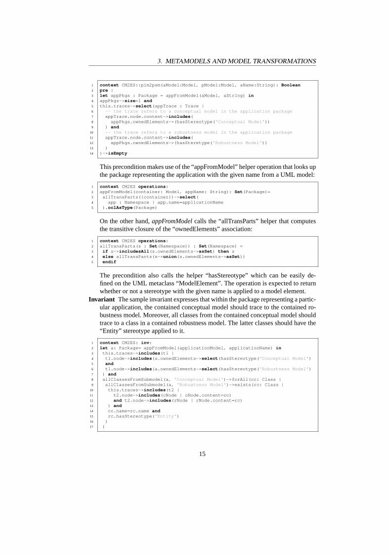
Precondition The precondition can be formalized as follows:
14
3. METAMODELS AND MODEL TRANSFORMATIONS
1 context CM2ES::pim2psm(aModel:Model, pModel:Model, aName:String): Boolean2 pre :3 let appPkgs : Package = appFromModel(aModel, aString) in4 appPkgs-> size =1 and5 this.traces-> select (appTrace : Trace |6 -- the trace refers to a conceptual model in the application package7 appTrace.node.content-> includes (8 appPkgs.ownedElements->(hasStereotype( " Conceptual Model " ))9 ) and
10 -- the trace refers to a robustness model in the application package11 appTrace.node.content-> includes (12 appPkgs.ownedElements->(hasSteretype( " Robustness Model " ))13 )14 )-> isEmpty
This precondition makes use of the “appFromModel” helper operation that looks upthe package representing the application with the given name from a UML model:
1 context CM2ES operations :2 appFromModel(container: Model, appName: String): Set (Package)=3 allTransParts({container})-> select (4 app : Namespace | app.name=applicationName5 ). oclAsType (Package)
On the other hand,appFromModelcalls the “allTransParts” helper that computesthe transitive closure of the “ownedElements” association:
1 context CM2ES operations :2 allTransParts(s : Set (Namespace)) : Set (Namespace) =3 if s-> includesAll (s.ownedElements-> asSet ) then s4 else allTransParts(s-> union (s.ownedElements-> asSet ))5 endif
The precondition also calls the helper “hasStereotype” which can be easily de-fined on the UML metaclass “ModelElement”. The operation is expected to returnwhether or not a stereotype with the given name is applied to a model element.
Invariant The sample invariant expresses that within the package representing a partic-ular application, the contained conceptual model should trace to the contained ro-bustness model. Moreover, all classes from the contained conceptual model shouldtrace to a class in a contained robustness model. The latter classes should have the“Entity” stereotype applied to it.
1 context CM2ES: inv :2 let a: Package= appFromModel(applicationModel, applicationName) in3 this.traces-> includes (t1 |4 t1.node-> includes (a.ownedElements-> select (hasStereotype( " Conceptual Model " )5 and6 t1.node-> includes (a.ownedElements-> select (hasStereotype( " Robustness Model " )7 ) and8 allClassesFromSubmodel(a, " Conceptual Model " )->forAll(cc: Class |9 allClassesFromSubmodel(a, " Robustness Model " )->exists(rc: Class |
10 this.traces-> includes (t2 |11 t2.node-> includes (cNode | cNode.content=cc)12 and t2.node-> includes (rNode | rNode.content=rc)13 ) and14 cc.name=rc.name and15 rc.hasStereotype( " Entity " )16 )17 )
15
3. METAMODELS AND MODEL TRANSFORMATIONS
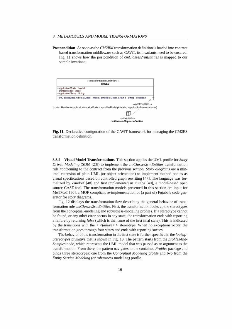
Postcondition As soon as theCM2RMtransformation definition is loaded into contractbased transformation middleware such as CAViT, its invariants need to be ensured.Fig. 11 shows how the postcondition ofcmClasses2rmEntitiesis mapped to oursample invariant.
<<Transformation Definition>>CM2ES
+applicationModel : Model
+applicationName : String+profilesModel : Model
+cmClasses2esEntities( aModel : Model, pModel : Model, aName : String ) : boolean
<<invariant>>cmClasses-Mapto-rmEntities
<<postcondition>>{contextHandler=<applicationModel,aModel>, <profilesModel,pModel>, <applicationName,aName>}
Fig. 11.Declarative configuration of the CAViT framework for managing the CM2EStransformation definition.
3.3.2 Visual Model Transformations This section applies the UML profile forStoryDriven Modeling(SDM [23]) to implement thecmClasses2rmEntitiestransformationrule conforming to the contract from the previous section.Story diagramsare a min-imal extension of plain UML (or object orientation) to implement method bodies asvisual specifications based on controlled graph rewriting [47]. The language was for-malized by Zündorf [48] and first implemented in Fujaba [49], a model-based opensource CASE tool. The transformation models presented in this section are input forMoTMoT [50], a MOF compliant re-implementation of (a part of) Fujaba’s code gen-erator for story diagrams.
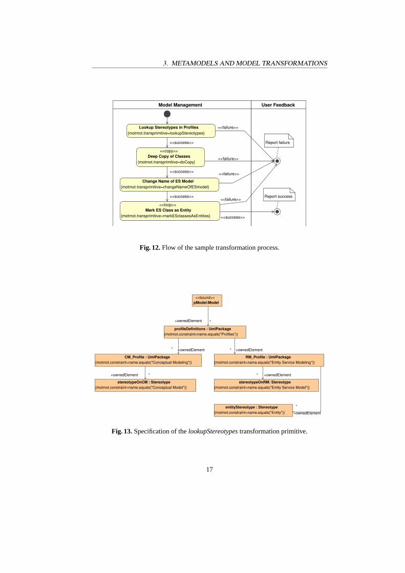
Fig. 12 displays the transformation flow describing the general behavior of trans-formation rulecmClasses2rmEntities. First, the transformation looks up the stereotypesfrom the conceptual-modeling and robustness-modeling profiles. If a stereotype cannotbe found, or any other error occurs in any state, the transformation ends with reportinga failure by returningfalse(which is the name of the first final state). This is indicatedby the transitions with the< <failure> > stereotype. When no exceptions occur, thetransformation goes through four states and ends with reporting succes.
The behavior of the transformation in the first state is further specified in thelookup-Stereotypesprimitive that is shown in Fig. 13. The pattern starts from theprofilesAnd-Samplesnode, which represents the UML model that was passed as an argument to thetransformation. From there, the pattern navigates to the containedProfilespackage andbinds three stereotypes: one from theConceptual Modelingprofile and two from theEntity Service Modeling(or robustnessmodeling) profile.
16
3. METAMODELS AND MODEL TRANSFORMATIONS
Model Management
<<loop>>Mark ES Class as Entity
{motmot.transprimitive=markESclassesAsEntities}
Change Name of ES Model{motmot.transprimitive=changeNameOfESmodel}
Lookup Stereotypes in Profiles{motmot.transprimitive=lookupStereotypes}
<<copy>>Deep Copy of Classes
{motmot.transprimitive=doCopy}
Report success
Report failure
User Feedback
<<failure>>
<<failure>>
<<failure>>
<<failure>>
<<success>>
<<success>>
<<success>>
<<success>>
Fig. 12.Flow of the sample transformation process.
RM_Profile : UmlPackage{motmot.constraint=name.equals("Entity Service Modeling")}
CM_Profile : UmlPackage{motmot.constraint=name.equals("Conceptual Modeling")}
stereotypeOnRM: Stereotype{motmot.constraint=name.equals("Entity Service Model")}{motmot.constraint=name.equals("Conceptual Model")}
stereotypeOnCM : Stereotype
profileDefinitions : UmlPackage{motmot.constraint=name.equals("Profiles")}
{motmot.constraint=name.equals("Entity")}entityStereotype : Stereotype
<<bound>>pModel:Model
+ownedElement
*
+ownedElement *
+ownedElement* +ownedElement*
+ownedElement * +ownedElement*
Fig. 13.Specification of thelookupStereotypestransformation primitive.
17
4. ARCHITECTURE OF THE CAVIT FRAMEWORK
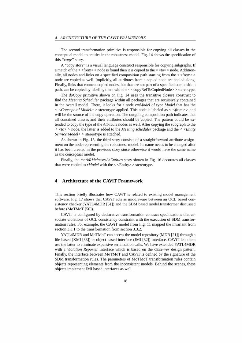
The second transformation primitive is responsible for copying all classes in theconceptual model to entities in the robustness model. Fig. 14 shows the specification ofthis “copy” story.
A “copy story” is a visual language construct responsible for copying subgraphs. Ifa match of the < <from> > node is found then it is copied to the < <to> > node. Addition-ally, all nodes and links on a specified composition path starting from the < <from> >node are copied as well. Implicitly, all attributes from a copied node are copied along.Finally, links that connect copied nodes, but that are not part of a specified compositionpath, can be copied by labeling them with the < <copyRefToCopiedNode> > stereotype.
The doCopyprimitive shown on Fig. 14 uses the transitive closure construct tofind theMeeting Schedulerpackage within all packages that are recursively containedin the overall model. There, it looks for a nodecmModelof type Model that has the< <Conceptual Model> >stereotype applied. This node is labeled as< <from> > andwill be the source of the copy operation. The outgoing composition path indicates thatall contained classes and their attributes should be copied. The pattern could be ex-tended to copy the type of theAttributenodes as well. After copying the subgraph to the< <to> > node, the latter is added to theMeeting schedulerpackage and the< <EntityService Model> >stereotype is attached.
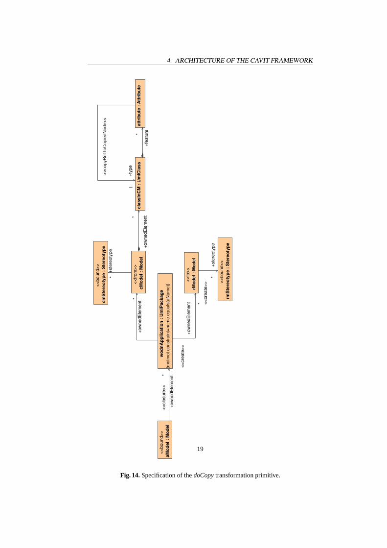
As shown in Fig. 15, the third story consists of a straightforward attribute assign-ment on the node representing the robustness model. Its name needs to be changed afterit has been created in the previous story since otherwise it would have the same nameas the conceptual model.
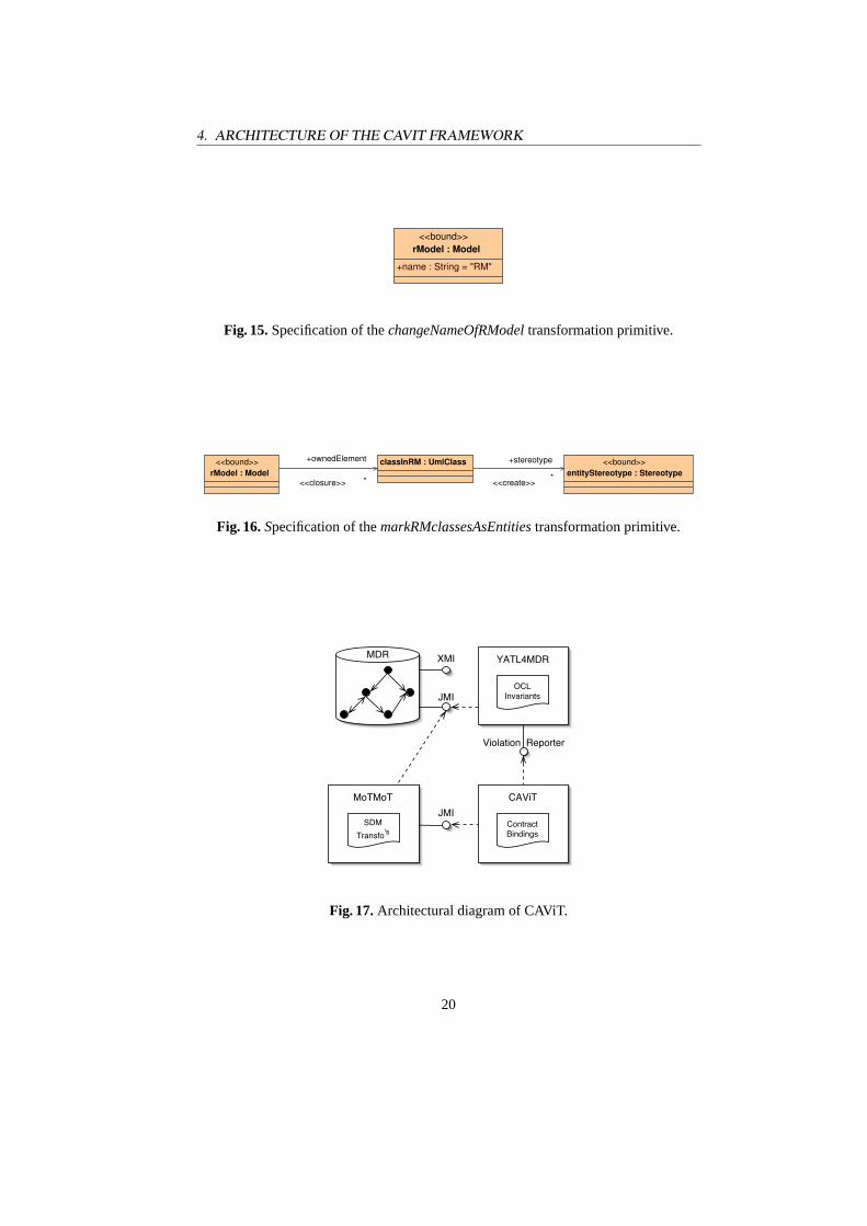
Finally, themarkRMclassesAsEntitiesstory shown in Fig. 16 decorates all classesthat were copied torModelwith the < <Entity> > stereotype.
4 Architecture of the CAViT Framework
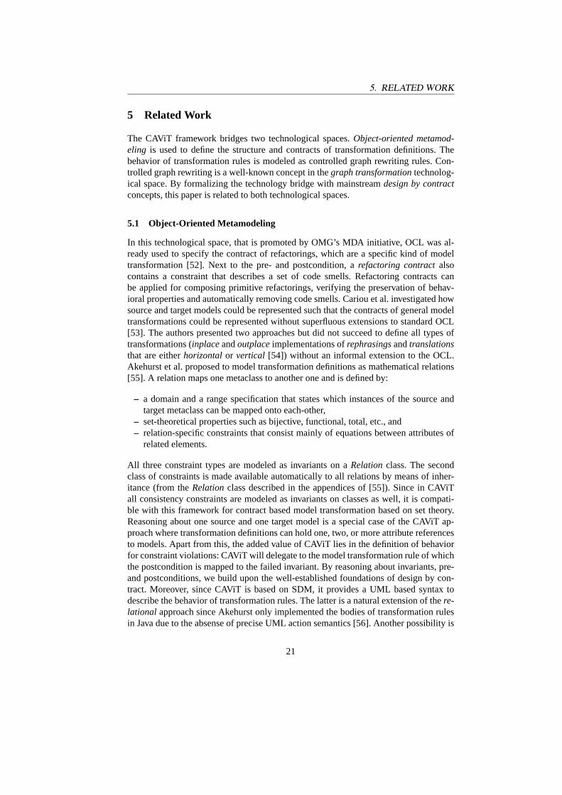
This section briefly illustrates how CAViT is related to existing model managementsoftware. Fig. 17 shows that CAViT acts as middleware between an OCL based con-sistency checker (YATL4MDR [51]) and the SDM based model transformer discussedbefore (MoTMoT [50]).
CAViT is configured by declarative transformation contract specifications that as-sociate violations of OCL consistency constraint with the execution of SDM transfor-mation rules. For example, the CAViT model from Fig. 11 mapped the invariant fromsection 3.3.1 to the transformation from section 3.3.2.
YATL4MDR and MoTMoT can access the model repository (MDR [21]) through afile-based (XMI [33]) or object-based interface (JMI [32]) interface. CAViT lets themuse the latter to eliminate expensive serialization calls. We have extended YATL4MDRwith a Violation Reporterinterface which is based on theObserverdesign pattern.Finally, the interface between MoTMoT and CAViT is defined by the signature of theSDM transformation rules. The parameters of MoTMoT transformation rules containobjects representing elements from the inconsistent models. Behind the scenes, theseobjects implement JMI based interfaces as well.
18
4. ARCHITECTURE OF THE CAVIT FRAMEWORK
wod
nApp
licat
ion
: Um
lPac
kage
{mot
mot
.con
stra
int=
nam
e.eq
uals
(aN
ame)
}<<bo
und>
>cm
Ste
reot
ype
: Ste
reot
ype
<<bo
und>
>rm
Ste
reot
ype
: Ste
reot
ype
clas
sInC
M :
Um
lCla
ssat
trib
ute
: Att
ribu
te<<
from
>>cM
odel
: M
odel
<<to
>>rM
odel
: M
odel
<<bo
und>
>aM
odel
: M
odel
<<co
pyR
efTo
Cop
iedN
ode>
>
+typ
e1
<<cl
osur
e>>
+ow
nedE
lem
ent*
+ow
nedE
lem
ent*
<<cr
eate
>>+o
wne
dEle
men
t *
+ow
nedE
lem
ent*
+fea
ture*
+ste
reot
ype
*
<<cr
eate
>>
+ste
reot
ype
*
Fig. 14.Specification of thedoCopytransformation primitive.
19
4. ARCHITECTURE OF THE CAVIT FRAMEWORK
<<bound>>rModel : Model
+name : String = "RM"
Fig. 15.Specification of thechangeNameOfRModeltransformation primitive.
<<bound>>entityStereotype : Stereotype
classInRM : UmlClass<<bound>>rModel : Model
<<closure>>
+ownedElement
* <<create>>
+stereotype
*
Fig. 16.Specification of themarkRMclassesAsEntitiestransformation primitive.
MDR XMI
JMI
Violation Reporter
Contract Bindings
CAViT
OCLInvariants
YATL4MDR
JMISDM
Transfo's
MoTMoT
Fig. 17.Architectural diagram of CAViT.
20
5. RELATED WORK
5 Related Work
The CAViT framework bridges two technological spaces.Object-oriented metamod-eling is used to define the structure and contracts of transformation definitions. Thebehavior of transformation rules is modeled as controlled graph rewriting rules. Con-trolled graph rewriting is a well-known concept in thegraph transformationtechnolog-ical space. By formalizing the technology bridge with mainstreamdesign by contractconcepts, this paper is related to both technological spaces.
5.1 Object-Oriented Metamodeling
In this technological space, that is promoted by OMG’s MDA initiative, OCL was al-ready used to specify the contract of refactorings, which are a specific kind of modeltransformation [52]. Next to the pre- and postcondition, arefactoring contractalsocontains a constraint that describes a set of code smells. Refactoring contracts canbe applied for composing primitive refactorings, verifying the preservation of behav-ioral properties and automatically removing code smells. Cariou et al. investigated howsource and target models could be represented such that the contracts of general modeltransformations could be represented without superfluous extensions to standard OCL[53]. The authors presented two approaches but did not succeed to define all types oftransformations (inplaceandoutplaceimplementations ofrephrasingsandtranslationsthat are eitherhorizontalor vertical [54]) without an informal extension to the OCL.Akehurst et al. proposed to model transformation definitions as mathematical relations[55]. A relation maps one metaclass to another one and is defined by:
– a domain and a range specification that states which instances of the source andtarget metaclass can be mapped onto each-other,
– set-theoretical properties such as bijective, functional, total, etc., and– relation-specific constraints that consist mainly of equations between attributes of
related elements.
All three constraint types are modeled as invariants on aRelationclass. The secondclass of constraints is made available automatically to all relations by means of inher-itance (from theRelationclass described in the appendices of [55]). Since in CAViTall consistency constraints are modeled as invariants on classes as well, it is compati-ble with this framework for contract based model transformation based on set theory.Reasoning about one source and one target model is a special case of the CAViT ap-proach where transformation definitions can hold one, two, or more attribute referencesto models. Apart from this, the added value of CAViT lies in the definition of behaviorfor constraint violations: CAViT will delegate to the model transformation rule of whichthe postcondition is mapped to the failed invariant. By reasoning about invariants, pre-and postconditions, we build upon the well-established foundations of design by con-tract. Moreover, since CAViT is based on SDM, it provides a UML based syntax todescribe the behavior of transformation rules. The latter is a natural extension of there-lational approach since Akehurst only implemented the bodies of transformation rulesin Java due to the absense of precise UML action semantics [56]. Another possibility is
21
5. RELATED WORK
the extension of OCL as a side-effect free constraint and query language to a transfor-mation language. Initial experiments were already conducted to build consistent modelelements automatically for architectural models [57]. More case studies are requiredto assess the readability and expressiveness of SDM and the OCL action language inpractice. Especially, there’s a lack of publications on transformation rules thatreconcileinconsistent models.
It should be noted that work in the object-oriented metamodeling space builds uponthe results of the logic-based knowledge bases. In the latter area, Balzer was among thepioneers that proposed to decouple the definition of declarative consistency contractsfrom imperative repair actions. Moreover, he recognized the importance of temporar-ily tolerating consistency violations and the role of manual reconciliation assisted byautomatic inconsistency notification [58]. Finkelstein et al. used executable temporallogic [59] to implement transformation rules for maintaining the consistency betweensoftware models from different viewpoints [60].
5.2 Graph Transformation
The roots of technological space were developed in the early seventies [61]. The foun-dations of controlled graph rewriting are described by Schürr in the handbook of graphtransformation [26].
Interestingly, one can describe the pre- and postconditions of transformation ruleswithin the graph transformation space itself [62]. Based on these concepts, tools can an-alyze whether a rule does not break the well-formedness rules of a modeling language[63]. Tom Mens mapped PROLOG-based work on “reuse contracts” to the graph trans-formation space to illustrate the applicability of graph transformation to the evolutionof object-oriented software [64]. Reuse contracts are model transformation rules thatwere defined to manage the evolution of class hierarchies and collaborations. By defin-ing a set of primitive reuse contracts as graph rewrite rules, Mens was able to derive aconflict matrix. This idea was later elaborated in collaboration with Täntzer and Runge[65]. One should note that the algorithms for computing conflict matrices have not beendesigned with the control structures and copy operator from SDM in mind.
Since our definition of a transformation contract is not based on a particular con-straint language such as the OCL, CAViT’s consistency maintenance approach shouldbe applicable to visual specifications of pre- and postconditions as well. This papercomplements previous work on pre- and postconditions within the graph transforma-tion space since one only investigated how inconsistency could be prohibited, ratherthan being tolerated temporarily. Once the work of Mens et al. would be extended tosupport controlled graph rewriting, it could be used to compute possibly undesired side-effects of executing one transformation rule before another one, when CAViT indicatedthat both of them could fix a model inconsistency.
As a running example for this paper, we modeled a meeting scheduler system usingUML profiles and defined transformations between the different models. We promotedthe use of language profiles for prototyping domain specific languages since today’sCASE tools allow one to tune general purpose editors to domain specific ones veryeasily. Nevertheless, we look forward to applying the results from recent advances in
22
6. CONCLUSIONS
editor technology that promise a simple decoupling of abstract syntax models from con-crete syntax models. This would significantly simplify our transformation contracts andrules because they would be defined on a dedicated abstract syntax model. Interestingly,it was exactly during the development of such configurable editors that Akehurst et al.proposed to use a contract based model transformation approach as well [66] whileBardohl defines the mapping between abstract and contrete syntax with graph gram-mars [67].
6 Conclusions
The main theoretical contribution of this paper is that it relates new developments inmodel transformation technology to existing paradigms. More specifically:
– the notions of transformation definitions and transformation rules were mappedback to classes and methods,
– one or more models are accessible from a transformation definition by storing ref-erences to model elements in attributes from the transformation class,
– the notion of consistency contracts was mapped back to class invariants,– we defined how pre- and postconditions of methods relate to class invariants when
automating consistency management, and finally– the behavior of transformation methods is modeled by executable UML diagrams
based on controlled graph rewriting.
Additionally, we illustrated that traceability can be modeled elegantly in an object-oriented fashion: a transformation class is associated with a set of traceability classes.The latter references a set of model elements that are related by a particular traceabilityrelation.
The proposed theory is validated by the implementation and use of theContractAware Visual Transformation(CAViT) framework. CAViT can be regarded as modeltransformation middleware since it integrates two model management frameworks thatwere developed separately:
– YATL4MDR is used to evaluate model consistency contracts that are specified inOCL,
– MoTMoT is used to execute the visual transformation models.
By combining the strengths of object-oriented metamodeling with graph rewriting,CAViT enables the development of more complex transformations and the explorationof new research topics such as metamodel and transformation evolution.
Acknowledgements
The authors would like to thank Hans Schippers and Olaf Muliawan for their contribu-tions to MoTMoT. Hans Schippers also provided valuable feedback to make the UMLprofiles related to MoTMoT and CAViT as readable as possible. This work has been
23
6. CONCLUSIONS
sponsored by the Belgian national fund for scientific research (FWO) under grants“Foundations of Software Evolution”, “A Formal Foundation for Software Refactor-ing” and “Formal Support for the Transformation of Software Models”. Other sponsor-ing was provided by the European research training network “Syntactic and SemanticIntegration of Visual Modeling Techniques (SegraVis)”.
References
1. Carlo Ghezzi and Gian Pietro Picco. An outlook on software engineering for modern dis-tributed systems. InProceedings of the Monterey workshop on Radical Approaches to Soft-ware Engineering, Venice (Italy), 8 2002.
2. Sun Microsystems. Java 2 platform enterprise edition specification, v1.3, July 2001.3. SAP. mySAP ERP. http://www.sap.com/solutions/business-suite/erp/, 2005.4. R. Floyd. Assigning meanings to programs. In J. T. Schwartz, editor,Proc. Symposium on
Mathematical Aspects of Computer Science, volume 19, pages 19–32. American Mathemat-ical Society, 1967.
5. C. A. R. Hoare. An axiomatic basis for computer programming.Communications of theACM, 12(10):576–580, 1969.
6. C. A. R. Hoare and N. Wirth. An axiomatic definition of the programming language pascal.Acta Informatica, 2:335–355., 1973.
7. Shigeru Igarashi, Ralph L. London, and David C. Luckham. Automatic program verificationi: A logical basis and its implementation.Acta Informatica, 4:145–182, 1974.
8. David Crocker. Safe object-oriented software: the verified design-by-contract paradigm.In F.Redmill and T.Anderson, editors,Proceedings of the Twelfth Safety-Critical SystemsSymposium, pages 19–41. Springer-Verlag, 2004.
9. Bertrand Meyer.Eiffel, the Language. Prentice Hall, 1992.10. R. Kramer. iContractor - The Java Design by Contract Tool. InTechnology of Object-
Oriented Languages and Systems (26th International Conference and Exhibition), 1998.11. Jean Bézivin and Olivier Gerbé. Towards a precise definition of the OMG/MDA frame-
work. In Proc. 16th Int’l Conf. Automated Software Engineering, page 273. IEEE ComputerSociety, November 2001.
12. E Seidewitz. What models mean.IEEE Software, 20, Sept.-Oct. 2003.13. Donald Norman.Mental Models, chapter Some Observations on Mental Models, pages 7–
14. LEA, 1983.14. Anneke Kleppe, Jos Warmer, and Wim Bast.MDA explained: the model driven architecture:
practice and promise. Object Technology Series. Addison – Wesley, 2003.15. Shane Sendall and Wojtek Kozaczynski. Model transformation – the heart and soul of model-
driven software development.IEEE Software, Special Issue on Model Driven Software De-velopment, 20(5):42–45, 2003.
16. Object Management Group. Unified Modeling Language (UML), March 2003. version 1.5.document ID formal/03-03-01.
17. James Martin.Rapid application development. Macmillan Publishing Co., Inc., 1991.18. Jean-Marie Favre. Foundations of meta-pyramids: Languages vs. metamodels – episode II:
Story of thotus the baboon. In Jean Bezivin and Reiko Heckel, editors,Language Engineer-ing for Model-Driven Software Development, number 04101 in Dagstuhl Seminar Proceed-ings. Internationales Begegnungs- und Forschungszentrum für Informatik (IBFI), SchlossDagstuhl, Germany, 2005.
19. Peter Pin-Shan S. Chen. The entity-relationship model: Toward a unified view of data.ACMTransactions on Database Systems, 1(1):9–36, 1976.
24
6. CONCLUSIONS
20. Jean Bézivin, Nicolas Farcet, Jean-Marc Jézéquel, Benoît Langlois, and Damien Pollet. Re-flective Model Driven Engineering. In Perdita Stevens, Jon Whittle, and Grady Booch, ed-itors, Proc. UML 2003 - The Unified Modeling Language. Model Languages and Applica-tions. 6th International Conference, San Francisco, CA, USA, volume 2863 ofLNCS, pages175–189. Springer, October 2003.
21. Sun Microsystems. NetBeans Metadata Repository, 2002. http://mdr.netbeans.org/.22. Bill Moore, David Dean, Anna Gerber, Gunnar Wagenknecht, and Philippe Vanderheyden.
Eclipse Development using the Graphical Editing Framework and the Eclipse ModelingFramework. IBM Redbooks. International Business Machines, January 2004.
23. Hans Schippers, Pieter Van Gorp, and Dirk Janssens. Leveraging UML profiles to generateplugins from visual model transformations.Software Evolution through Transformations(SETra). Satellite of the 2nd Intl. Conference on Graph Transformation, 127(3):5–16, 2004.
24. Pieter Van Gorp, Dirk Janssens, and Tracy Gardner. Write once, deploy N: A perfor-mance oriented MDA case study. InEnterprise Distributed Object Computing Conference,(EDOC), pages 123–134, 2004.
25. Octavian Patrascoiu. YATL:Yet Another Transformation Language. InProceedings of the1st European MDA Workshop, MDA-IA, pages 83–90. University of Twente, the Nederlands,January 2004.
26. Grzegorz Rozenberg, editor.Handbook of graph grammars and computing by graph trans-formation: volume I. foundations. World Scientific Publishing Co., Inc., 1997.
27. Object Management Group. Model Driven Architecture (MDA), July 2001.28. Conrad Bock. UML 2 activity and action models.Journal of Object Technology, 2(4), 2003.29. No Magic. Magicdraw. http://www.magicdraw.com/, 2005.30. Gentleware. Poseidon for UML, version 2.6, 2005. http://www.gentleware.com.31. Daniel T. Chang. Cwm enablement showcase: Warehouse metadata interchange made easy
using cwm.TDWI, 11(Data Warehousing: What Works?), 05 2001.32. Java Community Process. Java metadata interface (JMI) specification – JSR 000040, June
2002.33. Object Management Group. XML Metadata Interchange (XMI), v2.0. formal/03-05-02,
2003.34. Object Management Group. MOF 2.0 Query / Views / Transformations RFP ad/2002-04-10,
October 2002.35. A. v. Lamsweerde and R. Darimont and P. Massonet. The Meeting Scheduler System -
Problem Statement. Technical report, Université Catholique de Louvain - Départementd’Ingénierie Informatique, B-1348 Louvain-la-Neuve (Belgium), 1992.
36. M.S. Feather, S. Fickas, A. Finkelstein, and A. van Lamsweerde. Requirements and specifi-cation exemplars.Automated Software Engineering, 4(4):419–438, 1997.
37. Bertrand Meyer. Object-Oriented Software Construction, chapter Mul-tiple Criteria and View Inheritance. Prentice Hall, 2nd edition,1997. http://archive.eiffel.com/doc/manuals/technology/oosc/inheritance-design/section_10.html#HDR39.
38. Erich Gamma, Richard Helm, Ralph Johnson, and John Vlissides.Design Patterns: Elementsof Reusable Object-Oriented Software, chapter 5 (Strategy), pages 315–323. ProfessionalComputing Series. Addison-Wesley, 1995.
39. Doug Rosenberg and Kendall Scott.Use case driven object modeling with UML: a practicalapproach. Addison-Wesley Longman Publishing Co., Inc., Boston, MA, USA, 1999.
40. Pieter Van Gorp. UML Profile for Data Modeling. http://www.fots.ua.ac.be/ pvgorp/re-search/datamodelingprofile/, 2005.
41. Scott W. Ambler. A UML Profile for Data Modeling.http://www.agiledata.org/essays/umlDataModelingProfile.html, 2005.
25
6. CONCLUSIONS
42. Jeffrey D. Ullman and Jennifer Widom.A first course in database systems, chapter 3.3, pages103–107. Prentice-Hall, 1997.
43. Fabian Büttner and Martin Gogolla. Realizing UML metamodel transformations with AGG.In Reiko Heckel, editor,Proc. ETAPS Workshop Graph Transformation and Visual ModelingTechniques (GT-VMT’2004), ENTCS. Elsevier, 2004.
44. Object Management Group.Meta Object Facility (MOF) specification. Object Man-agement Group, 2002. Version 1.4. Available for download at url http://cgi.omg.org/cgi-bin/doc?formal/2002-04-03.
45. Birgit Demuth. The Dresden OCL Toolkit and its Role in Information Systems Development.In 13th International Conference on Information Systems Development: Methods and Tools,Theory and Practice, Vilnius (Lithuania), 9 2004.
46. Dan Chiorean. Using OCL Beyond Specification. InProceedings of the 4th InternationalConference on the UML "Modeling Languages, Concepts and Tools", number 2185 in Lec-ture Notes in Computer Science, Toronto (Canada), 2001. Springer-Verlag.
47. Lars Grunske, Leif Geiger, Albert Zündorf, Niels Van Eetvelde, Pieter Van Gorp, and DanielVarro. Model-driven Software Development - Volume II of Research and Practice in Soft-ware Engineering, chapter Using Graph Transformation for Practical Model Driven SoftwareEngineering. Springer-Verlag, 2005.
48. Albert Zündorf.Rigorous Object Oriented Software Development. PhD thesis, University ofPaderborn, 2001.
49. T. Fischer, J. Niere, L. Torunski, and A. Zündorf. Story diagrams: A new graph rewritelanguage based on the unified modeling language. In G. Engels and G. Rozenberg, editors,Proc. of the6th International Workshop on Theory and Application of Graph Transformation(TAGT), Paderborn, Germany, LNCS 1764. Springer Verlag, 1998.
50. Olaf Muliawan, Hans Schippers, and Pieter Van Gorp. Model driven, Template based, ModelTransformer (MoTMoT). http://motmot.sourceforge.net/, 2005.
51. Remco M. Dijkman. Yatl4mdr: A model transformation engine and ocl checker for thenetbeans meta-data repository.
52. Pieter Van Gorp, Hans Stenten, Tom Mens, and Serge Demeyer. Towards automating source-consistent UML refactorings. InProceedings of « UML » 2003 – The Unified ModelingLanguage. Springer-Verlag, 2003.
53. Eric Cariou, Raphaël Marvie, Lionel Seinturier, and Laurence Duchien. OCL for the speci-fication of model transformation contracts. In Octavian Patrascoiu, editor,OCL and ModelDriven Engineering, UML 2004 Conference Workshop, October 12, 2004, Lisbon, Portugal,pages 69–83. University of Kent, 2004.
54. Tom Mens, Krzysztof Czarnecki, and Pieter Van Gorp. 04101 discussion – a taxonomyof model transformations [online]. In Jean Bezivin and Reiko Heckel, editors,LanguageEngineering for Model-Driven Software Development, number 04101 in Dagstuhl SeminarProceedings. Internationales Begegnungs- und Forschungszentrum (IBFI), Schloss Dagstuhl,Germany, 2005. Extended version submitted to GraMoT’05.
55. David Akehurst, Stuart Kent, and Octavian Patrascoiu. A Relational Approach to Defin-ing and Implementing Transformations in Metamodels.Software and Systems Modeling,2(4):215–239, December 2003.
56. David H. Akehurst. Model Translation: A UML-based specification technique and activeimplementation approach. PhD thesis, December 2000. (unknown variable note).
57. M. W. A. Steen, D. H. Akehurst, H. W. L. ter Doest, and M. M. Lankhorst. Supportingviewpoint-oriented enterprise architecture. InEnterprise Distributed Object Computing Con-ference, (EDOC), pages 201–211, 2004.
58. Robert Balzer. Tolerating inconsistency. InICSE ’91: Proceedings of the 13th internationalconference on Software engineering, pages 158–165, Los Alamitos, CA, USA, 1991. IEEEComputer Society Press.
26
6. CONCLUSIONS
59. Ben Moszkowski.Executing temporal logic programs. Cambridge University Press, NewYork, NY, USA, 1986.
60. Anthony Finkelstein, Dov M. Gabbay, Anthony Hunter, Jeff Kramer, and Bashar Nuseibeh.Inconsistency handling in multi-perspective specifications. InESEC ’93: Proceedings ofthe 4th European Software Engineering Conference on Software Engineering, pages 84–99,London, UK, 1993. Springer-Verlag.
61. Hartmunt Ehrig and Michael Pfender and Hans Jürgen Schneider. Graph-Grammars: AnAlgebraic Approach. InFOCS, pages 167–180, 1973.
62. Reiko Heckel and Annika Wagner. Ensuring consistency of conditional graph rewriting – aconstructive approach.Electronic Notes in Theorectical Computer Science, 2, 1995. JointCOMPUGRAPH/SEMAGRAPH Workshop on Graph Rewriting and Computation.
63. Gabi Täntzer and Olga Runge. AGG – The Attributed Graph Grammar System: A De-velopment Environment for Attributed Graph Transformation Systems. http://tfs.cs.tu-berlin.de/agg/, 2005.
64. Tom Mens. A Formal Foundation for Object-Oriented Software Evolution. PhD thesis,Department of Computer Science, Vrije Universiteit Brussel, 1999.
65. Tom Mens, Gabriele Taentzer, and Olga Runge. Detecting structural refactoring conflictsusing critical pair analysis.Electronic Notes in Theoretical Computer Science, 127(3):113–128, April 2005.
66. D. Akehurst, H. Bowman, J. Bryans, and J. Derrick. A manual for a model checker forstochastic automata. Technical Report 5-00, University of Kent, Canterbury, 2000.
67. Roswitha Bardohl. A visual environment for visual languages.Science of Computer Pro-gramming, 44(2):181–203, August 2002.
27
Related Documents