CATALYTIC GASIFICATION OF COAL USING EUTECTIC SALT MIXTURES Final Technical Report For the Project Duration October 1997 to September 2001 Dr. Yaw D. Yeboah (PI) and Dr. Yong Xu (Co-PI) Department of Engineering Clark Atlanta University Atlanta, GA 30314 Dr. Atul Sheth (Co-PI) The University of Tennessee Space Institute 411 B.H. Goethet Parkway Tullahoma, TN 37388-8897 Dr. Pradeep Agrawal (Co-PI) School of Chemical Engineering Georgia Institute of Technology Atlanta, GA 30332 Submitted December, 2001 PREPARED FOR THE UNITED STATES DEPARTMENT OF ENERGY UNDER CONTRACT NUMBER DE-FG26-97FT97263

Welcome message from author
This document is posted to help you gain knowledge. Please leave a comment to let me know what you think about it! Share it to your friends and learn new things together.
Transcript
CATALYTIC GASIFICATION OF COAL USING EUTECTIC SALT MIXTURES
Final Technical Report For the Project Duration
October 1997 to September 2001
Dr. Yaw D. Yeboah (PI) and Dr. Yong Xu (Co-PI) Department of Engineering Clark Atlanta University
Atlanta, GA 30314
Dr. Atul Sheth (Co-PI) The University of Tennessee Space Institute
411 B.H. Goethet Parkway Tullahoma, TN 37388-8897
Dr. Pradeep Agrawal (Co-PI) School of Chemical Engineering Georgia Institute of Technology
Atlanta, GA 30332
Submitted December, 2001
PREPARED FOR THE UNITED STATES DEPARTMENT OF ENERGY UNDER CONTRACT NUMBER DE-FG26-97FT97263

EXECUTIVE SUMMARY
The Gas Research Institute (GRI) estimates that by the year 2010, 40% or more of U.S. gas supply will be provided by supplements including substitute natural gas (SNG) from coal. These supplements must be cost competitive with other energy sources. The first generation technologies for coal gasification e.g. the Lurgi Pressure Gasification Process and the relatively newer technologies e.g. the KBW (Westinghouse) Ash Agglomerating Fluidized-Bed, U-Gas Ash Agglomerating Fluidized-Bed, British Gas Corporation/Lurgi Slagging Gasifier, Texaco Moving-Bed Gasifier, and Dow and Shell Gasification Processes, have several disadvantages. These disadvantages include high severities of gasification conditions, low methane production, high oxygen consumption, inability to handle caking coals, and unattractive economics. Another problem encountered in catalytic coal gasification is deactivation of hydroxide forms of alkali and alkaline earth metal catalysts by oxides of carbon (COx). To seek solutions to these problems, a team consisting of Clark Atlanta University (CAU, a Historically Black College and University, HBCU), the University of Tennessee Space Institute (UTSI) and Georgia Institute of Technology (Georgia Tech) proposed to identify suitable low melting eutectic salt mixtures for improved coal gasification. The research objectives of this project were to: • Identify appropriate eutectic salt mixture catalysts for coal gasification; • Assess agglomeration tendency of catalyzed coal; • Evaluate various catalyst impregnation techniques to improve initial catalyst
dispersion; • Determine catalyst dispersion at high carbon conversion levels; • Evaluate effects of major process variables (such as temperature, system pressure,
etc.) on coal gasification; • Evaluate the recovery, regeneration and recycle of the spent catalysts; and • Conduct an analysis and modeling of the gasification process to provide better
understanding of the fundamental mechanisms and kinetics of the process. The educational objectives were to: • enhance the CAU, UTSI and Georgia Tech educational programs in catalysis
science and engineering and fossil fuel conversion. • train students towards the Bachelors, Master of Science and Doctoral degrees in
Chemistry and Chemical Engineering at CAU, UTSI and Georgia Tech, and • expose students to energy research and development and motivate them to pursue
advanced degrees and careers in catalysis science and engineering. Different eutectic salt mixture catalysts for the gasification of Illinois No. 6 coal were identified and various impregnation or catalyst addition methods to improve catalyst dispersion were evaluated in this study. In addition, the effects of the major process variables such as temperature, pressure, steam/carbon ratio were investigated in a thermogravimetric analyzer (TGA) and in fixed-bed bench scale reactor system. Based on the TGA studies of several binary and ternary eutectics, the 43.5% Li2CO3-31.5%

Na2CO3-25% K2CO3 and 39% Li2CO3-38.5% Na2CO3-22.5% Rb2CO3 ternary eutectic catalysts and the 29% Na2CO3-71 % K2CO3 binary eutectic were selected for the fixed-bed studies. Of these three catalyst mixtures, only LNK and NK were further evaluated in the high temperature, high pressure, differential fixed bed to develop overall reaction kinetic rate expressions as functions of temperature, carbon content of the bed and partial pressure of H2O. A Langmuir-Hinshelwood type rate model was used to describe the overall kinetics. Temperature was found to have a significant effect on the rate of gasification of coal. The rate of CO2 gasification increased up to 1033 K. The amount of catalyst increased the CO2 gasification and steam gasification rate and approached complete conversion when 10 wt % of catalyst was added to coal. There was no effect of system pressure on the gasification rate in the LNK system.
There was a significant effect of catalyst loading on the gasification reaction in both catalyst systems. Both the gasification rates and conversion levels were found to increase with the increase in the metal (catalyst) to carbon (M/C) ratio. Below 10 wt. % catalyst loading, the specific gasification rate increased linearly with increase in the M/C ratio, indicating the gasification rate to be independent of the catalyst type, and just dependent on the concentration of the alkali metals. The effect of steam flow rate showed a different behavior in the two catalyst systems. With increase in steam flow rate, the carbon conversion levels in the LNK system increased. However, the NK system showed an inconsistent behavior at different steam flow rates. The effect of the partial pressure of steam on the water gas-shift reaction was elucidated from the experiments carried at different steam/water flow rates for both catalyst systems. The rise in [CO2]/[CO] ratio with steam flow rates was in accordance with the thermodynamics of the shift reaction. Hydrogasification experiments were carried out mainly to evaluate the inhibition effect of hydrogen on the steam gasification kinetics and to derive a simple kinetic expression to fit the experimental data. For both catalyst systems (LNK and NK), a significant increase in the specific gasification rates was observed with the decrease in the partial pressure of hydrogen. The calculated hydrogasification rates for the LNK catalyst were found to be lower than the corresponding rates for the NK catalyst, as opposed to what was observed earlier in the case of pure steam gasification. With a decrease in the average particle size of the LNK pyrolyzed char the gasification rate increased. Further calculations showed that, probably the surface chemical reaction was the likely rate-limiting step in the hydrogasification experiments. A Langmuir-Hinshelwood type reaction kinetic model was developed to satisfy the experimental data for both catalyst systems and a mechanism was proposed to explain this model. Solvent-to-char ratio and mixing time were found to have negligible effect on the extraction efficiency by water. The weight percentage recovery of the desired catalyst salts by water was found to increase with an increase in the extraction temperature. Recovery of lithium in the case of water extraction was considerably low. Even at higher

temperatures, the maximum recovery of lithium was found to be only about 7.5% for the LNK catalyst. This was attributed to a major part of the lithium ions being either tied up as water-insoluble aluminosilicates and other insoluble salts, or low water solubility of Li2CO3. Sulfuric acid and acetic acid proved to be much better extraction solvents than water because, in addition to providing almost complete recovery of Na, close to 80% of K and Li could be recovered in both cases. While it can be concluded from the catalyst recovery experiments that acetic acid and sulfuric acid are much superior extraction solvents than water, an economic analysis of the catalyst recovery process showed that the annual cost of catalyst regeneration would be the lowest for the sulfuric acid based extraction scheme. Economic calculations also showed that the sulfuric acid based extraction was a better economic option than even the once-through system. Gasified chars with different levels of carbon conversions as well as catalyzed coal and pyrolyzed coal were characterized in this study by X-ray diffraction to identify several phases. NaKCO3, LiNaCO3 and most notably LiKCO3 were identified as phases formed during gasification, and were believed to be instrumental in the eutectics providing higher gasification (catalytic) activity. A new intermediate specie, KLiSO4 was also found in the gasified char. The physical distributions of LNK and NK catalyst systems in their respective Illinois #6 coal char surfaces were examined using a scanning electron microscope (SEM). Both catalyst systems showed uniform dispersion on the ungasified coal matrix indicating homogeneous mixing. An attempt was made to establish a qualitative correlation between the type of catalyst, its distribution, and effect on the overall carbon conversion. Gasified chars were found to be highly porous in nature and coalesce in the case of the binary (NK) catalyst, whereas the ternary catalyst (LNK) showed highly porous and crystalline morphology. X-ray diffraction patterns of these gasified char samples seemed to indicate the formation of potassium polysulfides (KxSy).
Several students were trained and educated at the three participating institutions. Most of these students are now either in graduate school in chemical engineering or employed. Two masters thesis and several publications resulted from this study. Overall, the project had significant impact on the chemical engineering research and educational program at Clark Atlanta University, the University of Tennessee Space Institute and the Georgia Institute of Technology. In summary, the CAU/UTSI/GT team demonstrated that the three eutectic catalyst mixtures can provide superior performance in comparison to the conventional (single salt) catalysts used in the field of coal gasification.

TABLE OF CONTENTS Executive Summary…………………………………………………………..………….2 List of Figures……………………………………………………………………………8 List of Tables……………………………………………………………………………12 Chapter One: Introduction and Objectives……………………………………………..14
1.1 Introduction……………………………………………………………...14 1.2 Scientific Background…………………………………………………...15
1.2.1 Literature Review…………………………...……………………15 1.2.1.1 Alkali metal salts………………………………….……..15 1.2.1.2 Alkaline-earth metal oxides……………………………..16 1.2.1.3 Transition and other metals; their oxides and
salts……………………………………………………...18 1.2.1.4 Mineral substances or ash in coal……………………….19 1.2.1.5 Eutectic salt mixtures……………………………………19
1.2.2 Catalytic coal gasification by eutectic salt mixtures…………….20 1.2.3 Effects of catalyst loading and dispersion on gasification………21
1.3 Research Needs……………………………………………………...….22 1.4 Project Objectives…………………………………………………….....23
1.4.1 Research Objectives……………………………………..……...23 1.4.2 Educational Objectives……………………………………….....23
1.5 References………………………………………………………………24 Chapter Two: Technical Approach…………………………………………………...…27
2.1 Methodology and Tasks…………………..……………………………..27 2.1.1 Selection of eutectic salt mixtures……………………………….27 2.1.2 Evaluation of gasification performance in a bench-scale
fixed-bed reactor…………………………………………………27 2.1.3 Data analysis and reporting………………………………………27
2.2 Materials…………………………………………………………………27 2.2.1 Coal………………………………………………………………27 2.2.2 Reagents and chemicals………………………………………….28
2.3 Preparation……………………………………………………………….28 2.3.1 Preparation of eutectic catalysts…………………………………28 2.3.2 Sample preparation (coal + catalyst)…………………………….28
2.3.2.1 Physical mixing technique (M1 method)………………..28 2.3.2.2 Incipient wetness method for mixture of
individual salts (M2 method)……………………………28 2.3.2.3 Incipient wetness method for mixture of individual
Salts (M3 method)……………………………………….28 2.3.2.4 Drying…………………………………………………...28 2.3.2.5 Devolatalization / pyrolysis………………………….….29 2.3.2.6 Sieving…………………………………………………..29

2.4 Gasification test by TGA in CO2………………………………………..29 2.4.2 Gasification test by fixed-bed reactor……………………………30
2.5 Zeta potential measurements…………………………………………….31 2.6 Free-swelling index tests…………………………………………………32 2.7 X-ray diffraction experiments……………………………………………32 2.8 SEM measurements……………………………………….……………..32 2.9 References……………………………………………………………….33
Chapter Three: Identification of Appropriate Eutectic Salt Mixtures……………..…..34
3.1 Selection of eutectic salt mixtures………………………………………34 3.2 Results and discussion…………………………………………………..38
3.2.1 Study on TGA reproducibility…………………………………..39 3.2.2 Study on single salt for the gasification…………………………40 3.2.3 Study on binary and ternary eutectics……………………………45
3.2.3.1 Measurements of melting point of binary and ternary eutectics…………………………………...………...45 3.2.3.2 Study of the catalytic activities of binary and ternary eutectics……………………………………………..45
3.2.4 Evaluation of the effect of preparation conditions on the catalytic activity………………………………………………….51
3.3 Conclusions………………………………………………………………52 3.4 References………………………………………………………………..54
Chapter Four: Gasification of Coal in Steam by Bench Scale Fixed-Bed
Reactor…………………………………………………………………...55 4.1 Introduction………………………………………………………………55 4.2 Evaluation of catalyst addition techniques………………………………55 4.3 Comparative study of single, binary and ternary salt catalysts…………..58 4.4 Study of the effects of process variables on the performance
of gasifiers……………………………………………………………….60 4.4.1 Effect of temperature…………………………………………….60 4.4.2 Effect of pressure………………………………………………..61 4.4.3 Effect of catalyst loading………………………………………..64 4.4.4 Effect of steam/water flow rate………………………………….66
4.5 Reaction kinetics modeling using binary and ternary eutectic catalysts in steam……………………………………………….68 4.5.1 Overview…………………………………………………………68 4.5.2 Kinetic modeling…………………………………………………70
4.6 Conclusions………………………………………………………………76 4.7 References………………………………………………………………..78
Chapter Five: Reaction Kinetics for Hydrogasification ……………………………….79
5.1. Introduction…………………..…………………………………………..79 5.2. Hydrogasification………………………………………..……………….80 5.3. Study of the effects of process variables of the gasification
of coal ……………………………………………………………….…...80

5.3.1 Effect of partial pressure of hydrogen………………………….81 5.3.2 Effect of average particle size of sample……………………….83 5.3.3 Reproducibility of experiments………………………………...87
5.4. Kinetic modeling……………………………………………………….87 5.5. Conclusions…………………………………………………………….92 5.6. References……………………………………………………………...95
Chapter Six: Recovery, Regeneration and Recycle of Spent Eutectic catalysts and
Economic Analysis………………………………………………….….96 6.1 Introduction…………………………………………………….……….96 6.2 Water Extraction………………………………………………………..98
6.2.1 Effect of solvent-to-char ratio……………………………….….98 6.2.2 Effect of mixing time…………………………………………...99 6.2.3 Effect of temperature…………………………………………...100
6.3 Sulfuric acid extraction…………………………………………………100 6.4 Acetic acid extraction………………………………...………………...103 6.5 Comparison of catalyst recovery results for LNK and NK catalysts…...105 6.6 Catalyst regeneration……………………………………………...……105 6.7 Economic analysis and cost estimation………………………………...108 6.8 Sensitivity analysis………………………………………………..……110 6.9 Conclusions……………………………………………………………..111 6.10 References………………………………………………………………112
Chapter Seven: Characterizations of Coal/Char with/without Catalysts………….….114
7.1 Study of the surface property of the coal with/without catalyst………..114 7.2 Free swelling index studies……………………………………………..114 7.3 X-ray diffraction experiments…………………………………………..116 7.4 Scanning electron microscopy (SEM)……………………………….....123 7.5 Conclusions……………………………………………………………..123 7.6 References………………………………………………………………126
Chapter Eight: Other Program Accomplishments………………………………...….127
8.1 Students supported on the project at Clark Atlanta University…………127 8.2 Students supported at the University of Tennessee Space
Institute (USTI)……………………………………………………...….127 8.3 Students supported at the Georgia Institute of Technology…………….127 8.4 Student thesis produced……………………………………...…………128 8.5 Publications and presentations………………………………………….128
8.5.1 Publications……………………………………………………..128 8.5.2 Presentations……………………………………………………128
Chapter Nine: Conclusions and Acknowledgments……………………………………129
9.1 Conclusions……………………………………………………………..129 9.2 Acknowledgments………………………………………………………132
Chapter Ten: Suggestions for Future Studies………..…………………………………133

LIST OF FIGURES Figure 2.1 The schematic diagram of the experimental setup………………………29 Figure 2.2 The schematic diagram of the bench-scale fixed-bed reactor……….…..31 Figure 3.1 Typical TGA experiment……………………………………………...…38 Figure 3.2 Pyrolysis of raw coal in nitrogen……………………………………..…39 Figure 3.3 Gasification rate of char versus 1/T I carbon dioxide…………………..39 Figure 3.4 Gasification of coal catalyzed by physical mixing of coal with single
carbonate salts in CO2…………………..……………………………….40 Figure 3.5 Gasification of coal catalyzed by physical mixing of coal with single
nitrate salt in carbon dioxide…………………………………………….41 Figure 3.6 Gasification of coal catalyzed by physical mixing of coal with single
sulfate salt in carbon dioxide……………………………………………42 Figure 3.7 Gasification of coal catalyzed by single salt catalysts in CO2 samples
prepared by physical mixing (1) and incipient wetness (2)……….……..43 Figure 3.8 Gasification of coal catalyzed by physical mixing of binary
salt solutions in CO2……………………………………………………47 Figure 3.9 Gasification of coal catalyzed by binary salt mixture catalysts in
CO2 using incipient wetness method…………………..………………..48 Figure 3.10 Gasification of coal catalyzed by ternary catalysts in
(a) physical mixing of coal with solid eutectic, (b) physical (b) mixing of coal with solid salt………………………………………..49
Figure 3.11 Gasification of coal catalyzed by ternary catalysts in prepared
by different physical methods, (a) incipient wetness method, (c) physical mixing of coal with solutions of individual salts, (d) (b) physical mixing of eutectic solid with coal……………….……49
Figure 3.12 Gasification of coal catalyzed by physical mixing of coal with different
catalysts in CO2……………………………………………………..….50 Figure 3.13 the effect of catalyst loading on the gasification rate in carbon dioxide. (a) physical mixing of solid eutectic
with coal, (b) physical mixing of salt solutions with coal. Gasification rate measured at 1073K……………………………………52

Figure 3.14 The effect of drying temperature on the gasification rate of coal
in carbon dioxide after 72 hours. Samples prepared by incipient wetness method………………………………………………53
Figure 4.1 Carbon conversions for runs A and B…………………………………..56 Figure 4.2 Carbon conversions for different catalyst application methods using LNK
catalysts (Runs B, C, and D)…………………………………………….57 Figure 4.3 Carbon conversion for different catalyst application methods using NK
catalyst (Runs E and F)………………………………………………….58 Figure 4.4 Reactivity of single, binary, and ternary catalysts……………………….59 Figure 4.5 Carbon conversions at different temperature (Runs 1, 2, 3, and 10)…….62 Figure 4.6 Carbon conversions at different temperature (Runs 11, 12, 13)…………62 Figure 4.7 Effect of temperature on [CO2]/[CO]. (Runs 1, 2, 3, and 10…………....63 Figure 4.8 Carbon conversions at different operating pressures
(Runs 2, 4, and 5)………………………………………………………..63 Figure 4.9 Carbon conversions at different catalyst loadings
(Runs 2, 6, and 7)……………………………………………………….65 Figure 4.10 Carbon conversions at different catalyst loadings
(Runs 12, 14, and 15)…………………………………………………..65 Figure 4.11 Effect of M/C ratio on specific gasification rate
( Runs 12, 14, and 15)………………………….………………………..66 Figure 4.12 Carbon conversions at different steam/water flow rate
(Runs 2, 8, and 9)…………………………………………………………67 Figure 4.13 Carbon conversions at different steam/water flow rate (Runs 12, 16, and 17)…………………………………………………..….67 Figure 4.14 Effect of steam/water flow rate on the water gas-shift reaction
(as a function of gasification time (Runs 2, 8, and 9)…………………….69 Figure 4.15 Effect of steam/water flow rate on the water gas-shift reaction
(as a function of gasification time (Runs 12, 16, and 17)………………...69 Figure 4.16 Plots of fitted first order rate expression with respect to carbon

versus time for LNK catalyst system………………………………….72 Figure 4.17 Plots of fitted first order rate expression with respect to
carbon versus time for NK catalyst system……………………………72 Figure 4.18 Determination of K1 and K2 for the LNK catalyst system……………74 Figure 4.19 Arrhenius plots for LNK catalyst system……………………………….74 Figure 4.20 Determination of K1 and K2 for the NK catalyst system…………….…75 Figure 4.21 Comparison of the specific gasification rates calculated from
the model with the experimental results for the LNK system (at 10wt% catalyst loading)……………………………………………...75
Figure 4.22 Comparison of the specific gasification rates calculated from
the model with the experimental results for the NK system (at 10wt% catalyst loading)…………………………………………….....77
Figure 5.1 Conversion vs. time for different H2 partial pressures For hydrogasification using LNK catalyst…………………………….…..84 Figure 5.2 Plot of fitted first order rate expression with respect to carbon for LNK
catalyst system…………………………………………………………….85 Figure 5.3 Conversion vs. time for different H2 partial pressures
for hydrogasification using NK catalyst……………………………….86 Figure 5.4 Conversion vs. time for different average sample particle………………88 Figure 5.5 Reproducibility of gasification experiments…………………………….90 Figure 5.6 Comparison of experimental specific gasification rates
with those calculated using the model for LNK catalyst………………...93 Figure 5.7 Comparison of experimental specific gasification rates
with those calculated using the model for NK catalyst……………………94 Figure 6.1 Comparison of the activities of virgin LNK catalyst with completely gasified char (spent catalyst)……………………………….….97 Figure 6.2 Effect of solvent-to-char ratio on extraction efficiency from LNK
gasified char……………………………………………………………….99 Figure 6.3 Effect of mixing time on extraction efficiency from LNK gasified char………………………………………………………....101

Figure 6.4 Effect of temperature on extraction efficiency from
LNK gasified char……………………………………………….……102 Figure 6.5 Effect of sulfuric acid concentration on extraction efficiency from LNK
gasified char……………………………….…………………..……….104 Figure 6.6 Effect of acetic acid concentration on extraction efficiency
from LNK gasified char……………………………………..…………106 Figure 6.7 Process schematic for the catalyst recovery and reactivation scheme….109 Figure 7.1 Zeta potential versus pH curve. Samples prepared by incipient wetness method………………………………………………115 Figure 7.2 Zeta potential versus gasification rate. Samples prepared by incipient wetness method……………………………………………120 Figure 7.3 Full scale standard profiles and corresponding index numbers………..116 Figure 7.4 X-ray diffraction pattern for Illinois No.6 coal………………………..118 . Figure 7.5. X-ray diffraction of gasified char (Sample 12)………………………...119 Figure 7.6. X-ray diffraction of gasified char (Sample 14)…………………………119 Figure 7.7. X-ray diffraction of gasified char (Sample 15)…………………………120 Figure 7.8. X-ray diffraction of gasified char……………………………………....121 Figure 7.9. X-ray diffraction of eutectic salt………………………………………..122 Figure 7.10 X-ray diffraction of fresh coal………………………………………….122 Figure 7.11 SEM micrographs of gasified char samples (reactor-aged) of the
LNK coal mixture………………………………………………………124 Figure 7.12 SEM micrographs of gasified char samples (reactor-aged) of the
LNK coal mixture………………………………………………………124 Figure 7.13 SEM micrographs of gasified char samples (reactor-aged) of the
LNK coal mixture………………………………………………………125 Figure 7.14 SEM micrographs of gasified char samples (reactor-aged) of the
LNK coal mixture………………………………………………………125

LIST OF TABLES Table 1.1. Composition of the eutectic salts investigated for coal
gasification at GE……………………………………………………….21 Table 2.1. Compositional data for the Illinois No.6 coal used (hv Cb
rank)…………………………………………………………………….27 Table 3.1. Single salts physically mixed with fresh coal…………………………..35 Table 3.2. Single salt solutions mixed by incipient wetness method
with fresh coal…………………………………………………………..35 Table 3.3. Binary Eutectic Mixtures studied……………………………………….36 Table 3.4. Binary eutectic salt catalysts used in the carbon dioxide
gasification of coal…………………………..…………………………..37 Table 3.5. Ternary eutectic salt catalysts used in the carbon dioxide gasification of coal………………………………………………………37 Table 3.6. Coal Gasification rates (at 873 K) of individual salts……………………44 Table 3.7. Eutectic catalyst compositions and melting points by DSC……………..46 Table 3.8. Comparison activation energy and gasification rate for single,
binary and ternary catalysts from TGA……………….………….…..…50 Table 4.1. Experimental conditions to evaluate the catalyst application
techniques for LNK and NK systems……………………………..……..56 Table 4.2. The operating gasification conditions for the experimental runs…….….57 Table 4.3. Experimental conditions for steam gasification runs using the
LNK and NK eutectic catalysts…………….…..…………………….…61 Table 4.4. Specific gasification rates for Runs 1-17………………..……………….64 Table 4.5. Experimental conditions for steam gasification runs using the
LNK and NK eutectic catalysts………………..……….………………71 Table 4.6. Rate parameters for steam gasification…………………………………73 Table 5.1. Operating parameters used for different experimental runs……………81 Table 5.2. Experimental condition for hydrogasification of coal………………….81

Table 5.3. Specific gasification rates for different experimental runs………………82 Table 5.4. Comparison of adjusted NK catalyst gasification rates with
LNK catalyst gasification rates…………………………………………87 Table 6.1. Overall composition of the three different extracts………………….....107
Table 6.2. Make-up catalyst required for each extraction scheme………….……..107
Table 6.3. Total annual cost of regeneration for the catalyst recovery plant (2001 US $)……………………………………………..110
Table 6.4. Sensitivity analysis with respect to critical components………………..111
Table 7.1 Free-swelling index of samples……………………………………...…116 Table 7.2 X-ray diffraction samples…………………………………………..….117

CHAPTER ONE: INTRODUCTION AND OBJECTIVES
1.1 INTRODUCTION
The Gas Research Institute (GRI) estimates that by the year 2010, 40% or more of U.S. gas supply will be provided by supplements including substitute natural gas (SNG) from coal. These supplements must be cost competitive with other energy sources. Large-scale commercial plants to produce SNG from coal will need to be constructed around the turn of the century to meet these projected demands. Currently, proven so-called first generation technologies for coal gasification include moving bed Lurgi Pressure Gasification Process, Entrained-Bed Koppers-Totzek Process, and the Fluidized-Bed Winkler Process. The most suitable for large-scale SNG production is the Lurgi Process at Sasol II and III and at the Great Plains Coal Gasification Plant. The relatively newer technologies that have the potential for SNG manufacture include KBW (Westinghouse) Ash Agglomerating Fluidized-Bed, U-Gas Ash Agglomerating Fluidized-Bed, British Gas Corporation/Lurgi Slagging Gasifier, Texaco Moving-Bed Gasifier, and Dow and Shell Gasification Processes. These processes are at various stages of development, ranging from demonstration units to commercial demonstration units. However, the relatively newer technologies have several disadvantages such as high severities of gasification conditions, low methane production, high oxygen consumption, inability to handle caking coals, and unattractive economics. To resolve these problems, studies involving the use of gasification catalysts have been conducted. However, most of the studies focused on the application of individual catalysts and little research attention has been given to the use of eutectic salt mixtures as catalysts. An advantage offered by the use of eutectic catalysts in coal gasification is that a lower temperature can be employed. Besides lower gasification severity and increased methane yield, other advantages of catalytic coal gasification include [1]: elimination of slagging problems in the gasifier since oxygen injection for heat input is not required; the reduction of the caking tendency of bituminous coals by the catalysts; lack of tars and oils production which, coupled with the low gasifier effluent temperature, permit the recovery of high level heat from the gasifier effluent (the absence of tars also simplify acid gas removal and water cleanup); separate shift and methanation reactors are unnecessary since all methane is formed in the gasifier (in addition, the use of large fluid-bed gasifiers result in high output per gasifer); and minimization of materials and mechanical problems due to moderate reaction temperature and pressures in the gasifier. It has been shown [2,3] that the initial catalyst dispersion and subsequent catalyst distribution during gasification are important problems that hinder the development of economically competitive commercial coal gasification. Catalyst application techniques that provide poor catalyst contact with the coal and, therefore, low catalyst dispersion result in poor catalyst performance. In this study, we propose to identify suitable low melting eutectic salt mixtures and application techniques for improved coal gasification. Another problem encountered in catalytic coal gasification is deactivation of hydroxide forms of alkali and alkaline earth metal catalysts by oxides of carbon (COx). It is

generally believed that the formation of carbonate forms of such catalysts (by the reaction of the hydroxide with the carbon oxide) reduces the number of catalyst active sites and prevents the formation of new active sites. This is because such carbonates would be present as crystals due to their high melting points (generally greater than 973 K) under typical catalytic coal gasification conditions. In order to overcome the deactivating effect of COx, catalysts that maintain high dispersion during gasification and close contact with the coal are required. To seek solutions to these problems, a team consisting of Clark Atlanta University (CAU, a Historically Black College and University, HBCU), the University of Tennessee Space Institute (UTSI) and Georgia Institute of Technology (Georgia Tech) proposed to identify suitable low melting eutectic salt mixtures for improved coal gasification. 1.2. SCIENTIFIC BACKGROUND 1.2.1 LITERATURE REVIEW Catalysts which have been used for gasification can be roughly classified under the following five groups: alkali metal salts; alkaline earth metal oxides and salts; mineral substances or ash in coal; transition metals and their oxides and salts; and eutectic salt mixtures. 1.2.1.1 ALKALI METAL SALTS The catalysis of coal and carbon gasification by alkali metal salts is a well-known phenomenon. Although the mechanism of alkali catalysis has been the subject of a large body of research, it is still not well understood. In particular, the active form of the alkali catalyst under gasification conditions has been the subject of a great deal of speculation and controversy. Steam and CO2 gasification catalyzed by alkali-metal salts are similar in a number of aspects, such as increased reactivity with better catalyst dispersion [4], higher alkali metal carbon ratio and order of catalytic activity of alkali metals (Cs >Rb>K>Na>Li) [5]. The present state of knowledge of alkali-metal-catalyzed carbon gasification by CO2 was summarized by Moulijn and Kapteijn [6]. Detailed reaction mechanisms are given by Cerfontain et al [7]. The catalytic behavior of alkali metal carbonates (Li2CO3, Na2CO3, K2CO3, Cs2CO3 and Rb2CO3) and oxides (Na2O, Rb2O, Cs2O, Li2O and K2O) in graphite oxidation reaction was studied by McKee and Chatterji [8]. It was found that the catalytic effect involves an oxidation-reduction cycle with the intermediate formation of peroxide or higher oxide of the alkali metal. The catalytic effect of alkali carbonates in the graphite-CO2 reaction was explained on the basis of a different oxidation-reduction cycle involving the formation of free alkali metal as intermediate. With respect to potassium salts, K2CO3 increases steam and CO2 gasification rate, permits the reaction to operate at low temperature for methanation, and inhibits swelling and agglomeration of caking coals. K-salts also are highly mobile, easy to apply by dry mixing and can maintain a constant number of active sites by constant renewal. Considering the anion effect, carbonates, sulfates and nitrates are found to be better

catalysts than the silicates and halides. K2CO3 is found to maintain the gasification rate even as carbon conversion increases to high levels. The catalyzed reaction, which is rapidly accelerated at temperatures in the vicinity of the melting point of the alkali metal carbonate, occurs most readily in the presence of the lithium salts [9]. The catalytic mechanism is believed to involve an oxidation-reduction cycle with the intermediate formation of the hydroxide of the alkali metal. Li-salts, especially Li2CO3 and LiOH, showed better catalytic activity due to their ability to reduce the apparent activation energy. However, activity of Li2CO3 is inhibited in the presence of CO and CO2. In general, alkali-salts of weak acids made better catalysts except for phosphates, borates, and silicates which were likely to form polymeric, glassy compounds at the gasification temperature. Coating of the carbon surface by the polymeric compounds inhibited the reaction with the gas phase. Further results of the gasification of graphite in carbon dioxide and water vapor have been achieved [10]. The results show that lithium salts, specifically the carbonate and hydroxide, are the most active catalysts for both reactions. The oxysalts of the alkali metals are effective catalysts in the reaction of graphite with carbon dioxide and water vapor and can be explained on the basis of the participation of the catalyst in a cyclic series of elementary reactions. The details of the catalytic process depend on the temperature, the salts present, and the nature of the oxidizing gas. Spiro et al. [11] used the microprobe to examine the alkali catalyst (Li2CO3 or K2CO3) particles during gasification of carbonaceous materials in CO2 and steam. In both CO2 and steam, alkali catalysts showed evidence of mobility. Alkali carbonate catalysts achieve an apparent molten state during incipient gasification. For single crystal graphite, circular pitting, hexagonal pitting and channeling were observed. Studies of the steam gasification of coal char using alkali and alkaline-earth metal catalysts [12], show that the order of catalytic activity is K2SO4 or K2CO3 > Na2CO3 > KCl > NaCl > CaCl2 or CaO. The loading method of K2CO3 had little effect on its catalytic activity but that of CaO influenced the activity significantly. The kinetics of CO2 gasification of carbon, catalyzed by Na, K, Rb and Cs was studied by Kaptejn et al [5]. In the case of Na, the number of active sites probably increases with temperature due to carbonate decomposition. Individual Na-salts such as NaCl, Na2CO3, and Na2SO4 were found to be less active than when used with other salts as a catalyst mixture. Chen and Yang [13] reported that many types of intermediates have been proposed and intensively investigated for alkali catalyzed gasification reaction of carbon by CO2 and H2O. The proposed active intermediates for potassium include metallic K, K2O, K2O2, K2CO3, and clusters that are nonstoichiometric compounds with excess metal. 1.2.1.2 ALKALINE-EARTH METAL OXIDES AND SALTS The reactivity of coal char towards steam is known to be enhanced by the presence of alkali and alkaline-earth metal salts or oxides. To overcome the expense and loss in recovery of K-salts, the cheaper Ca-salts were tried. They performed better at lower catalytic loadings but were immobile and needed to be chemically combined with the

organic matter for high activity. In general, Ca-salts could not replace K-salts because of their loss of activity during gasification and their not being good methanation catalysts. Most studies in this field on catalytic gasification of coals show that potassium salts (especially potassium carbonate) are the most active. Evaluations of the catalytic activity of alkaline-earth metal oxides, e.g. CaO, are not consistent. Apart from other properties of coals, it is believed that this inconsistency is related to different methods and conditions of catalyst loading on the coal. The behavior of calcium as a steam gasification catalyst showed that the calcium compounds provide good catalytic activity under certain conditions [14]. Essentially, the calcium must be atomically dispersed throughout the char to obtain good activity. Calcium is poorly active unless it is very well dispersed by chemical reaction with the organic matter. Sufficient sites occur naturally in lower-rank coals, and some of these coals have undergone ion-exchange with calcium naturally. Radovic et al [15] evaluated the importance of catalyst dispersion in the gasification of lignite chars. The relatively high gasification reactivity of lignite chars, compared to those obtained from higher rank coals, is due to the catalytic effect of the initially very highly dispersed CaO on the char surface. Char deactivation is caused primarily by CaO crystallite growth. Ohtsuka and Tomita [16] also carried out calcium-catalyzed steam gasification of Yallourn brown coal without demineralization and heat treatment. Calcium catalyst showed a high activity at ~950 K. Calcium hydroxide, carbonate, acetate, nitrate and chloride exhibited similar catalyst effectiveness. The gasification rate increased with increasing calcium loading and at a loading of 5 wt %, complete gasification was attained within 25 minutes at 973 K. Comparison of uncatalyzed and catalyzed rates showed that calcium catalyst can lower the reaction temperature by 150 K. The impregnation of calcium salt on devolatilized char in place of raw coal resulted in the formation of rather large catalyst particles, and their activity was low. For calcium-catalyzed gasification reaction [13], the proposed active intermediates include CaCO3, CaO, CaO2 and CaxOy. An exploratory study was made to evaluate calcium as an inexpensive substitute for catalytic potassium in the Exxon SNG process [17]. Ca(OH)2 was found to have good activity for the steam-carbon reaction, and was sometimes better than potassium because it reacted less with the coal mineral. Calcium appeared to be immobile and well dispersed and chemically reacted with the char to perform well. One disadvantage of calcium as a catalyst is that it tends to deactivate during gasification. This could be due to its immobility or its inability to re-associate chemically with char. In Jha and McCormick’s experiment [18], calcium acetate was used as the catalyst precursor and added to the high sulfur Illinois Basin coal at the coal preparation plant. They showed that the catalyst could reduce swelling, capture sulfur and increase carbon conversion or lower the gasification temperature. Effects of CaO, high-temperature treatment, carbon structure and coal rank on intrinsic char oxidation rates were investigated by Gopalakrishnan and Bartholomew [19]. Comparison of intrinsic oxidation rates of unloaded Spherocarb and (acid washed) chars showed a trend of increasing intrinsic rate with decreasing skeletal density suggesting

that the intrinsic rate is a function of carbon structure. Studies of ion-exchange calcium from calcium carbonate and low-rank coals [20] show the extent of the exchange is dependent on the crystalline form of CaCO3, and was higher for aragonite naturally present in seashells and coral reef than for calcite from limestone. The exchanged Ca promotes gasification and achieves 40-60 fold rate enhancement for brown coal with a lower content of inherent minerals. 1.2.1.3 TRANSITION AND OTHER METALS, THEIR OXIDES AND SALTS McKee [21] studied the rare earth oxides (La2O3, CeO2, Eu2O3, Gd2O3, Sm2O3, Nd2O3, Yb2O3, and Tb2O3) as carbon oxidation catalysts. It was verified that only CeO2 showed significant activity in accelerating the gasification of graphite by oxygen between 500 and 1273 K. Cerium salts (such as Ce2(CO3)3, Ce2(SO4)3, Ce(SO4)2, Ce(NO3)3, (NH4)4Ce(SO4)4, Ce(OH)2, (NH4)2Ce(NO3)6 and Ce2(C2O4)3), which decompose to finely dispersed oxide phase at low temperature were found to be very active catalysts. The metallic impurities were found to affect the gasification of graphite in water vapor and hydrogen [22]. Iron, cobalt and nickel are active catalysts for the former reaction between 873-1273 K when the metal is kept in the reduced state by means of added hydrogen. Vanadium and molybdenum are weak catalysts under these conditions, whereas copper, zinc, cadmium, silver, chromium, manganese and lead are inactive. When hydrogen is absent so that the metal remains in the oxidized state, the catalytic activity of all these impurities is low or negligible. McCarty and Wise [23] investigated the nature of carbon deposits on Ni/Al2O3 by temperature programmed reduction (TPR) with H2 and identified seven carbon states. Kieffer and van der Baan [24] using TPR with hydrogen on a coked Fe/ZnO catalyst, were also able to identify three carbon states of different reactivity. The characterization of coke deposits on Pt/Al2O3 reforming catalysts and studies of their reactivity have also been intensely researched. The gasification of carbon on the SiO2-Al2O3 catalyst was not catalyzed. The carbon deposit on Pt/Al2O3 catalyst may be gasified at a lower temperature. Silva and Lobo [25] carried out investigation of CO2 gasification of activated carbon catalyzed by molybdenum oxide. They showed that MoO3 is a good catalyst at low temperature and moderate pressures. The effect of loading on reactivity showed saturation above ~ 0.3 wt%. The mechanism of CO2 gasification of carbon catalyzed with group VIII metals was investigated by using steady-state gasification with thermogravimetric analysis [20]. Both steps in the oxidation and reduction of iron species proceeded very fast and the key step for carbon gasification was the oxidation step of iron metal in the redox cycle. The temperature programmed desorption (TPD) spectra and x-ray diffraction (XRD) also clarified that the active species is highly dispersed iron metal and the deactivated species are sintered iron and highly oxidized iron. Tsujiet et al [26] studied the coal gasification by using the ZnO/Zn redox system. A more effective chemical conversion was obtained via a proposed two-step scheme as compared to that obtained via the conventional single-step direct steam gasification. CO formation was more favorable with the coal-ZnO redox reaction than with the coal H2O reaction in the 1173-1373 K temperature range. Catalytic activity of V2O5/γ-Al2O3 as a typical transition metal oxide catalyst was also measured

for comparison [27]. V2O5/γ-Al2O3 showed linear increase of achieved conversion with the amount of catalyst, although the catalytic turnover number was limited. The carbonate supported on LSCMP (La0.8Sr0.2Cr0.5Mn0.45Pt0.05O3) showed high conversion at an alkali metal to carbon ratio as low as 0.012. The carbonate supported on γ-Al2O3 and LSCMP alone showed very limited activity. 1.2.1.4 MINERAL SUBSTANCES OR ASH IN COAL A TPD study of coal chars in relation to the catalysis of mineral matter shows that the presence of mineral matter is responsible for these gas evolutions [28]. The exchanged metal species like Ca and Na significantly catalyzed the gasification reaction. Carbon-catalyzed exchange carbon and oxygen between carbon dioxide and potassium carbonate was researched at 500-1000K by Saber et al [29]. Two labile surface carbonate complexes could be probable intermediates. The influence of mineral matter on the reactivity of chars derived from a bituminous coal during K-catalyzed steam gasification was carried out by Formella et al [30]. They performed experiments with chars with different ash contents impregnated with different amounts of K2CO3 and subsequently gasified at 973 K and 4 MPa in pure steam. Investigation of the mechanism of the alkali metal catalyzed gasification of carbon has shown that the most effective catalysts are generally the carbonates, oxides and hydroxides; other active salts tend to convert to these species under gasification conditions [31]. Alkali intermediates may also interact with the substrate to form free radical or possibly interaction compounds. For a given additive (Li2CO3, Na2CO3, K2CO3, Cs2CO3 and Rb2CO3), the magnitude of the catalytic effect increased with the rank of the parent coal [32]. A progressive loss in catalytic activity on thermal cycling during steam gasification was associated with reaction of the alkali salts with mineral matter in the chars. Catalytic activity of metal carbonates was studied for the gasification of activated carbon grains at 673-773 K by supporting the carbonates on carbon, alumina, and a perovskite-type oxide (La0.8Sr0.2Cr0.5Mn0.45Pt0.05O3, LSCMP). 1.2.1.5 EUTECTIC SALT MIXTURES Only two known publications on the use of eutectic salts are available. Choi [33] reported that K2CO3, Na2CO3, CaCO3, and other promising chemicals were used to identify relatively simple eutectic compositions. Some chemicals were mixed and heated to 977 K in a muffle furnace. The mixtures showing partial melting in the experiment showed complete melting if their eutectic compositions were used. For example, the K2CO3 + Na2CO3 mixture, when mixed at the eutectic composition of 0.4 and 0.6 weight fractions, showed complete melting while the mixture of 0.5/0.5 weight fractions showed only partial melting. A dry mixture of K2CO3 /Na2CO3 /CaCO3 prepared at 0.4/0.35/0.25 by weight resulted in complete melting. The eutectic salt catalysts NaCl-Na2CO3, NaCl-Na2SO4, KF-K2CO3, K2CO3-KCl, LiF-Li2CO3; NaCl-Na2CO3-Na2SO4, and Li2CO3-Na2CO3-K2CO3) were studied for graphite and coal char gasification by McKee et al [34]. It was found that low melting binary and ternary eutectics of the alkali metal halides, carbonates and sulfates are more effective low temperature catalysts for the CO2 and steam gasification of graphite and coal chars

than the pure salt components. The reduced melting points of the eutectic phases result in enhanced catalytic activity at lower gasification temperature by achieving a better dispersion of salt phases on the substrates 1.2.2 CATALYTIC COAL GASIFICATION BY EUTECTIC SALT MIXTURES The reactivity of carbonaceous materials and coal chars with CO2 or steam is strongly enhanced by the presence of alkali metal salts [35]. Interest in this subject has been stimulated by development of new processes for catalyzed gasification of coal [36,37]. However, the exact roles that the salts play in these processes are not well understood and details of the reaction mechanisms remain controversial [38]. For a catalyst to function satisfactorily in coal char gasification, a three phase interface must be maintained between the carbonaceous substrate, the catalyst phase, and the gaseous oxidant. The overall rate of gasification is enhanced by improving the contact between the catalyst and the carbon [39]. The gaseous reactant should also have ready access to the pores of the coal. Previous studies on alkali-catalyzed oxidation of graphite [40] has shown that the oxidation rates increase rapidly at temperatures in the vicinity of the melting point of the catalysts. Hence, it is possible that eutectic salts which melt at significantly lower temperatures than those of the individual salts can exhibit enhanced catalytic activity at lower temperatures. In contrast, if the carbon surface becomes coated with a film of molten salt, the kinetics of the reaction will be limited by diffusion of the gaseous reactant through the film of the salt and the overall rate of the gasification process will be reduced. Scientists at the General Electric (GE) Corporate Research and Development Center (41) have evaluated the behavior of binary and ternary eutectic salt catalysts in gasification of graphite and coal. A thermal gravimetric analyzer (TGA) was used to carry out gasification experiments at atmospheric pressure using CO2
. Binary and ternary eutectic catalysts were prepared by fusion of finely ground salt mixtures having compositions corresponding to the eutectic melting temperatures, as obtained from published phase diagrams [42]. The catalyst compositions and loadings evaluated in the GE work are provided in Table 1.1. It was found that the gasification rates of coal char and graphite in CO2 and in steam in the temperature range of 973-1173 K can be considerably increased by the addition of binary or ternary eutectic alkali salt catalysts. The reduced melting points of the eutectic phases increased catalytic activity at lower gasification temperatures by achieving a better dispersion of the salts on the carbonaceous substrates. However, there were important and major issues that were not addressed in the GE work. These include:
• Potential enhancement in gasification activities at high carbon conversions (i.e., >90%);
• The effects of gases such as CO and H2 in the reactor; • The effects of catalyst impregnation technique on catalyst dispersion and activity; • The influence of reactant gas pressure (e.g., ~500 psi) on the gasification; and • Issues relating to catalyst recovery, regeneration and recycle.
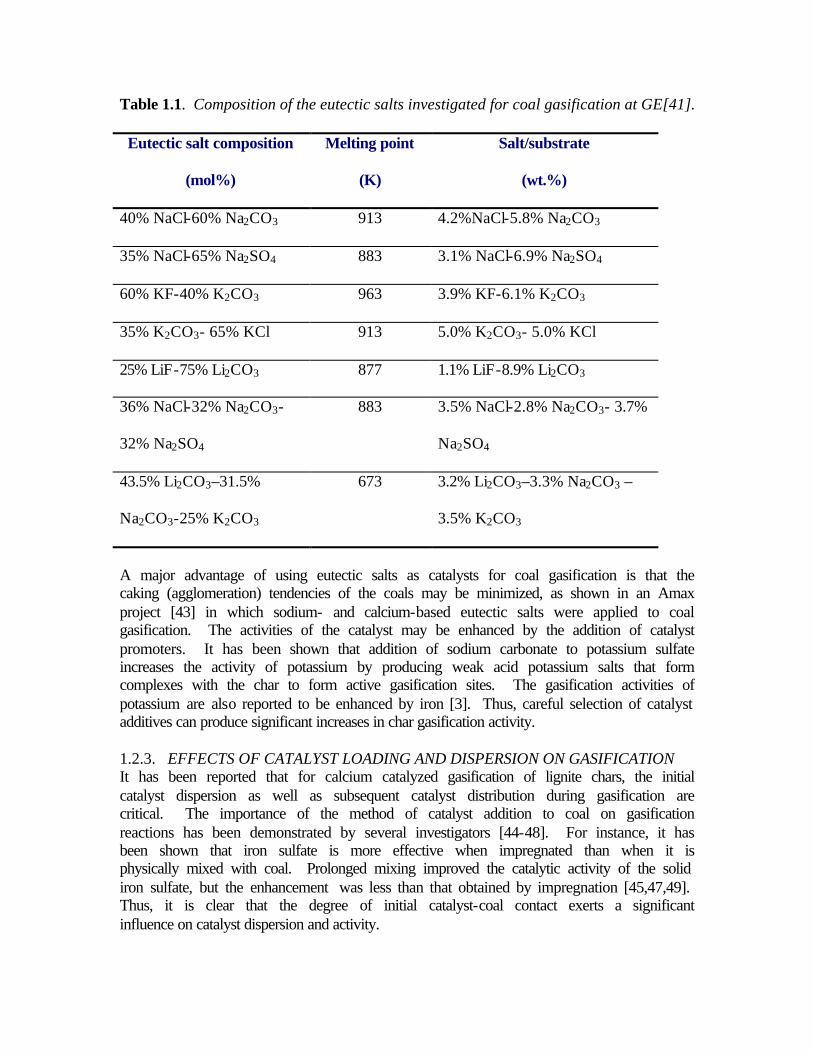
Table 1.1. Composition of the eutectic salts investigated for coal gasification at GE[41].
Eutectic salt composition
(mol%)
Melting point
(K)
Salt/substrate
(wt.%)
40% NaCl-60% Na2CO3 913 4.2%NaCl-5.8% Na2CO3
35% NaCl-65% Na2SO4 883 3.1% NaCl-6.9% Na2SO4
60% KF-40% K2CO3 963 3.9% KF-6.1% K2CO3
35% K2CO3- 65% KCl 913 5.0% K2CO3- 5.0% KCl
25% LiF-75% Li2CO3 877 1.1% LiF-8.9% Li2CO3
36% NaCl-32% Na2CO3-
32% Na2SO4
883 3.5% NaCl-2.8% Na2CO3- 3.7%
Na2SO4
43.5% Li2CO3–31.5%
Na2CO3-25% K2CO3
673 3.2% Li2CO3–3.3% Na2CO3 –
3.5% K2CO3
A major advantage of using eutectic salts as catalysts for coal gasification is that the caking (agglomeration) tendencies of the coals may be minimized, as shown in an Amax project [43] in which sodium- and calcium-based eutectic salts were applied to coal gasification. The activities of the catalyst may be enhanced by the addition of catalyst promoters. It has been shown that addition of sodium carbonate to potassium sulfate increases the activity of potassium by producing weak acid potassium salts that form complexes with the char to form active gasification sites. The gasification activities of potassium are also reported to be enhanced by iron [3]. Thus, careful selection of catalyst additives can produce significant increases in char gasification activity. 1.2.3. EFFECTS OF CATALYST LOADING AND DISPERSION ON GASIFICATION It has been reported that for calcium catalyzed gasification of lignite chars, the initial catalyst dispersion as well as subsequent catalyst distribution during gasification are critical. The importance of the method of catalyst addition to coal on gasification reactions has been demonstrated by several investigators [44-48]. For instance, it has been shown that iron sulfate is more effective when impregnated than when it is physically mixed with coal. Prolonged mixing improved the catalytic activity of the solid iron sulfate, but the enhancement was less than that obtained by impregnation [45,47,49]. Thus, it is clear that the degree of initial catalyst-coal contact exerts a significant influence on catalyst dispersion and activity.

Low rank coals contain substantial amounts of oxygenated surface groups, particularly carboxylic acid and phenolic groups. Several studies [50-52] have shown that the surface chemistry of coal is determined by these groups, although inorganic species also play a role. In aqueous or basic environments, these acidic groups dissociate and the coal particles acquire negative charges, whereas the surface groups are protonated in acidic medium. This reduces the negative charge density and the surface can become positively charged [50,51]. The type and magnitude of the charge on coal can be determined from zeta potential measurements. Thus, a knowledge of the surface charge properties of coal is essential for efficient adsorption of catalyst precursors onto coal. Using a combination of electrophoresis, adsorption and char reactivity studies, scientists at Clark Atlanta University [53] recently found that the gasification activities of calcium or potassium in carbon dioxide are strongly dependent on the surface charge properties of demineralized coals. Calcium or potassium loading around pH 6 significantly enhanced char reactivities compared to catalyst addition in strongly acidic (~pH 1) or basic (~pH 10) solution, even though the highest catalyst uptake occurred in the latter medium. X-ray diffraction analysis suggested highly dispersed catalysts at pH 6 whereas reduced dispersion occurred at pH 10 [53]. It has been reported [54] that a process-related problem in catalytic coal gasification is the method of catalyst addition to the coal. There is no apparent difficulty if the catalyst is physically mixed with coal and introduced into the gasifier or if the catalyst and coal are introduced individually. However, there is significant problem in supporting the catalyst on coal. Catalyst loading from solution (including the ion-exchange method) is a common technique for catalyst introduction into coal. Efforts are being made to transport pulverized coal in a coal-water slurry form from coal mines to major coal consumers. The excess water can either be removed at the consumption site by mechanical dewatering or introduced directly into the processing step without any subsequent physical separation. If the liquid used as a transport medium consists of an aqueous solution of the catalysts, the slurry mode of coal transport would provide adequate time for the catalyst solutions to soak the individual coal particles for extended periods of time, and therefore, provide much better catalyst penetration and dispersion. Hence, for coal-water slurry mode of transport, wet methods of catalyst application such as ion-exchange are economically more attractive than addition of solid catalysts to coal. 1.3. RESEARCH NEEDS A major issue in catalyzed coal gasification is the degree of contact between the coal and the catalyst. When the catalyst is simply mixed with coal and introduced into the system, the degree of catalyst-coal contact is generally poor until the catalyst is melted in the reactor. In the moving-bed gasifer, the degree of contact is relatively high, while the chances of intimate contact in a jet flow bed gasifier are significantly lower. In a fluidized-bed gasifier, the gasification results are dependent on the degree of catalyst-coal contact. For eutectic salt mixtures, the catalysts are assumed to be easily distributed over the surface of the coal because of the low melting points of these salts. However, the initial distribution of the salt mixtures in the coal should be homogeneous so that at the
gasifier conditions, the catalysts can penetrate the coal matrix and thus be present at the reacting carbon sites. This can be achieved only when a proper method of initial catalyst application is employed to ensure good catalyst penetration into the coal and high catalyst dispersion. In addition to uniform catalyst distribution, the effectiveness of the eutectic salt mixtures in maintaining good contact with the retrieving carbon matrix can only be adequately evaluated at high carbon conversions. This issue was not addressed in the GE study. During coal gasification, the gas atmosphere contains varying concentrations of species such as CO, H2, CO2, H2O, and H2S. It has been shown that gases such as CO and CO2 inhibit the carbon-steam reaction catalyzed by calcium, potassium, and sodium; H2 inhibits the catalysis by calcium [27]. Thus, the evaluation of eutectic salt mixtures must be carried out using the appropriate gaseous reactant and under suitable gasification conditions. To apply alkali metal catalysts to coal gasification for the production of methane or substitute natural gas (SNG), the methanation reaction is important. From thermodynamics, it is evident that because of the decrease in the number of moles during methanation, high pressures will produce more methane by favoring the forward reaction. Whether or not the eutectic salt mixtures investigated are able to promote the methanation reaction can only be evaluated by studying the gasification reaction at elevated pressures (~500 psi). 1.4 PROJECT OBJECTIVES 1.4.1 RESEARCH OBJECTIVES The objectives of this project were to: • Identify appropriate eutectic salt mixture catalysts for coal gasification; • Assess agglomeration tendency of catalyzed coal; • Evaluate various catalyst impregnation techniques to improve initial catalyst
dispersion; • Determine catalyst dispersion at high carbon conversion levels; • Evaluate effects of major process variables (such as temperature, system pressure,
etc.) on coal gasification; • Evaluate the recovery, regeneration and recycle of the spent catalysts; and • Conduct an analysis and modeling of the gasification process to provide better
understanding of the fundamental mechanisms and kinetics of the process. 1.4.2 EDUCATIONAL OBJECTIVES Clark Atlanta University (CAU) is strongly committed to catalysis, energy and fossil fuel research and the proposed project was to have a major impact on the Catalysis and Separation Science (CASS) Center. The catalysis aspect of the CASS center covers new catalyst development, characterization and testing. This proposed project was to assist in efforts towards increasing well-trained minorities in these fields. Thus, the project was to enhance the CAU, UTSI and Georgia Tech plans for developing undergraduate and graduate degree programs in catalysis science and engineering and fossil fuel conversion.

The training of students towards the Bachelors, Master of Science and Doctoral degree in Chemistry and Chemical Engineering at CAU, UTSI and Georgia Tech was to be emphasized. The project was also to expose students to energy research and development and motivate them to pursue careers in catalysis science and engineering. 1.5 REFERENCES
1 Gallagher, J.E., Jr., and C.A. Euker, Jr., “Catalytic Coal Gasification for SNG Manufacture,” presented at the 6th Annual International Conference on Coal Gasification, Liquefaction, and Conversion to Electricity, July 31-August 2, 1979, Pittsburgh, PA
2 Radovic, L.R., et al., “Importance of Catalyst Dispersion in the Gasification of Lignite Chars,” Journal of Catalysis, 82, 382-394, 1983.
3 Lang, Robert J., “Effects of Alkali Catalyzed Steam Gasification,” a paper presented at the Gordon Conference on Fuels Science, July 12, 1982.
4 Mims, C. A., K. D. Rose, M. T. Melchior and J. K. Pabst 1982, “Characterization of catalyzed carbon surface by derivation and solid-state NMR”, J. Am. Chem. Soc., 104(24), 6886-6887.
5 Kaptejn, F., O. Peer and J. A. Moulijn 1986, “Kinetics of the alkali carbonate catalyzed gasification of carbon; 1. CO2 gasification”, Fuel, Vol. 65, 1371-1376
6 Moulijn, J. A. and F. Kapteijn 1987, “The mechanism of the alkali metal catalyzed gasification of carbon”, Erdoel Kohle, Erdgas, Petrochem. 40,15-21.
7 Cerfontein, M. B., R. Meijer, F. Kapteijn and J. A. Moulyn 1987, “Alkali catalyzed carbon gasification in CO/CO2 mixtures: An extended model for the oxygen exchange and gasification reaction”, J. Catal. 107, 173-180.
8 McKee, D. W. and D. Chatterji 1978, “The catalyzed reaction of graphite with water vapor”, Carbon, Vol.16, 53-57.
9 McKee, D. W. 1982, “Gasification of graphite in carbon dioxide and water vapor-The catalytic effects of alkali metal salts”, Carbon, Vol.20, 59-66.
10 McKee, D. W. 1983, “Mechanism of alkali metal catalysed gasification of carbon”, Fuel, Vol.62, 170-176.
11 Spiro, C. L., D. W. McKee, P. G. Kosky and E. J. Lamby 1984, “Observation of alkali catalyst particles during gasification of carbonaceous materials in CO2 and steam”, Fuel, Vol.63, 686-691.
12 Liu, Z. L. and H. H. Zhu 1986, “Steam gasification of coal char using alkali and alkaline-earth metal catalysts”, Fuel, Vol. 65, 1334-1338.
13 Chen, S. G. and R. T. Yang 1997, “Unified mechanism of alkali and alkaline earth catalyzed gasification reactions of carbon by CO2 and H2O”, Energy Fuels, 11(2), 421-427.
14 Lang, R. J. and R. C. Neavel, “The behavior of calcium as a steam gasification catalyst”, ACS Southeast/Southwest Regional Meeting, New Orleans, December, 1980.
15 Radovic, L. R., P. L. Walker, Jr. and R. G. Jenkins 1983, “Importance of catalyst dispersion in the gasification of lignite chars”, J. Catal., 82, 382-394.
16 Ohtsuka, Y. and A. Tomita 1986, “Calcium catalyzed steam gasification of Yallourn brown coal”, Fuel, Vol.65, 1653-1657.

17 Lang, R. J. and R. C. Neavel, “The behavior of calcium as a steam gasification catalyst”, ACS Southeast/Southwest Regional Meeting, New Orleans,December, 1980.
18 Jha, M. C. and R. L. McCormick 1992, “NA/CA catalyzation of Illinois coals for gasification”, Final Technical Report.
19 Kaptejn, F., O. Peer and J. A. Moulijn 1986, “Kinetics of the alkali carbonate catalyzed gasification of carbon; 1. CO2 gasification”, Fuel, Vol. 65, 1371-1376
20 Ohme, H. and T. Suzuki 1996, “Mechanisms of CO2 gasification carbon catalyzed with group VIII metals. 1. Iron-catalyzed CO2 gasification”, Energy Fuels, 10(4), 980-987.
21 McKee, D. W. 1985, “Rare earth oxides as carbon oxidation catalysts”, Carbon, Vol. 23(6), 707-713.
22 McKee, D. W. 1974, “Effect of metallic impurities on the gasification of graphite in water vapor and hydrogen”, Carbon, Vol.12, 453-464.
23 McCarty, J. G. and H. Wise 1979, J. Catal., 57, 406. 24 Kieffer, E. and H.S. van der Baan 1982, Appl. Catal., 3, 245. 25 Silva, I. F. and L. S. Lobo 1986, “Study of CO2 gasification of activated carbon
catalyzed by molybdenum oxide and potassium carbonate”, Fuel, Vol.65, 1400-1403.
26 Tsuji, M., Y. Wada and Y. Tamaura 1996, “Coal gasification using the ZnO/Zn redox system”, Energy Fuels, 10(1), 225-228.
27 Miyazaki, T., N. Tokubuchi, M. Arita, M. Inoue and I. Mochida 1997, “Catalytic combustion of carbon by alkali metal carbonates supported on perovkite-type oxide”, Energy Fuels, 11(4), 832-836.
28 Kyotani, T., S. Karasawa and A. Tomita 1986, “A TPD study of coal chars in relation to the catalysis of mineral matter”, Fuel, Vol.65, 1466-1469.
29 Saber, J. M., J. L. Falconer and L. F. Brown 1984, “Carbon-catalyzed exchange between carbon dioxide and potassium carbonate at 500-1000 K”, J. Chem. Soc., Chem. Commun., 376-378.
30 Formella, K., P. Leonhard, A. Sulimma, K.-H. van Heek and H. Juntgen 1986, “Interaction of mineral matter in coal with potassium during gasification”, Fuel, Vol.65, 1470-1472.
31 McKee, D. W. 1983, “Mechanism of alkali metal catalysed gasification of carbon”, Fuel, Vol.62, 170-176.
32 McKee, D. W., C. L. Spiro, P. G. Kooky and E. J. Lamby 1983, “Catalysis of coal char gasification by alkali metal salts”, Fuel, Vol.63, 217-230.
33 Choi, P. S. 1983, “Use of catalysts at eutectic compositions--significance implication, and New leads hypothesis and preliminary test”, Exxon research and engineering company report.
34 Mckee, D. W., C. L. Spiro, P. G. Kosky and E. J. Lamby 1985, “Eutectic salt catalysts for graphite and co
35 McKee, D.W., “Chemistry and Physics of Carbon,” (Eds P.L. Walker, Jr. and P.A. Thrower), Marcel Dekker, NY, 16, 1-118, 1981.
36 Gallagher, J.E. and C.A. Euker, Energy Research, 4, 137, 1980. 37 Leonhardt, p., A.Sulimma, K.H. van Hreek, and H.Juntgen, Fuel, 62, 200, 1983. 38 McKee, D.W., Fuel, 62, 170, 1983.

39 Spiro, CF.L., D.W.McKee, P.G.Kosky, and E.Lamby, Fuel, 63, 686, 1984. 40 McKee, D.W. and D.Chatterji, Carbon, 13, 381, 1985. 41 McKee, D.W., et al., “Eutectic Salt Catalysts for Graphite and Coal Char
Gasification,” Fuel, Vol.64, p.805-809, June 1985. 42 Levin E.M., c.R. Robbins and H.F. McMurdie, “Phase Diagrams for Ceramists,”
American Ceramic Society, 1964. 43 Jha, M.C., “Na/Ca Catalyzation of Illinois Coals for Gasification,” Final
Technical Report for the period September 1, 1992 to August 31, 1993, submitted by Amax Research & Development Center under contract from Illinois Clean Coal Institute, December 1993.
44 Pradham, V.R., d.E. Herrick, J.W.Tierney, I.Wender, and G.P.Huffman, energy & Fuel, 5, 497, 1991.
45 Andres, M., H. charcosset, P.Chiche, L. Davignon, G.Djega-Mariadassou, J.P.Joky and S.Pregermain, Fuel 62, 690, 1983.
46 Schlessinger, M.D., L.V. Frank, and R.W.Hiceshue, Bureau of Mines Report on Investigation No. 6021, 1962.
47 Weller, S.W., and M.G.Pelipetz, Ind. Eng. Chem., 43, 1243, 1951. 48 Yamashita, H., Y.Ohtsuka, S.Yoshida, and T.Tomita, Energy & Fuels, 3, 686,
1989. 49 Garg, d., and E.N.Givens, Fuel Proc. Tech., 7, 59, 1983. 50 Quast, K.B., and D.J.Readett, Adv.Coll. Int. Sci., 27(3-4), 169, 1987. 51 Kelebek, S., T.Salman, and G.W.Smith, Canad. Metal. Quart., 21, 205, 1982. 52 Fuerstenau, d.W., J.M. Rosenbaum, and J. Laskowski, Coll. Surf., 8, 137, 1983. 53 Abotsi, G.M.K., K.B.Bota, and g.Saha, “Effects of Coal Surface Charge on the
Adsorption and Gasification Activities of Calcium and Potassium,” Fuel Sci, and Tech.Int 11(2), 327, 1992.
54 Tomita, Akira, “Catalytic Coal Gasification-Sekitan no Seshoku Gasuka,” Nenryo Kyokaishi, 58(5), p.332-342, May 1979. Translated from Japanese by the Ralph McElroy Company, Custom Division, 2102 Rio Grande, Austin, Texas 78705.

CHAPTER TWO: TECHNICAL APPROACH
2.1. METHODOLOGY AND TASKS To accomplish the project goals and objectives stated in chapter one, the project was subdivided into the following tasks. 2.1.1 TASK 1: SELECTION OF EUTECTIC SALT MIXTURES: • Literature review; identification of appropriate eutectic salt mixtures; • Evaluation of catalyst application methods; • TGA studies to evaluate gasification characteristics. 2.1.2 TASK 2: EVALUATION OF GASIFICATION PERFORMANCE IN A
BENCH-SCALE FIXED-BED REACTOR: • Evaluation of catalyst dispersion; • Study of the effects of process variables on the performance of gasifiers; and • Evaluation of the recovery, regeneration and recycle of the catalysts. 2.1.3 TASK 3: DATA ANALYSIS AND REPORTING: • Data analysis and modeling; • Economic evaluation of the gasification process; and Project management and
reporting 2.2. MATERIALS 2.2.1. COAL The Illinois No. 6 coal used in this study was supplied by the Penn State Sample Coal Bank. Compositional data for the parent coal and for the char prepared from it are given in Table 2. The coal used in the lab was 60 mesh. Table 2.1. Compositional data for the Illinois No.6 coal used (hv Cb rank)
Proximate analysis (wt%) Ultimate analysis (wt%) H2O 13.20 Ash 11.62 Ash 11.62 C 57.33 Volatiles 35.44 H 3.98 Fixed C 39.74 N 0.99 S 4.80 O 8.07
2.2.2 REAGENTS AND CHEMICALS The single salts investigated and used to prepare the eutectic salt mixtures included Sigma Chemical Company's analytical reagent grade Li2CO3, Na2CO3, Rb2CO3, K2CO3, LiOH, KOH, NaNO3, Cs2CO3, KNO3, LiNO3, K2SO4 and CaSO4. TGA gasification measurements were carried out in pure CO2 (Holox Products) at atmospheric pressure. 2.3. PREPARATION 2.3.1 PREPARATION OF EUTECTIC CATALYSTS Fifty binary and twelve ternary eutectic catalysts were prepared by fusion of finely ground salt mixtures having compositions corresponding to the eutectic melting temperatures, as obtained from published phase diagrams [8]. Fusion was carried out in air at temperatures of at least 100 K above the respective eutectic melting points. After cooling, the solidified melts were crushed and finely ground in an agate mortar. The melting points of the prepared eutectic catalysts were measured by Seiko Instruments Differential Scanning Calorimeter (DSC 220C). 2.3.2. SAMPLE PREPARATION (COAL + CATALYST) 2.3.2.1. Physical mixing technique (M1 method) Salt mixtures or eutectic catalysts were finely ground in an agate mortar and weighed amounts were then intimately mixed with the powdered coal or char in a Fisher Minimill to give the desired catalyst concentration. 2.3.2.2. Incipient wetness method for eutectic salts (M2 method) The powdered eutectic salt was weighed and dissolved in water. The solution or slurry (if eutectic did not dissolve completely) was further added to the powdered coal, shaken to make sure the solution/slurry mixed well with the coal and was then dried. The soluble binary eutectics formed complete solutions whereas the insoluble ternary eutectics formed slurries. The incipient wetness point for the Illinois #6 coal was established to be around 0.5-0.6 ml H2O/gm of coal. 2.3.2.3. Incipient wetness method for mixture of individual salts (M3 method) The amounts of individual salts needed to achieve the eutectic composition were mixed thoroughly, without prior fusion at its eutectic point. A slurry/solution was prepared from this salt mixture by adding required amounts of water to the coal/char, as stated in the M2 method. 2.3.2.4 Drying The samples prepared by wet mixing were dried in a Precision-Gravity Convection Oven at 383 K for 12 hours. After cooling, they were crushed in an agate mortar and further pyrolyzed.
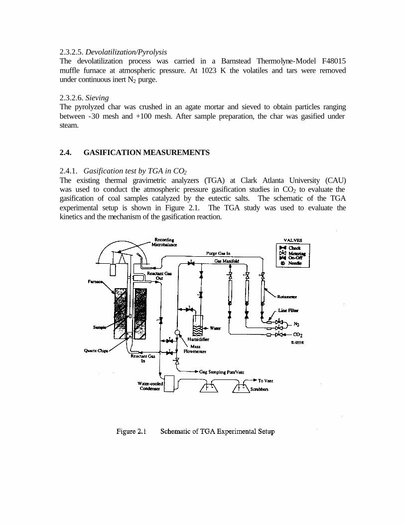
2.3.2.5. Devolatilization/Pyrolysis The devolatilization process was carried in a Barnstead Thermolyne-Model F48015 muffle furnace at atmospheric pressure. At 1023 K the volatiles and tars were removed under continuous inert N2 purge. 2.3.2.6. Sieving The pyrolyzed char was crushed in an agate mortar and sieved to obtain particles ranging between -30 mesh and +100 mesh. After sample preparation, the char was gasified under steam. 2.4. GASIFICATION MEASUREMENTS 2.4.1. Gasification test by TGA in CO2 The existing thermal gravimetric analyzers (TGA) at Clark Atlanta University (CAU) was used to conduct the atmospheric pressure gasification studies in CO2 to evaluate the gasification of coal samples catalyzed by the eutectic salts. The schematic of the TGA experimental setup is shown in Figure 2.1. The TGA study was used to evaluate the kinetics and the mechanism of the gasification reaction.

With carbon dioxide, mixtures of powdered coal with 10 wt % of the different individual salts were prepared by the above simple preparation methods and the rate of weight loss of the samples when heated in a flowing gas of CO2 was measured at a series of constant temperatures in a TGA. Measurements of gasification kinetics in flowing CO2 [140 ml/min at 1 atm (0.1MPa)] were performed in an SDT 2960 Simultaneous Thermogravimetric-Differential Thermal Analyzer (TGA-DTA). The TGA-DTA measurements were performed at a linearly increasing temperature rate of dT/dt = 10 K/min, in atmospheres of flowing carbon dioxide gas. The balance was usually operated in the isothermal mode with weight changes being recorded as a function of time and temperature at a series of TGA settings in the range 823-1273 K. At each temperature, gasification was continued for ~10 min to assure that steady state conditions were attained. The gasification rate at each temperature was derived from the relation:
Where: W is the weight of the sample at time t. r is the gasification rate of carbon (1/min). The kinetic data were presented in the form of Arrhenius plots [log rate versus 1/T (K)].
2.4.2. Gasification Test by Fixed-Bed reactor The catalytic steam gasification experiments were carried out in the high-pressure, high-temperature fixed-bed gasifier system. The gasifier in this system was typically operated with a downdraft gas flow regime and in a differential fixed bed mode. The reactor was packed with ceramic beads to support the char sample towards its center using two 200-mesh stainless steel screen baskets. A schematic of the gasifier is shown in Figure 2.2 and consists of the gas/steam feeding and preheating units, the reactor and furnace, condenser and dryer and gas analysis (gas chromatograph) units. The differential char bed accommodated about 2.5 grams of char during each experimental run. The exit gases from the steam gasification reaction were analyzed using an SRI 8610C gas chromatograph. Experiments were also performed using a thermogravimetric analyzer (TGA) to analyze the fixed carbon content of the char sample before and after steam gasification. The data were analyzed to determine the extent of carbon conversion in the bed and to obtain a rate expression to explain the kinetics of the gasification reaction. Before coal or coal char was submitted to bench scale fixed-bed gasification, several preparation steps were necessary. These included catalyst addition, drying and sieving, and devolatilization followed by the steam gasification in the fixed-bed gasifier. The method of catalyst addition plays a very important role in enhancing gasification rates by providing a better initial catalyst dispersion on the coal surface. The three methods of catalyst addition or sample preparation techniques described above for the TGA studies (M1, M2 and M3 methods) were used for fixed-bed studies as well
)1(1
tW
Wr
∆∆
⋅−=

Based on the gasification studies performed in CO2 using the SDT 2960 Simultaneous TGA-DTA discussed above, the best eutectic salt catalysts were chosen for further experimentation in a fixed-bed bench scale reactor.
2.5. ZETA POTENTIAL MEASUREMENTS Zeta potential measurements were conducted to determine the net surface charge present on the coal particles. The zeta potential technique involves suspending coal particles in an aqueous solution contained in a chamber to which an anode and a cathode are connected. Upon application of an electric field, a potential is created between the two electrodes and the particles will migrate to the anode or the cathode, depending upon the electrical charge. The electrophoretic mobility is proportional to the charge density on the coal particles and can be displayed by the instrument or calculated by hand.

Coal water slurries for zeta potential measurements were prepared by placing approximately 2.5 g of the coal sample in 500 ml of deionized water. To better disperse the particles, the solution was sonicated for twenty minutes using a Branson 2200 ultrasonic bath. The coal solution was decanted into five flasks each containing 50 ml of solution. After recording the original pH values of the coal dispersions, The zeta potential values were measured at room temperature using a Pen Kem Model 501 zeta meter. 2.6. FREE-SWELLING INDEX TESTS D720-91 (ASTM Standard)[2] was used to measure the free-swelling index of the coal. The test method consisted essentially of heating 1 g of coal, in a covered silica crucible in an oven. The oven was adjusted to give a temperature of 2073 ±10 K, in 1.5 minutes, and 1093 ± 5 K, in 2.5 minutes. The heating was continued for not less than 2.5 minutes. The coke button obtained was compared with a series of standard outlines to get a value corresponding to that of the nearest outline. One gram of ground 60 mesh coal was weighed in a cold crucible, and the crucible was lightly tapped 12 times on the bench, rotating it between taps, to level the surface of the coal. The crucible was then covered with a lid and placed upright in the oven. Three buttons were made for each time sample of coal tested. The three coke buttons of each sample of coal being tested were viewed through the sight tube and compared to a series of standard profiles. The drawing with which the button was compared was placed exactly in the center of the field of vision from the top of the tube. The button was rotated around its axis until the maximum cross-section area was in line with the drawing and viewed with one eye placed immediately over the top of the tube. 2.7. X-RAY DIFFRACTION EXPERIMENTS Catalyst constituents, eutectic salts, pyrolyzed and gasified char samples were examined using X-ray diffractometry (XRD). The purpose of these XRD studies was two-fold: (1) to determine if any phases or moeties are formed in the eutectic salts that are distinct from those present in the individual Li2CO3, Na2CO3, and K2CO3 salts, and (2) to establish changes in the XRD patterns of the eutectic salts before and after gasification reaction. A list of the samples were studied using a 2 hour scan period resulted in significantly improved signal to noise ratio over a 20 min scan. 2.8. SEM MEASUREMENTS Scanning electron microscopy (SEM) studies of (i) coal + eutectic salt (pyrolyzed, but not yet gasified in the reactor), and (ii) gasified char samples (reactor-aged) were conducted on several eutectic salt samples containing all three salts (Li, Na, & K carbonates) as well as only two salts (Na & K carbonates).

2.9 REFERENCES
1 Levin E.M., C.R. Robbins and H.F. McMurdie, “Phase Diagrams for Ceramists,” American Ceramic Society, 1964. 2 ASTM D 720-91, “Standard Test Method for Free-Swelling Index of Coal’,
American Society for Testing Materials, 1992.

CHAPTER THREE: Identification of Appropriate Eutectic Salt Mixtures
The available literature was thoroughly reviewed to identify appropriate eutectic salt mixtures, which exist in the liquid or gaseous phase under gasification conditions. Selected catalysts investigated by General Electric and additional catalysts identified from the literature were used. The literature review focused on salts that had been shown to be active for coal gasification. Emphasis was placed on the use of non-halide salts as the catalyst precursors.
Based on the review of the phase diagrams of various eutectic mixtures [1], the systems shown in Table 3.1 were identified for further investigation in this study. These chemicals were ordered and enabled us to prepare the catalysts and catalyst loaded coal/char samples. 10 lb of Illinois #6 coal were also ordered from the Penn State Coal Sample Bank and used for this project.
Samples of the salts were placed in a muffle furnace at various temperatures and in N2 atmosphere to determine their melting ranges. Eutectic salts that had melting points in the 873-1073 K range were selected for the gasification studies.
3.1 SELECTION OF EUTECTIC SALT MIXTURES
In order to compare the relative catalytic effects of the different catalysts in the gasification of coal with carbon dioxide, mixtures of powdered coal with 10 wt% of the different catalysts were prepared by different methods and the rate of weight loss of the samples when heated in a flowing gas of CO2 were measured at a series of constant temperatures. The catalyst samples (single salts, and binary and ternary eutectic catalysts) prepared by the different methods studied are summarized in Tables 3.1-3.5.
Measurements of gasification kinetics in flowing CO2 [140 ml/min at 1 atm (0.1MPa)] were performed in a SDT 2960 Simultaneous DTA-TGA. Simultaneous thermal gravimetry-differential thermal analyses (TG-DTA) were performed at a linearly increasing temperature rate of dT/dt = 10 K/min in an atmosphere of flowing carbon dioxide gas. The balance was usually operated in the isothermal mode with weight changes being recorded as a function of time at a series of TGA settings in the range 823-1273 K. At each temperature, gasification was continued for ~10 min to assure that steady state conditions were attained. The gasification rate at each temperature and time were derived from the relation:
r (min-1) = -(∆W/∆t) (1/W) (3.1)
Where: W is the weight of the sample at time t. r is the gasification rate of carbon (1/min).
The kinetic data were presented in the form of Arrhenius plots [log rate versus 1/T (K)].
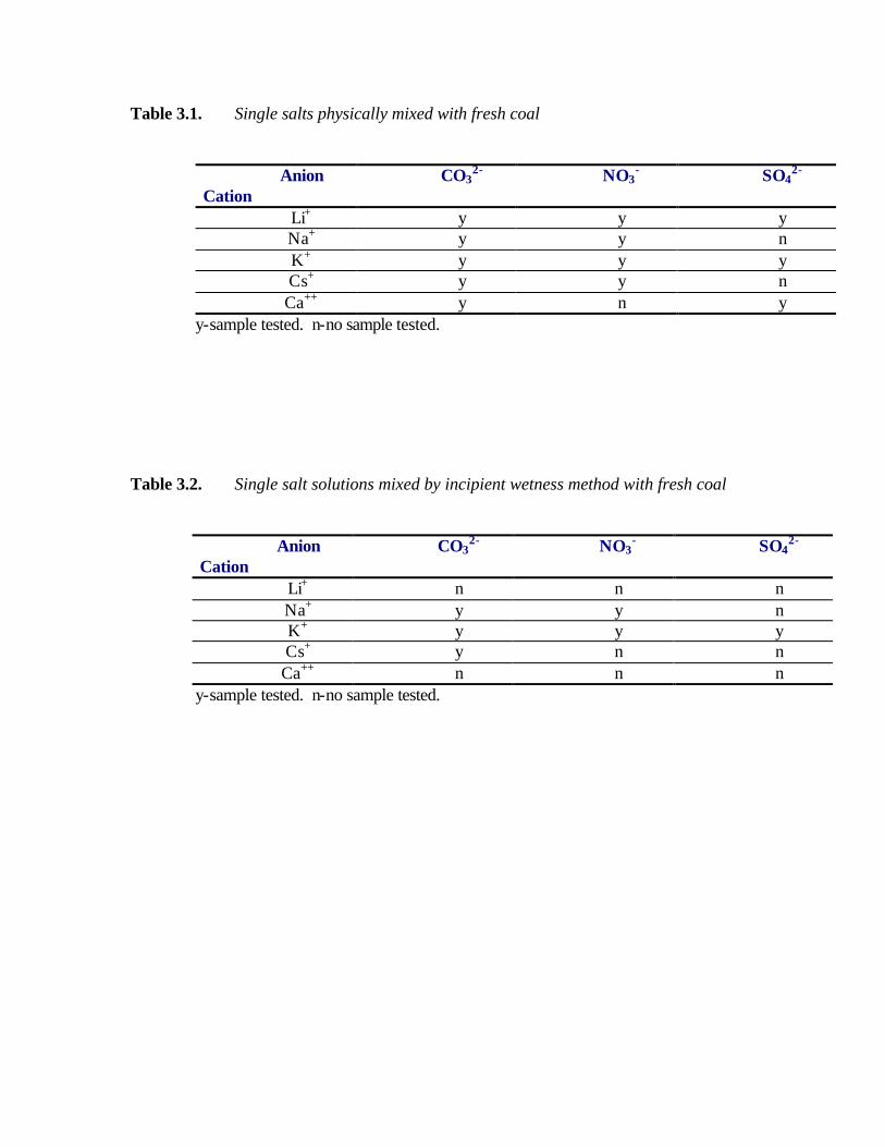
Table 3.1. Single salts physically mixed with fresh coal
Anion Cation
CO32- NO3
- SO42-
Li+ y y y Na+ y y n K+ y y y Cs+ y y n Ca++ y n y
y-sample tested. n-no sample tested.
Table 3.2. Single salt solutions mixed by incipient wetness method with fresh coal
Anion Cation
CO32- NO3
- SO42-
Li+ n n n Na+ y y n K+ y y y Cs+ y n n Ca++ n n n
y-sample tested. n-no sample tested.
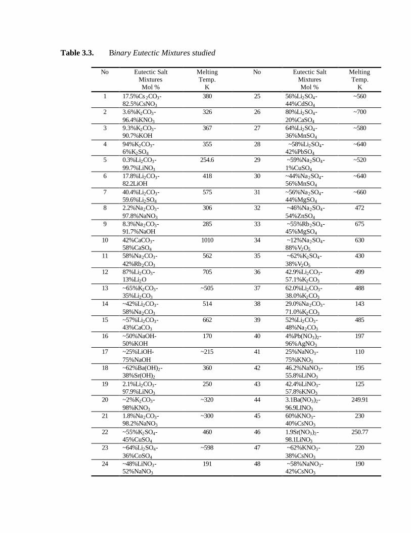
Table 3.3. Binary Eutectic Mixtures studied
No Eutectic Salt Mixtures Mol %
Melting Temp.
K
No Eutectic Salt Mixtures Mol %
Melting Temp.
K 1 17.5%Cs 2CO3-
82.5%CsNO3 380 25 56%Li2SO4-
44%CdSO4 ~560
2 3.6%K2CO3-96.4%KNO3
326 26 80%Li2SO4-20%CaSO4
~700
3 9.3%K2CO3-90.7%KOH
367 27 64%Li2SO4-36%MnSO4
~580
4 94%K2CO3-6%K2SO4
355 28 ~58%Li2SO4-42%PbSO4
~640
5 0.3%Li2CO3-99.7%LiNO3
254.6 29 ~59%Na2SO4-1%CuSO4
~520
6 17.8%Li2CO3-82.2LiOH
418 30 ~44%Na2SO4-56%MnSO4
~640
7 40.4%Li2CO3-59.6%Li2SO4
575 31 ~56%Na2SO4-44%MgSO4
~660
8 2.2%Na2CO3-97.8%NaNO3
306 32 ~46%Na2SO4-54%ZnSO4
472
9 8.3%Na2CO3-91.7%NaOH
285 33 ~55%Rb2SO4-45%MgSO4
675
10 42%CaCO3-58%CaSO4
1010 34 ~12%Na2SO4-88%V2O5
630
11 58%Na2CO3-42%Rb2CO3
562 35 ~62%K2SO4- 38%V2O5
430
12 87%Li2CO3-13%Li2O
705 36 42.9%Li2CO3-57.1%K2CO3
499
13 ~65%K2CO3-35%Li2CO3
~505 37 62.0%Li2CO3-38.0%K2CO3
488
14 ~42%Li2CO3-58%Na2CO3
514 38 29.0%Na2CO3-71.0%K2CO3
143
15 ~57%Li2CO3-43%CaCO3
662 39 52%Li2CO3-48%Na2CO3
485
16 ~50%NaOH-50%KOH
170 40 4%Pb(NO3)2-96%AgNO3
197
17 ~25%LiOH-75%NaOH
~215 41 25%NaNO3-75%KNO3
110
18 ~62%Ba(OH)2-38%Sr(OH)2
360 42 46.2%NaNO3-55.8%LiNO3
195
19 2.1%Li2CO3-97.9%LiNO3
250 43 42.4%LiNO3-57.8%KNO3
125
20 ~2%K2CO3-98%KNO3
~320 44 3.1Ba(NO3)2-96.9LINO3
249.91
21 1.8%Na2CO3-98.2%NaNO3
~300 45 60%KNO3-40%CsNO3
230
22 ~55%K2SO4-45%CuSO4
460 46 1.9Sr(NO3)2-98.1LiNO3
250.77
23 ~64%Li2SO4-36%CoSO4
~598 47 ~62%KNO3-38%CsNO3
220
24 ~48%LiNO3-52%NaNO3
191 48 ~58%NaNO3-42%CsNO3
190

Table 3.4. Binary eutectic salt catalysts used in the carbon dioxide gasification of coal.
solid salt mixing with coal
eutectic catalyst mixing with coal
salt solution mixed with coal
43.2%Li2CO3-57%K2CO3
y y n
62%Li2CO3-38%K2CO3
y y n
2.3%K2CO3-97.7%KNO3
y y y
2.2%Na2CO3-97.8%NaNO3
y n n
71%Na2CO3-29%K2CO3
y y y
48%Li2CO3-52%Na2CO3
y n n
48%CaCO3-52%CaSO4
y n n
3.6%K2CO3-96.4%KOH
y y y
57%Li2CO3-43%CaCO3
y n n
8.3%Na2CO3-91.7%NaOH
y y y
Table 3.5. Ternary eutectic salt catalysts used in the carbon dioxide gasification of coal.
# Eutectic Salt Mixtures (Mol %)
M.P. (K)
1 43.5%Li2CO3-31.5%Na2CO3 -25%K2CO3 673 2 49.5%Li2CO3-44.5%Na2CO3 -6%K2CO3 741 3 39%Li2CO3-27.9%Na2CO3 -33.1%K2CO3 622 4 58%Na2CO3-3%K2CO3-39%Rb2CO3 831 5 22%Li2CO3-38%Na2CO3-40%Rb2CO3 683 6 39%Li2CO3-38.5%Na2CO3-22.5%Rb2CO3 673 7 50%Li2CO3-29%Na2CO3-21%Rb2CO3 685 8 14%CaSO4-6%BaSO4-80%Li2SO4 933

3.2. RESULTS AND DISCUSSION
To identify the best catalyst loading technique and to ensure high catalyst dispersion, the incipient wetness technique and physical mixing methods were evaluated as catalyst application methods for the gasification of coal char in CO2.
The major thrust of this aspect of the project was to identify the best catalyst loading technique that ensured high catalyst dispersion. The catalyst addition methods that were used in this study included physical mixing of the dry catalyst precursors with the coal, and the incipient wetness technique. Typically, after physically mixing the catalyst with the coal, no further treatment was required before introduction of the coal into the gasifier. However, the sample may be dried at over 383 K in a vacuum oven before gasification if the incipient wetness method was used to load the coal with the catalyst.
Figure 3.1 shows the raw results from a typical TGA experiment. As stated earlier, the
balance was operated in an atmosphere of flowing CO2 such that weight changes could be recorded as a function of time in the isothermal mode at several TGA temperature settings between 823 K and 1273 K. These raw data were used to obtain rate information

from Equation 3.1. The rate data were subsequently used to generate Arrhenius plots of Log (gasification rate) vs. 1/T. 3.2.1 STUDY ON TGA REPRODUCIBILITY Pyrolysis of raw Illinois No.6 coal in 1 atm nitrogen gas as a function of temperature conducted at CAU is shown in Figure 3.2. As the temperature increased from room temperature to 973 K, the water and the volatiles existing in
the coal were mostly lost. The weight loss increased quickly at the initial temperatures and after 973 K, the rate of increase decreased slowly and the coal sample weight became more stable. The gasification results in CO2 of two char samples from the above pyrolysis studies are shown in Figure 3.3. The gasification rate increased with temperature. The results show excellent reproducibility.

3.2.2 STUDY ON SINGLE SALT FOR THE GASIFICATI0N Figures 3.4-3.7 show the results of TGA kinetic experiments with single salt catalysts. Figure 3.4 shows the Arrhenius plots of coal gasification in CO2 with single carbonate salts (M1- physical mixing method). Also shown in Figure 3.4 for comparison purposes is the gasification rate for raw coal (no catalyst).
Figure 3.4 Gasification of coal catalyzed by physical mixing of coal with single carbonate salts in CO2
-3
-2.5
-2
-1.5
-1
-0.50.7 0.8 0.9 1 1.1 1.2
1000/T (1/K)
gasi
ficat
ion
rate
, log
r (1
/min
)g
raw coal
10%CaCO3 + coal
10%Na2CO3 + coal
10%K2CO3 + coal
10%Cs2CO3 + coal
10%Li2CO3 + coal

Figure 3.5 Gasification of coal catalyzed by physical mixing of coal with single nitrate salts in CO2
-3
-2.5
-2
-1.5
-1
-0.5
0.7 0.8 0.9 1 1.1 1.2
1000/T (1/K)
gasi
ficat
ion
rate
, log
r (1
/min
)
raw coal
coal + LiNO3
coal + NaNO3
coal + KNO3
coal + CsNO3

Figure 3.6 Gasification of coal catalyzed by physical mixing of coal with single sulfate salt in CO2
-3
-2.5
-2
-1.5
-1
-0.5
0.7 0.8 0.9 1 1.1 1.2
1000/T (1/K)
Gas
ifica
tion
rate
, log
r (1
/min
)
raw coal
coal + 10%Li2SO4
coal +10% K2SO4
coal + 10%CaSO4

Figure 3.7 Gasification of coal catalyzed by single salt catalysts in CO2 Samples prepared by physical mixing (1) and incipient wetness (2)
-3
-2.5
-2
-1.5
-1
-0.5
0.7 0.8 0.9 1 1.1 1.2 1.3
1000/T(1/K)
gasi
ficat
ion
rate
, log
r (1
/min
)
raw coal coal + Na2CO3(1) coal + K2CO3(1)
coal + Cs2CO3(1) coal + NaNO3(1) coal + KNO3(1)
coal + K2SO4(1) coal + Na2CO3 solution(2) coal + K2CO3 solution(2)
coal +Cs2CO3 solution(2) coal + NaNO3 solution(2) coal + KNO3 solution(2)
coal + K2SO4 solution(2)
Li2CO3 increased the CO2 gasification rate of coal by more than an order of magnitude. Various carbonate salts had their catalytic activity in the following order:
Li > Cs > K > Ca ~ Na > raw coal
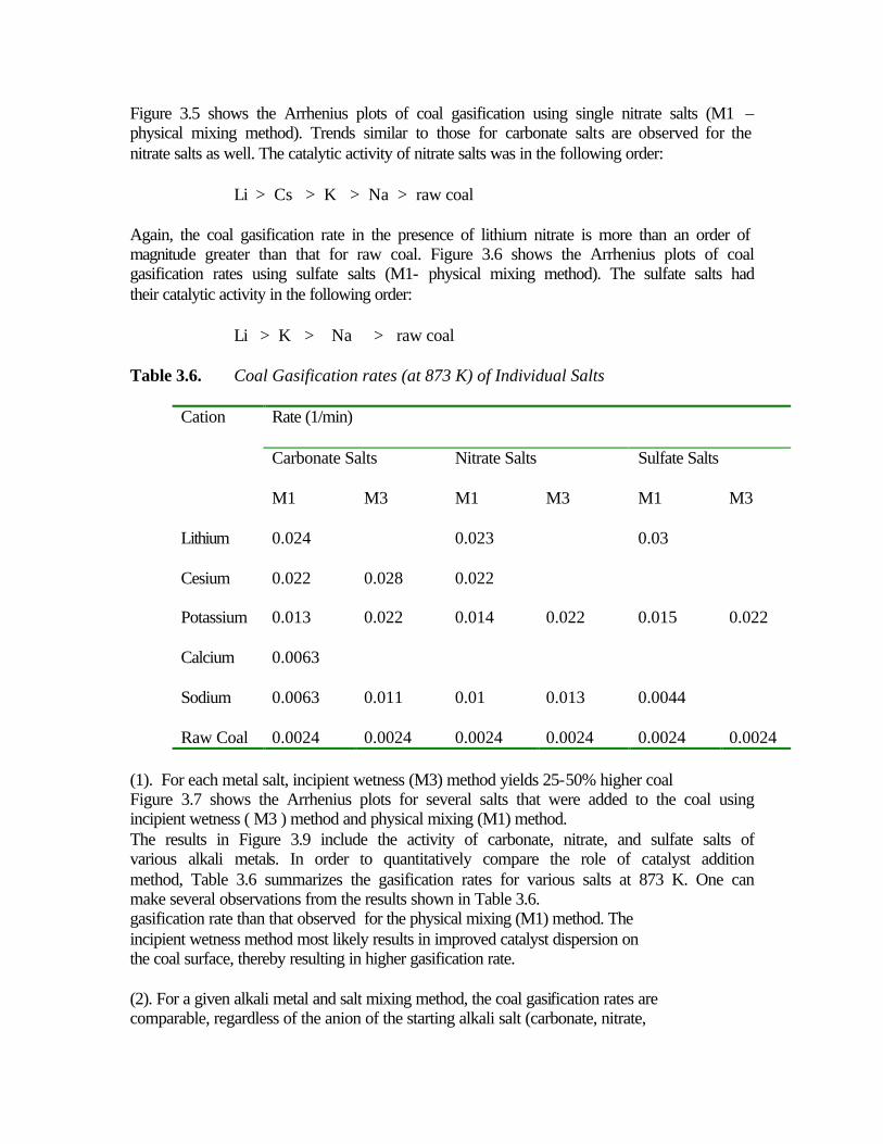
Figure 3.5 shows the Arrhenius plots of coal gasification using single nitrate salts (M1 –physical mixing method). Trends similar to those for carbonate salts are observed for the nitrate salts as well. The catalytic activity of nitrate salts was in the following order:
Li > Cs > K > Na > raw coal
Again, the coal gasification rate in the presence of lithium nitrate is more than an order of magnitude greater than that for raw coal. Figure 3.6 shows the Arrhenius plots of coal gasification rates using sulfate salts (M1- physical mixing method). The sulfate salts had their catalytic activity in the following order:
Li > K > Na > raw coal
Table 3.6. Coal Gasification rates (at 873 K) of Individual Salts
Rate (1/min)
Cation
Carbonate Salts Nitrate Salts Sulfate Salts
M1 M3 M1 M3 M1 M3
Lithium 0.024 0.023 0.03 Cesium 0.022 0.028 0.022 Potassium 0.013 0.022 0.014 0.022 0.015 0.022 Calcium 0.0063 Sodium 0.0063 0.011 0.01 0.013 0.0044 Raw Coal 0.0024 0.0024 0.0024 0.0024 0.0024 0.0024
(1). For each metal salt, incipient wetness (M3) method yields 25-50% higher coal Figure 3.7 shows the Arrhenius plots for several salts that were added to the coal using incipient wetness ( M3 ) method and physical mixing (M1) method. The results in Figure 3.9 include the activity of carbonate, nitrate, and sulfate salts of various alkali metals. In order to quantitatively compare the role of catalyst addition method, Table 3.6 summarizes the gasification rates for various salts at 873 K. One can make several observations from the results shown in Table 3.6. gasification rate than that observed for the physical mixing (M1) method. The incipient wetness method most likely results in improved catalyst dispersion on the coal surface, thereby resulting in higher gasification rate. (2). For a given alkali metal and salt mixing method, the coal gasification rates are comparable, regardless of the anion of the starting alkali salt (carbonate, nitrate,

or sulfate). For example, for potassium salt and M1 method, the rates for the carbonate, nitrate, and sulfate salts are 1.3x10⁻², 1.4x10⁻², and 1.5x10⁻² min-1 respectively. This supports the hypothesis that the active intermediate working as catalyst is most likely the same (perhaps oxide or hydroxide form), regardless of the starting salt anion.
(3). One may calculate activation energy for CO2 gasification of coal from the Arrhenius plots shown in Figures 3.8-3.12. The activation energy for gasification of the raw coal (no catalyst) is 30.10 kJ/mole. The activation energy for the catalyzed gasification is in the range of 19 ± 4 kJ/mole.
3.2.3 STUDY ON BINARY AND TERNARY EUTECTICS
3.2.3.1. Measurements of Melting Point of Binary and Ternary Eutectics The composition and melting points of some of the binary and ternary eutectic catalysts studied are summarized in Table 3.7. The DSC measurements show that the melting points of the eutectic catalysts prepared in our lab match the reported reference data well. Unfortunately, the DSC instrument used in the lab could only measure melting points below 823 K, so samples with melting points above 823 K are not shown in Table 3.7. 3.2.3.2 Study of the catalytic activities of binary and ternary Eutectics
With the binary and ternary eutectic catalysts in Tables 3.3 -3.5, a marked increase in gasification rate was observed (see Figures 3.8-3.10). It was evident that the eutectic catalysts were more active than the individual salt components. The low melting eutectics were found to be very active catalysts. Gasification of the coal occurred rapidly at temperatures near the melting points of the salts. The incipient wetness method gave higher activities than the physical mixing method (Figure 3.11). This is ascribed to better initial catalyst dispersion with the incipient wetness method. The incipient wetness method is believed to have yielded more uniform initial catalyst dispersion within the coal matrix as it permits penetration of the catalyst solution into the pores of the coal matrix.

Table 3.7. Eutectic catalyst compositions and melting points by DSC.
Eutectic salt composition
(mol %)
Melting point (K)
from literature(1)
Melting point (K) By DSC
Heated temperature (K)
43.5%Li2CO3-31.5%Na2CO3-25%K2CO3
673 664.8 798
58%Na2CO3-42%Li2CO3
787 758.1 913
57.1%K2CO3-42.9%Li2CO3
772 758.1 898
62%Li2CO3-38%K2CO3
761 752 883
71%Na2CO3-29%K2CO3
416 394 573
48%Na2CO3-52%Li2CO3
758 756.8 883
43.5%Li2CO3-31.5%Na2CO3-25%K2CO3
673 667.9 798

Figure 3.8 Gasification of coal catalyzed by physical mixing of binary salt mixtures in CO2
-3
-2.5
-2
-1.5
-1
-0.5
0.7 0.8 0.9 1 1.1 1.2 1.3 1.4
1000/T (1/K)
gas
ifica
tion
rat
e, l
og
r (1
/min
)
raw coal 43%Li2CO3-57%K2CO362%Li2CO3-38%K2CO3 3.6%K2CO3-96.4%KNO32.2%Na2CO3-97.8%NaNO3 29%Na2CO3-71%K2CO348%Li2CO3-52%Na2CO3 48%CaCO3-52%CaSO49.3%K2CO3-90.7%KOH 57%Li2CO3-43%CaCO38.3%Na2CO3-91.7%NaOH


Figure 3.10 Gasification of coal catalyzed by ternary catalyst in CO2 a-physical mixing of coal with solid eutectic catalyst; b-physical mixing of coal with solid salt
-2.6
-1.6
-0.6
0.7 0.8 0.9 1 1.1 1.2 1.3
1/T (1/1000K)
Lo
gr
(1/m
in)
raw coal 25%K2CO3-31.5%Na2CO3-43.5%Li2CO3(a) 25%K2CO3-31.5%Na2CO3-43.5%Li2CO3(b)

From TGA studies, with binary and ternary eutectic catalysts added to the coal, marked increases in gasification rates were observed. From comparison of the reaction rates (Figure 3.12) and activation energies for single, binary and ternary catalysts (Table 3.8), it is evident that the eutectic catalysts were more active than the individual salt components. In particular, the activity of the catalysts was in the order ternary > binary > single. Among the ternary systems studied, the 39% Li2CO3-38.5% Na2CO3-22.5% Rb2CO3 (LNR) and 43.5% Li2CO3-31.5% Na2CO3-25% K2CO3 (LNK) eutectics gave the highest gasification rates.
Table 3.8. Comparison activation energy and gasification rate for single, binary and ternary catalysts from TGA
Catalyst with coal Activation energy
KJ/mol Gasification rate at 873K
(min-1) Raw coal (only) 30.60 0.0073 Li2CO3 16.88 0.0212 Cs2CO3 17.63 0.0204 29.0%Na2CO3-71.0%K2CO3
13.59 0.0328
2.3%K2CO3-97.7%KNO3 13.97 0.0310 43.5%Li2CO3-31.5%Na2CO3-25%K2CO3
13.05 0.0381
39%Li2CO3-38.5%Na2CO3-22.5%Rb2CO3
12.08 0.0394
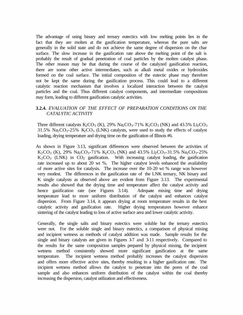
The advantage of using binary and ternary eutectics with low melting points lies in the fact that they are molten at the gasification temperature, whereas the pure salts are generally in the solid state and do not achieve the same degree of dispersion on the char surface. The slow increase in the gasification rate above the melting point of the salt is probably the result of gradual penetration of coal particles by the molten catalyst phase. The other reason may be that during the course of the catalyzed gasification reaction, there are some other active intermediates, such as alkali metal oxides or hydroxides formed on the coal surface. The initial composition of the eutectic phase may therefore not be kept the same during the gasification process. This could lead to a different catalytic reaction mechanism that involves a localized interaction between the catalyst particles and the coal. Thus different catalyst components, and intermediate compositions may form, leading to different gasification catalytic activities. 3.2.4. EVALUATION OF THE EFFECT OF PREPARATION CONDITIONS ON THE
CATALYTIC ACTIVITY
Three different catalysts K2CO3 (K), 29% Na2CO3-71% K2CO3 (NK) and 43.5% Li2CO3 31.5% Na2CO3-25% K2CO3 (LNK) catalysts, were used to study the effects of catalyst loading, drying temperature and drying time on the gasification of Illinois #6.
As shown in Figure 3.13, significant differences were observed between the activities of K2CO3 (K), 29% Na2CO3-71% K2CO3 (NK) and 43.5% Li2CO3-31.5% Na2CO3-25% K2CO3 (LNK) in CO2 gasification. With increasing catalyst loading, the gasification rate increased up to about 20 wt %. The higher catalyst levels enhanced the availability of more active sites for catalysis. The increase over the 10-20 wt % range was however very modest. The differences in the gasification rate of the LNK ternary, NK binary and K single catalysts as observed above are evident from Figure 3.13. The experimental results also showed that the drying time and temperature affect the catalyst activity and hence gasification rate (see Figures 3.14). Adequate mixing time and drying temperature lead to more uniform distribution of the catalyst and enhances catalyst dispersion. From Figure 3.14, it appears drying at room temperature results in the best catalytic activity and gasification rate. Higher drying temperatures however enhance sintering of the catalyst leading to loss of active surface area and lower catalytic activity.
Generally, the single salts and binary eutectics were soluble but the ternary eutectics were not. For the soluble single and binary eutectics, a comparison of physical mixing and incipient wetness as methods of catalyst addition was made. Sample results for the single and binary catalysts are given in Figures 3-7 and 3-11 respectively. Compared to the results for the same composition samples prepared by physical mixing, the incipient wetness method consistently showed more significant gasification at the same temperature. The incipient wetness method probably increases the catalyst dispersion and offers more effective active sites, thereby resulting in a higher gasification rate. The incipient wetness method allows the catalyst to penetrate into the pores of the coal sample and also enhances uniform distribution of the catalyst within the coal thereby increasing the dispersion, catalyst utilization and effectiveness.

3.3 CONCLUSIONS
The activity of single salt catalysts used in the gasification of coal was found to be in the following order:
Li2CO3>Cs2CO3>CsNO3>KNO3>K2CO3>K2SO4>Na2CO3>CaSO4.
The catalytic activity increased by varying degrees with increasing amounts of catalysts added to the coal/char. The eutectic catalysts increased gasification rate at lower temperatures due to their lower melting point. Based on the preparation and evaluation of over 50 binary and 12 ternary eutectics, we identified the 43.5% Li2CO3-31.5% Na2CO3-25% K2CO3 and 39% Li2CO3-38.5% Na2CO3-22.5% Rb2CO3 to be the best ternary eutectic catalysts. The 29% Na2CO3-71 % K2CO3 was the most effective binary eutectic, but not as effective as the ternary eutectics. In general, the activity was in the order of ternaty > binary > single salts.
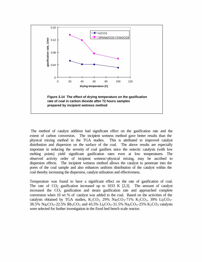
Figure 3.14 The effect of drying temperature on the gasification rate of coal in carbon dioxide after 72 hours samples prepared by incipient wetness method
0
0.04
0.08
0.12
0.16
0 20 40 60 80 100 120
drying temperature (C)
gas
ific
atio
n r
ate,
1/m
in
k2CO3
29%Na2CO3-71%k2CO3
The method of catalyst addition had significant effect on the gasification rate and the extent of carbon conversion. The incipient wetness method gave better results than the physical mixing method in the TGA studies. This is attributed to improved catalyst distribution and dispersion on the surface of the coal. The above results are especially important in reducing the severity of coal gasifiers since the eutectic catalysts (with low melting points) yield significant gasification rates even at low temperatures. The observed activity order of incipient wetness>physical mixing, may be ascribed to dispersion effects. The incipient wetness method allows the catalyst to penetrate into the pores of the coal sample and also enhances uniform distribution of the catalyst within the coal thereby increasing the dispersion, catalyst utilization and effectiveness.
Temperature was found to have a significant effect on the rate of gasification of coal. The rate of CO2 gasification increased up to 1033 K [2,3]. The amount of catalyst increased the CO2 gasification and steam gasification rate and approached complete conversion when 10 wt % of catalyst was added to the coal. Based on the activities of the catalysts obtained by TGA studies, K2CO3, 29% Na2CO3-71% K2CO3, 39% Li2CO3-38.5% Na2CO3-22.5% Rb2CO3 and 43.5% Li2CO3-31.5% Na2CO3-25% K2CO3 catalysts were selected for further investigation in the fixed bed bench scale reactor.

3.4. REFERENCES
(1) Levin, E.M, Robbins, C.R and McMurdie, H.F., “Phase Diagrams for Ceramist”, American Ceramic Society, New York: Marcel Dekker, 1964.
(2) Yeboah, Y.D, Xu Y., Sheth. A., Godavarty, A., and Agrawal, K.P. Catalytic Gasification of Coal Using Eutectic Salts: Identification of Eutectics (Submitted to Carbon).
(3) Yeboah YD, Xu Y, Sheth A, Godavarty A and Agrawal KP. Catalytic Gasification of Coal Using Eutectic Salts:Reaction Kinetics using Binary and Ternary Eutectic Catalysts. (Submitted to Fuel).

CHAPTER FOUR: GASIFICATION OF COAL IN STEAM BY BENCH SCALE FIXED-BED REACTOR
4.1. INTRODUCTION Experiments were carried out using the bench scale high-pressure fixed-bed gasification system shown in Figure 2.2. Based on the activities of the catalysts obtained by TGA studies, K2CO3 (K), 29% Na2CO3-71% K2CO3 (NK) and 43.5% Li2CO3-31.5% Na2CO3-25% K2CO3 (LNK) catalysts were further investigated in the fixed bed bench scale reactor. Unloaded and catalyst-loaded coal samples were pyrolyzed in a muffle furnace at high-temperature in a stream of nitrogen. Small quantities (~10 g) of the chars produced were placed in the differential fixed-bed reactor shown in Figure 2.2 and gasified in steam in the 1073-1673 K range. The effluent gases were monitored using an on-line GC/MS for identification of components such as CO, CO2, H2, CH4, and H2O. Following the experiments, the remains of the gasified chars were analyzed for carbon, hydrogen, and for the various catalyst constituents. Analysis of the ungasified and the gasified chars were used for determination of the overall carbon conversion, catalyst content, and the capture of sulfur-and halogen-containing species. The gasification rates at various stages of the reactions were computed from the gas analysis and compared with the total carbon conversion determined from the chemical analysis of the chars. The high-pressure, high-temperature fixed-bed catalytic coal gasification experiments using eutectic salt mixtures were carried out to initially choose a better catalyzed coal preparation technique and to optimize the process variables for an efficient gasification process. The coversions based on tga results were calculated using the formula below: Xc = [(Co – C )/Co]*100 (4.1) Where Co=Initial carbon content in the feed to the gasifier (grams) and C=Final carbon content after gasification (grams) 4.2. EVALUATION OF CATALYST ADDITION TECHNIQUES In the first phase of experimentation, the catalytic steam coal gasification experiments were performed using the LNK catalyst system. Experimental runs A and B were carried out to establish the differences in results using the raw coal and pyrolyzed coal (see Table 4.1). The sample with catalyst added to the raw coal gave significantly higher carbon conversions compared to the sample with catalyst added to the pyrolyzed coal (Figure 4.1). The corresponding initial gasification rates were relatively higher for run B than for run A.

Table 4.1. Experimental conditions to evaluate the catalyst application techniques for LNK and NK systems
Run Catalyst type Catalyst added to Catalyst addition technique
A LNK Pyrolyzed coal M3 B LNK Raw coal M3 C LNK Raw coal M2 D LNK Raw coal M1 E NK Raw coal M2 F NK Raw coal M1
The next set of experiments was performed to find a better method of catalyst addition to the raw coal. Experimental runs C and D using the M2 and M1 methods of catalyst addition to the raw coal were carried out at the operating conditions shown in Table 4.2. Figure 4.2 shows that M1 and M2 methods of catalyst addition gave better carbon conversions compared to the M3 method. This is attributed to the fact that in M1 and M2 methods, the catalyst was a eutectic salt with a melting point of 673 K and the catalytic gasification process was carried out above 973 K. The eutectic is believed to have been

well distributed in the carbon matrix in the molten state, and therefore, enhanced the gasification reaction. In the M3 method, the single salts were only mixed in the proportion of their eutectic composition, but were not necessarily present as a eutectic everywhere. They probably did not form a eutectic after they were added to the coal and gasified. This may be due to the low probability of the salts to remain at the eutectic composition uniformly throughout the char bed during gasification at the gasification temperature of 995 K. Table 4.2. The operating gasification conditions for the experimental runs Temperature Pressure Catalyst loading Steam/water flow rate Purge gas Sample size Gasification time
995 K 0.44 MPa 10 wt. % of coal/char 13.8 ml/sec N2 (at 0.5 MPa) 2.55 grams of char 240 min (arbitrarily chosen)
The initial gasification rates using TGA showed that experimental runs using M1 and M2 methods of ternary catalyst addition gave significantly higher gasification rates compared to the M3 method. Similar experiments at 150 psig in the fixed bed reactor showed no

significant difference in the gasification rate in the M1 method compared to the M2 method with the ternary eutectic catalysts. In view of this insignificant difference in the gasification rates and conversion level by M1 and M2 methods, M1 method of catalyst application was chosen for the subsequent experimental runs due to its simplicity. Runs E and F were performed using the NK binary catalyst system to evaluate the catalyst addition techniques (among M1 and M2 methods). The operating conditions remained the same for this catalyst system. The binary catalyst also showed no significant difference in the conversion level and gasification rate when the catalyst in its eutectic form was added by M1 or M2 method. The reactivity of the NK catalyst for different catalyst addition techniques is illustrated in Figure 4.3.
4.3 COMPARATIVE STUDY OF SINGLE, BINARY AND TERNARY SALT
CATALYSTS The effect of the catalyst type on the reaction rate was compared using the single salt-K2CO3, binary-NK and the ternary-LNK catalysts under the operating conditions shown in Table 4.2. The reactivity of these catalysts is shown in Figure 4.4. The carbon conversion was 85-87 % when the binary and the single catalysts were used, whereas it was 99 % within the first 2 hours of the run when the LNK was used as the catalyst.

There was no significant difference in the initial reaction rates among the three catalysts. However, the ternary catalyst appeared to show a slight increase in its initial reaction rate when compared to the binary and single catalyst. The single salt K2CO3 gave higher ratios of [CO]/[CO2] in the first 70 minutes of the reaction. It dropped to very low values with further increase in the gasification time, whereas the LNK catalyst continued to produce CO in the system, even after 3 hours of gasification. This indicates that probably after the first hour of gasification, the LNK catalyst was still catalytically active to gasify carbonaceous compounds and allow the gasification reaction to go to completion. For the NK and K- catalyzed systems, however, the catalyst seemed to have lost some activity as the gasification proceeded further. The CO/CO2 ratio results also suggest that the water-gas shift reaction was not fast enough to keep up with the enhanced carbon gasification reaction (CO is the primary gasification product). Details on these observations and discussions may be found elsewhere [1].

These experimental runs that were carried out to compare the effects of eutectic catalysts with the single salt catalysts tend to suggest that the eutectic salt mixtures are better substitutes for the single salt catalysts in improving the steam gasification step [1,2]. The kinetic results and analysis with the LNK and NK catalysts are reported later in Section 4.5. 4.4 STUDY OF THE EFFECTS OF PROCESS VARIABLES ON THE
PERFORMANCE OF GASIFIERS The effects of major process variables such as temperature, pressure, catalyst loading and steam flow rate on the gasification kinetics were evaluated using steam as the gasifying agent. A simple reaction kinetics model was also developed relating the effect of temperature and partial pressure of steam on the gasification reaction. Using the two eutectic catalysts (LNK and NK), a set of seventeen experiments were performed on steam gasification, each lasting for four hours, to study the effect of temperature, pressure, catalyst loading, and steam/water flow rate. The operating conditions for these runs are tabulated in Table 4.3. Runs 1 to 10 were carried out using the ternary eutectic (LNK) system, whereas Runs 11 to 17 were performed using the binary eutectic (NK) system as the catalyzing agent. 4.4.1 Effect of temperature Figures 4.5 and 4.6 respectively show the transient properties for catalytic steam gasification of char at several temperatures for both the LNK and NK catalyst systems. At similar temperatures, the LNK catalyst system gave better conversion levels compared to the NK catalyst system. At 92 K (1200°F), the reaction was not complete in both catalyst systems, although the conversions were much higher with LNK catalysts than with NK catalysts. At 1005 K (1350°F), the NK catalyst yielded only 85% conversion, whereas the reaction under similar conditions was almost 99% complete with the LNK catalyst. The variation in conversion levels between the two catalyst systems is attributed to the liquid nature of ternary eutectic salt (melting point of LNK is less than the gasification temperature), whereas the binary eutectic salt remained a solid solution. This liquid nature of the LNK at the gasification temperatures is believed to provide a better dispersion of the LNK catalyst during gasification, thereby enhancing the reaction rate. At 923 K, though the LNK catalyst (with a melting point of about 673 K) is in the liquid phase, the reaction does not go to completion due to the lower gasification rates. This is explained from the thermodynamics of the gasification reaction, where the ∆Greaction at this temperature is +3.7 kJ/mole [3]. Thus the system does not have enough of the required energy at 923 K to overcome the necessary energy barrier and proceed in the forward direction, at an acceptable gasification rate. The water-gas reaction during steam gasification is given by equation 4.2.
C + H2O →CO + H2 (4.2)

Table 4.3. Experimental conditions for steam gasification runs using the LNK and NK eutectic catalysts
Run Temp (K)
Pressure (MPa)
Catalyst loading (wt.%)
Steam/water flow rate (ml/sec)
Catalyst
1 923 0.44 10 13.8 LNK 2 1005 0.44 10 13.8 LNK 3 1044 0.44 10 13.8 LNK 4 1005 1.12 10 13.8 LNK 5 1005 2.14 10 13.8 LNK 6 1005 0.44 5 13.8 LNK 7 1005 0.44 15 13.8 LNK 8 1005 0.44 10 5.0 LNK 9 1005 0.44 10 8.7 LNK 10 964 0.44 10 13.8 LNK 11 923 0.44 10 13.8 NK 12 1005 0.44 10 13.8 NK 13 1044 0.44 10 13.8 NK 14 1005 0.44 5 13.8 NK 15 1005 0.44 15 13.8 NK 16 1005 0.44 10 5.0 NK 17 1005 0.44 10 8.6 NK
As gasification temperature was increased, the CO production was relatively higher for the LNK catalyst system than the NK catalyst system. Figure 4.7 shows the effect of temperature on the product distribution for the LNK system. The [CO2]/[CO] ratio increased with a decrease in temperature, a trend consistent with the thermodynamics of the water gas-shift reaction [3]. A similar behavior was observed with the binary catalyst system. The fact that the ratio [CO2]/[CO] remained mostly constant over a rather broad range of fractional conversions suggests too that the product distribution is controlled by thermodynamics and not kinetics. 4.4.2. Effect of pressure Pressure has a significant effect on the methanation reaction in the presence of CO and H2 during the gasification process [4]. In our study, the main focus was to increase the overall gasification rate of the char sample. Runs 2, 4 and 5 (Table 4.3) using the LNK catalyst demonstrated the effect of system pressure on the overall gasification rate. No significant effect of pressure on the carbon conversion and the overall gasification rate was observed in these runs as shown in Figure 4.8. This indicated that the reaction rate was independent of pressure in the pressure range studied. The results are also supported by the literature, where a similar effect of the system pressure was seen when K2CO3 was used as the catalyst for steam gasification of coal [5]. Similar behavior was observed for the NK catalyst as well.

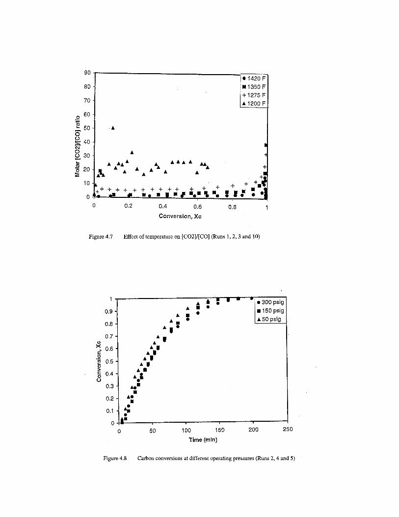

Table 4.4. Specific gasification rates for Runs 1-17 Run Catalyst 1/C(-dC/dt) (min-1) 1 2 3 4 5 6 7 8 9 10 11 12 13 14 15 16 17
LNK LNK LNK LNK LNK LNK LNK LNK LNK LNK NK NK NK NK NK NK NK
0.004 0.0208 0.0301 0.0177 0.0168 0.0037 0.0281 0.0053 0.0153 0.0135 0.001 0.0158 0.024 0.0018 0.0394 0.0128 0.0087
4.4.3 Effect of catalyst loading The increase in catalyst loading increases the number of cations (alkali metals) and hence the metal/carbon or M/C ratio, available for the catalytic activity. Runs 2, 6 and 7 using the LNK catalyst (Figure 4.9) and runs 12, 14 and 15 using the NK catalyst (Figure 4.10) were performed by varying the amount of catalyst loading to the amount of raw coal taken initially. At low catalyst loading of 5-wt. %, the conversion was only 60 % complete for the LNK system and 35% complete for the NK system. Upon increasing the loading to 10 wt. %, the reaction was almost 99% complete for Run 2 (using LNK) in comparison to about 85% completion for Run 12 (using NK). Further increasing the loading to 15-wt. % gave complete conversion in the binary catalyst system. At low catalyst loading of 5 wt. %, some of the catalyst could possibly be lost by the reaction of the catalyst with the mineral matter content of the coal during gasification, thus yielding very low gasification rates and lower overall carbon conversions [6]. Single salts such as K2CO3 showed a similar behavior at low loadings in steam gasification [7]. There was no significant rise in the overall gasification rate upon increasing the catalyst loading from 10 wt. % to 15 wt. % in the LNK system. This phenomenon was observed only for the ternary catalyst system. This may be due to the saturation of the available active sites in the carbon matrix by the increased number of cations available in the system. Similar observations were made using K2CO3 as the catalyst in the steam gasification of coal [5]. SEM studies of the char samples for the two catalyst systems at different catalyst loadings confirmed this phenomenon; the details of which are presented elsewhere [8].


The effect of the metal-to-carbon (M/C) ratio on the specific gasification rate for the two catalyst systems is shown as a combined plot in Figure 4.11. The figure indicates that M/C ratio may be independent of the type of catalyst in the mentioned range. For the same catalyst loading, the ratio M/C was mostly higher for the LNK system than for the NK system. This explains the reason for higher conversion levels and overall gasification rates for the ternary catalyst system when compared to the binary catalyst system. The above phenomenon infers that the reaction kinetics depend on the number of alkali metal cations available on the active sites of coal for enhancing the gasification process. At high catalyst loadings (>15 wt %) or M/C >4 %, NK catalyst system showed higher gasification rate than the LNK catalyst system. Further experimentation is needed to explain the behavior of both catalysts at higher loadings.
4.4.4. Effect of steam/water flow rate
Experiments were also performed at different steam/water flow rates varying from excess amount of steam required to a large excess of steam. Runs 2, 8 and 9 using the LNK catalyst (Figure 4.12) and Runs 12, 16 and 17 (Figure 4.13) using the NK catalyst were carried out at different steam/water flow rates. These flow rates corresponded to steam-to-initial carbon molar ratios in the range 2:1 to 6:1 (mol/hr of steam/mol of initial carbon in the bed). As the initial steam/water flow rate was increased, the extent of carbon conversion increased for the ternary system. Further increasing the flow rate gave no significant increase in the overall gasification rate in the LNK system. This could possibly be due to the saturation of the active site, attached with the alkali metal cations, with the water molecules in the carbon matrix. Addition of excess steam/water provided

no effect on the overall gasification rate. In the case of the binary system, it gave 100% conversion at lower water flow rates compared to about 80-85% conversion at higher water flow rates. Its behavior was quite different from that of the ternary catalyst. Microscopic analysis of the catalyst distribution is required to understand the behavior of the NK catalyst during gasification. Also, further experimentation is required at different water flow rates to better understand the behavior of the binary catalyst. The fractional amount of CO produced (on a molar basis) increased from less than 10% to about 30-35% upon increasing the steam flow rates for the LNK system (Figure 4.14). In the case of the NK system, the fraction of CO dropped from 40% to about 30% with the increase in steam/water flow rates. However, both catalysts behaved in accordance with the thermodynamics of the water gas-shift reaction, by showing a clear rise in the [CO2]/[CO] molar ratio with the increase in the steam/water flow rate and thereby enhancing the forward reaction. The rise in this ratio with the increase in the steam flow rate plotted as a function of carbon conversion in the bed for NK catalyst system is shown in Figure 4.15. 4.5 REACTION KINETICS MODELLING USING BINARY AND TERNARY
EUTECTIC CATALYSTS IN STEAM 4.5.1. OVERVIEW Based on the results obtained from the fixed-bed reactor, a study on the kinetic modeling for the eutectic salt mixtures as the gasifying catalyst was carried out. Kinetics of catalytic steam gasification of coal/graphite has been studied extensively by many researchers at various operating conditions using different varieties of coal samples. All the models that have been used to fit experimental results are of the Langmuir-Hinshelwood type of rate expression for heterogeneous systems [2-3]. The kinetics of K- catalyzed steam gasification was described using this model at Exxon Corporation in the 1980’s in a very extensive manner [4]. Similar models including the effect of product gases like hydrogen have also been developed by Schumacher [2].
The kinetic studies conducted using the 29 mol% Na2CO3 – 71 mol% K2CO3 (NK) binary, and 43.5 mol% Li2CO3 - 31.5 mol% Na2CO3 - 25 mol% K2CO3 (LNK) ternary eutectic catalysts are reported in this section of this chapter.


4.5.2. KINETIC MODELING Kinetics of catalytic steam gasification of coal/graphite has been studied extensively by several researchers [5-7]. Generally, a Langmuir-Hinshelwood mechanism for steam gasification has been proposed.
C(s) + H2O(g) → CO(g) + H2 (g) (4.3) H2O(g) → H2O(ad) (4.4)
C(s) + H2O(ad) → H2 (ad) + CO (ad) (4.5) H2 (ad) → H2 (g) (4.6)
CO (ad) → CO(g) (4.7)
Equation 4.3 represents the overall gasification step. Equations 4.4 through 4.7 represent the individual reaction steps. Water molecule is initially adsorbed on the active sites of the coal matrix and then reacts with carbon to produce CO and H2 species which subsequently desorb. Product inhibition due to H2 or CO can be neglected. If one assumes the surface reaction between an adsorbed water molecule and carbon to be the rate-determining step, the following Langmuir-Hinshelwood type of rate expression is obtained:
- rc =OpHk
OpHk
22
21
1 +• C (4.8)
where,
pH2O is the partial pressure of steam in the bed (kPa) k1 is the reaction rate constant k2 is the adsorption constant rc is the gasification rate of carbon in the bed (gm/min) C is the remaining carbon in the bed at any instant time, t (gm) Since excess steam was used in all the runs reported here (Table 4.5), it is fair to assume that in any given run (at the specified value of temperature, PH2O, and catalyst loading), the term
OpHkOpHk
22
21
1 +
remains uncharged during the entire duration of the run (~4 hrs). It would then appear from Equation 4.8 that the transient behavior of a run can be expressed by a first-order equation:
-rc =k’•C (4.9)
Where k’ =OpHk
OpHk
22
21
1 +

Equation 4.9 can be written as
dtdC = k’C (4.10)
or –ln(1-Xc)=k’t
(4.11) Where Xc, the carbon conversion at time t, defined as Xc=(C0-C)/C0 and C0 is the initial carbon content in the bed.
Table 4.5. Experimental conditions for steam gasification runs using the LNK and
NK eutectic catalysts Run Temp
(K) Pressure (MPa)
Catalyst loading (wt.%)
Steam/water flow rate (ml/sec)
Catalyst
1 923 0.44 10 13.8 LNK 2 1005 0.44 10 13.8 LNK 3 1044 0.44 10 13.8 LNK 4 1005 1.12 10 13.8 LNK 5 1005 2.14 10 13.8 LNK 6 1005 0.44 5 13.8 LNK 7 1005 0.44 15 13.8 LNK 8 1005 0.44 10 5.0 LNK 9 1005 0.44 10 8.7 LNK 10 964 0.44 10 13.8 LNK 11 923 0.44 10 13.8 NK 12 1005 0.44 10 13.8 NK 13 1044 0.44 10 13.8 NK 14 1005 0.44 5 13.8 NK 15 1005 0.44 15 13.8 NK 16 1005 0.44 10 5.0 NK 17 1005 0.44 10 8.6 NK
Thus, a linearity in the plot of –ln(1-Xc) vs time would provide the first test of the validity of the Langmuir-Hinshelwood kinetics as represented by Equation 4.11. Figure 4.16 shows –ln(1-Xc) vs time plots for the LNK catalyst; similar plots for the NK catalyst system are shown in Figure 4.17. In both cases, reasonably linear fits are obtained. In


view of the initial transients associated with the run start-up, the linear fits are quite acceptable. Similar first-order behavior with respect to carbon has been reported earlier [4, 6-7]. In general, the gasification reaction would occur thermally (homogeneously) as well as catalytically. The overall char gasification can therefore be expressed as:
overalldtdC
−
= catalyticdt
dC
−
+ thermaldt
dC
−
(4.12)
However, the kinetics of such mixed gasification cannot be separated easily. At the temperatures employed in this study, thermal gasification rates are usually negligible compared to the catalytic gasification rates. We, therefore, ascribed the observed rates solely to the catalytic process as expressed by Equation 4.8 Equation 4.8 can be inverted to give a linearized form as:
- rC
c =
1
2
21
1kk
OpHk+ (4.13)
The calculated specific rate data (-rc/C) from the experimental results for different temperatures and partial pressures of steam were used to fit this linearized rate expression. The resulting linearity following Equation 4.13 is shown in Figure 4.18 for the LNK system. The k1 and k2 values determined from Figure 4.18 were used to obtain the slope and intercept from Arrhenius type plots (Lnk vs 1/T) as shown in Figure 4.19 A similar procedure was carried out to obtain a rate expression for the NK system in Figure 4.20. The obtained values of the energy or heat of adsorption and the preexponential or frequency factors for both catalyst systems are given in Table 4.6. From the calculated values of the slopes of the Arrhenius plots for k2, one can see that the value in both catalyst systems are negative, indicating that the molar heat of adsorption is exothermic in contrast to the water gas reaction. Generally chemisorption is an exothermic process [8]. It may however, when accompanied by dissociation, be endothermic [8]. The heat of adsorption therefore supports the Langmuir-Hinshelwood adsorption model without dissociation used in this study. Table 4.6. Rate parameters for steam gasification
Catalyst Parameter ki O
Ei or ∆Hads (kJ mol-1)
LNK k1 9.2x 10³ kPa-1sec-1 98.6 LNK k2 3.7x10⁻¹² kPa-1 -180.3 NK k1 2.0x10⁹ kPa-1sec-1 201.5 NK k2 3.4x10⁻⁷ kPa-1 -91.9


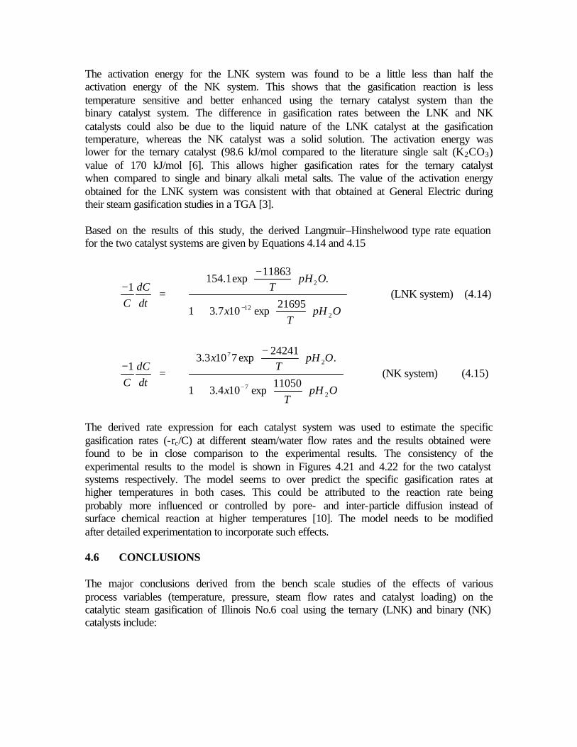
The activation energy for the LNK system was found to be a little less than half the activation energy of the NK system. This shows that the gasification reaction is less temperature sensitive and better enhanced using the ternary catalyst system than the binary catalyst system. The difference in gasification rates between the LNK and NK catalysts could also be due to the liquid nature of the LNK catalyst at the gasification temperature, whereas the NK catalyst was a solid solution. The activation energy was lower for the ternary catalyst (98.6 kJ/mol compared to the literature single salt (K2CO3) value of 170 kJ/mol [6]. This allows higher gasification rates for the ternary catalyst when compared to single and binary alkali metal salts. The value of the activation energy obtained for the LNK system was consistent with that obtained at General Electric during their steam gasification studies in a TGA [3]. Based on the results of this study, the derived Langmuir–Hinshelwood type rate equation for the two catalyst systems are given by Equations 4.14 and 4.15
dtdC
C1−
=
+
−
− OpHT
x
OpHT
212
2
21695exp107.31
.11863
exp1.154 (LNK system) (4.14)
dtdC
C1−
=
+
−
− OpHT
x
OpHT
x
27
27
11050exp104.31
.24241
exp7103.3 (NK system) (4.15)
The derived rate expression for each catalyst system was used to estimate the specific gasification rates (-rc/C) at different steam/water flow rates and the results obtained were found to be in close comparison to the experimental results. The consistency of the experimental results to the model is shown in Figures 4.21 and 4.22 for the two catalyst systems respectively. The model seems to over predict the specific gasification rates at higher temperatures in both cases. This could be attributed to the reaction rate being probably more influenced or controlled by pore- and inter-particle diffusion instead of surface chemical reaction at higher temperatures [10]. The model needs to be modified after detailed experimentation to incorporate such effects. 4.6 CONCLUSIONS The major conclusions derived from the bench scale studies of the effects of various process variables (temperature, pressure, steam flow rates and catalyst loading) on the catalytic steam gasification of Illinois No.6 coal using the ternary (LNK) and binary (NK) catalysts include:

1. Temperature was found to have a significant effect on the gasification rate for both
catalyst systems. The forward water gas-shift reaction was less favored with increase in temperature, which was in agreement with the thermodynamics of the reaction.
2. Within experimental error, there was no effect of system pressure on the gasification rate in the LNK system. This was similar to the observations made by earlier researchers.
3. There was a significant effect of catalyst loading on the gasification reaction in both catalyst systems. Both the gasification rates and conversion levels were found to increase with the increase in the metal (catalyst) to carbon (M/C) ratio.
4. Below 10-wt. % catalyst loading, the specific gasification rate increased linearly with increase in the M/C ratio, indicating the gasification rate to be independent of the catalyst type, and just dependent on the concentration of the alkali metals.
5. The effect of steam flow rate showed a different behavior in the two catalyst systems. With increase in steam flow rate, the carbon conversion levels in the LNK system increased. However, the NK system showed an inconsistent behavior at different steam flow rates. Additional work is needed to understand this difference in behavior.
6. The effect of the partial pressure of steam on the water gas-shift reaction was elucidated from the experiments carried at different steam/water flow rates for both catalyst systems. The rise in [CO2]/[CO] ratio with steam flow rates was in accordance with the thermodynamics of the shift reaction.

7. A simple Langmuir-Hinshelwood type rate model, excluding the effect of hydrogen inhibition provided a reasonably good fit to the experimental runs at different temperatures and steam/water flow rates.
8. The activation energy of the NK system (201 kJ/mol) was twice that of the LNK system (98 kJ/mol) indicating a better catalytic activity by the liquid ternary catalyst. The exothermic molar heats of adsorption for the LNK and NK systems were 180 and 92 kJ/mol respectively.
4.7. REFERENCES 1 Liu, Z. L. and Zhu, H. L. , Fuel, 1986, 65, 1334-1338. 2 McKee, W. D., Carbon, 1982, 20, 59-66. 3 McKee, W.D., Fuel, 1985, 64, 805-809. 4 Tetsuya, H, Kozo N., Masashi A. and Yoshiyuki N., Applied Catalysis, 1991, 67,
189-202. 5 Yeboah, Y. D., Xu, Y., Sheth, A., Godavarty, A. and Agrawal, P., Catalytic
Gasification of Coal Using Eutectic Salts: Identification of Eutectics (Submitted to Carbon)
6 Godavarty, A., Catalytic Coal Gasification Using Eutectic Salt Mixtures. Master's Thesis, University of Tennessee, Knoxville, August 1999.
7 Chase, Jr. M. W., Davies, C. A., Downey, Jr. JR, Frurip, D.J., McDonald, R.A. and Syverud, A.N., J. Phys. Chem. Ref. Data, 1985, 14, 535-600.
8 Gallagher, JE., Euker, Jr. C.A., Catalytic Coal Gasification for SNG Manufacture. 6th Annual International Conference on Coal Gasification, Liquefaction and Conversion to Electricity, Pittsburgh, July 31- August 2 1979.
9 Schumacher, W., Mühlen, J. H., Heek, K.H.V. and Jüntgen, H., Fuel, 1986, 65, 1360-1363.
10 Formella, K., Leonhard, P., Sulimma, A., Heek, K.H.V. and Jüntgen, H., Fuel 1986, 65, 1470-1472.
11 Godavarty, A. and Agarwal, A., Energy & Fuels 2000, 14 558-565 12 Vadovic, J. C. and Eakman, J. M., Kinetics of Potassium Catalyzed Gasification.
Annual ACS meeting, September 1978, Florida. 13 Tuyl, E. D., and William, J. T., Fuel 1986, 65, 58-62. 14 Bond, G. C., Heterogeneous catalysis-Principles and Applications, 2nd Edition,
Clarendon Press, Oxford, UK, 1990 15 Yeboah, Y. D., Xu, Y., Sheth, A., Godavarty, A. and Agrawal, P., Catalytic
Gasification of Coal Using Eutectic Salts: Reaction Kinetics using Binary and Ternary Eutectic Catalysts (Submitted to Fuel).
CHAPTER FIVE: REACTION KINETICS FOR HYDROGASIFICATION IN FIXED BED REACTOR
5.1. INTRODUCTION The presence of alkali metal salts greatly enhances the reactivity of coal char towards steam and CO2 [1,2]. Addition of binary and ternary eutectic alkali salt catalysts increase the gasification rates considerably [3-5]. Bench scale steam gasification experiments were carried out in the previous chapter using binary and ternary eutectic catalysts to evaluate the effects of major process variables such as temperature, pressure, catalyst loading and steam flow rate on the gasification kinetics. In addition to this, a simple reaction kinetics model was also developed to relate the effects of temperature and partial pressure of steam on the gasification reaction. Heinz et al. [6] and Schumacher et al. [7] conducted experiments in the past to investigate the effects of product gases like H2 and CO on steam gasification kinetics. But all their experiments were either conducted without a catalyst or using a single salt catalyst. The objective of this phase of the study was to evaluate the product inhibition effect of one of the product gases, H2, on the steam gasification kinetics using the same eutectic catalysts that were employed by Godavarty [3] in this project. In the hydrogasification study, bench scale experiments were carried out in a high-pressure, high-temperature fixed-bed gasifier using binary and ternary eutectic salt catalysts. The effect of hydrogen partial pressure on the steam gasification kinetics was evaluated by conducting various experiments at different hydrogen partial pressures. A simple reaction kinetics model was developed to fit the experimental results and a possible reaction mechanism was proposed to explain the suggested model. Results of the kinetic studies conducted using the 29 mol% Na2CO3 – 71 mol% K2CO3 (NK) binary, and 43.5 mol% Li2CO3 - 31.5 mol% Na2CO3 - 25 mol% K2CO3 (LNK) ternary eutectic catalysts are reported in this chapter. The bench-scale experiments on hydrogasification reactions using the NK binary and LNK ternary eutectic catalysts were carried out with the Illinois No.6 coal obtained from the Penn State Sample Bank. Catalyst sample preparation methods were described in Chapter 2. The binary and ternary catalysts were prepared by fusion of finely ground salt mixtures having compositions corresponding to the eutectic melting temperatures. The eutectic mixtures were heated in air at temperatures at least 100 K above their reported respective eutectic points. After cooling the mixture was crushed, finely ground and stored under an inert atmosphere. To prepare the coal-catalyst sample, the method of catalyst addition employed was the “Physical Mixing Technique” due to its simplicity [3]. After addition of the catalyst, the coal sample was devolatilized under nitrogen at 1023 K in a Barnstead Thermolyne – Model F48015 muffle furnace at 20 psig for three hours. The devolatilized/pyrolyzed char was crushed and sieved to obtain char particles varying in size from –30 mesh to +100 mesh. An average size of 80 mesh was estimated for the pyrolyzed char containing LNK catalyst. However, the sample particle size for pyrolyzed char containing NK

catalyst turned out to be less than 100 mesh due to possibly different catalyst/coal interactions. An average size of 120 mesh was estimated for the NK pyrolyzed char. 5.2. HYDROGASIFICATION The hydrogasification experiments were carried out in the high-pressure, high-temperature fixed-bed gasifier system. The gasifier operated with a downdraft gas flow regime and in a differential fixed bed mode as shown in Figure 2.2. The bottom half of the reactor was packed with ceramic beads and two 200-mesh stainless steel screen baskets were placed over this packing to support the char bed. The differential char bed accommodated about 2.5 grams of char during each experimental run. The exit gases from the gasifier were analyzed for its carbon-containing species using an off-line SRI 8610C gas chromatograph. Experiments were also performed using a thermogravimetric analyzer (TGA) to analyze the fixed carbon content of the char sample before and after the gasification step. The collected data were analyzed to get information on the carbon conversion, to calculate the gasification rates and also to obtain a rate expression to explain the kinetics of the hydrogasification reactions. Fourteen hydrogasification experiments, each lasting about four hours, were performed using the two eutectic catalysts (LNK and NK) to evaluate the product inhibition effect of hydrogen on the steam gasification kinetics. The various operating parameters maintained in each experiment are given in Table 5.1. It can be seen from Table 5.1 that while the partial pressure of steam is more or less constant for each run except the pure hydrogen case, the hydrogen partial pressure was varied from run to run. The rest of the operating conditions, kept constant for all the runs, are illustrated in Table 5.2. Runs 1 to 6 were carried out using the LNK system whereas Runs 7 to 12 were performed using the NK system. Apart from these twelve runs, two more experiments were performed. Run #6A was a duplicate of Run #6, and was performed to determine the extent of reproducibility of the hydrogasification experiments. Run #13 was carried out to determine the effect of average particle size of the LNK pyrolyzed char on the gasification kinetics. 5.3 STUDY OF THE EFFECTS OF PROCESS VARIABLES OF THE
GASIFICATION OF COAL The effect of the partial pressure of hydrogen on the steam gasification kinetics was evaluated and compared for the two catalyst systems. Also separate kinetic expressions were developed for each catalyst system. The extent of reproducibility of the hydrogasification experiments was determined and the effect of average sample particle size on the gasification rate was also assessed.

Table 5.1. Operating parameters used for different experimental runs Run # Catalyst PH2 (atm) PH2O (atm) PN2 (atm) Average
Sample Particle Size
(mesh) 1 LNK 21.41 0.00 0.00 80 2 LNK 17.39 4.01 0.00 80 3 LNK 12.37 4.28 4.76 80 4 LNK 6.28 3.97 11.16 80 5 LNK 2.50 4.12 14.79 80 6 LNK 0.00 4.01 17.39 80 7 NK 21.41 0.00 0.00 120 8 NK 17.39 4.01 0.00 120 9 NK 12.37 4.28 4.76 120 10 NK 6.28 3.97 11.16 120 11 NK 2.50 4.12 14.79 120 12 NK 0.00 4.01 17.39 120 13 LNK 17.39 4.01 0.00 120 6A LNK 0.00 4.01 17.39 80
Table 5.2. Experimental condition for hydrogasification of coal
CONDITION VALUE Temperature 1350oF Pressure 300 psig (21.41 atm) Catalyst loading 10 wt. % of coal-catalyst mixture Steam/Water flow rate 0.5 cc/min Purge gas Nitrogen Total gas flow rate 360 cc/min Sample size 2.5 g of char Gasification time 240 min
5.3.1 Effect of Partial Pressure of Hydrogen Runs 1 to 6 were conducted using the LNK catalyst. For these six runs, the data from the GC and TGA were used to calculate the reconciled values of the carbon conversion as a function of time. Figure 5.1 illustrates the effect of hydrogen partial pressure on the carbon conversion, and hence, the steam gasification kinetics for the LNK catalyst. It is evident from the graph that as the hydrogen partial pressure decreased the overall conversion and the gasification rate increased. The experimental specific gasification rate for each run was calculated by plotting –ln(1-Xc) vs. t. This was done because, as in
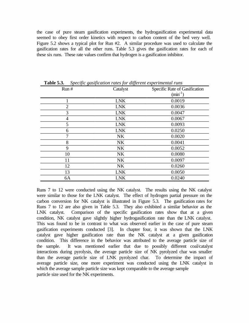
the case of pure steam gasification experiments, the hydrogasification experimental data seemed to obey first order kinetics with respect to carbon content of the bed very well. Figure 5.2 shows a typical plot for Run #2. A similar procedure was used to calculate the gasification rates for all the other runs. Table 5.3 gives the gasification rates for each of these six runs. These rate values confirm that hydrogen is a gasification inhibitor.
Table 5.3. Specific gasification rates for different experimental runs
Run # Catalyst Specific Rate of Gasification (min-1)
1 LNK 0.0019 2 LNK 0.0036 3 LNK 0.0047 4 LNK 0.0067 5 LNK 0.0093 6 LNK 0.0250 7 NK 0.0020 8 NK 0.0041 9 NK 0.0052 10 NK 0.0080 11 NK 0.0097 12 NK 0.0260 13 LNK 0.0050 6A LNK 0.0240
Runs 7 to 12 were conducted using the NK catalyst. The results using the NK catalyst were similar to those for the LNK catalyst. The effect of hydrogen partial pressure on the carbon conversion for NK catalyst is illustrated in Figure 5.3. The gasification rates for Runs 7 to 12 are also given in Table 5.3. They also exhibited a similar behavior as the LNK catalyst. Comparison of the specific gasification rates show that at a given condition, NK catalyst gave slightly higher hydrogasification rate than the LNK catalyst. This was found to be in contrast to what was observed earlier in the case of pure steam gasification experiments conducted [3]. In chapter four, it was shown that the LNK catalyst gave higher gasification rate than the NK catalyst at a given gasification condition. This difference in the behavior was attributed to the average particle size of the sample. It was mentioned earlier that due to possibly different coal/catalyst interactions during pyrolysis, the average particle size of NK pyrolyzed char was smaller than the average particle size of LNK pyrolyzed char. To determine the impact of average particle size, one more experiment was conducted using the LNK catalyst in which the average sample particle size was kept comparable to the average sample particle size used for the NK experiments.

5.3.1. Effect of Average Particle Size of Sample Figure 5.4 shows the plot of carbon conversion versus time for two experiments (Run #2 and Run #13) with two different average sample particle sizes. The catalyst used in these experiments was LNK. It is evident from the graph that the gasification rate was higher for the smaller particles with greater surface area. This possibly explains why the NK catalyst gave higher gasification rates compared to the LNK catalyst. Additionally, a few calculations were carried out to determine the rate-controlling step in the gasification reaction. The time needed to achieve the same fractional conversion for particles of different average sizes were noted from Figure 5.4 at three different conversion values chosen arbitrarily. The ratios of the corresponding times for each conversion were calculated and the average of these ratios was determined. This average ratio was found to be t80/t120=1.38, where t80 and t120 stand for the times needed to reach the same conversion for the particles of average initial size of 80 mesh and 120 mesh respectively. The ratio of their respective average initial particle sizes was calculated as R80/R120=1.416, where R stands for the average radius of the particle. The ratio of t80/t120 was found to be close to this ratio of R80/R120. Therefore, based on the shrinking core model [8], it was concluded that, since the time needed to achieve the same fractional conversion for particles with different average sizes was found to be nearly proportional to the particle radius, the surface chemical reaction was most likely the rate-controlling step [8]. Based on this argument, in the present hydrogasification experiments, surface chemical reaction was assumed to control the overall rate of the hydrogasification reactions. The specific reaction rates of hydrogasification using NK catalyst for an average particle size of 80 mesh, were adjusted by dividing the experimentally found earlier values (for average particle size of 120 mesh) of gasification rates with 1.4 (which is the mean of t80/t120 and R80/R120). Table 5.4 shows the adjusted gasification rates for the NK catalyst compared with the corresponding gasification rates for the LNK catalyst for the same average sample particle size. From the comparison of the gasification rates for the two catalyst systems shown in Table 5.4, it can be said that the ternary LNK catalyst would provide a better performance in the overall gasification rate compared to the binary NK catalyst of similar average particle size. This also agrees with our earlier finding from steam gasification discussed in chapter four. But in either case, hydrogen did exhibit an

Figure 5.1 Conversion vs. time for different H2 partial pressures for hydrogasification using LNK catalyst
0
0.2
0.4
0.6
0.8
1
1.2
0 50 100 150 200 250 300
Time, (min)
Car
bo
n C
on
vers
ion
, Xc
(bas
ed o
n p
yro
lyze
d c
har
)
Run# 1
Run# 2
Run# 3
Run# 4
Run# 5
Run# 6

Figure 5.2 Plot of fitted first order rate expression with respect to carbon for LNK catalyst system
y = 0.0036x + 0.0062
0
0.1
0.2
0.3
0.4
0.5
0.6
0.7
0.8
0.9
1
0 50 100 150 200 250 300Time, (min)
-ln
(1-X
c)
Run #2

Figure 5.3 Conversion vs. time for different H2 partial pressures for hydrogasification
0
0.2
0.4
0.6
0.8
1
1.2
0 50 100 150 200 250 300
Time, (min)
Car
bo
n C
on
vers
ion
, Xc
(bas
ed o
n p
yro
lyze
d c
har
)
Run# 7
Run# 8
Run# 9
Run# 10Run# 11
Run# 12

inhibiting effect on the steam gasification kinetics. Table 5.4. Comparison of adjusted NK catalyst gasification rates with LNK catalys gasification rates
Specific Rate of Gasification
(min-1) PH2 (atm)
PH2O (atm)
PN2 (atm)
NK (adjusted)* LNK 21.41 0.00 0.00 0.0014 0.0019 17.39 4.01 0.00 0.0029 0.0036 12.37 4.28 4.76 0.0037 0.0047 6.28 3.97 11.16 0.0057 0.0067 2.50 4.12 14.79 0.0069 0.0093 0.00 4.01 17.39 0.0186 0.0250
5.3.3. Reproducibility of Experiments To determine the reproducibility of the experimental procedure, one of the hydrogasification experiments, Run #6 was repeated, with all the operating conditions being kept the same for the two experiments. The carbon conversion vs. time plots for these two runs (Run #6 and Run #6A) are compared in Figure 5.5. A good match between these two plots as shown in this figure indicates a satisfactory reproducibility of the hydrogasification experiments. A comparison of the gasification rates for these two runs (see Table 5.3) also supports this fact.between these two plots as shown in this figure indicates a satisfactory reproducibility of the hydrogasification experiments. A comparison of the gasification rates for these two runs (see Table 5.3) also supports this fact. 5.4 KINETIC MODELING Many authors and researchers have proposed mechanisms for the gasification using different sets of elementary reaction steps and the Langmuir-Hinshelwood type kinetic models for both steam and CO2 gasification at atmospheric pressure. In chapter four, a Langmuir-Hinshelwood type of rate expression was used to fit the steam gasification data [3]. Blackwood studied the steam gasification of char in the presence of product gases like H2, CO2 and CO and came up with the following rate expression for steam

Figure 5.4 Conversion vs. time for different average sample particle sizes for hydrogasification using LNK catalyst
0
0.1
0.2
0.3
0.4
0.5
0.6
0.7
0.8
0 50 100 150 200 250 300Time, (min)
Car
bo
n C
on
vers
ion
, Xc
(bas
ed o
n p
yro
lyze
d c
har
)
Run# 13
Run# 2

gasification in the presence of hydrogen [6]:
22
22222
510
2412
2119
1 HOH
HHOHOHOHs PrPr
PrPPrPrPrr
++
+++=
where, ri = reaction constant and Pi = partial pressure for species ‘i’ A simplified version of this rate expression was attempted to fit the hydrogasification experimental data. In deriving the kinetic rate expression, the contribution of thermal gasification as well as the interaction term between H2 and H2O were neglected. The form of the rate expression that was used to fit the present experimental data was :
OHH
OHx
H
PkPk
PkPk
Cr
22
22
43
21
1 ++
+=
where, PH2O is the partial pressure of steam in the bed (atm) PH2 is the partial pressure of hydrogen in the bed (atm)
r is the gasification rate of carbon in the bed (g/min) C is the remaining carbon in the bed at any time t (g) r/C is the specific gasification rate (min-1) k1, k2, k3, k4 are specific rate constants that depend on the temperature x is a constant. The method of least squares was used to determine the values of the various constants in the rate expression [9]. It so happened that the solution found was not unique. So, the final solution was chosen on the following basis: In previous experiments conducted in steam gasification, the fitted rate expression for the LNK catalyst case was of the form [3] :
OH
OH
Pk
Pk
Cr
2
2
2
1
1+=
This expression is very similar to what we have assumed here for hydrogasification. The only difference in our case is the added hydrogen terms. So, the k1 and k2 of Equation 5.3 should be of the same order as the k2 and k4 of Equation 5.2. Also, from the literature [4], for hydrogasification we see that the PH2 term is raised to a power of 2. So, of all the possible solutions, the solution set for which the k2 and k4 values were of the same order as the k1 and k2 values of Equation 5.3 and for which the value of x was close to 2 was chosen. In the case of pure steam gasification experiments, under similar conditions, the values of k1 and k2 were reported as [3]:
………… (5.1)
……… (5.2)
……(5.3)

0
0.2
0.4
0.6
0.8
1
1.2
0 50 100 150 200 250 300
Time, (min)
Car
bo
n C
on
vers
ion
, Xc
Run #6
Run #6A
Figure 5.5 Reproducibility of gasification experiments

k1 = 0.117 atm-1min-1 and k1 = 0.885 atm-1 ………. LNK catalyst system k1 = 0.112 atm-1min-1 and k2 = 2.015 atm-1 ………. NK catalyst system The resulting final rate expressions for both catalyst systems were:
LNK system: OHH
OHH
PP
PP
Cr
22
22
43.116.41
0419.0000418.0 2
++
+=
NK system : OHH
OHH
PP
PP
Cr
22
22
54.36.81
07.00007.0 2
++
+=
In both rate expressions, we observe that the coefficient of PH2 in the denominator is much greater than its coefficient in the numerator. This shows that the inhibition effect of hydrogen is much greater than its enhancing effect on the gasification kinetics. The kinetic models developed for the two catalyst systems are applicable to the region, corresponding to the carbon conversion of ≤ 90% in the bed (up to which the first order fit seemed to be quite satisfactory as shown in Figure 5.2). The derived rate expression for each catalyst system was used to estimate the specific gasification rates at different partial pressures of hydrogen and steam and the results obtained were found to be in close comparison to the experimental results. The consistency between the experimental gasification rates and the model calculated gasification rates is shown in Figures 5.6 and 5.7 for the LNK and NK systems respectively. The proposed mechanism that can explain the suggested reaction rate model is given as: H2O (g) + S S.H2O
H2(g) + S S.H2
C(s) + S.H2O CO(g) + S.H2
C(s) + S.H2 S.CH2
H2(g) + S.CH2 CH4(g) + S
In the equations given above, ‘S’ stands for the active site on the catalyst surface. The rate expression that was derived based on the above mechanism is shown below [9]:
…… (5.4)
…… (5.5)
Adsorption-Desorption
k2 k-2
k5
k3
k4’
Adsorption-Desorption
Surface Reaction
Hydrogasification Reactions
………(5.7)
………(5.8)
………(5.9)
………(5.10)

22
22
)/()/(1
])/([])/([
2211
2224113
HOH
HtOHt
c pkkpkk
pCkkkpCkkk
Cr
−−
−−
++
+=
where Ct is the total number of active sites in the catalyst This expression is similar to the model rate expression that we assumed to fit the experimental data. In deriving this rate expression, the two hydrogasification reaction steps, Equations 5.9 and 5.10, were combined to get the complete hydrogasification reaction with rate constant k4. In addition, the other assumptions made included:
• Equations 5.6 and 5.9 are at equilibrium. • Equations 5.8 and 5.9 control the overall reaction rate, and • Equation 5.10 is instantaneous.
From equations 5.6 –5.10, we observe that the hydrogasification rate is directly proportional to the amount of carbon in the bed. Steam and hydrogen are adsorbed in the catalyst and react with carbon to produce CO and CH4. Due to this adsorption/desorption phenomenon and surface chemical reaction, we obtained a Langmuir-Hinshelwood type of rate expression to explain the behavior of the LNK and NK catalyst systems. It can be shown easily that if Equations 5.7, 5.9 and 5.10 involving H2 are removed, then calculations would yield a rate expression similar to the one that was proposed in chapter four for the steam gasification experiments conducted [5]. 5.5 CONCLUSIONS Hydrogasification experiments were carried out mainly to evaluate the inhibition effect of hydrogen on the steam gasification kinetics and to derive a simple kinetic expression to fit the experimental data. The major conclusions drawn from the hydrogasification experimental study are: • For both catalyst systems (LNK and NK), a significant increase in the specific
gasification rates was observed with the decrease in the partial pressure of hydrogen. • The calculated hydrogasification rates for the LNK catalyst were found to be lower
than the corresponding rates for the NK catalyst, as opposed to what was observed earlier in the case of pure steam gasification. Additional experiments established that the reason for this unexpected behavior was possibly due to the difference in the average sample particle size. Subsequently, one hydrogasification experiment was carried out with a slightly smaller average particle size of the LNK pyrolyzed char. With a decrease in the average particle size of the LNK pyrolyzed char the gasification rate increased. Further calculations showed that, probably the surface chemical reaction was the likely rate-limiting step in the hydrogasification experiments.
A Langmuir-Hinshelwood type reaction kinetic model was developed to satisfy the experimental data for both catalyst systems and a mechanism was proposed to explain this model.
k2 …… (5.11)

Figure 5.6 Comparison of experimental specific gasification rates with those calculated using the model for LNK catalyst
0
0.005
0.01
0.015
0.02
0.025
0.03
0 0.005 0.01 0.015 0.02 0.025 0.03
Experimental Gasification Rate (1/min)
Mo
del
Cal
cula
ted
Gas
ific
atio
n R
ate
(1/m
in)
Run# 2
Run# 6
Run# 5
Run# 4
Run# 3
Run# 1

Figure 5.7 Comparison of experimental specific gasification rates with those calculated using the model for NK catalyst
0
0.004
0.008
0.012
0.016
0.02
0 0.004 0.008 0.012 0.016 0.02
Experimental Gasification Rate (1/min)
Mo
del
Cal
cula
ted
Gas
ific
atio
n R
ate
(1/m
in)
Run#7
Run#
Run#
Run# 10
Run# Run#

5.6. REFERENCES 1. Liu, Z.L., H.L.Zhu, Steam Gasification of Coal Char Using Alkali and Alkaline-Earth
Metal Catalysts, Fuel 1986; 65: 1334-1338. 2. McKee, W.D., Gasification of Graphite in Carbon-dioxide and Water Vapor – The
Catalytic Effects of Alkali Metal Salts, Carbon 1982 ; 20 : 59-66. 3. Godavarty, A., Catalytic Coal Gasification Using Eutectic Salt Mixtures, Master’s
Thesis, University of Tennessee, Knoxville, August 1999. 4. Yeboah, Y., et al., Catalytic Gasification of Coal Using Eutectic Salts: Identification
of Eutectics (submitted to Carbon) 5. Yeboah, Y., et al., Catalytic Gasification of Coal Using Eutectic Salts: Reaction
Kinetics Using Binary and Ternary Eutectic Catalysts (submitted to FUEL) 6. Muhlen, H.J., et al., Kinetic Studies of Steam Gasification of Char in the Presence of
H2, CO2 and CO, Fuel 1985; 64: 945. 7. Schumacher, W., et al., Kinetics of K-catalyzed Steam and CO2 Gasification in the
Presence of Product Gases, Fuel 1986 ; 65 : 1360-1363. 8. Levenspiel, O., Chemical Reaction Engineering, 3rd ed. John Wiley & sons, New
York, 1999. 9. Sastry, C., Determination of the Kinetics of Hydrogasification Reactions and
Evaluation of Various Extraction Schemes Used in Recovery, Regeneration and Recycle of Spent Eutectic Catalysts, Master’s Thesis, University of Tennessee, Knoxville, August 2001.

CHAPTER SIX: RECOVERY, REGENERATION AND RECYCLE OF SPENT EUTECTIC CATALYSTS AND ECONOMIC ANALYSIS
6.1. INTRODUCTION Gasification of coal apart from providing useful gaseous products, leaves a residue in the form of gasified char at the end of the gasification step. This gasified char contains most of the catalyst that was originally fed into the gasifier along with the coal ash. This spent catalyst has to be recovered for two important reasons: 1. From an environmental point of view, the gasified char cannot be acceptably
disposed of in a conventional unlined landfill. A lined landfill would be required which is expensive. This is because, some of the alkali metal compounds present in the char are water-soluble, and hence, would pose a problem of leaching into the ground water. Surface runoffs from such sites would also alter the soil pH.
2. From the economic standpoint, the cost of replacement catalyst will be an important factor influencing the overall economics of the process. The catalyst salts used in the process are relatively expensive. So, if they are not recovered and recycled, the process economics may be unattractive.
Thus, for both economic and environmental reasons, the spent catalyst in the gasified char needs to be recovered, reactivated and recycled. Since, the gasified char contains the spent catalyst, a portion of this gasified char can be mixed with raw coal and gasified after mixing with the necessary amount of the make-up catalyst. This would work if the spent catalyst does not lose its activity. To determine the feasibility of this idea, experiments were conducted in a high-temperature high-pressure differential fixed bed reactor to compare the activity of the fresh catalyst with the activity of the spent catalyst present in the gasified char. Figure 6.1 shows the conversion vs. time plots for two experiments – one conducted using virgin catalyst and the other conducted using completely gasified char (but maintaining the same weight ratio of Li, Na and K with Carbon). From the graph it is clear that the activity of the virgin catalyst is at least four times the activity of the spent catalyst. This could be because the catalyst salts present in the gasified char may not be entirely in the carbonate or eutectic form. It should be noted here that the fresh catalyst salts were in the carbonate and eutectic form. This comparison showed that the catalyst regeneration was necessary. The Exxon Corporation as part of their development of the Catalytic Coal Gasification Process [1] conducted extensive catalyst recovery studies. All their experimental work involved the use of a single catalyst salt like Na2CO3 or K2CO3. Their studies included the evaluation of a few important process variables like solvent-to-char ratio, temperature and pH with respect to the effectiveness of catalyst recovery. Extraction schemes like water extraction and lime digestion were also studied. The present work employed a similar approach to the binary and ternary

Figure 6.1 Comparison of the activities of virgin LNK catalyst with completely gasified char (spent catalyst)
catalyst systems used in the gasification experiments conducted under this DOE sponsored project.
The procedure adopted for extracting the catalyst from the gasified char was very similar to that used by Exxon [1]. For each experiment, 2 g of the gasified char was taken in a 50 ml beaker. A known volume of the extraction solvent was poured into this beaker and this mixture was agitated using a magnetic stirrer for a predetermined amount of time. The resulting slurry was then filtered using filter paper and the clear extract was collected in a separate bottle. Such bottles for each extraction run were labeled suitably and stored under inert conditions. The residue was not washed again. A small known volume of this extract was taken in a 100 ml measuring flask and was diluted up to the mark using the same extraction solvent*. This diluted extract was then analyzed in a Perkin Elmer Inductively Coupled Plasma Emission Spectrometer (ICP) to determine the concentration of the desired alkali metal ions (Li, Na and K).
* The same extraction solvent was used for dilution instead of water because, analysis of such diluted samples with the ICP would be simpler than if water were used for dilution.
0
0 . 2
0 . 4
0 . 6
0 . 8
1
1 . 2
0 5 0 1 0 0 1 5 0 2 0 0 2 5 0 3 0 0T i m e , ( m i n )
Car
bo
n C
on
vers
ion
, Xc
V i r g i n c a t a l y s t
S p e n t c a t a l y s t f r o m g a s i f i e d C h a r
B a s i s : T e m p e r a t u r e - 1 3 5 0 F P r e s s u r e - 5 0 p s i g C a t a l y s t L o a d i n g - 1 0 w t . % S t e a m f l o w r a t e - 0 . 2 3

Knowing the composition of the extract and the composition of the gasified char, the weight percentage recoveries of the different catalyst cations were calculated [2]. Catalyst recovery experiments were conducted with three different extraction solvents to determine the best one. • Water: because it is cheap and abundant. • Sulfuric acid: because it is a strong acid and most likely to recover all the catalyst
cations completely. • Acetic acid: because regeneration of the catalyst from the solvent extract would be
easier than in sulfuric acid extraction as little or no sulfate ions would be involved. 6.2 WATER EXTRACTION
Based on the Exxon work [1], the following variables were evaluated to determine their role in recovering the catalyst from the gasified char: Solvent-to-Char Ratio, Mixing Time and Extraction Temperature.
6.2.1 Effect of Solvent-to-Char Ratio Experiments were carried out by varying the solvent-to-char ratio from 5 ml/g to 30ml/g. For each run, 2 grams of gasified char was dissolved in the corresponding volume of solvent ( at room temperature) and agitated for an hour by a magnetic stirrer. The slurry was filtered, and the filtrate was collected in a separate bottle. The residue was not washed. The filtrate was analyzed in an ICP and using the ICP data, the weight percentage recoveries of the desired catalyst cations were calculated. A plot of weight percentage recovery of Li, Na and K vs. solvent-to-char ratio is shown in Figure 6.2. It can be seen from the graph that the solvent-to-char ratio did not have a significant effect on the catalyst recovery. The slight deviation in values from the average value can be considered within the experimental error. The experiments conducted using the NK gasified char gave similar results.
It should be noted from Figure 6.2 that lithium recovery was substantially lower than the recoveries of sodium and potassium. One reason for this could be that a major part of the water-insoluble compounds may be tied up with lithium. Another reason could be that the solubility of Li2CO3 in water at room temperature is much lower than the solubilities of sodium and potassium carbonates under the same conditions ( Li2CO3 – 1.3 g/100 g ; Na2CO3 – 22 g/100 g ; K2CO3 – 112 g/100 g ) [3].
An interesting observation noted in the water extraction experiments was that all the water extracts were blue-green in color. When catalyst recovery experiments were conducted at Exxon, a similar phenomenon was observed [1]. Additional study of

Figure 6.2 Effect of solvent-to-char ratio on extraction efficiency from LNK
gasified char
such extracts at Exxon had revealed that the blue-green color of the fresh water washed char extracts was apparently due to a colloidal suspension of the potassium iron sulfide (KFeS2). To further confirm this, they reproduced the visible spectrum of the blue-green water washed extracts using synthetic iron-sulfide solutions. These spectra were found to closely resemble the literature spectra for the colloidal suspensions of alkali iron sulfides. KFeS2 is believed to be produced by the reaction between the active potassium compounds present in the catalyst and FeS2 present in the coal mineral matter. The source of the blue-green color in our case was assumed to be a similar alkali iron sulfide indicating that the gasified chars used in this study had not oxidized inadvertently during storage. 6.2.2 Effect of Mixing Time Experiments were carried out to study the effect of mixing time on the extraction efficiency. The solvent-to-char ratio for all subsequent runs was kept at 15 ml/g. A
0
10
20
30
40
50
60
70
80
90
100
0 5 10 15 20 25 30 35
Solvent-to-Char Ratio (ml/g)
Wt.
Per
cent
age
Rec
over
y
Lithium
Sodium
Potassium
Extraction Solvent : WaterMixing Time : 60 minTemperature : 25 C

solvent-to-char ratio of 15 ml/g was chosen because it provided enough filtrate to repeat the analysis and average out any errors in the ICP measurements. Any other solvent-to-char ratio would not have made any difference to the results because the extraction efficiency was earlier found to be independent of this ratio. Extraction was carried out at room temperature. Figure 6.3 shows a plot of weight percentage recoveries of Li, Na and K vs. mixing time. From the graph it is clear that mixing time, like solvent-to-char ratio, has very little effect on the extraction efficiency. The small deviations observed from the average value were considered within the experimental error. Experiments conducted using NK gasified char also showed a similar behavior. 6.2.3 Effect of Temperature It is a common observation that temperature has a significant effect on the solubility of many inorganic salts in water. So, experiments were conducted at different temperatures to possibly improve the recovery of Li, Na and K salts from the gasified char. A solvent-to-char ratio of 15 ml/g and a mixing time of 10 minutes were chosen arbitrarily for all the runs. Experiments were carried out by varying the extraction temperature from room temperature to about 368 K. The effect of temperature on the extraction efficiency is shown in Figure 6.4. From the graph it is evident that the weight percentage recoveries of all three alkali metals increased with the temperature. But still, lithium recovery was very low. The increase in extraction efficiency with temperature could be because of the increased solubility of carbonates and sulfates or additional dissolution of alkali silicate compounds present in the gasified char at higher temperatures. About 70-80 % of Na and K compounds were recovered at an extraction temperature of 366.5 K. Because of the incomplete recovery of Na and K and very low recovery of Li with water even at elevated temperatures, sulfuric acid and acetic acid extractions were tried next.
6.3. SULFURIC ACID EXTRACTION Dilute sulfuric acid being a strong acid exhibits a strong affinity towards alkali metals like Li, Na and K. Sulfuric acid was expected to extract most of the catalyst cations present in the char. The minimum theoretical concentration of sulfuric acid needed to react with all the catalyst cations present in the char was calculated based on stoichiometry and the analyzed composition of gasified char. This was found to be 0.351 M [2] and extraction runs with acid concentrations ranging from 0.3 M to 1.5 M were carried out at room temperature. The solvent-to-char ratio was kept at 15 ml/g and the mixing time was kept at 10 minutes for all the runs. The extracts were analyzed using the ICP as before and the weight percentage recoveries were calculated. The results are shown in Figure 6.5. From the graph, it is clear that sulfuric acid is a much better solvent than water. Catalyst recovery increased with the increase in acid concentration and almost 100% recovery of Na and K was achieved with 0.6 M sulfuric acid. Similar results were observed in experiments using NK gasified char. Also the lithium recovery went up to as high as 79%.

Figure 6.3 Effect of mixing time on extraction efficiency from LNK gasified char
0
10
20
30
40
50
60
70
80
90
100
0 10 20 30 40 50 60 70
Mixing Time (min)
Wt.
Per
cen
tag
e R
eco
very
Lithium
Sodium
Potassium
Extraction Solvent : WaterSolvent-to-Char Ratio: 15 ml/gTemperature : 25 C
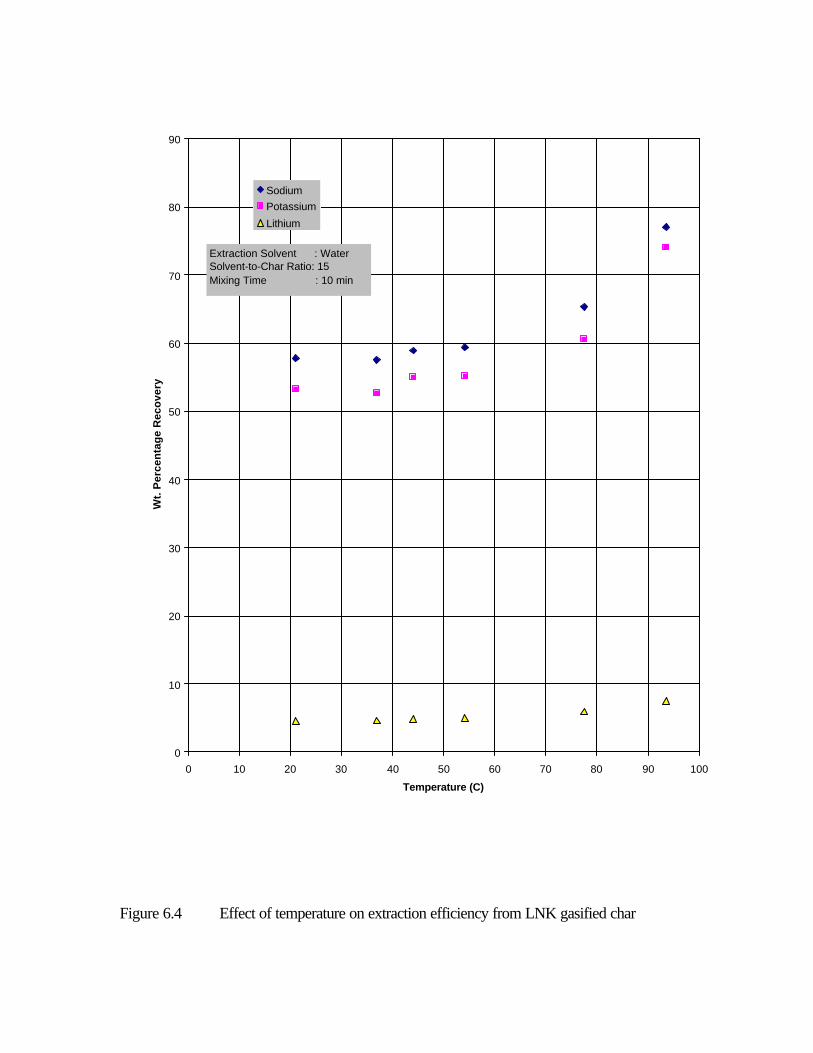
Figure 6.4 Effect of temperature on extraction efficiency from LNK gasified char
0
10
20
30
40
50
60
70
80
90
0 10 20 30 40 50 60 70 80 90 100
Temperature (C)
Wt.
Per
cen
tag
e R
eco
very
SodiumPotassium
Lithium
Extraction Solvent : WaterSolvent-to-Char Ratio: 15Mixing Time : 10 min

This increased catalyst recovery compared to water can be due to the extraction of the catalyst ions from the water-insoluble compounds present in the char. These water-insoluble compounds are assumed to be mainly in the form of aluminosilicates. These compounds are produced during gasification by the reactions of clay minerals (e.g., Kaolinite) originally present in the coal with the catalyst. A typical reaction is shown below [1]:
Al2Si2O5(OH)4 + R2CO3 2RAlS 2RAlSiO4 + CO2 + 2H2O (6.1)
(kaolinite) (Aluminosilicate)
where, R stands for any of the alkali metals present in the catalyst (Li, Na or K).
Unlike the water extracts, the sulfuric acid extracts were colorless. This is because, as found from the Exxon work the colloidal suspension of KFeS2, believed to be the source of the blue-green color, is stable only in the pH range of 8 to 13. When sulfuric acid is used as the solvent, the pH is significantly less than 7. So, the extracts were colorless. Sulfuric acid would also react with KFeS2 to release H2S. A faint offensive odor was noted during these experiments to support this fact. One drawback of sulfuric acid extraction is that all the catalyst cations in the extract will be in the form of sulfates and regeneration of the catalyst from this extract may involve additional costs. This is because, an ion-exchanger would be needed as one of the operating steps in converting the less active sulfate to the more active carbonate. For this reason, acetic acid was evaluated next as an extraction solvent.
6.4. ACETIC ACID EXTRACTION
To resolve the drawback identified in the sulfuric acid extraction case, acetic acid was chosen for catalyst extraction. When acetic acid is used, a major part of the alkali metals in the extract would come out as acetates. It is comparatively much easier to convert acetates to carbonates (by thermal calcining) than sulfates to carbonates. The associated costs are believed to be lower.
As in the case of sulfuric acid extraction, the minimum theoretical concentration of acetic acid needed for complete reaction with the alkali metals present in the gasified char was calculated. This was found to be 0.702 M. and runs were carried out by varying the acid concentration from 0.7 M to 3.0 M to evaluate the effect of acid concentration on the extraction efficiency. A solvent-to-char ratio of 15 ml/g and a mixing time of 10 min. were chosen for these runs. Extraction was carried out at room temperature and the extracts were analyzed using the ICP. Figure 6.6 shows the results. The performance of acetic acid was found to be as good as that of sulfuric acid. Sodium and lithium were extracted almost completely and the maximum recovery of potassium was around 80%. The difference in affinities of Li and K towards acetic acid could possibly explain Li recovery being greater than K recovery. While the water extracts were blue-green in color and the sulfuric acid extracts were colorless, the acetic acid extracts were light orange in
1350oF

Figure 6.5 Effect of sulfuric acid concentration on extraction efficiency from LNK gasified char
0
20
40
60
80
100
120
0 0.2 0.4 0.6 0.8 1 1.2 1.4 1.6
Concentration (M)
Wt.
Per
cen
tag
e R
eco
very
Sodium
Potassium
Lithium
Extraction Solvent : Sulfuric AcidSolvent-to-Char Ratio: 15 ml/gMixing Time : 10 minTemperature : 25 C

color. However, the source of this color was not established. Results for experiments using NK gasified char were also similar. 6.5. COMPARISON OF CATALYST RECOVERY RESULTS FOR LNK AND NK CATALYSTS
Based on the extent of extraction, it cannot be concluded with certainty which catalyst system is better than the other. Both systems performed equally well though LNK showed a slightly better performance in two of the three extraction schemes. However, it was concluded from previous steam gasification work in the Chapters four and five that the LNK catalyst gave higher gasification rates than the NK catalyst under similar experimental conditions [4].
6.6. CATALYST REGENERATION
The extracts obtained from recovery experiments are not useful for recycle in ”as-is” form. These extracts have to be treated suitably to regenerate/reactivate the catalyst and get them into their original form to restore the activity. It was shown earlier that the catalyst is most active if it is in the form of carbonates and as a eutectic. But the alkali metals in the extracts were not just in the form of carbonates; they were found to contain sulfates, bicarbonates, hydroxides and acetates of the alkali metals. Based on the analysis of the extracts by an outside laboratory, the concentrations of the major species in the three extracts (water, sulfuric acid and acetic acid) were determined [2]. Table 6.1 shows the overall composition of the three different extracts for the LNK gasified char. A similar analysis was carried out for the NK gasified char also. Subsequently, knowing the composition of the fresh catalyst, calculations were made to determine the make-up catalyst needed for each of the three extraction schemes [2]. Table 6.2 shows the make-up catalyst required for each extraction scheme for the LNK gasified char. Calculations were also made to determine the make-up catalyst required for each extraction scheme for the NK gasified char. The fresh catalyst ingredients for the LNK catalyst were in the form of Li2CO3, Na2CO3 and K2CO3. The catalyst recovered from the catalyst recovery scheme also needed to be in the same form to restore the catalytic activity. From the extracts’ analysis, it was found that sulfates were invariably present in the extracts. Additionally, the water extracts also contained hydroxides, carbonates and bicarbonates. The acetic acid extracts contained acetates in addition to sulfates. Thus, whatever extracting solvent was chosen, it was necessary that the sulfates present in the extract be converted to carbonates. Previous work conducted at UTSI on a separate DOE funded project entitled “The Anion-Exchange Resin-Based Desulfurization Process for Spent Seed Regeneration in an MHD Power Plant” demonstrated how sulfates could be converted to carbonates [5]. A similar procedure was considered for the present work. However, no actual experimental work was performed. Similarly, the bicarbonates and hydroxides may be converted into the carbonate form by concentrating the solution in an evaporator/crystallizer.
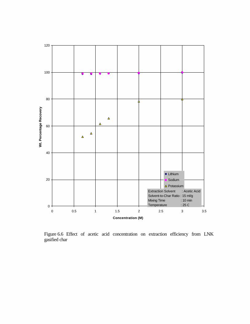
Figure 6.6 Effect of acetic acid concentration on extraction efficiency from LNK gasified char
0
20
40
60
80
100
120
0 0.5 1 1.5 2 2.5 3 3.5
Concentration (M)
Wt.
Per
cent
age
Rec
over
y
Lithium
Sodium
Potassium
Extraction Solvent : Acetic AcidSolvent-to-Char Ratio : 15 ml/gMixing Time : 10 minTemperature : 25 C
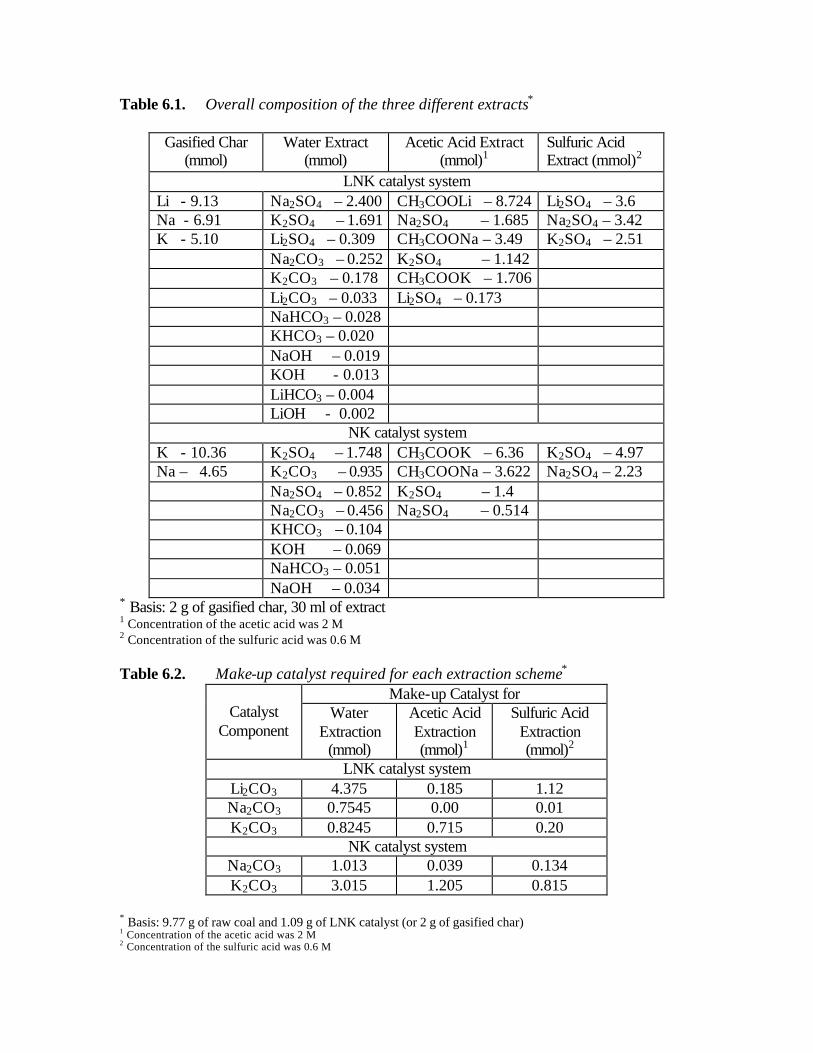
Table 6.1. Overall composition of the three different extracts*
Gasified Char
(mmol) Water Extract
(mmol) Acetic Acid Extract
(mmol)1 Sulfuric Acid Extract (mmol)2
LNK catalyst system Li - 9.13 Na2SO4 – 2.400 CH3COOLi – 8.724 Li2SO4 – 3.6 Na - 6.91 K2SO4 – 1.691 Na2SO4 – 1.685 Na2SO4 – 3.42 K - 5.10 Li2SO4 – 0.309 CH3COONa – 3.49 K2SO4 – 2.51 Na2CO3 – 0.252 K2SO4 – 1.142 K2CO3 – 0.178 CH3COOK – 1.706 Li2CO3 – 0.033 Li2SO4 – 0.173 NaHCO3 – 0.028 KHCO3 – 0.020 NaOH – 0.019 KOH - 0.013 LiHCO3 – 0.004 LiOH - 0.002
NK catalyst system K - 10.36 K2SO4 – 1.748 CH3COOK – 6.36 K2SO4 – 4.97 Na – 4.65 K2CO3 – 0.935 CH3COONa – 3.622 Na2SO4 – 2.23 Na2SO4 – 0.852 K2SO4 – 1.4 Na2CO3 – 0.456 Na2SO4 – 0.514 KHCO3 – 0.104 KOH – 0.069 NaHCO3 – 0.051 NaOH – 0.034
* Basis: 2 g of gasified char, 30 ml of extract 1 Concentration of the acetic acid was 2 M 2 Concentration of the sulfuric acid was 0.6 M
Table 6.2. Make-up catalyst required for each extraction scheme*
Make-up Catalyst for Catalyst
Component Water
Extraction (mmol)
Acetic Acid Extraction (mmol)1
Sulfuric Acid Extraction (mmol)2
LNK catalyst system Li2CO3 4.375 0.185 1.12 Na2CO3 0.7545 0.00 0.01 K2CO3 0.8245 0.715 0.20
NK catalyst system Na2CO3 1.013 0.039 0.134 K2CO3 3.015 1.205 0.815
* Basis: 9.77 g of raw coal and 1.09 g of LNK catalyst (or 2 g of gasified char) 1 Concentration of the acetic acid was 2 M 2 Concentration of the sulfuric acid was 0.6 M

The acetates may be converted into the carbonate form by calcining the concentrated solution or dry powder in a calciner. Based on this information, a process schematic was developed for the catalyst recovery scheme. This schematic is shown in Figure 6.7.
6.7. ECONOMIC ANALYSIS AND COST ESTIMATION
Before making a cost estimation for the catalyst recovery plant, the process design for the entire catalyst recovery process was carried out. To do this, a thermal input power of 100 MWt was assumed for the catalytic coal gasification plant. An overall material balance was carried out for this commercial plant by scaling up the bench-scale experimental values to the commercial scale [2]. The equipment needed for the plant was sized and the quantities of various consumables were calculated.
Based on this process design, cost estimation for the “stand alone” catalyst recovery section of the 100 MWt Catalytic Coal Gasification Plant was carried out [2]. The Total Cost of Regeneration (TCR) of the catalyst for each extraction scheme is shown in Table 6.3. From this table, it can be concluded that the performance of sulfuric acid as an extraction solvent is better than the other two acid solvents with regard to economics. Though the regeneration cost of NK catalyst with sulfuric acid is lower than the corresponding LNK catalyst regeneration cost, the fact that LNK was found to be a better steam gasification catalyst should also be considered before making the final catalyst selection for the overall gasification plant. Calculations were also carried out to compare the performance of the once-through process (no recycle of the spent catalyst) with the catalyst recovery/regeneration process. If the catalyst recovery operations were not carried out, then, the gasified char would be disposed off as waste. Since the gasified char contains water-soluble salts such as sulfides, sulfates and carbonates of Li, Na and K, it cannot be disposed off in a conventional landfill. Therefore, the disposal cost would be significant. For the once-through process, two cost components are involved – the cost of replacing the consumed catalyst continuously and the cost of disposal of the gasified char. The annual costs for the once-through process were found to be:
NK Catalyst: $ 9.98 million
LNK Catalyst: $ 13.97million Comparing these values with the costs for the various extraction schemes shown in Table 6.3, one can see that the catalyst recovery process using sulfuric acid as the extraction solvent is a better option on the economic grounds.

Figure 6.7 Process schematic for the catalyst recovery and reactivation scheme
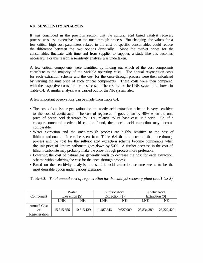
6.8. SENSITIVITY ANALYSIS It was concluded in the previous section that the sulfuric acid based catalyst recovery process was less expensive than the once-through process. But changing the values for a few critical high cost parameters related to the cost of specific consumables could reduce the difference between the two options drastically. Since the market prices for the consumables fluctuate with time and from supplier to supplier, a study like this becomes necessary. For this reason, a sensitivity analysis was undertaken. A few critical components were identified by finding out which of the cost components contribute to the majority of the variable operating costs. The annual regeneration costs for each extraction scheme and the cost for the once-through process were then calculated by varying the unit price of such critical components. These costs were then compared with the respective costs for the base case. The results for the LNK system are shown in Table 6.4. A similar analysis was carried out for the NK system also. A few important observations can be made from Table 6.4. • The cost of catalyst regeneration for the acetic acid extraction scheme is very sensitive
to the cost of acetic acid. The cost of regeneration goes down by 40% when the unit price of acetic acid decreases by 50% relative to its base case unit price. So, if a cheaper source of acetic acid can be found, then acetic acid extraction may become comparable.
• Water extraction and the once-through process are highly sensitive to the cost of lithium carbonate. It can be seen from Table 6.4 that the cost of the once-through process and the cost for the sulfuric acid extraction scheme become comparable when the unit price of lithium carbonate goes down by 50%. A further decrease in the cost of lithium carbonate may probably make the once-through process more preferable.
• Lowering the cost of natural gas generally tends to decrease the cost for each extraction scheme without altering the cost for the once-through process.
• Based on the sensitivity analysis, the sulfuric acid extraction scheme seems to be the most desirable option under various scenarios.
Table 6.3. Total annual cost of regeneration for the catalyst recovery plant (2001 US $)
Water Extraction ($)
Sulfuric Acid Extraction ($)
Acetic Acid Extraction ($)
Component
LNK NK LNK NK LNK NK Annual Cost
of Regeneration
15,515,356 10,315,139 11,487,846 9,627,909 25,834,380 26,222,429

Table 6.4. Sensitivity analysis with respect to critical components
Cost (2001 US $ in millions) Scheme Base
Case1 Low Acetic Acid Cost2
Low Natural Gas Cost3
Low Li2CO3 Cost4
High Li2CO3 Cost5
LNK catalyst system Water
Extraction 15.52 - 14.62 11.80 22.94
Sulfuric Acid Extraction 11.49 - 10.59 10.54 13.39
Acetic Acid Extraction
25.84 16.53 24.94 25.68 26.15
Once-Through Process 13.97 - 13.97 10.00 21.90
NK catalyst system Water
Extraction 10.32 - 9.42 - -
1 Base case: Costs pertain to the current cost (year 2001) of consumables 1 Low acetic acid cost: Cost of acetic acid/lb = 0.5*Cost of acetic acid/lb used in the base case 1 Low natural gas cost: Cost of natural gas/ft3 = 0.5*Cost of natural gas/ft3 used in the base case 1 Low Li2CO3 cost: Cost of Li2CO3/lb = 0.5*Cost of Li2CO3/lb used in the base case 1 High Li2CO3 cost: Cost of Li2CO3/lb = 2.0*Cost of Li2CO3/lb used in the base case 6.9. CONCLUSIONS The catalyst recovery experiments were conducted to determine if recovering and recycling the catalyst would lower the cost of the steam gasification process and in the process would also eliminate the difficulties involved in disposing off the gasified char. Three extraction solvents namely water, sulfuric acid and acetic acid were tested as the extraction solvents. Different operating parameters like solvent-to-char ratio, temperature, mixing time and concentration were evaluated to determine their effects on the extraction efficiency. The major conclusions derived from these experiments are as follows:

• Solvent-to-char ratio and mixing time were found to have negligible effect on the extraction efficiency by water.
• The weight percentage recovery of the desired catalyst salts by water was found to increase with an increase in the extraction temperature.
• Recovery of lithium in the case of water extraction was considerably low. Even at higher temperatures, the maximum recovery of lithium was found to be only about 7.5% for the LNK catalyst. This was attributed to a major part of the lithium ions being either tied up as water-insoluble aluminosilicates and other insoluble salts, or low water solubility of Li2CO3.
• Sulfuric acid and acetic acid proved to be much better extraction solvents than water because, in addition to providing almost complete recovery of Na, close to 80% of K and Li could be recovered in both cases.
• While it can be concluded from the catalyst recovery experiments that acetic acid and sulfuric acid are better extraction solvents than water, an economic analysis of the catalyst recovery process showed that the annual cost of catalyst regeneration would be the lowest for the sulfuric acid based extraction scheme.
• Economic calculations also showed that the sulfuric acid based extraction was a better economic option than even the once-through system.
• It can be concluded from the sensitivity analysis that while acetic acid based extraction cost is highly sensitive to the cost of acetic acid, water extraction and the once-through process are very sensitive to fluctuations in the cost of lithium carbonate. Sulfuric acid extraction is relatively inert to the changes in these critical components.
• Though the economic analysis showed that the cost of NK catalyst regeneration using sulfuric acid was lower than the corresponding cost for the LNK catalyst, the final choice of catalyst would depend on the combination of catalyst recovery economics and the particular catalyst’s effectiveness in improving the steam gasification rates.
• Finding a less expensive source of acetic acid could considerably lower the cost of catalyst regeneration and make the acetic acid extraction scheme very economical because, most of the other variable operating costs for the acetic acid extraction are low compared to the other two extraction schemes.
• A multi-stage extraction scheme could also be tried out to see if it can provide increased recovery of catalyst and thereby reduce the cost of make-up catalysts.
• Since the present work evaluated the economics of the catalyst recovery schemes by considering the catalyst recovery plant to be independent of the gasification plant, additional savings in the cost can be realized if heat and material integrations with the gasification plant are incorporated.
6.10. REFERENCES
1. Private communication from Soung, S.Y., and Robert J. Botto, Exxon, 1980. Sastry, C., Determination of the Kinetics of Hydrogasification Reactions and Evaluation of Various Extraction Schemes Used in Recovery, Regeneration and Recycle of Spent Eutectic Catalysts, Master’s Thesis, University of Tennessee, Knoxville, August 2001.

2. Perry, R. and Don Green, Eds., Chemical Engineer’s Handbook, 7th ed., McGraw-Hill, Inc., New York, 1997.
3. Godavarty, A., Catalytic Coal Gasification Using Eutectic Salt Mixtures, Master’s Thesis, University of Tennessee, Knoxville, August 1999.
4. Dharmapurikar, S.R., The Anion-Exchange Resin-Based Desulfurization Process for Spent Seed Regeneration in an MHD Power Plant, Master’s thesis, University of Tennessee, Knoxville, May 1994.
5. Yeboah, Y., et al., Catalytic Gasification of Coal Using Eutectic Salts: Reaction Kinetics Using Binary and Ternary Eutectic Catalysts (Submitted to FUEL)
6. Yeboah, Y., et al., Catalytic Gasification of Coal Using Eutectic Salts: Identification of Eutectics (Submitted to CARBON)
7. Sastry, C., et al., Catalytic Gasification of Coal Using Eutectic Salts: Reaction Kinetics for Hydrogasification Using Binary and Ternary Eutectic Catalysts (To be submitted).

CHAPTER SEVEN: CHARACTERIZATIONS OF COAL/CHAR WITH/WITHOUT CATALYSTS
7.1. STUDY OF THE SURFACE PROPERTY OF THE COAL WITH/WITHOUT CATALYST The surface charge or zeta potential on the coals were measured in aqueous solutions under well-controlled conditions of pH using a "Pen Kem Model 501 Zeta Meter" equipment described in Chapter 2. The surface charge properties of the samples were studied and are shown in Figures 7.1 & 7.2. By changing the content of the catalyst (amount and type), different pH solutions were obtained. As the pH of the sample increased, the zeta potential of the sample decreased (Figure 7.1). Also as the surface charge became more negative the gasification rate appeared to increase. The reasons and explanations for these observed interesting behavior are still unclear and should be further investigated in the future. 7.2. FREE SWELLING INDEX STUDIES D720-91 (ASTM Standard) was used to measure the free-swelling index of the coal. The test method consisted essentially of heating 1 g of coal, in a covered silica crucible in an oven. The oven was adjusted to give a temperature of 1073 ±10 K, in 1.5 minutes, and 1093 ± 5 K, in 2.5 minutes. The heating was continued for not less than 2.5 minutes. The coke button obtained was compared with a series of standard outlines to get a value corresponding to that of the nearest outline. One gram of ground 60 mesh coal was weighed in a cold crucible, and the crucible was lightly tapped 12 times on the bench, rotating it between taps, to level the surface of the coal. The crucible was then covered with a lid and placed upright in the oven. Three buttons were made for each sample of coal tested. The three coke buttons of each sample of coal being tested was viewed through the sight tube and compared to the series of standard profiles. The drawing with which the button was compared was placed exactly in the center of the field of vision from the top of the tube. The button was rotated around its axis until the maximum cross-section area was in line with the drawing and viewed with one eye placed immediately over the top of the tube. Free swelling is the property of certain coals when heated, without restraining influence, to expand freely in volume, as in the volatile matter test or when burned as fuel. The swelling number was determined as the number inscribed in the outline that the largest profile of the button most nearly matched according to Figure 7.3. The average swelling number of the series, expressed to the nearest 1/2 unit, was reported according to the ASTM method [1].

2

3
Table 7.1 Free-Swelling Index of Samples Coal Sample
1 Sample
2 Sample
3 Sample
4 Sample
5 Sample
6 Index
1.5
2
2
1.5
2
1.5
Average of Index
2
2
Coal + Ternary catalysts
Sample 1
Sample 2
Sample 3
Sample 4
Sample 5
Sample 6
Index 2.5 2.5 2.5 2.5 2 2.5 Average of Index
2.5 2.5
Table 7.1 gives an average free swelling index value of about 2 for the raw coal and about 2.5 for the coal with the ternary catalyst. Thus, as the ternary catalysts were added to the coal at 10% wt, the indexes showed a little higher value than that of the coal. This might be due to the catalyst accelerating the releasing of heat at high temperature at short time. The data gotten in our lab was very close to the data offered by the Pennsylvania State coal bank. 7.3. X-RAY DIFFRACTION EXPERIMENTS Catalyst constituents, eutectic salts, pyrolyzed and gasified char samples were examined using x-ray diffractometry (XRD). The purpose of these XRD studies was two-fold: (1) to determine if any phases or moeties are formed in the eutectic salts that are distinct from those present in the individual Li2CO3, Na2CO3, and K2CO3 salts, and (2) to establish changes in the XRD patterns of the eutectic salts before and after gasification

4
reaction. Table 7.2 contains a list of the samples studied. Using a 2 hour scan period resulted in significantly improved signal to noise ratio over a 20 min scan. Hence all the samples listed in Table 7.2 were obtained using 2 hr. scans. Below is a summary of the significant results to date. The first seven samples in Table 7.2 served as the base-line or reference against which the eutectic salt samples and aged samples were examined. Figure 7.4 shows XRD spectra of The Illinois No. 6 coal. The pattern matches that of graphite in the Reference Library in the XRD software. There are significant peaks at 270, 320, and 560. We suspect these peaks correspond to mineral matters present in the coal. Illinois No. 6 coal contains up to 5 % FeS2, in addition to alumina and silica species.
Table 7.2 X-Ray Diffraction Samples
No. Sample Comments
1 Fresh Coal Base-line
2 Na2CO3 Base-line
3 Li2CO3 Base-line
4 K2CO3 Base-line
5 NaNO3 Base-line
6 NaOH Base-line
7 KOH Base-line
8 2.9 % Na2CO3 + 7.1 % K2CO3 + char Gasified Char
9 10 % Li2CO3 + char Gasified Char
10 10 % K2CO3 + char Gasified Char
11 10 % Na2CO3 + char Gasified Char
12 43.5 % Li2CO3 + 31.5 % Na2CO3 + 25 % K2CO3 Eutectic salt
13 10% Li-Na-K carbonate eutectic + pyro. coal Pyrolyzed coal
14 (M1) Li-Na-K carbonate eutectic + pyro. coal Pyrolyzed coal
15 (M1) Li-Na-K carbonate eutectic + char Gasified Char
16 (B1) 0.22 % Na2CO3 + 9.78 % NaNO3 + char Gasified Char
17 (B2) 0.93 % K2CO3 + 9.07 % KOH + char Gasified Char
18 (B3) 9.4 % K2CO3 + 0.6 % K2SO4 + char Gasified Char
19 (B4) 9.64 % KNO3 + 0.36 % K2CO3 + char Gasified Char
20 (B5) 9.17% NaOH + 0.83 % Na2CO3 + char Gasified Char

5
Figure 7.5 shows the XRD spectra of the eutectic salt (Sample no. 12 in Table 7.2) . Individual peaks are identified as those due to one or more of the three constituents (Sample nos. 2,3, & 4 of Table 7.2). However, there are a few peaks that are difficult to attribute to any of the three constituent salts. These new peaks are expected to be due to the formation of new phases/ species, and will be investigated in more detail. Figure 7.6 shows the XRD spectra of the reactor feed (Sample no. 14), that involved mixing coal and eutectic salt in a ratio of 9:1 and then pyrolyzing the mixture in N2 at a temperature 100 K higher than the melting point of the eutectic salt. Many details of the eutectic salt shown in Figure 7.5 are overwhelmed by the coal spectra. However, there is a distinct broad peak in the range of 40-45 o that is observed neither in the original eutectic salt nor in any of the three catalyst constituents. This should be studied in greater detail.

6

7
Figure 7.7 shows the XRD spectra of gasified char (Sample no. 15), in which most of the coal appears to have been gasified and thus interference from the coal is significantly lower. When one compares Figure 7.7 to Figure 7.5, there are several new peaks present in the gasified char sample (e.g., at 22o, 34o, 63o, 75o, 79o, 95o, 111o, and 119o) that were not present in the original eutectic salt or in the pyrolyzed coal feed. This aspect should be studied in more detail as it might suggest potential catalyst deactivation species that are formed during the coal gasification process. This has the potential of suggesting pathways for recovering and regenerating deactivated catalysts. Figures 7.8-7.10 show the XRD spectra of three different samples: (1) fresh coal, (2) eutectic salt, LiNaKCO3 (LNK), and (3) gasified char. All peaks were identified and labeled in these figures using the computer library. The peaks were identified by the same method of comparing peaks, peak intensities, and d-spacing among pure salts, binary carbonate salts, impurities, binary sulfate salts and ternary eutectic salts. The following protocol was used for peak identification. When the peak of a selected salt/compound had a high intensity at a similar angle, d-spacing was checked for comparison. The deviation of d-spacing was 0.02 angstroms. The significance column was also taken into account when all other parameters were not decisive. Figure 7.8 shows an XRD spectra of a fresh coal sample; the major impurities include iron sulfide (FeS2) and silica (S1O2). It is well documented that Illinois No.6 Coal contains up to 5% FeS2, in addition to aluminum and silica species.

8
Figure 7.9 shows an XRD spectra of the pure eutectic salt catalyst (without coal). Although most peaks are attributed to either one or more of the three constituents (Na2CO2, Li2CO2 or K2CO2), a few peaks remained unidentified in our last report. We focused our attention on the possibility of formation of new phases/species. It is clear that binary salts such as NaKCO3, LiNaCO3, and most notably LiKCO3 are major new phases formed. Figure 7.10 shows an XRD spectra of gasified char in which most of the coal appears to have been gasified, and thus interference from the coal is significantly lower. Many peaks observed in Figure 7.10 were not identifiable in the eutectic salt (Figure 7.9) or in the pyrolyzed coal feed. This together with the observation that the eutectic salt lost its catalytic activity during the coal gasification run, prompted us to look for the formation of sulfides or sulfate phases (coal has up to 5% FeS2). It is clear from Figure 7.10 that the dominant phase present in the gasified char sample is KLiSO4. It is an interesting result since, as shown in Figure 7.9, LiKCO3 was the dominant binary salt in the eutectic salt. The protocols developed for the identification of XRD peaks have proved very useful. We plan to use these protocols on all the other XRD spectra to establish active phases as well as the phases formed during catalyst activation. This knowledge will be helpful in the development of methodologies for catalyst recycling/regeneration.
Figure 7.8. X-ray diffraction of gasified char

9
Figure 7.9. X-ray diffraction of eutectic salt
Figure 7.10 X-ray diffraction of fresh coal.

10
7.4. Scanning electron microscopy (SEM) Scanning electron microscopy (SEM) studies of (i) coal + eutectic salt (pyrolyzed, but not yet gasified in the reactor), and (ii) gasified char samples (reactor-aged) were conducted on several eutectic salt samples containing all three salts (Li, Na, & K carbonates) as well as only two salts (Na & K carbonates). Figures 7.11 and 7.12 (SEM4 and SEM5) show the SEM micrographs of a mixture of 10% Li-Na-K eutectic salt and 90 % coal (pyrolyzed). Most of the particles (coal) appear amorphous, as expected since the x-ray diffraction studies showed a rather broad peak for carbon (graphite). Sharp peaks in the XRD were attributed to eutectic salts as well as individual constituents of the salt. The only sharp peaks attributed to coal were due to the presence of iron as an impurity in coal. Both Figures 7.11 and 7.12 were taken at a magnification of 500. Some coal particles are as large as 50-60 um, but most are smaller. One can also easily see a few crystalline particles (10-20 um) with sharp facets and corners. We attribute these to the eutectic salts. Figures 7.13 and 7.14 (SEM1 and SEM2) show the electron micrographs of gasified char samples (reactor-aged) of the LNK-coal mixture. A dramatic change is obvious in the morphology and crystallinity of the sample and is consistent with the results obtained from the x-ray diffraction studies. XRD studies of reactor-aged samples showed a substantial increase in the sample crystallinity (due to the gasification of amorphous carbon). Here, we have mostly eutectic salt, presumably converted to sulfates as shown by XRD. Establishing the identity of the species present in these SEM micrographs by using energy dispersive analysis of x-rays (EDAX) should be a major focus of future studies. 7.5 CONCLUSIONS • As the ternary catalysts were added to the coal at 10% wt, the free swelling index
showed a little higher value than that of the coal. This might be due to the catalysts accelerating the releasing of heat at high temperature at short time.
• Gasified chars with different levels of carbon conversions as well as catalyzed coal
and pyrolyzed coal were characterized in this study by X-ray diffraction to identify several phases. NaKCO3, LiNaCO3 and most notably LiKCO3 were identified as phases formed during gasification, and were believed to be instrumental in the eutectics providing higher gasification (catalytic) activity. A new intermediate specie, KLiSO4 was also found in the gasified char.

11

12

13
• The physical distributions of LNK and NK catalyst systems in their respective Illinois
#6 coal char surfaces were examined using a scanning electron microscope (SEM). Both catalyst systems showed uniform dispersion on the ungasified coal matrix indicating homogeneous mixing. An attempt was made to establish a qualitative correlation between the type of catalyst, its distribution, and effect on the overall carbon conversion. Gasified chars were found to be highly porous in nature and coalesce in the case of the binary (NK) catalyst, whereas the ternary catalyst (LNK) showed highly porous and crystalline morphology. X-ray diffraction patterns of these gasified char samples seemed to indicate the formation of potassium polysulfides (KxSy).
7.6 REFERENCES (1). Levin, E.M., Robbins, C.R., and McMurdie, H.F., “Phase Diagrams for Ceramist”,
American Ceramic Society, 1964 (2). Godavarty, A., Catalytic Coal Gasification Using Eutectic Salt Mixtures, A Thesis
for the Masters Degree in Chemical Engineering, The University of Tennessee Space Institute, August 1999.
(3). Yeboah, Y.D., Xu, Y., Sheth, A., Agrawal, P., Semi-annual Progress Report to DOE, October 1998.
(4). Yeboah, Y.D., Xu, Y., Sheth, A., Agrawal, P.,”Catalytic Gasification of Coal Using Eutectic Salt Mixtures”, Presented at the 7th Annual Historically Black Colleges and Universities and Other Minority Institutions, Miami, FL, 1999.
(5). McKee, W., Douglas et. Al., “Eutectic Salt Catalysts for Graphite and Coal Char Gasification’, General Electric Corporate Research and Development, Fuel, 64(1985): 805-809.
(6). Tetsuya, Haga et. Al., “Composite Catalysts for Carbon Gasification”., Applied catalysis, 67(1991):189-202.
(7). Tomita, Akira, “Catalytic Coal Gasification”, Nenryo Kyokai-shi 589(1979): 332-342, Translated by Ralph Mcelroy Co., Texas.
(8). Figueiredo, J.L., “Gasification of carbon Deposists on Catalysts and Metal Surfaces’, Fuel, 65(1986):1377-1382.
(9). Formella, K. et. Al., “Intercation of Mineral Matter in Coal with Potassium during gasification”, Fuel, 65(1986):1470-1471.
(10). ASTM D 720-43, “Standard Test Method for Free-Swelling Index of Coal”, American Society for Testing and Materials, 1992.
14
CHAPTER EIGHT: OTHER PROGRAM ACCOMPLISHMENTS
A key objective of the project as detailed in chapter 1, was the education and training of students in catalysis, energy, and fossil fuel conversion. The project involved the active participation and training of several chemical engineering students at Clark Atlanta University, the University of Tennessee Space Institute, and the Georgia Tech Institute of Technology. Details on the students trained are provided below. 8.1 STUDENTS SUPPORTED ON THE PROJECT AT CLARK ATLANTA
UNIVERISTY • Antron Palmer and Tamara Gray, graduated with BS in Chemical Engineering
from Clark Atlanta University (CAU) in May 1999. They are currently working with Milleken Corp.in Lagrange, Georgia.
• Teona Edwards is a Junior in Chemical engineering at Clark Atlanta University who worked on the free swelling index measurements.
• Ms. Pamela Reid, graduated with a BS in Chemical Engineering at Clark Atlanta University (CAU) in May 2000. Pamela is now a graduate student in the School of Chemical Engineering at Georgia Tech.
• Ms. LaTanya Funches, is a senior in Chemical Engineering at CAU. LaTanya graduates in May 2002 and plans to go to Law school.
8.2. STUDENTS SUPPORTED AT THE UNIVERSITY OF TENNESSEE SPACE
INSTITUTE (UTSI) • Anuradha Godavarty, Graduated with an MS degree in chemical Engineering
from The University of Tennessee Space Institute (UTSI) in August 1999. Her thesis entitled, " is summarized in Chapter four. She is presently pursuing a PhD in Chemical Engineering at Texas A&M University.
• Mr.Chandramouli Sastry, Graduated with MS degree in Chemical Engineering from The University of Tennessee Space Institute (UTSI) in June 2001. His thesis entitled," is summarized in Chapter five and six. Mr. Sastry is currently employed by
8.1 STUDENTS SUPPORTED AT THE GEORGIA INSTITUTE OF
TECHNOLOGY • Ms. Megan Czarny, graduated with a BS in Chemical Engineering from Georgia
Tech in May 2000. Megan is presently employed by Agra-Simons Consulting Company in Atlanta.
• Mary A. Minton, graduated in Chemical Engineering at Georgia Tech in May 2001. Mary recently took over from Megan and has learned the XRD equipment operation as well as the protocols for peak identification.

15
8.2 STUDENT THESIS PRODUCED • Godavarty, A., Catalytic Coal Gasification Using Eutectic Salt Mixtures.
Master's Thesis, University of Tennessee, Knoxville, August 1999. • Mr.Chandramouli Sastry, Master's Thesis, University of Tennessee,
Knoxville, in June 2001.
8.5 PUBLICATIONS AND PRESENTATIONS 8.5.1 PUBLICATIONS • Godavarty, A. and Agarwal, A., Energy & Fuels 2000, 14 558-565 • Yeboah, Y. D., Xu, Y., Sheth, A., Godavarty, A. and Agrawal, K.P., Catalytic
Gasification of Coal Using Eutectic Salts: Identification of Eutectics (Submitted to Carbon)
• Yeboah Y.D., Xu Y., Sheth A., Godavarty A. and Agrawal K. P., Catalytic Gasification of Coal Using Eutectic Salts:Reaction Kinetics using Binary and Ternary Eutectic Catalysts.(Submitted to Fuel)
• Sheth A., Sastry C, Yeboah Y.D., Xu Y., and Agrawal K. P.,Catalytic Gasification of Coal Using Eutectic Salts: Recovery, Regeneration and Recycle of Spent Eutectic Catalysts (To be submitted to Fuel)
• Sheth A., Sastry C.Yeboah, Y.D., Xu Y., and Agrawal K. P.,Catalytic Gasification of Coal Using Eutectic Salts: Reaction Kinetics for Hydrogasification Using Binary and Ternary Eutectic Catalysts (To be submitted to Fuel)
8.5.2 PRESENTATIONS • Yeboah, Y. D., Y. Xu, A. Sheth, A. Godavarty, P. K. Agrawal, "Catalytic
Gasification of Coal Using Eutectic Salt Mixtures" , 1998 DOE University Coal Research Contractors Review Conference, Pittsburgh, Pennsylvania, June, 1998
• Yeboah, Y. D., Y. Xu, A. Sheth, A. Godavarty, P. K. Agrawal, "Catalytic Gasification of Coal Using Eutectic Salt Mixtures" , 7th Annual Historically Black Colleges and Universities and Other Minority Institutions, Miami, Florida, March, 1999
• Yeboah, Y. D., Y. Xu, A. Sheth, A. Godavarty, P. K. Agrawal, "Catalytic Gasification of Coal Using Eutectic Salt Mixtures" , 1999 DOE University Coal Research Contractors Review Conference, Pittsburgh, Pennsylvania, June 1-2, 1999
• Yeboah, Y. D., Y. Xu, A. Sheth, C. Sastry, P. K. Agrawal, M. Czarny "Catalytic Gasification of Coal Using Eutectic Salt Mixtures" , 2000 DOE University Coal Research Contractors Review Conference, Pittsburgh, Pennsylvania, June 1-2, 2000
• Yeboah, Y. D., Y. Xu, A. Sheth, C. Sastry, P. K. Agrawal, M. Minton, "Catalytic Gasification of Coal Using Eutectic Salt Mixtures" , 2001 DOE University Coal Research Contractors Review Conference, Pittsburgh, Pennsylvania, June 1-2, 2001.
.

16
CHAPTER NINE: CONCLUSIONS AND ACKNOWLEDGMENT 9.1. CONCUSIONS
• The activity of single salt catalysts used in the gasification of coal was found to be in the following order: Li2CO3>Cs2CO3>CsNO3>KNO3>K2CO3>K2SO4>Na2CO3>CaSO4. The catalytic activity increased by varying degrees with increasing amounts of catalysts added to the coal/char. The eutectic catalysts increased gasification rate at lower temperatures due to their lower melting point.
• Based on the preparation and evaluation of over 50 binary and 12 ternary
eutectics, the 43.5% Li2CO3-31.5% Na2CO3-25% K2CO3 and 39% Li2CO3-38.5% Na2CO3-22.5% Rb2CO3 were identified to be the best ternary eutectic catalysts. The 29% Na2CO3-71 % K2CO3 was the most effective binary eutectic. In general, the activity was in the order of ternary> binary > single salts.
• The method of catalyst addition had significant effect on the gasification rate and
the extent of carbon conversion. The incipient wetness method gave better results than the physical mixing method in the TGA studies. This is attributed to improved catalyst distribution and dispersion on the surface of the coal. The results are especially important in reducing the severity of coal gasifiers since the eutectic catalysts (with low melting points) yield significant gasification rates even at low temperatures.
• The observed activity order of incipient wetness>physical mixing, may be
ascribed to dispersion effects. The incipient wetness method allows the catalyst to penetrate into the pores of the coal sample and also enhances uniform distribution of the catalyst within the coal thereby increasing the dispersion, catalyst utilization and effectiveness.
• Temperature was found to have a significant effect on the rate of gasification of
coal. The rate of CO2 gasification increased up to 1033 K. The amount of catalyst increased the CO2 gasification and steam gasification rate and approached complete conversion when 10 wt % of catalyst was added to coal.
• Within experimental error, there was no effect of system pressure on the
gasification rate in the LNK system. This was similar to the observations made by earlier researchers.
• There was a significant effect of catalyst loading on the gasification reaction in
both catalyst systems. Both the gasification rates and conversion levels were found to increase with the increase in the metal (catalyst) to carbon (M/C) ratio.

17
• Below 10 wt. % catalyst loading, the specific gasification rate increased linearly with increase in the M/C ratio, indicating the gasification rate to be independent of the catalyst type, and just dependent on the concentration of the alkali metals.
• The effect of steam flow rate showed a different behavior in the two catalyst
systems. With increase in steam flow rate, the carbon conversion levels in the LNK system increased. However, the NK system showed an inconsistent behavior at different steam flow rates. Additional work is needed to understand this difference in behavior.
• The effect of the partial pressure of steam on the water gas-shift reaction was
elucidated from the experiments carried at different steam/water flow rates for both catalyst systems. The rise in [CO2]/[CO] ratio with steam flow rates was in accordance with the thermodynamics of the shift reaction.
• A simple Langmuir-Hinshelwood type rate model, excluding the effect of
hydrogen inhibition provided a reasonably good fit to the experimental runs at different temperatures and steam/water flow rates.
• The activation energy of the NK system (201 kJ/mol) was twice that of the LNK
system (98 kJ/mol) indicating a better catalytic activity by the liquid ternary catalyst. The exothermic molar heat of adsorption for the LNK and NK systems were 180 and 92 kJ/mol respectively.
• For both catalyst systems (LNK and NK), a significant increase in the specific
gasification rates was observed with the decrease in the partial pressure of hydrogen.
• The calculated hydrogasification rates for the LNK catalyst were found to be
lower than the corresponding rates for the NK catalyst, as opposed to what was observed earlier in the case of pure steam gasification. Additional experiments established that the reason for this unexpected behavior was possibly due to the difference in the average sample particle size. Subsequently, one hydrogasification experiment was carried out with a slightly smaller average particle size of the LNK pyrolyzed char. With a decrease in the average particle size of the LNK pyrolyzed char the gasification rate increased. Further calculations showed that, probably the surface chemical reaction was the likely rate-limiting step in the hydrogasification experiments.
• A Langmuir-Hinshelwood type reaction kinetic model was developed to satisfy
the experimental data for both the catalyst systems and a mechanism was proposed to explain this model.

18
• Solvent-to-char ratio and mixing time were found to have negligible effect on the extraction efficiency by water.
• The weight percentage recovery of the desired catalyst salts by water was found
to increase with an increase in the extraction temperature.
• Recovery of lithium in the case of water extraction was considerably low. Even at higher temperatures, the maximum recovery of lithium was found to be only about 7.5% for the LNK catalyst. This was attributed to a major part of the lithium ions being either tied up as water-insoluble aluminosilicates and other insoluble salts, or low water solubility of Li2CO3.
• Sulfuric acid and acetic acid proved to be much better extraction solvents than
water because, in addition to providing almost complete recovery of Na, close to 80% of K and Li could be recovered in both cases.
• While it can be concluded from the catalyst recovery experiments that acetic acid
and sulfuric acid are much superior extraction solvents than water, an economic analysis of the catalyst recovery process showed that the annual cost of catalyst regeneration would be the lowest for the sulfuric acid based extraction scheme.
• Economic calculations also showed that the sulfuric acid based extraction was a
better economic option than even the once-through system.
• It can be concluded from the sensitivity analysis that while acetic acid based extraction cost is highly sensitive to the cost of acetic acid, water extraction and the once-through process are very sensitive to fluctuations in the cost of lithium carbonate. Sulfuric acid extraction is relatively inert to the changes in these critical components.
• Though the economic analysis showed that the cost of NK catalyst regeneration
using sulfuric acid was lower than the corresponding cost for the LNK catalyst, the final choice of catalyst would depend on the combination of catalyst recovery economics and the particular catalyst’s effectiveness in improving the steam gasification rates.
• Finding a cheaper source of acetic acid could considerably lower the cost of
catalyst regeneration and make the acetic acid extraction scheme very economical because, most of the other variable operating costs for the acetic acid extraction are low compared to the other two extraction schemes.
• A multi-stage extraction scheme could also be tried out to see if it can provide
increased recovery of catalyst and thereby reduce the cost of make-up catalysts.
• Since the present work evaluated the economics of the catalyst recovery schemes considering the catalyst recovery plant to be independent of the gasification plant,

19
additional savings in the cost can be realized if the heat and material integrations with the gasification plant are incorporated.
• Gasified chars with different levels of carbon conversions as well as catalyzed coal and pyrolyzed coal were characterized in this study by X-ray diffraction to identify several phases. NaKCO3, LiNaCO3 and most notably LiKCO3 were identified as phases formed during gasification, and were believed to be instrumental in the eutectics providing higher gasification (catalytic) activity. A new intermediate specie, KLiSO4 was also found in the gasified char.
• The physical distributions of LNK and NK catalyst systems in their respective Illinois
#6 coal char surfaces were examined using a scanning electron microscope (SEM). Both catalyst systems showed uniform dispersion on the ungasified coal matrix indicating homogeneous mixing. An attempt was made to establish a qualitative correlation between the type of catalyst, its distribution, and effect on the overall carbon conversion. Gasified chars were found to be highly porous in nature and coalesce in the case of the binary (NK) catalyst, whereas the ternary catalyst (LNK) showed highly porous and crystalline morphology. X-ray diffraction patterns of these gasified char samples seemed to indicate the formation of potassium polysulfides (KxSy).
• Several students were trained and educated at the three participating institutions. Most of these students are now either in graduate school in chemical engineering or employed.
• Two masters thesis and several publications resulted from this study.
• Overall, the project had significant impact on the chemical engineering research and educational program at Clark Atlanta University, the University of Tennessee Space Institute and the Georgia Institute of Technology.
1.2 ACKNOWLEDGMENT
This work was supported by the US department of energy, under contract number DE-FG26-97FT97263. We also wish to acknowledge the support of Clark Atlanta University, the University of Tennessee Space Institute and the Georgia Institute of Technology.

20
CHAPTER TEN: SUGGESTIONS FOR FUTURE STUDIES
Based on the three-year study, a number of binary and ternary eutectic catalyst systems were identified and found to increase gasification rate significantly. The methods of catalyst preparation and addition had significant effect on the catalytic activity and coal gasification. The incipient wetness method gave more uniform catalyst distribution than that of physical mixing for the soluble catalysts resulting in higher gasification rates for the incipient wetness samples. The effects of major process variables such as temperature, pressure, catalyst loading and steam flow rate on the gasification kinetics were evaluated. Temperature was found to have a significant effect on the rate of gasification of coal/char. Pressure did not have much effect on the carbon conversion and the overall gasification rates. The amount of catalyst loading increased the CO2 and steam gasification rate and approached complete conversion when 10 wt % of catalyst was added to the coal. As part of this DOE University Coal Research (UCR) project, based on the TGA studies, the team recommended three eutectic salt mixtures, 43.5% Li2CO3–31. 5% Na2CO3–25% K2CO3 (LNK); 39% Li2CO3–38.5% Na2CO3–22.5% Rb2CO3 (LNR); and 29% Na2CO3–71% K2CO3 (NK) (2) for further evaluation. Of these three catalyst mixtures, only LNK and NK were further evaluated in the high temperature, high pressure, differential fixed bed to develop overall reaction kinetics rate expressions as functions of temperature, carbon content of the bed and partial pressure of H2O. A Langmuir-Hinshelwood type rate model was used to describe the overall kinetics and the effect of hydrogen inhibition was excluded. Gasified chars with different levels of carbon conversions as well as catalyzed coal and pyrolyzed coal were characterized in this study by X-ray diffraction to identify several phases. NaKCO3, LiNaCO3 and most notably LiKCO3 were identified as phases formed during gasification, and were believed to be instrumental in the eutectics providing higher gasification (catalytic) activity. A new intermediate specie, KLiSO4 was also found in the gasified char. The physical distributions of LNK and NK catalyst systems in their respective Illinois #6 coal char surfaces were examined using a scanning electron microscope (SEM). Both catalyst systems showed uniform dispersion on the ungasified coal matrix indicating homogeneous mixing. An attempt was made to establish a qualitative correlation between the type of catalyst, its distribution, and effect on the overall carbon conversion. Gasified chars were found to be highly porous in nature and coalesce in the case of the binary (NK) catalyst, whereas the ternary catalyst (LNK) showed highly porous and crystalline morphology. X-ray diffraction patterns of these gasified char samples seemed to indicate the formation of potassium polysulfides (KxSy). In summary, under the existing UCR contract, the CAU/UTSI/GT team demonstrated that the three eutectic catalyst mixtures can provide superior performance in comparison to the conventional (single salt) catalysts used in the field of coal gasification. Recent advances in modeling algorithms and computational capabilities have improved the development of detailed computational models to simulate molecule-surface
21
interactions. These models can help in eliminating unproductive and non-feasible reaction pathways. Validation of such models using coal gasification data obtained from ternary and binary eutectic salt mixtures can probably describe an ideal catalyst mixture for the desired reaction pathway. This would help in developing a “best’ catalyst system for producing synthesis gas from coal which can then serve as substitute for source of energy or as chemical feed stock. Under the current energy crisis, and skyrocketing prices of oil and natural gas, this development would be very timely. And the suggestions for the future studies are as follows: • Extend SEM/microprobe analysis and X-ray diffraction analysis of the partially
gasified, totally gasified and ungasified (but pyrolyzed and catalyzed coal) to develop relationships between the carbon conversion, catalyst mobility, catalyst dispersion and overall carbon gasification rate.
• Evaluate the effect of certain catalyst promoters/enhancers (such as sulfur compounds of K, Na, Li, and iron as pyrites) on demineralized carbon or commercially available graphite, or carbosieve (carbon molecular sieve). Select these promoters/enhancers based on the literature and X-ray diffraction results obtained so far.
• Determine catalyst turnover frequency (e.g., carbon gasification rate per surface area or active site) using TK (transient kinetics) method developed by scientists at the Penn State University .
• Confirm K2O distribution (as measured by CO2 chemisorption) using the method developed by Ratcliffe and Vaughn at Exxon. For chars containing alkali metal salts and with different carbon conversions, the results obtained from SEM/microprobe analysis and this chemisorption method should give comparable correlationship between the char reactivity and carbon conversion levels.
• Develop a reaction mechanism for one catalyst system using experimental and char characterization results. From this determine the necessary model parameters (such as rate constants for underlying reactions). Using this information then predict the behavior of the 2nd catalyst system, and compare such prediction with the actual experimental data from that 2nd catalyst system.
• Also, test the latest available literature models for the catalytic coal gasification with the experimental data generated for the LNK and NK catalysts.
Related Documents