CATALOG 2018/19 SENSORS | LIGHTING VISION | ID | SAFETY

Welcome message from author
This document is posted to help you gain knowledge. Please leave a comment to let me know what you think about it! Share it to your friends and learn new things together.
Transcript

CATALOG2018/19
SENSORS | LIGHTINGVISION | ID | SAFETY

WELCOME TO DI-SORIC
For over 35 years, we have been producing and selling sensors used in industrial automation, primarily in assembly and handling technology, the automotive, electronics and pharmaceutical industries and packaging technology. Other cornerstones of our product range are image processing and identifi -cation systems, high-quality LED lighting and products for work safety. Our subsidiary, di-soric Solutions GmbH & Co. KG, specializes in the busi-ness areas of image processing and identifi cation. Our priorities: In addition to high-quality products, di-soric Solutions prioritizes complete solutions, developed for you, which we call "engineered solutions". We are involved in all phases, from consultation and project engineering all the way to integra-tion into your systems.
We combine our resources to help you ensure that your production pro-cesses are as precise, free of error and cost-e� ective as possible, now and in the future.
ABOUT THE INVENTOR OF THE FORK LIGHT BARRIER:DI-SORIC.

DI-SORIC FACTS
100% OWNER-MANAGED
HEADQUARTERSUrbach, Germany
TECHNOLOGY AND PRODUCTION CENTER Lüdenscheid, Germany
REPRESENTATIVES AND BRANCH OFFICESin more than 40 countries
CERTIFICATIONSIQNet, DQS - ISO 9001:2015, UL, RoHS, GS1

OUR PROMISE TO YOU:
SOLUTIONS. CLEVER. PRACTICAL.
SOLUTIONS.
To us, fi nding solutions meansproviding you with exactly the right solution for the job.
¡ Solution-oriented consultation and implementation ¡ Product portfolio for numerous application areas ¡ Engineered solutions for industrial image processing
CLEVER.
To us, being clever meansfi nding new, smart, unconventional and therefore more e� ective solutions.
¡ Added value for product and application ¡ E� cient in function and application ¡ Openness and fl exibility for the best solutions
PRACTICAL.
To us, being practical meansbeing available, taking a straightforward approach and communicating as partners.
¡ Solution-oriented consultation and technical expertise ¡ Straightforward, cooperative and dynamic approach ¡ Address what is important, and forget about unnecessary factors.

6
A clearly structured design combined with intelligent search functions enables you to fi nd the right product quickly.You can use the product fi nder to select the right products based on technical characteristics.
The product direct selection enables targeted searching for a particular catalog designation or parts of it.
The product you need—ordering online is easy: di-soric e-shop
Innovative products for your automation
Page
Angled light barriers 36
Frame and ring light barriers 38
Plastic fi ber-optic sensors 40
Glass fi ber-optic sensors 48
Light grids 54
Color sensors 68
Ring and wire-break sensors 74
Tube sensors 80
Page
Company 2
Light barriers 8
Laser light barriers 16
Laser line di� use sensors 20
Laser distance sensors 22
High-performance light barriers 24
Fork light barriers 26
Laser fork light barriers 34
Table of contents
7For more information and models visit www.di-soric.com
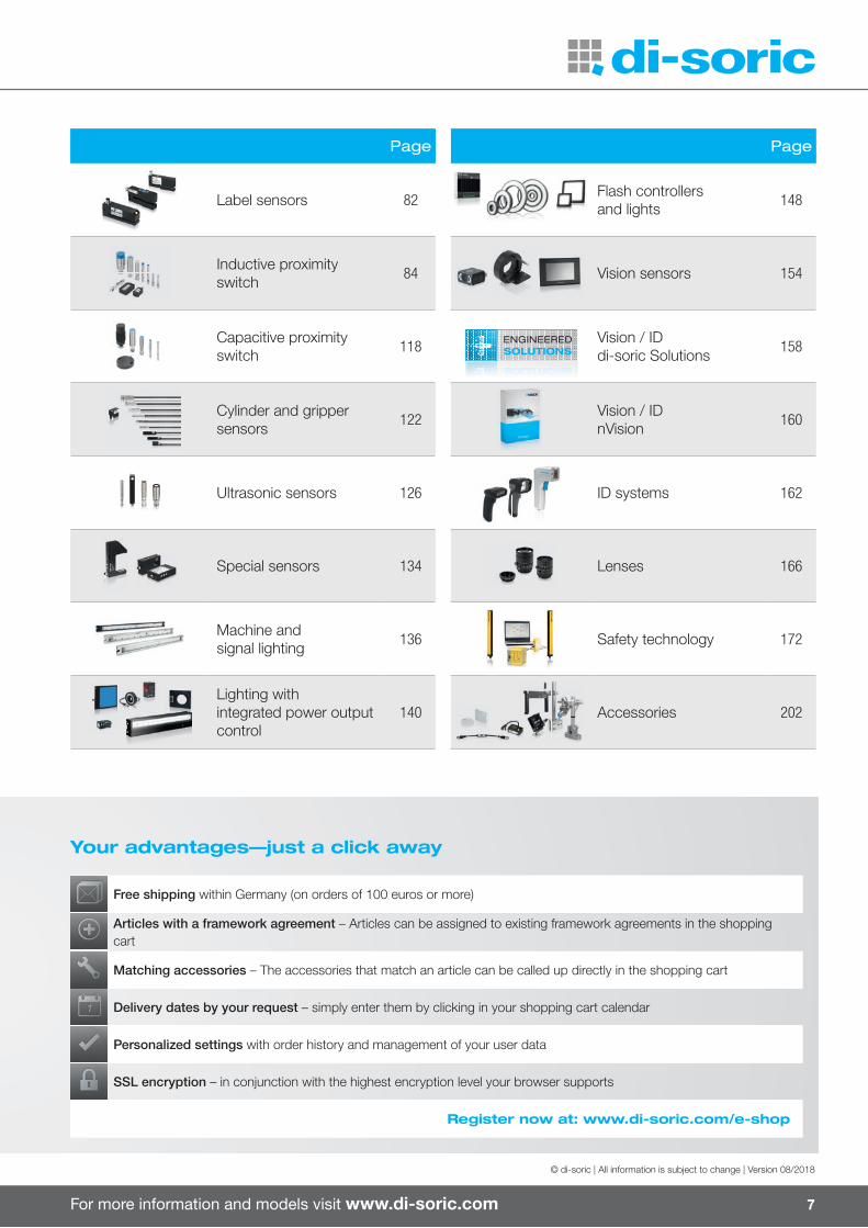
Your advantages—just a click away
Free shipping within Germany (on orders of 100 euros or more)
Articles with a framework agreement – Articles can be assigned to existing framework agreements in the shopping cart
Matching accessories – The accessories that match an article can be called up directly in the shopping cart
Delivery dates by your request – simply enter them by clicking in your shopping cart calendar
Personalized settings with order history and management of your user data
SSL encryption – in conjunction with the highest encryption level your browser supports
Register now at: www.di-soric.com/e-shop
© di-soric | All information is subject to change | Version 08/2018
Page
Label sensors 82
Inductive proximity switch 84
Capacitive proximity switch 118
Cylinder and grippersensors 122
Ultrasonic sensors 126
Special sensors 134
Machine andsignal lighting 136
Lighting withintegrated power output control
140
Page
Flash controllersand lights 148
Vision sensors 154
Vision / IDdi-soric Solutions 158
Vision / IDnVision 160
ID systems 162
Lenses 166
Safety technology 172
Accessories 202
ENGINEEREDSOLUTIONSSOLUTIONSSOLUTIONS
8
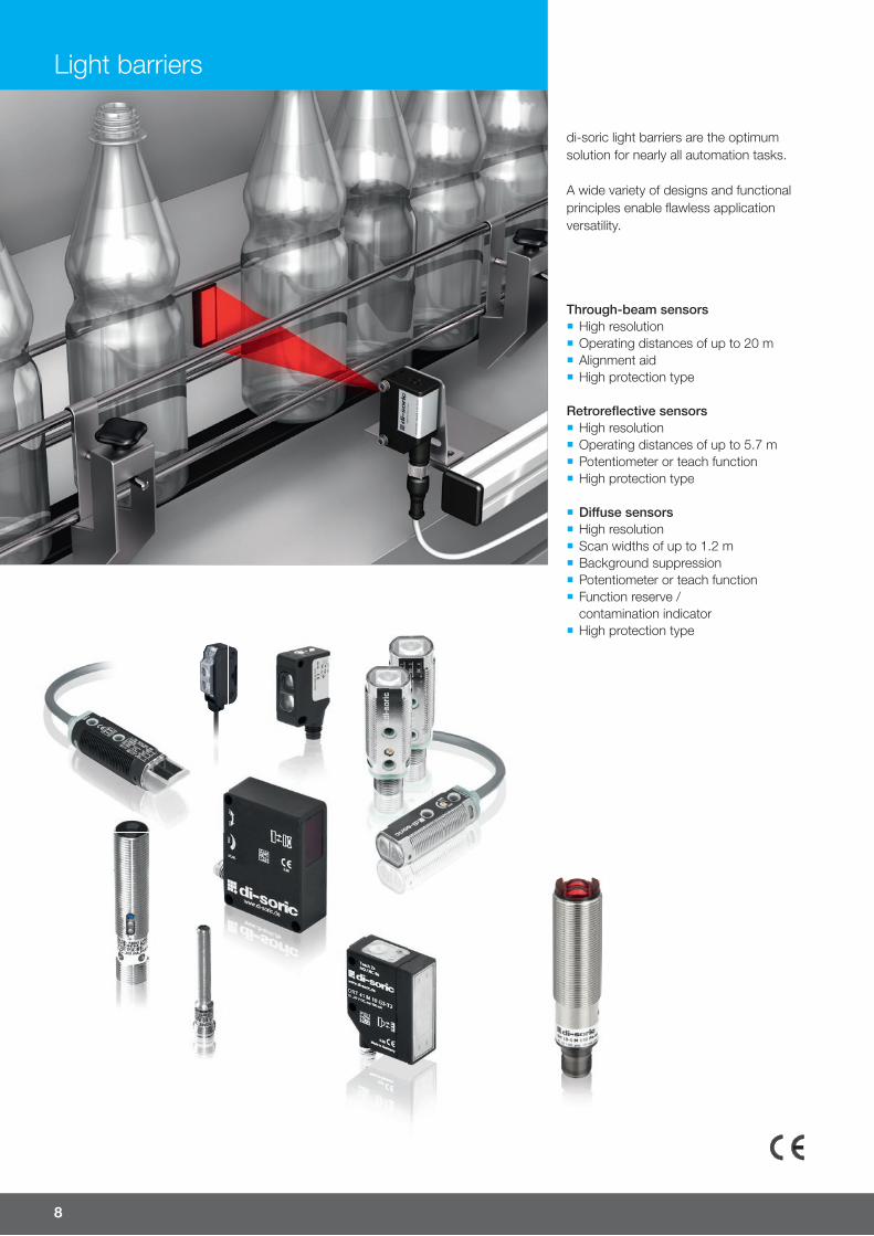
Through-beam sensors ¡ High resolution ¡ Operating distances of up to 20 m ¡ Alignment aid ¡ High protection type
Retrorefl ective sensors ¡ High resolution ¡ Operating distances of up to 5.7 m ¡ Potentiometer or teach function ¡ High protection type
¡ Di� use sensors ¡ High resolution ¡ Scan widths of up to 1.2 m ¡ Background suppression ¡ Potentiometer or teach function ¡ Function reserve / contamination indicator
¡ High protection type
di-soric light barriers are the optimum solution for nearly all automation tasks.
A wide variety of designs and functional principles enable fl awless application versatility.
Light barriers
For more information and models visit www.di-soric.com 9
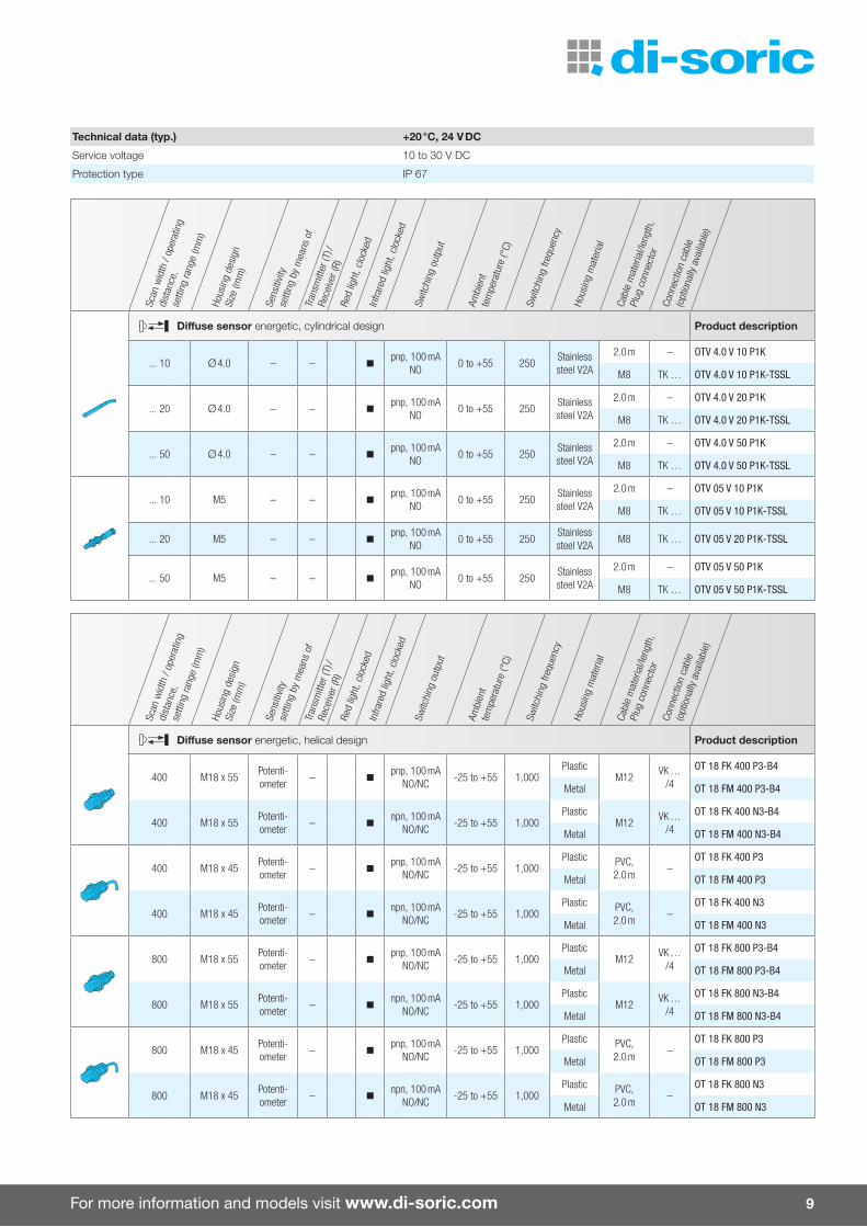
Technical data (typ.) +20 °C, 24 V DC
Service voltage 10 to 30 V DC
Protection type IP 67
Scan
wid
th /
oper
atin
g
dist
ance
, se
tting
rang
e (m
m)
Hous
ing
desi
gnSi
ze (m
m)
Sens
itivit
y
setti
ng b
y m
eans
of
Tran
smitt
er (T
) /
Rece
iver (
R)Re
d lig
ht, c
lock
edIn
frare
d lig
ht, c
lock
ed
Switc
hing
out
put
Ambi
ent
tem
pera
ture
(°C)
Switc
hing
freq
uenc
y
Hous
ing
mat
eria
l
Cabl
e m
ater
ial/l
engt
h,
Plug
con
nect
or
Conn
ectio
n ca
ble
(opt
iona
lly a
vaila
ble)
Di�use sensor energetic, cylindrical design Product description
... 10 Ø 4.0 – – npnp, 100 mA
NO0 to +55 250
Stainless steel V2A
2.0 m – OTV 4.0 V 10 P1K
M8 TK … OTV 4.0 V 10 P1K-TSSL
... 20 Ø 4.0 – – npnp, 100 mA
NO0 to +55 250
Stainless steel V2A
2.0 m – OTV 4.0 V 20 P1K
M8 TK … OTV 4.0 V 20 P1K-TSSL
... 50 Ø 4.0 – – npnp, 100 mA
NO0 to +55 250
Stainless steel V2A
2.0 m – OTV 4.0 V 50 P1K
M8 TK … OTV 4.0 V 50 P1K-TSSL
... 10 M5 – – npnp, 100 mA
NO0 to +55 250
Stainless steel V2A
2.0 m – OTV 05 V 10 P1K
M8 TK … OTV 05 V 10 P1K-TSSL
... 20 M5 – – npnp, 100 mA
NO0 to +55 250
Stainless steel V2A
M8 TK … OTV 05 V 20 P1K-TSSL
... 50 M5 – – npnp, 100 mA
NO0 to +55 250
Stainless steel V2A
2.0 m – OTV 05 V 50 P1K
M8 TK … OTV 05 V 50 P1K-TSSL
Scan
wid
th /
oper
atin
g
dist
ance
, se
tting
rang
e (m
m)
Hous
ing
desi
gnSi
ze (m
m)
Sens
itivit
y
setti
ng b
y m
eans
of
Tran
smitt
er (T
) /
Rece
iver (
R)Re
d lig
ht, c
lock
edIn
frare
d lig
ht, c
lock
ed
Switc
hing
out
put
Ambi
ent
tem
pera
ture
(°C)
Switc
hing
freq
uenc
y
Hous
ing
mat
eria
l
Cabl
e m
ater
ial/l
engt
h,
Plug
con
nect
or
Conn
ectio
n ca
ble
(opt
iona
lly a
vaila
ble)
Di�use sensor energetic, helical design Product description
400 M18 x 55Potenti-ometer
– npnp, 100 mA
NO/NC-25 to +55 1,000
PlasticM12
VK … /4
OT 18 FK 400 P3-B4
Metal OT 18 FM 400 P3-B4
400 M18 x 55Potenti-ometer
– nnpn, 100 mA
NO/NC-25 to +55 1,000
PlasticM12
VK … /4
OT 18 FK 400 N3-B4
Metal OT 18 FM 400 N3-B4
400 M18 x 45Potenti-ometer
– npnp, 100 mA
NO/NC-25 to +55 1,000
Plastic PVC, 2.0 m
–OT 18 FK 400 P3
Metal OT 18 FM 400 P3
400 M18 x 45Potenti-ometer
– nnpn, 100 mA
NO/NC-25 to +55 1,000
Plastic PVC, 2.0 m
–OT 18 FK 400 N3
Metal OT 18 FM 400 N3
800 M18 x 55Potenti-ometer
– npnp, 100 mA
NO/NC-25 to +55 1,000
PlasticM12
VK … /4
OT 18 FK 800 P3-B4
Metal OT 18 FM 800 P3-B4
800 M18 x 55Potenti-ometer
– nnpn, 100 mA
NO/NC-25 to +55 1,000
PlasticM12
VK … /4
OT 18 FK 800 N3-B4
Metal OT 18 FM 800 N3-B4
800 M18 x 45Potenti-ometer
– npnp, 100 mA
NO/NC-25 to +55 1,000
Plastic PVC, 2.0 m
–OT 18 FK 800 P3
Metal OT 18 FM 800 P3
800 M18 x 45Potenti-ometer
– nnpn, 100 mA
NO/NC-25 to +55 1,000
Plastic PVC, 2.0 m
–OT 18 FK 800 N3
Metal OT 18 FM 800 N3

10
Scan
wid
th /
oper
atin
g
dist
ance
, se
tting
rang
e (m
m)
Hous
ing
desi
gnSi
ze (m
m)
Sens
itivit
y
setti
ng b
y m
eans
of
Tran
smitt
er (T
) /
Rece
iver (
R)Re
d lig
ht, c
lock
edIn
frare
d lig
ht, c
lock
ed
Switc
hing
out
put
Ambi
ent
tem
pera
ture
(°C)
Switc
hing
freq
uenc
y
Hous
ing
mat
eria
l
Cabl
e m
ater
ial/l
engt
h,
Plug
con
nect
or
Conn
ectio
n ca
ble
(opt
iona
lly a
vaila
ble)
Retroreflective sensors helical design Product description
5,700 M18 x 55Potenti-ometer
– npnp, 100 mA
NO/NC-25 to +55 1,000
PlasticM12
VK … /4
OR 18-1 FK 5700 P3-B4
Metal OR 18-1 FM 5700 P3-B4
5,700 M18 x 55Potenti-ometer
– nnpn, 100 mA
NO/NC-25 to +55 1,000
PlasticM12
VK … /4
OR 18-1 FK 5700 N3-B4
Metal OR 18-1 FM 5700 N3-B4
5,700 M18 x 45Potenti-ometer
– npnp, 100 mA
NO/NC-25 to +55 1,000
Plastic PVC, 2.0 m
–OR 18-1 FK 5700 P3
Metal OR 18-1 FM 5700 P3
5,700 M18 x 45Potenti-ometer
– nnpn, 100 mA
NO/NC-25 to +55 1,000
Plastic PVC, 2.0 m
–OR 18-1 FK 5700 N3
Metal OR 18-1 FM 5700 N3
Through-beam sensors helical design
10,000 M18 x 55Potenti-ometer
– npnp, 100 mA
NO/NC-25 to +55 333
PlasticM12
VK … /4
OES 18 FK 10000 P3-B4
Metal OES 18 FM 10000 P3-B4
10,000 M18 x 55Potenti-ometer
– nnpn, 100 mA
NO/NC-25 to +55 333
PlasticM12
VK … /4
OES 18 FK 10000 N3-B4
Metal OES 18 FM 10000 N3-B4
10,000 M18 x 45Potenti-ometer
– npnp, 100 mA
NO/NC-25 to +55 333
Plastic PVC, 2.0 m
–OES 18 FK 10000 P3
Metal OES 18 FM 10000 P3
10,000 M18 x 45Potenti-ometer
– nnpn, 100 mA
NO/NC-25 to +55 333
Plastic PVC, 2.0 m
–OES 18 FK 10000 N3
Metal OES 18 FM 10000 N3
Di�use sensor angled optics energetic, helical design
320 M18 x 68Potenti-ometer
– npnp, 100 mA
NO/NC-25 to +55 1,000
PlasticM12
VK … /4
OT 18 FKR 320 P3-B4
Metal OT 18 FMR 320 P3-B4
320 M18 x 68Potenti-ometer
– nnpn, 100 mA
NO/NC-25 to +55 1,000
PlasticM12
VK … /4
OT 18 FKR 320 N3-B4
Metal OT 18 FMR 320 N3-B4
320 M18 x 58Potenti-ometer
– npnp, 100 mA
NO/NC-25 to +55 1,000
Plastic PVC, 2.0 m
–OT 18 FKR 320 P3
Metal OT 18 FMR 320 P3
320 M18 x 58Potenti-ometer
– nnpn, 100 mA
NO/NC-25 to +55 1,000
Plastic PVC, 2.0 m
–OT 18 FKR 320 N3
Metal OT 18 FMR 320 N3
600 M18 x 68Potenti-ometer
– npnp, 100 mA
NO/NC-25 to +55 1,000
PlasticM12
VK … /4
OT 18 FKR 600 P3-B4
Metal OT 18 FMR 600 P3-B4
600 M18 x 68Potenti-ometer
– nnpn, 100 mA
NO/NC-25 to +55 1,000
PlasticM12
VK … /4
OT 18 FKR 600 N3-B4
Metal OT 18 FMR 600 N3-B4
600 M18 x 58Potenti-ometer
– npnp, 100 mA
NO/NC-25 to +55 1,000
Plastic PVC, 2.0 m
–OT 18 FKR 600 P3
Metal OT 18 FMR 600 P3
600 M18 x 58Potenti-ometer
– nnpn, 100 mA
NO/NC-25 to +55 1,000
Plastic PVC, 2.0 m
–OT 18 FKR 600 N3
Metal OT 18 FMR 600 N3
Light barriers

For more information and models visit www.di-soric.com 11
Scan
wid
th /
oper
atin
g
dist
ance
, se
tting
rang
e (m
m)
Hous
ing
desi
gnSi
ze (m
m)
Sens
itivit
y
setti
ng b
y m
eans
of
Tran
smitt
er (T
) /
Rece
iver (
R)Re
d lig
ht, c
lock
edIn
frare
d lig
ht, c
lock
ed
Switc
hing
out
put
Ambi
ent
tem
pera
ture
(°C)
Switc
hing
freq
uenc
y
Hous
ing
mat
eria
l
Cabl
e m
ater
ial/l
engt
h,
Plug
con
nect
or
Conn
ectio
n ca
ble
(opt
iona
lly a
vaila
ble)
Retroreflective sensors angled optics, helical design Product description
3,600 M18 x 68Potenti-ometer
– npnp, 100 mA
NO/NC-25 to +55 1,000
PlasticM12
VK … /4
OR 18-1 FKR 3600 P3-B4
Metal OR 18-1 FMR 3600 P3-B4
3,600 M18 x 68Potenti-ometer
– nnpn, 100 mA
NO/NC-25 to +55 1,000
PlasticM12
VK … /4
OR 18-1 FKR 3600 N3-B4
Metal OR 18-1 FMR 3600 N3-B4
3,600 M18 x 58Potenti-ometer
– npnp, 100 mA
NO/NC-25 to +55 1,000
Plastic PVC, 2.0 m
–OR 18-1 FKR 3600 P3
Metal OR 18-1 FMR 3600 P3
3,600 M18 x 58Potenti-ometer
– nnpn, 100 mA
NO/NC-25 to +55 1,000
Plastic PVC, 2.0 m
–OR 18-1 FKR 3600 N3
Metal OR 18-1 FMR 3600 N3
Through-beam sensors angled optics, helical design
8,000 M18 x 68Potenti-ometer
– npnp, 100 mA
NO/NC-25 to +55 1,000
PlasticM12
VK … /4
OES 18 FKR 8000 P3-B4
Metal OES 18 FMR 8000 P3-B4
8,000 M18 x 68Potenti-ometer
– nnpn, 100 mA
NO/NC-25 to +55 1,000
PlasticM12
VK … /4
OES 18 FKR 8000 N3-B4
Metal OES 18 FMR 8000 N3-B4
8,000 M18 x 58Potenti-ometer
– npnp, 100 mA
NO/NC-25 to +55 1,000
Plastic PVC, 2.0 m
–OES 18 FKR 8000 P3
Metal OES 18 FMR 8000 P3
8,000 M18 x 58Potenti-ometer
– nnpn, 100 mA
NO/NC-25 to +55 1,000
Plastic PVC, 2.0 m
–OES 18 FKR 8000 N3
Metal OES 18 FMR 8000 N3
Scan
wid
th /
oper
atin
g
dist
ance
, se
tting
rang
e (m
m)
Hous
ing
desi
gnSi
ze (m
m)
Sens
itivit
y
setti
ng b
y m
eans
of
Tran
smitt
er (T
) /
Rece
iver (
R)Re
d lig
ht, c
lock
edIn
frare
d lig
ht, c
lock
ed
Switc
hing
out
put
Ambi
ent
tem
pera
ture
(°C)
Switc
hing
freq
uenc
y
Hous
ing
mat
eria
l
Cabl
e m
ater
ial/l
engt
h,
Plug
con
nect
or
Conn
ectio
n ca
ble
(opt
iona
lly a
vaila
ble)
Di�use sensors with background suppression, helical design Product description
30 to 130 M18 x 80Potenti-ometer
– n
pnp, 100 mA NO/NC
-25 to +70 1,000 Metal M12VK …
/4
OH 18-1 M 130 P4-B4
npn, 100 mA NO/NC
OH 18-1 M 130 N4-B4
Retroreflective sensors helical design
3,000 M18 x 83Potenti-ometer
– n
pnp, 100 mA NO/NC
-25 to +70 250 Metal M12VK …
/4
OR 18-1 M 3000 P4-B4
npn, 100 mA NO/NC
OR 18-1 M 3000 N4-B4
12
Scan
wid
th /
oper
atin
g
dist
ance
, se
tting
rang
e (m
m)
Hous
ing
desi
gnSi
ze (m
m)
Sens
itivit
y
setti
ng b
y m
eans
of
Tran
smitt
er (T
) /
Rece
iver (
R)Re
d lig
ht, c
lock
edIn
frare
d lig
ht, c
lock
ed
Switc
hing
out
put
Ambi
ent
tem
pera
ture
(°C)
Switc
hing
freq
uenc
y
Hous
ing
mat
eria
l
Cabl
e m
ater
ial/l
engt
h,
Plug
con
nect
or
Conn
ectio
n ca
ble
(opt
iona
lly a
vaila
ble)
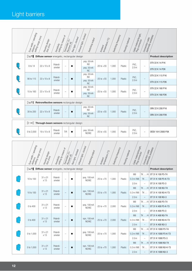
Di�use sensor energetic, rectangular design Product description
6 to 14 22 x 10 x 8Potenti-ometer
– n
pnp, 50 mA NO
-25 to +55 1,000 PlasticPVC, 2.0 m
–OTV 22 K 14 P1K
pnp, 50 mA NC
OTV 22 K 14 P2K
90 to 115 22 x 10 x 8Potenti-ometer
– n
pnp, 50 mA NO
-25 to +55 1,000 PlasticPVC, 2.0 m
–OTV 22 K 115 P1K
pnp, 50 mA NC
OTV 22 K 115 P2K
15 to 160 22 x 10 x 8Potenti-ometer
– n
pnp, 50 mA NO
-25 to +55 1,000 PlasticPVC, 2.0 m
–OTV 22 K 160 P1K
pnp, 50 mA NC
OTV 22 K 160 P2K
Retroreflective sensors rectangular design
30 to 200 22 x 10 x 8Potenti-ometer
– n
pnp, 50 mA NO
-25 to +55 1,000 PlasticPVC, 2.0 m
–ORV 22 K 200 P1K
pnp, 50 mA NC
ORV 22 K 200 P2K
Through-beam sensors rectangular design
0 to 2,000 19 x 10 x 8Potenti-ometer
T/R npnp, 50 mA
NO/NC-25 to +55 1,000 Plastic
PVC, 2.0 m
– OESV 19 K 2000 P3K
Scan
wid
th /
oper
atin
g
dist
ance
, se
tting
rang
e (m
m)
Hous
ing
desi
gnSi
ze (m
m)
Sens
itivit
y
setti
ng b
y m
eans
of
Tran
smitt
er (T
) /
Rece
iver (
R)Re
d lig
ht, c
lock
edIn
frare
d lig
ht, c
lock
ed
Switc
hing
out
put
Ambi
ent
tem
pera
ture
(°C)
Switc
hing
freq
uenc
y
Hous
ing
mat
eria
l
Cabl
e m
ater
ial/l
engt
h,
Plug
con
nect
or
Conn
ectio
n ca
ble
(opt
iona
lly a
vaila
ble)
Di�use sensor energetic, rectangular design Product description
10 to 10031 x 21
x 13Potenti-ometer
– npnp, 100 mA
NO/NC-25 to +70 1,000 Plastic
M8 TK … /4 OT 31 K 100 P3-T4
0.2 m / M8 TK … OT 31 K 100 P3-K-T3
2.0 m – OT 31 K 100 P3-3
10 to 10031 x 21
x 13Potenti-ometer
– nnpn, 100 mA
NO/NC-25 to +70 1,000 Plastic
M8 TK … /4 OT 31 K 100 N3-T4
0.2 m / M8 TK … OT 31 K 100 N3-K-T3
2.0 m – OT 31 K 100 N3-3
0 to 40031 x 21
x 13Potenti-ometer
– npnp, 100 mA
NO/NC-25 to +70 2,000 Plastic
M8 TK … /4 OT 31 K 400 P3-T4
0.2 m / M8 TK … OT 31 K 400 P3-K-T3
2.0 m – OT 31 K 400 P3-3
0 to 40031 x 21
x 13Potenti-ometer
– nnpn, 100 mA
NO/NC-25 to +70 2,000 Plastic
M8 TK … /4 OT 31 K 400 N3-T4
0.2 m / M8 TK … OT 31 K 400 N3-K-T3
2.0 m – OT 31 K 400 N3-3
0 to 1,00031 x 21
x 13Potenti-ometer
– npnp, 100 mA
NO/NC-25 to +70 1,000 Plastic
M8 TK … /4 OT 31 K 1000 P3-T4
0.2 m / M8 TK … OT 31 K 1000 P3-K-T3
2.0 m – OT 31 K 1000 P3-3
0 to 1,00031 x 21
x 13Potenti-ometer
– nnpn, 100 mA
NO/NC-25 to +70 1,000 Plastic
M8 TK … /4 OT 31 K 1000 N3-T4
0.2 m / M8 TK … OT 31 K 1000 N3-K-T3
2.0 m – OT 31 K 1000 N3-3
Light barriers

For more information and models visit www.di-soric.com 13
Scan
wid
th /
oper
atin
g
dist
ance
, se
tting
rang
e (m
m)
Hous
ing
desi
gnSi
ze (m
m)
Sens
itivit
y
setti
ng b
y m
eans
of
Tran
smitt
er (T
) /
Rece
iver (
R)Re
d lig
ht, c
lock
edIn
frare
d lig
ht, c
lock
ed
Switc
hing
out
put
Ambi
ent
tem
pera
ture
(°C)
Switc
hing
freq
uenc
y
Hous
ing
mat
eria
l
Cabl
e m
ater
ial/l
engt
h,
Plug
con
nect
or
Conn
ectio
n ca
ble
(opt
iona
lly a
vaila
ble)
Di�use sensors with background suppression, rectangular design Product description
30 to 20031 x 21
x 13Potenti-ometer
– npnp, 100 mA
NO/NC-25 to +70 1,000 Plastic
M8 TK … /4 OH 31 K 200 P3-T4
0.2 m / M8 TK … OH 31 K 200 P3-K-T3
2.0 m – OH 31 K 200 P3-3
30 to 20031 x 21
x 13Potenti-ometer
– nnpn, 100 mA
NO/NC-25 to +70 1,000 Plastic
M8 TK … /4 OH 31 K 200 N3-T4
0.2 m / M8 TK … OH 31 K 200 N3-K-T3
2.0 m – OH 31 K 200 N3-3
30 to 40031 x 21
x 13Potenti-ometer
– npnp, 100 mA
NO/NC-25 to +70 1,000 Plastic
M8 TK … /4 OH 30 K 400 P3-T4
0.2 m / M8 TK … OH 30 K 400 P3-K-T3
2.0 m – OH 30 K 400 P3-3
30 to 40031 x 21
x 13Potenti-ometer
– nnpn, 100 mA
NO/NC-25 to +70 1,000 Plastic
M8 TK … /4 OH 30 K 400 N3-T4
0.2 m / M8 TK … OH 30 K 400 N3-K-T3
2.0 m – OH 30 K 400 N3-3
Retroreflective sensors rectangular design
50 to 1,50031 x 21
x 13Potenti-ometer
– npnp, 100 mA
NO/NC-25 to +70 2,000 Plastic
M8 TK … /4 OR 31 K 1500 P3-T4
0.2 m / M8 TK … OR 31 K 1500 P3-K-T3
2.0 m – OR 31 K 1500 P3-3
50 to 1,50031 x 21
x 13Potenti-ometer
– nnpn, 100 mA
NO/NC-25 to +70 2,000 Plastic
M8 TK … /4 OR 31 K 1500 N3-T4
0.2 m / M8 TK … OR 31 K 1500 N3-K-T3
2.0 m – OR 31 K 1500 N3-3
400 to 4,00031 x 21
x 13Potenti-ometer
– npnp, 100 mA
NO/NC-25 to +70 2,000 Plastic
M8 TK … /4 OR 31 K 4000 P3-T4
0.2 m / M8 TK … OR 31 K 4000 P3-K-T3
2.0 m – OR 31 K 4000 P3-3
400 to 4,00031 x 21
x 13Potenti-ometer
– nnpn, 100 mA
NO/NC-25 to +70 2,000 Plastic
M8 TK … /4 OR 31 K 4000 N3-T4
0.2 m / M8 TK … OR 31 K 4000 N3-K-T3
2.0 m – OR 31 K 4000 N3-3
20 to 5,00031 x 21
x 13Potenti-ometer
– npnp, 100 mA
NO/NC-25 to +70 2,000 Plastic
M8 TK … /4 OR 31 K 5000 P3-T4
0.2 m / M8 TK … OR 31 K 5000 P3-K-T3
2.0 m – OR 31 K 5000 P3-3
20 to 5,00031 x 21
x 13Potenti-ometer
– nnpn, 100 mA
NO/NC-25 to +70 2,000 Plastic
M8 TK … /4 OR 31 K 5000 N3-T4
0.2 m / M8 TK … OR 31 K 5000 N3-K-T3
2 m – OR 31 K 5000 N3-3
Through-beam sensors rectangular design
0 to 20,00031 x 21
x 13Potenti-ometer
– npnp, 100 mA
NO/NC-25 to +70 2,000 Plastic
M8 TK … /4 OES 31 K 20000 P3-T4
0.2 m / M8 TK … OES 31 K 20000 P3-K-T3
2.0 m – OES 31 K 20000 P3-3
0 to 20,00031 x 21
x 13Potenti-ometer
– nnpn, 100 mA
NO/NC-25 to +70 2,000 Plastic
M8 TK … /4 OES 31 K 20000 N3-T4
0.2 m / M8 TK … OES 31 K 20000 N3-K-T3
2.0 m – OES 31 K 20000 N3-3
14
Scan
wid
th /
oper
atin
g
dist
ance
, se
tting
rang
e (m
m)
Hous
ing
desi
gnSi
ze (m
m)
Sens
itivit
y
setti
ng b
y m
eans
of
Tran
smitt
er (T
) /
Rece
iver (
R)Re
d lig
ht, c
lock
edIn
frare
d lig
ht, c
lock
ed
Switc
hing
out
put
Ambi
ent
tem
pera
ture
(°C)
Switc
hing
freq
uenc
y
Hous
ing
mat
eria
l
Cabl
e m
ater
ial/l
engt
h,
Plug
con
nect
or
Conn
ectio
n ca
ble
(opt
iona
lly a
vaila
ble)
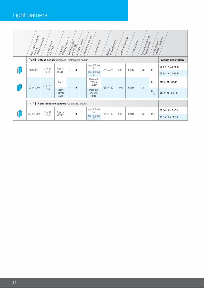
Di�use sensor energetic, rectangular design Product description
10 to 60038 x 27
x 15Potenti-ometer
– n
pnp, 100 mA NO
-25 to +60 500 Plastic M8 TK …OT 6-41 K 0.6 P1-T3
pnp, 100 mA NC
OT 6-41 K 0.6 P2-T3
100 to 1,00041 x 31.5
x 16
Teach
– n
Push-pull, 200 mA NO/NC
-25 to +60 1,000 Plastic M8
TK … OTT 41 M 1 G3-T3
Teach Remote teach
Push-pull, 200 mA NO/NC
TK … /4
OTT 41 M 1 FG3-T4
Retroreflective sensors rectangular design
400 to 4,000 38 x 27 x 15
Potenti-ometer – n
pnp, 100 mA NC
-25 to +60 500 Plastic M8 TK …OR 6-41 K 4 P1-T3
pnp, 100 mA NO OR 6-41 K 4 P2-T3
Light barriers
For more information and models visit www.di-soric.com 15
Scan
wid
th /
oper
atin
g
dist
ance
, se
tting
rang
e (m
m)
Hous
ing
desi
gnSi
ze (m
m)
Sens
itivit
y
setti
ng b
y m
eans
of
Tran
smitt
er (T
) /
Rece
iver (
R)Re
d lig
ht, c
lock
edIn
frare
d lig
ht, c
lock
ed
Switc
hing
out
put
Ambi
ent
tem
pera
ture
(°C)
Switc
hing
freq
uenc
y
Hous
ing
mat
eria
l
Cabl
e m
ater
ial/l
engt
h,
Plug
con
nect
or
Conn
ectio
n ca
ble
(opt
iona
lly a
vaila
ble)
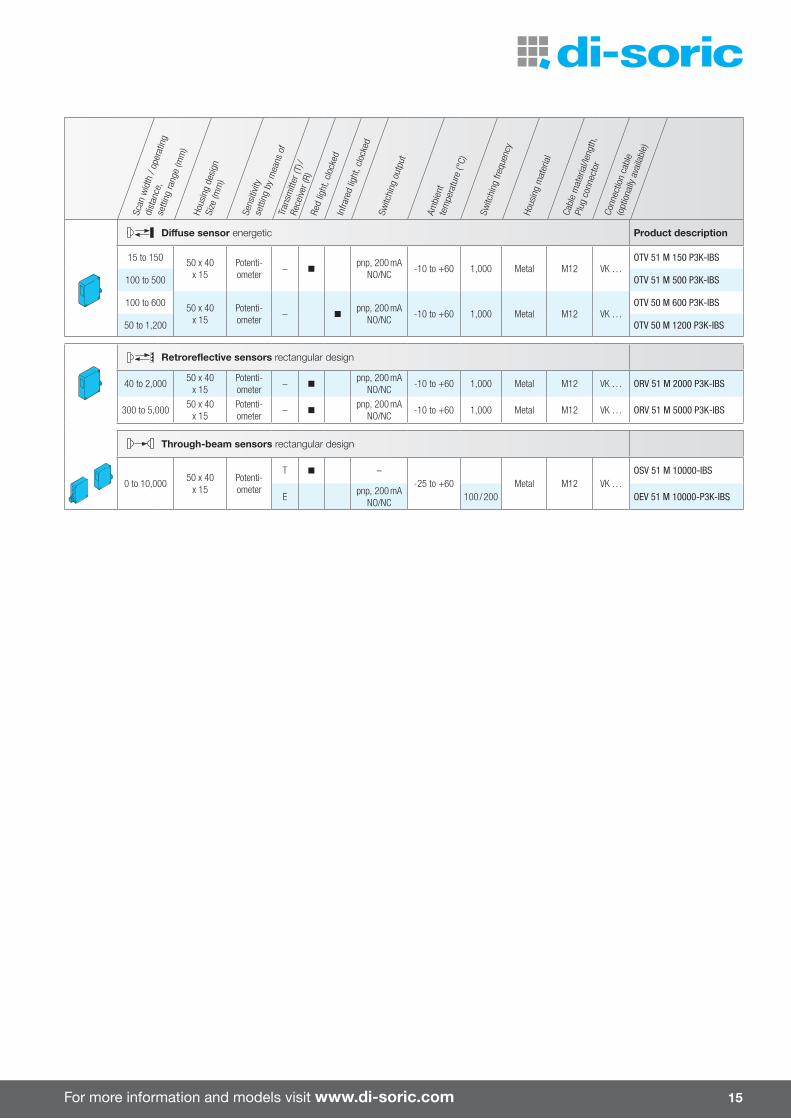
Di�use sensor energetic Product description
15 to 150 50 x 40 x 15
Potenti-ometer
– npnp, 200 mA
NO/NC-10 to +60 1,000 Metal M12 VK …
OTV 51 M 150 P3K-IBS
100 to 500 OTV 51 M 500 P3K-IBS
100 to 600 50 x 40 x 15
Potenti-ometer
– npnp, 200 mA
NO/NC-10 to +60 1,000 Metal M12 VK …
OTV 50 M 600 P3K-IBS
50 to 1,200 OTV 50 M 1200 P3K-IBS
Retroreflective sensors rectangular design
40 to 2,00050 x 40
x 15Potenti-ometer
– npnp, 200 mA
NO/NC-10 to +60 1,000 Metal M12 VK … ORV 51 M 2000 P3K-IBS
300 to 5,00050 x 40
x 15Potenti-ometer
– npnp, 200 mA
NO/NC-10 to +60 1,000 Metal M12 VK … ORV 51 M 5000 P3K-IBS
Through-beam sensors rectangular design
0 to 10,00050 x 40
x 15Potenti-ometer
T n –-25 to +60 Metal M12 VK …
OSV 51 M 10000-IBS
Epnp, 200 mA
NO/NC100 / 200 OEV 51 M 10000-P3K-IBS

16
Laser light barriers and di� use sensors are used for the precise detection of small parts in all areas of automation. These devices are lightning-fast, non-contact, wear-free and extremely precise, count-ing small parts, determining their position and completeness exactly, and providing trigger signals for camera systems and system controls.
Laser light barriers
Laser light barriers ¡ Collimated red-light laser ¡ Various designs ¡ Resolution down to 0.2 mm ¡ High switching frequency
Laser line retrorefl ective sensors ¡ Red-light laser, clocked ¡ Fan-shaped laser beam with auto-collimation principle
¡ Detection of small parts within the active zone
Laser di� use sensors with foreground and background suppression ¡ Red-light laser, with small laser spot ¡ Large detection range ¡ Automatic adjustment of transmitting power
¡ Remote teach option and key lock function
¡ Push-pull output pnp + npn ¡ Light/dark switching switchable
Laser di� use sensors with background suppression ¡ Red-light laser ¡ Optical or electronic background suppression
¡ Vibration-proof multiturn adjustment for fi nest adjustment
¡ High resolution, switching accuracy, switching frequency
¡ Automatic adjustment of transmitting power

For more information and models visit www.di-soric.com 17
Technical data (typ.) +20 °C, 24 V DC
Emitted light Red-light laser
Service voltage 10 to 35 V DC
10.8 to 26.4 V DC (LLT 21 … / LES 21 …)
18 to 30 V DC (LVHT 51 …)
Protection type IP 67
Scan
wid
th /
oper
atin
g
dist
ance
, se
tting
rang
e (m
m)
Hous
ing
desi
gnSi
ze (m
m)
Sens
itivit
y
setti
ng b
y m
eans
of
Tran
smitt
er (T
) /
Rece
iver (
R)
Switc
hing
out
put
Switc
hing
freq
uenc
y (H
z)La
ser c
lass
Ambi
ent
tem
pera
ture
(°C)
Hous
ing
mat
eria
lCa
ble
mat
eria
l/len
gth,
Plug
con
nect
or
Conn
ectio
n ca
ble
(opt
iona
lly a
vaila
ble)
Laser through-beam sensors helical or rectangular design Product description
0 to 2,000 M8 x 70 –T –
2,0001
0 to +50Stainless
steelM8 TK …
OLS 08 V 2000-TSSL
Epnp, 200 mA
NOOLE 08 V 2000 P2K-TSSL
0 to 500 10 x 10 x 60 –
T – 2,000 1 0 to +50 Metal M8 TK … OLSQ 10 M 500-TSSL
Epnp, 200 mA
NC2,000 0 to +50 Metal M8 TK …
OLEQ 10 M 500 P1K-TSSL
Epnp, 200 mA
NOOLEQ 10 M 500 P2K-TSSL
0 to 2,000 10 x 10 x 60 –
T –
2,000
1
0 to +50 Metal M8 TK …
OLSQ 10 M 2000-TSSL
Epnp, 200 mA
NCOLEQ 10 M 2000 P1K-TSSL
Epnp, 200 mA
NOOLEQ 10 M 2000 P2K-TSSL
Swash plate for OLE / OLS Q 10 …
For easy alignment of laser light barriers in the series OLS Q 10 …
TP1-Q90
Scan
wid
th /
oper
atin
g
dist
ance
, se
tting
rang
e (m
m)
Hous
ing
desi
gnSi
ze (m
m)
Sens
itivit
y
setti
ng b
y m
eans
of
Tran
smitt
er (T
) /
Rece
iver (
R)
Switc
hing
out
put
Switc
hing
freq
uenc
y (H
z)La
ser c
lass
Ambi
ent
tem
pera
ture
(°C)
Hous
ing
mat
eria
lCa
ble
mat
eria
l/len
gth,
Plug
con
nect
or
Conn
ectio
n ca
ble
(opt
iona
lly a
vaila
ble)
Laser di�use sensors rectangular design Product description
20 to 50 22 x 13 x 8.5Potentiom-
eter–
pnp, 50 mA NO/NC
1,000 1 -10 to +55 Plastic2.0 m – LT 21 K 50 P3
M8 TK ... /4 LT 21 K 50 P3-K-T4
45 to 300 22 x 13 x 8.5Potentiom-
eter–
pnp, 50 mA NO/NC
1,000 1 -10 to +55 Plastic2.0 m – LT 21 K 300 P3
M8 TK ... /4 LT 21 K 300 P3-K-T4
Laser retroreflective sensors rectangular design
0 to 4,000 22 x 13 x 8.5Potentiom-
eter–
pnp, 50 mA NO/NC
1,000 1 -10 to +55 Plastic2.0 m – LT 21 K 4000 P3
M8 TK ... /4 LT 21 K 4000 P3-K-T4

18
Laser light barriers
Scan
wid
th /
oper
atin
g
dist
ance
, se
tting
rang
e (m
m)
Hous
ing
desi
gnSi
ze (m
m)
Sens
itivit
y
setti
ng b
y m
eans
of
Tran
smitt
er (T
) /
Rece
iver (
R)
Switc
hing
out
put
Switc
hing
freq
uenc
y (H
z)La
ser c
lass
Ambi
ent
tem
pera
ture
(°C)
Hous
ing
mat
eria
lCa
ble
mat
eria
l/len
gth,
Plug
con
nect
or
Conn
ectio
n ca
ble
(opt
iona
lly a
vaila
ble)
Laser line di�use sensor rectangular design Product description
20 to 70 22 x 13 x 8.5Potentiom-
eter–
pnp, 50 mA NO/NC
1,000 1 -10 to +55 Plastic2.0 m – LLT 21 K 70 P3
M8 TK ... /4 LLT 21 K 70 P3-K-T4
Laser through-beam sensors rectangular design
0 to 1,000 19 x 12 x 8.5 – T / R pnp, 50 mA NO/NC
1,000 1 -10 to +55 Plastic2.0 m – LES 21 K 1000 P3
M8 TK ... /4 LES 21 K 1000 P3-K-T4
Scan
wid
th /
oper
atin
g
dist
ance
, se
tting
rang
e (m
m)
Hous
ing
desi
gnSi
ze (m
m)
Sens
itivit
y
setti
ng b
y m
eans
of
Tran
smitt
er (T
) / R
ecei
ver (
R)
Switc
hing
out
put
Switc
hing
freq
uenc
y (H
z)La
ser c
lass
Ambi
ent
tem
pera
ture
(°C)
Hous
ing
mat
eria
lCa
ble
mat
eria
l/len
gth,
Plug
con
nect
or
Conn
ectio
n ca
ble
(opt
iona
lly a
vaila
ble)
Laser di�use sensors with optical background suppression, rectangular design Product description
30 to 350 40 x 30 x 15Potentiom-
eter– Push-pull, 200 mA
NO/NC antivalent1,000 1 -10 to +50 Metal M8 TK ... /4 LH 41 M 350 G4L-T4
Scan
wid
th /
oper
atin
g
dist
ance
, se
tting
rang
e (m
m)
Hous
ing
desi
gnSi
ze (m
m)
Sens
itivit
y
setti
ng b
y m
eans
of
Tran
smitt
er (T
) / R
ecei
ver (
R)
Switc
hing
out
put
Switc
hing
freq
uenc
y (H
z)La
ser c
lass
Ambi
ent
tem
pera
ture
(°C)
Hous
ing
mat
eria
lCa
ble
mat
eria
l/len
gth,
Plug
con
nect
or
Conn
ectio
n ca
ble
(opt
iona
lly a
vaila
ble)
Laser di�use sensors rectangular design Product description
75 to 20050 x 40 x 15
Potentiom-eter
–pnp, 200 mA
NO/NC
2,0001 -10 to +50 Metal M12 VK ...
LTV 51 M 200 P3K-IBS
100 to 600 500 LTV 51 M 600 P3K-IBS
Laser di�use sensors with background suppression, rectangular design
50 to 200 50 x 40 x 15Potentiom-
eter–
Push-pull, 200 mA NO/NC
500 1 -10 to +50 Metal M12 VK ... LHT 51 M 200 G3-B4 1)
Laser di�use sensors with foreground and background suppression, rectangular design
50 to 400 50 x 50 x 16Teach,
Remote teach–
Push-pull, 200 mA NO/NC
100 1 0 to +50 Aluminum M12 VK ... /4 LVHT 51 M 400 G3-B4
Laser retroreflective sensors rectangular design
100 to 1,000
50 x 40 x 15Potentiom-
eter–
pnp, 200 mA NO/NC
2,000 1 0 to +50 Metal M12 VK ...
LRV 51 M 1000 P3K-IBS
200 to 2,000 LRV 51 M 2000 P3K-IBS
1,000 to 10,000 LRV 51 M 10000 P3K-IBS

For more information and models visit www.di-soric.com 19
Scan
wid
th /
oper
atin
g
dist
ance
, se
tting
rang
e (m
m)
Hous
ing
desi
gnSi
ze (m
m)
Sens
itivit
y
setti
ng b
y m
eans
of
Tran
smitt
er (T
) / R
ecei
ver (
R)
Switc
hing
out
put
Switc
hing
freq
uenc
y (H
z)La
ser c
lass
Ambi
ent
tem
pera
ture
(°C)
Hous
ing
mat
eria
lCa
ble
mat
eria
l/len
gth,
Plug
con
nect
or
Conn
ectio
n ca
ble
(opt
iona
lly a
vaila
ble)
Laser di�use sensors with optical background suppression, rectangular design Product description
40 to 400 76 x 30 x 18Potentiom-
eter–
Antivalent, 200 mA NO/NC
1,000 1 -10 to +60 Metal M12 VK ... /4
LHT 81 M 300 G4L-IBS
200 mA, NO switching output
NC alarm outputLHT 81 M 300 G6L-IBS
Scan
wid
th /
oper
atin
g
dist
ance
, se
tting
rang
e (m
m)
Hous
ing
desi
gnSi
ze (m
m)
Sens
itivit
y
setti
ng b
y m
eans
of
Tran
smitt
er (T
) / R
ecei
ver (
R)
Switc
hing
out
put
Switc
hing
freq
uenc
y (H
z)La
ser c
lass
Ambi
ent
tem
pera
ture
(°C)
Hous
ing
mat
eria
lCa
ble
mat
eria
l/len
gth,
Plug
con
nect
or
Conn
ectio
n ca
ble
(opt
iona
lly a
vaila
ble)
Laser distance sensors rectangular design Product description
200 to 10,000 45 x 52 x 42 Teach –pnp, 200 mA
NO/NC programmable
5 2 -10 to +60 Metal M12 VK ... LHT 9-45 M 10 P3-B4
Scan
wid
th /
oper
atin
g
dist
ance
, se
tting
rang
e (m
m)
Hous
ing
desi
gnSi
ze (m
m)
Sens
itivit
y
setti
ng b
y m
eans
of
Tran
smitt
er (T
) / R
ecei
ver (
R)
Switc
hing
out
put
Switc
hing
freq
uenc
y (H
z)La
ser c
lass
Ambi
ent
tem
pera
ture
(°C)
Hous
ing
mat
eria
lCa
ble
mat
eria
l/len
gth,
Plug
con
nect
or
Conn
ectio
n ca
ble
(opt
iona
lly a
vaila
ble)
Laser line retroreflective sensors rectangular design Product description
50 to 500 50 x 40 x 15Potentiom-
eter–
pnp, 200 mA NO/NC
750 1 5 to +50 Metal M12 VK ... LLRV 51 M 500 P3K-IBS
Laser line di�use sensor with background suppression, rectangular design
50 to 200 50 x 40 x 15Potentiom-
eter–
Push-pull, 200 mA NO/NC
500 1 -10 to +50 Metal M12 VK ... LLH 51 M 200 G3-B4
1) Increased function reserve
20
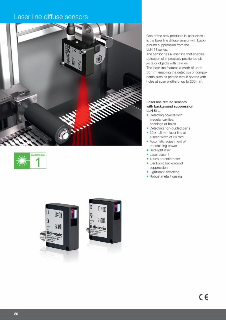
Laser line di� use sensors
Laser line di� use sensors with background suppressionLLH 51 … ¡ Detecting objects with irregular cavities, openings or holes
¡ Detecting non-guided parts ¡ 30 x 1.5 mm laser line at a scan width of 20 mm
¡ Automatic adjustment of transmitting power
¡ Red-light laser ¡ Laser class 1 ¡ 4-turn potentiometer ¡ Electronic background suppression
¡ Light/dark switching ¡ Robust metal housing
One of the new products in laser class 1 is the laser line di� use sensor with back-ground suppression from the LLH 51 series. The sensor has a laser line that enables detection of imprecisely positioned ob-jects or objects with cavities. The laser line features a width of up to 30 mm, enabling the detection of compo-nents such as printed circuit boards with holes at scan widths of up to 200 mm.

For more information and models visit www.di-soric.com 21
Oper
atin
g di
stan
ce /
setti
ng ra
nge
(mm
)M
in. t
each
rang
e (m
m)
Red-
light
lase
r, cl
ocke
d, 6
50 n
m
Sens
itivit
y ad
just
men
t by
mea
ns o
f La
ser l
ine
at s
can
wid
th (m
m)
No-lo
ad c
urre
nt (m
A)
Switc
hing
freq
uenc
y (H
z)Hy
ster
esis
Cabl
e m
ater
ial/l
engt
h,
Plug
con
nect
or le
ngth
Conn
ectio
n ca
ble
(opt
iona
lly a
vaila
ble)
Laser line di� use sensors with background suppression Product description
50 to 200 50 nPotenti-ometer 30 x 1.5 (200) 25 500 6%
M8 TK … LLH 51 M 200 G3-T3
M12 VK … LLH 51 M 200 G3-B4
Application example
30 x 1.5 mm laser line at a scan width of 200 mm
Detecting objects with irregular cavities, openings or holes
Detecting non-guided parts
Technical data (typ.) +20 °C, 24 V DC
Service voltage 10 to 35 V DC
Switching output 200 mA, push-pull, NO/NC
Laser class 1 (IEC 60825-1)
Ambient light immunity 5 kLx
Ambient temperature -10 to +50 °C
Protection type IP 67
Protection class III, operation on protective low voltage
Housing material Die-cast zinc, varnished
Window material Polycarbonate
22
Laser distance sensors
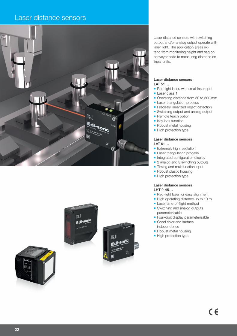
Laser distance sensors with switching output and/or analog output operate with laser light. The application areas ex-tend from monitoring height and sag on conveyor belts to measuring distance on linear units.
Laser distance sensors LAT 51 … ¡ Red-light laser, with small laser spot ¡ Laser class 1 ¡ Operating distance from 50 to 500 mm ¡ Laser triangulation process ¡ Precisely linearized object detection ¡ Switching output and analog output ¡ Remote teach option ¡ Key lock function ¡ Robust metal housing ¡ High protection type
Laser distance sensors LAT 61 … ¡ Extremely high resolution ¡ Laser triangulation process ¡ Integrated configuration display ¡ 2 analog and 3 switching outputs ¡ Timing and multifunction input ¡ Robust plastic housing ¡ High protection type
Laser distance sensors LHT 9-45 … ¡ Red-light laser for easy alignment ¡ High operating distance up to 10 m ¡ Laser time-of-flight method ¡ Switching and analog outputs parameterizable
¡ Four-digit display parameterizable ¡ Good color and surface independence
¡ Robust metal housing ¡ High protection type
For more information and models visit www.di-soric.com 23
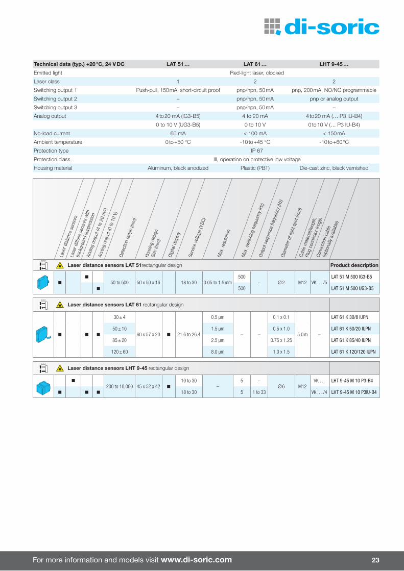
Technical data (typ.) +20 °C, 24 V DC LAT 51 … LAT 61 … LHT 9-45 …
Emitted light Red-light laser, clocked
Laser class 1 2 2
Switching output 1 Push-pull, 150 mA, short-circuit proof pnp/npn, 50 mA pnp, 200 mA, NO/NC programmable
Switching output 2 – pnp/npn, 50 mA pnp or analog output
Switching output 3 – pnp/npn, 50 mA –
Analog output 4 to 20 mA (IG3-B5) 4 to 20 mA 4 to 20 mA (… P3 IU-B4)
0 to 10 V (UG3-B5) 0 to 10 V 0 to 10 V (… P3 IU-B4)
No-load current 60 mA < 100 mA < 150 mA
Ambient temperature 0 to +50 °C -10 to +45 °C -10 to +60 °C
Protection type IP 67
Protection class III, operation on protective low voltage
Housing material Aluminum, black anodized Plastic (PBT) Die-cast zinc, black varnished
Lase
r dis
tanc
e se
nsor
sLa
ser d
i�us
e se
nsor
s w
ith
back
grou
nd s
uppr
essi
onAn
alog
out
put (
4 to
20
mA)
Anal
og o
utpu
t (0
to 1
0 V)
Dete
ctio
n ra
nge
(mm
)
Hous
ing
desi
gnSi
ze (m
m)
Digi
tal d
ispl
ay
Serv
ice
volta
ge (V
DC)
Max
. res
olut
ion
Max
. sw
itchi
ng fr
eque
ncy
(Hz)
Outp
ut s
eque
nce
frequ
ency
(Hz)
Diam
eter
of l
ight
spo
t (m
m)
Cabl
e m
ater
ial/l
engt
h,
Plug
con
nect
or le
ngth
Conn
ectio
n ca
ble
(opt
iona
lly a
vaila
ble)
Laser distance sensors LAT 51rectangular design Product description
n
n
50 to 500 50 x 50 x 16 18 to 30 0.05 to 1.5 mm500
– Ø 2 M12 VK … /5LAT 51 M 500 IG3-B5
n 500 LAT 51 M 500 UG3-B5
Laser distance sensors LAT 61 rectangular design
n n n
30 ± 4
60 x 57 x 20 n 21.6 to 26.4
0.5 µm
– –
0.1 x 0.1
5.0 m –
LAT 61 K 30/8 IUPN
50 ± 10 1.5 µm 0.5 x 1.0 LAT 61 K 50/20 IUPN
85 ± 20 2.5 µm 0.75 x 1.25 LAT 61 K 85/40 IUPN
120 ± 60 8.0 µm 1.0 x 1.5 LAT 61 K 120/120 IUPN
Laser distance sensors LHT 9-45 rectangular design
n
200 to 10,000 45 x 52 x 42 n
10 to 30–
5 –Ø 6 M12
VK … LHT 9-45 M 10 P3-B4
n n n 18 to 30 5 1 to 33 VK … /4 LHT 9-45 M 10 P3IU-B4
24
High-performance light barriers
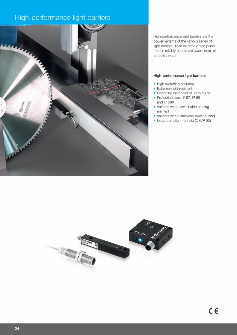
¡ High switching accuracy ¡ Extremely dirt-resistant ¡ Operating distances of up to 50 m ¡ Protection class IP 67, IP 68 and IP 69K
¡ Variants with a switchable heating element
¡ Variants with a stainless steel housing ¡ Integrated alignment aid (OEVP 50)
High-performance light barriers are the power variants of the various series of light barriers. Their extremely high perfor-mance reliably penetrates swarf, dust, oil, and dirty water.
High-performance light barriers

For more information and models visit www.di-soric.com 25
Oper
atin
g di
stan
ce (o
peni
ng a
ngle
15°
)
whe
n op
erat
ed w
ith
OSP
12 V
LF …
/ OS
PQ 1
2 M
LFL …
(m)
Oper
atin
g di
stan
ce (o
peni
ng a
ngle
6°)
whe
n op
erat
ed w
ith
OSP
12 V
HF …
/ OS
PQ 1
2 M
HFL …
(m)
Hous
ing
desi
gnSi
ze (m
m)
Tran
smitt
er (T
) / R
ecei
ver (
R)Di
sper
sion
ang
le /
open
ing
angl
eSw
itchi
ng o
utpu
t
NC (p
np) /
NO
(npn
)NO
(pnp
) / N
C (n
pn)
NO/N
C
Switc
hing
freq
uenc
y (H
z)Pr
otec
tion
type
Hous
ing
mat
eria
l
Plug
con
nect
orCo
nnec
tion
cabl
e(o
ptio
nally
ava
ilabl
e)
High-performance through-beam sensors cylindrical design Product description
– – M12 x 60 T15 °
– –IP 67, IP
68, IP 69K
StainlesssteelV2A
PVC, 5 m
OSP 12 VLFL-5M 2)
6 ° OSP 12 VHFL-5M 2)
1 5
M12 x 60 EPush-pull200 mA
n500
IP 67, IP 68, IP 69K
StainlesssteelV2A
PVC, 5 m
OEP 12 V 5000 G1L-5M
n OEP 12 V 5000 G2L-5M
6 20n
150OEP 12 V 20000 G1L-5M
n OEP 12 V 20000 G2L-5M
20 50n
20OEP 12 V 50000 G1L-5M
n OEP 12 V 50000 G2L-5M
– – M12 x 75 T15 °
– –IP 67, IP
68, IP 69K
StainlesssteelV2A
M12 VK …OSP 12 VLF-IBSL 2)
6 ° OSP 12 VHF-IBSL 2)
1 5
M12 x 75 EPush-pull200 mA
n500
IP 67, IP 68, IP 69K
StainlesssteelV2A
M12 VK …
OEP 12 V 5000 G1-IBSL
n OEP 12 V 5000 G2-IBSL
6 20n
150OEP 12 V 20000 G1-IBSL
n OEP 12 V 20000 G2-IBSL
20 50n
20OEP 12 V 50000 G1-IBSL
n OEP 12 V 50000 G2-IBSL
High-performance through-beam sensors rectangular design
– – 12 x 12 x 82 T15 °
– – IP 67 Aluminum, anodized
PVC, 5 m
OSPQ 12 MLFL-5M 2)
6 ° OSPQ 12 MHFL-5M 2)
1 5
12 x 12 x 82 EPush-pull200 mA
n500
IP 67 Aluminum, anodized
PVC, 5 m
OEPQ 12 M 5000 G1L-5M
n OEPQ 12 M 5000 G2L-5M
6 20n
150OEPQ 12 M 20000 G1-5M
n OEPQ 12 M 20000 G2L-5M
20 50n
20OEPQ 12 M 50000 G1L-5M
n OEPQ 12 M 50000 G2L-5M
– – 12 x 12 x 82 T15 °
– – IP 67 Aluminum, anodized
M8 TK …OSPQ 12 MLF-TSSL 2)
6 ° OSPQ 12 MHF-TSSL 2)
1 5
12 x 12 x 82 EPush-pull200 mA
n500
IP 67 Aluminum, anodized
M8 TK …
OEPQ 12 M 5000 G1-TSSL
n OEPQ 12 M 5000 G2-TSSL
6 20n
150OEPQ 12 M 20000 G1-TSSL
n OEPQ 12 M 20000 G2-TSSL
20 50n
20OEPQ 12 M 50000 G1-TSSL
n OEPQ 12 M 50000 G2-TSSL
50 50 50 x 40 x 15T – –
IP 67 Die-cast zinc M12 VK …
OSP 50 M 50000-IBS
EPush-pull,200 mA
n 20 OEVP 50 M 50000 G3LK-IBS
50 50 50 x 40 x 15T – –
IP 67 Die-cast zinc M12
VK … /4
OSP 50 M 50000-IBS/H 1)
EPush-pull200 mA
n 20OEVP 50 M 50000 G3LK-IBS/H 1)
2) Function modules FM 70-1 … for adjusting the transmitting power and activating the test function; see the Accessories chapter
Technical data (typ.) +20 °C, 24 V DC
Emitted light Infrared light, clocked
Service voltage 10 to 35 V DC
Ambient temperature -10 to +60 °C
-20 to +60 °C (OxP 12 …)
-40 to +50 °C (…/H / heating element 1) )
26
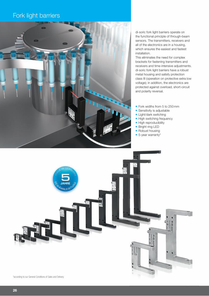
di-soric fork light barriers operate on the functional principle of through-beam sensors. The transmitters, receivers and all of the electronics are in a housing, which ensures the easiest and fastest installation. This eliminates the need for complex brackets for fastening transmitters and receivers and time-intensive adjustments. di-soric fork light barriers have a robust metal housing and satisfy protection class III (operation on protective extra low voltage); in addition, the electronics are protected against overload, short-circuit and polarity reversal.
Fork light barriers
¡ Fork widths from 5 to 250 mm ¡ Sensitivity is adjustable ¡ Light/dark switching ¡ High switching frequency ¡ High reproducibility ¡ Bright ring LED ¡ Robust housing ¡ 5-year warranty*
*according to our General Conditions of Sales and Delivery
For more information and models visit www.di-soric.com 27
Fork
wid
th (m
m)
Hous
ing
desi
gnSi
ze (m
m)
Red
light
, 660
nm
, clo
cked
Infra
red
light
, 880
nm
Reso
lutio
n, s
mal
lest
dete
ctab
le p
art (
mm
)
Volta
ge d
rop
(V)
Adju
stab
le s
witc
hing
freq
uenc
y (H
z)
Repr
oduc
ibilit
y (m
m)
Die-
cast
zin
c, p
owde
r-co
ated
Alum
inum
, bla
ck v
arni
shed
/ano
dize
d
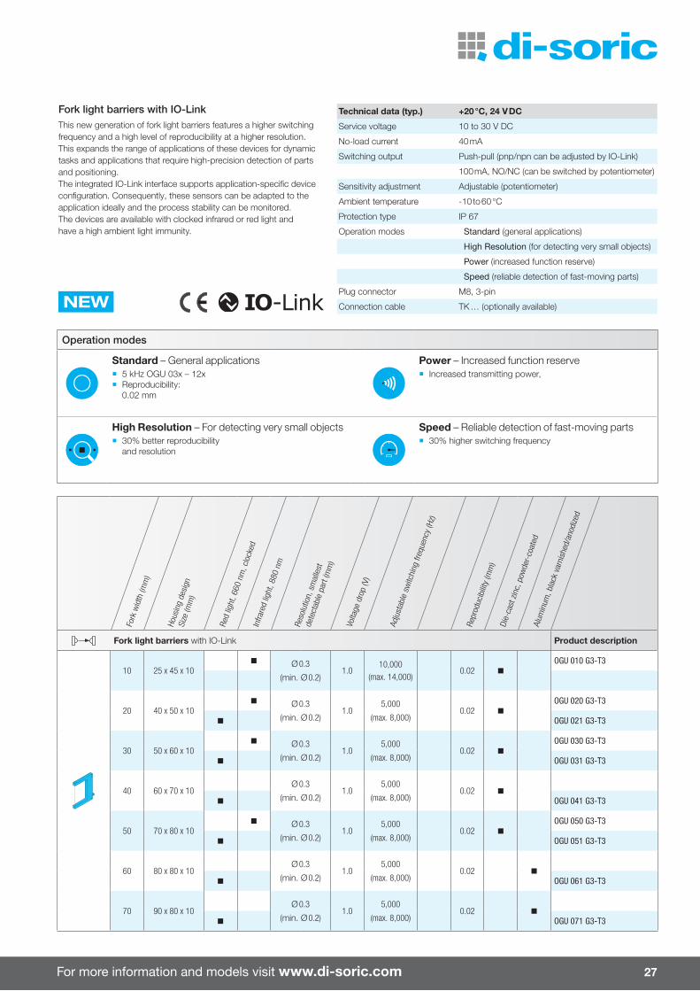
Fork light barriers with IO-Link Product description
10 25 x 45 x 10n Ø 0.3
(min. Ø 0.2)1.0
10,000(max. 14,000)
0.02 n
OGU 010 G3-T3
20 40 x 50 x 10n Ø 0.3
(min. Ø 0.2)1.0
5,000
(max. 8,000)0.02 n
OGU 020 G3-T3
n OGU 021 G3-T3
30 50 x 60 x 10n Ø 0.3
(min. Ø 0.2)1.0
5,000
(max. 8,000)0.02 n
OGU 030 G3-T3
n OGU 031 G3-T3
40 60 x 70 x 10Ø 0.3
(min. Ø 0.2)1.0
5,000
(max. 8,000)0.02 n
n OGU 041 G3-T3
50 70 x 80 x 10n Ø 0.3
(min. Ø 0.2)1.0
5,000
(max. 8,000)0.02 n
OGU 050 G3-T3
n OGU 051 G3-T3
60 80 x 80 x 10Ø 0.3
(min. Ø 0.2)1.0
5,000
(max. 8,000)0.02 n
n OGU 061 G3-T3
70 90 x 80 x 10Ø 0.3
(min. Ø 0.2)1.0
5,000
(max. 8,000)0.02 n
n OGU 071 G3-T3
Fork light barriers with IO-LinkThis new generation of fork light barriers features a higher switching frequency and a high level of reproducibility at a higher resolution. This expands the range of applications of these devices for dynamic tasks and applications that require high-precision detection of parts and positioning.The integrated IO-Link interface supports application-specific device configuration. Consequently, these sensors can be adapted to the application ideally and the process stability can be monitored. The devices are available with clocked infrared or red light and have a high ambient light immunity.
Technical data (typ.) +20 °C, 24 V DC
Service voltage 10 to 30 V DC
No-load current 40 mA
Switching output Push-pull (pnp/npn can be adjusted by IO-Link)
100 mA, NO/NC (can be switched by potentiometer)
Sensitivity adjustment Adjustable (potentiometer)
Ambient temperature -10 to 60 °C
Protection type IP 67
Operation modes Standard (general applications)
High Resolution (for detecting very small objects)
Power (increased function reserve)
Speed (reliable detection of fast-moving parts)
NEWPlug connector M8, 3-pin
Connection cable TK … (optionally available)
Operation modes
Standard – General applications ¡ 5 kHz OGU 03x – 12x ¡ Reproducibility:
0.02 mm
Power – Increased function reserve ¡ Increased transmitting power,
High Resolution – For detecting very small objects ¡ 30% better reproducibility
and resolution
Speed – Reliable detection of fast-moving parts ¡ 30% higher switching frequency
28
Fork light barriers
Fork
wid
th (m
m)
Hous
ing
desi
gnSi
ze (m
m)
Red
light
, 660
nm
, clo
cked
Infra
red
light
, 880
nm
Reso
lutio
n, s
mal
lest
dete
ctab
le p
art (
mm
)
Volta
ge d
rop
(V)
Adju
stab
le s
witc
hing
freq
uenc
y (H
z)
Repr
oduc
ibilit
y (m
m)
Die-
cast
zin
c, p
owde
r-co
ated
Alum
inum
, bla
ck v
arni
shed
/ano
dize
d
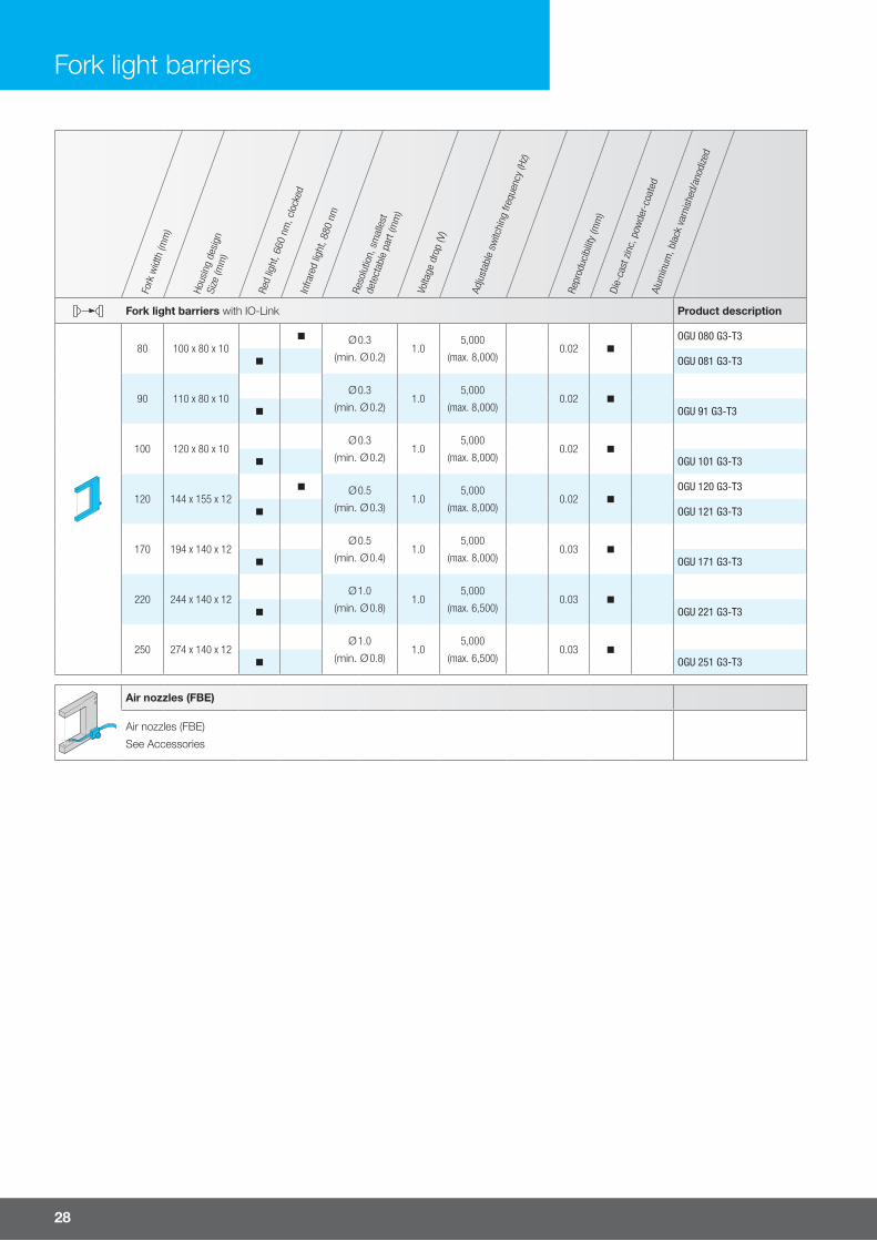
Fork light barriers with IO-Link Product description
80 100 x 80 x 10n Ø 0.3
(min. Ø 0.2)1.0
5,000
(max. 8,000)0.02 n
OGU 080 G3-T3
n OGU 081 G3-T3
90 110 x 80 x 10Ø 0.3
(min. Ø 0.2)1.0
5,000
(max. 8,000)0.02 n
n OGU 91 G3-T3
100 120 x 80 x 10Ø 0.3
(min. Ø 0.2)1.0
5,000
(max. 8,000)0.02 n
n OGU 101 G3-T3
120 144 x 155 x 12n Ø 0.5
(min. Ø 0.3)1.0
5,000
(max. 8,000)0.02 n
OGU 120 G3-T3
n OGU 121 G3-T3
170 194 x 140 x 12Ø 0.5
(min. Ø 0.4)1.0
5,000
(max. 8,000)0.03 n
n OGU 171 G3-T3
220 244 x 140 x 12Ø 1.0
(min. Ø 0.8)1.0
5,000
(max. 6,500)0.03 n
n OGU 221 G3-T3
250 274 x 140 x 12Ø 1.0
(min. Ø 0.8)1.0
5,000
(max. 6,500)0.03 n
n OGU 251 G3-T3
Air nozzles (FBE)
Air nozzles (FBE)
See Accessories
For more information and models visit www.di-soric.com 29
Fork
wid
th (m
m)
Hous
ing
desi
gnSi
ze (m
m)
Infra
red
light
, 860
nm
No-lo
ad c
urre
nt (m
A)
Reso
lutio
n, s
mal
lest
dete
ctab
le p
art (
mm
)
Volta
ge d
rop
(V)
Switc
hing
freq
uenc
y (H
z)
Repr
oduc
ibilit
y (m
m)
Die-
cast
zin
c, b
lack
, p
owde
r-co
ated
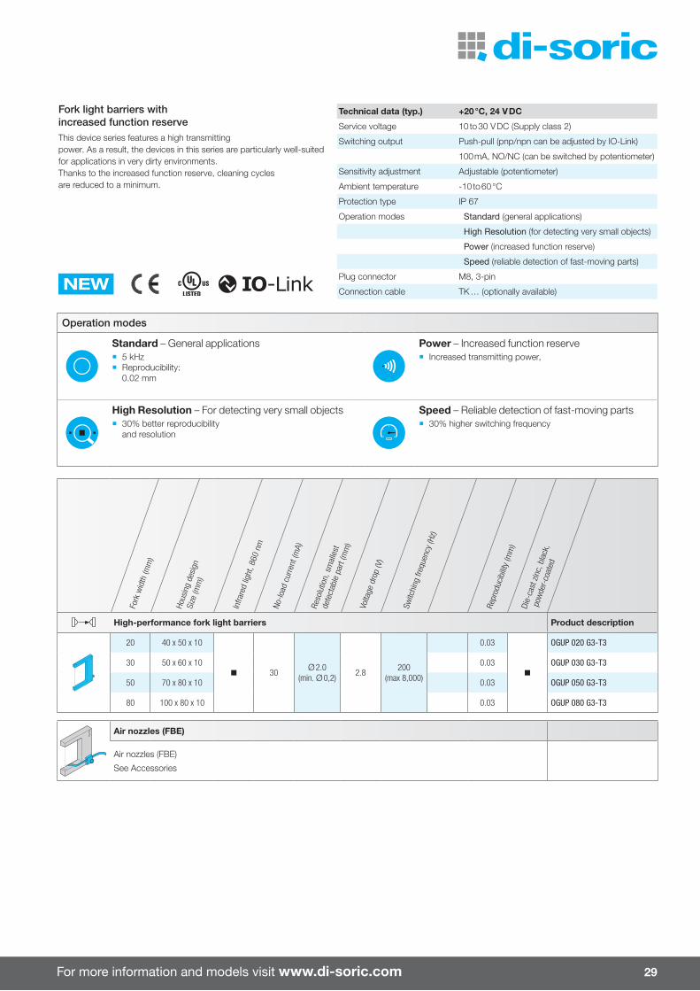
High-performance fork light barriers Product description
20 40 x 50 x 10
n 30Ø 2.0
(min. Ø 0,2)2.8
200 (max 8,000)
0.03
n
OGUP 020 G3-T3
30 50 x 60 x 10 0.03 OGUP 030 G3-T3
50 70 x 80 x 10 0.03 OGUP 050 G3-T3
80 100 x 80 x 10 0.03 OGUP 080 G3-T3
Air nozzles (FBE)
Air nozzles (FBE)
See Accessories
Operation modes
Standard – General applications ¡ 5 kHz ¡ Reproducibility:
0.02 mm
Power – Increased function reserve ¡ Increased transmitting power,
High Resolution – For detecting very small objects ¡ 30% better reproducibility
and resolution
Speed – Reliable detection of fast-moving parts ¡ 30% higher switching frequency
Fork light barriers with increased function reserveThis device series features a high transmittingpower. As a result, the devices in this series are particularly well-suited for applications in very dirty environments. Thanks to the increased function reserve, cleaning cycles are reduced to a minimum.
Technical data (typ.) +20 °C, 24 V DC
Service voltage 10 to 30 V DC (Supply class 2)
Switching output Push-pull (pnp/npn can be adjusted by IO-Link)
100 mA, NO/NC (can be switched by potentiometer)
Sensitivity adjustment Adjustable (potentiometer)
Ambient temperature -10 to 60 °C
Protection type IP 67
Operation modes Standard (general applications)
High Resolution (for detecting very small objects)
Power (increased function reserve)
Speed (reliable detection of fast-moving parts)
NEWPlug connector M8, 3-pin
Connection cable TK … (optionally available)

30
Fork light barriers
Operation modes
Standard – General applications ¡ 5 kHz OGU 03x – 12x ¡ Reproducibility:
0.02 mm
Power – Increased function reserve ¡ Increased transmitting power,
High Resolution – For detecting very small objects ¡ 30% better reproducibility
and resolution
Speed – Reliable detection of fast-moving parts ¡ 30% higher switching frequency
Fork
wid
th (m
m)
Hous
ing
desi
gnSi
ze (m
m)
Red
light
, 660
nm
, clo
cked
No-lo
ad c
urre
nt (m
A)
Reso
lutio
n, s
mal
lest
dete
ctab
le p
art (
mm
)
Volta
ge d
rop
(V)
Switc
hing
freq
uenc
y (H
z)
Repr
oduc
ibilit
y (m
m)
Stai
nles
s st
eel V
4A (1
.440
4 /
1.45
71)
Fork light barriers, stainless steel housing Product description
30 50 x 60 x 10 n 30Ø 0.3
(min. Ø 0.2)1.0 4,000 0.02 n OGU 031 G3-T3/V4A
50 70 x 80 x 10 n 30Ø 0.3
(min. Ø 0.2)1.0 4,000 0.04 n OGU 051 G3-T3/V4A
80 100 x 80 x 10 n 30Ø 0.3
(min. Ø 0.2)1.0 4,000 0.06 n OGU 081 G3-T3/V4A
120 144 x 90 x 12 n 45Ø 0.5
(min. Ø 0.2)1.0 2,000 0.06 n OGU 121 G3-T3/V4A
Air nozzles (FBE)
Air nozzles (FBE)
See Accessories
Fork light barriers OGU … / V4A are housed in a rugged stainless steel housing. These devices are most notably used in the pharmaceutical, beverage and food industries and meet the special requirements for easy and reliable cleaning using aggressive media.
The integrated IO-Link interface supports application-specific device configuration. As a result, these sensors can be optimized for the respective application and it is possible to monitor process stability. The devices are available with clocked infrared or red light and are highly immune to ambient light influences.
Technical data (typ.) +20 °C, 24 V DC
Service voltage 10 to 35 V DC (Supply class 2)
Switching output Push-pull (pnp/npn can be adjusted by IO-Link)
100 mA, NO/NC (can be switched by potentiometer)
Sensitivity adjustment Adjustable (potentiometer)
Ambient temperature -10 to 60 °C
Protection type IP 67
Operation modes Standard (general applications)
High Resolution (for detecting very small objects)
Power (increased function reserve)
Speed (reliable detection of fast-moving parts)
NEWPlug connector M8, 3-pin
Connection cable TK … (optionally available)
For more information and models visit www.di-soric.com 31
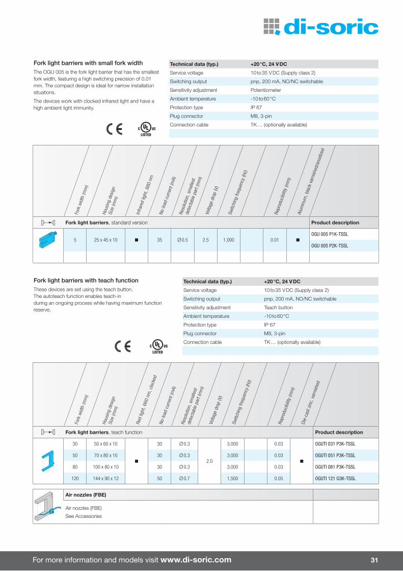
Fork light barriers with small fork width The OGU 005 is the fork light barrier that has the smallest fork width, featuring a high switching precision of 0.01 mm. The compact design is ideal for narrow installation situations.
The devices work with clocked infrared light and have a high ambient light immunity.
Technical data (typ.) +20 °C, 24 V DC
Service voltage 10 to 35 V DC (Supply class 2)
Switching output pnp, 200 mA, NO/NC switchable
Sensitivity adjustment Potentiometer
Ambient temperature -10 to 60 °C
Protection type IP 67
Plug connector M8, 3-pin
Connection cable TK … (optionally available)
Fork
wid
th (m
m)
Hous
ing
desi
gnSi
ze (m
m)
Infra
red
light
, 880
nm
No-lo
ad c
urre
nt (m
A)Re
solu
tion,
sm
alle
st
dete
ctab
le p
art (
mm
)Vo
ltage
dro
p (V
)
Switc
hing
freq
uenc
y (H
z)
Repr
oduc
ibilit
y (m
m)
Alum
inum
, bla
ck v
arni
shed
/ano
dize
d
Fork light barriers, standard version Product description
5 25 x 45 x 10 n 35 Ø 0.5 2.5 1,000 0.01 n
OGU 005 P1K-TSSL
OGU 005 P2K-TSSL
Fork
wid
th (m
m)
Hous
ing
desi
gnSi
ze (m
m)
Red
light
, 660
nm
, clo
cked
No-lo
ad c
urre
nt (m
A)
Reso
lutio
n, s
mal
lest
dete
ctab
le p
art (
mm
)
Volta
ge d
rop
(V)
Switc
hing
freq
uenc
y (H
z)
Repr
oduc
ibilit
y (m
m)
Die-
cast
zin
c, v
arni
shed
Fork light barriers, teach function Product description
30 50 x 60 x 10
n
30 Ø 0.3
2.0
3,000 0.03
n
OGUTI 031 P3K-TSSL
50 70 x 80 x 10 30 Ø 0.3 3,000 0.03 OGUTI 051 P3K-TSSL
80 100 x 80 x 10 30 Ø 0.3 3,000 0.03 OGUTI 081 P3K-TSSL
120 144 x 90 x 12 50 Ø 0.7 1,500 0.05 OGUTI 121 G3K-TSSL
Air nozzles (FBE)
Air nozzles (FBE)
See Accessories
Fork light barriers with teach functionThese devices are set using the teach button. The autoteach function enables teach-in during an ongoing process while having maximum function reserve.
Technical data (typ.) +20 °C, 24 V DC
Service voltage 10 to 35 V DC (Supply class 2)
Switching output pnp, 200 mA, NO/NC switchable
Sensitivity adjustment Teach button
Ambient temperature -10 to 60 °C
Protection type IP 67
Plug connector M8, 3-pin
Connection cable TK … (optionally available)

32
Fork light barriers
Fork
wid
th (m
m)
Hous
ing
desi
gnSi
ze (m
m)
Red
light
, 660
nm
, clo
cked
Infra
red
light
, 880
nm
No-lo
ad c
urre
nt (m
A)Re
solu
tion,
sm
alle
st
dete
ctab
le p
art (
mm
)Vo
ltage
dro
p (V
)
Switc
hing
freq
uenc
y (H
z)
Repr
oduc
ibilit
y (m
m)
Die-
cast
zin
c, v
arni
shed
Alum
inum
, bla
ck v
arni
shed
/ano
dize
d
Fork light barriers, adjustable on the front side Product description
30 50 x 60 x 10n
30 Ø 0.5 2.8 4,000 0.02 n
OGU 030 VP3K-TSSL
n OGU 031 VP3K-TSSL
50 70 x 80 x 10n
30 Ø 0.5 2.8 4,000 0.04 n
OGU 050 VP3K-TSSL
n OGU 051 VP3K-TSSL
50 70 x 150 x 10n
30 Ø 0.5 2.8 4,000 0.06 n
OGU 050/125 VP3K-TSSL
n OGU 051/125 VP3K-TSSL
80 100 x 80 x 10n
30 Ø 0.5 2.8 4,000 0.06 n
OGU 080 VP3K-TSSL
n OGU 081 VP3K-TSSL
80 100 x 150 x 10 n 30 Ø 0.5 2.8 4,000 0.06 n OGU 081/125 VP3K-TSSL
120 144 x 155 x 12 n 44 Ø 0.8 2.8 2,000 0.06 n OGU 121/125 VP3K-TSSL
Air nozzles (FBE)
Air nozzles (FBE)
See Accessories
Fork light barriers, adjustable on the front sideThese devices have been developed for applications for which the sensitivity potentiometer has to be operated from the front side for installation reasons.
Technical data (typ.) +20 °C, 24 V DC
Service voltage 10 to 35 V DC (Supply class 2)
Switching output pnp, 200 mA, NO/NC switchable
Sensitivity adjustment Potentiometer
Ambient temperature -10 to 60 °C
Protection type IP 67
Plug connector M8, 3-pin
Connection cable TK … (optionally available)

For more information and models visit www.di-soric.com 33
Fork
wid
th (m
m)
Hous
ing
desi
gnSi
ze (m
m)
Infra
red
light
, 880
nm
No-lo
ad c
urre
nt (m
A)Re
solu
tion,
sm
alle
st
dete
ctab
le p
art (
mm
)Vo
ltage
dro
p (V
)
Switc
hing
freq
uenc
y (H
z)
Repr
oduc
ibilit
y (m
m)
Alum
inum
, bla
ck v
arni
shed
/ano
dize
d
Di�erential fork light barriers Product description
30 50 x 70 x 10
n 35
Ø 0.07
2.5 5,000 0.01 n
ODG 30 P3K-TSSL 1)
50 70 x 90 x 10 Ø 0.1 ODG 50 P3K-TSSL 1)
90 110 x 115 x 10 Ø 0.25 ODG 90 P3K-TSSL 1)
Air nozzles (FBE)
Air nozzles (FBE)
See Accessories
1) Without UL approval
Di�erential fork light barriersThis device series features a 2-beam di�erential evaluation, which can be used for reliably detecting even glass-clear foils as well as objects of less than Ø 0.07 mm (wires, threads, etc.).
Technical data (typ.) +20 °C, 24 V DC
Service voltage 10 to 35 V DC
Switching output pnp, 200 mA, NO/NC switchable
Sensitivity adjustment 4-turn potentiometer
Ambient temperature -10 to 60 °C
Protection type IP 67
Plug connector M8, 3-pin
Connection cable TK … (optionally available)
34
Laser fork light barriers
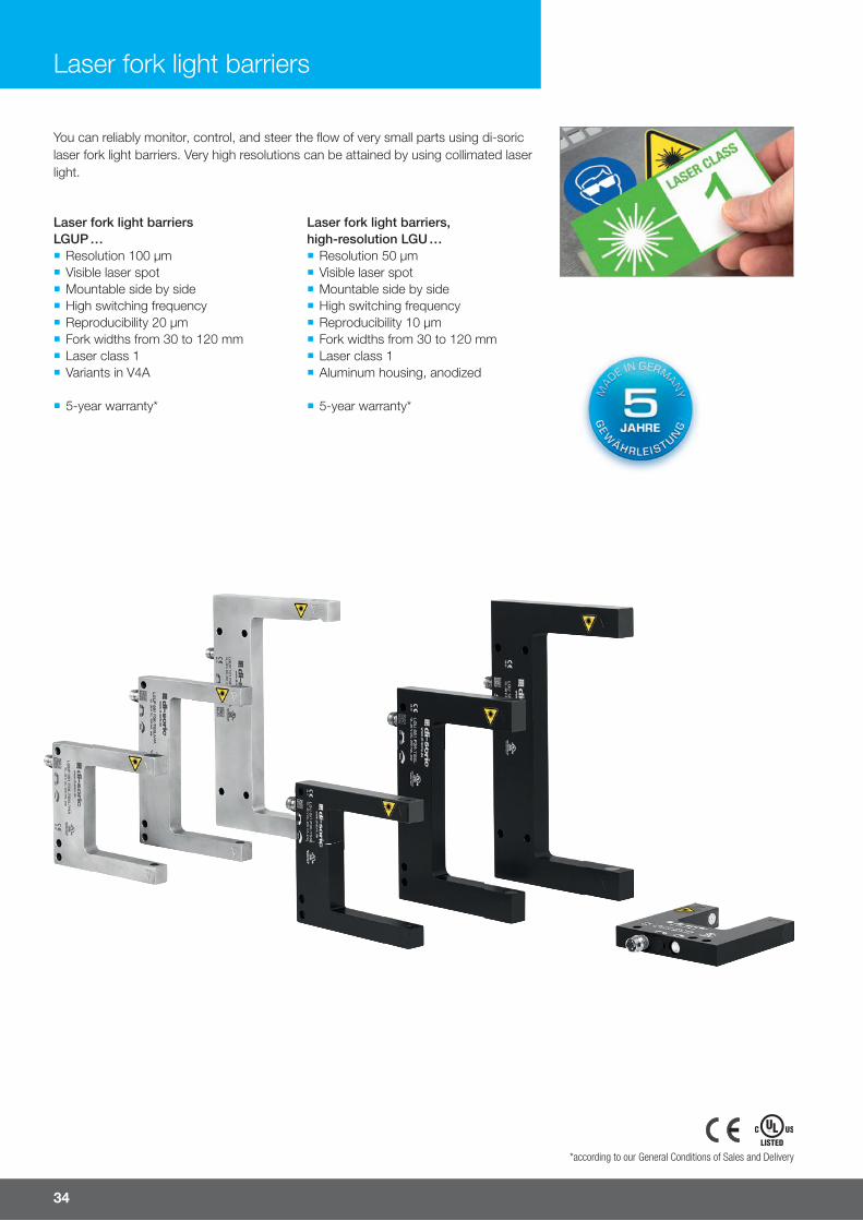
Laser fork light barriers LGUP … ¡ Resolution 100 µm ¡ Visible laser spot ¡ Mountable side by side ¡ High switching frequency ¡ Reproducibility 20 µm ¡ Fork widths from 30 to 120 mm ¡ Laser class 1 ¡ Variants in V4A
¡ 5-year warranty*
Laser fork light barriers, high-resolution LGU … ¡ Resolution 50 µm ¡ Visible laser spot ¡ Mountable side by side ¡ High switching frequency ¡ Reproducibility 10 µm ¡ Fork widths from 30 to 120 mm ¡ Laser class 1 ¡ Aluminum housing, anodized
¡ 5-year warranty*
You can reliably monitor, control, and steer the fl ow of very small parts using di-soric laser fork light barriers. Very high resolutions can be attained by using collimated laser light.
*according to our General Conditions of Sales and Delivery
For more information and models visit www.di-soric.com 35
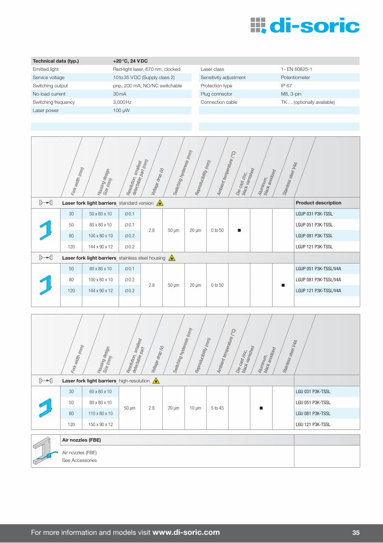
Technical data (typ.) +20 °C, 24 V DC
Emitted light Red-light laser, 670 nm, clocked Laser class 1- EN 60825-1
Service voltage 10 to 35 V DC (Supply class 2) Sensitivity adjustment Potentiometer
Switching output pnp, 200 mA, NO/NC switchable Protection type IP 67
No-load current 30 mA Plug connector M8, 3-pin
Switching frequency 3,000 Hz Connection cable TK … (optionally available)
Laser power 100 µW
Fork
wid
th (m
m)
Hous
ing
desi
gnSi
ze (m
m)
Reso
lutio
n, s
mal
lest
dete
ctab
le p
art (
mm
)Vo
ltage
dro
p (V
)
Switc
hing
hys
tere
sis
(mm
)Re
prod
ucib
ility
(mm
)
Ambi
ent t
empe
ratu
re (°
C)Di
e-ca
st z
inc,
bl
ack
varn
ishe
d
Alum
inum
,bl
ack
anod
ized
Stai
nles
s st
eel V
4A
Laser fork light barriers, standard version Product description
30 50 x 60 x 10 Ø 0.1
2.8 50 µm 20 µm 0 to 50 n
LGUP 031 P3K-TSSL
50 80 x 80 x 10 Ø 0.1 LGUP 051 P3K-TSSL
80 100 x 80 x 10 Ø 0.2 LGUP 081 P3K-TSSL
120 144 x 90 x 12 Ø 0.2 LGUP 121 P3K-TSSL
Laser fork light barriers, stainless steel housing
50 80 x 80 x 10 Ø 0.1
2.8 50 µm 20 µm 0 to 50 n
LGUP 051 P3K-TSSL/V4A
80 100 x 80 x 10 Ø 0.2 LGUP 081 P3K-TSSL/V4A
120 144 x 90 x 12 Ø 0.2 LGUP 121 P3K-TSSL/V4A
Fork
wid
th (m
m)
Hous
ing
desi
gnSi
ze (m
m)
Reso
lutio
n, s
mal
lest
dete
ctab
le p
art
Volta
ge d
rop
(V)
Switc
hing
hys
tere
sis
(mm
)Re
prod
ucib
ility
(mm
)
Ambi
ent t
empe
ratu
re (°
C)Di
e-ca
st z
inc,
blac
k va
rnis
hed
Alum
inum
,bl
ack
anod
ized
Stai
nles
s st
eel V
4A
Laser fork light barriers, high-resolution
30 60 x 60 x 10
50 µm 2.8 20 µm 10 µm 5 to 45 n
LGU 031 P3K-TSSL
50 80 x 80 x 10 LGU 051 P3K-TSSL
80 110 x 80 x 10 LGU 081 P3K-TSSL
120 150 x 90 x 12 LGU 121 P3K-TSSL
Air nozzles (FBE)
Air nozzles (FBE)
See Accessories

36
The angled light barrier fi nds its particu-lar use during removal of workpieces or detection of parts. The high switching frequency, short activation time and high resolution enable maximum positioning accuracy and reliable detection of the fastest motion sequences, even for very small parts.
Angled light barriers
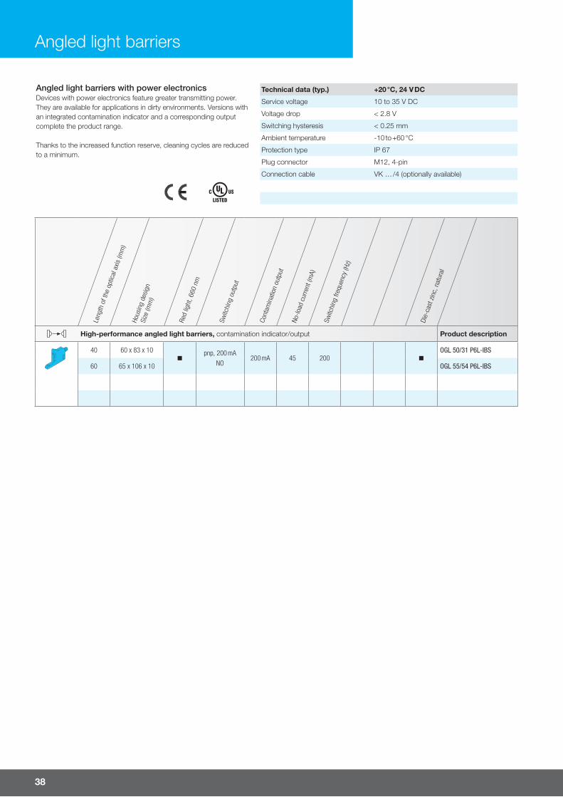
High-performance angled light barriers with a contamination indicator/output ¡ Intelligent contamination outputwith LED display
¡ Intelligent contamination indicator ¡ High function reserve ¡ Listed in the automotive industry ¡ Optical axis approachable in x-, y- and z-direction
¡ All-purpose mounting ¡ Robust metal housing
Angled light barriers ¡ Red- or infrared-light versions ¡ High switching frequency ¡ Sensitivity is adjustable ¡ Light/dark switching ¡ Robust metal housing ¡ All-purpose mounting ¡ 5-year warranty 1)
Laser angled light barriers ¡ Very high resolution ¡ Visible laser spot ¡ Mountable side by side ¡ High switching frequency ¡ Sensitivity is adjustable ¡ Light/dark switching ¡ Robust metal housing ¡ All-purpose mounting ¡ Laser class 1 ¡ 5-year warranty 1)
For more information and models visit www.di-soric.com 37
Leng
th o
f the
opt
ical
axis
(mm
)Ho
usin
g de
sign
Size
(mm
)
Red
light
, 660
nm
Infra
red
light
, 880
nm
No-lo
ad c
urre
nt (m
A)
Reso
lutio
n (m
m)
Switc
hing
freq
uenc
y (H
z)Re
prod
ucib
ility
(mm
)
Die-
cast
zin
c, b
lack
po
wde
r-co
ated
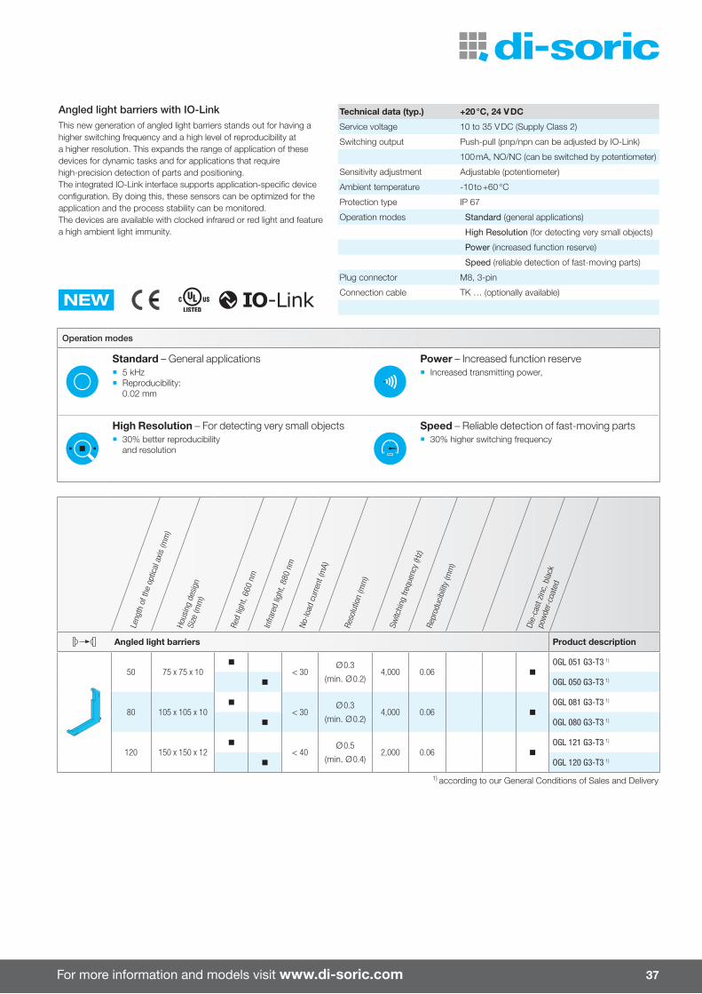
Angled light barriers Product description
50 75 x 75 x 10n
< 30Ø 0.3
(min. Ø 0.2)4,000 0.06 n
OGL 051 G3-T3 1)
n OGL 050 G3-T3 1)
80 105 x 105 x 10n
< 30Ø 0.3
(min. Ø 0.2)4,000 0.06 n
OGL 081 G3-T3 1)
n OGL 080 G3-T3 1)
120 150 x 150 x 12n
< 40Ø 0.5
(min. Ø 0.4)2,000 0.06 n
OGL 121 G3-T3 1)
n OGL 120 G3-T3 1)
1) according to our General Conditions of Sales and Delivery
Angled light barriers with IO-LinkThis new generation of angled light barriers stands out for having a higher switching frequency and a high level of reproducibility at a higher resolution. This expands the range of application of these devices for dynamic tasks and for applications that require high-precision detection of parts and positioning. The integrated IO-Link interface supports application-specific device configuration. By doing this, these sensors can be optimized for the application and the process stability can be monitored.The devices are available with clocked infrared or red light and feature a high ambient light immunity.
Technical data (typ.) +20 °C, 24 V DC
Service voltage 10 to 35 V DC (Supply Class 2)
Switching output Push-pull (pnp/npn can be adjusted by IO-Link)
100 mA, NO/NC (can be switched by potentiometer)
Sensitivity adjustment Adjustable (potentiometer)
Ambient temperature -10 to +60 °C
Protection type IP 67
Operation modes Standard (general applications)
High Resolution (for detecting very small objects)
Power (increased function reserve)
Speed (reliable detection of fast-moving parts)
Plug connector M8, 3-pin
NEWConnection cable TK … (optionally available)
Operation modes
Standard – General applications ¡ 5 kHz ¡ Reproducibility:
0.02 mm
Power – Increased function reserve ¡ Increased transmitting power,
High Resolution – For detecting very small objects ¡ 30% better reproducibility
and resolution
Speed – Reliable detection of fast-moving parts ¡ 30% higher switching frequency
38
Leng
th o
f the
opt
ical
axis
(mm
)
Hous
ing
desi
gnSi
ze (m
m)
Red
light
, 660
nm
Switc
hing
out
put
Cont
amin
atio
n ou
tput
No-lo
ad c
urre
nt (m
A)
Switc
hing
freq
uenc
y (H
z)
Die-
cast
zin
c, n
atur
al
High-performance angled light barriers, contamination indicator/output Product description
40 60 x 83 x 10n
pnp, 200 mANO
200 mA 45 200 n
OGL 50/31 P6L-IBS
60 65 x 106 x 10 OGL 55/54 P6L-IBS
Angled light barriers with power electronicsDevices with power electronics feature greater transmitting power. They are available for applications in dirty environments. Versions with an integrated contamination indicator and a corresponding output complete the product range.
Thanks to the increased function reserve, cleaning cycles are reduced to a minimum.
Technical data (typ.) +20 °C, 24 V DC
Service voltage 10 to 35 V DC
Voltage drop < 2.8 V
Switching hysteresis < 0.25 mm
Ambient temperature -10 to +60 °C
Protection type IP 67
Plug connector M12, 4-pin
Connection cable VK … /4 (optionally available)
Angled light barriers
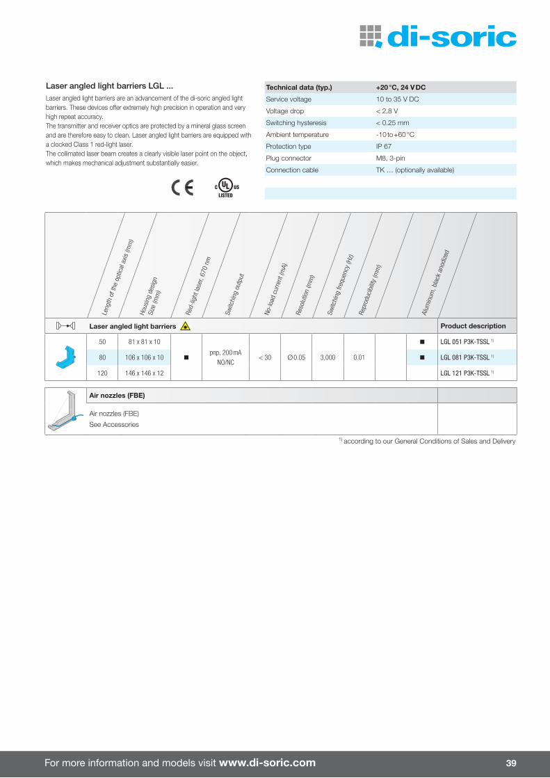
For more information and models visit www.di-soric.com 39
Leng
th o
f the
opt
ical
axis
(mm
)
Hous
ing
desi
gnSi
ze (m
m)
Red-
light
lase
r, 67
0 nm
Switc
hing
out
put
No-lo
ad c
urre
nt (m
A)
Reso
lutio
n (m
m)
Switc
hing
freq
uenc
y (H
z)
Repr
oduc
ibilit
y (m
m)
Alum
inum
, bla
ck a
nodi
zed
Laser angled light barriers Product description
50 81 x 81 x 10
pnp, 200 mANO/NC
n LGL 051 P3K-TSSL 1)
80 106 x 106 x 10 n < 30 Ø 0.05 3,000 0.01 n LGL 081 P3K-TSSL 1)
120 146 x 146 x 12 LGL 121 P3K-TSSL 1)
Air nozzles (FBE)
Air nozzles (FBE)
See Accessories
1) according to our General Conditions of Sales and Delivery
Laser angled light barriers LGL ...Laser angled light barriers are an advancement of the di-soric angled light barriers. These devices o�er extremely high precision in operation and very high repeat accuracy.The transmitter and receiver optics are protected by a mineral glass screen and are therefore easy to clean. Laser angled light barriers are equipped with a clocked Class 1 red-light laser.The collimated laser beam creates a clearly visible laser point on the object, which makes mechanical adjustment substantially easier.
Technical data (typ.) +20 °C, 24 V DC
Service voltage 10 to 35 V DC
Voltage drop < 2.8 V
Switching hysteresis < 0.25 mm
Ambient temperature -10 to +60 °C
Protection type IP 67
Plug connector M8, 3-pin
Connection cable TK … (optionally available)

40
Frame and ring light barriers are used for detecting and counting very small parts and for monitoring the ejection/removal of workpieces in pressing and stamping plants.
Frame and ring light barriers
Frame light barriers ¡ Light/dark switching ¡ Removable crossbar ¡ Impact protection for protected optics ¡ Resolution as of Ø 0.7 mm ¡ Very short activation time ¡ Pulse stretching adjustable ¡ Operating principle static/dynamic switchable
¡ Air nozzle, optional ¡ Robust metal housing
Ring light barriers ¡ Resolution 1.5 mm ¡ Short activation time ¡ Pulse stretching adjustable ¡ Operating principle static/dynamic switchable
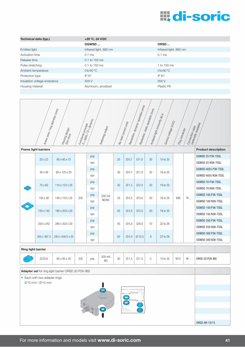
For more information and models visit www.di-soric.com 41
Technical data (typ.) +20 °C, 24 V DC
OGWSD … ORSD …
Emitted light Infrared light, 880 nm Infrared light, 880 nm
Activation time 0.1 ms 0.1 ms
Release time 0.1 to 150 ms
Pulse stretching 0.1 to 150 ms 1 to 150 ms
Ambient temperature 0 to 60 °C 0 to 60 °C
Protection type IP 67 IP 67
Insulation voltage endurance 500 V 500 V
Housing material Aluminum, anodized Plastic PA
Activ
e zo
ne /
ring
diam
eter
(mm
)
Hous
ing
desi
gnSi
ze (m
m)
Func
tiona
l prin
cipl
e S
= st
atic
/ D
= d
ynam
ic
Switc
hing
out
put
No-lo
ad c
urre
nt (m
A)Re
solu
tion,
dyn
amic
ope
ratio
n (m
m)
Reso
lutio
n, s
tatic
ope
ratio
n (m
m)
Ambi
ent l
ight
imm
unity
(kLx
)Se
rvic
e vo
ltage
(V D
C)
Plug
con
nect
or
Conn
ectio
n ca
ble
(opt
iona
lly a
vaila
ble)
Frame light barriers Product description
25 x 23 60 x 60 x 15
S/D
pnp
200 mANO/NC
25 Ø 0.7 Ø 1.0 30 10 to 35
M8 TK …
OGWSD 25 P3K-TSSL
npn OGWSD 25 N3K-TSSL
40 x 49 80 x 125 x 20pnp
30 Ø 0.7 Ø 1.0 20 18 to 35OGWSD 4055 P3K-TSSL
npn OGWSD 4055 N3K-TSSL
70 x 62 110 x 123 x 20pnp
30 Ø 1.5 Ø 2.0 20 18 to 35OGWSD 70 P3K-TSSL
npn OGWSD 70 N3K-TSSL
100 x 92 140 x 153 x 20pnp
35 Ø 2.5 Ø 3.0 20 18 to 35OGWSD 100 P3K-TSSL
npn OGWSD 100 N3K-TSSL
150 x 142 190 x 203 x 20pnp
45 Ø 3.0 Ø 5.0 20 18 to 35OGWSD 150 P3K-TSSL
npn OGWSD 150 N3K-TSSL
250 x 242 290 x 303 x 20pnp
45 Ø 5.0 Ø 8.0 10 22 to 26OGWSD 250 P3K-TSSL
npn OGWSD 250 N3K-TSSL
300 x 397.5 340 x 458.5 x 20pnp
50 Ø 5.0 Ø 10.0 8 22 to 26OGWSD 300 P3K-TSSL
npn OGWSD 300 N3K-TSSL
Ring light barrier
Ø 20.6 60 x 85 x 20 S/D pnp200 mA
NO30 Ø 1.5 Ø 1.5 5 10 to 35 M12 VK … ORSD 20 P2K-IBS
Adapter set for ring light barrier ORSD 20 P2K-IBS
Each with two adapter rings
Ø 10 mm / Ø 15 mm
Ø15,6 mm
Ø10,6 mm
ORSD-AR-10/15
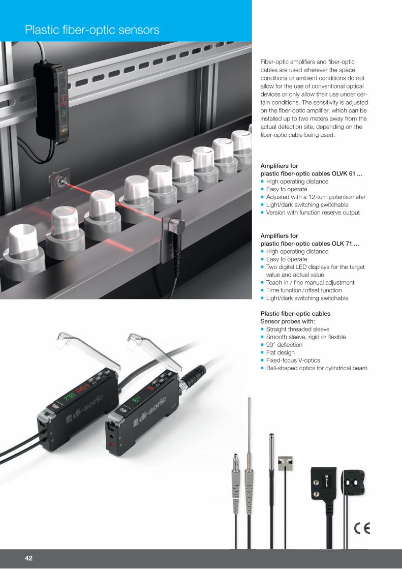
42
Fiber-optic amplifi ers and fi ber-optic cables are used wherever the space conditions or ambient conditions do not allow for the use of conventional optical devices or only allow their use under cer-tain conditions. The sensitivity is adjusted on the fi ber-optic amplifi er, which can be installed up to two meters away from the actual detection site, depending on the fi ber-optic cable being used.
Plastic fi ber-optic sensors
Amplifi ers for plastic fi ber-optic cables OLVK 61 … ¡ High operating distance ¡ Easy to operate ¡ Adjusted with a 12-turn potentiometer ¡ Light/dark switching switchable ¡ Version with function reserve output
Amplifi ers for plastic fi ber-optic cables OLK 71 … ¡ High operating distance ¡ Easy to operate ¡ Two digital LED displays for the target value and actual value
¡ Teach-in / fi ne manual adjustment ¡ Time function / o� set function ¡ Light/dark switching switchable
Plastic fi ber-optic cablesSensor probes with: ¡ Straight threaded sleeve ¡ Smooth sleeve, rigid or fl exible ¡ 90° defl ection ¡ Flat design ¡ Fixed-focus V-optics ¡ Ball-shaped optics for cylindrical beam

For more information and models visit www.di-soric.com 43
Hous
ing
desi
gnSi
ze (m
m)
Sens
itivit
y ad
just
men
t by
mea
ns
of Serv
ice
volta
ge (V
)
Activ
atio
n tim
e (m
s)
Pola
rity
Digi
tal L
ED d
ispl
ay
Switc
hing
hys
tere
sis
(%)
Tem
pera
ture
drif
t (%
/K)
No-lo
ad c
urre
nt (m
A)Pl
ug c
onne
ctor
Conn
ectio
n ca
ble
(opt
iona
lly a
vaila
ble)
Amplifi ers for plastic fi ber-optic cables Product description
60 x 31 x 10Potenti-ometer
10 to 30 0.33pnp 10 0.2
15 M8TK … OLVK 61 P3K-TSSL/3
pnp 10 0.2 TK … /4 OLVK 61 P3FK-TSSL
69 x 33 x 10.5 Teach 12 to 24 0.25 to 1.25pnp n
40 M8 TK … /4OLK 71 P3-T4
npn n OLK 71 N3-T4
69 x 33 x 10.5 Teach 12 to 24 0.25 to 1.25pnp n
40 Cable 2.0 mOLK 71 P3-3
npn n OLK 71 N3-3
Technical data (typ.) +20 °C, 24 V DC
OLVK 61 … OLK 71 …
Emitted light Red light, clocked Red light, clocked
Switching output Transistor, 200 mA, NO/NC, switchable 100 mA, NO/NC, programmable
Ambient temperature -25 to +55 °C -10 to +55 °C
Protection type IP 64 IP 54
Housing material PBTP (Crastin) ABS / PC
Operating distance specifi cations for plastic fi ber-optic cablesThe maximum operating distance specifi cation for fi ber-optic cables refers to measurements using the reference amplifi er OLK 71 … with a light intensity of 200% and a standard target of 100 x 100 mm, white. When using another amplifi er or a di� erent amplifi er setting, determine the expected range based on the calculation factor.
Fiber-optic amplifi er Calculation factor compared to the reference amplifi er OLK 71 … 1) (typ.)
OLK 71 … 1) 100 %
22
Kunststoff-LichtleitkabelPlastic fibre-optic cables
Lichttaster Tastkopf (Größe / Material) Faser Reichweite 1)
(mm)Auflösung 2)
(mm) Produktbezeichnung
Diffuse reflective sensor (Sensor probe(Size / Material) Fibre Operating range 1)
(mm)Resolution 2)
(mm) Product-ID
Ø4.0
1215
2000
53
3Ø2.2(2x)
Ø1.0 (2x)Fiber optic core
Flexible protective tubeM6
M6Edelstahl
Stainless steel
Parallel1,0 mm (2x) 200 Ø 0,1 /70°C
-55
2 m R min 25
Große Reichweite Long operating range KLT-M6-T2-1
Ø1.0 (1x)Fiber optic core
Ø0.25 (16x)Fiber optic core
Ø4.0
12
15
2000
53
3Ø2.2(2x)
Flexible protective tubeM6
M6Edelstahl
Stainless steel
Koaxial1,0 mm (1x)
0,25mm 16x)250 Ø 0,05
coaxial /70°C-55
2 m R min 25
Große ReichweiteKleinteileerkennung
Long operating rangeSmall parts detection KLT-M6-T2-1K
M2.6
2000
50.8
Ø1.0 (2x)
M4Ø0.5 (2x)Fiber optic core
13
93.0
2.2
10 13.5Flexible protective tube
M4Edelstahl
Stainless steel
Parallel0,5 mm (2x) 75 Ø 0,05
M4 /70°C-55
2 m R min 15
Genaue ErkennungOptionale Vorsatzoptik
Precise detectionOptional attachment optics KLT-M4-T2-0.5
M2.6
2000
50.8
Ø1.25 (2x)
M4
Ø0.5 (1x)Fiber optic core
2.2
10 13.5Flexible protective tube
Ø0.25 (9x)Fiber optic core
13
93.0
M4Edelstahl
Stainless steel
Koaxial0,5 mm (1x)0,25mm 9x)
100 Ø 0,05M4 coaxial /70°C
-55
2 m R min 15
KleinteileerkennungOptionale Vorsatzoptik
Small parts detectionOptional attachment optics KLT-M4-T2-0.5K
Ø2.0
2000
48.8
M3
Ø0.5 (2x)Fiber optic core
10.510
Ø1.0 (2x)
2.2
10 13.5Flexible protective tube
M3Edelstahl
Stainless steel
Parallel0,5 mm (2x) 75 Ø 0,05
M3 /70°C-55
2 m R min 15
Genaue ErkennungOptionale Vorsatzoptik
Precise detectionOptional attachment optics KLT-M3-T2-0.5
Ø2.0 M3
Ø0.5 (1x)Fiber optic core
Flexible protective tube
2000
Ø1.25 (2x)
2.2
10 13.5Ø0.25 (9x)
Fiber optic core
53.8
10.5
10
M3Edelstahl
Stainless steel
Koaxial0,5 mm (1x)0,25mm 9x)
100 Ø 0,05M3 coaxial /70°C
-25
2 m R min 15
KleinteileerkennungOptionale Vorsatzoptik
Small parts detectionOptional attachment optics KLT-M3-T2-0.5K
1) Maximalwerte (typ.) bei einer Normmessplatte 100 x 100 mm weiß / maximum values (typ.) with standard target 100 x 100 mm white.2) Auflösung (typ.) bei optiomalen Einstellungen und optimalen Messabständen (Taster ca.5 mm, Einweg: ca. 100 mm).
2) Resolution (typ.) at optimal settings and measuring distances (sensor approx. 5 mm, one-way: approx. 100 mm).
OLVK 61 P3K-TSSL/3 100 %
OLVK 61 P3FK-TSSL 100 %
Lichtintensität Faktor Reichweite 1) AnsprechzeitLight intensity Range factor 1) Response time 200 % 100 % 100 % 75 % 50 % 70 % 25 % 40 % 12 % 25 % 0,25 ms
0,31 ms
0,42 ms
0,63 ms
1,25 ms
1) OLK 71 … bei Lichtintensität 12 ... 200%1) OLK 71 ... at Light intensity 12 ... 200%
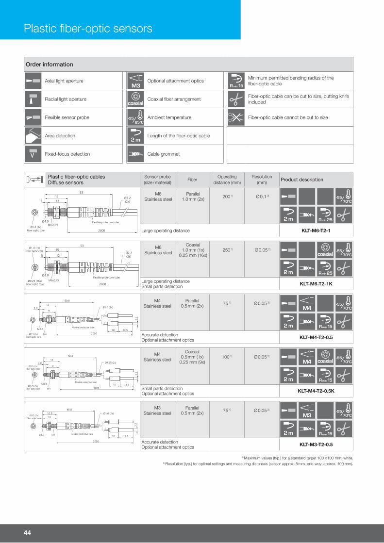
44
Order information
Axial light apertureM3
Optional attachment opticsR min 15
Minimum permitted bending radius of the fiber-optic cable
Radial light aperturecoaxial
Coaxial fiber arrangement Fiber-optic cable can be cut to size, cutting knife included
Flexible sensor probe /85°C-35 Ambient temperature Fiber-optic cable cannot be cut to size
Area detection2 m
Length of the fiber-optic cable
Fixed-focus detection Cable grommet
Plastic fiber-optic cablesDi�use sensors
Sensor probe (size / material)
FiberOperating
distance (mm)Resolution
(mm)Product description
Ø4.0
1215
2000
53
3Ø2.2(2x)
Ø1.0 (2x)Fiber optic core
Flexible protective tubeM6x0.75
M6Stainless steel
Parallel1.0 mm (2x) 200 1) Ø 0,1 2)
/70°C-55
2 m R min 25
Large operating distance KLT-M6-T2-1
Ø1.0 (1x)Fiber optic core
Ø0.25 (16x)Fiber optic core
Ø4.0
12
15
2000
53
3Ø2.2(2x)
Flexible protective tubeM6x0.75
M6Stainless steel
Coaxial1.0 mm (1x)
0.25 mm (16x)250 1) Ø 0,05 2)
coaxial /70°C-55
2 m R min 25
Large operating distanceSmall parts detection KLT-M6-T2-1K
M2.6
2000
50.8
Ø1.0 (2x)
M4Ø0.5 (2x)Fiber optic core
13
93.0
2.2
10 13.5Flexible protective tube
M4Stainless steel
Parallel0.5 mm (2x) 75 1) Ø 0,05 2)
M4 /70°C-55
2 m R min 15
Accurate detectionOptional attachment optics KLT-M4-T2-0.5
M2.6
2000
50.8
Ø1.25 (2x)
M4
Ø0.5 (1x)Fiber optic core
2.2
10 13.5Flexible protective tube
Ø0.25 (9x)Fiber optic core
13
93.0
M4Stainless steel
Coaxial0.5 mm (1x)
0.25 mm (9x)100 1) Ø 0,05 2)
M4 coaxial /70°C-55
2 m R min 15
Small parts detectionOptional attachment optics KLT-M4-T2-0.5K
Ø2.0
2000
48.8
M3
Ø0.5 (2x)Fiber optic core
10.510
Ø1.0 (2x)
2.2
10 13.5Flexible protective tube
M3Stainless steel
Parallel0.5 mm (2x) 75 1) Ø 0,05 2)
M3 /70°C-55
2 m R min 15
Accurate detectionOptional attachment optics KLT-M3-T2-0.5
Plastic fiber-optic sensors
1) Maximum values (typ.) for a standard target 100 x 100 mm, white.2) Resolution (typ.) for optimal settings and measuring distances (sensor approx. 5 mm, one-way: approx. 100 mm).
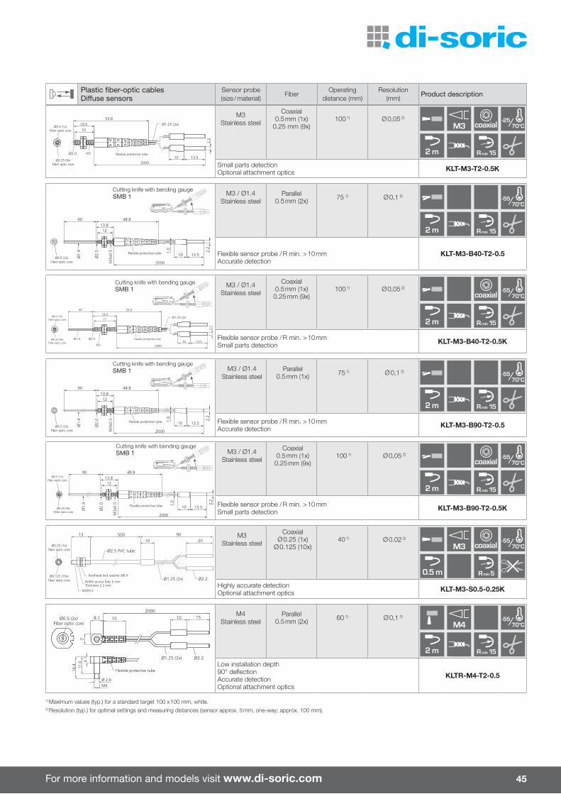
For more information and models visit www.di-soric.com 45
Plastic fiber-optic cablesDi�use sensors
Sensor probe (size / material)
FiberOperating
distance (mm)Resolution
(mm)Product description
Ø2.0 M3
Ø0.5 (1x)Fiber optic core
Flexible protective tube
2000
Ø1.25 (2x)
2.2
10 13.5Ø0.25 (9x)
Fiber optic core
53.8
10.5
10
M3Stainless steel
Coaxial0.5 mm (1x)
0.25 mm (9x)100 1) Ø 0,05 2)
M3 coaxial /70°C-25
2 m R min 15
Small parts detectionOptional attachment optics KLT-M3-T2-0.5K
R10
Cutting knife with bending gaugeSMB 1
Ø2.
0
2000
Ø1.
4
40
1213.8
48.8
10
1.0
13.5
2.2
M3x
0.5
Ø0.5 (2x)Fiber optic core
Flexible protective tube
M3 / Ø1.4Stainless steel
Parallel0.5 mm (2x) 75 1) Ø 0,1 2)
/70°C-55
2 m R min 15
Flexible sensor probe / R min. > 10 mmAccurate detection
KLT-M3-B40-T2-0.5
R10
Cutting knife with bending gaugeSMB 1
Ø2.0
M3
Ø0.5 (1x)Fiber optic core
Flexible protective tube
2000
Ø1.25 (2x)
2.2
10 13.5Ø0.25 (9x)
Fiber optic core
53.8
18.8
17
Ø1.4
40
M3 / Ø1.4Stainless steel
Coaxial0.5 mm (1x)
0.25 mm (9x)100 1) Ø 0,05 2)
coaxial /70°C-55
2 m R min 15
Flexible sensor probe / R min. > 10 mmSmall parts detection KLT-M3-B40-T2-0.5K
R10
Cutting knife with bending gaugeSMB 1
Ø2.
0
2000
Ø1.
4
90
1213.8
48.8
10
1.0
13.5
2.2
M3x
0.5
Ø0.5 (2x)Fiber optic core
Flexible protective tube
M3 / Ø1.4Stainless steel
Parallel0.5 mm (1x) 75 1) Ø 0,1 2)
/70°C-55
2 m R min 15
Flexible sensor probe / R min. > 10 mmAccurate detection KLT-M3-B90-T2-0.5
R10
Cutting knife with bending gaugeSMB 1
Ø2.
0
2000
Ø1.
4
90
1213.8
48.8
10
1.0
13.5
2.2
M3x
0.5
Flexible protective tube
Ø0.5 (1x)Fiber optic core
Ø0.25 (9x)Fiber optic core
M3 / Ø1.4Stainless steel
Coaxial0.5 mm (1x)
0.25 mm (9x)100 1) Ø 0,05 2)
coaxial /70°C-55
2 m R min 15
Flexible sensor probe / R min. > 10 mmSmall parts detection KLT-M3-B90-T2-0.5K
13 500 90
Ø0.125 (10x)fiber optic core Ø2.2
2010
Ø2.5 PVC tube
Ø1.25 (2x)
M3P0.5
Ø0.25 (1x)fiber optic core
Toothead lock washer Ø6.4
Width across flats 5 mmThickness 2.2 mm
M3Stainless steel
CoaxialØ 0.25 (1x)
Ø 0.125 (10x)40 1) Ø 0.02 2)
M3 coaxial /70°C-55
0.5 m R min 5
Highly accurate detectionOptional attachment optics KLT-M3-S0.5-0.25K
Ø0.5 (2x)Fiber optic core
Ø 2.6M4
4.1
11.4
14.4
1515
2000
10
Ø1.25 (2x) Ø2.2
8.1
7
Flexible protective tube
M4Stainless steel
Parallel0.5 mm (2x) 60 1) Ø 0,1 2)
M4 /70°C-55
2 m R min 15
Low installation depth90° deflectionAccurate detectionOptional attachment optics
KLTR-M4-T2-0.5
1) Maximum values (typ.) for a standard target 100 x 100 mm, white.2) Resolution (typ.) for optimal settings and measuring distances (sensor approx. 5 mm, one-way: approx. 100 mm).
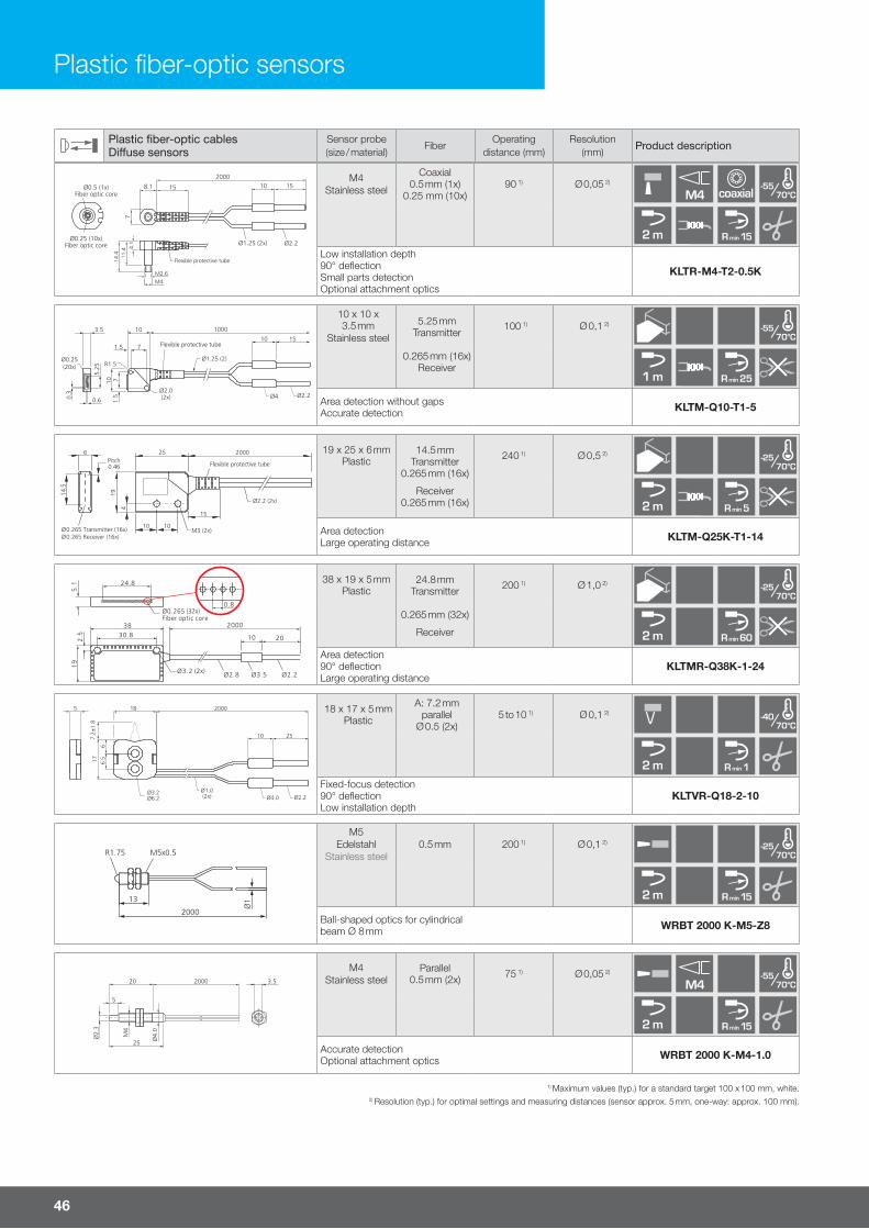
46
Plastic fiber-optic cablesDi�use sensors
Sensor probe (size / material)
FiberOperating
distance (mm)Resolution
(mm)Product description
M2.6M4
4.1
11.4
14.4
15Ø0.5 (1x)Fiber optic core
15
200010
Ø1.25 (2x) Ø2.2
8.1
7
Ø0.25 (10x)Fiber optic core
Flexible protective tube
M4Stainless steel
Coaxial0.5 mm (1x)
0.25 mm (10x)90 1) Ø 0,05 2)
M4 coaxial /70°C-55
2 m R min 15
Low installation depth90° deflectionSmall parts detectionOptional attachment optics
KLTR-M4-T2-0.5K
100010
7
Ø1.25 (2)
Ø2.0(2x)
R1.5
3.5
Ø0.25(20x)
1.5
10 7
1.510 15
0.60.3
5.25
Ø4 Ø2.2
Flexible protective tube
10 x 10 x 3.5 mm
Stainless steel
5.25 mm Transmitter
0.265 mm (16x)Receiver
100 1) Ø 0,1 2)/70°C
-55
1 m R min 25
Area detection without gapsAccurate detection KLTM-Q10-T1-5
10 10
25 2000
Ø2.2 (2x)
Flexible protective tube
4
19
M3 (2x)
15
14.5
6Pitch0.46
Ø 0.265 Transmitter (16x)Ø 0.265 Receiver (16x)
19 x 25 x 6 mmPlastic
14.5 mm Transmitter
0.265 mm (16x)
Receiver0.265 mm (16x)
240 1) Ø 0,5 2)/70°C
-25
2 m R min 5
Area detectionLarge operating distance KLTM-Q25K-T1-14
Ø2.2Ø3.5Ø2.8
3830.8
2000
2010
19
2.5
5.1 24.8
Ø0.265 (32x)Fiber optic core
0.8
Ø3.2 (2x)
38 x 19 x 5 mmPlastic
24.8 mmTransmitter
0.265 mm (32x)
Receiver
200 1) Ø 1,0 2)/70°C
-25
2 m R min 60
Area detection90° deflection Large operating distance
KLTMR-Q38K-1-24
200018
2510
Ø4.0 Ø2.2Ø1.0(2x)
5
7.2±
1.8
66.
517
Ø3.2Ø6.2
18 x 17 x 5 mmPlastic
A: 7.2 mm parallel
Ø 0.5 (2x)5 to 10 1) Ø 0,1 2)
/70°C-40
2 m R min 1 Fixed-focus detection90° deflectionLow installation depth
KLTVR-Q18-2-10
Ø1
M5x0.5R1.75
2000
13
M5Edelstahl
Stainless steel0.5 mm 200 1) Ø 0,1 2)
/70°C-25
2 m R min 15
Ball-shaped optics for cylindricalbeam Ø 8 mm WRBT 2000 K-M5-Z8
Ø2.
3
M4
Ø4.
0
2000 3.5
5
25
20
M4Stainless steel
Parallel0.5 mm (2x) 75 1) Ø 0,05 2)
M4 /70°C-55
2 m R min 15
Accurate detectionOptional attachment optics WRBT 2000 K-M4-1.0
1) Maximum values (typ.) for a standard target 100 x 100 mm, white.2) Resolution (typ.) for optimal settings and measuring distances (sensor approx. 5 mm, one-way: approx. 100 mm).
Plastic fiber-optic sensors

For more information and models visit www.di-soric.com 47
1) Maximum values (typ.) for a standard target 100 x 100 mm, white.2) Resolution (typ.) for optimal settings and measuring distances (sensor approx. 5 mm, one-way: approx. 100 mm).
Plastic fiber-optic cablesThrough-beam sensor
Sensor probe (size / material)
FiberOperating distance
(mm)Resolution
(mm)Product description
Ø4.0
1215
2000
53
3Ø2.2(2x)
Ø1.0 (1x)Fiber optic core
Flexible protective tubeM6x0.75
M6Stainless steel 1.0 mm 1,000 1) Ø 0,2 2)
/70°C-55
2 m R min 25
Large operating distance KLE-M6-T2-1
2000
50.8
Ø2.2
Ø1.0 (1x)Fiber optic core
Flexible protective tube
M4
M2.6
13
93.0
M6Stainless steel 1.0 mm 1,000 1) Ø 0,2 2)
/70°C-55
2 m R min 25
Large operating distance KLE-M4-T2-1
M2.6
2000
50.8
Ø2.2
M4Ø0.5 (1x)Fiber optic core
13
93.0
Flexible protective tube
M4Stainless steel 0.5 mm 250 1) Ø 0,1 2)
M2.6 /70°C-55
2 m R min 15
Accurate detectionOptional attachment optics KLE-M4-T2-0.5
Ø2.0
2000
48.8
M3
Ø1.0 (1x)Fiber optic core
10.510
Ø2.2
Flexible protective tube
M3Stainless steel 1.0 mm 1,000 1) Ø 0,2 2)
/70°C-55
2 m R min 25
Large operating distance KLE-M3-T2-1
Ø2.0
2000
48.8
M3
Ø0.5 (1x)Fiber optic core
10.510
Ø1.0
2.2
10 13.5Flexible protective tube
M3Stainless steel 0.5 mm 250 1) Ø 0,1 2)
/70°C-55
2 m R min 15
Accurate detection KLE-M3-T2-0.5
Plastic fiber-optic cablesDi�use sensors
Sensor probe (size / material)
FiberOperating
distance (mm)Resolution
(mm)Product description
Ø1
Ø2.
0
M3
2000
13.812
6
M3Stainless steel
Parallel0.5 mm (2x) 75 1) Ø 0,05 2)
M3 /70°C-55
2 m R min 15
Accurate detectionOptional attachment optics WRBT 2000 K-M3-0.5
Ø 2
1.6
Ø 5
Ø 2
.2
1520
2.5
2000
7Klemmbereich
Screw tightening rangeSeitlicher LichtaustrittLateral light emission
Ø 5Stainless steel Ø 0.8 mm 100 1) Ø 0,2 2)
/80°C-55
2 m R min 25
Low installation depth Small sensor probe WRBT 2000 KR-5.0-2.0
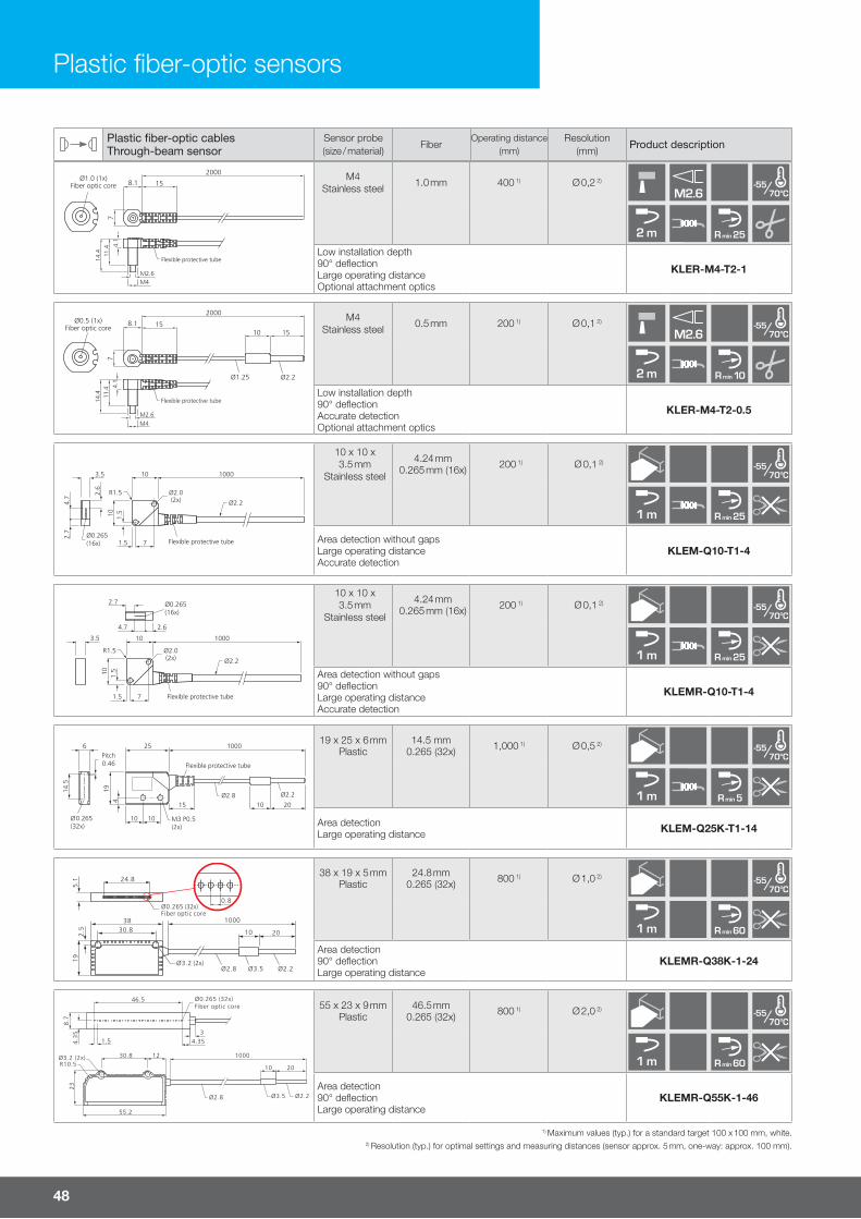
48
Plastic fiber-optic cablesThrough-beam sensor
Sensor probe (size / material)
FiberOperating distance
(mm)Resolution
(mm)Product description
Ø1.0 (1x)Fiber optic core
M2.6M4
4.1
11.4
14.4
15
2000
8.1
7
Flexible protective tube
M4Stainless steel 1.0 mm 400 1) Ø 0,2 2)
M2.6 /70°C-55
2 m R min 25
Low installation depth90° deflection Large operating distanceOptional attachment optics
KLER-M4-T2-1
Ø0.5 (1x)Fiber optic core
M2.6M4
4.1
11.4
14.4
1515
2000
10
Ø1.25 Ø2.2
8.1
7
Flexible protective tube
M4Stainless steel 0.5 mm 200 1) Ø 0,1 2)
M2.6 /70°C-55
2 m R min 10
Low installation depth 90° deflectionAccurate detectionOptional attachment optics
KLER-M4-T2-0.5
100010
7
4.7
Ø2.2
Ø2.0(2x)
R1.5
3.5
2.6
2.7
Ø0.265(16x)
1.510
1.5 Flexible protective tube
10 x 10 x 3.5 mm
Stainless steel
4.24 mm0.265 mm (16x) 200 1) Ø 0,1 2)
/70°C-55
1 m R min 25
Area detection without gapsLarge operating distanceAccurate detection
KLEM-Q10-T1-4
100010
7
Ø2.2
Ø2.0(2x)
R1.5
3.5
Ø0.265(16x)
1.510
1.5 Flexible protective tube
4.7
2.7
2.6
10 x 10 x 3.5 mm
Stainless steel
4.24 mm0.265 mm (16x) 200 1) Ø 0,1 2)
/70°C-55
1 m R min 25
Area detection without gaps90° deflection Large operating distanceAccurate detection
KLEMR-Q10-T1-4
10 10
25 1000
Ø2.8
Flexible protective tube
419
M3 P0.5(2x)
15
14.5
6Pitch0.46
Ø 0.265(32x)
2010
Ø2.2
19 x 25 x 6 mmPlastic
14.5 mm0.265 (32x) 1,000 1) Ø 0,5 2)
/70°C-55
1 m R min 5
Area detection Large operating distance KLEM-Q25K-T1-14
Ø2.2Ø3.5Ø2.8
3830.8
1000
2010
19
2.5
5.1 24.8
Ø0.265 (32x)Fiber optic core
0.8
Ø3.2 (2x)
38 x 19 x 5 mmPlastic
24.8 mm0.265 (32x) 800 1) Ø 1,0 2)
/70°C-55
1 m R min 60
Area detection 90° deflection Large operating distance
KLEMR-Q38K-1-24
46.5
1.53
4.35
30.8Ø3.2 (2x) 1000
10 20R10.5
55.2
23
Ø2.8 Ø2.2Ø3.5
4.3
5
8.7
12
Ø0.265 (32x)Fiber optic core 55 x 23 x 9 mm
Plastic46.5 mm
0.265 (32x) 800 1) Ø 2,0 2)/70°C
-55
1 m R min 60
Area detection 90° deflectionLarge operating distance
KLEMR-Q55K-1-46
Plastic fiber-optic sensors
1) Maximum values (typ.) for a standard target 100 x 100 mm, white.2) Resolution (typ.) for optimal settings and measuring distances (sensor approx. 5 mm, one-way: approx. 100 mm).
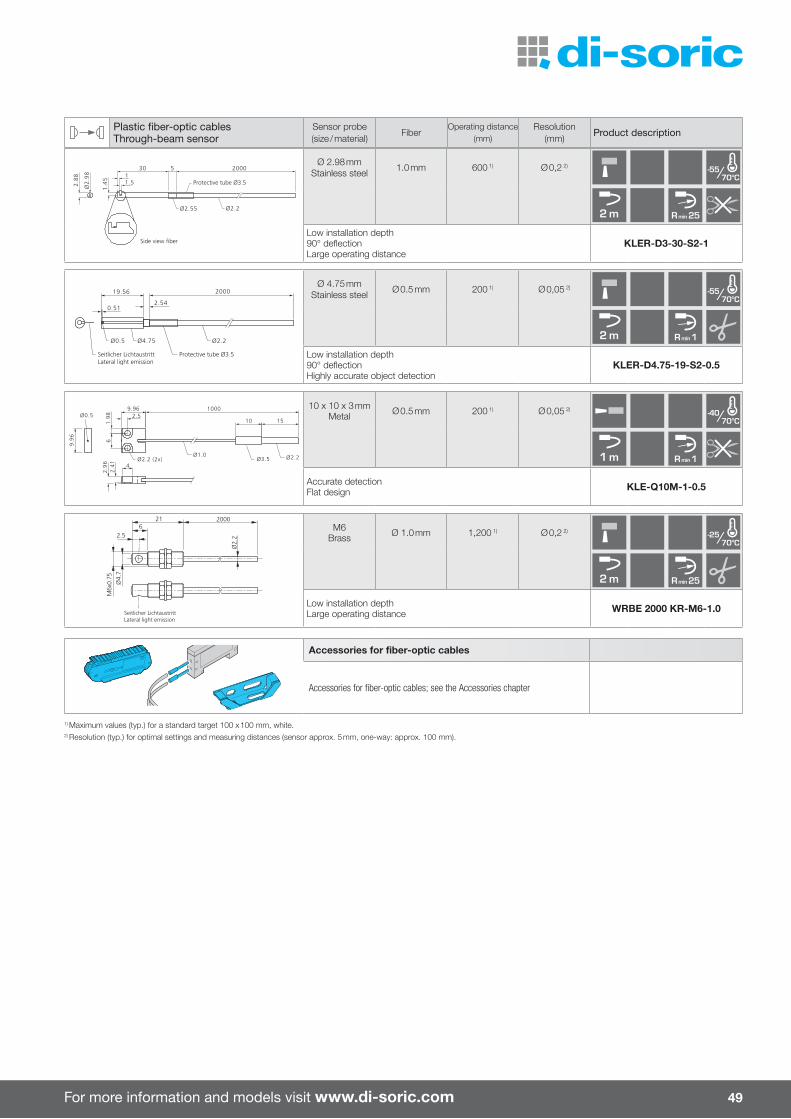
For more information and models visit www.di-soric.com 49
Plastic fiber-optic cablesThrough-beam sensor
Sensor probe (size / material)
FiberOperating distance
(mm)Resolution
(mm)Product description
Ø2
.98
20001
530
1.5
1.4
5
2.8
8
Ø2.55 Ø2.2
Protective tube Ø3.5
Side view fiber
Ø 2.98 mmStainless steel 1.0 mm 600 1) Ø 0,2 2)
/70°C-55
2 m R min 25
Low installation depth90° deflectionLarge operating distance
KLER-D3-30-S2-1
200019.56
0.512.54
Ø4.75 Ø2.2
Protective tube Ø3.5
Ø0.5
Seitlicher LichtaustrittLateral light emission
Ø 4.75 mmStainless steel Ø 0.5 mm 200 1) Ø 0,05 2)
/70°C-55
2 m R min 1
Low installation depth90° deflectionHighly accurate object detection
KLER-D4.75-19-S2-0.5
1000
Ø1.0Ø3.5
10 15
Ø2.2Ø2.2 (2x)
1.9
8
9.962.5
6
Ø0.5
9.9
6
4
2.9
62
.41
10 x 10 x 3 mmMetal Ø 0.5 mm 200 1) Ø 0,05 2)
/70°C-40
1 m R min 1
Accurate detectionFlat design KLE-Q10M-1-0.5
Ø4.
7
21 2000
Ø2.
22.56
M6x
0.75
Seitlicher LichtaustrittLateral light emission
M6Brass Ø 1.0 mm 1,200 1) Ø 0,2 2)
/70°C-25
2 m R min 25
Low installation depth Large operating distance WRBE 2000 KR-M6-1.0
1) Maximum values (typ.) for a standard target 100 x 100 mm, white.2) Resolution (typ.) for optimal settings and measuring distances (sensor approx. 5 mm, one-way: approx. 100 mm).
Accessories for fiber-optic cables
Accessories for fiber-optic cables; see the Accessories chapter

50
Glass fi ber-optic sensors are used in confi ned spatial conditions.
Glass fi ber-optic cables feature high mechanical durability and a large temperature range.
Glass fi ber-optic sensors
Glass fi ber-optic cablesVariants with: ¡ Silicone-metal sleeve for high mechanical stress and high protection type
¡ Metal sleeve for high temperatures ¡ Polyurethane protective jacket ¡ Wide detection range ¡ Attachment optics for large operating distances
Amplifi ers for glass fi ber-optic cables ¡ Auto-teach and manual teach ¡ Robust housing made of die-cast zinc ¡ High scan widths and operating dis-tances
¡ Green-light variants for detecting glass ¡ Switch-on/o� delay

For more information and models visit www.di-soric.com 51
Hous
ing
desi
gnSi
ze (m
m)
Sens
itivit
y ad
just
men
t by
mea
ns
of Serv
ice
volta
ge (V
)
Switc
hing
freq
uenc
y (k
Hz)
Infra
red
light
, clo
cked
Red
light
, clo
cked
Gree
n lig
ht, c
lock
edSw
itchi
ng h
yste
resi
s (%
)Te
mpe
ratu
re d
rift (
%/K
)Am
bien
t lig
ht im
mun
ity (k
Lx)
No-lo
ad c
urre
nt (m
A)Pl
ug c
onne
ctor
Conn
ectio
n ca
ble
(opt
iona
lly a
vaila
ble)
Amplifiers for glass fiber-optic cables Product description
40 x 41 x 75Potenti-ometer
12 to 35
1.5 n
10 0.3 20 55 M12 VK … /4
OLV 40 P3K-IBS
1.5 n OLV 41 P3K-IBS
0.5 n OLV 42 P3K-IBS
40 x 41 x 75Potenti-ometer
12 to 35 1.5n
10 0.3 20 55 ClampsOLV 40 P4K
n OLV 41 P4K
40 x 41 x 75 Teach 10 to 35 1.5n
120.1
50 45 M12 VK … /4OLVTI 40 P3K-IBS
n 0.25 OLVTI 41 P3K-IBS
Technical data (typ.) +20 °C, 24 V DC
Glass fiber-optic sensors WRB … (see pages 50-53)
Housing material V2A
Aluminum (…SQ … / … MQ … / WRB 220 SW)
Single fiber 50 µm
Opening angle 67°
Temperature resistance -40 to +180 °C, for short periods up to +250 °C (silicone-metal sleeve)
-40 to +180 °C, for short periods up to +300 °C (metal sleeve)
Technical data (typ.) +20 °C, 24 V DC
Amplifiers for glass fiber-optic cables OLV …
Switching output Transistor, pnp, 200 mA, NO/NC, switchable
Ambient temperature -10 to +60 °C
Housing material Die-cast zinc
Protection type IP 65
Di�use sensors Installation instructions for glass fiber-optic cables
1) For permanently installed fiber-optic cables.3) All specified scan widths and operating distances are average values in conjunc-
tion with the fiber-optic amplifier in infrared light. If necessary, adjust the sensitivity range using the basic sensitivity potentiometer P2.
The specified scan widths and operating distances are reduced to about 80% in red light and to about 30% in green light. The values depend on the fiber-optic cables and on the object to be scanned (size, shape, surface, color, etc.).
4) With attachment optics and axial light aperture. Only possible for fiber-optic cables of corresponding length.
Through-beam sensors
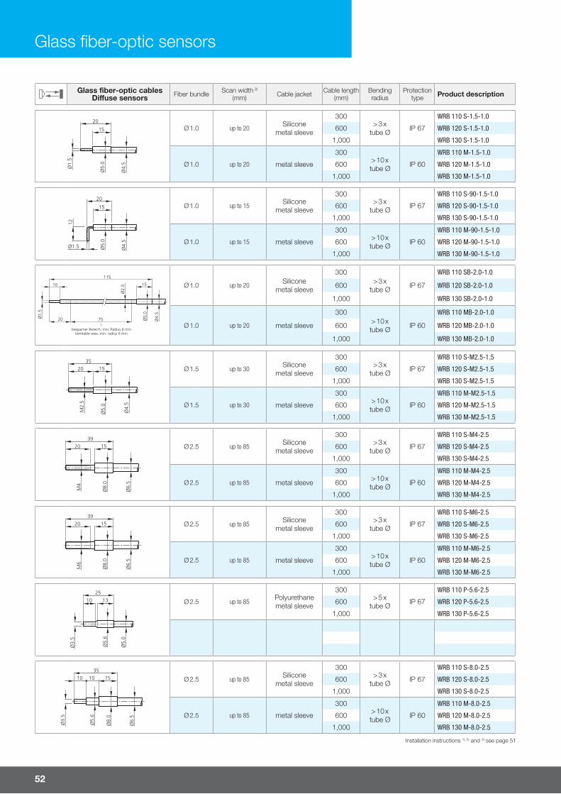
52
Glass fiber-optic cablesDi�use sensors Fiber bundle Scan width 3)
(mm) Cable jacket Cable length(mm)
Bending radius
Protection type Product description
Ø 1.0 up to 20Silicone
metal sleeve
300> 3 x
tube Ø IP 67
WRB 110 S-1.5-1.0
600 WRB 120 S-1.5-1.0
1,000 WRB 130 S-1.5-1.0
Ø 1.0 up to 20 metal sleeve
300> 10 xtube Ø IP 60
WRB 110 M-1.5-1.0
600 WRB 120 M-1.5-1.0
1,000 WRB 130 M-1.5-1.0
Ø 1.0 up to 15Silicone
metal sleeve
300> 3 x
tube Ø IP 67
WRB 110 S-90-1.5-1.0
600 WRB 120 S-90-1.5-1.0
1,000 WRB 130 S-90-1.5-1.0
Ø 1.0 up to 15 metal sleeve
300> 10 xtube Ø IP 60
WRB 110 M-90-1.5-1.0
600 WRB 120 M-90-1.5-1.0
1,000 WRB 130 M-90-1.5-1.0
Ø 1.0 up to 20Silicone
metal sleeve
300> 3 x
tube Ø IP 67
WRB 110 SB-2.0-1.0
600 WRB 120 SB-2.0-1.0
1,000 WRB 130 SB-2.0-1.0
Ø 1.0 up to 20 metal sleeve
300> 10 xtube Ø IP 60
WRB 110 MB-2.0-1.0
600 WRB 120 MB-2.0-1.0
1,000 WRB 130 MB-2.0-1.0
Ø 1.5 up to 30Silicone
metal sleeve
300> 3 x
tube Ø IP 67
WRB 110 S-M2.5-1.5
600 WRB 120 S-M2.5-1.5
1,000 WRB 130 S-M2.5-1.5
Ø 1.5 up to 30 metal sleeve
300> 10 xtube Ø IP 60
WRB 110 M-M2.5-1.5
600 WRB 120 M-M2.5-1.5
1,000 WRB 130 M-M2.5-1.5
Ø 2.5 up to 85Silicone
metal sleeve
300> 3 x
tube Ø IP 67
WRB 110 S-M4-2.5
600 WRB 120 S-M4-2.5
1,000 WRB 130 S-M4-2.5
Ø 2.5 up to 85 metal sleeve
300> 10 xtube Ø IP 60
WRB 110 M-M4-2.5
600 WRB 120 M-M4-2.5
1,000 WRB 130 M-M4-2.5
Ø 2.5 up to 85Silicone
metal sleeve
300> 3 x
tube Ø IP 67
WRB 110 S-M6-2.5
600 WRB 120 S-M6-2.5
1,000 WRB 130 S-M6-2.5
Ø 2.5 up to 85 metal sleeve
300> 10 xtube Ø IP 60
WRB 110 M-M6-2.5
600 WRB 120 M-M6-2.5
1,000 WRB 130 M-M6-2.5
Ø 2.5 up to 85Polyurethanemetal sleeve
300> 5 x
tube Ø IP 67
WRB 110 P-5.6-2.5
600 WRB 120 P-5.6-2.5
1,000 WRB 130 P-5.6-2.5
Ø 2.5 up to 85Silicone
metal sleeve
300> 3 x
tube Ø IP 67
WRB 110 S-8.0-2.5
600 WRB 120 S-8.0-2.5
1,000 WRB 130 S-8.0-2.5
Ø 2.5 up to 85 metal sleeve
300> 10 xtube Ø IP 60
WRB 110 M-8.0-2.5
600 WRB 120 M-8.0-2.5
1,000 WRB 130 M-8.0-2.5
Glass fiber-optic sensors
Installation instructions 1), 2) and 3) see page 51

For more information and models visit www.di-soric.com 53
Glass fiber-optic cablesDi�use sensors Fiber bundle Scan width 3)
(mm) Cable jacket Cable length(mm)
Bending radius
Protection type Product description
Ø 4.0 up to 150Silicone
metal sleeve
300> 3 x
tube Ø IP 67
WRB 110 S-8.5-4.0
600 WRB 120 S-8.5-4.0
1,000 WRB 130 S-8.5-4.0
Ø 4.0 up to 150 metal sleeve
300> 10 xtube Ø IP 60
WRB 110 M-8.5-4.0
600 WRB 120 M-8.5-4.0
1,000 WRB 130 M-8.5-4.0
Ø 2.5 up to 80Silicone
metal sleeve
300> 3 x
tube Ø IP 67
WRB 110 S-90-4.0-2.5
600 WRB 120 S-90-4.0-2.5
1,000 WRB 130 S-90-4.0-2.5
Ø 2.5 up to 80 metal sleeve
300> 10 xtube Ø IP 60
WRB 110 M-90-4.0-2.5
600 WRB 120 M-90-4.0-2.5
1,000 WRB 130 M-90-4.0-2.5
Ø 2.5 up to 70Silicone
metal sleeve
300> 3 x
tube Ø IP 67
WRB 110 SR-8.0-2.5
600 WRB 120 SR-8.0-2.5
1,000 WRB 130 SR-8.0-2.5
Ø 2.5 up to 70 metal sleeve
300> 10 xtube Ø IP 60
WRB 110 MR-8.0-2.5
600 WRB 120 MR-8.0-2.5
1,000 WRB 130 MR-8.0-2.5
Ø 0.6 (10x)Ø 0.3 (10x) up to 90
Siliconemetal sleeve
300> 3 x
tube Ø IP 67
WRB 110 SQ-10-0.6
600 WRB 120 SQ-10-0.6
1,000 WRB 130 SQ-10-0.6
Ø 0.6 (10x)Ø 0.3 (10x) up to 90 metal sleeve
300> 10 xtube Ø IP 60
WRB 110 MQ-10-0.6
600 WRB 120 MQ-10-0.6
1,000 WRB 130 MQ-10-0.6
Ø 0.6 (10x)Ø 0.3 (10x) up to 85
Siliconemetal sleeve
300> 3 x
tube Ø IP 67
WRB 110 SQ-90-10-0.6
600 WRB 120 SQ-90-10-0.6
1,000 WRB 130 SQ-90-10-0.6
Ø 0.6 (10x)Ø 0.3 (10x) up to 85 metal sleeve
300> 10 xtube Ø IP 60
WRB 110 MQ-90-10-0.6
600 WRB 120 MQ-90-10-0.6
1,000 WRB 130 MQ-90-10-0.6
Ø 0.6 (20x)Ø 0.3 (20x) up to 210
Siliconemetal sleeve
300> 3 x
tube Ø IP 67
WRB 110 SQ-20-0.6
600 WRB 120 SQ-20-0.6
1,000 WRB 130 SQ-20-0.6
Ø 0.6 (20x)Ø 0.3 (20x) up to 210 metal sleeve
300> 10 xtube Ø IP 60
WRB 110 MQ-20-0.6
600 WRB 120 MQ-20-0.6
1,000 WRB 130 MQ-20-0.6
Ø 0.6 (20x)Ø 0.3 (20x) up to 200
Siliconemetal sleeve
300> 3 x
tube Ø IP 67
WRB 110 SQ-90-20-0.6
600 WRB 120 SQ-90-20-0.6
1,000 WRB 130 SQ-90-20-0.6
Ø 0.6 (20x)Ø 0.3 (20x) up to 200 metal sleeve
300> 10 xtube Ø IP 60
WRB 110 MQ-90-20-0.6
600 WRB 120 MQ-90-20-0.6
1,000 WRB 130 MQ-90-20-0.6
Ø 2.5 10 - 100Silicone
metal sleeve
300> 3 x
tube Ø IP 67600 WRB 220 SW
1,000
Installation instructions 1), 2) and 3) see page 51

54
Glass fiber-optic cables Through-beam sensors Fiber bundle Scan width 3)
(mm) Cable jacket Cable length(mm)
Bending radius
Protection type Product description
Ø 1.0 up to 150Silicone
metal sleeve
300> 3 x 1)
tube Ø IP 67
WRB 210 S-1.5-1.0
600 WRB 220 S-1.5-1.0
1,000 WRB 230 S-1.5-1.0
Ø 1.0 up to 150 metal sleeve
300> 10 x 1)
tube Ø IP 60
WRB 210 M-1.5-1.0
600 WRB 220 M-1.5-1.0
1,000 WRB 230 M-1.5-1.0
Ø 1.0 up to 120Silicone
metal sleeve
300> 3 x 1)
tube Ø IP 67
WRB 210 S-90-1.5-1.0
600 WRB 220 S-90-1.5-1.0
1,000 WRB 230 S-90-1.5-1.0
Ø 1.0 up to 120 metal sleeve
300> 10 x 1)
tube Ø IP 60
WRB 210 M-90-1.5-1.0
600 WRB 220 M-90-1.5-1.0
1,000 WRB 230 M-90-1.5-1.0
Ø 1.0 up to 150Silicone
metal sleeve
300> 3 x 1)
tube Ø IP 67
WRB 210 SB-2.0-1.0
600 WRB 220 SB-2.0-1.0
1,000 WRB 230 SB-2.0-1.0
Ø 1.0 up to 150 metal sleeve
300> 10 x 1)
tube Ø IP 60
WRB 210 MB-2.0-1.0
600 WRB 220 MB-2.0-1.0
1,000 WRB 230 MB-2.0-1.0
Ø 1.5 up to 250(500 4)
Siliconemetal sleeve
300> 3 x 1)
tube Ø IP 67
WRB 210 S-M2.5-1.5
600 WRB 220 S-M2.5-1.5
1,000 WRB 230 S-M2.5-1.5
Ø 1.5 up to 250(500 4) metal sleeve
300> 10 x 1)
tube Ø IP 60
WRB 210 M-M2.5-1.5
600 WRB 220 M-M2.5-1.5
1,000 WRB 230 M-M2.5-1.5
Ø 2.5 up to 900(1,800 4)
Siliconemetal sleeve
300> 3 x 1)
tube Ø IP 67
WRB 210 S-M4-2.5
600 WRB 220 S-M4-2.5
1,000 WRB 230 S-M4-2.5
Ø 2.5 up to 900(1,800 4) metal sleeve
300> 10 x 1)
tube Ø IP 60
WRB 210 M-M4-2.5
600 WRB 220 M-M4-2.5
1,000 WRB 230 M-M4-2.5
Ø 2.5 up to 900Silicone
metal sleeve
300> 3 x 1)
tube Ø IP 67
WRB 210 S-M6-2.5
600 WRB 220 S-M6-2.5
1,000 WRB 230 S-M6-2.5
Ø 2.5 up to 900 metal sleeve
300> 10 x 1)
tube Ø IP 60
WRB 210 M-M6-2.5
600 WRB 220 M-M6-2.5
1,000 WRB 230 M-M6-2.5
Ø 2.5 up to 85Polyurethanemetal sleeve
300> 5 x 1)
tube Ø IP 67
WRB 210 P-5.6-2.5
600 WRB 220 P-5.6-2.5
1,000 WRB 230 P-5.6-2.5
Ø 2.5 up to 85Silicone
metal sleeve
300> 3 x 1)
tube Ø IP 67
WRB 210 S-8.0-2.5
600 WRB 220 S-8.0-2.5
1,000 WRB 230 S-8.0-2.5
Ø 2.5 up to 85 metal sleeve
300> 10 x 1)
tube Ø IP 60
WRB 210 M-8.0-2.5
600 WRB 220 M-8.0-2.5
1,000 WRB 230 M-8.0-2.5
Glass fiber-optic sensors
Installation instructions 1), 2) and 3) see page 51

For more information and models visit www.di-soric.com 55
Glass fiber-optic cables Through-beam sensors Fiber bundle Scan width 3)
(mm) Cable jacket Cable length(mm)
Bending radius
Protection type Product description
Ø 4.0 up to 150Silicone
metal sleeve
300> 3 x
tube Ø IP 67
WRB 210 S-8.5-4.0
600 WRB 220 S-8.5-4.0
1,000 WRB 230 S-8.5-4.0
Ø 4.0 up to 150 metal sleeve
300> 10 xtube Ø IP 60
WRB 210 M-8.5-4.0
600 WRB 220 M-8.5-4.0
1,000 WRB 230 M-8.5-4.0
Ø 2.5 up to 900Silicone
metal sleeve
300> 3 x
tube Ø IP 67
WRB 210 S-90-4.0-2.5
600 WRB 220 S-90-4.0-2.5
1,000 WRB 230 S-90-4.0-2.5
Ø 2.5 up to 900 metal sleeve
300> 10 xtube Ø IP 60
WRB 210 M-90-4.0-2.5
600 WRB 220 M-90-4.0-2.5
1,000 WRB 230 M-90-4.0-2.5
Ø 2.5 up to 800Silicone
metal sleeve
300> 3 x
tube Ø IP 67
WRB 210 SR-8.0-2.5
600 WRB 220 SR-8.0-2.5
1,000 WRB 230 SR-8.0-2.5
Ø 2.5 up to 800 metal sleeve
300> 10 xtube Ø IP 60
WRB 210 MR-8.0-2.5
600 WRB 220 MR-8.0-2.5
1,000 WRB 230 MR-8.0-2.5
Ø 0.6 (10x)Ø 0.3 (10x) up to 700
Siliconemetal sleeve
300> 3 x
tube Ø IP 67
WRB 210 SQ-10-0.3
600 WRB 220 SQ-10-0.3
1,000 WRB 230 SQ-10-0.3
Ø 0.6 (10x)Ø 0.3 (10x) up to 700 metal sleeve
300> 10 xtube Ø IP 60
WRB 210 MQ-10-0.3
600 WRB 220 MQ-10-0.3
1,000 WRB 230 MQ-10-0.3
Ø 0.6 (10x)Ø 0.3 (10x) up to 650
Siliconemetal sleeve
300> 3 x
tube Ø IP 67
WRB 210 SQ-90-10-0.3
600 WRB 220 SQ-90-10-0.3
1,000 WRB 230 SQ-90-10-0.3
Ø 0.6 (10x)Ø 0.3 (10x) up to 650 metal sleeve
300> 10 xtube Ø IP 60
WRB 210 MQ-90-10-0.3
600 WRB 220 MQ-90-10-0.3
1,000 WRB 230 MQ-90-10-0.3
Ø 0.6 (20x)Ø 0.3 (20x) up to 1,200
Siliconemetal sleeve
300> 3 x
tube Ø IP 67
WRB 210 SQ-20-0.3
600 WRB 220 SQ-20-0.3
1,000 WRB 230 SQ-20-0.3
Ø 0.6 (20x)Ø 0.3 (20x) up to 1,200 metal sleeve
300> 10 xtube Ø IP 60600 WRB 220 MQ-20-0.3
1,000 WRB 230 MQ-20-0.3
Ø 0.6 (20x)Ø 0.3 (20x) up to 1,100
Siliconemetal sleeve
300> 3 x
tube Ø IP 67
WRB 210 SQ-90-20-0.3
600 WRB 220 SQ-90-20-0.3
1,000 WRB 230 SQ-90-20-0.3
Ø 0.6 (20x)Ø 0.3 (20x) up to 1,100 metal sleeve
300> 10 xtube Ø IP 60
WRB 210 MQ-90-20-0.3
600 WRB 220 MQ-90-20-0.3
1,000 WRB 230 MQ-90-20-0.3
Accessories for fiber-optic cables
Accessories for fiber-optic cables; see the Accessories chapter
Installation instructions 1), 2) and 3) see page 51

56
Light grids
Each light grid system consists of a transmitter and receiver array made of anodized aluminum.
Depending on the light grid type, the evaluation electronics are integrated into the light grid array or act as an external amplifi er in a separate housing.
di-soric light grids monitor a defi ned control area with multiple invisible infrared light beams. The light grid systems oper-ate on the principle of multiple through-beam sensors whose output signals are either interlinked (switching light grids) or evaluated individually (measuring light grids).
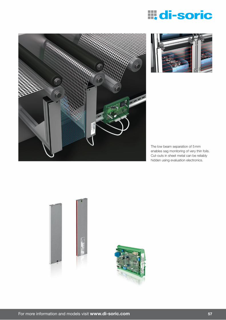
For more information and models visit www.di-soric.com 57
The low beam separation of 5 mm enables sag monitoring of very thin foils. Cut-outs in sheet metal can be reliably hidden using evaluation electronics.

58
Light grid LA ... – horizontal beam evaluationThe various beam separations of 12.5 to 112 mm and the large selection in regard to the number of beams enable monitoring heights of 88 to 2.6 m. The evaluation electronics are integrated into the receiver profi le, which minimizes the wiring e� ort. The transmitter and receiver array are optically synchronized by the fi rst light beam.If necessary, failed or manipulated light beams can be hidden so that the light grid can continue to be operated in such cases.In the standard profi le variant I, multiple M4 x 10 threaded bolts are used for fastening. Profi le variant Q is available as an option.
Light grid LA-D … – diagonal beam evaluationThese light grids have the same functional range as the type LA …, but additional evaluation of the diagonal beams further improves the resolution in the middle between transmitter and receiver.
Profi le cross sections Design Profi le Beam separation
LA … I 12.5 x 24 mm (standard) 10 to 112 mm
LA … Q 10 x 27 mm (on request) 10 to 112 mm (optionally available)
Light grid LA ... with integrated electronics ¡ Transistor outputs ¡ Alarm output in the event of contamination ¡ Beam separation 12.5 to 112 mm ¡ Monitoring heights up to 2,350 mm ¡ Compact design ¡ Aluminum housing ¡ Easy to install
Light grids with integrated electronics
LA-D …
LA …

For more information and models visit www.di-soric.com 59
Technical data (typ.) +20 °C, 24 V DC
Operating distance 0.7 to 4.0 m / set to 4.0 m at the factory Outputs Transistor pnp (switching output and alarm output)
Number of beams 8 to 112 Current-carrying capacity 200 mA, short-circuit proof
Beam separation 12.5 / 25 / 50 / 112 mm Ambient temperature -10 to +45 °C
Monitoring height 88 to 2571 mm Protection type IP 54, optionally IP 65
Emitted light Infrared light, 880 nm, clocked EMC directives EN 61000-6-3:2001/EN 61000-6-1:2001
Service voltage 20.4 to 28.8 V DC Housing material Aluminum bar profile
Bea
m s
epar
atio
n (m
m)
Num
ber
of b
eam
sM
onito
ring
heig
ht H
(mm
)P
rofil
e le
ngth
L c
a. (m
m)
Des
ign
Num
ber
of t
hrea
ded
bol
tsD
imen
sion
A (m
m)
Dim
ensi
on B
(mm
)D
imen
sion
X (m
m)
Dim
ensi
on Y
(mm
)Li
ght sw
itchi
ngD
ark
switc
hing
LA … / LA-D … integrated electronics Horizontalbeam evaluation
Diagonalbeam evaluation
12.5
8 88 260
I
2 30 200
13.5 153.5
LA 8-12.5-88-260 I-H LA-D 8-12.5-88-260 I-H
LA 8-12.5-88-260 I-D LA-D 8-12.5-88-260 I-D
16 188 360 2 30 300 LA 16-12.5-188-360 I-H LA-D 16-12.5-188-360 I-H
LA 16-12.5-188-360 I-D LA-D 16-12.5-188-360 I-D
24 288 460 2 80 300 LA 24-12.5-288-460 I-H LA-D 24-12.5-288-460 I-H
LA 24-12.5-288-460 I-D LA-D 24-12.5-288-460 I-D
32 388 560 2 80 400 LA 32-12.5-388-560 I-H LA-D 32-12.5-388-560 I-H
LA 32-12.5-388-560 I-D LA-D 32-12.5-388-560 I-D
40 488 660 2 80 500 LA 40-12.5-488-660 I-H LA-D 40-12.5-488-660 I-H
LA 40-12.5-488-660 I-D LA-D 40-12.5-488-660 I-D
48 588 760 2 30 700 LA 48-12.5-588-760 I-H LA-D 48-12.5-588-760 I-H
LA 48-12.5-588-760 I-D LA-D 48-12.5-588-760 I-D
56 688 860 2 80 700 LA 56-12.5-688-860 I-H LA-D 56-12.5-688-860 I-H
LA 56-12.5-688-860 I-D LA-D 56-12.5-688-860 I-D
64 788 960 3 80 400 LA 64-12.5-788-960 I-H LA-D 64-12.5-788-960 I-H
LA 64-12.5-788-960 I-D LA-D 64-12.5-788-960 I-D
72 888 1,060 3 130 400 LA 72-12.5-888-1060 I-H
LA 72-12.5-888-1060 I-D
80 988 1,160 3 80 500 LA 80-12.5-988-1160 I-H
LA 80-12.5-988-1160 I-D
88 1,088 1,260 3 30 600 LA 88-12.5-1088-1260 I-H
LA 88-12.5-1088-1260 I-D
96 1,188 1,360 3 80 600 LA 96-12.5-1188-1360 I-H
LA 96-12.5-1188-1360 I-D
104 1,288 1,460 3 130 400 LA 104-12.5-1288-1460 I-H
LA 104-12.5-1288-1460 I-D
112 1,388 1,560 4 30 500 LA 112-12.5-1388-1560 I-H
LA 112-12.5-1388-1560 I-D
Light grids in housing design LA … Q are available on request!
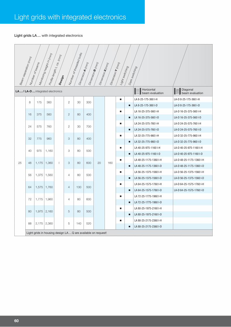
Light grids LA … with integrated electronics
60
Bea
m s
epar
atio
n (m
m)
Num
ber
of b
eam
sM
onito
ring
heig
ht H
(mm
)P
rofil
e le
ngth
L c
a. (m
m)
Des
ign
Num
ber
of t
hrea
ded
bol
tsD
imen
sion
A (m
m)
Dim
ensi
on B
(mm
)D
imen
sion
X (m
m)
Dim
ensi
on Y
(mm
)Li
ght sw
itchi
ngD
ark
switc
hing
LA … / LA-D … integrated electronics Horizontalbeam evaluation
Diagonalbeam evaluation
25
8 175 360
I
2 30 300
20 160
LA 8-25-175-360 I-H LA-D 8-25-175-360 I-H
LA 8-25-175-360 I-D LA-D 8-25-175-360 I-D
16 375 560 2 80 400 LA 16-25-375-560 I-H LA-D 16-25-375-560 I-H
LA 16-25-375-560 I-D LA-D 16-25-375-560 I-D
24 575 760 2 30 700 LA 24-25-575-760 I-H LA-D 24-25-575-760 I-H
LA 24-25-575-760 I-D LA-D 24-25-575-760 I-D
32 775 960 3 80 400 LA 32-25-775-960 I-H LA-D 32-25-775-960 I-H
LA 32-25-775-960 I-D LA-D 32-25-775-960 I-D
40 975 1,160 3 80 500 LA 40-25-975-1160 I-H LA-D 40-25-975-1160 I-H
LA 40-25-975-1160 I-D LA-D 40-25-975-1160 I-D
48 1,175 1,360 3 80 600 LA 48-25-1175-1360 I-H LA-D 48-25-1175-1360 I-H
LA 48-25-1175-1360 I-D LA-D 48-25-1175-1360 I-D
56 1,375 1,560 4 80 500 LA 56-25-1375-1560 I-H LA-D 56-25-1375-1560 I-H
LA 56-25-1375-1560 I-D LA-D 56-25-1375-1560 I-D
64 1,575 1,760 4 130 500 LA 64-25-1575-1760 I-H LA-D 64-25-1575-1760 I-H
LA 64-25-1575-1760 I-D LA-D 64-25-1575-1760 I-D
72 1,775 1,960 4 80 600 LA 72-25-1775-1960 I-H
LA 72-25-1775-1960 I-D
80 1,975 2,160 5 80 500 LA 80-25-1975-2160 I-H
LA 80-25-1975-2160 I-D
88 2,175 2,360 5 140 520 LA 88-25-2175-2360 I-H
LA 88-25-2175-2360 I-D
Light grids in housing design LA … Q are available on request!
Light grids with integrated electronics

For more information and models visit www.di-soric.com 61
Bea
m s
epar
atio
n (m
m)
Num
ber
of b
eam
sM
onito
ring
heig
ht H
(mm
)P
rofil
e le
ngth
L c
a. (m
m)
Des
ign
Num
ber
of t
hrea
ded
bol
tsD
imen
sion
A (m
m)
Dim
ensi
on B
(mm
)D
imen
sion
X (m
m)
Dim
ensi
on Y
(mm
)Li
ght sw
itchi
ngD
ark
switc
hing
LA … / LA-D … integrated electronics Horizontalbeam evaluation
Diagonalbeam evaluation
50
8 350 560
I
2 80 400
20 185
LA 8-50-350-560 I-H LA-D 8-50-350-560 I-H
LA 8-50-350-560 I-D LA-D 8-50-350-560 I-D
16 750 960 3 80 400 LA 16-50-750-960 I-H LA-D 16-50-750-960 I-H
LA 16-50-750-960 I-D LA-D 16-50-750-960 I-D
24 1,150 1,360 3 80 600 LA 24-50-1150-1360 I-H LA-D 24-50-1150-1360 I-H
LA 24-50-1150-1360 I-D LA-D 24-50-1150-1360 I-D
32 1,550 1,760 4 130 500 LA 32-50-1550-1760 I-H LA-D 32-50-1550-1760 I-H
LA 32-50-1550-1760 I-D LA-D 32-50-1550-1760 I-D
40 1,950 2,160 5 130 500 LA 40-50-1950-2160 I-H LA-D 40-50-1950-2160 I-H
LA 40-50-1950-2160 I-D LA-D 40-50-1950-2160 I-D
48 2,350 2,560 5 80 600 LA 48-50-2350-2560 I-H LA-D 48-50-2350-2560 I-H
LA 48-50-2350-2560 I-D LA-D 48-50-2350-2560 I-D
Light grids in housing design LA … Q are available on request!
112
8 783 1,050
I
3 125 400
20 245
LA 8-112-783-1050 I-H LA-D 8-112-783-1050 I-H
LA 8-112-783-1050 I-D LA-D 8-112-783-1050 I-D
16 1,677 1,950 4 75 600 LA 16-112-1677-1950 I-H LA-D 16-112-1677-1950 I-H
LA 16-112-1677-1950 I-D LA-D 16-112-1677-1950 I-D
Light grids in housing design LA … Q are available on request!
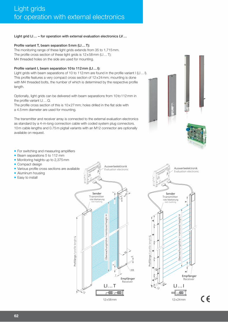
62
¡ For switching and measuring amplifi ers ¡ Beam separations 5 to 112 mm ¡ Monitoring heights up to 2,375 mm ¡ Compact design ¡ Various profi le cross sections are available ¡ Aluminum housing ¡ Easy to install
Light gridsfor operation with external electronics
Light grid LI … – for operation with external evaluation electronics LV …
Profi le variant T, beam separation 5 mm (LI … T):The monitoring range of these light grids extends from 35 to 1,715 mm.The profi le cross section of these light grids is 12 x 58 mm (LI … T); M4 threaded holes on the side are used for mounting.
Profi le variant I, beam separation 10 to 112 mm (LI … I):Light grids with beam separations of 10 to 112 mm are found in the profi le variant I (LI … I). This profi le features a very compact cross section of 12 x 24 mm; mounting is done with M4 threaded bolts, the number of which is determined by the respective profi le length.
Optionally, light grids can be delivered with beam separations from 10 to 112 mm in the profi le variant LI … Q.The profi le cross section of this is 10 x 27 mm; holes drilled in the fl at side with a 4.5 mm diameter are used for mounting.
The transmitter and receiver array is connected to the external evaluation electronics as standard by a 4-m-long connection cable with coded system plug connectors. 10 m cable lengths and 0.75 m pigtail variants with an M12 connector are optionally available on request.
LI … T
12 x 58 mm
LI … I
12 x 24 mm

For more information and models visit www.di-soric.com
Light grid LI … for operation with evaluation electronics LVE … / LVX … or LVB …
63
Technical data (typ.) +20 °C, 24 V DC
Operating distance 0.25 to 6.0 m can be adjusted using the evaluation electronics for evaluation electronics LVB ... (switching)
Number of beams 8 to 344 for evaluation electronics LVE ... / LVX ... (m easuring)
Beam separation 5 / 10 / 12.5 / 25 / 50 / 112 mm Ambient temperature -10 to +40 °C
Monitoring height 35 to 2375 mm Protection type IP 54, optionally IP 65
Emitted light Infrared light, 880 nm
Service voltage – Housing material Aluminum bar profi le
LI … T for operation with external evaluation electronics LVE … / LVX … or LVB …Horizontal or diagonalbeam evaluation
5
8 35 70
T 17.5 17.5
LI 8-5-35-70 T
16 75 110 LI 16-5-75-110 T
24 115 150 LI 24-5-115-150 T
32 155 190 LI 32-5-155-190 T
40 195 230 LI 40-5-195-230 T
48 235 270 LI 48-5-235-270 T
56 275 310 LI 56-5-275-310 T
64 315 350 LI 64-5-315-350 T
72 355 390 LI 72-5-355-390 T
80 395 430 LI 80-5-395-430 T
88 435 470 LI 88-5-435-470 T
96 475 510 LI 96-5-475-510 T
104 515 550 LI 104-5-515-550 T
112 555 590 LI 112-5-555-590 T
120 595 630 LI 120-5-595-630 T
128 635 670 LI 128-5-635-670 T
136 675 710 LI 136-5-675-710 T
144 715 750 LI 144-5-715-750 T
152 755 790 LI 152-5-755-790 T
160 795 830 LI 160-5-795-830 T
168 835 870 LI 168-5-835-870 T
176 875 910 LI 176-5-875-910 T
184 915 950 LI 184-5-915-950 T
192 955 990 LI 192-5-955-990 T
200 995 1,030 LI 200-5-995-1030 T
208 1,035 1,070 LI 208-5-1035-1070 T
216 1,075 1,110 LI 216-5-1075-1110 T
224 1,115 1,150 LI 224-5-1115-1150 T
232 1,155 1,190 LI 232-5-1155-1190 T
240 1,195 1,230 LI 240-5-1195-1230 T
248 1,235 1,270 LI 248-5-1235-1270 T
256 1,275 1,310 LI 256-5-1275-1310 T
264 1,315 1,350 LI 264-5-1315-1350 T
272 1,355 1,390 LI 272-5-1355-1390 T
280 1,395 1,430 LI 280-5-1395-1430 T
288 1,435 1,470 LI 288-5-1435-1470 T
296 1,475 1,510 LI 296-5-1475-1510 T
344 1,715 1,750 LI 344-5-1715-1750 T
Bea
m s
epar
atio
n (m
m)
Num
ber
of b
eam
s
Mon
itorin
g he
ight
H
(mm
)
Pro
fi le
leng
th L
ca.
(mm
)
Des
ign
Dim
ensi
on X
(mm
)
Dim
ensi
on Y
(mm
)

LI … I for operation with external evaluation electronics LVE … / LVX … or LVB …Horizontal or diagonalbeam evaluation
10
8 70 130
I
2 20 90
13.5 38.5
LI 8-10-70-130 I
16 150 210 2 55 100 LI 16-10-150-210 I
24 230 290 2 45 200 LI 24-10-230-290 I
32 310 370 2 35 300 LI 32-10-310-370 I
40 390 450 2 75 300 LI 40-10-390-450 I
48 470 530 2 65 400 LI 48-10-470-530 I
56 550 610 2 105 400 LI 56-10-550-610 I
64 630 690 2 45 600 LI 64-10-630-690 I
72 710 770 2 35 700 LI 72-10-710-770 I
80 790 850 2 75 700 LI 80-10-790-850 I
88 870 930 2 65 800 LI 88-10-870-930 I
96 950 1,010 3 105 400 LI 96-10-950-1010 I
104 1,030 1,090 3 145 400 LI 104-10-1030-1090 I
112 1,110 1,170 3 85 500 LI 112– 10-1110-1170 I
120 1,190 1,250 3 125 500 LI 120-10-1190-1250 I
128 1,270 1,330 3 65 600 LI 128-10-1270-1330 I
136 1,350 1,410 3 105 600 LI 136-10-1350-1410 I
144 1,430 1,490 4 145 400 LI 144-10-1430-1490 I
152 1,510 1,570 4 35 500 LI 152-10-1510-1570 I
160 1,590 1,650 4 75 500 LI 160-10-1590-1650 I
1) Light grids with a larger monitoring height H (max. 196 beams) are available upon request!
12.5
8 88 140
I
2 25 90
13.5 38.5
LI 8-12.5-88-140 I
16 188 240 2 70 100 LI 16 – 12.5-188-240 I
24 288 340 2 70 200 LI 24-12.5-288-340 I
32 388 440 2 70 300 LI 32-12.5-388-440 I
40 488 540 2 70 400 LI 40-12.5-488-540 I
48 588 640 2 70 500 LI 48-12.5-588-640 I
56 688 740 2 70 600 LI 56-12.5-688-740 I
64 788 840 2 70 700 LI 64-12.5-788-840 I
72 888 940 2 70 800 LI 72-12.5-888-940 I
80 988 1,040 3 120 400 LI 80-12.5-988-1040 I
88 1,088 1,140 3 70 500 LI 88-12.5-1088-1140 I
96 1,188 1,240 3 120 500 LI 96-12.5-1188-1240 I
104 1,288 1,340 3 70 600 LI 104-12.5-1288-1340 I
112 1,388 1,440 3 120 600 LI 112-12.5-1388-1440 I
120 1,488 1,540 4 170 400 LI 120-12.5-1488-1540 I
128 1,588 1,640 4 70 500 LI 128-12.5-1588-1640 I
136 1,688 1,740 4 120 500 LI 136-12.5-1688-1740 I
144 1,788 1,840 4 170 500 LI 144-12.5-1788-1840 I
1) Light grids with a larger monitoring height H (max. 196 beams) are available upon request!
Bea
m s
epar
atio
n (m
m)
Num
ber
of b
eam
sM
onito
ring
heig
ht H
(mm
)
Pro
fi le
leng
th L
ca.
(mm
)D
esig
n
Num
ber o
f thr
eade
d bo
ltsD
imen
sion
A (m
m)
Dim
ensi
on B
(mm
)D
imen
sion
X (m
m)
Dim
ensi
on Y
(mm
)
Light grid LI … for operation with evaluation electronics LVE … / LVX … or LVB …
64
Light grids for operation with external electronics

For more information and models visit www.di-soric.com
Bea
m s
epar
atio
n (m
m)
Num
ber
of b
eam
sM
onito
ring
heig
ht H
(mm
)
Pro
fi le
leng
th L
ca.
(mm
)D
esig
n
Num
ber o
f thr
eade
d bo
ltsD
imen
sion
A (m
m)
Dim
ensi
on B
(mm
)D
imen
sion
X (m
m)
Dim
ensi
on Y
(mm
)
LI … I for operation with external evaluation electronics LVE … / LVX … or LVB …Horizontal or diagonalbeam evaluation
25
8 175 240
I
2 70 100
20 45
LI 8-25-175-240 I
16 375 440 2 70 300 LI 16-25-375-440 I
24 575 640 2 70 500 LI 24-25-575-640 I
32 775 840 2 70 700 LI 32-25-775-840 I
40 975 1,040 3 120 400 LI 40-25-975-1040 I
48 1,175 1,240 3 125 500 LI 48-25-1175-1240 I
56 1,375 1,440 3 120 600 LI 56-25-1375-1440 I
64 1,575 1,640 4 70 500 LI 64-25-1575-1640 I
72 1,775 1,840 4 170 500 LI 72-25-1775-1840 I
80 1,975 2,040 4 120 600 LI 80-25-1975-2040 I
88 2,175 2,240 5 120 500 LI 88-25-2175-2240 I
96 2,375 2,440 5 165 520 LI 96-25-2375-2440 I
50
8 350 440
I
2 70 300
20 70
LI 8-50-350-440 I
16 750 840 2 70 700 LI 16-50-750-840 I
24 1,150 1,240 3 120 500 LI 24-50-1150-1240 I
32 1,550 1,640 4 70 500 LI 32-50-1550-1640 I
40 1,950 2,040 4 120 600 LI 40-50-1950-2040 I
48 2,350 2,440 5 180 520 LI 48-50-2350-2440 I
112
4 336 490
I
2 95 300
20 130
LI 4-112-336-490 I
8 783 940 2 70 800 LI 8-112-783-940 I
12 1,230 1,380 3 90 600 LI 12-112-1230-1380 I
16 1,677 1,830 4 165 500 LI 16-112-1677-1830 I
20 2,124 2,280 5 175 500 LI 20-112-2124-2280 I
Profi le cross section LI … Q
10 x 27 mm
10 Light grids in housing design LI … Q are optionally available upon request
12.5
25
50
112
Light grid LI … for operation with evaluation electronics LVE … / LVX … or LVB …
65
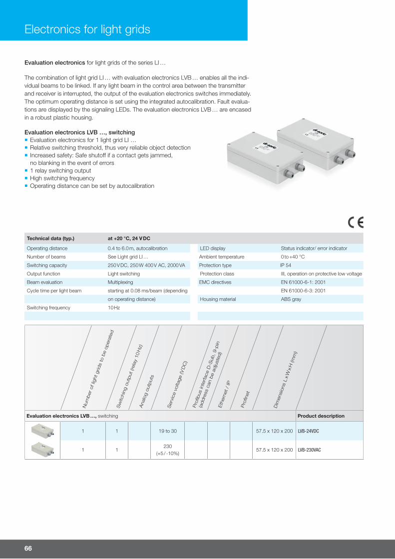
Evaluation electronics for light grids of the series LI …
Technical data (typ.) at +20 °C, 24 V DC
Operating distance 0.4 to 6.0 m, autocalibration LED display Status indicator/ error indicator
Number of beams See Light grid LI … Ambient temperature 0 to +40 °C
Switching capacity 250 V DC, 250 W 400 V AC, 2000 VA Protection type IP 54
Output function Light switching Protection class III, operation on protective low voltage
Beam evaluation Multiplexing EMC directives EN 61000-6-1: 2001
Cycle time per light beam starting at 0.08 ms/beam (depending EN 61000-6-3: 2001
on operating distance) Housing material ABS gray
Switching frequency 10 Hz
Num
ber
of l
ight
grid
s to
be
oper
ated
Sw
itchi
ng o
utput
(rel
ay 1
0 H
z)A
nalo
g ou
tput
s
Ser
vice
vol
tage
(V D
C)
Pro
fi bus
inte
rfac
e D
-Sub
, 9-p
in
(addre
ss c
an b
e ad
just
ed)
Eth
erne
t /
IP
Pro
fi net
Dim
ensi
ons
L x
W x
H (m
m)
Evaluation electronics LVB …, switching Product description
1 1 19 to 30 57.5 x 120 x 200 LVB-24VDC
1 1230
(+5 / -10%)57.5 x 120 x 200 LVB-230VAC
66
Electronics for light grids
The combination of light grid LI … with evaluation electronics LVB … enables all the indi-vidual beams to be linked. If any light beam in the control area between the transmitter and receiver is interrupted, the output of the evaluation electronics switches immediately. The optimum operating distance is set using the integrated autocalibration. Fault evalua-tions are displayed by the signaling LEDs. The evaluation electronics LVB … are encased in a robust plastic housing.
Evaluation electronics LVB …, switching ¡ Evaluation electronics for 1 light grid LI … ¡ Relative switching threshold, thus very reliable object detection ¡ Increased safety: Safe shuto� if a contact gets jammed, no blanking in the event of errors
¡ 1 relay switching output ¡ High switching frequency ¡ Operating distance can be set by autocalibration
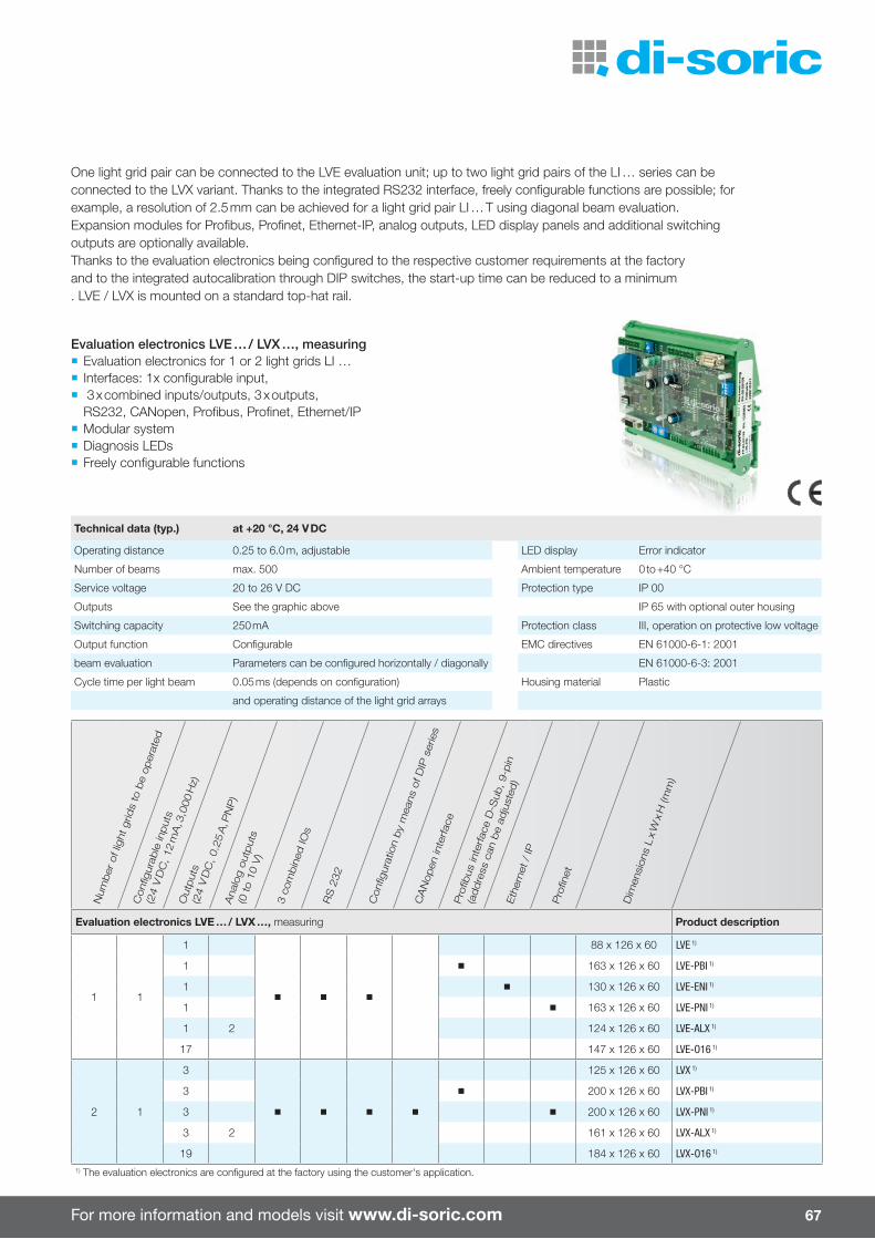
For more information and models visit www.di-soric.com
Num
ber
of l
ight
grid
s to
be
oper
ated
Con
fi gur
able
input
s
(24
V D
C, 1
2 m
A, 3
,000
Hz)
Out
put
s(2
4 V
DC
, 0.2
5 A
, PN
P)
Ana
log
outp
uts
(0 to
10
V)
3 co
mbin
ed IO
s
RS
232
Con
fi gur
atio
n by
mea
ns o
f DIP
ser
ies
CA
Nop
en in
terfac
eP
rofi b
us in
terfac
e D
-Sub
, 9-p
in
(addre
ss c
an b
e ad
just
ed)
Eth
erne
t /
IP
Pro
fi net
Dim
ensi
ons
L x
W x
H (m
m)
Evaluation electronics LVE … / LVX …, measuring Product description
1 1
1
88 x 126 x 60 LVE 1)
1 163 x 126 x 60 LVE-PBI 1)
1 130 x 126 x 60 LVE-ENI 1)
1 163 x 126 x 60 LVE-PNI 1)
1 2 124 x 126 x 60 LVE-ALX 1)
17 147 x 126 x 60 LVE-O16 1)
2 1
3
125 x 126 x 60 LVX 1)
3 200 x 126 x 60 LVX-PBI 1)
3 200 x 126 x 60 LVX-PNI 1)
3 2 161 x 126 x 60 LVX-ALX 1)
19 184 x 126 x 60 LVX-O16 1)
1) The evaluation electronics are confi gured at the factory using the customer's application.
Technical data (typ.) at +20 °C, 24 V DC
Operating distance 0.25 to 6.0 m, adjustable LED display Error indicator
Number of beams max. 500 Ambient temperature 0 to +40 °C
Service voltage 20 to 26 V DC Protection type IP 00
Outputs See the graphic above IP 65 with optional outer housing
Switching capacity 250 mA Protection class III, operation on protective low voltage
Output function Confi gurable EMC directives EN 61000-6-1: 2001
beam evaluation Parameters can be confi gured horizontally / diagonally EN 61000-6-3: 2001
Cycle time per light beam 0.05 ms (depends on confi guration) Housing material Plastic
and operating distance of the light grid arrays
67
One light grid pair can be connected to the LVE evaluation unit; up to two light grid pairs of the LI … series can be connected to the LVX variant. Thanks to the integrated RS232 interface, freely confi gurable functions are possible; for example, a resolution of 2.5 mm can be achieved for a light grid pair LI … T using diagonal beam evaluation. Expansion modules for Profi bus, Profi net, Ethernet-IP, analog outputs, LED display panels and additional switching outputs are optionally available. Thanks to the evaluation electronics being confi gured to the respective customer requirements at the factory and to the integrated autocalibration through DIP switches, the start-up time can be reduced to a minimum . LVE / LVX is mounted on a standard top-hat rail.
Evaluation electronics LVE … / LVX …, measuring ¡ Evaluation electronics for 1 or 2 light grids LI … ¡ Interfaces: 1x confi gurable input, ¡ 3 x combined inputs/outputs, 3 x outputs,RS232, CANopen, Profi bus, Profi net, Ethernet/IP
¡ Modular system ¡ Diagnosis LEDs ¡ Freely confi gurable functions

68
Color sensors
¡ Perceptive method (based on perception)
¡ Measurement in colorimetric color spaces such as L*a*b and L*u*v
¡ Di� erentiation of very small shades of color (∆E <1)
¡ Up to 350 channels ¡ 2-channel di� erential evaluation ¡ Adjustable color tolerance ¡ Very short response time ¡ High ambient light immunity ¡ Refl ection compensation ¡ Measured values for computer applica-tions (.xls, .csv) exportable
¡ Extensive options for using a computer to confi gure settings
¡ Control of the surface structure ¡ Separate evaluation of brightness and color value
¡ Lighting with aging-compensated white-light LED
¡ Key lock function ¡ Fixed optics or fi ber-optic cable adap-tation
¡ Fiber-optic cable with various attachment optics
¡ Visualization of the color values withcomputer software
¡ FS software is included in the scope of delivery
Color sensors These quality sensors detect nuances in a change in color or surface structure and are often used for quality checks.
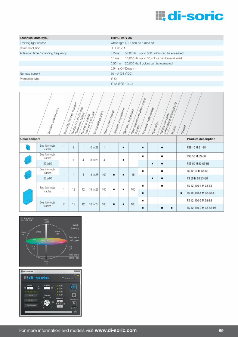
For more information and models visit www.di-soric.com
Axis L:Intensity
Color axis a:red / green
Color axis b:yellow / blue
L*a*b*
green-a*
blue-b*
yellow+b*
red+a*
whiteL=100
blackL=0
Shade
69
Technical data (typ.) +20 °C, 24 V DC
Emitting light source White-light LED, can be turned o�
Color resolution DE Lab < 1
Activation time / scanning frequency 0.2 ms 5,000 Hz: up to 350 colors can be evaluated
0.1 ms 10,000 Hz: up to 30 colors can be evaluated
0.05 ms 20,000 Hz: 3 colors can be evaluated
0.5 ms O� -Delay / -
No-load current 80 mA (24 V DC)
Protection type IP 54
IP 67 (FSB 10 …)
Oper
atin
g di
stan
ce (m
m)
Mea
surin
g ch
anne
ls (n
umbe
r)Nu
mbe
r of c
olor
cha
nnel
s
(Tea
ch-in
via
but
ton)
Num
ber o
f out
puts
npn
+ p
np (p
ush-
pull)
Serv
ice
volta
ge (V
DC)
Colo
r mem
ory
inte
rnal
Oper
atio
n us
ing
softw
are
Oper
atio
n us
ing
butto
nsCo
lor c
hann
els
with
bin
ary
codi
ng
(num
ber)
Fibe
r-op
tic c
able
ada
pter
Fixe
d op
tics
Ligh
ting
with
agi
ng-
com
pens
atin
g w
hite
-ligh
t LED
Profi
bus
Ethe
rnet
Color sensors Product description
See fi ber-optic cables
1 1 1 10 to 28 1 FSB 10 M G1-B8
See fi ber-optic cables
1 4 4 18 to 28 4
FSB 50 M G3-B8
30 to 60 FSB 50 M 60 G3-B8
See fi ber-optic cables
1 4 4 18 to 28 100 15 FS 12-50 M G3-B8
30 to 60 FS 50 M 60 G3-B8
See fi ber-optic cables
1 12 12 18 to 28 100 100 FS 12-100-1 M G8-B8
FS 12-100-1 M G8-B8-E
See fi ber-optic cables
2 12 12 18 to 28 100 100 FS 12-100-2 M G8-B8
FS 12-100-2 M G8-B8-PB

70
Color sensors
Overview of components and matching accessories
For more information and models visit www.di-soric.com 71
FSB
10 M
G1-
B8FS
B 50
M 6
0 G3
-B8
FSB
50 M
G3-
B8FS
50
M 6
0 G3
-B8
FS 5
0 M
G3-
B8FS
12-
100-
1 M
G3-
B8FS
12-
100-
1 M
G3-
B8-E
FS 1
2-10
0-2
M G
3-B8
FS 1
2-10
0-2
M G
3-B8
-PB
Conn
ectio
ns
Cabl
e le
ngth
(m)
Prot
ectio
n ty
pe
Connection cable Product description
Angled M9 connector, 8-pin /
flying leads2.0 IP 67 BSHM-W-2/8A
Straight connector
M9, 8-pin / flying leads
2.0 IP 67 BSHM-Z-2/8A
5.0 IP 67 BSHM-Z-5/8A
10.0 IP 67 BSHM-Z-10/8A
Connection cable for computer, connection set for Profibus / Ethernet
computer / RS 232 2.0 BSHM-Z-2/4-RS232K
computer / USB 2.0 BSHM-Z-2/4-USB
computer / Ethernet 5.0 VKHM-Z-5/4-RJ45
computer / Profibus M12, B-coded FS-AS-PB
Adapter RS232 / USB
USB / RS 232 0.25 RS232S-0.25-USB
Cover for M9 sockets (USB / RS232, for two or more sockets)
FS-Kappe-M9
Fiber-optic cables / focus optics
Articles, see pages 72 to 73
Stabilization system
0.3 IP 67 WRB 110 S-M6-2.5
FS-STAB

72
Fiber-optic cables / focus opticsGlass fiber-optic cables feature high temperature resistance and a robust design.One- or two-armed fiber-optic cables with di�erent sensor probes are available.Focus optics focus the light beam down to a small measuring spot diameter, enabling color measurement on very small surfaces. The operating range of the focus optics is 10 to 300 mm.
Color sensors
Focus optics
for operation with 1-arm fiber
VO-M12/10-4.5-2.5 VO-M6/35-M6x30-2.5 VO-M6/50-M6x30-2.5
Ø 15
60
M 12 20
Ø 2.0
Ø 6.6
25
1063
M6
5,5
Ø 22
Ø 6.0
35
for operation with 2-arm fiber
VO-F/90-4.5-2.5 VO-F/200-4.5-2.5
200
mm (typ.)
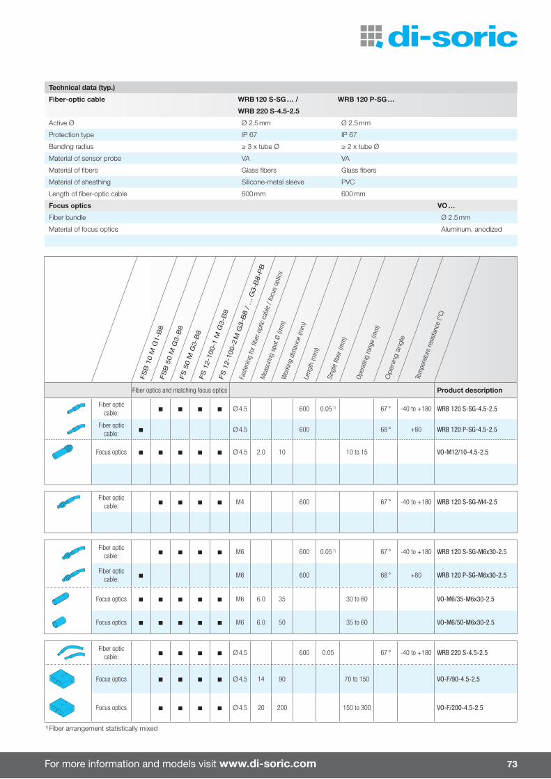
For more information and models visit www.di-soric.com 73
1) Fiber arrangement statistically mixed
Fiber optics and matching focus optics Product description
Fiber optic cable: Ø 4.5 600 0.05 1) 67 ° -40 to +180 WRB 120 S-SG-4.5-2.5
Fiber optic cable: Ø 4.5 600 68 ° +80 WRB 120 P-SG-4.5-2.5
Focus optics Ø 4.5 2.0 10 10 to 15 VO-M12/10-4.5-2.5
Fiber optic cable: M4 600 67 ° -40 to +180 WRB 120 S-SG-M4-2.5
Fiber optic cable: M6 600 0.05 1) 67 ° -40 to +180 WRB 120 S-SG-M6x30-2.5
Fiber optic cable: M6 600 68 ° +80 WRB 120 P-SG-M6x30-2.5
Focus optics M6 6.0 35 30 to 60 VO-M6/35-M6x30-2.5
Focus optics M6 6.0 50 35 to 60 VO-M6/50-M6x30-2.5
Fiber optic cable: Ø 4.5 600 0.05 67 ° -40 to +180 WRB 220 S-4.5-2.5
Focus optics Ø 4.5 14 90 70 to 150 VO-F/90-4.5-2.5
Focus optics Ø 4.5 20 200 150 to 300 VO-F/200-4.5-2.5
Technical data (typ.)
Fiber-optic cable WRB 120 S-SG … / WRB 120 P-SG …
WRB 220 S-4.5-2.5
Active Ø Ø 2.5 mm Ø 2.5 mm
Protection type IP 67 IP 67
Bending radius ≥ 3 x tube Ø ≥ 2 x tube Ø
Material of sensor probe VA VA
Material of fibers Glass fibers Glass fibers
Material of sheathing Silicone-metal sleeve PVC
Length of fiber-optic cable 600 mm 600 mm
Focus optics VO …
Fiber bundle Ø 2.5 mm
Material of focus optics Aluminum, anodized
FSB
10
M G
1-B
8FS
B 5
0 M
G3-
B8
FS 5
0 M
G3-
B8
FS 1
2-10
0-1
M G
3-B
8FS
12-
100-
2 M
G3-
B8
/ …
G3-
B8-
PB
Fast
enin
g fo
r fibe
r-op
tic c
able
/ fo
cus
optic
s
Mea
surin
g sp
ot Ø
(mm
)W
orki
ng d
ista
nce
(mm
)Le
ngth
(mm
)
Sing
le fi
ber (
mm
)
Oper
atin
g ra
nge
(mm
)
Open
ing
angl
e
Tem
pera
ture
resi
stan
ce (°
C)

74
Ring and wire-break sensors
Inductive ring and wire-break sensors are available with static or dynamic evaluation for various ring diameters. The very high detection sensitivity en-ables detection of metal parts with very low mass at a very high part speed.
There are various fastening options and accessories available for easy integration into machines and systems. A special shield enables multiple sensors to be lined up without impacting one another.Both the sensitivity and the pulse stretch-ing can be adapted to the requirements of the application.
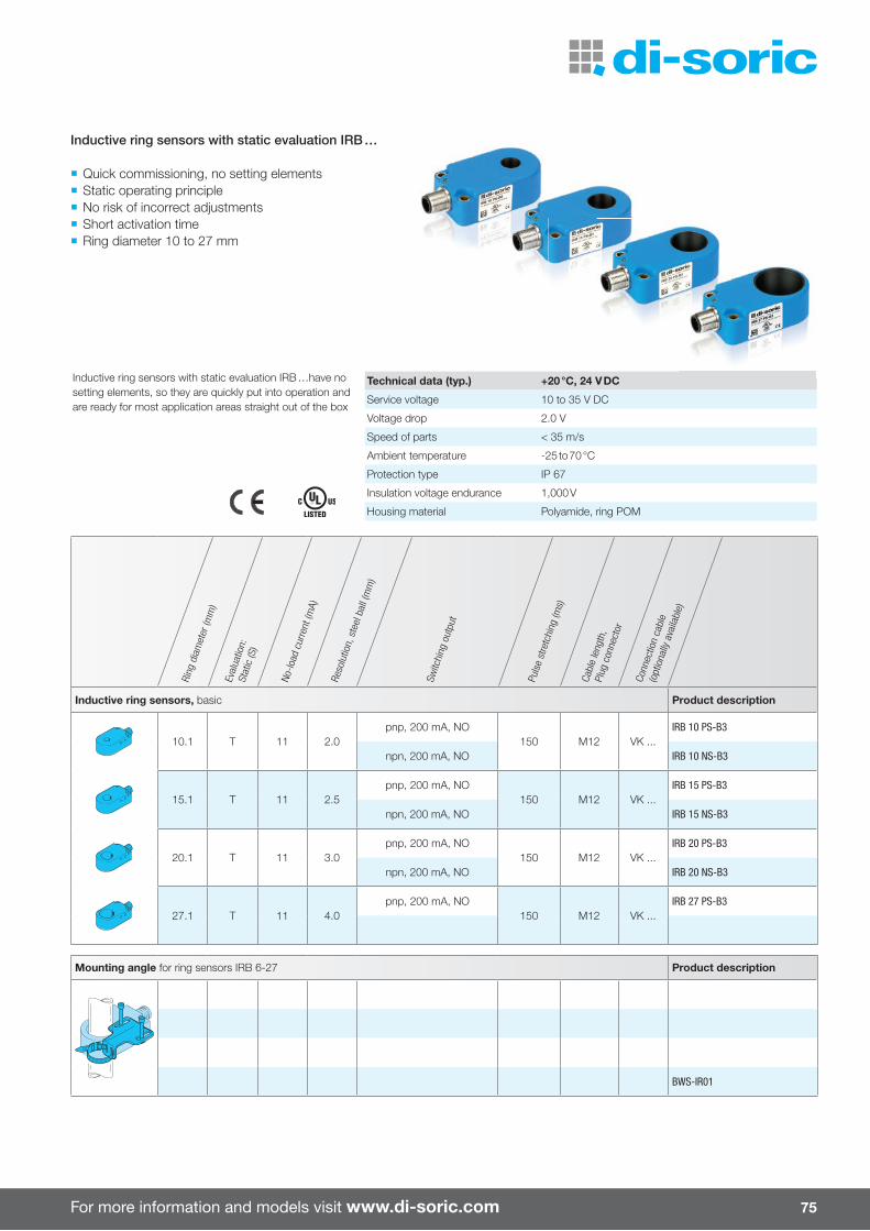
For more information and models visit www.di-soric.com 75
¡ Quick commissioning, no setting elements ¡ Static operating principle ¡ No risk of incorrect adjustments ¡ Short activation time ¡ Ring diameter 10 to 27 mm
Ring
dia
met
er (m
m)
Eval
uatio
n:
Stat
ic (S
)
No-lo
ad c
urre
nt (m
A)
Reso
lutio
n, s
teel
bal
l (m
m)
Switc
hing
out
put
Puls
e st
retc
hing
(ms)
Cabl
e le
ngth
,Pl
ug c
onne
ctor
Conn
ectio
n ca
ble
(opt
iona
lly a
vaila
ble)
Inductive ring sensors, basic Product description
10.1 T 11 2.0pnp, 200 mA, NO
150 M12 VK ...IRB 10 PS-B3
npn, 200 mA, NO IRB 10 NS-B3
15.1 T 11 2.5pnp, 200 mA, NO
150 M12 VK ...IRB 15 PS-B3
npn, 200 mA, NO IRB 15 NS-B3
20.1 T 11 3.0pnp, 200 mA, NO
150 M12 VK ...IRB 20 PS-B3
npn, 200 mA, NO IRB 20 NS-B3
27.1 T 11 4.0pnp, 200 mA, NO
150 M12 VK ...IRB 27 PS-B3
Mounting angle for ring sensors IRB 6-27 Product description
BWS-IR01
Inductive ring sensors with static evaluation IRB …have no setting elements, so they are quickly put into operation and are ready for most application areas straight out of the box
Technical data (typ.) +20 °C, 24 V DC
Service voltage 10 to 35 V DC
Voltage drop 2.0 V
Speed of parts < 35 m/s
Ambient temperature -25 to 70 °C
Protection type IP 67
Insulation voltage endurance 1,000 V
Housing material Polyamide, ring POM
Inductive ring sensors with static evaluation IRB …

76
Ring and wire-break sensors
Ring
dia
met
er (m
m)
Eval
uatio
n:
Stat
ic (S
) / D
ynam
ic (D
)
No-lo
ad c
urre
nt (m
A)
Reso
lutio
n, s
teel
bal
l (m
m)
Switc
hing
out
put
Puls
e st
retc
hing
(ms)
Cabl
e le
ngth
,Pl
ug c
onne
ctor
Conn
ectio
n ca
ble
(opt
iona
lly a
vaila
ble)
Inductive ring sensors, static evaluation Product description
6.1 T 11 1.0
pnp, 200 mA, NO/NC
10 to 150M12
VK ...
IR 6 PSOK-IBS
npn, 200 mA, NO/NC IR 6 NSOK-IBS
pnp, 200 mA, NO/NC 0.3 m / M12 IR 6 PSOK-K-BS
10.1 T 11 1.5
pnp, 200 mA, NO/NC
10 to 150M12
VK ...
IR 10 PSOK-IBS
pnp, 200 mA, NO/NC IR 10 NSOK-IBS
pnp, 200 mA, NO/NC 0.3 m / M12 IR 10 PSOK-K-BS
15.1 T 11 2.0
pnp, 200 mA, NO/NC
10 to 150M12
VK ...
IR 15 PSOK-IBS
pnp, 200 mA, NO/NC IR 15 NSOK-IBS
pnp, 200 mA, NO/NC 0.3 m / M12 IR 15 PSOK-K-BS
Inductive ring sensors with static evaluation are used for detecting and counting parts. The static evaluation principle enables a simple accumulation monitoring to be implemented.
Technical data (typ.) +20 °C, 24 V DC
Service voltage 10 to 35 V DC
Sensitivity adjustment Potentiometer
Voltage drop 2.0 V
Speed of parts < 35 m/s
Ambient temperature -25 to 70 °C
Protection type IP 67
Insulation voltage endurance 1,000 V
Housing material Polyamide, ring POM
Die-cast aluminum, ring POM (only IR 150 …)
¡ High resolution ¡ Static operating principle ¡ Sensitivity adjustment ¡ Short activation time ¡ Pulse stretching adjustable ¡ NO/NC function, switchable
Inductive ring sensors with static evaluation IR …
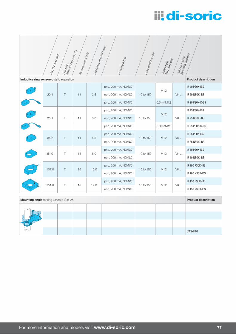
For more information and models visit www.di-soric.com 77
Ring
dia
met
er (m
m)
Eval
uatio
n:
Stat
ic (S
) / D
ynam
ic (D
)
No-lo
ad c
urre
nt (m
A)
Reso
lutio
n, s
teel
bal
l (m
m)
Switc
hing
out
put
Puls
e st
retc
hing
(ms)
Cabl
e le
ngth
,Pl
ug c
onne
ctor
Conn
ectio
n ca
ble
(opt
iona
lly a
vaila
ble)
Inductive ring sensors, static evaluation Product description
20.1 T 11 2.5
pnp, 200 mA, NO/NC
10 to 150M12
VK ...
IR 20 PSOK-IBS
npn, 200 mA, NO/NC IR 20 NSOK-IBS
pnp, 200 mA, NO/NC 0.3 m / M12 IR 20 PSOK-K-BS
25.1 T 11 3.0
pnp, 200 mA, NO/NC
10 to 150M12
VK ...
IR 25 PSOK-IBS
npn, 200 mA, NO/NC IR 25 NSOK-IBS
pnp, 200 mA, NO/NC 0.3 m / M12 IR 25 PSOK-K-BS
35.2 T 11 4.5pnp, 200 mA, NO/NC
10 to 150 M12 VK ...IR 35 PSOK-IBS
npn, 200 mA, NO/NC IR 35 NSOK-IBS
51.0 T 11 6.0pnp, 200 mA, NO/NC
10 to 150 M12 VK ...IR 50 PSOK-IBS
npn, 200 mA, NO/NC IR 50 NSOK-IBS
101.0 T 15 10.0pnp, 200 mA, NO/NC
10 to 150 M12 VK ...IR 100 PSOK-IBS
npn, 200 mA, NO/NC IR 100 NSOK-IBS
151.0 T 15 19.0pnp, 200 mA, NO/NC
10 to 150 M12 VK ...IR 150 PSOK-IBS
npn, 200 mA, NO/NC IR 150 NSOK-IBS
Mounting angle for ring sensors IR 6-25 Product description
BWS-IR01
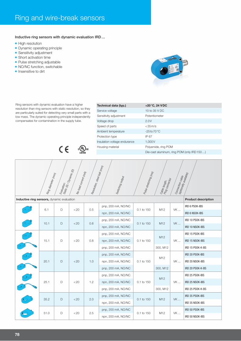
78
Ring sensors with dynamic evaluation have a higher resolution than ring sensors with static resolution, so they are particularly suited for detecting very small parts with a low mass. The dynamic operating principle independently compensates for contamination in the supply tube.
Technical data (typ.) +20 °C, 24 V DC
Service voltage 10 to 35 V DC
Sensitivity adjustment Potentiometer
Voltage drop 2.0 V
Speed of parts < 35 m/s
Ambient temperature -25 to 70 °C
Protection type IP 67
Insulation voltage endurance 1,000 V
Housing material Polyamide, ring POM
Die-cast aluminum, ring POM (only IRD 150 …)
Ring
dia
met
er (m
m)
Eval
uatio
n:
Stat
ic (S
) / D
ynam
ic (D
)
No-lo
ad c
urre
nt (m
A)
Reso
lutio
n, s
teel
bal
l (m
m)
Switc
hing
out
put
Puls
e st
retc
hing
(ms)
Cabl
e le
ngth
,Pl
ug c
onne
ctor
Conn
ectio
n ca
ble
(opt
iona
lly a
vaila
ble)
Inductive ring sensors, dynamic evaluation Product description
6.1 D < 20 0.5pnp, 200 mA, NO/NC
0.1 to 150 M12 VK ...IRD 6 PSOK-IBS
npn, 200 mA, NO/NC IRD 6 NSOK-IBS
10.1 D < 20 0.6pnp, 200 mA, NO/NC
0.1 to 150 M12 VK ...IRD 10 PSOK-IBS
npn, 200 mA, NO/NC IRD 10 NSOK-IBS
15.1 D < 20 0.8
pnp, 200 mA, NO/NC
0.1 to 150M12
VK ...
IRD 15 PSOK-IBS
npn, 200 mA, NO/NC IRD 15 NSOK-IBS
pnp, 200 mA, NO/NC 300, M12 IRD 15 PSOK-K-BS
20.1 D < 20 1.0
pnp, 200 mA, NO/NC
0.1 to 150M12
VK ...
IRD 20 PSOK-IBS
npn, 200 mA, NO/NC IRD 20 NSOK-IBS
pnp, 200 mA, NO/NC 300, M12 IRD 20 PSOK-K-BS
25.1 D < 20 1.2
pnp, 200 mA, NO/NC
0.1 to 150M12
VK ...
IRD 25 PSOK-IBS
npn, 200 mA, NO/NC IRD 25 NSOK-IBS
pnp, 200 mA, NO/NC 300, M12 IRD 25 PSOK-K-BS
35.2 D < 20 2.0pnp, 200 mA, NO/NC
0.1 to 150 M12 VK ...IRD 35 PSOK-IBS
npn, 200 mA, NO/NC IRD 35 NSOK-IBS
51.0 D < 20 2.5pnp, 200 mA, NO/NC
0.1 to 150 M12 VK ...IRD 50 PSOK-IBS
npn, 200 mA, NO/NC IRD 50 NSOK-IBS
¡ High resolution ¡ Dynamic operating principle ¡ Sensitivity adjustment ¡ Short activation time ¡ Pulse stretching adjustable ¡ NO/NC function, switchable ¡ Insensitive to dirt
Inductive ring sensors with dynamic evaluation IRD …
Ring and wire-break sensors

For more information and models visit www.di-soric.com 79
Ring
dia
met
er (m
m)
Eval
uatio
n:
Stat
ic (S
) / D
ynam
ic (D
)
No-lo
ad c
urre
nt (m
A)
Reso
lutio
n, s
teel
bal
l (m
m)
Switc
hing
out
put
Puls
e st
retc
hing
(ms)
Cabl
e le
ngth
,Pl
ug c
onne
ctor
Conn
ectio
n ca
ble
(opt
iona
lly a
vaila
ble)
101.0 D < 20 5.0pnp, 200 mA, NO/NC
0.1 to 150 M12 VK ...IRD 100 PSOK-IBS
npn, 200 mA, NO/NC IRD 100 NSOK-IBS
151.0 D < 20 10.0pnp, 200 mA, NO/NC
0.1 to 150 M12 VK ...IRD 150 PSOK-IBS
npn, 200 mA, NO/NC IRD 150 NSOK-IBS
Inductive ring sensors with dynamic evaluation IRD …
Ring
dia
met
er (m
m)
Eval
uatio
n:
Stat
ic (S
) / D
ynam
ic (D
)No
-load
cur
rent
(mA)
Reso
lutio
n, C
u w
ire (m
m)
Switc
hing
out
put
Puls
e st
retc
hing
(ms)
Cabl
e le
ngth
,Pl
ug c
onne
ctor
Conn
ectio
n ca
ble
(opt
iona
lly a
vaila
ble)
Wire-break sensors Product description
4.0
T 11 0.2pnp, 200 mA, NO
10 to 150
M12 VK ...
IRDB 4 PSOK-IBS
npn, 200 mA, NO IRDB 4 NSOK-IBS
D < 20 0.1pnp, 200 mA, NO
0.1 to 150IRDBD 4 PSOK-IBS
npn, 200 mA, NO IRDBD 4 NSOK-IBS
6.1
T 11 0.2pnp, 200 mA, NO
10 to 150
M12 VK ...
IRDB 6 PSOK-IBS
npn, 200 mA, NO IRDB 6 NSOK-IBS
D < 20 0.1pnp, 200 mA, NO
0.1 to 150IRDBD 6 PSOK-IBS
npn, 200 mA, NO IRDBD 6 NSOK-IBS
Wire-break sensors with particularly high resolution are available in static and dynamic versions. The static version detects very thin wires made of various alloys that are fed through the detection fi eld. Wire-break sensors in the dynamic version are used for detecting very small wire movements. Thus, for example, a wire break is reliably detected even if the wire stays in the detection fi eld.
Technical data (typ.) +20 °C, 24 V DC
Service voltage 10 to 35 V DC
Sensitivity adjustment Potentiometer
Voltage drop 2.0 V
Speed of parts < 35 m/s
Ambient temperature -25 to 70 °C
Protection type IP 67
Insulation voltage endurance 1,000 V
Housing material Polyamide, ring POM, ceramic insert (IRDBx 4 …)
Polyamide, ring POM (IRDBx 6 …)
Wire-break sensors with static / dynamic evaluation
¡ Particularly high resolution ¡ Static or dynamic operating principle ¡ Sensitivity adjustment ¡ Short activation time ¡ Pulse stretching adjustable ¡ NO/NC function, switchable ¡ Ring diameters 4 and 6.1 mm ¡ Insensitive to dirt
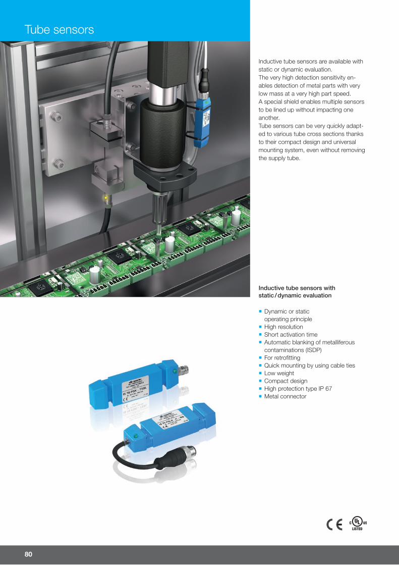
80
Tube sensors
Inductive tube sensors with static / dynamic evaluation
¡ Dynamic or static operating principle
¡ High resolution ¡ Short activation time ¡ Automatic blanking of metalliferous contaminations (ISDP)
¡ For retrofi tting ¡ Quick mounting by using cable ties ¡ Low weight ¡ Compact design ¡ High protection type IP 67 ¡ Metal connector
Inductive tube sensors are available with static or dynamic evaluation. The very high detection sensitivity en-ables detection of metal parts with very low mass at a very high part speed. A special shield enables multiple sensors to be lined up without impacting one another. Tube sensors can be very quickly adapt-ed to various tube cross sections thanks to their compact design and universal mounting system, even without removing the supply tube.
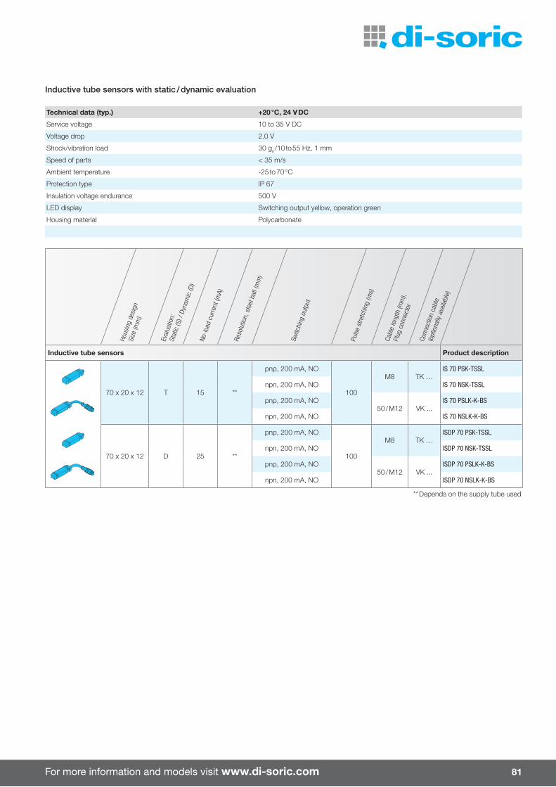
For more information and models visit www.di-soric.com 81
Hous
ing
desi
gnSi
ze (m
m)
Eval
uatio
n:
Stat
ic (S
) / D
ynam
ic (D
)
No-lo
ad c
urre
nt (m
A)
Reso
lutio
n, s
teel
bal
l (m
m)
Switc
hing
out
put
Puls
e st
retc
hing
(ms)
Cabl
e le
ngth
(mm
),Pl
ug c
onne
ctor
Conn
ectio
n ca
ble
(opt
iona
lly a
vaila
ble)
Inductive tube sensors Product description
70 x 20 x 12 T 15 **
pnp, 200 mA, NO
100
M8 TK …IS 70 PSK-TSSL
npn, 200 mA, NO IS 70 NSK-TSSL
pnp, 200 mA, NO50 / M12 VK ...
IS 70 PSLK-K-BS
npn, 200 mA, NO IS 70 NSLK-K-BS
70 x 20 x 12 D 25 **
pnp, 200 mA, NO
100
M8 TK …ISDP 70 PSK-TSSL
npn, 200 mA, NO ISDP 70 NSK-TSSL
pnp, 200 mA, NO50 / M12 VK ...
ISDP 70 PSLK-K-BS
npn, 200 mA, NO ISDP 70 NSLK-K-BS
** Depends on the supply tube used
Technical data (typ.) +20 °C, 24 V DC
Service voltage 10 to 35 V DC
Voltage drop 2.0 V
Shock/vibration load 30 gn /10 to 55 Hz, 1 mm
Speed of parts < 35 m/s
Ambient temperature -25 to 70 °C
Protection type IP 67
Insulation voltage endurance 500 V
LED display Switching output yellow, operation green
Housing material Polycarbonate
Inductive tube sensors with static / dynamic evaluation
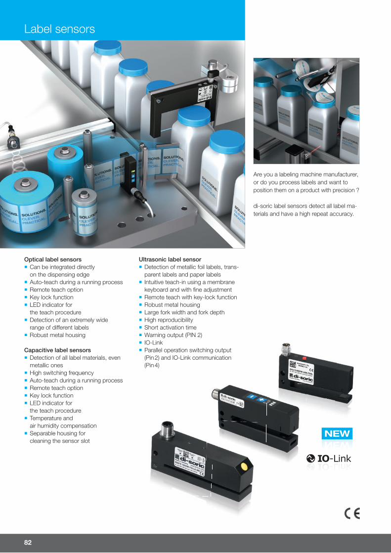
NEWNEW
82
Label sensors
Are you a labeling machine manufacturer, or do you process labels and want to position them on a product with precision ?
di-soric label sensors detect all label ma-terials and have a high repeat accuracy.
Ultrasonic label sensor ¡ Detection of metallic foil labels, trans-parent labels and paper labels
¡ Intuitive teach-in using a membrane keyboard and with fi ne adjustment
¡ Remote teach with key-lock function ¡ Robust metal housing ¡ Large fork width and fork depth ¡ High reproducibility ¡ Short activation time ¡ Warning output (PIN 2) ¡ IO-Link ¡ Parallel operation switching output (Pin 2) and IO-Link communication (Pin 4)
Capacitive label sensors ¡ Detection of all label materials, even metallic ones
¡ High switching frequency ¡ Auto-teach during a running process ¡ Remote teach option ¡ Key lock function ¡ LED indicator for the teach procedure
¡ Temperature and air humidity compensation
¡ Separable housing for cleaning the sensor slot
Optical label sensors ¡ Can be integrated directly on the dispensing edge
¡ Auto-teach during a running process ¡ Remote teach option ¡ Key lock function ¡ LED indicator for the teach procedure
¡ Detection of an extremely wide range of di� erent labels
¡ Robust metal housing

For more information and models visit www.di-soric.com 83
Fork
/slo
t wid
th (m
m)
Slot
dep
th (m
m)
Infra
red
light
, 880
nm
,
cloc
ked
Switc
hing
out
put
IO-L
ink
inte
rface
No-lo
ad c
urre
nt (m
A)Ac
tivat
ion
time
(µs)
Max
. bel
t spe
ed
(m/m
in)
Repr
oduc
ibilit
y (µ
m)
Sens
itivit
y ad
just
men
t
usin
g te
ach
butto
nSe
nsiti
vity
adju
stm
ent
usin
g re
mot
e te
achi
ngPl
ug c
onne
ctor
Conn
ectio
n ca
ble
(opt
iona
lly a
vaila
ble)
Optical label sensors Product description
2 40 npnp
200 mA, NO/NC35 166 500 < 50
nM8
TK … OGUTI 002 P3K-TSSL
n n TK … /4 OGUTI 002 FP3K-TSSL
5 50 nPush-pull
200 mA, NO/NC35 166 500 < 50
nM8
TK … OGUTI 005/50 G3K-TSSL
n n TK … /4 OGUTI 005/50 FG3K-TSSL
Capacitive label sensors
0.4 50Push-pull
200 mA, NO/NC70 < 600 300 1) < 150 2)
nM8
TK … KSSTI 400 G3K-TSSL
n n TK … /4 KSSTI 400 FG3K-TSSL
0.6 50Push-pull
200 mA, NO/NC70 < 600 300 1) < 150 2)
nM8
TK … KSSTI 600 G3K-TSSL
n n TK … /4 KSSTI 600 FG3K-TSSL
1.0 50Push-pull
200 mA, NO/NC70 < 600 300 1) < 150 2)
nM8
TK … KSSTI 1000 G3K-TSSL
n n TK … /4 KSSTI 1000 FG3K-TSSL
0.685
Push-pull200 mA, NO/NC
70 < 600 300 1) < 150 2)n n
M12 VK …/4KSSTI 600/80 FG3LK-IBS
1.0 n n KSSTI 1000/80 FG3LK-IBS
0.685
Push-pull200 mA, NO/NC
70 < 600 300 1) < 150 2)
n n M12VK …/4
KSSTI 600/80 FG3LK-AIBS
1.0 n nM12
(radial) KSSTI 1000/80 FG3LK-AIBS
Ultrasonic label sensors with IO-Link
6 702 independent outputs,
push-pull, 100 mA, NO/NC
n 40 < 250 250 1) < 200 2) n n
M12VK …/5
UGUTI 6/70 G6-B5
M12 (radial) UGUTI 6/70 G6-RB5
Technical data (typ.) +20 °C, 24 V DC
Service voltage 10 to 35 V DC
Ambient temperature -10 to +60 °C (OGUTI …)
0 to +60 °C (KSSTI … / UGUTI …)
Housing material Die-cast zinc, varnished (OGUTI …)
Aluminum, black anodized (KSSTI … / UGUTI 6/70 …)
Detection Optical Capacitive UltrasonicSeries OGUTI KSSTI UGUTIVery small labelsTransparent labelsMetallic labelsVery thin labelsThick labelsBookletsThick carrier material
Special requirementsExact positioningMaximum belt speedMaximum reproducibilityMounting directly on the dispensing edgeIO-LinkManual teachAuto-teachRemote teachAdjustable pulse stretching (using IO-Link)Warning output
1) 2 mm label and 2 mm gap2) Depends on the label material and carrier material
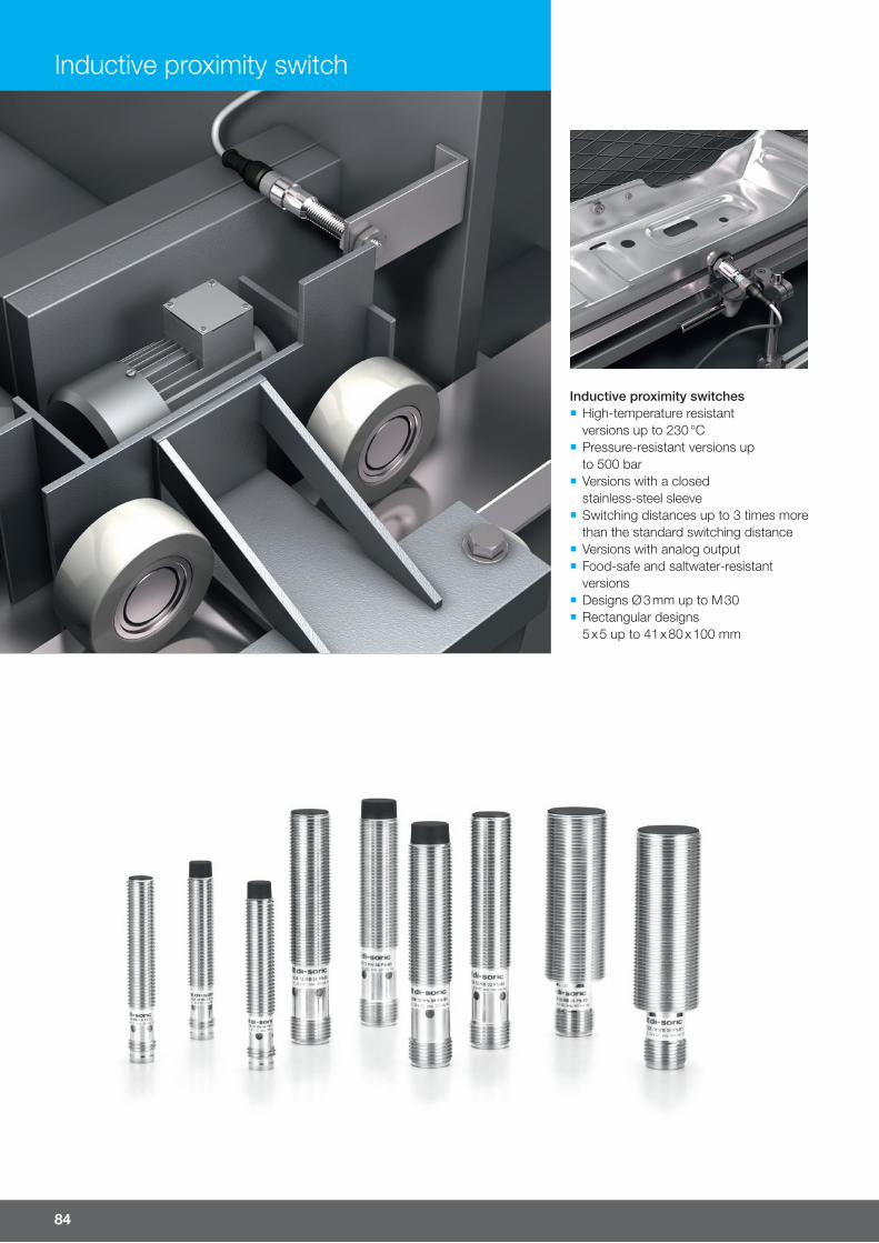
84
Inductive proximity switch
Inductive proximity switches ¡ High-temperature resistant versions up to 230 °C
¡ Pressure-resistant versions up to 500 bar
¡ Versions with a closed stainless-steel sleeve
¡ Switching distances up to 3 times more than the standard switching distance
¡ Versions with analog output ¡ Food-safe and saltwater-resistant versions
¡ Designs Ø 3 mm up to M 30 ¡ Rectangular designs 5 x 5 up to 41 x 80 x 100 mm
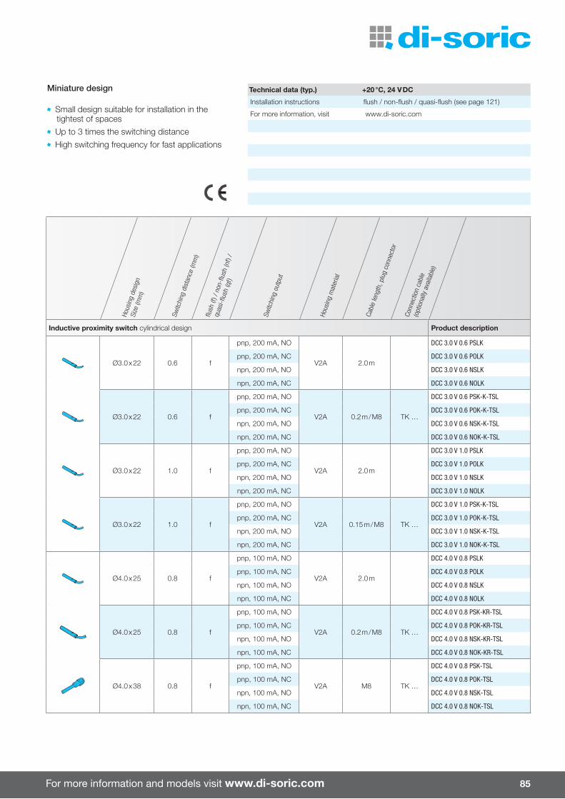
For more information and models visit www.di-soric.com 85
Hous
ing
desi
gnSi
ze (m
m)
Switc
hing
dis
tanc
e (m
m)
flush
(f) /
non
-flus
h (n
f) /
quas
i-flus
h (q
f)
Switc
hing
out
put
Hous
ing
mat
eria
l
Cabl
e le
ngth
, plu
g co
nnec
tor
Conn
ectio
n ca
ble
(opt
iona
lly a
vaila
ble)
Inductive proximity switch cylindrical design Product description
Ø3.0 x 22 0.6 f
pnp, 200 mA, NO
V2A 2.0 m
DCC 3.0 V 0.6 PSLK
pnp, 200 mA, NC DCC 3.0 V 0.6 POLK
npn, 200 mA, NO DCC 3.0 V 0.6 NSLK
npn, 200 mA, NC DCC 3.0 V 0.6 NOLK
Ø3.0 x 22 0.6 f
pnp, 200 mA, NO
V2A 0.2 m / M8 TK …
DCC 3.0 V 0.6 PSK-K-TSL
pnp, 200 mA, NC DCC 3.0 V 0.6 POK-K-TSL
npn, 200 mA, NO DCC 3.0 V 0.6 NSK-K-TSL
npn, 200 mA, NC DCC 3.0 V 0.6 NOK-K-TSL
Ø3.0 x 22 1.0 f
pnp, 200 mA, NO
V2A 2.0 m
DCC 3.0 V 1.0 PSLK
pnp, 200 mA, NC DCC 3.0 V 1.0 POLK
npn, 200 mA, NO DCC 3.0 V 1.0 NSLK
npn, 200 mA, NC DCC 3.0 V 1.0 NOLK
Ø3.0 x 22 1.0 f
pnp, 200 mA, NO
V2A 0.15 m / M8 TK …
DCC 3.0 V 1.0 PSK-K-TSL
pnp, 200 mA, NC DCC 3.0 V 1.0 POK-K-TSL
npn, 200 mA, NO DCC 3.0 V 1.0 NSK-K-TSL
npn, 200 mA, NC DCC 3.0 V 1.0 NOK-K-TSL
Ø4.0 x 25 0.8 f
pnp, 100 mA, NO
V2A 2.0 m
DCC 4.0 V 0.8 PSLK
pnp, 100 mA, NC DCC 4.0 V 0.8 POLK
npn, 100 mA, NO DCC 4.0 V 0.8 NSLK
npn, 100 mA, NC DCC 4.0 V 0.8 NOLK
Ø4.0 x 25 0.8 f
pnp, 100 mA, NO
V2A 0.2 m / M8 TK …
DCC 4.0 V 0.8 PSK-KR-TSL
pnp, 100 mA, NC DCC 4.0 V 0.8 POK-KR-TSL
npn, 100 mA, NO DCC 4.0 V 0.8 NSK-KR-TSL
npn, 100 mA, NC DCC 4.0 V 0.8 NOK-KR-TSL
Ø4.0 x 38 0.8 f
pnp, 100 mA, NO
V2A M8 TK …
DCC 4.0 V 0.8 PSK-TSL
pnp, 100 mA, NC DCC 4.0 V 0.8 POK-TSL
npn, 100 mA, NO DCC 4.0 V 0.8 NSK-TSL
npn, 100 mA, NC DCC 4.0 V 0.8 NOK-TSL
Miniature design
Small design suitable for installation in the tightest of spaces Up to 3 times the switching distance High switching frequency for fast applications
Technical data (typ.) +20 °C, 24 V DC
Installation instructions flush / non-flush / quasi-flush (see page 121)
For more information, visit www.di-soric.com
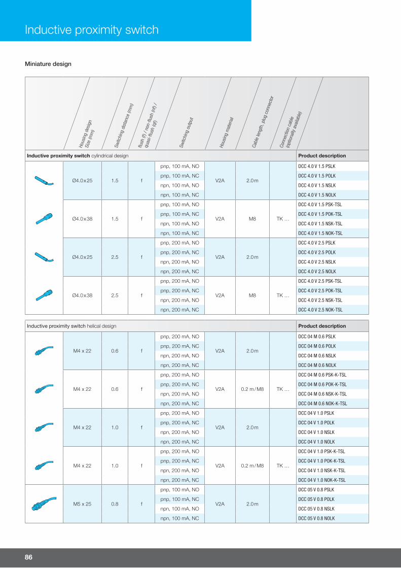
86
Hous
ing
desi
gnSi
ze (m
m)
Switc
hing
dis
tanc
e (m
m)
flush
(f) /
non
-flus
h (n
f) /
quas
i-flus
h (q
f)
Switc
hing
out
put
Hous
ing
mat
eria
l
Cabl
e le
ngth
, plu
g co
nnec
tor
Conn
ectio
n ca
ble
(opt
iona
lly a
vaila
ble)
Inductive proximity switch cylindrical design Product description
Ø4.0 x 25 1.5 f
pnp, 100 mA, NO
V2A 2.0 m
DCC 4.0 V 1.5 PSLK
pnp, 100 mA, NC DCC 4.0 V 1.5 POLK
npn, 100 mA, NO DCC 4.0 V 1.5 NSLK
npn, 100 mA, NC DCC 4.0 V 1.5 NOLK
Ø4.0 x 38 1.5 f
pnp, 100 mA, NO
V2A M8 TK …
DCC 4.0 V 1.5 PSK-TSL
pnp, 100 mA, NC DCC 4.0 V 1.5 POK-TSL
npn, 100 mA, NO DCC 4.0 V 1.5 NSK-TSL
npn, 100 mA, NC DCC 4.0 V 1.5 NOK-TSL
Ø4.0 x 25 2.5 f
pnp, 200 mA, NO
V2A 2.0 m
DCC 4.0 V 2.5 PSLK
pnp, 200 mA, NC DCC 4.0 V 2.5 POLK
npn, 200 mA, NO DCC 4.0 V 2.5 NSLK
npn, 200 mA, NC DCC 4.0 V 2.5 NOLK
Ø4.0 x 38 2.5 f
pnp, 200 mA, NO
V2A M8 TK …
DCC 4.0 V 2.5 PSK-TSL
pnp, 200 mA, NC DCC 4.0 V 2.5 POK-TSL
npn, 200 mA, NO DCC 4.0 V 2.5 NSK-TSL
npn, 200 mA, NC DCC 4.0 V 2.5 NOK-TSL
Inductive proximity switch helical design Product description
M4 x 22 0.6 f
pnp, 200 mA, NO
V2A 2.0 m
DCC 04 M 0.6 PSLK
pnp, 200 mA, NC DCC 04 M 0.6 POLK
npn, 200 mA, NO DCC 04 M 0.6 NSLK
npn, 200 mA, NC DCC 04 M 0.6 NOLK
M4 x 22 0.6 f
pnp, 200 mA, NO
V2A 0.2 m / M8 TK …
DCC 04 M 0.6 PSK-K-TSL
pnp, 200 mA, NC DCC 04 M 0.6 POK-K-TSL
npn, 200 mA, NO DCC 04 M 0.6 NSK-K-TSL
npn, 200 mA, NC DCC 04 M 0.6 NOK-K-TSL
M4 x 22 1.0 f
pnp, 200 mA, NO
V2A 2.0 m
DCC 04 V 1.0 PSLK
pnp, 200 mA, NC DCC 04 V 1.0 POLK
npn, 200 mA, NO DCC 04 V 1.0 NSLK
npn, 200 mA, NC DCC 04 V 1.0 NOLK
M4 x 22 1.0 f
pnp, 200 mA, NO
V2A 0.2 m / M8 TK …
DCC 04 V 1.0 PSK-K-TSL
pnp, 200 mA, NC DCC 04 V 1.0 POK-K-TSL
npn, 200 mA, NO DCC 04 V 1.0 NSK-K-TSL
npn, 200 mA, NC DCC 04 V 1.0 NOK-K-TSL
M5 x 25 0.8 f
pnp, 100 mA, NO
V2A 2.0 m
DCC 05 V 0.8 PSLK
pnp, 100 mA, NC DCC 05 V 0.8 POLK
npn, 100 mA, NO DCC 05 V 0.8 NSLK
npn, 100 mA, NC DCC 05 V 0.8 NOLK
Inductive proximity switch
Miniature design
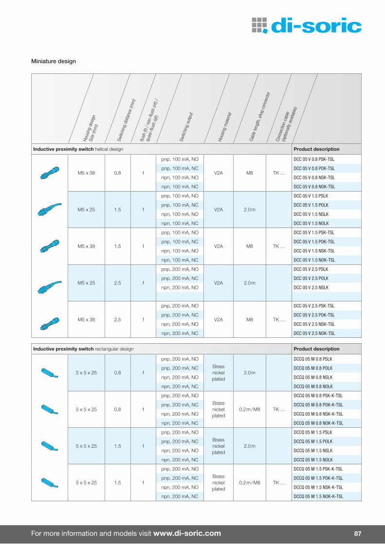
For more information and models visit www.di-soric.com 87
Miniature design
Hous
ing
desi
gnSi
ze (m
m)
Switc
hing
dis
tanc
e (m
m)
flush
(f) /
non
-flus
h (n
f) /
quas
i-flus
h (q
f)
Switc
hing
out
put
Hous
ing
mat
eria
l
Cabl
e le
ngth
, plu
g co
nnec
tor
Conn
ectio
n ca
ble
(opt
iona
lly a
vaila
ble)
Inductive proximity switch helical design Product description
M5 x 38 0.8 f
pnp, 100 mA, NO
V2A M8 TK …
DCC 05 V 0.8 PSK-TSL
pnp, 100 mA, NC DCC 05 V 0.8 POK-TSL
npn, 100 mA, NO DCC 05 V 0.8 NSK-TSL
npn, 100 mA, NC DCC 05 V 0.8 NOK-TSL
M5 x 25 1.5 f
pnp, 100 mA, NO
V2A 2.0 m
DCC 05 V 1.5 PSLK
pnp, 100 mA, NC DCC 05 V 1.5 POLK
npn, 100 mA, NO DCC 05 V 1.5 NSLK
npn, 100 mA, NC DCC 05 V 1.5 NOLK
M5 x 38 1.5 f
pnp, 100 mA, NO
V2A M8 TK …
DCC 05 V 1.5 PSK-TSL
pnp, 100 mA, NC DCC 05 V 1.5 POK-TSL
npn, 100 mA, NO DCC 05 V 1.5 NSK-TSL
npn, 100 mA, NC DCC 05 V 1.5 NOK-TSL
M5 x 25 2.5 f
pnp, 200 mA, NO
V2A 2.0 m
DCC 05 V 2.5 PSLK
pnp, 200 mA, NC DCC 05 V 2.5 POLK
npn, 200 mA, NO DCC 05 V 2.5 NSLK
M5 x 38 2.5 f
pnp, 200 mA, NO
V2A M8 TK …
DCC 05 V 2.5 PSK-TSL
pnp, 200 mA, NC DCC 05 V 2.5 POK-TSL
npn, 200 mA, NO DCC 05 V 2.5 NSK-TSL
npn, 200 mA, NC DCC 05 V 2.5 NOK-TSL
Inductive proximity switch rectangular design Product description
5 x 5 x 25 0.8 f
pnp, 200 mA, NO
Brassnickel plated
2.0 m
DCCQ 05 M 0.8 PSLK
pnp, 200 mA, NC DCCQ 05 M 0.8 POLK
npn, 200 mA, NO DCCQ 05 M 0.8 NSLK
npn, 200 mA, NC DCCQ 05 M 0.8 NOLK
5 x 5 x 25 0.8 f
pnp, 200 mA, NO
Brassnickel plated
0.2 m / M8 TK …
DCCQ 05 M 0.8 PSK-K-TSL
pnp, 200 mA, NC DCCQ 05 M 0.8 POK-K-TSL
npn, 200 mA, NO DCCQ 05 M 0.8 NSK-K-TSL
npn, 200 mA, NC DCCQ 05 M 0.8 NOK-K-TSL
5 x 5 x 25 1.5 f
pnp, 200 mA, NO
Brassnickel plated
2.0 m
DCCQ 05 M 1.5 PSLK
pnp, 200 mA, NC DCCQ 05 M 1.5 POLK
npn, 200 mA, NO DCCQ 05 M 1.5 NSLK
npn, 200 mA, NC DCCQ 05 M 1.5 NOLK
5 x 5 x 25 1.5 f
pnp, 200 mA, NO
Brassnickel plated
0.2 m / M8 TK …
DCCQ 05 M 1.5 PSK-K-TSL
pnp, 200 mA, NC DCCQ 05 M 1.5 POK-K-TSL
npn, 200 mA, NO DCCQ 05 M 1.5 NSK-K-TSL
npn, 200 mA, NC DCCQ 05 M 1.5 NOK-K-TSL
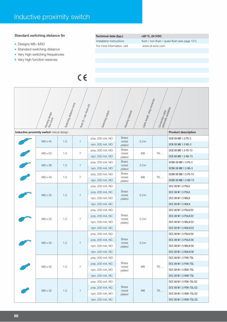
88
Hous
ing
desi
gnSi
ze (m
m)
Switc
hing
dis
tanc
e (m
m)
flush
(f) /
non
-flus
h (n
f)
Switc
hing
out
put
Hous
ing
mat
eria
l
Cabl
e le
ngth
, plu
g co
nnec
tor
Conn
ectio
n ca
ble
(opt
iona
lly a
vaila
ble)
Inductive proximity switch helical design Product description
M8 x 45 1.5 fpnp, 200 mA, NO Brass
nickel plated
2.0 mDCB 08 MB 1.5 PS-3
npn, 200 mA, NO DCB 08 MB 1.5 NS-3
M8 x 50 1.5 fpnp, 200 mA, NO Brass
nickel plated
M8 TK …DCB 08 MB 1.5 PS-T3
npn, 200 mA, NO DCB 08 MB 1.5 NS-T3
M8 x 36 1.5 fpnp, 200 mA, NO Brass
nickel plated
2.0 mDCBK 08 MB 1.5 PS-3
npn, 200 mA, NO DCBK 08 MB 1.5 NS-3
M8 x 40 1.5 fpnp, 200 mA, NO Brass
nickel plated
M8 TK …DCBK 08 MB 1.5 PS-T3
npn, 200 mA, NO DCBK 08 MB 1.5 NS-T3
M8 x 35 1.5 f
pnp, 200 mA, NO
Brassnickel plated
2.0 m
DCC 08 M 1.5 PSLK
pnp, 200 mA, NC DCC 08 M 1.5 POLK
npn, 200 mA, NO DCC 08 M 1.5 NSLK
npn, 200 mA, NC DCC 08 M 1.5 NOLK
M8 x 22 1.5 f
pnp, 200 mA, NO
Brassnickel plated
2.0 m
DCC 08 M 1.5 PSLK/22
pnp, 200 mA, NC DCC 08 M 1.5 POLK/22
npn, 200 mA, NO DCC 08 M 1.5 NSLK/22
npn, 200 mA, NC DCC 08 M 1.5 NOLK/22
M8 x 30 1.5 f
pnp, 200 mA, NO
Brassnickel plated
2.0 m
DCC 08 M 1.5 PSLK/30
pnp, 200 mA, NC DCC 08 M 1.5 POLK/30
npn, 200 mA, NO DCC 08 M 1.5 NSLK/30
npn, 200 mA, NC DCC 08 M 1.5 NOLK/30
M8 x 45 1.5 f
pnp, 200 mA, NO
Brassnickel plated
M8 TK …
DCC 08 M 1.5 PSK-TSL
pnp, 200 mA, NC DCC 08 M 1.5 POK-TSL
npn, 200 mA, NO DCC 08 M 1.5 NSK-TSL
npn, 200 mA, NC DCC 08 M 1.5 NOK-TSL
M8 x 32 1.5 f
pnp, 200 mA, NO
Brassnickelplated
M8 TK …
DCC 08 M 1.5 PSK-TSL/32
pnp, 200 mA, NC DCC 08 M 1.5 POK-TSL/32
npn, 200 mA, NO DCC 08 M 1.5 NSK-TSL/32
npn, 200 mA, NC DCC 08 M 1.5 NOK-TSL/32
Inductive proximity switch
Standard switching distance Sn
Designs M8 – M30 Standard switching distance Very high switching frequencies Very high function reserves
Technical data (typ.) +20 °C, 24 V DC
Installation instructions flush / non-flush / quasi-flush (see page 121)
For more information, visit www.di-soric.com

For more information and models visit www.di-soric.com 89
Hous
ing
desi
gnSi
ze (m
m)
Switc
hing
dis
tanc
e (m
m)
flush
(f) /
non
-flus
h (n
f)
Switc
hing
out
put
Hous
ing
mat
eria
l
Cabl
e le
ngth
, plu
g co
nnec
tor
Conn
ectio
n ca
ble
(opt
iona
lly a
vaila
ble)
Inductive proximity switch helical design Product description
M8 x 40 1.5 f
pnp, 200 mA, NO
V2A M8 TK …
DCC 08 M 1.5 PSK-TSL/40
pnp, 200 mA, NC DCC 08 M 1.5 POK-TSL/40
npn, 200 mA, NO DCC 08 M 1.5 NSK-TSL/40
npn, 200 mA, NC DCC 08 M 1.5 NOK-TSL/40
M8 x 45 1.5 f
pnp, 200 mA, NO
V2A M12 VK …
DCC 08 M 1.5 PSK-IBSL
pnp, 200 mA, NC DCC 08 M 1.5 POK-IBSL
npn, 200 mA, NO DCC 08 M 1.5 NSK-IBSL
npn, 200 mA, NC DCC 08 M 1.5 NOK-IBSL
M8 x 16 1.5 f
pnp, 200 mA, NO
V2A 2.0 m
DCCK 08 M 1.5 PSLK
pnp, 200 mA, NC DCCK 08 M 1.5 POLK
npn, 200 mA, NO DCCK 08 M 1.5 NSLK
npn, 200 mA, NC DCCK 08 M 1.5 NOLK
M8 x 45 1.5 fpnp, 200 mA, NO Brass
nickel plated
2.0 mDCB 08 MN 2.5 PS-3
npn, 200 mA, NO DCB 08 MN 2.5 NS-3
M8 x 50 2.5 nfpnp, 200 mA, NO Brass
nickel plated
M8 TK …DCB 08 MN 2.5 PS-T3
npn, 200 mA, NO DCB 08 MN 2.5 NS-T3
M8 x 36 2.5 nfpnp, 200 mA, NO Brass
nickel plated
2.0 mDCBK 08 MN 2.5 PS-3
npn, 200 mA, NO DCBK 08 MN 2.5 NS-3
M8 x 40 2.5 nfpnp, 200 mA, NO Brass
nickel plated
M8 TK …DCBK 08 MN 2.5 PS-T3
npn, 200 mA, NO DCBK 08 MN 2.5 NS-T3
M8 x 45 2.5 nf
pnp, 200 mA, NO
V2A M8 TK …
DCC 08 M 2.5 PSK-TSL
pnp, 200 mA, NC DCC 08 M 2.5 POK-TSL
npn, 200 mA, NO DCC 08 M 2.5 NSK-TSL
npn, 200 mA, NC DCC 08 M 2.5 NOK-TSL
M8 x 48 2.5 nf
pnp, 200 mA, NO
V2A M12 VK …
DCC 08 M 2.5 PSK-IBSL
pnp, 200 mA, NC DCC 08 M 2.5 POK-IBSL
npn, 200 mA, NO DCC 08 M 2.5 NSK-IBSL
npn, 200 mA, NC DCC 08 M 2.5 NOK-IBSL
Standard switching distance Sn

90
Hous
ing
desi
gnSi
ze (m
m)
Switc
hing
dis
tanc
e (m
m)
flush
(f) /
non
-flus
h (n
f)
Switc
hing
out
put
Hous
ing
mat
eria
l
Cabl
e le
ngth
, plu
g co
nnec
tor
Conn
ectio
n ca
ble
(opt
iona
lly a
vaila
ble)
Inductive proximity switch helical design Product description
M12 x 50 2.0 fpnp, 200 mA, NO Brass
nickelplated
2.0 mDCB 12 MB 02 PS-3
npn, 200 mA, NO DCB 12 MB 02 NS-3
M12 x 50 2.0 fpnp, 200 mA, NC Brass
nickelplated
2.0 mDCC 12 M 02 POLK
npn, 200 mA, NC DCC 12 M 02 NOLK
M12 x 35 2.0 f
pnp, 200 mA, NO
Brassnickelplated
2.0 m
DCCK 12 M 02 PSLK
pnp, 200 mA, NC DCCK 12 M 02 POLK
npn, 200 mA, NO DCCK 12 M 02 NSLK
npn, 200 mA, NC DCCK 12 M 02 NOLK
M12 x 65 2.0 f
pnp, 200 mA, NO Brassnickelplated
M12 VK …
DCB 12 MB 02 PS-B3
npn, 200 mA, NO DCB 12 MB 02 NS-B3
M12 x 53 2.0 f
pnp, 200 mA, NO
Brassnickelplated
M12 VK …
DCBK 12 MB 02 PS-B3
pnp, 200 mA, NC DCBK 12 MB 02 PO-B3
npn, 200 mA, NO DCBK 12 MB 02 NS-B3
M12 x 60 2.0 fpnp, 200 mA, NC Brass
nickelplated
M12 VK …DCC 12 M 02 POK-IBSL
npn, 200 mA, NC DCC 12 M 02 NOK-IBSL
M12 x 45 2.0 f
pnp, 200 mA, NO
Brassnickelplated
M12 VK …
DCCK 12 M 02 PSK-IBSL
pnp, 200 mA, NC DCCK 12 M 02 POK-IBSL
npn, 200 mA, NO DCCK 12 M 02 NSK-IBSL
npn, 200 mA, NC DCCK 12 M 02 NOK-IBSL
M12 x 50 4.0 nfpnp, 200 mA, NO Brass
nickelplated
2.0 mDCB 12 MN 04 PS-3
npn, 200 mA, NO DCB 12 MN 04 NS-3
M12 x 65 4.0 nfpnp, 200 mA, NO Brass
nickelplated
M12 VK …DCB 12 MN 04 PS-B3
npn, 200 mA, NO DCB 12 MN 04 NS-B3
M12 x 50 4.0 nf
pnp, 200 mA, NO
Brassnickelplated
2.0 m
DCC 12 M 04 PSLK
pnp, 200 mA, NC DCC 12 M 04 POLK
npn, 200 mA, NO DCC 12 M 04 NSLK
npn, 200 mA, NC DCC 12 M 04 NOLK
Standard switching distance Sn
Inductive proximity switch

For more information and models visit www.di-soric.com 91
Hous
ing
desi
gnSi
ze (m
m)
Switc
hing
dis
tanc
e (m
m)
flush
(f) /
non
-flus
h (n
f)
Switc
hing
out
put
Hous
ing
mat
eria
l
Cabl
e le
ngth
, plu
g co
nnec
tor
Conn
ectio
n ca
ble
(opt
iona
lly a
vaila
ble)
Inductive proximity switch helical design Product description
M12 x 35 4.0 nf
pnp, 200 mA, NO
Brassnickelplated
2.0 m
DCCK 12 M 04 PSLK
pnp, 200 mA, NC DCCK 12 M 04 POLK
npn, 200 mA, NO DCCK 12 M 04 NSLK
npn, 200 mA, NC DCCK 12 M 04 NOLK
M12 x 60 4.0 nf
pnp, 200 mA, NO
Brassnickelplated
M12 VK …
DCC 12 M 04 PSK-IBSL
pnp, 200 mA, NC DCC 12 M 04 POK-IBSL
npn, 200 mA, NO DCC 12 M 04 NSK-IBSL
npn, 200 mA, NC DCC 12 M 04 NOK-IBSL
M12 x 45 4.0 nf
pnp, 200 mA, NO
Brassnickelplated
M12 VK …
DCCK 12 M 04 PSK-IBSL
pnp, 200 mA, NC DCCK 12 M 04 POK-IBSL
npn, 200 mA, NO DCCK 12 M 04 NSK-IBSL
npn, 200 mA, NC DCCK 12 M 04 NOK-IBSL
M18 x 50 5.0 fpnp, 400 mA, NO Brass
nickelplated
2.0 mDCB 18 MB 05 PS-3
npn, 400 mA, NO DCB 18 MB 05 NS-3
M18 x 50 5.0 f
pnp, 200 mA, NO
Brassnickelplated
2.0 m
DCC 18 M 05 PSLK
pnp, 200 mA, NC DCC 18 M 05 POLK
npn, 200 mA, NO DCC 18 M 05 NSLK
npn, 200 mA, NC DCC 18 M 05 NOLK
M18 x 35 5.0 f
pnp, 200 mA, NO
Brassnickelplated
2.0 m
DCCK 18 M 05 PSLK
pnp, 200 mA, NC DCCK 18 M 05 POLK
npn, 200 mA, NO DCCK 18 M 05 NSLK
npn, 200 mA, NC DCCK 18 M 05 NOLK
M18 x 64 5.0 fpnp, 400 mA, NO Brass
nickelplated
M12 VK …DCB 18 MB 05 PS-B3
npn, 400 mA, NO DCB 18 MB 05 NS-B3
M18 x 65 5.0 f
pnp, 200 mA, NO
Brassnickelplated
M12 VK …
DCC 18 M 05 PSK-IBSL
pnp, 200 mA, NC DCC 18 M 05 POK-IBSL
npn, 200 mA, NO DCC 18 M 05 NSK-IBSL
npn, 200 mA, NC DCC 18 M 05 NOK-IBSL
M18 x 50 5.0 f
pnp, 200 mA, NO
Brassnickelplated
M12 VK …
DCCK 18 M 05 PSK-IBSL
pnp, 200 mA, NC DCCK 18 M 05 POK-IBSL
npn, 200 mA, NO DCCK 18 M 05 NSK-IBSL
npn, 200 mA, NC DCCK 18 M 05 NOK-IBSL
Standard switching distance Sn

92
Hous
ing
desi
gnSi
ze (m
m)
Switc
hing
dis
tanc
e (m
m)
flush
(f) /
non
-flus
h (n
f)
Switc
hing
out
put
Hous
ing
mat
eria
l
Cabl
e le
ngth
, plu
g co
nnec
tor
Conn
ectio
n ca
ble
(opt
iona
lly a
vaila
ble)
Inductive proximity switch helical design Product description
M18 x 50 8.0 nf
pnp, 400 mA, NO Brassnickelplated
2.0 m
DCB 18 MN 08 PS-3
npn, 400 mA, NO DCB 18 MN 08 NS-3
M18 x 50 8.0 nf
pnp, 200 mA, NO
Brassnickelplated
2.0 m
DCC 18 M 08 PSLK
pnp, 200 mA, NC DCC 18 M 08 POLK
npn, 200 mA, NO DCC 18 M 08 NSLK
npn, 200 mA, NC DCC 18 M 08 NOLK
M18 x 35 8.0 nf
pnp, 200 mA, NO
Brassnickelplated
2.0 m
DCCK 18 M 08 PSLK
pnp, 200 mA, NC DCCK 18 M 08 POLK
npn, 200 mA, NO DCCK 18 M 08 NSLK
npn, 200 mA, NC DCCK 18 M 08 NOLK
M18 x 64 8.0 nf
pnp, 400 mA, NO Brassnickelplated
M12 VK …
DCB 18 MN 08 PS-B3
npn, 400 mA, NO DCB 18 MN 08 NS-B3
M18 x 65 8.0 nf
pnp, 200 mA, NO
Brassnickelplated
M12 VK …
DCC 18 M 08 PSK-IBSL
pnp, 200 mA, NC DCC 18 M 08 POK-IBSL
npn, 200 mA, NO DCC 18 M 08 NSK-IBSL
npn, 200 mA, NC DCC 18 M 08 NOK-IBSL
M18 x 50 8.0 nf
pnp, 200 mA, NO
Brassnickelplated
M12 VK …
DCCK 18 M 08 PSK-IBSL
pnp, 200 mA, NC DCCK 18 M 08 POK-IBSL
npn, 200 mA, NO DCCK 18 M 08 NSK-IBSL
npn, 200 mA, NC DCCK 18 M 08 NOK-IBSL
M30 x 60 10.0 f
pnp, 400 mA, NO Brassnickelplated
2.0 m
DCB 30 MB 10 PS-3
npn, 400 mA, NO DCB 30 MB 10 NS-3
M30 x 52 10.0 f
pnp, 200 mA, NO
Brassnickelplated
2.0 m
DCC 30 M 10 PSLK
pnp, 200 mA, NC DCC 30 M 10 POLK
npn, 200 mA, NO DCC 30 M 10 NSLK
npn, 200 mA, NC DCC 30 M 10 NOLK
M30 x 36 10.0 f
pnp, 200 mA, NO
Brassnickelplated
2.0 m
DCCK 30 M 10 PSLK
pnp, 200 mA, NC DCCK 30 M 10 POLK
npn, 200 mA, NO DCCK 30 M 10 NSLK
npn, 200 mA, NC DCCK 30 M 10 NOLK
Standard switching distance Sn
Inductive proximity switch
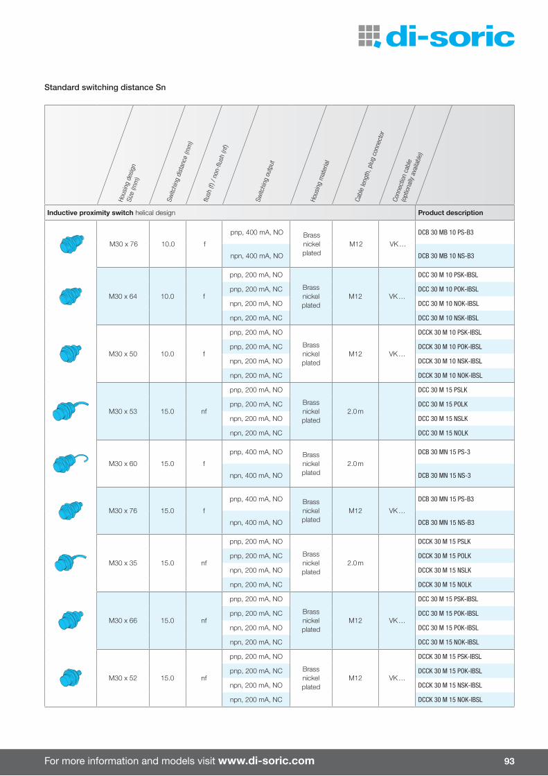
For more information and models visit www.di-soric.com 93
Hous
ing
desi
gnSi
ze (m
m)
Switc
hing
dis
tanc
e (m
m)
flush
(f) /
non
-flus
h (n
f)
Switc
hing
out
put
Hous
ing
mat
eria
l
Cabl
e le
ngth
, plu
g co
nnec
tor
Conn
ectio
n ca
ble
(opt
iona
lly a
vaila
ble)
Inductive proximity switch helical design Product description
M30 x 76 10.0 f
pnp, 400 mA, NO Brassnickelplated
M12 VK …
DCB 30 MB 10 PS-B3
npn, 400 mA, NO DCB 30 MB 10 NS-B3
M30 x 64 10.0 f
pnp, 200 mA, NO
Brassnickelplated
M12 VK …
DCC 30 M 10 PSK-IBSL
pnp, 200 mA, NC DCC 30 M 10 POK-IBSL
npn, 200 mA, NO DCC 30 M 10 NOK-IBSL
npn, 200 mA, NC DCC 30 M 10 NSK-IBSL
M30 x 50 10.0 f
pnp, 200 mA, NO
Brassnickelplated
M12 VK …
DCCK 30 M 10 PSK-IBSL
pnp, 200 mA, NC DCCK 30 M 10 POK-IBSL
npn, 200 mA, NO DCCK 30 M 10 NSK-IBSL
npn, 200 mA, NC DCCK 30 M 10 NOK-IBSL
M30 x 53 15.0 nf
pnp, 200 mA, NO
Brassnickelplated
2.0 m
DCC 30 M 15 PSLK
pnp, 200 mA, NC DCC 30 M 15 POLK
npn, 200 mA, NO DCC 30 M 15 NSLK
npn, 200 mA, NC DCC 30 M 15 NOLK
M30 x 60 15.0 f
pnp, 400 mA, NO Brassnickelplated
2.0 m
DCB 30 MN 15 PS-3
npn, 400 mA, NO DCB 30 MN 15 NS-3
M30 x 76 15.0 f
pnp, 400 mA, NO Brassnickelplated
M12 VK …
DCB 30 MN 15 PS-B3
npn, 400 mA, NO DCB 30 MN 15 NS-B3
M30 x 35 15.0 nf
pnp, 200 mA, NO
Brassnickelplated
2.0 m
DCCK 30 M 15 PSLK
pnp, 200 mA, NC DCCK 30 M 15 POLK
npn, 200 mA, NO DCCK 30 M 15 NSLK
npn, 200 mA, NC DCCK 30 M 15 NOLK
M30 x 66 15.0 nf
pnp, 200 mA, NO
Brassnickelplated
M12 VK …
DCC 30 M 15 PSK-IBSL
pnp, 200 mA, NC DCC 30 M 15 POK-IBSL
npn, 200 mA, NO DCC 30 M 15 POK-IBSL
npn, 200 mA, NC DCC 30 M 15 NOK-IBSL
M30 x 52 15.0 nf
pnp, 200 mA, NO
Brassnickelplated
M12 VK …
DCCK 30 M 15 PSK-IBSL
pnp, 200 mA, NC DCCK 30 M 15 POK-IBSL
npn, 200 mA, NO DCCK 30 M 15 NSK-IBSL
npn, 200 mA, NC DCCK 30 M 15 NOK-IBSL
Standard switching distance Sn
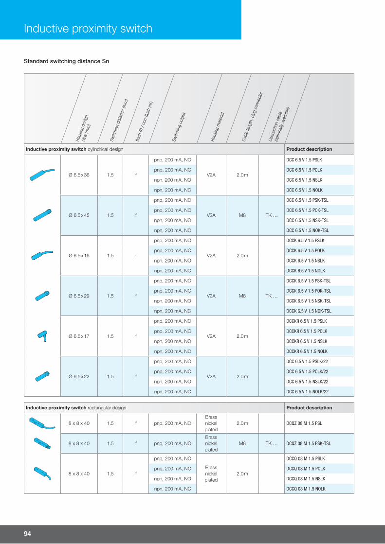
94
Hous
ing
desi
gnSi
ze (m
m)
Switc
hing
dis
tanc
e (m
m)
flush
(f) /
non
-flus
h (n
f)
Switc
hing
out
put
Hous
ing
mat
eria
l
Cabl
e le
ngth
, plu
g co
nnec
tor
Conn
ectio
n ca
ble
(opt
iona
lly a
vaila
ble)
Inductive proximity switch cylindrical design Product description
Ø 6.5 x 36 1.5 f
pnp, 200 mA, NO
V2A 2.0 m
DCC 6.5 V 1.5 PSLK
pnp, 200 mA, NC DCC 6.5 V 1.5 POLK
npn, 200 mA, NO DCC 6.5 V 1.5 NSLK
npn, 200 mA, NC DCC 6.5 V 1.5 NOLK
Ø 6.5 x 45 1.5 f
pnp, 200 mA, NO
V2A M8 TK …
DCC 6.5 V 1.5 PSK-TSL
pnp, 200 mA, NC DCC 6.5 V 1.5 POK-TSL
npn, 200 mA, NO DCC 6.5 V 1.5 NSK-TSL
npn, 200 mA, NC DCC 6.5 V 1.5 NOK-TSL
Ø 6.5 x 16 1.5 f
pnp, 200 mA, NO
V2A 2.0 m
DCCK 6.5 V 1.5 PSLK
pnp, 200 mA, NC DCCK 6.5 V 1.5 POLK
npn, 200 mA, NO DCCK 6.5 V 1.5 NSLK
npn, 200 mA, NC DCCK 6.5 V 1.5 NOLK
Ø 6.5 x 29 1.5 f
pnp, 200 mA, NO
V2A M8 TK …
DCCK 6.5 V 1.5 PSK-TSL
pnp, 200 mA, NC DCCK 6.5 V 1.5 POK-TSL
npn, 200 mA, NO DCCK 6.5 V 1.5 NSK-TSL
npn, 200 mA, NC DCCK 6.5 V 1.5 NOK-TSL
Ø 6.5 x 17 1.5 f
pnp, 200 mA, NO
V2A 2.0 m
DCCKR 6.5 V 1.5 PSLK
pnp, 200 mA, NC DCCKR 6.5 V 1.5 POLK
npn, 200 mA, NO DCCKR 6.5 V 1.5 NSLK
npn, 200 mA, NC DCCKR 6.5 V 1.5 NOLK
Ø 6.5 x 22 1.5 f
pnp, 200 mA, NO
V2A 2.0 m
DCC 6.5 V 1.5 PSLK/22
pnp, 200 mA, NC DCC 6.5 V 1.5 POLK/22
npn, 200 mA, NO DCC 6.5 V 1.5 NSLK/22
npn, 200 mA, NC DCC 6.5 V 1.5 NOLK/22
Inductive proximity switch rectangular design Product description
8 x 8 x 40 1.5 f pnp, 200 mA, NOBrassnickelplated
2.0 m DCQZ 08 M 1.5 PSL
8 x 8 x 40 1.5 f pnp, 200 mA, NOBrassnickelplated
M8 TK … DCQZ 08 M 1.5 PSK-TSL
8 x 8 x 40 1.5 f
pnp, 200 mA, NO
Brassnickelplated
2.0 m
DCCQ 08 M 1.5 PSLK
pnp, 200 mA, NC DCCQ 08 M 1.5 POLK
npn, 200 mA, NO DCCQ 08 M 1.5 NSLK
npn, 200 mA, NC DCCQ 08 M 1.5 NOLK
Standard switching distance Sn
Inductive proximity switch
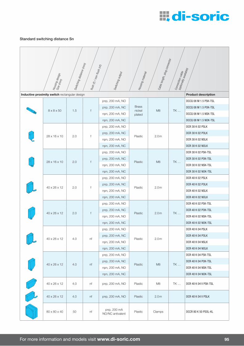
For more information and models visit www.di-soric.com 95
Hous
ing
desi
gnSi
ze (m
m)
Switc
hing
dis
tanc
e (m
m)
flush
(f) /
non
-flus
h (n
f)
Switc
hing
out
put
Hous
ing
mat
eria
l
Cabl
e le
ngth
, plu
g co
nnec
tor
Conn
ectio
n ca
ble
(opt
iona
lly a
vaila
ble)
Inductive proximity switch rectangular design Product description
8 x 8 x 50 1.5 f
pnp, 200 mA, NO
Brassnickelplated
M8 TK …
DCCQ 08 M 1.5 PSK-TSL
pnp, 200 mA, NC DCCQ 08 M 1.5 POK-TSL
npn, 200 mA, NO DCCQ 08 M 1.5 NSK-TSL
npn, 200 mA, NC DCCQ 08 M 1.5 NOK-TSL
28 x 16 x 10 2.0 f
pnp, 200 mA, NO
Plastic 2.0 m
DCR 30 K 02 PSLK
pnp, 200 mA, NC DCR 30 K 02 POLK
npn, 200 mA, NO DCR 30 K 02 NSLK
npn, 200 mA, NC DCR 30 K 02 NOLK
28 x 16 x 10 2.0 f
pnp, 200 mA, NO
Plastic M8 TK …
DCR 30 K 02 PSK-TSL
pnp, 200 mA, NC DCR 30 K 02 POK-TSL
npn, 200 mA, NO DCR 30 K 02 NSK-TSL
npn, 200 mA, NC DCR 30 K 02 NOK-TSL
40 x 26 x 12 2.0 f
pnp, 200 mA, NO
Plastic 2.0 m
DCR 40 K 02 PSLK
pnp, 200 mA, NC DCR 40 K 02 POLK
npn, 200 mA, NO DCR 40 K 02 NSLK
npn, 200 mA, NC DCR 40 K 02 NOLK
40 x 26 x 12 2.0 f
pnp, 200 mA, NO
Plastic 2.0 m TK …
DCR 40 K 02 PSK-TSL
pnp, 200 mA, NC DCR 40 K 02 POK-TSL
npn, 200 mA, NO DCR 40 K 02 NSK-TSL
npn, 200 mA, NC DCR 40 K 02 NOK-TSL
40 x 26 x 12 4.0 nf
pnp, 200 mA, NO
Plastic 2.0 m
DCR 40 K 04 PSLK
pnp, 200 mA, NC DCR 40 K 04 POLK
npn, 200 mA, NO DCR 40 K 04 NSLK
npn, 200 mA, NC DCR 40 K 04 NOLK
40 x 26 x 12 4.0 nf
pnp, 200 mA, NO
Plastic M8 TK …
DCR 40 K 04 PSK-TSL
pnp, 200 mA, NC DCR 40 K 04 POK-TSL
npn, 200 mA, NO DCR 40 K 04 NSK-TSL
npn, 200 mA, NC DCR 40 K 04 NOK-TSL
40 x 26 x 12 4.0 nf pnp, 200 mA, NO Plastic M8 TK … DCR 40 K 04 V PSK-TSL
40 x 26 x 12 4.0 nf pnp, 200 mA, NO Plastic 2.0 m DCR 40 K 04 V PSLK
80 x 80 x 40 50 nfpnp, 200 mA
NO/NC antivalentPlastic Clamps DCCR 80 K 50 PSOL-KL
Standard switching distance Sn
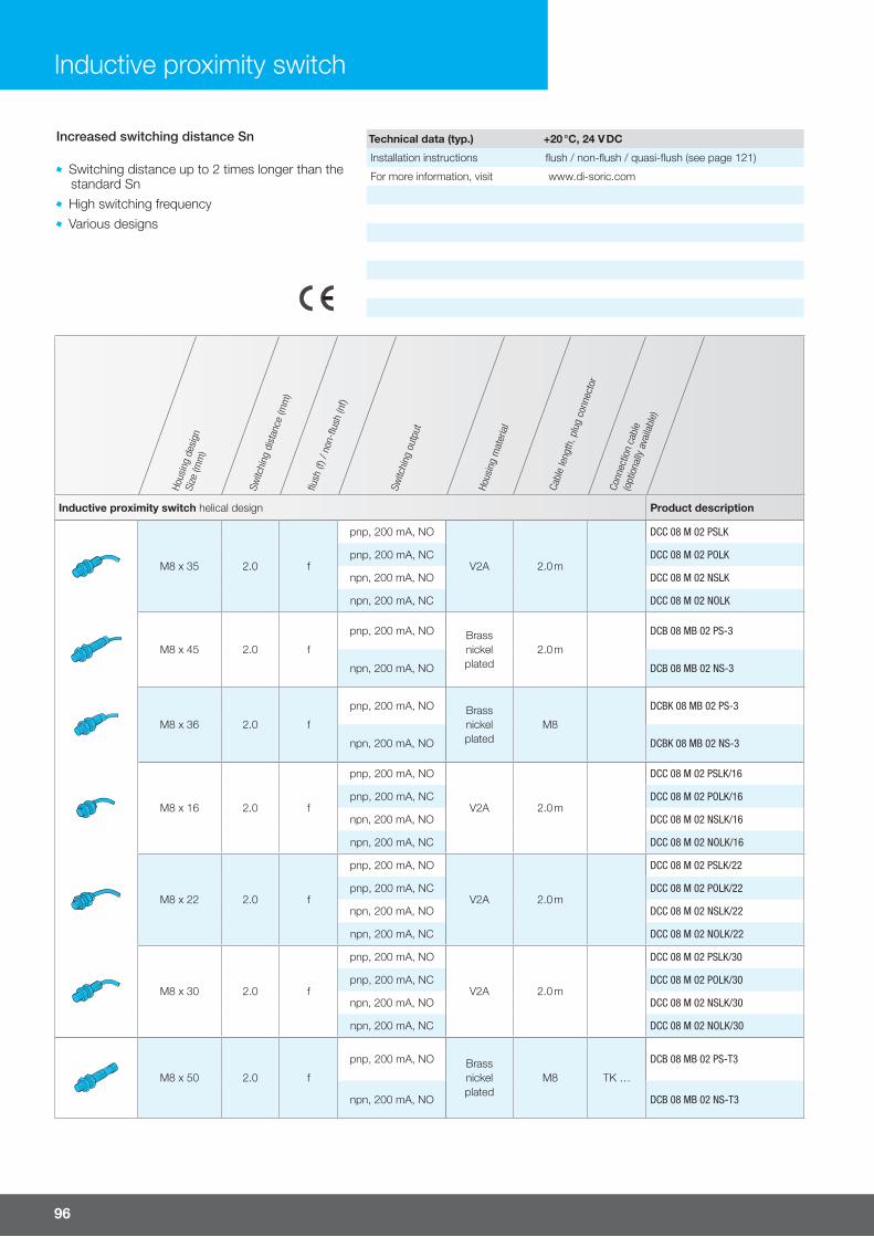
96
Hous
ing
desi
gnSi
ze (m
m)
Switc
hing
dis
tanc
e (m
m)
flush
(f) /
non
-flus
h (n
f)
Switc
hing
out
put
Hous
ing
mat
eria
l
Cabl
e le
ngth
, plu
g co
nnec
tor
Conn
ectio
n ca
ble
(opt
iona
lly a
vaila
ble)
Inductive proximity switch helical design Product description
M8 x 35 2.0 f
pnp, 200 mA, NO
V2A 2.0 m
DCC 08 M 02 PSLK
pnp, 200 mA, NC DCC 08 M 02 POLK
npn, 200 mA, NO DCC 08 M 02 NSLK
npn, 200 mA, NC DCC 08 M 02 NOLK
M8 x 45 2.0 f
pnp, 200 mA, NO Brassnickelplated
2.0 m
DCB 08 MB 02 PS-3
npn, 200 mA, NO DCB 08 MB 02 NS-3
M8 x 36 2.0 f
pnp, 200 mA, NO Brassnickelplated
M8
DCBK 08 MB 02 PS-3
npn, 200 mA, NO DCBK 08 MB 02 NS-3
M8 x 16 2.0 f
pnp, 200 mA, NO
V2A 2.0 m
DCC 08 M 02 PSLK/16
pnp, 200 mA, NC DCC 08 M 02 POLK/16
npn, 200 mA, NO DCC 08 M 02 NSLK/16
npn, 200 mA, NC DCC 08 M 02 NOLK/16
M8 x 22 2.0 f
pnp, 200 mA, NO
V2A 2.0 m
DCC 08 M 02 PSLK/22
pnp, 200 mA, NC DCC 08 M 02 POLK/22
npn, 200 mA, NO DCC 08 M 02 NSLK/22
npn, 200 mA, NC DCC 08 M 02 NOLK/22
M8 x 30 2.0 f
pnp, 200 mA, NO
V2A 2.0 m
DCC 08 M 02 PSLK/30
pnp, 200 mA, NC DCC 08 M 02 POLK/30
npn, 200 mA, NO DCC 08 M 02 NSLK/30
npn, 200 mA, NC DCC 08 M 02 NOLK/30
M8 x 50 2.0 f
pnp, 200 mA, NO Brassnickelplated
M8 TK …
DCB 08 MB 02 PS-T3
npn, 200 mA, NO DCB 08 MB 02 NS-T3
Inductive proximity switch
Increased switching distance Sn
Switching distance up to 2 times longer than the standard Sn High switching frequency Various designs
Technical data (typ.) +20 °C, 24 V DC
Installation instructions flush / non-flush / quasi-flush (see page 121)
For more information, visit www.di-soric.com
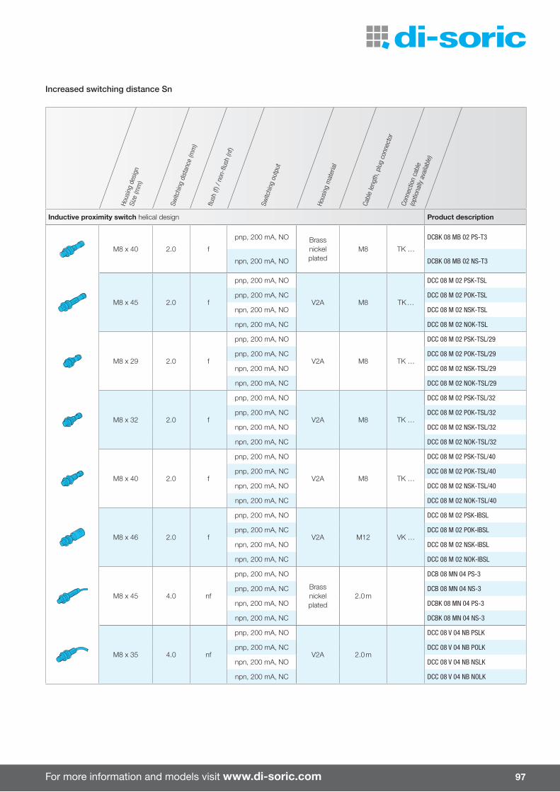
For more information and models visit www.di-soric.com 97
Hous
ing
desi
gnSi
ze (m
m)
Switc
hing
dis
tanc
e (m
m)
flush
(f) /
non
-flus
h (n
f)
Switc
hing
out
put
Hous
ing
mat
eria
l
Cabl
e le
ngth
, plu
g co
nnec
tor
Conn
ectio
n ca
ble
(opt
iona
lly a
vaila
ble)
Inductive proximity switch helical design Product description
M8 x 40 2.0 f
pnp, 200 mA, NO Brassnickelplated
M8 TK …
DCBK 08 MB 02 PS-T3
npn, 200 mA, NO DCBK 08 MB 02 NS-T3
M8 x 45 2.0 f
pnp, 200 mA, NO
V2A M8 TK …
DCC 08 M 02 PSK-TSL
pnp, 200 mA, NC DCC 08 M 02 POK-TSL
npn, 200 mA, NO DCC 08 M 02 NSK-TSL
npn, 200 mA, NC DCC 08 M 02 NOK-TSL
M8 x 29 2.0 f
pnp, 200 mA, NO
V2A M8 TK …
DCC 08 M 02 PSK-TSL/29
pnp, 200 mA, NC DCC 08 M 02 POK-TSL/29
npn, 200 mA, NO DCC 08 M 02 NSK-TSL/29
npn, 200 mA, NC DCC 08 M 02 NOK-TSL/29
M8 x 32 2.0 f
pnp, 200 mA, NO
V2A M8 TK …
DCC 08 M 02 PSK-TSL/32
pnp, 200 mA, NC DCC 08 M 02 POK-TSL/32
npn, 200 mA, NO DCC 08 M 02 NSK-TSL/32
npn, 200 mA, NC DCC 08 M 02 NOK-TSL/32
M8 x 40 2.0 f
pnp, 200 mA, NO
V2A M8 TK …
DCC 08 M 02 PSK-TSL/40
pnp, 200 mA, NC DCC 08 M 02 POK-TSL/40
npn, 200 mA, NO DCC 08 M 02 NSK-TSL/40
npn, 200 mA, NC DCC 08 M 02 NOK-TSL/40
M8 x 46 2.0 f
pnp, 200 mA, NO
V2A M12 VK …
DCC 08 M 02 PSK-IBSL
pnp, 200 mA, NC DCC 08 M 02 POK-IBSL
npn, 200 mA, NO DCC 08 M 02 NSK-IBSL
npn, 200 mA, NC DCC 08 M 02 NOK-IBSL
M8 x 45 4.0 nf
pnp, 200 mA, NO
Brassnickelplated
2.0 m
DCB 08 MN 04 PS-3
pnp, 200 mA, NC DCB 08 MN 04 NS-3
npn, 200 mA, NO DCBK 08 MN 04 PS-3
npn, 200 mA, NC DCBK 08 MN 04 NS-3
M8 x 35 4.0 nf
pnp, 200 mA, NO
V2A 2.0 m
DCC 08 V 04 NB PSLK
pnp, 200 mA, NC DCC 08 V 04 NB POLK
npn, 200 mA, NO DCC 08 V 04 NB NSLK
npn, 200 mA, NC DCC 08 V 04 NB NOLK
Increased switching distance Sn

98
Hous
ing
desi
gnSi
ze (m
m)
Switc
hing
dis
tanc
e (m
m)
flush
(f) /
non
-flus
h (n
f)
Switc
hing
out
put
Hous
ing
mat
eria
l
Cabl
e le
ngth
, plu
g co
nnec
tor
Conn
ectio
n ca
ble
(opt
iona
lly a
vaila
ble)
Inductive proximity switch helical design Product description
M8 x 50 4.0 nf
pnp, 200 mA, NO Brassnickelplated
M8 TK …
DCB 08 MN 04 PS-T3
npn, 200 mA, NO DCB 08 MN 04 NS-T3
M8 x 40 4.0 nf
pnp, 200 mA, NO Brassnickelplated
M8 TK …
DCBK 08 MN 04 PS-T3
npn, 200 mA, NO DCBK 08 MN 04 NS-T3
M8 x 46 4.0 nf
pnp, 200 mA, NO
V2A M8 TK …
DCC 08 V 04 NB PSK-TSL
pnp, 200 mA, NC DCC 08 V 04 NB POK-TSL
npn, 200 mA, NO DCC 08 V 04 NB NSK-TSL
npn, 200 mA, NC DCC 08 V 04 NB NOK-TSL
M12 x 50 4.0 f
pnp, 200 mA, NO
Brassnickelplated
2.0 m
DCC 12 M 04 B PSLK
pnp, 200 mA, NC DCC 12 M 04 B POLK
npn, 200 mA, NO DCC 12 M 04 B NSLK
M12 x 35 4.0 f
pnp, 200 mA, NO
Brassnickelplated
2.0 m
DCCK 12 M 04 B PSLK
pnp, 200 mA, NC DCCK 12 M 04 B POLK
npn, 200 mA, NO DCCK 12 M 04 B NOLK
npn, 200 mA, NC DCCK 12 M 04 B NSLK
M12 x 65 4.0 f
pnp, 200 mA, NO Brassnickelplated
M12 VK …
DCB 12 MB 04 PS-B3
npn, 200 mA, NO DCB 12 MB 04 NS-B3
M12 x 53 4.0 f
pnp, 200 mA, NO Brassnickelplated
M12 VK …
DCBK 12 MB 04 PS-B3
pnp, 200 mA, NC DCBK 12 MB 04 PO-B3
M12 x 60 4.0 f
pnp, 200 mA, NO
Brassnickelplated
M12 VK …
DCC 12 M 04 B PSK-IBSL
pnp, 200 mA, NC DCC 12 M 04 B POK-IBSL
npn, 200 mA, NO DCC 12 M 04 B NSK-IBSL
npn, 200 mA, NC DCC 12 M 04 B NOK-IBSL
M12 x 45 4.0 f
pnp, 200 mA, NO
Brassnickelplated
M12 VK …
DCCK 12 M 04 B PSK-IBSL
pnp, 200 mA, NC DCCK 12 M 04 B POK-IBSL
npn, 200 mA, NO DCCK 12 M 04 B NSK-IBSL
Increased switching distance Sn
Inductive proximity switch

For more information and models visit www.di-soric.com 99
Hous
ing
desi
gnSi
ze (m
m)
Switc
hing
dis
tanc
e (m
m)
flush
(f) /
non
-flus
h (n
f)
Switc
hing
out
put
Hous
ing
mat
eria
l
Cabl
e le
ngth
, plu
g co
nnec
tor
Conn
ectio
n ca
ble
(opt
iona
lly a
vaila
ble)
Inductive proximity switch helical design Product description
M12 x 50 8.0 nf
pnp, 200 mA, NO Brassnickelplated
2.0 m
DCB 12 MN 08 PS-3
npn, 200 mA, NO DCB 12 MN 08 NS-3
M12 x 40 8.0 nf
pnp, 200 mA, NO Brassnickelplated
2.0 m
DCBK 12 MN 08 PS-3
npn, 200 mA, NO DCBK 12 MN 08 NS-3
M12 x 65 8.0 nf
pnp, 200 mA, NO Brassnickelplated
M12 VK …
DCB 12 MN 08 PS-B3
npn, 200 mA, NO DCB 12 MN 08 NS-B3
M12 x 53 8.0 nf
pnp, 200 mA, NO Brassnickelplated
M12 VK …
DCBK 12 MN 08 PS-B3
npn, 200 mA, NO DCBK 12 MN 08 NS-B3
M18 x 50 8.0 f
pnp, 400 mA, NO Brassnickelplated
2.0 m
DCB 18 MB 08 PS-3
npn, 400 mA, NO DCB 18 MB 08 NS-3
M18 x 50 12.0 nf
pnp, 400 mA, NO Brassnickelplated
2.0 m
DCB 18 MN 12 PS-3
npn, 400 mA, NO DCB 18 MN 12 NS-3
M18 x 64 8.0 f
pnp, 400 mA, NO Brassnickelplated
M12 VK …
DCB 18 MB 08 PS-B3
npn, 400 mA, NO DCB 18 MB 08 NS-B3
Increased switching distance Sn

100
Hous
ing
desi
gnSi
ze (m
m)
Switc
hing
dis
tanc
e (m
m)
flush
(f) /
non
-flus
h (n
f)
Switc
hing
out
put
Hous
ing
mat
eria
l
Cabl
e le
ngth
, plu
g co
nnec
tor
Conn
ectio
n ca
ble
(opt
iona
lly a
vaila
ble)
Inductive proximity switch helical design Product description
M30 x 64 12.0 nf
pnp, 400 mA, NO Brassnickelplated
M12 VK …
DCB 18 MN 12 PS-B3
npn, 400 mA, NO DCB 18 MN 12 NS-B3
M30 x 60 15.0 f
pnp, 400 mA, NO Brassnickelplated
2.0 m
DCB 30 MB 15 PS-3
npn, 400 mA, NO DCB 30 MB 15 NS-3
M30 x 76 15.0 f
pnp, 400 mA, NO Brassnickelplated
M12 VK …
DCB 30 MB 15 PS-B3
npn, 400 mA, NO DCB 30 MB 15 NS-B3
M30 x 60 20.0 nf
pnp, 400 mA, NO
Brassnickelplated
2.0 m
DCB 30 MN 20 PS-3
npn, 400 mA, NO DCB 30 MN 20 NS-3
npn, 400 mA, NC DCB 30 MN 20 NO-3
M30 x 76 20.0 nf
pnp, 400 mA, NO Brassnickelplated
M12 VK …
DCB 30 MN 20 PS-B3
npn, 400 mA, NO DCB 30 MN 20 NS-B3
Inductive proximity switch cylindrical design Product description
Ø 6.5 x 35 2.0 f
pnp, 200 mA, NO
V2A 2.0 m
DCC 6.5 V 02 PSLK
pnp, 200 mA, NC DCC 6.5 V 02 POLK
npn, 200 mA, NO DCC 6.5 V 02 NSLK
npn, 200 mA, NC DCC 6.5 V 02 NOLK
Ø 6.5 x 22 2.0 f
pnp, 200 mA, NO
V2A 2.0 m
DCC 6.5 V 02 PSLK/22
pnp, 200 mA, NC DCC 6.5 V 02 POLK/22
npn, 200 mA, NC DCC 6.5 V 02 NOLK/22
Ø 6.5 x 30 2.0 f
pnp, 200 mA, NO
V2A 2.0 m
DCC 6.5 V 02 PSLK/30
pnp, 200 mA, NC DCC 6.5 V 02 POLK/30
npn, 200 mA, NO DCC 6.5 V 02 NSLK/30
npn, 200 mA, NC DCC 6.5 V 02 NOLK/30
Ø 6.5 x 45 2.0 f
pnp, 200 mA, NO
V2A M8 TK …
DCC 6.5 V 02 PSK-TSL
pnp, 200 mA, NC DCC 6.5 V 02 POK-TSL
npn, 200 mA, NO DCC 6.5 V 02 NSK-TSL
npn, 200 mA, NC DCC 6.5 V 02 NOK-TSL
Increased switching distance Sn
Inductive proximity switch

For more information and models visit www.di-soric.com 101
Hous
ing
desi
gnSi
ze (m
m)
Switc
hing
dis
tanc
e (m
m)
flush
(f) /
non
-flus
h (n
f)
Switc
hing
out
put
Hous
ing
mat
eria
l
Cabl
e le
ngth
, plu
g co
nnec
tor
Conn
ectio
n ca
ble
(opt
iona
lly a
vaila
ble)
Inductive proximity switch helical design Product description
M30 x 64 12.0 nf
pnp, 400 mA, NO Brassnickelplated
M12 VK …
DCB 18 MN 12 PS-B3
npn, 400 mA, NO DCB 18 MN 12 NS-B3
M30 x 60 15.0 f
pnp, 400 mA, NO Brassnickelplated
2.0 m
DCB 30 MB 15 PS-3
npn, 400 mA, NO DCB 30 MB 15 NS-3
M30 x 76 15.0 f
pnp, 400 mA, NO Brassnickelplated
M12 VK …
DCB 30 MB 15 PS-B3
npn, 400 mA, NO DCB 30 MB 15 NS-B3
M30 x 60 20.0 nf
pnp, 400 mA, NO
Brassnickelplated
2.0 m
DCB 30 MN 20 PS-3
npn, 400 mA, NO DCB 30 MN 20 NS-3
npn, 400 mA, NC DCB 30 MN 20 NO-3
M30 x 76 20.0 nf
pnp, 400 mA, NO Brassnickelplated
M12 VK …
DCB 30 MN 20 PS-B3
npn, 400 mA, NO DCB 30 MN 20 NS-B3
Inductive proximity switch cylindrical design Product description
Ø 6.5 x 35 2.0 f
pnp, 200 mA, NO
V2A 2.0 m
DCC 6.5 V 02 PSLK
pnp, 200 mA, NC DCC 6.5 V 02 POLK
npn, 200 mA, NO DCC 6.5 V 02 NSLK
npn, 200 mA, NC DCC 6.5 V 02 NOLK
Ø 6.5 x 22 2.0 f
pnp, 200 mA, NO
V2A 2.0 m
DCC 6.5 V 02 PSLK/22
pnp, 200 mA, NC DCC 6.5 V 02 POLK/22
npn, 200 mA, NC DCC 6.5 V 02 NOLK/22
Ø 6.5 x 30 2.0 f
pnp, 200 mA, NO
V2A 2.0 m
DCC 6.5 V 02 PSLK/30
pnp, 200 mA, NC DCC 6.5 V 02 POLK/30
npn, 200 mA, NO DCC 6.5 V 02 NSLK/30
npn, 200 mA, NC DCC 6.5 V 02 NOLK/30
Ø 6.5 x 45 2.0 f
pnp, 200 mA, NO
V2A M8 TK …
DCC 6.5 V 02 PSK-TSL
pnp, 200 mA, NC DCC 6.5 V 02 POK-TSL
npn, 200 mA, NO DCC 6.5 V 02 NSK-TSL
npn, 200 mA, NC DCC 6.5 V 02 NOK-TSL
Hous
ing
desi
gnSi
ze (m
m)
Switc
hing
dis
tanc
e (m
m)
flush
(f) /
non
-flus
h (n
f)
Switc
hing
out
put
Hous
ing
mat
eria
l
Cabl
e le
ngth
, plu
g co
nnec
tor
Conn
ectio
n ca
ble
(opt
iona
lly a
vaila
ble)
Inductive proximity switch cylindrical design Product description
Ø 6.5 x 29 2.0 f
pnp, 200 mA, NO
V2A M8 TK …
DCC 6.5 V 02 PSK-TSL/29
pnp, 200 mA, NC DCC 6.5 V 02 POK-TSL/29
npn, 200 mA, NO DCC 6.5 V 02 NSK-TSL/29
npn, 200 mA, NC DCC 6.5 V 02 NOK-TSL/29
Ø 6.5 x 40 2.0 f
pnp, 200 mA, NO
V2A M8 TK …
DCC 6.5 V 02 PSK-TSL/40
pnp, 200 mA, NC DCC 6.5 V 02 POK-TSL/40
npn, 200 mA, NO DCC 6.5 V 02 NOK-TSL/40
Ø 6.5 x 17 2.0 f
pnp, 200 mA, NO
V2A 2.0 m
DCCK 6.5 V 02 PSLK
pnp, 200 mA, NC DCCK 6.5 V 02 POLK
npn, 200 mA, NO DCCK 6.5 V 02 NSLK
npn, 200 mA, NC DCCK 6.5 V 02 NOLK
Ø 6.5 x 17 2.0 f
pnp, 200 mA, NO
V2A 2.0 m
DCCKR 6.5 V 02 POLK
pnp, 200 mA, NC DCCKR 6.5 V 02 PSLK
npn, 200 mA, NO DCCKR 6.5 V 02 NOLK
npn, 200 mA, NC DCCKR 6.5 V 02 NSLK
Inductive proximity switch rectangular design Product description
8 x 8 x 40 2.0 f
pnp, 200 mA, NO
Brassnickelplated
2.0 m
DCCQ 08 M 02 PSLK
pnp, 200 mA, NC DCCQ 08 M 02 POLK
npn, 200 mA, NO DCCQ 08 M 02 NSLK
npn, 200 mA, NC DCCQ 08 M 02 NOLK
8 x 8 x 50 2.0 f
pnp, 200 mA, NO
Brassnickelplated
M8 TK …
DCCQ 08 M 02 PSK-TSL
pnp, 200 mA, NC DCCQ 08 M 02 POK-TSL
npn, 200 mA, NO DCCQ 08 M 02 NSK-TSL
npn, 200 mA, NC DCCQ 08 M 02 NOK-TSL
40 x 40 x 118 20.0 f pnp, 200 mA, NO PA Clamps DCCR 40 K 20 PSOL-KL
40 x 40 x 67 20.0 f pnp, 200 mA, NO PA M12 VK … DCCR 44 K 20 PSOL-IBS
Increased switching distance Sn

102
Hous
ing
desi
gnSi
ze (m
m)
Switc
hing
dis
tanc
e (m
m)
flush
(f) /
non
-flus
h (n
f)
Switc
hing
out
put
Hous
ing
mat
eria
l
Cabl
e le
ngth
, plu
g co
nnec
tor
Conn
ectio
n ca
ble
(opt
iona
lly a
vaila
ble)
Inductive proximity switch helical design Product description
M8 x 48 3.0 f
pnp, 200 mA, NO
Brassnickelplated
2.0 m
DCC 08 M 03 PSLK
pnp, 200 mA, NC DCC 08 M 03 POLK
npn, 200 mA, NO DCC 08 M 03 NSLK
npn, 200 mA, NC DCC 08 M 03 NOLK
M8 x 60 3.0 f
pnp, 200 mA, NO
Brassnickelplated
M8 TK …
DCC 08 M 03 PSK-TSL
pnp, 200 mA, NC DCC 08 M 03 POK-TSL
npn, 200 mA, NO DCC 08 M 03 NSK-TSL
npn, 200 mA, NC DCC 08 M 03 NOK-TSL
M8 x 67 3.0 f
pnp, 200 mA, NO
Brassnickelplated
M12 VK …
DCC 08 M 03 PSK-IBSL
pnp, 200 mA, NC DCC 08 M 03 POK-IBSL
npn, 200 mA, NO DCC 08 M 03 NSK-IBSL
npn, 200 mA, NC DCC 08 M 03 NOK-IBSL
M8 x 45 6.0 nf
pnp, 200 mA, NO
Brassnickelplated
2.0 m
DCC 08 M 06 PSLK
pnp, 200 mA, NC DCC 08 M 06 POLK
npn, 200 mA, NO DCC 08 M 06 NSLK
npn, 200 mA, NC DCC 08 M 06 NOLK
M8 x 60 6.0 nf
pnp, 200 mA, NO
Brassnickelplated
M8 TK …
DCC 08 M 06 PSK-TSL
pnp, 200 mA, NC DCC 08 M 06 POK-TSL
npn, 200 mA, NO DCC 08 M 06 NSK-TSL
npn, 200 mA, NC DCC 08 M 06 NOK-TSL
M8 x 66 6.0 nf
pnp, 200 mA, NO
Brassnickelplated
M12 VK …
DCC 08 M 06 PSK-IBSL
pnp, 200 mA, NC DCC 08 M 06 POK-IBSL
npn, 200 mA, NO DCC 08 M 06 NSK-IBSL
npn, 200 mA, NC DCC 08 M 06 NOK-IBSL
Inductive proximity switch
3 times the switching distance Sn
Switching distance up to 3 times longer than the standard Sn Longest switching distances for demanding applications
Technical data (typ.) +20 °C, 24 V DC
Installation instructions flush / non-flush / quasi-flush (see page 121)
For more information, visit www.di-soric.com

For more information and models visit www.di-soric.com 103
Hous
ing
desi
gnSi
ze (m
m)
Switc
hing
dis
tanc
e (m
m)
flush
(f) /
non
-flus
h (n
f)
Switc
hing
out
put
Hous
ing
mat
eria
l
Cabl
e le
ngth
, plu
g co
nnec
tor
Conn
ectio
n ca
ble
(opt
iona
lly a
vaila
ble)
Inductive proximity switch helical design Product description
M12 x 50 10.0 nf
pnp, 200 mA, NO
Brassnickelplated
2.0 m
DCC 12 M 10 PSLK
pnp, 200 mA, NC DCC 12 M 10 POLK
npn, 200 mA, NO DCC 12 M 10 NSLK
npn, 200 mA, NC DCC 12 M 10 NOLK
M12 x 35 10.0 nf
pnp, 200 mA, NO
Brassnickelplated
2.0 m
DCCK 12 M 10 PSLK
pnp, 200 mA, NC DCCK 12 M 10 POLK
npn, 200 mA, NO DCCK 12 M 10 NSLK
npn, 200 mA, NC DCCK 12 M 10 NOLK
M12 x 60 10.0 nf
pnp, 200 mA, NO
Brassnickelplated
M12 VK …
DCC 12 M 10 PSK-IBSL
pnp, 200 mA, NC DCC 12 M 10 POK-IBSL
npn, 200 mA, NO DCC 12 M 10 NSK-IBSL
npn, 200 mA, NC DCC 12 M 10 NOK-IBSL
M12 x 45 10.0 nf
pnp, 200 mA, NO
Brassnickelplated
M12 VK …
DCCK 12 M 10 PSK-IBSL
pnp, 200 mA, NC DCCK 12 M 10 POK-IBSL
npn, 200 mA, NO DCCK 12 M 10 NSK-IBSL
npn, 200 mA, NC DCCK 12 M 10 NOK-IBSL
M18 x 50 20.0 nf
pnp, 200 mA, NO
Brassnickelplated
2.0 m
DCC 18 M 20 PSLK
pnp, 200 mA, NC DCC 18 M 20 POLK
npn, 200 mA, NO DCC 18 M 20 NSLK
npn, 200 mA, NC DCC 18 M 20 NOLK
M18 x 35 20.0 nf
pnp, 200 mA, NO
Brassnickelplated
2.0 m
DCCK 18 M 20 PSLK
pnp, 200 mA, NC DCCK 18 M 20 POLK
npn, 200 mA, NO DCCK 18 M 20 NSLK
npn, 200 mA, NC DCCK 18 M 20 NOLK
M18 x 64 20.0 nf
pnp, 200 mA, NO
Brassnickelplated
M12 VK …
DCC 18 M 20 PSK-IBSL
pnp, 200 mA, NC DCC 18 M 20 POK-IBSL
npn, 200 mA, NO DCC 18 M 20 NSK-IBSL
npn, 200 mA, NC DCC 18 M 20 NOK-IBSL
M18 x 49 20.0 nf
pnp, 200 mA, NO
Brassnickelplated
M12 VK …
DCCK 18 M 20 PSK-IBSL
pnp, 200 mA, NC DCCK 18 M 20 POK-IBSL
npn, 200 mA, NO DCCK 18 M 20 NSK-IBSL
npn, 200 mA, NC DCCK 18 M 20 NOK-IBSL
3 times the switching distance Sn

104
Hous
ing
desi
gnSi
ze (m
m)
Switc
hing
dis
tanc
e (m
m)
flush
(f) /
non
-flus
h (n
f)
Switc
hing
out
put
Hous
ing
mat
eria
l
Cabl
e le
ngth
, plu
g co
nnec
tor
Conn
ectio
n ca
ble
(opt
iona
lly a
vaila
ble)
Inductive proximity switch helical design Product description
M30 x 60 40.0 nf
pnp, 200 mA, NO
Brassnickelplated
2.0 m
DCC 30 M 40 PSLK
pnp, 200 mA, NC DCC 30 M 40 POLK
npn, 200 mA, NO DCC 30 M 40 NSLK
npn, 200 mA, NC DCC 30 M 40 NOLK
M30 x 35 40.0 nf
pnp, 200 mA, NO
Brassnickelplated
2.0 m
DCCK 30 M 40 PSLK
pnp, 200 mA, NC DCCK 30 M 40 POLK
npn, 200 mA, NO DCCK 30 M 40 NSLK
npn, 200 mA, NC DCCK 30 M 40 NOLK
M30 x 74 40.0 nf
pnp, 200 mA, NO
Brassnickelplated
M12 VK …
DCC 30 M 40 PSK-IBSL
pnp, 200 mA, NC DCC 30 M 40 POK-IBSL
npn, 200 mA, NO DCC 30 M 40 NSK-IBSL
npn, 200 mA, NC DCC 30 M 40 NOK-IBSL
M30 x 49 40.0 nf
pnp, 200 mA, NO
Brassnickelplated
M12 VK …
DCCK 30 M 40 PSK-IBSL
pnp, 200 mA, NC DCCK 30 M 40 POK-IBSL
npn, 200 mA, NO DCCK 30 M 40 NSK-IBSL
npn, 200 mA, NC DCCK 30 M 40 NOK-IBSL
3 times the switching distance Sn
Inductive proximity switch

For more information and models visit www.di-soric.com 105
3 times the switching distance Sn
Hous
ing
desi
gnSi
ze (m
m)
Switc
hing
dis
tanc
e (m
m)
flush
(f) /
non
-flus
h (n
f)
Switc
hing
out
put
Hous
ing
mat
eria
l
Cabl
e le
ngth
, plu
g co
nnec
tor
Conn
ectio
n ca
ble
(opt
iona
lly a
vaila
ble)
Inductive proximity switch cylindrical design Product description
Ø 6.5 x 48 3.0 f
pnp, 200 mA, NO
Brassnickelplated
2.0 m
DCC 6.5 M 03 PSLK
pnp, 200 mA, NC DCC 6.5 M 03 POLK
npn, 200 mA, NO DCC 6.5 M 03 NSLK
npn, 200 mA, NC DCC 6.5 M 03 NOLK
Ø 6.5 x 60 3.0 f
pnp, 200 mA, NO
Brassnickelplated
M8 TK …
DCC 6.5 M 03 PSK-TSL
pnp, 200 mA, NC DCC 6.5 M 03 POK-TSL
npn, 200 mA, NO DCC 6.5 M 03 NSK-TSL
npn, 200 mA, NC DCC 6.5 M 03 NOK-TSL
Inductive proximity switch rectangular design Product description
40 x 40 x 118 40.0 nf pnp, 200 mA, antivalent PA Clamps DCCR 40 K 40 PSOL-KL
40 x 40 x 67 40.0 nf pnp, 200 mA, antivalent PA M12 VK … DCCR 44 K 40 PSOL-IBS

106
Hous
ing
desi
gnSi
ze (m
m)
Switc
hing
dis
tanc
e (m
m)
flush
(f) /
non
-flus
h (n
f)
Switc
hing
out
put
Hous
ing
mat
eria
l
Prot
ectio
n ty
pe
Cabl
e le
ngth
, plu
g co
nnec
tor
Conn
ectio
n ca
ble
(opt
iona
lly a
vaila
ble)
Inductive proximity switch helical design Product description
M8 x 45 2.0 f
pnp, 200 mA, NO
V2A IP 68 2.0 m
D7B 08 VB 02 PS-3
npn, 200 mA, NO D7B 08 VB 02 NS-3
M8 x 60 2.0 f
pnp, 200 mA, NO
V2A IP 68 M8 TK …
D7B 08 VB 02 PS-T3
npn, 200 mA, NO D7B 08 VB 02 NS-T3
M8 x 45 3.0 f
pnp, 200 mA, NO
V2AIP 68
IP69K2.0 m
D7C 08 V 03 PSLK
pnp, 200 mA, NO D7C 08 V 03 NSLK
M8 x 60 3.0 f
pnp, 200 mA, NO
V2A IP 67 M8 TK …
D7C 08 V 03 PSK-TSL
pnp, 200 mA, NO D7C 08 V 03 NSK-TSL
M8 x 66 3.0 f
pnp, 200 mA, NO
V2A IP 67 M12 VK …
D7C 08 V 03 PSK-IBSL
pnp, 200 mA, NC D7C 08 V 03 POK-IBSL
npn, 200 mA, NO D7C 08 V 03 NSK-IBSL
npn, 200 mA, NC D7C 08 V 03 NOK-IBSL
M8 x 45 6.0 nf
pnp, 200 mA, NO
V2A IP 68 2.0 m
D7C 08 V 06 PSLK
npn, 200 mA, NO D7C 08 V 06 NSLK
Inductive proximity switch
Solid metal
Closed, all-steel sleeve Switching distance 2 to 3 times longer than the standard Sn
Particularly robust design Pressure-resistant up to 100 bar
Technical data (typ.) +20 °C, 24 V DC
Installation instructions flush / non-flush / quasi-flush (see page 121)
For more information, visit www.di-soric.com

For more information and models visit www.di-soric.com 107
Hous
ing
desi
gnSi
ze (m
m)
Switc
hing
dis
tanc
e (m
m)
flush
(f) /
non
-flus
h (n
f)
Switc
hing
out
put
Hous
ing
mat
eria
l
Prot
ectio
n ty
pe
Cabl
e le
ngth
, plu
g co
nnec
tor
Conn
ectio
n ca
ble
(opt
iona
lly a
vaila
ble)
Inductive proximity switch helical design Product description
M8 x 45 6.0 nf
pnp, 200 mA, NO
V2A IP 67 M8 TK …
D7C 08 V 06 PSK-TSL
pnp, 200 mA, NC D7C 08 V 06 POK-TSL
M8 x 66 6.0 nf
pnp, 200 mA, NO
V2A IP 67 M12 VK …
D7C 08 V 06 PSK-IBSL
pnp, 200 mA, NC D7C 08 V 06 POK-IBSL
npn, 200 mA, NO D7C 08 V 06 NSK-IBSL
npn, 200 mA, NC D7C 08 V 06 NOK-IBSL
M12 x 50 3.0 f
pnp, 200 mA, NO
V2AIP 68 / IP
69K2.0 m
D7B 12 VB 03 PS-3
npn, 200 mA, NO D7B 12 VB 03 NS-3
M12 x 60 3.0 f
pnp, 200 mA, NO
V2AIP 68 / IP
69KM12 VK …
D7B 12 VB 03 PS-B3
npn, 200 mA, NO D7B 12 VB 03 NS-B3
M12 x 50 6.0 f
pnp, 200 mA, NO
V2A IP 69K 2.0 m
D7C 12 V 06 PSLK
pnp, 200 mA, NC D7C 12 V 06 POLK
npn, 200 mA, NO D7C 12 V 06 NSLK
npn, 200 mA, NC D7C 12 V 06 NOLK
M12 x 60 6.0 f
pnp, 200 mA, NO
V2A IP 68 M12 VK …
D7C 12 V 06 PSK-IBSL
pnp, 200 mA, NC D7C 12 V 06 POK-IBSL
npn, 200 mA, NO D7C 12 V 06 NSK-IBSL
npn, 200 mA, NC D7C 12 V 06 NOK-IBSL
M12 x 50 10.0 nf
pnp, 200 mA, NO
V2A IP 69K 2.0 m
D7C 12 V 10 PSLK
pnp, 200 mA, NC D7C 12 V 10 POLK
npn, 200 mA, NO D7C 12 V 10 NSLK
npn, 200 mA, NC D7C 12 V 10 NOLK
M12 x 60 10.0 nf
pnp, 200 mA, NO
V2A IP 68 M12 VK …
D7C 12 V 10 PSK-IBSL
pnp, 200 mA, NC D7C 12 V 10 POK-IBSL
npn, 200 mA, NO D7C 12 V 10 NSK-IBSL
npn, 200 mA, NC D7C 12 V 10 NOK-IBSL
Solid metal
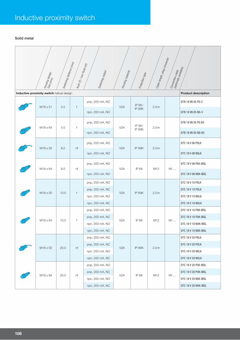
108
Hous
ing
desi
gnSi
ze (m
m)
Switc
hing
dis
tanc
e (m
m)
flush
(f) /
non
-flus
h (n
f)
Switc
hing
out
put
Hous
ing
mat
eria
l
Prot
ectio
n ty
pe
Cabl
e le
ngth
, plu
g co
nnec
tor
Conn
ectio
n ca
ble
(opt
iona
lly a
vaila
ble)
Inductive proximity switch helical design Product description
M18 x 51 5.0 f
pnp, 200 mA, NO
V2A IP 68 / IP 69K 2.0 m
D7B 18 VB 05 PS-3
npn, 200 mA, NO D7B 18 VB 05 NS-3
M18 x 64 5.0 f
pnp, 200 mA, NO
V2A IP 68 / IP 69K 2.0 m
D7B 18 VB 05 PS-B3
npn, 200 mA, NO D7B 18 VB 05 NS-B3
M18 x 50 8.0 nf
pnp, 200 mA, NO
V2A IP 69K 2.0 m
D7C 18 V 08 PSLK
npn, 200 mA, NO D7C 18 V 08 NSLK
M18 x 64 8.0 nf
pnp, 200 mA, NO
V2A IP 68 M12 VK …
D7C 18 V 08 PSK-IBSL
npn, 200 mA, NO D7C 18 V 08 NSK-IBSL
M18 x 50 10.0 f
pnp, 200 mA, NO
V2A IP 69K 2.0 m
D7C 18 V 10 PSLK
pnp, 200 mA, NC D7C 18 V 10 POLK
npn, 200 mA, NO D7C 18 V 10 NSLK
npn, 200 mA, NC D7C 18 V 10 NOLK
M18 x 64 10.0 f
pnp, 200 mA, NO
V2A IP 68 M12 VK …
D7C 18 V 10 PSK-IBSL
pnp, 200 mA, NC D7C 18 V 10 POK-IBSL
npn, 200 mA, NO D7C 18 V 10 NOK-IBSL
npn, 200 mA, NC D7C 18 V 10 NSK-IBSL
M18 x 50 20.0 nf
pnp, 200 mA, NO
V2A IP 69K 2.0 m
D7C 18 V 20 PSLK
pnp, 200 mA, NC D7C 18 V 20 POLK
npn, 200 mA, NO D7C 18 V 20 NSLK
npn, 200 mA, NC D7C 18 V 20 NOLK
M18 x 64 20.0 nf
pnp, 200 mA, NO
V2A IP 68 M12 VK …
D7C 18 V 20 PSK-IBSL
pnp, 200 mA, NC D7C 18 V 20 POK-IBSL
npn, 200 mA, NO D7C 18 V 20 NSK-IBSL
npn, 200 mA, NC D7C 18 V 20 NOK-IBSL
Solid metal
Inductive proximity switch

For more information and models visit www.di-soric.com 109
Solid metal
Hous
ing
desi
gnSi
ze (m
m)
Switc
hing
dis
tanc
e (m
m)
flush
(f) /
non
-flus
h (n
f)
Switc
hing
out
put
Hous
ing
mat
eria
l
Prot
ectio
n ty
pe
Cabl
e le
ngth
, plu
g co
nnec
tor
Conn
ectio
n ca
ble
(opt
iona
lly a
vaila
ble)
Inductive proximity switch helical design Product description
M30 x 50 10.0 f
pnp, 200 mA, NO
V2A IP 68 / IP 69K 2.0 m
D7B 30 VB 10 PS-3
pnp, 200 mA, NC D7B 30 VB 10 NS-3
M30 x 65 10.0 f
pnp, 200 mA, NO
V2A IP 68 / IP 69K M12 VK …
D7B 30 VB 10 PS-B3
pnp, 200 mA, NC D7B 30 VB 10 NS-B3
M30 x 50 20.0 f
pnp, 200 mA, NO
V2A IP 69K 2.0 m
D7C 30 V 20 PSLK
pnp, 200 mA, NC D7C 30 V 20 POLK
M30 x 64 20.0 f
pnp, 200 mA, NO
V2A IP 68 M12 VK …
D7C 30 V 20 PSK-IBSL
pnp, 200 mA, NC D7C 30 V 20 POK-IBSL
npn, 200 mA, NO D7C 30 V 20 NSK-IBSL
npn, 200 mA, NC D7C 30 V 20 NOK-IBSL
M30 x 50 40.0 nf
pnp, 200 mA, NO
V2A IP 69K 2.0 m
D7C 30 V 40 PSLK
pnp, 200 mA, NC D7C 30 V 40 POLK
npn, 200 mA, NO D7C 30 V 40 NSLK
npn, 200 mA, NC D7C 30 V 40 NOLK
M30 x 64 40.0 nf
pnp, 200 mA, NO
V2A IP 68 M12 VK …
D7C 30 V 40 PSK-IBSL
pnp, 200 mA, NC D7C 30 V 40 POK-IBSL
npn, 200 mA, NO D7C 30 V 40 NSK-IBSL
npn, 200 mA, NC D7C 30 V 40 NOK-IBSL
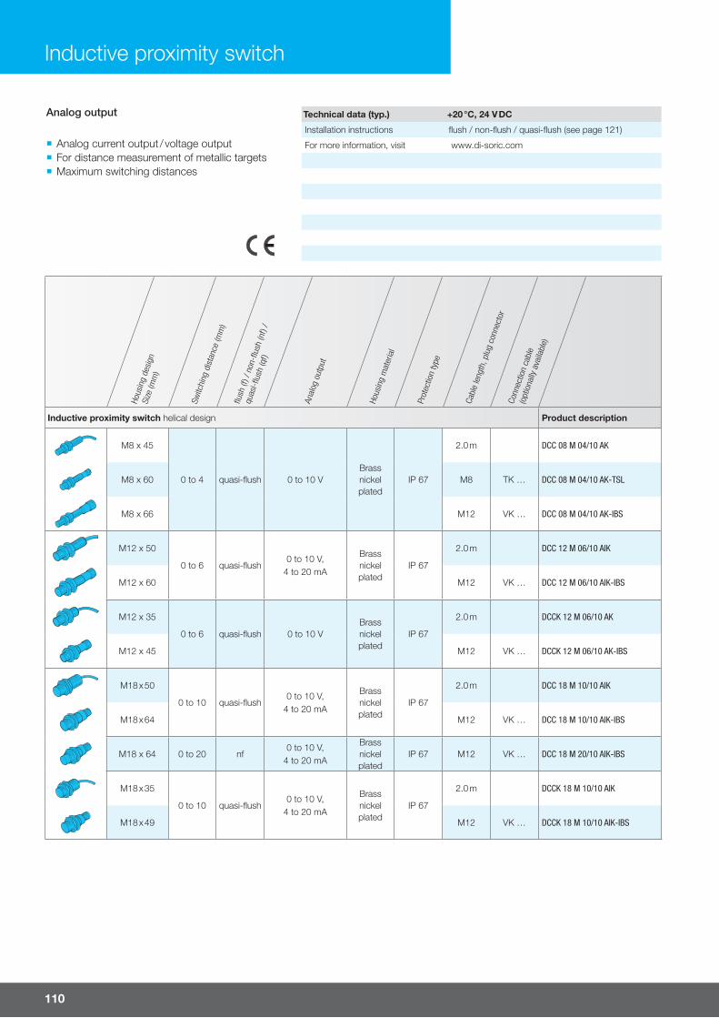
110
Hous
ing
desi
gnSi
ze (m
m)
Switc
hing
dis
tanc
e (m
m)
flush
(f) /
non
-flus
h (n
f) /
quas
i-flus
h (q
f)
Anal
og o
utpu
t
Hous
ing
mat
eria
l
Prot
ectio
n ty
pe
Cabl
e le
ngth
, plu
g co
nnec
tor
Conn
ectio
n ca
ble
(opt
iona
lly a
vaila
ble)
Inductive proximity switch helical design Product description
M8 x 45
0 to 4 quasi-flush 0 to 10 VBrassnickelplated
IP 67
2.0 m DCC 08 M 04/10 AK
M8 x 60 M8 TK … DCC 08 M 04/10 AK-TSL
M8 x 66 M12 VK … DCC 08 M 04/10 AK-IBS
M12 x 50
0 to 6 quasi-flush0 to 10 V,
4 to 20 mA
Brassnickelplated
IP 67
2.0 m DCC 12 M 06/10 AIK
M12 x 60 M12 VK … DCC 12 M 06/10 AIK-IBS
M12 x 35
0 to 6 quasi-flush 0 to 10 VBrassnickelplated
IP 67
2.0 m DCCK 12 M 06/10 AK
M12 x 45 M12 VK … DCCK 12 M 06/10 AK-IBS
M18 x 50
0 to 10 quasi-flush0 to 10 V,
4 to 20 mA
Brassnickelplated
IP 67
2.0 m DCC 18 M 10/10 AIK
M18 x 64 M12 VK … DCC 18 M 10/10 AIK-IBS
M18 x 64 0 to 20 nf0 to 10 V,
4 to 20 mA
Brassnickelplated
IP 67 M12 VK … DCC 18 M 20/10 AIK-IBS
M18 x 35
0 to 10 quasi-flush0 to 10 V,
4 to 20 mA
Brassnickelplated
IP 67
2.0 m DCCK 18 M 10/10 AIK
M18 x 49 M12 VK … DCCK 18 M 10/10 AIK-IBS
Inductive proximity switch
Analog output
¡ Analog current output / voltage output ¡ For distance measurement of metallic targets ¡ Maximum switching distances
Technical data (typ.) +20 °C, 24 V DC
Installation instructions flush / non-flush / quasi-flush (see page 121)
For more information, visit www.di-soric.com
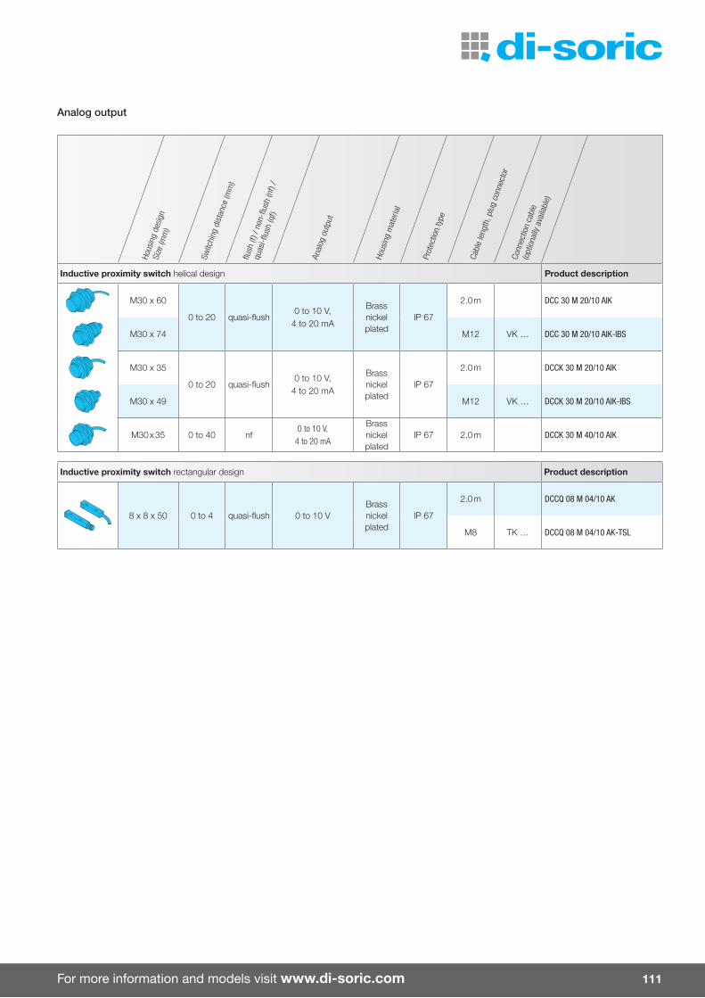
For more information and models visit www.di-soric.com 111
Hous
ing
desi
gnSi
ze (m
m)
Switc
hing
dis
tanc
e (m
m)
flush
(f) /
non
-flus
h (n
f) /
quas
i-flus
h (q
f)
Anal
og o
utpu
t
Hous
ing
mat
eria
l
Prot
ectio
n ty
pe
Cabl
e le
ngth
, plu
g co
nnec
tor
Conn
ectio
n ca
ble
(opt
iona
lly a
vaila
ble)
Inductive proximity switch helical design Product description
M8 x 45
0 to 4 quasi-flush 0 to 10 VBrassnickelplated
IP 67
2.0 m DCC 08 M 04/10 AK
M8 x 60 M8 TK … DCC 08 M 04/10 AK-TSL
M8 x 66 M12 VK … DCC 08 M 04/10 AK-IBS
M12 x 50
0 to 6 quasi-flush0 to 10 V,
4 to 20 mA
Brassnickelplated
IP 67
2.0 m DCC 12 M 06/10 AIK
M12 x 60 M12 VK … DCC 12 M 06/10 AIK-IBS
M12 x 35
0 to 6 quasi-flush 0 to 10 VBrassnickelplated
IP 67
2.0 m DCCK 12 M 06/10 AK
M12 x 45 M12 VK … DCCK 12 M 06/10 AK-IBS
M18 x 50
0 to 10 quasi-flush0 to 10 V,
4 to 20 mA
Brassnickelplated
IP 67
2.0 m DCC 18 M 10/10 AIK
M18 x 64 M12 VK … DCC 18 M 10/10 AIK-IBS
M18 x 64 0 to 20 nf0 to 10 V,
4 to 20 mA
Brassnickelplated
IP 67 M12 VK … DCC 18 M 20/10 AIK-IBS
M18 x 35
0 to 10 quasi-flush0 to 10 V,
4 to 20 mA
Brassnickelplated
IP 67
2.0 m DCCK 18 M 10/10 AIK
M18 x 49 M12 VK … DCCK 18 M 10/10 AIK-IBS
Analog output
Hous
ing
desi
gnSi
ze (m
m)
Switc
hing
dis
tanc
e (m
m)
flush
(f) /
non
-flus
h (n
f) /
quas
i-flus
h (q
f)
Anal
og o
utpu
t
Hous
ing
mat
eria
l
Prot
ectio
n ty
pe
Cabl
e le
ngth
, plu
g co
nnec
tor
Conn
ectio
n ca
ble
(opt
iona
lly a
vaila
ble)
Inductive proximity switch helical design Product description
M30 x 60
0 to 20 quasi-flush0 to 10 V,
4 to 20 mA
Brassnickelplated
IP 67
2.0 m DCC 30 M 20/10 AIK
M30 x 74 M12 VK … DCC 30 M 20/10 AIK-IBS
M30 x 35
0 to 20 quasi-flush0 to 10 V,
4 to 20 mA
Brassnickelplated
IP 67
2.0 m DCCK 30 M 20/10 AIK
M30 x 49 M12 VK … DCCK 30 M 20/10 AIK-IBS
M30 x 35 0 to 40 nf0 to 10 V,
4 to 20 mA
Brassnickelplated
IP 67 2.0 m DCCK 30 M 40/10 AIK
Inductive proximity switch rectangular design Product description
8 x 8 x 50 0 to 4 quasi-flush 0 to 10 VBrassnickelplated
IP 67
2.0 m DCCQ 08 M 04/10 AK
M8 TK … DCCQ 08 M 04/10 AK-TSL

112
Inductive proximity switch
Hou
sing
des
ign
Siz
e (m
m)
Sw
itchi
ng d
ista
nce
(mm
)flu
sh (f
) / n
on-fl
ush
(nf)
Sw
itchi
ng o
utput
Hou
sing
mat
eria
l
Pro
tect
ion
type
Cabl
e le
ngth
, plu
g co
nnec
tor
Con
nect
ion
cable
(optio
nally
ava
ilable
)
Inductive proximity switch helical design Product description
M12 x 70 2.0 fUC, 300 mA, NO Brass
nickelplated
IP 67 2.0 mUCC 12 M 02 SL
UC, 300 mA, NC UCC 12 M 02 OL
M12 x 75 2.0 fUC, 300 mA, NO Brass
nickelplated
IP 67 M12 VK …UCC 12 M 02 S-IBSL
UC, 300 mA, NC UCC 12 M 02 O-IBSL
M12 x 70 4.0 nfUC, 300 mA, NO Brass
nickelplated
IP 67 2.0 mUCC 12 M 04 SL
UC, 300 mA, NC UCC 12 M 04 OL
M12 x 75 4.0 nfUC, 300 mA, NO Brass
nickelplated
IP 67 M12 VK …UCC 12 M 04 S-IBSL
UC, 300 mA, NC UCC 12 M 04 O-IBSL
M18 x 60 5.0 fUC, 300 mA, NO Brass
nickelplated
IP 67 2.0 mUCC 18 M 05 SL
UC, 300 mA, NC UCC 18 M 05 OL
M18 x 80 5.0 fUC, 300 mA, NO Brass
nickelplated
IP 67 M12 VK …UCC 18 M 05 S-IBSL
UC, 300 mA, NC UCC 18 M 05 O-IBSL
M18 x 60 8.0 nfUC, 300 mA, NO Brass
nickelplated
IP 67 2.0 mUCC 18 M 08 SL
UC, 300 mA, NC UCC 18 M 08 OL
M18 x 80 8.0 nfUC, 300 mA, NO Brass
nickelplated
IP 67 M12 VK …UCC 18 M 08 S-IBSL
UC, 300 mA, NC UCC 18 M 08 O-IBSL
M30 x 60 10.0 fUC, 300 mA, NO Brass
nickelplated
IP 67 2.0 mUCC 30 M 10 SL
UC, 300 mA, NC UCC 30 M 10 OL
M30 x 80 10.0 fUC, 300 mA, NO Brass
nickelplated
IP 67 M12 VK …UCC 30 M 10 S-IBSL
UC, 300 mA, NC UCC 30 M 10 O-IBSL
M30 x 60 15.0 nfUC, 300 mA, NO Brass
nickelplated
IP 67 2.0 mUCC 30 M 15 SL
UC, 300 mA, NC UCC 30 M 15 OL
Inductive proximity switch rectangular design Product description
120 x 40 x 40 20.0 fUC, 300 mA,
NO or NCPA 6.6 IP 67 Clamps UCCR 40 K 20 SO-KL
Universal voltage
¡ Service voltage 20 to 250 V AC, 10 to 250 V DC ¡ Protection class IP 67
Technical data (typ.) +20 °C, 24 V DC
Installation instructions flush / non-flush / quasi-flush (see page 121)
For more information, visit www.di-soric.com

For more information and models visit www.di-soric.com 113
Hou
sing
des
ign
Siz
e (m
m)
Sw
itchi
ng d
ista
nce
(mm
)flu
sh (f
) / n
on-fl
ush
(nf)
/
qua
si-fl
ush
(qf)
Tem
per
atur
e ra
nge
(°C
)
Sw
itchi
ng o
utput
Hou
sing
mat
eria
l
Pro
tect
ion
type
Cabl
e le
ngth
, plu
g co
nnec
tor
Inductive proximity switch helical design Product description
M8 x 55 2.0 f 0 to +140pnp, 120 mA, NO
V2ALCP
IP 65 2.0 mDCC 08 VH 02 PSK/140
npn, 120 mA, NO DCC 08 VH 02 NSK/140
M12 x 63 2.0 f -25 to +120 pnp, 200 mA, NOV4A
PlasticIP 65 2.0 m DCE 12 VH 02 PSK
M12 x 56 3.0 f 0 to +150pnp, 120 mA, NO
V2ALCP
IP 65 2.0 mDCC 12 VH 03 PSK/150
npn, 120 mA, NO DCC 12 VH 03 NSK/150
M12 x 63 4.0 nf -25 to +120 pnp, 200 mA, NOV4A
PlasticIP 68 2.0 m DCE 12 VH 04 PSK
M18 x 80 5.0 f -25 to +120 pnp, 200 mA, NOV4A
PlasticIP 65 2.0 m DCE 18 VH 05 PSK
M18 x 67 5.0 f -25 to +120 pnp, 200 mA, NOV4A
PlasticIP 68 2.0 m DCE 18 VH 05 PSLK
M18 x 70 5.0 f 0 to +180 pnp, 200 mA, NOV2ALCP
IP 65 2.0 m DCC 18 VH 05 PSK/180
M18 x 70 5.0 f 0 to +180 pnp, 150 mA, NOV2ALCP
IP 65 2.0 m DCC 18 VH 05 NSK/180
M18 x 70 5.0 f0 to +230 (sensor)
npn, 200 mA, NOV2ALCP
IP 65 2.0 m DCC 18 VH 05 NSK/230/V
M18 x 67 7.0 nf -25 to +120 pnp, 200 mA, NOV4A
PlasticIP 68 2.0 m DCE 18 VH 07 PSLK
M18 x 77 8.0 nf 0 to +180pnp, 150 mA, NO
V2ALCP
IP 65 2.0 mDCC 18 VH 08 PSK/180
npn, 150 mA, NO DCC 18 VH 08 NSK/180
M30 x 85 10.0 f -25 to +160 pnp, 200 mA, NOV4A
PlasticIP 65 2.0 m DCE 30 VH 10 PSK
M30 x 75 10.0 f 0 to +180
pnp, 150 mA, NO
V2ALCP
IP 65 2.0 m
DCC 30 VH 10 PSK/180
pnp, 150 mA, NC DCC 30 VH 10 POK/180
npn, 150 mA, NO DCC 30 VH 10 NSK/180
High-temperature resistant
¡ High-temperature resistant version (sometimes with an external amplifier)
¡ Permanent temperature up to 230 °C
Technical data (typ.) +20 °C, 24 V DC
Installation instructions flush / non-flush / quasi-flush (see page 121)
For more information, visit www.di-soric.com
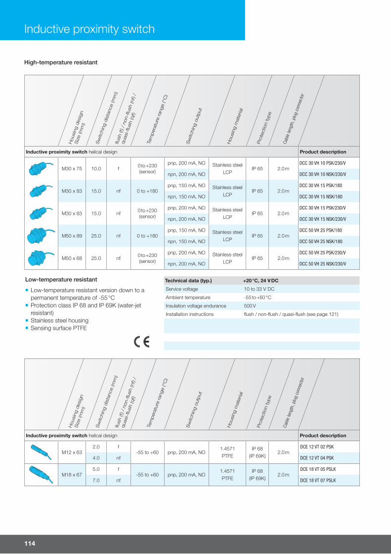
114
Hou
sing
des
ign
Siz
e (m
m)
Sw
itchi
ng d
ista
nce
(mm
)flu
sh (f
) / n
on-fl
ush
(nf)
/
qua
si-fl
ush
(qf)
Tem
per
atur
e ra
nge
(°C
)
Sw
itchi
ng o
utput
Hou
sing
mat
eria
l
Pro
tect
ion
type
Cabl
e le
ngth
, plu
g co
nnec
tor
Inductive proximity switch helical design Product description
M12 x 632.0 f
-55 to +60 pnp, 200 mA, NO1.4571PTFE
IP 68(IP 69K)
2.0 mDCE 12 VT 02 PSK
4.0 nf DCE 12 VT 04 PSK
M18 x 675.0 f
-55 to +60 pnp, 200 mA, NO1.4571PTFE
IP 68(IP 69K)
2.0 mDCE 18 VT 05 PSLK
7.0 nf DCE 18 VT 07 PSLK
High-temperature resistant
Inductive proximity switch
Hou
sing
des
ign
Siz
e (m
m)
Sw
itchi
ng d
ista
nce
(mm
)flu
sh (f
) / n
on-fl
ush
(nf)
/
qua
si-fl
ush
(qf)
Tem
per
atur
e ra
nge
(°C
)
Sw
itchi
ng o
utput
Hou
sing
mat
eria
l
Pro
tect
ion
type
Cabl
e le
ngth
, plu
g co
nnec
tor
Inductive proximity switch helical design Product description
M30 x 75 10.0 f 0 to +230 (sensor)
pnp, 200 mA, NO Stainless steelLCP
IP 65 2.0 mDCC 30 VH 10 PSK/230/V
npn, 200 mA, NO DCC 30 VH 10 NSK/230/V
M30 x 83 15.0 nf 0 to +180pnp, 150 mA, NO Stainless steel
LCPIP 65 2.0 m
DCC 30 VH 15 PSK/180
npn, 150 mA, NO DCC 30 VH 15 NSK/180
M30 x 83 15.0 nf 0 to +230 (sensor)
pnp, 200 mA, NO Stainless steelLCP
IP 65 2.0 mDCC 30 VH 15 PSK/230/V
npn, 200 mA, NO DCC 30 VH 15 NSK/230/V
M50 x 89 25.0 nf 0 to +180pnp, 150 mA, NO Stainless steel
LCPIP 65 2.0 m
DCC 50 VH 25 PSK/180
npn, 150 mA, NO DCC 50 VH 25 NSK/180
M50 x 68 25.0 nf 0 to +230 (sensor)
pnp, 200 mA, NO Stainless steelLCP
IP 65 2.0 mDCC 50 VH 25 PSK/230/V
npn, 200 mA, NO DCC 50 VH 25 NSK/230/V
Low-temperature resistant
¡ Low-temperature resistant version down to a permanent temperature of -55 °C
¡ Protection class IP 68 and IP 69K (water-jet resistant)
¡ Stainless steel housing ¡ Sensing surface PTFE
Technical data (typ.) +20 °C, 24 V DC
Service voltage 10 to 33 V DC
Ambient temperature -55 to +60 °C
Insulation voltage endurance 500 V
Installation instructions flush / non-flush / quasi-flush (see page 121)
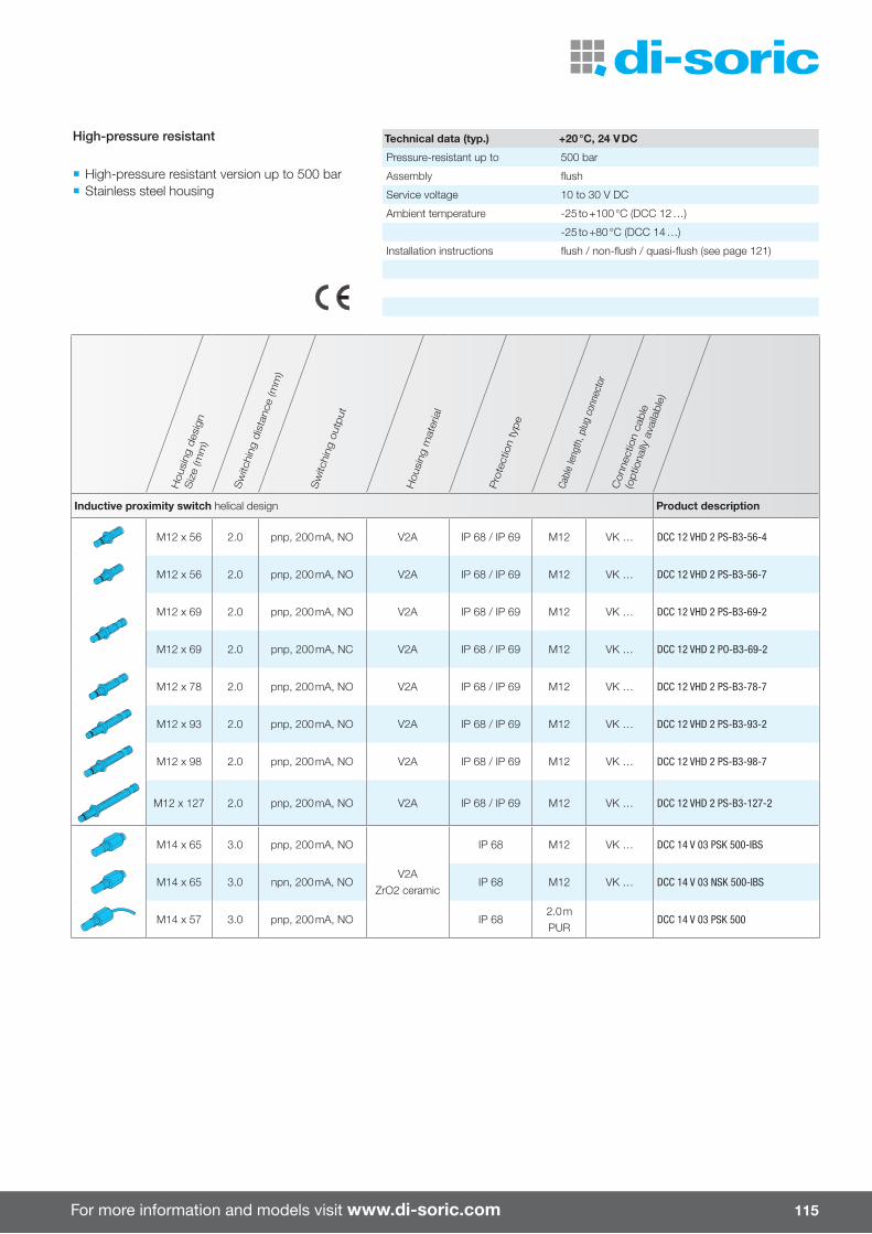
For more information and models visit www.di-soric.com 115
Hou
sing
des
ign
Siz
e (m
m)
Sw
itchi
ng d
ista
nce
(mm
)flu
sh (f
) / n
on-fl
ush
(nf)
/
qua
si-fl
ush
(qf)
Tem
per
atur
e ra
nge
(°C
)
Sw
itchi
ng o
utput
Hou
sing
mat
eria
l
Pro
tect
ion
type
Cabl
e le
ngth
, plu
g co
nnec
tor
Inductive proximity switch helical design Product description
M30 x 75 10.0 f 0 to +230 (sensor)
pnp, 200 mA, NO Stainless steelLCP
IP 65 2.0 mDCC 30 VH 10 PSK/230/V
npn, 200 mA, NO DCC 30 VH 10 NSK/230/V
M30 x 83 15.0 nf 0 to +180pnp, 150 mA, NO Stainless steel
LCPIP 65 2.0 m
DCC 30 VH 15 PSK/180
npn, 150 mA, NO DCC 30 VH 15 NSK/180
M30 x 83 15.0 nf 0 to +230 (sensor)
pnp, 200 mA, NO Stainless steelLCP
IP 65 2.0 mDCC 30 VH 15 PSK/230/V
npn, 200 mA, NO DCC 30 VH 15 NSK/230/V
M50 x 89 25.0 nf 0 to +180pnp, 150 mA, NO Stainless steel
LCPIP 65 2.0 m
DCC 50 VH 25 PSK/180
npn, 150 mA, NO DCC 50 VH 25 NSK/180
M50 x 68 25.0 nf 0 to +230 (sensor)
pnp, 200 mA, NO Stainless steelLCP
IP 65 2.0 mDCC 50 VH 25 PSK/230/V
npn, 200 mA, NO DCC 50 VH 25 NSK/230/V
Inductive proximity switch helical design Product description
M12 x 56 2.0 pnp, 200 mA, NO V2A IP 68 / IP 69 M12 VK … DCC 12 VHD 2 PS-B3-56-4
M12 x 56 2.0 pnp, 200 mA, NO V2A IP 68 / IP 69 M12 VK … DCC 12 VHD 2 PS-B3-56-7
M12 x 69 2.0 pnp, 200 mA, NO V2A IP 68 / IP 69 M12 VK … DCC 12 VHD 2 PS-B3-69-2
M12 x 69 2.0 pnp, 200 mA, NC V2A IP 68 / IP 69 M12 VK … DCC 12 VHD 2 PO-B3-69-2
M12 x 78 2.0 pnp, 200 mA, NO V2A IP 68 / IP 69 M12 VK … DCC 12 VHD 2 PS-B3-78-7
M12 x 93 2.0 pnp, 200 mA, NO V2A IP 68 / IP 69 M12 VK … DCC 12 VHD 2 PS-B3-93-2
M12 x 98 2.0 pnp, 200 mA, NO V2A IP 68 / IP 69 M12 VK … DCC 12 VHD 2 PS-B3-98-7
M12 x 127 2.0 pnp, 200 mA, NO V2A IP 68 / IP 69 M12 VK … DCC 12 VHD 2 PS-B3-127-2
M14 x 65 3.0 pnp, 200 mA, NO
V2AZrO2 ceramic
IP 68 M12 VK … DCC 14 V 03 PSK 500-IBS
M14 x 65 3.0 npn, 200 mA, NO IP 68 M12 VK … DCC 14 V 03 NSK 500-IBS
M14 x 57 3.0 pnp, 200 mA, NO IP 682.0 mPUR
DCC 14 V 03 PSK 500
Hou
sing
des
ign
Siz
e (m
m)
Sw
itchi
ng d
ista
nce
(mm
)
Sw
itchi
ng o
utput
Hou
sing
mat
eria
l
Pro
tect
ion
type
Cabl
e le
ngth
, plu
g co
nnec
tor
Con
nect
ion
cable
(optio
nally
ava
ilable
)
High-pressure resistant
¡ High-pressure resistant version up to 500 bar ¡ Stainless steel housing
Technical data (typ.) +20 °C, 24 V DC
Pressure-resistant up to 500 bar
Assembly flush
Service voltage 10 to 30 V DC
Ambient temperature -25 to +100 °C (DCC 12 …)
-25 to +80 °C (DCC 14 …)
Installation instructions flush / non-flush / quasi-flush (see page 121)
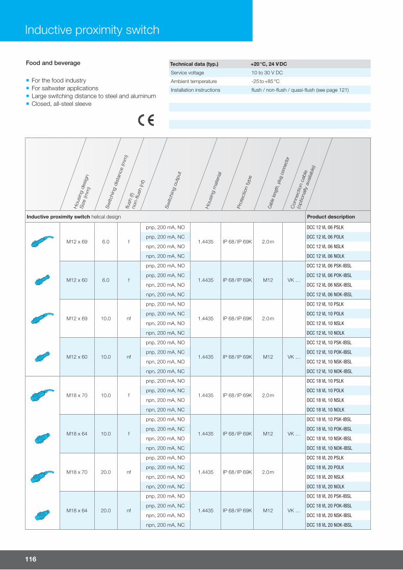
116
Inductive proximity switch
Hou
sing
des
ign
Siz
e (m
m)
Sw
itchi
ng d
ista
nce
(mm
)flu
sh (f
)no
n-flu
sh (n
f)
Sw
itchi
ng o
utput
Hou
sing
mat
eria
l
Pro
tect
ion
type
Cabl
e le
ngth
, plu
g co
nnec
tor
Con
nect
ion
cable
(optio
nally
ava
ilable
)
Inductive proximity switch helical design Product description
M12 x 69 6.0 f
pnp, 200 mA, NO
1.4435 IP 68 / IP 69K 2.0 m
DCC 12 VL 06 PSLK
pnp, 200 mA, NC DCC 12 VL 06 POLK
npn, 200 mA, NO DCC 12 VL 06 NSLK
npn, 200 mA, NC DCC 12 VL 06 NOLK
M12 x 60 6.0 f
pnp, 200 mA, NO
1.4435 IP 68 / IP 69K M12 VK …
DCC 12 VL 06 PSK-IBSL
pnp, 200 mA, NC DCC 12 VL 06 POK-IBSL
npn, 200 mA, NO DCC 12 VL 06 NSK-IBSL
npn, 200 mA, NC DCC 12 VL 06 NOK-IBSL
M12 x 69 10.0 nf
pnp, 200 mA, NO
1.4435 IP 68 / IP 69K 2.0 m
DCC 12 VL 10 PSLK
pnp, 200 mA, NC DCC 12 VL 10 POLK
npn, 200 mA, NO DCC 12 VL 10 NSLK
npn, 200 mA, NC DCC 12 VL 10 NOLK
M12 x 60 10.0 nf
pnp, 200 mA, NO
1.4435 IP 68 / IP 69K M12 VK …
DCC 12 VL 10 PSK-IBSL
pnp, 200 mA, NC DCC 12 VL 10 POK-IBSL
npn, 200 mA, NO DCC 12 VL 10 NSK-IBSL
npn, 200 mA, NC DCC 12 VL 10 NOK-IBSL
M18 x 70 10.0 f
pnp, 200 mA, NO
1.4435 IP 68 / IP 69K 2.0 m
DCC 18 VL 10 PSLK
pnp, 200 mA, NC DCC 18 VL 10 POLK
npn, 200 mA, NO DCC 18 VL 10 NSLK
npn, 200 mA, NC DCC 18 VL 10 NOLK
M18 x 64 10.0 f
pnp, 200 mA, NO
1.4435 IP 68 / IP 69K M12 VK …
DCC 18 VL 10 PSK-IBSL
pnp, 200 mA, NC DCC 18 VL 10 POK-IBSL
npn, 200 mA, NO DCC 18 VL 10 NSK-IBSL
npn, 200 mA, NC DCC 18 VL 10 NOK-IBSL
M18 x 70 20.0 nf
pnp, 200 mA, NO
1.4435 IP 68 / IP 69K 2.0 m
DCC 18 VL 20 PSLK
pnp, 200 mA, NC DCC 18 VL 20 POLK
npn, 200 mA, NO DCC 18 VL 20 NSLK
npn, 200 mA, NC DCC 18 VL 20 NOLK
M18 x 64 20.0 nf
pnp, 200 mA, NO
1.4435 IP 68 / IP 69K M12 VK …
DCC 18 VL 20 PSK-IBSL
pnp, 200 mA, NC DCC 18 VL 20 POK-IBSL
npn, 200 mA, NO DCC 18 VL 20 NSK-IBSL
npn, 200 mA, NC DCC 18 VL 20 NOK-IBSL
Food and beverage
¡ For the food industry ¡ For saltwater applications ¡ Large switching distance to steel and aluminum ¡ Closed, all-steel sleeve
Technical data (typ.) +20 °C, 24 V DC
Service voltage 10 to 30 V DC
Ambient temperature -25 to +85 °C
Installation instructions flush / non-flush / quasi-flush (see page 121)
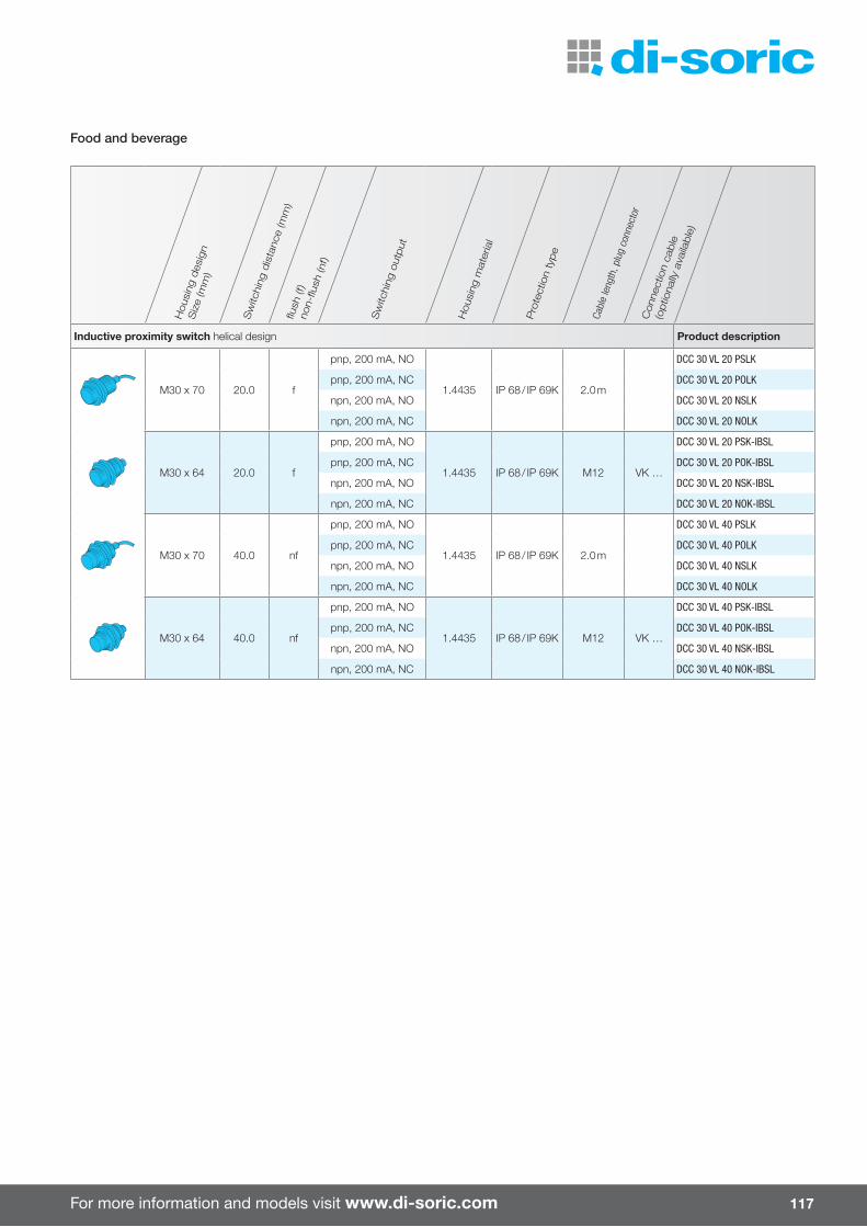
For more information and models visit www.di-soric.com 117
Hou
sing
des
ign
Siz
e (m
m)
Sw
itchi
ng d
ista
nce
(mm
)flu
sh (f
)no
n-flu
sh (n
f)
Sw
itchi
ng o
utput
Hou
sing
mat
eria
l
Pro
tect
ion
type
Cabl
e le
ngth
, plu
g co
nnec
tor
Con
nect
ion
cable
(optio
nally
ava
ilable
)
Inductive proximity switch helical design Product description
M30 x 70 20.0 f
pnp, 200 mA, NO
1.4435 IP 68 / IP 69K 2.0 m
DCC 30 VL 20 PSLK
pnp, 200 mA, NC DCC 30 VL 20 POLK
npn, 200 mA, NO DCC 30 VL 20 NSLK
npn, 200 mA, NC DCC 30 VL 20 NOLK
M30 x 64 20.0 f
pnp, 200 mA, NO
1.4435 IP 68 / IP 69K M12 VK …
DCC 30 VL 20 PSK-IBSL
pnp, 200 mA, NC DCC 30 VL 20 POK-IBSL
npn, 200 mA, NO DCC 30 VL 20 NSK-IBSL
npn, 200 mA, NC DCC 30 VL 20 NOK-IBSL
M30 x 70 40.0 nf
pnp, 200 mA, NO
1.4435 IP 68 / IP 69K 2.0 m
DCC 30 VL 40 PSLK
pnp, 200 mA, NC DCC 30 VL 40 POLK
npn, 200 mA, NO DCC 30 VL 40 NSLK
npn, 200 mA, NC DCC 30 VL 40 NOLK
M30 x 64 40.0 nf
pnp, 200 mA, NO
1.4435 IP 68 / IP 69K M12 VK …
DCC 30 VL 40 PSK-IBSL
pnp, 200 mA, NC DCC 30 VL 40 POK-IBSL
npn, 200 mA, NO DCC 30 VL 40 NSK-IBSL
npn, 200 mA, NC DCC 30 VL 40 NOK-IBSL
Food and beverage

118
Capacitive proximity switch
Capacitive proximity switches detect both metallic and non-metallic materials. A wide variety of di� erent shapes and designs provides versatile options for use.
¡ Detection of: liquid, powdered, solid, electrically con-ductive and non-conductive materials
¡ Potentiometer and teach variants ¡ Switching distances can be set up to 30 mm
¡ Designs Ø 6.5 mm up to M 30 ¡ Panel design Ø 50 x 10 mm
Capacitive proximity switches

For more information and models visit www.di-soric.com 119
Hous
ing
desi
gnSi
ze (m
m)
Switc
hing
dis
tanc
e (m
m)
flush
(f) /
non
-flus
h (n
f)
Switc
hing
out
put
Serv
ice
volta
ge
Ambi
ent t
empe
ratu
re
Prot
ectio
n ty
pe
Hous
ing
mat
eria
l
Cabl
e m
ater
ial/l
engt
h,
Plug
con
nect
or
Conn
ectio
n ca
ble
(opt
iona
lly a
vaila
ble)
Capacitive proximity switch cylindrical design Product description
Ø 6.5 x 522.0
(0.1 to 3.0)f
Push-pull,100 mA, NO/NC
18 to 30 -25 to +70 IP 67 V2A
2m KNS D6.5M 02B G3-2R
Ø 6.5 x 60 M8 TK … KNS D6.5M 02B G3-T3
Ø 6.5 x 523.0
(0.1 to 4.0)nf
Push-pull,100 mA, NO/NC
18 to 30 -25 to +70 IP 67 V2A
2m KNS D6.5M 03N G3-2R
Ø 6.5 x 60 M8 TK … KNS D6.5M 03N G3-T3
Ø 6.5 x 552.0
(0.1 to 3.0)f
Push-pull,150 mA, NO/NC
18 to 30 -25 to +70 IP 65 V2A 2 m / PURTK … KDCT 6.5 V 02 G3-3
TK … /4 KDCT 6.5 V 02 G3-4
Ø 6.5 x 602.0
(0.1 to 3.0)f
Push-pull,150 mA, NO/NC
18 to 30 -25 to +70 IP 65 V2A M8TK … KDCT 6.5 V 02 G3-T3
TK … /4 KDCT 6.5 V 02 G3-T4
Capacitive proximity switch helical design
M8 x 522.0
(0.1 to 3.0)f
Push-pull,100 mA, NO/NC
18 to 30 -25 to +70 IP 67 V2A
2m KNS M8M 02B G3-2R
M8 x 60 M8 TK … KNS M8M 02B G3-T3
M8 x 523.0
(0.1 to 4.0)nf
Push-pull,100 mA, NO/NC
18 to 30 -25 to +70 IP 67 V2A
2m KNS M8M 03N G3-2R
M8 x 60 M8 TK … KNS M8M 03N G3-T3
M8 x 522.0
(0.1 to 3.0)f
Push-pull,150 mA, NO/NC
18 to 30 -25 to +70 IP 65 V2A 2 m / PUR3-core KDCT 08 V 02 G3-3
4-core KDCT 08 V 02 G3-4
M8 x 602.0
(0.1 to 3.0)f
Push-pull,150 mA, NO/NC
18 to 30 -25 to +70 IP 65 V2A M8TK … KDCT 08 V 02 G3-T3
TK … /4 KDCT 08 V 02 G3-T4
M8 x 603.0
(0.1 to 4.0)nf
Push-pull,150 mA, NO/NC
18 to 30 -25 to +70 IP 65 V2A M8TK … KDCT 08 V 03 G3-T3
TK … /4 KDCT 08 V 03 G3-T4

120
Hous
ing
desi
gnSi
ze (m
m)
Switc
hing
dis
tanc
e (m
m)
flush
(f) /
non
-flus
h (n
f)
Switc
hing
out
put
Serv
ice
volta
ge
Ambi
ent t
empe
ratu
re
Prot
ectio
n ty
pe
Hous
ing
mat
eria
l
Cabl
e m
ater
ial/l
engt
h,
Plug
con
nect
or
Conn
ectio
n ca
ble
(opt
iona
lly a
vaila
ble)
Capacitive proximity switch helical design Product description
M12 x 55 4.0(0.1 to 8.0)
fPush-pull,
100 mA, NO/NC18 to 30 -20 to +70
IP 65IP 67 VA 2 m KNS M12M 04B G3-2R
M12 x 60 IP 67 VA M12 VK … KNS M12M 04B G3-B3
M12 x 55 4.0(0.1 to 6.0)
fPush-pull,
150 mA, NO/NC18 to 30 -25 to +70 IP 65 V2A
2 m, PUR KDCT 12 V 04 G3-4
M12 x 60 M12 VK … KDCT 12 V 04 G3-B4
M18 x 66 8.0 fpnp, 200 mA, NC
10 to 35 -30 to +70 IP 67 VA 2 m, PVCKDC 18 M 08 NSLK
npn, 200 mA, NO KDC 18 M 08 NOLK
M18 x 75 8.0 f
pnp, 200 mA, NO
10 to 35 -30 to +70 IP 67 VA M12 VK …
KDC 18 M 08 PSK-IBSL
pnp, 200 mA, NC KDC 18 M 08 POK-IBSL
npn, 200 mA, NO KDC 18 M 08 NSK-IBSL
npn, 200 mA, NC KDC 18 M 08 NOK-IBSL
M18 x 76 8.0 f pnp, 100 mA, NO 10 to 30 -25 to +85 IP 672 m,PUR
KDC 18 MB 08 PSL
M30 x 67 15 f pnp, 100 mA, NO 10 to 30 -25 to +85 IP 67 VA2 m,PUR
– KDC 30 M 15 PSLK
M30 x 67 20 fpnp,
300 mA, NO/NC10 to 35 -30 to +70 IP 67 VA
2 m,PUR
KDC 30 M 20 NSOLK
M30 x 67 20 f
pnp,300 mA, NO/NC
10 to 35 -30 to +70 IP 67 VA M12 VK …
KDC 30 M 20 PSOK-BSL
npn,300 mA, NO/NC
KDC 30 M 20 NSOK-BSL
Capacitive proximity switch flat design Product description
Ø 50 x 1025
(adjustable)f
pnp/npn,150 mA, NO/NC
10 to 30 -30 to +70 IP 67 Plastic2 m,PUR
KDC 50 K 25 PNSOLK
Ø 50 x 1025 (adjustable), self-compen-
satingnf
pnp,300 mA, NO/NC
10 to 35 -10 to +60 IP 67 Plastic2 m,PVC
KDC 50 K 25S PSOLK
Ø 50 x 1025
(adjustable)nf
npn,300 mA, NO/NC
10 to 35 -10 to +60 IP 67 Plastic2 m,PVC
KDC 50 K 25S NSOLK
Ø 50 x 10 2.0 to 25 fpnp/npn,
150 mA, NO/NC10 to 30 -30 to +70 IP 67 Plastic M8 TK … KDC 50 K 25 PNSOK-TSL
Capacitive proximity switch
Capacitive proximity switches

For more information and models visit www.di-soric.com 121
Installation instructions for inductive and capacitive proximity switches
Flush installation (f)
d
≥ 3sn
These proximity switches can be installed in all materials (metals / non-met-als) such that the active sensor surface lines up flush with the surrounding material on the front side.
They have the following advantages: Flush installation in conductive materials (metals) Protection of the sensing surface prior to mechanical damage Less influence from external interference fields Less distance to the next proximity switch on the side
Non-flush installation (nf)
d
≥ 3d
≥ 2sn
≥ 3sn
These proximity switches are allowed to be installed non-flush in conductive materials.
They have the greatest possible switching distance.
Special installation instructions apply to these proximity switches. Flush installation in nonconductive materials is permitted.
Quasi-flush installation (qf)
d≥ 2d
X
≥ 3sn
These proximity switches have a greater switching distance than proximity switches for flush installation. However, they are allowed to be installed in conductive materials only quasi-flush, i.e. not entirely flush. The proximity switches must protrude from the installation surface by dimension X (see the Installation instructions).
Flush installation in nonconductive materials is permitted.
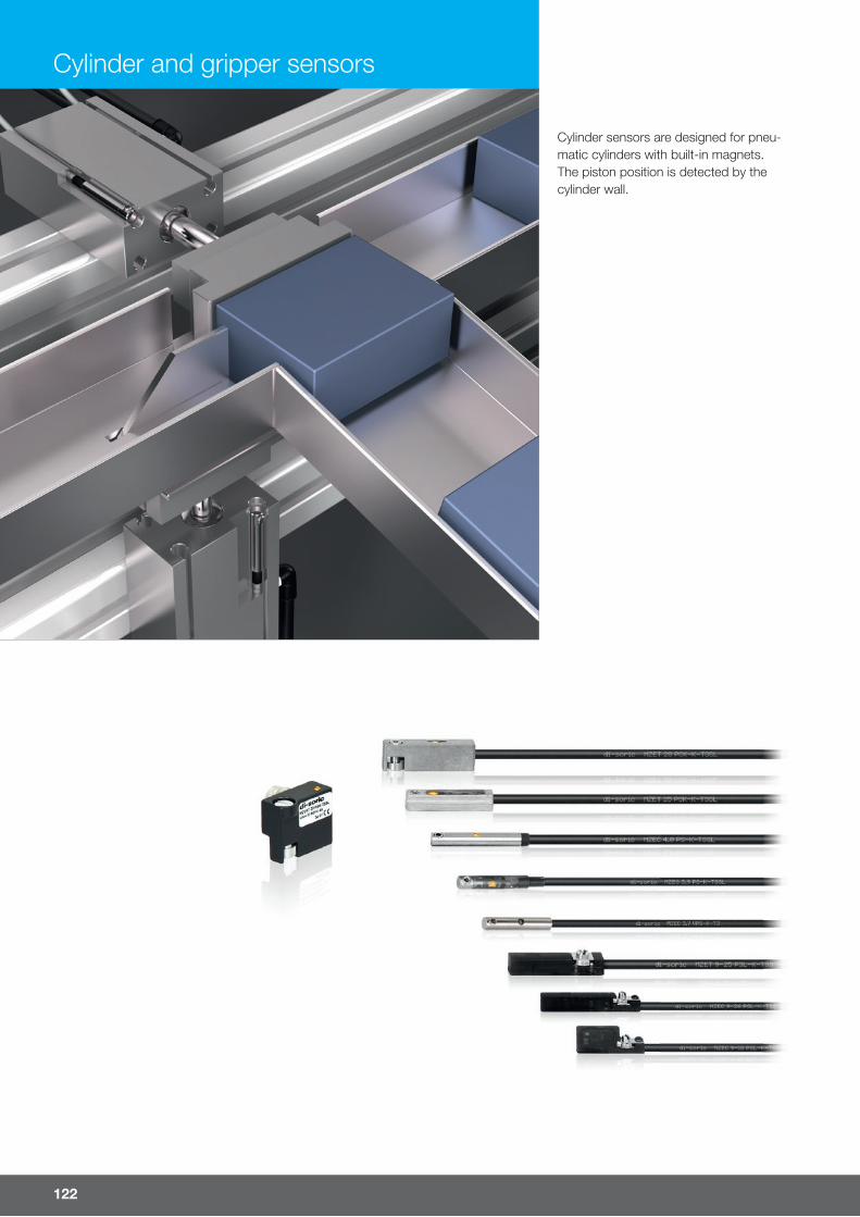
122
Cylinder and gripper sensors
Cylinder sensors are designed for pneu-matic cylinders with built-in magnets. The piston position is detected by the cylinder wall.
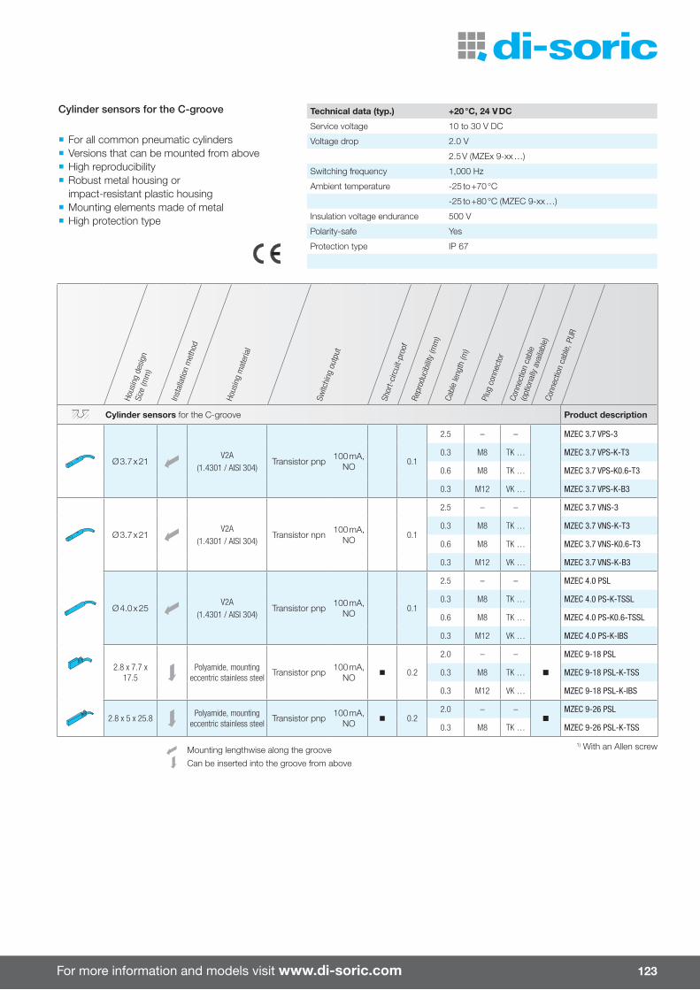
For more information and models visit www.di-soric.com 123
Hous
ing
desi
gnSi
ze (m
m)
Inst
alla
tion
met
hod
Hous
ing
mat
eria
l
Switc
hing
out
put
Shor
t-ci
rcui
t-pr
oof
Repr
oduc
ibilit
y (m
m)
Cabl
e le
ngth
(m)
Plug
con
nect
orCo
nnec
tion
cabl
e(o
ptio
nally
ava
ilabl
e)Co
nnec
tion
cabl
e, P
UR
Cylinder sensors for the C-groove Product description
Ø 3.7 x 21V2A
(1.4301 / AISI 304)Transistor pnp 100 mA,
NO 0.1
2.5 – – MZEC 3.7 VPS-3
0.3 M8 TK … MZEC 3.7 VPS-K-T3
0.6 M8 TK … MZEC 3.7 VPS-K0.6-T3
0.3 M12 VK … MZEC 3.7 VPS-K-B3
Ø 3.7 x 21V2A
(1.4301 / AISI 304)Transistor npn 100 mA,
NO 0.1
2.5 – – MZEC 3.7 VNS-3
0.3 M8 TK … MZEC 3.7 VNS-K-T3
0.6 M8 TK … MZEC 3.7 VNS-K0.6-T3
0.3 M12 VK … MZEC 3.7 VNS-K-B3
Ø 4.0 x 25V2A
(1.4301 / AISI 304)Transistor pnp 100 mA,
NO 0.1
2.5 – – MZEC 4.0 PSL
0.3 M8 TK … MZEC 4.0 PS-K-TSSL
0.6 M8 TK … MZEC 4.0 PS-K0.6-TSSL
0.3 M12 VK … MZEC 4.0 PS-K-IBS
2.8 x 7.7 x 17.5
Polyamide, mounting eccentric stainless steel
Transistor pnp 100 mA, NO
n 0.2
2.0 – –
n
MZEC 9-18 PSL
0.3 M8 TK … MZEC 9-18 PSL-K-TSS
0.3 M12 VK … MZEC 9-18 PSL-K-IBS
2.8 x 5 x 25.8Polyamide, mounting
eccentric stainless steelTransistor pnp 100 mA,
NOn 0.2
2.0 – –n
MZEC 9-26 PSL
0.3 M8 TK … MZEC 9-26 PSL-K-TSS
Mounting lengthwise along the groove1) With an Allen screw
Can be inserted into the groove from above
Cylinder sensors for the C-groove
¡ For all common pneumatic cylinders ¡ Versions that can be mounted from above ¡ High reproducibility ¡ Robust metal housing or impact-resistant plastic housing
¡ Mounting elements made of metal ¡ High protection type
Technical data (typ.) +20 °C, 24 V DC
Service voltage 10 to 30 V DC
Voltage drop 2.0 V
2.5 V (MZEx 9-xx …)
Switching frequency 1,000 Hz
Ambient temperature -25 to +70 °C
-25 to +80 °C (MZEC 9-xx …)
Insulation voltage endurance 500 V
Polarity-safe Yes
Protection type IP 67
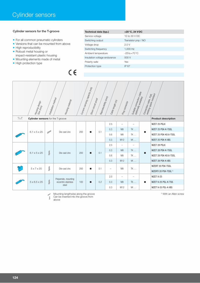
124
Cylinder sensors
Hous
ing
desi
gnSi
ze (m
m)
Inst
alla
tion
met
hod
Hous
ing
mat
eria
l
Curre
nt-c
arry
ing
capa
city
(mA)
Shor
t-ci
rcui
t-pr
oof
Repr
oduc
ibilit
y (m
m)
Cabl
e le
ngth
(m)
Plug
con
nect
or
Suita
ble
conn
ectio
n ca
ble
(opt
iona
lly a
vaila
ble)
Conn
ectio
n ca
ble,
PUR
,
wel
ding
-spa
rk-r
esis
tant
Cylinder sensors for the T-groove Product description
6.1 x 5 x 25 Die-cast zinc 200 n 0.1
2.5 – –
n
MZET 25 PSLK
0.3 M8 TK … MZET 25 PSK-K-TSSL
0.6 M8 TK … MZET 25 PSK-K0.6-TSSL
0.3 M12 VK … MZET 25 PSK-K-IBS
6.1 x 5 x 25 Die-cast zinc 200 n 0.1
2.5 – –
n
MZET 28 PSLK
0.3 M8 TK … MZET 28 PSK-K-TSSL
0.6 M8 TK … MZET 28 PSK-K0.6-TSSL
0.3 M12 VK … MZET 28 PSK-K-IBS
5 x 7 x 20 Die-cast zinc 200 n 0.1 – M8 TK …MZERT 20 PSK-TSSL
MZERTI 20 PSK-TSSL 1)
5 x 6.5 x 25Polyamide, mounting eccentric stainless
steel100 n 0.2
2.0 – –
n
MZET 9-25
0.3 M8 TK … MZET 9-25 PSL-K-TSS
0.3 M12 VK … MZET 9-25 PSL-K-IBS
Mounting lengthwise along the groove 1) With an Allen screwCan be inserted into the groove from above
Cylinder sensors for the T-groove
¡ For all common pneumatic cylinders ¡ Versions that can be mounted from above ¡ High reproducibility ¡ Robust metal housing or impact-resistant plastic housing
¡ Mounting elements made of metal ¡ High protection type
Technical data (typ.) +20 °C, 24 V DC
Service voltage 10 to 30 V DC
Switching output Transistor pnp / NO
Voltage drop 2.0 V
Switching frequency 1,000 Hz
Ambient temperature -25 to +70 °C
Insulation voltage endurance 500 V
Polarity-safe Yes
Protection type IP 67
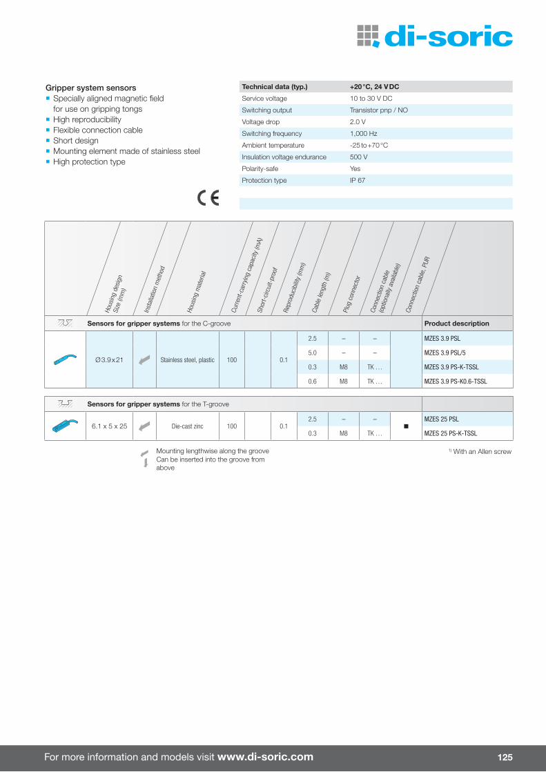
For more information and models visit www.di-soric.com 125
Hous
ing
desi
gnSi
ze (m
m)
Inst
alla
tion
met
hod
Hous
ing
mat
eria
l
Curre
nt-c
arry
ing
capa
city
(mA)
Shor
t-ci
rcui
t-pr
oof
Repr
oduc
ibilit
y (m
m)
Cabl
e le
ngth
(m)
Plug
con
nect
or
Conn
ectio
n ca
ble
(opt
iona
lly a
vaila
ble)
Conn
ectio
n ca
ble,
PUR
Sensors for gripper systems for the C-groove Product description
Ø 3.9 x 21 Stainless steel, plastic 100 0.1
2.5 – – MZES 3.9 PSL
5.0 – – MZES 3.9 PSL/5
0.3 M8 TK … MZES 3.9 PS-K-TSSL
0.6 M8 TK … MZES 3.9 PS-K0.6-TSSL
Sensors for gripper systems for the T-groove
6.1 x 5 x 25 Die-cast zinc 100 0.12.5 – –
nMZES 25 PSL
0.3 M8 TK … MZES 25 PS-K-TSSL
Mounting lengthwise along the groove 1) With an Allen screwCan be inserted into the groove from above
Gripper system sensors ¡ Specially aligned magnetic field for use on gripping tongs
¡ High reproducibility ¡ Flexible connection cable ¡ Short design ¡ Mounting element made of stainless steel ¡ High protection type
Technical data (typ.) +20 °C, 24 V DC
Service voltage 10 to 30 V DC
Switching output Transistor pnp / NO
Voltage drop 2.0 V
Switching frequency 1,000 Hz
Ambient temperature -25 to +70 °C
Insulation voltage endurance 500 V
Polarity-safe Yes
Protection type IP 67
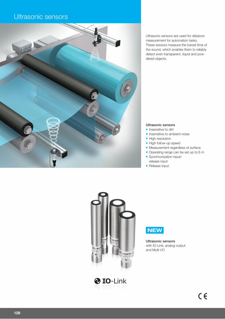
NEW
Ultrasonic sensorswith IO-Link, analog outputand Multi I/O
126
Ultrasonic sensors are used for distance measurement for automation tasks. These sensors measure the transit time of the sound, which enables them to reliably detect even transparent, liquid and pow-dered objects.
Ultrasonic sensors
Ultrasonic sensors ¡ Insensitive to dirt ¡ Insensitive to ambient noise ¡ High resolution ¡ High follow-up speed ¡ Measurement regardless of surface ¡ Operating range can be set up to 6 m ¡ Synchronization input/release input
¡ Release input

For more information and models visit www.di-soric.com
M8
127

128
Ultrasonic sensors
Ultrasonic sensors with IO-Link ¡ Greatly simplifi ed teach process ¡ Can be confi gured with IO-Link as a sensor or retrorefl ective sensor
¡ Additional switching output thanks to MI/O
¡ Variants with switching output and analog output
NEW
IO-LINK IN A NUTSHELL.
IO-Link provides a point-to-point connection within any network, fi eldbus or backplane bus. The IO-Link master can be installed either directly in the fi eld or in the control cabinet.
Any sensor, actuator or even a combination of the two can be an IO-Link device. This device is connected to the IO-Link master by a standard connection cable up to 20 m long. The IO-Link device communicates with the IO-Link master using a driver fi le (the IODD – IO-Link Device Description) and can send and receive signals (binary switch signals or analog signals). IO-Link digitizes these signals directly so that they can be transferred virtually free of interference.
The international IO-Link standard (in accordance with IEC 61131-9) is now regarded as an "enabler for Industry 4.0"
1
2 3
4PIN SIGNAL REMARKS1 L+ 24 V2 OUT Sensor dependent3 L- Ground4 C/Q Communication /
Switching signal
IO-LINK
SIO
C/Q
L-
L+

For more information and models visit www.di-soric.com 129
Oper
atin
g ra
nge
(mm
)
Hous
ing
desi
gnSi
ze (m
m)
Soun
d ou
tlet
Switc
hing
out
put
Anal
og o
utpu
t
Repe
atab
ility
Ambi
ent t
empe
ratu
re (°
C)
Plug
con
nect
or
Conn
ectio
n ca
ble
(opt
iona
lly a
vaila
ble)
Ultrasonic distance sensors with IO-Link (switching output) Product description
20 to 100 M8 x 70 AxialPush-pull, 150 mA
NO/NC– 0.3 mm 0 to 50 M8 TK … /4 US 08 M 100 G3-B4
20 to 200 M12 x 65 AxialPush-pull, 150 mA
NO/NC– 0.5 mm -25 to 70 M12 VK … /4 US 12 M 200 G3-B4
40 to 400 M12 x 65 AxialPush-pull, 150 mA
NO/NC– 0.5 mm -10 to 70 M12 VK … /4 US 12 M 400 G3-B4
80 to 800 M18 x 55.5 AxialPush-pull, 150 mA
NO/NC– ± 0.15 % -25 to 70 M12 VK … /4 US 18 M 800 G3-B4
120 to 1,500 M18 x 55.5 AxialPush-pull, 150 mA
NO/NC– ± 0.15 % -25 to 70 M12 VK … /4 US 18 M 1500 G3-B4
300 to 3,000 M30 x 60 AxialPush-pull, 100 mA
NO/NC– 2.0 mm -25 to 70 M12 VK … /4 US 30 M 3000 G3-B4
600 to 6,000 M30 x 78 AxialPush-pull, 100 mA
NO/NC– 4.0 mm -25 to 70 M12 VK … /4 US 30 M 6000 G3-B4
Ultrasonic distance sensors with IO-Link, analog output and MI/O
20 to 200 M12 x 75 Axial –0 to 10 V
4.0 to 20 mA-25 to 70 M12 VK … /4 US 12 M 200 IU-B4
40 to 400 M12 x 75 AxialPush-pull, 150 mA
NO/NC0 to 10 V
4 to 20 mA-10 to 70 M12 VK … /4 US 12 M 400 IU-B4
80 to 800 M18 x 65 Axial Push-pull, 150 mA0 to 10 V
4 to 20 mA-25 to 70 M12 VK … /4 US 18 M 800 IU-B4
150 to 1,500 M18 x 65 AxialPush-pull, 150 mA
NO/NC0 to 10 V
4 to 20 mA-25 to 70 M12 VK … /4 US 18 M 1500 IU-B4
300 to 3,000 M30 x 60 AxialPush-pull, 100 mA
NO/NC0 to 10 V
4 to 20 mA-25 to 70 M12 VK … /4 US 30 M 3000 IU-B4
600 to 6,000 M30 x 78 AxialPush-pull, 100 mA
NO/NC0 to 10 V
4 to 20 mA-25 to 70 M12 VK … /4 US 30 M 6000 IU-B4
Ultrasonic distance sensors with IO-Link / MI/O
This new generation of ultrasonic sensors has IO-Link with considerably improved performance data. These ultrasonic sensors can be ideally adapted to the application by configuring IO-Link and can monitor the process stability by means of IO-Link diagnostics.
Technical data (typ.) +20 °C, 24 V DC
Service voltage 18 to 30 V DC
Protection type IP 67
Housing material Brass, nickel-plated

130
Oper
atin
g ra
nge
(mm
)
fork
wid
th /
mea
surin
g ra
nge
(mm
)Ho
usin
g de
sign
Size
(mm
)
Soun
d ou
tlet
Switc
hing
out
put
Anal
og o
utpu
t
Repe
atab
ility
Ambi
ent t
empe
ratu
re (°
C)
Hous
ing
mat
eria
l
Plug
con
nect
orCo
nnec
tion
cabl
e(o
ptio
nally
ava
ilabl
e)
Ultrasonic distance sensors Product description
20 to 150 M12 x 72 Axial
pnp, 100 mANO/NC
–
0.5 % 0 to 70Brassnickelplated
M12 VK …/4
USTI 12 TFB 150 PSOK-IBSL
– 0 to 10 V USTI 12 TFB 150 A-IBSL
– 4.0 to 20 mA USTI 12 TFB 150 I-IBSL
120 to 1,500 Ø 54 x 106 Axial
pnp, 100 mANO/NC
–
2% / Sn max. 0 to 60
BrassnickelplatedPVDF
M12 VK …/4
UST 17 T 1500 P3-B4
npn, 100 mA NO/NC
– UST 17 T 1500 N3-B4
–0 to 10 V
4 to 20 mAUST 17 T 1500 IU-B4
30 to 200
M18 x 81.5 Radialpnp, 150 mA
NO– – -25 to 70
Brassnickelplated
M12 VK …/4
USCTI 18 MR 200 FPSK-BSL
0 to 200 USCRTI 18 MR 200 FPSK-BSL
120 to 1,500 M18 x 123 Radial
pnp, 100 mANO/NC
–
2% / Sn max. 0 to 60Brassnickelplated
M12 VK …/4
UST 18 MR 1500 P3-B4
npn, 100 mANO/NC
– UST 18 MR 1500 N3-B4
–0 to 10 V
4 to 20 mAUST 18 MR 1500 IU-B4
0 to 200 M30 x 71 Axialpnp, 100 mA
NO– -20 to 50
Brassnickelplated
M12 VK… US 30 M 200 PSK-IBS
40 to 400 12 x 12 x 75 RadialPush-pull, 150 mA,
NO/NC– < 0.5 mm 0 to 50 Aluminum,
anodized M8 TK … /4 UST Q12 M 400 G3-T4
60 to 150 46 x 30 x 18 Radial
pnp, 100 mA NO
–1 % / Sn
max.0 to 50
PolyamideV2A
M8
TK … US 46 K 150 PSK-TSSL
npn, 100 mANO
TK … US 46 K 150 NSK-TSSL
120 to 500 46 x 30 x 18 Radialpnp, 100 mA
NO–
1 % / Sn max.
0 to 50Polyamide
V2AM8 TK … US 46 K 500 PSK-TSSL
Technical data (typ.) +20 °C, 24 V DC
Service voltage 18 to 30 V DC
Some variants have an expanded service voltage range from 12 to 36 V DC
Protection type IP 67
Ultrasonic sensors
Ultrasonic sensors

For more information and models visit www.di-soric.com 131
Oper
atin
g ra
nge
(mm
)
fork
wid
th /
mea
surin
g ra
nge
(mm
)Ho
usin
g de
sign
Size
(mm
)
Soun
d ou
tlet
Switc
hing
out
put
Anal
og o
utpu
t
Repe
atab
ility
Ambi
ent t
empe
ratu
re (°
C)
Hous
ing
mat
eria
l
Plug
con
nect
orCo
nnec
tion
cabl
e(o
ptio
nally
ava
ilabl
e)
Ultrasonic distance sensors Product description
80 to 500 60 x 41 x 32 Radial
pnp, 100 mA 2 x NO
–
1 % / Sn max.
0 to 50 Polyamide M8 TK … /4
US 60 K 500 PSS-TSSL
pnp, 100 mA NO + NC
– US 60 K 500 PSO-TSSL
pnp, 100 mANO
0 to 10 V US 60 K 500 PSA-TSSL
pnp, 100 mA NO
10 to 0 V US 60 K 500 PSA-I-TSSL
pnp, 100 mANO
4 to 20 mA US 60 K 500 PSI-TSSL
pnp, 100 mANO
20 to 4 mA US 60 K 500 PSI-I-TSSL
80 to 800 60 x 41 x 32 Radial
–0 to 10 V
4 to 20 mA 1 % / Sn max.
0 to 50 Polyamide M8 TK … /4
US 60 K 500 AI-TSSL
–10 to 0 V
20 to 4 mAUS 60 K 500 AI-I-TSSL
135 to 1,000 60 x 41 x 32 Radial
pnp, 100 mA 2 x NO
–
1 % / Sn max.
0 to 50 Polyamide M8 TK … /4
US 60 K 1000 PSS-TSSL
pnp, 100 mANO + NC
– US 60 K 1000 PSO-TSSL
pnp, 100 mANO
0 to 10 V US 60 K 1000 PSA-TSSL
pnp, 100 mANO
10 to 0 V US 60 K 1000 PSA-I-TSSL
pnp, 100 mANO
4 to 20 mA US 60 K 1000 PSI-TSSL
pnp, 100 mA NO
20 to 4 mA US 60 K 1000 PSI-I-TSSL
135 to 1,500 60 x 41 x 32 Radial –
0 to 10 V4 to 20 mA 1 % / Sn
max.0 to 50 Polyamide M8 TK … /4
US 60 K 1000 AI-TSSL
10 to 0 V20 to 4 mA
US 60 K 1000 AI-I-TSSL
Ultrasonic sensors

132
Oper
atin
g ra
nge
(mm
)
fork
wid
th /
mea
surin
g ra
nge
(mm
)Ho
usin
g de
sign
Size
(mm
)
Soun
d ou
tlet
Switc
hing
out
put
Anal
og o
utpu
t
Repe
atab
ility
Ambi
ent t
empe
ratu
re (°
C)
Hous
ing
mat
eria
l
Plug
con
nect
orCo
nnec
tion
cabl
e(o
ptio
nally
ava
ilabl
e)
Ultrasonic distance sensors Product description
250 to 2,500 60 x 41 x 33 Radial
pnp, 100 mA2 x NO
–
1 % / Sn max.
0 to 50 Polyamide M8 TK … /4
US 60 K 2500 PSS-TSSL
pnp, 100 mANO + NC
– US 60 K 2500 PS0-TSSL
pnp, 100 mANO
0 to 10 V US 60 K 2500 PSA-TSSL
pnp, 100 mA NO
10 to 0 V US 60 K 2500 PSA-I-TSSL
pnp, 100 mANO
4 to 20 mA US 60 K 2500 PSI-TSSL
pnp, 100 mANO
20 to 4 mA US 60 K 2500 PSI-I-TSSL
250 to 3,000 60 x 41 x 33 Radial –
0 to 10 V4 to 20 mA 1 % / Sn
max.0 to 50 Polyamide M8 TK … /4
US 60 K 2500 AI-TSSL
10 to 0 V20 to 4 mA
US 60 K 2500 AI-I-TSSL
400 to 5,000 60 x 41 x 38 Radial
pnp, 100 mA 2 x NO
–
1 % / Sn max.
0 to 50 Polyamide M8 TK … /4
US 60 K 5000 PSS-TSSL
pnp, 100 mANO + NC
– US 60 K 5000 PSO-TSSL
pnp, 100 mANO
0 to 10 V US 60 K 5000 PSA-TSSL
pnp, 100 mANO
10 to 0 V US 60 K 5000 PSA-I-TSSL
pnp, 100 mANO
4 to 20 mA US 60 K 5000 PSI-TSSL
pnp, 100 mANO
20 to 4 mA US 60 K 5000 PSI-I-TSSL
400 to 6,000 60 x 41 x 38 Radial –
0 to 10 V4 to 20 mA 1 % / Sn
max.0 to 50 Polyamide M8 TK … /4
US 60 K 5000 AI-TSSL
10 to 0 V20 to 4 mA
US 60 K 5000 AI-I-TSSL
Ultrasonic retrorefl ective sensors
0 to 200 M18 x 63.5 Axialpnp, 150 mA
NO– – -25 to 70
Brassnickelplated
M12 VK …/4
USCRTI 18 M 200 FPSK-BSL
0 to 700 M18 x 81.5 Radial USCRTI 18 MR 700 FPSK-BSL
Ultrasonic through-beam sensors
0 to 1,500 Receiver Radial
pnp, 100 mA NO
– – 0 to 50Polyamide
V2AM8 TK …
USE 46 K 1500 PSKT-TSSL
npn, 100 mA NO
USE 46 K 1500 NSKT-TSSL
Transmitter Radial – – – 0 to 50Polyamide
V2AM8 TK … USS 46 K 1500-TSSL
Ultrasonic sensors
Ultrasonic sensors

For more information and models visit www.di-soric.com 133
Ultrasonic fork light barriers have been specially designed for web edge control, even of transparent materials. The control range can be taught in through teach-in and the web edge fl uc-tuations are forwarded using a standard signal to the downstream web edge control.
¡ Large linearized analog range ¡ Very high repeatability ¡ Web edge control also with transparent materials ¡ Insensitive to dirt ¡ Robust metal housing
Oper
atin
g ra
nge
(mm
)
fork
wid
th /
mea
surin
g ra
nge
(mm
)Ho
usin
g de
sign
Size
(mm
)
Switc
hing
out
put
Anal
og o
utpu
t
Repe
atab
ility
Ambi
ent t
empe
ratu
re (°
C)
Hous
ing
mat
eria
l
Plug
con
nect
or
Conn
ectio
n ca
ble
(opt
iona
lly a
vaila
ble)
Ultrasonic fork light barriers Product description
30/8 74 x 30 x 65 –
0 to 10 V10 to 0 V
0.15 mm 1) 0 to 60Aluminumanodized
M12 VK …/4
USGT 30/8 U-B4
40/13 92 x 39 x 80 – USGT 40/13 U-B4
60/8 104 x 30 x 65 – USGT 60/8 U-B4
70/13 122 x 39 x 80 – USGT 70/13 U-B4
1) For 50% cover
Ultrasonic fork light barrier

V mA NO/NCV mA NO/NC
20 µm
134
Special sensors
¡ Teach-in for measuring area and switching outputs
¡ Remote teach option with key-lock function
¡ Current/voltage output switchable ¡ Switching outputs with window mode
The measuring, high-resolution laser line laser fork light barrier is used to reliably capture and analyze even the smallest di� erences in dimensions.
Line laser fork light barriers
Line laser fork light barrier Product description
Fork width 80 mm LLGT 081 M 25 IUG8-B8
Accessories
M12 connection cable, 8-pin, angled, fl ying leads
Protection type IP 67 Cable length2.5 m VKHM-W-2.5/8
5 m VKHM-W-5/8
M12 connection cable, 8-pin, straight, fl ying leads
Protection type IP 67 Cable length2.5 m VKHM-Z-2.5/8
5 m VKHM-Z-5/8
Technical data (typ.) at +20 °C, 24 V DC
Fork width 80 mm Frequency of measuring sequence 200 Hz
Emitted light Red-light laser line, 650 nm, clocked Characteristics Trigger input
Laser class 1 (EN60825-1) Display LED green (operation)
Service voltage 18 to 30 V DC LED yellow (switching outputs)
No-load current 70 mA (24 V DC) Voltage drop 2 V
Resolution > 20 µm (analog output) Ambient temperature +5 to 45 °C
Smallest detectable object Ø 0.5 mm (switching output) Ambient light immunity 5 kLx
Measuring range 25 mm Insulation voltage endurance 500 V
Switching output Push-pull, 150 mA (2x) Protection type IP 67
Switching hysteresis 0.1 mm Protection class III, operation on protective low voltage
Analog output 4 to 20 mA / 0 to 10 V switchable Housing material Aluminum, black anodized
Analog output linearity ± 0.3% Protection optics PMMA
Admissible impedance ≤ 500 ohm / ≥ 1 kohm Plug connector M12 connector, 8-pin
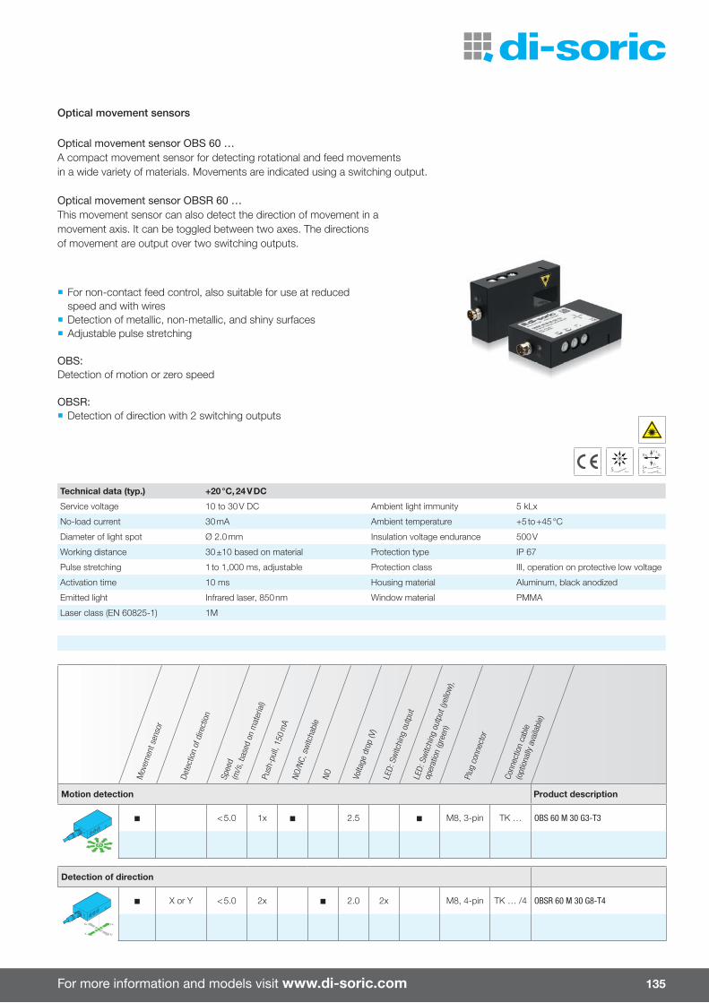
For more information and models visit www.di-soric.com 135
S
X+ X-Y+
Y-S+S-
Optical movement sensor OBS 60 …A compact movement sensor for detecting rotational and feed movements in a wide variety of materials. Movements are indicated using a switching output.
Optical movement sensor OBSR 60 …This movement sensor can also detect the direction of movement in a movement axis. It can be toggled between two axes. The directions of movement are output over two switching outputs.
Optical movement sensors
¡ For non-contact feed control, also suitable for use at reduced speed and with wires
¡ Detection of metallic, non-metallic, and shiny surfaces ¡ Adjustable pulse stretching
OBS:Detection of motion or zero speed
OBSR: ¡ Detection of direction with 2 switching outputs
Mov
emen
t sen
sor
Dete
ctio
n of
dire
ctio
n
Spee
d (m
/s, b
ased
on
mat
eria
l)Pu
sh-p
ull,
150
mA
NO/N
C, s
witc
habl
eNO Vo
ltage
dro
p (V
)
LED:
Sw
itchi
ng o
utpu
tLE
D: S
witc
hing
out
put (
yello
w),
oper
atio
n (g
reen
)
Plug
con
nect
or
Conn
ectio
n ca
ble
(opt
iona
lly a
vaila
ble)
Motion detection Product description
< 5.0 1x 2.5 M8, 3-pin TK … OBS 60 M 30 G3-T3
Detection of direction
X or Y < 5.0 2x 2.0 2x M8, 4-pin TK … /4 OBSR 60 M 30 G8-T4
Technical data (typ.) +20 °C, 24 V DC
Service voltage 10 to 30 V DC Ambient light immunity 5 kLx
No-load current 30 mA Ambient temperature +5 to +45 °C
Diameter of light spot Ø 2.0 mm Insulation voltage endurance 500 V
Working distance 30 ±10 based on material Protection type IP 67
Pulse stretching 1 to 1,000 ms, adjustable Protection class III, operation on protective low voltage
Activation time 10 ms Housing material Aluminum, black anodized
Emitted light Infrared laser, 850 nm Window material PMMA
Laser class (EN 60825-1) 1M

NEWNEW
136
Machine lighting
E¥ cient, extreme light intensity and easy installation ¡ Comprehensive range of lengths: 250 / 480 / 700 / 910 mm often means that the lighting does not have to be cascaded
¡ Compact design with width of just 40 mm allows lighting to be used anywhere
¡ Mounted using magnetic holder set rather than time-consuming drilling and screwing
¡ Swivel-mounted retaining bracket for dazzle-free installation
Maximum safety at the workplace in accordance with DIN EN 12464-1 ¡ Very high color rendering ensures safe-ty at the workplace in accordance with DIN EN 12464-1 (color rendering index Ra 85, 5000 K color temperature)
¡ New high-performance LEDs with very high light intensity ensure reliable and even illumination
¡ Energy-saving system light yield of >100 lumens per watt
¡ Very homogeneous wide-angle illumi-nation of 120°
Very long life thanks to tested quality ¡ Extremely long life thanks to intelligent thermal management and trigger input
¡ Outstanding energy eÁ ciency ¡ Maximum robustness thanks to shock-resistant and vibration-resistant housing with protection class IP 67
¡ Made-in-Germany quality
The extremely powerful and quick-to-inte-grate MB-N LED machine lighting allows ongoing processes in machines to be observed with accuracy as well as rapid retooling and maintenance—guaranteeing maximum eÁ ciency.
910 mm
700 mm
480 mm
250 mm
NEW:
In black or natural aluminum ¡ Integrates into machines seamlessly
MB-NProtected ¡ Also ideal for tough application conditions with its stainless steel front frame and safety glass

For more information and models visit www.di-soric.com 137
Illum
inat
ed a
rea
(mm
)N
o-lo
ad c
urre
nt
at 2
4 V
Pow
er d
raw
at
24
V
Ligh
t in
tens
ity
at 0
.5 m
Ligh
t in
tens
ity
at 1
.0 m
Lum
inou
s fl u
xA
lum
inum
,bla
ck a
nodiz
edA
lum
inum
,na
tura
l ano
diz
edC
able
300
mm
, M12
, 3-p
inC
able
3,0
00 m
m,
fl yin
g le
ads
Wei
ght
(exc
ludin
g pac
kagi
ng)
MB-100 Housing material Product description
77 x 25 3.1 W 350 lx 100 lx nn 50 g MB-100-K-B3
n 70 g MB-100-K
MB-N
95 x 30 190 mA 4.6 W 720 lx 220 lx 440 lm nn 115 g MB-N-125-K-B3
n 175 g MB-N-125-K
220 x 30 450 mA 10.8 W 1800 lx 530 lx 1100 lm nn 210 g MB-N-250-K-B3
n 260 g MB-N-250-K
440 x 30 900 mA 21.6 W 3200 lx 1000 lx 2200 lm nn 390 g MB-N-480-K-B3
n 440 g MB-N-480-K
660 x 30 1350 mA 32.4 W 3900 lx 1300 lx 3300 lm nn 550 g MB-N-700-K-B3
n 600 g MB-N-700-K
870 x 30 1800 mA 43.2 W 4400 lx 1600 lx 4400 lm nn 700 g MB-N-910-K-B3
n 750 g MB-N-910-K
95 x 30 190 mA 4.6 W 720 lx 220 lx 440 lm nn 115 g MB-N-126-K-B3
n 175 g MB-N-126-K
220 x 30 450 mA 10.8 W 1800 lx 530 lx 1100 lm nn 210 g MB-N-251-K-B3
n 260 g MB-N-251-K
440 x 30 900 mA 21.6 W 3200 lx 1000 lx 2200 lm nn 390 g MB-N-481-K-B3
n 440 g MB-N-481-K
660 x 30 1350 mA 32.4 W 3900 lx 1300 lx 3300 lm nn 550 g MB-N-701-K-B3
n 600 g MB-N-701-K
870 x 30 1800 mA 43.2 W 4400 lx 1600 lx 4400 lm nn 700 g MB-N-911-K-B3
n 750 g MB-N-911-K
MB-NP Protected, for use in corrosive environments
30 x 220 450 mA 10.8 W 1,400 lx 430 lx n n 410 g MB-NP-250-K
30 x 440 900 mA 21.6 W 2,600 lx 800 lx n n 700 g MB-NP-480-K
Machine lightingThis durable and reliable machine lighting is designed especially for industrial use for general mechanical engineering.
Highly eÁ cient power LEDs and industrial encapsulation guarantee outstanding performance data. The lighting features an input through which it can be switched o� and dimmed.
Technical data (typ.) +20 °C
Service voltage 24 V DC (Supply Class 2)
Light color 5,000 K white (LED)
Ambient temperature 0 to 40 °C (MB-100 / MB-NP …)
0 to 40 °C (MB-N …)
Protection type IP 67
Connection cable VK … (optionally available)

138
Machine / signal lighting
Machine lighting with signallighting element MB-RGBW … ¡ High light intensity thanks to state-of-the art Power LEDs
¡ Easy operation is also possible without IO-Link
¡ High color rendering guarantees work-place safety in accordance with DIN EN 12464-1 / EN 12464-1
¡ Large illuminated area for optimal dis-play of machine status
¡ Freely confi gurable functions via IO-Link ¡ Long life thanks to intelligent thermal management
¡ Homogeneous wide light fi eld for opti-mal machine lighting
¡ Can be used immediately thanks to three color pre-sets: red - green - yellow
SB-RGB signal lighting … ¡ High light intensity thanks to state-of-the art high-eÁ ciency LEDs
¡ Easy operation is also possible without IO-Link
¡ Freely confi gurable functions via IO-Link ¡ Long life thanks to intelligent thermal management
¡ Large illuminated area for optimal dis-play of machine status
¡ Can be used immediately thanks to three color pre-sets: red - green - yellow
NEW:
In black or natural aluminum ¡ Integrates into machines seamlessly
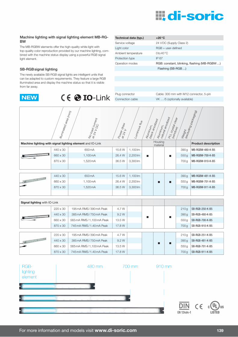
For more information and models visit www.di-soric.com 139
Illum
inat
ed a
rea
(mm
)
No-
load
cur
rent
at
24
V D
C
Pow
er d
raw
at
24
V
Lum
inou
s fl u
x
Alu
min
um,
bla
ck a
nodiz
edA
lum
inum
,na
tura
l ano
diz
edP
U, c
ryst
al c
lear
(w
indow
)
Wei
ght
(exc
ludin
g pac
kagi
ng)
Machine lighting with signal lighting element and IO-Link Housing material Product description
440 x 30 650 mA 15.6 W 1,100 lm
n n
390 g MB-RGBW-480-K-B5
660 x 30 1,100 mA 26.4 W 2,200 lm 550 g MB-RGBW-700-K-B5
870 x 30 1,520 mA 36.5 W 3,300 lm 700 g MB-RGBW-910-K-B5
440 x 30 650 mA 15.6 W 1,100 lm
n n
390 g MB-RGBW-481-K-B5
660 x 30 1,100 mA 26.4 W 2,200 lm 550 g MB-RGBW-701-K-B5
870 x 30 1,520 mA 36.5 W 3,300 lm 700 g MB-RGBW-911-K-B5
Signal lighting with IO-Link
220 x 30 195 mA RMS / 390 mA Peak 4.7 W
n n
210 g SB-RGB-250-K-B5
440 x 30 385 mA RMS / 750 mA Peak 9.2 W 390 g SB-RGB-480-K-B5
660 x 30 565 mA RMS / 1,100 mA Peak 13.5 W 550 g SB-RGB-700-K-B5
870 x 30 745 mA RMS / 1.40 mA Peak 17.8 W 700 g SB-RGB-910-K-B5
220 x 30 195 mA RMS / 390 mA Peak 4.7 W
n n
210 g SB-RGB-251-K-B5
440 x 30 385 mA RMS / 750 mA Peak 9.2 W 390 g SB-RGB-481-K-B5
660 x 30 565 mA RMS / 1,100 mA Peak 13.5 W 550 g SB-RGB-701-K-B5
870 x 30 745 mA RMS / 1.40 mA Peak 17.8 W 700 g SB-RGB-911-K-B5
Machine lighting with signal lighting element MB-RG-BWThe MB-RGBW elements o� er the high-quality white light with top-quality color reproduction provided by our machine lighting, com-bined with the machine status display using a powerful RGB signal light element.
SB-RGB signal lightingThe newly available SB-RGB signal lights are intelligent units that can be adapted to custom requirements. They feature a large RGB illuminated area and display the machine status so that it is visible from far away.
Technical data (typ.) +20 °C
Service voltage 24 V DC (Supply Class 2)
Light color RGB + user-defi ned
Ambient temperature 0 to 40 °C
Protection type IP 67
Operation modes RGB: constant, blinking, fl ashing (MB-RGBW …)
Flashing (SB-RGB …)
NEWPlug connector Cable: 300 mm with M12 connector, 5-pin
Connection cable VK … /5 (optionally available)
910 mm700 mm480 mmRGB-lightingelement

Lighting ¡ Internal control of power output ¡ Homogeneous luminous fi eld ¡ High IP 69K protection type ¡ External trigger input ¡ High eÁ ciency ¡ Low levels of heat produced ¡ Light intensity can be adjusted ¡ Variety of fastening options ¡ Di� erent light colors ¡ Sturdy housing design ¡ Standard M12 connector
di-soric o� ers a comprehensive range of lighting products for supporting image processing systems and inspection tasks. These lighting systems feature exception-al technical characteristics in combination with extremely rugged housings and a high protection type.
Lightingwith integrated control of power output
140

For more information and models visit www.di-soric.com
Illum
inat
ed a
rea
(mm
)
Disp
ersi
on a
ngle
(°)
Size
/ ho
usin
g de
sign
(mm
)
Serv
ice
volta
ge (V
DC)
Ambi
ent t
empe
ratu
re (°
C)In
tegr
ated
con
trol o
f pow
er
outp
ut
Ligh
t int
ensi
ty c
an b
e ad
just
edTr
igge
r
Prot
ectio
n ty
pe
Hous
ing
mat
eria
l
Ligh
t col
or
Area lighting Product description
30 x 30 – 30 x 30 x 20 24 0 to +40 IP 67Aluminum
BlackAnodized
Red BE-F30/30RL-G1-K-BS
White BE-F30/30RL-G5-K-BS
50 x 50 – 50 x 50 x 20 24 0 to +40 IP 67Aluminum
BlackAnodized
Red BE-F50/50RL-G1-K-BS
White BE-F50/50RL-G5-K-BS
50 x 50 – 80 x 110 x 15
15 to 35
0 to +50 n n n IP 67Aluminum
BlackAnodized
IR Infrared BEK-F50/50-G0TI-IBS
15 to 35 Red BEK-F50/50-G1TI-IBS
18 to 35 Green BEK-F50/50-G2TI-IBS
18 to 35 Blue BEK-F50/50-G3TI-IBS
18 to 35 White BEK-F50/50-G5TI-IBS
100 x 100 – 130 x 160 x 15
15 to 35
0 to +50 n n n IP 67Aluminum
BlackAnodized
IR Infrared BEK-F100/100-G0TI-IBS
15 to 35 Red BEK-F100/100-G1TI-IBS
18 to 35 Green BEK-F100/100-G2TI-IBS
18 to 35 Blue BEK-F100/100-G3TI-IBS
18 to 35 White BEK-F100/100-G5TI-IBS
150 x 150 – 180 x 210 x 15
15 to 35
0 to +50 n n n IP 67Aluminum
BlackAnodized
IR Infrared BEK-F150/150-G0TI-IBS
15 to 35 Red BEK-F150/150-G1TI-IBS
18 to 35 Green BEK-F150/150-G2TI-IBS
18 to 35 Blue BEK-F150/150-G3TI-IBS
18 to 35 White BEK-F150/150-G5TI-IBS
200 x 200 – 230 x 260 x 18
15 to 35
0 to +50 n n n IP 67Aluminum
BlackAnodized
IR Infrared BEK-F200/200-G0TI-IBS
15 to 35 Red BEK-F200/200-G1TI-IBS
18 to 35 Green BEK-F200/200-G2TI-IBS
18 to 35 Blue BEK-F200/200-G3TI-IBS
18 to 35 White BEK-F200/200-G5TI-IBS
Area lighting
250 x 250 – 317 x 317 x 23 24 0 to +40 IP 67Aluminum
BlackAnodized
Red BEK-FL250/250-G1T-IBS
White BEK-FL250/250-G5T-IBS
400 x 400 – 467 x 467 x 23 24 0 to +40 IP 67Aluminum
BlackAnodized
Red BEK-FL400/400-G1T-IBS
White BEK-FL400/400-G5T-IBS
1,000 x 1,000 –1067 x 1067
x 2324 0 to +40 IP 67
AluminumBlack
Anodized
Red BEK-FL1000/1000-G1T-IBS
White BEK-FL1000/1000-G5T-IBS
141
Area lightingArea light is used for background lighting and contour checking for contents such as wire spools, stamped parts and countless other objects that require contour monitoring. Individual versions to customer specifications can be provided.
Technical data (typ.) +20 °C, 24 V DC
Trigger input low level 0 to < 2.8 V
Trigger input high level > 3.3 to 35 V
Plug connector M12
Connection cable VK … (optionally available)

Lighting with integrated control of power output
Illum
inat
ed a
rea
/ len
gth
(mm
)
Disp
ersi
on a
ngle
(°)
Size
/ ho
usin
g de
sign
(mm
)
Serv
ice
volta
ge (V
DC)
Ambi
ent t
empe
ratu
re (°
C)In
tegr
ated
con
trol o
f pow
er
outp
ut
Ligh
t int
ensi
ty c
an b
e ad
just
edTr
igge
r
Prot
ectio
n ty
pe
Hous
ing
mat
eria
l
Ligh
t col
or
Barlights Product description
30 x 30 – 30 x 30 x 20 24 0 to +40 IP 67Aluminum
BlackAnodized
Red BE-A30/30-G1-K-BS
White BE-A30/30-G5-K-BS
50 x 50 – 50 x 50 x 20 24 0 to +40 IP 67Aluminum
BlackAnodized
Red BE-A50/50-G1-K-BS
White BE-A50/50-G5-K-BS
Barlights with SMD-LED
SMD-LED
16 x 65 120 ° 16 x 20 x 84 24 0 to +40 IP 20Aluminum
BlackAnodized
IR Infrared BE 1-A65/120-G0-K-BS
Red BE 1-A65/120-G1-K-BS
Green BE 1-A65/120-G2-K-BS
Blue BE 1-A65/120-G3-K-BS
White BE 1-A65/120-G5-K-BS
16 x 130 120 ° 16 x 20 x 144 24 0 to +40 IP 20Aluminum
BlackAnodized
IR Infrared BE 1-A130/120-G0-K-BS
Red BE 1-A130/120-G1-K-BS
Green BE 1-A130/120-G2-K-BS
Blue BE 1-A130/120-G3-K-BS
White BE 1-A130/120-G5-K-BS
16 x 240 120 ° 16 x 20 x 254 24 0 to +40 IP 20Aluminum
BlackAnodized
IR Infrared BE 1-A240/120-G0-K-BS
Red BE 1-A240/120-G1-K-BS
Green BE 1-A240/120-G2-K-BS
Blue BE 1-A240/120-G3-K-BS
White BE 1-A240/120-G5-K-BS
142
BarlightsBarlights are used for high-intensity, uniform lighting for camera systems and countless inspection tasks. Individual long versions to customer specifications can be provided.
Technical data (typ.) +20 °C, 24 V DC
Trigger input low level 0 to < 2.8 V
Trigger input high level > 3.3 to 35 V
Shock/vibration load 30 g / 10 – 55 Hz, 1 mm
Plug connector M12
Connection cable VK … (optionally available)

For more information and models visit www.di-soric.com
Illum
inat
ed a
rea
/ len
gth
(mm
)
Disp
ersi
on a
ngle
(°)
Size
/ ho
usin
g de
sign
(mm
)
Serv
ice
volta
ge (V
DC)
Ambi
ent t
empe
ratu
re (°
C)In
tegr
ated
con
trol o
f pow
er
outp
ut
Ligh
t int
ensi
ty c
an b
e ad
just
edTr
igge
r
Prot
ectio
n ty
pe
Hous
ing
mat
eria
l
Ligh
t col
or
Barlights 3 mm LED Product description
16 x 130 – 16 x 20 x 144 24 0 to +40 IP 20Aluminum
BlackAnodized
IR Infrared BE 1-A130-G0-K-BS
Red BE 1-A130-G1-K-BS
Green BE 1-A130-G2-K-BS
Blue BE 1-A130-G3-K-BS
White BE 1-A130-G5-K-BS
16 x 240 – 16 x 20 x 254 24 0 to +40 IP 20Aluminum
BlackAnodized
IR Infrared BE 1-A240-G0-K-BS
Red BE 1-A240-G1-K-BS
Green BE 1-A240-G2-K-BS
Blue BE 1-A240-G3-K-BS
White BE 1-A240-G5-K-BS
Barlights
96 x 23 30° 40 x 60 x 113 18 to 30 0 to +40 n n IP 67Aluminum
BlackAnodized
IR Infrared BEK-A100-G0T-K-BS
Red BEK-A100-G1T-K-BS
Green BEK-A100-G2T-K-BS
Blue BEK-A100-G3T-K-BS
White BEK-A100-G5T-K-BS
296 x 23 30° 40 x 60 x 313 18 to 30 0 to +40 n n IP 67Aluminum
BlackAnodized
IR Infrared BEK-A300-G0T-K-BS
Red BEK-A300-G1T-K-BS
Green BEK-A300-G2T-K-BS
Blue BEK-A300-G3T-K-BS
White BEK-A300-G5T-K-BS
396 x 23 30° 40 x 60 x 413 18 to 30 0 to +40 n n IP 67Aluminum
BlackAnodized
IR Infrared BEK-A400-G0T-K-BS
Red BEK-A400-G1T-K-BS
White BEK-A400-G5T-K-BS
496 x 23 30° 40 x 60 x 513 18 to 30 0 to +40 n n IP 67Aluminum
BlackAnodized
IR Infrared BEK-A500-G0T-K-BS
Red BEK-A500-G1T-K-BS
White BEK-A500-G5T-K-BS
143
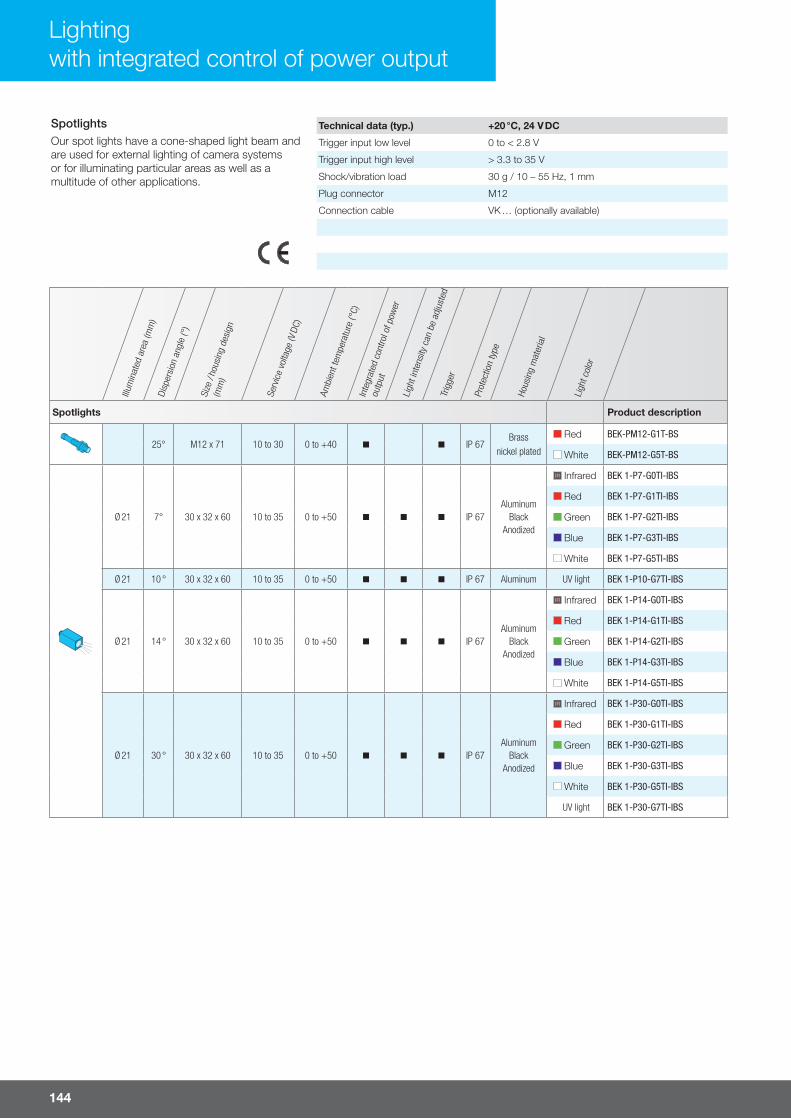
Lighting with integrated control of power output
144
SpotlightsOur spot lights have a cone-shaped light beam and are used for external lighting of camera systems or for illuminating particular areas as well as a multitude of other applications.
Technical data (typ.) +20 °C, 24 V DC
Trigger input low level 0 to < 2.8 V
Trigger input high level > 3.3 to 35 V
Shock/vibration load 30 g / 10 – 55 Hz, 1 mm
Plug connector M12
Connection cable VK … (optionally available)
Illum
inat
ed a
rea
(mm
)Di
sper
sion
ang
le (°
)
Size
/ ho
usin
g de
sign
(mm
)
Serv
ice
volta
ge (V
DC)
Ambi
ent t
empe
ratu
re (°
C)In
tegr
ated
con
trol o
f pow
er
outp
ut
Ligh
t int
ensi
ty c
an b
e ad
just
edTr
igge
r
Prot
ectio
n ty
pe
Hous
ing
mat
eria
l
Ligh
t col
or
Spotlights Product description
25° M12 x 71 10 to 30 0 to +40 n n IP 67Brass
nickel plated
Red BEK-PM12-G1T-BS
White BEK-PM12-G5T-BS
Ø 21 7° 30 x 32 x 60 10 to 35 0 to +50 n n n IP 67Aluminum
BlackAnodized
IR Infrared BEK 1-P7-G0TI-IBS
Red BEK 1-P7-G1TI-IBS
Green BEK 1-P7-G2TI-IBS
Blue BEK 1-P7-G3TI-IBS
White BEK 1-P7-G5TI-IBS
Ø 21 10 ° 30 x 32 x 60 10 to 35 0 to +50 n n n IP 67 Aluminum UV light BEK 1-P10-G7TI-IBS
Ø 21 14 ° 30 x 32 x 60 10 to 35 0 to +50 n n n IP 67Aluminum
BlackAnodized
IR Infrared BEK 1-P14-G0TI-IBS
Red BEK 1-P14-G1TI-IBS
Green BEK 1-P14-G2TI-IBS
Blue BEK 1-P14-G3TI-IBS
White BEK 1-P14-G5TI-IBS
Ø 21 30 ° 30 x 32 x 60 10 to 35 0 to +50 n n n IP 67Aluminum
BlackAnodized
IR Infrared BEK 1-P30-G0TI-IBS
Red BEK 1-P30-G1TI-IBS
Green BEK 1-P30-G2TI-IBS
Blue BEK 1-P30-G3TI-IBS
White BEK 1-P30-G5TI-IBS
UV light BEK 1-P30-G7TI-IBS
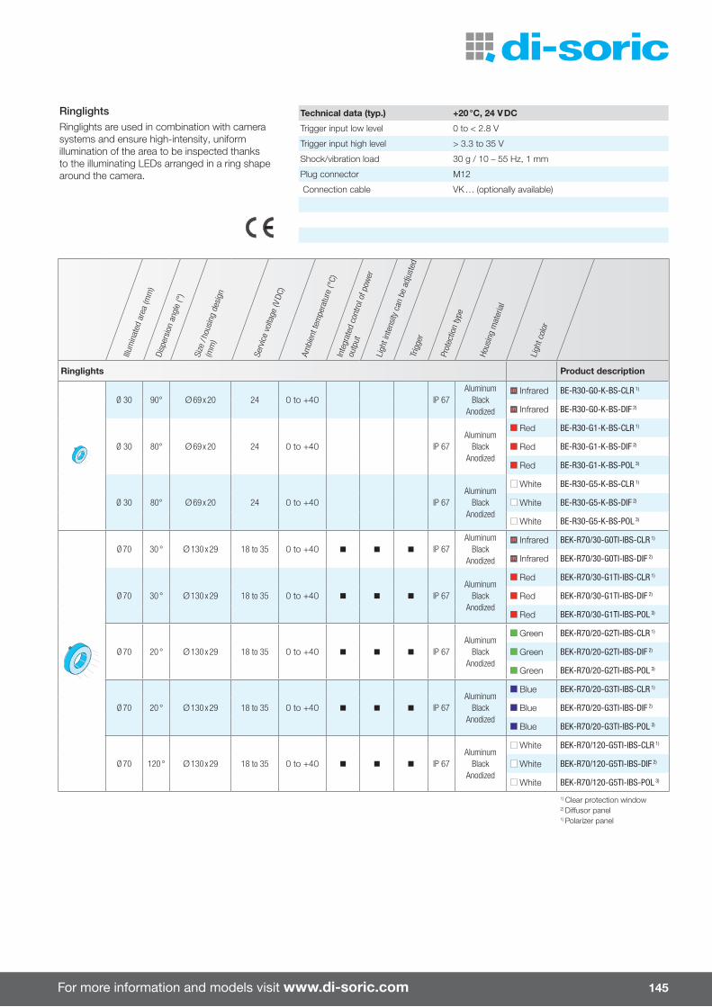
For more information and models visit www.di-soric.com 145
RinglightsRinglights are used in combination with camera systems and ensure high-intensity, uniform illumination of the area to be inspected thanks to the illuminating LEDs arranged in a ring shape around the camera.
Technical data (typ.) +20 °C, 24 V DC
Trigger input low level 0 to < 2.8 V
Trigger input high level > 3.3 to 35 V
Shock/vibration load 30 g / 10 – 55 Hz, 1 mm
Plug connector M12
Connection cable VK … (optionally available)
Illum
inat
ed a
rea
(mm
)Di
sper
sion
ang
le (°
)
Size
/ ho
usin
g de
sign
(mm
)
Serv
ice
volta
ge (V
DC)
Ambi
ent t
empe
ratu
re (°
C)In
tegr
ated
con
trol o
f pow
er
outp
ut
Ligh
t int
ensi
ty c
an b
e ad
just
edTr
igge
r
Prot
ectio
n ty
pe
Hous
ing
mat
eria
l
Ligh
t col
or
Ringlights Product description
Ø 30 90° Ø 69 x 20 24 0 to +40 IP 67Aluminum
BlackAnodized
IR Infrared BE-R30-G0-K-BS-CLR 1)
IR Infrared BE-R30-G0-K-BS-DIF 2)
Ø 30 80° Ø 69 x 20 24 0 to +40 IP 67Aluminum
BlackAnodized
Red BE-R30-G1-K-BS-CLR 1)
Red BE-R30-G1-K-BS-DIF 2)
Red BE-R30-G1-K-BS-POL 3)
Ø 30 80° Ø 69 x 20 24 0 to +40 IP 67Aluminum
BlackAnodized
White BE-R30-G5-K-BS-CLR 1)
White BE-R30-G5-K-BS-DIF 2)
White BE-R30-G5-K-BS-POL 3)
Ø 70 30 ° Ø 130 x 29 18 to 35 0 to +40 n n n IP 67Aluminum
BlackAnodized
IR Infrared BEK-R70/30-G0TI-IBS-CLR 1)
IR Infrared BEK-R70/30-G0TI-IBS-DIF 2)
Ø 70 30 ° Ø 130 x 29 18 to 35 0 to +40 n n n IP 67Aluminum
BlackAnodized
Red BEK-R70/30-G1TI-IBS-CLR 1)
Red BEK-R70/30-G1TI-IBS-DIF 2)
Red BEK-R70/30-G1TI-IBS-POL 3)
Ø 70 20 ° Ø 130 x 29 18 to 35 0 to +40 n n n IP 67Aluminum
BlackAnodized
Green BEK-R70/20-G2TI-IBS-CLR 1)
Green BEK-R70/20-G2TI-IBS-DIF 2)
Green BEK-R70/20-G2TI-IBS-POL 3)
Ø 70 20 ° Ø 130 x 29 18 to 35 0 to +40 n n n IP 67Aluminum
BlackAnodized
Blue BEK-R70/20-G3TI-IBS-CLR 1)
Blue BEK-R70/20-G3TI-IBS-DIF 2)
Blue BEK-R70/20-G3TI-IBS-POL 3)
Ø 70 120 ° Ø 130 x 29 18 to 35 0 to +40 n n n IP 67Aluminum
BlackAnodized
White BEK-R70/120-G5TI-IBS-CLR 1)
White BEK-R70/120-G5TI-IBS-DIF 2)
White BEK-R70/120-G5TI-IBS-POL 3)
1) Clear protection window2) Di�usor panel1) Polarizer panel
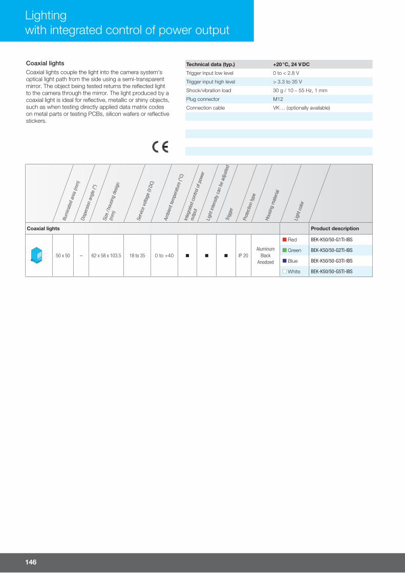
Lighting with integrated control of power output
146
Coaxial lightsCoaxial lights couple the light into the camera system's optical light path from the side using a semi-transparent mirror. The object being tested returns the reflected light to the camera through the mirror. The light produced by a coaxial light is ideal for reflective, metallic or shiny objects, such as when testing directly applied data matrix codes on metal parts or testing PCBs, silicon wafers or reflective stickers.
Technical data (typ.) +20 °C, 24 V DC
Trigger input low level 0 to < 2.8 V
Trigger input high level > 3.3 to 35 V
Shock/vibration load 30 g / 10 – 55 Hz, 1 mm
Plug connector M12
Connection cable VK … (optionally available)
Illum
inat
ed a
rea
(mm
)Di
sper
sion
ang
le (°
)
Size
/ ho
usin
g de
sign
(mm
)
Serv
ice
volta
ge (V
DC)
Ambi
ent t
empe
ratu
re (°
C)In
tegr
ated
con
trol o
f pow
er
outp
ut
Ligh
t int
ensi
ty c
an b
e ad
just
edTr
igge
r
Prot
ectio
n ty
pe
Hous
ing
mat
eria
l
Ligh
t col
or
Coaxial lights Product description
50 x 50 – 62 x 58 x 103.5 18 to 35 0 to +40 n n n IP 20Aluminum
BlackAnodized
Red BEK-K50/50-G1TI-IBS
Green BEK-K50/50-G2TI-IBS
Blue BEK-K50/50-G3TI-IBS
White BEK-K50/50-G5TI-IBS

For more information and models visit www.di-soric.com 147
Darkfield lightsDarkfield lights feature a flat angle of incidence on the illuminated surface. Changes to the surface, such as scratches, stampings, embossings or ridges change the beam input of the light, reflecting or scattering the light as a result. These changes to the surface di�er significantly and can be detected with the aid of a camera system.
Technical data (typ.) +20 °C, 24 V DC
Trigger input low level 0 to < 2.8 V
Trigger input high level > 3.3 to 35 V
Shock/vibration load 30 g / 10 – 55 Hz, 1 mm
Plug connector M12
Connection cable VK … (optionally available)
Illum
inat
ed a
rea
(mm
)Di
sper
sion
ang
le (°
)
Size
/ ho
usin
g de
sign
(mm
)
Serv
ice
volta
ge (V
DC)
Ambi
ent t
empe
ratu
re (°
C)In
tegr
ated
con
trol o
f pow
er
outp
ut
Ligh
t int
ensi
ty c
an b
e ad
just
edTr
igge
r
Prot
ectio
n ty
pe
Hous
ing
mat
eria
l
Ligh
t col
or
Darkfield lights Product description
Ø 70 – 95 x 130 x 12 10 to 35 0 to +40 n n n IP 67Aluminum
BlackAnodized
IR Infrared BEK-D70-G0TI-K-BS
Red BEK-D70-G1TI-K-BS
Green BEK-D70-G2TI-K-BS
Blue BEK-D70-G3TI-K-BS
White BEK-D70-G5TI-K-BS
Ø 120 – 170 x 200 x 15 10 to 35 0 to +50 n n n IP 67Aluminum
BlackAnodized
IR Infrared BEK 1-D120-G0TI-IBS
Red BEK 1-D120-G1TI-IBS
Green BEK 1-D120-G2TI-IBS
Blue BEK 1-D120-G3TI-IBS
White BEK 1-D120-G5TI-IBS

148
Flash controllers and lights
The di-soric fl ash controller BC-100-20A allows the LEDS to "over-drive" with several times the power, increasing the light intensity many times over. This enables shorter exposure times for freezing object movement or the option to select a higher f-number for more depth of fi eld during the same exposure time. More light in the application also reduces outside interference. Even interference due to external scattered light is signifi -cantly reduced by overdriving the lights.
¡ High excess current factor ¡ Flash mode operation for "freezing images" and inspection of fast moving objects at extremely high light intensity
¡ Intelligent thermal management for a long life ¡ Homogeneous luminous fi eld ¡ Protection class IP 67 ¡ Robust metal housing
Lights forfl ash controllers
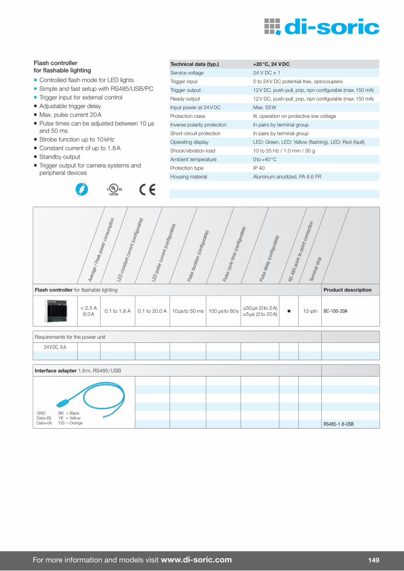
For more information and models visit www.di-soric.com 149
Flash controller for fl ashable lighting Product description
< 2.5 A6.0 A 0.1 to 1.8 A 0.1 to 20.0 A 10 µs to 50 ms 100 µs to 60 s ≥50 µs (0 to 2 A)
≥5 µs (2 to 20 A) 12-pin BC-100-20A
Requirements for the power unit
24 V DC, 6 A
Interface adapter 1.8 m, RS485 / USB
GND BK = BlackData-(B) YE = YellowData+(A) OG = Orange RS485-1.8-USB
Aver
age
/ Pea
k po
wer
con
sum
ptio
nLE
D co
nsta
nt c
urre
nt (c
onfi g
urab
le)
LED
puls
e cu
rrent
(con
fi gur
able
)
Puls
e du
ratio
n (c
onfi g
urab
le)
Puls
e cy
cle
time
(con
fi gur
able
)
Puls
e de
lay
(con
fi gur
able
)
RS 4
85 p
oint
-to-
poin
t con
nect
ion
Term
inal
stri
p
Flash controller for fl ashable lighting
¡ Controlled fl ash mode for LED lights ¡ Simple and fast setup with RS485/USB/PC ¡ Trigger input for external control ¡ Adjustable trigger delay ¡ Max. pulse current 20 A ¡ Pulse times can be adjusted between 10 µs and 50 ms
¡ Strobe function up to 10 kHz ¡ Constant current of up to 1.8 A ¡ Standby output ¡ Trigger output for camera systems and peripheral devices
Technical data (typ.) +20 °C, 24 V DC
Service voltage 24 V DC ± 1
Trigger input 5 to 24 V DC potential-free, optocouplers
Trigger output 12 V DC, push-pull, pnp, npn confi gurable (max. 150 mA)
Ready output 12 V DC, push-pull, pnp, npn confi gurable (max. 150 mA)
Input power at 24 V DC Max. 55 W
Protection class III, operation on protective low voltage
Inverse polarity protection In pairs by terminal group
Short-circuit protection In pairs by terminal group
Operating display LED: Green, LED: Yellow (fl ashing), LED: Red (fault)
Shock/vibration load 10 to 55 Hz / 1.0 mm / 30 g
Ambient temperature 0 to +40 °C
Protection type IP 40
Housing material Aluminum anodized, PA 6.6 FR
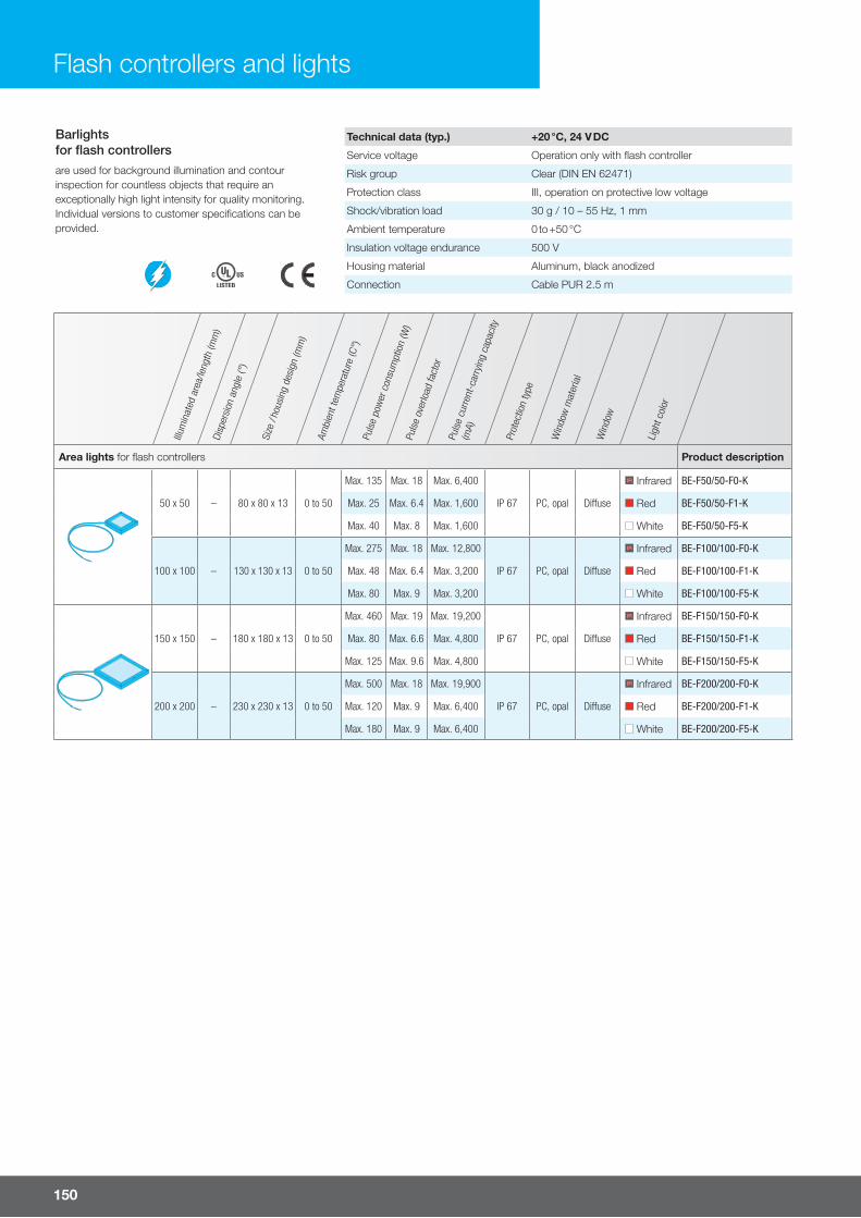
150
Flash controllers and lights
Barlightsfor fl ash controllersare used for background illumination and contour inspection for countless objects that require an exceptionally high light intensity for quality monitoring. Individual versions to customer specifi cations can be provided.
Technical data (typ.) +20 °C, 24 V DC
Service voltage Operation only with fl ash controller
Risk group Clear (DIN EN 62471)
Protection class III, operation on protective low voltage
Shock/vibration load 30 g / 10 – 55 Hz, 1 mm
Ambient temperature 0 to +50 °C
Insulation voltage endurance 500 V
Housing material Aluminum, black anodized
Connection Cable PUR 2.5 m
Illum
inat
ed a
rea/
leng
th (m
m)
Disp
ersi
on a
ngle
(°)
Size
/ ho
usin
g de
sign
(mm
)
Ambi
ent t
empe
ratu
re (C
°)Pu
lse
pow
er c
onsu
mpt
ion
(W)
Puls
e ov
erlo
ad fa
ctor
Puls
e cu
rrent
-car
ryin
g ca
paci
ty
(mA)
Prot
ectio
n ty
pe
Win
dow
mat
eria
l
Win
dow
Ligh
t col
or
Area lights for fl ash controllers Product description
50 x 50 – 80 x 80 x 13 0 to 50
Max. 135 Max. 18 Max. 6,400
IP 67 PC, opal Di� use
IR Infrared BE-F50/50-F0-K
Max. 25 Max. 6.4 Max. 1,600 Red BE-F50/50-F1-K
Max. 40 Max. 8 Max. 1,600 White BE-F50/50-F5-K
100 x 100 – 130 x 130 x 13 0 to 50
Max. 275 Max. 18 Max. 12,800
IP 67 PC, opal Di� use
IR Infrared BE-F100/100-F0-K
Max. 48 Max. 6.4 Max. 3,200 Red BE-F100/100-F1-K
Max. 80 Max. 9 Max. 3,200 White BE-F100/100-F5-K
150 x 150 – 180 x 180 x 13 0 to 50
Max. 460 Max. 19 Max. 19,200
IP 67 PC, opal Di� use
IR Infrared BE-F150/150-F0-K
Max. 80 Max. 6.6 Max. 4,800 Red BE-F150/150-F1-K
Max. 125 Max. 9.6 Max. 4,800 White BE-F150/150-F5-K
200 x 200 – 230 x 230 x 13 0 to 50
Max. 500 Max. 18 Max. 19,900
IP 67 PC, opal Di� use
IR Infrared BE-F200/200-F0-K
Max. 120 Max. 9 Max. 6,400 Red BE-F200/200-F1-K
Max. 180 Max. 9 Max. 6,400 White BE-F200/200-F5-K

For more information and models visit www.di-soric.com 151
Barlightsfor fl ash controllersare used for high-intensity, uniform lighting for camera systems and countless inspection tasks.
Individual long versions to customer specifi cations can be provided.
Technical data (typ.) +20 °C, 24 V DC
Service voltage Operation only with fl ash controller
Risk group Clear (DIN EN 62471)
Protection class III, operation on protective low voltage
Shock/vibration load 30 g / 10 – 55 Hz, 1 mm
Ambient temperature 0 to +50 °C
Insulation voltage endurance 500 V
Housing material Aluminum, black anodized
Connection Cable PUR 2.5 m
Illum
inat
ed a
rea/
leng
th (m
m)
Disp
ersi
on a
ngle
(°)
Size
/ ho
usin
g de
sign
(mm
)
Ambi
ent t
empe
ratu
re (C
°)Pu
lse
pow
er c
onsu
mpt
ion
(W)
Puls
e ov
erlo
ad fa
ctor
Puls
e cu
rrent
-car
ryin
g ca
paci
ty
(mA)
Prot
ectio
n ty
pe
Win
dow
mat
eria
l
Win
dow
Ligh
t col
or
Barlights for fl ash controllers Product description
16 x 130 – 16 x 20 x 144 0 to 4031 8 1,350
IP 20 Red BE-A130-F1-K
35 10 1,400 White BE-A130-F5-K
Accessories for BE-A 130 …
Matching accessories
See chapter
Accessories
46 x 95 – 60 x 40 x 113 0 to 40
290 9.33 20,000
IP 67 PMMA Clear
IR Infrared BE-A100-F0-K
240 8.0 8,000 Red BE-A100-F1-K
250 8.0 8,000 White BE-A100-F5-K
46 x 295 – 60 x 40 x 313 0 to 40
1,500 24 60,000
IP 67 PMMA Clear
IR Infrared BE-A300-F0-K
720 12 24,000 Red BE-A300-F1-K
750 12 24,000 White BE-A300-F5-K
Accessories for BE-A 100 … / BE-A 300 …
max.2 BE-A ... Matching accessories
See chapter
Accessories

152
Ringlights for fl ash controllersRinglights for lighting controllers are used in combination with camera systems and feature extremely high light intensity. The lighting LEDs arranged in a ring shape around the camera system ensure uniform and high-intensity illumination of the area to be inspected.
Technical data (typ.) +20 °C, 24 V DC
Service voltage Operation only with fl ash controller
Risk group Clear (DIN EN 62471)
Protection class III, operation on protective low voltage
Shock/vibration load 30 g / 10 – 55 Hz, 1 mm
Ambient temperature 0 to +50 °C
Insulation voltage endurance 500 V
Housing material Aluminum, black anodized
Connection Cable PUR 2.5 m
Flash controllers and lights
Illum
inat
ed a
rea/
leng
th (m
m)
Disp
ersi
on a
ngle
(°)
Size
/ ho
usin
g de
sign
(mm
)
Ambi
ent t
empe
ratu
re (C
°)Pu
lse
pow
er c
onsu
mpt
ion
(W)
Puls
e ov
erlo
ad fa
ctor
Puls
e cu
rrent
-car
ryin
g ca
paci
ty
(mA)
Prot
ectio
n ty
pe
Win
dow
mat
eria
l
Win
dow
Ligh
t col
or
Ringlights for fl ash controllers Product description
Ø 30 30 ° Ø 69 x 20 0 to 40 Max. 30 8 Max. 2,000 IP 67 PMMA
Clear Red BE-R30-F1-K-CLR
Di� use Red BE-R30-F1-K-DIF
Polarized Red BE-R30-F1-K-POL
Ø 30 120 ° Ø 69 x 20 0 to 40 Max. 45 10 Max. 2,000 IP 67 PMMA
Clear White BE-R30-F5-K-CLR
Di� use White BE-R30-F5-K-DIF
Polarized White BE-R30-F5-K-POL
Ø 70 30 ° Ø 130 x 20 0 to 40 Max. 96 8 Max. 6,000 IP 67 PMMA
Clear Red BE-R70-F1-K-CLR
Di� use Red BE-R70-F1-K-DIF
Polarized Red BE-R70-F1-K-POL
Ø 70 120 ° Ø 130 x 20 0 to 40 Max. 140 10 Max. 6,000 IP 67 PMMA
Clear White BE-R70-F5-K-CLR
Di� use White BE-R70-F5-K-DIF
Polarized White BE-R70-F5-K-POL
Ø 130 30 ° Ø 200 x 20 0 to 40 Max. 230 8 Max. 12,000 IP 67 PMMA
Clear Red BE-R130-F1-K-CLR
Di� use Red BE-R130-F1-K-DIF
Polarized Red BE-R130-F1-K-POL
Ø 130 120 ° Ø 200 x 20 0 to 40 Max. 275 10 Max. 11,000 IP 67 PMMA
Clear White BE-R130-F5-K-CLR
Di� use White BE-R130-F5-K-DIF
Polarized White BE-R130-F5-K-POL
For connection of lights of the next size to a unit in pairsSet consists of two connecting elements and four M4x6 cheese-head screws. For installing all three lights into one unit, two BE-R-MOUNTINGSETs are needed.
BE-R-MOUNTINGSET
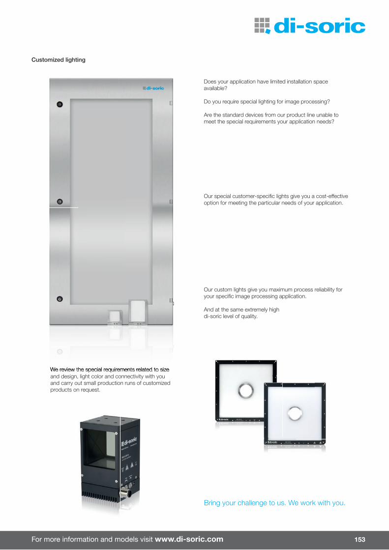
For more information and models visit www.di-soric.com 153
Does your application have limited installation space available?
Do you require special lighting for image processing?
Are the standard devices from our product line unable to meet the special requirements your application needs?
Our special customer-specifi c lights give you a cost-e� ective option for meeting the particular needs of your application.
We review the special requirements related to size and design, light color and connectivity with you and carry out small production runs of customized products on request.
Our custom lights give you maximum process reliability for your specifi c image processing application.
And at the same extremely high di-soric level of quality.
Bring your challenge to us. We work with you.
We review the special requirements related to size
Customized lighting
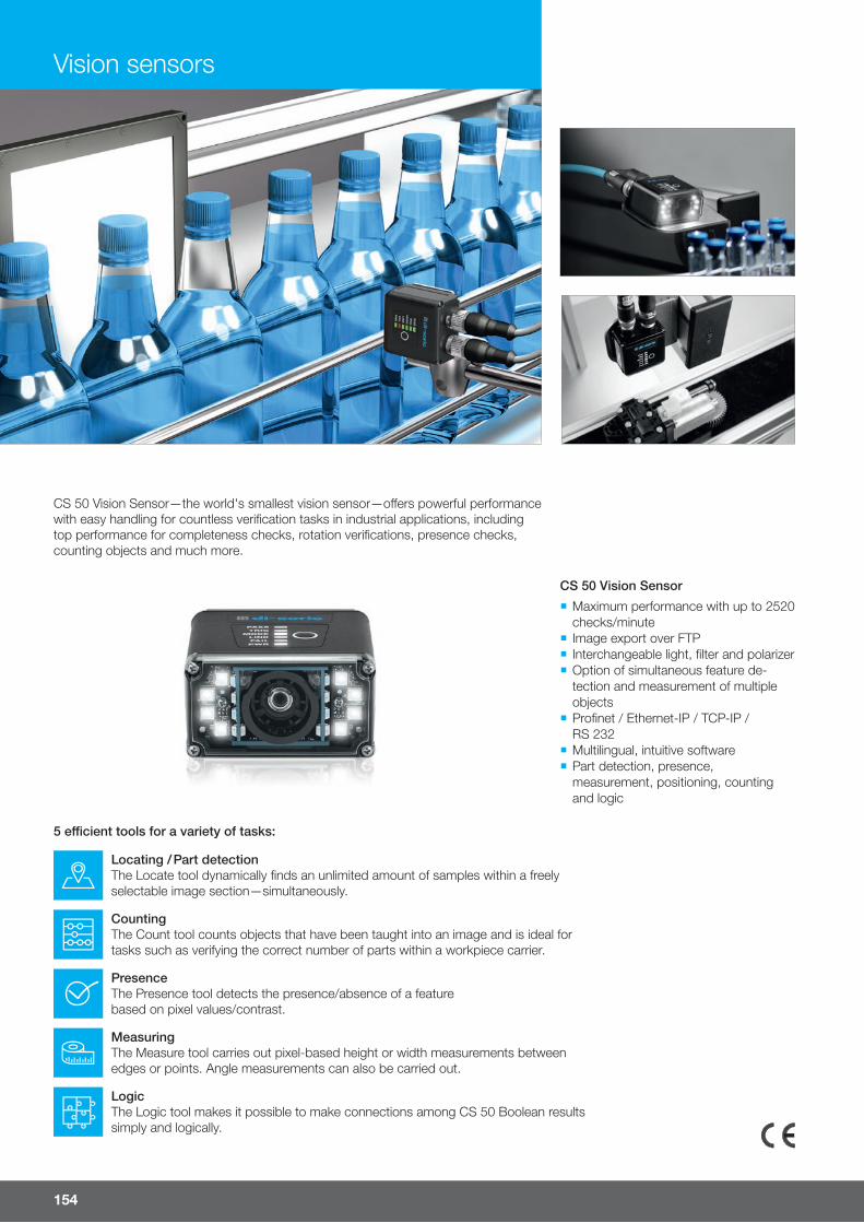
Vision sensors
154
CS 50 Vision Sensor
CS 50 Vision Sensor—the world's smallest vision sensor—o�ers powerful performance with easy handling for countless verification tasks in industrial applications, including top performance for completeness checks, rotation verifications, presence checks, counting objects and much more.
5 e¥cient tools for a variety of tasks:
Locating / Part detectionThe Locate tool dynamically finds an unlimited amount of samples within a freely selectable image section—simultaneously.
CountingThe Count tool counts objects that have been taught into an image and is ideal for tasks such as verifying the correct number of parts within a workpiece carrier.
PresenceThe Presence tool detects the presence/absence of a feature based on pixel values/contrast.
MeasuringThe Measure tool carries out pixel-based height or width measurements between edges or points. Angle measurements can also be carried out.
LogicThe Logic tool makes it possible to make connections among CS 50 Boolean results simply and logically.
¡ Maximum performance with up to 2520 checks/minute
¡ Image export over FTP ¡ Interchangeable light, filter and polarizer ¡ Option of simultaneous feature de-tection and measurement of multiple objects
¡ Profinet / Ethernet-IP / TCP-IP / RS 232
¡ Multilingual, intuitive software ¡ Part detection, presence, measurement, positioning, counting and logic

For more information and models visit www.di-soric.com 155
Foca
l len
gth
(mm
)
Wor
king
dis
tanc
e (m
m)
Ligh
t co
lor
Max
. par
t sp
eed
(imag
es/s
ec)
Pro
fi net
RS
232
Eth
erne
t /
IP
TCP
/IP
Vision Sensor Product description
5 / 10 50 to 300High power, red
42 n n n nCS 50 BM2-2-ES-G1
High power, white CS 50 BM2-2-ES-G5
16 / 32 50 to 150High power, red
42 n n n nCS 50 BM2-4-ES-G1
High power, white CS 50 BM2-4-ES-G5
90° attachment mirror
CS-R90
LED board replacement kit
IR Infrared BE-CS-G0
Red (625 nm) BE-CS-G1
Blue (470 nm) BE-CS-G3
White (6500 K) BE-CS-G5
Windows
Transparent plate Clear CS-WINDOWKIT
For eliminating surface refl ections
Di� user CS-WINDOWKIT-DIF
Polarizer CS-WINDOWKIT-POL
Filter
For increasing contrastRed CS-WINDOWKIT-G1
Blue CS-WINDOWKIT-G3
USB stick
Software and documentation for CS 50 (alternatively available at www.di-soric.com) USB stick CS50
Technical data (typ.) at +20 °C, 24 V DC
Service voltage 4.75 to 30 V DC Number of inputs/outputs 1/3
No-load current 150 mA, (24 V DC) External trigger input o� = < 1.0 V (ON input)
Dimensions (H x W x D) 25.4 x 44.5 x 44.5 mm Inspection tasks Locating, counting, presence, measuring, logic
Control buttons 1 Equipment Internal trigger
Interchangeable light Yes (red, white, blue, infrared) External trigger input
Ambient temperature 0 to +40 °C PC software setup
Protection type IP 65, IP 67 Logic for user-defi ned outputs
Protection class III, operation on protective low voltage Highest resolution (640 x 480 pixels)
Housing material Aluminum, black Image output b/w, VGA
Weight 68 g Number of jobs Unlimited (1.4 GB)
Vibration/shock resistance 55 Hz sine / 2,000 Hz random / 50 g 1 -255 for operation with Profi net
Exposure time 66 to 58.825 µs

Vision sensors
NEWNEW
156
Rin
glig
hts
Dis
per
sion
ang
le
Ligh
t co
lor
Ris
k gr
oup
(DIN
EN
624
71)
Ligh
t in
tens
ity
Pow
erA
t 24
V D
C (W
)
Wei
ght (g
)
At 0.1 m At 0.3 m At 0.5 m Product description
Ø 33
90° IR Infrared, 850 nm Open 11,800 µW/cm2 1,720 µW/cm2 640 µW/cm2 23 80 BEK-R33-E0T-K-BS
80° Red, 625 nm Open 29,000 lux 3,370 lux 1,450 lux 23 80 BEK-R33-E1T-K-BS
80° White, 6,000 K Open 51,300 lux 7,100 lux 2,500 lux 23 80 BEK-R33-E5T-K-BS
Accessories for operating the CS 50 with a ringlight BEK-R33 …
Polarization fi lm for aÁ xing to the ringlight BEK-R33 … BEK-R33-POL
Focus optics for use with the ringlight BEK-R33 … BEK-R33-FOK
Y-distributor cable for CS 50 and BEK-R33 CS-Y-0.3/12-A
Technical data (typ.) +20 °C
Service voltage 22 to 30 V DC Ambient temperature 0 to +40 °C
Protection type IP 67 Housing material Aluminum, black anodized
Protection class III, operation on protective low voltage Window material PMMA, clear
Shock/vibration load 30 g / 10 - 55 Hz, 1 mm Plug connector M12
¡ Easy to install ¡ High-intensity light pulse in red/white/IR light colors ¡ Automatic trigger signal from CS 50 Vision Sensor ¡ Attachment window optionally available
High power attachment light
For the comprehensive range of accessories, see the Accessories chapter
Comprehensive range of accessoriesSee chapterAccessories
mm (typ.)

For more information and models visit www.di-soric.com
NEWNEWNEW
157
Scr
een
dia
gona
l
Eth
erne
t
I/O
Cou
plin
g
Cab
le le
ngth
(m)
Con
nect
or
Pro
tect
ion
type
Cab
le m
ater
ial
Dra
g ch
ain
com
pat
ible
Multi-functional control panel Product description
7" IP 65(front side)
VP 700
10" VP 1000
Ethernet cable
2.0 IP 67 PUR VKHM-Z-2/RJ45
5.0 IP 67 PUR VKHM-Z-5/RJ45
10.0 IP 67 PUR VKHM-Z-10/RJ45
10.0 P 67 PUR VKHM-W-5/RJ45
I/O cable
5.0 IP 67 PVC VKHM-Z-5/12-A
5.0 IP 67 PUR VKSM-Z-5/12-A
10.0 IP 67 PUR VKSM-Z-10/12-A
15.0 IP 67 PUR VKSM-Z-15/12-A
20.0 IP 67 PUR VKSM-Z-20/12-A
5.0 IP 67 PUR VKHM-W-5/12-A-CS
I/O extension cable
5.0 IP 67 PVC VSM-Z-5/VKM-Z/12-A
¡ Rugged housing design ¡ Visualization of all image and evaluation data ¡ Easy-to-use rights management ¡ Job switching on-the-fl y ¡ Remote access over VNC ¡ Multi-camera mode ¡ Customer-specifi c design adjustment ¡ Multi-lingual user interface
Multi-functional control panel
Technical data (typ.) at +20 °C
Mounting M4 stud bolts (6x) Functions
Operating principle Embedded touch screen monitor Communication with camera CloudLink/Telnet-based
ARM/Linux-based Change for camera jobs Using touch screen
Service voltage 24±5% VDC Interaction with camera settings Using touch screen
Ambient temperature 0 to +40°C Interaction with a job Using all linked variables/no
For use with Vision Sensors CS 50 Interfaces telnet, REST Api, HTTP
Connection RJ45 (network) Base languages German, English, French
2-pin connector (power supply) Spanish, Italian and more
Selection of data communication to the camera
All variables linked in AutoVision can be displayed/manipulated

158
Vision / ID – di-soric Solutions
A successful overall image processing solution consists of components that are high-quality and precisely coordinated to each other,paired with expertise and the corresponding knowledge of the boundary conditions.
ENGINEEREDSOLUTIONS
ENGINEEREDENGINEEREDSOLUTIONSSOLUTIONS
di-soric Solutions is a part of the di-soric group of companies and focuses on consultation and confi guration for image processing projects as well as integrating automation solutions using image processing and industrial identifi cation.
We ensure the quality of products manufactured in automated processes and provide for complete traceability during the individ-ual process steps. We work with powerful systems and work with you to determine the most e� ective and eÁ cient solution.
Continuous further development of our products and services, constant awareness of quality and competent consultation ensure that your processes deliver the highest quality.

For more information and models visit www.di-soric-solutions.com 159
Feasibility testing
Every task has its own challenges. Once secure function has been guaranteed, the steps that follow involve optimized pro-cess integration. We openly address your compulsory requirements, test them with well-founded expertise and provide you with the best possible setup of coordinat-ed hardware and software.
We give you the results of the research and show you the path to the solution in detail. Risks and their countermeasures are also presented with transparency.
Consultation
Determining each and every one of your tasks and paying careful attention to the specifi c process steps involved ensures that implementation is a success.
For this reason, competent consultation takes top priority. Our comprehensive experience and precise approach make complex matters easily intelligible for you.
Engineering
Our expertise in industrial image pro-cessing and identifi cation provides you with critical added value for continuous applications. We develop custom solutions, which are confi gured and ready for use upon delivery.
We secure your production process smoothly by developing develop and programming a target-oriented and eÁ cient automated image processing and identifi cation solution based on your manufactured parts.
We place a great deal of value on mod-ularity so that our solutions ensure high fl exibility, even for your future require-ments.
Integration
Every image processing and identifi ca-tion solution from di-soric Solutions is fully implemented into your system and brought into operation in accordance with your requirements. That way, you are free to concentrate on your core strengths – your products and services.
We take over programming and adjust-ment work while providing you with turn-key concepts and implementing them.
Our references attest to the high quality of our products and services alike.
Service
We consider ourselves to be a com-prehensive partner to our customers throughout the entire duration of the application.
We are happy to handle professional sys-tem maintenance, necessary adjustment work, modifi cations and extensions on site as well as remote maintenance. We view fast and reliable customer service as an integral part of proximity to the customer.
Training programs
Do you want to continuously increase the quality of your products as well?
We are happy to give you access to all of our expertise and years of experience. You will gain knowledge from us that you cannot fi nd in textbooks. With only one goal in mind:To make you even better.
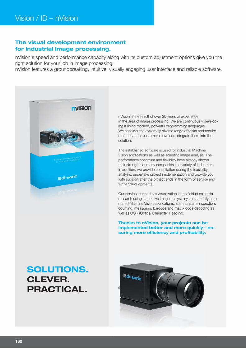
160
Vision / ID – nVision
SOLUTIONS.CLEVER.PRACTICAL.
The visual development environment for industrial image processing.
nVision's speed and performance capacity along with its custom adjustment options give you the right solution for your job in image processing. nVision features a groundbreaking, intuitive, visually engaging user interface and reliable software.
nVision is the result of over 20 years of experience in the area of image processing. We are continuously develop-ing it using modern, powerful programming languages. We consider the extremely diverse range of tasks and require-ments that our customers have and integrate them into the solution.
The established software is used for industrial Machine Vision applications as well as scientifi c image analysis. The performance spectrum and fl exibility have already shown their strengths at many companies in a variety of industries. In addition, we provide consultation during the feasibility analysis, undertake project implementation and provide you with support after the project ends in the form of service and further developments.
Our services range from visualization in the fi eld of scientifi c research using interactive image analysis systems to fully auto-mated Machine Vision applications, such as parts inspection, counting, measuring, barcode and matrix code decoding as well as OCR (Optical Character Reading).
Thanks to nVision, your projects can be implemented better and more quickly – en-suring more e� ciency and profi tability.

For more information and models visit www.di-soric-solutions.com 161
The easy-to-use image processing software for industry and science.
nVision is the unique and state-of-the-art culmination of 20 years of experience.nVision is a complete and fl exible solution, making it perfect for your applications in image processing as well.
Advantages
¡ Modern user interface
¡ Simple, intuitive and personalized operation
¡ Easy handling
¡ Top performance and stability
¡ Wide repertoire of functions
¡ Security for the resolvability of applications
¡ Less development time
¡ Time saving = Time-to-Market is shortened
¡ Supports a wide variety of cameras
¡ Easy integration into automated devices
¡ Individualized service and support
Functions
¡ Live data processing
¡ Automation of your application
¡ All pixel calculations either monochromatic or in color
¡ Barcode and Data Matrix identifi cation
¡ Completeness check
¡ Interactive measuring
¡ Font recognition (OCR, OCV)
¡ Pattern detection
¡ Surface inspection
¡ Position detection and robot guidance
¡ Printed image control
¡ Color recognition/ color processing
See it for yourself and call us up: +49 7181 98 78-0
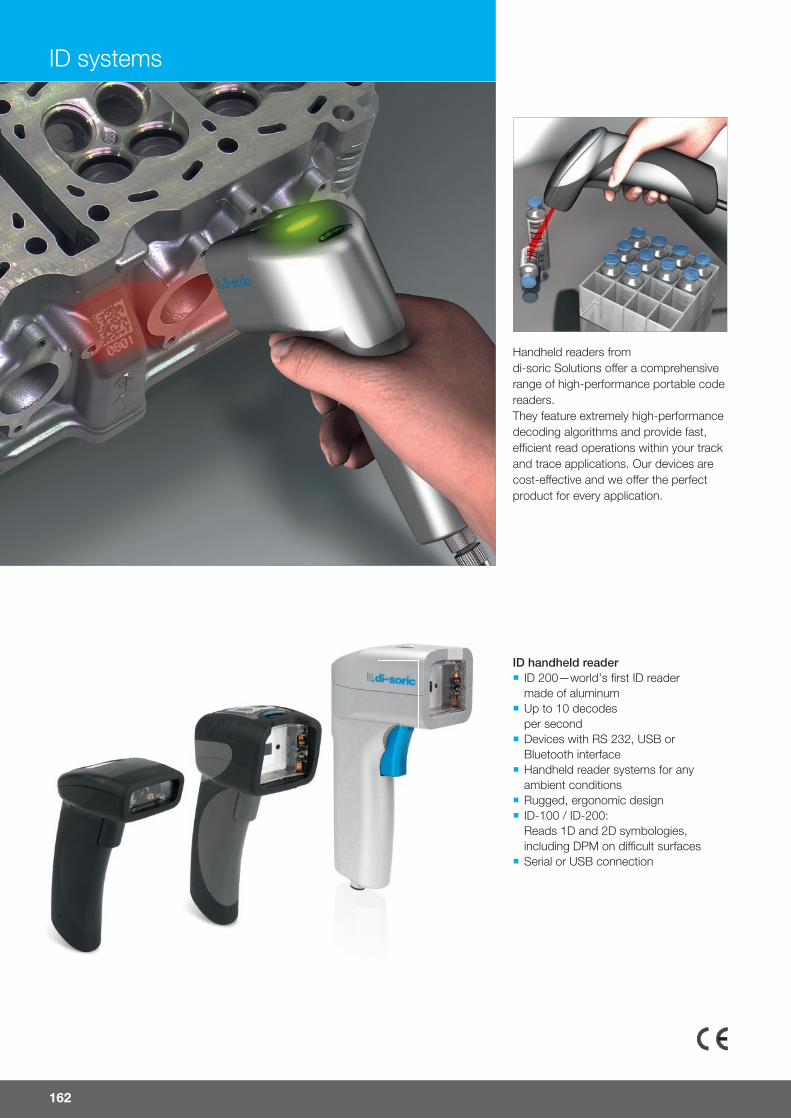
162
ID handheld reader ¡ ID 200—world's fi rst ID readermade of aluminum
¡ Up to 10 decodes per second
¡ Devices with RS 232, USB or Bluetooth interface
¡ Handheld reader systems for any ambient conditions
¡ Rugged, ergonomic design ¡ ID-100 / ID-200:Reads 1D and 2D symbologies,including DPM on diÁ cult surfaces
¡ Serial or USB connection
ID systems
Handheld readers from di-soric Solutions o� er a comprehensive range of high-performance portable code readers.They feature extremely high-performance decoding algorithms and provide fast, eÁ cient read operations within your track and trace applications. Our devices are cost-e� ective and we o� er the perfect product for every application.
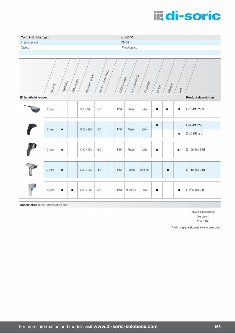
For more information and models visit www.di-soric-solutions.com 163
War
rant
y
Targ
et s
etup
ESD-
capa
ble
Reso
lutio
n (p
ixels
)
Serv
ice
volta
ge (V
DC)
Prot
ectio
n ty
pe
Hous
ing
mat
eria
l
Conn
ectio
n
RS 2
32
Blue
toot
h
USB
ID handheld reader Product description
2-year 960 x 640 5.0 IP 54 Plastic Cable n n 1) n ID-10-IM3-2-US
5-year n 1280 x 960 5.0 IP 54 Plastic Cablen ID-80-IM3-2-S
n ID-80-IM3-2-U
3-year n 1280 x 960 5.0 IP 54 Plastic Cable n n 1) ID-100-IM3-2-US
3-year n 1280 x 960 4.2 IP 65 Plastic Wireless n ID-110-IM3-2-BT
3-year n n 1280 x 960 5.0 – IP 54 Aluminum Cable n n ID-200-IM3-2-US
Accessories for ID handheld readers
Matching accessories
See page(s)
164 / 165
1) With separately available accessories
Technical data (typ.) at +20 °C
Image sensor CMOS
Optics Fixed optics
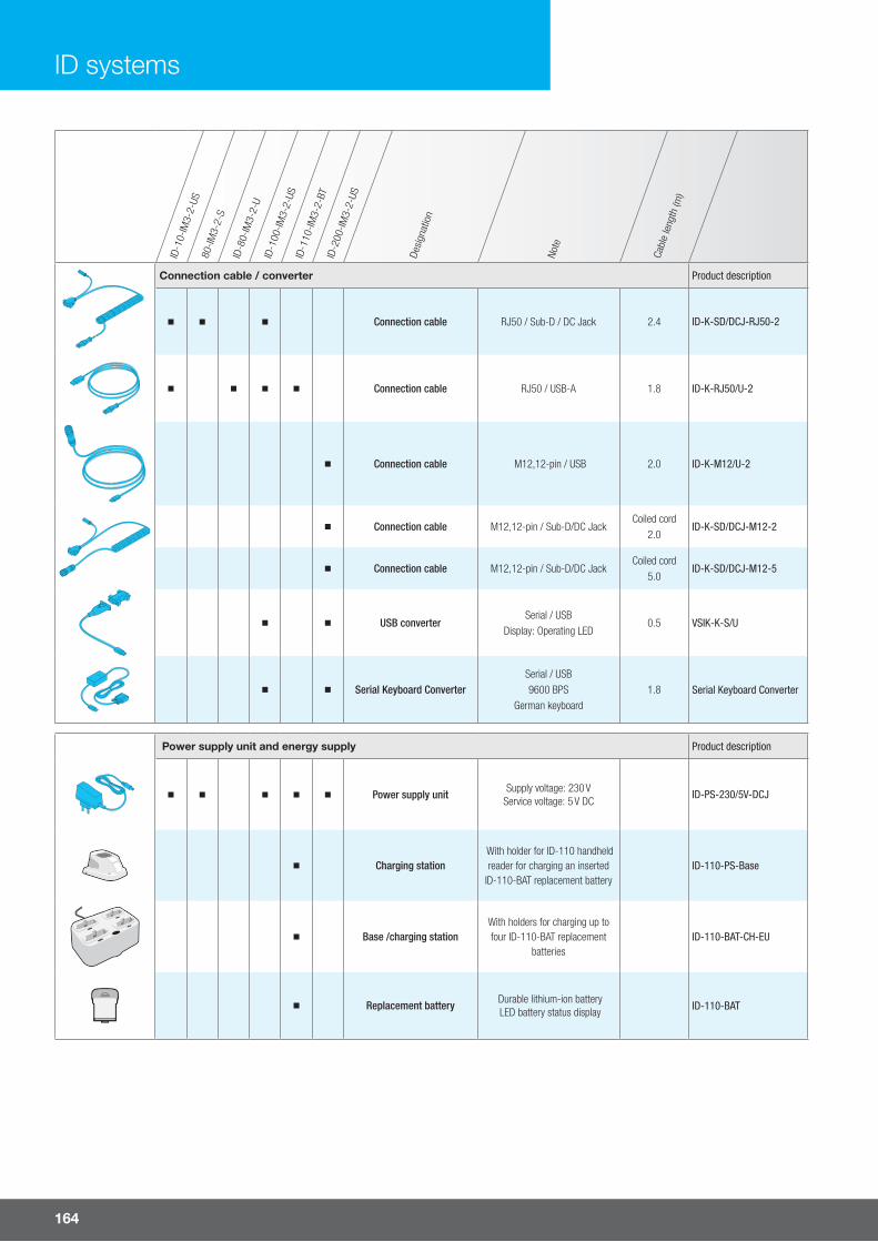
164
ID systems
ID-1
0-IM
3-2-
US80
-IM3-
2-S
ID-8
0-IM
3-2-
UID
-100
-IM3-
2-US
ID-1
10-IM
3-2-
BTID
-200
-IM3-
2-US
Desi
gnat
ion
Note
Cabl
e le
ngth
(m)
Connection cable / converter Product description
Connection cable RJ50 / Sub-D / DC Jack 2.4 ID-K-SD/DCJ-RJ50-2
Connection cable RJ50 / USB-A 1.8 ID-K-RJ50/U-2
Connection cable M12,12-pin / USB 2.0 ID-K-M12/U-2
Connection cable M12,12-pin / Sub-D/DC JackCoiled cord
2.0ID-K-SD/DCJ-M12-2
Connection cable M12,12-pin / Sub-D/DC JackCoiled cord
5.0ID-K-SD/DCJ-M12-5
USB converterSerial / USB
Display: Operating LED0.5 VSIK-K-S/U
Serial Keyboard ConverterSerial / USB 9600 BPS
German keyboard1.8 Serial Keyboard Converter
Power supply unit and energy supply Product description
Power supply unit Supply voltage: 230 VService voltage: 5 V DC
ID-PS-230/5V-DCJ
Charging station With holder for ID-110 handheld reader for charging an inserted
ID-110-BAT replacement batteryID-110-PS-Base
Base /charging stationWith holders for charging up to four ID-110-BAT replacement
batteriesID-110-BAT-CH-EU
Replacement battery Durable lithium-ion batteryLED battery status display ID-110-BAT
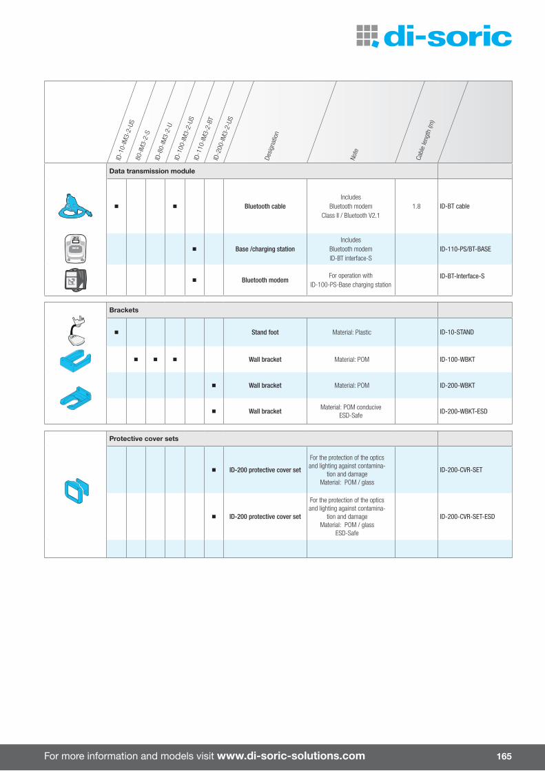
For more information and models visit www.di-soric-solutions.com 165
ID-1
0-IM
3-2-
US80
-IM3-
2-S
ID-8
0-IM
3-2-
UID
-100
-IM3-
2-US
ID-1
10-IM
3-2-
BTID
-200
-IM3-
2-US
Desi
gnat
ion
Note
Cabl
e le
ngth
(m)
Data transmission module
Bluetooth cableIncludes
Bluetooth modem Class II / Bluetooth V2.1
1.8 ID-BT cable
Base /charging stationIncludes
Bluetooth modem ID-BT interface-S
ID-110-PS/BT-BASE
Bluetooth modemFor operation with
ID-100-PS-Base charging stationID-BT-Interface-S
Brackets
Stand foot Material: Plastic ID-10-STAND
Wall bracket Material: POM ID-100-WBKT
Wall bracket Material: POM ID-200-WBKT
Wall bracket Material: POM conduciveESD-Safe ID-200-WBKT-ESD
Protective cover sets
ID-200 protective cover set
For the protection of the optics and lighting against contamina-
tion and damageMaterial: POM / glass
ID-200-CVR-SET
ID-200 protective cover set
For the protection of the optics and lighting against contamina-
tion and damage Material: POM / glass
ESD-Safe
ID-200-CVR-SET-ESD

166
di-soric Solutions lenses are used in a variety of applications and feature an extremely rugged mechanical design. All lenses have a standardized C-mount connection, lock screws for focus and iris adjustment and a compact design. Low distortion, high image contrasts and high light transmissionset these lenses apart.
Lenses ¡ Standardized C-mount connection ¡ Various focal lengths from 3.5 to 100 mm
¡ Compact design ¡ Lock screws for focus and iris adjustment
¡ Option for attaching fi lters on all models
Filter and protective glassfor all lenses ¡ Bandpass fi lter ¡ Cuto� fi lter ¡ Daylight cuto� fi lter ¡ Neutral density fi lter ¡ Polarized fi lter ¡ Lens protective glass
Lenses and accessories
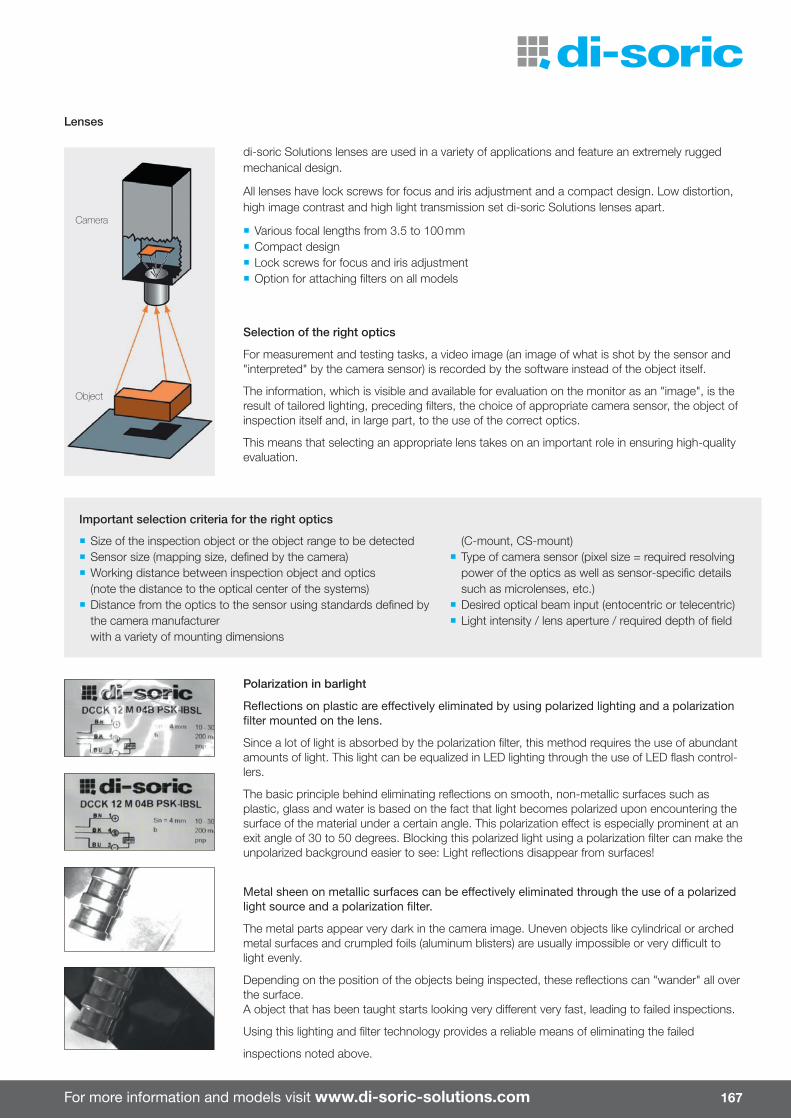
For more information and models visit www.di-soric-solutions.com 167
Polarization in barlight
Refl ections on plastic are e� ectively eliminated by using polarized lighting and a polarization fi lter mounted on the lens.
Since a lot of light is absorbed by the polarization fi lter, this method requires the use of abundant amounts of light. This light can be equalized in LED lighting through the use of LED fl ash control-lers.
The basic principle behind eliminating refl ections on smooth, non-metallic surfaces such as plastic, glass and water is based on the fact that light becomes polarized upon encountering the surface of the material under a certain angle. This polarization e� ect is especially prominent at an exit angle of 30 to 50 degrees. Blocking this polarized light using a polarization fi lter can make the unpolarized background easier to see: Light refl ections disappear from surfaces!
Metal sheen on metallic surfaces can be e� ectively eliminated through the use of a polarizedlight source and a polarization fi lter.
The metal parts appear very dark in the camera image. Uneven objects like cylindrical or arched metal surfaces and crumpled foils (aluminum blisters) are usually impossible or very diÁ cult to light evenly.
Depending on the position of the objects being inspected, these refl ections can "wander" all over the surface. A object that has been taught starts looking very di� erent very fast, leading to failed inspections.
Using this lighting and fi lter technology provides a reliable means of eliminating the failed
inspections noted above.
Important selection criteria for the right optics
¡ Size of the inspection object or the object range to be detected ¡ Sensor size (mapping size, defi ned by the camera) ¡ Working distance between inspection object and optics (note the distance to the optical center of the systems)
¡ Distance from the optics to the sensor using standards defi ned by the camera manufacturer with a variety of mounting dimensions
(C-mount, CS-mount) ¡ Type of camera sensor (pixel size = required resolving power of the optics as well as sensor-specifi c details such as microlenses, etc.)
¡ Desired optical beam input (entocentric or telecentric) ¡ Light intensity / lens aperture / required depth of fi eld
Lenses
di-soric Solutions lenses are used in a variety of applications and feature an extremely rugged mechanical design.
All lenses have lock screws for focus and iris adjustment and a compact design. Low distortion, high image contrast and high light transmission set di-soric Solutions lenses apart.
¡ Various focal lengths from 3.5 to 100 mm ¡ Compact design ¡ Lock screws for focus and iris adjustment ¡ Option for attaching fi lters on all models
Selection of the right optics
For measurement and testing tasks, a video image (an image of what is shot by the sensor and "interpreted" by the camera sensor) is recorded by the software instead of the object itself.
The information, which is visible and available for evaluation on the monitor as an "image", is the result of tailored lighting, preceding fi lters, the choice of appropriate camera sensor, the object of inspection itself and, in large part, to the use of the correct optics.
This means that selecting an appropriate lens takes on an important role in ensuring high-quality evaluation.
Camera
Object
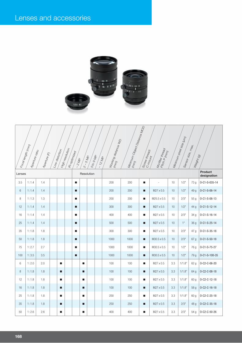
168
Foca
l len
gth
(mm
)A
per
ture
ratio
Aper
ture
(F)
Low
dis
tort
ion
Hig
h re
solu
tion
IR-o
ptim
ized
– 2
MP
2 –
5 M
P5
to 9
MP
– 12
MP
Wor
king
dis
tanc
e W
D
(mm
)
Min
imum
Obje
ct D
ista
nce
MO
D
(mm
)
Scr
ew thr
ead:
C-m
ount
M x
fi lte
r th
read
Pitc
h P
(mm
)
Min
imum
pix
el s
ize
(µm
)S
enso
r si
ze, m
ax.
Wei
ght (g
)
Lenses Resolution Productdesignation
3.5 1 : 1.4 1.4 n 200 200 n - 10 1/2" 73 g O-C1-S-035-14
6 1 : 1.4 1.4 n 200 200 n M27 x 0.5 10 1/2" 49 g O-C1-S-06-14
8 1 : 1.3 1.3 n 200 200 n M25.5 x 0.5 10 2/3" 55 g O-C1-S-08-13
12 1 : 1.4 1.4 n 300 300 n M27 x 0.5 10 1/2" 44 g O-C1-S-12-14
16 1 : 1.4 1.4 n 400 400 n M27 x 0.5 10 2/3" 34 g O-C1-S-16-14
25 1 : 1.4 1.4 n 500 500 n M27 x 0.5 10 1" 36 g O-C1-S-25-14
35 1 : 1.8 1.8 n 300 300 n M27 x 0.5 10 2/3" 47 g O-C1-S-35-18
50 1 : 1.8 1.8 n 1000 1000 n M30.5 x 0.5 10 2/3" 67 g O-C1-S-50-18
75 1 : 2.7 2.7 n 1000 1000 n M30.5 x 0.5 10 1/2" 76 g O-C1-S-75-27
100 1 : 3.5 3.5 n 1000 1000 n M30.5 x 0.5 10 1/2" 79 g O-C1-S-100-35
6 1 : 2.0 2.0 n n 100 100 n M27 x 0.5 3.3 1/1.8" 62 g O-C2-C-06-20
8 1 : 1.8 1.8 n n 100 100 n M27 x 0.5 3.3 1/1.8" 64 g O-C2-C-08-18
12 1 : 1.8 1.8 n n 100 100 n M27 x 0.5 3.3 1/1.8" 60 g O-C2-C-12-18
16 1 : 1.8 1.8 n n 100 100 n M27 x 0.5 3.3 1/1.8" 58 g O-C2-C-16-18
25 1 : 1.8 1.8 n n 250 250 n M27 x 0.5 3.3 1/1.8" 60 g O-C2-C-25-18
35 1 : 1.8 1.8 n n 250 250 n M27 x 0.5 3.3 2/3" 48 g O-C2-C-35-18
50 1 : 2.6 2.6 n n 400 400 n M27 x 0.5 3.3 2/3" 54 g O-C2-C-50-26
Lenses and accessories
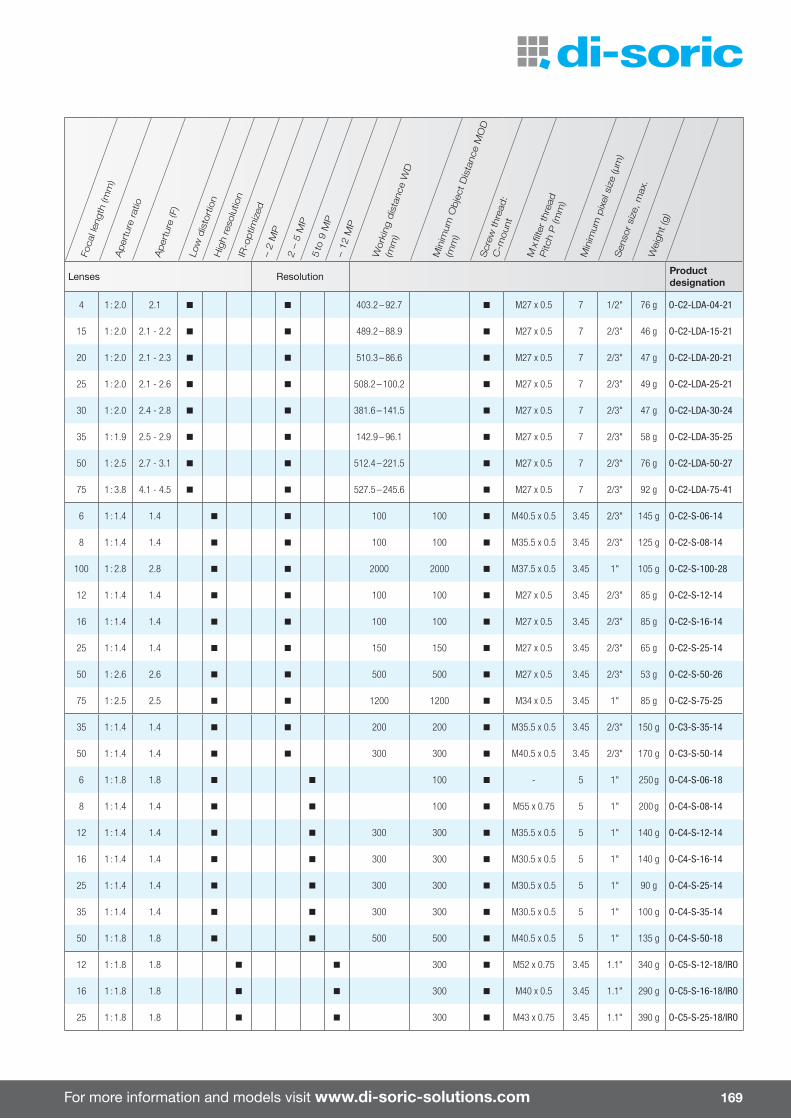
For more information and models visit www.di-soric-solutions.com 169
Foca
l len
gth
(mm
)A
per
ture
ratio
Aper
ture
(F)
Low
dis
tort
ion
Hig
h re
solu
tion
IR-o
ptim
ized
– 2
MP
2 –
5 M
P5
to 9
MP
– 12
MP
Wor
king
dis
tanc
e W
D
(mm
)
Min
imum
Obje
ct D
ista
nce
MO
D
(mm
)
Scr
ew thr
ead:
C-m
ount
M x
filte
r th
read
P
itch
P (m
m)
Min
imum
pix
el s
ize
(µm
)S
enso
r si
ze, m
ax.
Wei
ght (g
)
Lenses Resolution Product designation
4 1 : 2.0 2.1 n n 403.2 – 92.7 n M27 x 0.5 7 1/2" 76 g O-C2-LDA-04-21
15 1 : 2.0 2.1 - 2.2 n n 489.2 – 88.9 n M27 x 0.5 7 2/3" 46 g O-C2-LDA-15-21
20 1 : 2.0 2.1 - 2.3 n n 510.3 – 86.6 n M27 x 0.5 7 2/3" 47 g O-C2-LDA-20-21
25 1 : 2.0 2.1 - 2.6 n n 508.2 – 100.2 n M27 x 0.5 7 2/3" 49 g O-C2-LDA-25-21
30 1 : 2.0 2.4 - 2.8 n n 381.6 – 141.5 n M27 x 0.5 7 2/3" 47 g O-C2-LDA-30-24
35 1 : 1.9 2.5 - 2.9 n n 142.9 – 96.1 n M27 x 0.5 7 2/3" 58 g O-C2-LDA-35-25
50 1 : 2.5 2.7 - 3.1 n n 512.4 – 221.5 n M27 x 0.5 7 2/3" 76 g O-C2-LDA-50-27
75 1 : 3.8 4.1 - 4.5 n n 527.5 – 245.6 n M27 x 0.5 7 2/3" 92 g O-C2-LDA-75-41
6 1 : 1.4 1.4 n n 100 100 n M40.5 x 0.5 3.45 2/3" 145 g O-C2-S-06-14
8 1 : 1.4 1.4 n n 100 100 n M35.5 x 0.5 3.45 2/3" 125 g O-C2-S-08-14
100 1 : 2.8 2.8 n n 2000 2000 n M37.5 x 0.5 3.45 1" 105 g O-C2-S-100-28
12 1 : 1.4 1.4 n n 100 100 n M27 x 0.5 3.45 2/3" 85 g O-C2-S-12-14
16 1 : 1.4 1.4 n n 100 100 n M27 x 0.5 3.45 2/3" 85 g O-C2-S-16-14
25 1 : 1.4 1.4 n n 150 150 n M27 x 0.5 3.45 2/3" 65 g O-C2-S-25-14
50 1 : 2.6 2.6 n n 500 500 n M27 x 0.5 3.45 2/3" 53 g O-C2-S-50-26
75 1 : 2.5 2.5 n n 1200 1200 n M34 x 0.5 3.45 1" 85 g O-C2-S-75-25
35 1 : 1.4 1.4 n n 200 200 n M35.5 x 0.5 3.45 2/3" 150 g O-C3-S-35-14
50 1 : 1.4 1.4 n n 300 300 n M40.5 x 0.5 3.45 2/3" 170 g O-C3-S-50-14
6 1 : 1.8 1.8 n n 100 n - 5 1" 250 g O-C4-S-06-18
8 1 : 1.4 1.4 n n 100 n M55 x 0.75 5 1" 200 g O-C4-S-08-14
12 1 : 1.4 1.4 n n 300 300 n M35.5 x 0.5 5 1" 140 g O-C4-S-12-14
16 1 : 1.4 1.4 n n 300 300 n M30.5 x 0.5 5 1" 140 g O-C4-S-16-14
25 1 : 1.4 1.4 n n 300 300 n M30.5 x 0.5 5 1" 90 g O-C4-S-25-14
35 1 : 1.4 1.4 n n 300 300 n M30.5 x 0.5 5 1" 100 g O-C4-S-35-14
50 1 : 1.8 1.8 n n 500 500 n M40.5 x 0.5 5 1" 135 g O-C4-S-50-18
12 1 : 1.8 1.8 n n 300 n M52 x 0.75 3.45 1.1" 340 g O-C5-S-12-18/IRO
16 1 : 1.8 1.8 n n 300 n M40 x 0.5 3.45 1.1" 290 g O-C5-S-16-18/IRO
25 1 : 1.8 1.8 n n 300 n M43 x 0.75 3.45 1.1" 390 g O-C5-S-25-18/IRO
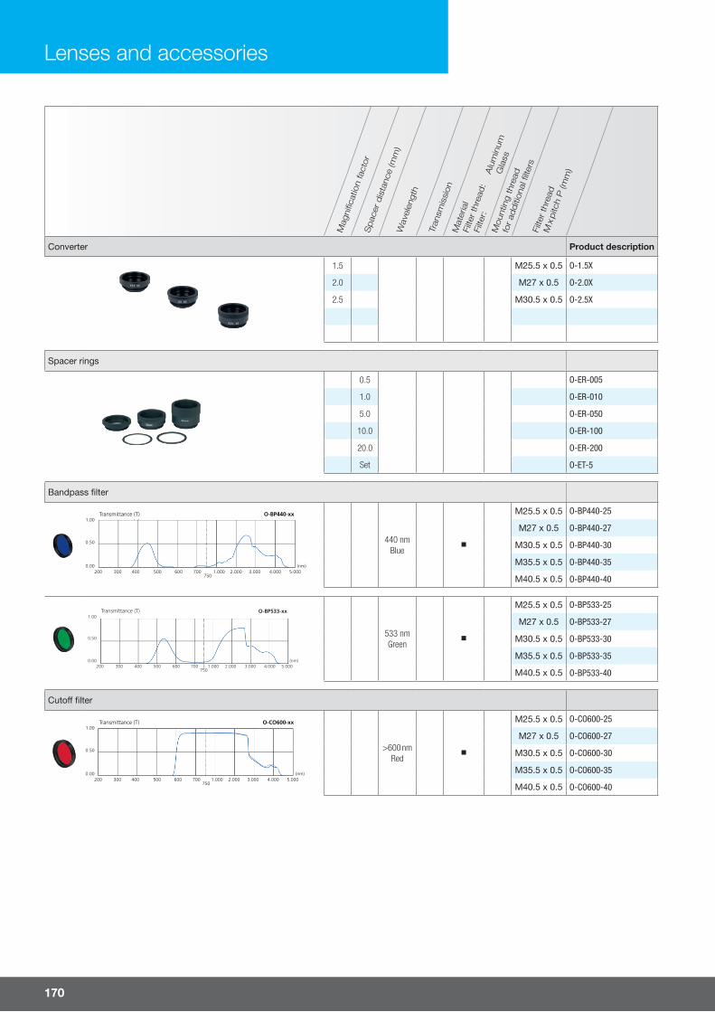
170
Mag
nifi c
atio
n fa
ctor
Spac
er d
ista
nce
(mm
)W
avel
engt
h
Tran
smis
sion
Alu
min
umG
lass
Mou
ntin
g th
read
for
additi
onal
fi lte
rsFi
lter
thre
ad
M x
pitc
h P
(mm
)
Mat
eria
lFi
lter
thre
ad:
Filte
r:
Converter Product description
1.5 M25.5 x 0.5 O-1.5X
2.0 M27 x 0.5 O-2.0X
2.5 M30.5 x 0.5 O-2.5X
Spacer rings
0.5 O-ER-005
1.0 O-ER-010
5.0 O-ER-050
10.0 O-ER-100
20.0 O-ER-200
Set O-ET-5
Bandpass fi lter
Transmittance (T) O-BP440-xx1.00
0.50
0.00200 300 400 500 600 700
7501.000 2.000 3.000 4.000 5.000
(nm)
440 nmBlue
M25.5 x 0.5 O-BP440-25
M27 x 0.5 O-BP440-27
M30.5 x 0.5 O-BP440-30
M35.5 x 0.5 O-BP440-35
M40.5 x 0.5 O-BP440-40
Transmittance (T) O-BP533-xx1.00
0.50
0.00200 300 400 500 600 700
7501.000 2.000 3.000 4.000 5.000
(nm)
533 nmGreen
M25.5 x 0.5 O-BP533-25
M27 x 0.5 O-BP533-27
M30.5 x 0.5 O-BP533-30
M35.5 x 0.5 O-BP533-35
M40.5 x 0.5 O-BP533-40
Cuto� fi lter
Transmittance (T) O-CO600-xx1.00
0.50
0.00200 300 400 500 600 700
7501.000 2.000 3.000 4.000 5.000
(nm)
>600 nmRed
M25.5 x 0.5 O-CO600-25
M27 x 0.5 O-CO600-27
M30.5 x 0.5 O-CO600-30
M35.5 x 0.5 O-CO600-35
M40.5 x 0.5 O-CO600-40
Lenses and accessories

For more information and models visit www.di-soric-solutions.com 171
Mag
nific
atio
n fa
ctor
Spac
er d
ista
nce
(mm
)W
avel
engt
h
Tran
smis
sion
Alu
min
umG
lass
Mou
ntin
g th
read
for
additi
onal
filte
rsFi
lter
thre
ad
M x
pitc
h P
(mm
)
Mat
eria
lFi
lter
thre
ad:
Filte
r:
Daylight cuto� filter Product description
Transmittance (T) O-DC700-xx1.00
0.50
0.00200 300 400 500 600 700
7501.000 2.000 3.000 4.000 5.000
(nm)
>700 nm
M25.5 x 0.5 O-DC700-25
M27 x 0.5 O-DC700-27
M30.5 x 0.5 O-DC700-30
M35.5 x 0.5 O-DC700-35
M40.5 x 0.5 O-DC700-40
Neutral density filter
Transmittance (T)O-ND25-xxO-ND50-xx
1.00
0.50
0.00200 300 400 500 600 700
7501.000 2.000 3.000 4.000 5.000
(nm)
25%
M25.5 x 0.5 O-ND25-25
M27 x 0.5 O-ND25-27
M30.5 x 0.5 O-ND25-30
M35.5 x 0.5 O-ND25-35
M40.5 x 0.5 O-ND25-40
50%
M25.5 x 0.5 O-ND50-25
M27 x 0.5 O-ND50-27
M30.5 x 0.5 O-ND50-30
M35.5 x 0.5 O-ND50-35
M40.5 x 0.5 O-ND50-40
Polarization filter with lock screw
M25.5 x 0.5 O-POL-25
M27 x 0.5 O-POL-27
M30.5 x 0.5 O-POL-30
M35.5 x 0.5 O-POL-35
M40.5 x 0.5 O-POL-40
Lens protection glass
M25.5 x 0.5 O-PG-25
M27 x 0.5 O-PG-27
M30.5 x 0.5 O-PG-30
M35.5 x 0.5 O-PG-35
M40.5 x 0.5 O-PG-40
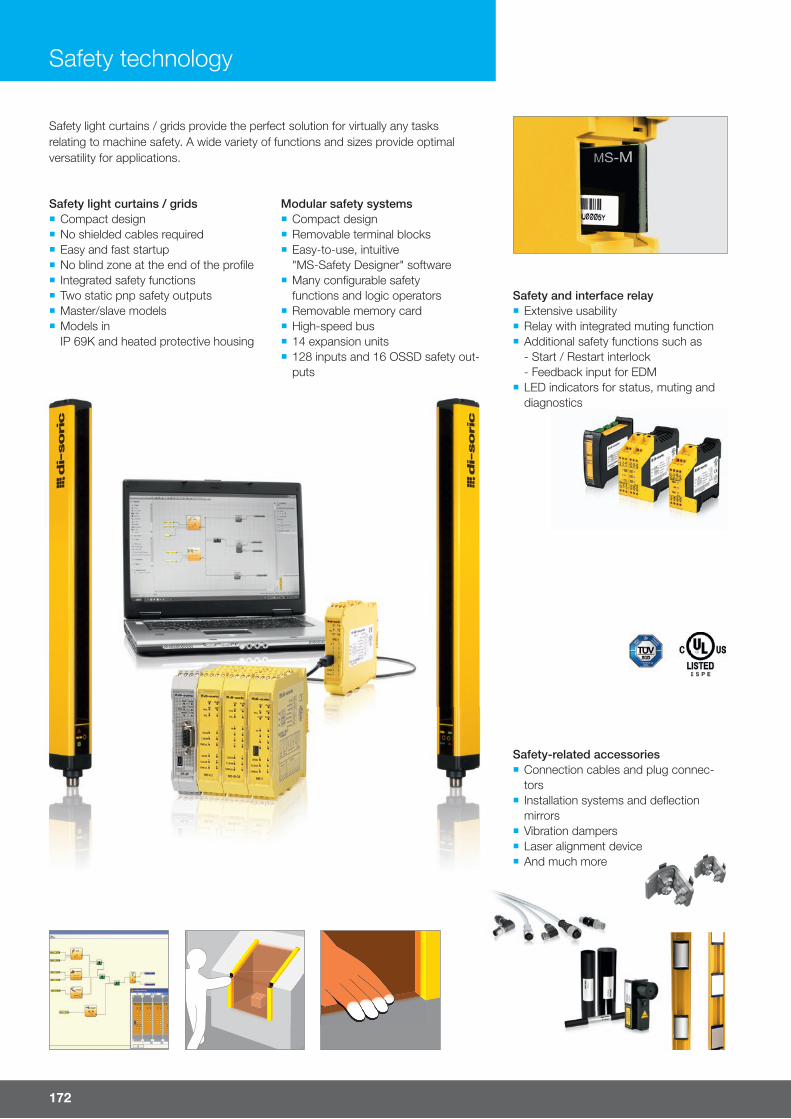
Safety technology
Safety light curtains / grids ¡ Compact design ¡ No shielded cables required ¡ Easy and fast startup ¡ No blind zone at the end of the profi le ¡ Integrated safety functions ¡ Two static pnp safety outputs ¡ Master/slave models ¡ Models in IP 69K and heated protective housing
Modular safety systems ¡ Compact design ¡ Removable terminal blocks ¡ Easy-to-use, intuitive "MS-Safety Designer" software
¡ Many confi gurable safety functions and logic operators
¡ Removable memory card ¡ High-speed bus ¡ 14 expansion units ¡ 128 inputs and 16 OSSD safety out-puts
Safety light curtains / grids provide the perfect solution for virtually any tasks relating to machine safety. A wide variety of functions and sizes provide optimal versatility for applications.
Safety and interface relay ¡ Extensive usability ¡ Relay with integrated muting function ¡ Additional safety functions such as- Start / Restart interlock- Feedback input for EDM
¡ LED indicators for status, muting and diagnostics
Safety-related accessories ¡ Connection cables and plug connec-tors
¡ Installation systems and defl ection mirrors
¡ Vibration dampers ¡ Laser alignment device ¡ And much more
172
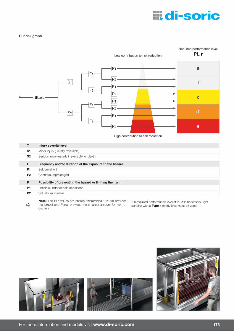
For more information and models visit www.di-soric.com
T Injury severity level
S1 Minor injury (usually reversible)
S2 Serious injury (usually irreversible) or death
F Frequency and/or duration of the exposure to the hazard
F1 Seldom/short
F2 Continuous/prolonged
P Possibility of preventing the hazard or limiting the harm
P1 Possible under certain conditions
P2 Virtually impossible
➪Note: The PLr values are entirely "hierarchical". PLr(e) provides the largest and PLr(a) provides the smallest amount for risk re-duction.
* If a required performance level of PL d is necessary, light curtains with a Type 4 safety level must be used!
PLr risk graph
Required performance level
PL rLow contribution to risk reduction
High contribution to risk reduction
Start
S1
S2
F1
F2
P1
P2
P1
P2
P1
P2
P1
P2
F1
F2
a
f
c
d*
e
173
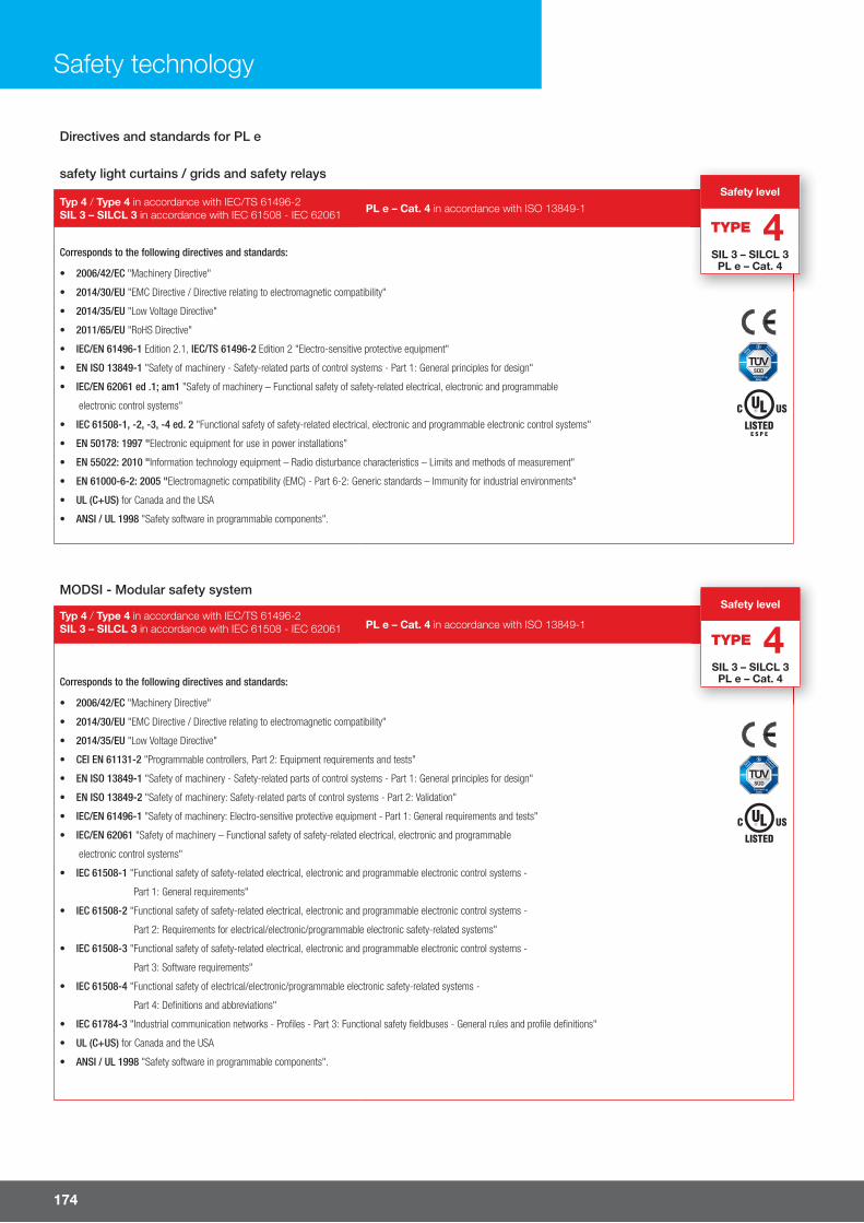
Directives and standards for PL e
safety light curtains / grids and safety relays
Typ 4 / Type 4 in accordance with IEC/TS 61496-2SIL 3 – SILCL 3 in accordance with IEC 61508 - IEC 62061 PL e – Cat. 4 in accordance with ISO 13849-1
Corresponds to the following directives and standards:
• 2006/42/EC "Machinery Directive"
• 2014/30/EU "EMC Directive / Directive relating to electromagnetic compatibility"
• 2014/35/EU "Low Voltage Directive"
• 2011/65/EU "RoHS Directive"
• IEC/EN 61496-1 Edition 2.1, IEC/TS 61496-2 Edition 2 "Electro-sensitive protective equipment"
• EN ISO 13849-1 "Safety of machinery - Safety-related parts of control systems - Part 1: General principles for design"
• IEC/EN 62061 ed .1; am1 "Safety of machinery – Functional safety of safety-related electrical, electronic and programmable
electronic control systems"
• IEC 61508-1, -2, -3, -4 ed. 2 "Functional safety of safety-related electrical, electronic and programmable electronic control systems"
• EN 50178: 1997 "Electronic equipment for use in power installations"
• EN 55022: 2010 "Information technology equipment – Radio disturbance characteristics – Limits and methods of measurement"
• EN 61000-6-2: 2005 "Electromagnetic compatibility (EMC) - Part 6-2: Generic standards – Immunity for industrial environments"
• UL (C+US) for Canada and the USA
• ANSI / UL 1998 "Safety software in programmable components".
MODSI - Modular safety system
Typ 4 / Type 4 in accordance with IEC/TS 61496-2SIL 3 – SILCL 3 in accordance with IEC 61508 - IEC 62061 PL e – Cat. 4 in accordance with ISO 13849-1
Corresponds to the following directives and standards:
• 2006/42/EC "Machinery Directive"
• 2014/30/EU "EMC Directive / Directive relating to electromagnetic compatibility"
• 2014/35/EU "Low Voltage Directive"
• CEI EN 61131-2 "Programmable controllers, Part 2: Equipment requirements and tests"
• EN ISO 13849-1 "Safety of machinery - Safety-related parts of control systems - Part 1: General principles for design"
• EN ISO 13849-2 "Safety of machinery: Safety-related parts of control systems - Part 2: Validation"
• IEC/EN 61496-1 "Safety of machinery: Electro-sensitive protective equipment - Part 1: General requirements and tests"
• IEC/EN 62061 "Safety of machinery – Functional safety of safety-related electrical, electronic and programmable
electronic control systems"
• IEC 61508-1 "Functional safety of safety-related electrical, electronic and programmable electronic control systems -
Part 1: General requirements"
• IEC 61508-2 "Functional safety of safety-related electrical, electronic and programmable electronic control systems -
Part 2: Requirements for electrical/electronic/programmable electronic safety-related systems"
• IEC 61508-3 "Functional safety of safety-related electrical, electronic and programmable electronic control systems -
Part 3: Software requirements"
• IEC 61508-4 "Functional safety of electrical/electronic/programmable electronic safety-related systems -
Part 4: Definitions and abbreviations"
• IEC 61784-3 "Industrial communication networks - Profiles - Part 3: Functional safety fieldbuses - General rules and profile definitions"
• UL (C+US) for Canada and the USA
• ANSI / UL 1998 "Safety software in programmable components".
E S P E
Safety level
TYPE 4SIL 3 – SILCL 3
PL e – Cat. 4
Safety level
TYPE 4SIL 3 – SILCL 3
PL e – Cat. 4
Safety technology
174

For more information and models visit www.di-soric.com
Directives and standards for PL e
safety light curtains / grids and safety relays
Typ 4 / Type 4 in accordance with IEC/TS 61496-2SIL 3 – SILCL 3 in accordance with IEC 61508 - IEC 62061 PL e – Cat. 4 in accordance with ISO 13849-1
Corresponds to the following directives and standards:
• 2006/42/EC "Machinery Directive"
• 2014/30/EU "EMC Directive / Directive relating to electromagnetic compatibility"
• 2014/35/EU "Low Voltage Directive"
• 2011/65/EU "RoHS Directive"
• IEC/EN 61496-1 Edition 2.1, IEC/TS 61496-2 Edition 2 "Electro-sensitive protective equipment"
• EN ISO 13849-1 "Safety of machinery - Safety-related parts of control systems - Part 1: General principles for design"
• IEC/EN 62061 ed .1; am1 "Safety of machinery – Functional safety of safety-related electrical, electronic and programmable
electronic control systems"
• IEC 61508-1, -2, -3, -4 ed. 2 "Functional safety of safety-related electrical, electronic and programmable electronic control systems"
• EN 50178: 1997 "Electronic equipment for use in power installations"
• EN 55022: 2010 "Information technology equipment – Radio disturbance characteristics – Limits and methods of measurement"
• EN 61000-6-2: 2005 "Electromagnetic compatibility (EMC) - Part 6-2: Generic standards – Immunity for industrial environments"
• UL (C+US) for Canada and the USA
• ANSI / UL 1998 "Safety software in programmable components".
MODSI - Modular safety system
Typ 4 / Type 4 in accordance with IEC/TS 61496-2SIL 3 – SILCL 3 in accordance with IEC 61508 - IEC 62061 PL e – Cat. 4 in accordance with ISO 13849-1
Corresponds to the following directives and standards:
• 2006/42/EC "Machinery Directive"
• 2014/30/EU "EMC Directive / Directive relating to electromagnetic compatibility"
• 2014/35/EU "Low Voltage Directive"
• CEI EN 61131-2 "Programmable controllers, Part 2: Equipment requirements and tests"
• EN ISO 13849-1 "Safety of machinery - Safety-related parts of control systems - Part 1: General principles for design"
• EN ISO 13849-2 "Safety of machinery: Safety-related parts of control systems - Part 2: Validation"
• IEC/EN 61496-1 "Safety of machinery: Electro-sensitive protective equipment - Part 1: General requirements and tests"
• IEC/EN 62061 "Safety of machinery – Functional safety of safety-related electrical, electronic and programmable
electronic control systems"
• IEC 61508-1 "Functional safety of safety-related electrical, electronic and programmable electronic control systems -
Part 1: General requirements"
• IEC 61508-2 "Functional safety of safety-related electrical, electronic and programmable electronic control systems -
Part 2: Requirements for electrical/electronic/programmable electronic safety-related systems"
• IEC 61508-3 "Functional safety of safety-related electrical, electronic and programmable electronic control systems -
Part 3: Software requirements"
• IEC 61508-4 "Functional safety of electrical/electronic/programmable electronic safety-related systems -
Part 4: Definitions and abbreviations"
• IEC 61784-3 "Industrial communication networks - Profiles - Part 3: Functional safety fieldbuses - General rules and profile definitions"
• UL (C+US) for Canada and the USA
• ANSI / UL 1998 "Safety software in programmable components".
Finger protection SLB4-… SLI4-…
Light barrier type Light curtain
Safety levelType 4
SIL 3 – SILCL 3PL e – Cat. 4
Resolution 14 mm
Protective field height 160 - 1,810 mm
Maximum operating distance 6 m
Start / restart interlock integrated - üEDM integrated - ü
Master/slave versions - ü(Slave / Slave 2)
It is helpful to divide the application of safety light curtains / grids into four groups:
Selection guide for safety light curtains / grids
Detection of a finger Detection of a body in thedanger zone
Detection of a hand Detection of a body during the access control
Hand protection SLB4-… SLBH4-… SLI4-… SLIH4-...
Light barrier type Light curtain
Safety levelType 4
SIL 3 – SILCL 3PL e – Cat. 4
Resolution 20 - 30 - 40 mm
Protective field height 160 - 1,810 mm
Maximum operating distance 12 m 20 m 12 m 20 m
Start / restart interlock integrated - - ü üEDM integrated - - ü ü
Master/slave versions - - ü(Slave / Slave 2)
-
175

Safety technology
GlossaryStart / restart interlock:Locking function when the machine is started or restarted(manual confi rmation required).
EDM - External Device Monitoring:Monitoring of the external switch protection devices using a feedback input.
Master/slave:Two or three light curtains/grids can be switched in series; all outputs are managed by only one light curtain/grid (Master).
Body protection SLB4-… SLBH4-… SLI4-… SLIH4-...
Light barrier type Light curtain
Safety levelType 4
SIL 3 – SILCL 3PL e – Cat. 4
Resolution 50 - 90 mm
Protective field height 160 - 1,810 mm
Maximum operating distance 12 m 20 m 12 m 20 m
Start / restart interlock integrated - - ü üEDM integrated - - ü ü
Master/slave versions - - ü(Slave / Slave 2)
-
Access control SLB4-xB SLBH4-xB SLI4-xB SLIH4-xB
Light barrier type Light grids
Safety levelType 4
SIL 3 – SILCL 3PL e – Cat. 4
Number of beams 2 - 3 - 4
Beam separation (axis distance) 300 - 400 - 500 mm
Protective field height 510 - 810 - 910 mm
Maximum operating distance 12 m 20 m 12 m 20 m
Start / restart interlock integrated - - ü üEDM integrated - - ü ü
Master/slave versions - - ü(Slave / Slave 2)
-
176

For more information and models visit www.di-soric.com
Re
solu
tion
/ b
ea
m
sep
ara
tion
(m
m)
Nu
mb
er
of
be
am
sP
rote
ctiv
e fi
eld
he
igh
t
(mm
)
Tota
l he
igh
t (m
m)
Re
spo
nse
tim
e (
ms)
Co
nn
ec
tion
ca
ble
(op
tion
ally
ava
ilab
le)
Safety light curtain / grid SLB4 SLBH4 SLI4 SLIH4
Safety level Type 4 Type 4 Type 4 Type 4
Particularity For external safety functions Integrated safety functions
Operating distance up to 6 m up to 6 m
Finger protec-tion
14 mm
15 160 213 4
TransmitterCD …
ReceiverCD … /
SLI… : C8D
SLB4-151 SLI4-1511)
30 310 363 5.5 SLB4-301 SLI4-3011)
45 460 513 7.5 SLB4-451 SLI4-4511)
60 610 663 9 SLB4-601 SLI4-6011)
75 760 813 11 SLB4-751 SLI4-7511)
90 910 963 13 SLB4-901 SLI4-9011)
105 1060 1113 14.5 SLB4-1051 SLI4-10511)
120 1210 1263 16.5 SLB4-1201 SLI4-12011)
135 1360 1413 18 SLB4-1351 SLI4-13511)
150 1510 1563 20 SLB4-1501 SLI4-15011)
165 1660 1713 22 SLB4-1651 SLI4-16511)
180 1810 1886 23.5 SLB4-1801 SLI4-18011)
Safety level
TYPE 4SIL 3 – SILCL 3
PL e – Cat. 4
¡ SLB … and SLI … ¡ Highest safety level ¡ Light curtains for fi nger protection, hand protection, body protection and presence check ¡ Light grid with 2, 3 or 4 beams for detecting a body during access control ¡ Models with an increased operating distance for large systems and applications with defl ecting mirrors
¡ Protective fi eld heights from 160 to 1,810 mm ¡ Protection area up to the profi le length end of the light curtain/grid ¡ Confi guring the operating distance via the connection cable ¡ Unshielded connection cables with a length of up to 100 meters are possible ¡ High protection typeOnly SLI …
¡ Integrated safety function – no external safety relay required ¡ Selectable manual or automatic Start/Restart ¡ Feedback input for external relay monitoring (EDM)
Technical data (typ.)
Safety levelType 4 in accordance with IEC/TS 61496-2SIL 3 – SILCL 3 in accordance with IEC 61508 - IEC 62061PL e – Cat. 4 in accordance with ISO 13849-1
Profile cross section 28 x 30 mm
Safety outputs (master) PNP (2x), 400 mA, 24 V DC
LED displaysSelf-diagnosticsStatus
Start / restart (master) Automatic
Service voltage 19.2 to 28.8 V DC
Master connection M12, 5-pin
M12, 8-pin (receiver) (SLB … and SLI …)
Length of connection cable max. 100 m unshielded
Ambient temperature -20 to +55 °C
Protection type IP 65 + IP 67
Protection class III, operation on protective low voltage
Housing material Aluminum
Window material Polycarbonate
Mounting Rear side, T-shaped slot, or using adjustable brackets SFB E180 (optional)
1) See the note on page 181
Product description
177

Re
solu
tion
/ b
ea
m
sep
ara
tion
(m
m)
Nu
mb
er
of
be
am
sP
rote
ctiv
e fi
eld
he
igh
t
(mm
)
Tota
l he
igh
t (m
m)
Re
spo
nse
tim
e (
ms)
Co
nn
ec
tion
ca
ble
(op
tion
ally
ava
ilab
le)
Safety light curtain / grid SLB4 SLBH4 SLI4 SLIH4
Safety level Type 4 Type 4 Type 4 Type 4
Particularity For external safety functions Integrated safety functions
Operating distance up to 20 m up to 12 m up to 20 m
Hand protec-tion
20 mm
15 160 213 4
TransmitterCD …
ReceiverCD … / C8D
SLBH4-152 SLIH4-152
30 310 363 5.5 SLBH4-302 SLIH4-302
45 460 513 7.5 SLBH4-452 SLIH4-452
60 610 663 9 SLBH4-602 SLIH4-602
75 760 813 11 SLBH4-752 SLIH4-752
90 910 963 13 SLBH4-902 SLIH4-902
105 1060 1113 14.5 SLBH4-1052 SLIH4-1052
120 1210 1263 16.5 SLBH4-1202 SLIH4-1202
135 1360 1413 18 SLBH4-1352 SLIH4-1352
150 1510 1563 20 SLBH4-1502 SLIH4-1502
165 1660 1713 22 SLBH4-1652 SLIH4-1652
180 1810 1886 23.5 SLBH4-1802 SLIH4-1802
Operating distance up to 12 m up to 20 m up to 12 m up to 20 m
Hand protec-tion
30 mm
8 160 213 4
TransmitterCD …
ReceiverCD … / C8D
SLB4-153 SLI4-1531)
13 260 313 5 SLB4-253 SLI4-2531)
16 310 363 5.4 SLB4-303 SLI4-3031)
23 460 513 7.5 SLB4-453 SLI4-4531)
31 610 663 9 SLB4-603 SLI4-6031)
38 760 813 10.5 SLB4-753 SLI4-7531)
46 910 963 12.5 SLB4-903 SLI4-9031)
53 1060 1113 14 SLB4-1053 SLI4-10531)
61 1210 1263 15.5 SLB4-1203 SLI4-12031)
68 1360 1413 17 SLB4-1353 SLI4-13531)
76 1510 1563 19 SLB4-1503 SLI4-15031)
88 1660 1713 20.5 SLB4-1653 SLI4-16531)
91 1810 1886 22 SLB4-1803 SLI4-18031)
Operating distance up to 12 m up to 20 m up to 12 m up to 20 m
Hand protec-tion
30 mm
8 160 213 3
TransmitterCD …
ReceiverCD … / C8D
SLBH4-153 SLIH4-1531)
16 310 363 4 SLBH4-303 SLIH4-3031)
23 460 513 5 SLBH4-453 SLIH4-4531)
31 610 663 6 SLBH4-603 SLIH4-6031)
38 760 813 6.5 SLBH4-753 SLIH4-7531)
46 910 963 7.5 SLBH4-903 SLIH4-9031)
53 1060 1113 8.5 SLBH4-1053 SLIH4-10531)
61 1210 1263 9.5 SLBH4-1203 SLIH4-12031)
68 1360 1413 10 SLBH4-1353 SLIH4-13531)
76 1510 1563 11 SLBH4-1503 SLIH4-15031)
88 1660 1713 12 SLBH4-1653 SLIH4-16531)
91 1810 1886 13 SLBH4-1803 SLIH4-18031)
Safety technology
1) See the note on page 181
Product description
178

For more information and models visit www.di-soric.com
Re
solu
tion
/ b
ea
m
sep
ara
tion
(m
m)
Nu
mb
er
of
be
am
sP
rote
ctiv
e fi
eld
he
igh
t
(mm
)
Tota
l he
igh
t (m
m)
Re
spo
nse
tim
e (
ms)
Co
nn
ec
tion
ca
ble
(op
tion
ally
ava
ilab
le)
Safety light curtain / grid SLB4 SLBH4 SLI4 SLIH4
Safety level Type 4 Type 4 Type 4 Type 4
Particularity For external safety functions Integrated safety functions
Operating distance up to 12 m up to 20 m up to 12 m up to 20 m
Hand protec-tion
40 mm
6 160 213 3.5
TransmitterCD …
ReceiverCD … / C8D
SLB4-154 SLI4-1541)
8 260 313 4 SLB4-254 SLI4-2541)
11 310 363 4.5 SLB4-304 SLI4-3041)
16 460 513 5.5 SLB4-454 SLI4-4541)
21 610 663 7 SLB4-604 SLI4-6041)
26 760 813 8 SLB4-754 SLI4-7541)
31 910 963 9 SLB4-904 SLI4-9041)
36 1060 1113 10 SLB4-1054 SLI4-10541)
41 1210 1263 11 SLB4-1204 SLI4-12041)
46 1360 1413 12.5 SLB4-1354 SLI4-13541)
51 1510 1563 13.5 SLB4-1504 SLI4-15041)
56 1660 1713 14.5 SLB4-1654 SLI4-16541)
61 1810 1886 15.5 SLB4-1804 SLI4-18041)
Operating distance up to 12 m up to 20 m up to 12 m up to 20 m
Hand protec-tion
40 mm
6 160 213 3
TransmitterCD …
ReceiverCD … / C8D
SLBH4-154 SLIH4-1541)
8 260 313
11 310 363 3.5 SLBH4-304 SLIH4-3041)
16 460 513 4 SLBH4-454 SLIH4-4541)
21 610 663 4.5 SLBH4-604 SLIH4-6041)
26 760 813 5 SLBH4-754 SLIH4-7541)
31 910 963 6 SLBH4-904 SLIH4-9041)
36 1060 1113 6.5 SLBH4-1054 SLIH4-10541)
41 1210 1263 7 SLBH4-1204 SLIH4-12041)
46 1360 1413 7.5 SLBH4-1354 SLIH4-13541)
51 1510 1563 8 SLBH4-1504 SLIH4-15041)
56 1660 1713 8.5 SLBH4-1654 SLIH4-16541)
61 1810 1886 9.5 SLBH4-1804 SLIH4-18041)
1) See the note on page 181
Product description
179
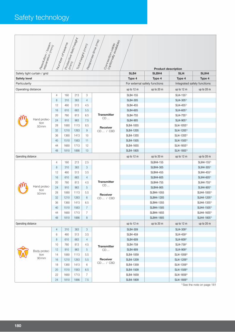
Re
solu
tion
/ b
ea
m
sep
ara
tion
(m
m)
Nu
mb
er
of
be
am
sP
rote
ctiv
e fi
eld
he
igh
t
(mm
)
Tota
l he
igh
t (m
m)
Re
spo
nse
tim
e (
ms)
Co
nn
ec
tion
ca
ble
(op
tion
ally
ava
ilab
le)
Safety light curtain / grid SLB4 SLBH4 SLI4 SLIH4
Safety level Type 4 Type 4 Type 4 Type 4
Particularity For external safety functions Integrated safety functions
Operating distance up to 12 m up to 20 m up to 12 m up to 20 m
Hand protec-tion
50 mm
4 160 213 3
TransmitterCD …
ReceiverCD … / C8D
SLB4-155 SLI4-1551)
8 310 363 4 SLB4-305 SLI4-3051)
12 460 513 4.5 SLB4-455 SLI4-4551)
16 610 663 5.5 SLB4-605 SLI4-6051)
20 760 813 6.5 SLB4-755 SLI4-7551)
24 910 963 7.5 SLB4-905 SLI4-9051)
28 1060 1113 8.5 SLB4-1055 SLI4-10551)
32 1210 1263 9 SLB4-1205 SLI4-12051)
36 1360 1413 10 SLB4-1355 SLI4-13551)
40 1510 1563 11 SLB4-1505 SLI4-15051)
44 1660 1713 12 SLB4-1655 SLI4-16551)
48 1810 1886 13 SLB4-1805 SLI4-18051)
Operating distance up to 12 m up to 20 m up to 12 m up to 20 m
Hand protec-tion
50 mm
4 160 213 2.5
TransmitterCD …
ReceiverCD … / C8D
SLBH4-155 SLIH4-1551)
8 310 363 3 SLBH4-305 SLIH4-3051)
12 460 513 3.5 SLBH4-455 SLIH4-4551)
16 610 663 4 SLBH4-605 SLIH4-6051)
20 760 813 4.5 SLBH4-755 SLIH4-7551)
24 910 963 5 SLBH4-905 SLIH4-9051)
28 1060 1113 5.5 SLBH4-1055 SLIH4-10551)
32 1210 1263 6 SLBH4-1205 SLIH4-12051)
36 1360 1413 6.5 SLBH4-1355 SLIH4-13551)
40 1510 1563 7 SLBH4-1505 SLIH4-15051)
44 1660 1713 7 SLBH4-1655 SLIH4-16551)
48 1810 1886 8 SLBH4-1805 SLIH4-18051)
Operating distance up to 12 m up to 20 m up to 12 m up to 20 m
Body protec-tion
90 mm
4 310 363 3
TransmitterCD …
ReceiverCD … / C8D
SLB4-309 SLI4-3091)
6 460 513 3.5 SLB4-459 SLI4-4591)
8 610 663 4 SLB4-609 SLI4-6091)
10 760 813 4.5 SLB4-759 SLI4-7591)
12 910 963 5 SLB4-909 SLI4-9091)
14 1060 1113 5.5 SLB4-1059 SLI4-10591)
16 1210 1263 5.5 SLB4-1209 SLI4-12091)
18 1360 1413 6 SLB4-1359 SLI4-13591)
20 1510 1563 6.5 SLB4-1509 SLI4-15091)
22 1660 1713 7 SLB4-1659 SLI4-16591)
24 1810 1886 7.5 SLB4-1809 SLI4-18091)
Safety technology
1) See the note on page 181
Product description
180

For more information and models visit www.di-soric.com
Re
solu
tion
/ b
ea
m
sep
ara
tion
(m
m)
Nu
mb
er
of
be
am
sP
rote
ctiv
e fi
eld
he
igh
t
(mm
)
Tota
l he
igh
t (m
m)
Re
spo
nse
tim
e (
ms)
Co
nn
ec
tion
ca
ble
(op
tion
ally
ava
ilab
le)
Safety light curtain / grid SLB4 SLBH4 SLI4 SLIH4
Safety level Type 4 Type 4 Type 4 Type 4
Particularity For external safety functions Integrated safety functions
Operating distance up to 12 m up to 20 m up to 12 m up to 20 m
Body protec-tion
90 mm
4 310 363 2.5
TransmitterCD …
ReceiverCD … / C8D
SLBH4-309 SLIH4-3091)
6 460 513 3 SLBH4-459 SLIH4-4591)
8 610 663 3 SLBH4-609 SLIH4-6091)
10 760 813 3.5 SLBH4-759 SLIH4-7591)
12 910 963 3.5 SLBH4-909 SLIH4-9091)
14 1060 1113 3.5 SLBH4-1059 SLIH4-10591)
16 1210 1263 4 SLBH4-1209 SLIH4-12091)
18 1360 1413 4 SLBH4-1359 SLIH4-13591)
20 1510 1563 4.5 SLBH4-1509 SLIH4-15091)
22 1660 1713 4.5 SLBH4-1659 SLIH4-16591)
24 1810 1886 5 SLBH4-1809 SLIH4-18091)
Operating distance up to 12 m up to 20 m up to 12 m up to 20 m
500 2 510 653 2.5 TransmitterCD …
ReceiverCD … /
SLI… : C8D
SLB4-2B SLI4-2B1)
400 3 810 953 3 SLB4-3B SLI4-3B1)
300 4 910 1053 3 SLB4-4B SLI4-4B1)
500 2 510 653 2.5 TransmitterCD …
ReceiverCD … /
SLI… : C8D
SLBH4-2B SLIH4-2B1)
400 3 810 953 2.5 SLBH4-3B SLIH4-3B1)
300 4 910 1053 2.5 SLBH4-4B SLIH4-4B1)
Note
1) Light curtains/grids are also available as a variant in a protective housing.
SLI … - WTF (IP 69K)
SLI … -WTHF (IP 69K, heated)
Product description
181

Safety light curtains / grids type 4- master/slave models, with integrated monitoring functions
Safety technology
Formulas for calculating the total response time in the case of master/slave series connections SLI4-…:
For a resolution of 14 mm
Master + Slave ttot = [0.06 x (No.Master + No.Slave ) + 0.9636] x 2
Master + Slave 2 + Slave ttot = [0.06 x (No.Master + No.Slave 2 + No.Slave ) + 1.0036] x 2
For all other resolutions or beam separations
Master + Slave ttot = [0.11 x (No.Master + No.Slave ) + 0.9376] x 2
Master + Slave 2 + Slave ttot = [0.11 x (No.Master + No.Slave 2 + No.Slave ) + 1.0508] x 2
Key ttot = Total response time No. = Number of beams for the selected model
Safety level
TYPE 4SIL 3 – SILCL 3
PL e – Cat. 4
¡ Combination of di� erent resolutions and protective fi eld heights ¡ Up to three monitoring ranges ¡ Only one safety module / two relays required for evaluation ¡ Simplifi ed cabling via series connection ¡ Highest safety level ¡ Light curtains for fi nger protection, hand protection, body protection and presence check ¡ Light grid with 2, 3 or 4 beams for detecting a body during access control ¡ Protective fi eld heights from 160 to 1,810 mm ¡ Unshielded connection cables ¡ Master connection cable up to 100 m – Master/Slave connection cable up to 50 m ¡ Selectable manual or automatic Start/Restart ¡ Feedback input for external relay monitoring (EDM) ¡ High protection type
182

For more information and models visit www.di-soric.com
Examples for series connection of master/slave models
MASTER
MASTER
SLAVE
SLAVE 2
SLAVE
It is possible to connect each master model to any slave model.
All electrical connections are made with 5-pin M12 connectors, withthe exception of the master receiver, which requires an 8-pin M12 connector.
For the connection between master and slave, cables prefabricated with 2 connectors are available (see page 186).
MASTER
Hazard area
SLAVE
The master is positioned horizontally for detecting a body, while the vertical slave takes over detecting hands.
You can also turn the connection and position the master vertically for protecting hands and the slave horizontally for detecting a body.
The application pictured here is among the most common:Horizontal safety light curtains / grids are used for preventing the operator from going undetected if he or she remains between the vertical light curtain/grid and the dangerous machine when turning it on or restarting it.
Example of series connection of master/slave models for protecting two sides of a machine
MASTER
Transmitter 1
Receiver 1
Transmitter 2 Receiver 2SLAVE In the case of safety light curtains / grids SLI, a (non-shielded) standard cable is used for the connection between master and slave. It can have a length of up to 50 meters (see page 186).
This property allows for the use of 2 light curtains / grids switched in series,whereby one of them is positioned on the front side and the other on the rear side of the machine; in the event of only one connection for the power supply and the control circuit of the machine.
Up to 3 safety light curtains / grids switched in series are possible.
Advantage when using master/slave series connections
A BSchematic of the series connection
A
B
For three standard light curtains/grids, 3 safety modules or6 relays have to be used and cabled.
For the master/slave solution with 3 light curtains/grids switched in series,it is possible to use and cable only 1 safety module or2 relays.
Function of master/slave models
The master/slave model makes it possible to switch up to three light curtains/grids in series and to have combined detection of hands and body, or to simultaneously monitor various sides of the machine. With the following critical advantages:
Only one pair of safety outputs No interference between light barriers installed in adjacent spaces
183

Res
olut
ion
(mm
)
Num
ber
of b
eam
sP
rote
ctiv
e fie
ld h
eigh
t
Total height Conf. range
Product descriptionMas
ter
/ sl
ave
2
Sla
ve
Low
Ran
ge to
Hig
h R
ange
to
Safety level mm mm mm mm mm Master Slave Slave 2
Finger protec-tion
14 mm
15 160 - 213
3 6
- SLI4-151-S -30 310 387 363 SLI4-301-M SLI4-301-S SLI4-301-S245 460 537 513 SLI4-451-M SLI4-451-S SLI4-451-S260 610 687 663 SLI4-601-M SLI4-601-S SLI4-601-S275 760 837 813 SLI4-751-M SLI4-751-S SLI4-751-S290 910 987 963 SLI4-901-M SLI4-901-S SLI4-901-S2
105 1,060 1,137 1,113 SLI4-1051-M SLI4-1051-S SLI4-1051-S2120 1,210 1,287 1,263 SLI4-1201-M SLI4-1201-S SLI4-1201-S2135 1,360 1,437 1,413 SLI4-1351-M SLI4-1351-S SLI4-1351-S2150 1,510 1,587 1,563 SLI4-1501-M SLI4-1501-S SLI4-1501-S2165 1,660 1,737 1,713 SLI4-1651-M SLI4-1651-S SLI4-1651-S2180 1,810 1,910 1,886 SLI4-1801-M SLI4-1801-S SLI4-1801-S2
Hand protection30 mm
8 160 - 213
4 12
- SLI4-153-S -13 260 337 313 SLI4-253-M SLI4-253-S SLI4-253-S216 310 387 363 SLI4-303-M SLI4-303-S SLI4-303-S223 460 537 513 SLI4-453-M SLI4-453-S SLI4-453-S231 610 687 663 SLI4-603-M SLI4-603-S SLI4-603-S238 760 837 813 SLI4-753-M SLI4-753-S SLI4-753-S246 910 987 963 SLI4-903-M SLI4-903-S SLI4-903-S253 1,060 1,137 1,113 SLI4-1053-M SLI4-1053-S SLI4-1053-S261 1,210 1,287 1,263 SLI4-1203-M SLI4-1203-S SLI4-1203-S268 1,360 1,437 1,413 SLI4-1353-M SLI4-1353-S SLI4-1353-S276 1,510 1,587 1,563 SLI4-1503-M SLI4-1503-S SLI4-1503-S288 1,660 1,737 1,713 SLI4-1653-M SLI4-1653-S SLI4-1653-S291 1,810 1,910 1,886 SLI4-1803-M SLI4-1803-S SLI4-1803-S2
Technical data (typ.)
Safety levelType 4 in accordance with IEC/TS 61496-2SIL 3 – SILCL 3 in accordance with IEC 61508 - IEC 62061PL e – Cat. 4 in accordance with ISO 13849-1
Profile cross section 28 x 30 mm
Safety outputs (master) PNP (2x), 400 mA, 24 V DC
LED displays Self-diagnosticsStatus
Start / restart (master) Automatic or manual (selectable)
External relay (device) monitoring - EDM (master models) Feedback input, selectable release
Service voltage 19.2 to 28.8 V DC
Master connection M12, 5-pin (transmitter)M12, 8-pin (receiver)
Master / slave 2 / slave connection M12, 5-pin (transmitter and receiver)
Length of connection cable max. 100 m unshielded
Length of connection cable max. 50 m unshielded (between master/slave)
Ambient temperature -20 to +55 °C
Protection type IP 65 + IP 67
Protection class III, operation on protective low voltage
Housing material Aluminum
Window material Polycarbonate
Mounting Rear side, T-shaped slot, or using adjustable brackets SFB E180 (optional)
Safety technology
Safety light curtains / grids type 4- master/slave models, with integrated monitoring functions
184

For more information and models visit www.di-soric.com
Res
olut
ion
(mm
)
Num
ber
of b
eam
sP
rote
ctiv
e fie
ld h
eigh
t
Total height Conf. range
Product descriptionMas
ter
/ sl
ave
2
Sla
ve
Low
Ran
ge to
Hig
h R
ange
to
Safety level mm mm mm mm mm Master Slave Slave 2
Hand protection40 mm
6 160 - 213
4 12
- SLI4-154-S -8 260 337 313 SLI4-254-M SLI4-254-S SLI4-254-S2
11 310 387 363 SLI4-304-M SLI4-304-S SLI4-304-S216 460 537 513 SLI4-454-M SLI4-454-S SLI4-454-S221 610 687 663 SLI4-604-M SLI4-604-S SLI4-604-S226 760 837 813 SLI4-754-M SLI4-754-S SLI4-754-S231 910 987 963 SLI4-904-M SLI4-904-S SLI4-904-S236 1,060 1,137 1,113 SLI4-1054-M SLI4-1054-S SLI4-1054-S241 1,210 1,287 1,263 SLI4-1204-M SLI4-1204-S SLI4-1204-S246 1,360 1,437 1,413 SLI4-1354-M SLI4-1354-S SLI4-1354-S251 1,510 1,587 1,563 SLI4-1504-M SLI4-1504-S SLI4-1504-S256 1,660 1,737 1,713 SLI4-1654-M SLI4-1654-S SLI4-1654-S261 1,810 1,910 1,886 SLI4-1804-M SLI4-1804-S SLI4-1804-S2
Body protection50 mm
4 160 - 213
4 12
- SLI4-155-S -8 310 387 363 SLI4-305-M SLI4-305-S SLI4-305-S2
12 460 537 513 SLI4-455-M SLI4-455-S SLI4-455-S216 610 687 663 SLI4-605-M SLI4-605-S SLI4-605-S220 760 837 813 SLI4-755-M SLI4-755-S SLI4-755-S224 910 987 963 SLI4-905-M SLI4-905-S SLI4-905-S228 1,060 1,137 1,113 SLI4-1055-M SLI4-1055-S SLI4-1055-S232 1,210 1,287 1,263 SLI4-1205-M SLI4-1205-S SLI4-1205-S236 1,360 1,437 1,413 SLI4-1355-M SLI4-1355-S SLI4-1355-S240 1,510 1,587 1,563 SLI4-1505-M SLI4-1505-S SLI4-1505-S244 1,660 1,737 1,713 SLI4-1655-M SLI4-1655-S SLI4-1655-S248 1,810 1,910 1,886 SLI4-1805-M SLI4-1805-S SLI4-1805-S2
Body protection90 mm
4 310 387 363
4 12
SLI4-309-M SLI4-309-S SLI4-309-S26 460 537 513 SLI4-459-M SLI4-459-S SLI4-459-S28 610 687 663 SLI4-609-M SLI4-609-S SLI4-609-S2
10 760 837 813 SLI4-759-M SLI4-759-S SLI4-759-S212 910 987 963 SLI4-909-M SLI4-909-S SLI4-909-S214 1,060 1,137 1,113 SLI4-1059-M SLI4-1059-S SLI4-1059-S216 1,210 1,287 1,263 SLI4-1209-M SLI4-1209-S SLI4-1209-S218 1,360 1,437 1,413 SLI4-1359-M SLI4-1359-S SLI4-1359-S220 1,510 1,587 1,563 SLI4-1509-M SLI4-1509-S SLI4-1509-S222 1,660 1,737 1,713 SLI4-1659-M SLI4-1659-S SLI4-1659-S224 1,810 1,910 1,886 SLI4-1809-M SLI4-1809-S SLI4-1809-S2
Beam sepa-ration
Beams2-3-4
500 2 510 677 653
4 12SLI4-2B-M SLI4-2B-S SLI4-2B-S2
400 3 810 977 953 SLI4-3B-M SLI4-3B-S SLI4-3B-S2300 4 910 1077 1053 SLI4-4B-M SLI4-4B-S SLI4-4B-S2
185

Dim
ensi
ons
Inte
grat
ed m
utin
g fu
nctio
nTw
o-ch
anne
l inp
uts
for
safe
ty li
ght
curt
ains
/ g
rids
Saf
ety
rela
y ou
tput
s
Sta
tus
outp
ut
Input
s fo
r m
utin
g se
nsor
s
2x, 2
4 V
DC
, PN
P, d
ark-
on, N
OIn
put
for
mut
ing
rele
ase
24 V
DC
, PN
P o
r re
lay
Type 4 safety relaySIL 3 – Safety relay SILCL 3, in accordance with IEC 61 508 - IEC 62 061
Product description
99 x 22.5 x 114.5 1 n n SR-1
99 x 35 x 114.5 n 1 n n n n SR-M
* Reliable control of the Start / Restart command in accordance with the IEC 61496-1 standard.
Technical data (typ.) +20 °C, 24 V DC
Safety levelType 4 IEC/TS 61496-1,-2SIL 3 – SILCL 33 in accordance with IEC 62061 (ed. 1) at 1PL e – Cat. 4 in accordance with ISO 13849-1
Two-channel inputs for safety light curtains / grids 1
Reaction time < 20 ms
Service voltage 19.2 to 28.8 V DC
Safety relay outputs NO (2x), 2 A, 250 V AC
Status output PNP (1x), 100 mA, 24 V DC
Reaction time < 20 ms
Start / restart* Automatic or manual (selectable on terminal strip), interlock
External device (relay) monitoring - EDM Feedback input, selectable release
Connection to terminal strip
Ambient temperature 0 to +55 °C
Protection typeIP 20 for housing
IP 2X for terminal strip
Mounting on top-hat rail in accordance with EN 50022-35 standard
Safety technology
Safety level
TYPE 4SIL 3 – SILCL 3
PL e – Cat. 4
186
Type 4 safety relay for type 2 and type 4 safety light curtains / grids
¡ Usable for safety light curtains / grids with safety level type 2 and type 4 ¡ Additional safety functions such as:- Start / restart interlock- Feedback input for EDM (for monitoring additional external relays)
¡ LED displays for status and diagnostics

For more information and models visit www.di-soric.com
* Each NO safety switching output is interrupted twice by the two relays.
Technical data (typ.) +20 °C, 24 V DC
Safety relay outputs* NO (2x) + NC (1x), 2 A, 250 V AC
Reaction time < 20 ms
Service voltage 19.2 to 28.8 V DC
Connection to terminal strip
Ambient temperature 0 to +55 °C
Protection typeIP 20 for housing
IP 2X for terminal strip
Mounting on top-hat rail in accordance with EN 50022-35 standard
Dimensions - H x L x D 101 x 35 x 120 mm
Description Product description
Interface relay for all light curtains / grids SLI... SR-0
187
Interface relay - for safety light curtains / grids SLI...
¡ Can be used for all safety light curtains / grids with an integrated EDM (exter-nal device monitoring) function
¡ Function with two guided-contact safety relays ¡ Control and monitoring carried out directly by light curtains / grids
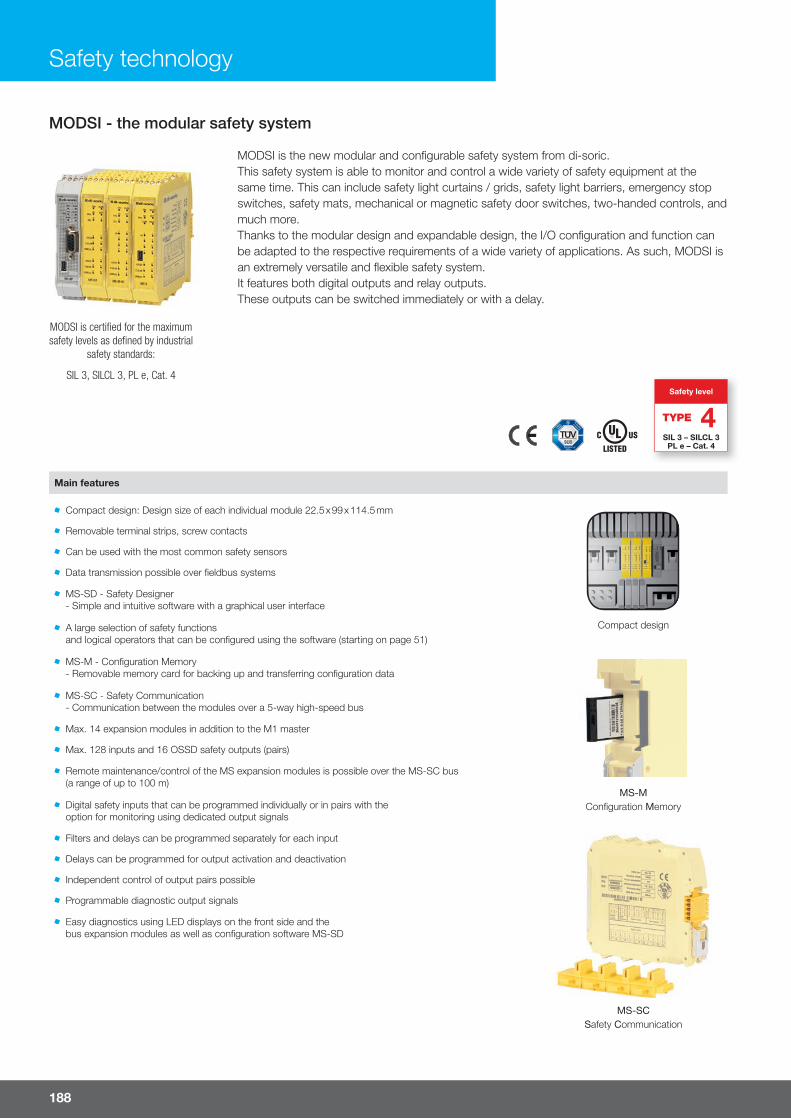
Safety technology
MODSI is certified for the maximumsafety levels as defined by industrial
safety standards:
SIL 3, SILCL 3, PL e, Cat. 4
MODSI is the new modular and confi gurable safety system from di-soric.This safety system is able to monitor and control a wide variety of safety equipment at the same time. This can include safety light curtains / grids, safety light barriers, emergency stop switches, safety mats, mechanical or magnetic safety door switches, two-handed controls, and much more.Thanks to the modular design and expandable design, the I/O confi guration and function can be adapted to the respective requirements of a wide variety of applications. As such, MODSI is an extremely versatile and fl exible safety system.It features both digital outputs and relay outputs. These outputs can be switched immediately or with a delay.
Main features
Compact design: Design size of each individual module 22.5 x 99 x 114.5 mm
Compact design
Removable terminal strips, screw contacts
Can be used with the most common safety sensors
Data transmission possible over fieldbus systems
MS-SD - Safety Designer- Simple and intuitive software with a graphical user interface
A large selection of safety functionsand logical operators that can be configured using the software (starting on page 51)
MS-M - Configuration Memory- Removable memory card for backing up and transferring configuration data
MS-MConfiguration Memory
MS-SC - Safety Communication- Communication between the modules over a 5-way high-speed bus
Max. 14 expansion modules in addition to the M1 master
Max. 128 inputs and 16 OSSD safety outputs (pairs)
Remote maintenance/control of the MS expansion modules is possible over the MS-SC bus(a range of up to 100 m)
Digital safety inputs that can be programmed individually or in pairs with theoption for monitoring using dedicated output signals
Filters and delays can be programmed separately for each input
MS-SCSafety Communication
Delays can be programmed for output activation and deactivation
Independent control of output pairs possible
Programmable diagnostic output signals
Easy diagnostics using LED displays on the front side and thebus expansion modules as well as configuration software MS-SD
Safety level
TYPE 4SIL 3 – SILCL 3
PL e – Cat. 4
188
MODSI - the modular safety system

For more information and models visit www.di-soric.com
¡ Programmable main unit, able to control any other expansion unit ¡ Can also be used as a stand-alone device ¡ Internal LOG fi le with the last 5 confi guration changes in chronologicalorder and the change date
¡ Slot for optional MS-M confi guration memory card ¡ MS-SC rear bus for connection with other expansion modules ¡ The MS-1 master is equipped with a serial USB 2.0 bus for connecting to a computer. The MS-SD (MS Safety Designer) confi guration software is run on thiscomputer
Technical data (typ.) +20 °C, 24 V DC
Safety level SIL 3 – SILCL 3 in accordance with IEC 61508 - IEC 62061PL e – Cat. 4 in accordance with ISO 13849-1
Safety inputs 8
Safety outputs (OSSD) PNP (2 pairs), 400 mA
Programmable signal outputs PNP (2x), 100 mA
Test outputs 4
Inputs for start / restartandexternal device monitoring - EDM
2
LED displaysStatus input / output
Error diagnostics
Service voltage 19.2 to 28.8 V DC
Connections Removable terminal strips, screw contacts
Ambient temperature -10 to +55 °C
Protection typeIP 20 for housing
IP 2X for terminal strip
Mounting on top-hat rail in accordance with EN 50022-35 standard
Dimensions - H x L x D 99 x 22.5 x 114.5 mm
Description Product description
Main module for the modular safety system MS-1
Safety level
TYPE 4SIL 3 – SILCL 3
PL e – Cat. 4
USB interface for computer connection
(USB cable: USB-A-M-1.8)
189
MS-1 master main module

Safety technology
Exp
ansi
on m
odul
eC
onfi g
urat
ion
mem
ory
for
mai
n
mod
ule
Saf
ety
com
mun
icat
ion
for
mai
n m
odul
e/ex
pan
sion
mod
ule
Saf
ety
input
sP
NP
saf
ety
outp
uts,
400
mA
OS
SD
(num
ber
of p
airs
)P
NP
sig
nal o
utput
s, 1
00 m
A
(pro
gram
mab
le)
Test
out
put
sS
afet
y re
lay
outp
uts:
NO
(2x)
NC
(1x)
6A
250
V A
C
NO
(4x)
NC
(2x)
6A
250
V A
C
Input
s fo
r st
art /
rest
art an
d
exte
rnal
dev
ice
mon
itorin
g (E
DM
)S
ervi
ce v
olta
ge (V
DC
)P
rote
ctio
n cl
ass:
IP 2
0 ho
usin
g,IP
2X te
rmin
al s
trip
Am
bie
nt te
mper
atur
e (°
C)
Modular safety systemsSIL 3 - 3 SILCL 3 safety level, in accordance with IEC 61 508 - IEC 62 061
Product description
n 8 2 2 4 2
24 V ± 10% n –10 to 55
MS-I8-O2
n 8 4 MS-I8
n 16 – – 4 – MS-I16
n 12 8 MS-I12-T8
n MS-O2
n – 4 4 – 4 MS-O4
n MS-R2
n – – – – n – MS-R4
n 4 (NO) MS-OR4
n 8 4 (NO) MS-OR4-S8
n – – – – – – – MS-M
n – – – – – – – MS-SC
MS expansion modules
Expansion modules for bus diagnostics and data transmission MS-B …
¡ For connection to the most frequently used industrial fi eldbus systems ¡ The MS-Bx expansion modules are equipped with a serial USB 2.0 bus for connecting to a computer to ensure fast and easy confi guration
LED displays for error diagnostics Connection to MS-1 master over a proprietary MS-SC bus Including an MS-SC connector for connecting to the MS-1 master
Description Product description
Profibus DP - expansion module MS-BP
DeviceNET - expansion module MS-BD
CANopen - expansion module MS-BC
Ethernet IP - expansion module MS-BEI
EtherCAT - expansion module MS-BEC
PROFINET - expansion module MS-BEP
Universal Serial Bus - expansion module MS-BU
190

For more information and models visit www.di-soric.com
MS-CTx interface modules - enable the connection of relocated expansion modules over the MS-SC bus
¡ Ideal solution for the interconnection of the safety functions of several machines on a single produc-tion line
¡ Up to 50 m for each individual connection (total range of up to 250 m) ¡ LED displays for output status ¡ Connection to MS-1 master over a proprietary MS-SC bus ¡ Including an MS-SC connector for connecting to the MS-1 master
Description Product description
MS-CT1* - Interface with 1 connection (1 input or 1 output) MS-CT1
MS-CT2 - Interface with 2 connections (1 input and 1 output) MS-CT2
Connection variant
MS-CT1*MS-CT1* MS-CT2 MS-CT2
* End or start of the network
RS485 cable
RS485 cable
Safety level
TYPE 4SIL 3 – SILCL 3
PL e – Cat. 4
For technical features, see page 193
MS-1Master
191
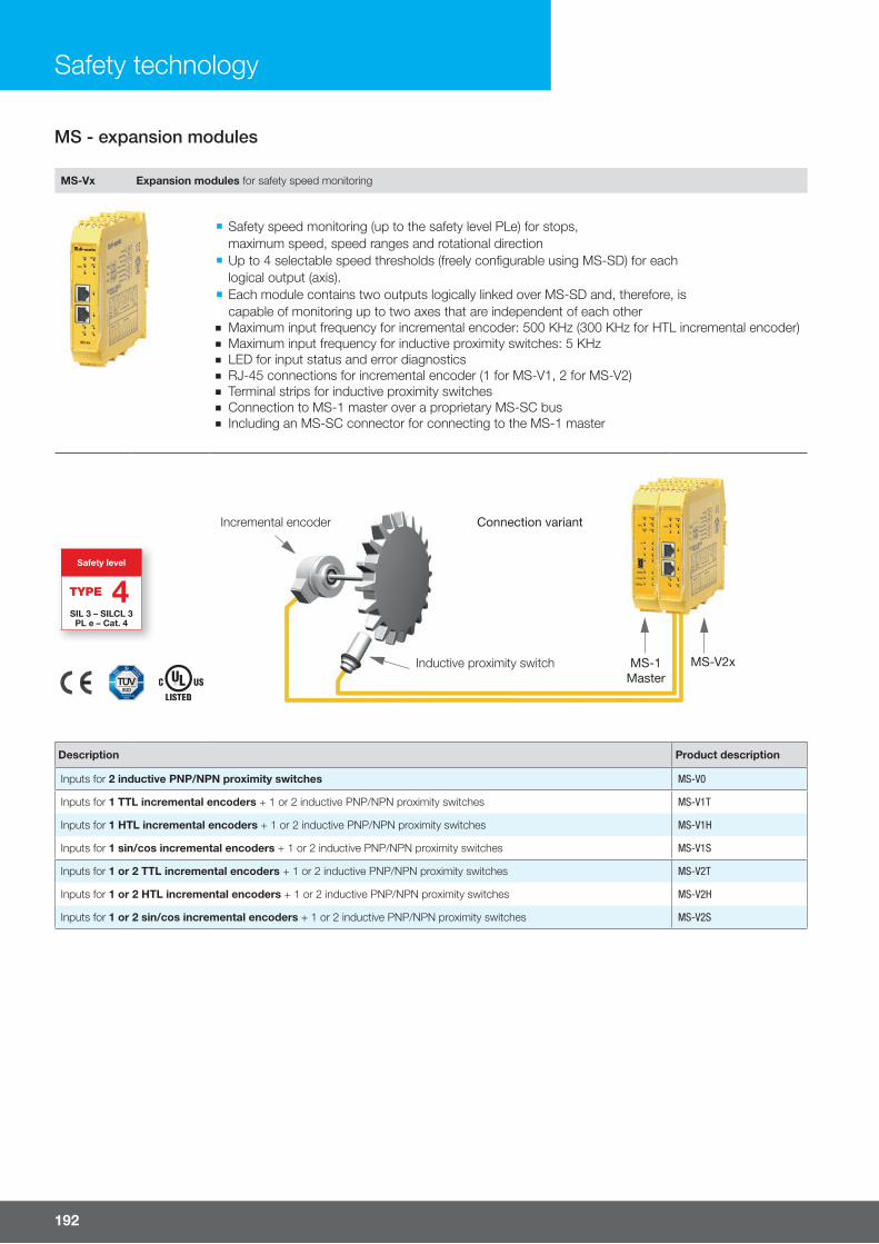
Safety technology
MS-Vx Expansion modules for safety speed monitoring
¡ Safety speed monitoring (up to the safety level PLe) for stops,maximum speed, speed ranges and rotational direction
¡ Up to 4 selectable speed thresholds (freely confi gurable using MS-SD) for eachlogical output (axis).
¡ Each module contains two outputs logically linked over MS-SD and, therefore, iscapable of monitoring up to two axes that are independent of each other
Maximum input frequency for incremental encoder: 500 KHz (300 KHz for HTL incremental encoder) Maximum input frequency for inductive proximity switches: 5 KHz LED for input status and error diagnostics RJ-45 connections for incremental encoder (1 for MS-V1, 2 for MS-V2) Terminal strips for inductive proximity switches Connection to MS-1 master over a proprietary MS-SC bus Including an MS-SC connector for connecting to the MS-1 master
MS-1Master
MS-V2x
Connection variantIncremental encoder
Inductive proximity switch
Safety level
TYPE 4SIL 3 – SILCL 3
PL e – Cat. 4
Description Product description
Inputs for 2 inductive PNP/NPN proximity switches MS-V0
Inputs for 1 TTL incremental encoders + 1 or 2 inductive PNP/NPN proximity switches MS-V1T
Inputs for 1 HTL incremental encoders + 1 or 2 inductive PNP/NPN proximity switches MS-V1H
Inputs for 1 sin/cos incremental encoders + 1 or 2 inductive PNP/NPN proximity switches MS-V1S
Inputs for 1 or 2 TTL incremental encoders + 1 or 2 inductive PNP/NPN proximity switches MS-V2T
Inputs for 1 or 2 HTL incremental encoders + 1 or 2 inductive PNP/NPN proximity switches MS-V2H
Inputs for 1 or 2 sin/cos incremental encoders + 1 or 2 inductive PNP/NPN proximity switches MS-V2S
192
MS - expansion modules

For more information and models visit www.di-soric.com
Characteristics Module: MS-1 MS-I8-O2 MS-I8 MS-I16 MS-I12-T8 MS-O2 MS-O4
USB connection n – – – – – –
MS-M card slot n – – – – – –
Connection to MS-SC bus n n n n n n n
MS-SC connector including – n n n n n n
Safety level SIL 3 - SILCL 3 in accordance with IEC 61508 - IEC 62061 / PL e – Cat. 4 in accordance with ISO 13849-1
Safety inputs 8 8 8 16 12 - -
Safety outputs (OSSD) PNP400 mA 2 pairs 2 pairs – – – 2 pairs 4 pairs
Programmable signal outputs PNP100 mA 2 2 – – – 2 4
Test outputs 4 4 4 4 8 – –
Inputs for start / restart and EDM 2 2 – – – 2 4
LED displays Input / output status and error diagnostics
Service voltage 19.2 to 28.8 V DC
Connections Removable terminal strips, screw contacts
Ambient temperature -10 to +55 °C
Storage temperature -10 to +85 °C
Protection type IP 20 for housing, IP 2X for terminal strip
Mounting on top-hat rail in accordance with EN 50022-35 standard
Dimensions - H x L x D 99 x 22.5 x 114.5 mm
Characteristics Module: MS-R2 MS-R4 MS-OR4 MS-OR4-S8 MS-Bx MS-CTx MS-Vx
USB connection – – – – n – –
Connection to MS-SC bus – – n n n n n
MS-SC connector including – – n n n n n
Safety levelSIL 3 - SILCL 3 in accordance with IEC 61508 - IEC
62061PL e - Cat. 4 in accordance with ISO 13849-1
– SIL 3 - SILCL 3PL e - Cat. 4
Safety inputs – – – – – – 1 - 4
Programmable signal outputs PNP100 mA – – – 8 – – –
Safety relay outputs 6 A240 V AC
NO (2x) + NC (1x)
NO (4x) + NC (2x) NO (4x) NO (4x) – – –
Inputs for start / restart and EDM 1 (EDM) 2 (EDM) 4 4 – – –
LED displays Output status Diagnostics Output status Input status+ diagnostics
Service voltage 19.2 to 28.8 V DC
Connections Removable terminal strips, screw contacts
Ambient temperature -10 to +55 °C
Storage temperature -10 to +85 °C
Protection type IP 20 for housing, IP 2X for terminal strip
Mounting on top-hat rail in accordance with EN 50022-35 standard
Dimensions - H x L x D 99 x 22.5 x 114.5 mm
193
MS - technical characteristics
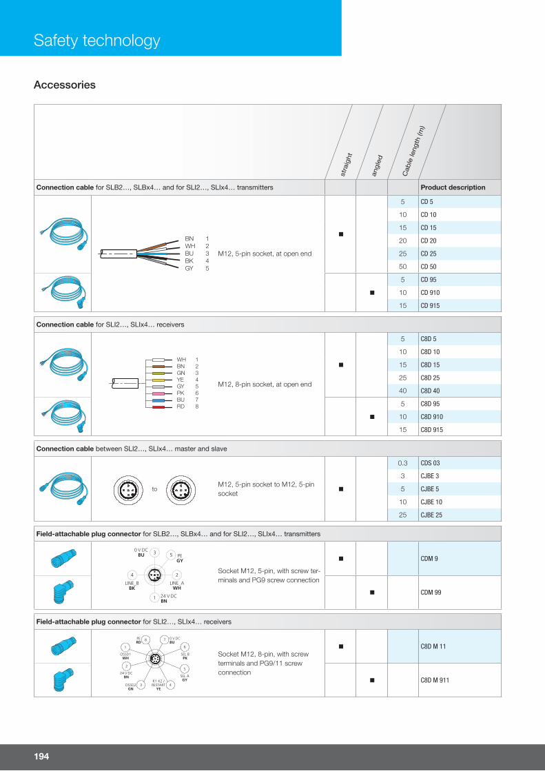
Safety technology
Accessories
stra
ight
angl
ed
Cab
le le
ngth
(m)
Connection cable for SLB2…, SLBx4… and for SLI2…, SLIx4… transmitters Product description
BN 1WH 2BU 3BK 4GY 5
M12, 5-pin socket, at open end
n
5 CD 5
10 CD 10
15 CD 15
20 CD 20
25 CD 25
50 CD 50
n
5 CD 95
10 CD 910
15 CD 915
Connection cable for SLI2…, SLIx4… receivers
WH 1BN 2GN 3YE 4GY 5PK 6 BU 7 RD 8
M12, 8-pin socket, at open end
n
5 C8D 5
10 C8D 10
15 C8D 15
25 C8D 25
40 C8D 40
n
5 C8D 95
10 C8D 910
15 C8D 915
Connection cable between SLI2…, SLIx4… master and slave
toM12, 5-pin socket to M12, 5-pin socket
n
0.3 CDS 03
3 CJBE 3
5 CJBE 5
10 CJBE 10
25 CJBE 25
Field-attachable plug connector for SLB2…, SLBx4… and for SLI2…, SLIx4… transmitters
3 5
LINE_AWH
2
1
LINE_BBK
4
PEGY
Socket M12, 5-pin, with screw ter-minals and PG9 screw connection
n CDM 9
n CDM 99
Field-attachable plug connector for SLI2…, SLIx4… receivers
PERD
OSSD1WH
OSSD2GN
1
2
3 4
8 7
K1 K2 /RESTART
YE
SEL AGY
SEL BPK
5
6
Socket M12, 8-pin, with screw terminals and PG9/11 screw connection
n C8D M 11
n C8D M 911
194
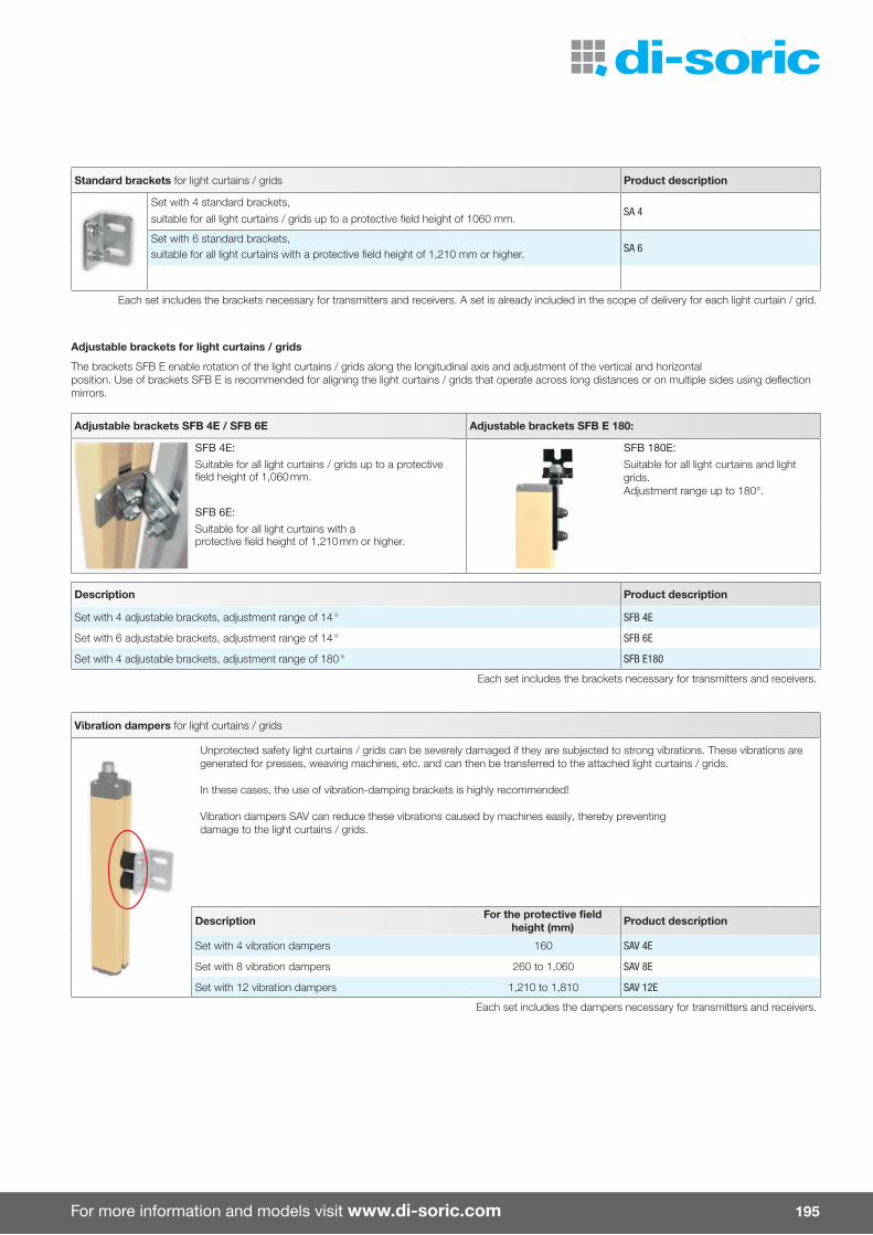
For more information and models visit www.di-soric.com
Standard brackets for light curtains / grids Product description
Set with 4 standard brackets,SA 4
suitable for all light curtains / grids up to a protective field height of 1060 mm.
Set with 6 standard brackets,SA 6suitable for all light curtains with a protective field height of 1,210 mm or higher.
Each set includes the brackets necessary for transmitters and receivers. A set is already included in the scope of delivery for each light curtain / grid.
Adjustable brackets for light curtains / grids
The brackets SFB E enable rotation of the light curtains / grids along the longitudinal axis and adjustment of the vertical and horizontalposition. Use of brackets SFB E is recommended for aligning the light curtains / grids that operate across long distances or on multiple sides using deflection mirrors.
Adjustable brackets SFB 4E / SFB 6E Adjustable brackets SFB E 180:
SFB 4E: SFB 180E:Suitable for all light curtains / grids up to a protective field height of 1,060 mm.
Suitable for all light curtains and light grids.Adjustment range up to 180°.
SFB 6E:Suitable for all light curtains with aprotective field height of 1,210 mm or higher.
Description Product description
Set with 4 adjustable brackets, adjustment range of 14 ° SFB 4E
Set with 6 adjustable brackets, adjustment range of 14 ° SFB 6E
Set with 4 adjustable brackets, adjustment range of 180 ° SFB E180
Each set includes the brackets necessary for transmitters and receivers.
Vibration dampers for light curtains / grids
Unprotected safety light curtains / grids can be severely damaged if they are subjected to strong vibrations. These vibrations are generated for presses, weaving machines, etc. and can then be transferred to the attached light curtains / grids.
In these cases, the use of vibration-damping brackets is highly recommended!
Vibration dampers SAV can reduce these vibrations caused by machines easily, thereby preventingdamage to the light curtains / grids.
Description For the protective fi eld height (mm) Product description
Set with 4 vibration dampers 160 SAV 4E
Set with 8 vibration dampers 260 to 1,060 SAV 8E
Set with 12 vibration dampers 1,210 to 1,810 SAV 12E
Each set includes the dampers necessary for transmitters and receivers.
v
195
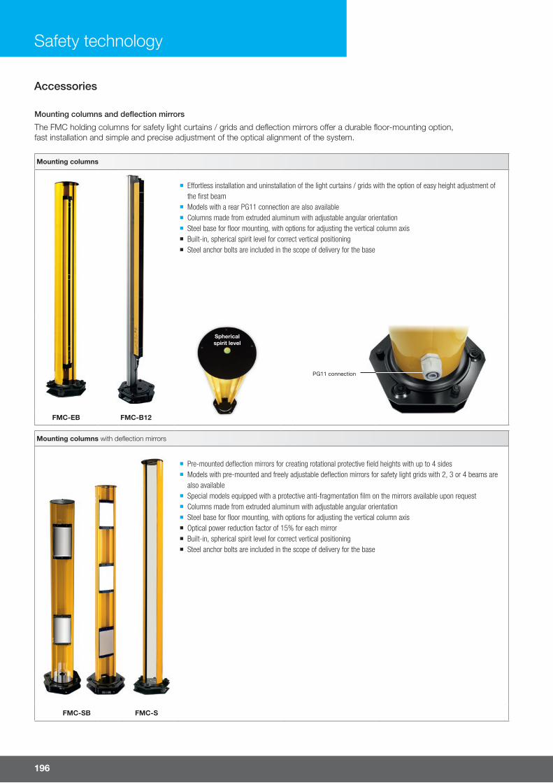
Safety technology
Accessories
Mounting columns and deflection mirrors
The FMC holding columns for safety light curtains / grids and deflection mirrors o�er a durable floor-mounting option, fast installation and simple and precise adjustment of the optical alignment of the system.
Mounting columns
¡ E� ortless installation and uninstallation of the light curtains / grids with the option of easy height adjustment of the fi rst beam
¡ Models with a rear PG11 connection are also available ¡ Columns made from extruded aluminum with adjustable angular orientation ¡ Steel base for fl oor mounting, with options for adjusting the vertical column axis ¡ Built-in, spherical spirit level for correct vertical positioning ¡ Steel anchor bolts are included in the scope of delivery for the base
Sphericalspirit level
PG11 connection
FMC-EB FMC-B12
Mounting columns with deflection mirrors
¡ Pre-mounted defl ection mirrors for creating rotational protective fi eld heights with up to 4 sides ¡ Models with pre-mounted and freely adjustable defl ection mirrors for safety light grids with 2, 3 or 4 beams are also available
¡ Special models equipped with a protective anti-fragmentation fi lm on the mirrors available upon request ¡ Columns made from extruded aluminum with adjustable angular orientation ¡ Steel base for fl oor mounting, with options for adjusting the vertical column axis ¡ Optical power reduction factor of 15% for each mirror ¡ Built-in, spherical spirit level for correct vertical positioning ¡ Steel anchor bolts are included in the scope of delivery for the base
FMC-SB FMC-S
196
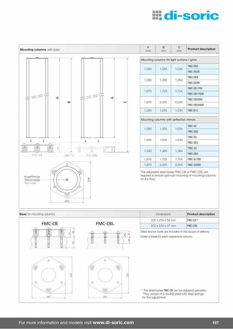
For more information and models visit www.di-soric.com
Mounting columns with baseA
mmB
mmC
mm Product description
FMC-CBLFMC-CB
A
KugelförmigeWasserwaageSpirit level
202
224
55 34
oder / or
A
B C
Mounting columns for light curtains / grids
1,000 1,055 1,034FMC-EB2
FMC-EB2R
1,330 1,385 1,364FMC-EB4
FMC-EB4R
1,670 1,725 1,704FMC-EB1700
FMC-EB1700R
1,970 2,025 2,004FMC-EB2000
FMC-EB2000R
1,200 1,255 1,234 FMC-B12
Mounting columns with deflection mirrors
1,000 1,055 1,034FMC-S2
FMC-SB2
1,200 1,255 1,234FMC-S3
FMC-SB3
1,330 1,385 1,364FMC-S4
FMC-SB4
1,670 1,725 1,704 FMC-S1700
1,970 2,025 2,004 FMC-S2000
The adjustable steel bases FMC-CB or FMC-CBL are required to ensure optimum mounting of mounting columns on the floor.
Base for mounting columns Dimensions Product description
403726
675847
FMC-CB FMC-CBL
202
224
202
224
202 x 224 x 58 mm FMC-CB *
202 x 224 x 37 mm FMC-CBL
Steel anchor bolts are included in the scope of delivery
Order a base for each respective column.
* The steel bases FMC-CB can be adjusted precisely. They consist of a double plate with steel springs for fine adjustment
197

Safety technology
Accessories
For light curtains / grids with…
Pro
tect
ive
field
hei
ght
up to
(mm
)P
rote
ctiv
e fie
ld h
eigh
t
up to
(mm
)
2 b
eam
s
3 b
eam
s
4 b
eam
s
Mounting columns for light curtains / grids 1,210 1,810 Product description
Without PG11 connection
n FMC-EB2
n n FMC-EB4
n FMC-EB1700
n FMC-EB2000
Without PG11 connection
n FMC-EB2R
n n FMC-EB4R
n FMC-EB1700R
n FMC-EB2000R
Aluminum profi le with fastening grooves n n n FMC-B12
Mounting columns with deflection mirrors
Premounted deflection mirror
n FMC-S2
n FMC-S3
n FMC-S4
n FMC-S1700
n FMC-S2000
Freely adjustable deflection mirrors
n FMC-SB2
n FMC-SB3
n FMC-SB4
Base for mounting columns
202 x 224 x 58 mmn n n n n
FMC-CB
202 x 224 x 37 mm FMC-CBL
The following must be taken into account when using deflection mirrors:n The working distance (range) is yielded from the sum of the lengths of all access sides of the monitored area.n The maximum range between the transmitter and receiver is reduced by 15% for each mirror.n The mirrors must be positioned so that the safety distance to the hazard zone can be maintained on each access side.n If protective devices are implemented across long distances are equipped with defl ection mirrors on multiple sides, the laser alignment device LAD 4 is used to align the light curtains / grids with each quickly and correctly (see page 200).
198
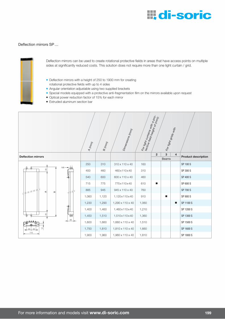
For more information and models visit www.di-soric.com
Defl ection mirrors can be used to create rotational protective fi elds in areas that have access points on multiple sides at signifi cantly reduced costs. This solution does not require more than one light curtain / grid.
¡ Defl ection mirrors with a height of 250 to 1900 mm for creating rotational protective fi elds with up to 4 sides
¡ Angular orientation adjustable using two supplied brackets ¡ Special models equipped with a protective anti-fragmentation fi lm on the mirrors available upon request ¡ Optical power reduction factor of 15% for each mirror ¡ Extruded aluminum section bar
A (m
m)
B (m
m)
Dim
ensi
ons
(mm
)
For
light
cur
tain
s w
ith a
pro
-
tect
ive
field
hei
ght
of (m
m):
For
light
grid
s w
ith
Deflection mirrors2 3 4
Product descriptionBeams
B
M8
40
110
3333
3030
12
A
250 310 310 x 110 x 40 160 SP 100 S
400 460 460 x 110 x 40 310 SP 300 S
540 600 600 x 110 x 40 460 SP 400 S
715 775 775 x 110 x 40 610 n SP 600 S
885 945 945 x 110 x 40 760 SP 700 S
1,060 1,120 1,120 x 110 x 40 910 n SP 900 S
1,230 1,290 1,290 x 110 x 40 1,060 n SP 1100 S
1,400 1,460 1,460 x 110 x 40 1,210 SP 1200 S
1,450 1,510 1,510 x 110 x 40 1,360 SP 1300 S
1,600 1,660 1,660 x 110 x 40 1,510 SP 1500 S
1,750 1,810 1,810 x 110 x 40 1,660 SP 1600 S
1,900 1,960 1,960 x 110 x 40 1,810 SP 1800 S
Deflection mirrors SP …
199
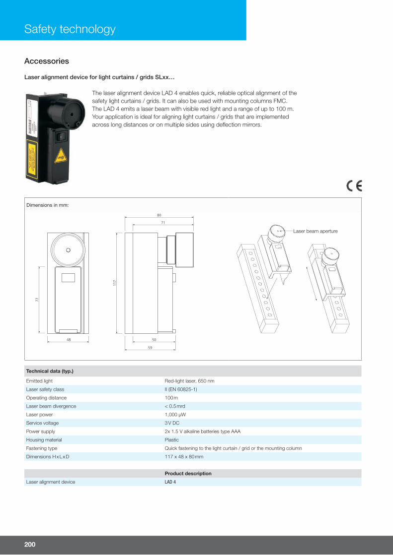
Safety technology
The laser alignment device LAD 4 enables quick, reliable optical alignment of the safety light curtains / grids. It can also be used with mounting columns FMC.The LAD 4 emits a laser beam with visible red light and a range of up to 100 m.Your application is ideal for aligning light curtains / grids that are implemented across long distances or on multiple sides using defl ection mirrors.
Technical data (typ.)
Emitted light Red-light laser, 650 nm
Laser safety class II (EN 60825-1)
Operating distance 100 m
Laser beam divergence < 0.5 mrd
Laser power 1,000 µW
Service voltage 3 V DC
Power supply 2x 1.5 V alkaline batteries type AAA
Housing material Plastic
Fastening type Quick fastening to the light curtain / grid or the mounting column
Dimensions H x L x D 117 x 48 x 80 mm
Product description
Laser alignment device LAD 4
Dimensions in mm:
80
71
50
59
117
77
48
Austrittsöffnungdes LaserstrahlsLaser beam aperture
Laser alignment device for light curtains / grids SLxx…
Accessories
200

For more information and models visit www.di-soric.com
The test rod is an aluminum cylinder with a matte surface that is used to ensure that no beams are diverted due to refl ective surfaces after the safety light curtains have been installed. This is tested by slowly moving the test rod (Ø = resolution) in the center and along each side of the monitoring area. The green LED of the receiver must be o� for the entirety of the test.
Description Diameter (mm) Product description
Test rod for light curtains with a 14 mm resolution Ø 14 TR 14
Test rod for light curtains with a 20 mm resolution Ø 20 TR 20
Test rod for light curtains with a 30 mm resolution Ø 30 TR 30
Test rod for light curtains with a 40 mm resolution Ø 40 TR 40
Test rod for light curtains with a 50 mm resolution Ø 50 TR 50
Safety screens for safety light curtains For the protective fi eld height (mm) Product description
160 PSE 150
310 PSE 300
460 PSE 450
610 PSE 600
760 PSE 750
910 PSE 900
1,060 PSE 1050
1,210 PSE 1200
1,360 PSE 1350
1,510 PSE 1500
1,660 PSE 1650
1,810 PSE 1800
Safety screens for safety light grids For the protective fi eld height (mm) Product description
Safety screen set for 2-beam light grid 510 PSE 2B
Safety screen set for 3-beam light grid 810 PSE 3B
Safety screen set for 4-beam light grid 910 PSE 4B
Fastening set for PSE safety screens Product description
Stainless steel clamps and end caps for safety screens SFS E
End cap Clamps
Safety screens
PSE safety screens made of polycarbonate protect the front screen of the safety light curtains / grids from damage resulting from welding sparks, scratches and aggressive media. Each PSE set contains 4 safety screens (2 of which are replacement parts) and are selected according to the protective fi eld height of the safety light curtain / grid. The fastening set SFS E is required for fastening. Each set consists of a pair of stainless steel clamps and 4 end caps. Thanks to quick and easy installation using stainless steel clamps, the safety screen can be re-placed without any problems if it gets damaged.
Fastening set
Safety screens for light curtains / grids
Test rod
201
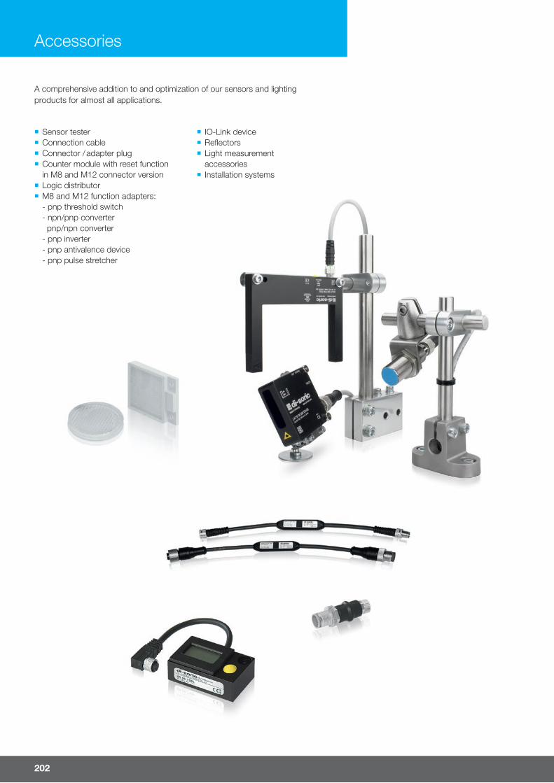
202
Accessories
¡ Sensor tester ¡ Connection cable ¡ Connector / adapter plug ¡ Counter module with reset functionin M8 and M12 connector version
¡ Logic distributor ¡ M8 and M12 function adapters:- pnp threshold switch- npn/pnp converter pnp/npn converter- pnp inverter- pnp antivalence device- pnp pulse stretcher
¡ IO-Link device ¡ Refl ectors ¡ Light measurementaccessories
¡ Installation systems
A comprehensive addition to and optimization of our sensors and lighting products for almost all applications.
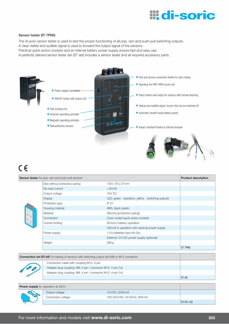
For more information and models visit www.di-soric.com 203
Sensor tester ST 7PNG
The di-soric sensor tester is used to test the proper functioning of all pnp, npn and push-pull switching outputs. A clear visible and audible signal is used to forward the output signal of the sensors. Practical quick-action sockets and an internal battery power supply ensure fast and easy use. A perfectly tailored sensor tester set (ST set) includes a sensor tester and all required accessory parts.
Fast and secure connection thanks to color coding
Signaling the PNP-/NPN-/push-pull
Teach button and output for sensors with remote teaching
Optical and audible signal; buzzer that can be switched o�
Automatic shuto� saves battery power
Impact-resistant thanks to silicone bumper
Power supply connection
ON/OFF button with status LED
Test surfaces for:
Inductive operating principle
Sensor tester for pnp, npn and push-pull sensors Product description
Size without protective casing 135 x 76 x 27 mm
No-load current < 40 mA
Output voltage 18 V DC
Display LED: green - operation, yellow - switching outputs
Protection type IP 21
Housing material ABS, black plastic
Material Silicone (protective casing)
Connection Color-coded quick-action sockets
Current limiting 60 mA in battery operation
240 mA in operation with external power supply
Power supply 1.5 V batteries type AA (3x)
External 12 V DC power supply (optional)
Weight 295 g
ST 7PNG
Connection set ST-AS For testing of sensors with switching output and M8 or M12 connector
-Connection cable with coupling M12, 4-pin
-Adapter plug coupling, M8, 3-pin / connector M12, 4-pin (1x)
-Adapter plug coupling, M8, 4-pin / connector M12, 4-pin (1x)
ST-AS
Power supply for operation at 220 V
Output voltage 12 V DC, 2000 mA
Connection voltage 100-240 V AC, 50-60 Hz, 800 mA
ST-PS-12V
Magnetic operating principle
Retrorefl ective sensors

204
Connection cable M8 Product description Product description
straightM8
32.5
n 60 IP 67 PU n
TKHM-Z-2.5 2)
PVC n
TKPM-Z-2.5
5.0 TKHM-Z-5 2) TKPM-Z-5
42.5 TKHM-Z-2.5/4 2) TKPM-Z-2.5/4
5.0 TKHM-Z-5/4 2) TKPM-Z-5/4
angled
M8
32.5
n 60 IP 67 PU n
TKHM-W-2.5 2)
PVC n
TKPM-W-2.5
5.0 TKHM-W-5 2) TKPM-W-5
42.5 TKHM-W-2.5/4 2) TKPM-W-2.5/4
5.0 TKHM-W-5/4 2) TKPM-W-5/4
Connection cable M12
straightM12 4
2.5
n 250 IP 67 PUR n
VKHM-Z-2.5/4 2)
PVC n
VKPM-Z-2.5/4
5.0 VKHM-Z-5/4 2) VKPM-Z-5/4
10.0 VKHM-Z-10/4 2) VKPM-Z-10/4
straightM12 5
3.0
n 125 IP 67 PUR n
VKHM-Z-3/5 2)
5.0 VKHM-Z-5/5 2)
10.0 VKHM-Z-10/5 2)
angledM12 4
2.5
n 250 IP 67 PUR n
VKHM-W-2.5/4 2)
PVC n
VKPM-W-2.5/4
5.0 VKHM-W-5/4 2) VKPM-W-5/4
10.0 VKHM-W-10/4 2) VKPM-W-10/4
angledM12 5
3.0
n 125 IP 67 PUR n
VKHM-W-3/5 2)
5.0 VKHM-W-5/5 2)
10.0 VKHM-W-10/5 2)
straightM12 8
2.5
n 30 IP 67 PUR n
VKHM-Z-2.5/8 2)
5.0 VKHM-Z-5/8 2)
10.0 VKHM-Z-10/8 2)
angledM12 8 n 30 IP 67 PUR n5.0 VKHM-W-5/8 2)
10.0 VKHM-W-10/8 2)
straightM12 12
2.5
n 30 IP 67 PUR n5.0 VKSM-Z-5/12-A 1,2)
10.0 VKSM-Z-10/12-A 1,2)
straightM12 12 n 30 IP 67 PVC n5.0 VKHM-Z-5/12-A 1)
10.0 VKHM-Z-10/12-A 1)
1) Shielded cable
2) Drag chain compatible
Siz
e
Num
ber
of w
ires
Cab
le le
ngth
(m)
Met
al c
ouplin
g rin
gM
ax. p
erm
issi
ble
ser
vice
volta
ge (V
AC
/DC
)P
rote
ctio
n ty
pe
Con
nect
or m
ater
ial
Cab
le m
ater
ial
PV
C, P
U c
oatin
gC
able
mat
eria
l P
UR
Con
nect
or m
ater
ial
Cab
le m
ater
ial
PV
C
Accessories
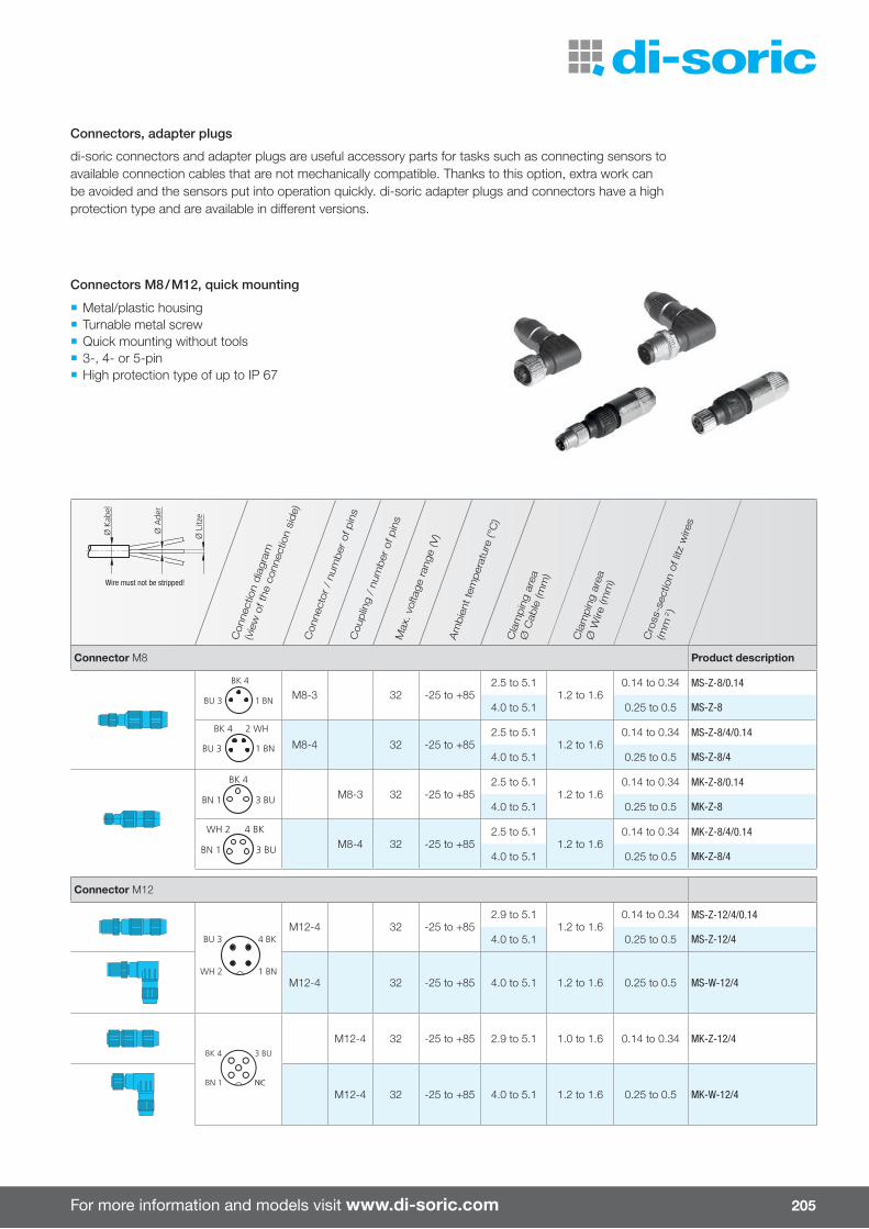
For more information and models visit www.di-soric.com 205
Con
nect
ion
dia
gram
(vie
w o
f the
con
nect
ion
side)
Con
nect
or /
num
ber
of p
ins
Cou
plin
g /
num
ber
of p
ins
Max
. vol
tage
rang
e (V
)
Am
bie
nt te
mper
atur
e (°
C)
Cla
mpin
g ar
eaØ
Cab
le (m
m)
Cla
mpin
g ar
ea
Ø W
ire (m
m)
Cro
ss-s
ectio
n of
litz
wire
s
(mm
2)
Connector M8 Product description
1 BNBU 3
BK 4
M8-3 32 -25 to +852.5 to 5.1
1.2 to 1.60.14 to 0.34 MS-Z-8/0.14
4.0 to 5.1 0.25 to 0.5 MS-Z-8
1 BNBU 3
2 WHBK 4
M8-4 32 -25 to +852.5 to 5.1
1.2 to 1.60.14 to 0.34 MS-Z-8/4/0.14
4.0 to 5.1 0.25 to 0.5 MS-Z-8/4
3 BUBN 1
BK 4
M8-3 32 -25 to +852.5 to 5.1
1.2 to 1.60.14 to 0.34 MK-Z-8/0.14
4.0 to 5.1 0.25 to 0.5 MK-Z-8
3 BUBN 1
4 BKWH 2
M8-4 32 -25 to +852.5 to 5.1
1.2 to 1.60.14 to 0.34 MK-Z-8/4/0.14
4.0 to 5.1 0.25 to 0.5 MK-Z-8/4
Connector M12
4 BK
WH 2
BU 3
1 BN
M12-4 32 -25 to +852.9 to 5.1
1.2 to 1.60.14 to 0.34 MS-Z-12/4/0.14
4.0 to 5.1 0.25 to 0.5 MS-Z-12/4
M12-4 32 -25 to +85 4.0 to 5.1 1.2 to 1.6 0.25 to 0.5 MS-W-12/4
3 BU
BN 1
BK 4
NC
M12-4 32 -25 to +85 2.9 to 5.1 1.0 to 1.6 0.14 to 0.34 MK-Z-12/4
M12-4 32 -25 to +85 4.0 to 5.1 1.2 to 1.6 0.25 to 0.5 MK-W-12/4
Wire must not be stripped!
Connectors, adapter plugs
di-soric connectors and adapter plugs are useful accessory parts for tasks such as connecting sensors to available connection cables that are not mechanically compatible. Thanks to this option, extra work can be avoided and the sensors put into operation quickly. di-soric adapter plugs and connectors have a high protection type and are available in di� erent versions.
¡ Metal/plastic housing ¡ Turnable metal screw ¡ Quick mounting without tools ¡ 3-, 4- or 5-pin ¡ High protection type of up to IP 67
Connectors M8 / M12, quick mounting
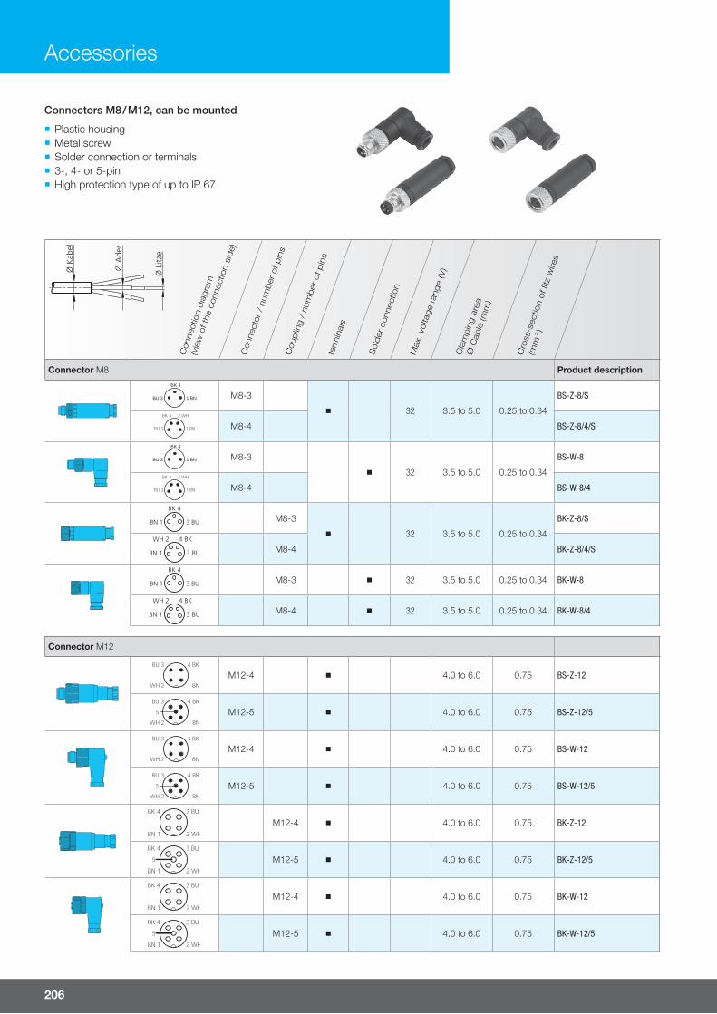
206
Con
nect
ion
dia
gram
(vie
w o
f the
con
nect
ion
side)
Con
nect
or /
num
ber
of p
ins
Cou
plin
g /
num
ber
of p
ins
term
inal
s
Sol
der
con
nect
ion
Max
. vol
tage
rang
e (V
)
Cla
mpin
g ar
ea
Ø C
able
(mm
)
Cro
ss-s
ectio
n of
litz
wire
s
(mm
2)
Connector M8 Product descriptionBK 4
BU 3 1 BN M8-3
32 3.5 to 5.0 0.25 to 0.34
BS-Z-8/S
M8-4 BS-Z-8/4/S
BK 4
BU 3 1 BN M8-3
32 3.5 to 5.0 0.25 to 0.34
BS-W-8
M8-4 BS-W-8/4
3 BUBN 1
BK 4
M8-3
32 3.5 to 5.0 0.25 to 0.34
BK-Z-8/S
3 BUBN 1
4 BKWH 2
M8-4 BK-Z-8/4/S
3 BUBN 1
BK 4
M8-3 32 3.5 to 5.0 0.25 to 0.34 BK-W-8
3 BUBN 1
4 BKWH 2
M8-4 32 3.5 to 5.0 0.25 to 0.34 BK-W-8/4
Connector M12
M12-4 4.0 to 6.0 0.75 BS-Z-12
M12-5 4.0 to 6.0 0.75 BS-Z-12/5
M12-4 4.0 to 6.0 0.75 BS-W-12
M12-5 4.0 to 6.0 0.75 BS-W-12/5
M12-4 4.0 to 6.0 0.75 BK-Z-12
M12-5 4.0 to 6.0 0.75 BK-Z-12/5
M12-4 4.0 to 6.0 0.75 BK-W-12
M12-5 4.0 to 6.0 0.75 BK-W-12/5
Connectors M8 / M12, can be mounted
¡ Plastic housing ¡ Metal screw ¡ Solder connection or terminals ¡ 3-, 4- or 5-pin ¡ High protection type of up to IP 67
Accessories
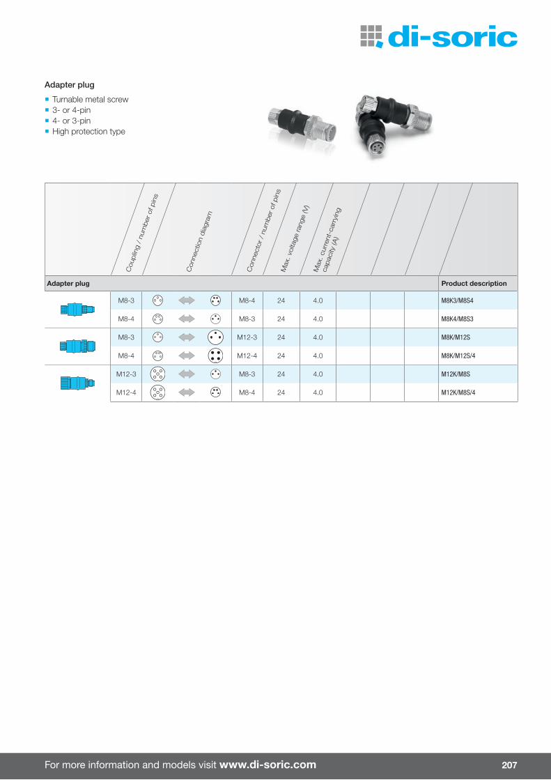
For more information and models visit www.di-soric.com 207
Cou
plin
g /
num
ber
of p
ins
Con
nect
ion
dia
gram
Con
nect
or /
num
ber
of p
ins
Max
. vol
tage
rang
e (V
)M
ax. c
urre
nt-c
arry
ing
capac
ity (A
)
Adapter plug Product description
M8-3 M8-4 24 4.0 M8K3/M8S4
M8-4 M8-3 24 4.0 M8K4/M8S3
M8-3 M12-3 24 4.0 M8K/M12S
M8-4 M12-4 24 4.0 M8K/M12S/4
M12-3 M8-3 24 4.0 M12K/M8S
M12-4 M8-4 24 4.0 M12K/M8S/4
¡ Turnable metal screw ¡ 3- or 4-pin ¡ 4- or 3-pin ¡ High protection type
Adapter plug

208
Counter module with reset function
Service voltage 10 to 35 V DC
Display LCD display, 6-digit
Input pnp
Counting frequency 10,000 Hz
Protection type IP 40
Housing material Aluminum, black anodized
Type Product description
Counter module with reset button, connector / socket M8, 3-pin ZR 06B-TSSL
Counter module with reset button and remote reset, connector / socket M12, 4-pin ZRR 06B-IBS
Accessories
¡ 6-digit LCD display ¡ Quick and simple mounting directly on the sensor ¡ Pluggable without any wiring (work) ¡ Long-term storage of counting values thanks to back-up battery
¡ Reset via key or connection ¡ Robust metal housing
Counter modules with reset function
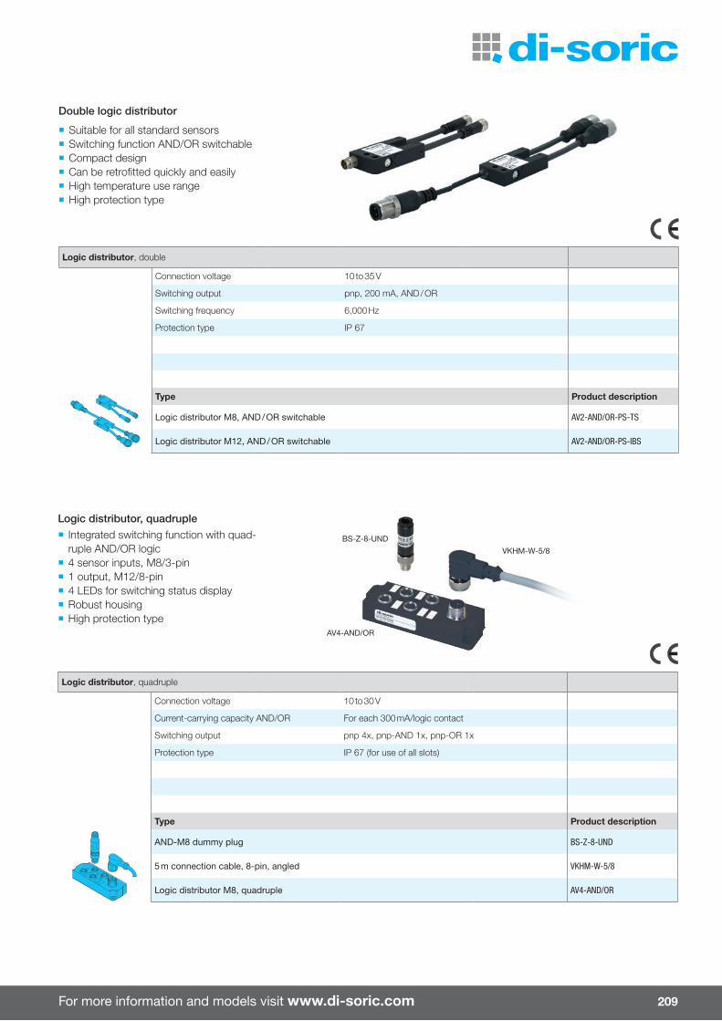
For more information and models visit www.di-soric.com 209
Logic distributor, double
Connection voltage 10 to 35 V
Switching output pnp, 200 mA, AND / OR
Switching frequency 6,000 Hz
Protection type IP 67
Type Product description
Logic distributor M8, AND / OR switchable AV2-AND/OR-PS-TS
Logic distributor M12, AND / OR switchable AV2-AND/OR-PS-IBS
Logic distributor, quadruple
Connection voltage 10 to 30 V
Current-carrying capacity AND/OR For each 300 mA/logic contact
Switching output pnp 4x, pnp-AND 1x, pnp-OR 1x
Protection type IP 67 (for use of all slots)
Type Product description
AND-M8 dummy plug BS-Z-8-UND
5 m connection cable, 8-pin, angled VKHM-W-5/8
Logic distributor M8, quadruple AV4-AND/OR
¡ Suitable for all standard sensors ¡ Switching function AND/OR switchable ¡ Compact design ¡ Can be retrofi tted quickly and easily ¡ High temperature use range ¡ High protection type
¡ Integrated switching function with quad-ruple AND/OR logic
¡ 4 sensor inputs, M8/3-pin ¡ 1 output, M12/8-pin ¡ 4 LEDs for switching status display ¡ Robust housing ¡ High protection type
Double logic distributor
Logic distributor, quadruple
AV4-AND/OR
BS-Z-8-UND
VKHM-W-5/8

210
Connection diagram A B
BN = BrownBK = BlackBU = BlueWH = White
SteckerConnector
M8
KupplungCoupling
M8
1 BN
4 BK
BU 3BN 1 3 BU
4 BK
KupplungCoupling
M8
SteckerConnector
M8
1 BN (S) WH 2 (S) 4 BK (S)
BN 1 3 BU
4 BK
BU 3
C D
KupplungCoupling
M12
SteckerConnector
M12
1 BN
BN 1 n.c.
BK 4 3 BU4 BK
BU 3
n.c.KupplungCoupling
M12
SteckerConnector
M12
1 BN
BN 1 2 WH (S)
BK 4 (S) 3 BU4 BK (S)
BU 3
n.c.
R
SteckerConnector
M8
KupplungCoupling
M8
1 BN
BK 4 2 WH
BU 3 BN 1 3 BU
4 BKWH 2
+ 1432
4
2
+ 1
3
¡ Suitable for all standard sensors ¡ Compact design ¡ Can be retrofi tted quickly and easily ¡ High temperature use range ¡ LED display for status and switching output
Function adapters
Function adapters can switch sensor-specifi c functions to the desired function (e.g. pulse stretching). Logic distributors and function adapters are suitable for all con-ventional sensors, have a compact design and can be retrofi tted quickly and easily.
Accessories
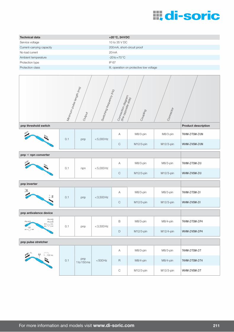
For more information and models visit www.di-soric.com 211
Min
imum
pul
se le
ngth
(ms)
Out
put
Sw
itchi
ng fr
eque
ncy
(Hz)
Con
nect
ion
dia
gram
(the
oppos
ite s
ide)
Cou
plin
g
Con
nect
or
pnp threshold switch Product description
0.1 pnp < 5,000 Hz
A M8/3-pin M8/3-pin TKHM-Z/TSM-Z/UN
C M12/3-pin M12/3-pin VKHM-Z/VSM-Z/UN
pnp npn converter
0.1 npn < 5,000 Hz
A M8/3-pin M8/3-pin TKHM-Z/TSM-Z/U
C M12/3-pin M12/3-pin VKHM-Z/VSM-Z/U
pnp inverter
0.1 pnp < 3,500 Hz
A M8/3-pin M8/3-pin TKHM-Z/TSM-Z/I
C M12/3-pin M12/3-pin VKHM-Z/VSM-Z/I
pnp antivalence device
0.1 pnp < 3,500 Hz
B M8/3-pin M8/4-pin TKHM-Z/TSM-Z/P4
D M12/3-pin M12/4-pin VKHM-Z/VSM-Z/P4
pnp pulse stretcher
1 ...150 ms
0.1 pnp 1 to 150 ms < 500 Hz
A M8/3-pin M8/3-pin TKHM-Z/TSM-Z/T
R M8/4-pin M8/4-pin TKHM-Z/TSM-Z/T4
C M12/3-pin M12/3-pin VKHM-Z/VSM-Z/T
Technical data +20 °C, 24 V DC
Service voltage 10 to 35 V DC
Current-carrying capacity 200 mA, short-circuit proof
No-load current 20 mA
Ambient temperature -20 to +70 °C
Protection type IP 67
Protection class III, operation on protective low voltage
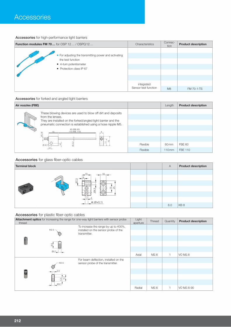
212
Accessories
Accessories for forked and angled light barriers
Air nozzles (FBE) Length Product description
These blowing devices are used to blow o� dirt and deposits from the lenses.They are installed on the forked/angled light barrier and the pneumatic connection is established using a hose nipple M5.
1560 (FBE 60)
110 (FBE 110) 6
15
Ø 4.3 Ø 2
.2
4
11
Ø 2
.8
4
Flexible 60 mm FBE 60
Flexible 110 mm FBE 110
Accessories for glass fiber-optic cables
Terminal block A Product description
8.0 KB 8
Accessories for plastic fiber-optic cablesAttachment optics for increasing the range for one-way light barriers with sensor probe
threadLight
aperture Thread Quantity Product description
Ø4.1
M2.6
8.6
To increase the range by up to 400%, installed on the sensor probe of the transmitter.
Axial M2.6 1 VO M2.6
Ø4.1
M2.6
9.3
5.5
2.5
For beam defl ection, installed on the sensor probe of the transmitter.
Radial M2.6 1 VO M2.6-90
Accessories for high-performance light barriers
Function modules FM 70 … for OSP 12 … / OSPQ 12 … Characteristics Connec-tion Product description
¡ For adjusting the transmitting power and activating
the test function
¡ 4-turn potentiometer
¡ Protection class IP 67
integrated Sensor test function M8 FM 70-1-TS
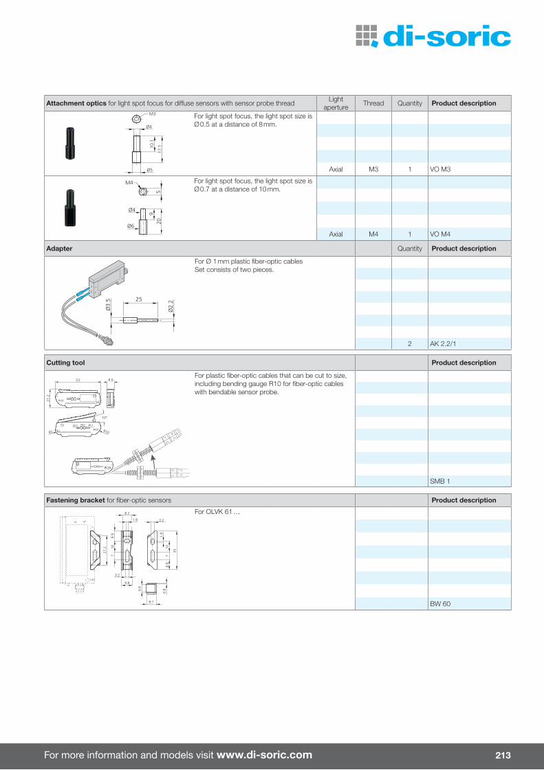
For more information and models visit www.di-soric.com 213
Attachment optics for light spot focus for di� use sensors with sensor probe thread Light aperture Thread Quantity Product description
For light spot focus, the light spot size is Ø 0.5 at a distance of 8 mm.
Axial M3 1 VO M3
For light spot focus, the light spot size is Ø 0.7 at a distance of 10 mm.
Axial M4 1 VO M4
Adapter Quantity Product description
For Ø 1 mm plastic fi ber-optic cablesSet consists of two pieces.
2 AK 2.2/1
Cutting tool Product description
R10
R10R5
Ø1.3Ø2.2Ø1.0
R10R5
53 8.6
21.2
10°
R10R5
For plastic fi ber-optic cables that can be cut to size, including bending gauge R10 for fi ber-optic cables with bendable sensor probe.
SMB 1
Fastening bracket for fi ber-optic sensors Product description
0.86.
6
8.7
78.
9
35
1.8
107
8.9
9.8
3.2
8.2
1.8 3.2
10
27.2
For OLVK 61 …
BW 60
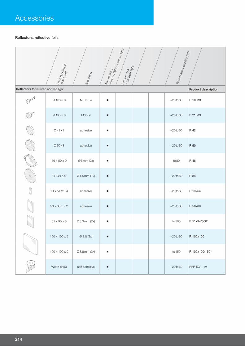
214
Accessories
Reflectors, reflective foils
Hou
sing
des
ign
Siz
e (m
m)
Mou
ntin
g
For
sens
ors
with
red
ligh
t /
infra
red li
ght
For
sens
ors
with
lase
r lig
ht
Tem
per
atur
e st
abilit
y (°
C)
Reflectors for infrared and red light Product description
Ø 10 x 5.8 M3 x 8.4 –20 to 60 R 10 M3
Ø 19 x 5.8 M3 x 9 –20 to 60 R 21 M3
Ø 42 x 7 adhesive –20 to 60 R 42
Ø 50 x 8 adhesive –20 to 60 R 50
69 x 50 x 9 Ø 5 mm (2x) to 80 R 46
Ø 84 x 7.4 Ø 4.5 mm (1x) –20 to 60 R 84
19 x 54 x 9.4 adhesive –20 to 60 R 19x54
50 x 80 x 7.2 adhesive –20 to 60 R 50x80
51 x 95 x 8 Ø 3.3 mm (2x) to 500 R 51x94/500°
100 x 100 x 9 Ø 3.8 (2x) –20 to 60 R 100x100
100 x 100 x 9 Ø 3.8 mm (2x) to 150 R 100x100/150°
Width of 50 self-adhesive –20 to 60 RFP 50/… m
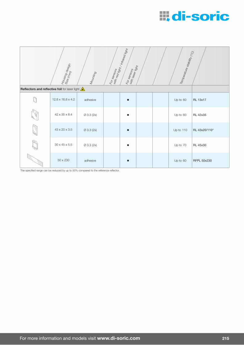
For more information and models visit www.di-soric.com 215
Hou
sing
des
ign
Siz
e (m
m)
Mou
ntin
g
For
sens
ors
with
red
ligh
t /
infra
red li
ght
For
sens
ors
with
lase
r lig
ht
Tem
per
atur
e st
abilit
y (°
C)
Reflectors and reflective foil for laser light
12.8 x 16.8 x 4.2 adhesive Up to 60 RL 13x17
42 x 35 x 8.4 Ø 3.3 (2x) Up to 60 RL 42x35
43 x 20 x 3.5 Ø 3.3 (2x) Up to 110 RL 43x20/110°
30 x 45 x 5.5 Ø 3.3 (2x) Up to 70 RL 45x30
50 x 230 adhesive Up to 60 RFPL 50x230
The specified range can be reduced by up to 50% compared to the reference reflector.
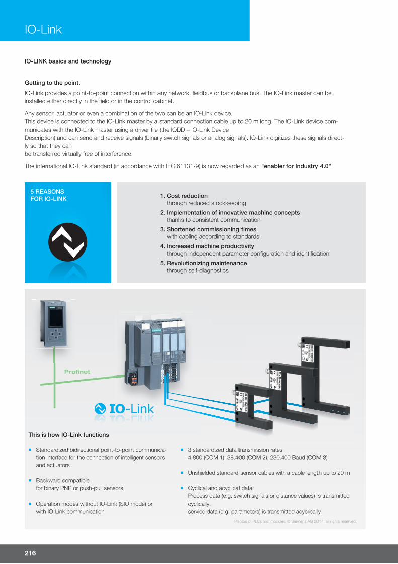
216
IO-Link
1. Cost reductionthrough reduced stockkeeping
2. Implementation of innovative machine conceptsthanks to consistent communication
3. Shortened commissioning timeswith cabling according to standards
4. Increased machine productivitythrough independent parameter confi guration and identifi cation
5. Revolutionizing maintenancethrough self-diagnostics
IO-LINK basics and technology
Getting to the point.
IO-Link provides a point-to-point connection within any network, fi eldbus or backplane bus. The IO-Link master can be installed either directly in the fi eld or in the control cabinet.
Any sensor, actuator or even a combination of the two can be an IO-Link device. This device is connected to the IO-Link master by a standard connection cable up to 20 m long. The IO-Link device com-municates with the IO-Link master using a driver fi le (the IODD – IO-Link Device Description) and can send and receive signals (binary switch signals or analog signals). IO-Link digitizes these signals direct-ly so that they can be transferred virtually free of interference.
The international IO-Link standard (in accordance with IEC 61131-9) is now regarded as an "enabler for Industry 4.0"
5 REASONSFOR IO-LINK
Photos of PLCs and modules: © Siemens AG 2017, all rights reserved.
Profi net
¡ Standardized bidirectional point-to-point communica-tion interface for the connection of intelligent sensors and actuators
¡ Backward compatible for binary PNP or push-pull sensors
¡ Operation modes without IO-Link (SIO mode) or with IO-Link communication
This is how IO-Link functions
¡ 3 standardized data transmission rates 4.800 (COM 1), 38.400 (COM 2), 230.400 Baud (COM 3)
¡ Unshielded standard sensor cables with a cable length up to 20 m
¡ Cyclical and acyclical data: Process data (e.g. switch signals or distance values) is transmitted cyclically, service data (e.g. parameters) is transmitted acyclically

For more information and models visit www.di-soric.com 217
Technical data
USB USB 2.0 (Mini USB B)
Power supply 5 V / 500 mA (PC USB)
24 V / 80 mA (IO-Link device from USB)
24 V / 1 A (IO-Link device from the power supply)
Protected against polarity reversal Yes
Protection class III
IO-Link communication IO-Link specifi cation V1.1
IO-Link port class A
Temperature range for operation 0 to 45 °C
Storage temperature -40 to 80 °C
Protection type IP 20
Scope of delivery Product description
IO-Link device tool
-USB A-B cable
-AC adapter (24 V/24 W)
-"Read Me First" document IOL master
Accessories
Connection cable (coupling M12, 4-pin / M12 connector, 4-pin) VSHM-Z-0.6/VKM-Z/4
Adapter plug (coupling M8, 3-pin / connector M12, 3-pin) M8K/M12S
Adapter plug (coupling M8, 4-pin / connector M12, 4-pin) M8K/M12S/4
System requirements for operating the IO-Link device tool V 4.0 software
Computer Operating system
Computer with an available USB 1.1 or 2.0 port Windows 7 32/64 bit Service Pack 1
Ethernet network interface Windows 8.1 32/64 bit
Windows 10 64 bit
Monitor Microsoft.Net Framework 3.5
Resolution of 1024 x 768 or higher
IO-Link device
The IO-Link Device V4 tool can be used for operating sensors and actuators with an IO-Link interface (IO-Link devices). The IO-Link devices are described by XML device descriptions, so they can be conveniently monitored and confi gured in mul-tiple languages. The tool is designed for presetting, testing and demonstrating IO-Link devices. The tool is not intended for ongoing operation in production systems.
What we have for you:
3 user levels set up in the IODD:
¡ OPERATORView only
¡ MAINTENANCETeach-in and modifi cation of approvedsettings
¡ SPECIALISTFull access to all available setting options
Only the relevant setting options provided in the IODD and not the ex-haustive, full listing of all options,
which would be unhelpful.
The IODD completely developed in accordance with the Smart Sensor Profi le and opening up the option to confi gure the sensor directly over the PLC without additional parameterization software. The Smart Sensor Profi le describes the confi guration of the most important indexes and subindexes, allowing devices to be addressed directly over the master if the IODD is not accessible at some point.
Software that does away with lengthy explanations You know intuitively what each property represents.

Mounting bracket Mounting frame Di� user Polarizer
For barlights
Stepless adjustment Stepless adjustment
For up to four lights
The bracket and fastening materials for four lights are included in the scope of delivery
PMMA
Material thickness 3 mm
PMMA
Material thickness 3 mm
BE 1-A 65 … n n n n
BE 1-A 130 … n n n n
BE 1-A 240 … n n n n
BW
-BE
1-A
(2 u
nits
)
BE
1-A
65-F
RA
ME
SE
T
BE
1-A
130-
FRA
ME
SE
T
BE
1-A
240-
FRA
ME
SE
T
BE
1-A
65-D
IF
BE
1-A
130-
DIF
BE
1-A
240-
DIF
BE
1-A
65-P
OL
BE
1-A
130-
PO
LB
E 1
-A24
0-P
OL
Power supply unit Magnet-holder
Fasteningangle Di� user PWM dimmer Plug-
connector
For machine lighting 5...100 %
Adhesive force3.6 kg (2x)
Adhesive force9.0 kg (2x)
Stepless adjustment
Simple installation using clamping groove
Pulse width modulation
Dimming range 5 to 100 %
M12,
4-pin
MB-100-K n n n n n
MB-100-K-B3 n n n n n
MB-N-25x-K-B3 n n n n n n
MB-N-25x-K n n n n n n n
MB-N-48x-K-B3 n n n n n n
MB-N-48x-K n n n n n n n
MB-N-70x-K-B3 n n n n n n
MB-N-70x-K n n n n n n n
MB-N-91x-K-B3 n n n n n n
MB-N-91x-K n n n n n n n
MB-NP-250-K n n n n n
MB-NP-480-K n n n n n
PS
-24V
/0.9
DP
S-2
4V/4
.0
MB
-MH
S
MB
-MH
S-2
BW
-MB
MB
-DIF
-250
MB
-DIF
-480
MB
-DIF
-700
MB
-DIF
-910
MB
-DIM
2
BK
-Z-1
2
218
Lighting accessories
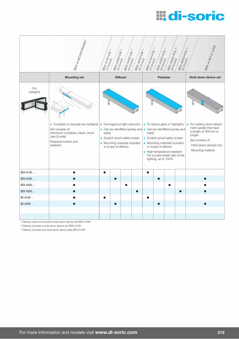
For more information and models visit www.di-soric.com
Mounting set Di� user Polarizer Hold-down device set
Forbarlights
max.2 BEK-A ...
Crossbar to cascade two barlights
Set consists of:Aluminum crossbars, black, anod-ized (2 units)
Required screws and washers
Homogenous light reduction
Can be retrofi tted quickly and easily
Scratch-proof safety screen
Mounting materials included in scope of delivery
To reduce glare or highlights
Can be retrofi tted quickly and easily
Scratch-proof safety screen
Mounting materials included in scope of delivery
High-temperature resistant: For a pulse-break ratio of the lighting, up to 100%
For holding down attach-ment panels that have a length of 300 mm or longer
Set consists of:
-Hold-down devices (2x)
-Mounting material
BEK-A100 … n n n
BEK-A300 … n n n n
BEK-A400 … n n n n
BEK-A500 … n n n n
BE-A100 … n n n
BE-A300 … n n n n
1) Delivery does not include a hold-down device set BEK-A-NH2) Delivery includes a hold-down device set BEK-A-NH3) Delivery includes two hold-down device sets BEK-A-NH
BE
K-A
-MO
UN
TIN
GS
ET
BE
K-A
100-
DIF
1)
(113
mm
)B
EK
-A30
0-D
IF 2
)
(313
mm
)B
EK
-A40
0-D
IF 3
)
(413
mm
)B
EK
-A50
0-D
IF 3
)
(513
mm
)B
EK
-A10
0-P
OL
1)
(113
mm
)B
EK
-A30
0-P
OL
2)
(313
mm
)B
EK
-A40
0-P
OL
3)
(413
mm
)B
EK
-A50
0-P
OL
3)
(513
mm
)
BE
K-A
-NH
(2 u
nits
)
219

220
System holder
Mounting examples system holder, basic holder
Ø 12 mm

For more information and models visit www.di-soric.com 221
Mounting examples system holder, basic holder
Ø 15 mm

Basic holder A B Aluminum
62
7 Ø6.6 (4x)
M6
Ø6.6
18.5
35±0.2
55±0.2
A
2
402010
B
12 20 HS-GH-12-A
15 25 HS-GH-15-A
Basic holder Aluminum
HS-GH-3-12-A
Mounting rod Ø 12 mm VA
HS-S-12-130-M10
Basic holder for mounting rod HS-S-12-130-M10 ZDG
HS-GH-12
222
System holder

For more information and models visit www.di-soric.com
Cross connector A B C D R Aluminum
1.50
20 R10
C
6.5
E
DB
A
1.50
20
R10
Ø12
Ø10 31.5 48 16.5 41.5 HS-K-10-12-A
Ø 12 31.5 48 16.5 41.5 HS-K-12-12-A
Ø14 33.5 50 18.5 43.5 HS-K-14-12-A
Ø 15 33.5 50 18.5 43.5 HS-K-15-12-A
Mounting rods Ø 12 mm A B VA
Ø 12 100 HS-S-12-100-V
Ø 12 200 HS-S-12-200-V
Ø 12 500 HS-S-12-500-V
Mounting rods Ø 15 mm A B VA
Ø 15 100 HS-S-15-100-V
Ø 15 200 HS-S-15-200-V
Ø 15 500 HS-S-15-500-V
Mounting tube Ø 15 mm A B C VA
Ø 15 150 12 HS-R-15-150-V
Product holder Ø 12 mm A B C E VA
9
A
1x45° (2x)
M4 (3x)
4.50
B
C
71 / 101
E
6
Ø 12 61 - 120 HS-PH-12-120-V
Ø 12 61 91 150 HS-PH-12-150-V
223

Clamping cylinder for mounting rods Ø 12 mm VA
3.34.5
1729.8
37
Ø16
Ø20
Ø22
Ø12
Ø27
Ø12.5 / Ø20 HS-KL-12-20-V
Adapter ring for connecting two clamping cylinders VA
Ø20 / Ø20 HS-AR-KL-20
Mounting bracket A B VA
A
B
Ø 12.5 Ø 20 HS-BW-12
Ø 18.5 Ø 20 HS-BW-18
Basic holder for barlights and coaxial lights Aluminum
Barlights BE 1-A 65 …
BE 1-A 130 …
BE 1-A 240 …
BEK-A 100 …
BEK-A 300 …
BE-A 130 …
BE-A 100 …
BE-A 300 …
Coaxial lights BEK-K50/50 …
SH-G-BE
224
System holder

For more information and models visit www.di-soric.com
Adapter plate for mounting a high-power attachment light BEK-R33 on CS 50 Vision Sensor VA
6
2
2
Ø25
Ø20
Ø3.3
Ø6.5
46
28
38
16
R4
SH-G-CSR
Fastening bracket for CS 50 Vision Sensor VA
HS-BW-CS
Ball head holder, adjustable for CS 50 Vision Sensor Aluminum
SH-KK-CS
225

Holder for cylindrical housing designs A D T Polyamide
T
D
A
6.5 10 16 SH-6.5-10
8 10 16 SH-8-10
12 10 16 SH-12-10
Mounting plate for CS 50 Vision Sensor Aluminum
M4 (2x)
SH-G-CS
Adjustable bracket for mounting plate SH-G-CS Aluminum
CKR-200-BKT
226
System holder

For more information and models visit www.di-soric.com 227
Universal holder for lights VA
Area lighting BE-F30/30RL …
BE-F50/50RL …
BEK-F50/50 …
BEK-F100/100 …
BEK-F150/150 …
BEK-F200/200 …
Barlights BE-A 30/30 …
150
55
5 15
1545
10 8
R5
Ø3,31x)
7
M4 (3x)
1.9
+0.
2-0
3.3+0.1-0
12±0.1
Ø4.5(2x)
BE-A 50/50 …
Spotlights BEK 1-P xxx …
Darkfield lights BEK-D 70 …
BEK 1-D 120 …
SH-U1-12-150-V
Holder for area lights, spotlights and dark field lights Aluminum
Area lighting BEK 1 F …
Spotlights BEK 1-P …
Darkfield lights BEK-D 70 …
BEK 1-D 120 …
SH-BEK
Holders for forked and angled light barriers Plastic
16
For angled light barriers
OGL …-TSSL
OGLP …-TSSL
For fork light barriers
Fork width of up to 100 mm SH-UGU-08-14
16 20
Ø14 For fork light barriers
Fork width of 100 mm or greater SH-UGU-20-14
Holder for light barriers in the 50 housing series Plastic
Ø14
16
44
34
SH-S50-34-44-14
di-soricGmbH & Co. KG
Steinbeisstrasse 673660 UrbachGermany
Phone: +49 71 81 98 79-0Fax: +49 71 81 98 79-179
di-soric SolutionsGmbH & Co. KG
Steinbeisstrasse 673660 UrbachGermany
Phone: +49 71 81 98 78-0Fax: +49 71 81 98 78-177
di-soricInternational
di-soric GmbH & Co. KG | Germanydi-soric Solutions GmbH & Co. KG | Germanydi-soric Austria GmbH & Co. KG | Austriadi-soric SAS | Francedi-soric SNT AG | Switzerlanddi-soric Pte. Ltd. | Singapore
www.di-soric.com/international
© d
i-sor
ic |
All
info
rmat
ion
is s
uppl
ied
with
out g
uara
ntee
. Con
tent
s m
ay c
onta
in m
ista
kes
or p
rint e
rror
s an
d ar
e su
bjec
t to
tech
nica
l cha
nges
. | V
ersi
on 0
9/18
| K
AT.E
.201
809
SOLUTIONS. CLEVER. PRACTICAL.
Related Documents