Capturing the Motion of Ski Jumpers using Multiple Stationary Cameras Atle Nes [email protected] culty of Informatics and e-Learning ondheim University College Department of Computer and Information Scien Norwegian University of Science and Technolo

Capturing the Motion of Ski Jumpers using Multiple Stationary Cameras Atle Nes [email protected] Faculty of Informatics and e-Learning Trondheim University.
Dec 22, 2015
Welcome message from author
This document is posted to help you gain knowledge. Please leave a comment to let me know what you think about it! Share it to your friends and learn new things together.
Transcript
Capturing the Motion of Ski Jumpers using Multiple Stationary Cameras
Atle Nes
Faculty of Informatics and e-Learning Trondheim University College
Department of Computer and Information ScienceNorwegian University of Science and Technology

Project description
Task: Build a cheap and portable video camera system that can be used to capture and study the 3D motion of ski jumps during take-off.
Goal: Use it to give reliable feedback to : Use it to give reliable feedback to the ski jumpers and their trainers that can the ski jumpers and their trainers that can help improve the jumping skills.help improve the jumping skills.
Solution / How ?
Multiple video cameras are placed strategically around in a ski jumping hill capturing image sequences from different views synchronously (10 m before + 30 m after edge).
Using calibrated cameras it is then possible to reconstruct 3D coordinates if the same physical point is detected in at least two views.
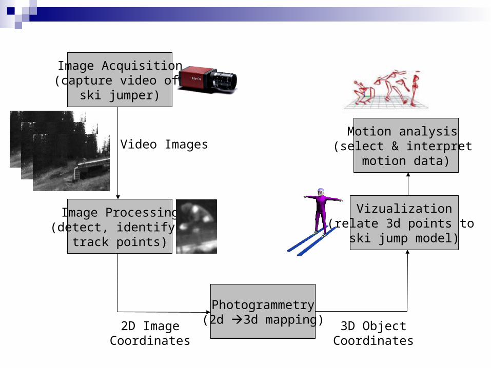
Image Acquisition(capture video of
ski jumper)
Video Images
Image Processing(detect, identify &
track points)
2D ImageCoordinates
Photogrammetry(2d 3d mapping) 3D Object
Coordinates
Motion analysis (select & interpret
motion data)
Vizualization(relate 3d points to
ski jump model)
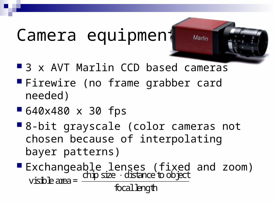
Camera equipment
3 x AVT Marlin CCD based cameras Firewire (no frame grabber card needed) 640x480 x 30 fps 8-bit grayscale (color cameras not chosen
because of interpolating bayer patterns) Exchangeable lenses (fixed and zoom)
chip size distance to objectvisible area =
focal length

Camera equipment (cont.)
Video data (3 x 9MB/s = 27 MB/s): 2 GB RAM (sequences buffered to memory) 2 x WD Raptor 10.000 rpm in RAID-0
(enables continuous capture)
Extended range: 3 x 400 m optical fibre (full duplex firewire) Power from outlets around the hill 400 m BNC synchronization cable
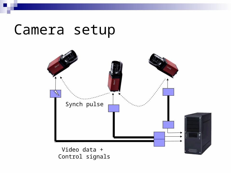
Camera setup
Video data + Control signals
Synch pulse

Video processing
Points must be automatically detected, Points must be automatically detected, identified and tracked over time and identified and tracked over time and accross different views.accross different views.
Reflective markers are placed on the ski jumpers suit, helmet and skies.

Video processing (cont.)
Blur caused by fast moving jumpers (80 km/h) is avoided by tuning aperture and integration time.
Three cameras gives a redundancy in case of occluded/undetected points (epipolar lines).
Also possible to use information about the structure of human body to identify relative marker positions.
Camera calibration
Direct Linear Transformation used to give a quick estimate of the 2D3D mapping.
Unconstrained Bundle Adjustment is used to refine the 3D geometry iteratively.
Intrinsic parameters precomputed (focal length, principal point, lens distortion)
Extrinsic parameters computed on-site (camera position & direction)

Direct Linear Transformation
1 2 3 4
9 10 11
5 6 7 8
9 10 11
1
1
L x L y L z Lu
L x L y L z
L x L y L z Lv
L x L y L z

Direct Linear Transformation
6 visible calibration points minimum for camera calibration. More points will in general increase calibration accuracy.
2 different views minimum for 3D point reconstruction. More views will in general increase triangulation accuracy.
Direct solution using Least Squares Method (linear equations)

Lens distortion / Optical errors
Imperfect lenses result in nonlinear terms (straight lines are no longer straight)
2 4 6 2 212 13 14 15 16
2 4 6 2 212 13 14 15 16
radial distortion tangential distortion
0 0
2 2 2
( ) ( 2 )
( ) ( 2 )
where
[ , ] [ , ]
u L r L r L r L r L
v L r L r L r L L r
u u v v
r

Bundle Adjustment
Adds lens distortion, skew and affinity Iterative solution using Levenberg
Marquardt Method (unlinear equations)
Calibration points with the largest errors are removed automatically resulting in a more stable geometry.

Calibration frame
Was used for finding estimates of theintrinsic parameters.
Exact coordinates in the hill was measured using differential GPS and a land survey robot station.
Points made visible in the camera views using white marker spheres.

Visualization
Moving feature points are connected back onto a dynamic 3D model of a ski jumper.
Model is allowed to be moved and controlled in a large static model of the ski jump arena.

Granåsen ski jump arena
Conclusion
I have presented a 3D video system that can be used in a large scale environment like a ski jumping hill.
It remains to be seen how well the ski jumpers will perform based on this kind of feedback.

Questions?
Related Documents