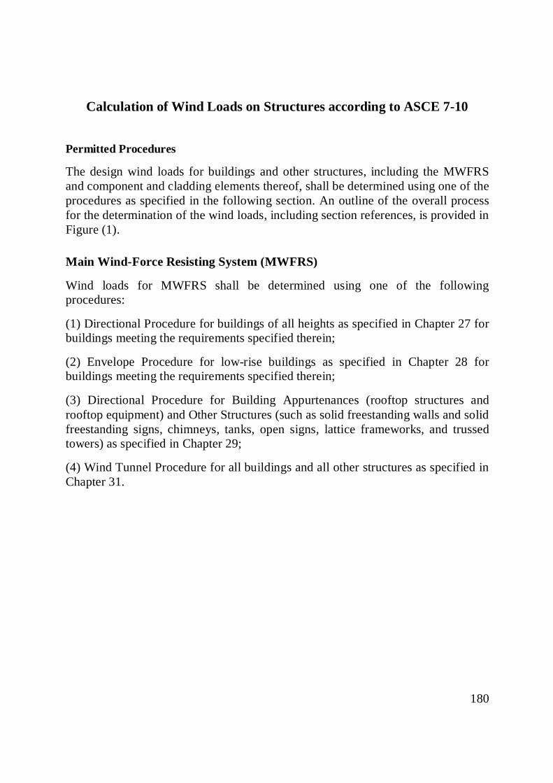
180 Calculation of Wind Loads on Structures according to ASCE 7-10 Permitted Procedures The design wind loads for buildings and other structures, including the MWFRS and component and cladding elements thereof, shall be determined using one of the procedures as specified in the following section. An outline of the overall process for the determination of the wind loads, including section references, is provided in Figure (1). Main Wind-Force Resisting System (MWFRS) Wind loads for MWFRS shall be determined using one of the following procedures: (1) Directional Procedure for buildings of all heights as specified in Chapter 27 for buildings meeting the requirements specified therein; (2) Envelope Procedure for low-rise buildings as specified in Chapter 28 for buildings meeting the requirements specified therein; (3) Directional Procedure for Building Appurtenances (rooftop structures and rooftop equipment) and Other Structures (such as solid freestanding walls and solid freestanding signs, chimneys, tanks, open signs, lattice frameworks, and trussed towers) as specified in Chapter 29; (4) Wind Tunnel Procedure for all buildings and all other structures as specified in Chapter 31.

Welcome message from author
This document is posted to help you gain knowledge. Please leave a comment to let me know what you think about it! Share it to your friends and learn new things together.
Transcript
180
Calculation of Wind Loads on Structures according to ASCE 7-10 Permitted Procedures
The design wind loads for buildings and other structures, including the MWFRS and component and cladding elements thereof, shall be determined using one of the procedures as specified in the following section. An outline of the overall process for the determination of the wind loads, including section references, is provided in Figure (1).
Main Wind-Force Resisting System (MWFRS)
Wind loads for MWFRS shall be determined using one of the following procedures:
(1) Directional Procedure for buildings of all heights as specified in Chapter 27 for buildings meeting the requirements specified therein;
(2) Envelope Procedure for low-rise buildings as specified in Chapter 28 for buildings meeting the requirements specified therein;
(3) Directional Procedure for Building Appurtenances (rooftop structures and rooftop equipment) and Other Structures (such as solid freestanding walls and solid freestanding signs, chimneys, tanks, open signs, lattice frameworks, and trussed towers) as specified in Chapter 29;
(4) Wind Tunnel Procedure for all buildings and all other structures as specified in Chapter 31.
181
Figure (1): Dtermination of Wind Loads
182
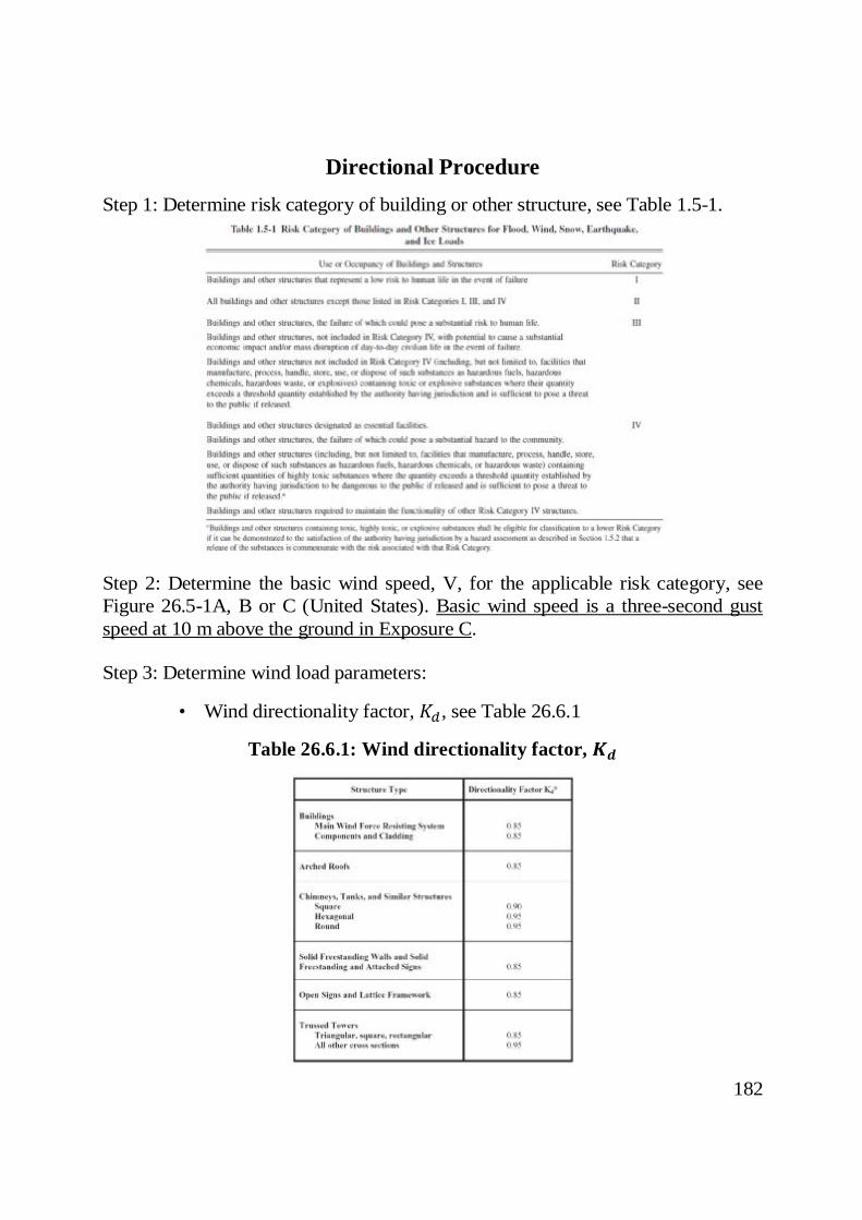
Directional Procedure
Step 1: Determine risk category of building or other structure, see Table 1.5-1.
Step 2: Determine the basic wind speed, V, for the applicable risk category, see Figure 26.5-1A, B or C (United States). Basic wind speed is a three-second gust speed at 10 m above the ground in Exposure C.
Step 3: Determine wind load parameters:
• Wind directionality factor, , see Table 26.6.1
Table 26.6.1: Wind directionality factor,
183
The directionality factor used in the ASCE 7 wind load provisions for components and cladding is a load reduction factor intended to take into account the less than 100% probability that the design event wind direction aligns with the worst case building aerodynamics.
• Exposure category, for each wind direction considered, the upwind exposure shall be based on ground surface roughness that is determined from natural topography, vegetation, and constructed facilities.
Surface Roughness B: Urban and suburban areas, wooded areas, or other terrain with numerous closely spaced obstructions having the size of single-family dwellings or larger.
Surface Roughness C: Open terrain with scattered obstructions having heights generally less than 9.1 m. This category includes flat open country and grasslands.
Surface Roughness D: Flat, unobstructed areas and water surfaces. This category includes smooth mud flats, salt flats, and unbroken ice.
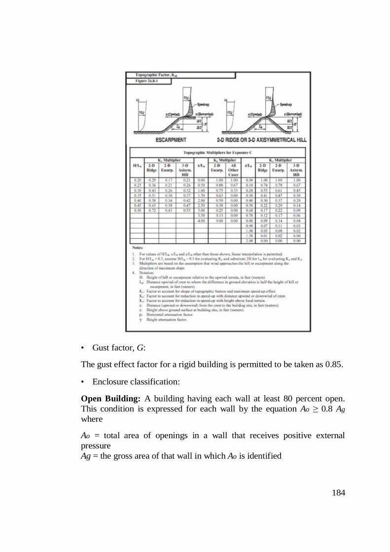
• Topographic factor, , see Figure 26.8-1. = (1 + ) , where , and are given in Fig. 26.8-1. For flat terrains, = . .
184
• Gust factor, G:
The gust effect factor for a rigid building is permitted to be taken as 0.85.
• Enclosure classification:
Open Building: A building having each wall at least 80 percent open. This condition is expressed for each wall by the equation Ao ≥ 0.8 Ag where
Ao = total area of openings in a wall that receives positive external pressure Ag = the gross area of that wall in which Ao is identified
185
Partially Enclosed Building: A building that complies with both of the following conditions: 1. The total area of openings in a wall that receives positive external pressure exceeds the sum of the areas of openings in the balance of the building envelope (walls and roof) by more than 10 percent. 2. The total area of openings in a wall that receives positive external pressure exceeds (0.37 m2) or 1 percent of the area of that wall, whichever is smaller, and the percentage of openings in the balance of the building envelope does not exceed 20 percent.
Enclosed Building: It is a building that is not classified as open or partially enclosed.
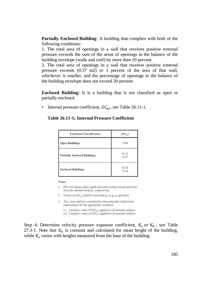
• Internal pressure coefficient, , see Table 26.11-1. Table 26.11-1; Internal Pressure Coefficient
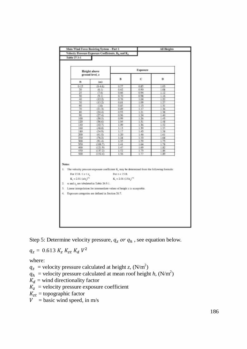
Step 4: Determine velocity pressure exposure coefficient, , see Table 27.3-1. Note that is constant and calculated for mean height of the building, while varies with heights measured from the base of the building.
186
Step 5: Determine velocity pressure, , see equation below. = 0.613
where: = velocity pressure calculated at height z, (N/m2) = velocity pressure calculated at mean roof height h, (N/m2) = wind directionality factor = velocity pressure exposure coefficient = topographic factor = basic wind speed, in m/s
187
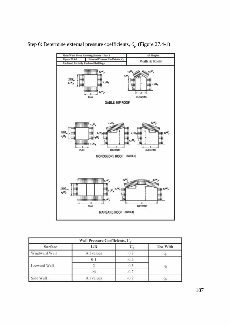
Step 6: Determine external pressure coefficients, (Figure 27.4-1)

188
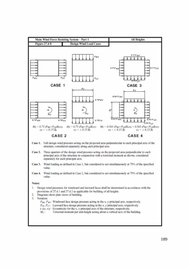
Step 7: Determine wind pressure, p, on each building surface (enclosed and partially enclosed). = − ( ) Design wind load cases are shown in Figure 27.4-8.
189
190
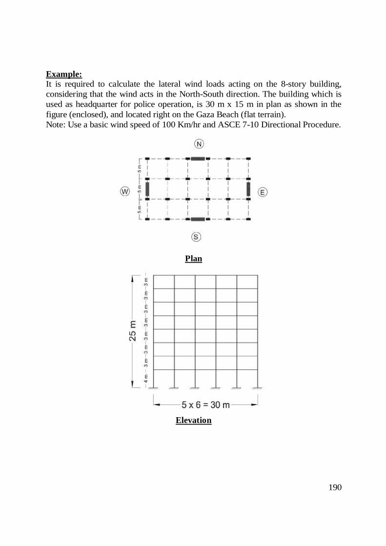
Example: It is required to calculate the lateral wind loads acting on the 8-story building, considering that the wind acts in the North-South direction. The building which is used as headquarter for police operation, is 30 m x 15 m in plan as shown in the figure (enclosed), and located right on the Gaza Beach (flat terrain). Note: Use a basic wind speed of 100 Km/hr and ASCE 7-10 Directional Procedure.
Plan
Elevation
191
Step 1: Building risk category: • Based on Table 1.5-1, building risk category is IV.
Step 2: Basic wind speed:
• It is given as 100 km/hr.
Step 3: Building wind load parameters: • 85.0=dK (wind directionality factored evaluated from Table 26.6.1) • Exposure category is D • 0.1=ztK (Topographic factor for flat terrain) • Gust factor, G , is 0.85 for rigid buildings • Building is enclosed • Internal pressure coefficient for enclosed buildings, , is 18.0±
Step 4: Velocity pressure coefficients, hK and zK :
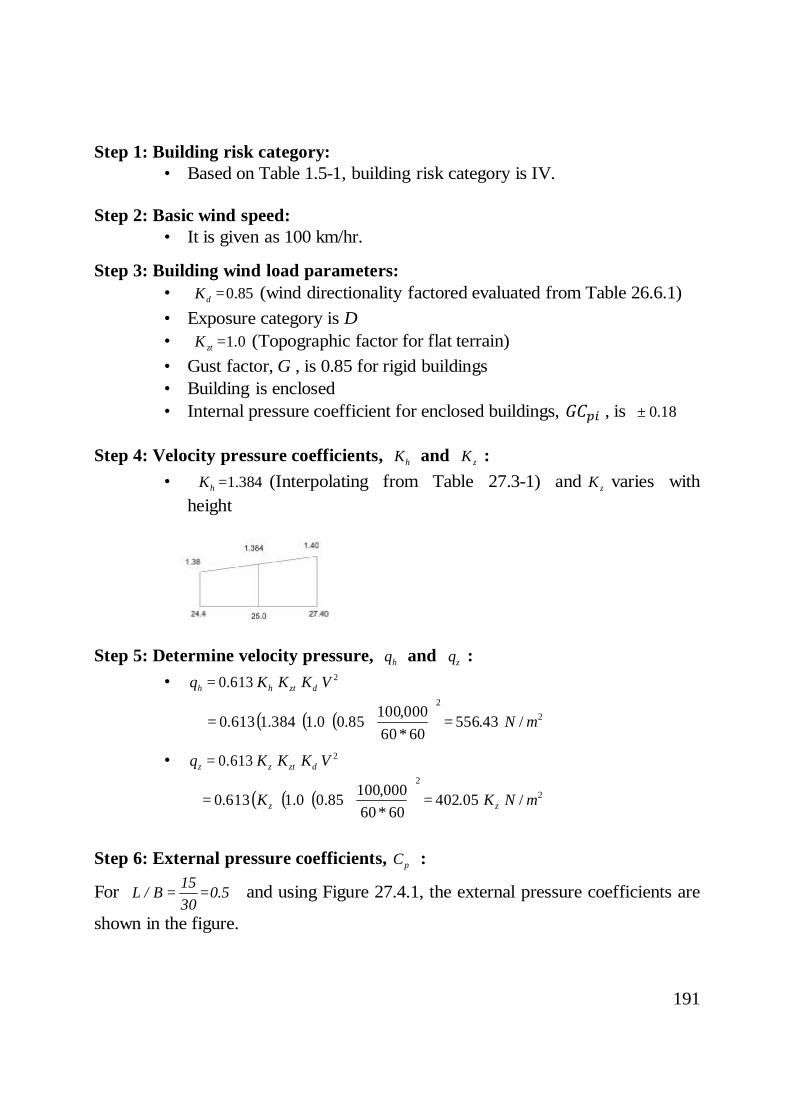
• 384.1=hK (Interpolating from Table 27.3-1) and zK varies with height
Step 5: Determine velocity pressure, hq and zq :
• 2613.0 VKKKq dzthh =
( ) ( ) ( ) 22
/43.5566060
000,10085.00.1384.1613.0 mN=
∗
=
• 2613.0 VKKKq dztzz =
( ) ( ) ( ) 22
/05.4026060
000,10085.00.1613.0 mNKK zz =
∗
=
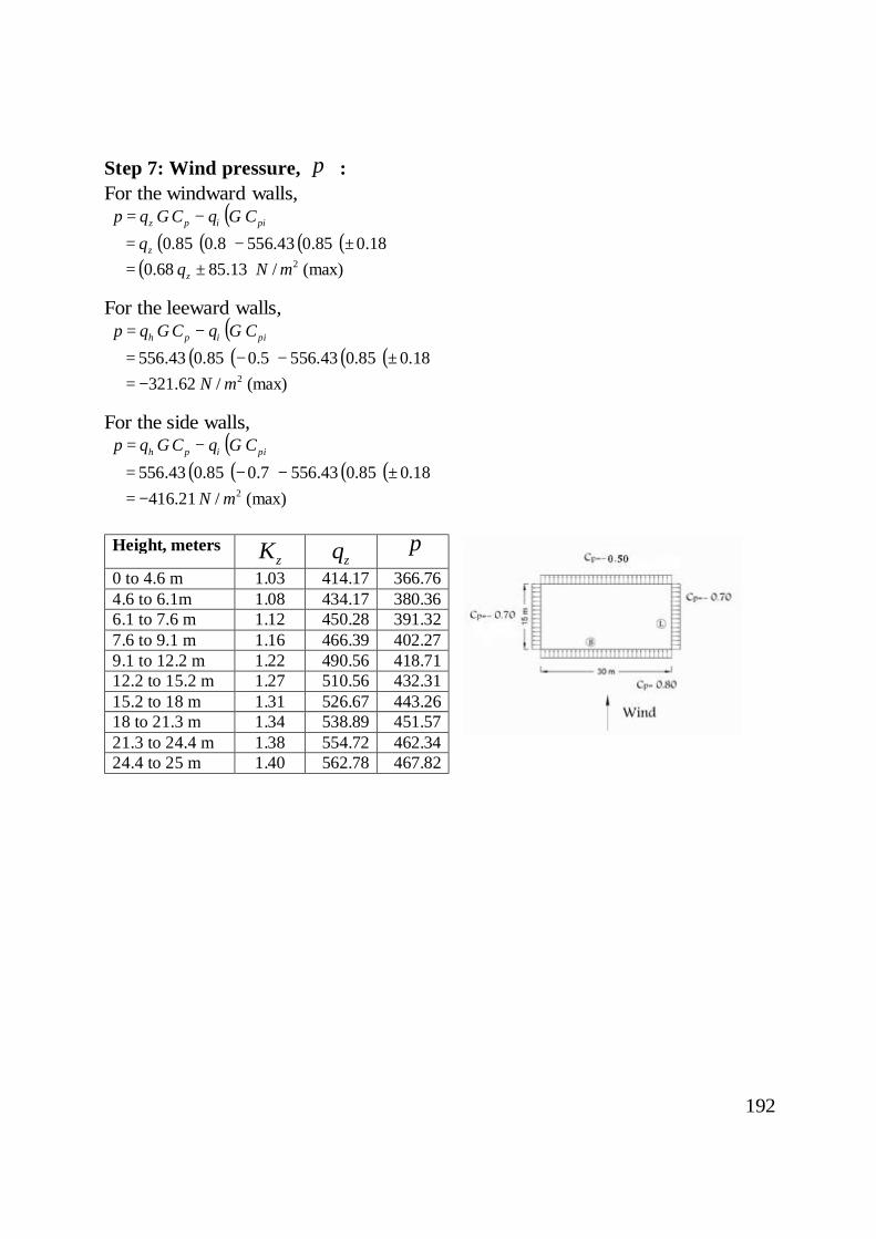
Step 6: External pressure coefficients, pC :
For 5.03015B/L == and using Figure 27.4.1, the external pressure coefficients are
shown in the figure.
192
Step 7: Wind pressure, p : For the windward walls,
( )piipz CGqCGqp −= ( )( ) ( )( )18.085.043.5568.085.0 ±−= zq
( ) (max)/13.8568.0 2mNqz ±=
For the leeward walls, ( )piiph CGqCGqp −=
( )( ) ( )( )18.085.043.5565.085.043.556 ±−−= (max)/62.321 2mN−=
For the side walls, ( )piiph CGqCGqp −=
( )( ) ( )( )18.085.043.5567.085.043.556 ±−−= (max)/21.416 2mN−=
Height, meters
zK zq p 0 to 4.6 m 1.03 414.17 366.76 4.6 to 6.1m 1.08 434.17 380.36 6.1 to 7.6 m 1.12 450.28 391.32 7.6 to 9.1 m 1.16 466.39 402.27 9.1 to 12.2 m 1.22 490.56 418.71 12.2 to 15.2 m 1.27 510.56 432.31 15.2 to 18 m 1.31 526.67 443.26 18 to 21.3 m 1.34 538.89 451.57 21.3 to 24.4 m 1.38 554.72 462.34 24.4 to 25 m 1.40 562.78 467.82
Related Documents

![CM01 02 [režim kompatibility]) - cvut.czpeople.fsv.cvut.cz/~bilypet1/vyuka/CM01/CM01_02.pdf · Detailed calculation of 2D frame • Calculation of loads • Modelling 2D frame in](https://static.cupdf.com/doc/110x72/6015257dd2f2d625fa5b076c/cm01-02-reim-kompatibility-cvut-bilypet1vyukacm01cm0102pdf-detailed.jpg)