RUNGTA COLLEGE OF ENGINEERING & TECHNOLOGY DEPARTMENT OF MECHANICAL ENGINEERING (APPROVED BY AICTE NEW DELHI) RAIPUR (CG) COMPUTER AIDED DESIGNING & MACHINING LAB PREPARED AS PER SYLLABUS PRESCRIBED BY: CHHATTISGARH SWAMI VIVEKANAND TECHNICAL UNIVERSITY, RAIPUR RUNGTA COLLEGE OF ENGINEERING AND TECHNOLOGY,RAIPUR DEPARTMENT OF MECHANICAL ENGINEERING

Welcome message from author
This document is posted to help you gain knowledge. Please leave a comment to let me know what you think about it! Share it to your friends and learn new things together.
Transcript
RUNGTA COLLEGE OF ENGINEERING & TECHNOLOGYDEPARTMENT OF MECHANICAL ENGINEERING
(APPROVED BY AICTE NEW DELHI)
RAIPUR (CG)
COMPUTER AIDED DESIGNING &MACHINING LAB
PREPARED AS PER SYLLABUS PRESCRIBED BY:
CHHATTISGARH SWAMI VIVEKANAND TECHNICAL UNIVERSITY, RAIPUR
RUNGTA COLLEGE OF ENGINEERING AND TECHNOLOGY,RAIPURDEPARTMENT OF MECHANICAL ENGINEERING

CAD CAM LAB
AT A GLANCE
NAME OF LAB – INCHARGE: Mr. MORRISH KUMAR
NAME OF LAB ASSISTANT:
LOCATION
GB-11
FLOOR AREA
1200 SQ FEET
TOTAL INVESTMENT OF THE LAB
Rs. 22,62,500/-
NO. OF EXPERIMENTS TOPERFORM
10
LAB UTILITY HRS./WEEKJLLJLLL
ODD SEM. 8 HRS/WEEK
LIST OF DO’s &DON’Ts
AVAILABLE
MASTER LABMANUAL
AVAILABLE
NO. OF EDUCATIONAL CHARTSDDS
NIL
EQUIPMENTS
30 COMPUTERS WITH UNIGRAPHICSNX AND PRO ENGINEERING
SOFTWARE INSTALLED
FUTURE PLAN
ONE NEW EXPERIMENT WILL BEINCLUDED EVERY YEAR
RUNGTA COLLEGE OF ENGINEERING AND ECHNOLOGY,RAIPURDEPARTMENT OF MECHANICAL ENGINEERING

CAD / CAM LABSemester: 7th Code: 337723 (37)
Total practical periods: 24Total Marks in end Semester Exam: 40
LIST OF EXPERIMNETS (PRESCRIBED BY C.S.V.T.U.)
S.N. LIST OF EXPERIMENTS (Minimum 7 experiments are to be performed) REMARK
1 Introduction & different features of the CAD Software √
2 2-D Drafting √
3 3-D Modeling √
4 3-D Advanced Modeling √
5 Assembly modeling -
6 Feature Modification and Manipulation -
7 Detailing -
8 Sheet Metal Operations -
9 Surface Modeling √
10 One Dimensional problems of Finite Element Method. -
NOTE: (1) √ Marked experiments have been identified and made ready to perform.(2) Remaining experiments will be added as per growth plan of the lab. It is
proposed to introduce minimum one experiment every year.

S.N. LIST OF EXPERIMENTS (Minimum 5 experiments are to be performed) REMARK
1 To prepare part programming for plain turning operation. √
2 To prepare part programming for turning operation in absolute mode. √
3 To prepare part program in inch mode for plain turning operation. -
4 To prepare part program for taper turning operation. -
5 To prepare part program for turning operations using turning cycle -
6 To prepare part program for threading operation. √
7 To prepare part program for slot milling operation. -
8 To prepare part program for gear cutting operation. -
9 To prepare part program for gear cutting using mill cycle. -
10 To prepare part program for drilling operation. √
11 To prepare part program for multiple drilling operation in Z-axis. -
12 To prepare part program for multiple drilling in X-axis. -
13 To prepare part program for multiple drilling in X and Z axis using drilling cycle. √
NOTE: (1) √ Marked experiments have been identified and made ready to perform.(2) Remaining experiments will be added as per growth plan of the lab. It is
proposed to introduce minimum one experiment every year.

RUNGTA COLLEGE OF ENGINEERING ANDTECHNOLOGY,RAIPURDEPARTMENT OF MECHANICAL ENGINEERING
CAD CAM LABList of DO’s & DON’Ts.
DO’s:
§ First read the manual of assigned experiment carefully then accordingly do
the experiment.
§ Before switching on the supply, get all the connections checked, by the
Faculty-in-charge/Lab – in - charge of the lab.
§ Always use proper rating instruments.
§ After the supply is switched on, Maintain safe distance from the rotating /
reciprocating / oscillating elements.
§ For any abnormal working of machine or equipment, switch off the supply
at once and consult the Faculty-in-charge/Lab-in-charge immediately.
§ Switch off the supply mains after performing experiment.
§ Maintain silence and proper discipline in the lab.
§ Take the reading without parallex error
DON’Ts
§ Do not come very close to any machine or any rotating part.
§ Don’t use metallic pen while observing the instrument reading.
§ Don’t leave the unwanted wires / tools / items near experimental setup.
§ Do not tamper the instruments in the Lab, and do not disturb their settings.
§ Do not wear loose clothes while performing the experiments.

…SAFETY FIRST…
CAD/CAM
LAB MANUAL
DEPARTMENT OF MECHANICAL ENGINEERINGRUNGTA COLLEGE OF ENGINEERING & TECHNOLOGY
(APPROVED BY AICTE, NEW DELHI)RAIPUR (C.G.)

RUNGTA COLLEGE OF ENGINEERING AND TECHNOLOGY, RAIPURDEPARTMENT OF MECHANICAL ENGINEERING
CERTIFICATE
This is to certify that Mr./Ms. ____________
__________________ has satisfactorily completed the required
number of experiments in CAD/CAM Laboratory as per syllabus
of B.E. Seventh semester Mechanical , prescribed by
Chhattishgarh Swami Vivekanand Technological
University , for the academic session ____________
Signature of Head Signature of TeacherDate: Date:

LIST OF EXPERIMENTS
CAD (MINIMUM FIVE EXPERIMENTS)
1. Introduction & different features of the CAD Software2. 2-D Drafting3. 3-D Modeling4. 3-D Advanced Modeling5. Assembly modeling6. Feature Modification and Manipulation7. Detailing8. Sheet Metal Operations9. Surface Modeling10.One Dimensional problems of Finite Element Method.
(These exercises may be performed by any of the following Advanced CAD Software)
CAM (MINIMUM FIVE EXPERIMENTS)
1. To prepare part programming for plain turning operation.2. To prepare part programming for turning operation in absolute mode.3. To prepare part program in inch mode for plain turning operation.4. To prepare part program for taper turning operation.5. To prepare part program for turning operations using turning cycle.6. To prepare part program for threading operation.7. To prepare part program for slot milling operation.8. To prepare part program for gear cutting operation.9. To prepare part program for gear cutting using mill cycle.10.To prepare part program for drilling operation.11.To prepare part program for multiple drilling operation in Z-axis.12.To prepare part program for multiple drilling in X-axis.13.To prepare part program for multiple drilling in X and Z axis using drilling cycle.
LIST OF EQUIPMENTS/MACHINES REQUIRED
1. Computer Numerically Control Lathe Trainer.2. P-IV (IBM) 2.6 GHz, 80 GB HDD,256/512 SD RAM(As Compatible with CAD
Software) 52 X CD RW, 1.44 MB, FDD, 17” Colour Monitor, Laser Scroll Mouse.3. Softwares – Pro-E, Solid-work, CATIA, ANSYS,UNIGRAPHICS NX.4. CNC Controlled Milling Machine.5. CNC Controlled Drilling Machine.
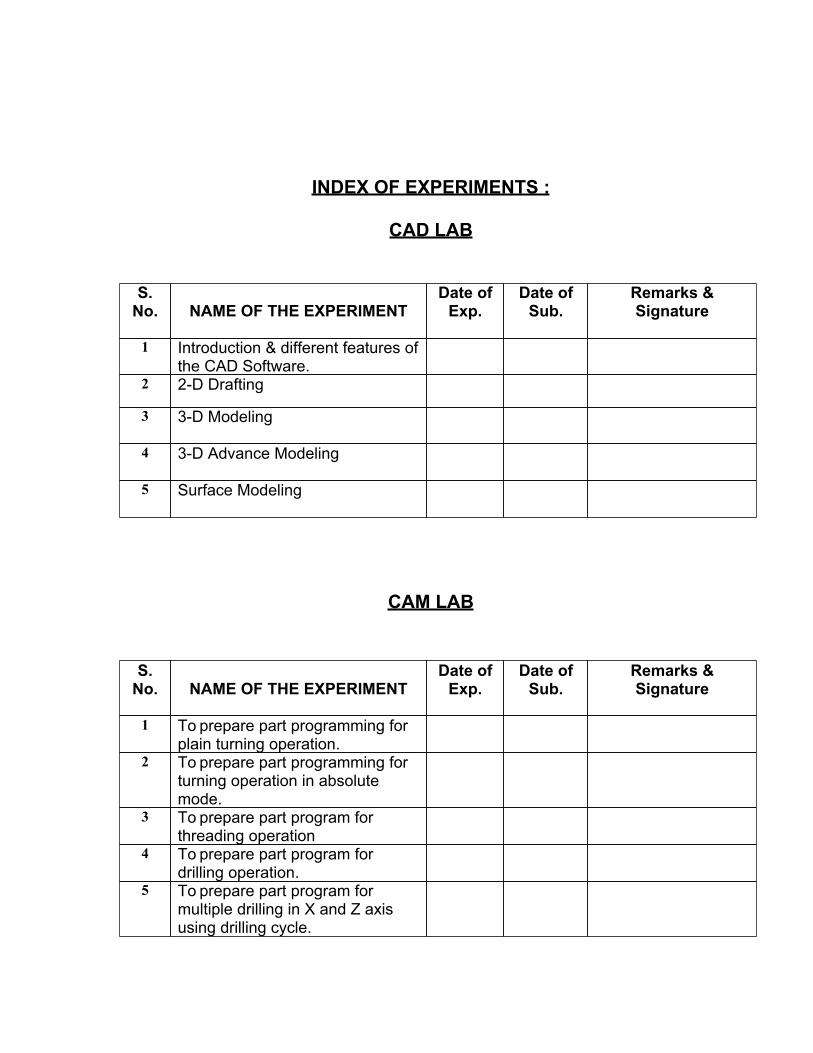
INDEX OF EXPERIMENTS :
CAD LAB
S.No. NAME OF THE EXPERIMENT
Date ofExp.
Date ofSub.
Remarks &Signature
1 Introduction & different features ofthe CAD Software.
2 2-D Drafting
3 3-D Modeling
4 3-D Advance Modeling
5 Surface Modeling
CAM LAB
S.No. NAME OF THE EXPERIMENT
Date ofExp.
Date ofSub.
Remarks &Signature
1 To prepare part programming forplain turning operation.
2 To prepare part programming forturning operation in absolutemode.
3 To prepare part program forthreading operation
4 To prepare part program fordrilling operation.
5 To prepare part program formultiple drilling in X and Z axisusing drilling cycle.

EXPERIMENT – 01
OBJECTIVE: Introduction & different features of the CAD Software
DESCRIPTION OF UGS NX 5.0:
UGS : UNIGRAPHICS SOLUTIONSNX : NEXT GENERATIONVERSION : 5.0
INTRODUCTION
NX is an interactive Computer-Aided Design, Computer-Aided Manufacturing, and Computer-Aided Engineering (CAD/CAM/CAE) system. The CAD functions automate the normalengineering, design, and drafting capabilities found in today's manufacturing companies. TheCAM functions provide NC programming for modern machine tools using the NX design modelto describe the finished part. The CAE functions provide a number of product, assembly, andpart performance simulation abilities, across a broad range of engineering disciplines.NX functions are divided into "applications" of common capabilities. These applications aresupported by a prerequisite application called NX Gateway. Every NX user must have NXGateway; however, the other applications are optional and may be configured to meet the needsof each individual user.NX is a fully three-dimensional, double precision system that allows you to accurately describealmost any geometric shape. By combining these shapes, you can design, analyze, and createdrawings of your products.Once the design is complete, the Manufacturing application allows you to select the geometrydescribing the part, enter manufacturing information such as cutter diameter, and automaticallygenerate a cutter location source file (CLSF), which can be used to drive most NC machines.
HOW TO START THE SOFTWARE
START
SHADED VIEW (UGS)
SELECT MODELING
GATEWAY
NEW FILE (Give the name of file)
WELCOME NOTE
OK

1) STARTING THE SOFTWARE
2) SHADED VIEW

3) WELCOME WINDOW
4) GATEWAY(GIVE THE NAME OF NEW FILE HERE….)
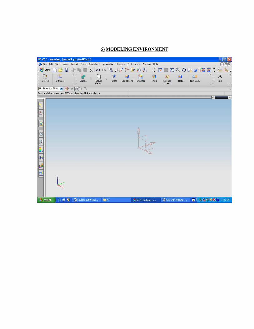
5) MODELING ENVIRONMENT
BASIC OPERATIONS
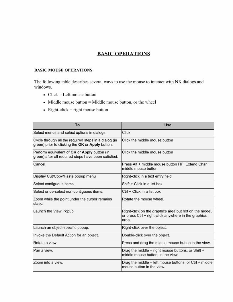
BASIC MOUSE OPERATIONS
The following table describes several ways to use the mouse to interact with NX dialogs andwindows.
· Click = Left mouse button
· Middle mouse button = Middle mouse button, or the wheel
· Right-click = right mouse button
To Use
Select menus and select options in dialogs. Click
Cycle through all the required steps in a dialog (ingreen) prior to clicking the OK or Apply button.
Click the middle mouse button
Perform equivalent of OK or Apply button (ingreen) after all required steps have been satisfied.
Click the middle mouse button
Cancel Press Alt + middle mouse button HP: Extend Char +middle mouse button
Display Cut/Copy/Paste popup menu Right-click in a text entry field
Select contiguous items. Shift + Click in a list box
Select or de-select non-contiguous items. Ctrl + Click in a list box
Zoom while the point under the cursor remainsstatic.
Rotate the mouse wheel.
Launch the View Popup Right-click on the graphics area but not on the model,or press Ctrl + right-click anywhere in the graphicsarea.
Launch an object-specific popup. Right-click over the object.
Invoke the Default Action for an object. Double-click over the object.
Rotate a view. Press and drag the middle mouse button in the view.
Pan a view. Drag the middle + right mouse buttons, or Shift +middle mouse button, in the view.
Zoom into a view. Drag the middle + left mouse buttons, or Ctrl + middlemouse button in the view.

MOUSE WHEEL ENVIRONMENT VARIABLE
To specify the mouse wheel's behavior in the graphics window, you can set theUGII_MOUSE_WHEEL environment variable. The system supports the mouse wheel onWindows only.
The following table describes each setting and the resulting mouse wheel behavior.
UGII_MOUSE_WHEEL Description
Undefined Same as UGII_MOUSE_WHEEL=1.
0 Disables the mouse wheel in the graphics window. Does not affect its behaviorelsewhere in NX or in other applications.
1 To zoom in, scroll the mouse wheel toward you; To zoom out, scroll away fromyou. The default.
2 To zoom in, scroll the mouse wheel away from you; To zoom out, scroll towardyou.
KEYBOARD
You can perform most actions with both the mouse and keyboard. This allows you to select theappropriate input device for each task or the device with which you are most comfortable.Although the mouse is the primary means of interaction, you can also perform most interfaceactions from the keyboard
CONTROLLING DIALOGS USING THE KEYBOARD
To navigate through the active window in NX, use the keyboard controls in the following table:
To: Do This:
Advance through each dialog control in a dialog. <Tab>
Move backward through each dialog control in a dialog. <Shift><Tab>
Move the focus to individual elements within a dialog control, such as options on apull-down menu.
Arrow keys
Activate the OK button in a dialog, if a text field currently has focus. <Return> Key
Accept the active button in a message dialog. Space Bar/<Return>Key
Interactive Abort (limited usage). <Shift><Ctrl>L
Quiting from any command <Esc>
Nearest 2 D View <F8>
Trisometric View <Home>

Isometric View <End>
Top View Ctrl + Alt + T
Front View Ctrl + Alt + F
Right Hand Side View Ctrl + Alt + R
Left Hand Side View Ctrl + Alt + L
VIVAQUESTIONS:

Ques.1. What is UGS NX5. Explain it briefly.
Ques.2. What are the advancements in this software as compared to otherdesigning softwares.
Ques.3. What are the alternate shortcut keys for performing Zoom in/out andPan functions?
Ques.4. What is the extension name of files prepared in NX5. Can it bemodified?
Ques.5. What is difference between isometric and trisometric view. Give theirshortcuts also.
EXPERIMENT – 02

OBJECTIVE: To implement 2 D Drafting.
DESCRIPTION OF 2-D DRAFTING
This feature of NX provides two dimensional environment to draw sketches and with the help ofthis, three dimensional models can be generated.
In 2 –D Drafting, the sketcher curves and corresponding tools can be drawn and used usingvarious options.
After the sketching, constraining is done
Following are the sketcher curves and related tools.
How to start the sketcher tool:-
Sketcher tool:-

Tool functions
1 Line for making lines2 Profile for making continues lines & making tangent arc3 Circle For making circle using two method 1. by center 2. by three points4 Arc For making arc using two method 1. by center 2. by three points5 Quick Trim For erase the curve within boundary6 Make Corner Extends or trim two curves to make a corner7 Fillet For making fillet between two or three curves8 Rectangle For making rectangle using three method 1. by 2 points 2. by 3points 3.
from center9 Studio Spline For making spline by points or poles10
InferredDimensions
For giving dimensions to constraints
11
Constraints For giving relationships between curve or axis geometric constraints
12
Show allConstraints
For showing all the geometric constraints
13
Show/RemoveConstraints
For remove the geometric constraints
1) ProfileCreates a series of continuous lines and arc in strings mode, that is the end of last curvebecomes the beginning of next curve.

2) Line
Creates lines with constraint inferencing
3) ArcCreates an arc through three points or by specifying center and end points.
4) CircleCreates a circle through three points or by specifying its center and diameter.
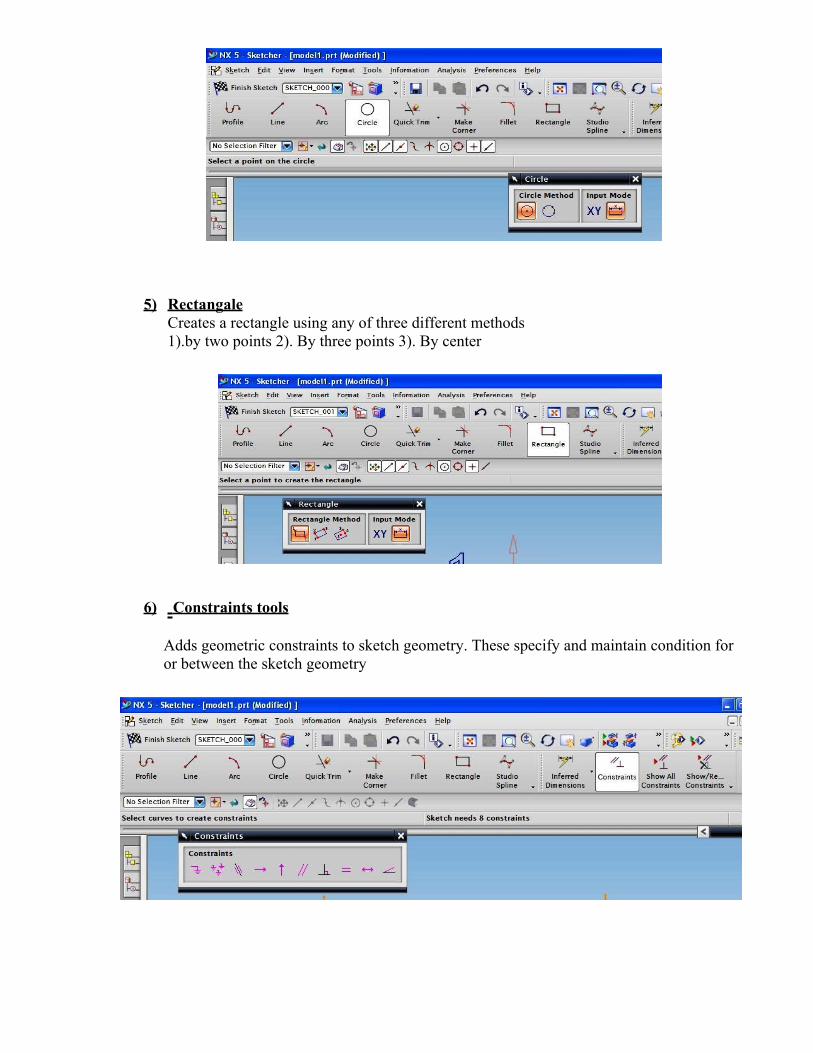
5) RectangaleCreates a rectangle using any of three different methods1).by two points 2). By three points 3). By center
6) Constraints tools
Adds geometric constraints to sketch geometry. These specify and maintain condition foror between the sketch geometry
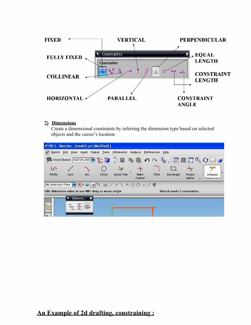
7) DimensionsCreats a dimensional constraints by inferring the dimension type based on selectedobjects and the curser’s location.
An Example of 2d drafting, constraining :

1) Select ‘profile’ and make the rough sketch as shown below:
2) Give all geometrical constraints , for example vertical, horizontal, equal, etc. as shown:

3) After giving all the geometrical constraints, following sketch will obtain:
4) Give all dimensional constraints to fix the sketch, as shown:

Viva Questions
1. What is difference between line & profile tool.
2. Why constraint is important.
3. Why we generally don’t use fixed, constant line & constant angleconstraints.
4. How to remove the constraints.
5. In which color fully constraint sketch show.

EXPERIMENT – 03
OBJECTIVE: To implement 3-D Modeling.
DESCRIPTION OF 3-D MODELING
NX Modeling provides a solid modeling system to enable rapid conceptual design. You cancreate and edit complex, realistic, solid models interactively. You can change and update solidbodies by directly editing their dimensions or by using other construction techniques.
STARTING WITH A SKETCHUse the Sketcher to freehand a sketch, and dimension an "outline" of curves. You can then sweepthe sketch using Extrude or Revolved Body to create a solid or sheet body. You can later refinethe sketch to precisely represent the object of interest by editing the dimensions and by creatingrelationships between geometric objects. Editing a dimension of the sketch not only modifies thegeometry of the sketch, but also the body created from the sketch.
TYPES OF MODELING:
1) SKETCH BASED
In this type of modeling we use sketches in 2-D environment after then, we will convert in 3-Denvironment.
2) FEATURE BASED
In this type of modeling, there is no need to draw any sketch, because NX-5 provides special tools formaking 3-D model, for example hole, blocks, cylinder, cone, spheres, etc.
3) SURFACE BASED
In this type of modeling. Some complex problems that can’t be solved by above two methods can bedone through this method.
NECESSARY TOOLS TO BE USED

S.No.
Name of tool Function
1 Extrude Creates a feature by extruding a section along a vector2 Revolve Creates a feature by revolving a section about an axis.3 Swept Creates a body by sweeping a section along one or more guides.4 Tube Creates a solid body by sweeping a circular cross section along a curve5 Boss Adds a cylindrical boss on a planar face of a solid body.6 Pad Adds material to a solid body7 Block Creates a block by defining corner location and dimensions.8 Cylinder Creates a cylinder by defining axis location and dimension.9 Cone Creates a cone by defining axis location and dimension.
10 Sphere Creates a sphere by defining centre location and dimension.11 Unite Combines the volume of two or more solid bodies into a single body.12 Datum plane Creates a datum plane used to construct other features.13 Draft Modifies faces by changing the angle relative to a draw direction.14 Edge blend Round sharp edges between faces. The radius can be variable or constant15 Chamfer Chamfers sharp edges between faces.16 Shell Modifies a solid body by applying wall thickness and opening selected
faces.17 Emboss sheet Modifies a sheet body, by adding faces of a solid body.18 Hole Adds a hole to a solid body with counter bore & countersink options19 Trim body Trims off a portion of a body using faces or a datum plane.20 Extracts Creates a body by copying a face, a set of faces or another body.
PROCEDURE:Steps for extrusion
1) Firstly draw a sketch in which, the modeling operation is to be performed.
2) For drawing the sketch, select the “sketch” tool and then select (Xc,Yc) plane for frontview and then press “ok”. Sketcher environment will appear.
3) Now draw the sketch and do the constraining and dimensioning to fix the position ofsketch in work bench as shown below and then click on”Finish Sketch”.

4. 3-D environment will appear.
5. Click on “extrude” tool, extrude operation window will appear.
6. Enter the value of “distance” as width of the object, and then click on “ok”, to get thefinally extruded object as shown below.
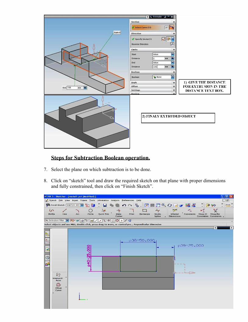
Steps for Subtraction Boolean operation.
7. Select the plane on which subtraction is to be done.
8. Click on “sketch” tool and draw the required sketch on that plane with proper dimensionsand fully constrained, then click on “Finish Sketch”.
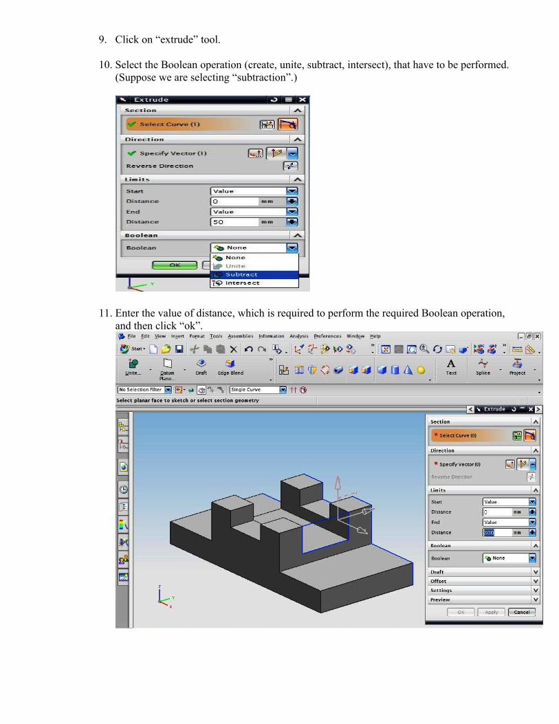
9. Click on “extrude” tool.
10. Select the Boolean operation (create, unite, subtract, intersect), that have to be performed.(Suppose we are selecting “subtraction”.)
11. Enter the value of distance, which is required to perform the required Boolean operation,and then click “ok”.

VIVAQUESTIONS:
Ques.1. Explain different types of constraining.
Ques.2. How to exit from the sketcher environment?
Ques.3. What are the different types of Boolean operations?
Ques.4. Explicate types of limits in extrude operation window.
Ques.5. What are the necessary points that should be taken in consideration,while selecting the sketch for extrusion?

EXPERIMENT – 04
OBJECTIVE: To implement 3D Advanced Modeling.
DESCRIPTION OF 3D ADVANCED MODELING
There are some extra features in 3 D advance modeling methods such as “selection intent”
Using selection intent is in advanced modeling.
It is the best tool example for advanced modeling.
Selection Intent has the following enhancements:
· A Chain within Feature command is added to the Selection Intent options on the SelectionBar, that indicates the scope of chaining. This command is also available on the shortcut menufor valid objects.
In the context of already created geometry, using the Chain within Feature command limits thechaining to collect curves only from the feature of the selected curve.
· The Stop at Intersection and Follow Fillet commands, available as Selection Intent options onthe Selection Bar, are also now available on the shortcut menu as object-specific commands.
· If you deselect objects while editing curves or faces, smart deselection captures the intent ofdeselecting objects in the chain. These removed objects are displayed in a Removed Objectssubfolder, in the Chain folder under Section, in the detailed view of the Dependencies panel inthe Part Navigator.
· The Stop at Intersection start and end limits are shown in the Intersection Limits subfolder, inthe Chain folder under Section, in the detailed view of the Dependencies panel in the PartNavigator.
· Selection Intent now provides better error reporting messages and warnings while updatingfeatures. The messages provide better feedback about the errors propagated while revalidatingthe design intent rules during feature update.
Why should I use it?Use the Selection Intent options, to select and group multiple curves, edges, and faces, with rules todefine their use when creating and editing features.
Where do I find it?The Selection Intent options are available on the Selection Bar while creating or editing a feature thatsupports selection intent.
PROCEDURE:
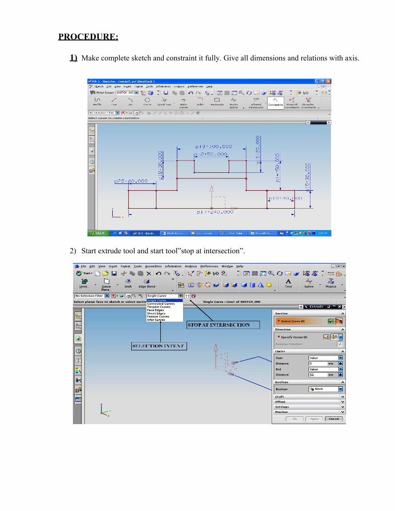
1) Make complete sketch and constraint it fully. Give all dimensions and relations with axis.
2) Start extrude tool and start tool”stop at intersection”.

3) Take “connected curve” and select the outer sketch.
4) Give symmetric valve for making solid on both side of the sketch.

5) Take wireframe to show inside sketch.
6) Choose “stop at intersection ” and then start “extrude tool”, and give symmetrical value forsubtracting both side of the sketch.
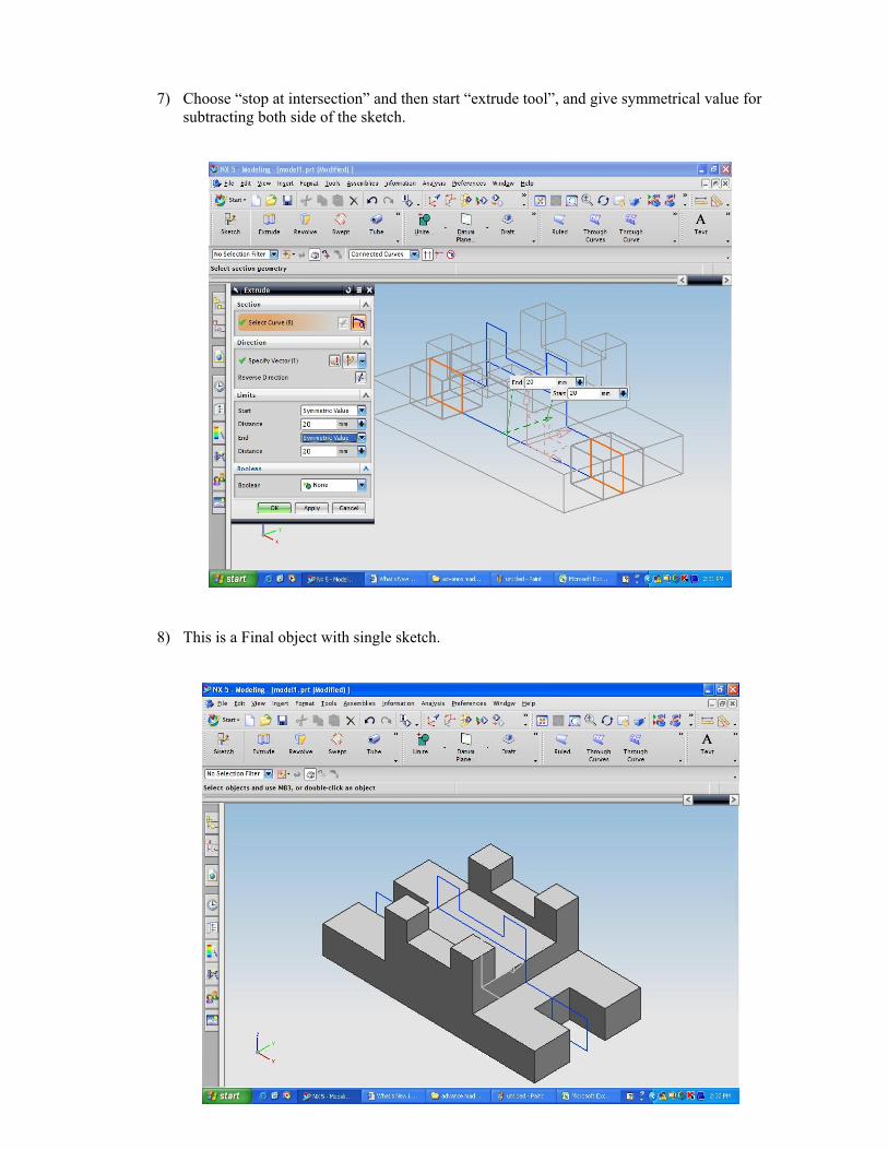
7) Choose “stop at intersection” and then start “extrude tool”, and give symmetrical value forsubtracting both side of the sketch.
8) This is a Final object with single sketch.

Viva Questions:
1. What is difference between 3d modeling & 3d advancedmodeling?
2. If we don’t use the “stop at intersection”. Then what will happen?
3. What is function of “stop at inter section”.
4. What is deference between ‘single curve’ & ‘connected curve’.
5. Difference between subtract and intersect.

EXPERIMENT – 05
OBJECTIVE: To implement surface Modeling.
DESCRIPTION OF SURFACE MODELING
In this type of modeling we use that kind of problem that can not be solved by the sketch basedmodeling and feature based modeling.
This is used only in special purpose
In the surfaced modeling following tools are used:-
COMMONLY USED TOOLS ARE:-
S.N.
TOOL FUNCTION
1 Ruled create a body between two section2 Through Curves create a body through multiple section3 Through Curve
Meshcreate a body through a mesh of section in one direction and guidein another direction
4 Swept create a body by sweeping section along one or more guides5 Bridge create a sheet body that joints two faces6 N -sided surface create a surface enclosed by a set of end-connected curves

PROCEDURE OF SURFACEMODELING :
1) Take a rectangle for base.
2) Take a plane for making circle parallel to rectangle plane.

3) Select sketch tool and select plane ok.
4) Make circle in the plane in such a way that, the centre of circle and intersection point of diagonalsof rectangle both lie in the same point.
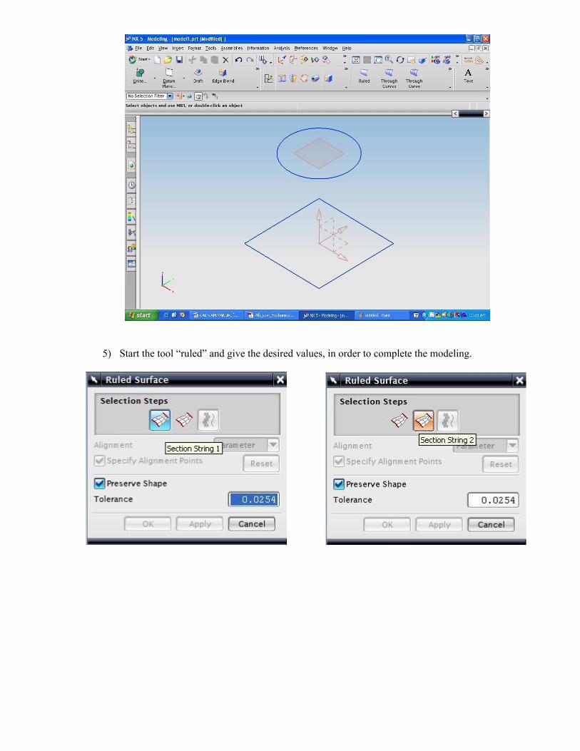
5) Start the tool “ruled” and give the desired values, in order to complete the modeling.

Viva Questions:
1) What is surface modeling?
2) Why it is used?
3) Difference between “ruled” and “through curves” tool.
4) If the loop is not closed then what will happen?
5) What is the color identification for solids and surfaces?

INDEX OF EXPERIMENTS :
CAM LAB
S.No. NAME OF THE EXPERIMENT
Date ofExp.
Date ofSub.
Remarks &Signature
1 To prepare part programming for plainturning operation.
2 To prepare part programming for turningoperation in absolute mode.
3 To prepare part program for threadingoperation

4 To prepare part program for drillingoperation.
5 To prepare part program for multipledrilling in X and Z axis using drillingcycle.
CNC LATHEINTRODUCTION
AIM OF LEARNING CNC OPERATIONS
1. TO GET FAMILIAR WITH BASIC OPERATIONS OF CNC MACHINES.
2. TO KNOW THE THEOROTICAL & PRACTICAL CONCEPTS OF CNC MACHINE.
3. TO LEARN BASIC CONCEPT OF CNC PART PROGRAMMING.
4. TO UNDERSTAND THE BASIC WORKING PRINCIPLE OF CNC SYSTEM,ELECTRONIC, SOFTWARE,MECHANICAL SYSTEM.

SAFETY PRECAUTIONS
1. Never attempt to machine a work piece without first checking theoperation of the machine. Before starting a trainer, ensure that thetrial run is ok by operating the machine with neither a tool nor workpiece mounted.
2. Coordinate setting is very important factor while operating the CNCtrainer. Incorrect coordinates may damage the tool, the machine, oruser.
3. Before giving numerical input command determine the currentposition of the tool & work piece & ensure the axis, direction &command have been specified correctly & the entered values arevalid.
4. It is very dangerous to touch any rotating part of the machineNEVER attempt to remove swart whilst the machine is in motion.
FRONT PANEL INDICATIONS & SWITCHES
INDICATIONS:
- Mains ON (Red `ON’ lamp)When the key switch is turned ON, this lamp will glow.
- Spindle ON (Green lamp)It will glow when the spindle is turned ON to move in turned forward directionthrough program or in JOG mode.
- Coolant ON (Green lamp)When coolant motor is made ON through M07 or M08 command, this lamp will glow.
- Emergency Stop (Red lamp)This lamp will glow when somebody presses the Emergency stop switch on frontpanel. It indicates that there is no power supply to the machine motors & other circuit. Ifyou run the program you will get ‘Power Failure ‘ message.

SWITCHES
1) Mains ON switch:This switch is used to turn on the main supply. Now the computer is to be started.
2) CNC ON Switch:This switch will start the supply to the stepper motor, Spindle motor & other electronic circuits. Butremember to switch ON this only after the PC is started.
3) Emergency Stop Switch (Red colour):This is a Press-To-Lock switch. These will cut-off the machines supply but thecomputer will not be off.
PARTPROGRAMMING CODES
LIST OF G CODES
CODE FUNCTIONG00 RAPID POSITIONING
G01 LINEAR INTERPOLATION
G02 CLOCKWISE CIRCULAR INTERPOLATION
G03 COUNTER CLOCKWISE CIRCULAR INTERPOLATION
G04 DWELL IN SECONDS
G20 INCH PROGRAMMING

G21 METRIC PROGRAMMING
G28 AUTO. RETURN TO REF. POINT
G70 FINISHING CYCLE
G71 STOCK REMOVALIN TURNING
G72 STOCK REMOVALIN FACING
G73 PATTERN REPEATING CYCLE
G74 PECK DRILLING CANNED CYCLE
G81 Drilling Cycle
G90 DIAMETER CUTTING CYCLE
G92 THREADING CANNED CYCLE
G94 FACING CANNED CYCLE
G96 CONSTANT SURFACE SPEED ON
G97 CONSTANT SURFACE SPEED OFF
LIST OF M-CODES
CODE FUNCTION
M00 PROGRAM HAULTM01 OPTIONAL PROGRAM STOPM02 PROGRAM ENDM03 SPINDLE START CLOCKWISEM04 SPINDLE START ANTICLOCKWISEM05 SPINDLE STOPM08 COOLANT ONM09 COOLANT OFFM13 SPINDLE CLOCKWISE & COOLANT ONM14 SPINDLE ANTI-CLOCKWISE & COOLANT ONM30 PROGRAM END & REWINDM98 START OF SUBROUTINEM99 END OF SUBROUTINE

LATHEMACHINING EXERCISES
Experiment 1
Aim:- To prepare part programming for plain turning operation & to make the job byFollowing specification.
Material AluminumLength of job 40 mmSpindle speed 3000 rpmInitial Taper 25Final Taper 21
Procedure:-
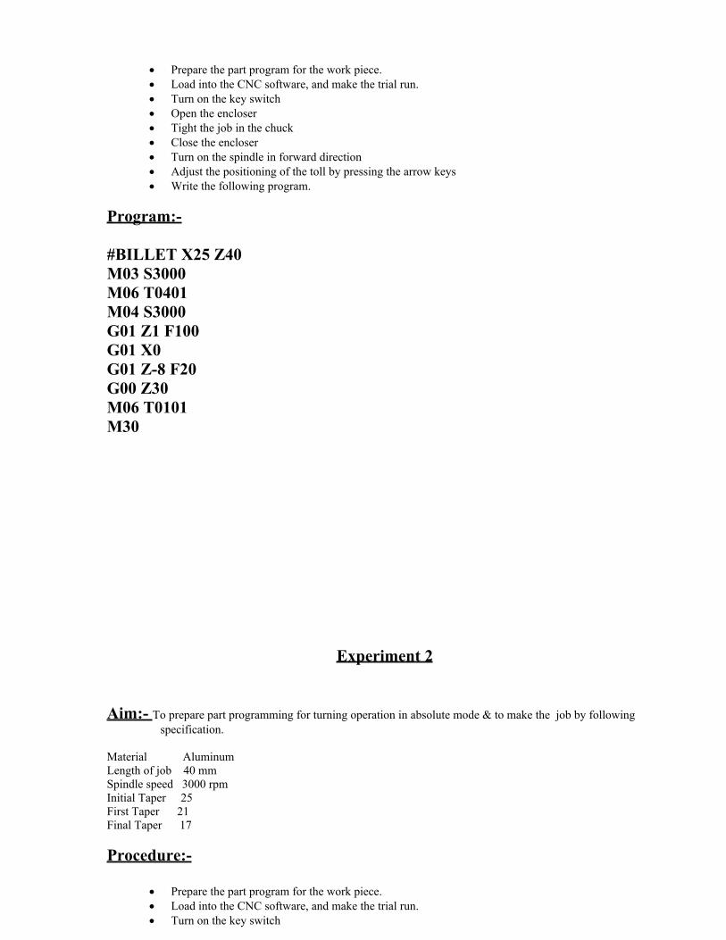
· Prepare the part program for the work piece.· Load into the CNC software, and make the trial run.· Turn on the key switch· Open the encloser· Tight the job in the chuck· Close the encloser· Turn on the spindle in forward direction· Adjust the positioning of the toll by pressing the arrow keys· Write the following program.
Program:-
#BILLET X25 Z40M03 S3000M06 T0401M04 S3000G01 Z1 F100G01 X0G01 Z-8 F20G00 Z30M06 T0101M30
Experiment 2
Aim:- To prepare part programming for turning operation in absolute mode & to make the job by followingspecification.
Material AluminumLength of job 40 mmSpindle speed 3000 rpmInitial Taper 25First Taper 21Final Taper 17
Procedure:-
· Prepare the part program for the work piece.· Load into the CNC software, and make the trial run.· Turn on the key switch

· Open the encloser· Tight the job in the chuck· Close the encloser· Turn on the spindle in forward direction· Adjust the positioning of the toll by pressing the arrow keys· Write the following program.
Program:-
#BILLET X25 Z40M03 S3000G01 X25 Z0 F100G90 X24 Z-20 F30X23X22X21G90 X20 Z-10 F30X19X18X17G00 X30G00 Z20M30
Experiment 3
Aim:- To prepare part programming for threading operation & to make the job byfollowing specification.
Material AluminumLength of job 30 mmSpindle speed 20600 rpm
Procedure:-
· Prepare the part program for the work piece.· Load into the CNC software, and make the trial run.· Turn on the key switch· Open the encloser· Tight the job in the chuck· Close the encloser

· Turn on the spindle in forward direction· Adjust the positioning of the toll by pressing the arrow keys· Write the following program.
Program:-
#BILLET X33 Z30M03 S2000M06 T0501G01 X32 F300G01 Z1G92 U-0.2 W-15 F1U-0.4U-0.6U-0.8U-1G00 Z15M30
Experiment 4
Aim:- To prepare part programming for plain drilling operation & to make the job byfollowing specification.
Material AluminumLength of job 40 mmSpindle speed 3000 rpm
Procedure:-
· Prepare the part program for the work piece.· Load into the CNC software, and make the trial run.· Turn on the key switch· Open the encloser· Tight the job in the chuck· Close the encloser· Turn on the spindle in forward direction· Adjust the positioning of the toll by pressing the arrow keys

· Write the following program.
Program:-
#BILLET X25 Z40M03 S3000M06 T0401M04 S3000G01 Z1 F100G01 X0G01 Z-8 F20G00 Z30M06 T0101M30
Experiment 5
Aim:- To prepare part programming for multiple drilling operation in X and Z axis using drilling cycle &to make the job by following specification.
Material AluminumLength of job 40 mmSpindle speed 3000 rpm
Procedure:-
· Prepare the part program for the work piece.· Load into the CNC software, and make the trial run.· Turn on the key switch· Open the encloser· Tight the job in the chuck· Close the encloser· Turn on the spindle in forward direction· Adjust the positioning of the toll by pressing the arrow keys

· Write the following program.
Program:-
#BILLET X25 Z40M03 S3000M06 T0401M04 S3000G01 Z1 F100G01 X12.5G01 Z-8 F20G00 Z30G01 Z1 F100G01 X-12.5G01 Z-8 F20G00 Z30M06 T0101M30
Related Documents