Government of Pakistan National Vocational and Technical Training Commission Prime Minister’s Hunarmand Pakistan Program "Skills for All" Course Contents / Lesson Plan Course Title: Advanced CAD CAM Duration: 6 Months

Welcome message from author
This document is posted to help you gain knowledge. Please leave a comment to let me know what you think about it! Share it to your friends and learn new things together.
Transcript

Government of Pakistan
National Vocational and Technical Training Commission
Prime Minister’s Hunarmand Pakistan Program
"Skills for All"
Course Contents / Lesson Plan
Course Title: Advanced CAD CAM
Duration: 6 Months

2 | Advanced CAD CAM
Trainer Name
Course Title
Advanced CAD CAM
Objectives and Expectations
Employable skills and hands-on practice for Advanced CAD CAM This course offers a broad, cross-disciplinary learning experience for students looking to pursue career in Advanced CAD CAM. The needs for superior Computer Aided Designing and Computer Aided Manufacturing technology have increased in keeping with the demands for a wide variety of performances such as high productivity, high quality, as well as labor and cost savings. This course will provide participants with an integrated approach to learn about the various aspects of CAD and CAM. The course will introduce the execution of Product design & Manufacturing of Tools & Dies using latest CAD/CAM software, CNC Programming & Machining Practices Main Expectations: In short, the course under reference should be delivered by professional instructors in such a robust hands-on manner that the trainees are comfortably able to employ their skills for earning money (through wage/self-employment) at its conclusion. This course thus clearly goes beyond the domain of the traditional training practices in vogue and underscores an expectation that a market-centric approach will be adopted as the main driving force while delivering it. The instructors should therefore be experienced enough to be able to identify the training needs for the possible market roles available out there. Moreover, they should also know the strengths and weaknesses of each trainee to prepare them for such market roles during/after the training. i. Specially designed practical tasks to be performed by the trainees have
been included in the Annexure-I to this document. The record of all tasks performed individually or in groups must be preserved by the management of the training Institute clearly labeling name, trade, session, etc so that these are ready to be physically inspected/verified through monitoring visits from time to time. The weekly distribution of tasks has also been indicated in the weekly lesson plan given in this document.
ii. To materialize the main expectations, a special module on Job Search & Entrepreneurial Skills has been included in the latter part of this course (5th & 6th month) through which, the trainees will be made aware of the Job search techniques in the local as well as international job markets (Gulf countries). Awareness around the visa process and immigration laws of the most favored labor destination countries also form a part of this module. Moreover, the trainees would also be encouraged to venture into self-employment and exposed to the main requirements in this regard. It is also expected that a sense of civic duties/roles and responsibilities will also be inculcated in the trainees to make them responsible citizens of the country.

3 | Advanced CAD CAM
iii. A module on Work Place Ethics has also been included to highlight the importance of good and positive behavior in the workplace in the line with the best practices elsewhere in the world. An outline of such qualities has been given in the Appendix to this document. Its importance should be conveyed in a format that is attractive and interesting for the trainees such as through PPT slides +short video documentaries. Needless to say that if the training provider puts his heart and soul into these otherwise non-technical components, the image of the Pakistani workforce would undergo a positive transformation in the local as well as international job markets.
To maintain interest and motivation of the trainees throughout the course, modern techniques such as: • Motivational Lectures • Success Stories • Case Studies These techniques would be employed as an additional training tool wherever possible (these are explained in the subsequent section on Training Methodology). Lastly, evaluation of the competencies acquired by the trainees will be done objectively at various stages of the training and a proper record of the same will be maintained. Suffice to say that for such evaluations, practical tasks would be designed by the training providers to gauge the problem-solving abilities of the trainees.
(i) Motivational Lectures The proposed methodology for the training under reference employs motivation as a tool. Hence besides the purely technical content, a trainer is required to include elements of motivation in his/her lecture. To inspire the trainees to utilize the training opportunity to the full and strive towards professional excellence. Motivational lectures may also include general topics such as the importance of moral values and civic role & responsibilities as a Pakistani. A motivational lecture should be delivered with enough zeal to produce a deep impact on the trainees. It may comprise of the following:
Clear Purpose to convey the message to trainees effectively. Personal Story to quote as an example to follow. Trainees fit so that the situation is actionable by trainees and not
represent a just idealism. Ending Points to persuade the trainees on changing themselves.
A good motivational lecture should help drive creativity, curiosity, and spark the desire needed for trainees to want to learn more. The impact of a successful motivational strategy is amongst others commonly visible in increased class participation ratios. It increases the trainees’ willingness to be engaged on the practical tasks for a longer time without boredom and loss of interest because they can see in their mind's eye where their hard work would take them in short (1-3 years); medium (3 -10 years) and long term (more than 10 years). As this tool is expected that the training providers would make arrangements for regular well planned motivational lectures as part of a coordinated strategy

4 | Advanced CAD CAM
interspersed throughout the training period as suggested in the weekly lesson plans in this document. Course-related motivational lectures online link is available in Annexure-II.
(ii) Success Stories Another effective way of motivating the trainees is using Success Stories. Its inclusion in the weekly lesson plan at regular intervals has been recommended till the end of the training. A success story may be disseminated orally, through a presentation, or using a video/documentary of someone that has risen to fortune, acclaim, or brilliant achievement. A success story shows how a person achieved his goal through hard work, dedication, and devotion. An inspiring success story contains compelling and significant facts articulated clearly and easily comprehendible words. Moreover, it is helpful if it is assumed that the reader/listener knows nothing of what is being revealed. The optimum impact is created when the story is revealed in the form of:-
Directly in person (At least 2-3 cases must be arranged by the training institute)
Through an audio/ videotaped message (2-3 high-quality videos must be arranged by the training institute)
It is expected that the training provider would collect relevant high-quality success stories for inclusion in the training as suggested in the weekly lesson plan given in this document. Suggestive structure and sequence of a sample success story and its various shapes can be seen in Annexure III.
(iii) Case Studies Where a situation allows, case studies can also be presented to the trainees to widen their understanding of the real-life specific problem/situation and to explore the solutions. In simple terms, the case study method of teaching uses a real-life case example/a typical case to demonstrate a phenomenon in action and explain theoretical as well as practical aspects of the knowledge related to the same. It is an effective way to help the trainees comprehend in depth both the theoretical and practical aspects of the complex phenomenon in depth with ease. Case teaching can also stimulate the trainees to participate in discussions and thereby boost their confidence. It also makes the classroom atmosphere interesting thus maintaining the trainee interest in training till the end of the course. Depending on suitability to the trade, the weekly lesson plan in this document may suggest case studies be presented to the trainees. The trainer may adopt a PowerPoint presentation or video format for such case studies whichever is deemed suitable but only those cases must be selected that are relevant and of a learning value. The Trainees should be required and supervised to carefully analyze the cases. For this purpose, they must be encouraged to inquire and collect specific information/data, actively participate in the discussions, and intended solutions to the problem/situation.

5 | Advanced CAD CAM
Case studies can be implemented in the following ways: -
i. A good quality trade-specific documentary (At least 2-3 documentaries must be arranged by the training institute)
ii. Health & Safety case studies (2 cases regarding safety and industrial accidents must be arranged by the training institute)
iii. Field visits (At least one visit to a trade-specific major industry/ site must be arranged by the training institute)
Entry-level of trainees
Intermediate
Learning Outcomes of the course
By the end of this course, students will be able to: Describe basic structure of CAD workstation, Memory types,
input/output devices and display devices and computer graphics Acquire the knowledge of geometric modeling Execute the steps required in CAD software for developing 2D and 3D
models and perform transformations Explain fundamental and advanced features of CNC machines Analyze technical drawings using both CAD and basic manual tools Apply the stages of the design process from scratch using engineering
graphics techniques such as sectional projections, dimensioning and computer-generated drawings (2D).
Course Execution Plan
The total duration of the course: 6 months (26 Weeks) Class hours: 4 hours per day Theory: 20% Practical: 80% Weekly hours: 20 hours per week Total contact hours: 520 hours
Companies offering jobs in the respective
trade
1. Steel manufacturing industry. 2. Construction industry. 3. Fertilizer industry 4. Chemical industry 5. Sugar industry 6. Industrial projects. 7. Shipyards. 8. Railways. 9. Pakistan Ordinance Factory Wah. 10. Heavy Mechanical Complex Taxila. 11. Heavy Forge and Foundry Taxila. 12. Tractor and Agricultural Equipment Industry. 13. Automobile industry. 14. Local industry. 15. Local metal fabrication shops.
Job Opportunities
All over the world there is a high demand in the Integrated CAD/CAM/CAE Software like Pro/Engineer, I-DEAS & CATIA help manufacturers optimize product concept early in Design process, enabling them to significantly improve product quality, while reducing product development time and cost.

6 | Advanced CAD CAM
With the help of this course, we will be able to give technical trainings of Advance Computer Aided Designing & Computer Aided Manufacturing to our youth. There are also opportunities for start-up entrepreneurship due to the high demand in the market in following designated jobs;
CAD/CAM Operator/Designer CAD/CAM Programmer
3D Draftsman
CNC Machine Operator Product Designer
CAD/CAM Course Instructor
No of Students 25
Learning Place Classroom / Lab
Instructional Resources
1. CAD/CAM Theory and Practice by Ibrahim Zeid R Sivasubramanian McGrawHill Education
2. CAD/CAM/CIM by P. Radhakrishan S. Subramanyan V. Raju New Age International Publishers
3. CAD/CAM Theory and Concepts by Kuldeep Sareen Chandandeep Grewal S.Chand Publishers
4. CAD/CAM Principles And Applications by J. Srinivas Oxford Higer Education
5. Fundamentals of CAD/CAM/CIM by Dr. Vikram Sharma International Book House (Pvt) Ltd, India
6. CAD/CAM Computer-Aided Deisgn and Manufacturing by M. Groover E.Zimmers Pearson

7 | Advanced CAD CAM
MODULES
Scheduled Weeks
Module Title Learning Units Remarks
Week 1
Orientation/Course Introduction
Understand the basics of Power
Shape
Motivational Lecture (For further detail please see Page No: 3 & 4)
Job market Course Applications Institute/work ethics
Students are introduced to:
Introduction to Design & 2D/3D drafting
Understanding the concepts of MS Window based CAD and CAM tools
Understand types of different CAD/CAM softwares
Identify and use the editing toolbar, Status tool bar, view standard directions
Identify and use Model display options Use Quick key commands from
keyboard
Home Assignment Task 1 Task 2 Task 3
Details may be seen at Annexure-I
Week 2 Understand the wire
frame generation
Success stories ( For further detail please see Page No: 3& 4)
Students are introduced to: Generating wireframe Draw single lines Create swept arc, fitted arc, fillet arc Create a composite curve Use general edit toolbar Use point Limiting Perform interactive limiting Draw filleting composite curves Draw wireframe arc Perform Switch off trim tangent items Use of position input form Saving the model with a name
Task 4
Details may be seen at Annexure-I
Week 3 Understand Work
Planes
Motivational Lecture( For further detail please see Page No: 3& 4)
Students are introduced to: Use of Work Planes Create different geometrical shapes Draw Work Plane Placement Create geometry based on active
workplane Use of position button
Task 5
Details may be seen at Annexure-I

8 | Advanced CAD CAM
Twist and align work planes
Week 4
Perform Surface Modeling & Fill in
Surfaces
Success stories ( For further detail please see Page No: 3& 4)
Students are introduced to learn: Parameterizes surfaces 7 Primitive surfaces Extruded Surfaces Surfaces of Revolution Creation of composite curve Application of Extrusion Command
Task 6 Task 7
Details may be seen at Annexure-I Monthly
Test 1
Week 5
Perform Surface Limiting and
introduction to POWER SURFACES
Motivational Lecture (For further detail please see Page No: 3& 4)
Students are introduced to: Use of Surface Limiting in
PowerSHAPE Use of limiting surfaces Use of multiple surfaces Trim Region editing Knowledge of Laterals, Longitudinal
and Spine (drive curve) 3 types of POWER surfaces i.e.
Surfaces from wire frame, Fillet, Split and Draft
Task 8
Details may be seen at Annexure-I
Week 6 Create surfaces
from wire
Success stories ( For further detail please see Page No: 3& 4)
Students are introduced to: Draw surfaces from wire and bead Draw curves and sections Creation of wireframe Generation of wireframe section Application of drive curve command Creation of different sections to be
drive Use of curves Draw surface from lateral curves Draw surface from a network of curves Surface from two rails
Task 9
Details may be seen at Annexure-I
Week 7 Perform filleting of surfaces and split
surfaces
Motivational Lecture( For further detail please see Page No: 3& 4)
Students are introduced to: Knowledge of fillet surfaces Perform basic filleting operation Application of Extrusion command Perform filleting using secondary
surfaces
Task 10
Details may be seen at Annexure-I

9 | Advanced CAD CAM
Knowledge of split surfaces and their definition
Using of part/model for split surface Automatic stepped split surfaces
Week 8 Perform editing of
surfaces
Success stories ( For further detail please see Page No: 3& 4)
Students are introduced to: Adding laterals Adding longitudinal Deleting laterals Deleting longitudinal Editing laterals
Task 11
Details may be seen at Annexure-I Monthly
Test 2
Week 9 Perform Basic Solid
Modeling
Motivational Lecture( For further detail please see Page No: 3& 4)
Students are introduced to: Concept of basic solid modeling Main solid commands known as
Boolean i.e. Add, Remove and Intersect
Task 12
Details may be seen at Annexure-I
Week 10 Perform different
operations & Use of Die wizard
Success stories ( For further detail please see Page No: 3& 4) Students are introduced to:
Generate solid extrusion Draw the draft angle Draw Solid Cut Create primitive solid cone Create hollow solid Curve projection Create bulge on the part Create solid hole Create plain hole Making cavity and core Chamfer corners/edges Simulate operation
Task 13
Details may be seen at Annexure-I
Week 11 Introduction to CAM
and Power MILL Software
Motivational Lecture (For further detail please see Page No: 3& 4)
Students are introduced to: Power MILL Environment Menu Bar Main Toolbar Explorer
Task 14
Details may be seen at Annexure-I
10 | Advanced CAD CAM
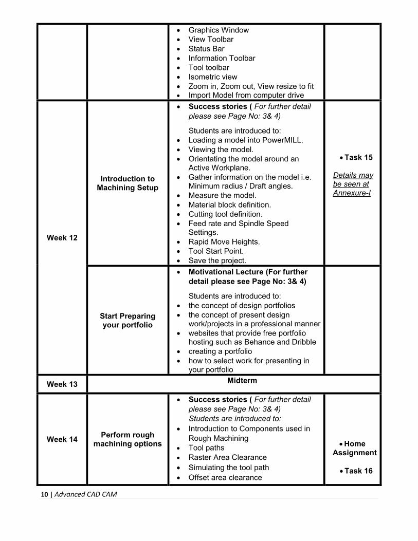
Graphics Window View Toolbar Status Bar Information Toolbar Tool toolbar Isometric view Zoom in, Zoom out, View resize to fit Import Model from computer drive
Week 12
Introduction to Machining Setup
Success stories ( For further detail please see Page No: 3& 4)
Students are introduced to: Loading a model into PowerMILL. Viewing the model. Orientating the model around an
Active Workplane. Gather information on the model i.e.
Minimum radius / Draft angles. Measure the model. Material block definition. Cutting tool definition. Feed rate and Spindle Speed
Settings. Rapid Move Heights. Tool Start Point. Save the project.
Task 15
Details may be seen at Annexure-I
Start Preparing your portfolio
Motivational Lecture (For further detail please see Page No: 3& 4)
Students are introduced to: the concept of design portfolios the concept of present design
work/projects in a professional manner websites that provide free portfolio
hosting such as Behance and Dribble creating a portfolio how to select work for presenting in
your portfolio
Week 13 Midterm
Week 14 Perform rough
machining options
Success stories ( For further detail please see Page No: 3& 4) Students are introduced to:
Introduction to Components used in Rough Machining
Tool paths Raster Area Clearance
Simulating the tool path Offset area clearance
Home Assignment
Task 16

11 | Advanced CAD CAM
Profiling area clearance Cutter direction Ramping Zag angle
Details may be seen at Annexure-I
Week 15 Use finish
machining options
Motivational Lecture (For further detail please see Page No: 3& 4)
Students are introduced to: Introduction to finish machining Raster finishing Radial Machining Spiral Machining Pattern Strategies
Task 17
Details may be seen at Annexure-I
Introduction to Freelancing
Motivational Lecture (For further detail please see Page No: 3& 4)
Students are introduced to: the concept of freelancing how to become freelance and create a
sustainable income pros and cons of freelancing the ethical and professional way of
becoming a productive freelancer resources available for freelancing in
the field of design how to join freelancing sites the process of creating a freelancing
profile
Week 16 Use of 3D Offset &
constant Z
Success stories ( For further detail please see Page No: 3& 4)
Students are introduced to: ● Introduction of 3D offset machining ● Constant Z machining ● Corner correction ● Pocket machining ● Optimized Constant Z Machining
● Task 18
Details may be seen at Annexure-I
Week 17
Perform corner machining &
Projection machining
Motivational Lecture (For further detail please see Page No: 3& 4)
Students are introduced to: ● Corner machining ● Corner Along Finishing ● Corner Stitch Finishing ● Corner Multi-Pencil Finishing ● Corner Automatic finishing ● Pencil finishing ● Plane Projection ● Curve Projection Finishing ●
● Task 19
Details may be seen at Annexure-I
Monthly
Test 3

12 | Advanced CAD CAM
Week 18 Use editing tool
paths & Collision Checking
Success stories (For further detail please see Page No: 3& 4)
Students are introduced to: ● Use editing tool paths ● 3 types of transform i.e. Mirror, Move
and Rotate ● Limiting to a plane ● Limiting to a boundary ● Moving the start points ● Collision checking
Task 20
Details may be seen at Annexure-I
Week 19 Use of Leads, Links
& Patterns
Motivational Lecture (For further detail please see Page No: 3& 4)
Students are introduced to: ● Z Heights ● Lead In/Lead out Moves ● Vertical Arcs ● Horizontal Arcs ● Circular Arcs ● Extended Move ● Extensions ● Links ● Skim ● Introduction to patterns ● Patterns with 3D offset machining
Task 21
Details may be seen at Annexure-I
Week 20 NC Programs &
Feature sets / 2D machining
Success stories ( For further detail please see Page No: 3& 4)
Students are introduced to: Introduction to NC Programs Setting Preferences Creating NC Program Viewing & Editing NC Code Output Area Features 2D Geometry Pocket Slot Boss or Hole Area Clearance Drilling
Task 22
Details may be seen at Annexure-I
Week 21
Employable Project/ Assignment
(6 weeks) i.e. 21-26 besides regular classes
OR On the job training
● Guidelines to the Trainees for selection of students employable project like final year project (FYP)
● Assign Independent project to each Trainee
● A project-based on trainee’s aptitude and acquired skills.
● Designed by keeping in view the emerging trends in the local market as

13 | Advanced CAD CAM
(2 weeks) well as across the globe. ● The project idea may be based on
Entrepreneur. ● Leading to successful employment. ● The duration of the project will be 6
weeks Final viva/assessment will be
conducted on project assignments. At the end of the session, the project
will be presented in a skills competition
The skill competition will be conducted on zonal, regional, and National levels.
The project will be presented in front of Industrialists for commercialization
The best business idea will be placed in the NAVTTC business incubation center for commercialization.
OR On the job training for 2 weeks:
Aims to provide 2 weeks of industrial training to the Trainees as part of the overall training program
Ideal for the manufacturing trades As an alternative to the projects that
involve expensive equipment Focuses on increasing Trainee’s
motivation, productivity, efficiency, and quick learning approach.
Week 22
Capstone Project
The capstone project is a unique opportunity to carry out research in order to devise an innovative and unique solution for a real-world problem.
The detailed requirements for any capstone project will be determined by the supervising faculty member and can take a wide range of forms, including but not limited:
A traditional academic research A policy paper An operational plan A case study A business plan
How to search and apply for jobs
in at least two
Browse the following website
and create an account on

14 | Advanced CAD CAM
labor marketplace countries (KSA,
UAE, etc.)
each website • www.linkedIn.com -
primarily used for professional networking and career development, and allows job seekers to post their CVs and employers to post jobs
• www.glassdoor.com - where current and former employees anonymously review companies. Glassdoor also allows users to anonymously submit and view salaries as well as search and apply for jobs on its platform
• pk.indeed.com - worldwide employment website for job listings
• www.rozee.pk – Pakistan’s leading website for employers and employees to hunt new job opportunities
Find the handy ‘search’ option at the top of your homepage to search for the jobs that best suit your skills.
Select the job type from the first ‘Job Type’ drop-down menu, next, select the location from the second drop- down menu.
Enter any keywords you want to use to find suitable job vacancies.
On the results page you can search for part-time jobs only, full-time jobs only, employers only, or agencies only. Tick the boxes as appropriate to your search.
Search for jobs by: Company Category Location All jobs Agency

15 | Advanced CAD CAM
Industry
Week 23 Freelancing
Create profile on Fiverr Create gigs Create profile on Upwork Prepare cover letter Make proposal Find project on Upwork and apply for it
Task 26
Details may be seen at Annexure-I
Week 24 Professional
practice methods & legal side of design
Success stories ( For further detail please see Page No: 3& 4)
Students are introduced to: the standards that define the
expectations of a professional CAD/CAM designer
the principles of integrity that demonstrate respect for the profession, for colleagues, for clients, for audiences or consumers, and society as a whole
the perspectives of the CAD/CAM profession i.e. understanding the profession, the meanings of environmental responsibility, copyright, and ethics
what legalities are involved in professional CAD/CAM projects
how to build strong professional proposals
copyrights, copyright infringement, plagiarism, crediting creators, purchasing online products, downloading ‘free’ content
the do’s and don’ts of how to price their time, effort, and creativity
Week 25 Team Management
The candidates are expected to develop following skills to improve their skills, effectiveness, efficiency and to achieve success and goals set by them in real life:
Acuity Allocating Resources Critical Observation Focus Goal Setting Memory Organize Personal Time Management Planning Organizing

16 | Advanced CAD CAM
Prioritization Recalling Scheduling Sense of Urgency Streamlining Stress Management Task Planning Task Tracking Time Awareness Work-Life Balance
Week 26
Entrepreneurship and Final
Assessment in project
Success stories ( For further detail please see Page No: 3& 4)
Job Market Searching Self-employment Introduction Fundamentals of Business
Development Entrepreneurship Startup Funding Business Incubation and Acceleration Business Value Statement Business Model Canvas Sales and Marketing Strategies How to Reach Customers and Engage Stakeholders Power Grid RACI Model, SWOT Analysis, PEST
Analysis SMART Objectives OKRs Cost Management (OPEX, CAPEX,
ROCE, etc.)
Final Assessment
Final Assessment
17 | Advanced CAD CAM
Annexure-I:
Tasks For Certificate in Advanced CAD CAM
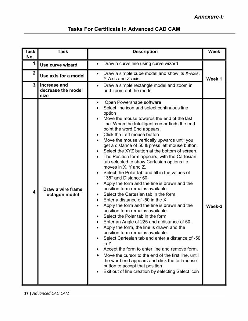
Task No.
Task Description Week
1. Use curve wizard Draw a curve line using curve wizard
Week 1 2.
Use axis for a model Draw a simple cube model and show its X-Axis, Y-Axis and Z-axis
3. Increase and decrease the model size
Draw a simple rectangle model and zoom in and zoom out the model
4. Draw a wire frame
octagon model
Open Powershape software Select line icon and select continuous line
option Move the mouse towards the end of the last
line. When the Intelligent cursor finds the end point the word End appears.
Click the Left mouse button Move the mouse vertically upwards until you
get a distance of 50 & press left mouse button. Select the XYZ button at the bottom of screen. The Position form appears, with the Cartesian
tab selected to show Cartesian options i.e. moves in X, Y and Z.
Select the Polar tab and fill in the values of 135° and Distance 50.
Apply the form and the line is drawn and the position form remains available
Select the Cartesian tab in the form. Enter a distance of -50 in the X Apply the form and the line is drawn and the
position form remains available Select the Polar tab in the form Enter an Angle of 225 and a distance of 50. Apply the form, the line is drawn and the
position form remains available. Select Cartesian tab and enter a distance of -50
in Y. Accept the form to enter line and remove form. Move the cursor to the end of the first line, until
the word end appears and click the left mouse button to accept that position
Exit out of line creation by selecting Select icon
Week-2

18 | Advanced CAD CAM
5.
Draw a geometrical shape and perform
Workplane placement
Create the wire frame shape from 0 Draw base length 100, width of 75, back height
of 150, and front height of 125 Create a workplane and position it at the rear
corner point Move the mouse to the small blue line just to
the right of the X Drag the workplane around to line up with the 0
position Release the left mouse button. The X-axis is
now fixed Select one of the yellow lines as indicated and
drag the workplane to the back vertical edge and snap on the line
This new workplane becomes active and is now our new datum point of 0 0 0
Week 3
6.
Draw a gear stick made up of simple primitive surfaces using Edit toolbar
Create a workplane at 0 and a box primitive of size X 70, Y 70 and Z 40.
Generate a plane primitive at 0 0 40 of size X 70 and Y 70.
Generate a cone primitive at 0 0 40 and change the base radius to be 30, the top radius to be 5 and the length to be 50.
Generate a cylinder primitive at 0 0 90 and change the length to 60 and the radius to 5.
Generate a sphere primitive at 0 0 160 and change the radius to 15.
Week 4
7. Apply Fill-in Surface
option
From the Surface menu select the automatic surfaces icon
The automatic surface form pops up and shows what the finished surface will look.
Select fill-in option like Apply then OK the form to generate the surface Now generate a composite curve around the
base of the neck form. Select the new curve in addition to the original
composite curve defining the top of the bottle sidewalls.
Blank all other entities except the above 2 composite curves.
Make a Fill-in surface from Automatic Surfaces icon using the 2 selected composite curves.
8.
Perform multiple surfaces limitation by a single surface.
Create a surface plane at the workplane of size X 75 and Y 50.
Create a cylinder at 25 15 -10 with a radius of 5 and a length of 20.
Create a cone at -25 -15 -10 with a base radius of 5, top radius of 2.5 and a length of 20.
Select the plane and pick the Limit icon.
Week 5

19 | Advanced CAD CAM
Pick the cylinder and cone only using the cursor to make a box.
Exit out of trimming. Select only the cone Convert the Cone and then double click it.
9. Generate surface from a network of
curves
Generate a primitive cylinder of radius 7.5 at 0 0 20 with a length of 10.
Select the point creation icon from work plane pull down menu
Enter 5 points. 12 0 12 -12 0 12 0 15 15 0 -15 15 8 0 18
Select the curve icon and create a Bezier curve by selecting all four points and double click the first point again to close the curve.
Create a new curve from the point at position 12 0 12 to the extra point to the key point on the cylinder.
Create 3 lines from each of the 3 points to the complimentary point on the cylinder to build up a network for the surface.
Create a composite curve around the bottom curve of the cylinder and then blank the cylinder.
Select all of this (including the points) and generate a surface from a network of curves.
A defined surface is generated.
Week 6
10.Perform filleting
operation
Create a Plane Primitive of length 100 and width 100 at 0 0 0.
Create a Cone Primitive of base radius 30, top radius 15 and length 50 at 0 0 0.
Right click over the cone and select Convert Surface.
Select the Shaded icon. Select both surfaces by dragging a window
around them. Revert to a normal view by selecting the
Wireframe View icon. Select the Filleting option from the Surfaces
submenu. Select Preview on the Fillet Surface form. Select the route. Select OK on the form. The Fillet Route form appears. Select Apply. Select OK off the form
Week 7

20 | Advanced CAD CAM
11 Perform editing
surfaces
Create a cylinder of radius 10 and length 100 up the Z-axis.
Convert the surface and move point 3 on lateral 2 by -20 in the X direction
Move point 1 by 5 in the X and 10 in the Z. Add in a new lateral halfway from lateral 1 to
lateral 2. In parameter terms this is described as 1.5.
Select the Add Curve icon Select Lateral, enter the Parameter Value of 1.5
in the form. Apply and the Dismiss the form. Select the bottom lateral (lateral 1). Open the
edit toolbar. Even though a lateral is selected all of the edit
operations work on the complete surface. To work on the selected curve, press in the object icon and note the change in the toolbar.
Select (Switch on) the object icon. Select offset and enter a value of 5. The bottom lateral is now offset by 5 mm all
around.
Week 8
12 Make a die sample
Open a new model. Create a workplane at 0 and set the principal
plane to Z. Select the Solid icon from the top toolbar. Select the Create Solid Block icon. Position the block by typing 0 0 -40. Press ESC on the keyboard to break out of the
command. Double click on the solid block in the graphics
area which brings up the form below Set the length as 100, width as 150 and height
as 40 and press OK. The first solid automatically becomes Active
and is shown in Red. Set the principal plane to X. Select the solid icon and then the solid cylinder
primitive icon. Position the cylinder with the co-ordinates: -55
0 0 Enter a radius of 2 and a length of 20. Create a solid cone with the co-ordinates: -35 0
0. Enter a base radius of 2, a top radius of 1 and a
length of 30. Select the solid cylinder and Right click over it
to bring up the sub-menu and select Active.
Week 9

21 | Advanced CAD CAM
Select the other solid cone. Select the Add the Selected Solid to the Active
Solid icon. The surfaces have become one single solid. If
the surfaces do not match a watertight wizard will appear to fix any gaps.
A copy of this solid should be made for later use
Blank all of the solids
13 Draw an object and
make holes and shelling the part
Create a workplane at 0 and rename it Datum. Generate a rectangle equally around the
workplane of size X 250, Y 300 and turn this into a composite curve.
Generate a solid extrusion up the Z-axis using the Solid extrusion icon.
Change the extrusion length to 130 and Draft Angle to 340 and OK.
Generate a rectangle equally around the workplane of size X 120 Y 160 at Z 130 and turn this into a composite curve.
Fillet the composite curve with a Radius of 10. Select the Solid Cut icon Select Blind Select Depth 1 & press Ok Select the fillet icon to bring up its form Enter a radius of 10 Select the 4 steep edges and Apply Select the top edge. Apply and Dismiss. Create a primitive solid cone at 80 –135 5 Fill in the values (Top Radius: 10, Base Radius:
6, Length: 90) Create a 2mm fillet around the base of cone. Mirror this cone around the YZ, XZ and YZ to
produce a total of 4 cones Select the 4 cones and Remove selected Solid
from Active Create a 1 radius fillet around the top edge of
each cone Select the Hollow Solid icon Select the bottom face of the model. The red
cross will then change to a green tick Enter a Thickness of 3 & press OK
Week 10
14
Import any model (.dgk file) from
example folder and resize to fit it
Select File -> Import Model from CADCAM Examples
Select the phone.dgk (or any other file) model and then click on Open
Select the Resize to fit icon in the Viewing toolbar to show the whole model
Week 11

22 | Advanced CAD CAM
15
Load a model into PowerMILL, Perform different operations and save to another
drive
Select File -> import cad cam training models Click on the file name speaker_core.dgk (or any
other file) and then Open. Select the Resize to fit icon from the View
toolbar on the right Select an Isometric 1 View. Change the dimensions of the model Right click over Workplanes in the PowerMILL
Explorer and select Create Workplane Click on the Plus (+) sign next to Workplanes in
the explorer. Right click over the new Workplane in the
explorer and select Activate. Right click over the workplane in the explorer
and select Rename. Click Models in the explorer Right click over the model Select Edit > Rotate > Z. Type in –90 and select the green tick on the
form Select a View in Z to see the model has been
rotated. Select File -> Save Project as Save the file with the name “Trainee”
Week 12
16 Perform offset area
clearance
Open the model WingMirrorDie.dgk located in CADCAM models.
Create a Tip Radiused tool of 40 diameter with a 6 tiprad and Name it d40t6.
From the Main toolbar open the Block form and Calculate a material Block to the full model dimensions.
Reset the Rapid Move Heights and set the Incremental moves to Skim.
Set the Start Point form to Automatic and Block Centre Safe.
From the Main toolbar select the Toolpath Strategies icon
Select the option Offset AreaClear Model to open the popup form
Enter the name D40T6_D1 Select type Ramping Thickness: 0.5 Stepover: 25.0 Stepdown -> Automatic: 10.0 Type: All Select Ramping Options Entering; Zig Angle 4, Follow Circle, and Circle diameter 0.6 Input or modify the data as shown in the
sections arrowed above and click Apply to
Week 14

23 | Advanced CAD CAM
create the Offset Area Clear toolpath Select the ViewMill icon located towards the
right in the Main Toolbar at the top of screen. Select ISO 2 view of the model and scale it to
be as large as possible. Select the ViewMill toggle icon. Run a View Mill simulation of the tool path. The finished result indicates that the current
tool geometry is not suitable to fully, access some features (arrowed) on the model.
As a result a further Area Clearance strategy is required.
17 Perform raster
finishing
Delete All and Reset forms and from File > Examples select the model chamber.dgk.
Calculate the Block and define a 12 diameter ball nose tool named bn12.
Select the Rapid move heights icon from the top toolbar and in the form click Reset to safe heights then Accept.
Select the Start Point icon from the top toolbar then Accept.
Note that it is in Block Centre Safe Z is active. Select the Tool path Strategies icon from the
top toolbar. Select the Raster Finishing icon then OK. Name the toolpath Raster_basic. Enter Tolerance as 0.02 and Thickness as 0. Select a tool Stepover of 1mm. Apply and Cancel the Form. Select the Arc Fit option in the form. Right click over toolpath Raster_basic in the
explorer & select Settings from available menu Select the copy toolpath icon from the form. Rename the toolpath Raster_arc fit. Check the box Arc Fit and change the Arc
Radius to 0.1. Zoom into the same area as previous to see the
changes. Select Leads and Links icon from top toolbar. Select the Links tab on the form. Change the Short links to Circular Arc Change the Long and Safe links to Skim. Apply Links and Accept the form. Right click over the toolpath icon in the
explorer area, move down to Animate and select the speed Position the cursor where required and right
click on top of the toolpath. Select Attach Active Tool. Use the Left and Right arrow keys to move the
Week 15

24 | Advanced CAD CAM
tool forwards and backwards Experiment with some of the animation options
seen on the Animation toolbar.
18 Optimized Constant
Z Exercise
Generate a new toolpath using the Copy method
Perform Closed Offsets – off Use Spiral. Animate to show the difference.
Week 16
19 Perform pencil
finishing
From File > Examples open the model cowling.dgk
Calculate the Block. Create a Ball nosed dia 10 tool and name it
as bn10. Select an Iso2 view. Keep the threshold angle of 30 degrees. Selecting both will produce the steep and
shallow toolpath. Apply the toolpath and Cancel. Animate the toolpath. Rename the toolpath as
pencil_both. Right click over the toolpath in the explorer
and select Settings. Select the copy toolpath icon from the form. Change the Output option from Both to
Shallow. Select Apply to generate the Shallow slope
machining only. Animate the toolpath. Rename the toolpath as
pencil_shallow. Right click over the toolpath in the explorer
and select Settings. Select the copy toolpath icon from the form. Change the Output option from Both to Steep. Generate a steep pencil machining toolpath. Animate the toolpath. Rename the toolpath as
pencil_steep Save the project in computer drive as train-
corner.
Week 17
20
Perform Limiting to Planes and
Polygons Example
Open the Example model speaker.dgk. Calculate a Block with an expansion in X and
Y of 20 only, (lock Z Min and Max). Define a 10mm diameter End Mill tool called
em10. Select the model side surface Select the Toolpaths Strategy icon at the top
of the screen and from the Finishing tab select a Profile Finishing Strategy.
Set the values exactly in the form (Tolerance:
Week 18

25 | Advanced CAD CAM
0.02, Thickness: 0.0, Radial Offset: 0.0, Boundary: 1, Gouge Check: tick, Multiple Cuts: Mode OFF, Tool Axis: Vertical).
Apply and Close the form.
21 Patterns with 3D Offset machining
Create a Pattern with 3D Offset machining with the given data Week 19
22 Drilling of holes
Use PS-Sketcher to create 2 new 6 diameter holes 30mm each side of the 40 diameter hole.
Drill the two new holes
Week 20
23 Build your CV
Download professional CV template from any good site (www.coolfreecv.com or www.elevant or https://free-cv-templates.com ) or build your resume online at www.europa.eu or at www.zety.com or www.cvmkr.com Include following details in the resume:
Resume title i.e. Mechanical Engineer 10 Year’s Experience
Profile Summary Personal Information Educational details Experience/Portfolio Professional Courses/Certifications/Trainings Projects Completed Contact details/profile links Always keep your CV up to date
Week
21-26
24
Create an account profile on Fiverr (at least two gigs) and
Up-work
Create an account by following these steps: Step 1: Personal Info Step 2: Professional Info Step 3: Linked Accounts Step 4: Account Security
Week
21-26
25
How to search and apply for jobs in at
least two labor marketplace
countries (KSA, UAE, etc.)
Browse the following website and create an account on each website
www.linkedIn.com - primarily used for professional networking and career development, and allows job seekers to post their CVs and employers to post
Week
21-26
26 | Advanced CAD CAM
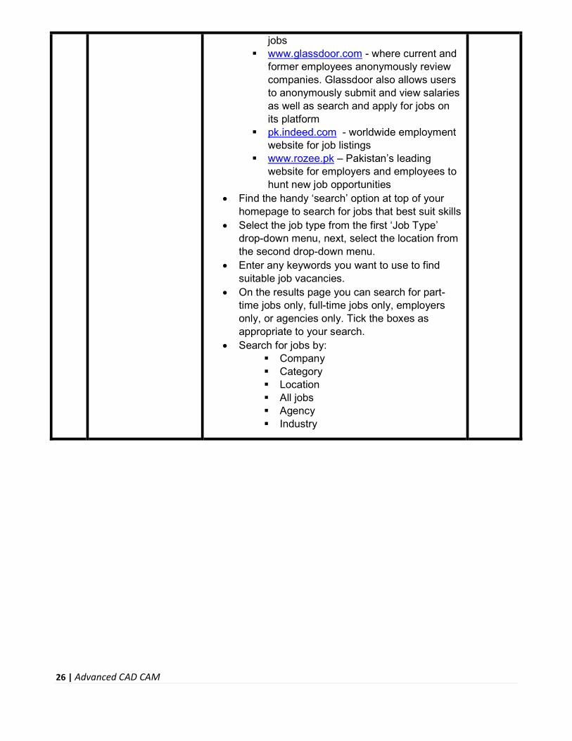
jobs www.glassdoor.com - where current and
former employees anonymously review companies. Glassdoor also allows users to anonymously submit and view salaries as well as search and apply for jobs on its platform
pk.indeed.com - worldwide employment website for job listings
www.rozee.pk – Pakistan’s leading website for employers and employees to hunt new job opportunities
Find the handy ‘search’ option at top of your homepage to search for jobs that best suit skills
Select the job type from the first ‘Job Type’ drop-down menu, next, select the location from the second drop-down menu.
Enter any keywords you want to use to find suitable job vacancies.
On the results page you can search for part-time jobs only, full-time jobs only, employers only, or agencies only. Tick the boxes as appropriate to your search.
Search for jobs by: Company Category Location All jobs Agency Industry

27 | Advanced CAD CAM
Annexure-II:
Motivational Lectures
What is freelancing and how you can make money online – BBC URDU
https://www.youtube.com/watch?v=9jCJN3Ff0kA
What Is the Role of Good Manners in the Workplace? By Qasim Ali Shah | In Urdu
https://www.youtube.com/watch?v=Qi6Xn7yKIlQ
Hisham Sarwar Motivational Story | Pakistani Freelancer
https://www.youtube.com/watch?v=CHm_BH7xAXk
21 Yr Old Pakistani Fiverr Millionaire | 25-35 Lakhs a Month Income | Interview
https://www.youtube.com/watch?v=9WrmYYhr7S0
Success Story of a 23 Year - Old SEO Expert | How This Business Works | Urdu Hindi Punjabi
https://www.youtube.com/watch?v=tIQ0CWgszI0
Failure to Millionaire - How to Make Money Online | Fiverr Superhero Aaliyaan Success Story
https://www.youtube.com/watch?v=d1hocXWSpus
CAD/CAM Engineer - Careers with Major Tool & Machine
https://www.youtube.com/watch?v=HAObPXgBOfM&ab_channel=MajorTool%26Machine
The Future of CAD | Jon Hirschtick | TEDxBeaconStreet
https://www.youtube.com/watch?v=i0uyi1MWY5Y&ab_channel=TEDxTalks

28 | Advanced CAD CAM
Annexure-II:
SUGGESTIVE FORMAT & SEQUENCE ORDER OF MOTIVATIONAL LECTURE
Mentor Mentors are provided an observation checklist form to evaluate and share their observational feedback on how students within each team engage and collaborate in a learning environment. The checklist is provided at two different points: Once towards the end of the course. The checklists are an opportunity for mentors to share their unique perspective on group dynamics based on various team activities, gameplay sessions, pitch preparation, and other sessions, giving insights on the nature of communication and teamwork taking place and how both learning outcomes and the student experience can be improved in the future.
Session- 1 (Communication): Please find below an overview of the activities taking place Session plan that will support your delivery and an overview of this session’s activity.
Session- 1 OVERVIEW
Aims and Objectives:
To introduce the communication skills and how it will work Get to know mentor and team - build rapport and develop a strong sense of a team Provide an introduction to communication skills Team to collaborate on an activity sheet developing their communication, teamwork, and
problem-solving Gain an understanding of participants’ own communication skills rating at the start of the
program
Activity: Participant Time Teacher Time Mentor Time
Intro Attend and contribute to the scheduled.
Understand good communication skills and how it works.
Understand what good communication skills mean
Understand what skills are important for good communication skills
Key learning outcomes:
Resources: Enterprise skills developed:
Understand the communication skills and how it works.
Understand what
Podium Projector Computer Flip Chart
Communication Self Confidence Teamwork
29 | Advanced CAD CAM
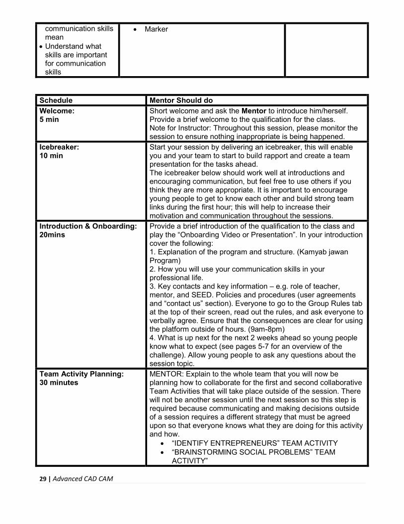
communication skills mean
Understand what skills are important for communication skills
Marker
Schedule Mentor Should do
Welcome: 5 min
Short welcome and ask the Mentor to introduce him/herself. Provide a brief welcome to the qualification for the class. Note for Instructor: Throughout this session, please monitor the session to ensure nothing inappropriate is being happened.
Icebreaker: 10 min
Start your session by delivering an icebreaker, this will enable you and your team to start to build rapport and create a team presentation for the tasks ahead. The icebreaker below should work well at introductions and encouraging communication, but feel free to use others if you think they are more appropriate. It is important to encourage young people to get to know each other and build strong team links during the first hour; this will help to increase their motivation and communication throughout the sessions.
Introduction & Onboarding: 20mins
Provide a brief introduction of the qualification to the class and play the “Onboarding Video or Presentation”. In your introduction cover the following: 1. Explanation of the program and structure. (Kamyab jawan Program) 2. How you will use your communication skills in your professional life. 3. Key contacts and key information – e.g. role of teacher, mentor, and SEED. Policies and procedures (user agreements and “contact us” section). Everyone to go to the Group Rules tab at the top of their screen, read out the rules, and ask everyone to verbally agree. Ensure that the consequences are clear for using the platform outside of hours. (9am-8pm) 4. What is up next for the next 2 weeks ahead so young people know what to expect (see pages 5-7 for an overview of the challenge). Allow young people to ask any questions about the session topic.
Team Activity Planning: 30 minutes
MENTOR: Explain to the whole team that you will now be planning how to collaborate for the first and second collaborative Team Activities that will take place outside of the session. There will not be another session until the next session so this step is required because communicating and making decisions outside of a session requires a different strategy that must be agreed upon so that everyone knows what they are doing for this activity and how.
“IDENTIFY ENTREPRENEURS” TEAM ACTIVITY “BRAINSTORMING SOCIAL PROBLEMS” TEAM
ACTIVITY”

30 | Advanced CAD CAM
As a team, collaborate on a creative brainstorm on social problems in your community. Vote on the areas you feel most passionate about as a team, then write down what change you would like to see happen. Make sure the teams have the opportunity to talk about how they want to work as a team through the activities e.g. when they want to complete the activities, how to communicate, the role of the project manager, etc. Make sure you allocate each young person a specific week that they are the project manager for the weekly activities and make a note of this. Type up notes for their strategy if this is helpful - it can be included underneath the Team Contract.
Session Close: 5 minutes
MENTOR: Close the session with the opportunity for anyone to ask any remaining questions. Instructor: Facilitate the wrap-up of the session. A quick reminder of what is coming up next and when the next session will be.

31 | Advanced CAD CAM
Annexure-III
SUCCESS STORY
S. No Key Information Detail/Description
1. Self & Family background Abdullah Zafar, a resident of an underprivileged area of Khyber Pakhtunkha, is an ideal example to be followed by many people. He belongs to a middle class family and hardly managed to bear his school and college expenses. In 2014, Abdullah successfully completed his college and decided to enroll in a skilled based professional course “CAD/CAM”. He did hard work and managed to learn the software. Later on, in 2018, he started his journey as freelancer and started earning through online working. His client mostly belong to USA and Canada. They were satisfied with his quality of work and commitments. Now Abdullah is earning Rs. 1 Million in a year. If at first, you don’t succeed, try try again
2. How he came on board NAVTTC Training/ or got trained through any other source
Certification in CAD/CAM from PITAC HQ Lahore (NAVTTC partner institute)
3. Post-training activities Abdullah’s area of expertise is in Computer Aided Designing & Computer Aided Manufactuting. In start of his career as freelancer, he successfully managed to create profile on Fiverr and Upwork. He applied mostly for projects focused on Computer Aided Designing. In start it wasn’t so easy for him to grab clients. In the first few weeks, he didn’t hear back from even a single client, despite bidding for dozens of projects. “I needed to understand what worked, so I read blogs, participated in forums, and analyzed profiles of successful freelancers. It was an uphill struggle, but I didn’t want to give up,” he explains. Abdullah says he understands why clients would be apprehensive giving projects to untested freelancers. They have hundreds of options to choose from, he

32 | Advanced CAD CAM
explains, and to give a project to someone with no experience requires a strong leap of faith. A slow stream of projects started to come Abdullah’s way. He soon realized that increased use of precise, versatile and easy-to-machine CAD designs has fundamentally revolutionized the areas of engineering, architecture and the manufacturing industry. But he’s had to face his fair share of challenges too. The shoddy state of internet infrastructure in his city, Karak, threatened to derail his freelancing career. “Sometimes I haven’t had connectivity for two days straight,” he explains. “That’s unthinkable for someone who makes his livelihood on the internet.”
4. Message to others
(under training)
Take the training opportunity seriously Impose self-discipline and ensure regularity Make Hard work pays in the end so be always ready for the same.
Note: Success story is a source of motivation for the trainees and can be presented in several ways/forms in a NAVTTC skill development course as under: -
1. To call a passed out successful trainee of the institute. He will narrate his success story to the trainees in his own words and meet trainees as well.
2. To see and listen to a recorded video/clip (5 to 7 minutes) showing a successful trainee Audio-video recording that has to cover the above-mentioned points.*
3. The teacher displays the picture of a successful trainee (name, trade, institute, organization, job, earning, etc) and narrates his/her story in the teacher’s own motivational words.
* The online success stories of renowned professional can also be obtained from Annex-II

33 | Advanced CAD CAM
Annexure-IV:
Workplace/Institute Ethics Guide
Work ethic is a standard of conduct and values for job performance. The modern definition of what
constitutes good work ethics often varies. Different businesses have different expectations. Work
ethic is a belief that hard work and diligence have a moral benefit and an inherent ability, virtue, or
value to strengthen character and individual abilities. It is a set of values-centered on the
importance of work and manifested by determination or desire to work hard.
The following ten work ethics are defined as essential for student success:
1. Attendance:
Be at work every day possible, plan your absences don’t abuse leave time. Be punctual
every day.
2. Character:
Honesty is the single most important factor having a direct bearing on the final success of
an individual, corporation, or product. Complete assigned tasks correctly and promptly.
Look to improve your skills.
3. Team Work:
The ability to get along with others including those you don’t necessarily like. The ability to carry your weight and help others who are struggling. Recognize when to speak up with an idea and when to compromise by blend ideas together.
4. Appearance:
Dress for success set your best foot forward, personal hygiene, good manner, remember
that the first impression of who you are can last a lifetime
5. Attitude:
Listen to suggestions and be positive, accept responsibility. If you make a mistake, admit it.
Values workplace safety rules and precautions for personal and co-worker safety. Avoids
unnecessary risks. Willing to learn new processes, systems, and procedures in light of
changing responsibilities.
6. Productivity:
Do the work correctly, quality and timelines are prized. Get along with fellows, cooperation
is the key to productivity. Help out whenever asked, do extra without being asked. Take
pride in your work, do things the best you know-how. Eagerly focuses energy on
accomplishing tasks, also referred to as demonstrating ownership. Takes pride in work.

34 | Advanced CAD CAM
7. Organizational Skills:
Make an effort to improve, learn ways to better yourself. Time management; utilize time and resources to get the most out of both. Take an appropriate approach to social interactions at work. Maintains focus on work responsibilities.
8. Communication:
Written communication, being able to correctly write reports and memos.
Verbal communications, being able to communicate one on one or to a group.
9. Cooperation:
Follow institute rules and regulations, learn and follow expectations. Get along with fellows,
cooperation is the key to productivity. Able to welcome and adapt to changing work
situations and the application of new or different skills.
10. Respect:
Work hard, work to the best of your ability. Carry out orders, do what’s asked the first time.
Show respect, accept, and acknowledge an individual’s talents and knowledge. Respects
diversity in the workplace, including showing due respect for different perspectives,
opinions, and suggestions.
Related Documents