Administration Guide Release 12.1 CA NetMaster® Network Management for SNA

Welcome message from author
This document is posted to help you gain knowledge. Please leave a comment to let me know what you think about it! Share it to your friends and learn new things together.
Transcript
Administration Guide Release 12.1
CA NetMaster® Network Management for SNA

This Documentation, which includes embedded help systems and electronically distributed materials, (hereinafter referred to as the “Documentation”) is for your informational purposes only and is subject to change or withdrawal by CA at any time.
This Documentation may not be copied, transferred, reproduced, disclosed, modified or duplicated, in whole or in part, without the prior written consent of CA. This Documentation is confidential and proprietary information of CA and may not be disclosed by you or used for any purpose other than as may be permitted in (i) a separate agreement between you and CA governing your use of the CA software to which the Documentation relates; or (ii) a separate confidentiality agreement between you and CA.
Notwithstanding the foregoing, if you are a licensed user of the software product(s) addressed in the Documentation, you may print or otherwise make available a reasonable number of copies of the Documentation for internal use by you and your employees in connection with that software, provided that all CA copyright notices and legends are affixed to each reproduced copy.
The right to print or otherwise make available copies of the Documentation is limited to the period during which the applicable license for such software remains in full force and effect. Should the license terminate for any reason, it is your responsibility to certify in writing to CA that all copies and partial copies of the Documentation have been returned to CA or destroyed.
TO THE EXTENT PERMITTED BY APPLICABLE LAW, CA PROVIDES THIS DOCUMENTATION “AS IS” WITHOUT WARRANTY OF ANY KIND, INCLUDING WITHOUT LIMITATION, ANY IMPLIED WARRANTIES OF MERCHANTABILITY, FITNESS FOR A PARTICULAR PURPOSE, OR NONINFRINGEMENT. IN NO EVENT WILL CA BE LIABLE TO YOU OR ANY THIRD PARTY FOR ANY LOSS OR DAMAGE, DIRECT OR INDIRECT, FROM THE USE OF THIS DOCUMENTATION, INCLUDING WITHOUT LIMITATION, LOST PROFITS, LOST INVESTMENT, BUSINESS INTERRUPTION, GOODWILL, OR LOST DATA, EVEN IF CA IS EXPRESSLY ADVISED IN ADVANCE OF THE POSSIBILITY OF SUCH LOSS OR DAMAGE.
The use of any software product referenced in the Documentation is governed by the applicable license agreement and such license agreement is not modified in any way by the terms of this notice.
The manufacturer of this Documentation is CA.
Provided with “Restricted Rights.” Use, duplication or disclosure by the United States Government is subject to the restrictions set forth in FAR Sections 12.212, 52.227-14, and 52.227-19(c)(1) - (2) and DFARS Section 252.227-7014(b)(3), as applicable, or their successors.
Copyright © 2012 CA. All rights reserved. All trademarks, trade names, service marks, and logos referenced herein belong to their respective companies.
CA Technologies Product References
This document references the following CA Technologies products:
■ CA Common Services for z/OS
■ CA NetMaster® Network Automation (CA NetMaster NA)
■ CA NetMaster® Network Management for SNA (CA NetMaster NM for SNA)
■ CA NetSpy™ Network Performance (CA NetSpy)
■ CA Network and Systems Management (CA NSM)
■ CA OPS/MVS® Event Management and Automation (CA OPS/MVS)
■ CA Service Desk for z/OS (CA Service Desk)
■ CA SOLVE:Access™ Session Management (CA SOLVE:Access)
■ CA SOLVE:Central™ Service Desk for z/OS (CA SOLVE:Central), which includes CA SOLVE:Problem
■ CA TCPaccess™ Communications Server for z/OS (CA TCPaccess CS)

Contact CA Technologies
Contact CA Support
For your convenience, CA Technologies provides one site where you can access the information that you need for your Home Office, Small Business, and Enterprise CA Technologies products. At http://ca.com/support, you can access the following resources:
■ Online and telephone contact information for technical assistance and customer services
■ Information about user communities and forums
■ Product and documentation downloads
■ CA Support policies and guidelines
■ Other helpful resources appropriate for your product
Providing Feedback About Product Documentation
If you have comments or questions about CA Technologies product documentation, you can send a message to [email protected].
To provide feedback about CA Technologies product documentation, complete our short customer survey which is available on the CA Support website at http://ca.com/docs.
Contents 5
Contents
Chapter 1: Introduction 17
Intended Audience ..................................................................................................................................................... 17
Typographic Conventions ........................................................................................................................................... 17
Chapter 2: Starting and Stopping a Region 19
Start SOLVE SSI ........................................................................................................................................................... 19
Stop SOLVE SSI............................................................................................................................................................ 20
Start a Region ............................................................................................................................................................. 20
WTOR Confirmation Message ............................................................................................................................. 20
Stop a Region ............................................................................................................................................................. 21
SHUTDOWN Command ....................................................................................................................................... 22
FSTOP Command ................................................................................................................................................. 22
How You Preserve Data When Region Stops and Restarts ........................................................................................ 22
Create Persistent Global Variables Using the User Interface .............................................................................. 23
Prevent the Reloading of Preserved Data ........................................................................................................... 23
Chapter 3: Configuring a Region 25
Region Configuration.................................................................................................................................................. 25
How You Use JCL Parameters to Configure a Region ................................................................................................. 25
How You Display and Change JCL Parameter Settings ........................................................................................ 25
How You Identify the Region to Users ....................................................................................................................... 26
How You Identify Domains and Panels ............................................................................................................... 26
Region Customizer ..................................................................................................................................................... 26
What Are Parameter Groups? ............................................................................................................................. 27
Print Parameter Group Settings .......................................................................................................................... 27
System Parameters .................................................................................................................................................... 28
Use the SYSPARMS Command ............................................................................................................................ 28
Initialization Operands ........................................................................................................................................ 28
Transient Log Tuning .................................................................................................................................................. 29
Customize Tuning Parameters ............................................................................................................................ 29
Resize Selected Transient Logs ........................................................................................................................... 30
Resize Multiple Transient Logs in an Image ........................................................................................................ 31
Chapter 4: Customizing Your Product 33
Perform Administrative Tasks .................................................................................................................................... 33
6 Administration Guide
Implement Features ................................................................................................................................................... 33
Implement Network Services Control File .......................................................................................................... 34
Implement NEWS Databases .............................................................................................................................. 35
Implement the NTS Log Database ....................................................................................................................... 35
Identify Your Initialization Procedure ................................................................................................................. 36
Implement NSCNTL Cache Options ..................................................................................................................... 37
Implement NEWS Database Logging Options ..................................................................................................... 38
Implement Event Filters ...................................................................................................................................... 39
Implement Performance Objectives for Event Recording .................................................................................. 40
Implement SMF Event Recording Options .......................................................................................................... 41
Implement the PPI Receiver ................................................................................................................................ 42
Implement Device Support Diagnostics .............................................................................................................. 42
Customize Facilities .................................................................................................................................................... 43
Customize NEWS Facilities .................................................................................................................................. 43
Customize NTS Facilities ...................................................................................................................................... 43
Customize NCPView Facilities ............................................................................................................................. 43
Customize NCS Facilities ..................................................................................................................................... 43
Configure the Startup Procedure ............................................................................................................................... 44
Enable Tivoli NetView Operator Command Emulation ....................................................................................... 44
Set Up NTS ........................................................................................................................................................... 45
Enable the Logging of SPO and Unsolicited PPO Messages ....................................................................................... 45
Security ....................................................................................................................................................................... 45
Security Considerations for Existing Users .......................................................................................................... 46
Define User Exits ........................................................................................................................................................ 46
Implement NCS Display Limits.................................................................................................................................... 47
Chapter 5: Network Error Warning System 49
Data Available to NEWS ............................................................................................................................................. 49
Unsolicited Data .................................................................................................................................................. 49
Solicited Data ...................................................................................................................................................... 50
Response Time Data ............................................................................................................................................ 50
How NEWS Obtains Data ............................................................................................................................................ 50
SNA Networks and the CNM Interface ................................................................................................................ 51
APPN Networks and SNA Management Services ................................................................................................ 51
NEWS and Intersystem Routing .......................................................................................................................... 52
NEWS and PPI ...................................................................................................................................................... 52
Processing Concepts ................................................................................................................................................... 52
Network Services Control File ............................................................................................................................. 53
Events .................................................................................................................................................................. 53
CNMPROC Record Processing ............................................................................................................................. 56
NEWS Facilities ........................................................................................................................................................... 58
Contents 7
NCL Verbs and Procedures .................................................................................................................................. 58
Unattended Solicitation ...................................................................................................................................... 59
NEWS Commands................................................................................................................................................ 60
Testing NEWS Events .......................................................................................................................................... 61
Review Parameters to Send and Receive CNM Data ................................................................................................. 68
Configure NEWS Database Options .................................................................................................................... 68
Review NCP Parameters and Operations ................................................................................................................... 69
Customize Device Configuration ................................................................................................................................ 69
Utilize LPDA Support ........................................................................................................................................... 69
Utilize RTM Support ............................................................................................................................................ 70
FCS Support ......................................................................................................................................................... 70
Maintain Control File Records .................................................................................................................................... 70
Access the SNA : Control File Administration Panel ............................................................................................ 70
Alias Name Translation Facility .................................................................................................................................. 73
Reviewing and Reporting on Data .............................................................................................................................. 73
Maintain the NEWS Database .................................................................................................................................... 74
Implement CNMPROC Logging Options .............................................................................................................. 74
Access Database Maintenance ........................................................................................................................... 75
Delete Records Generically by Date and Node ................................................................................................... 75
Delete All Records ............................................................................................................................................... 76
Reorganize the NEWS Database ......................................................................................................................... 76
Chapter 6: Network Tracking System 79
Data Available to NTS ................................................................................................................................................. 79
Session Awareness Data...................................................................................................................................... 79
Session Trace Data .............................................................................................................................................. 80
Response Time Monitoring Data......................................................................................................................... 81
Route Configuration Data ................................................................................................................................... 82
How NTS Obtains Data ............................................................................................................................................... 82
VTAM Interfaces .................................................................................................................................................. 82
Intersystem Routing ............................................................................................................................................ 83
MAI Sessions ....................................................................................................................................................... 83
Collect NTS Data .................................................................................................................................................. 84
Open the VTAM CNM Interface .......................................................................................................................... 84
Enable NTS Session Awareness ........................................................................................................................... 84
Define NTS Classes ..................................................................................................................................................... 84
Specify the DEFCLASS Command ........................................................................................................................ 85
Define Session Classes ........................................................................................................................................ 86
Define Resource Classes ...................................................................................................................................... 89
Define SAW Classes ............................................................................................................................................. 91
Define RTM Classes ............................................................................................................................................. 93
8 Administration Guide
Modify NTS Class Definitions .............................................................................................................................. 94
Set NTS System Parameters ....................................................................................................................................... 95
Specify the SYSPARMS Command ....................................................................................................................... 96
Collect NTS Session Accounting Data .................................................................................................................. 97
Collect NTS Resource Statistics ........................................................................................................................... 98
Log Active Sessions at Shutdown ...................................................................................................................... 100
Enable Intensive Message Recording ................................................................................................................ 100
Enable MAI Session Visibility ............................................................................................................................. 101
Enable NTS Session Event Generation .............................................................................................................. 101
Modify Processing for Active Sessions .............................................................................................................. 101
Set the Data Correlation Interval ...................................................................................................................... 103
Limit NTS Trace Activity..................................................................................................................................... 103
Set Session Keep Counts ................................................................................................................................... 104
Set VTAM Session and Trace Data Buffer Allocations ....................................................................................... 104
Set Resource Statistics Collection Intervals ...................................................................................................... 106
GMT/Local Timestamps in SMF Type 39 Records ............................................................................................. 106
Maintain the NTS Database .............................................................................................................................. 107
Write NTS Records to SMF for Further Processing ........................................................................................... 107
Network Definitions and Names Used by NTS ......................................................................................................... 108
System Resource Utilization ..................................................................................................................................... 108
How Session Start Notification Works ..................................................................................................................... 108
Output Processing .................................................................................................................................................... 109
How Session End Processing Works .................................................................................................................. 109
System Event Generation ......................................................................................................................................... 110
NTS Database ........................................................................................................................................................... 110
Session Keep Counts and Database Slots .......................................................................................................... 111
Connect and Disconnect the NTS Database ...................................................................................................... 111
Error Handling ................................................................................................................................................... 112
MAI Support ............................................................................................................................................................. 112
Understanding MAI Sessions............................................................................................................................. 113
MAI/NTS Interface ............................................................................................................................................ 114
MAI Sessions on the NTS Database ................................................................................................................... 114
MAI Sessions and the NTS User Exit .................................................................................................................. 114
Chapter 7: NCPView 115
How NCPView Works ............................................................................................................................................... 115
NCPView and Connected Domains ................................................................................................................... 115
NCP Monitoring ........................................................................................................................................................ 116
System Images .................................................................................................................................................. 116
NCP Definitions ................................................................................................................................................. 116
Work with NCPs ................................................................................................................................................ 117
Contents 9
Monitor Resources in a Multisystem Environment .......................................................................................... 117
Define a System Image ............................................................................................................................................. 117
Define NCP Resources .............................................................................................................................................. 118
Allocate NCP Unformatted Dumps ........................................................................................................................... 119
Expected Unformatted Dump File Characteristics ............................................................................................ 120
Estimate Storage Requirements for Processing NCP Dumps Using NCPView .................................................. 120
Configure the NCPView NCL Exit .............................................................................................................................. 121
Chapter 8: Network Control System 123
How NCS Works........................................................................................................................................................ 123
Transfer of NCS Data Across an INMC Link ....................................................................................................... 124
Chapter 9: Configuring Tivoli NetView Operator Command Emulation 125
Tivoli NetView Operator Command Emulation Facility ............................................................................................ 125
Modify Table Entries ................................................................................................................................................ 126
Considerations When Modifying Table Entries ................................................................................................. 127
Chapter 10: Advanced Configuration Tasks 129
Load a System Image ................................................................................................................................................ 129
Cold and Warm Load Features .......................................................................................................................... 130
Enable Multisystem Support .................................................................................................................................... 130
Define ISR Communications .............................................................................................................................. 131
Manage Focal Points ................................................................................................................................................ 132
Focal Points and Entry Points ............................................................................................................................ 133
Browse, Update, or Delete Focal Points............................................................................................................ 135
Manage Entry Points ................................................................................................................................................ 137
Activate a Focal Point ........................................................................................................................................ 137
Maintain Entry Point Definitions ....................................................................................................................... 138
Maintain Resource Alias Names ............................................................................................................................... 139
Alias Name Translation ..................................................................................................................................... 140
Display Alias Name Definitions ......................................................................................................................... 141
Define Alias Names ........................................................................................................................................... 143
Define Generic Names ...................................................................................................................................... 143
Replace Alias Names ......................................................................................................................................... 144
Delete Alias Names ........................................................................................................................................... 146
Test Alias Names Translation ............................................................................................................................ 146
Examples: Test Translation ....................................................................................................................................... 147
10 Administration Guide
Chapter 11: Implementing Activity Logs 149
Activity Logs ............................................................................................................................................................. 149
Implement Online Activity Logging .......................................................................................................................... 150
Use Additional Log Files .................................................................................................................................... 151
Administer Online Activity Log Files ......................................................................................................................... 151
Swap the Online Log ................................................................................................................................................. 152
Online Log Exit .......................................................................................................................................................... 152
Variables Available to the Activity Log Exit ....................................................................................................... 153
Enable the Log Exit ............................................................................................................................................ 154
Online Logging Procedure ........................................................................................................................................ 154
Structure of Supplied Log Files .......................................................................................................................... 154
How You Write Logging and Browsing Procedures ........................................................................................... 155
Implement Logging and Browsing Procedures .................................................................................................. 156
Hardcopy Activity Log ............................................................................................................................................... 156
Format of Logged Information .......................................................................................................................... 157
Format of the Hardcopy Log ............................................................................................................................. 158
Swap the Hardcopy Log ............................................................................................................................................ 158
Reuse of Hardcopy Log Data Sets ............................................................................................................................. 159
Cross-Reference of Hardcopy Logs ........................................................................................................................... 159
I/O Errors on the Hardcopy Log................................................................................................................................ 160
Write to the System Log ........................................................................................................................................... 160
Chapter 12: Setting Up the Alert Monitor 161
Access Alert Administration ..................................................................................................................................... 161
Alert Monitor Trouble Ticket Interface .................................................................................................................... 162
Define a Trouble Ticket Interface ...................................................................................................................... 163
Set Up the Trouble Ticket Data Entry Definition ............................................................................................... 168
Implement Trouble Ticket Interface for Multiple Email Addressees ................................................................ 170
Define Alert Monitor Filters ..................................................................................................................................... 172
Alert Monitor Display Format .................................................................................................................................. 173
Create the Alert Monitor Display Format ......................................................................................................... 173
Enable Alerts from External Applications ................................................................................................................. 174
Alert Forwarding ...................................................................................................................................................... 174
Implement Alert Forwarding ............................................................................................................................. 175
SNMP Trap Definition ........................................................................................................................................ 175
Forward to Tivoli NetView ................................................................................................................................ 176
CA Service Desk Integration ..................................................................................................................................... 176
Software Requirements .................................................................................................................................... 176
How Requests Are Created ............................................................................................................................... 177
Other Ways to Create Requests or Incidents .................................................................................................... 177
Request Description Format ............................................................................................................................. 178
Contents 11
Implement the Alert History Function ..................................................................................................................... 179
Reorganize Files and Monitor Space Usage ...................................................................................................... 180
Extract Alert Data for Reporting........................................................................................................................ 181
Chapter 13: Setting Up the Initialization File 183
Generate an Initialization File .................................................................................................................................. 183
How You Configure the Initialization File ................................................................................................................. 184
Configure a Common Initialization File ............................................................................................................. 184
Configure Individual Initialization Files ............................................................................................................. 185
Start Your Region from an Initialization File............................................................................................................. 186
Chapter 14: Administering a Multisystem Environment 187
Multisystem Operation ............................................................................................................................................ 187
Links in a Multisystem Environment ................................................................................................................. 189
Multisystem Implementation Considerations ................................................................................................... 190
How a Multisystem Environment Is Established ............................................................................................... 191
Linked Regions and Database Synchronization ........................................................................................................ 191
Background User Considerations ...................................................................................................................... 193
Transmit Records .............................................................................................................................................. 194
Link and Synchronize Regions ........................................................................................................................... 196
Monitor the Synchronization Procedure........................................................................................................... 198
Knowledge Base Synchronization Maintenance ............................................................................................... 199
Display Linked Regions ............................................................................................................................................. 199
Unlink Regions .......................................................................................................................................................... 200
Chapter 15: Implementing the NetMaster-to-NetSpy Interface 201
Customize the NetMaster-to-NetSpy Interface ....................................................................................................... 201
Manage NetMaster-to-NetSpy Connections ............................................................................................................ 202
Manage CA NetSpy Alerts and Monitors .................................................................................................................. 202
Manage NetSpy User Alert Monitors in CA NetMaster .................................................................................... 203
Define CA NetSpy User Alert Monitors ............................................................................................................. 203
Issue CA NetSpy Commands ..................................................................................................................................... 204
Chapter 16: Implementing Print Services 205
Print Services Manager ............................................................................................................................................ 205
Access PSM ............................................................................................................................................................... 206
Add a Printer Definition ........................................................................................................................................... 207
List Printer Definitions .............................................................................................................................................. 207
Add a Form Definition .............................................................................................................................................. 207
12 Administration Guide
List Form Definitions ................................................................................................................................................ 208
Add Control Characters ............................................................................................................................................ 208
List Control Characters ............................................................................................................................................. 208
Add a Default Printer for a User ID .......................................................................................................................... 209
List Default Printers .................................................................................................................................................. 209
Clear the Printer Spool ............................................................................................................................................. 210
Exits to Send Print Requests to a Data Set ............................................................................................................... 210
How the Procedures Process a Print Request ................................................................................................... 211
$PSDS81X and $PSDS81Z Parameters ............................................................................................................... 211
Printer Exit Definition Example ......................................................................................................................... 214
Print-to-Email ........................................................................................................................................................... 215
Appendix A: Security Exit Support Requirements 217
Structured Field Descriptions ................................................................................................................................... 217
Appendix B: Understanding the CNM Interface 219
CNM Interface .......................................................................................................................................................... 219
Network Services Request Units (NS RUs) ........................................................................................................ 220
CNM Data from Network Resources ................................................................................................................. 220
SSCP-Related CNM Requests ............................................................................................................................ 226
How Records Are Processed ............................................................................................................................. 226
References ........................................................................................................................................................ 229
Appendix C: Understanding the Session Awareness Interface 231
NTS Classes ............................................................................................................................................................... 231
SAW Classes ...................................................................................................................................................... 232
RTM Classes ...................................................................................................................................................... 233
Session Classes .................................................................................................................................................. 234
Session Classification ........................................................................................................................................ 235
Resource Classification ...................................................................................................................................... 237
Collect Resource Statistics........................................................................................................................................ 238
Collection Intervals ........................................................................................................................................... 239
Resource RTM Statistics .................................................................................................................................... 239
Cross-Domain Statistics ..................................................................................................................................... 240
Monitor Resource Availability ........................................................................................................................... 240
NTS Resource Statistics Logging ........................................................................................................................ 241
Collect Further Data ................................................................................................................................................. 241
Session and Resource Data ............................................................................................................................... 242
Accounting Data ................................................................................................................................................ 243
Response Time Monitor Data ........................................................................................................................... 245
Contents 13
Data Correlation ................................................................................................................................................ 245
How NTS-SI Works .................................................................................................................................................... 247
NTS-SI Configuration ................................................................................................................................................ 247
Transfer of Session Data Using an ISR Link ....................................................................................................... 248
Data Propagation Across ISR Links .................................................................................................................... 249
Star Network Configuration .............................................................................................................................. 250
How NTS Systems Share Data .................................................................................................................................. 250
Reference Network Concept ............................................................................................................................. 251
Dormant NTS Concept ....................................................................................................................................... 251
SAW Data Sharing ............................................................................................................................................. 251
Session Data Sharing ......................................................................................................................................... 253
Session Data Flows ............................................................................................................................................ 257
Appendix D: NEWS Device Solicitation Procedures 259
NEWS Device Solicitation ......................................................................................................................................... 259
Line Command Procedures ...................................................................................................................................... 260
$NW386SO Procedure ............................................................................................................................................. 261
$NWDS13B Procedure ............................................................................................................................................. 262
$NWFCSSO Procedure .............................................................................................................................................. 266
$NWLPDA2 Procedure ............................................................................................................................................. 267
$NWRTMSO Procedure ............................................................................................................................................ 270
$NWRUNCM Procedure ........................................................................................................................................... 272
$NWSOLCT Procedure .............................................................................................................................................. 274
$NWVPDSO Procedure ............................................................................................................................................. 276
Appendix E: Implementing the NEWS User Exit 279
NEWS User Exit ......................................................................................................................................................... 279
Sample NEWS Exits ................................................................................................................................................... 280
How the NEWS Exit Is Called .................................................................................................................................... 280
NEWS Exit Execution ......................................................................................................................................... 280
NEWS Exit Coding Requirements ............................................................................................................................. 281
Maintain Registers on Entry to an Exit .............................................................................................................. 281
Parameter List Format ...................................................................................................................................... 281
Exit Function Codes .................................................................................................................................................. 282
Function Code 0 ................................................................................................................................................ 282
Function Code 4 ................................................................................................................................................ 283
Function Code 8 ................................................................................................................................................ 284
Separate Messages from the NEWS Exit .................................................................................................................. 284
NEWS SMF Record Formats ..................................................................................................................................... 285
SMF Header Section .......................................................................................................................................... 285
CNM Record Section ......................................................................................................................................... 287
14 Administration Guide
TARA Header Section ........................................................................................................................................ 287
TARA Data Section ............................................................................................................................................ 288
Appendix F: Implementing the NTS User Exit 289
NTS User Exit ............................................................................................................................................................ 289
Sample NTS Exit ........................................................................................................................................................ 289
How the NTS Exit Is Called ........................................................................................................................................ 290
NTS Exit Execution ............................................................................................................................................. 290
NTS Exit Coding Requirements ................................................................................................................................. 290
Maintain Registers on Entry to an Exit .............................................................................................................. 290
Parameter List Format ...................................................................................................................................... 291
Exit Function Codes .................................................................................................................................................. 292
Function Code 0 ................................................................................................................................................ 292
Function Code 4 ................................................................................................................................................ 293
Function Code 8 ................................................................................................................................................ 294
Generate Messages from the NTS Exit ..................................................................................................................... 295
Appendix G: NTS SMF Record Format 297
System Management Facility ................................................................................................................................... 297
NTS SMF Record Description for All Sub-types ........................................................................................................ 298
NTS SMF Record Sub-type 1 to 7 Description .......................................................................................................... 298
NTS SMF Record Sub-type 255 Description.............................................................................................................. 299
SMF Header Section ................................................................................................................................................. 299
Data Section ............................................................................................................................................................. 300
Product Section ........................................................................................................................................................ 301
Session Configuration Section .................................................................................................................................. 301
Extension of Session Configuration Section ...................................................................................................... 303
Session Accounting Section ...................................................................................................................................... 304
Session Route Configuration Section ....................................................................................................................... 305
Session Response Time Measurement Section ........................................................................................................ 306
Resource Configuration Section ............................................................................................................................... 307
Resource Accounting Section ................................................................................................................................... 308
Resource Response Time Measurement Section ..................................................................................................... 309
Appendix H: NTS Storage Estimates 311
Active Session Data .................................................................................................................................................. 311
When Using NTS-SI ............................................................................................................................................ 311
NTS Database ........................................................................................................................................................... 312
NTS Database Management Strategy ...................................................................................................................... 313
Contents 15
Appendix I: Health Checks 315
CA Health Checker .................................................................................................................................................... 315
NM_ACB ................................................................................................................................................................... 316
NM_INITIALIZATION ................................................................................................................................................. 317
NM_SOCKETS ........................................................................................................................................................... 318
NM_SSI ..................................................................................................................................................................... 319
Index 321

Chapter 1: Introduction 17
Chapter 1: Introduction
This section contains the following topics:
Intended Audience (see page 17) Typographic Conventions (see page 17)
Intended Audience
This guide is intended for technical personnel responsible for the planning, setup, and maintenance of your product’s functions and services.
Typographic Conventions
This table explains the conventions used when referring to various types of commands and when indicating field attributes.
Convention Description
Commands Commands such as SYSPARM and SHUTDOWN are shown in uppercase.
User Entries Information to enter onto panels is displayed in bold text.
Cross-References Cross-reference links to other sections of the book are displayed as underlined blue text.
Shortcuts Shortcuts to menus or options are displayed in bold, for example, /PARMS.

Chapter 2: Starting and Stopping a Region 19
Chapter 2: Starting and Stopping a Region
This section contains the following topics:
Start SOLVE SSI (see page 19) Stop SOLVE SSI (see page 20) Start a Region (see page 20) Stop a Region (see page 21) How You Preserve Data When Region Stops and Restarts (see page 22)
Start SOLVE SSI
To start the SOLVE SSI, issue the following command:
S ssiname,REUSASID=YES
For a region to connect to SOLVE SSI, it must first know the SSID to connect to. To identify the SSID, specify the SSID JCL parameter or use Customizer parameter groups. When this connection is complete, authorized region users can issue SOLVE SSI commands.
The region can use the SSID JCL parameter to establish an early connection to SOLVE SSI during initialization.
This parameter has the following format:
SSID={ NO | * | name }
NO
(Default) Does not attempt to connect to SOLVE SSI. The connection is only started (or attempted) after a SYSPARMS SSID command is issued.
*
Starts or attempts a connection to an SSID with the first four characters of the region job name.
name
Starts or attempts a connection to the specified SSID.
If asterisk (*) or name is specified, an attempt to connect to the SSI is immediately made. If it fails, it retries every n seconds, depending on the default value of the SSI retry interval.
Note: To change the value of the SSID to connect at any time, update the SSI parameter group (enter /PARMS). You can use this parameter group to change the SSID value or to specify an SSI retry interval.
Stop SOLVE SSI
20 Administration Guide
Stop SOLVE SSI
To stop SOLVE SSI, use one of the following methods:
■ Enter the following command:
SSI STOP
■ Enter the following operating system STOP (P) command:
P ssiname
Note: If you use cross memory services but have not specified REUSASID=YES when you start SOLVE SSI, the address space running SOLVE SSI terminates and is not available until after the next IPL.
Start a Region
To start a region, you run it as a job or a started task. A started task has been set up during the installation process.
To start a region, issue the following command:
S rname,REUSASID=YES
Users log on to a region by using the user IDs and passwords specified in their UAMS (or external security package) records.
WTOR Confirmation Message
If you have implemented region startup confirmation, the RMIWTO06 WTOR message is displayed and startup pauses.
The WTOR message enables you to change the startup parameters. If a reply to the message is not made in 120 seconds, startup continues.
Note: For information about startup confirmation, see the online help for the AUTOIDS parameter groups.
Continue Startup with No Change
To continue startup with no change to the parameters, reply as follows:
R n,U
n is the identification number of the WTOR message.
Stop a Region
Chapter 2: Starting and Stopping a Region 21
Continue Startup with Changes
To continue startup with changes to the parameters, reply as follows:
R n,parameter-1=value-1[,parameter-2=value-2[,…[,parameter-n=value-n]]]
You can use the following parameters in your reply. The parameters change the field values in the AUTOIDS parameter group specification panel that affects the loading of the system image.
SYSTEM
Corresponds to the System Image Name field.
VERSION
Corresponds to the Version field.
MODE
Corresponds to the Automation Mode field.
COLD
Corresponds to the Cold Start on Next Restart? field.
If you reply to change parameters, you are asked to confirm your changes. You can then make additional changes or accept the displayed values.
Example: Load a Different System Image
This example reply changes the system image to load to PROD version 2:
R n,SYSTEM=PROD,VERSION=2
Stop a Region
If you have the necessary authority, you can shut down the region.
To stop a region, issue the operating system STOP (P) command.
You can also stop a region by issuing one of the following commands: SHUTDOWN or FSTOP.
How You Preserve Data When Region Stops and Restarts
22 Administration Guide
SHUTDOWN Command
The SHUTDOWN command stops the region when the last user logs off. When you issue the SHUTDOWN command, a broadcast is issued to all users. No further logons are accepted until the region is restarted, or the SHUTDOWN CANCEL command is issued.
You can issue the SHUTDOWN command from OCS or Command Entry. Alternatively, you can issue it as a z/OS MODIFY command.
Note: For more information about the SHUTDOWN command, see the online help.
FSTOP Command
The FSTOP command immediately disconnects user sessions and shuts down the region.
Restrict the use of the FSTOP command.
You can issue the FSTOP command from OCS or Command Entry. Alternatively, you can issue it as a z/OS MODIFY command.
Important! If you are running another product in the same region, it also stops if the FSTOP command is issued.
Note: For more information about the FSTOP command, see the online help.
How You Preserve Data When Region Stops and Restarts
You can preserve some data when a region stops so that this data is available when the region restarts. You can use global variables to preserve data. You can save global variables that the region reloads when it restarts. Saved global variables are known as persistent global variables.
To preserve data, create global variables with data you want to preserve and save them, for example:
■ Use the Persistent Variables Administration option (access shortcut is /PVARS).
■ Call the $CAGLBL procedure using the SAVE option.
Note: For information about the $CAGLBL procedure, see the Network Control Language Reference Guide.
How You Preserve Data When Region Stops and Restarts
Chapter 2: Starting and Stopping a Region 23
Create Persistent Global Variables Using the User Interface
You can create persistent global variables from the Persistent Variables List panel. The panel also lets you maintain those variables, for example, update, purge, or reload them.
To create a persistent global variable using the user interface
1. Enter the /PVARS panel shortcut.
The Persistent Variables List panel appears.
2. Press F4 (Add).
The Persistent Variable - Add panel appears.
3. Specify the name of the variable (without its global prefix) and its value. Press F3 (File).
The variable is saved so that it can be loaded the next time the region starts up.
Prevent the Reloading of Preserved Data
If problems occur during region startup because of invalid data being loaded, you can disable the reloading of the preserved data.
To prevent the reloading of preserved data, enter the following command when you start the region:
S rname,PARM='XOPT=NOPVLOAD'
The region starts without reloading the preserved data.

Chapter 3: Configuring a Region 25
Chapter 3: Configuring a Region
This section contains the following topics:
Region Configuration (see page 25) How You Use JCL Parameters to Configure a Region (see page 25) How You Identify the Region to Users (see page 26) Region Customizer (see page 26) System Parameters (see page 28) Transient Log Tuning (see page 29)
Region Configuration
After you have completed installation and startup, your region is operational at a basic level; however, you must configure it to suit your requirements.
How You Use JCL Parameters to Configure a Region
JCL parameters enable you to configure a region. You use JCL parameters to set region information. This information includes, for example, the names of your INIT and READY procedures, and the types of security exit to use in your region.
This information is supplied by the PPREF statements in the RUNSYSIN member.
You can also pass this information in the START command using the JCL PARM field. If you specify multiple parameters, separate each with a comma.
Note: For more information, see the Reference Guide.
How You Display and Change JCL Parameter Settings
You can display the current settings of all the JCL parameters with the SHOW PARMS command from OCS or Command Entry. To change any of these parameters, specify their new values in the RUNSYSIN member and then restart the region.
Note: For more information about JCL parameters, see the Reference Guide.
How You Identify the Region to Users
26 Administration Guide
How You Identify the Region to Users
If you have multiple regions or communicate with other regions, you can set the domain ID and put titles on the panels.
How You Identify Domains and Panels
The NMDID JCL parameter identifies the domain ID for each region. If you have multiple regions, specify a different domain ID for each one.
Note: For more information about the NMDID parameter, see the Reference Guide.
You can use the SYSTEMID (System Identifications) parameter group in Customizer to help identify your regions. This parameter group specifies a system identifier that is used when you link to other regions. Specify a different system identifier for each of your regions.
This parameter group also specifies the titles to display on the logon panel and the OCS console panel. These titles help users to identify the region that they have logged on to.
Note: The system ID parameter takes effect when the region is initialized.
Region Customizer
Customizer lets you review and update parameter groups.
You use Customizer to initialize and customize your region. Customizer is an initialization facility that lets you implement a region rapidly and easily. Also, Customizer enables you to customize parameters easily at a later stage.
When you first install a product, you set various parameters to get the product up and running. Customizer helps you set up these parameters. An initial dialog is supplied for the first time user, to walk you through the customization process. You are prompted to supply required and optional parameter values.
To access the parameter groups, enter /PARMS.
Region Customizer
Chapter 3: Configuring a Region 27
What Are Parameter Groups?
System parameters are grouped by category (such as Security) in logical parameter groups, to simplify the process of initializing and customizing a region.
Groups of individual parameters translate into one or more of the following:
■ SYSPARMS that determine how your region functions
■ Global variables that various NCL applications use to control their functions
■ Local parameters that define how to implement actions associated with parameter groups
Print Parameter Group Settings
You can print the parameter group settings in a region for analysis. The output is in the same format as the initialization file (see page 183).
To print parameter group settings
1. Enter the /PARMS panel shortcut.
The Parameter Groups panel appears.
2. Enter PRINT at the Command prompt.
The Confirm Printer panel appears.
3. Specify your printing requirements, and press F6 (Confirm).
The parameter group settings in the region are printed.
System Parameters
28 Administration Guide
System Parameters
Most customization of your region is performed by using Customizer.
You can also use the SYSPARMS command to customize your region. Each operand of the SYSPARMS command lets you specify options to change and customize the way your region works. For ease of maintenance, you can use the Display/Update SYSPARMS panel, which is accessible by using the /SYSPARM panel shortcut.
Notes:
■ SYSPARMS set by Customizer parameter groups can only be updated using Customizer.
■ For SYSPARMS without a corresponding parameter group, set the SYSPARMS in the INIT and READY procedures so that they are applied when the region starts. You can update them dynamically using the SYSPARMS command.
■ For more information about SYSPARMS operands, see the Reference Guide.
Use the SYSPARMS Command
To change a SYSPARMS operand with the SYSPARMS command, enter the following command at the OCS command line:
SYSPARMS operand=value operand=value ...
Example: Display Time on OCS Title Line
This example sets the time display at the beginning of the OCS title line using the following command:
SYSPARMS OCSTIME=YES
Initialization Operands
There are some SYSPARMS command operands that cannot be changed while the region is operational. These operands must be included in your INIT procedure so that they are executed during initialization.
Note: For a complete list of SYSPARMS commands, see the Reference Guide.
If you specify new values for these initialization operands, the new values do not take effect until the region is initialized. All other SYSPARMS can be changed during region operation by authorized users.
Transient Log Tuning
Chapter 3: Configuring a Region 29
Transient Log Tuning
A transient log is a log of activities associated with a resource that is monitored. One transient log exists for each resource definition loaded in a region and exists as long as the definition remains loaded in the region. You can specify the age over which logged activities are deleted to keep their number down. When the default size parameters do not suit your requirements, you can customize them. You can also change the size of the transient logs for selected resources.
Customize Tuning Parameters
The AUTOTABLES parameter group contains the tuning parameters for transient logs. The parameters control the default and maximum sizes, and the deletion of logged activities that are over a specified age. For example, when overflows occur in the logs, you can lower the maximum size while you investigate the cause of the problem.
To customize the tuning parameters for transient logs
1. Enter the /PARMS panel shortcut.
The Parameter Groups panel appears.
2. Enter F AUTOTABLES.
The cursor locates the AUTOTABLES parameter group.
3. Enter U beside the group.
The group opens for updating.
4. Customize the parameters for transient logs to suit your requirements. Press F6 (Action).
The changes are applied in the region.
5. (Optional) Press F3 (File) if you want to make the changes permanent.
The group is updated with the changes.
Transient Log Tuning
30 Administration Guide
Resize Selected Transient Logs
After your region operates for a while, you may find that you need to tune the size of some transient logs. You may also find that you need to change the resource definition templates to suit your requirements.
Important! Resizing a transient log updates the resource definition. It is recommended that if a resource needs a large transient log size, it should be updated individually. If you have a large system image and you set all resource transient logs to the maximum size, there could be system performance degradation and storage issues.
To resize selected transient logs
1. Access the list of system images that contain the resources for which you want to resize logs. For example, enter /RADMIN.I.L to access the list of local system images.
A System Image List panel appears.
2. Enter STL beside the required image.
A Set TLog Size Specification panel appears.
3. Select the required resources using the Resource Class and Resource Name fields, specify the required size for their logs, and then press F6 (Action).
A message appears, indicating the number of resource definitions affected.
4. Press F6 (Action).
The resource definitions are updated with the specified size. If the image is active, the affected logs are also resized.
Note: For active system images, you can also resize the transient logs from the monitors using the SETTLOG command.
Transient Log Tuning
Chapter 3: Configuring a Region 31
Resize Multiple Transient Logs in an Image
If the transient logs for certain resources become full, you can resize them from a resource monitor.
Important! Resizing a transient log updates the resource definition. It is recommended that if a resource needs a large transient log size, it should be updated individually. If you have a large system image and you set all resource transient logs to the maximum size, there could be system performance degradation and storage issues.
To resize multiple transient logs in an image from a resource monitor
1. Enter SETTLOG at the Command prompt.
You are prompted to select the image that contains the resources whose logs you want to resize.
2. Enter S beside the required image.
A Set TLog Size Specification panel appears.
3. Select the required resources using the Resource Class and Resource Name fields, specify the required size for their logs, and then press F6 (Action).
A message appears, indicating the number of resource definitions affected.
4. Press F6 (Action).
The resource definitions are updated with the specified size, and the affected logs are resized.

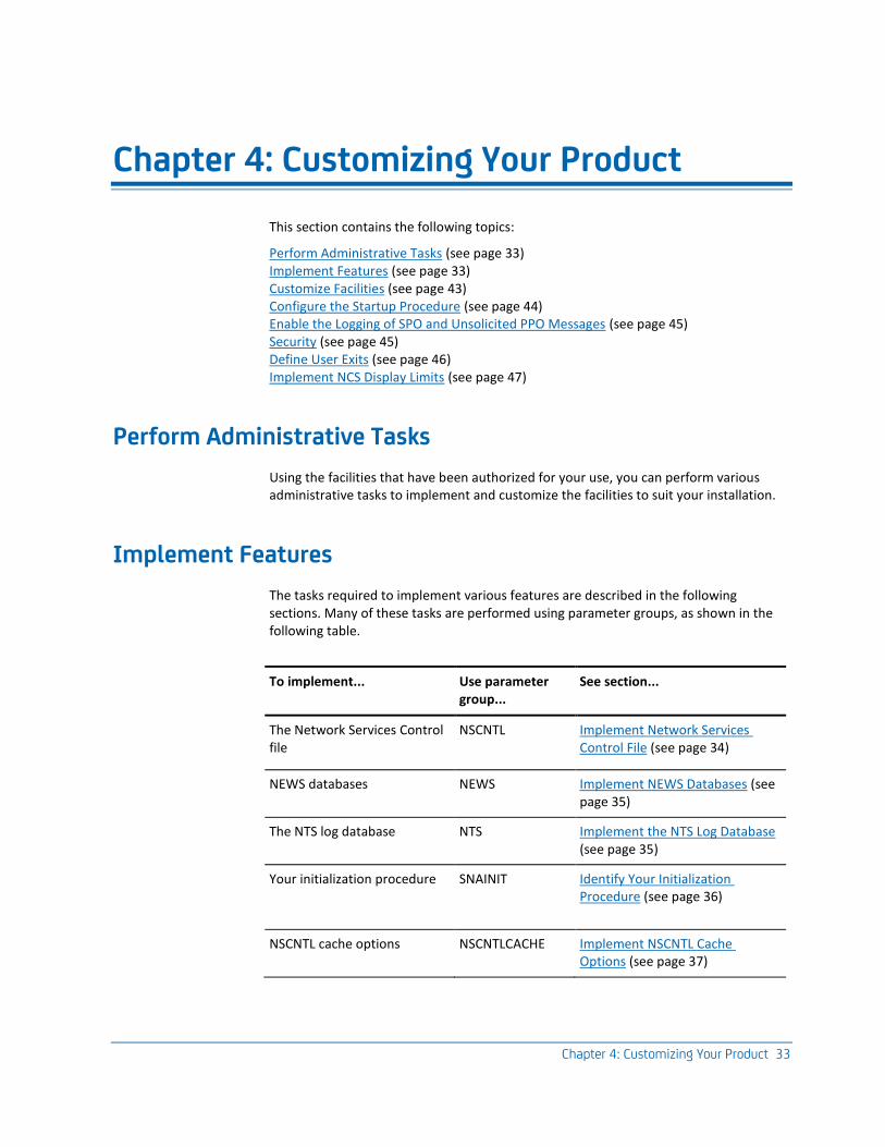
Chapter 4: Customizing Your Product 33
Chapter 4: Customizing Your Product
This section contains the following topics:
Perform Administrative Tasks (see page 33) Implement Features (see page 33) Customize Facilities (see page 43) Configure the Startup Procedure (see page 44) Enable the Logging of SPO and Unsolicited PPO Messages (see page 45) Security (see page 45) Define User Exits (see page 46) Implement NCS Display Limits (see page 47)
Perform Administrative Tasks
Using the facilities that have been authorized for your use, you can perform various administrative tasks to implement and customize the facilities to suit your installation.
Implement Features
The tasks required to implement various features are described in the following sections. Many of these tasks are performed using parameter groups, as shown in the following table.
To implement... Use parameter group...
See section...
The Network Services Control file
NSCNTL Implement Network Services Control File (see page 34)
NEWS databases NEWS Implement NEWS Databases (see page 35)
The NTS log database NTS Implement the NTS Log Database (see page 35)
Your initialization procedure SNAINIT Identify Your Initialization Procedure (see page 36)
NSCNTL cache options NSCNTLCACHE Implement NSCNTL Cache Options (see page 37)
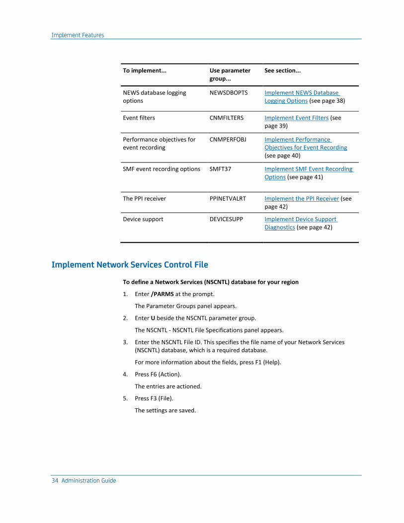
Implement Features
34 Administration Guide
To implement... Use parameter group...
See section...
NEWS database logging options
NEWSDBOPTS Implement NEWS Database Logging Options (see page 38)
Event filters CNMFILTERS Implement Event Filters (see page 39)
Performance objectives for event recording
CNMPERFOBJ Implement Performance Objectives for Event Recording (see page 40)
SMF event recording options SMFT37 Implement SMF Event Recording Options (see page 41)
The PPI receiver PPINETVALRT Implement the PPI Receiver (see page 42)
Device support DEVICESUPP Implement Device Support Diagnostics (see page 42)
Implement Network Services Control File
To define a Network Services (NSCNTL) database for your region
1. Enter /PARMS at the prompt.
The Parameter Groups panel appears.
2. Enter U beside the NSCNTL parameter group.
The NSCNTL - NSCNTL File Specifications panel appears.
3. Enter the NSCNTL File ID. This specifies the file name of your Network Services (NSCNTL) database, which is a required database.
For more information about the fields, press F1 (Help).
4. Press F6 (Action).
The entries are actioned.
5. Press F3 (File).
The settings are saved.
Implement Features
Chapter 4: Customizing Your Product 35
Implement NEWS Databases
You can define the following NEWS databases for your region:
■ Network Error (NEWSFILE) database
■ Network Error Backup (NEWSBKP) database.
Note: If you do not define the NEWSFILE database, no CNM events can be saved. If you do not define the NEWSBKP database, you cannot perform an online reorganization of the NEWSFILE database.
Define NEWS Databases
To define the NEWSFILE and NEWSBKP databases
1. Enter /PARMS at the prompt.
The Parameter Groups panel appears.
2. Enter U beside the NEWS parameter group.
The NEWS - NEWS File Specifications panel appears.
3. Enter the NEWS Database File ID. This specifies the file name of your Network Error database. If you do not enter a value here, no Network Error database is allocated.
4. Complete the remaining fields on the panel. For more information about the fields, press F1 (Help).
5. Press F8 (Forward).
The second panel for this parameter group appears.
6. Enter the NEWSBKP Database File ID. This specifies the file name of your Network Error Backup database. If you do not enter a value here, no Network Error database is allocated.
7. Complete the remaining fields on the panel. For more information about the fields, press F1 (Help).
8. Press F6 (Action).
The entries are actioned.
9. Press F3 (File).
The settings are saved.
Implement the NTS Log Database
You can define a Network Tracking Log (NTSLOG) database for your region.
Note: If you do not define the NTSLOG database, no session awareness or session trace data can be saved.
Implement Features
36 Administration Guide
Define NTSLOG Database
To define the NTSLOG database
1. Enter /PARMS at the prompt.
The Parameter Groups panel appears.
2. Enter U beside the NTS parameter group.
The NTS - NTSLOG File Specifications panel appears.
3. Enter the NTSLOG Database File ID. This specifies the file name of your Network Tracking Log database. If you do not enter a value here, no NTSLOG database is allocated.
4. Complete the remaining fields on the panel. For more information about the fields, press F1 (Help).
5. Press F6 (Action).
The entries are actioned.
6. Press F3 (File).
The settings are saved.
Identify Your Initialization Procedure
A default initialization procedure, $NSINIT, is provided. If you make a copy of this procedure and customize it, you need to identify your customized initialization procedure to CA NetMaster NM for SNA .
To identify a customized initialization procedure
1. Enter /PARMS at the prompt.
The Parameter Groups panel appears.
2. Enter U beside the SNAINIT parameter group.
The SNAINIT - NetMaster for SNA Init Process panel appears.
3. If you have copied and customized the default initialization process, $NSINIT, enter your process name under NetMaster for SNA Initialization Details.
4. Press F6 (Action).
The entries are actioned.
5. Press F3 (File).
The settings are saved.
Implement Features
Chapter 4: Customizing Your Product 37
Implement NSCNTL Cache Options
By setting an optimum cache size for the Network Services control file, you can improve the performance of NEWS processing by eliminating as much VSAM activity as possible.
The control file is a database that controls all NEWS CNM record processing. The Control File contains codes and messages that are used to control NEWS functions. It is front-ended by a cache that holds the most recently retrieved records from the Control File. Once full, the cache discards an infrequently referenced record when a new record is added.
Note: The cache is an in-storage vartable. Actioning this parameter group results in the vartable being deleted and redefined.
To implement the NSCNTL cache options
1. Enter /PARMS at the prompt.
The Parameter Groups panel appears.
2. Enter U beside the NSCNTLCACHE parameter group.
The NSCNTLCACHE - NSCNTL Cache Size panel appears.
3. Enter a value in the Maximum Number of Records Cached field, or leave the default value.
4. Press F6 (Action).
The entries are actioned.
5. Press F3 (File).
The entries are saved.
Implement Features
38 Administration Guide
Implement NEWS Database Logging Options
You can control the performance of record logging to the NEWS database by implementing the NEWS Database Recording Options (NEWSDBOPTS) parameter group. This parameter group controls how many records are stored on the NEWS database for each resource name, per category.
To implement NEWS Database Logging options
1. Enter /PARMS at the prompt.
The Parameter Groups panel appears.
2. Enter U beside the NEWSDBOPTS parameter group.
The NEWSDBOPTS - NEWS Database Recording Options panel appears.
3. Enter the maximum number of records to capture for each category shown, or leave the default value. For more information, press F1 (Help).
4. Press F6 (Action).
The entries are actioned.
5. Press F3 (File).
The settings are saved.
Examples
To receive a warning message every time a device information record is discarded, type the value 1 in the Device Information field.
To receive no warnings after the initial notification that logging has been suspended, type 0 in the Device Information field.
Implement Features
Chapter 4: Customizing Your Product 39
Implement Event Filters
You can control how network events are processed by defining which events are recorded, how they are processed, and what severity alert is generated. You do this by implementing the Event Recording Filters (CNMFILTERS) parameter group.
The use of resource masks restricts the processing of event records to a subset of the network only. The Event Recording Filters parameter group lets you set resource masks for further filtering of records in the selected event type. You can specify any combination of include or exclude mask type for an event type.
To implement the Event Recording Filters parameter group
1. Enter /PARMS at the prompt.
The Parameter Groups panel appears.
2. Enter U beside the CNMFILTERS parameter group.
The CNMFILTERS - Event Recording Filters panel appears. This panel has ten pages (each with two types of event filter) that you can scroll through to define filters for each event category (see page 53). For a list of event types, see Network Error Warning System.
3. Enter the Processing Option and Alert Severity for each event category, if you want to change the default values.
Note: If you enter an Alert Severity value between 1 and 4, NEWS events appear in the Alert Monitor.
4. Define an Include Mask or an Exclude Mask for each event category for which you want further filtering. For more information, press F1 (Help).
5. Press F6 (Action).
The entries are actioned.
6. Press F3 (File).
The settings are saved.
Examples
To prevent an event generating an alert that appears on the Alert Monitor, specify an Alert Severity of 0.
To write an event to the Events Category, specify a Processing Option of E.
Implement Features
40 Administration Guide
Implement Performance Objectives for Event Recording
The Performance Objectives (CNMPERFOBJ) parameter group lets you set threshold values for certain network statistics that create a performance event when the values are reached or exceeded.
The following network statistics are used for performance objectives:
■ 3x74 RTM Data
■ RECMS Statistics
■ FCS RECFMS 04 Data
To define performance objectives
1. Enter /PARMS at the prompt.
The Parameter Groups panel appears.
2. Enter U beside the CNMPERFOBJ parameter group.
The CNMPERFOBJ - Performance Objectives panel appears. This panel has three pages that you can scroll through to define performance objectives for each type of event.
3. Enter the threshold values for each type of performance event to create. For more information, press F1 (Help).
4. Press F6 (Action).
The entries are actioned.
5. Press F3 (File).
The settings are saved.
Implement Features
Chapter 4: Customizing Your Product 41
Implement SMF Event Recording Options
By setting SMF recording options (SMFT37), you can control the generation of SMF records from NEWS events and statistics.
When turned on, these options cause CNMPROC to write the specified NEWS records to the SMF file in type 37 format.
To implement SMF Event Recording options
1. Enter /PARMS at the prompt.
The Parameter Groups panel appears.
2. Enter U beside the SMFT37 parameter group.
The SMFT37 - SMF Type 37 Recording Options panel appears.
3. Complete the following fields:
Events and Attentions
Specify the types of NEWS event records for which you want to write SMF records. For more information, press F1 (Help).
Statistics
Specify whether you want to write SMF records for statistics.
4. Press F6 (Action)
This is to action your entries.
5. Press F3 (File)
This saves your settings.
Implement Features
42 Administration Guide
Implement the PPI Receiver
The PPI receiver (PPINETVALRT) processes external events that are queued to the NETVALRT PPI resource by other tasks.
To define details for starting and stopping the PPI receiver
1. Enter /PARMS at the prompt.
The Parameter Groups panel appears.
2. Enter U beside the PPINETVALRT parameter group.
The PPINETVALRT - NETVALRT PPI Receiver Process panel appears.
3. Specify YES or NO in the Initially Active? field.
This field indicates whether to start the PPI receiver during initialization.
4. Specify YES or NO in the Currently Active? field.
This field indicates whether to start or stop the PPI receiver now.
5. Press F6 (Action).
The entries are actioned.
6. Press F3 (File).
The settings are saved.
Implement Device Support Diagnostics
NEWS device support lets you diagnose problems with SNA controller devices. The DEVICESUPP parameter group lets you specify which options to display on your SNA : Device Support Diagnostics Menu.
To implement device support diagnostics
1. Enter /PARMS at the prompt.
The Parameter Groups panel appears.
2. Enter U beside the DEVICESUPP parameter group.
The DEVICESUPP - Device Support Diagnostics Menu appears.
3. Enter YES or NO for each option shown to control whether the option appears on the Device Support Diagnostics Menu. For more information about the fields, press F1 (Help).
4. Press F6 (Action).
Your entries are actioned.
5. Press F3 (File).
Your settings are saved.
Customize Facilities
Chapter 4: Customizing Your Product 43
Customize Facilities
The tasks required to customize facilities for various features are described in the following sections.
Customize NEWS Facilities
To customize NEWS facilities in your region, you can update the following parameter groups that you reviewed when implementing your region:
■ NEWS File Specifications
■ NEWS Database Recording Options
You can also do the following:
■ Review your NEWS parameters to suit your installation.
■ Manage your network focal points and entry points by using the NEWS : Control Functions Menu.
More information:
Network Error Warning System (see page 49)
Customize NTS Facilities
To customize NTS functions to suit your installation, use the SYSPARMS and DEFCLASS commands. These commands are normally included in the initialization procedure, $NSINIT (see page 44).
Customize NCPView Facilities
To customize NCPView facilities to suit your installation, you can do the following:
■ Configure the NCPView NCL exit.
■ Define additional NCPs to monitor.
Customize NCS Facilities
To customize NCS facilities in your region, you can do the following:
■ Limit the size of display lists and individual node displays
■ Integrate NCS with a configuration management database
Configure the Startup Procedure
44 Administration Guide
Configure the Startup Procedure
The $NSINIT procedure is executed during initialization and is designed for actions specific to CA NetMaster NM for SNA.
Review the $NSINIT procedure for the following purposes:
■ To enable Tivoli NetView operator command emulation, if necessary.
■ To set up NTS.
Note: $NSINIT is the default procedure. If you copy this procedure and you customize it, identify your customized procedure in the SNAINIT parameter group.
Enable Tivoli NetView Operator Command Emulation
You can use Tivoli NetView operator commands in CA NetMaster NM for SNA.
To enable Tivoli NetView operator command emulation
1. Add the following statement to the $NSINIT member.
EXEC $VWCALL OPT=INIT
Alternatively, if this statement already exists, remove the comment symbols (-*) beside the statement.
2. After you update your ..., enter the following command at the command prompt:
unload proc=$NSINIT at OCS (=o)
Your $NSINIT procedure is unloaded.
3. Action the SNAINIT (see page 36) parameter group for the changes to take effect.
Note: You can also use an NCCF-like facility that lets you execute some existing Tivoli NetView REXX procedures. For information about how to use this facility, see the NetMaster REXX Guide.
More information:
Configuring Tivoli NetView Operator Command Emulation (see page 125)
Enable the Logging of SPO and Unsolicited PPO Messages
Chapter 4: Customizing Your Product 45
Set Up NTS
In the $NSINIT procedure, review the following:
■ SYSPARMS parameters to control NTS functions
■ DEFCLASS commands to control NTS data collection
These are administrative tasks that you can perform now or after startup.
For more information about the SYSPARMS parameters for NTS, see the Reference Guide
Enable the Logging of SPO and Unsolicited PPO Messages
By default, SPO and unsolicited PPO messages are not logged. If you want to log these messages, update the PPO parameter group.
Note: CA OPS/MVS can automate responses to messages in the system hardcopy log. If the region owns the PPO and you want this automation to occur for unsolicited PPO messages, write these messages to the system hardcopy log.
Follow these steps:
1. Enter the /PARMS panel shortcut.
The parameter groups are listed.
2. Enter U next to the PPO parameter group.
3. Update the following fields as required:
■ Log Unsolicited PPO Messages?
Note: If the region does not include CA NetMaster NA and you use CA OPS/MVS for automation, specify WTO.
■ Log SPO Messages?
4. Press F6 (Action).
The region starts logging the selected types of messages.
5. Press F3 (File).
You save the changes. The new settings apply when the region restarts.
Security
Access to a region is controlled by the User ID Access Maintenance Subsystem (/UAMS).
For more information, see the Security Guide.
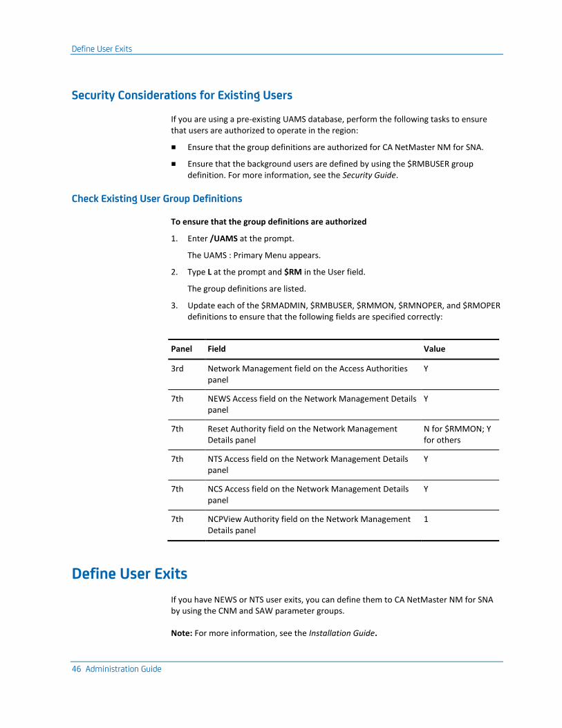
Define User Exits
46 Administration Guide
Security Considerations for Existing Users
If you are using a pre-existing UAMS database, perform the following tasks to ensure that users are authorized to operate in the region:
■ Ensure that the group definitions are authorized for CA NetMaster NM for SNA.
■ Ensure that the background users are defined by using the $RMBUSER group definition. For more information, see the Security Guide.
Check Existing User Group Definitions
To ensure that the group definitions are authorized
1. Enter /UAMS at the prompt.
The UAMS : Primary Menu appears.
2. Type L at the prompt and $RM in the User field.
The group definitions are listed.
3. Update each of the $RMADMIN, $RMBUSER, $RMMON, $RMNOPER, and $RMOPER definitions to ensure that the following fields are specified correctly:
Panel Field Value
3rd Network Management field on the Access Authorities panel
Y
7th NEWS Access field on the Network Management Details panel
Y
7th Reset Authority field on the Network Management Details panel
N for $RMMON; Y for others
7th NTS Access field on the Network Management Details panel
Y
7th NCS Access field on the Network Management Details panel
Y
7th NCPView Authority field on the Network Management Details panel
1
Define User Exits
If you have NEWS or NTS user exits, you can define them to CA NetMaster NM for SNA by using the CNM and SAW parameter groups.
Note: For more information, see the Installation Guide.
Implement NCS Display Limits
Chapter 4: Customizing Your Product 47
Implement NCS Display Limits
To set a maximum number of lines in NCS display lists and a maximum number of subnodes displayed for a node, use the SNA Node Display Limits parameter group.
To implement NCS display limits
1. Enter /PARMS at the prompt.
The Parameter Groups panel appears.
2. Enter U beside the NCS parameter group.
The NCS - SNA Node Display Limits panel appears.
3. Complete the following fields:
Maximum Number of Display Lines
Specify the maximum number of resources to display in NCS.
Maximum Number of Sub-node
If you are using Fujitsu VTAM-G, specify the maximum number of sub-nodes to display in VTAM.
4. Press F6 (Action).
The entries are actioned.
5. Press F3 (File).
The entries are saved.

Chapter 5: Network Error Warning System 49
Chapter 5: Network Error Warning System
This section contains the following topics:
Data Available to NEWS (see page 49) How NEWS Obtains Data (see page 50) Processing Concepts (see page 52) NEWS Facilities (see page 58) Review Parameters to Send and Receive CNM Data (see page 68) Review NCP Parameters and Operations (see page 69) Customize Device Configuration (see page 69) Maintain Control File Records (see page 70) Alias Name Translation Facility (see page 73) Reviewing and Reporting on Data (see page 73) Maintain the NEWS Database (see page 74)
Data Available to NEWS
NEWS processes a wide variety of data received from different sources and responds to the data it receives in an appropriate (user-definable) way. NEWS receives the following types of data:
■ Unsolicited data
■ Solicited data
■ Response time data
NEWS also processes solicited and unsolicited data from the 3x74 Response Time Monitor.
Unsolicited Data
Unsolicited data—which originates from network nodes and distributed devices—received by NEWS includes the following:
■ Traffic statistics
■ Temporary and permanent error statistics
■ Errors detected by network nodes
■ Alert data generated by network components
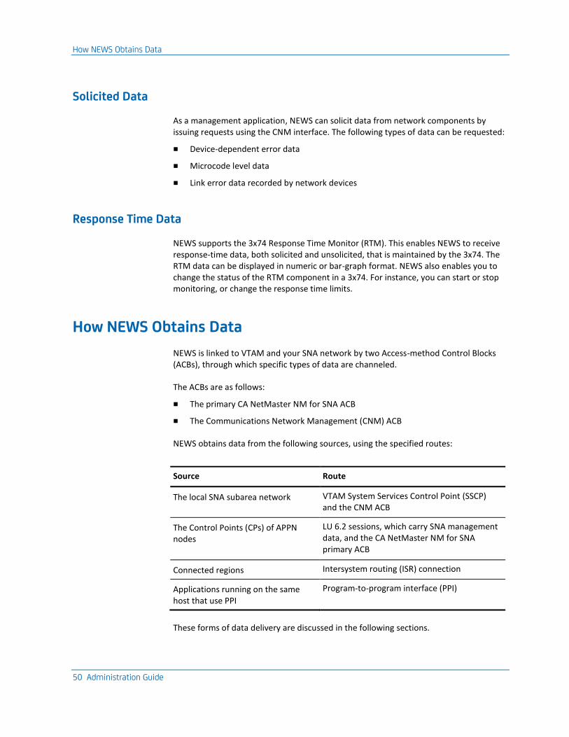
How NEWS Obtains Data
50 Administration Guide
Solicited Data
As a management application, NEWS can solicit data from network components by issuing requests using the CNM interface. The following types of data can be requested:
■ Device-dependent error data
■ Microcode level data
■ Link error data recorded by network devices
Response Time Data
NEWS supports the 3x74 Response Time Monitor (RTM). This enables NEWS to receive response-time data, both solicited and unsolicited, that is maintained by the 3x74. The RTM data can be displayed in numeric or bar-graph format. NEWS also enables you to change the status of the RTM component in a 3x74. For instance, you can start or stop monitoring, or change the response time limits.
How NEWS Obtains Data
NEWS is linked to VTAM and your SNA network by two Access-method Control Blocks (ACBs), through which specific types of data are channeled.
The ACBs are as follows:
■ The primary CA NetMaster NM for SNA ACB
■ The Communications Network Management (CNM) ACB
NEWS obtains data from the following sources, using the specified routes:
Source Route
The local SNA subarea network VTAM System Services Control Point (SSCP) and the CNM ACB
The Control Points (CPs) of APPN nodes
LU 6.2 sessions, which carry SNA management data, and the CA NetMaster NM for SNA primary ACB
Connected regions Intersystem routing (ISR) connection
Applications running on the same host that use PPI
Program-to-program interface (PPI)
These forms of data delivery are discussed in the following sections.
How NEWS Obtains Data
Chapter 5: Network Error Warning System 51
SNA Networks and the CNM Interface
The CNM interface lets a suitably authorized CNM application (such as NEWS) maintain a session with an SSCP, to acquire data from Physical Units (PUs) in your SNA network. This session is established when NEWS successfully opens its VTAM CNM ACB, allowing data to be exchanged with the SSCP of the VTAM under which NEWS is running.
NEWS receives the following types of data from the SSCP:
■ Unsolicited, as a result of some network event
■ Solicited, as a reply to a previous request for data issued by NEWS itself
■ As a solicitation from the SSCP, requesting that NEWS send some data in response
NEWS sends data to the SSCP for the following reasons:
■ To solicit data from a network resource
■ In response to a solicitation request from the SSCP
APPN Networks and SNA Management Services
When CA NetMaster NM for SNA starts, a primary ACB that links it to VTAM opens. During initialization, NEWS registers with Multiple Domain Support (MDS) as the ALERT-NETOP application that acts as a focal point for alert collection from your APPN network.
MDS is a component of SNA Management Services (SNAMS), which facilitates the routing of management data between applications. It enables management roles—that is, which node is the focal point for the receipt of which data—to be negotiated between nodes.
For more information about the functions and services associated with SNAMS, see the IBM publication, SNA Management Services Reference.
SNA Management Services Units
SNA data units are known as Management Services Units (MSUs). There are various types of SNA MSUs and many reasons for the generation of each type. As a result, NEWS needs to apply rules to classify incoming records, to determine the relative importance of the data that each carries, and whether a response is appropriate.
SNAMS Data Transfer
The SNAMS architecture makes use of SNA Management Services transport, which consists of a number of APPC transactions used to transport SNA MSUs across the network.
Processing Concepts
52 Administration Guide
&SNAMS Verb
The &SNAMS verb enables NCL procedures to participate as management applications in the SNAMS architecture. The partner application can exist in the same CA NetMaster region, a remote CA NetMaster region, or any other region that supports MDS functions.
For more information about the &SNAMS verb, see the Network Control Language Reference Guide.
NEWS and Intersystem Routing
The Intersystem Routing (ISR) feature enables data to be transparently routed to remote processing environments in other regions.
NEWS takes advantage of ISR to exchange data with remote regions. Requests, including CNM requests, can be routed to remote NEWS regions for processing, and the results returned to the originating region. This can be used to change the operation of, or solicit data from, a device managed by VTAM in the remote region.
ISR also enables a NEWS region to deliver unsolicited records to a remote NEWS region for processing.
By using ISR, you can implement centralized management, resulting in one NEWS region processing all data received by NEWS in linked regions. This lets you control all database logging from one region.
NEWS and PPI
Applications running on the same host can communicate using PPI, a support facility provided by the subsystem interface or Tivoli NetView. Users of PPI can send various types of data to this interface, which then distributes the data to the application registered to receive that particular type of data.
NEWS registers with PPI, as the receiver of generic alerts, to monitor and report on the state of other applications using PPI.
Processing Concepts
This section explains the various concepts relating to the processing of all records received by NEWS.
Processing Concepts
Chapter 5: Network Error Warning System 53
Network Services Control File
The processing requirements for records received by NEWS are determined by a control database called the Network Services Control File (NSCNTL). This database contains control codes that describe the processing to perform for each type of record received by NEWS. It also acts as a data dictionary and is used to interpret the control codes present in the record.
This approach of determining processing requirements through data held on a control database provides extensive flexibility. The NEWS Control Function menu provides functions that allow you to add support for non-standard devices and requirements, or modify a control record held on the database. Any alterations or additions made to the control database are effective immediately.
NSCNTL is used by CNMPROC, a specialized NCL procedure, to process all records received by NEWS.
Events
Any record received by NEWS is classified as an event, or as having the capacity to generate an event. The concept of the event enables different types of data to be grouped into one broad category, to provide a chronological record for a network node.
Generally, unsolicited records notifying NEWS of network errors are immediately classified as events. Records carrying statistical data have the potential to generate an event, if they include values that exceed thresholds set by your installation.
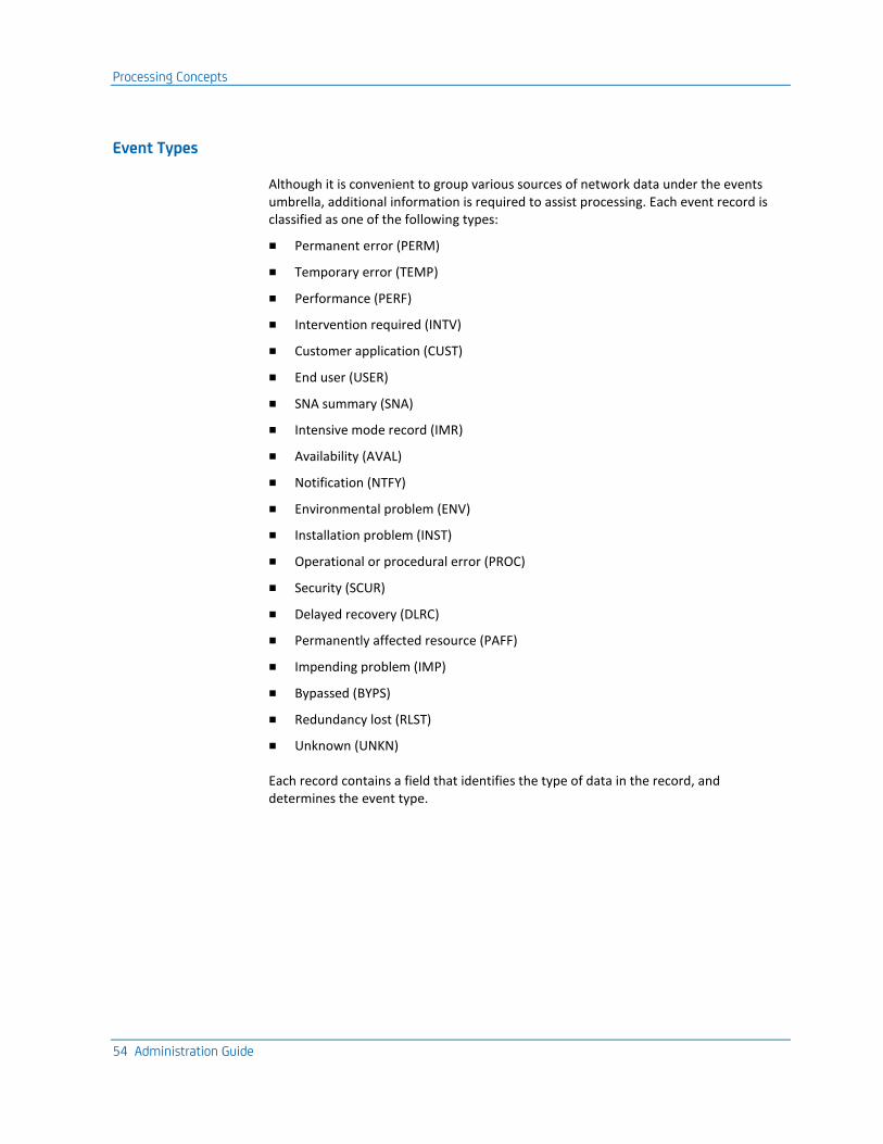
Processing Concepts
54 Administration Guide
Event Types
Although it is convenient to group various sources of network data under the events umbrella, additional information is required to assist processing. Each event record is classified as one of the following types:
■ Permanent error (PERM)
■ Temporary error (TEMP)
■ Performance (PERF)
■ Intervention required (INTV)
■ Customer application (CUST)
■ End user (USER)
■ SNA summary (SNA)
■ Intensive mode record (IMR)
■ Availability (AVAL)
■ Notification (NTFY)
■ Environmental problem (ENV)
■ Installation problem (INST)
■ Operational or procedural error (PROC)
■ Security (SCUR)
■ Delayed recovery (DLRC)
■ Permanently affected resource (PAFF)
■ Impending problem (IMP)
■ Bypassed (BYPS)
■ Redundancy lost (RLST)
■ Unknown (UNKN)
Each record contains a field that identifies the type of data in the record, and determines the event type.
Processing Concepts
Chapter 5: Network Error Warning System 55
Event Characteristics
The characteristics that identify an event are generally represented by one or more codes in the record. These codes may describe the following:
■ The reason why the event was generated
■ The probable cause or causes of the event
■ The severity of the problem associated with the event
■ The resources affected by this problem
■ The recommended remedial action
The codes may also provide additional information that assists in determining the cause of the associated problem, and are used by NEWS in conjunction with the control file, to determine record processing.
Event Filtering
Different installations have different network configurations and employ a variety of device types, some of which have their own special requirements. Also, installations assign differing levels of importance to particular network events and problems in their environments.
NEWS provides for this situation by passing all event records through a process termed event filtering, using parameters set in the Control File. This process enables you to discard those event records not required by your installation, while bringing to the attention of the network operator those considered important.
For each of the event types described on the previous page, you can filter by using resource masks. You can also set options that control how the event is recorded in the NEWS database and whether an alert is generated for display on the Alert Monitor.
Event filtering is performed by the NEWS and user CNM processing procedures. CNMPROC uses control values that you set through the CNMFILTERS parameter group to perform filtering.
More information:
Implement Event Filters (see page 39)
Processing Concepts
56 Administration Guide
Resource Masks
Because all records are sent by, or on behalf of, a network resource, it is possible to restrict the processing of certain types of data to particular resources.
Resource masks are defined generically and are used to include or exclude records based on the originating resource name. Records that do not satisfy resource masking criteria are discarded.
Alert Monitor
You can generate alerts to increase operator awareness of important events in the network using NEWS. Any record received by NEWS can be classified, through event filtering, as an alert. The alert monitor contains the most recent alerts produced by NEWS. The display is updated as new alerts arrive, or the status of alerts on the display change.
CNMPROC Record Processing
CNMPROC is a special NCL procedure that acts as a focal point application for SNA management data. CNMPROC executes in a background environment under user ID xxxxCNMP, where xxxx is the four-letter domain ID. A working version of CNMPROC is distributed as $NWCNMPR.
The function of CNMPROC is to do the following:
■ Analyze the content of each record delivered to it, in conjunction with the Network Services Control File (NSCNTL), to determine the processing requirements
■ Process the record accordingly
CNMPROC is written as a continuous procedure (like PPOPROC and LOGPROC) and uses the &CNMREAD verb to receive each record as it becomes available for focal point processing. CNMPROC does some pre-processing to identify the record and then calls other procedures to perform further processing.
CNMPROC can be activated to process the following:
■ All records that arrive unsolicited from VTAM across the CNM interface
■ Records from APPN nodes sent to the ALERT-NETOP application using the Management Services implementation of MS Transport
■ Solicited records delivered to it by users
■ Alerts created by the &CNMALERT verb
Messages generated by CNMPROC are sent to OCS users who have monitor capability, and have a prefix of C to identify their origin.
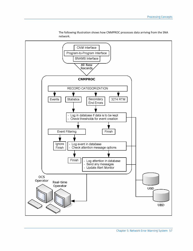
Processing Concepts
Chapter 5: Network Error Warning System 57
The following illustration shows how CNMPROC processes data arriving from the SNA network.
NEWS Facilities
58 Administration Guide
Keep the following in mind when reviewing this illustration:
■ All records received through the CNM interface from VTAM are processed by CNMPROC, including the following:
– RECMS records from NCPs with statistical and error data
– Unsolicited RECFMS and NMVT RUs containing alerts and statistical data from SNA controllers
– Solicited RECFMS and NMVT RUs
■ CNMPROC categorizes records and logs those that are to be kept in the NEWS database.
■ Installation options define the event generation and filtering processes.
■ Attention messages providing notice of important events may be sent to operators.
NEWS Facilities
NEWS provides NCL programming facilities, and commands for customization and diagnosis.
NCL Verbs and Procedures
NEWS provides NCL procedures, and NCL verbs and system variables, to perform different functions.
The following is a summary of NEWS NCL verbs and system variables:
&CNMALERT
Sends a CNM alert to a local or remote NEWS region for processing.
&CNMCLEAR
Clears any outstanding Response Units (RUs) which have been solicited by an &CNMSEND statement and not processed by an &CNMREAD statement.
&CNMCONT
Used in CNMPROC to send the current CNM record across specified ISR links.
&CNMDEL
Used in CNMPROC to delete the current CNM record or stop the current CNM record from being sent across specified ISR links.
&CNMPARSE
Produces tokenized data from the $CNM mapped MDO used by NEWS.
NEWS Facilities
Chapter 5: Network Error Warning System 59
&CNMREAD
Makes the next CNM record received from VTAM available to CNMPROC, or the next outstanding RU available to a user procedure that has solicited data using an &CNMSEND statement.
&CNMSEND
Sends an RU across the CNM interface.
&CNMVECTR
Parses supplied hexadecimal data in the form of a CNM record into NCL tokens that correspond to the CNM vectors present.
&NEWSAUTH
Indicates whether the user ID of the user invoking a procedure is authorized for NEWS (system variable).
&NEWSRSET
Indicates whether the user ID of the user invoking a procedure is authorized to delete records from the NEWS database (system variable).
&SNAMS
Provides the SNA Management Services interface which enables NCL procedures to participate as management applications in an APPN network.
For more information about NEWS NCL verbs and system variables, see the Network Control Language Reference Guide.
Unattended Solicitation
NEWS supplies NCL procedures to solicit various types of network data, including RTM, VPD, EC level data, FCS, and LPDA2 data.
More information:
Line Command Procedures (see page 260)
NEWS Facilities
60 Administration Guide
NEWS Commands
The following is a summary of NEWS commands:
CNM
Starts and stops the VTAM CNM interface.
CNMTRACE
Defines a trace of records that come across the CNM interface. By default, all trace data is recorded.
DEFALIAS
Defines an alias entry for the Alias Name Translation Facility of NEWS.
DELALIAS
Deletes an alias entry used by the Alias Name Translation Facility of NEWS.
REPALIAS
Replaces an alias name entry used by the Alias Name Translation Facility of NEWS.
REQMS
Sends data across the CNM interface.
SHOW CNMTRACE
Displays active CNM trace requests.
SHOW DEFALIAS
Displays one or more DEFALIAS entries used by the Alias Name Translation Facility of NEWS.
SHOW SNAMS
Displays a list of all applications registered with SNA Management Services.
SYSMON
Logs the user on to the System Monitor residing in a 3600 or 4700 controller and sends data to the Monitor.
SYSPARMS
Initializes or modifies system parameter values.
XLATE
Performs name translation testing through the Alias Name Translation Facility of NEWS.
NEWS Facilities
Chapter 5: Network Error Warning System 61
Testing NEWS Events
You can use NEWS alerts, also called NEWS events, to test processing in the structure of NEWS.
You can create the following types of NEWS events:
■ Hardware events
■ Software events
Alerts can be used to test the CNM record processing. This allows the testing of record support, which may not otherwise be possible until a CNM record arrives through the CNM interface. If the processing path for the record is incomplete or incorrect, or if a processing procedure fails, then a valuable record may be lost.
Test with Pre-existing Events
If there are NEWS events already created, you can test them instead of creating new alerts.
To test with pre-existing events
1. Enter /SNAHIST to display the NEWS : Database Review menu, and enter 2.
The NEWS : Events Review menu appears.
2. Tab to a node and enter S.
Another NEWS : Events Review panel appears.
3. Tab to one of the records and enter S.
The NEWS : Generic Alert Display panel appears.
4. Enter C at the command prompt.
The control codes that relate to that event appear. The codes determine what category on the control file defines the descriptive text.
5. Enter D at the command prompt.
A dump of the event appears.
6. Enter RESEND at the command prompt.
The alert is generated again, and, if you have made changes to the control file, the event will be reprocessed and will display updated values.
NEWS Facilities
62 Administration Guide
Create an Alert Menu
The NEWS : Create an Alert menu lets you create the following NMVT alerts:
■ Operator Alerts
■ Non-generic (Basic) Alerts
■ Generic Alerts
Create an Operator Alert
You can produce operator alerts in the form of text messages to send to network operators.
To create an operator alert
1. Enter /SNADIAG.CA at the prompt.
The NEWS : Create an Alert Menu appears.
2. Enter 1 at the prompt.
The NEWS : Create an Operator Alert panel appears.
3. Complete the following fields:
Text Message
Type a maximum of 10 lines of text, each of 60 characters.
The text is entirely free-form and can contain any information required by the operator.
Node Name
If you want to change the default, then type the name of a resource in the Node Name field.
By default, the user ID of the operator creating the alert is used as the name of the resource sending the alert. The receiving NEWS region logs the record in the NEWS database under the name of the resource which sent the alert.
4. Perform the following steps if remote routing is required:
a. In the Link Name field, type a link name to send the alert to the associated remote region.
b. In the SSCP Name field, type an SSCP name to send the alert to the associated remote region.
5. Press Enter.
If successful, a message appears; otherwise, the alert is sent to the Alert Monitor as a NTFY Operator notification. Use the D option to display.
NEWS Facilities
Chapter 5: Network Error Warning System 63
Create a Non-Generic (Basic) Alert
You can create a basic NMVT alert to report user-defined events, or to test the existing CNM processing path for any type of alert. The alert is queued to the targeted CNMPROC (on a local or remote region) for processing.
Much of the alert information is built to form subvectors. Each subvector carries information that helps describe the alert condition.
Note: For a description of these subvectors, see the IBM publication, SNA Formats and Protocols Reference.
To create a non-generic (basic) alert
1. Enter /SNADIAG.CA at the prompt.
The NEWS : Create an Alert Menu appears.
2. Enter 2 at the prompt.
The first NEWS : Create a Basic (Non-generic) Alert panel appears. The panel provides fields for the following alert information:
■ Basic alert
■ Detail qualifiers
NEWS Facilities
64 Administration Guide
3. Obtain the relevant reference codes associated with the subvector from IBM's SNA Formats and Protocols Manual and enter this information as follows:
a. Enter information in the Basic Alert section. This information is built to form the following required subvector:
■ X'91'—Describes the condition that led to the generation of the alert, the possible causes of the alert condition, the recommended action, and may also supply a Detail Text Reference code to further describe the alert condition.
b. Enter information in the Detailed Qualifiers section. When you enter detail qualifiers, you specify how data for the detail text of an alert message is transmitted for display. The detail text describes in detail what condition caused the generation of the alert and is defined by the reference code you entered in the Detail Text field in the Basic Alert subvector.
You can either transmit the detail data in text characters using the text contents of the subvector X‘91’ to type the text characters for the detail data in each Qualifiers field, or you can transmit the hexadecimal representation of the data by typing the hexadecimal equivalent of the contents of the subvector X‘91’. The hexadecimal representation is converted to EBCDIC text before being displayed.
The information in this section is built to form the following optional subvectors:
■ X'A0'—Supplies a qualifier that is added to the Detail Text when it appears and only applies if a Detail Text Reference code was supplied in the X'91' subvector. The qualifier contained in this subvector is in character form and is not interpreted before being displayed.
■ X'A1'—Supplies a qualifier that is added to the Detail Text when it appears and only applies if a Detail Text Reference code was supplied in the X'91' subvector. The qualifier contained in this subvector is in hexadecimal form and is translated into character format before being displayed.
4. Press F8.
The next panel appears. The panel provides fields for the following alert information:
■ Alert sender PSID
■ Indicated resource PSID
■ Resource hierarchy
■ Remote routing
NEWS Facilities
Chapter 5: Network Error Warning System 65
5. Continue to enter the reference code information you obtained from IBM's SNA Formats and Protocols Manual in the Alert Sender PSID and Indicated Resource PSID sections. This information is built to form the following optional subvector:
■ X'10' (Product Set ID)—Describes a network resource. The alert can contain up to two of these subvectors. The first, if present, describes the resource sending the alert. This resource, called the Alert Sender, may be reporting an alert condition in another resource. If this is the case, a second Product Set ID subvector may be present, which describes the indicated resource. These resources are identified by their Common Hardware or Common Software name. For example, an IBM 3174 Control Unit would have a Common Hardware name of 3174.
6. Enter information in the Resource Hierarchy section by typing resource names and types in descending order, so that the resource immediately connected to the reported resource is the last in the hierarchy list.
7. Enter information in the Remote Routing section to direct the alert to a remote region for processing by using the NEWS ISR facilities.
Note: If no remote routing is requested, then the alert is directed to the local CNMPROC.
Create a Generic Alert
You can create Generic NMVT alerts to report events in the network or to test the existing CNM processing path for such an alert. The alert is queued to the targeted CNMPROC (on a local or remote region) for processing.
Much of the alert information is built to form subvectors. Each subvector carries information that helps describe the alert condition.
To create a generic alert
1. Enter /SNADIAG.CA at the prompt.
The NEWS : Create an Alert Menu appears.
2. Enter 3 at the prompt.
The first NEWS : Create a Generic Alert panel appears. The panel provides fields for the following alert information:
■ Generic alert data
■ Probable causes
■ User causes
■ Install causes
■ Failure causes
NEWS Facilities
66 Administration Guide
3. Obtain the relevant reference codes associated with the subvector from IBM's SNA Formats and Protocols Manual and enter this information as follows:
a. Enter information in the Generic Alert Data section. This information is built to form the following required subvector:
■ X'92'—Describes the severity of the condition which led to the generation of the alert, and gives a code which describes the alert condition.
b. Enter information in the Probable Causes section. This information is built to form the following required subvector:
■ X'93'—Provides codes which describe the probable causes of the alert condition. A maximum of three Probable Cause codes can be entered.
c. Enter information in the User Causes section. This information is built to form the following optional subvector:
■ X'94'—Provides codes that describe possible user-related causes of the alert condition, and supplies Recommended Action codes. A maximum of three User Cause codes and three Recommended Action codes can be entered.
d. Enter information in the Install Causes section. This information is built to form the following optional subvector:
■ X'95'—Provides codes describing errors which may have been made during the installation of the resource which may have caused the alert condition, and supplies Recommended Action codes. A maximum of three Install Cause codes and three Recommended Action codes can be entered.
e. Enter information in the Failure Causes section. This information is built to form the following optional subvector:
■ X'96'—Provides codes which describe possible device or software failures which may have caused the alert condition, and supplies Recommended Action codes. A maximum of three Failure Cause codes and three Recommended Action codes can be entered.
4. Press F8 (Forward).
The next panel appears. The panel provides fields for the following alert information:
■ Undetermined cause
■ Self-defining text message
■ Alert sender PSID
■ Indicated resource PSID
■ Resource hierarchy
■ Remote routing
NEWS Facilities
Chapter 5: Network Error Warning System 67
5. Continue to enter the reference code information you obtained from IBM's SNA Formats and Protocols Manual as follows:
a. Enter information in the Undetermined Cause section. This information is built to form the following optional subvector:
■ X'97'—Specifies Recommended Action codes to describe the necessary action. If the cause for the alert condition is not known or cannot be expressed in the previous cause code subvectors, this subvector must be included in the alert. It carries no Cause codes. A maximum of three Recommended Action codes can be entered.
b. Enter information in the Self-defining Text Message section. This information is built to form the following optional subvector:
■ X'31'—Carries text which can help with further diagnosis of the condition leading to the generation of the alert.
c. Enter information in the Alert Sender PSID and Indicated Resource PSID sections. This information is built to form the following optional subvector:
■ X'10' (Product Set ID)—Describes a network resource. The alert can contain up to two of these subvectors. The first, if present, describes the resource sending the alert. This resource, called the Alert Sender, may be reporting an alert condition in another resource. If this is the case, a second Product Set ID subvector may be present, which describes the indicated resource. These resources are identified by their Common Hardware or Common Software name. For example, an IBM 3174 Control Unit would have a Common Hardware name of 3174.
6. Enter information in the Resource Hierarchy section by typing resource names and types in descending order, so that the resource immediately connected to the reported resource is the last in the hierarchy list.
7. Enter information in the Remote Routing section to direct the alert to a remote region for processing by using the NEWS ISR facilities.
Note: If no remote routing is requested, then the alert is directed to the local CNMPROC.
Review Parameters to Send and Receive CNM Data
68 Administration Guide
Review Parameters to Send and Receive CNM Data
To send and receive CNM data, you must set fields on the first page of the CNM parameter group.
In the CNM parameter group, specify the required CNM ACB name. The CNM ACB name is the name of the ACB used to send and receive CNM requests and responses, and optionally, used to receive unsolicited CNM data.
Note: If the ACB specified is unable to receive unsolicited CNM data, then the name of the CA NetMaster NM for SNA or Tivoli NetView region where it resides must be specified in the ISR Link Name field on the ISRIN Initialization Parameters panel.
More information:
Advanced Configuration Tasks (see page 129)
Configure NEWS Database Options
The NEWS database options lets you control how many records are stored on the NEWS database for each resource name, per category.
To implement the NEWS database options, use the NEWSDBOPTS parameter group.
More information:
Implement NEWS Database Logging Options (see page 38)
Review NCP Parameters and Operations
Chapter 5: Network Error Warning System 69
Review NCP Parameters and Operations
The NCP generates statistics records whenever certain internal counters overflow. Generally speaking, the counters for SNA devices overflow fairly frequently because the transmission counters include poll-type transmissions, and so the arrival rate of statistics for those devices is normally high. However, the counters for non-SNA devices include data transmissions only and by default wrap only after 65535 transmissions or 255 temporary errors. The arrival rate for statistics records for these devices can be quite low.
To adjust the statistics arrival rate for SNA and non-SNA devices, specify the SRT NCP generation parameter. You can specify it on a PU macro for an SNA controller or a TERMINAL macro for a non-SNA terminal. We recommend that the parameter be utilized, particularly for non-SNA devices, so that statistics can be kept as current as possible.
Another concern for statistics collection is that of network shutdown. Whenever VTAM varies an NCP inactive, that NCP delivers statistics for all devices connected to it. If the network is shutdown using the Z NET,QUICK command, VTAM varies all NCPs inactive, which then deliver their statistics. However, it is possible that your region is terminating because of the Z NET,QUICK command and therefore will not accumulate those statistics.
We recommend that an orderly network shutdown be implemented whereby all NCPs are made inactive before VTAM is halted.
Customize Device Configuration
You may consider customizing the configuration to include the following features:
■ LPDA support
■ RTM support
■ FCS support
Utilize LPDA Support
To utilize LPDA support
1. Consider the inclusion of LPDA support.
2. Set the LPDATS operand on the LINE macro to YES; otherwise, the solicitation of link status and DTE data from such devices fails.
Note: Use if 386X type modems are used in the installation only.
Maintain Control File Records
70 Administration Guide
Utilize RTM Support
To utilize the support NEWS provides for the 3x74 RTM feature, you must customize the controller for host support.
To utilize RTM support
1. During the customization process for the 3x74, select any one of the options available that provide host support. The specific option depends on your other requirements.
2. Configure the default RTM definition and boundary values for all attached devices. These values can subsequently be changed by NEWS.
FCS Support
For NEWS to converse with a 3600/4700 controller, the controller must include the expanded System Monitor with Communications Network Management/Controller Support (CNM/CS).
For more information about the generation statements required and CNM support, see the appropriate 3600/4700 Subsystem Instruction and Macros Reference, Programmer’s Guide, System Programmer’s Guide, Component Descriptions, and Principles of Operation guides.
Maintain Control File Records
You can configure the processing of NEWS facilities by maintaining the Network Services Control File (also called the NSCNTL database). The Control File contains records that control NEWS processing and provide a database of messages for the display of solicited and unsolicited records about network events. NEWS uses the control file to determine the CNM processing path for solicited and unsolicited records.
The SNA : Control File Administration panel lets you browse, modify, or add existing support for Control File records of a specified category.
Access the SNA : Control File Administration Panel
This panel lets you list and maintain control records.
To access the SNA : Control File Administration Panel
1. Enter /SNACFA at the prompt.
The SNA : Control File Administration menu appears.
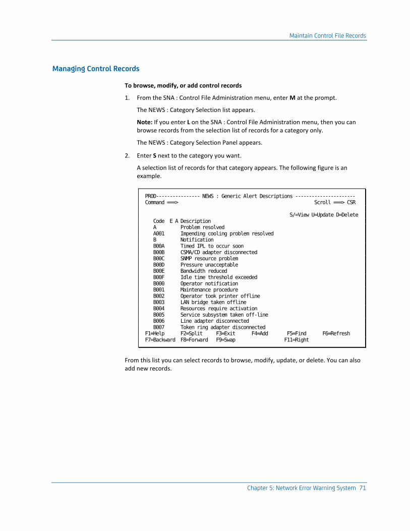
Maintain Control File Records
Chapter 5: Network Error Warning System 71
Managing Control Records
To browse, modify, or add control records
1. From the SNA : Control File Administration menu, enter M at the prompt.
The NEWS : Category Selection list appears.
Note: If you enter L on the SNA : Control File Administration menu, then you can browse records from the selection list of records for a category only.
The NEWS : Category Selection Panel appears.
2. Enter S next to the category you want.
A selection list of records for that category appears. The following figure is an example.
PROD---------------- NEWS : Generic Alert Descriptions ---------------------- Command ===> Scroll ===> CSR S/=View U=Update D=Delete Code E A Description A Problem resolved A001 Impending cooling problem resolved B Notification B00A Timed IPL to occur soon B00B CSMA/CD adapter disconnected B00C SNMP resource problem B00D Pressure unacceptable B00E Bandwidth reduced B00F Idle time threshold exceeded B000 Operator notification B001 Maintenance procedure B002 Operator took printer offline B003 LAN bridge taken offline B004 Resources require activation B005 Service subsystem taken off-line B006 Line adapter disconnected B007 Token ring adapter disconnected F1=Help F2=Split F3=Exit F4=Add F5=Find F6=Refresh F7=Backward F8=Forward F9=Swap F11=Right
From this list you can select records to browse, modify, update, or delete. You can also add new records.
Maintain Control File Records
72 Administration Guide
Add Control Records
To add control records
1. Press F4 (Add).
A panel for record details of that type appears in Add mode.
2. Enter details of the new record. For more information about how to define each type of record, press F1 (Help).
3. Press F3 (File).
The control records are saved.
Note: Control records are stored in the Network Services Control File (NSCNTL), which can be shared between multiple regions. Before you update records, you must open the file for update and limit it to one region.
Browse Control Records
To browse a record from the selection list of records for a category
1. Enter S next to the record.
The selected record appears in Browse mode.
Modify Control Records
To modify control records
1. To modify a record from the selection list of records for a category, enter U next to it.
The selected record appears in Update mode.
2. Modify the record as required. For more information about how to modify each type of record, press F1 (Help).
3. Press F3.
The changes are filed.
Delete Control Records
To delete control records
1. Enter D next to the record you want to delete.
A message appears, asking you to confirm your delete request.
2. Press Enter to confirm your delete request or F12 to cancel the request.
Alias Name Translation Facility
Chapter 5: Network Error Warning System 73
Alias Name Translation Facility
NEWS provides VTAM alias name translation services for those levels of VTAM that require this function. VTAM requests alias name translation if the CNM Routing table entry for the CNM ACB contains the translate-inquiry RU. When establishing cross-domain or cross-network sessions, VTAM can request the translation of LU names, COS names, and LOGMODE names.
Generic name definitions allow ranges of names to be translated by NEWS from a single translation definition. You display and maintain translation definitions by using NEWS commands.
More information:
Advanced Configuration Tasks (see page 129)
Reviewing and Reporting on Data
After data has been filtered and recorded in the NEWS database, you can review it by using the NEWS menus and full-screen panels, or have it exported to a data set for analysis by external applications.
If you want to analyze or report on NEWS data using an external application, do one of the following:
■ Use the supplied user exits to archive all required records to a sequential data set.
■ Generate SMF records by activating SMF recording.
If required, you can enable the generation of type 37 SMF records for all event, attention, and statistics records that pass NEWS filtering.
NEWS also provides predefined reports. For more information about these reports, see the User Guide.
Maintain the NEWS Database
74 Administration Guide
Maintain the NEWS Database
The NEWS Control Functions let you set NEWS parameters and tune the various features of NEWS after you have installed NEWS.
You can improve the capacity of the NEWS database by deleting database records or by reclaiming unused VSAM space.
The Database Maintenance panel lets you delete specific records from the database, delete all records, or perform a manual reorganization of the database to reclaim VSAM space.
Implement CNMPROC Logging Options
The CNMLOGGING parameter group lets you turn logging on and off for the NEWS database and to define what is to happen if the NEWS database is filled:
■ Logging a reminder message after a specified number of lost records
■ Whether to automatically reorganize the NEWS database
To implement the CNMPROC logging options
1. Enter /PARMS at the prompt.
The Parameter Groups panel appears.
2. Enter U beside the CNMLOGGING parameter group.
The CNMLOGGING - NEWS Database Logging Options panel appears. This panel has two pages that you can scroll through to define CNMPROC logging options.
3. Complete the following fields:
Logging Active?
Enter NO to suspend logging, or YES to resume logging.
Lost Record Reminder
Specify what is to happen if the NEWS database is full.
Auto-reorg?
Specify what is to happen if the NEWS database is full.
For more information about the fields, press F1 (Help).
4. Press F6 (Action).
The entries are actioned.
5. Press F3 (File).
The settings are saved.
Maintain the NEWS Database
Chapter 5: Network Error Warning System 75
Access Database Maintenance
The NEWS : Database Maintenance panel lets you do the following:
■ Delete specified records
■ Delete all records
■ Perform a reorganization of the NEWS database.
To access Database Maintenance
1. Enter /SNADBA at the prompt.
The NEWS : Database Maintenance menu appears.
2. Specify the parameters that you want to delete.
Delete Records Generically by Date and Node
To delete specified records generically from the NEWS : Database Maintenance menu
1. Choose option 1 - Delete Records Generically by Date and/or Node.
2. Complete the following fields:
Keep Date
Specify a date to delete any records that arrive before the specified date. For more information about date formats, press F1 (Help).
Node Name
Specify one of the following:
■ A node name
■ A generic node name, by typing a generic node name and the wild character *
■ All nodes, by typing the wild character *
Delete Masters
Type Y to delete master and detail records, or N to delete detail records only.
The Master record contains information, in a record category for a specific node, about when detailed records were collected, the record count, and the record collection period.
Detail records contain detailed information for a specific node.
A panel appears showing the number of detail records deleted, the number of master records updated, and the number of master records deleted.
Note: If you deleted large numbers of records, we suggest that you perform a database reorganization (see page 76) to reclaim unused VSAM space.
Maintain the NEWS Database
76 Administration Guide
Delete All Records
To delete all records from the NEWS database
1. From the NEWS : Database Maintenance menu, choose option 2 - Delete All NEWS Database Records.
A confirmation message appears.
Note: After clearing the database, it is recommended that you perform a database (see page 76) reorganization (see page 76) to reclaim unused VSAM space.
Reorganize the NEWS Database
Reorganizing the NEWS database lets you reclaim any unused VSAM space.
Note: NEWS can perform automatic database reorganization if you enable the Auto Re-org facility by using the CNMLOGGING - NEWS Database Logging Options panel.
Before you reorganize the database, ensure you have appropriate VSAM definitions.
To reorganize the NEWS database
1. Review the VSAM cluster definition of NEWSFILE on the NEWS - NEWS File Specifications parameter group panel and ensure that the NEWSFILE is defined with the REUSE option. For some levels of VSAM, this is possible where the data set has been sub-allocated only.
2. Review the backup file (NEWSBKP) definition on the NEWS - NEWS File Specifications panel and ensure that the backup data set is large enough to contain all database records.
3. Go to OCS (=O) and enter SHOW UDBUSERS to check that the NEWSFILE ID is not being used (see page 76).
Release the NEWSFILE from CNMPROC
The NEWSFILE file ID would normally be in use by CNMPROC and any users currently using NEWS options involving access to the database. Certain options, such as the System Support Services menu, are entered without allocating the file until a specific requests required its use.
You can release the NEWSFILE from CNMPROC by suspending database logging, using the CNMLOGGING parameter group.
Maintain the NEWS Database
Chapter 5: Network Error Warning System 77
Reorganize the Database Manually
This action invokes NCL procedure $NWCNMRO, which builds IDCAMS control statements and calls the utility program UTIL0007 to attach IDCAMS and perform the actual reorganization.
To manually reorganize the NEWS database
1. From the NEWS : Database Maintenance menu, choose option 3 - Perform Re-org of the NEWS Database.
A confirmation message appears.
Note: If the reorganization is unsuccessful, determine the reason for the failure by referring to the message issued to the activity log.
2. Restart CNMPROC or reactivate database logging by using the CNMLOGGING - NEWS Database Logging Options parameter group panel.

Chapter 6: Network Tracking System 79
Chapter 6: Network Tracking System
This section contains the following topics:
Data Available to NTS (see page 79) How NTS Obtains Data (see page 82) Define NTS Classes (see page 84) Set NTS System Parameters (see page 95) Network Definitions and Names Used by NTS (see page 108) System Resource Utilization (see page 108) How Session Start Notification Works (see page 108) Output Processing (see page 109) System Event Generation (see page 110) NTS Database (see page 110) MAI Support (see page 112)
Data Available to NTS
The primary objects that concern NTS are network-addressable units, also called resources, and sessions between these resources. The resources can be in the same domain, in different domains, or even in different networks.
The following data types are available to NTS:
■ Session awareness (SAW) data, which consists of session start and session end notifications from VTAM
■ Session data that contains information about the performance and status of a session, including the following:
– Session trace data
– Response time data
– Route configuration data
Session Awareness Data
VTAM supplies NTS Session Awareness (SAW) data relating to sessions that the local SSCP maintains. This includes data about SSCP-SSCP, SSCP-PU, SSCP-LU, LU-LU and CP-CP sessions.
If linked to other NTS regions, NTS can also receive SAW data from VTAMs in remote domains.
Data Available to NTS
80 Administration Guide
Composition
SAW data consists of the following data:
Session Identification Data
Includes the following:
■ Session partner names (or aliases, if applicable) and addresses
■ PCIDs
■ Session start and end time
■ Session type and class (such as: same domain, cross domain)
Session Connectivity Data
Includes the following:
■ Explicit Route (ER)
■ Virtual Route (VR) and Transmission Priority (TP) that the session is using
■ Logmode and Class of Service (CoS) table entries the session is using
Session Hierarchy Data
Includes the following:
■ Controlling PU name
■ Link name, and subarea PU name (where relevant) for each session partner resource
Session Exception Data
Includes the following:
■ Sense codes describing any error conditions that occurred while the session was in progress
Session Trace Data
Through NTS, you can issue requests to VTAM to start tracing sessions that involve resources in the local VTAM domain. As a result, NTS receives trace data from VTAM and associates it with session records in storage. NTS can also solicit trace data collected by VTAMs in other, linked NTS regions.
Data Available to NTS
Chapter 6: Network Tracking System 81
Composition
Trace data consists of copies of Path Information Units (PIUs) that flow on traced sessions. PIUs are message units that comprise the following:
■ A Transmission Header (TH)
■ A Request/response Header (RH)
■ Any Request/response Unit (RU)
For session control RUs, the entire RU is included; otherwise, for performance reasons, only the first 11 bytes are retained.
For more information about how to obtain extended trace information, see the STRACE command description in the online help.
Response Time Monitoring Data
Response Time Monitoring (RTM) data is a measure of how long it takes for an operation to transmit between a display station and a host.
NTS obtains the response time information from the cluster controller at session end, then associates the response time obtained for a display station with the session record in storage.
Note: For RTM data to be available to NTS, the cluster controller must support host programming.
The cluster controller sends solicited and unsolicited data to NTS. This data originates from PUs that implement RTM (3x74s or equivalent) for their attached LUs.
NTS can also solicit RTM data collected by other NTS regions.
Composition
RTM data received from the cluster controller consists of the following:
Boundary Values in Seconds
These boundaries demarcate buckets into which individual response times are counted; an overflow bucket is also provided.
Bucket Counts
These counts represent the total number of response times in the specified boundaries since the beginning of the session, or since the response times were last reset.
How NTS Obtains Data
82 Administration Guide
Route Configuration Data
NTS receives solicited and unsolicited route configuration data from VTAM and other subarea nodes. You can dynamically request ER and VR configuration information from subarea nodes visible to NTS.
Composition
Route configuration information includes the following:
■ Source, destination, and adjacent subarea numbers
■ Source, destination, and adjacent control point names if the session involves APPN
■ The status of the ER, VR, and TP
■ Session route information for the current APPN subnetwork if available
How NTS Obtains Data
NTS derives its data from the following sources:
■ Standard host access method interfaces (VTAM)
■ Other NTS regions
■ The Multiple Application Interface (MAI) component of CA SOLVE:Access
VTAM Interfaces
VTAM is aware of all sessions that have at least one session partner defined in its domain. These sessions are presented to the local NTS region across a VTAM interface, resulting in NTS building up an image of the logical network activity in this domain.
VTAM interfaces to NTS include the following:
■ A CNM interface, through which NTS requests are issued to VTAM, and RTM, VR, and ER information is collected
■ A local VTAM interface (ISTPDCLU), through which the following sessions are conducted:
– An LU-LU session with VTAM for the collection of SAW data (and some route configuration data)
– An LU-LU session with VTAM for the collection of session trace data
How NTS Obtains Data
Chapter 6: Network Tracking System 83
Intersystem Routing
NTS uses the Intersystem Routing (ISR) feature to obtain more information about cross-domain and cross-network sessions.
VTAM is only aware of sessions that have at least one session partner defined in its domain. It is possible to centralize (or distribute) the monitoring of logical network activity by expanding the sources of data available to an NTS regions to include the following:
■ SAW data collected by NTS regions in other domains
■ Session trace, accounting, and RTM data collected by NTS regions in other domains
In a cross-network environment, extra configuration data relating to cross-network sessions is made available to the host that controls the SNA gateway. This data includes network addresses and route information for sessions in the adjacent network.
To make the most effective use of NTS, you must run NTS on the gateway host. Use ISR to link other NTS regions to the gateway host NTS region. This ensures that NTS has maximum accessibility to all session data.
The other NTS regions may or may not be in the same SNA network.
The user of an NTS region that is linked to other NTS regions is presented with a single image of the following:
■ Sessions between resources throughout the networks
■ Performance and problem determination data collected for these sessions
This single image is preserved in the NTS database and NTS SMF exit.
More information:
Enable Multisystem Support (see page 130) How NTS-SI Works (see page 247)
MAI Sessions
MAI is a component of CA SOLVE:Access that lets you operate multiple sessions concurrently.
MAI provides NTS with information about the logical relationship between the real half-sessions that form the MAI virtual session. When the MAI/NTS interface is first activated, MAI provides NTS with this information for all currently existing MAI sessions. MAI then notifies NTS as new MAI sessions are started.
Define NTS Classes
84 Administration Guide
More information:
MAI Support (see page 112)
Collect NTS Data
Before you can productively use NTS, you must activate session awareness processing. If session awareness processing is not activated, no NTS data is collected. The NTS function then available is the review of historical information in the NTS database only.
Open the VTAM CNM Interface
NTS uses the CNM interface to transmit various commands to VTAM and to receive solicited and unsolicited data from VTAM. You must open the CNM ACB before you can start session awareness processing.
Note: The CNM interface is primarily used by NEWS.
To open the CNM ACB, use the CNM parameter group.
Enable NTS Session Awareness
Before NTS can process session awareness data, it must establish a session with VTAM.
After a session is established between NTS and VTAM, VTAM sends session start notifications for all currently active sessions to NTS. This is the start of NTS session awareness and is termed a warm start. From this point, VTAM sends session start and session end notifications to NTS as they occur for as long as session awareness remains active.
Define NTS Classes
Processing performed by NTS is determined by class definitions.
In a given network, there are various different types of sessions and resources. You may want NTS to collect specific types and amounts of data for each different session type, and require different forms of processing for different session types. You may also want to map session data to the underlying resource hierarchy.
Define NTS Classes
Chapter 6: Network Tracking System 85
You can achieve these objectives by defining the following types of NTS classes to suit your installation needs:
■ Session classes
■ Resource classes
■ SAW classes
■ RTM classes
By default, only SAW data is collected, and for all sessions, which may not suit your installation. No accounting, RTM, or resource statistics data is collected until you define your classes.
More information:
Understanding the Session Awareness Interface (see page 231)
Specify the DEFCLASS Command
To define the attributes of the various categories or classes of session that control how NTS is to collect and process data, use the DEFCLASS command.
For more information about the attributes used to set up the class definitions, see the online help.
To define classes
1. Decide which classes you need and the attributes each class should have.
2. Specify the DEFCLASS SESSION, RESOURCE, SAW, and RTM commands, and appropriate operand values in your initialization procedure (normally $NSINIT).
3. Periodically review the data collected by NTS and adjust any class definitions to suit new requirements.
To subsequently add class definitions, issue a DEFCLASS command from OCS. You must enter all operands, except those that have default values. If you do this while the region is running, the new class definitions do not affect any existing sessions NTS is aware of but are used by any new sessions.
Define NTS Classes
86 Administration Guide
Define Session Classes
Session class definitions provide the following:
■ The session selection criteria that determine to which session class each session belongs
■ The names of SAW and RTM classes from which the member sessions derive their SAW and RTM class values
Each session class definition contains the following information:
■ A unique session class identification name
■ Parameters that a session must match, to be considered a member of this session class:
– Full and partial names of primary and secondary resources
– The subarea and APPN COS (Class-Of-Service) name for the session
– An explicit route number and a virtual route number
– A subarea and an APPN transmission priority
– The session type and class
– The source of the session
– An SSCP name (identifying the domain of origin of the session)
■ The names of the SAW and RTM class definitions that can be used by sessions in this class
Valid characters for operands in session classes include the following:
Character Description
* Can be used in any position to represent a single wild character.
> Can be used as a suffix to indicate one or more trailing wild characters.
- Can be used as a suffix (for an LU only) to indicate one or more trailing wild characters for LU names that are not displayed.
Note: If any session class selection operands are omitted, any value of the omitted parameter is considered valid. For example, if no PRI operand is specified, any primary name is considered valid.
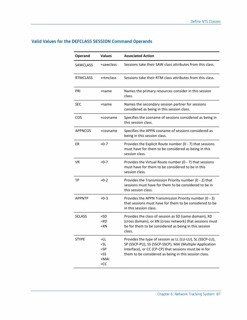
Define NTS Classes
Chapter 6: Network Tracking System 87
Valid Values for the DEFCLASS SESSION Command Operands
Operand Values Associated Action
SAWCLASS =sawclass Sessions take their SAW class attributes from this class.
RTMCLASS =rtmclass Sessions take their RTM class attributes from this class.
PRI =name Names the primary resources consider in this session class.
SEC =name Names the secondary session partner for sessions considered as being in this session class.
COS =cosname Specifies the cosname of sessions considered as being in this session class.
APPNCOS =cosname Specifies the APPN cosname of sessions considered as being in this session class.
ER =0-7 Provides the Explicit Route number (0 - 7) that sessions must have for them to be considered as being in this session class.
VR =0-7 Provides the Virtual Route number (0 - 7) that sessions must have for them to be considered to be in this session class.
TP =0-2 Provides the Transmission Priority number (0 - 2) that sessions must have for them to be considered to be in this session class.
APPNTP =0-3 Provides the APPN Transmission Priority number (0 - 3) that sessions must have for them to be considered to be in this session class.
SCLASS =SD =XD =XN
Provides the class of session as SD (same domain), XD (cross domain), or XN (cross network) that sessions must be for them to be considered as being in this session class.
STYPE =LL =SL =SP =SS =MAI =CC
Provides the type of session as LL (LU-LU), SL (SSCP-LU), SP (SSCP-PU), SS (SSCP-SSCP), MAI (Multiple Application Interface), or CC (CP-CP) that sessions must be in for them to be considered as being in this session class.
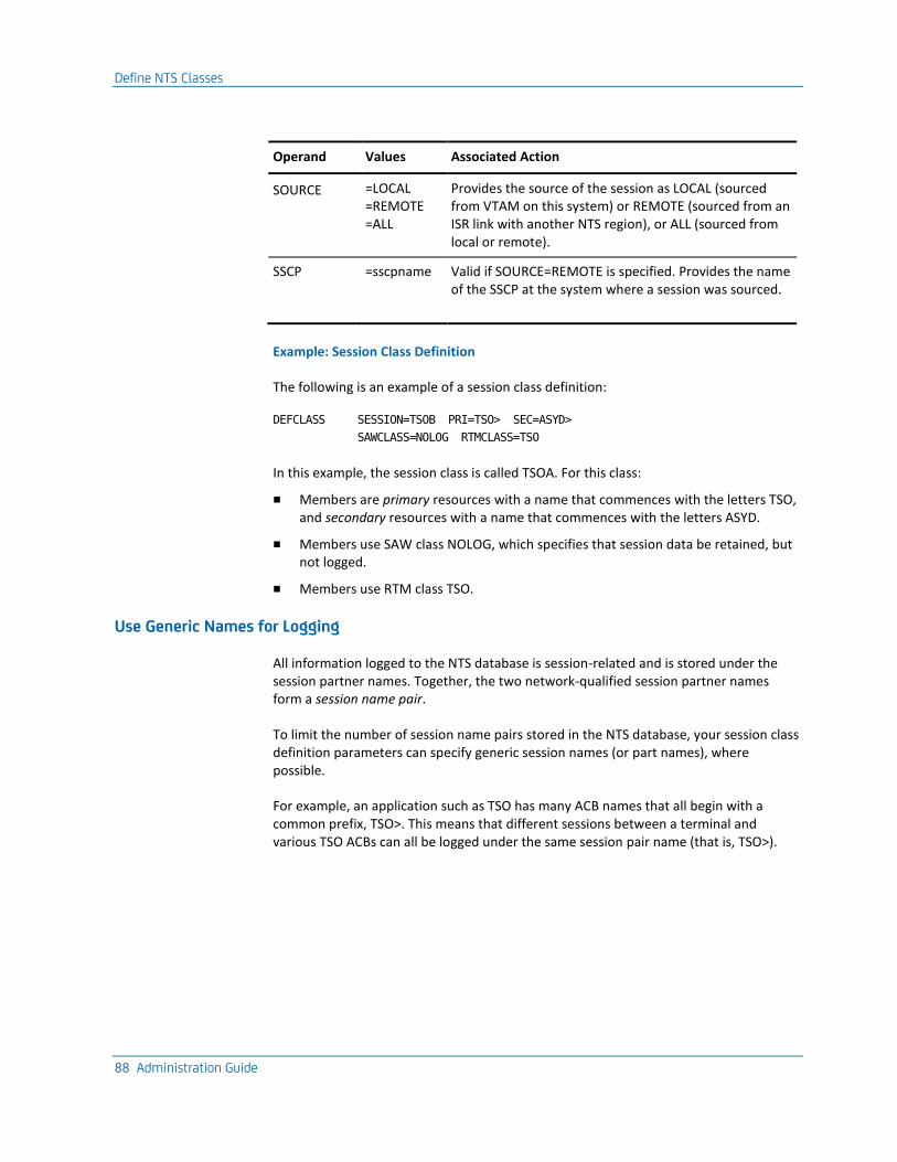
Define NTS Classes
88 Administration Guide
Operand Values Associated Action
SOURCE =LOCAL =REMOTE =ALL
Provides the source of the session as LOCAL (sourced from VTAM on this system) or REMOTE (sourced from an ISR link with another NTS region), or ALL (sourced from local or remote).
SSCP =sscpname Valid if SOURCE=REMOTE is specified. Provides the name of the SSCP at the system where a session was sourced.
Example: Session Class Definition
The following is an example of a session class definition:
DEFCLASS SESSION=TSOB PRI=TSO> SEC=ASYD>
SAWCLASS=NOLOG RTMCLASS=TSO
In this example, the session class is called TSOA. For this class:
■ Members are primary resources with a name that commences with the letters TSO, and secondary resources with a name that commences with the letters ASYD.
■ Members use SAW class NOLOG, which specifies that session data be retained, but not logged.
■ Members use RTM class TSO.
Use Generic Names for Logging
All information logged to the NTS database is session-related and is stored under the session partner names. Together, the two network-qualified session partner names form a session name pair.
To limit the number of session name pairs stored in the NTS database, your session class definition parameters can specify generic session names (or part names), where possible.
For example, an application such as TSO has many ACB names that all begin with a common prefix, TSO>. This means that different sessions between a terminal and various TSO ACBs can all be logged under the same session pair name (that is, TSO>).
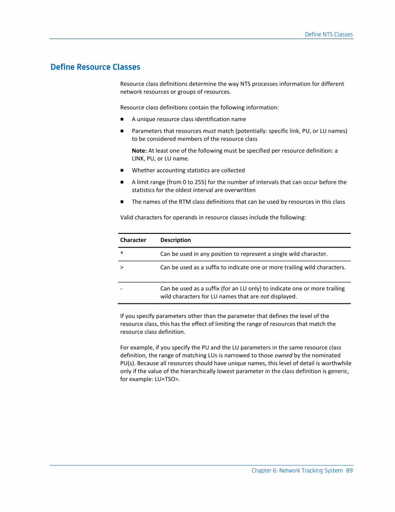
Define NTS Classes
Chapter 6: Network Tracking System 89
Define Resource Classes
Resource class definitions determine the way NTS processes information for different network resources or groups of resources.
Resource class definitions contain the following information:
■ A unique resource class identification name
■ Parameters that resources must match (potentially: specific link, PU, or LU names) to be considered members of the resource class
Note: At least one of the following must be specified per resource definition: a LINK, PU, or LU name.
■ Whether accounting statistics are collected
■ A limit range (from 0 to 255) for the number of intervals that can occur before the statistics for the oldest interval are overwritten
■ The names of the RTM class definitions that can be used by resources in this class
Valid characters for operands in resource classes include the following:
Character Description
* Can be used in any position to represent a single wild character.
> Can be used as a suffix to indicate one or more trailing wild characters.
- Can be used as a suffix (for an LU only) to indicate one or more trailing wild characters for LU names that are not displayed.
If you specify parameters other than the parameter that defines the level of the resource class, this has the effect of limiting the range of resources that match the resource class definition.
For example, if you specify the PU and the LU parameters in the same resource class definition, the range of matching LUs is narrowed to those owned by the nominated PU(s). Because all resources should have unique names, this level of detail is worthwhile only if the value of the hierarchically lowest parameter in the class definition is generic, for example: LU=TSO>.
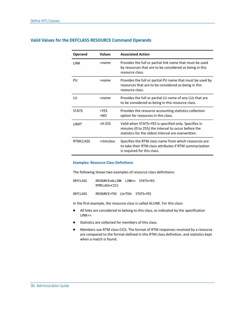
Define NTS Classes
90 Administration Guide
Valid Values for the DEFCLASS RESOURCE Command Operands
Operand Values Associated Action
LINK =name Provides the full or partial link name that must be used by resources that are to be considered as being in this resource class.
PU =name Provides the full or partial PU name that must be used by resources that are to be considered as being in this resource class.
LU =name Provides the full or partial LU name of any LUs that are to be considered as being in this resource class.
STATS =YES =NO
Provides the resource accounting statistics collection option for resources in this class.
LIMIT =0-255 Valid when STATS=YES is specified only. Specifies in minutes (0 to 255) the interval to occur before the statistics for the oldest interval are overwritten.
RTMCLASS =rtmclass Specifies the RTM class name from which resources are to take their RTM class attributes if RTM summarization is required for this class.
Examples: Resource Class Definitions
The following shows two examples of resource class definitions:
DEFCLASS RESOURCE=ALLINK LINK=> STATS=YES
RTMCLASS=CICS
DEFCLASS RESOURCE=TSO LU=TSO> STATS=YES
In the first example, the resource class is called ALLINK. For this class:
■ All links are considered to belong to this class, as indicated by the specification LINK=>.
■ Statistics are collected for members of this class.
■ Members use RTM class CICS. The format of RTM responses received by a resource are compared to the format defined in this RTM class definition, and statistics kept when a match is found.
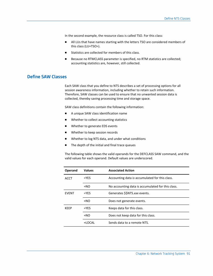
Define NTS Classes
Chapter 6: Network Tracking System 91
In the second example, the resource class is called TSO. For this class:
■ All LUs that have names starting with the letters TSO are considered members of this class (LU=TSO>).
■ Statistics are collected for members of this class.
■ Because no RTMCLASS parameter is specified, no RTM statistics are collected; accounting statistics are, however, still collected.
Define SAW Classes
Each SAW class that you define to NTS describes a set of processing options for all session awareness information, including whether to retain such information. Therefore, SAW classes can be used to ensure that no unwanted session data is collected, thereby saving processing time and storage space.
SAW class definitions contain the following information:
■ A unique SAW class identification name
■ Whether to collect accounting statistics
■ Whether to generate EDS events
■ Whether to keep session records
■ Whether to log NTS data, and under what conditions
■ The depth of the initial and final trace queues
The following table shows the valid operands for the DEFCLASS SAW command, and the valid values for each operand. Default values are underscored.
Operand Values Associated Action
ACCT =YES Accounting data is accumulated for this class.
=NO No accounting data is accumulated for this class.
EVENT =YES Generates $$NTS.xxx events.
=NO Does not generate events.
KEEP =YES Keeps data for this class.
=NO Does not keep data for this class.
=LOCAL Sends data to a remote NTS.
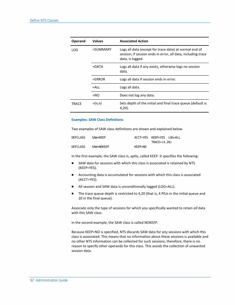
Define NTS Classes
92 Administration Guide
Operand Values Associated Action
LOG =SUMMARY Logs all data (except for trace data) at normal end of session; if session ends in error, all data, including trace data, is logged.
=DATA Logs all data if any exists, otherwise logs no session data.
=ERROR Logs all data if session ends in error.
=ALL Logs all data.
=NO Does not log any data.
TRACE =(n,n) Sets depth of the initial and final trace queue (default is 4,20).
Examples: SAW Class Definitions
Two examples of SAW class definitions are shown and explained below.
DEFCLASS SAW=KEEP ACCT=YES KEEP=YES LOG=ALL
TRACE=(4,20)
DEFCLASS SAW=NOKEEP KEEP=NO
In the first example, the SAW class is, aptly, called KEEP. It specifies the following:
■ SAW data for sessions with which this class is associated is retained by NTS (KEEP=YES).
■ Accounting data is accumulated for sessions with which this class is associated (ACCT=YES).
■ All session and SAW data is unconditionally logged (LOG=ALL).
■ The trace queue depth is restricted to 4,20 (that is, 4 PIUs in the initial queue and 20 in the final queue).
Associate only the type of sessions for which you specifically wanted to retain all data with this SAW class.
In the second example, the SAW class is called NOKEEP.
Because KEEP=NO is specified, NTS discards SAW data for any sessions with which this class is associated. This means that no information about these sessions is available and no other NTS information can be collected for such sessions; therefore, there is no reason to specify other operands for this class. This avoids the collection of unwanted session data.
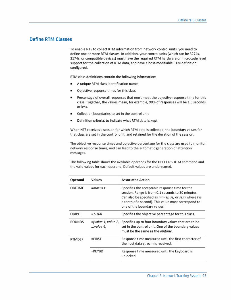
Define NTS Classes
Chapter 6: Network Tracking System 93
Define RTM Classes
To enable NTS to collect RTM information from network control units, you need to define one or more RTM classes. In addition, your control units (which can be 3274s, 3174s, or compatible devices) must have the required RTM hardware or microcode level support for the collection of RTM data, and have a host-modifiable RTM definition configured.
RTM class definitions contain the following information:
■ A unique RTM class identification name
■ Objective response times for this class
■ Percentage of overall responses that must meet the objective response time for this class. Together, the values mean, for example, 90% of responses will be 1.5 seconds or less.
■ Collection boundaries to set in the control unit
■ Definition criteria, to indicate what RTM data is kept
When NTS receives a session for which RTM data is collected, the boundary values for that class are set in the control unit, and retained for the duration of the session.
The objective response times and objective percentage for the class are used to monitor network response times, and can lead to the automatic generation of attention messages.
The following table shows the available operands for the DEFCLASS RTM command and the valid values for each operand. Default values are underscored.
Operand Values Associated Action
OBJTIME =mm:ss.t Specifies the acceptable response time for the session. Range is from 0.1 seconds to 30 minutes. Can also be specified as mm:ss, ss, or ss:t (where t is a tenth of a second). This value must correspond to one of the boundary values.
OBJPC =1-100 Specifies the objective percentage for this class.
BOUNDS =(value 1, value 2, ...value 4)
Specifies up to four boundary values that are to be set in the control unit. One of the boundary values must be the same as the objtime.
RTMDEF =FIRST Response time measured until the first character of the host data stream is received.
=KEYBD Response time measured until the keyboard is unlocked.
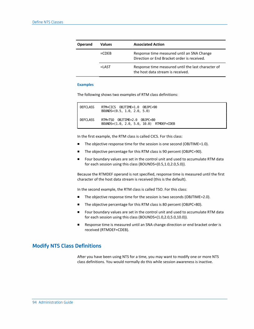
Define NTS Classes
94 Administration Guide
Operand Values Associated Action
=CDEB Response time measured until an SNA Change Direction or End Bracket order is received.
=LAST Response time measured until the last character of the host data stream is received.
Examples
The following shows two examples of RTM class definitions:
DEFCLASS RTM=CICS OBJTIME=1.0 OBJPC=90 BOUNDS=(0.5, 1.0, 2.0, 5.0)
DEFCLASS RTM=TSO OBJTIME=2.0 OBJPC=80 BOUNDS=(1.0, 2.0, 5.0, 10.0) RTMDEF=CDEB
In the first example, the RTM class is called CICS. For this class:
■ The objective response time for the session is one second (OBJTIME=1.0).
■ The objective percentage for this RTM class is 90 percent (OBJPC=90).
■ Four boundary values are set in the control unit and used to accumulate RTM data for each session using this class {BOUNDS=(0.5,1.0,2.0,5.0)}.
Because the RTMDEF operand is not specified, response time is measured until the first character of the host data stream is received (this is the default).
In the second example, the RTM class is called TSO. For this class:
■ The objective response time for the session is two seconds (OBJTIME=2.0).
■ The objective percentage for this RTM class is 80 percent (OBJPC=80).
■ Four boundary values are set in the control unit and used to accumulate RTM data for each session using this class (BOUNDS=(1.0,2.0,5.0,10.0)).
■ Response time is measured until an SNA change direction or end bracket order is received (RTMDEF=CDEB).
Modify NTS Class Definitions
After you have been using NTS for a time, you may want to modify one or more NTS class definitions. You would normally do this while session awareness is inactive.
Set NTS System Parameters
Chapter 6: Network Tracking System 95
Display Definitions
To display NTS class definitions
1. Use the SHOW DEFCLASS command.
2. Specify the type of class or classes you want to display—session, SAW, RTM, or resource—and, if you want to limit the display, the class name or partial name.
Example: Display Definitions
This is an example of the use of the SHOW DEFCLASS command.
SHOW DEFCLASS RTM=CICS
All RTM classes starting with the letters CICS are listed.
Update Class Definitions
To replace or delete class definitions, use the REPCLASS and DELCLASS commands.
To change one or more attributes of a class, use the REPCLASS command to redefine the entire class. This command shares the same operands as the DEFCLASS command.
Example: Update Class Definitions
To delete the RTM class called CICS, issue the following command:
DELCLASS RTM=CICS
Set NTS System Parameters
NTS system parameters are used to do the following:
■ Define the NTS environment to VTAM.
■ Specify global data collection options.
■ Optimize NTS performance characteristics.
■ Enable and disable data collection interfaces.
■ Enable and disable NTS outputs.
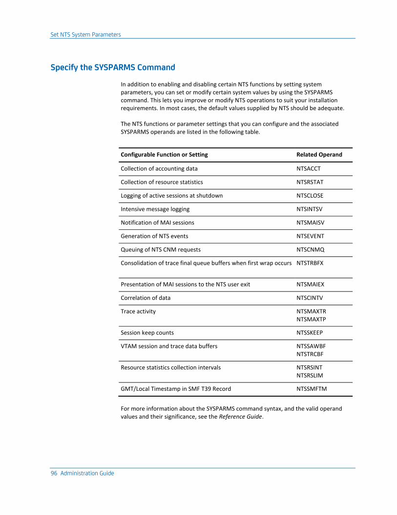
Set NTS System Parameters
96 Administration Guide
Specify the SYSPARMS Command
In addition to enabling and disabling certain NTS functions by setting system parameters, you can set or modify certain system values by using the SYSPARMS command. This lets you improve or modify NTS operations to suit your installation requirements. In most cases, the default values supplied by NTS should be adequate.
The NTS functions or parameter settings that you can configure and the associated SYSPARMS operands are listed in the following table.
Configurable Function or Setting Related Operand
Collection of accounting data NTSACCT
Collection of resource statistics NTSRSTAT
Logging of active sessions at shutdown NTSCLOSE
Intensive message logging NTSINTSV
Notification of MAI sessions NTSMAISV
Generation of NTS events NTSEVENT
Queuing of NTS CNM requests NTSCNMQ
Consolidation of trace final queue buffers when first wrap occurs NTSTRBFX
Presentation of MAI sessions to the NTS user exit NTSMAIEX
Correlation of data NTSCINTV
Trace activity NTSMAXTR NTSMAXTP
Session keep counts NTSSKEEP
VTAM session and trace data buffers NTSSAWBF NTSTRCBF
Resource statistics collection intervals NTSRSINT NTSRSLIM
GMT/Local Timestamp in SMF T39 Record NTSSMFTM
For more information about the SYSPARMS command syntax, and the valid operand values and their significance, see the Reference Guide.
Set NTS System Parameters
Chapter 6: Network Tracking System 97
Collect NTS Session Accounting Data
To enable the collection of NTS session accounting data, use the NTSACCT operand. Collection of this data can be selective (the default) or global.
When session awareness processing is active, you can specify NTSACCT=NO only.
To change to any other value
1. Stop session awareness.
2. Make the required modification.
3. Restart session awareness.
Selective Accounting
NTSACCT=SELECTIVE is set by default. This means that accounting data for a session is collected only if the DEFCLASS ACCT operand is set to YES in the SAW class definition associated with the session.
To collect NTS accounting data for a particular session class
1. Define an appropriate SAW class, with ACCT=YES specified.
2. Associate this SAW class with the session class, by specifying the SAW class as the value for the DEFCLASS SAWCLASS operand in the session class definition.
Global Accounting
If you enable or disable the accounting function globally, SAW class definition accounting options are ignored.
To enable or disable the accounting function globally, specify NTSACCT=ALL or NTSACCT=NO.
Set NTS System Parameters
98 Administration Guide
Collect NTS Resource Statistics
To enable the collection of NTS resource accounting and RTM statistics, use the NTSRSTAT operand. This operand globally enables or disables resource statistics collection when you specify a value of YES or NO. The default is NO.
Also consider the following actions:
■ Because NTS resource statistics are derived from session accounting data, ensure that NTSACCT=ALL is specified if you want resource accounting data collected.
■ There is a hierarchy governing statistics collection for resources:
– Collection must be enabled for the link used by a PU before statistics can be collected for the PU itself.
– Collection must be enabled for the owning PU before statistics can be collected for an LU.
■ If you specify NTSRSTAT=YES, but you do not want statistics collected for certain types of resources, specify STATS=NO in the resource class definitions for those types of resources.
■ If the resource statistics function is globally disabled, the NTS resource class statistics collection option is ignored.
■ When session awareness processing is active, you can disable resource statistics collection only.
To change from NTSRSTAT=NO to NTSRSTAT=YES
1. Stop session awareness.
2. Make the required change.
3. Restart session awareness.
Important! Carefully evaluate the requirements of your installation for resource statistics collection, because summarizing many resources may not give useful results and may adversely impact the performance of NTS.
Set NTS System Parameters
Chapter 6: Network Tracking System 99
Rules Governing Statistics Collection
The rules governing statistics collection are as follows:
■ To collect statistics for an LU, statistics collection must be enabled for the PU that owns the LU.
■ To collect statistics for a PU, statistics collection must be enabled for the link used by the PU.
■ Accounting statistics for resources above the LU level are summarized from statistics collected for resources directly below them in the hierarchy. That is, PU accounting statistics are derived from statistics collected for LUs owned by the PU. Link accounting statistics are derived from statistics accumulated for the PUs that use the link.
Where a resource class specifies that statistics are collected, NTS accumulates resource statistics for resources that match the class, at the level of the resource class. For example:
■ If the resource is an LU, and the selected resource class is at the LU level, statistics are collected for the specified LU in isolation.
■ If the resource is an LU, and the selected resource class is at the PU level, statistics are collected for the specified LU, and are added to statistics collected from peer LUs owned by the same PU, to form the statistics for the owning PU. Statistics are not retained for the LU alone.
Monitor NTS Resource Availability
If you have enabled the collection of statistics for a particular resource, NTS automatically uses SAW data to monitor the availability of that resource. A resource is considered available if it is participating in a session with the SSCP of the domain in which it is defined.
If NTS is monitoring resource availability, it automatically passes SMF records that indicate changes in the status of a resource to the NTS User Exit, if you have defined one.
Set NTS System Parameters
100 Administration Guide
Log Active Sessions at Shutdown
When your region is being shut down, all NTS activities must cease. It is likely that a number of sessions will be active and that session data collected by NTS for those sessions will not be logged.
To treat these residual sessions as ended for the purpose of logging, set the NTSCLOSE operand of the SYSPARMS command to YES. The sessions are queued for output processing and the NTS class definitions checked to determine whether logging is required.
Because there is only a small delay (approximately 10 seconds) between the time that NTS is notified of the impending shutdown and the actual termination of your region, this setting is useful only when the residual session count is small.
An alternative method of closing sessions is available through the SAWARE STOP CLOSE command.
Note: To improve performance during NTS logging, operate the NTS database using VSAM Local Shared Resources (LSR) and deferred I/O capabilities.
More information:
NTS Storage Estimates (see page 311)
Enable Intensive Message Recording
NTS receives large quantities of data from VTAM and may not process data that it cannot understand. For example, NTS cannot collect trace data indefinitely for a session of which it has no knowledge. As a result, at some stage it purges such data. At other times, NTS may receive data that is not in the expected format and this data is discarded. During normal operation, these kinds of data are purged on a regular basis and may go unreported by NTS.
If you suspect that data is missing, to aid problem detection, you can enable intensive message recording to see if NTS is discarding any data.
To enable intensive message recording, set the NTSINTSV operand to YES. This creates log messages whenever the conditions of data inconsistencies arise.
Set NTS System Parameters
Chapter 6: Network Tracking System 101
Enable MAI Session Visibility
To enable NTS to be aware of MAI sessions, specify NTSMAISV=YES (the default is NO).
For trace and accounting data to be available for an MAI session, collection must be requested for the primary half-session component of an MAI virtual session. When trace data is received for the primary half session and you have requested trace or accounting data collection for MAI sessions, NTS indicates that the MAI session has such data available. If you request the display of trace or accounting data for an MAI session, primary or secondary, then the data collected for the primary half session appears.
If you specify NTSMAISV=NO when the interface is already active, NTS retains knowledge of existing MAI sessions, but is not notified of any new MAI sessions.
Enable NTS Session Event Generation
To enable NTS event generation
1. Specify NTSEVENT=YES.
2. Ensure that appropriate SAW classes (with EVENT=YES specified) are defined for and associated with sessions for which events are generated.
Modify Processing for Active Sessions
After NTS has built a session record for an active session, the future processing for that session is fixed by the various values extracted from the matching class or classes. However, you may need to modify such processing options under certain circumstances, especially since sessions can remain active for extended periods.
To modify the processing options for an active session, use the NTSMOD command.
Set NTS System Parameters
102 Administration Guide
NTSMOD Command
The NTSMOD command lets you do the following:
■ Alter the trace queue depths; this can be useful, for example, if you want to collect more trace data for a session that is experiencing problems.
■ Modify the NTS log options to collect additional data for a session that is experiencing problems by doing the following:
– Logging all data when the session ends, regardless of the original SAW class log options
– Forcing the current data to be logged in its present form, for future reference (a historical record)
– Forcing the current session data to be presented to the NTS user exit instead of, or as well as, being logged to the NTS database
Example: NTSMOD Command
This is an example of the use of the NTSMOD command.
NTSMOD NAME=CICS TRACE=(4,50) LOG=FORCE
In this case, the following occurs:
■ The trace queue depth for sessions with the name CICS is modified.
■ Sessions with the name CICS are flagged for force-logging and immediately placed on the output queue. The currently stored session data is logged, while normal NTS processing of the session continues.
When you review CICS session data at a later stage, the display of an F next to the end time for each session on the NTS Session List Panel indicates that these sessions were force-logged before they ended.
For more information about the NTSMOD command and its operands, see the online help.
Note: If you issue the NTSMOD command with neither the TRACE nor the LOG operand specified, then the sessions specified by the NAME operand are listed, so that you can determine the scope of the command prior to making any modifications.
Set NTS System Parameters
Chapter 6: Network Tracking System 103
Set the Data Correlation Interval
One of the primary functions of NTS is to gather data from a number of sources and correlate it at session level.
The sequence in which data arrives and the interval between such arrivals, is beyond the control of NTS. Under certain circumstances, such as a network failure, anticipated data may not arrive.
To protect NTS from waiting indefinitely for such session data, there is an interval defined that represents the time limit for data correlation. The default correlation interval is 30 seconds.
To change the default correlation interval, use the NTSCINTV operand.
We recommend that the length of the correlation interval be kept constant throughout the network.
Limit NTS Trace Activity
The STRACE command is used to start and stop global or specific NTS tracing. This command provides operands that let you select the precise session trace activity that you want. For more information about these operands, see the online help.
Global tracing consumes large amounts of system resources. To avoid this, NTS provides parameters to limit the number of outstanding trace requests.
The PIU operand of the STRACE command lets you do a PARTIAL or FULL tracing. In most instances, PARTIAL tracing provides sufficient data for problem determination.
Important! Before you issue a request to trace a complete RU from VTAM, take note that an RU can be very large.
Limit the Number of Concurrent Traces
To set the maximum number of specific trace requests that can be outstanding at any time, specify the limit in the value of the SYSPARMS NTSMAXTR operand.
■ This value includes the following requests:
■ Specific trace start requests (even if these are pending)
■ When global tracing is active, specific trace stop requests
■ Any specific trace requests started by the NTS selective accounting function, which operate automatically if you specify ACCT=YES in a SAW class definition.
NTS rejects any attempt to issue a specific trace request that would result in the value set for NTSMAXTR being exceeded.
Set NTS System Parameters
104 Administration Guide
Set Trace Limits
To impose limits on the number of specific trace requests that can be outstanding, use the NTSMAXTR operand.
Limit Trace PIU Collection
To set the trace queue depths for the initial and final trace queues for a session, set the values in your SAW class definitions. These values determine the maximum number of PIUs that can be stored for a session at any given time.
To override the values in the SAW definition, issue the SYSPARMS NTSMAXTP command.
Note: After you define values for NTSMAXTP, you cannot define a new SAW class with trace queue depths exceeding these values or change the trace queue depths of an existing SAW class to be greater than the values set for this system parameter.
Set Session Keep Counts
The session keep count refers to the number of session incidences that are stored concurrently in the NTS database for any session name pair. The default session keep count is 10.
To modify the default count, use the NTSSKEEP operand.
Note: The session keep count is used the first time a session incidence for a new name pair is written to the database only. The value is subsequently stored with the records in the database. To modify this value, use the NTSDBMOD command.
Set VTAM Session and Trace Data Buffer Allocations
When NTS session awareness processing begins, requests are sent to VTAM specifying the number and size of the buffers to allocate for the collection of session awareness and session trace data.
To modify these values, use the NTSSAWBF and NTSTRCBF operands.
Set NTS System Parameters
Chapter 6: Network Tracking System 105
Default Allocations
NTS allocates the following by default, which should be adequate for normal usage:
■ Two buffers of 4K each to accommodate the flow of session awareness data from VTAM
■ Four buffers of 4K each for the collection of session trace data
However, during times of exceptionally heavy trace activity, the allocation may be insufficient.
When These Allocations are Insufficient
If NTS cannot service the data buffers quickly enough, VTAM overwrites the data in the oldest, unprocessed buffer, with the result that you lose data. NTS can detect this data loss and notify operators by issuing a monitor message.
In times of intense system activity, you may lose some trace data in this way.
Overcoming the Problem
If buffer overrun conditions occur, allocate a larger number of smaller buffers, rather than a smaller number of larger buffers. If more buffers are available to VTAM, they are likely to be available to NTS at any time.
Other factors influence the delivery of data to NTS, especially the ability of the operating system to dispatch data. If its dispatching priority is too low, it may not be able to service large amounts of trace data in times of intensive activity. You need to check the dispatching priority and ensure that it is set just below that of VTAM.
Set NTS System Parameters
106 Administration Guide
Set Resource Statistics Collection Intervals
Resource statistics are collected and presented by NTS as counts of events that occurred in a specified time interval. Statistics gathered during different intervals can be compared for the purpose of network performance monitoring and analysis.
The valid range for the resource collection interval is 1 to 480 minutes (8 hours), and the default is 30 minutes.
To configure the duration of the interval, use the NTSRSINT operand to set the value you require.
To set the value of the number of intervals that can occur before NTS overwrites the statistics collected for the oldest interval, use the DEFCLASS RESOURCE LIMIT operand, or set the global default by using the SYSPARM NTSRSLIM operand. The valid range of values for this operand 0 to 255; the default is 16.
Important! High settings for this operand can consume large amounts of storage.
GMT/Local Timestamps in SMF Type 39 Records
All application timestamps records in type 39 SMF records consist of the first four bytes of the system TOD clock value, plus a 4-byte signed number for the time zone adjustment value, in seconds. By definition, the first four bytes represent GMT time in approximately 1-second intervals. However, Tivoli NetView (NLDM) writes the first four bytes of these timestamps in local time.
■ To write timestamps in type 39 SMF records in local time, specify NTSSMFTM=LOCAL.
■ To write timestamps in type 39 SMF records in GMT time, specify NTSSMFTM=GMT.
The default is GMT.
Set NTS System Parameters
Chapter 6: Network Tracking System 107
Maintain the NTS Database
To maintain the NTS database, use the NTSDBMOD command. This command lets you do the following:
■ Delete session records.
■ Alter session keep counts for sessions stored in the NTS database.
■ Cancel the execution of a previously issued NTSDBMOD command.
Example: Maintain the NTS Database
This is an example of the use of the NTSDBMOD command:
NTSDBMOD PRINAME=CICS KEEPDATE=01/03/31
In this case, all stored records for sessions with the primary name of CICS that predate April 1, 2001, are deleted.
For more information about the NTSDBMOD command and its operands, see the online help.
Modify the Database Session Keep Counts
After the first session incidence has been recorded for a session name pair, the master record contains the session keep count for that name pair.
To display this value, use the SHOW SKEEP command.
To modify this value, use the NTSDBMOD command.
To delete all records for the session name pair, including master and cross-reference records, set a new session keep count of zero in the NTSDBMOD command.
The NTSDBMOD command lets a generic name specification permit mass update and deletion with a single command.
Write NTS Records to SMF for Further Processing
You can convert NTS session records to SMF type 39 format to use the output in report-generating applications. To do this, you must specify the name of an NTS user exit in the SAW parameter group.
NTS automatically passes SMF-formatted records to this exit. The supplied exit can be customized to perform further processing of the data before the data is passed to SMF and finally to a report-generating application, such as SAS, to produce statistical reports based on the raw NTS data.
Network Definitions and Names Used by NTS
108 Administration Guide
More information:
NTS SMF Record Format (see page 297)
Network Definitions and Names Used by NTS
NTS does not require definitions of the network or VTAM environment in which it is executing. All such knowledge is derived by NTS through standard access method interfaces. NTS panels display the network ID for the host VTAM under which NTS runs.
Because NTS operates in SNA Network Interconnection (SNI) environments, all NTS resource names are qualified by the network name (that is, both the resource name and the network name are required to identify an SNA resource), and alias names are fully supported. The network in which NTS is executing is always the assumed default. Therefore, the use of network qualified names by NTS in a single network environment (or in the default network in an SNI environment) is totally transparent to the user.
System Resource Utilization
NTS defines buffer pools for allocating all resource records, session records, and trace data kept in virtual storage. No storage is allocated until NTS begins SAW processing. Storage allocation and NTS processing are carefully managed to produce low system overheads and paging rates. All NTS buffers are located above the 16MB line.
It is possible to retain all session information and to trace all session activity on most installations, with little or no loss of performance. This does, of course, depend on the extent of system resource consumption during network operation.
How Session Start Notification Works
As part of session start notification, the following processing occurs:
1. VTAM passes to NTS the SSCP name or names that identify the domain or domains in which the participating resources reside.
2. If either resource does not reside in the local domain, NTS determines whether an ISR link to the NTS in the other domain exists.
3. If there is a suitably configured link, NTS is able to solicit session data from the other domain; if not, data for the session will be incomplete.
4. NTS then proceeds to classify the session using the DEFCLASS session definitions to determine the DEFCLASS SAW definition that controls data retention and logging options.
Output Processing
Chapter 6: Network Tracking System 109
Output Processing
Session records can be queued for output processing by NTS for any of the following reasons:
■ Session start notification—applies only to sessions for which accounting information has been requested
■ Forced logging by an operator through an NTSMOD command
■ Session awareness close processing when CLOSE=ALL is specified on SAW STOP
■ Normal end-of-session processing
For sessions placed on the output queue, logging commences immediately after one of the following:
■ Session start notification (accounting information is logged)
■ Being force-logged by an operator
■ Being closed by session awareness close processing when WAIT=NO is specified on SAW STOP
How Session End Processing Works
All data associated with an active session is kept in storage until the session ends. When termination notification for a session is received from VTAM, NTS queues the session for output processing, which occurs as follows:
1. Firstly, NTS correlates all session data, such as session awareness data and any other statistical or problem-determination data, waiting for the correlation interval if necessary.
2. This final session data is then passed to a user exit, if one is active, and logged in the NTS database (unless the user exit suppresses logging).
3. When output processing is complete, the session data is purged from storage and is subsequently available (in the NTS database) as historical data only.
NTS User Exit Processing
If an exit is defined, all session records scheduled for logging (this is determined by the record type) are first passed to this exit. The exit can perform additional record processing, and can set a flag to indicate that the record be ignored by the subsequent NTS logging function.
More information:
Implementing the NTS User Exit (see page 289)
System Event Generation
110 Administration Guide
System Event Generation
Event Distribution Services (EDS) is a component that lets NCL procedures listen for and generate events.
If requested by SYSPARMS NTSEVENT and the SAW class definition, EDS generates events on behalf of NTS at the following times:
Time Event Name
At session start $$NTS.SESSION.START
At session end $$NTS.SESSION.END
On session failure $$NTS.SESSION.FAIL
When RTM objectives are exceeded $$NTS.RTM.OBJ.EXCEEDED
A data field containing all information relating to the session accompanies the event notification. Any SNA sense code supplied appears in the reference code field of the event notification.
NTS Database
All information logged to the NTS database is session-related and is stored under the session partner names. Together, the two network-qualified session partner names form a session name pair and each session logged in the database is termed a session incidence. For each session name pair, there exists a master and a cross-reference record, both of which are created when the first session for the name pair is logged to the database.
NTS Database
Chapter 6: Network Tracking System 111
Session Keep Counts and Database Slots
The session incidence count for any given session name pair is restricted by the session keep count. The default session keep count is 10, but this can be modified. This value is stored as part of the master record when the first session incidence for a session name pair is logged.
Each session incidence is allocated a single slot in the database. When a new session is due to be logged, the master record is checked to determine whether the number of slots used for the session name pair has reached the session keep count. If it has, the oldest session incidence data is overwritten; otherwise, a new database slot is allocated.
The advantage of database slots is that the key used to access session incidence data can be reused, which means that database maintenance is minimized. For example, if the database contains as much data as it is required to hold, then it can be used for session logging indefinitely without requiring reorganization. However, it takes some time before the database reaches such an ideal state.
Connect and Disconnect the NTS Database
For historical recording purposes, NTS session awareness data can be logged to the NTS database.
The SAWLOG parameter group lets you stop and start SAW logging on an ad-hoc basis, without needing to stop and start normal SAW processing.
Connect the NTS Database
To connect the NTS database
1. Enter /PARMS at the prompt.
The Parameter Groups panel appears.
2. Enter U beside the SAWLOG parameter group.
The SAWLOG - Session Awareness (SAW) Logging panel appears.
3. Enter Yes in the Logging Active? field, to start logging SAW records at any time after initialization. For more information about the fields, press F1 (Help).
4. Press F6 (Action).
The entries are actioned.
5. Press F3 (File).
The settings are saved.
MAI Support
112 Administration Guide
Disconnect the NTS Database
To disconnect the NTS database
1. Enter /PARMS at the prompt.
The Parameter Groups panel appears.
2. Enter U beside the SAWLOG parameter group.
The SAWLOG - Session Awareness (SAW) Logging panel appears.
3. Enter No in the Logging Active? field to stop logging SAW records at any time after initialization. For more information about the fields, press F1 (Help).
4. Press F6 (Action).
The entries are actioned.
5. Press F3 (File).
The settings are saved.
Error Handling
If an error occurs in the NTS database during output processing, the NTSLOG file ID is released. NTS continues to function normally without a database, apart from the fact that it cannot perform database logging until you allocate and open a new database. In the case of a file full condition, you can use the NTSDBMOD command to delete unwanted data (see page 107).
MAI Support
The Multiple Application Interface (MAI) component of CA SOLVE:Access enables you to operate multiple sessions simultaneously
Note: For more information about MAI, see the CA SOLVE:Access User Guide or the CA SOLVE:Access Administrator Guide.
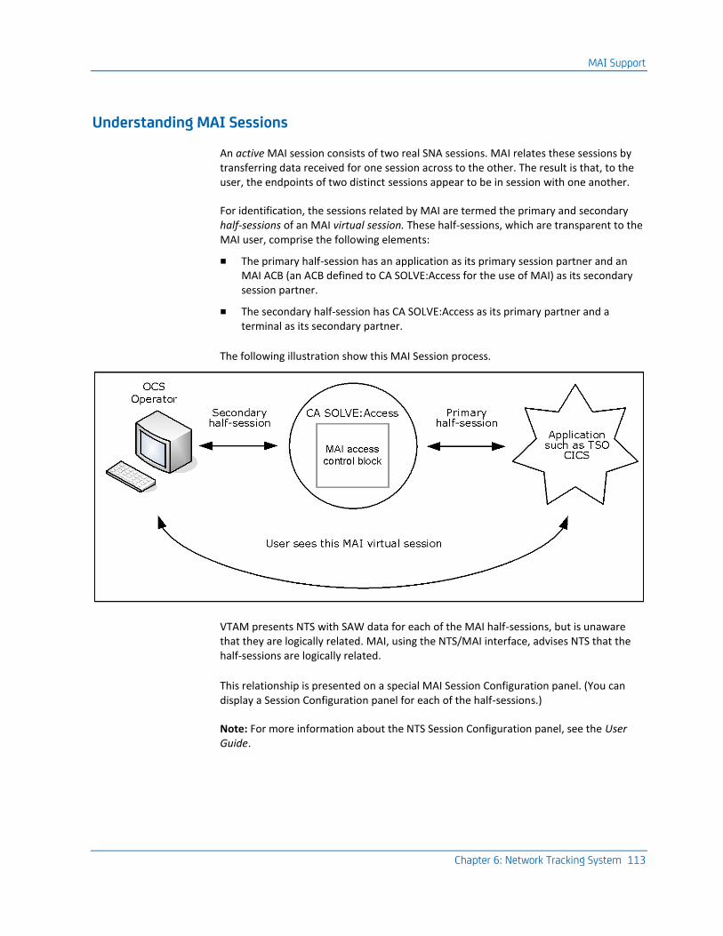
MAI Support
Chapter 6: Network Tracking System 113
Understanding MAI Sessions
An active MAI session consists of two real SNA sessions. MAI relates these sessions by transferring data received for one session across to the other. The result is that, to the user, the endpoints of two distinct sessions appear to be in session with one another.
For identification, the sessions related by MAI are termed the primary and secondary half-sessions of an MAI virtual session. These half-sessions, which are transparent to the MAI user, comprise the following elements:
■ The primary half-session has an application as its primary session partner and an MAI ACB (an ACB defined to CA SOLVE:Access for the use of MAI) as its secondary session partner.
■ The secondary half-session has CA SOLVE:Access as its primary partner and a terminal as its secondary partner.
The following illustration show this MAI Session process.
VTAM presents NTS with SAW data for each of the MAI half-sessions, but is unaware that they are logically related. MAI, using the NTS/MAI interface, advises NTS that the half-sessions are logically related.
This relationship is presented on a special MAI Session Configuration panel. (You can display a Session Configuration panel for each of the half-sessions.)
Note: For more information about the NTS Session Configuration panel, see the User Guide.
MAI Support
114 Administration Guide
MAI/NTS Interface
When active, NTS is aware of all real sessions that have at least one partner in its domain. Using the NTS/MAI interface, MAI provides NTS with information about the logical relationship between the real half sessions that form the MAI virtual session or sessions.
From this, NTS builds information from the two half sessions into a single virtual session. This virtual session can be listed, selected, and displayed in the same manner as real sessions in NTS.
No RTM data is collected or available for MAI sessions.
You can implement the NTS and MAI features in different domains on the same host. To route MAI data across ISR, ensure that the following conditions are met:
■ NTS is licensed in both domains.
■ SYSPARMS NTSMAISV=YES is specified in both domains.
The NTS ISR link is configured for unsolicited message flow from the domain where MAI is resident, to the domain in which NTS is active.
MAI Sessions on the NTS Database
When an MAI session is logged to the NTS database, NTS checks if any trace or accounting data, or both, is flagged as available for the MAI session. If this is the case, NTS logs the trace or accounting data (or both) collected for the primary half session with the MAI session incidence record. (This avoids the need to log the primary half session to the database if the MAI session is the preferred record of the session incidence.)
MAI Sessions and the NTS User Exit
The user ID of the user who started the MAI session is provided by the MAI/NTS interface. This data is passed to the NTS user exit in an additional field added to the session configuration section of the type 39 SMF record. This field contains nulls for non-MAI sessions.
Chapter 7: NCPView 115
Chapter 7: NCPView
This section contains the following topics:
How NCPView Works (see page 115) NCP Monitoring (see page 116) Define a System Image (see page 117) Define NCP Resources (see page 118) Allocate NCP Unformatted Dumps (see page 119) Configure the NCPView NCL Exit (see page 121)
How NCPView Works
NCPView monitors IBM 3720, 3725, 3745, and 3746-900 communications processors that are running NCP version 4, 5, 6, or 7.
Note: Although NCPView can obtain information about a 3746-900 communications processor, it cannot communicate directly with this type of resource. NCPView obtains what information it can about a 3746-900 communications processor from the associated 3745 processor.
NCPView obtains NCP data using the VTAM secondary program operator (SPO) interface, by using VTAM display commands.
NCPView identifies NCPs at initialization by issuing a D RSCLIST,IDTYPE=PUT45 command.
NCPView obtains its information about the NCPs using the standard VTAM command—D NET,NCPSTOR,ADDR=xx.
Alternatively, NCPView can obtain its information from an NCP unformatted dump. This is achieved by NCPView reading a section of storage in the unformatted dump instead of issuing a D NET,NCPSTOR,ADDR=xx command.
NCPView and Connected Domains
To view all NCPs in your enterprise from one domain, you must operate in a multisystem environment supported by your region.
More information:
Administering a Multisystem Environment (see page 187)
NCP Monitoring
116 Administration Guide
NCP Monitoring
NCP monitoring enables you to do the following:
■ View performance information about the NCPs in your network
■ Perform diagnostics on selected NCPs
Before you can use the NCP monitor, you must have a system image that defines the resources you want to monitor. You can specify whether performance monitoring is done for each resource defined in the system image.
Performance monitoring uses data sampled at regular intervals. The information retrieved by data sampling is used to do the following:
■ Trigger alerts if the monitored performance is outside defined boundaries
■ Generate online reports that can be viewed from the NCP monitor
System Images
The system image represents the set of resources you can monitor and control. Each system image has a name and a version number. You can define multiple system images, but one system image only can be active in a region at a time. The system image becomes active when it is loaded. A system image is loaded in one of the following ways:
■ At region startup
■ By issuing the LOAD command
Your region uses a default system image if no system image is successfully loaded during startup.
During system image load the following occurs:
■ Performance monitoring is started for the NCPs defined in the system image.
■ The NCPs are defined to the NCP monitor.
NCP Definitions
NCP definitions are qualified by the following:
■ The system image name and version
■ The NCP name
Define a System Image
Chapter 7: NCPView 117
Work with NCPs
The NCP administration facilities let you do the following:
■ Update, copy, and delete the NCPs defined when you implement your region
■ Add new resources
■ Define which NCPs are monitored
■ Set the attributes to monitor for each NCP
■ Define the conditions that raise alerts and the actions taken
Monitor Resources in a Multisystem Environment
In a multisystem environment, you can view and perform diagnostics from a single monitor on the resources from the connected systems.
In a multisystem environment, each region must load a different system image. Each NCP’s system image name is visible on the NCP monitor. For subordinate regions, the system image name must match the name supplied during the multisystem linking process.
Define a System Image
If you do not want to use the default system image, you can define a system image to your region.
To define a system image
1. Enter /RADMIN.I at the prompt.
The System Image List panel appears. This panel lists the system images defined to your system.
2. Press F4 (Add).
The system image definition panel appears.
3. Specify the name of the system image, its version, and a short description of the system image in this panel.
One system image is required for each region. If you are defining a system image for a subordinate, use the name assigned during the multisystem linking process.
4. Press F3 (File).
The system image is added to the knowledge base.
Define NCP Resources
118 Administration Guide
Define NCP Resources
Your existing NCP resources are automatically defined when you implement your region. After implementation you can use the resource definition facility to do the following:
■ Update, copy, or delete existing definitions
■ Add new resource definitions
Note: To monitor NCPs, ensure that the value specified for the OPTIONS keyword in the NCP SYSCNTRL definition statement is STORDSP. This value lets storage information display by NCPView. For more information, see the IBM NCP, SSP, and EP Definition Reference guide.
To define a new NCP resource to be monitored by the NCP monitor
1. Enter /RADMIN.R at the prompt.
The ResourceView : Resource Definition panel appears. This panel displays the system image name and lists the resource classes that you can maintain.
2. Enter S in front of the NCPMON (NCP Monitor) class.
The ResourceView : NCP Monitor List panel appears. The NCP resources already defined to the system image are listed on this panel.
3. Press F4 (Add).
The ResourceView : NCP Monitor General Description panel appears.
4. Enter the NCP Monitor Name.
This defines the NCP resource.
5. Set Monitoring to Active and provide a description of the NCP resource.
6. Press F8 (Forward).
The ResourceView : NCPMON Monitoring Definition panel appears.
7. Set the frequency that you want to take monitor samples in the Monitor Interval field—this can be from 5 to 60 minutes.
8. Press F10 (Attributes) to edit the list of attributes to monitor.
By default, two attributes only are dynamically defined. If you want to add more to the list, press PF4 to display a full list of attributes that can be monitored by NCPView.
Allocate NCP Unformatted Dumps
Chapter 7: NCPView 119
9. Press F8 (Forward).
The ResourceView : NCPMON Automation Log Details panel appears. This panel defines the resource transient log.
It is recommended that you accept the default settings for this feature. For more information, press F1 (Help).
10. Press F8 (Forward).
The ResourceView : NCPMON Owner Details panel appears. The fields on this panel are for documentation purposes only.
(Optional) Complete the fields on the panel and press F3 (File).
The NCP resource definition is added.
Allocate NCP Unformatted Dumps
To use an NCP unformatted (raw) dump, you need to allocate it to NCPView, so that NCPView can access information in the dump as though it is a real NCP.
To access the NCP Dump Menu
1. Enter /NCPDUMP at the prompt.
The NCP : NCP Dump Menu appears.
From this menu, you can allocate (option AL) or unallocate (option UN) an unformatted NCP Dump file. For more information about the fields, press F1 (Help).
Note: The DD Name that is specified must not conflict with DDs already allocated and also cannot conflict with an existing NCP name.
When the process is complete, the following message appears:
ZNC0702 FUNCTION COMPLETED SUCCESSFULLY
For example, if a dump file was allocated using the option AL on the NCPView Control Functions menu with a DD name of PRODDUMP specified, then the NCP selection list includes an NCP with the name PRODDUMP with all the information that a real NCP has displayed. This line on the list appears in blue to distinguish it from real NCPs.
Allocate NCP Unformatted Dumps
120 Administration Guide
Expected Unformatted Dump File Characteristics
The first record in the unformatted dump file is a control record. The device type that produced the dump is indicated in the first word of the control record.
The format of the first word is XXXXXXTT. The following are possible values of the TT byte:
■ X‘00’ indicates a 3705 dump (not supported by NCPView)
■ X‘01’ indicates a 3725/3720
■ X‘02’ indicates a 3745
In a valid 3725/3720/3745 NCP dump, the actual NCP storage begins in the second record. The first word of the second record must contain X‘714C01AA’.
The LRECL of the dump must be equal to 512 or 2048.
Estimate Storage Requirements for Processing NCP Dumps Using NCPView
When a dump is accessed, only the required amount of storage is read into memory. For example, if you browse storage that is in the middle of the dump, then only half of the dump is read into memory. If the dump is not accessed for 30 minutes, the dump stored in memory is released, thus freeing memory; therefore, further access to the dump causes the dump to be read into memory again.
Most dumps are 4 or 8 Mb in size, although they can be up to 16 MB in size.
When considering how much virtual storage a dump may consume, the general rule is as follows:
storage_required = size _of _dump + 300K
Ensure that the size of your region is set to an appropriate value.
Note: All storage is above the 16 MB line.
Configure the NCPView NCL Exit
Chapter 7: NCPView 121
Configure the NCPView NCL Exit
An NCL exit, dsnpref.NMC1.CC2AEXEC(ZNCUX000), which lets you configure NCPView functions, is distributed with NCPView. This exit is called at the end of NCPView initialization to let you include code specific to your installation. You can, for example, include code that does the following:
■ Filters out NCPs that you do not want monitored
■ Allocates NCP unformatted dump files
Whenever NCPView finds an NCP, ZNCUX000 is called to determine whether the NCP is included in NCPView’s monitoring scope. This process can happen during NCPView initialization, or whenever NCPView detects a new NCP being activated.
Important! If modifications are required, copy the distributed member to the TESTEXEC data set for the region for modification.
Note: For more information about how to change these functions, see the comments in the ZNCUX000 procedure.
The following procedure shows you how to configure the exit using the alternative method.
To configure the ZNCUX000 NCL exit
1. Place a copy of ZNCUX000 in the dsnpref.rname.TESTEXEC library.
2. Change any of the following functions, as required:
■ Exclude one or more NCPs.
■ Allocate NCP dumps.

Chapter 8: Network Control System 123
Chapter 8: Network Control System
This section contains the following topics:
How NCS Works (see page 123)
How NCS Works
The Network Control System (NCS) provides summary displays of resource types, and graphic displays of individual resources and their subordinate nodes.
NCS functions by issuing VTAM Display commands and interpreting the responses received.
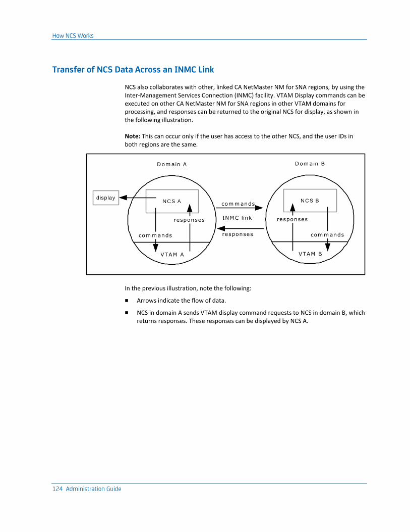
How NCS Works
124 Administration Guide
Transfer of NCS Data Across an INMC Link
NCS also collaborates with other, linked CA NetMaster NM for SNA regions, by using the Inter-Management Services Connection (INMC) facility. VTAM Display commands can be executed on other CA NetMaster NM for SNA regions in other VTAM domains for processing, and responses can be returned to the original NCS for display, as shown in the following illustration.
Note: This can occur only if the user has access to the other NCS, and the user IDs in both regions are the same.
com m andsdisplay
responses
INMC link
Dom ain A
NCS A
VTAM A
responses
com m ands
Dom ain B
NCS B
VTAM B
responses
com m ands
In the previous illustration, note the following:
■ Arrows indicate the flow of data.
■ NCS in domain A sends VTAM display command requests to NCS in domain B, which returns responses. These responses can be displayed by NCS A.
Chapter 9: Configuring Tivoli NetView Operator Command Emulation 125
Chapter 9: Configuring Tivoli NetView Operator Command Emulation
This section contains the following topics:
Tivoli NetView Operator Command Emulation Facility (see page 125) Modify Table Entries (see page 126)
Tivoli NetView Operator Command Emulation Facility
The Tivoli NetView operator command emulation facility assists former Tivoli NetView users with the commands used in CA NetMaster NM for SNA.
This lets users operate CA NetMaster NM for SNA by using the same commands and procedures they are accustomed to using with Tivoli NetView.
Modify Table Entries
126 Administration Guide
Modify Table Entries
The command emulation tables are contained in a CAS table called EQUATES. Each table entry represents a Tivoli NetView operator command and can be defined as ACTIVE or INACTIVE. You can modify the EQUATES table while your region is running by using CAS Table Services.
To modify table entries
1. Enter /CASTAB at the prompt.
The CAS : Table Definition List appears.
2. Enter L $VW at the prompt.
The CAS : Table Definition List repositions.
3. Enter U next to $VWEQUATES.
The CAS : Table Description panel appears.
4. Press F6 (Entries).
The CAS : Table Entries for Field $VW.EQUATES appears.
5. Enter U beside a command.
The CAS : Table Entry Definition panel appears.
6. Change the Active? (Yes/No) field and press F3 (File).
The CAS : Table Entries for Field $VW.EQUATES appears.
7. Press F3 (Exit)
The CAS : Table Description panel appears.
8. Press F3 (File).
The CAS : Table Definition List appears.
9. Enter R beside $VWEQUATES and enter SUBMIT BSYS -START $VWCALL OPT=INIT from OCS or Command Entry.
The changes take effect.
Modify Table Entries
Chapter 9: Configuring Tivoli NetView Operator Command Emulation 127
Considerations When Modifying Table Entries
Any changes you make are limited by the following rules:
■ Changing an entry from INACTIVE to ACTIVE does not set a global equate. To do this, you must restart the region.
■ Changing an entry from ACTIVE to INACTIVE takes affect after the table is reloaded. When an entry is set to INACTIVE, the NetView operator command is not operational.
Note: When you inactivate Tivoli NetView operator commands that have the same name as MS commands, that is ACT and INACT, the inactivation does not become effective until the region is next restarted.
■ If an entry is INACTIVE when the operator tries to use it, the command is executed as if it were an NCL procedure name and an error message may result, for example:
START commandname
N04005 NCL PROCEDURE commandname DOES NOT EXIST IN LIBRARY COMMANDS.
The Tivoli NetView operator commands initialization process, described in the Installation Guide, can be performed on entry to OCS; however, this means that the following applies:
■ The equates are effective only while the operator remains in OCS.
■ You cannot set an equate for a command that has the same name as a Management Services (MS) command, that is, the ACT and INACT commands.

Chapter 10: Advanced Configuration Tasks 129
Chapter 10: Advanced Configuration Tasks
This section contains the following topics:
Load a System Image (see page 129) Enable Multisystem Support (see page 130) Manage Focal Points (see page 132) Manage Entry Points (see page 137) Maintain Resource Alias Names (see page 139) Examples: Test Translation (see page 147)
Load a System Image
The region loads a system image during region initialization. During operation, you may need to change the system image by loading another image.
Note: When you request to load a system image, the $RMEXSTR exit NCL procedure is executed before the starting process. This procedure may be customized at your site to perform any required tasks before any automated resources are started. The starting process cannot proceed if the exit sets a non-zero return code.
To load a system image
1. Enter /RADMIN.I at the prompt.
The System Image Definition Menu appears.
2. Select the type of system image that you want to load.
The System Image List appears.
3. Enter L beside the system image that you want to load.
The LOAD Command Parameter Specification panel appears.
4. Complete the following fields:
SysName to be Loaded
Enter ? and select a system image from the displayed prompt list.
Global Automation Mode
Specify the global operation mode for your system image.
Perform COLD Start?
If the Checkpoint Restart Status field is set to ACTIVE, you can enter NO in the Perform COLD Start? field to specify a warm load.
5. Press F6 (Action) to load the system image.
The Command Confirmation panel appears.
Enable Multisystem Support
130 Administration Guide
6. Enter CONFIRM in the Response field.
The system image is loaded.
Important! Resources that are monitored by the region are defined to the system image. Loading a system image affects all users of this region.
Cold and Warm Load Features
When you load a system image, you can specify that a cold or warm load be performed. This is dependent on the setting of the Checkpoint Restart Status field in the $RM AUTOIDS parameter group.
When a cold load is performed, resources defined to the system image are checked, and if automated, are brought into the desired state. The system image is loaded as if this was the first time it was loaded.
When a warm load is performed, resources are placed in the state they were in when this system image was last in use. All manual overrides performed on resources defined to the system image are retained when this system image is loaded.
The Checkpoint Restart Status field displayed on the LOAD Command Parameter Specification panel displays the status as specified in $RM AUTOIDS parameter group.
Enable Multisystem Support
If you have regions on different systems, you can link them together, using INMC links, to form a multisystem configuration.
A multisystem configuration enables you to log onto your local region and view and control the resources of linked regions. For example, you can do the following:
■ Display a VTAM node in a remote region
■ Display the alerts raised from all the linked regions
■ Monitor NCP utilization in all the linked regions
Multisystems are set up and administered from the Automation Services : Multi-System Support Menu. To access this menu, enter A.M at the prompt of the Primary Menu.
For more information about this menu, press F1(Help).
More information:
Administering a Multisystem Environment (see page 187)
Enable Multisystem Support
Chapter 10: Advanced Configuration Tasks 131
Define ISR Communications
The Intersystem Routing (ISR) facility provides communication services between NEWS features and between NTS features in multiple regions.
To enable these services, define ISR network traffic between the peers through the ISRIN and ISROUT parameter groups. You must define the parameters on the appropriate region, as shown in the following example.
Example: Define ISR Communications
To send ISR traffic from region A to region B, do the following:
■ Define ISROUT on region A, specifying region B’s link name
■ Define ISRIN on region B, specifying region A’s link name
Define ISR Inbound Parameters (ISRIN)
To define ISR inbound parameters
1. Enter /PARMS at the prompt.
The Customizer : Parameter Groups panel appears.
2. Enter U beside the ISRIN parameter group.
The ISRIN - ISR (Inbound) panel appears.
3. Specify link names for PPO messages, CNM data, and SAW data.
4. Specify whether these links are to Tivoli NetView (PPO messages and CNM data only).
5. Press F6 (Action).
The parameters are actioned.
6. Press F3 (File).
The parameters are saved.
Manage Focal Points
132 Administration Guide
Define ISR Outbound Parameters (ISROUT)
To define ISR outbound parameters
1. Enter /PARMS at the prompt.
The Customizer : Parameter Groups panel appears.
2. Enter U beside the ISROUT parameter group.
The ISROUT - ISR (Outbound) panel appears.
3. Specify link names for PPO messages, CNM data, and SAW data.
4. Press F6 (Action).
The parameters are actioned.
5. Press F3 (File).
The parameters are saved.
Manage Focal Points
The Focal Point Management menu options apply to APPN network nodes and allow authorized users to manage and maintain the definitions of the backup and nesting focal points for the Problem Management category of SNA Management Services (SNAMS). Managing these definitions ensures that Problem Management information from the APPN network flows to a centralized management focal point.
For more information about SNAMS and focal point management, see the following IBM guides:
■ SNA Management Services Reference
■ SNA Transaction Programmer’s Reference Manual for LU Type 6.2
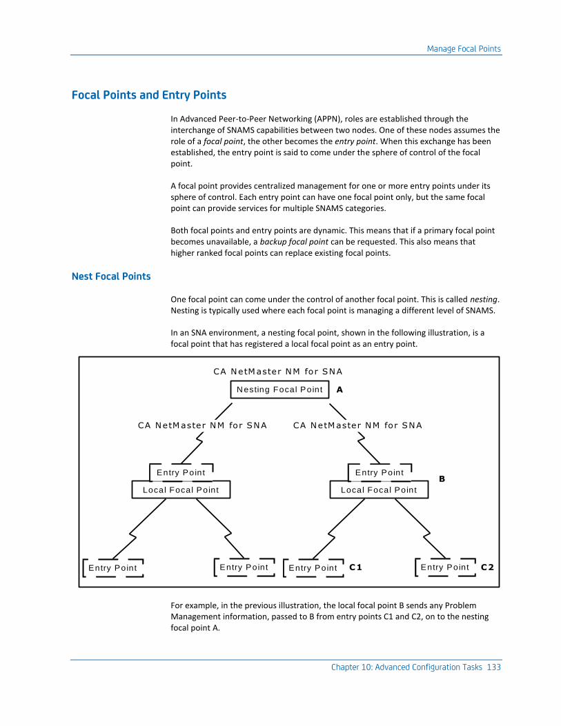
Manage Focal Points
Chapter 10: Advanced Configuration Tasks 133
Focal Points and Entry Points
In Advanced Peer-to-Peer Networking (APPN), roles are established through the interchange of SNAMS capabilities between two nodes. One of these nodes assumes the role of a focal point, the other becomes the entry point. When this exchange has been established, the entry point is said to come under the sphere of control of the focal point.
A focal point provides centralized management for one or more entry points under its sphere of control. Each entry point can have one focal point only, but the same focal point can provide services for multiple SNAMS categories.
Both focal points and entry points are dynamic. This means that if a primary focal point becomes unavailable, a backup focal point can be requested. This also means that higher ranked focal points can replace existing focal points.
Nest Focal Points
One focal point can come under the control of another focal point. This is called nesting. Nesting is typically used where each focal point is managing a different level of SNAMS.
In an SNA environment, a nesting focal point, shown in the following illustration, is a focal point that has registered a local focal point as an entry point.
CA NetMaster NM for SNA
AN esting Focal Point
CA NetMaster NM for SNA CA NetMaster NM for SNA
Local Focal Point Local Focal Point
Entry Point Entry Point
Entry Point Entry Point Entry Point Entry Point
B
C2C1
For example, in the previous illustration, the local focal point B sends any Problem Management information, passed to B from entry points C1 and C2, on to the nesting focal point A.
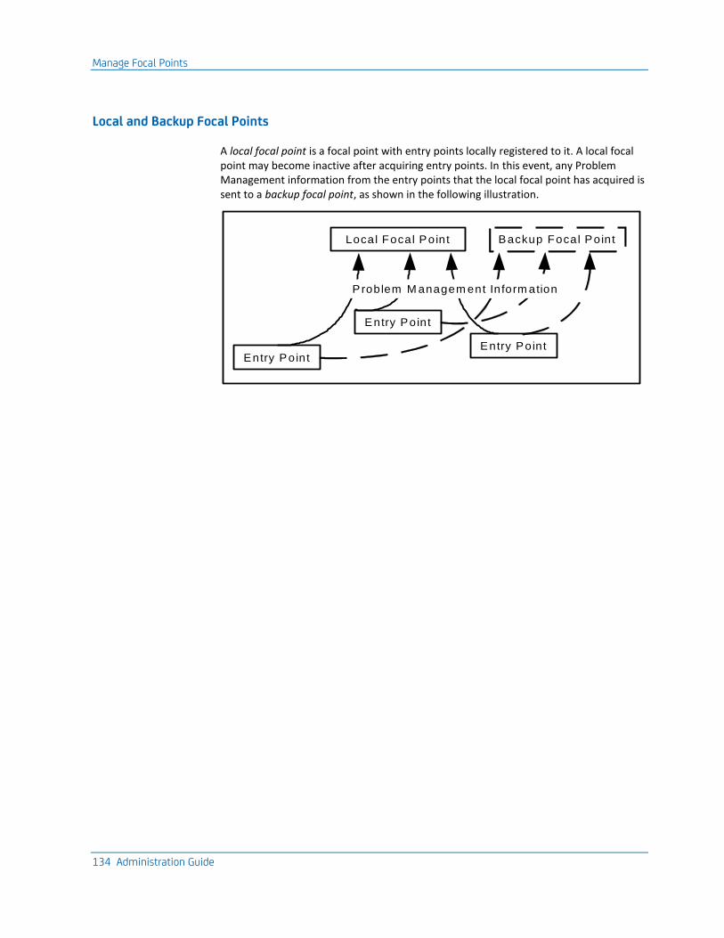
Manage Focal Points
134 Administration Guide
Local and Backup Focal Points
A local focal point is a focal point with entry points locally registered to it. A local focal point may become inactive after acquiring entry points. In this event, any Problem Management information from the entry points that the local focal point has acquired is sent to a backup focal point, as shown in the following illustration.
Local Focal Point Backup Focal Point
Entry PointEntry Point
Entry Point
P roblem M anagem ent Inform ation
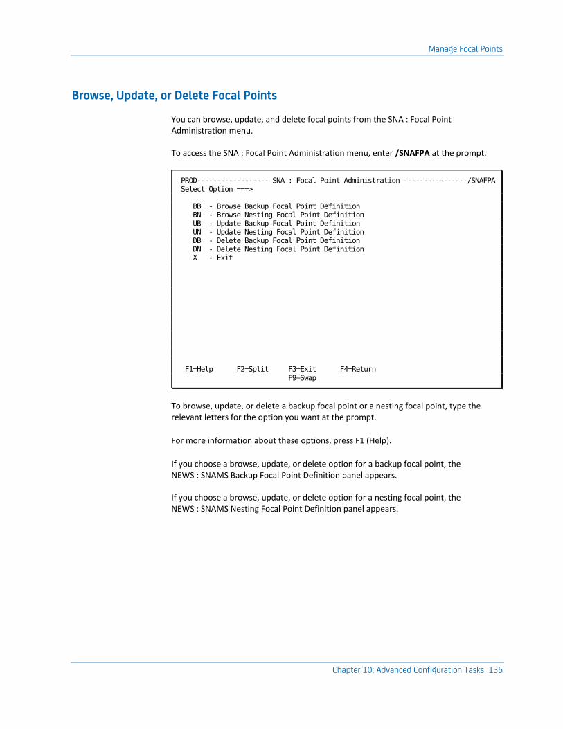
Manage Focal Points
Chapter 10: Advanced Configuration Tasks 135
Browse, Update, or Delete Focal Points
You can browse, update, and delete focal points from the SNA : Focal Point Administration menu.
To access the SNA : Focal Point Administration menu, enter /SNAFPA at the prompt.
PROD------------------ SNA : Focal Point Administration ----------------/SNAFPA Select Option ===> BB - Browse Backup Focal Point Definition BN - Browse Nesting Focal Point Definition UB - Update Backup Focal Point Definition UN - Update Nesting Focal Point Definition DB - Delete Backup Focal Point Definition DN - Delete Nesting Focal Point Definition X - Exit F1=Help F2=Split F3=Exit F4=Return F9=Swap
To browse, update, or delete a backup focal point or a nesting focal point, type the relevant letters for the option you want at the prompt.
For more information about these options, press F1 (Help).
If you choose a browse, update, or delete option for a backup focal point, the NEWS : SNAMS Backup Focal Point Definition panel appears.
If you choose a browse, update, or delete option for a nesting focal point, the NEWS : SNAMS Nesting Focal Point Definition panel appears.
Manage Focal Points
136 Administration Guide
Define Backup Focal Points
The NEWS : SNAMS Backup Focal Point Definition panel displays definitions for the SNAMS backup focal point.
To define a backup focal point
1. From the SNA : Focal Point Administration menu, type UB at the prompt.
The NEWS : SNAMS Backup Focal Point Definition panel appears.
2. Complete the following fields:
Focal Point Name
Specify a name in the form Network Identifier and Network Addressable Unit (NAU) separated by a period (for example, NTWKNAME.NAUNAME).
Application Name
Type a four-byte hexadecimal quoted string (in the format ’aabbccdd’X) if the string contains non-display characters.
3. Press F3 (File).
The backup focal point is saved.
Define Nesting Focal Points
The NEWS : SNAMS Nesting Focal Point Definition panel displays the definition for the SNAMS nesting focal point.
To define a nesting focal point
1. From the SNA : Focal Point Administration menu, type UN at the prompt.
The NEWS : SNAMS Nesting Focal Point Definition panel appears.
2. Specify a focal point name in the form Network Identifier and Network Addressable Unit (NAU) separated by a period (for example, NTWKNAME.NAUNAME).
3. Press F3 (File).
The nesting focal point is saved.
Manage Entry Points
Chapter 10: Advanced Configuration Tasks 137
Manage Entry Points
The SNA : Entry Point Administration menu lets you manage and maintain the definitions of the Entry Points for the Problem Management category of SNA Management Services (SNAMS). It also lets you acquire entry points for the focal point so that the focal point can receive Problem Management information from them.
From the SNA : Entry Point Administration menu, you can access the NEWS : SNAMS EP Definitions panel to maintain entry point definitions or get a full or partial list of currently defined entry points.
Activate a Focal Point
To activate a focal point
1. Enter /SNAEPA at the prompt.
The SNA : Entry Point Administration menu appears.
2. Type ACT at the prompt and complete the following field:
Entry Point Name
Specifies the fully-qualified node name in the form Network Identifier and Network Addressable Unit (NAU) separated by a period (for example, NTWKNAME.NAUNAME).
If you enter the NAUNAME portion of the name only, NEWS prefixes it with the name of the network in which this region is active.
Press Enter.
The NEWS : SNAMS EP Definitions panel appears.
Manage Entry Points
138 Administration Guide
Maintain Entry Point Definitions
The NEWS : Entry Point Definitions panel displays a list of entry point definitions that can be registered to the Problem Management focal point. From the list, you can select an entry point definition to browse, update, or delete.
To list entry point definitions
1. Enter /SNAEPA at the prompt.
The SNA : Entry Point Administration menu appears.
2. Enter M at the prompt.
The NEWS : Entry Point Definitions panel appears.
Note: To narrow the range of entry points listed, specify a prefix in the Entry Point Name field. Entry point names beginning with the entered prefix only are listed.
3. Press Enter.
The NEWS : Entry Point Definitions panel appears in update mode.
Update an Entry Point
To update an entry point
1. From the NEWS : Entry Point Definitions panel, enter U beside an entry point name on the list.
The NEWS : SNAMES EP Definitions panel appears for the selected entry point.
2. Edit the details, as required.
3. Press F3 (File).
The changes are filed.
4. Press F4 (Save).
The changes are saved.
Maintain Resource Alias Names
Chapter 10: Advanced Configuration Tasks 139
Define an Entry Point
To define an entry point
1. From the NEWS : Entry Point Definitions panel, press F4 (Add).
The NEWS : SNAMS EP Definitions panel appears.
2. Complete the following fields:
Entry Point Name
Type a name in the form Network Identifier and Network Addressable Unit (NAU) separated by a period (for example, NTWKNAME.NAUNAME).
Initial Status
Type ACTIVE or INACTIVE.
3. Press F3 (File).
The changes are filed.
4. Press F4 (Save).
The changes are saved.
Delete an Entry Point
To delete an entry point
1. From the NEWS : Entry Point Definitions panel, enter D beside the entry point that you want to delete.
The entry point is deleted.
Maintain Resource Alias Names
NEWS provides VTAM with alias name translation services for those levels of VTAM that request this function. Alias names are used to differentiate between same name resources in interconnected networks.
Note: Alias name translation is not necessary if there are no resource name clashes when sessions are being established between interconnected networks. A name clash occurs if a resource name in one network is also defined in the other network.
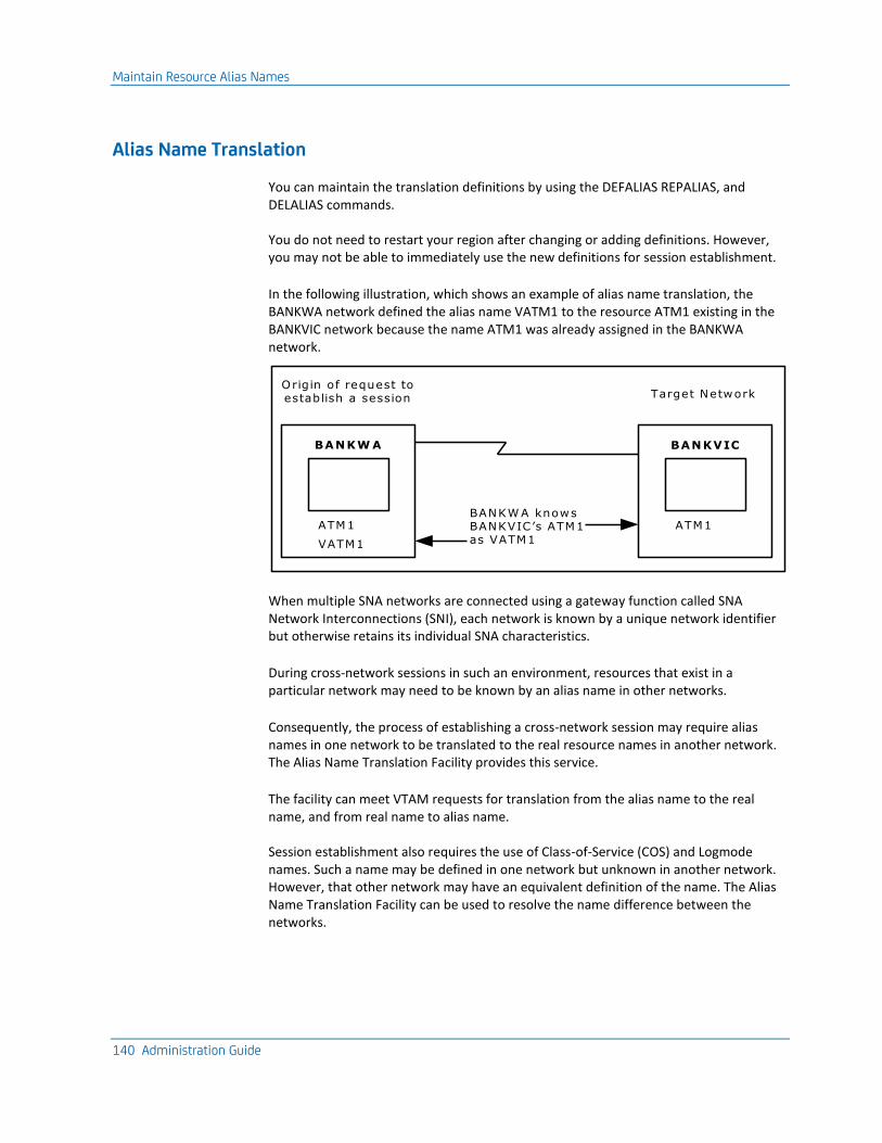
Maintain Resource Alias Names
140 Administration Guide
Alias Name Translation
You can maintain the translation definitions by using the DEFALIAS REPALIAS, and DELALIAS commands.
You do not need to restart your region after changing or adding definitions. However, you may not be able to immediately use the new definitions for session establishment.
In the following illustration, which shows an example of alias name translation, the BANKWA network defined the alias name VATM1 to the resource ATM1 existing in the BANKVIC network because the name ATM1 was already assigned in the BANKWA network.
Origin of request to establish a session
BANKW A
ATM1
VATM1
Target Network
BANKVIC
ATM1BANKW A knows BANKVIC’s ATM1 as VATM1
When multiple SNA networks are connected using a gateway function called SNA Network Interconnections (SNI), each network is known by a unique network identifier but otherwise retains its individual SNA characteristics.
During cross-network sessions in such an environment, resources that exist in a particular network may need to be known by an alias name in other networks.
Consequently, the process of establishing a cross-network session may require alias names in one network to be translated to the real resource names in another network. The Alias Name Translation Facility provides this service.
The facility can meet VTAM requests for translation from the alias name to the real name, and from real name to alias name.
Session establishment also requires the use of Class-of-Service (COS) and Logmode names. Such a name may be defined in one network but unknown in another network. However, that other network may have an equivalent definition of the name. The Alias Name Translation Facility can be used to resolve the name difference between the networks.
Maintain Resource Alias Names
Chapter 10: Advanced Configuration Tasks 141
Example: Resource Alias Name Translation
An LU, named X, in network A needs to connect to an application in network B. However, there is already a resource named X in network B. To establish a session, an alias name for use in network B must be provided for the resource X in network A.
Example: Class-of-Service or Logmode Alias Names Translation
A file transfer application in network A always uses logmode X, and needs to connect to an application in another network, B. If the logmode X does not exist in network B, but an equivalent logmode exists, then the Alias Name Translation Facility can be used to assign the equivalent logmode in network B.
Display Alias Name Definitions
By using the SHOW DEFALIAS command, you can display one or more alias definitions used by the Alias Name Translation Facility of NEWS. By default, you can have an authority level of 0 to display alias name definitions.
For a full explanation and examples of the SHOW DEFALIAS command and details of operands, see the online help.
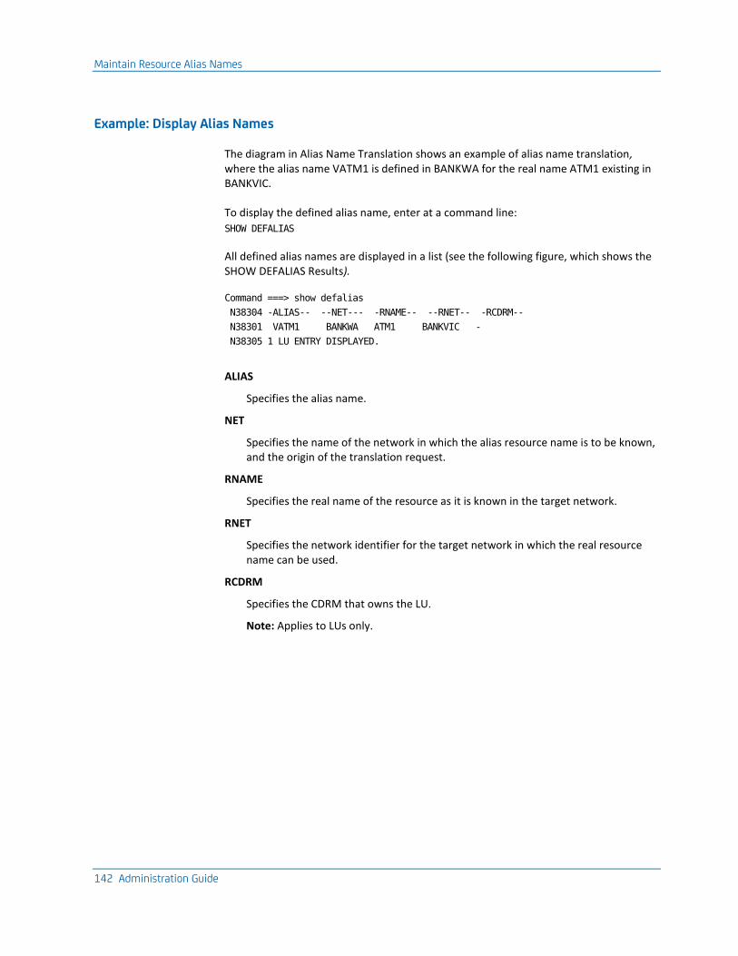
Maintain Resource Alias Names
142 Administration Guide
Example: Display Alias Names
The diagram in Alias Name Translation shows an example of alias name translation, where the alias name VATM1 is defined in BANKWA for the real name ATM1 existing in BANKVIC.
To display the defined alias name, enter at a command line:
SHOW DEFALIAS
All defined alias names are displayed in a list (see the following figure, which shows the SHOW DEFALIAS Results).
Command ===> show defalias
N38304 -ALIAS-- --NET--- -RNAME-- --RNET-- -RCDRM--
N38301 VATM1 BANKWA ATM1 BANKVIC -
N38305 1 LU ENTRY DISPLAYED.
ALIAS
Specifies the alias name.
NET
Specifies the name of the network in which the alias resource name is to be known, and the origin of the translation request.
RNAME
Specifies the real name of the resource as it is known in the target network.
RNET
Specifies the network identifier for the target network in which the real resource name can be used.
RCDRM
Specifies the CDRM that owns the LU.
Note: Applies to LUs only.
Maintain Resource Alias Names
Chapter 10: Advanced Configuration Tasks 143
Define Alias Names
By using the DEFALIAS command, you can add an alias name to NEWS for use by the Alias Name Translation Facility. By default, you must have an authority level of 4 to add an alias name.
For a full explanation and examples of the DEFALIAS command and details of operands, see the online help.
Note: The addition of definitions is normally a function of the INIT procedure processing.
Example: Define an Alias Name
The diagram in Alias Name Translation shows the alias name VATM1 defined in BANKWA for the real name ATM1 existing in BANKVIC.
To define the alias name of VATM1 as an LU in BANKWA, at a command line, enter:
DEFALIAS NAME=VATM1 NET=BANKWA
RNAME=ATM1 RNET=BANKVIC
A message confirming the definition appears.
To see the result of the definition, at a command line, enter:
SHOW DEFALIAS NAME=VATM1
Define Generic Names
You can reduce the number of DEFALIAS commands used and simplify subsequent modifications by defining generic alias names and network names.
You can also override the generic definitions by one or more specific conditions.
For a full explanation and examples of the command and details of operands, see the online help.
Define Generic Alias Names
You can define a generic alias name and real name pair when you want to map a range of similarly named resources (for example, MAIVF001 to MAIVF999) to some other range (for example, AMF001 to AMF999) in the target network.
By generically defining the two prefix strings only (that is, MAIVF and AMF), the Alias Name Translation Facility can carry the trailing suffix during the translation (that is, it translates MAIVF034 to AMF034).
Maintain Resource Alias Names
144 Administration Guide
Define Generic Network Names
You can generically define the networks in which an alias name is known. By using a totally generic network name (that is, a name that any network name matches), in a single DEFALIAS command, you can define an alias to exist in all networks.
When a network name is generically defined, any network name that matches the generic network name contains the alias resource name defined to that network.
Replace Alias Names
By using the REPALIAS command, you can replace the real name and network defined for an existing alias name and network combination. You must have an authority level of 4 to replace an alias name.
For more information about the REPALIAS command, see the online help.
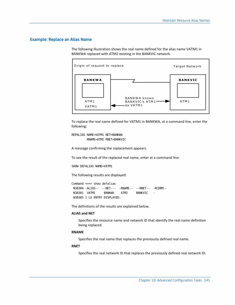
Maintain Resource Alias Names
Chapter 10: Advanced Configuration Tasks 145
Example: Replace an Alias Name
The following illustration shows the real name defined for the alias name VATM1 in BANKWA replaced with ATM2 existing in the BANKVIC network.
Origin of request to replace
BANKW A
ATM1
VATM1
Target Network
BANKVIC
ATM1BANKW A knows BANKVIC’s ATM1 as VATM1
To replace the real name defined for VATM1 in BANKWA, at a command line, enter the following:
REPALIAS NAME=VATM1 NET=BANKWA
RNAME=ATM2 RNET=BANKVIC
A message confirming the replacement appears.
To see the result of the replaced real name, enter at a command line:
SHOW DEFALIAS NAME=VATM1
The following results are displayed:
Command ===> show defalias
N38304 -ALIAS-- --NET--- -RNAME-- --RNET-- -RCDRM--
N38301 VATM1 BANKWA ATM2 BANKVIC -
N38305 1 LU ENTRY DISPLAYED.
The definitions of the results are explained below.
ALIAS and NET
Specifies the resource name and network ID that identify the real name definition being replaced.
RNAME
Specifies the real name that replaces the previously defined real name.
RNET
Specifies the real network ID that replaces the previously defined real network ID.
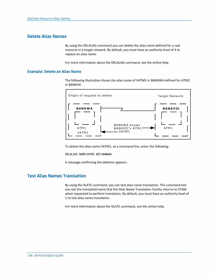
Maintain Resource Alias Names
146 Administration Guide
Delete Alias Names
By using the DELALIAS command you can delete the alias name defined for a real resource in a target network. By default, you must have an authority level of 4 to replace an alias name.
For more information about the DELALIAS command, see the online help.
Example: Delete an Alias Name
The following illustration shows the alias name of VATM1 in BANKWA defined for ATM2 in BANKVIC.
Origin of request to delete
BANKW A
ATM1
VATM1
Target Network
BANKVIC
ATM1BANKW A knows BANKVIC’s ATM1 as VATM1
To delete the alias name VATM1, at a command line, enter the following:
DELALIAS NAME=VATM1 NET=BANKWA
A message confirming the deletion appears.
Test Alias Names Translation
By using the XLATE command, you can test alias name translation. This command lets you see the translated name that the Alias Name Translation Facility returns to VTAM when requested to perform translation. By default, you must have an authority level of 1 to test alias name translation.
For more information about the XLATE command, see the online help.
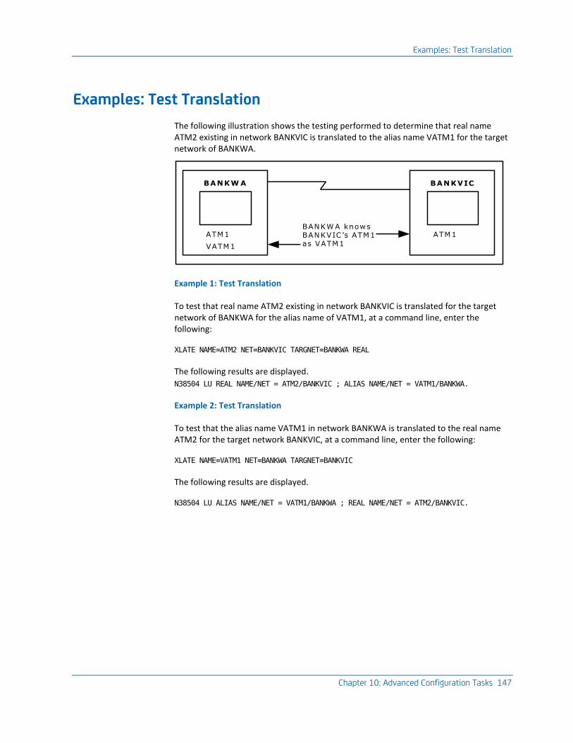
Examples: Test Translation
Chapter 10: Advanced Configuration Tasks 147
Examples: Test Translation
The following illustration shows the testing performed to determine that real name ATM2 existing in network BANKVIC is translated to the alias name VATM1 for the target network of BANKWA.
BANKW A
ATM1
VATM1
BANKVIC
ATM1BANKW A knows BANKVIC’s ATM1 as VATM1
Example 1: Test Translation
To test that real name ATM2 existing in network BANKVIC is translated for the target network of BANKWA for the alias name of VATM1, at a command line, enter the following:
XLATE NAME=ATM2 NET=BANKVIC TARGNET=BANKWA REAL
The following results are displayed.
N38504 LU REAL NAME/NET = ATM2/BANKVIC ; ALIAS NAME/NET = VATM1/BANKWA.
Example 2: Test Translation
To test that the alias name VATM1 in network BANKWA is translated to the real name ATM2 for the target network BANKVIC, at a command line, enter the following:
XLATE NAME=VATM1 NET=BANKWA TARGNET=BANKVIC
The following results are displayed.
N38504 LU ALIAS NAME/NET = VATM1/BANKWA ; REAL NAME/NET = ATM2/BANKVIC.

Chapter 11: Implementing Activity Logs 149
Chapter 11: Implementing Activity Logs
This section contains the following topics:
Activity Logs (see page 149) Implement Online Activity Logging (see page 150) Administer Online Activity Log Files (see page 151) Swap the Online Log (see page 152) Online Log Exit (see page 152) Online Logging Procedure (see page 154) Hardcopy Activity Log (see page 156) Swap the Hardcopy Log (see page 158) Reuse of Hardcopy Log Data Sets (see page 159) Cross-Reference of Hardcopy Logs (see page 159) I/O Errors on the Hardcopy Log (see page 160) Write to the System Log (see page 160)
Activity Logs
The activity logging facility records all the activity in your region. You can use the activity logs to help determine the cause of problems.
Two separate activity log formats exist:
■ Online
■ Hardcopy
Log records are written to both formats.
By default, activity logs contain the following information:
■ All commands entered
■ All responses to commands entered
■ Any unsolicited messages received from VTAM or the operating system, provided the related interfaces are available
■ All messages explicitly written to the log by NCL procedures
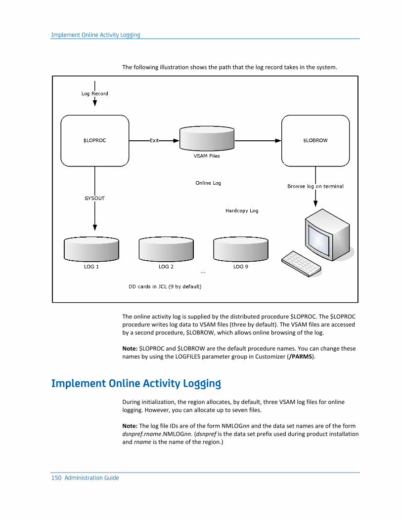
Implement Online Activity Logging
150 Administration Guide
The following illustration shows the path that the log record takes in the system.
The online activity log is supplied by the distributed procedure $LOPROC. The $LOPROC procedure writes log data to VSAM files (three by default). The VSAM files are accessed by a second procedure, $LOBROW, which allows online browsing of the log.
Note: $LOPROC and $LOBROW are the default procedure names. You can change these names by using the LOGFILES parameter group in Customizer (/PARMS).
Implement Online Activity Logging
During initialization, the region allocates, by default, three VSAM log files for online logging. However, you can allocate up to seven files.
Note: The log file IDs are of the form NMLOGnn and the data set names are of the form dsnpref.rname.NMLOGnn. (dsnpref is the data set prefix used during product installation and rname is the name of the region.)
Administer Online Activity Log Files
Chapter 11: Implementing Activity Logs 151
Use Additional Log Files
If you want to make more than three files available to the region, define the new VSAM files and then customize the LOGFILES parameter group by defining additional logging data sets.
To customize the LOGFILES parameter group
1. Enter /PARMS at the prompt.
The Customizer : Parameter Groups list appears.
2. Enter U beside the LOGFILES parameter group.
The Customizer : Parameter Group panel for the LOGFILES parameter group appears.
3. Press F8 (Forward) to display the next page.
4. Complete the fields for each file you want to make available. To allocate more files, press F8 (Forward) again.
5. When you have specified the required number of log files, press F6 (Action) to allocate and open the files.
6. Press F6 (Action).
The changes are applied.
7. Press F3 (File).
The changes are saved.
Note: For more information about using this panel, press F1 (Help).
Administer Online Activity Log Files
From the Activity Log : Administration menu, you can do the following:
■ Swap active activity logs
■ List all days contained in log files and browse logs for a particular date
■ List all log files and browse a particular file
To administer online activity log files, enter /LOADMIN at the prompt.
The Activity Log : Administration menu appears.
Note: For information about the options available on this menu, press F1 (Help).
Swap the Online Log
152 Administration Guide
Swap the Online Log
The online activity log automatically swaps to a fresh VSAM file when each file fills up.
You can manually swap your currently active VSAM file if you want to free a particular log file (for example, for backups).
Important! Swapping the current VSAM log causes the $LOPROC procedure to write all subsequent activity log records to the next VSAM log. If this log was previously used, it is reset. Therefore, you can no longer browse the old records that it contained.
To swap the online activity log
1. Enter /LOGSWAP at the prompt.
The Activity Log Services : Confirm Swap Log panel appears.
2. Press F6 to request the log swap, or F12 to cancel your request.
Note: If the $LOPROC procedure encounters a VSAM error when it is logging activity to an online log file, it automatically swaps to the next log file.
Online Log Exit
You can create an NCL procedure to intercept, analyze, and react to the messages that are sent to the activity log.
Use the LOGFILES parameter group in Customizer to specify the name of your exit.
The exit is executed every time a message is sent to the log. Using the exit to perform complex functions can degrade the performance of the region.
Note: Ensure that your log exit procedure is well-tested before you put it into production.
Online Log Exit
Chapter 11: Implementing Activity Logs 153
Variables Available to the Activity Log Exit
The following variables are available to the activity log exit:
&#LO$RECORD
Contains records of the following formats:
time_generated user_id terminal_id message_text
The text of the message starts at the fourth word of the record.
arrival_time origin region $$AOMTIME$$ aom_time message_text
The text of the message starts at the sixth word of the record. This format lets you identify AOM-sourced messages.
You can change the contents of this variable. To suppress the message from the log, set the variable to NOLOG.
Note: For more information, see the &LOGREAD verb in the Network Control Language Reference Guide.
$LOG
Specifies a Mapped Data Object (MDO) that contains the message attributes. The MDO is mapped by the $MSG map.
You can use the &ASSIGN verb to query the MDO.
Note: For information about querying MDO components and additional variables, see the Network Control Language Programming Guide.
Example: Remove Messages from the NCL Log
The following shows an example procedure:
&CONTROL
-*------------------------------------------------*
-* TO REMOVE IKJ56247I MESSAGES FROM THE NCL LOG. *
-*------------------------------------------------*
&PARSE DELIM=' ' VARS=#LO$WORD* DATA=&#LO$RECORD
&IF .&#LO$WORD4 EQ .IKJ56247I &THEN +
&#LO$RECORD = NOLOG
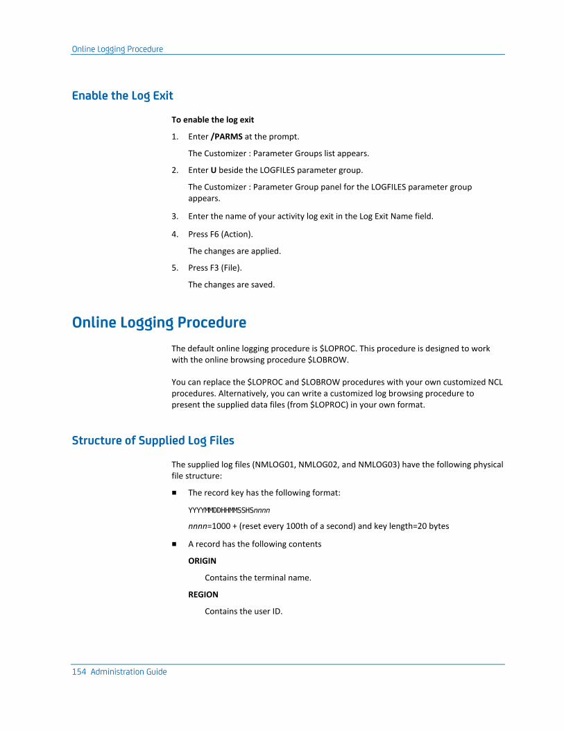
Online Logging Procedure
154 Administration Guide
Enable the Log Exit
To enable the log exit
1. Enter /PARMS at the prompt.
The Customizer : Parameter Groups list appears.
2. Enter U beside the LOGFILES parameter group.
The Customizer : Parameter Group panel for the LOGFILES parameter group appears.
3. Enter the name of your activity log exit in the Log Exit Name field.
4. Press F6 (Action).
The changes are applied.
5. Press F3 (File).
The changes are saved.
Online Logging Procedure
The default online logging procedure is $LOPROC. This procedure is designed to work with the online browsing procedure $LOBROW.
You can replace the $LOPROC and $LOBROW procedures with your own customized NCL procedures. Alternatively, you can write a customized log browsing procedure to present the supplied data files (from $LOPROC) in your own format.
Structure of Supplied Log Files
The supplied log files (NMLOG01, NMLOG02, and NMLOG03) have the following physical file structure:
■ The record key has the following format:
YYYYMMDDHHMMSSHSnnnn
nnnn=1000 + (reset every 100th of a second) and key length=20 bytes
■ A record has the following contents
ORIGIN
Contains the terminal name.
REGION
Contains the user ID.
Online Logging Procedure
Chapter 11: Implementing Activity Logs 155
TEXT
Contains the message text to display in the activity log.
MSGATTR
Contains the 2-byte color/highlight indicator. Colors are R=red, Y=yellow, W=white, B=blue, G=green, T=turquoise, or P=pink. Highlight values are R=reverse, B=blink, U=underscore, or N=none.
ORIGTIM
Contains the time at the remote domain.
ORIGDMN
Contains the name of the originating domain.
ORIGSRC
Contains the ID of the remote terminal.
Note: For more information, see the following references:
■ The description of the &FILE OPEN verb in the Network Control Language Reference Guide.
■ The Network Control Language Programming Guide.
How You Write Logging and Browsing Procedures
To write your own customized NCL procedure to replace $LOBROW, use the &FILE OPEN statement with FORMAT=DELIMITED.
You can store your log records in whatever file format you want. Your log browsing procedure must match this file format.
Note: For more information, see the descriptions of the following verbs in the Network Control Language Reference Guide:
■ &LOGREAD
■ &LOGCONT
■ &LOGDEL
Hardcopy Activity Log
156 Administration Guide
Implement Logging and Browsing Procedures
After you write your own browsing procedure or your own logging and browsing procedures, you implement them for use.
To implement your procedures
1. Enter U next to the LOGFILES parameter group in Customizer.
2. Update the relevant fields.
3. Press F6 (Action).
Your procedures are used for logging and browsing.
4. Press F3 (File).
Your changes to the parameter group are saved.
Hardcopy Activity Log
A region can have more than one hardcopy activity log, of which only one is open for logging.
Your region can be configured to perform logging to disk, tape, or hard copy. From one to nine logs can be specified by including the required number of DD statements in the execution JCL. Logging can be specified to wrap when the last log is full or is swapped.
To obtain the status of these logs, use the SHOW LOGS command.
Note: When logging to disk the following DCB attributes should be used:
DSORG=PS,RECFM=VBA,LRECL=137,BLKSIZE=15476
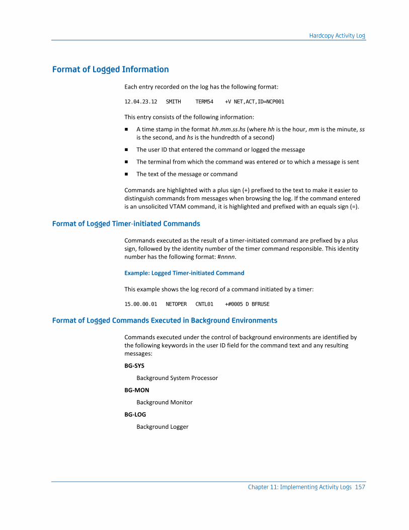
Hardcopy Activity Log
Chapter 11: Implementing Activity Logs 157
Format of Logged Information
Each entry recorded on the log has the following format:
12.04.23.12 SMITH TERM54 +V NET,ACT,ID=NCP001
This entry consists of the following information:
■ A time stamp in the format hh.mm.ss.hs (where hh is the hour, mm is the minute, ss is the second, and hs is the hundredth of a second)
■ The user ID that entered the command or logged the message
■ The terminal from which the command was entered or to which a message is sent
■ The text of the message or command
Commands are highlighted with a plus sign (+) prefixed to the text to make it easier to distinguish commands from messages when browsing the log. If the command entered is an unsolicited VTAM command, it is highlighted and prefixed with an equals sign (=).
Format of Logged Timer-initiated Commands
Commands executed as the result of a timer-initiated command are prefixed by a plus sign, followed by the identity number of the timer command responsible. This identity number has the following format: #nnnn.
Example: Logged Timer-initiated Command
This example shows the log record of a command initiated by a timer:
15.00.00.01 NETOPER CNTL01 +#0005 D BFRUSE
Format of Logged Commands Executed in Background Environments
Commands executed under the control of background environments are identified by the following keywords in the user ID field for the command text and any resulting messages:
BG-SYS
Background System Processor
BG-MON
Background Monitor
BG-LOG
Background Logger
Swap the Hardcopy Log
158 Administration Guide
Format of Logged Commands from NCL Procedure-dependent Environment
If a command is executed from an NCL procedure-dependent environment (&INTCMD), the node field on the log contains the NCL ID of the process issuing the command.
Format of the Hardcopy Log
The hardcopy log data set has the following format:
■ A heading on each page—contains the day and date on which the log was created and the system identifier (NMID) of the originating region.
■ A log identifier on the right side of the page. The log identifier is the ddname under which the log was created. This log identifier assists log collation after printing.
■ 60 lines on each page—this format can be altered to suit your requirements using the SYSPARMS LOGPAGE operand.
Note: For information about LOGPAGE, see the Reference Guide.
Swap the Hardcopy Log
Swapping the current log frees the log for immediate printing. Swapping the log is possible only when another unused log remains to which logging can continue. You can specify up to nine logs. Logs do not need to be consecutive.
To swap the log, enter the LOGSWAP command.
When a log is swapped, the log status, the requesting user ID, and the reason for the swap are recorded. You can display these details with the SHOW LOGS command.
Each of the logs is identified in the JCL member by the LOGn ddname. n is in the range one to nine.
Example: Log Name
This example defines the LOG4 ddname:
//LOG4 DD SYSOUT=A,FREE=CLOSE
Mixing of device types is valid. Inclusion of FREE=CLOSE prints the log when it is released by the LOGSWAP command.
Reuse of Hardcopy Log Data Sets
Chapter 11: Implementing Activity Logs 159
Reuse of Hardcopy Log Data Sets
Wrapping lets you reuse a LOG data set when all of the available LOG data sets have been used.
The LOGWRAP SYSPARM determines whether log data set wrapping is allowed. You set the value of this SYSPARM in the Are Activity Logs to Wrap? field when you customize the LOGFILES parameter group in Customizer (/PARMS).
If you specify NO (the default) in the Are Activity Logs to Wrap? field, then wrapping is not permitted. When all the LOG data sets have been used due to successive LOGSWAP commands, the previous LOG data sets cannot be reused. After the last LOG data set is used, any further LOGSWAP commands are rejected.
If you specify YES in the Are Activity Logs to Wrap? field, log wrapping is allowed according to the following rules:
■ If you direct your LOG data sets to SYSOUT, then, as each LOGn DD statement is used, the data set is unallocated because FREE=CLOSE. In this case, you can reissue an ALLOC command to reallocate another SYSOUT file under the same ddname. For example:
ALLOC DD=LOG3 SYSOUT=A FREE=CLOSE
This ddname is now available for use as another LOG data set. Subsequent LOGSWAP operations can now reuse this LOG data set rather than rejecting the command when the last LOG data set is used.
■ If the LOG DD statements point to sequential data sets, log wrapping overwrites the earlier LOG data held in these data sets. Archive the existing data before allowing the wrap to occur.
Cross-Reference of Hardcopy Logs
To help operations staff to piece the full log together, certain information is recorded on the last and first lines of swapped LOG data sets.
The first line of a new log contains the reason for the swap, or the initiating user ID.
The last message printed on a swapped log is the ddname of the new log. Also printed at the start of the new log is the ddname or logical ID for the previous log.
I/O Errors on the Hardcopy Log
160 Administration Guide
I/O Errors on the Hardcopy Log
If an I/O error occurs on a log, the log is closed and the next available log is automatically swapped to, if one is available, and logging continues. This also applies to data set full conditions when logging to disk.
If the I/O error occurs on the last available log, a warning message is sent to all monitor terminals informing them that logging has ceased. The STATUS command also includes a warning message if logging is stopped. All log messages are passed to LOGPROC for analysis even if no log output is possible.
Write to the System Log
You can use the SYSPARMS SYSLOG operand to write all logged output or all VTAM PPO messages received to the system log.
To write all logged output to the system log also, enter the SYSPARMS SYSLOG=YES command.
To write all VTAM PPO messages to the system log also, enter the SYSPARMS SYSLOG=PPO command.
Note: For more information about the SYSPARMS SYSLOG operand, see the Reference Guide.
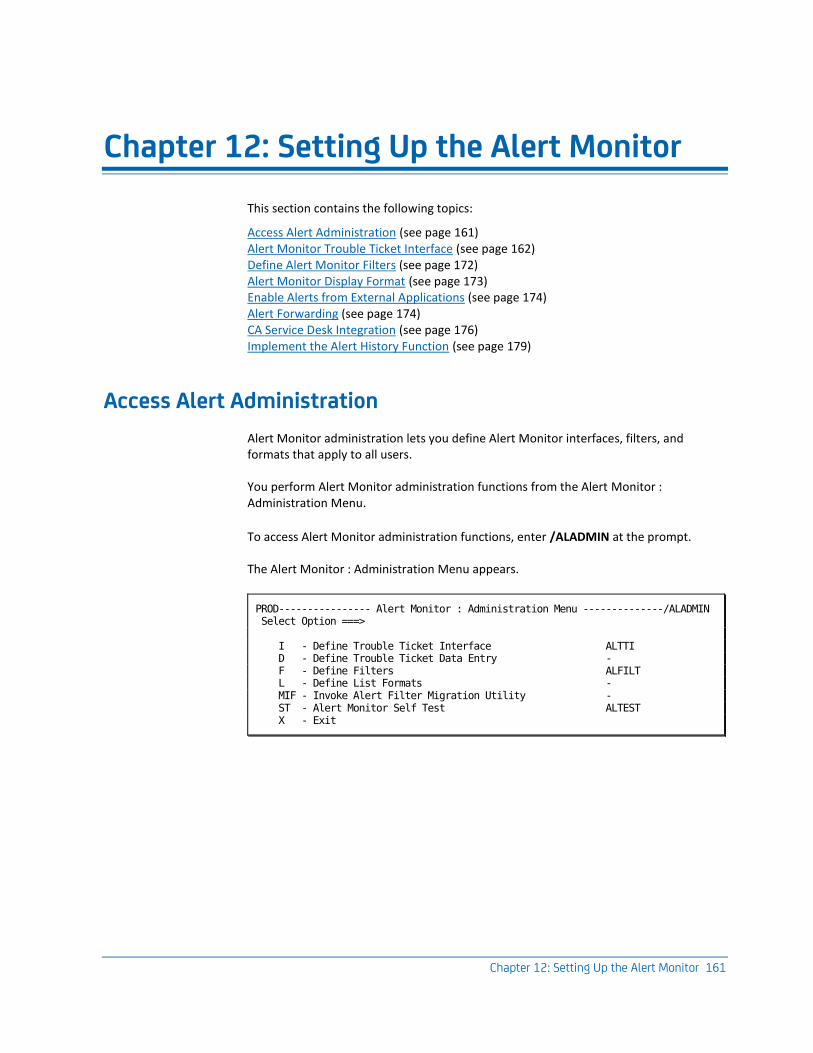
Chapter 12: Setting Up the Alert Monitor 161
Chapter 12: Setting Up the Alert Monitor
This section contains the following topics:
Access Alert Administration (see page 161) Alert Monitor Trouble Ticket Interface (see page 162) Define Alert Monitor Filters (see page 172) Alert Monitor Display Format (see page 173) Enable Alerts from External Applications (see page 174) Alert Forwarding (see page 174) CA Service Desk Integration (see page 176) Implement the Alert History Function (see page 179)
Access Alert Administration
Alert Monitor administration lets you define Alert Monitor interfaces, filters, and formats that apply to all users.
You perform Alert Monitor administration functions from the Alert Monitor : Administration Menu.
To access Alert Monitor administration functions, enter /ALADMIN at the prompt.
The Alert Monitor : Administration Menu appears.
PROD---------------- Alert Monitor : Administration Menu --------------/ALADMIN Select Option ===> I - Define Trouble Ticket Interface ALTTI D - Define Trouble Ticket Data Entry - F - Define Filters ALFILT L - Define List Formats - MIF - Invoke Alert Filter Migration Utility - ST - Alert Monitor Self Test ALTEST X - Exit
Alert Monitor Trouble Ticket Interface
162 Administration Guide
Alert Monitor Trouble Ticket Interface
The Alert Monitor provides an interface that lets you send alert information in the form of a trouble ticket to another interface automatically or manually.
The Alert Monitor supports the following interfaces for raising trouble tickets:
Electronic Mail
Sends an email describing the problem to a problem management application or a particular person. This method can be used to send tickets to multiple problem management applications.
Custom
Lets you write your own NCL procedure to deliver the trouble ticket to an application by whatever means you choose. For example, you can do the following:
■ Invoke a REXX procedure, and pass alert variables.
■ Send to any external interface, for example, problem-management product.
■ Send to MVS system facilities, for example, system console, data sets, SMF user records, or batch jobs.
■ Invoke applications, for example, FTP.
Service Desk
Creates a new CA Service Desk request from the alert details.
Note: If your CA Service Desk installation is configured with the optional ITIL application, incidents are created instead of requests.
Note: You can choose one interface only.
If you want the operator to supply information when requesting the creation of a ticket, you also need to set up the trouble ticket data entry definition.
Alert Monitor Trouble Ticket Interface
Chapter 12: Setting Up the Alert Monitor 163
Define a Trouble Ticket Interface
If you want to enable operators to raise trouble tickets on alerts, you must define the trouble ticket interface.
To define a trouble ticket interface between the Alert Monitor and another application
1. From the Alert Monitor Administration Menu, select option I - Define Trouble Ticket Interface.
The Alert Monitor : Interface Definition panel appears.
2. Enter the type of interface that you want to define in the Interface Type field.
Note: To obtain a selection list of valid values, enter ? in this field.
3. Press F6 (Action).
A panel appears where you can define an email (see page 163), custom (see page 165), or CA Service Desk (see page 166) interface. The type of panel displayed varies, depending on the interface type that you specified.
Define an Email Trouble Ticket Interface
This option enables alert details to be sent using email.
Note: To enable this option, you must ensure that your Systems Programmer enables SMTP support on this region's TCP/IP stack.
To define an email trouble ticket interface
1. Enter /ALADMIN at the prompt.
The Alert Monitor : Administration Menu appears.
2. Select option I - Define Trouble Ticket Interface.
The Alert Monitor : Trouble Ticket Interface Definition panel appears.
3. Enter EMAIL in the Interface Type field, and press F6 (Action).
The Email a Trouble Ticket panel appears.
Alert Monitor Trouble Ticket Interface
164 Administration Guide
4. Leave the &$USRNAME variable in the Mail Address field. The variable works with the default trouble ticket data entry definition (see page 168) to specify the email address of the trouble ticket system to which you want to send the message. The data entry definition lets operators specify the address.
If you do not want operators to be able to change the address, specify the address in the Mail Address field and delete the fields in the data entry definition.
Complete the other fields:
Host Name
(IBM's Communications server only) Specifies the host name of this system. This is usually the NJE node name.
SMTP Node Name
(IBM's Communications Server only) Specifies the NJE node name on which the SMTP server runs. This is usually the same value as the Host Name.
SMTP Job Name
(IBM's Communications server only) Specifies the name of the address space in which SMTP runs. This is usually SMTP.
SMTP DEST Id
(CA TCPaccess CS only) Specifies the destination ID in the REMOTE parameter of the SMTP statement in member APPCFGxx of the PARM data set.
Exit Procedure Name
Specifies the name of an NCL exit routine, in which you can customize the email message sent by this trouble ticket.
Subject
Specifies the heading to display as the subject of the email message.
Enter Mail Text Below
Specifies the mail message text. Press F1 (Help) for information about variables.
Press F3 (File).
The definition is saved.
Alert Monitor Trouble Ticket Interface
Chapter 12: Setting Up the Alert Monitor 165
Define a Custom Trouble Ticket Interface
You use the custom interface if you want to use your own procedure to send trouble tickets.
To define a custom trouble ticket interface
1. Enter /ALADMIN at the prompt.
The Alert Monitor : Administration Menu appears.
2. Select option I - Define Trouble Ticket Interface.
The Alert Monitor : Trouble Ticket Interface Definition panel appears.
3. Enter CUSTOM in the Interface Type field, and press F6 (Action).
The Custom Trouble Ticket panel appears.
4. Complete the following fields:
Procedure Name
Specifies the name of your NCL procedure for delivering tickets.
Important! The NCL procedure must be in the COMMANDS concatenation for your region. To list the concatenation, enter /ALLOC.
Enter Parameters Below
Specifies any parameters that you want the NCL procedure to receive. Press F1 (Help) for information about variables.
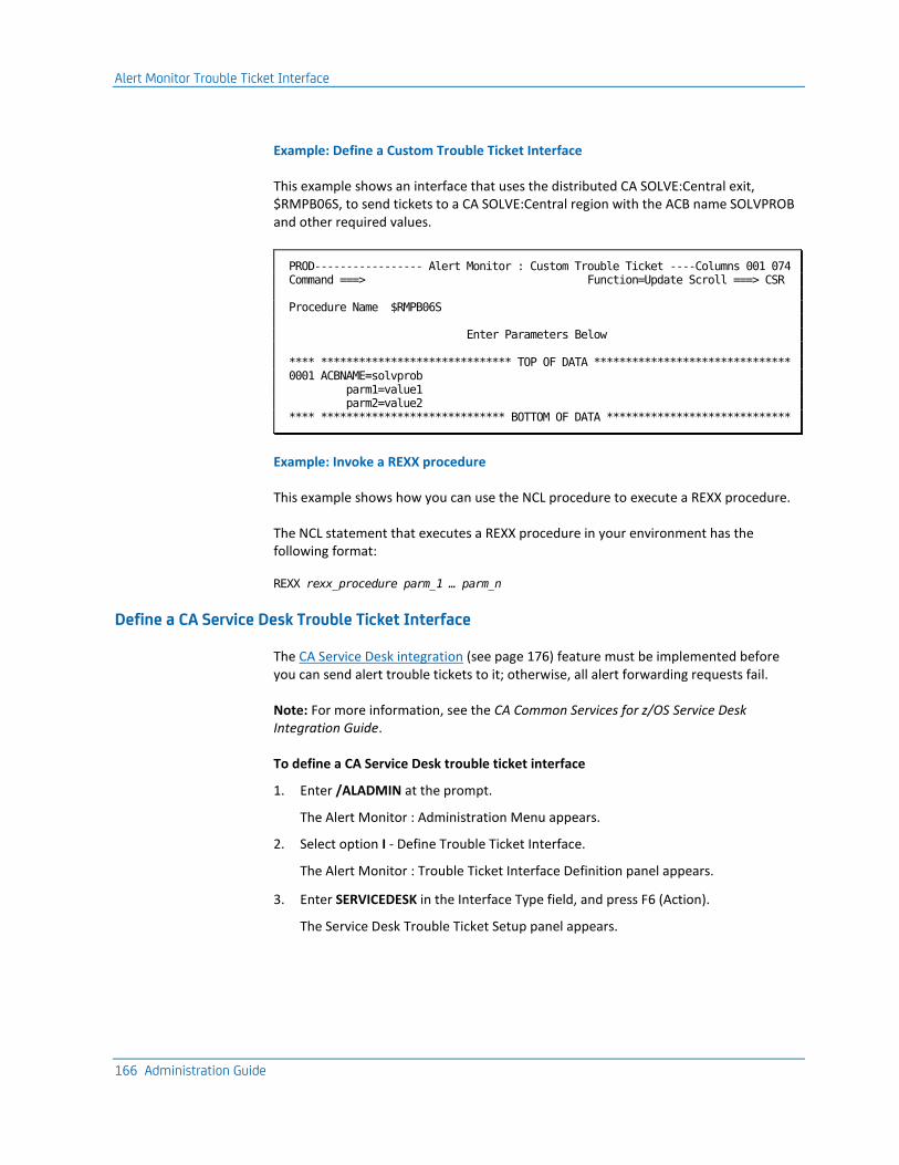
Alert Monitor Trouble Ticket Interface
166 Administration Guide
Example: Define a Custom Trouble Ticket Interface
This example shows an interface that uses the distributed CA SOLVE:Central exit, $RMPB06S, to send tickets to a CA SOLVE:Central region with the ACB name SOLVPROB and other required values.
PROD----------------- Alert Monitor : Custom Trouble Ticket ----Columns 001 074 Command ===> Function=Update Scroll ===> CSR Procedure Name $RMPB06S Enter Parameters Below **** ****************************** TOP OF DATA ******************************* 0001 ACBNAME=solvprob parm1=value1 parm2=value2 **** ***************************** BOTTOM OF DATA *****************************
Example: Invoke a REXX procedure
This example shows how you can use the NCL procedure to execute a REXX procedure.
The NCL statement that executes a REXX procedure in your environment has the following format:
REXX rexx_procedure parm_1 … parm_n
Define a CA Service Desk Trouble Ticket Interface
The CA Service Desk integration (see page 176) feature must be implemented before you can send alert trouble tickets to it; otherwise, all alert forwarding requests fail.
Note: For more information, see the CA Common Services for z/OS Service Desk Integration Guide.
To define a CA Service Desk trouble ticket interface
1. Enter /ALADMIN at the prompt.
The Alert Monitor : Administration Menu appears.
2. Select option I - Define Trouble Ticket Interface.
The Alert Monitor : Trouble Ticket Interface Definition panel appears.
3. Enter SERVICEDESK in the Interface Type field, and press F6 (Action).
The Service Desk Trouble Ticket Setup panel appears.
Alert Monitor Trouble Ticket Interface
Chapter 12: Setting Up the Alert Monitor 167
4. Complete the following fields:
CA Service Desk Server Web Services HTTP URL
Specifies the HTTP URL of the web services definitions on the target CA Service Desk server.
Default: If left blank, the CA Common Services CAISDI/soap component chooses the default server.
Note: This URL points to the web services definitions that CAISDI/soap invokes to create the requests. This is not the same as the URL that is used to log on to CA Service Desk. Contact your CA Service Desk administrator for the URL.
CCI Sysid
Specifies the CCI system ID of the LPAR where the CAISDI/soap task is active. This is the SYSID name specified in the CAICCI startup JCL.
Default: If left blank, the local CAICCI on this LPAR locates a suitable CAISDI/soap task.
Request Description Format
Specifies whether the USD Request Description field is produced with HTML formatting or in plain text (TEXT).
Default: HTML
Note: In most cases, leaving the CA Service Desk Server Web Services HTTP URL and CCI Sysid fields blank will suffice. This lets the CAISDI/soap component use its default values.
Press F3 (File)
The definition is saved.
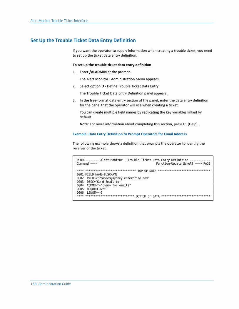
Alert Monitor Trouble Ticket Interface
168 Administration Guide
Set Up the Trouble Ticket Data Entry Definition
If you want the operator to supply information when creating a trouble ticket, you need to set up the ticket data entry definition.
To set up the trouble ticket data entry definition
1. Enter /ALADMIN at the prompt.
The Alert Monitor : Administration Menu appears.
2. Select option D - Define Trouble Ticket Data Entry.
The Trouble Ticket Data Entry Definition panel appears.
3. In the free-format data entry section of the panel, enter the data entry definition for the panel that the operator will use when creating a ticket.
You can create multiple field names by replicating the key variables linked by default.
Note: For more information about completing this section, press F1 (Help).
Example: Data Entry Definition to Prompt Operators for Email Address
The following example shows a definition that prompts the operator to identify the receiver of the ticket.
PROD--------- Alert Monitor : Trouble Ticket Data Entry Definition ------------ Command ===> Function=Update Scroll ===> PAGE **** ****************************** TOP OF DATA ******************************* 0001 FIELD NAME=$USRNAME 0002 VALUE="[email protected]" 0003 DESC="Send Email to:" 0004 COMMENT="(name for email)" 0005 REQUIRED=YES 0006 LENGTH=40 **** ***************************** BOTTOM OF DATA *****************************
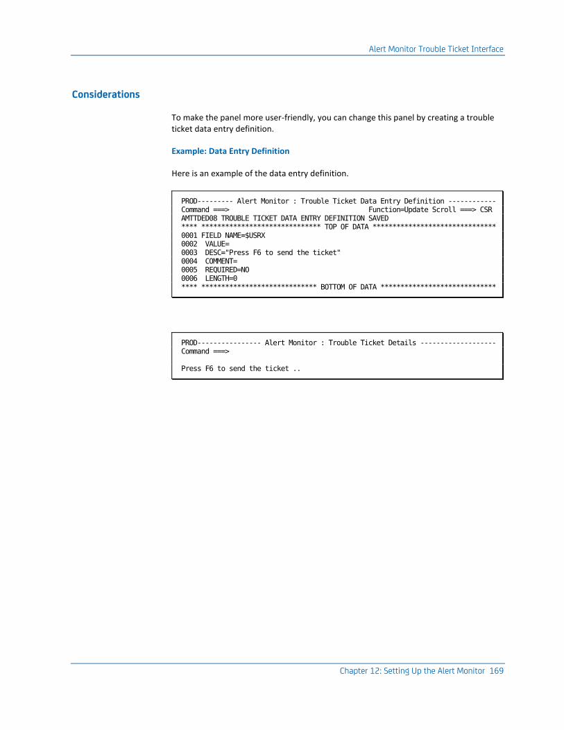
Alert Monitor Trouble Ticket Interface
Chapter 12: Setting Up the Alert Monitor 169
Considerations
To make the panel more user-friendly, you can change this panel by creating a trouble ticket data entry definition.
Example: Data Entry Definition
Here is an example of the data entry definition.
PROD--------- Alert Monitor : Trouble Ticket Data Entry Definition ------------ Command ===> Function=Update Scroll ===> CSR AMTTDED08 TROUBLE TICKET DATA ENTRY DEFINITION SAVED **** ****************************** TOP OF DATA ******************************* 0001 FIELD NAME=$USRX 0002 VALUE= 0003 DESC="Press F6 to send the ticket" 0004 COMMENT= 0005 REQUIRED=NO 0006 LENGTH=0 **** ***************************** BOTTOM OF DATA *****************************
PROD---------------- Alert Monitor : Trouble Ticket Details ------------------- Command ===> Press F6 to send the ticket ..
Alert Monitor Trouble Ticket Interface
170 Administration Guide
Implement Trouble Ticket Interface for Multiple Email Addressees
You can use an exit procedure, together with the trouble ticket interface and data entry definitions, to implement an interface that prompts operators for more than one email address.
To implement a trouble ticket interface for multiple email addressees
1. Create an NCL procedure with the following statements, and save it to your TESTEXEC:
&IF .&$USRNAME1 NE . &THEN +
&$AMTADDRESS1 = &$USRNAME1
&IF .&$USRNAME2 NE . &THEN +
&$AMTADDRESS2 = &$USRNAME2
...
Note: The number of &IF statements sets up the number of addresses you want to provide.
2. Update the trouble ticket data entry definition (see page 168) with the following fields:
FIELD NAME=$USRNAME1
VALUE="&$AMTADDRESS1"
DESC="EMAIL ADDRESS #1"
COMMENT=""
REQUIRED=NO
LENGTH=40
FIELD NAME=$USRNAME2
VALUE=""
DESC="EMAIL ADDRESS #2"
COMMENT=""
REQUIRED=NO
LENGTH=40
...
Notes:
■ The number of fields corresponds to the number of email addresses in the procedure you created.
■ The value &$AMTADDRESS1 must be specified.
3. Define the email trouble ticket interface (see page 163) specifying a default address in the Mail Address field and the name of the procedure in the Exit Procedure Name field.
The trouble ticket interface prompts operators for email addresses when they enter TT next to an alert.
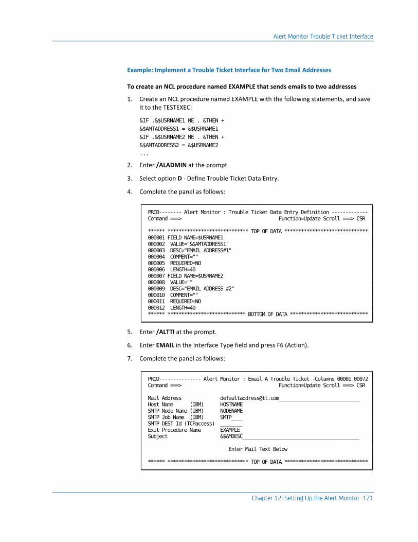
Alert Monitor Trouble Ticket Interface
Chapter 12: Setting Up the Alert Monitor 171
Example: Implement a Trouble Ticket Interface for Two Email Addresses
To create an NCL procedure named EXAMPLE that sends emails to two addresses
1. Create an NCL procedure named EXAMPLE with the following statements, and save it to the TESTEXEC:
&IF .&$USRNAME1 NE . &THEN +
&$AMTADDRESS1 = &$USRNAME1
&IF .&$USRNAME2 NE . &THEN +
&$AMTADDRESS2 = &$USRNAME2
...
2. Enter /ALADMIN at the prompt.
3. Select option D - Define Trouble Ticket Data Entry.
4. Complete the panel as follows:
PROD-------- Alert Monitor : Trouble Ticket Data Entry Definition ------------- Command ===> Function=Update Scroll ===> CSR ****** ***************************** TOP OF DATA ****************************** 000001 FIELD NAME=$USRNAME1 000002 VALUE="&$AMTADDRESS1" 000003 DESC="EMAIL ADDRESS#1" 000004 COMMENT="" 000005 REQUIRED=NO 000006 LENGTH=40 000007 FIELD NAME=$USRNAME2 000008 VALUE="" 000009 DESC="EMAIL ADDRESS #2" 000010 COMMENT="" 000011 REQUIRED=NO 000012 LENGTH=40 ****** **************************** BOTTOM OF DATA ****************************
5. Enter /ALTTI at the prompt.
6. Enter EMAIL in the Interface Type field and press F6 (Action).
7. Complete the panel as follows:
PROD--------------- Alert Monitor : Email A Trouble Ticket -Columns 00001 00072 Command ===> Function=Update Scroll ===> CSR Mail Address [email protected]_____________________________ Host Name (IBM) HOSTNAME SMTP Node Name (IBM) NODENAME SMTP Job Name (IBM) SMTP____ SMTP DEST Id (TCPaccess) ________ Exit Procedure Name EXAMPLE_ Subject &$AMDESC__________________________________________ Enter Mail Text Below ****** ***************************** TOP OF DATA ******************************
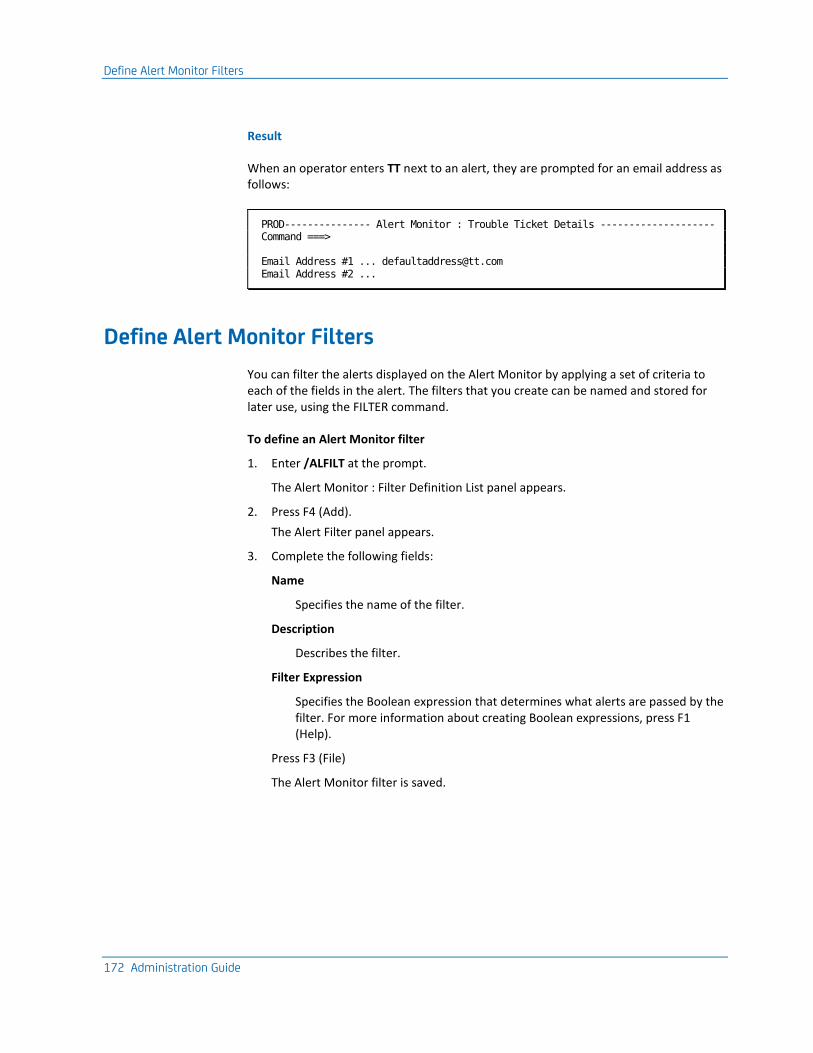
Define Alert Monitor Filters
172 Administration Guide
Result
When an operator enters TT next to an alert, they are prompted for an email address as follows:
PROD--------------- Alert Monitor : Trouble Ticket Details -------------------- Command ===> Email Address #1 ... [email protected] Email Address #2 ...
Define Alert Monitor Filters
You can filter the alerts displayed on the Alert Monitor by applying a set of criteria to each of the fields in the alert. The filters that you create can be named and stored for later use, using the FILTER command.
To define an Alert Monitor filter
1. Enter /ALFILT at the prompt.
The Alert Monitor : Filter Definition List panel appears.
2. Press F4 (Add).
The Alert Filter panel appears.
3. Complete the following fields:
Name
Specifies the name of the filter.
Description
Describes the filter.
Filter Expression
Specifies the Boolean expression that determines what alerts are passed by the filter. For more information about creating Boolean expressions, press F1 (Help).
Press F3 (File)
The Alert Monitor filter is saved.
Alert Monitor Display Format
Chapter 12: Setting Up the Alert Monitor 173
Alert Monitor Display Format
The Alert Monitor display format determines the information displayed for the alerts on the Alert Monitor, for example, the columns and the order in which they appear.
You specify the Alert Monitor display format on the List Format panel.
For each type of information you want to display on the Alert Monitor, you need to specify two items: a static heading and a variable that contains the required information.
You can create a multiscreen Alert Monitor display with up to 10 screens, enabling you to display more information on the monitor. The screens can be accessed by pressing the F11 (Right) or F10 (Left) function keys from the monitor.
The variable contains the information you want to display. The name of a variable can sometimes be longer than the data to display. You can enter a shorter name and then make that shorter name an alias of the actual name.
Create the Alert Monitor Display Format
You can create format definitions that can be used to customize the information displayed on the Alert Monitor.
To create the Alert Monitor display format
1. Enter /ALADMIN.L at the prompt.
The List Definition List appears.
2. Enter C beside the DEFAULT display format definition.
A copy of the List Description panel appears.
3. Enter a new value in the List Name field to identify the new definition, and update the Description and Title fields.
Press F8 (Forward) three times.
The List Format panel appears.
4. Enter column headings and variables using the text editor to specify the information to display on the Alert Monitor.
Note: For more information about the text editor, press F1 (Help).
5. (Optional) Press F5 (Fields) to create aliases.
6. Press F3 (File).
The details are saved.
Enable Alerts from External Applications
174 Administration Guide
Enable Alerts from External Applications
You can generate alerts (to view on the Alert Monitor) from external applications such as CA OPS/MVS.
Note: To use this feature, the SOLVE SSI must be active.
Follow these steps:
1. Enter /PARMS at the prompt.
The Parameter Groups list appears.
2. Enter U next to the $NM ALERTS parameter group in the Interfaces category.
The ALERTS - Alert Monitor Interface panel appears.
3. Enter YES in the Enable External Alerts? field.
4. Press F6 (Action).
The changes are activated immediately.
5. Press F3 (File).
The settings are saved.
Alert Forwarding
Alerts are displayed on the Alert Monitor; however, you can also forward them to the following platforms:
■ EM Console in CA NSM
■ UNIX platforms as SNMP traps
■ CA NetMaster NM for SNA or Tivoli NetView (TME10) systems, as generic alert NMVTs
■ CA Service Desk servers (see page 176), as CA Service Desk requests or incidents
You can apply filter criteria to forward different types of alerts to different platforms.
Alert forwarding does not require manual intervention; it occurs automatically when the alert is created.
Alert Forwarding
Chapter 12: Setting Up the Alert Monitor 175
Implement Alert Forwarding
You implement alert forwarding by using Customizer parameter groups.
Note: TNGTRAP and SERVICEDESK do not have clear alert events. Only alert open and considerations are forwarded.
To implement alert forwarding
1. Enter /PARMS at the prompt.
The Customizer : Parameter Groups list appears.
2. Enter U in front of the ALERTS parameter group in the Interfaces category.
The parameter group opens for update.
3. Complete the following field:
Dest Type
Specifies the type of alert forwarding to use.
Press Enter.
The fields dynamically change to match the specified destination type.
4. Review the fields, and update as required.
(Optional) Press F8 (Forward), and repeat Step 3 for each Definition ID.
Note: Press F1 (Help) for information about the fields.
5. Press F6 (Action).
The changes are applied.
6. Press F3 (File).
The settings are saved.
SNMP Trap Definition
The MIB definition for alerts forwarded as SNMP traps is provided in member $AMTRAP, supplied in the CC2DSAMP data set. You can download this member to your UNIX system and compile it.
Note: When copying this member to your UNIX system, you can rename it to avoid problems on some UNIX systems where the $ sign has special meaning.
The supplied MIB defines two traps with the following object identifiers:
■ $AMTRAP = 1.3.6.1.4.1.1126.1.2.1.2 (for an alert)
■ $AMTRAPC = 1.3.6.1.4.1.1126.1.2.1.3 (when an alert is cleared)
CA Service Desk Integration
176 Administration Guide
Forward to Tivoli NetView
To receive alerts in a Tivoli NetView region, the CNMCALRT task must be defined and active. The alerts are formatted as Operator Notification generic alerts.
To forward alerts to Tivoli NetView
1. Check the DSIDMN (or DSIDMNB) member in the DSIPARM PDS. DSIPARM.PDS is allocated by the Tivoli NetView started task.
2. Ensure that the CNMCALRT task is included and is initialized (INIT=Y). For example:
TASK MOD=CNMCALRT,TSKID=CNMCALRT,PRI=6,INIT=Y
Note: This statement is necessary for the z/OS software alert forwarding function.
CA Service Desk Integration
The CA Service Desk Integration feature creates CA Service Desk requests from forwarded alerts and alert trouble tickets, or both.
You can define multiple forwarding destinations to CA Service Desk, with each one pointing to a different CA Service Desk server.
Note: If your CA Service Desk installation is configured with the optional ITIL application, incidents are created instead of requests.
Many CA Technologies mainframe products use this feature to consolidate their problem notification on a specified CA Service Desk server. The feature uses W3C SOAP (Simple Object Access Protocol) to invoke web services provided by CA Service Desk.
Software Requirements
CA Service Desk Integration has the following software requirements:
■ CA Service Desk r11 or r11.1
■ CA Common Services for z/OS r11, specifically the CAICCI and CAISDI/soap components
CA Service Desk Integration
Chapter 12: Setting Up the Alert Monitor 177
How Requests Are Created
To create a CA Service Desk request from an alert, the following internal steps are performed:
1. The CA Common Services for z/OS CAICCI component is used to pass the request to the CA Common Services for z/OSCAISDI soap component. CAISDI/soap is a z/OS-hosted SOAP client.
2. CAISDI/soap sets up an IP connection with the CA Service Desk server, then uses HTTP/HTTPS requests to invoke the necessary web services on the CA Service Desk server to create the new request or incident.
3. The request or incident number is returned and annotated in the alert.
Request Assignment
By default, CA Service Desk requests created by your region appear as assigned requests, with an assignee and an end user of System_NetMaster_User.
Your CA Service Desk administrator can customize the product templates to change these assignments to suit your organization.
Request Updating
A CA Service Desk request created from an alert is static. It reflects the alert details that were current at the time it was created.
Note: A CA Service Desk request is not subsequently updated with any changes to the alert, nor closed when the corresponding alert is closed.
Requests are intended for initial problem notification to a wider and more general data center audience. CA Service Desk Integration complements the functions of the Alert Monitor; it does not replace the Alert Monitor.
Every request (if HTML format is used) contains hyperlinks to various WebCenter pages, including the Alert Monitor. You should use the Alert Monitor for real-time dynamic alerting functions.
For recurring alerts, a request is created for the first occurrence only.
Other Ways to Create Requests or Incidents
In addition to Alert Monitor forwarding and trouble tickets, CA Service Desk requests or incidents can also be created from the following functions:
■ Operator Console Services (OCS)
■ MVS console
CA Service Desk Integration
178 Administration Guide
Operator Console Services
The OCS command SDCREATE can be used to create a CA Service Desk request from the OCS command line, for example:
SDCREATE Problem xxx has occurred
This attempts to open a request on the default CA Service Desk server. The request will have a severity of 4, and a summary and description of Problem xxx has occurred. Like other requests raised, it is assigned to System_NetMaster_User.
Use the SDTEST command to check if a default server is implemented.
MVS Console
As with any product command, you can also issue SDCREATE from the MVS system console, for example:
F rname,SDCREATE Problem xxx has occurred
Request Description Format
By default, your region generates CA Service Desk request description content in HTML format.
By default, CA Service Desk does not render embedded HTML directives in the request description field. To support this, you must customize your CA Service Desk server. This task involves customizing the detail_cr.htmpl form to add keeptags and keeplinks support.
Note: For more information, see the Service Desk Modification Guide.
Implement the Alert History Function
Chapter 12: Setting Up the Alert Monitor 179
Implement the Alert History Function
The Alert Monitor retains data in an alert history file. You can define the time period that alerts are retained.
To specify the time period that alerts are retained
1. Enter /PARMS at the prompt.
The Customizer : Parameter Groups list appears.
2. Enter U in front of the $NM ALERTHIST parameter group in the Files category.
The ALERTHIST - Alert History File Specification panel appears.
3. Complete the following fields:
Days to Retain Alerts
Specifies the number of days that you want to retain alerts in the history file.
Limits: 999 days
Default: 7 days
Time of Day for Alert Purge
Specifies the time of day (in the format hh.mm) at which alerts older than the value in the Days to Retain Alerts field are deleted from the history file.
Press F6 (Action).
The changes are applied.
4. Press F3 (File).
The settings are saved.
Implement the Alert History Function
180 Administration Guide
Reorganize Files and Monitor Space Usage
Over time, the alert history file can become fragmented. You can reorganize the file to improve its efficiency.
To reorganize the Alert History database for optimum space usage
1. Copy (REPRO) the alert history file to a backup file.
2. Delete and redefine the original file.
Use the same attributes that were used when the file was defined at region setup. See the generated S01LCALC member in your INSTALL.JCL data set; this member has the original VSAM definition JCL for the file.
Monitor the amount of disk space used by the data set to estimate the optimal file size and optimal frequency of reorganization.
Example: Back Up Alert History File
This example backs up an alert history file.
//BKALERTH EXEC PGM=IDCAMS
//SYSPRINT DD SYSOUT=*
//IN DD DSN=?prefix.ALERTH,DISP=SHR
//OUT DD SN=?prefix.ALERTH.BACKUP.SEQ,DISP=OLD
//SYSIN DD *
REPRO INFILE(IN) OUTFILE(OUT)
/*
The sequential backup file has the following format:
DSORG=PS,RECFM=VB,LRECL=32756,BLKSIZE=32760
Implement the Alert History Function
Chapter 12: Setting Up the Alert Monitor 181
Extract Alert Data for Reporting
You can extract alert data from the Alert History database in a character separated values (CSV) format for processing by external reporting and analysis tools. The default field separator character is comma (,). You can change it in the ALERTHIST parameter group.
To extract alert data for reporting and analysis
1. Allocate a sequential data set with the following attributes:
■ LRECL is greater than or equal to 300 bytes.
■ RECFM is VB.
2. Enter /ALHIST.
The History Menu appears.
3. Type EX at the prompt, and specify the data set name that you have allocated in the Extract DSN field.
(Optional) If you want to limit the extracted data, select an Alert Monitor filter (see page 172) through the Filter Name field.
Press Enter.
The data is extracted to the specified data set.
4. Transfer the data set to your personal computer (PC) in ASCII format, and save it with an appropriate extension. (For example, if you plan to use Microsoft Excel to process the data, use the .csv extension.)
The extracted data is saved in a text file.
5. Open the text file by using your preferred PC application.
The extracted data is presented in your preferred format for analysis.
6. Analyze your data by applying facilities such as graphs and charts, tables, and macros.

Chapter 13: Setting Up the Initialization File 183
Chapter 13: Setting Up the Initialization File
This section contains the following topics:
Generate an Initialization File (see page 183) How You Configure the Initialization File (see page 184) Start Your Region from an Initialization File (see page 186)
Generate an Initialization File
If you are deploying multiple regions, each region must be configured for its local environment. When you have configured your first region, you can build an initialization file from that region and then configure it for use with your other regions. This removes the need to customize each region with Customizer.
The tasks outlined below show how to configure a region from an initialization file. The initialization file is produced from a running region for your product.
To generate an initialization file
1. From the Primary Menu, enter /CUSTOM.
The Customizer panel appears.
2. Select option G - Generate INI Procedure.
The Customizer : Generate INI Procedure panel appears.
3. Enter the data set name and the member name of the file in the Generate INI File Details section.
Note: The data set must be in the commands concatenation of the RUNSYSIN member for the region in which it is used.
4. Ensure that the member name and data set name are correct. Enter YES in the Replace Member? field if you are replacing an existing member.
5. Press F6 (Action).
The initialization file is generated.
6. Make a note of the data set and member names and press F6 (Confirm).
The details are saved.
How You Configure the Initialization File
184 Administration Guide
How You Configure the Initialization File
The initialization file must be configured before it can be used for other regions. You can perform this configuration as follows:
■ Configure an individual initialization file for each region.
■ Configure a common initialization file for multiple regions.
You can use system variables and static system variables with both of these methods. The variables substitute for the initialization parameters in the INI file.
Configure a Common Initialization File
You can customize an initialization file using variables so that it can be used for multiple regions.
To configure a common initialization file
1. Create a data set that is available to every region to be initialized from the common initialization file, for example, PROD.INIFILES.
2. Add the newly created data set to the COMMANDS concatenation of the RUNSYSIN member to every region to be initialized from the common initialization file.
Note: RUNSYSIN is located in TESTEXEC.
3. Copy the initialization file generated into the new INIFILES data set.
4. Use your TSO editing tool to open the initialization file in edit mode.
5. Replace the relevant generated variables in the initialization file with the following system variables:
&ZDSNQLCL
The local VSAM data set qualifier.
&ZDSNQSHR
The shared VSAM data set qualifier.
&ZACBNAME
The primary VTAM ACB name used by the region.
&ZDSNQLNV
The local non-VSAM data set qualifier.
&ZDSNQSNV
The shared non-VSAM data set qualifier.
&ZNMDID
The domain identifier.
How You Configure the Initialization File
Chapter 13: Setting Up the Initialization File 185
&ZNMSUP
The system user prefix.
6. Replace the relevant generated variables in the initialization file with the z/OS static system symbols as follows:
&SYSCLONE
The short name for the system.
&SYSNAME
The name of the system.
&SYSPLEX
The name of the sysplex.
&SYSR1
The IPL VOLSER.
7. Save the changes to the initialization file.
Configure Individual Initialization Files
You can customize an initialization file generated from one region so that it can be used for another region.
To configure an individual initialization file for each region
1. Use your TSO editing tool to open the initialization file in edit mode.
2. Substitute the parameters in the initialization file with one of the following:
■ Hard-coded data set names for the region in which the file is used
■ System variables
This enables the initialization file to work in regions with different data sets than the region in which it was generated.
3. Save the changes to the initialization file.
4. Copy the initialization file to the region's TESTEXEC or one of the other libraries in the COMMANDS concatenation.
5. Repeat steps 1 to 4 for each initialization file needed.
Note: The region from which the original initialization file was generated should have the same product sets as the destination regions that will use that initialization file.
Start Your Region from an Initialization File
186 Administration Guide
Start Your Region from an Initialization File
The name of the initialization file must be specified by the INIFILE parameter in the RUNSYSIN member.
Updating your RUNSYSIN member causes your region to set its initialization parameters from the initialization file. All Customizer parameter settings are overwritten.
To update your RUNSYSIN member
1. Use a text editor to open your RUNSYSIN member.
2. Insert the line PPREF='INIFILE=membername' into your RUNSYSIN member.
3. Save the member.
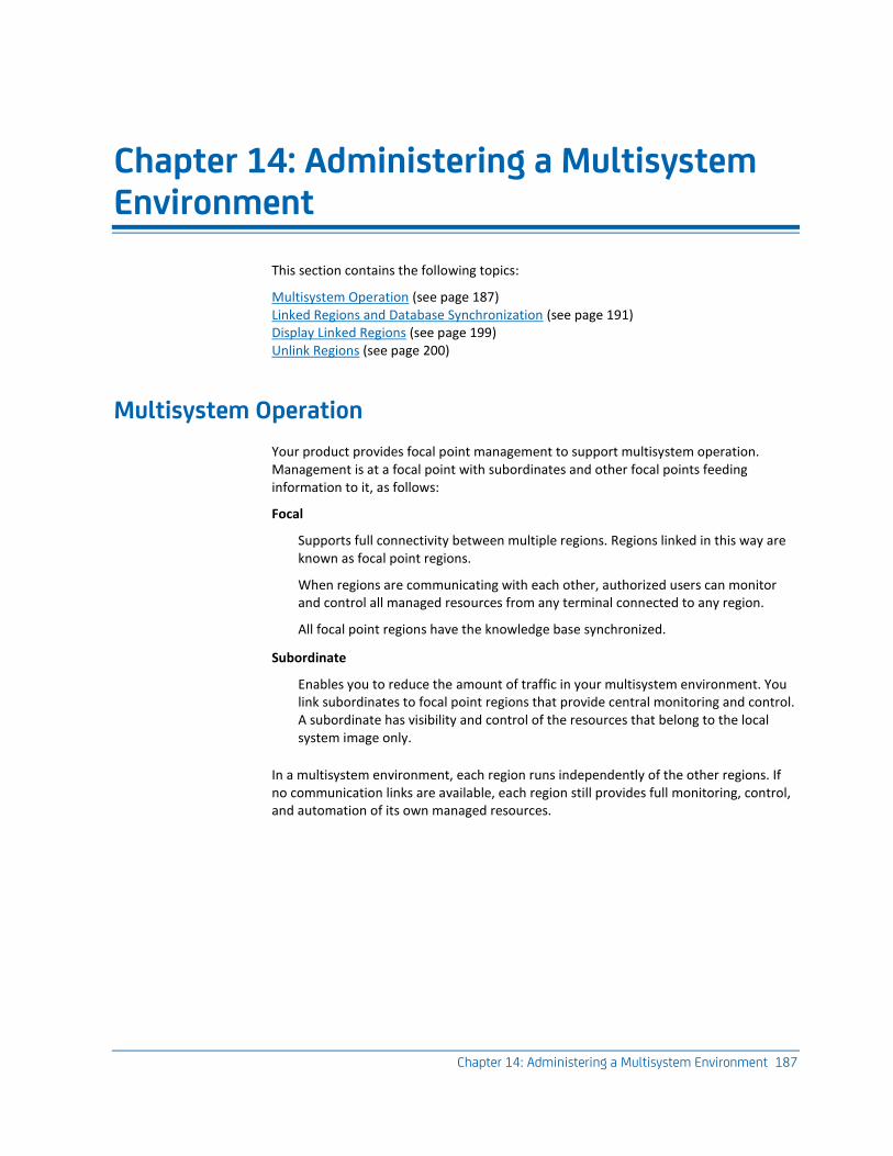
Chapter 14: Administering a Multisystem Environment 187
Chapter 14: Administering a Multisystem Environment
This section contains the following topics:
Multisystem Operation (see page 187) Linked Regions and Database Synchronization (see page 191) Display Linked Regions (see page 199) Unlink Regions (see page 200)
Multisystem Operation
Your product provides focal point management to support multisystem operation. Management is at a focal point with subordinates and other focal points feeding information to it, as follows:
Focal
Supports full connectivity between multiple regions. Regions linked in this way are known as focal point regions.
When regions are communicating with each other, authorized users can monitor and control all managed resources from any terminal connected to any region.
All focal point regions have the knowledge base synchronized.
Subordinate
Enables you to reduce the amount of traffic in your multisystem environment. You link subordinates to focal point regions that provide central monitoring and control. A subordinate has visibility and control of the resources that belong to the local system image only.
In a multisystem environment, each region runs independently of the other regions. If no communication links are available, each region still provides full monitoring, control, and automation of its own managed resources.
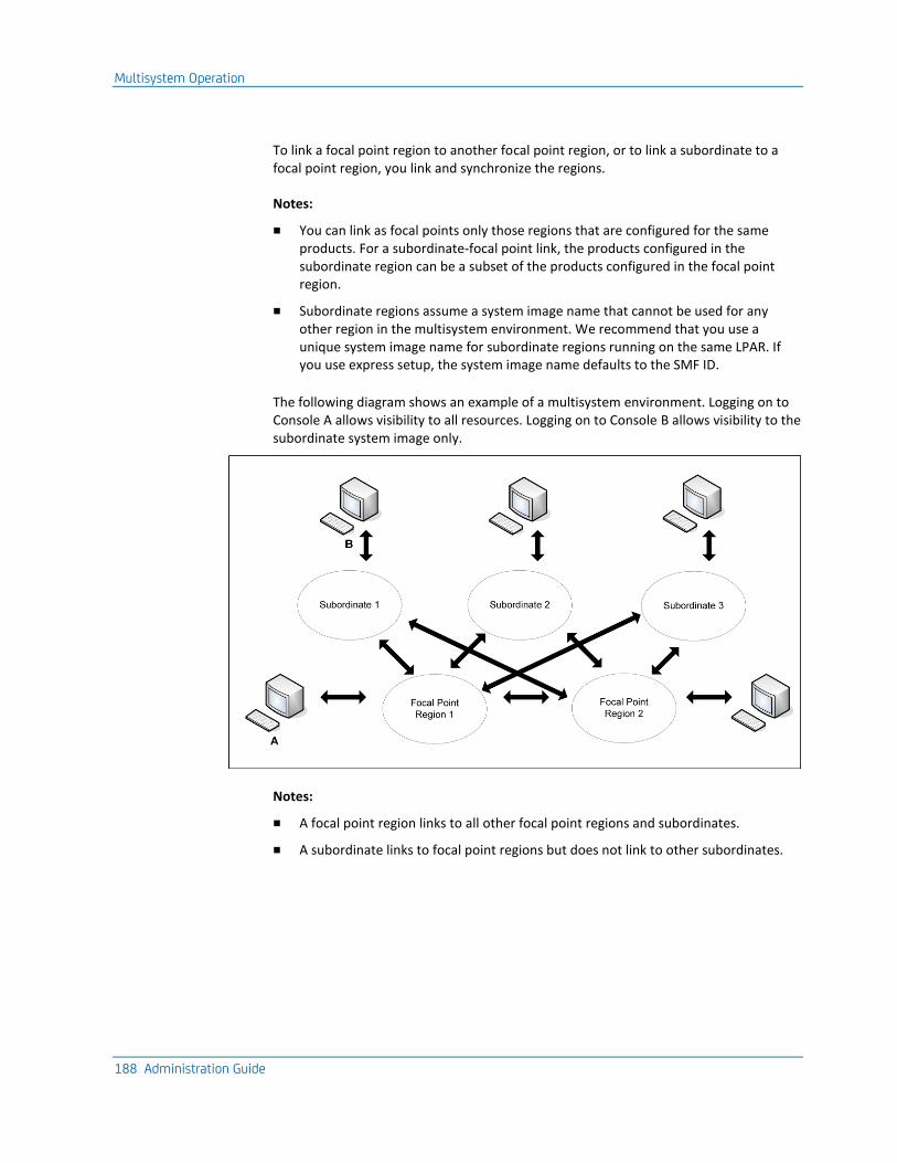
Multisystem Operation
188 Administration Guide
To link a focal point region to another focal point region, or to link a subordinate to a focal point region, you link and synchronize the regions.
Notes:
■ You can link as focal points only those regions that are configured for the same products. For a subordinate-focal point link, the products configured in the subordinate region can be a subset of the products configured in the focal point region.
■ Subordinate regions assume a system image name that cannot be used for any other region in the multisystem environment. We recommend that you use a unique system image name for subordinate regions running on the same LPAR. If you use express setup, the system image name defaults to the SMF ID.
The following diagram shows an example of a multisystem environment. Logging on to Console A allows visibility to all resources. Logging on to Console B allows visibility to the subordinate system image only.
Notes:
■ A focal point region links to all other focal point regions and subordinates.
■ A subordinate links to focal point regions but does not link to other subordinates.
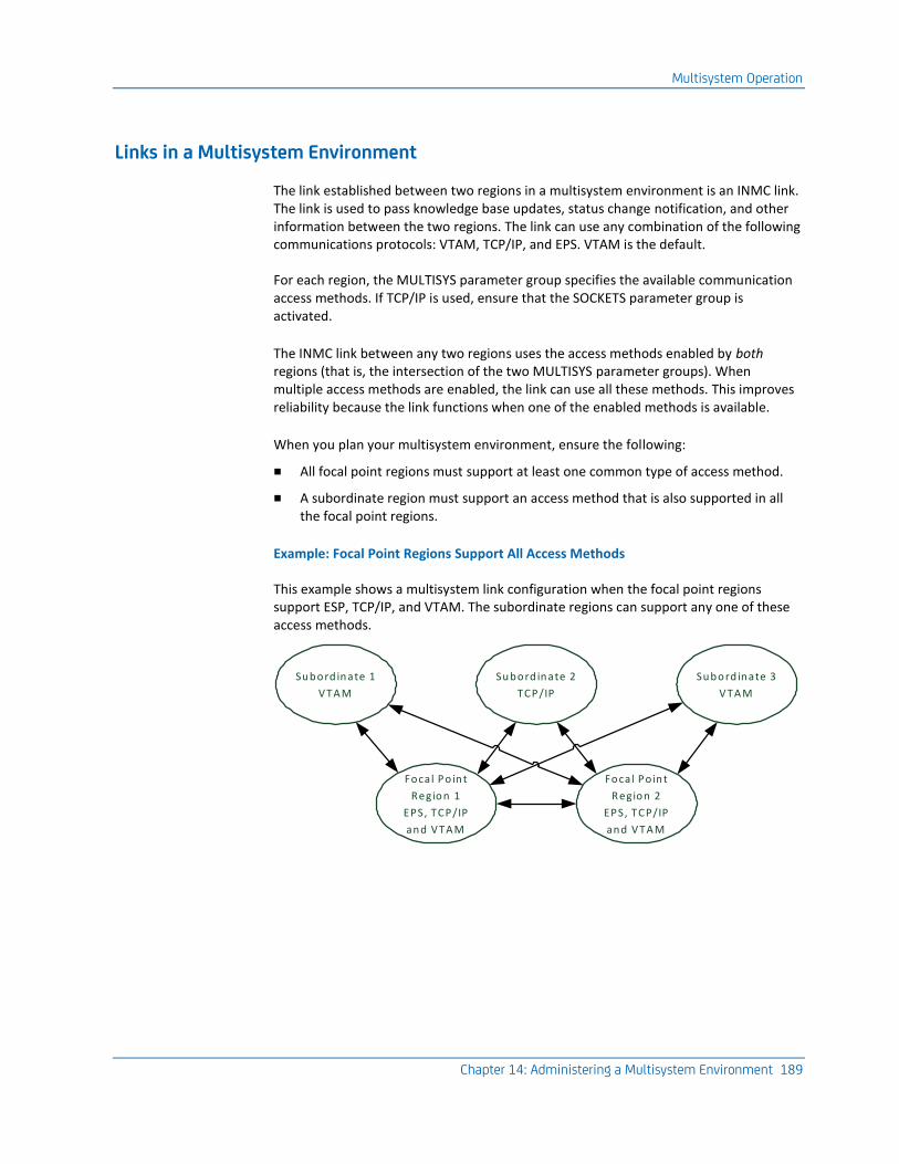
Multisystem Operation
Chapter 14: Administering a Multisystem Environment 189
Links in a Multisystem Environment
The link established between two regions in a multisystem environment is an INMC link. The link is used to pass knowledge base updates, status change notification, and other information between the two regions. The link can use any combination of the following communications protocols: VTAM, TCP/IP, and EPS. VTAM is the default.
For each region, the MULTISYS parameter group specifies the available communication access methods. If TCP/IP is used, ensure that the SOCKETS parameter group is activated.
The INMC link between any two regions uses the access methods enabled by both regions (that is, the intersection of the two MULTISYS parameter groups). When multiple access methods are enabled, the link can use all these methods. This improves reliability because the link functions when one of the enabled methods is available.
When you plan your multisystem environment, ensure the following:
■ All focal point regions must support at least one common type of access method.
■ A subordinate region must support an access method that is also supported in all the focal point regions.
Example: Focal Point Regions Support All Access Methods
This example shows a multisystem link configuration when the focal point regions support ESP, TCP/IP, and VTAM. The subordinate regions can support any one of these access methods.
Subord inate 1
V TA M
Subord inate 2
TCP/IP
Focal Po int
Region 1
EPS, TCP/IP
and V TA M
Subord inate 3
V TA M
Focal Po int
Region 2
EPS, TCP/IP
and V TA M
Multisystem Operation
190 Administration Guide
Example: One Focal Point Region Supports VTAM Only
This example shows a multisystem link configuration when a focal point region supports VTAM only. The subordinate regions must support VTAM.
Subord inate 1
V TA M
Subord inate 2
V TA M
Focal Po int
Region 1
EPS, TCP/IP
and V TA M
Subord inate 3
V TA M
Focal Po int
Region 2
V TA M
Multisystem Support in a Sysplex
With the EPS access method, you can use the sysplex cross-system coupling facility (XCF) to implement your multisystem environment.
Notes:
■ To support the EPS access method, a SOLVE SSI region must be active in each of the co-operating systems and must be registered to XCF.
■ To register the SSI region to XCF, ensure that XCF=YES is set in the SSI parameters member of the SSIPARM data set. This is the default setting at installation.
Multisystem Implementation Considerations
When you implement your multisystem environment, consider the following:
■ Ensure that the link requirements (see page 189) are satisfied for the planned multisystem environment.
■ When you link two regions, the knowledge base in one region overwrites the knowledge base in the other region. You must transmit all system images used by the local region to the target focal point region prior to synchronization.
■ You can only link a region to a focal point region. The focal point region can be a stand-alone region or part of a multisystem environment.
■ You can only link a stand-alone region into a multisystem environment.
Linked Regions and Database Synchronization
Chapter 14: Administering a Multisystem Environment 191
How a Multisystem Environment Is Established
When you install your product, two databases are downloaded. These databases, which can be customized to suit your requirements, are:
■ An icon panel database, where icon panel definitions are stored for the graphical monitor
■ The RAMDB, where system image, resource, availability map, process, macro, command, and other definitions are stored
Together, these databases form the knowledge base.
Populate these databases with definitions specific to your environment. These definitions can include the system image definitions for any other regions that you want to install in your environment in the future.
As you establish regions, link the new regions to the first region by using the Link Region and Synchronize Database (see page 191) option. When databases are linked, future synchronization is automatic. Changes to the database in one region are sent to the databases in the linked regions that have visibility to those resources and system images.
Note: Synchronization does not apply to the NCL procedures represented by the registered commands and macros. Changes to these NCL procedures are not automatically reflected in the linked regions.
In a multisystem environment, you can monitor and control the resources in all linked regions from a single focal point.
Linked Regions and Database Synchronization
When the first region is created in your environment, two databases are downloaded and can be customized for your environment. Together, these two databases (the Automation Services database and the icon panel library) form the knowledge base.
To build a multisystem environment, you start by linking two regions, and then continue to link in any other regions. The linking process also synchronizes the knowledge bases of these regions.
Notes
■ For linked focal point regions, synchronization is complete and the focal point knowledge bases are identical.
■ For linked subordinates, synchronization is complete only to the extent of the relevant definitions in the knowledge base. For example, a subordinate knowledge base does not contain all system images. A subordinate knowledge base contains only those images that represent the environment the subordinate is managing.
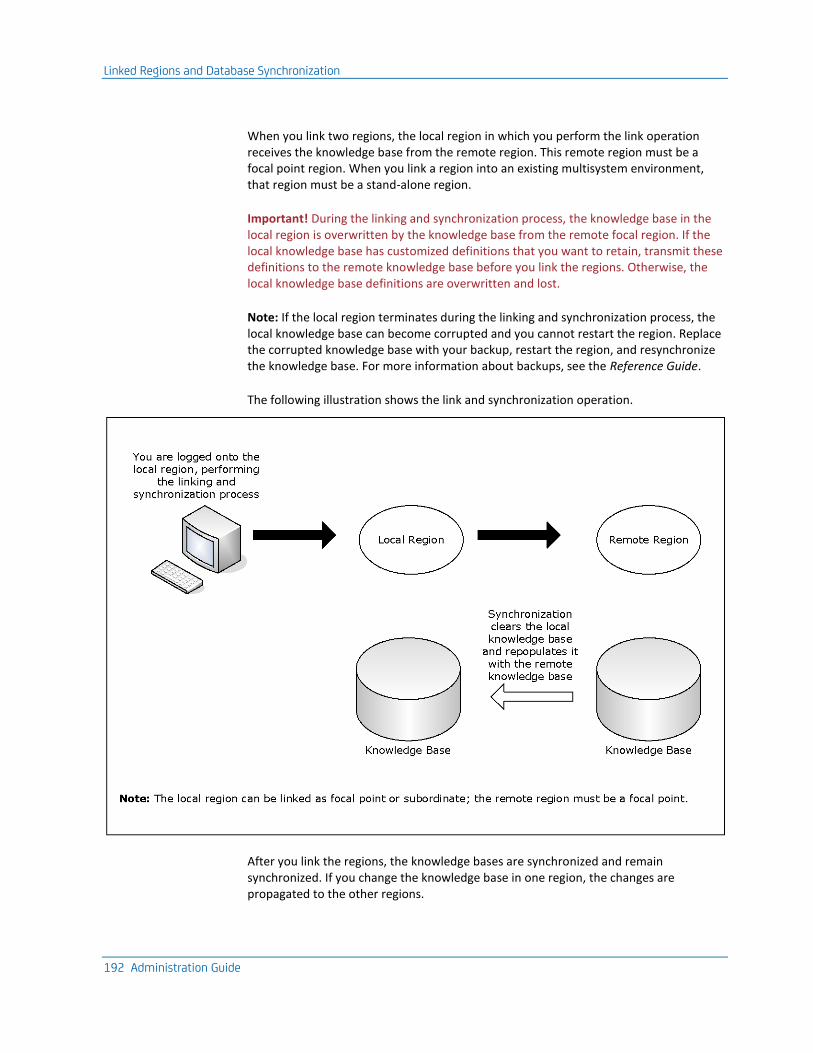
Linked Regions and Database Synchronization
192 Administration Guide
When you link two regions, the local region in which you perform the link operation receives the knowledge base from the remote region. This remote region must be a focal point region. When you link a region into an existing multisystem environment, that region must be a stand-alone region.
Important! During the linking and synchronization process, the knowledge base in the local region is overwritten by the knowledge base from the remote focal region. If the local knowledge base has customized definitions that you want to retain, transmit these definitions to the remote knowledge base before you link the regions. Otherwise, the local knowledge base definitions are overwritten and lost.
Note: If the local region terminates during the linking and synchronization process, the local knowledge base can become corrupted and you cannot restart the region. Replace the corrupted knowledge base with your backup, restart the region, and resynchronize the knowledge base. For more information about backups, see the Reference Guide.
The following illustration shows the link and synchronization operation.
After you link the regions, the knowledge bases are synchronized and remain synchronized. If you change the knowledge base in one region, the changes are propagated to the other regions.
Linked Regions and Database Synchronization
Chapter 14: Administering a Multisystem Environment 193
Background User Considerations
When you establish a region, a UAMS background system (BSYS) user ID for that region is automatically defined. The background user ID comprises the four-byte region domain ID, followed by the characters BSYS. To establish fully-functioning communication links between regions, the BSYS user ID of each region must be duplicated in each linked region.
During a link and synchronize procedure, any required BSYS user IDs are defined automatically to UAMS, provided that the following conditions apply:
■ You have UAMS maintenance authority on all the linked regions.
■ The existing multisystem linked regions are active when the request is made.
If either of these conditions does not apply, then any required BSYS user IDs must be defined manually to UAMS. The simplest way to do this is to copy the BSYS user ID for the current region from the UAMS User Definition List and update the user ID. To access the UAMS maintenance functions, enter the /UAMS shortcut.
The link and synchronize request is rejected if both of the following apply:
■ You do not have UAMS maintenance authority in the local or the remote region. (The user ID of the person who requests the link and synchronize procedure must be defined in the local and remote regions.)
■ The required BSYS user IDs are not defined in the local or the remote region.
Important! If you use an external security system, you must manually define the BSYS user IDs of the remote systems to your external security system.
Linked Regions and Database Synchronization
194 Administration Guide
Transmit Records
You can transmit (that is, copy) knowledge base records from the local region to a remote region that is not linked to it.
You cannot transmit a system image to a region in which the image is currently loaded.
By specifying the appropriate transmission mode on the Remote System Identification panel, you can specify how to update the records in the remote region.
The following transmission modes are available:
■ Replace (R) deletes any existing remote records, then transmits the local records.
■ Overlay (O) replaces existing remote records with the same name, adds records that do not already exist, but does not delete any records in the remote knowledge base.
Merge (M) adds records that do not already exist, but does not have any affect on existing records in the remote knowledge base.
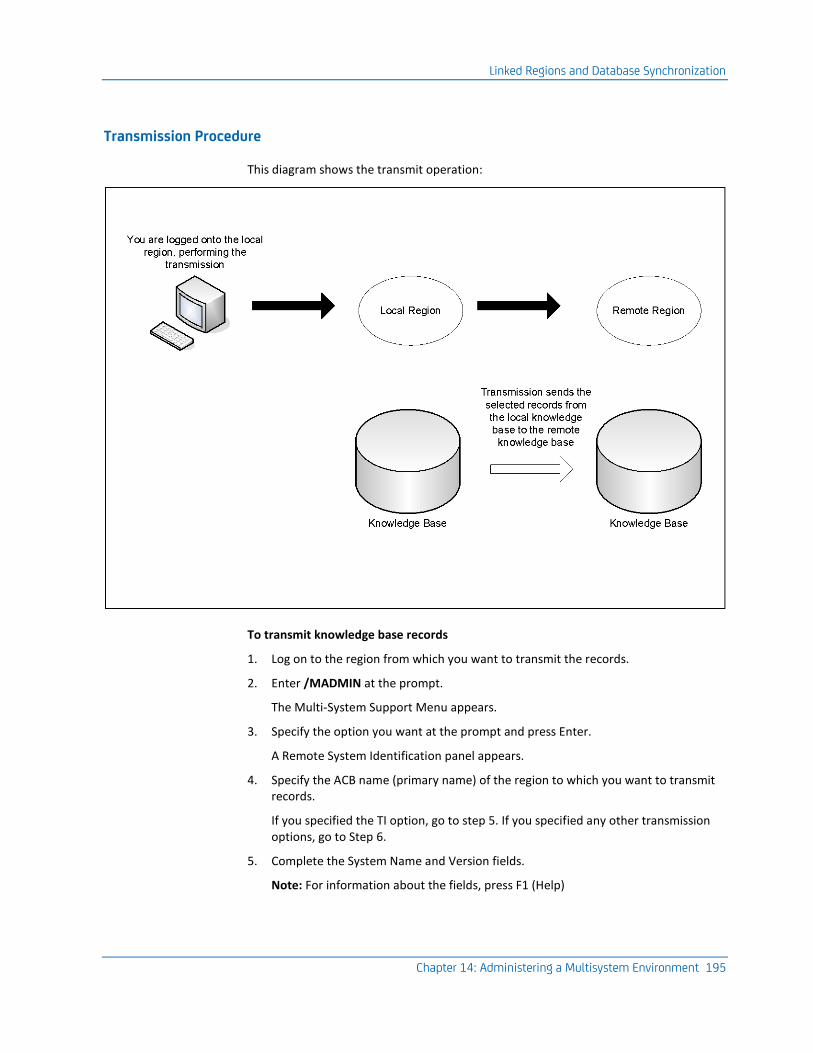
Linked Regions and Database Synchronization
Chapter 14: Administering a Multisystem Environment 195
Transmission Procedure
This diagram shows the transmit operation:
To transmit knowledge base records
1. Log on to the region from which you want to transmit the records.
2. Enter /MADMIN at the prompt.
The Multi-System Support Menu appears.
3. Specify the option you want at the prompt and press Enter.
A Remote System Identification panel appears.
4. Specify the ACB name (primary name) of the region to which you want to transmit records.
If you specified the TI option, go to step 5. If you specified any other transmission options, go to Step 6.
5. Complete the System Name and Version fields.
Note: For information about the fields, press F1 (Help)
Linked Regions and Database Synchronization
196 Administration Guide
6. Do one of the following:
■ If you want to replace a set of records or all elements of a component, enter REPLACE in the Transmission Mode field.
■ If you want to update a region by adding new records without updating existing records, enter MERGE in the Transmission Mode field.
■ If you want to update a region by adding new records and updating existing records, enter OVERLAY in the Transmission Mode field.
7. Specify the communication access methods to use for transmitting the selected records. You can enable any combination of the access methods.
8. Press F6 (Action) to select the specified option.
If a selection list appears, go to step 9. If the Confirm Transmit panel appears, go to step 11.
9. Do one of the following:
■ If you selected option TC with a transmission mode of REPLACE, enter S beside the categories that you want to transmit.
■ If you selected option TC with a transmission mode of MERGE or OVERLAY, enter S beside the categories that you want to transmit. To select specific definitions in a category for transmission, enter L (List) beside the category to list the definitions, then enter S beside the definitions to transmit.
■ If you selected other transmission options with a transmission mode of MERGE or OVERLAY, press F4 (All) to transmit all definitions or enter S beside the definitions that you want to transmit.
10. Press F6 (Transmit).
A Confirm Transmit panel appears.
11. Press Enter to confirm transmission.
A status panel appears, showing the progress of the transmission.
Note: If you choose to exit the status panel, you can check the status of the task by viewing the administration task log. Before you exit, note the task number for future reference.
Link and Synchronize Regions
Important! Do not add, update, or delete knowledge base records in any linked regions while synchronization is in progress. These changes may not be propagated to the new region. Before you perform synchronization, ensure that you back up the knowledge base.
Linked Regions and Database Synchronization
Chapter 14: Administering a Multisystem Environment 197
To link and synchronize regions
1. Log on to the region to synchronize with the source (remote) region.
The source region contains the knowledge base you want.
2. Enter /MADMIN at the prompt.
The Multi-System Support Menu appears.
3. Select option SD.
This establishes a link between the local region and another region, and updates the knowledge base of the current region.
The Remote System Identification panel appears.
4. Complete the following fields:
Primary Name
Specifies the ACB name of the remote focal point region to which you want to link this region.
Role in Multi-System Operation
Specifies whether this region is a focal point region or a subordinate region. A focal point region must satisfy the following conditions:
■ The product sets in all focal point regions match.
■ At least one access method must be available.
Subordinate System Image Name
(Optional) If you specified subordinate, specify the name of the system image that is to be used by it.
Important! Each subordinate is assigned a unique system image name, and it can use an image by that system image name only. When you build your environment for a subordinate, you must build the environment under the system image name specified during the linking operation.
Subordinate regions are restricted to loading only system images with the name specified here. Different system image versions can be maintained under the system image name.
Work Dataset
(Optional) Specifies the VSAM data set to use to reduce the time for synchronization.
The following fields specify the communication access methods to be used during synchronization. You can select any combination of the access methods; however, you can only select an access method if it is enabled in the MULTISYS parameter group.
Use VTAM?
(Optional) Specifies whether to use VTAM for communication.
Linked Regions and Database Synchronization
198 Administration Guide
Use EPS?
(Optional) Specifies whether to use EPS for communication.
TCP/IP Host Name/Addr
(Optional) Specifies the TCP/IP host name and address of the remote region.
Port Number
(Optional) Specifies the TCP/IP port number of the remote region.
5. Press F6 (Action) to initiate the linking process.
A confirmation panel appears.
6. Press F6 (Confirm) to initiate region linking and knowledge base synchronization.
A status panel appears.
Note: Press F3 (Exit) to exit the status panel at any time without affecting the link and synchronize procedure. If you exit early, note the task number for later reference.
Monitor the Synchronization Procedure
While the synchronization procedure is in progress, the Synchronize Database Status panel is refreshed automatically every 10 seconds. This panel can be refreshed manually at any time by pressing the Enter key.
To check the status of the synchronization
1. From the Multi-System Support Menu, select option L to view the administration task log.
2. Enter S beside the appropriate entry from the log to view the status of the task.
The administration task log may contain up to 50 entries at any given time. Each task is allocated a sequential task number (between 1 and 50) as it commences. When the maximum task number is reached, allocation restarts from one and the oldest status records are overwritten. To delete a completed or failed task from the log, apply the D (Delete) action.
Display Linked Regions
Chapter 14: Administering a Multisystem Environment 199
Knowledge Base Synchronization Maintenance
Automation Services maintains synchronization between linked knowledge bases by using a staging file.
When a knowledge base update occurs, information about the update is stored in the staging file as follows:
■ For an update in a focal point region, a separate update record is written for each affected linked region.
■ For an update in a subordinate region, a single update record is written for a linked focal point region.
A record stays in the staging file until the update is performed successfully in the destined region. If the region is inactive, the record stays in the staging file until the region is started.
Important! If the staging file becomes full, knowledge base synchronization cannot be maintained and the local region is unlinked automatically. A staging file can become full if a remote linked region remains inactive for an extended period of time. If an extended downtime is planned for a linked region, unlink the remote region before inactivation.
Display Linked Regions
To list the linked regions in your multisystem environment, enter /LISTREG at the prompt.
The Linked Regions panel displays the ACB names, the mode these regions are linked in, and a brief description of the linked regions. The panel also displays the status of the data flow traffic managers.
Press F11 (Right) to scroll right to display more information.
Unlink Regions
200 Administration Guide
Unlink Regions
You may want to unlink a region from the other regions in a multisystem environment (for example, for maintenance purposes). If a region is no longer of use and you want to remove it, ensure that you unlink it first. An unlinked region is a stand-alone region.
To unlink a region
1. Log on to the region you want to unlink and enter /MADMIN.U at the prompt.
The Confirm Unlink Panel appears.
Note: To cancel the unlinking procedure, press F12 (Cancel) now.
2. Press Enter to proceed with the unlinking procedure.
To relink a region, link that region with one of the regions in the multisystem environment.
Chapter 15: Implementing the NetMaster-to-NetSpy Interface 201
Chapter 15: Implementing the NetMaster-to-NetSpy Interface
This section contains the following topics:
Customize the NetMaster-to-NetSpy Interface (see page 201) Manage NetMaster-to-NetSpy Connections (see page 202) Manage CA NetSpy Alerts and Monitors (see page 202) Issue CA NetSpy Commands (see page 204)
Customize the NetMaster-to-NetSpy Interface
If you use CA NetSpy, you can define an interface to it to perform some CA NetSpy functions from your CA NetMaster region.
To customize the interface, update the NETSPYLINKS parameter group in Customizer.
To update the NETSPYLINKS parameter group
1. Enter /PARMS at the prompt.
The Customizer : Parameter Groups list appears.
2. Enter U beside the NETSPYLINKS parameter group.
The NETSPYLINKS - Links to NetSpy Applications panel appears.
3. In the Connections fields, specify the values of the NSYXNAME parameter in the INITPRM member of the CA NetSpy that you want to link to your region.
4. Enter a value in each field that you require.
For more information about completing this panel, press F1 (Help).
5. Press F6 (Action).
The changes are actioned.
6. Press F3 (File).
The changes are saved.
Note: The Enable NetSpy Alert Processing field in the NETSPYLINKS parameter group lets you switch off the receipt of all alerts from CA NetSpy. Normally, you should leave the field to its default value of YES; however, you may want to enter NO to switch the alerts off under abnormal conditions (for example, when the region is flooded by these alerts).
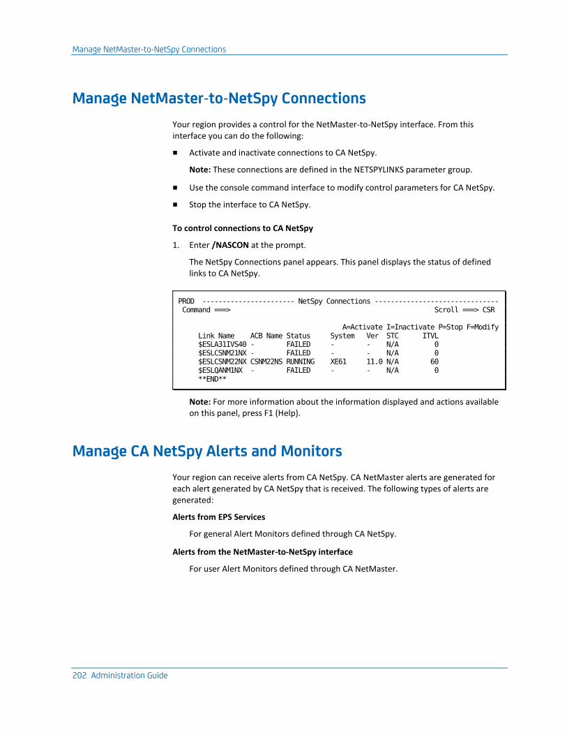
Manage NetMaster-to-NetSpy Connections
202 Administration Guide
Manage NetMaster-to-NetSpy Connections
Your region provides a control for the NetMaster-to-NetSpy interface. From this interface you can do the following:
■ Activate and inactivate connections to CA NetSpy.
Note: These connections are defined in the NETSPYLINKS parameter group.
■ Use the console command interface to modify control parameters for CA NetSpy.
■ Stop the interface to CA NetSpy.
To control connections to CA NetSpy
1. Enter /NASCON at the prompt.
The NetSpy Connections panel appears. This panel displays the status of defined links to CA NetSpy.
PROD ----------------------- NetSpy Connections ------------------------------- Command ===> Scroll ===> CSR A=Activate I=Inactivate P=Stop F=Modify Link Name ACB Name Status System Ver STC ITVL $ESLA31IVS40 - FAILED - - N/A 0 $ESLCSNM21NX - FAILED - - N/A 0 $ESLCSNM22NX CSNM22NS RUNNING XE61 11.0 N/A 60 $ESLQANM1NX - FAILED - - N/A 0 **END**
Note: For more information about the information displayed and actions available on this panel, press F1 (Help).
Manage CA NetSpy Alerts and Monitors
Your region can receive alerts from CA NetSpy. CA NetMaster alerts are generated for each alert generated by CA NetSpy that is received. The following types of alerts are generated:
Alerts from EPS Services
For general Alert Monitors defined through CA NetSpy.
Alerts from the NetMaster-to-NetSpy interface
For user Alert Monitors defined through CA NetMaster.
Manage CA NetSpy Alerts and Monitors
Chapter 15: Implementing the NetMaster-to-NetSpy Interface 203
Manage NetSpy User Alert Monitors in CA NetMaster
To manage CA NetSpy user Alert Monitors
1. Enter /NASMON at the prompt.
The NetSpy Monitors List appears. This panel lists the CA NetSpy user Alert Monitors defined for a resource.
Note: For more information about the information displayed and actions available on this panel, press F1 (Help).
Define CA NetSpy User Alert Monitors
Authorized users can define, delete, and update CA NetSpy user Alert Monitors for a particular resource.
To define a CA NetSpy user Alert Monitor
1. Enter /NASMON at the prompt.
The NetSpy Monitors List appears.
Note: For more information about these monitors, press F1 (Help)
2. Press F4 (Add).
The NetSpy : Monitor Definition panel appears.
3. Complete the fields on this panel and press F3 (File).
The definition is saved.
Issue CA NetSpy Commands
204 Administration Guide
Issue CA NetSpy Commands
Your region supports a CA NetSpy command interface. This interface allows a subset of display commands to return information to your region.
To issue a command
1. Enter /NASCMD at the prompt.
The NetSpy Commands panel appears. This panel lists the CA NetSpy commands that you can issue.
2. Enter S next to the command.
The NetSpy : Command Arguments panel appears.
3. Enter values in the fields for any operands that you want to use.
4. Press F6 (Action).
The command output appears.
Note: You can also issue a command, together with any operands, by entering it directly at the command prompt on the NetSpy Commands panel. If you enter a command without any operands, it is issued with its default operands.
Chapter 16: Implementing Print Services 205
Chapter 16: Implementing Print Services
This section contains the following topics:
Print Services Manager (see page 205) Access PSM (see page 206) Add a Printer Definition (see page 207) List Printer Definitions (see page 207) Add a Form Definition (see page 207) List Form Definitions (see page 208) Add Control Characters (see page 208) List Control Characters (see page 208) Add a Default Printer for a User ID (see page 209) List Default Printers (see page 209) Clear the Printer Spool (see page 210) Exits to Send Print Requests to a Data Set (see page 210) Print-to-Email (see page 215)
Print Services Manager
Print Services Manager (PSM) allows you to specify the format of a print request and on which printer it is printed. Print requests can be viewed online before or after printing and can be redirected to files rather than printers.
PSM provides the following features, which can be customized to suit your requirements:
■ Printer definition facilities
■ Form definition maintenance
■ Setup definition maintenance
■ Default printer assignment maintenance
■ Alias printer name definitions
■ Banner page customization on output
■ Spooled print request browsing, retention, and redirection to a different printer
■ Integration with NCL-based components
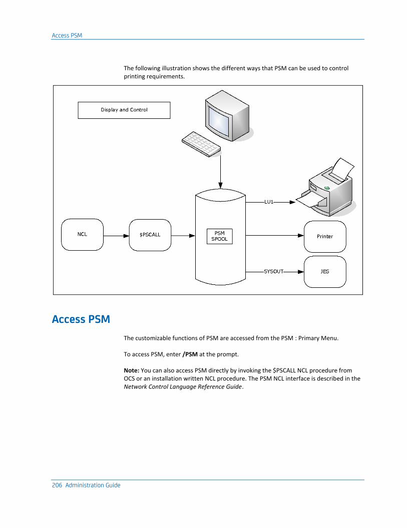
Access PSM
206 Administration Guide
The following illustration shows the different ways that PSM can be used to control printing requirements.
Access PSM
The customizable functions of PSM are accessed from the PSM : Primary Menu.
To access PSM, enter /PSM at the prompt.
Note: You can also access PSM directly by invoking the $PSCALL NCL procedure from OCS or an installation written NCL procedure. The PSM NCL interface is described in the Network Control Language Reference Guide.
Add a Printer Definition
Chapter 16: Implementing Print Services 207
Add a Printer Definition
A printer definition defines where, how, and on what paper output is printed. A printer definition is required for each printer at which output is printed.
To add a printer definition
1. Enter /PSMPRTR at the prompt.
The PSM : Printer Definition List appears.
2. Press F4 (Add).
The PSM : Printer Definition panel appears.
3. Complete the fields, as required.
Note: For information about the fields, press F1 (Help).
4. Press F3 (File).
The definition is saved.
List Printer Definitions
You can display a list of all the printer definitions defined for your region. This lets you browse and perform maintenance on the listed definitions.
To list all printer definitions, enter /PSMPRTR at the prompt.
Add a Form Definition
A form definition is required for each type of paper on which output is printed. The Form Definition Menu is used to set up and administer these form definitions.
To add a form definition
1. Enter /PSMFORM at the prompt.
The PSM : Form Definition List appears.
2. Press F4 (Add).
The PSM : Form Definition panel appears.
3. Complete the fields and press F3 (File).
The form definition is saved.
Note: For information about the fields, press F1 (Help).
List Form Definitions
208 Administration Guide
List Form Definitions
You can list all of the form definitions defined for your region and then browse and perform maintenance on them.
To list all form definitions, enter /PSMFORM at the prompt.
Add Control Characters
Control characters are sent to a printer before or after (or both) the output is printed. They are defined in setup definitions.
To add control characters
1. Enter /PSMSET at the prompt.
The PSM : Setup Definition List appears.
2. Press F4 (Add).
The PSM : Setup Definition panel appears. To access the second panel of the setup definition, press F8 (Forward).
Complete the fields, as required.
Note: For information about the fields, press F1 (Help).
3. Press F3 (File).
The setup definition is saved.
List Control Characters
You can display a list of all the setup definitions defined for your region. This list lets you browse and perform maintenance on the listed definitions.
To list control characters, enter /PSMSET at the prompt.
Add a Default Printer for a User ID
Chapter 16: Implementing Print Services 209
Add a Default Printer for a User ID
Each user ID in your region can be assigned a default printer. Default printer assignments let you define the printer to which output is sent whenever a user ID does not specify a printer.
To add a default printer for a user ID
1. Enter /PSMDFTP at the prompt.
The PSM : Default Printer Assignment List appears.
2. Press F4 (Add).
The PSM : Default Printer Assignment panel appears.
3. Complete the following fields:
User ID
Specifies the User ID of the user to whom the printer is assigned a default.
Printer Name
Specifies the name of the printer to which this user's printing is sent.
Press F3 (File).
The default printer assignment is saved.
List Default Printers
You can display a list of all the default printer assignments defined for each user ID. This list lets you browse and perform maintenance on the listed definitions.
To list default printers, enter /PSMDFTP at the prompt.
Clear the Printer Spool
210 Administration Guide
Clear the Printer Spool
Print requests are retained on the print spool if an error occurs during printing or if HELD is specified on the PSM : Print Request panel. The PSM clear spool panel is used to clear print requests from the print queue.
Note: This function is available to authorized users only.
To clear the print spool
1. Enter /PSMADMN at the prompt.
The PSM : Administration Menu appears.
2. Enter CS at the prompt.
The PSM : Clear Spool panel appears.
3. Complete the following field:
Date
Specifies that all print requests added to the spool before or on this date are deleted.
Press F6 (Action).
The print requests are deleted.
Exits to Send Print Requests to a Data Set
Two printer exit procedures are distributed with your product. Each writes the output for a print request to a data set. The procedure $PSDS81X can be customized to specific site requirements. The procedure $PSDS81Z offers the same functionality with improved performance, but cannot be customized. The target data sets for both procedures can be sequential or partitioned.
Parameters that control the operation of the exit are defined in the Exit Data portion of the printer definition. Procedures that pass data to PSM for printing can override the exit data specified in the PSM printer definition.
The procedures use the parameters contained in the exit data to do the following:
■ Determine the target data set
■ Determine how to process a data line with a skip amount of zero
■ Set the length of the lines print
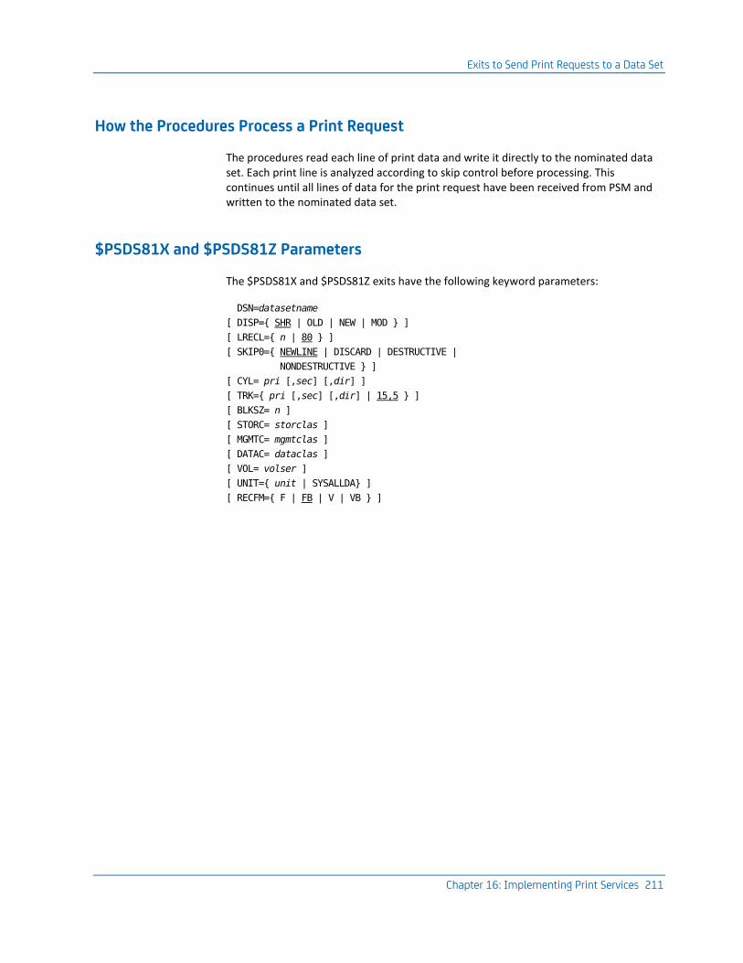
Exits to Send Print Requests to a Data Set
Chapter 16: Implementing Print Services 211
How the Procedures Process a Print Request
The procedures read each line of print data and write it directly to the nominated data set. Each print line is analyzed according to skip control before processing. This continues until all lines of data for the print request have been received from PSM and written to the nominated data set.
$PSDS81X and $PSDS81Z Parameters
The $PSDS81X and $PSDS81Z exits have the following keyword parameters:
DSN=datasetname
[ DISP={ SHR | OLD | NEW | MOD } ]
[ LRECL={ n | 80 } ]
[ SKIP0={ NEWLINE | DISCARD | DESTRUCTIVE |
NONDESTRUCTIVE } ]
[ CYL= pri [,sec] [,dir] ]
[ TRK={ pri [,sec] [,dir] | 15,5 } ]
[ BLKSZ= n ]
[ STORC= storclas ]
[ MGMTC= mgmtclas ]
[ DATAC= dataclas ]
[ VOL= volser ]
[ UNIT={ unit | SYSALLDA} ]
[ RECFM={ F | FB | V | VB } ]
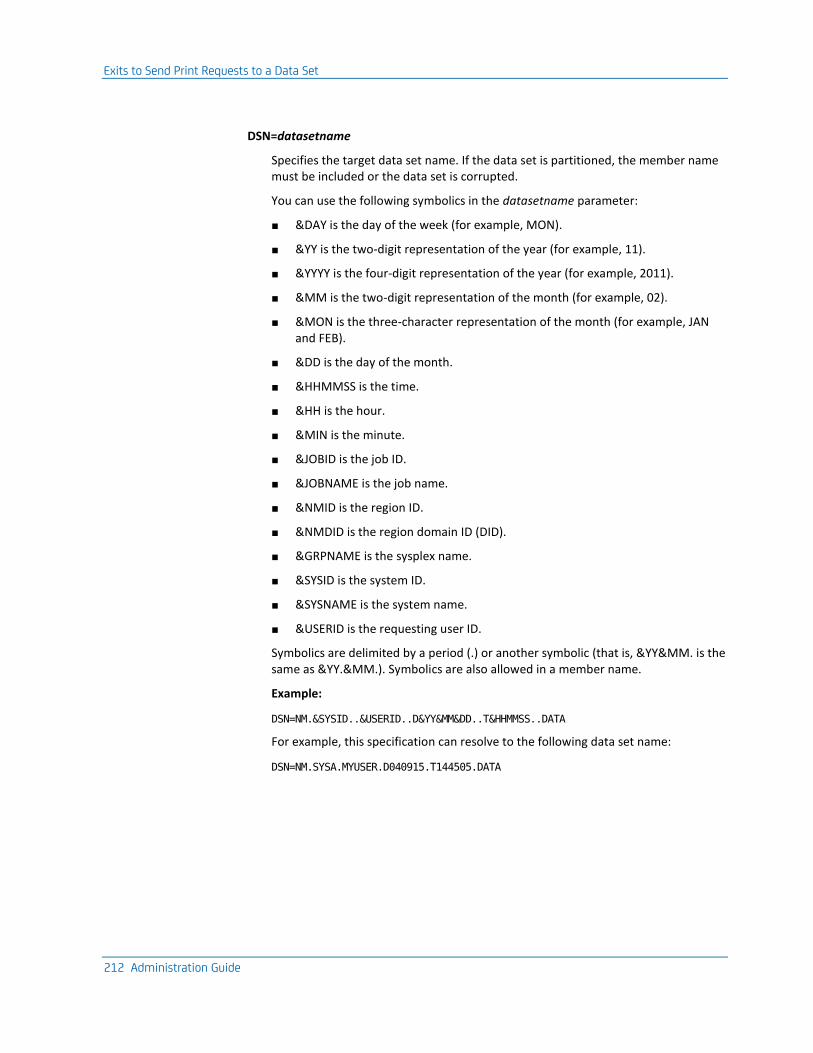
Exits to Send Print Requests to a Data Set
212 Administration Guide
DSN=datasetname
Specifies the target data set name. If the data set is partitioned, the member name must be included or the data set is corrupted.
You can use the following symbolics in the datasetname parameter:
■ &DAY is the day of the week (for example, MON).
■ &YY is the two-digit representation of the year (for example, 11).
■ &YYYY is the four-digit representation of the year (for example, 2011).
■ &MM is the two-digit representation of the month (for example, 02).
■ &MON is the three-character representation of the month (for example, JAN and FEB).
■ &DD is the day of the month.
■ &HHMMSS is the time.
■ &HH is the hour.
■ &MIN is the minute.
■ &JOBID is the job ID.
■ &JOBNAME is the job name.
■ &NMID is the region ID.
■ &NMDID is the region domain ID (DID).
■ &GRPNAME is the sysplex name.
■ &SYSID is the system ID.
■ &SYSNAME is the system name.
■ &USERID is the requesting user ID.
Symbolics are delimited by a period (.) or another symbolic (that is, &YY&MM. is the same as &YY.&MM.). Symbolics are also allowed in a member name.
Example:
DSN=NM.&SYSID..&USERID..D&YY&MM&DD..T&HHMMSS..DATA
For example, this specification can resolve to the following data set name:
DSN=NM.SYSA.MYUSER.D040915.T144505.DATA
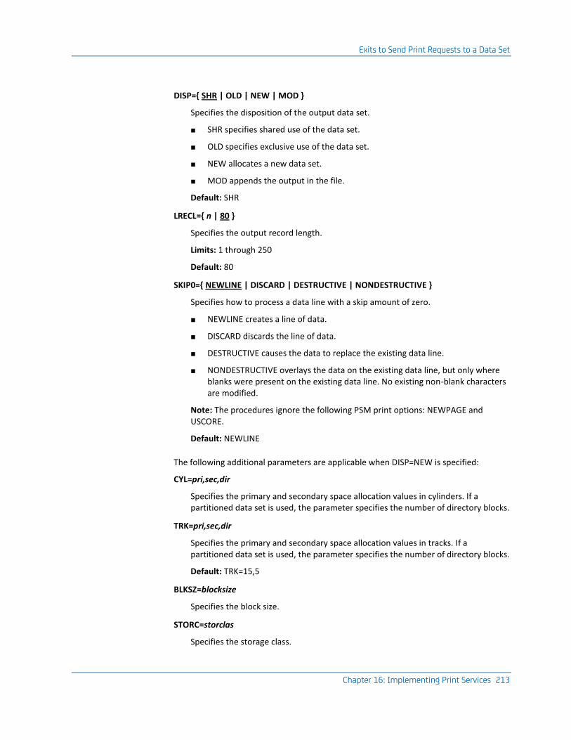
Exits to Send Print Requests to a Data Set
Chapter 16: Implementing Print Services 213
DISP={ SHR | OLD | NEW | MOD }
Specifies the disposition of the output data set.
■ SHR specifies shared use of the data set.
■ OLD specifies exclusive use of the data set.
■ NEW allocates a new data set.
■ MOD appends the output in the file.
Default: SHR
LRECL={ n | 80 }
Specifies the output record length.
Limits: 1 through 250
Default: 80
SKIP0={ NEWLINE | DISCARD | DESTRUCTIVE | NONDESTRUCTIVE }
Specifies how to process a data line with a skip amount of zero.
■ NEWLINE creates a line of data.
■ DISCARD discards the line of data.
■ DESTRUCTIVE causes the data to replace the existing data line.
■ NONDESTRUCTIVE overlays the data on the existing data line, but only where blanks were present on the existing data line. No existing non-blank characters are modified.
Note: The procedures ignore the following PSM print options: NEWPAGE and USCORE.
Default: NEWLINE
The following additional parameters are applicable when DISP=NEW is specified:
CYL=pri,sec,dir
Specifies the primary and secondary space allocation values in cylinders. If a partitioned data set is used, the parameter specifies the number of directory blocks.
TRK=pri,sec,dir
Specifies the primary and secondary space allocation values in tracks. If a partitioned data set is used, the parameter specifies the number of directory blocks.
Default: TRK=15,5
BLKSZ=blocksize
Specifies the block size.
STORC=storclas
Specifies the storage class.
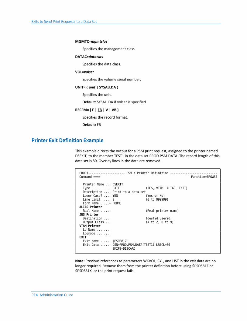
Exits to Send Print Requests to a Data Set
214 Administration Guide
MGMTC=mgmtclas
Specifies the management class.
DATAC=dataclas
Specifies the data class.
VOL=volser
Specifies the volume serial number.
UNIT= { unit | SYSALLDA }
Specifies the unit.
Default: SYSALLDA if volser is specified
RECFM= { F | FB | V | VB }
Specifies the record format.
Default: FB
Printer Exit Definition Example
This example directs the output for a PSM print request, assigned to the printer named DSEXIT, to the member TEST1 in the data set PROD.PSM.DATA. The record length of this data set is 80. Overlay lines in the data are removed.
PROD1--------------------- PSM : Printer Definition --------------------------- Command ===> Function=BROWSE Printer Name ... DSEXIT Type ........... EXIT (JES, VTAM, ALIAS, EXIT) Description .... Print to a data set Lower Case? .... YES (Yes or No) Line Limit ..... 0 (0 to 999999) Form Name .....+ FORM0 ALIAS Printer Real Name .....+ (Real printer name) JES Printer Destination .... (destid.userid) Output Class ... (A to Z, 0 to 9) VTAM Printer LU Name ........ Logmode ........ EXIT Exit Name ...... $PSDS81Z Exit Data ...... DSN=PROD.PSM.DATA(TEST1) LRECL=80 SKIP0=DISCARD
Note: Previous references to parameters WKVOL, CYL, and LIST in the exit data are no longer required. Remove them from the printer definition before using $PSDS81Z or $PSDS81X, or the print request fails.
Print-to-Email
Chapter 16: Implementing Print Services 215
Print-to-Email
The $PSEMAIL printer definition lets you email the output of a printing request. The request can be either an attachment or in the body of the email. When the output is sent as an attachment, the email uses the PS8803 message as its body and the PS8804 message as its salutation:
Data attached for email_subject
Yours,
user_name
user_name
Displays the sender name defined in UAMS.
You can maintain these messages from the Message Definition List panel. The shortcut to the panel is /CASMSG.
Note: For information about how to maintain messages, see the Managed Object Development Services Guide.

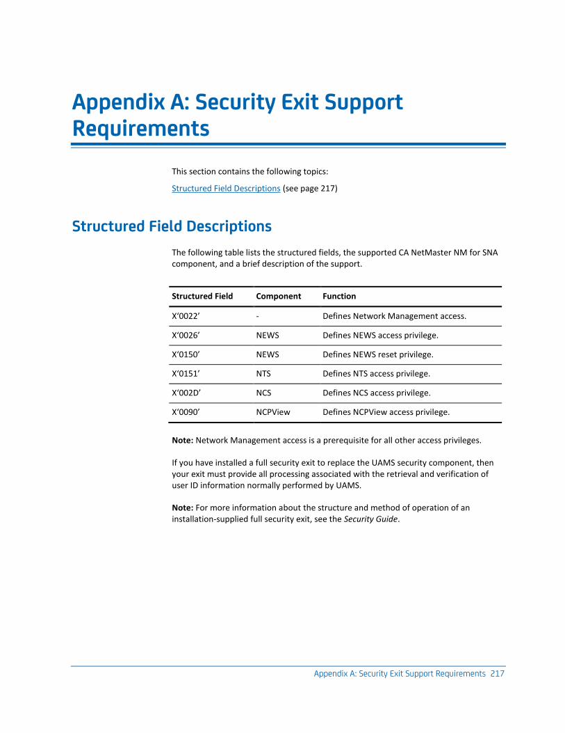
Appendix A: Security Exit Support Requirements 217
Appendix A: Security Exit Support Requirements
This section contains the following topics:
Structured Field Descriptions (see page 217)
Structured Field Descriptions
The following table lists the structured fields, the supported CA NetMaster NM for SNA component, and a brief description of the support.
Structured Field Component Function
X‘0022’ - Defines Network Management access.
X‘0026’ NEWS Defines NEWS access privilege.
X‘0150’ NEWS Defines NEWS reset privilege.
X‘0151’ NTS Defines NTS access privilege.
X‘002D’ NCS Defines NCS access privilege.
X‘0090’ NCPView Defines NCPView access privilege.
Note: Network Management access is a prerequisite for all other access privileges.
If you have installed a full security exit to replace the UAMS security component, then your exit must provide all processing associated with the retrieval and verification of user ID information normally performed by UAMS.
Note: For more information about the structure and method of operation of an installation-supplied full security exit, see the Security Guide.

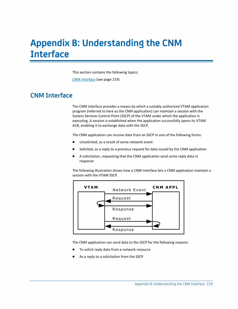
Appendix B: Understanding the CNM Interface 219
Appendix B: Understanding the CNM Interface
This section contains the following topics:
CNM Interface (see page 219)
CNM Interface
The CNM interface provides a means by which a suitably authorized VTAM application program (referred to here as the CNM application) can maintain a session with the System Services Control Point (SSCP) of the VTAM under which the application is executing. A session is established when the application successfully opens its VTAM ACB, enabling it to exchange data with the SSCP.
The CNM application can receive data from an SSCP in one of the following forms:
■ Unsolicited, as a result of some network event
■ Solicited, as a reply to a previous request for data issued by the CNM application
■ A solicitation, requesting that the CNM application send some reply data in response
The following illustration shows how a CNM interface lets a CNM application maintain a session with the VTAM SSCP.
VTAM
Request
CNM APPLNetwork Event
Response
Request
Response
The CNM application can send data to the SSCP for the following reasons:
■ To solicit reply data from a network resource
■ As a reply to a solicitation from the SSCP
CNM Interface
220 Administration Guide
Network Services Request Units (NS RUs)
There following types of NS RUs can be received or sent by an application that is using the CNM interface:
Deliver RUs
Delivers data to the CNM application, for example, Record Formatted Maintenance Statistics (RECFMS) and Record Maintenance Statistics (RECMS) RUs.
Forward RUs
Sent by the CNM application to request data delivery, for example, Request Maintenance Statistics (REQMS) RUs.
Network Management Vector Transport (NMVT) RUs
Performs delivery and request functions
If an NS RU is solicited, then reply data is always returned to the soliciting application. If the NS RU is unsolicited, then delivery is influenced by the contents of the VTAM CNM Routing Table. Other factors, such as the functional capabilities of the SSCP and the CNM application, also have a bearing on the nature of data exchanged across the CNM interface.
CNM Data from Network Resources
When a CNM application requires an SSCP to perform a particular service, it sends a Forward RU to the SSCP with which the destination network resource is associated. Among other data, this RU contains the node name of the network resource to which the request applies.
Embedded in the Forward RU is the NS RU describing the service required. The following are the most common forms of embedded RUs:
■ Request Maintenance Statistics (REQMS) RUs
■ Network Management Vector Transport (NMVT) RUs
If a REQMS or NMVT is destined for a resource in the network, then the SSCP forwards the NS RU to the destination resource across an SSCP-PU session.
One or more NS RUs can be sent in reply by the network resource. These flow back to the originating SSCP, which in turn presents them, embedded in a Deliver RU, to the soliciting CNM application.
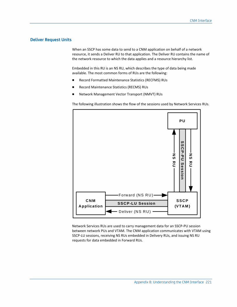
CNM Interface
Appendix B: Understanding the CNM Interface 221
Deliver Request Units
When an SSCP has some data to send to a CNM application on behalf of a network resource, it sends a Deliver RU to that application. The Deliver RU contains the name of the network resource to which the data applies and a resource hierarchy list.
Embedded in this RU is an NS RU, which describes the type of data being made available. The most common forms of RUs are the following:
■ Record Formatted Maintenance Statistics (RECFMS) RUs
■ Record Maintenance Statistics (RECMS) RUs
■ Network Management Vector Transport (NMVT) RUs
The following illustration shows the flow of the sessions used by Network Services RUs.
SSCP-LU SessionCNM
Application
PU
SSCP
(VTAM )
SS
CP
-PU
Se
ss
ion
Forward (NS RU )
Deliver (NS RU )
NS
RU
NS
RU
Network Services RUs are used to carry management data for an SSCP-PU session between network PUs and VTAM. The CNM application communicates with VTAM using SSCP-LU sessions, receiving NS RUs embedded in Delivery RUs, and issuing NS RU requests for data embedded in Forward RUs.
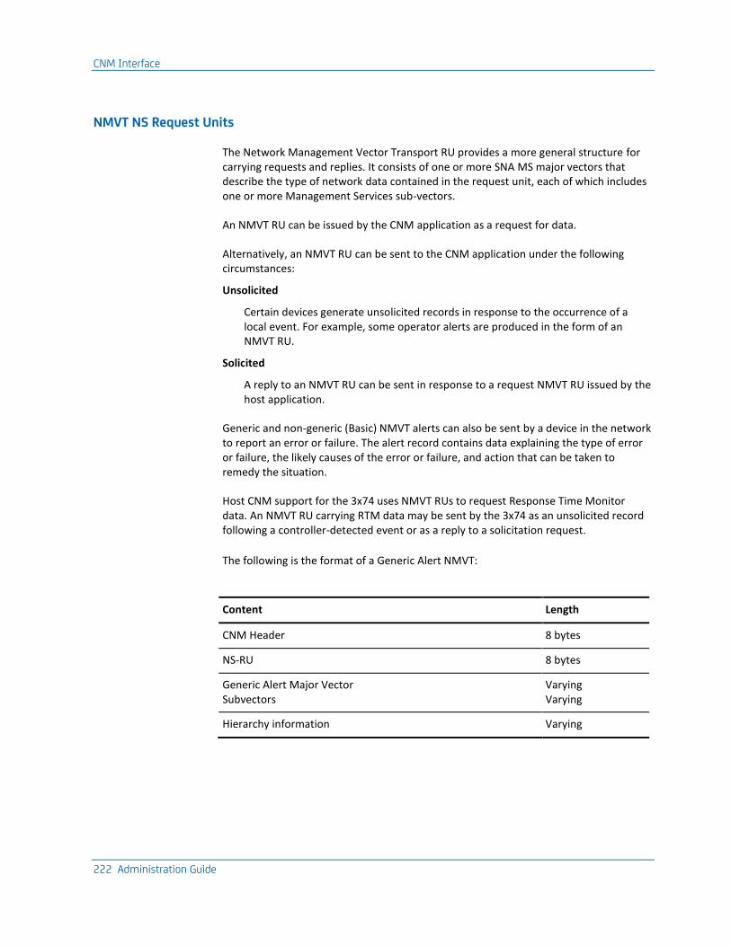
CNM Interface
222 Administration Guide
NMVT NS Request Units
The Network Management Vector Transport RU provides a more general structure for carrying requests and replies. It consists of one or more SNA MS major vectors that describe the type of network data contained in the request unit, each of which includes one or more Management Services sub-vectors.
An NMVT RU can be issued by the CNM application as a request for data.
Alternatively, an NMVT RU can be sent to the CNM application under the following circumstances:
Unsolicited
Certain devices generate unsolicited records in response to the occurrence of a local event. For example, some operator alerts are produced in the form of an NMVT RU.
Solicited
A reply to an NMVT RU can be sent in response to a request NMVT RU issued by the host application.
Generic and non-generic (Basic) NMVT alerts can also be sent by a device in the network to report an error or failure. The alert record contains data explaining the type of error or failure, the likely causes of the error or failure, and action that can be taken to remedy the situation.
Host CNM support for the 3x74 uses NMVT RUs to request Response Time Monitor data. An NMVT RU carrying RTM data may be sent by the 3x74 as an unsolicited record following a controller-detected event or as a reply to a solicitation request.
The following is the format of a Generic Alert NMVT:
Content Length
CNM Header 8 bytes
NS-RU 8 bytes
Generic Alert Major Vector Subvectors
Varying Varying
Hierarchy information Varying
CNM Interface
Appendix B: Understanding the CNM Interface 223
REQMS NS Request Units
The REQMS NS RU (embedded in a Forward RU) enables a CNM application to solicit data from a network resource. Six types of data that can be solicited are defined, although not all devices support all data types. Some devices support non-standard types and formats; therefore NEWS lets any format be transmitted.
REQMS can be sent to a resource that is owned by (that is, is in the domain of) the SSCP of the VTAM under which the CNM application is running only, unless ISR is operating.
Defined REQMS Data Types
The following are the defined REQMS data types:
REQMS Type 1
Solicits link test statistics from a Physical Unit (PU). PUs that support this function maintain details of the number of link test frames (from a VTAM Link-Level 2 test) received and the number responded to.
REQMS Type 2
Solicits summary counters from a PU. PUs that support this function maintain three categories of error counters: internal hardware errors, communications adapter errors, and negative responses.
REQMS Type 3
Solicits communications adapter errors from a PU. PUs that support this function maintain various categories of communications adapter error counters.
REQMS Type 4
Solicits PU/LU-dependent data from those PUs that support this type. The type of data sent varies according to the device type involved. For instance, REQMS type 4 RUs are sent to 3600/4700 subsystems to access the system monitor functions of that device type.
REQMS Type 5
Solicits EC-level data. PUs that support this function return data such as their microcode EC level, or part numbers installed. The reply format varies depending on the device type.
REQMS Type 6
Solicits link connection subsystem data. Used in conjunction with some modem types to retrieve link-related data.
CNM Interface
224 Administration Guide
RECFMS NS Request Units
The RECFMS RU is sent to a CNM application by an SSCP under the following circumstances:
■ As a reply to a previous REQMS request from the SSCP: when a network resource receives a REQMS, it formats a RECFMS in reply, and VTAM forwards it to the CNM application.
■ As an unsolicited record: certain network resources can generate unsolicited RECFMS records under some circumstances.
Network resources always deliver RECFMS RUs to the SSCP that owns them (that is, the SSCP for the local domain).
Defined RECFMS Data Types
The types of RECFMS RUs are categorized in the same way as REQMS RUs. This means that a type 1 REQMS receives a type 1 RECFMS in reply (and so on), and that certain devices may generate a RECFMS of one of the types without being requested to do so. For instance, the 3600/4700 subsystem can generate RECFMS type 4 records to inform the host of a variety of conditions.
One additional RECFMS type exists, known as type 0. Because there is no matching REQMS type 0, the RECFMS type 0 is always unsolicited, and is classified as an alert message. Its content is not explicitly defined, so the exact data sent is device-dependent.
CNM Interface
Appendix B: Understanding the CNM Interface 225
RECMS NS Request Units
NCPs in a network generate RECMS RUs under a variety of conditions, and there are a large number of RECMS types. Some of these types are described in the following examples:
Statistical
Each time certain counters for a particular node in the NCP reach a set threshold (that is, wrap), the NCP generates a statistical RECMS record, containing such data as traffic counts and temporary error counts. The frequency at which the counters wrap can be adjusted using NCP generation. The records are also forwarded whenever a node or the NCP itself is varied inactive (that is, the device is inoperative as far as the SSCP is concerned).
Error notification
A variety of error conditions cause the generation of RECMS records. These include permanent link and device failures, and temporary errors. The RECMS records provide an indication of the most likely cause of the error by including a snapshot of various NCP control blocks.
Software failure
Records can be generated as a result of NCP software failures or abends.
Hardware failure
Records can be generated as a result of communications controller hardware errors.
NCP delivers RECMS RUs to the SSCPs that own the resource to which they refer (that is, they are in the local domain of the SSCP).
CNM Interface
226 Administration Guide
SSCP-Related CNM Requests
All the NS RUs discussed previously are concerned with the transportation of network management requests between the host CNM application and network devices. As described, these requests are transported in one of the following ways:
■ Embedded in a forward RU and passed to the SSCP for onward propagation to a network device
■ Embedded in a deliver RU on arrival from a network device for delivery to the CNM application
Another class of requests also make use of the CNM interface. These requests contain data relating to the services of the SSCP directly and do not involve the redirection of RUs to other network devices. Such SSCP-related requests are sourced from the SSCP and delivered to the CNM application, or from the CNM application for delivery to the SSCP. In either case, since no further propagation of the request is necessary, these requests are not embedded in a deliver RU (if sourced from the SSCP) or a forward RU (if sourced from the CNM application).
Some important SSCP-related CNM requests are described in the following sections.
Translate Inquiry and Reply Request Units
NEWS supports the unembedded Translate-Inquiry and Translate-Reply RUs. These request units are used for alias name translation by certain levels of VTAM.
The Translate-Inquiry RU (see page 139) is sent to NEWS from the SSCP and solicits a Translate-Reply RU in response.
CNM-RU
The CNM-RU is a control request unit used by the Network Tracking System (NTS) feature. It is also passed unembedded across the CNM interface and is ignored by NEWS.
How Records Are Processed
This section describes how the processing requirements of the record are determined using the Network Services Control File (NSCNTL) and how the requirements are met by the execution of the nominated NCL procedures.
CNM Interface
Appendix B: Understanding the CNM Interface 227
Record Type Recognition
Each record received by NEWS using the CNM interface is an RECMS record, an RECFMS record, or an NMVT record. The record type is further qualified as follows:
■ For NMVT records, the MS major vector type
■ For RECMS records, the recording mode
■ For RECFMS records, the record type
Alerts received by NEWS from the APPN network arrive as SNA MSUs containing one or more major vectors. MSUs are processed as if they are NMVTs, which also contain major vectors.
Processing Code Assignment
CNMPROC extracts the resource identifier from the record and uses the NSCNTL to identify the device from which the record was sourced. On this basis, the NSCNTL assigns two codes to the record to identify its processing requirements:
■ A Resource ID (RID), used to group similar resource types
■ An Event ID (EID), used to qualify later record processing
NMVT Records and MDS-MUs
NMVT records (and MSUs) normally contain a Product Set ID (PSID) sub-vector field that contains the hardware or software common name or machine type of the resource that sent the record. The PSID is used to obtain, from Category 001 (Product-Set Identification) of the NSCNTL table, a description of the resource and the associated RID and EID to assign to the record.
If no matching PSID exists in the NSCNTL table, the RID and EID are set to UNKNOWN.
RECFMS Records
RECFMS records contain a block number field that identifies the type of resource that sent the CNM record. The block number is used to obtain from Category 002 (Block Number Identification) of the NSCNTL table a description of the resource, and the associated RID and EID to assign to the record. If no matching block number exists in the NSCNTL table, the RID and EID are set to UNKNOWN.
CNM Interface
228 Administration Guide
Processing Path Selection
After the RID and EID have been selected, NEWS uses the NSCNTL to select a processing path for the record. This processing path describes the arrival and display processing requirements for the record, and is represented by a single control code called the PID. The PID is dependent on the following:
■ RU type
■ RID
■ Record type (NMVT major vector type, RECMS recording mode, or RECFMS record type)
The PID is retrieved from Category 003—Record to PID Conversion—of the NSCNTL by CNMPROC. The PIDs (Category 004) then define the processing path for the records. This selection process allows common processing paths for different types of records. The selection process lets a PID be assigned to any record type from any device.
RECMS Records
RECMS records have no resource identifier specified; therefore, these codes cannot be assigned. Instead, RECMS records are assigned an Event ID during PID selection, as described in the next section.
Process Path Definitions
Process path definitions detail the processing requirements for the record. Included are the names of several NCL procedures that are used to perform NEWS record arrival processing functions. The procedures are classified into the following groups:
■ NEWS record arrival processing procedures, which are responsible for interpreting the contents of the record during processing by CNMPROC
■ User intercept procedures, which provide further processing during processing by CNMPROC
■ Display procedures which provide display formatting and presentation services. These procedures are executed to format and display data retrieved from the record.
These procedures are all optional. Where a procedure has been nominated and is enabled, it is executed by NEWS during record arrival processing.
CNM Interface
Appendix B: Understanding the CNM Interface 229
How Processing Solicited CNM Records Works
Solicited records can be processed by any NCL procedure. The process works as follows:
1. Data is solicited from devices in the network by using the &CNMSEND verb.
2. The replies to these solicitation requests are retrieved using the &CNMREAD verb.
3. The READ= operand on the &CNMSEND verb is checked to determine whether the reply is processed by CNMPROC, the soliciting procedure, or both.
4. If the reply is to be processed by the soliciting procedure, the $NWDSPLY procedure is usually executed. This procedure does the following:
■ Performs NEWS record arrival processing to determine the PID for the record
■ Invokes display processing procedures nominated in the PID description to display the results
5. If any logging is required, the reply is directed to CNMPROC because the $NWDSPLY procedure does not perform any SMF or NEWS database logging functions.
How Unsolicited CNM Record Processing Works
All unsolicited CNM records received by NEWS are directed to CNMPROC for processing. CNMPROC does the following processing:
1. Determines the processing requirements for the record
2. Executes the procedures defined in the processing path for the record
3. Performs SMF and NEWS database logging, if required
References
The formats of individual records and RUs, and more information about the CNM interface appear in a number of IBM manuals, including the following:
■ Communications Server manuals
■ NCP/EP manuals
■ SNA Architecture manuals
Various product-related manuals may also contain information about record formats that are peculiar to their device types.

Appendix C: Understanding the Session Awareness Interface 231
Appendix C: Understanding the Session Awareness Interface
This section contains the following topics:
NTS Classes (see page 231) Collect Resource Statistics (see page 238) Collect Further Data (see page 241) How NTS-SI Works (see page 247) NTS-SI Configuration (see page 247) How NTS Systems Share Data (see page 250)
NTS Classes
In a given network, different session types need different types and amounts of data collected by NTS. It is also useful to map this data onto the underlying resource hierarchy.
These objectives are achieved through use of the following types of NTS classes:
■ SAW classes
■ RTM classes
■ Session classes
■ Resource classes
When NTS receives a session start notification from VTAM, it determines, from the NTS class definitions, which options are to apply to the session. NTS extracts and stores these options, with other information about the session, for use in subsequent processing. This means that all NTS class definitions should be in place before collection of SAW data is started. Defining classes when SAW processing is active does not affect existing sessions, only new ones.
By default, if no classes are defined to NTS, SAW data only is collected for all sessions. Trace data can also be collected by operator request, but no accounting, RTM, or resource statistics data are collected.
NTS Classes
232 Administration Guide
SAW Classes
Each SAW class defined to NTS describes a set of processing options for all SAW information, including whether such information is required.
By default, NTS keeps in storage information concerning every session that is currently active. However, if this is not necessary or is impracticable due to storage restrictions, you must have a SAW class definition with the KEEP=NO option (using the DEFCLASS or REPCLASS command) to prevent NTS from collecting any data for sessions in that class. In this case, no other SAW class options are meaningful; therefore, only one such SAW class definition should be necessary because many session classes can nominate to use the same SAW class definition.
SAW class definitions specify the conditions under which all or any session data is logged to the NTS database at session end. For example, you may want to log session data if an error occurs that terminates the session, or perhaps whenever the operator collects trace data. Various SAW class options exist that cater for these and other requirements.
You can set the initial and final trace queue depths with the SAW class definition. This allows differing amounts of trace data be kept for different sessions.
You can also use SAW classes to determine whether accounting information should be collected when NTS selective accounting is requested (that is, SYSPARMS NTSACCT=SELECTIVE is specified or defaulted).
NTS Classes
Appendix C: Understanding the Session Awareness Interface 233
RTM Classes
NTS lets you collect RTM data for particular sessions. For NTS to collect RTM information from network control units, you must define one or more RTM classes. In addition, it is necessary for the control units (which may be 3274s, 3174s or compatible devices) to have the required RTM hardware or microcode level support for the collection of RTM data and host-modifiable RTM definition configured.
Each RTM class specifies a set of up to four boundary values to use for the collection of RTM data. These boundary values are ascending times in the range 0.1 seconds to 30 minutes. For sessions using the RTM class, these boundary values are set in the control unit for the duration of the session to capture the RTM data.
In addition, for each RTM class an objective response time and an objective percentage value are defined. These values can be used to represent a level of service so that you can compare the measured service level with that specified in a service agreement. You can also define RTM definitions, which are the response criteria that indicate what RTM data is kept.
The objective values are used in performance monitoring for network response times and can lead to attention message creation.
The objective response time must correspond to one of the boundary values allocated for the objective percentage comparison to be accurate. We recommend that the second or third boundary contain the objective value. This lets you observe how the responses are distributed and decide whether to revise the objective value upward or downward.
Note: For an understanding of RTM data collection in the network control units, or their attached distributed function devices, see the relevant component description guides.
NTS Classes
234 Administration Guide
Session Classes
Session class definitions provide a dual function. They provide the session selection criteria that determine to which session class each session belongs, and they also provide the SAW and RTM class names from which the sessions falling in each session class should take their SAW and RTM class values. Hence, unless each SAW and RTM class defined is nominated by at least one session class definition, their attributes are never used by NTS.
Session partner names are available as session selection attributes, and the definition for the class can use wild character positions and generic character strings as the criteria to match. Therefore, you can select a specific name, such as an application, or generic names, such as all terminals on a certain line or NCP, and any number of combinations of such names.
Other session selection criteria include the following:
■ The Class-Of-Service name (COSNAME) for the session
■ A SSCP name
■ An Explicit Route (ER) number
■ A Virtual Route (VR) number
■ The Transmission Path (TP)
■ Session type (for example, LU-LU)
■ Session class (for example, XDOM)
■ The source of the SAW data (SAW data may come from the local VTAM or from a remote VTAM if you are using NTS-SI)
Session classes are defined using the DEFCLASS command.
NTS Classes
Appendix C: Understanding the Session Awareness Interface 235
Session Classification
When NTS receives a new session start notification from VTAM, it searches your session class definitions for the best match. Session attributes are checked in the following order:
■ Primary session partner name
■ Secondary session partner name
■ COSNAME
■ ER number
■ VR number
■ TP
More specific attributes are checked before less specific ones; for example, the name TSO1B is checked before the generic name TSO>. Any attributes not specified are considered wild, and to match any session value.
When a match is found, NTS stores the options defined for the SAW, RTM, and resource class names (if present) with the session data. These options determine the form of subsequent processing for the session.
Next Best Match
If an RTM definition is not supplied for the class with which the session is initially matched, the search continues for an RTM class definition in the next most suitable session class.
Similarly, if a SAW definition is not supplied for the class with which the session is initially matched, the search continues for a SAW class definition in the next most suitable session class.
Session data can therefore be derived from more than one session class. For example, session data can include the following:
■ SAW options, derived from the session class that has a matching primary session partner name
■ RTM options, derived from the session class that has a matching secondary session partner name
It is also possible to have a session class definition where every attribute is wild (that is, every session matches it). This enables you to supply default SAW or RTM classes for those sessions that do not match any of the more selective session classes.
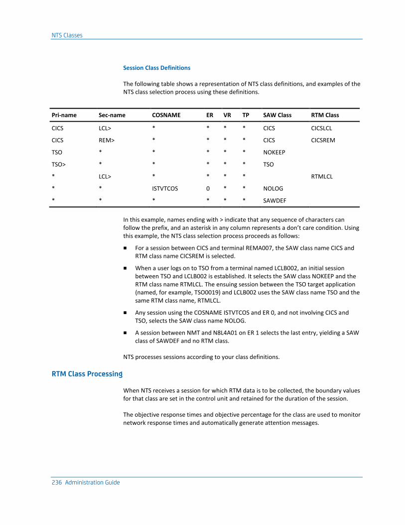
NTS Classes
236 Administration Guide
Session Class Definitions
The following table shows a representation of NTS class definitions, and examples of the NTS class selection process using these definitions.
Pri-name Sec-name COSNAME ER VR TP SAW Class RTM Class
CICS LCL> * * * * CICS CICSLCL
CICS REM> * * * * CICS CICSREM
TSO * * * * * NOKEEP
TSO> * * * * * TSO
* LCL> * * * * RTMLCL
* * ISTVTCOS 0 * * NOLOG
* * * * * * SAWDEF
In this example, names ending with > indicate that any sequence of characters can follow the prefix, and an asterisk in any column represents a don’t care condition. Using this example, the NTS class selection process proceeds as follows:
■ For a session between CICS and terminal REMA007, the SAW class name CICS and RTM class name CICSREM is selected.
■ When a user logs on to TSO from a terminal named LCLB002, an initial session between TSO and LCLB002 is established. It selects the SAW class NOKEEP and the RTM class name RTMLCL. The ensuing session between the TSO target application (named, for example, TSO0019) and LCLB002 uses the SAW class name TSO and the same RTM class name, RTMLCL.
■ Any session using the COSNAME ISTVTCOS and ER 0, and not involving CICS and TSO, selects the SAW class name NOLOG.
■ A session between NMT and N8L4A01 on ER 1 selects the last entry, yielding a SAW class of SAWDEF and no RTM class.
NTS processes sessions according to your class definitions.
RTM Class Processing
When NTS receives a session for which RTM data is to be collected, the boundary values for that class are set in the control unit and retained for the duration of the session.
The objective response times and objective percentage for the class are used to monitor network response times and automatically generate attention messages.
NTS Classes
Appendix C: Understanding the Session Awareness Interface 237
Resource Classification
To match a resource with a resource class definition, NTS must be aware of the resource and its position in the hierarchy. The time when this occurs depends on the domain in which the resource is defined:
■ If the resource is in the same domain as NTS, then NTS becomes aware of the resource and its position in the hierarchy when it receives session data for a session in which the resource is participating.
■ If the resource is in another domain, then NTS becomes aware of its hierarchical position only if a suitably configured intersystem routing (ISR) link to the NTS in the other domain exists, and the link is active.
Having been made aware of a resource and its position in the hierarchy, and providing that you have defined at least one resource class, NTS selects the resource class definition that best matches the attributes of the resource. If no class definition matches the attributes of the resource, no data is collected for it.
Resource Levels
The level of the resource class is the level of the hierarchically lowest parameter specified in the class definition. In this context, a link is at a higher level than a PU, which is at a higher level than an LU. Links are said to own PUs that use the link, as well as the LUs that are defined on those PUs. PUs own LUs that are defined on the PU.
A resource matches a resource class if all operands of parameters in the resource class definition are matched by the actual resource in the hierarchy. It is possible for a resource to match more than one resource class definition, but data from one class definition only can be stored for the resource. NTS searches resource class definitions in order from most to least specific, and selects the first resource class definition that matches the attributes of the resource.
Collect Resource Statistics
238 Administration Guide
Mechanics of Resource-matching
NTS compares resource attributes to the values of resource class definition parameters as follows:
■ If an attribute of a resource matches the value of a parameter in more than one resource class definition, then NTS selects the class in which the match is most specific, in the order LU, then PU, then link.
■ If higher level parameter values in a resource class definition are matched, then NTS attempts to match resources with resource class definitions at the same level.
For example, if the resource is an LU, NTS first searches resource class definitions that have the LU parameter as the hierarchically lowest parameter, for a match.
■ If the resource does not match any resource class definitions at its own level, then NTS checks to see if there is a resource class at a level above with a member that owns the current resource. If there is more than one, then NTS selects the resource class that is hierarchically closest to the current resource.
For example, if the resource is an LU, a matching PU-level class is selected before a matching link-level class.
■ A resource cannot match a resource class if the level of the resource is higher than the level of the class.
For example, if the resource is a PU, it cannot match class definitions that have the LU parameter as the hierarchically lowest parameter.
Resource class definitions determine the way NTS processes data for different network resources or groups of resources.
Collect Resource Statistics
Resource statistics are requested on the basis of resource classes. A resource class can specify that statistics are collected and NTS collects statistics for any resource that matches the resource class, provided that the resource statistics function is not disabled.
Collect Resource Statistics
Appendix C: Understanding the Session Awareness Interface 239
Collection Intervals
NTS collects resource statistics at specified intervals. These intervals can be thought of as discrete buckets into which NTS accumulates all accounting data for a particular resource during that period. When the specified interval expires, NTS resets the counters to zero and starts collecting data in a new bucket. After a specified (or default) number of intervals, NTS wraps, that is, overwrites the counters for the oldest interval, and so on.
Intervals provide one of the basic units for the analysis performed by the NTS Resource Statistics option.
Resource RTM Statistics
NTS attempts to collect RTM statistics for PUs (specifically, cluster controllers) if both of the following conditions apply:
■ Resource statistics collection is enabled (both globally and in the resource class definition).
■ The resource class definition includes the name of a defined RTM class.
On the expiry of an interval, NTS solicits RTM data from a resource that meets these requirements, while simultaneously resetting the RTM counters of the resource. In this way, accurate response time data is collected for each interval.
NTS collects the following sets of RTM statistics:
■ Aggregate statistics, derived from all RTM responses received from a resource, irrespective of the format of the response
■ Detailed statistics, derived from those RTM responses received from a resource that have the exact format specified in the RTM class that matches the resource class definition
If no RTM responses received from a resource have the exact format specified in the matching RTM class, aggregate RTM statistics are collected only.
Collect Resource Statistics
240 Administration Guide
Cross-Domain Statistics
If one resource involved in a session is defined in a remote domain, NTS can still collect statistics for the cross-domain resource, provided the following conditions apply:
■ There is an ISR link between the two domains that is configured to allow unsolicited data transfer.
■ Resource statistics collection is enabled in both NTS systems.
When an ISR link is established, a handshake occurs that lets each NTS calculate the time difference between the system clocks. This figure is then used to calculate the completion time of the resource statistics collection interval of the other NTS. The remote NTS waits until this time before forwarding the collected statistics to the local NTS.
If no suitably-configured ISR link exists or if resource statistics collection is disabled in either NTS, no cross-domain statistics collection occurs.
Monitor Resource Availability
If NTS has been instructed to collect statistics for a particular resource, it automatically uses SAW data to monitor the availability of that resource. A resource is considered available if it is participating in a session with the SSCP of the domain in which it is defined.
When NTS is notified by VTAM of the first session involving a resource, an SMF record is presented to the NTS User Exit, indicating that the resource is available. When notified of the termination of the last session in which the resource was involved (that is, the session with the SSCP), NTS presents an SMF record to the NTS User Exit indicating that the resource is unavailable. In addition, SMF records containing interval-based resource statistics are presented to the NTS User Exit, indicating what the current status of the resource is.
Collect Further Data
Appendix C: Understanding the Session Awareness Interface 241
NTS Resource Statistics Logging
When the resource statistics collection interval expires, NTS waits for a period of up to the correlation interval for any outstanding statistics. These statistics may consist of the following:
■ Statistics collected for resources—owned by the local SSCP—that are participating in cross-domain sessions. These statistics have been collected by NTS systems in one or more remote domains.
■ RTM data solicited by NTS at interval expiry
NTS reports the arrival or non-arrival of statistics from other domains in the activity log. In the case of the non-arrival of statistics, the log entry specifies why statistics were not received from other domains. A separate log entry is created for each SSCP of which NTS is aware.
When this process is complete, NTS writes an entry to the activity log signaling that logging is about to commence. In this way, you can gain an accurate indication of the completeness of the statistics collected for each resource statistics collection interval.
Finally, NTS passes all the statistics collected during the interval to the NTS user exit, if one is active.
Note: Resource statistics are not logged to the NTS database, but passed to SMF for processing.
Collect Further Data
When NTS is aware of active sessions and resources, further data can be collected and stored with the appropriate session records in its database.
Collect Further Data
242 Administration Guide
Session and Resource Data
NTS keeps session records that are flagged to be kept by the matching SAW class only. (The only exception is SSCP-SSCP session records, which are always kept.) Any trace, accounting, or RTM data collected by NTS is stored with the appropriate session record.
NTS stores both resource records and session records in its database. For each session record that is kept, there is always a resource record that represents the session partner. In addition, NTS keeps a record for every resource in the domain of the VTAM host system in which it is running, regardless of whether sessions with that resource are kept or not.
Note: The only way that NTS can be made aware of resources is through SAW. NTS is therefore only aware of resources that are currently active; that is, are involved in an SSCP-PU or an SSCP-LU session. NTS may have database records for additional resources, but each of those resources must have been active at some previous time when NTS was running.
Session Trace Data
NTS provides a trace monitoring capability that selects and formats trace data (which consists of copies of Path Information Units (PIUs) that flow on traced sessions) for a specific resource as it arrives from VTAM. Trace data is time-stamped by VTAM before being passed to NTS for correlation with other data related to the appropriate session.
NTS stores session establishment PIUs with session records in an initial queue. When this queue is full or when session establishment is complete, subsequent PIUs are placed in a final queue. When the final queue is full, wrap processing occurs (that is, the oldest PIUs are deleted to make way for the newest ones). The depth of the queue is determined by the SAW class definition for the session.
Formatted trace PIUs are directed to a user’s OCS screen, the activity log, or both, according to the options you specify. This facility lets an OCS operator closely monitor a particular resource, or an NCL procedure can be written to examine the session data flow.
Resource Trace Request
When a specific resource is being traced, data is collected for all sessions that involve the resource.
If the resource is unknown to NTS when the trace request is issued, the request is nevertheless accepted and passed to VTAM. Provided that the major node to which the resource is defined is currently active, VTAM accepts the request. NTS remembers such requests, which remain in a pending state until the resource is activated.
Similarly, if a resource being traced is deactivated, NTS places the trace request in a pending state until it is reactivated, or until a trace termination request is received.
Collect Further Data
Appendix C: Understanding the Session Awareness Interface 243
Accounting Data
NTS accounting data is extracted from the trace data supplied by VTAM; therefore, it is dependent on the capture of trace data. Trace PIUs, which are not relevant to accounting, are discarded unless the STRACE command is issued.
NTS can only collect accounting data for selected sessions, or globally for all sessions, depending on the value of the SYSPARMS NTSACCT operand.
Selective Collection of Accounting Data
When selective accounting (the default) is specified, accounting data is collected for those sessions that match SAW classes requiring the collection of accounting data.
A specific trace request is issued by NTS to the session partner that resides in the VTAM subarea (or to the primary partner, if both session partners reside in the local subarea). This is because VTAM captures trace data only when the session traffic transits the VTAM host. In other words, unless one session partner resides in the VTAM subarea, no trace data is captured by VTAM.
Collection From Another VTAM Domain
The NTS Single Image (NTS-SI) feature does, however, allow you to access data from domains other than the domain in which your NTS region is active. Provided that the NTS systems are linked by suitably configured ISR links, NTS-SI lets you access trace data from other NTS systems in other domains exactly as if the session partners were both in the local domain.
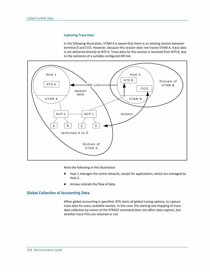
Collect Further Data
244 Administration Guide
Capturing Trace Data
In the following illustration, VTAM A is aware that there is an existing session between terminal D and CICS. However, because this session does not transit VTAM A, trace data is not delivered directly to NTS A. Trace data for this session is received from NTS B, due to the existence of a suitably configured ISR link.
session data
A
N C P 1
Host 1
N TS A
VTAM A
N C P 1
B C D
Host 2
N TS B
VTAM B
C IC S
term inals A to D
Dom ain of
VTAM A
ISR Link
Dom ain of
VTAM B
session
Note the following in this illustration:
■ Host 1 manages the entire network, except for applications, which are managed by Host 2.
■ Arrows indicate the flow of data.
Global Collection of Accounting Data
When global accounting is specified, NTS starts all global tracing options, to capture trace data for every available session. In this case, the starting and stopping of trace data collection by means of the STRACE command does not affect data capture, but whether trace PIUs are retained or not.
Collect Further Data
Appendix C: Understanding the Session Awareness Interface 245
Response Time Monitor Data
NTS attempts the collection of RTM data for LU-LU sessions that are matched with an RTM class only. Additionally, the following must apply:
■ The secondary resource involved in the session must be in the domain of the VTAM in the host where NTS is running.
■ The PU name of the terminal control unit for the secondary device must be known to support RTM (NTS assumes that a PU supports the RTM facility, unless a response to the contrary is received).
When the session start notification is received for such sessions, the RTM class values are extracted by NTS and stored with the session record. At the same time, a request is sent to the terminal control unit to set the RTM boundary and definition parameters for the device according to these RTM class values. If the PU indicates it does not support the RTM function, or does not support host programming, then no further requests are sent to the control unit.
When a session for which RTM data is being collected ends, the RTM data collected by the secondary device is sent unsolicited to NTS and stored with other session information.
Solicit RTM Data
RTM data can also be solicited during NTS review functions or more systematically, through the standard NEWS RTM procedures that allow collection on a timer or interval basis (see the User Guide). Whenever RTM data is solicited by any means, NTS updates its statistics for the session.
Analyze RTM Data
As RTM data arrives, it is first examined by NTS to determine whether or not the performance objectives defined for the RTM class have been met. If not, this information is appended to the CNM record and made available to NEWS. This can lead to generation of performance events and, ultimately, attention messages to notify network operators of a performance problem.
When a session for which RTM data is being collected ends, a performance event notification is also generated by NTS if the response time objectives are not met.
Data Correlation
One of the primary functions of NTS is to gather data from a number of sources and correlate it at session level. To protect NTS from waiting indefinitely for session data, you define an interval that represents the time limit for data correlation.
Collect Further Data
246 Administration Guide
Enforce the Correlation Interval
The NTS correlation interval is enforced in the following situations:
■ When session trace data arrives from VTAM before NTS has been notified by VTAM of the start of that session. All trace data for the pending session is kept until the session start notification is received or the NTS correlation interval expires (in which case it is discarded).
■ While waiting for all session-related data to arrive before committing a session record for logging after the session has ended:
– Following receipt of session end notification from VTAM, NTS determines whether any trace or RTM data is pending. If such data is expected, NTS waits for it to arrive, or for the correlation interval to expire, before continuing output processing.
– When waiting for unsolicited data from a connected NTS region, either at session end or after a resource statistics collection interval expiry, NTS waits for it to arrive, or for the correlation interval to expire, before continuing with the logging process.
How NTS-SI Works
Appendix C: Understanding the Session Awareness Interface 247
How NTS-SI Works
The NTS Single Image (NTS-SI) feature lets you access data from domains other than the domain in which your NTS region is active. Provided that the NTS regions are linked by suitably configured ISR links, NTS-SI lets you access trace data from other NTS regions in other domains exactly as if the session partners were both in the local domain.
It is possible to centralize the monitoring of logical network activity in multiple domains by expanding the sources of data available to an NTS region to include the following types of data:
■ Session awareness (SAW) data collected by NTS regions in other domains
■ Session data—that is, session trace, accounting, and RTM data—collected by NTS regions in other domains
The NTS regions may be in the same network or different networks. You are presented with a single image of the sessions between resources throughout the network, and of the performance and problem determination data collected for these sessions, provided that you do the following:
■ Correctly configure your NTS regions
■ Correctly configure the ISR links using which your NTS regions communicate
This single image perspective is preserved in the NTS database and NTS user exit.
The user is not aware that data originates from both local and remote domains. Actions performed by NTS in response to requests to view information may differ, depending on the source of the information, but all commands, panels, and general presentation of data are consistent, irrespective of the data source.
NTS-SI Configuration
NTS-SI lets SAW data and session data collected in one domain be passed on to another NTS running in another domain, provided that a direct ISR link exists.
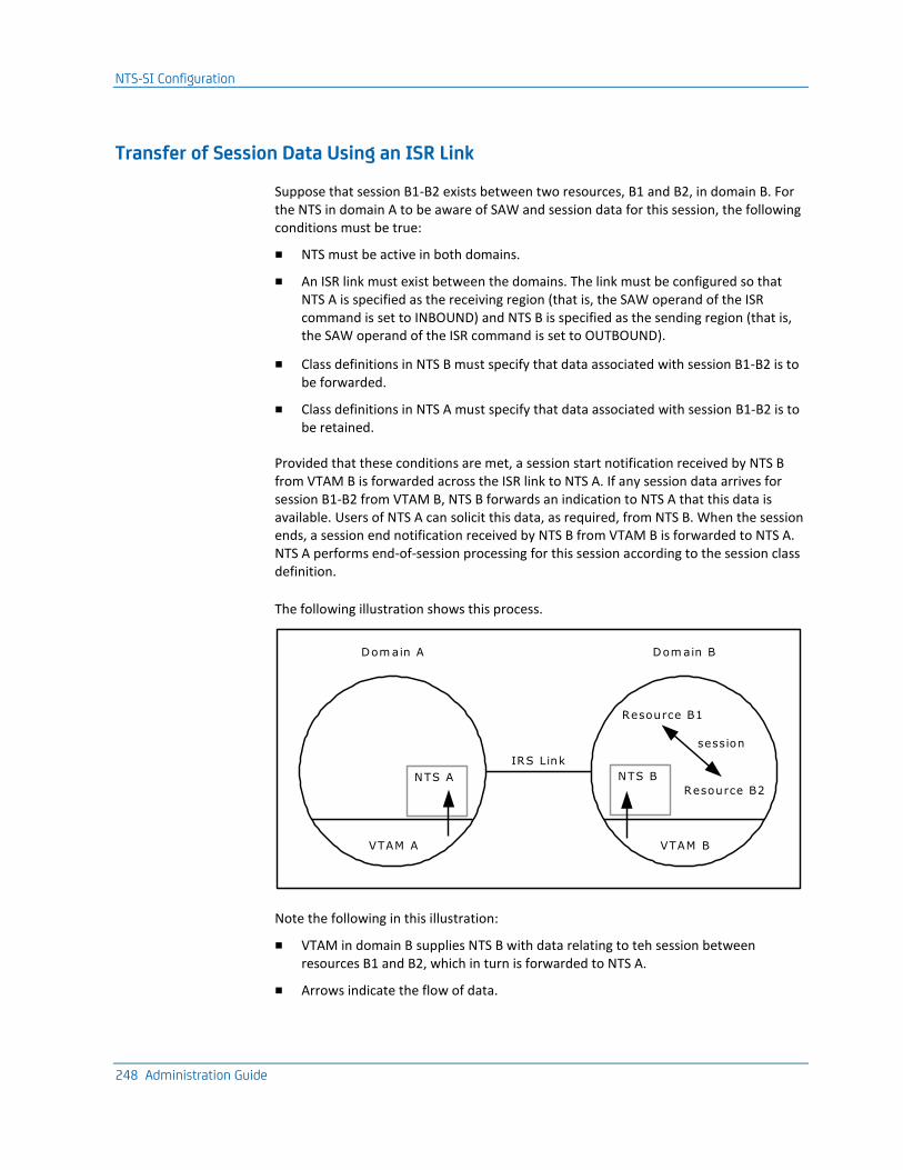
NTS-SI Configuration
248 Administration Guide
Transfer of Session Data Using an ISR Link
Suppose that session B1-B2 exists between two resources, B1 and B2, in domain B. For the NTS in domain A to be aware of SAW and session data for this session, the following conditions must be true:
■ NTS must be active in both domains.
■ An ISR link must exist between the domains. The link must be configured so that NTS A is specified as the receiving region (that is, the SAW operand of the ISR command is set to INBOUND) and NTS B is specified as the sending region (that is, the SAW operand of the ISR command is set to OUTBOUND).
■ Class definitions in NTS B must specify that data associated with session B1-B2 is to be forwarded.
■ Class definitions in NTS A must specify that data associated with session B1-B2 is to be retained.
Provided that these conditions are met, a session start notification received by NTS B from VTAM B is forwarded across the ISR link to NTS A. If any session data arrives for session B1-B2 from VTAM B, NTS B forwards an indication to NTS A that this data is available. Users of NTS A can solicit this data, as required, from NTS B. When the session ends, a session end notification received by NTS B from VTAM B is forwarded to NTS A. NTS A performs end-of-session processing for this session according to the session class definition.
The following illustration shows this process.
IRS Link
Dom ain A Dom ain B
VTAM B
Resource B1
NTS B
Resource B2
session
VTAM A
NTS A
Note the following in this illustration:
■ VTAM in domain B supplies NTS B with data relating to teh session between resources B1 and B2, which in turn is forwarded to NTS A.
■ Arrows indicate the flow of data.
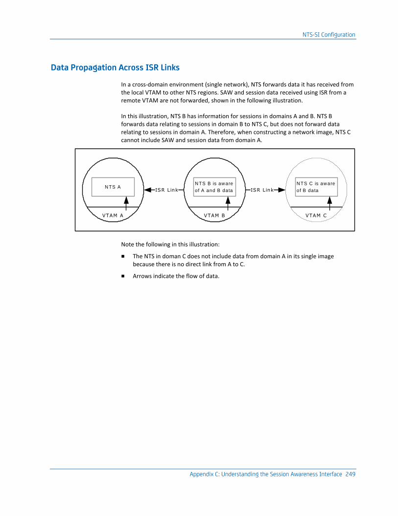
NTS-SI Configuration
Appendix C: Understanding the Session Awareness Interface 249
Data Propagation Across ISR Links
In a cross-domain environment (single network), NTS forwards data it has received from the local VTAM to other NTS regions. SAW and session data received using ISR from a remote VTAM are not forwarded, shown in the following illustration.
In this illustration, NTS B has information for sessions in domains A and B. NTS B forwards data relating to sessions in domain B to NTS C, but does not forward data relating to sessions in domain A. Therefore, when constructing a network image, NTS C cannot include SAW and session data from domain A.
ISR Link
VTAM B
N TS B is aw are
of A and B data ISR Link
VTAM A
N TS A
VTAM C
N TS C is aw are
of B data
Note the following in this illustration:
■ The NTS in doman C does not include data from domain A in its single image because there is no direct link from A to C.
■ Arrows indicate the flow of data.
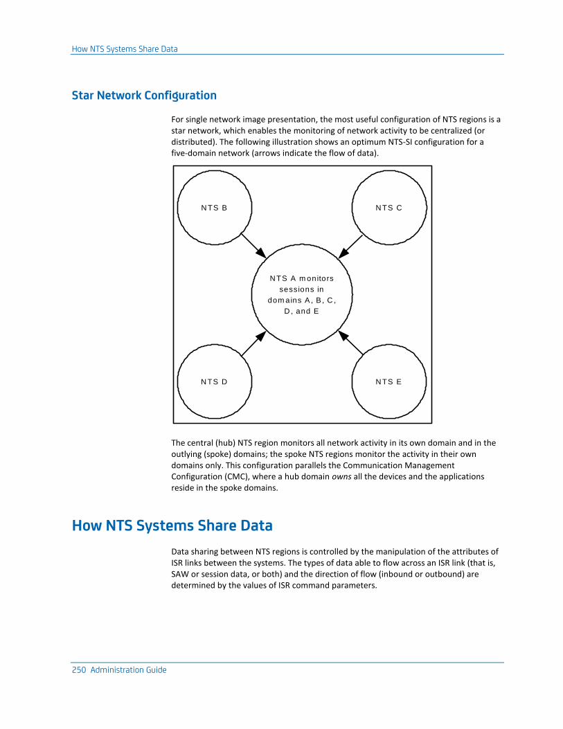
How NTS Systems Share Data
250 Administration Guide
Star Network Configuration
For single network image presentation, the most useful configuration of NTS regions is a star network, which enables the monitoring of network activity to be centralized (or distributed). The following illustration shows an optimum NTS-SI configuration for a five-domain network (arrows indicate the flow of data).
N TS A m onitors
sessions in
dom ains A , B , C ,
D , and E
N TS B N TS C
N TS D N TS E
The central (hub) NTS region monitors all network activity in its own domain and in the outlying (spoke) domains; the spoke NTS regions monitor the activity in their own domains only. This configuration parallels the Communication Management Configuration (CMC), where a hub domain owns all the devices and the applications reside in the spoke domains.
How NTS Systems Share Data
Data sharing between NTS regions is controlled by the manipulation of the attributes of ISR links between the systems. The types of data able to flow across an ISR link (that is, SAW or session data, or both) and the direction of flow (inbound or outbound) are determined by the values of ISR command parameters.
How NTS Systems Share Data
Appendix C: Understanding the Session Awareness Interface 251
Reference Network Concept
Because NTS-SI makes it possible to share SAW data between NTS systems in different networks, NTS has a reference network concept. Although a cross-network session is actually a single, logical connection, the session has a different appearance (due to alias names and network addresses) to VTAMs in each network. NTS commands that display or manipulate session information have a REFNET operand that allows a specific reference network ID to be specified.
Dormant NTS Concept
It is possible to start an NTS region solely for the purpose of having it receive SAW and session data using ISR links; that is, you can disable data collection from the local VTAM. This is referred to as a dormant NTS region.
SAW Data Sharing
NTS-SI enables NTS to obtain SAW data for sessions that are unknown to the local VTAM. For SAW data sharing between NTS regions to occur, an ISR link must be active between the regions, with an NTS conversation currently enabled for the following:
■ Outbound transfer of SAW data from the sending region
■ Inbound receipt of SAW data by the receiving region
It is possible for one NTS region to send and receive SAW data at the same time, but SAW data sharing terminates if one of the conditions required for transfer is disabled.
To facilitate the operation of SAW data sharing, the ISR command supports specialized parameters that are valid for NTS conversations only.
How NTS Systems Share Data
252 Administration Guide
SAW Data Sharing Rules
NTS regions determine which SAW data is available for sharing with other regions, on the basis of the following rules (some rules are dependent on whether the link is cross-network or cross-domain):
Rule 1
SAW data is forwarded to another NTS region only if it is not accessible to the VTAM in that domain. (NTS is able to determine whether SAW data for a particular session is visible to the VTAM in another domain.)
The application of this rule means that no unnecessary ISR traffic is generated.
Note: Applies to all link types.
Rule 2
SAW data is available for forwarding only if it was received from the local VTAM. This means that, for an NTS region to see all network activity in a particular domain, one of the following must be true:
– It must be in session with the VTAM in that domain.
– It must have a direct, suitably configured ISR link with an active NTS region in that domain.
Note: Applies to cross-domain links only.
Rule 3
SAW data is available for forwarding only if it was collected from the local VTAM, or from an NTS region in the same network as the local VTAM. This means that SAW data received across ISR can be forwarded to an NTS region in another network, provided that the data was derived from an NTS region in the local network. A corollary to this is that SAW data received from an NTS region in another network cannot be forwarded.
Note: Applies to cross-network links only.
Rule 4
A single NTS region can receive SAW data from one NTS region in another network at any one time. Any attempt to enable multiple ISR links for SAW data receipt from multiple NTS regions in other networks fails.
This rule enforces a gateway concept, where SAW data is sent to a central NTS region in one network before being forwarded to an NTS region in another network.
Note: Applies to cross-network links only.
How NTS Systems Share Data
Appendix C: Understanding the Session Awareness Interface 253
SAW Data Clean-up
When an NTS region detects that SAW data sharing with another NTS region has terminated for any reason, it purges from storage any SAW data that was received exclusively from that region. This precaution is taken in case the data is no longer up to date. In this way, the image presented by NTS is kept accurate and current.
Session Data Sharing
Unless NTS-SI is operating, complete session data may not be available to an NTS region (even if one of the session partners is in the local domain).
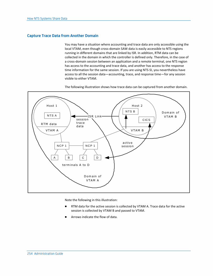
How NTS Systems Share Data
254 Administration Guide
Capture Trace Data from Another Domain
You may have a situation where accounting and trace data are only accessible using the local VTAM, even though cross-domain SAW data is easily accessible to NTS regions running in different domains that are linked by ISR. In addition, RTM data can be collected in the domain in which the controller is defined only. Therefore, in the case of a cross-domain session between an application and a remote terminal, one NTS region has access to the accounting and trace data, and another has access to the response time information for the same session. If you are using NTS-SI, you nevertheless have access to all the session data—accounting, trace, and response time—for any session visible to either VTAM.
The following illustration shows how trace data can be captured from another domain.
session trace data
A
N C P 1
Host 1
N TS A
VTAM A
N C P 1
B C D
Host 2
N TS B
VTAM B
C IC S
term inals A to D
Dom ain of
VTAM A
ISR Link
Dom ain of
VTAM B
active session
RTM data
Note the following in this illustration:
■ RTM data for the active session is collected by VTAM A. Trace data for the active session is collected by VTAM B and passed to VTAM.
■ Arrows indicate the flow of data.
How NTS Systems Share Data
Appendix C: Understanding the Session Awareness Interface 255
Necessary Conditions
You request session data by using the ISR command. For session data sharing between NTS regions to occur, the following conditions must exist:
An ISR link must be active between the regions, with an NTS conversation currently enabled for these types of data transfer and receipt:
■ Outbound unsolicited transfer of data from the sending region
■ Inbound unsolicited and solicited receipt of data by the receiving region
It is possible for one NTS region to send and receive session data at the same time, but session data sharing terminates if one of the conditions required for transfer is disabled.
How NTS Systems Share Data
256 Administration Guide
Session Data Sharing Rules
NTS regions determine which session data is available for sharing with other regions on the basis of the following rules (some rules are dependent on whether the link is cross-network or cross-domain):
Rule 1
Session data is forwarded to another region only if it is likely to be unavailable to the other region. In some cases, session data is visible to the two VTAMs in two different domains, and therefore to the NTS regions running in these domains.
NTS is able to determine whether the data is visible in more than one domain, and whether the NTS in the other domain is likely to be collecting data for this session or not.
Note: Applies to all link types.
Rule 2
Session data is available for forwarding only if it was collected by the local VTAM from the local domain. Session data received from another region is not kept in storage but handled in one of the following ways:
■ Displayed directly as part of an NTS display
■ Logged immediately to the NTS user exit and the NTS database
Note: Applies to cross-domain links only.
Rule 3
Session data received from a cross-domain ISR link can be forwarded to an NTS region in another network, provided that the receiving NTS region verifies that SAW data relating to this session has been forwarded to the cross-network NTS region.
This means that the gateway NTS region performs a routing role, to ensure that:
■ Cross-network session data requests are forwarded to the NTS region that is able to respond to them (that is, the region that can collect the information directly from VTAM).
■ Unsolicited session data and session data notifications are forwarded to linked networks, to provide the cross-network region with a complete picture of network activity.
Note: Applies to cross-network links only.
How NTS Systems Share Data
Appendix C: Understanding the Session Awareness Interface 257
Session Data Flows
Session data sharing is implemented by the following separate transaction types or flows that can occur in the scope of a single session:
■ Session data availability notifications
■ Session data solicitations (request and reply)
■ Unsolicited data records at session end
Session Data Availability Notifications
When an NTS region receives trace or RTM data for a session for the first time, or when the NTS region becomes aware that accounting data for a session needs to be collected, it checks to see whether either of the following is true:
■ SAW data sharing is in progress between the local NTS region and any other NTS regions.
■ The session is cross-domain—and if it is, is there is a suitably configured ISR link to an active NTS region in the other domain.
If an NTS region accepts a data available notification, it indicates the availability of this data on any NTS Session List display as follows:
After Session Awareness Activation
You can initiate session data sharing after session awareness has been activated in the sending region. In this case, session data may already have been collected. When the sending region detects that session data sharing with another region has become active, it sends data available notifications to this region for the sessions for which data has been collected.
On Session Termination
If an NTS region detects that session data sharing with another region has been terminated for any reason, it resets the session data present indicators that were set exclusively in response to session data available notifications received from that other NTS region. This is because the data can no longer be solicited.
How NTS Systems Share Data
258 Administration Guide
Session Data Solicitation
After an NTS region has received notification of data availability, it can send a solicitation request to the collecting region to view all or part of the data. This occurs when a user requests a particular display. The solicitation requests that the collecting region immediately forward a reply containing all collected data of the specified type.
Session data received in reply to a solicitation request appears immediately. When the user exits the display, the data is discarded. Another user request to view the session data results in another solicitation. Refreshing the current display also discards the current data and issues another solicitation. In this way, NTS guarantees that the data displayed is the most recent (and therefore most accurate) available and that the data is actually stored in one location in the network only.
Unsolicited Session Data at Session End
When an NTS region detects the end of a session, the following processing occurs:
■ The NTS region determines whether there are any other NTS regions that are aware of the session but do not have actual visibility of the session data. If this is the case, then the NTS region forwards locally sourced data that is not visible (or not being collected) in the other domain, to the other NTS region. In this way, the complete data for the session is made available to the other NTS user exit and database.
■ The NTS region determines whether there is any session data type that has been requested but has not yet arrived. If this is the case, then the NTS region determines whether it has any suitably configured ISR links to any regions that could provide the data and waits for a limited period of time for the data to arrive using the ISR link or links.
When session data arrives from another NTS region, the receiving region determines whether this session data was requested or not. Any data that was not requested is discarded. If the data was requested, then it is immediately logged to the NTS database or user exit (or both, depending on what is requested) and the session and accompanying data is purged from storage.

Appendix D: NEWS Device Solicitation Procedures 259
Appendix D: NEWS Device Solicitation Procedures
This section contains the following topics:
NEWS Device Solicitation (see page 259) Line Command Procedures (see page 260) $NW386SO Procedure (see page 261) $NWDS13B Procedure (see page 262) $NWFCSSO Procedure (see page 266) $NWLPDA2 Procedure (see page 267) $NWRTMSO Procedure (see page 270) $NWRUNCM Procedure (see page 272) $NWSOLCT Procedure (see page 274) $NWVPDSO Procedure (see page 276)
NEWS Device Solicitation
You can solicit data from network devices using the NEWS Device Support option from an OCS window or on an unattended basis using the AT and EVERY commands. The NEWS command procedures are a means of passing solicited data to other procedures in an automated operations environment, so that these procedures can act upon the data returned.
When a request for data has been successfully completed and the response returned to the user, the format of the response is similar to that used by VTAM (that is, each line of data is returned as a message with a message number that is unique to that data).
Line Command Procedures
260 Administration Guide
Line Command Procedures
The NEWS line command procedures are used primarily to pass solicited data to other procedures in an automated operations environment so that they can act upon the data returned.
The procedures are similar in format to current commands and the parameters are, overall, keyword driven.
$NW386SO
Solicits link status or DTE test results from a 386x type modem configured with the LPDA-1 option.
$NWDS13B
Provides a batch command interface for the Central Site Control Facility (CSCF).
$NWFCSSO
Solicits loop status, loop errors, and response time data from an IBM 3600/4700 Financial Communication System devices. The data is always returned to CNMPROC for logging.
$NWLPDA2
Records or changes, configuration or coupler parameters; changes the modem's functional characteristics; or runs online diagnostic tests for an LPDA-2 device.
$NWRTMSO
Solicits RTM data from a 3x74 controller that supports the RTM function. RTM data may be requested for a single LU, or for those LUs with non-zero data only.
$NWRUNCM
Packs a command into an NMVT RU to be sent to, and executed by, a service-point application. Responses received are displayed as text messages.
$NWSOLCT
Solicits secondary end errors and engineering change level data from a PU that supports such requests. Secondary end errors include link test statistics, summary error data, communications adapter error statistics and EC level information. Any or all of these summaries may be requested.
$NWVPDSO
Solicits vital product data from a PU (and its port-attached devices).
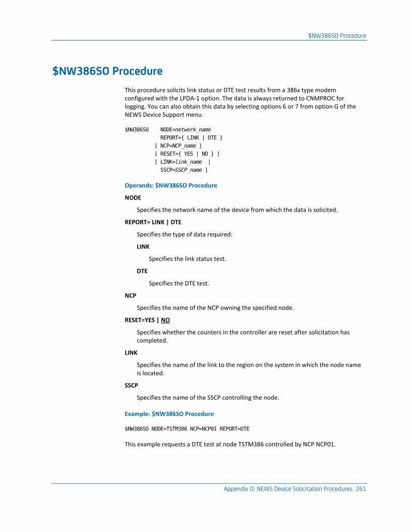
$NW386SO Procedure
Appendix D: NEWS Device Solicitation Procedures 261
$NW386SO Procedure
This procedure solicits link status or DTE test results from a 386x type modem configured with the LPDA-1 option. The data is always returned to CNMPROC for logging. You can also obtain this data by selecting options 6 or 7 from option G of the NEWS Device Support menu.
$NW386SO NODE=network_name
REPORT={ LINK | DTE }
[ NCP=NCP_name ]
[ RESET={ YES | NO } ]
[ LINK=link_name |
SSCP=SSCP_name ]
Operands: $NW386SO Procedure
NODE
Specifies the network name of the device from which the data is solicited.
REPORT= LINK | DTE
Specifies the type of data required:
LINK
Specifies the link status test.
DTE
Specifies the DTE test.
NCP
Specifies the name of the NCP owning the specified node.
RESET=YES | NO
Specifies whether the counters in the controller are reset after solicitation has completed.
LINK
Specifies the name of the link to the region on the system in which the node name is located.
SSCP
Specifies the name of the SSCP controlling the node.
Example: $NW386SO Procedure
$NW386SO NODE=TSTM386 NCP=NCP01 REPORT=DTE
This example requests a DTE test at node TSTM386 controlled by NCP NCP01.
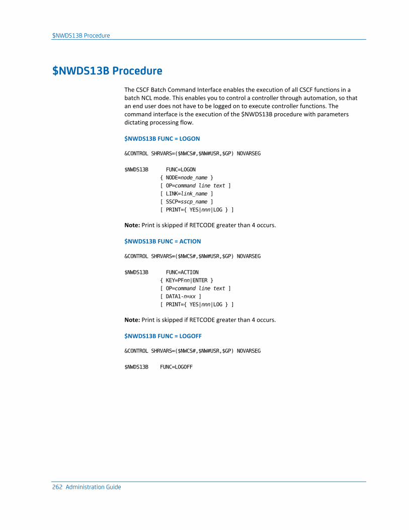
$NWDS13B Procedure
262 Administration Guide
$NWDS13B Procedure
The CSCF Batch Command Interface enables the execution of all CSCF functions in a batch NCL mode. This enables you to control a controller through automation, so that an end user does not have to be logged on to execute controller functions. The command interface is the execution of the $NWDS13B procedure with parameters dictating processing flow.
$NWDS13B FUNC = LOGON
&CONTROL SHRVARS=($NWCS#,$NW#USR,$GP) NOVARSEG
$NWDS13B FUNC=LOGON
{ NODE=node_name }
[ OP=command line text ]
[ LINK=link_name ]
[ SSCP=sscp_name ]
[ PRINT={ YES|nnn|LOG } ]
Note: Print is skipped if RETCODE greater than 4 occurs.
$NWDS13B FUNC = ACTION
&CONTROL SHRVARS=($NWCS#,$NW#USR,$GP) NOVARSEG
$NWDS13B FUNC=ACTION
{ KEY=PFnn|ENTER }
[ OP=command line text ]
[ DATA1-n=xx ]
[ PRINT={ YES|nnn|LOG } ]
Note: Print is skipped if RETCODE greater than 4 occurs.
$NWDS13B FUNC = LOGOFF
&CONTROL SHRVARS=($NWCS#,$NW#USR,$GP) NOVARSEG
$NWDS13B FUNC=LOGOFF
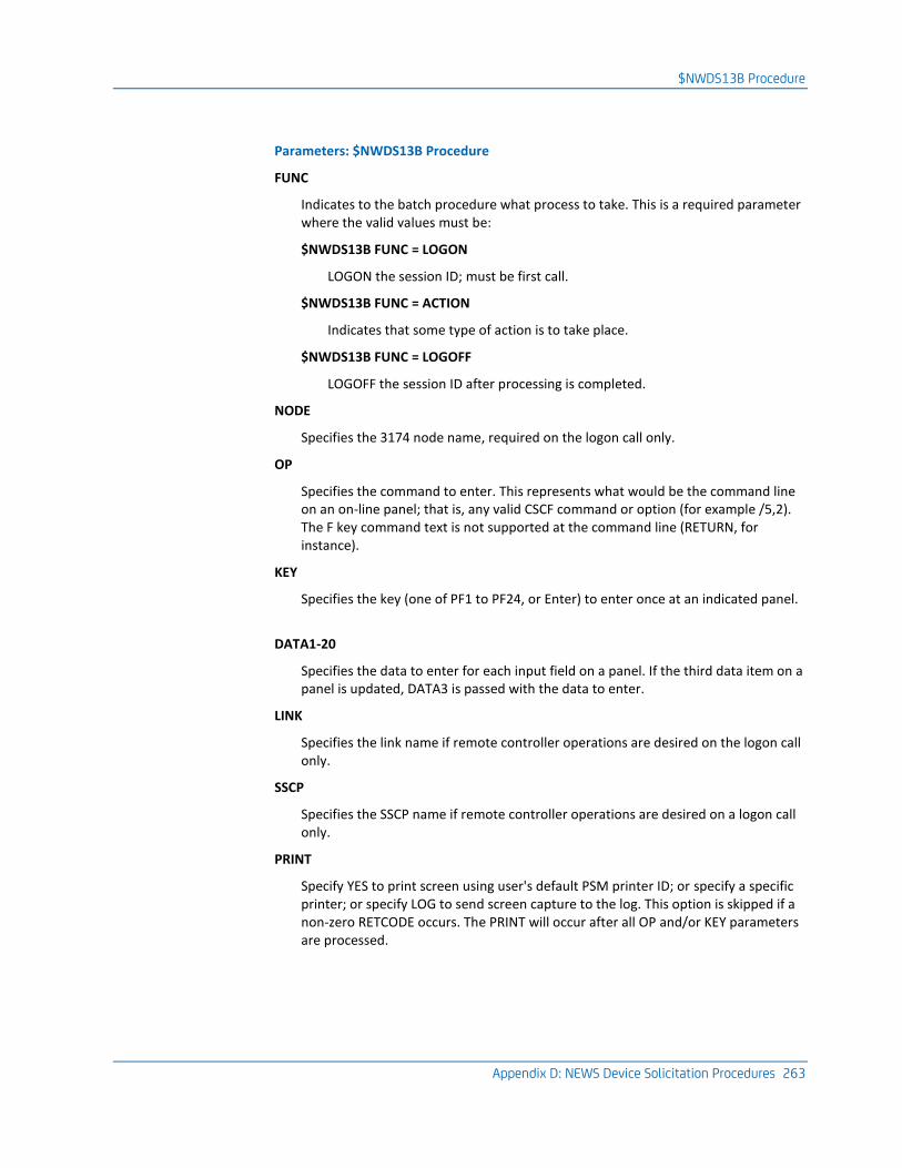
$NWDS13B Procedure
Appendix D: NEWS Device Solicitation Procedures 263
Parameters: $NWDS13B Procedure
FUNC
Indicates to the batch procedure what process to take. This is a required parameter where the valid values must be:
$NWDS13B FUNC = LOGON
LOGON the session ID; must be first call.
$NWDS13B FUNC = ACTION
Indicates that some type of action is to take place.
$NWDS13B FUNC = LOGOFF
LOGOFF the session ID after processing is completed.
NODE
Specifies the 3174 node name, required on the logon call only.
OP
Specifies the command to enter. This represents what would be the command line on an on-line panel; that is, any valid CSCF command or option (for example /5,2). The F key command text is not supported at the command line (RETURN, for instance).
KEY
Specifies the key (one of PF1 to PF24, or Enter) to enter once at an indicated panel.
DATA1-20
Specifies the data to enter for each input field on a panel. If the third data item on a panel is updated, DATA3 is passed with the data to enter.
LINK
Specifies the link name if remote controller operations are desired on the logon call only.
SSCP
Specifies the SSCP name if remote controller operations are desired on a logon call only.
Specify YES to print screen using user's default PSM printer ID; or specify a specific printer; or specify LOG to send screen capture to the log. This option is skipped if a non-zero RETCODE occurs. The PRINT will occur after all OP and/or KEY parameters are processed.
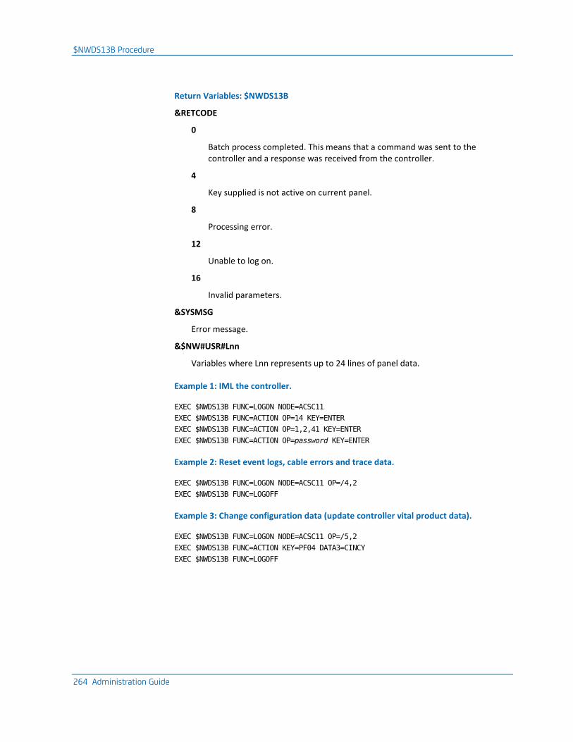
$NWDS13B Procedure
264 Administration Guide
Return Variables: $NWDS13B
&RETCODE
0
Batch process completed. This means that a command was sent to the controller and a response was received from the controller.
4
Key supplied is not active on current panel.
8
Processing error.
12
Unable to log on.
16
Invalid parameters.
&SYSMSG
Error message.
&$NW#USR#Lnn
Variables where Lnn represents up to 24 lines of panel data.
Example 1: IML the controller.
EXEC $NWDS13B FUNC=LOGON NODE=ACSC11
EXEC $NWDS13B FUNC=ACTION OP=14 KEY=ENTER
EXEC $NWDS13B FUNC=ACTION OP=1,2,41 KEY=ENTER
EXEC $NWDS13B FUNC=ACTION OP=password KEY=ENTER
Example 2: Reset event logs, cable errors and trace data.
EXEC $NWDS13B FUNC=LOGON NODE=ACSC11 OP=/4,2
EXEC $NWDS13B FUNC=LOGOFF
Example 3: Change configuration data (update controller vital product data).
EXEC $NWDS13B FUNC=LOGON NODE=ACSC11 OP=/5,2
EXEC $NWDS13B FUNC=ACTION KEY=PF04 DATA3=CINCY
EXEC $NWDS13B FUNC=LOGOFF
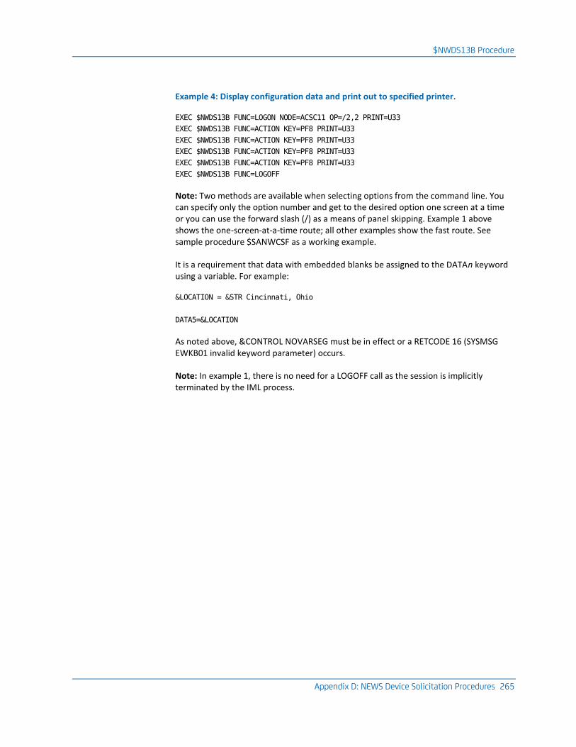
$NWDS13B Procedure
Appendix D: NEWS Device Solicitation Procedures 265
Example 4: Display configuration data and print out to specified printer.
EXEC $NWDS13B FUNC=LOGON NODE=ACSC11 OP=/2,2 PRINT=U33
EXEC $NWDS13B FUNC=ACTION KEY=PF8 PRINT=U33
EXEC $NWDS13B FUNC=ACTION KEY=PF8 PRINT=U33
EXEC $NWDS13B FUNC=ACTION KEY=PF8 PRINT=U33
EXEC $NWDS13B FUNC=ACTION KEY=PF8 PRINT=U33
EXEC $NWDS13B FUNC=LOGOFF
Note: Two methods are available when selecting options from the command line. You can specify only the option number and get to the desired option one screen at a time or you can use the forward slash (/) as a means of panel skipping. Example 1 above shows the one-screen-at-a-time route; all other examples show the fast route. See sample procedure $SANWCSF as a working example.
It is a requirement that data with embedded blanks be assigned to the DATAn keyword using a variable. For example:
&LOCATION = &STR Cincinnati, Ohio
DATA5=&LOCATION
As noted above, &CONTROL NOVARSEG must be in effect or a RETCODE 16 (SYSMSG EWKB01 invalid keyword parameter) occurs.
Note: In example 1, there is no need for a LOGOFF call as the session is implicitly terminated by the IML process.
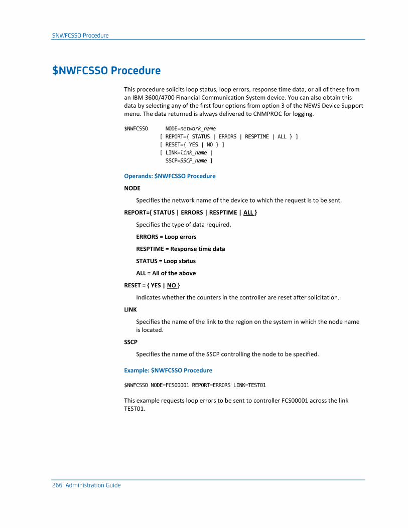
$NWFCSSO Procedure
266 Administration Guide
$NWFCSSO Procedure
This procedure solicits loop status, loop errors, response time data, or all of these from an IBM 3600/4700 Financial Communication System device. You can also obtain this data by selecting any of the first four options from option 3 of the NEWS Device Support menu. The data returned is always delivered to CNMPROC for logging.
$NWFCSSO NODE=network_name
[ REPORT={ STATUS | ERRORS | RESPTIME | ALL } ]
[ RESET={ YES | NO } ]
[ LINK=link_name |
SSCP=SSCP_name ]
Operands: $NWFCSSO Procedure
NODE
Specifies the network name of the device to which the request is to be sent.
REPORT={ STATUS | ERRORS | RESPTIME | ALL }
Specifies the type of data required.
ERRORS = Loop errors
RESPTIME = Response time data
STATUS = Loop status
ALL = All of the above
RESET = { YES | NO }
Indicates whether the counters in the controller are reset after solicitation.
LINK
Specifies the name of the link to the region on the system in which the node name is located.
SSCP
Specifies the name of the SSCP controlling the node to be specified.
Example: $NWFCSSO Procedure
$NWFCSSO NODE=FCS00001 REPORT=ERRORS LINK=TEST01
This example requests loop errors to be sent to controller FCS00001 across the link TEST01.
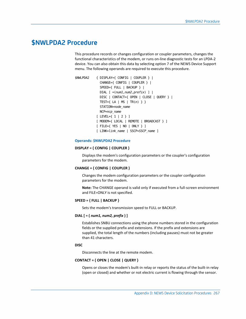
$NWLPDA2 Procedure
Appendix D: NEWS Device Solicitation Procedures 267
$NWLPDA2 Procedure
This procedure records or changes configuration or coupler parameters, changes the functional characteristics of the modem, or runs on-line diagnostic tests for an LPDA-2 device. You can also obtain this data by selecting option 7 of the NEWS Device Support menu. The following operands are required to execute this procedure.
$NWLPDA2 { DISPLAY={ CONFIG | COUPLER } |
CHANGE={ CONFIG | COUPLER } |
SPEED={ FULL | BACKUP } |
DIAL [ =(num1,num2,prefix) ] |
DISC | CONTACT={ OPEN | CLOSE | QUERY } |
TEST={ LA | MS | TR(n) } }
STATION=node_name
NCP=ncp_name
[ LEVEL={ 1 | 2 } ]
[ MODEM={ LOCAL | REMOTE | BROADCAST } ]
[ FILE={ YES | NO | ONLY } ]
[ LINK=link_name | SSCP=SSCP_name ]
Operands: $NWLPDA2 Procedure
DISPLAY = { CONFIG | COUPLER }
Displays the modem's configuration parameters or the coupler's configuration parameters for the modem.
CHANGE = { CONFIG | COUPLER }
Changes the modem configuration parameters or the coupler configuration parameters for the modem.
Note: The CHANGE operand is valid only if executed from a full-screen environment and FILE=ONLY is not specified.
SPEED = { FULL | BACKUP }
Sets the modem's transmission speed to FULL or BACKUP.
DIAL [ = ( num1, num2, prefix ) ]
Establishes SNBU connections using the phone numbers stored in the configuration fields or the supplied prefix and extensions. If the prefix and extensions are supplied, the total length of the numbers (including pauses) must not be greater than 41 characters.
DISC
Disconnects the line at the remote modem.
CONTACT = { OPEN | CLOSE | QUERY }
Opens or closes the modem's built-in relay or reports the status of the built-in relay (open or closed) and whether or not electric current is flowing through the sensor.
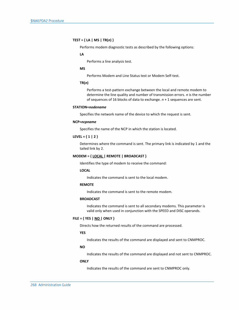
$NWLPDA2 Procedure
268 Administration Guide
TEST = { LA | MS | TR(n) }
Performs modem diagnostic tests as described by the following options:
LA
Performs a line analysis test.
MS
Performs Modem and Line Status test or Modem Self-test.
TR(n)
Performs a test-pattern exchange between the local and remote modem to determine the line quality and number of transmission errors. n is the number of sequences of 16 blocks of data to exchange. n + 1 sequences are sent.
STATION=nodename
Specifies the network name of the device to which the request is sent.
NCP=ncpname
Specifies the name of the NCP in which the station is located.
LEVEL = { 1 | 2 }
Determines where the command is sent. The primary link is indicated by 1 and the tailed link by 2.
MODEM = { LOCAL | REMOTE | BROADCAST }
Identifies the type of modem to receive the command:
LOCAL
Indicates the command is sent to the local modem.
REMOTE
Indicates the command is sent to the remote modem.
BROADCAST
Indicates the command is sent to all secondary modems. This parameter is valid only when used in conjunction with the SPEED and DISC operands.
FILE = { YES | NO | ONLY }
Directs how the returned results of the command are processed.
YES
Indicates the results of the command are displayed and sent to CNMPROC.
NO
Indicates the results of the command are displayed and not sent to CNMPROC.
ONLY
Indicates the results of the command are sent to CNMPROC only.
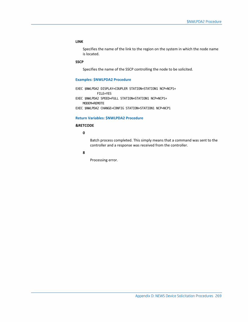
$NWLPDA2 Procedure
Appendix D: NEWS Device Solicitation Procedures 269
LINK
Specifies the name of the link to the region on the system in which the node name is located.
SSCP
Specifies the name of the SSCP controlling the node to be solicited.
Examples: $NWLPDA2 Procedure
EXEC $NWLPDA2 DISPLAY=COUPLER STATION=STATION1 NCP=NCP1+
FILE=YES
EXEC $NWLPDA2 SPEED=FULL STATION=STATION1 NCP=NCP1+
MODEM=REMOTE
EXEC $NWLPDA2 CHANGE=CONFIG STATION=STATION1 NCP=NCP1
Return Variables: $NWLPDA2 Procedure
&RETCODE
0
Batch process completed. This simply means that a command was sent to the controller and a response was received from the controller.
8
Processing error.
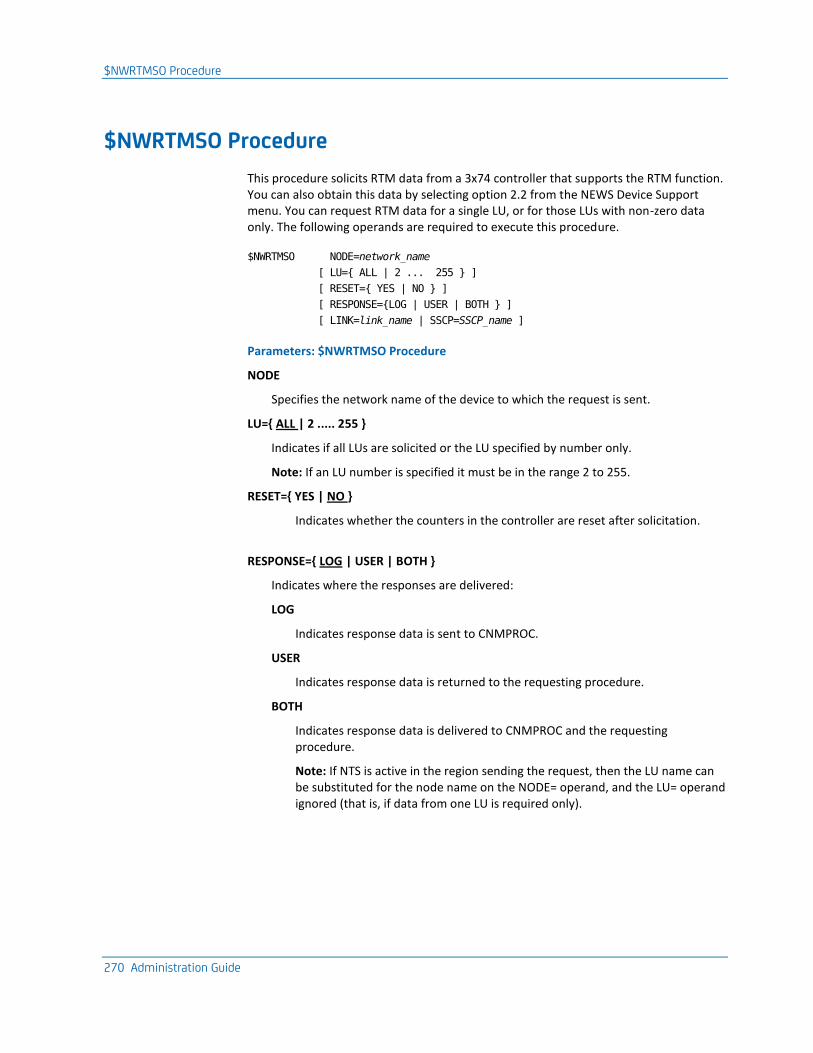
$NWRTMSO Procedure
270 Administration Guide
$NWRTMSO Procedure
This procedure solicits RTM data from a 3x74 controller that supports the RTM function. You can also obtain this data by selecting option 2.2 from the NEWS Device Support menu. You can request RTM data for a single LU, or for those LUs with non-zero data only. The following operands are required to execute this procedure.
$NWRTMSO NODE=network_name
[ LU={ ALL | 2 ... 255 } ]
[ RESET={ YES | NO } ]
[ RESPONSE={LOG | USER | BOTH } ]
[ LINK=link_name | SSCP=SSCP_name ]
Parameters: $NWRTMSO Procedure
NODE
Specifies the network name of the device to which the request is sent.
LU={ ALL | 2 ..... 255 }
Indicates if all LUs are solicited or the LU specified by number only.
Note: If an LU number is specified it must be in the range 2 to 255.
RESET={ YES | NO }
Indicates whether the counters in the controller are reset after solicitation.
RESPONSE={ LOG | USER | BOTH }
Indicates where the responses are delivered:
LOG
Indicates response data is sent to CNMPROC.
USER
Indicates response data is returned to the requesting procedure.
BOTH
Indicates response data is delivered to CNMPROC and the requesting procedure.
Note: If NTS is active in the region sending the request, then the LU name can be substituted for the node name on the NODE= operand, and the LU= operand ignored (that is, if data from one LU is required only).
$NWRTMSO Procedure
Appendix D: NEWS Device Solicitation Procedures 271
LINK
Specifies the name of the link to the region on the system in which the node name is located.
SSCP
Specifies the name of the SSCP controlling the node to be solicited.
Example: $NWRTMSO Procedure
$NWRTMSO NODE=RTMNODE1 LU=ALL RESET=NO RESPONSE=BOTH
This example requests RTM data for ALL LUs to be sent to controller RTMNODE and the responses to be delivered to CNMPROC and the soliciting procedure.
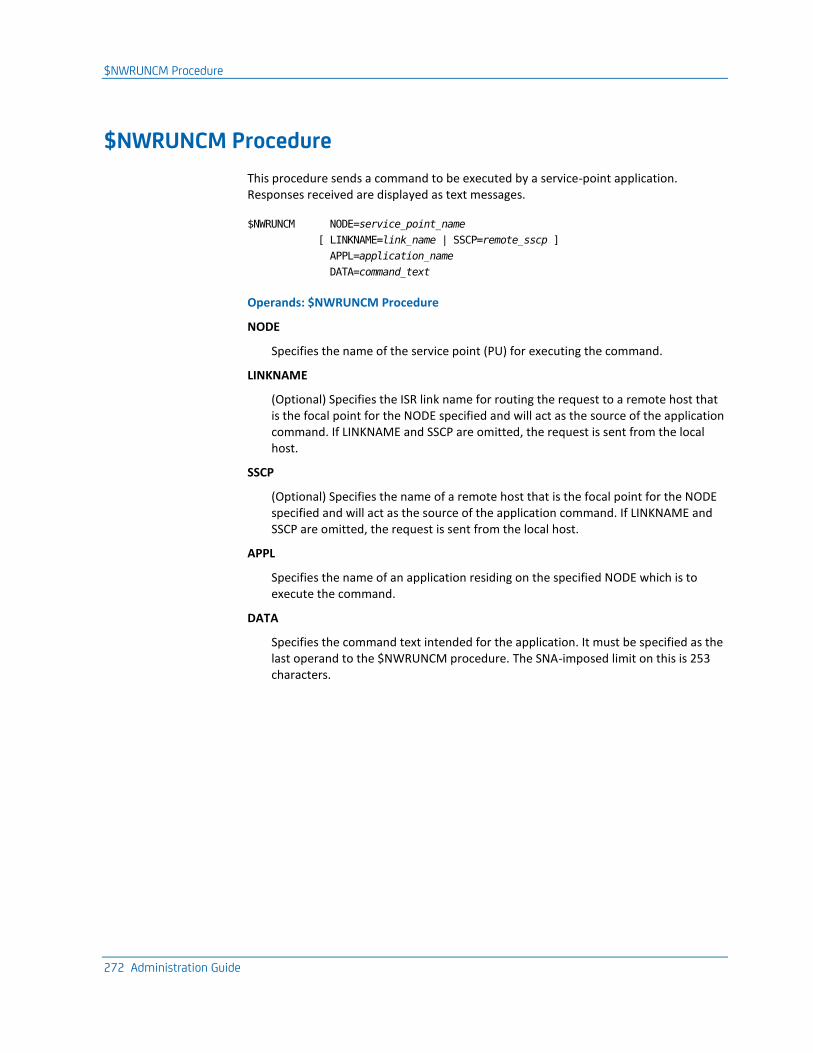
$NWRUNCM Procedure
272 Administration Guide
$NWRUNCM Procedure
This procedure sends a command to be executed by a service-point application. Responses received are displayed as text messages.
$NWRUNCM NODE=service_point_name
[ LINKNAME=link_name | SSCP=remote_sscp ]
APPL=application_name
DATA=command_text
Operands: $NWRUNCM Procedure
NODE
Specifies the name of the service point (PU) for executing the command.
LINKNAME
(Optional) Specifies the ISR link name for routing the request to a remote host that is the focal point for the NODE specified and will act as the source of the application command. If LINKNAME and SSCP are omitted, the request is sent from the local host.
SSCP
(Optional) Specifies the name of a remote host that is the focal point for the NODE specified and will act as the source of the application command. If LINKNAME and SSCP are omitted, the request is sent from the local host.
APPL
Specifies the name of an application residing on the specified NODE which is to execute the command.
DATA
Specifies the command text intended for the application. It must be specified as the last operand to the $NWRUNCM procedure. The SNA-imposed limit on this is 253 characters.
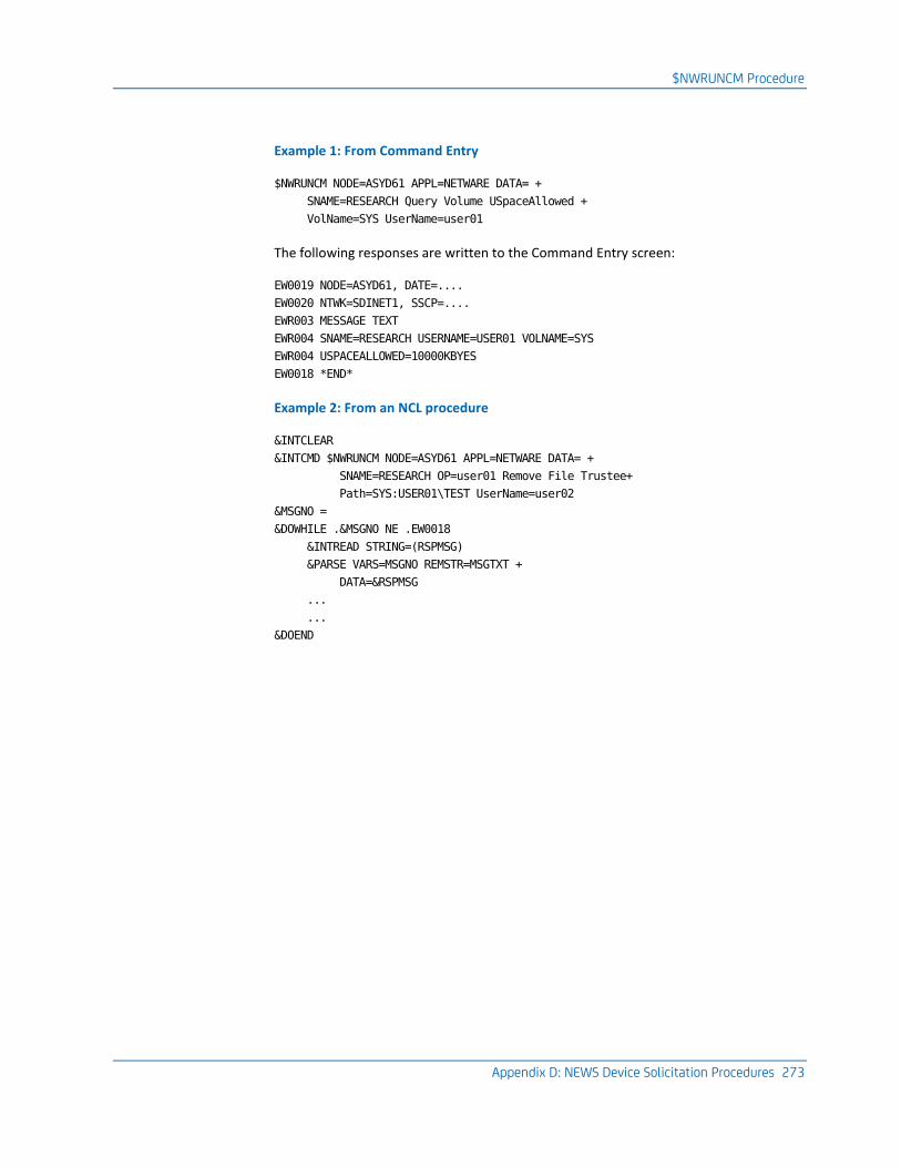
$NWRUNCM Procedure
Appendix D: NEWS Device Solicitation Procedures 273
Example 1: From Command Entry
$NWRUNCM NODE=ASYD61 APPL=NETWARE DATA= +
SNAME=RESEARCH Query Volume USpaceAllowed +
VolName=SYS UserName=user01
The following responses are written to the Command Entry screen:
EW0019 NODE=ASYD61, DATE=....
EW0020 NTWK=SDINET1, SSCP=....
EWR003 MESSAGE TEXT
EWR004 SNAME=RESEARCH USERNAME=USER01 VOLNAME=SYS
EWR004 USPACEALLOWED=10000KBYES
EW0018 *END*
Example 2: From an NCL procedure
&INTCLEAR
&INTCMD $NWRUNCM NODE=ASYD61 APPL=NETWARE DATA= +
SNAME=RESEARCH OP=user01 Remove File Trustee+
Path=SYS:USER01\TEST UserName=user02
&MSGNO =
&DOWHILE .&MSGNO NE .EW0018
&INTREAD STRING=(RSPMSG)
&PARSE VARS=MSGNO REMSTR=MSGTXT +
DATA=&RSPMSG
...
...
&DOEND
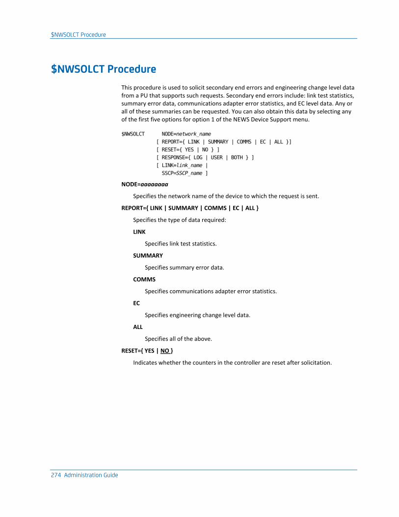
$NWSOLCT Procedure
274 Administration Guide
$NWSOLCT Procedure
This procedure is used to solicit secondary end errors and engineering change level data from a PU that supports such requests. Secondary end errors include: link test statistics, summary error data, communications adapter error statistics, and EC level data. Any or all of these summaries can be requested. You can also obtain this data by selecting any of the first five options for option 1 of the NEWS Device Support menu.
$NWSOLCT NODE=network_name
[ REPORT={ LINK | SUMMARY | COMMS | EC | ALL }]
[ RESET={ YES | NO } ]
[ RESPONSE={ LOG | USER | BOTH } ]
[ LINK=link_name |
SSCP=SSCP_name ]
NODE=aaaaaaaa
Specifies the network name of the device to which the request is sent.
REPORT={ LINK | SUMMARY | COMMS | EC | ALL }
Specifies the type of data required:
LINK
Specifies link test statistics.
SUMMARY
Specifies summary error data.
COMMS
Specifies communications adapter error statistics.
EC
Specifies engineering change level data.
ALL
Specifies all of the above.
RESET={ YES | NO }
Indicates whether the counters in the controller are reset after solicitation.
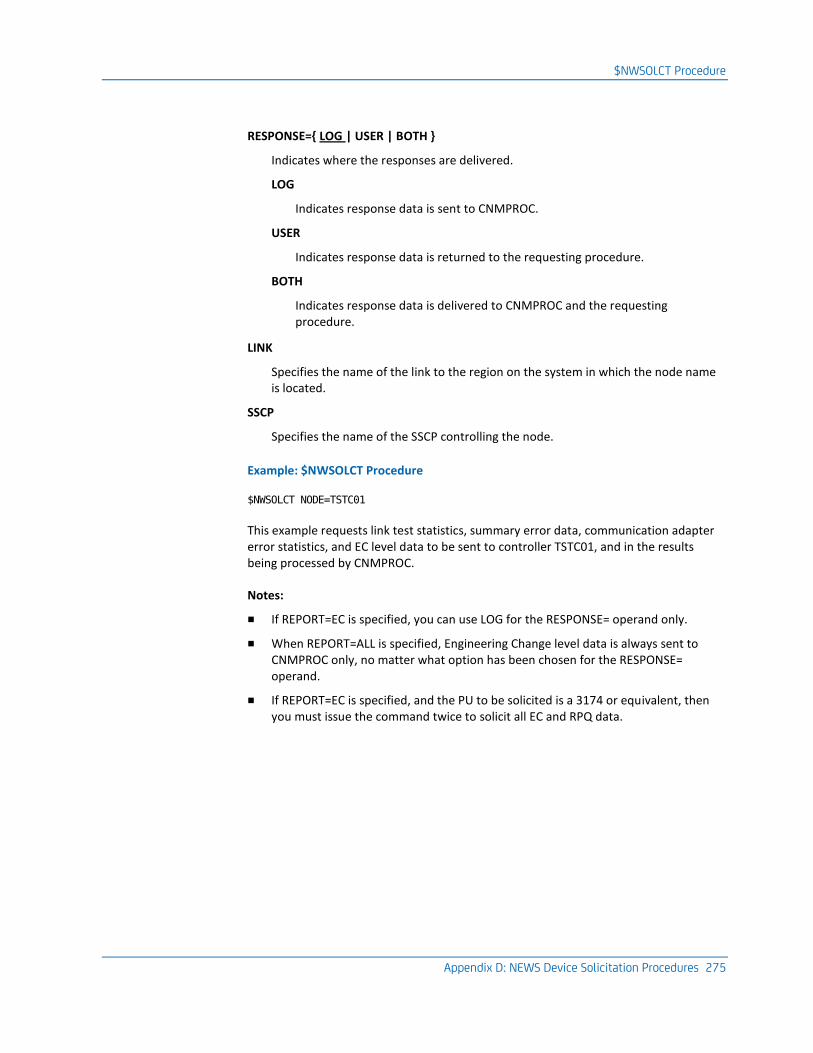
$NWSOLCT Procedure
Appendix D: NEWS Device Solicitation Procedures 275
RESPONSE={ LOG | USER | BOTH }
Indicates where the responses are delivered.
LOG
Indicates response data is sent to CNMPROC.
USER
Indicates response data is returned to the requesting procedure.
BOTH
Indicates response data is delivered to CNMPROC and the requesting procedure.
LINK
Specifies the name of the link to the region on the system in which the node name is located.
SSCP
Specifies the name of the SSCP controlling the node.
Example: $NWSOLCT Procedure
$NWSOLCT NODE=TSTC01
This example requests link test statistics, summary error data, communication adapter error statistics, and EC level data to be sent to controller TSTC01, and in the results being processed by CNMPROC.
Notes:
■ If REPORT=EC is specified, you can use LOG for the RESPONSE= operand only.
■ When REPORT=ALL is specified, Engineering Change level data is always sent to CNMPROC only, no matter what option has been chosen for the RESPONSE= operand.
■ If REPORT=EC is specified, and the PU to be solicited is a 3174 or equivalent, then you must issue the command twice to solicit all EC and RPQ data.
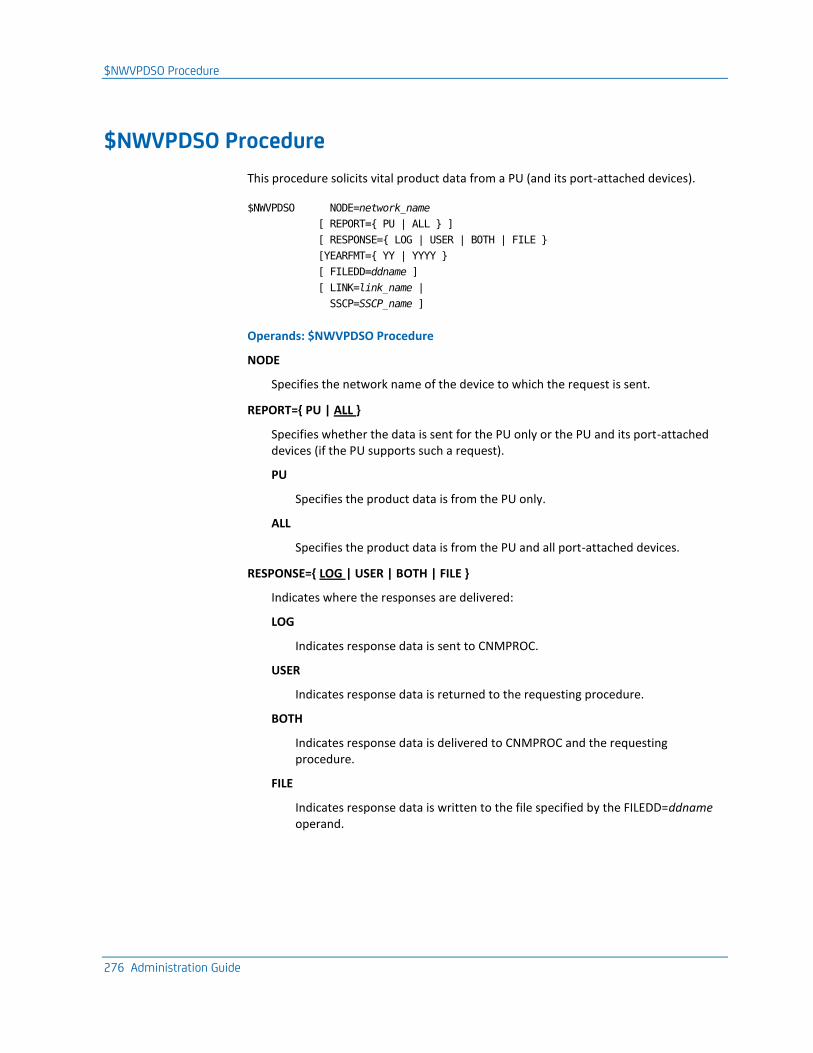
$NWVPDSO Procedure
276 Administration Guide
$NWVPDSO Procedure
This procedure solicits vital product data from a PU (and its port-attached devices).
$NWVPDSO NODE=network_name
[ REPORT={ PU | ALL } ]
[ RESPONSE={ LOG | USER | BOTH | FILE }
[YEARFMT={ YY | YYYY }
[ FILEDD=ddname ]
[ LINK=link_name |
SSCP=SSCP_name ]
Operands: $NWVPDSO Procedure
NODE
Specifies the network name of the device to which the request is sent.
REPORT={ PU | ALL }
Specifies whether the data is sent for the PU only or the PU and its port-attached devices (if the PU supports such a request).
PU
Specifies the product data is from the PU only.
ALL
Specifies the product data is from the PU and all port-attached devices.
RESPONSE={ LOG | USER | BOTH | FILE }
Indicates where the responses are delivered:
LOG
Indicates response data is sent to CNMPROC.
USER
Indicates response data is returned to the requesting procedure.
BOTH
Indicates response data is delivered to CNMPROC and the requesting procedure.
FILE
Indicates response data is written to the file specified by the FILEDD=ddname operand.
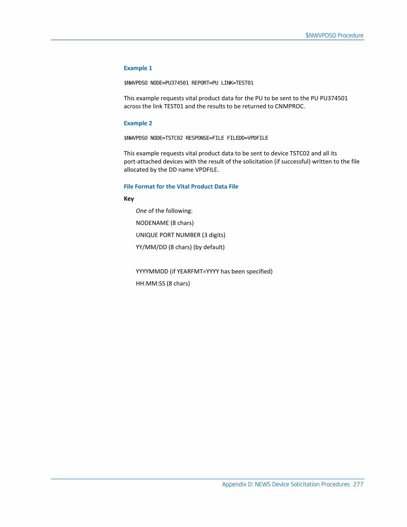
$NWVPDSO Procedure
Appendix D: NEWS Device Solicitation Procedures 277
Example 1
$NWVPDSO NODE=PU374501 REPORT=PU LINK=TEST01
This example requests vital product data for the PU to be sent to the PU PU374501 across the link TEST01 and the results to be returned to CNMPROC.
Example 2
$NWVPDSO NODE=TSTC02 RESPONSE=FILE FILEDD=VPDFILE
This example requests vital product data to be sent to device TSTC02 and all its port-attached devices with the result of the solicitation (if successful) written to the file allocated by the DD name VPDFILE.
File Format for the Vital Product Data File
Key
One of the following:
NODENAME (8 chars)
UNIQUE PORT NUMBER (3 digits)
YY/MM/DD (8 chars) (by default)
YYYYMMDD (if YEARFMT=YYYY has been specified)
HH:MM:SS (8 chars)
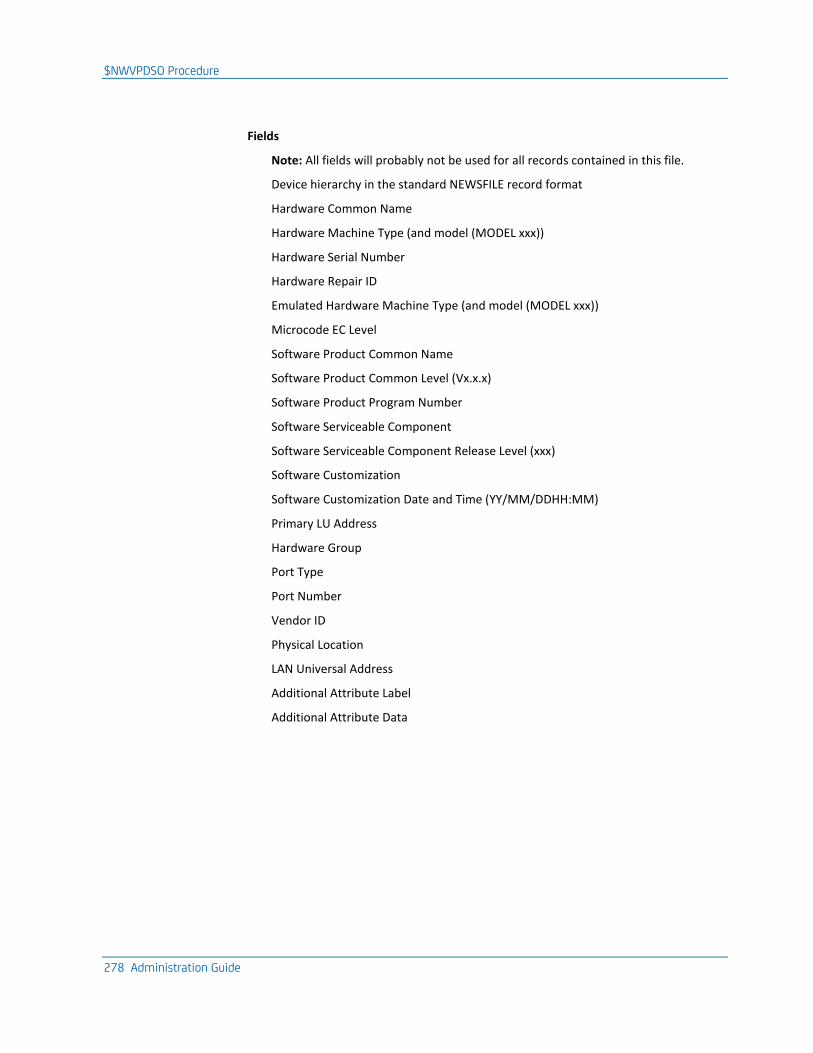
$NWVPDSO Procedure
278 Administration Guide
Fields
Note: All fields will probably not be used for all records contained in this file.
Device hierarchy in the standard NEWSFILE record format
Hardware Common Name
Hardware Machine Type (and model (MODEL xxx))
Hardware Serial Number
Hardware Repair ID
Emulated Hardware Machine Type (and model (MODEL xxx))
Microcode EC Level
Software Product Common Name
Software Product Common Level (Vx.x.x)
Software Product Program Number
Software Serviceable Component
Software Serviceable Component Release Level (xxx)
Software Customization
Software Customization Date and Time (YY/MM/DDHH:MM)
Primary LU Address
Hardware Group
Port Type
Port Number
Vendor ID
Physical Location
LAN Universal Address
Additional Attribute Label
Additional Attribute Data
Appendix E: Implementing the NEWS User Exit 279
Appendix E: Implementing the NEWS User Exit
This section contains the following topics:
NEWS User Exit (see page 279) Sample NEWS Exits (see page 280) How the NEWS Exit Is Called (see page 280) NEWS Exit Coding Requirements (see page 281) Exit Function Codes (see page 282) Separate Messages from the NEWS Exit (see page 284) NEWS SMF Record Formats (see page 285)
NEWS User Exit
NEWS can present all records received across the VTAM CNM interface to an installation-supplied user exit before any processing is performed for the record.
The exit can perform any desired processing of the record and can indicate that the record is to be ignored by NEWS, unless it was generated in response to a solicitation request by an &CNMSEND statement.
Note: APPN alerts sent to the ALERT-NETOP NEWS application, and records from remote regions arriving over ISR links are not passed to the exit.
Sample NEWS Exits
280 Administration Guide
Sample NEWS Exits
Two sample NEWS exits are supplied as working models that can be modified as required. The exits are members of the ?dsnpref.NMC1.CC2ASAMP library distributed on the installation tape.
NEWSEXIT
NEWSEXIT takes a copy of each CNM record received and writes it to a sequential data set.
Any DD cards required by the exit to write the CNM records to a data set should be included in the execution JCL. The NEWSEXIT sample exit provided writes all records to a variable blocked data set which requires a DD card with a DD name of DDNEWS.
NEWSXSMF
NEWSXSMF takes a copy of each CNM record and formats an SMF record which can then be processed by external packages that use SMF data.
The Assembler macro $NMSMF, distributed in the macro library, provides mapping for the format of the SMF record generated.
How the NEWS Exit Is Called
Note: To implement a NEWS exit, you must define the exit name in the CNM parameter group. For more information, see the Installation Guide.
NEWS is initialized when your region starts and a subtask that acts as the driver for the exit is attached. The subtask mainline routines handle communications between the subtask and the NEWS components in the mother task.
When the subtask is attached, subtask mainline routines do the following:
1. Load the load module specified as the installation-supplied user exit.
2. Call the exit using conventional branching and linking.
3. Pass an initialization parameter list to the exit.
NEWS Exit Execution
Because the user exit executes as part of a subtask, no restrictions are placed on the functions that the exit can perform. This is because the activities of the subtask do not impact the performance of the main task, and the exit subtask runs at a lower dispatching priority than the main task.
Processing of CNM records by the main task is, however, delayed by processing occurring in the CNM exit.
NEWS Exit Coding Requirements
Appendix E: Implementing the NEWS User Exit 281
NEWS Exit Coding Requirements
This section describes the coding requirements for NEWS exits.
Maintain Registers on Entry to an Exit
You must observe standard linkage conventions when coding an exit.
On entry, the registers must be saved in the caller’s save area, and on exit, restored (except R15, which must contain a return code).
On entry, register contents are as follows:
R0 Unpredictable
R1 Address of a parameter list
R2-R12 Unpredictable
R13 Address of the caller’s standard save area
R14 Caller’s return address
R15 Address of the entry point of the user exit
On exit, the same registers should be restored except for R15, the exit return code.
Parameter List Format
The parameter list addressed by Register 1 on entry consists of one or two contiguous fullwords. If there are two fullwords, the first contains the address of another fullword that holds a function code indicating the reason that the exit is being called.
The second fullword of the parameter list is present for function codes 0 and 4 only. The high-order bit of this last (or solitary) fullword is not set; therefore, the length of the parameter list must be determined by examination of the function code as follows:
■ For function code 0, the second word of the parameter list contains the address of an area that contains system data that may be of value to the exit in determining its processing options.
■ For function code 4, the second word of the parameter list contains the address of the CNM record being passed to the exit for examination.
■ For function code 8, the parameter list contains one word.
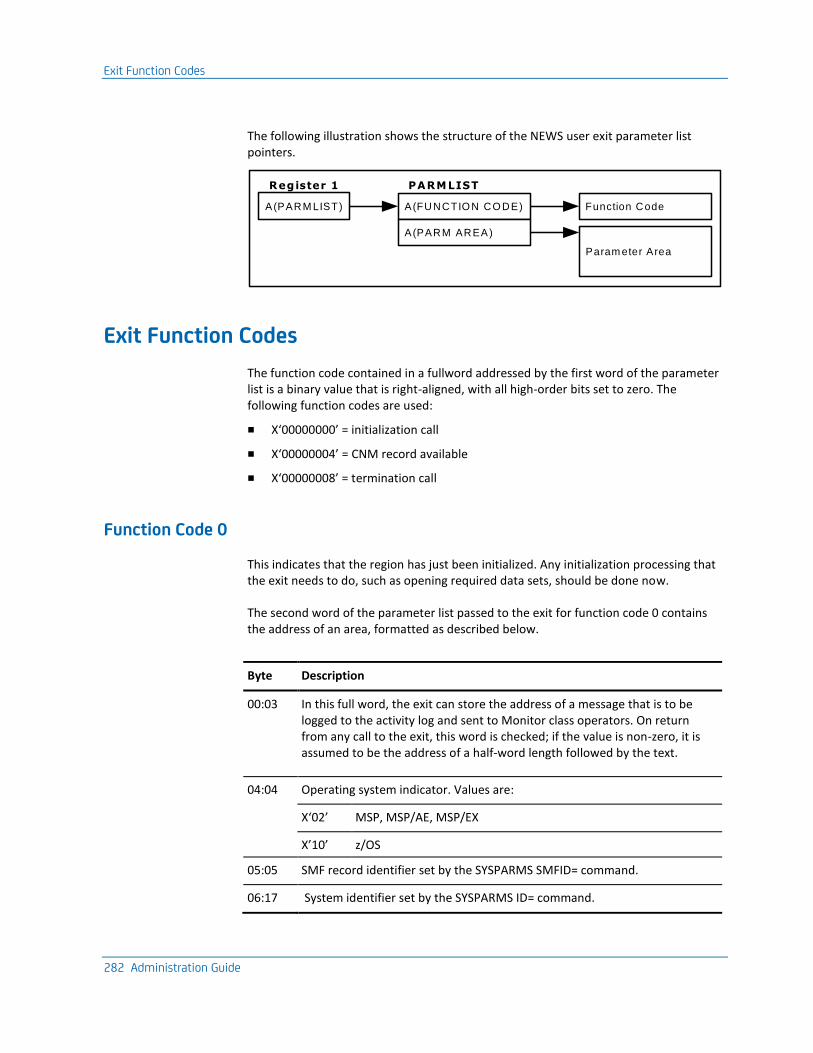
Exit Function Codes
282 Administration Guide
The following illustration shows the structure of the NEWS user exit parameter list pointers.
A(PARM LIST)
Register 1
A(FUNCTIO N CO DE)
PARMLIST
A(PARM AREA)
Function Code
Param eter Area
Exit Function Codes
The function code contained in a fullword addressed by the first word of the parameter list is a binary value that is right-aligned, with all high-order bits set to zero. The following function codes are used:
■ X‘00000000’ = initialization call
■ X‘00000004’ = CNM record available
■ X‘00000008’ = termination call
Function Code 0
This indicates that the region has just been initialized. Any initialization processing that the exit needs to do, such as opening required data sets, should be done now.
The second word of the parameter list passed to the exit for function code 0 contains the address of an area, formatted as described below.
Byte Description
00:03 In this full word, the exit can store the address of a message that is to be logged to the activity log and sent to Monitor class operators. On return from any call to the exit, this word is checked; if the value is non-zero, it is assumed to be the address of a half-word length followed by the text.
04:04 Operating system indicator. Values are:
X‘02’ MSP, MSP/AE, MSP/EX
X’10’ z/OS
05:05 SMF record identifier set by the SYSPARMS SMFID= command.
06:17 System identifier set by the SYSPARMS ID= command.
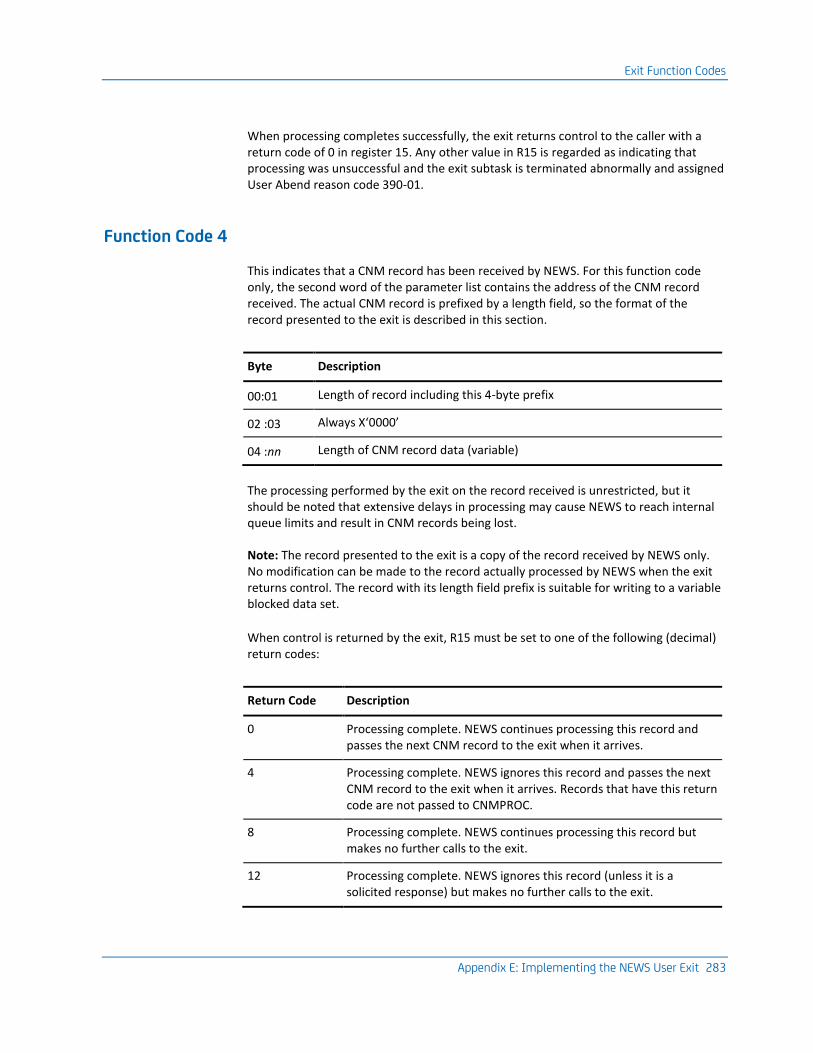
Exit Function Codes
Appendix E: Implementing the NEWS User Exit 283
When processing completes successfully, the exit returns control to the caller with a return code of 0 in register 15. Any other value in R15 is regarded as indicating that processing was unsuccessful and the exit subtask is terminated abnormally and assigned User Abend reason code 390-01.
Function Code 4
This indicates that a CNM record has been received by NEWS. For this function code only, the second word of the parameter list contains the address of the CNM record received. The actual CNM record is prefixed by a length field, so the format of the record presented to the exit is described in this section.
Byte Description
00:01 Length of record including this 4-byte prefix
02 :03 Always X‘0000’
04 :nn Length of CNM record data (variable)
The processing performed by the exit on the record received is unrestricted, but it should be noted that extensive delays in processing may cause NEWS to reach internal queue limits and result in CNM records being lost.
Note: The record presented to the exit is a copy of the record received by NEWS only. No modification can be made to the record actually processed by NEWS when the exit returns control. The record with its length field prefix is suitable for writing to a variable blocked data set.
When control is returned by the exit, R15 must be set to one of the following (decimal) return codes:
Return Code Description
0 Processing complete. NEWS continues processing this record and passes the next CNM record to the exit when it arrives.
4 Processing complete. NEWS ignores this record and passes the next CNM record to the exit when it arrives. Records that have this return code are not passed to CNMPROC.
8 Processing complete. NEWS continues processing this record but makes no further calls to the exit.
12 Processing complete. NEWS ignores this record (unless it is a solicited response) but makes no further calls to the exit.
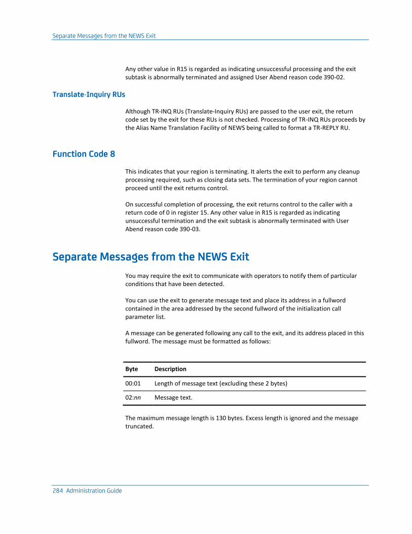
Separate Messages from the NEWS Exit
284 Administration Guide
Any other value in R15 is regarded as indicating unsuccessful processing and the exit subtask is abnormally terminated and assigned User Abend reason code 390-02.
Translate-Inquiry RUs
Although TR-INQ RUs (Translate-Inquiry RUs) are passed to the user exit, the return code set by the exit for these RUs is not checked. Processing of TR-INQ RUs proceeds by the Alias Name Translation Facility of NEWS being called to format a TR-REPLY RU.
Function Code 8
This indicates that your region is terminating. It alerts the exit to perform any cleanup processing required, such as closing data sets. The termination of your region cannot proceed until the exit returns control.
On successful completion of processing, the exit returns control to the caller with a return code of 0 in register 15. Any other value in R15 is regarded as indicating unsuccessful termination and the exit subtask is abnormally terminated with User Abend reason code 390-03.
Separate Messages from the NEWS Exit
You may require the exit to communicate with operators to notify them of particular conditions that have been detected.
You can use the exit to generate message text and place its address in a fullword contained in the area addressed by the second fullword of the initialization call parameter list.
A message can be generated following any call to the exit, and its address placed in this fullword. The message must be formatted as follows:
Byte Description
00:01 Length of message text (excluding these 2 bytes)
02:nn Message text.
The maximum message length is 130 bytes. Excess length is ignored and the message truncated.
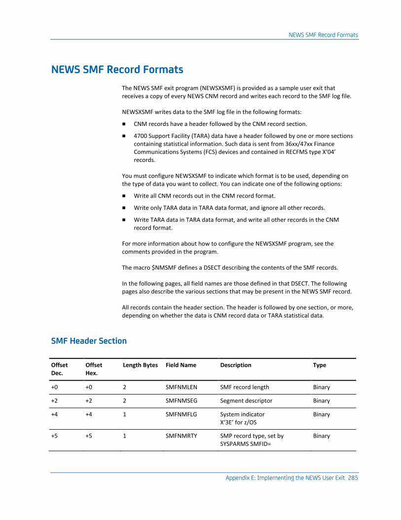
NEWS SMF Record Formats
Appendix E: Implementing the NEWS User Exit 285
NEWS SMF Record Formats
The NEWS SMF exit program (NEWSXSMF) is provided as a sample user exit that receives a copy of every NEWS CNM record and writes each record to the SMF log file.
NEWSXSMF writes data to the SMF log file in the following formats:
■ CNM records have a header followed by the CNM record section.
■ 4700 Support Facility (TARA) data have a header followed by one or more sections containing statistical information. Such data is sent from 36xx/47xx Finance Communications Systems (FCS) devices and contained in RECFMS type X‘04’ records.
You must configure NEWSXSMF to indicate which format is to be used, depending on the type of data you want to collect. You can indicate one of the following options:
■ Write all CNM records out in the CNM record format.
■ Write only TARA data in TARA data format, and ignore all other records.
■ Write TARA data in TARA data format, and write all other records in the CNM record format.
For more information about how to configure the NEWSXSMF program, see the comments provided in the program.
The macro $NMSMF defines a DSECT describing the contents of the SMF records.
In the following pages, all field names are those defined in that DSECT. The following pages also describe the various sections that may be present in the NEWS SMF record.
All records contain the header section. The header is followed by one section, or more, depending on whether the data is CNM record data or TARA statistical data.
SMF Header Section
Offset Dec.
Offset Hex.
Length Bytes Field Name Description Type
+0 +0 2 SMFNMLEN SMF record length Binary
+2 +2 2 SMFNMSEG Segment descriptor Binary
+4 +4 1 SMFNMFLG System indicator X‘3E’ for z/OS
Binary
+5 +5 1 SMFNMRTY SMP record type, set by SYSPARMS SMFID=
Binary
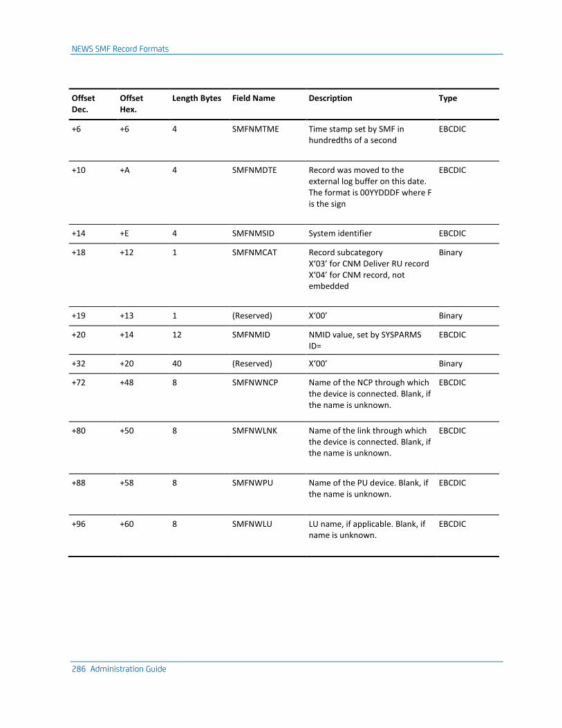
NEWS SMF Record Formats
286 Administration Guide
Offset Dec.
Offset Hex.
Length Bytes Field Name Description Type
+6 +6 4 SMFNMTME Time stamp set by SMF in hundredths of a second
EBCDIC
+10 +A 4 SMFNMDTE Record was moved to the external log buffer on this date. The format is 00YYDDDF where F is the sign
EBCDIC
+14 +E 4 SMFNMSID System identifier EBCDIC
+18 +12 1 SMFNMCAT Record subcategory X‘03’ for CNM Deliver RU record X‘04’ for CNM record, not embedded
Binary
+19 +13 1 (Reserved) X‘00’ Binary
+20 +14 12 SMFNMID NMID value, set by SYSPARMS ID=
EBCDIC
+32 +20 40 (Reserved) X‘00’ Binary
+72 +48 8 SMFNWNCP Name of the NCP through which the device is connected. Blank, if the name is unknown.
EBCDIC
+80 +50 8 SMFNWLNK Name of the link through which the device is connected. Blank, if the name is unknown.
EBCDIC
+88 +58 8 SMFNWPU Name of the PU device. Blank, if the name is unknown.
EBCDIC
+96 +60 8 SMFNWLU LU name, if applicable. Blank, if name is unknown.
EBCDIC
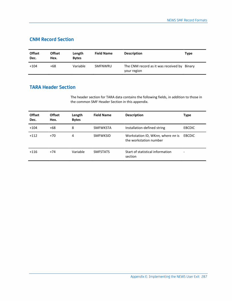
NEWS SMF Record Formats
Appendix E: Implementing the NEWS User Exit 287
CNM Record Section
Offset Dec.
Offset Hex.
Length Bytes
Field Name Description Type
+104 +68 Variable SMFNWRU The CNM record as it was received by your region
Binary
TARA Header Section
The header section for TARA data contains the following fields, in addition to those in the common SMF Header Section in this appendix.
Offset Dec.
Offset Hex.
Length Bytes
Field Name Description Type
+104 +68 8 SMFWKSTA Installation-defined string EBCDIC
+112 +70 4 SMFWKSID Workstation ID, WKnn, where nn is the workstation number
EBCDIC
+116 +74 Variable SMFSTATS Start of statistical information section
-
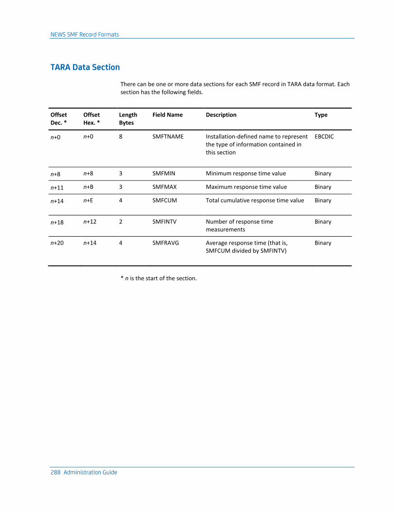
NEWS SMF Record Formats
288 Administration Guide
TARA Data Section
There can be one or more data sections for each SMF record in TARA data format. Each section has the following fields.
Offset Dec. *
Offset Hex. *
Length Bytes
Field Name Description Type
n+0 n+0 8 SMFTNAME Installation-defined name to represent the type of information contained in this section
EBCDIC
n+8 n+8 3 SMFMIN Minimum response time value Binary
n+11 n+B 3 SMFMAX Maximum response time value Binary
n+14 n+E 4 SMFCUM Total cumulative response time value Binary
n+18 n+12 2 SMFINTV Number of response time measurements
Binary
n+20 n+14 4 SMFRAVG Average response time (that is, SMFCUM divided by SMFINTV)
Binary
* n is the start of the section.
Appendix F: Implementing the NTS User Exit 289
Appendix F: Implementing the NTS User Exit
This section contains the following topics:
NTS User Exit (see page 289) Sample NTS Exit (see page 289) How the NTS Exit Is Called (see page 290) NTS Exit Coding Requirements (see page 290) Exit Function Codes (see page 292) Generate Messages from the NTS Exit (see page 295)
NTS User Exit
All session data that has been captured by NTS and queued for output processing is first passed to an installation-supplied user exit, where one exists. Following any exit processing, the session record is returned to NTS and considered for logging on the NTS database.
The user exit can perform any desired processing on the session data and may indicate that the session record is to be ignored by the subsequent NTS logging function.
Sample NTS Exit
A sample NTS user exit named NTSXSMF is provided in source form and can be modified as required. The exit is a member of the ?dsnpref.NMC1.CC2ASAMP library distributed on the installation tape.
The sample exit is extensively documented and provides an example of an exit that writes, to the System Management Facility (SMF) database, all NTS session data queued for output processing.
This exit takes the record as passed from NTS and inserts the SMF record type of 39. Since SMF fills out the SMF header area for system type records this is all that the exit need do before issuing the SMFWTM macro to write the record to SMF.
The Assembler macro $NMSMF, distributed in the macro library provides mapping for the format of the SMF record generated.
How the NTS Exit Is Called
290 Administration Guide
How the NTS Exit Is Called
NTS is initialized when your region starts and a subtask that acts as the driver for the exit is attached. The subtask mainline routines handle communications between the subtask and the NTS components in the main task.
When the subtask is attached, subtask mainline routines do the following:
1. Load the load module specified as the installation-supplied user exit.
2. Call the exit using conventional branching and linking.
3. Pass an initialization parameter list to the exit.
Note: To implement an NTS exit, you must define the exit name in the SAW parameter group. For more information, see the Installation Guide.
NTS Exit Execution
Because the user exit executes as part of a subtask, no restrictions are placed on the functions that the exit can perform. This is because the activities of the subtask do not impact the performance of the main task, and the exit subtask runs at a lower dispatching priority than the main task.
However, all processing of NTS session records on the output queue by the main task is delayed by processing occurring in the NTS user exit.
NTS Exit Coding Requirements
This section describes the coding requirements for the NTS exit.
Maintain Registers on Entry to an Exit
You must observe standard linkage conventions on entry to an exit.
On entry, the registers must be saved in the caller’s save area, and on exit, restored (except R15, which contains a return code).
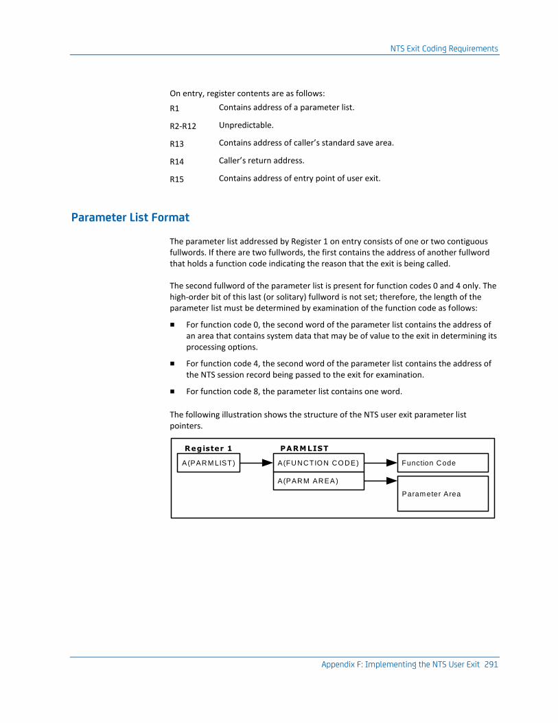
NTS Exit Coding Requirements
Appendix F: Implementing the NTS User Exit 291
On entry, register contents are as follows:
R1 Contains address of a parameter list.
R2-R12 Unpredictable.
R13 Contains address of caller’s standard save area.
R14 Caller’s return address.
R15 Contains address of entry point of user exit.
Parameter List Format
The parameter list addressed by Register 1 on entry consists of one or two contiguous fullwords. If there are two fullwords, the first contains the address of another fullword that holds a function code indicating the reason that the exit is being called.
The second fullword of the parameter list is present for function codes 0 and 4 only. The high-order bit of this last (or solitary) fullword is not set; therefore, the length of the parameter list must be determined by examination of the function code as follows:
■ For function code 0, the second word of the parameter list contains the address of an area that contains system data that may be of value to the exit in determining its processing options.
■ For function code 4, the second word of the parameter list contains the address of the NTS session record being passed to the exit for examination.
■ For function code 8, the parameter list contains one word.
The following illustration shows the structure of the NTS user exit parameter list pointers.
A(PARM LIST)
Register 1
A(FUNCTIO N CO DE)
PARMLIST
A(PARM AREA)
Function Code
Param eter Area
Exit Function Codes
292 Administration Guide
Exit Function Codes
The function code contained in a fullword addressed by the first word of the parameter list is a binary value that is right-aligned, with all high-order bits set to zero. The following function codes are used:
■ X‘00000000’ = initialization call
■ X‘00000004’ = SMF record available
■ X‘00000008’ = termination call
Function Code 0
This indicates that the region has just been initialized. Any initialization processing that the exit needs to do, such as opening required data sets, should be done now.
The second word of the parameter list passed to the exit for function code 0, contains the address of an area, formatted as described next.
Byte Description
00-03 In this fullword, the exit can store the address of a message to log to the activity log and send to Monitor class operators. On return from any call to the exit, this word is checked; if the value is non-zero, it is assumed to be the address of a message.
04-04 Operating system indicator. Value is:
X’10’ z/OS
05-05 SMF record identifier set by the SYSPARMS SMFID= command.
06-17 System identifier set by the SYSPARMS ID= command.
When processing completes successfully, the exit returns control to the caller with a completion code of 0 in register 15. Any other value in R15 is regarded as indicating that processing was unsuccessful and the exit subtask is terminated abnormally and assigned User Abend reason code 75D-01.
Exit Function Codes
Appendix F: Implementing the NTS User Exit 293
Function Code 4
This indicates that a session record has been placed on the NTS output queue. For this function code only, the second word of the parameter list contains the address of the record passed to the exit.
The session record passed to the exit is formatted as an SMF Type 39 system record. The full record layout is available in the macro DSECT $NMSMF, which is located in the distributed management services macro library.
To map the NTS session record description, code the following:
label $NMSMF TYPE=NTS
Note that the area after the SMF record header contains variable information relating to the offset and length of those subsections present in the record. As the various data subsections are not always available to NTS, their inclusion is not guaranteed. This means that all access to such data subsections must proceed through the offset and length fields which relate to the subsections that are present. All offsets are from the first byte of the entire area passed (that is, the start of the SMF record header).
Record Subtype Identification
A copy of the session information is passed to the user exit and this data can be modified in any way without affecting subsequent NTS output processing. A halfword field labeled SMFNSUBT in the DSECT macro $NMSMF, and located at an offset of 22 bytes from the start of the record, contains the record subtype. NTS sets this field as follows:
01 The record passed contains RTM data collected for the session and was force-closed by the operator or closed during session awareness termination, but the session had not ended.
02 The record passed is a session end notification for a session that required NTS accounting.
03 The record passed is a session start notification for a session that requires the NTS accounting facility.
04 The record passed was force-closed by the operator, or closed during session awareness termination, but the session had not ended.
05 The record passed contains all data available at session end.
06 The record passed contains notification of a BIND rejection at session initialization.
07 The record passed contains notification of a session initialization failure that occurred before a BIND request was sent.
Exit Function Codes
294 Administration Guide
255 The record passed contains resource-based information. The type of information contained is indicated in the SMFNPSUB field. For more information, see the Reference Guide.
The processing performed by the exit on the record received is unrestricted, but it should be noted that exit processing is serialized and no additional NTS session records are processed on the output queue until the exit returns control to NTS.
Return Code Values
When control is returned by the exit, R15 must be set to one of the following (hexadecimal) return codes:
00 Processing complete. NTS continues processing the session record and passes the next record to the exit when it is available.
04 Processing complete. If this is a normal end of session record (record subtype 5) NTS does not log the record, otherwise this return code is treated in the same way as return code 0.
08 Processing complete. NTS processes the record but no further calls are made to the exit.
0C Processing complete. As for return code 04, but no further calls are made to the exit.
Any other value in R15 is regarded as indicating unsuccessful processing and the exit subtask is abnormally terminated and assigned User Abend reason code 75D-02.
Function Code 8
This indicates that your region is terminating. It alerts the exit to perform any cleanup processing required, such as closing data sets. The termination of your region cannot proceed until the exit returns control.
On successful completion of processing, the exit returns control to the caller with a completion code of 0 in register 15. Any other value in R15 is regarded as indicating unsuccessful termination and the exit subtask is abnormally terminated and assigned User Abend reason code 75D-03.
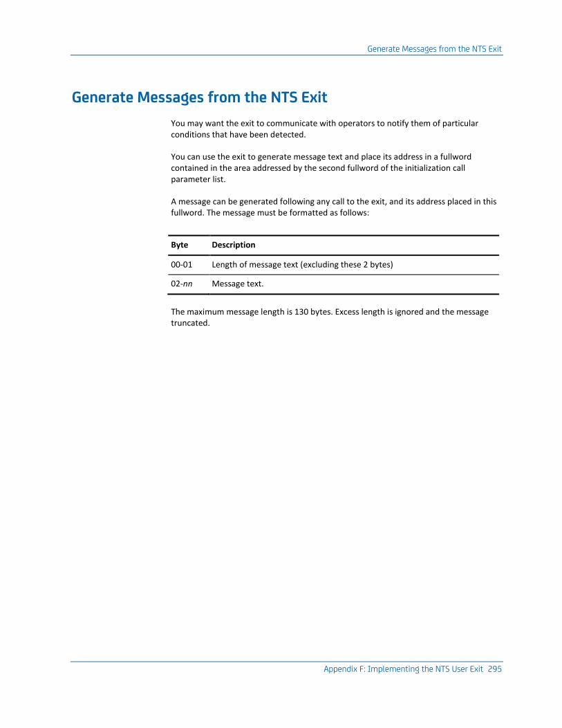
Generate Messages from the NTS Exit
Appendix F: Implementing the NTS User Exit 295
Generate Messages from the NTS Exit
You may want the exit to communicate with operators to notify them of particular conditions that have been detected.
You can use the exit to generate message text and place its address in a fullword contained in the area addressed by the second fullword of the initialization call parameter list.
A message can be generated following any call to the exit, and its address placed in this fullword. The message must be formatted as follows:
Byte Description
00-01 Length of message text (excluding these 2 bytes)
02-nn Message text.
The maximum message length is 130 bytes. Excess length is ignored and the message truncated.

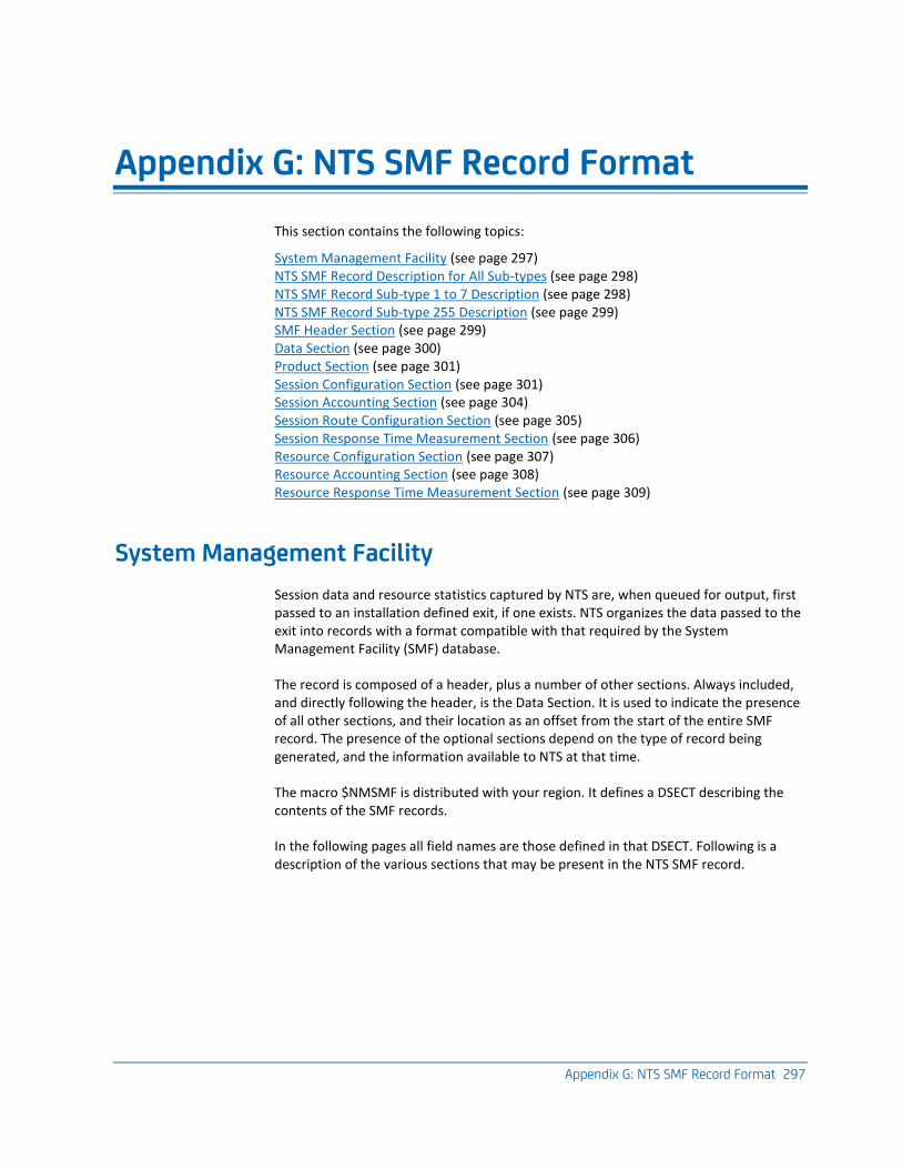
Appendix G: NTS SMF Record Format 297
Appendix G: NTS SMF Record Format
This section contains the following topics:
System Management Facility (see page 297) NTS SMF Record Description for All Sub-types (see page 298) NTS SMF Record Sub-type 1 to 7 Description (see page 298) NTS SMF Record Sub-type 255 Description (see page 299) SMF Header Section (see page 299) Data Section (see page 300) Product Section (see page 301) Session Configuration Section (see page 301) Session Accounting Section (see page 304) Session Route Configuration Section (see page 305) Session Response Time Measurement Section (see page 306) Resource Configuration Section (see page 307) Resource Accounting Section (see page 308) Resource Response Time Measurement Section (see page 309)
System Management Facility
Session data and resource statistics captured by NTS are, when queued for output, first passed to an installation defined exit, if one exists. NTS organizes the data passed to the exit into records with a format compatible with that required by the System Management Facility (SMF) database.
The record is composed of a header, plus a number of other sections. Always included, and directly following the header, is the Data Section. It is used to indicate the presence of all other sections, and their location as an offset from the start of the entire SMF record. The presence of the optional sections depend on the type of record being generated, and the information available to NTS at that time.
The macro $NMSMF is distributed with your region. It defines a DSECT describing the contents of the SMF records.
In the following pages all field names are those defined in that DSECT. Following is a description of the various sections that may be present in the NTS SMF record.
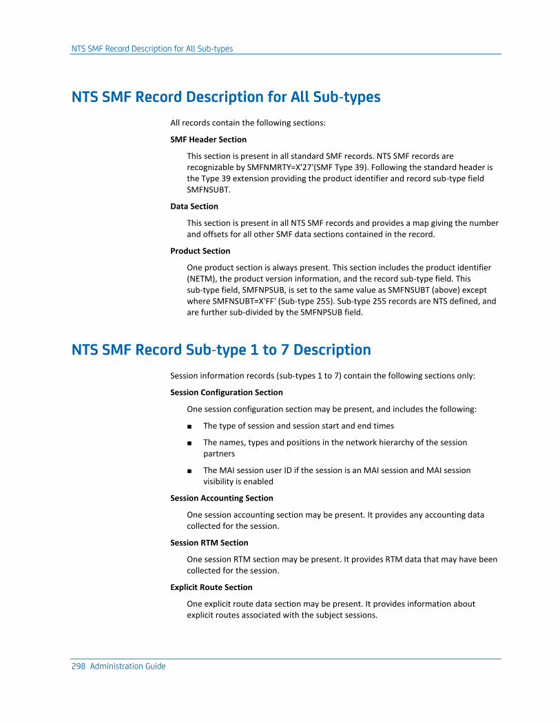
NTS SMF Record Description for All Sub-types
298 Administration Guide
NTS SMF Record Description for All Sub-types
All records contain the following sections:
SMF Header Section
This section is present in all standard SMF records. NTS SMF records are recognizable by SMFNMRTY=X'27'(SMF Type 39). Following the standard header is the Type 39 extension providing the product identifier and record sub-type field SMFNSUBT.
Data Section
This section is present in all NTS SMF records and provides a map giving the number and offsets for all other SMF data sections contained in the record.
Product Section
One product section is always present. This section includes the product identifier (NETM), the product version information, and the record sub-type field. This sub-type field, SMFNPSUB, is set to the same value as SMFNSUBT (above) except where SMFNSUBT=X'FF' (Sub-type 255). Sub-type 255 records are NTS defined, and are further sub-divided by the SMFNPSUB field.
NTS SMF Record Sub-type 1 to 7 Description
Session information records (sub-types 1 to 7) contain the following sections only:
Session Configuration Section
One session configuration section may be present, and includes the following:
■ The type of session and session start and end times
■ The names, types and positions in the network hierarchy of the session partners
■ The MAI session user ID if the session is an MAI session and MAI session visibility is enabled
Session Accounting Section
One session accounting section may be present. It provides any accounting data collected for the session.
Session RTM Section
One session RTM section may be present. It provides RTM data that may have been collected for the session.
Explicit Route Section
One explicit route data section may be present. It provides information about explicit routes associated with the subject sessions.
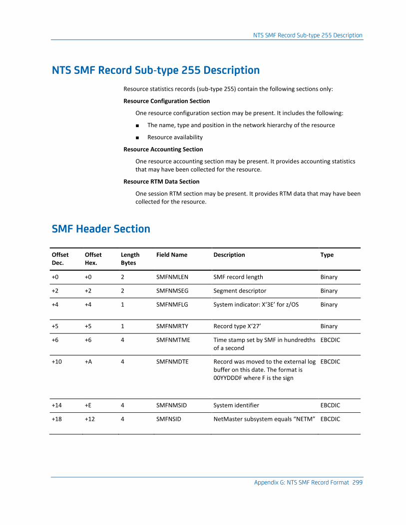
NTS SMF Record Sub-type 255 Description
Appendix G: NTS SMF Record Format 299
NTS SMF Record Sub-type 255 Description
Resource statistics records (sub-type 255) contain the following sections only:
Resource Configuration Section
One resource configuration section may be present. It includes the following:
■ The name, type and position in the network hierarchy of the resource
■ Resource availability
Resource Accounting Section
One resource accounting section may be present. It provides accounting statistics that may have been collected for the resource.
Resource RTM Data Section
One session RTM section may be present. It provides RTM data that may have been collected for the resource.
SMF Header Section
Offset Dec.
Offset Hex.
Length Bytes
Field Name Description Type
+0 +0 2 SMFNMLEN SMF record length Binary
+2 +2 2 SMFNMSEG Segment descriptor Binary
+4 +4 1 SMFNMFLG System indicator: X‘3E’ for z/OS Binary
+5 +5 1 SMFNMRTY Record type X‘27’ Binary
+6 +6 4 SMFNMTME Time stamp set by SMF in hundredths of a second
EBCDIC
+10 +A 4 SMFNMDTE Record was moved to the external log buffer on this date. The format is 00YYDDDF where F is the sign
EBCDIC
+14 +E 4 SMFNMSID System identifier EBCDIC
+18 +12 4 SMFNSID NetMaster subsystem equals “NETM” EBCDIC
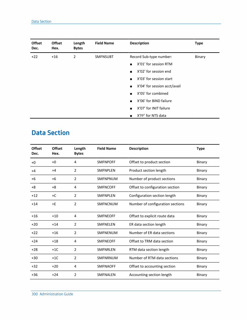
Data Section
300 Administration Guide
Offset Dec.
Offset Hex.
Length Bytes
Field Name Description Type
+22 +16 2 SMFNSUBT Record Sub-type number:
■ X‘01’ for session RTM
■ X‘02’ for session end
■ X‘03’ for session start
■ X‘04’ for session acct/avail
■ X‘05’ for combined
■ X‘06’ for BIND failure
■ X‘07’ for INIT failure
■ X‘FF’ for NTS data
Binary
Data Section
Offset Dec.
Offset Hex.
Length Bytes
Field Name Description Type
+0 +0 4 SMFNPOFF Offset to product section Binary
+4 +4 2 SMFNPLEN Product section length Binary
+6 +6 2 SMFNPNUM Number of product sections Binary
+8 +8 4 SMFNCOFF Offset to configuration section Binary
+12 +C 2 SMFNPLEN Configuration section length Binary
+14 +E 2 SMFNCNUM Number of configuration sections Binary
+16 +10 4 SMFNEOFF Offset to explicit route data Binary
+20 +14 2 SMFNELEN ER data section length Binary
+22 +16 2 SMFNENUM Number of ER data sections Binary
+24 +18 4 SMFNEOFF Offset to TRM data section Binary
+28 +1C 2 SMFNRLEN RTM data section length Binary
+30 +1C 2 SMFNRNUM Number of RTM data sections Binary
+32 +20 4 SMFNAOFF Offset to accounting section Binary
+36 +24 2 SMFNALEN Accounting section length Binary
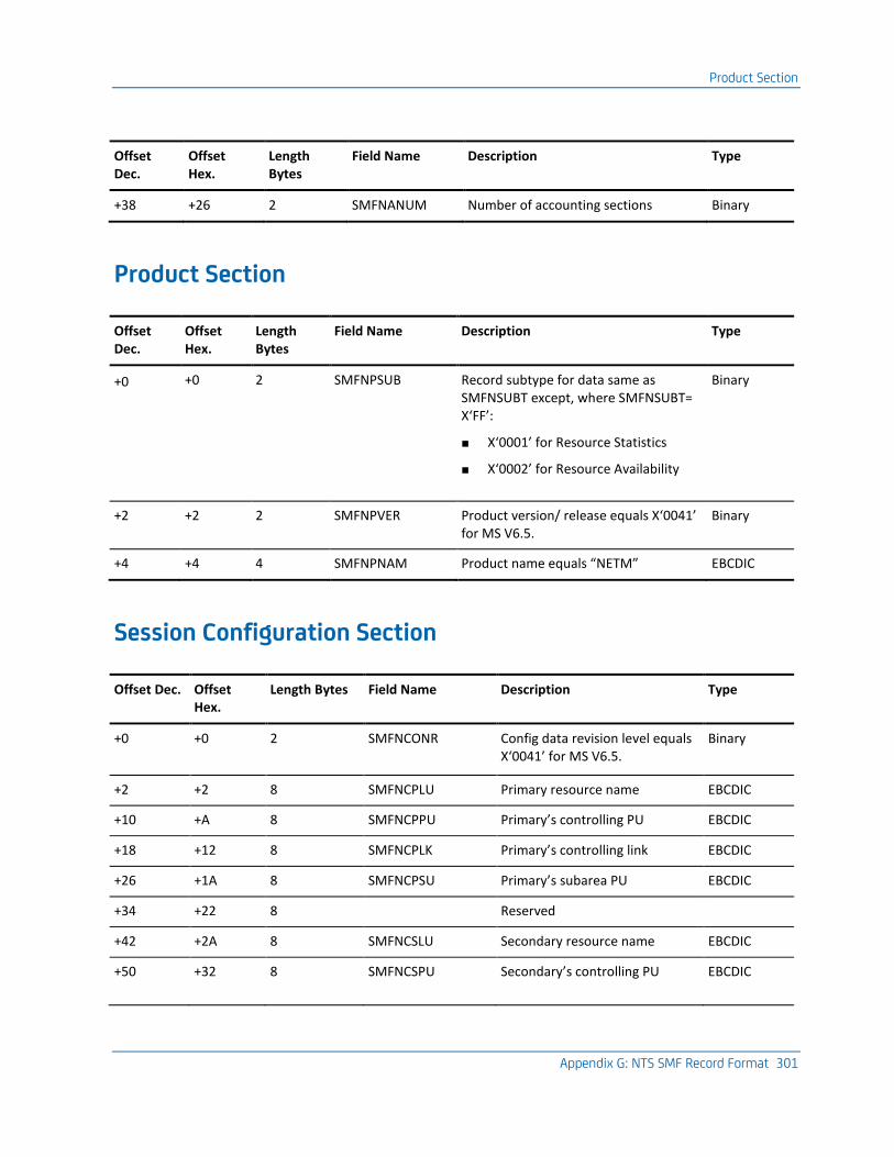
Product Section
Appendix G: NTS SMF Record Format 301
Offset Dec.
Offset Hex.
Length Bytes
Field Name Description Type
+38 +26 2 SMFNANUM Number of accounting sections Binary
Product Section
Offset Dec.
Offset Hex.
Length Bytes
Field Name Description Type
+0 +0 2 SMFNPSUB Record subtype for data same as SMFNSUBT except, where SMFNSUBT= X‘FF’:
■ X‘0001’ for Resource Statistics
■ X‘0002’ for Resource Availability
Binary
+2 +2 2 SMFNPVER Product version/ release equals X‘0041’ for MS V6.5.
Binary
+4 +4 4 SMFNPNAM Product name equals “NETM” EBCDIC
Session Configuration Section
Offset Dec. Offset Hex.
Length Bytes Field Name Description Type
+0 +0 2 SMFNCONR Config data revision level equals X‘0041’ for MS V6.5.
Binary
+2 +2 8 SMFNCPLU Primary resource name EBCDIC
+10 +A 8 SMFNCPPU Primary’s controlling PU EBCDIC
+18 +12 8 SMFNCPLK Primary’s controlling link EBCDIC
+26 +1A 8 SMFNCPSU Primary’s subarea PU EBCDIC
+34 +22 8 Reserved
+42 +2A 8 SMFNCSLU Secondary resource name EBCDIC
+50 +32 8 SMFNCSPU Secondary’s controlling PU EBCDIC
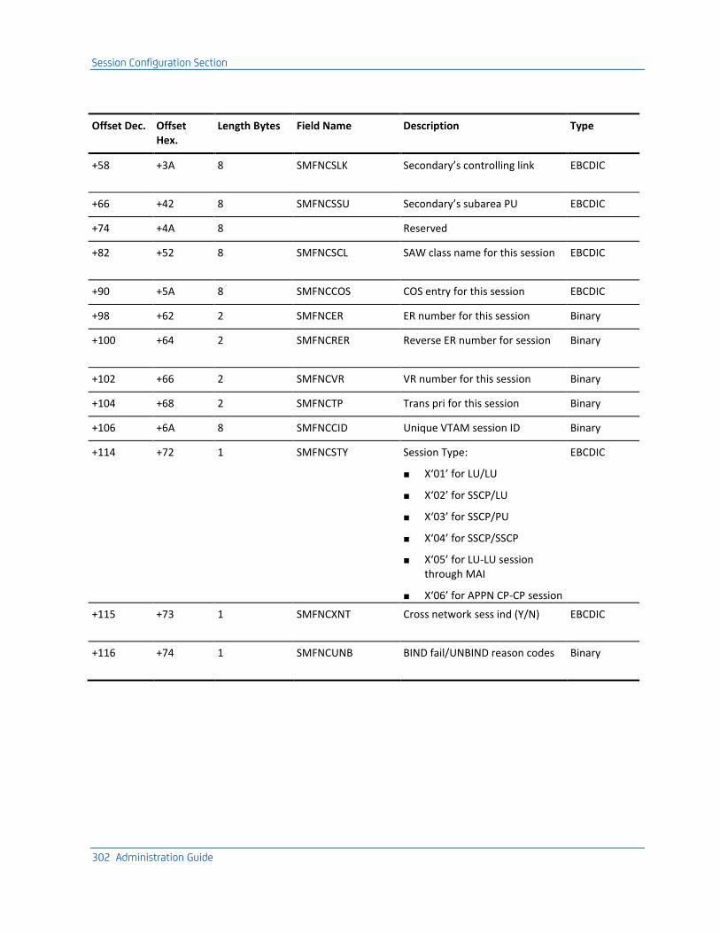
Session Configuration Section
302 Administration Guide
Offset Dec. Offset Hex.
Length Bytes Field Name Description Type
+58 +3A 8 SMFNCSLK Secondary’s controlling link EBCDIC
+66 +42 8 SMFNCSSU Secondary’s subarea PU EBCDIC
+74 +4A 8 Reserved
+82 +52 8 SMFNCSCL SAW class name for this session EBCDIC
+90 +5A 8 SMFNCCOS COS entry for this session EBCDIC
+98 +62 2 SMFNCER ER number for this session Binary
+100 +64 2 SMFNCRER Reverse ER number for session Binary
+102 +66 2 SMFNCVR VR number for this session Binary
+104 +68 2 SMFNCTP Trans pri for this session Binary
+106 +6A 8 SMFNCCID Unique VTAM session ID Binary
+114 +72 1 SMFNCSTY Session Type:
■ X‘01’ for LU/LU
■ X‘02’ for SSCP/LU
■ X‘03’ for SSCP/PU
■ X‘04’ for SSCP/SSCP
■ X‘05’ for LU-LU session through MAI
■ X‘06’ for APPN CP-CP session
EBCDIC
+115 +73 1 SMFNCXNT Cross network sess ind (Y/N) EBCDIC
+116 +74 1 SMFNCUNB BIND fail/UNBIND reason codes Binary
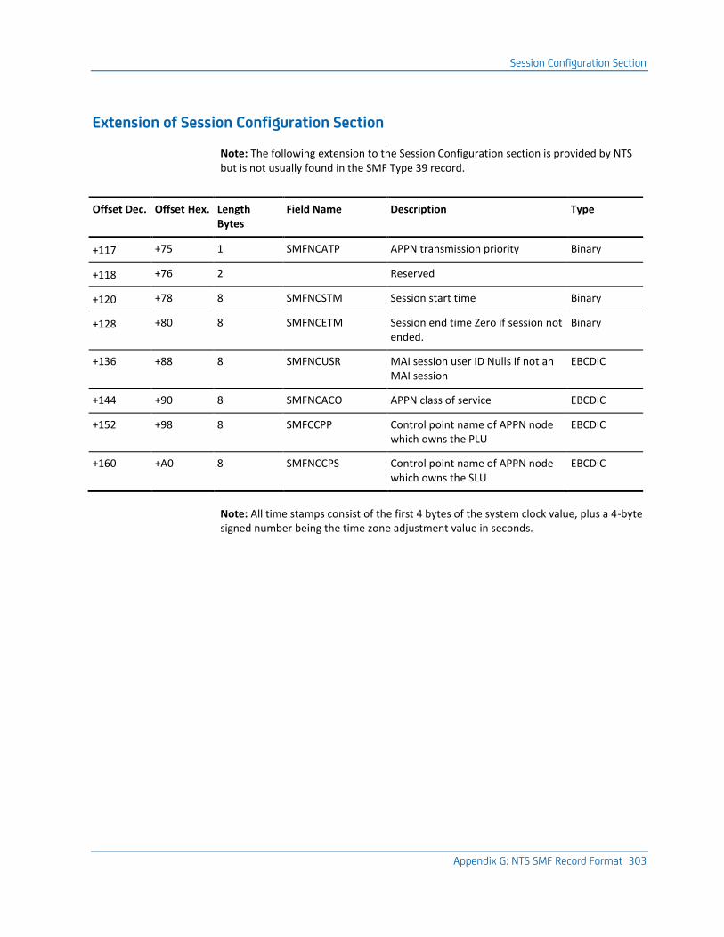
Session Configuration Section
Appendix G: NTS SMF Record Format 303
Extension of Session Configuration Section
Note: The following extension to the Session Configuration section is provided by NTS but is not usually found in the SMF Type 39 record.
Offset Dec. Offset Hex. Length Bytes
Field Name Description Type
+117 +75 1 SMFNCATP APPN transmission priority Binary
+118 +76 2 Reserved
+120 +78 8 SMFNCSTM Session start time Binary
+128 +80 8 SMFNCETM Session end time Zero if session not ended.
Binary
+136 +88 8 SMFNCUSR MAI session user ID Nulls if not an MAI session
EBCDIC
+144 +90 8 SMFNCACO APPN class of service EBCDIC
+152 +98 8 SMFCCPP Control point name of APPN node which owns the PLU
EBCDIC
+160 +A0 8 SMFNCCPS Control point name of APPN node which owns the SLU
EBCDIC
Note: All time stamps consist of the first 4 bytes of the system clock value, plus a 4-byte signed number being the time zone adjustment value in seconds.
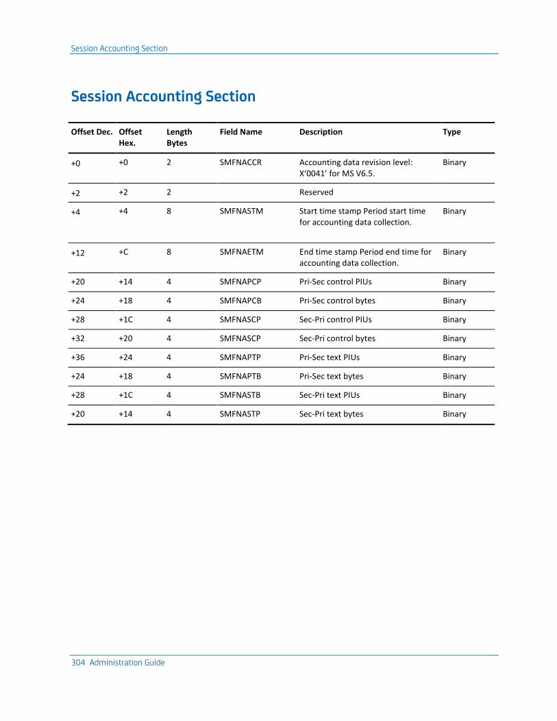
Session Accounting Section
304 Administration Guide
Session Accounting Section
Offset Dec. Offset Hex.
Length Bytes
Field Name Description Type
+0 +0 2 SMFNACCR Accounting data revision level: X‘0041’ for MS V6.5.
Binary
+2 +2 2 Reserved
+4 +4 8 SMFNASTM Start time stamp Period start time for accounting data collection.
Binary
+12 +C 8 SMFNAETM End time stamp Period end time for accounting data collection.
Binary
+20 +14 4 SMFNAPCP Pri-Sec control PIUs Binary
+24 +18 4 SMFNAPCB Pri-Sec control bytes Binary
+28 +1C 4 SMFNASCP Sec-Pri control PIUs Binary
+32 +20 4 SMFNASCP Sec-Pri control bytes Binary
+36 +24 4 SMFNAPTP Pri-Sec text PIUs Binary
+24 +18 4 SMFNAPTB Pri-Sec text bytes Binary
+28 +1C 4 SMFNASTB Sec-Pri text PIUs Binary
+20 +14 4 SMFNASTP Sec-Pri text bytes Binary
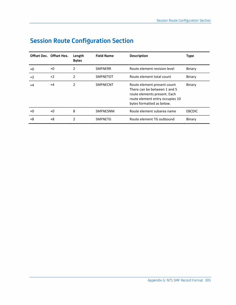
Session Route Configuration Section
Appendix G: NTS SMF Record Format 305
Session Route Configuration Section
Offset Dec. Offset Hex. Length Bytes
Field Name Description Type
+0 +0 2 SMFNERR Route element revision level Binary
+2 +2 2 SMFNETOT Route element total count Binary
+4 +4 2 SMFNECNT Route element present count There can be between 1 and 5 route elements present. Each route element entry occupies 10 bytes formatted as below.
Binary
+0 +0 8 SMFNESNM Route element subarea name EBCDIC
+8 +8 2 SMFNETG Route element TG outbound Binary
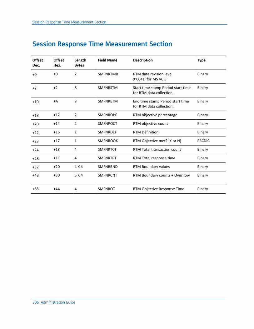
Session Response Time Measurement Section
306 Administration Guide
Session Response Time Measurement Section
Offset Dec.
Offset Hex.
Length Bytes
Field Name Description Type
+0 +0 2 SMFNRTMR RTM data revision level X‘0041’ for MS V6.5.
Binary
+2 +2 8 SMFNRSTM Start time stamp Period start time for RTM data collection.
Binary
+10 +A 8 SMFNRETM End time stamp Period start time for RTM data collection.
Binary
+18 +12 2 SMFNROPC RTM objective percentage Binary
+20 +14 2 SMFNROCT RTM objective count Binary
+22 +16 1 SMFNRDEF RTM Definition Binary
+23 +17 1 SMFNROOK RTM Objective met? (Y or N) EBCDIC
+24 +18 4 SMFNRTCT RTM Total transaction count Binary
+28 +1C 4 SMFNRTRT RTM Total response time Binary
+32 +20 4 X 4 SMFNRBND RTM Boundary values Binary
+48 +30 5 X 4 SMFNRCNT RTM Boundary counts + Overflow Binary
+68 +44 4 SMFNROT RTM Objective Response Time Binary
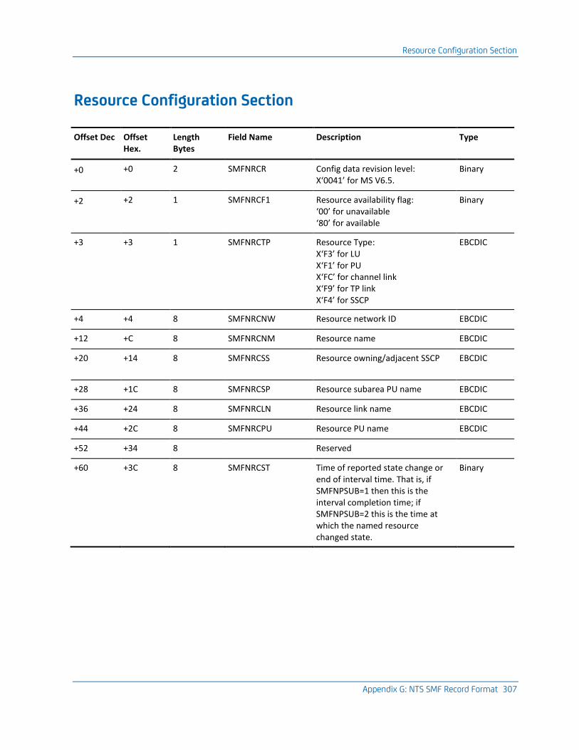
Resource Configuration Section
Appendix G: NTS SMF Record Format 307
Resource Configuration Section
Offset Dec Offset Hex.
Length Bytes
Field Name Description Type
+0 +0 2 SMFNRCR Config data revision level: X‘0041’ for MS V6.5.
Binary
+2 +2 1 SMFNRCF1 Resource availability flag: ‘00’ for unavailable ‘80’ for available
Binary
+3 +3 1 SMFNRCTP Resource Type: X‘F3’ for LU X‘F1’ for PU X‘FC’ for channel link X‘F9’ for TP link X‘F4’ for SSCP
EBCDIC
+4 +4 8 SMFNRCNW Resource network ID EBCDIC
+12 +C 8 SMFNRCNM Resource name EBCDIC
+20 +14 8 SMFNRCSS Resource owning/adjacent SSCP EBCDIC
+28 +1C 8 SMFNRCSP Resource subarea PU name EBCDIC
+36 +24 8 SMFNRCLN Resource link name EBCDIC
+44 +2C 8 SMFNRCPU Resource PU name EBCDIC
+52 +34 8 Reserved
+60 +3C 8 SMFNRCST Time of reported state change or end of interval time. That is, if SMFNPSUB=1 then this is the interval completion time; if SMFNPSUB=2 this is the time at which the named resource changed state.
Binary
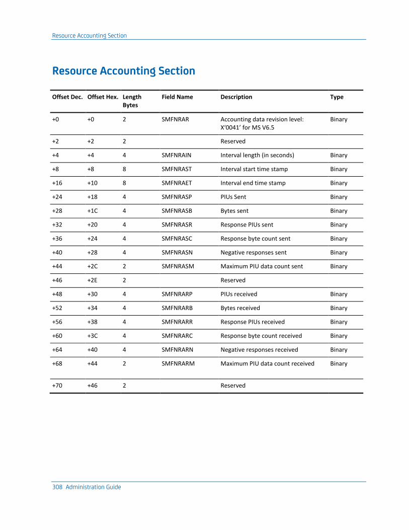
Resource Accounting Section
308 Administration Guide
Resource Accounting Section
Offset Dec. Offset Hex. Length Bytes
Field Name Description Type
+0 +0 2 SMFNRAR Accounting data revision level: X‘0041’ for MS V6.5
Binary
+2 +2 2 Reserved
+4 +4 4 SMFNRAIN Interval length (in seconds) Binary
+8 +8 8 SMFNRAST Interval start time stamp Binary
+16 +10 8 SMFNRAET Interval end time stamp Binary
+24 +18 4 SMFNRASP PIUs Sent Binary
+28 +1C 4 SMFNRASB Bytes sent Binary
+32 +20 4 SMFNRASR Response PIUs sent Binary
+36 +24 4 SMFNRASC Response byte count sent Binary
+40 +28 4 SMFNRASN Negative responses sent Binary
+44 +2C 2 SMFNRASM Maximum PIU data count sent Binary
+46 +2E 2 Reserved
+48 +30 4 SMFNRARP PIUs received Binary
+52 +34 4 SMFNRARB Bytes received Binary
+56 +38 4 SMFNRARR Response PIUs received Binary
+60 +3C 4 SMFNRARC Response byte count received Binary
+64 +40 4 SMFNRARN Negative responses received Binary
+68 +44 2 SMFNRARM Maximum PIU data count received Binary
+70 +46 2 Reserved
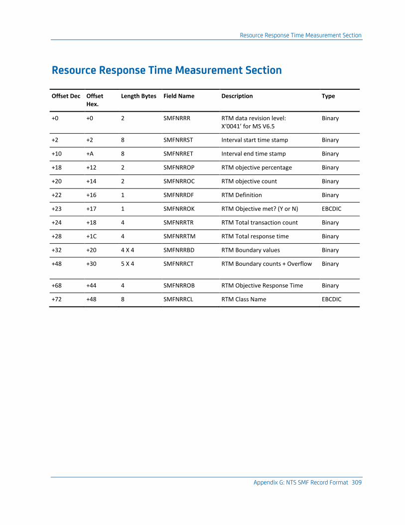
Resource Response Time Measurement Section
Appendix G: NTS SMF Record Format 309
Resource Response Time Measurement Section
Offset Dec Offset Hex.
Length Bytes Field Name Description Type
+0 +0 2 SMFNRRR RTM data revision level: X‘0041’ for MS V6.5
Binary
+2 +2 8 SMFNRRST Interval start time stamp Binary
+10 +A 8 SMFNRRET Interval end time stamp Binary
+18 +12 2 SMFNRROP RTM objective percentage Binary
+20 +14 2 SMFNRROC RTM objective count Binary
+22 +16 1 SMFNRRDF RTM Definition Binary
+23 +17 1 SMFNRROK RTM Objective met? (Y or N) EBCDIC
+24 +18 4 SMFNRRTR RTM Total transaction count Binary
+28 +1C 4 SMFNRRTM RTM Total response time Binary
+32 +20 4 X 4 SMFNRRBD RTM Boundary values Binary
+48 +30 5 X 4 SMFNRRCT RTM Boundary counts + Overflow Binary
+68 +44 4 SMFNRROB RTM Objective Response Time Binary
+72 +48 8 SMFNRRCL RTM Class Name EBCDIC

Appendix H: NTS Storage Estimates 311
Appendix H: NTS Storage Estimates
This section contains the following topics:
Active Session Data (see page 311) NTS Database (see page 312) NTS Database Management Strategy (see page 313)
Active Session Data
All active session data which has been captured by NTS is kept in main memory. This storage is above the 16 MB line. The actual amount of storage required for any given network configuration varies depending upon the NTS processing options. As a guide, the following scenario may be useful.
Example
Consider an NTS region operating in a single VTAM domain that contains 500 terminals, of which 400 are continually in session with one of several applications.
■ If all active sessions (that is the 400 LU-LU sessions, 500 SSCP-LU sessions, plus a handful of SSCP-PU sessions) are to be kept by NTS, the storage requirement would be approximately 350K.
■ By keeping LU-LU sessions only, this is reduced to about 180K.
■ Gathering accounting data takes no extra storage.
■ To collect RTM data for all 400 LU-LU sessions would require an extra 40K.
■ If the default trace queue limits were used, and trace data collected for every LU-LU session, then this could reach a requirement of up to an extra 700K. However, it is not usual for all sessions to be concurrently holding the maximum number of trace PIUs in storage. New sessions take some time to reach this wrap level, while for ended sessions, the trace data is logged then purged from storage.
When Using NTS-SI
If your NTS region is configured to receive session awareness data through NTS Single Image, this must be considered when calculating the storage requirements of NTS. The local NTS receives session awareness from the remote NTS and maintain this data in storage. This data includes SSCP-SSCP, SSCP-PU, SSCP-LU and LU-LU session data. Session data (trace, RTM, and accounting) is solicited from the remote NTS when requested and is discarded when the data is not being viewed.
NTS Database
312 Administration Guide
NTS Database
The space requirements of the NTS database vary according to the amount of data collected and logged. To store a single session incidence for a session name pair requires approximately 800 bytes. Each additional session incidence requires an extra amount of approximately 350 bytes. Further requirements are an extra 128 bytes for each record of session accounting or RTM data, and around 1200 bytes if trace data is logged (assuming the default trace queue depths are used).
Hence, for the default session keep count of 10 session incidence records per session name pair, the total database space requirement per session name pair is as follows (approximately):
■ 4KB when no additional session data is logged
■ 6.6KB when all accounting and RTM data is logged
■ 18KB when all trace data is additionally logged
Extrapolating further, with a 500-terminal network in which up to six different applications can be used by all terminals, this translates to an overall database storage requirement of the following (approximately):
■ 10 MB when no additional session data is logged
■ 18 MB when all accounting and RTM data is logged
■ 50 MB when all trace data is additionally logged
Follow the sizing formula and calculate a primary space allocation. Allow an additional 25% primary allocation for growth, and provide a 5% secondary allocation and index allocation. For example, if the calculation indicates that the data requires 80 cylinders, use CYLS(100 5) for the data allocation and CYLS(5 1) for the index allocation.
Note: These figures are intended as a guide only for the initial implementation, as in operation many changing factors can affect the amount of data stored in the NTS database.
NTS Database Management Strategy
Appendix H: NTS Storage Estimates 313
NTS Database Management Strategy
CA NetMaster uses the NTSLOG database in a slot-managed fashion. This means that as session instances are logged, space is reserved for the records for that session combination. The data set grows as CI/CA splits occur. Eventually, as all combinations to be recorded occur for the site, the database stabilizes. When this occurs, the NTSLOG mirrors the needs of the NTS session logging options in terms of session pairs and number of session instances.
When the NTSLOG data set has grown and stabilized, perform a reorganization. This once only cleanup removes all of the splits and reclaims any split CAs not used. The new define can have a more exact space allocation (reducing multiple extents). It must retain the minimal free space specifications. Also, if a VSAM analyser is available, analyse the data set (particularly the index) and determine an optimal index CI size based on data CI/CA size, average record length, and key compression statistics. CI size changes must be reflected in the region's LSR pool definitions.
Ensure that you avoid the following:
■ Large free space percentage allocation
■ Frequent reorganization
■ Using NTSDBMOD followed by a reorganization (unless session recording options have reduced the recording requirements).
■ VSAM choosing CI sizes


Appendix I: Health Checks 315
Appendix I: Health Checks
This section contains the following topics:
CA Health Checker (see page 315) NM_ACB (see page 316) NM_INITIALIZATION (see page 317) NM_SOCKETS (see page 318) NM_SSI (see page 319)
CA Health Checker
The CA Health Checker provides a simple and consistent method for CA products to create health checks to run under the IBM Health Checker for z/OS. The IBM Health Checker for z/OS helps you identify potential problems in your z/OS environment by checking system or product parameters and system status against recommended settings. CA NetMaster NM for SNA health checks are automatically activated on the target system when the product is started on a system with IBM Health Checker for z/OS installed and configured.
The CHECK_OWNER for all CA NetMaster NM for SNA health checks is CA_NM.
Use either CA SYSVIEW or SDSF Health Checker displays to list and view the checks. View messages generated by CA health checks in the MVS System Log.
NM_ACB
316 Administration Guide
NM_ACB Description
This CA NetMaster NM for SNA health check checks that the primary ACB of the region is open. This check runs every 5 minutes.
Best Practice
VTAM is required to access the 3270 interface. If you primarily use the WebCenter interface to access you region, you can lower the priority of this health check.
Parameters accepted
None.
Debug Support
No.
Verbose Support
No.
Reference
None.
Non-exception Messages
The following messages can appear in health checker:
■ This region's primary ACB, acbname, is open.
■ The region is shutting down. Check is not relevant at this time.
Exception Messages
If an exception occurs, the following messages are issued as WTOs and written to the SYSLOG:
■ CAH0001E The check timed out while waiting for a response to a command.
■ NMH0106E This region's primary ACB, acbname, is not open.
NM_INITIALIZATION
Appendix I: Health Checks 317
NM_INITIALIZATION Description
This CA NetMaster NM for SNA health check checks region initialization. The check runs once at region startup. If an exception occurs, the check repeats every 5 minutes until initialization is successful.
Best Practice
Follow the Install Utility procedures in the Installation Guide to set up your region, and ensure that the parameters are specified correctly.
Parameters Accepted
None.
Debug Support
No.
Verbose Support
No.
Reference
See the online help for region parameter groups.
Non-exception Messages
The following messages can appear in health checker:
■ The region has initialized successfully.
■ The region is initializing. Check is not relevant at this time.
■ The region is shutting down. Check is not relevant at this time
Exception Messages
If an exception occurs, the following messages are issued as WTOs and written to the SYSLOG:
■ CAH0001E The check timed out while waiting for a response to a command.
■ NMH0104E Initialization errors have occurred in region regionname.
NM_SOCKETS
318 Administration Guide
NM_SOCKETS Description
This CA NetMaster NM for SNA health check checks that the sockets are available to support IP connections. The check runs every 15 minutes.
Best Practice
To help ensure IP connections, the port number for the connection must be specified and not in use by another task.
Parameters Accepted
None.
Debug Support
No.
Verbose Support
No.
Reference
None.
Non-exception Messages
The following messages can appear in health checker:
■ Sockets are configured and active. HTTP port is nnnn URL is http://nnn.nnn.nnn.nnn:nnnn
■ The region is initializing. Check is not relevant at this time.
■ The region is shutting down. Check is not relevant at this time
Exception Messages
If an exception occurs, the following messages are issued as WTOs and written to the SYSLOG:
■ CAH0001E The check timed out while waiting for a response to a command.
■ NMH0110E TCP/IP interface is not active, status is cccccccc.
■ NMH0111E No port number has been specified for this region.
NM_SSI
Appendix I: Health Checks 319
NM_SSI Description
This CA NetMaster NM for SNA health check checks that the SOLVE SSI SSID is defined and connected. The check runs every 15 minutes.
Best Practice
Ensure that the following conditions are met:
■ The SOLVE SSI started task is active.
■ The SOLVE SSI SSID value for the region matches the SSID= parameter for the SOLVE SSI started task.
■ The SOLVE SSI SSID and the AOM SSID are different.
Parameters Accepted
None.
Debug Support
No.
Verbose Support
No.
Reference
None.
Non-exception Messages
The following messages can appear in health checker:
■ SOLVE SSI SSID correctly defined and connected. SSID is ssidname.
■ The region is initializing. Check is not relevant at this time.
■ The region is shutting down. Check is not relevant at this time.
Exception Messages
If an exception occurs, the following messages are issued as WTOs and written to the SYSLOG:
■ CAH0001E The check timed out while waiting for a response to a command.
■ NMH0108E SSID error, no SSID specified.
■ NMH0108E SSID error, ssidname is not connected.
■ NMH0108E SSID error, SSID matches AOM SSID(ssidname).

Index 321
Index
$
$LOBROW procedure • 149 $LOPROC procedure • 149 $NMSMF macro • 109, 280, 285, 289, 293 $NSINIT procedure • 44, 85 $NW386SO procedure • 260 $NWCNMPR procedure • 56 $NWCNMRO procedure • 77 $NWDS13B procedure • 260 $NWDSPLY procedure • 229 $NWFCSSO procedure • 260 $NWLPDA2 procedure • 260 $NWRTMSO procedure • 260 $NWRUNCM procedure • 260 $NWSOLCT procedure • 260 $NWVPDSO procedure • 260 $PSDS81X printer exit for a data set • 210
&
&CNMALERT verb • 56, 58, 61 &CNMCLEAR verb • 58 &CNMCONT verb • 58 &CNMDEL verb • 58 &CNMPARSE verb • 58 &CNMREAD verb • 56, 58, 229 &CNMSEND
verb • 58, 229 &CNMVECTR verb • 58 &INTCMD verb • 158 &NEWSAUTH verb • 58 &NEWSRSET verb • 58 &SNAMS verb • 52, 58
A
ACBs CNM • 84 MAI • 113 NEWS • 50 NTS • 84, 87
accounting data ISR considerations • 83 NTS • 89, 91, 97, 109, 114, 239, 243, 247 NTS-SI • 254
activity logs
cross referencing • 159 deal with I/O errors • 160 file structure • 154 format • 157, 158 hardcopy • 156, 158 logged information • 149 online swapping • 152 swapping • 158
administrative tasks on startup • 33
advanced peer-to-peer networking • See APPN networks
alert administration, access • 161 alert history
implement • 179 reorganize files and monitor space usage • 180
Alert Monitor define • 56 define filters • 172 display format • 173 enable alerts from external applications • 174 forward alerts • 174 implement alert history • 179 implement CA Service Desk • 176
alerts analysis • 181 basic • 63 CNMPROC procedure • 61 create user • 61 enable from external applications • 174 event filters • 39 forward • 174 generic • 65 multiple email addressees, to • 170 NEWS • 56 non-generic • 63 operator • 62 types • 62
alias names and NTS • 108 definitions • 141 translation facility • 73, 139, 284
ALLOC command • 159 APPN networks • 51, 56, 133, 227 attention messages • 61
322 Administration Guide
NTS • 236 attentions
real-time • 61 automatic log swapping • 160 Automation Services
multisystem operation • 191 AUTOTABLES parameter group • 29 AVAL event type • 54
B
boundary values, RTM • 233 BSYS, effect on multisystem implementation • 193 buffers and trace data • 104 BYPS event type • 54
C
CA OPS/MVS integration • 45, 174 CA Service Desk
create requests • 177 class definitions • 248 class-of-service names • 140 clear printer spool • 210 CMC (Communications Management Configuration)
• 250 CNM
application • 219 NEWS interface • 50, 56, 61, 227 NTS interface • 82, 84 record • 245 record processing • 37, 70 requests, SSCP-related • 226 SNA networks • 51
CNM parameter group • 46, 68, 84, 280 CNMFILTERS parameter group • 39, 55 CNMLOGGING parameter group • 74, 76, 77 CNMPERFOBJ parameter group • 40 CNMPROC procedure • 41, 53, 55, 56, 61, 76, 227,
228, 229 record processing • 56
CNM-RUs • 226 commands, general
CAS tables • 126 NEWS commands, summary • 60 VTAM • 84
commands, SHOW SHOW DEFALIAS • 141 SHOW DEFCLASS • 95 SHOW PARMS • 25
SHOW SKEEP • 107 SHOW UDBUSERS • 76
commands, specific ALLOC • 159 DEFALIAS • 140, 143, 144 DEFCLASS • 85, 232, 234 DEFCLASS RESOURCE • 90 DEFCLASS RTM • 93 DEFCLASS SAW • 91 DEFCLASS SESSION • 87 DELALIAS • 140, 146 DELCLASS • 95 ISR • 131, 255 LOGSWAP • 159 NTSDBMOD • 104, 107 NTSMOD • 102, 109 REPALIAS • 140, 144 REPCLASS • 95, 232 SAWARE STOP CLOSE • 100 STRACE • 81, 103, 243, 244 SYSPARMS • 96, 100, 103, 104, 243 UDBCTL • 112 XLATE • 146 Z NET,QUICK • 69
Communications Network Management, see CNM • 50
configure multiple regions • 183 connecting
SOLVE SSI, to • 19 considerations
multisystem implementation • 190 trouble ticket data entry definition • 169
contacting technical support • 4 control
codes • 53 database • 53, 226 database, control codes • 53
control characters, printer add • 208
correlation intervals • 103, 245
cross referencing logs • 159 CUST event type • 54 customer support, contacting • 4 customize
your region • 25 Customizer parameter groups • 26
FTLOGS • 150 SYSTEMID • 26
Index 323
D
data accounting • 83, 91, 97, 109, 114, 239, 243 APPN networks • 51 correlation interval • 103, 245 ISR • 52, 83 MAI • 83 network • 59 NEWS • 50, 73 NTS • 79, 82, 231, 249, 251, 253 NTS session trace • 80, 83 resources • 242 response time • 50, 245 route configuration • 82 RTM • 83, 114, 236, 241, 245, 247, 254 SAW • 79, 83, 84, 113, 240, 247, 251 sessions • 235, 242, 247, 253 sharing, SAW • 251 SNAMS • 51 solicited • 50, 56, 84, 245, 255 SSCP • 51, 79 statistical • 53 trace • 91, 102, 114, 242, 243, 247, 254 unattended solicitation • 59 unsolicited • 49, 53, 56, 84, 229, 245, 246, 255
database icon panel • 191 NEWS • 38, 42, 74 NTS • 87, 100, 107, 110, 111, 112, 114, 247, 313 slots, NTS sessions • 111
database synchronization maintain • 199
default printers assign • 209
detail records • 75 device
configuration • 69 solicitation procedures • 260
DEVICESUPP parameter group • 42 display formats
create • 173 DLRC event type • 54 domain ID, defining • 26 dormant network • 251 DSECT macro • 109, 293
E
EDS, NTS event generation • 91, 101, 110
emails of printed output • 215 entry points
management • 137 nodes • 133
ENV event type • 54 EPS (EndPoint Services), multisystem support in
sysplex • 190 EQUATES CAS table • 126 errors in activity log • 160 event filters • 39 Event ID • 227 events
and EDS • 110 characteristics • 55 filtering • 55 generation, NTS • 101 NEWS • 53, 61 types • 39, 54, 55
exits printers • 210
extracting data to a file alerts • 181
F
file IDs, logs • 150 filter events • 39, 55 focal point regions
knowledge base synchronization • 191 focal points
backup • 134 local • 134 management • 132, 135 nesting • 133 nodes • 133
form definitions • 207 list • 208
formats activity log • 157 logged information • 157
forward alerts SNMP trap definition • 175 to NetView • 176
function codes, NEWS user exits • 282
G
global variables data preservation • 22
324 Administration Guide
H
hardcopy log, format • 158 Health Checker • 315
I
icon panel database • 191 identify your region to users • 26 IMP event type • 54 implement CA Service Desk
request assignments • 177 request updating • 177 software requirements • 176
implementation considerations, multisystem environment • 190
IMR event type • 54 initialization files • 183 INMC links
NTS-SI • 247 INST event type • 54 intensive message recording • 100 interface, MAI/NTS • 114 Inter-Management Services Connection, see INMC •
247 Inter-System Routing, see ISR • 250 INTV event type • 54 ISR
and NEWS • 52, 61, 131 and NTS • 131, 237, 240, 243 and NTS-SI • 247, 250, 255 communication links • 131 data • 52, 83 handshake • 240
ISRIN parameter group • 68, 131 ISROUT parameter group • 132 ISTPDCLU VTAM interface • 82
J
JCL parameters customize your region • 25 displaying current settings • 25 specify • 25
JCL parameters, specific NMDID • 26
K
knowledge base linked • 191
monitor synchronization • 198 staging files • 199 synchronize focal point regions • 191 synchronize subordinates • 191 update • 199
L
line commands device solicitation • 260
links multisystem support • 189 unlink a region • 200
log data sets, wrap • 159 log file IDs • 150 logmode names
translation • 140 LOGPAGE operand • 158 logs
activity • 154 LOGSWAP command • 159
M
MAI and NTS • 83, 112, 114 data • 83 interface to NTS • 114
MAI sessions logging • 101, 114
masks resource • 56
master records • 75 MSUs • 227
for NEWS • 51 Multiple Application Interface • 112 Multiple Domain Support • 51 multiple domains, see VTAM domains • 247 multiple regions
configure • 183 multisystem support
considerations • 190 how it works • 187 sysplex • 190
N
NAUs • 79 NCL (Network Control Language)
verbs, summary, NEWS • 58 NCL procedures
Index 325
$LOBROW • 149 $LOPROC • 149 INIT member • 25 NCPView • 121 NEWS • 58, 61, 226, 228, 229 PSM to data set exit • 210 READY member • 25 summary, NEWS • 58 tailoring • 44
NCPs allocate unformatted dumps • 119 and NCPView • 115, 121 operations • 69 parameters • 69 statistics records • 69 storage needs for dumps • 120
NCPView and communications processors • 115 and NCP • 115 and SPO • 115 and VTAM • 115 exit • 121 NCP dumps • 120 tailor • 121
NCS and VTAM • 123 graphic displays • 123 summary displays • 123
NCS parameter group • 47 NetView operator command emulation • 44 network
addressable units • 79 alias name translation, see alias names
translation facility • 139 data • 59 definitions, NTS • 108 dormant • 251 reference • 251 services control file • 53, 226 shutdown • 69 statistics • 40
Network Error Warning System, see NEWS • 52 Network Management Vector Transport, see NMVT
• 222 Network Services
Control File, see NSCNTL • 53 request units, see NS RUs • 220
Network Tracking System • See NTS NEWS
alerts • 61 and ISR • 52 and NTS • 50, 245 assigning record processing codes • 227 command summary • 60 control file • 37, 53, 70, 226, 228 control file maintenance • 70 data • 49, 73 database • 38, 42, 74 device recognition • 227 events • 39, 53, 61 NCL procedures • 58 NCL verbs summary • 58 NEWSFILE • 76 NEWSFILE and CNMPROC • 76 overview • 49 procedures, see NEWS NCL procedures • 58 Process ID • 228 processing path selection • 228 record processing • 52, 226 record type • 227 SMF exit sample • 285 verbs, see NEWS NCL verbs • 58
NEWS parameter group • 35, 43, 76 NEWS user exits • 73
coding requirements • 281 function codes • 282 initialization • 280 issuing messages • 284 parameter list • 281 processing • 280 registers • 281 samples • 280
NEWSDBOPTS parameter group • 38, 43, 68 NEWSEXIT exit member • 280 NEWSFILE, see NEWS • 76 NEWSXSMF exit member • 280, 285 NMDID JCL parameter • 26 NMVT
alerts, see alerts • 62 records • 227 RU • 222
NS RUs • 220 NSCNTL and NEWS • 53, 226
see also NEWS control file • 53 NSCNTLCACHE parameter group • 37 NTFY event type • 54 NTS • 79
accounting data • 89, 97, 243, 247
326 Administration Guide
and MAI • 101, 114 and NEWS • 50, 245 and SMF • 107 and SNI • 108 buffer pool definition • 108 class definitions • 84, 94, 231, 235, 248 CNM-RUs • 226 data • 79, 82, 231, 245, 249, 251, 253 intensive message recording • 100 interface to MAI • 114 network definitions • 108 processing and storage requirements • 311 resources, see resources • 237 return codes • 293 route configuration data • 82 RTM data • 81, See RTM SAS reports • 107 session awareness data • 79 sessions, see sessions • 79 setting up • 45 Single Image • 243 SMF record formats • 298 storage allocation • 108 storage requirements • 311 SYSPARMS command • 96, 100 system parameters • 95 trace data • 91, 103, 242
NTS database connect and disconnect • 111 connect to • 112 historical information • 312 initialization strategy • 313 logging • 87, 91, 100, 110, 111 MAI session logging • 114 maintenance • 107 single image • 247 space requirements • 312
NTS parameter group • 36 NTS user exits • 46, 109
function codes • 292 initialization • 290 issue messages • 295 MAI sessions • 114 parameter list • 291 processing • 290 registers • 290 resource monitoring • 240 resource statistics • 241 sample • 109, 289
session data • 109 single image data presentation • 247
NTS-SI • 243, 247 storage requirements • 311
NTSXSMF exit member • 289
O
objective percentage • 233 response time • 233
OCS and NTS class definitions • 85 and PIUs • 242 CNMPROC messages • 56
online activity log • 157
P
PAFF event type • 54 paper definitions
add • 207 list • 208
parameter groups • 33 CNM • 46, 68, 84, 280 CNMFILTERS • 39, 55 CNMLOGGING • 74, 76, 77 CNMPERFOBJ • 40 Customizer • 26 DEVICESUPP • 42 FTLOGS • 150 ISRIN • 68, 131 ISROUT • 132 NCS • 47 NEWS • 35, 43, 76 NEWSDBOPTS • 38, 43, 68 NSCNTLCACHE • 37 NTS • 36 PPINETVALRT • 42 SAW • 46, 82, 107, 290 SAWLOG • 111 settings, printing • 27 SMFT37 • 41 SNAINIT • 36, 44, 126 SYSTEMID • 26
path information units • 242 PERF event type • 54 PERM event type • 54 persistent global variables • 22 PIUs • 81, 104, 242
Index 327
PPI interface and NEWS • 52 PPINETVALRT parameter group • 42 PPO messages
CA OPS/MVS, for • 45 unsolicited, logging of • 45
printer definitions • 207 list • 207 Print-to-Email • 215
printer exit procedure for writing to data set • 210
printer requirements clear printer spool • 210 control characters • 208 setup definition • 208
printers spool • 210
printing parameter group settings • 27
PROC event type • 54 procedures, device solicitation
line commands • 260 Process ID in NEWS records • 228 PSM
access • 206 customize • 205 facilities • 205 send print requests to data set • 210
R
RECFMS NS RUs • 224 records • 227
RECMS NS RUs • 225 records • 40, 227, 228
record processing CNMPROC • 56 NEWS • 226
reference network • 251 region startups
confirmation • 20 data preservation • 22
regions BSYS background user considerations • 193 define to users • 26 domain ID • 26 link • 191 linked, keeping track of • 199
start • 20 stop • 21
reporting alerts • 181
REQMS NS RUs • 223 type 1 • 223 type 2 • 223 type 3 • 223 type 4 • 223 type 5 • 223 type 6 • 223
Request Units • 220 Resource ID • 227 resource statistics • 98, 238, 240, 241
collection intervals • 106 RTM • 239
resources alias name translation • 139 class definitions • 84, 89, 237 class processing • 237 data • 242 masks • 56 monitor • 79, 240 trace request • 242
Response Time Monitor • 245 RLST event type • 54 route configuration data • 82 RTM • 81, 233
boundary values • 233 class definitions • 84, 86, 89, 233, 235 class processing • 236 data • 40, 50, 81, 83, 114, 233, 236, 241, 245,
247, 254 resource statistics • 239
RUs • 220 CNM-RU • 226 deliver • 221 NMVT NS • 222 RECFMS NS • 224 RECMS NS • 225 REQMS NS • 223 translate-inquiry • 226, 284 translate-reply • 226
S
SAW
328 Administration Guide
class definitions • 84, 86, 91, 104, 232, 235, 242, 243
data • 79, 83, 84, 113, 240, 247, 251 data buffers • 104 data share • 251
SAW parameter group • 46, 82, 107, 290 SAWLOG parameter group • 111 SCUR event type • 54 secondary program operator • 115 security
structured field descriptions • 217 UAMS • 45
sense codes, SNA • 110 session awareness data • 79, 83 sessions
arrival processing • 248, 258 class definitions • 84, 86, 234, 235 class processing • 235 classifications • 235 data • 235, 242, 247, 253 data history • 312 data rules • 252 data sharing • 253, 257 data storage • 311 database slots • 111 end processing • 109, 248, 258 events • 101, 110 keep counts • 91, 104, 107, 111, 313 MAI and SNA • 101, 113 partner names • 87, 110 partners • 247, 253 SAW and trace data buffers • 104 shutdown processing • 100 single image • 247 storing data for • 242 trace data • 80, 83, 247 virtual MAI • 113 warm start • 84
setup definition • 208 SHOW PARMS command • 25 single image session • 247 SMF
and NEWS • 73, 285 and NTS • 107, 109, 114, 240, 289 database • 289 record formats • 285, 298 record processing • 41, 280 resource statistic processing • 241
SMFT37 parameter group • 41
SMFWTM macro • 289 SNA
event type • 54 MAI sessions • 113 Management Services, see SNAMS • 132 MSUs • 51, 227 Network Interconnection • 108 sense codes • 110
SNAINIT parameter group • 36, 44, 126 SNAMS • 132, 137
data • 51 SNI
and NEWS • 140 and NTS • 108
SOLVE SSI retry interval • 19 start • 19 stop • 20 terminate • 20
SPO and NCPView • 115 SPO messages, logging of • 45 SSCP • 219, 240
data • 51, 79 staging file • 193, 199 star network and NTS • 250 startup, WTOR confirmation • 20 statistical data • 53 storage requirements • 311 structured field description, security • 217 subordinates
knowledge base synchronization • 191 support, contacting • 4 synchronize databases
link regions • 191 maintain synchronization • 199
SYSLOG operand • 160 SYSOUT • 159 SYSPARMS, general information
command format • 28 specify in INIT member • 28
system identifier • 26 system log • 160
PPO messages • 160 System Management Facility • 240 System Services Control Point • 219 SYSTEMID parameter • 26
Index 329
T
tailor NCL procedures • 44 NCPView • 121
technical support, contacting • 4 TEMP event type • 54 threshold for network statistics • 40 timer commands • 157 traces
buffer • 104 data • 80, 83, 91, 102, 103, 114, 242, 243, 247,
254 limits, NTS • 103, 104
transient logs size • 31
translate-inquiry RUs • 226, 284 translate-reply RUs • 226 trouble ticket interface
define CA Service Desk • 166 define custom • 165 define email • 163 defined • 162 multiple email addressees, for • 170 set up data definition • 168
U
unlink a region • 200 USER event type • 54 user exits
define • 46 function codes • 282 maintain NEWS registers • 281 NEWS • 46, 73 NEWS coding requirements • 281 NEWS parameter list format • 281 processing NEWS exits • 280
user exits, migration IDs NCPView • 121
V
verbs &INTCMD • 158
virtual session, MAI • 113 VSAM
control interval • 313 definitions • 76 space • 76
VTAM alias name translation • 73, 139, 226 and NCPView • 115 and NTS • 84, 113 commands • 84 domains • 79, 80, 82, 83, 115, 124, 242, 243, 247 trace data • 242, 246
W
warm start • 84 wrap log data sets • 159
Z
ZNCUX000 exit • 121
Related Documents