NASA CR 175093 1"rnEIN@ FSCM NO. 81205 THIS DOCUMENT IS: CONTROLLED BY ALL REVISIONS TO THIS DOCUMENT SH4I.L BE APPaOVEO ev THE AWVE ORGANIZATION PRIOR TO RELEASE PREPARED UNDER CONTRACT NO. NAS3-23353 I A80 OTHER PREPARED ON- DOCUMENT NO. 0483-10060-1 FILED UNDER MODEL TITLE Space Station Propulsion-ECLSS Interaction Study ORIGINAL RELEASE DATE 2/14/86 ISSUE NO. TO DATE ADDITIONAL LIMITATIONS IMPOSED ON THIS OOCUMENT PREPARED BY Scott +I. Brenn- SUPERVISED EY Bernard M. Lehv 31GNA\TURE RGN 3A'E EO 5000 2'55 REV 3.82 https://ntrs.nasa.gov/search.jsp?R=19870020161 2018-11-11T14:55:18+00:00Z

Welcome message from author
This document is posted to help you gain knowledge. Please leave a comment to let me know what you think about it! Share it to your friends and learn new things together.
Transcript

NASA CR 175093
1"rnEIN@ FSCM NO. 81205
THIS DOCUMENT IS:
CONTROLLED BY ALL REVISIONS TO THIS DOCUMENT SH4I.L BE APPaOVEO ev THE AWVE ORGANIZATION PRIOR TO RELEASE
PREPARED UNDER CONTRACT NO. NAS3-23353 I A 8 0
OTHER
PREPARED ON-
DOCUMENT NO. 0483-10060-1 FILED UNDER
MODEL
TITLE Space Station Propulsion-ECLSS Interaction Study
ORIGINAL RELEASE DATE 2/14/86
ISSUE NO. TO DATE
ADDITIONAL LIMITATIONS IMPOSED ON THIS OOCUMENT
PREPARED BY Scott +I. Brenn-
SUPERVISED EY Bernard M. Lehv
31GNA\TURE RGN 3 A ' E
EO 5000 2 ' 5 5 REV 3.82
https://ntrs.nasa.gov/search.jsp?R=19870020161 2018-11-11T14:55:18+00:00Z
0 PREFACE
The Space Station Propulsion-ECLSS Interaction Study, NASA Contract NAS3-23353,
Modification 4, was managed by the NASA Lewis Research Center (LERC) and was performed by t h e Flight Technology organization under t h e Advanced Development Program of t h e Boeing Aerospace Company in Kent, Washington. The LERC contract monitor was Richard M. Donovan.
This final report is an extension of the NASA Contract NAS3-23353, Boeing Document D180-28 2 64-1.
The following Boeing personnel were key contributors during this study: Scott M. Brennan ................................................... Principal Investigator Hans H. Peters ...................................................... ECLSS Analysis Bernard M. Lehv .................................................... Study Manager Jacqueline A. Griesbaurn ......................................... Word Processing Judith A. Swapp .................................................... Graphic Support
i
D483-10060-1

Preface 1.0 INTRODUCTION
. 1.1 Study Objective 1.2 Scope of Work 1.3 Mission Profile
TABLE OF CONTENTS
i.
1-1
1-1
1-1 1-2
2.0 ENVIRONMENTAL CONTROL AND LIFE SUPPORT SYSTEMS DEFINITION 2.1 Atmosphere Revitalization Subsystems 2-1
2.1.1 Oxygen Generation 2-1 2.1.2 Carbon Dioxide Removal and Collection 2-4 2.1.3 Carbon Dioxide Reduction 2-5
2.2 ECLSS Options Analyzed 2-1 3 2.3 ECLS Systems Summary 2-22
3.0 PROPULSION REQUIREMENTS FOR ORBIT MAINTENANCE 3-1 3.1 Impulse Requirements 3-1 3.2 Available Specific and 90-Day Impulses 3-5
3.3 Enhanced Total Impulse 3-22 3.4 Propulsion Systems Summary 3-23
4.0 COLLECTION AND STORAGE 4-1
5.0 LOGISTICS 5-1
6.0 CONCLUSIONS AND RECOMMENDATIONS FOR FURTHER WORK 6-1
APPENDIX A ECLSS MASS FLOW, WEIGHT, AND VOLUME SIZING A-1
ii
D483-10060-1

LIST OF FIGURES
@ Figure
1-1 Task Flow Diagram page 1-2
2-1 2-2 2-3 SA WD Concept Schematic 2-4 2-5 2-6 Sabatier Subsystem 2-7 2-8 Bosch Subsystem 2-9 2-1 0
2-1 1
2-1 2
Static Feed Water Electrolysis Subsystem (SF W E )
SF WE Cell Functional Schematic
EDC C 0 2 Removal Subsystem Schematic EDC Single Cell Functional Schematic
Sabatier Reactor - Cross Section
Open C 0 2 Loop Using EDC ECLSS Material Balance Open C 0 2 Loop Using SAWD ECLSS Material Balance Sabatier C 0 2 Reduction ECLSS Material Balance Bosch C 0 2 Reduction ECLSS Material Balance
3-1 A a 3-1B 3-2 3-3 3-4 3-5 3-6 3-7 3-8 3-9 3-1 0
3-1 1
3-1 2
3-1 3
3-1 4
Design Reference Orbit Maintenance Steady State Total Density Nominal Orbit Maintenance Steady State Total Density
Earth-Oriented Solar Array Angle Variation Solar Array Angle of Attack 90-Day Required Impulse for 2-Sigma and Nominal Atmospheres C02/H2 and CO2/CH4 Ideal Specific Impulse Performance O2/CH4 Ideal Specific Impulse Performance O2/Hg Ideal Specific Impulse Performance 90-Day Impulse Capability of Open C o g Loop Using EDC Effluents 90-Day Impulse Capability of Open COP Loop Using SAWD Effluents 90-Day Impulse Capability of Sabatier Effluents 90-Day Impulse Capability of Bosch Effluents O2/CH4 Combustion Jet for Increased Impulse ECLSS Material Balance
90-Day Impulse Capability of a Sabatier System With Excess 02 Generation for Enhance Performance
O2/CH4 Combustion Jet for Maximum Impulse ECLSS Material Balance
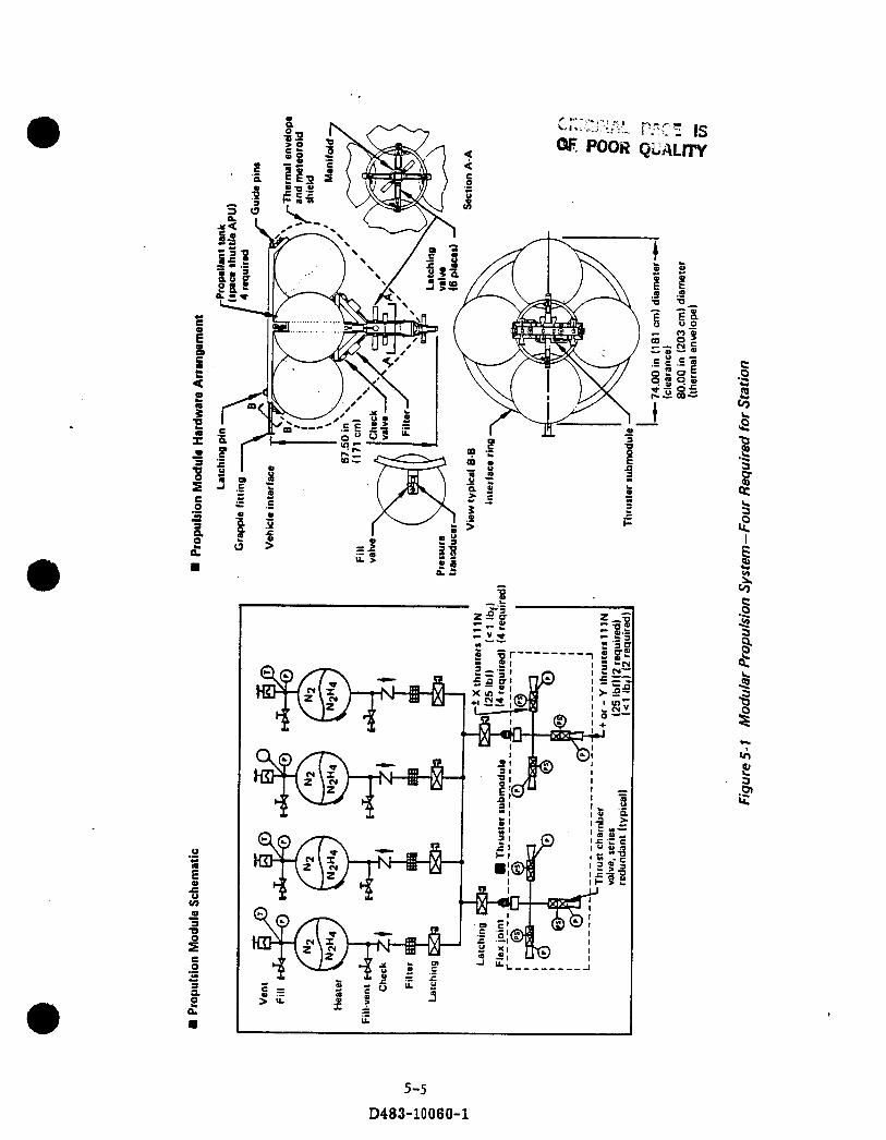
5-1 Modular Propulsion System - Four Required for Station
2-3 2-3 2-6 2-7 2-8 2-10 2-1 1
2-12 2-15 2-16 2-17 2-18
3-2 3-2 3-3 3-4 3-8 3-10 3-1 1
3-12 3-16 3-17 3-19 3-21 3-24
3-25
3-26
5-5
iii D483-10060-1

LIST OF FIGURES (Continued)
A-l a
A-2
A-3
A-4
A-5
A-6
Electrochemical Depolarized C 0 2 Reduction No. C 0 2 Reduction (Baseline System) SAWD
Electrochemical Depolarized C 0 2 Collection Sabatier C 0 2 Reduction Electrochemical Depolarized C 0 2 Collection Bosch C 0 2 Reduction System Electrolytic Oxygen System Weight and Volume as a Function of Oxygen Generation R a t e for Continuous Operation Excess 02 Generation for O2/CH4 Combustion Jet System
Collection No C02 Reduction System
A-2
A-3
A-4
A-5
A-a
A-1 1
iv D483-10060-1

TABLE OF CONTENTS
Preface i 1.0 INTRODUCTION 1-1
1.1 Study Objective 1-1
1.2 Scope of Work 1-1
1.3 Mission Profile 1-2
2.0 ENVIRONMENTAL CONTROL AND LIFE SUPPORT SYSTEMS DEFINITION 2.1 Atmosphere Revitalization Subsystems 2-1
2.1.1 Oxygen Generation 2-1 2.1.2 Carbon Dioxide Removal and Collection 2-4 2.1.3 Carbon Dioxide Reduction 2-5
2.2 ECLSS Options Analyzed 2-1 3
2.3 ECLS Systems Summary 2-22
3.0 PROPULSION REQUIREMENTS FOR ORBIT MAINTENANCE 3.1 Impulse Requirements 3.2 Available Specific and 90-Day Impulses
3.3 Enhanced Total Impulse 3.4 Propulsion Systems Summary
3-1 3-1 3-5 3-22 3-23
4.0 COLLECTION AND STORAGE 4-1
5.0 LOGISTICS 5-1
6.0 CONCLUSIONS AND RECOMMENDATIONS FOR FURTHER WORK 6-1
APPENDIX A ECLSS MASS FLOW, WEIGHT, AND VOLUME SIZING A-1
V D483-10060-1

LIST OF ACRONYMS AND OTHER ABBREVIATIONS
ACT Augmented Catalytic Thruster CCA Coolant Control Assembly CEC Chemical Equilibrium Computer CH4 Methane. C 0 2 Carbon Dioxide C S ~ C O Q Cesium Carbonate ECLS ECLSS EDC EVA IOC LiOH
N2H4 02/H2
SFWES
Environmental Control and Life Support Environmental Control and Life Support System Electrochemical Desorbed Concentrator External Vehicular Activity Initial Operation Capability Lithium Hydroxide Hydrazine Oxygen/Hydrogen Pressure Control Assembly Solid Amine-Water Desorbed Static Feed Water Electrolysis System
vi
D483-10060-1

REFERENCES
1) Vaughan, William W., "Natural Environment Design Cri ter ia for t h e Space Station
Definition and Preliminary Design (Second Revision)," NASA TM-86460, September 1984
2) Ames R. K., "Environmental Control and Life Support . Systems and Subsystems, VOL 11, Hardware State-of-the-Art," D180-2704-2, Boeing Aerospace Company, December 1983
3) "Hamilton Standard Stat ic Feed Solid Polymer Electrolyle (SPE) Water Electrolysis Subsystem (WES) For The Environmental Control and Life Support System Technology Demonstrator", Prepared for t h e Boeing Aerospace Company, HSPC: 85T20, April, 1985
4) Lin, C. H., Y3pace Station Environmental Control and Life Support System,
Preliminary Conceptual Design," Doc. No. CSO-SS-059, Crew Systems Division, JSC Houston, Texas, September 1982
5) Heppnes, D. B. and Shubert, F. H., "Electrochemical and Steam-Desorbed Amine
C 0 2 Concentration: Subsystem Comparison," SAE Technical Paper Series #831120
6) Blakely, R., "Technology Option Data Sheet, Atmospheric Conditioning, C 0 2 Processing - Bosch Reactor," Hamilton Standard Division of United Technologies, September 15,1982
7 ) "Environmental Control and Life Support Systems for Space Station, Recommendations Report," Life Systems, Inc. TR-524-3, January 15, 1983
v i i
D483-10060-1

a 8) Cushman, R. J., "Technology Option Data Sheet, Atmospheric Conditioning, C 0 2 Removal - Solid Amine Water Desorbed (SA WD)," Hamilton Standard Division of United Technologies, 13 September 1982
9) Blakely, R., "Technology Option Data Sheet Atmospheric Conditioning, C 0 2 Processing - Sabatier with Methane Dump," Hamilton Standard Division of United Technologies, 14 September 1983
10) "Test Report - Test Results, Operational Ninety-Day Manned Test of a Regenerative
Life Support System," pgs 38-39 NASA CR-111881, McDonnell Douglas Astronautics Co., MDC G2282, May 1971
-
11) "Space Station Propulsion Requirements Study - Technical Report," Boeing Aerospace Company, NAS3-23353
12) Gordon, Sanford and McBride, Bonnie J.: "Computer Program for Calculation of Complex Chemical Equilibrium Compositions, Rocket Performance, Incident and Reflected Shocks, and Chapman - Jouguet Detonations," NASA Lewis Research Center, NASA SP-273
13) "Space Station Reference Configuration Description," NASA JSC - 19989 August 1984
14) JANNAF Thermochemical Data," Dow Chemical Company; March 1979
15) McKevitt, Frank, "Design and Development Approach for the Augmented Catalyt ic Thruster," Rocket Research Company, AIAA 83-1255 1983 Propulsion Conference, Seatt le, Washington
v i i i
D483-10060-1
1.0 INTRODUCTION
Past studies of Space Station propulsion and environmental control/life support (ECLS)
systems have focused on examining proven concepts for each system primarily in te rms of development risk for the IOC station and up/down logistics. From these studies i t can be generally concluded tha t system development risk increases as logistic requirements decrease. In t h e ECLS system this increased risk results from the advanced technologies needed for increased closure, whereas in propulsion it is associated with going from a storable N2H4 system t o a cryogenic or water electrolysis H2/02 system.
0
For t h e most part, synergistic operation of the propulsion and ECLS system has not been considered and, therefore, benefits from synergism have not been illuminated. Specifically, 1) what level of ECLS closure is optimum when considering propulsion synergy, 2) what concept modifications or changes to the N2H4 reference design are needed to accommodate synergistic operation and, 3) what are the logistic benefits of synergistic operation which have not been quantified. To scope t h e problem, Boeing under the direction of the Lewis Research Center initiated t h e Space Station Propulsion - ECLSS Interaction Study, NAS 3-23353. The results of this work are reported herein.
1.1 Study Objective
The primary objective of this study is t o determine the benefits tha t the ECLSS system could experience by using its effluents to augment or even supplement the propulsion system. The potential benefits which both the ECLS and propulsion systems could experience include: reductions in logistic weight and volume; fixed weight and volume; power requirements; and overall system cost. Four different ECLS systems with various levels of closure are analyzed for their use in conjunction with cold or warm gas thrusters. Missions and available technologies used in this study are applicable for t he t ime f rame 1985-2003.
0
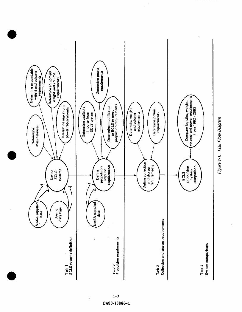
1.2 Scope of Work The work performed in this study consists of four primary tasks. These tasks, which are shown in figure 1-1, define ECLS requirements for four different systems, propulsion requirements for orbit maintenance, collection and storage requirements, and compare each of the ECLS-propulsion system combinations against a baseline system for t h e
t ime f rame 1992-2003. For those ECLS systems tha t do not ordinarily supply enough impulse for propulsion, modifications are made t o generate additional impulse. All
* 1-1
D483-10060-1
,
I
0483-10060-1
1.2 Continued
system combinations will be compared against an ECLS system using OPEN C 0 2 loop
with Electrochemical Depolarized C 0 2 Collection (EDC) in conjunction with a modular hydrazine propulsion system as the baseline case.
a
1.3 Mission Profile Analyses assume, 1) a 283O - 270-nm orbit Space Station with a n eight-man crew and with a docked orbiter for 14 of every 90-day resupply period, 2) NASA two-sigma atmosphere for sizing t h e propulsion system (ref. I), 3) NASA nominal atmosphere for determining resupply requirements, 4) results from Space Station Propulsion Requirements Study, Tasks 1, 2, & 3, NASA 3-23353 and, 5) t h a t non-propulsive venting of ECLS effluents is not acceptable but propulsive thrusting using ECLS effluents is acceptable.
1-3 D483-10 0 60-1

2.0
The major functions of the Environmental Control and Life Support (ECLS) system include atmospheric pressure and composition control, temperature and humidity control, atmospheric revitalization, water manage men t , waste manage men t, and EVA support. In accomplishing t h e processes associated with these functions, effluents are produced which must be stored and periodically returned to ear th or vented propulsively. The type and quantity of effluents depends primarily upon t h e methods used to accomplish atmosphere revitalization.
ENVIRONMENTAL CONTROL AND LIFE SUPPORT SYSTEMS DEFINITION
(I)
2.1 Atmosphere Revitalization Subsystems The primary functions of the Atmosphere Revitalization system include oxygen generation by water electrolysis, regenerable carbon dioxide removal and concentration, and carbon dioxide reduction. The first two of these functions play a vital par t in maintaining t h e breatheable atmosphere within t h e limits prescribed in Table 2-1, whereas the third function (COz reduction) has a major influence on ECLSS fixed weight and volume, and logistic requirements. All th ree functions impact the amount and chemical makeup of t h e ECLSS effluents. The following three sections provide a synopsis of how each subsystem functions.
0 2.1.1 Oxygen Generation There are a variety of methods t h a t may be used to generate oxygen from water. These include: 1) water electrolysis, 2) sulfur-iodine thermochemistry, 3) photosynthesis and, 4) thermal decomposition through solar radiation. Based upon constraints such as power, mass, volume, cost, and potential production ra tes water electrolysis is t h e preferred method. A functional schematic of a static feed water electrolysis system (SFWES) is shown in figure 2-1. This unit generates oxygen for atmospheric makeup
and hydrogen, as a by-product, from water supplied from t h e water management subsystem of the ECLS system.
The SFWES consists of th ree main components; t h e electrochemical module, a coolant control assembly (CCA), and a pressure control assembly (PCA). The module consists of a series of electrochemical cells connected electrically in series with fluid inlet and outlet passages in parallel. The CCA and PCA provide t h e necessary supporting functions to regulate the temperature and operating pressures of t h e system. In addition, the SFWES must have an inlet water pump and accumulator and a constant current power supply to apply conditioned power to t h e electrolysis module. a
2- 1 D483-10060-1
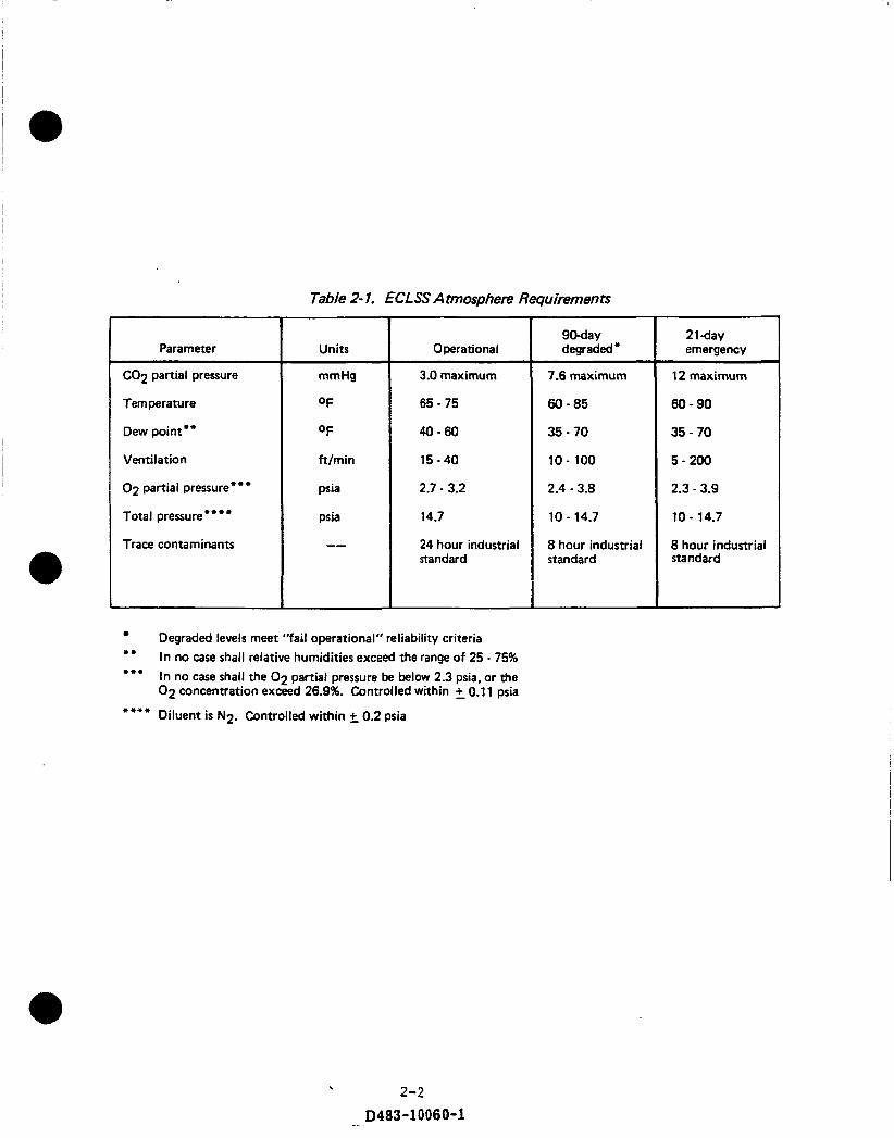
Parameter
C02 partial pressure
Temperature
Dew point**
Ventilation
02 partial pressure"""
Total pressure' ***
Trace contaminants
Table 2- 1. ECLSS Atmosphere Requimments
Units
mmHg
OF
OF
ft/min
psia
psia
--
Operational
3.0 maximum
65 - 75
40-60
15 - 40
2.7 - 3.2
14.7
24 hour industrial standard
Degraded levels meet "fail operational" reliability criteria In no case shall relative humidities exceed the range of 25 - 75% In no case shall the 0 2 partial pressure be below 2.3 psia, or the 02 concentration exceed 26.9%. Controlled within +_ 0.1 1 psia
Diluent is N2. Controlled within +- 0.2 psia
** ***
****
9May degraded*
7.6 maximum
60-85
35 - 70
10 - 100
2.4 - 3.8
10 - 14.7
8 hour industrial standard
2 1 -day emergency
12 maximum
60-90
35 - 70
5 - 200
2.3 - 3.9
10 - 14.7
8 hour industrial standard
2-2
D483-10060-1

I I
Warn in
Coolant in
I I I
i t
I i I i I
i
I -- --. I
I I / I
I . -- I "'"ureJ-- i I
i
I ---&-. ~conmoller
I StatK feed water electrolysis I module electrolysis
I
0 2 out
H2 out
Coolant out
I Heat exchanger I
Figure 2.1. Static Feed Water Electrolysis Subsystem (SFWE)
Water feed ovity
Water feed matrix
H2 cavity
Cathode
Poly sulfone cell pwn - Coolant in
in
N2 purge in
Figure 2.2. SFWE Cell Functional Schematic
2-3 D483-10060-1

2.1.1 Continued
0 Figure 2-2 is a functional schematic of a SFWE cell. When not operating, both t h e water. feed cavity and t h e cell matrix have an electrolyte solution consisting of equal concentrations of water in potassium hydroxide. When electrical power is supplied to t h e electrodes, a current flows and water is electrolyzed in the cell matrix, causing H2 t o form at the cathode and oxygen a t the anode. This depletion of water in the cell matr ix solution creates a concentration gradient relative to the water feed cavity causing water vapor to diffuse into the cell matrix t o make up the water usage. Concurrently, the water from t h e water feed cavity is replenished statically from the external water supply tank. (Ref. 2)
2.1.2 Both expendable and regenerable methods for C 0 2 removal have been developed. Expendable chemical canisters such as LiOH, though acceptable for short missions with few crew members, become increasingly unacceptable as mission duration and/or number of crew increase. This has led t o t h e development of regenerable methods such as non-hydrophobic molecular sieves, the solid amine-water desorbed (SAWD)
concept and t h e electrochemical desorbed concentrator (EDC). Only the SAWD and EDC have been considered in t h e present study. Non-hydrophobic molecular sieves were considered not cost effective for the required 3.0 nm Hg C 0 2 maximum partial pressure, and expendable chemical canisters are too heavy.
Carbon Dioxide Removal and Collection
@
Solid Amine- W a t e r Desorption The SAWD process uses as a n absorbent a solid amine material known as amberli te (RA-45) which is a weak base ion exchange resin t h a t is deposited on a high surface area granular substrate. In absorbing C02, the amine first combines with water vapor from t h e atmosphere t o form a hydrated amine, then with t h e C o g t o form a bicarbonate. The amine is regenerated by heating with s team, breaking t h e bicarbonate bond and replacing the absorbed Cog with water.
A typical SAWD system is shown in Figure 2.3. This is a t w o canister system, with one absorbing while the other is desorbing. While t h e C 0 2 saturated canister is isolated
from t h e cabin air and desorbed, cabin air is routed t o the absorbing canister for C 0 2 removal. An electrically heated s team generator built into t h e head of the canister produces low pressure s team for the desorbing process. The s team heats the bed and
2-4
D483-10060-1

2.1.2 Continued at first pushes ullage air out of t h e canister at a low flow ra te , which is returned to t h e cabin. As the s team advances into the bed, a wave of high purity (99%) C 0 2 is evolved, resulting in a sharp increase in effluent flow rate. A sensor de tec ts this increase and diverts the C 0 2 into a storage system. A back pressure regulator in t h e C 0 2 outlet controls the saturation temperature of t h e s team and thereby t h e desorption temperature of t h e bed. After desorption is completed, t h e process a i r flow is re-directed through the bed, cooling it and making it ready for an absorption period. The s team used for desorption is evaporated into the process air s t ream and then condensed out in the cabin humidity control heat exchanger.
(I)
Electrochemical Desorbed Concentrator The EDC concept is shown schematically in Figure 2-4. C 0 2 is removed from t h e atmosphere by passing atmospheric air through a module consisting of electrochemical cells. Each cell consists of two electrodes separated by a process matrix containing a n aqueous solution of cesium carbonate (CSzC03). As shown in Figure 2-5, cabin air is passed through t h e cavity adjacent t o the cathode, and Hydrogen, from t h e SFWES, is passed by the anode. As a result, a fuel-cell reaction occurs, transfering some of t h e hydrogen through t h e electrolyte matrix to combine with oxygen from t h e a i r s t ream t o form water vapor which shows up in the effluent a i r stream. Concurrently, an electrical current is generated across a load connected between the anode and cathode. The reaction and the power available from t h e reaction is controlled by this load impedance.
As the H2 - 0 2 fuel cell reaction occurs, a corresponding transfer of C 0 2 occurs from t h e a i r side of t h e matrix t o t h e H2 side. The rate of this transfer depends upon the partial pressure of C 0 2 in the air s t ream and t h e cell current density. Unused hydrogen exits t he cell mixed with the transferred COB and is then stored or fur ther processed in t h e C 0 2 reduction system.
2.1.3 Carbon Dioxide Reduction
Two concepts have been studied t o perform C 0 2 reduction: t he Sabatier process, and t h e Bosch process. The primary advantage of using a COS reduction process is tha t i t reduces the amount of effluent generated by the oxygen generation and C 0 2 collection units. I t does this by breaking down and combining the COP with Hg to form water vapor and carbon or methane depending on the reduction process. The water vapor is then sent back into the ECLS system thus enabling a higher level of closure.
0 2-5
D483-10060-1

Air in
Figure 23. SAW0 Concept Schematic
2-6
D483-10060-1
n A&-+ c02 out
Water (from
feed condenser)

1
I
I I
I I
.-.
+ X a N
rc v Y
I '
P
- u j-? ti3 ILL
1
I
I I Y . -. a A
--- I
T-'
I
I
l- I
I
I
( V N Z I
44
- f op 0 - 0 .-
2-7
D483-10060-1

H i + c02
Anode
Electrolyte matrix
separator
- H2 Liquid d cooling inlet outlet
Process air outlet
Figure 2-5. EDC Single Cell Functional Schematic
2-8 D483-10060-1

2.1.3 Continued
@ Sabatier Process The Sabatier process takes a mixed stream of H2 and C02 and passes it through a heated catalyst bed to produce methane (CH4) and water vapor. Typically, a single pass through the bed will convert at least 99 percent of the H2 in the stream. Normally there is excess CO2 in the process, leaving an effluent gas stream of mixed C02 and CH4 which is stored. Water vapor is condenced, separated from the gas stream and pumped to the potable water tank.
’
Figures 2-6 and 2-7 show a schematic of a Sabatier subsystem and a cross section of a typical reactor respectively. The reaction occurs at 860 to 1060OR (477 to 588OK) and produces enough heat to make the reaction self-sustaining after a start-up heater is used to initiate it. Excess heat is removed either by liquid cooling or by compartment air. An activated charcoal absorption bed ahead of the catalyst bed is used to remove any trace contaminants from the incoming gas stream. The preferred catalyst is 20%
Ruthenium on an alumina substrate.
Bosch Prcicess The Bosch process takes a gas mixture of H2 and C02, heats it to between 1460 and 1810OR (811 and 1006OK) and then passes it through a steel wool catalyst to produce carbon and water vapor. Each pass over the steel wool typically converts only 5 to 10 percent of the reactants. A s a result, a recycling system with close control on the H2/C02 mixture in the system is required to obtain complete reduction of the C02. Effluents consist of water vapor, a small amount of H2, and carbon deposited on the steel wool. The water vapor after cooling is pumped to potable water tanks. Only about 60% of the water produced in the reduction process is needed to close the water cycle. Storage capacity is required to handle the excess water. The H2 after cooling is Compressed and stored. The steel wool reactor wi th deposited carbon is periodically replaced and stored.
0
Figure 2-8 is a simplified flow schematic of a Bosch system. Two expendable reactor beds are used so that one may be operated while the other is cooled prior to change out. A compressor circulates the gases through a regenerative heat exchanger and heater to preheat the gases entering the reactor bed. During each pass through the
the reactor, some of the gases are converted to water vapor, and carbon which is deposited in the steel wool matrix. Upon leaving the reactor the gases pass through a
2- 9
D483-10060-1
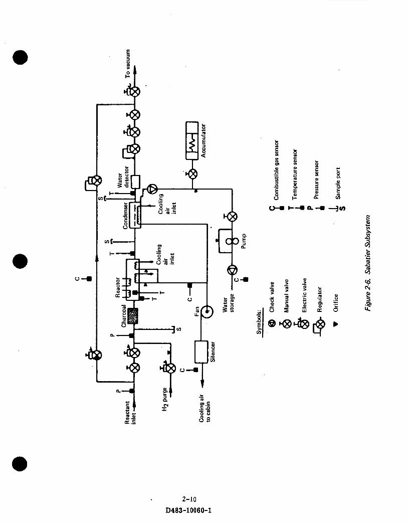
2-10 D483-10060-1

I
2-1 1 D483-10060-1

f
e4 I
a 5 d I ri, 0 %
b.
51. 2 E
v)
P
s
b
- a 2-12
D483-10060-1
C 0
u f

2.1.3 Continued a regenerative heat exchanger, transferring heat to the incoming gas stream, and then through a liquid cooled condenser separator before returning to the compressor. Feed gases are introduced into the loop at the compressor inlet.
0 2.2 ECLSS Options Analyzed
Four ECLS systems were analyzed for (1) gaseous and liquid effluents, (2) fixed weight and volume of major atmosphere revitalization subsystems, (3) power required by major
r power atmosphere revitalization subsystems, and (4) equivalent weight penalties fc and thermal cooling. They are:
0 Open Loop system using water electrolysis (WES) for 0 2 generat electrochemical depolarizer concentrator (EDC) for C 0 2 concentration. effluent includes C02 and Hg.
0
0
on, and Useable
Open Loop system using water electrolysis for 0 2 generation, and solid amine water desorbed (SA WD) concentrator for Cog concentration. Useable effluent includes C 0 2 and Hp.
Closed Loop - Sabatier system using water electrolysis for 02 generation, EDC for C02 concentration and Sabatier carbon dioxide reduction. Useable effluent includes C02 and CH4.
Closed Loop - Bosch system using water electrolysis for 0 2 generation, EDC
for COP concentration and Bosch carbon dioxide reduction. Useable effluent includes H2 and H20.
It should be emphasized that the weights, volumes, powers, and equivalent weights for power and thermal cooling in this section are for only the major subsystems of the atmosphere revitalization system Le., EDC or SAWD, Sabatier or Bosch, WES.
Subsystems common to all the analyzed systems such as: o Waste water collection, pretreatment and storage o Waste water recovery and post-treatment o Product water collection and storage o Trace contaminant o Temperature and humidity control o Atmosphere pressure and composition control
2-13 D483-10060-1

2.2 Continued
a are not included in these data. Also not included, at least in this section, is storage tankage unique to an ECLSS option. This tankage and associated compressors a r e
included in section 5.0, where total comparisons of ECLSS-Propulsion combinations
are made.
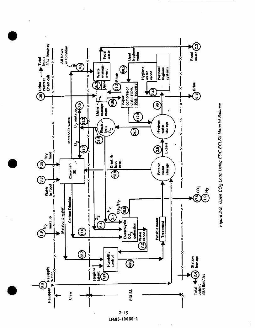
Figures 2-9 through 2-12 show material balances for each of the four ECLS systems.
Input materials, material flows within the system, and output materials are shown in units of lbm/day.
There are two important aspects of these figures t h a t are of interest. The f i rs t is
t h a t t h e inputs t o t h e system are equal to the outputs from t h e system Le . the system
is balanced). The second is t h e type and quantity of effluents being generated by each
system. If t h e effluent can be used in another Space Station subsystem or even one
of t h e frce-flying platforms, then i t can alleviate the need to be returned t o earth.
The quantity is important since i t determines how much can be used in another subsystem
or how much has to be brought back to earth. Obviously, if t h e effluent needs to be
brought back down in the Shuttle, the lesser the amount t h e cheaper the cost t o the @ ECLS system.
Figure 2-9 shows t h e baseline Open Loop system material balance in which an EDC
is used for C 0 2 removal. Input materials are 8.5 lbm/day of water, 8.8 lbm/day of
water in the food, 10.9 lbm/day of dry food, 1.9 lbm/day of N2, and 0.35 lbm/day of
urine pre t rea t chemicals. Output materials are 2.4 lbm/day of (station leakage) N 2
and 02, 6.3 lbm/day of brine, 2.2 lbmlday of fecal waste and 19.5 Ibm/day of C 0 2 and H2.
The system requires the electrolysis of 24.3 lbm/day of water to generate 21.6 lbm/day
of 0 2 , of which 15.2 lbm/day a r e required for crew respiration and 0 2 leakage make-up.
The remaining 6.4 lbm/day of 0 2 plus 2.7 lbm/day of H2 a r e used in the EDC C 0 2
concentration process. EDC outputs consist of 7.2 lbm/day of water vapor which is
condensed and returned t o the WES and 19.5 lbm/day of COS and H2 which cannot
be fur ther used in the ECLS system.
2-14
D483-10060-1
..
I X
\
I
I A

L
2-16 D483-10060-1

.
X
I I I I
X
X
X
X i
2-17 D483-10060-1
I x
2-18
0483-10060-1
2.2 Continued
0 Figure 2-10 shows the Open Loop system material balance using a SAWD. It produces t h e same amount of C 0 2 and Hg effluent as t h e Open C 0 2 Loop system using EDC. However, in the SAWD system the C 0 2 and H2 effluents are separate.
The SAWD system requires 13.2 lbm/day of water resupply which is 4.7 lbm/day more than t h e EDC system. This is caused by the difference between how the hygiene and potable water supplies can be used. Excess potable water can be used for hygiene, but t h e opposite is not true. Hence, t h e SAWD system generates a n excess of 4.7 lbm/day of hygiene water which cannot be further used by the ECLS system.
Figure 2-11 shows t h e Closed Loop - Sabatier system material balance. The Sabatier subsystem reduces a portion of the 17.6 lbm/day of C 0 2 and 1.9 lbm/day of H2 leaving t h e EDC unit. Effluents consist of 8.5 lbm/day of water, 3.8 Ibm/day of CH4, and 7.2 lbm/day of unreduced C02. No resupply water is required and no excess water is generated. The C02/CHq effluent cannot be fur ther used in the ECLSS. If stored, t h e s torage weight and volume penalties a r e significantly reduced from those of t h e
Open Loop system because of the lower mass and higher density effluents.
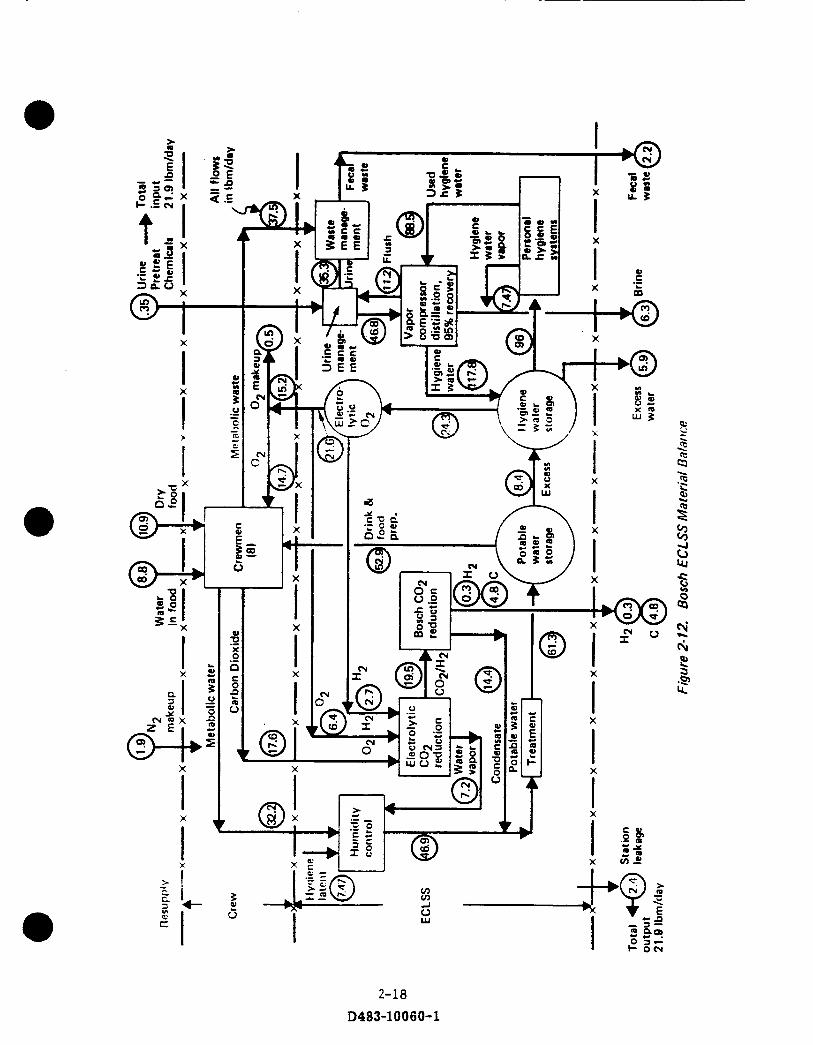
@ Figure 2-12 shows t h e Closed Loop - Bosch system material balance. The system
generates 5.9 lbm/day of excess water, 0.3 lbm/day of gaseous hydrogen and 4.8 lbm/day of solid carbon. The solid carbon (and filters) must be returned every resupply period, while t h e excess hydrogen must be continuously eliminated or stored and periodically eliminated from the Space Station. The Bosch system, like the Sabatier, has zero water resupply requirements.
The weight, volume, power and thermal cooling for major components of t h e ECLS systems are shown in Appendix A Figures A-1 through A-5. The schematics on each
of the figures illustrates inputs and outputs of each unit operation, mass flow ra tes in lbm/day, thermal (heat rejection) loads, and power requirements. Station numbers indicate entrance and exit points. The table in the upper right corner of each figure summarizes t h e fixed weight and volume and resupply requirements of t h e major components. Resupply requirements include water plus tankage when required (i.e. open loop systems) or, in t h e case of the Bosch system, the weight of the fi l ters and
canisters to store the carbon.
2-19 D483-10060-1

2.2 C O r r t i n U e d
T h e shown f ixed weight and volume, weight penalty for power, and weight penalty
f o r t h e r m a l cooling a r e based on (1) light-side operation of t h e systems, (2) t h e daily m a t e r i a l balances shown in Figures 2-9 through 2-12 a f t e r t h e continuous internal
mater id flows were adjusted f o r light-side operation, (3) relationships given in Appendix A Tables A-1 and A-2, and in Figure A-6. Appendix A expands fur ther on these figures and tab les and the i r relationships.
Table 2-2 s u m m a r i z e s t h e weight, volume, and e.xpendable penallies for each ECLS
s y s t e m considered and how they compare to t he baseline system. As s t a t e d previously,
t h e baseline sys tem in this s tudy is t h e Open C02 loop using EDC in conjunction with a hydrazine propulsion system.
The f i r s t column of Table 2-2 correlates the ECLS system with :he appropriate f igure in Appendix A. The second and third columns S ~ G W t h e absoiute fixed weights of
t h e main components in each ECLS system and then how :>at weight compares to
the Seseline system. The fixed weights include the ryeig5t cf t h e water electrolysis unit . E3C (or SAWD) unit. SeSatier (or Bcsch) unit when appiicabie. equivaient weight
f o r power, and equivalent weight f o r t he thermal heat. Of the four ECLS systems, t h e baseline sys tem is t h e l ightest while t h e Bosch is the heavies:.
Columns four and f ive show the absolute fixed volume of each system and their
corresponding d i f fe rences with t h e baseline system. The fixed voiumns include the
s a m e components as t h e fixed weights excluding t h e equivalent power and thermal
heat . Again. t h e baseline ECLS system is t h e smallest w i t h t h e Bosch system being t h e largest . -4 spec ia l n o t e should be mentioned and tha t is if the accumulator tank
required t o s t o r e the eff luents were included, then for both cases of fixed weight and
fixed volume. t h e Open CO2 loop using SXWD would be the heaviest and largest system.
Columns six and seven show t h e resupply weight required for each system and t h e corresponding comparison w i t h the baseline EC LS system. The resupply weight includes
t h e required w a t e r and tankage or, in the case of t h e Bosch system, t h e required
canis te rs and f i l t e r s to col lect and s t o r e the accummulated carbon. The Sabat ier system
is t h e onlv o n e that does not reauire anv resuoolv water or canisters.

a
a
a
z sg Q $
A, Q
C 0 a E 8 3 u W
(0 I (0 ' + *
F d OD
f c c
0 c)
s1
c
a
(Y
3
I-
c
: +
m P (3 +
2-20 D483-10060-1

2.2 Con t hued
Columns eight and nine show the resupply volumes of those water tanks or canisters and f i l ters discussed previously and their differences compared to the baseline system. Obviously, t h e Sabatier has no resupply volume requirements and hence has t h e smallest volume requirements of t h e four systems.
Finally, column t e n shows t h e generated effluent tha t if not stored and brought back t o Earth could be used for some other purpose (Le. propulsion). These effluents consist of e i ther C 0 2 , CH4, Ha, and/or H20. Figures 2-9 through 2-12 show the combinations and quantities of effluents for each system.
2.3 ECLS Systems Summary Four ECLS systems have been looked at:
(1) Open C 0 2 loop using EDC, which is considered t h e baseline for this study; (2) Open C 0 2 loop using SAWD;
(3) Sabatier C02 reduction using EDC;
(4) Bosch C 0 2 reduction using EDC;
@ to determine how they function as stand alone systems on-board t h e Space Station. The main components of each system have been examined and their functional capabilities determined. For each system it was determined t h e type and quantity of effluents generated. Of these effluents, some can be used for other functions on the Space Station. By using these effluents in other Space Station subsystems, i t is possible to reduce t h e amount and frequency of bringing ECLS by-products back to earth. The next section examines the Space Station propulsion system requirement and determines how the ECLS waste gases can reduce and at t imes eliminate propulsion resupply requirements by supplementing o r replacing t h e primary fuel.
2-21
D483-10 0 6 0- 1

3.0
Space Station propulsion requirements (Ref. ll) include thrust and total impulse requirements for drag makeup, desaturation of momentum storage devices, back-up support for at t i tude control, and cancellation of docking disturbances. In the reference 11, t h e latter three functions require a small amount of propellant compared to tha t needed for orbit maintenance. Hence, only drag makeup requirements are considered when examining the impact of ECLSS effluents on propulsion.
PROPULSION REQUIREMENTS FOR ORBIT MAINTENANCE
@
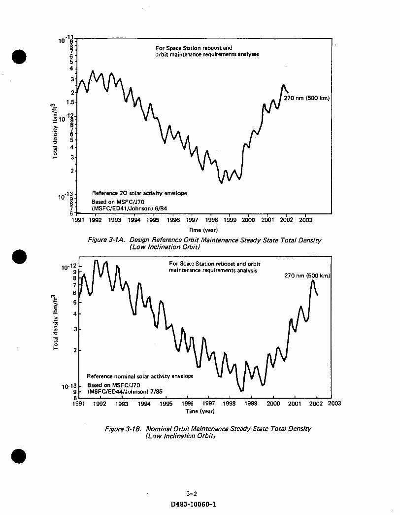
3.1 Impulse Requirements The Space Station propulsion system 90-day impulse requirements are determined using two types of atmospheric models. The first is a 2-sigma model, shown in figure 3-1A, which encompasses 97.5% of t h e "estimated" possible atmospheres tha t could occur over an l l -year solar cycle. The 2-sigma atmospheric model is used to s ize the tanks, thrusters, lines, etc ... of the propulsion system.
The second is a zero-sigma (or nominal) atmospheric model, shown in figure 3-1B, which encompasses 50% of the "estimated" possible atmospheres t h a t could occur over a n l l -year solar cycle. The nominal atmospheric model is used t o determine t h e expected resupply schedule over t h e 10-year mission of the station. Both figures 3-1A and 3-1B show how the density models f luctuate over l l -year and annual cycles. Daily and orbital fluctuations due to light and dark side variations and geomagnetic disturbances have been averaged out.
@
The aerodynamic drag used in determining impulse requirements is a function of t h e coefficient of drag, atmospheric density, velocity (squared), and the effect ive cross sectional a r e a of the station. For a given alt i tude only t h e atmospheric density changes significantly over t ime (figure 3-1A). The velocity (24931 ft /sec) is for 270 n.m. altitude.
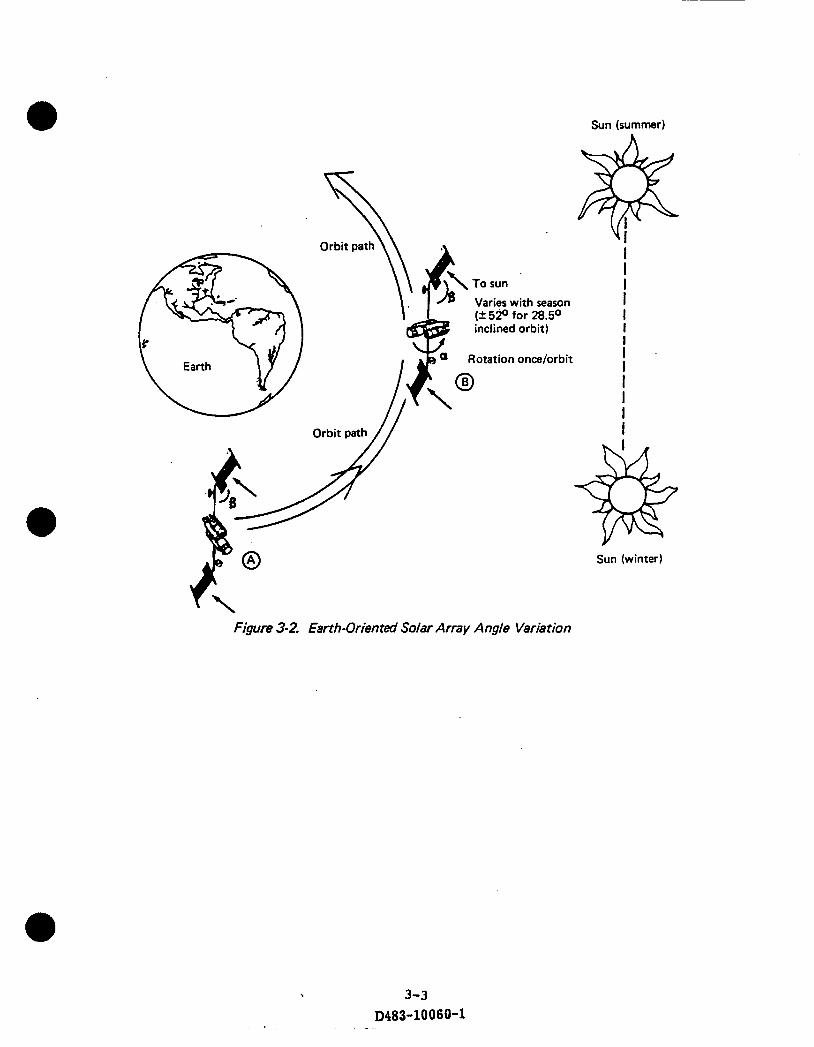
The effect ive cross sectional area is based on the average frontal area of t h e station over one orbit. Since, the solar arrays are Sun-pointing, their area, projected along the velocity vector, changes cyclically. Figure 3-2 illustrates these effects. At point
A, the arrays are "flat" to t h e wind and t h e array a rea is reduced by the cosine of t h e beta angle only. At point B, t h e arrays remained essentially fixed in inertial space while t h e body has rotated between t h e arrays. Effective array a r e a at point B has been reduced to zero. Figure 3-3 illustrates t h e array angle of a t t a c k history from which an average 47.5 degree angle of a t tack was determined. The cross sectional
0 3- 1
D483-10 0 6 0-1
For Space Station reboost and orbit maintenance requirements analyses
”-’;! 7
nm (500 km)
Reference 2 6 solar activity envelope Based on MSFClJ70 (MSF C/E D4 1 /Johnson 1 6/84
I .
For Space Station reboost and orbit maintenance requirements analysis
270 nrn (500 krn
‘?, < 5 - E 9, 4 -
5 3 -
!- 2 -
> c v) .- U
0
- s c
Reference nominal solar activity envelope
10-13 - Based on MSFClJ70 9 - (MSFC/ED44/Johnson) 7/85 8 - I I 1 I I I I 1 I I 1
1 9 9 1 1992 1993 1994 19% 1996 1997 1998 1999 2000 2001 2002 2003 Time (year)
Figure 3- 18. Nominal Orbit Maintenance Steady State Total Density (Low Inclination Orbit)
3-2 D483-10060-1
Sun (summer)
Orbit path
Varies with season (-+ 52" for 28.5O
Orbit path //
Figure 3-2. Earth-Orien ted Solar Array Angle Variation
3-3 D483-10060-1
Sun (winter)

: flat = edge on
Time (sec)
Figure 3-3. Solar Array Angle of Attack
3-4 D483-10060-1

3.1 Continued
area of t h e station is determined with the orbiter docked for 1 4 days of every 90-day
resupply period. This results in a total effective cross sectional area of 31775 ft2. Tables 3-la and b and 3-2a and b show the drag and required 90-day impulse values for the 2-sigma and nominal atmospheres of a n 8- t o 12-man, 2 8 3 O - inclination, 270-n.m., Sun-pointing array, earth-oriented core Space Station.
0
Figure 3-4 illustrates the difference in magnitude between the 2-sigma and nominal atmospheres. During t h e initial and l a t t e r years of t h e Space Station 10-year mission, t h e 2-sigma impulse model is as much as three times the requirement as the nominal impuse model. This plays a significant role in determining which propulsion and ECLS system is chosen as will be made clear further in t h e text.
The 1992 2-sigma 90-day impulse requirement is used throughout this study in sizing all aspects of t h e propulsion system as well as imparting t h e resupply scheme. The nominal 90-day impulse requirements a r e used solely to determine t h e expected 90-day fuel consumption over the 10-year mission of t h e station.
0 Possible thrusting strategies are examined using the 1992 2-sigma, 90-day impulse requirements to be t te r understand what thrust levels are most appropriate for propulsion systems using resistojets, warm gas thrusters, or combustion jets. These are shown in table 3-3. Thrust levels and burn t imes assume no loss of alt i tude between thrusting periods. Actual thrust levels and/or burn times would be larger for longer thrusting frequencies. For example, a 45-day thrusting frequency results in approximately a 16 nmi (20 kw) drop in altitude. Hence, a reboost would require e i ther a higher thrust level, longer burn time, or some combination of t h e two than is shown in table 3-3.
3.2 Specific impulse performance d a t a is generated using a Chemical Equilibrium Computer program (CEC) (Ref. 12) for the different propellant combinations produced by the
Open Loop (EDC and SAWD), Sabatier and Bosch ECLS systems
Available Specific and 90-Day Impulses
Figures 3-5 through 3-7 show the variation of specific impulse versus chamber pressure
for CO2/H2 and C02/CH4 resistojets and specific impulse versus mixture ra t io for O2/CH4 and Og/H2 combustion jets. For the resistojet curve a maximum chamber
3-5 D483-10060-1

Table 3- 7A. Drag Data (20 Atmosphere)
Year <
Drag (14) 1992 1993 1 994 1995 1996 1997
Mean .a60 .0266 .0187 -01 16 .Om7 .0068
1998 1999 2000 2001 2002 2003
Mean .0055 .0058 .QO95 -0197 .0332 .0360
8 - 12 man station 28X0 inclination 270 nmi altitude Orbiter docked 14/90 days
A
Mean drag (1 1 years) = .055 Ibf
.* 8 - 12 man station 28W0 inclination 270 nmi altitude Orbiter docked 14/90 days
Mean drag (1 1 years) = .0166 Ibf
3-6
D483-10060-1

Ta&le 3-2A. %-Day Required Impulse 120 Atmosphere)
I Year I
Impulse (Ibf-sec)
%day
Year
1992 1993 1994 1995 1996 1997
894,000 630,000 412,000 233,000 148,000 101,OOO
1 I
Impulse (Ibf-sec)
%day lolOoOo I
- -.
1992 1993 1994 1995 1996
894,000 630,000 412,000 233,000 148,000
90-day 894,000 A 1998 1999 2000 2001 2002
62,000 101 ,OOO 295,000 575,000 840,000
8 - 12 man station 28X0 inclination 270 nmi altitude
0 Orbiter docked 14/90 days
1 90-day
Mean impulse (1 1 years)" = 428,000 Ibf-sec
1998 1999 2000 2001 2002 2003
62,000 101,OOO 295,000 575,000 840,000 894,000
" Per 90-day resupply cycle
Impulse (Ibf-sed
90-day
w a y
Table 3-2B. 9OOa y Required Impulse (Nominal Atmosphere) r
Year
1992 1993 1994 1995 1996
280.000 207,000 145,000 90.000 67,700
1998 1999 2000 2001 2002
42,800 45,100 73,900 153,000 258,000
8 - 12 man station 28X0 inclination 270 nmi altitude Orbiter docked 14/90 days
" Per 9Oday resupply cycle
=;i 52,900
Il 280,000
Mean impulse (1 1 years)* = 129,000 Ibf-rec I
3- 7 D483-10060-1

900.Oo0
800,000
700,000
600,000
300,ooa
200,000
100,000
I" 0 8- to 12-man station 0 270 nmi altitude
28x0 inclination Orbiter docked 14/90 days
1
1 Nominal
1 I I I I
1992 1 994 1996 1998 2000 2002 2( Year
Figure 3-4. 90-Day Required Impulse for 20 and Nominal Atmospheres
3-8 D483-10060-1

Table 3-3. Orbit Maintenance Thrust Levels for Various Thrusting Strategies
Thrust level (Ibf)
.11
.17 -54
1.1
1.7 2.6
8.3 16 17
26
83
170 79
120
370
750
~
Thrust duration
Continuous
3792'"
1200 (20 min)
600 (10 rnin) 5688 (1.58 hrs)
3792 1200 600
5688 3792
1200
600 5688
3792
1200
600
'One orbit = 1.58 hours "Sunlit portion or 2/3 of orbit
Per orbit*
Thrusting frequency
Per '
day
X X X
X
~
Per 10 days
~-
X
X
X
X
Per 45 days
~
X X X
X
1992 9Qday impulse = 894,000 Ibf-sec Z - sigma atmosphere Altitude = 270 nmi 8- to 12-man station
J
3-9 D483-10060-1

30(
2a(
260
240
220
200
C02/H2 MR = 9.26:l
* E : =250:1 Resistojet
Tinlet = 2760OR
C02/CH4 MR = 1.89:1
E: =250:1 Resistojet
Tinlet = 1800'R
180 I I I I I
100 150 200 250 14.7 50
Chamber pressure (psia)
F&re 3-5. C02/H2 and COz/CHq ideal Specific impulse Performance
3-10 D483-10060-1

410
390
370
- E 350 P \ u 0 c I] - I
5
.- E
3
> 330 - % - 3
0 'c
tn
.-
310
290
270
250
02ICHq 0 Pc= 250 psia . € = 250:l 0 Tinlet = 54WR
Combustion jet
0 1 2 3 4 5
Mixture ratio
Figure 3-6. O2/CH4 Ideal Specific Impulse Performance
3-1 1 D483-10060-1
6

500 -
490 -
480 -
470 -
460 - 0 G02/GH2
P, = 250 psia 0 & =250:1
Tinlet =a 5N0R 0 Combustor
Mixture ratio
Figure 3-7. 02/H2 ideal Specific impulse Performance
3-12 D483-10060-1
I

3.2 Continued
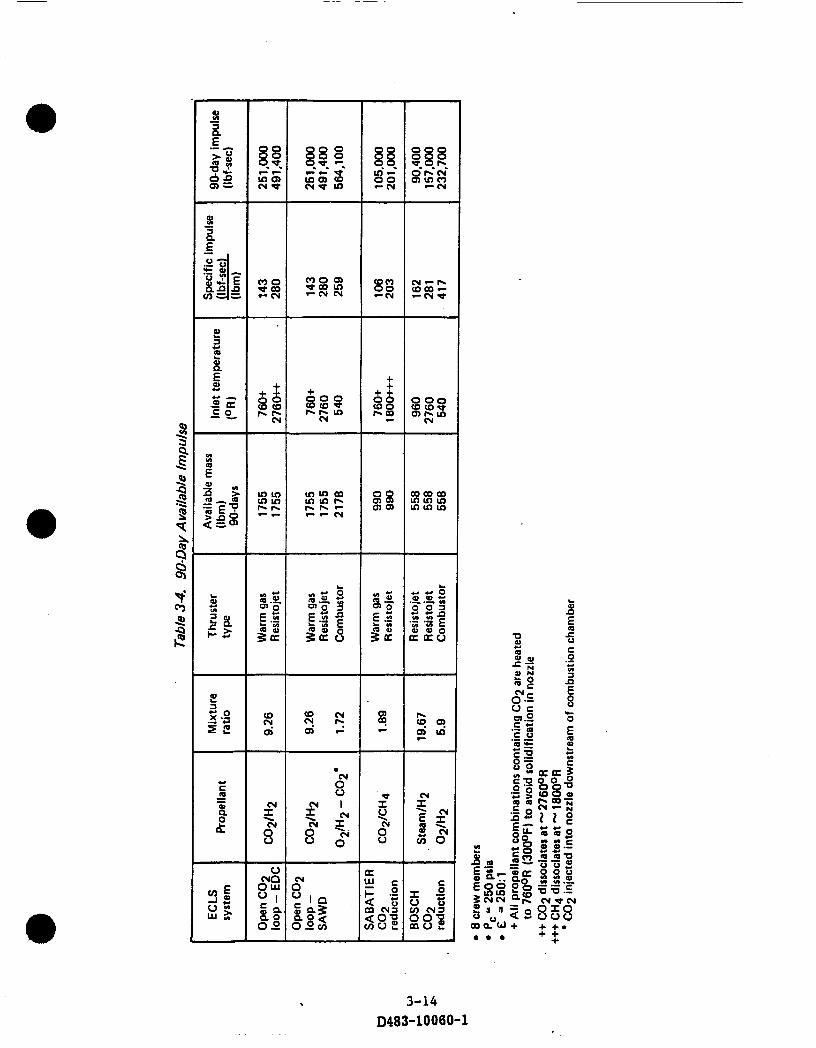
@ temperature based on t h e dissociation values of C 0 2 (2760OR) and C02CH4 (1800OR) is used. From these curves, the available 90-day total impulse of t h e effluents from each ECLSS is determined (TabIe 3-4).
For each ELCS system option there exists one or more propellant combinations tha t can be created. In table 3-4 six propellant combinations are used from the four ECLS
systems. The effluents (propellants) generated by t h e different ECLS systems are fixed based on t h e crew, hence t h e mixture ratios shown in ' t ab le 3-4 can only change if t h e crew size changes or if additional water is electrolyzed t o generate more propellant. This latter option is discussed in section 3.5. For those propellant combinations tha t are used in warm gas thrusters o r resistojets, temperature ranges are used based on t h e characterist ics of the propellants. For example, C 0 2 will solidify in a nozzle unless it is heated to at least 76O0R. Likewise, C 0 2 begins to dissociate
at approximately 2760OR. I t is these temperature ranges which dictates t h e specific impulse of t h e propellants and, coupled with the available mass, t h e 90-day specific impulse.
In t h e case of t h e Open C 0 2 loop ECLS system using SAWD and t h e Bosch C 0 2 reduction * . system, two propellant combinations were used. In both cases excess water is generated. If, in the case of the SAWD system, the excess water is electrolyzed and combined with the available H2 from the EDC unit a mixture ratio of 1.72 is obtained. This propellant could then be combusted while injecting t h e available C o g into the nozzle downstream of t h e combustion chanber. This provides about 73,000 lbrsec of additional impulse over the CO2/H2 at 2760OR.
In t h e case of t h e Bosch, the excess water could be electrolyzed and combined with the available H2 from t h e Bosch unit. This would provide a mixture ra t io of 5.9:l and generates an additional 75,000 l b p e c of impulse every 90-days.
Figures 3-8 through 3-11 compare the available impulse from t h e basic ECLSS options; against t h e impulse values required over the ll-year cycle for t h e 2-sigma model (Table 3-2A). Maximum and minimum available impulses are shown for each option based
on alternative thrusting concepts e.g. warm gas and resistojet.
3-13 D483-10 0 60-1
a
a
0 0 Q) bQ) UY - c y (Y
. - . c r N
*
8
3-14 D483-10060-1

3.2 Continued
Figure 3-8 shows how under 2-sigma atmospheric conditions t h e C02/H2 from a n Open Loop ECLS system using an EDC can reduce and even eliminate, for some years, propellant requirements and t h e need to storeheturn-to-earth ECLS system effluents. For example, in 1992, 90-day impulse requiremen'ts for t h e primary propulsion system can be reduced by 400,000 lbf-sec from about 900,000 to 500,000 lbf-sec. This represents a saving of about 1670 lbm every 90-days for a hydrazine propulsion system. This saving is equivalent t o a longer resupply period for the system when it is sized for non augmented operation. In 1994 through 2000, 90-day impulse requirements can be completely met with t h e available C02/H2 impulse from a resistojet operating at temperatures between 2760OR and 760°R or by a warm gas thruster operating at 760OR. I t should be noted tha t for the years between 1995 t o 2000 some storageheturn-to-earth of CO2/H2 wi l l be required if t h e reboost impulse is not increased by deliberately performing reboost inefficiently since the minimum available impulse is greater than the required impulse. Another alternative would be to allow the station to drop t o a lower alt i tude thus requiring a higher impulse. This method would in turn enable t h e Shuttle t o bring up larger payloads.
0 - Under nominal atmospheric conditions, shown in figure 3-45 the available impulse from t h e Open COP loop ECLS system using EDC is sufficient t o meet all t h e 90-day impulse requirements (table 3-2B). Consequently i t provides too much impulse for all but th ree years. Hence, some type of inefficient thrusting would b e required or, as mentioned above, t h e station could be flown at a lower altitude.
Figure 3-9 shows similar information for the Open C 0 2 Loop ECLS system using SAWD. The Open C 0 2 Loop system using SAWD generates 4.7 lbm/day of excess water which must be ei ther storedheturned-to-earth or used for propulsion. Since the propulsive capabilities of the effluents from t h e EDC and SAWD systems a r e t h e same when t h e excess water is returned to earth, only the case of using t h e water t o provide 0 2 and Hg for propulsion was considered for t h e maximum available impulse shown in Figure 3-9. This maximum impulse is based on electrolyzing t h e water into 0 2 and H2, combining t h e stored products with stored H2 from water electrolysis for crew 0 2 , combusting t h e combined products in an 02/H2 gas burner, injecting stored C 0 2 effluent into t h e combusted stream, and then expanding the to ta l mixture through thrusters. The resulting impulse is approximately 73,000 lbf-sec higher than the C02/H2 resistojet a t 2760OR.
3-15 D483-10060-1

I I I I I I 1
1992 1994 1996 1998 2000 2002 2004
Year
Figure 3-8. 90Day Impulse Capability of Open C02 Loop Using EDC Effluents
3-16 D483-10060-1

E a2 z
Q E c1 m
0 cy
U
3 m
E
E .-
900.000
800,000
700,000
600,000
500,000
400,000
300,000
200;000
100,000
I I I I I I I
1992 1994 1996 1998 2000 2002 2004
Year
Figure 3-9. 90-Day Impulse Capability of Open C02 Loop Using SA WD Effluents
3-17
D483-10060-1

3.2 Continued
The subject system, though interesting, expecially for t he higher impulse years and when O2/H2 primary propulsion is used, has significant problems not encountered by t h e Open C o g Loop system using EDC. These problems center on purity requirements
' for electrolysis water, higher power requirements for electrolysis and gas compression, gas storage weight and volume penalties, ' complex combustion - thruster system, and on a n inability t o reduce available impulse as easily as t h e Open C o g Loop system using EDC. However, in contrast to t h e CO2/H2 resistojet concept of the Open Loop - EDC, the 02/H2-C02 combustion jet concept does not require continuous or very long duration thrusting and can counteract much larger disturbances.
0
Figure 3-10 continues the comparison of required versus available impulse, for the Closed Loop Sabatier system. As can be seen, this system does not provide t h e available impulse of either Open Loop system. A maximum available 90-day impulse of about 210,000 lbf-sec is all tha t can be attained using the CO2/CH4 effluents in a resistojet at 1800OR.
As shown, the maximum available impulse is less than the required impulse for all
but 4 years of t h e 10-year 2-sigma cycle. During these deficient years primary propulsion is required t o augment C02/CH4 impulse capability. Two types of hydrazine thrusters were considered for this function. The first was a continuous low thrust level augmented catalyt ic thruster (ACT) using NzHq/C02/CHq. The second was a periodically fired higher thrust level (25 lbf) catalyt ic thruster using N ~ H ~ / C O Z / C H ~ .
0
For t h e maximum impulse year of 1992, t h e ACT approach would require 2475 lbm of N2H4 every 90 days plus about 0.6 KW, and the catalyt ic thruster approach would require 3590 lbm of N2H4 every 90 days. This is in contrast t o a straight N2H4 system in which 4096 lbm is required every 90 days and 990 lbm of C02/CH4 must be compressed, stored and returned-to-earth every 90 days.
Only during the years 1997 through 1999 is there a small excess of C02/CH4. This excess can be eliminated by once again operating t h e reboost cycle slightly inefficiently or allowing the s ta t ion t o drop t o a lower altitude.
When compared t o t h e nominal atmospheric model, t he C02/CH4 effluent can meet almost all of the impulse requirements over the 10-year mission. During the middle years there is excess C02/CH4 available, however, this again can b e eliminated by the techniques mentioned above.
3-18 D483-10060-1

900.000
800,000
700,000
600,000
500,000
400,000
300,000
200,000
100.000
Additional propellant required
be stored and returned or dissipated via inefficient thrusting
Uses resistojet at 18OOOR ** Propellant heated to 760"R
k-9 Excess propellant available must
to avoid solidification of C02 in nozzle
_----- Varies with input power
a Pc = 250 psia E =250:1
1992 1994 1996 1998 2000 2002 2004
Year
Figure 3- 10. %-Day Impulse Capability of Sabatier Effluents
3-19 0483-10060-1

3.2 Continued
Figure 3-11 shows the 90-day impulse capability for the Closed Loop - Bosch system. e
Like t h e Closed Loop - Sabatier, the Bosch maximum available impulse is significantly
less than for Open Loop systems (233,000 lbf-sec versus 500,000 lbf-sec). I t does supply
enough impulse, however, t o eliminate propellant resupply during t h e years 1995 through
1999 under the 2-sigma atmosphere.
Maximum impulse is generated by electrolyzing t h e 5.9 lbm/day excess water effluent,
combining the resulting 0 2 and H2 with the 0.3 lbm/day excess H2 effluent and then
combusting/expanding t h e mixture in thrusters operating at a mixture ratio of 5.9:l.
Minimum impulse is generated by using the excess water and H2 in 960°R inlet
temperature steam/Hg thrusters.
For t h e nominal atmospheric conditions t h e Bosch effluents can meet all but th ree
years of t h e 90-day impulse requirements between 1992 and 2003. During some of t h e middle years there is more than a sufficient amount of impulse available using
a 960°R inlet temperature. Again this could be eliminated by the previously mentioned
techniques. 0
3-20 D483-10060-1

I I I I I I I 1992 1994 1996 1998 2000 2002 2004
Year
Figure 3- 11. 90-Day Impulse Capability of BOSCH Effluents
3-21
D483-10060-1

3.3 Enhanced Total Impulse
In each of the four basic systems just discussed, no modification to the system mater ia l
balance was made to improve 'propulsive performance. Of these four systems none could meet t h e 2-sigma impulse requirement during t h e initial and latter years of space
s ta t ion 10-year missions. However, all could meet or nearly meet t h e nominal impulse
requirements. Hence, only during a peak period in which a 2-sigma atmosphere was
experienced, would a system with significant enhanced impulse capability be required.
In t h e system which is now discuss, a modification to t h e material balance is made
for improved propulsive performance. This modification to t h e Closed Loop - Sabatier
system involves no change in hardware concepts and only an increase in the water
electrolysis unit sizing. In t h e modified Closed Loop Sabatier system, water in excess of t h a t required for crew 02 is electrolyzed t o provide the additional H2 needed to reduce all t h e C o g to CH4, and t o provide t h e 02 for an O2/CH4 combustion jet .
0
Figure 3-12 shows t h e material balance of an ECLS system using Sabatier C 0 2 reduction.
This system requires 5.8 lbm/day of resupply water or 522 Ibm every 90 days. For every 6.4 lbm/day of CH4 generated, 10.4 lbm/day of 0 2 is also genereted. This
corresponds t o a mixture ratio of 1.625:l and a total mass of 1512 lbm of 0 2 and CH4
generated every 90-days. At a chamber pressure of 250 psia and an expansion ratio
of 250:l a specific impulse of 341 l b p e c / l b m is attainable or a total impulse of 515,600
lbf-sec every 90-days. Figure 3-13 illustrates this enhanced impulse capability. At
mixture ratios less tha t 1.625:l the C02 is no longer completely broken down. As
t h e mixture ratio drops, more COP is available until such a t ime when combustion
is no longer possible. During these situations as long as t h e gases are heated to at lease 760°R then warm gas thrusters or resistojets can be used.
@
For mixture ratios above 1.625:l excess H2 is generated and hence t h e combustible
mixture becomes 02/CH4/H2. In order t o meet t h e maximum 2-sigma impulse
requirement of 894,000 lbf-sec, 1256 lb, of water needs t o be electrolyzed every
90-days or 13.95 lbm/day. Figure 3-14 shows t h e material balance of such a system.
In this system 17.65 lbm/day of 02 are generated versus 6.4 lbm/day of CH4 and 0.9
lbm/day of Hp. This correlates to a mixture ra t io of 0 2 to CHq/H2 of 1.72:l or a specific impulse of 399 lbfsec/lbm. The effluent generated is 2241 lbm every 90-days.
Figure 3-13 illustrates this maximum impulse capability.
0 To achieve impulses between 515,600 l b p e c and 894,000 lbf-sec i t is simply a mat te r
of electrolyzing additional water. The mixture ratio will change and so will t h e amount
3-22 D483-10060-1

3.3 Continu@
of generated effluent. The maximum power requirements of such a system is approximately 4kW to electrolyze t h e additional water. This much power solely for propulsion is excessive, however i t only occurs during periods in which ex t ra power may be available. During t h e initial years, all experiments may not be up and running until approximately eight resupply periods into t h e s ta t ion life. During the latter years, more efficient solar dynamic collectors may be available instead of solar arrays.
This type of technique of modifying the ECLS system to generate additional effluent for higher impulse, though complicated, seems a credible concept and deserves fur ther consideration and analysis.
3.4 Propulsion Systems Summary
Space Station propulsion system 90-day impulse requirements have been defined for a 2-sigma and nominal atmosphere. The first is used t o design and s ize t h e propulsion system while second is used t o estimate t h e expected propellant consumption and resupply schedule. For whichever propulsion systems is baselined for the station, in this case hydrazine, any of t h e four ECLS systems considered can generate sufficient quantities of effluent to satisfy nearly all of t h e nominal atmospheric 90 day impulse requirements. The next stage in this study is t o t r y and determine which ECLS system, if any, benefits the most by reducing its fixed weight and volume and logistic weight and volume. This next section explains, in brief, the different methods of collecting and storing the effluents generated by the various ECLS systems whether they be used for propulsion or returned t o earth.
3-23 D483-10060-1

I
e
X
I I I I
X
X
X
X r
3-24 D483-10060-1

.
02/CH,$H2 9@day available impulse"
1 I I I I I I 1992 1994 1996 1998 2000 2002 2004
Year
Figure 3- 13. 90-Day Impulse Capability of a Sabatier System with Excess 02 Generation for Enhanced Performance
3-25 D483-10060-1

..
I
X
I I I I
X
X
X
X i
3-26 D483-10060-1

4.0 COLLECTION AND STORAGE There are four options for the disposal of ECLSS gaseous effluents having a major impact on logistics: (1) vent them overboard (currently unacceptable), (2) collect, store and return them to earth at 90-day resupply periods, (3) collect and near continuously (on a daily basis or less) use effluents propulsively for drag makeup, and (4) collect, store and periodically use effluents propulsively for reboost.
0'
For each of t h e above acceptable options, compression or compression and storage is required. Thus, before equipment can be sized, maximum compressor outlet pressure (equal to maximum tank pressure) must be selected. Selections of pressure were based
on 1) t h e specific purpose of the effluent; 2) impact of pressure on compression power and tank weight/volume; and 3) engineering judgement. Thus for option 2, in which
- large quantities of gaseous effluents are compressed and stored for return to earth,
a 3000 psia pressure was selected to provide for reasonable tank volumes and to achieve tank weight savings when highly non-ideal gases such as CO2 are stored; for option 3, in which effluents are used on a daily basis or less in a 250 psia thruster, a 400 psia compressor outlet pressure w a s selected to account for line losses; and for option 4
in which gases are stored for only 10 days prior to use in a 250 psia thruster or gas generator, a 1000 psia pressure was selected to provide for reasonable tank volume weights.
For cornpression, a multistage compressor was used with intercooling between stages. Its characteristics and overall efficiency of 50% are based on a four-stage, flight-type, high pressure ratio, 02 compressor designed by AirResearch. This design, though for somewhat larger flows than needed in this analysis, could be adapted t o required flow requirements by returning proportional amounts of outlet flow t o t h e compressor inlet.
The resulting tank volume and weights for ECLSS options are shown in tables 4-1 and 4-2 respectively. The tank weights a re based on (1) the use of 2219 aluminum for 0 2
storage, and 6 AL-4V titanium for the storage of all other gases, (2) spherical tanks, and (3) a factor of safety of 2.0 on the ultimate stress. A t the bottom of table 4-1
is t h e respective flow rates, in lbm/day, of the various gas combinations from each of t h e ECLSS systems considered.
Alternatives to using metal tanks would be t h e use of composite tanks with aluminous or incone/liners and either a graphite or carbon overwrap. In addition to be lighter and cheaper to mass produce, they are also safer, since they do not explode at high pressures. This is important when storing high pressure gases such as oxygen and hydrogen.
0 4-1
D483-10060-1

a I Z I 0 1 - 1 W
c LL
N c 0
0
0
c: I r l
v) 24 YI
a .:
I m l a
I f ' N W I r n l
OD
n I r l
m 1 2 1
m
c ' $ 1
U 1 ' 0 1 2
E n - a a a 2 I
Y 7
a 2 e 9 2 Y a
a
d e
3
a z
W W
ul
m tz
!i 3 P 2
w-
Y z a
5 z 3 U U
2
W
a a a W
d e ul
1 2 1 W
m 1 % '
9 I c l
4
U U
i m i
I f 1 N
c ' $ 1
1 4 1 N
4 l l n l N
N I N 1
c
a I N 1
c
I I I m
OD
N , m i
1 2 3 c r y
m OD y ! I I 2 1 I
c
a W ? I 1 Z I I
c
. * . e * * a
e . c
4-2 D483-10060-1

54 LOGISTICS
There are nineteen ECLS propulsion concepts t h a t are described and analyzed in this section. Tables 5-1 a, b, and c summarize the fixed weight and volume, power and its equivalent weight, and logistics weight and volume up/down of these eighteen options for 1992 90-day impulse requirements. Table 5.la summarizes the propulsion systems, table 5-lc summarizes t h e ECLS systems and table 5-lc summarizes t h e combination of t h e propulsion and ECLS systems. The fixed weight and volume, power and its equivalent weight have been discussed in previous sections. This section wil l deal
primarily with logistics and the input i t plays in trying t o choo$e the best systems.
a
Logistics is a key factor in the evaluation and selection of an ECLSS and/or propulsion system due t o shuttle constraints, difficulties/penalties associated with transferring equipments and fluids to/from t h e Shuttle, and transportation costs. In this study, only logistic weight and volume requirements for each of t h e eighteen options were defined so tha t future analyses regarding Shuttle constraints, equipment/fluid transfer and cost could be made.
For all options, the propulsion logistics weight up consist of t h e propellant (hydrazine or water), tanks, and thrusters. The thrusters a r e assumed t o be replaced with the propulsion modules. The weight down consists of the emptied propellant tanks and t h e thrusters. The volume up and down consists of either four hydrazine modules (figure 5-1) or the water tank(s1.
a Also for all options, the ECLS logistics weight up consists of resupply water, water tank, and effluent storage tank(s) when the effluent is to be returned to earth. The logistics weight down consists of the water tank, effluent s torage tank(s) and effluent when t h e effluent is not used for propulsion. The logistics volume up and down includes the water tank(s) and effluent storage tank(s) when t h e effluent is not used for propulsion.
To simplify the following discussion regarding logistics, alpha-numeric designations for options instead of t h e system combination name will be used. These are given in the first column of Tables 5-la, b, and c.
5-1
D483-10060-1

- C
Y 3 Q
a
e a
- b
+ r 2 5 Y
0 C H
n
m o o ' ; % Z Z Z
a3 3 Q
Q e
ai E, 3L >"
c
0000 0800
. I" .
IS
I
z"
ii
z C H
c
E 0 .- U
0" a m u o w u l r m m m m m
E 0 (I)
3 Q
a.
.- - '2
c 0
m
. e * * e * *
e . e
5-2 D483-10060-1
POOR QdALITy

m m o o o a sr c c
00 0 00 0
m m o o o a t? c c
00 0 00 0
0 00 0 00
m m o o o a e o
00
lnm $?E%% m m m m
m m o o c o a m m 9 3 9 9 m m m m 2
0 .2 L
I-I-I-I- I-I-I-I- 9 9 9 9 c e r e c c - c c c
E al H s, w
*I, 3 .= 9) U-
~a E
6 2 U
C 0
Q c)
@ a d E, z r 0 > I
Y 8 f! 6
r; I-- c
00 al
e . . . . .
B 2 .. H c c U
u o u o w u m m m m m m
8 . 1 1 8
W 8 8
a w -
5-3 D483-10060-1

< 2 c
3 c (I) * (I)
E a8 * H s, w C 0 a
N r
Q, z c c(I)(I)* u u w I u a a g
W a I
m c 3 II) .- a I
E 0 (I)
1
.- - n 2 P
a m u o u u n m m m m m
5-4 D483-10060-1
U c e e E m s t a
U
5-5
D483-10060-1

In option lA, the CO2/H2 effluent generated by t h e ECLS system is compressed to 3000 psia, stored for 90-days and then returned to earth, since there is zero commonality between the ECLS and propulsion systems. Because of this lack of commonality, the propulsion logistic weight requirements ''up'' are largely due t o the amount of hydrazine resupply (see table 5-21 and the ECLS logistics weight "up" and "down" are largely due to t h e weight of a 90-day storage tank with (logistics "down") or without (logistics %p") 171 lbm of gaseous H2 and 1584 lbm of C02. Corresponding volumes are also large. I t should be reiterated tha t the propulsion propellant requirements in this study are only for reboost and do not include alt i tude control, collision avoidance, CMG desaturation, docking disturbances, or emergencies. Although, should these be included, they would require approximately 500,000 l b p e c of impulse. Half of this would be for a l t i tude control and would need replenishing every 90-days. The remainder is contingency which is used infrequently (if at all).
I t should be noted t h a t in these cases (lA, lB, 3A and 3B respectively), where no commonality exists between t h e ECLS and propulsion system and the effluent is returned to ear th , where t h e ECLSS effluent and effluent storage tanks a r e charged to ECLSS logistics. For all other cases t h e effluent storage tanks are included in t h e propulsion system fixed weight and volume.
~ 0 Option 1B is similar to 1A except tha t resistojets a r e used in place of t h e 25-lbf catalyt ic thrusters (CAT) in 1A. More power is used ( .62KW) but also considerably less logistics "upt' is required per 90 days ( 1000 lbm). This results directly from the difference in specific impulse between an ACT and a CAT (290 sec vs. 220 sec).
In option 1C t h e ECLSS effluent of C02/H2 is compressed to 1000 psia, stored for 10 days and then used propulsively in t h e 25 lbf N2H4 catalyt ic thrusters. Since no combustion occurs between t h e C02/H2 and N2H4 a weighted to ta l impulse was used based on t h e to ta l impulse of t h e available C02/H2 and t h e total impulse of t h e N2H4 used to m e e t 90-day impulse requirements. This method was used for all options where t h e ECLSS effluent did not combust with the primary propellant. I t is a simple method, providing sufficient accuracy for a scoping study such as this one. By using t h e C02/H2 effluent, the logistics up/down weights per 90-days are dramatically reduced from those of option 1A or 1B.
For option l C , t h e logistic "up" mass is reduced by over 6000 lbm and t h e logistic "down" mass by close to 9000 lbm. Similar dramatic changes occur in volume "up/down''. The reason for this dramatic change is directly attr ibutable t o t h e change from the 90-day storage/return-to-earth in 1A and 1B to t h e 10-day s torage with no return t o ear th of effluents in 1C.
@
5-6 D483-10060-1

Option 1D is similar t o 1C except tha t it uses continuous resistojet (290 sec Isp) thrusting rather than periodic catalyt ic (220 sec I ) thrusting. This increases the power required
f o r thrusting, reduces t h e power required for compression (400 psia vs. 1000 psia), el iminates effluent storage tanks, and reduces propellant requirements. Consequently t h e power is higher ( .66KW), t h e fixed weight lower by 1000 lbm, the logistics llupfr mass lower by 1600 lbm and t h e logistics "down" mass about the same. Volumes "up/down" are also lower by about 25%.
SP 0
In Options 1E and lF, a centralized 02/H2 propulsion system rather than a modular N2H4 system is used t o meet 1992 impulse requirements. In 1E only 02/H2 is used whereas in 1F an 02/H2/C02 propellant is used. In both cases t h e propulsion system is tied to the ECLSS: i.e. by the use of 0 2 and H2 from t h e ECLSS Water Electrolysis Subsystem (WES) in lE, and by t h e use of 0 2 and H2 from the WES in combination with C 0 2 from t h e EDC in 1F. Of t h e two options, 1F is superior in all the categories of interest , Le. fixed weight/volume, power, and logistic weight/volume both up and down. This results from the use of ECLSS C 0 2 as a propellant during the thrusting periods at 10 day intervals. By so doing, t h e 90-day C 0 2 storageheturn-to-earth requirement and associated tankage in 1E is converted t o a 10-day storage requirement and associated tankage.
For both cases fixed weight/volume and logistic weight/volume a r e considerably less than options 1A and 1B. They, however, do not exhibit t h e same across t h e board superiority when compared with 1C and 1D. In comparison with 1C and lD, their fixed plus equivalent weights are considerably higher due to t h e weight penalty associated with greater WES power. Option lE, furthermore, has a considerably greater logistic "down" mass than either 1C or 1D because of its 90-day C 0 2 storage/return-to-earth requirement and a somewhat higher logistics t'up" mass than 1D.
Options 2A through 2C are similar to options lC, 1D and 1F respectively. The only difference being in the ECLS portion of the system combinations where a SAWD with its grea te r water useage, ra ther than an EDC C 0 2 concentrator, is used. This results in somewhat greater logistics "upf' weight (10 to 15%), about the same logistic "down" weight, about t h e same logistic up/down volumes, and slightly greater power ( 20%)
than those for options lC, 1D and 1F.
5-7 D483-10060-1

Options 3A and 3B are similar to 1A and 1B in tha t t h e effluent from the ECLSS is not used propulsively. They instead use a modular N2H4 system for propulsion with no tie-in to t h e ECLSS. They are different from 1A and 1B in t h a t they use a Sabatier subsystem to reduce about 60% of the C02 to CH4 and H 2 0 vapor. The effluent mixture of unreacted C 0 2 and CH4 is then, based upon the study groundrules for effluent not used in propulsion, compressed t o 3000 psia, stored and returned t o ear th every 90-days. Because of this, logistic up-down weight and volume is considerably greater than i t is for systems in which the C 0 2 , CO2/H2, or C02/CHq, are used propulsively in combination with a primary propellant (N2 H4 or 02/H2). However, i t s logistics requirements and fixed plus equivalent weights a r e still very much less than those of 1A and 1B primarily because there is less effluent to store.
0
Option 3C as in 1C or 2A use t h e effluent from t h e ECLSS in t h e propulsion system, thereby reducing 90-day propellant resupply requirements and eliminating t h e need to storeheturn-to-earth ECLSS effluents every 90-days. As in lC, t h e effluent is compressed to 1000 psia and stored for 10-days before being mixed with decomposed N2H4 and expelled propulsively.
The to ta l impulse of t h e available CO2/CH4 is less than t h e total impulse of t h e
available C02/H2 in 1C or 2A, thus N2H4 resupply is greater (3934 lbm vs. 3238 lbm). However, since the ACT thrusters operate only when the ECLS air revitalization system (ARS) operates no storage tanks a re required. Instead the C02/CH4 effluent from the Sabatier subsystem is continuously compressed whenever t h e ARS is operating to 400 psia and routed to t h e ACT thrusters.
0
Option 3D has t h e same relationship to 3C, as 1D has t o lC, Le. identical ECLSS and propulsion systems which primarily differ because of the types of thruster used. In 3D, as in lD, they are very low thrust N2H4 augmented catalyt ic thrusters (ACT) operating whenever t h e ARS of t h e ECLSS is operating, whereas in 3C they are 25 lbf N2H4 catalytic thrusters (CAT). Option 3D therefore does not require t h e storage tanks used in 1C or 3C for 10-day effluent storage. Because of this, and because the ACT has considerably greater specific impulse than CAT when it uses resistance heating to heat - both the decomposed N2H4 and the ECLSS effluents (2460OR for N2H4/C02/H2 and 1800OR for N ~ H ~ / C O Z / C H ~ as in lD, 2B and 3D, the 90-day logistics '*up" mass is about 1200 lbm less than 3C, the logistic "down" mass about 15% less, and the logistic up/down volume about 15% less.
5-8 D483-10060-1

Options 3E and 3F examined a different approach t o supplying additional impulse for propulsion. In this approach t h e Closed Loop - Sabatier which normally does not require water resupply, does require water resupply every 90-days. This excess water, i.e. water not needed for crew 02 , is used to generate t h e 0 2 oxidizer, and the Hg needed to reduce all t h e C 0 2 t o a CH4 fuel for e i ther an O2/CH4 combustion j e t (3E) or an 02/CHq/H2 combustion j e t (3F).
0
In Option 3E, 522 lbm of water are used every 90-days t o reduce all t h e crew generated C 0 2 t o CH4. The resulting propellants of 0 2 and CH4 are then separately stored at 1000 psia prior to their useage in a combustion j e t at 10-day intervals. This results in a specific impulse of 340 seconds (O2/CH4 of 1.625:l) and a 90-day impulse of 516,000 lbf-sec.
For t h e additional impulse of 378,000 l b p e c needed to meet 1992 impulse requirements either a separate N2H4 system was used (Option 3E) or an extension of t h e above described combustion j e t system was used (Option 3F).
In 3F, 0 2 and Hg from t h e electrolysis of water in excess of tha t required to provide for the complete reduction of C 0 2 is after s torage at 1000 psia used in an 02/CHq/H2 combustion j e t at 10-day intervals. This results in a specific impulse of 390 seconds (02/CH4/H2 of 2.42:l).
@
Each of t h e options is superior t o their counterparts, Le. 3E of all N2H4 or N2H4 combination options provides for the lowest logistic penalties and 3F of all 02/H2 or 02/H2 combination options provides for t h e lowest logistic penalties. Both require considerably more power than t h e thirteen options not using water electrolysis for supplying propellants. They furthermore have somewhat greater fixed plus equivalent weights due to t h e combustion j e t system and t h e weight penalty for water electrolysis power.
The final four options 4A, 4B, 4C and 4D in use a Closed Loop - Bosch ECLSS in conjunction wi th either a N2H4 propulsion system using ei ther H2 or steam/H2 injection or a n 02/Hg propulsion system (4D) using both the excess water and H2. Approximately 0.3 lbm/day of H2 and 4.8 lbm/day of H20 are available from t h e Bosch for augmenting the primary propulsion systems used in these options.
5-9 D48 3-1 0 0 6 0- 1

In Option 4A, t h e excess H2 from t h e Bosch is stored at 1000 psia between the 10-day firing intervals, then used along with t h e primary N2H4 propellant in catalyt ic thrusters (CAT). Option 4B also only uses t h e excess H2 from the Bosch to augment t h e primary N2H4 propulsion system. However, in 4B, as for all other cases using a combination propellant system with augmented catalytic thrusters (ACT), no storage of H2 is required (thrusting is continuous when ARS operates), the specific impulse of the propellants is grea te r than for CAT, and the power requirement is greater than for CAT. As a consequence, logistic requirements are less for 4B vs. 4A but fixed weight plus equivalent weight for power and thermal cooling i s greater.
@
Because Options 4A and 4B only make propulsive use of t h e small amount of H2 available (excess H 2 0 is returned t o earth), their N2H4 resupply requirements are nearly t h e
same as lA, lB, 3A, and 3B. Overall, options 4A and 4B are comparable to options 3A and 3B logistically and in t h e use of power.
In Option 4C, the excess H2 and water from t h e Bosch are used as propellants in augmented catalyt ic thrusters. Thus again as in 4B no s torage of augmenting propellants is required. By using t h e H 2 0 and H2 for augmenting primary N2H4 propulsion, a reduction in resupplied N2H4 of about 500 lbm from tha t needed in option 4B is realized. As a consequence of this propellant resupply and the elimination of water storageheturn-to-earth, all logistic penalties are lower for 4C vs. 4B.
0
Option 4D utilizes t h e excess water and H2 from the BOSCH to augment an 02/H2 water electrolysis propulsion system. In this system t h e excess water is electrolyzed with water resupplied from the ground for propulsion and then added with the excess
H2. This combination yields a mixture ratio of 7.2:l and generates a specific impulse of approximately 402 l b p e c / l b m . During t h e 1992 2-sigma impulse year 1666 lbm of water are required for resupply and 2.83 kW of power for electrolysis and compression of t h e gases.
This option has t h e second lowest logistics requirements of all the options considered. Only option 3F is lower. However, option 3F has a higher power requirement by approximately 1.1 k W.
Tables 5-2 and 5-3 provide an overview of hydrazine and/or water resupply for propulsion, and the maximum resupply interval for each of the 19 options just discussed over t h e years from 1992 through 2002. 0
5-10 D483-10060-1

(Y 0 s c
U
~
a a L
0 , m m o o 0 1 o I " : o 0 0 0
o m o m m N N m o O o m
b m o m 0 0 N e
m - 0 o z o (Yo N N
* a z m o h e 0 0 (Yo O 1::: I --= 0 0 0 10- N
0
1 0 * m s o o
m 0) a c
0 o z a c c ? 2 : 5 a z
m 0, s
I .
N a z I
C C
9)
m
n - -
.- : a 2 n - a n - 2 a 6
2 c. H
r I- E c * > *
H C 0
n 0
.- C
m
x
U
5-1 1
D483-10 0 6 0-1

m o w w q k Y m tu
? 2
c 0 0 N
h O N q q q 0 m y
F C o 0 0 0
m 0) 0 8 c
5 4 0 0 0 0
h 0) 0 ) c
= G o 0 0 0
3 s r o c y y o o
m Q) z
U Q) s m e w -
? " " :
m 0) z O N O m
k u ! ? N
N Q, s s E
a
L
0 * H H
w r y u 0 0 m 3 3
c
u m u o w U. m m m m m m
5-12
D483-10060-1

From Table 5-2 it can be seen tha t these propellant resupply requirements range from a maximum of 4060 lbm every 90-days t o zero for periods from 3 to 7 years. I t should be fur ther noted tha t Options 3E and 3F do not --- have to use, as indicated in Table 5-3, a N ~ H ~ / C O Z / C H ~ ACT system in the low impulse years. They could, by t h e use of no more than about 500 lbm of water every 90 days and inefficient thrusting, eliminate t h e need for the above ACT system.
0
Table 5-3 presents another way of looking at propulsion logistic rrupr' characterist ics; namely t h e maximum resupply interval. The shown resupply intervals for N2H4 systems and for 02/H2 systems are with respect to t h e 90-day resupply requirement of option IA, which is the baseline for this study. For systems 3E and 3F, the maximum besupply interval, if a n ACT system was not used, as discussed above, would be about 340 days for each year from 1994 through 2000.
Table 5-4 shows the total power requirements (as defined on Tables 5-la and b) for t h e years 1992 through 2002. This summarizes t h e power requirements for t h e propulsion system and major components of t h e ECLS atmospheric revitalization subsystem. During t h e lower impulse years, high performance propulsion systems a r e not required, hence t h e power requirements decrease. Option 3F requires the highest power requirements during the high impulse years. This is a result of electrolyzing additional water to reduce t h e C 0 2 t o CH4 and condensate. During t h e low impulse years option 4D requries the highest amount of power. This is a result of the Bosch generating less excess effluent, hence water still needs electrolyzing during low impulse years, unlike option 3F.
Option 3A, which is a non-integrated propulsion-ECLS system, has the lowest power requirements. Option lA, which is also a non-integrated system, requires tha t t h e large amounts of C 0 2 and H2 be compressed compared to t h e lesser amount of C 0 2 and CH4 in Option 3A.
5-13
D483-10060-1

3 N
- 0 0 cy
0 0 0 cy
w m m cy rn o m * ? C Y f
~
Q, 0, z
m o c o g g s z
OD 0, m c
r. Q, z
w 01 z
r o m w e ? T + g z + o m
Q, s
o a z wODm m w e o m * o w m ? C Y ? C Y
m Q, z
cy Q, Q, w
a
H E 0 .- * 0"
5-14 D483-10060-1

6.0 CONCLUSIONS AND RECOMMENDATIONS FOR FURTHER WORK
The primary objective of this NASA/LERC sponsored study was t o determine t h e benefits e
t h a t exist by utilizing t h e effluents generated by the Space Station Environmental Control and Life Support (ECLS) system for use in the propulsion system. In order t o accomplish this study, the effor t was divided into four tasks. Task one included defining four different ECLS systems and their levels of closure, plus determining their mater ia l balance and amount of effluent generated by each. Task two included determining t h e propulsion requirements for t h e years 1992 through 2002 and then evaluating t h e amount of impulse supplied by the various effluents to reduce t h e basic propulsion requirements. Task three included defining various collection and storing techniques and determining tank weights and volumes for t h e different ECLS effluents and propulsion gases. Finally, task four included the comparison of the various ECLS propulsion system options on t h e basis of logistics, fixed weights and volumes, and power requirements. The results of these four tasks are summarized in t h e following sections. An additional section is included to discuss recommendations for future work in areas where additional or new work should be performed.
6.1 a ECLSS Definitions and Requirements
Four primary ECLS systems were considered in this study. They were: 1) Open C 0 2 loop using EDC 2) Open C 0 2 loop using SAWD 3) Sabatier CO2 reduction using EDC 4) Bosch COP reduction using EDC.
Mass balances were performed on each of t h e four systems. In addition, the Sabatier system was modified to provide additional impulse for t h e 2-sigma, high impulse years. Modifications were made in the form of electrolyzing additional water in order to fur ther reduce the CO2 to CH4 and condensate.
The open C 0 2 loop using SAWD generated t h e largest amount of usable effluent (1755 lbm/90-days) of t h e unmodified ECLS systems, while t h e Bosch C o g reduction ECLS system generated t h e least amount of useable effluent (558 lbm/90-days). In te rms of system weight the ECLS system using Bosch is t h e heaviest at 3085 lb,, and t h e open C 0 2 loop ECLS system using EDC is t h e lightest at 1930 lbm. It is noted that
these weights are only for t h e major components of t h e systems. a 6- 1
D483-10060-1

@ 6.2 Propulsion Definition and Requirements Propulsion system requirements for the study were defined as only t h e reboost requirements and do not include at t i tude control, docking disturbances, desaturation, or emergency contingencies. Two atmospheric models were used in sizing the propulsion system and determining expected resupply requirements. They were a 2-sigma and a nominal atmospheric model. The 2-sigma was used t o size t h e propulsion system while the nominal atmospheric model was used t o determine expected propellant consumption over t h e l ife of t h e station.
Available impulse capabilities were determined for t h e various generated effluents. These impulse capabilities were compared against t h e required impulse for t h e 2-sigma and nominal atmospheric models over the expected 10-year l ife of the station. The Open C 0 2 loop ECLS system using EDC provided t h e greatest amount of impulse capability, while t h e Sabatier C 0 2 reduction ECLS system using EDC provided t h e least. However, none of the unmodified systems provided enough impulse to satisfy t h e 2-sigma impulse requirements for all t e n years. In t h e case of t h e nominal atmospheric model, the open C 0 2 loop ECLS systems using EDC and SAWD satisfied t h e impulse requirements for all ten years (compare figure 3-4 wi th figures 3-8 and 3-9). In most years there was more than enough available impulse and hence m e method of inefficient thrusting or flying the s ta t ion at a lower alt i tude could be used to balance the excess effluent against t h e requirements.
(I)
The Sabatier and Bosch C02 reduction systems meet all, but a few, of t h e 90-day impulse requirements for t h e nominal atmospheric model (compare figure 3-4 with figure 3-10 and 3-11). In those years when additional impulse capability wil l be required many different options exist t o make up the difference. In the case of t h e Sabatier system, two options are available. The f i rs t is to resupply hydrazine and run the C02/CH4 effluent into a chamber t o combine with the decomposed N2H4 a f t e r it has run through a catalyst bed. The mixture can then be expelled through a typical DeLavel nozzle or through a resistojet. The latter case reduces the amount of N2H4 to be resupplied, but increases, t h e overall system power consumption.
6-2 D483-10060-1

The second option is to resupply water and electrolyze i t in t h e Sabatier ECLS system. The additional hydrogen allows for further reduction of C 0 2 and enables the excess
0 2 to b e combined with t h e CH4 and remaining CO2. Depending on the amount of additional impulse required and hence additional water, all of t h e C 0 2 can be reduced t o condensate and CH4, thus enabling an O2/CH4 combustion jet. Based on an eight man crew this condition occurs after an additional 522 lbm of water have been electrolyzed.
In t h e case of the Bosch C o g reduction system there a r e four options t h a t exist. Of these four, only two make a significant impact in reducing propulsion logistic requirements. The first is t o run t h e excess water and hydrogen in a resistojet to generate a n impulse in t h e range of 90,000 to 160,000 lbf-sec. The major disadvantage to this is t h e required purity of t h e water in order t o avoid throat blockage with residue. The second option is to electrolyze t h e excess water and combine it with t h e excess H2 to form a mixture ra t io of 5.5:l. This technique supplies additional impulse of 233,000
lb-sec every 90 days.
6.3 Collection and Storage Techniques
Three techniques are used in collecting and storing generated ECLS effluents. The first is to collect t he gases, compress them to 3000 psia and return them t o ear th every 90 days. The second technique is t o collect and compress the gasses t o 1000 psia for ten days and then expel t h e gases through an engine thus generating impulse capability for reboost. The third technique is to compress the gases continuously or near continuously on a per orbit basis, t o 400 psia. The gases can then be heated and ejected through a resistojet in order t o offset t h e drag force.
0
6.4 ECLS-Propulsion Options Considered There were nineteen different ECLS-propulsion options considered in this study. Though others exist, these nineteen were assessed to be the most practical. Options 3F and 4D were determined t o have the most significant impact on reducing logistic requirements for both t h e ECLS and propulsion systems..
Option 3F is a Sabatier C 0 2 Reduction ECLS system combined with a combustion j e t propulsion system. In order t o meet the 1992 2-sigma atmospheric requirement, ex t ra water is resupplied and electrolyzed t o reduce the C02 to CH4 and water condensate. The impulse requirement forced the final gas mixture to be 02/CH4/H2.
6-3 D483-10060-1

The excess hydrogen is a result of all t h e Cog being completely reduced before sufficient impulse capability is generated. Though this system has the lowest logistics requirement of the options considered, it has other questionable attr ibutes. One example is the by-products generated by combustion of 02 and CH4. Approximately 8% solid carbon is formed from this chemical reaction.
Option 4D used a Bosch COP reduction ECLS system in conjunction with an 02/H2 combustion jet. In order t o meet t h e 1992 2-sigma impulse requirement, additional water (1666 lbm) has to be resupplied. This water is electrolyzed and combined with the excess hydrogen and electrolyzed water from t h e Bosch ECLS system. As t h e impulse requirement drops, less water is required for resupply until t h e excess water and hydrogen satisfies all requirements.
All of the options considered, excluding t h e baseline system, reduce t h e logistics requirement of both the ECLS and propulsion systems. Regardless of which ECLS system is eventually used on the station, a n appropriate propulsion system can be integrated effectively. I t can be seen from Table 5-1C tha t some propulsion systems work be t te r with some ECLS systems than with others. For example, in the Bosch ECLS system, options 4A and use a hydrazine propulsion system in conjunction with hydrogen. Unfortunately, there is a n insignificant amount of H2 t o augment N2lI4 very well and thus there is little reduction in t h e overall logistics of the system. Option C uses hydrazine in conjunction with steam and hydrogen. Though there is more mass, s team does not effectively augment hydrazine. Option 4D, on t h e other hand, uses 02/H2 combustion, and hence can utilize the excess hydrogen and water more efficiently.
0
6.5 Recommendations for Further Work I t was not t he purpose of this study to recommend one system combination over another. Rather, i t is to suggest alternatives depending on which ECLS system is chosen. Factors which were not considered, but play a significant role in eventually choosing an ECLS-propulsion system combination include the cost of developing ei ther system, maintenance cost t o keep i t operating, and assembly cost t o bring t h e system up and put i t together. However, none of these costs (or delta costs) are as significant as t h e l ife cycle resupply cost which can run into the billions if dealing with large quantities of fluids.
6-4 D483-10060-1

The one system which, based on data presented in this study, shows t h e most potential independent of the atmospheric model, is t h e Bosch ECLS - 02/H2 combustion j e t propulsion system. Studies which should be conducted to confirm the viability of this
type of system include: 1) Test bed analysis of an integrated system. 2 ) Development of a space qualified, long life compressor. 3) Development of an 02/H2 thruster which can operate over a wide mixture ratio. 4) Compatibility testing of storage tanks for high pressure oxygen and hydrogen. 5) Testing of a static feed water electrolysis unit at various pressures (Le., 150 to
3000 psia)
Additional studies include testing multifuel resistojets (Le., C02/CH4/N2H4) t o determine impulse capability and contamination and testing of an O2/CH4 and 02/CH4/H2 combustion jet. More general studies include integrating not only t h e ECLS and propulsion systems, but t h e material laboratory, shuttle, regenerative fuel cell, co-orbiting platforms and electrophoresis experiments as well.
6-5 D483-10060-1

APPENDIX A
ECLSS MASS FLOW, WEIGHT, AND VOLUME SIZING
As mentioned in Section 2.0, only the major components of t h e ECLS system's atmospheric revitalization subsystem are considered in this study. These major components, which vary with each of the four ECLS systems considered are shown in Figures A-1 through A-4. The schematics on each of the figures illustrates inputs and outputs of each unit operation, as well as their mass flow rates, in lbm/day, thermal (heat rejection) loads, and power requirements. Station numbers indicate entrance and exi t points. The table in the upper right corner of each figure summarizes t h e fixed weight and volume and resupply requirements of t h e major ECLS components. Storage requirements (not shown) a r e addressed in Section 4.0 and their e f fec ts on t h e ECLS system shown in Table 5-lb.
Table A-1 shows the electrical and thermal equivalent weight penalties for both continuous and light side operations. The EDC and 02 units both operate during t h e light side of t h e orbit while requiring regulated VDC. The Sabatier unit also operates on the light side only and requires both liquid and air heat removal. The Bosch has light side operation only and uses AC/DC power. Both t h e compressor power and resistojet power are based on continuous operation where t h e former uses regulated VAC and t h e latter regulated VDC.
@
Table A-2 summarizes t h e weight, volume, and expendable penalties for each ECLS system considered and how they compare to t h e baseline system.
The fixed weight, volume, power, and heat rejection est imates for the EDC and SAWD C o g collection subsystems a r e as published by Life Systems, Inc. (Ref. 5). The Bosch and Sabatier C 0 2 reduction subsystems parameters were obtained from Hamilton Standard Technology option data sheets (Ref. 6). Equivalent weight penalties and heat rejection were provided by Life Systems (Ref. 7).
Figure A-1 shows a working schematic of t h e major components for the Open CO2 loop systems using EDC. I t should be noted that this system, as w e l l as the other three, are partially to completely closed. Hence, choosing a staring point for the s ta t ion numbers is somewhat arbitrary.
A- 1 D483-10060-1

I I 43 . N
s z
s 2
A-2
D483-10060-1

I
I_ Q I
,
A-3 D483-10060-1

c 0 .-
A-4
D483-10060-1

9 c f Ol c
A-5 D483-10060-1
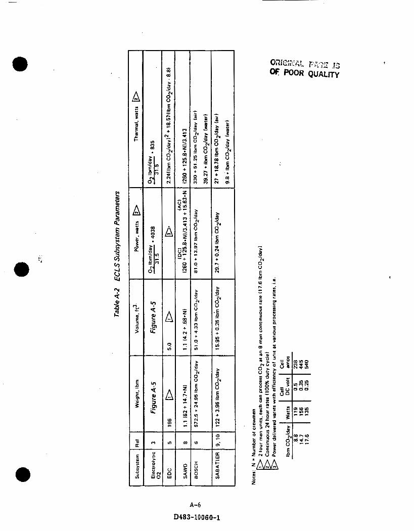
ln 0 W
n o" $1
W
P 8
0 0
0 3
U
l- w a m a u) -
4
I c P
: 0 B
.- n " 01
Ul
e I
A-6
D483-10060-1

7
6
5
0 4 ”, r i - 5 B
3
2
1
0
350
300
250
100
50
0
Volume I(
I Weight”
0‘ /
, /
1 I I
I
I I I I I I 0 10 20 30 40 50 60 70
02 , Ibdday
I
Figure A-5 Electrolytic Oxygen System Weight and Volume as a Function of Oxygen Generation Rate for Continuous Operation
1
A- 7
D483-10060-1

@ As discussed previously, t h e hydrogen and par t of the oxygen generated from water electrolysis combine in the EDC unit to form water vapor. The C 0 2 collected by t h e EDC unit mixes with remaining Hg and are sent to storage tanks. The a i r which enters the EDC unit is recirculated and the water vapor is used partly for crew drink and food preparation (potable water) and for electrolysis or personal hygiene (hygiene water). The coolant which is used for both the EDC unit and the electrolysis unit is returned t o t h e thermal bus. This schematic shows the generated effluent being used for propulsion. If a continuous or near continuous thrusting sequence is used then the
thruster shown in t h e schematic would be a resistojet. Less frequent thrusting sequences (Le., 10 days) would require warm gas or combustion thrusters.
Figure A-2 shows a working schematic of t h e Open CO2 loop system using SAWD. THis system requires less water for electrolysis than t h e EDC system since t h e SAWD unit does not require 02 and H2. However, t h e SAWD unit requires more power to operate t h e blowers and move the air and water through t h e system. Coolant in this system is used in t h e 02 unit and t h e SAWD unit and then returned to t h e thermal bus. The CO2 and H2 are stored in separate storage tanks for 10 days at 1000 psia. The AC blower for SAWD unit results in a 836 lb,/KW penalty. 0 Figure A-3 illustrates a Sabatier C 0 2 reduction working schematic. This requires coolant for the 02 unit, EDC unit, and Sabatier unit. This system operates t h e same as the Open CO2 loop system using EDC, except t h a t the C 0 2 and Hg are sent into t h e Sabatier unit to be reduced to water condensate and a C02/CH2 mixture, which is then sen t to storage. The condensate combines with t h e water generated by t h e
EDC unit to contribute t o t h e available potable water for drink and food preparation and electrolysis.
The Bosch C 0 2 reduction system working schematic is shown in Figure A-4. In th i s
system, t h e C 0 2 and H2 generated from the EDC unit are heated through a heat exchanger with s team and then separated into condensate (14.4 lb,/day), carbon, and hydrogen.
The s team used by the Bosch unit is closed looped. The excess water generated by the Bosch system can be used both for t h e ECLS and propulsion system, since an excess
A-a
D483-10 06 0-1
of 5.9 lb,/day of hygiene water is generated. Coolant is required for t h e Bosch unit, as w e l l as the 02 and EDC units which when a f t e r i t has been used is sen t back to t h e
thermal bus. 0
A-9
D483-10060-1
1. R.poct No. 2Oormmrnt-No. NASA CR 175093
5Mpcm’8-(Jo.
S c o t t M. Brennan
I
4. 11th ud mlth
Space Stat ion Propulsion - ECLSS In te rac t ion Study
7. AUthor(8) 1 D483-10060-1
ammt0.rr A p r i l 1986
a-lnoOloncutrocrCodr
506-49-22 a -w OIW~IWI ~lpor( NO.
0. Mormlng orgmlatrocr )Ilmr nd Addnu
Boeing Aerospace Company P.O. Box 3999 S e a t t l e , Was h i ngton 98124
2.SpomoftngAg.mY )Ilmrnd A d d m
N a t i o n a l Aeronaut ics and Space A d m i n i s t r a t i o n Washington, D.C. 20546
11. conlrr( 01 onnt No.
NAS 3-23353 13. T y p Of R8pW md pwlod corrrrd
Cont rac to r Repor t
14. Soonrorlng Agoncy cod. I 506-64-12
7. Key Words (Sugg0rt.d by Authorts))
I
5. Supplemontuy Noter
F i n a l Repor t
18. Dlstrlbutlon Statomant
General Release
Lewis Project Manager - R. M. Donovan, Power System Eng ineer ing D i v i s i o n , NASA Lewis Research Center, Cleveland, Ohio 44135.
9 Security Classlf. (of this repon)
U n c l a s s i f i e d
6. A h t r J C t
The b e n e f i t s o f t h e u t i l i z a t i o n o f t h e e f f l u e n t s o f t h e Space S t a t i o n Environmental C o n t r o l and L i f e Support (ECLS) system a r e examined. Var ious ECLSS-propulsion system i n t e r a c t i o n o p t i o n s a r e eva lua ted and compared on t h e b a s i s o f we igh t , volume and power requi rements. Annual p r o p u l s i v e impulse t o m a i n t a i n s t a t i o n a l t i t u d e d u r i n g a complete s o l a r c y c l e o f e leven yea rs and t h e e f f e c t on s t a t i o n r e s u p p l y are considered.
20 Security Ciassi t (of this page) 21 No of poges 22 Prlce’
U n c l a s s i f i e d
Related Documents