Installation Manual BWC EXCEL 10 Wind Turbine and Self-Supporting Lattice Towers Part # MANSSV Revision 4.5 December 2014 Bergey Windpower Co. 2200 Industrial Blvd. Norman, OK 73069 USA TEL: 405-364-4212 FAX: 405-364-2078 E-mail: [email protected] Web Site: www.bergey.com

Welcome message from author
This document is posted to help you gain knowledge. Please leave a comment to let me know what you think about it! Share it to your friends and learn new things together.
Transcript

Installation
Manual
BWC EXCEL 10
Wind Turbine and
Self-Supporting Lattice Towers
Part # MANSSV
Revision 4.5 December 2014
Bergey Windpower Co. 2200 Industrial Blvd.
Norman, OK 73069 USA TEL: 405-364-4212 FAX: 405-364-2078
E-mail: [email protected] Web Site: www.bergey.com

BWC Excel-10 Installation Manual - SSL Tower 1
Version 4.5, December 2014
Contents
I. SAFETY.............................................................................................................................................................. 3
II. RECEIVING, HANDLING AND IDENTIFICATION ................................................................................................... 4
A. BWC WIND TURBINE ................................................................................................................................................ 4 B. SSL TOWER KIT ........................................................................................................................................................ 6 C. TOWER WIRING KITS ................................................................................................................................................. 7 D. PACKING LISTS .......................................................................................................................................................... 8
III. TOWER FOUNDATIONS ................................................................................................................................... 10
A. LAYOUT OF FOUNDATIONS ........................................................................................................................................ 10
IV. TOWER ASSEMBLY .......................................................................................................................................... 19
A. ASSEMBLE TOWER SECTIONS ..................................................................................................................................... 19 B. INSTALL FURLING LANYARD, CABLE AND WINCH.............................................................................................................. 22 C. INSTALL TOWER WIRING AND DISCONNECT SWITCH ....................................................................................................... 25
V. WIND TURBINE ASSEMBLY AND SYSTEM ERECTION ....................................................................................... 28
A. ASSEMBLE AND ATTACH THE TAIL BOOM AND FIN ......................................................................................................... 29 B. COMPLETE TURBINE & TOWER WIRING CONNECTIONS .................................................................................................. 33 C. ATTACH TAIL BOOM TO TURBINE ............................................................................................................................... 36 D. INSTALL TURBINE BLADES AND SPINNER ....................................................................................................................... 38 E. RAISING THE TOWER ................................................................................................................................................ 42 F. SECURE AND GROUND THE TOWER ............................................................................................................................. 42
VI. ELECTRICAL CONNECTION ............................................................................................................................... 44
VII. COMMISSIONING ........................................................................................................................................... 45
A. FURLING WINCH AND DAMPER OPERATION ................................................................................................................. 45 B. ALTERNATOR OUTPUT CHECK .................................................................................................................................... 46 C. POWER WIRING CHECK ............................................................................................................................................ 47 D. DAMPER CLEARANCE CHECK ...................................................................................................................................... 48 E. SPECIAL TOPICS ....................................................................................................................................................... 49
VIII. INSPECTIONS AND MAINTENANCE ................................................................................................................. 51
IX. TROUBLE-SHOOTING PROBLEMS .................................................................................................................... 53
X. APPENDIX ....................................................................................................................................................... 54
A. TOWER SECTIONS .................................................................................................................................................... 54 B. WIRE SIZING ........................................................................................................................................................... 78 C. LIFTING WITH STRONGBACK FIXTURE .......................................................................................................................... 79 D. SINGLE LINE DIAGRAM ............................................................................................................................................. 80
Tables
TABLE 1: SSL TOWER HARDWARE KIT MASTER PARTS LIST ............................................................................................................. 8 TABLE 2: SSL TOWER WIRING MASTER PARTS LIST ....................................................................................................................... 9 TABLE 3: LIFT WEIGHT AND LIFT POINT FOR SSL TOWERS ............................................................................................................ 28 TABLE 4: CONTENTS OF BLADE & SPINNER HARDWARE KIT ........................................................................................................... 39

BWC Excel-10 Installation Manual - SSL Tower 2
Version 4.5, December 2014
Figures
FIGURE 1: SSL TOWER SECTION SCHEDULE ................................................................................................................................ 10 FIGURE 2: LAYOUT OF ANCHOR BOLTS ...................................................................................................................................... 11 FIGURE 3: TYPICAL SLAB FOUNDATION ...................................................................................................................................... 12 FIGURE 4: TYPICAL PAD-WITH-PIERS FOUNDATION ..................................................................................................................... 13 FIGURE 5: ANCHOR RODS AND TEMPLATE IN CONCRETE (80-120 FT) ............................................................................................ 14 FIGURE 6: ANCHOR RODS AND TEMPLATE IN CONCRETE (140-160 FT) .......................................................................................... 15 FIGURE 7: TRIANGULAR ANCHOR BOLT FIXTURE ......................................................................................................................... 17 FIGURE 8: TOOL LIST FOR SSL TOWER INSTALLATION ................................................................................................................... 20 FIGURE 9: TORQUE RECOMMENDATIONS FOR SSL ...................................................................................................................... 20 FIGURE 10: WINCH MOUNTING ON SSL TOWERS ....................................................................................................................... 22 FIGURE 11: FURLING CABLE AND LANYARD DETAILS .................................................................................................................... 24 FIGURE 12: ATTACHMENT OF FURLING CABLE TO WINCH ............................................................................................................. 25 FIGURE 13: ATTACHMENT OF DISCONNECT SWITCH .................................................................................................................... 26 FIGURE 14: ATTACHMENT OF EXCEL TURBINE TO SSL TOWER ....................................................................................................... 32 FIGURE 15: EXCEL TAIL BOOM AND PIVOT PIN ........................................................................................................................... 37 FIGURE 16: TAIL PIVOT PIN CAP .............................................................................................................................................. 38 FIGURE 17: EXCEL BLADE, CLAMP PLATE AND SPINNER ATTACHMENT ........................................................................................... 39 FIGURE 18: CLAMP PLATE ATTACHMENT ................................................................................................................................... 40 FIGURE 19: TOWER LEG GROUNDING ....................................................................................................................................... 43 FIGURE 20: TOWER ELEVATION AND SCHEDULE .......................................................................................................................... 54 FIGURE 21: TOP SECTION - VG65 ........................................................................................................................................... 55 FIGURE 22: SECOND SECTION - 6N69 ...................................................................................................................................... 56 FIGURE 23: SECOND SECTION - 6N231 (160 FT) ....................................................................................................................... 57 FIGURE 24: THIRD SECTION – 7N29 ........................................................................................................................................ 58 FIGURE 25: THIRD SECTION – 7N1118 (BASE OF 60 FT TOWER) .................................................................................................. 59 FIGURE 26: FOURTH SECTION - 8N111 .................................................................................................................................... 60 FIGURE 27: FOURTH SECTION - 8N711 (BASE OF 80 FT TOWER) .................................................................................................. 61 FIGURE 28: FIFTH SECTION - 9N182 ........................................................................................................................................ 62 FIGURE 29: FIFTH SECTION - 9N242 (160 FT) ........................................................................................................................... 63 FIGURE 30: FIFTH SECTION - 9N538 (BASE OF 100 FT TOWER) .................................................................................................... 64 FIGURE 31: SIXTH SECTION - 10N7 ......................................................................................................................................... 65 FIGURE 32: SIXTH SECTION - 10N415 (160 FT)......................................................................................................................... 66 FIGURE 33: SIXTH SECTION - 10N403 (BASE OF 120 FT TOWER) .................................................................................................. 67 FIGURE 34: SEVENTH SECTION – 11N381 ................................................................................................................................ 68 FIGURE 35: SEVENTH SECTION – 11N376 (BASE OF 140 FT TOWER) ............................................................................................ 69 FIGURE 36: EIGHTH SECTION – 12N203 (BASE OF 160 FT TOWER) .............................................................................................. 70 FIGURE 37: ANCHOR LAYOUT FOR SSL-60 TOWER ..................................................................................................................... 71 FIGURE 38: ANCHOR LAYOUT FOR SSL-80 TOWER ..................................................................................................................... 72 FIGURE 39: ANCHOR LAYOUT FOR SSL-100 TOWER ................................................................................................................... 73 FIGURE 40: ANCHOR LAYOUT FOR SSL-120 TOWER ................................................................................................................... 74 FIGURE 41: ANCHOR LAYOUT FOR SSL-140 TOWER ................................................................................................................... 75 FIGURE 42: ANCHOR LAYOUT FOR SSL-160 TOWER ................................................................................................................... 76 FIGURE 43: APPLICATION OF PAL NUTS .................................................................................................................................... 77 FIGURE 44: STRONGBACK ILLUSTRATION ................................................................................................................................... 79 FIGURE 45: EXCEL-S SYSTEMS ONE-LINE ELECTRICAL DIAGRAM ..................................................................................................... 80
BWC Excel-10 Installation Manual - SSL Tower 3
Version 4.5, December 2014
I. Safety This manual contains important information concerning the installation of your Rohn Self Supporting Lattice tower. We strongly recommend that you read and familiarize yourself with its contents. At several points in this manual, items of special interest or significant impact are highlighted by one of the following symbols:
DANGER: Hazard or unsafe practice that could cause personal injury or death.
WARNING: Hazard or unsafe practice which could cause product damage.
NOTE: Significant point of interest.
TOWER SAFETY NOTES
1. All persons not directly involved in the tower work should stay clear of the area.
2. All persons on or near the tower should wear OSHA-approved hardhats.
3. Tower work should be done by trained personnel.
4. Tower should not be constructed near utility lines. Injury or death may result.
5. Climb the tower with proper safety equipment.
6. When working on the tower, use a safety harness and tool belt.
7. Never carry tools or parts in your hands while climbing the tower.
8. Keep the amount of work to be done on the tower to a minimum.
9. Never stand directly below someone who is working on the tower.
10. Never work on the tower if alone onsite.
11. Never climb tower unless alternator is shorted and blades are barely rotating.
12. Stay clear of the tower in the presence or possibility of severe weather of any kind.

BWC Excel-10 Installation Manual - SSL Tower 4
Version 4.5, December 2014
II. Receiving, Handling and Identification
A. BWC Wind Turbine BWC turbines are shipped in three pieces: two crates plus the tail boom as an unpackaged assembly. Additionally, the controller is shipped in its own box. The contents, weights and dimensions of these pieces are as follows:
1. Powerhead Skid: 1022 lb, 53” x 74” x 36” (HxWxD)
a. Mainframe/alternator assembly with tower adapter b. Spinner (nose cone) c. Tail Fin d. Blade, Spinner, Tail Fin attachment hardware
BWC Excel-10 Installation Manual - SSL Tower 5
Version 4.5, December 2014
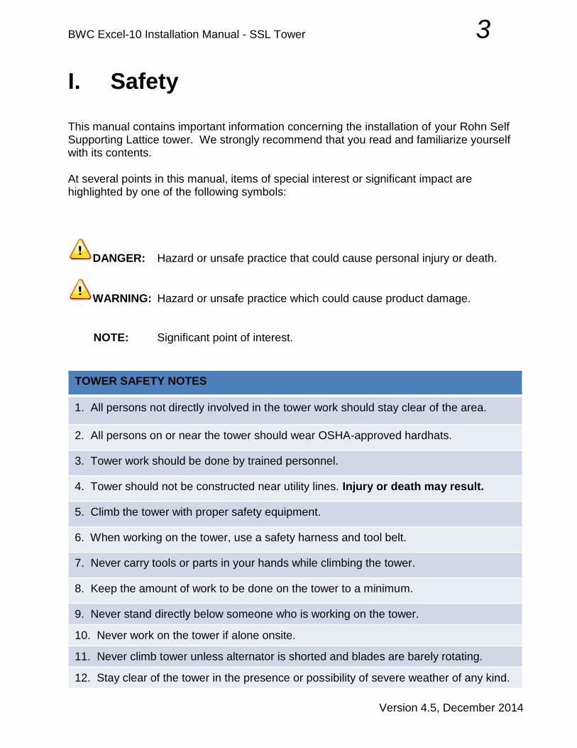
2. Blade Carton: 180 lbs, 16” x 131” x 14” (HxWxD) a. Three rotor blades
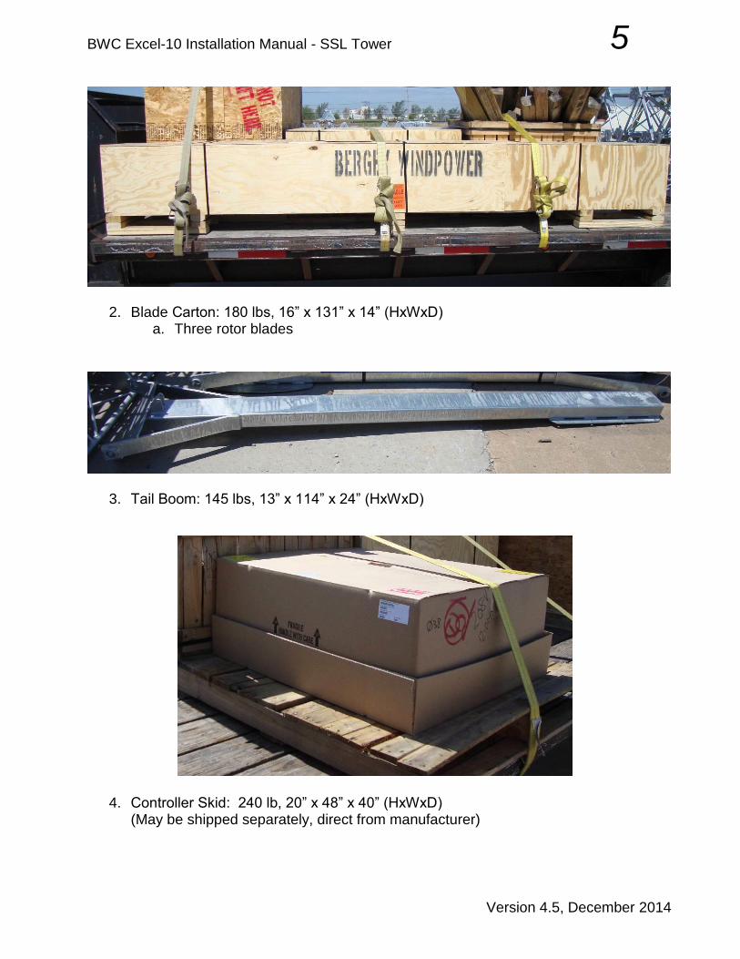
3. Tail Boom: 145 lbs, 13” x 114” x 24” (HxWxD)
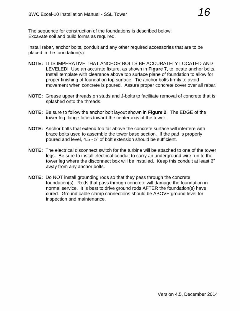
4. Controller Skid: 240 lb, 20” x 48” x 40” (HxWxD)
(May be shipped separately, direct from manufacturer)

BWC Excel-10 Installation Manual - SSL Tower 6
Version 4.5, December 2014
Upon delivery, the boxes and contents should be checked for parts and signs of damage. If any damage is found its extent should be noted as precisely as possible. Digital photographs can be helpful in verifying claims against the carrier. BWC should be notified as soon as possible so that the necessary replacement parts can be sent. When reporting a damaged or malfunctioning component of the system, include the item's part number. Do not dispose of damaged goods until they have been inspected by the carrier’s claims department. The blade box, electronics box and powerhead shipping pallet should be retained in storage in case component shipping is required at some later date.
B. SSL Tower Kit
The SSL Tower Kit will include a number of 20 ft welded tower legs, a bundle of grounding rods, a large bundle of tower diagonal “braces” and one or more boxes/pallets of hardware and miscellaneous materials. Tower legs and braces are typically shipped directly from Rohn, and these will usually be banded together as a single bulky, heavy mass on a large pallet. The master parts lists for the SSL Tower Kits is shown in Table 1 to assist you in determining that all auxiliary material from BWC has been received. Specific packing lists are also provided with each shipment. All major items should be properly inspected before delivery is accepted. The Rohn drawings showing the individual tower section assembly details (See Appendix) are the best source for information concerning the Rohn-supplied tower components. The Rohn tower components are very heavy; section weights progress from 850 lb for the VG65 top section to 2700 lb for the 12N203 base section for a 160 ft tower. Individual leg components vary from 150 lb for the VG65W to 600 lb for the 12N203. Handling these large components by hand is not recommended because of the risk of back injury. If you must move major tower parts by hand always use several helpers. The best way to move SSL tower components is with a forklift, tractor (with a front end loader), or crane.

BWC Excel-10 Installation Manual - SSL Tower 7
Version 4.5, December 2014
C. Tower Wiring Kits
Most people choose to purchase a Tower Wiring Kit along with the Tower Kit. The Tower Wiring Kit consists of the down-tower armored cable, connectors and fasteners, a fused disconnect switch that mounts to the tower, and a surge arrestor. Specific packing lists are provided with each shipment. An example of the anticipated packing list is included in this chapter. All major items should be properly inspected before delivery is accepted.

BWC Excel-10 Installation Manual - SSL Tower 8
Version 4.5, December 2014
D. Packing Lists
Table 1: SSL Tower Hardware Kit Master Parts List
No. Description BOM QTY Comments
HK0021- 60 80 100 120 140 160
MANSSV MANUAL 1 1 1 1 1 1 Installation Instructions
HBA011 BOLT 5/8"-11 x 2-1/2" HH A325 9 9 9 9 9 9 Attach turbine to top tower section
HWA003 WASHER 5/8" HARDENED FLAT 18 18 18 18 18 18 Attach turbine to top tower section
HNA008 NUT, 5/8"-11 HEX A563-DH HDG 9 9 9 9 9 9 Attach turbine to top tower section
HNA004 PAL NUT, 5/8" HDG 9 9 9 9 9 9 Attach turbine to top tower section
11508-1 FURL CABLE ASSY, 3/16” x 60' SS 1
Cable from turbine to furling winch
11508-2 FURL CABLE ASSY, 3/16” x 80' SS
1
Cable from turbine to furling winch
11508-3 FURL CABLE ASSY, 3/16” x 100' SS
1
Cable from turbine to furling winch
11508-4 FURL CABLE ASSY, 3/16” x 120' SS
1
Cable from turbine to furling winch
11508-5 FURL CABLE ASSY, 3/16” x 140' SS
1
Cable from turbine to furling winch
11508-6 FURL CABLE ASSY, 3/16” x 160' SS
1 Cable from turbine to furling winch
HM3003 THIMBLE 3/16” SS 1 1 1 1 1 1 Attach furl cable to turbine cable
HM3002-B CLIP MALLEABLE 3/16" - SS 2 2 2 2 2 2 Attach furl cable to turbine cable
11155 LANYARD, SSV FURLING CABLE 1 1 1 1 1 1 Center furl cable in top section
11119GALV PLATE WINCH MOUNT SSV TOWER 1 1 1 1 1 1 Attach furling winch
HW8003 WASHER 1/2" SPLIT LOCK ZPS 4 4 4 4 4 4 Attach winch plate to tower leg
HN8003 NUT 1/2"-13 HEX, ZPS 4 4 4 4 4 4 Attach winch plate to tower leg
HB8031 U-BOLT 1/2"-13 x 3” x 4-1/2" ZPS 2
Attach winch plate to tower leg
HB8004 U-BOLT 1/2"-13 x 3-1/2” x 5" ZPS
2
Attach winch plate to tower leg
HB8008 U-BOLT 1/2”-13 x 4” x 5-1/2” ZPS
2 2
Attach winch plate to tower leg
HB8013 U-BOLT 1/2”-13 x 4-1/2” x 6” ZPS
2
Attach winch plate to tower leg
HB8042 U-BOLT 1/2"-13 x 5-5/8” x 7-1/4" ZPS
2 Attach winch plate to tower leg
HB6002 BOLT 3/8”-16 x 1” HH, SS 3 3 3 3 3 3 Attach furling winch to mounting plate
HW6004 WASHER 3/8” SAE FLAT SS 6 6 6 6 6 6 Attach furling winch to mounting plate
HW6002 WASHER 3/8” SPLIT LOCK SS 3 3 3 3 3 3 Attach furling winch to mounting plate
HN6001 NUT 3/8”-16 HEX SS 3 3 3 3 3 3 Attach furling winch to mounting plate
HM0008 ROD GROUNDING 3/8” x 8’ COPPER CL
3 3 3 3 3 3 Ground rod at each pad
HM0042 CLAMP GROUNDING DIRECT BURIAL
3 3 3 3 3 3 Attach tower leg to grounding rod
11471-1 GROUNDING CABLE ASSM 72" 3 3 3 3 3 3 Attach tower leg to grounding rod
HB8035 BOLT 1/2"-13 x 1-1/4” A325HDG 3 3 3 3 3 3 Attach ground wires to anchor pads
HN8004 NUT 1/2"-13 HEAVY HEX HDG 3 3 3 3 3 3 Attach ground wires to anchor pads
HN8005 NUT 1/2" PAL HDG 3 3 3 3 3 3 Attach ground wires to anchor pads

BWC Excel-10 Installation Manual - SSL Tower 9
Version 4.5, December 2014
Table 2: SSL Tower Wiring Master Parts List
No. Description BOM QTY Unit Comments
XLSSxx-TWK 18 24 30 37 43 49
AXA009 SWITCH DISCONNECT - 600V 60A 1 1 1 1 1 1 EA Turbine disconnect
AXA013 HUB 3/4" N3R - SQD DISCONNECT 1 1 1 1 1 1 EA Hub for disconnect
AFA016 FUSE FRS-R-45 (BUS) 3 3 3 3 3 3 EA Fuses for disconnect
CAB006 CABLE ARMOR MC 3x#6AWG 600V 60 80 100 120 140 160 FT Down tower cable
EC0152 CONNECTOR, ARMORED CABLE 3/4" 2 2 2 2 2 2 EA Turbine & Disconnect connector
HNB002 LOCKNUT 3/4 ELECTRICAL 1 1 1 1 1 1 EA Turbine side connector
HMB006 BUSHING 3/4 PLASTIC INSULATING 1 1 1 1 1 1 EA Turbine side connector
HM0012 CABLE TIE 13.4" NYLON BLACK HD 50 50 50 50 50 50 EA Attach cable to tower leg
EC0184 GROUNDING BAR KIT, SQD GTK0610 1 1 1 1 1 1 EA Grounding bar for disconnect
HB6025 U-BOLT GUILLOTINE 2.75" ZPS 2
EA Attach disconnect to tower
HB6021 U-BOLT GUILLOTINE 3.5" ZPS
2
EA Attach disconnect to tower
HB6024 U-BOLT GUILLOTINE 4" ZPS
2 2
EA Attach disconnect to tower
HB6029 U-BOLT GUILLOTINE 4.5" ZPS
2
EA Attach disconnect to tower
HB6030 U-BOLT GUILLOTINE 5.5" ZPS
2 EA Attach disconnect to tower
HN6003 NUT 3/8-16 HEX NYLOC ZPS 4 4 4 4 4 4 EA Attach disconnect to U-Bolt
HW6001 WASHER 3/8 SAE FLAT ZPS 4 4 4 4 4 4 EA Attach disconnect to U-Bolt
ARR003 ARRESTOR LIGHTNING LA603V 1 1 1 1 1 1 EA Install on disconnect

BWC Excel-10 Installation Manual - SSL Tower 10
Version 4.5, December 2014
III. Tower Foundations
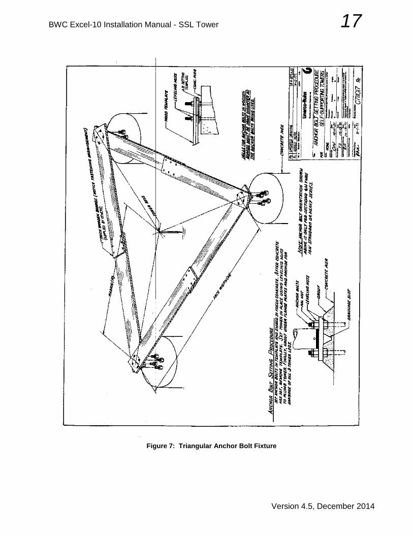
A. Layout of Foundations The required anchor bolt layout is shown in Figure 2. Tower height is increased in 20 foot increments by adding new sections to the base of the tower structure. Each additional section is stronger and heavier, with a larger spread between the tower legs. Foundation size also increases with tower height. The most common foundation consists of a single large, square concrete pad with three anchor groups, illustrated in Figure 3. The pad must be deep enough to extend below maximum frost depth. The actual size of every foundation depends on wind conditions at the turbine site, local frost depth and soil conditions at the tower site. Other foundations may be used where deep frost occurs; drilled-and-bell piers, hybrid pier-pads, and thick pads are available options. For deep frost areas, the standard Bergey design is the pad-with-piers layout, shown in Figure 4. Consult local codes, soil data summaries and excavation contractors to develop a practical and economical plan for a tower foundation. Assembly of the anchor studs and templates is shown in Figure 5 for 80-120 ft towers or Figure 6 for 140-160 ft towers. Construction and use of a triangular fixture to properly locate and orient groups of anchor bolts is shown in Figure 7. Each anchor kit includes 18 thin, metal template patterns that are used to control the arrangement of bolts in the anchor groups. (These patterns may also be used as guides when drilling the triangular placement fixture.) Each anchor stud is first fitted with a nut that is threaded 12” onto the upper thread section. One template with small center hole is then double-nutted in place near the top of the anchor group. A second template with large center hole is double-nutted on the lower threads of the anchor group, and it will remain embedded in the finished concrete. The large hole in the center of these lower plates allows proper move ment of concrete into the interior of the anchor “cage” formed when the templates
Tower Top Section Section Section Section Section Section Section Tower
Height Section 2 3 4 5 6 7 8 Weight
(ft) (lb)
60 VG65 6N69 7N1118 2,340
80 VG65 6N69 7N29 8N715 3,475
100 VG65 6N69 7N29 8N111 9N538 5,175
120 VG65 6N69 7N29 8N111 9N182 10N403 6,985
140 VG65 6N69 7N29 8N111 9N182 10N7 11N376 9,295
160 VG65 6N231 7N29 8N111 9N242 10N415 11N381 12N203 11,995
Weight 750 670 920 1135 1700 1810 2310 2700
Figure 1: SSL Tower Section Schedule

BWC Excel-10 Installation Manual - SSL Tower 11
Version 4.5, December 2014
Figure 2: Layout of Anchor Bolts

BWC Excel-10 Installation Manual - SSL Tower 12
Version 4.5, December 2014
Figure 3: Typical Slab Foundation

BWC Excel-10 Installation Manual - SSL Tower 13
Version 4.5, December 2014
Figure 4: Typical Pad-with-Piers Foundation

BWC Excel-10 Installation Manual - SSL Tower 14
Version 4.5, December 2014
Figure 5: Anchor Rods and Template in Concrete (80-120 ft)

BWC Excel-10 Installation Manual - SSL Tower 15
Version 4.5, December 2014
Figure 6: Anchor Rods and Template in Concrete (140-160 ft)
BWC Excel-10 Installation Manual - SSL Tower 16
Version 4.5, December 2014
The sequence for construction of the foundations is described below: Excavate soil and build forms as required. Install rebar, anchor bolts, conduit and any other required accessories that are to be placed in the foundation(s). NOTE: IT IS IMPERATIVE THAT ANCHOR BOLTS BE ACCURATELY LOCATED AND
LEVELED! Use an accurate fixture, as shown in Figure 7, to locate anchor bolts. Install template with clearance above top surface plane of foundation to allow for proper finishing of foundation top surface. Tie anchor bolts firmly to avoid movement when concrete is poured. Assure proper concrete cover over all rebar.
NOTE: Grease upper threads on studs and J-bolts to facilitate removal of concrete that is
splashed onto the threads.
NOTE: Be sure to follow the anchor bolt layout shown in Figure 2. The EDGE of the tower leg flange faces toward the center axis of the tower.
NOTE: Anchor bolts that extend too far above the concrete surface will interfere with
brace bolts used to assemble the tower base section. If the pad is properly poured and level, 4.5 - 5” of bolt extension should be sufficient.
NOTE: The electrical disconnect switch for the turbine will be attached to one of the tower
legs. Be sure to install electrical conduit to carry an underground wire run to the tower leg where the disconnect box will be installed. Keep this conduit at least 6” away from any anchor bolts.
NOTE: Do NOT install grounding rods so that they pass through the concrete
foundation(s). Rods that pass through concrete will damage the foundation in normal service. It is best to drive ground rods AFTER the foundation(s) have cured. Ground cable clamp connections should be ABOVE ground level for inspection and maintenance.
BWC Excel-10 Installation Manual - SSL Tower 17
Version 4.5, December 2014
Figure 7: Triangular Anchor Bolt Fixture

BWC Excel-10 Installation Manual - SSL Tower 18
Version 4.5, December 2014
Order the concrete. When ordering concrete, refer to the specifications given on blueprints or drawings. Let the supplier determine the proper mix of cement, sand, gravel, etc. to meet the strength and stiffness requirements. Pour concrete. Vibrate concrete during the pour to assure that it fills properly around rebar and anchor bolts. Finish the foundation, making sure it is level with a slight top surface crown to provide drainage. NOTE: Do not remove templates or forms until concrete is cured and hard. Any attempt
to do so may disturb the anchor bolts and reduce their effectiveness.
Minimum cure time for pads is 14 days, but for maximum strength 28 days is recommended. For both strength and surface finish quality, it is important to control the cure process. In hot conditions pad tops should be covered with burlap or similar material and watered down several times a day, at least for the first 3-4 days. In cold conditions the concrete should be covered and insulated to prevent freezing. For specific recommendations refer to a standard construction manual for concrete techniques. Remove templates and forms after at least 1 week of cure, and backfill if necessary. Backfill with cohesive soil compacted to at least 100 lb/cu ft. Clean concrete from anchor bolt threads. Drive ground rods into the ground near each tower leg location. Rods should be driven until the top of the rod is at least 3” below ground level. (This operation can be done at any time before the tower is raised. If rods are set now, it is recommended that they be marked with wooden stakes and/or flagging so they may be easily located later.)

BWC Excel-10 Installation Manual - SSL Tower 19
Version 4.5, December 2014
IV. Tower Assembly Assembly drawings and instructions are shipped by the manufacturer with each tower. Study these carefully before starting any assembly. Standard procedure is to assemble the tower and turbine completely on the ground, then lift the entire EXCEL-and-tower structure into place on the anchor bolts. This will require a crane with lifting capacity to handle the combined weight of turbine and tower, and a convenient area of reasonably level ground for assembly of the tower-turbine combination. NOTE: Use of standard wrenches to snug the brace bolts is recommended. Use of a
torque-controlled impact wrench to accomplish final tightening of all fasteners is highly recommended, and will speed the assembly process immeasurably.
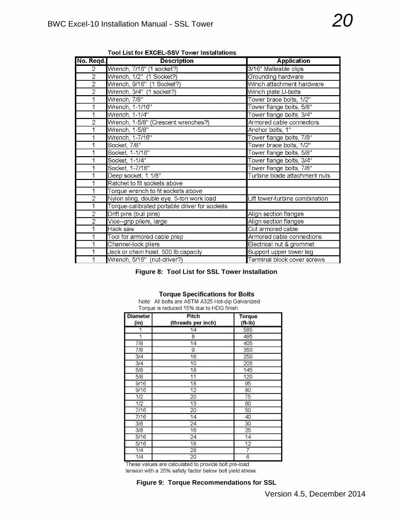
A. Assemble Tower Sections Figure 8 shows a list of tools required or recommended for assembly of the SSL towers and attachment of the BWC EXCEL turbine. Figure 9 shows a summary of torque recommendations for hot-dip galvanized bolts. All tower bolts are coarse-thread, hot-dipped ASTM A325 bolts. When fully assembled, the tower should be lying on the ground next to the foundation(s), on the opposite side from where the crane will be stationed. The point on the tower where the crane sling will attach should be aligned with the central axis of the foundation. Lay out ALL tower legs and cross pieces (“braces”) on the ground in their approximate assembled positions. Be sure that all step legs are aligned on the tower. NOTE: Each tower leg has a part number stamped into one of the flanges at the end of
the leg. The leg MUST be installed with this stamped flange AT THE BOTTOM. The tower cannot be properly assembled if any of the legs are upside-down!
NOTE: Documentation delivered with the tower includes Assembly Detail drawings for
each tower section. Braces are used in each tower section in the same top-to-bottom order given in the bill of material shown on these drawings.
NOTE: All cross braces have a hole near the center. This hole is NOT in the center.
Cross braces can only be installed in one orientation (short hole-hole distance upward). Proper orientation may be checked by balancing at “middle” hole; long section will rotate downward.
BWC Excel-10 Installation Manual - SSL Tower 20
Version 4.5, December 2014
Figure 8: Tool List for SSL Tower Installation
Figure 9: Torque Recommendations for SSL

BWC Excel-10 Installation Manual - SSL Tower 21
Version 4.5, December 2014
Start with the top section. Tower legs are usually bowed due to the manufacturing weld process. This bow will be pulled out as the section is assembled, but force will be required. Use of jacks, a scaffold or an A-frame to hold the upper leg in place will be required. This can require a support over 10 ft high for the bottom section of a 120 ft tower! Support the two lower legs with blocks at each end and in the middle to level them and keep them from bowing. Once you have bolted the braces to the tower leg, place a bolt through the hole in the middle of each brace, bolting two crossing braces together. Bolts used for all brace connections are 1/2” x 1-1/4” A325. These will require 7/8” wrenches. Install the braces. Insert the bolts for the braces so that all nuts will go on the outside of the tower. The end of the brace stamped with a part number is oriented toward the top of the tower. (The hole is NOT in the middle!) Do not torque any of the hardware until the tower is erected and securely anchored. Leave all brace hardware finger-tight until the tower is erected. Attach the sections to each other. Flange bolts should be tightened to final torque specification. We suggest that all PAL nuts be installed after the tower is installed on the foundations; install PAL nuts only after a nut has been tightened to final torque specification. Drift pins and vice grips will be required to align flanges before bolts can be inserted. A jack, bumper crane, come-along, or a 4x4 post may be needed to push or pull legs into position when the drift pins can’t be started. Bolts used for the flange joints on the VG65W and 6N69W sections are 5/8” x 2-1/2” A325, requiring 1-1/16” wrenches. The 3/4” bolts for the 7N99W lower flange joint require 1-1/4” wrenches. The lowest tower sections (8N64W, 9N84W and 10N58W for 80, 100, and 120 ft towers) use 7/8” bolts in their bottom flange connections. These bolts require 1-7/16” wrenches. NOTE: Install flange connection bolts with nuts on the top, as shown below. This
allows detection of loose or missing bolts in a quick ground-level inspection. Twelve bolts are required at each tower joint level.

BWC Excel-10 Installation Manual - SSL Tower 22
Version 4.5, December 2014
B. Install furling lanyard, cable and winch
Determine which tower leg will support the electrical fused disconnect switch. (The electrical conduit stubs out of the concrete near the base of this leg.) The winch cannot be attached to this leg. Attach the winch mounting plate, included with the tower hardware kit, to one of the bottom tower legs using two U-bolts provided in hardware kit HK0019. Be sure to orient the winch plate properly. Refer to Figure 10. Locate the plate so it will be at a convenient height above ground when the tower is installed. The recommended mounting height for the furling winch is 4 - 5 ft.
Figure 10: Winch Mounting on SSL Towers
Mount the winch to the plate using three 3/8” x 1” hex bolts with flat washers, lock washers and hex nuts. NOTE: The winch is mounted INSIDE the tower, so the winch drum is oriented toward the
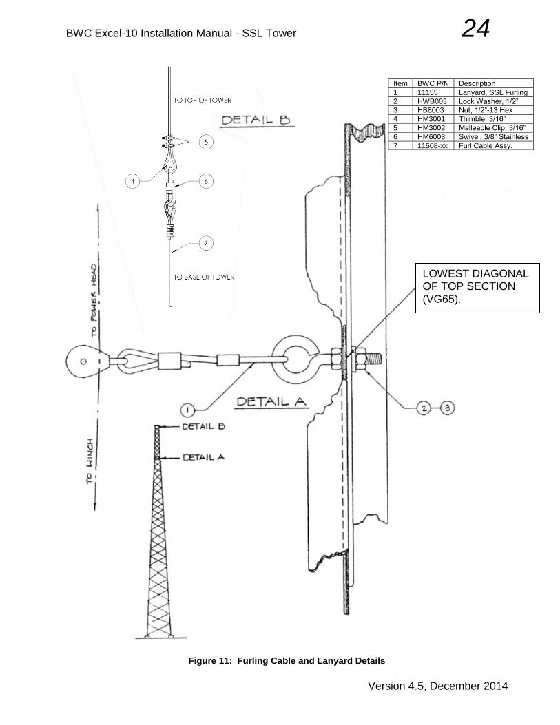
center of the tower. Before tightening the U-bolts that fasten the mounting plate it is advisable to turn the handle on the winch and check that it rotates freely (i.e. that it does not hit the braces or brace clips of the tower). Attach the furling cable lanyard as shown in Figure 11, Detail A. The lanyard is required to assure that the furling cable remains centered in the upper tower section, then angles properly to the winch drum. The lanyard attachment eye-bolt replaces the standard 1/2”
BWC P/N Description Qty.
See Table 1 Large U-Bolt 2
HWB003 Lock Washer, 1/2” 4
HNB003 Nut, 1/2”-13 Hex 4
11119GALV Winch Mounting Plate 1
HB8002 Bolt, 3/8”-16x1” SS 3
HW6004 Flat Washer, 3/8” SS 3
HN6001 Lock Washer,3/8” SS 3
HN6002 Nut, 3/8”-16 SS 3
HA0001 Winch, Furling 1

BWC Excel-10 Installation Manual - SSL Tower 23
Version 4.5, December 2014
bolt at the crossing of the two VG58 braces on the tower face OPPOSITE TO the winch. These are the lowest braces in the top (VG65W) section. Feed the furling cable through the tower, starting from the tower base section. Run the cable through the lanyard pulley, and then attach the end to the heavy stainless swivel provided in the tower kit. Use a thimble loop in the furling cable as shown in Figure 11, Detail B. The swivel will later be connected to the turbine furling cable; for now it will hold the down-tower furling cable secure in the lanyard pulley.
BWC Excel-10 Installation Manual - SSL Tower 24
Version 4.5, December 2014
Figure 11: Furling Cable and Lanyard Details
Item BWC P/N Description
1 11155 Lanyard, SSL Furling
2 HWB003 Lock Washer, 1/2”
3 HB8003 Nut, 1/2”-13 Hex
4 HM3001 Thimble, 3/16”
5 HM3002 Malleable Clip, 3/16”
6 HM6003 Swivel, 3/8” Stainless
7 11508-xx Furl Cable Assy.
LOWEST DIAGONAL OF TOP SECTION (VG65).

BWC Excel-10 Installation Manual - SSL Tower 25
Version 4.5, December 2014
Attach the lower end of the furling cable to the winch by threading the cable through the long slot in the side of the cable drum and securing the cable end as shown in Figure 12.
Figure 12: Attachment of Furling Cable to Winch
C. Install Tower Wiring and Disconnect Switch
1. Pull the armored electrical cable (or other customer-supplied electrical cable) through the center of the tower, starting from the base section.
NOTE: Do not use conduit for tower wiring unless internal strain relief is provided for the
conductors. 2. Attach the disconnect switch to the appropriate tower leg using the two U-bolts
supplied with the tower wiring kit. If a wiring kit was not purchased from BWC, the customer must supply the appropriate switch, and all hardware required to make mechanical and electrical connections (Refer to packing list.) The switch box must be drilled to accommodate appropriate U-bolts. Locate the disconnect at a height suitable to the customer. Figure 13 shows typical attachment of the disconnect switch.

BWC Excel-10 Installation Manual - SSL Tower 26
Version 4.5, December 2014
Figure 13: Attachment of Disconnect Switch
Item BWC P/N Description
1 AXA009 Switch, 60A Fused
2 See Table 2 U-Bolt Guillotine
3 HW6001 Flat Washer, 3/8”
4 HN6003 Nylon Lock Nut, 3/8”
5 AXA013 Hub, 3/8”
6 EC0152 Electrical Connector
7 CAB006 Cable, 3 x #6 Armored

BWC Excel-10 Installation Manual - SSL Tower 27
Version 4.5, December 2014
NOTE: The tower is now ready for attachment of the EXCEL turbine at ground level.
Crane rental cost can be minimized if all possible preparation work is done before the crane arrives on-site.
If some of steps B and C above could not be accomplished, because of the tower position on the ground, they can be completed after the crane has raised the tower top to allow attachment of the turbine.
BWC Excel-10 Installation Manual - SSL Tower 28
Version 4.5, December 2014
V. Wind Turbine Assembly and System Erection
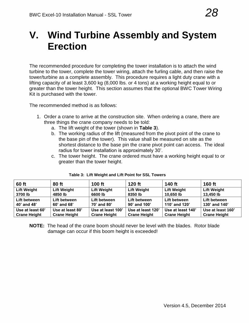
The recommended procedure for completing the tower installation is to attach the wind turbine to the tower, complete the tower wiring, attach the furling cable, and then raise the tower/turbine as a complete assembly. This procedure requires a light duty crane with a lifting capacity of at least 3,600 kg (8,000 lbs. or 4 tons) at a working height equal to or greater than the tower height. This section assumes that the optional BWC Tower Wiring Kit is purchased with the tower. The recommended method is as follows:
1. Order a crane to arrive at the construction site. When ordering a crane, there are three things the crane company needs to be told:
a. The lift weight of the tower (shown in Table 3). b. The working radius of the lift (measured from the pivot point of the crane to
the base pin of the tower). This value shall be measured on site as the shortest distance to the base pin the crane pivot point can access. The ideal radius for tower installation is approximately 30’.
c. The tower height. The crane ordered must have a working height equal to or greater than the tower height.
Table 3: Lift Weight and Lift Point for SSL Towers
60 ft 80 ft 100 ft 120 ft 140 ft 160 ft Lift Weight 3700 lb
Lift Weight 4850 lb
Lift Weight 6600 lb
Lift Weight 8350 lb
Lift Weight 10,650 lb
Lift Weight 13,450 lb
Lift between 40’ and 48’
Lift between 60’ and 68’
Lift between 70’ and 80’
Lift between 90’ and 100’
Lift between 110’ and 120’
Lift between 130’ and 140’
Use at least 60’ Crane Height
Use at least 80’ Crane Height
Use at least 100’ Crane Height
Use at least 120’ Crane Height
Use at least 140’ Crane Height
Use at least 160’ Crane Height
NOTE: The head of the crane boom should never be level with the blades. Rotor blade
damage can occur if this boom height is exceeded!

BWC Excel-10 Installation Manual - SSL Tower 29
Version 4.5, December 2014
A. Assemble and Attach the Tail Boom and Fin
1. Shortly before the crane is scheduled to arrive, attach the tail fin to the tail boom using the hardware provided in the Tail Assembly Hardware Kit. Lay the tail boom on a work surface with the fin mounting plate upward. Position the tail fin on the mounting plate, with the trailing edge bend upward. Eight bolts (3/8”-16 x 1”), 16 flat washers and 8 nylon lock nuts are used. Recommended torque is 20 ft-lb. Set the tail assembly aside for later use.
WARNING: Anti-seize MUST be used on all stainless steel fasteners.
TAIL ASSEMBLY HDWR KIT 10kW
HM5006 CLEVIS PIN 5/16" x 1" SS EA 2
HM2005 COTTER PIN 1/8x3/4" SS EA 2
HB6002 BOLT 3/8-16x1 HH,SS EA 8
HW6004 WASHER 3/8 SAE FLAT SS 13/16OD EA 16
HN6008 NUT 3/8-16 HH NYLOCK SS EA 8
HBM106 BOLT M10-1.5x65MM HHCS SS EA 1
HNM101 NUT M10-1.5 NYLOC SS EA 1
HM0040 ANTISEIZE COMPOUND - 2mL EA 1

BWC Excel-10 Installation Manual - SSL Tower 30
Version 4.5, December 2014
2. Position the crane so it will be DOWNWIND of the tower during the lift. (The tail will orient toward the crane boom, keeping the rotor blades away from the cable.) The boom should lean outward to make initial contact with the tower lifting point; boom movement must then be TOWARD the crane’s center of gravity as the lift and tower placement occurs. (During the lift, the base of the tower will skid across the ground as it moves toward the foundation.)
3. Have the crane attach its lifting cable to the tower at a point in accordance with Table 3. The rigging can be done with either a strap or a sling, but it should be routed to catch two legs of the tower. The rigging point is well below the top of the tower so that the crane boom will not catch the blades during erection.
DANGER: Never use an open hook when rigging the lifting cable and always ensure that all cables and slings are in good condition prior to use.
DANGER: Do not operate the crane in any way that will introduce a bounce to the tower structure. This will create excessive loading, and may fail the tower.
4. Lift the tower until the top is chest high; support it with a scaffold, jack stands or a
strong, stable stack of timbers. The support structure should be located near the bottom of the top tower section. After the tower is SECURELY supported, remove the crane line.

BWC Excel-10 Installation Manual - SSL Tower 31
Version 4.5, December 2014
5. Use the crane to lift the powerhead, still attached to the shipping skid, clear of the ground using a double-eye nylon strap. Slip one eye over each end of the tail pivot pin and onto the mainframe; hook the crane line to the center of the strap and lift. The shipping nuts can now be removed from the blade studs so the skid can be pulled off and set aside.
6. Direct the crane to move the powerhead until the tower adapter plate meets the
tower top plate.
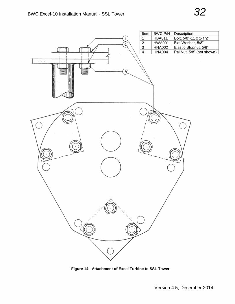
7. Use one or two spud wrenches to line up the nine attachment holes on the two plates. Bolt the turbine in place using 6 bolts, 3/4” x 2-1/2”, with hex nuts and PAL nuts. Remember - nuts go on top! This hardware is included in the tower hardware kit. Torque the hex nuts to 205 ft-lb. PAL nuts are tightened to 1/4 turn past contact. Disconnect the turbine from the crane after the turbine is bolted securely in place.
BWC Excel-10 Installation Manual - SSL Tower 32
Version 4.5, December 2014
Figure 14: Attachment of Excel Turbine to SSL Tower
Item BWC P/N Description
1 HBA011 Bolt, 5/8”-11 x 2-1/2”
2 HWA001 Flat Washer, 5/8”
3 HNA002 Elastic Stopnut, 5/8”
4 HNA004 Pal Nut, 5/8” (not shown)

BWC Excel-10 Installation Manual - SSL Tower 33
Version 4.5, December 2014
B. Complete Turbine & Tower Wiring Connections
Make electrical connections to the turbine as follows:
1. Remove the stainless steel cover of the terminal block housing.
a. Strip the tower top end of the armored cable as shown, being very careful not to cut the insulation on the three conductors. A special tool may be purchased for this task at most electrical supply distributors. Cut off green ground wire at both ends of the cable. It is not needed for this installation.
NOTE: Leave at least 8” of conductor exposed beyond the armor. NOTE: Cut off grounding wire at both ends of the cable. It is not needed for this
installation.
b. It is best to install the connector on the cable before installing the assembly into the junction box. Disassemble the fitting, and remove the plastic ring. Reassemble the fitting.
c. Insert the prepared cable into the fitting until the armor rests against the
armor stop. Tighten both the intermediate body and the nut to 42 ft-lb. Insert the fitting, through the large off-center hole in the tower top plate, into the bottom of the terminal block area. Add the electrical locknut and tighten securely. Install the plastic bushing. The bushing is required to avoid chafing and, eventually, short circuits in the tower wiring.
Remove Ring

BWC Excel-10 Installation Manual - SSL Tower 34
Version 4.5, December 2014
NOTE: The metallic armor must not go beyond the armor stop.
Plastic Bushing

BWC Excel-10 Installation Manual - SSL Tower 35
Version 4.5, December 2014
d. Trim each of the conductors to a length that will allow formation of full 360º strain relief loops to each terminal connection. Strip each of the three conductor wires back 3/4" (2 cm), apply anti-oxidation compound to the bare copper and make connections to the terminal block. All three wires are equivalent; there is no polarity or required phase rotation.
e. Perform tests for continuity, ground faults, etc. Correct any problems.
f. Replace the terminal block cover.

BWC Excel-10 Installation Manual - SSL Tower 36
Version 4.5, December 2014
2. Form a gentle S-bend in armored cable so that it rests along one of the tower legs
that is close to the disconnect switch.
3. Starting from a point 4 ft below the tower top, use plastic zip ties every 4 ft to secure the cable to the tower leg. Shape the cables around flanges to avoid chafing; use a zip tie immediately above and below each flange joint. Continue this process until the cable has been shaped around the lowest flange joint.
4. Prepare the lower end of the armored cable as shown for the connection to the turbine, leaving enough free conductor to make the electrical connections in the disconnect box, and connect tower wiring to the disconnect switch. The armored cable connector screws into the hub; an insulating grommet is not required.
5. A 3-phase surge arrestor such as a Delta LA-603 (included in the tower wiring kit) should be connected to the system at this time. The three wires of the arrestor should be connected to the lower (load) set of switch box terminals, along with the tower wiring conductors. There is no polarity or required phase rotation in these connections; all three wires are equal. Ground the arrestor.
6. Install jumpers between the three lower (load) terminals on the switch box, to provide a short circuit, as later described in Special Topics. Put the switch in the “ON” position, effectively short-circuiting the tower wiring and alternator.
WARNING: Do not leave the alternator shorted for an extended period of time. Doing so may cause damage to the turbine, and void the warranty.
C. Attach Tail Boom to Turbine Attaching the tail boom to the powerhead is a job that requires at least three people. The best approach is to use the crane to lift and position the tail boom.
1. Remove the retaining bolt and washer from one end of the tail pivot pin, which is
shipped in the turbine pallet.
2. Work the pin part of the way in to the tail boom. It should move easily, but a spud wrench and hammer can be used if necessary. The pivot pin must not protrude into the space between the bronze tail pivot bushings.
3. Get the tail boom orientation correct by making sure that the furling cable and damper attachment brackets on the tail boom are aligned with the damper and furling cable on the powerhead. The fin will be on TOP.
4. Hold the tail boom in a position so the end with the fin is angled up ~ 15˚ and align the tail bushings with those of the powerhead, then insert the tail pivot pin as shown in Figure 15. The pin may need tapping through, but keep in mind that the

BWC Excel-10 Installation Manual - SSL Tower 37
Version 4.5, December 2014
stainless steel pin can be damaged if it is handled incorrectly. Use a block of wood or rubber mallet on the pin.
Figure 15: Excel Tail boom and Pivot Pin
WARNING: Anti-seize MUST be used on all stainless steel fasteners.
5. After the pin is in place, install the M10 retaining bolt and Nylock nut. Recommended torque is 20 ft-lb.
6. Release the tail boom and allow it to swing down (about 45º). It may be necessary to put cardboard on the ground to avoid scraping the paint on the fin. (A piece of 2x4 or a pipe inserted into the end of the tail boom will also work to keep the fin off the ground).
7. Make sure the fork on the damper strut is centered on the "upper" tail boom connection tab. Adjust the tail boom tab by slightly bending if necessary (this should not be required unless the turbine is damaged in shipping). Attach the damper strut and furling cable to the tail boom using clevis pins and cotter pins provided in Tail Assembly Hardware Kit HK0002. If there appears to be a clearance

BWC Excel-10 Installation Manual - SSL Tower 38
Version 4.5, December 2014
issue between the damper and the nacelle, it is permissible to file the nacelle to create proper clearance.
Figure 16: Tail Pivot Pin Cap
8. Place the tail pivot pin cap (P/N 11285) on the pivot pin and use a zip tie (P/N HM0012) to secure it in place, as shown in Figure 16.
D. Install Turbine Blades and Spinner
1. Attach the crane lifting line at the final lifting position, as specified in Table 3. Use
two equal length chokers attached to the top leg and one other leg. TWO LEGS MUST SHARE THE LIFTING LOAD!
DANGER: Never use an open hook when rigging this lift, and assure that all cables and slings are in good condition. Each sling should be rated individually for the lift weight.
2. Raise the tower top to a height of approximately 2.5 m (8 ft), then insert a length of
2” x 4” lumber into the open end of the tail boom, allowing it to protrude about 18-36” to prop up the end of the tail boom and keep the fin off the ground. The powerhead will hang down to allow turbine blades to be set in place on the alternator.
3. Attach the three blades to the powerhead as show in Figure 17 with the hardware provided in the Blade and Spinner Hardware Kit.

BWC Excel-10 Installation Manual - SSL Tower 39
Version 4.5, December 2014
Figure 17: EXCEL Blade, Clamp Plate and Spinner Attachment
Table 4: Contents of Blade & Spinner Hardware Kit
P/N BLADE HARDWARE KIT Qty
HNB016PLT NUT EXCEL BLADE 3/4"X16 PLATED 12
SF0064 THREAD LOCK - BLUE - 2mL 1
SPINNER HARDWARE KIT
HNB016PLT NUT EXCEL BLADE 3/4"X16 PLATED 3
HWB008 WASHER 3/4" x 1.75"OD FLAT, SS 6
11306 WASHER, SILICON 2"OD RED 6
11305 SPACER SPINNER,SPLIT SEAM 1"OD 3

BWC Excel-10 Installation Manual - SSL Tower 40
Version 4.5, December 2014
4. A 1-1/8” deep socket and torque wrench will be required. Follow the sequence of steps below. Note that at least two workers are needed.
WARNING: DO NOT USE anti-seize compound on the blades studs or blade nuts. Doing so will cause the nuts to loosen over time and cause damage to the turbine, and void the warranty.
DO USE blue thread lock to prevent loosening of the nuts.
a. Rotate the alternator until one of the blades can be held horizontal by two workers and set onto the four mounting studs in the alternator. Push the blade onto the studs; it will stay in place on the studs, but the outboard end will need to be supported. Make sure the blade is properly seated. Install two flanged Spiralock nut on the studs in the thick section of the root pad, and finger tighten. Leave the thin section unfastened until later.
b. Rotate the alternator so another blade can be set in place. Be careful to avoid damaging the first blade; a third worker may be needed to hold the tip of the first blade off the ground. Hold the blade in place with Spiralock nuts on the thick root pad section. Repeat this process for the third blade.
Attach secondary blade-clamp plate first
Attach primary blade-clamp plate second
Figure 18: Clamp Plate Attachment
c. Attach the secondary (inner) blade clamp plate so it fits over the six studs in
the thin sections of the blade root pads. Only one blade clamp orientation will allow this placement, as shown in Figure 18. Apply blue thread lock on 5-6 bolt threads near the clamp plate on all six bolts then secure the clamp plate on the blade roots using six Spiralock nuts, torqued to 150 ft-lb (210 N-m).

BWC Excel-10 Installation Manual - SSL Tower 41
Version 4.5, December 2014
d. Remove the nuts on the thick sections of the blade roots and attach the main (outer) blade clamp plate so it fits over the six studs in the thick section of the root pads. Only one blade clamp orientation will allow this placement, as shown in Figure 18. Apply blue thread lock on 5-6 bolt threads near the plate on all six bolts then secure the clamp plate on the blade roots using six Spiralock nuts, torqued to 150 ft-lb (210 N-m).
5. Attach the spinner to the powerhead as shown in Figure 17, making sure that all
hardware is ordered and positioned properly. The recommended procedure is as follows:
a. Pre-assemble a stainless washer, rubber washer and spacer in proper configuration (shown in Figure 17), fastened together with a small amount of silicone caulk. Be sure the spacer is inside the rubber washer and against the stainless washer. Be sure the inner diameters of the stainless washer and spacer are properly aligned. Do this ahead of time for three separate assemblies, and use these assemblies when you are ready to attach the spinner.
b. Use a dab of silicone caulk to position a spacer assembly in place on each of the three attachment studs. The stainless washer is glued to the blade nut, and the bronze spacer is directed outward along the blade stud.
c. Set the spinner in position on the studs, carefully positioning the spinner
attachment holes over the bronze spacers. Add the outer rubber washer, surrounding the spacer, and stainless washer resting against the spacer, and then snug the stack with the upper blade nut. Make sure the spacer rests against the upper stainless washer, not against the rubber washer.
d. Repeat steps (b.) and (c.) for the other spinner attachment studs. Be sure
that all three bronze spacers are properly positioned within the rubber washers, resting against the stainless washers above and below.
e. Tighten the three spinner attachment nuts to 50 ft-lb.
NOTE: Do not be alarmed by a bit of cracking noise when the spinner attachment nuts are
tightened. This is caused by flattening and deformation of the spinner material, and is to be expected. Torque the nuts to the full 50 ft-lb value. If you have properly positioned the spacers inside the rubber washers you will not harm the spinner.
6. Prepare the EXCEL wind turbine for tower raising by winching in the furling cable
until it is just snug. DO NOT OVER-TIGHTEN THE FURLING CABLE. The electrical short-circuit previously established in the disconnect switch, together with the furled tail held by the snug cable, will prevent rotation of the turbine blades during the tower raising process.

BWC Excel-10 Installation Manual - SSL Tower 42
Version 4.5, December 2014
WARNING: Do not leave the alternator shorted for an extended period of time. Doing so may cause damage to the turbine, and void the warranty.
E. Raising the Tower Put an adjusting nut on each anchor bolt. Nuts on the 6 inner anchor bolts will determine initial tower position, because the base flanges tilt slightly toward the center of the tower. Try to get all six of them level at a height approximately 1” above the concrete surface. Screw the outboard nuts down until they are slightly below the inner nuts. Raise the tower slowly and carefully to the vertical position. Be careful to avoid fouling rotor blades with the crane cable. Rotate the tower so the disconnect switch is properly oriented, and then guide the base flanges onto the anchor bolts. Secure the tower with 6 upper adjusting nuts, but do not add PAL nuts at this time. NOTE: If all legs do not align properly with the bolts, start one or two legs onto the bolts then use a chain hoist or come-along to pull the remaining leg(s) into place. The hoist can be attached to a truck tow ring for support. DO NOT HAMMER THE ANCHOR BOLTS INTO ALIGNMENT! NOTE: The turbine should be short-circuited and fully furled; the rotor should not be free to rotate at this time, but the turbine will yaw to allow the tail to be downwind. Level the tower as required, using the adjusting nuts closest to the center of the tower. When the tower is perfectly plumbed, raise the remaining 6 lower adjusting nuts to firmly contact the bottom surface of the base flanges. Add the remaining upper adjusting nuts. Torque the upper adjusting nuts to 100 ft-lb and add PAL nuts to all anchors. Put one of the grounding brackets on the lowest brace bolts of each tower leg as shown in Figure 19.
F. Secure and Ground the Tower
Climb the tower to detach the lifting slings. The crane is no longer required. NOTE: WHILE WORKING ANYWHERE ON THE UPPER TOWER SECTION, EXERCISE CAUTION AT ALL TIMES TO AVOID CONTACT WITH THE TURBINE ROTOR BLADES. Starting at the top of the tower, inspect ALL connections and hardware; tighten as needed using an accurate torque wrench. Assure that all locking hardware and PAL nuts are in place. Remove the step bolts from the upper and lower 15 feet of the tower. Leave the bolts with the owner, to be stored in a location that is both safe and accessible. Make a note of the location to be included with the installation record.

BWC Excel-10 Installation Manual - SSL Tower 43
Version 4.5, December 2014
Grout the spaces between the concrete surface and the base flanges with high-strength grout in accordance with the manufacturer’s specifications (Figure 5). Ground each tower leg by connecting the grounding cable assembly to the tower leg and the grounding clamp attached to the ground rod. Avoid sharp bends in the grounding cable. Note that all clamp connections should be above ground level for inspection and future service.
Figure 19: Tower Leg Grounding
WARNING: Before starting the next operation, be sure the turbine rotor is not spinning. The voltage in a spinning alternator can get very high in “open-circuit” operation. Handling the alternator output wires poses a serious shock hazard. BWC does NOT recommend tying blades to the tower except in an emergency.
Ground the switch box with a length of bare copper wire. The disconnect switch has a small hole on the back panel to attach the ground bus bar supplied with the tower wiring kit. Connect a bare copper ground wire between one of the lugs on the bus bar and the clamp on the nearest ground rod.

BWC Excel-10 Installation Manual - SSL Tower 44
Version 4.5, December 2014
VI. Electrical Connection The electrical output of the wind turbine is a three-phase alternating current (AC). We strongly recommend the installation of a fused three-phase AC disconnect switch between the wind turbine and the Powersync II, as shown in the one-line drawings in the Appendix. This switch is commonly referred to as an Accessible Disconnect Switch (ADC). A 60A weather-tight switch box with 45A fuses for the 240 VAC, 60Hz or 220VAC, 50Hz system is recommended. The fuses will help protect the alternator in the event of a wiring, controller, or load short circuit. The fused disconnect switch is normally installed at the base of the tower.
WARNING: Do not install a “short circuiting switch” that will provide dynamic braking of the alternator. These switches can be easily misused, leading to serious damage to the alternator. Such damage is not covered by the BWC warranty.
Please refer to the Appendix for recommended wire sizes for the tower-to-Powersync II wire run. The Powersync II inverter must be installed indoors, near the main breaker enclosure if possible. The Powersync II is designed to operate in a clean environment and should never be installed outdoors as it is not weatherproof and will be damaged by rain. A minimum of six inches of clearance is required on the top, bottom and sides of the Powersync II to ensure adequate air flow through the enclosure.
WARNING: The Powersync II inverter must not be installed in another enclosure. The Powersync II should be connected to a dedicated breaker installed in the main breaker box, in accordance with NEC 694. System grounding is accomplished by attaching a wire, # 8 AWG minimum, from the grounding lug inside the Powersync II enclosure to the panel ground inside the main breaker box. Additionally, the tower “bond” ground wire should be connected to the grounding lug inside the Powersync II enclosure. The three AC connections from the wind turbine can be connected to the Powersync II terminals in any order; there is no required phase orientation.
DANGER: Do not attempt to make the Powersync II connections with energized leads. Always have the wind turbine fully disconnected and the circuit breaker switched to “off” before making the Powersync II connections.
All wiring should conform to the National Electric Code or other governing local electrical code. The use of electrical conduit for wiring between components is highly recommended. All terminations should be coated with an anti-oxidation compound to prevent corrosion.
WARNING: All loads should be equipped with fuses or circuit breakers to avoid hazards from accidental short circuits.

BWC Excel-10 Installation Manual - SSL Tower 45
Version 4.5, December 2014
VII. Commissioning Before the EXCEL wind turbine system is allowed to operate, a number of system checks must be made:
A. Furling Winch and Damper Operation Purpose: Determines whether the manual furling system, including the tail damper, is operating properly. Tools and Equipment Required:
None Procedure:
1. Furl the turbine using the procedure outlined in the turbine Owner’s Manual. Use caution when operating the winch - proper control of the handle must be maintained at all times. Crank the winch until the tail just makes contact with the bumper. The tail will not rotate around 90 degrees, so it will not be parallel with the blades at its stopping point.
WARNING: Do not over-tighten the furling cable. The tail will not make a 90° angle with the turbine when it is fully furled. Over tightening will damage the furling system. Stop cranking the winch as soon as the tail boom just makes contact with the bumper.
2. While firmly grasping the furling winch handle, rapidly unwind the furling cable. This
should cause the furling cable to go slack for a few seconds. If you do not see the cable go slack, there may be a problem with the damper.

BWC Excel-10 Installation Manual - SSL Tower 46
Version 4.5, December 2014
B. Alternator Output Check Purpose: Determines whether the output of the turbine at the base of the tower is balanced on all three electrical phases. Tools and Equipment Required:
- Volt-ohm meter NOTE: This test requires that the turbine run unloaded (with no electrical load). It will not harm or endanger the turbine to allow it to spin without a load, regardless of wind speed.
DANGER: The output voltage of the turbine can be very high and poses a shock hazard.
DANGER: Make sure the disconnect box is not connected to the power grid when testing alternator output.
Procedure:
1. Set volt-ohm meter to the AC voltage scale.
2. Switch the disconnect box at the base of the tower to the “OFF” position. Make sure the disconnect box is not hooked up to the grid. Open the switch box cover.
3. Use the volt-ohm meter to measure the AC voltage between each of the three phases on the turbine side of the disconnect. The three phase-to-phase readings should be within a few volts of each other, though they will not be the same. Do not measure phase to ground. Typical phase-to-phase voltage is approximately 1volt per rpm.
BWC Excel-10 Installation Manual - SSL Tower 47
Version 4.5, December 2014
C. Power Wiring Check Purpose: Determines whether the wiring from the turbine to the controller has continuity and is adequately insulated. Tools and Equipment Required:
- 500 V Meggar (insulation breakdown tester) Procedure:
1. Stop the wind turbine, using the procedure outlined in Special Topics.
2. Using a 500 V Meggar (insulation breakdown tester) check the resistance between the shorted tower and ground. Consult Meggar manufacturer manual for detailed instructions on the use of a Meggar. If the reading is below 50 MΩ the fault must be traced and corrected. The most likely problems are an inadequately insulated connection or a cut in the insulation of the wire.
3. Check the resistance from wire to ground of each of the three power wires that lead from the disconnect box to the inverter. If any of the readings are below 50 MΩ the fault must be traced and corrected. The most likely problems are an inadequately insulated connection or a cut in the insulation of the wire.
4. Turn disconnect switch off. Remove shorting wires.
DANGER: When removing shorting wires, make sure the disconnect switch is turned to the “OFF” position. Leaving the switch in the “ON” position poses a shock hazard.
5. Reconnect the grid side wires to the disconnect box.
Additional commissioning tests may be required for the controller and its output wiring, please refer to the Owner’s Manual for a list of these tests.

BWC Excel-10 Installation Manual - SSL Tower 48
Version 4.5, December 2014
D. Damper Clearance Check Purpose: To make sure the damper rod is not rubbing against the nacelle. Tools and equipment required:
- File (if necessary to improve clearance) Procedure:
1. Stop the wind turbine, using the procedure outlined in Special Topics.
2. Climb the tower and inspect the damper rod, specifically where it comes out of the nacelle.
3. If there is inadequate clearance (it looks like the damper will rub against the nacelle), use a file to clear the nacelle away from the damper rod.
4. Turn disconnect switch off. Remove shorting wires.
DANGER: When removing shorting wires, make sure the disconnect switch is turned to the “OFF” position. Leaving the switch in the “ON” position poses a shock hazard.
5. Reconnect the grid side wires to the disconnect box.

BWC Excel-10 Installation Manual - SSL Tower 49
Version 4.5, December 2014
E. Special Topics
Purpose: Procedure for Stopping the Wind Turbine Prior to Climbing the Tower Tools and Equipment Required:
- Two 6” pieces of #10 AWG insulated copper wire, stripped 3/4” at each end. - Flat bladed screwdriver.
Procedure:
1. Furl the wind turbine.
2. Switch the tower disconnect switch to "OFF."
3. Switch the inverter grid-tie breaker to “OFF” (if installed).
DANGER: Failure to turn the grid-tie breaker to the “OFF” position may result in electrocution, causing serious injury and death.
4. Remove all three conductors from the grid side of the disconnect box. Bridge the
connections in the box using the #10 AWG wire. This will create a short circuit for the tower when the disconnect switch is turned “ON.”
WARNING: Do not leave the alternator shorted for an extended period of time. Doing so may cause damage to the turbine, and void the warranty.

BWC Excel-10 Installation Manual - SSL Tower 50
Version 4.5, December 2014
WARNING: Failure to disconnect the power cable from the disconnect box may result in serious damage to equipment.
DANGER: Failure to disconnect the power cable from the disconnect box may cause danger of electrocution, leading to serious injury and death.
5. Stand at the base of the tower and wait for a lull in the wind. When the rotor has
slowed, turn the disconnect switch to the "ON" position. The alternator should come to a smooth stop with no loud, intense “growling”. If the alternator does not come to a stop within 1 minute, turn the disconnect switch to the "OFF" position, wait for the wind speed to drop further and try again.
WARNING: You must turn the disconnect switch to the "OFF" position if the rotor does not stop turning within 1 minute or makes excessive growling noise to avoid serious alternator damage. Never let a short-circuited alternator run for a period of longer than 1 minute at rpm greater than 10.
WARNING: Do not leave the alternator shorted for an extended period of time. Doing so may cause damage to the turbine, and void the warranty.

BWC Excel-10 Installation Manual - SSL Tower 51
Version 4.5, December 2014
VIII. Inspections and Maintenance The BWC EXCEL installation should be inspected 30 days and then again 180 days after installation. Following these two inspections the installation should be inspected every two years and after any particularly severe weather. Inspection should be done on days when the wind is below 7 m/s (16 mph). Take pictures of inspected items. A service inspection checklist is in the Appendix. Check List for Inspections
1. Inspect each of the anchor bolt connections. Ensure that all hardware is secure and all drain holes are open. Check condition of grout under base flanges.
2. Furl the wind turbine and check that the damper restricts the tail's unfurling to a
period of at least five (5) seconds when the winch cable is rapidly released.
3. Furl the turbine and short the alternator using the procedure given in the “Special Topics” section of Chapter 6. Climb the tower. Always use proper safety belts and lanyards.
4. Inspect the blades for:
a. Cracks near the hub. b. Condition of the leading edge protection tape. c. Tip, leading edge or trailing edge damage.
5. Remove the spinner and hang it from the machine.
a. Check the torque on the blade nuts (value should be 150 ft-lbs). b. Check the front bearing for seal integrity and grease loss. c. Reattach the spinner, adding hardware as described in Chapter 4, Section
4.16, and torque spinner nuts to 50 ft-lb (Be sure to get rubber washers and bronze spacers properly positioned).
6. Open the hatch on the nacelle. Use a small rope to lash the hatch open.
7. Inspect the flange connection between the mainframe and alternator. Check the torque on each of the bolts; the recommended value is 100 ft-lbs.
8. Check the rear alternator bearing for seal integrity and grease loss.
9. Inspect the mainframe for cracks.
10. Remove the slip-ring cover plate. Make the following inspections: a. Check brushes for ease of movement in the brush holder. b. Check slip rings for signs of arcing damage. c. Clean excessive grease from the slip-rings where the yaw bearing has
leaked onto them.

BWC Excel-10 Installation Manual - SSL Tower 52
Version 4.5, December 2014
11. Inspect damper. Minor leakage around the front seal is acceptable.
12. Inspect the furling cable (particularly at the ball end/fork attachment to the tail boom) and furling cable conduit. Be alert for fraying where the cable enters the conduit.
13. Check for cracks or loose hardware on the tail boom and fin.
14. Check the tail pivot pin, pin retainer bolts, and tail pivot bushings. Outside diameters of bushings should be concentric.
15. Close the nacelle and check that all of its fasteners are secure.
16. While descending the tower, inspect the following: a. Check that the tower wiring is properly secure. b. Check all fasteners. Replace missing PAL nuts. c. Look for any cracks in the tower structure. d. Check the furling cable and associated lanyard.
17. Check the furling winch and make sure that the furling cable is not twisted. If the
cable is twisted, check the swivel.
18. Check the connections on all ground rods and hardware. Be sure all contact surfaces are clean and free of oxidation.
19. Inspect the surge arrestor(s). Any sign of scorching or heat should trigger
replacement.
20. Remove the alternator shorting connection. Check the disconnect switch.
21. Switch the disconnect switch to "OFF" and unfurl the wind turbine. Listen to the sound of the machine as it speeds up. No mechanical sounds, such as a "clunking" or "banging," should be heard. Also watch for any new or significant vibration. The turbine operation should be very smooth.
22. Inspect the wire run, particularly all electrical connections.
23. Check the controller per the instructions provided in the Owner’s Manual.

BWC Excel-10 Installation Manual - SSL Tower 53
Version 4.5, December 2014
IX. Trouble-Shooting Problems Refer to the Owner’s Manual for the specific model of turbine you own for a guide to the causes and remedies for operational problems. For special assistance please contact the Service Department at Bergey Windpower Company: Telephone: 405-364-4212 FAX: 405-364-2078 Email: [email protected]

BWC Excel-10 Installation Manual - SSL Tower 54
Version 4.5, December 2014
X. Appendix A. Tower Sections
Figure 20: Tower Elevation and Schedule

BWC Excel-10 Installation Manual - SSL Tower 55
Version 4.5, December 2014
Figure 21: Top Section - VG65

BWC Excel-10 Installation Manual - SSL Tower 56
Version 4.5, December 2014
Figure 22: Second Section - 6N69

BWC Excel-10 Installation Manual - SSL Tower 57
Version 4.5, December 2014
Figure 23: Second Section - 6N231 (160 ft)
BWC Excel-10 Installation Manual - SSL Tower 58
Version 4.5, December 2014
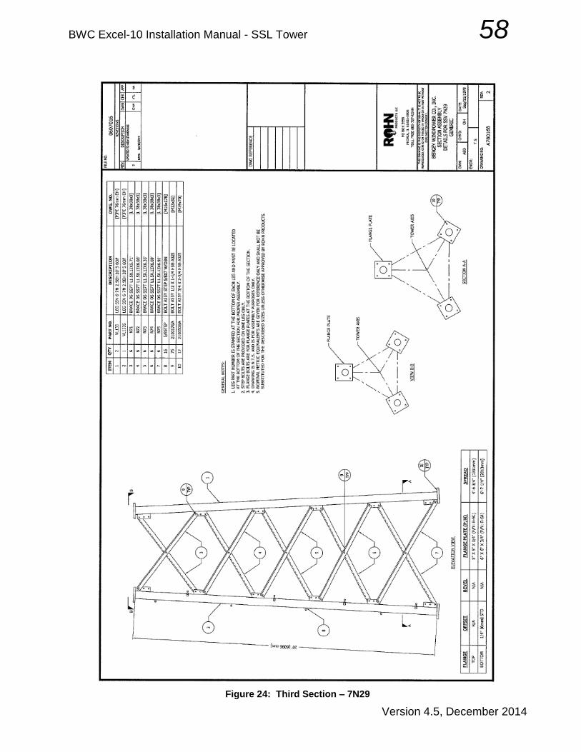
Figure 24: Third Section – 7N29

BWC Excel-10 Installation Manual - SSL Tower 59
Version 4.5, December 2014
Figure 25: Third Section – 7N1118 (Base of 60 ft Tower)

BWC Excel-10 Installation Manual - SSL Tower 60
Version 4.5, December 2014
Figure 26: Fourth Section - 8N111

BWC Excel-10 Installation Manual - SSL Tower 61
Version 4.5, December 2014
Figure 27: Fourth Section - 8N711 (Base of 80 ft Tower)
BWC Excel-10 Installation Manual - SSL Tower 62
Version 4.5, December 2014
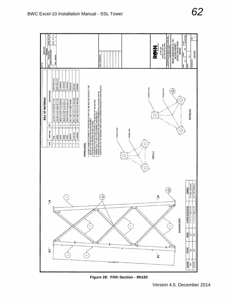
Figure 28: Fifth Section - 9N182

BWC Excel-10 Installation Manual - SSL Tower 63
Version 4.5, December 2014
Figure 29: Fifth Section - 9N242 (160 ft)

BWC Excel-10 Installation Manual - SSL Tower 64
Version 4.5, December 2014
Figure 30: Fifth Section - 9N538 (Base of 100 ft Tower)

BWC Excel-10 Installation Manual - SSL Tower 65
Version 4.5, December 2014
Figure 31: Sixth Section - 10N7
BWC Excel-10 Installation Manual - SSL Tower 66
Version 4.5, December 2014
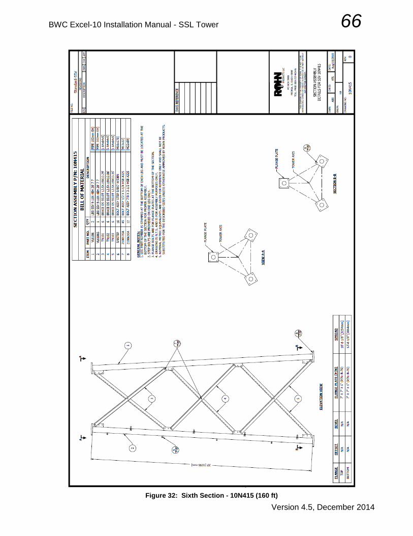
Figure 32: Sixth Section - 10N415 (160 ft)

BWC Excel-10 Installation Manual - SSL Tower 67
Version 4.5, December 2014
Figure 33: Sixth Section - 10N403 (Base of 120 ft Tower)
BWC Excel-10 Installation Manual - SSL Tower 68
Version 4.5, December 2014
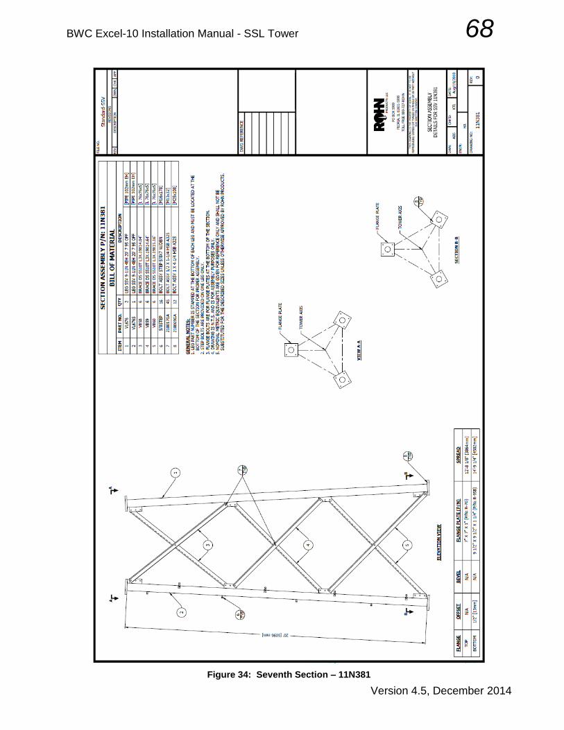
Figure 34: Seventh Section – 11N381

BWC Excel-10 Installation Manual - SSL Tower 69
Version 4.5, December 2014
Figure 35: Seventh Section – 11N376 (Base of 140 ft Tower)

BWC Excel-10 Installation Manual - SSL Tower 70
Version 4.5, December 2014
Figure 36: Eighth Section – 12N203 (Base of 160 ft Tower)

BWC Excel-10 Installation Manual - SSL Tower 71
Version 4.5, December 2014
Figure 37: Anchor Layout for SSL-60 Tower
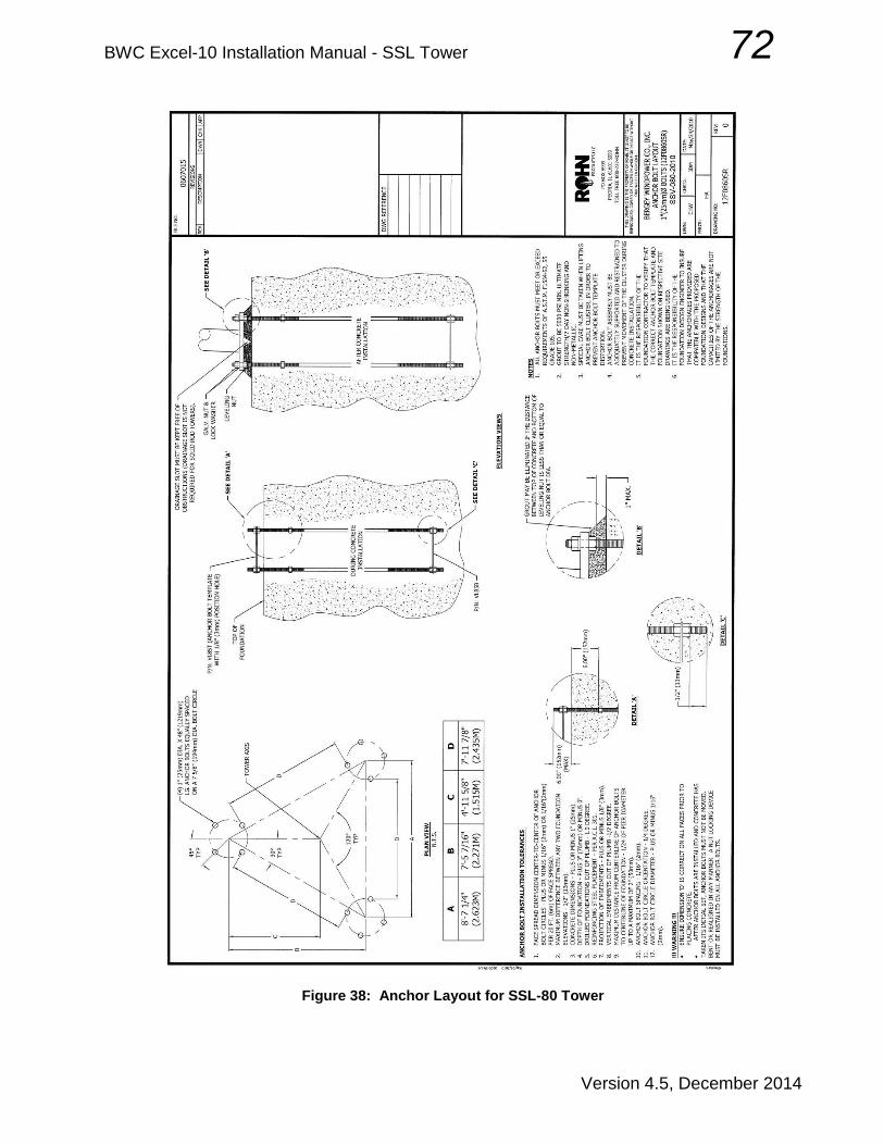
BWC Excel-10 Installation Manual - SSL Tower 72
Version 4.5, December 2014
Figure 38: Anchor Layout for SSL-80 Tower
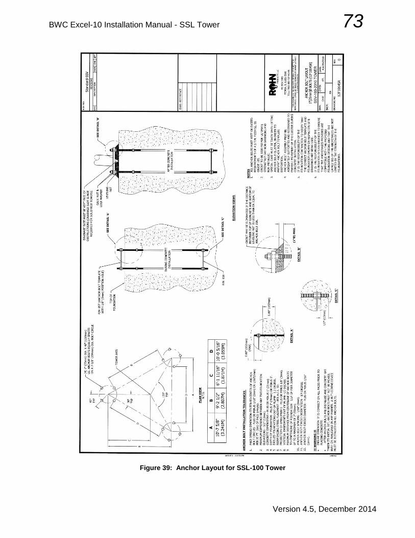
BWC Excel-10 Installation Manual - SSL Tower 73
Version 4.5, December 2014
Figure 39: Anchor Layout for SSL-100 Tower

BWC Excel-10 Installation Manual - SSL Tower 74
Version 4.5, December 2014
Figure 40: Anchor Layout for SSL-120 Tower

BWC Excel-10 Installation Manual - SSL Tower 75
Version 4.5, December 2014
Figure 41: Anchor Layout for SSL-140 Tower

BWC Excel-10 Installation Manual - SSL Tower 76
Version 4.5, December 2014
Figure 42: Anchor Layout for SSL-160 Tower
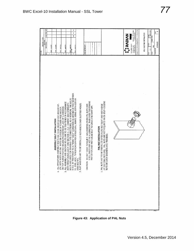
BWC Excel-10 Installation Manual - SSL Tower 77
Version 4.5, December 2014
Figure 43: Application of PAL Nuts

BWC Excel-10 Installation Manual - SSL Tower 78
Version 4.5, December 2014
B. Wire sizing
Wire run limit for performance equal to WindCAD estimation
tower height, feet (6awg) 60 80 100 120 140 160
AWG wire run distance to base of tower (feet)
6 210 190 170 150 130 110
4 340 300 270 240 210 180
3 420 380 340 300 260 220
2 530 480 430 380 330 280
0 850 771 690 610 529 449
00 1080 980 880 780 670 560
000 1370 1240 1110 980 850 720
Recommended Wire Size for BWC EXCEL Installations Note that wire run lengths correspond to performance values estimated by WindCAD. Annual Energy Output losses of 4.5% were factored into the WindCAD model to account for energy losses due to wire sizing.

BWC Excel-10 Installation Manual - SSL Tower 79
Version 4.5, December 2014
C. Lifting with StrongBack Fixture
Figure 44: Strongback illustration

BWC Excel-10 Installation Manual - SSL Tower 80
Version 4.5, December 2014
D. Single Line Diagram
Figure 45: Excel-S Systems One-line Electrical Diagram
Related Documents